i ï i f l ® - FIA Historic Database
143
a i ïifl® iUlN IIN 1 C,JKiN/\l 1U1N/\L,Ü U il. JL A U lU M U D lU E , Annuaire du sport automobile Appendix J Appendix B Yearbook of Automobile Sport
-
Upload
khangminh22 -
Category
Documents
-
view
0 -
download
0
Transcript of i ï i f l ® - FIA Historic Database
ai
ï i f l ®
i U l N IIN 1 C ,J K iN / \ l 1 U 1 N / \ L , Ü U i l . JL A U l U M U D l U E ,
Annuaire du sport
autom obile
Appendix J Appendix B
Yearbook ofAutom obileSport
Appendix Jto the International Sporting Code, 1996 > (classifications, definitions and specifications of cars)
In the case of differences of interpretation as regards the terms used in the various franslatkxis of olflcal FIA regulations, only the French text will t)e consider^ authentic.
TEXTS OF THE VARIOUS REGULATIONS DRAFTED BY THE FIA (International Sporting Code and its Appendiœs and regulations of ttie FIA International Ctiampionships) APPEARING IN THIS YEAR BOOK ARE THOSE DRAWN UP ON 19 OCTOBER 1995.
ANY AMENDMENTS WILL BE PUBLISHED AFTER THIS DATE IN THE FIA MONTHLY OFFICIAL BULLETIN.
© 1996 Fédération Internationale de I'AutomotxIe
APPENDIX J
Appendix J to the international Sporting Code
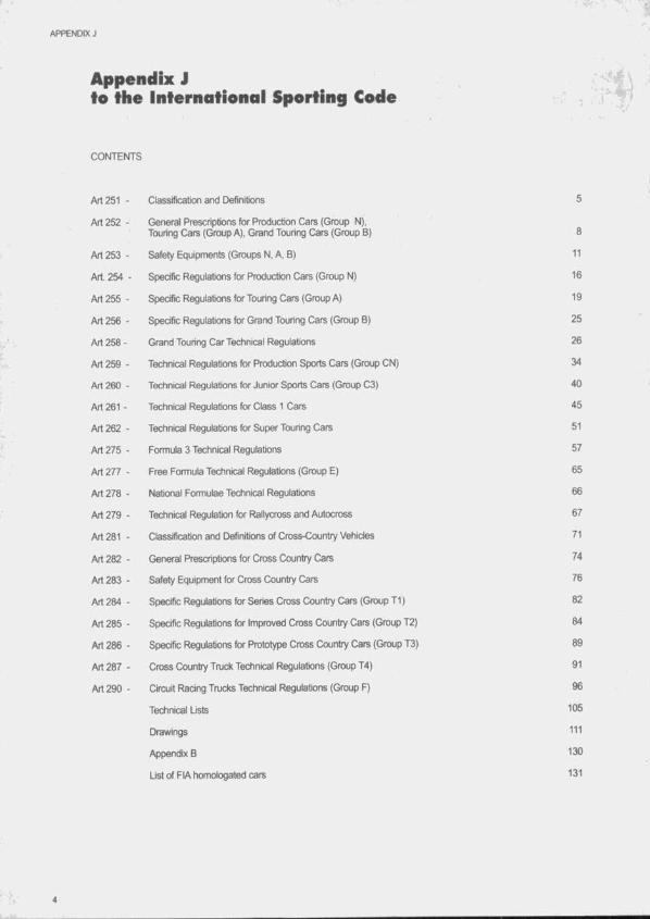
CONTENTS
Art 251 - Classification and Definitions 5
Art 252 - General Prescriptions for Production Cars (Group N), Touring Cars (Group A), Grand Touring Cars (Group B) 8
Art 253 - Safety Equipments (Groups N, A, B) 11
Art. 254 - Specific Regulations for Production Cars (Group N) 16
Art 255 - Specific Regulations for Touring Cars (Group A) 19
Art256 - Specific Regulations for Grand Touring Cars (Group B) 25
Art 258- Grand Touring Car Tectinlcal Regulations 26
Art259 - Tectinical Regulations for Production Sports Cars (Group CN) 34
Art 260 - Tectmical Regulations for Junior Sports Cars (Group C3) 40
Art 261 - Tecfrnical Regulations for Class 1 Cars 45
Art 262 - Technical Regulations for Super Touring Cats 51
Art 275 - Formula 3 Technical Regulations 57
Art 277 - Free Fomiula Technical Regulations (Group E) 65
Art 278 - National Fonoulae Technical Regulations 66
Art 279 - Technical Regulatton for Rallycross and Autocross 67
Art 281 - Classification and Definitions of Cross-Country Vehicles 71
Art 282 - General Prescriptions for Cross Country Cars 74
Art 283 - Safety Equipment for Cross Country Cars 76
Art 284 - Specific Regulations for Series Cross Country Cars (Group T1) 82
Art 285 - Specific Regulations for Improved Cross Country Cars (Group T2) 84
Art 286 - Specific Regulations for Prototype Cross Crxintry Cars (Group T3) 89
Art 287 - Cross Country Truck Technical Regulations (Group T4) 91
Art 290 - Circuit Ftacing Tnjcks Technical Regulations (Group F) 96
Technical Lists 105
Drawings 111
Appendix B 130
List of FIA homologated cars 131
A rticle 2 5 1 - Cla ssif ic a tio n a n d d e f in it io n s
1) CLASSIFICATION1.1 ■ Categories and groupsThe cars used in competition shall be divided up into the foiiowing categories and groups :Category I ; - Group N : Production Cars
- Group A : Touring Cars- Group B : Grand Touring Cars- Group ST : Super Touring Cars- Group CL1 : Class 1 Cars- Group T1 : Series Cross-Country Cars- Group T2 : improved Cross-Country Cars
Category I! : - Group T3 : Prototype Cross-Country Cars- Group GT : Grand Touring Sports Cars- Group C : Sports Cars- Group □ : intemationai Formula Racing Cars- Group E : Free Formula Racing Cars
Category III : - Group F : Racing Trucks- Group T4 : Crosscountry Trucks
1.2- Cubic capacity classesThe cars will be divided up into the foiiowing classes according to their cubic capacity :1. Up to 500 cm32. From 500 cm3 to 600 cm33. From 600 cm3 to 700 cm34. From 700 cm3 to 850 cm35. From 850 cm3 to 1000 cm36. From 1000 cm3 to 1150 cm37. From 1150 cm3 to 1300 cm38. From 1300cm3 to 1600 cm39. From 1600 cm3 to 2000 cm310. From 2000 cm3 to 2500 cm311. From 2500 cm3 to 3000cm312. From 3000 cm3 to 3500 cm313. From 3500 cm3 to 4000 cm314. From 4000 cm3 to 4500 cm315. From 4500 cm3 to 5000 cm316. From 5000 cm3 to 5500 cm317. From 5500 cm3 to 6000cm318. Over 6000 cm3Unless otherwise specified in special provisions imposed by the FIA for a certain category of events, the organisers are not bound to include ail ttie above-mentioned classes in the Supplementary Regulations and, furthermore, they are free to group two or more consecutive classes, according to the partcular circumstances of their events.No dass can be subdivided.
2) DEFINITIONS2.1 - General conditions2.1.1) Series Production cars (Category I) :Cars of which ttie production of a certain number of identicai examples (see definition of this word hereinafter) within a certain period of time has been verified at the request of the manufacturer, and which are destined for normal sale to the public (see this expression).Cars must be sold in arxordance with the homologation form.2.1.2) Competition cars (Category I!) :Cars built as single examples and destined solely for competition.2.1.3) Trucks (Category III)2.1.4) identical cars :Cars belonging to the same production series and which have the same bodywork (outside and inside), same mechanicai components and same chassis (even though this chassis may be an integral part of the bodywork in case of a monocoque construction).
2.1.5) Model of car:'Car belonging to a production-series distinguishable by a specific conception and external general lines of the bodywork and by an identicai mechanicai constnjction of the engine and the transmission to the wheels.2.1.6) Normal sale:Means the distribution of cars to individual purchasers through the normal commercial channels of the manufacturer.2.1.7) Homologation:Is the official certification made by the FIA that a minimum number of cars of a specific model has been made on series-pnxiuction ternis to justify classification in Production Cars (Group N), Touring Cars (Group A), Grand Touring Cars (Group B), Super Touring Cars (Group ST), Class 1 Cars (Group CL1), Series Cross-Country Cars (Group T1) of these regulations. Application for homologation shall be submitted to the FiA by the ASN of the country in which the vehicle is manufactured and shall entail the drawing up of a homologation form (see below), it must be established in accordance with the special regulations called “Regulations for homologation’ , laid down by the FiA. Homologation of a series-produced car will become null and void 5 years after the date on which the series-production of the said model has been stopped (series-prcxfurrtion under 10 % of the minimum production of the group considered).The homologation of a model can only be valid in one group. Production Cars (Group N)/Tour1ng Cars (Group A)/Series Cross- Country Cars (Group T1 ) or Grand Touring Cars (Group B). If a model already homologated in Grand Touring Cars (Group B) passes into Production Cars (Group N)/Touring Cars (Group A)/Series Cross- Country Cars (Group T1), the first homologation is cancelled.2.1.8) Homologation forms :Ail cars recognised by the FIA will be the sutqect of a descriptive form called homologation form on which shall be entered all data enabling identification of tfie said model.This homologation form defines the series as indicated by the manufacturer. According to the group in whkdi the competitors race, the modification limits allowed in intemationai competition for the series are stated in Appendix J.The presentation of the fomis at scrutineering and/or at the start may be required by the organisers who will be entitled to refuse the participation of the entrant in the event in case of non-presentation.Likewise, if a Group A car fitted with a kit variant (see below) concerning the chassis/shell is used, the original certificate supplied at the time of mounting by a centre approved by the manufacturer must be presented.Should the date for the coming into force of a homologation form fail during an event, this form will be valid for that event throughout the duration of the said event.With regard to Production Cars (Group N), apart from the specific form for this group, the Touring Cars (Grtiup A) fomi must also be submitted.In case of any doubt remaining after the checking of a model of car against its homologation form, tfie scnrtineers should refer eittier to the maintenance booklet published for the use of the make’s distributors or to the general catalogue in which are listed all spare parts.In case of lack of sufficient accurate documentation, scrutineers may carry out direct scrutineering by comparison with an identicai part available from a concessionaire. It will be up to the competitor to obtain the homologation form concerning his car from his ASf .Description : A form breaks down in the foiiowing way :1 ) A tiasic fonn giving a description of the basic model.2) At a later stage, a certain number of additional sheets describing "homotogation extensions”, which can be “variants", or "errata" or "evolutions”.a - Variants (VF, VO, VK)These are either supply variants (VF) (two suppliers providing the
APPENDIX T DEFINITIONS
same part for the manufacturer and the client does not have the possibility of choice), or options (VO) (supplied on request and available at tlie concessionnaires), or “kits" (VK) for use in rallies (supplied on request and available at the concessionnaires), b - Erratum (ER)Replaces and cancels an incorrect piece of information previously supplied by the constructor on a form, c - Evolution (ET, ES)Characterises modifications made on a permanent basis to the basic rrrodel (complete cessation of the production of the car in its original form in the case of the evolution of the type (ET), or sporting evolution (ES) intended to render a model more competitive.Use :1) Variants (VF, VO, VK)The competitor may use any variant or any part of a variant as he wishes, only on condition that all the technical data of the vehicle, so designed, conforms to that described on the homologation form applicable to the car, or expressly allowed by Appendix J. For example, the fitting of a brake calliper as defined on a variant form is only possible if the dimensions of the brake linings, etc. obtained in this way, are indicated on a form applicable to the car in question. (For Production Cars (Group N), see also art. 254.2). As far as kit-variants (VK) are concemed, they may not be used in Super Touring Cars, and may be used in other disciplines only under the conditions indicated by the manufacturer on the homologation form. This concerns in particular those groups of parts which must be considered as a wtxile by the competitor, and the specifications which are to be respected, if applicable.2) Evolution of the type (ET)(For Production Cars - Group N, see also art. 254.2)The car must comply with a given stage of evolution (independent of the date when it left the factory), and thus an evolution must be wholly applied or not at all.Besides, from the moment a competitor has ctxjsen a particular evolution, all the previous evolutions should be applied, except where they are incompatible : for example, if two brake evolutions happen one after another, only that conesponding to the date of the stage of evolution of the car will be used.3) Sporting evolution (ES)Since the ES form refers to a previous extension, or to the basic form, the car must correspond to the stage of evolution corresponding to this reference ; moreover, the Sporting Evolution must be applied in full.2.1.9) Mechanical components :All those necessary for the propulsion, suspension, steering and braking as well as all accessories wtiether moving or not which are necessary for their normal working.2.1.10) Original or series parts :A part which has undergone all the stages of production foreseen and carried out by the manufacturer of the vehicle concemed, and originally fitted on the vehicle.2.2 - DimensionsPerimeter of the car seen from above :The car as presented on the starting grid for the event in question.2.3 - Engine2.3.1) Cylinder capacity :Volume V generated in cylinder (or cylinders) by the upward or downward movement of ttie piston(s).V = 0.7854 X b^ X s X n where: b = bote
s = stroken = number of cylinders
2.3.2) Supercharging :Ircreasing the weight of the charge of the fuel-air mixture in the combustion chamber (over the weight induced by normal atmospheric pressure, ram effect and dynamic effects in the intake and/or exhaust systems) by any means whatsoever.The injection of fuel under pressure is not considered to be supercharging (see article 3.1 of the General Prescriptions fix Groups N, A, 8).2.3.3) Cylinder block :The crankcase and the cylinders.
2.3.4) Intake manifold :- Part collecting the air-fuel mixture from the carburettor(s) and extending to the entrance ports of the cylinder head, in ttie case of the carburettor induction system. >- Part situated between the valve of the device regulating the air intake and extending to the ports on the cylinder head, in the case of an injection intake system. t- Part collecting the air at the air filter outlet and extending to the cylinder head entrance ports in the case of a diesel engine.2.3.5) Exhaust manifold :Part collecting together the gases from the cylinder head and extending to the first gasket separating it from the rest of the exhaust system.2.3.6) For cars with a turtxx:harger, the exhaust begins after the turbocharger.2.3.7) Sump :The elements tiolted tielow and to the cylinder block which contain and control the lubrifying oil of the engine. These elements must not have any mounting part of the crankshaft.2.3.8) Engine compartment :Volume defined by the stnjctural envelope closest to the engine.2.4 - Running gearThe running gear includes all parts totally or partially unsuspended.2.4.1) Wheel :Flange and rim ; by complete wheel is meant flange, rim and tyre.2.4.2) Friction surface of ttie brakes :Surface swept by the linings on the drum, or the pads on both sides of the disc when the wheel achieves a complete revolution.2.4.3) Mac Pherson suspension :Any suspension system in which a telescopic strut, not necessarily providing the springing and/or damping action, but incorporating the stub axle, is anchored on the body or chassis through single attachment point at its top end, and pivots at its Ixittom end either on a transversal wishbone locating it transversally and tongitudinally, or on a single transversal link located longitudinally by an anti-roll bar, or by a tie rod.2.5 - Chassis - Bodywork2.5.1) Chassis :The overall structure of the car around which are assembled the mechanical components and the bodywork including any stnjctural part of the said structure.2.5.2) Bodywork :- extemally : all the enUrely suspended parts of the car licked by the airstream.- intemally : cockpit and boot.Bodywork is differentiated as follows :1) completely closed bodywork2) completely open bodywork3) convertible bodywork with the hood in either supple (drop-head) or rigid (hard-top) material.2.5.3) Seat :The two surfaces making up the seat cushion and seattiack or backrest. ÎSeatback or backrest :Surface measured from the bottom of a normally seated person's spine.Seat cushion :Surface measured from the bottom of the same person’s spine towards the front.2.5.4) Luggage compartment :Any volume distinct from the cockpit and the engine compartment inside the vehicle.These volumes are limited in length by the fixed structures provided for by the manufacturer and/or by the rear of the seats and/or, if this is pos- sitjle, reclined at a maximum angle of 15° to the tear. These volumes are limited in height by the fixed stmctures and/or by the detachable partitions provided for by the manufacturer, or in the absence of these, by the horizontal plane passing through the lowest point of the windscreen.2.5.5) Cockpit :Structural inner volume which accommodates the driver and the passengers.

APPENDIX ‘X DEFINITIONS
2.5.6) Bonnet :Outer part of the bodywor1( which opens to give access to the engine.2.5.7) Mudguard :A mudguard will tie considered to be the area defined according to drawing 251-1.Front mudguard :The area defined by the inner face of the complete wheel of the standard car (C1/C1) and the lower edge of the side window(s) (A/A) and the front edge of the front door (B1/B1).Rear mudguard :The area defined by the inner face of the complete wheel of the standard car (C2/C2) and the lower edge of the side window(s) (A/A) and the rear edge of the rear door (B2/B2).
In the case of two-door cars (B1/B1 ) and (B2/B2) will be defined by the front and rear of the same door.2.6 • Electrical systemHeadlight ; Any signal the focus of which creates an in-depth luminous beam directed towards the front.2.7 - Fuel tankAny container holding fuel likely to flow by any means whatsoever towards the main tank or the engine.

A rticle 252 - G eneral pr esc r iptio n s for p r o d u c t io n cars ( G r o u p N), TOURING CARS (G rOUP A ) , GRAND TOURING CARS (GROUP B)
1) GENERAL REMARKS1.1 - All mcxllfications are fbtbidden unless expressly authorised t)y the regulations specific to the group in which the car is entered or by ttre general prescriptions below or imposed under the chapter "Safety Equipmenr. The components of the car must retain Itieir original function.1.2 - Application o f the general prescriptionsThe general prescriptions must be observed in the event that the specifications of Production Cars (Grtjup N). Touring Cars (Group A), Grand Touring Cars (Group 8) do not lay down a rmre strict prescription.1.3- MagnesiumThe use of magnesium alloy street metal with a thickness less than 3 mm is prohibited.1.4- It Is the duty of each competitor to satisfy the Scnjtineers and tfre Stewards of the meeting that his automobile complies with these regulations in their entirety at all times during the event1.5 - Damaged threads can be repaired by screwing on a newthread with the same interior diameter (‘helicotr type).
2) DIMENSIONS AND WEIGHT2.1 - (jround clearanceNo part of the car must touch the ground when all the tyres on one side are deflated. This test shall be carried out on a flat surface under race corrditlons (occupants on board).22 - BallastIt is permitted to ccxnplete the weight of tfre car by one or several ballasts provided that they are strong and unitary bkicks, fixed by means of tools with the possitrility to fix seals, placed on tfre floor of the cockpit, visible and sealed by tfie scrutineers.Application : Tcxjring Cars (Group A), Grand Touring Cars (Group B) ; no kind of ballast Is autfrarised In Production Cars (Group N). In rallies, however, the carrying of tcxils and spare parts for the car will be allowed under the rxxiditions laid down in article 253.
3) ENGINE3.1 • SuperchargingIn case of supercharging, the ncxoinal cylinder-capacity will be multiplied by 1.7 artd the car will pass into tfre class corres(x>nding to the ficbve volume thus otrtained. The car will be treated In all respects as If Its cylinder-capadty thus increased were its real capacity.This sftall partkxilariy be the case for assigning the car to itscylinder-capadty dass, its interior dimensions, its minimum number of places, its minimum weight, etc.3.2 ■ EquivaleiKe form ula between reciprocating piston
and rotary engines (of ttie t ^ coveted by ttie NSU Wankel patents)The equivalent cubic capacity is 1.5 times the volume determined by ttte differenœ between the maximum and minimum capacities of the combustion chamtier.3.3 - Equivalence frxm ula between reciprocating piston
and turtrine enginesThe formula is the fbllowing :
S(3.10 X R) - 7.63C = ------------------------
0.09625S = High pressure nozzle area - expressed in square centimetres by which is meant the area of the air-How at the exit IrWn the stator blades (or at the exit from the first stage if the stator has several stages). Measurerrrent is done by taking ttte area between tfre fixed blades of the high pressure turtxne first stage. In cases wtrere the first stage turbine stator blades are adjustable, they must be opened to their greatest extent.The area of tfre high pressure nozzle is thus the product of the height
(expressed in cm) by the width (expressed in cm) and by tfie number of blades.R = The pressure ratio is the ratio of the compressor of the turtxne engine. It is otitained by multiplying together the value for each stage of the compressor, as indicated herealter :Subsonic axial compressor : 1.15 per stageTrans-sonic axial ccxnpress(}r : 1.5 per stageRadial compressor : 4.25 per stage.Thus a compressor with cxie radial and six axial sutisonic stages willbe designated to have a pressure ratio of :4.25 X 1.15 x 1.15 X 1.15 X 1.15 X 1.15 X 1.15 or 4.25 x (1.15)®.C = Equivalent cubic capacity for reciprocating piston engines in cm®.3.4 - All engines into which fuel is injected or in which fuel isburned after an exhaust port are prohibited.3.5 - Equivalencies between reciprocating piston engines
and new types of engines The FIA resenres the right to make modifications on the basis of comparisons established between classic engines and new types of engines, by giving a two year notice from the 1 st January fbllowing the decision taken.3.6 - Exhaust system and silenrrerEven when the specific provisions for a group allow the replacement of the original silencer, the cars competing in an opervroad event sfiall always be equipped with an exhaust silencer complying with the traffic regulations of tfie crxrntry(ies) through which the event is run.Tfie orifices of tfie exhaust pipes shall be placed at a maximum of 45 cm and a minimum of 10 cm from the ground. The exit of the exhaust pipe must be situated within the perimeter of the car and less than 10 cm from this perimeter, and aft of the vertical plane passing through tfie centre of tfie wheelbase. Moreover, acfequate protection must be provided in order to prevent heated pipes from causing bums.The exhaust system must not be provisional. Exhaust gas may only exit at the end of the system. Parts of tfie chassis must not be u ^ to evacuate exhaust gasses.Catalytic exhausts : Should two possible verskxis of one car mcxlel be hcxncrlogated (catalytic and other exhaust), the cars must ccxnply with one or other version, any combination of the two versions being prohibited.3.7 - Starting on board ttie vehicleStarter with electric or other scxjroe of energy on boanl operable by the driver wtien seated in the seat.3.8 - CylindersFor non-sieeved engines, it will be possible to repair tfie cylinders by adding material, but not parts.
4) TRANSMISSIONAll cars must be fitted with a geartxix including a reverse gear wfiich must be in working order when tfie car starts the event and be able to be operated by the driver when he is normally seated.
5) SUSPENSIONSuspension parts made partially or entirely from composite materials are prohibited.
6) VVHEELSWheels made partially rx entirely from composite materials are prohibited.Measuring wheel wkfth :The width is to be measured with the wtieel mcxjnted on the car, on the ground, tfie vehicle in race conditkxi, driver aboard, at any point along tfie drcumferenœ erf the tyre, except in tfie area in contact with the ground. When multiple tyres are fitted as part of a complete wheel, the latter must comply with the maximum dimenskxis fbr tfie Grcxjp In which these tyres are used (see article 255.5.4 and artkrfe 256.5).

APPENDIX "J" GENERAL PRESCRIPTIONS
7) COACHWORK7.1 - Convertible vehicles must comply In all respects with the specifications applying to open cars.7.2 - Minimum inside dimensionsif a modification authorised by Appendix J affects a dimension stated on the homologation fbrni this dimension may not be retained as an eligibility critetion for the car.7.3 - CockpitOnly the following accessories may be Installed In the cockpit : spare wheels, trxrls. spare parts, safety equipment communication equipment. ballast (If permitted), wlndsaeen washer water container (Touring Cars (Group A) and Grand Touring Cars (Group B) only). The passenger area and seat of an open car must In no way be covered.Containers for helmets and tools situated In the cockpit must be made of non-inflammable material and they must not, In case of fire, give off toxic vapours.The original fitting of ttie air bags may be removed, without modifying the appearance of the bodywork.7.4 - Ail body panels of the vehicle must be at ail times of thesame material as those of the original homologated car and must be of the same material thickness as that of the original homologated car (tolerance ± 10 %).7.5 - Headlamp mounting and protectionThe boring of holes In the front bodywork for light brackets Is authorised, limited solely to mountings.in rallies, non-re fl^ng protectors made from flexible material may be mounted on the headlamps ; they must not protrude fonvards beyond the headlamp glass by more than 10 cm.7.6 - Any object of a dangerous nature (battery. Inflammable products, etc.) must be carried outside the cockpit.7.7 - Mud flaps (In Rallies only)If the supplementary regulations of ttie event auttiorise them or Impose them, transversal mud flaps will be accepted under ttie following conditions:- They must be made from flexible material.- They must cover at least the width of each wheel, but at least one third of the width of the car (see drawing 252-6) must be free behind the front wheels and ttie rear wheels.- There must be a gap of at least 20 cm between the right and left mud flaps In front of the rear wheels.- The bottom of these mud flaps must be no more than 10 cm from the ground when the car Is stopped, with nobody on board.- In vertical projection, these mud flaps must not protrude beyond the bodywork.Mud flaps to prevent splashing towards the front, made from flexible material, may be Installed at the front of the vehicle, if the supplementary regulations of ttie event auttiorise them or Impose ttiem. They must not protrude beyond the overall width of the vehicle, or beyond the original overall length by more than 10 cm, and at least one third of the width of the car must be free In front of the front wheels.
8) ELECTRICAL SYSTEM8.1 - LightingA fog light may be changed for another light and vice versa, provided that the original mounting remains the same.8.2 - The mounting of ttie alternator is free.
9) FUEL - COMBUSTIVE9.1 - The fuel must be commercial petrol which comes from a service station pump, without any additive other than that of a lubricant on cunent sale. The fuel must comply with the following specifications :- 102.0 RON and 90.0 MON maximum, 95.0 RON and 85.0 MON minimum for unleaded fuel.100.0 RON and 92.0 MON maximum, 97.0 RON and 86.0 MON minimum for leaded fuel.The measurements will be made according to the standards ASTM D 2699-86 and D 2700-86.- Specific gravity between 720 and 785 kg/m3 at 15°C (measured according to ASTM D 4052).- A maximum of 2.8 % oxygen (or 3.7 % If the lead content Is less thanO.013 g/l)and0.5 % nitrogen by weight, the remainder of the fuel
consisting exclusively of hydrocarbons and not containing any power-boosting additives.The measuring of the nitrogen content will be carried out according to the standard ASTM D 3228 and that of the oxygen content by elemental analysis with a tolerance of 0.2 %.- Maximum content of peroxides and nitrooxlde compounds : 100 ppm (ASTM D 3703 or In the case of Impossibility UOP 33-82).- Maximum lead content : 0.40 g/l or ttie standard of the country of the event If It Is lower (ASTM D 3341 or D 3237).- Maximum benzene content : 5 % In volume (ASTM D 3606).- Maximum Reid vapour pressure : 900 hPa (ASTM D 323).- Distillation at 70°C : 10 % - 47 % (ASTM D 86).- Distillation at 100°C : 30 % - 70 % (ASTM D 86).- Distillation at 180° C : 85 % minimum (ASTM D 86).- Maximum final boiling point ; 225°C (AiSTM D 86).- Maximum residue : 2 % volume (ASTM D 86).The fuel being accepted or rejected according to the standard ASTM D 3244 with a confidence limit of 95 %.If the fuel available locally for the event Is not of a sufficient quality for use by competitors, the ASN of the organising country must ask the FIA for a waiver In order to enable the use of fuel not corresponding to the characteristics defined above.9.2 - Only air may be mixed with the fuel as an oxidant.9.3 - Refuelling procedure Standardised coupling- In case of a centralised system provided by the circuit or a system provided by the competitors, the refuelling hose shall be provided with a leak-proof coupling to fit the standardised filler mounted on the car. The dimensions of this fitting are given In the drawing 252-5.- All cars must be provided with a fuel filler complying with this diagram. This leak-proof fitting must comply with the dead man principle and must not therefore Incorporate any retaining device wtien In an open position (spring-loaded, bayonet, etc.).- The air vent(s) must be equlpp^ with non return and closing valves having the same closing system as that of the standard filler and having the same diameter. During refuelling the outlets of the alr-vents must be connected with the appropriate coupling elttier to the main supply-tank or to a transparent portable container with a minimum capacity of 20 litres provided with a closing system rendering It completely leak-proof. The venting catch tanks must be empty at the beginning of the refuelling operation.In the cases where the circuits are unatrle to provide the entrants with a centralised system, they will have to refuel according to the above procedure.The level of the reserve tank may In no case be more than 3 metres above the level of the track where the refuelling Is effected. This applies to the whole duration of the event.The overflow bottles must confonn to one of the drawings 252-1 or252-2.The reserve tank and ail metal parts of the refuelling system from the coupling over the flow meter up to the tank and Its rack must be connected electrically to the earth.The application of the following Is recommended :1. Each pit should be equipped with two aircraft type grounding connections.2. The refuelling system (Including tower, tank, hose, nozzle, valves and vent bottle) should be connected to one of the above grounding connections for the entire duration of the race.3. The car should be connected, at least momentarily, to the other grounding connection as soon as It stops In the pit.4. No fuel hose connection (fill or vent) unless and until conditions 2 and 3 have been fulfilled.5. All fuel-handling pit crew members should wear non-static protective clothing.The refuelling tank may be one of the following :- models made of rubber, of the type FT3, built by an approved manufacturer, or- tanks conforming to one of the drawings 252-3 or 252-4.Application : For Touring Cars (Group AL Grand Touring Cars (Group B), refer to the general prescriptions of the FIA Championships.9.4 - Tank ventiiationit is auttterised to equip a tank with ventilation exiting through the car roof.

APPENDIX “J" GENERAL PRESCRIPTIONS
9.5 ■ Installation o f the FT3 tank beyond the bodywork and guarantees that no fuel shall leak into oneThe FT3 tank may be placed either in the original location of the tank of the interior compartments of the car.or in the luggage compartment. If the filler hole is situated Inside the car, it must be separated from theThere must be an orifice to evacuate any fuel which may have spread cockpit by a liquid-tight protection,into the tank compartment.The position and the dimension of the filler hole as well as that of the 10) BRAKEScap may be changed as long as the new installation does not protrude Cartxxi brake discs are forbidden.
10
A r t ic le 2 5 3 - S a fe ty equipm ent (G ro u p s N, A , B, ST)
1) A car, the constnjction of which is deemed to be dangerous,may tie excluded by the Stewards of the meeting.
2) If a device is optional, it must be fitted in a way that complieswith regulations.
3) LINES3.1 - ProtectionFuel, oil and brake lines must be protected externally against any risk of deterioration (stones, corrosion, mechanical breakages, etc.) and internally against all risks of fire. If the series production fitting is retained, no additional protection is necessary.Application: Optional for Group N, obligatory for the other Groups.
In the case of fuel lines, the metal parts which are isolated from the shell of the car by non-conducting parts must be connected to it electrically.Application: All groups, unless the series production fitting is maintained.3.2 - Specifications and installationSeries production fittings may tie retained. If they are modified, they must comply with the specifications conceming them below :- Fuel and lubricating oil lines must have a minimum burst pressure of 70 bar (1000 psi) and a minimum operating temperature of 135°C (250°F).When flexible, these lines must have threaded connectors and an outer btakj resistant to abrasion and flame (will not sustain combustion).- Lines containing hydraulic fluid, with the exception of lines under gravity head only, must have a minimum burst pressure of 70 bar (1000 psi) or higher according to operating pressure, and a minimum operating temperature of 232°C (450°F).When flexible, these lines must have threaded connectors and an outer brakj resistant to abrasion and flame (will not sustain combustion).- Lines containing cooling water or lutxicating oil must be outside tfie C(X*pit. Lines containing fuel or hydraulic fluid may pass through ttie cockpit, but without any connectors inside except on the front arid rear bulkheads according to drawings 253-1 and 253-2, and on the braking circuit.
4) BRAKING SAFETY SYSTEMDouble circuit operated by the same pedal : the pedal shall normally control all the wheels ; in case of a leakage at any point of the brake system pipes or of any kind of failure in the brake transmission system, the pedal shall still control at least two wheels.If this system is fitted in series production, no modifications are necessary.
5) ADDITIONAL FASTENERSAt least two additional safety fasteners must tie fitted for each of the bonnet and boot lids. The original locking mechanisms will be rendered inoperative or removed.Large objects carried on board the vehicle (such as the spare wheel, tool-kit, etc.) must be finnly fixed.Application: Optional for Group N, obligatory for the ottier Groups.
6) SAFETY BELTS6.1 - Wearing o> two shoulder straps and one lap strap ; anchorage points on the shell : two for the lap strap, two or possibly one symmetrical about the seat for the shoulder straps.These belts must be homologated by the FIA and comply with FIA standard n°8854 or 8853. Furthermore, the belts used in circuit competitions must be equipped with JutD buckle release systems. On the other hand, it is recommended that for competitions which include
public road sections, the belts be equipped with push button release systems.th e ASNs may homologate mounting points on the roilcage when this cage is being homologated (see art. 253.8.4), on condition that ttiey are tested.6.2 - Installation- A safety hamess must be installed on the anchorage points of the series car.The recommended geometrical locations of the anctrorage points are shown in drawing n° 253-42.In the downwards direction, the shoulder straps must be directed towards the rear and must be installed in such a way that they do not make an angle of more than 45“ to the horizontal from the upper rim of the backrest, although it is recommended that this angle should not exceed 10”.The maximum angles in relation to the centre-line of the seat are 20° divergent or convergent.If possible, the anchorage point originaily mounted by the car manufacturer on the C-pillar should be used.Anchorage points creating a higher angle to the horizontal must not be used unless tfie seat meets the requirements of tfie FIA standard.In that case, the shoulder straps of 4-point safety hamesses must be installed on the rear seat lap strap anchorage points originally mounted by the car manufacturer.For a 4-point hamess, the shoulder straps must be installed crosswise symmetrically atxxrt the centre-line of the front seat.A safety hamess must not be installed on a seat having no head restraint or having a backrest with integrated head restraint (no opening between backrest and head restraint).The lap and crotch straps should pass not over the sides of the seat but through the seat, in order to wrap and hold the pelvic r^km over the greatest possible surface. The lap straps must fit tightly in the bend between the pelvic crest and the upper thigh. Under no conditions must they be wom over the region of the abdomen. Holes may tre made in the series seat if this proves to tie necessary in order to avoid such an occurrence. Care must be taken ttiat the straps cannot be damaged through chafing against sharp edges.- If installation on the series anchorage points is impossible for the shoulder and/or cratch straps, new anchorage points must be installed on the shell or the chassis, as near as possible to the centre-line of the rear wheels for the shoulder straps. The shoulder straps may also be fixed to the safety roilcage or to a reinforcement bar by means of a loop, and may also be fixed to the top anchorage points of the rear belts, or tie fixed or leaning on a transversal reiriforcement welded to the backstays of the rollbar. In this case, the use of a transversal reinforcement is subject to the following conditions:- The transversal reinforcement shall be a tube measuring at least 38 mm x 2.5 mm or 40 mm x 2 mm, made from cold drawn seamless cartxm steel, with a minimum yield strength of 350 fJ/mm».- The height of this reinforcement must tie such that the shoulder straps, towards the rear, are directed downwards with an angle of between 10° and 45° to the horizontal from the rim of the backrest, an angle of 10° being recommended.- The straps may be attached by looping or by screws, but in the latter case an insert must be welded for each mounting point (see drawings253-17C and 253-53 for the dimensions). These inserts will be positioned in the reinforcement tube and the st aps will be attached to them using bolts of M12 8.8 or 7/16 UNF spectotion.- Each anchorage point must be able fri withstand a load of 1470 daN, or 720 daN for the cratch straps. In the case of one anchorage point for two straps, the load considered will be equal to tfie sum of the required loads.- For each new anchorage point created, a steel reinforcement plate with a surface area of at least 40 cm» and a thickness of at least 3 mm must be used.
APPENDIX T SAFETY
- Principles of mounting to trie chassis/monocoque:1) General mounting system: see drawing 253-43.2) Srioulder strap mounting: see drawing 253-44.3) Crotch strap mounting: see drawing 253-45.6.3 - UseA safety harness must tse used in its homologation configuration without any modifications or removal of parts, and in conformity with the manufacturer's instructions. The effectiveness and longevity of safety tielts are directly related to the manner in which they are installed. used and maintained. The tielts must t>e replaced after every severe collision, and whenever the wettbing is cut, ^ y e d or weakened due to the actions of chemicals or sunlight. They must also tre replaced if metal parts or buckles are tient, defomed or rusted. Any harness which does not function perfectly must be replaced.
7) 0(TINGUISHERS - EXTINGUISHING SYSTEMS7.1 - In rallies- Group N :The systems mounted In accordance with art. 7.3 are recommended.- Groups A and B :These systems are compulsory.Furthermore, hand-operated extinguishers ate compulsory for all Groups (see art. 7.4).72 - In circuit events, slaloms, hillclimbsHand-operated extinguishers are compulsory.An automatic extinguisher (see art. 7.3) may replace the manual extinguisher. In this case, a single 4 kg bottle will be accepted, the extinguishing agent being shared tietween the cockpit and the engine in accordance with the directives given below.7.3 - Systems mounted7.3.1 ) All cars must be fitted with two fire extinguisher systems, one which will discharge into the cockpit and one into the engine compartment. A single bottle may be used if the extinguishant is divided up in accordance with the directives given below.7.3.2) Pemnitted extinguishants:BCF (C F2 Cl Br)NAFS3NAFPAny AFFF which has been specifically approved by the FIA (see Technical List n° 6^.Dry powder is also permitted but only on cars being used in or coming from countries where national regulations preclude the use of the above products.7.3.3) Minimum extinguisher capacity:- For BCF, NAF S3, NAF P:Cockpit: 1.65 litres.Engine: 3.30 litres.- For AFFF: The capacity may vary according to the type used (see Technical List n° 6")7.3.4) Minimum quantity of extinguishant:BCF: Cockpit: 2.5 kg
Engine: 5.0 kgNAF S3: Cockpit: 2.0 kg
Engine: 4.0 kgNAFP: Cockpit: 2.0 kg
Engine: 4.0 kgPowder Cockpit 1.2 kg
Engine: 2.4 kgAFFF:
7.3.5)
The quantity may vary according to the type used (see Technical List n° 6”)Discharge time:
Engine : 10 seconds minimum / 40 seconds maximum.Cockpit : 30 seconds minimum 180 seconds maximum.Both extinguishers must be released simultaneously.7.3.6) All extinguishers must be pressurised according to the contents:BCF: 7.0 barNAF S3: 7.0 barNAF P: 7.0 barPowder 13.5 barAFFF: The pressure may vary according to the
type used (see Technical List n” 6")
Furthermore, in the case of an AFFF, each extinguisher must be equipped with a means of checking the pressure of the contents.7.3.7) The following information must be visible on each extinguisher:-capacity- type of extinguishant- weight or volume of the extinguishant- date the extinguisher must be checked, which must be no more than two years after either the date of filling or tfie date of the last check.7.3.8) All extinguishers must be adequately protected and must be situated within the cockpit. In all cases their mountings must be able to withstand a deceleration of 25 g.All extinguishing equipment must withstand fire.7.3.9) Any triggering system having its own source of energy is permitted, provided it is possible to operate all extinguishers should the main electrical circuits of the car fail.The driver must be able to trigger all extinguishers manually wtien seated normally with his safety belts fastened and the steering wheel in place.Furthemore, a means of triggering from the outside must be combined with the drcuit-breaker switch, or situated close to i l It must be marked with a letter “E" in red inside a white circle of at least 10 cm diameter with a red edge.7.3.10) The system must work in any position, even when the car is invert^.7.3.11) Extinguisher nozzles must tre suitable for tfie extinguisfiant and be installed in such a way that they are not directly pointed at the occupants.7.4 - Manual extinguishers7.4.1 ) All cars must be fitted with one or two fire extinguishers.7.4.2) Permitted extinguishants:BCF (C F2 01 Br)NAF S3 NAFP AFFF Powder7.4.3) Minimum extinguisher capacity:In case of use of BCF, NAF S ill, NAF P, or powder :2.60 litres for the quantities specified hereafter.7.4.4) Minimum quantity of extinguishant:BCF: 4.0 kgNAF S3: 3.2 kgNAF P: 3.2 kgAFFF: 2.4 litresPowder 2.0 kg7.4.5) All extinguishers must be pressurised according to the contents:BCF: 7.0 barNAF S3: 7.0 barNAF P: 7.0 barAFFF: 12.0 barPowder 13.5 barFurthermore, each extinguisher when filled with AFFF must be equipped with a means of checking the pressure of the contents.7.4.6) The following information must be visible on each extinguisher:- capacity- type of extinguishant- weight or volume of the extinguishant- date the extinguisher must be checked, which must be no rrxxe tfian two years after either the date of filling or the date of the last check.7.4.7) All extinguishers must be adequately protected. Their mountings must be able to withstand a deceleration of 25 g. Furthermore, only quick-release metal fastenings, with metal straps, will be accepted.7.4.8) The extinguishers must be easily accessible for the driverand the co-driver.
8) ROLLOVER STRUCTURES8.1 - Definitions8.1.1) Safety cage:A starctural framework designed to prevent serious bodyshell deformation in the case of a collision or of a car turning over.

APPENDIX “J“ SAFETY
8.1.2) Rollbar;Structural frame or hoop and mounting points.8.1.3) Rollcage:Structural framework made up of a main rollbar and a front rollbar (or of two lateral rollbars), their connecting members, one diagonal memt>er. t>ackstays and mounting points. (For example, see drawings 253-3 and 2534).8.1.4) Main rollbar;Structure consisting of a near-vertical frame or hoop located across the vehicle just behind the front seats.8.1.5) Front rollbar :Similar to main rollbar but its shape follows the windscreen pillars and top screen edge.8.1.6) Lateral rollbar :Structure consisting of a near-vertical frame or hoop located along the right or left side of the vehicle. The rear legs of a lateral rollbar must be just behind the front seats. The fixxit leg must be against the saeen pillar and the door pillar such that it does not unduly impede the entry or exit of driver and co-driver.8.1.7) Longitudinal memt>er :Longitudinal tube which is not a part of the rr>ain, front or lateral rollbar and linking them, together with the backstays.8.1.8) Diagonal member :Transverse tube between a top comer of the main rollbar or upper end of a t)ackstay and a lower mounting point on the other side of the rollbar of backstay.8.1.9) Framework reinforcement :Reinforcing member fixed to the rollcage to improve its structural efficiency.8.1.10) Reinforcement plate :Metal plate fixed to the bodyshell or chassis structure under a rollbar mounting foot to spread load into the structure.8.1.11) Mounting foot :Plate welded to a rollbar tube to permit its bolting or welding to the bodyshell or chassis structure, usually onto a reinforcement plate.8.1.12) Removable members :Structural members of a safety cage which must be able to be removed.8.2 - Specifications8.2.1) General comments :8.2.1.1. - Safety cage must be designed and made so that, when correctly installed, they substantially reduce bodyshell deformation and so reduce the risk of injury to occupants.The essential features of safety cages are sound construction, designed to suit the particular vehicle, adequate mountings and a close fit to the bodyshell.Tubes must not carry fluids. The safety cage must not unduly impede the entry or exit of the driver and co-driver.Members may intrude into the occupant’s space in passing through the dashboard and front side-trim, as well as through the rear side-trim and rear seats. The rear seat may be folded down.Longitudinally, the safety cage must be entirely contained between the top mounting points of the front suspension and the top mounting points of tfie rear suspension.Any modification to a homologated safety cage is forbidden.8.2.1.2- Basic safety cage :Only rollcages must be used.8.2.1.3 - Compulsory diagonal member :Different ways of fitting the compulsory diagonal member : see drawings 253-3 to 253-5.The combination of several members is permitted.8.2.1.4 - Optional reinforcing members :Each type of reinforcement (drawings 253-6 to 253-17, 253-17A and 253-17C) may be used separately or combined with others.8.2.2) Technical specifications :8.2.2.1 - Main, front and lateral rollbars :These frames or hoops must be made in one piece without joints. Their construction must t>e smooth and even, without ripples or cracks. The vertical part of the main rollbar must be as straight as possible and as dose as possible to the interior contour of the bodyshell.The front leg of a front rollbar or of a lateral ro llta r must be straight, or if it is not possitMe, must follow the windscreen pillars and have only
one t>end with its lower vertical part. Where a main ro llta r forms the rear legs of a lateral rollt)ar (drawing 253-4), the connection to the lateral rollbar must be at roof level.To achieve an efficient mounting to the bodyshell, the original interior trim may be modified around the safety cages and their mountings by cutting it away or by distorting it.However, this modification does not permit the removal of complete parts of upholstery or trim.Where necessary, the fuse box may be moved to enable a rollcage to befitted.8.2.2.2 - Mounting of rollcages to the bodyshell :Minimum mountings are :-1 for each leg of the main or lateral rollbar ;-1 for each of the front rollbar ;-1 for each backstay (see 8.2.2.S).Each mounting foot of the front, main and lateral rollbars must include a reinforcement plate, of a thickness of at least 3 mm which must not be less than that of the tube onto which it is welded.Each mounting foot must be attached by at least three bolts on a steel reinforcement plate at least 3 mm thick and of at least 120 cm^ area which is welded to the bodyshell. Examples are shown in drawings 253-18 to 253-24. This does not necessarily apply to backstays (see below).Bolts must be of at least M8 size of ISO standard 8.8 or better. Fasteners must be self-locking of fitted with lock washers.These are minimum requirements. In addition to these requirements, more fasteners may be used, the rollbar legs may be welded to reinforcement plates, the rollcage may be welded to the Ixxlyshell. Rollbar mounting feet must not be welded directly to the bodyshell without a reinforcement plate.8.2.2.3 - Backstays ;These are compulsory and must t>e attached near the roof line and near the top outer bends of the main rollbar on lx)th sides of the car. They must make an angle of at least 30" with the vertical, must run rearwards and be straight and as dose as possit>le to the interior side panels of the txxjyshell.Their materials specification, diameter and thickness must be as defined in 8.3.Their mountings must be reinforced by plates. Each backstay should be secured by bolts having a cumulative section area at least two thirds of that recommended for each rollbar leg mounting in 8.2.2.2 above, and with identical reinforcement plates of at least 60 cm« area (seedrawing 253-25).A single bolt in double shear is permitted, provided it is of adequate section and strength (see drawing 253-26) and provided that a bush is welded into the backstay.8.2.2.4 - Diagonal members :At least one diagonal member must be fitted.Their location must be in accordance with drawings 253-3 to 253-5 and they must be straight, not curved.The attachment points of the diagonal members must be so located that they cannot cause injuries. They may be made removable but must be in place during events. The lower end of the diagonal must join the main rollbar of t>ad<stay not furttier than 100 mm from the mounting foot. The upper end must join the main rollbar not further than 100 mm from the junction of the backstay joint, or the backstay not more than 100 mm from its junction with the main rollbar.They must comply with the minimum specification set out in 8.3. Diagonal members fixed to the bodyshell must have reinforcement plates as defined In 8.2.2.3 above.8.2.2.5 - Optional reinforcement of the rollcage :The diameter, thickness and material of reinforcements must be as defined in 8.3.They shall be either welded in position or installed by means of demountable joints.8.2.2.5.1) Transverse reinforcing members :The fitting of two transverse members as shown in drawing 253-7 is pemiitted. The transverse member fixed to the front rollbar must not encroach upon the space reserved for the occupants. It must t>e placed as high as possible but its lower edge must not be higher than the top of the dashtx>ard.
13
APPENDIX T SAFETY
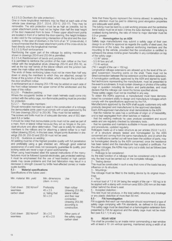
8.2.2 5.2) Ctoorbars (for side protection) :One or more longitudinal memtiens may l>e fitted at eadi side of tfie vetiicle (see drawings 253-7, 253-8, 253-12, 253-17). Ttiey may tie removatile. Ttie side protection must l)e as tiigti as possible, but its upper attachment points must not be higher than half the total height of the door measured from its base. If these upper attachment points are located in front of or behind the door opening, this height limitation is also valid for the comesponding Intersection of the strut and the door opening. In the case of doortars in the fonn of an "X* (cross-struts), it is recommended that the lower attachment points of ttie cross-struts be fixed directly onto the longitudinal member.8.2.2 5.3) Roof reinforcement :Reinforcing tfie upper part of the rollcage by adding members as shown in drawings 253-9 and 253-9A is pemiitted.8.2.2.5.4) Reinforcement of bends and junctions :It is permitted to reinforce the Junction of the main rollbar or the front rollbar with ttie longitudinal struts (drawings 253-10 and 253-16), as well as the top rear bends of the lateral rollbars and the junction between the main rollbar and the backstays.The ends of these reinforcing tubes must not be more than half way down or along the members to which they are attached, except for those of the junction of the front rollbar, which may join the junction of the (foor strut/front rollbar.A reinforcement as in drawing 253-17B may be added on each side of the front rollbar between the upper comer of ttie windscreen and the base of this rollbar.8.2.2.6 - Protective padding :Where the occupants' bodies or their crash helmets could come into contact with the safety cage, non-flammatile padding must be provided for protection.8.2.2.7 - Removable members :Should removable members be used in the construction of a roltaage, ttie demountable joints used must comply with a type approved by the FIA (see drawings 253-27 to 253-36). Ttiey must not be welded.The screws and bolts must be of adequate diameter, and of ISO standard 8.8 or better.It should be noted that demountable joints must not be used as part of a main, front or lateral rollbar because they act as hinges in the principal structure and allow deformation. Their use is solely for attaching members to the rollbars and for attaching a lateral rollbar to a main rollbar (drawing 253-4). In this last case, hinged joints illustrated in drawings 253-30, 253-33 and 253-36 must not be used.8.2.2.8) Guidance on welding :All welding must be of the highest possible quality with full penetration and preferably using a gas shielded arc. Although good extemal appearance of a weld does not necessarily guarantee its quality, poor looking welds are never a sign of good workmanship.When using head-treated steel the special instructions of tfie manufacturers must be followed (special electrodes, gas protected welding). It must be emphasised that the use of heat-treated or high carbon steels may cause problems and that bad fabrication may result in a decrease in strength (caused by brittle heat-affected zones) or inadequate ductility.8.3 - Material specificationsSpecifications of the tubes used :
Min. material Min. yield
Cold drawn 350 tJ/mm^seamlesscartxin steel
Cold drawn 350 N/mm^ seamless
Min. dimensions (diam. in mm)
Use
Preferably Main rollbar45 X 2.5 (drawing 253-38) ;or, failing that lateral rollbar50x2.0 and their rear
connection (drawing 253-39) according to construction.
38x2.5 Other parts ofor 40 X 2.0 ttie safety cage,
carton steel
Note that these figures represent the minima allowed. In selecting the steel, attention must tie paid to obtaining gtxxl elongation properties and adequate weld ability.The tubing must be bent by a cold working process and the centreline bend radius must be at least 3 times the tulie diameter. It the tubing is ovalised during bending, the ratio of minor to major diameter must be 0.9 or greater.8.4 - Homologation by an ASNSafety cage manufacturers may submit a safety cage of their own design to an ASN for approval as regards the quality of steel used, the dimensions of the tubes, the optional reinforcing members and the mounting to the vehicle, provided that the construction is certified to withstand ttie stress minima given hereafter in any combination on top of the safety cage :-1 .5 W* lateral ;- 5.5 W fore and aft ;- 7.5 W vertical.(*W = weight of the car + 150 kg).Longitudinal rollcage extensions are allowed up to ttie level of the original suspension mounting points on the shell. There must not be direct connection between the top extension and the bottom extension. A homologation certificate, approved by the ASN and signed by qualified technicians representing the manufacturer, must be presented to the event's scrutineers. It must contain drawings or photos of ttie safety cage in question including its fixation and particularities, and must declare that the rollcage can resist the forces specified above.These safety cages must not be modified in any way.To obtain tfie ASN’s approval, a manufocturer must have demonstrated his consistent ability to design and manufacture rollcages which comply with the specifications approved by ttie FIA.Manufacturers approved by the ASN shall supply customers only with products designed and manufoctured to the approved standards.Each ASN-approved manufacturer shall demonstrate to the ASN :- that the material he uses has a certificate of origin or of traceability, and is kept segregated from other batches or material :- that the welding methrxfs he uses produce consistent and sound welds and are regularly ctiecked by laboratory tests :- that he operates and maintains auditable in-house quality standards and procedures, updated regularly.Rollcages made up of a basic structure as per articles 253.8.1 to 8.3, or of a structure already tested and homologated by the ASN concerned and coming from the same manufacturer, and on which the only modifications carried out will have been the addition of parts, may be homologated directly by the ASN concemed, once the resistance has been tested and the manufacturer has supplied a certificate. For the other rollcages, the ASNs may carry out a static test as follows (see drawing 253-37);1 - Rollcage to be considered :As the total function of a rollcage must be considered only in its entirety, the test must be carried out on the complete rollcage.2 - Testing device :This must be constructed in such a way that none of the loads has any influenrre on its structure.3 - Mountings :The rollcage must be fitted to the testing device by its original rrxiun- tings.4 - Test :A vertical load of 7.5 W (W being the weight of the car + 150 kg) is to be applied with a stamp with minimum area 500 x 200 mm on the main rollbar behind the driver's seat.5 - Accepted distortion :This test must not produce, in the total safety structure, any breakage or any plastic distortion of more than 50 mm.8.5 ■ FIA homologationFIA suggests that each car manufacturer should recommend a type of safety cage complying with FIA standards, as defined in 8.4 above. This safety cage must be described on a homologation extension form presented to FIA for approval and the safety cage must not be modified (see 8.2.1.1) in anyway.
9) REAR VIEWThis shall be provided by an inside mirror commanding a rear window with at least a 10 cm vertical opening, maintained along a width of at
APPENDIX "J" SAFETY
least 50 cm. However, If ttie straight line connecting the upper and lower edges of the rear window opening makes an angle inferior to 20° with the horizontal, the rear view must t)e effidentiy obtained by other means (two outside mirrors or any other system of équivalait efficiency). Furthermore, ail these cars should be equipped with two outside mirrors for circuit events.Application: Groups N, A, B. For ST, see specific regulations.
10 TOWING-EYEAll cars will be equipped with a rear and front towing-eye for ail events. This towing-eye will only be used if the car can move freely. It will be clearly visible and painted in yellow, red or orange.
11) WINDOWSThe windows must be certified for road use, their marking standing as proof. Tfie windshield must be made of laminated glass.Ttie use of silvered or tinted films is authorised in rallies only, on the side and rear windows, and on the following conditions :- Openings in these films must allow a person outside the car to see the driver as well as the contents of the car.- This authorisation must be mentioned in the supplementary regulations of the event.Application: Groups N, A, B. For ST, see specific regulations.
12) SAFETY FIXING DEVICES FOR WINDSHIELDSudi devices may be used freely.Application: Groups N, A, B. For ST, see specific regulations.
13) GENERAL CIRCUIT BREAKERThe general circuit breaker must cut all electrical circuits, battery, alternator or dynamo, lights, hooters, ignition, electrical controls, etc.) and must also stop the engine. It must be a spark-proof model, and will be accessible frtim inside and outside ttie car. As for the outside, the triggering system of the circuit breaker will compulsorily be situated at the lower part of the windscreen mounting of the driver's side for closed cars. It will be marked by a red spark in a white-edged blue triangle with a base of at least 12 cm. This outside triggering system only concerns closed cars.Application : Compulsory fitting for ail cars taking part in speed events on circuits or hill-dimbs. The fitting is recommended for other events.
14) FIA APPROVED SAFETY FUEL TANKSWhenever a competitor uses a safety fuel tank. It must come from a manufacturer approved by the FIA.In order to obtain the FIA’s agreement, a manufacturer must have proved the constant quality of its product and its compliance with the specifications approved by the FiA.Safety tank manufacturers recognised by the FIA must undertake to deliver to their customers exdusiveiy tanks complying with the norms approved. To this end, on each tank delivered the name of the manu- fiitu re r, the model, the exact specifications according to which this tank has been manufactured, the date of the manufacturing, and the series numtrer, shall be printed.14.1 - Technical specificationsThe FIA reserves the right to approve any other set of technical specifications after study of the dossier submitted by the manufacturers concerned.
14.2 - Specifications FiA/FT3The technical specifications for these tanks are available, on request, from the FIA Secretariat14.3 • Ageing o f tanksThe ageing of safety tanks entails a considerable reduction in the strength characteristics after approximately five years.No bladder shall be used more than 5 years after the date of manufacture, unless inspected and recertifiai by the manufacturer for a period of up to another two years..14.4- Applications o f these specifications Group N, Group A and Group B cars may be equipped with an FT3 safety fuel tank if the modifications necessary do not exceed those allowed by the regulations. Group ST cars must be equipped with an FT3 tank.As far as Group N cars are concemed, the maximum capacity of the FT3 tanks must be that of the homoiogated tank, and the original tank must be removed.The use of safety foam in FT3 tanks is recommended.
15) PROTECTION AGAINST FIREAn efficient protective screen must be placed between the engine and the occupaht's seat, in order to prevent the direct passage of flames in case of fire.Should this screen be formed by the rear seats, it is advisable to cover them with a flameproof coating.
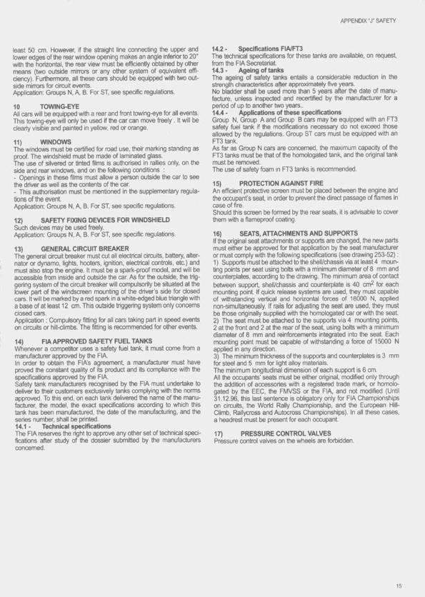
16) SEATS, ATTACHMENTS AND SUPPORTSIf the original seat attachments or supports are changed, the new parts must either be approved for that application by the seat manufacturer or must comply the following spiedfications (see drawing 253-52) :1) Supports must be attached to the shell/ctiassis via at least 4 mounting points per seat using bolts with a minimum diameter of 8 mm and counterplates, according to the drawing. The minimum area of contact between support, shell/chassis and counterpiate is 40 cm^ for each mounting point. If quick release systems are used, they must capable of withstanding vertical and horizontal forces of 18000 N, applied non-simultaneously. If rails for adjusting the seat are used, they must be those originally supplied with the homoiogated car or with the seat.2) The seat must be attached to the supports via 4 mounting points, 2 at the front and 2 at the rear of the seat using bolts with a minimum diameter of 8 mm and reinforcements integrated into the seat. Each mounting point must tre capatiie of withstanding a force of 15000 N applied in any direction.3) The minimum thickness of the supports and counterpiates is 3 mm for steel and 5 mm for light alloy materials.The minimum longitudinal dimension of each support is 6 cm.All the occupants' seats must be either original, modified only through the addition of accessories with a registered trade mark, or homologated by the EEC, the FMVSS or the FiA, and not modified (Until 31.12.96, this last sentence is obiigatory only for FIA Championships on circuits, the World Rally Championship, and the European Hili- Ciimb, Ftailycross and Autocross Championships), in ail these cases, a headrest must be present for each occupant.
17) PRESSURE CONTROL VALVESPressure control valves on the wheels are forbidden.

A rt. 2 5 4 • S pecific r eg u la tio n s fo r p r o d u c t io n cars (G r o u p N)1 ^ -
1) DEFINITIONLarge scale series producBori touring cars.
2) HOMOLOGATIONAt least 25(X) Identical units must have tieen produced In 12 consecutive months and homologated by the FIA In Touring Cars (Group A), The Supply Variants (VF) homologated In Touring Cars (Group A) are also valid In Production (!^rs (Group N).The Optional Variants (VO) of the Touring C^rs (Group A) form shall not be valid In Production Cars (Group N), unless they refer to :- fly-wtieel for automatic gearboxes :- fuel tank ;- automatic gearboxes ;- sun roof ;- safety rollcage ;- seat mountings:- safety hamess mounting points;- 2/4 doors versions.The use of tanks homologated In VO on the Touring Car (Group A) form must tie carried out under the conditions laid dow i In article 5.9.2 of the Touring Car (Group A) regulations, and article 254.6.8. Evolutions of the type (ET) or sporting evolutions (ES) homologated In Touring Cars (Group A) are trot valid In production Cars (Group N).
3) NUMBER OF SEATSCars must have at least four places, In accordance with the dimensions defined for Touring Cars (Group A).
4) MODIFICATIONS AND ADJUNCTIONS ALLOWED OR OBLIGATORY
All the modifications which are not allowed by the present regulations are expressly fbrtildden. The only work which may be carried out on the car Is that necessary for Its nomial sen/lcing, or for the replacements of parts worn through use or accident. The limits of the modifications and fittings allowed are specified hereinafter. Apart from these, any part wom through use or accident can only be replaced by an original part Identical to the damaged one.The cars must be strictly series production models Identifiable by the homologation form data.
5) MINIMUM WEIGHTC^rs must have at least the weight appearing on the homologation form plus the weight of the safety devices As far as rollcages which cannot be removed from ttie car and which were manufactured In accordance with articles 253.8.2 and 8.3 of Appendix J are concerned, the following weights will be taken as a basis :- Rollcage according to drawings 253-3/4 : 30 kg- Rollcage according to drawings 253-5 to 17C : 35 kgThis Is the real weight of the empty car (without persons or luggage aboard) without tools. Jack. Ail the liquid tanks (lubrication, cooling, braking, heating where appllcabie) must be at the normal level foreseen by the manufacturer, with the exception of the windscreen wiper or headlight wiper, brake cooling system, fuel and water Injection tanks, which stiall lie empty. Additional headlights which do not appear on the homologation fbmn must be removed before weighing.
6)6.1 - Engine- The acceterator cable may be replaced or doubled by another one regardless of whether It comes from the manufacturer or not.- Ignition : The make and type of the spark plugs, rev. limiter and high tension leads are free. The Ignition components In the electronic control unit are free. Sensors and actuators on the Input side must be standard, as must their function.
- Coo/ing system .The thermostat Is free as Is the control systemand tfie temperature at which the fan cuts In. Locking system for the radiator cap Is free.- Carburettors : The original system must be retained. The components of the carburettor which control ttie quantity of petrol entering the combustion chamber may be modified, provided that they do not have any Influence over the quantity of air admitted.Replacement air filter cartridges are accepted In the same way as the original ones.- Injection : The original system must be retained. Components of the Injection system situated downstream of the alr-flow measuring device, and which control the quantity of petrol entering the combustion ctiamtier may be modified but not replaced, provided that ttiey do not have any Influence over the quantity of air admitted. The interior of the electronic control unit for the Injection is free. Inputs to the electronic control unit (sensors, actuators, etc.), including their function, must remain as standard. O u ^ ts from ttie electronic control unit must retain ttieir original functions In accordance with the homologation fonn. - "The flow rate of injectors may be modified, but not their operating p rti- clple nor their mounting.Replacement air filter cartridges are accepted In the same way as tfie original ones.- Lubrication : The fitting of baffles in the oil sump is authorised. Replacement oil filter cartridges are accepted In the same way as the original ones.- The material of the elastic part of the engine mountings is free, but not the number of engine mountings.- Exhaust : It will be possible :. either to remove the Inside of the original silencer ;. or to modify the exhaust from the first silencer to the exit, the maximum dimensions of the duct being those of the pipe situated upstream of ttie first silencer (see drawing 254-3). Shouid two inlets exist In the first silencer, the section of the modified duct must be less than or equal to the total of the two original sections. Only one pipe may be present at the exit, unless the original part Is used. The exit should be situated In the same position as that of the series production exhaust system.These liberties must not entail any bodywork modifications and must respect the laws of the country In which the event Is nrn with regard to noise levels.Additional parts for the mounting of the exhaust are authorised.If an exhaust silencer is added, it must be of the original type and must contain noise-absorbing material.If It Is fixed directly onto the manifold, the catalyst may be replaced with a conical part of the same length and with the same Inlet and outlet diameters. After this part, the exhaust will be free with a tutie diameter no greater than that of the outlet from ttie catalyst.The catalytic converter is considered as a silencer.- Cyiinder head gasket : The material is free, but not the thickness.- Cruising speed controiier : This controller may be disconnected.- in raiiies only :The number of cylinders Is limited to 6. The cubic capacity Is limited as follows for normally aspirated engines :
. 3 I maximum for two valves per cylinder,
. 2.5 I maximum for more than two valves per cylinder.In the event of supercharged engines being used :The nominal cylinder capacity Is limited to 2500 cm^ maximum.The supercharged system must comply with that of the homologated engine.All supercharged cars must be fitted with a restrictor fixed to the compressor housing. All the air necessary for feeding the engine must pass through this restrictor which must respect the following:The maximum Internal diameter of the restrictor Is 32 mm, maintained for a minimum distance of 3 mm measured downstream of a plane

APPENDIX ' T PRODUCTION CARS GROUP N
perpendicular to the rotational axis situated at a maximum of 50 mm upstream of a plane passing through the most upstream extremities of the wheel blades (see drawing 254-4).This diameter must be compiied with, regardless of the temperature conditions.The external diameter of the restrictor at Its narrowest point must be less than 38 mm, and must be maintained over a distance of 5 mm to each side.The mounting of the restrictor onto the turbocharger must be carried out in such a way that two screws have to be entirely removed frxxn the body of the compressor, or from the restrictor, in order to detach the restrictor from tfie compressor. Attachment by means of a needle screw Is not authorised.For the Installation of this restrictor, it is pemnitted to remove material from the compressor housing, and to add it for the sole purpose of attaching the restrictor onto the compressor housing.The heads of the screws must tie pierced so that ttiey can be sealed. The restrictor must tie made from a single material and may be pierced solely for the purpose of mounting and sealing, which must be carried out between the mounting saews, between the restrictor (or the res- trictor/compressor housing attachment), the compressor housing (or the housing/flange attachment) and the turbine housing (or the housing/flange attachment) (see drawing 254-4).In case of an engine with two parallel compressors, each compressor must be limited to a maximum intake diameter of 22.6 mm.This restrictor, which is compulsory In rallies and in the European Hill- Climb Championship, is not prohibited in other events, should a competitor decide to use it.6.2 - Transmission- Clutch : The disc is free, inciuding the weight, with the exception of the number and diameter.6.3 - Suspension- Springs : The spring seats may be adjustable If the adjustable structural part is a part of the spring seat and is separated from the original suspension parts/bodyworir (it may be removed).Coil springs : The length Is free, as is the number of coils, the wire diameter, the type of spring (progressive or not), the extemal diameter and the fomi of the spring seats.Leaf springs : The length, width, thickness and vertical cun/ature are free.Torsion bars : The diameter is free.These freedoms on the suspension springs do not authorise one to disregard article 205 of the homologation form (minimum height of the centre of the hubcap, wheel passage opening).- Shock absorbers ; Free, provided that their number, their type (telescopic, anrr, etc.), their working principle (hydraulic, friction, mixed, etc.), and their attachment points remain unchanged. A silent block may be replaced by a “Unibair jo in t but only on condition that the shock absortrer has no guiding function.Gas filled dampers, regarding their working principle, will be considered as hydraulic dampers.If, in order to change the damping element of a Mac Pherson suspension, or a suspension operating in an identical manner, it is necessary to replace the entire Mac Pherson strut, ttie replacement parts must be mechanically equivalent to the original ones and have the same mounting points.For McPherson suspensions, the shape of the spring seats is free. Their material is free.The reinforcing of the suspension and its anctiorage points by the addition of material is allowed.In the case of oil-pneumatic suspension, the spheres may be changed as regards their dimension, shape and material, but not their number. A tap, adjustable from outside of the car, may be fitted on the spheres.6.4 - Wheels and tyresThe wheels are free, respecting the homologated diameter (article 801 .a, and the homologated width (article 801 .b) which is considered as a maximum.Ttiey must be covered by the wings (same checking system as in Group A, article 255.5.4), and the maximum track given on the homologation fomn must be respected.Tyres are free provided that they can be mounted on those wheeis. The spare wtieel may be brought inside the driving compartment, on
condition that it is firmly secured there and that it Is not Installed in the space reserved for the occupants.Wheels fixations by bolts may be changed to fixations by pins and nuts provided that the number of attachment points and the diameter of the threaded parts as indicated on drawing 254-1 are respected.Air extractors added on tfie wfieels are fortxdden.6.5 - Braking systemBrake linings are free, as well as their mountings (riveted, bonded, etc.) provided that the contact surface of the brakes is not increased. Protection plates may be removed or bent.In tfie case of a car fitted with servo-assisted brakes, this device may be disconnected. The same applies for anti4ock braking systems.Brake lines may be changed for aviation type lines.A device for scraping away the mud which collects on the brake discs may be added.6.6 - Bodywork6.6.1) Exterior:Hubcaps must be removed.Protective headlight covers may be fitted provided that their only function is to cover the glass, and that they have no influence on the car's aerodynamics.The fitting of underbody protections is authorised in rallies only, prt>-vlded that these really are protections which respect the ground clearance, which are removable and which are designed exclusively and specifically In order to protect the following parts : engine, radiator, suspension, geartxjx, tank, transmission, exhaust, extinguisher bottles.Any locking system may be used for the cap of the petrol tank.The fitting of extemal rear view mirrors is auttiorised, as is the changing of the windscreen wiper biades both front and rear.6.6.2) Passenger space :All accessories which have no effect on the vehicle's behaviour are allowed without restrictions, such as those conceming the aesthetics or Interior comfort (lighting, heating, radio, etc.), on the express condition that they do not influence, even in a secondary manner, the efficiency of the engine, steering, strength, transmission, braking, or rxrad-holding.Inversion of the driving side is possible, on condition that the original car and the modified car are mechanically equivalent and tlia t the parts used are foreseen by the manufacturer for such a conversion for tfie model In question.The carpeting must remain in place.All the controls must be those provided by the manufacturer and they must retain their original function but they can be worked on to make them more accessible or more easily usable ; for example, the addition of an extension to the handbrake lever, of an additional flange to tfie brake pedal, etc.The following is allowed in particular :1) Additional measuring Instruments, counters, etc. may be freely installed, provided that tlie ir fitting is not likely to create any danger.2) The hom may be changed. Another one, possibly for the passenger's use, may bie added.3) The mechanism of the handbrake lever may be adapted in order to ' obtain instant unlocking (fly-off handbrake).4) Seat-covers, Including those creating txicket seats, may be added to the original seats, respecting art. 253.16.5) Ttie front seats may be changed for bucket seats, respecting art. 253.16.6) Additional compartments may tie added to the glove compartment as well as additional pockets to the doors.7) The steering wheel Is free. The locking system of the anti-theft steering lock may be rendered inoperative.8) It is authorised to replace the electric window winders with manually-operated winders, using corresponding parts which are available for the model concemed. Likewise, the inner door panel may be replaced.6.6.3) Reinforcements.Reinforcement bars may be fitted on the suspension mounting points to the bodyshell or chassis of the same axle, on each side of the car's longitudinal axis, on condition that they are removable and are attached by means of bolts. The distance between a suspenston attachment point and an anchorage point of the bar cannot be more than 100 mm, unless the bar Is a transversal strut homologated with the rollbar, or unless it is an upper bar attached to a MacPherson suspension or
17

APPENDIX " r PRODUCTION CARS GROUP N
similar. In the latter case, the maximum distance between an anchorage point of the bar and the upper articuiation point will be 150 mm (drawings 255-4 and 2552).Apart from these points, this bar must not be mounted on the bodyshell or the mechanical parts.Strengthening of the suspended part is allowed provided that the material used follows the original shape and is in contact with it.6.6.4) When the spare wheel Is originally set In a dosed accommodation, and when this wheel is changed for a thicker one (see article6.4), situated in this space, it is possilile to remove from the cover of ttie location of the wheel the surface induced by the diameter of the new wheel (drawing 254-2).6.7 ■ Electrical system- Battery : The make, capacity, and battery cables are free. The tension and the site of the battery must be retained.- Generator: May be replaced by a more powerful one. A dynamo may not be replaced by an alternator and vice-versa.- Ugtrting system : Additional headlights induding the corresponding relays are allowed, provided that the total does not exceed eight (tail and parking lights not included) and that this is accepted by the laws of the country.They may not be housed within the bodywork. Headlights and other exterior lights must always exist in pairs.
The original headlights can be made inoperative and covered with adhesive tape. They can be replaced by other headlights, in compliance with this article. A reversing light may be fitted provided it can only be used when the gear lever is in the “reverse" position, and provided that tfie police regulations on this subject are obsenred.- Fuses may be added to the electrical system.6.8 • Fuel circuitProviding the original tank is equipped with an electric pump and an interior filter, it is possible when using an FT3 tank to place a filter and a pump with identical cfiaracteristics to the homologated one outside. These parts must be protected in adequate fashion.The filler holes may not be located in the window panels.Fuel lines must be changed for aviation type lines If an FT3 tank is used, the route of these lines being free. Should a series production tank be used, this change is optional.The total capacity of the tanks must not exceed that indicated in article 401.d of the Group A homologation form.6.9 - JackThe jack is free on condition that its lifting points on tfie car are not modified.
18
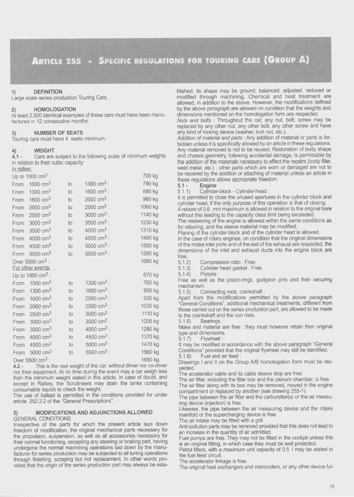
A rticle 255 - S pecific r e g u u t io n s for t o u r in g cars (G r o u p A )
1) DEFINITIONLarge scale series production Touring Cars.
2) HOMOLOGATIONAt least 2,500 identical examples of these cars must have been manufactured in 12 consecutive months.
3) NUMBER OF SEATS Touring cars must have 4 seats minimum.
4) WEIGHT4.1 - Cars are subject to the following scale of minimum weightsin relation to their cubic capacity;In rallies:Up to 1000 cm3; 700 kg
From 1000 cm3 to 1300 cm3 790 kg
From 1300 cm^ to 1600 cm3 880 kg
From 1600 cm^ to 2000 cm3 960 kg
From 2000 cm3 to 2500 cm3 1060 kg
From 2500 cm3 to 3000 cm3 1140 kg
From 3000 cm^ to 3500 cm3 1230 kg
From 3500 cm3 to 4000 cm3 1310 kg
From 4000 cm^ to 4500 cm3 1400 kg
From 4500 cm^ to 5000 cm3 1500 kg
From 5000 cm3 to 5500 cm3 1590 kg
Over 5500 cm^ : 1680 kg
UptolOOOcm ^; 670 kg
From 1000 cm^ to 1300 cm3 760 kg
From 1300 cm3 to 1600 cm3 850 kg
From 1600 cm3 to 2000 cm3 930 kg
From 2000 cm3 to 2500 cm3 1030 kg
From 2500 cm3 to 3000 cm3 1110 kg
From 3000 cm3 to 3500 cm3 1200 kg
From 3500 cm3 to 4000 cm3 1280 kg
From 4000 cm3 to 4500 cm3 1370 kgFrom 4500 cm3 to 5000 cm3 1470 kg
From 5000 cm3 to 5500 cm3 1560 kg
Over 5500 cm^ : 1650 kg4.2 • This is the real weight of the car, without driver nor co-drivernor their equipment. At no time during the event may a car weigh less than the minimum weight stated in this article. In case of doubt, and except In Rallies, the Scrutineers may drain the tanks containing consumable liquids to check the weight.The use of ballast Is permitted In the conditions provided for under article 252.2.2 of the “General Prescriptions".
5) MODIFICATIONS AND ADJUNCTIONS ALLOWEDGENERAL CONDITIONSIrrespective of the parts for which the present article lays down freedom of modification, the original mechanical parts necessary for the propulsion, suspension, as well as all accessories necessary for their normal functioning, excepting any steering or braking part, having undergone the normal machining operations laid down by the manufacturer for series production may be subjected to all tuning operations through finishing, scraping but not replacement. In other words provided that the origin o f the series production part may always be esta
blished, its shape may be ground, balanced, adjusted, reduced or modified through machining. Chemical and heat treatment are allowed. In addition to the above. However, the modifications defined by the above paragraph are allowed on condition that the weights and dimensions mentioned on the honx)logation form are respected.Nuts and bolts : Throughout the car, any nut, bolt, screw may be replaced by any other nut any other bolt, any other screw and have any kind of locking device (washer, lock nut, etc.).Addition of material and parts : Any addition of material or parts is forbidden unless It is specifically allowed by an article in these regulations. Any material removed is not to be reused. Restoration of body shape and chassis geometry, following accidental damage, is permissible by the addition of the materials necessary to effect the repairs (body filler, weld metal, etc.) ; other parts which are wom or damaged are not to be repaired by the addition or attaching of material unless an article in these regulations allows appropriate freedom.5.1 - Engine5.1.1 ) Cylinder-block - Cylinder-head :It is permitted to close the unused apertures in the cylinder block and cylinder head, if the only purpose of this operation is that of closing.A rebore of 0.6 mm maximum is allowed in relation to the original bore without this leading to the capacity class limit being exceeded.The resleeving of the engine is allowed within the same conditions as for reboring, and the sleeve material may be modified.Planing of the cylinder-block and of the cylinder head is allowed.In the case of rotary engines, on condition that the original dimensions of the intake inlet ports and of the exit of the exhaust are respected, the dimensions of the inlet and exhaust ducts into the engine block are free.5.1.2) Compression ratio : Free.5.1.3) Cylinder head gasket : Free.5.1.4) Pistons:Free as well as the piston-rings, gudgeon pins and their securing mechanism.5.1.5) Connecting rods, crankshaft :Apart from the modifications permitted by the above paragraph “General Conditions", additional mechanical treatments, different from those carried out on the series production part, are allowed to be made to the crankshaft and the con rods.5.1.6) Bearings:Make and material are free ; they must however retain their original type and dimensions.5.1.7) Flywheel:It may be modified in accordance with the above paragraph “General Conditions” provided that the original flywheel may still be identified.5.1.8) Fuel and air feed :Drawings I and I! on the Group A/B homologation form must be respected.The accelerator cable and its cable sleeve stop are free.The air filter, including the filter box and the plenum chamber, is free. The air filter along with its box may be removed, moved In the engine compartment or replaced by another (see drawing 255-1).The pipe between the air filter and the cartxjrettor(s) or the air measuring device (injection) is free.Likewise, the pipe between the air measuring device and the intake manifold or the supercharging device is free.The air intake may be fitted with a grill.Anti-pollution parts may be removed provided that this does not lead to an increase in the quantity of air admitted.Fuel pumps are free. They may not be fitted in the cockpit unless this is an original fitting. In which case they must be well protected.Petrol filters, with a maximum unit capacity of 0.5 I may be added to the fuel feed circuit.The accelerator linkage is free.The original heat exchangers and intercoolers, or any other device ful-
19

APPENDIX "X TOURING CARS GROUP A
filling ttie same function, must Ije retained, and remain in tfieir original location, wfticfi means ttiat ttieir supports and position must remain original.Ttie pipes tjetween tfie supercfiarglng device, ttie intercooler and tfie manifold are free, but tfieir only function must be to channel air.In tfie case of air-water Intercoolers, the pipes connecting the intercooler and its radiator are free, but their only function must be that of channelling water.Any water injection fitted must be homologated and must not be modified.Ttie use of any other substance or device to reduce tfie temperature of the mixture is foitidden.Ttie inner dimensions of tfie ports are free in the rotary chambers for rotary engines and for 2-stroke engines.The drive pulley of the “G" compressor Is free.For African rallies only : It Is possible to make a hole, with a maximum diameter of 10 cm, in the engine bonnet in order to provide air for the engine, and to place a pipe, with a maximum internal diameter of 10 cm, in this hole (see drawing 255-13).5.1.8.1 - Carburettor :The carburettors are free, but the original number of carburettors and their working principle must be retained and they must remain In their original location.Furthermore, the diameter and number of tfie butterflies as stated on the homologation fomi must be respected.5.1.8.2- Injection:The original system and its type, as specified on the homologation fbmi of the vehicle (such as K-Jetronic) must be retained, as must Its location.The elements of the Injection device regulating the metering of the quantity of fuel admitted to the engine may be modified, but not the diameter of the opening of the butterfly.The air measuring device is free.The injectors are free, except for their number, their position, their assembly axis and their operating principle.The petrol lines feeding them are free.The electronic box is free. Insofar as it does not incorporate more data. The fuel pressure regulator is free.5.1.8.3- Limitation in rallies :The number of cylinders Is limited to 6.The cubic capacity is limited as follows for normally aspirated engines :- 3 I maximum fbr two valves per cylinder.- 2.5 I maximum fbr more than two valves per cylinder.In the event of superctiarged engines being used :The nominal cylinder capacity Is limited to 2500 cm^ maximum.The supercharged system must comply with that of the homologated engine.All supercharged cars must be fitted with a restrictor fixed to the compressor housing. All the air necessary for feeding the engine must pass through this restrictor which must respect the following:The maximum internal diameter of the restrictor Is 34 mm, maintained fbr a minimum distance of 3 mm measured downstream of a plane perpendicular to the rotational axis situated at a maximum of 50 mm upstream of a plane passing through tfie most upstream extremities of the wheel blades (see drawing 254-4).This diameter must be complied with, regardless of the temperature conditions.The external diameter of the restrictor at its narrowest point must be less than 40 mm, and must be maintained over a distance of 5 mm to each side.The mounting of ttie restrictor onto the turbocharger must be carried out in such a way that two saews have to be entirely removed from the body of the compressor, or from the restrictor, in order to detach the restridor from the compressor. Attachment by means of a needle screw is not authorised.For the installation of this restrictor, it is permitted to remove material from the compressor housing, and to add It for the sole purpose of attaching tlie restrictor onto the compressor housing.The heads of the screws must be pierced so that they can be sealed. The restrictor must be made from a single material and may be pierced solely for the puqxise of mounting and sealing, which must be carried out between the mounting saews, between the restrictor (or the res-
tricta/compressor hrxjsing attachment), the compressa housing (a the housing/flange attachment) and the turbine housing (a the housing/flange attachment) (see drawing 254-4).In case of an engine with two parallel compressors, each compressor must be limited to a maximum intake diameter of 24.0 mm.This restrictor, which is compulsory In rallies and in the European Hill- Climb Championship, is not prohibited in other events, stxHikj a com- petita decide to use it.5.1.9) Camshaft(s) :Free, except the number and number of tiearings. Timing is free. The material, t ^ and dimensions of the pulleys, chains and belts fbr driving the camshafts are free. The material of the gearing and sprockets associated with the camshaft Is free. The route and the numba c4 belts and chains are free. The guides and tensioners associated with these chains a belts are also free, as are protective covers.5.1.10) Valves:The material and the shape of the valves are free, but tfieir characteristic dimensions (mentioned on the homologation fbrm) must be retained, including the respective angles of the valves axis. Valve lift is free.With regard to the cylinda head orifices (inna side of the engine), in the case of rotary engines, only those dimensions which have bW i entered on the homologation form have to be respected.The cups, cotters and guides (even if they do not exist as original parts) are not subject to any restriction. Shims may be added unda the springs.The material of the seats is free.5.1.11) Rocker amis and tappets :Rocker arms may only be modified in accordance with article 5 "General Conditions” above. Tappets are free, provided they are inta- changeable with the original ones.It Is possible to use bracking plates to adjust them.5.1.12) Ignition:The ignition coil(s), condenser, distributor, interrupter and plugs are free sutjject to the ignition system (battery/coil or magneto), remaining the same as provided by the manufactura fa tfie model concerned. The fitting of an electronic ignition system, even witfiout a mechanical Intemjpter, Is allowed provided no mechanical part ottier ttian those mentioned here above is modified a changed, with the exception of the crankshaft, the flywheel a the crankshaft pulley, fa which modifications limited to the necessary additions will be pc^lble. In the same conditions, it shall be possible to change an electronic ignition for a mechanical Ignition. The number of plugs may not be modified ; that of the coils Is free.5.1.13) Cooling :Provided the original fitting on the car is retained, the radiata and its fixation are free, as are the lines linking it to the engine. A radiata saeen may be fitted. The fan and its drive system can be ctianged freely, a be withdrawn. It Is allowed to add a fan p a function. Thermostat Is free.Dimensions and material of tfie fan/turbine are free, as are tfieir number. The fitting of a water catch tank is allowed. Tlie radiator cap may be locked.The water Injection devices may be disconnected, but not removed. The expansion chamber may be modified ; If one does not exist originally, one may be added.5.1.14) Lubrication :Radiator, oil/wata exchanger, lines, thermostat sump and pump filter are free, without modifying the bodywork.However, the fitting of an oil radiata outside the bodywrxk is only allowed belrdw ttie horizontal plane passing through the hub in such a way that it does not protrude beyotid the general perimeter of the car seen from above as it stands on the starting line, without modifying the txxfywork.Fitting an oil radiator in this manner does not allow the addition of an envelopii aerodynamic structure. All air openings must have the sole effect of inducing the necessary air fa the crxiling of tfie radiator, and must not have any aerodynamic effect.Oil pressure may be increased by changing the discharge valve spring.If tfie lubrication system includes an open type sump breather, it must be equipped in such a wray that the oil flows into a catch tank.This must have a capacity of 2 litres fa cars with a cutiic capacity

APPENDIX “J’ TOURING CARS GROUP A
equal to or t>elow 2,000 cm^, and 3 litres for cars with a cubic capacity of over 2,000 cm^. This container shall be made either out of plastic or shall include a transparent window.An air/oil separator can be mounted outside the engine (maximum capacity 1 litre), In accordance with the drawing 255-3. The oil must only flow from the oil catch tank towards the engine by the force of gravity alone.A fan may be fitted for cooling the engine oil, but must have no aerodynamic effect.5.1.15) Engine : Mountings - Angle and position :Mountings are free (but not their number) provided that the angle and position of the engine within its compartment are not modified, and that articles 5.7.1 and 5 - General Conditions are respected. Supports may be welded to the engine and to the bodywork and their position is free.In Rallies only, it is possit)le to cut out a part of the bulkhead situated in the engine compartment for the fitting of one or more air filters or for the intake of air ; however, such cut-outs must be strictly limited to those parts necessary for this installation (see drawing 2 5 ^ ) . Furthermore, if the air Intake ventilating the driving compartment is In the same zone as the air intake for the engine, this zone must 1)6 isolated from the air filter unit, in case of fire.5.1.16) Exhaust:Drawfings III and IV on the Group A/B homologation form must be respected.Downstream the exhaust manifold exit the exhaust is free provided that the maximum sourxJ levels permitted in the country(ies) crossed are not exceeded if it is an event on open roads. The exhaust exit must t>e inside the car’s perimeter (see General Prescriptions, article 252.3.6). For cars with turt)ocharged engines the exhaust can only be modified after the turtxxîharger.In the case of rotary engines, and on condition that the original dimensions of the inlet ports of the exhaust manifold are respected, the dimensions of the ducts in the manifold are free.Thermal screens may be fitted on the exhaust manifold, the turt)o- charger and on the exhaust device, with, however, the sole function of thermal protection.5.1.17) Driving pulleys, belts and chains for ancillaries situated outside the engine :The material, type and dimensions of the pulleys, chains and belts for driving the ancillaries are free. The route and the number of belts and chains are free.5.1.18) Gaskets : Free.5.1.19) Engine springs :Springs are not sutiject to any restrictions but they must keep their original functioning principle.5.1.20) Starter:It must be retained, but its make and type are free.5.1.21 ) Supercharging pressure :This pressure may be modified by article 5.1.19 and article 5 - General Conditions. The connection between the housing and the waste-gate may be made adjustable if it Is not originally so. The original system of operation of the waste-gate may be modified and be rendered adjustable but this system must tie retained. A mechanlcat system must remain mechanical, an electrical system must remain electrical, etc.5^ - Transmission5.2.1) Clutch :Clutch is free, but the homologated bell-housing must be retained, together with the operation type.5.2.2) Gearbox :An additional lubrication and oil cooling device is allowed (circulation pump, radiator, and air intakes situated under the car) in the same conditions as for article 5.1.14, but the original lubrication principle must be retained.However, a geartx)x homologated as an additional one with an oil pump can t>e used without this pump.A fan may be fitted for cooling the geattox oil, but must have no aerodynamic effect.The gears of the additional geartox on the homologation form may be c h a r i^ , provided that they respect the Information given on this form. Geartox supports are flee, but not their numt>er.
May be used :- the series housing with series ratios or one of the two sets of additional ratios ;- one of the additional housings only with one of the additional sets of ratios.5.2.3) Final drive and differential :A limited-slip differential is allowed provided that It can be fitted into the original housing without any modification other than those laid down In the above paragraph “General Conditions". The original differential may also be locked.The original lutwicating principle for the rear axle must be retained. However an additional lut>ricatlng and oil cooling device is allowed (circulation pump, radiator, and air intakes situated under the car) under the same conditions as for article 5.1.14.The differential supports are free.5.3 • SuspensionThe position of the rotational axles of the mounting points of the suspension to the wheel uprights and to the shell (or chassis) must remain unchanged.In the case of an oil-pneumatic suspension, lines and valves connected to the spheres (pneumatic parts) are free.5.3.1) Reinforcement bars may be fitted on the suspension mounting points to the t)odyshetl or chassis of the same axle, on each side of the car’s longitudinal axis. The distance between a suspensionattachment point and an anchorage point of the bar cannot be morethan 100 mm, unless the t>ar is a transversal strut homologated with the rollbar, or unless it Is an upper bar attached to a MacPherson suspension or similar. In the latter case, the maximum distance between an anchorage point of the bar and the upper articulation point will be 150 mm (drawings 255-4 and 255-2).Apart from these points, this bar must not be mounted on the bodyshell or the mechanical parts.5.3.2) Strengthening of the mounting points and of the running gear, by adjunction of material, is allowed.5.3.3) Anti-roll bar :The anti-roll bars homologated by the manufacturer may be replaced or removed, provided that their mounting points on the chassis remain unchanged.These anchorage points can be used for the mounting of reinforcement bars.5.3.4) The joints may be of a different material from the original ones.The suspension mounting points to the bodyshell or chassis may be modified :- by using a “Uniball" joint. The original arm can be cut and a new seat for the "Unibair w e ld ^ . Braces will be used next to the “Uniball" itself.- by using a screw with a greater diameter.- by reinforcing the anchorage point through the addition of material. The position of the centre of the articulation cannot be changed (see drawing 255-5).5.3.5) The material and main spring dimensions are free (but not the type). The spring seats may be made adjustable even If this irtcludes the adjunction of material.A coil spring may be replaced with two or more springs of the same type, concentric or in series, provided that they are fully Interchan- geat)le with the original and can be fitted without any rriodifications other than those s p ^ e d in this article.5.3.6) Shock AI)Sorbers :Make Is free, but not the number, the type (arm, etc.), the system of operation (hydraulic, friction, mixed, etc.) nor the supports.With regard to their principle of operation, gas-filled shock-absort>ers will be considered as hydraulic shock-absorbers.If in order to change the damping element of a Mac Pherson suspension, or suspension working on an identical principle, it is necessary to replace the entire Mac Pherson strut, the replacement part must be mechanically equivalent to the original one, except for the damping element and the spring cup.5.4 - Wheels and tyresComplete wheels are free provided that they may be housed within the original bodywork ; this means the upper part of the complete wheel, located vertically over the wtieel hub centre, must be covered by the bodywork, when measured vertically. Wheel fixations by bolts may be freely changed to fixations by pins and nuts. The use of tyres Intended
21

APPENDIX T TOURING CARS GROUP A
for motor cycles is fort)iclden. In no case may ttie width of the rim-tyre assembly in relation to the cubic capacity of the car, exceed the follo-wing :In rallies :Up to 1000 cm3 6.5"
1300 cm3 7 ■1600 cm3 7.5"2000 cm3 9"2500 cm3 9 •3000 cm3 9 "3500 cm3 9 ■4000 cm3 9 •4500 cm3 9 ■5000 cm3 9 •
Over 5000 cm3 10"For other events :Up to 1000 cm3 6.5"
1300 cm3 ‘ 7 ■1600 cm3 7.5"2000 cm3 8.5"2500 cm3 9 •3000 cm3 9 "3500 cm3 10"4000 cm3 10"4500 cm3 11 “5000 cm3 11 *
Over 5000 cm3 12"The rim diameter may be Increased or reduced by up to 2 Inches in relation to the original dimensions.In rallies, the maximum diameter of the compiete wheels is 650 mm, not including the studs if studded tyres are used.The wheeis do not necessarily have to be of the same diameter. Should the wheel be fixed using a central nut a safety spring must be in place on the nut throughout the duration of the event and must be replaced after each wheel change. The springs must be painted ■I3ayglo' red. Spare springs must be available at all times.5.5 • Braking system5.5.1) Brake linings :Material and mounliiTg method (riveted or bonded) are free provided that the dimensions of ttie linings are retained.5.5.2) Servo brakes, braking force adjusters,
anti-iocking devices :Servo-tirakes may be disconnected and removed; braking force adjusters and antilocking devices may be disconnected, but not removed. The adjusting device is free. The braking force adjusters may not be moved from the compartment in which they are originally situated (cockpit engine compartment, exterior, etc.).5.5.3) Cooling of brakes :Protection shields may be nrradified or removed, but material may not be added.Only one flexible pipe to bring ttie air to the brakes of each wheel is allowed, but its inside section must be able to fit into a circle with a 10 cm diameter. The air pipes must not go beyond the perimeter of the car, seen from above.5.5.4) Brake discs :The only operatiori allowed is rectification.5.5.5) The handlxake devk» may be disconnected but only for closed course races (circuit hill climbs, slaloms).5.5.6) Hydraulic pipes :Hydraulic pipes may tie replaced by lines of aircraft quality.5.6- SteeringPower steering may be disconnected but not removed.5.7 - Bodywork - Chassis5.7.1) Lightening and reinforcements :Strerigttiening of the sprung pearls of the chassis and bodywork isallowed p ro v iM that ttie material used follows the original stiape andis in contact with itReinforcements by composite materials are allowed in accordance
with this article, whatever their thickness, according to the drawing 255-8.insulating material may be removed from under the car floor, from the engine compartment, the luggage boot and the wheel arches. Unused supports (e.g. spare wheel) situated on the chassis/bodywork can be removed, unless they are supports for mechanical parts which cannot tie moved or removed.It is possible to close the holes in the cockpit, the engine and luggage compartments, and in the wings. The holes may be closed using sheet metal or plastic materials, and may be welded, stuck or rivetaj. The other holes in the bodywork may be dosed, by adhesive tape only.5.7.2) Exterior :5.7.2.1 - Bumpers :Overriders may be removed.5 7.2.2 - H ub^p s and wheel embellishers :Hub-caps may be removed. Wheels embellishers must be removed.5.7.2.3 - Windscreen wipers :Motor, position, blades and mechanism are free but there should be at least one windscreen wiper provided for ttie windscreen. The windscreen washer device may be dismounted. The capacity of the washer tank may be increased and the tank may be moved inside the cockpit in accordance with article 252.7.3.5.7.2.4 - External decorative strips may be removed. Any parts folio- wing external contour of the bodywork and less than 25 mm high will be considered as decorative strips.5.7.2.5- Jacking points may be strengthened, moved, and increased in number.5.7.2.6 - Headlight covers may be fitted provided their sole aim is to protect the headlight glass and they have no effect on the car’s aerodynamics.5.7.2.7 - Taking into account the different police regulations in each country, registration plate locations and type are free.5 7.2.8 - The registration plate mountings may be dismounted but not their lighting system.5.7.2.9 - Additionai safety fastenings for the windscreen and ttie side windows may be fitted provided they do not improve the aerodynamic qualities of ttie car.5.7.2.10 - The fitting of underbody protections is authorised in rallies only, provided that these really are protections which respect the ground clearance, which are removabte and which are designed exclusively and specifically in order to protect the following parts : engine, radiator, suspension, gearbox, tank, transmission, exhaust, extinguisher bottles.5.7.2.11 -It is permitted to fold back the steel edges or reduce the plastic e < ^ of the wings if they protnide inside the wheel housing. The plastic sound-proofing parts may be removed from the interior of the wheel passages. These plastic elements may be changed for aluminium elements of the same shape.It is possible to fit plastic protection parts in the wings, on the same ground as aluminium parts.5.7.2.12 - Removable pneumatic jacks are permitted, but without the compressed air bottle on board (circuits only).5.7.2.13 - "Skirts" are tjanned. All non-horriologated devices or constructions designed so as to fully or partially fill the space tietween the sprung part of the car and the ground is fortiidden in all circumstances. No protection authorised by article 255.5.7.2.10 can play a role In the aerodynamks of the car.5.7.2.14 - It is authorised to remove or replace existing supports between the bodywork and the chassis, tx it it is not possible to r^ n g e or add locations.5.7.2.15 - The external rear-view mirror are free, if they are only rear-view minors. However, the extemal rear-view minor on the driver's side, if It is modified or changed, must have a reflecting sur^ce of at least 90 cm^.5.7.3) Cockpit :5.7.3.1 - Seats :Occupants' seats and their mountings are free provided that they comply with article 253.16, tiut they must include a headrest The front seats may be rtxjved backwards but not beyond the vertical plane defined by the front edge of the original rear seat The limit relating to the front seat is fbnned by the height of the seattiack wittiout Itie hea
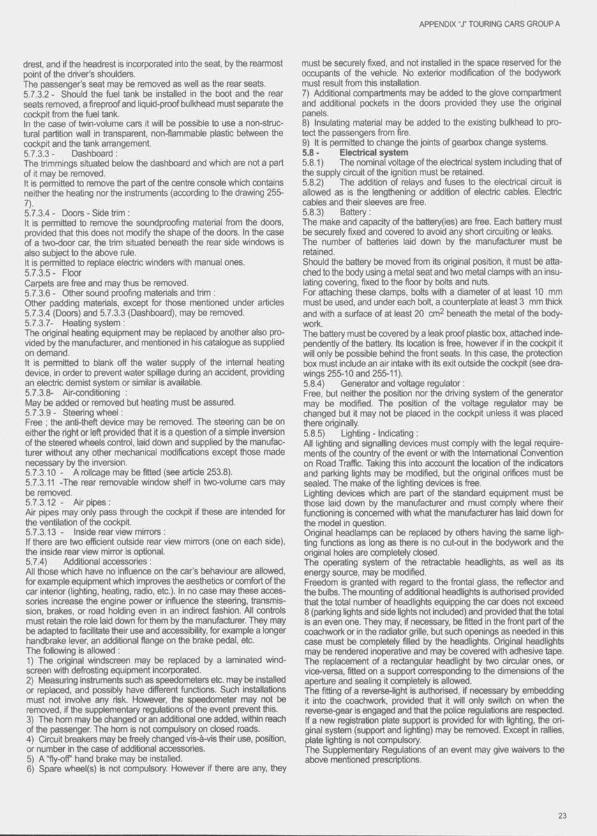
APPENDIX -X TOURING CARS GROUP A
drest, and if the headrest Is incorporated into the seat, by the rearmost point of the driver’s shoulders.The passenger's seat may be removed as well as ttie rear seats.5.7.3.2 - Should the fuel tank tje installed in the boot and the rear seats removed, a fireproof and liquid-proof bulkhead must separate the cockpit from the fuel tank.In the case of twin-volume cars it will be possible to use a non-stmc- turai partition wall in transparent, non-flammable plastic between the cockpit and the tank arrangement.5.7.3.3 - Dashboard :The trimmings situated below the dashboard and which are not a part of it may tie removed.it is permitted to remove the part of the centre console which contains neither the heating nor the instruments (according to the dravring 255-7).5.7.3.4 - Doors - Side trim :It is permitted to remove the soundproofing material from the doors, provided that this does not modify the shape of the doors. In the case of a two-door car, the trim situated beneath the rear side windows is also subject to the above nrle.It is pemritted to replace electric winders with manual ones.5.7 .35- FloorCarpets are free and may thus be removed.5.7.3.6 - Other sound proofing materials and trim :Other padding materials, except for those mentioned under articles5.7.3.4 (Doors) and 5.7.3 3 (Dcéhboard), may be removed.5.7.3.7- Heating system :The original heating equipment may be replaced by another also provided by the manufacturer, and mentioned in his catalogue as supplied on demand.it is permitted to blank off the water supply of the internal heating device, in order to prevent water spillage during an accident, providing an electric demist system or similar is available.5.7.3.S- Air-conditioning :May be added or removed tx it heating must be assured.5.7 3.9 - Steering wheel :Free ; the anti-theft device may be removed. The steering can be on either the right or left provided that it is a question of a simple inversion of the steered wheels control, laid down and supplied by ttie manufacturer wittiout any other mechanical modifications except those made necessary by the inversion.5.7.3.10 - A roilcage may be fitted (see article 253.8).5.7.3.11 -The rear removable window shelf in two-voiume cars may be removed.5.7.3.12- A irpipes:Air pipes may only pass through the cockpit if these are intended for the ventilation of the cockpit.5.7.3.13- Inside rear view mirrors :If there are two efficient outside rear view mirrors (one on each side), the inside rear view mirror is optional.5.7.4) Additional accessories :All those which have no influence on the car's behaviour are allowed, for example equipment virhich improves the aesthetics or comfort of the car interior (lighting, heating, radio, etc.). In no case may these accessories increase the engine power or influence the steering, transmission, brakes, or road holding even in an indirect fashion. All controls must retain the role laid dowm for them by the manufacturer. They may tie adapted to facilitate their use and accessibility, for example a longer handbrake lever, an additional flange on the brake pedal, etc.The following is allowed :1) The original windscreen may be replaced by a laminated windscreen with defrosting equipment incorporated.2) Measuring instruments such as speedometers etc. may be installed or replaced, and possibly have different functions. Such installations must not involve any risk. However, the speedometer may not be removed, if ttie supplementary regulations of the event prevent this.3) The hom may be changed or an additional one added, within reach of the passenger. The hom is not compulsory on closed roads.4) Circuit breakers may be freely changed vis-à-vis their use, position, or number in the case of additional accessories.5) AHy-ofT hand brake may be installed.6) Spare wheel(s) is not compulsory. However if ttiere are any, they
must be securely fixed, and not installed in the space reserved for the occupants of the vehicle. No exterior modification of the bodywork must result from this installation.7) Additional compartments may be added to ttie glove compartment and additional pockets in the rioors provided they use the original panels.8) Insulating material may be added to the existing bulkhead to protect the passengers from fire.9) It is permitted to change the joints of gearixix change systems.5.8 - Electrical system5.8.1) The nominal voltage of the electrical system including that of the supply circuit of the ignition must be retained.5.8.2) The addition of relays and fuses to the electrical circuit is allowed as is the lengthening or addition of electric cables. Electric cables and their sleeves are free.5.8.3) Battery :The make and capacity of the battery(ies) are free. Each battery must be securely fixed and covered to avoid any short circuiting or leaks. Ttie number of batteries laid down by the manufacturer must be retained.Should the battery be moved from its original position, it must be attached to the body using a metal seat and two metal clamps with an insulating covering, fixed to the floor by bolts and nuts.For attaching these clamps, bolts with a diameter of at least 10 mm must be used, and under each bolt, a counterplate at least 3 mm thick and with a surface of at least 20 cm^ beneath the metal of the bodywork.The battery must be covered by a leak proof plastic box, attactied independently of the battery, its location is free, however if in the cockpit it will only be possible behind the front seats. In this case, the protection box must include an air intake with its exit outside ttie cockpit (see drawings 255-10 and 255-11).5.8.4) Generator and voltage regulator :Free, but neither the position nor tlie driving system of the generator may be modified. The position of the voltage regulator may be changed but it may not be placed in the cockpit unless it was placed there originally.5.8.5) Lighting - Indicating :All lighting and signalling devices must comply with the legal requirements of the country of the event or with the Intemationai Convention on Road Traffic. Taking this into account the location of the indicators and parking lights may be modified, but the original orifices must be sealed. The make of the lighting devices is free.Lighting devices which are part of ttie standard equipment must be those laid dovm by the manufacturer and must comply virhere their functioning is concerned with what the manufacturer has laid down for the model in question.Original headlamps can be replaced by others having the same lighting functions as long as there is no cut-out in the bodywork and the original holes are completely closed.The operating system of 8ie retractable headlights, as well as its energy source, may be modified.Freedom is granted with regard to the frontal glass, the reflector and the bulbs. The mounting of additional headlights is authorised provided that the total number of headlights equipping tfie car does not exceed 8 (parking lights and side lights not included) and provided that the total is an even one. They may, if necessary, be fitted in ttie front part of the coachwork or in the radiator grille, but such openings as needed in this case must be completely filled by the headlights. Original headlights may be rendered inoperative and may be covered with adhesive tape. The replacement of a rectangular headlight by two circular ones, or vice-versa, fitted on a support corresponding to the dimensions of the aperture and sealing it completely is allowed.The fitting of a reverse-light is authorised, if necessary by embedding it into the coachwork, provided that it will only switch on when the reverse-gear is engaged and that the police regulations are respected. If a new registration plate support is provided for with lighting, the original system (support and lighting) may be removed. Ei«»pt in rallies, plate lighting is not compulsory.The Supplementary Regulations of an event may give waivers to the above mentioned prescriptions.

APPENDIX - r TOURING CARS GROUP A
5.9 - Fuel tanks5.9.1) The total capacity of the fuel tanks must not exceed the following limits, in relation to the engine capacity :Up toFromFromFromFromFromOver5.9.2)
700 cm3: 700 cm^ 1000 cm3 1300 cm3 1600 cm3 2000 cm3 2500 cm3;
1000 cm3 1300 cm3 1600 cm3 2000 cm3 2500 cm3
601701SOI90110011 1 0 1
1201The fuel tank may t» replaced by a safety fuel tank homolo
gated by the FIA (specification FT3) or by another tank homologated by the car manufacturer. In this case, the number of tanks is free and the tank must be placed inside the luggage compartment or in the original location.The construction of collector tanks with a capacity of less than 1 litre is free.The various homologated tanks and the FT3 tanks may also be combined (including the standard tank), insofar as the total of their capacities does not exceed the limits detennlned by article 5.9.1.
The position of tfie original tank may only be modified in cars of which tlie lank has been placed by the manui cturer inside the cockpit or dose to the occupants. In this case it shall be pennisslble eittierto install a protective device between ttie tank and the occupants of the car, or to place the tank in the luggage compartment and, if need be, to modify its supplementary accessories (refuelling orifice, petrol pump, overflow pipe). In any case, these changes of the position of the tanks should not give rise to any lightenings or reinforcements oltier than those provided for under article 5.7.1 but the opening remaining after the removal of ttie original tank may be closed by the installation of a panel. «The filler holes may be located In the window panels. * i. 'It is possible to fit a radiator in the fuel drcuit (maximum capacity one litre).5.9.3) The use of an increased-capadty fuel tank may be authorised by an ASN with the agreement of the FIA far events organised under special geographic conditions (crossing desert or tropical country for example). ^
24

A rticle 2 5 6 - S pecific r eg u la tio n s for g r a n d t o u r in g cars (G r o u p B)
1) DEFINITIONGrand Touring Cars. VA
2) HOMOLOGATIONAt least 200 Identical units (minimum 2 seats) of ttiese cars must have l)een built In 12 consecutive months.
3) FITTINGS AND MODIFICATIONS ALLOWEDAll those allowed for Touring Cars (Group A) with the following modifications. However, article 255.5.1.8.3 (Restrictor) has not to be applied, but these cars will be accepted In rallies only on condition that their cylinder capacity, after correction If necessary (see article 252, 3.1 to 3.5), Is less than 1600 cm^.
4) WEIGHTCars are subjected to the following minimum weight scale In relation totheir cubic capacity.Up to 1000 cm^: 620 kgFrom 1000 cm3 to 1300 cm3 700 kgFrom 1300 cm^ to 1600 cm3 780 kgFrom 1600 cm3 to 2000 cm3 860 kgFrom 2000 cm3 to 2500 cm3 940 kgFrom 2500 cm3 to 3000 cm3 1020 kgFrom 3000 cm3 to 3500 cm3 1100 kgFrom 3500 cm3 to 4000 cm3 1180 kg
From 4000 cm3 to 4500 cm3 1260 kg
From 4500 cm3 to 5000 cm3 1340 kg
From 5000 cm3 to 5500 cm3 1420 kgOver 5500 cm3: 1500 kg
5) VVHEELS AND TYRESSame text as for Touring Cars (Group A - art. 5.4) except for the rim diameter and the maximum widths (In rallies only).In relation to ttie cubic capacity, the total of the widths of two rim-tyre assemblies on one and the same side of the car must be less than or equal to :Up to 1000 cm3: 13From 1000 cm3 to 1300 cm3 14From 1300 cm^ to 1600 cm3 15From 1600 cm3 to 2000 cm3 17From 2000 cm3 to 2500 cm3 18From 2500 cm3 to 3000 cm3 18From 3000 cm3 to 3500 cm3 20From 3500 cm3 to 4000 cm3 20From 4000 cm^ to 4500 cm3 22From 4500 cm3 to 5000 cm3 22Over 5000 cm3: 24In rallies : The rim diameter cannot exceed 16" (or 415 mm for metric dimensions).

V -
■is,?
A rticle 258 - G r a n d t o u r in g car technic al r eg u la tio n s
SUMMARY
ARTICLE 1 : DEFINITiONS1.11.21.31.41.51.61.71.81.91.10 1.11 1.121.131.141.151.16 1.17
Grand Touring car Automobile Land vehide Bodywork Original Event WeigfitRacing welgtitWheelDoorCockpitSuperchargingSprung suspensionActive suspensionMechanical componentsTelemetrySemi automatic gearbox
ARTICLE 2 ; REGULATIONS2.1 Role of the FIA2.2 Permitted modifications2.3 Vehicle eligibility2.4 Eligible cars2.5 Regulation and eligibility amendments2.6 Compliance with the regulations2.7 Measurements
ARTICLE 3 : BODYWORK AND DIMENSIONS3.1 Dimensions3.2 Overhangs and wheelbase3.3 Doors3.4 Windscreen and windows3.5 Bodywork3.6 Bodywork modifications
ARTICLE 4 : WEIGHT4.1 Minimum weight4.2 Ballast4.3 Adding during the race4.4 Liquids
ARTICLE 5 : ENGINE5.1 Type and position of engine5.2 Engine modifications5.3 Nonnally aspirated engines5.4 Turtxxharged engines5.5 Temperature of the charge5.6 Cooiing5.7 Exhaust5.8 Teiemetry
ARTICLE 6 : PIPING AND FUEL TANKS6.1 Fuel tanks6.2 Fittings and piping6.3 Fuel tank fillers
Refuelling6.46.5 Fuel capacity
ARTICLE 7 : OIL SYSTEM7.1 Oil tanks7.2 Catch tank
ARTICLE 8 : ELECTRICAL EQUIPMENT8.1 Battery8.2 Windscreen wiper8.3 Starting8.4 Lighting equipment
ARTICLE 9 : TRANSMISSION9.1 Transmission to the wheels9.2 Reverse gear
ARTICLE 10 : SUSPENSION AND STEERING10.1 Spmng suspension10.2 Suspension type and mounting (Class 1)10.3 Suspension type and mounting (Class 2)10.4 Active suspension10.5 Chromium plating10.6 Suspension members10.7 Steering (Class 1)10.8 Steering (Class 2)
ARTICLE 11 : BRAKES11.1 Separate circuit11.2 Brake discs11.3 Anti lock braking system11.4 Power braking
i l ' t
ARTICLE 12 : WHEELS AND TYRES12.1 Dimensions12.2 Lrxxition12.3 Wheel material12.4 Number of wheels12.5 Wheel attachment12.6 Pneumatic jacks
i l l ' l l '
ARTICLE 13 : COCKPIT13.1 Equipment which may be removed from the cockpit13.2 Equipment permitted in the cockpit13.3 Crxkpit exit time
ARTICLE 14 : SAFETY EQUIPMENT15.1 Fire extinguishers15.2 Safety belts15.3 Rear view mirrors15.4 Seat and headrest15.5 Master switch15.6 Towing eye
•7
i
ARTICLE 15 ; SAFETY STRUCTURES15.1 Magnesium sheet15.2 Roltover structure15.3 Firewall and floor15.4 Crash test
ARTICLE 16 : FUEL16.1 Fuel16.2 Air
ARTICLE 17 : FINAL TEXT
26
APPENDIX ‘ J’ GRAND TOURING CAR
ARTICLE 1 : DEFINITIONS1.1 Grand Touring car :An open or closed automobile which has no more ttian one door on each side, has no more than four seats, is fully legal for road use and has been modified to ensure suitability for speed races on circuits or closed courses.1.2 Automobile :A land vehicle mnning on at least four non-aligned complete wheels, of which at least two are used for steering and at least two for propul- ston.1.3 Land vehicle:A locomotive device, propelled by its own means, moving by constantly taking real support on the earth’s surface, of which the propulsion and steering are under the control of a driver aboard the vehicle.1.4 Bodywork :All entirely sprung parts of the car in contact with the external air stream, except the parts definitely associated with the mechanical functioning of the engine, transmission and running gear. Any air intake shall be considered to be part of the bodywork.1.5 Original :As fitted to the road registered FIA homologated car.1.6 Event :An event shall consist of official practice and the race.1.7 Weight :Is the weight of the car without the driver at all times during the event.1.8 Racing weight :is the weight of the car in mnning order with the driver aboard and the fuel tank hjll.1.9 Wheel:Flange and rim. Complete wheel : Flange, rim and tyre.1.10 Door :Ttiat part of the bodywork that opens to give access to the driver and passenger compartments.1.11 Cockpit:The volume which accommodates the driver and the passenger.1.12 Supercharging :Increasing the weight of the charge of the fuel/air mixture in the combustion chamber (over the weight induced by normal atmospheric pressure, ram effect and dynamic effects in the intake and/or exhaust system) by any means whatsoever. The injection of fuei under pressure is not considered to be supercharging.1.13 Sprung suspension :The means whereby all complete wheels are suspended from the body/chassis unit by a spring medium.1.14 Active suspension :/\ny system which allows control of any part of the suspension or of the trim height when the car is moving.1.15 Mechanical components :/Ml those necessary for the propulsion, suspension, steering and braking, as well as all accessories, whether moving or not. which are necessary for their normal working.1.16 Telemetry :The transmission of data between a moving car and anyone connected with the entry of that car.1.17 Semi automatic gearbox :One which, when the driver calls for a gear change, takes over tfie control of one or more of the engine, clutch and gear selectors momentarily to enable tfie gear to be engaged.
ARTICLE 2 : REGULATIONS2.1 Role of the FIA :The following technical regulations for Grand Touring cars are issued by the FIA.2.2 Permitted modifications :/Ml modifications not allowed by these regulations are expressly forbidden.2.3 Vehicle type eligibility :2.3.1 - Vehicles will be eligible in two different classes. For a vehicleto be eligible in either class, It must be an FIA homologated Grand Touring car which is also recognised by the FIA as a bona fide road car which is on genuine and general sale to the public and has been type
approved for EEC use, or has undergone the same level of tests in USA or Japan.A manufacturer seeking homologation must send a completed homologation fiDrm, a technical manual and brochures for the car and make a car available for inspection. Tfie entire dossier will then go before the FIA Homologation Working Group for approval.2.3.2 - A car may not be homologated in both classes. However, acar which is homologated in Class 2 may compete in Class 12.4 Eligible cars :A list of homologated GT cars will be published by the FIA.2.5 Regulation and eiiglbiiity amendments :Each year in October the FiA will publish changes made to these regulations. All such changes will take effect on the second 1st o f January following their publication.Changes for safety reasons may be made without notice.Changes rxivered by Articles 4.1.3,5.3.4.5.4.5 and 6.5.2 will be made in accordance with the period of notice specified in the relevant Sporting Regulations, save in circumstances deemed to be exceptional by the goveming body of the relevant Championship.2.6 Compliance with the reguiations :It is the duty of each competitor to satisfy the Scnttineers and the Stewards of the Meeting that his automobile complies with these regulations in their entirety at ail times during an event.2.7 Measurements :All measurements must be made while the car is stationary on a flat horizontal surface or as provided in the Sporting Regulations of the relevant Championship.
ARTICLE 3 : BODYWORK AND DIMENSIONS3.1 Dimensions :/Ml bodywork dimensions and shape must remain original with the exception of alterations required by Article 3.5.1 and those permitted under/Mticle 3.6.3.2 Overhangs and wheelbase :Front overhang, rear overtiang and wheelbase must remain original.3.3 Doors :The dimensions and functions of the doors must remain original.3.4 Windscreen and windows :A windscreen made of one piece of laminated glass is compulsory.Side and rear windows may be replaced with an altemadve equally transparent material or nets. Additional fastenings may be used.3.5 Bodywork :3.5.1- Between the front and rear wheel centre lines all bodyworkvisible from directly beneath the car, with the exception of wheel arches and exhaust tunnels, must lie on one plane. All these parts must produce a uniform, solid, hard, continuous, rigid (no degree of freedom in relation to the body/ctiassis unit), impervious surface, under all circumstances. The periphery of the surface formed by ttiese parts may be curved upwards with a maximum radius of 25mm.To help overcome any possible manufacturing problems, a tolerance of +/- 5mm is permissible across this surface. No sprung part of the car is permitted below the flat bottom. No air may pass above this surface. However two circular openings of not more than 200 mm in diameter in the flat bottom for the purpose of cooling the exhaust, as well as minimum openings allowing the use of air jacks.It is permitted to add an inclined, perfectly flat panel with no openings:- between the rear edge of the flat bottom and the vertical plane formed by the rearmost vertical panel of the bodywork.- between the vertical planes fonned by the inside faces of the rear wheels.No point of this inclined panel is pemiitted more than 150 mm above the flat bottom. Vertical fins are allowed provided:- they remain parallel to the longitudinal centre-line of the car.- they exert no aerodynamic influence.No air may pass above this surface.3.5.2 - With the exception of the lower half of the complete wheels, the bodywork must cover all mechanical components in vertical projection seen from above.3.5.3 - /Miy air intake higher than the highest point of the windscreen must not be forward of that prDinl3.5.4 - Any part of the bodywork, including any part having an aerodynamic influence, must be rigidly secured to the entirely sprung part
27
APPENDIX ‘J* GRAND TOURING CAR
of the car (chassis/body unit), must not have any degree of freedom, must be securely fixed and remain immot>ile in relation to this part while the car is in motion.3.5.5 - Any device or construction that is designed to bridge the gap t>etween the sprung part of the car and the ground is prohibited under all circumstances.3.5.6 - Material used for the tXKinet, boot, doors and wings is free, but where a panel Is replaced, it must be attached in a way which is at least as strong as the original method.There must t>e at least two safety fasteners securing bonnet/boot/engine covers, both of which are clearly indicated by red (or contrasting colour) arrows. It must t>e possible to remove the bonnet and boot without the use of tools.3.5.7 - The cockpit opening of open cars must be symmetrical when viewed in plan or left/right elevation. The passenger area must rx)t be covered.3.5.8 - All bodywork joints in the vicinity of the refuelling connections must be designed in such a way as to prevent any leaka^ of fuel into the engine compartment or cockpit during refuelling.3.5.9 - No part of the car must touch the ground when both the tyres on one side are deflated. This test will be carried out on a flat surface, in race trim, with the driver on board.3.6 Bodywork modifications :3.6.1 - Strengthening of the chassis and bodywork is allowed provided that the material used follows the original shape and is in direct contact virith it.Furthermore, reinforcement bars may be fitted on the suspension mounting points to the bodyshell of the same axle, on each side of the car's longitudinal axis.3.6.2 - The width of the bodywork across the front arxJ rear wheel arches may be increased by lOcm. These modifications must result in &ie panel toeing as close to the original as possible in appearance.3.6.3 • It is permitted to fit a rear wng. This can replace an existing wing but may not be used in addition to it. The wing assembly must not protrude beyond the perimeter of the bodywork as seen from above, nor must any part of it form the highest part of the txxlywrork.ft must comprise no more than one aerofoil section with a single Wm tab. No air may p a ^ t>etween the wing section and trim tab. The chord of the aerofoil section must not exceed 250mm.In Class 2, if the original wing is fitted it must not protrude beyond the perimeter of the bodywork as seen from above, nor must any part of it form the highest part of the bodywork.3.6.4 - Bodywork may be modified below the horizontal plane of the front wheel axis and forward of the complete front wheels provided that the result does not protrude beyond the perimeter of the original bodywork when viewed from above.3.6.5 - Bodywork may be added t)etween the front and rear wheel arches provided it is below the lowest wheel centre line, that it is not visible from above the car and Article 3.5.8 may be satisfied.3.6.6 - Internal wheel arches may be modified to accommodate larger wheels but must be at least as strong as the original.3.6.7 - Any parts following the external contour of the bodywork and less than 25rnm high will be considered as decorative strips and may be removed.3.6.8 - Two holes for cooling the rear txakes may be added, one each side of the car, provided that each does not exceed ISScm^ in area and that nothing protrudes beyond the original surface of the bodywork.3.6.9 - Modifications required to fit additional lighting and refuelling connectors are permitted.
ARTICLE 4 : WEIGHT4.1 Minimum weight (Class 1 and Class 2) :4.1.1 - The weight of the car must not be less than 950 kg.See appendix 1.4.1.2 - If a car is fitted with four wheel drive 100kg must t>e added to any weight laid out in Appendix 1.4.1.3 - The right is reserved, by the Sporting Authority of the relevant Championship, to adjust the weight of any car to maximise equality of performance.
4.2 Ballast : ,Provision must be made to secure t>allast such that tools are requiredfor its removal and to allow the fixing of seals by the scrutineers.4.3 Adding during the race :The adding to the car during the race of any solid material whatsoever or the replacement during the race of any part of the car with another which is materially heavier is forbidden.4.4 Liquids :The weight may be checked at any time during the event with the quantity of liquids remaining in the tanks except after the race where the car may be emptied of all the fuel before weighing.
ARTICLE 5 : ENGINEProvided the regulations in Articles 5.1 to 5.8 are complied with, the engine and anciliaries are free.5.1 Type and position of engine :The make arid type of engine used must remain original. The position of the engine Is free provided the location and orientation remains original. The interior dimensions of the cockpit must remain original if the engine is re-positioned.5.2 Engine modifications :5.2.1 - The engine must retain the original cylinder block, cylinder heads, valve angles, number and location of camshafte and firing order.The addition of material to the block or heads Is not permitted. However, it is permitted to sleeve a block that originally is not fitted with sleeves, by welding if necessary.It is also permitted to modify or dose the lubrication holes in the cylinder head, close standard Injector holes or to use helicoils.5.2.2 - Variable valve timing is not permitted.5.2.3 - Variable length Inlet systems are not permitted.5.2.4 - Titanium is not permitted except in connecting rods, valves, valve retainers and heat shields.5.2.5 - The use of magnesium is not permitted.5.2.6 - The use of any ceramic component is forbidden.5.2.7 - The use of carbon or composite materials is restricted todutches and non-stressed covers or ducts. > ^5.2.8 - Only a direct mechanical linkage between the throttle pedal and the engine is permitted.Systems listed at)ove in 5.2.2 - 5.2.8 may be used if they are fitted as original equipment using original parts. However, if a manufacturer intends to use any of these they must appear on the homologation fonn.5.3 Normally aspirated engines :5.3.1 - The engine air intake system must be fitted with one or twoair restrictors 3mm long with maximum diameters laid out inAppendix 1.5.3.2 - All the air feeding the engine must pass through these restrictors, which must be made of metal or metal alloy. ^5.3.3-. The entire intake system induding manifolds, injectors,airbox and restrictors must be capable of fitting into a box 100cm long X 50cm wide x 50cm high or into an equivalent volume.5.3.4 - The right is reserved, by the Sporting Authority of the relevant Championship, to adjust the size of these air restrictors to maximise equality of performance.5.4 Turbocharged engines :5.4.1 - Tufbochargers may only be used if fitted to the FIA homologated road car. ^5.4.2 - The engine air intake system must be fitted with one or twoair restrictors 3mm long with maximum diameters laid out inAppendix 1.5.4.3 - All restrictors must be placed no further than 50mm from the forward face of the compressor wheel blades.5.4.4 - All the air feeding the engine must pass through these restrictors, which must be made of metal or metal alloy.5.4.5 - The right is reserved, by the Sporting Authority of the relevant Championship, to adjust the size of these air restrictors to maximise equality of performance.5.4.6 - Turbocharged cars must not to be equipped with any device which allows the boost pressure or the electronic management system controlling the boost pressure, to be adjusted while the car is in motion.
26

APPENDIX T GRAND TOURING CAR
5.4.7 - Variable diameter inlets and adjustable internal vanes on tuit)ochargers are forbidden.5.5 Temperature of the charge :5.5.1 - With the exception of location, intercoolers are free and may be used for cooling intake air. However, any modifications carried out to accomodate a different intercooler must not alter the structural integrity of the car.Apart from intercoolers, any device, system, procedure, construction or design the purpose and/or effect of which Is any decrease whatsoever of the temperature of the intake air and/or of the charge (air and/or fuel) of the engine is forbidden.The pipes between the supercharging device, the Intercooler and the manifold are free, but their only function must be to channel air.5.5.2 - Internal and/or external spraying or injection of water or any substance whatsoever is forbidden (other than fuel for the normal purpose of combustion in the engine).5.6 Cooling :Provided the method of cooling is retained, the cooling system is free but the water radiator must remain in the original position.5.7 Exhaust :Provided the regulations in Articles 5.7.1, 5.7.2, 5.7.3 and 5.7.4 are complied witfi, the exhaust system is free.5.7.1 - The exhaust system should incorporate one or more FIA accepted catalytic converters, which should be functioning at all times and through which ail exhaust gases should pass.5.7.2 - The noise generated by the car is not to exceed 110 dB (A) at 6300rpm, or at three quarter maximum revs if less.This will be measured at a distance of 0.5m and at a 45 degree angle to the point of exit of the exhaust.All measures which are taken to ensure that the maximum noise limits are not exceeded must be permanent in nature, and must not be removed by the exhaust gas pressure.5.7.3 - Exhaust pipe outlets must exit to the rear of the centre of the wheelbase of the car.They must not probude beyond or be more than 10cm from the perimeter of the bodywork as seen from above.5.7.4 - The underbody and bulkhead may be modified for the installation of the exhaust s^^tem, but these modifications may only serve to accommodate or provide clearance for the exhaust system.The exhaust system must be adequately isolated from the driver compartment.5.8 Telemetry :The use of telemetry is forbidden.
ARTICLE 6 : PIPING AND FUEL TANKSProvided the regulations in Articles 6.1:6.2 and 6.3 are complied with, the fuel system is free.6.1 Fuel tanks :6.1.1 - /VI fuel tanks must be placed in the luggage compartment or in the original location and must be separated from the driver and engine compartment by a firewall.6.1.2- All fuel tanks must be rubber bladders conforming to or exceeding the specification of FIA/FT3.6.1.3 - /VI rubber bladders must be made by manufacturers recognised by the FIA.In order to obtain the agreement of the FIA a manufacturer must prove the compliance of Its jxoduct with the specifications approved by the FIA. These manufacturers must undertake to deliver to their customers exclusively tanks complying with the approved standards. A list of approved manufacturers is available from the FIA.6.1.4 - /VI ojbber bladders shall have a printed code indicating the name of the manufacturer, the specifications to which the tank has been manufactured and the date of manufacture.6.1.5 - No rubber bladders shall be used more than 5 years after the date of manufacture, unless inspected and recertified by the manufacturer for a period of up to anofrier 2 years.6.2 Fittings and piping :6.2.1 - /VI fuel fittings in the tank (including air vents, inlets, outlets, tank fillers, inter tank connectors and access openings) must be metal fittings bonded into the fuel tank.6.2.2 - All fuel lines between the fuel tank and the engine must have a self sealing breakaway valve. This valve must separate at less than
50% of the load required to break the fuel line fitting or to pull it out of the fuel tank.6.2.3 - No lines containing fuel, cooling water or lubricating oil may pass through the cockpit.6.2.4 - /VI lines must be fitted in such a way that any leakage cannot result in accumulation of fluid in the cockpit.6.2.5- When flexible, all lines must have threaded connectors and an outer braid which is resistant to abrasion and flame.6.2.6 - /VI fuel and lubricating oil lines must have a minimum burst pressure of 41 bar at the maximum operating temperature of 135C.6.2.7 - /VI hydraulic fluid lines which are not subjected to abrupt changes in pressure, with the exception of lines under gravity head, must have a minimum burst pressure of 408 t>ar at the maximum operating temperature of 204C when used with steel connectors and 1 3 ^ when used with aluminium connectors.6.2.8 - /VI hydraulic fluid lines subjected to abmpt changes in pressure must have a minimum burst pressure of 816 bar at the maximum operating temperature of 204C.6.2.9 - No hydraulic fluid lines may have removable connectors inside the cockpit.6.3 Fuel tank fillers :6.3.1 - All cars must be fitted with fuel tank fillers and vents which must be combined, or single units installed on both sides of the car. Both fillers and air vents must be equipped with leakproof dry break couplings complying with fae dead man principle and therefore not incorporating any retaining device when in an open position.Coupling dimensions are given in the diagrams of Appendix J Article 252.8.3.6.3.2 - The tank fillers, vents and caps must not protrude beyond the bodywork. The fillers may be situated in the rear windows, if so they must be separated from the driver and engine compartment by a firewall.6.3.3 - The tank fillers, vents and breathers must be placed where they would not t>e vulnerable in the event of an accident.6.3.4 - Unless the tank fillers are connected directly to the tank, there must be a valve, supplied by the tank manufacturer, at the top of the tank which seals in t l^ event of the filler being knocked off during an accident.6.3.5 - /V iy txeather pipe connecting the tank to atmosphere must exit on the outside of the bodywork, must be fitted with a non retum valve and must be designed in such a way as to avoid any liquid leakage when the car is running or upside down.6.3.6 - /VI cars must be fitted with a self sealing connector which can be used by the scrutineers to obtain fuel from the tank.This connector must be the type approved by F.IA and must be fitted immediately before the injectors.6.4 Refuelling during the race :6.4.1 - Refuelling the car by any other means than by gravity with a maximum height of 2 metres atx)ve the track where the refaelling takes place is forbidden throughout the event.6.4.2 - During the race, only one autonomous supply tank complying with the diagram 257-2 must be used per car. This tank must have a simple cylindrical internal shape and must not have any additional internal parts.6.4.3 - Above the tank there must be either a collector tank of at least 5 litres capacity or a vent at least 1 m above.6.4.4 - The refuelling pipe, minimum length 250cm, must be provided with a leak proof coupling to fit the filler mounted on the car, and during refuelling fae outlet of the air vent must be connected with the appropriate coupling to the supply tank.6.4.5 - Before refuelling commences, the car connector must be connected electrically to earth.All metal parts of the refuelling system from the coupling to the supply tank and its rack must also be connected to earth.6.4.6 - A 90 cut off valve, situated on the outlet o f the supply tank and controlling the fuel flow must be manned at all times during refuelling.6.4.7 - /VI hoses and fittings from the supply tank to the car and back must have a maximum inside diameter of 1.5".6.4.8 - During practice, the standard supply tank or an unpressurised container not exceeding 12 litres capacity which is vented to air and has a leak proof coupling connecting it to the tank filler on the car can be used.
29

APPENDIX "J’ GRAND TOURING CAR
6.4.9 - If a meter is used It must be of a FIA homologated type.If an extemal sight glass is fitted to the tank, it must be fitted with isolating valves as close as possible to the tank.6.4.10 - Refuelling on the starting grid is forbidden.6.4.11 - The storing of fuel on board the car at a temperature less than IC ’C t>elow the ambient temperature is forbidden.The use of a specific device, whether on board the car or not. to reduce the temperature of the fuel t>elow the ambient temperature is forbidden.6.5 Fuel capacity :6.5.1 - The maximum amount of fuel which may be carried on board is 100 litres. Any device, system, procedure, construction or design, the purpose and/or effect of which is any increase whatsoever, even temporarily, of the total fuel storage capacity beyond the maximum of 100 litres is forbidden.6.5.2 - The right is reserved, by the Sporting Authority of the relevant Championship, to adjust the size of the fuel tank to maximise equality of performance.
ARTICLE 7 : OIL SYSTEMProvided the regulations in this Article are complied with, the oil system is free.7.1 Oil tanks:7.1.1 - If oil storage tanks are not located in the original position theymust be surrounded by a 10mm thick crushaWe structure.7.1.2 - The oil tank must not t>e located In the cockpit.7.2 Catch tank :When a car’s lubrication system includes an open type sump breather, it must vent into a catch tank of at least 3 litres capacity.
ARTICLE 8 : ELECTRICAL EQUIPMENTProvided the regulations in this Article are complied with, the electrical system is free,8.1 Battery :Batteries must be securely fixed and completely surrounded by a box made of insulating material. If located in the cockpit they must be behind the front seats and the protection box must include an air vent which exits outside the cockpit.8.2 Windscreen wiper :The car must be fitted with at least one effective windscreen wiper which must be in working order throughout the Event.8.3 Starting :A starter must be fitted and be in working order at all times during an Event The driver must also be able to operate the starter when seated normally.8.4 Lighting equipment :6.4.1 - All lighting equipment must be in working order throughout the Event.8.4.2 - With the exception of the number plate light all original exterior lighting equipment must be retained, but supplementary lighting may be added.
ARTICLE 9 : TRANSMISSION TO THE WHEELSProvided the regulations In this Article are complied with, the transmission system is free.9.1 Transmission to the wheels :9.1.1 - Four wheel drive may only be used If it Is fitted as original equipment. In this case only homologated parts may be used except for the transmission shafts and halfshafts which are free.9.1.2 - The position of the gearbox is free provided the location and orientation remains original. The interior dimensions of the cockpit must remain original If the geartwx Is re-positioned.9.1.3- Semi automatic or automatic geartwxes and differentials with electronic, pneumatic or hydraulic slip control, are forbidden. Viscous differentials are not considered to have hydraulic slip control, provided outside control is not possible when the car is in motion.9.1.4 - The use of traction control Is forbidden.9.2 Reverse gear :All cars must have a reverse gear which, at any time during the event, can be selected while the engine Is running and used by the driver when seated normally.
ARTICLE 10 : SUSPENSION AND STEERING10.1 Sprung suspension :Cars must tie fitted with sprung suspension.The springing medium must not consist solely of bolts located through flexible bushes or mountings.There must be movement of the wheels to give suspension travel in excess of any flexibility in the attachments.10.2 Suspension type and mounting (Class 1) :10.2.1 - All suspension components are free but the suspension type and method of operation must remain original.10.2.2- All suspension mounting points may be strengthened but must remain in the original position, with a tolerance of 2CÎnm.10.2.3 - The addition of an anti roll bar Is permitted. ’10.3 Suspension type and mounting (Class 2) :10.3.1 - All suspension components, with the exception of parts specifically mentioned, must be original equipment supplied by the manufacturer. These parts may be strengthened provküi the original part can still be identified.10.3.2- Suspension mounting points must remain In the original position but may be strengthened.10.3.3 - Rubber joints may be replaced by unlbal joints.10.3.4- The addition of an anti roll bar is permitted.10.3.5- The material, number and dimensions of the springs are free.10.3.6- Shock absorbers are free provided tfieir number remains original.10.4 Active suspension :The use of active suspension is forbidden.10.5 Chromium plating :Chromium plating of steel suspension members Is forbidden.10.6 Suspension members ;All suspension memt)ers must be made from an homogeneous metallic material.10.7 Steering (Class 1) :10.7.1 • The steering system is free but must consist of a mechanical link between the driver and the wheels.10.7.2 - The use of four wheel steering is forbidden.10.8 Steering (Class 2) :10.8.1 - All steering components, with the exception of the steering ratio, must be original equipment supplied by the manufacturer. These parts may be strengthened provided the original part can still be identified.10.8.2 - Power steering may be disconnected.10.8.3 - The use of four wheel steering is forbidden.
ARTICLE 11 : BRAKES * -11.1 Separate circuits :With the exception of 2), 3) and 4) below, the complete t)raking system is free provided It incorporates at least two separate circuits operated by the same pedal. This system must be designed so that if leakage or failure occurs in one circuit, the pedal shall operate the brakes on at least two wheels.11.2 Brake discs:For Class 2 cars only, brake discs must be made from ferrous material.11.3 Anti lock braking systems :The use of anti lock brake systems is forbidden.11.4 Power braking :The use of power braking systems is forbidden.
ARTICLE 12 : WHEELS AND TYRES12.1 Dimensions :12. 1.1 -
Class 1 : Maximum width of the rim/tyre assembly Is 14".Class 2 : Maximum width of the rim/tyre assembly is 12".Maximum complete wheel diameter : 28”.12.1.2 - Measurements will be taken horizontally at axle height.12.2 Location :The complete wheel above the hub centre line must be able to be housed within the wheel arch.12.3 Wheel material :Wheel material is free but they must be made from an homogeneous metallic material.
30

APPENDIX “J" GRAND TOURING CAR
12.4 Number of wheels :The maximum number of wheels is four.12.5 Wheel attachment :Wheel attachment is free but if a single wheel nut is used, a safety spring must be in place on the nut whenever the car is running and must be replaced after each wheel change. These springs must be painted dayglo red or orange. Alternatively, another method of retaining the wheels may be u ^ . provided it has been approved by the FIA.12.6 Pneumatic jacks :Pneumatic jacks may be fitted to the car, but compressed air bottles are not to t>e carried on board.
ARTICLE 13 : COCKPIT13.1 Equipment In the cockpit :13.1.1 - The following must be removed from the cockpit :- Roof padding and lining- Steering lock- Carpets and insulating material13.1.2- The following may also be removed from the cockpit :- Seats- All trim except the dashboard- Heating system and air conditioning, but an adequate ventilation and demisting system must t>e retained- Window winding mechanisms, central locking systems and any other systems fitted to the original car solely for the comfort of the driver or passengers.13.2 Equipment permitted in the cockpit:13.2.1 - The only components which can be added in the cockpit are:- Safety equipment and structures- Tool kit- Seat, instruments and any other controls necessary for driving- Electronic equipment• Driver cooling system.- Ballast• Pneumatic jacks and their pipes ■ B a tt^- Ventilation equipment• Door trims may be replaced with different material13.2.2 - None of the above items may hinder cockpit exit.13.2.3 - The above components must be covered where necessary by a rigid protective material to minimize injury and must be attached such that they are able to withstand 25g deceleration.13.3 Cockpit exrt time:13.3.1 - The cockpit must be designed so as to allow the driver to get out from his normal driving position in 7 seconds through the driver’s door and in 9 seconds through the passenger’s door.13.3.2 - For the purposes of the above tests, the driver must be wearing all normal driving equipment, the seat belts must be fastened, the steering wheel must be in place in the most inconvenient position, and the doors must be closed.
ARTICLE 14 ; SAFETY EQUIPMENT14.1 Fire extinguishers :14.1.1 - All cars must be fitted with two fire extinguishing systems, one which will discharge into the cockpit and one into the engine compartment.14.1.2- Permitted extinguishants :a) BOF (CF2CIBr)b) NAF S3c) NAFPd) Any AFFF which has been specifically approved by the FIA (See Technical List No 6’0-e) Dry powder is also permitted but only on cars t>eing used in or coming from countries where national regulations preclude the use of the at)ove products.14.1.3 - Minimum extinguisher capacity :a) BOF : Cockpit
Engine :b) NAF S3 : Cockpit
c)NAFPEngine ; Cockpit Engine
1.653.301.653.301.653.30
litreslitreslitreslitreslitreslitres
d) AFFF : The capacity may vary according to the type used(See Technical List No 6”).
e) Powder : Cockpit : 1.65 litresEngine : 3.30 litres
14.1.4 - Minimum quantity of extinguishant :a)BCF: Cockpit 2.50 kg
Engine 5.00 kgb) NAF S3 : Cockpit 2.00 kg
Engine 4.00 kgc)N A FP : Cockpit 2.00 kg
Engine 4.00 kgd) AFFF : The quantity may vary according to the type used
(See Technical List No 6").e) Powder: Cockpit 1.20 kg
Engine 2.40 kg14.1.5- Discharge time :Engine : 30 secs mini 80 secs max Cockpit : 10 secs mini 40 secs maxBoth extinguishers must be released simultaneously.14.1.6- All extinguishers must be pressurised according to the contents:a) BCF : 7.00 barb) NAF S3 : 7.00 barc) NAF P : 7.00 bard) AFFF : The pressure may vary according to the type used
(See Technical List No 6").e) Powder: 13.50 barFurthermore, each extinguisher when filled with an AFFF must beequipped with a means of checking the pressure of the contents.14.1.7 - The following information must be visible on each extinguisher:a) Capacityb) Type of extinguishantc) Weight or volume of the extinguishantd) Date the extinguisher must be checked, which must be no more than two years after the date of filling or the date of the last check.14.1.8 - All extinguishers must be adequately protected and must be situated lAfithin the survival cell. In all cases their mountings must be able to withstand a deceleration of 25g.All extinguishing equipment must withstand fire.14.1.9 - Any triggering system having its own source of energy is permitted, provided it is possible to operate all extinguishers should the main electrical circuits of the car fail.The driver must be able to trigger all extinguishers manually when seated normally with his safety belts fastened and the steering wheel in place.Furthermore, a means of triggering from the outside must t>e combined with the circuit breaker switch.It must be marked with a letter “E” in red inside a white circle of at least 10cm diameter with a red edge.14.1.10 - The system must work in any position, even when the car is inverted.14.1.11 - Extinguisher nozzles must be suitable for the extinguishant and be installed in such a way that they are not directly pointed at the driver.14.2 Safety belts :The wearing of two shoulder straps, one abdominal strap and two straps between the legs is compulsory. These straps must comply with FIA standard 8853-85.14.3 Rear view mirrors :The car must be fitted with two rear view mirrors, one fitted on each side of the car in order to give an efficient view to the rear. Each mirror must have a minimum area of 100cm®.14.4 Seat and headrest :14.4.1 - The driver's seat must either be original equipment or a competition seat and mounting frame of adequate strength and proven standard, attached to the original seat mounting points.14.4.2 - All cars must be equipped with a headrest which cannot deflect more than 5cm when a rearward force of 85daN is applied. The headrest surface must not be less than 400cm® and must be continuous and without protruding parts.It must be positioned so that it is the first point of contact for the driver’s
31

APPENDIX -J- GRAND TOURING CAR
helmet In the event of an impact projecting his head t)ackwaitis wrhen he is seated nonnaiiy.14.5 Master switch :14.5.1 - The driver, when seated normaiiy with ttie safety tjeit fastened and the steering wheel in place, must be able to cut off the ail electrical circuits by nneans of a sparir proof circuit breaker switch. This switch must be located on the dashboard and must be cleariy marired by a symbol showing a red spark in a white edged blue triangle.14.5.2 - There must also be an exterior switch, with a handle which is capable of being operated from a distance by a hook. This switch must be located at the lower part of the windscreen pillar on the left hand side.14.6 Towing eye :14.6.1 - A towing eye with a minimum and maximum inner diameter of 80mm and 100mm respectively must be securely fitted to the front and rear struictures of all cars.14.6.2 - They must be positioned in such a way that they can be used should ttie car be stopped in a gravel tied.14.6.3 - The towing eye must be cleariy visible and painted in yellow, red or orange.
ARTICLE 15 : SAFETY STRUCTURES15.1 Magnesium sheet :The use of magnesium sheet less than 3mm thick is forbidden.15.2 Rollover structure :The car must be fitted with a rollcage complying with Appendix J Artcle 253.8.Longitudinal struts, or an altemative acceptable to the FIA, providing lateral protection, must be induded In both cases.15.3 Firewall and floor:Cars must be equipped with a firewall between the driver and engine to prevent the passage of flames from the engine compartment to the cockpit. Any hrjies in the firewall must tre of the minimum size for the passage of controls and wires and must be completely sealed.15.4 Crash test :15.4.1 - The chassis or unita^ construction must remain to the manufacturers original specification and material.No modification, other than those specifically pemiitted by these regulations, may be introduced into any starcture which has been tested.
ARTICLE 16 : FUEL16.1 Fuel specification :The fuel must be commerdal petrol which comes from a service station pump, without any additive other than that of a lubricant on current sale. The fuel must comply with the following specifications :
- 102 RON and 90 MON maximum, 95 RON and 85 MON minimum for unleaded fuel. "U "'100 RON and 92 MON maximum, 97 RON and 86 MON maximum for leaded fuel.The measurements will be made according to the standards ASTM D 2699-86 and D 2700-86, ttie fuel being arxepted or rejected according to the standard ASTM D 3244 with a confidence limit of 95 %.- Specific gravity between 720 and 785 kg/m^ at 15“C (measured according to ASTM D 4052).- A maximum of 2.8 % oxygen (or 3.7 % If the lead content is less than 0.013 g/l)and0.5 % nitrogen by weight, the remainder of the fuel consisting exclusively of hydrocartxins and not containing any power-boosting additives.The measuring of the nitrogen content will be carried out according to the standard ASTM D 3228 and that of the oxygen content by elemental analysis with a tolerance of 0.2 %.- Maximum content of peroxides and nitrooxide compounds’ 100 ppm (ASTM D 3703 or In the case of impossibility UOP 33-82).- Maximum lead content : 0.40 g/l or the standard of ttie country of the event if It Is lower (ASTM D 3341 or D 3237).- Maximum benzene content : 5 % in volume (ASTM D 3606).- Maximum Reid vapour pressure : 900 hPa (ASTM D 323).- Distillation at 70“C : 10 % - 47 % (ASTM D 86).- Distillation at 100”C : 30 % - 70 % (ASTM D 86).- Distillation at 180° C : 85 % minimum (ASTM D 86).- Maximum final boiling point : 225*C (/^T M D 86).- Maximum residue : 2 % volume (ASTM D 86).If the fuel available locally for the event Is not of a sufficient quality for use by competitors, the ASN of the organising country must ask the FIA for a waiver in order to enable the use of fuel not corresponding to the characteristics defined above.16.2 Air :Only air may be mixed with the fuel as an oxidant.
ARTICLE 17 : FINAL TEXTThe final text of these regulations is the English version which will be used should any dispute arise over their interpretation.
t : r■ I.-
• ■ I f ■
< • .
32
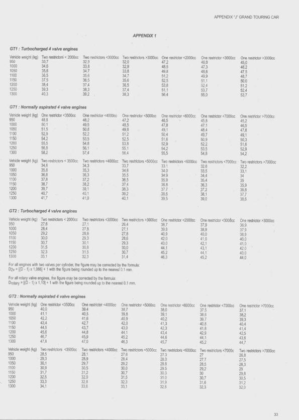
APPENDIX T GRAND TOURING CAR
GT1 : Turbochaiged 4 valve engines
Vehicle weight (kg) Two resthctore < 2000cc
A P P E N D IX 1
Two resthclors <3000cc Two reslrlctors >3000cc One restrictor <2000cc One restriclor <3000cc950 33.7 32.9 32,0 47.2 46.0 45,01000 34.6 33,8 32,9 48.5 47.3 46.21050 35.6 34.7 33.8 49.8 48.6 47.51100 36.5 35.6 34.7 51.2 49.9 48,71150 37,5 36.5 35.6 52.5 51,1 50,01200 38,4 37.4 36.5 53.8 52.4 51,21250 39.3 38.3 37.4 51,1 53.7 52.41300 40.3 392 38.3 56.4 55.0 53.7
GT1:: Normally aspirated 4 valve engines
Vehicle weight (kg) One restrictor <3500cc One restrictor <4000cc One restrictor <5000œ One restrictor <6000cc950 48.8 48.2 47.2 46,51000 50.1 49.5 48.5 47,81050 51.5 50,8 49,8 49,11100 52.9 52,2 51,2 50,41150 54.2 53,5 52,5 51,61200 55.5 54,8 53,8 52,91250 56,8 56,1 55.1 54,21300 58,2 57,4 56.4 55,5
Vehicle weight (kg) Two restrictors < 3500cc Two restrictors <4000cc Two restrictors <5000cc Two restrictors <6000cc950 34,8 34,3 33,7 33.11000 35,8 35,3 34,6 34.01050 36,8 36,3 35,5 34.91100 37,8 37,2 36,5 35.91150 38,7 38,2 37.4 36.81200 39,7 39.1 38.3 37.71250 40,7 40.1 39,2 38,61300 41.7 41.0 40,1 39,5
GT2 ; Turbocharged 4 valve engines
Vehicle weight (kg) Two restrictors < 2000cc Two restrictors <3000cc Two restrictors >3000cc One restrictor <2000cc950 27.6 27.1 26,4 38,71000 28.4 27.8 27,1 39,81050 29,2 26,6 27,8 40,91100 30,0 29,3 28,6 42,01150 30,7 30,1 29,3 43,01200 31,5 30,8 30,0 44,11250 32,3 31.5 30,7 45.21300 33.1 32.3 31.4 46,3
For all engines with two valves per cylinder, the figure may be corrected by the formula: D2v = [(D -1) X1.066] ♦ 1 with the figure being rounded up to the nearest 0.1 mm.
For all rotary valve engines, the figure may be corrected by the formula:Drotary = l(D -1) x 1.10] ♦ 1 with the figure being rounded up to the nearest 0.1 mm.
45.847.148.449.750.952.253.554.8
45.246.547.849.150.351.652.954.2
Two restrictors <7000œ Two restrictors >7000cc32.633.534.435.4 36.3 37,2 38.1 39.0
37.938.940.041.042.143.144.145.2
32,233,13435 35.9 36.8 37.7 38,6
One restrictor >3000a36.937.9 j38.940.041.042.043.044.0
GT2 : Normally aspirated 4 valve engines
Vehicle weight (kg) One restrictor <3500cc One restrictor <4000cc One restrictor <5000cc One restrictor <6000cc950 40,0 39.4 38.7 38,01000 41,1 40.5 39.8 39,11050 42,2 41.6 40.9 40,21100 43,4 42,7 42,0 41,31150 44.5 43,7 43,0 42.31200 45,6 44,8 44,1 43.41250 46,7 45,9 45,2 44.61300 47,8 47,0 46,3 45.7Vehicle weight (kg) Two restrictors <3500cc Two restrictors <4000cc Two restrictors <5000cc Two restrictors <6000cc950 28.5 28,1 27,6 27.31000 29.3 28,9 28,4 28.01050 30,1 29,7 29,2 28.81100 30,9 30,5 30,0 29.51150 31,7 31,2 30.7 30.31200 32.5 32,0 31,5 31.01250 33,3 32,8 32,3 31.91300 34.1 33,6 33,1 32.6
37.538.639.740.841.842.944.145.2
2727.728.529.2 3030.731.632.3
37.138239.340.441.442.543.644.7
26.827.5 28.3 29 29.830.5 31,2 32.0
33
A r t ic le 259 - Techn ica l re g u la tio n s FOR PRODUCTION SPORTS CARS (GROUP CN)
1) DEFINITIONS1.1 ■ Production sports carTwo-seater competition automobile, open or dosed, construded espe- dally for speed races.1.2- AutomobileLand vehicle running on at least four non-aligned complete wheels, of which at least two are used for steering and two used for propulsion.1.3- Land vehicleLocomotive device, propelled by its own motive power by constantly taking real support from the ground surface, with propulsion and steering controlled by a driver on board the vehicle.1.4- BodyworkAil those parts of the automotdle which are wholly spaing, in contact with ttie extemai airstream, excepting those parts ciearty associated with the mectianical function of the engine, the transmission or the rnn- ning gear. All air intakes shall be considered to be part of the txxJywork.1.5- Automobile makeAn automobile make corresponds to a complete vehicle. When a manufacturer fits an engine not manufactured by himself, the vehicle stiall be considered as a hybrid and the name of the engine manufacturer shall be associated with the name of the car manufacturer. The name of the car manufacturer shall always precede that of the engine manufacturer. Should a hybrid win a Championship Title, Cup or Trophy, this will be awarded to the manufacturer of the automotiile.1.6- EventAn event shall consist of the official practice sessions and the race itself.1.7- WeightThe weight is held to be that of the car without the driver at any moment during the event.1.8- Wheel Flange and rim.Complete wheel : Flange, rim and tyre1.9- DoorThat part of the bodywork which opens to give access to the driver and passenger compartments.1.10- CockpKinner structural volume used to accommodate the driver and passenger.1.11 - EngineAssembly constituted by the cylinder block, cylinders and cylinder heads.1.12- Cylinder capacityThe volume swept by the movement of the pistons inside the cylinders of the engine. In calculations of cylinder capacity, the number n is held to be 3.1416.1.13- SuperchargingIncreasing the weight of the charge of the fuel-air mixture in the combustion chamber (over the weight induced by nornnal atmospheric pressure, ram effect and dynamic effects in ttie intake and/or exhaust system) by any means whatsoever. The injection of fuel under pressure Is not considered to be supercharging.1.14- Main structureThis is the fully sprung part of the stoicture to which the suspension and/or spring loads are transmitted, extending longitudinally from the foremost front suspension mounting on the ctiassis to the rearmost rear mounting.1.15- Mechanical elements/kll the elements necessary for propulsion, suspension, steering and braking, together with ail the accessories, moving or not, which are necessary for the normal function of the above.
2) REGULATIONS2.1 - The following regulations governing the constaiction of Production Sports Car automobiles are issued by the FIA.
2.2 - In October each year, the FIA will publish any changes made to these regulations. Ail such changes will take effect on ttie second January 1 following their publication. Changes made for safety reasons may come into force witfiout notice.2.3 - /\ny automobile which is deemed to be daogerous may tie excluded by the Stewards of the event2.4 - It is the duty of each competitor to satisfy the Scrutineers and Stewards that his car compiies with ttie regulations in their entirety at all times during the event. The competitrbr must be able to show the Scojtineers the Group A and N homologation fomi conesponding to the reference vehicle for the engine used, wtienever tfie Scrutineers so request.2.5 - /Ml measurements must be taken while the car Is stationary on a fiat horizontal surface.2.6 - The use of titanium is prohibited.2.7- Only chassis made exclusively of metal, whether monocoque or tubular, are authorised; as far as the chassis is concerned, metal honeycomb constructions are authrjrised only for the flat bottom (see article 3.7.4).2.8 - /Ml modifications not explicitly authorised are prohibited. /\part from these authorisations, the engine must be strictly series production and identifiable from the information given in the corresponding articles of the FIA homologatbn fonn. Therefore, any engine part damaged through wear or through an arxident may rxrly be replaced with an original part identical to the damaged part.
3) BODYWORK AND EXTERIOR DIMENSIONS3.1 - LengthThe overall length of the car must not exceed 48(X) mm.3.2 - WidthThe overall width of the car including the complete wheels shall not exceed 2000 mm, when the steered wheels are in the straight ahead position.3.3 - HeightThe height measured verticaliy from the lowest point of the flat surface as defined in article 3.7.4 to the highest part of the vehicie, shall not exceed 1030 mm, except as regards ttie rollover bar which must not constitute an aerodynamic element.3.4 - OverhangsFront plus rear overhangs must not exceed 80 % of the wfieelbase. The difference between the front and rear overfiangs must not exceed 15 % of the wheelbase.3.5 - Doors3.5.1) Closed cars:Two doors are compulsory.The doors when opened must afford free access to the seals. No mechanical element may hinder access to the seats. The extemai door handle on closed cars must be dearly indicated.The dimensions of the lower pahel (ttie part which is normally opaque) must be such as to allow a rectangle or a parallelogram at least 500 mm wide and 300 mm high, measured vertically, to be affixed. The comers of this rectangle or parallelogram may be rounded with a maximum radius of 150 mm.Cars with sliding dorxs will be admitted only if ttiey are fitted with a safety device enatrling the occupants of the car to be evacuated quickly and easily.The doors must indude a window distinct from the panel mentioned above, made of transparent material, and capable of ccmtaining a parallelogram with trorizontal sides measuring at least 400 mm. The height measured on the surface of ttie window perpendicular to ttie horizontal sides shall be at least 250 mm. The comers of the parallelogram may be rounded to a maximum radius of M mm. frleasurements shall be taken on the chord of the arc.The drxxs must be designed in such a way that the lateral vision of the driver is never restricted.
APPENDIX T PRODUCTION SPORTS CARS
Each door must have only one outside handle which must tie of a lever type, operated by being pulling upwards, and which must be clearly Indicated by an arrow in red or in another contrasting colour.Door hinges must be designed in the form of pins which can be removed, without using tools, from the outside of the car.3.5.2) Open cars :Doors are optional.If doors are fitted, they must comply with the dimensions stipulated In article 3.5.1 above (closed cars) as regards the opaque element.If doors are not fitted, the bodyworir at the side of the cockpit must comply with these same dimensions.3.6 - Windscreen3.6.1) Closed cars :A windsCTeen made of one piece of laminated glass or equivalent FIA approved material Is compulsory.The shape of the windscreen must be such that at a distance of 50 mm measured vertically downwards from the highest point of the transparent part, the glazed surface Is at least 250 mm wide measured across the chord of the arc on either side of the longitudinal axis of the car.The shape of the windscreen must be such that its upper edge fom s a regular, continuous convex line.It must be possible to affix to ttie windscreen a vertical band 100 mm high and 950 mm long (measured horizontally) across the chord of the arc between the Inner faces of the windscreen, the centre of which shall be 300 mm (measured vertically downwards) from the highest point of the roof, excluding air intakes.3.6.2) Open cars :The windscreen is optional and dimensions are free, on condition that article 3.3 of these regulations is complied with.3.7 - Bodywork3.7.1) The use of cartx)n fibre and/or kevlar for the manufacturing of the bodywork is prohibited.3.7.2) The bodywork shall cover all the mechanical components; only the exhaust and air intake piping, and the top of the engine, may project.3.7.3) On closed cars, the height of the air intakes must not exceed that of the highest point of the roof; open cars must comply with article 3.3.3.7.4) Ttie bottom of all cars, reanxrard of the vertical plane tangent to the rear of the complete front wheels, and forward of the vertical plane tangent to the complete rear wheels, must be fitted with a continuous solid, flat (toterance 5 mm), hard, impervious and rigid surface within which it would be possible to draw a rectangle 1000 mm (measured along the transverse axis of the car) by 800 mm (measured along the longitudinal axis of the car).The whole of this surface must form an Integral part of the chassis/body unit and must have no freedom of movement or provision for adjustment in relation to this unit. fJo spaœ may exist between this “flat txrttom” as defined above and the chassis/body unit.To help overcome any manufacturing difficulties, a tolerance of 5 mm will be permitted for the “flat bottom” defined above. The aim of this tolerance Is not to permit designs which go against the spirit of the Tlat bottom".3.7.5) No part having an aerodynamic effect, and no part of the bodywork may under any circumstances be located betow the geometric plane of the flat surface provided for in article 3.7.4.3.7.6) /\ny part having an aerodynamic effect, and all parts of the bodywork must be rigidly secured to the entirely spmng part of the car (chassis/body unit), must have no freedom of movement, must be solidly fixed and must remain immobile in relation to this part while the car is in motion.3.7.7) /kny device or contrivance designed to bridge the gap between the sprung part of the car and the ground is prohibited in all circumstances.3.7.8) Behind the rear wheels, the bodywork must descend below the rear axle.Any cooling holes in the bodywork which are directed rearward must be fitted with louvres or other similar devices to ensure that the tyres will not at any time be visible from the rear.The bodywork shall project over the complete wheels In such a way as to cover at least one third of their circumference and their entire width.
3.7.9) All elements of the bodywork shall be completely and cleanly finished, with no temporary or makeshift elements.3.7.10) In the case of open cars, the opening atxive tfie seats must be symmetrical in relation to the longitudinal axis of the car.An open car must respect the following prescriptions:- The shape of the bridywork seen from one side must be identical to the shape seen from the other side.- Seen from above, the existence of a central element separating the driver from the passenger, even if this element is not connected to the bodywork at the backs of the seats, may be accepted as long as the cockpit opening is of the same size for both driver and passenger.- The bodywork may be made of transparent material, but the rules regarding the windscreen must be complied with.(see also artcle 13.8)3.7.11) The clips fastening the front and rear covers must be clearly Indicated by arrows In red or In another contrasting colour, and It must be possible to manipulate them without using tools.3.7.12) The engine cover and Its junction with the bodywork/cockpit must be designed so as to prevent any leakage of fuel Into the Interior of the engine compartment during refuelling.
Up to 1000 cm^ :From 1000 to 1300 cm^ From 1300 to 1600 cm^ From 1600 to 2000 cm^ From 2000 to 2500 cm^ From 2500 to 3000 cm^
4) WEIGHT4.1 - Cars must weigh at least the following weights, according to their engine capacity:
460 kg 480 kg 500 kg 520 kg 560 kg 600 kg.
4.2 - Ballast may be used provided that it is secured in such a waythat tools are required for its removal. It must be possible to affix sealsIf this is deemed necessary by the Scrutineers.4.3 • The adding of any solid material whatsoever to the car, or the replacement of any part of the car by a heavier part, is strictly prohibited during the race.4.4 - The weight of the car may be checked at any time during the event with the quantity of fluids remaining in the tanks. In case of doubt, the Scrutineers may drain the fuel tanks to check the weight.
5) ENGINE5.1 - Type of engine allowedThe engine must come from a model of car homologated by the FIA in Group N.Cylinder capacity: less than or equal to 3000 cm^.Maximum number of cylinders: 6.Cars with rotary piston engines covered by NSU-Wankel patents win be admitted on the basis of a piston displacement equivalence. This equivalence is 1.5 times the volume detemilned by the difference between the maximum and minimum capacities of the working chamber.5.2 - Supercharging of any kind whatsoever is prohitjited.5.3 - Injection and spraying of waterInternal and/or extemal spraying or injection of water or any substance whatsoever is prohibited (other than fuel for the normal purpose of combustion Inside the engine).5.4 - Temperature of the chargeAny device, system, procedure, construction or design the puqxise and/or effect of which Is to decrease in any way the temperature of the intake air and/or the charge (air and/or fuel) of the engine is prohibited.5.5 - Engine mountings - PositionThe material, type and number of engine mountings are free, as are the position and Incline of the engine in its compartment.5.6 ■ IgnitionThe original Ignition system (battery/coll or magneto) must be maintained. The make and type of plugs, the rev limiter and the high tension cables are free. Electronic control of the engine is free.5.7 - LubricationThe lubrication system is free, on condition that it complies with articles3,7.2 and 7.5.8 - CoolingThe cooling radiator and the lines connecting it to the engine are free.
APPENDIX "J" PRODUCTION SPORTS CARS
as are the thermostat and the fan, and their location. The water pump Is free.5.9 - Fuel feedCaiturettor parts or fuel injection system parts regulating the quantity of fuel reaching the engine may tie modified, provided that they have no influence on air admission. The original injection system must tie maintained. The injectors may tie changed for injectors which are identical except with regard to the size of the pintle nozzle hole at the end. Electronic control of the engine is free.The air filter, along with its txix, the plenum chamtier and the lines connecting it to the engine, are free. The air filter and its txix may therefore lie removed, moved to a different position, or replaced. The air measuring device is free.5.10 - Exhaust5.10.1) The exhaust is free after the cylinder head, tmt the interior dimensioris of the exit from the original manifold must tie maintained, and the maximum interior dimensions of the duct must be those of the exit from the manifold. This freedom must not enable the maximum sound levels permitted by the laws of the country in which the eveht is mn to be exceeded.5.10.2) The exhaust pipe outlets must be directed either reanivards or sideways. If the exhaust pipes are directed rearwards, their outlets shall be situated between 450 mm and 100 mm above the ground. If the exhaust pipes are directed sideways, their outlets must be located to the rear of a vertical plane passing ttirough the wheelbase centre plane and may not project beyond the bodywork in any way.5.11 - Cylinder head gasketThe material is free, but not the thickness.5.12- The accelerator control cable may be replaced or doubled, using another of unrestricted origin.5.13 - The engine flywheel is free.5.14 - Pulleys fitted outside the engine are free.
6) FUEL SYSTEM6.1 ■ Fuel specification6.1.1 ) For petrol engines :The ftiel must be commercial petrol which comes from a service station pump, without any additive other than that of a lubricant on current sale. The fuel must comply with the following specifications :- 102.0 RON and 90.0 MON maximum, 95.0 RON and 85.0 MON minimum for unleaded fuel.100.0 RON and 92.0 MON maximum, 97.0 RON and 86.0 MON minimum for leaded fuel.The measurements will be made according to the standards ASTM D 2699-86 and D 2700-86.- Specific gravity between 720 and 785 kg/m3 at 15“C (measured according to ASTM D 4052).- A maximum of 2.8 % oxygen (or 3.7 % if the lead content Is less than 0.013 gfl) and 0.5 % nitrogen by weight, the remainder of the fuel consisting exclusively of hydrocartxrns and not containing any power- boosting additives.The nitrogeh content will be measured according to standard ASTM D 3228, and the oxygen content by elemental analysis with a tolerance of 0.2 %.- Maximum content of peroxides and nitrooxide compounds: 100 ppm (ASTM D 3703 or in the case of Impossibility UOP 33-82).- Maximum lead content: 0.40 g/l or the standard of the country of the event if this Is lower (ASTM D 3341 or ASTM D 3237).- Maximum benzene content 5 % in volume (ASTM D 3606).- Maximum Reid vapour pressure : 900 hPa (ASTM D 323).- Distillation at 70”C : 10 % - 47 % (ASTM D 86).- Distillation at 100°C : 30 % - 70 % (ASTM D 86).- Distillation at 180°C : 85 % minimum (ASTM D 86).- Maximum final boiling point : 225°C (ASTM D 86).- Maximum residue : 2 % volume (ASTM D 86).The fuel being accepted or rejected according to the standard ASTM D 3244 with a confidence limit of 95 %.If the fuel available locally for the event is not of a sufficient quality for use by competitors, the ASN of the organising country must ask the FIA for a waiver in order to allow the use of fuel not corresponding to the characteristics defined above.6.1.2) For diesel engines : '■Fuel must meet the following specifications:
- hydrocartxin content, % in weight : minimum 99.0- density : maximum 0.860- cetane Index (ASTM D 613) orcalculated cetane index (ASTM D 976/80) : maximum 60 •*6.1.3) Storage of fuel on board the car at a temperature of more than 10°C below the ambient temperature Is prohitiited.The use of any device (whether oh board ttie car or not) to reduce the temperature of the fuel below the ambient temperature Is prohitxted.6.1.4) Only air may be mixed with the fuel as an oxidant6.2 - Fuel lines, pumps and filters6.2.1) Must have a minimum burst pressure of 41 bars (600 psi) and a minimum operating temperature of 135”C (250°F).When flexible, these lines must have threaded cormectors and an outer braid resistant to abrasion and flame (will not sustain combustion).6.2.2) No lines containing fuel may pass through the cockpit.6.2.3) No fuel pumps or fuel filters may be fitted inside the cockpit6.2.4) All fuel lines, filters and pumps must be positioned in such a way that any leakage cannot result In fuel entering the cockpit6.3 - Fuel tank6.3.1) Fuel tanks may not be positioned more than 65 cm from the longitudinal axis of the car and must be located within the limits defined by file front and rear wheel axes. The tank must be insulated by means of bulkheads preventing the fuel from passing Into the cockpit or engine compartment or coming into contact with exhaust piping, in the event of spillage, leakage or any other accident occurring to the tank. Fuel tanks must tre properly protected (see article 15.2).6.3.2) For hlH-dlmbs and slaloms lif the total capacity of the fuel tanks is not greater than 201, the safety tank will not be compulsory on condition that the prjsition of the tank does not protrude beyond 30 cm in any direction from the longitudinal axis of the car, and that it Is surrounded by a cnjshable structure 1 cm thick. The safety tank Is also optional for circuit races of less than 100 km under the same conditions of Installation.In ottier cases, cars must be equipped with fuel tanks which comply with or exceed FT3 safety specifications, and are supplied by an approved manufacturer.6.3.3) On all tanks of this type, the name of the manufacturer, the specifications to which the tank has been manufactured and the date of manufacture must tje printed.6.3.4) No tank of this type may be used more than 5 years after the date of manufacture, unless inspected and recertified by ttie manufacturer for a period of up to another two years.6.4 - Tank fille rs and caps6.4.1) All filler and vent caps must be designed to ensure an efficient locking action which reduces the risks of accidental opening following a crash Impact or incomplete closing after refuelling.6.4.2) The tank fillers, vents and caps must not protrude beyondthe bodywork. '6.4.3) The tank fillers, vents and tjreathers must be placed where they would not be vulnerable in the event o f an accident.6.5 - Refuelling(Only for circuit races where refuelling is necessary)The refuelling hose must be provided with a leak proof coupling to fit the standardised filler mountal on the car. The dimensions of this filler are given In drawing 252-5.Fillers and air vents must be equipped with leak proof dry break couplings complying with ttie dead man principle and therefore not incorporating any retaining device wtien In an open position (spring loaded balls, bayonet, etc.).The air vent(s) must be equipped with non-retum and closing valves having the same closing system as that of the standard filler, and the same diameter. During refuelling, the outlets of the air vents must be connected with the appropriate coupling, either to the main supply tank or to a transparent portable container with a minimum capacity of 20 litres provided with a closing system rendering it completely leak proof. Should the circuits be unable to provide the entrants with a centralised system, these will have to refuel according to the above procedure. In no case may the level of the reserve tank exceed two metres above the track where the refuelling takes place, for the entire duration of ttie event.The overflow bottles and the independent storage tanks must comply with drawings 252-1 or 252-2 and 252-3 or 252-4.
36

APPENDIX “X PRODUCTION SPORTS CARS
All metal parts of the refuelling system from the coupling over the flow meter to the tank and its radc must be connected electrically to the earth.A 90" cut off valve situated close to the main supply tank, controlling the fuel flow, must be manned at all times during refuelling.All hoses, valves, fittings and couplings used must have a maximum inner diameter of 1 1/2".6.6 • Fuel capacityThe maximum amount of fuel which may be earned on board is 100 litres. Any device, system, procedure, construction or design the purpose and/or effect of which is to increase in any way, even temporarily, the total fuel storage capacity beyond 100 litres, is prohibited.
7) OIL SYSTEM7.1 - Oil tanksThe quantity of oil carried on board must not exceed 20 litres.7.2 • No part of the car containing oil may be situated behind thecomplete rear wheels.7.3 • All oil tanks must be property protected. All oil tanks situated outside the main structure of the car must be surrounded by a 10 mm thick crushable structure as defined in article 15.2.3.7.4 • Oil catch tankIf a car has a lubrication system which includes an open type sump t)reather, this must vent into a catch tank of at least 3 litres capacity. The catch tank must either be made of transparent material or include a transparent panel.7.5 • Oil lines7.5.1) All lubricatir^ oil lines must have a minimum burst pressure of 41 bars (600 psi) and a minimum operating temperature of 135"C (250"F).When flexible, these lines must have threaded connectors and an outer braid resistant to abrasion and flame (will not sustain combustion).7.5.2) No lines containing lubricating oil may pass through the cockpit.
8) ELECTRICAL EQUIPMENT8.1 • BatteriesBatteries must be located outside the cockpit. They must be securely fixed and completely protected inside a box made of insulating material.8.2 - Windscreen wiperIf the car has a windscreen, it must be fitted with at least one windscreen wiper which is in working order throughout the event.8.3 - StartingA starter with an electrical or other power source must be carried on board the car it must be possible for the driver to operate it when seated normally in the car. The starter must be capable of starting the engine at ail times.8.4 > Lighting equipment8.4.1) All lighting equipment must be In working order throughout the event, even if the event is mn entirely in daylight.8.4.2) All cars must be fitted with two red stop lights and two red rear lights. They must be located symmetrically on either side of the longitudinal axis of the car and must be mounted in a visible position.8.4.3) For night races, all cars must t>e fitted at least two headlights, and with direction indicators mounted at the front and rear of the vehicle (with side indicators mounted to the rear of the front wheel axle).8.4.4) All cars must have at least one red rain light of at least 21 watts which must be in working order throughout the event, and which: . faces rearward and is clearly visible from the rear;. is mounted not less than 40 cm from the ground;. is mounted not more than 100 mm from the car centre-line or, in the case of two lights, are mounted symmetrically on either side of the longitudinal axis of the car on the bodywork behind the rear wheels in frontal projection:
has a minimum surface of 50 cm2;. can be switched on by the driver when he is seated normally in the car.In addition, the lenses and reflectors must conform to standards EEC
77/538 or ECE 38 for rear fog lamps of motor vehicles and must carry the con-esponding approval marking.8.5 • CablesAll electrical circuits must be enclosed in fire-resistant material.8.6 • Alternator The alternator is free.
9) TRANSMISSION9.1 - GearboxFree, but the maximum number of geartwx ratios Is 5, not including the reverse gear. All cars must have a reverse gear v^ich must be in working order throughout the event. It must be possible for the driver to select reverse gear while seated normally at the wheel and with the engine running. Transverse gearboxes and semi-automatic and automatic gearboxes are prohibited.9.2 - ClutchFree, but with a maximum of two discs. These discs must not be made fromcartx)n.9.3 - DifferentialFree, but electronically, pneumatically or hydraulically controlled slip differentials are prohibited.9.4 • Four-wheel drive cars are prohibited.
10) SUSPENSION10.1 - All road wheels/axles must be suspended from thechassis/txxjy unit by a springing medium (i.e. axles or wheels must not be connected directly to the chassis/body unit). The springing medium must not consist of bolts located through flexible bushes or flexible mountings. There must be independent niovement of the axles/hub carriers/stub axles giving suspension travel from “bump” to “droop” in excess of the flexibility of the mounting location attachments.10.2 - Active suspensionActive suspension systems are prohitHted, as are all systems enabling the flexibility of springs, shock absort)ers and the ground clearance height of the car to be controlled while the car is in motion.10.3 - Chromium-plafing of steel suspension elements is prohibited.10.4 • Suspension parts made partially or completely from composite materials are prohibited.
11) BRAKES11.1 - All cars must have a braking system which has at least twoseparate circuits operated by the same pedal. The system must bedesigned in such a way that in case of leakage or failure on one of the circuits, the pedal continues to operate the brakes on at least two wheels.11.2- Carbon brake disks are prohibited.
12) WHEELS AND TYRES, STEERING12.1 - The maximum width of the complete wheel is 16”.This measurement shall be taken horizontally at the height of the axle with the tyre at normal running pressure and with the car in mnning order with the driver on board.12.2 • The number of wheels is fixed at four.12.3 • A safety spring must be in place on the wheel nut throughout the duration of the event and must be replaced after each wheel change. These springs must be painted dayglo red or orange. Alternatively, any other wheel-retaining device which has been approved by FIA must be used throughout the event.12.4 - Cars equipped with four-wheel steering systems are prohibited.12.5 - Pressure control valves on tfie wheels are prohibited.12.6 • The use of wheels equipped with a tyre-retaining device is recommended.12.7- There must t>e a continuous mechanical connection between the steering wheel and the steered wheels.12.8 - Wheels made partially or entirely from composite materials are prohibited.
13) COCKPIT13.1 - The structural volume of the cockpit must t>e symmetricalabout the longitudinal centre-line of the car.13.2 • Up to a height of 300 mm from the floor, the driver in his
37

APPENDIX " r PRODUCTION SPORTS CARS
normal driving position must be located on one side of the longitudinal centre-line of the car.13.3- Eltiow widthThe minimum elbow width in the cockpit must be 110 cm, maintained over a height of 10 cm and a iength of 25 cm. This measurement shall be taken horizontally, and perpendicular to the longitudinal centre-line of the car.13.4) Footwells13.4.1) The car must have two footwells, defined as two free symmetrical volumes on either side of the longitudinal centre-line of the car, each one having a minimum vertical cross-section of 750 cm^.This cross-section must be maintained from tfie pedal farres to the vertical projection of the centre of the steering wtieei.13.4.2) The minimum width of each footwell is 250 mm and this width must be maintained over a height of at least 250 mm.13.5 - Equipment permitted In ttie cockpit13.5.1) Thie only components which can be fitted in the cockpit are tfie following :. Safety equipment and structures . Electronic equipment . Driver cooling system . Tool kit. Seat and controls required to drive the car.13.5.2) Each and all of tfiese elements must nevertheless respect the 750 cm^ free footwell sections on each side of the centre-line of the car, and must not restrict access through the doors.13.5.3) These components must be covered by a rigid protection if tfiey have sharp edges which may cause injury. T ^ r testenings must be able to witfistand a 25 g deceleration.13.6 - VentilationThe cockpits of all closed cars must be fitted with a fresh air inlet and a used air outlet.13.7 - PedalsThe soles of the driver's feet, wtien he is seated in the normal driving position with his feet on the pedals and with the pedals in the inoperative position, shall not be situated forward of the vertical plane passing through tfie centre-line of the front wheels. Should the car not be fitted with pedals, the driver's feet at tfie maximum fonrrard extension shall not be situated forward of tfie vertical plane mentioned above.13.8 - Cockpit openingIn ojren cars, the openings which correspond to the driver and pæ- s e n ^ seats must enable the horizontal template defined in drawing 259-2 to be placed vertically within the cockpit with the steering wheel removed.It must be possible to lower the template to a point 25 mm below the lowest point of the cockpit opening.13.9 • Lines in tfie cockpttNo lines containing fuel, cooling liquid, lubricating oil or hydraulic fluid may pass through the cockpit. Only brake lines no connectors installed within the cockpit may p ^ through the cockpit All lines cxmtaining hydraulic fluid, with the exception of lines under gravity head only, must have a minimum burst pressure of 70 bars (1000 psi) or higher according to the operabng pressure, and a minimum operating temperature of 232”C (450T).When flexible, these Knes must have threaded connectors and an outer braid resistant to abrasion and flame (will not sustain comtms- tion).13.10 • Steering wtieelThe steering wheel must be fitted with a quick release mechanism. Its m^hod of release must be by pulling a concentric flange installed on the steering column behind the wfieel.
14) SAFETY EQUIPNIENT14.1 - Fire extinguishers14.1.1) All cars must tie fitted with two fire extinguishing systems, one which will discharge into the crxikpit and one into the engine compartment14.1.2) Permitted exbnguishants :BCF(CF2 aBr)NAFS3NAFP
Any AFFF which has been specifically approved by the FIA (see Technical List n ' 6").Dry powder is also permitted but only on cars being used in or coming from countries wtiere national regulafions preclude the use of tfie above products.14.1.3) Minimum extinguisher capacity :- For BCF, NAF S3, NAF P:
Closed cars: Open cars:Cockpit 1.65 litres 3.30 litresEngine: 3.30 litres 1.65 litres-F or AFFF: The capacity may vary according to the type used . ;
(see Technical List n° 6")14.1.4) Minimum quantity of exbnguishant :
(5losed Opencars : cars :
BCF: Cockpit: 2.5 kg 5.0 kgEngine: 5.0 kg 2.5 kg
NAF S3: Cockpit: 2.0 kg 4.0 kgEngine: 4.0 kg 2.0 kg
NAF P: Cockpit: 2.0 kg 4.0 kgEngine: 4.0 kg 2.0 kg
Powder Cockpit: 1.2 kg 2.4 kgEngine: 2.4 kg 1.2 kg
AFFF: The quantity may vary according to the type used (see Technical List n° 6")14.1.5) Discharge fime :Engine : 10 seconds minimum / 40 seconds maximum.Cockpit : 30 seconds minimum / 80 seconds maximum.Both extinguishers must be released simultaneously.14.1.6) All exbnguishers must be pressurised according to the contents:BCF: 7.0 barNAF S3: 7.0 barNAF P: 7.0 barPowder 13.5 barAFFF: The pressure may vary according to the type used (see Technical List n° 6")Furtfierrrxxe, in tfie case of an AFFF, each extinguisher must be equipped virith a means of checMng tfie pressure of the contents.14.1.7) The fblloviring information must be visible on each extinguisher-capacity- type of extinguishant- weight or volume of the extinguisfiant- date the extinguisher must be checked, which must be no more than two years after the date of filling or the date of the last check.14.1.8) All extinguishers must be adequately protected and must be situated within tfie survival cell. In all cases their mountings must be able to witfistand a deceieraticxi of 2Sg.All extinguishing equipment must witfistand fire.14.1.9) Any triggering system having its own scxjrce of energy is permitted, provided it is possible to operate all extinguishers shcxjld the main electrical circuits cif tfie car fail.The driver must be able to trigger all extinguishers manually wfien seated ncxmally with his safety belts fastened and the steering wfieel in place.Furtfiermore, a means of triggering frcxn tfie outside must be ccxnbined with tfie circufl-breaker switch, or situated dose to it It must be marked with a letter 'F ' in red inside a white drde of at least 10cm diameter with a red edge.14.1.10) The system must wcxk in any positicxi, even when tfie car is inverted.14.1.11) Both extinguisher nozzles riKist be suitable for the extinguishant and be installed in such a way that they are not directly poirited at the driver. i,14,2- Safety befts y:14.2.1) The wearing of a safety belt comprising two shoulder straps, cxie lap strap and two straps fcietween the legs is compulscxy. These straps must comply with FIA standard n* 8853-85.14.2.2) Points of anchorage to b o d y ^ l: two anchorage points for tfie lap strap, two {or one anchorage point symmetrical about the seat) for the sfioulder straps, two for tfie straps between the legs. .
38
APPENDIX -J’ PRODUCTION SPORTS CARS
14.3 - Rear view mirrorsTtie car must be fitted with two rear-view mirrors, one fitted on each side of the car in order to give an effective view to the rear. Each minx)r must have a minimum area of 100 cm^.14.4- Headrest14.4.1) A headrest with a minimum area of 400 cm^ must be fitted to all cars. Its surface must be continuous, without any protruding parts.14.4.2) The headrest must not deflect more than 6 cm under an 85 kg reanfvard force.14.4.3) The headrest shall be located in a position such that it will be the first point of contact with the driver’s helmet in the event of an impact projecting the driver's head reanvards when he is in the normal driving position. The distance between the driver's helmet and the headrest should be kept to a minimum so that the helmet will move less than 5 cm under the above-mentioned force.14.5 - Circuit breakerThe driver, when seated normally with his safety belts fastened and the steering wheel in place, must be able to shut off all the electrical circuits and stop the engine by means of a spark-proof drcuit-breaker. The intemal switch must be marked by a symbol showing a red spark in a white-edged blue triangle.There must also be a clearty indicated extemal handle which emergency service personnel can operate from a distance by means of a hook. For closed cars, this handle must be located at the lower part of the windscreen pillar on the driver’s side, and for open cars, at the lower part of the pillar of the roltover structure on the driver’s side.14.6 • Towing eye14.6.1) A towing eye with minimum inner diameter of 80 mm must be securely fitted to the front and rear structures of the car.14.6.2) The towing eye must be placed in such a way that it can be used should the car be stopped in a gravel t>ed.14.6.3) The towing eye must be clearly visible and painted yellow, red or orange, and must be located within the contour of the bodywork as viewed ^ m above.
15) SAFETY STRUCTURES15.1 • Rollover structures15.1.1) Closed cars:The car must be fitted with two rollbars, one to the front and one behind the chest of the driver and passenger. Both rollbars must correspond in shape to the inner profile of the upper part of the cockpit, and must be connected at the top by at least one tubular member (preferably two, with junctions as far apart as possible) or a box member. In addi- tbn, the rear roltbar shall comprise at least one diagonal reinforcing member and two backstays directed rearwards (see drawing 259-3). The various authorised diagonal members are MQ, MS, NP, and NR, but it is preferable that the upper extremity of the diagonal of the main rollbar should be situated on the driver's side.This structure must t e made exclusively of steel tubing with the following minimum characteristics:
Cold drawn seamless cartxxi steel Yield strength : 300 N/mm^
Altoy steel type 25 CD4 SAE 4125, SAE 4130, CDS 110 Yield strength : 500 N/mm^
Diam. 45 x 2.5 mm
Diam. 40 x 2.5 mm
Rollbars must be covered with protective fire-resistant anti-shock foam.15.1.2) Open cars :Included as open cars, are all cars which do not possess a supporting structure between the top of the windscreen pillars and those of the rear window (if fitted).The main rollbar behind the front seats must be symmetrical about the longitudinal axis of the car, and meet the following dimensional criteria:- Height: the top of the rollbar must be 5 cm higher than the top of the driver’s helmet when the driver is seated normally at the wheel.- Width: measured between the inside faces of the vertical members of the rollbar, the width should t>e at least 20 cm measured 60 cm above the driver’s and passenger's seats (on a straight line perpendicular to the vertebral column) from the longitudinal axis of the seat towards the outside.- Longitudinal position: the longitudinal distance between the top of the
rollbar and the helmet of the driver seated normally at the wheel must not exceed 25 cm.The rollbar structure should conform to drawing 259-1, to the table given in article 15.1.1, to the specifications relevant to removable connections and to the general remarks, as well as to those concerning the diagonal strut of the main rollbar and the presence of anti- shock foam. The fitting of frontal struts directed forward and designed to protect the driver is authorised for open cars, provided that the struts are removable.15.1.3) The manufacturer of the car may submit a safety cage of his own design to an ASM for approval as regards the quality of steel used, the dimensions of the tubes, the optional reinforcing members and the mounting to the vehicle, provided that the construction is certified to withstand the stress minima given hereafter in any combination on top of the safety cage;-1 .5 W* lateral;- 5.5 W fore and aft;- 7.5 W vertical.(*W = weight of the car + 75 kg).A homologation certificate, approved by the ASN and signed by qualified technicians representing the manufacturer, must be presented to the event’s scrutineers. It must contain drawings or photos of the safety cage in question including its fixation and particularities, and must declare that the rollcage can resist the forces specified above.These safety cages must not be modified in any way.15.2 - Cmshable structures15.2.1 ) The bottoms of fuel tanks must be protected by a crushable structure at least 1 cm thick.15.2.2) If the fuel tank is situated less than 20 cm from tf»e sides of the car, the entire lateral surface must t)e protected by a crushable structure at least 10 cm thick.15.2.3) The crushable structure must be of a sandvwch construction incorporating a fire-resistant core with a minimum crush strength of 18 N/cm2, and of two sheets at least 1.5 mm thick, one of which is made from aluminium alloy with a minimum tensile strength of 225 N/mm^ and minimum elongation of 5 %, or, alternative^, two sheets at least 1.5 mm thick with a minimum tensile strength of 225 N/mm2.15.2.4) Only water pipes may pass through the crushable structures; fuel or oil lines or electrical cables must not.15.3 • Firewall and floor15.3.1) Cars must be fitted with a firewall placed between the driver and the engine to prevent flames passing from the engine compartment into the cockpit. Any openings made in the firewall must be the minimum size necessary to allow the passage of controls and cables, and must subsequently be completely sealed.15.3.2) The floor of the cockpit must be designed in such a way as to protect the driver against gravel, oil, water or any other debris thrown up from the road or coming from the engine.15.3.3) The floor panels or separation bulkheads must be properly vented to avoid the accumulation of fluids.15.4 • Frontal protectionThe chassis must include an impact-absorbing structure installed in front of the driver’s and passenger’s feet. This structure must be independent of the bodywork and, if it is removable, it must be securely fixed to the edges of the side box members of the main chassis (i.e. by means of bolts requiring the use of tools for removal).The structure must have a minimum length of 30 cm, a minimum height of 15 cm at any vertical cross section and a minimum total section of 800 cm2.The structure must be made from a metallic material with a minimum tensile strength of 225 N/mm2; construction should be of the sandwich and honeycomb type with a skin thickness of at least 1.5 mm. It must constitute a box the panels of which must be at least 15 mm thick, or, if the radiator(s) is (are) incorporated into the stmcture, two continuous box members with a minimum section of 100 cm2 on either side of the radiator(s). All holes and cut-outs in this structure must be strongly reinforced and all material sections through these holes must still comply with the minimum material area requirements.
16) FINAL TEXTThe final text of these regulations is the French text, \whlch shall be referred to in the event of any disagreement as to interpretation.
39

A rticle 2 6 0 - T echnical reg u la tio n s FOR JUNIOR SPORTS CARS (GROUP C 3 )
1) DEFINITIONTwo sealer competltfon automobiles built specially for races on closed circuits.
2) SPECIFICATIONS2.1 ■ Engine :The whole made up by the block, cylinders and cylinder heads. All modifications are allowed, but the engine must compulsorily be a reciprocating engine, without supercharging, with a maximum cubic capacity of 2,5 litres, or Wankel type (coefficient 1.8). Oval pistons and water injectkxi are fbrbidden.2.2- W eight:The cars must have the following minimum weight, according to their cylinder capacity :Up to 1000 cm^ : 500 kgFrom 1000 cm^ to 1300 cm^ From 1300 cm^ to 1600 cm^ From 1600 cm^ to 2000 cm^ From 2000 cm^ to 2500 cm^
535 kg 560 kg 600 kg 640 kg
This is the real weight of the empty car, with no persons or baggage on board, the car being fully e q u ip ^ . All the safety parts normally prescribed are Included in this weight.The weight may be checked at any time during an event with the quantity of liquid remaining in the tanks and after emptying the car of all the fuel (on the understanding that it is fortridden to add oil, water or any other liquid before the weighing). The weight of the car may be completed ^ means of one or several ballasts Incoqxrrated In the material of the car provided that these are solid and unitary blocks, fixed by means of tools and offering ttie possibility for seals to be affixed if the Scrutineers deem it necessary.2.3 - Main structure :Ttie fully sprung stnxiure of the vehicle to which the suspension and/or spring loads are transmitted, extending longitudinally from tfre foremost frw t suspension mounting on the chassis to the rearmost one at the
3) OTHER PRESCRIPTIONS3,1 ■ Exterior dimensions :Maximum width : 200 cm.Maximum length : 480 cm.The height measured vertically from the lowest point of the fiat surface as defirrâd under article 3.8 to the highest point of the car must not exceed 1030 mm, except with regard to the rollbar which must not give rise to an aerodynamic structure.Front plus rear overfiangs must not exceed 80% of the wheelbase. Tfie difierence between ttie front and rear overfiangs must not exceed 15 % of the wheelbase.3.2- Doors :- Closed cars : Two doors are otiligatory. Tfie word drxir shrxrld be taken as meaning Itiat part of the txxlywork which opens to giveaccess to the seats. The rtoors, when open, must afford free access tothe seats. No mechanical part shrxrld otjstruct access to the seats. The outside drxx handle cxi closed cars must be dearty indicated.The dimensions of ttie lower door panel (ttie part which is nomially opaque) must be such as to allow a parallelogram of at least 50 cm wide arid 30 cm height, measured vertically, to be inserted in it The comers of the parallelogram may be rounded to a maximum radius of 15 cm.Cars with sliding doors will not be allowed unless they Include a safety system enabling a quick and easy evacuation of the car's rxxxipants in caseofacckfentThe drxxs sfiould have a window of transparent material into which a parallelogram sfiould be able to be inschbed, tfie horizcxital sides of
which stiall measure at least 40 cm. The height measured on the surface of tfie window perpendkxilany to ttie horizontal sides, shall tie at least 25 cm. The angles may be rounded with a maximum radius of 5 cm. The measurements shall be taken across the chord of the arc. The doors sfxiuld be designed in such a way as to never restrict the lateral vision of the driver.- Open cars : Doors are optional. If they exist, they must respect the dimensions laid down in the previous paragraph (closed cars), as far as the opaque part Is concerned. If ttiey do not exist, the bodywork at the sides of ttie cockpit must respect these dimensions.3.3 - Windscreen :- Closed cars : A windscreen of a single piece, made of laminated glass. Is compulsory.The shape of the windscreen must be such that at a distance of 5 cm measured vertically downwards from the highest point of the transparent part, the width of the glazed surface is at least 25 cm measured across tfie chord of the arc on either side of the longitudinal axis of the car.The shape of the screen must be such that Its upper edge forms a regular, continuous convex line.It must be possible to fit on the windscreen a band 10 cm high (measured vertically) by 95 cm (measured horizontally) across the chord of the arc between the inner faces of the windscreen, ttie centre of which will be 30 cm vertically from the highest point of the roof.- Open cars : A windscreen Is optional and its dimensions are free.3.4 • Cockpit ;3.4.1) Cockpit: Inner volume in which the driver and the passengersit.3.4.2) The stnjctural volume of the cockpit must be symmetrical on either side of the kxigitudinai centre line of the car.3.4.3) Up to a height of 30 cm from the floor, the driver in his normal driving position must be kxated on one side of the longitudinal centre line of the car,3.4.4) Tfie minimum elbow width above the seat is 130 cm, measured hcxizontally and perpendkxilarty to the longitudinal centre line of the car between the inner faces of the doors.3.4.5) The car must have two footwells defined as two freevolumes, symmetrical on either side of the longitudinal centre line ofthe car. The only components allowed to intrude into the footwells are the steering column and its joints.Each of these footwells will be defined by the following :- its vertical section perpendicular to the tongitudlnal centre line of the car, which has a minimum cross section of 750 cm^ and its minimum width of 25 cm maintained up to a height of minimum 25 cm,- its length m the pedals to the vertical projection of the centre of the steering wheel.3.4.6) Only the following comprinenis can be fitted in the cockpit ; a communication system, fire extinguishers, driver cooling system, rollbar, tool kit, seat. Ignition box and other electronic equipmenL These comprxients must not reduce tfie access defined by the doors and must respect ttie free sections of the footwells defined atxxre. They must be covered by a rigid protection if ttiey have sharp edges that could cause Injury. Their fixatkxis must withstand a 25 g deceleration.3.4.7) An efficient ventilation system with a fresh air inlet arxi a used air outlet must be provided for,3.4.8) For open cars, it must be possible to insert vertically the horizontal template shown on drawing 259-2, into the bcxlywork and chassis openings corresponding to the volume for the driver and the passenger. This verification will be done with the steering wheel removed, down to the seat back rests,3.5 - Wheels and tyres :The number of wheels is fixed at four. The use of wtieels with a device to hold on tfie tyres is recommended. Should TcnockofT nuts be used, these stKxild never protrude tieyond the rims.
40
APPENDIX "X JUNIOR SPORTS CARS
The maximum width of the complete wheel is limited to 16”.The width shall be measured with the tyre at normal running pressure, and the wheel mounted on the car resting on the ground in running order with the driver aboard. This measurement of the width will only be taken at the widest point of the tyre, above the hub-level. In no case can the width measured where the beads join the rim exceed the width of the tyre.The fitting of multiple tyres on one and the same rim is authorised.A safety spring must be in place on the nut throughout the duration of the event and must be replaced after each wheel change. These springs must be painted dayglo red or orange. Spare springs must be available at all times.Pressure control valves on the wheels are forbidden.3.6 - Transmission :The maximum numt)er of geartx)x ratios is set at 5, not including the reverse gear. This reverse gear is obligatory, and the driver must be able to operate it from his seat.3.7 • Suspension parts :It is forbidden to chromium-plate steel suspension parts.3.8 - Bodywork :All elements of the bodyvrork shall be completely and neatly designed and finished, with no temporary or makeshift elements. The body shall cover all mechanical components ; the only parts which may protrude are the exhaust and intake pipes and the top of the engine.Air intakes must not be higher than the highest points of the roof or windscreen.In the case of open cars, the opening above the seats must be symmetrical in relation to the longitudinal axis of the car.An open car must respect the following prescriptions :- The shape of the bodywork seen from one side must be identical to the shape seen from the other side.- Seen from above, a central part separating the driver from the passenger, even If this part is not connected to ttte bodywork at the seat- back level, can be accepted, considering that the opening Is of the same size for the driver and for the passenger.- The bodywork can be made from transparent material, but the rules conceming the windscreen must be respected.The bodywork shall project over the wheels so as to provide efficient covering of at least a third of their circumference, and at least the whole vridth of the tyre. Behind the rear wheels, the bodywork must terminate below the axis of the rear wheels.Cooling holes directed to the rear must be fitted with louvres or any other (tevice to prevent the tyre being visible from the rear.Any parts having an aerodynamic influence and all parts of the bodywork must t)e rigidly secured to the entirely sprung part of the car (chassis-body unit), must not have any degree of freedom, must be securely fixed and remain immobile in relation to this part while the car is in motion. On the bottom of any car, rearward of the vertical plane tangent to the rear of the complete front wheels, and forward of the vertical plane tangent to the fore of the complete rear wheels, a solid, flat (tolerance 5 mm), hard, rigid and continuous surface must be provided in which a rectangle of 100 cm (measured along the transverse axis of the car) by 80 cm (measured atong the longitudinal axis of the car) can be inscrilDed. The entire surface of this plate, which must be an integral part of the chassis-body unit must not have any degree of freedom or any provision for adjustment in relation to this unit. No space may exist between the flat bottom defined above and the chassis-body unit.No part having an aerodynamic influence and no part of the bodywork may. under any circumstances, be located below the geometrical plane produced by the surface as defined above.Any transverse, tongltudinal or other flexible, retractable, pivoting or sliding device bridging the gap between the body and the road surface is forbidden.3.9 - Lighting component :At the rear, the cars will be equipped with at least two “stop” lights, as well as two rear red lights. They will be situated synimetrically on either side of the car’s longitudinal axis in a visible position. All cars will t>e equipped with a rear red rain light, of which the optical seen from the rear will have a flat vertical surface of at least 50 cm^ (minimum 21 Watts) and will be clearly visible from the rear.The bulb and reflector must conform to EEC 77/538 or ECE 38 stan
dards for the rear fog lamps or motor vehicles and must carry the corresponding approval marking.In addition, for night racing, the cars must be equipped with at least two headlights as powerful as those with which touring cars are usually fitted (3us direction indicators (with side indicators mounted to the rear of the axis of the hub of the front wheels) mounted at the front and rear. The lighting equipment must be in working order throughout the whole duration of the race.3.10- B attery:It must be fitted outside the cockpit and be firmly fixed and completely protected by a box in insulating material.3.11 • W indscreen w iper :If the car is equipped with a windscreen, at least one windscreen wiper, in working order, is obligatory.3.12 • O il tanks :The quantity of oil carried on board may not exceed 20 litres.All oil tanks must be efficiently protected. All oil storage tanks situated outside the main structure of the car must be surrounded by 10 mm thick crushable structure. No part of the car containing oil may be situated aft of the gearbox or final drive casing on any rear wheel driven car. In the case of front wheel drive, no part containing oil may be situated behind the complete rear wheels.All oil lines external to the cockpit with the exception of lines permanently mounted on the engine, must be capable of withstanding a pressure of 70 kg/cm2 (1000 psi) and a temperature of 230”C (446“ F).3.13 • Starting :Only the on-board source of energy and starter may be used to start the engine, operated by the driver from his seat.3.14- Fuel:- For petrol engines :The fuel must be commercial petrol which comes from a service station pump, without any additive other than that of a lubricant on current sale. The fuel must comply with the following specifications :- 102.0 RON and 90.0 MON maximum, 95.0 RON and 85.0 MON minimum for unleaded fuel.- 100.0 RON and 92.0 MON maximum, 97.0 RON and 86.0 MON minimum for leaded fuel.The measurements will be made according to the standard ASTM D2699-86.- Specific gravity between 720 and 758 kg/m^ at 15“C measured according to ASTM D4052.- A maximum of 2.8 % oxygen (or 3.7 % if the lead content is less than0.013g/l) and 0.5 % nitrogen by weight, the remainder of the fuel consisting exclusively of hydrocartxxis and not containing any power- boosting additives.The measuring of the nitrogen content will be carried out according to the standard ASTM D 3228 and that of the oxygen content by elemental analysis with a tolerance of 0.2 %.- Maximum content of peroxides and nitrooxide compounds : 100 ppm (ASTM D 3703 or in the case of impossibility UOP 33-82).- Maximum lead content : 0.40 g/l or the standard of the country of the event if this is lower (ASTM D 3341 or D 3237).- Maximum benzene content : 5 % in volume (ASTM D3606).- Maximum Reid vapour pressure : 900 hPa (ASTM D 323).- Distillation at 70“C : 10 % - 47 % (ASTM D 86).- Distillation at 100X : 30 % - 70 % (ASTM D 86).- Distillation at 180‘’C : 85 % minimum (ASTM D 86).- Maximum final boiling point : 225‘’C (ASTM D 86).- Maximum residue : 2 % volume (ASTM D 86).The fuel being accepted or rejected according to the standard ASTM D 3244 with a confidence limit of 95 %.If the fuel available locally for the event is not of a sufficient quality for use by competitors, the ASN of the organising country must ask the FIA for a waiver in order to enable the use of fuel not corresponding to the characteristics defined above.The storing of fuel on board the car at a temperature more than 10 degrees centigrade below the ambient temperature is fortndden.The use of a specific device (either on board or otherwise) to reduce the fuel temperature t>elow the amtxent temperature is forbidden.- For diesel engines :The fuel must correspond to the following specifications :
41
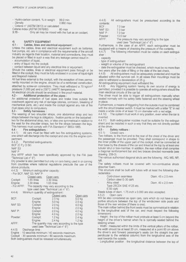
APPENDIX ' r JUNIOR SPORTS CARS
- Hydro-carixin content, % in weigtit 99.0 mln- Density 0.860 max- Cetane n° (ASTM D613)orcalcuiated Cetane index (ASTM D976/80) 60 max3.15 - Oniy air may t)e mixed witfi the fuel as an oxidant.
4) SAFETY EQUIPMENT4.1 - Cables, lines and electrical equipment :Unless the cables, lines and electrical equipment such as batteries, fuel pumps, etc. are in compliance with the requirements of the aircraft industry as regards their location, material and connections, they must be placed or fitted in such a way that any leakage cannot result in :- accumulation of liquid,- entry of liquid into the cockpit,- contact between Ik^uid and any electrical line or equipment.Should the cables, lines or electrical equipment pass through or be fitted in the cockpit they must be fully enclosed In a cover of ilquld-tlght and fireproof material.All fuel lines external to the cockpit, with the exception of lines permanently mounted on the engine, should be of a reinforced construction, attached by screw-on connectors. They must withstand a 70 kg/cm^ pressure (1,000 psi) and a 230°C (446°F) temperature.All electricai circuits should be enclosed In fire-proof material.4.2 - Additional protection of the pipes :An addltlonai protection of fuel pipes and brake lines outside ttie (xrachvirork against any risk of damage (stones, corrosion, breaking of mechanical parts, etc.) and inside the cockpit against any risk of fire (fuel pipes oniy) is compulsory.4.3 - Safety harnesses :The wearing of two shoulder straps, one abdominal strap and two straps between the legs is obligatory ; fixation points on the brxtysheil : two for the abdominal strap, two, or else one symmetrical in relation to the seat for the shoulder straps, two for the straps between the legs. This harness must comply with FIA Standard n° 8853-1985.4.4 ■ Fire extinguishers :4.4.1) Ail cars must be fitted with two fire extinguishing systems,one which will discharge into the cockpit and one into the engine compartment.4.4.2) Permitted extlngulshants :BCF (C F2 Ci Br)NAFS3NAFPAny AFFF which has been specificaiiy approved by the FIA (see Technical List n° 6").Dry powder is also permitted but only on cars being used in or coming from countries where natlonai regulations preclude the use of the above products.4.4.3) Minimum extinguisher capacity :- For BCF, NAF S3, NAF P.
Closed cars: Open cars:Cockpit: 1.65 litres 3.30 litresEngine: 3.30 litres 1.65 litres- For AFFF: The capacity may vary according to the
type used (see Technical List n° 6")4.4.4) Minimum quantity of extinguishant :
Closed cars: Qoen cars.BCF: Coclqjit: 2.5 kg 5.0 kg
Engine: 5.0 kg 2.5 kgNAF S3: Cockpit: 2.0 kg 4.0 kg
Engine: 4.0 kg 2.0 kgNAF P: Cockpit: 2.0 kg 4.0 kg
Engine: 4.0 kg 2.0 kgPowder Cockpit: 1.2 kg 2.4 kg
Engine: 2.4 kg 1.2 kgAFFF: The quantity may vary according to the type
used (see Technlcai List n° 6")4.4.5) Discharge time :Engine : 10 seconds minimum 140 seconds maximum.Cockpit : 30 serxjnds minimum / 80 seconds maximum.Both extinguishers must be released simultaneously.
4.4.6) Ail extinguishers must be pressurised according to the contents:BCF : 7.0 barNAF S3: 7.0 bar : "NAF P : 7.0 barPowder: 13.5 barAFFF: The pressure may vary according to the type
used (see Technical List n“ 6")Furthemiore, in the case of an AFFF, each extinguisher must be equipped with a means of checking the pressure of the contents.4.4.7) The foliowlng information must be visible on each extinguisher:- capacity■ type of extinguishant- weight or volume of the extinguishant- date the extinguisher must be checked, which must be no more than two years after the date of filling or the date of the last check. j4.4.8) All extinguishers must be adequately protected and must be situated within the survival ceil, in all cases their mountings must be able to withstand a deceleration of 25 g.All extinguishing equipment must withstand fire.4.4.9) Any triggering system having Its own source of energy is permitted, provided it is possible to operate all extinguishers should ttie main elecrirical circuits of the car fail.The driver must be able to trigger all extinguishers manually when seated normally with his safety belts fastened and the steering wheel in place.Furthermore, a means of triggering from the outside must be combined with the circuit breaker switch. It must be marked with a letter "E” In red inside a white circle of at least 10 cm diameter with a red edge.4.4.10) The system must work in any position, even when the car is inverted.4.4.11) Both extinguisher nozzles must be suitable for the extinguishant and be installed in such a way that they are not directly pointed at the driver.4.5 - Safety rollbars :4.5.1) Closed cars :Two rollbars, to the front and to the rear of the chest tjf the driver and the passenger must be provided. They shall correspond In shape to the Inner profile of the upper part of the cockpit, shall tre connected at their base by the chassis of the car and linked at the top by at least one tubular strut or box-member. In addition, the rear rolibar shall comprise a diagonal reinforcement bar and two braces directed rearwarels (see drawing 259-3).The various authorised diagonal struts are the following : MQ, MS, NP,NR.The safety rollbars must be covered with non-combustlve shock absorber foam.This structure shall be built with tubes with at least the foliowing characteristics :
Cold-drawn seamless DIam. 45 x 2.5 mmCartxtn steel E-30 daNAlloy steel Diam. 40 x 2.5 mmType 25CD4 SAE 4125 etc.E-50 daN
Steels tubes of diam. 1.75 inch x 0.090 are also accepted.4.5.2) Open cars :Will be also considered as open cars, cars which do not have a supportive structure between the top of the windscreen side posts and those of the rear window (if there is one).The main roilbar behind the front seats must be symmetrical In relation to the longitudinal axis of the car, and must respect the foliowing dimensions :- Height : the top of the rolibar must protrude at least 5 cm beyond the height of the driver’s helmet when he Is normally seated behind the steering wheel.- Width : measured within the limits of the vertical pillars of the rolibar, the width should be at least 20 cm, measured at a point 60 cm above the driver’s and forward passenger’s seats (on the straight line perpendicular to the vertebral column) from the longitudinal axis of the seat towards the outside.- Longitudinal position : the longitudinal distance between the top of
42

APPENDIX •J’ JUNIOR SPORTS CARS
the rolibar and the driver’s helmet when he is normally seated at the wheel must not exceed 25 cm.The structure of the rolibar must conform to the drawing 259-1, or to the drawing 259-3, and to the foregoing table, to the specifications conceming removable connections, and to the General Conslderatior^s. The fitting of frontal struts, facing forward, intended for the protection of the driver is authorised for open cars, on condition that these struts are removable.
Cold-drawn seamless Diam. 45 x 2.5 mmCartx)n steel E-30 daNAlloy steel Diam. 40 x 2.5 mmType25CD4 SAE 4125 etc.E-50 daN
The various authorised diagonal struts are the following : MQ, MS, NR,NR.4.6 - General circuit breaker :The general circuit breaker must cut all electrical circuits (battery, alternator or dynamo, lights, hooters, ignition, electrical controls, etc.). It must be of a spark-proof model, and will be accessible from inside and outside the car. As for the outside, the triggering system must be situated at the lower part of the windscreen pillar on tiie driver's side for closed cars, or at the lower part of the main hoop of the rolibar. either on the right or on the left, for open cars. It will be marked by a red spark in a white-edged blue triangle with a base of at least 12 cm.4.7 - Oil catch tank :Any car with a lubrication system which includes an open type sump breather, must be equipped in such a way as to prevent oil spillage. The oil catching device shall have a minimum capacity of 3 litres. The container shall either be made out of translucent plastic or include a transparent panel.4.8 - Towing eye :A towing-eye (minimum inner diameter : 80 mm) must be securely fitted to the front and the rear of the cars.This towing-eye will only be used if the car can move freely.It shall be dearly visible and painted in yellow, red or orange. It must be located inside the contour of the bodywork.4.9 • Tank fiilers and air vents :The tank fillers and their caps must not protrude beyond the coach-work. The caps must be designed in such a way as to ensure an efficient locking action which reduces the risks of acddental opening following a crash impact or incomplete locking after dosing. The fillers must be placed away from points which are vulnerable in case of acd- dent. The air-vents must be located at places which present no danger.4.10 - Standardised coupling :- The refuelling hose must be provided with a leak-proof coupling to fit the standardised filler mounted on the car. The dimensions of this filler are given in the drawing 252-5.- All cars must be provided with a fuel filler complying with this diagram. This leak-proof filler must comply with the dead-man prindple and must not therefore incorporate any retaining device when in an open position (spring loaded, bayonet, etc.).- The air-vent(s) must be equipped with non return and closing valves having the same closing system as that of the standard filler, and the same diameter.During refuelling the outlets of the air-vents must be connected with the appropriate coupling, either to the main supply-tank or to a transparent portable container with a minimum capacity of 20 litres provided with a closing system rendering It completely leak-proof.- Should the circuits be unable to provide the entrants with a centralised system, these will have to refuel according to the above procedure. In no case may the level of the reserve tank exceed two metres atx)ve the track where the refuelling takes place, for the entire duration of the event.The overflow bottles and the independent storage tanks must comply with the drawings 252-1 or 252-2 and 252-3 or 252-4.• All metal parts of the refuelling system from the coupling over the flowmeter to the tank and Its rack must be connected electrically to the earth.A 90® cut off valve situated close to the main supply tank, controlling the fuel flow, must be manned at all times during refuelling.All hoses, valves, fittings and couplings used must have a maximum inner diameter of 50 mm (2 inches).
4.11 • Petrol tanks :All the cars must be equipped with safety fuel tanks conforming to the specifications F1A/FT3 and supplied by an approved manufacturer.The maximum outer diameter of the lines going from the engine to the tanks is 20 mm and their path must be as direct as possible.The tank(s) may not be placed more than 65 cm from the longitudinal axis of the car and must be located within the limits defined by the front and rear axles of the wheels.It shall be isolated by means of bulkheads so that in case of spillage, leakage or accident happening to the tank, the fuel will not pass into the cockpit or engine compartment or come into contact with any part of the exhaust system.The fuel tanks must be effidentiy protected (see article 4.14). Competitors must provide an illustration of the entire fuel circuit of the vehicle. Low points must be provided for in the circuit enabling ail the fuel to be speedily drained when the vehicle is positioned on a horizontal surface.For hill-dimbs and slaloms if the total capacity of the fuel tanks is not greater than 2 0 1, the safety tank will not be compulsory on condition that the position of the tank does not protrude beyoruj 30 cm in any direction from the tongitudlnal axis of the car, and that it is surrounded by a crushable structure 1 cm thick.The safety tank is also optional for circuit races of less than 100 km under the same conditions of installation.The maximum amount of fuel which may be carried on board is 100 I.4.12 • Headrest :Headrest of a minimum area of 20 x 20 cm must be fitted, covered with non-combustive shock absortxng foam.It must be designed in such a way that the driver's head may not become trapped between the safety structure and the headrest,4.13 - Firewall and floor :Cars shall have an adequate firewall to prevent the passage of fire from the engine compartment or under the car to the cockpit. Openings in the firewall for the passage of engine controls, wires and lines shall be of the minimum size necessary. The cockpit floor shall be constructed to protect the driver by preventing the entry of gravel, oil, water and debris from the road or f i ^ the engine. Bottom panels or belly panels shall be adequately vented to prevent the accumulation of liquid.4.14 - Crushable structures :The bottom of the tanks licked by the airflow shall be protected by a crushable structure, the entire surface of which shall be 1 cm thick.All the petrol tanks shall be at least 20 cm from the lateral flanks and must be protected by a crushable structure, the entire surface of which shall be 10 cm thick.The crushable structure should be a sandwich construction based on a fire-resistant core of a minimum crushirtg strength of 18 N/cm^. Water pipes may be passed through this core, but not fuel, oil or electrical lines.The sandwich construction must include two sheets of 1.5 mm thickness, one of which shall be aluminium alloy sheet having a tensile strength of 225 N/mm^ and minimum elongation of 5 %, or, alternatively, two sheets of 1.5 mm thickness having a tensile strength of225 N/mm2.
4.15 - Survival cell and frontal protection :The chassis must include an impact-absorbing structure fitted ahead of the feet of the driver and passenger. This structure must be independent of the bodywork and, if it is detachable, it must be solidty fixed to the extremities of the side box members of the main chassis (i.e. using bolts requiring the use of tools for removal).It must have a minimum length of 30 cm, a minimum height of 15 cm in any vertical section, and a total minimum cross section of 800 cm^. This structure must be made from a metallic material with a minimum tensile strength of 225 N/mm^ and be of a honeycomb sandwich construction with a minimum skin thickness of 1.5 mm. It must constitute a box. the panels of which will have a minimum thickness of 15 mm, or if the radiator(s) is(are) incorporated into the structure, two continuous box members of a minimum cross section of 100 cm^ on either side of the radiator(s).
43
APPENDIX ' y JUNIOR SPORTS CARS
4.16- Rearview:Rear-view mirrors giving an efficient view towards the rear must be fitted on both sides, (minimum surface 100 cm^ for each one).4.17 - Brakes :The braking system must be designed in such a way that the brake pedal controls all wtieels normally, in the event of any kind of failure in the brake transmission, the pedal shall still control at least two wheels.4.18 ■ Exhaust system :it shall be directed either reanwards or sideways, if the outlet pipes are pointing rearwards, their orifices shall be placed between 45 cm and 10 cm above the ground, if the exhaust pipes are directed sideways, their orifices must be located aft of a vertical passing through ttie wtieelbase centre plane and may not project in any way tjeyond the bodywork.4.19 - Position of the pedals :Tfie axis of the pedals must never be situated to the fore of the axis of the front wheels.
N.B. : The prescriptions under art. 4.15,4.19, 3.1,4.5.1 and 4.5.2 are compulsory for any new car built as from 1st January 1987. The cars which were built tiefore this date are admitted, provided that proof of the date of construction is supplied. ■'in the case of the latter : ^- article 3.1 : The prescriptions conceming the sum and the differenœ of the overhangs are not to be respected, nor is the maximum width of 200 cm, which is then fixed at 210 cm.- articie 3.3.4 : The minimum width can be reduced to 110 cm, and to 100 cm for cars of less than 1000 cm^.- article 4.5.1 and 4.5.2 : Tfie dimensions of the tubes for the roiltjars should then be respectively :. 42.4 x 2.6 mm for cartxrn steel . 35 X 2 mm for alloy steel.
• V
t
44
A rticle 261 - T echnical reg ulatio ns for class i cars
The present Technical Regulations will be valid from 01.01.1996 until 31.12.1997. Changes made to the Regulations in this period are oniy possibie- if provisions of the Sporting Code are changed,- in case of possibie legal provisions,- for safety reasons or- due to “force majeure"Moreover, the FIA reserves the right to modify the Technical Regulations In compliance with the following time limits:- All changes must be published by the FIA on 30th June at latest; all such changes will take effect on the 1st January of the following year.- The first possible change, however, may take effect on 1st January 1996 at the earliest- The tjasic weight for two-wtieei and four-wheel drive cars may be modified until 1st October, taking effect for the year following.As far as the admitted noise level and the checking procedure are concerned, the FIA can also decide about changes at short notice. In case of dispute over the interpretation of the present regulations, only the English text will be binding.
1) DEFINITIONS1.1 - Series Model:Any passenger car of a manufacturer. At least 2500 identical units must have tjeen produced in 12 consecutive months. Series models must be available through the nonnal commercial channels of the manufacturer.1.2- Modelline:Different series models belonging to a production series of one manufacturer. At least 25000 cars with identical external general lines of the tx)dywot1< according to articie 2.1.1 must have been prtxiuced in 12 consecutive months.1.3- Basic model:The series modei of the iine chosen as the basic modei for the competition car. At least 2500 identical units must have been produced in 12 consecutive months. The basic model defines the bodywork of the competition car.1.4 - Competition canThe competition car originating from the tasic model and prepared for the International Touring Car Series in compliance with ttie present regulations.1.5- Manufacturer:Car manufacturer who is a member of the FIA Manufacturers' Commission.1.6 - Power transmission version:The drive unit construction between engine and wheels.The distinction is made between tw o -w fi^ drive and four-wheel drive. The drive version chosen is recorded on the FIA Vehicle Specific Form and determines ttre vehicie type.1.7- Basic engine:Ttie engine of a manufacturer installed in a quantity of at least 2500 engines in series models of the same manufacturer.1.8- Engine compartment:Volume defined by the first structural envelope surrounding the engine. The structural envelope is part of the engine compartment. The Ijul- khead separates the engine compartment from the passenger compartment1.9- Appendix J:Binding text of the current FiA International Sporting Code.1.10 - Mudgards:Front: The area defined by the inner face of the complete wheel of the tiasic rtradel (C1/C1) and the lower edge of the side window(s) (A/A) and the front edge of ttie front door (B1/B1 ).Rear The area defined by the inner face of the complete wheel of the basic model (C2/C2) and the lower edge of the side window(s) (A/A) and the front edge of the rear door (B2/B2).
In the case of two-door cars (B1/B1) and (B2/B2) will be defined by the front and rear edges of the same door. (Drawing 261-1)1.11- Material family:Is defined according to the main constituent of the tiasic alloy of the corresponding series part.1.12- Consumption substances:Substances carried on board primarily for the puqxise of consumption during the competition.Lubricating, coolant, brake and hydraulic fluid used for the competition car do not count as consumption substances.1.13- Cylinder Capacity:Volume V generated in the cyiinder/s by the upward and downward movement of the pistons.V = 0.7854 xb 2 + x h x zb = tiore in cmh = stroke in cm z = number of cyiindersV = volume in cm^1.14- Engine block:The crankcase and the cyiinders.1.15- Bodywork:Externally: all the entirely suspended parts of the car licked by the airstream.intemally: cockpit and boot1.15.1) Cockpit:Structurai inner volume of the basic modei which accommodates the passengers. For cars witfiout a fixed bulkhead between the cockpit and the luggage compartment, the cockpit is iimited by the rearmost point of the seats reclined at a maximum angie of 15° to tfie rear in the basic mrxlei.1.15.2) Lugga^ compartment:Any volume distinct from the cockpit and the engine compartment inside the vehicle. These volumes are limited in length by fixed staic- tures provided for by the manufacturer and/or by rear of the seats reciined, if this is possible, at a maximum angle of 15° to the rear. These volumes are limited in height by the fixed stnjctures and/or by the detachabie partitions provided for by the manufacturer or, in the absence of these, by the horizontal plane passing through the lowest point of the windscreen.1.16- Wheel:Flange and rim.1.17- Complete wheel:Flange, rim and tyre.1.18- Free:A free part may be machined and aitered in every respect, and may also be replaced by another part or parts with the same purpose. Total freedom exists with regard to the material, the form and the number. This means that the part can be totally omitted.1.19 - Modification:Alteration of the construction (according to the dimensions) and/or of the material.1.20- Active system:In an active system an actual value is continuously monitored, is conti- nuousiy compared with a reference value and is automaticaliy adjusted according to the result of the comparison.
2) GENERAL2.1 - Eligible Cars:2.1.1) Origin of the CarThe series modei chosen as the basis for the competition car must originate from a manufacturer's modei line of which at least 25000 identical examples with the minimum length of 4.30 m must have been produced in twelve consecutive months. All series models must be available through the nomial commercial channels of the manufacturer. The term "model line” describes a series of cars with ttie same three
APPENDIX "X CLASS 1 CARS
dimensional bodywrark shape. They may vary in the folbwing details:- shape and material of front and rear bumpers,- removable aerodynamic devices (spoilers, wings, sill mouldings, etc.),- control and comfort items (sun roof, auxiliary lamps, door handles, exterior mirrors, etc.),- decorative strips and mouldings,- left and right hand drive versions,- 2- and 4-door versions, provided that these differ only with regard to the doors, door openings and B-pillar.2.1.2) Basic model:The series model. It must have been produced in a quantity of at least 2500 identical units in 12 consecutive months and must originate from the model line described in article 2.1.1.2.1.3) Interior dimensions:It must have at least 4 seats (two front, two rear) and the following minimum interior dimensions:B = 93 cm;C = 120 cm;D = 93 cm;E = 120 cm;H = F+G = 210 cm. (Drawing 261-2)The heights B and D must be determined using the FIA measuring device. (Drawing 261-3)2.1.4) Minimum length:The basic model and the competition car must have a minimum length of 4.30 m.2.1.5) Technical variations:The following technical variations are permitted provided that from the 25000 series models of the model line at least 2500 cars of one model of the manufacturer are built in a period of 12 consecutive months with the technicai variations below:- non metallic wheel suspension parts.All parts with these technicai characteristics must be functioning and in compliance with EEC standards.If the minimum number of 2500 engines from the same type with cylinder heads with more than 4 valves per cylinder are built in any series models of the manufacturer in a period of 12 consecutive months, the cylinder head of the competition engine may have the same number of valves per cylinder.2.2 - Approval of a series model:Applications to enter a series model must be submitted to tfie FIA. A|3proval will be given by the FIA after the verification of all details by a representative of the FIA Technical Department and the Technical Delegate in the presence of one competitor chosen by all the manufacturers, and the FIA Vehicle Specific Fomi will be issued. After the acceptance of the Class 1 Vehicle Specific Form, each technical chan^ of parts/elements which are described in the Ciassi Vehicle Specific Form or are necessary for issuing the Class 1 Vehicle Specific Form, must be submitted in writing (possibly with photos) to the FiA Technical Department. At the same time a draft of the planned technical change must be submitted to all the manufacturers, but only the FIA may decide whether this request is authorised.2.3 General:The competition cats must comply with all points of the present regulations arid be in conformity with the corresponding car's specification sheet. The use of standard parts in the competition car, which are not in confbmiity with the present regulations, is not allowed. All modifications which are not expressly allowed or prescribed by the present regulations are forbidden.
3) ENGINE3.1 - Type of the admitted engine:The engine must originate from the basic model or another series model made by the same manufacturer. However, at least 2500 identical units of the engine must have been mounted in series models produced by the same manufacturer in 12 consecutive months.The tiasic engine determines the cylinder distance, the cylinder angle and the material family of the engine block for the competition engine. The cylinder angle is the angle between the cylinder axis laid through the crank-shaft axis (Drawing 261-4). The cylinder distance is determined through the distance of the cylinder axis.The following data are binding:
- one OTTO-engine, four-stroke, with reciprocating pistons only,- max. 2.5 litres cylinder capacity,- max. 6 cylinders,- max. 4 valves per cylinder or in accordance with article 2.1.5. Supercharging is not allowed. This means: Any mechanical or thermodynamic measures to increase ttie weight of the charge of the fuel-air mixture in the comtxjstion chamtier are not allowed. Ram effects or dynamic effects in the intake and exhaust system are allowed.3.2 - Engine block:The engine block as specified in 3.1 must tie used.The following points must be observed for the construction of the competition engine block:- Stroke and bore are free.- The stroke must be linear and the bore cylindrical.- Sleeving is allowed.Cylinder distance, cylinder angle and material family of die engine block must correspond to the basic engine.Machining through removal or addition of material and the addition or removal of a maximum of 2 cylinders through casting technique is permitted (Drawing 261-4).3.3 - Cylinder head:The constructional design of the cylinder head is free with due regard to the provisions of article 2.1.5.3.4 - Mechanical parts of the competition engine:Free. Connecting rods and crankshafts however, must be made of the same material family as the original parts of the basic engine. Connecting rods made from titanium are not allowed. Crankshaft and connecting rod bearings are free but the original principle (e.g. sliding bearings) must be retained. The distances between the crankshaft bearings must not be altered.3.5 - Admission and Ignition:Free, but maximum aliowed engine revolutions are 12000 rpm and the prescribed FIA-RPM limiting device must be included, which must be installed according to the prescriptions of the limiter manufacturer. This RPM limiting device must be installed in such a manner as to be directly and easily accessitXe, to facilitate inspection and testing procedures which are to be carried out by the Scrutineer or other approved FIA personnel. The RPM limiter must be installed and wired up strictly in accordance with the limiter manufacturer’s instructions and any wiring diagrams issued. The regulation wiring plug seal must always be intact.The limiter will be ctiecked and certified as and when deemed necessary throughout the event.The rev-limiter, prescribed and made available by FIA, has only the function of control in the sporting legai context, independent of its working method. This means: The drivers/competitors are themselves responsible for compliance with the maximum permitted rpm. Eventual speed tops appearing not under charge, as for example during shifting down or at bumps, will be judged by a judge of fact Variable lengths and variable diameters of the inlet trumpets and inlet ports are fortiidden (exception: throttle valves or throttle slides for load regulation of the engine).Water injection and the use of any other devices or substances to reduce the temperature of the fuel/air mixture are fortiidden. Any spraying or injection of water or any other substances is prohibited, with the exclusion of fuei injection for combustion in the engine.3.6 - Exhaust system:Free, but variable lengths and variable diameters of the exhaust ports and exhaust manifolds are forbidden, as is a throttle valve in ttie exhaust manifold.FIA homologated catalytic converters equipped with a lambda-probe are prescribed. Ail exhaust gases must at all times pass through the catalytic converter/s.The undertxxJy and bulkhead may be modified for the installation of the exhaust system, but these modifications may only serve to accommodate or provide clearance for the exhaust system.The exit point of the exhaust gases must be within 10 cm of the rear of the car. (Drawing 261-5)Maximum exhaust noise must not exceed 95 + 2 dB(A) + 3 %, measured according to the FIA close-range ctiecking prorîedure.3.7 - Cooling and lubrication:Free. However, all radiators must be fitted in the same compartment as in the original car (for example in the engine compartment). Dry sump
46
APPENDIX “J’ CLASS 1 CARS
lubrication is permitted. Coolers must not protrude beyond the bodywork of the competition car. No other coolants apart from water, ambient air and oil may be used. Spraying of the coolers with water and/or the use of any other substances such as dry ice is not allowed. Anti-freeze and anti-c»nrosive additives are permitted.If the lubrication system includes an open type sump breather, escaping lubrication substances must be conducted into a reservoir of at least 3 litres capacity. This reservoir must be transparent or have an inspection window.3.8 - Engine ancillaries and auxiliaries:All engine auxiliaries and ancillaries of the competition engine are free including their position and type of drive, but they must be driven electrically or mechanically by the engine of the car. They may not be placed in the passenger compartment (except electronic control elements).Auxiliaries are;- starter- generator- servo pumps and tanks- oil pumps, oil filters and oil tanks- water and fuel pumps- ventilators- parts of the electrical system of the engine Ancillaries are:- intake system for combustion air- coolers for engine liquids including air compartment- ductings in the engine compartment- cooling air supply in the engine compartment3.9 - Engine Installation:The orientation of the competition engine and its position within the original engine compartment are free. All necessary modifications in the engine compartment to mount the engine, the auxiliaries and ancillaries, fuel feed and the exhaust system are free. The original bulkhead of the basic model (separating the engine and passenger compartments) forms the rear limit to the position of the competition engine within the engine compartment of the race car. This spatial limit Is valid, even if the original bulkhead no longer exists due to modifications allowed by the technical regulations.3.10- Starter:A starter with electrical or other source of energy is compulsory. It must be able to be controlled by the driver when seated normally in his seat. It must be possible to start the competition engine using the starter at any time.3.11 - Other engine components:Gaskets, springs and supports on the competition engine are free.
4) TRANSMISSION4.1 - Clutch:The clutch and clutch operating system are free.Lubrication, air and oil cooling devices are allowed, but must have no aerodynamic effect.4.2 • Gearbox:The gearbox is free. Semi-automatic gearboxes as well as mechanical gear-shift systems with a maximum of six forward gears are allowed. Semi-automatic gearboxes may be driven by automatic control and may, for the purpose of changing a gear ratio only, momentarily take control of the propulsion system away from the driver. The car must have a reverse gear in working order.The casing of the gearbox must be made from metallic material.The geartx)x must be mounted in the original location (In front of or behind the wheelbase centre) of the geartox on the basic model. Modification of the transmission tunnel and the engine compartment is permitted provided that the modifications are made for the sole purpose of installing the geatbox and the driveshafts. The drive flange at the geartx)x output must be located in front of the wheelbase centre line except in competition cars with the same transaxle design as the basic model.The gearbox mountings are free.Lubrication, air and oil cooling devices are allowed, but must have no aerodynamic effect.4.3 - Drive train:The drive train layout (front-wheel drive, rear-wheel drive or four-wheel
drive) Is free. If a four-wheel drive version is used, it is permitted that only the front or the rear wheels are driven.Axle transmissions and ratios, limited slip differentials, drive shafts between engine and final drive(s) as well as the wheel drive shafts are free. However, the casing of ftie final drive and differentials must be made from metallic material. The body may be modified to allow for their installation. Lubrication, air and oil cooling devices are allowed, but must have no aerodynamic effect.
5) SUSPENSION5.1 - Wheel suspension:The wheel suspension includes all parts necessary for the wheel control with the exception of the suspension springs and damping. Springs, shock absorbers and stabilisers and their position are free. Active trim height regulation, active track regulation (active toe-in / toe- out control) and active wheel camber regulation are forbidden. Necessary mounting points may be installed.5.2 - Front suspension:The operation principle of the front suspension is free. Necessary mounting points may be installed. However, the wheelbase and the front overhang must be respected as indicated in the Vehicle Specific Form.5.3 - Rear suspension:The operation principle of the rear suspension is free. Necessary mounting points may be installed. However, the wheelbase and the rear overhang must be respected as indicated in the Vehicle Specific Form.5.4- Other m odifications allowed:The suspension components and the bearing principle are free. Axle supports (sub-frames) are free. The frame side members may be modified locally for the installation of the wheel drive mechanism. The use of suspension components made of non-metallic material is prohibited subject to article 2.1.5.Bars may be installed between the suspension mounting points.
6) STEERINGThe steering, including the location, suspension mountings and links, steering column and steering wheel, is free. For the installation of the steering system and its mountings, local modifications of the bulkhead are allowed, but these modifications may only be made in order to allow the installation and operation of the steering. The number of steered road wheels must be the same as on the basic model.
7) BRAKING SYSTEMThe braking system is free subject to the following provisions:The car must have a dual circuit braking system.The brake lines must be made in accordance with Art. 253.3 of the Appenidx J.Brake discs of non-metallic material are not allowed.The cooling of brakes is free but ambient air is the only cooling medium allowed.One air duct per brake with a maximum section of 170 cm^ is allowed. This section may not be exceeded for at least 2/3 of the distance between the intake and outlet orifices. The intake orifice in the area of the bumpers and the outlet orifice in the area of the brake are free. The ducts, however, must not protrude outside the perimeter of the car as seen from above (Drawing 261-7).
8) WHEELS AND TYRESThe wheels (maximum allowed number fitted on the competition car 4) and tyres (maximum allowed number fitted on the competition car 4) are free. The wheels must be made of metallic material. The maximum diameter of the complete wheel is 650 mm. The maximum total width of the complete wheel is 10 inches. Wheels with a central locking system must be equipped with a safety device. The housing of the complete wheel must be made in such a way that the upper part of the mounted complete wheel including the rim flange Is covered by the wings or the bodywork, in vertical projection as seen from above (Drawing 261-6).Method of measuring the wheel width:1. The complete wheel mounted on the competition car resting on the ground, the car in running order, with the driver aboard at the steering
47
APPENDIX "J" CLASS 1 CARS
wheel. The measurement can take place at any point of the complete wheel except where the surface of the wheel is in contact with the ground.2. The complete wheel disassembled, with the tyre at normal running pressure.
9) BODYWORK9.1 - General bodywork:The strengttiening of the bodywork is allowed provided that the material used is original and follows the original shape and is in contact with it. Reinforcements made from composite materials, whatever their thickness, are allowed in compliance with this article and according to the relevant drawing for those parts which are screwed to the body. (Drawing 255-8)All nuts, bolts and screws are free provided that they are not specifically defined try the present regulations. Insulation material and corrosion preventatives may be removed.It is allowed to close standard holes in the cockpit, the engine compartment and the wings by using metal or fire-proof plastic material. This may be done by welding, bonding or riveting. The other holes in the exterior bodywork may be closed by adhesive tape only. Unused supports situated on the bodywork can be removed.Thie tolerances for the sheet metal thickness of the bodywork are0.15 mm.9.2 - Exterior:The material of the engine bonnet, front wings, txxrt cover, bumpers, the rear doors of four-door cars and the attachments at the sides is free (except rear wings). It is allowed, to cut the front wings from the A-pillar area to the wheel opening in order to create a removable unit comprising the engine bonnet and the front wings.The external shape of the engine bonnet, the boot cover and the bumper parts located atXDve the wheel hub centre on the competition car must correspond to the basic model.All parts to the body must be solid. Modifications of the original wheel arches and the installation of wheel arch extensions are permitted subject to the following conditions:- The shape of the front wings and the original rear wings must be retained.- The external contour of the original wings within a 400 mm radius measured from the wtieel hub centre is free.The radius of the upper edge of the wheel arch extensions (transition section to the vehicle body) is limited to 500 mm (measured from the wheel hub centre) and must be kept within an angular range of 60 degrees to the front and rear of the vertical plane through the wheel hub centre. Outside of this range, the edge of the wheel arch extensions may pass over into the vehicle body beyond the 500 mm radius (Drawings 261-11 and 261-12).The upper edge may not protrude above the contour of the original wing. The wheel arch extensions may exceed the total width of the basic model as laid down In the FIA Vehicle Specification Form by 3 % at maximum.The inner wheel housings may be modified.All measurements and controls will be carried out with the car in racing condition and without the driver.External decorative strips and protective mouldings may be removed. There must be at least one windscreen wiper in working order. Pneumatic jacks are permitted.The engine bonnet and boot cover must at all times remain in their original and completely closed position as determined by the basic model. It is prohibited to raise the bonnet or cover. The attachment of the engine lionnet and boot cover is free.9.3 • Windows:The use of safety glass panels with a thinner glass than In the basic model is permitted provided that the panels have a suitable test mark (EEC-standards, Motor Vehicle Construction and Use Regulations - CUR). The principle of mounting is free. The windsaeen must be made of laminated glass or of hardcoated and appropriately marked polycartxjnate.Additional fixings for the windows are allowed provided that they do not have an aerodynamic effect. The following maximum dimensions for the clips must be respected:
Width: 33 mmMaterial thickness: 3 mmLength: 75 mm9.4 - Interior:The driver's seat Is free. It must have a headrest with dimensions ensuring that the driver's head with his helmet is retained with no possibility of tfie head being trapped between the headrest and the roll trar.The seat and the mountings must comply with ttie FIA regulations. An appropriate certification by the seat manufacturing company must be submitted. The driver's seat must bear a test certification mark showing the seat serial number and the year of manufacture. Seats which are more than three years old may not be used.It must be possible to move the driver's seat backwanJs but the bottom of the front seat cushion must not go beyond the vertical plane determined by the front edge of the rear seat in the basic model (Drawing 261-13).All other seats must be removed.The shape of the dashboard must be identical to that of the basic model. The material Is free. On the driver’s side up to the car centre line it is allowed to reduce the dashboard down to the plane which runs through the lower edge of the complete transparent area of the standard windscreen and parallel to ttie door members. The remaining form of the dashboard may not be changed by these measures. The trimmings situated trelow the dashboard and the centre console may be removed. The Instruments are free. (Drawing 261-14)It Is permitted to remove Insulating and padding material, roof lining, side trim and floor coverings.The interior door trim and soundprrxjfing material may be replaced by non-flammable material. The doorslde hinges of the rear doors are free. There must tie 2 hinges per door. Window winders are free provided that their continuous function is maintained at the front doors. Heating and ventilation are free but an effective demisting for the windscreen must be provided. Fresh air may be routed into Bie passenger compartment via a maximum of two additional openings and extracted from it via a maximum of two additional openings. The cross-section area of these Intakes and outlets must not be more than 80 cm^ per opening. For air extraction two openings may be made with max. 80 cm2 per opening in an 8 cm wide area parallel to the outer edge of the rear window. The max. allowed length of one opening is 40 cm. They must only be Intended for the ventilation of the cockpit The car's extemal shape may not be altered by this. The advertising regulations must be strictly respected.Lines containing liquid may only pass through the cockpit if they do not have any connections in the coclqxt. The passage at the bulkhead and at the rear separating bulkhead must be executed In conformity with drawings 253-1 and 253-2 with the exception of txake lines and txake components. The lines must be made In accordance with Art. 253.3, App. J.The fitting of assembly openings to the inside of the body Is permitted provided that they are reclosed with the same material and form.All additional accessories which have no influence on the car’s handling are allowed. In no case must such accessoires affect, either directly or Indirectly, the engine power, the steering, ttie transmission, the brakes or the roadholding.The pedals Including their mountings are free. A local modification of the bulkhead and of the floor panel Is permitted provided that the only purpose is the installation and operation of the p ^ ls .9.5 - Ground clearance:No part of ttie competition car except the tyres must touch the ground when both tyres on one side are deflated. Both valves on one side will be removed to check this.This test will be carried out with the competition car in race trim with full tanks and the driver on board.
10) AERODYNAMICSAerodynamic modifications at the front, the sides and the rear below the wheel hub centre are free subject to the requirements for ground clearance, overall length and overall width (Drawing 261-9). Tfie material of the aerodynamic devices at the front, rear and the 4 jes Is free. Any specific part of the car Influencing its aerodynamic performance:- Must comply with the rules relating to bodywork.
APPENDIX 'J" CLASS 1 CARS
- Must be rigidly secured to the entirety sprung part of the car (rigidly secured means not havir^ any degree of freedom).- Must remain immobile in relation to the sprung part of the car.The aerodynamic modifications may not protrude laterally into the bottom of the car by more than 100 mm and they must pass over the car’s floor at an angle of max. 135“ (Drawing 261-8).From the front, they may extend as far as the front edge of the front tyre and from tine rear as far as tfie rear edge of the rear tyre. These aerodynamic devices may exceed the total width and length of the t>asic model as laid down in the FIA Vehicle Specification Form by 3 % at maximum (Drawing 261-9).Notwithstanding the silhouette of the basic car, aerodynamic devices at the vehicle’s rear, above the wheel hub centre, are permitted subject to the following requirements;They must be within the frontal projection (without outside mirrors) and the total length of the basic model.Their lateral projection, including all mountings, must fall within a 20cm square, viewed along a line parallel with the vehicle’s transverse axis (Drawing 261-10).
11) ELECTRICAL SYSTEMThe nominal voltage of the electrical system of the basic model must be retained. Otherwise, the electrical system is free.Electronic control devices may be mounted in the cockpit.The battery is free. Each battery must be securely fixed and covered to avoid any short circuit or leaks. Its location is free, except that It must not be located in the cockpit.The lighting system is free but must be in conformity with the basic model concerning its optical effect and Its exterior contour. The basic functions, dipped beam. Indicators, hazard waming system, rear lamp, rear fog lamp (right and left 21 W each) and stop signal must be operational. The licence plate illumination may be omitted.
12) FUEL SYSTEM12.1- Fuel tanks:The capacity of the complete fuel system is free.Only safety fuel tanks complying with the specifications of article 253, Appendix J, (FT3) are admitted. They must be placed inside the luggage compartment and/or in the area between the middle of the wheel base and the middle of the rear axle of the basic model. Only 1 fuel tank vflth a maximum capacity of 70 I in the rear boot is allowed. Bodywork modifications on the underside of the car are allowed only for the mounting of the fuel tank(s). The mounting of an underbody protection to cover the fuel tank(s) is permitted, provided that it does not have an aerodynamic effect.The refuelling orifice(s) must not be placed in the cockpit.The fuel pumps are free.It is permitted to place a collector tank with a maximum capacity of 1 litre in the engine compartment.A fire-proof and liquid-proof bulkhead must be installed between fuel tank and passenger compartment12.2 • Fuel circuit:All fuel lines must be made in accordance with Art. 253.3, App. J. A filter with a maximum capacity of 0 .5 1 is permitted. It is allowed to integrate in the fuel circuit a fuel cooler with a maximum capacity of 1 I but ambient air is the only cooling medium permitted.12.3 - Automatic fuel cut-off:All fuel feed pipes going to the engine and retum pipes from the engine must be provided with automatic cut-off valves located directly on the fuel tank which dose all of these fuel lines automatically if one of the lines under pression in the fuel system is fractured or leaks.The vent lines must also be provided with a gravity activated roll-over valve.All fuel pumps must only operate when the engine is running, except during the starting process.
13) SAFETY DEVICES13.1- Exterior mirrors:Free. However, the car must t>e fitted with two rear view mirrors, one fitted on each side of the car. Each mirror must have a minimum area of 90 cm2 a 6 cm square must be able to fit in each mirror area. The driver, normally seated and with his seat belts fastened, must be
able to see a car, moving or standing still, laterally behind him. The Scrutineer may carry out this test at any time.13.2- Rollover structure:Complying with article 253, Appendix J. Because the seating position of most drivers is far in the rear of the car, the following stnjts of the roll- cage and the following inner bodywork parts (Drawing 261-17) have to be padded:1. The B-pillar on the driver's side.2. The lateral cross-struts on the driver's side.3. The main bar on the driver's side.4. The side bar on the driver's side.5. All diagonal struts and cross-bars in the area of the driver's head.6. All cross-t)ars in the area of the driver’s knees.See drawing 261-17 for explanation. All paddings have to be made individually according to the construction of the rollcage of the car.A transversal protection in the vicinity of the front doors, t>etween the front and rear rollover bars is obligatory. Reinforcements up to 1/3 of the door opening are allowed. All transversal protection variants as per article 253, /Appendix J, both single and in combination, are allowed. This area may also be reinforced with additional lengthways or vertical protections.The only protections permitted above the height of 1/3 of the door opening shall be the upper attachment points of a cross-strut between the front and rear rollover t>ars. The upper attachment point must not be placed higher than the centre of the door opening. The lower attachment point must t>e placed directly on the longitudinal member. If the rollover structure is located in front of or behind the door cut-out, this height limitation is also valid for the corresponding intersection of the cross-strut and the door cut-out The cross-struts may be curved towards the outside.Reinforcements in the doors are recommended for all cars, for instance as per U.S. starxlard SMV S3 214 (Drawing 261-15).To increase the side impact protection for the driver, it is allowed to install crash-pads in the doors, which support them extensively to the lateral protection of the roll cage.For the installation of the crash-pads. modifications to the relevant areas of the inner side of the driver’s door are allowed. However, the door outer skin must not be modified.Furthermore the modifications must not interfere with the function of the door latching mechanism.A continuous opening of the front side windows must be possible, but the opening of the side windovfô may be reduced only through the crash-pads.13.3- Safety belts:The seat belts must be six-point harnesses with six anchorage points on the car In conformity with the FIA standard. The shoulder and abdominal straps must engage in the buckle separately.13.4 - Fire extinguishing systems:A fire extinguishing system with a content of at least 4 kg extinguishant according to the FIA specifications In article 253 Appendix J. ISC. is obligatory. The arrangement of the pressurised containers Is free but may not t>e installed in the cockpit. The system must empty at least into the engine compartment and cockpit, but other mechanical parts vulnerable to fire and difficult accessible areas of the car must also be covered by the built-in extinguishing system. The extinguishing system nozzles must be installed in such a way that they are not directed towards the driver.13.5 - Additional fasteners:At least two additional safety fasteners must be fitted for each of the bonnet and boot lids. The original locking mechanisms of the basic model must be rendered inoperative or removed.Objects carried on board the car must be firmly fixed.13.6 - General circuit breaker:The general circuit txeaker must cut all electrical circuits aixl stop the engine. It must be a spark-proof model and accessible from inside and outside the car. As for the outside, the triggering system of the circuit breaker must be marked by a red spark In a white-edged blue triangle with a base of at least 12 cm.13.6.1) Positioning of the triggers for the fire extinguishing system and for the general circuit breakerThe external triggering systems for the fire extinguishing system and for the general circuit breaker must be positioried either t>elow the windscreen on the driver's side and freely accessible, or in the right
49
APPENDIX -J- CLASS 1 CARS
and left C-plllar. In case of a positioning in the C-piilar, the following regulations are applicable: they must not protrude beyond the bodywork. These triggers must be electrical, annular push-pull switches, which can be operated by a marshal by means of a hook even from a greater distance. In order to ensure this, the Interior ring diameter must be at least 30 mm (Drawing 261-16).It Is permitted to secure this push-pull switch against accidental release by means of a wire with a maximum thickness of 0.2 mm. These triggering systems must be marked according to their function (see article 253, A p^ndlx J). The holes In the C-plllars which accommodate the switches may be covered by a film under the following conditions:1. The film must be transparent, so you can see the annular push-pull switches.2. The max. allowed film thickness Is 0,25 mm.3. The film must have a perforation, which can be tom easily.13.7 - Towing eyes:A towing eye (eye bolt, round or oval) with a minimum Inner clear diameter of 50 mm must be securely fitted to the front and the rear struc
tures of the car. It must be marked, freely accessible and solid so that the car can be moved. A hinged version Is permitted.13.8 - Fire bulkhead:An efficient protective screen must be placed between ttie engine and the passenger compartment In order to prevent the direct passage of flames and liquid.
14) THE WEIGHT OF THE COMPETITION CARThe minimum weight of tfie œmpetitlon car without driver txrt Including all consumption material at the moment of weighing Is 1040 kg regardless of the drive version. The car must comply with this minimum weight - which may be Increased by the handicap weight and the finish weight (see articles 13 and 16 In the Sporting Regulations) - at any time during an event.
50
A rticle 262 - T echnical r eg u la tio n s FOR SUPER TOURING CARS (G rO UP ST)
1) GENERAL1.1 These Technical Regulations apply to large-scale series production touring cars of a minimum overall length of 4.20 metres and a maximum engine capacity of 2 litres, and having the engine installed In the front part of the car. These cars must tie homologated in Super Touring by the FIA.1.2 Closed-loop electronic control system:Electronically controlled system in which an actual value (controlled variatjie) is continuously monitored, the feedback signal is compared with a desired value (reference variable) and the system Is then automatically adjusted according to the result.1.3 Decorative strips:Any parts following the external contour of the bodywork and less than 25mm high.1.4 Action of signal:Any signal which causes the vehicle to respond must be directly activated by the driver alone and not by the operation of other vehicle controls activating a switch.1.5 Signal from the ECU:Any signal from the ECU to control vehicle systems other than those directly related to the engine is prohibited.1.6 Computer systems :It must be possible to upload machine code from all onboard computer systems. The method of uploading must be compatible with Scrutineer's equipment.1.7 Land vehicle:A locomotive device propelled by Its own means, moving by constantly taking reai support on the earth's surface, of which the propulsion and steering are urider the control of a driver aboard the vehicle.1.8 Active suspension:Any system which allows control of any part of the suspension or of the trim height when the car is moving.1.9 Semi-automatis geartrox:One which, when the driver calls for a gear change, takes over the control of one or more of the engine, clutch and gear selectors momentarily to enable the gear to be engaged.
2) FIA APPROVAL2.1 The vehicle must comply with all the dimensional and other FIA Super Touring homologation requirements, except for those additional nrodlfications allowed in these regulations. In particular, this car must belong to a family produced In a quantity of at least 25,000 units with identical external silhouettes and shells.2.2 Homologation of a car will become null and void 5 years after the date on which the series production of the said model has been stopped.2.3 Homologation forms (available from the ASN) must be presented, describing ttie vehicle and engine used.
3) WEIGHT3.1 All cars using front-wheel drive oniy must not weigh less than 975 kg.All cars using rear-wheel drive only must not weigh less than 1000 kg. All cars using four-wheei drive must not weigh less than 1040 kg.3.2 The minimum weights specified in art. 3.1 must be compliedwith at any time during the event, in particular at the time the car crosses the finishing line, excluding the driver and its equipment.The use of trallast is permitted in accordance with Appendix J, article252.2.2 - General Prescriptions.Weight is used as the only controlling element between front-, rear- and 4-wtreel drive cars.
4) MODIFICATIONS ALLOtNED4.1 General conditions:4.1.1) Any nut bolt or screw throughout the car may be replaced
by any other nut, bolt or screw and have any kind of locking device (washer, lock-nut, etc.).4.1.2) Apart from the parts for which the present reguiation lays down freedom of modification, the original mechanical parts necessary for the propulsion, suspension as well as all accessories necessary for their normal functioning, excepting any steering or braking part, having undergone the normal machining operations laid down by the manufacturer for series production may be sutijected to all tuning operations through finishing, scraping but not replacement.In other words provided that the origin of the series production part may always be established, its shape may be ground, balanced, adjusted, reduced or modified through machining. Chemical and heat treatment are allowed, in addition to the above. However, the modifications defined by the above paragraph are allowed on condition that the weights and dimensions mentioned on the homologation form are respected.4.1.3) Addition of material and parts:Any addition of material or parts is not permitted unless It is specifically allowed by an article In these regulations. Any material removed is not to be reused.Restoration of body shape and chassis geometry, following accidental damage, is permissible only using original panels or parts or by the addition of the materials necessary to effect the repairs (body filler, weld metal, etc.); other parts which are worn or damaged are not to be repaired by the addition or attaching of material unless an article in these regulations allows appropriate freedom.4.2 Engine:4.2.1 ) The engine must be of the same make as the car and must be homologated by the FIA in Super Touring. The orientation and direction of the axis of the original eriglne relative to the homologated bodyshell must be retained. The engine revolution direction is free, provided art. 4.2 is respected.Two-stroke engines are prohibited.Any device to artificially limit the engine speed/power below the peak of the engine power curve will Ire deemed to tie artificially controlling power and is therefore prohibited with the exception of a rev limit above 8200 rpm whose sole purpose is to control the engine below an FIA approved limit. For the purpose of changing a gear ratio only it is momentarily permitted to take the control of ttie propulsion system away from the driver.4.2.2) Engine block:The engine must have no more than 6 cylinders. Bore and stroke may be changed to achieve a maximum capaci of 2000 cm^. The bore is required to be cylindrical and the stroke linear. The position and the axis of the ports must be retained. The axis of the cylinders may be moved, but they must remain parallel to the original ones.Sleeving or resieeving of the cylinder bores is allowed; material of the sleeves is free. Machining of all surfaces is allowed; material may tre added. Steel, or other material, main caps are allowed, as are ladder reinforcement frames, inside the block and following the bearing supports.4.2.3) Cylinder head;The position and the axis of the cylinders and ports must be retained, as must the axis and angle of the valves. Port sizes may be changed, but the port centres at the manifold face must remain original ( 2 mm). The addition or removal of material Is allowed subject to the restrictions in ttiese regulations (see In particular art. 4.2.12).The cylinder head covers (rocker covers) are free, including their mate- riai, if these parts have no other function than covering the cylinder head, and possitjiy that of attaching the engine.4.2.4) Comprœsion ratio: Free.4.2.5) Cylinder head gasket: Free.4.2.6) Pistons: Free, as well as the piston rings, gudgeon pins and their securing mechanism.4.2.7) Connecting rods. Crankshaft: Free, but they must be made
APPENDIX T SUPER TOURING CARS
of ferrous materials, I.e. containing at least 80% of pure Iron by welgtit. Ttie use of non-ferrous materials for balancing tfie cxankstiaft Is not permitted.4.2.8) Bearings:Make, dimensions and material are free; but the original type must be retained (e.g. thin wall shell or roller bearings), as well as their number (see art. 4.2.11 for exœption).4.2.9) Flywheel: Free.4.2.10) Fuel feed and Induction system:Free, except It Is forbidden to use any type of water Injection system. The use of any other substance or device to reduce ttie temperature of the mixture Is forbidden (other than the fuel radiator permitted by art.4.10.1). The Induction system, Icxtatlon of the Injectors, number of Injectors, air filter assemblies and pipes are free to be changed or modified. Fuel electronics and Injector types are free. It Is not permitted to Inject any fuel or additive other than that specified under art. 4.2.24. Variable intake systems are forbidden.4.2.11) Camshaft(s):Free, except position and number which must remain as for the original head. Number of bearings Is free. Belts, pulleys, chains are free, as are ttieir layout and protection. A belt may therefore t>e changed for a chain, and vice versa.Within these conditions and those specified under art. 4.2, the variable valve driving Is therefore allowed.4.2.12) Valves:The material, dimensions and the shape of the valves are free, but their principle of operation (coil springs, hydraulic) mentioned on the homologation fonn must be retained (Including the respective angles of the valve axes). Cups, cotters, guides and springs are all free. Shims may be added under the springs. Hydraulic cam followers may be changed for solid ones. Valve lift Is free. The material of the seats Is free. The number of valves cannot be changed from that homologated.4.2.13) Rocker arms and tappets:Free, Including the respective leverages of the rocker anus.4.2.14) Ignition:Free, but must Include the FIA approved RPM limiting device which must be Installed so as to limit engine RPM to 8,500 maximum.This RPM limiting device must be Installed In such a manner as to provide direct and easy access to It, to facilitate Inspection and testing procedures which are to be carried out by the Technical Scrutineer or other approved FIA personnel. It must be placed either on the dashboard, or on the floor on the passenger side If a camera Is present In the cockpit. The RPM limiter must be Installed and wired up strictly In accordance with the limiter manufecturer’s Instnjctlons and any wiring diagrams issued. The regulation wiring plug seal must always be Intact. The limiter will be checked and certified as and when deemed necessary throughout the event.The number of spark plugs may not be modified.4.2.15) Cooling:Ttie method of cooling must tie as on the homologated car or engine (I.e. air cooled/water cooled). Provided the original location In the car Is retained, the radiator and Its attachments are free, as are all Its connections to ttie engine. Within these conditions one radiator may therefore be replaced by several. A radiator screen may be fitted, but It must not be adjustable while the vehicle Is moving. If adhesive tape Is used for this purpose. It must be transparent or the same colour as ttie car and must follow the contour of the bodywork If placed on the outside of the vehicle. Cooling fans and their method of operation are free. Thermostats are free, as well as their housings and the lines situated between the thermostat body and the water pump on the one hand, and between the ttiermostat body and ttie cylinder head on the other hand. The water pump Is free. Including with regard to Its location In Its original compartment. A water catch-tank may be fitted. The expansion chamber Is free.4.2.16) Lubrication:Lubrication Is free. A dry sump system Is permissible.The position of the oil tank Is free other than It must not be located within the cockpit, unless positioned In the luggage area of a hatchback car and ttien enclosed within a flulcMame-proof bulkhead. Additional oil pumps, fans and coolers are allowed, but no aerodynamic benefits may be derived from them. Air ducts and mounting brackets under the car to these coolers and pumps are allowed, txjt no aerodynamic benefits may be derived from them, and the external
appearance of the car must remain unchanged: oil pumps and ducts must not protnjde beyond the perimeter of tfw bodywork as seen from above. Oil coolers must be contained within the volume left free under the car when a template with an angle of 45” to the horizontal Is Introduced along the ground around the perimeter of the car touching the bodywork (see drawing 262-1 ). If the lubrication system Includes an open type sump breather. It must be equipped In such a way tfiat the oil can flow Into a catch-tank of at least 2 litres capacity. This catctvtank must be made out of plastic or must Include a transparent window.4.2.17) Engine mountings:The engine position and Its mountings are free, provided tlie crankshaft retains Its same orientation within the engine bay as In the homologated car, and the metal sheet forming the engine/gearbox bay remains as In the FIA homologated car. The bulkhead must be capable of preventing the passage of fluid or flame Into the cockpit.4.2.18) Exhaust:Exhaust manifold and system are free but the noise from the car Is not to exceed 110 dB(A) at 6300 RPM (or 3/4 max RPM, If less), when measured at 0.5 m distance and at a 45 degrees angle to the point of exit of the exhaust. No exhaust-pipe or pipes may protrude beyond the perimeter of the car's bodywork as seen from above; furthermore the outlet for the exhaust-pIpe must be at the rear of the car, not more ttian 10 cm from the perimeter of the car. The exhaust system must Incorporate one or more homologated catalytic converters, which must be functioning at all times and through w hkii all exhaust gases must pass. It Is pennltted to modify the floor pan for the purposes of providing exhaust-pipe clearance, but at no point may this result In a duct larger than 21 cm In diameter, and only one such duct per vehicle Is allowed; this tunnel must not include any closed section and must contain only the exhaust. If this tunnel passes through a structural element, this element must not be reconstituted. Any cutting of the bumper In order to provide clearance for the exhaust Is forbidden.The exhaust system must be adequately Isolated ftxxti the driver compartment. /Ml measures which are taken to ensure that the maximum noise limit Is not exceeded, must be permanent In nature, and must not be removed by the exhaust gas pressure. For exemple a tiutterfly valve In the exhaust manifold Is prohibited.4.2.19) Driving belts and pulleys for anclllaries:These are free. In number, location and design.4.2.20) Gaskets: Free.4.2.21) Engine springs:Free, but they must keep their original functioning principle.4.2.22) StarterA starter must be present. Its make and type being free; It must be capable of starting the engine at any time using energy stored on board.In the pits, the use of an extemal source of energy Is permitted.4.2.23) Supercharging:Any system of forced Inductton Is prohibited. Ram effects which are entirely produced by the forward motion of the vehicle or the tuning of Induction or exhaust pipe length, are permitted.4.2.24) Fuel:The fuel must be commercial petrol which comes from a service station pump, without any additive ottier than that of a lubricant on current sale. The fuel must be approved by the ASN and must have the following characteristics:- 102.0 RON and 90.0 MON maximum, 95.0 RON and 85.0 MON minimum for unleaded fuel.- 100.0 RON and 92.0 MON maximum, 97.0 RON and 86.0 MON minimum for leaded fuel.The measurements will be made according to the standards /\STM D 2699-86 and D 2700-86.- Specific gravity between 720 and 785 kg/m^ at 15°C (measured according to ASTM D4052).- A maximum of 2.8 % oxygen (or 3.7 % If the lead content Is less than 0.013 ^ ) and 0.5 % n ltn ^ n by weight the remainder of the fuel consisting exclusively of hydrocarbons and not containing any power- boosting additives.The measuring of the nitrogen content will be carried out according to the standard ASTM D3228 and that of the oxygen content by elemental analysis with a tolerance of 0.2 %.- Maximum content of peroxides and nitrooxlde compounds: 100 ppm (ASTM D3703 or In the case of Impossibility UOP 3382).
52

APPENDIX ‘J’ SUPER TOURING CARS
- Maximum lead content: 0.40 g/i or the standard of the country of the event, if it is lower (ASTM D3341 or D3237).- Maximum benzene content: 5 % volume (ASTM D3606).• Maximum Reid vapour pressure: 900 hPa (ASTM D 323).- Distillation at 70 X : 10 % - 47 % (ASTM D 86).- Distillation at 100X : 30 % - 70 % (ASTM D 86).- Distillation at 180*C: 85 % minimum (ASTM D 86).- Maximum final boiling point: 225'’C (ASTM D 86).- Maximum residue: 2 % volume (ASTM D 86).The fuel being accepted or rejected according to the standard ASTM D 3244 with a confidence lim it of 95 %.If the fuel available locally for the event is not of a sufficient quality for use by competitors, the ASN of the oiganising country must ask the FIA for a waiver In order to enable the use of fuel not corresponding to the characteristics defined above.4.2.25) Only air may be mixed with the fuel as an oxidant.4.3 Transmission:4.3.1) Clutch:The clutch and its control are free but automatic operation of the clutch is not allowed and. in the case of a hydraulic dutch, the liquid tank must not be situated in the cockpit. The clutch must be activated by the driver's feet.Automatic dedutching devices in the event of over-rewir>g are permitted, if these devices have no other functions, if the declutching occurs at an engine speed higher than that foreseen by the limiter and If it is homologated (2 500 units).4.3.2) Geartx)x:Considering the following reservations, gearbox is free.Gear selection mechanisms must be mechanically operated, (electronic, hydraulic or pneumatic mechanisms are not permitted). The maximum number of forward gears allowed is 6. Semi-automatic and automatic geartx)xes are fort>idden. The drive train concept, i.e. FWD, RWD or 4WD must be retained. However 4WD cars can disconned either front or reardrive, and remove transmission parts being therefore no longer necessary, a rt 3.1 will then apply according to the type of resulting transmission. A reverse gear must be retained and be operational at all times. Additional oil pumps and coolers are allowed, but no aerodynamic benefits may be derived from them. Air ducts and mounting brackets under the car to these coolers and pumps are allowed, but no aerodynamic benefits may be derived from them, and the external appearance of the car must remain unchanged; oil pumps, coolers and ducts must not protrude beyorKj the perimeter of the t)ody- work as seen from above. Oil coolers must be contained within the volume left free under the car wrhen a template with an angle of 45® to the horizontal is introduced along the ground around the perimeter of the car touching the bodywork (see drawing 262-1). Geartx»x supports are free. The gearbox location relative to the other transmission/drive train components must be retained, and it will have to remain in the half of the wheelbase in which it was originally located.The making of a hole with a maximum diameter of 80 mm is authorised in order to allow the passage of the geart)ox lever, but the assembly must be impenetrable by gases.4.3.3) Final-drive assembly, differentials, prop-shafts and drive- shafts:Free, subject to art. 4.3.2 and to the following:.Closed-loop electronically controlled systems are prohibited, included traction control. Constantly variable transmissions {CVT) are also prohibited. A simple electrical switch acting simply on an electric engine Is not considered to be an electronic control.Traction control is prohibited, and the competitor must be able to demonstrate that the sensors installed do not allow this control. Differentials with electronic, pneumatic or hydraulic slip control are forbidden. Viscous differentials are not considered to have hydraulic slip control. Outside control of differentials is not possible when the car is in motion.4.3.4) Transfer boxes:4WD transfer boxes with electronic, pneumatic or hydraulic slip control are forbidden. Outside control of 4WD transfer boxes is not allowed when the car is in motion.4.4 Suspension:4.4.1) The original position of the rotational axis of the mountingpoints of the suspension to the shell (or chassis) may be moved by a maximum of 20 mm. except with regard to the upper nx)unting points
for suspension struts with nx)unting points on the shell situated above the upper line of the wheel rim: in this case, the original position of the upper rotational axis may be moved by a maximum of 75 mm, with minimal modifications to the shell.The operating and design layout of the suspension system (i.e. McPherson strut Double A arms, etc.) must remain as per the homologated car. The materials from which the suspension components are made and their design are free, except composite components are not permitted.4.4.2) Reinforcing bars on the suspension mounting points of the body shell (or chassis) may be installed as follows: the distance bet- ween the suspension attachment point and the attachment point of the reinforcing bar must not exceed 100 mm, unless the bar is a transverse strut homologated with the rollcage, or unless there is an upper bar attached to a McPherson suspension or similar. In the latter case, the maximum distance between the attachment point of the reinforcing bar and the upper articulation point of the strut must not exceed 150 mm. The attachment points at not more than 100 mm/150 mm are the only points on or within the car to which the reinforcing bars are to be affixed.4.4.3) Strengthening of the mounting points, suspension parts, and the running gear is allowed.4.4.4) Active suspension and any system which allows control of the spring flexibility, shock absorption and trim height when the car is moving are not allowed.Mechanically adjustable anti-roll bars are permitted and these may be adjusted from the cockpit. If anti-roll bars are fitted as standard, their removal is allowed, and their mounting points may be used as suspension attachment points.These stabilising bars may pass through the luggage compartment and wheel arches, but not the cockpit.4.4.5) “Unibair suspension joints may be used, or joints of a different material from original.4.4.6) Road springs:The material and main spring dimensions are free but not the type: a hydraulic suspension must remain hydraulic. The spring seats may be made adjustable even if this includes the addition of material.The road springs must retain their original operating principle. A coil spring may be replaced with two or more springs of the same type, concentric or in series, provided they can be fitted without any modifications other than those specified in these regulations. Combined spring/shock-absorber units are permissible subject to art. 4.4.7.4.4.7) Shock absort>ers:Make and type are free, but not the number. It is permissible to replace the McPherson strut with another make or type Including coil spring seats, but this must not result in a change of their woriOng principle. Eccentric top-mounts for McPherson struts are permissible. In this case the articulation point of the strut is not subject to the 20 mm restriction as per art. 4.4.1.4.5 Wheels and tyres:4.5.1) The maximum width of the rim-tyre assembly is of 9 inches; the complete wheel diameter is not to exceed 650 mm.The complete wheel above the hub centre-line must be able to be housed within the wheel arch.The internal arch may be modified minimally to accommodate the complete allowed wheel (diameter 650 mm) as long as it does not affect the structural integrity of the vehicle, does not change the extemal appearance, does not contravene a rt 4.4 and art. 4.8.3.11, allows the normal operation of the suspension, transmission and steering, with no possible contact between the wheel and the wheel arch, and does not contravene the following :It is authorised to reach the maximum width of the basic car provided for in art. 204 of the FIA hom olo^tlon form of the car considered In other words, the wing of the original car. having undergone all the stages of manufacture foreseen by the manufacturer for series production, up to the final stage for the car considered, may be stretched to ttie vertical fiom the axis of the wheel (point o f measurement in art.204) The deformation resulting from this stretching may be hammered in order to obtain a finish following the general line of the wing of the original car. It is not authorised to cut or trim the arch of the wing. The development of the wing will be measured according to the drawing 262-2.For those parts of the Inside of the wheel arch which may be changed
53
APPENDIX -J- SUPER TOURING CARS
in this way, the material shall tie free within the same family (steel remaining steel, plastic remaining plastic, this provision Including composite materials, etc.).In the special case In which a modification has tjeen made to the wheel arch and the front side memtiers In order to allow the fitting of the wtieel, it Is permitted to tx jit on the new side members4.5.2) Wheels:The design and diameter are free, as Is the type of attachment, but wheels made partially or entirely from composite materials are prohl- txted. If the wtreel Is of the centre lock type using a central nut, tfien a safety spring must be In place on the nut at all times during the event. These springs must be painted “dayglo red" and each car must have spare springs available at all times.4.5.3) Ground clearance:At any time during an event no part of the car must touch the ground when both the tyres on one side are deflated.A test may be carried out on a flat surface. In race trim, with the driver on board.4.6 Brakes:4.6.1) Dnjm brakes may be changed for disc brakes and viceversa. Anti-lock devices are not allowed, and brake fluid tanks must not be situated In ttie cockpit. On the other hand brake master cylinders may be located Inside the cockpit.4.6.2) Brake linings:Material, dimensions and mounting method are free.4.6.3) Brake senras, callipers, brake pumps and brake adjustersare free.4.6.4) Brake cooling:ProtoAlon shields may be modified or removed.At the front: The openings homologated with the front aerodynamic device may be used, as may those corresponding to the holes for the additional headlamps In the original front face. From these openings, flexible ducts to bring the air to the brakes of each wheel are allowed, but its cross-sectional area must total less than 80 cm^ and the maximum dimension less than 25 cm. Ttie air ducts must not protrude beyond the perimeter of the car seen from above.At the rear Flexible ducts to bring the air to the brakes of each wheel are allowed, but Its cross-sectional area must total less than 80 cm2 and the maximum dimension less than 25 cm. The air ducts must not protnxle beyond the perimeter of the car seen from above, and the air Intakes must be situated within the rear half of the wheelbase of the car.4.6.5) Brake discs:Brake discs are free, sutiject to them being made from ferrous material.4.6.6) Handbrake:May be removed.4.6.7) Hydraulic lines:Hydraulic lines may be replaced by lines of aircraft quality.4.7 Steering:Free, Including the wheel, providing the type fitted to the homologated vehicle Is retained, and that the steering mechanism operates only the front wheels. Power steering may be disconnected removed, or added, but the power steering pump must not be ptarred In the coctqjit Free; the antMhefl steering-lock device must be made Inoperative.
The steering may be either right or left-hand, provided this Is achieved by a simple Inversion of the steering wheel controls, specified and sup- piled by the manufacturer, without any other mechanical modifications except those made necessary by the Inversion.A limited cutting of the bulkhead is pennltted for the passage of a new steering column (see a rt 4.8.4.2), with no deformation of this bulkhead.4.8 Bodywork - Bodyshell:4.8.1) Lightening and neinfbrcement:All bodywixk panels of the vehicle must be of the same shape, material and thickness as the original homologated car. Strengthening of the chassis and bodywork Is allowed provided that the material used follows the original shape, is in direct contact with fl. and that the original material is fully preserved under ttie reinforcement Subframes or auxiliary frames (parts bolted to the chassis) may freely be removed or c h a n ^ If they are Interctiangeable with the original ones, and further attachments may be added.New supports and mounting brackets may be added as required sub
ject to art. 4.4. Reinforcement by composite materials Is allowed In accordance with this article. Insulating material may be removed from under the car floor, from ttie engine compartment, the luggage boot and the wheel arches. Unused supports (e.g. fOr spare wtieel) situated on the chassis/bodywork may be removed unless they are required for mechanical parts which cannot be moved or removed.4.8.2) Any holes In the rxxkpit, engine bay and luggage compartment, must be closed In such a way as to prevent the passage of fluid or flame. Any other holes may tie closed off using adhesive tape which Is transparent or the same colour as the car, and this adhesive tape must follow the contour of ttie bodywork.4.8.3) Exterior4.8.3.1 - Except In the case of explicit allowance by this regulation, all external bodywork must remain as on the original homologated vehicle.4.8.3 2 - The cutting of the bumper, limited to what Is strictly necessary, will be authorised for access to the towing eye. The Interior reinforcements of the bumpers may be removed, and the bumpers may be attached to the car by means of fast attachments.It Is authorised to reduce the plætic edges of the bumpers when they protoide Inside the wheel housing. The limit of the modification of the original part must not extend beyond the thickness of the bumper at the point where the edge begins to turn In. In other words, the appearance of the bumper after modification must retain Its original finish and the bumper must retain the same devetopment as the original on all points (It must still be possible to see the point where the ec§e begins to turn In In order to determine the development of the bumper).4.8.3.3 - Hub caps and wheel embellishers must be removed.4.8.3 4 - Windscreen wipers and washers:The wiper is free but It must be operational and dear the screen directly In front of the driver. The capacity of the washer tank may be Increased and It may be moved In position or removed.4.8.3.5 - External decorative strips and mud flaps may be removed (see art. 1.3).4.8.3.6 - Jacking points may be strengthened, moved and Increased In number4.8 3.7 - Headlights covers may be fitted provided that their sole aim Is to protect the headlight glass and that they have no effect on the car's aerodynamics.4.8.3.8 - Registration plates and registration plate mountings may be dismounted as well as their lighting system.4.8.3.9 - Windows must be made of glass, tie approved for road use and marked accordingly. Additional safety fastenings for the windows may be fitted provided that they do not Improve the aerodynamic qualities of the car.4.8.3.10 - The fitting of any undertiody protection is prtihibited except for undertrays installed as original equipment on the homoto- gated car. If they are In contact with the external alrstream, the engine and gearbox supports must be perforated with 50 mm diameter holes with centres 150 mm apart4.8.3.11 -The metal or s tlc e d ^ of the wing panels may be folded back or trimmed If they protrede Inside the wheelhouslng. The plastic sound-proofing parts may be removed from the interior of the wheel bays (see also art. 4.5.1).4.8.3.12 - Pneumatic jacks are permitted, tiut compressed air bottles are not to be carried on board.4.8.3.13 - “Skirls" are tanned. All non-homologated devices or constructions designed so as to fill, fully or partially, the space between the sprang parts of the car and the ground are forbidden In all circumstances.4.8.3.14 - It Is authorised to remove or replace existing supports between the bodywork and the chassis, but It Is not possible to change or add locations.4.8.3.15 - Aerodynamic devices: Only homologated devices may be used. Including with regard to the mounting on the car, the profile, and the position, throughout the duration of the event Furthennore, if a front device and a rear device are homologated together, on the basic form or on a variant, they must be used simultaneously, as combinations are not authorised.The ftont aerodynamic devices must have no radiators visible fipom outside the car. The original non-stractural parts covered by the front device may be removed.
54
APPENDIX T SUPER TOURING CARS
At no time during the event may the lowest point of the front device t)e situated less than 45 mm from the ground.The rear aerodynamic device must tie situated entirely, including its supports, ahead of the vertical plane perpendicular to the longitudinal centre-line of the car situated 100 mm ahead of the rearmost point of th© C3r4.8.3.16 - Extemal rear-view mirrors: The reflecting part may tie replaced with another possessing the same qualities of reflection and of which the tiasis is composed of plastic. The electrical defrosting and adjustment systems may tie removed.4.8.4) Cockpit:4.8.4.1 - Seats:The driver’s seat and its mountings are free, but the seat must include a head restraint. The head restraint must be capable of restraining a 17 kg mass decelerating at 5 g. Its dimensions must be such that the driver's head with its helmet is retained and cannot move past it under reanvard acceleration, or be trapped between the roll-over bar and the head restraint. The driver's seat may be moved backwards but not beyond the vertical plane defined by the front edge of the original rear seat. The driver's seat must be situated entirely to one side of the longitudinal centre-line of ttie car. Passengers' seats are to be removed to reduce combustible material.4.8 4.2 - Dashlxiard:The trim situated below the dashboard, and which is not part of it, may be removed. It is also permitted to remove the part of the centre console which contains neither the heating nor the instalments. The limited cutting of the dashboard is permitted for tlie passage of ttie gear lever and steering (see drawing 255-7).4.8 4.3 - Doors:All door interior-trim and sound-proofing material may be removed and replaced with panels of non-combustible material (e.g. aluminium, cartxin and/or aramid based composites) in order to obscure the door and window mectianisms. Manual winders may replace electric ones and, on condition that the original txidywork is respected, ttie door locking system may be modified.4.8.4 4 - Roof:All padding, insulating material and roof lining are to be removed from the underside of the roof. Sun roofs are not pemiitted. Therefore, a sun roof may be riveted or welded, on condition that it is integrated into the structure of the car. A glass sun roof may also tie replaced with a metal sheet if the thickness of the metal is the same as for the rest of the roof. 4 8.4.5 - FloorInsulating and padding materials and carpets are to be removed. For cars with rear-wtieel or four-wtieel drive, part of the floor may be displaced within a maximum volume of 30 dm^ and a maximum height of 20 cm, in relation to the original floor.4.8.4.6 - /\ny other padding and interior trim may be removed.4 8.4.7 - The cockpit heatiiig system may be removed; however an adequate system of de-misting must be fitted.4.8.4.8 - /kir conditioning may be added or removed, but de-misting must tie assured.4.8 4.9 - Pedals:Pedals are free, and their installation may entail a limited cutting of the engine/cockpit bulkhead, but there must be no deformation of this bulkhead. The pedals may be either right or left provided this is achieved by a simple inversion of ttie pedals controls, specified and supplied by the manufacturer, without any other mechanical modifications except those made necessary by the inversion,4.8.4.10 - The removable rear window shelf in two volume cars may be removed togettier with its supports.4.8.4.11 -Air pipes:/kir pipes may only pass through the cockpit if these are intended for the ventilation of the cockpit or air jacks.4.8.4.12 - The inside rear view mirror is optional.4.8.5) Additional accessories:All those which have no influence on the car's behaviour are allowed, e.g. equipment which improves the aesthetics or comfort of the car interior (lighting, radio, etc.). In no case are these accessories permitted to increase ttie engine power or influence tlie steering, transmission, brakes or road holding, even in an indirect fashion. All controls must retain the role laid down tor them by the manufacturer. They may be adapted to facilitate their use and accessibility, e.g. a longer handbrake lever, an additional pad on the brake pedal, etc.
The following are allowed:1 - The original windscreen may be replaced by a laminated windscreen with defrosting equipment incorporated.2 - Measuring instalments such as speedometer, etc, may be installed, replaced, or removed. In this last case the original holes must be sealed.Data logging/time-keeping equipment may be fitted outside the field of view of any on-board camera.3 - The hom is not compulsory.4 - Circuit breakers on the dashboard may be removed, on condition that the original shape and appearance of tlie dashboard remain the same.Circuit breakers may be freely changed re^rding their use, position or number in the case of additional accessories.5 - A Hy-ofT hand brake may be installed.6 - A spare wheel is not compulsory. However, if there is one, it must be securely fixed and not installed in the cockpit. No exterior modification of the bodywork is to result from its installatioh.7- Insulating material may be added to the existing bulkheads to provide additional protection for the driver from fire.4.9 Electrical system:4.9.1) The nominal voltage of the electrical system, including that of the supply drtxiit of tlie ignition, must be retained.Relays, fuses and cables are free.4.9.2) Battery:The make, number and capacity of the batteries are free. Each battery must tie securely fixed and covered to avoid any short-drcuits or leaks. The location of each battery is free, however if in the cockpit it will only be possible behind the front seats. In this case, the protection box must indude an air intake with its exit outside the cockpit (see drawings 255- 10 and 255-11). Should the battery be moved from its original position, it must be attached to the body using a metal seat and two metal damps with an insulating covering, fixâ t to the floor by bolts and nuts. For attaching these clamps, bolts with a diameter of at least 10 mm must be used, and under each bolt a counterplate at least 3 mm thick and with a surface of at least 20 cm2 peneath the metal of the bodywork.The battery must be covered by a leakptoof plastic box, attached independently of the battery (see drawing 255-11).4.9.3) Generator and voltage regulator:Free, induding position and drive system.4.9.4) Lighting and indicating:/Ml lighting and signalling devices, as homologated, must tie opera- tiorial (witti the exception of the number-plate lights and reversing lights) in order to preserve vehicle identity. The make of the lighting devices is free. Original headlights may be replaced by others having the same lighting functions as long as there is no cutout in the bodywork, the original holes are completely closed, and the shape of the headlights and their operation remain unchanged. The operating system of the retractable headlights, as well as its energy source, may be modified. If a reversing light is operational, it must only operate when reverse gear is selected. Fog lights may be removed and the subsequent apertures must be blocked off if they are not used according to art. 4.6.4.The headlamps must tie capable of providing effective illumination.4.10 Fuel circuit:4.10.1) The fuel tank must be replaced by one or several safety fuel tanks homologated by FIA (specification FT3). Each tank must be placed inside the luggage compartment or in its original location, provided tia t it is not in the cockpit It is permitted to make holes in the bottom of the luggage compartment to allow the refuelling pipes to reach the tank if fliis is situated beneath the luggage compartment. The construction of collector-tanks with a capacity of less than 1 litre is fr ^ . A fluid/flame-proof bulkhead is to be installed between the tank compartments and the cockpit, and if needs be, suitable protection provided for the supplementary accessories (refuelling orifice, petrol pump, overflow pipe). The changes of the position of ttie tanks should not give rise to any lightening or reinforcement other than provided for under this article and a rt 4.8.1. In the case of a fuel tank being fitted below the floor of the car, it must lie contained in a close fitting flame proof housing that adds no aerodynamic advantaœ. This housing must include a crushable structure as defined for F3 fuel tanks and be secured using a minimum of two metal clamps 30 mm x 3 mm, fixed
APPENDIX "J" SUPER TOURING CARS
to ttie floor pan by txjits and nuts. For attactiing these clamps, bolts with at least 10 mm must be used, and under each bolt a raunterblow at least 3 mm thick and with a surface of at least 20cm2 above the metal of the floor pan. The opening remaining after the removal of the original tank may be closed by the Installation of a panel of the same dimensions as the fuel tank aperture. The position and the dimension of the filler hole, as well as that of the cap may be changed as long as the new Installation does not protrude beyond the bodywork, and Is effected In such a way that no fuel will leak Into ttie Interior compartments of the car. If the filler hole Is situated Inside the car, It must be separated from the cockpit by a llquld-tlght protection.Fuel lines are permitted through the cockpit, on condition that they are protected with a llquld-tlght arid Hame proof cover.It Is permitted to fit a radiator In the fuel circuitThe total capacity of the fuel tanks must not exceed 100 litres.4.10.2) All cars must be fitted with a self sealing connector which can be used by the scrutineers to obtain fuel from the tank.This connector must be of a type approved by the FIA.4.11 General prescriptions and safety:Cars must also comply with the following requirements of Appendix J article 252 - General Prescriptions and article 253 - Safety, as published in tfie FIA Yeartxxik and Sporting Bulletin, and which are not already covered In these regulations:
- 252.1.1 - Prohlblted modifications- 252.1 3 - Magnesium- 252.2.2 - Ballast- 252.6 - Wheels- 252.9.3 - Refuelling procedure- 252.9.4 - Tank ventilation- 253.1 - Dangerous car- 253.3.1 - Protection of lines- 253.3.2 - Specifications and Installation of lines- 253.4 - Braking safety system- 253-5- Additional fasteners- 253-6- Harness- 253-7- Extlnghlshers- 253-8- Safety cage- 253-10- Towing eye- 253-13- General circuit breaker- 253-14 - FT3 tank- 253-15 - Protection against fire- 253-16- Seat attachments and supports- 253-17- Pressure control valves
5) FINAL TEXTThe final text for these regulations shall be the French version which will be used should any dispute arise over their Interpretation.
H i
56
A rticle 275 - Fo r m u l a 3 t ic h n ic a l reg u la tio n s
SUMMARY
ARTICLE 1 : DEFINITIONS1) Formula 3 car2) Automobile3) Larxl vehicle4) Bodywork5) Wheel6) Autontx)bile make7) Event8) Weight9) Racing weight10) Cubic capacity11) Supercharging12) Intake system13) Main stnx^ture14) Sprung suspension15) Active suspension16) Cockpit17) Survival cell18) Composite structure19) Telemetry20) Semi-automatic geartxrx
ARTICLE 2 ; REGULATIONS2.1) Role of the FIA2.2) Publication date for amendments2.3) Notice for change In the air restrictor2.4) Permanent compliance with
the regulations2.5) Measurements2.6) Technical passport
ARTICLE 3 : BODYWORK AND DIMENSIONS3.1) Wheel centre line3.2) Height measurements3.3) Overall width3.4) Width ahead of the rear edge of the
front wheels3.5) Width between the rear edge of the
front wheelsand rear wheel centre line
3.6) Width behind the rear wheel centre line
3.7) Overall height3.8) Front bodywork height3.9) Height In frxxit of the rear wheels3.10) Height between the rear wheels3.11) Bodywork behind the front edge of the
complete rear wheels3.12) Bodywork around the front wheels3.13) Bodywixk facing the ground3.14) Overhangs3.15) Aerodynamic influence3.16) Wheelbase and track
ARTICLE 4 : VVEIGHT4.1) Minimum weight4.2) Ballast4.3) Adding during the race
ARTICLE 5 : ENGINE5.1) Types of engine pennitted5.2) Maximum capacity5.3) Superchargi5.4) Engine mcxliflcations5.5) Vaoium tightness control of the
induction system5.6) Exhaust system5.7) Telemetry5.8) Clutch5.9) Oil and water pumps
ARTICLE 6 : PIPING AND FUEL TANKS6.1) Fuel tanks6.2) Fittings and piping6.3) Crushable structure6.4) Tank fillers6.5) Refuelling
ARTICLE 7 ; OIL SYSTEM '7.1) Location of oil tanks7.2) Longitudinal location of oil system7.3) Catch tank7.4) Transversal location of oil system7.5) Oil replenishment
ARTICLE 8 : STARTING8.1) Starter8.2) Starting the engine
ARTICLE 9 : TRANSMISSION TO THE WHEELS9.1) Four wheel drive9.2) Type of gearbox9.3) Reverse gear9.4) Traction control
ARTICLE 10 : SUSPENSIOIN AND STEERING10.1) Active suspension10.2) Chromium plating tO.3) Suspension members10.4) Sprur^ suspenston10.5) Steering
ARTICLE 11 ; BRAKES11.1) Separate circuits11.2) Brake discs11.3) Brake calipers11.4) Air ducts11.5) Liquid cooling11.6) Brake pressure modulation
ARTICLE 12 : WHEELS AND TYRES12.1) Lrxation12.2) Wheel material12.3) Dimensions12.4) Maximum number of wtieels12.5) Wheel attachment12.6) Pressure control valves
ARTICLE 13 : COCKPIT13.1) Cockpit opening13.2) Steering wheel13.3) Internal cross section
ARTICLE 14 : SAFETY EQUIPMENT14.1) Fire extinguishers14.2) Master switch14.3) Rear view mirrors14.4) Safety belts14.5) Rear light14.6) Headrest
ARTICLE 15 : SAFETY STRUCTURES15.1) Materials used for car construction15.2) Rollover stmctures15.3) Survival cell and frontal protection15.4) Lateral protection structures
ARTICLE 16 ; FUEL16.1) Fuel16.2) Air
ARTICLE 17: FINAL TEXT
ARTICLE 18 : CHANGES FOR 199718.1) Amend Article 5.4.518.2) Create Articles 5.4.13, 5.4.14
and 5.4.1518.3) Create an Article 5.10
57

APPENDIX 'J' FORMULA 3
ARTICLE 1 : DEFINITIONS1.1) Formula 3 carAutomobile designed solely for speed races on circuits or closed courses.1.2) AutomobileLand vehicle running on at least four non aligned complete wheels, of which at least two are for steering and at least two for propulsion.1.3) Land vehicleA locomotive device propelled by its own means, moving by constantly taking real support on the earth’s surface, of which the propulsion and steering are under the control of a driver aboard the vehicle.1.4) BodyworkAll entirely sprung parts of the car in contact with the extemal air stream, except the rollover structures and the parts definitely associated with the mechanical functioning of the engine, transmission and running gear. Airtx)xes and radiators are considered to be part of the bodywork.1.5) WheelFlange and rim. Complete wheel ; Flange, rim and tyre.1.6) Automobile MakeIn the case of Formula racing cars, an automobile make is a completecar. When the car manufacturer fits an engine which It does not manufacture, the car shall be considered a hybrid and the name of the engine manufacturer shall be associated with that of the car manufacturer. The name of the car manufacturer must always precede that of the engine manufacturer.Should a hybrid car win a Championship Title, Cup or Trophy, this will be awarded to the manufacturer of the car.1.7) EventAn event shall consist of official practice and the race.1.8) WeightIs the weight of the car without fuel or driver at all times during the event.1.9) Racing weightIs the weight of the car in running order with the driver aboard and all fuel tanks full.1.10) Cubic capacityThe volume swept in the cylinders of the engine by the movement of the pistons. This volume shall be expressed in cubic centimetres. In calculating engine cubic capacity, the number n shall be 3.1416.1.11) SuperchargingIncreasing the weight of the charge of the fuel/air mixture in the combustion chamber (over the weight induced by normal atmospheric pressure, ram effect and dynamic effects in the intake and/or exhaust system) by any means whatsoever. The injection of fuel under pressure is not considered to be supercharging.1.12) Intake systemAll the elements between the cylinder head and the extemal side of the air restrictor.1.13) Main structureThe fully sprung structure of the vehicle to which the suspension and/or spring loads are transmitted, extending longitudinally from the foremost front suspension on the chassis to the rearmost one at the rear.1.14) Sprung suspensionThe means whereby all complete wheels are suspended from the body/chassis unit by a spring medium.1.15) Active suspension/\ny system which allows control of any part of the suspension or of the trim height when the car is moving.1.16) CockpitThe volume which accommodates the driver.1.17) Survival cellA continuous closed structure containing all fuel tanks and the cockpit.1.18) Composite structureNon-homogeneous materials which have a cross-section comprising either two skins bonded to each side of a core material or an assembly of plies which form one laminate.1.19) TelemetryThe transmission of data t>etween a moving car and anyone connected with the entry of that car.1.20) Semi-automatic gearboxOne which, when the driver calls for a gear change, takes over the
control of one or more of the engine, clutch and gear selectors nxxnen- tarily to enable the gear to be engaged.
ARTICLE 2 : REGULATIONS2.1) Role o f the FIAThe following technical regulations for Formula 3 cars are issued by the FIA.2.2) Publication date for amendmentsEach year in October at the latest, the FIA w ill publish all changes made to these regulations. All such changes will take effect on the third 1st January following their publication.Changes made for safety reasons may come Into force without notice.2.3) Notice for change in the air restrictorThe FIA reserves its right to modify the dimensions of the air restrictor with one year’s notice.2.4) Permanent compliance with regulationsAutomobiles must comply with these regulations in their entirety at all times during an event.2.5) MeasurementsAll measurements must be made while the car is stationary on a flat horizontal surface.2.6) Technical passportAll competitors must be in possession of a technical passport for their car which will be issued by theTelevant ASN and must accompany the car at all times.No car will be permitted to take part in an event unless the passport is available for inspection at initial scrutineering.
ARTICLE 3 : BODYWORK AND DIMENSIONS3.1) Wheel centre lineThe centre line of any wheel shall be deemed to be half way between two straight edges, perpendicular to the surface on which the car is standing, placed against opposite sides of the complete wheel at the centre of the tyre tread.3.2) Height measurementsAll height measurements will be taken with the car in normal racing trim with the driver aboard seated normally.3.3) Overall widthThe overall width of the car including complete wheels shall not exceed 185cm, with the steered wheels in the straight ahead position.3.4) Width ahead of the rear edge of the front wheelsThe bodywork ahead of the rear edge of the complete front wheels is limited to a maximum width of 130cm.3.5) Width between the rear edge of the front wheels and
rear wheel centre lineThe maximum width of the bodywork behind the rear edge of the complete front wheels and in front of the centre line of the rear wheels is 130cm.3.6) Width behind the rear wheel centre lineBodywork t>ehind the centre line of the rear wheels must not exceed 90cm in width.3.7) Overall heightExcept for the rollover structures, no part of the car can be higher than 90cm from the ground. However, any part o f the rollover structures more than 90cm from the ground must not be shaped to have a significant aerodynamic influence on the performance of the car.3.8) Front bodywork heightNo part of the bodyvwxk in front of the rear edge of the complete front wheels and more than 25cm from the longitudinal centre line of the car may be closer than 40mm to the reference plane referred to in Article3 . l l or above the height of the front wheel rims.3.9) Height in front of the rear wheelsW itii the exception of engine airtxDxes, no part of the IxxJywork forward of the front edge of the complete rear wheels and extending above the height of the complete rear wheels may project beyond 45cm each side of the tongitudinal axis of the car.3.10) Height between the rear wheels/\ny bodywork between the front edge of the complete rear wheels and 25cm behind the rear wheel centre line must be no higher than the complete rear wheels.3.11) Bodywork behind the front edge of the complete
rear wheelsBehind the front edge of the complete rear wheels, a maximum of three
58
APPENDIX "sT FORMULAS
aerofoil sections may be used. All aerofoil sections used in this area must conform to one of the three sets of dimensions given in Appendix 1 of these Technical Regulations.No trim tabs may be added to any of these aerofoil sections. However, devices used to keep the space between sections constant may be used provided it is clear that this is their only purpose.A tolerance of 1.0mm will be permitted on any stated dimension.3.12) Bodywork around the front wheelsWith the exception of brake cooling ducts, in plan view, there must be no bodywork in the area formed by two longitudinal lines parallel to and 40cm and 90cm from the car centre line and two transversal lines, one 5cm forward of the front edge and one 20cm behind the rear edge of the complete front wheel.3.13) Bodywork facing the groundBetween the rear edge of the complete front wheels and the front edge of the complete rear wheels, all sprung parts of the car visible from underneath must lie on one of two parallel planes, the reference plane or the step plane. The step plane must be 50mm above the reference plane. This distance may be reduced by up to 5mm if wear occurs to the surface lying on the reference plane after contact with the ground. The surface formed by all parts lying on the reference plane must extend from the rear edge of the complete front wheels to the front edge of the complete rear wheels, have a minimum width of 30cm (+/- 3mm), a maximum width of 50cm and must be symmetrical about the longitudinal centre line of the car.All parts lying on the reference and step planes, in addition to the transition between the two planes, must produce uniform, solid, hard, continuous, rigid (no degree of freedom in relation to the body/chassis unit), impervious surfaces under all circumstances.The peripheries of the surfaces formed by the parts lying on the reference and step planes may be curved upwards with maximum radii of 25 and 50mm respectively. The surface formed by the parts lying on the reference plane must be connected at its extremities vertically to the parts lying on the step plane and any radius which forms the transition between the two planes may have a maximum radius of 25mm. To help overcome any possible manufacturing problems, a tolerance of 5mm is permissible across these surfeces.All sprung parts of the car behind the front edge of the complete rear wheels visible from underneath and more than 15cm (+ /-1.5mm) from the longitudinal centre line must be at least 50mm above the reference plane.3.14) OverhangsNo part of the car shall be more than 50cm behind the centre line of the rear wheels or more than 100cm in front of the centre line of the front wheels.No part of the bodywork more than 20cm from the longitudinal centre line of the car may be more than 90cm in front of the front wheel centre line.3.15) Aerodynamic influenceAny specific part of the car Influencing its aerodynamic performance :- Must comply with the rules relating to bodywork.- Must be rigidly secured to the entirely sprung part of the car (rigidly secured means not having any degree of freedom).- Must remain immobile in relation to the sprung part of the car.Any device or construction that is designed to bridge the gap between the sprung part of the car and the ground is prohibited under all circumstances.No part having an aerodynamic influence and no part of the bodywork may under any circumstances be located below the reference plane described in Article 3.13.3.16) Wheelbase and track Minimum wheelbase ; 200cm.Minimum track ; 120cm.
ARTICLE 4 : WEIGHT4.1) Minimum weightThe weight of the car must not be less than 455kg.4.2) BallastBallast can t>e used provided It is secured in such a way that tools are required for its removal. It must be possible to fix seals if deemed necessary by the scrutineers.4.3) Adding during the raceThe adding to the car during the race of any liquid or other material
whatsoever or the replacement during the race of any part with another materially heavier is forbidden.
ARTICLE 5 : ENGINE5.1) Types of engine permitted5.1.1 - Engines with reciprocating pistons;The maximum number of cylinders is 4.Two stroke engines are forbidden.5.1.2- Engines with rotary pistons:Cars with rotary piston engines covered by NSU-Wankel patents will be admitted on the basis of a piston displacement equivalence. This equivalence is 1.5 the volume determined by the difference between the maximum and minimum capacity of the working chamber.5.1.3 - The use of magnesium is forbidden In any engines homologated after 01.01.94.5.2) Maximum capacityEngine capacity must not exceed 2000cm3.5.3) Supercharging Supercharging is forbidden.5.4) Engine modifications5.4.1 - The engine block and engine head castings, machining completed, must be those of a car engine equipping a car model of which the FIA has ascertained the series production of at least 2500 units in 12 consecutive months.This engine must t>e homologated by the FIA, and descrit)ed on an homologation form for Formula 3 engines.5.4.2 - The original engine block and cylinder head may be modified by the removal of material, but addition of material is not permitted. However, It Is permitted to sleeve an engine t)lock. by welding if necessary, that originally is not fitted with sleeves, to modify or dose the lubrication holes in the cylinder head, close standard injector holes or to use helicoils.Unused apertures in the cylinder head or block may be dosed provided the only purpose is that of closing.Any parts added to the intake system must be permanently attached only to the intake manifold, not to the cylinder head.5.4.3 - The type of crankshaft bearir>gs may not be modified.5.4.4 - Mechanical components from the original engine do not have to be used.5.4.5 - The intake system is free but must be fitted with an air res- trictor 3mm tong and having a maximum diameter of 24mm.All the air feeding the engine must pass through this air restrictor, which must be made of metal or metal alloy.5.4.6 - The material of the air box is free, provided that it is not porous.The entire intake system induding manifolds, injectors, airtx)x and restrictor must fit into a box 100cm long x 50cm wide x 50cm high.It must be possible to remove the entire intake system from the engine as one unit with the cylinder head.5.4.7 - Provided Article 52 is respected, the bore and stroke are free.5.4.8 - Internal and/or external spraying or injection of water or any substance whatsoever for the purpose of assisting combustion is forbidden (other than fuel for the normal purpose of combustion in the engine).5.4.9 - Inlet and exhaust valves must be the conventional poppet type and controlled by coil springs.5.4.10 - The use of ceramic materials is forbidden.5.4.11 - Connecting rods must be made from a conventional steel alloy.5.4.12 - Inlet and exhaust valves must be made from a conventional steel alby.5.5) Vacuum tightness control of the intake systemThe control apparatus described hereafter represents the ultimate method of verification of the vacuum tightness of intake systems, without the possibility of appeal.All event organisers will have to put such an apparatus at the disposal of the scrutineers for verification purposes, both before and after the race.The apparatus aims to create artificially a vacuum in the intake system and includes- A membrane suction pump, with a nominal output of 25 to 28
59
APPENDIX -J’ FORMULA 3
litres/minute, and capable of obtaining a vacuum of 55 to 65cm Hg for zero air flow.- A rubber tubular stop perfectly adjusted to the flange.- A vacuum gauge connected to the piping between the rubber stop and the suction-pump.The procedure to be respected for the checking is the following:a) Rotate the engine into such a position that, in each cylinder, at least one of the valves is closed.b) Open the injection slide or the carburettor butterflies.c) Check on the vacuum gauge that the suction pump creates in the induction system a depression superior or equal to 15on Hg.d) If condition a) cannot be met, disconnect the rocker arms or remove the camshaft, in order to shut all Inlet valves.If one or several valves have been damaged during the event, the entrant may repair them under the steward’s control t>efore undergoing the testing procedure.In these last cases, the minimum vacuum to be obtained shall be 20cm Hg instead of 15cm Hg.5.6) Exhaust system5.6.1 - Variable length exhaust systems are forbidden.5.6.2 - The outlet orifices of the exhaust pipes, when directed to the rear, must be less than 60cm from the ground.5.6.3 - The exhaust system must incorporate at least one approved and functioning catalytic converter through which all exhaust gases must pass. The matrix of each converter must have at least 100 cpsi, be 105mm in diameter and 120mm long.Each type of converter must be specifically approved by the FIA before use in an event.N.B.: The application of this article is left to the discretion of each ASN.5.6.4 - The noise generated by the car must not exceed 98 dbA at 3800 rpm measured at 0.5 m and 45“ to the exhaust outlet.All measures which are taken to ensure that the maximum noise limits are not exceeded must be permanent in nature, and must not be removed by the exhaust gas pressure.N.B.: the application of this article is left to the discretion of each ASN.5.7) TelemetryThe use of telemetry is forbidden.5.8) ClutchThe diameter of the clutch assembly must not be less than 165mm.5.9) O il and water pumps :Electrically driven engine oil and water pumps are forbidden.
ARTICLE 6 : PIPING AND FUEL TANKS6.1) Fuel tanks6.1.1 - All fuel tanks must be rubber bladders conforming to or exceeding the specifications of FIA/FT3.6.1.2 - Fuel must not be stored more than 55cm from the longitudinal axis of the car.6.1.3 - All njbber bladders must be made by m an u^ure rs recognised by the FIA. In order to obtain the agreement of the FIA, the manufacturer must prove the compliance of his product with the specifications approved by the FIAThese manufacturers must undertake to deliver to their custonr^rs exclusively tanks complying with the approved standards.A list of approved manufacturers is available from the FIA.6.1.4 - All rubber bladders shall have a printed code indicating thename of the manufacturer, the specifications to which the tank hasbeen manufactured and the date of manufacture.6.1.5 - No rubber bladders shall be used more than 5 years after the date of manufacture, unless inspected and recertified by the manufacturer for a period of up to another 2 years.6.2) F ittings and piping6.2.1 - No lines containing fuel, cooling water or lubricating oil may pass through the cockpit.6.2.2 - All lines must be fitted in such a way that any leakage cannot result in the accumulation of fluid in the cockpit.6.2.3 • When flexible, all lines must have threaded connectors and an outer braid which is resistant to abrasion and flame.6.2.4 • Ail fuel and lubricating oil lines must have a minimum burstpressure of 41 bar at the maximum operating temperature of 135degrees centigrade.6.2.5 - All hydraulic fluid lines which are not subjected to abrupt changes in pressure, with the exception of lines under gravity head,
must have a minimum burst pressure o f408 bar at the maximum operating temperature of 204 degrees centigrade when used with steel connectors and 135 degrees centigrade when used with aluminium connectors.6.2.6 • Alt hydraulic fluid lines subjected to abrupt changes in pressure must have a minimum burst pressure of 816 bar at the maximum operating temperature of 204 degrees centigrade.6.2.7 - No hydraulic fluid lines may have removable connectors inside the cockpit.6.3) Crushable structureThe chassis must include a crushable stnjcture suneunding the fuel tank with the exception of the access hatches, this structure being an integral part of the car main structure and of the survival ceil, and confonning to the following specifications:6.3.1 - The crushable structure must be a honeycomb sandwich construction based on a fire resistant core of a minimum crushing strength of 1 SN/cm^ (25lb/in2). It shall be permitted to pass water pipes through this core, but not fuel, lubricating oil or electrical lines.The sandwich construction must include two skins of 1.5mm thickness having a tensile strength of minimum 225N/mm2 (14 tons/in^).6.3.2 - The minimum thickness of the sandwich construction must be 1 cm.6.4) Tank fille rs6.4.1 - Tank fillers must not protrude beyond the bodywork. Anybreather pipe connecting the fuel tank to the atmosphere must be designed to avoid liquid leal^ge when the car is running and Its outlet must not be less than 25cm from the cockpit opening.A I tank fillers must be designed to ensure an efficient locking action which reduces the risk of a rp e n ta i opening following a crash impact or incomplete locking after refuelling.6.4.2 - A I cars must be fitted with a self sealing connector whichcan be used by the scrutineers to obtain fuel from the tank.This connector must be the type approved by the FIA.6.5) Refuelling6.5.1 - Refuelling during the race is fortxdden.6.5.2 - Refuelling the car on the grid by any other means than bygravity from a maximum head of 2 metres above the ground Is forbidden.6.5.3 - Any storage of fuel on board the car at a temperature ofmore than ten degrees centigrade below the ambient temperature is forbidden.6.5.4 - The use of any specific device, whether on board or not to deaease the temperature of the fuel below the ambient temperature is forbidden.
ARTICLE 7 : OIL SYSTEM7.1) Location of oil tanksA I oil storage tanks must be situated between the front wheel axis and the reanmost gear1x)x casing longitudinally, and if situated outside the main structure of the car they must be surrounded by a 10mm thick crushable structure.7.2) Longitudinal location of oil systemNo other part of the car containing oil may be situated behind the complete rear wheels.7.3) Catch tankWhen a car's lubrication system includes an open type sump breather, this breather must vent into a catch tank of at least 2 litres capacity.7.4) Transversal location of oil systemNo part of the car containing oil may be more than 55cm from the longitudinal centre line of the car.7.5) Oil replenishmentNo oil replenishment is allowed during a race.
ARTICLE 8 : STARTING8.1) StarterA starter must be fitted with electrical or other source of energy carried aboard the car, and able to be controlled by the driver when seated normally.The starter must be capable of starting the engine at all times.8.2) Starting the engineA supplementary device temporarily connected to the car may be used to start the engine both on the grid and in the pits.
60

APPENDIX-J" FORMULA 3
ARTICLE 9 ; TRANSMISSION TO THE WHEELS9.1) Four wheel driveFour wheel drive cars are forbidden.9.2) Type of gearboxAll cars must have no more than five forward gears.Transversal geartxrxes, sequential geartxjxes or gearboxes fonvard of the rear wheel axis are forbidden.Semi automatic and automatic gearboxes and differentials with electronic, pneumatic or hydraulic slip control are forbidden.9.3) Reverse gearAll cars must have a reverse gear which, at any time during the event, can be selected while the engine is running and used by the driver when seated normally.9.4) Traction conbolThe use of traction control is forbidden.
ARTICLE 10 : SUSPENSION AND STEERING10.1) Active suspensionActive suspension is forbidden.10.2) Chromium platingChromium plating of any steel suspension components is forbidden.10.3) Suspension membersAll suspension memtiers must be made from an homogeneous metallic material.10.4) Sprung suspensionCars must be fitted with sprung suspension.The springing mediam must not consist solely of bolts located through flaxible bushes or mountings.There must be movement of the wheels to give suspension travel in excess of any flexibility in the attachments.10.5) Steering10.5.1 - The steering must consist of a mechanical link between the driver and the wheels.10.5.2 - Four wheel steering is fortridden.
ARTICLE 11 : BRAKES11.1) Separate circuitsAll cars must have a brake system which has at least two separate circuits operated by the same pedal. This system must tie designed so that if leakage or failure occurs in one circuit, the pedal shall still operate the brakes on at least two wheels.11.2) Brake discs11.2.1 - Brake discs must be made from ferrous material.11.2.2 - Brake discs must not be drilled, and must have a maximum of 4 grooves per side. Additionally, all solid discs must have a minimum thickness of 9.5mm and ventilated discs 15.0mm when new.11.3) Brake calipers11.3.1 - All brake calipers must be made from an homogeneous metallic material.11.3.2 - There must be no more than four brake caliper pistons on each wheel.11.4) Air ductsAir ducts for the purpose of cooling the front brakes shall not protrude beyond :- A plane parallel to the ground situated at a distance of 140mm above the horizontal centre line of the wheel.- A plane parallel to the ground situated at a distance of 140mm below the horizontal centre line of the wheel.- A vertical plane parallel to the inner face of the front rim and displaced from it by 120mm toward the centre line of the car.- The periphery of the tyre forwards or the wheel rim backwards, when viewed from the side of the car.11.5) Liquid coolingLiquid cooling of any part of the braking system is forbidden.11.6) Brake pressure modulationAnti-lock brakes and power braking are forbidden.
ARTICLE 12 : WHEELS AND TYRES12.1) LocationComplete wheels must be extemal to the bodywork in plan view, withthe rear aerodynamic device removed.12.2) Wheel materialAll wheels must be made from homogeneous metallic materials.
12.3) Dimensions12.3.1 - Maximum complete wheel width : 11.5 inches.Compulsory wheel diameter : 13.0 inches.12.3.2 - These measurements will be taken horizontally at axle height.12.4) Maximum number of wheelsThe numtrer of wheels is fixed at four.12.5) Wheel attachmentA safety spring must be in place on the wheel nut throughout the event and must be replaced after each wheel change. These springs must be painted dayglo red or orange.Altematively, another mettiod of retaining the wheels may be used, provided it has been approved by the FIA.12.6) Pressure control valvesPressure control valves on the wheels are fortridden.
ARTICLE 13 : COCKPIT13.1) Cockpit openingThe opening giving access to the cockpit must allow the horizontal template, shown in Appendix J Drawing 274-5, to be inserted vertically, from above the car into the sunrival cell and trodywork, with the steering wheel renxived.It must be possible to lower the template 25mm below the lowest point of the cockpit opening.The driver must be able to enter and get out of his seat without it being necessary to open a door or move any part of the car. Sitting at his steering wheel, the driver must be facing forward.The cockpit must be so conceived that the maximum time necessary for the driver to get out frxxn his normal driving position does not exceed 5 seconds with all driving equipment being wom, the safety belts fastened and the steering wheel in place in the most inconvenient position.13.2) Steering wheelThe steering wheel must be fitted with a quick release mechanism. Its mettxxJ of release must be by pulling a concentric flange installed on the steering column behind the wheel.13.3) Internal cross sectionThe intemal cross section of the cockpit from the soles of the driver's feet to behind his seat shall at no point be less than TOOcm . The only things which can encroach on this area are the steering column and padding for driver comfort.A free vertical cress section, having a minimum width of 25cm, maintained over a minimum height of 25cm and with comer radii of a maximum of 5cm, must be maintained along the whole length of the cockpit with the steering wheel removed.The driver, seated normally with his seat belts fastened and with the steering wheel removed, must be able to raise both legs together so that his knees are past the plane of the steering wfieel in the reanvard direction. This action must not be obstructed by any part of the car.
ARTICLE 14 : SAFETY EQUIPMENT14.1) Fire extinguishers14.1.1 - All cars must be fitted with two fire extinguishing systems, one which will discharge into the cockpit and one into the engine compartment.14.1.2- Permitted extinguishants :BCF (C F2 Cl Br)NAFS3NAFPAny AFFF which has been specifically approved by the FIA (see 'Technical List n° 6")Dry powder is also permitted but only on cars being used in or coming from countries where national regulations preclude the use of the above products.14.1.3- Minimum extinguisher capacity :- For BCF, NAF S3, NAF P:
Cockpit: 1.65 litres.Engine: 3.30 litres.
- For AFFF: The capacity may vary according to thetype used (see Technical List n° 6")
14.1.4 - Minimum quantity of extinguishant :
APPENDIX -J- FORMULA 3
BCF:
NAFS3:
NAFP:
Powder :
AFFF:
Cockpit Engine : Cockpit Engine : Cockpit Engine : Cockpit Engine :
2.5kg5.0kg2.0kg4.0kg2.0kg4.0kg1.2kg2.4kg
Tfie quantity may vary according to ttie type used (see Tectinical List n° 6”)
14.1.5 - Discharge time :Engine : 30 secs minimum / 80 secs maximum.Cockpit : 10 secs minimum / 40 secs maximum.Both extinguishers must l)e released simultaneously.14.1.6 - All extinguishers must tie pressurised according to the contents:BCF : 7.0 barNAF S3 : 7.0 barNAF P : 7.0 barPowder: 13.5 barAFFF: The pressure may vary according to the
type used (see "Technical List n“ 6")Furthennore, each extlnghisher when filled with an AFFF must be equipped with a means of checking the pressure of ttie contents.14.1.7 - The following Information must be visible on each extinguishera) Capacityb) Type of extinguishantc) Weight or volume of the extinguishantd) Date the extinguisher must tie checked, which must be no more than two years after the date of filling or the date of the last check.14.1.8 - All extinguishers must be adequately protected and must be situated within the sun/ival cell. In all cases their mountings must tre able to withstand a deceleration of 25g.All extinguishing equipment must withstand fire.14.1.9 - Any triggering system having its own source of energy is permitted, provided it is possible to operate all extinguishers should the main electrical circuits of the car fail.The driver must be able to trigger all extinguishers manually when seated normally with his safety belts fastened and the steering wheel In place.Furthenrrxire, a means of triggering from the outside must be combined with ttie circuit breaker switch. It must be marked with a letter “E" In red Inside a white circle of at least 10cm diameter with a red edge.14.1.10 - The system must work in any position, even when the car is inverted.14.1.11 - Extinguisher nozzles must be suitable for the extinguishant and be installed in such a way that they are not directly pointed at the driver.14.2) Master switch14.2.1 - The driver, when seated normally with safety belt fastened and steering wheel in place, must be able to cut off all electrical circuits to the ignition, all fuel pumps and the rear light by means of a spark proof circuit breaker switch.This switch must be Irxated on the dashboard and must be clearly marked by a symbol showing a ted spark in a white edged blue triangle.14.2.2 - There must also be an exterior switch, with a horizontal handle, which is capable of being operated from a rilstance by a hook. This switch must be situated at the base of the main rollover structure on the right hand side.14.3) Rear view mirrorsAll cars must have at least two mirrors, each with a minimum surface area of 55cm2, mounted so that the driver has visibility to the rear and both sides of the car.14.4) Safety beltsThe wearing of two shoulder stras, one abdominal strap and two straps between the legs Is mandatory. These straps must be securely fixed to the car and must comply with FIA standard 8853-1985.14.5) Rear lightAll cars must have a ted light of at least 21 watts, in working order throughout the event which :
- Faces reanivards at 90° to the car centre line.- Is clearly visible from the rear.- Is not mounted more than 10cm from the car centre line.- Is at least 40cm from the ground.The two measurements treing taken to the centre of area of the lens.- Has a minimum surface area of 50cm2.- Can be switched on by the driver when seated normally in the car. In addition the lens and reflector must confomn to the EEC standards and must carry the corresponding approval marking.14.6) HeadrestAll cars must be equipped with a headrest which cannot deflect more than 5cm wfien a reanward force of 85daN is applied.The headrest surface must not be less than 400cm2 and must be continuous and without protruding parts.It must be positioned so that It Is the first point of contact for the driver’s helmet In the event of an impact projecting his head tiackwartis, when he is seated normally.
ARTICLE 15 : SAFETY STRUCTURES15.1) Materials used for car construction15.1.1 - The use of magnesium sheet less than 3mm thick is forbidden.15.1.2- The use of titanium Is forbidden.15.1.3 - Within composite structures, the strain-to-feilure of any fibrous reinforcing material must not be less than 1.5%.15.1.4 - The use of carbon or aramid fibre reinforcing materials In composite structures is forbidden except in the survival cell, frontal impact absorbing structure, roll over structures, non-structural components on the engine, bodywork ahead of the front edge of the complete front wheels and bodywork more than 20cm behind the rear wheel centre line.15.1.5 - The surface formed by all the parts lying on the reference plane referred to In Article 3.13 must tre made of wood.15.1.6 - Any repairs to the survival cell or nosebox must be carried out In accordance with the manufacturer’s specifications, in a repair facility approved by the manufacturer.15.1.7 - The car may not be used in another event until the technical passport has treen completed satisfactorily.15.2) Rollover structures15.2.1 - The basic purpose of safety structures Is to protect the driver. This purpose is the primary design consideration.15.2.2 - All cars must have at least two rollover structures.The first stmcture must be In front of the steering wheel, not more than 25cm forward of, and at least as high as the top of the steering wheel rim.The second structure must not be less than 50cm behind the first and high enough for a line extended from the top of the first structure to the top of the second to pass 5cm over the driver’s helmet when he is seated normally In the car with his helmet on and seat belts fastened.15.2.3 - Both rollover starctures required by Article 15.2.2 must when attached to the car, be capable of wittistanding three loads applied simultaneously to the top of the structure which are 1.5w laterally, 5.5w longitudinally, and 7.5w vertically, w being 560kg.15.2.4 - The second rollover structure shall be subjected to a static load test by applying the combined loads described In 2.5. On top of the structure through a rigid flat pad perpendicular to the loading axis. During the test, the rollover structure must be attached to the survival cell which is supported on its underside on a fiat plate, fixed to it through Its engine mounting points and wedged laterally, but not In a way as to increase the resistance of ttie structure being tested.Under the load, the deformation must be less than 50mm, measured along the loading axis and any structural failure limited to 100mm below the top of the rollover structure, measured vertically.This test must be carried out in the presence of an FIA technical delegate and using measuring equipment verified by ttie FIA.15.2.5 - The design concept of the rollover structures required by Artcle 15.2.2 shall be free. However, the second roltover structure must have a minimum structural cross section, in vertical projection, of 11X)cm2, across a horizontal plane passing 5cm lower than the highest point of the second rollover structure.15.3) Survival cell and frontal protection15.3.1 - The chassis structure must include a survival cell fonned
62
APPENDIX ‘J* FORMULA 3
from two continuous box memt)ers, one on each side of the driver. These box members must be connected by at least one cbsed bulkhead at the main rollbar level, one hoop at the front rollbar level and a closed bulkhead In front of the pedal box. Openings in the closed bulkheads must be of a minimum size to allow the passage of controls.15.3.2 • Each box member sliall extend from behind ttie driver to a plane at least 30cm in front of the soles of his feet with the driver seated normally and with his feet on the pedals in the inoperative position. When he is seated normally, the soles of the driver’s feet, resting on the pedals in the inoperative position, shall not be situated to the fore of the vertical plane passing through the centre line of the front wheels. Should the car not be fitted with pedals, the driver’s feet at their maximum forward extension shall not be situated to the fore of the above mentioned vertical plane.15.3.3 - Throughout Its length from behind the driver to the soles of his feet, each box must have a minimum cross sectional area of 150cm2 and a minimum structural material cross section of lOcm^. Fonward of this, the boxes may taper to a minimum cross section of lOOcm^ and a minimum structural material cross section of Scm^.All these areas must be calculated by considering only that part of the box members more than 12.5cm from the centre line of the car.15.3.4 - The forward 20cm of the box members need not to be an integral part of the survival cell but must be solidly attached to It.15.3.5 - Throughout the length of each box member or panel, the structural material shall have a minimum tensile strength of 31 ON/mm^ for composite materials or 225N/mm2 for metallic materials and the total of the skin thicknesses across the section of each box member or panel must l>e minimum 3mm. The skins must be stabilised.15.3.6 - All holes and cut outs in the boxes shall be strongly reinforced and all material sections through these holes shall still comply with the minimum material area requirements.15.3.7 - The minimum height of the box member between the front and rear rollover bar structures shall at no point be less than 40cm. and 30cm between the front rollover bar and the soles of the driver’s feet.15.3.8 - Furthermore, at least that part of the box members forward of a transversal section 20cm to the rear of the front wheel axis, shall be subjected to an impact test against a solid vertical banier placed at right angles to the centre line of the car.If such a part is tested separately from the rest of the chassis structure it must be attached to the trolley in such a way that it does not increase tfie impact resistance of the structure being tested.For the purposes of this test, the total weight of the trolley and test structure shall be 560kg and the velocity of impact 10 metres/sec.The resistance of the test structure must be such that during the impact Üie average deceleration of ttie trolley does not exceed 25g. Furthermore, all structural damage must be contained in the zone ahead of the front wheel axis.This test must be carried out in the presence of an FIA technical delegate in an approved testing centre.Any significant modification introduced into any part of the structure tested shall require the structure to undergo a further test.15.4) Lateral protection structures15.4.1 • Continuous panels whose projections on a vertical plane parallel to the longitudinal axis of the car shall be at least 15 cm high, shall extend on either side of the car, at a minimum distance of 55 cm from the car’s longitudinal centre line between at least the transversal planes passing through the fuel tank rear face and the frontal extremity of the minimum cockpit opening (Art. 13.1), and ata minimum distance of 35 cm from the car’s longitudinal centre line between at least the transversal planes passing tfirough the above extremity and the front rollover bar hoop.15.4.2 - These panels shall be made from a composite material of 30cm2 minimum cross section with a honeycomb core in metal or
nomex giving adequate resistance to compression. The extemal skins shall be of aluminium alloy, plastic, or caition fibre of a minimum thickness of 0.5mm or made up of another assembly of materials of equivalent efficiency.The panels must be securely attached to the flat bottom and at their upper extremity to the main structure of the car in such a manner as to ensure absorption of a lateral impact.The radiators may play the role of protective panels or of transversal struts.
ARTICLE 16 : FUEL16.1) FuelThe fuel must be commercial petrol which is available from service stations and must contain no additive other than that of a lubricant on current sale.The fuel must have the following characteristics :- 102RON I 90MON maximum; 95RON I 85MON minimum for unleaded fuels and 100RON I 92MON maximum; 97RON / 86MON minimum for leaded fuels, the measurements t)eing made according to the standards ASTM D 2699-86 and D 2700-86, the fuel t>eing accepted or rejected according to ASTM D 3244 with a confidence limit of 95%.- Specific gravity between 720 and 785kg/m3 at 15 degrees C (measured according to ASTM D 4052).- A maximum of 2.8% oxygen for leaded fuel or 3.7% if the lead content is less than 0.013^, and 0.5% nitrogen by weight, the remainder of the fuel consisting exclusively of hydrocartxxis and not containing any power boosting additives.The measurement of the nitrogen content will be carried out according to the standard ASTM D 3228, and that of the oxygen by elemental analysis with a tolerance of 0.2%.- Maximum content of peroxides and nitrooxide compounds : lOOppm (ASTM D 3703).- Maximum lead content ; 0.40g/l or the standard of the country of the event, if this is lower (ASTM D 3341 orD 3237).- Maximum benzene content : 5% in vol. (ASTM D 3606)- Maximum Reid vapour pressure : 900hPa (ASTM D 323)- Distillation at 70“C : 10% - 47% (ASTM D 86)- Distillation at 100X : 30% - 70% (ASTM D 86)- Distillation at 180*C : 85% min (ASTM D 86)- Maximum final boiling point : 225°C ASTM D 86)- Maximum residue : 2% volume (ASTM D 86)16.2) AirOnly air may be mixed with the fuel as an oxidant
ARTICLE 17: FINAL TEXTThe final text for these regulations shall be the English version which will be used should any dispute arise over their interpretation. Headings and typeface in this document are for ease of reference only and do not form part of these Technical Regulations.
ARTICLE 18 : CHANGES FOR 199718.1) Amend Article 5.4.55.4.5 - The intake system is free but must be fitted with an air restrictor 3mm long and having a maximum diameter of 26mm.All the air feeding the engine must pass through this air restrictor, which must be made of metal or metal alloy.18.2) Create Articles 5.4.13, 5.4.14 and 5.4.155.4.13 - No more than one fuel injector per cylinder is permitted. 5 .4 .1 4 . Variable valve timing is forbidden.5.4.15 • No more than one ignition coil is permitted.18.3) Create an Article 5.105.10 - Variable length engine inlet trumpets are fortxdden.
63
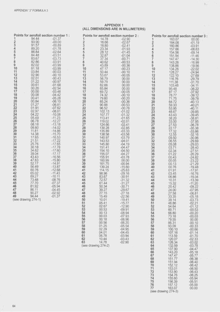
APPENDIX T FORMULA 3
APPENDIX 1 (ALL DIMENSIONS ARE IN MILLIMETERS)
Points fo r aerofoil section numt>er 1 : Points fo r aerofoil section numb1 94.44 -01.37 1 14.78 -02.902 93.90 -00.00 2 16.66 -02.673 91.57 -00.89 3 18.80 -02.414 89.20 -01.78 4 23.34 -01.935 86.84 -02.64 5 28.12 -01.456 84.48 -03.51 6 32.87 -01.047 83.67 -03.73 7 37.34 -00.718 82.86 -03.91 8 40.62 -00.539 82.02 -03.99 9 43.89 -00.3610 81.18 -03.99 10 47.17 -00.2311 03.84 -00.03 11 50.44 -00.1012 02.90 -00.10 12 53.67 -00.0513 02.01 -00.43 13 56.79 00.0014 01.22 -00.97 14 59.79 00.0015 00.61 -01.68 15 62.66 00.0016 00.20 -02.54 16 65.84 00.0017 00.00 -03.48 17 69.72 -00.0518 00.08 -04.42 18 74.32 -00.1019 00.41 -05.28 19 79.60 -00.2020 00.84 -06.10 20 85.24 -00.3621 01.27 -06.81 21 90.88 -00.5322 01.91 -07.62 22 96.52 -00.7623 02.97 -08.81 23 102.13 -01.0224 04.22 -10.08 24 107.77 -01.3225 05.49 -11.23 25 113.41 -01.6526 06.78 -12.27 26 119.02 -02.0127 08.18 -13.18 27 124.66 -02.4128 09.80 -14.02 28 130.28 -02.8529 11.81 -14.86 29 135.89 -03.3330 14.38 -15.70 30 138.58 -03.5631 17.65 -16.53 31 140.97 -03.7932 21.51 -17.22 32 143.53 -04.0133 25.76 -17.65 33 145.80 -04.1934 30.18 -17.78 34 151.41 -04.4735 34.62 -17.60 35 154.10 -04.5036 39.04 -17.17 36 155.07 -04.2737 43.43 -16.56 37 155.91 -03.7838 47.83 -15.80 38 160.99 00.0039 52.17 •14.91 39 161.75 -00.9440 56.49 -13.87 40 139.24 -15.6041 60.76 -12.68 41 114.15 -25.6342 65.02 -11.43 42 98.96 -29.1643 69.27 -10.11 43 83.67 -30.9144 73.48 -08.76 44 72.57 -31.3245 77.70 -07.37 45 61.44 -31.2746 81.92 -05.94 46 50.34 -30.7147 86.11 -04.45 47 39.27 -29.6748 90.27 -02.92 48 27.15 -27.1849 94.44 -01.37 49 15.49 -22.56(see drawing 274-1) 50 10.01 -19.41
51 05.41 -15.7752 02.67 -12.9053 00.53 -09.9154 00.13 -08.9455 00.03 -07.9356 00.18 -06.9657 00.56 -06.2058 01.25 -05.5459 02.29 -04.9560 04.01 -04.4561 06.78 -03.9462 10.44 -03.4363 14.78 -02.90(see drawing 274-2)
Points for aerofoil1 163.072 164.083 160.864 157.665 154.566 151.547 147.47a 143.269 138.8610 134.2611 128.2712 122.1013 116.7614 111.3815 103.4816 95.4817 87.1718 78.7719 71.7520 64.7221 59.3322 53.9523 48.6724 43.4325 38.2026 33.0027 27.5328 22.1729 17.3230 12.5531 09.5032 06.5533 05.0834 03.7135 02.3436 01.2237 00.4338 00.0539 00.1340 00.7641 01.9142 03.4543 06.8644 10.3145 15.3246 20.4247 24.0048 27.5849 33.3550 39.1451 46.8652 54.6453 60.7154 66.8055 73.1856 79.5557 86.3158 93.0959 100.1060 107.1661 113.5962 120.0763 126.3464 132.5965 137.9066 143.2067 147.4768 151.7769 151.9470 152.1271 153.0172 153.9073 154.7674 155.6075 156.3976 157.1277 163.07 (see drawing 274-3)
section number 300.00
-01.19-03.91-06.63-09.14-11.46-14.30-16.99-19.56- 22.02-24.94-27.69-29.79-31.70-34.11-36.22-37.92-39.12-39.78-40.13-40.21-40.11-39.85-39.45-38.81-37.95-36.78-35.38-33.86-32.16-30.96-29.69-29.03-28.40-27.51-26.29-24.82-23.22-21.29-19.48-17.91-16.76-15.04-13.39- 11.20-09.22-07.95-06.81-05.18-03.73- 02.21- 01.12-00.53-00.20-00.0300.00
-00.10-00.33-00.66-01.14-01.70-02.33-03.02-03.78-04.47-05.18-05.77-06.38-06.40-06.42-06.50-06.43-06.25-05.94-05.51-05.0000.00
64

A rticle 2 7 7 - Pr ie fo r m u la technical r e g u u t io n s ( G r o u p E)
It is permitted to organise sporting competitions open to ottier racing cars than those defined in one of the previous Groups of Appendix J. All specifications conceming the vehicies and particularly the limitations of the cylinder-capacity are in this case at the discretion of promoters and it nests with them to list clearly these specifications in the Supplementary Regulations of the event, which anyway have to tie approved by the National Sporting Authority answerable to the FIA. However, racing cars, which do not comply with any of the Intemationai Racing formuiae, must for security reasons be in confomiity with the following articles :
- 253.4 : Braking safety system ;- 253.13 : Circuit breaker ;- 253.14 : Safety fuei tank ;- 259.6.2 : Fuei lines, pumps and filters ;- 259.6.4 : Tank fillers and caps ;- 259.7.4 : Oil catch tank ;- 259.8.5 : Electrical catrles ;- 259.14.2.1: Safety belts;- 275.3.5 : Overhangs ;- 275.7.2 : Longitudinal location of oil system ;- 275.9.3 : Reverse gear ;- 275.10.3: Suspenston members ;- 275.12.2 : Wheel material ;- 275.14.1 : Extinguishers ;- 275.14.3 : Rear view mirrors ;- 275.14.5; Rear light ;- 275.14.6 : Headrest ;
Rollbars :All cars must have at least two rollover structures.Dimensions and positioning:The first structure must be in front of the steering wheei, not more than 25 cm forwanJ of, and at ieast as high as, the top of the steering wheel
The second strurtture must be at least 50 cm tiehind the first and high enough for a iine extended from ttie top of this structure to the top of the first structure to pass 5 cm over the driver's helmet when he is seated normaliy in the car with his heimet on and seat belts fastened. The minimum height of this second structure must be at least 92 cm measured along the straight line following the driver's spine, from the seat's metal shell to the top of the rollbar. The width must be at least 38 cm measured inside the rolibar between the two verticai pillars of the sides. It must be measured at a height of 60 cm above the seat's metal shell on the perpendicular to the straight line follovring the driver's spine.Strength:In order to obtain a sufficient strength for the rollbar, two possibilities are left to the manufacturers :a - The rollbar, of entirely free stnjctural conception, must be capable to withstand ttie stress minima indicated in article 275.15.2.3. This must be certified on a form approved by an ASN and signed by a qualified person.b - The tubes and bracefs) must have a diameter of at least 1 3/8 inch (3.5 cm) and at least 0.090 inch (2 mm) wall thickness. The material should be molytxlenum chromium SAE 4130 or SAE 4125 (or equivalent in DIN, NF, etc.).There must be at least one brace from the top of the bar reanvards at an angle not exceeding 60° to the horizontal.The diameter and material of the brace must be the same as those of the rollbar itself.In the case of two braces, the diameter of each of them may be reduced to 20/26 mm. Removable connection between the main hrxjp and the brace must comply with drawings 253-27 to 253-36. Fororard fitted stays are allowed.
A rticle 278 - N a t io n a l fo r m u la e technica l r eg u la tio n s
REGISTRATION OF NATIONAL FORMULAEThe FIA will accept to study the registration of “Nationar formulae, in order to have their technical prescriptions known at an intemational level and to ensure a certain stability and a standardisation of the regulations which rule them.1) In presence of article 251, any ASN has the right to define regulations applying to given types of Free Formula racing cars denominated hereafter “National Formulae".2) Are eligible for registration only the applications presented by at least two National Sporting Authorities and concerning a National Formula used In at least two countries.3) The FIA will accept, in compliance with the preceding article 2 to register on a voluntary basis any set of prescriptions defining such National Formulae.The regulations thus registered by the FIA will be applicable in countries ttie ASNs of which have declared to abide by them.The declaration made t>y the National Sporting Authority to adopt the regulations of a determined National Formula Is exclusively valid for the regulations such as they were originally deposited at the FIA, and this National Sporting Authority is entitled to withdraw this declaration if the regulations are altered aftenwards.The withdrawal of a declaration for another reason that the one here above mentioned, must compulsorily be communicated to the FIA before December 31st In order to tre valid as from the following year.
4) From the time when such National Formula is registered. Its appellation can be used in those countries where the ASNs have adopted the registered regulations, only for cars entirely complying with the regulations deposited at the FIA.5) Any application for the registration of regulations for a National Formula should be addressed to the FIA at the latest on October 1st to be valid as from January 1st of tfre following year. Ttie National Formulae can (but Is not compulsory) form the subject of restrictions as regards the engine or other manufacturing elements. In order to allow exclusively the use of parts of a given make. Such a one-make Formula may have a distinct commercial name related to the imposed design restrictions.6) The National Sporting Authorities which have adopted a determined National Formula may file an application at the FIA In view of the organisation of an ward including several countries.Any application of that kind will te submitted to the appreciation of the FIA whose decision will depend on the number of countries interested by the organisation of an event included in that award and on the advisability or the necessity, for the general interest of Automobile Sport to introduce such a form of competition.7) The organisation of any type of intemational award without the FIA's agreement will entail the application of penalties.
66
-■ ■ A t
A rticle 279 - T echnical regulations for rallycross a n d autocross cars
1) DEFINITIONS Division 1: Production cars :Homologated in Group N and œnforming to Appendix J Group N (Articles 251 to 254) Including the Rally requirements, tmt penmitted the modifications listed In Article 3 t>elow. In addition the allowed restrlctor diameter (see a rt 254.6.1) is 36 mm. Cars must be rigidly-closed non- convertible models.Division 2: Touring cars :Homologated In Group A and conforming to Appendix J Group A (Articles 251 to 255), permitted the modifications listed in Articles 3 and 4 t>elow. Cars must be rigidly-closed non-convertible models.Division 3: Autocross Single-seaters :4>wheeled vehicles designed and built specifically for participating in Autocross. The vehicles shall have 2- or 4- wheel drive. They must comply with Article 5 below.
2) NOISEA limit of 100 dB is imposed for all cars.The noise will be measured with a sonometer regulated at “A" and “SLOW", placed at an angle of 45° to and a distance of 50 cm from the exhaust outlet, with the car’s engine running at 4500 rpm.A carpet of minimum 1.50 x 1.50 m must be placed over the relevant area of ground.
3) MODIFICATIONS ALLOWED AND PRESCRIPTIONS APPLICABLE TO CARS OF DIVISIONS 1 AND 2
The following prescriptions apply to all cars in addition to the prescriptions of Append ixJ.3.1 - Rear lights:Each car will be fitted with two red rear lights of the fog lamp type (minimum illuminated area of each light: 60 cm^; bulbs of minimum 15 watts each) working with or replacing the car’s original brake-lights. They must be positioned between 1.50 m and 1.15 m above ground level. They must be placed symmetrically in relation to the longitudinal axis of the car and in a transversal plane.3.2- Towing eye;Must be fitted at the front and at the rear. These eyes must not protrude beyond the perimeter of the bodywork seen from above. They should be painted a bright yellow, red or orange, and must be fitted so as to be easy to find for the rescue in case of emergency.3.3- Driver’s seat:Must be securely fixed; if it is mounted on rails, or if it has an adjustable back rest it must be additionally secured so as to be absolutely immovable and rigid. The seat shall include a headrest. The dimensions of the headrest shall be such that the driver’s head cannot be trapped between the rollbar and the headrest. The passenger seats may be removed.3.4 - Windscreens:Must be of laminated glass or of a polycarbonate, and the windows must be of safety glass or plastic. If of ^astic, the thickness shall not be less than 5 mm. Cars with laminated windscreens which are damaged to such an extent that visibility Is seriously impaired or that there is a likelihood of their breaking further during the event, will be rejected. Goggles or visors must be worn in cars with laminated screens.3.5 - Spare wheels:Prohibited.3.6- Wheels and tyres:The complete wheel (flange + rim + inflated tyre) must always fit inside a U-shaped gauge of which the extremities are 250 mm apart (200 mm for 4 -w h ^ drive cars of Division 1 ), the measurement to be made on an unloaded part of the tyre. The rim diameter may be increased or reduced by up to 2” in relation to the original dimension.Twin wheels and wheels fitted with chains are forbidden.Studded tyres are forbidden.
Tyres fitted with “knobbly" treads or rubber studs are not permitted unless by decision of the stewards of the meeting when the weather conditions are unfavourable and thus compromise the good running of the race.Tyres with the following characteristics ARE NOT CONSIDERED AS “KNOBBLY” OR WITH RUBBER STUDS:- no gap between two blocks measured perpendicularly or parallel to the tread may exceed 15 mm. In the case of wear or tear of the corners, the measurement will be taken at ttie base of the block. In the case of circular or oval t>iocks, the measurement is taken at the tangent of the blocks;- the depth of the tread may not exceed 15 mm. These measurements do not apply over a width of 30 mm at the edge on each side of the tread, but the blocks may not extend beyond the vertical plane of the tyre walls.3.7 • Throttle:There shall be a positive means of closing the throttle in the event of failure of the throttle linkage, by means of an external spring operating on each throttle spindle or slide.3.8 - Parking brake:Obligatory; it must be efficient and simultaneously control the two front wheels or the two rear wheels.3.9- Fuel tank:If a non-original tank is fitted, it shall be located at least 30 cm from the bodyshell in both lateral and longitudinal directions, outside the driver’s compartment, and must t>e separated from this compartment by a firewall or by a container, lx>th of which shall t>e flameproof and fire-resistant. In the case of twin-volume cars, it will be possible to use a non- structural partition wall In transparent non-flammable plastic between the cockpit and the tank arrangement.3.10 - Steering column:Anti-theft devices must be removed.3.11 - Safety harness:Compulsory, with at least four points conforming to the specifications of Article 253.6 of Appendix J. The two shoulder straps shall have separate anchorage points.3.12 - Mud flaps:Autocross cars only : obligatory behind the driven wheels, in a flexible material at least 5 mm thick. They must descend to at least 5 cm below the axis of the wheels and cover at least the vwdth of the complete wheel, but shall not be more than 5 cm wider than it.3.13- Bumpers:Bumpers and their supports must not be removed or reinforced.3.14- Water radiator:The water radiator and its capacity are free; Its location may not be changed. The fitting of extra cooling fans is permitted. A radiator screen may be fitted, provided that no reinforcement of the bodyshell results.3.15- External lights:May be removed provided any resultant openings in the bodywork are covered and that the prescriptions of Article 3.1 are respected. Covers must conform to the original general silhouette.3.16- Safety rollcage:Must be fitted, as defined in Appendix J, with backstays and diagonal member.3.17 - Prescription applicable to cars of Division 1 only: Bodywork: mudguard extensions of 5 cm on both sides of the car are permitted but the complete wheel must be housed within the original bodywork when measured as In Article 255.5.4. of Appendix J.3.18- Floor carpets:Floor carpets may be removed from the cockpit.3.19- Extinguisher systems:Installed automatic systems are recommended. They must be produced In accordance with art. 253.7.3 of Apperfoix J. If the vehicle is equipped with these systems, manual extinguishers are not obligatory.
67
APPENDIX "J" RALLYCROSS AND AUTOCROSS
3.20 - Transmission:The material of the gearing is free.3.21 - Differential:A mechanicai self-locking differential is authorised, on condition that it can tie housed within the original differential housing, with no modifications.
4) PRESCRIPTIONS APPLICABLE TO ANDMODIFICATIONS PERMITTED FOR CARS OF DIVISION 2, IN ADDITION TO THE PRESCRIPTIONS OF ARTICLE 3 ABOVE
4.1 - Minimum weights:Cars will weigh at least the following weights in relation to their cubic capacity:1000 cm3 580 kg1300 cm3 675 kg1600 cm3 750 kg2000 cm3 820 kg2500 cm^ 890 kg3000 cm3 960 kg3500 cm3 1030 kg4000 cm3 1100 kg4500 cm3 1170 kg5000 cm3 1235 kg5500 cm3 1300 kg5500 cm3 1370 kg
4.2 - Bodywork - Chassis4.2.1 - Bodywork;The original bodywork must be retained, except as concerns the wings and the aerodynamic devices allowed. Trim strips, mouldings, etc., may be removed. Windscreen wipers are free, but there must be at least one in working order.4.2.2- Bodyshell-Chassis:Ttre series-production IxxJysheii and chassis must be retained but the original basic structure may tie lightened by removing material, or reinforced. However, it is forbidden to reinforce a structure which has been lightened, or vice-versa.4.2.3 - Doors, bonnets and boot lids:Except for the driver's door, the material is free, provided that the original outsirJe shape is retained. Door hinges and outside drxir handles are free. The original locks may be replaced but the new ones must be efficient. The original driver's door must be retained, trim may be removed. The rear doors may be sealed shut by welding. The locking devices on the bonnet and txjot Ik), as well as the hinges, are free, but each lid must be fixed at four points, and opening from the outside must be possible. The original closing systems must be removed. Openings may be made in the bonnet frx ventilation, provided that they do not allow mechanical components to be seen, in all circumstances, ttie tx)nnets and boot lids must be interchangeable with the original homologated ones.4.2.4 - Cockpit ventilation openings:Openings may be made in the bodywork for ventilating the cockpit, provided:- that they are placed in front of the rear roof edge above the rear window and/or in the area between the rear side window and the rear window;- that they do not protrude beyond the original line of the bodywork, seen from the front.4.3 - Aerodynamic devices:Seen from above, aerodynamic devices need not follow the contour of the shape of the car. Those which are not homologated for series production must fit within the car's frontal projection.4.3.1 - At the front:They may not exceed the wheelbase of the car by more than 10 % (measurement made from the overall limit of the bodywork) and may in no case exceed the overall limits of ttie original bodywork by more than 20 cm. They will compulsorily be installed tjelow the horizontal plane passing through the wheel hub and may be situated between the lowest suspended part and the ground.4.3.2 - At the rearThey may not exceed the wheelbase of the car by more than 20 %
(measurement made from the overall limit of the txxlywork) and may in no case exceed the overall limits of the original bodyvvork by nxxe than 40 cm.4.4 - Mudguards:The definition of “mudguard" is that given in article 251.2.5.7. of Appendix J. The material and shape of the mudguards are free. However, the shape of the wheel arches must be retained, but this does not imply that their original dimensions must be retained. Ttie mudguards shall project out over the wheels and provide efficient coverage over at least one third of their circumference and at least the entire width of the tyre.Openings for cooling may be made in the mudguards. However, should they be made behind the rear wfieeis, louvres must make it impossible to see the tyre from the rear along a horizontal plane. It is permitted to install mechanical components within the mudguards, but their installation shall under no circumstances be used as a pretext for reinforcing the mudguards.4.5 - Lights:Pursuant to Article 3.15, in each cover a hole with an area of 30 cm2 may be left for cooling purposes.4.6 - Engine:The engine is free but the engine block must be from a homologated engine of the same original trademark as the car's original bodywork and must have the same number of cylinders as the engine originally homologated for that car. The engine must be Icxated in the original engine compartment. Twin engine configurations are not permitted unless homologated in that form.Variabte valve timing is not permitted. Variable length inlet trumpets are forbidden. Titanium is not pemiitted except in connecting rods, valves, valve retainers and heat shields. The use of magnesium is not permitted in moving parts. The use of any ceramic component is fbr- bklden.Internal and/or external spraying or injection of water or any substance whatsoever is forbidden (ottier than fuel for the normal purpose of combustion in the engine).The use of cartxjn or composite materials is restricted to dutches and non-stressed covers or ducts.Only a direct mechanical linkage between the throttle pedal and the engine is penoitted.The tunnels used for ttie passage of the exhaust must remain open to the outside atong at least two thirds of their length.In Autrxross only, exhaust pipe outlets which point downwards are prohibited.if supercharging is used, the exhaust gases from the waste-gate must exit into the vehicle's exhaust system.Water injection is prohibited, even if it originally exists on the homologated block. Spraying of the intercooler is pemitted only if there is no liquid to go on the ground.Turbocharged cars must not be equipped with any device which allows the boost pressure or the electronic management system controlling the boost pressure, to be adjusted by the driver while the car is in motion. Ceramic components, variable diameter inlets and adjustable internal vanes on turbochargers are forbidden.4.7 - Interior: interior trim is free.The dashboard must have no protruding angles. The complete seat must be located entirely on one side or the other of the vertical plane of the longitudinal centre line of the car.The bulkheads separating the cockpit from the engine compartment and the boot must retain their original place and shape. Their material must be the same as or stronger than the original material. Installing components up against or passing through one of these bulkheads is, however, pemitted, provided that they do not protrude into the cockpit by more than 20 cm (as measured horizontally from the originai bulkhead). This possibility does not apply to the engine block, sump, crankshaft or cylinder head. In addition, the floor may be modified, provided that it is not made higher than the door sills, in this case, the original floor may be removed.it is also pemitted to make the modifications necessary for installing a new transmission.4.8 - Fuel, oil and cooling water tanks:Shall be isolated from the driver's compartment by means of bui-
APPENDIX "J" RALLYCROSS AND AUTOCROSS
kheads so that In the case of spillage, leakage or failure of a tank, no liquid will pass Into the driver’s compartment. The same applies to the fuel tanks vIs-à-vIs the engine compartment and exhaust system.The fuel tank filler cap shall not protaide tieyond the txxJyvrork and shall t)e leakproof.The storing of fuel on txjard the car at a temperature of more than 10 degrees centigrade tielow the ambient temperature Is forbidden.4.9 - Suspension:Cars must be fitted with a sprung suspension.The springing medium must not consist solely of bolts located through flexible bushes or mountings but may be of fluid type.There must be movement of the wheels to give suspension travel In excess of any flexibility In the attachments.The use of active suspension Is forbidden.Chromium plating of steel suspension members Is forbidden.All suspension members must be made from a homogeneous metallic material.Hydropneumatic suspension systems are pennltted, on condition ttiat they do not have active control.With these reservations, the suspension Is free.4.10 - Transmission:Free; conversion to four-wheel drive is permitted.4.11 - Water radiator:Its locatlori Is free, provided that It does not encroach upon the driver's compartment.4.12 - Brakes:Free, but there must be a double circuit operated by the same pedal and complying with following; the pedal shall normally control all the wtreels. In case of a leakage at any point of the brake system pipes or of any kind of failure In the brake transmission system, the pedal shall still control at least two wheels. Anti-lock brake systems are not permitted.A handbrake Is obligatory; It must be efficient and simultaneously control the two front wheels or the h«o rear wheels.4.13- Mechanical components:No mechanical component may protrude beyond the car’s original txxiywork, except Inside the wings.4.14- Driver's seat:It Is recommended to brace the top of the driver’s seat to the rollcage.4.15- Steering:Only a direct mechanical linkage between the steering wheel and the steered wheels Is permitted.Four wheel steering Is forbidden.4.16 - Type of gearbox:Semi-automatic or automatic gearboxes with electronic, pneumatic or hydraulic slip control are forbidden.Differentials with electronic, pneumatic or hydraulic slip control which are adjustable by the driver while the car Is In motion are forbidden.4.17 - Magnesium sheet:The use of magnesium sheet less than 3 mm thick Is forbidden.4.18- Telemetry:The use of telemetry Is forbidden.
5) PRESCRIPTIONS FOR CARS OF DIVISION 3 (AUTOCROSS SINGLE-SEATERS)
These cars must comply with Articles 2,3.1, 3.2,3.3, 3.5,3.6,3.7,3.8,3.11 and 4.12 of the Technical regulations for Flallycross and Autocross", and with the folloviring:5.1 - Cylinder capacity: .The maximum corrected cylinder capacity Is 3500 cm' .5.2 - Engine protection:A protective hoop Is obligatory for rear-englnes. The rear part of this hoop must entirely envelope ttie engine Including the exhaust and Its
This hoop must be braced In Its centre. This may be connected to the underneath of the vehicle or to the main roll bar. The tubes used will have a minimum wall thickness of 1.5 mm. The protective hoop for the engine may tie In several detachable parts, txjt In this case the joined tubes must be sleeved and the assembly effected by a bolt of 6 mm minimum diameter on each end of the sleeve, posltloried at 90“ the one to the other, separated by at least 30 mm. The diameter of the bolts to be used Is at least 6 mm.
5.3 - Lateral protection:This will consist of composite honeycomb structures solidly attached to steel tube structures on each side of the car. These tube starctures must conform to the material specifications given In article 253.8.3 of Appendix J, and be fixed to the main staicture of the car. The minimum thickness of the composite panels Is 15 mm, and they may be mouhted on either side of the tubes.The outermost part of the protection shall be situated at the level of the centre of the wheel hubs, over a minimum length of 60 % of the wheelbase. This protection shall extend outwards on both sides at least as far as the vertical planes passing through the middle of the foremost part of the rear tyres and through the middle of the reannost part of tfie front tyres, but not further than the vertical planes passing through the outside of the foremost part of the rear tyres and through the outside of the rearmost part of the front tyres. The space between this protection and the bodywork must be covered, to prevent wheels penetrating It.5.4 - Bodywork:This must be Impeccably finished. In no way of a makeshift nature. It must not have any sharp angles or sharp-edged or pointed parts, and angles or comers must t>e rounded with a radius of not less than 15 mm. At the front and at the sides there must be hard, opaque bodywork providing protection against stones. This bodywork must rise at least to the level of the centre of the steering wheel, ahd Its height must not be less than 42 cm measured from the driver’s seat mounting.All mechanical elements necessary for propulsion (engine, transmission) must tre covered by ttie txxiywork or mudguards.Seen from above, all parts of the engine must be covered by sturdy, hard and opaque bodywork; the sides of the engine may t» left uncovered. The panels used must not be more than 10 mm thick.An external rear-vlew mirror must be present on each side of the car. The reflecting surface of each of these rear-vlew mirrors must not be less than 90 crri^, and It must be possible to fit Into this surface a square with sides measuring 6 cm.5.5 - Cockpit:The width of the cockpit, maintained over 50 cm from the most rearward point of the seat In a horizontal plane towards the front, shall not be Inferior to 60 cm. No part of the cockpit, or situated In the cockpIL may have sharp or pointed parts. Particular care must be taken to avoid any protrusion which could Injure the driver. The two safety rolF bars must be high enough for a line extended from the top of the main rollbar to the top of the front rollbar to pass at least 5 cm over the top of the driver’s helmet when he Is seated normally In the car with his helmet on and his safety harness fastened.A rigid roof panel above the driver Is pennltted.N.B.: the requirement that the seats must be homologated by the CEE, the FMVSS or the FIA as from 01.01.97 is withdrawn.Any transmission shaft joint situated tDeneath the floor of tfie cockprt must be envetoped by a band of mild steel at least 3 mm thick over a length of at least 25 cm, securely fixed to the chassis. In order to prevent the shaft from penetrating the cockpit or hitting the ground In case of failure of the jointNo mechanical part may be situated In the cockpit.It Is recommended that lateral protection tie provided as follows for the two side openings of the cockpit:These openings must tie closed completely to prevent the passage of a hand or arm. This closing must be effected:- either by netting with a maximum mesh of 6 cm x 6 cm made from cords of at least 3 mm In diameter, this netting being fixed pemia- nently at the top and rapidly detachable at the bottom from Inside or outside;- or by a wire grille with a maximum mesh of 6 cm x 6 cm, the wire being at least 2 mm In diameter, this grille being attached by two hinges at the top and having an extemal quick release device at the bottom, also accessible from Inside the car (an opening may be made for this purpose), allowing the grille to be swung upwards to a vertical position.- or by side windows made from polycartxinate, of a minimum thickness of 5 mm.5.6 - Weight:The weight of the vehicle, without the driver on board, must at all times during the event comply writh the following scale according to the number of cylinders, the type of Intake and the type of transmission:
APPENDIX T RALLYCRC3SS AND AUTOCROSS
2WD 4WD-4cyl 4WD-6cyl 4WD-8cylnorm.asp. +
4W[>-4cylsuperch.
+4WD-6cylsuperch.
440 kg 490 kg - -
450 kg 500 kg 550 kg 600 kg500 kg 550 kg 600 kg 650 kg550 kg 600 kg 650 kg 700 kg600 kg 650 kg 700 kg 750 kg
CylinderCapacity
< 1,300 ari3< 1,600 cm^< 2,000 cm3< 2,500 cm3< 3,500 cm3
5.7 • Fire-proof bulkhead:A metallic fire-proof, flame-proof and liquid-tight bulkhead must be fixed to the floor of the car and to the two rear uprights of the nollcage. It must extend over the whole width of the rollcage; its upper edge will be at least 50 cm from the floor. The floor will be closed.5.8 - Mudguards:Ttiey must be fimnly fixed. The mudguards must project over the wheels, and provide efficient covering of at least one third of their circumference and at least the entire width of the tyre, and descend towards the rear to at least 5 cm below tfie axis of tfie v^eels. In those cars where the mudguards form part of the txxlywork or are entirely or partly overhung by parts of the bodywork, the mudguards-body combination or the body alone shall nevertheless meet the above-mentioned protection requirements. Mudguards must fiave no perforations or sharp angles. Should it t)e necessary to reinforce the mudguards, this may be done with iron rod of 10 mm maximum diameter, or witti tubing with a maximum diameter of 20 mm.Under no circumstances may the mudguard reinforcement be used as a pretext for the construction of crash bars.5.9 - Suspension:The axles must be spaing. The mounting of axles directly onto the chassis is not allowed.5.10 - Steeling:The system is free.5.11 - Fuel, oil and cooling water tanks:They shall be isolated from the driving compartment by means of bulkheads so that In the case of spillage, leakage or failure of a tank, no liquid will pass into the driving compartment. The same applies to the fuel lanks vis-à-vis the engine compartment and exhaust system.The fuel tank must be an FT3 type and be situated behind the seat. It must be mounted in a sufficiently protected location and be firmly attached to tfie car. It must not tie in the driver's compartment, and must be separated from it by a Une-wall. It must be situated at least 40 cm away from the cylinder head and the exhaust system. The filler caps of this fuel tank must be leak proof and must not protrude beyond the bodywork. The capacity of the fuel tank must not exceed 12 litres.
5.12 - Dynamos, alternators, batteries:Dynamos and alternators may be removed, but each car must have a fully charged battery.The use of any outside source of energy to start the engine of the car on the grid or during a race is forbidden.5.13- Piping:Fuel lines, oil lines and brake lines must be protected externally against any risk of deterioration (stones, corrosion, mechanical breakages, etc.), and inside the cockpit, as far as the fuel circuit is concerned, against all risks of fire. There must be no connections on the lines situated in the cockpit.5.14 - Wheels and tyres:The maximum diameter permitted for wheels is 18 inches. Tyres manufactured specifically for agricultural use or marked for use at limited speeds are prohibited.If wheels made from a material other than steel are used, the competitor must provide documentary evidence that these wheels have been supplied for a series production car either as original equipment or as altemative equipment. Home-made constructions are prohibited.5.15- Rear light:Each car must be fitted with one red rear light of the fog lamp type (bulb of minimum 21 watts), dearly visible from the rear. It must be positioned between 1.50 m and 1.15 m above ground level. It must be possible for the driver sitting at his steering wheel to switch it on.5.16 - Competition number:This must be displayed once on each side of the car and on each side of a panel on the roof. The car must bear no other number likely to be confused with it. The roof number must be permanently fixed on a vertical support, 24 cm X 35 cm, with no sharp edges and must be positioned along the longitudinal axis of the car. The number must be 18 cm high and the strokes forming it must be 4 cm thick.5.17 - Windscreen:This must be made of laminated glass, or of a polycarbonate at least 5 mm thick. Scrutineers will not accept cars whose windscreen shows traces of collision or cracks to such an extent that visibility is seriously impaired or that there is a likelihood of their breaking further during the event.The windsaeen may be replaced, or protected, by a metal grille covering the entre surface of the windscreen opening. The mesh size shall be between 10 mm x 10 mm and 25 mm x 25 mm, and the minimum diameter of the wire of which the mesh is formed shall be 1 mm.In cars i^ ich have a laminated glass windscreen or which have the metal grille detned above and no polycaibonate windscreen, motorcycle type goggles or a visor fitted on the helmet must be worn by the driver.Apertures of a total area not exceeding 64 cm^ may be made in the windscreen.
70

A rticle 2 8 1 - C l a s s if ic a t io n a n d d e f in it io n s o f cr o ss - c o u n t r y veh ic les
1) CLASSIFICATION1.1 Categories and Groups :The vehicles used in cross country rallies will be divided up into the fol- iowing categories and groups ;Category I : - Group T1 : Series Cross-Country Cars
. Group T2 : Improved Cross-Country CarsCategory II : - Group T3 : Prototype Cross-Country CarsCategory III ; - Group T4 ; Cross-Country Trucks1.2 Cubic capacity classes :The cars will be divided up into the following cla«cubic capacity.
500 cm31. Up to
2. From 500 cm^ to 600 cm3
3. From 600 cm3 to 700 cm34. From 700 cm3 to 850 cm35. From 850 cm3 to 1000 cm3
6. From 1000 cm^ to 1150 cm37. From 1150 cm3 to 1300 cm3
8. From 1300 cm3 to 1600 cm39. From 1600 cm3 to 2000 cm310. From 2000 cm3 to 2500 cm311. From 2500 cm3 to 3000 cm3
12. From 3000 cm3 to 3500 cm3
13. From 3500 cm3 to 4000 cm3
14. From 4000 cm3 to 4500 cm315. From 4500 cm3 to 5000 cm3
16. From 5000 cm3 to 5500 cm3
17. From 5500 cm3 to 6000 cm3
18. Over 6000 cm3U IIIO O O U U ltS I W IOC l l l p i w j W ..............
a certain category of events, the organisers are not bound to include ail the above-mentioned classes in the Supplementary Regulations and. furthermore, they are free to group two or more consecutive classes, according to the particular circumstances of their events.No class can be subdivided.
2) DEFINITIONS2.1 General conditions :2.1.1) Series Production cars (Cat^ory I) :Cars of which the production of a certain number of identical examples (see definition of this word hereinafter) within a certain period of time has been verified at the request of the manufacturer, and which are destined for normal sale to the public (see this expression).Cars must be sold In accordance with the homologation form. These cars will have a maximum of six wheels and a minimum of four driven wheels.2.1.2) Competition cars (Category II) :Cars built singly and intended solely for competition.2.1.3) Trucks (Category III) :Trucks will be considered to mean vehicles with a gross weight exceeding 3500 kg. with a maximum of eight wheels and a minimum of four driven wtieels.2.1.4) Identical cars :Cars belonging to the same production series and which have the same mechanical components and same chassis (even though this chassis may be an integral part of the bodywork in the case of a monocoque construction).2.1.5) Model of car:Car belonging to a productbn-series distinguishable by a specific conception and external general lines of the bodywork and by an identical mechanical construction of the engine and the transmission to the wheels, with the same wheelbase and the same cubic capacity.
2.1.6) Normal sale:Means the distribution of cars to individual purchasers through the normal commercial channels of the manufacturer.2.1.7) Homologation:Is the official certification made by the FIA that a minimum number of cars of a specific model has been made on series-production terms to justify classification in Series Cross Country Cars (Group T1) of these regulations.A^lication for homologation shall be submitted to the FIA by the ASN of the country in which the vehicle is manufactured and shall entail the drawing up of a honx)logation form (see below). It must be established in accordance with the special regulations called “Homologation Regulations", laid down by the FIA. Homologation of a series-produced car will become null and void 5 years after the date on which the series-production of the said model has been stopped (series-production under 10 % of the minimum production of the group considered).2.1.8) Homologation forms :All cars recognised by the FIA will be the sut^ect of a descriptive form called homologation form on which shall be entered all data enabling identification of the said model.This homologation form defines the series as indicated by the manufacturer. According to the group in which the competitors race, the modification limits allowed in international competition for the series are stated in Appendix J.The presentation of the forms at scrutineering and/or at the start may be required by the organisers who will be entitled to refuse the participation of the entrant in the event in c ^ of non-presentation.Should the date for the coming into force of a homologation form fall during an event this form will be valid for that event throughout the duration of the said eventShould any doubt remain after the checking of a model of car against its honx)k)gation form, the scrutineers should refer either to the maintenance booklet published for the use of the make’s distributors or to the general catalogue in whk:h are listed all spare parts.In the case of a lack of sufficient accurate documentation, scrutineers may carry out direct scrutineering by comparison with an identical part available from a concessionaire. It will t>e up to the competitor to obtain the homologation concerning his car from his ASN.Description : A form breaks down in the fo llow i^ way :1) A basic form giving a description of the basic model.2) At a later stage, a certain number of additional sheets describing “horTK)logation extensions", which can be “variants", or “errata" or “evolutions”.a - Variants (VF. VO)These are either supply variants (VF) (two suppliers providing the same part for the manufecturer and the client does not have the possibility of choice), or options (VO) (supplied on request and available at the concessionaires), b - Erratum (ER)Replaces and cancels an incorrect piece of information previously supplied by the constructor on a form, c - Evolution (ET)Characterises rrxxlifications made on a permanent basis to the basic model (complete cessation of the production of the car in Its original form).Use :1) Variants (VF. VO)The competitor may use any variant or any part of a variant as he wishes, only on condition that all the technical data of the vehicle, so designed, conforms to that described on the homologation form applicable to the car. or expressly allowed by Appendix J. For example, the fitting of a brake calliperas defined on a variant form is only possible if the dimensions of the brake linings, etc. obtained in this way, are indicated on a form applicable to the car in question.
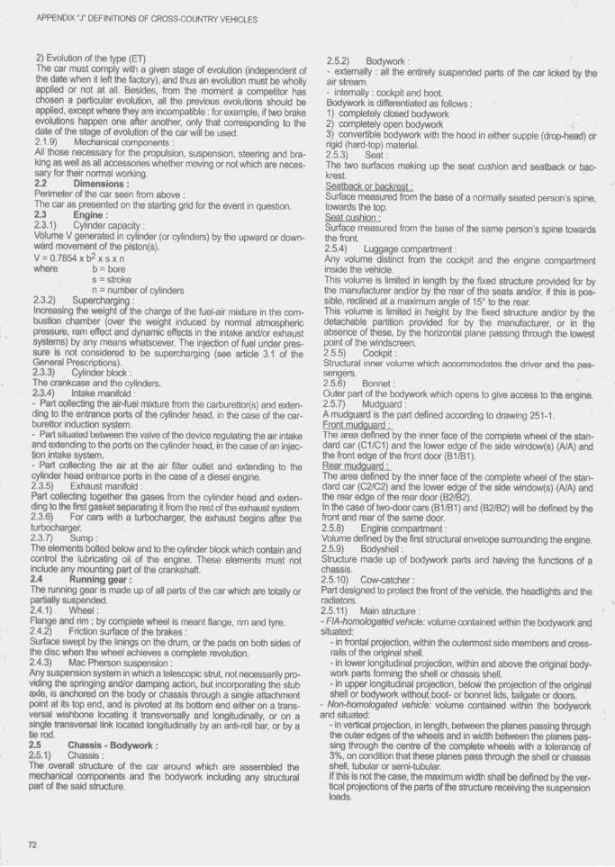
APPENDIX “J" DEFINITIONS OF CROSS-COUNTRY VEHICLES
2) Evolution of the type (ET)The car must comply v rith a given stage of evolution (independent of the date when it left the factory), and ftius an evolution must t)e wholly applied or not at all. Besides, from the moment a competitor has chosen a particular evolution, all the previous evolutions should be applied, except where they are incompatible : for example, if two brake evolutions happen one after another, only that corresponding to the date of the stage of evolution of the car will be used.2.1.9) Mechanical components :All those necessary for the propulsion, suspension, steering and braking as well as all accessories whether moving or not which are necessary for their normal working.2.2 Dimensions :Perimeter of the car seen from above :The car as presented on the starting grid for the event in question.2.3 Engine :2.3.1) Cylinder capacity :Volume V generated in cylinder (or cylinders) by the upward or downward movement of the piston(s).V = 0.7854 X t)2 X s X n where b = bore
s = stroken = number of cylinders
2.Z2) Supercharging ;IncTMsing the weight of the charge of the fuel-air mixture in the combustion chamber (over the weight induced by normal atnx)spheric pressure, ram effect and dynamic effects in the intake and/or exhaust systems) by any means whatsoever. The injection of fuel under pressure is not considered to be supercharging (see article 3.1 of the General Prescriptions).2.3.3) Cylinder block :The crankcase and the cylinders.2.3.4) Intake manifold ;- Part collecting the air-fuel mixture from the cart)urettor(s) and extending to the entrance ports of the cylinder head, in the case of the carburettor induction system.- Part situated between the valve of the device regulating the air intake and extending to the ports on the cylinder head, in the case of an injection intake system.- Part collecting the air at the air filter outlet and extending to the cylinder head entrance ports in the case of a diesel engine.2.3.5) Exhaust manifold ;Part collecting together the gases from the cylinder head and extending to the first gasket separating it from the rest of the exhaust system.2.3.6) For cars with a turbocharger, the exhaust begins after the turtxicharger.2.3.7) Sump :The elements tidted below and to the cylinder block which contain and control the lubricating oil of the engine. These elements must not include any mounting part of the crankshaft.2.4 Running gear :The running gear is made up of all parts of the car which are totally or partially suspended.2.4.1) Wheel:Flange and rim ; by complete wfieel is meant flange, rim and tyre.2.4.2) Friction surface of the brakes :S u r f^ swept by the linings on the drum, or the pads on both sides of tfie disc when the wheel achieves a complete revolution.2.4.3) Mac Pherson suspension :Any suspension system in which a telescopic strut, not necessarily providing the springing and/or damping action, but incorporating the stub axle, is ancfxxed on the body or chassis through a single attachment point at its top end, and is pivoted at Its bottom end either on a transversal wishbone locating it transversally and longitudinally, or on a single transversal link located longitudinally by an antkoll bar, or by a tie rod.2.5 Chassis - Bodywork :2.5.1) Chassis :The overall structure of the car around which are assembled the mechanical components and the bodywork Including any structural part of the said structure.
2.5.2) Bodywork :- externally : all the entirely suspended parts of the car licked by the air stream.- intemally : cockpit and boot.Bodywork is differentiated as follows :1) completely closed bodywork2) completely open bodywork3) convertible bodywork with the hood In either supple (drop-head) or rigid (hard-top) material.2.5.3) Seat :The two surfaces making up the seat cushion and seatback or backrest.Seatback or backrest :Surface measured from the base of a normally seated person's spine, towards the top.Seat cushion :Surface measured from the base of the same person's spine towards the front.2.5.4) Luggage compartment :Any volume distinct frxin the cockpit and the engine compartment inside the vehicle.This volume is limited in length tjy the fixed structure provided for by the manufacturer and/or by the rear erf the seats and/or, if this is possible, reclined at a maximum angle of 15“ to the rear.This volume is limited in height by the fixed structure and/or by the detachable partition provided for by the manufacturer, or in the absence of these, by the horizontal plane passing through the lowest point of the windscreen.2.5.5) Cockpit :Structural inner volume which accommodates the driver and the passengers.2.5.6) Bonnet :Outer part of the bodywork which opens to give access to the engine.2.5.7) Mudguard :A mudguard is the part defined according to drawing 251-1.Front mudguard :The area defined by the inner face of the complete wheel of the standard car (01/01) and the lower edge of the side window(s) (A/A) and the front edge of the front door (B1/B1).Rear mudguard :The area defined by the inner face of the complete wheel of the standard car (02/02) and the lower edge of the side window(s) (A/A) and the rear edge of the rear door (B2/B2).In the case of two-door cars (B1/B1 ) and (B2/B2) will be defined by the front and rear of the same door.2.5.8) Engine compartment :Volume defined by ttie first structural envelope surrounding tfie engine.2.5.9) Bodyshell :Structure made up of bodywork parts and having the functions of a chassis.2.5.10) Oow-catcher:Part designed to protect the front of the vehicle, the headlights and the radiators.2.5.11) Main structure :- F IA ^ h o m o lo g a t e d v e h ic le : volume contained within the bodywork and situated:
- in frontal projection, within the outermost side members and cross- rails of the original shell.- in lower longitudinal projection, within and above the original bodywork parts forming the shell or chassis shell.- in upper longitudinal projection, below the projection of the original shell or bodywork without txx)t- or bonnet IkJs, tailgate or doors.
- N o n - h o m o l o g a t e d v e h ic le : volume contained within the bodywork and situated:
- In vertical projection, in lerrgth, between the planes passing through the outer edges of the wheels and in width between the planes passing through the centre of the complete wtieels with a tolerance of 3%, on condition that these planes pass through the shell or chassis shell, tubular or semi-tubular.If this is not the case, the maximum width shall be defined by the vertical projections of the parts of the structure receiving the suspension loads.
72
APPENDIX "J" DEFINITIONS OF CROSS-COUNTRY VEHICLES
- in longitudinal projaction, tha voluma shall ba definad in its lower part by the longitudinal projections of tha lower parts of tha structure receiving the suspension loads, and in its upper part, at the front, by the planes passing through the highest points of the front safety rollbar and the highest points of the structure receiving the suspension loads or, alternatively, the upper edges of the front wheels.
• To the rear it shall be defined by the planes passing through the highest points of the main safety lolltiar and the highest points of the structure receiving the suspension loads or, alternatively, the upper edges of the rear wheels.
Between the main and front rollbars, it shall be defined by the planes joining their upper parts.
2.6 Electrical system :Headlight : any signal the focus of which creates an in-depth luminous beam directed towards the front.2.7 Fuel tank :Any container holding fuel likely to flow by means of lines towards the main tank or the engine.
73

A rticle 282 - G eneral prescriptions for cross country cars
1) GENERAL REMARKS1.1 All modifications are fbrtjidden unless expressly authorised t)y the regulations specific to the group in which the car is entered or by the general prescriptions below or Imposed under the chapter "Safety Equipmenf.The components of the car must retain their original function.1.2 Application o f the general prescriptions :The general prescriptions must be observed in the event that the specifications of Cross Country cars (Groups T1, T2, T3) do not lay down a more strict prescription.1.3 Magnesium :The use of magnesium altoy sheet metal with a thickness less than 3 mm Is prohibited.1.4 It is the duty of each competitor to satisfy the Scrutineers and the Stewards of the Meeting that his automobile complies with these regulations in their entirety at all times during the event1.5 Damaged threads can be repaired by screwing on a newthread with the same interior diameter (“heiicoir type).
2) DIMENSIONS AND WEIGHT2.1 Ground clearance :No part of the car must touch the ground when ail the tyres on one side are deflated. This test shall be carried out on a flat surface under race conditions (occupants on board).2.2 Ballast :No kind of ballast is authorised on Series Cross Country (Group T1). The carrying of tools and spare parts for the car will be allowed under the conditions laid down in article 283.
3) ENGINE3.1 Supercharging :In me case of supercharging, me nominal cylinder-capacity will be multiplied by 1.7 and the car will pass into me class corresponding to me ^ v e volume mus obtained. The car will be treated in all respects as if Its cylinder-capacity mus increased were its real capacity. This shall particularly be the case for assigning me car to its cylinder-capacity dass, its interior dimensions, its minimum number of places, its minimum weight, etc.3.2 Equivalence formula between reciprocating piston and rotary engines :(of the type covered by me NSU Wankel patents)The cubic capacity equivalent is 1.8 times me volume detennined between me maximum and minimum capacities of the combustion chambers.3.3 Equivalence formula between reciprocating piston and turbine engines :The formula is the following :C = S (3.10xR )-7.63
0.09625S = High pressure rtozzle area - expressed in square centimetres by which is meant me area of the air-flow at the exit from me stator blades (or at me exit from me first stage if me stator has several stages). Measurement is done by taking me area between the fixed blades of the high pressure turbine first stage. In cases where the first stage turbine stator blades are adjustable, they must be opened to meir greatest extent The area of the high pressure nozzle is mus me product of the height (expressed in cm) by the widm (expressed in cm) and by the number of blades.R = The pressure ratio is me ratio of me compressor of the turtjine engine. It is obtained by multiplying togemer the value for each stage of the compressor, as Indicated h e re a ^ ;Subsonic axial compressor : 1.15 per stageTrans-sonic axial compressor : 1.5 per stageRadial compressor : 4.25 per stage.
Thus a compressor wim one radial and six axial subsonic stages will be designated to have a pressure ratio of :4.25 x 1.15 X 1.15 X 1.15 X 1.15 X 1.15 X 1.15 or4 .25x (1.15)6.C = Equivalent cubic capacity for reciprocating piston engines m cm^.3.4 All engines into which fuel is in je c t^ or in which fuel isburned after an exhaust port are prohibited.3.5 Equivalences between reciprocating piston enginesand new types of engines :The FIA reserves me right to make modifications on the basis of comparisons established between classic engines and new types of engines, by giving a two year notice from me 1st January following the decision taken.3.6 Exhaust system and silencer :Even when me specific provisions for a group allow me replacement of me original silencer, the cars competing in an open-road event shall always be equipped wim an exhaust silencer complying wim me traffic regulations of me country(ies) mrough which me event is mn. The exhaust system must not pass mrough me cockpit The exhaust outlet must tie horizontal or directed upwards.The orifices of the exhaust pipes shall be placed at a maximum of 80 cm and a minimum of 10 cm from the grourKl. The exit of me extraust pipe must be situated wimin the perimeter of me car and less man 10 cm from mis perimeter, and aft of me vertical plane passing mrough the centre of the wheelt)ase. Moreover, adequate protection must t)e provided in order to prevent heated pipes from causing bums.The exhaust system must not be provisional. Exhaust gas may only exit at the end of me system. Parts of the chassis must rx)t t>e used to evacuate exhaust gases.C a t a ly t ic e x h a u s t s : Should two possible versions of one car model be homologated (catalytic and omer exhaust), me cars must comply wim one or omer version, all (X)mbinations of the tvro versbns being wohi- bited.3.7 Starting on board the vehicle :Starter wrth electric or other source of energy on board operable by me driver when seated in me seat.3.8 Accelerator controls of me “fly-by-wire" type are forbidden.
4) TRANSMISSIONAll cars must be fitted wim a gearbox including a reverse gear which must be in working order when the car starts the event and be able to be operated by the driver when he is nonnally seated.
5) SUSPENSIONSuspension parts made partially or entirely from composite materials are prohibited.
6) WHEELSWheels made partially or entirely from composite materials are prohi- t>ited.M e a s u r in g w h e e l w id th :The wktth is to be measured wim me wheel mounted on me car, on me ground, the vehicle in race condition, driver atx)ard, at any point along me circumference of the tyre, except in the area in contact wrth the ground.When multiple tyres are fitted as part of a complete wheel, the latter must comply wrth me maximum dimensions for t h e group in which these tyres are used.
7) COACHWORK7.1 Convertible vehicles must comply in all respects wrth thespecifications apptyir^ to open cars.72 Minimum Inside dimensions :If a modification authorised by Appendix J affects a dimension stated on the homologation form, mis dimension may not be retained as an eligibility criterion for the car.
74

APPENDIX “J" GENERAL PRESCRIPTIONS CROSS COUNTRY CARS
7.3 Cockpit :Only the following accessories may be installed In the cockpit : spare wheel(s), spare parts, tools, safety equipment, electronic equipment, materials and controls necessary for driving, windscreen washer water container, ballast (if permitted).The passenger area and seat of an open car must in no way be covered.Containers for helmets and tools situated in the cockpit must be made of non-inflammable materia! and they must not, in case of fire, give off toxic vapours.In the case of a car with a crew of three and in which the back of the rearmost seat is situated more than 20 cm to the rear of the back of the seat which is furthest forward, the car must respect the following conditions ;- it must have four side doors equipped with transparent windows and allowing free access to the seats.- it must have a specific rollbar as defined in article 283.8.- the front of the rear seat(s) must be positioned more than 20 cm to the rear of the back(s) of the front seat(s).7.4 All body panels of the vehicle must be at all times of the same material as those of the original homologated car and must be of the same material thickness as that of the original homologated car (tolerance! 10 %).7.5 Headlamp mounting and protection :The boring of holes in the front bodywork for light brackets is authorised, limited solely to mountings.Non-reflecting protectors made from flexible material may be mounted on the headlamps ; they must not protrude forwards beyond the headlamp glass by more than 10 cm.7.6 Any object of a dangerous nature (inflammable products, etc.) must be carried outside the cockpit.7.7 Flexible shielding may be used to protect the externalswitches or attachments of the compulsory safety equipment.
8) ELECTRICAL SYSTEM8.1 Lighting :A fog light may be changed for another, and vice versa, provided thatthe original mounting remains the same.8.2 The mounting of the altemator is free.
9) FUEL-COMBUSTIVE9.1 For petrol engines the fuel must be commercial petrol whichcomes from a service station pump, without any additive other than that of a lubricant on current sale. The fuel must comply with the following specifications :- 102.0 RON and 90.0 MON maximum, 95.0 RON and 85.0 MON minimum for unleaded fuel.- 100.0 RON and 92.0 MON maximum, 97.0 RON and 86.0 MON minimum for leaded fuel.
The measurements will be made according to the standards ASTM D 2699-86 and D 2700-86.- Specific gravity between 720 and 785 kg/m^ at 15“C (measured according to ASTM D 4052).- A maximum of 2.8 % oxygen (or 3.7 % if the lead content \é less than 0.013 g/l)and0.5 % nitrogen by weight, the remainder of the fuel consisting exclusively of hydrocarbons and not containing any power- boosting additives.The measuring of the nitrogen content will be carried out according to the standard ASTM D 3228 and that of the oxygen content by elemental analysis with a tolerance of 0.2 %.- Maximum content of peroxides and nitrooxide compounds : 100 ppm (ASTM D 3703 or in the case of impossibility UOP 33-82).- Maximum lead content : 0.40 g/1 or the standard of the country of the event, if this is lower (ASTM D 3341 or D 3237).- Maximum benzene content : 5 % in volume (ASTM D 3606).- Maximum Reid vapour pressure : 900 hPa (ASTM D 323).- Distillation at 70“C : 10 % - 47 % (ASTM D 86).- Distillation at 100“C : 30 % - 70 % (ASTM D 86).- Distillation at 180X : 85 % minimum (ASTM D 86).- Maximum final boiling point : 225°C (ASTM D 86).- Maximum residue : 2 % volume (ASTM D 86).The fuel being accepted or rejected according to the standard ASTM D 3244 with a confidence limit of 95 %.If the fuel available locally for the event is not of a sufficient quality for use by competitors, the ASN of the organising country must ask the FIA for a waiver in order to enable the use of fuel not corresponding to the characteristics defined above.9.2 Diesel o il :For Diesel engines, the fuel must be gas oil corresponding to the following specifications ;- Hydrocarbon level, % by weight 99.0 min.- Specific gravity, kg/m^ 860 max.- Cetane number (ASTM D613) 55 max.- Calculated cetane numt>er 55 max.(ASTM D976-80)9.3 Only air may be mixed with the fuel as an oxidant.9.4 Refuelling :Prior to any refuelling operation, it is necessary to establish earthing common to the vehicle and to the refuelling device.9.5 Tank ventilation :The tank must be equipped with ventilation complying with article 283.14.4, unless the series production tank, fuel feed circuit and ventilation are retained.
10) BRAKESCart>on brakes discs are forbidden.
75
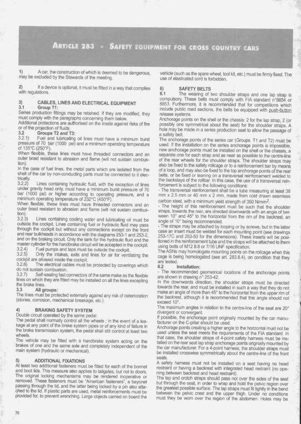
A rticle 2 8 3 - Safety e q u ip m e n t fo r cross c o u n tr y cars
1) A car, the construction of which is deemed to tie dangerous, may be exciuded by the Stewards of the meeting.
2) If a device is opConai, it must be fitted in a way that compiieswith regulations.
3) CABLES, LINES AND ELECTRICAL EQUIPMENT3.1 Group T1:Series production fittings may be retained. If they are modified, they must compiy with the paragraphs conceming them beiow.Additional protections are authorised on the inside against risks of fire or of the projection of fluids.3.2 Groups T2 and T3:3.2.1) Fuel and lubricating oil lines must have a minimum burst pressure of 70 bar (1000 psi) and a minimum operatinq temperature of135“C(250T). I- » I -When flexible, these lines must have threaded connectors and an outer braid resistant to abrasion and flame (will not sustain combustion),in the case of fuel lines, the metai parts which are isolated from the shell of the car by non-conducting parts must be connected to it electrically.3.2.2) Lines containing hydraulic fluid, with the exception of lines under gravity head only, must have a minimum burst pressure of 70 bar (1000 psi) or higher according to operating pressure, and a minimum operating temperature of 232°C (450”F),When flexible, these lines must have threaded connectors and an outer braid resistant to abrasion and flame (will not sustain combustion).3.2.3) Lines containing cooling water and lubricating oil must be outside the cockpit. Lines containing fuel or hydraulic fluid may pass through the cockpit but without any connections except on the front and rear bulkheads in accordance with the diagrams 253-1 and 253-2, and on the braking circuit. Only the tank for the hydraulic fluid and the master cylinder for the handbrake circuit will be accepted in the cockpit.3.2.4) Fuel pumps and taps must be outside the cockpit.3.2.5) Only the intakes, exits and lines for air for ventilating the cockpit are allowed inside the cockpit.3.2.6) The electrical cables must be protected by coverings which do not sustain combustion.3.2.7) Seif-seaiing fast connectors of the same make as the flexible lines on which they are fitted may be installed on all the lines excepting the brake lines.3.3 All groups:The lines must be protected externally against any risk of deterioration (stones, corrosion, mechanical breakage, etc.).
4) BRAKING SAFETY SYSTEMDouble circuit operated by the same pedal:The pedal shall normally control all the wheels ; in the event of a leakage at any point of the brake system pipes or of any kind of failure in the brake transmission system, the pedal shall still control at least two wheels.The vehicle may be fitted with a handbrake system acting on the brakes of one and the same axle and completely independent of the main system (hydraulic or mechanical).
5) ADDITIONAL FIXATIONSAt least two additional fasteners must be fitted for each of the bonnet and boot lids. This measure also applies to tailgates, but not to doors. Ttie original locking mechanisms may be rendered inoperative or removed. These fasteners must be "American fasteners", a bayonet passing through the lid, and the latter being locked by a pin also attached to the lid. if plastic parts are used, metai reinforcements must be provided for, to prevent wrenching. Large objects carried on board the
vehicle (such as the spare wheel, tool kit, etc.) must be firmly fixed. The use of elasticated cord is forbidden.
6) SAFETY BELTS6.1 The wearing of two shoulder straps and one lap strap iscompulsory. These belts must comply with FIA standard n"8854 or 8853. Furthermore, it is recommended that for competitions which include public road sections, the belts be equipped with oush-button release systems.Anchorage points on the shell or the chassis: 2 for the lap strap, 2 (or possibly one symmetrical about the seat) for the shoulder straps. A hole may be made in a series production seat to allow the passage of a safety belt.The anchorage points of the series car (Groups T1 and T2) must be used. If the installation on the series anchorage points is impossible, new anchorage points must be installed on the shell or the chassis, a separate one for each strap and as near as possible to the centre-line of ttie rear wheels for the shoulder straps. The shoulder straps may also be fixed to the safety roilcage or to a reinforcement bar by means of a loop, and may also t>e fixed to the top anchorage points of the rear belts, or tie fixed or leaning on a transversal reinforcement welded to the tiackstays of the rolltiar. In this case, the use of a transversal reinforcement is subject to the following conditions:- The transversal reinforcement shall be a tube measuring at least 38 mm X 2.5 mm or 40 mm x 2 mm, made from cold drawn seamless carbon steel, with a minimum yield strength of 350 N/mm^.- The height of this reinforcement must be such that the shoulder straps, towards the rear, are directed downwards with an angle of tiet- ween 10° and 45° to the horizontal from the rim of the backtest, an angle of 10° being recommended.- The straps may be attached by looping or by saews, but in the latter case an insert must be welded for each mounting point (see drawings253-17C and 253-53 for the dimensions). These inserts will be positioned in the reinforcement tube and the straps will be attached to them using bolts of M12 8.8 or 7/16 UNF specification.The ASNs may homologate mounting points on the roilcage when this cage is being homologated (see art. 283.8.4), on condition that they are tested.6.2 Installation:- The recommended geometrical locations of the anchorage points are shown in drawing n° 253-42.In the downwards direction, the shoulder straps must be directed towards the rear, and must be installed in such a way that they do not make an angle of more than 45° to the horizontal from the upper rim of the backrest, although it is recommended that this angle should not exceed 10°.The maximum angles in relation to the centre-line of the seat are 20° divergent or convergent.if possible, the anchorage point originally mounted by the car manufacturer on the C-piliar should be used.Anchorage points creating a higher angle to the horizontal must not be used unless the seat meets the requirements of the FIA standard. In that case, the shoulder straps of 4-point safety hamess must be installed on the rear seat lap strap anchorage points originally mounted by the car manufacturer. For a 4 ^ in t hamess, the shoulder straps must be installed crosswise symmetricaiiy about the centre-line of the front seats.A safety hamess must not be installed on a seat having no head restraint or having a backrest with integrated head restraint (no opening between backrest and head restraint).The lap and crotch straps should pass not over the sides of the seat but through the seat, in order to wrap and hold the pelvic region over the greatest possible surface. The lap straps must fit tightly in the bend between the pelvic crest and the upper thigh. Under no conditions must they be wom over the region of the abdomen. Holes may be
76

APPENDIX “J’ SAFETY CROSS COUNTRY CARS
made in the series seat If this proves to be necessary in order to avoid such an occurrence. Care must tie taken that ttie straps cannot be damaged through chafing against sharp edges.- If installation on the series anchorage points is impossible for the shoulder and/or crotch straps, new anchorage points must be installed on the shell or the chassis, as near as possible to the centre-line of the rear wheels for the shoulder straps. If this latter mounting is impossible, the shoulder straps may be fixed or leaning on a rear transversal tube fixed to the rollbar or to the top anchorage points of the front belts.• Each anchorage point must be able to withstand a load of 1470 daN. or 720 daN for the crotch straps. In the case of one anchorage point for two straps, the load considered will be equal to the sum of the required loads.- For each new anchorage point created, a steel reinforcement plate with a surface area of at least 40 cm^ and a thickness of at least 3 mm must be used.- Principles of mounting to the chassis/monocoque:1) General mounting system: see drawing 253-43.2) Shoulder strap mounting:see drawing 253-44.3) Crotch strap mountingisee drawing 253-45.6.3 Use:A safety harness must be used In its homologation configuration without any modifications or removal of parts, and in conformity with the manufacturer’s instructions. The effectiveness and longevity of safety belts are directly related to the manner in which they are installed. used and maintained. The belts must be replaced after every severe collision, and whenever the webbing is cut, frayed or weakened due to the actions of chemicals or sunlight. They must also be replaced If metal parts or buckles are bent, deformed or msted. Any harness which does not function perfectly must be replaced.
7) EXTINGUISHERS7.1 Manual extinguishers:7.1.1) All cars must be fitted with one or two fire extinguishers.7.1.2) Permitted extinguishants:BCF (C F2 Cl Br)NAFS3NAFPAFFFPowder7.1.3) Minimum extinguisher capacity:In case of use of BCF. NAF Sill. NAF P. or powder 2.60 litres for the quantities specified hereafter.7.1.4) Minimum quantity of extinguishant:BCF: 4.0 kgNAF S3: 3.2 kgNAF P: 3.2 kgAFFF: 2.4 litresPowder: 2.0 kg7.1.5) All extinguishers must be pressurised according
to the contents;BCF: 7.0 barNAF S3: 7.0 barNAFP; 7.0 barAFFF; 12.0 barPowder: 13.5 barFurthemiore, in the case of AFFF, each extinguisher must t>e equipped with a means of checking the pressure of the contents.7.1.6) The following information must be visible on each extinguisher-capacity- type of extinguishant- weight or volume of the extinguishant- date the extinguish^ must be checked, which must be ix) more than two years after either the date of filling or the date of tfie last check.7.1.7) All extinguishers must be adequately protected. Their mountings must be able to withstand a deceleration of 25 g. Furthermore, only quick-release metal fastenings, with metal straps, will be accepted.7.1.8) The extinguishers must be easily accessible for the dnver and the co-driver.
7.2 Mounted systems:Obligatory for Improved Cross-Country Cars (Group T2) and Prototypes (Group T3). optional in the Series Cross-Country group (Group T1).7.2.1) All cars must be fitted with two fire extinguisher systems, one which will discharge into the cockpit and one into the engine compartment. A single bottle may be used If the extinguishant is divided up in accordance with the directives given below.7.2.2) Pennitted extinguishants:BCF (0 F2 Cl Br)NAF S3NAF P ^ ,Any AFFF which has been specifically approved by the FIA (see “Technical List n° 6”)Dry powder is also permitted but only on cars being used in or coming from countries where national regulations preclude the use of the above products.7.2.3) Minimum extinguisher capacity:- For BCF.NAF S3, NAF P:
Closed cars Open cars;(including covered cars):
Cockpit: 1 -65 litres 3.30 litresEngine: 3.30 litres 1.65 litres- For AFFF: The capacity may vary according to the type
used (see “Technical List n* 6”)7.2.4) Minimum quantity of extinguishant:
Closed cars: Open cars:(incl. covered cars)
BCF: Cockpit: 2.5 kg 5.0 kgEngine: 5.0 kg 2.5 kg
NAF S3: Cockpit: 2.0 kg 4.0 kgEngine: 4.0 kg 2.0 kg
NAFP: Cockpit 2.0 kg 4.0 kgEngine: 4.0 kg 2.0 kg
Powder. Cockpit: 1.2 kg 2.4 kgEngine: 2.4 kg 1.2 kg
AFFF: The quantity may vary according to the typeused (see Technical List n® 6")
7.2.5) Discharge time:Engine: 10 seconds minimum / 40 seconds maximum.Cockpit: 30 seconds minimum 180 seconds maximum.Both extinguishers must be released simultaneously.7.2.6) All extinguishers must be pressurised according to the contents:BCF: 7.0 barNAF S3: 7.0 barNAF P: 7.0 barPowder 13.5 barAFFF: The pressure may vary according to the type
used (see Technical List n® 6")Furthermore, in the case of an AFFF. each extinguisher must t>e equipped with a means of checking the pressure of the contents.7.2.7) The following information must be visible on each extinguisher:-capacity• type of extinguishant- weight or volume of the extinguishant- date the extinguisher must be checked, which must t>e no more than two years after either the date of filling or the date of the last check.7.2.8) All extinguishers must be adequately protected and must be situated within the cockpit. In all cases their mountings must be able to withstand a deceleration of 25 g.All extinguishing equipment must withstand fire.7.2.9) Any triggering system having its own source of energy is permitted, provided it Is possible to operate all extinguishers should the main electrical circuits of the car fail.The driver must be able to trigger all extinguishers manually when seated normally with his safety belts fastened and the steering wheel in place.Furthermore, a means of triggering from the outside must be situated near to the circuit-breaker switch, and not combined with it. It must be marked with a letter "E” in red inside a white circle of at least 10 cm diameter with a red edge.
77

APPENDIX ‘X SAFETY CROSS COUNTRY CARS
A single external switch Is obligatory for T1 and 12 vehicles using an installed s^tem , but Group T3 cars must be eguipped with two extemal switches, one each side of the windsoeen.7.2.10) The system must work in any position, even when the car is inverted.7.2.11) Extinguisher nozzles must be suitable for the extinguishant and be installed in such a way that they are not directly pointed at the occupants.
8) ROLLOVER STRUCTURES8.1 Definitions:8.1.1) Safety cageA structural framework designed to prevent serious bodyshell deformation in the case of a collision or of a car turning over.8.1.2) RollbarStructural frame or hoop and mounting points.8.1.3) RollcageStructural frameworl made up of a main rollbar and a front rollbar (or of two lateral rollbars), their connecting members, one diagonal member, backstays and mounting points. (For example, see drawinos 253-3 and 25S4).8.1.4) Main rollbarStructure consisting of a near-vertical frame or hoop located across the vehicle just behind the front seats.8.1.5) Front rollbarSimilar to main rollbar but Its shape follows the windscreen pillars and top screen edge.8.1.6) Lateral rollbarStructure consisting of a near-vertical frame or hoop located along the right or left side of the vehicle. The rear legs of a lateral rollbar must be just behind the front seats. The front leg must be against the screen pillar and the door pillar such that It does not unduly impede the entry or exit of the driver and co-driver.8.1.7) Longitudinal memberLongitudinal tube which is not a part of the main, front or lateral rollbar and linking them, together with the backstays.8.1.8) Diagonal memberTransverse tube between a top comer of the main rollbar or upper end of a backstay and a lower mounting point on the other side of the rollbar of backstay.8.1.9) Framework reinforcementReinforcing memtjer fixed to the rollcage to improve Its structural efficiency.8.1.10) Reinforcement plateMetal plate fixed to the bodyshell or chassis structure under a rollbar mounting foot to spread load into the structure.8.1.11) Mounting footPlate welded to a rollbar tube to permit Its bolting or welding to the bodyshell or chassis structure, usually onto a reinforcement plate.8.1.12) Removable membersStructural members of a safety cage which must be able to be removed.8.2 Specifications:8.2.1) General comments8.2.1.1 - Safety cage must be designed and made so that, when correctly installed, tfiey substantially reduce bodyshell deformation and so reduce the risk of injury to occupants.The essential features of safety cages are sound construction, designed to suit the particular vehicle, adequate mountings and a close fit to the bodyshell.Tubes must not carry fluids. The safety cage must not unduly impede the entry or exit of the driver and co-driver.Memt>ers may intrude into the occupant’s space in passing through the dashboard and front side-trim, as well as through the rear side-trim and rear seats. The rear seat may be folded down.Longitudinally, the safety cage must be entirely contained between the top mounting points of the front suspension and the top mounting points of the rear suspensbn.Any modification to a homologated safety cage is forbidden. The rear face of the headrest subjected to the regulation bad will define the position of the tube of the main rollbar w h i^ may not protrude beyond it in vertical projection. The minimum free height below the rollbar tube
will be 900 mm, measured vertically from the bottom of the uncrushed seal8.2.1.2- Basic safety cage:Only rollcages must be used, completed by a front transversal strut and two door struts (see drawing 283-6).In the case of a car with a crew of three, the safety cage must comply with drawing 283-5, svith a second main rollt)ar situated dose to the t)ack(s) of the rear seat(s).With regard to pick-up vehicles, the cockpit of which is not large enough to allow the fitting of the compulsory basic safety cage. It shall be possibte to mount the rollbar(s) as per one of the drawings 283-1 to 283-4. This possibility is open to pick-ups only, to the excbsbn of all other types of bodywork and all the points of the installation must comply with the prescriptions of the other paragraphs (including the material specifications of art. 8.3).Drawing 283-1: One diagonal stnjt compulsory.Drawing 283-2: Two d i^onal struts compulsory, one for the four-point rollbar insbe the cockpit (according to drawing 253-4), one for the four points outsbe rollbar (according to drawing 253-3 or 253-4).Drawing 283-3: One diagonal strut compulsory (according to drawing 253-3 or 253-4).Drawing 2834: Two diagonal struts compulsory, one for the interior four-point rollbar, one for the exterior six-point rollbar.8.2.1.3 - Compulsory diagonal member:Different ways of fitting the compulsory diagonal memt>er: see drawings 253-3 to 253-5.The combination of several memt)ers is permitted.8.2.1.4- Optional reinforcing members:Each type of reinforcement (drawings 253-6 to 253-17, 253-17A and 253-170) may be used separately or combined with others.8.2.2) Technical specifications8.2.2.1 - Main, front and lateral rollbars:These frames or hoops must be made in one piece without joints. Their construction must be smooth and even, without ripples or cracks. The vertical part of ttie main rollbar must t>e as straight as possible and as dose as possible to the interior contour of the bodyshell.The front leg of a front rollbar or of a lateral rollbar must be straight, or if it is not possible, must follow the windscreen pillars and have only one t>end with its lower vertical part. Where a main rollbar forms the rear legs of a lateral rollbar (drawing 253-4), the connection to the lateral rollbar must be at roof level.To achieve an efficient mounting to the bodyshell, the original interior trim may be modified around the safety cages and tfieir mountings by cutting it away or by distorting It.However, this modification does not permit the removal of complete parts of upholstery or trim.Where necessary, the fuse box may be moved to enable a rollcage to befitted.8.2.2.2 - Mounting of rollcages to the bodyshell:Minimum mountings are:-1 for each leg of the main or lateral rollbar ;-1 for each of the front rollbar ;-1 for each backstay (see S.2.2.3).Each mounting foot of the front, main and lateral rollbars must include a reinforcement plate, of a thickness of at least 3 mm which must not be less than that of the tube onto which it Is welded.Each mounting foot must be attached by at least three bolts on a steel reinforcement plate at least 3 mm thick and of at least 120 cm^ area which is welded to the bodyshell. Examples are shown in drawings 253-18 to 253-24. This does not necessarily apply to backstays (see below).Bolts must be of at least M8 size of ISO standard 8.8 or better. Fasteners must be self-locking of fitted with lock washers.These are minimum requirements. In addition to these requirements, more fasteners may be used, the rollt)ar legs may be welded to reinforcement plates, the rollcage may be welded to the bodyshell. Rollbar mounting feet must not be wekJ^ directly to the bodyshell without a reinforcement plate.The safety rollcages must be fixed directly to the steel bodyshell or the main chassis, i.e. onto the structure to which the suspension loads are transmitted (with If necessary additional reinforcement at ttie joint between the chassis and the foot of the rollbar).
78
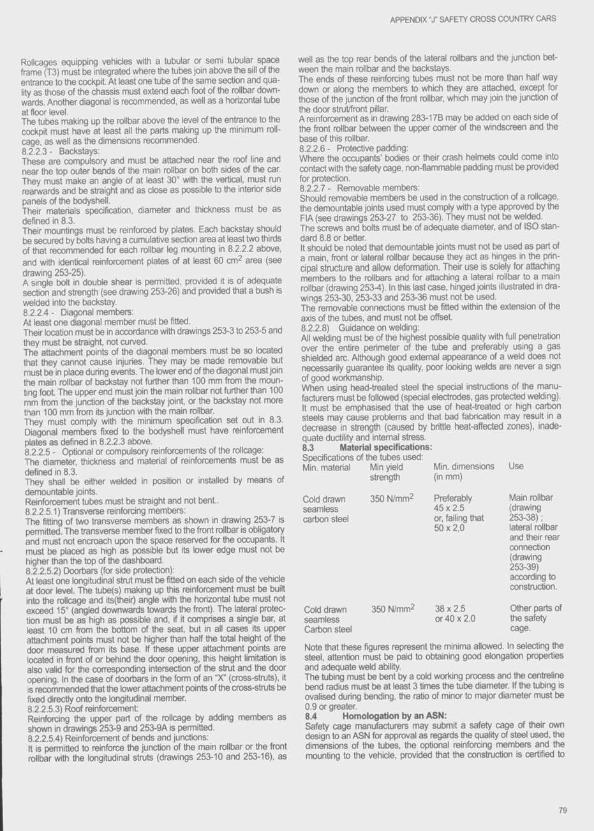
APPENDIX "J" SAFETY CROSS COUNTRY CARS
Rolkages equipping vehides with a tubular or semi tubular space frame (13) must be integrated where the tubes join above the sill of the entrance to the cockpit. At least one tube of the same section and quality as those of the chassis must extend each foot of the rollbar downwards. Another diagonal is recommended, as well as a horizontal tube at floor level.The tubes making up the rollbar above the level of the entrance to the cockpit must have at least all the parts making up the minimum roll- cage, as well as the dimensions recommended.8.2.23- Backstays;These are compulsory and must tie attached near the roof line and near the top outer bends of the main rollbar on both sides of the car. They must make an angle of at least 30° with the vertical, must mn rearwards and be straight and as dose as possible to the interior side panels of the bodyshell.Their materials specification, diameter and thickness must be as defined in 8.3.Their mountings must be reinforced by plates. Each backstay should be secured by bolts having a cumulative section area at least two thirds of that recommended for each rollbar leg mounting in 8.2.2.2 above, and with identical reinforcement plates of at least 60 cm^ area (see drawing 253-25).A single bolt in doutrle shear is pemiitted, provided it is of adequate section and strength (see drawing 25326) and provided that a bush is welded into the backstay.8.2.2.4 - Diagonal members:At least one diagonal member must be fitted.Their location must be in accordance with drawings 2533 to 2535 and they must be straight, not curved.The attachment points of the diagonal members must be so located ttiat they cannot cause injuries. They may be made removable but must tie in place during events. The lower end of the diagonal must join the main rolltrar of backstay not furttier than 100 mm from the mounting foot. The upper end must join the main rollbar not further than 100 mm from the junction of the backstay joint, or the backstay not more than too mm from its junction with the main rollbar.They must comply with the minimum specification set out in 8.3. Diagonal members fixed to the bodyshell must have reinforcement plates as defined in 8.2 2.3 above.8 2.2.5 - Optional or compulsory reinforcements of the rollcage:The diameter, thickness and material of reinforcements must be as defined in 8.3.They shall be either welded in position or installed by means of demountable joints.Reinforcement tubes must be straight and not bent.8.2.2.5.1) Transverse reinforcing members:The fitting of two transverse members as shown in drawing 2537 is permitted. The transverse member fixed to the front rollbar is obligatory and must not encroach upon the space reserved for the occupants. It must be placed as high as possible but its lower edge must not be higher than the top of the dashboard.8.2 2.5.2) Doortjars (for side protection):At least one longitudinal start must be fitted on each side of the vehicle at door level. The tube(s) making up this reinforcement must be built into the rollcage and its(their) angle with the horizontal tube must not exceed 15° (angled downwards towards the front). The lateral protection must be as high as possible and, if it comprises a single bar, at least 10 cm from the bottom of the seat, but in all cases its upper attachment points must not be higher than half the total height of the door measured from its base. If these upper attachment points are located in front of or behind the door opening, this height limitation is also valid for the corresponding intersection of the strut and the door opening. In the case of doorbars in the form of an “X" (crrjss-struts), it is recommended that the lower attachment points of the cross-struts be fixed directly onto the longitudinal member.8.2.2.5.3) Rrxjf reinforcement:Reinforcing ttie upper part of the rollcage by adding members as shown in drawings 2539 and 2539A is permitted.8.2.2.5.4) Reinforcement of bends and junctions:It is permitted to reinforce the junction of the main rollbar or the front rollbar with the longitudinal stmts (drawings 25310 and 253-16), as
well as the top rear bends of the lateral rollbars and the junction between the main rollbar and the backstays.The ends of ttiese reinforcing tubes must not t>e more than half way down or along the members to which they are attached, except for those of the junction of the front rollbar, which may join the junction of the door stmt/front pillar.A reinforcement as in drawing 283178 may be added on each side of the front rollbar between the upper comer of the windscreen and the base of this rollbar.8.2.2 6 - Protective padding:Where the occupants' bodies or their crash helmets could come into contact with the safety cage, non-flammable padding must be provided for protection.8.2.2.7 - Renrovable members:Should removable members be used in the construction of a rollcage, the demountable joints used must comply with a type approved by the FIA (see drawings 25327 to 25336). They must not be welded.The saews and bolts must be of adequate diameter, and of ISO standard 8.8 or better.It should be noted that demountable joints must not be used as part of a main, front or lateral rollbar because they act as hinges in the principal structure and allow deformation. Their use is solely for attaching members to the rollbars and for attaching a lateral rollbar to a main rollbar (drawing 253-4). In this last case, hinged joints illustrated in drawings 25330, 25333 and 25336 must not be used.The removable connections must be fitted within the extension of the axis of the tubes, and must not be offset.8.2.2,8) Guidance on welding:All welding must be of the highest possible quality with full penetration over the entire perimeter of the tube and preferably using a gas shielded arc. Although good extemal appearance of a weld does not necessarily guarantee its quality, poor looking welds are never a sign of good workmanship.When using head-treated steel the special instructions of the manufacturers must be followed (special electrodes, gas protected welding). It must be emphasised that the use of heat-treated or high carbon steels may cause problems and that trad fabrication may result in a decrease in strength (caused by brittle heat-afferrted zones), inadequate ductility and intemal stress.8.3 Material specifications:Specifications of the tubes used:Min. material Min yield Min. dimensions Use
strength (in mm)
Cold drawn seamless cartxrn steel
350 N/mm^ Preferably 45 X 2.5 or, failing that 50x2,0
350 N/mm2 38x2.5 or 40 X 2.0
Main rollbar (drawing25338); lateral rollbar and their rear connection (drawing25339) according to construction.
Otfier parts of the safety cage.
Cold drawn seamless Cartron steel
Note that these figures represent the minima allowed. In selecting the steel, attention must be paid to obtaining good elongation properties and adequate weld ability.The tubirig must be bent by a cold working process and the centreline bend radius must be at least 3 times the tube diameter. If the tubing is ovalised during bending, the ratio of minor to major diameter must be 0.9 or greater.8.4 Homologation by an ASN:Safety cage manufacturers may submit a safety cage of their own design to an ASN for approval as regards the quality of steel used, the dimensions of the tubes, the optional reinforcing members and the mounting to the vehicle, provided that the construction is certified to
79
APPENDIX “J" SAFETY CROSS COUNTRY CARS
withstand the stress minima given hereafter in any combination on top of the safety cage;-1 .5 W* lateral ;- 5.5 W fore and aft ;- 7.5 W vertical.(*W = weight of the car + 500 kg).A homologation certificate, approved by the ASN and signed by qualified technicians representing the manufacturer, must be presented to the event’s scrutineers. It must contain drawings or photos of the safety cage in question including its fixation and particularities, and must declare that the rollcage can resist the forces specified above.These safety cages must not be modified in any way.To obtain the ASN's approval, a manufacturer must have demonstrated his consistent ability to design and manufacture rollcages which comply with the specifications approved by the FIA.Manufacturers approved by the ASN shall supply customers only with products designed and manufactured to the approved standards.Each ASN-approved manufacturer shall demonstrate to the ASN:• that the material he uses has a certificate of origin or of traceability, and is kept segregated from other batches of material ;- that the welding methods he uses produce consistent and sound welds and are regularly checked by laboratory tests ;- that he operates and maintains auditable in-house quality standards and procedures, updated regularly.Rollcages made up of a basic structure as per articles 283.8.1 to 8.3, or of a structure already tested and homologated by the ASN concemed and coming from the same manufacturer, and on which the only modifications carried out will have been the addition of parts, may be homologated directly by the ASN concemed. once the resistance has been tested and the manufacturer has supplied a certificate. For the other rollcages, the ASNs may carry out a static test as follows (see drawing 253-37):1 - Rollcage to be considered:As the total function of a rollcage must be considered only in its entirety. the test must be carried out on the complete rollcage.2 - Testing device:This must be constructed in such a way that none of the loads has any influence on Its structure.3 - Mountings:The rollcage must be fitted to the testing device by its original mountings.4 - Test:A vertical load of 7.5 W (VV being the weight of the car + 500 kg) is to be applied with a stamp with minimum area 500 x 200 mm on the main rollbar behind the driver’s seat.5 • Accepted distortion:This test must not produce, in the total safety structure, any breakage or any plastic distortion of more than 50 mm.8.5 FIA hom ologation:FIA suggests that each car manufacturer should recommend a type of safety cage complying with FIA standards, as defined in 8.4 above. This safety cage must t>e described on a homologation extension form presented to FIA for approval and the safety cage must not t>e modified (see 8.2.1.1) in anyway.
9) REAR VIEWThe rear view must be efficiently obtained by means of two outside mirrors (one on each side of car).
10) TOWING-EYEAll cars will be equipped with a rear and front towing-eye. This towing- eye must be very firmly fixed and it must not be used to lift the car. It will be clearly visible a r ij painted in yellow, red or orange, and must be located within the perimeter of the car. Minimum inside diameter 50 mm.
11) WINDSCREEN, WINDOWS, APERTURESA windshield made of laminated glass is compulsory. In the event of breakage of a windscreen, the wearing of a crash helmet with a visor (or motor-cyde type goggles) shall be compulsory, othenwise the vehicle shall not be admitted to the start. If, after an accident, the deformation of the bodywork will not allow the replacement of the windscreen by a windscreen made from laminated glass, it may be
replaced by a windscreen made from polycarbonate with a minimum thickness of 5 mm.The rear and side windows, if transparent, must be made from a homologated material or from polycarlx)nate with a minimum thickness of 3 mm.NASCAR-type protection nets are authorised over all the apertures.
12) SAFETY FIXING DEVICES FOR WINDSHIELDSuch devices may be used freely.
13) GENERAL CIRCUIT BREAKERThe general circuit breaker must cut all electrical circuits, battery, alternator or dynamo, lights, hooters, ignition, electrical controls, etc.) and must also stop the engine. It must be a spark-proof model, and will be accessible from inside and outside the car. As for the outside, the triggering system of the circuit breaker will compulsorily be situated at the lower part of the windscreen mounting of the driver’s side. It will be marked by a red spark in a white-edged blue triangle with a base of at least 12 cm.One single extemal switch is compulsory in Groups T1 and T2, but Group T3 cars must be equipped with two extemal switches, one on either side of the windscreen.For Diesel engines, the circuit breaker must t>e coupled with a device cutting off the intake into the engine.
14) FIA APPROVED SAFETY FUEL TANKSWhenever a competitor uses a safety fuel tank, it must come from a manufacturer approved by the FIA.In order to obtain the FIA’s agreement, a manufacturer must have proved the constant quality of its product and its compliance with the specifications approved by the FIA. Safety tank manufacturers recognised by the FIA must undertake to deliver to their customers exclusively tanks complying with the norms approved. To this end, on each tank delivered, the name of the manufacturer, the exact specifications according to which this tank has been manufactured, the date of the manufacturing, and the series number, shall be printed.14.1 Technical speciftcations:The FIA reserves the right to approve any other set of technical specifications after study of the dossier submitted by the manufacturers concemed.14.2 Specifications FIA/FT3:The Technical specifications for these tanks are available, on request, from the FIA Secretariat.14.3 Ageing o f tanks:The ageing of safety tanks entails a considerable reduction in the strength characteristics after approximately five years.No bladder shall be used more than 5 years after the date of manufacture, unless inspected and recertified by the manufacturer for a period of up to another two years.A leak proof window made from non-flammable material, installed in the protection for FT3 tanks must make It possible to check the use-by date.14.4 Installation o f tanks:The tank may be replaced by a safety tank homologated by the FIA(FT3 specification), or by another tank homologated by the manufacturer of the car. In this case a panel may be used to dose off the opening left by the removal o f the original tank. The number of tanks is free. It is also possible to combine the various homologated tanks (induding the standard tank) and FT3 tanks. k.Any tank which is not homologated must be an FT3 tank. The competitor must submit the certificate of conformity or FIA approval certificate, bearing the tank number and the year of manufacturer (maximum 5 years).Collecting tanks with a capacity of less than 1 litre are of free construction, but their number is limited by that of the main tanks equipping the vehide.The original tank may be conserved in its original position. An increased capadty FT3 tank may be fitted in the position of the original tank.For cars in respect of which the manufacturer has provided for a closed compartment for luggage (front or rear luggage space) which is an integral part of the bodywork, this compartment must be used to house the additional tank. Holes must be provided for in the floor of the boot In
APPENDIX “J* SAFETY CROSS COUNTRY CARS
order to allow the outflow of the fuel in the event of a leak. F o r^ rs in respect of wrhich the manufacturer has not provided for a spe ^c luggage compartFDent, as an integral part of the bodywork, the additional tank may be situated inside the cockpit to the rear of the rearmost s ^ l In all cases, the tank including the filling pipes, must be totally insulate by means of flameproof and liquid-tight bulkheads, preventing the infiltration of fuel into the cockpit or contact writh the exhaust pipes. Should the tank be installed in the luggage compartment, and vÿen the rear seats are removed, the cockpit must be separated from the tank by a fire- resistant, flameproof and liquid-tight bulkhead. In the case of a two-volume car, it will be possible to use a non-structural, non-flammable bulkhead made from transparent plastic between the cockpit and the location of the tank. Tanks must be efficiently protected and very firmly attached to the bodyshell or the chassis of the car.The use of safety foam in F13 tanks is recommended.The location and dimension of the filler hole and cap may be change on condition that the new installation does not protrude beyond the bodywork and gives every guarantee against a possible leakage of fuel into one of the inner compartments of the car. These holes may be situated In the location of the rear windows. ^ ^The filler hole and the air vent must always be situated outside the cockpit on a metal part. If there is a filler hole inside the bodywork, it must be surrounded by a receptacle with outflow to the outside. The air vent must either come out on the roof of the vehicle or make a loop as high as possible inside the vehicle and come out under the vehicle on the opposite side to Its connection to the tank. These air vents m u^ be fitted with self-sealing valves. For pick-up cars in T1 orT2, the cockpit of vi/hich is totally separated from the rear platfonn (completely closed metal cabin) the tank must either originate of a series production vehicle, or be an FT3-type tank and the platform must be modified in order to allow the outflow of the fuel in the event of a leak.
15) PROTECTION AGAINST FIREAn efficient protective screen must be placed between the engine and all the mechanical parts on the one hand, and the occupants seats on the other hand, in order to prevent the direct passage of flames in case of fire.
16) LIGHTING EQUIPMENT . . . ,The lighting equipment must comply on all points with the International Convention on Road Traffic.Each car must be fitted with at least:- 2 headlights (combined passing lights/headlights)- 2 front lamps► 2 rear lamps and number plate lighting- 2 stop lights- 2 flashing indicators at the front and at the rear- distress lights.Each ‘stop’ light will have a minimum surface of 50 cm^. The two headlamps and the additional lamps must be located In front of th e s is of the front wheels, at a maximum height corresponding to that of the line of the bonnet/bottom of the windscreen (8 lamps maximum).Each car must also be equipped with two red rear fog lamps, twinned or placed side by side with two “stop" lights. Each of these lamps will have a power between 21 and 55 watts. They will t)e situated at a minimum height of 1.50 m from the ground, visible from the rear and attached to the outside of the vehicle. They must be fixed to both rear sides of the vehicle or. for pick-up type vehicles, to the upper angles of the rear part of the cabin. They will each have a working surface area of 50 cm^, or must have been approved by the FIA having been proved to be at least as effective. These lights must be constantly switched on during the running of the selective section upon the directions of the Cleric of the Course. . , ^All the lighting equipment must t>e maintairred in perfect working ord^ throughout frie entire duration of ttie event. A crew may not t>e allowed to start a stage until the electric circuit has been mended should it have been ascertained as t)eing faulty.
The fitting of a reverse light is authorised, provided that it only operates when the gear lever is in the reverse position.17) a u d ib le WARNING DEVICEEach car must be equipped with a compressor audible warning device, in viorking order throughout the entire duration of the event.
18) SPARE WHEELS ^Each vehicle shall include at least two spare wheels, identical to those with which the car is fitted, which must be very firmly secured throughout the entire duration of the event.
19) MUDFLAPSTransversal mud flaps will be accepted under the following conditions.- they must be made from flexible material.- they must cover at least fae width of each wheel, but at least onethird of the width of the car (see drawing 252-6) must be free behindthe front wheels and the rear wheels.- there must be a gap of at least 20 cm between the nght and left mud flaps in front of the rear wheels.- the t>ottom of these mud flaps must be no more than 10 cm from the ground when the car is stopped, with nobody on board.- in vertical projection, these mud flaps must not protrude beyond thebodywork. * a. ■These mud flaps are compulsory to the rear of the rearmost whæis and to the rear of the driven wheels : they must fulfil the preceding conditions, must be made from rutiberised canvas or plastic (minimum thickness 5 mm) and be continuous with the bodywork.Mud flaps to prevent splashing towards the front, made from flexible material may be installed at the front of the vehicle. They must not protrude beyond the overall width of the vehicle, or beyond the on g ii^ overall length by more than 10 cm, and at least one third of the width of the car must be free in front of the front wheels.
20) SEATS ^In T3. and in T1 and T2 if the original seat attachments or supports are c h a n ^ these parts must either be made by a FIA approved manufacturer or must comply with the following specifications (see drawing n" 253-52): . . x.1) Supports must be attached to the shell/chassis via at least 4 mourvting points per seat using bolts with a minimum diameter of 8 mm and counterplates, according to the drawing. The minimum area of contact between support, shell/chassis and counterplate will be 40 cm2 for each mounting point If quick release systems are used, they r ^ t te capable of withstanding vertical and horizontal forces of 18000 N, applied non-simultaneously. If rails for adjusting the seat are faey must be those originally supplied with the homologated car (T1, T2) orwith the seat. ^ «2) The seat must be attached to the supports via 4 nrounting points, 2 at the front and 2 at the rear of the seat, using bolts with a minimum diameter of 8 mm and reinforcements integrated into the s e a t^ c ^ mounting point must te capable of withstanding a force of 15000 N applied in any direction.3) The minimum thickness of the supports and counterplates will be 3 mm for steel and 5 mm for light alloy materials.The minimum longitudinal dimension of each support will be 6 cm. Unless the original series production seats are retained, a headrest with a minimum surface area of 400 cm2 must be installed for each occupant of the car.The surface must be continuous and have no protruding parts. Its position will be such that it will be the first point of contact with the driver's or passenger’s helmet in the event of an impact projecting the heads of the vehicle’s occupants rearwards, when they are seated in their normal position.This headrest must not deflect by more than 5 cm when a rearward force of 850 N is applied to it The distance between the helmet and the headrest must be minimal, such that the distance moved by the helmet, when the above-mentioned force Is applied and the occupant is in his normal driving position, is less than 5 cm.
81
ARTiCLi 2 8 4 - Specific r eg u la tio n s
FOR SERIES CROSS COUNTRY CARS (G rOUP T 1 )
1) DEFINITIONSeries production Cross Country cars.
2) HOMOLOGATIONAt least 1000 identical units must tiave tieen produced in 12 consecutive monttis and homologated by the FIA in Series Cross Country Cars (Group T1).
3) NUMBER OF SEATSCans must have room to accommodate at least two persons.
4) MODIFICATIONS AND ADJUNCTIONS ALLOWED OR OBLIGATORY
Ail the modifications which are not allowed by the present regulations are expressly forbidden.The only work which may be earned out on the car is that necessary for its normal servicing or for the replacement of parts wom through use or accident. The limits of the modifications and fittings allowed are specified hereinafter. Apart from these, any part wom through use or accident can only be replaced by an original part identical to the damaged one.The cars must be strictly series production models identifiable by the homologation form data.
5) MINIMUM WEIGHTCars must have at least the weight appearing on the homologation form plus the weight of the safety equipments.As far as roilcages or roiibars which cannot be removed from the car and which were manufactured in accordance with Article 283.8.2, 8.3 and 8.4 are concemed, the following weight will be taken as a basis for the safety cage:- Roilcage according to drawings 253-3/4: 30 kg- Rdicage according to drawings 253-5 to 17C: 35 kgThis is the weight of the car including the weight of the safety equipment, but without persons, luggage, tools, jack, spare parts, portable survival, navigation or communication equipment, provisions, etc. Ail the liquid tanks (lubrication, cooling, braking, heating where applicable) must be at the normal level foreseen by the manufacturer, with the exception of the windscreen wiper or headlight wiper, brake cooling system, fuel and water injection tanks, which shall be empty. Additional headlights which do not appear on the homologation form must be removed before weighing.
6)6.1 Engine:- The accelerator cable may be replaced or doubled by another one regardless of whether it comes from the manufacturer or not.- Ignition: iVIake and type of plugs are flee as are rev-iimiters and high tension cables.- Cooling circuit: The capacity of the tank containing the coolant is free, as is the type of themnostat which may be removed. The original location and attachment points of the series production radiator must be conserved.- Fuei and air feed: Carburettor parts or fuel injection system parts regulating the quantity of fuel reaching the engine may be modified, provided that they have no influence on air admission.The original injection system must be maintained. The injectors may be changed for injectors which are identical except with regard to the size of the pintle nozzle hole at the end.The air filter, its housing and the tube between this housing and the atmosphere are free, but the housing must remain in its original location, the air must not be taken from the cockpit, modifications must not affect the strocture of the car, and the installation must be situated entirely in the engine compartment.- Timing: The springs and play of the valves are free, but the cam
shafts (including the profiie of the cams) must remain as in the series.- Feed pump: The number and the operating principle of the feed pumps are free.- The elastic material of the engine mountings is free, but not the number of the engine mountings.- Exhaust: it will be possible:. either to remove the inside of the original silencer ;
or to modify the exhaust from the first silencer to the exit (drawing254-3), the maximum dimensions of the duct being those of the pipe situated upstream of the first silencer. The exit should be situated either to the rear or to the side.Should two inlets exist in the first silencer, the section of the modified duct must be less than or equal to the total of the two original sections. These liberties must not entail any bodywork modifications and must respect the laws of the country in which the event is run with regard to noise levels.If an exhaust silencer is added, it must be of the original type and must contain noise-absorbing material. Additional parts for the mounting of the exhaust are authorised.- Cruising speed controlier: This controlier may be disconnected.- Soundproofing panels: These panels may be removed.6.2 Transmission:- Clutch: The disc is free, including the weight, with the exception of the number and diameter.6.3 Suspension:- Springs:Coll springs: The length is free, as is the number of coils, the wire diameter, the external diameter, the type of spring (progressive or not), the external diameter and the form of the spring seats.Leaf springs: The length, width, thickness and vertical curvature are free. The fitting of shackle protection pads is strongly recommended. The numtier of leaves is free.Torsion bars: The diameter is free.- Shock absorbers: Free, provided that their type (telescopic, arm, etc.), their working principle (hydraulic, friction, mixed, etc.), and their attachment points remain unchanged.Gas filled dampers, regarding their working principle, will be considered as hydraulic dampers.If, in order to change the damping element of a MacPhenson suspension, or a suspension operating in an identical manner, it is necessary to replace the entire MacPherson strut, the replacement parts must be mechanically equivalent to the original ones and have the same mounting points. The form of the spring seats in Me Pherson suspensions is free.The number of shock absortrers is limited to two per wheel. No other part, apart from those whose only function is to permit the fitting of an additional shock absorber, may be added to or removed from the suspension.The fluid tanks for the shock absorbers may be attached in the wheel arches as well as to the chassis.- Straps: Suspension travel straps are allowed at the front and rear.- Rigid axle: If a rigid axle is used, the original parts may be strengthened in such a way that the original part can be still recognised.6.4 Wheels and tyres:The wheels are free, respecting the homologated width (Article 801 .b) virhich is considered as a maximum, and the homologated diameter with, in the latter case, a tolerance of 1 inch.They must be covered by the wings, and the maximum track given on the homologation form must be kept.Tyres are free provided that they can be mounted on these wheels, but studded tyres are forbidden.The spare wheel may be brought inside the driving compartment, on condition that it is firmly secured and that it is not installed in the space reserved for the occupants.Wheel fixations by txrits may be changed to fixations by pins and nuts
APPENDIX "J" SERIES CROSS COUNTRY CARS
provided that the numtier of attachment points and the diameter of the threaded parts as indicated on the drawing 254-1 are respected.6.5 Braking system:Brake linings are free, as well as their mountings (riveted, tionded, etc.) provided that the contact surface of the brakes is not inaeased. Protection plates may be dismantled or t>ent. In the case of a car fitted with servo-assisted brakes or an anti-locking device, this device may be disconnected. The same applies for anti-lock braking systems.Brake lines may be changed for aviation type lines.6.6 Bodywork:6.6.1) Exterior:Hubcaps must be removed.Protective headlight covets may be fitted provided that their only function is to cover the glass, and that they have no influence on the car's aercxlynamics.The fitting of underbody protections is recommended but only authorised provided that these really are protections which respect the ground clearance, which are removable and which are designed exclusively and specifically in order to protect the following parts: engine, radiator, suspension, geartxrx, tank, transmission, exhaust.A cow-catcher is recommended, in addition to the bumper. This protective grill must be independent of the structure of the car and must not reinforce it or contribute to its rigidification. This cow-catcher must be made up of tubes and its mountings are situated on the original bumpers. It must have no significant function other than that of protection and mounting of additional headlights. The side and rear windows situated behind the driver may be made from non-transparent material or replaced by transparent material with a minimum thickness of 3 mm. The profile of the bodywork must not be modified as a resuit of these freedoms. Their fixation is free, the mechanisms may be removed, several panes filling an opening may be replaced by just one panel, and the same applies for the windows of the side doors.The glass panel of a sun roof may be replaced by a metal street with a minimum thickness of 1.5 mm, with additional attachments if neces- sary.Any locking system may be used for the cap of the petrol tank.If the original spare wheel support constitutes a hazard on the outside of the bodywork and if this wheel is brought inside the cockpit (see art.6.4), it may be removed. The fitting of extemal rear-view mirrors is permitted, as is the changing of the windscreen wiper blades, front and rear.Only electric winches, fitted without making any modifications to the structure of the vehicle other than a modification aliowing the winch to be attached by means of bolts, are authorised.6.6.2) Passenger space:All accessories which have no effect on the vehicle's tiehaviour are allowed without restrictions, such as those concerning the aesthetics or interior comfort (lighting, heating, etc.), on the express condition that they do not influence, even on a secondary manner, the efficiency of the engine, steering, strength, transmission, braking, or road-holding. All the passenger seats, if occupied, must be fitted with a headrest. The c o ^ t carpeting situated behind the front seats may be removed in the event of an FT3 tank being fitted in this area.All the controls must be those provided by the manufacturer and they must retain their original funrSion but they can be worked on to rriake them more accessible or more easily usable ; for example, the addition of an extension to the handbrake lever, of an additional flange to the brake pedal, etc.The following is allowed in particular:1) Additional measuring instruments, counters, etc. may be freely installed, provided that their fitting is not likely to create any danger.
2) The horn may be changed. Another one, possibly for the passenger's use, may tre added.3) The mechanism of the handbrake lever may be adapted in order to obtain instant unlocking (fly-off handbrake).4) Seats supports may be strengthened, and all kinds of seat-covers may be added including those creating bucket seats. The rear seats may tre removed on condition that a liquid-tight bulkhead separates the cockpit from the engine compartment and/or the fuel tank.5) The seats of the occupants may be changed for bucket seats.6) Additional compartments may be added to the glove compartment as well as additional pockets to the doors.7) Steering wheel is free.8) It is authorised to replace the electric windows by manually-operated windows.6.6.3) Reinforcements:Strenghtening of the suspended part is allowed provided that the material used follows the original shape and is in contact with it.It is permitted to fit front reinforcement bars, on condition that they are removable and are bolted onto the attachment points of the suspension to the bodyshell or onto the suspension spring mounts. A hole may also be bored in the upper suspension trim to fit these rods.These bars may also be fitted at the rear, on each side, at a maximum of two points. The distance between these two points must Ije inferior to 10 cm. The distance between one of these points and the suspension attachment is at most 10 cm.6.6.4) When the spare wheel is originally placed in a closed housing and when this wheel is changed for a wider one from the running gear (see article 6.4), situated in this space, it is possible to remove from the cover of the location of the wheel the surface induced by the diameter of the new wheel (drawing 254-2).6.7 Electrical system:- Battery: The make, capacity, and battery cables are free. The tension and the site of the battery must be retained.- Generator: fAay be replaced by a more powerful one. Adynamo may not be replaced by an alternator and vice-versa.- Lighting system: Additional headlights including the corresponding relays are allowed, on condition that the total does not exceed eight (tail and parking lights not included) and provided that this is accepted by the laws of the country. They may not be housed within the bodywork.Headlights and other exterior lights must always exist in pairs. The on- ginal headlights can be made inoperative and covered with adhesive tape. They can be replaced by other headlights, in compliance with this article. A reversing light may be fitted provided it can only be usedwhen the gear lever is in the “reverse" position, and provided that thepolice regulations on this subject are obsenred.- Fuses may be added to the electrical system.- Flashing lights are forbidden.6.8 Fuel circuit:Fuel lines must be changed for aviation-type fuel lines if an FT3 tank is used, the route of these lines being free. Should a series production tank be used, this change is optional, it is permitted to fit an FT3 tank and its accessories (in conformity with the various articles of the regulations) feeding the originai tank via a connector on the original filler pipe. In this case, the air vent of the original tank must pass through the FT3 tank, all the original fuel lines must be retained, and the new lines and atxessories equipping the FT3 tank must tie in conformity with art. 283.3.2.6.9 Jack:The jack is free and the jacking points may be changed for others which have no other function.
83
A rtic le 285 - Specific r e g u la t io n sFOR improved cross COUNTRY CARS (GrOUP T 2 )
1) DEFINITIONSCars derived from cars homologated In the Series Cross Country Group.
2) HOMOLOGATIONAt least 1000 identical examples of these cars must have been manufactured in 12 consecutive months.The up-tCKJate homologation form must be presented at scrutineering.
3) NUMBER OF SEATSImproved Cross Country cars must have room to accommodate at least two persons.
4) WEIGHTCars must respect a minimum weight equal to that of the homologated car multiplied by a factor of 0.9.This is the weight of the car including the weight of the safety equipment. but wlüiout persons, luggage, tools, jack, spare parts, portable survival, navigation or communication equipment, provisions, etc. At no time during the event may a car weigh less than the minimum weight stated in this article. In case of doubt, the Scrutineers may drain the tanks to check the weight.It is permitted to complete the weight of the car by one or several ballasts provided that they are strong and unitary blocks, fixed by means of tools, with the possibility to fix seals, placed on the floor of the cockpit, visible and sealed by the scrutineers.
5) MODIFICATIONS AND ADJUNCTIONS ALLOWED GENERAL CONDITIONS;Irrespective of ^ e parts for which the present article lays down freedom of modification, the original mechanical parts necessary for the propulsion, suspension as well as all accessories necessary for their normal functioning, excepting any steering or braking part, having undergone the normal machining operations laid down by the manufacturer for series production may be subjected to all tuning operations through finishing, scraping but not replacement. In other worxJs provided that the origin of the series production part may always be established, It may be grounded, balanced, adjusted, reduced or modified through machining. Only chemical and heat treatment are allowed, in addition to the above. However, the modifications defined by the above paragraph are allowed on condition that the weights and dimensions mentioned on the homologation form are respected.Nuts and bolts: Throughout the car, any nut. bolt, screw may be replaced by any other nut, any other bolt, any other screw and have any kind of locking device (washer, lock nut. etc.).Adjunction of material:Any adjunction of material or parts is forbidden unless it is specifically allowed by an article In these regulations. Any material removed is not to be reused.All modifications authorised for Series Cross Country Cars (article 284 -Group T1) are authorised.5.1 Engine:The engine must originate from the homologated base car or from a car of the same make homologated In Group A (Touring Cars) or in the Series Cross Country Group (Group T1). For engines homologated in Group A, evolutions of the type (ET) valid in rallies will be accepted, but not sporting evolutions (ES). The eligible engines must be in their integral and complete homologated versions, according to article 3 of the homologation form.The nominal cubic capacity of the engines is limited to:Fc^ petrol engines:- 5000 cm3 for normally aspirated engines with 2 valves per cylinder, homologated In Group T1 and defined as in article 3 of the homologation form, with modifications strictly limited to those authorised for Group T1 (see article 284.6.1).
- 4000 cm^ for engines with 2 valves per cylinder, homologated In Group T1.- 3500 cmA for engines with more than 2 valves per cylinder, homologated in Group T1 and defined by article 3 of the homologation form, w rt?^|m ^ratons strictly limited to those authorised for Group T1 (see
- 3000 cm3 for engines homologated in Group T1 with more than 2 valves per cylinder, and engines homologated in Group A.For Diesel engines:- 6000 cm3 for normally aspirated engines with 2 valves per cylinder, homologated in Group T1 and defined by article 3 of the homologation form, with modifications strictly limited to those permitted for Group T1 (see article 284.6.1).- 5000 cm^ for engines with 2 valves per cylinder, homologated in Group T1.- 4000 cm3 for engines with more than 2 valves per cylinder, homologated in Group T1.5.1.1) Cylinder-block - Cylinder head:It is permitted to close the unused apertures in the cylinder block and cylinder head, if the only purpose of this operation is that of closing.A rebore is allowed in relation to the original bore, as long as the original cylinder block is retained. The resleeving of the engine is allowed within the same conditions as for reboring, and the sleeve material may be modified.Planing of the cylinder-block and of the cylinder head is altowed.In the case of rotary engines, on condition that the original dimensions of the intake inlet ports and of the exit of the exhaust are respected, the dimensions of the inlet and exhaust ducts into the engine block are free.5.1.2) Compression ratio: Free.5.1.3) Cylinder head gasket: Free.5.1.4) Pistons: Free as well as the piston-rings, gudgeon pins and their securing mechanism.5.1.5) Connecting rods, crankshaft:Apart from the modifications permitted by the above paragraph "General Conditions”, the original crankshaft and connecting rods may receive chemical, heat or mechanical treatment different from that laid down for series production parts.5.1.6) Bearings:Make and material are free ; they must however retain their original type and dimensions.5.1.7) Flywheel:It may be modified in accordance with the above paragraph “General Conditions” provided that the original flywheel may still be identified.5.1.8) Fuel and air feed:The air filter, including the filter box and the plenum chamber, is free. The air filter along with its box may t>e removed, moved in the engine compartment or replaced by another.The pipe between the air filter and the carburettor(s) or the air measuring device (injection) is free.Likewise, the pipe between the air measuring device and the intake manifold or the supercharging device is free.The air filter may be fitted with a grill.Anti-pollution parts may be removed provided that this does not lead to an increase in the quantity of air admitted.It is possible to make a hole, with a maximum diameter of 10 cm, in the engine bonnet In order to provide air for the engine, and to place a pipe, with a maximum internal diameter of 10 cm. in this hole (see drawing 255-13).Fuel pumps are free. They may not be fitted In the cockpit unless this is an original fitting, in which case they must be well protected.It is possible to fit a radiator in the fuel circuit.Petrol filters, with a maximum unit capacity of 0.5 I may be added to the fuel feed circuit.
84

APPENDIX “J" IMPROVED CROSS COUNTRY CARS
The accelerator linkage is free.The original heat exchangers and intercoolers, or any other device fulfilling the same function, must be retained, and remain in their original location (petrol engines only). In the case of a petrol engine originating from Group A, or of another model from Group T1 (see the first sentence of article 5.1), these exchangers must not be modified and must remain in their original compartment. The exchangers for Diesel engines are free In the engine compartment, but the bodywork must not be modified.The pipes between the supercharging device, the intercooler and the manifold are free, but their only function must be to channel air.Any water injection fitted must be homologated and must not be modi-^0C|The use of any other substance or device to reduce the temperature of the mixture is forbidden.Drawings I and 11 on the homologation form must be respected.The inner dimensions of the ports are free in the rotary chambers for rotary engines and for 2-stroke engines.5.1.8.1 - CarburettorThe original system must be maintained. Carburettor parts regulating the amount of fuel reaching the combustion chamber may be modified, provided that they have no influence on air admission.5-1.8.2 - InjectionThe original system and its type, as specified on the homologation form of the vehicle (such as K-Jetronic) must be retained, as must its loca-
The elements of the injection device regulating the metering of the quantity of fuel admitted to the engine may be modified, but not the diameter of the opening of the butterfly.The air measuring device is free.The injectors are free, except for their number, their position, their assembly axis and their operating principle.The petrol lines feeding them are free.The electronic box is free, insofar as it does not incorporate more data. The fuel pressure regulator is free. In the case of a Diesel engine, the injection pump Is free.5.1.8.3 - Restrictor (petrol engines only)In the event of supercharged petrol engines being used;The supercharged system must comply with that of the homologatedengine. ^ .The maximum diameter of the air intake into the compressor must be 43 mm, maintained for a minimum distance of 3 mm measured downstream of a plane perpendicular to the rotational axis situated at a maximum of 50 mm upstream of a plane passing through the most upstream extremities of the wheel blades (see drawing 285-1).The compressors respecting the above dimensions must be retained. The others must be fitted with a non-detachable restrictor fixed to the compressor housing and coupling with the dimensions defined above. This restrictor must not be an integral part of the compressor housing; it must be an added part.All the air necessary for feeding the engine must pass through the restrictor. For the installation of this restrictor, it is permitted to remove material from the compressor housing, and to add it, for the sole purpose of attaching the restrictor onto the compressor housing. It must be possible to affix seals to the restrictor attachment, and to the compressor housing. It must be easy to inspect the restrictor, or possible to dismantle it for inspection. The shape of the restrictor is free, subject to the restrictions mentioned atx)ve.In case of an engine with two parallel compressors, each compressor must be limited to a maximum intake diameter of 30 mm.5.1.9) Camshaft(s);Free (except the number and number of bearings). Timing is free. The material, type and dimensions of the pulleys, chains and belts for driving the camshafts are free. The route and the number of belts and chains are free.The guides and tensioners associated with these chains or belts are also free.5.1.10) Valves:The material and the shape of the valves are free, but their characteristic dimensions (mentioned on the homologation form) must be retained, including the respective angles of the valve axis. Valve lift is fr00With regard to the cylinder head orifices (Inner side of the engine), in
the case of rotary engines, only those dimensions which have been entered on the homologation form have to be respected.The cups, cotters or guides (even if they do not exist as original parts) are not subject to any restriction. Shims may be added under the springs.The material of the seats is free.5.1.11) Rocker arm and tappets, push rods:Rocker arms may only be modified in accordance with article 5 “General Conditions" above. Tappets are free, provided they are interchangeable with the original ones ; the same applies to push rods. It is possible to use bracking plates to adjust them.5.1.12) Ignition:The ignition coil(s), condenser, distributor, interrupter and plugs are free subject to the ignition system (battery/coil or magneto) remaining the same as laid down by the manufacturer for the model concerned. The fitting of an electronic ignition system, even without a mechanical interrupter, is allowed provided no mechanical part other than those mentioned above is modified or changed, with the exception of the crankshaft, the flywheel or the crankshaft pulley, for which modifications limited to the necessary additions will be possible. In the same conditions it shall be possible to change an electronic ignition for a mechanical ignition. The number of plugs may not be modified ; that of the coils is free.5.1.13) Cooling:Provided the original fitting on the car is retained, the radiator and its fixations are free, as are the lines linking it to the engine. A radiator screen may be fitted. The fan and its drive system can be c h a n ^ freely, or be withdrawn. It is allowed to add a fan per function. Thermostat is free. Dimensions and material of the fan/turbine are free, as are their number.The fitting of a water catch tank is allowed. The radiator cap may be lockedThe water injection devices may be disconnected, but not removed. The expansion chamber may be modified ; if one does not exist originally, one may be added.5.1.14) Lubrication:Radiator, oil/water exchanger, lines, thermostat, sump and pump filter, are free.The oil radiators must be situated within the original penmeter of the car, and undemeath the vehicle.Fitting an oil radiator in this manner does not allow the addition of an enveloping aerodynamic stmcture.All air openings must have the sole effect of inducing the necessary air for the cooling of the radiator, and must not have any aerodynamic effectOil pressure may be increased by changing the discharge valve spring. If the lubrication system includes an open type sump breather, it must be equipped in such a way that the oil flows into a catch tank.This must have a capacity of 2 litres for cars with a cubic capacity equal to or below 2,000 cm^- and 3 litres for cars with a cubic capacity of over 2,000 cm^. This container shall be made either out of plastic or shall include a transparent window. An air/oll separator can be mounted outside the engine (maximum capacity 1 litre), in accordance writh the drawing 255-3. The oil must flow from the oil catch tank towards the engine by the force of gravity alone.5.1.15) Engine: Mountings - Angle and position:Mountings are free provided that the position of the engine respects the original layout (longitudinal, transversal), and that the engine remains in its original half of the wheelbase. The only possible modifications to this compartment are those made necessary by the difference in space requirement between the homologated engine and the engine used. The incline may be modified. Supports may be welded to the engine and to the bodywork and their position is free.It is possible to cut out a part of the bulkhead situated in the engine compartment for the fitting of one or more air filters or for the intake of air ; however, such cut-outs must be strictly limited to those parts necessary for this installation.Furthermore, if the air intake ventilating the driving compartment is in the same zone as the air intake for the engine, this zone must be isolated from the air filter unit, in case of fire.5.1.16) Exhaust:Downstream the exhaust manifold exit the exhaust is free provided that
85
APPENDIX “J* IMPROVED CROSS COUNTRY CARS
the maximum sound levels permitted in the country(ies) crossed are not exceeded if it is an event on open roads. The exhaust exit must t)e inside the car’s perimeter (see General Prescriptions, article 282 3 6) For cars with tuitocharged engines the exhaust can only t)e modified after the tuitocharger.In the case of rotary engines, and on condition that the original dimensions of the inlet ports of the exhaust manifold are respected the dimensions of the ducts in the manifold are free.Thermal screens may be fitted on the exhaust manifold, the turbo- ctiarger and the exhaust device, with, however, the sole function of thermal protection.5.1.17) Driving pulleys and belts for ancillaries situated outside the engine:The material, type and dimensions of the pulleys, chains and belts for driving the ancillaries are free. The route and the number of belts and chains are free.5.1.18) Gaskets: free.5.1.19) Engine springs:Springs are not subject to any restrictions but they must retain their original functioning principle.5.1.20) Starter:It must be retained, but its make and type are free.5.1.21) Supercharging pressure:This pressure may be modified by article 5.1.19 and article 5 - General Conditions.The connection between the housing and the waste-gate may be made adjustable if it is not originally so. The original system of operation of the waste-gate may be modified and be rendered adjustable, but this system must tie retained. A mechanical system must remain mechanical, an electrical system must remain electrical, etc.5.2 Transmission:The number of driven wheels of the homologated base car must be retained.5.2.1) Clutch:Clutch Is free.5.2.2) Gearbox and transfer box:Free. An additional lubrication and oil cooling device is allowed (circulation pump, radiator, and air intakes situated under the car) in the same conditions as for article 5.1.14. Gearbox supports are free.5.2.3) Final drives, differentials and their casings:Free. An additional lubricating and oil cooling device is allowed (circulation pump, radiator, and air intakes situated under the car) under the same conditions as for article 5.1.14. The drive shafts are free.5.3 Suspension:Free. The axles are also free and can be substituted.Reinforcement bars on the suspension mounting points to the body sheli (or chassis) may tre installed. The distance tretween a suspension fixation point and the anchorage point of the bar cannot be more than 100 mm, unless the bar is a transversai strut homologated with the rollbar, and untess there is an upper bar fixed to a MacPhersonsuspension or similar. In the latter case the maximum distance between the anchorage point of the bar and the upper articulation point will be 150 mm (drawing 255-4).Apart from these two points, this bar must not be mounted on the bodyshell or the mechanical parts. One and the same tiar may only be fixed to two of these points situated on the original chassis (bodyshell) (drawing 255-2).5.4 Wheels and tyres:Complete wheels are free provided that they may be housed within the original bodywork, with the authorised wing extensions (see art. 5.7.2.11), and that their diameter is no greater than 810 mm.The use of tyres intended for motor cycles is forbidden.The fitting of intermediary parts between the wheels and the tyres is forbidden.The rim diameter may be increased or reduced by up to 2 inches in relation to the original dimensions. The wheels do not have to be of the same diameter.W l^ l fixations by bolts may be freely changed to fixations by pins and
Should the wheel be fixed using a central nut, a safety spring must be in place on the nut throughout the duration of the event and must tre replaced after every wheel change. The springs must be painted "Dayglo" red. Spare springs must be available at all times.
5.5 Brakes:Free, except with regard to the following point:5.5.1) Cooling of brakes:Only one flexible pipe to bring the air to the brakes of each wheel is aliowed, but its inside section must be able to fit into a circle with a 10 cm diameter. The air pipes must not go beyond the perimeter of the car, seen from above.5.6 Steering:The housing is free but the operating principle must be retained. Power steering may be disconnected.5.7 Bodywork - Chassis:5.7.1) Lightening and reinforcements:Modifications to tfie chassis/shell/interior txxJywork made necessary exclusively by the installation of nxxjified parts such as the engine (art.5.1.15), transmission (art. 5.2) and suspension (art. 5.3) are allowed. Fixed bulkheads may be rendered movable on condition that this does not modify their capacity to prevent the passage of liquids and flame. Strenghtening of the sprung parts of the chassis and bodywork is allowed provided that the material used follows the original shape andis in contact with it. Reinforcements by composite materials areallowed in accordance with this article, whatever their thickness according to the drawing 255-8.Insulating materiai may be removed from the car floor, from the engine compartment, the luggage t)oot, and the wheel arches.Unused supports (e.g. spare wheel) situated on the chassis/bodywork can be removed.It is recommended that the holes in the cockpit, the engine and luggage compartment, and in the wings tie rfiosed. Tfie fioles may tie closed using sheet metal or plastic materials, and may be welded, stuck or riveted. The other holes in the brxlywork may tie closed by adhesive tape only.5.7.2) ExteriorThe extemal contour and shapes of the car must be conserved in their entirety, except in the cases mentioned beiow.5.7.2.1 - Bumpers, cow-catcherThe materiai of the bumpers is free, but their shape and the original mountings must be retained. A cow-catcher may be mounted if it is made up of tubes and if its mountings are situated on the bumper It must have no significant function other than that of protection and mounting of additional headlights.5.7.2.2 - Hub-caps and wheel embellishersHuti-caps may tie removed. Wheels emtiellishers must be removed.5.7.2.3 - Windscreen wipersMotor, position, blades and mechanism are free but there should be at least one windscreen wiper provided for the windscreen. The windscreen washer device may be dismounted. The capacity of the washer tank may be increased and the tank may be moved inside the cockpit in accordance with article 282.7.3.5.7.2.4 - Extemal decorative strips may be removed. Any parts following extemal contour of the bodywork and less than 25 mm high will be considered as decorative strips.5.7.2.5 - Jacking points may be strengthened, moved, and increased in number, but points vvhich have been changed or created must have no other function.5.7.2.6 - Light covers may be fitted provided their sole aim is to protect the glass of the lights and that they have no effect on the car’s aerodynamics.5.7.2.7 - Taking into account the different police regulations in each country, registration piate iocations and types are free.5.7.2.8 - The registration plate mountings may be dismounted but not their lighting system. If a new mounting is provided for with lighting, the original system (mounting and lighting) may be removed.5.T.2.9 - Additional safety fastenings for the windscreen and the side windows may be fitted provided they do not improve the aercxiy- namic quaiities of the car.5.7.2.10 - The fitting of underbody protections is autfxirised, provided that these really are protections which respect the ground clearance, which are removable and which are designed exclusively and specifically in order to protect the following parts: engine, radiator, suspension, geartiox, tank, transmission, exhaust.5.7.2.11 -The fitting of wing extensions is authorised ; these must cover the wheels over their entire width and at least one third of their circumference (inciuding the hub disconnecting device if there is one)
86
APPENDIX “J" IMPROVED CROSS COUNTRY CARS
These wing extensions will consist of deflectors of at least 120”, maximum width 5 cm, maximum height 10 cm. They will cover the rearward opening of the wheel passage over at least 60° In relation to the vertical, passing through the hub. The plastic sound-proofing rnay be removed from the interior of the wheel passages. It is possible to fit plastic protection parts In the wings, on the same ground as aluminium parts. . ,. . u ,The metal or plastic edges of the wing panel may be folded back if they protrude Inside the wheel housing.5.7.2.12- R e m o v a b l e p n e u m a t i c jacks a r e p e r m i t t e d .
5.7.2.13 - “Skirts" are banned. All non-homologated devices or constructions designed so as to fully or partially fill the space between the sprung part of the car and the ground Is forbidden in all circumstances. , ,5.7.2.14 - It i s a u t h o r i s e d t o r e m o v e o r r e p l a c e existing supports between the bodywork and the chassis, but It is not possible to change or add locations. ,, ,,5 7 215 - The material of the doors, bonnet and boot-lids, handles and tilnges is free, but their external appearance and operation must bô rctsincdThe material of the front lateral windows is free, but it must be transparent and at least 3 mm thick.Their opening systems are free.5.7.3) Cockpit:No mechanical part may protmde Into the intenor of the cockpit. Modifications to the cockpit must not be dangerous for the occupants of the vehicle, especially in the event of a crash.5 7 31 . Sôsts(Dccupants' seats and their mountings are free, provided that they comply with article 283.20, but they must Include a headrest. The front seats may be moved backwards but not beyond the vertical plane defined by the front edge of the original rear seat. The limit relating to the front seat is formed by the height of the seatback without the headrest, and if the headrest is incorporated into the seat, by the rearmost point of the driver's shoulders.The rear seats may be removed (including their backrests).5.7.3.2 - Dash boardThe dashboard is free, but its parts must not have any projecting angles.5.7.3.3- Roof .All padding and insulating material may be removed from the underside of the roof.5.7.3.A- Floor , ^ .Insulating and padding materials may be removed. Carpets are free and may thus be removed.5.7.3.5 - Other insulating and padding materials May be removed.5.7.3.6 - Heating systemThe original heating equipment may be removed or replaced by another It is permitted to blank off the water supply of the internal heating device in order to prevent water spillage during an accident, provided that an electric demist system or similar Is available.5.7.3.7- Air-condltioning May be added or removed.5.7.3.B- Steering wheelFree: the anti-theft device may be removed. The steering can be on either the right or left provided that It is a question of a simple Inversion of the steered wheels control, laid down and supplied by the manufacturer without any other mechanical modifications except those made necessary by the inversion.5.7.3.9 - The rear removable window shelf In two-volume cars may be removed. „ .5.7.3.10 - It is permitted to install a ventilatron flap in the roof of the car, in the following conditions:- maximum height 10 cm- displacement contained within the front third of the roof- hinges on the rear edge- maximum width 500 mm.5.7.4) Additional accessories:All those which have no Influence on the car’s behaviour are allowed, for example equipment which Improves the aesthetics or comfort of the car interior (lighting, heating, etc.). In no case may these accessones increase the engine power or influence the steering, transmission.
brakes or roadholding even in an indirect fashion. All controls must retain the role laid down for them by the manufacturer. They may be adapted to facilitate their use and accessibility, for example a longer handbrake lever, an additional flange on the brake pedal, etc.The following Is allowed: . ■ j1) The original windscreen may be replaced by a laminated windscreen with defrosting equipment incoqxjrated.2) Measuring instruments such as speedometers, etc. may be installed or replaced, and possibly have different functions. Such Installations must not involve any risk. However, the speedometer may not tre removed. .3) The hom may be changed and/or an additional one added, within reach of the passenger.4) Circuit breakers may be freely changed vis-à-vIs their use, position, or number In the case of additional accessories.5) A "fly-ofT hand brake may be Installed.6) The spare wheels must be securely fixed, and not installed in the space reserved for the occupants of the vehicle. No exterior modification of the bodywork must result from their installation.7) Additional compartments may tie added to the glove compartment and additional pockets In the doors.8) Insulating material may be added to the existing bulkhead to protect the passengers from fire.9) It Is permitted to change the joints of gearbox change systems.5.8 Electrical system:5.8.1 ) The nominal voltage of the electrical system including that of the supply circuit of the ignition must be retained.5.8.2) The addition of relays and fuses to the electrical circuit is allowed as Is the lengthening or addition of electric cables. Electnc cables and their sleeves are free.5.8.3) Battery:The make and capacity of the battery(ies) are free. Each battery must be securely fixed and covered to avoid any short circuiting or leaks. The number of batteries laid down by the manufacturer must be r6tdiri0ciShould the battery be moved from Its original position, it must be attached to the body using a metal seat and two metal clamps witti an Insulating covering, fixed to the flrxir by bolts and nuts. For attaching these clamps, securing bolts with a diameter of at least 10 mm must te used, and under each bolt, a counterplate at least 3 mm thick and with a surface of at least 20 cm^ beneath the metal of the bodywork.The battery must be covered by a leak proof plastic box, attached independently of the battery. It will be possible to place the battery In the cockpit but only behind the front seats. In this case, the protection box must Include an air intake with its exit outside the cockpit (see drawings255-10 and 255-11).5.8.4) Generator and voltage regulator:Free, but neither the position nor the driving system of the generator may be modified. The position of the voltage regulator may be changed but it may not be placed in the cockpit unless it was placed there originally.5.8.5) Lighting - Indicating:All lighting and signalling devices must comply with the legal requirements of the country of the event or with the International Convention on Road Traffic. j u , .Taking this into account, frie location of the indicators and parking lights may be modified, but the original orifices must be sealed. The make of the lighting devices is free.Lighting devices which are part of the standard equipment must be those laid down by the manufacturer and must comply where their functioning Is concerned with what the manufacturer has laid down for the model In question. However, the operating system of the retractable headlights, as well as Its energy source, may be modified. Freedom Is granted with regard to the frontal glass, the reflector and the bulbs. The mounting of additional headlights is authorised provided that the total number of headlights equipping the car does not exceed 8 (parking lights and side lights not included) and provided that the total Is an even one. They may. If necessary, te emtiedded In the front part of the coachwork or in the radiator grille, but such openings as needed In this case must te completely filled by the headlights. Additional original headlights may be rendered inoperative and may be covered by adhesive tape.
87

T v TT
APPENDIX "J" IMPROVED CROSS COUNTRY CARS
Er“—
88

A rticle 2 8 6 ■ S pecific r eg u la tio n s
FOR PROTOTYPE CROSS COUNTRY CARS (GROUP T 3 )
Mechanical propelled single-englned land vehicles with 4 to 8 wheels, propelled by their own means, taking continually a real bearing on the ground, and of which the propelling device and steering are controlled by a driver on board each vehicle. These cars may be unlt-bullt, but must comply with the Intematlonal Convention on Road Traffic, particularly with regard to the following points: windscreen wipers and washers, speedometer.Automobile Make: an “automobile make" corresponds to a complete car. When the car manufacturer fits an engine which It does not manufacture, the car shall be considered a hybrid and the name of the engine manufacturer shall t)e associated with that of the car manufacturer. Ttie name of the car manufacturer must always precede that of the engine manufacturer.Should a hybrid car win a Champbnship Title, Cup or Trophy, this will be granted to the manufacturer of the car.
1) OBLIGATIONSGroup T3 cars must comply with the general prescriptions and with the safety equipment defined In articles 282 and 283 respectively. Furthemnore, they must comply with articles 285.5.1.14, 5.2.2, 5.2.3, 5.4, 5.7.2.13 and 5.8.3.Any tank containing oil or fuel must be situated In the main starcture of the vehicle.Only fuel tanks conforming to the FT3 standards will be allowed.The maximum diameter of the wheels Is 890 mm for two-wheel drive vehicles and 810 mm for four-wheel drive vehicles.
2) BODYWORK2.1 Exterior:The materials are free.A windscreen Is optional. However, should It be provided for. It must be of laminated glass regardless of Its shape and surface. In the event of the trreakage or absence of a windscreen, the wearing of a crash helmet with a visor (or motorcycle type goggles) shall be compulsory, otherwise the vehlrfie shall not t)e admitted to the start. All parts of the bodywork must be carefully and fully finished, with no temporary or makeshift parts and no sharp comers.No part of the bodywork may present sharp edges or points. The minimum radius of the angles and comers must not be less than 15 mm. The frant bodywork of each car must be made from a hard, nontransparent material extending upwards to at least the centre of the steering wheel without being less than 42 cm atxrve the plane determined by the fixation of the driver's seat, and providing protection against loose stones.Seen In vertical projection, the bodywork shall cover all the mechanical components; only the exhaust pipes may project rearwards. The bodywork must terminate aL or be extended reanwards to, at least the level of the upper edge of the rim.An opening for cooling the engine transmission unit may be made In the rear or In the side.The width of the bodywork may not exceed 210 cm.All parts having an aerodynamic Influence and all parts of the bodywork must be rigidly secured to the entirely sprung part of the car (chassis/body unit), must not have any degree of freedom, must be securely fixed and remain Immobile In relation to this part when the car Is In motion.2.2 Interior:The bodywork shall be designed so as to provide the driver and possible co-drivers with comfort and safety. No part of the bodywork may present sharp edges or points.No mechanical part may protaide Into the Interior of the cockpit.Any equipment which could Involve a risk must be protected or Insulated and must not be situated In the cockpit. The cars must have lateral openings allowing the exit of the driver and possible co-drivers. The dimensions of these openings must be such that It Is possible to
fit Into them a rectangle at least 50 cm wide and 50 cm high, measured vertically, the comers of which may t)e rounded with a maximum radius of 15 cm. The cockpit must be designed so as to allow an occupant to exit It from his normal position In the vehicle In 7 seconds through the door on his side and In 9 seconds through the door on the other side.For the purpose of the above tests, the occupant must be wearing all his nomnal equipment, the seat belts must tie fastened, the steering wheel must be In place In the most Inconvenient position, and the doors must be closed. These tests will be repeated for all the occupants of the car.
- Slnnle-seater cars: The location provided for the seat must have a minimum width of 45 cm maintained over the complete depth of theS 6 S t .The minimum vertical protected height shall be 80 cm between the bottom of the flattened seat and a line joining (on the outside) the two main rollbars or the Inside of the roof.The minimum width of the footwell must t>e 25 cm, maintained to a height of 25 cm, measured horizontally and perpendicularly to the longitudinal axis of ttie chassis, plumb with the pedals.- Two-seater cars: Each location provided for each seat must have a minimum width of 45 cm maintained over the complete depth of the seat. The distance between the lengthwise centre-lines of the two seats must not be less than 50 cm. If the two centre4lnes are not parallel, the measurement should be taken from the hollow of each of the two seats.The minimum Interior width for the front seats shall be 110 cm, maintained freely over at least 25 cm In height and 40 cm In length. The minimum vertical protected height shall be 80 cm between the bottom of the flattened seat and a line joining (on the outside) the two main rollbars or the Inside of the roof.The minimum width of each footwell must tre 25 cm, maintained to a height of 25 cm, measured horizontally and perpendicularly to the longitudinal axis of the chassis, plumb with the pedals.
The axis of the pedal box must be situated behind or plumb with the axis of the front wheels.Cars without side windows must be fitted with lateral protection nets which unfasten at the bottom.Doors with windows must have an opening made of transparent material and Into which It Is possible to fit a parallelogram with horizontal sides measuring at least 40 cm. The height measured on the surface of the window perpendicularly to the horizontal sides shall be at least 25 cm. The angles may be rounded In accordance with a maximum radius of 5 cm. The measurements shall be taken across the chord of the arc.
3)3.1
MINIMUM WEIGHT
- For a corrected cylinder capacity less than or equal to 2,000 cm3:. 2 wheel drive cars: 900 kg.. 4 wheel drive cars: 1.000 kg.- For a corrected cylinder capacity greater than 2,000 cm3:. 2 wheel drive cars: 1,200 kg.. cars with 4 or more driven wheels: 1,300 kg.- For cars equipped with a normally aspirated engine with a cylinder cap. between 4000 and 5000 cm®: 1,400 kg.- For cars equipped with a normally aspirated engine with a cylinder capacity above 5000 cm®: 1.600 kg.3.2 This Is the minimum weight of the car Including the weightof the safety equipment, but without persons, luggage, tools, jack, spare parts, portable survival, navigation or communication equipment, provisions, etc. At no time during the event may a car weigh less than the minimum stated In this article. In case of doubt, the Scrutineers may drain the tanks to check the weight. It Is permitted to
APPENDIX "J" PROTOTYPE CROSS COUNTRY CARS
œmplete the weight of the car by one or several ballasts provided that they are strong and unitary blocks, fixed by means of tools with the possibility of affixing seals, and placed on the floor of the cockpit, visible and sealed by the Scrutineers.4) ENGINEThe compressors must be of a single-stage compression and expansion. These compressors must not be fitted in series.- For petrol engines:Volumetric compressors will be accepted if they have an air intake with a maximum section of 80 cm^. All other supercharged cars must be fitted with a restrictor fixed to the compressor housing. All the air necessary for feeding the engine must pass through this restrictor, which must respect the following:The maximum intemal diameter of the restrictor is 34 mm, maintained for a minimum distance of 3 mm measured downstream of a plane perpendicular to the rotaConai axis situated at a maximum of 50 mm upstream of a plane passing through the most upstream extremities of the wheel blades (see drawing 254-4).This diameter must be complied with, regardless of the temperature conditions.The external diameter of the restrictor at its narrowest point must be less than 40 mm, and must be maintained over a distance of 5 mm to each side.The mounting of the restrictor onto the turtxx:harger must be carried out in such a way that two screws have to be entirely removed from the
body of the compressor, or from the restrictor, in order to detach the restrictor from the compressor. Attachment by means of a needle screw is not authorised.For the installation of this restrictor, it is permitted to remove material from the compressor housing, and to add it, for the sole purpose of attaching the restrictor onto the compressor housing.The heads of the screws must be pierced so that they can be sealed. The restrictor must tje made from a single material and may be pierced solely for the purpose of mounting and sealing, which must be carried out between the mounting saews, between the restrictor (or the res- trictor/compressor housing attachment), the compressor housing (or the housing/flange attachment) and the turbine housing (or the housing/flange attachment) (see drawing 254-4).In case of an engine with two parallel compressors, each compressor must be limited to a maximum intake diameter of 24.0 mm.It must be possible for the compressors to be marked and/or sealed during the event.
5) CHASSISThe car must have a structure immediately behind the driver's seat which is wider and extends above his shoulders when he is seated normally in the car with his seat belts fastened. This stmcture must be capable of withstanding a sustained lateral load of 1.5 w applied to its top, w being the racing weight of the car, i.e. with persons, fuel and equipment.
90
A rticle 287 - Cross country truck technical regulations (G roup T 4 )
1) GENERAL1.1 Definitions1.1.1) The definitions featured in article 281 of Appendix J must be applied to these technical regulations.1.1.2) The expression “Constructor" (of vehicles) must be considered as covering only those firms who hold or who have held a coded “world constructor identification" for identifying the vehicle (V.I.N.).1.2 Authorised modificationsAll modifications which are not expressly authorised are forbidden. Theonly work which may be carried out on the vehicle is that which is necessary for its normal maintenance, or in replacement of damaged parts. The limits of the authorised modifications and assemblies are specified below. Outside these authorisations, any damaged part may only be replaced by an original part identical to the damaged part. The vehicles must be strictly series production and identifiable from the information given in the articles of the documents listed in article 2.3.1.3 Traffic1.3.1) The vehicles must comply with the International Road Traffic Convention.1.3.2) The vehicles submitted for examination must be dean, dry and free of grease.
2) ELIGIBILITY2.1 GeneralThe present technical regulations govern competitions between 2- to 4-axle trucks. With the exception of the authorised modifications specified in these regulations, the vehicles must comply with a FIA honrx)- logation form for Group T4. Optional equipment or additional accessories which do not modify the vehide’s performance are authorised.2.2 Eligible vehiclesSeries production 2- to 4-axle trucks (chassis-cab) produced by a recognised constructor, with a pOTiissible total laden weight of minimum 3,500 kg and fitted with conventional bodywork are eligible. The competitor is responsible for providing all the proof requested by the scrutineers, such that they may check that the submitted vehide is or has been produced In series and that it is on normal sale to the public, and is hornologated in Group T4.2.3 Documentation2.3.1 ) The following documents must be presented by the competitor1) FIA homologation form.2) Report of the annual technical inspection.3) Registration certificate (provisional or temporary registrations are forbidden).4) Certificate of “homologation" of the conventional type bodywork in the case of a separate homologation.2.3.2) Homologation:Is the official certification made by the FIA that a sufficient number of trucks of a sp e c if model has been made on series-production ternis to justify classification in Group T4. The application for homologation shall be submitted to the FIA by an ASN of the country in which the vehide is manufactured and shall entail the drawing up of a homologation form (see below).It rTHist be established In accordance with the special regulations called “Homologation Regulations", laid down by the FIA.The homologation of a series-produced model will become null and void 5 years after the date on which the series-production of the said model has t>een stopped (annual production t>elow 10 % of the minimum production erf Group T4).2.3.3) Homologation fbmis:All modete ofT4 trucks homologated by the FIA will be the subject of a descriptive fbnn called homolo^tion form on which shall be entered all the data enabling identification of the said model.This homologation fbmi defines the series as indicated by the manu
facturer. The modification limits allowed in international competition for the series are stated in Appendix J.The presentation of the forms at scrutineering and/or at the start niay be required by the organisers wtx) will t>e entitled to refuse the participation of the entrant in the event In the case of non-presentation. Should any doubt remain after the checking of a model of truck against its homologation form, the scrutineers should refer either to the maintenance booklet published for the use of the make’s distributors or to the general catalogue in which are listed all spare parts.In the case of a lack of sufficiently accurate documentation, scrutineers may carry out direct scrutineering by comparison with an identical part available from a concessionaire, or with a vehicle of the same type. It will be up to the competitor to obtain the homologation form concerning his vehicle from his ASN.Descriptbn: A form breaks down in the following way:1 ) A basic form giving a description of the basic model.2) At a later stage, a certain number of additional sheets describing “homologation extensions", whkrfi can t>e "variants", “emata" or “evolutions".a - Variants (VF. VO)These are either supply variants (VF) (two suppliers providing the same part for the manufecturer and the client does not have the possibility of choice), or options (VO) (supplied on request and available from the concessionaire), b - Erratum (ER)Replaces and cancels an inconect piece of Information previously ap^ied by the constructor on a form, c - Evolution (ET)Characterises modifications made on a permanent basis to the basic model (complete cessation of the production of the vehicle in its original form).US6'1) Variants (VF, VO)The competitor may use any variant or any part of a variant as he wishes, only on condition that all the technical data of the vehicle, so designed, conforms to that described on the homologation form applicable to the truck, or expressly allowed by Appendix J.2) Evolution of the type (ET)The truck must comply with a given stage of evolution (independent of the date when it left the factory), and thus an evolution must be wholly applied or not at all.Furthermore, from the moment a competitor has chosen a particular evolution, alt the previous evolutions should be applied, except where they are incompatible, for example, if two brake evolutions happen one after another, only that conesponding to the date of the stage of evolution of the track will be used.”
3) SAFETY REQUIREMENTS3.1 Rollcage3.1.1) Cab:An intemal cab rollcage must be fitted. Ttie basic purpose of such a rollcage is to protect the driver and passengers if the vehicle is involved in a serious accident.Minimum acceptable rollcage requirements are detailed in these regulations but the following observations should be noted:The essential characteristics of a rollcage come from a finely detailed construction, suitat)le fixation to the cab and snug fitting against the bodywork. It is recommended that mounting feet be made as large as possible in order to spread loads over the maximum area. It is also advisable to attach the cage to the cab structure (e.g. to the screen and door pillars) wherever possible. This greatly increases strength and rigidity. All welding should be of the highest quality possible, with foil penetration (preferably arc welding and in particular under protecting
91

APPENDIX “X CROSS COUNTRY TRUCK
A longitudinal member (door reinforcement) must be fitted at eacti side of ttie vehicle. These members may be removabie. This iaterai protection must as high as possibie but not higher than one third of the total height of the door measured from its base.The requirements are a minimum. It is permitted to fit extra elements or reinfbrcements in addition to the basic requirements (see Appendix J article 283.8 and drawings 287-1 and 287-2).In addition to the internal rolicage, it is permitted to fit an external roll- cage, subject to the following conditions:- To the front, no part of the cage may extend beyond the projection of the base vehicle over the ground.- No part of the extemai cage may project beyond the side and the upper extremities of the load-bearing bodywortr of the base vehicle.- To the rear, no part of the extemai cage may be located more than0.5 metres behind the back of the bodywork of the cab.3.1.2) Load-tiearing bodywork:(see drawing 287-3)Ttie rear part of the vehicle (the part intended to carry the merchandise) must be reinforced in front (the panel of the bodywork situated behind the cab) by a completely closed rolibar ABCD made rigid by a diagonal AD or BC which must follow exactly the contour of tfie inside of the bodywork and its minimum height must be at least equal to that of the highest part of the cab or of its extemai rolibar (air intakes and exhaust outlets are not taken into consideration).This rolibar will be fixed on the one hand by steel plates welded to the tube and bolted to counterplates at floor level, as near as possibie to comers C and D, and on the other hand, in the same fashion, to the vertical wall of the bodywork (except in tarpaulin type trucks) near corners A and B. If the floor is not strong enough, this attachment must be carried out on the chassis. The rolibar must be held up by two rectiii- near tension rods fixed at A and B and bolted to the floor of the vehicie with plates and counterpiates (AE and BF). If the floor is not sufficiently resistant, these rods must be bolted onto the chassis.The plates and counterplates used above must have a surface area of 200 cm2 and a minimum thickness of 3 mm, and be fixed by 4 bolts of 12 mm diameter.3.1.3) Minimum specifications:The minimum acceptable roilcage is shaped as shown in drawing 287-1. Each rolibar must be in one piece and must be free from unevenness and cracks. Ail ttie parts of the mileage must tre welded together or be connected by the connections defined in article 283.8 of Appendix J.Note: The rear diagonal must have its top fixing on the driver's side of the cab.It is permissible, and even recommended, to fit additional struts to the mileage. An example is shown in drawing 287-2. Such additional struts may be welded, or fixed by removatiie connections.The minimum fixation of the cage to the cab consists of four mounting plates, one for each vertical pillar of the cage. Each mounting foot must have an area of at least 200 cm2 gnd a thickness of 3 mm. Reinforcing plates with an area of at least 200 cm2 and a minimum thickness of 3 mm must be fitted such that the cab floor is sandwiched between the mounting feet and the reinforcing plates. At least three bolts must damp each mounting foot to its reinforcing plate, such bolts to have a minimum specification of 8.8 (“S” Grade) and diameter of 12 mm. This mounting represents a minimum. It is pemiitted to increase the number of bolts and to attach the mileage to the cab shell, (e.g. to windscreen and door pillars), (see texts and drawings in Appendix J, art. 283.8). Minimum material specification for all mandatory tubes is as foliows: Cold drawn seamless steel tube with a minimum tensile strength of 340 N/mm2.Minimum permitted tube sizes are as foiiows:57 mm outside diameter x 4.9 mm wall thickness or60 mm outside diameter x 3.2 mm wail thickness or70 mm outside diameter x 2.4 mm wall thickness.Every tube in drawing 287-1 must have an inspection hole of 5 mm diameter, drilled in an easily visible position.Note: The tutre sizes quoted above are standard sizes which should be easily available. However if one of these sizes cannot be obtained, the tube will be acceptable if its dimensions exceed the dimensions shown
above ; for example 60 mm x 4.9 mm or 57 mm x 5.0 mm are acceptable in place of the 57 mm x 4.9 mm tube.3.2 Seat belts3.2.1) General:They must be securely attached to the vehicle's cab structure or roll cage (it is oat acceptable for seat belts to be anchored to seats). Anchorage points on tfie cab structure must be reinforced to ensure adequate strength.The wearing of at least two shoulder straps and one lap strap is com- pujsory. The lap strap must be attached to the cab by two mounting points, and the shoulder straps also by two mounting points situated behind the driver's seat. These belts must comply with FIA standard n”8854 or 8853. Furthermore, it is recommended tfrat for competitions which include public road sections, the belts be equipped with pushbutton release systems.Note: It is not allowed to mix parts of seat belts. Only complete sets, of proprietary manufacture, may be used.3.2.2) installation and use:The effectiveness and longevity of safety belts are directly related to ttie manner in which they are installed, used and maintained.The belts must be replaced after every severe collision.Seat belts must be replaced immediately whenever the webbing is cut frayed or weakened due to the actions of chemicals or sunlight. They must also be replaced if hardware or buckles are bent, deformed or rusted, or if the seat belt does not function property.Shoulder straps must not be mounted so as to make an angle of more than 20” to the horizontal from tfie wearer's shoulders.The shoulder straps must be fixed or supported on a rear transversal tube fixed to the rolibar or to the top anchorpoints of the front belts.The lap and crotch straps must be located in such a way that they wrap and hold the pelvic region over the greatest possibie surface, the lap straps crossing it below the antero-superior iliac spines. Under no conditions must tfiey be wom over the region of the abdomen. Holes may be made in the seat if this proves necessary in order to avoid such an occurrence.Care must be taken that the belts cannot be damaged through chafing against sharp edges.3.2.3) Principles of mountings to the monocoque:1) General fixing system: see drawing 253-43.2) Shoulder straps mounting: see drawing 2 5 3 ^ .3) Crutch strap mounting: see drawing 253-45.3.3 Fire extinguishers3.3.1) Each truck must tie fitted with two fire extinguishers.3.3.2) Permitted extinguishants:BCF (C F2 Ci Br)NAF S3 NAFP AFFF Powder3.3.3) Minimum extinguisher capacity:In case of use of BCF, NAF Sill, NAF P, or powder 2.60 litres for the quantities specified hereafter.3.3.4) Minimum quantity of extinguishant for each bottle:BCF: 4.0 kgNAF S3: 3.2 kgNAF P: 3.2 kgAFFF: 2.4 litresPowder 2.0 kg3.3.5) Ail extinguishers must be pressurised according to the contents:BCF: 7.0 barNAF S3: 7.0 barNAF P: 7.0 trarAFFF: 12.0 barPowder 13.5 barFurthermore, in the case of AFFF, each extinguisher must be equipped with a means of ctiecking the pressure of the contents.3.3.6) The following information must be visible on each extinguisher:- capacity

APPENDIX "J’ CROSS COUNTRY TRUCK
- type of extinguishant- weigfit or volume of ttie extinguishant- date the extinguisher must tie checked, which must Ite no more than two years after either the date of filiing or the date of the iast check.3,3.7) Ali extinguishers must t)e firmiy attached inside the cab and must be adequateiy protected. Their mountings must be able to withstand a deceleration of 25 g. Furthermore, only quick-release metai fastenings, with metal straps, will be accepted.3 3.8) The extinguishers must be easiiy accessible for the driver and the co-driver.3.3.9) in place of one of the two extinguishers mentioned above, it is permitted to fit an automatic extinguisher system which conforms to the specifications of article 283.7 - Cross-Country Cars of Appendix J.3.4 Circuit breakerVehicles must be fitted with a circuit breaker and a choker device wtiich shuts down the engine and disconnects the batteries from aii eiectncai circuitry (except any automatic fire extinguisher system). This switch must be painted yellow and identified by a red spark on a white edged, blue triangle. A prominent notice not less than 20 cm in width should be affixed to indicate the location of the switch. The circuit breaker and the choker device must be placed on the outside, in the middle of the front face of the cab, beneath the windscreen. The circuit breaker must be easily accessible at all times, even if ttie vehicle is lying on its side or roof.In addition, an engine shut-down switch must be fitted in the cab, with its on-off positions clearly marked. It must be operable by the driver when normally seated arid wearing his seat belt. The switch must also isolate any electric fuel pumps.Note: In the case of vehicles which use a mechanical engine shut-down system, a shut-down device may be fitted on the outside, separate to the electricai circuit breaker. However, the device must be fitted close to the circuit breaker, be clearly marked and have clear operating instructions (e.g. pull knob to stop engine).3.5 Rear warning lightsEach vehicle must be equipped with two red rear fog lights, of a minimum power of 21 watts and a maximum of 55 watts, situated at a minimum height of 1.5 m from the ground, visible from the rear and attactied to the outside of ttie vehicle, to the left and right rear of the truck.Two other "stop" lights of a minimum power of 21 watts and a maximum of 55 watts must be situated at the same position and the same height as the red rear fog lights, in order to indicate braking in the dust.The lighted area of these lamps must not exceed 100 cm2.3.6 Head restraintThe driver's and passengers' seats must be equipped with a head restraint, capable of supporting a 17 kg mass under a rearward acceleration of 5 g. Its dimensions must be such that the driver's head is restrained and cannot move to the rear under this acceleration, or be trapped between the head restraint and the rolicage.3.7 Cab and bonnet lock downVehicles with tilt cabs must have an additional device which bridges the normal tilt lock mechanism and will prevent cab tilt in the event of that mechanism disengaging. The weakest part of the device will be either one steel bolt or pin of at least 16 mm diameter or two steel bolts or pins oif at least 12 mm diameter.Steel cables are allowed on each side of the cab, with a minimum diameter of 12 mm (or equivalent section). They will be of a sufficient length to allow movement between the cab and the chassis.Vehicles with bonnets must be fitted with an additionai locking device, in addition to the normal bonnet lock, to prevent the bonnet from opening in case of failure of the normal lock (attachment by means of “American" steel pins).These additional devices must be positiveiy engaged while the vehicle is in motion.3.8 Propeller shaftFor each longitudinal transmission shaft over 1 m long, a rollbar or a safety loop made from steel must be installed close to the front extremity.3.9 Wheels and tyres3.9.1) Wheel rims, spacers:Split rim wheels are forbidden.
it is prohibited to fit any spacers or adaptors between the road wheels and the hub.3.9.2) Wheel nut covers:Wheel nut covers must be fitted to all wheels if nuts or studs extend beyond the complete wheel.3.9.3) Wheel balance weights:It is prohibited to have removable tialance weights fitted to any wheel.3.9.4) Tyres:Any tyre which the scrutineers consider to tie dangerous or in breach of the regulations, for one reason or another, shall be refused.3.9.5) Spare wheei/tyre:Two wheels or two tyres, depending on the type of wheels used, are compulsory.3.10 Isolation from engine and transmission(Firewall)All vehicles must have a protective bulkhead of non-flammabie material tietween the engine/transmission and the driver's compartment capable of preventing the passage of fluid or flames in the event of fire. Gaps must be sealed with glass fibre.Magnesium is prohitrited for bulkheads.3.11 Lines3.11.1) Fuel lines:it is prohibited to run any fuel lines within the cab.3.11.2) Oil lines:The only oil lines which may run within the cab are those leading solely to temperature and pressure gauges. Such lines must be metallic, or be aviation type lines.3.11.3) Coolant lines:TTie only coolant lines which may mn within the cab are those leading to temperature/pressure gauges or the cab heater.3.12 Windscreen and body glazingA windscreen of laminated glass must be fitted, bearing a mark to verify the fact. All other windows may be of any type of homologated safety glass. Ail window operating mechanisms must function as designed by the manufacturers (e.g. manufacturers' wind-down windows must remain as wind-down windows).The wearing of visors or motorcycle type goggles is compulsory for all members of the crew, in case tfie wintiscreen breaks.3.13 Steering lockAny steering lock system fitted to the vehicle may be removed.3.14 Parking brakeThe location of the parking brake control must be clearly indicated by a notice inside the cab at least 20 cm in width. The parking brake control must be operable by the driver while normally seated with the seat belt fastened.3.15 Windscreen wiper and washerAli vehicles must be fitted with at least one windscreen wiper and a washer. These must be maintained in a working condition at ali times.3.16 Oil catch tankAil engine breathers venting to the atmosphere must lead Into a catchtank, arranged In such a way as to prevent oil from spilling onto the ground. If a single catch tank is used, it must have a volume of at least four litres, it is permitted to use multiple tanks, but each tank must be at least two litres. Tanks may be made of any material, but it must be possible to view the contents of the tank (e.g. a sight glass is required in a metai tank, and plastic tanks must be translucent). All tanks must be capable of being readily emptied.3.17 Towing eyeAli vehicles must be fitted with a front towing attachment of strength and size adequate for towing the vehicle on the itinerary of the event. It must be painted in a contrasting colour (yellow, red or orange) for easy identification and be available for immediate use when required, it must not project fon/vard tieyond the front face of the bumper.3.18 LampsThe number of headlamps is limited to 8. They must be fitted in accordance with the IntemaSonai Road Traffic Convention, at a maximum height not exceeding that of the lowest part of the windscreen.All forward facing lamps of more than 32 cm2 surface area must be adequately protected and secured in case of glass breakage, by a grille or additional translucent panel.3.19 Warning triangleThis is compulsory, in case of a breakdown or an unscheduled stop.
93

APPENDIX "J" CROSS COUNTRY TRUCK
The triangle must be placed on the track, in such a way that it is cleariy visible, 100 m before the immobilised vehicle.3.20 Audible signalling devicesEach vehicle must be equipped with a powerful audible signalling device, in working order throughout the event.3.21 Mud flapsThe fitting of efficient mud flaps behind every wheel of the vehicle is compulsory ; they must be fixed as far back as possible. Each flap must stop at most 10 cm above the ground arxJ It must t>e wider than the tyres.For vehicles with more than 4 driven wheels, the only wheels to be taken into consideration will be the rearmost wheels on the front and rear axles.3.22 Rear view m irrorsIt is permitted to fit additional rear view mirrors, but the standard mirrors must be retained and kept in working order, at all times.
4) CHASSISOnly local modifications of the chassis frame are permitted In order to comply with the safety requirements described in art. 3 of these regulations.With the exception of the items covered in art. 7.1, the chassis frame must be exactly to manufacturer’s standard specification. Manufacturers’ options on chassis shape and material are prohibited.
5) BODYWORK5.1 Cab in terio r5.1.1) Door locks:Door locks must be kept in tfie unlocked position while the vehicle is on the route.5.1.2) Toolkits:All tool kits and other equipment not rigidly secured must be removed from inside the cab.5.1.3) Seats:All seats must be rigidly fixed and must not slide, tilt, hinge or fold. Any sliding seat runners and seat back hinges must be locked. All seats must face forward.Passenger seat may be removed. Non-standard seats of proprietary manufactjre (designed for use in trucks or cars) may replace original seats. All joints between any seat and the cab (i.e. seat to subframe If fitted, and subframe to floor) must have at least four 8 mm diameter or six 6 mm diameter bolts, minimum Grade 8.8 (“S" Grade).Minimum thickness of material used for the seat attachments, reinforcement plates, etc.: 3 mm for steel, 5 mm for light alloy.Minimum surface area for each attachment point (attachments and plates): 40 cm2.5.1.4) Trim:Carpet and floor coverings may be removed. Any loose floor coverings must be removed.5.1.5) Steering wheel:A non-standard steering wheel of proprietary manufacture may be fitted.5.1.6) Pedals:The pads of the pedals may be modified as long as this does not involve any lessening to their resistance.5.1.7) Apertures:N A S C A R -t^ protection nets are authorised over all the apertures.5.2 Cab Interior5.2.1)' Mudguards:All vehicles must be equipped with mudguards on the rear wheels. They must have no sharp edges and must cover the full width of the tyre over a continuous arc of 120“. This minimum coverage must be achieved with a continuous surface of rigid material uninterrupted by any gaps, holes, slots or vents.The mudguards must extend forward of the relevant axle centre line in vertical projection.The trailing e d ^ of the mudguard must be no higher than the top of the corresponding rim.The front mudguards will remain those of the cabin of the homologated vehicle.5.2.2) Winches:Only electric winches, fitted without making any modifications to the
structure of the vehicle other than a modification allowing the winch to t)e attached by means of bolts, are authorised.5.3 Load-bearing bodywork5.3.1) Outside:Modifications or adjustments carried out after homologation (article 2) must respect the road regulations and the present regulations.5.3.2) Inside:The transporting of "merchandise" is entirely the responsibility of the competitor. However, the Scrutineers may check the quality of the load, with regard to safety.The transporting of certain quantities of dangerous materials is governed by official regulations.Any dangerous liquids must be held in tanks similar to those of the vehicle (FT3 safety tank or truck tank).
6) ENGINE6.1 GeneralWith the exception of permitted modifications detailed thereunder the engine and all ancillaries must be exactly to manufacturer’s standard specification.6.2 Engine speedMaximum engine speed may be changed.6.3 Water cooling systemThe original number of water cooling radiator units must be retained.They must be fitted to their original mounting points on the chassis. However, it is permitted to change the size and shape of these radiators, and associated piping, as long as this does not cause any change in body or chassis shape. \6.4 A ir induction system ^The air filter(s) and tubing upstream of it(them) may be modified. ■No part of the air induction system may project more than 300 mmbeyond the side or top extremities of the cab.- no more than two air induction pipes may be fitted.- the total cross-sectional area of the air induction pipes or ram air collector boxes must not exceed 1,000 cm2.6.5 Fuel injection systemOnly the settings on the fuel injection pump, may t>e modified.6.6 FuelThe fuel must be gas oil with the following specifications:- Hydro-carbon content % w/w 99.0 min.- Specfflc gravity, kg/ms 860 max.- Cetane number (ASTM D613) 55 max.- Calculated Cetane number (ASTMD976/80)55 max.Only atmospheric air may be mixed with fuel as an oxidant.6.7 SmokeIt is fortxdden to produce excessive smoke from the engine. Smoke levels will be measured to E.E.C. standards or equivalent and a Judge of Fact will detenmine unacceptable smoke levels.6.8 ExhaustAfter the final muffler, the exhaust pipe may be modified. A vertical exit pipe, or two at the most, may be installed without exceeding by more than 300 mm the top of the cab, or o f the load-bearing bodywork if this is higher.6.9 Fly-by-wireAccelGrator controls o f the Hy-by-wire" type are forbidden.
7) SUSPENSION7.1 DampersA maximum of four damper units are allowed per axle. Their make and type are free, but they must have no other function than that o f dampers. If hydraulic damper units are used, there must be no interconnection between tfte circuits.The damper supports are free on condition that they have no other function than that o f support.7.2 Rigid axlesRigid axles may be strengthened, but in such a manner that the original parts may be recognised.7.3 SpringsThe number of spring leaves is free.
94
APPENDIX T CROSS COUNTRY TRUCK
7.4 Travel limitationTravel straps may be fitted.8) TRANSMISSION8.1 ClutcllTtie clutcti plates are free.
9) ELECTRICS9.1 LIgtiting systemAll lamps required for normal legal road use must be functional at all times and must not be concealed.No lamp ottier than those provided for by the International Road Traffic Convention and the present regulations (article 3.18) may be fitted.9.2 BatteriesVehicle batteries must be to original specification or equivalent. They must not t>e positioned inside the cab. They must be securely fastened, each battery to be held dovrn by at least two steel bolts of 10 mm minimum diameter. They must be protected to prevent short circuiting of terminals.Batteries must not be visible from outside the vehicle.
10) BRAKES10.1 Braking systemThe entire braking s^tem must remain original (except for art. 5.1.1.6 - Pedals).The material and attachment system of the brake linings are free.10.2 Brake coolingBrake cooling is permitted using ducted air only. Cooling ducts must be fed by air Intakes (one per wheel) which can fit within a circle of 150 mm diameter, fixed below the axis of the wheels and not extending beyond the vertical projection of the vehicle.
11) WHEELS11.1 SpecificationThese must be of unmodified proprietary manufacture and must be such that no part of a rim or tyre fouls on any part of the vehicle under extremes of steering a suspension movements.The wheel nuts and studs must match the wheel rims being useci, to ensure adequate fixing strength. Wheel nuts must tte of unmodified proprietary manufacture.11.2 Rim dimensions Maximum allowed wheel rim width is 14”.Different rims from the original ones may be authorised by the supplementary regulations of the event, according to the type of terrain.11.3 Wheel track and vehicle widthThe combination of axles and wheels/tyres fitted must not cause the vehicle width to exceed 2,500 mm, nor increase the front or rear wheel track by more than 150 mm beyond manufacturer's standard specification.Note also the requirements of article 11.1 concerning wheels/tyres fouling on the bodywork.
12) TYRES12.1 SpecificationMaximum penriitted section width: 19".All tyres fitted to the vehicle must have a tread depth complying with relevant national legal requirements for ttie duration of tlie event. Re-cut and/or hand grrxtved tyres are not penriitted.Tyres fitted must be available through nomial retail outlets for all-weather use on roads and/or tracks. Special tread compounds and/or patterns are not allowed, nor are any extemally applied chemical compounds which may affect tyre grip.
All tyres must have a speed Index of ”P or more.No carcass may have undergone serious repairs.12.2 Approved manufacturersAll tyres used must be to E.E.C. Type Approval standard (E.E.C. regulation 54) or equivalent.12.3 Retreated tyres Retreated tyres are forbidden.
13) VEHICLE WEIGHTThe minimum allowed vehicle weight at any time is the weight of the vehicle, emptied of fuel, without persons, luggage, tools, jack, spare parts, portable survival, navigation or communication equipment, provisions, etc., but with the safety devices, and Its bodywork as defined here above. It must not be less than the weight of the chassis-cab stated in the certificate of receipt by type modified by the multiplicating coefficient 1.33.
14) FUEL TANK14.1 TypeAdditional fuel tanks are free In respect of capacity. They must be of unmodified proprietary manufacture, of a type normally used In trucks ; they must be without modification, and fully proofed against accidental fuel spillage or leakage from fillers and vents. Filler caps must have a positive closure action and must not project beyond the line of the vehicle's bodywork.Note: It Is recommended to fit FIA/FT3 safety fuel tanks as described in article 253.14, Cross Country Cars, of Appendix J.14.2 PositionSubject to the following requirements, fuel tank position is free:- Tank(s) must be firmly fixed to the chassis. They must have underbody protection against flying stones and lateral protection against impact.- Tank(s) may not be fitted inside the cab.14.3 Additional tanks(Other than ttxjse feeding the vehicle)No resenres containing fuel may be situated on the outside of the vehicle (jerrycans or other cans). Containers for water or lubricants will be tolerated on the outside of the vehicle, must be firmly secured and must not project beyond the perimeter of ttie vehicle.
15) TACHOGRAPHSThe tachographs record vehicle speed. Competitors are reminded that any change to the vehicle which may affect the calibraticxi of the tachograph (e.g. a change of tyre make or tyre size) must be approved by the Scnjtineers.It is specifically forbidden to conceal, or interfere in any way with, the approved tactiograph or any associated wiring, cable drive or sender units.If any change Is made to the vehicle specification which may affect tachograph calibration, or if the system is interfered with in any way, it is the competitor's responsibility to have the tachograph re-calibrated and re-certified. Failure to comply with this requirement may cause the vehicle to be rejected at Scrotineering.Competitors are reminded that tachographs are extremely accurate measuring devices.
16) FINAL TEXTIn the event of any dispute over the interpretation of the terms used in the various translations of these regulations, the French version will be used.
95

A rticle 290 - Ra c in g trucks technical regulations (G roup F)
Super race trucks 3.3) Braking safety systemRace trucks 3.4) Additional fasteners
3.4.1 - Cab lock-downSUMMARY 3.4.2 - Bonnet lock-down
3.5) Seat beltsARTICLE 1;DEFINmONS 3.6) Fire extinguishers1.1) General 3.6.1 - Equipment1.2) Super Race Truck 3.6.2 - Installation1.3) Race Truck 3.6.3- Operation - Triggering (manual)1.4) Manufacturer 3.6.4 - Checking1.5) Tractor/Semi-traller 3.6.5 - Automatic systems
combination 3.7) Circuit breaker - Engine1.6) Cab shutdown1.7) Chassis 3.8) Roil cage
3.8.1 - GeneralARTICLE 2 : GENERAL PRESCRIPTIONS 3.8.2- Minimum specifications2.1) General 3.9) Side, front and rear guards2.2) Tachographs 3.9.1 - Side guards2.3) Dimensions and weight 3.9.2- Front and rear guards2.3.1 - Ground clearance 3.10) Towing eye2.3.2 - Ballast 3.11) Windscreen2.3.3 - Ride attitude 3.12) Rear view mirrors2.4) Engine 3.13) Fire protection2.4.1 - Supercharging 3.14) Wheels and tyres2.4.2 - Two-stroke engines 3.14.1- Wheel rims2.4.3- Normally aspirated engines 3.14.2- Wheel nut covers2.4.4 - Smoke 3.14.3- Wheel balance weights2.4.5 • Exhaust pipes 3.14.4- Tyres2.4.6 - Air induction system 3.14.5- Spacers2.5) Fuel - Oxidant 3.15) Propeller shafts2.6) Cab interior 3.16) Rear waming light2.6.1 - Trim 3.17) Cab2.6.2 - Steering wheel 3.17.1 - Construction2.7) Cab exterior 3.17.2- Head restraint2.7.1 - Trailer susles 3.17.3- Door locks2,7.2 - Lighting system 3.17.4- Tools2.7.3- Batteries 3.17.5- Seats2.7.4 - Telemetry and radio 3.17.6- Steering lock2.8) Wheels 3.17.7- Parking brake2.8.1 - Specifications 3.17.8- Windscreen wipers2.8.2 - Spare wheel and washers2.9) Tyres 3.18) Engine-oil catch tank2.9.1 - Specifications 3.19) Lamps2.9.2 - Tread pattems 3.20) Mudguards2.9.3 - Approved manufacturers2.9.4 - Retreaded tyres ARTICLE 4 : SPECIFIC REGULATIONS2.10) Fuel tank FOR SUPER RACE TRUCKS2.10.1 - Type 4.1) Dimensions2.10.2- Position 4.1.1 - Overall width2.11) Transmission 4.1.2- Height of the cab2.12) Steering geometry 4.1.3- Width of the cab2.12.1 - Camber angle 4.1.4- Ground clearance2.12.2- Castor angle 4.2) Engine2.13) Bodywork 4.2.1 - General2.13.1 - Aerodynamic devices 4.2.2 ■ Block2.13.2- Body firin gs 4.2.3- Cylinder head2.13.3- Windscreen and body glazing 4.2.4 - Compression ratio2.14) Accessories 4.2.5- Cylinder head gasket
4.2.6- PistonsARTICLE 3 : SAFETY EQUIPMENT 4.2.7- Connecting rods3.1) General 4.2.8 - Bearings3.2) Cables, lines and electrical 4.2.9 - Fuel feed and induction system
equipment 4.2.10- Camshaft3.2.1 - Fuel lines 4.2.11 - Valves3.2.2- Oil lines 4.3) Cooling systems3.2.3 - Coolant lines 4.3.1 - Fuel/oil cooling system
4.3.2 - Water and charge cooling system
4.4) Exhaust system4.4.1 - Turbocharger4.4.2- Air induction system4.5) Transmission4.5.1 - Geartox4.5.2- Clutch4.5.3 - Axles4.6) Suspension4.7) Wheels4.8) Brakes4.8.1 ■ Braking system4.8.2 - Cooling4.8.3 - Air tanks arxl air pressure4.9) Chassis4.9.1 - General4.9.2 - Fifth wheel4.10) Cab4.11) Vehicle weight
ARTICLE 5 : SPECIFIC REGULAT!FOR RACE TRUCKS5.1) General5.2) Chassis5.2.1 - Modifications permitted5.2.2 - Modifications prohibited5.2.3 - Wheel track5.3) Bodywork5.3.1 - General5.3.2 - Interior5.3.3 - Exterior5.3.4 - Silhouette5.3.5 - Ground clearance5.3.6 - Fifth wheel
5.4)5.4.1 - 5.4.2-5.4.3 -5.4.4 -5.4.5 -5.4.6 -5.4.7 -5.5)5.5.1 -5.5.2 -5.5.3 -5.5.4 - 5.5.5-5.5.6 -5.5.7 -5.6)5.6.1 -5.6.2 -5.6.3 -5.6.4 -5.7)5.7.1 -5.7.2 -5.8)5.8.1 -5.8.2 -5.8.3 - 5.8.4.5.9)
EngineModifications permitted Modifications prohit>ited Engine location OilM^ter cooling Induction systems Exhaust system Fuel delivery systenns Suspension Modifications Ride height Shock absort>ers Anti-rollbars Castor angle AxlesWheeltase/TrackTransmissionGearboxClutchFinal driveRatiosBrakesModifications permitted Modifications prohibited Road wheels Permitted options Prohibited options Construction and materials Dimensions Weight
96
APPENDIX "J" RACING TRUCKS
These technical regulations govern competitions mn on circuits between two-axie heavy tractor units from tractor/semi-trailer comttina- tions only.In the event of any dispute over the interpretation of the terms used in the various translations of these regulations, the English version will be used.Racing trucks will be divided up into the following 2 groups:Super race trucks Race trucks
ARTICLE 1 : DEFINITIONS1.1) GeneralThe definitions given in Article 251 of Appendix J shall apply to these Technical Regulations, except with regard to articles 2.1.7 and 2.1.8 which are replaced by 2.3 and 2.4 respectively.Any reference to standard specification and/or parts and/or matenais in these regulations shall be interpreted as a reference to the manufacturer’s listed items only.1.2) Super race truckTwo-axie road tractor units of which the chassis, homologated by a national transport authority for a permissible total gross weight (laden weight of tractor with semi-trailer) of at least 14,000 kg and a permissible total train weight of at least 28,000 kg, has been produced by a recognised truck manufacturer, in more then 15 units in orie year and of which the engine has been produced at least 100 units in one year. The cabin and the other mechanical components must corne from models of series-production tractors of which at least 15 units have been produced by a recognised truck manufacturer within one year. Any such vehicle will be considered for eligibility. It is the entrant’s responsibility to produce any evidence requested by the scrutineers, in order to check that the components of the proposed vehicle are, or have been, in series production and available for normal sale to the public for public road use. The general shape of the tractor unit must correspond to the shape of a road-going tractor unit homologated for the transportation of merchandise. Super race trucks must be in conformity with articles 2 ,3 and 4 of these regulations.1.3) Race truckSeries production two-axie tractor units, produced by a recognised manufacturer, with a permissible total laden weight of at least 14,000 kg and a permissible total combined weight of at least 28,000 kg, manufactured for commercial road-going use. Only those trucks included on the approved list published by the FIA will Ite admitted. Trucks may be added to this list following an application to the FIA by an ASN, accompanied by full documentation demonstrating conformity with the above definition.Appllcstions must be received by the FIA 3t least two months before it is intended to compete with the taicks concerned.Race trucks must be in conformity with articles 2, 3 and 5 of these regulations.1.4) ManufacturerThe expression “Manufacturer” (of vehicles) must be considered as covering only those firms who hold or who have held a coded "world manufacturer identification" for identifying the vehicle (V.I.N.).When the truck manufacturer fits an engine which it does not manufacture, the truck shall be considered a hybrid and the name of the engine manufacturer shall be associated with that of the truck manufacturer. The name of the truck manufacturer must always precede that of the engine manufacturer.Should a hybrid tnjck win a championship title, cup or trophy, this will be awarded to tfie manufacturer of the truck.1.5) Tractor/Seml-trailer combination/Wiculated vehicle: tractor with semi-trailer exerting an appreciable vertical force on the coupling device.1.6) CabStructure defining the volume which accommodates the dnver and the passenger(s).1.7) ChassisAissembly of members accommodating the various mechanrcal parts of the truck.
ARTICLE 2 : GENERAL PRESCRIPTIONS2.1) GeneralAll modifications are forbidden unless expressly authorised by the
regulations specific to the group in which the truck is entered, or by the general prescriptions below, or imposed under the chapter “Safety Equipmenr. The components of the truck must retain their originalfunction. .It is the duty of each competitor to satisfy the Scrutineers and tne Stewards of the Meeting that his tnjck compiles with these regulations in their entirety at ail times during the event.All vehicles must be presented at scrutineering in a dean and dry condition.2.2) TachographsThe limited speed Is fixed at 160 km/hAll competing vehicles must be fitted with a correctly calibrated and functioning tachograph of an approved type, /tny vehide which is not fitted with an approved tachograph will not be eligible for radng. (However, the FIA reserves the right, at the beginning of each year, to impose any other device which may prove more effident.)Note : In addition to the fitting of the approved tachograph, each vehicle must be fitted with a working cigar/dgarette lighter socket of an approved type, to supply power for checking the tachograph. This socket must be inside the cab, visible from the driver’s seat and less than 1 metre (40 inches) from the tachograph. It must be electrically connected to the same battery supply as the tachograph and must be protected by a 2 ampere continuously rated fuse. It must be wired as negative earth (e.g. HELLA part n° 8 E Z100 LS 241, or equivalent). The tachographs record road speed.It is specifically forbidden to conceal, or to interfere in any way with, the approved tachograph or the assodated wiring, drive shaft or sender units.If any change is made to the vehide spedfication which may atfect tachograph calibration, or if the system is interfered with in any way, it is the competitor’s responsibility to have the tachograph re-calibrated and re-certified. Failure to comply with these requirements may cause the vehicle to be rejected at scrutineering.Competitors are reminded that tachographs are extremely accurate measuring devices. If the road speed could possibly exceed the values allowed in these regulations, it is recommended to fit road speed governors to prevent any accidental infringement of these regulations. Any infringement, even an unintentional one, will be penalised. It is the competitor’s responsibility to comply with the regulations.2.3) Dimensions and weight2.3.1 - Ground dearanceNo part of the vehide must touch the ground when all the tyres on one side are deflated.This test shall be carried out on a flat surface under race conditions (driverfs) on board).In the case of adjustable suspension, these measurements shall be made with the suspension in its lowest position.No mechanical part must generate an aerodynamic effect.2.3.2 - BallastIt is permitted to make up the weight of the vehide with one or several ballasts, provided that they are strong and unitary blocks, attached by means of tods, easily accessible for affixing seals, placed between the chassis rails, bietween the cab and the fifth wfieei.2.3.3 - Ride attitudeThe chassis must not slope downward towards the rear of the vehide wtien measured at the midpoint of the wtieelt)ase.2.4) Engine2.4.1 - SuperchargingIn the case of supercharging, the nominal cylinder capaaty will be multiplied by 1.2.4.2 - Two-stroke enginesIn the case of two-stroke engines, the nominal cylinder capadty will be multiplied by 1.4.2.4.3 - Normally aspirated enginesin the case of normally aspirated engines, the nominal cylinder capadty will be multiplied by 0.6..2.4.4 - SmokeThe engine must not produce visible exhaust emissions under race conditions.2.4.5- Exhaust pipesExhaust components may be modified, but must terminate within the perimeter of the vehide (in plan view) and below the level of the top rail of the chassis.
APPENDIX "J" RACING TRUCKS
Note : In order to minimise the risk of hot parts of a broken englne/tur- bocharger being blown onto the circuit, a protection device must be fitted to the end of all exhaust pipes. This device must be made so that any part with a diameter of more than 40 mm cannot pass directly out of the exhaust pipe. An example of a suitable protection device is : strips of metal. 1.6 mm thick x 25 mm wide, welded into the end of the exhaust, edge-on to the exhaust gas flow, at less than 40 mm spacing.2.4.6 - Air induction systemNo part of the air induction system may project more than 200 mm beyond the sides or roof of the cab.The total cross-secbonal area of the air induction pipes or ram air collector boxes must not exceed 1.000 cm=.Air induction pipes must not pass inside the cab.2.5) Fuel - OxidantThe term “fuel” shall include all substances fed into the combustion chambers of the engine, excepting only atmospheric air and the water vapour contained naturally therein.The only fuel authorised Is diesel fuel corresponding to the followinq specifications:- hydrocarbon content. % w/w : 99.0 min.- density, kg/litre : 0.860 max.• cetane number (ASTM D613) : 60 max.- calculated cetane number : 60 max.• (ASTM D976/80)Oxidant:Only air may be mixed with the fuel as an oxidant.Any chemical additive which increases the power is forbidden.2.6) Cab interior2.6.1 - TrimThe interior of the cab is free.2.6.2 - Steering wheelThe steering wheel is free, on condition that it comes from a recognised manufecturer of this type of accessories.2.7) Cab exterior2.7.1- Trailer susiesTrailer susie pipes must be removed.2.7.2 - Lighting systemAll lamps required by law for normal road use, excepting sidelights, must be furxÆonal at all times and must not be obscured. Generators must remain in circuit. No lights other than those authorised in the International Convention on Road Traffic may be lit when the vehicle is on the circuit, excepting the rear light as described in article 3-17.2.7.3 - BatteriesVehicle batteries must be of at least 55 Ah capacity. They must not be positioned inside the cab. They must be securely fastened, each battery to be held in place by at least two steel bdts of 10 mm minimumdiameter, and must be protected to prevent short-circuiting of terminals.Batteries must not be visible from outside the vehicle.2.7.4 • Telemetry and radioThe transmission of data between the moving truck and any person or instrument exterior to the truck is forbidden. Only vocal radio transmission Is authorised.2.8) Wheels2.8.1 - SpecificationsThe wheels must be of unmodified proprietary manufacture and must be such that no part of the rim or t ^ fouls on any part of the vehicle under extreme conditions of traffic, steering or suspension movement. The wheel nuts and studs used must match tfie wheel rims used, to ensure adequate fixing strength. Wheel nuts must be of unmodified proprietary manufacture.All the complete wheels of a tmck must be interchangeable (i.e. a rear wheel may t)e mounted on a front hub with no special tools or accessories).2.8.2- Spare wheelAny spare wheel must be removed.2.9) Tyres2.9.1 - Specifications (See appendix B)- The maximum permitted section width is 315 mm.- All tyres fitted to the vehicle must have a tread depth of 2 mm minimum measured at the beginning of each race or practice.
- Re-cut and/or hand grooved tyres are not permitted, except for the tread patterns authorised by the general prescriptions below.- The vehicle must t>e fitted with all-weather tyres designed for road use and available through normal retail outlets. Special tread compounds and/or patterns are not allowed, nor are any externally applied chemical compounds which may affect tyre grip.- The maximum cold inflation pressure must not exceed the tyre manufacturer's permitted pressure.- All tyre carcasses must be of tubeless radial steel construction.- Tyre carcasses must not have undergone any major repairs.- All tyres must have a speed rating of “L" or higher, and a load index of minimum 3.5 tons.2.9.2 - Tread patternsa - Non-driven axles : steer rit>bed pattern only, b - Driven axles: steer or drive pattern.Important : Note that the following concessions on hand cut treads are granted for safety reasons. It is absolutely forbidden to make any other modifications to standard tread patterns.a - Driven axles : hand cut treads may be added in any of the configurations shown in drawing 290-1. but all such treads must strictly comply with the dimensions shown in drawing 290-2. b - Non-driven axles : no hand cut tread patterns allowed.2.9.3 - Approved manufacturersAll tyres used must be to E.E.C. type approval standard (E.E.C. regulation 54) or equivalent.2.9.4 - Retreaded tyresRetreaded tyres must not be fitted to any steering axles.N o t e : It is recommended that all worn-out racing tyre carcasses t>e destroyed and not retreaded for either race or road use.2.10) Fuel tank2 .10 .1 - TypeFuel tanks are free in respect of capacity, design and material. However, they must be of unmodified proprietary manufacture and must be fully proofed against accidental fuel spillage or leakage from fillers and vents. Filler caps must have an efficient closirrg action N o t e : It is recommended to fit FIA/FT3 safety fuel tanks as described in Article 253 of Appendix J to the FIA International Sporting Code2 .10 .2 - PositionThe position of the fuel tank is free, subject to the following requirements:- The tank must be securely mounted on the chassis and must be adequately protected from impact.- The tank must be mounted between the internal faces of the chassis rails (or their vertical projections), in front of the fifth wheel but behind the cab.2.11 • TransmissionTransmission and final drive ratios may be changed.The front axle assembly cannot be driven.It is not permitted to use the rear axle for active steering.2.12) Steering geometry2 .12 .1 - Camber angleThe camber angle on the steering axle may not be negative. Zero or positive camber is allowed, but with no tolerance.2 .1 2 .2 - Castor angle The castor angle is free.2.13) Bodywork2.13.1 • Aerodynamic devicesStandard or optional aerodynamic devices listed by the manufacturer may be removed. They may be fitted only if they do not contravene the requirements of point 2.13.2.2 .13 .2 - Body fairingsSide and top fairings may be fitted subject to the following provisions:- All fairings must be firmly affixed and made of rigid material.• No fairing may impede access to safety devices, e.g. fuel and electrical cut-off switches.- If fairings impede inspection of the side guards, they must be removable for scfutineering purposes.- Top fairings must be able to support the weight of a person walking on them.- No fairing may extend forward of the front wings or rearward of the end of the chassis rails. No wheel/tyre may be obscured by a side fairing.
98
APPENDIX "J" RACING TRUCKS
- When viewed from the side, all parts of all fairings must be parallel to the chassis rails for their entire length.- No fairing may extend more than 100 mm above the top face of \ h e chassis rails; fairings must not impede the connection of a semi-trailer to the trailer coupling plate.- Fairings may not extend beyond the unfaired vehicle outline (in plan view).- Rear axle mudguards may be integral with fairings.- UndertxxJy feirings are forbidden.2.13.3 - Windscreen and body glazingA windscreen of laminated glass must be fitted, bearing a mark to verify the fact. All other windows may be of any type of safety glass, or transparent plastic of at least 4.8 mm thickness.However, all window operating mechanisms must function as designed by the manufacturer (in particular, the window-opening system envisaged by the manufacturer must remain Identical).N o t e : If side and/or rear windows are made of safety glass, it is recommended ttiat they be covered with self-adhesive plastic film in order to prevent possible injury from broken glass.A protective net or mesh must be fitted to the inside of the driver’s door, covering the area of the window. It must not Impede vision, but must be able to prevent any part of the driver’s hand or arm from falling out of the (broken) window If the vehicle rolls over.2.14) AccessoriesSupplementary accessories which do not affect the performance or thehandling of the vehicle are permitted (e.g. air homs).
ARTICLE 3 : SAFETY EQUIPMENT3.1) GeneralAny truck, the construction of which is deemed to t>e dangerous, may be excluded by the Stewards of the Meeting.3.2) Cables, lines and electrical equipmentIt is recommended that there be no connections in the cab, apart from on the front bulkhead and the rear bulkhead.If the series production fitting is retained, no additional protection is necessary.3.2.1 - Fuel linesIt is prohibited to run any fuel lines inside the cab.3.2.2 - Oil linesThe only oil lines which may run inside the cab are those leading to temperature or pressure gauges. Such lines must t>e metallic.3 .2 .3 - Coolant linesThe only coolant lines which may run Inside the cab are those leading to temperature/pressure gauges or to the cab heater.All such lines must be painted red and, if non-metalllc, must be enclosed in a solid metal cover or an Intemaliy/extemally metal braided hydraulic pressure hose.3.3) Braking safety systemDouble circuit operated by the same pedal: the pedal must normally control all the wheels. In case of leakage anywhere in the brake system piping or of any kind of failure of the brake transmission system, the pedal must still control at least two wheels.3.4) Additional fasteners3 .4 .1 - Cab lock-downVehicles with tilt cabs must have an additional device which bridges the normal tilt lock mechanism and will prevent cab tilt in the event of that mechanism disengaging.The weakest part of the device must be either one steel bolt or pin of at least 16 mm diameter or two steel bolts or pins of at least 12 mm diameter.N o t e : wire cables and/or chains are not acceptable.3.4.2 - Bonnet lock-downVehicles with an extemal/intemal bonnet must be fitted with an additional locking device, as well as the normal bonnet lock, to prevent the bonnet from opening should the normal lock fail.These additional devices must be in the locked position while the vehicle is on the circuit.3.5) Seat beltsAll seat belts must be securely attached to the vehicle’s cab structure or roll cage, but not to the seats. Anchorage points on the cab structure must be reinforced to ensure adequate strength.The safety belts must comprise at least two shoulder straps and one lap strap and they must comply with FIA standard n“ 88 W or, prefe
rably, standard n" 8853. Belts used in circuit competitions must be equipped with a turn buckle release system. The lap strap must be attached to the cab by two mounting points. The shoulder straps must be parallel and must also be attached by two mounting points, situated behind the seat.Seat belts which have been involved in a serious accident, or which are showing signs of wear, should t>e discarded. Combinations of parts from different seat belts are not allowed. Only complete sets, as supplied by the manufacturer, may be used.Shoulder straps must t>e mounted so as to make an angle of not more than 20“ to the horizontal from the wearer’s shoulders.The shoulder straps must be fixed or supported on a rear transversal tube attached to the rollbar or to the upper anchorage points of the front belts.The lap and crotch straps must be fitted in such a way that they wrap and hold the pelvic region over the greatest possible surface, the lap straps crossing it below the anterior-superior iliac spines. Under no conditions must they be worn over the region of the abdomen. Holes may be made in the seat if this proves necessary in order to avoid such an occurrence.Care must be taken that the belts cannot be damaged through chafing against sharp edges.3.6) Fire extinguishers3.6.1 - All trucks must be fitted with one or two fire extinguishers.3.6.2 - Permitted extinguishants:BCF (0 F2 01 Br)NAFS3 NAFP ZERO 2000Dry powder is also permitted but only on trucks being used in or coming from countries where national regulations preclude the use of the above products.3.6.3 - Minimum extinguisher capacity:2.72 litres.3.6.4 - Minimum quantity of extinguishant:BCF: 4.0 kgNAF S3: 3.2 kgNAF P: 3.2 kgZERO 2000: 1.8 litresPowder 2.0 kg3.6.5- All extinguishers must be pressurised according to the contents:BCF: 7.0 barNAF S3: 7.0 barNAFP: 7.0 barZERO 2000: 12.0 barPowder 7.0 barFurthermore, if filled with ZERO 2000. each extinguisher must be equipped with a means of checking the pressure of the contents.3.6.6 - The following information must be visible on each extinguisher- capacity- type of extinguishant- weight or volume of the extinguishant- date the extinguisher must t>e checked, which must be no more than two years after the date of filling.3.6.7 - All extinguishers must be adequately protected and must be situated within the survival cell. In all cases their mountings must be able to withstand a deceleration of 25 g. Furtfiermore, only quick- release metal fastenings, with metal straps, will be accepted.3.6.8 - The extinguishers must be easily accessible for the driver.3.6.9 - Automatic systemsAs an alternative to the above, it is permitted to fit an automatic extinguishing system complying with article 253.7 of Appendix J to the FIA International Sporting Code.3.7) Circuit breaker • Engine shutdown Vehicles must be fitted with a circuit breaker and a choker device which shuts down the engine and disconnects the batteries from all electrical circuitry (except that of the automatic fire extinguisher system). This switch must be painted yellow and Identified by a red spark on a \white- edged, blue triangle. A prominent notice not less than M cm in width should be affixed to each side of the vehicle to Indicate the location of
APPENDIX "J" RACING TRUCKS
the switch. The circuit breaker and the choker device must be placed on the outside of the cab, between the chassis side rails, behind the rear axle. The circuit breaker must be easily accessible at all times, even if the vehicle is lying on its side or roof.In addition, an engine shut-down switch must be fitted inside the cab, with its on-off positions clearty marked. It must be operable by the driver when nonnally seated and wearing his seat belt. The switch must also isolate any electric fuel pumps.Note : In the case of vehicles which use a mechanical engine shutdown system, a shut-down device may be fitted on the outside, separate from the electrical circuit breaker. However, the device must tje fitted dose to the drcuit breaker, be clearly marked and have clear operating instructions (e.g. pull knob to stop engine).3.8) Roll cage3.8.1 - General (See appendix A)The driver’s cab must be fitted with an internal roll cage.The basic purpose of such a roll cage is to protect the driver and pas- senger(s) If the vehicle Is involved in a serious acddent.The minimum acceptable roll cage requirements are detailed in these regulations, but the following otjservations should be noted:The essential characteristics of a roll cage are first and foremost the result of a finely detailed construction, suitable attachment to the cab and snug fitting against the bodywork. It is recommended that the mounting bases be made as large as possible in order to spread loads over the maximum area. It is also advisable to weld the cage to the cab structure (e.g. to the windscreen and door pillars) wherever possible. This greatly increases strength and rigidity. All welding should be of the high^t quality possible, with full penetration (preferably arc welding ar^ in particular under protecting gas). The requirements are a minimum. It is permitted to fit extra elements or reinforcements in addition to the basic requirements (See Appendix J Article 253.8 and drawings 287-1 and 287-2).3.8.2 - Minimum specificationsThe minimum acceptable roll cage shape is as shown in drawings 287- 1 and 287-2. It must follow the interior shape of the cab as closely as possible, and must be free from unevenness or cracks. The rollbars must be in one piece, i.e. all the parts must be welded together or be connected by the connections defined in Article 283.8 of/^pendix J. Note : The attachment of the upper extremity of the rear diagonal must be on the driver's side of the cab.It is pennissible, and even recommended, to fit additional struts to the roll cage. An example is shown in drawing 287-2. Such additional struts may be welded, bolted or clamped in place. The minimum mounting of the cage to the cab consists of four mounting bases, one for each vertical pillar of the cage. Each mounting base must have an area of at least 200 cm^ and a thickness of 3 mm. Reinforcing plates with an area of at least 200 cm^ and a minimum thickness of 3 mm must tie fitted such that the cab floor is sandwiched tietween the mounting bases and the reinforcing plates. At least three bolts must clamp each mounting base to its reinforcing plate, such bolts to have a minimum specification of 8.8 (“S" grade) and a minimum diameter of 12 mm. This mounting represents a minimum. It is permitted to increase the number of bolts and to weld the roll cage to the cab shell (e.g. to the windscreen and door pillars).Minimum material specification for all mandatory tubes is as follows : Cold drawn seamless steel tube with a minimum tensile strength of 340N/mm2.Minimum permitted tube cross sections are as follows:57 mm external diameter x 4.9 mm wall thickness OR63.5 mm external diameter x 3.2 mm wall thickness OR70 mm external diameter x 2.4 mm wall thickness.Each tube in diagram 1 must have an inspection hole of 5 mm diameter, drilled in an easily visitrle position.Note : The tube sizes quoted above are examples of standard sizes which should be easily available. However, if one of these sizes cannot be obtained, the tube size will be acceptable if it exceeds the dimensions shown above, for example 60 mm x 4.9 mm or 57 mm x 5.0 mm is acceptable in place of the specified 57 mm x 4.9 mm. However, it should be noted that 57 mm is the minimum acceptable diameter, and
that 2.4 mm is the minimum acceptable wall thickness for a minimum diameter of 70 mm.3.9) Side, front and rear guards3.9.1- Side guardsMetal side guards must be fitted between the wings of the front and driven axles to prevent wheels interlocking and to protect fuel tanks and other external parts. The side guards may be made with any of the following :- 1 steel channel 100 mm high x 50 mm x 5 mm wall thickness OR- 1 steel box section 100 mm high x 50 mm x 3 mm wall thickness OR- 1 steel tube 65 mm diameter x 3 mm wall thickness OR- 2 steel tubes 50 mm diameter x 3 mm wall thickness.Aluminium may be used in place of steel, but in that case the material thickness must be doubled. Outriggers from the chassis to the side guards must be made from material at least equal in strength to the side guard material. All tubes and box sections must have a 5 mm hole drilled in a visible position for inspection purposes. Maximum spacing tretween any two outriggers is 1.5 metres. Maximum unsupported sideguard overhang is 500 mm. Maximum permitted gap (in side view) between the front or rear wing and the sideguard is 100 mm. Outriggers must be mounted to the chassis using spreader plates of at least 100 cm= area and 5 mm thickness. These plates must be welded to the outriggers and bolted to the chassis. At least 4 x 8 mm diameter bolts must be used for each outrigger these bolts must be at least grade 8.8 (“S" grade). It is pennitted to drill holes in the chassis for the attachment of the side guards. The bottom of the side guards must be at least 500 mm above the ground. The top must be no more than 1 metre from the ground. Ttie sideguards must extend outward so that they are within 300 mm of the extremities of the vehicle in plan view. They may not project beyond the extremities of the vehicle in plan view. All welding must be of the highest quality, with full penetration. It must tre possible to inspect all welds.The side guards must not present any sharp angles or comers on the vehicle in plan view. It is permitted to cover the side guards with fairings as described in section 6, but all such fairings must be readily detachable to allow for inspection of the side guards.Note : This regulation describes the minimum requirements. It is permitted to fit extra guards if desired, so long as they do not project beyond the extremities of the vehicle in plan view or extend fonArard beyond the perimeter of the vehicle in plan view.3.9.2 - Front and rear guardsGuards must be fitted to the front and rear of the vehicle to prevent it from driving over the top of "armco" safety barriers, and to assist with "suspended tow” vehicle recovery. These guards must meet the folto- wing requirements:Front guard only:- The front face of the guard must be vertical and in line with the front face of the standard tximper.- The top face of the guard must be in line with the top face of the standard bumper.Rear guard only:- Ttie rear face of the guard must be vertical.- No part of the rear guard may extend more than 200 mm behind the end of the chassis side rails.- The top face of the guard must not be higher than the top flange of the main chassis side rails, measured at the extreme rear of the vehicle.- The overall width of the rear guard must not exceed 2300 mm.Front and rear guards:- The bottom face of each guard must be between 300 mm and 400 mm above the ground.- The bottom face of each guard must be between 1800mmand2300 mm wide.- All exposed parts of the guards which are not part of the standarel bumper must be made of tubing. The tubing material Is free, but it is recommended that roll cage or side guard tubing is used.- Ends of tubes must not be left e x p c ^ . Bottom tubes must be joined to top tubes/bumper and there must be no sharp edges or exposed comers or angles.
APPENDIX T RACING TRUCKS
- It is permitted to œ ver all or part of the guards with securely attached metal panels.- Each guard must be able to withstand a load equal to the vehicle weight on the rear axle, applied hoiizontally to the bottom tube, along the axis of the vehicle. It must also be capable of supporting the weight of the rear end of the vehicle. These loads must not cause permanent distortion of the guards.3.10) Towing eyeAll vehicles must be fitted with a towing attachment at both front and rear. The strength and size of these towing eyes must be sufficient to allow the vehicle to be to\wed under all circumstances. They must be painted In a contrasting colour (yellow, red or orange) for easy identification and be available for Immediate use when required. They must not project beyond the front face of the front bumper or the rear face of the rear bumper.3.11) WindscreenA windscreen of laminated glass must be fitted, bearing a mark to verify the fact.3.12) Rear view mirrorsThe truck must be fitted with two external rear view mirrors, one fitted on each side of the truck, in order to give an efficient view to the rear.3.13) Fire protectionAll vehicles must have a protective bulkhead of non-flammable material between the engine/transmission and the driver’s compartment, capat)le of preventing the passage of fluid or flanrtes in the event of fire. All gaps must be sealed with glass fibre.It is forbidden to use magnesium for the bulkheads.3.14) Wheels and tyres3 .1 4 .1 - Wheel rimsSplit rim wheels are forbidden.The rear external rims must be made from magnetic steel.3 .1 4 .2 - Wheel nut coversWheel nut covers must be firmly affixed to all wheels on steering axles. No part of the wheel nuts or studs may project through these covers, which must be fixed to the rims by means of at least 4 separate attachments.3.14.3 - Wheel balance weightsIt is prohibited to have removable balance weights fitted on any wheel. Balance \welghts must be welded or screwed onto the rim.3 .1 4 .4 - TyresAny tyre which the scrutineers consider to be dangerous or in breach of the regulations, for one reason or another, will be rejected. Any vehicle fitted with such a tyre will not be allowed on the circuit3 .1 4 .5 - SpacersIt is prohibited to fit any spacers or adapters between the wheels and the hub/drum.3.15) Propeller shaftsA minimum of two strong, steel, safety loops must be fitted to each propeller shaft, to prevent it hitting the ground in case of breakage. They must be fitted so that they are positioned one on either side of the midpoint of the propeller shaft.3.16) Rear warning lightA rearward facing red warning light of at least 20 watts (maximum 30 watts) must be mounted on the rear panel of the cab. It must be situated as high as possible on the vehicle centreline. It must be switched on throughout all practice sessions and races. The lighted area of this lamp must not exceed 100 cm^ but must t>e greater than
60 cm2.3.17) Cab3.17.1 - ConstructionThe cab must retain its original strength and integrity. Any corrosion of the cab structure or mountings will cause the vehicle to be rejected at scrutineering.3 .1 7 .2 - Head restraintA head restraint must be fitted on the driver’s seat. This head restraint must be capable of restraining a 17 kg mass under a rearward acceleration of 5 g. Its dimensions must be such that the driver’s head is restrained and cannot rrrove past it under rearward acceleration, or be trapped between the head restraint and the roll cage.3 .1 7 .3 - Door locksDoor locks must be kept in the unlocked position while the vehicle is
on the circuit Door catches must be fully operable from both inside and outside the vehicle.3.17.4- ToolsAll tools and other loose equipment must be removed.3.17.5- SeatsAll seats fitted must be firmly attached and must not slide, tilt, hinge or fold. The driver’s seat must support the driver and hold him in position inside the cab.All seats must face forward. Passenger seats irtay be removed. Nonstandard seats of proprietary manufacture (designed for use in trucks or cars) may be fitted in the positions reserved for the driver and/or passenger. All joints between any seat and the cab (i.e. seat to sub- frame (if fitted) and subframe to floor) must have at least 4 x 8 mm diameter or 6 X 6 mm diameter bolts, minimum grade 8.8 (“S” grade). Sliding seat runners must be locked and bolted in position by a system requiring the use of tools.3.17.6- Steering lock/^ny steering lock system fitted to the vehicle must be removed.3.17.7- Parking brakeThe location of the parking brake control must be dearly indicated by a notice at least 20 cm in width placed inside the cab. The parking brake control must be operable by the driver while normally seated and with the seat belt fastened.3.17.8- Windscreen wipers and washersAll vehicles must be fitted with windscreen wipers and washers. These must be maintained in working order at all times.3.18) Engine • Oil catchtankAll engine breathers venting to atmosphere must lead into a catch tank, arranged in such a way as to prevent oil from spilling onto the track. If a single catch tank Is used, it must have a capadty of at least four litres.It is permitted to use multiple tanks, but each tank must be able to hold at least two litres.Tanks may be made of any material, but it must be possible to view the contents of the tank (e.g. a sight glass is required in a metal tank, and plastic tanks must be translucent). All tanks must be capable of being easily emptied.3.19) LampsAll forward fadng lamps with a surface area of more than 32 cm2 ^ust be adequately protected and secured in case of glass breakage.3.20) MudguardsAll vehicles must be equipped with mudguards on the rear wheels. They must have no sharp edges and must cover the full vwdth of the tyre over a continuous arc of 120®. This minimum coverage may be achieved with a continuous surface of rigid material uninterrupted by any gaps, holes, slots or vents.The mudguards must extend forward of the relevant axle centre line in vertical projection. The trailing edge of frie mudguard must t>e no more than 75 mm above the relevant axle centreline.The mudguard must be situated not nxjre than 200 mm from the outside of the tyre.The front mudguards will remain those of the homologated cab of the vehicle.
ARTICLE 4 : SPECIFIC REGULATIONS FOR SUPER RACE TRUCKS4.1) Dimensions (See drawing 290-3)4.1.1- Overall widthThe overall width of the vehicle is limited to 2550 mm4.1.2- Height of the cabThe height of the vehicle up to the highest point of the cab must not be less than 2500 mm measured vertically over a width of 1800 mm.This measurement must t>e taken 50 mm t>ehind the rearmost part of the cab.The lowest point of the floor of the cab must l>e at least 1000 mm from the ground.4.1.3- Width of the cabThe width of the cab must l>e not less than 1800 nrMn.4.1.4- Ground clearanceGround clearance must at all times be greater than 180 mm, with the exception of the front and rear axles which must not be situated less than 150 mm from the ground and must not generate any aerodynamic effect.
101
APPENDIX T RACING TRUCKS
4.2) Engine4.2.1 - GeneralWith the exception of the permitted modifications detailed in the present article 4.2, the engine and all ancillaries must t» exactly to manufacturer’s standard specification.More than 100 units of this engine must have tieen built per year, and the manufacturer must be able to justify this numtter at any time using official documentation from the engine manufacturer.The rearmost part of the (single) engine block must be situated forward of the centreline of the wheelbase.4.2.2- BlockThe bore and stroke may be changed in order to obtain a maximum cylinder capacity of 12 000 cc.the bore must be cylindrical and the stroke linear. Lining or reiining of the cylinders is authorised, the material of the linings is free Ail surfaces may be machined: material may be added.4.2.3 - Cylinder head The cylinder head is free.4.2.4 - Compression ratio: free4.2.5 - Cylinder head gasket : free4.2.6- Pistons: free, as are the rings, their pins and retaining method..4.2.7 - Connecting rods are free, but they must be made from material consisting of at least 80% pure iron by weight.The crankshaft is free but must be made from ferrous material.The use of non-ferrous materials for balancing the crankshaft is prohibited.4.2.8 - Bearings: Make, dimension and numbers are free, but the original type must be retained, e.g. plain or roller bearing.4.2.9 - Fuel feed and Induction systemFuel injection system parts regulating the quantity of fuel to the engine may be changed, provided that the new parts fit the original location without modification. The original fuel system design must be retained as the manufacturer envisaged, e.g. Cummins PT.The induction system, the location and number of the injectors, the air filter assemblies and the piping are free and may be changed or modified. Electric injection parts and the types of injectors are free, it is prohibited to injed fuel or additives other than those specified in these regulations.4.2.10- CamshaftFree, but must be made from ferrous material.4.2.11 - \^ivesThe material, dimensions and shape of the valves are free, but their operating principle (coii/hydraulic springs) in the basic engine must be retained.4.3) Cooling systems4.3.1 - Fuel/oil cooling systemFuel and oil coolers must be fitted within the periphery of the bodywork when viewed from any angle.4.3.2 - Water and charge cooling systemThe water and charge cooiing system is free, on condition that it is fitted within the periptiery of the bodywork when viewed from any angle.Water injection on the radiators is authorised on condition that this water contains no power-boosting additives.4.4) Exhaust system4.4.1 - TurbochargerThe number of turbochargers is limited to two. it is permitted to change the make and type of the turtxx;harger(s) insofar as this does not cause any change in body or chassis shape.Turtxicharger wastegates may be fitted.The turbochargers must be single stage compresston and expansion.4.4.2 - Air induction systemComponents of the air induction system may be modified or replaced.4.5) Transmission4.5.1 - GeartxixThe geartxjx is free, but it must have a working reverse gear4.5.2- Clutch The clutch is free.4.5.3 - AxlesAlternative axles may be fitted only if the load indicated by the manufacturer is equal to or greater than that permitted for the axles cones- ponding to the chassis which is used.
Only rigid axles are authorised.Only the rear wheels may be driven.Electronic traction control is prohibited.4.6) Suspension .C;The suspension and shock absorbers are free, with the exceptions that :- in the case of pneumatic suspension, the tanks must be of unmodi- fied proprietary manufacture, it is fortxdden for the vehicle's air system pressure to exceed 12 bar.- it is forbidden for suspension components, other than bearing bushes, which have any axle locating function to be made of non-ferrous material (e.g. spring hangers, shackles, springs, \ l ' bolts).4.7) WheelsThe choice of the size and material of ttie wheel rims is free, on condition that the safety equipment specified in article 3-15 is respected.The maximum allowed wheel rim width is 229 mm (9.0 inches). fJo part of any wheel rim fitted to a steering axle may project outward past the plane of the wheel nut/rim interface.4.8) Brakes4.8.1 - Braking systemAll braking system components must be of proprietary manu^cture.The braking system is free except with regard to the parking brake.The braking of the vehicle must solely be driven by the foot of the ij driver, electronic assistance is forbidden (ABS is forbidden). iAn effective parking brake system must be fitted, operated mechanically (i.e. not by air pressure, but by springs).4.8.2 - CoolingBrake cooling is pemnitted using water and/or ducted air only. Cooiing ducts must comply with the txxlywork regulations given in art 2-13.Any water tanks must be securely attached to the chassis.4.8.3 - Air tanks and air pressureBrake air tanks must be of unmodified proprietary manufacture, if is forbidden for the vehicle's air system pressure to exceed 9.0 bar./^ y air tanks must be securely attached to the chassis.4.9) Chassis4.9.1 - GeneralThe chassis must come from a series in which more than 15 units have been built.The definition of the chassis includes the frame, the material, the position of the axles, and the wheelbase.The truck manufacturer must be able to justify this number at any time using official documentation from the chassis manufacturer.Only local modifications of the chassis are permitted in order to satisfy the safety requirements described in article 3 of these reguiatioris or in order to fit the engine and the transmission.With the exception of the modifications authorised in articie 3, the chassis frame, including the semi-trailer coupling, must be exactly to manufacturer's standard specification and must be made from steel material. Manufacturers’ options on chassis shape and material are prohibited.4.9.2 - Fifth wheel (See drawing 290-3)Regardless of manufacturer’s specification, the semi-trailer pin coupling (fifth wheel) must be situated forward of the drive axle centreline.It must be possible for tfie vehide to couple to a normal semi-traiier.The fifth wheel must be a commercial model homologated for a load of 17 tonnes, with an opening of 50 mm.The fifth wheel must be situated between 1200 mm and 1300 mm from the ground at all times.For taking this measurement, the fifth wheel shall be horizontal.No other part, within a circle of 2040 mm radius, the centre of this circle being the kingpin axis of the fifth wheel, may be situated less than 100 mm below the upper surface of the fifth wheel.4.10) CabThe dimensions of the cab must comply with the drawing 290-3.The cab must come from a series in which at least 15 units have been built in one year.The tnjck manufacturer must be able to justify this number at any time using official documentation from the cab manufacturer.The dashboard is free.Pedals may be modified on condition that this does not involve any modification to the cab.4.11) Vehicle weightThe minimum allowed vehicle weight at any time during the event is
102

APPENDIX T RACING TRUCKS
the weight of the vehicle, emptied of fuel and of the water for the windscreen and headlight wipers and system for cooling the mechanical parts, with notjody on tx)ard tw t with the safety devices. The minimum allowed weight for Super Race Trucks is 5000 kg.
ARTICLE 5 : SPECIFIC REGULATIONS FOR RACE TRUCKS5.1) GeneralUnless specifically prohit)ited by these regulations, it is permitted to use “pattern parts” as direct replacement of manufacturer’s parts, provided such parts are commercially available as direct replacements and are of the same design as the vehicle manufacturer's parts.Repair of components may be effected using accepted repair methods such as welding. Competitors' attention Is drawn to the limitations of such action : the addition of gussetts. additional welding or material, the change of shape, design, material, surface finish or removal of material constitute a “modification”.Any reference to standard specification and/or parts and/or materials in these regulations shall be interpreted as a reference to the manufacturer’s listed standard item(s) only as set down in the appropriate type removal. It shall not include manufacturer’s options.5.2) Chassis5.2.1 - Modifications permittedIt is permitted to locally modify the chassis frame in order to comply with the safety requirements specified within these regulations.5.2.2 - Modifications prohibitedThe chassis frame must be exactly to manufacturer’s standard specification, including semi-trailer coupling and mounting. Regardless of manufacturer’s specification the semi-trailer pin coupling position must be fonward of the drive axle{s) centreline. The coupling must be a commercially available model produced by a recognised manufacturer, homologated for 17 tonnes with an opening of 3.2". It shall be mounted to the vehicle in accordance with the coupling manufacturer’s recommendations. Excepting any obstructions arising from the presence of either the fuel tank and/or any safety cage external bracing members. It must be possible to couple a laden ISO semi-trailer.Manufacturer’s options on chassis shape and material are prohibited.5.2.3- Wheel trackThe combination of axles, wheels and tyres fitted must not increase the ftont or rear track by more than 150 mm beyond the vehicle manufacturer’s standard specifications.5.3) Bodywork5.3.1 - GeneralIt is permitted to make modifications under the general restriction that the appearance of the vehicle bears a dose resemblance to the standard vehicle, induding radiator grill and other trim. The cab must retain Its original strength and integrity.5.3.2 - InteriorDashboards may be deleted or modified as long as this does not cause any modification to the structure of the cab. It is strongly recommended that a non-standard steering wheel of proprietary manufacture be fitted. It is recommended that a soft rim type be used.All controls must be those provided by the manufacturer and they must retain their original function but they can be worked on to make them more accessible or more easily usable.The driver’s seat, and the fitting of a passenger seat are free, but must comply with Art. 3.17.5.5.3.3 - ExteriorSide and top fairings may be fitted in accordance with Art. 3.12.2. Mudguards may be fitted to all wheels and must present no sharp edges and cover the full width of the tyre around a continuous arc of 120 degrees. This minimum coverage must be achieved with a continuous surface of a rigid material uninterrupted by any gaps, holes, stots or vents. The mudguards must extend forward of the relevant axle centreline. The trailing edge of the mudguard must be no more than 75 mm atx)ve the relevant axle centreline.Standard or optional aerodynamic devices listed by the manufacturer may be removed. They may be fitted only if they do not contravene the requirements of these regulations.5.3.4 - SilhouetteTtie only modifications permitted are those which do not infringe the above regulations.5.3.5- Ground clearanceThe minimum ground clearance is 200 mm.
5.3.6 • Fifth wheel (See drawing 290-3)Regardless of manufacturer’s specification, the semi-trailer pin coupling (fifth wheel) must be situated forward of the drive axle centreline.It must be possible for the vehicle to couple to a normal semi-trailer. The fifth wheel must be a commercial model homologated for a load of 17 tonnes, with an opening of 50 mm.The fifth wheel must be situated between 1200 mm and 1300 mm from the ground at all times.For taking this measurement, the fifth wheel shall be horizontal.No other part, \within a circle of 2040 mm radius, the centre of this circle being the kingpin axis of the fifth wheel, may be situated less than 100 mm below the upper surface of the fifth wheel.
5.4) Engine5.4.1- Modifications permittedThe engine and its ancillaries may only be modified within the limitations of the following regulations. It is permitted, unless specifically disallowed by these regulations, for internal engine components to be substituted by alternative components sourced from the same engine manufacturer.Camshaft timing and profile may be modified but valve lift must remain as standard.5.4.2 - Modifications prohibitedUnless specifically permitted by these regulations, the engine and all, ancillaries must be exactly to manufacturer’s standard specification.It is not permitted to substitute other engine blocks or cylinder head castings for those which are the manufacturer’s standard for the specified engine.5.4.3 - Engine location The engine location is free.5.4.4- Oil/water cooling5.4.4.1 - OilLubrication oil sumps may be baffled internally, but the standard sump casing must be retained. Fuel and oil coolers may t>e fitted \within the periphery of the bodywork.5.4.4.2- WaterRadiators may be enlarged, replaced by alternative specification items, or supplemented by additional radiators, provided that all radiators are fitted within the periphery of the bodywork.5.4.5 - Induction systems5.4.5.1 - Air induction systemAir induction system components up to the turbocharger or supercharger may be modified or replaced. No part of the air induction system may project more than 200 mm beyond the side or top extremities of the cab.5.4.5.2 - TurtxxîhargersIt is permitted to change the type of turbocharger(s) provided that the induction system components (i.e. the pipework and fittings between the turt)ocharger(s) and engines) ) are standard components manufactured by the relevant engine manufacturer. It is pennltted to fit an air to air intercooler provided that all relevant components are standard production parts. The manufacturer’s standard number of turbocharger units and stages must be fitted in the original posltion(s).The maximum diameter of the air inlet of the compressor must be 65 0.5 mm maintained for a minimum distance of 3 mm measured downstream of the plane defined by the most upstream point of the compressor wheel blades (see drawing 290-4).In the case of an engine with two parallel compressors, each compressor inlet diameter must be limited to a maximum of 46 mm. in the same conditions.5.4.6 - Exhaust systemThe exhaust components after the turbocharger or exhaust manifolds in the case of supercharged engines are free. The exhaust must terminate within the extremities of the vehicle plan view and below the level of the bottom rail of the chassis.It is permitted to fit a “wastegate” or “pop-off valve" provided such a component is of proprietary manufacture.5.4.7 - Fuel delivery systemsFuel injection system parts regulating the quantity of fuel to the engine may be changed, provided that the new parts fit the original location without any modification. The original fuel system designed must be retained in its entirety as the manufacturer envisaged e.g. Cummins PT. The maximum engine free run out speed may be changed.
103

APPENDIX “J" RACING TRUCKS
V ? 1
5.5) Suspension5.5.1 - ModificationsWitti ttie exception of ttie pemiitted modifications listed, it is forbidden to add any components to the suspension or to reiocate/reaiign standard components sucti as location devices or any device which allows alteration of chassis ride height.For safety reasons however, it is permitted to combine the principle of air suspension with leaf springs.5.5.2 - Ride heightRide height may be adjusted by the re-setting of manufacturer’s specification road springs or air springs to lower the ride height to the minimum manufacturer’s specification for the vehicle laden to design weight. In the case of multi-ieaf steel springs this may be achieved by the removal of one or more leaves from the unit.5.5.3 - Shock absortrersShock absortter units may be of any proprietary make and type, provided ttiat their number, ttieir type, their wortring principle and their attachment points remain unchanged.5.5.4 - Anti-roiibarsAnti-roil bars may be added to the vehicle or standard items modified, as long as they perfonn no function except for the control of relative lateral roil between axles and chassis. They must not affect axle location or geometry in any way.5.5.5 - Castor angleCastor angle adjusting wedges may be fitted to any axle but must be securely located either by tieing welded to the axle spring pad or so that it is impossible for such wedges to be removed without first removing at least two axle/spring damping txrits.5.5.6 - AxlesAxles (tx)th driven and steering) may t>e replaced by any suitable alternative but must tie rated by the relevant axle manufacturer as having an on-road weight rating equal to, or greater than, the vehicle's original axles. They must be fixed to tfie recipient vehicle’s attachment points only.5.5.7 - Wheeibase/TrackWheelbase must be within the manufacturer's specification for the vehide in question. Wtieei track must not be increased by more than 150 mm over and above that specified by the vehide manufadurer.5.6) Transmission5.6.1 - GeartxixThe geartxix is free but must be of a direct manual lever actuated type nonnally fitted to heavy trucks and must have a working reverse gear. The fitment of automatic geartxixes of any type is not allowed.The distance from the rear of the engine to the front of the geartxix must not be altered from that specified with the original gearbox.Fluid couplings between engine and geartxix are not allowed, regardless of the manufacturer's specification.5.6.2 - ClutchTtie dutch is free, but must be of the friction type.5.6.3 - Final driveDifferentials may be kicked by any means.Electronic traction control is fbrtiidden.
5.6.4 - RatiosTransmission and drive ratios may be changed.5.7) Brakes5.7.1 - Modifications permitted ? There are no restrictions other than as set out in 5.7.2. Brake cooling is permitted using ducted air or water. Cooling ducts must comply with the bodyworir regulations in Art. 5.3. Brake air tanks may be repositioned to allow the fitment of safety devices and/or fuel tank. An effective parking brake system must be fitted which is held on by mechanical energy. The parking brake must be operable by the driver sitting normally with safety belts fastened.Ttie braking of the vehide must solely be driven by the foot of the driver, electronic assistance is fbrtiidden. Anti-iock braking systems (e.g. ABS) are fortiidden.5.7.2 - Modifications prohibitedThe use of any brake system components which are not of proprietary manufacture is prohibited. Disc brakes may not be fitted, it is fortiidden for the vehicle’s air system pressure to exceed 9.0 tiar.5.8) Road wheels5.8.1 - Permitted optionsWheels are free within the limitations imposed by the foitowing regulations.5.8.2 - Prohibited optionsNo part of any wheel rim or tyre fitted to a steering axle may project outward past the plane of the wheel nut/wheel rim interface. Thus it must be pœsibie to fit two front rims to a rear hub in a twin wheel configuration. The use of wheels of non-proprietary manufacture is prohitiited, as is the nxxfification of proprietary manufacture wtieeis. tJo part of ttie wheel rim or tyre must foul any part of the vehide under extremes of steering or suspension movement. Wheel nuts and studs must match the wheel rims being used, to ensure adequate fixing strength. Ttie use of any spacers or adapters between the road wheels and the hub/dnim is prohibited.5.8.3 - Construction and materialsThe use of spilt rim wheels is prohibited. Outer wheels on twin wheel installations must be of metallic steel construction. There is no restriction in respect of wheel material for the remaining road wheels.5.8.4 - DimensionsWheel diameter is unrestricted, wheel rim width is limited to a maximum of 230 mm.5.9) WeightThe minimum allowed vehicle weight at any time during the event is the weight of the vehide, emptied of fuel and of the water for the windscreen and headlight wipers and system for cooling the mechanical parts, with nobody on board but with the safety devices. The minimum allowed weight for Race Trecks is 6000 kg of which 3800 kg measured at the front wheels.
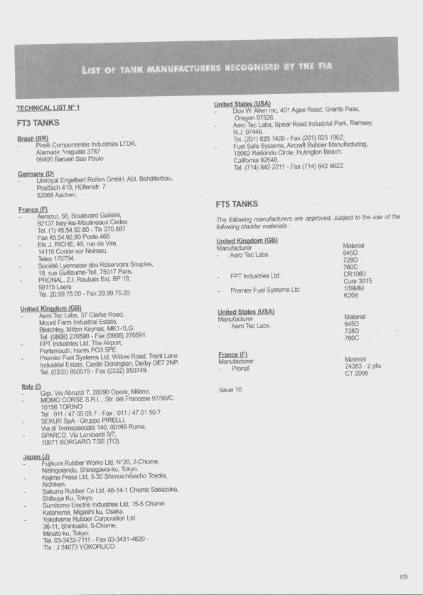
L is t o f t a n k m a n u f a c t u r e r s r e c o g n is e d by the f ia
TFCHNICAL UST N“ 1
FT3 TANKS
Brasil (BRIPirelli Componentes Industrials LTDA,AlamadP 'raguaia 3787 06400 Bameri Sao Paulo.
Germany (D1 „ .Uniroyal Engelbert Reifen GmbH, Abt. Behalterbau, Postfacti 410, Hüttenstr. 7 52068 Aactien.
France (FtAerazur, 58, Boulevard Galliéni,92137 Issy-les-Moulineaux Cedex Tel. (1) 45.54.92.80 - Tlx 270.887 Fax 45.54.92.80 Poste 465 Ets J. RICHE, 48, tue de Vire,14110 Conde sur Noireau.Telex 170794.Société Lyonnaise des Réservoirs Souples,18, rue Guillaume-Tell, 75017 Paris PRONAL, Z.l. Roubaix Est BP 18,59115 LeersTel. 20.99.75.00 - Fax 20.99.75.20
United Kingdom (GBlAeno Tec Labs, 37 Clarite Road,Mount Farm Industrial Estate,Bletchley, Milton Keynes, MK1-1LG.Tel. (0908) 270590 - Fax (0908) 270591.FPT Industries Ltd, The Airport,Portsmouth, Hants P03 5PE.Premier Fuel Systems Ltd, Willow Road, Trent Lane Industrial Estate, Castle Donington, Derby DE7 2NP. Tel. (0332) 850515 - Fax (0332) 850749.
Italy (I)Gipi Via Abruzzi 7, 20090 Opera, Milano.MOMO CORSE S.R.L., Str. del Francese 97/50/C, 10156 TORINOTel:011/47 05 057-F ax:011 /47 01 507 SEKUR SpA - Gruppo PIFtELLI,Via di Tonespeccata 140,00169 Roma.SPARCO, Via Lombardi 5/7,10071 BORGARO T.SE (TO).
Japan (J) _____Fujikura Rubtier Worits Ltd, N 20, 2-Chome, Nishlgotandu, ShinagawsFku, Tokyo.Kpjima Press Ltd, 3-30 Shimoichibacho Toyota, /\ichiken.Sakurra Rubber Co Ltd, 48-14-1 Chôme Sasazuka, Shibuya Ku, Tokyo.Sumitomo Electric Industries Ltd, 15-5 Chôme Katahama, Migashi ku, Osaka.Yokohama Rubber Corporation Ltd 36-11, Shinbashi, 5-Chome,Minato-ku, Tokyo.Tel 03-3432-7111 - Fax 03-3431-4820 - Tlx ; J 24673 YOKORUCO
United States (USA) „ ^ ^ dDon W. /Mien Inc, 401 Agee Road, Grants Pass, Oregon 97526.
Aero Tec Labs, Spear Road Industrial Park, Ramsey, N.J. 07446.Tel. (201 ) 825 1400 - Fax (201 ) 825 1962.Fuel Safe Systems, /Mrcraft Rubber Manufacturing, 18062 Redondo Circle, Hubngton Beach,California 92648.Tel. (714) 842 2211 - Fax (714) 842 6622.
FT5 TANKS
The following manufacturers are approved, sufyecf to the use the following bladder materials
United Kingdom (GB)Manufacturer
Aero Tec Labs
FPT Industries Ltd
Premier Fuel Systems Ltd
ManufacturerAiero Tec Labs
Frangei DManufacturer
Pronal
Issue 10
Material645D728D760CCR1060Cure 3015109MMK208
Material645D728D760C
Material 24353 - 2 plis CT2006

L is t o i= fuel a n a l y s is l a b o r a t o r ie s r e c o g n is e d b y t h e f ia
TECHNICAL LIST ?
Austria (A>1. Institut fiir Vebrennungskraftmasctiinen und
Kraftfatifzeugtjau der Technlsctien Unlversitat Wien Vorstand Prof. Lenz, Getreidemart<t 9,1060 WiEN For detemination of octane rate)Institut fur Ctiemiscfie Technologie fiir Erddlpnodukte der Universltat Wien,Vorstand Prof. Schindltiauer, Getreidemartd 9 1060 WIEN
Australia fAUS)1. Mr. Mark Giroletti - Chief Chemist
BNP Petroleum Latxiratory245 Wellington Road, Mulgrave 3170, VICTORIA Tel. : 61 3 566 7349 - Fax : 61 3 560 8576
2. SGS Australia Pty. Ltd1/33 Hurrel 121 Way, Rockingham WA6168 Tel : (61 9) 592 62 22 - Fax : (61 9) 592 60 55
Belgium fB>SGS Depauw & Stokoe N.V.Haven 407, Polderdijkweg 16, 2030/kNTWERPEN Tel. : (03) 545 84 11 - Fax : (03) 545 84 19
Switzerland (CHIEMPA - Service/Ztbteilung N° 133 Uetieriandstrasse 139 - 8600 DÜBENDORF Tel. : 1/823.41.33 - Tlx. : 825.345 Fax : 1/821.62.44
Czechoslovakia fCS)Chemopetrol, Korytna 47, PRAHA 10 - Strasnice
figfmany (P)1. PHL
Vorhoelzerstr.3, 8000 MÜNCHEN 71 Postfach 710 626Tel. : 089/79 89 77 - 089/3 54 25 41Fax : 089/7 91 88 89
2. SGS Control - COMBHPetrochemisches Latxir /Vn Neuen Rheinafen 12A6720 SPREYER - Tel. : 06232 /130140
3. PHLVorhoelzerstr.3, 8000 MÜNCHEN 71 Postfach 710 626Tel. : 089/79 89 77 - 089/3 54 25 41 Fax : 089/7 91 88 89
4. SGS Control - Co.mbH Behringstr. 154 22763 HAMBURGTel. : (040) 88 30 71 12 - Fax : (040) 88 02 653
5. SGS Control - Co.mbH Friedrich Albert Lange Platz 1 47051 DUISBURGTel. : (0203) 92 98 850 - Fax : (0203) 92 98 845
6. TUV Hannover Am TÜVI30175 HANNOVER DÔHRENTei. : (0511) 986 15 21 - Fax : (0511) 986 12 37
7. TUV Bayem Sachsen e.V./tbgasprüfstelle (G4-FBF€)Ridlerstr. 5780674 MÜNCHENTel. : (089) 51 90 31 52 - Fax : (089) 51 90 32 33
8. PETROLAB GmbH Brunckstr. 12 67346 SPEYERTel. : (06232) 33 O il - Fax : (06232) 33 015
9. DEKRAAGSchulze Delizsch. Str. 49, 70565 Stuttgart Tel : 071 17 86 10 - Fax : 071 17 86 12 506
France (FI1. ATEPE
Parc d'Activité de la Tuilerie Saint Benoît AUFFARGIS78610 LE PERRAY EN YVELINES
2. PCASZI La Vigne aux Loups 23, roe Bossuet 91160 LONGJUMEAU
United Kingdom fGBl1. BSI Testing
Mayland AvenueHemel Hempstead, Hertfordshire, HP2 4SQ Tel. : (0442) 230442 - Tlx. : 82424 Fax : (0442)231442
2. Caleb Brett Intemational Limited Laboratory and Technical ServicesUnit "A", 734 London Road, West Thurrock, EssexRM16 1HNTel. : (0708) 869960Fax : (0708)861496
3. SGS Redwood Ltd.Old Station /ApproachLondon Road, PURTLEET, Essex, RM16 IQS Tel. : 0708 866 855 - Tlx. : 897 361 Fax : 0708 864 137
4. Ricardo Consulting Engineers Ltd Shoreham by SeaWest Sussex, BN43 FG Tel. : 0273 455 611 -87 383 Fax : 0273 464 124
Greece (GRlGénérale Chimie de l'Etat Rue A. Tsoha 16 Ampelokipi-ATHENES
Italy fl)Stazione Sperimentale CombusïbillVia Galileo Galilei 120097 SAN DONATO MILANESE - MlTel. : 02/510031EcocontrolVia della Scafa 12100054 FlUMINCINO (ROMA)Tel. : 06/6453840
106
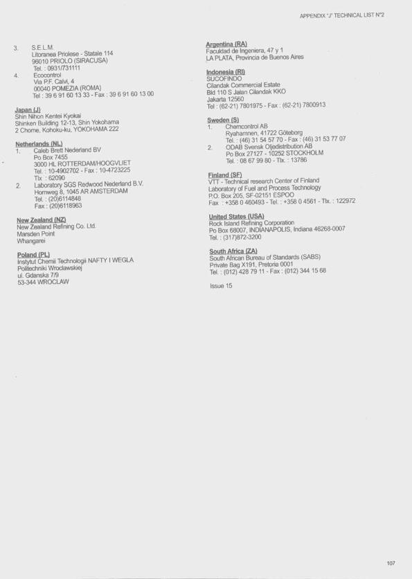
APPENDIX -J" TECHNICAL LIST N"2
3. S.E.L.M.Litoranea Priolese - Statale 114 96010 PRIOLO (SIRACUSA)Tel. : 0931/731111
4. EcocontrolVia P.P. Caivi, 4 00040 POMEZIA (ROMA)Tel ; 39 6 91 60 13 33 - Fax : 39 6 91 60 13 00
Japan (J)Shin Nihon Kentei KyokaiShinken Building 12-13, Shin Yokohama2 Chôme, Kohoku-ku, YOKOHAMA 222
Netheriands (NL)1. Caleb Brett Nedertand BV
Po Box 74553000 HL ROTTERDAM/HOOGVLIET Tel. ; 104902702 - Fax : 104723225 Tlx : 62090
2. Laboratory SGS Redwood Nederland B.V.Hcmweg 8,1045 AR AMSTERDAMTel. ; (20)6114848 Fax : (20)6118963
New Zealand (NZ)New Zealand Refining Co. Ltd.Marsden Point Whangarei
Poland (PÜinstytut Chemii Technokigii NAFTYIWEGLA Politechniki Wrodawskiej ul. Gdanska 7/9 53-344 WROCLAW
Argentina (RA)Faculdad de Ingeniera, 47 y 1 LA PLATA, Provincia de Buenos Aires
Indonesia (Rl)SUCOFINDOCilandak Commercial Estate Bid 110 S Jalan Cilandak KKOi j j iz o r fQ
Tel : (62-21) 7801975 - Fax : (62-21) 7800913
Sweden (S)1. Chemcontrol AB
Ryahamnen, 41722 Goteborg Tel. : (46) 31 54 57 70 - Fax : (46) 31 53 77 07
2 OD/Æ Svensk Oljedistribution ABPo Box 27127 -10252 STOCKHOLM Tel. : 08 67 99 8 0 -Tlx. : 13786
Finland(SF) ^VTT - Technical research Center of FinlandLaboratory of Fuel and Process TechnologyP.O. Box 205, SF-02151 ESPOOFax : +358 0 460493 - Tel. : +358 0 4561 - Tlx. : 122972
United States (USA!Rock Island Refining CorporationPo Box 68007, INDIANAPOLIS, Indiana 46268-0007Tel. : (317)872-3200
SoMtfi Afriw (ZA)South African Bureau of Standards (SABS)Private Bag X I91, Pretoria 0001Tel. ; (012) 428 79 11 - Fax : (012) 344 15 68
Issue 15
107
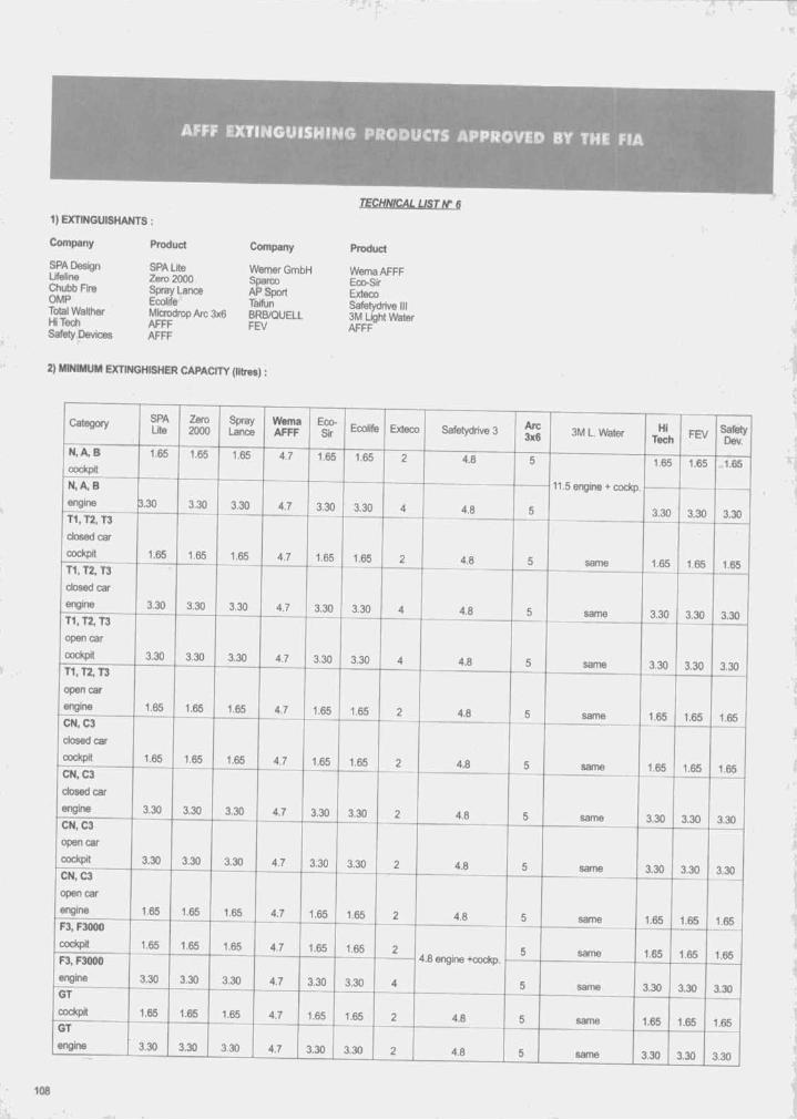
AFFF EXTINGIIISHING PRODUCTS APPROVED BY THE FIA
lECHNiCALUSTN^S
1) EXHNGUISHANTS :
Company Product Company Product
SPA Design Lifeline Chubb Fire OMRTotal Walther HiTechSafety Devices
SPA Lite Werner GmbHZero 2000 SparcoSpray Lance AP SportEcolife TaifunMicrodrop Arc 3x6 BRB/QUELLa f f f f e vAFFF
WemaAFFF Eco^ir Exteco Safetydrive III 3M Light Water AFFF
2) MINIMUM EXTINGHISHER CAPACITY (litres) :
Category SPALite
Zero2000
SprayLance
WemaAFFF
Eco-Sir Ecolife Exteco Safetydrive 3 Arc
3x6 3M L. Water HiTech FEV Safety
Dev.N, A, B
cockpit1.65 1.65 1.65 4.7 1.65 1.65 2 4.8 5 1.65 1.65 ^1.65
N ,A .B
engine ).30 3.30 3.30 4.7 3.30 3.30 4 4.8 5
- 11.5 engine+ cockp
3.30 3.30 3.30T1, T2, T3
closed car
cockpit 1.65 1.65 1.65 4.7 1.65 1.65 2 4.8 5 same 1.65 1.65 1.65T1, T2, T3
dosed car
engine 3.30 3.30 3.30 4.7 3.30 3.30 4 4.8 5 same 3.30 3.30 3.30T1, T2, T3
open car
cockpit 3.30 3.30 3.30 4.7 3.30 3.30 4 4.8 5 same 3.30 3.30 3.30T1,T2, T3
open car
engine 1.65 1.65 1.65 4.7 1.65 1.65 2 4.8 5 same 1.65 1.65 1.65CN, C3
closed car
cockpit 1.65 1.65 1.65 4.7 1.65 1.65 2 4.8 5 same 1.65 1.65 1 65CN, C3
dosed car
engine 3.30 3.30 3.30 4.7 3.30 3.30 2 4.8 5 same 3.30 3.30 3.30CN, C3
open car
cockpit 3.30 3.30 3.30 4.7 3.30 3.30 2 4.8 5 same 3.30 3.30 3.30CN, C3
open car
engine 1.65 1.65 1.65 4.7 1.65 1.65 2 4.8 5 same 1.65 1.65 1.65F3, F3000
cockpit 1.65 1.65 1.65 4.7 1.65 1.65 2 5 same 1.65 1.65 1.65F3, F3000
engine 3.30 3.30 3.30 4.7 3.30 3.30 4
4.8 engine +cockp. ■
5 same 3.30 3.30 3.30GT
cockpit 1.65 1.65 1.65 4.7 1.65 1.65 2 4.8 5 same 1.65 1.65 1.65GT
engine 3.30 3.30 3.30 4.7 3.30 3.30 2 4.8 1 5 same 3.30 3.30 3.30
108
'ik
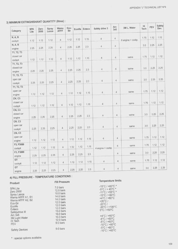
APPENDIX T TECHNICAL LIST N '6
CategorySPALite
Zero2000
SprayLance
WemaAFFF
Eco-SIr
Ecolife Exteco Safety drive 3Arc3x6
3M L. WaterHi
TechFEV M a ty
Dev.
N .A .B1.12 1.12 1.12 4 1.12 1.12 1.15 4 4
8 engine + cockp.1.75 1.12 1.12
N ,A ,B2.25 2.25 2.25 4 2.25 2.25 2.3 4 4 3.0 2.25 2.25
T1.T2, T3
dosed car112 1.12 1.12 4 1.12 1.12 1.15 4 4 same 1.75 1.12 1.12
T1.T2, T3
dosed car2,25 2.25 2.25 4 2.25 2.25 2.3 4 4 same 3.0 2.25 2.25
T1.T2, T3
open car2.25 2.25 2.25 4 2.25 2.25 2.3 4 4 san^ 3.0 2.25 2.25
T1.T2, T3
open car1.12 1.12 1.12 4 1.12 1.12 1.15 4 4 same 1.75 1.12 1.12
ON. 03
dosed car1.12 1.12 1.12 4 1.12 1.12 1.15 4 4 same 1.75 1.12 1.12
ON, 03
dosed car2.25 2.25 2.25 4 2.25 2.25 2.3 4 4 same 3.0 2.25 2.25
ON, 03
open car2.25 2.25 2.25 4 2.25 2.25 2.3 4 4 same 3.0 2.25 2.25
ON, 03
open car1.12 1.12 1.12 4 1.12 1.12 1.15 4 4 same 1.75 1.12 1.12
F3, F30001.12 1.12 1.12 4 1.12 1.12 1.15 4 same 1.75 1.12 1.12
F3, F30002.25 2.25 2.25 4 2.25 2.25 2.3 4 same 3.0 2.25 2.25
GT1.12 1.12 1.12 4 1.12 1.12 115 4 4 same 1.75 1.12 1.12
GT
engine 2.25 2.25 2.25 4 2.25 2.25 2.3 4 4 same 3.0 2.25 2.25
4) FILL PRESSURE - TEMPERATURE CONDITIONS :
Product
SPA LiteZero 2000Spray LanceWemaAFFFAl, B1Wema AFFF A2, B2Eco-SIrEcolifeExtecoSafetydrive IIIArc 3x63M Light WaterHiTeâiFEV
Safety Devices
* : special options available
Fill Pressure
7.0 bars12.0 bars10.0 bars14.0 bars14.0 bars12.0 bars12.0 bars12.0 tars15.0 bars16.0 bars 10.3 bars12.0 bars9.0 bars
9.0 bars
Temperature limits
-15”C/+60°C* -5“C / + 45°C * - irC /+ 5 5 ”C* -15”C/+60°C +4'C / +60°C +20“C I -2 0 °C I-20°C / +100“C 0°C / +50°C
+4°C / +60°C ■e'C I +60°C -5°C / +60“C -10“C/+60°C -5“C I +60°C -10“C /+60“C
109

Drawings
© 1996 Fédération Intemationate de l’Automobile111
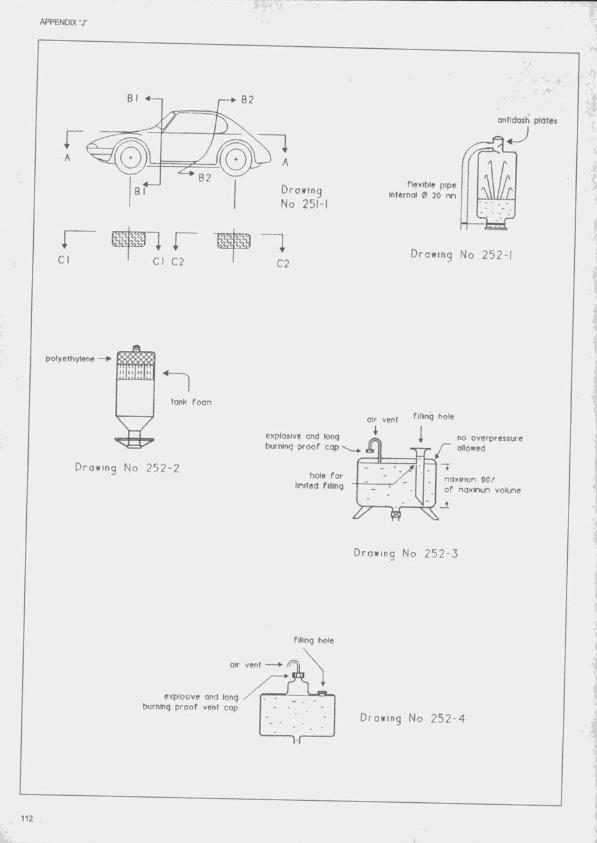
APPENDIX T
B2flexible pipe
internal ® 20 mDrowlng No 251-
Orawing No 2 5 2 -1C2
polyethylene
tonk foon
air vent
explosive and long burninq proof cop
no overpressure allowed
Drawing No 2 5 2 - 2hole for
United fillingnaxinun 90/ of naxinun volune
Drawing No 2 5 2 - 3
fiHing hole
Aexplosive ond long burning proof vent cop
Drawing No 2 5 2 - 4
112
V?
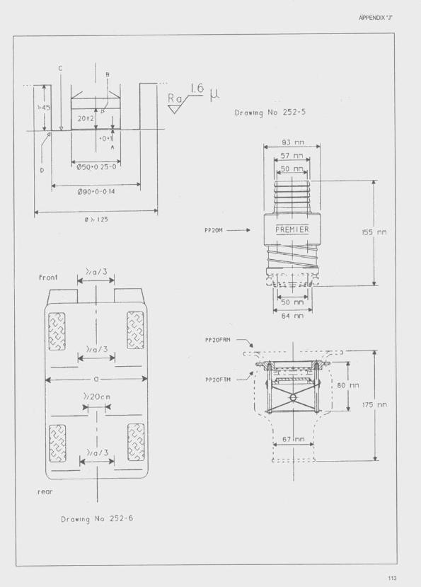
APPENDIX " jr
>/45
20±2
0 5 0 * 0 25 -0
V 1 25
) / a / 3fron t
) / a / 3
) /20cm
) / a / 3
rear
Drawing No 2 5 2 - 6
1.6 ,, R a ^ K
Drawing No 2 5 2 - 5
PP20M
93 nn
57 nn
.50 nn,
PREMIER 155 nn
50 nn
64 nn
PP20FRM
PP20FTM80 nn
175 nn
n n
113
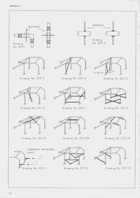
APPENDIX T
bulkheadbulkhead
Drawing No 2 5 3 - 2Drowing
N o 25 3 -1
Drawing No 2 5 3 - 5
d \< 3 0 cm
Drawing No 2 5 3 - 3 Drowing No 2 5 3 - 4
Drawing No 2 5 3 - 7
àip
Drawing No 2 5 3 - 6 Drawing No 2 5 3 -
Drawing No 2 5 3 - 9 Drawing No 2 5 3 - 9 A Drawing No 2 5 3 - 1 0
suspension anchorage points
Drawing No 2 5 3 -1 3Drawing No 2 5 3 -1 2Drawing No 253-11
114
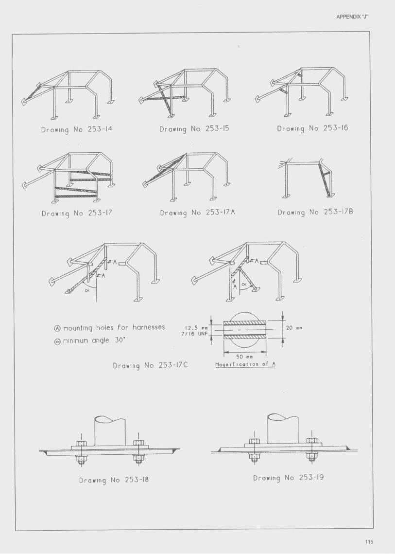
APPENDIX “X
IDrawing No 253-14 Drawing No 253-15 Drawing No 253-16
Drawing No 253-17
^ à i7
V
Drowing No 253-I7A Drawing No 253- I7B
^ 7
® nountinq holes fo r harnesses
0 nininun angle 30*
12 .5 nn 7 / 1 6 UNF,”
50 mm
20 mn
Drawing No 253-I7C Mogmficotton of A
o JEUr L
Drawing No 253-18 Drawing No 253-19
115

APPENDIX "X
n T1 rtlny
V ' f 'Drawing No 2 5 3 - 2 0
Drawing No 2 5 3 - 2 2
P c i
Drawing No 2 5 3 - 2 3
Drowing No 2 5 3 - 2 5
Drawing No 2 5 3 - 2 6
C03
direction o f applied load
Drawing No 2 5 3 - 2 7
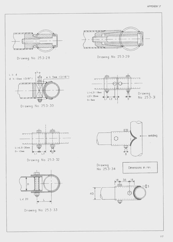
APPENDIX T
Drawing No 2 5 3 - 2 9Drawing No 2 5 3 - 2 8
>/ 5n« 1 3 / 1 6 " )d ) / 10mm 1 3 / 8 " )
— e
Drowing No 2 5 3-31
Drowing N o 2 5 3 - 3 0
in i
Drawing No 2 5 3 - 3 2
Drawing No 2 5 3 - 3 4 Dinensions m
m
40
L>< 2D
Drawing No 2 5 3" 3 3
117
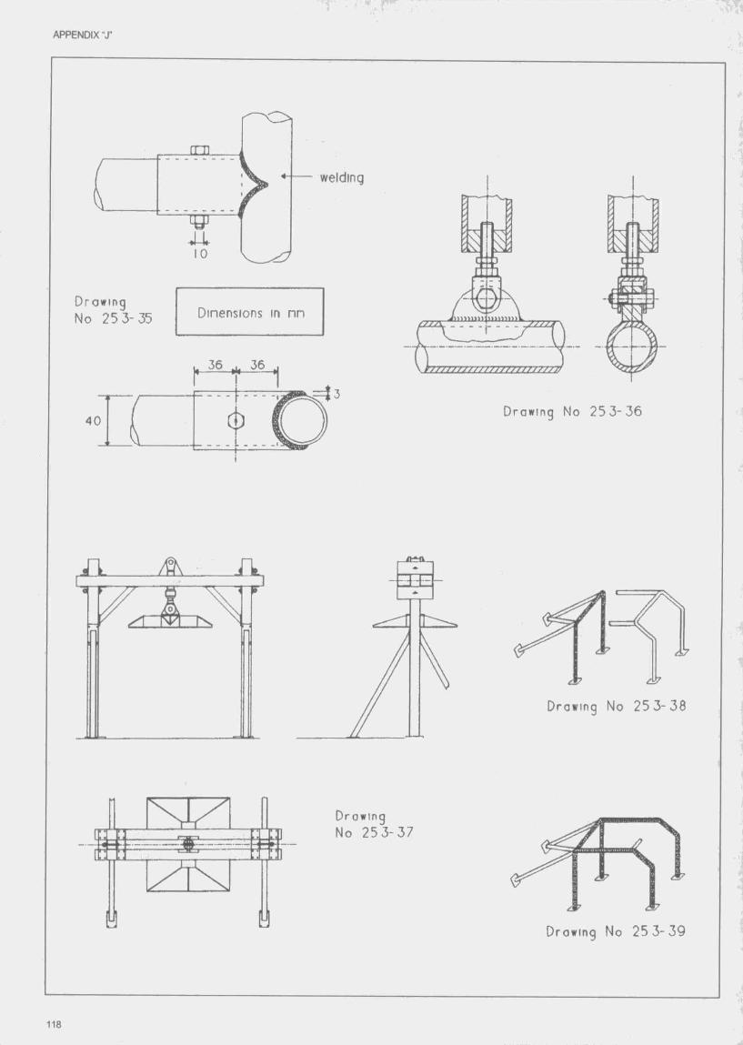
APPENDIX T
w elding
Drawing No 25 3-35 Dinensions in nn
36
40Drawing No 2 5 3 - 3 6
Drawing No 25 3 -38
Drowing No 2 5 3 -3 7
Drowing No 25 3 -3 9
118
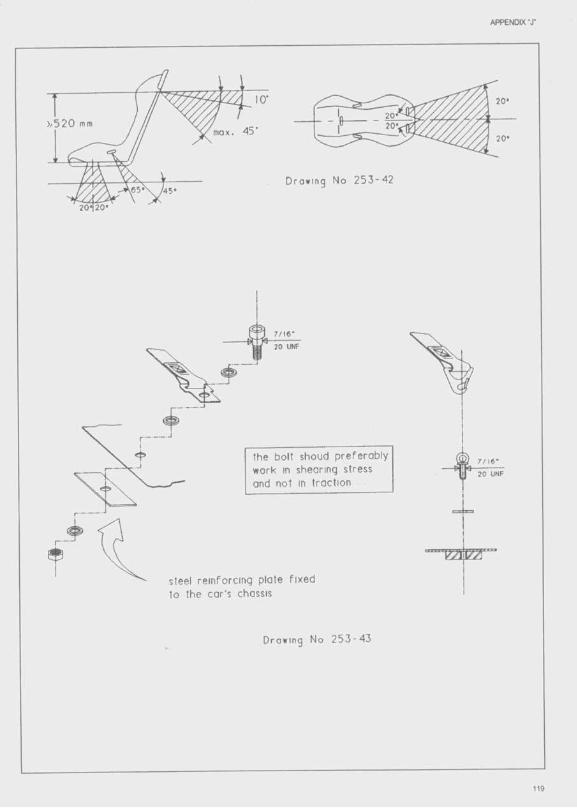
APPENDIX T
max. 45 '
.65*' ^45*
2 0 ^ 0 '
Drawing No 2 5 3 - 4 2
2 0 UNF
the bolt shoud p re fe ra b ly work in shearing stress and not in traction
steel re in forc ing p late fixed to the car's chassis
20 UNF
Ii
Drawing No 2 5 3 - 4 3

APPENDIX " T
p late Fixed to the chossis and strengthened by o re in fo rced
p la te on the o th er side
Draviing No 2 5 3 - 4 4
re in forc ing plate f ix e d to the cor's chassis
re in forcen ent
o o Q o gseat shell
co nterp lcte
Drawing No 2 5 3 - 5 2
conterp late
(g) nounling holes fo r harness
Drawing No 25 3 - 4 5
7/16 UNF
50 RID
Drowinq No 2 5 3 - 5 3
120
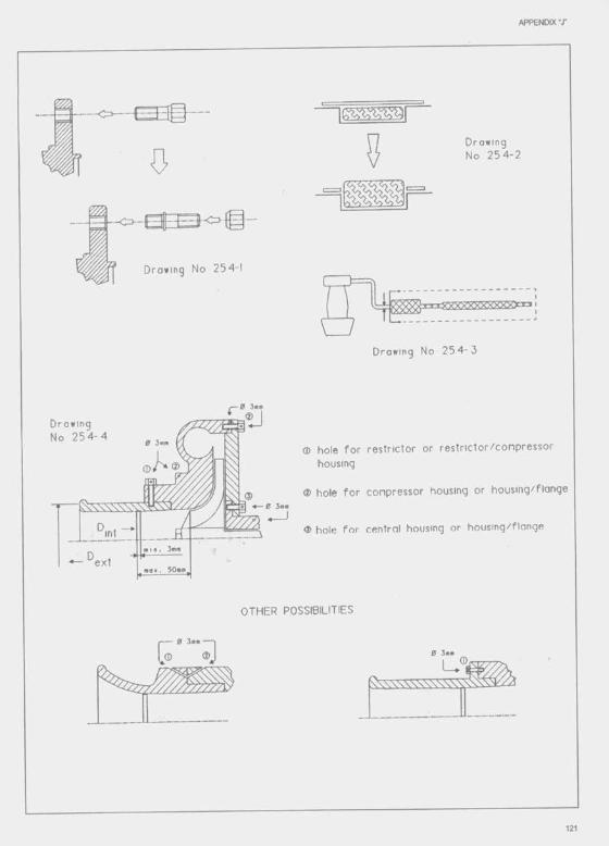
APPENDIX "J"
0
Drowing No 2 5 4 - 2
Drowing No 2 5 4 -
S S S S c o i— — — — — — — —
Drowing No 2 5 4 - 3
Drowing No 2 5 4 - 4
ext
® hole fo r restnctor or restrictor/compressor housing
® hole fo r compressor housing or housing/flange
® hole fo r central housing or housing/flonge
OTHER POSSIBILITIES
0 3 m m
Z22ZZZ
121
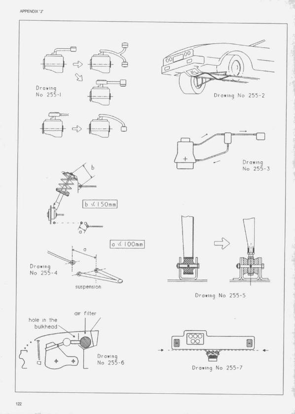
APPENDIX -J"
Drawing No 25 5 -1 Drawing No 2 5 5 - 2
Drawing No 2 5 5 - 3
b \< I 50mm
o \ ( I 0 0 mm
Drowtng No 2 5 5 - 4
— I
suspension
Drawing No 2 5 5 - 5
air fillerhole in the
bulkhead
O O
DrawingNo 2 5 5 - 6
Drawing No 2 5 5 - 7
122
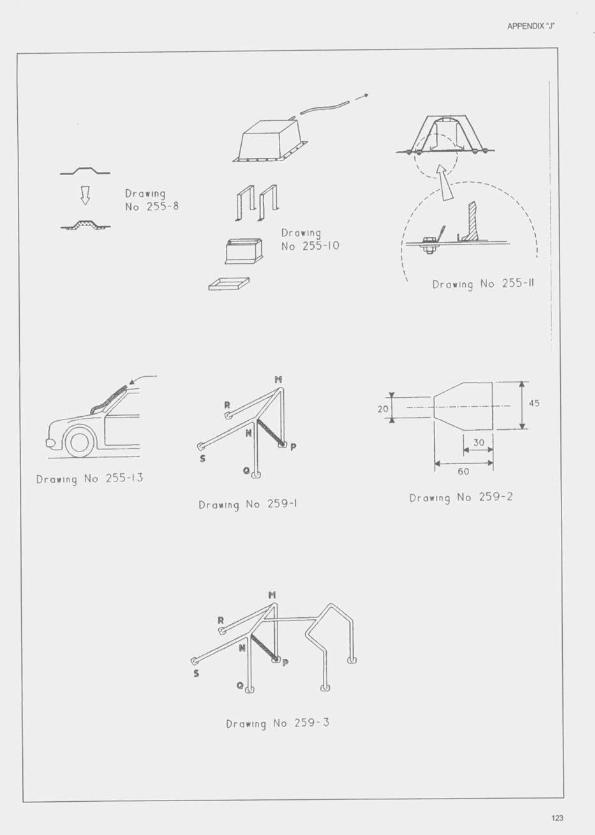
APPENDIX-J-
No 2 5 5 -
Drowing No 2 5 5 - 1 0
Drawing No 255-11
20
60Drowing No 2 5 5 - 1 3
Drawing N o 2 5 9 - 2Drawing No 2 5 9 -
Drawing No 2 5 9 - 3
123
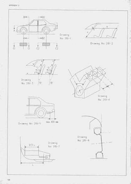
Drawing
No 261-1
Drawing No 261-2
Drawing
No 261-3
max. KX) mm
Drawing
No 261-72/3 L
w
Drowing
No 261-4
Drawing
No 261-

Drawing
No 261-
max. 10 cm
Drawing No 261-9
Drawing No 261-10
Drawing
No 261-
500400
Drawing
No 261-12
Drawing No 261-13

APPENDIX "J"
O O
Drawing 1
No 261-14
3 - h ”/ 3
max.H / 2 " ^ m a x . ^ V “ T m o x .
_ 1 h / 3 I X X I 1 h / 3
Drawing No 261-15
min. 5 0 mm
l^min. 100 ram.
P 1
Drawing No 261-16
5 0 mm Û Q \^ b odyw ork
Drowing No 261-17
4 0 mra 3 0 mm
Drawing N o 2 6 2 -1
126

APPENDIX T
94.4
17.8
Drawing No 2 7 4 -
161,7
31.4Drawing No 2 6 2 - 2
Drowing No 2 7 4 - 2
40.2Drawing No 2 7 4 - 3
Six holes 50 diameter
:oo
100Drawing No 2 7 4 - 4
300 100
50;5o
Fron t edge o f the re a r wheelsR ear edge o f the fro n t wheels
car cen tre line
Drawing No 2 7 4 - 5
♦ j PLAN VIEW
127
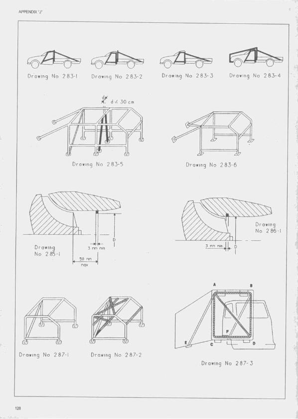
APPENDIX Ti '■
Drawing No 2 8 3 - 1 Drowing No 2 8 3 - 2 Drowing No 2 8 3 - 3 Drowing No 2 8 3 - 4
d \< 3 0 c m
2 ^
Drawing No 2 8 3 - 5 Drawing No 2 8 3 - 6
Drawing No 2 86-1
Drawing No 2 85 -
nax
Drawing No 2 87-1 Drawing No 2 8 7 - 2
Drawing No 2 8 7 - 3
128

APPENDIX T
Drawing No 2 9 0 - 1
hand cut tre e dI
[ / / / I ! LES ksssi i r
2 nn nininun
tre a d wear indicator
Drowing No 2 9 0 - 2
2550nax
1800nin
ALL DIMENSIONS IN MM
centre line o f f i f t h wheel2500nin
100Drawing No 2 9 0 - 31200 nin
1300 nax180nin
2040
Drawing No 2 9 0 - 4
3 nn nin
129
List of FIA homologated vehicles and engines- This list Is classifieci by country.
- The letter immediately preceding the homctogation number indicates the Group in which the vehicle or engine is homologated;
Group N: Production Cars (N)Group A: Touring Cars (A)Group B: Grand Touring Cars (B)Group T : Series Cross-Country Cars (T1)
Cross-Country Trucks (T4)Group ST: Super Touring cars
C2: Super Touring enginesF3: Formula 3 engines
Group C1 : Grand Touring Cars Class 1Group C2: Grand Touring Cars Class 2
- The date mentioned after the commercial denomination indicates the beginning of the homologation of the vehicle or engine.
- The number in brackets gives the last year for which the vehicle or engine is homologated, e.g. (96) homologation valid until 31/12/96. If the sign + is added, this means that the homologation is likely to be extended.
NB. : The present list of vehicles and engines was established on 15 November 1995. The periodical addenda to this list will be published in the FIA Official Bulletin.
€> 1996 Fédération Internationale de I'AutomotxIe 131
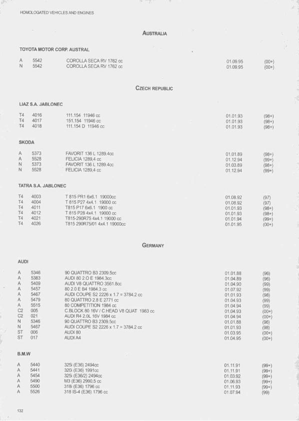
» "T.* ■T
HOMOLOGATED VEHICLES AND ENGINES
A u s t r a l ia
TOYOTA MOTOR CORP. AUSTRAL
55425542
COROLLA SEGA RV 1762 cc COROLLA SEGA RV 1762 cc
C z e c h r e p u b l ic
LIAZ S A JABLONEC
G erm any
AUDI
01.09.9501.09.95
T4 4016 111.154 11946CC 01.01.93T4 4017 151.154 11946CC 01.01.93T4 4018 111.154 0 11946 cc 01.01.93
SKODA
A 5373 FAVORIT 136 L 1289.4CC 01.01.89A 5528 FELICIA 1289,4 CC 01.12.94N 5373 FAVORIT 136 L 1289.4cc 01.03.89N 5528 FELICIA 1289,4 cc 01.12.94
TATRA SA. JABLONEC
T4 4003 T 815 PR1 6x6.1 19000CC 01.08.92T4 4004 T 815 P27 4x4.1 19000 cc 01.08.92T4 4011 T815P17 6x6.1 1900 cc 01.01.93T4 4012 T 815 P28 4x4.1 19000 cc 01.01.93T4 4021 T815-290R75 4x4.1 19000 cc 01.01.94T4 4026 T815 290R75/01 4x4.1 19000CC 01.01.95
A 5346 90 QUATTRO B3 2309.5CC 01.01.88A 5383 AUDI 80 2.0 E 1984.3CC 01.04.89A 5409 AUDI V8 QUATTRO 3561,8cc 01.04.90A 5457 80 2.0 E B4 1984.3 cc 01.07.92A 5467 AUDI COUPE S2 2226 x 1.7 = 3784.2 cc 01.01.93A 5479 80 QUATTRO 2.8 E 2771 cc 01.04.93A 5515 80 COMPETITION 1984 cc 01.04.94C2 005 C.BLOCK 80 16V / C.HEAD V8 QUAT 1983 cc 01.04.93C2 021 AUDI R4 2.0L 16V 1984 cc 01.04.94N 5346 90 QUATTRO B3 2309.5CC 01.01.88N 5467 AUDI COUPE S2 2226 x 1.7 = 3784.2 cc 01.01.93ST 006 AUDI 80 01.03.95ST 017 AUDI A4 01.04.95
B.M,W
A 5440 3251 (E36) 2494CC 01.11.91A 5441 3201 (E36) 1991CC 01.11.91A 5454 3251 (E36/2) 2494cc 01.03.92A 5490 M3 (E36) 2990,5 cc 01.06.93A 5500 3181 (E36) 1796CC 01.11.93A 5526 318IS-4 (E36)1796cc 01.07.94
:4
(00+)(00+)
(98+)(98+)(98+)
(98+)(99+)(98+)(99+)
(97)(97)(98+)(98+)(99+)(00+)
(96)(96)(99)(99)(98)(99) (99) (00+) (00+) (96) (98) (00+) (00+)
(99+)(99+)(99+)(99+)(99+)(99)
132
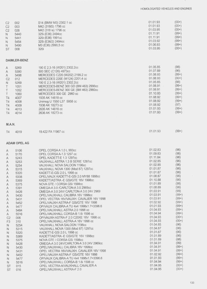
H0M0LCX3ATED VEHICLES AND ENGINES
C2 002 S 14(B M W M3) 2302.1 cc 01.01.93 (00+)
C2 003 M42 (318iS) 1796cc 01.01.93 (00+)
C2 026 M42 (318 Is) 1796 CC 01.03.95 (00+)
N 5440 3251 (E36) 2494CC 01.11.91 (99+)
N 5441 3201 (E36) 1991CC 01.11.91 (99+)
N 5454 3251 (E36/2) 2494cc 01.03.92 (99+)
N 5490 M3 (E36) 2990,5 cc 01.06.93 (99+)
ST 008 3201 01.03.95 (00+)
DAIMLER-BENZ
A 5269 190 E 2.3-16 (W 201) 2302.2CC 01.05.85 (98)
A 5390 500 SEC (0126) 4973CC 01.07.89 (96)A 5498 M ERCEDES C220 (W 202) 2199.2 cc 01.08.93 (99+)
C2 012 M ERCEDES 220E (W 124) 2201.4 cc 01.08.93 (00+)
N 5269 190 E 2.3-16 (W 201) 2302.2cc 01.05.85 (98)
T 1051 MERCEDES-BENZ 300 GD (BM 463) 2996cc 01.08.91 (99+)
I 1052 MERCEDES-BENZ 300 GE (BM 463) 2960cc 01.08.91 (99+)
I 1060 M ERCEDES 300 GE 2960 CC 01.10.93 (99+)14 4007 1935 AK 14618 cc 01.08.92 (99+)
14 4008 Unimog U 1550 L37 5958 cc 01.08.92 (99+)
14 4009 1936 AK 18273 cc 01.08.92 (97)
T4 4013 2635 AK 14618 cc 01.01.93 (99+)
14 4014 2636 AK 18273 cc 01.01.93 (99+)
M.A.N.
14 4019 19.422 FA 11967 cc 01.01.93 (99+)
ADAM O PEL AG
A 5106 OPEL C O R S A A 1 .0 L 993CC 01.02.83 (96)
A 5170 OPEL C O R SAA -1.31297CC 01.09.83 (96)
A 5243 OPEL KADETT-E 1.3 1297cc 01.11.84 (96)
A 5253 VAUXHALL ASTRA 1.3 B SERIE 1297cc 01.02.85 (96)
A 5254 VAUXHALL NOVA SALOON 1196cc 01.02.85 (96)
A 5315 VAUXHALL NOVA 1300 (Mod 87) 1297cc 01.01.87 (96)
A 5320 KADETT-E-GSi 2.0 L 1998 cc 01.01.87 (96)
A 5338 OPEL/VAÜX KADETT-E-GSi 2.0 MY88 1998cc 01.08.87 (96)
A 5369 KADETT/ASTRA-E GSI/GTE 16V 1998cc 01.10.88 (96)
A 5375 NOVA GTE 1 CORSA GS11598cc 01.01.89 (98)A 5391 OMEGA-A 3.0 /CARLTON-A 3.0 2969cc 01.08.89 (96)
A 5426 OMEGA-A 3.0 24V/ CARLTON-A 3.0 24V 2969 01.03.91 (99)A 5430 OPELA/AUXHALL CALIBRA 16V 1998cc 01.03.91 (99+)A 5431 OPEL VECTRA 16VA/AUXH. CAVALIER 16V 1998 01.03.91 (99+)
A 5452 OPELA/AUXH ASTRA-F GSI/GTE 16V 1998 01.02.92 (99+)
A 5477 OPA/AUX CALIBRA-A TÜ 4x4 1998x1.7=3396.6 01.01.93 (99+)
A 5484 OPELA/AUXHALL ASTRA 2.0 1998 cc 01.04.93 (99+)
A 5516 OPELA/AUXHALL CORSA-B 1.611598 cc 01.04.94 (99+)
C2 006 OPA/AUXH ASTRA-F 2.0 C20XE 16V 1998 cc 01.04.93 (00+)
F3 310 OPELA/AUXHALL ASTR A-A16V 1998 cc 01.04.93 (00+)
N 5254 VAUXHALL NOVA SALOON 1196cc 01.04.85 (96)
N 5315 VAUXHALL NOVA 1300 (Mod 87) 1297cc 01.04.87 (96)
N 5320 KADETT-E-GSI 2.0 L 1998 CC 01.01.87 (96)
N 5369 KADETT/ASTRA -E GSI/GTE 16V 1998cc 01.01.89 (96)
N 5375 NOVA GTE / CORSA GSi 1598cc 01.01.89 (98)
N 5426 OMEGA-A 3.0 24V/CARLTON-A 3.0 24V 2969cc 01.04.91 (99)
N 5430 OPELA/AUXHALL CALIBRA 16V 1998cc 01.04.91 (99+)
N 5431 OPEL VECTRA 16VA/AUXH. CAVALIER 16V 1998 01.04.91 (99+)
N 5452 OPELA/AUXH ASTRA-F GSI/GTE 16V 1998 01.02.92 (99+)
N 5477 OPA/AUX CALIBRA-A TU 4x4 1998x1.7=3396.6 01.01.93 (99+)
N 5516 OPELA/AUXHALL CORSA-B 1.611598 cc 01.04.94 (99+)
ST 015 OPEL VECTRA-A/VAUXHALL CAVALIER-A 01.04.95 (00+)
ST 016 OPELA/AUXHALL ASTRA-F 2.0 01.04.95 (00+)
133

HOMOLOGATED VEHICLES AND ENGINES
PORSCHE
B 283 928 S 4957CC 01.06.868 284 944 TURBO 2479x1.7=4214.3cc 01.06.86B 294 911 CARRERA 4 3600.27CC 01.09.90B 295 911 CARRERA 2 3600.27CC 01.09.90B 296 911 CARRERA RS 3600.5CC 01.03.92B 298 911 TURBO 2 3299 X 1.7 = 5608.3 (X 01.04.93G2 002 911 CARRERA RS 3.8 01.08.95
VEB AUTOMOBILWERKE EISENACH
A 5411 WARTBURG 1.3 1272CC 01.06.90N 5411 WARTBURG 1.3 1272CC 01.06.90
VOLKSWAGEN (ALLEMAGNE)
A 5175 SCIROCCO GTi 1800 1781cc 01.11.83A 5212 19G0LFGTI1781CC 01.04.84A 5295 19 GOLF GTI 16V1781CC 01.03.86A 5314 53 SCIROCCO 16V 1781.3CC 01.11.86A 5337 19 GOLF SYNCR01781.3CC 01.07.87A 5425 GOLF GTi G60 1781x1.7=3028cc 01.01.91A 5438 POLO COUPE G40 (86C) 1272.5x1 7=2163cc 01.10.91A 5439 86 POLO COUPE 1275.5CC 01.10.91A 5482 VENTO GT 2.0 1984 cc 01.04.93A 5483 GOLF GTI 16V 2.0 1984 cc 01.04.9302 007 GOLF GTI 16V 1.8L 1781 cc 01.04.9302 008 GOLF GTI 16V 2.0L 1984 cc 01.04.93F3 302 PASSAT 1984 cc 01.08.91F3 309 19 GOLF GT11781 cc 01.04.93F3 311 17 GOLF GTI 1588 cc 01.04.93N 5212 19 GOLF GTI1781CC 01.07.84N 5295 19 GOLF GTi 16V 1781CC 01.05.86N 5314 53 SCIROCCO 16V 1781.3cc 01.11.86N 5337 19 GOLF SYNCRO 1781,3cc 01.07.87N 5425 GOLF GTi G60 1781x1.7=3028cc 01.01.91N 5438 POLO COUPE G40 (860) 1272.5x1 7=2163cc 01.10.91N 5439 86 POLO COUPE 1275.5CC 01.10.91N 5482 VENTO GT 2.0 1984 cc 01.04.93N 5483 GOLF GTI 16V 2.0 1984 CC 01.04.93
(97)(97)(99)(99)(99)(99)(00+)
(96)(96)
(97)(96)(96)(97) (96) (96) (99) (99) (99+) (99+) (00+) (00+) (00+) (00+) (00+) (96)(96)(97) (96) (96) (99) (99) (99+) (99+)
S p ain
MIRANDA ALONSO FERNANDEZ S.A.
T4 4020 IPV-180R 17680 cc 01.01.94
SEAT
A 5358 MARBELLA GL 5vel 903cc 01.04.88A 5368 IBIZA 1.5 SXI1461CC 01.10.88A 5478 TOLEDO GT 16V 1781.32cc 01.01.93A 5504 IBIZA GTI 2.0 1984,5 cc 01.01.94A 5517 IBIZA GTI 16V 1781.32 cc 01.07.94C2 030 TOLEDO GT 01.08.95N 5368 IBIZA 1.5 SXI 1461CC 01.01.90N 5478 TOLEDO GT 16V 1781.32CC 01.01.93N 5504 IBIZA GTI 2.0 1984,5 cc 01.01.94N 5517 IBIZA GTI 16V 1781.32 cc 01.07.94ST 022 TOLEDO GT 01.08.95
(99+)
(98+)(98)(98+)(99+)(99+)(00+)(98)(98+)(99+)(99+)(00+)
134
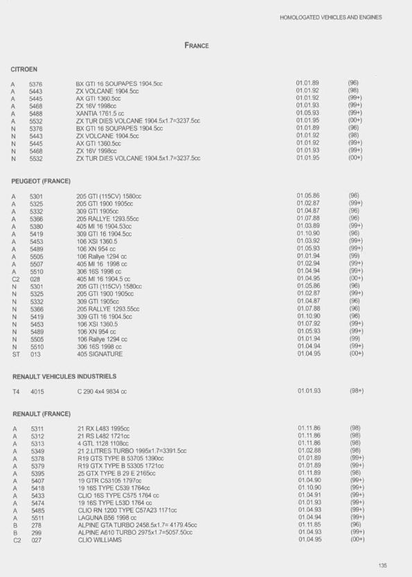
CITROEN
F rance
HOMOLOGATED VEHICLES AND ENGINES
A 5376 BX GTI 16 SOUPAPES 1904.5CC 01.01.89 (96)A 5443 ZXVOLCANE1904.5CX: 01.01.92 (98)A 5445 AX GTI 1360.5CC 01.01.92 (99+)A 5468 ZX16V1998CC 01.01.93 (99+)A 5488 XANTIA1761.5CC 01.05.93 (99+)A 5532 ZX TUR DIES VOLCANE 1904.5x1.7=3237.5cc 01.01.95 (00+)N 5376 BX GT116 SOUPAPES 1904.5CC 01.01.89 (96)N 5443 ZX VOLCANE 1904.5CC 01.01.92 (98)N 5445 AX GTI 1360.5CC 01.01.92 (99+)N 5468 ZX 16V 1998CC 01.01.93 (99+)N 5532 ZX TUR DIES VOLCANE 1904.5x1,7=3237,5cc 01.01.95 (00+)
PEUGEOT (FRANCE)
A 5301 205 GTI (115CV) 1580CC 01.05.86 (96)A 5325 205 GT11900 1905CC 01.02.87 (99+)A 5332 309 GTI 1905CC 01.04.87 (96)A 5366 205 RALLYE 1293.55cc 01.07.88 (96)A 5380 405 Ml 16 1904.53CC 01.03.89 (99+)A 5419 309 GTI16 1904.5CC 01.10.90 (96)A 5453 106 XS11360.5 01.03.92 (99+)A 5489 106 XN 954 cc 01.05.93 (99+)A 5505 106 Rallye 1294 cc 01.01.94 (99)A 5507 405 Ml 16 1998 cc 01.02.94 (99+)A 5510 306 16S 1998 cc 01.04.94 (99+)C2 028 405 Ml 16 1904.5 cc 01.04.95 (00+)N 5301 205 GTI (115CV) 1580CC 01.05.86 (96)N 5325 205 GT11900 1905CC 01.02.87 (99+)N 5332 309 GTI 1905CC 01.04.87 (96)N 5366 205 RALLYE 1293.55cc 01.07.88 (96)N 5419 309 GTI16 1904.5CC 01.10.90 (96)N 5453 106 XS11360.5 01.07.92 (99+)N 5489 106 XN 954 cc 01.05.93 (99+)N 5505 106 Rallye 1294 cc 01.01.94 (99)N 5510 306 16S 1998 cc 01.04.94 (99+)ST 013 405 SIGNATURE 01.04.95 (00+)
RENAULT VEHICULES INDUSTRIELS
T4 4015 C 290 4x4 9834 cc 01.01.93 (98+)
RENAULT (FRANCE)
A 5311 21 RX L483 1995CC 01.11.86 (98)A 5312 21 RS L482 1721CC 01.11.86 (98)A 5313 4 GTL 1128 1108CC 01.11.86 (98)A 5349 21 2.LITRES TURBO 1995x1.7=3391.5cc 01.02.88 (98)A 5378 R19 GTS TYPE B 53705 1390cc 01.01.89 (99+)A 5379 R19 GTXTYPE B 53305 1721CC 01.01.89 (99+)A 5395 25 GTX TYPE B 29 E 2165CC 01.11.89 (98)A 5407 19 GTR C53105 1797CC 01.04.90 (99+)A 5418 19 16S TYPE 0539 1764CC 01.10.90 (99+)A 5433 CLIO 16S TYPE C575 1764 cc 01.04.91 (99+)A 5474 19 16S TYPE L53D 1764 cc 01.01.93 (99+)A 5485 CLIO RN 1200 TYPE C57A23 1171cc 01.04.93 (99+)A 5511 LAGUNA B56 1998 cc 01.04.94 (99+)B 278 ALPINE GTA TURBO 2458.5x1.7= 4179.45CC 01.11.85 (96)B 299 ALPINE A610 TURBO 2975x1 7=5057.50cc 01.04.93 (99+)02 027 CLIO WILLIAMS 01.04.95 (00+)
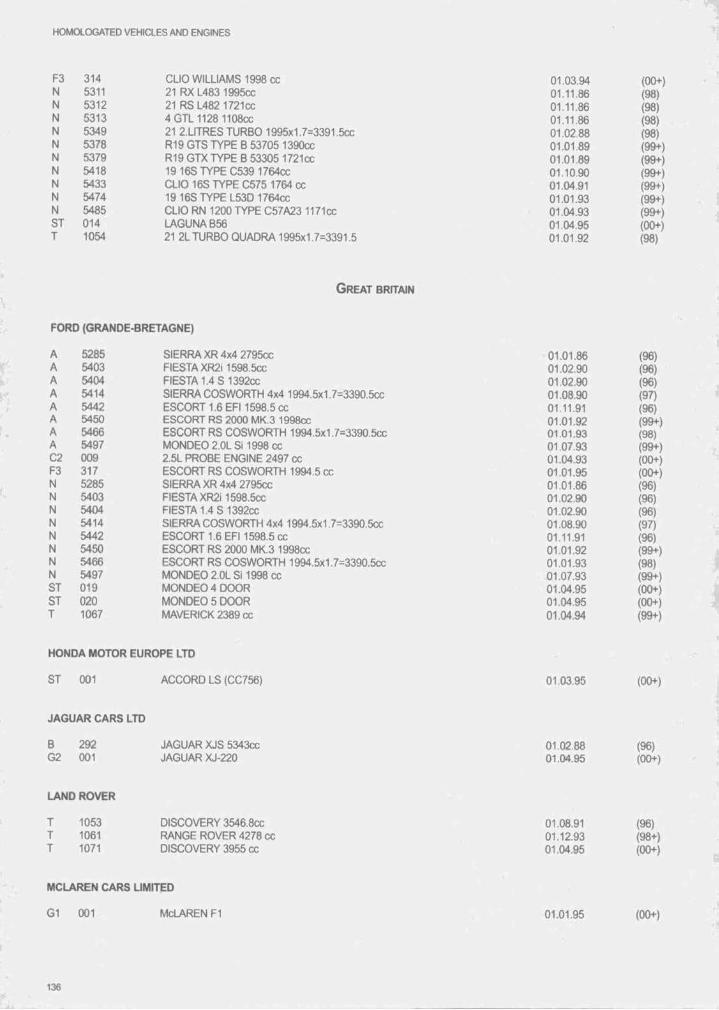
HOMOLOGATED VEHICLES AND ENGINES
F3 314 CLIO WILLIAMS 1998 CC 01.03.94N 5311 21 RX L483 1995CC 01.11.86N 5312 21 RS L482 1721CC 01.11.86N 5313 4 GTL 1128 1108CC 01.11.86N 5349 21 2.LITRES TURBO 1995x1.7=3391,5cc 01.02.88N 5378 R19 GTS TYPE 8 53705 1390cc 01.01.89N 5379 R19 GTX TYPE 8 53305 1721cc 01.01.89N 5418 1916STYPE C539 1764CC 01.10.90N 5433 CLIO 16S TYPE C575 1764CC 01.04.91N 5474 1916STYPE L53D1764CC 01.01.93N 5485 CLIO RN 1200 TYPE C57A23 1171cc 01.04.93ST 014 LAGUNA 856 01.04.95T 1054 21 2L TURBO QUADRA 1995x1.7=3391.5 01.01.92
(00+)(98)(98)(98)(98)(99+)(99+)(99+)(99+)(99+)(99+)(00+)(98)
G r eat Britain
FORD (GRANDE-BRETAGNE)
A 5285 SIERRA XR 4x4 2795cc 01.01.86A 5403 FIESTA XR2i 1598.5cc 01.02.90A 5404 FIESTA 1.4 8 1 392CC 01.02.90A 5414 SIERRA COSWORTH 4x4 1994.5x1.7=3390.5cc 01.08.90A 5442 ESC0RT1.6 EF11598.5 cc 01.11.91A 5450 ESCORT RS 2000 MK.3 1998cc 01.01.92A 5466 ESCORT RS COSWORTH 1994.5x1.7=3390.5cc 01.01.93A 5497 MONDEO2.0L Si 1998 cc 01.07.93C2 009 2.5L PROBE ENGINE 2497 cc 01.04.93F3 317 ESCORT RS COSWORTH 1994.5 cc 01.01.95N 5285 SIERRA XR 4x4 2795cc 01.01.86N 5403 FIESTA XR2i1598.5cc 01.02.90N 5404 FIESTA 1.4 S 1392CC 01.02.90N 5414 SIERRA COSWORTH 4x4 1994.5x1 7=3390.5cc 01.08.90N 5442 ESCORT 1.6 EF11598.5 cc 01.11.91N 5450 ESCORT RS 2000 MK.3 1998cc 01.01.92N 5466 ESCORT RS COSWORTH 1994.5x1.7=3390.5cc 01.01.93N 5497 MONDEO2.0L SI1998cc 01.07.93ST 019 M0NDE0 4D 00 R 01.04.95ST 020 MONDEO 5 DOOR 01.04.95T 1067 MAVERICK 2389 cc 01.04.94
(96)(96)(96)(97) (96) (99+)(98) (99+) (00+) (00+) (96) (96)(96)(97) (96) (99+)(98) (99+) (00+) (00+) (99+)
HONDA MOTOR EUROPE LTD
ST 001 ACCORD LS (CC756) 01.03.95 (00+)
JAGUAR CARS LTD
8 29202 001
JAGUAR XJS 5343CC JAGUAR XJ-220
01.02.8801.04.95
(96)(00+)
LAND ROVER
T 1053 T 1061 T 1071
DISCOVERY 3546.8CC RANGE ROVER 4278 cc DISCOVERY 3955 cc
01.08.9101.12.9301.04.95
(96)(98+)(00+)
MCLAREN CARS LIMITED
G1 001 MCLAREN FI 01.01.95 (00+)
136
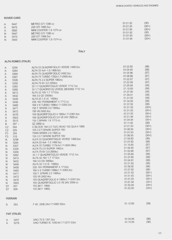
HOMOLOGATCD VEHICLES AND ENGINES
ROVER CARS
AAANNN
544754755502544754755502
METRO G TI1396CC 220 GTI 1996.5CC MINI COOPER 1.311274 cc METRO GT11396 cc 220 GTI 1996.5CC MINI COOPER 1.311274 cc
01.01.9201.01.9301.01.9401.01.9201.01.9301.01.94
(00)(00+)(00+)(00)(00+)(00+)
It a ly
ALFA ROMEO (ITAUE)
A 5256 ALFA 33 QUADRIFOGLIO VERDE 1489.5ccA 5264 ALFA 33 4x4-1.5 1489.5CCA 5300 ALFA 75 QUADRIFOGLIO 2492.5CCA 5307 ALFA 75 TURBO 1762x1 7=2995.4ccA 5326 ALFA75 2.0 SUPER 1962CCA 5350 ALFA 75 6V 3.0 2959CCA 5362 33 1.7 QUADRIFOGLIO VERDE 1712.1CCA 5392 33 1.7 QUADRIFOG.VERDE (MOD89) 1712.1CCA 5413 ALFA3316V1.7 1712CCA 5432 164 3.0 QV 2959CCA 5449 ALFA 33 1.5 I.E. 1489CCA 5456 33S 16V PERMANENT 4 1712 ccA 5460 164 V 6 TURBO 1996x1.7=3393.2ccA 5471 155 T. SPARK 2.0 1995CCA 5472 155V6 2492.4CCA 5476 155 QUADRIFOGLIO 4 1995x1.7=3391.5ccA 5503 164 QUADRIFOGLIO 3.0 V6 24V 2959 ccA 5513 155 T.SPARK 1.8 1773 ccB 297 • SZ2959CC02 004 C.BLOCK 164 2.0 TU/C.HEAD 155 QUA 4 1995C2 029 155 2.0 T.SPARK SUPER 16VF3 304 TWIN SPARK 2.0 1995 ccF3 318 155 2.0 T.SPARK SUPER 16VN 5256 ALFA 33 QUADRIFOGLIO VERDE 1489.5CCN 5264 ALFA334x4-1.51489.5ccN 5307 ALFA 75 TURBO 1779.4x1 7=3024.98ccN 5326 ALFA 75 2.0 SUPER 1962CCN 5350 ALFA 75 6V 3.0 2959CCN 5362 33 1.7 QUADRIFOGLIO VERDE 1712.1CCN 5413 ALFA3316V1.71712CCN 5432 164 3.0 QV 2959CCN 5449 ALFA 33 1.5 I.E. 1489CCN 5456 33S 16V PERMANENT 4 1712CCN 5460 164 V 6 TURBQ 1996x1 7=3393.2ccN 5471 155 T.SPARK 2.01995CCN 5472 155 V6 2492.4CCN 5476 155 QUADRIFOGLIO 4 1995x1.7=3391.5ccN 5503 164 QUADRIFOGLIO 3.0 V6 24V 2959 ccST 007 155(M.Y. 1994)ST 009 155 (M.Y. 1995)
FERRARI
B 293
FIAT (ITAUE)
52075278
F 40 2936.24x1.7=4991.60cc
UNO 70 S I 301.5ccUNO TURBO IE 1300.9x1.7=2211.53cc
01.02.85 (98)01.04.85 (98)01.05.86 (97)01.08.86 (97)01.02.87 (97)01.02.88 (97)01.05.88 (98)01.10.89 (98)01.07.90 (98)01.04.91 (98)01.01.92 (98)01.04.92 (98)01.07.92 (98)01.01.93 (00+)01.01.93 (00+)01.01.93 (00+)01.01.94 (00+)01.04.94 (99+)01.11.92 (98)01.01.93 (00+)01.06.95 (00+)01.01.93 (00+)01.06.95 (00+)01.04.85 (98)01.07.85 (98)01.10.86 (97)01.04.90 (97)01.02.88 (97)01.05.88 (98)01.07.90 (98)01.04.91 (98)01.01.92 (98)01.06.92 (98)01.07.92 (98)01.01.93 (00+)01.01.93 (00+)01.01.93 (00+)01.01.94 (00+)01.03.95 (00+)01.03.95 (00+)
01.12.89 (98)
01.04.84 (96)01.10.85 (96)

H O M aO G ATED VEHICLES AND ENGINES
A 5402 UNO TURBO IE 1372.1x1.7=2332.6ccA 5406 TlPO i.e. 16V 1755.6CCA 5428 UNO 70X8 i.e. 1372.1CCA 5436 TlPO 2.0/16V 1995CCA 5463 CINQUECENTO 902.6CCA 5529 CINQUECENTO SPORTING 1108.3 ccA 5530 COUPE 2.0 16V 1995 ccA 5531 COUPE 2.0 16V TURBO 1995x1.7=3391 5ccF3 303 TlPO i.e. 16V 1755.6 ccN 5207 UNO 70 S 1301.6CCN 5278 UNO TURBO IE 1300.9x1.7=2211.53ccN 5402 UNO TURBO IE 1372.1x1.7=2332.6ccN 5406 TlPO l.e. 16V 1755.6CCN 5428 UNO70XSi.e. 1372.1CCN 5436 TlPO 2.0/16V 1995CCN 5463 CINQUECENTO 902.6ccN 5529 CINQUECENTO SPORTING 1108.3 ccN 5530 COUPE 2.0 16V 1995 ccN 5531 COUPE 2.0 16V TURBO 1995x1.7=3391 5cc
01.02.9001.04.9001.04.9101.10.9101.10.9201.01.9501.01.9501.01.9501.10.9201.04.8401.10.8501.02.9001.04.9001.04.9101.10.9101.10.9201.01.9501.01.9501.01.95
(00+)(98)(98)(00+)(98)(00+)(00+)(00+)(00+)(96)(96)(00+)(98)(98)(00+)(98)(00+)(00+)(00+)
IVECO S.P.A.
T4 4027 135 E 23 W/RS 5861 cc 01.08.95 (00+)
LANCIA
5394544853945448
DELTA HF INTEGRALE 16V 1995x1.7=3391.5cc HF INTEGRALE 1995x1.7=3391,5cc DELTAHF INTEGRALE 16V 1995x1.7=3391 5cc DELTA HF INTEGRALE 1995x1.7=3391.5cc
01.10.8901.01.9201.10.8901.01.92
(96)(98)(96)(98)
In d ia
MARUTI UDYOG LTD
A 5371 MARUTI 800 796 CC 01 .10.88 (99+)
M/S. PREMIER AUTOMOBILES LTD
A 5283 PREMIER PADMINI 1089.5ccB 290 PREMIER 118 NE 1172CCN 5283 PREMIER PADMINI 1089.5CC
01.12.85 01.11.8701.12.85
(99+)(96)(99+)
Japan
DAIHATSU
AAAAAANNNNN
53435344 5374 5494 5509 5541 5344 5374 5494 5509 5541
CHARADE 3 DOOR (G100S) 993ccCHARADE GT (G1005) 993x1.7=1688.1ccCHARADE 1.31 (G102S) 1295.6CCCHARADE (G200) 1295.5 ccCHARADE GTI (G201) (DETOMASO) 1589.5 ccMIRA(L210) PORODUA KANCIL 659x1.7=1120.5CHARADE GT (G100S) 993x1.7=1688.1ccCHARADE 1.31 (G102S) 1295.6CCCHARADE (G200) 1295.5 ccCHARADE GTI (G201) (DETOMASO) 1589.5 ccMIRA(L210) PORODUA KANCIL 659x1.7=1120.5
01.01.8801 .01.8801.01.8901.07.9301.04.9401.07.95 01.01.8801.01.8901.07.9301.04.9401.07.95
(97)(96)(97) (99+) (99+) (00+)(96)(97) (99+) (99+) (00+)
138
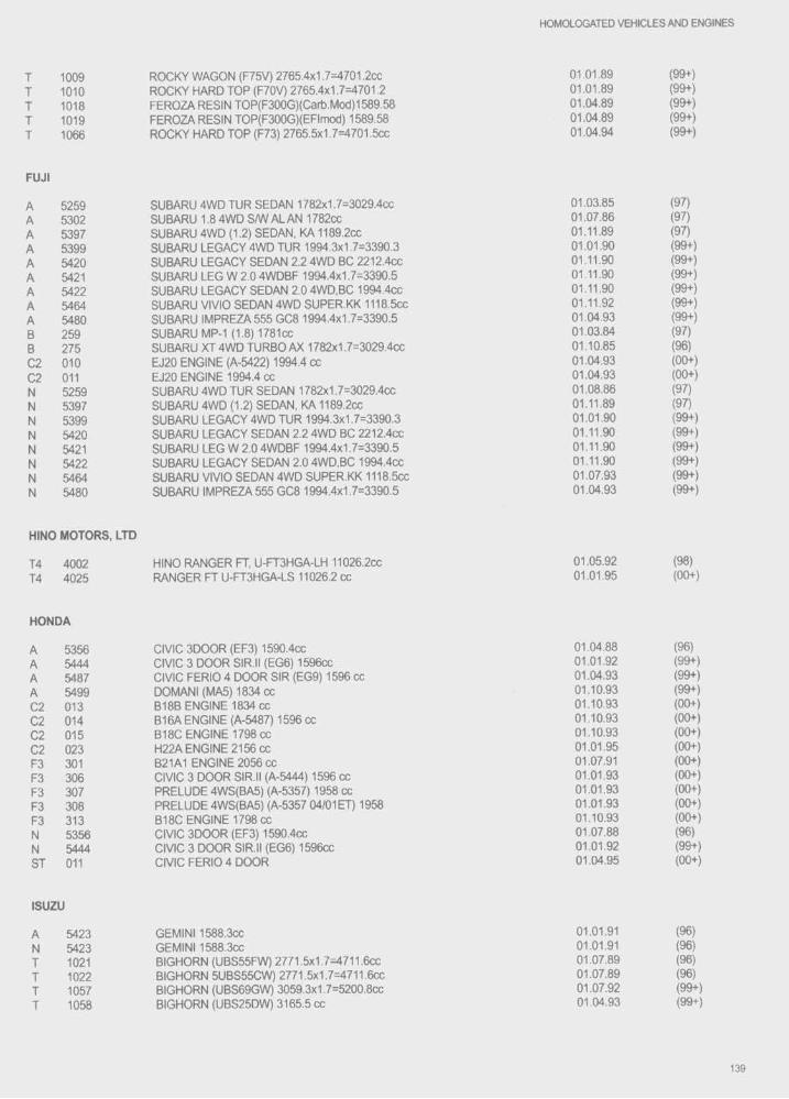
HOMOLOGATED VEHICLES AND ENGINES
T 1009 ROCKY WAGON (F75V) 2765.4x1.7=4701.2cc 01.01.89 (99+)T 1010 ROCKY HARD TOP (F70V) 2765.4x1.7=4701.2 01.01.89 (99+)I 1018 FEROZA RESIN TOP(F300G)(Cart).Mod)1589.58 01.04.89 (99+)T 1019 FEROZA RESIN TOP(F300G)(EFImod) 1589.58 01.04.89 (99+)T 1066 ROCKY HARD TOP (F73) 2765.5x1.7=4701.5cc 01.04.94 (99+)
FUJI
A 5259 SUBARU 4WD TUR SEDAN 1782x1.7=3029.4cc 01.03.85 (97)A 5302 SUBARU 1.8 4WD S/W ALAN 1782cc 01.07.86 (97)A 5397 SUBARU 4WD (1.2) SEDAN, KA 1189.2CC 01.11.89 (97)A 5399 SUBARU LEGACY 4WD TUR 1994.3x1.7=3390.3 01.01.90 (99+)A 5420 SUBARU LEGACY SEDAN 2.2 4WD BC 2212.4cc 01.11.90 (99+)A 5421 SUBARU LEG W 2.0 4WDBF 1994.4x1.7=3390.5 01.11.90 (99+)A 5422 SUBARU LEGACY SEDAN 2.0 4WD.BC 1994.4cc 01.11.90 (99+)A 5464 SUBARU VIVIO SEDAN 4WD SUPER.KK 1118.5CC 01.11.92 (99+)A 5480 SUBARU IMPREZA555 GC8 1994.4x1.7=3390.5 01.04.93 (99+)B 259 SUBARU MP-1 (1.8) 1781CC 01.03.84 (97)B 275 SUBARU XT 4WD TURBO AX 1782x1,7=3029.4cc 01.10.85 (96)C2 010 EJ20 ENGINE (A-5422) 1994.4 cc 01.04.93 (00+)C2 011 EJ20 ENGINE 1994.4 cc 01.04.93 (00+)N 5259 SUBARU 4WD TUR SEDAN 1782x1.7=3029.4cc 01.08.86 (97)N 5397 SUBARU 4WD (1.2) SEDAN, KA 1189.2CC 01.11.89 (97)N 5399 SUBARU LEGACY 4WD TUR 1994.3x1.7=3390.3 01.01.90 (99+)N 5420 SUBARU LEGACY SEDAN 2.2 4WD BC 2212.4cc 01.11.90 (99+)N 5421 SUBARU LEG W 2.0 4WDBF 1994.4x1.7=3390.5 01.11.90 (99+)N 5422 SUBARU LEGACY SEDAN 2.0 4WD.BC 1994.4cc 01.11.90 (99+)N 5464 SUBARU VIVIO SEDAN 4WD SUPER.KK 1118.5CC 01.07.93 (99+)N 5480 SUBARU IMPREZA555 GC8 1994.4x1.7=3390.5 01.04.93 (99+)
NINO MOTORS, LTD
14 4002 HINO RANGER FT, U-FT3HGA-LH 11026.2CC 01.05.92 (98)14 4025 RANGER FT U-FT3HGA-LS 11026.2 CC 01.01.95 (00+)
HONDA
A 5356 CIVIC 3D00R (EF3) 1590.4cc 01.04.88 (96)A 5444 CIVIC 3 DOOR SIR.II (EG6) 1596cc 01.01.92 (99+)A 5487 CIVIC FERIO 4 DOOR SIR (EG9) 1596 cc 01.04.93 (99+)A 5499 DOMANI (MA5) 1834 cc 01.10.93 (99+)C2 013 B18B ENGINE 1834 cc 01.10.93 (00+)C2 014 B16A ENGINE (A-5487) 1596 cc 01.10.93 (00+)C2 015 B18C ENGINE 1798 cc 01.10.93 (00+)C2 023 H22A ENGINE 2156 cc 01.01.95 (00+)F3 301 B21A1 ENGINE 2056 cc 01.07.91 (00+)F3 306 CIVIC 3 DOOR SIR.II (A-5444) 1596 cc 01.01.93 (00+)F3 307 PRELUDE 4WS(BA5) (A-5357) 1958 cc 01.01.93 (00+)F3 308 PRELUDE 4WS(BA5) (A-5357 04/01ET) 1958 01.01.93 (00+)F3 313 B18C ENGINE 1798 cc 01.10.93 (00+)N 5356 CIVIC 3D00R (EF3) 1590.4cc 01.07.88 (96)N 5444 CIVIC 3 DOOR SIR.II (EG6) 1596cc 01.01.92 (99+)ST 011 CIVIC FERIO 4 DOOR 01.04.95 (00+)
ISUZU
A 5423 GEMINI 1588.3CC 01.01.91 (96)N 5423 GEMINI 1588.3CC 01.01.91 (96)T 1021 BIGHORN (UBS55FW) 2771.5x1.7=4711.6cc 01.07.89 (96)T 1022 BIGHORN 5UBS55CW) 2771.5x1.7=4711.6cc 01.07.89 (96)I 1057 BIGHORN (UBS69GW) 3059.3x1.7=5200.8cc 01.07.92 (99+)T 1058 BIGHORN (UBS25DW) 3165.5 cc 01.04.93 (99+)
139
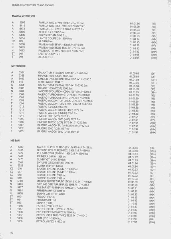
HOMOLOGATED VEHICLES AND ENGINES
MAZDA MOTOR CO
A 5286 FAMILIA4WD BFMR 1598x1.7=2716.6ccA 5415 FAMILIA4WD (BG8) 1939.6x1.7=3127.3ccA 5473 FAMILIAGT-R4WD 1839.6x1 7=3127.5ccA 5495 XEDOS 6 2.0 1995.5 ccA 5496 626 2.5 SEDAN 2496.5 ccA 5514 LANTIS COUPE 2.0 1995.5 ccC2 024 KL 2496,5 ccN 5286 FAMILIA4WD BFMR 1598x1.7=2716.6ccN 5415 FAMILIA4WD (BG8) 1839.6x1 7=3127.3ccN 5473 FAMILIAGT-R4WD 1839.6x1.7=3127.5ccST 004 LANTIS COUPE 2.0ST 005 XEDOS 6 2.0
MITSUBISHI
AAAF3NNN
5364538854693155364538854691001100210031004 1012101310141044104510461047 1062 1063
GALANT VR-4 (EA39A) 1997.4x1 7=3395.6cc MIRAGE 1600 (C53A) 1595.9CC LANCER EVOLUTION CD9A 1997.5x1.7=3395.5 4G93 ENGINE 1834 cc GALANT VR-4 (EA39A) 1997.4x1 7=3395.6cc MIRAGE 1600 (C53A) 1595.9CC LANCER EVOLUTION CD9A 1997.5x1.7=3395.5 PAJERO TURBO (L044G) 2476.8x1.7=4210.6cc PAJERO TURBO 2 (L144G) 2476.8x1.7=4210.6 PAJERO WAGON TUR L049G 2476.6x1.7=4210.6 PAJERO WAGON TUR2 L149G 2477x1.7=4210.6 PAJERO (L042G) 2555.2CC PAJERO WAGON 3000 (L146G) 2972.3cc PAJERO WAGON (L047G) 2555.2CC PAJERO 3000 (V23) 2972.3CC PAJERO WAGON 3000 (V43) 2972.3CC PAJERO TURBO (V24) 2476.8x1.7=4210.6cc PAJERO WAGON TU (V44) 2476.8x1.7=4210.6 PAJERO 3500 (V25) 3497 cc PAJERO WAGON 3500 (V45) 3497 cc
01.01.86 (97)01.08.90 (96)01.01.93 (98+)01.07.93 (98+)01.07.93 (98+)01.04.94 (99+)01.03.95 (00+)01.08.86 (97)01.08.90 (96)01.01.93 (98+)01.03.95 (00+)01.03.95 (00+)
01.05.88 (96)01.05.89 (96)01.01.93 (99+)01.03.94 (00+)01.05.88 (96)01.05.89 (96)01.01.93 (99+)01.01.89 (96)01.01.89 (96)01.01.89 (96)01.01.89 (96)01.01.89 (96)01.01.89 (96)01.01.89 (96)01.07.91 (97)01.07.91 (97)01.07.91 (99+)01.07.91 (99+)01.01.94 (99+)01.01.94 (99+)
NISSAN
A 5389A 5405A 5427A 5461A 5470A 5501A 5523C2 016C2 017C2 018C2 019N 5389N 5405N 5427N 5461N 5470ST 010ST 021ST 023T 1016T 1017T 1036T 1037T 1038T 1059
MARCH SUPER TURBO (EK10) 930.6x1.7=1582cSKYLINE GTR TUR(BNR32) 2568.7x1.7=4366.8PULSAR GTI-R (RNN14) 1998.2x1.7=3396.9ccPRIMERA (HP10) 1998 ccSUNNY GTI (N14) 1998CCSKYLINE GTS25 (ER33) 2499 ccSUNNY (FB14) 1498 ccSR20DE ENGINE (A-5427) 1998.2 ccSR20DE ENGINE (A-5461) 1998 ccSR20DE ENGINE 1998 ccSR20DE ENGINE 1998 ccMARCH SUPER TURBO (EK10) 930.6x1.7=1582cSKYLINE GTR TUR(BNR32) 2568.7x1.7=4366.8PULSAR GTI-R (RNN14) 1998.2x1.7=3396.9ccPRIMERA (HP10) 1998 ccSUNNY GTI (N14) 1998ccPULSAR (FN14)PRIMERA (HP10)SUNNY (FB14)PATROL (Y60) 4169.2CC PATROL DIESEL (RY60) 4169.2CC PATHFINDER MPI (WD21) 2960.5CC PATROL DIES TUR (YY60) 2825.9x1.7=4804.0 CIMA(PY31)2960.5cc PATROL (GY60) 4169.0 cc
01.05.8901.03.9001.03.9101.07.9201.01.9301.01.9401.07.9401.10.9301.10.9301.10.9301.10.9301.05.8901.03.9001.03.9101.07.9201.01.9301.04.9501.04.9501.10.9501.01.8901.01.8901.01.9001.01.9001.01.9001.07.93
(96)(99+)(99+)(99+)(99+)(99+)(99+)(00+)(00+)(00+)(00+)(96)(99+)(99+)(99+)(99+)(00+)(00+)(00+)(99+)(99+)(99+)(99+)(96)(99+)
140
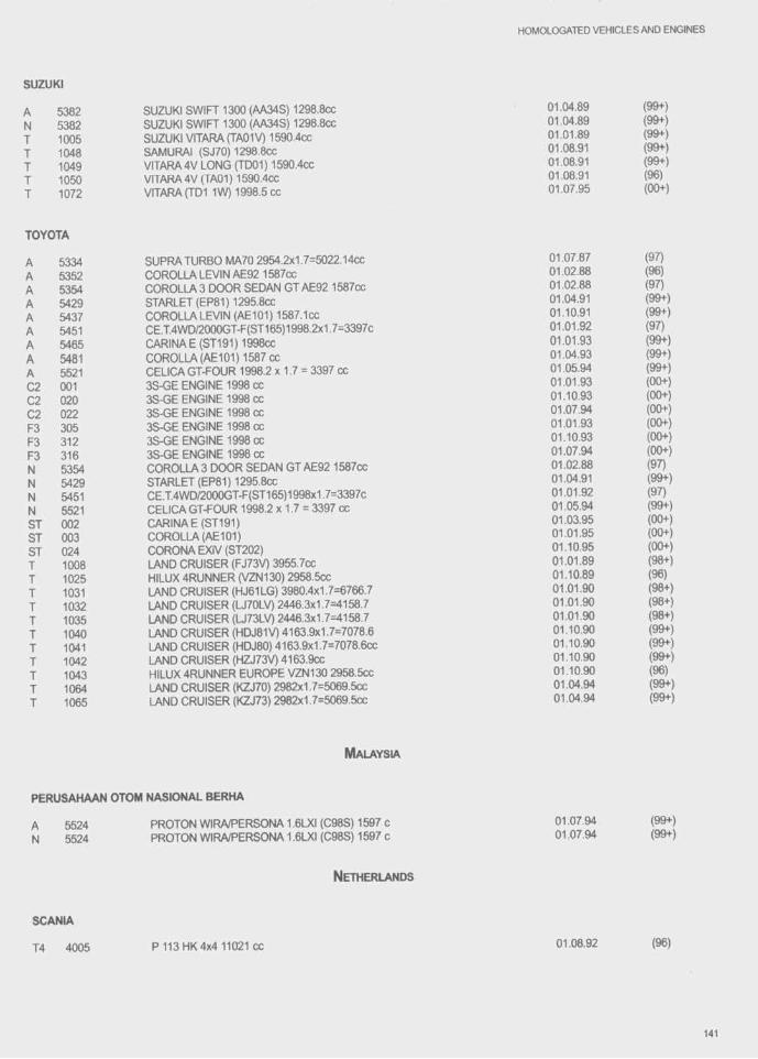
HOMOLOGATED VEHICLES AND ENGINES
SUZUKI
538253821005104810491050 1072
SUZUKI SWIFT 1300 (AA34S) 1298.8CC SUZUKI SWIFT 1300 (AA34S) 1298.8cc SUZUKI VITARA(TA01V) 1590.4cc SAMURAI (SJ70) 1298.8cc VITARA4V LONG (TD01) 1590.4cc VITARA4V (TA01) 1590.4CC VITARAfTDI 1W) 1998.5 cc
01.04.8901.04.8901.01.8901.08.9101.08.9101.08.91 01.07.95
(99+)(99+)(99+)(99+)(99+)(96)(00+)
TOYOTA
AAAAAAAAAC2C2C2F3F3F3NNNNSTSTST
53345352535454295437545154655481552100102002230531231653545429545155210020030241008102510311032 1035104010411042104310641065
SUPRA TURBO MA70 2954.2x1.7=5022.14ccCOROLLA LEVIN AE92 1587CCCOROLLA 3 DOOR SEDAN GT AE92 1587ccSTARLET (EP81)1295.8ccCOROLLA LEVIN (AE101) 1587.1CCCE.T.4WD/2000GT-F(ST165)1998.2x1.7=3397cCARINAE(ST191)1998ccCOROLLA (AE101) 1587 ccCELICA GT-FOUR 1998.2 x 1.7 = 3397 cc3S-GE ENGINE 1998 cc3S-GE ENGINE 1998 cc3S-GE ENGINE 1998 cc3S-GE ENGINE 1998 cc3S-GE ENGINE 1998 cc3S-GE ENGINE 1998 ccCOROLLA 3 DOOR SEDAN GT AE92 1587ccSTARLET (EP81) 1295.8CCCE.T.4WD/2000GT-F(ST165)1998x1.7=3397cCELICA GT-FOUR 1998.2 x 1.7 = 3397 ccCARINA E(ST191)COROLLA (AE101)CORONA EXIV(ST202)LAND CRUISER (FJ73V) 3955.7cc HILUX 4RUNNER (VZN130) 2958.5cc LAND CRUISER (HJ61LG) 3980.4x1.7=6766.7 LAND CRUISER (U70LV) 2446.3x1.7=4158.7 LAND CRUISER (U73LV) 2446.3x1.7=4158.7 LAND CRUISER (HDJ81V) 4163.9x1.7=7078.6 LAND CRUISER (HDJ80) 4163.9x1.7=7078.6cc LAND CRUISER (HZJ73V) 4163.9CC HILUX 4RUNNER EUROPE VZN130 2958.5CC LAND CRUISER (KZJ70) 2982x1.7=5069.5cc LAND CRUISER (KZJ73) 2982x1.7=5069.5cc
01.07.8701.02.88 01.02.8801.04.9101.10.9101.01.9201.01.9301.04.9301.05.9401.01.9301.10.9301.07.9401.01.9301.10.9301.07.94 01.02.8801.04.9101.01.9201.05.9401.03.9501.01.9501.10.9501.01.8901.10.8901.01.9001.01.9001.01.9001.10.9001.10.9001.10.9001.10.9001.04.9401.04.94
(97)(96)(97) (99+) (99+) (97) (99+) (99+) (99+) (00+) (00+) (00+) (00+) (00+) (00+) (97) (99+) (97) (99+) (00+) (00+) (00+) (98+) (96) (98+) (98+) (98+) (99+) (99+) (99+) (96) (99+) (99+)
M alaysia
PERUSAHAAN OTOM NASIONAL BERHA
55245524
PROTON WIRA/PERSONA 1.6LXI (C98S) 1597 c PROTON WIRA/PERSONA 1.6LXI (C98S) 1597 c
01.07.9401.07.94
(99+)(99+)
N etherlands
SCANIA
T4 4005 P113HK4x4 11021 cc 01.08.92 (96)
141

HOMOLOGATED VEHICLES AND ENGINES
VOLVO (PAYS-BAS)
AANN
5416541754165417
440Turt)O 1721.7x1.7=2925.9cc 480TurtX) 1721.1x1.7=2925.9cc 440TurtX) 1721.7x1,7=2925.9cc 480Turtx) 1721.1x1.7=2925.9cc
01.08.9001.08.9001.08.9001.08.90
(96)(96)(96)(96)
P ortugal
UNIAO METALO MECANICA, LDA
1020 ALTER TURBO INTERCOOLER 2498x1.7=4246.6 01.04.89 (96)
F.S.O.
P oland
Aa
51425359
125P 1598CCPOLSKI FIAT 126 BIS 703,7cc
01.05.8301.04.88
(96)(97)
A rgentina
AUTOLATINA ARGENTINA S.A.
A 5462 FORD ESCORT 1.81781 cc 01.07.92 (98)
RENAULT (ARGENTINE)
A 5160 R18GTX 1995œ 01.08.83 (99)
SEVEL ARGENTINA S A
A 5459 FIAT REGATTA 2000 1995.2 cc 01.07.92 (98- )
OLTcrr
A 5251A 5298
TA-QB - OLTCIT CLUB 1128.5CC OLTCIT CLUB 12TRS 1299.25 cc
01.01.85 (96)01.04.86 (97)
DAEWOO
55375537
K orea
CIELO (NEXIA) 1.5D H/B 4DR 1498.5cc CIELO (NEXIA) 1.5D H/B 4DR 1498.5cc
01.04.95 (00+)01.04.95 (00+)
HYUNDAI MOTOR COMPANY
A 5434 ELANTRA16V 1596ccA 5492 LANTRA(ELANTRA) 1.8 16V 1836 ccA 5508 PONY 1500 GS11468 CC
01.04.91 (96)01.07.93 (98+)01.04.94 (99+)
142

HOMOLOGATED VEHICLES AND ENGINES
A 5540 NEW LANTRA(ELANTRA) 18.8 16V 1795 cc 01.07.95 (00+)N 5434 ELANTRA16V 1596CC 01.04.91 (96)N 5492 LANTRA(ELANTRA) 1.8 16V 1836 cc 01.07.93 (98+)N 5508 PONY 1500 GS11468 cc 01.04.94 (99+)
KIA MOTORS CORPORATION
A 5458 SPORTAGE 1998 cc 01.07.92 (97)A 5538 SEPHIA1793CC 01.07.95 (00+)A 5539 SEPHIA1.6D 1598 cc 01.07.95 (00+)N 5538 SEPHIA1793CC 01.07.95 (00+)N 5539 SEPHIA1.6D 1598 cc 01.07.95 (00+)T 1056 SPORTAGE 1998CC 01.07.92 (97)
R u s s ia
KAMAZ INC. NABEREZHNYE TCHELNY
T4 4001 KAMAZ+131010 11756 cc 01.05.92 (97)T4 4022 KAMAZ-49250 11756 cc 01.01.94 (99+)T4 4023 KAMAZ 49252 17241 cc 01.11.94 (99+)T4 4024 KAMAZ 49251 14016 cc 01.11.94 (99+)
MOSKvrrcH
A 5361 AZLK 2141 ALEKO-RALLY 1568.5CC 01.04.88 (98+)
THE URAL AUTOMOBILE WORKS
T4 4010 UraM3223 16730 cc 01.09.92 (97)
VAZ
A 5174 LADA 2105 1295CC 01.11.83 (99+)A 5308 LADA 2108 1288CC 01.08.86 (99+)A 5345 LADA-SAMARA 21083 1500CC 01.01.88 (99+)A 5381 LADA(BA3-21074) 1568.5CC 01.04.89 (98+)T 1039 LADANIVAVAZ-2121 1568.5CC 01.04.90 (98+)
USINE AUTOM. DE ZAPOROJIE
A 5424 TAVRIA(ZAZ-1102) 1092cc 01.01.91 (96+)
S w e d e n
SAAB
A 5293 900 TURBO 16 1985 X 1.7 = 3374.5 cc 01.02.86 (98)A 5304 9000 TURBO 16 1985 x 1.7 = 3374.5 cc 01.07.86 (97)A 5321 900 8 16 SEDAN 1985 CC 01.01.87 (98)A 5322 900 S 16 COMBI COUPE 1985 cc 01.01.87 (98)A 5435 9000 T16-2.3 2290x1.7=3893.5cc 01.04.91 (96)A 5455 9000 CS 2.3 TURBO 2290x1.7=3893cc 01.04.92 (99+)A 5525 900 TURBO 1985 X 1.7 = 3374.5 cc 01.07.94 (99+)N 5293 900 TURBO 16 1985 x 1.7 = 3374.5 CC 01.08.86 (98)N 5304 9000 TURBO 16 1985 X 1.7 = 3374.5 cc 01.01.88 (97)
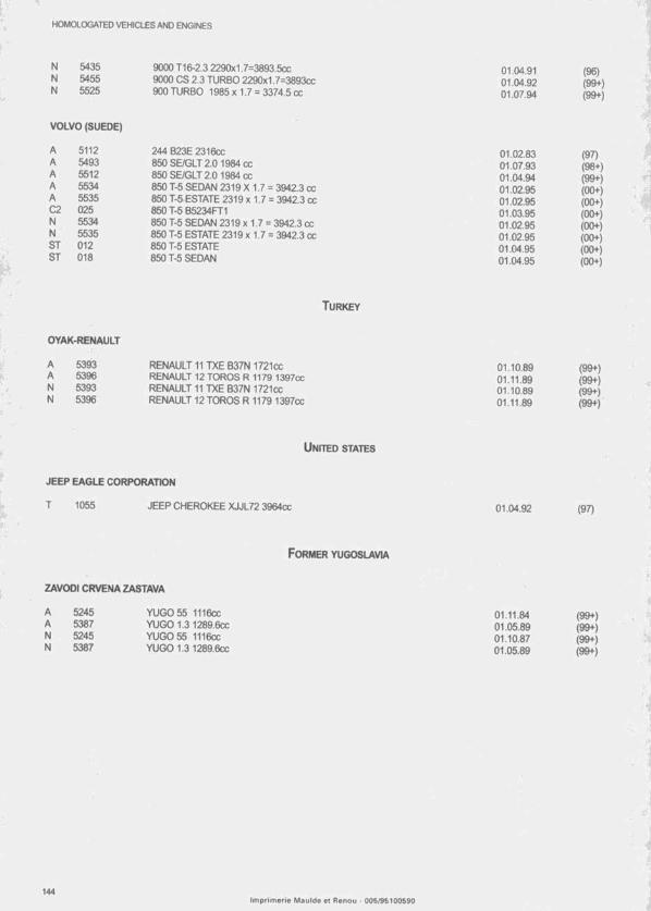
H0M0LCX3ATED VEHICLES AND ENGINES
N 5435 9000 T16-2.3 2290x1.7=3893.5ccN 5455 9000 OS 2.3 TURBO 2290x1.7=3893ccN 5525 900 TURBO 1985 X 1.7 = 3374.5 cc
01.04.9101.04.92 01.07.94
VOLVO (SUEDE)
AAAAAC2NNSTST
51125493551255345535 02555345535 012 018
244 B23E 2316CC850 SBGLT 2.0 1984 CC850SE/GLT2.0 1984 cc850 T-5 SEDAN 2319 X 1.7 = 3942.3 cc850 T-5 ESTATE 2319 x 1.7 = 3942.3 cc850 T-5 B5234FT1850 T-5 SEDAN 2319 x 1.7 = 3942.3 cc 850 T-5 ESTATE 2319 x 1.7 = 3942.3 cc 850 T-5 ESTATE 850 T-5 SEDAN
01.02.8301.07.9301.04.9401.02.9501.02.9501.03.9501.02.9501.02.9501.04.9501.04.95
T u r k e y
OYAK-RENAULT
AANN
5393539653935396
RENAULT 11 TXE B37N 1721cc RENAULT 12 TOROS R 1179 1397cc RENAULT 11 TXE B37N 1721cc RENAULT 12 TOROS R 1179 1397cc
01.10.8901.11.8901.10.8901.11.89
U n it e d s ta te s
JEEP EAGLE CORPORATION
T 1055 JEEP CHEROKEE XJJL72 3964CC 01.04.92
F ormer Yugoslavia
ZAVODI CRVENA ZASTAVA
A 5245 YUG0 55 1116CCA 5387 YUGO 1.3 1289.6CCN 5245 YUG0 55 1116CCN 5387 YUGO 1.3 1289.6CC
01.11.8401.05.89 01.10.8701.05.89
(96)(99+)(99+)
(97)(98+)(99+)(00+)(00+)(00+)(00+)(00+)(00+)(00+)
(99+)(99+)(99+)(99+)
(97)
(99+)(99+)(99+)(99+)
'.y
Im p r im e r ie M a u ld e et R e n o u - 0 0 5 /9 5 1 0 0 S 9 0