OPTIBAR PSM 2010 - Downloads
40
Electronic pressure switch with flush welded diaphragm OPTIBAR PSM 2010 OPTIBAR PSM 2010 OPTIBAR PSM 2010 OPTIBAR PSM 2010 Handbook Handbook Handbook Handbook © KROHNE 03/2020 - 4008116901 - MA OPTIBAR PSM 2010 R01 en
-
Upload
khangminh22 -
Category
Documents
-
view
6 -
download
0
Transcript of OPTIBAR PSM 2010 - Downloads

Electronic pressure switch with flush welded diaphragm
OPTIBAR PSM 2010OPTIBAR PSM 2010OPTIBAR PSM 2010OPTIBAR PSM 2010 HandbookHandbookHandbookHandbook
© KROHNE 03/2020 - 4008116901 - MA OPTIBAR PSM 2010 R01 en

All rights reserved. It is prohibited to reproduce this documentation, or any part thereof, without
the prior written authorisation of KROHNE Messtechnik GmbH.
Subject to change without notice.
2 www.krohne.com 03/2020 - 4008116901 - MA OPTIBAR PSM 2010 R01 en
Copyright 2020 by
KROHNE Messtechnik GmbH - Ludwig-Krohne-Str. 5 - 47058 Duisburg (Germany)
: IMPRINT :::::::::::::::::::::::::::::::::::::::

CONTENTS
3www.krohne.com03/2020 - 4008116901 - MA OPTIBAR PSM 2010 R01 en
OPTIBAR PSM 2010
1 Safety instructions 5
1.1 Intended use ..................................................................................................................... 51.2 Technical limits ................................................................................................................ 51.3 Certification ...................................................................................................................... 51.4 Safety instructions from the manufacturer ..................................................................... 6
1.4.1 Copyright and data protection ................................................................................................ 61.4.2 Disclaimer ............................................................................................................................... 61.4.3 Product liability and warranty ................................................................................................ 71.4.4 Information concerning the documentation........................................................................... 71.4.5 Warnings and symbols used................................................................................................... 8
1.5 Safety instructions for the operator................................................................................. 8
2 Device description 9
2.1 Scope of delivery............................................................................................................... 92.2 Nameplate ...................................................................................................................... 10
3 Installation 11
3.1 General notes on installation ......................................................................................... 113.2 Installation specifications .............................................................................................. 113.3 Mounting ......................................................................................................................... 12
3.3.1 Installation steps for connections acc. to DIN 3852............................................................. 133.3.2 Installation steps for connections acc. to EN 837 ................................................................ 133.3.3 Installation steps for NPT connections ................................................................................ 133.3.4 Installation steps for clamp and Varivent connections........................................................ 143.3.5 Installation steps for flange connections ............................................................................. 14
4 Electrical connections 15
4.1 Safety instructions.......................................................................................................... 154.2 Terminal assignment ..................................................................................................... 154.3 Electrical connection diagram ....................................................................................... 164.4 Switching output signals ................................................................................................ 17
5 Start-up 20
5.1 Commissioning............................................................................................................... 205.2 Keypad functions ............................................................................................................ 205.3 Menu structure ............................................................................................................... 21
6 Service 23
6.1 Maintenance ................................................................................................................... 236.2 Recalibration .................................................................................................................. 236.3 Spare parts availability................................................................................................... 236.4 Availability of services .................................................................................................... 23

CONTENTS
4 www.krohne.com 03/2020 - 4008116901 - MA OPTIBAR PSM 2010 R01 en
OPTIBAR PSM 2010
6.5 Repairs............................................................................................................................ 236.6 Returning the device to the manufacturer..................................................................... 24
6.6.1 General information.............................................................................................................. 246.6.2 Form (for copying) to accompany a returned device............................................................ 25
6.7 Disposal .......................................................................................................................... 25
7 Technical data 26
7.1 Technical data................................................................................................................. 267.2 Dimensions ..................................................................................................................... 297.3 Measuring ranges........................................................................................................... 32
8 Description IO-LINK interface 33
8.1 General description ........................................................................................................ 338.2 SIO-mode (standard IO mode)........................................................................................ 338.3 IO-Link mode (communication mode) ........................................................................... 338.4 Process data ................................................................................................................... 338.5 Error message................................................................................................................ 348.6 Event codes..................................................................................................................... 348.7 Parameter data............................................................................................................... 35
9 Notes 38

SAFETY INSTRUCTIONS 1
5
OPTIBAR PSM 2010
www.krohne.com03/2020 - 4008116901 - MA OPTIBAR PSM 2010 R01 en
1.1 Intended use
The OPTIBAR PSM 2010OPTIBAR PSM 2010OPTIBAR PSM 2010OPTIBAR PSM 2010 pressure transmitter is designed to measure the absolute pressure and gauge pressure in gases and liquids.
1.2 Technical limits
The device was constructed solely for use within the technical limits indicated on the nameplate and in the technical data. Applications outside of these limits are not permitted and could lead to significant risk of accident. For this reason, observe the following limits:
• Do not exceed the maximum working pressure (MWP).• Do not exceed the indicated permissible operating temperature range.• The permissible ambient temperatures given may not be exceeded or undershot.• Check the materials used for the wetted parts (e.g. gasket, process connection, separating
diaphragm etc.) for suitability as regards process compatibility.
1.3 Certification
CE markingThe device fulfils the statutory requirements of the following EU directives:
• EMC Directive 2014/30/EU• EMC specification acc. to EN 61326-1:2013• RoHS Directive 2011/65/EU
The manufacturer certifies successful testing of the product by applying the CE marking.
Pressure equipment directive (PED)Devices with a permissible pressure PS ≤ 200 bar (20 MPa) comply with Pressure equipment directive (PED) 2014/68/EU Article 4 Section (3) and are not subject to a conformity assessment. These devices were designed and manufactured in accordance with sound engineering practice (SEP).
The CE marking on the device does not apply to the Pressure Equipment Directive.
CAUTION!Responsibility for the use of the measuring devices with regard to suitability, intended use and corrosion resistance of the used materials against the measured fluid lies solely with the operator.
INFORMATION!The manufacturer is not liable for any damage resulting from improper use or use for other than the intended purpose.
DANGER!For devices used in hazardous areas, additional safety notes apply; please refer to the Ex documentation.

1 SAFETY INSTRUCTIONS
6
OPTIBAR PSM 2010
www.krohne.com 03/2020 - 4008116901 - MA OPTIBAR PSM 2010 R01 en
1.4 Safety instructions from the manufacturer
1.4.1 Copyright and data protection
The contents of this document have been created with great care. Nevertheless, we provide no guarantee that the contents are correct, complete or up-to-date.
The contents and works in this document are subject to copyright. Contributions from third parties are identified as such. Reproduction, processing, dissemination and any type of use beyond what is permitted under copyright requires written authorisation from the respective author and/or the manufacturer.
The manufacturer tries always to observe the copyrights of others, and to draw on works created in-house or works in the public domain.
The collection of personal data (such as names, street addresses or e-mail addresses) in the manufacturer's documents is always on a voluntary basis whenever possible. Whenever feasible, it is always possible to make use of the offerings and services without providing any personal data.
We draw your attention to the fact that data transmission over the Internet (e.g. when communicating by e-mail) may involve gaps in security. It is not possible to protect such data completely against access by third parties.
We hereby expressly prohibit the use of the contact data published as part of our duty to publish an imprint for the purpose of sending us any advertising or informational materials that we have not expressly requested.
1.4.2 Disclaimer
The manufacturer will not be liable for any damage of any kind by using its product, including, but not limited to direct, indirect or incidental and consequential damages.
This disclaimer does not apply in case the manufacturer has acted on purpose or with gross negligence. In the event any applicable law does not allow such limitations on implied warranties or the exclusion of limitation of certain damages, you may, if such law applies to you, not be subject to some or all of the above disclaimer, exclusions or limitations.
Any product purchased from the manufacturer is warranted in accordance with the relevant product documentation and our Terms and Conditions of Sale.
The manufacturer reserves the right to alter the content of its documents, including this disclaimer in any way, at any time, for any reason, without prior notification, and will not be liable in any way for possible consequences of such changes.

SAFETY INSTRUCTIONS 1
7
OPTIBAR PSM 2010
www.krohne.com03/2020 - 4008116901 - MA OPTIBAR PSM 2010 R01 en
1.4.3 Product liability and warranty
The operator shall bear responsibility for the suitability of the device for the specific purpose. The manufacturer accepts no liability for the consequences of misuse by the operator. Improper installation or operation of the devices (systems) will cause the warranty to be void. The respective "Standard Terms and Conditions" which form the basis for the sales contract shall also apply.
1.4.4 Information concerning the documentation
To prevent any injury to the user or damage to the device it is essential that you read the information in this document and observe applicable national standards, safety requirements and accident prevention regulations.
If this document is not in your native language and if you have any problems understanding the text, we advise you to contact your local office for assistance. The manufacturer can not accept responsibility for any damage or injury caused by misunderstanding of the information in this document.
This document is provided to help you establish operating conditions, which will permit safe and efficient use of this device. Special considerations and precautions are also described in the document, which appear in the form of icons as shown below.

1 SAFETY INSTRUCTIONS
8
OPTIBAR PSM 2010
www.krohne.com 03/2020 - 4008116901 - MA OPTIBAR PSM 2010 R01 en
1.4.5 Warnings and symbols used
Safety warnings are indicated by the following symbols.
• HANDLINGHANDLINGHANDLINGHANDLINGThis symbol designates all instructions for actions to be carried out by the operator in the specified sequence.
i RESULTRESULTRESULTRESULTThis symbol refers to all important consequences of the previous actions.
1.5 Safety instructions for the operator
DANGER!This warning refers to the immediate danger when working with electricity.
DANGER!This warning refers to the immediate danger of burns caused by heat or hot surfaces.
DANGER!This warning refers to the immediate danger when using this device in a hazardous atmosphere.
DANGER!These warnings must be observed without fail. Even partial disregard of this warning can lead to serious health problems and even death. There is also the risk of seriously damaging the device or parts of the operator's plant.
WARNING!Disregarding this safety warning, even if only in part, poses the risk of serious health problems. There is also the risk of damaging the device or parts of the operator's plant.
CAUTION!Disregarding these instructions can result in damage to the device or to parts of the operator's plant.
INFORMATION!These instructions contain important information for the handling of the device.
LEGAL NOTICE!This note contains information on statutory directives and standards.
WARNING!In general, devices from the manufacturer may only be installed, commissioned, operated and maintained by properly trained and authorized personnel. This document is provided to help you establish operating conditions, which will permit safe and efficient use of this device.

DEVICE DESCRIPTION 2
9
OPTIBAR PSM 2010
www.krohne.com03/2020 - 4008116901 - MA OPTIBAR PSM 2010 R01 en
2.1 Scope of delivery
The following items are supplied with the device:• Measuring device in ordered version• For mechanical connections DIN 3852: O-ring (pre-assembled)• Product documentation
INFORMATION!Inspect the packaging carefully for damages or signs of rough handling. Report damage to the carrier and to the local office of the manufacturer.
INFORMATION!Do a check of the packing list to make sure that you have all the elements given in the order.
INFORMATION!Look at the device nameplate to ensure that the device is delivered according to your order.Check for the correct supply voltage printed on the nameplate.
INFORMATION!Assembly materials and tools are not part of the delivery. Use the assembly materials and tools in compliance with the applicable occupational health and safety directives.
2 DEVICE DESCRIPTION
10
OPTIBAR PSM 2010
www.krohne.com 03/2020 - 4008116901 - MA OPTIBAR PSM 2010 R01 en
2.2 Nameplate
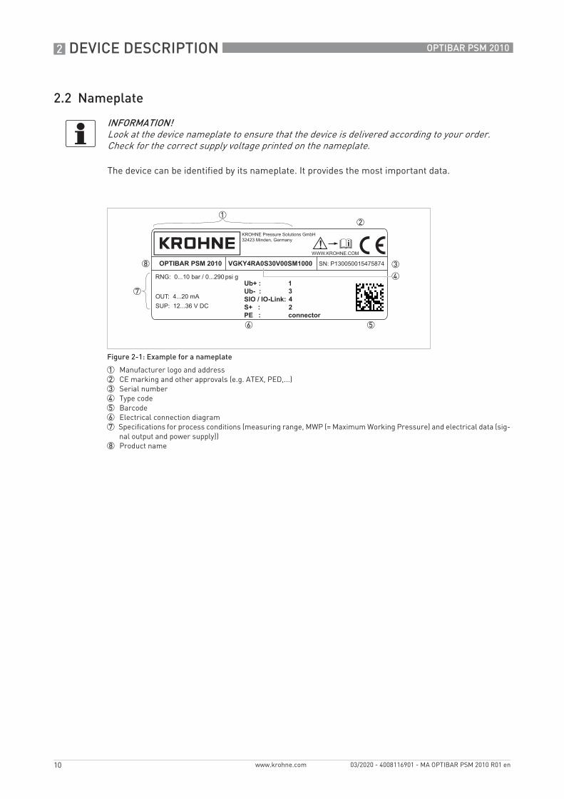
The device can be identified by its nameplate. It provides the most important data.
INFORMATION!Look at the device nameplate to ensure that the device is delivered according to your order.Check for the correct supply voltage printed on the nameplate.
Figure 2-1: Example for a nameplate
1 Manufacturer logo and address2 CE marking and other approvals (e.g. ATEX, PED,...)3 Serial number4 Type code5 Barcode6 Electrical connection diagram7 Specifications for process conditions (measuring range, MWP (= Maximum Working Pressure) and electrical data (sig-
nal output and power supply))8 Product name
VGKY4RA0S30V00SM1000OPTIBAR PSM 2010
Ub+ : Ub- : SIO / IO-Link: S+ : PE : connector
1
2
34
INSTALLATION 3
11
OPTIBAR PSM 2010
www.krohne.com03/2020 - 4008116901 - MA OPTIBAR PSM 2010 R01 en
3.1 General notes on installation
3.2 Installation specifications
INFORMATION!Inspect the packaging carefully for damages or signs of rough handling. Report damage to the carrier and to the local office of the manufacturer.
INFORMATION!Do a check of the packing list to make sure that you have all the elements given in the order.
INFORMATION!Look at the device nameplate to ensure that the device is delivered according to your order.Check for the correct supply voltage printed on the nameplate.
WARNING!Install the device only when depressurised and without power!
DANGER!For installation the respective regulations for explosion protection have to be fulfilled.
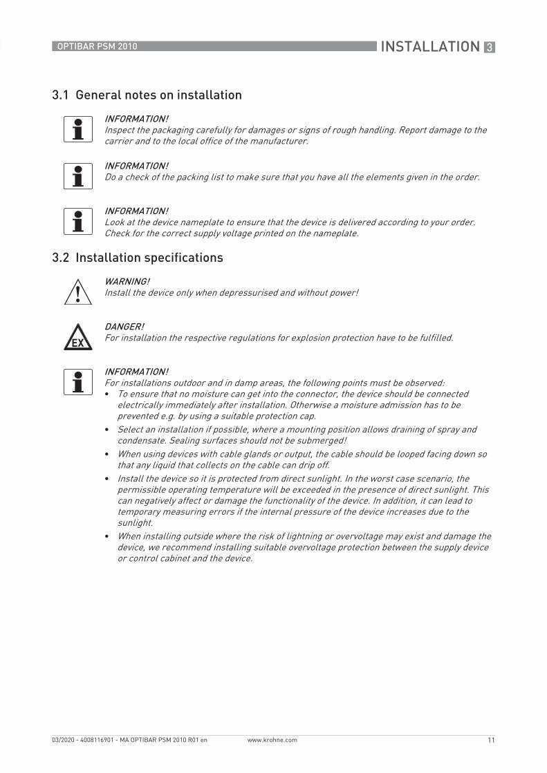
INFORMATION!For installations outdoor and in damp areas, the following points must be observed:• To ensure that no moisture can get into the connector, the device should be connected
electrically immediately after installation. Otherwise a moisture admission has to be prevented e.g. by using a suitable protection cap.
• Select an installation if possible, where a mounting position allows draining of spray and condensate. Sealing surfaces should not be submerged!
• When using devices with cable glands or output, the cable should be looped facing down so that any liquid that collects on the cable can drip off.
• Install the device so it is protected from direct sunlight. In the worst case scenario, the permissible operating temperature will be exceeded in the presence of direct sunlight. This can negatively affect or damage the functionality of the device. In addition, it can lead to temporary measuring errors if the internal pressure of the device increases due to the sunlight.
• When installing outside where the risk of lightning or overvoltage may exist and damage the device, we recommend installing suitable overvoltage protection between the supply device or control cabinet and the device.

3 INSTALLATION
12
OPTIBAR PSM 2010
www.krohne.com 03/2020 - 4008116901 - MA OPTIBAR PSM 2010 R01 en
3.3 Mounting
INFORMATION!• Handle this highly sensitive electronic measuring device with care, both in and out of the
packaging!• Only remove the packaging and any protection cap from the device immediately before
installing to prevent damage to the diaphragm! Keep the supplied protection cap! Remove the protection cap slowly and carefully to avoid any negative pressure on the diaphragm.
• Handle the unprotected diaphragm with extreme care; it is very easily damaged.• A device with a gauge reference in the housing (small hole next to the electrical connection)
must be installed so that the gauge reference necessary for measurement is protected from dirt and moisture. Should the pressure transmitter be exposed to fluid admission, the air pressure compensation is blocked by the gauge reference. Accurate measurement in this state is not possible. It can also result in damage to the pressure transmitter.
• Ensure that no mechanical stress is applied to the pressure port during installation as this may result in a shift in the characteristic curve. This applies in particular to very small pressure ranges as well as to devices with plastic pressure ports.
• With hydraulic systems, arrange the device so that the pressure port faces up (venting).
WARNING!Do not screw in using the housing! Tightening this way can cause damage to the rotary mechanism on the housing.
CAUTION!• Prior to installing the transmitter, it is essential to verify whether the version of the device on
hand completely fulfils the technical and safety requirements of the measuring point. This applies in particular to the measuring range, overpressure resistance, temperature, explosion protection and operating voltage.
• Check the materials used for the wetted parts (e.g. gasket, process connection, separating diaphragm etc.) for suitability as regards process compatibility.
• The device must not be heated by radiated heat (e.g. exposure to the sun) to an electronics housing surface temperature above the maximum permissible ambient temperature. If it is necessary to prevent damage from heat sources, a heat protection (e.g. sun shade) has to be installed.

INSTALLATION 3
13
OPTIBAR PSM 2010
www.krohne.com03/2020 - 4008116901 - MA OPTIBAR PSM 2010 R01 en
3.3.1 Installation steps for connections acc. to DIN 3852
• Make sure that the O-ring fits properly in the intended groove.• Ensure that the raised face of the receiving part has a smooth surface.• Screw the device into the thread by hand.• Devices with wrench flats must be tightened with a wrench. For information on tightening
torque refer to the following table.
3.3.2 Installation steps for connections acc. to EN 837
• When sealing, use a suitable gasket that corresponds to the product and pressure to be measured (e.g. a copper gasket).
• Ensure that the raised face of the receiving part has a smooth surface.• Screw the device into the thread by hand.• Then tighten the device with the wrench.
3.3.3 Installation steps for NPT connections
• When sealing, use a suitable sealing agent that is compatible with the product (e.g. PTFE tape).
• Screw the device into the thread by hand.• Then tighten the device with the wrench.
Wrench size Tightening torque [Nm]
Wrench size of steelWrench size of steelWrench size of steelWrench size of steel
G1/4 approx. 5
G1/2 approx. 10
G3/4 approx. 15
G1 approx. 20
G1 1/2 approx. 25
Wrench size of plasticWrench size of plasticWrench size of plasticWrench size of plastic
All sizes max. 3
Wrench size Tightening torque [Nm]
G1/4 approx. 20
G1/2 approx. 50
Wrench size Tightening torque [Nm]
1/4 NPT approx. 30
1/2 NPT approx. 70

3 INSTALLATION
14
OPTIBAR PSM 2010
www.krohne.com 03/2020 - 4008116901 - MA OPTIBAR PSM 2010 R01 en
3.3.4 Installation steps for clamp and Varivent connections
Notes for versions acc. to 3A standard
The device has to be installed in the way that drainability (E1.8.1) and demands acc. to L1.1 are met. The device must be installed with the pressure port downwards or to the side.
The user is responsible for:• using a suitable sealing material• defining adequate service intervals• using an elastomer sealing material according to 3A standard 18-03 and 21CFR177.2600• the right dimension of the gasket
Make sure that welding sockets are mounted flush inside the tank.
General procedure• When sealing, use a suitable gasket that corresponds to the product and pressure to be
measured.• Place the gasket on the corresponding fitting.• Centre the clamp or Varivent connection over the corresponding fitting and gasket.• Then use a suitable connecting element (e.g. half ring or clamp ring connection) to attach the
device according to the manufacturer's specifications.
3.3.5 Installation steps for flange connections
• When sealing, use a suitable gasket that corresponds to the product and pressure to be measured (e.g. a fibre gasket)
• Put the gasket between connecting flange and counter flange.• Then fasten the device using 4 or 8 screws (depending on flange version) to the counter flange.
INFORMATION!The device must be assembled according to 3A standard 74-06.
ELECTRICAL CONNECTIONS 4
15
OPTIBAR PSM 2010
www.krohne.com03/2020 - 4008116901 - MA OPTIBAR PSM 2010 R01 en
4.1 Safety instructions
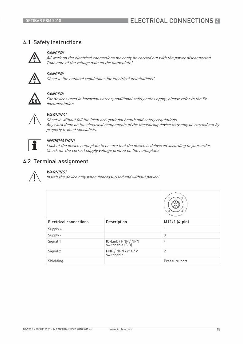
4.2 Terminal assignment
DANGER!All work on the electrical connections may only be carried out with the power disconnected.Take note of the voltage data on the nameplate!
DANGER!Observe the national regulations for electrical installations!
DANGER!For devices used in hazardous areas, additional safety notes apply; please refer to the Ex documentation.
WARNING!Observe without fail the local occupational health and safety regulations.Any work done on the electrical components of the measuring device may only be carried out by properly trained specialists.
INFORMATION!Look at the device nameplate to ensure that the device is delivered according to your order.Check for the correct supply voltage printed on the nameplate.
WARNING!Install the device only when depressurised and without power!
Electrical connections Description M12x1 (4-pin)
Supply + 1
Supply - 3
Signal 1 IO-Link / PNP / NPNswitchable (SIO)
4
Signal 2 PNP / NPN / mA / Vswitchable
2
Shielding Pressure-port

4 ELECTRICAL CONNECTIONS
16
OPTIBAR PSM 2010
www.krohne.com 03/2020 - 4008116901 - MA OPTIBAR PSM 2010 R01 en
4.3 Electrical connection diagram
Figure 4-1: Electrical connection diagram 2-wire 4...20 mA
1 Supply +2 Supply - 3 Signal 2 4 Power supply5 IO-Link Master
I / U

ELECTRICAL CONNECTIONS 4
17
OPTIBAR PSM 2010
www.krohne.com03/2020 - 4008116901 - MA OPTIBAR PSM 2010 R01 en
4.4 Switching output signals
The output for the switching signals can be configured with two different function, both for normally open and normally closed actuators.
Window functionWhen the window function is activated, the output signal is set when the applied pressure is within the upper (FH) and lower (FL) pressure threshold:
Figure 4-2: Switching output signals (window function)
1 FH2 Pressure range3 FL4 Hno (normally open)5 Hnc (normally closed)
01
01
P
t
t
t
P
P

4 ELECTRICAL CONNECTIONS
18
OPTIBAR PSM 2010
www.krohne.com 03/2020 - 4008116901 - MA OPTIBAR PSM 2010 R01 en
Hysteresis-functionWhen the hysteresis-function is activated, the output signal is activated when the pressure reaches the switching pressure (SP) and deactivated when the release pressure (rP) is applied:
Figure 4-3: Switching output signals (hysteresis-function)
1 SP2 Hysteresis3 rP4 Hno (normally open)5 Hnc (normally closed)
0
0
1
1
P
t
t
t

ELECTRICAL CONNECTIONS 4
19
OPTIBAR PSM 2010
www.krohne.com03/2020 - 4008116901 - MA OPTIBAR PSM 2010 R01 en
Hysteresis-functionTo eliminate an unintended switching signal caused by pressure spikes, a damping-constant (dr, dS) can be configured for both switching-functions:
Figure 4-4: Switching output signals (hysteresis-function with damping)
1 SP2 Hysteresis3 rP4 Hnc (normally closed)5 dS6 dr7 Hno (normally open)
01
01
P
t
t
t

5 START-UP
20
OPTIBAR PSM 2010
www.krohne.com 03/2020 - 4008116901 - MA OPTIBAR PSM 2010 R01 en
5.1 Commissioning
The signal converter may only be started up after it has been completely installed and checked by appropriately qualified personnel. Switch on the operating voltage for start-up.
Prior to applying the operating voltage check that • the pressure transmitter is completely installed• the process connection fits properly• the signal and, if necessary, supply lines are properly connected• the impulse lines are completely filled with the process medium
5.2 Keypad functions
The display and adjustment module is used for indication of measuring values and adjustment.
The device is operated via the two keys 2 on the display and adjustment module. The LED-Display 1 indicates the individual menu items.
Figure 5-1: Keypad
1 LED Display2 Function buttons
Key Description Function
Short press Skip through menu 1 – 5
Long press Count up parameter values quickly
Short press Select option within one menu
Long press Save adjusted value and jump pack to current menu
+ Press both simultaneously Jump back to indication

START-UP 5
21
OPTIBAR PSM 2010
www.krohne.com03/2020 - 4008116901 - MA OPTIBAR PSM 2010 R01 en
5.3 Menu structure
Function Description
Operating mode
SP1 | FH1 Adjustment of switch-on point 1Set value from where switching point 1 should be activated (SP1). If the window function is activated, the value is the upper pressure limit of the window (FH1).
rP1 | FL1 Adjustment of switch-off point 1Set value from where switching point 1 should be deactivated (rP1). If the window function is activated, the value is the lower pressure limit of the window (FL1).
SP2 | FH2 Adjustment of switch-on point 2Set value from where switching point 2 should be activated (SP2). If the window function is activated, the value is the upper pressure limit of the window (FH2).
rP2 | FL2 Adjustment of switch-off point 2Set value from where switching point 2 should be deactivated (rP2). If the window function is activated, the value is the lower pressure limit of the window (FL2).
Additional menuASt2 | AEn2(Only if Output-Signal 2is activated)
Adjustment of output-signal 2Analog-output 2. Change possibilities: 5% at zero (ASt2), 90-100% at span (AEn2)
EF - (Extended function)
rES Factory-reset
dS1 Adjustment of switch-on delay 1Set value for switch-on delay after reaching switch-on point 1(Adjustable from 0.0...50.0 s)
dr1 Adjustment of switch-off delay 1Set value for switch-off delay after reaching switch-off point 1(Adjustable from 0.0...50.0 s)
dS2 Adjustment of switch-on delay 2Set value for switch-on delay after reaching switch-on point 2(Adjustable from 0.0...50.0 s)
dr2 Adjustment of switch-off delay 2Set value for switch-off delay after reaching switch-off point 2(Adjustable from 0.0...50.0 s)
ou1 Adjustment of switch-output 1Switching functions for switch-output:- Hno: Hysteresis function, normally open- Hnc: Hysteresis function, normally closed- Fno: Window function, normally open- Fnc: Window function, normally closed
ou2 Adjustment of switch-output 2See "ou1"
Uni Change UnitsSelect unit for indicated and adjusted pressure valuebAr = barnnBa = mbarPsi = PSIΠPA = MPa

5 START-UP
22
OPTIBAR PSM 2010
www.krohne.com 03/2020 - 4008116901 - MA OPTIBAR PSM 2010 R01 en
EF - (Extended function)
FLIP Rotate indication by 180°
Lo Min-ValueShow minimal applied pressure during measurement. In case of interruption of power supply the value is lost
Hi Max-ValueShow maximal applied pressure during measurement. In case of interruption of power supply the value is lost
---- Reset "Min-Value" and "Max-Value"
SEt0 Adjustment of Zero-PointAdjustment/Correction of zero-point of indicated value and analog-output signal by up to 3% of nominal pressure
dAP Damping of measurementSet value of damping(0...1000 ms in 10 ms steps)
codE Access protectionSet password for access protection0000 = no password (deactivated)1000...9999 adjustable (activated)
o1 Output-Signal 1Switch between PNP- and NPN-functions
o2 Output-Signal 2Switch between PNP- and NPN-functions, 4...20 mA and 0...10 V
hent Operating time in [h]
Pent Number of pressure spikes
Function Description

SERVICE 6
23
OPTIBAR PSM 2010
www.krohne.com03/2020 - 4008116901 - MA OPTIBAR PSM 2010 R01 en
6.1 Maintenance
In principal, the device is maintenance free. If necessary, clean the device housing when switched off using a damp cloth and a non-aggressive cleaning solution.
Depending on the product, deposits or contamination can still occur on the diaphragm. If the product has a known affinity, the operator must determine the cleaning intervals accordingly. Once the device has been properly taken out of commission, the diaphragm can generally be carefully cleaned using a non-aggressive cleaning solution and a soft brush or sponge. If the diaphragm is calcified, decalcification by the manufacturer is recommended.
6.2 Recalibration
During the life cycle of the device, the offset or full-scale of the device may shift. If this occurs, note that the signal value output will deviate based on the set start or end value of the measuring range. If one of these phenomena does occur following prolonged use, recalibration is recommended to ensure continued high accuracy.
6.3 Spare parts availability
The manufacturer adheres to the basic principle that functionally adequate spare parts for each device or each important accessory part will be kept available for a period of 3 years after delivery of the last production run for the device.
This regulation only applies to spare parts which are subject to wear and tear under normal operating conditions.
6.4 Availability of services
The manufacturer offers a range of services to support the customer after expiration of the warranty. These include repair, maintenance, technical support and training.
6.5 Repairs
Repairs must be carried out exclusively by the manufacturer or the manufacturer authorised specialist companies.
INFORMATION!Improper cleaning can result in irreparable damage to the measuring cell. For this reason, never use sharp objects or compressed air to clean the diaphragm.
INFORMATION!For more precise information, please contact your local sales office.

6 SERVICE
24
OPTIBAR PSM 2010
www.krohne.com 03/2020 - 4008116901 - MA OPTIBAR PSM 2010 R01 en
6.6 Returning the device to the manufacturer
6.6.1 General information
This device has been carefully manufactured and tested. If installed and operated in accordance with these operating instructions, it will rarely present any problems.
WARNING!Should you nevertheless need to return a device for inspection or repair, please pay strict attention to the following points:• Due to statutory regulations on environmental protection and safeguarding the health and
safety of the personnel, the manufacturer may only handle, test and repair returned devices that have been in contact with products without risk to personnel and environment.
• This means that the manufacturer can only service this device if it is accompanied by the following certificate (see next section) confirming that the device is safe to handle.
WARNING!If the device has been operated with toxic, caustic, radioactive, flammable or water-endangering products, you are kindly requested:• to check and ensure, if necessary by rinsing or neutralising, that all cavities are free from
such dangerous substances,• to enclose a certificate with the device confirming that it is safe to handle and stating the
product used.

SERVICE 6
25
OPTIBAR PSM 2010
www.krohne.com03/2020 - 4008116901 - MA OPTIBAR PSM 2010 R01 en
6.6.2 Form (for copying) to accompany a returned device
6.7 Disposal
CAUTION!To avoid any risk for our service personnel, this form has to be accessible from outside of the packaging with the returned device.
Company: Address:
Department: Name:
Telephone number:
Fax number:
Email address:
Manufacturer order number or serial number:
The device has been operated with the following medium:
This medium is: radioactive
water-hazardous
toxic
caustic
flammable
We checked that all cavities in the device are free from such substances.
We have flushed out and neutralized all cavities in the device.
We hereby confirm that there is no risk to persons or the environment caused by any residual media contained in this device when it is returned.
Date: Signature:
Stamp:
LEGAL NOTICE!Disposal must be carried out in accordance with legislation applicable in your country.
Separate collection of WEEE (Waste Electrical and Electronic Equipment) in the European Union:Separate collection of WEEE (Waste Electrical and Electronic Equipment) in the European Union:Separate collection of WEEE (Waste Electrical and Electronic Equipment) in the European Union:Separate collection of WEEE (Waste Electrical and Electronic Equipment) in the European Union:
According to the directive 2012/19/EU, the monitoring and control instruments marked with the WEEE symbol and reaching their end-of-life must not be disposed of with other wastemust not be disposed of with other wastemust not be disposed of with other wastemust not be disposed of with other waste.The user must dispose of the WEEE to a designated collection point for the recycling of WEEE or send them back to our local organisation or authorised representative.

7 TECHNICAL DATA
26
OPTIBAR PSM 2010
www.krohne.com 03/2020 - 4008116901 - MA OPTIBAR PSM 2010 R01 en
7.1 Technical data
INFORMATION!• The following data is provided for general applications. If you require data that is more
relevant to your specific application, please contact us or your local sales office.• Additional information (certificates, special tools, software,...) and complete product
documentation can be downloaded free of charge from the website (Downloadcenter).
Measuring systemMeasuring principle Piezoresistive measuring cell
Application range Measurement of gauge and absolute pressure in gases and liquids
Measuring range 0.1...40 bar / 1.5...580 psi; refer also to chapter "Measuring ranges"Adjustment (in relation to the nominal range):Zero: ± 5%Span: 90...100%
Display and user interfaceDisplay on signal converter 4-digit, 7-segment LED-Display 22.5 x 10.5 mm / 0.89 x 0.41"
4 LED's for indication of unit (bar, mbar, PSI, Mpa)Status LED for IO-Link and switching-outputsDisplay infinitely rotatable up to -210° and +100°Ambient temperatures below -20°C may affect the readability of the display
Display function Display of measured valueAll parameters are accessible via the operating menu
Operating Local operation via 2 softkeys on the display and adjustment module
Remote control PACTware™ via IODD and USB IO-Link interface
Measuring accuracyReference conditions Medium: air
Temperature: ambient temperature
Ambient pressure: 1013 mbar / 14.7 psi
Nominal position: vertical, pressure port down
Power supply: 24 VDC
Pressure type Gauge pressure / absolute pressure
Measuring accuracy according to IEC 60770 (terminal based)(Hysteresis, non-linearity, non-repeatability)
Nominal pressure (PN) < 0.4 bar / 5.8 psi: ≤± 0.5% of URL
Nominal pressure (PN) ≥ 0.4 bar / 5.8 psi: ≤± 0.35% of URL
(URL = Upper Range Limit)
Ambient temperature effect on zero and span
≤± 0.3% of URL per 10K in compensated range of -25...85°C / -13...185°F
Long-term stability ≤±0.3% of URL within one year under reference conditions
Step response time ≤ 12 ms (T90)
Vacuum resistance PN ≥ 1 bar / 14.5 psi: vacuum resistantPN < 1 bar / 14.5 psi: on request
TECHNICAL DATA 7
27
OPTIBAR PSM 2010
www.krohne.com03/2020 - 4008116901 - MA OPTIBAR PSM 2010 R01 en
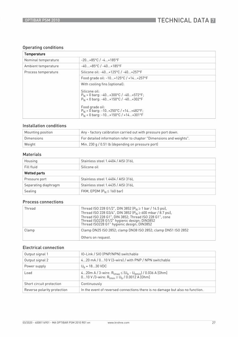
Operating conditionsTemperatureTemperatureTemperatureTemperature
Nominal temperature -20...+85°C / -4...+185°F
Ambient temperature -40…+85°C / -40...+185°F
Process temperature Silicone oil: -40...+125°C / -40...+257°F
Food grade oil: -10...+125°C / +14...+257°F
With cooling fins (optional):
Silicone oil:PN > 0 barg: -40...+300°C / -40...+572°F;PN < 0 barg: -40...+150°C / -40...+302°F
Food grade oil:PN > 0 barg: -10..+250°C / +14...+482°F;PN < 0 barg: -10...+150°C / +14...+301°F
Installation conditionsMounting position Any - factory calibration carried out with pressure port down.
Dimensions For detailed information refer to chapter "Dimensions and weights".
Weight Min. 230 g / 0.51 lb (depending on pressure port)
MaterialsHousing Stainless steel 1.4404 / AISI 316L
Fill fluid Silicone oil
Wetted partsWetted partsWetted partsWetted parts
Pressure port Stainless steel 1.4404 / AISI 316L
Separating diaphragm Stainless steel 1.4435 / AISI 316L
Sealing FKM, EPDM (PN ≤ 160 bar)
Process connectionsThread Thread ISO 228 G1/2", DIN 3852 (PN ≥ 1 bar / 14.5 psi),
Thread ISO 228 G3/4", DIN 3852 (PN ≥ 600 mbar / 8.7 psi), Thread ISO 228 G1", DIN 3852; Thread ISO 228 G1", coneThread ISO228 G1/2" hygienic design; DIN3852Thread ISO228 G1" hygienic design; DIN3852
Clamp Clamp DN25 ISO 2852; clamp DN38 ISO 2852; clamp DN51 ISO 2852
Others on request.
Electrical connectionOutput signal 1 IO-Link / SIO (PNP/NPN) switchable
Output signal 2 4...20 mA / 0...10 V (3-wire) / with PNP / NPN switchable
Power supply Ub = 18...30 VDC
Load 4...20m A / 3-wire: Rlmax ≤ (Ub - Ubmin) / 0.036 A [Ohm]0...10 V /3-wire: Rlmin ≥ Ub / 0.0012 A [Ohm]
Short circuit protection Continuously
Reverse polarity protection In the event of reversed connections there is no damage but also no function.

7 TECHNICAL DATA
28
OPTIBAR PSM 2010
www.krohne.com 03/2020 - 4008116901 - MA OPTIBAR PSM 2010 R01 en
Ripple Supply: 0.05% URL Load: ≤ 0.1% URL
Electrical connection Connector M12x1, 4-pin
Properties switching signalSwitch point accuracy ≤ +/- 0.5% URL
Repeatability ≤ +/- 0.1% URL
Max. switching current 150 mA
Switching frequency max. 170 Hz
Delay 0...50 seconds
IO-LinkInterface IO-Link 1.1; Slave
Data transmission 38.4 kbit/s (COM2)
Mode SIO / IO-Link
Standard IEC 61132-2, IEC 61161-9
Approvals and certificatesCE The device fulfils the statutory requirements of the EU directives. The manufacturer
certifies that these requirements have been met by applying the CE marking.
Electromagnetic compatibility (EMC) acc. to EN 61326-1:2013
EMC Directive: 2014/30/EU
For more information consult the relevant declaration of conformity.
Pressure equipment directive 2014/68/EU
Other standards and approvalsOther standards and approvalsOther standards and approvalsOther standards and approvals
Vibration resistance acc. to EN 60068-2-6
10g RMS (25...2000 Hz)
Shock resistant (impact) according to EN 60068-2-27
500g / 11 ms (PN ≥ 60 bar / 870 psi)
Hygienic 3-A approved; FDA approved materials

TECHNICAL DATA 7
29
OPTIBAR PSM 2010
www.krohne.com03/2020 - 4008116901 - MA OPTIBAR PSM 2010 R01 en
7.2 Dimensions
Figure 7-1: Dimensions
Dimensions
a b c
[mm] ["] [mm] ["] [mm] ["]
26 1.02 35.5 1.40 64 2.52

7 TECHNICAL DATA
30
OPTIBAR PSM 2010
www.krohne.com 03/2020 - 4008116901 - MA OPTIBAR PSM 2010 R01 en
The entire length of the device is made up of the electrical connection (a), the transmitter housing (e) and the process connection (k).With cooling fins (optional) additional 32 mm / 1.26".
Pressure transmitter with threaded connection
Figure 7-2: Dimensions for pressure transmitter with threaded connection
1 G1/2" DIN 3852 flush2 G3/4" DIN 3852 flush3 G1" DIN 3852 flush4 G1/2" DIN 3852 flush hygienic design5 G1" DIN 3852 flush hygienic design6 G1" cone
Dimensions
1 2 3 4 5 6
[mm] ["] [mm] ["] [mm] ["] [mm] ["] [mm] ["] [mm] ["]
e 60 2.36 60 2.36 60 2.36 60 2.36 60 2.36 60 2.36
f Ø26.5 Ø1.04 Ø26.5 Ø1.04 Ø26.5 Ø1.04 Ø26.5 Ø1.04 Ø26.5 Ø1.04 Ø26.5 Ø1.04
g WS27 WS34 WS41 WS27 WS41 WS34
h G½" G¾" G1" G½" G1" G1"
k 18 0.71 20 0.79 22 0.87 23.5 0.93 23.5 0.93 26 1.02
m 15 0.59 17 0.67 19 0.75 20.5 0.81 20.5 0.81 - -
n - - - - - - - - 7.5 0.3 9 0.35

TECHNICAL DATA 7
31
OPTIBAR PSM 2010
www.krohne.com03/2020 - 4008116901 - MA OPTIBAR PSM 2010 R01 en
The entire length of the device is made up of the electrical connection (a), the transmitter housing (e) and the process connection (k).
Pressure transmitter with cooling fins and hygienic process connections
Figure 7-3: Dimensions for pressure transmitter with cooling fins and hygienic process connections
1 Cooling fins (optional)2 Clamp DIN 32678 / ISO 2852, 3-A approved
3 Varivent® DN40/50, 3-A approved
Dimensions
1 2 3
[mm] ["] [mm] ["] [mm] ["]
e 50 1.97 50 1.97 48 1.89
f Ø26.5 Ø1.04 Ø26.5 Ø1.04 Ø26.5 Ø1.04
h - -DN25: 50.5
DN38: 50.5
DN51: 64
DN25: 2.0
DN38: 2.0
DN51: 2.5
Ø84 Ø3.3
k - - 5 0.2 17 0.67
r 32 1.26 - - - -
INFORMATION!Other hygienic connections are available on request.

7 TECHNICAL DATA
32
OPTIBAR PSM 2010
www.krohne.com 03/2020 - 4008116901 - MA OPTIBAR PSM 2010 R01 en
7.3 Measuring ranges
Pressure in bar
Pressure in psi
Nominal pressure (gauge/abs.)
0.10 0.16 0.25 0.40 0.50 0.60 1 1.6
Max. working pressure (MWP)
0.5 1 1 2 2 5 5 10
Burst pressure (OPL) 1.5 1.5 1.5 3 3 7.5 7.5 15
Nominal pressure (gauge/abs.)
2 2.5 4 5 6 10 16 25 40
Max. working pressure (MWP)
10 10 20 20 40 40 80 80 105
Burst pressure (OPL) 15 15 25 25 50 50 120 120 210
Nominal pressure (gauge/abs.)
1.45 2.32 3.63 5.80 7.5 8.70 14.5 23.2
Max. working pressure (MWP)
7.3 14.5 14.5 29 29 72.5 72.5 145
Burst pressure (OPL) 21.8 21.8 21.8 43.5 43.5 108.8 108.8 217.6
Nominal pressure (gauge/abs.)
29 36.3 58.0 72.5 87.0 145 232.1 362.6 580
Max. working pressure (MWP)
145 145 290 290 580 580 1160 1160 1523
Burst pressure (OPL) 217,6 217.6 362.6 362.6 725 725 1740 1740 3046

DESCRIPTION IO-LINK INTERFACE 8
33
OPTIBAR PSM 2010
www.krohne.com03/2020 - 4008116901 - MA OPTIBAR PSM 2010 R01 en
8.1 General description
The device is equipped with an IO-Link interface as standard in order to exchange process data, diagnostic reports and status messages with a superordinate control level.
IO-Link is the first standardized IO technology worldwide (IEC 61131-9) for the communication with sensors and actuators. The powerful point-to-point communication is based on the long established 3-wire sensor and actuator connection without additional requirements regarding the cable material. IO-Link is no fieldbus but the further development of the existing, tried-and-tested connection technology for sensors and actuators.
8.2 SIO-mode (standard IO mode)
In this mode the sensor operates like a normal pressure sensor with standard output signals. The digital output is always on Pin 4 (output 1) of the M12 connector. Depending on the version, pin 2 (output 2) can be an analog or an additional digital output.
8.3 IO-Link mode (communication mode)
The pressure sensor switches into IO-Link communication mode when operating under an IO-Link master. IO-Link communication is only possible via Pin 4 of the M12 connector.
8.4 Process data
The process data length of the sensor is 16 bits. The switching states (BCD1 and BCD2) as well as the current measured values are transmitted. The 14 bits of the measured value are scaled according to the measuring range.
Baud rate COM 2 (38,4 kBaud)
Input process data length 2 Byte
Minimum cycle time 5 ms
IO-Link version V 1.1 (backward compatible V 1.0)
SIO-Modus Yes
15 bit15 bit15 bit15 bit 14...214...214...214...2 1111 0000
Signed Bit Measurement BDC2 /output 2
BDC1 /output 1
INFORMATION!Please note the bit sequence, otherwise the process value will be misinterpreted.

8 DESCRIPTION IO-LINK INTERFACE
34
OPTIBAR PSM 2010
www.krohne.com 03/2020 - 4008116901 - MA OPTIBAR PSM 2010 R01 en
8.5 Error message
8.6 Event codes
Error CodeError CodeError CodeError Code DescriptionDescriptionDescriptionDescription
0x8011 Index not available
0x8012 Subindex not available
0x8023 Access denied
0x8030 Parameter value out of range
0x8033 Parameter length overrun
0x8034 Parameter length underrun
Event-Codes IOLinkEvent-Codes IOLinkEvent-Codes IOLinkEvent-Codes IOLink1.11.11.11.1
Event-Codes IOLinkEvent-Codes IOLinkEvent-Codes IOLinkEvent-Codes IOLink1.01.01.01.0
Device statusDevice statusDevice statusDevice status TypeTypeTypeType
No malfunction 0x0000 0x0000 0 Notification
General malfunction.Unknown error
0x1000 0x1000 4 Error
Process variable range over-run.Process data uncertain
0x8C10 0x8C10 2 Warning
Process variable range under-run.Process data uncertain
0x8C30 0x8C10 2 Warning
DESCRIPTION IO-LINK INTERFACE 8
35
OPTIBAR PSM 2010
www.krohne.com03/2020 - 4008116901 - MA OPTIBAR PSM 2010 R01 en
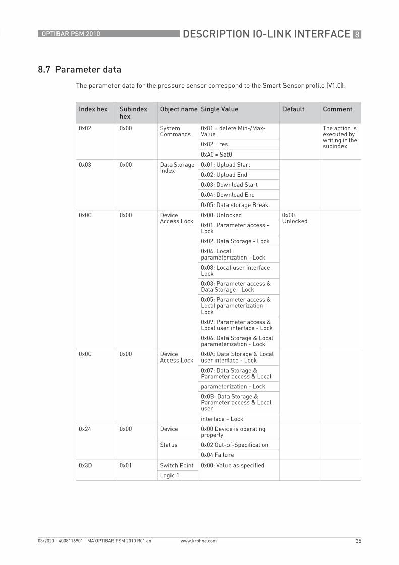
8.7 Parameter data
The parameter data for the pressure sensor correspond to the Smart Sensor profile (V1.0).
Index hex Subindex hex
Object name Single Value Default Comment
0x02 0x00 System Commands
0x81 = delete Min-/Max-Value
The action is executed by writing in the subindex0x82 = res
0xA0 = Set0
0x03 0x00 Data Storage Index
0x01: Upload Start
0x02: Upload End
0x03: Download Start
0x04: Download End
0x05: Data storage Break
0x0C 0x00 Device Access Lock
0x00: Unlocked 0x00: Unlocked
0x01: Parameter access - Lock
0x02: Data Storage - Lock
0x04: Local parameterization - Lock
0x08: Local user interface - Lock
0x03: Parameter access & Data Storage - Lock
0x05: Parameter access & Local parameterization - Lock
0x09: Parameter access & Local user interface - Lock
0x06: Data Storage & Local parameterization - Lock
0x0C 0x00 Device Access Lock
0x0A: Data Storage & Local user interface - Lock
0x07: Data Storage & Parameter access & Local
parameterization - Lock
0x0B: Data Storage & Parameter access & Local user
interface - Lock
0x24 0x00 Device 0x00 Device is operating properly
Status 0x02 Out-of-Specification
0x04 Failure
0x3D 0x01 Switch Point 0x00: Value as specified
Logic 1

8 DESCRIPTION IO-LINK INTERFACE
36
OPTIBAR PSM 2010
www.krohne.com 03/2020 - 4008116901 - MA OPTIBAR PSM 2010 R01 en
0x3D 0x02 Switch Point 0x80: Hysteresis NO
0x82: Window NO
0x80: HNo
Mode 1 0x81: Hysteresis NC
0x83: Window NC
0x3D 0x03 Switch Point 0x0000: No Hysteresis
Hysteresis 1
0x3F 0x01 Switch Point 0x00: Value as specified
Logic 2
0x3F 0x02 Switch Point 0x80: Hysteresis NO
0x82: Window NO
0x80: HNo
Mode 2 0x81: Hysteresis NC
0x83: Window NC
0x3F 0x03 Switch Point 0x0000: No Hysteresis
Hysteresis 2
0x93 0x00 Switch Point 0x01 - NPN Output
Typ 1 0x00 - PNP Output
0x97 0x00 Switch Point 0x01 - NPN Output
0x02 - 0...10 V Output
Typ 2 0x00 - PNP Output
0x03 - 4...20 mA
0xD4 0x00 Unit 0x00 bar 0x00: bar Pressure unit of the display changed, the IO-Link process data are not changed
0x01 mbar
0x02 PSI
0x03 MPa
Index hex Subindex hex
Object name Single Value Default Comment
DESCRIPTION IO-LINK INTERFACE 8
37
OPTIBAR PSM 2010
www.krohne.com03/2020 - 4008116901 - MA OPTIBAR PSM 2010 R01 en
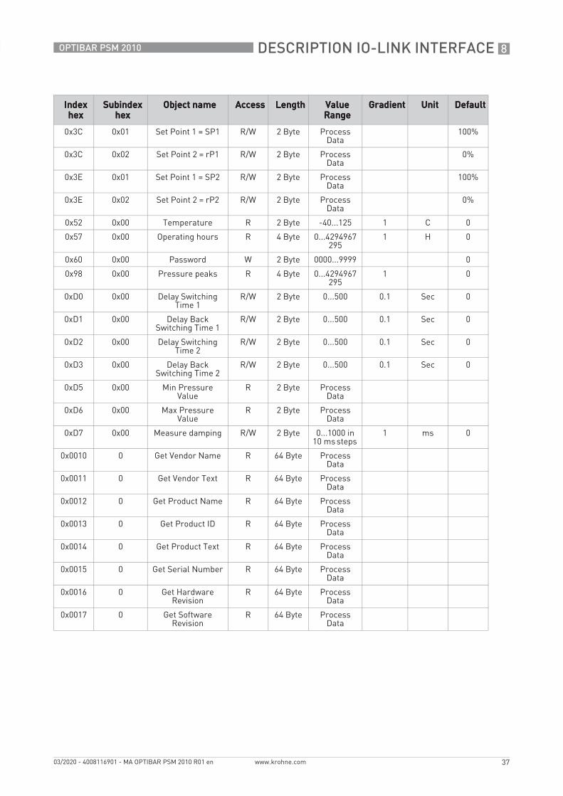
Index Index Index Index hexhexhexhex
SubindexSubindexSubindexSubindexhexhexhexhex
Object nameObject nameObject nameObject name AccessAccessAccessAccess LengthLengthLengthLength Value Value Value Value RangeRangeRangeRange
GradientGradientGradientGradient UnitUnitUnitUnit DefaultDefaultDefaultDefault
0x3C 0x01 Set Point 1 = SP1 R/W 2 Byte Process Data
100%
0x3C 0x02 Set Point 2 = rP1 R/W 2 Byte Process Data
0%
0x3E 0x01 Set Point 1 = SP2 R/W 2 Byte Process Data
100%
0x3E 0x02 Set Point 2 = rP2 R/W 2 Byte Process Data
0%
0x52 0x00 Temperature R 2 Byte -40...125 1 C 0
0x57 0x00 Operating hours R 4 Byte 0...4294967295
1 H 0
0x60 0x00 Password W 2 Byte 0000...9999 0
0x98 0x00 Pressure peaks R 4 Byte 0...4294967295
1 0
0xD0 0x00 Delay Switching Time 1
R/W 2 Byte 0...500 0.1 Sec 0
0xD1 0x00 Delay Back Switching Time 1
R/W 2 Byte 0...500 0.1 Sec 0
0xD2 0x00 Delay Switching Time 2
R/W 2 Byte 0...500 0.1 Sec 0
0xD3 0x00 Delay Back Switching Time 2
R/W 2 Byte 0...500 0.1 Sec 0
0xD5 0x00 Min Pressure Value
R 2 Byte Process Data
0xD6 0x00 Max Pressure Value
R 2 Byte Process Data
0xD7 0x00 Measure damping R/W 2 Byte 0...1000 in 10 ms steps
1 ms 0
0x0010 0 Get Vendor Name R 64 Byte Process Data
0x0011 0 Get Vendor Text R 64 Byte Process Data
0x0012 0 Get Product Name R 64 Byte Process Data
0x0013 0 Get Product ID R 64 Byte Process Data
0x0014 0 Get Product Text R 64 Byte Process Data
0x0015 0 Get Serial Number R 64 Byte Process Data
0x0016 0 Get Hardware Revision
R 64 Byte Process Data
0x0017 0 Get Software Revision
R 64 Byte Process Data

9 NOTES
38
OPTIBAR PSM 2010
www.krohne.com 03/2020 - 4008116901 - MA OPTIBAR PSM 2010 R01 en

NOTES 9
39
OPTIBAR PSM 2010
www.krohne.com03/2020 - 4008116901 - MA OPTIBAR PSM 2010 R01 en

KROHNE – Process instrumentation and measurement solutions
• Flow
• Level
• Temperature
• Pressure
• Process Analysis
• Services
Head Office KROHNE Messtechnik GmbHLudwig-Krohne-Str. 547058 Duisburg (Germany)Tel.: +49 203 301 0Fax: +49 203 301 [email protected]
© K
RO
HN
E 03
/202
0 -
4008
1169
01 -
MA
OP
TIB
AR
PSM
201
0 R
01 e
n -
Subj
ect t
o ch
ange
with
out n
otic
e.
The current list of all KROHNE contacts and addresses can be found at:www.krohne.com