
PLUTO Product Manual
102
INGENIA-CAT S.L. 8-14 MARIE CURIE, ADVANCED INDUSTRY PARK 08042 BARCELONA PLUTO Product Manual Edition 05/29/2017 For the most up to date information visit the online manual.
-
Upload
khangminh22 -
Category
Documents
-
view
1 -
download
0
Transcript of PLUTO Product Manual

INGENIA-CAT S.L.
8-14 MARIE CURIE, ADVANCED INDUSTRY PARK
08042 BARCELONA
PLUTO Product Manual
Edition 05/29/2017
For the most up to date information visit the online manual.

1 Table of Contents
1 Table of Contents 2
2 General Information 52.1 Manual revision history ..................................................................................................................................... 52.2 Disclaimers and limitations of liability ............................................................................................................. 52.3 Contact ............................................................................................................................................................... 6
3 Safety Information 73.1 About this manual.............................................................................................................................................. 73.2 Warnings............................................................................................................................................................. 73.3 Precautions ........................................................................................................................................................ 7
4 Product Description 84.1 Pluto part numbering ........................................................................................................................................ 84.2 Specifications..................................................................................................................................................... 94.3 Hardware revisions .......................................................................................................................................... 124.4 Power and current ratings............................................................................................................................... 134.4.1 Current ratings ................................................................................................................................................. 144.4.2 Dynamic application (non-constant current)................................................................................................. 154.4.3 System temperature ........................................................................................................................................ 154.4.4 Architecture...................................................................................................................................................... 16
5 Connectors Guide 175.1 Connectors position and pinout of Pluto (PLU-x/xx-S and PLU-x/xx-C) ....................................................... 175.1.1 Supply and shunt connector ........................................................................................................................... 195.1.2 Motor connector............................................................................................................................................... 205.1.3 Micro-Match connectors mating ..................................................................................................................... 215.1.3.1 Ribbon cable .................................................................................................................................................... 215.1.3.2 Multi-core crimped cable................................................................................................................................. 225.1.4 Feedback connector ........................................................................................................................................ 245.1.5 I/O connector ................................................................................................................................................... 275.1.6 USB connector ................................................................................................................................................. 315.1.7 CAN connector ................................................................................................................................................. 335.2 Connectors position and pinout of Pluto with EtherCAT (PLU-x/xx-E) ........................................................ 345.2.1 EtherCAT connectors ...................................................................................................................................... 36
6 Signalling LEDs 376.1 Power and operation signalling LEDs ............................................................................................................. 376.2 CAN signalling LEDs ......................................................................................................................................... 386.3 EtherCAT signalling LEDs................................................................................................................................. 39
7 Wiring and Connections 417.1 Protective earth ............................................................................................................................................... 417.2 Power supply.................................................................................................................................................... 447.2.1 Power supply requirements ............................................................................................................................ 447.2.2 Power supply connection ................................................................................................................................ 457.2.3 Battery supply connection .............................................................................................................................. 467.2.4 Connection of multiple drives with the same power supply ......................................................................... 46
7.2.5 Power supply wiring recommendations......................................................................................................... 477.2.5.1 Wire section ...................................................................................................................................................... 477.2.5.2 Wire ferrules ..................................................................................................................................................... 477.2.5.3 Wire length ....................................................................................................................................................... 487.3 Motor and shunt braking resistor.................................................................................................................... 487.3.1 AC and DC brushless motors ........................................................................................................................... 487.3.2 DC motors and voice coils actuators .............................................................................................................. 497.3.3 Motor wiring recommendations ..................................................................................................................... 517.3.3.1 Wire section ..................................................................................................................................................... 517.3.3.2 Wire ferrules ..................................................................................................................................................... 517.3.3.3 Motor choke ..................................................................................................................................................... 517.3.3.4 Wire length ....................................................................................................................................................... 527.3.4 Shunt braking resistor ..................................................................................................................................... 527.4 Feedback connections..................................................................................................................................... 537.4.1 Digital Halls interface....................................................................................................................................... 547.4.2 Analog Halls interface...................................................................................................................................... 567.4.3 Digital Incremental Encoder............................................................................................................................ 587.4.3.1 Termination resistors....................................................................................................................................... 617.4.3.2 Digital encoders with single ended 24 V outputs ........................................................................................... 627.4.3.3 Encoder broken wire detection....................................................................................................................... 627.4.4 Digital input feedback - PWM encoder............................................................................................................ 637.4.5 Analog input feedback..................................................................................................................................... 647.4.5.1 Potentiometer.................................................................................................................................................. 647.4.5.2 DC tachometer ................................................................................................................................................. 657.4.6 Feedback wiring recommendations ............................................................................................................... 667.4.6.1 Recommendations for applications witch close feedback and motor lines ................................................ 667.5 I/O connections ................................................................................................................................................ 677.5.1 General purpose single ended digital inputs interface (GPI1, GPI2) ............................................................. 677.5.2 High-speed digital inputs interface (HS_GPI1, HS_GPI2) .............................................................................. 707.5.3 Analog inputs interface (AN_IN1, AN_IN2)...................................................................................................... 757.5.4 Digital outputs interface (GPO1, GPO2).......................................................................................................... 787.5.4.1 Wiring of 5V outputs......................................................................................................................................... 797.5.4.2 Wiring of 24V loads........................................................................................................................................... 807.5.5 Motor brake output (GPO1, GPO2).................................................................................................................. 827.5.6 Torque off input (custom purchase order) ..................................................................................................... 837.6 Command sources ........................................................................................................................................... 857.6.1 Network communication interface................................................................................................................. 857.6.2 Standalone ....................................................................................................................................................... 867.6.3 Analog input ..................................................................................................................................................... 867.6.4 Step and direction............................................................................................................................................ 877.6.5 PWM command ................................................................................................................................................ 887.6.5.1 Single input mode............................................................................................................................................ 887.6.5.2 Dual input mode .............................................................................................................................................. 897.6.6 Encoder following or electronic gearing......................................................................................................... 907.7 Communications.............................................................................................................................................. 917.7.1 USB interface.................................................................................................................................................... 927.7.1.1 USB wiring recommendations ........................................................................................................................ 927.7.2 CANopen interface ........................................................................................................................................... 937.7.2.1 CAN interface for PC......................................................................................................................................... 957.7.2.2 CAN wiring recommendations ........................................................................................................................ 957.7.3 EtherCAT interface ........................................................................................................................................... 96

8 Dimensions 988.1 PLU-x/xx-S and PLU-x/xx-C.............................................................................................................................. 988.2 PLU-x/xx-E (Pluto with EtherCAT) ................................................................................................................... 99
9 Software 1019.1 Configuration ................................................................................................................................................. 1019.2 Applications.................................................................................................................................................... 101
10 Service 102

PLUTO Product Manual | General Information
INGENIA | 05/29/2017 5
1 http://doc.ingeniamc.com/download/attachments/3277106/Installation%20Manual%20-%20Pluto-v1.pdf?api=v2&modificationDate=1487862025836&version=1
2 http://doc.ingeniamc.com/download/attachments/3277106/Installation%20Manual%20-%20Pluto-v2.pdf?api=v2&modificationDate=1456830827256&version=1
3 http://doc.ingeniamc.com/download/attachments/3277106/Product%20Manual-v3-20160301_1143.pdf?api=v2&modificationDate=1456832646531&version=1
4 http://doc.ingeniamc.com/download/attachments/3277106/Product%20Manual-v4-20160419_0844.pdf?api=v2&modificationDate=1461055485489&version=1
5 http://doc.ingeniamc.com/download/attachments/3277106/Product%20Manual-v5-20161121_1044.pdf?api=v2&modificationDate=1479725212680&version=1
6 http://doc.ingeniamc.com/download/attachments/3277106/Pluto%20Servo%20Drive%20Product%20Manual%20v6.pdf?api=v2&modificationDate=1488557062606&version=2
7 http://doc.ingeniamc.com/display/PLU
2 General Information
2.1 Manual revision history
Revision Release Date Changes PDF
v1 January 2013 Initial Version. For pluto 1.0.0B1 and 1.0.1R. Download1
v2 April 2014 Update for hardware revision 1.1.0R Download2
v3 March 2016 Several improvements after revision 2.0.1R Download3
v4 April 2016 Added EtherCAT information. Structure improvements. Download4
v5 November 2016 Minor improvements. Download5
v6 March 2017 Aesthetics and structure improvements. Wiring information improved.
Download6
For the most up to date information use the online Product Manual7. The PDF manual is generated only after major changes.
Please refer to Hardware revisions (see page 12) for information on previous hardware revisions and changes.
2.2 Disclaimers and limitations of liability
The information contained within this document contains proprietary information belonging to INGENIA-CAT S.L..Such information is supplied solely for the purpose of assisting users of the product in its installation.
INGENIA-CAT S.L. rejects all liability for errors or omissions in the information or the product or in other documents mentioned in this document.
The text and graphics included in this document are for the purpose of illustration and reference only. The specifications on which they are based are subject to change without notice.
PLUTO Product Manual | General Information
INGENIA | 05/29/2017 6
8 mailto:[email protected] http://www.ingeniamc.com/
This document may contain technical or other types of inaccuracies.The information contained within this document is subject to change without notice and should not be construed as a commitment by INGENIA-CAT S.L.. INGENIA-CAT S.L. assumes no responsibility for any errors that may appear in this document.
Some countries do not allow the limitation or exclusion of liability for accidental or consequential damages, meaning that the limits or exclusions stated above may not be valid in some cases.
2.3 Contact
INGENIA-CAT S.L.8-14 Marie CurieAdvanced Industry Park08042 BarcelonaSpain
Telephone: +34 932 917 682E-mail: [email protected]
Web site: www.ingeniamc.com9
PLUTO Product Manual | Safety Information
INGENIA | 05/29/2017 7
3 Safety Information
3.1 About this manual
Read carefully this chapter to raise your awareness of potential risks and hazards when working with the Pluto Servo Drive.
To ensure maximum safety in operating the Pluto Servo Drive, it is essential to follow the procedures included in this guide. This information is provided to protect users and their working area when using the Pluto Servo Drive, as well as other hardware that may be connected to it. Please read this chapter carefully before starting the installation process. Please also make sure all system components are properly grounded.
3.2 Warnings
The following statements should be considered to avoid serious injury to those individuals performing the procedures and/or damage to the equipment:
• To prevent the formation of electric arcs, as well as dangers to personnel and electrical contacts, never connect/disconnect the Pluto Servo Drive while the power supply is on.
• Power cables may be exposed to high voltages, even when the motor is not in motion. Disconnect the Pluto Servo Drive from all power sources before proceeding with any possible wiring change.
• After turning off the power and disconnecting the equipment power source, wait at least 1 minute before touching any parts of the controller that are electrically charged or hot (such as capacitors or contacts).
3.3 Precautions
The following statements should be considered to avoid serious injury to those individuals performing the procedures and/or damage to the equipment:
• The Pluto Servo Drive components temperature may exceed 100 ºC during operation.• Some components become electrically charged when in operation.• The power supply connected to this controller should comply with the parameters specified in this
document.• When connecting the Pluto Servo Drive to an approved power source, do so through a line that is
separate from any possible dangerous voltages, using the necessary insulation in accordance with safety standards.
• High-performance motion control equipment can move rapidly with very high forces. Unexpected motion may occur especially during product commissioning. Keep clear of any operational machinery and never touch them while they are working.
• Do not make any connections to any internal circuitry. Only connections to designated connectors are allowed.
• All service and maintenance must be performed by qualified personnel.• Before turning on the Pluto Servo Drive, check that all safety precautions have been followed, as well as
the installation procedures.

PLUTO Product Manual | Product Description
INGENIA | 05/29/2017 8
4 Product DescriptionPluto is a high performance closed loop servo drive controller suitable for DC brushed, voice coils and brushless motors.
Its design includes multiple communication ports, enabling thus a wide choice of interfacing methods. Its extended voltage operating range allows its use in several applications, and the small footprint and the needless of an external heatsink allow the controller to be a valid OEM for critical-size applications.
The design also includes a wide variety of self protection mechanisms.
4.1 Pluto part numbering
Ordering part number Status Image
PLU-1/48-S
PLU-1/48-C
PLU-5/48-S
PLU-5/48-C
PLU-8/48-S
PLU-8/48-C
ACTIVE
ACTIVE
ACTIVE
ACTIVE
ACTIVE
ACTIVE

PLUTO Product Manual | Product Description
INGENIA | 05/29/2017 9
PLU-1/48-E
PLU-5/48-E
PLU-8/48-E
4.2 Specifications
Electrical and power specifications
Part number → PLU-1/48-y PLU-5/48-y PLU-8/48-y
Power supply voltage 10 VDC to 48 VDC
Transient peak voltage 60 V
Logic supply voltage Not needed, supplied from Power supply voltage
Internal DC bus capacitance 112 µF
Minimum motor inductance 200 µH
Nominal phase continuous current 1 ARMS 5 ARMS 8 ARMS
Maximum phase peak current 2 ARMS (5 s) 10 ARMS (5 s) 16 ARMS (5 s)
Current sense range ± 4.8 A ± 19.2 A ± 32 A
Current sense resolution 9.35 mA/count 37.39 mA/count 62.32 mA/count
Shunt braking transistor Shunt braking transistor on board. 16 A maximum current.
ACTIVE
ACTIVE
ACTIVE
Legacy Part Numbers
Part numbers have changed from Pluto Manual version 4. Follow this equivalence to identify your old Pluto:
• PLU-HS → PLU-1/48-y• PLU-STD → PLU-5/48-y• PLU-EXT → PLU-8/48-y

PLUTO Product Manual | Product Description
INGENIA | 05/29/2017 10
10 http://doc.ingeniamc.com/display/EMCL/0x2020+-+Enable+high+frequency+PWM11 http://doc.ingeniamc.com/display/NIX/Nix+Documentation+Home
Cold plate No
Power connectors Pluggable terminal block 3.5 mm pitch
Standby power consumption 1.5 W (max). 2 W EtherCAT version (PLU-x/xx-E)
Efficiency > 97% at the rated power and current
Motion control specifications
Supported motor types • Rotary brushless (trapezoidal and sinusoidal)• Linear brushless (trapezoidal and sinusoidal)• DC brushed• Rotary voice coil• Linear voice coil
Power stage PWM frequency 40 kHz (default)
20 kHz (alternative PWM frequency, configurable10)
Current sensing On phases A, B and C using 4 terminal shunt resistors.
Accuracy is ± 1% full scale.
10 bit ADC resolution.
Sensors for commutation
(brushless motors)
• Digital halls (Trapezoidal)• Analog halls (Sinusoidal / Trapezoidal)• Quad. Incremental encoder differential and single
ended (Sinusoidal / Trapezoidal)• PWM encoder (Sinusoidal / Trapezoidal)• Analog potentiometer (Sinusoidal / Trapezoidal)
Sensors supported for servo loops • Digital halls • Analog halls • Quadr. Incremental encoder• PWM encoder • Analog potentiometer • DC tachometer
Pluto does not allow Sin-Cos encoder. For a drive with similar form factor power and Sin-Cos encoder see the Nix Servo Drive11.
PLUTO Product Manual | Product Description
INGENIA | 05/29/2017 11
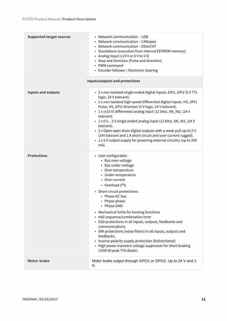
Supported target sources • Network communication – USB• Network communication – CANopen • Network communication – EtherCAT• Standalone (execution from internal EEPROM memory)• Analog input (±10 V or 0 V to 5 V)• Step and Direction (Pulse and direction)• PWM command• Encoder follower / Electronic Gearing
Inputs/outputs and protections
Inputs and outputs • 2 x non isolated single ended digital inputs. GPI1, GPI2 (5 V TTL logic, 24 V tolerant).
• 2 x non isolated high speed differential digital inputs. HS_GPI1 Pulse, HS_GPI2 Direction (5 V logic, 24 V tolerant).
• 1 x (±10 V) differential analog input (12 bits). AN_IN2. (24 V tolerant).
• 1 x 0 V... 5 V single ended analog input (12 bits). AN_IN1. (24 V tolerant).
• 2 x Open open drain digital outputs with a weak pull-up to 5 V. (24V tolerant and 1 A short-circuit and over-current rugged).
• 1 x 5 V output supply for powering external circuitry (up to 200 mA).
Protections • User configurable:• Bus over-voltage• Bus under-voltage• Over-temperature• Under-temperature• Over-current• Overload (I2t)
• Short-circuit protections: • Phase-DC bus• Phase-phase• Phase-GND
• Mechanical limits for homing functions• Hall sequence/combination error• ESD protections in all inputs, outputs, feedbacks and
communications.• EMI protections (noise filters) in all inputs, outputs and
feedbacks.• Inverse polarity supply protection (bidirectional)• High power transient voltage suppressor for short braking
(1500 W peak TVS diode).
Motor brake Motor brake output through GPO1 or GPO2. Up to 24 V and 1 A.

PLUTO Product Manual | Product Description
INGENIA | 05/29/2017 12
Communications
USB µUSB (2.0) connector.
CANopen Available. Non-isolated. 120Ω termination not included on board.CiA-301, CiA-305 and CiA-402 compliant.
EtherCAT Available.
Environmental and mechanical specifications
Ambient air temperature • -40 ºC to +50 ºC full current (operating)• +50 ºC to +100 ºC current derating (operating)• -40 to +125 ºC (storage)
Maximum humidity 5% - 85% (non-condensing)
Dimensions 60 mm x 60 mm x 15 mm
Weight (exc. mating connectors) 35 g
4.3 Hardware revisions
Hardware revision*
Description and changes
1.0.1R First product release.
1.1.0R Changes from previous version:
• CAN connector change from 4 ways to 3 ways (Phoenix Contact 1937509). PE pin is removed from connector. PE connection should be made with the plated mounting holes
• CAN LEDs position change• Supply connector change from 4 ways to 3 ways (Phoenix Contact 1937509). PE pin is
removed from connector. PE connection should be made with the plated mounting holes
• IO connector change TE Micro-Match model 8-188275-6. Same pinout except one change: +5.0 V output is added at pin 16. (Version 1.0.1 had this pin connected to GND)
• Feedback connector change to TE Micro-Match model 8-188275-2. Pinout remains identical to version 1.0.1R
• Increased USB port electrical robustness and noise immunity• Readjusted power stage elements to minimize electromagnetic emissions

PLUTO Product Manual | Product Description
INGENIA | 05/29/2017 13
12 http://doc.ingeniamc.com/display/EMCL/0x20C2+-+Drive+temperature
Hardware revision*
Description and changes
2.0.1R Changes from previous version:
• Added EtherCAT connectivity• PCB and PCA modifications to improve manufacturing reliability• Changed rounded corners radius for aesthetic reasons• High-speed (HS) digital inputs interface are pre-biased to allow easy wiring in single
ended applications• Added STO (Safe Torque Off) as a mounting option upon demand
2.1.0 Changes from previous version:
• Manufacturing improvements and component upgrades• Improvements on power stage transistors to minimize losses in all versions• Removed unnecessary components• CAN connector changed to FCI 20020110-C031A01LF (green) to avoid confusion with
the supply and shunt connector• Silkscreen improvements
4.4 Power and current ratings
Pluto is capable of providing the nominal current from -40ºC to 50ºC ambient air temperature without the need of any additional heatsink or forced cooling system. From 50ºC to 80ºC of ambient temperature a current derating is needed.
Excessive power losses lead to over temperature that will be detected and cause the drive to turn off. The system temperature is available in E-Core registers12 and is measured on the power stage. The temperature parameter that can be accessed from USB 2.0 or CAN interface does not indicate the air temperature. Above 110ºC the Pluto automatically turns off the power stage and stay in fault state avoiding any damage to the drive. A Fault LED will be activated and cannot be reset unless temperature decreases.
Identifying the hardware revision
Hardware revision is screen printed on the board.
Drive safety is always ensured by its protections. However, power losses and temperature limit the allowable motor current.
Some parts of the Pluto exceed 100ºC when operating, especially at high load levels.Do not touch the drive when operating and wait at least 5 minutes after turn off to allow a safe cool down.

PLUTO Product Manual | Product Description
INGENIA | 05/29/2017 14
Following figure shows the basic power flow and losses in a servo drive system.
4.4.1 Current ratings
The Pluto Servo drive has no cold plate, so the board itself is the heatsink. Power losses cause the drive to increase its temperature according to:
Power losses have a positive correlation with the motor RMS current. For this reason, when the ambient temperature rises, the output current must be limited to avoid an excessive drive temperature (TP< 110ºC). The threshold temperature where the current derating should start depends on the DC bus voltage and the Pluto part number.
Current derating
The current derating graph is only indicative and is based on thermal tests performed in a climatic room where there was enough room for natural air convection. Each application may reach different
PLUTO Product Manual | Product Description
INGENIA | 05/29/2017 15
4.4.2 Dynamic application (non-constant current)
The Pluto has a great thermal inertia that allows storing heat during short power pulses (exceeding nominal current) without overpassing the maximum temperature. This allows achieving high peak current ratings without need of additional heatsink.
For most systems where the cycle time is shorter than 3 τ (thermal time constant) the equivalent current can be calculated as the quadratic mean of the current during the full cycle. The load cycle can be simplified as different constant currents during some times:
Where:
T is the full cycle period.
I1 is the current during t1
I2 is the current during t2
In is the current during tn
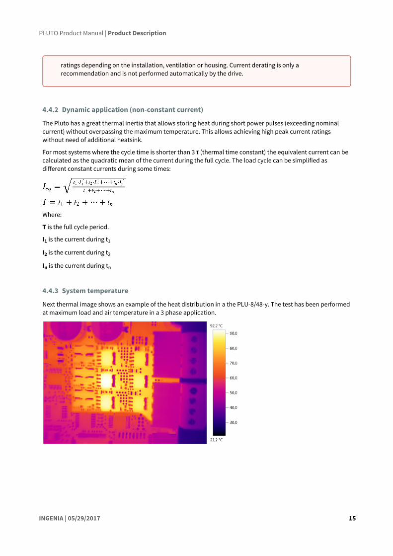
4.4.3 System temperature
Next thermal image shows an example of the heat distribution in a the PLU-8/48-y. The test has been performed at maximum load and air temperature in a 3 phase application.
ratings depending on the installation, ventilation or housing. Current derating is only a recommendation and is not performed automatically by the drive.

PLUTO Product Manual | Product Description
INGENIA | 05/29/2017 16
4.4.4 Architecture
Following figure shows a simplified hardware architecture of the Pluto Servo Drive. Links provide direct access to relevant pages.
The drive is getting hot even at 0 current!
This is normal. Pluto power stage includes high power MOSFET transistors which have parasitic capacitances. Switching them fast means charging and discharging those capacitors thousands of times per second which results in power losses and temperature increase even at 0 current!
Recommendation: when motor is off, exit motor enable mode which will switch off the power stage.

PLUTO Product Manual | Connectors Guide
INGENIA | 05/29/2017 17
5 Connectors GuideThis chapter details the Pluto Servo Drive connectors and pinout. Two Pluto variants are detailed:
• Pluto with USB or USB/CANOpen (PLU-x/xx-S and PLU-x/xx-C). (see page 17) • Pluto with EtherCAT (PLU-x/xx-E). (see page 34)
5.1 Connectors position and pinout of Pluto (PLU-x/xx-S and PLU-x/xx-C)

PLUTO Product Manual | Connectors Guide
INGENIA | 05/29/2017 18

PLUTO Product Manual | Connectors Guide
INGENIA | 05/29/2017 19
13 http://www.molex.com/molex/products/datasheet.jsp?part=active/0395021003_TERMINAL_BLOCKS.xml14 http://www.molex.com/molex/products/datasheet.jsp?part=active/0395000003_TERMINAL_BLOCKS.xml15 https://octopart.com/click/track?country=ES&ct=offers&ppid=657436&sid=1106&sig=0b1e60d&vpid=33369367
5.1.1 Supply and shunt connector
P1 Connector
3 position 3.5 mm pitch pluggable terminal block, black. MOLEX 39502-100313
Pin Signal Function
1 GND Negative power supply input (Ground)
2 SHUNT_OUT External shunt resistor connection
3 POW_SUP Positive power supply input
Mating
Description Pluggable terminal block, 3 positions 3.5 mm pitch
Part number MOLEX 39500000314
Distributor codes Arrow 39500000315

PLUTO Product Manual | Connectors Guide
INGENIA | 05/29/2017 20
16 http://www.molex.com/molex/products/datasheet.jsp?part=active/0395021004_TERMINAL_BLOCKS.xml
Notes
• See Power supply (see page 44) for power wiring information• For details on shunt operation see Motor and shunt Braking Resistor (see page 48)• Dimension the wiring according to the application current ratings. Higher section is always preferred to
minimize resistance and wire self-heating. Recommended wire section is 0.5 mm² ~ 1.5 mm²
5.1.2 Motor connector
P2 Connector
4 position 3.5 mm pitch pluggable terminal block, black. Molex 39502-100416
Do not confuse with CAN connector
Please note that both CAN and Supply use the same type of connector, except for a difference of color: Supply and shunt connector is black and CAN connector is green. Please check you are connecting your power supply to the right connector.
Previous versions compatibility
Supply connector has changed from version 1.0.1R of Pluto Servo Drive. Please see Hardware revisions (see page 12) for more information.

PLUTO Product Manual | Connectors Guide
INGENIA | 05/29/2017 21
17 http://www.molex.com/molex/products/datasheet.jsp?part=active/0395000004_TERMINAL_BLOCKS.xml18 https://octopart.com/click/track?country=ES&ct=offers&ppid=657441&sid=459&sig=0ef036a&vpid=184234419 https://octopart.com/click/track?country=ES&ct=offers&ppid=657441&sid=819&sig=0970471&vpid=14761700820 https://octopart.com/click/track?country=ES&ct=offers&ppid=657441&sid=2401&sig=03b2376&vpid=37815012
Pin Signal Function
1 PH_A Motor phase A (Positive for DC and voice coils)
2 PH_B Motor phase B (Negative for DC and voice coils)
3 PH_C Motor phase C (Do not connect for DC and voice coils)
4 PE Motor protective earth connection, internally connected to standoffs
Mating
Description Pluggable terminal block, 4 positions 3.5 mm pitch
Part number Molex 39500-000417
Distributor codes Digi-Key WM7734-ND18
Farnell 136847019
Mouser 538-39500-000420
Notes
• Dimension the wiring according to the application current ratings. Higher section is always preferred to minimize resistance and wire self-heating. Recommended wire section is 0.5 mm² ~ 1.5 mm²
• For wiring information, see motor and shunt braking resistor (see page 48) and protective earth (see page 41)wiring sections.
5.1.3 Micro-Match connectors mating
Most Pluto Servo Drive signal connections are based in TE Micro-Match connectors. Two different wiring options can be used ribbon cable and multi-core crimped cable.
Ribbon cable
Ribbon cable mating
Description
TE Micro-Match Male-on-Wire 1.27 mm pitch
https://octopart.com/click/track?country=ES&ct=offers&ppid=657441&sid=819&sig=0970471&vpid=147617008
https://octopart.com/click/track?country=ES&ct=offers&ppid=657441&sid=819&sig=0970471&vpid=147617008
PLUTO Product Manual | Connectors Guide
INGENIA | 05/29/2017 22
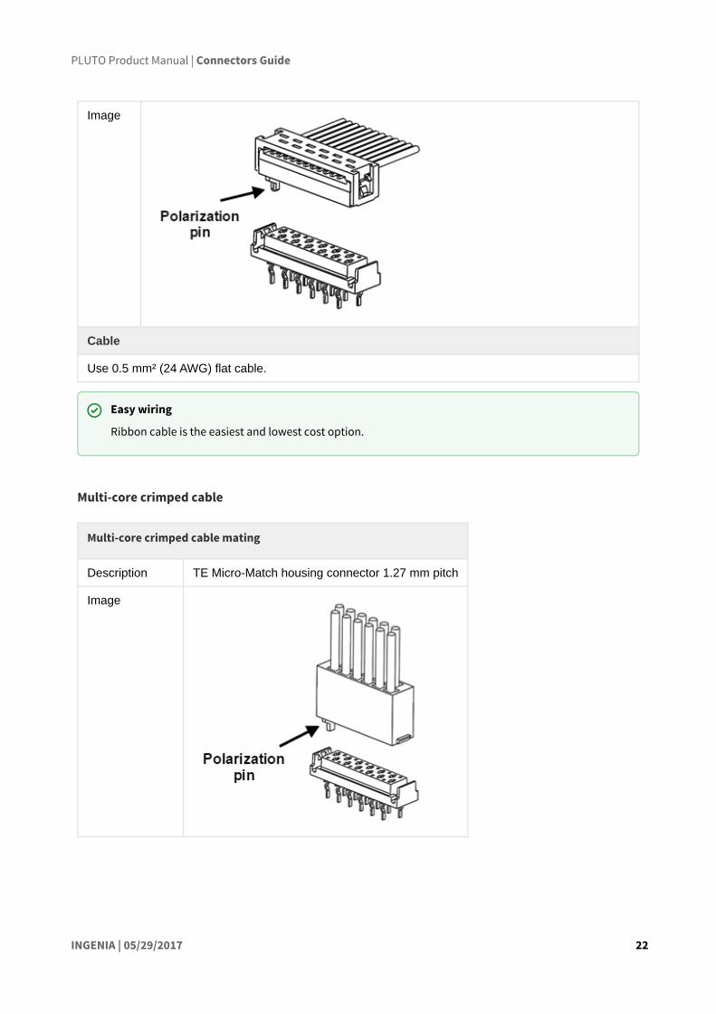
Image
Cable
Use 0.5 mm² (24 AWG) flat cable.
Multi-core crimped cable
Multi-core crimped cable mating
Description TE Micro-Match housing connector 1.27 mm pitch
Image
Easy wiring
Ribbon cable is the easiest and lowest cost option.
PLUTO Product Manual | Connectors Guide
INGENIA | 05/29/2017 23
21 http://www.te.com/usa-en/product-1-338097-1.html22 http://es.farnell.com/te-connectivity-amp/1-338097-1/contacto-macho-24-20awg/dp/1291807?ost=129180723 http://www.digikey.es/product-search/en?KeyWords=A99491CT-ND&WT.z_header=search_go24 http://www.mouser.com/ProductDetail/TE-Connectivity/1-338097-1/?qs=%2fha2pyFaduiA7MVMGX1qmLOMag
%2fOqvxq0cN%2fGPbiEvVBdoEDyAq0%2fw%3d%3d
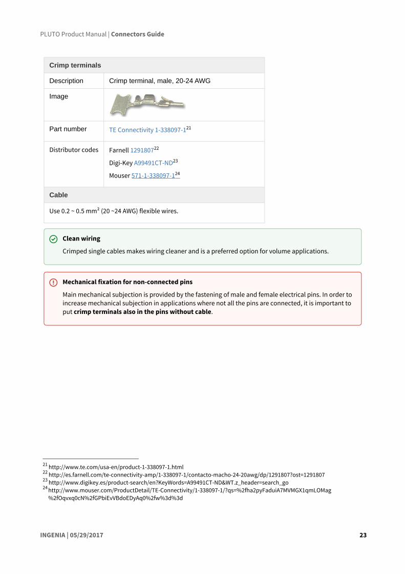
Crimp terminals
Description Crimp terminal, male, 20-24 AWG
Image
Part number TE Connectivity 1-338097-121
Distributor codes Farnell 129180722
Digi-Key A99491CT-ND23
Mouser 571-1-338097-124
Cable
Use 0.2 ~ 0.5 mm² (20 ~24 AWG) flexible wires.
Clean wiring
Crimped single cables makes wiring cleaner and is a preferred option for volume applications.
Mechanical fixation for non-connected pins
Main mechanical subjection is provided by the fastening of male and female electrical pins. In order to increase mechanical subjection in applications where not all the pins are connected, it is important to put crimp terminals also in the pins without cable.

PLUTO Product Manual | Connectors Guide
INGENIA | 05/29/2017 24
25 http://www.te.com/usa-en/product-1-338068-2.html
5.1.4 Feedback connector
P3 Connector
12 pin 1.27 mm pitch TE Micro-Match 1-338068-225 connector.
Pin Signal Function
1 +5V_OUT +5V 200mA max supply for feedbacks (shared with I/O connector)
2 GND Ground connection
3 ENC_A+ Single ended digital encoder: A inputDifferential digital encoder: A+ input
4 ENC_A- Differential Encoder: A- input
5 ENC_B+ Single ended digital encoder: B inputDifferential digital encoder: B+ input

PLUTO Product Manual | Connectors Guide
INGENIA | 05/29/2017 25
26 http://doc.ingeniamc.com/display/JUP/Jupiter+Documentation+Home27 http://doc.ingeniamc.com/display/CHA/Hydra+Documentation+Home28 http://doc.ingeniamc.com/display/NIX29 http://doc.ingeniamc.com/display/NEP/Neptune+Documentation+Home30 http://doc.ingeniamc.com/display/i02102/IO+Starter+Kit+Documentation+Home31 http://doc.ingeniamc.com/display/PLU/Cable+Kit+Manual
6 ENC_B- Differential Encoder: B- input
7 ENC_Z+ Single ended digital encoder: Index inputDifferential digital encoder: Index+ input
8 ENC_Z- Differential Encoder: Index- input
9 GND Ground connection
10 HALL_1 Hall sensor input 1 (analog and digital)
11 HALL_2 Hall sensor input 2 (analog and digital)
12 HALL_3 Hall sensor input 3 (analog and digital)
Notes
• Polarization hole on PCB indicates pin 1 and ensures correct cable position.• See Feedback connections (see page 53) for further information about different feedbacks wiring.• Pluto connectors include locking latches that provide audible click during mating and ensure assembly
robustness
Ribbon cable mating
Description TE Micro-Match Male-on-Wire 1.27 mm pitch 12 position
I/O Starter Kit and Cable Kit
Feedback connector pinout is shared with Jupiter26, Hydra27, Nix28and Neptune29servo drives, which allows using the IO starter kit30 and Pluto Cable Kit31.
Previous versions compatibility
Feedback connector has changed from previous hardware revisions. Please see Hardware revisions(see page 12) for more information.

PLUTO Product Manual | Connectors Guide
INGENIA | 05/29/2017 26
32 http://www.te.com/catalog/pn/en/8-215083-233 http://es.farnell.com/te-connectivity-amp/8-215083-2/connector-male-12way/dp/149093?ost=14909334 http://www.digikey.es/product-search/en?KeyWords=A99460CT-ND&WT.z_header=search_go35 http://www.mouser.com/ProductDetail/TE-Connectivity/8-215083-2/?qs=
%2fha2pyFadugdxAFatZceTp11WohXcBUKedSwBmHMht%2fbds%2fkm6wHkQ%3d%3d36 http://www.farnell.com/datasheets/31586.pdf37 http://es.farnell.com/3m/3302-16/flat-cable-16cond-100ft-28awg/dp/1369751?ost=136975138 http://www.digikey.es/product-search/en?KeyWords=MC16M-300-ND&WT.z_header=search_go39 http://www.mouser.com/ProductDetail/3M/C3302-16SF/?qs=%2fha2pyFaduitR4m
%252bYTEc4gsrCrYxZMoGNm4kPq22S5%252bKVAPsWFuruw%3d%3d40 http://doc.ingeniamc.com/display/PLU/Feedbacks+cable41 http://www.te.com/catalog/pn/en/1-338095-242 http://www.digikey.es/product-search/en?KeyWords=A99497-ND&WT.z_header=search_go43 http://www.mouser.com/ProductDetail/TE-Connectivity/1-338095-2/?qs=
%2fha2pyFaduiA7MVMGX1qmJfBprCLOcdyqrl7G6nXntRisMNu6iPG5w%3d%3d
Part number TE Conectivity 8-215083-232
Distributor codes Farnell 14909333
Digi-Key A99460CT-ND34
Mouser 571-8-215083-235
Cable
Part number 3M 3302/16 300SF36
Distributor codes Farnell 136975137
Digi-Key MC16M-300-ND38
Mouser 517-C3302/16SF39
Notes
• For further information see Pluto cable Kit - Feedbacks40.
Multi-core crimped cable mating
Description TE Micro-Match housing connector 1.27 mm pitch 12 position
Part number TE Connectivity 1-338095-241
Distributor codes Digi-Key A99497-ND42
Mouser 571-1-338095-243
Cable
Use 0.2 ~ 0.5 mm² (20 ~24 AWG) flexible wires.

PLUTO Product Manual | Connectors Guide
INGENIA | 05/29/2017 27
44 http://www.te.com/catalog/pn/en/1-338068-6
5.1.5 I/O connector
P4 Connector
16 pin 1.27 mm pitch TE Micro-Match 1-338068-644 connector.
Pin Signal Function
1 HS_GPI2+ / DIR+ High speed digital differential input 2+Command source: Direction+ input
2 HS_GPI2- / DIR- High speed digital differential input 2-Command source: Direction- input
3 GND Ground
4 GPO2 Digital output 2 (open collector with weak pull-up to 5 V)
5 GPO1 Digital output 1 (open collector with weak pull-up to 5 V)
6 GND Ground
7 HS_GPI1+ / PULSE+ / PWM+
High speed digital differential input 1+Command source: Pulse+ input

PLUTO Product Manual | Connectors Guide
INGENIA | 05/29/2017 28
8 HS_GPI1- / PULSE- / PWM-
High speed digital differential input 1-Command source: Pulse- input
9 GND Ground
10 AN_IN1 Single ended analog input 1
11 AN_IN2- Differential analog inverting input 2Single ended analog input 2 ground
12 AN_IN2+ Differential analog non inverting input 2Single ended analog input 2
13 GND Ground
14 GPI2 General purpose single ended digital input 2
(Could be torque off input on request)
15 GPI1 General purpose single ended digital input 1
16 +5V_OUT +5V 200mA max output (shared with feedback connector)

PLUTO Product Manual | Connectors Guide
INGENIA | 05/29/2017 29
45 http://doc.ingeniamc.com/display/JUP/Jupiter+Documentation+Home46 http://doc.ingeniamc.com/display/CHA/Hydra+Documentation+Home47 http://doc.ingeniamc.com/display/NIX48 http://doc.ingeniamc.com/display/NEP/Neptune+Documentation+Home49 http://doc.ingeniamc.com/display/i02102/IO+Starter+Kit+Documentation+Home50 http://doc.ingeniamc.com/display/PLU/Cable+Kit+Manual51 http://www.te.com/catalog/pn/en/8-215083-252 http://es.farnell.com/te-connectivity-amp/8-215083-2/connector-male-12way/dp/149093?ost=14909353 http://www.digikey.es/product-search/en?KeyWords=A99460CT-ND&WT.z_header=search_go54 http://www.mouser.com/ProductDetail/TE-Connectivity/8-215083-2/?qs=
%2fha2pyFadugdxAFatZceTp11WohXcBUKedSwBmHMht%2fbds%2fkm6wHkQ%3d%3d55 http://www.farnell.com/datasheets/31586.pdf
Notes
• Polarization hole on PCB indicates pin 1 and ensures correct cable position.• See I/O connections (see page 67) for further information about different I/O wiring.• Pluto connectors include locking latches that provide audible click during mating and ensure assembly
robustness
Ribbon cable mating
Description TE Micro-Match Male-on-Wire 1.27 mm pitch 16 position
Part number TE Conectivity 8-215083-251
Distributor codes Farnell 14909352
Digi-Key A99460CT-ND53
Mouser 571-8-215083-254
Cable
Part number 3M 3302/16 300SF55
I/O Starter Kit and Cable Kit
I/O connector pinout is shared with Jupiter45, Hydra46, Nix47and Neptune48servo drives, which allows using the IO starter kit49 and Pluto Cable Kit50.

PLUTO Product Manual | Connectors Guide
INGENIA | 05/29/2017 30
56 http://es.farnell.com/3m/3302-16/flat-cable-16cond-100ft-28awg/dp/1369751?ost=136975157 http://www.digikey.es/product-search/en?KeyWords=MC16M-300-ND&WT.z_header=search_go58 http://www.mouser.com/ProductDetail/3M/C3302-16SF/?qs=%2fha2pyFaduitR4m
%252bYTEc4gsrCrYxZMoGNm4kPq22S5%252bKVAPsWFuruw%3d%3d59 http://doc.ingeniamc.com/pages/viewpage.action?pageId=2198764960 http://www.te.com/catalog/pn/en/1-338095-261 http://www.digikey.es/product-search/en?KeyWords=A99497-ND&WT.z_header=search_go62 http://www.mouser.com/ProductDetail/TE-Connectivity/1-338095-2/?qs=
%2fha2pyFaduiA7MVMGX1qmJfBprCLOcdyqrl7G6nXntRisMNu6iPG5w%3d%3d
Distributor codes Farnell 136975156
Digi-Key MC16M-300-ND57
Mouser 517-C3302/16SF58
Notes
• For further information see Pluto cable Kit - General purpose I/O59.
Multi-core crimped cable mating
Description TE Micro-Match housing connector 1.27 mm pitch 16 position
Part number TE Connectivity 1-338095-260
Distributor codes Digi-Key A99497-ND61
Mouser 571-1-338095-262
Cable
Use 0.2 ~ 0.5 mm² (20 ~24 AWG) flexible wires.
Previous versions compatibility
Note: In previous Pluto versions (1.0.1R), which had CLIK-Mate connectors, pin 16 was connected to GND. Please see Hardware revisions (see page 12) for more information.

PLUTO Product Manual | Connectors Guide
INGENIA | 05/29/2017 31
63 http://portal.fciconnect.com/Comergent/fci/drawing/10118193.pdf
5.1.6 USB connector
P5 Connector
5 pin horizontal micro-USB connector Amphenol FCI 1011819363
Pin Signal Function
1 USB_SUPPLY USB +5 V supply input.
2 USB_D- USB Data- line
3 USB_D+ USB Data+ line
4 NC Not connected
5 GND Ground
SHIELD NC Connector metallic shield, NOT CONNECTED.

PLUTO Product Manual | Connectors Guide
INGENIA | 05/29/2017 32
64 http://ingeniamc.com/software#motionlab65 http://doc.ingeniamc.com/display/I071QUICKSTART/Update+Drive+Firmware66 http://www.molex.com/molex/products/datasheet.jsp?part=active/0687840002_CABLE_ASSEMBLIES.xml67 http://es.farnell.com/molex/68784-0002/cable-ass-usb-a-to-micro-usb-b/dp/161758668 http://www.digikey.es/product-search/en?KeyWords=WM17146-ND&WT.z_header=search_go69 http://www.mouser.es/ProductDetail/Molex/51110-1056/?qs=
%2fha2pyFaduiMjkvwWmWuOZy0mFhuCLeDSv3wJ9%2f1J325nRN%2fRFKKgQ%3d%3dhttp://www.mouser.es/ProductDetail/Molex/68784-0002/?qs=%2fha2pyFadujzzmc7Hrcjf2BglrT%2fRSoijj4vkovWYfZ89xZu3tlJQg%3d%3d
Notes
• Micro-USB connection allows easy access to the drive configuration using Motion Lab64 or downloading latest firmware revision65.
• Shorter USB cables are preferred whenever possible for minimal EMI.• Avoid applying excessive mechanical stress to the USB connector.• Please see Communications (see page 91) page for further information
Mating
Description USB Shielded I/O Cable Assembly, USB A-to-Micro-USB B, 1.50m Length, Black, Lead-Free
Image
Part number Molex 68784-000266
Distributor codes
Farnell 161758667
Digi-Key WM17146-ND68
Mouser 538-68784-000269

PLUTO Product Manual | Connectors Guide
INGENIA | 05/29/2017 33
70 http://portal.fciconnect.com/portal/page/portal/fciconnect/ecatalog?appname=catDisplayStyle$domProductQueryName=20020110-C031A01LF*$OP=search
71 http://portal.fciconnect.com/portal/page/portal/fciconnect/ecatalog?appname=catDisplayStyle$domProductQueryName=20020004-C031B01LF*$OP=search
5.1.7 CAN connector
P6 Connector
3 position 3.5 mm pitch pluggable terminal block, green. FCI 20020110-C031A01LF70
Pin Signal Function
1 CAN_GND CAN ground (connected to circuit ground)
2 CAN_L CAN bus line dominant low
3 CAN_H CAN bus line dominant high
Mating
Description Pluggable terminal block, 3 positions 3.5 mm pitch
Part number FCI 20020004-C031B01LF71

PLUTO Product Manual | Connectors Guide
INGENIA | 05/29/2017 34
72 https://octopart.com/click/track?c=1&country=ES&ct=offers&ppid=12573328&sid=459&sig=06d608e&vpid=8207619273 https://octopart.com/click/track?country=ES&ct=offers&ppid=12573328&sid=819&sig=091e2e9&vpid=14745167574 https://octopart.com/click/track?country=ES&ct=offers&ppid=12573328&sid=2401&sig=00c86d5&vpid=318858577
Distributor codes Digi-Key 20020004-C031B01LF-ND72
Farnell 178843273
Mouser 649-220004-C031B01LF74
Notes
• A 120 Ω termination is needed at the end of the CAN bus. • See Communications (see page 91) for further information about CAN wiring.
5.2 Connectors position and pinout of Pluto with EtherCAT (PLU-x/xx-E)
Do not confuse with Supply connector
Please note that both CAN and Supply use the same type of connector, except for a difference of color: Supply and shunt connector is black and CAN connector is green. Please check you are connecting your power supply to the right connector.
Previous versions compatibility
CAN connector has changed from previous hardware revisions. Please see Hardware revisions (see page 12) for more information.

PLUTO Product Manual | Connectors Guide
INGENIA | 05/29/2017 35

PLUTO Product Manual | Connectors Guide
INGENIA | 05/29/2017 36
75 http://katalog.we-online.de/pbs/datasheet/7499021125.pdf
5.2.1 EtherCAT connectors
P7-P8 Connectors
Dual RJ45 connector Magjack Wurth 749902112575
Pin Signal Function
1 TX_D+ Transmit Data+ line
2 TX_D- Transmit Data- line
3 RX_D+ Receive Data+ line
4 +2V5 2.5 V generated internally
5 +2V5 2.5 V generated internally
6 RX_D- Receive Data- line
7 NC Not connected
8 GND_CHASSIS Connected to the connector chassis
Notes
• Pinout is the same for Input (PORT 1) and output (PORT 2) connectors

PLUTO Product Manual | Signalling LEDs
INGENIA | 05/29/2017 37
76 http://doc.ingeniamc.com/display/EMCL/Error+management
6 Signalling LEDsPluto Servo Drive provides information through 5 signalling LEDs:
• Supply and operation: 3 LEDs next to the electrolytic capacitors. • CANopen communication: 2 LEDs next to the CAN connector.
Pluto with EtherCAT includes 3 more LEDs for the EtherCAT fieldbus status.
6.1 Power and operation signalling LEDs
Three LEDs situated next to the electrolytic capacitors indicate the supply and operation status. Next table shows the meaning of each LED:
LED Colour Meaning
POWER Green LED is on when internal power supply is working.
FAULT Red LED is on when a fault or error 76has occurred.

PLUTO Product Manual | Signalling LEDs
INGENIA | 05/29/2017 38
77 http://www.can-cia.org/
SHUNT Orange LED is turned on with the shunt braking resistor is activated, indicating that maximum user voltage has been exceeded and power is being dissipated.
6.2 CAN signalling LEDs
Two LEDs besides the CAN connector provide information about the CANopen communication status, according to CiA 303-3 recommendations77. The red LED is ERROR LED and green one is RUN LED.
ERROR LED indicates the status of the CAN physical layer and errors due to missed CAN messages (sync, guard or heartbeat). Next table the meaning of the ERROR LED states:
ERROR LEDstate*
Concept Description
Off No error Device is in working condition.
Single flash Warning limit reached
At least one of the error counters of the CAN controller has reached or exceeded the warning level (too many error frames).
Double flash Error control event
A guard event (NMT-slave or NMT-master) or a heartbeat event (heartbeat consumer) has occurred.
Triple flash Sync error The sync message has not been received within the configured communication cycle period time out.
On Bus off The CAN controller is bus off.
RUN LED indicates the status of the CANopen network state machine. Next table shows the meaning of the RUN LED states:
RUN LED state* Concept Description
Off Off The device is switched off
Blinking Pre-operational The device is in state PREOPERATIONAL
Single flash Stopped The device is in state STOPPED
On Operational The device is in state OPERATIONAL
*See a detailed description of the states in the next table:

PLUTO Product Manual | Signalling LEDs
INGENIA | 05/29/2017 39
78 https://www.ethercat.org/default.htm
* Possible LED states Description
ON The LED is always on
OFF The LED is always off
Single flash One short flash (~200 ms) followed by a long off phase (~1000 ms)
Double flash Sequence of 2 short flashes (~200 ms), separated by an off phase (~200 ms). The sequence is finished by a long off phase (~1000 ms)
Triple flash Sequence of 3 short flashes (~200 ms), separated by an off phase (~200 ms). The sequence is finished by a long off phase (~1000 ms)
Blinking On and off with a frequency of ~2.5 Hz: ON for ~200 ms followed by off for ~200 ms.
Note that the specified timings can vary in up to ±20%.
6.3 EtherCAT signalling LEDs
The Pluto Servo Drive with EtherCAT fieldbus includes 3 more LEDs to indicate communication status according to EtherCAT78 specification.
The EtherCAT bicolor green/red LED indicates the EtherCAT state machine status. The green LED is the RUN LED, and the red LED is the ERROR LED. Next table shows their states meaning:
RUN LED state EtherCAT slave status ERROR LED state EtherCAT slave status
Off INIT Off No error
Blinking PRE-OPERATIONAL Blinking Invalid configuration
Single Flash SAFE-OPERATIONAL Single flash Local error
On OPERATIONAL Double flash Watchdog timeout

PLUTO Product Manual | Signalling LEDs
INGENIA | 05/29/2017 40
On Application controller failure
For high severity errors inside the Pluto Servo Drive, an special LED state has been developed:
Status Signalling RUN LED state ERROR LED state
Internal error Interleaved blink Blinking (Initial status: OFF) Blinking (Initial status: ON)
The other two LEDs are situated in the EtherCAT connector. Each connector has two LEDs, but only the yellow LED is used. The LINK LED indicates the state of the EtherCAT physical link activity:
LINK LED Slave State
Off Port closed
Flickering Port opened (activity on port)
On Port opened (no activity on port)
The frequency of the blinking is different than the used for communication and is product dependent.

PLUTO Product Manual | Wiring and Connections
INGENIA | 05/29/2017 41
7 Wiring and ConnectionsProper wiring, and especially grounding and shielding, are essential for ensuring safe, immune and optimal servo performance of Pluto Servo Drive. Next pages show detailed connection recommendation as well as technical details of each interface.
• Protective earth (see page 41)• Power supply (see page 44)• Motor and shunt braking resistor (see page 48)• Feedback connections (see page 53)• I/O connections (see page 67)• Command sources (see page 85)• Communications (see page 91)
7.1 Protective earth
Connection of Pluto Servo Drive and motor housing to Protective Earth (PE) is required for safety reasons. Electrical faults can electrically charge the housing of the motor or cabinet, increasing the risk of electrical shocks. A proper connection to PE derives the charge to Earth, activating the installation safety systems (differential protections) and protecting the users.
Moreover, a proper connection to PE prevents many of the noise problems that occur operating a servo drive.
Pluto Servo Drive PE provides the following earth/ground connection points, which are internally connected and decoupled to power ground:
• PE terminal in the Motor connector.• Plated holes for standoffs.
1. test2. test2
A diagram of the recommended Earth wiring is shown following.
Reducing EMI susceptibility
Connecting the drive PE terminals and cold plate screws to your system Earth and to the motor housing solves many noise and EMI problems. The PE drive terminals are decoupled to power ground through a safety capacitor. This provides a low impedance preferential path for coupled common mode noises that otherwise would be coupled to sensitive electronics like the encoders. A good grounding of the drive to the earth of the power supply is also essential for a EMI reduction.

PLUTO Product Manual | Wiring and Connections
INGENIA | 05/29/2017 42
Some considerations for a proper earth connection are detailed next:
• Switching noise can be coupled to the earth through the housing of the motor. This high-frequency noise creates common mode current loop between drive and motor. Although the motor housing is connected to earth through the system chassis, its electrical connection may have a relatively high impedance and present a big loop. For this reason is essential to reduce the common mode current return path impedance and its loop area.
• For reducing the return path impedance, motor frame should be directly wired to drive PE terminals.
• PE wiring should be as close as possible to power cables, reducing current loop.
• Power supply is another source of switching noise. The neutral of the grid transformer or the housing of our power supply may also be connected to earth. For reducing noise and EMI, similar considerations should be taken.
• Directly wire power supply PE to drive PE.• PE wiring should be as close as possible to power supply cables.
• In order to avoid ground loops, it is a good practice to have a central earth connection point (or bus) for all the electronics of the same bench. If multiple drives are supplied from the same power supply or supply PE to drive PE connection is not practical (not enough connection terminals) connect all PE terminals in a central connection bus.
• Whenever possible, mount the Ingenia drive on a metallic conductive surface connected to earth. Use good quality plated screws that won’t oxidize or lose conductivity during the expected lifetime. Note that the PE terminal is internally connected with the Pluto Servo Drive standoffs.
• For achieving low impedance connections, use wires that are short, thick, multistrand cables or preferably conductive planes. PE wire section should be, at least, the same as power supply cables. Always minimize PE connection length.
Earth plane reference
While some systems will not have a "real Earth" connection, use your machine chassis, the metallic structure of the device or a good grounding conductive plane as your reference earth.

PLUTO Product Manual | Wiring and Connections
INGENIA | 05/29/2017 43
For an even better EMI immunity, use shielded or armored cables with isolating jacket, connecting the shield to PE with a cable clamp.
If a simplified wiring is required, the following shielding priority can be applied:
1. Shield the motor cables, which are the main high-frequency noise source.2. Shield the feedback signals, which are sensitive signals usually coming from the motor housing.3. Shield I/O signals and communication cables.
The clamp has to be selected according to the shielded cable diameter, ensuring a good support and connection between the cable shield and the clamp. Following examples are only suggested for conceptual purpose:
Description Image Part number
Cable Clamp, P-Type Silver Fastener 0.625" (15.88 mm)
Keystone Electronics 8107
Cable Clamp, P-Type Silver Fastener 0.187" (4.75 mm)
Keystone Electronics 8100
Cable Clamp, Saddle Type Stainless Steel 20 mm RS Pro 471-1300

PLUTO Product Manual | Wiring and Connections
INGENIA | 05/29/2017 44
79 http://doc.ingeniamc.com/display/KB/How+to+dimension+a+power+supply+for+an+Ingenia+drive
7.2 Power supply
The Pluto Servo Drive is supplied from the Supply and shunt connector, using the same terminal for logic and power supply (10 VDC to 48 VDC). An internal DC/DC converter provides circuits with appropriate voltages as well as a regulated 5 V output voltage to supply feedback sensors and I/O.
7.2.1 Power supply requirements
The choice of a power supply is mainly determined by voltage and current ratings of the power supply. Main requirements of the Pluto power supply are:
• The voltage should be the targeted for the motor. This means up to 48 V for all the Pluto versions. Make sure that the voltage rating of the power supply does not exceed the voltage rating of the motor, otherwise it could be damaged.
• The current should be the one able to provide the phase peak current of the application. This means up to 2 A for the PLU-1/48, up to 10 A for the PLU-5/48 and up to 16 A for the PLU-8/48 Make sure that the current rating for the power supply is at least as high as the motor.
• The voltage and current range can be decreased due to the motor requirements.
Further information on how to dimension a power supply for the Ingenia drives can be found here79.
Following are shown different power supply examples:
Manufacturer
Part Number
Rated Voltage (V)
Rated Current (A)
Image Description
CUI Inc. VBM-100-48
48 2.1 Switching closed frame power supply recommended for Pluto-1/48, 100 W
Power supply for configuration
Power supply has to be provided for configuration purposes. Pluto Servo Drive can not be supplied from USB connector.
Disconnection recommendations
There are no critical instructions for disconnecting the Pluto. Just some recommendations:• The board could be hot during < 1 min after disconnection.• Preferably do not disconnect the supply while having a motor in motion.• If working with Motion Lab with USB connection, preferably disconnect the drive from the
application before disconnecting. This prevents COM port corruption.

PLUTO Product Manual | Wiring and Connections
INGENIA | 05/29/2017 45
TDK Lambda
PFE500F48
48 10.5 Switching closed frame power supply recommended for Pluto-5/48, 500 W
TDK Lambda
PFE1000F48
48 21 Switching closed frame power supply recommended for Pluto-8/48, 1000 W
7.2.2 Power supply connection
Pluto logic and power supply are provided through the same terminal. All Pluto versions support an input voltage of +10 V to +48 V.
The following picture show the Pluto supply wiring diagram.
Twisted cables
Twisted power supply cables are preferred to reduce electromagnetic emissions and increase immunity.
Isolated power supplies
For safety reasons, it is important to use power supplies with full galvanic isolation.

PLUTO Product Manual | Wiring and Connections
INGENIA | 05/29/2017 46
7.2.3 Battery supply connection
Next figure shows a simplified wiring diagram for the Pluto Servo Drive supplied from a battery.
7.2.4 Connection of multiple drives with the same power supply
When different servo drives are connected to the same power supply, connect them in star topology for reducing cable impedance and common mode coupled noise. That is, connect each drive to the common supply using separate wires for positive and return.
Motor braking current
Motor braking can cause reverse current sense and charge the battery.
Always ensure that the battery can accept this charge current which will be within the Pluto current ratings.

PLUTO Product Manual | Wiring and Connections
INGENIA | 05/29/2017 47
80 http://www.digikey.es/product-detail/en/3200881/277-5453-ND/349955
7.2.5 Power supply wiring recommendations
Wire section
The minimum wire section is determined by the current consumption and the allowed voltage drop across the conductor. It is preferred to use wide section stranded wires to reduce impedance, power losses and ease the assembly. Insulator size should not exceed 3.5 mm (connector pitch). Following table indicates recommended section for the Pluto Servo Drive:
Connection Minimum wire size Maximum wire size
Stranded wire (preferred) 0.5 mm2 (20 AWG) 1.5 mm2 (16 AWG)
Solid wire 0.5 mm2 (20 AWG) 1.5 mm2 (16 AWG)
Wire ferrules
For low power applications, it is recommended to use wire ferrules to prevent cable damage or wrong contacts. For higher power applications, direct cable connection is recommended, since it provides lower contact resistance. Due to the connector's size, the maximum allowed ferrule size is 0.5 mm2. Ensure the insulator does not exceed 3.5 mm (connector pitch). Following table indicates recommended wire ferrules for the Pluto Servo Drive:
Manufacturer Part number Image Description
Phoenix Contact 320136980 8 mm pin length,
0.5 mm2 (20 AWG)

PLUTO Product Manual | Wiring and Connections
INGENIA | 05/29/2017 48
81 http://www.digikey.es/product-detail/en/966067-1/A114629-ND/1152396
TE Connectivity 966067-181 6 mm pin legth,
0.5 mm2 (20 AWG)
Wire length
• The distance between the Pluto Servo Drive and the power supply should be minimized when possible. Short cables are preferred since they reduce power losses as well as electromagnetic emissions and immunity.
• For best immunity use twisted and shielded 2-wire cables for the DC power supply. This becomes crucial in long cable applications.
• Avoid running supply wires in parallel with other wires for long distances, especially feedback and signal wires.
7.3 Motor and shunt braking resistor
7.3.1 AC and DC brushless motors
Brushless motors should be connected to phase A, B and C terminals. Note that some manufacturers may use different phase name conventions (see Table below).
Phase name Alphabetic Numeric UVW
PH_A A 1 U

PLUTO Product Manual | Wiring and Connections
INGENIA | 05/29/2017 49
PH_B B 2 V
PH_C C 3 W
7.3.2 DC motors and voice coils actuators
DC motors and voice coil actuators are connected to phase A and phase B terminals. Phase C terminal is left unconnected.
Common-mode choke
In order to minimize EMI that can affect sensitive signals, the use of a motor choke is recommended. The objective of the motor choke is to block the common mode current to the motor and cables. While using a separate choke for each phase could also work, the EMI reduction would be much lower than passing all the phases through the same choke.
Proper three-phase motor choke wiring
In order to minimize the capacitive coupling of the motor wires, and therefore cancelling the effect of the common mode rejection effect, the choke has to be properly wired.
• An excessive number of turns causes a high capacitive coupling. Only 2 or 3 turns per motor phase are recommended.
• For reducing the coupling between phases, space the phases 120º apart. Start each phase wire in the same rotating direction, wrapping all phases clockwise or anticlockwise. This will add the common mode flux and increase its impedance.

PLUTO Product Manual | Wiring and Connections
INGENIA | 05/29/2017 50
Common-mode choke
In order to minimize EMI that can affect sensitive signals, the use of a motor choke is recommended. The objective of the motor choke is to block the common mode current to the motor and cables. While using a separate choke for each phase could also work, the EMI reduction would be much lower than passing all the phases through the same choke.
Proper DC motor choke wiring
In order to minimize the capacitive coupling of the motor wires, and therefore cancelling the effect of the common mode rejection effect, the choke has to be properly wired.
• An excessive number of turns causes a high capacitive coupling. Only 2 or 3 turns per motor phase are recommended.
• For reducing the coupling between positive and negative, space them 180º apart. Start positive and negative wire in the same rotating direction, wrapping both phases clockwise or anticlockwise. This will add the common mode flux and increase its impedance.

PLUTO Product Manual | Wiring and Connections
INGENIA | 05/29/2017 51
82 http://www.wagocatalog.com/okv3/index.asp?lid=5&cid=51&strBestNrID=216020683 http://www.wagocatalog.com/okv3/index.asp?lid=5&cid=51&strBestNrID=2160224
7.3.3 Motor wiring recommendations
Wire section
The minimum wire section is determined by the motor current. It is preferred to use wide section stranded wires to reduce impedance, power losses and ease the assembly. Insulator size should not exceed 5 mm (connector pitch). Following table indicates recommended section for the Pluto Servo Drive:
Connection Minimum wire size Maximum wire size
Stranded wire (preferred) 0.5 mm2 (20 AWG) 1.5 mm2 (16 AWG)
Solid wire 0.5 mm2 (20 AWG) 1.5 mm2 (16 AWG)
Wire ferrules
For low power applications, it is recommended to use wire ferrules to prevent cable damage or wrong contacts. For higher power applications, direct cable connection is recommended, since it provides lower contact resistance. Due to the connector's size, the maximum allowed ferrule size is 0.5 mm2. Ensure the insulator does not exceed 3.5 mm (connector pitch). Following table indicates recommended wire ferrules for the Pluto Servo Drive:
Manufacturer Part number Image Description
WAGO 216-20182 0.5 mm2 (20 AWG)
WAGO 216-22483 1.5 mm2 (16 AWG)
Motor choke
In applications where electromagnetic compatibility is a concern or that must comply with the EMC standards, the use of an external common mode choke is necessary. Some choke wiring recommendations are:
• Place the choke as close to the drive as possible. • Make sure the chosen choke does not saturate at the maximum operating phase current. If this
happens, the choke temperature would increase rapidly.• Only 2 or 3 turns of the motor cables to the choke are recommended for best performance. Doing more
than 3 turns reduces choke effectiveness, as capacitive coupling between wires would bypass the choke effect.

PLUTO Product Manual | Wiring and Connections
INGENIA | 05/29/2017 52
84 http://www.digikey.es/product-search/en?keywords=LFB360230-30085 http://doc.ingeniamc.com/display/KB/Dimensioning+a+Shunt+Resistor+for+Regenerative+Braking
• PE conductor should NOT pass through the choke.• Avoid contact of the toroid core with a grounding point.
Next table shows a choke that fits the Pluto Servo Drive specifications and has a great performance at low frequencies.
Type Manufacturer Reference
Low frequency ferrite Laird Technologies LFB360230-30084
Wire length
• The distance between the Pluto Servo Drive and the motor should be minimized when possible. Short cables are preferred since they reduce power losses as well as electromagnetic emissions and immunity.
• Avoid running motor wires in parallel with other wires for long distances, especially feedback and signal wires.
• The parasitic capacitance between motor wires should not exceed 10 nF. If very long cables (> 100 meters) are used, this value may be higher. In this case, add series inductors between the Pluto outputs and the cable. The inductors must be magnetically shielded, and must be rated for the motor surge current. Typical values are around 100 μH.
7.3.4 Shunt braking resistor
While decelerating a motor (abrupt motion brakes or reversals), the mechanical energy is converted into electrical energy by the motor. This energy is regenerated into the power supply and could lead to an increase of the supply voltage. To absorb this energy the Pluto incorporates a shunt transistor to connect an external braking resistor.
Wiring recommendations of the shunt braking resistor:
• The external braking resistor should be connected between SHUNT_OUT and POW_SUP terminals of the Pluto Supply and shunt connector.
• It is strongly recommended to use an external fuse to limit the maximum power dissipation according to the chosen shunt resistor.
• Wire section should be, at least, like the motor wires. • Shunt resistor connections should be as short as possible to reduce parasitic inductances.
Shunt resistor calculation tool
Additional information on shunt braking resistor sizing and a calculation tool can be found here85.

PLUTO Product Manual | Wiring and Connections
INGENIA | 05/29/2017 53
86 http://doc.ingeniamc.com/display/EMCL/0x2103+-+Shunt+configuration87 http://doc.ingeniamc.com/display/EMCL/0x2101+-+Drive+bus+voltage
7.4 Feedback connections
The Pluto Servo Drive has a feedback connector dedicated to the following feedback options:
• Digital Halls (see page 54)• Analog Halls (see page 56) • Quad. Incremental encoder (see page 57)
Hot surfaces
Be careful, shunt resistor may have hot surfaces during operation.
Configuration of the shunt
The shunt transistor can be configured using parameters in the register 0x2103 - Shunt configuration86. When the supply voltage reaches the maximum voltage indicated in register 0x2101 - Drive bus voltage87, the shunt transistor is activated.
As a recommendation, set the DC bus voltage limit above the maximum expected DC supply voltage + 5%.
When using batteries set the DC bus voltage limit below the maximum charge voltage. This will allow regenerative braking and protect the battery against overcharging.
PLUTO Product Manual | Wiring and Connections
INGENIA | 05/29/2017 54
Additional feedback connections can be found on I/O connector:
• PWM encoder (see page 63)• Analog input for potentiometer (see page 64)• Analog input for DC tachometer (see page 65)
Pluto also provides a 5V, 200 mA outputs for feedbacks supply. This output is overload and short circuit protected.
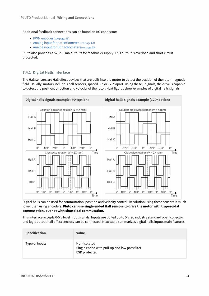
7.4.1 Digital Halls interface
The Hall sensors are Hall effect devices that are built into the motor to detect the position of the rotor magnetic field. Usually, motors include 3 hall sensors, spaced 60º or 120º apart. Using these 3 signals, the drive is capable to detect the position, direction and velocity of the rotor. Next figures show examples of digital halls signals.
Digital halls signals example (60º option) Digital halls signals example (120º option)
Digital halls can be used for commutation, position and velocity control. Resolution using these sensors is much lower than using encoders. Pluto can use single ended Hall sensors to drive the motor with trapezoidal commutation, but not with sinusoidal commutation.
This interface accepts 0-5 V level input signals. Inputs are pulled up to 5 V, so industry standard open collector and logic output hall effect sensors can be connected. Next table summarizes digital halls inputs main features:
Specification Value
Type of inputs Non-isolated Single ended with pull-up and low pass filterESD protected
PLUTO Product Manual | Wiring and Connections
INGENIA | 05/29/2017 55
Number of inputs 3
ESD capability IEC 61000-4-2 (ESD) ± 15 kV (air), ± 8 kV (contact) IEC 61000-4-4 (EFT) 40 A (5/50 ns)
Voltage range 0 ~ 5 V
Maximum voltage range -0.5 ~ 5.5 V
Maximum recommended working frequency
1 kHz
1st order filter cutting frequency (-3dB)
160 kHz
Sampling frequency 10 ksps
Type of sensors Open collector Logic outputPush-pull output
Pull-up resistor value 1 kΩ (The pull-up is activated only when the drive is configured to use digital hall sensors)
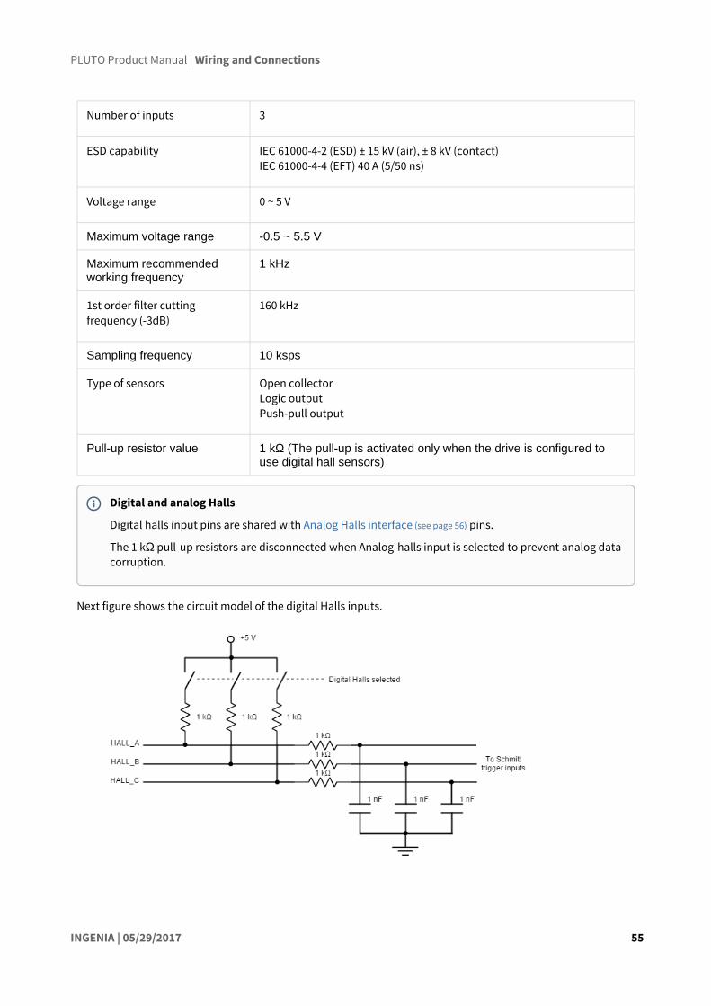
Next figure shows the circuit model of the digital Halls inputs.
Digital and analog Halls
Digital halls input pins are shared with Analog Halls interface (see page 56) pins.
The 1 kΩ pull-up resistors are disconnected when Analog-halls input is selected to prevent analog data corruption.

PLUTO Product Manual | Wiring and Connections
INGENIA | 05/29/2017 56
Next figure illustrates how to connect the digital halls to the Pluto Servo Drive. Refer to Feedback wiring recommendations (see page 66) for more information about connections and wires.
7.4.2 Analog Halls interface
The Pluto Servo Drive can operate with analog Hall sensors (also known as linear halls) as feedback option. Signals provided by these sensors are typically 5 V peak-to-peak sinusoidal signals, with 2.5 V offset and a phase shift of 120 degrees. These sensors can be used for a fine positioning of the rotor. Pluto analog halls inputs main features are shown in next table:
Specification Value
Type of inputs Non-isolated Single ended analog filteredESD protected
Number of inputs 3
ESD capability IEC 61000-4-2 (ESD) ± 15 kV (air), ± 8 kV (contact) IEC 61000-4-4 (EFT) 40 A (5/50 ns)
Maximum recommended working frequency
1 kHz
2nd order filter cutting frequency 10.8 kHz
Velocity control with Halls
Due to inherent low resolution of motor mounted Hall sensors, they are not recommended for velocity feedback in low speed applications.

PLUTO Product Manual | Wiring and Connections
INGENIA | 05/29/2017 57
Sampling frequency 10 ksps
Voltage range 0 ~ 5 V (10 bits)
Maximum voltage range -0.3 ~ 5.3 V
Input impedance > 24 kΩ
Next figure illustrates the circuit model for one of the linear Halls inputs. An active Sallen-Key low pass filter provides immunity to motor and feedback noise. Note that analog halls pins are shared with Digital Halls interface (see page 0), to avoid any signal distortion, when analog halls interface is selected, the 1 kΩ pull-up is disconnected automatically.
Next figure shows how to connect the linear Halls to the Pluto Servo Drive. Refer to Feedback wiring recommendations (see page 66) for more information about connections and wires.

PLUTO Product Manual | Wiring and Connections
INGENIA | 05/29/2017 58
7.4.3 Digital Incremental Encoder
Pluto can use single ended or differential digital incremental encoder inputs (also known as quadrature incremental encoders) for velocity and/or position control, as well as commutation sensor. The encoder provides incremental position feedback that can be extrapolated into precise velocity or position information. Using high resolution encoders allows Pluto Servo Drive to use sinusoidal commutation.
Channel A and channel B signals should have a phase shift of 90 degrees, indicating the rotation direction. Based on the pulses frequency, the drive can calculate the motor velocity and position.
Example of single ended digital encoder inputs
Example of digital differential encoder signals
The Pluto Servo Drive has one differential digital encoder interface, with optional index signal input. Index signal (Z) is a single pulse per revolution signal that can be used to know absolute positions. Next table illustrates digital encoder inputs main features.
High precision applications
High resolution motor mounted encoders allows excellent velocity and position control at all speeds. Encoder feedback should be used for applications requiring precise and accurate velocity and position control. Digital encoders are especially useful in applications where low-speed smoothness is the objective.

PLUTO Product Manual | Wiring and Connections
INGENIA | 05/29/2017 59
Specification Value
Type of inputs Non-isolatedDifferential or single endedESD protected
Number of inputs 3 (A, B and Index)
ESD capability IEC 61000-4-2 (ESD) ± 15 kV (air), ± 8 kV (contact) IEC 61000-4-4 (EFT) 40 A (5/50 ns)
Nominal voltage range 0 ~ 5 V
Maximum voltage range -0.5 ~ 5.5 V
Maximum recommended working frequency
10 MHz (differential)
1st order filter cutting frequency (-3 dB)
6.6 MHz
Maximum readable pulse frequency
30 MHz
Termination resistor 120 Ω (between ENC_x+ and ENC_x-)
Bias resistors ENC_x+ (positive input) 2 kΩ to 5 V
ENC_x- (negative input) 1.5 kΩ to 4 V (equivalent)
For encoder signal reception, an RS-422 differential line receiver is used. The high signals (ENC_A+, ENC_B+ and ENC_Z+) are pulled up to +5 V, and the low signals (ENC_A-, ENC_B- and ENC_Z-) are biased to 4 V (approx). This arrangement let the user to connect either differential output encoders or single ended encoders (both open collector and totem pole).
The encoder interface also accepts an RS-422 differential quadrature line drive signal in the range of 0 V to 5 V, up to 10 MHz. When single ended encoder is connected, only high signals (ENC_A+, ENC_B+ and ENC_Z+) must be used.
Next figure shows the circuit model of the digital encoder inputs.

PLUTO Product Manual | Wiring and Connections
INGENIA | 05/29/2017 60
Next figures illustrate how to connect a differential and a single ended encoder to the Pluto Servo Drive. Refer to Feedback wiring recommendations (see page 66) for more information about connections and wires.

PLUTO Product Manual | Wiring and Connections
INGENIA | 05/29/2017 61
Termination resistors
The Pluto does not have termination resistors on board. In a noisy environment it is recommended to add 120Ωtermination resistors between the positive and the negative lines of the differential signals of the encoder. Next figure shows how connect the termination resistors:
To minimize the power consumption, an AC termination topology can be used, which consist on connecting a 10 nF capacitor in series with the 120Ω termination resistors:

PLUTO Product Manual | Wiring and Connections
INGENIA | 05/29/2017 62
88 http://doc.ingeniamc.com/display/EMCL/Error+management
Suggested part numbers:
Manufacturer PN Description
Xicon 271-120-RC Resistor 120Ω, 250 mW, 1%
Murata RDER71E104K0P1H03B Capacitor 0.1 µF, ceramic, X7R, 25 V
Digital encoders with single ended 24 V outputs
Pluto Servo Drive can also interface single ended digital encoders with output voltages higher than 5 V, for instance 24 V PLC level encoder. With the use of series connected limiting resistors, Pluto is able to read encoder counts correctly while the inputs are correctly protected.
It is recommended to use a 4.7 kΩ 1/4 W resistor in series with the ENC_X- (inverting) input and leave the ENC_X+ floating.
Encoder broken wire detection
Pluto Servo Drive includes a broken wire detection circuit. The circuit is based on 3 EX-OR gates that will generate an error88 if the encoder is disconnected or a wire is broken. This system only works for differential encoders.

PLUTO Product Manual | Wiring and Connections
INGENIA | 05/29/2017 63
7.4.4 Digital input feedback - PWM encoder
Pluto Servo Drive can also use a PWM encoder connected through the I/O connector as a feedback element. A PWM encoder provides a Pulse Width Modulated (PWM) signal with a duty cycle proportional to the angle (position) of the rotor. This feedback can be interfaced through the high-speed digital input 1 (HS_GPI1). Both differential and single-ended PWM encoders can be used. Further specifications about the PWM input can be found in I/O connection section (see page 67).
Next figure illustrates PWM feedback input for different rotor positions:
Next figures illustrates how to connect differential and single ended PWM encoders to the Pluto Servo Drive:
Encoder without Index (Z) line
To avoid a broken wire fault when the differential encoder has no index (Z) line, connect the negative pin (ENC_Z-) to GND (this ensures the XOR result = 1) or configure the encoder as single ended in MotionLab.

PLUTO Product Manual | Wiring and Connections
INGENIA | 05/29/2017 64
Refer to Feedback wiring recommendations (see page 66) for more information about connections and wires.
7.4.5 Analog input feedback
Pluto Servo Drive can also use analog feedback systems connected through the I/O connector. From the voltage level of one analog input, the position or velocity of the rotor can be calculated. The Pluto have 2 analog inputs that can be used for feedback input, each one with a different input range. The input used as feedback can be selected by software. Further specifications about the analog inputs input can be found in I/O connection section (see page 67).
Refer to Feedback wiring recommendations (see page 66) for more information about connections and wires.
Potentiometer
A typical analog sensor used for position feedback is a potentiometer. This sensor provides a voltage proportional to the rotor position.
The following picture shows how to connect a potentiometer as a position sensor using analog input 1:
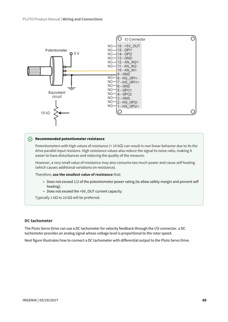
PLUTO Product Manual | Wiring and Connections
INGENIA | 05/29/2017 65
DC tachometer
The Pluto Servo Drive can use a DC tachometer for velocity feedback through the I/O connector. a DC tachometer provides an analog signal whose voltage level is proportional to the rotor speed.
Next figure illustrates how to connect a DC tachometer with differential output to the Pluto Servo Drive.
Recommended potentiometer resistance
Potentiometers with high values of resistance (> 10 kΩ) can result in non linear behavior due to its the drive parallel input resistors. High resistance values also reduce the signal to noise ratio, making it easier to have disturbances and reducing the quality of the measure.
However, a very small value of resistance may also consume too much power and cause self heating (which causes additional variations on resistance).
Therefore, use the smallest value of resistance that:
• Does not exceed 1/2 of the potentiometer power rating (to allow safety margin and prevent self heating).
• Does not exceed the +5V_OUT current capacity.
Typically 1 kΩ to 10 kΩ will be preferred.

PLUTO Product Manual | Wiring and Connections
INGENIA | 05/29/2017 66
7.4.6 Feedback wiring recommendations
Signal distortion and electrical noise is a common problem in feedback signals. These problems can result in a bad position or velocity calculation for both digital feedbacks (gain or loss of counts) and analog feedbacks (wrong voltage levels).To minimize these problems some wiring recommendations are shown:
• Use differential signals whenever is possible. That is, connect both positive and negative signals of differential feedback sensors. Use a twisted pair for each differential group of signals and another twisted pair for the +5 V supply and GND. Twisted-pairs help in elimination of noise because disturbances induced in twisted pairs
• Twisted-pairs help in elimination of noise due to electromagnetic fields by twisting the two signal leads at regular intervals. Any induced disturbance in the wire will have the same magnitude and result in error cancellation.
• Connect the Pluto and encoder GND signals even if the encoder supply is not provided by the drive. • Connection between Pluto PE and the motor metallic housing is essential to provide a low
impedance path and minimize noise coupling to the feedback. For further information, see Protective Earth wiring (see page 41).
• For better noise immunity, use shielded cables, with the shield connected to PE only in the drive side. Never use the shield as a conductor carrying a signal, for example as a ground line.
• It is essential to keep feedback wiring as far as possible from motor, AC power and all other power wiring.
Recommendations for applications witch close feedback and motor lines
In some applications, like in the subsea market, where additional connectors and cables are a problem, the feedback cannot be wired separately from the motor and power lines. This creates noise problems that could result in hall sensors wrong commutation errors or encoder loss of counts. For these applications we recommend:
• Use a common mode choke on the motor phases. This single action can reduce common mode noise drastically and will solve most problems. See recommended wiring in Motor and shunt braking resistor wiring (see page 48).
• Ensure the motor housing is well connected to protective earth and the system chassis (PE).

PLUTO Product Manual | Wiring and Connections
INGENIA | 05/29/2017 67
89 http://ingeniamc.com/support
• If possible, minimize power supply voltage. This will also minimize the electromagnetic noise generated by the motor switching.
• Add additional RC low pass filters on the feedback inputs. The filter should attenuate at a frequency above the maximum speed signal to prevent loss of counts and signal distortion. Preferably use resistors with low values to prevent distortion to the servo drive input circuit at low frequency (< 500 Ω). Use ceramic capacitors with good quality dielectric, like C0G.
For further information contact Ingenia engineers for support89.
7.5 I/O connections
The Pluto Servo Drive provides various inputs and output terminals for parameter observation and drive control options. These inputs can also be used for some feedback purposes (see Feedback connections (see page 53)).
The input and output pins are summarized below:
• 2 x 5 V general purpose non-isolated single ended digital inputs (see page 67) (GPI1, GPI2).• 2 x 5 V high-speed non-isolated differential digital inputs (see page 70) (HS_GPI1, HS_GPI2).• 1 x 0 ~ 5 V single ended 12 bits analog input (see page 75) (AN_IN1).• 1 x ±10 V differential 12 bits analog input (see page 75) (AN_IN2).• 2 x 5 V non-isolated digital outputs (see page 78) (GPO1, GPO2).
7.5.1 General purpose single ended digital inputs interface (GPI1, GPI2)
The general purpose non-isolated digital inputs are ready for 5 V levels, but are 24 V tolerant. Next table show their electrical specifications.
Motor brake input
Digital outputs (GPO1 and GPO2) can also be used as a motor brake output (see page 82).
Alternative assembly options
Under a custom purchase order, Pluto Servo Drive can be provided with a Torque Off input (see page 83).
Wiring recommendations
Wiring recommendations for I/O signals are the same than for feedback signals. Detailed information about good wiring practices can be found in Feedback wiring recommendations (see page 66).

PLUTO Product Manual | Wiring and Connections
INGENIA | 05/29/2017 68
Specification Value
Number of inputs 2 (GPI1, GPI2)
Type of input Single endedESD protectedLow pass filtered
ESD capability IEC 61000-4-2 (ESD) ± 15 kV (air), ± 8 kV (contact)
Input current 0.7 mA @ 5 V; 2 mA @ 15 V
High level input voltage 4 V < Vin < 24 V
Low level input voltage 0 < Vin < 1 V
Input impedance 30 kΩ
1st order filter cutting frequency (-3 dB) 100 kHz
Sampling rate 1 ksps
Max delay 2 μs
General purpose inputs electrical equivalent circuit is the following:
Next figure shows an example of how to connect a switch to the GPI, using +5V_OUT (pin 16) pin as a supply source.

PLUTO Product Manual | Wiring and Connections
INGENIA | 05/29/2017 69
Pluto Servo Drive general purpose inputs can be used for connecting three-wire sensors. Next figures illustrate the connection of PNP and NPN three-wire sensors in input GPI2 (Same wiring can be used for GPI1). Pin 16 (+5V_OUT) can be used as a supply source.
Non-isolated I/O
Pluto Inputs and outputs are not isolated. The ground of the Pluto Servo Drive and the ground of the devices connected to I/Os must be the same. Otherwise inputs or outputs may be damaged.

PLUTO Product Manual | Wiring and Connections
INGENIA | 05/29/2017 70
7.5.2 High-speed digital inputs interface (HS_GPI1, HS_GPI2)
The high-speed (HS) non-isolated digital inputs are ready for 5 V levels but are 24 V tolerant. Next table show their electrical specifications.
Specification Value
Number of inputs 2 (HS_GPI1, HS_GPI2)
Type of input ESD protectedDifferential and single ended
ESD capability IEC 61000-4-2 (ESD) ± 15 kV (air), ± 8 kV (contact)
GPI Pull-up resistors
Pull-up resistors ensure the desired logic state when the sensor (transistor or relay) is in off-state.
NPN pull-up resistor value must be chosen in order to ensure ≥ 4 V at the GPI pin considering the 30 kΩinput resistance. For a sensor supply of 5 V, 1 kΩ is recommended. For a sensor supply of 24 V, 10 kΩ is recommended.
Defect logic value
Pluto high-speed inputs are default high-level (ON). When no signal or load is connected, the board will detect a logic high.

PLUTO Product Manual | Wiring and Connections
INGENIA | 05/29/2017 71
Input current 2 mA @ 5 V; 5 mA @ 15V
High level input voltage (HS_GPI+ - HS_GPI-) > 150 mV
Low level input voltage (HS_GPI+ - HS_GPI-) < -600 mV
Maximum working input voltage ±24 V
Maximum recommended frequency 10 MHz
Sampling rate 20 Msps
Total rising delay 65 ns
Total falling delay 55 ns
Maximum common mode voltage (VCM) -7 V ≤ VCM ≤ 12 V
Next figure shows the circuit model for high-speed digital input. Input is composed of a 3-resistor differential divider, with 10 kΩ resistors, resulting in a total input impedance of 30 kΩ. This bias resistors allow both single ended and differential input operation. Noise immunity can be improved by reducing input impedance with a termination resistor between HS_GPI+ and HS_GPI-.
High-speed digital inputs electrical equivalent circuit is the following:

PLUTO Product Manual | Wiring and Connections
INGENIA | 05/29/2017 72
Next figures illustrate how to connect high-speed differential and single ended signals to HS_GPI1 (same wiring can be used for HS_GPI2).
Single ended operation of HS_GPI
In order to use the high-speed digital input in single ended mode, connect HS_GPIx- to GND and HS_GPI+ to the desired input signal.
Non-isolated I/O
Pluto Inputs and outputs are not isolated. The ground of the Pluto Servo Drive and the ground of the devices connected to I/Os must be the same. Otherwise inputs or outputs may be damaged.

PLUTO Product Manual | Wiring and Connections
INGENIA | 05/29/2017 73
Pluto Servo Drive high-speed digital inputs can be used for connecting three-wire sensors. Next figures illustrate the connection of PNP and NPN three-wire sensors in input HS_GPI2 (Same wiring can be used for HS_GPI1). Pin 16 (+5V_OUT) can be used as a supply source.

PLUTO Product Manual | Wiring and Connections
INGENIA | 05/29/2017 74
The connection of a NPN three-wire sensor with a noise filter is shown in the next figure.
HS_GPI pull-up and pull-down resistors
Pull-up and pull-down resistors ensure the desired logic state when the sensor (transistor or relay) is in off-state.
NPN pull-up resistor value must be chosen in order to ensure a positive value in the differential receiver while consuming low current. For a sensor supply of 5 V, 10 kΩ is recommended. For a sensor supply of 24 V, 100 kΩ is recommended.
PNP pull-down resistor value is not critical. It should be calculated to consume low current when the sensor is on-state. A 10 kΩ resistor is recommended.

PLUTO Product Manual | Wiring and Connections
INGENIA | 05/29/2017 75
7.5.3 Analog inputs interface (AN_IN1, AN_IN2)
Pluto Servo Drive has two 12-bit analog inputs, a single ended one (AN_IN1) and a differential one (AN_IN2). Each one of them has a different input voltage range. Next table summarizes the main features of the analog inputs:
Specification Analog input 1 Analog input 2
Type of inputs Single ended ESD protected
DifferentialESD protected
ESD capability IEC 61000-4-2 (ESD) ± 15 kV (air), ± 8 kV (contact)
Analog input resolution 12 bits
Maximum operating voltage 0 ~ 5 V ±10 V
Maximum common mode voltage (Analog input 2)
- ±10 V
Maximum voltage on any pin (referred to GND)
24 V
1st order filter cutting frequency (-3 dB) 4.5 kHz 4.8 kHz

PLUTO Product Manual | Wiring and Connections
INGENIA | 05/29/2017 76
Sampling rate (max) 10 ksps
Next figure shows the circuit model for the analog input 1:
Next figure shows the circuit model for the analog input 2:
Next figure illustrates how to connect an analog single ended source to the Pluto Servo Drive analog input 1.
Extending AN_IN1 voltage range
To get a 0 ~ 10 V input range in AN_IN1 input, place a 25 kΩ resistor in series with the input.
Non-isolated I/O
Pluto Inputs and outputs are not isolated. The ground of the Pluto Servo Drive and the ground of the devices connected to I/Os must be the same. Otherwise inputs or outputs may be damaged.
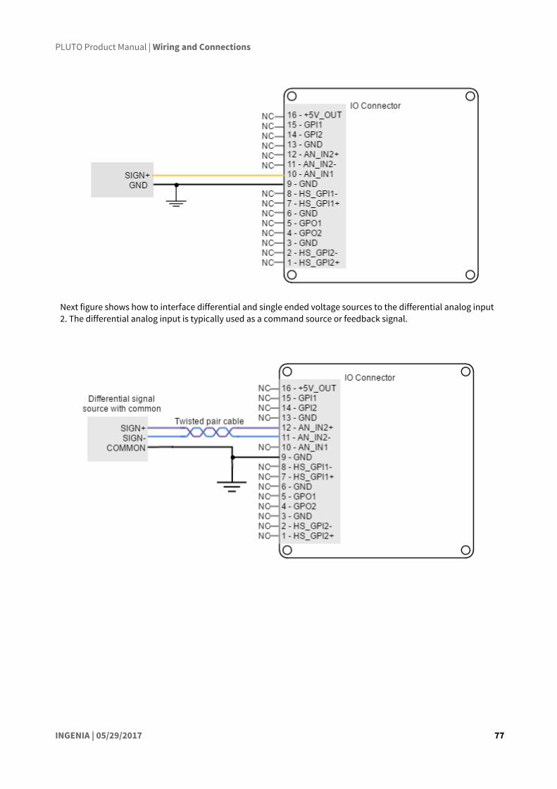
PLUTO Product Manual | Wiring and Connections
INGENIA | 05/29/2017 77
Next figure shows how to interface differential and single ended voltage sources to the differential analog input 2. The differential analog input is typically used as a command source or feedback signal.

PLUTO Product Manual | Wiring and Connections
INGENIA | 05/29/2017 78
7.5.4 Digital outputs interface (GPO1, GPO2)
Pluto Servo Drive has two digital non-isolated outputs. Digital outputs are based on an open drain MOSFET with a weak pull-up to 5 V, and are 24 V tolerant and short-circuit protected. Next table shows their main features:
Specification Value
Number of outputs
2
Type of output Open drain output with weak pull-up to 5 VESD protectedOverload, short circuit and over-temperature protected with auto restart (self protected MOSFET)
ESD capability IEC 61000-4-2 (ESD) ± 15 kV (air), ± 8 kV (contact)
Maximum supply output
30 V (5-24 V typical)
Maximum sink/source current
Source: low current @ 5 V: 5 mA Sink: 500 mA @ 5 or 24 V
ON-OFF delay 124 μs @ 30 V and Rload = 100 kΩ 20 μs @ 5 V and Rload = 100 kΩ

PLUTO Product Manual | Wiring and Connections
INGENIA | 05/29/2017 79
OFF_ON delay 15μs @ 30 V and Rload = 100 kΩ 50 μs @ 5 V and Rload = 100 kΩ
Max working frequency
1 kHz
Next figure shows digital outputs circuit model.
Wiring of 5V outputs
Loads that require 5V as high-level voltage can be connected directly to the digital output. A wiring example for GPO2 is shown in the next figure (same wiring could be used for GPO1).
Non-isolated I/O
Pluto Inputs and outputs are not isolated. The ground of the Pluto Servo Drive and the ground of the devices connected to I/Os must be the same. Otherwise inputs or outputs may be damaged.

PLUTO Product Manual | Wiring and Connections
INGENIA | 05/29/2017 80
Wiring of 24V loads
Loads that require 24V as high-level voltage can also be interfaced with GPO. For this option, an external power supply is needed. The load can be connected with a pull-up to 24V or directly switched with the GPO. Next figures show two example connections to GPO2 (same wiring could be used for GPO1).

PLUTO Product Manual | Wiring and Connections
INGENIA | 05/29/2017 81
90 http://www.onsemi.com/pub_link/Collateral/1N4001-D.PDF91 http://www.vishay.com/docs/88508/1n4933.pdf
An example of how to connect an inductive load to GPO2 is shown in the next figure (same wiring could be used for GPO1).
Interfacing inductive loads
The switching of inductive loads (like relays or motor brakes) can cause inductive kicking, that is a sudden voltage rise when the current through the inductor is falls to zero. In order to avoid this voltage rise, it is recommended to place a diode in anti-parallel with the load (known as freewheeling diode).
Standard rectifier diodes such as 1N400290or 1N493491are appropriate for the application.
An alternative to the freewheeling diode is to place a varistor or an RC snubber in parallel with the load.

PLUTO Product Manual | Wiring and Connections
INGENIA | 05/29/2017 82
92 http://doc.ingeniamc.com/display/i02201/Inputs+Outputs
7.5.5 Motor brake output (GPO1, GPO2)
Electromechanical brakes are needed in critical applications where the disconnection of the motor or a lack of electric braking could be dangerous or harmful (i.e. falling suspended loads). Pluto Servo Drive can use the digital outputs (GPO1 and GPO2) as a brake output. This output consists on an open drain MOSFET (1 A and 24 V). Further specifications can be found in Digital outputs interface (see page 78).
Next figure show how the typical connection using the main supply as brake power supply.
Motor brake operation
For brake operation of a GPO, this function has to be configured through Motion Lab92.
The brake operation is usually configured for normally locked electromechanical brakes; that is, brakes that by default block the movement of the motor shaft. For this reason, the switch is controlled with inverted logic, being activated to allow the rotation of the shaft. This kind of brakes increase the safety of the application, because in a drive power failure, the switch would be opened and therefore the brake activated.
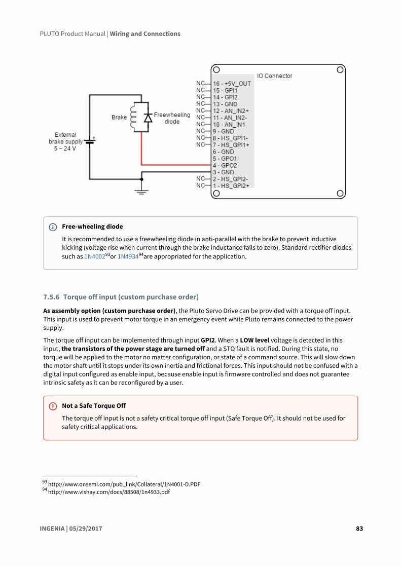
PLUTO Product Manual | Wiring and Connections
INGENIA | 05/29/2017 83
93 http://www.onsemi.com/pub_link/Collateral/1N4001-D.PDF94 http://www.vishay.com/docs/88508/1n4933.pdf
7.5.6 Torque off input (custom purchase order)
As assembly option (custom purchase order), the Pluto Servo Drive can be provided with a torque off input. This input is used to prevent motor torque in an emergency event while Pluto remains connected to the power supply.
The torque off input can be implemented through input GPI2. When a LOW level voltage is detected in this input, the transistors of the power stage are turned off and a STO fault is notified. During this state, no torque will be applied to the motor no matter configuration, or state of a command source. This will slow down the motor shaft until it stops under its own inertia and frictional forces. This input should not be confused with a digital input configured as enable input, because enable input is firmware controlled and does not guarantee intrinsic safety as it can be reconfigured by a user.
Free-wheeling diode
It is recommended to use a freewheeling diode in anti-parallel with the brake to prevent inductive kicking (voltage rise when current through the brake inductance falls to zero). Standard rectifier diodes such as 1N400293or 1N493494are appropriated for the application.
Not a Safe Torque Off
The torque off input is not a safety critical torque off input (Safe Torque Off). It should not be used for safety critical applications.

PLUTO Product Manual | Wiring and Connections
INGENIA | 05/29/2017 84
GPI2 input reads a logic low state (0 V < Vin < 1 V) by defect, so the input must be connected to a logic high level (4 V < Vin < 24 V) to activate the power stage. Next figures show two examples of connection of the torque off input, a self-supplied option and an external supplied option.

PLUTO Product Manual | Wiring and Connections
INGENIA | 05/29/2017 85
95 http://doc.ingeniamc.com/display/EMCL/Command+Sources96 http://doc.ingeniamc.com/display/EMCL/Command+Reference+Manual
7.6 Command sources
The target or command sources are used for setting a reference for position, velocity or torque controllers. Pluto Servo Drive supports the following command sources:
• Network communication interface (see page 85) (USB, CANOpen or EtherCAT)• Standalone (see page 86)• Analog input (see page 86) (±10 V or 0 V to 5 V)• Step and direction (see page 87)• PWM command (see page 88) (single and dual input mode)• Encoder follower / electronic gearing (see page 0).
Analog inputs, step and direction, PWM command and encoder follower / electronic gearing are interfaced through general purpose inputs. Next table illustrates which variables can be controlled with each command source:
Command source Target variable
Network interface Position, velocity, torque
Standalone Position, velocity, torque
Analog input (+/- 10 V o 0 - 5 V) Position, velocity, torque
Step and direction Position
PWM command Position, velocity, torque
Encoder following / electronic gearing Position
Please, see Command sources95 section from E-Core96 documentation for configuration details.
7.6.1 Network communication interface
Pluto Servo Drive can utilize network communication as a form of input command. Supported network interfaces for Pluto Servo drive are CAN (CANopen protocol), USB and EtherCAT.
USB interface is not suitable for long distances or noisy environments. This protocol is only recommended for configuration purposes.

PLUTO Product Manual | Wiring and Connections
INGENIA | 05/29/2017 86
97 http://ingeniamc.com/software#motionlab98 http://doc.ingeniamc.com/display/i02201/User+Manual
For normal operation, it is suggested to use CAN or EtherCAT. These interfaces are more robust against noise than USB, and allow higher distances between the Pluto Servo Drive and the commander. These command sources can be used for setting position, velocity or torque target.
For further information, see Communications section (see page 91).
7.6.2 Standalone
Pluto Servo Drive is provided with an internal non-volatile memory where a standalone program can be saved. With the use of Ingenia Motion Lab97 suite, the user can configure and save instructions to this 1 Mb (128K x 8bit) EEPROM, allowing Pluto Servo Drive to work in standalone mode. In this mode, there is no need of any external command source.
Programs or macros composed with Motion Lab suite allow to configure position, velocity or torque targets and to interface with general purpose inputs and outputs.
This feature can be very useful in applications such as production lines or test equipment, where repetitive movements are usual. Please refer to MotionLab documentation98 for further information.
7.6.3 Analog input
Position, velocity or torque targets can also be controlled trough an analog signal. Any general purpose analog input can be used as command source. Pluto Servo Drive has two 12-bit analog inputs, a single ended one with 0 V to 5 V range (AN_IN1) and a differential one with +/-10 V range (AN_IN2). Refer to I/O Connections (see page 67) for further details about analog inputs.
A common application of the analog command source is the use of joysticks (or other kinds of potentiometers) for controlling the position or velocity of a system. As application examples, the following figures show how to connect a potentiometer to the single ended analog input (AN_IN1) and a dual track potentiometer to the differential analog input (AN_IN2).

PLUTO Product Manual | Wiring and Connections
INGENIA | 05/29/2017 87
7.6.4 Step and direction
For this command source, the drive typically accepts two digital inputs from an external source: Step (pulse) and Direction. Direction signal sets the direction of rotation (i.e., logic low or "0" for clockwise rotation and logic high or "1" for counter-clockwise rotation). Pulse signal is usually a square signal and each pulse on this signal causes the controller to move the motor one step in that direction. This command source can be used only for position mode.
This command source is interfaced through high-speed digital inputs. HS_GPI1 is used for Step input, and HS_GPI2 is used for Direction input. Refer to I/O Connections (see page 67) for further specifications about high-speed digital inputs. Next figures illustrate how to connect a single ended and differential step and direction command source to the Pluto Servo Drive.

PLUTO Product Manual | Wiring and Connections
INGENIA | 05/29/2017 88
7.6.5 PWM command
PWM command source sets a position, velocity or torque target from the duty cycle value of a PWM signal. PWM command has to be interfaced with the high-speed digital input 2 (HS_GPI2). Further details about this input can be seen in I/O Connections (see page 67) page. PWM command sources with single and dual input modes can be used.

PLUTO Product Manual | Wiring and Connections
INGENIA | 05/29/2017 89
Single input mode
Single input mode is based o the use of a PWM signal whose duty cycle sets the target position, velocity or torque. A duty cycle of 50% corresponds with a target of 0 rad, 0 rpm or 0 N·m, and higher or lower values indicate the target in a different rotating direction. That is, a duty cycle of 0% corresponds with the maximum position, velocity or torque in one direction, and a 100% duty corresponds to the maximum position, velocity or torque in the opposite direction.
Examples of single input mode PWM command in differential and single ended connections are shown in the next figures.

PLUTO Product Manual | Wiring and Connections
INGENIA | 05/29/2017 90
Dual input mode
Dual input mode uses two signal lines, a PWM signal whose duty cycle sets the target position, velocity or torque, and a Direction signal that indicates the rotation direction (i.e., logic low or "0" for clockwise rotation and logic high or "1" for counter-clockwise rotation). In this mode, a duty cycle of 0% corresponds with a target of 0 rad, 0 rpm or 0 N·m, and a duty cycle of 100% corresponds to the maximum position, velocity or torque.
Two general purpose inputs are used:
• High speed digital input 2 (HS_GPI2) for PWM Command• General purpose digital input 1 (GPI1) for Direction.
Examples of dual input mode PWM command in differential and single ended connections are shown in the next figures.
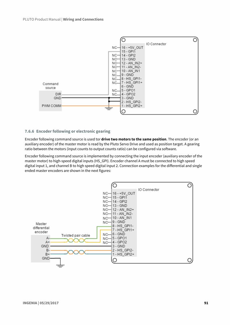
PLUTO Product Manual | Wiring and Connections
INGENIA | 05/29/2017 91
7.6.6 Encoder following or electronic gearing
Encoder following command source is used tor drive two motors to the same position. The encoder (or an auxiliary encoder) of the master motor is read by the Pluto Servo Drive and used as position target. A gearing ratio between the motors (input counts to output counts ratio) can be configured via software.
Encoder following command source is implemented by connecting the input encoder (auxiliary encoder of the master motor) to high-speed digital inputs (HS_GPI). Encoder channel A must be connected to high speed digital input 1, and channel B to high speed digital input 2. Connection examples for the differential and single ended master encoders are shown in the next figures:

PLUTO Product Manual | Wiring and Connections
INGENIA | 05/29/2017 92
99 http://ingeniamc.com/software#motionlab
7.7 Communications
The Pluto Servo Drive provides the following network communication interfaces for configuration and operation:
• USB (see page 92)• CANopen (see page 92)• EtherCAT (see page 96)
All the interfaces can be used to connect the Pluto with Ingenia Motion Lab99 suite or a custom application built with the supplied controller libraries. With the objective of configure and diagnostic CAN communication, CANopen and another communication interface can be used simultaneously.
7.7.1 USB interface
Pluto Servo Drive supports Universal Serial Bus (USB), a standard interface for connecting peripheral devices to a host computer. The following table shows main USB interface specifications:
Specification Details
USB version USB 2.0 (full speed)
Data rate Up to 12 Mbps
Maximum cable length 5 meters (16 feet)

PLUTO Product Manual | Wiring and Connections
INGENIA | 05/29/2017 93
USB wiring recommendations
Although USB is a widespread communication standard it has some disadvantages when operating in noisy environments. Following are some wiring recommendations.
• Use shielded cable with the shield connected to PC end. Shield of micro USB connector is not connected on Pluto.
• Do not rely on an earthed PC to provide the Pluto Servo Drive earth connection. The drive must be earthed through a separate circuit.
• Avoid creating ground loops by using isolated power supplies.• Shortest cables are preferred.
7.7.2 CANopen interface
Pluto Servo Drive supports CANopen interface, a multi-terminal communication protocol based on CAN (Controller Area Network) bus. Pluto CAN interface is isolated, and self-supplied. Main physical specifications are shown in the next table:
Specification Details
Interface Non-isolatedSelf-supplied (no need for external supply)
Baud rate From 125 kbps to 1 Mbps (default value)
Maximum number of nodes 64
Common mode voltage Up to 48 V
Termination resistor 120 Ω on board (mount jumper to enable the termination)
USB application
USB interface is only recommended for configuration purposes. For noisy environments, CANopen interface is strongly recommended.
Power supply for configuration
Power supply has to be provided for configuration purposes. Pluto Servo Drive can not be supplied from USB connector.

PLUTO Product Manual | Wiring and Connections
INGENIA | 05/29/2017 94
An example of CAN wiring is shown in the next figure.
Drive ID
When installing CANopen communication, ensure that each servo drive is allocated a unique ID. Otherwise, CANopen network may hang.

PLUTO Product Manual | Wiring and Connections
INGENIA | 05/29/2017 95
100 http://ingeniamc.com/software#motionlab
CAN interface for PC
The Ingenia Motion Lab100 suite is able to communicate with the Pluto Servo Drive through CANopen interface. For this purpose, a CAN transceiver for PC is required. Motion Lab is compatible with the following CAN transceivers: Kvaser, Peak-System, IXXAT, Vector and Lawicel. Please, install the drivers you can find on the manufacturer web sites before, plugging any transceiver to the USB port. Execute Motion Lab only after the device is already installed.
Some recommended CAN transceivers are shown below:
Manufacturer
Part Number Image
Description
Peak-system
PCAN-USB opto-decoupled (IPEH-002022)
• USB to CAN single channel interface with 9-pin D-SUB CAN connector.
• Enables simple connection to CAN networks.• Opto-decoupled with galvanic isolation of up to
500 Volts between the PC and the CAN side.
Kvaser USBcan Pro 2xHS v2 • USB to CAN or CAN FD dual channel interface.• High-speed CAN channels in two separate 9-pin D-
SUB CAN connectors.
IXXAT USB-to-CAN V2 Professional
• USB to CAN dual channel interface.• High-speed CAN channels in two separate RJ-45
connectors.• Cable adapter to 9-pin D-SUB CAN.
Termination resistor
The use of bus termination resistors (120 Ω between CAN_L and CAN_H), one at each end of the bus, is essential for correct operation of the CAN bus. Even with only one Pluto connected, mount the termination resistor to ensure CAN bus operation. Do not use wirewound resistors, which are inductive.
CAN GND connection
GND line in CAN devices is used for equaling potential between master and slaves, but is not used for data transmission, as the line is fully differential. For this reason, if the host device shares supply GND with Pluto it is not needed to connect CAN connector GND again, as this could cause ground loop issues.

PLUTO Product Manual | Wiring and Connections
INGENIA | 05/29/2017 96
Vector Informatik
VN1630 • USB to CAN or CAN FD four channel (two connectors) interface .
• High-speed CAN channels in two separate 9-pin D-SUB CAN connectors.
• Highly robust plastic housing.
CAN wiring recommendations
• Build CAN network using cables with 2-pairs of twisted wires (2 wires/pair) as follows: one pair for CAN_H with CAN_L and the other pair for CAN_V+ with CAN_GND.
• Cable impedance must have an impedance of 105 to 135 Ω (120 Ω typical) and a capacitance below 30 pF/meter.
• Whenever possible, use bus links between the CAN nodes. Avoid using stubs (a "T" connection, where a derivation is taken from the main bus). If stubs cannot be avoided keep them as short as possible. For maximum speed (1 Mbps), use a stub length lower than 0.3 meters.
• For a total CAN bus length over 40 meters, it is mandatory to use shielded twisted cables. Connect the cable shield to protective earth at both ends. Ensure that the cable shield is connected to the connector shield, as connection to host protective earth is usually soldered inside the connector.
7.7.3 EtherCAT interface
Pluto Servo Drive with EtherCAT (PLU-x/xx-E) variant provides access to the EtherCAT fieldbus system. EtherCAT is an isolated bus suitable for hard and soft real-time requirements in automation technology, test and measurement and many other applications.
Next table summarizes the features of the Pluto EtherCAT interface.
EtherCAT specific features
Ports available 2
LED Signals Status LED
Link/Act LED
Supported Mailbox CoE
SDO info Not supported
Segmented SDO Supported
SDO complete access Not supported
Synchronization modes Free Run
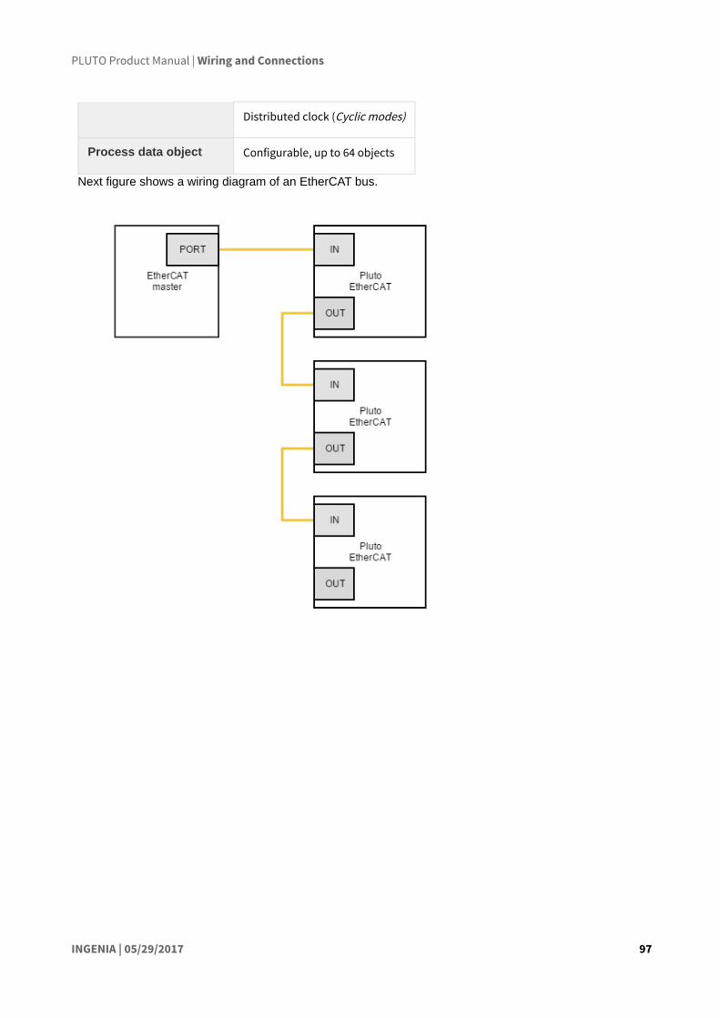
PLUTO Product Manual | Wiring and Connections
INGENIA | 05/29/2017 97
Distributed clock (Cyclic modes)
Process data object Configurable, up to 64 objects
Next figure shows a wiring diagram of an EtherCAT bus.

PLUTO Product Manual | Dimensions
INGENIA | 05/29/2017 98
101 http://ingeniamc.com/support/pluto
8 DimensionsThe Pluto Servo Drive is available in different versions, which present 2 different dimensions specifications:
• PLU-x/xx-S and PLU-x/xx-C (Pluto with USB and USB/CANopen)• PLU-x/xx-E (Pluto with EtherCAT)
8.1 PLU-x/xx-S and PLU-x/xx-C
Pluto Servo Drive versions PLU-x/xx-S and PLU-x/xx-C have a 60 mm x 60 mm footprint and a maximum 15 mm height. The drive is provided with 4 x Ø 3.2 mm holes for M3 standoff mounting and to allow mounting the EtherCAT Daughter Board and the IO Starter Kit. These holes are plated and connected to protective earth (PE). 3D models can be downloaded here101.
Next figure shows mechanical dimensions in mm. Tolerances ≤ ±0.2 mm.
Fixation elements diameter ≤ 6 mm
Please do not use spacers, washers or nuts exceeding 6 mm external diameter as they could collide with some electrical parts.
Also, take due precautions not to damage any components during assembly.

PLUTO Product Manual | Dimensions
INGENIA | 05/29/2017 99
102 http://ingeniamc.com/support/pluto
8.2 PLU-x/xx-E (Pluto with EtherCAT)
Pluto Servo Drive version PLU-x/xx-E has a 60 mm x 60 mm footprint and a maximum 34.6 mm height. The drive is provided with 4 x M3 standoff. 3D models can be downloaded here102.
Next figure shows mechanical dimensions in mm. Tolerances ≤ ±0.2 mm.

PLUTO Product Manual | Dimensions
INGENIA | 05/29/2017 100

PLUTO Product Manual | Software
INGENIA | 05/29/2017 101
103 http://ingeniamc.com/software#motionlab104 http://ingeniamc.com/software#mclib
9 Software
9.1 Configuration
To connect, configure, tune your motor or upgrade the firmware of the Pluto, install Ingenia Motion Lab103 suite. The software package includes USB drivers.
9.2 Applications
If you want to make your own application to communicate with the Pluto and develop standalone or multiaxis systems, you can use the multi-platform library MCLIB104.
Keep the firmware updated
Before configuring your drive for a new application make sure you have upgraded to the latest firmware revision.

INGENIA-CAT S.L.
8-14 MARIE CURIE, ADVANCED INDUSTRY PARK
08042 BARCELONA
10 ServiceWe are committed to quality customer service. In order to serve in the most effective way, please open a ticket on our service desk at www.ingeniamc.com/support or contact your local sales representative for assistance.
If you are unaware of your local sales representative, please contact the Customer Support.
SpainINGENIA HEADQUARTERS www.ingeniamc.com [email protected]
France A2V www.a2v.fr [email protected]
Germany MACCON GMBH www.maccon.de [email protected]
India MPAGS www.mapgs.com [email protected]
Israel MEDITAL www.medital.co.il [email protected]
Italy SERVOTECNICA SPA www.servotecnica.com [email protected]
Norway ELECTRO DRIVES AS www.electro-drives.no [email protected]
PortugalMECÂNICA MORDERNA www.mecmod.com/pt [email protected]
Russia AVI SOLUTIONS www.avi-solutions.com [email protected]
Singapore I-MOTION www.imotionasia.com [email protected]
South Korea SERVOSTAR www.servostar.co.kr [email protected]
South Korea ALLTEK www.alltek.co.kr [email protected]
SpainMECANICA MORDERNA www.mecmod.com/es [email protected]
Spain GIZATECH www.gizatech.eu/ [email protected]
SwitzerlandANTRIMON MOTION AG www.antrimon.com [email protected]
Turkey FEMSAN www.femsan.com [email protected] Kingdom
MOTION CONTROL PRODUCTS www.motioncontrolproducts.com [email protected]
United States NAMPRO www.namproinc.com [email protected]
United States GROUP SIX www.grp6.com [email protected]