REACT-3.6_4.6-TL-Product manual EN-RevB ... - Fimer
174
ABB solar inverters Product manual REACT-3.6/4.6-TL (from 3.6 to 4.6 kW)
-
Upload
khangminh22 -
Category
Documents
-
view
1 -
download
0
Transcript of REACT-3.6_4.6-TL-Product manual EN-RevB ... - Fimer

ABB solar inverters
Product manualREACT-3.6/4.6-TL(from 3.6 to 4.6 kW)

- 2 -
0004
55BG
IMPORTANT SAFETY INSTRUCTIONSThis manual contains important safety instructions that must be followed during the installation and maintenance of the equipment.
Operators are required to read this manual and scrupulously follow the instructions given in it, since ABB cannot be held responsible for damage caused to people and/or property or to the equipment if the conditions described below are not observed.

- 3 -
0004
55BG
Product Manual
REACT-3.6/4.6 photovoltaic system with storage
1 - Introduction and general information
2 - Characteristics
3 - Safety and accident prevention
4 - Lifting and transport
5 - Installation
6 - Instruments
7 - Operation
8 - Maintenance
REACT-3.6_4.6-TL-Product Manual EN-Rev B (M000025BG) EFFECTIVE 28/04/2016
© Copyright 2016 ABB. All Rights Reserved.

- 4 -
0000
02FG
Warranty and supply conditionsThe warranty conditions are considered to be valid if the Customer adheres to the indications in this manual; any conditions deviating from those described herein must be expressly agreed in the purchase order.
ABB declares that the equipment complies with the provisions of law currently in force in the country of installation and has issued the corresponding declaration of conformity.
Not included in the supply
ABB accepts no liability for failure to comply with the instructions for correct installation and will not be held responsible for systems upstream or downstream of the equipment it has supplied.It is absolutely forbidden to modify the equipment. Any modification, manipulation, or alteration not expressly agreed with the manufacturer, concerning either hardware or software, shall result in the immediate cancellation of the warranty.The customer is fully responsible for any changes made to the system.
Given the countless array of system configurations and installation environments possible, it is essential to check the following: adequate spaces, suitable for housing the equipment; airborne noise produced based on the environment; possible flammability conditions.
ABB will NOT be held liable for defects or malfunctions arising from: improper use of the equipment; deterioration resulting from transportation or particular environmental conditions; performing maintenance incorrectly or not at all; tampering or unsafe repairs; use or installation by unqualified persons.
ABB is not responsible for any loss of the equipment, or part of it, which does not take place on the basis of the regulations and laws in force in the country of installation.
1Introduction and general information

- 5 -
0004
56BG
1 - Introduction and general information
Table of Contents
Introduction and general information ............................................................................................... 4Warranty and supply conditions ...........................................................................................................4
Not included in the supply .......................................................................................................4Table of Contents ....................................................................................................................................5Reference number index .......................................................................................................................9Graphical representation of references .............................................................................................10
REACT-3.6/4.6-TL .................................................................................................................10REACT-UNO-3.6/4.6-TL .......................................................................................................11REACT-BATT-AP1 ................................................................................................................12REACT-MTR-1PH .................................................................................................................13REACT-MTR-3PH .................................................................................................................13
Scope and target audience ..................................................................................................................14Purpose and document structure .........................................................................................14List of appendix documents ..................................................................................................14Operator and maintenance personnel skills/prerequisites ...................................................14
Symbols and signs ...............................................................................................................................15Field of use, general conditions ........................................................................................................17
Intended or allowed use ........................................................................................................17Limits in field of use ...............................................................................................................17Improper or disallowed use ..................................................................................................18
Characteristics ................................................................................................................................. 19General conditions ...............................................................................................................................19Models and range of equipment .........................................................................................................20
Identification of the equipment and manufacturer ................................................................21Characteristics and technical data .....................................................................................................22
Tightening torques ................................................................................................................25Overall dimensions REACT-3.6/4.6-TL ................................................................................26Overall dimensions REACT-MTR-1PH .................................................................................27Overall dimensions REACT-MTR-3PH .................................................................................27Dimensions main bracket REACT-3.6/4.6-TL ......................................................................28Dimensions additional bracket (REACT-BATT-AP1) ............................................................29
Efficiency curves ..................................................................................................................................30Power limitation (Power Derating) ......................................................................................................31
Power reduction due to environmental conditions ................................................................32Power reduction due to the altitude of the installation ..........................................................33Output power reduction due to the input voltage ..................................................................34Input power reduction due to the input voltage ....................................................................35
Characteristics of a photovoltaic generator ......................................................................................36Strings and Arrays .................................................................................................................36
Description of the REACT system ......................................................................................................37Notes on the sizing of the system .........................................................................................37Operating diagram ................................................................................................................38Operating stages of the system ............................................................................................39Functionality and components of the equipment ..................................................................40Topographic diagram of the equipment ................................................................................43

- 6 -
0004
56BG
1 - Introduction and general information
Safety devices .......................................................................................................................................44Anti-Islanding ........................................................................................................................44Ground fault of the photovoltaic panels ................................................................................44“STOP” button .......................................................................................................................44REACT-BATT-AP1 state of health (SOH) .............................................................................44Other safeguards ..................................................................................................................44
Safety and accident prevention ..................................................................................................... 45Safety information and instructions ..................................................................................................45Hazardous areas and operations .......................................................................................................46
Environmental conditions and risks ......................................................................................46Signs and labels ....................................................................................................................46Thermal and electrical hazard ..............................................................................................47Clothing and protection of personnel ....................................................................................47Safety precautions relating to REACT-BATT-AP1 ................................................................48
Residual risks .......................................................................................................................................50Table of residual risks ...........................................................................................................50
Lifting and transport ........................................................................................................................ 51General conditions ..............................................................................................................................51Storage of equipment...........................................................................................................................52
Special rules for storage of REACT-BATT ............................................................................52Lifting .....................................................................................................................................................53
Equipment weight .................................................................................................................53Transport of the equipment .................................................................................................................54
Transport of the REACT-BATT-AP1 .....................................................................................54Overview of the “Ancillary rule” and the “1000 units rule” ....................................................54
Unpacking and checking ....................................................................................................................56List of components supplied .................................................................................................56
Installation ......................................................................................................................................... 58General conditions ..............................................................................................................................58
Environmental checks ...........................................................................................................59Installation position ................................................................................................................61
Wall installation of the REACT system ..............................................................................................62Wall installation of the REACT-UNO alone ........................................................................................66Connection of the energy meter (REACT-MTR) ................................................................................70
Connection of the REACT-MTR-1PH (mono-phase) ...........................................................70Connection and configuration of the REACT-MTR-3PH (three-phase) .........................................................................................................................72
Preliminary operations for connection of the PV generator ...........................................................74Checking the correct polarity of the strings ..........................................................................74Checking of leakage to ground of the photovoltaic generator ..............................................74Selection of differential protection downstream of the inverter ............................................74
Distribution grid output connection (AC side) ..................................................................................76Characteristics and sizing of the line cable ..........................................................................76Load protection switch (AC disconnect switch) ....................................................................77Connection to the AC side terminal block .............................................................................77
Back-up output connection (AC) ........................................................................................................78Characteristics and sizing of the cable for back-up output ...................................................79Load protection switch (AC disconnect switch) for back-up output ......................................79Connection to back-up AC output terminal block .................................................................80

- 7 -
0004
56BG
1 - Introduction and general information
Configuration of independent or parallel input channels ................................................................81Channel configuration examples ..........................................................................................82Independent channel configuration (default configuration) ..................................................83Configuration of parallel-connected channels ......................................................................83
Input connection to PV generator (DC side) .....................................................................................84Installation procedure for quick-fit connectors ......................................................................86
Communication and control signal connections .............................................................................90Description of communication and control signal terminal blocks ........................................91External backup command connection ................................................................................92Remote control connection ...................................................................................................92+5V output connection ..........................................................................................................93Connection of RS485 M-B (Modbus) serial communication line ..........................................93Connection of RS485 PC serial communication line ............................................................95Connection of RS485 METER serial communication line ....................................................97Configurable Relay connection (ALARM) .............................................................................99Connection to load management system (Load Manager Box) .........................................100
Instruments ...................................................................................................................................... 101General conditions ............................................................................................................................101Display, keyboard and status LED ...................................................................................................102
Description of symbols and display fields ...........................................................................102Description of the keyboard and status LEDs ....................................................................106
Operation ........................................................................................................................................ 107General conditions ............................................................................................................................107Monitoring and data transmission ...................................................................................................108
User interface ......................................................................................................................108Measurement tolerance ......................................................................................................108
Commissioning ...................................................................................................................................109Updating the firmware from an SD card .............................................................................117
LED behaviour ....................................................................................................................................118Specifications on the behaviour of the LEDs ......................................................................119Red GFI LED.......................................................................................................................119
Description of the menus ..................................................................................................................120General information ............................................................................................................120Menu structure ....................................................................................................................122System Menu ......................................................................................................................123Inverter Menu ......................................................................................................................127Display Menu ......................................................................................................................139Meter Menu .........................................................................................................................140Battery Menu......................................................................................................................142Load Manager Menu ...........................................................................................................146Wi-Fi Logger Menu .............................................................................................................146
REACT system switch-off ..................................................................................................................147Maintenance ................................................................................................................................... 148
General conditions ............................................................................................................................148Routine maintenance .........................................................................................................149Troubleshooting ..................................................................................................................149Alarm Messages .................................................................................................................149Power limitation messages .................................................................................................162

- 8 -
0004
56BG
1 - Introduction and general information
Procedure for dismantling of the REACT system ..........................................................................164Registration on “Registration” website and calculation of second-level password (Service Menu) ...................................................................................................................................................165Resetting the time remaining to change the grid standard ...........................................................168Verification of ground leakage .........................................................................................................169
Behaviour of a system without leakage ..............................................................................169Behaviour of a system with leakage ...................................................................................170
Measuring the insulation resistance of photovoltaic generator ...................................................171Storage and dismantling ..................................................................................................................172
Storage of the equipment or prolonged stop ......................................................................172Dismantling, decommissioning and disposal ......................................................................172
Further information ............................................................................................................................173Contact us ...........................................................................................................................................174
- 9 -
0004
56BG
1 - Introduction and general information
Reference number index
01 wall bracket 31 battery communication and control cable
02 heat sink 32 battery power cable
03 REACT-UNO 33 battery protection fuse
04 display 34 smoke sensor (inverter)
05 keypad 35 ground connection points
06 LED panel 36 cable conduit (male)
07 cable conduit (female) 37 power connector (cable from unit on the left)
08 DC disconnect switch 38 power connector (cable from unit on the right)
09 cover for area of inverter unit connections 39 connector for communication and control (cable from unit on the right)
10 plastic cover for inverter unit 40 smoke sensor (battery)
11 plastic cover for battery unit 41 connector for communication and control (cable from unit on the left)
12 cover for area of battery unit connections 42 Rotary switch (RS485 internal line address)
13 battery pack 43 connector for internal communication line (cable from unit on the right)
14 REACT-BATT-AP1 44 termination switch for internal communication line
15 VSN300 Wi-Fi Logger Card 45 connector for internal communication line (cable from unit on the left)
16 expansion board connector 46 input connectors (MPPT1)
17 RJ45 connectors for serial RS485 PC 47 input connectors (MPPT2)
18 termination switch for PC RS485 line 48 AC cable gland
19 termination switch for METER RS485 line 49 AC cable gland (back-up)
20 termination switch for M-B RS485 line 50 emergency button
21 communication and control signal terminal block 51 service cable glands
22 multifunctional relay terminal block 52 -Wi-Fi antenna support
23 Load Manager Box 53 Wi-Fi antenna
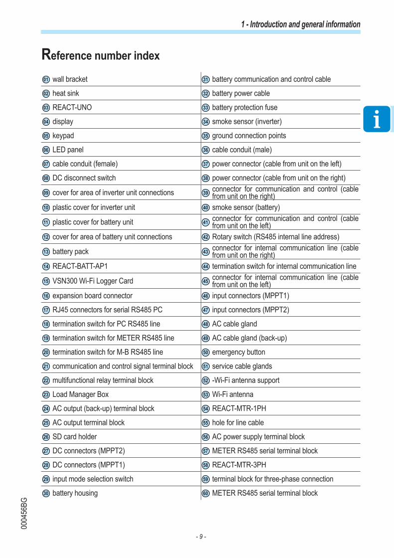
24 AC output (back-up) terminal block 54 REACT-MTR-1PH
25 AC output terminal block 55 hole for line cable
26 SD card holder 56 AC power supply terminal block
27 DC connectors (MPPT2) 57 METER RS485 serial terminal block
28 DC connectors (MPPT1) 58 REACT-MTR-3PH
29 input mode selection switch 59 terminal block for three-phase connection
30 battery housing 60 METER RS485 serial terminal block

- 10 -
0004
56BG
1 - Introduction and general information
Graphical representation of references
REACT-3.6/4.6-TL
01
02
03
04
05
06
07
08
09
10
51
14
13
12
11
4607 47 08 4802 49
50
52

- 11 -
0004
56BG
1 - Introduction and general information
REACT-UNO-3.6/4.6-TL
LOAD MANAGER BOX
87D
5 6C
3 4B
1 2A
J1
5
1
6
2
7
3
8
4
LOAD MANAGER BOX
87D
5 6C
3 4B
1 2A
J1
5
1
6
2
7
3
8
4
03
04
05
06
10
09
07
53
15
16
17
18
19
20
21
22
23
242526082728
33
34
31
32
30
29

- 12 -
0004
56BG
1 - Introduction and general information
REACT-BATT-AP1
J6 J5
BATT. COMM.BUS
BATT. COMM.BUS
3J4J
.MOC O/IYRETTAB-ITLUM KNIL .MOC O/I
MULTI-BATTERY
DC POWER
D1
D2
D3
OFF
J2
J1J7 PE
120 ΩON
BATTERY ADDRESSSELECTOR
DC POWER LINK
J6 J5
BATT. COMM.BUS
BATT. COMM.BUS
3J4J
.MOC O/IYRETTAB-ITLUM KNIL .MOC O/I
MULTI-BATTERY
DC POWER
D1
D2
D3
OFF
J2
J1J7 PE
120 ΩON
BATTERY ADDRESSSELECTOR
DC POWER LINK
14
11
12
13
35
36
45 44 43 42 41 40 39 38 37
- 13 -
0004
56BG
1 - Introduction and general information
REACT-MTR-1PH
REACT-MTR-1PH
SUTATS
ER
USAEM
INPUT :
110/230 V
50/60 Hz
10 mA max
57
56
55
54
REACT-MTR-3PH
59
59 60
58

- 14 -
0000
04FG
1- Introduction and general information
Scope and target audience
Purpose and document structure
This operating and maintenance manual is a useful guide that will enable you to work safely and carry out the operations necessary for keeping the equipment in good working order.
If the equipment is used in a manner not specified in this manual, the protection provided by the equipment may be impaired.
The language in which the document was originally written is ITALIAN; therefore, in the event of inconsistencies or doubts please ask the manufacturer for the original document.
List of appendix documents
In addition to this user manual and maintenance you can consult (and download) the product documentation by visiting www.abbsolarinverters.com.
Part of the information given in this document is taken from the original supplier documents. This document contains only the information considered necessary for the use and routine maintenance of the equipment.
Operator and maintenance personnel skills/prerequisites
Personnel in charge of using and maintaining the equipment must be skilled for the described tasks and must reliably demonstrate their capacity to correctly interpret what is described in the manual.
For safety reasons, only a qualified electrician who has received training and/or demonstrated skills and knowledge of the inverter’s structure and operation may install the inverter.
The installation must be performed by qualified installers and/or licensed electricians in accordance with the existing regulations in the country of installation.
Inverter operation and maintenance by a person who is NOT qualified, is intoxicated, or on narcotics, is strictly forbidden.
The customer has civil liability for the qualification and mental or physical state of the personnel who interact with the equipment. They must always use the personal protective equipment (PPE) required by the laws of the country of destination and whatever is provided by their employer.

- 15 -
0000
06HG
1 - Introduction and general information
Symbols and signsIn the manual and/or in some cases on the equipment, the danger or hazard zones are indicated with signs, labels, symbols or icons.
Symbol Description
Indicates that it is mandatory to consult the manual or original document, which must be available for future use and must not be damaged in any way.
General warning - Important safety information. Indicates operations or situations in which staff must be very careful.
Dangerous Voltage - Indicates operations or situations in which staff must be very careful with regard to dangerous voltage levels.
Hot parts - Indicates a risk arising from the presence of hot zones or zones with parts at high temperatures (risk of burns).
Risk of explosion
Risk of injury due to the weight of the equipment. Take care during lifting and transport
Indicates that the area in question must not be accessed or that the operation described must not be carried out.
Keep out of the reach of children
Indicates that smoking and the use of naked flames is prohibited.
Indicates that it is mandatory to carry out the described operations using theclothing and/or personal protective equipment provided by the employer.
WEEE logo. Indicates that the product is to be disposed of according to current legislation regarding the disposal of electronic components.
IPXX Indicates the protection rating of the equipment according to IEC 70-1 (EN 60529 June 1997) standard.
Point of connection for grounding protection.
Indicates the permitted temperature range

- 16 -
0000
06HG
1 - Introduction and general information
Symbol Description
XX
Indicates a risk of electric shock. The discharge time of the stored energy (represented in the figure by the letters XX), is provided on the identification label.
DC Direct Current
AC Alternate current
With insulation transformer
Without insulation transformer
Positive pole of the input voltage (DC)
Negative pole of the input voltage (DC)
Indicates the centre of gravity of the equipment.
Indicates the requirement to wear acoustic protection devices in order to prevent damage to hearing

- 17 -
0005
50AG
1 - Introduction and general information
Field of use, general conditions ABB accepts no liability for damage of any kind that may arise from incorrect or careless operations.
You may not use the equipment for a use that does not conform to that provided for in the field of use. The equipment MUST NOT be used by inexperienced staff, or even experienced staff if carrying out operations on the equipment that fail to comply with the indications in this manual and enclosed documentation.
Intended or allowed use
The system is designed to optimise self-consumption in residential contexts and consists of • REACT-UNO (inverter) transforms a direct current (DC) from a photovoltaic generator (FV) into an alternating current (AC) which can be fed into the public distribution grid. • REACT-BATT (battery pack) temporarily stores unused energy from the photovoltaic generator which will subsequently be used when the energy demand from users is greater than the energy produced by the PV generator• REACT-MTR (energy meter) which measures energy at the connection point to the grid and communicates with REACT-UNO in order to maximise energy self-sufficiency by managing the storage system.
Limits in field of useThe REACT system can be used only with photovoltaic modules which do not require the grounding of one of the input poles, unless accessories are installed which are compatible with the inverter and enable this operation to be carried out. In this case you must install an isolation transformer on the AC side of the system.Only a photovoltaic generator consisting of class II modules (in accordance with IEC 61730) can be connected as input to the REACT system (do not connect batteries or other power sources)The REACT system can be connected to the electricity grid only in countries for which it has been certified/approved.The REACT system cannot be connected on the DC side in parallel to other inverters to convert energy from a photovoltaic generator with a power greater than the nominal power of the single inverter.The REACT system can be used only if all the technical characteristics are observed.Batteries other than those approved by ABB cannot be connected to the REACT system

- 18 -
0005
50AG
1 - Introduction and general information
Improper or disallowed use
IT IS STRICTLY FORBIDDEN TO:
• Install the system in such a way that it is exposed to direct sunlight• Install the equipment in environments with particular flammability conditions or in environmental conditions (temperature and humidity) other than those specified.• Use the equipment with safety devices which are faulty or disabled.• Use the equipment or parts of the equipment by linking it to other machines or equipment, unless expressly provided for.• Modify operating parameters that are not accessible to the operator and/or parts of the equipment to vary its performance or change its insulation.• Clean the equipment with corrosive products that may attack parts or generate electrostatic charges.• Use or install the appliance or parts of it without having read and understood the contents of the user and maintenance manual.• Warm or dry rags and clothes on parts at temperature. In addition to being hazardous, doing so would compromise component ventilation and cooling.
For further information on the installation conditions refer to chapter 5 “Installation”

- 19 -
0000
08EG
General conditionsA description of the equipment characteristics is provided to identify its main components and specify the technical terminology used in the manual.
This chapter contains information about the models, details of the equipment, characteristics and technical data, overall dimensions and equipment identification.
The customer/Installer takes full responsibility if, when reading this manual, the chronological order of its presentation provided is not observed. All information is provided considering occasional inclusion of information in previous chapters.
In certain cases, there may be a need to separately document software functionality or attach supplementary documentation to this manual which is intended for more qualified professionals.
2Characteristics

- 20 -
0005
51AG
2 - Characteristics
Models and range of equipmentThe pieces of equipment which make up the REACT system to which this manual is dedicated are:
Single-phase inverter unit:REACT-UNO-3.6-TL single-phase, maximum output power 3600WREACT-UNO-4.6-TL single-phase, maximum output power 4600WMain characteristics• Number of input channels: 2• Input connectors: quick fit connectors (2 pairs for each channel) • DC disconnect switch• Wireless communication through integrated Wi-Fi board• Management of external loads through four integrated relays• AC Back-up Output (off grid)
Battery unit:REACT-BATT-AP1 average battery capacity 2kWhIn the system up to three REACT-BATT-AP1s can be used (maximum capacity of the system 3x2kWh=6kWh)
Energy meter:
REACT-MTR-1PH energy meter for single-phase line
REACT-MTR-3PH energy meter for three-phase line
The choice of the components for the system must be made by a qualified technician who knows about the installation conditions, the devices that will be installed outside the inverter and possible integration with an existing system.
REACT
POWER ALARM GFI ESC UP DOWN ENTER
REACT-UNO
REACT-BATT
REACT
POWER ALARM GFI ESC UP DOWN ENTER
REACT-UNO
REACT-BATT
REACT-MTR-1PH
SUTATS
TSET
ER
USAEM
INPUT :
110/230 V
50/60 Hz
10 mA max

- 21 -
0005
51AG
2 - Characteristics
The labels are NOT to be hidden by foreign objects and parts (rags, boxes, equipment, etc.); they must be regularly cleaned and always kept in sight.
Identification of the equipment and manufacturer
The technical data provided in this manual does not substitute the data supplied onthe labels affixed to the equipment.
The labels affixed to the equipment must NOT be removed, damaged, stained, hidden, etc., for any reason whatsoever.
The approval label contains the following information:1. Manufacturer2. Model3. Rating data4. Certification marks
REACT
POWER ALARM GFI ESC UP DOWN ENTER
REACT-UNO
REACT-BATT
A4 1:1 1/1 XLP.V1B03.1AL
A.Statuti
G.Iannuzzi
23/02/2016
A.Becattini
Pantone
Process Cyan C Process Yellow C
LABEL MATERIAL: 3M type 7331 (UL R/C, PGJI2)
INKS: Refer to UL File MH16411
LABEL CONTENT: Fixed as shown in the picture
SIZE: 90 mm (height) x 90 mm (width)
23/02/2016
23/02/2016
23/02/2016 S.Bindi
draft
Vdc max
Idc max
Vdc MPP
Vdc, Full Power
Isc max
Vacr
fr
Iac max
Smax
Pacr (cos =0.9-1) ,φ(1)
Pac max
Vacr
fr
Sacr
Iac max
MODEL:
REACT-UNO-3.6-TL
IP655 minutes
600 V
90 - 580 V
2 x 12 A
160 - 520 V
2 x 15 A
Made in Italy
PROTECTIVE CLASS: I
230 V 1Ø
50 Hz
4000 VA
3600 W
19 A
-20 to + 55 °C
-4 to +131 °F
INVERTERSOLARwww.abb.com/solar
BACKUP OUTPUT(2)
230 V 1Ø
50 Hz
3000 VA
13 A
Regulatory Label of REACT-UNO-3.6-TL
(1): Over/Under excited
Adj. cosφ 0.1-1(1)
(2): Optionally available
PROTECTIVE
EARTHING
REQUIRED
All material used and finished product, must meet the requirements of the current RoHS rectii ve 2002/95/EC.
Title
Issued
Modified
D
D
esign approved
Elec. Eng. approved
Mfg. approved
Size Scale Dim. in mm Sheet Drawing No. Revision
© Copyright 2016 Power-One Italy Spa. All rights reserved. Reproduction, use or disclosure to third parties without express written authority is strictly forbidden.
41
2
33
2
2
41
1 4
A4 1:1 1/1 XLP.V1B04.1AL
A.Statuti
G.Iannuzzi
23/02/2016
A.Becattini
Pantone
Process Cyan C Process Yellow C
LABEL MATERIAL: 3M type 7331 (UL R/C, PGJI2)
INKS: Refer to UL File MH16411
LABEL CONTENT: Fixed as shown in the picture
SIZE: 90 mm (height) x 90 mm (width)
23/02/2016
23/02/2016
23/02/2016 S.Bindi
draft
Vdc max
Idc max
Vdc MPP
Vdc, Full Power
Isc max
Vacr
fr
Iac max
Smax
Vacr
fr
Sacr
Iac max
MODEL:
REACT-UNO-4.6-TL
600 V
90 - 580 V
2 x 13.5 A
180 - 520 V
2 x 15 A
Made in Italy
PROTECTIVE CLASS: I
230 V 1Ø
50 Hz
5100 VA
4600 W
24 A
INVERTERSOLARwww.abb.com/solar
PROTECTIVE
EARTHING
REQUIRED
230 V 1Ø
50 Hz
3000 VA
13 A
Regulatory Label of REACT-UNO-4.6-TL
Adj. cosφ
Pacr (cos =0.9-1) ,φ(1)
Pac max
IP655 minutes-20 to + 55 °C
-4 to +131 °F
BACKUP OUTPUT(2)
(1): Over/Under excited
0.1-1(1)
(2): Optionally available
All material used and finished product, must meet the requirements of the current RoHS rectii ve 2002/95/EC.
Title
Issued
Modified
D
D
esign approved
Elec. Eng. approved
Mfg. approved
Size Scale Dim. in mm Sheet Drawing No. Revision
© Copyright 2016 Power-One Italy Spa. All rights reserved. Reproduction, use or disclosure to third parties without express written authority is strictly forbidden.
3

- 22 -
0005
52AG
2 - Characteristics
Characteristics and technical dataPhotovoltaic system with storage REACT-3.6-TL REACT-4.6-TL
System componentsREACT-UNO-3.6-TL REACT-UNO-4.6-TL
REACT-BATT-AP1REACT-MTR-1PH or REACT-MTR-3PH
Photovoltaic inverter with integrated charger REACT-UNO-3.6-TL REACT-UNO-4.6-TLInputAbsolute maximum DC voltage (Vdc, max) 600VDC start-up voltage (Vstart) 200 V (adj. 120...350 V)Operating DC voltage range (Vdc MPP) 0.7 x Vstart ...580 V (min 90 V)DC nominal voltage (Vdcr) 360 VDC nominal power (Pdcr) 5000 W 6000 WNumber of Independent MPPTs 2
Maximum DC power for each MPPT (PMPPTmax) 2500W Linear derating [520V ≤ VMPPT≤ 580V]
3000W Linear derating [520V ≤ VMPPT≤ 580V]
Input DC voltage range with MPPT configuration in parallel to Pacr, without battery (Vdc FULL POWER) 160...520 V 180...520 V
Maximum DC current (Idcmax) / for each MPPT 24 A / 12 A 27 A / 13.5 AMaximum short-circuit current for each MPPT (Iscmax) 15 ANumber of DC input connection pairs for each MPPT 2DC connection type Quick-fit PV connector (4)
Input protection Reverse polarity protection Yes, from current limited sourceInput overvoltage protection for each MPPT - varistor YesInsulation check Complying with the local regulationsCharacteristics of DC disconnect switch for each MPPT 25 A / 660 VBattery chargerMaximum charge power (with minimum of 3 x REACT-BATT-AP1) 3000 WMaximum discharge power (with minimum of 2 x REACT-BATT-AP1) 3000 WOutputAC grid connection type Single phaseNominal AC power (Pacr @ cosφ = 0.9 – 1, over/under excited) 3600 W 4600 WMaximum AC power (Pacmax) 3600 W 4600 WMaximum apparent power (Smax) 4000 VA 5100 VANominal AC voltage (Vac,r) 230 VAC voltage range 180...264 V 1)
Maximum AC current (Iac,max) 19 A 24 AContribution to short-circuit current 23A 29ANominal frequency (fr) 50 HzFrequency range (fmin...fmax) 47...53 Hz (2)
Adjustable Cosφ 0.1 - 1 (over/under excited)Total current harmonic distortion <2%AC connections type Screw terminal block, M25 cable glandOutput protectionAnti-islanding protection Complying with the local regulationsMaximum AC overcurrent protection 25 A 32 AOutput overvoltage protection - varistor 2 (L - N / L - PE)Back-up output 5)
AC connection type Single phaseNominal apparent power (Sacr) 3000 VANominal AC voltage (Vac,r) 230 VMaximum AC current (Iac,max) 13 AContribution to short-circuit current 27 Arms (60 ms)Nominal frequency (fr) 50 HzAC connections type Screw terminal block, M25 cable gland

- 23 -
0005
52AG
2 - Characteristics
Photovoltaic inverter with integrated charger REACT-UNO-3.6-TL REACT-UNO-4.6-TLBack-up output protectionMaximum AC overcurrent protection 16 AOperating performanceMaximum efficiency (ηmax) 97.1%Weighted efficiency (EURO/CEC) 96.6% / -Typical battery efficiency (full cycle) 94.0%CommunicationRemote monitoring Integrated Wi-Fi dataloggerWireless local monitoring Wi-Fi with UI webserver, mobile APPUser interface Mobile APP, UI Webserver, Graphic displayWired local monitoring PVI-USB-RS232_485 (opt.)EnvironmentalAmbient temperature -20...+55°COptimal operating temperature for battery +5...+35°COperating temperature for battery - charge 0...+40°COperating temperature for battery - discharge -10...+45°C
Relative humidity 5…95% without condensation (when used without battery 4…100% condensing)
Noise emission pressure, typical 50dB @ 1mMaximum operating altitude without derating 2000 m / 6560 ftRecommended location Internal with ventilationPhysicalDegree of environmental protection IP54 (REACT-UNO), IP21 (REACT-BATT-AP1) 3)
Cooling system NaturalSize (H x W x D), equipped with 1 REACT-BATT-AP1 740 mm x 985 mm x 231 mmWeight (REACT-UNO and REACT-BATT-AP1) < 67 kgAssembly system Wall bracketSafetyInsulation level TransformerlessMarking CE
Safety and EMC StandardsIEC/EN62109-1, IEC/EN62109-2, EN61000-6-2,
EN61000-6-3, EN61000-3-2, EN61000-3-3, EN61000-3-11, EN61000-3-12
Grid Standard(check availability through the sales channel)
CEI 0-21, DIN V VDE V 0126-1-1, VDE-AR-N 4105, G83/2, G59/3, VFR2014, 4777.2:2015
Other characteristicsLoad management Yes, through load manager boxAC back-up output, off grid Yes, automatic or manual restart in the case of no gridGrid support Yes, where required by the regulations
1) The output voltage range may vary according to the grid standard of the country of installation2) The output frequency range may vary according to the grid standard of the country of installation3) The IP54 protection level is guaranteed by complying with the indications set out in this manual and listed here below: • in regard to covers, by complying with the prescribed tightening torques;• in regard to connectors 46 , 47 , 52 , through use of the available counterparts;• in regard to the cable glands 48 , 49 , 51 , following the prescriptions indicated in this manual during installation.The connectors to the battery pack are excluded from the assessment of the IP54 protection level ( 39 , 35 , 38 ), for which external protection of a minimum of IP21 is required.In regard to the connectors to the battery pack, the IP protection is provided by the battery pack box itself. Using the RECAT-BATT-AP1 battery pack with the IP21 protection level, the protection level of the whole system becomes IP21.4) Please refer to the document “String inverters – Product manual appendix” available at www.abb.com/solarinverters for information on the quick-fit connector brand and model used in the inverter.5) OptionalNote. Characteristics not specifically mentioned in this data sheet are not included in the product

- 24 -
0005
52AG
2 - Characteristics
Battery Pack REACT-BATT-AP1Manufacturer PanasonicType Li-IonTypical/maximum discharge power 1.5 kW / 1.8 kW.Maximum charge power 1.1 kWAverage useful capacity over life 2 kWh (6 kWh, with 3x REACT-BATT-AP1)Useful life >4500 cyclesUseful life in years, typical 10 years (maximum 9MWh discharged)Relative humidity 5…95% without condensationDegree of environmental protection IP21Size REACT-BATT-AP1 (H x W x D) 740 mm x 492 mm x 231 mmWeight < 37 kg
Safety and EMC EN62109-1, EN62109-2, compliant with the applicable requirements of EN60950-1, EN61000-6-2, EN61000-6-3, UN38.3, UN3480
Meter REACT-MTR-1PH REACT-MTR-3PHAC Meter Obligatory for optimal energy managementMeasurements P / Q / A / V / IMeasurement accuracy / resolution <1% / 1%Maximum current 30 A 65 ANumber of AC phases 1 3Nominal voltage / voltage range 230 V / 85...265 V 400 V / 380...415 VNominal frequency 50 HzCommunication RS485Power Supply / Consumption Integrated / <1WProtection class IP20Assembly system DIN rail (3 modules) DIN rail (4 modules)Operating temperature range -20...+55°CSafety and EMC IEC 61010-1, IEC 61326-1Marking CE

- 25 -
0005
52AG
2 - Characteristics
Tightening torques
To maintain the IP65 protection of the system and for optimal installation, the following tightening torques must be used:
REACT-UNOAC cable gland 48 called AC GRID (M25) 7.5 NmAC back-up cable gland 49 called AC-1 (M25) 7.5 NmService cable glands 51 called OUT-1, OUT-2, OUT-3, OUT-4 (M20)
7.0 Nm
Screws for plastic cover for inverter unit 10 2.0 Nm
Screws for cover in connections area 09 1.2 NmAC output terminal block screws 25 - 16 mm2 Max 1.5 NmAC output (back-up) terminal block screws 24 - 4 mm2 Max 0.6 Nm
Communication and control terminal block screws 21 1.5 mm2 MaxMultifunctional relay terminal block screws 22 1.5 mm2 Max
0.25 Nm
IP65 cover fastening ring nut for installation on single REACT-UNO 10Nm
REACT-BATT-AP1Ground connection point screws 35 2.0 Nm
Plastic cover screws 11 2.0 Nm
Screws for cover in connections area 09 1.2 Nm
REACT-MTR-1PHCommunication signal terminal block screws 57 1.5 mm2 Max 0.5 NmPower supply terminal block screws 56 4 mm2 Max 0.5 Nm
REACT-MTR-3PHRS485 serial terminal block screws 60 - 1 mm2 Max 0.25 NmThree-phase connection terminal block screws 59 - 25 mm2 Max 4.0 Nm

- 26 -
0005
52AG
2 - Characteristics
Overall dimensions REACT-3.6/4.6-TL
The overall dimensions are expressed in millimetres and include the wall installation bracket.
492mm
492mm
985mm 231mm
740m
m
REACT
POWER ALARM GFI ESC UP DOWN ENTER
REACT-UNO
REACT-BATT
740m
m
REACT-BATT
492mm
492mm
492mm
1478mm 231mm
REACT
POWER ALARM GFI ESC UP DOWN ENTER
REACT-UNO
REACT-BATT
740m
m
REACT-BATT
REACT-BATT
492mm
492mm
492mm
1971mm
231mm
REACT
POWER ALARM GFI ESC UP DOWN ENTER
REACT-UNO
REACT-BATT
492mm

- 27 -
0005
52AG
2 - Characteristics
Overall dimensions REACT-MTR-1PH
The overall dimensions are given in mm.
Overall dimensions REACT-MTR-3PH
The overall dimensions are given in mm.
REACT-MTR-1PH
SUTAT
S
ER
US
AE
M
INPUT :110/230 V50/60 Hz10 mA max
100
645397
6570

- 28 -
0005
52AG
2 - Characteristics
Dimensions main bracket REACT-3.6/4.6-TL
The dimensions of the wall mounting bracket are expressed in mm
AB
A-A
B-B
94
850
=28
016
328
0=
2525
2525
0 AB
55.2
524
6.5
246.
524
6.5
55.2
5
1515
1515
24
10
2
1
RE
AC
T
POW
ER
A
LARM
GF
I
ESC
U
P
DOW
N
E
NTER
RE
AC
T-U
NO
RE
AC
T-B
AT
T
2
8
Ø6.5 Ø6.5
1
2
13.7
11.8
7
50 43
99.4
99.4

- 29 -
0005
52AG
2 - Characteristics
Dimensions additional bracket (REACT-BATT-AP1)
The dimensions of the wall mounting bracket are expressed in mm
A-A
B-B
2
8Ø6.5 Ø6.5
1
2
13.7
11.8
7
50 43
99.4
99.4
21
21
RE
AC
T
POW
ER
A
LARM
GF
I
ESC
U
P
DOW
N
E
NTER
RE
AC
T-U
NO
RE
AC
T-B
AT
T
RE
AC
T-B
AT
T
B B
A A
10
55.2
524
6.5
1515
24
39.66
502.
96
25
530
370
450
38.34
523.
04
13.5
2528
0

- 30 -
0005
53AG
2 - Characteristics
Efficiency curvesThe equipment was designed considering current energy conservation standards, to avoid waste and unnecessary leakage.
Graphs of the efficiency curves of all models of inverter described in this manual are shown below.
The efficiency curves are linked to technical parameters that are continually being developed and improved and should therefore be considered approximate.
REACT-UNO-3.6-TL
REACT-UNO-4.6-TL
90
91
92
93
94
95
96
97
98
99
100
E�ci
ency
, %
% of Rated Output Power
520 Vdc
360 Vdc
160 Vdc
0% 10% 20% 30% 40% 50% 60% 70% 80% 90% 100%
Efficiency curves
90
91
92
93
94
95
96
97
98
99
100
E�ci
ency
, %
% of Rated Output Power
0% 10% 20% 30% 40% 50% 60% 70% 80% 90% 100%
520 Vdc
360 Vdc
180 Vdc
Efficiency curves

- 31 -
0005
53AG
2 - Characteristics
Power limitation (Power Derating)In order to allow inverter operation in safe thermal and electrical conditions, the unit automatically reduces the amount of power fed into the grid.Power limiting may occur due to:• Adverse environmental conditions (thermal derating)• Percentage of output power• Over-frequency of grid voltage• Grid overvoltage U>10min Der.• Anti-islanding • Grid undervoltage• High input voltage values.• High input current values.
The aforementioned power limits may vary depending on the grid standard of the country of installation.

- 32 -
0005
53AG
2 - Characteristics
Power reduction due to environmental conditions
The power reduction value and the inverter temperature at which it occurs depend on the ambient temperature and on many operating parameters. Example: input voltage, grid voltage and power available from the photovoltaic field.The inverter can therefore reduce the power during certain periods of the day according to the value of these parameters. In any case, the inverter guarantees the maximum output power even at high temperatures, provided the sun is not shining directly on it.
01050
1559
2068
2577
3086
3595
40104
45113
50122
55131
60140
Ambient temperature [°C and °F]
50
100
95
% N
omin
al O
utpu
t Pow
er [%
]
90
85
80
75
70
65
60
55
45
40
35
30
25
20
15
10
5
Pout Vs Ambient temperatureREACT-UNO-4.6-TL
01050
1559
2068
2577
3086
3595
40104
45113
50122
55131
60140
Ambient temperature [°C and °F]
50
100
95
% N
omin
al O
utpu
t Pow
er [%
]
90
85
80
75
70
65
60
55
45
40
35
30
25
20
15
10
5
Pout Vs Ambient temperatureREACT-UNO-3.6-TL

- 33 -
0005
53AG
2 - Characteristics
REACT-UNO-3.6-TL REACT-UNO-4.6-TL
REACT-UNO-3.6-TL REACT-UNO-4.6-TL
Power reduction due to the altitude of the installation
The graphs show the automatic reduction of supplied power as a function of the altitude of the installation.
50
75
100
%M
axim
um In
put V
olta
ge [V
]
95
90
85
80
70
65
60
55
10003280
12003937
14004593
16005249
18005905
20006561
Altitude [mt and ft]
22007217
24007874
26008530
28009186
30009842
Altitude Vs Max input voltage
50
75
100
Nor
mal
ized
tem
pera
ture
(Tm
ax d
erat
ed /
Tmax
sea
leve
l)
95
90
85
80
70
65
60
55
Derating Pout Vs Altitude
10003280
12003937
14004593
16005249
18005905
20006561
Altitude [mt and ft]
22007217
24007874
26008530
28009186
30009842
Altitude Vs Max output power

- 34 -
0005
53AG
2 - Characteristics
Output power reduction due to the input voltage
The graphs show the automatic reduction of supplied power when input voltage values are too high or too low.
Vin [V]
Pout
[W]
0
500
1000
1500
2000
2500
3000
3500
4000
4500
5000
0 50 100 150 200 250 300 350 400 450 500 550 600
Pout - 2 battery
Pout - 3 battery
Pout - 1 battery
Pout - No battery
Pout Vs. Vin
The operating point of REACT, inside the area of the diagram, depends on the level of charge of the battery/ies, the PV power available and the setting of the control algorithm. For input voltages below 90Vdc, the output power of the inverter could be different from zero should the battery be low.
REACT-UNO-3.6-TL
REACT-UNO-4.6-TL

- 35 -
0005
53AG
2 - Characteristics
Input power reduction due to the input voltage
The graphs show the automatic reduction of supplied power when input voltage values are too high or too low.
Vin [V]
Pout
[W]
0
500
1000
1500
2000
2500
3000
3500
4000
4500
5000
0 50 100 150 200 250 300 350 400 450 500 550 600
5500
6000
Pcharge - 3 battery Pcharge - 2 battery
Pin - with batteryPin - No battery
Pcharge - 1 battery
Pin Vs. Vin
For input voltages below 90Vdc the batteries can only be charged from the grid, while over 90Vdc the batteries can be charged from the photovoltaic system and/or from the grid at the same time.
Vin [V]
Pout
[W]
0
500
1000
1500
2000
2500
3000
3500
4000
4500
5000
0 50 100 150 200 250 300 350 400 450 500 550 600
5500
6000
Pcharge - 3 battery
Pcharge - 2 battery Pin - with battery
Pin - No battery
Pcharge - 1 battery
Pin Vs. Vin
For input voltages below 90Vdc the batteries can only be charged from the grid, while over 90Vdc the batteries can be charged from the photovoltaic system and/or from the grid at the same time.
REACT-UNO-3.6-TL
REACT-UNO-4.6-TL

- 36 -
0005
90AG
2 - Characteristics
Characteristics of a photovoltaic generatorA PV generator consists of an assembly of photovoltaic modules that transform solar radiation into DC electrical energy and can be made up of: Strings: number (X) of PV modules connected in seriesArray: group of X strings connected in parallel
Strings and Arrays
The string technology was developed to significantly reduce the installation costs of a photovoltaic system, mainly associated to wiring on the DC side of the inverter and subsequent distribution on the AC side. A photovoltaic panel consists of many photovoltaic cells mounted on the same support.• A string consists of a certain number of panels connected in series.• An array consists of two or more strings connected in parallel.Large photovoltaic systems can include multiple arrays connected to one or more inverters. The greater the number of panels in each string, the lower the cost and the less complex the wiring connections of the system.
The current of each array must fall within the limits of the inverter.
+
_
+
_
CELL PANEL STRING ARRAY

- 37 -
0005
54AG
2 - Characteristics
Description of the REACT systemThe REACT (Renewable Energy Accumulator and Conversion Technology) system is designed to optimise self-consumption in residential environments and consists of:
• REACT-UNO (inverter). It transforms a direct current (DC) from a photovoltaic generator (FV) into an alternating current (AC) which can be fed into the public distribution grid. In addition, the REACT-UNO inverter receives data from the REACT-MTR energy meter and performs smart management of energy storage in the REACT-BATT battery pack in order to maximise self-consumption for domestic utilities.The configuration and monitoring of the system are made possible by the Wi-Fi Logger Card installed on the equipment which enables the sending of the system data to a Wi-Fi router which, in turn, sends the data to the Aurora Vision portal and can be consulted online or through an App for smartphones/tablets.
• REACT-BATT (battery pack). It temporarily stores the unused energy from the photovoltaic generator. The energy stored will subsequently be used whenever the demand for energy is greater than that produced by the generator.
• REACT-MTR (energy meter). It measures the energy at the connection point to the grid and communicates with REACT-UNO in order to manage the storage system.
On the basis of domestic consumption and the level of charge of the batteries it is possible that the maximum limit on active power fed into the grid that was set by the operator may be exceeded; in this case the REACT system can automatically limit the feeding of active power into the grid.
Notes on the sizing of the system
Decisions on how to structure a photovoltaic system depend on a series of factors and considerations, such as the type of panels, the available space, the future location of the system, energy production goals over the long term, etc.
A configuration program that can help to correctly size the photovoltaic system is available on the ABB website http://stringsizer.abb.com.
- 38 -
0005
54AG
2 - Characteristics
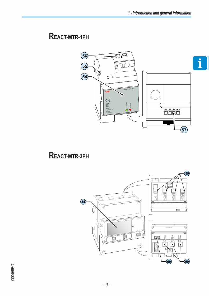
Operating diagram
REACT
POWER ALARM GFI ESC UP DOWN ENTER
REACT-UNO
REACT-BATT
Internet Aurora Vision web portal(Remote monitoring and settings)
A
A
B
C
G
H
I ML
D E FREACT-MTR-1PH
SUTATS
TSE T
ER
USAEM
INPUT :
110/230 V
50/60 Hz
10 mA max
Load Manager
Backup
Reference Description
A Photovoltaic generator
B REACT system (consisting of REACT-UNO and REACT-BATT)
C Meter for energy produced (where required by national regulations)
D REACT-MTR
E Exchange meter (on the supply point of the grid)
F Electricity grid
G Domestic utilities connected to the back-up output
H Domestic utilities
I Wi-FI Router
L Aurora Vision web portal
M Smartphone/Tablet or Desktop/Laptop

- 39 -
0005
54AG
2 - Characteristics
Operating stages of the system
The REACT system enables the storage of unused energy and makes it available during evening hours or times of maximum absorption, enabling self-consumption to be maximised. The main operating stages of the system are:
1. The energy from the PV generator is converted by the inverter (REACT-UNO) and powers the utilities in order to maximise self-consumption. The unused energy produced is stored in the batteries (REACT-BATT).
2. Once the batteries are fully charged the system powers the utilities and unused energy is fed into the grid. During this stage it is possible that the maximum limit on active power fed into the grid that was set by the operator may be exceeded; in this case the REACT system can automatically limit the feeding of active power to the grid.
3. When the energy supplied by the PV generator is insufficient to power the utilities, the system supplies the energy stored in the batteries thus enabling greater energy self-sufficiency
4. When the battery is completely discharged, or if the power supplied by the battery is insufficient, the system will draw energy from the grid
REACT
POWER ALARM GFI ESC UP DOWN ENTER
REACT-UNO
REACT-BATT
REACT
POWER ALARM GFI ESC UP DOWN ENTER
REACT-UNO
REACT-BATT
REACT
POWER ALARM GFI ESC UP DOWN ENTER
REACT-UNO
REACT-BATT
kWh
kWh
kWh
kWh
REACT
POWER ALARM GFI ESC UP DOWN ENTER
REACT-UNO
REACT-BATT

- 40 -
0005
55AG
2 - Characteristics
Functionality and components of the equipment
Configurable relay (ALARM relay)The inverter is equipped with a configurable switching relay, which can be used in different operating configurations that can be set in the dedicated menu. A typical example of its application is closing the contact when an alarm is triggered.
Remote switching on and off (Remote ON-OFF)This command can be used to switch off/switch on the inverter via an external (remote) command.This function must be enabled in the menu and, when it is active, switching on the inverter will not only be dictated by the presence of the normal parameters that allow the inverter to connect to the grid, but will also depend on the external on-off command.
Reactive power feed into the gridThe inverter is able to produce reactive power and can feed this power into the grid when the phase factor is set. Managing the feed can be controlled directly by the grid company via a dedicated RS485 serial interface or set by the display or through the configuration software, Aurora Manager LITE.Power feeding management modes vary according to the country of installation and the grid companies. For detailed information on the parameters and characteristics of this function, please contact ABB directly.
Limiting the active power fed into the gridThe inverter, if enabled and set using the display or the configuration software, can limit the amount of active power fed into the grid by the inverter to the desired value (expressed as a percentage).
Data transmission and controlThe inverter or a network of several inverters can be monitored locally or remotely by using the integrated web server or dedicated mobile app.The system also has an RS-485 serial interface (public communication protocol “Modbus RTU”).
SD cardThe inverter is equipped with a slot for insertion of an SD Card memory. The maximum size of the SD Card is 4 GB. Its main function is to allow the inverter firmware to be updated in a few simple steps.The most up-to-date inverter firmware version is available from the website https://registration.abbsolarinverters.com

- 41 -
0005
55AG
2 - Characteristics
Load management systemThe REACT system is provided with four relays (incorporated into the Load Manager Box) to manage external loads. The types of utilities that can be connected to the four relays are subdivided into three types:
• TYPE 0 can be activated ON-OFF (e.g. Lights, heaters)These utilities require the configuration only of the time slot in which it is wished to activate the relay.
• TYPE 1: Switchable (e.g. Lights, Heaters, Heat Pumps, Boilers)These utilities require configuration of: - Time slots- Power Threshold ON- Minimum time between two ONs
The relays are not power components (230Vac, 1A Max) and must be used, for example, to control a power relay installed outside the REACT system.
For further details relating to the external load management system and the configurations required for its operation, refer to the document “REACT -3.6/4.6-TL EXTERNAL LOADS MANAGEMENT – Load Manager Description” available on website www.abb.com/solarinverters.
Optimisation of self-consumptionREACT is equipped with an storage system (2kWh base system, expandable up to 6kWh), which enables use of the photovoltaic energy at different times.The energy stored in the battery during the day can be used in evening hours or whenever photovoltaic production is not sufficient to meet consumption by domestic utilities.Compared to a photovoltaic system without storage, self-consumption of photovoltaic energy increases considerably.
Wi-Fi communication and monitoring REACT is equipped with a Wi-Fi board which enables the configuration and monitoring of the system to be performed wirelessly. This enables the user to connect to the system directly and to activate it using a smartphone, tablet or notebook. Once the system is in service the data will be transmitted to the Aurora Vision web portal (an internet connection using a Wi-Fi router is required) and can be consulted online or from the app for smartphone/tablet.
AC back-up output - Means of operation The REACT system is equipped with an AC Back-up output that can be activated in different operating modes as listed below:

- 42 -
0005
55AG
2 - Characteristics
• Back-up Mode: Manual 1: Conditions necessary to activate the back-up function are:1. Agreement of manual user (by pressing “Enter” key on display for at least 5sec); 2. External command/signal (Communication and control signal terminal block 21 , terminal 1-3).
• Back-up Mode: Manual 2: A necessary condition for activating the back-up function is:- Agreement of manual user (by pressing “Enter” key on display for at least 5sec).
• Back-up Mode: Manual 3: Conditions necessary to activate the back-up function are:- Agreement of manual user (by pressing “Enter” key on display for at least 5sec); - Lack of grid.
• Back-up Mode: Manual 4: Conditions necessary to activate the back-up function are:- Agreement of manual user (by pressing “Enter” key on display for at least 5sec); - External command/signal (Communication and control signal terminal block 21 , terminal 1-3). - Lack of grid.
• Back-up Mode: Auto 1: A necessary condition for activating the back-up function is:- External command/signal (Communication and control signal terminal block 21 , terminal 1-3).
• Back-up Mode: Auto 2: A necessary condition for activating the back-up function is:- Lack of grid.
For further details relating to the Backup output and the corresponding operation modes, please refer to the document “REACT -3.6/4.6-TL BACKUP OUTPUT - Operation and setup", available on the website www.abb.com/solarinverters

- 43 -
0005
56AG
2 - Characteristics
Topographic diagram of the equipment
IN1.1(+)
IN1.2(+)
IN1.1(-)
IN1.2(-)
IN2.1(+)
IN2.2(+)
IN2.1(-)
IN2.2(-)
MPPT 1(DC/DC)
MPPT 2(DC/DC)
Bulk capsInverter(DC/AC)
Grid parallelrelay
Linefilter
L
N
PEResidual current
detection
RS485
+ T/R
- T/R
RTN
Remote control
+ R
- R
Alarm
N.C
N.O
C
L
N
ACOutput
ACBackupOutput
REACT-UNO
Charger/Discharger
(DC/DC)
Protection
ST
OP
REACT-BATT-AP1 (Opt.)
REACT-BATT-AP1 (Opt.)
Switch
+ T
/R
- T
/R
RT
N
+ T
/R1
- T
/R
RT
N
WIFI
Load ManagerBox
RS485 RTU
ModbusRS485 (Meter)
Protection
BMS
Batterypack
Protection
BMS
Batterypack
DC/DCDSPcontr.
DC/ACDSPcontr.
µP
Control circuit
2 3 4 5 6 7 8
A B C D

- 44 -
0005
57BG
2 - Characteristics
Safety devicesAnti-Islanding
In the event of a local grid outage by the electricity company, or when the equipment is switched off for maintenance operations, the inverter must be physically disconnected to ensure the protection of the people working on the grid, in accordance with the relevant national laws and regulations. To prevent possible islanding, the inverter is equipped with an automatic safety disconnection system called “Anti-Islanding”.
Anti-islanding protection mechanisms are different depending on the grid standards, even if they all have the same purpose.
Ground fault of the photovoltaic panelsThis inverter is to be used with panels connected in "floating" mode, i.e. with no ground connections on the positive and negative terminals. An advanced ground fault protection circuit continuously monitors the ground connection and disconnects the inverter when a ground fault is detected, indicating the fault condition by means of the red "GFI" LED on the front panel.
“STOP” buttonThe system is equipped with a STOP button (set on the lower side of REACT-UNO) which, if activated, causes the interruption of the operation of the equipment both when connected to the grid and when in back-up mode.
REACT-BATT-AP1 state of health (SOH)The state of health (SOH) is defined as the relation between the current capacity and the nominal capacity of the battery (2kWh).The SOH trend is constantly decreasing for natural aging linked to the use of the battery and is not an indication of its malfunction. The downward inclination of the degradation capacity depends on the actual use and in particular on the number of average daily cycles, and on the environmental working conditions such as temperature and humidity.The SOH value is automatically measured periodically by the REACT system and its value is detectable by all user interfaces (MyREACT, Aurora Vision, web server and display). Battery usage will be automatically interrupted when the SOH reaches 67% and displaying Warning (W054).In case the W054 warning is present, the REACT inverter will continue to function as a standard photovoltaic inverter.
Other safeguards- Constant monitoring of the grid voltage to ensure that voltage and frequency values remain within operating limits;- Internal temperature control to automatically limit the power if necessary to prevent overheating of the unit (derating).
The numerous control systems determine a redundant structure to ensure absolutely safe operations.

- 45 -
0000
16BG
Safety information and instructions The equipment has been manufactured in accordance with the strictest accident-prevention regulations and supplied with safety devices suitable for the protection of components and operators.
For obvious reasons, it is not possible to anticipate the great number of installations and environments in which the equipment will be installed. It is therefore necessary for the customer to appropriately inform the manufacturer about particular installation conditions.
ABB accepts no liability for failure to comply with the instructions for correct installation and cannot be held responsible for the upstream or downstream equipment.
It is essential to provide operators with correct information. They must therefore read and comply with the technical information provided in the manual and in the attached documentation.
The instructions provided in the manual do not replace the safety devices and technical data for installation and operation labels on the product, and they do not replace the safety regulations in force in the country of installation.The manufacturer is willing to train staff, at its premises or on site, in accordance with conditions agreed to in the contract.
Do not use the equipment if you find any operating anomalies.
Avoid temporary repairs. All repairs should be carried out using only genuine spare parts, which must be installed in accordance with their intended use.
Liabilities arising from commercial components are delegated to the respective manufacturers.
1
2
TRAINING
3Safety and accident prevention

- 46 -
0005
58AG
3 - Safety and accident prevention
Hazardous areas and operations
Environmental conditions and risks
The equipment is to be installed in locations with suitable environmental conditions which observe the safety conditions and do not prevent its regular operation. These conditions are listed in the technical data and in the installation chapter.
ABB is not responsible for any loss of the equipment, or part of it, which does not take place on the basis of the regulations and laws in force in the country of installation.
The same precautions should be adopted for dismantling the equipment.
The equipment is not designed to operate in environments that are particularly inflammable or explosive.
IThe customer and/or installer must appropriately train operators or anyone who may come into close proximity of the equipment, and highlight, with notices or other means where necessary, the hazardous areas or operations at risk : magnetic fields, hazardous voltages, high temperatures, possible discharges, generic hazard, etc.
Keep out of the reach of children
Signs and labels
The labels affixed on the equipment must strictly NOT be removed, damaged, defaced, hidden, etc.
The labels must be regularly cleaned and kept in sight, i.e. NOT hidden by foreign objects and parts (rags, boxes, equipment, etc.)The technical data provided in this manual does not in any case replace that shown on the labels affixed on the equipment.

- 47 -
0005
58AG
3 - Safety and accident prevention
Thermal and electrical hazard
CAUTION: the removal of guards or covers is permitted by qualified personnel only after the equipment has been put out of service and after the period of time indicated on the label has passed. This is to let the components cool down and allow the internal capacitors to discharge.
When the equipment has just been switched off, it may have hot parts as a result of overheating of the heated surfaces (e.g.: transformers, accumulators, coils, etc.) so be careful where you touch.
For all the safety aspects relating to the battery unit, please refer to the safety sheet provided with the product.
Clothing and protection of personnelABB has done its best to eliminate sharp edges and corners, but as this is not always possible you are advised always to wear theclothing and personal protection equipment provided by the employer.
Personnel must not wear clothes or accessories that could start fires or generate electrostatic charges or, in general, clothing that can compromise personal safety.
All operations on the equipment should be performed with suitably insulated clothing and tools.E.g.: insulating gloves, class 0, RC category
Maintenance operations may only be performed after the correct procedure for taking the equipment out of service has been carried out.
Personnel must NOT go near the equipment with bare feet or wet hands.
The maintenance technician must in any case ensure that no one else can switch on or operate the equipment during the maintenance operations, and should report any anomaly or damage due to wear or ageing so that the correct safety conditions can be restored.
The installer or maintenance technician must always pay attention to the work environment, ensuring that it is well-lit and there is enough room to ensure an escape route.
During installation, consider whether the noise emitted in that particular environment might exceed the legal thresholds (less than 80 dBA); if so, suitable ear protection must be worn.
MODEL:
IP65
5 minutes
Made inIta
ly
DINV VDE 0126-1-1
PROTECTIVE CLASS: I
-25 to+60 °C
-13 to+140 °F
SOLAR INVERTER
www.abb.com/solar
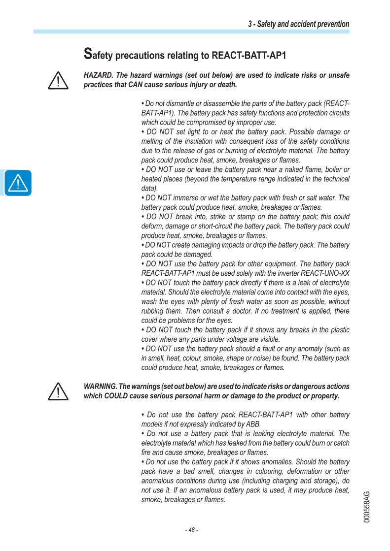
- 48 -
0005
58AG
3 - Safety and accident prevention
Safety precautions relating to REACT-BATT-AP1
HAZARD. The hazard warnings (set out below) are used to indicate risks or unsafe practices that CAN cause serious injury or death.
• Do not dismantle or disassemble the parts of the battery pack (REACT-BATT-AP1). The battery pack has safety functions and protection circuits which could be compromised by improper use.• DO NOT set light to or heat the battery pack. Possible damage or melting of the insulation with consequent loss of the safety conditions due to the release of gas or burning of electrolyte material. The battery pack could produce heat, smoke, breakages or flames.• DO NOT use or leave the battery pack near a naked flame, boiler or heated places (beyond the temperature range indicated in the technical data). • DO NOT immerse or wet the battery pack with fresh or salt water. The battery pack could produce heat, smoke, breakages or flames. • DO NOT break into, strike or stamp on the battery pack; this could deform, damage or short-circuit the battery pack. The battery pack could produce heat, smoke, breakages or flames.• DO NOT create damaging impacts or drop the battery pack. The battery pack could be damaged.• DO NOT use the battery pack for other equipment. The battery pack REACT-BATT-AP1 must be used solely with the inverter REACT-UNO-XX• DO NOT touch the battery pack directly if there is a leak of electrolyte material. Should the electrolyte material come into contact with the eyes, wash the eyes with plenty of fresh water as soon as possible, without rubbing them. Then consult a doctor. If no treatment is applied, there could be problems for the eyes.• DO NOT touch the battery pack if it shows any breaks in the plastic cover where any parts under voltage are visible.• DO NOT use the battery pack should a fault or any anomaly (such as in smell, heat, colour, smoke, shape or noise) be found. The battery pack could produce heat, smoke, breakages or flames.
WARNING. The warnings (set out below) are used to indicate risks or dangerous actions which COULD cause serious personal harm or damage to the product or property.
• Do not use the battery pack REACT-BATT-AP1 with other battery models if not expressly indicated by ABB. • Do not use a battery pack that is leaking electrolyte material. The electrolyte material which has leaked from the battery could burn or catch fire and cause smoke, breakages or flames.• Do not use the battery pack if it shows anomalies. Should the battery pack have a bad smell, changes in colouring, deformation or other anomalous conditions during use (including charging and storage), do not use it. If an anomalous battery pack is used, it may produce heat, smoke, breakages or flames.

- 49 -
0005
58AG
3 - Safety and accident prevention
CAUTION. The caution messages (set out below) are used to indicate risks or dangerous actions which could cause serious harm to people or damage to property.
• Do not use or leave the battery pack exposed to direct sunlight (or in a vehicle which is exposed to the sun). The battery pack could produce heat, smoke, breakages or flames. In addition, its performance might deteriorate and/or it might have a shorter lifespan.• If the battery pack has signs of rust, a bad smell or any anomaly on first being used, do not use the equipment.• If the skin or clothes come into contact with electrolyte material which has leaked from the battery pack, wash them in plenty of fresh water as soon as possible, otherwise it might cause inflammation of the skin.
Final installation of the equipment must not hinder access to any externally located disconnection devices.
Please refer to the warranty terms and conditions to evaluate any possible warranty exclusions due to improper installation.

- 50 -
0000
18CG
3 - Safety and accident prevention
Residual risksDespite the warnings and safety systems, there are still some residual risks that cannot be eliminated.These risks are listed in the following table with some suggestions to prevent them.
Table of residual risks
RISK ANALYSIS AND DESCRIPTION SUGGESTED REMEDY
Noise pollution due to installation in unsuitable environments or where staff work permanently.
Reassess the environment or the place of installation.
Suitable local ventilationthat does not cause overheating of the equipment and is sufficient not to create discomfort to people in the room.
Restore suitable ambient conditions and air the room.
External weather conditions, such as water seepage, low temperatures, high humidity, etc.
Maintain ambient conditions suitable for the system.
Overheating of surfaces at temperature (transformers, accumulators, coils, etc. ) can cause burns. Also be careful not to block the cooling slits or systems of the equipment.
Use suitable protective equipment or wait for the parts to cool down before switching on the equipment.
Inadequate cleaning: compromises cooling and does not allow the safe-ty labels to be read.
Clean the equipment, labels and work environment adequately.
Accumulation of electrostatic energy can generate hazardous dischar-ges.
Ensure the devices have discharged their energy before working on them.
Inadequate training of staff. Ask for a supplementary course.
During installation, temporarily mounting the equipment or its components may be risky.
Be careful about and disallow access to the installation area.
Accidental disconnections of the quick-fit connectors with the equipment in operation, or wrong connections, may generate electric arcs
Be careful about and disallow access to the installation area.

- 51 -
0005
59AG
General conditions
Storage, handling and transport must comply with particular rules and regulations indicated in the subsequent paragraphs.
The lifting and transporting of pallets containing the equipment can be done using pallet trucks or forklifts, by picking up the pallet in the area intended for lifting.
The transport of individual boxes containing the equipment must be done using suitable means and with careful supervision by authorised staff. The accident and safety prescriptions for handling and lifting operations must be complied with.
4Lifting and transport

- 52 -
0005
60AG
4 - Lifting and transport
Storage of equipment
Special rules for storage of REACT-BATT
The storage of REACT-BATT starts from the moment of delivery by ABB. In order to guarantee the full operation of the system, REACT-BATT must be put into service within 3 months at most of the date of delivery by ABB to the recipient of the goods.In order to reduce risks during storage of the REACT-BATT it must be considered that:• In the case of damage to the REACT-BATT there is a high risk of fire.• Keep the REACT-BATT in a dry place.• Relative humidity, not condensing: 5% … 95%• Handle and treat packages carefully.• Avoid unnecessary movements of the REACT-BATT.• Ambient temperature allowed during storage: -20°C...+40°C• Maximum height above sea level (a.s.l.): = 2 000 m
For the rules on storing the battery, refer to the regulations in force in the country concerned
- Handling of damaged batteriesShould damage or visible deformation of the cover be found, or should it be noted that the batteries have overheated during operation, immediately contact the ABB technical assistance service.

- 53 -
0005
60AG
4 - Lifting and transport
LiftingABB usually stores and protects individual components by suitable means to make their transport and subsequent handling easier. Nonetheless, as a rule, it is necessary to turn to the experience of specialised staff to take charge of loading and unloading components.Where indicated and/or available, eyebolts or handles, which can be used as anchorage points, are inserted and/or can be inserted.
The ropes and means used for lifting must be suitable for bearing the weight of the equipment.
Do not lift several units or parts of the equipment at the same time, unless otherwise indicated.
Equipment weight
Risk of injury due to the weight of the equipment. Take care during lifting and transport
Table: WeightsDevice Weight (kg/lb) Lifting pointsREACT-UNO-3.6/4.6-TL 30kg / 66.1lb 4 (2 people)REACT-BATT-AP1 37kg / 81.5lb 4 (2 people)
REACT
POWER ALARM GFI ESC UP DOWN ENTER
REACT-UNO
REACT-BATT
If the package is stored correctly, it can withstand a maximum load of 5 pallets. DO NOT stack with equipment or products other than those indicated.
NO
MAX 5

- 54 -
0005
60AG
4 - Lifting and transport
Transport of the equipmenttransportation of the equipment, especially by road, must be carried out using appropriate vehicles and methods to protect the components (particularly electronic components) from violent shocks, humidity, vibration, etc.
During handling, do not make any sudden or fast movements that can create dangerous swinging.
Transport of the REACT-BATT-AP1
The REACT-BATT-AP1, as it falls within the category of dangerous goods (UN 3480 lithium-ion battery, class 9, group II), must comply with the rules of the ADR (European Agreement concerning the International Carriage of Dangerous Goods by Road) as regards packaging, transport and marking.For more information, consult the website of the Ministry of Infrastructure and Transport on page http://www.mit.gov.it/mit/site.php?o=vc&lm=2&id_cat=207).Exemptions from the provisions:• the “Ancillary rule” (1.1.3.1 c ADR)• the “1,000 Units rule” (1.1.3.6 ADR)
In order to guarantee full operation and the validity of any guarantees, the REACT-BATT must be put into service within 3 months at most of the date of delivery by ABB to the recipient of the goods. Should the guarantee be used, the date of commissioning must be demonstrated by submitting to ABB the commissioning report or the invoice to the end user.
The ambient temperature allowed for transport is from -20°C to +40°C. The manufacturer guarantees the characteristics of the REACT-BATT-AP1 only if the aforementioned condition is respected.
Overview of the “Ancillary rule” and the “1000 units rule”
For road transport of the REACT-BATT-AP1 the rules of the European Agreement concerning the International Carriage of Dangerous Goods by Road (ADR) must be complied with.
In the following notes, ABB wishes to provide a short overview of the rules to be complied with for the carriage of dangerous goods contained in the “Ancillary rule” and the “1,000 units rule”.
ABB does not accept any responsibility for the correctness and completeness of what is set out. The installer must check and comply with all the regulations in force.

- 55 -
0005
60AG
4 - Lifting and transport
For the transport of lithium-ion batteries the installers can make use of legal exemptions, which are:- “Ancillary rule” (1.1.3.1 c ADR, attachment 2 GGVSEB) - “1,000 units rule” for carriage in exempt quantities (1.1.3.6 ADR).
The “ancillary rule” can be applied only if the following conditions are met:• Carriage is ancillary to the main business (deliveries to or returns from building or civil engineering works for repair or maintenance work).• A volume of 450 litres is not exceeded per packaging.• The quantity of 1000 units must not be exceeded (333 kg).• Protections to avoid leaks must be arranged.• The general standards on packaging must be complied with.• The limitations for particular substances must be complied with.• Sections 4.1.1.6, 4.1.1.7 and 4.1.6.8 ADR must be complied with.
The “1000 units rule” can be applied only if the following conditions are met:• Respect of a maximum quantity of 1000 units (333 kg)• Presence of a 2 kg extinguisher for each vehicle• Marking and labelling of the packaging• Waybill with correct indication of the dangerous substances • Respect of all the provisions of the ADR except for:- ADR certificate- Vehicle marking- Written engagement
In addition, the following points must be verified and complied with:• Load guaranteed in regulatory way• Instruction of the driver• Ban on driver opening packages• Ban on smoking during loading operations

- 56 -
0005
60AG
4 - Lifting and transport
Unpacking and checking Bear in mind that the packaging elements (cardboard, cellophane, staples, adhesive tape, straps, etc.) may cause cuts and/or injuries if not handled with care. They should be removed by suitable means and not left in the hands of individuals who are not responsible (e.g. children).
The packaging components must be disposed of in accordance with the regulations in force in the country of installation.
When you open the package, check that the equipment is undamaged and make sure all the components are present.
If any defect or damage is detected, please stop, contact the carrier and also promptly inform the ABB Service .
List of components supplied
Inside the package the following components required to correctly install the inverter are supplied
Components supplied together with the inverter REACT-UNO:Components available for REACT-UNO Quantity
Connector for connection of the configurable relay 2
Connector for connecting the communication and control signals 2
Male key TORX TX20 1
Jumper for configuration of the parallel input channels 1
Bracket for wall mounting 1
Plugs, screws and washers for wall mounting 12 + 12 + 12

- 57 -
0005
60AG
4 - Lifting and transport
Components available for REACT-UNO Quantity
Two-hole gasket for M25 service cable glands and cover 2 + 2
Two-hole gasket for M20 service cable glands and cover 3 + 3
Wi-Fi antenna 1
EMI filter for AC cable gland (back-up) 49 1
IP65 cover (with fastening ring nut) for individual installation on REACT-UNO 1
In addition to what is explained in this guide, the safety and installation information provided in the installation manual must be read and followed.
The technical documentation and the interface and management software for the product are available at the website.
XXXXXXXXXXXXXXXXXXX
XXXXXXXXXXXXXXXXXXX
ABB solar inverters
Technical documentation 1
Components supplied together with the inverter REACT-BATT:Components available for REACT-BATT Quantity
Cable conduit (male) 1
In addition to what is explained in this guide, the safety and installation information provided in the installation manual must be read and followed.
The technical documentation and the interface and management software for the product are available at the website.
XXXXXXXXXXXXXXXXXXX
XXXXXXXXXXXXXXXXXXX
ABB solar inverters
Technical documentation 1

- 58 -
0000
21FG
General conditions The device is installed depending on the system and the place where the device is installed. Its performance therefore depends on the correctness of the connections.
Staff authorised to carry out the installation must be specialised and experienced in this job. They must also have received suitable training on equipment of this type.
The operation must be carried out by qualified personnel and it is advisable to adhere to the indications provided in this manual, the diagrams and the enclosed documentation.
For safety reasons, only a qualified electrician who has received training and/or demonstra-ted skills and knowledge on the structure and operation of the unit may install the inverter.
The installation must be performed by qualified installers and/or licensed electricians in ac-cordance with the existing regulations in the country of installation.
The removal of the inverter panels/covers allows access to the area dedicated to service personnel (the operator is not authorized to access this area)
Connection of the photovoltaic system to an electric installation connected to the distribution grid must be approved by the electricity provider.
The installation must be carried out with the equipment disconnected from the grid (power disconnect switch open) and with the photovoltaic panels shaded or isolated.
When the photovoltaic panels are exposed to sunlight they provide continuous DC voltage to the inverter.
5Installation

- 59 -
0005
61AG
5 - Installation
Environmental checks
The installation location must comply with the requirements of the standards EN 50272-2 and EN 60069-10.
• The installation location must be easily accessible• Prevent access to the installation location by children• The minimum air volume in the installation location must be 15m3 and equipped with two openings with a diameter of 6cm for natural air circulation. If the two openings are located in the same wall they must be made at a minimum distance of 2 metres from each other.• Installation of the unit in a location exposed to solar rays must be avoided as it may cause:- power limitation phenomena in the inverter (with a resulting decreased energy production by the system)- premature wear of the electrical/electromechanical components- premature wear of the mechanical components (gaskets) and of the user interface (display)- reduction in performance, lifetime and possible damage of the battery pack• Always ensure that the flow of air around the inverter is not blocked so as to prevent overheating.• Do not install in locations where flammable substances or gases may be present• Do not install in locations with a constant presence of water and/or high humidity level.• Do not install in rooms where people live or where the prolonged presence of people or animals is expected, because of the noise (around 50dB(A) at 1 m) that the inverter produces during operation.
2m
Ø 6cm
Ø 6cm
>15m3
60cm 60cm
60cm
60cm

- 60 -
0005
61AG
5 - Installation
• Avoid electromagnetic interference that can compromise the correct operation of electronic equipment, with the consequent hazards• The ambient temperature of the installation location must be between 5°C and 35°C to guarantee the optimal operation of the battery unit (REACT-BATT-AP1). Here below are the functions available from the system on the basis of the ambient temperature:T1 - Optimal operation of the REACT systemT2 - Correct operation of the REACT system with possible reduction in the lifetime of the batteriesT3 - Partial operation of the battery which limits its functioning to discharge onlyT4 - Operation limited to the inverter part only. Management of the battery is disabled.
-20 -10 0 +5 +35 +40 +45 +55
T1T2T3T4
°C
T2 T3 T4
• Consult the technical data to check the required environmental conditions (protection rating, temperature, humidity, altitude, etc.)
Final installation of the REACT system must not compromise access to any externally located disconnection devices.
Please refer to the warranty terms and conditions to evaluate any possible warranty exclusions due to improper installation.

- 61 -
0005
61AG
5 - Installation
Installation position
When choosing the place of installation, observe the following conditions:
• Install on a wall or strong structure capable of bearing the weight of the equipment• Install in safe, easy to reach locations• If possible, install at eye-level so that the display and status LEDs can be seen easily• Install at a height that considers the heaviness of the equipment. Failure to meet this condition could result in problems during servicing, unless suitable means are provided to carry out the operation• Install vertically with a maximum inclination of 5° (forward or backward). If this condition cannot be met, the inverter could undergo derating due to high temperature because of poor heat dissipation.• The installation must take account of any electrical devices (e.g. lamps, switches, etc.) which must be at least 60cm from the equipment. These distances must be maintained also to facilitate the circulation of the air needed to cool the unit and to facilitate the operations to install/maintain hardware and software which is done by dismantling the covers placed on the front.
• For a multiple installation, position the inverters side by side.
• If the space available does not allow this arrangement, position the inverters in a staggered arrangement as shown in the figure so that heat dissipation is not affected by other inverters.
60cm
60cm
60cm60cm
60cm
60cm
60cm60cm

- 62 -
0005
62AG
5 - Installation
• Position the bracket 01 so that it is perfectly level on the wall and use it as a drilling template.
• Make the 4 holes necessary, using a drill with a 10 mm. diameter bit. The depth of the holes must be around 70 mm.
• Install four 10mm diameter wall plugs in the holes and fix the bracket to the wall using 4 screws with washers A (supplied).
REACT
POWER ALARM GFI ESC UP DOWN ENTER
REACT-UNO
• Lift and fasten the REACT-UNO 03 to the wall bracket 01 by inserting the springs that are on the bracket itself into the 2 holes on the rear bracket of the REACT-UNO 03 .
Risk of injury due to the weight of the equipment.
01A
AA
A
4 x Ø 10 mm
Wall installation of the REACT system

- 63 -
0005
62AG
5 - Installation
• Lift and fasten the REACT-BATT 14 to the wall bracket 01 by inserting the springs that are on the bracket itself into the 2 holes on the rear bracket of the REACT-BATT 14 .
Risk of injury due to the weight of the equipment.
REACT
POWER ALARM GFI ESC UP DOWN ENTER
REACT-UNO
REACT-BATT
REACT-BATT
REACT
POWER ALARM GFI ESC UP DOWN ENTER
REACT-UNO
BB
BB
• Anchor the lower part of the REACT to the wall by installing 4 plugs (10 mm. diameter supplied). Then screw in 4 screws with washers into the holes on the lower side of the equipment.

- 64 -
0005
62AG
5 - Installation
• Remove the plastic covers installed on the REACT-UNO 03 and on the REACT-BATT 14 (16 screws in total). Then remove the metal covers of the compartments for the electric connections (16 screws in total).
• Remove the protective cover from the support of the Wi-Fi antenna 52 located on the lower part of the REACT-UNO 03 and install the Wi-Fi antenna 53 by screwing it into the specific connector.

- 65 -
0005
62AG
5 - Installation
• Connect the cables to the respective counterparts on the battery pack respecting the positions:a Communication and control cable on the communication and control connector (cable from the unit on the
right) 39 .b Power cable on the power connector (cable from the unit on the right) 38 .c Ground cable on the ground connection points 35 .
Dangerous voltage on the terminals of the power connector. Be careful not to touch the terminals with fingers or with uninsulated equipment
Make the connections usingpersonal protective clothing and/or equipment, such as insulating gloves.
• Proceed with installation of the REACT-MTR
• Insert the battery pack connection cables (which come out of the inverter) into the REACT-BATT 14 using the hole present on the side of the mechanical cover.• Feed the cables into the cable conduit (male) supplied with the REACT-BATT 14 .• Insert the cable conduit (male) 36 into the REACT-BATT 14 and screw it into its counterpart (cable conduit (female) 07 on REACT-UNO 03 .
J6 J5
BATT. COMM.BUS
BATT. COMM.BUS
3J4J
.MOC O/IYRETTAB-ITLUM KNIL .MOC O/I
MULTI-BATTERY
DC POWER
D1
D2
D3
OFF
J2
J1J7 PE
120 ΩON
BATTERY ADDRESSSELECTOR
DC POWER LINKa b
c
44 42 39 35 38

- 66 -
0005
62AG
5 - Installation
Wall installation of the REACT-UNO alone
• Position the bracket 01 so that it is perfectly level on the wall and use it as a drilling template.
• Make the 4 holes necessary, using a drill with a 10 mm. diameter bit. The depth of the holes must be around 70 mm.
• Install four 10mm diameter wall plugs in the holes and fix the bracket to the wall using 4 screws with washers A (supplied).
REACT
POWER ALARM GFI ESC UP DOWN ENTER
REACT-UNO
• Lift and fasten the REACT-UNO 03 to the wall bracket 01 by inserting the springs that are on the bracket itself into the 2 holes on the rear bracket of the REACT-UNO 03 .
Risk of injury due to the weight of the equipment.
01A
AA
A
4 x Ø 10 mm

- 67 -
0005
62AG
5 - Installation
REACT
POWER ALARM GFI ESC UP DOWN ENTER
REACT-UNO
BB
• Anchor the lower part of the REACT to the wall by installing 2 plugs (10 mm. diameter supplied). Then screw in 2 screws with washers into the holes on the lower side of the equipment.
• Remove the plastic cover installed on the REACT-UNO 03 (8 screws in total). Then remove the metal cover from the compartment for the electric connections (8 screws in total).

- 68 -
0005
62AG
5 - Installation
ab
c
• Remove the protective cover from the support of the Wi-Fi antenna 52 located on the lower part of the REACT-UNO 03 and install the Wi-Fi antenna 53 by screwing it into the specific connector.
• Disconnect the cables connecting to the battery unit, in particular:- a the communication service cable- b the power cable - c the ground connection cableThen remove the cable conduit cabling.
• Remove the fastening ring nut of the cable conduit. The wing nut must be kept since it will be used again to set the sealing cover IP65.

- 69 -
0005
62AG
5 - Installation
• Install the sealing cover IP65 (supplied) in the hole left free by the cabling to connect to the battery unit.
Position the cover outside the REACT-UNO and screw the fastening ring nut on the internal side.
• Make the electric connections using personal protective clothing and/or equipment, such as insulating gloves.
• Proceed with installation of the REACT-MTR

- 70 -
0005
63AG
5 - Installation
Connection of the energy meter (REACT-MTR)Management of the storage system in order to optimise the energy self-consumption and self-sufficiency of the REACT system is based on the reading of the power by the meter REACT-MTR. On the basis of the type of electric supply the following are available:• REACT-MTR-1PH 54 for mono-phase supplies• REACT-MTR-3PH 58 for three-phase suppliesThe energy meter REACT-MTR will communicate with the REACT throu-gh a dedicated serial line (RS485 METER).
If the energy meter REACT-MTR is not installed or correctly connected, the REACT system will manage the functions connected to energy storage in provisional mode; where power is available from the sun, REACT charges the battery with 300 W. The rest of the power is fed into the grid. This mode makes it possible, even if there is no meter, to charge the battery.
For further details relating to compatibility and the relative configurations required for opera-tion of the energy meters, refer to the document REACT-MTR 1PH/3PH Compatibility and Configuration of the meters to manage energy flows” available on website www.abb.com/solarinverters.
Connection of the REACT-MTR-1PH (mono-phase)
The indications set out below are necessary to connect the REACT-MTR to the REACT sy-stem. Always refer to the specific documentation supplied with the REACT-MTR-1PH.
The energy meter REACT-MTR-1PH 54 is a DIN rail device (3 modules) and must be installed where the electricity supply is mono-phase.
To avoid risks of electrical shock, all wiring operations must be carried out with the AC disconnect switch (or the supply meter) upstream of the REACT-MTR disconnected.
• Ensure that the AC line has been correctly disconnected upstream from the REACT-MTR. Check that there is no voltage by using a multimeter.
• Strip 8/10mm of sheathing from the connection cables of the AC power supply and connect the phase (L) and neutral (N) on the specific terminal block 56 set on the upper side of the meter; each individual terminal of the terminal block takes a cable with a maximum section from 0.5 to 4mm² (tightening torque of 0.5Nm).
• Connect the cables of the serial line (+T, -T and RTN) on the terminal block 57 on the lower part of the REACT-MTR. Each individual terminal of the terminal block takes a cable with a section from 0.14 to 1.5mm² (tightening torque of 0.5Nm).
Subsequently the cable must be connected inside the REACT-UNO re-specting the correspondence between the signals of the serial line.

- 71 -
0005
63AG
5 - Installation
Serial line terminal blockof the REACT-MTR 57
Communication and control signal terminal block 21 of the
REACT-UNO+T Terminal 16 (+T/R)-T Terminal 14 (-T/R)
RTN Terminal 18 (RTN)
RS485 METER
REACT
POWER ALARM GFI ESC UP DOWN ENTER
REACT-UNO
REACT-BATT
REACT-MTR-1PH
SUTATS
ER
USAEM
INPUT :
110/230 V
50/60 Hz
10 mA max
To connect the serial cable inside the inverter, refer to the section “Connection of METER RS485 serial communication line” in this chapter.
• Install the device on the DIN rail and ensure to trigger the fixing system on it
• Disconnect the phase cable (L) of the electric supply
• Insert the phase cable (L) through the hole (Ø8mm) on the REACT-MTR-1PH 54 . The arrow corresponding to the hole for the feeding of the line cable 55 , indicates the direction of insertion which must be complied with for correct measurement of the current; in fact the direction of the arrow indicates the supply point of the electric energy (as indicated in the diagram).
• Once the connection stage is finished, the correct installation of the REACT-MTR-1PH must be verified 54 :- Power the REACT-MTR-1PH while keeping the REACT system off- Action a load (of at least 50W) in the house so that the REACT-MTR records drawing of current from the grid- Check that the LED MEASURE (red) is permanently on. This condition indicates that a drawing from the grid is recorded and so that the reading of the direction of the current by the REACT-MTR is correct.
Here below is set out the behaviour of LEDs on the REACT-MTR:STATUS LED description
Off Serial communication absent or malfunctioningFlashing Serial communication present
MEASURE LED descriptionPermanent red Drawing of energy from the gridGreen (steady) Self-consumption (maximum exchange ±20W)
Flashing red and green Feeding of energy from the grid
REACT-MTR-1PH
SUTAT
S
ER
US
AE
M
INPUT :110/230 V50/60 Hz10 mA max
REACT-MTR-1PH
SUTAT
S
ER
US
AE
M
INPUT :110/230 V50/60 Hz10 mA max

- 72 -
0005
63AG
5 - Installation
Connection and configuration of the REACT-MTR-3PH (three-phase)
The indications set out below are necessary to connect the REACT-MTR to the REACT sy-stem. Always refer to the specific documentation supplied with the REACT-MTR-3PH.
The energy meter REACT-MTR-3PH 58 is a DIN rail device (4 modules) and must be installed where the electricity supply is three-phase.
To avoid risks of electrical shock, all wiring operations must be carried out with the AC disconnect switch (or the supply meter) upstream of the REACT-MTR disconnected.
• Disconnect the AC disconnect switch upstream of the REACT-MTR.
• Strip the insulation of the cable for the length which is indicated on the meter (13mm).
• Connect the cables of the three-phase line in accordance with the lay-out printed on the meter (L1, L2, L3 and N) to the three-phase connection terminal block 59 and tighten the screws (tightening torque 2.0 Nm).
Take note of the phase to which the REACT system is connected; this information will be requested when the system is commissioned.
• Connect the cables of the serial line A (37), B (36) and C (37) on the terminal block 60 set on the rear of the REACT-MTR-3PH 58 and tighten the screws (tightening torque 0.25 Nm). Subsequently the cable must be connected inside the REACT-UNO re-specting the correspondence between the signals of the serial line.
Serial line terminal blockof the REACT-MTR 60
Communication and control signal terminal block 21 of the REACT-
UNOB (36) Terminal 16 (+T/R)A (37) Terminal 14 (-T/R)C (35) Terminal 18 (RTN)
RS485 METER
REACT
POWER ALARM GFI ESC UP DOWN ENTER
REACT-UNO
REACT-BATT
To connect the serial cable inside the inverter, refer to the section “Connection of METER RS485 serial communication line” in this chapter.
• Install the device on the DIN rail and ensure to trigger the fixing system on it

- 73 -
0005
63AG
5 - Installation
• Once the phase of mechanical installation of the METER is finished, it is necessary to configure the METER in order to make it compatible with the REACT system. Set the parameters of the meter as set out in the table:
Parameter SettingsAddress 1Protocol MODBUS
Baud rate 57600Parity EVEN
The settings are made by using the keypad and the display on the meter:
1. Press for two seconds to access the setup menu of the meter.
2. Press repeatedly until the display shows “Set”. - Press to confirm.
3. Press repeatedly until the display shows “RS-485”. - Press to confirm.
4. Press repeatedly until the display shows “Protocol”.- Press to access. - Press to enable the change in the value.- Press repeatedly until the display shows “Modbus”.- Press to confirm the change.- Press for two seconds to return to the RS485 menu.
5. Press repeatedly until the display shows “Baud rate”.- Press to access. - Press to enable the change in the value.- Press repeatedly and select 57600.- Press to confirm the change. - Press for two seconds to return to the RS485 menu.
6. Press repeatedly until the display shows “Address”.- Press to access. - Press to enable the change in the value.- Press repeatedly and select 1. - Press to confirm the change. - Press for two seconds to return to the RS485 menu.
7. Press repeatedly until the display shows “Modbus”. - Press to access. - Press to enable the change in the value.- Press repeatedly and select even. - Press to confirm the change.

- 74 -
0000
24EG
5 - Installation
Preliminary operations for connection of the PV generator
Checking the correct polarity of the strings
Using a voltmeter, check that the voltage of each string has the correct polarity and falls within the input voltage limits of the inverter (see technical data).
Polarity inversion can cause serious damage.
If the open circuit voltage of the string is near the maximum value accepted by the inverter, consider that low ambient temperatures cause an increase in the string voltage (different according to the photovoltaic module used). In this case it is necessary to carry out a check of the sizing of the system and/or a check on the connections of the modules of the system (e.g.: number of modules in series higher than the design number).
A configuration program that can help to correctly size the photovoltaic system is available on the ABB website http://stringsizer.abb.com.
Checking of leakage to ground of the photovoltaic generator
Measure the voltage present between the positive and negative pole of each string with respect to ground, as described in the section on "Verification of leakage to ground".
Do not connect the strings if a leakage to ground has been detected, as the inverter might not connect to the grid.
Selection of differential protection downstream of the inverter
All ABB string inverters marketed in Europe are equipped with a device for protection against ground faults in accordance with the safety standard IEC 62109-2, sections 4.8.2 and 4.8.3 of the Standard (equivalent to Standard DIN V VDE V 0126-1:2006, section 4.7). In particular, ABB inverters are equipped with a redundancy on the reading of the ground leakage current sensitive to all components of both direct and alternating current. Measurement of the ground leakage current is carried out at the same time and independently by 2 different processors: it is sufficient for one of the two to detect an anomaly to trip the protection, with consequent disconnection from the grid and stopping of the conversion process. There is an absolute threshold of 300 mA of total leakage current AC+DC with protection tripping time at a max. of 300 msec.In addition, there are another three tripping levels with thresholds respectively at 30 mA/sec, 60 mA/sec and 150 mA/sec to cover the “rapid” changes in fault current induced by accidental contact with leaking live

- 75 -
0000
24EG
5 - Installation
parts. The max. tripping times are progressively shortened as the speed of change in the fault current increases and, starting from the 300 msec/max for the 30 mA/sec change, they are shortened respectively to 150 msec and 40 msec for 60 mA and 150 mA changes.It should in any case be noted that the integrated device only protects the system against ground faults that occur upstream of the AC terminals of the inverter (namely towards the DC side of the photovoltaic system and consequently towards the photovoltaic modules). The leakage currents that can occur in the AC section between the draw/feed and the inverter are not detected and require an external protection device.For protection of the AC line, on the basis of the information above with regard to the differential protection integrated in ABB inverters, it is not necessary to install a type B differential switch.
In accordance with article 712.413.1.1.1.2 of Section 712 of IEC Standard 64-8/7, we hereby declare that, because of their construction, ABB inverters do not inject ground fault direct currents.
The use of an AC type circuit breaker with differential thermal magnetic protection with tripping current of 300 mA is advisable so as to prevent false tripping, due to the normal capacitive leakage current of photovoltaic modules.
In the case of systems which consist of several inverters connected to a single switch with differential protection it is recommended that a device is installed which allows the adjustment of the tripping value and the tripping time.

- 76 -
0005
64AG
5 - Installation
Distribution grid output connection (AC side)To connect the inverter to the grid you need 3 connections: ground, neu-tral and phase. In any case, connection of the inverter to ground is mandatory.
Any failure of the inverter when it is not connected to ground through the appropriate terminal is not covered by the warranty.
Insert the grid cable into the inverter using the AC cable gland 48 called AC GRID (M25 equipped with toroid) and make the connections to the AC output terminal block 25 .
Use a properly sized tripolar cable and check the tightness of the AC cable gland 48 at the end of the installation.
Characteristics and sizing of the line cable
The cross-section of the AC line conductor must be sized in order to pre-vent unwanted disconnections of the inverter from the grid due to high impedance of the line that connects the inverter to the power supply; If the impedance is too high it causes an increase in the AC voltage which, on reaching the limit set by the standards in the country of installation, causes the inverter to switch off.
The table shows the maximum length of the line conductor based on the cross-section of this conductor:
Conductor cross-sec-tion
of line (mm²)
Maximum length of the line conductor (m)
REACT-3.6-TL REACT-4.6-TL4 16 m 10 m6 24 m 15 m10 41 m 25 m16 65 m 40 m
The values are calculated in nominal power conditions, considering:- loss of power along the line no greater than 1%- use of copper cable, with HEPR rubber insulation and positioned in open air
max 16 mm²
10 ÷ 17 mm
LOAD MANAGER BOX
87D
5 6C
3 4B
1 2A
J1
5
1
6
2
7
3
8
4
25
48

- 77 -
0005
64AG
5 - Installation
Load protection switch (AC disconnect switch)
It is recommended that the inverter AC connection line be fitted with a device to protect against maximum current and leakage to ground, with the following characteristics:
REACT-3.6-TL REACT-4.6-TLType Automatic circuit breaker with differential thermal magnetic protection
Voltage rating 230 VacCurrent rating 25 A 32 A
Magnetic protection characteristic B/CType of differential protection A/AC
Differential sensitivity 300 mANumber of poles 2
Connection to the AC side terminal block
To avoid risks of electrical shock, all wiring operations must be carried out with the disconnect switch downstream of the inverter (grid side) off.
For all the models the connection is made with the AC output terminal block 25 by passing the cables through the AC cable gland 48 .
Strip 10mm of sheathing from the cables to connect to the AC grid, then insert into the inverter the AC line cable, making it pass through the AC cable gland 48 ; the maximum diameter of the cable accepted by the cable gland is from 10 to 17 mm².
Connect on the cable gland 25 the ground cable (yellow-green) to protect against contact marked by the symbol , the neutral cable (usually blue) to the terminal marked by the letter N and the phase cable to the terminal marked by the screen-print L1; every individual terminal of the terminal block accepts a cable with maximum section of 16 mm² (It is necessary to fix the AC cables to the terminal block with a tightening torque of at least 1,5 Nm).
Once the connection to the terminal block has been made, firmly screw the cable gland (7.5 Nm tightening torque) and check the tightness.
48
25 24

- 78 -
0005
64AG
5 - Installation
Back-up output connection (AC)To connect the back-up output of the inverter, you need 3 connections: ground, neutral and phase. In any case, connection of the inverter to ground is mandatory.
Any failure of the inverter when it is not connected to ground through the appropriate terminal is not covered by the warranty.
Install the filter on the AC cable gland 49 (side inside the REACT-UNO). The installation is carried out:- a position the filter on the internal side of the cable gland - b Screw the filter on the thread of the cable gland
a
b
Insert the grid cable into the inverter using the AC cable gland 49 called AC -1 (M25 equipped with toroid) and make the connections to the AC output terminal block 24 .
Use a properly sized tripolar cable and check the tightness of the AC cable gland 49 at the end of the installation.
LOAD MANAGER BOX
87D
5 6C
3 4B
1 2A
J1
5
1
6
2
7
3
8
4
24
49

- 79 -
0005
64AG
5 - Installation
Characteristics and sizing of the cable for back-up output
The section of the conductor for the back-up output must be sized in order to avoid high impedances of the cable which connects the back-up output to the load; in fact if the impedance is too high there is the risk that the load is powered at a lower voltage than the nominal voltage.
max 4 mm²
10 ÷ 17 mm
The table shows the maximum length of the line conductor based on the cross-section of this conductor:
Conductor cross-sec-tion
of line (mm²)
Maximum length of the line conductor (m)
1.5 6 m2.5 11 m4 19 m
The values are calculated in nominal power conditions, considering:- loss of power along the line no greater than 1%- use of copper cable, with HEPR rubber insulation and positioned in open air
Load protection switch (AC disconnect switch) for back-up output
To protect the AC back-up connection line of the inverter, a device must be installed to protect against maximum current and leakage to ground, with the following characteristics:
REACT-3.6-TL REACT-4.6-TL
Type Automatic circuit breaker with diffe-rential thermal magnetic protection
Voltage rating 230 VacCurrent rating 16 AMagnetic protection characteri-stic B/C
Type of differential protection A/ACDifferential sensitivity 30 mANumber of poles 2

- 80 -
0005
64AG
5 - Installation
Connection to back-up AC output terminal block
To avoid risks of electrical shock, all wiring operations must be carried out after putting the system out of service.
For all the models the connection is made with the AC output terminal block 24 by passing the cables through the AC cable gland 49 .
Strip 10mm of sheathing from the cables and then insert into the inverter the cable, making it pass through the AC cable gland 49 ; the maximum diame-ter of the cable accepted by the cable gland is from 10 to 17 mm².
Connect on the cable gland 24 the ground cable (yellow-green) to protect against contact marked by the symbol , the neutral cable (usually blue) to the terminal marked by the letter N and the phase cable to the terminal marked by the screen-print L; every individual terminal of the terminal block accepts a cable with maximum section of 4 mm² (It is necessary to fix the AC cables to the terminal block with a tightening torque of at least 1,5 Nm).
Once the connection to the terminal block has been made, firmly screw the cable gland (7.5 Nm tightening torque) and check the tightness.
49
25 24

- 81 -
0005
65AG
5 - Installation
Configuration of independent or parallel input channelsAll versions of the inverter are equipped with two input channels (therefore with double maximum power point tracker MPPT) independent of each other, which can however be connected in parallel using a single MPPT.
Each channel must be connected with strings of PV modules having the same type and number of panels in series; they must also have the same installation conditions (in terms of orientation and inclination).
When connecting the two input channels in parallel, you must comply with the above requirements in order to benefit from the ability to leverage the full power of the inverter output on a single channel.
MPP
TM
PPT1
MPP
T2
The dual MPPT structure however allows management of two photovoltaic generators which are independent of each other (one for each input channel), and which may differ between themselves with regard to installation conditions, type and number of photovoltaic modules connected in series. A necessary condition for the two MPPT to be used independently is that the photovoltaic generator connected to each of the inputs has a lower power than the power limit of the single input channel and a maximum current lower than the current limit of the single input channel.
MPP
TM
PPT1
MPP
T2
All input parameters that must be met for correct inverter operation are shown in the "technical data" table.

- 82 -
0005
65AG
5 - Installation
Channel configuration examples
Characteristics of PV generator MPPT configuration
Notes
The photovoltaic generator is made up of strings with differing series modules numbers. MPPT
configurationhas to be
INDEPENDENT
A NECESSARY condition for the two MPPT to be used independently is that the photovoltaic generator connected to each of the inputs has a lower power than the power limit of the single input channel AND a maximum current lower than the current limit of the single input channel.
The photovoltaic generator is made up of strings which have installation conditions which are different to each other.The photovoltaic generator is made up of strings with identical series modules numbers.
Possibility of choosing between the configuration
with INDEPENDENT
MPPT orPARALLEL
A NECESSARY condition for the two MPPT to be used independently is that the photovoltaic generator connected to each of the inputs has a lower power than the power limit of the single input channel AND a maximum current lower than the current limit of the single input channel.An ADVISABLE condition (*) in order that the two MPPT may be parallel, is that the photovoltaic generator connected to the two inputs is made up of strings created from the same number of modules in series and that all the modules have the same installation conditions.
The photovoltaic generator is made up of strings which have the same installation conditions, that is, all the strings have the same inclination angle in relation to the horizontal plane and the same orientation to SOUTH.The photovoltaic generator connected to each of the inputs has a lower power than the power limit of the single input channel AND a maximum current lower than the current limit of the single input channel.(*) The condition is advisable from a system energy production viewpoint, not from the point of view of the operation of the inverter.The photovoltaic generator is made up of strings with identical series modules numbers.
MPPT configurationPARALLEL mandatory
A SUFFICIENT condition (*) for the two MPPT to be used in parallel is that the photovoltaic generator connected to each of the inputs has a higher power than the power limit of the single input channel OR a maximum current greater than the current limit of the single input channel.An ADVISABLE condition (**) in order that the two MPPT may be parallel, is that the photovoltaic generator connected to the two inputs is made up of strings created from the same number of modules in series and that all the modules have the same installation conditions.
The photovoltaic generator is made up of strings which have the same installation conditions, that is, all the strings have the same inclination angle in relation to the horizontal plane and the same orientation to SOUTH.The photovoltaic generator connected to each of the inputs has a greater power than the power limit of the single input channel OR a maximum current greater than the current limit of the single input channel.(*) The condition is sufficient from a system energy production viewpoint, not from the point of view of operation of the inverter.(**) The condition is advisable from a system energy production viewpoint, not from the point of view of operation of the inverter.

- 83 -
0005
65AG
5 - Installation
Independent channel configuration (default configuration)
This configuration uses the two input channels (MPPT) independently. This means that the jumper (supplied) between the positive poles of the DC (MPPT1) connectors 28 and the DC (MPPT2) connectors 27 must not be installed and that the mode which must be selected during the guided setup for commissioning the system is “INDEPENDENT”.
Configuration of parallel-connected channels
This configuration uses the two input channels (MPPT) connected in parallel. This means that the jumper (supplied) between the positive poles of the DC (MPPT1) connectors 28 and the DC (MPPT2) connectors 27 must be installed and that the mode which must be selected during the guided setup for commissioning the system is “PARALLEL”.

- 84 -
0005
65AG
5 - Installation
Input connection to PV generator (DC side)Once preliminary checks have been carried out and no problems found with the photovoltaic system, and the channel configuration has been selected (parallel or independent) you may connect the inputs to the inverter.
When the photovoltaic panels are exposed to sunlight they provide continuous DC voltage to the inverter.To avoid risks of electric shock, all wiring operations must be carried out with the DC disconnect switch (internal or external to the inverter) off.
For the connections of the strings the quick fit connectors (one for each pole of each string) located on the lower side of the REACT-UNO mechanism are used.
46 47
Connect all the strings required by the system, always checking the seal of the connectors.The number of connections for each input channel is 2 pairs of connectors.
Connect directly the individual input strings to the REACT-UNO. Should it be necessary to make parallel strings outside the inverter, the maximum current allowed by the individual quick fit connector must be respected, which is 18A.
Polarity inversion can cause serious damage. Check polarity before connecting each string!
According to the system configuration, check the correct setting of the channels to independent or in parallel mode. An incorrect setting of the input channels can lead to loss of energy production.

- 85 -
0005
65AG
5 - Installation
If any string inputs are not required, you must ensure that covers are installed to the connectors, and install any which are missing.
This is necessary both for the inverter grade IP seal, and to avoid damage to the free connector which may be used at a later time.
IP54

- 86 -
0000
26GG
5 - Installation
Installation procedure for quick-fit connectors
There are typically four different types of quick-fit connector models used on ABB inverters: Weidmüller PV-Stick or WM4, MultiContact MC4 and Amphenol H4.
Please refer to the document “String inverters – Product manual ap-pendix” available at www.abb.com/solarinverters for information on the quick-fit connector brand and model used in the inverter.
The model of connectors installed on your inverter must be matched by the same model of the respective corresponding parts to be used (che-cking the conforming corresponding part on the manufacturer's website or with ABB).
Using corresponding parts that are not compliant with the quick-fit connector models on the inverter could cause serious damage to the unit and lead to invalidation of the warranty.
CAUTION: To avoid damage to the equipment, when attaching cables, pay particular atten-tion to polarity.
1. WEIDMÜLLER PV-Stick quick-fit connectors
Installation of Weidmüller PV-Stick connectors does not require any spe-cial tooling.
- Strip the cable to which you want to apply the connector (after verifying that it complies with the connector limits).
- Insert the wire into the connector until you hear a locking "click".
Click !
3 ... 4 Nm
0 !
- Tighten the knurled ring nut for optimal clamping.
15...
16.5
mm
4...6mm
5.5...7.5mm
2

- 87 -
0000
26GG
5 - Installation
2. WEIDMÜLLER WM4 quick-fit connectors
Installation of Weidmüller WM4 connectors requires crimping to be carri-ed out with suitable equipment.- Strip the cable to which you want to apply the connector (after verifying that it complies with the connector limits).
- Apply the terminal to the conductor using the designated pliers.
Weidmüller CTF PV WM4(1222870000)
- Insert the cable with the terminal into the interior of the connector, until you hear the click indicating that the terminal is locked inside the con-nector.
Click
- Firmly tighten the cable gland using the relevant tool to finish the ope-ration.
2.0÷2.5 Nm WEIDMÜLLERSET MULTI-TOOL PV
(1217280000)
7mm
4...6mm
6...7mm
2

- 88 -
0000
26GG
5 - Installation
3. MULTICONTACT MC4 quick-fit connectors
Installation of Multicontact MC4 connectors requires crimping to be carri-ed out with suitable equipment.- Strip the cable to which you want to apply the connector (after verifying that it complies with the connector limits).
- Apply the terminal to the conductor using the designated pliers.
Multi-Contact 32.6020-19100
- Insert the cable with the terminal into the interior of the connector, until you hear the click indicating that the terminal is locked inside the con-nector.
Click
- Firmly tighten the cable gland using the relevant tool to finish the ope-ration.
2.5 Nm
Multi-Contact32.6024
12m
m
4...6mm
5.5...9mm
2
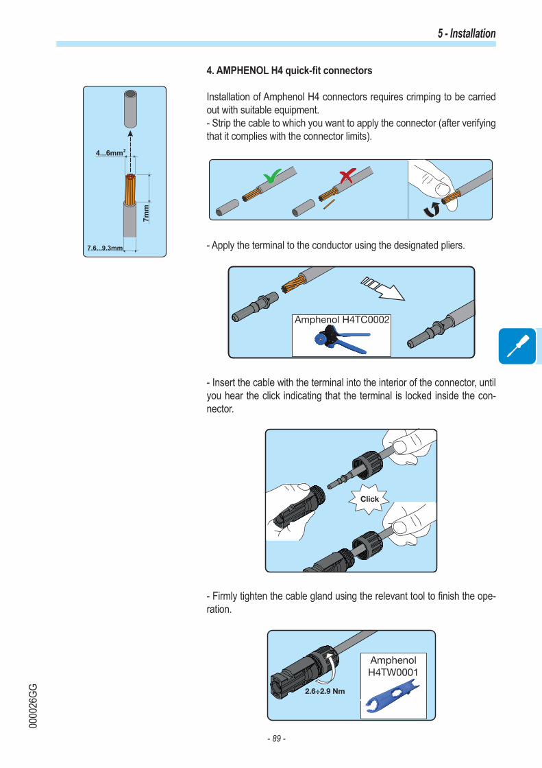
- 89 -
0000
26GG
5 - Installation
4. AMPHENOL H4 quick-fit connectors
Installation of Amphenol H4 connectors requires crimping to be carried out with suitable equipment.- Strip the cable to which you want to apply the connector (after verifying that it complies with the connector limits).
- Apply the terminal to the conductor using the designated pliers.
Amphenol H4TC0002
- Insert the cable with the terminal into the interior of the connector, until you hear the click indicating that the terminal is locked inside the con-nector.
Click
- Firmly tighten the cable gland using the relevant tool to finish the ope-ration.
2.6÷2.9 Nm
AmphenolH4TW0001
7mm
4...6mm
7.6...9.3mm
2

- 90 -
0005
66AG
5 - Installation
Communication and control signal connectionsEach communication and control service cable that must be connected inside the REACT-UNO must pass through one of the four service cable glands 51 available, named OUT-1, OUT-2, OUT-3 and OUT-4.
51
They are M20 service cable glands 51 and can take a cable with a diameter of 7 mm to 13 mm.
Two-hole gaskets are supplied to be inserted into the cable gland, which allow two separate cables with cross-section of up to 5 mm to pass through.
A B C

- 91 -
0005
66AG
5 - Installation
Description of communication and control signal terminal blocks
21
22
Description of communication and control signal terminal block 21 :Terminal
nameTerminal number Description
WIND 1, 3 External backup commandREM 2, 4 Remote external ON/OFF command+5V 5, 6 Auxiliary 5V positive
RS485M-B
7, 8 -T/R of the RS485 M-B (ModBus) communication line9, 10 +T/R of the RS485 M-B (ModBus) communication line11, 12 Reference (RTN) of the RS485 M-B (ModBus) communication line
RS485PC
13 -T/R of the RS485 PC communication line15 +T/R of the RS485 PC communication line17 Reference (RTN) of the RS485 PC communication line
RS485METER
14 -T/R of the RS485 METER communication line16 +T/R of the RS485 METER communication line18 Reference (RTN) of the RS485 METER communication line
19, 20 Ground terminal
Description of multifunctional relay terminal block 22 :Terminal
nameTerminal number Description
ALARMN.C. "Normally closed" terminal of multifunctional relay
C "Common" terminal of multifunctional relayN.O. "Normally open" terminal of multifunctional relay

- 92 -
0005
66AG
5 - Installation
External backup command connection
The REACT system is equipped with a Backup AC output that can be activated in different operating modes that can be set via a display menu. Some modes (“Manual 1”, “Manual 4” and “Auto 1”) demand that entry into backup is also subordinate to the state of terminal 1 compared to terminal 3 on the communication and control signal terminal block 21 .
When terminal 1 is brought to the same potential as terminal 3 (i.e. creating a short circuit between the two terminals on the terminal block), entry into backup mode is activated.
The condition of going into backup is shown on the display.
Since this is a digital input, there are no requirements to be observed as regards cable cross-section (it only needs to comply with the sizing requirement for passing cables through the cable glands and the terminal block).
Remote control connection
The connection and disconnection of the inverter to and from the grid can be controlled through an external control.
The function must be enabled in the relevant menu. If the remote control function is disabled, the switching on of the inverter is dictated by the presence of the normal parameters that allow the inverter to connect to the grid.
If the remote control function is on, besides being dictated by the presence of the normal parameters that allow the inverter to connect to the grid, switching on the inverter also depends on the state of terminal 4 (positive state of the remote ON/OFF) with regard to terminal 2 (ON/OFF remote negative) on the communication and control signal terminal block 21 .
When terminal 4 is brought to the same potential as terminal 2 (that is to say when a short circuit is created between the two terminals on the terminal block), the inverter is disconnected from the grid.The remote control OFF condition is shown on the display.
Since this is a digital input, there are no requirements to be observed as regards cable cross-section (it only needs to comply with the sizing requirement for passing cables through the cable glands and the terminal block).
21
Impostazioni
Remote ON/OFF
ENTER
Inverter
ENTER
Password 0000
ENTER
Impostazioni
Backup
ENTER
Inverter
ENTER
Password 0000
ENTER
21

- 93 -
0005
66AG
5 - Installation
+5V output connection
On the communication and control signal terminal block 21 there is auxiliary voltage of +5V.The maximum absorption permitted from this auxiliary power supply voltage is 100 mA.
Connection of RS485 M-B (Modbus) serial communication line
The RS485 M-B serial communication line on the communication and control signal terminal block 21 is reserved for the connection of the inverter to monitoring devices that communicate with the Modbus public communication protocol. On the communication and control signal terminal block 21 there are two connection points for each serial line signal (+T/R, -T/R and RTN) so as to be able to make a daisy-chain connection ("in-out") of multiple inverters.
Connection of a monitoring system to the RS485 M-B communication line consists of first connecting all the units in the chain in the “daisy-chain” (“in-out”) configuration, respecting corresponding signals, and then activating the communication line termination resistance in the last element in the chain by setting the switch for RS485 M-B line termination 20 (to the ON position).
The communication line must also be terminated on the first element of the chain which usually corresponds to the monitoring device.
RS485 M-B
MONITORING SYSTEMModbus
REACT
POWER ALARM GFI ESC UP DOWN ENTER
REACT-UNO
REACT-BATT
REACT
POWER ALARM GFI ESC UP DOWN ENTER
REACT-UNO
REACT-BATT
REACT
POWER ALARM GFI ESC UP DOWN ENTER
REACT-UNO
REACT-BATT
20
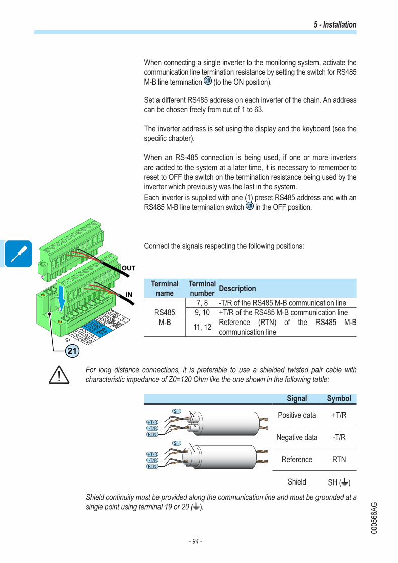
- 94 -
0005
66AG
5 - Installation
When connecting a single inverter to the monitoring system, activate the communication line termination resistance by setting the switch for RS485 M-B line termination 20 (to the ON position).
Set a different RS485 address on each inverter of the chain. An address can be chosen freely from out of 1 to 63.
The inverter address is set using the display and the keyboard (see the specific chapter).
When an RS-485 connection is being used, if one or more inverters are added to the system at a later time, it is necessary to remember to reset to OFF the switch on the termination resistance being used by the inverter which previously was the last in the system.Each inverter is supplied with one (1) preset RS485 address and with an RS485 M-B line termination switch 20 in the OFF position.
Connect the signals respecting the following positions:
Terminal name
Terminal number Description
RS485M-B
7, 8 -T/R of the RS485 M-B communication line 9, 10 +T/R of the RS485 M-B communication line
11, 12 Reference (RTN) of the RS485 M-B communication line
For long distance connections, it is preferable to use a shielded twisted pair cable with characteristic impedance of Z0=120 Ohm like the one shown in the following table:
Signal Symbol
-T/R+T/R
SH
RTN
-T/R+T/R
SH
RTN
Positive data +T/R
Negative data -T/R
Reference RTN
Shield SH ( )
Shield continuity must be provided along the communication line and must be grounded at a single point using terminal 19 or 20 ( ).
21
IN
OUT

- 95 -
0005
66AG
5 - Installation
Connection of RS485 PC serial communication line
The RS485 PC serial communication line on the communication and control signal terminal block 21 is reserved for connecting the inverter to advanced configuration software or monitoring devices that communicate with the proprietary "Aurora" communication protocol.
Connection of the REACT to advanced configuration software consists of first connecting all the units in a chain in the “daisy-chain” (“in-out”) configuration, respecting corresponding signals of the RS485 PC serial line, and then activating the communication line termination resistance in the last element in the chain by setting the switch for RS485 PC line termination 18 (to the ON position).
The communication line must also be terminated on the first element of the chain which usually corresponds to the monitoring device.
RS485 PC
REACT
POWER ALARM GFI ESC UP DOWN ENTER
REACT-UNO
REACT-BATT
REACT
POWER ALARM GFI ESC UP DOWN ENTER
REACT-UNO
REACT-BATT
REACT
POWER ALARM GFI ESC UP DOWN ENTER
REACT-UNO
REACT-BATT
RS485 > USB Software “Aurora
Manager”
RS 485 • HALF DUPLEX
RESETTX/RX
PWR OK
RTN
RX/D-
TX/D+
N.C.
USBB-Type
RS232/RS485
PVI-USB-RS232_485
RS232/485 Sel.=RS232
=RS485
RESET
TX/RX
PWR OK
USBB-Type
RS232/RS485
RS232/485 SEL.
RS232
RS485
RTN
RX/D-
TX/D+
N.C.
PVI-USB-RS232_485
18
When connecting a single inverter to the monitoring system, activate the communication line termination resistance by setting the switch for RS485 PC line termination 18 (to the ON position).
Set a different RS485 address on each inverter of the chain. An address can be chosen freely from out of 1 to 63.
The inverter address is set using the display and the keyboard (see the specific chapter).
When an RS-485 connection is being used, if one or more inverters are added to the system at a later time, it is necessary to remember to reset to OFF the switch on the termination resistance being used by the inverter which previously was the last in the system.Each inverter is supplied with one (1) preset RS485 address and with an RS485 PC line termination switch 18 in the OFF position.

- 96 -
0005
66AG
5 - Installation
17
IN
OUT
IN
OUT
(A)(B)
21
18
Cables connecting the RS485 PC line may use two different types of connection:
• Connection of the conductors using the terminals of the communication and control signal terminal block 21 (+T/R, -T/R, and RTN)
Connect the signals respecting the following positions:
Terminal name
Terminal number Description
RS485PC
13 -T/R of the RS485 PC communication line
15 +T/R of the RS485 PC communication line
17 Reference (RTN) of the RS485 PC communication line
For long distance connections, it is preferable to use a shielded twisted pair cable with characteristic impedance of Z0=120 Ohm like the one shown in the following table:
Signal Symbol
-T/R+T/R
SH
RTN
-T/R+T/R
SH
RTN
Positive data +T/R
Negative data -T/R
Reference RTN
Shield SH ( )
Shield continuity must be provided along the communication line and must be grounded at a single point using terminal 19 or 20 ( ).
• Connection of conductors with RJ45 connectors 17
The two RJ45 connectors (A) and (B) available for RS485 PC communication, are equivalent to each other and can be used interchangeably for the arrival or for the output of the line when creating the daisy chain connection of the inverters.
Table: crimping diagram for RJ45 connectorsPin N° Function
1 8
3 +T/R5 -T/R7 RTN
1, 2, 4, 6, 8 not used
Use a connector with metal body to provide cable shield continuity!
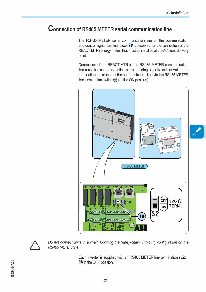
- 97 -
0005
66AG
5 - Installation
Connection of RS485 METER serial communication line
The RS485 METER serial communication line on the communication and control signal terminal block 21 is reserved for the connection of the REACT-MTR (energy meter) that must be installed at the AC line's delivery point.
Connection of the REACT-MTR to the RS485 METER communication line must be made respecting corresponding signals and activating the termination resistance of the communication line via the RS485 METER line termination switch 19 (to the ON position).
RS485 METER
REACT
POWER ALARM GFI ESC UP DOWN ENTER
REACT-UNO
REACT-BATT
REACT-MTR-1PH
SUTATS
TSE T
ER
USAEM
INPUT :
110/230 V
50/60 Hz
10 mA max
19
Do not connect units in a chain following the "daisy-chain" ("in-out") configuration on the RS485 METER line
Each inverter is supplied with an RS485 METER line termination switch 19 in the OFF position.

- 98 -
0005
66AG
5 - Installation
Connect the signals respecting the following positions:
Terminal name
Terminal number Description
RS485METER
14 -T/R RS485 METER communication line16 +T/R RS485 METER communication line
18 Reference (RTN) of the RS485 METER communication line
For long distance connections, it is preferable to use a shielded twisted pair cable with characteristic impedance of Z0=120 Ohm like the one shown in the following table:
Signal Symbol
-T/R+T/R
SH
RTN
-T/R+T/R
SH
RTN
Positive data +T/R
Negative data -T/R
Reference RTN
Shield SH ( )
Shield continuity must be provided along the communication line and must be grounded at a single point using terminal 19 or 20 ( ).
21

- 99 -
0005
66AG
5 - Installation
Configurable Relay connection (ALARM)
The inverter is equipped with a multifunction relay with configurable activation. It can be connected with normally open contact (being connected between the NO terminal and the common contact C) and with normally closed contact (being connected between the NC terminal and the common contact C).
Different types of devices (light, sound, etc.) can be connected to the relay, provided they comply with the following requirements:
Alternating currentMaximum Voltage: 240 Vac Maximum Current: 1 A
Direct currentMaximum Voltage: 30 Vdc Maximum Current: 0.8 A
Cable requirementsExternal diameter: from 5 to 17 mmConductor cross-section: from 0.14 to 1.5 mm2
This contact can be used in different operating configurations that can be selected by accessing the "Inverter → Settings → Alarms" menu. The selectable modes are described in the paragraph about the "Inverter Menu → Settings".
22
Impostazioni
Allarme
ENTER
Inverter
ENTER
Password 0000
ENTER

- 100 -
0005
66AG
5 - Installation
Connection to load management system (Load Manager Box)
The REACT system is provided with four relays (incorporated into a Load Manager Box) to manage external loads. The types of users that can be connected to the four relays are subdivided into two types:
• TYPE 0 can be activated ON-OFF (e.g. Lights, heaters)• TYPE 1: Switchable (e.g. Lights, Heaters, Heat Pumps, Boilers)
Connections to the Load Manager Box must be made on the two terminal blocks on the lower part, respecting the corresponding terminals:
Terminal Relay
1 and 2 A
3 and 4 B
5 and 6 C
7 and 8 D
The relays are not power components and must be used, for example, to control a power relay installed outside the REACT system.
If the external device is connected directly to the relays, the following characteristics must be respected:
Technical data (for each relay)Maximum Power 250W
Maximum voltage: 250Vac
Maximum current: 1A
Protection Fuse (non-resettable)
For further details relating to the external load management system and the configurations required for its operation, refer to the document “REACT -3.6/4.6-TL EXTERNAL LOADS MANAGEMENT – Load Manager Description” available on website www.abb.com/solarinverters.
LOAD MANAGER BOX
87D
5 6C
3 4B
1 2A
J1
5
1
6
2
7
3
8
4
3
4
1
2
5
6
7
8RTN
+12V
A
TTL
TTL
TTL
TTL
B
C
D

- 101 -
0000
29BG
General conditions One of the first rules for preventing damage to the equipment and to the operator is to have a thorough knowledge of the instruments. We, therefore, advise that you carefully read this manual. If you are not sure about any information in this manual, please ask ABB Service for more detailed information.
Do not use the equipment if:- you do not have suitable qualifications to work on this equipment or similar products;- you are unable to understand how it works;- you are not sure what will happen when the buttons or switches are operated;- you notice any operating anomalies;- there are doubts or contradictions between your experience, the manual and/or other operators.
ABB cannot be held responsible for damage to the equipment or the operator if it is the result of lack of knowledge, insufficient qualifications or lack of training.
6Instruments

- 102 -
0005
67AG
6 - Instruments
Display, keyboard and status LEDThe system is equipped with a graphic display and status LEDs which make it possible to immediately understand the operating status of the system. In addition, on the display it is possible to make configurations, view statistics and information relating to all the components which make up the system itself. Navigation of the display menus is made possible by a keyboard.
Description of symbols and display fields
Using the display, operating parameters for the equipment are shown. warnings, alarms, channels, voltages, etc. During operation, the display behaves dynamically, which allows some information to be displayed cyclically (see relevant chapter).
b02 b08 b23b01 b03
b09 b11 b10
b20
b12 b13 b14 b15 b16 b17 b18 b19
b21 b24b22 b25 b26
b04 b06 b07b05
Ref. Descriptionb01 Indicates the transmission and reception of data through the RS485 line.b02 Indicates the presence of the RS485 communication line.b03 Indicates the presence and enablement of the WiFi communication line.b04 Reports an active power derating for out-of-range input voltage or power restrictions set by the grid
manager or by the displayb05 Reports a power derating due to high internal temperatureb06 Instantaneous power fed into the gridb07 MPPT SCAN function activeb08 Text lines to cyclically display the inverter parameters, error codes, and for menu navigationb09 Area of the display where it is possible to graphically represent one of the parameters monitored by the
system (which can be selected from display menus)

- 103 -
0005
67AG
6 - Instruments
Ref. Descriptionb10 Displays the total energy from the inverter installationb11 Shows the energy produced throughout the dayb12 Indicates that the PV generator voltage is greater than the inverter Vstartb13 Indicates the input channel (or the list) for which the data relating to the input parameters are shown in
the field b22b14 Indicates the DC/DC input circuit part (Booster)b15 Indicates the DC to AC conversion circuit (inverter)b16 Indicates the serial communication line between the REACT system and the METER. The icon in the
form of an X, if lit, indicates the lack of communication between the two devicesb17 Indicates the METERb18 Indicates the output voltage phase (or the list) for which the data relating to the output parameters are
shown in the field b25b19 Indicates the status of the grid voltage:
Icon absent: no grid voltageFlashing icon: grid voltage present but outside the parameters set by the grid standardIcon present: Grid voltage present and within parameters set by the standard grid
b20 Cyclic display of the input parametersb21 Cyclic display of storage parameters (batteries)b22 Indicates the status of the battery chargeb23 When the ENTER key is pressed, cyclic display of the parameters can be:
blocked ( ) or cyclic ( ) b24 Cyclic display of the output parametersb25 Cyclic display of the parameters relating to the domestic loadsb26 Representation of domestic loads
Depending on the operating conditions of the system, the graphics of the display behave dynamically. Below are some examples.
Example 1:
- Photovoltaic production of 4.5kW. This production is distributed in:- 3kW is supplied to the house to meet the power requirement of domestic loads- 1kW is used to charge the battery (the line between the icon representing the inverter has the arrow pointed towards the battery. This means that the battery is charged)- 0.5kW of surplus power produced is fed into the grid (the line between the symbol representing the meter and the supply point has the arrow pointed towards the grid. This means that the power is being fed into the grid)

- 104 -
0005
67AG
6 - Instruments
Example 2:
- Photovoltaic production of 2.5kW. - 2.5kW is supplied in full to the house to meet the power requirement of 3kW for the domestic loads- 0.5kW is supplied to the house to meet the power request (the line between the symbol representing the inverter has the arrow pointed towards the inverter. This means that the battery is being charged)- 0.0kW of power is being fed into or taken from the grid
Example 3:
- Photovoltaic production absent.- 3kW is required by the house. To meet the power requirement for domestic loads the power is drawn from:- 1.3kW is supplied from the storage system to the house (the line between the symbol representing the inverter and the battery has the arrow pointed towards the inverter. This means that the battery is being charged)- 1.7kW is drawn from the grid (the line between the symbol representing the meter and the grid has the arrow pointed towards the meter. This means that the power is drawn from the grid).
Example 4:
- Photovoltaic production absent.- 3kW is required by the house.- 0.0kW is supplied by the storage system to the house since the batteries are low- 3.0kW of power is drawn from the grid (the line between the symbol representing the meter and the grid has the arrow pointed towards the meter. This means that the power is drawn from the grid).

- 105 -
0005
67AG
6 - Instruments
The display has a graphics area (summary) b11 where it is possible to graphically represent one of the parameters monitored by the system. The type of graphic to be viewed can be selected through display menus (Display→Settings→Power Graph)
- Graphic “PW Vs GRID”This diagram shows the energy drawn (area highlighted in red) or fed into the grid (area highlighted in green).Each dot represents a value of 500Wh (full scale ±5KWh) of average energy. The time scale is 24 hours in 1 hour intervals
- Graphic “PW Vs BATT”This diagram shows the energy discharged (area highlighted in red) or charged (area highlighted in green) by the battery.Each dot represents 300Wh (full scale ±3KWh) of average energy. The time scale is 24 hours in 1 hour intervals
- Diagram “BATTERY SOC”This diagram shows the state of charge of the battery.Each dot represents 5% (full scale 100%). The time scale is 24 hours in 1 hour intervals
- Diagram “PW TO LOAD”This diagram shows the energy used to fulfil the request from domestic loads.Each dot represents a value of 250Wh (full scale 5KWh) of average energy. The time scale is 24 hours in 1 hour intervals
- Diagram “REACT PROD”This diagram shows the total energy production of the system.Each dot represents 300Wh (full scale 6KWh) of average energy. The time scale is 24 hours in 1 hour intervals
The 5 types of diagram can be displayed cyclically on the display by selecting the “Auto” mode (menu Display→Settings→Power Graph).

- 106 -
0005
67AG
6 - Instruments
POWER ALARM GFI ESC UP DOWN ENTER
By pressing the ENTER key, cyclic display of the parameters can be:
Locked Cyclical
Allows you to confirm the operation or enter the data set.
Allows you to read through the data in descending order on the display, or when inserting, correct the value set by reducing it.
This allows you to read the data on the display by scrolling upwards, or to increase the set value to correct it during data entry.
Allows you to exit the current mode
The “GFI” (ground fault) LED indicates that the inverter has detected a ground fault in the DC side photovoltaic generator. When this fault is detected, the inverter immediately disconnects from the grid and displays the relevant error indication on the LCD display. In addition, the red LED may indicate also errors relating to the operation of the battery unit.
Indicates that the inverter has detected an anomaly. The type of problem will be shown in the display
Indicates that the inverter is functioning correctly.When the unit is commissioned, while the grid is checked, this LED blinks. If a valid grid voltage is detected, the LED remains continuously lit, as long as there is sufficient sunlight to activate the unit. Otherwise, the LED will continue to blink until the sunlight is sufficient for activation. In this phase, the LCD display shows the message “Waiting Sun...”
Description of the keyboard and status LEDs
Using the combination of the keyboard keys below the display, values can be set or data can be viewed by scrolling.
In their various possible multiple combinations, the LEDs can indicate conditions that are different from the original single one; see the various descriptions given in the manual.
In their various possible multiple combinations, the buttons allow you to obtain actions that are different from the original single one; see the various descriptions given in the manual.

- 107 -
0000
31BG
General conditions Before checking the operation of the equipment, it is necessary to have a thorough knowledge of the Instruments chapter 6 and the functions that have been enabled in the installation process.The equipment operates automatically without the aid of an operator; the operating state should be controlled through the equipment’s instrumentation.
The interpretation or variation of some data is reserved exclusively for specialized and qualified staff.
The incoming voltage must not exceed the maximum values shown in the technical data, section 2 in order to avoid damaging the equipment. Consult the technical data for further details.
During operation, check that the environmental and logistical conditions are correct (see installation chapter 5). Make sure that enviromental and logistical conditions have not changed over time and that the equipment is not exposed to adverse weather conditions.
7Operation

- 108 -
0005
91AG
7 - Operation
Monitoring and data transmission
User interface
The inverter is able to provide information about its operation through the following instruments:• Warning lights (luminous LEDs)• LCD display showing operating data• Mobile app and webserver• Data transmission on the dedicated RS-485 serial line. The data can be collected by a PC or a data logger equipped with an RS-485 port. Con-tact the ABB support service with any queries about device compatibility.
Measurement tolerance
The data supplied by the inverter may differ from measurements taken by certified measuring instruments (e.g. output meters, multimeters and grid analysers); since the inverter is not a measuring instrument it has wider tolerances for the measurements it makes.The tolerances are generally:±5% for real-time measurements with output power below 20%±3% for real-time measurements with output power above 20%±4% for all statistical data.

- 109 -
0005
68AG
7 - Operation
CommissioningDo not place objects of any kind on the inverter during operation!Do not touch the heat sink while the inverter is operating!Some parts may be very hot and cause burns.
Before proceeding with commissioning, make sure you have carried out all the checks and verifications indicated in the section on preliminary checks. Also make sure you have instal-led all the front covers; if this is not so, the REACT system will report an error when launched.
Commissioning is carried out via Wi-Fi connection to the REACT's in-ternal webserver. Initial setup of the REACT system must therefore be carried out via a tablet, notebook or smartphone with a Wi-Fi connection. To establish the connection and operate with the REACT, it is necessary to power up the inverter by connecting its input to the DC voltage of the photovoltaic panels or its output to the AC grid.
• Close the DC disconnect switch to supply the inverter with input voltage from the photovoltaic generator.
Where the system is powered by the photovoltaic generator (DC) make sure irradiation is stable and adequate for the REACT's commissioning procedure to be completed.
• Close the (external) AC disconnect switch downstream of the inverter thus applying grid voltage to the inverter
• Once powered, the REACT will automatically create a Wi-Fi network that will be visible as an Access Point from the user devices previously men-tioned (tablet, smartphone, etc.) and will show the symbol of a wrench on the display to indicate that initial system setup must be carried out.
• Enable the Wi-Fi connection on the device which is being used for the board setup (tablet, smartphone or PC) and connect it to the Access Point created by the REACT system approx. 60 seconds after its switch-on.
The name of the Wi-Fi network created by the system (approx. 60 se-conds after its switch-on), that the connection should be established with, will be:
ABB-SSSSSS-PPPP-WWYY
Field DescriptionSSSSSS Serial numberPPPP Product codeWW Week of manufactureYY Year of manufacture

- 110 -
0005
68AG
7 - Operation
Once the network has been created by the inverter, start up the connec-tion and wait for the device to complete the procedure (a password is not required for the Wi-Fi network).
ABB-123456-3N08-0115
The screens shown below pertain to a tablet with the Android operating system. Screens on other devices or operating systems may differ.
• Open an internet browser and enter the pre-set IP address 192.168.117.1 to access the setup pages (web user interface) A guided setup procedure will open that will enable you to impose the necessary settings for correct commissioning of the REACT system.
The setup is broken down into 7 steps:
• Assisted setup - STEP 1 Settings of:- menu language- Time zone- Grid standardEach of the above-mentioned settings has a drop-down menu from which preset parameters can be selected.
Press "Avanti" (Next) at the end of the settings to move on to setup step 2.
Setting the language refers to the webserver language, not the language of the display me-nus on the REACT.It might take several minutes to save the Grid Standard settings, then the inverter will carry out a restart. Once the Grid Standard has been set it can be changed during the first 24 hours of operation; after that time it will be necessary to obtain the second-level password to access the “Inverter>Settings>Service> Reset Country S.” menu.

- 111 -
0005
68AG
7 - Operation
• Assisted setup - STEP 2 Setting Wi-Fi networkThis setup stage relates to connecting the REACT system to a Wi-Fi network.
The parameters relating to the home Wi-Fi network (set on the router) that must be known and set during setup are:
- IP address acquisition type: DHCP or Static. If you select the DHCP function (default setup) the router will automati-cally assign an IP address to the REACT whenever it tries to connect to the user network. With Static, the user can assign a fixed IP address to the system.the data which has to be entered in order for IP static address assigning to take place will appear. Complete the additional fields at the bottom of the screen (all the fields are mandatory with the exception of the secon-dary DNS server).
- SSID: name of Wi-Fi network. Identify and select your own (home) Wi-Fi network from all those shown in the SSID field (you can carry out a new search of the networks that can be detected with the "Aggiorna" (Update) button).Once the network has been selected, confirm.
- Password: Wi-Fi network password.Enter the password for the destination network (if necessary) and start the connection attempt (it will take a few seconds).
If it is not possible to connect the REACT to the Wi-Fi network, or you do not want to do so, select the "Procedi in modalità AP" (Continue in AP mode) button. In this situation, communi-cation between the REACT and the tablet/smartphone/PC will continue to be point to point.
Once the REACT is associated with the domestic Wi-Fi network, the user must reconnect the tablet/smartphone/PC to the same Wi-Fi network as the REACT system. The key remains locked until this connection is esta-blished.
The message provides the links required for the second stage of the installation procedure (corresponding to the IP address assigned by the home Wi-Fi network router to the REACT system). Both links can be used each time you want to access the web server inside the board, with the board connected to the home network.
The IP address assigned may vary for reasons connected to the Wi-Fi home router setup (for example, a very brief DHCP lease time). If verification of the address is required, it is usually possible to obtain the client list (and the corresponding IP addresses) from the Wi-Fi router administration panel.

- 112 -
0005
68AG
7 - Operation
From now on the REACT system is connected to the home Wi-Fi net-work.
The Wi-Fi board automatically disables its access point with the name ABB-SSSSSS-PPPP-WWYY (no longer necessary).
If the REACT system loses the connection with the home Wi-Fi network (and therefore, loses the internet connection), it will once again enable its own access point.
The most common causes of losing connectivity might be: different Wi-Fi network password, faulty or unreachable router, replacement of router (different SSID) without the necessary setting updates.
• Assisted setup - STEP 3 Setting date and time
Fill in the fields relating to date, time and time zone.
If the inverter is connected to the internet, the settings will be filled in automatically and it will not be possible to edit the fields.
Date and time
The date and time shown are provided by the inverter or have been entered manually.
Please enter the correct values if requested.
The date and time will again be synchronised automatically when the connection to the internet and/or the NTP server are available.
Date
Time
Time zone
SaveBack

- 113 -
0005
68AG
7 - Operation
• Assisted setup - STEP 4 Setting general data relating to the system, the installer and the client.
- System data to monitor (system name, address, town, etc.).
Latitude and Longitude are fundamental parameters; incorrect values could render it impossible for the system to operate correctly.If the system is connected to the internet, the Longitude and Latitude fields are filled in automatically. Check that they are correct
Administrator password.
Pay particular attention and make a note of the administrator password that will enable you to do advanced system setup.
User password.
Pay particular attention and make a note of the user password that will enable you to do basic system setup. The "No Password" box can be selected if you do not want to enter any password to access the user level (recommended)

- 114 -
0005
68AG
7 - Operation
• Assisted setup - STEP 5Setting type of METER and REACT-BATT number.
- Type of REACT-MTR:1. No meter (where system is installed without meter)2. REACT-MTR-1PH (single-phase)3. REACT-MTR-3PH (three-phase)If the METER is three-phase the phase to which the REACT system is connected must be selected.
- Type of battery unit (REACT-BATT) installed:1. No battery (when the REACT system is used without a battery). Select the number of battery units installed.2. REACT-BATT-AP1
Once the type of meter (REACT-MTR) and number of battery units (RE-ACT-BATT) are selected, the system will check the settings entered, gi-ving confirmation or an error message if the setup was incorrect:
The guided system setup can be continued only if no errors are detected in the settings made.

- 115 -
0005
68AG
7 - Operation
• Assisted setup - STEP 6 Settings related to energy management.
Energy consumption- Power committed: setting related to the power of the electrical energy supply expressed in kW.
Energy management policy- Grid standard: set the grid standard of the country in which the REACT is installed- Energy management policy: set the way in which you want to manage the energy produced by the PV plant, choosing from the following:
Management mode Description
Maximisation of self-consumption
The REACT system automatically manages power flows in order to maximise self-con-sumption. Priority: Domestic loads, temporary storage in battery, and lastly, power fed into grid.
Zero injection
The REACT system automatically manages power flows in order to avoid the injection of energy to the grid. If the meter is disconnected or not working the REACT's output power is restricted to zero in order to avoid accidental input to the grid.
Adjustable
The REACT system automatically manages power flows in order to avoid feeding the grid with power greater than:
PDC x Plim
where PDC is the power of the photovoltaic ge-nerator (W) and Plim is the output power limit with respect to PDC(%). The two variables can be set during the REACT commissioning sta-ge.
KfW
The REACT system automatically manages power flows in order to fulfil the requirements of the KfW incentive programme available in Germany.
- Photovoltaic power PDC: insert the power value of the photovoltaic sy-stem (kWp) installed- Output power restriction compared to PDC: percentage AC power restric-tion with reference to power installed
Electrical energy tariffs- Currency: select the currency of the country in which the system is installed- Average energy cost (€/kWh): enter an average value for the energy cost that is shown on the bill- Input incentive (€/kWh): enter the value of the incentive (if applicable) for energy fed into the grid.
SaveBack
Energy Management
Energy consumption
Energy management policy
Electrical energy tariffs
Power committed
Grid standard
Type
Maximisation of self-consumption
Power installed PDC
Lim. Output power compared to PDC
Currency
Average energy cost
Input incentive
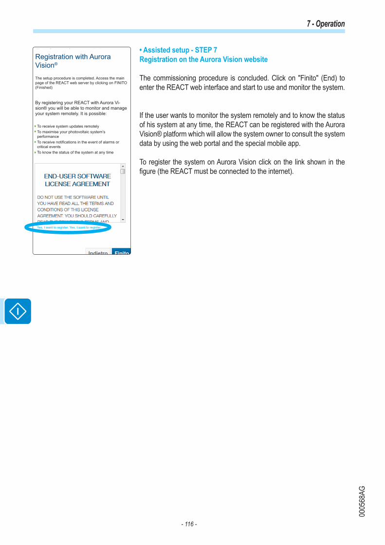
- 116 -
0005
68AG
7 - Operation
• Assisted setup - STEP 7Registration on the Aurora Vision website
The commissioning procedure is concluded. Click on "Finito" (End) to enter the REACT web interface and start to use and monitor the system.
If the user wants to monitor the system remotely and to know the status of his system at any time, the REACT can be registered with the Aurora Vision® platform which will allow the system owner to consult the system data by using the web portal and the special mobile app.
To register the system on Aurora Vision click on the link shown in the figure (the REACT must be connected to the internet).
Registration with Aurora Vision®
The setup procedure is completed. Access the main page of the REACT web server by clicking on FINITO (Finished)
To receive system updates remotelyTo maximise your photovoltaic system’s performanceTo receive notifications in the event of alarms or critical eventsTo know the status of the system at any time
Yes, I want to register. Yes, I want to register.
By registering your REACT with Aurora Vi-sion® you will be able to monitor and manage your system remotely. It is possible:

- 117 -
0005
68AG
7 - Operation
Updating the firmware from an SD card
The firmware can be easily updated by means of an SD Card (4GB ma-ximum capacity)The latest firmware version is available from the download area of the website www.abb.com/solarinverters or from https://registration.abbsolarinverters.com
Perform the update during good irradiation conditions (avoid the dawn and dusk hours)
• Format the SD card with a "FAT32" File System• Save the (.tib) update file on the SD Card. The file must not be com-pressed and/or nested inside folders• Switch the inverter off by physically disconnecting the AC and DC side, as well as any voltages connected to the multi-function relay, then open the inverter front cover. • Insert the SD Card into the memory card holder• Start the inverter • The inverter display prompts for confirmation to launch the update
The update procedure starts automatically. Do not carry out any operation on the inverter during the update process
• Once the procedure is completed, the display shows the outcome of the update

- 118 -
0005
92AG
7 - Operation
LED behaviourThe LEDs on the front panel can behave in different ways depending on the inverter's operating state.
All possible LED activation combinations are shown in the following table. In particular, each LED could behave in one of the following ways:
= LED on = LED flashing (slow) = LED flashing (fast) = LED off = Any one of the conditions described above
LED status Operating stategreen: yellow: red:
Firmware programmingThe inverter firmware is being programmed
green: yellow: red:
Night mode (inverter automatically switches off) The inverter is in night time switch-off mode (input voltage less than 70% of the set start-up voltage).
green: yellow: red:
Inverter initialisationThis is a transitional state due to the verification of the operating conditions. During this stage the inverter checks that the conditions for connecting to the grid are met.
green: yellow: red:
The inverter is connected and feeds power into the gridNormal operation. During this stage, the inverter automatically tracks and analyses the photovoltaic generator's maximum power point (MPP).
green: yellow: red:
Disconnection from the gridIndicates no grid voltage. This condition does not allow the inverter to connect to the grid (the inverter display shows the message "Missing Grid").
green: yellow: red:
Indication of Warning (W message codes) or Error E warning codes)Indicates that the inverter control system has detected a warning (W) or error (E). The display shows a message indicating the type of problem found (see Alarm messages).
green: yellow: red:
• Ventilation anomalyIndicates an anomaly in the operation of the internal ventilation system that could limit output power at high ambient temperatures.• Failed association of internal inverter components (after replacement)Indicates that the installed wiring box (only if replacing the inverter) was already associated with another inverter and that it cannot be associated with the new inverter.• Overvoltage surge arresters triggered (where fitted)Indicates that any class II overvoltage surge arresters installed on the AC or DC side have been triggered • String protection fuses triggered (where fitted)Indicates that one or more input string protection fuses that may be installed have been triggered• Autotest (for Italian grid standards only) The inverter is performing an Autotest

- 119 -
0005
92AG
7 - Operation
LED status Operating stategreen: yellow: red:
Backup operating modesDepending on the different modes that can be set, and after detecting the conditions required for the output to be enabled, the system went into backup operation
green: yellow: red:
Blackstart operating mode
green: yellow: red:
• Anomaly in the insulation system of the photovoltaic generatorIndicates that a leakage to ground from the PV generator has been detected, causing the inverter to disconnect from the grid. • Indicates an operating anomaly in the battery unit• Front cover openThe sensor located inside the equipment warns that the front cover is not on or not correctly installed. This condition blocks the commissioning of the equipment.
Specifications on the behaviour of the LEDs
In correspondence to each state of the inverter indicated by the constant or intermittent lighting of the specific LED, the display 07 also shows a message identifying the operation which is being carried out or the defect/anomaly recorded (see specific chapter).
In the event of malfunctioning, it is extremely dangerous to try to eliminate the fault personally. The instructions below must be followed scrupulously; if you do not have the necessary experience and training to intervene safely, please contact a specialist.
Red GFI LED
When the red LED comes on, first try to reset the warning by pressing the ESC button on the keyboard 08 .Should the inverter reconnect normally to the grid, the fault was due to temporary phenomena.
You are advised to have the plant inspected by the installer or a specialist should this malfunction occur repeatedly.
Should the inverter not reconnect to the grid it is necessary to isolate it (DC side, AC side, and any batteries), then contact the installer or authorised centre to repair the fault to the photovoltaic generator.

- 120 -
0005
69BG
7 - Operation
Description of the menusThe ABB inverters are equipped with a graphical display 07 , consisting of 2 lines of 16 characters each, which can be used to:• Display the operating status of the inverter and the statistical data• Display service messages for the operator• Display the alarm and fault messages• Change the inverter settings.
General information
While the inverter is operating, the display shows various items of infor-mation on the main parameters measured, the operating conditions and the inverter's operating status.The sequence of screens displayed is shown below, with a description of the parameters monitored.
Alarm descriptionWarning/Error xxx Inverter OK
Mon 22 Jan 15:55
E-day xxx.xkWh$-day xx.xEUR
E-tot xxx.xkWhE-par xxx.xkWh
Pout xxxxWLim XX% Pnom
Psetpoint xxx%
Regulation TypeCOSp x.xxx
DOWN UP
DOWN UP
DOWN UP
Backup: xxxxxxx
xxxxW XXXX
DOWN UP
DOWN UP
DOWN UP
DOWN UP
Ppk xxxxW Ppk-Day xxxxW
DOWN UP
Vgrid xxxV
Igrid xx.xVFgrid xx.xxHz
DOWN UP
Riso xx.xM©Ileak x.xxxxA
Vbulk xxxVVbulk_m xxxV
DOWN UP
DOWN UPDOWN UP
Vin1 xxxV Iin1 xx.xA
Vin2 xxxV Iin2 xx.xA
Pin1 xxxxW
Pin2 xxxxW DOWN UP
DOWN UP
DOWN UP
DOWN UPDOWN UP
DOWN UP
DOWN UP
Vin xxxV Iin xx.xA
Pin xxxxW
DOWN UP
Inverter status: The code for any malfunction will be displayed.Date and time as set on the inverter
Presence of Errors/Warnings
NoErrors/Warnings
E-day: Daily energy produced $-day : Today's savings/earnings
Value and graphical representation of the energy fed into or taken from the grid. Power fed into grid=bars and arrow towards symbol +. Power taken from grid=bars and arrow towards the symbol -. Zero exchange with the grid= central down arrow with words ZERO NET POWER.
E-tot: Energy produced since the inverter was commissionedE-par: Partial energy produced since the last reset
Backup: Backup mode set
Pout: Instantaneous output powerLim XX%: Limitation applied to the nominal output power
Psetpoint: Intervention threshold for the output nominal power limit set
*
*
Regulation Type: Mode for regulating the reactive power currently set COSp: Phase difference set for feeding in reactive power
Ppk: Maximum output power peak since the inverter was commissionedPpk-Day: Maximum daily output power peak
Vgrid: Measurement of output voltage
Igrid: Measurement of output currentFgrid: Measurement of output frequency
Riso: Insulation resistance on DC input side (PV generator)Ileak: Leakage current on DC input side (PV generator)
Vbulk: Internal voltage at the bulk capacitor terminals (booster circuit)Vbulk_m: Internal voltage at the bulk capacitor mid-point (booster circuit)
* Present only if the value or mode have been set
Vin 1: Input voltage channel 1 Vin: Input voltageIin 1: Input current channel 1 Iin: Input current
Vin 2: Input voltage channel 2Iin 2: Input current channel 2
Pin1: Instantaneous input power channel 1 Pin: Instantaneous input power
Pin2: Instantaneous input power channel 2
Independent inputs
Parallel inputs

- 121 -
0005
69BG
7 - Operation
The sequence of screens displayed is shown below, with a description of the parameters monitored.
When the icon appears on the display, information is shown cyclically; if the padlock icon is displayed it means that information display is locked and the UP and DOWN buttons can be used to scroll through the screens of information instead.
Backup:xxxxx
VoutBkp xxxVIoutBkp xxxA
PoutBkp xxxW
DOWN UP
DOWN UP
Vin1 xxxV Iin1 xx.xA
Vin2 xxxV Iin2 xx.xA
Pin1 xxxxW
Pin2 xxxxW
DOWN UP
DOWN UP
DOWN UP
DOWN UPDOWN UP
Vin xxxV Iin xx.xA
Pin xxxxW
DOWN UP
Alarm descriptionWarning/Error xxx Inverter OK
Mon 22 Jan 15:55DOWN UPDOWN UP
Inverter status: The code for any malfunction will be displayed.Date and time as set on the inverter
Presence of Errors/Warnings
NoErrors/Warnings
Pout: Instantaneous output power (backup)
Backup: operating modes of backup output
Vin 1: Input voltage channel 1 Vin: Input voltageIin 1: Input current channel 1 Iin: Input current
VoutBkp: Measurement of output voltage (backup)IoutBkp: Measurement of output current (backup)
Vin 2: Input voltage channel 2Iin 2: Input current channel 2
Pin1: Instantaneous input power channel 1 Pin: Instantaneous input power
Pin2: Instantaneous input power channel 2
Independent inputs
Parallel inputs

- 122 -
0005
69BG
7 - Operation
Menu structure
> Statistics
> Self consumpti.
> Self sufficien.
> Ener. from grid
> Ener. to grid
> Ener. to load
> PV en. to load
> PV ener.
> Settings
> Info
> Measures
> Set time
Password 0000
> Set cash
> Set RS485 com
> Country Select
> New password
> SD Update Info
> Energy Policy
Inverter
> Statistics
> Settings
> Vstart
> Input mode
> Input UV Delay
> Service
> Info
> Part No.
> Serial No.
> Firmware
> Remote ON/OFF
> MPPT Scan
> Power Limit.
> Reactive Power
> Autotest
> Alarms
> Backup
> Lifetime
> Partial
> Today
> Last 7 days
> Last 30 days
> Last 365 days
> User Period
Display
> Settings
> Backlight
> Contrast
> Buzzer
> Power Graph
> Language
Meter
> Settings
> Info
> Type
> Part No.
> Serial No.
> FW Rel.
> Measures
> Voltage
> Active Power
> Line current
> Load current
> Frequency
> Meter model
> Meter Address
> Meter com
Battery
> General
**
****Load Manager
> info
> Relay Status
****WIFI Logger
> Settings
> Info
> Part No.
> Serial No.
> View IP
> View Mode
> Restore AP
*
System
****
Password 0000
Password 0000 Password 0000 > Settings
> Info
> Nom. Cap
> Measures
> Ibat
> Vbat
> Pbat
> RE
> SOC
> SOH
> RT
> Battery Model
> Battery Packs
Password 0000
> Pack 1
> Settings
> Info
> Device Name
> Serial No.
> FW Rel.
> Nom. Capacity
> Init. Capacity
> Status
> Warning
> Alarms
> Measures
> Pack 1 enable
> Smoke Sensor
Password 0000
> Statistics
> Energy dischar.
> E-day
> E-7d
> E-30d
> E-365
> E-tot
> Ibat
> Vbat
> Pbat
> Tbat
> FCC
> RC
> RE
> TED
> SOC
> SOH
> TUT
> TDT
> RT
> CC
(*): Available only if SD Card is inserted.
(**): Available for the Italian country standard only. Re-fer to the section on this topic in the manual.

- 123 -
0005
69BG
7 - Operation
System Menu
By selecting the System menu, the following menus can be accessed:
System > Statistics1. Self consumpti.
This section of the menu displays the statistics relating to self-con-sumption (expressed as a %). In particular:• SC-day: self-consumption today• SC-7d: self-consumption for last 7 days• SC-30d: self-consumption for last 30 days• SC-365d: self-consumption for last 365 days• SC-tot: total self-consumption
2. Self sufficien.This section of the menu displays the statistics relating to energy self-sufficiency (expressed as a %). In particular:• SS-day: self-sufficiency today• SS-7d: self-sufficiency for last 7 days• SS-30d: self-sufficiency for last 30 days• SS-365d: self-sufficiency for last 365 days• SS-tot: total self-sufficiency
3. Ener. from gridThis section of the menu displays the statistics relating to the energy taken from the grid. In particular:• E-day: energy taken from grid today • E-7d: energy taken from grid in last 7 days • E-30d: energy taken from grid in last 30 days• E-365d: energy taken from grid in last 365 days• E-tot: total energy taken from grid
4. Ener. to gridThis section of the menu displays the statistics relating to the energy taken from the grid. In particular:• E-day: energy fed into the grid today • E-7d: energy fed into the grid in the last 7 days• E-30d: energy fed into the grid in the last 30 days• E-365d: energy fed into the grid in the last 365 days• E-tot: total energy fed into the grid
5. Ener. to loadThis section of the menu displays the statistics relating to the energy used to fulfil the requests from residential loads. In particular:• E-day: energy used for residential loads today • E-7d: energy used for residential loads in last 7 days• E-30d: energy used for residential loads in last 30 days• E-365d: energy used for residential loads in last 365 days• E-tot: total energy used for residential loads
> Statistics
> Self consumpti.
> Self sufficien.
> Ener. from grid
> Ener. to grid
> Ener. to load
> PV en. to load
> PV ener.
> Settings
> Info
> Measures
> Set time
Password 0000
> Set cash
> Set RS485 com
> Country Select
> New password
> SD Update Info
> Energy Policy
Inverter
> Statistics
> Settings
> Vstart
> Input mode
> Input UV Delay
> Service
> Info
> Part No.
> Serial No.
> Firmware
> Remote ON/OFF
> MPPT Scan
> Power Limit.
> Reactive Power
> Autotest
> Alarms
> Backup
> Lifetime
> Partial
> Today
> Last 7 days
> Last 30 days
> Last 365 days
> User Period
Display
> Settings
> Backlight
> Contrast
> Buzzer
> Power Graph
> Language
Meter
> Settings
> Info
> Type
> Part No.
> Serial No.
> FW Rel.
> Measures
> Voltage
> Active Power
> Line current
> Load current
> Frequency
> Meter model
> Meter Address
> Meter com
Battery
> General
**
****Load Manager
> info
> Relay Status
****WIFI Logger
> Settings
> Info
> Part No.
> Serial No.
> View IP
> View Mode
> Restore AP
*
System
****
Password 0000
Password 0000 Password 0000 > Settings
> Info
> Nom. Cap
> Measures
> Ibat
> Vbat
> Pbat
> RE
> SOC
> SOH
> RT
> Battery Model
> Battery Packs
Password 0000
> Pack 1
> Settings
> Info
> Device Name
> Serial No.
> FW Rel.
> Nom. Capacity
> Init. Capacity
> Status
> Warning
> Alarms
> Measures
> Pack 1 enable
> Smoke Sensor
Password 0000
> Statistics
> Energy dischar.
> E-day
> E-7d
> E-30d
> E-365
> E-tot
> Ibat
> Vbat
> Pbat
> Tbat
> FCC
> RC
> RE
> TED
> SOC
> SOH
> TUT
> TDT
> RT
> CC

- 124 -
0005
69BG
7 - Operation
6. PV en. to loadThis section of the menu displays the statistics relating to the photovol-taic energy used to fulfil the requests from residential loads. In particular:• E-day: photovoltaic energy used for residential loads today • E-7d: photovoltaic energy used for residential loads in last 7 days• E-30d: photovoltaic energy used for residential loads in last 30 days• E-365d: photovoltaic energy used for residential loads in last 365 days• E-tot: total photovoltaic energy used for residential loads
7. PV ener.This section of the menu displays the statistics relating to the photovol-taic energy produced. In particular:• E-day: photovoltaic energy produced today • E-7d: photovoltaic energy relating to last 7 days• E-30d: photovoltaic energy relating to last 30 days• E-365d: photovoltaic energy relating to last 365 days• E-tot: total photovoltaic energy producedIf the input channels are configured to be independent, the above-men-tioned parameters will be displayed for each of the two input channels (CH1 and CH2)
System > SettingsSelecting Settings brings up the first screen relating to the password.
The default password is “0000”.
Enter the password using the keys on the display:• DOWN scrolls down the numerical scale (from 9 to 0)• UP scrolls up the numerical scale (from 0 to 9)• ENTER confirms and moves to next digit• ESC returns to the previous digit (from right to left)• Press ESC several times to return to the previous menus
1. Set TimeAllows you to set the current date and time (not counting summer time)
2. Set CashThis section of the menu allows you to set the name of the currency and the value given to 1 kWh of energy produced. Setting these parameters correctly allows the actual earnings/savings achieved by the system to be displayed. • Currency: sets the desired currency (default is Euro)• Curr/KWh: indicates the cost/incentive of 1 KWh expressed in the cho-sen currency (default is 0.50).
> Statistics
> Self consumpti.
> Self sufficien.
> Ener. from grid
> Ener. to grid
> Ener. to load
> PV en. to load
> PV ener.
> Settings
> Info
> Measures
> Set time
Password 0000
> Set cash
> Set RS485 com
> Country Select
> New password
> SD Update Info
> Energy Policy
Inverter
> Statistics
> Settings
> Vstart
> Input mode
> Input UV Delay
> Service
> Info
> Part No.
> Serial No.
> Firmware
> Remote ON/OFF
> MPPT Scan
> Power Limit.
> Reactive Power
> Autotest
> Alarms
> Backup
> Lifetime
> Partial
> Today
> Last 7 days
> Last 30 days
> Last 365 days
> User Period
Display
> Settings
> Backlight
> Contrast
> Buzzer
> Power Graph
> Language
Meter
> Settings
> Info
> Type
> Part No.
> Serial No.
> FW Rel.
> Measures
> Voltage
> Active Power
> Line current
> Load current
> Frequency
> Meter model
> Meter Address
> Meter com
Battery
> General
**
****Load Manager
> info
> Relay Status
****WIFI Logger
> Settings
> Info
> Part No.
> Serial No.
> View IP
> View Mode
> Restore AP
*
System
****
Password 0000
Password 0000 Password 0000 > Settings
> Info
> Nom. Cap
> Measures
> Ibat
> Vbat
> Pbat
> RE
> SOC
> SOH
> RT
> Battery Model
> Battery Packs
Password 0000
> Pack 1
> Settings
> Info
> Device Name
> Serial No.
> FW Rel.
> Nom. Capacity
> Init. Capacity
> Status
> Warning
> Alarms
> Measures
> Pack 1 enable
> Smoke Sensor
Password 0000
> Statistics
> Energy dischar.
> E-day
> E-7d
> E-30d
> E-365
> E-tot
> Ibat
> Vbat
> Pbat
> Tbat
> FCC
> RC
> RE
> TED
> SOC
> SOH
> TUT
> TDT
> RT
> CC

- 125 -
0005
69BG
7 - Operation
3. Set RS485 ComThis section of the menu allows you to adjust the settings relating to the RS485 communication serial portsSet port 1” and “Set port 2”).• RS485 address: Allows you to set the address for serial communica-tion of the individual inverters connected to the RS485 line. Use the UP and DOWN buttons to scroll the numerical scale. (The addresses that can be assigned are 2 to 63).• Protocol: It allows you to set the type of protocol to be used for the RS485 line. The proprietary "Aurora (slave)" protocol or "ModBus RTU" protocol can be selected.• Parity: It allows you to set the Parity bit (None, Even, Odd).• Baud Rate: Allows you to set the Baud Rate (2400/4800/9600/19200/34800/57600/115200).
4. Country Select.Allows you to modify the grid standard (this option can be selected when the inverter is first switched on) within 24 hours while the inverter is ope-rating.• Set Std: allows you to set the required grid standard.• Residual Time: indicates the time remaining until the "Country Select" feature is blocked.• Reset Country: Unlocks the grid standard selection (resets the 24 hours available for changing the grid standard). To carry out the reset, it is necessary to enter the 2nd level password.
5. New PasswordThis section of the menu allows you to change the password for acces-sing the settings menu (default 0000).We ADVISE you to be very careful in memorizing the new password. If the Password is lost you will not have access to the inverter, since there is no Reset function for security reasons.
System > InfoThe Info menu is only available if previous firmware updates have been carried out via SD Card.
Select Info to access the following sub-menus:
1. SD Update InfoThis section of the menu (visible only when SD card is inserted) is used to display the outcome of the firmware update of the various devices in the inverter carried out using the SD Card,The word "OK" signals programming was successful (if the opposite is true, it shows "FAIL").
2. Energy PolicyThis section of the menu allows you to check the settings relating to the energy management policy. In particular:• PV Peak Power: power of the PV generator• Grid Power Lim.: limit of output power.
> Statistics
> Self consumpti.
> Self sufficien.
> Ener. from grid
> Ener. to grid
> Ener. to load
> PV en. to load
> PV ener.
> Settings
> Info
> Measures
> Set time
Password 0000
> Set cash
> Set RS485 com
> Country Select
> New password
> SD Update Info
> Energy Policy
Inverter
> Statistics
> Settings
> Vstart
> Input mode
> Input UV Delay
> Service
> Info
> Part No.
> Serial No.
> Firmware
> Remote ON/OFF
> MPPT Scan
> Power Limit.
> Reactive Power
> Autotest
> Alarms
> Backup
> Lifetime
> Partial
> Today
> Last 7 days
> Last 30 days
> Last 365 days
> User Period
Display
> Settings
> Backlight
> Contrast
> Buzzer
> Power Graph
> Language
Meter
> Settings
> Info
> Type
> Part No.
> Serial No.
> FW Rel.
> Measures
> Voltage
> Active Power
> Line current
> Load current
> Frequency
> Meter model
> Meter Address
> Meter com
Battery
> General
**
****Load Manager
> info
> Relay Status
****WIFI Logger
> Settings
> Info
> Part No.
> Serial No.
> View IP
> View Mode
> Restore AP
*
System
****
Password 0000
Password 0000 Password 0000 > Settings
> Info
> Nom. Cap
> Measures
> Ibat
> Vbat
> Pbat
> RE
> SOC
> SOH
> RT
> Battery Model
> Battery Packs
Password 0000
> Pack 1
> Settings
> Info
> Device Name
> Serial No.
> FW Rel.
> Nom. Capacity
> Init. Capacity
> Status
> Warning
> Alarms
> Measures
> Pack 1 enable
> Smoke Sensor
Password 0000
> Statistics
> Energy dischar.
> E-day
> E-7d
> E-30d
> E-365
> E-tot
> Ibat
> Vbat
> Pbat
> Tbat
> FCC
> RC
> RE
> TED
> SOC
> SOH
> TUT
> TDT
> RT
> CC

- 126 -
0005
69BG
7 - Operation
System > Measures
Select Measures to see the instantaneous value of the following para-meters:
• P PV tot: instantaneous power of the photovoltaic generator • Pinv: instantaneous output power• Grid Pw: instantaneous power feeding into or taken from the grid• Pload1: active power towards residential loads (stage 1)• Pload2: active power towards residential loads (stage 2)• Pload3: active power towards residential loads (stage 3)• Grid F: frequency of grid voltage• SOC: state of load of storage system expressed as a percentage
> Statistics
> Self consumpti.
> Self sufficien.
> Ener. from grid
> Ener. to grid
> Ener. to load
> PV en. to load
> PV ener.
> Settings
> Info
> Measures
> Set time
Password 0000
> Set cash
> Set RS485 com
> Country Select
> New password
> SD Update Info
> Energy Policy
Inverter
> Statistics
> Settings
> Vstart
> Input mode
> Input UV Delay
> Service
> Info
> Part No.
> Serial No.
> Firmware
> Remote ON/OFF
> MPPT Scan
> Power Limit.
> Reactive Power
> Autotest
> Alarms
> Backup
> Lifetime
> Partial
> Today
> Last 7 days
> Last 30 days
> Last 365 days
> User Period
Display
> Settings
> Backlight
> Contrast
> Buzzer
> Power Graph
> Language
Meter
> Settings
> Info
> Type
> Part No.
> Serial No.
> FW Rel.
> Measures
> Voltage
> Active Power
> Line current
> Load current
> Frequency
> Meter model
> Meter Address
> Meter com
Battery
> General
**
****Load Manager
> info
> Relay Status
****WIFI Logger
> Settings
> Info
> Part No.
> Serial No.
> View IP
> View Mode
> Restore AP
*
System
****
Password 0000
Password 0000 Password 0000 > Settings
> Info
> Nom. Cap
> Measures
> Ibat
> Vbat
> Pbat
> RE
> SOC
> SOH
> RT
> Battery Model
> Battery Packs
Password 0000
> Pack 1
> Settings
> Info
> Device Name
> Serial No.
> FW Rel.
> Nom. Capacity
> Init. Capacity
> Status
> Warning
> Alarms
> Measures
> Pack 1 enable
> Smoke Sensor
Password 0000
> Statistics
> Energy dischar.
> E-day
> E-7d
> E-30d
> E-365
> E-tot
> Ibat
> Vbat
> Pbat
> Tbat
> FCC
> RC
> RE
> TED
> SOC
> SOH
> TUT
> TDT
> RT
> CC

- 127 -
0005
69BG
7 - Operation
Inverter Menu
Select the Inverter menu to access the following sub-menus:
Inverter > StatisticsSelect Statistics to access the following sub-menus:
1. LifetimeThis section of the menu displays the Total statistics:• Time: Total operating time• E-tot: Total energy produced• Er-tot: Total energy taken from grid used to recharge storage system• P-Peak: peak power value• Val. : Total production value, calculated using the currency and conver-sion coefficient set in the relevant section of the Settings menu• CO2: Amount of CO2 saved compared to fossil fuels
2. PartialThis section of the menu displays the Partial statistics:• Time: Partial operating time• E-par: Partial energy produced • Val. : Partial production value, calculated using the currency and con-version coefficient set in the relevant section of the Settings menu• CO2: Partial amount of CO2 saved
To reset all the meters of this sub-menu, press the ENTER button for more than 3 seconds. At the end of this time, you will hear a sound re-peated 3 times.
3. TodayThis section of the menu displays today's statistics:• E-day: Energy produced today• Er-day: Energy taken from the grid today to recharge the storage sy-stem• P-Peak: daily peak power value• Val. : Value of today's production, calculated using the currency and conversion coefficient set in the relevant section of the Settings menu• CO2: Amount of CO2 saved daily
4. Last 7 daysThis section of the menu displays the statistics for the last 7 days:• E-7d: Energy produced over the last 7 days• Er-7d: • Val. : Value of production over the last 7 days, calculated using the currency and conversion coefficient set in the relevant section of the Set-tings menu • CO2: Amount of CO2 saved over the last 7 days
> Statistics
> Self consumpti.
> Self sufficien.
> Ener. from grid
> Ener. to grid
> Ener. to load
> PV en. to load
> PV ener.
> Settings
> Info
> Measures
> Set time
Password 0000
> Set cash
> Set RS485 com
> Country Select
> New password
> SD Update Info
> Energy Policy
Inverter
> Statistics
> Settings
> Vstart
> Input mode
> Input UV Delay
> Service
> Info
> Part No.
> Serial No.
> Firmware
> Remote ON/OFF
> MPPT Scan
> Power Limit.
> Reactive Power
> Autotest
> Alarms
> Backup
> Lifetime
> Partial
> Today
> Last 7 days
> Last 30 days
> Last 365 days
> User Period
Display
> Settings
> Backlight
> Contrast
> Buzzer
> Power Graph
> Language
Meter
> Settings
> Info
> Type
> Part No.
> Serial No.
> FW Rel.
> Measures
> Voltage
> Active Power
> Line current
> Load current
> Frequency
> Meter model
> Meter Address
> Meter com
Battery
> General
**
****Load Manager
> info
> Relay Status
****WIFI Logger
> Settings
> Info
> Part No.
> Serial No.
> View IP
> View Mode
> Restore AP
*
System
****
Password 0000
Password 0000 Password 0000 > Settings
> Info
> Nom. Cap
> Measures
> Ibat
> Vbat
> Pbat
> RE
> SOC
> SOH
> RT
> Battery Model
> Battery Packs
Password 0000
> Pack 1
> Settings
> Info
> Device Name
> Serial No.
> FW Rel.
> Nom. Capacity
> Init. Capacity
> Status
> Warning
> Alarms
> Measures
> Pack 1 enable
> Smoke Sensor
Password 0000
> Statistics
> Energy dischar.
> E-day
> E-7d
> E-30d
> E-365
> E-tot
> Ibat
> Vbat
> Pbat
> Tbat
> FCC
> RC
> RE
> TED
> SOC
> SOH
> TUT
> TDT
> RT
> CC

- 128 -
0005
69BG
7 - Operation
> Statistics
> Self consumpti.
> Self sufficien.
> Ener. from grid
> Ener. to grid
> Ener. to load
> PV en. to load
> PV ener.
> Settings
> Info
> Measures
> Set time
Password 0000
> Set cash
> Set RS485 com
> Country Select
> New password
> SD Update Info
> Energy Policy
Inverter
> Statistics
> Settings
> Vstart
> Input mode
> Input UV Delay
> Service
> Info
> Part No.
> Serial No.
> Firmware
> Remote ON/OFF
> MPPT Scan
> Power Limit.
> Reactive Power
> Autotest
> Alarms
> Backup
> Lifetime
> Partial
> Today
> Last 7 days
> Last 30 days
> Last 365 days
> User Period
Display
> Settings
> Backlight
> Contrast
> Buzzer
> Power Graph
> Language
Meter
> Settings
> Info
> Type
> Part No.
> Serial No.
> FW Rel.
> Measures
> Voltage
> Active Power
> Line current
> Load current
> Frequency
> Meter model
> Meter Address
> Meter com
Battery
> General
**
****Load Manager
> info
> Relay Status
****WIFI Logger
> Settings
> Info
> Part No.
> Serial No.
> View IP
> View Mode
> Restore AP
*
System
****
Password 0000
Password 0000 Password 0000 > Settings
> Info
> Nom. Cap
> Measures
> Ibat
> Vbat
> Pbat
> RE
> SOC
> SOH
> RT
> Battery Model
> Battery Packs
Password 0000
> Pack 1
> Settings
> Info
> Device Name
> Serial No.
> FW Rel.
> Nom. Capacity
> Init. Capacity
> Status
> Warning
> Alarms
> Measures
> Pack 1 enable
> Smoke Sensor
Password 0000
> Statistics
> Energy dischar.
> E-day
> E-7d
> E-30d
> E-365
> E-tot
> Ibat
> Vbat
> Pbat
> Tbat
> FCC
> RC
> RE
> TED
> SOC
> SOH
> TUT
> TDT
> RT
> CC
5. Last 30 daysThis section of the menu displays the statistics for the last 30 days:• E-30d: Energy produced over the last 30 days• Er-30d: • Val. : Value of production over the last 30 days, calculated using the currency and conversion coefficient set in the relevant section of the Set-tings menu • CO2: Amount of CO2 saved over the last 30 days
6. Last 365 daysThis section of the menu displays the statistics for the last 365 days:• E-365d: Energy produced over the last 365 days• Er-365d: • Val. : Value of production over the last 365 days, calculated using the currency and conversion coefficient set in the relevant section of the Set-tings menu• CO2: Amount of CO2 saved over the last 365 days
7. User PeriodThis section of the menu displays the statistics for a period chosen by the user.Once the start and end dates for the period have been set, the following data are available:• E-user: Energy produced during the selected period• Val. : Value of production for the selected period, calculated with the currency and conversion coefficient set in the relevant section of the SETTINGS menu • CO2: Amount of CO2 saved during the selected period
Inverter > SettingsSelecting Settings brings up the first screen relating to the password.
The default password is “0000”.
Enter the password using the keys on the display:• DOWN scrolls down the numerical scale (from 9 to 0)• UP scrolls up the numerical scale (from 0 to 9)• ENTER confirms and moves to next digit• ESC returns to the previous digit (from right to left)• Press ESC several times to return to the previous menus
1. VstartThis section of the menu is used to set the Vstart activation voltage to adapt it to the needs of the system. This voltage imposes a minimum input voltage on the inverter above which connection to the grid will be attempted.

- 129 -
0005
69BG
7 - Operation
We advise changing the activation voltage only if really necessary and to set it to the correct value: the photovoltaic generator sizing tool availa-ble on the ABB website will indicate whether Vstart needs changing and what value to set it to.
2. Input modeThis section of the menu allows you to set the input configuration mode. In particular:• Independent. Independent configuration of the two input channels. This configuration is set by default.• Parallel. Parallel configuration of the input channels (single input chan-nel). Other hardware settings must be set on the inverter to set this mode. See the paragraph "Channel configuration in parallel mode"
3. Input UV DelayThis section of the menu allows you to set the time for which the inverter stays connected to the grid after the input voltage has dropped below the Under Voltage limit (set at 70% of Vstart).
This value can be set from 1 to 3600 seconds (60 seconds is the default setting).
Example: With Input UV Delay set at 60 seconds, if voltage Vin drops be-low 70% of Vstart at 9.00, the inverter stays connected to the grid (taking power from it) until 9.01.
4. ServiceThis section of the menu is reserved for installers. A special access password is required, which may be obtained from the website https://registration.ABBsolarinverters.com.
Before connecting to the site, make sure you have all the information required to calculate your password: Inverter Model, Serial Number and week of manufacture of the Inverter
When you have a password you can set the parameters in the menu.
Changing the above-mentioned parameters may prevent disconnection from the grid if the new values exceed those given in the standards of the country of installation. If these parameters are changed to values outside the standard range, an interface protection must be installed external to the inverter in accordance with the requirements of the country of instal-lation.
> Statistics
> Self consumpti.
> Self sufficien.
> Ener. from grid
> Ener. to grid
> Ener. to load
> PV en. to load
> PV ener.
> Settings
> Info
> Measures
> Set time
Password 0000
> Set cash
> Set RS485 com
> Country Select
> New password
> SD Update Info
> Energy Policy
Inverter
> Statistics
> Settings
> Vstart
> Input mode
> Input UV Delay
> Service
> Info
> Part No.
> Serial No.
> Firmware
> Remote ON/OFF
> MPPT Scan
> Power Limit.
> Reactive Power
> Autotest
> Alarms
> Backup
> Lifetime
> Partial
> Today
> Last 7 days
> Last 30 days
> Last 365 days
> User Period
Display
> Settings
> Backlight
> Contrast
> Buzzer
> Power Graph
> Language
Meter
> Settings
> Info
> Type
> Part No.
> Serial No.
> FW Rel.
> Measures
> Voltage
> Active Power
> Line current
> Load current
> Frequency
> Meter model
> Meter Address
> Meter com
Battery
> General
**
****Load Manager
> info
> Relay Status
****WIFI Logger
> Settings
> Info
> Part No.
> Serial No.
> View IP
> View Mode
> Restore AP
*
System
****
Password 0000
Password 0000 Password 0000 > Settings
> Info
> Nom. Cap
> Measures
> Ibat
> Vbat
> Pbat
> RE
> SOC
> SOH
> RT
> Battery Model
> Battery Packs
Password 0000
> Pack 1
> Settings
> Info
> Device Name
> Serial No.
> FW Rel.
> Nom. Capacity
> Init. Capacity
> Status
> Warning
> Alarms
> Measures
> Pack 1 enable
> Smoke Sensor
Password 0000
> Statistics
> Energy dischar.
> E-day
> E-7d
> E-30d
> E-365
> E-tot
> Ibat
> Vbat
> Pbat
> Tbat
> FCC
> RC
> RE
> TED
> SOC
> SOH
> TUT
> TDT
> RT
> CC

- 130 -
0005
69BG
7 - Operation
The table below shows the parameters which cannot be modified.
Parameter Description
Set U>>
Grid over-voltage (OV) threshold (extended range):En/Dis U>>. Enable/Disable the parameterValue U>>. Set tripping valueTime U>>. Set tripping time
Set U>
Grid over-voltage (OV) threshold (restricted range):En/Dis U>. Enable/Disable the parameterValue U>. Set tripping valueTime U>. Set tripping time
Set U> (10Min)
Grid over-voltage (OV) threshold (average grid voltage value):En/Dis U> (10min). Enable/Disable the parameterEn/Dis U> (10min)d. Enable/Disable the derating on this parameterValue U> (10min). Set tripping value
Set U<
Grid under-voltage (UV) threshold (restricted range):En/Dis U<. Enable/Disable the parameterValue U<. Set tripping valueTime U<. Set tripping time
Set U<<
Grid under-voltage (UV) threshold (extended range):En/Dis U<<. Enable/Disable the parameterValue U<<. Set tripping valueTime U<<. Set tripping time
Set F>>
Grid over-frequency (OF) threshold (extended range):En/Dis F>>. Enable/Disable the parameterValue F>>. Set tripping valueTime F>>. Set tripping time
Set F>
Grid over-frequency (OF) threshold (restricted range):En/Dis F>. Enable/Disable the parameterValue F>. Set tripping valueTime F>. Set tripping time
Set F<
Grid under-frequency (UF) threshold (restricted range):En/Dis F<. Enable/Disable the parameterValue F<. Set tripping valueTime F<. Set tripping time
Set F<<
Grid under-frequency (UF) threshold (extended range):En/Dis F<<. Enable/Disable the parameterValue F<<. Set tripping valueTime F<<. Set tripping time
Set Connect
Set U>Connect. Max. permissible voltage during checks prior to grid connectionSet U<Connect. Min. permissible voltage during checks prior to grid connectionSet F>Connect. Max. permissible frequency during checks prior to grid connectionSet F<Connect. Min. permissible frequency during checks prior to grid connectionSet Time con. Grid control interval before connectionSet T GridFault. Grid control interval before connection following a grid fault
Set Slow Ramp Enables gradual ramping up of power after the grid con-nection.
> Statistics
> Self consumpti.
> Self sufficien.
> Ener. from grid
> Ener. to grid
> Ener. to load
> PV en. to load
> PV ener.
> Settings
> Info
> Measures
> Set time
Password 0000
> Set cash
> Set RS485 com
> Country Select
> New password
> SD Update Info
> Energy Policy
Inverter
> Statistics
> Settings
> Vstart
> Input mode
> Input UV Delay
> Service
> Info
> Part No.
> Serial No.
> Firmware
> Remote ON/OFF
> MPPT Scan
> Power Limit.
> Reactive Power
> Autotest
> Alarms
> Backup
> Lifetime
> Partial
> Today
> Last 7 days
> Last 30 days
> Last 365 days
> User Period
Display
> Settings
> Backlight
> Contrast
> Buzzer
> Power Graph
> Language
Meter
> Settings
> Info
> Type
> Part No.
> Serial No.
> FW Rel.
> Measures
> Voltage
> Active Power
> Line current
> Load current
> Frequency
> Meter model
> Meter Address
> Meter com
Battery
> General
**
****Load Manager
> info
> Relay Status
****WIFI Logger
> Settings
> Info
> Part No.
> Serial No.
> View IP
> View Mode
> Restore AP
*
System
****
Password 0000
Password 0000 Password 0000 > Settings
> Info
> Nom. Cap
> Measures
> Ibat
> Vbat
> Pbat
> RE
> SOC
> SOH
> RT
> Battery Model
> Battery Packs
Password 0000
> Pack 1
> Settings
> Info
> Device Name
> Serial No.
> FW Rel.
> Nom. Capacity
> Init. Capacity
> Status
> Warning
> Alarms
> Measures
> Pack 1 enable
> Smoke Sensor
Password 0000
> Statistics
> Energy dischar.
> E-day
> E-7d
> E-30d
> E-365
> E-tot
> Ibat
> Vbat
> Pbat
> Tbat
> FCC
> RC
> RE
> TED
> SOC
> SOH
> TUT
> TDT
> RT
> CC

- 131 -
0005
69BG
7 - Operation
Parameter Description
Set F Derating
F Der. Mode. Select power derating in the event of grid over-frequency.F Der. Res. T. Time period after OF derating in which the inverter checks that the frequency is back within the opera-ting ranges (parameters “F<Connect” “F>Connect”) requi-red by the grid standard before ramping up the output from the derating condition.F Der. Del. T. Setting deliberate delay before going into derating
Set VRT Set Zero P Th. Sets the voltage threshold at which the inverter interrupts the export of energy to the grid.
Set FRT Set Zero P Th. Sets the frequency threshold at which the inverter interrupts the export of energy to the grid.
Set BackupAllows the Stand Alone accessory board to be enabled/disabled. Once this mode is enabled, the guided setup will automatically start.
Reset Latch Allows the active alarms preventing the system from ope-rating (Latch) to be reset manually
5. Remote ON/OFFThis section of the menu is used to enable / disable connection/discon-nection of the inverter from the grid using the special control signal (REM).• Disable: the connection/disconnection of the inverter to/from the grid is dictated by the input (voltage from the photovoltaic generator) and output (grid voltage) parameters of the inverter.• Enable: connection/disconnection of the inverter to/from the grid is dic-tated (as well as by the inverter input - voltage from photovoltaic genera-tor - and output parameters - grid voltage) by the state of the remote On/Off signal.
6. MPPT ScanThis section of the menu allows you to set the parameters of the maxi-mum power point search (MPPT) function. This function is useful when there are areas of shade on the PV generator, which may create several points of maximum power on the operating curve.• E/D MPPT Scan: Enables/Disables the scan for identifying the maxi-mum power point of the system.• Scan Interval: This section allows you to set the time between scans. Remember that the shorter the scan interval the greater the loss of pro-duction, due to the fact that energy is transferred to the grid during the scan but not at the maximum power point. Each scan takes 2 seconds.
7. Power Limit.This section of the menu allows you to adjust the limit to the active power that the inverter can feed into the grid by setting the percentage of nomi-nal power at which the limit should be triggered.Setting it to 100% resets the default maximum power, which in some installation country standards may be 110% of nominal power
> Statistics
> Self consumpti.
> Self sufficien.
> Ener. from grid
> Ener. to grid
> Ener. to load
> PV en. to load
> PV ener.
> Settings
> Info
> Measures
> Set time
Password 0000
> Set cash
> Set RS485 com
> Country Select
> New password
> SD Update Info
> Energy Policy
Inverter
> Statistics
> Settings
> Vstart
> Input mode
> Input UV Delay
> Service
> Info
> Part No.
> Serial No.
> Firmware
> Remote ON/OFF
> MPPT Scan
> Power Limit.
> Reactive Power
> Autotest
> Alarms
> Backup
> Lifetime
> Partial
> Today
> Last 7 days
> Last 30 days
> Last 365 days
> User Period
Display
> Settings
> Backlight
> Contrast
> Buzzer
> Power Graph
> Language
Meter
> Settings
> Info
> Type
> Part No.
> Serial No.
> FW Rel.
> Measures
> Voltage
> Active Power
> Line current
> Load current
> Frequency
> Meter model
> Meter Address
> Meter com
Battery
> General
**
****Load Manager
> info
> Relay Status
****WIFI Logger
> Settings
> Info
> Part No.
> Serial No.
> View IP
> View Mode
> Restore AP
*
System
****
Password 0000
Password 0000 Password 0000 > Settings
> Info
> Nom. Cap
> Measures
> Ibat
> Vbat
> Pbat
> RE
> SOC
> SOH
> RT
> Battery Model
> Battery Packs
Password 0000
> Pack 1
> Settings
> Info
> Device Name
> Serial No.
> FW Rel.
> Nom. Capacity
> Init. Capacity
> Status
> Warning
> Alarms
> Measures
> Pack 1 enable
> Smoke Sensor
Password 0000
> Statistics
> Energy dischar.
> E-day
> E-7d
> E-30d
> E-365
> E-tot
> Ibat
> Vbat
> Pbat
> Tbat
> FCC
> RC
> RE
> TED
> SOC
> SOH
> TUT
> TDT
> RT
> CC

- 132 -
0005
69BG
7 - Operation
8. Reactive PowerThis section of the menu may be used to manage the supply of reactive power into the grid. There are 5 possible types of management:
• No Regulation: no regulation of reactive power. To activate this mode, press ENTER and then press ENTER to confirm.
• Cos-phi fixed: Sets the power factor to a fixed value. To activate this mode, press ENTER and set the Cos-Phi value to Over excited or Under excited, from 1.000 to 0.800; press ENTER to confirm.
• Q fixed: Sets the reactive power to a fixed value. To enable this mode, select Enable and then OK (using the UP / DOWN arrows). When ena-bled, Set value will appear on the display, allowing you to set the value of the reactive power (as either Over or Under excited, from 1.000 to 0.001)
• Cos-phi = f(P): Power factor as a function of the active power supplied by the inverter. To enable this mode, select Enable and then OK (using the UP / DOWN arrows). When it has been enabled, Load std curve will appear on the display, allowing you to set the following regulation curve:
Cos-phi (Over excited)
P/Pn
1
0.9
0.85
0.95
0.95
0.85
0.9
0.20 .3 0.4 0.6Cos-phi (Under excited)
0.50 .7 10.90.8
The curve can be modified using the Aurora Manager Lite setup software
• Q = f(U): reactive power as a function of the grid voltage measured by the inverter. To enable this mode, select Enable and then OK (using the UP / DOWN arrows). When it has been enabled, Load std curve will appear on the display, allowing you to set the following regulation curve:
Q/Pn
Vout
0
-0.2
-0.3-0.36
0.1
-0.1
0.360.3
0.2
210 220 230 240 250
The curve can be modified using the Aurora Manager Lite setup software
> Statistics
> Self consumpti.
> Self sufficien.
> Ener. from grid
> Ener. to grid
> Ener. to load
> PV en. to load
> PV ener.
> Settings
> Info
> Measures
> Set time
Password 0000
> Set cash
> Set RS485 com
> Country Select
> New password
> SD Update Info
> Energy Policy
Inverter
> Statistics
> Settings
> Vstart
> Input mode
> Input UV Delay
> Service
> Info
> Part No.
> Serial No.
> Firmware
> Remote ON/OFF
> MPPT Scan
> Power Limit.
> Reactive Power
> Autotest
> Alarms
> Backup
> Lifetime
> Partial
> Today
> Last 7 days
> Last 30 days
> Last 365 days
> User Period
Display
> Settings
> Backlight
> Contrast
> Buzzer
> Power Graph
> Language
Meter
> Settings
> Info
> Type
> Part No.
> Serial No.
> FW Rel.
> Measures
> Voltage
> Active Power
> Line current
> Load current
> Frequency
> Meter model
> Meter Address
> Meter com
Battery
> General
**
****Load Manager
> info
> Relay Status
****WIFI Logger
> Settings
> Info
> Part No.
> Serial No.
> View IP
> View Mode
> Restore AP
*
System
****
Password 0000
Password 0000 Password 0000 > Settings
> Info
> Nom. Cap
> Measures
> Ibat
> Vbat
> Pbat
> RE
> SOC
> SOH
> RT
> Battery Model
> Battery Packs
Password 0000
> Pack 1
> Settings
> Info
> Device Name
> Serial No.
> FW Rel.
> Nom. Capacity
> Init. Capacity
> Status
> Warning
> Alarms
> Measures
> Pack 1 enable
> Smoke Sensor
Password 0000
> Statistics
> Energy dischar.
> E-day
> E-7d
> E-30d
> E-365
> E-tot
> Ibat
> Vbat
> Pbat
> Tbat
> FCC
> RC
> RE
> TED
> SOC
> SOH
> TUT
> TDT
> RT
> CC

- 133 -
0005
69BG
7 - Operation
9. AutotestThis section of the menu is available only for the Italian country standard. Refer to the section on this topic in the manual.
10. AlarmThis section of the menu allows you to set the activation status of a relay (available either as a normally open contact – N.O. - and as a normally closed contact -N.C.) and to configure customised alarm conditions.
This contact can be used, for example, to: activate a siren or a visual alarm, control the disconnect device of an external transformer, or control an exter-nal device.
Relay switching can be set in 9 different modes using the submenu Set Alarm Type (For the "Alarm Conf.", "Al. Conf. Latch”, “Al. Conf. Ext.”, “GoGo Rel(Auto)” and “GoGo Rel(Slave)” it is possible to configure cu-stomised alarm conditions through the sub-menu Alarm Config and GoGo Config):
• Production (display text “Production”)
The relay is activated (status: switched) whenever the inverter connects to the grid; as soon as the inverter is disconnected from the grid (for whatever reason that caused disconnection), the relay is in its resting position.
INVERTER RUN- PRODUCTION -
GRID DISCONNECTION- NO PRODUCTION -
GRID RECONNECTIONt=based on Country Standard
DISCONNECTION CAUSE IS STILL
PRESENT
Yes No
N.C.
N.O.
N.C.
N.O.
N.C.
N.O.
Relay State: Idle
Relay State: Idle
Relay State: Switched
> Statistics
> Self consumpti.
> Self sufficien.
> Ener. from grid
> Ener. to grid
> Ener. to load
> PV en. to load
> PV ener.
> Settings
> Info
> Measures
> Set time
Password 0000
> Set cash
> Set RS485 com
> Country Select
> New password
> SD Update Info
> Energy Policy
Inverter
> Statistics
> Settings
> Vstart
> Input mode
> Input UV Delay
> Service
> Info
> Part No.
> Serial No.
> Firmware
> Remote ON/OFF
> MPPT Scan
> Power Limit.
> Reactive Power
> Autotest
> Alarms
> Backup
> Lifetime
> Partial
> Today
> Last 7 days
> Last 30 days
> Last 365 days
> User Period
Display
> Settings
> Backlight
> Contrast
> Buzzer
> Power Graph
> Language
Meter
> Settings
> Info
> Type
> Part No.
> Serial No.
> FW Rel.
> Measures
> Voltage
> Active Power
> Line current
> Load current
> Frequency
> Meter model
> Meter Address
> Meter com
Battery
> General
**
****Load Manager
> info
> Relay Status
****WIFI Logger
> Settings
> Info
> Part No.
> Serial No.
> View IP
> View Mode
> Restore AP
*
System
****
Password 0000
Password 0000 Password 0000 > Settings
> Info
> Nom. Cap
> Measures
> Ibat
> Vbat
> Pbat
> RE
> SOC
> SOH
> RT
> Battery Model
> Battery Packs
Password 0000
> Pack 1
> Settings
> Info
> Device Name
> Serial No.
> FW Rel.
> Nom. Capacity
> Init. Capacity
> Status
> Warning
> Alarms
> Measures
> Pack 1 enable
> Smoke Sensor
Password 0000
> Statistics
> Energy dischar.
> E-day
> E-7d
> E-30d
> E-365
> E-tot
> Ibat
> Vbat
> Pbat
> Tbat
> FCC
> RC
> RE
> TED
> SOC
> SOH
> TUT
> TDT
> RT
> CC

- 134 -
0005
69BG
7 - Operation
• Alarm with reset at the end of the alarm signalling process (display text “Alarm”):
The relay is activated (status: switched) whenever an error (code Exxx) or warnings related to grid parameters out of range (Warning – codes W003, W004, W005, W006, W007) are present on the inverter. The alarm contact returns to its resting position when the alarm signal ends, i.e. before the inverter checks the grid parameters after the alarm state. This is because grid control state is not an alarm state but a state of nor-mal operation.
INVERTER RUN
ERROR OCCURENCY
ERROR MESSAGEt=15s
GRID RECONNECTIONt=based on Country Standard
ERROR STILL
PRESENT
Yes No
N.C.
N.O.
N.C.
N.O.
N.C.
N.O.
Relay State: Idle
Relay State: Idle
Relay State: Switched
Alarms for which the relay is activatedE001 E002 E003 E004 E005 E006E007 E009 E010 E011 E012 E013E014 E015 E016 E017 E018 E019E020 E021 E022 E023 E024 E025E026 E027 E028 E029 E030 E031E032 E033 E034 E035 E036 E037E046 E050 E053 E054 E055 E056E057 E058 E077 E078 E081 E084E089 W003 W004 W005 W006 W007
In the presence of W003, W004, W005, W006, W007 signalling, the alarm contact switches to then reset itself at the end of the alarm signal. This means that during the absence of grid voltage (display message "Missing Grid") the alarm contact remains in its resting position.
> Statistics
> Self consumpti.
> Self sufficien.
> Ener. from grid
> Ener. to grid
> Ener. to load
> PV en. to load
> PV ener.
> Settings
> Info
> Measures
> Set time
Password 0000
> Set cash
> Set RS485 com
> Country Select
> New password
> SD Update Info
> Energy Policy
Inverter
> Statistics
> Settings
> Vstart
> Input mode
> Input UV Delay
> Service
> Info
> Part No.
> Serial No.
> Firmware
> Remote ON/OFF
> MPPT Scan
> Power Limit.
> Reactive Power
> Autotest
> Alarms
> Backup
> Lifetime
> Partial
> Today
> Last 7 days
> Last 30 days
> Last 365 days
> User Period
Display
> Settings
> Backlight
> Contrast
> Buzzer
> Power Graph
> Language
Meter
> Settings
> Info
> Type
> Part No.
> Serial No.
> FW Rel.
> Measures
> Voltage
> Active Power
> Line current
> Load current
> Frequency
> Meter model
> Meter Address
> Meter com
Battery
> General
**
****Load Manager
> info
> Relay Status
****WIFI Logger
> Settings
> Info
> Part No.
> Serial No.
> View IP
> View Mode
> Restore AP
*
System
****
Password 0000
Password 0000 Password 0000 > Settings
> Info
> Nom. Cap
> Measures
> Ibat
> Vbat
> Pbat
> RE
> SOC
> SOH
> RT
> Battery Model
> Battery Packs
Password 0000
> Pack 1
> Settings
> Info
> Device Name
> Serial No.
> FW Rel.
> Nom. Capacity
> Init. Capacity
> Status
> Warning
> Alarms
> Measures
> Pack 1 enable
> Smoke Sensor
Password 0000
> Statistics
> Energy dischar.
> E-day
> E-7d
> E-30d
> E-365
> E-tot
> Ibat
> Vbat
> Pbat
> Tbat
> FCC
> RC
> RE
> TED
> SOC
> SOH
> TUT
> TDT
> RT
> CC

- 135 -
0005
69BG
7 - Operation
• Configurable alarm with reset at the end of the alarm signalling process (display text “Alarm Conf.”)
INVERTER RUN
SELECTED ERROR/WARNING
OCCURENCY
ERROR MESSAGEt=15s
GRID RECONNECTIONt=based on Country Standard
ERROR/WARNING STILL
PRESENT
Yes No
N.C.
N.O.
N.C.
N.O.
Relay State: Idle
N.C.
N.O.
Relay State: Switched
Relay State: Idle
The relay is activated (status: switched) whenever an error (code Exxx) or a war-ning (code Wxxx) is among those se-lected from the list in the dedicated submenu Alarm Config. The contact re-turns to its resting position when the alarm signal ends, i.e. before the inverter checks the grid after the alarm state. This is be-cause grid control state is not an alarm state but a state of normal operation.
Selectable alarms for which the relay is activatedE001 E002 E003 E004 E005 E006E007 E009 E010 E011 E012 E013E014 E015 E016 E017 E018 E019E020 E021 E022 E023 E024 E025E026 E027 E028 E029 E030 E031E032 E033 E034 E035 E036 E037E046 E050 E053 E054 E055 E056E057 E058 E077 E078 E081 E084E089 W001 W002 W003 W004 W005W006 W007 W009 W011 W015 W046W047 W048 W051 W058 W059
For the configurable relay operating mode “Alarm Conf.”, the following considerations are valid:If the alarm condition is persistent, the alarm contact cyclically switches from its resting state to its activated state.
In the presence of W002 signalling (Input UV – input voltage below the limit of operation), the alarm contact switches to then reset itself at the end of the alarm signal. This means that during the reduced input voltage (display message "Waiting Sun") the alarm contact remains in its resting position.
In the presence of W003, W004, W005, W006, W007 signalling, the alarm contact switches to then reset itself at the end of the alarm signal.
> Statistics
> Self consumpti.
> Self sufficien.
> Ener. from grid
> Ener. to grid
> Ener. to load
> PV en. to load
> PV ener.
> Settings
> Info
> Measures
> Set time
Password 0000
> Set cash
> Set RS485 com
> Country Select
> New password
> SD Update Info
> Energy Policy
Inverter
> Statistics
> Settings
> Vstart
> Input mode
> Input UV Delay
> Service
> Info
> Part No.
> Serial No.
> Firmware
> Remote ON/OFF
> MPPT Scan
> Power Limit.
> Reactive Power
> Autotest
> Alarms
> Backup
> Lifetime
> Partial
> Today
> Last 7 days
> Last 30 days
> Last 365 days
> User Period
Display
> Settings
> Backlight
> Contrast
> Buzzer
> Power Graph
> Language
Meter
> Settings
> Info
> Type
> Part No.
> Serial No.
> FW Rel.
> Measures
> Voltage
> Active Power
> Line current
> Load current
> Frequency
> Meter model
> Meter Address
> Meter com
Battery
> General
**
****Load Manager
> info
> Relay Status
****WIFI Logger
> Settings
> Info
> Part No.
> Serial No.
> View IP
> View Mode
> Restore AP
*
System
****
Password 0000
Password 0000 Password 0000 > Settings
> Info
> Nom. Cap
> Measures
> Ibat
> Vbat
> Pbat
> RE
> SOC
> SOH
> RT
> Battery Model
> Battery Packs
Password 0000
> Pack 1
> Settings
> Info
> Device Name
> Serial No.
> FW Rel.
> Nom. Capacity
> Init. Capacity
> Status
> Warning
> Alarms
> Measures
> Pack 1 enable
> Smoke Sensor
Password 0000
> Statistics
> Energy dischar.
> E-day
> E-7d
> E-30d
> E-365
> E-tot
> Ibat
> Vbat
> Pbat
> Tbat
> FCC
> RC
> RE
> TED
> SOC
> SOH
> TUT
> TDT
> RT
> CC

- 136 -
0005
69BG
7 - Operation
This means that during the absence of grid voltage (display message "Missing Grid") the alarm contact remains in its resting position.
• Crepuscular (display text “Crepuscular”)Vin > Vstart
Vin < Vstart
GRID RECONNECTIONt=based on Country Standard
Vin IS STILL LESS THAN
Vstart
Yes No
N.C.
N.O.
N.C.
N.O.
N.C.
N.O.
Relay State: Idle
Relay State: Switched
Relay State: Idle
The relay is activated (status: switched) as soon as the inverter input voltage exceeds the activation voltage set.
The relay is in its rest position when the input voltage drops below 70% of the acti-vation voltage set.
This mode is useful for disconnecting any output transformers that could have unne-cessary consumption during the night.
• Alarm Latch (display text “Alarm Latch”)INVERTER RUN
ERROR OCCURENCY
ERROR MESSAGEt=15s
GRID RECONNECTIONt=based on Country Standard
ERROR STILL
PRESENT
Yes No
N.C.
N.O.
N.C.
N.O.
Relay State: Idle
Relay State: Switched
N.C.
N.O.
Relay State: Switched
The relay is activated (status: switched) whenever an error (code Exxx) or a warning (code Wxxx) is present (see the table below). The contact returns to its resting position when the inverter re-turns to its normal operating state and reconnects to the grid.
Alarms for which the relay is activatedE001 E002 E003 E004 E005 E006E007 E009 E010 E011 E012 E013E014 E015 E016 E017 E018 E019E020 E021 E022 E023 E024 E025E026 E027 E028 E029 E030 E031E032 E033 E034 E035 E036 E037E046 E050 E053 E054 E055 E056E057 E058 E077 E078 E081 E084E089 W003 W004 W005 W006 W007
> Statistics
> Self consumpti.
> Self sufficien.
> Ener. from grid
> Ener. to grid
> Ener. to load
> PV en. to load
> PV ener.
> Settings
> Info
> Measures
> Set time
Password 0000
> Set cash
> Set RS485 com
> Country Select
> New password
> SD Update Info
> Energy Policy
Inverter
> Statistics
> Settings
> Vstart
> Input mode
> Input UV Delay
> Service
> Info
> Part No.
> Serial No.
> Firmware
> Remote ON/OFF
> MPPT Scan
> Power Limit.
> Reactive Power
> Autotest
> Alarms
> Backup
> Lifetime
> Partial
> Today
> Last 7 days
> Last 30 days
> Last 365 days
> User Period
Display
> Settings
> Backlight
> Contrast
> Buzzer
> Power Graph
> Language
Meter
> Settings
> Info
> Type
> Part No.
> Serial No.
> FW Rel.
> Measures
> Voltage
> Active Power
> Line current
> Load current
> Frequency
> Meter model
> Meter Address
> Meter com
Battery
> General
**
****Load Manager
> info
> Relay Status
****WIFI Logger
> Settings
> Info
> Part No.
> Serial No.
> View IP
> View Mode
> Restore AP
*
System
****
Password 0000
Password 0000 Password 0000 > Settings
> Info
> Nom. Cap
> Measures
> Ibat
> Vbat
> Pbat
> RE
> SOC
> SOH
> RT
> Battery Model
> Battery Packs
Password 0000
> Pack 1
> Settings
> Info
> Device Name
> Serial No.
> FW Rel.
> Nom. Capacity
> Init. Capacity
> Status
> Warning
> Alarms
> Measures
> Pack 1 enable
> Smoke Sensor
Password 0000
> Statistics
> Energy dischar.
> E-day
> E-7d
> E-30d
> E-365
> E-tot
> Ibat
> Vbat
> Pbat
> Tbat
> FCC
> RC
> RE
> TED
> SOC
> SOH
> TUT
> TDT
> RT
> CC

- 137 -
0005
69BG
7 - Operation
If the alarm condition is persistent, the relay will remain activated (status:switched)
• Latch configurable alarm (display text “Al. Conf. Latch”)
INVERTER RUN
SELECTED ERROR/WARNING
OCCURENCY
ERROR MESSAGEt=15s
GRID RECONNECTIONt=based on Country Standard
ERROR/WARNING STILL
PRESENT
Yes No
N.C.
N.O.
N.C.
N.O.
Relay State: Idle
Relay State: Switched
N.C.
N.O.
Relay State: Switched
The relay is activated (status: switched) whenever an error (code Exxx) or a warning (code Wxxx) is among those selected from the list in the dedicated submenu Alarm Config (see the table below). The contact re-turns to its resting position when the inverter returns to its normal operating state and reconnects to the grid.
Selectable alarms for which the relay is activatedE001 E002 E003 E004 E005 E006E007 E009 E010 E011 E012 E013E014 E015 E016 E017 E018 E019E020 E021 E022 E023 E024 E025E026 E027 E028 E029 E030 E031E032 E033 E034 E035 E036 E037E046 E050 E053 E054 E055 E056E057 E058 E077 E078 E081 E084E089 W001 W002 W003 W004 W005W006 W007 W009 W011 W015 W046W047 W048 W051 W058 W059
If the alarm condition is persistent, the relay will remain activated (status:switched)
• Ext configurable alarm (display text “Al. Conf. Ext.”)
In this mode, it is possible to configure the behaviour of the alarm relay according to an external error table which can be setup with the Aurora Manager LITE software. In the table it is possible to select the alarms
> Statistics
> Self consumpti.
> Self sufficien.
> Ener. from grid
> Ener. to grid
> Ener. to load
> PV en. to load
> PV ener.
> Settings
> Info
> Measures
> Set time
Password 0000
> Set cash
> Set RS485 com
> Country Select
> New password
> SD Update Info
> Energy Policy
Inverter
> Statistics
> Settings
> Vstart
> Input mode
> Input UV Delay
> Service
> Info
> Part No.
> Serial No.
> Firmware
> Remote ON/OFF
> MPPT Scan
> Power Limit.
> Reactive Power
> Autotest
> Alarms
> Backup
> Lifetime
> Partial
> Today
> Last 7 days
> Last 30 days
> Last 365 days
> User Period
Display
> Settings
> Backlight
> Contrast
> Buzzer
> Power Graph
> Language
Meter
> Settings
> Info
> Type
> Part No.
> Serial No.
> FW Rel.
> Measures
> Voltage
> Active Power
> Line current
> Load current
> Frequency
> Meter model
> Meter Address
> Meter com
Battery
> General
**
****Load Manager
> info
> Relay Status
****WIFI Logger
> Settings
> Info
> Part No.
> Serial No.
> View IP
> View Mode
> Restore AP
*
System
****
Password 0000
Password 0000 Password 0000 > Settings
> Info
> Nom. Cap
> Measures
> Ibat
> Vbat
> Pbat
> RE
> SOC
> SOH
> RT
> Battery Model
> Battery Packs
Password 0000
> Pack 1
> Settings
> Info
> Device Name
> Serial No.
> FW Rel.
> Nom. Capacity
> Init. Capacity
> Status
> Warning
> Alarms
> Measures
> Pack 1 enable
> Smoke Sensor
Password 0000
> Statistics
> Energy dischar.
> E-day
> E-7d
> E-30d
> E-365
> E-tot
> Ibat
> Vbat
> Pbat
> Tbat
> FCC
> RC
> RE
> TED
> SOC
> SOH
> TUT
> TDT
> RT
> CC

- 138 -
0005
69BG
7 - Operation
or warnings for which the alarm relay is activated (status: switched); for each individual alarm it is also possible to select "Latch" or "No Latch" mode.
11. BackupThis section of the menu allows you to set the parameters relating to the functionality of the Backup AC output. In particular:• Set mode: allows the input mode to be set depending on the Backup output from None, Manual 1, Manual 2, Manual 3, Manual 4, Auto 1 and Auto 2For further details relating to the Backup output and the corresponding operation modes, refer to the document “REACT -3.6/4.6-TL BACKUP OUTPUT - Operation and setup modes", available on the website www.abb.com/solarinverters• Set SOC Th. : Threshold (percentage) relating to state of load through which the system can go into backup mode
Inverter > InfoSelect Info to access the following sub-menus:
1. Part No.Displays the model code
2. Serial No.Displays the serial number and week and year of manufacture of the equipment
3. FirmwareLets you see the revision of the firmware and the Update version (if the inverter has been updated with a .tib type firmware package) installed on the equipment.
> Statistics
> Self consumpti.
> Self sufficien.
> Ener. from grid
> Ener. to grid
> Ener. to load
> PV en. to load
> PV ener.
> Settings
> Info
> Measures
> Set time
Password 0000
> Set cash
> Set RS485 com
> Country Select
> New password
> SD Update Info
> Energy Policy
Inverter
> Statistics
> Settings
> Vstart
> Input mode
> Input UV Delay
> Service
> Info
> Part No.
> Serial No.
> Firmware
> Remote ON/OFF
> MPPT Scan
> Power Limit.
> Reactive Power
> Autotest
> Alarms
> Backup
> Lifetime
> Partial
> Today
> Last 7 days
> Last 30 days
> Last 365 days
> User Period
Display
> Settings
> Backlight
> Contrast
> Buzzer
> Power Graph
> Language
Meter
> Settings
> Info
> Type
> Part No.
> Serial No.
> FW Rel.
> Measures
> Voltage
> Active Power
> Line current
> Load current
> Frequency
> Meter model
> Meter Address
> Meter com
Battery
> General
**
****Load Manager
> info
> Relay Status
****WIFI Logger
> Settings
> Info
> Part No.
> Serial No.
> View IP
> View Mode
> Restore AP
*
System
****
Password 0000
Password 0000 Password 0000 > Settings
> Info
> Nom. Cap
> Measures
> Ibat
> Vbat
> Pbat
> RE
> SOC
> SOH
> RT
> Battery Model
> Battery Packs
Password 0000
> Pack 1
> Settings
> Info
> Device Name
> Serial No.
> FW Rel.
> Nom. Capacity
> Init. Capacity
> Status
> Warning
> Alarms
> Measures
> Pack 1 enable
> Smoke Sensor
Password 0000
> Statistics
> Energy dischar.
> E-day
> E-7d
> E-30d
> E-365
> E-tot
> Ibat
> Vbat
> Pbat
> Tbat
> FCC
> RC
> RE
> TED
> SOC
> SOH
> TUT
> TDT
> RT
> CC

- 139 -
0005
69BG
7 - Operation
Display Menu
Select the Display menu to access the following sub-menus:
Display > SettingsSelecting Settings brings up the first screen relating to the password.
The default password is “0000”.
Enter the password using the keys on the display:• DOWN scrolls down the numerical scale (from 9 to 0)• UP scrolls up the numerical scale (from 0 to 9)• ENTER confirms and moves to next digit• ESC returns to the previous digit (from right to left)• Press ESC several times to return to the previous menus
1. BacklightThis section of the menu allows you to set the display's backlighting cha-racteristics:• Mode. Allows you to set from:- ON: Light always on- OFF: Light always off- AUTO: Automatic light control. The backlighting comes on whenever a button is pressed and stays on for 30 sec, after which it gradually dims out.• Intensity: adjustment of display brightness (scale from 1 to 9)
2. ContrastThis section of the menu allows you to set the contrast of the display (on a scale of 1 to 9).
3. BuzzerEnabling/Disabling key sounds
4. Power GraphThis section of the menu allows you to set the type of graph that will be displayed in the graph section of the display. In particular:• Auto. Displays the 5 graphs listed below cyclically, changing the graph every 5 seconds.• PW Vs Grid. Display of energy fed into and taken from the grid.• PW Vs Batt. Display of energy fed into and taken from the battery.• Battery SOC. Display of state of charge of the battery.• PW to Load. Display of the energy used to fulfil the request from do-mestic loads.• REACT Prod. Display of total energy production of the system
5. LanguageAllows you to set the required menu language
> Statistics
> Self consumpti.
> Self sufficien.
> Ener. from grid
> Ener. to grid
> Ener. to load
> PV en. to load
> PV ener.
> Settings
> Info
> Measures
> Set time
Password 0000
> Set cash
> Set RS485 com
> Country Select
> New password
> SD Update Info
> Energy Policy
Inverter
> Statistics
> Settings
> Vstart
> Input mode
> Input UV Delay
> Service
> Info
> Part No.
> Serial No.
> Firmware
> Remote ON/OFF
> MPPT Scan
> Power Limit.
> Reactive Power
> Autotest
> Alarms
> Backup
> Lifetime
> Partial
> Today
> Last 7 days
> Last 30 days
> Last 365 days
> User Period
Display
> Settings
> Backlight
> Contrast
> Buzzer
> Power Graph
> Language
Meter
> Settings
> Info
> Type
> Part No.
> Serial No.
> FW Rel.
> Measures
> Voltage
> Active Power
> Line current
> Load current
> Frequency
> Meter model
> Meter Address
> Meter com
Battery
> General
**
****Load Manager
> info
> Relay Status
****WIFI Logger
> Settings
> Info
> Part No.
> Serial No.
> View IP
> View Mode
> Restore AP
*
System
****
Password 0000
Password 0000 Password 0000 > Settings
> Info
> Nom. Cap
> Measures
> Ibat
> Vbat
> Pbat
> RE
> SOC
> SOH
> RT
> Battery Model
> Battery Packs
Password 0000
> Pack 1
> Settings
> Info
> Device Name
> Serial No.
> FW Rel.
> Nom. Capacity
> Init. Capacity
> Status
> Warning
> Alarms
> Measures
> Pack 1 enable
> Smoke Sensor
Password 0000
> Statistics
> Energy dischar.
> E-day
> E-7d
> E-30d
> E-365
> E-tot
> Ibat
> Vbat
> Pbat
> Tbat
> FCC
> RC
> RE
> TED
> SOC
> SOH
> TUT
> TDT
> RT
> CC

- 140 -
0005
69BG
7 - Operation
Meter Menu
Select the Meter menu to access the following sub-menus:
Meter > SettingsSelecting Settings brings up the first screen relating to the password.
The default password is “0000”.
Enter the password using the keys on the display:• DOWN scrolls down the numerical scale (from 9 to 0)• UP scrolls up the numerical scale (from 0 to 9)• ENTER confirms and moves to next digit• ESC returns to the previous digit (from right to left)• Press ESC several times to return to the previous menus
1. Meter ModelAllows you to set the type of meter connected to the REACT system:• No meter. No meter connected• REACT-MTR-1PH. Single-phase meter connected to system• REACT-MTR-3PH. Three-phase meter connected to system
2. Meter AddressAllows you to set the RS485 address assigned to the meter connected to the REACT system
3. Meter com• Baud Rate. Allows you to set the Baud Rate (19200/57600/115200)• Parity. It allows you to set the Parity bit (None, Even, Odd).
Meter > InfoSelect Info to access the following sub-menus:
1. TypeDisplays the type of meter connected to the REACT system
2. Part No.Displays the model code
3. Serial No.Displays the serial number and week and year of manufacture of the equipment
4. FW Rel.Lets you view the revision of the firmware installed on the equipment.
> Statistics
> Self consumpti.
> Self sufficien.
> Ener. from grid
> Ener. to grid
> Ener. to load
> PV en. to load
> PV ener.
> Settings
> Info
> Measures
> Set time
Password 0000
> Set cash
> Set RS485 com
> Country Select
> New password
> SD Update Info
> Energy Policy
Inverter
> Statistics
> Settings
> Vstart
> Input mode
> Input UV Delay
> Service
> Info
> Part No.
> Serial No.
> Firmware
> Remote ON/OFF
> MPPT Scan
> Power Limit.
> Reactive Power
> Autotest
> Alarms
> Backup
> Lifetime
> Partial
> Today
> Last 7 days
> Last 30 days
> Last 365 days
> User Period
Display
> Settings
> Backlight
> Contrast
> Buzzer
> Power Graph
> Language
Meter
> Settings
> Info
> Type
> Part No.
> Serial No.
> FW Rel.
> Measures
> Voltage
> Active Power
> Line current
> Load current
> Frequency
> Meter model
> Meter Address
> Meter com
Battery
> General
**
****Load Manager
> info
> Relay Status
****WIFI Logger
> Settings
> Info
> Part No.
> Serial No.
> View IP
> View Mode
> Restore AP
*
System
****
Password 0000
Password 0000 Password 0000 > Settings
> Info
> Nom. Cap
> Measures
> Ibat
> Vbat
> Pbat
> RE
> SOC
> SOH
> RT
> Battery Model
> Battery Packs
Password 0000
> Pack 1
> Settings
> Info
> Device Name
> Serial No.
> FW Rel.
> Nom. Capacity
> Init. Capacity
> Status
> Warning
> Alarms
> Measures
> Pack 1 enable
> Smoke Sensor
Password 0000
> Statistics
> Energy dischar.
> E-day
> E-7d
> E-30d
> E-365
> E-tot
> Ibat
> Vbat
> Pbat
> Tbat
> FCC
> RC
> RE
> TED
> SOC
> SOH
> TUT
> TDT
> RT
> CC

- 141 -
0005
69BG
7 - Operation
> Statistics
> Self consumpti.
> Self sufficien.
> Ener. from grid
> Ener. to grid
> Ener. to load
> PV en. to load
> PV ener.
> Settings
> Info
> Measures
> Set time
Password 0000
> Set cash
> Set RS485 com
> Country Select
> New password
> SD Update Info
> Energy Policy
Inverter
> Statistics
> Settings
> Vstart
> Input mode
> Input UV Delay
> Service
> Info
> Part No.
> Serial No.
> Firmware
> Remote ON/OFF
> MPPT Scan
> Power Limit.
> Reactive Power
> Autotest
> Alarms
> Backup
> Lifetime
> Partial
> Today
> Last 7 days
> Last 30 days
> Last 365 days
> User Period
Display
> Settings
> Backlight
> Contrast
> Buzzer
> Power Graph
> Language
Meter
> Settings
> Info
> Type
> Part No.
> Serial No.
> FW Rel.
> Measures
> Voltage
> Active Power
> Line current
> Load current
> Frequency
> Meter model
> Meter Address
> Meter com
Battery
> General
**
****Load Manager
> info
> Relay Status
****WIFI Logger
> Settings
> Info
> Part No.
> Serial No.
> View IP
> View Mode
> Restore AP
*
System
****
Password 0000
Password 0000 Password 0000 > Settings
> Info
> Nom. Cap
> Measures
> Ibat
> Vbat
> Pbat
> RE
> SOC
> SOH
> RT
> Battery Model
> Battery Packs
Password 0000
> Pack 1
> Settings
> Info
> Device Name
> Serial No.
> FW Rel.
> Nom. Capacity
> Init. Capacity
> Status
> Warning
> Alarms
> Measures
> Pack 1 enable
> Smoke Sensor
Password 0000
> Statistics
> Energy dischar.
> E-day
> E-7d
> E-30d
> E-365
> E-tot
> Ibat
> Vbat
> Pbat
> Tbat
> FCC
> RC
> RE
> TED
> SOC
> SOH
> TUT
> TDT
> RT
> CC
Meter > MeasureSelect the Measure menu to access the following sub-menus:
1. VoltageGrid voltage value. Depending on the type of meter connected it is pos-sible to have a single value L1 (for the single-phase) or three values L1, L2 and L3 (for the three-phase).
2. Active powerValue of active power delivered by system. Depending on the type of meter connected it is possible to have a single value L1 (for the single-phase) or three values L1, L2 and L3 (for the three-phase).
3. Line currentValue of current fed into or taken from the grid. Depending on the type of meter connected, it is possible to have a single value IL1 (for the single-phase) or three values IL1, IL2 and IL3 (for the three-phase).
4. Load currentValue of current used to power domestic loads. Depending on the type of meter connected it is possible to have a single value IL1-L (for the single-phase) or three values IL1-L, IL2-L and IL3-L (for the three-phase).
5. FrequencyGrid frequency value.
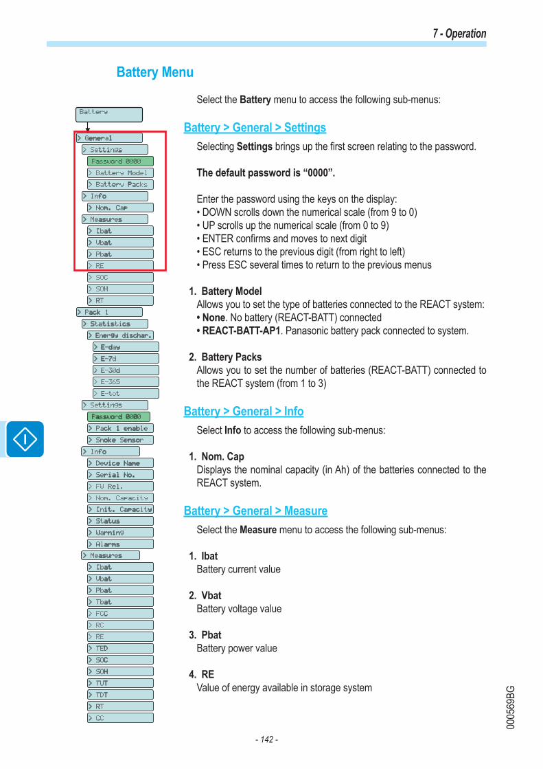
- 142 -
0005
69BG
7 - Operation
Battery Menu
Select the Battery menu to access the following sub-menus:
Battery > General > SettingsSelecting Settings brings up the first screen relating to the password.
The default password is “0000”.
Enter the password using the keys on the display:• DOWN scrolls down the numerical scale (from 9 to 0)• UP scrolls up the numerical scale (from 0 to 9)• ENTER confirms and moves to next digit• ESC returns to the previous digit (from right to left)• Press ESC several times to return to the previous menus
1. Battery ModelAllows you to set the type of batteries connected to the REACT system:• None. No battery (REACT-BATT) connected• REACT-BATT-AP1. Panasonic battery pack connected to system.
2. Battery PacksAllows you to set the number of batteries (REACT-BATT) connected to the REACT system (from 1 to 3)
Battery > General > InfoSelect Info to access the following sub-menus:
1. Nom. CapDisplays the nominal capacity (in Ah) of the batteries connected to the REACT system.
Battery > General > MeasureSelect the Measure menu to access the following sub-menus:
1. IbatBattery current value
2. VbatBattery voltage value
3. PbatBattery power value
4. REValue of energy available in storage system
> Statistics
> Self consumpti.
> Self sufficien.
> Ener. from grid
> Ener. to grid
> Ener. to load
> PV en. to load
> PV ener.
> Settings
> Info
> Measures
> Set time
Password 0000
> Set cash
> Set RS485 com
> Country Select
> New password
> SD Update Info
> Energy Policy
Inverter
> Statistics
> Settings
> Vstart
> Input mode
> Input UV Delay
> Service
> Info
> Part No.
> Serial No.
> Firmware
> Remote ON/OFF
> MPPT Scan
> Power Limit.
> Reactive Power
> Autotest
> Alarms
> Backup
> Lifetime
> Partial
> Today
> Last 7 days
> Last 30 days
> Last 365 days
> User Period
Display
> Settings
> Backlight
> Contrast
> Buzzer
> Power Graph
> Language
Meter
> Settings
> Info
> Type
> Part No.
> Serial No.
> FW Rel.
> Measures
> Voltage
> Active Power
> Line current
> Load current
> Frequency
> Meter model
> Meter Address
> Meter com
Battery
> General
**
****Load Manager
> info
> Relay Status
****WIFI Logger
> Settings
> Info
> Part No.
> Serial No.
> View IP
> View Mode
> Restore AP
*
System
****
Password 0000
Password 0000 Password 0000 > Settings
> Info
> Nom. Cap
> Measures
> Ibat
> Vbat
> Pbat
> RE
> SOC
> SOH
> RT
> Battery Model
> Battery Packs
Password 0000
> Pack 1
> Settings
> Info
> Device Name
> Serial No.
> FW Rel.
> Nom. Capacity
> Init. Capacity
> Status
> Warning
> Alarms
> Measures
> Pack 1 enable
> Smoke Sensor
Password 0000
> Statistics
> Energy dischar.
> E-day
> E-7d
> E-30d
> E-365
> E-tot
> Ibat
> Vbat
> Pbat
> Tbat
> FCC
> RC
> RE
> TED
> SOC
> SOH
> TUT
> TDT
> RT
> CC

- 143 -
0005
69BG
7 - Operation
5. SOCState of charge - Value of state of charge of the battery (expressed as a percentage)
6. SOHState of health - Percentage value that indicates the state of health of the battery pack. The value is given by the ratio between FCC (actual battery capacity) and IC (nominal battery capacity)
7. RTRemaining time - Time remaining before the battery runs out calculated based on actual absorption.
Battery > Pack 1 > Statistics1. Energy dischar.
This section of the menu displays the statistics relating to the battery running out (Pack 1). In particular:• E-day: Energy used today from battery• E-7d: Energy used from battery in last 7 days.• E-30d: Energy used from battery in last 30 days.• E-365d: Energy used from battery in last 365 days.• E-tot: Total energy used from battery
Battery > Pack 1 > SettingsSelecting Settings brings up the first screen relating to the password.
The default password is “0000”.
Enter the password using the keys on the display:• DOWN scrolls down the numerical scale (from 9 to 0)• UP scrolls up the numerical scale (from 0 to 9)• ENTER confirms and moves to next digit• ESC returns to the previous digit (from right to left)• Press ESC several times to return to the previous menus
1. Pack 1 EnableEnables or disables the operation of the REACT-BATT 1:
2. Smoke SensorEnables or disables the control of the brightness sensor installed inside the REACT-BATT (relating to battery pack 1)
Battery > Pack 1 > InfoSelect Info to access the following sub-menus:
1. Device NameDisplays the name of battery pack 1 (4-digit code)
> Statistics
> Self consumpti.
> Self sufficien.
> Ener. from grid
> Ener. to grid
> Ener. to load
> PV en. to load
> PV ener.
> Settings
> Info
> Measures
> Set time
Password 0000
> Set cash
> Set RS485 com
> Country Select
> New password
> SD Update Info
> Energy Policy
Inverter
> Statistics
> Settings
> Vstart
> Input mode
> Input UV Delay
> Service
> Info
> Part No.
> Serial No.
> Firmware
> Remote ON/OFF
> MPPT Scan
> Power Limit.
> Reactive Power
> Autotest
> Alarms
> Backup
> Lifetime
> Partial
> Today
> Last 7 days
> Last 30 days
> Last 365 days
> User Period
Display
> Settings
> Backlight
> Contrast
> Buzzer
> Power Graph
> Language
Meter
> Settings
> Info
> Type
> Part No.
> Serial No.
> FW Rel.
> Measures
> Voltage
> Active Power
> Line current
> Load current
> Frequency
> Meter model
> Meter Address
> Meter com
Battery
> General
**
****Load Manager
> info
> Relay Status
****WIFI Logger
> Settings
> Info
> Part No.
> Serial No.
> View IP
> View Mode
> Restore AP
*
System
****
Password 0000
Password 0000 Password 0000 > Settings
> Info
> Nom. Cap
> Measures
> Ibat
> Vbat
> Pbat
> RE
> SOC
> SOH
> RT
> Battery Model
> Battery Packs
Password 0000
> Pack 1
> Settings
> Info
> Device Name
> Serial No.
> FW Rel.
> Nom. Capacity
> Init. Capacity
> Status
> Warning
> Alarms
> Measures
> Pack 1 enable
> Smoke Sensor
Password 0000
> Statistics
> Energy dischar.
> E-day
> E-7d
> E-30d
> E-365
> E-tot
> Ibat
> Vbat
> Pbat
> Tbat
> FCC
> RC
> RE
> TED
> SOC
> SOH
> TUT
> TDT
> RT
> CC

- 144 -
0005
69BG
7 - Operation
2. Serial No.Displays the serial number of battery pack 1 connected to the REACT system
3. FW Rel.Displays the revision of the firmware installed on the REACT-BATT.
4. Nom. CapacityDisplays the nominal capacity of battery pack 1 connected to the system.
5. Init. CapacityDisplays the value of the initial capacity of battery pack 1.
6. StatusDisplays the operating status of the battery pack from the following:- Stand-by- Sleep- Run- Warning- Fault 1- Fault 2- Other fault- Emergency- Wait black start- Disabled
7. WarningDisplays details of the warning detected by the REACT-BATT
8. AlarmDisplays details of Fault 1 and Fault 2 detected by the REACT-BATT
Battery > Pack 1 > MeasureSelect the Measure menu to access the following sub-menus:
1. IbatBattery pack 1 current value
2. VbatBattery pack 1 voltage value
3. PbatBattery pack 1 instantaneous power value
4. TbatBattery pack 1 temperature value
5. FCCFull charge capacity - Current capacity of battery pack. This value is con-tinuously updated based on the operation of the storage system.
> Statistics
> Self consumpti.
> Self sufficien.
> Ener. from grid
> Ener. to grid
> Ener. to load
> PV en. to load
> PV ener.
> Settings
> Info
> Measures
> Set time
Password 0000
> Set cash
> Set RS485 com
> Country Select
> New password
> SD Update Info
> Energy Policy
Inverter
> Statistics
> Settings
> Vstart
> Input mode
> Input UV Delay
> Service
> Info
> Part No.
> Serial No.
> Firmware
> Remote ON/OFF
> MPPT Scan
> Power Limit.
> Reactive Power
> Autotest
> Alarms
> Backup
> Lifetime
> Partial
> Today
> Last 7 days
> Last 30 days
> Last 365 days
> User Period
Display
> Settings
> Backlight
> Contrast
> Buzzer
> Power Graph
> Language
Meter
> Settings
> Info
> Type
> Part No.
> Serial No.
> FW Rel.
> Measures
> Voltage
> Active Power
> Line current
> Load current
> Frequency
> Meter model
> Meter Address
> Meter com
Battery
> General
**
****Load Manager
> info
> Relay Status
****WIFI Logger
> Settings
> Info
> Part No.
> Serial No.
> View IP
> View Mode
> Restore AP
*
System
****
Password 0000
Password 0000 Password 0000 > Settings
> Info
> Nom. Cap
> Measures
> Ibat
> Vbat
> Pbat
> RE
> SOC
> SOH
> RT
> Battery Model
> Battery Packs
Password 0000
> Pack 1
> Settings
> Info
> Device Name
> Serial No.
> FW Rel.
> Nom. Capacity
> Init. Capacity
> Status
> Warning
> Alarms
> Measures
> Pack 1 enable
> Smoke Sensor
Password 0000
> Statistics
> Energy dischar.
> E-day
> E-7d
> E-30d
> E-365
> E-tot
> Ibat
> Vbat
> Pbat
> Tbat
> FCC
> RC
> RE
> TED
> SOC
> SOH
> TUT
> TDT
> RT
> CC
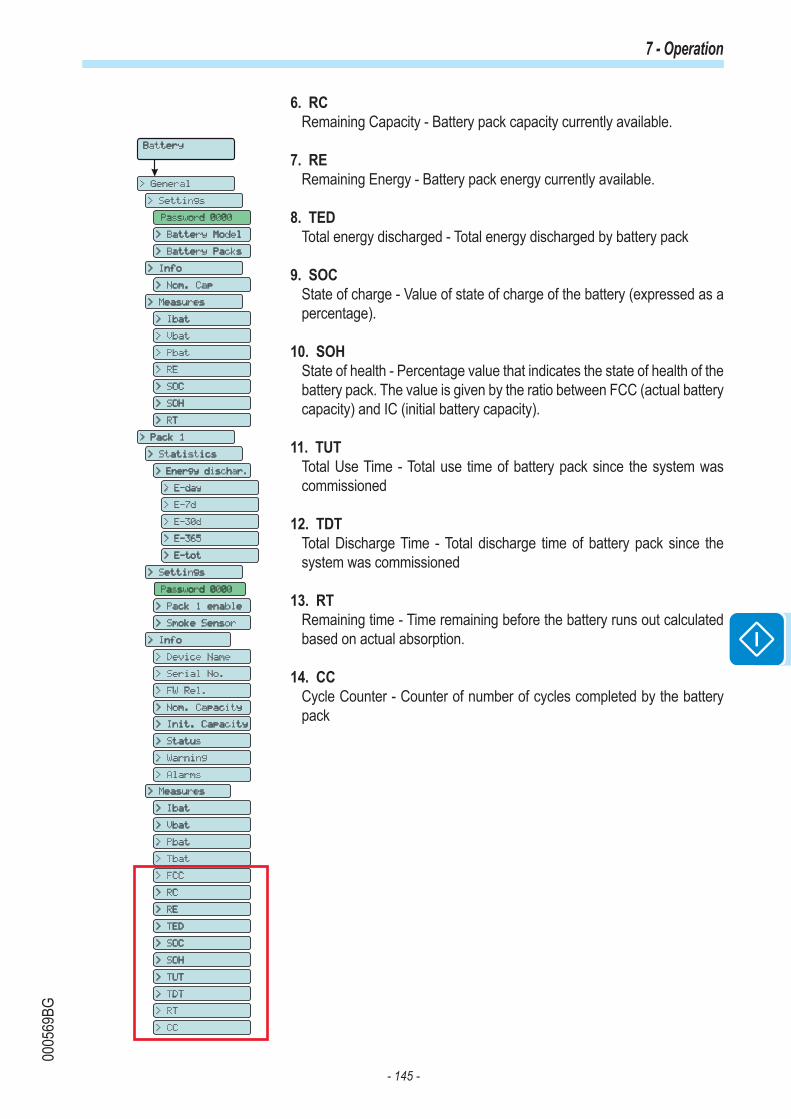
- 145 -
0005
69BG
7 - Operation
6. RCRemaining Capacity - Battery pack capacity currently available.
7. RERemaining Energy - Battery pack energy currently available.
8. TEDTotal energy discharged - Total energy discharged by battery pack
9. SOCState of charge - Value of state of charge of the battery (expressed as a percentage).
10. SOHState of health - Percentage value that indicates the state of health of the battery pack. The value is given by the ratio between FCC (actual battery capacity) and IC (initial battery capacity).
11. TUTTotal Use Time - Total use time of battery pack since the system was commissioned
12. TDTTotal Discharge Time - Total discharge time of battery pack since the system was commissioned
13. RTRemaining time - Time remaining before the battery runs out calculated based on actual absorption.
14. CCCycle Counter - Counter of number of cycles completed by the battery pack
> Statistics
> Self consumpti.
> Self sufficien.
> Ener. from grid
> Ener. to grid
> Ener. to load
> PV en. to load
> PV ener.
> Settings
> Info
> Measures
> Set time
Password 0000
> Set cash
> Set RS485 com
> Country Select
> New password
> SD Update Info
> Energy Policy
Inverter
> Statistics
> Settings
> Vstart
> Input mode
> Input UV Delay
> Service
> Info
> Part No.
> Serial No.
> Firmware
> Remote ON/OFF
> MPPT Scan
> Power Limit.
> Reactive Power
> Autotest
> Alarms
> Backup
> Lifetime
> Partial
> Today
> Last 7 days
> Last 30 days
> Last 365 days
> User Period
Display
> Settings
> Backlight
> Contrast
> Buzzer
> Power Graph
> Language
Meter
> Settings
> Info
> Type
> Part No.
> Serial No.
> FW Rel.
> Measures
> Voltage
> Active Power
> Line current
> Load current
> Frequency
> Meter model
> Meter Address
> Meter com
Battery
> General
**
****Load Manager
> info
> Relay Status
****WIFI Logger
> Settings
> Info
> Part No.
> Serial No.
> View IP
> View Mode
> Restore AP
*
System
****
Password 0000
Password 0000 Password 0000 > Settings
> Info
> Nom. Cap
> Measures
> Ibat
> Vbat
> Pbat
> RE
> SOC
> SOH
> RT
> Battery Model
> Battery Packs
Password 0000
> Pack 1
> Settings
> Info
> Device Name
> Serial No.
> FW Rel.
> Nom. Capacity
> Init. Capacity
> Status
> Warning
> Alarms
> Measures
> Pack 1 enable
> Smoke Sensor
Password 0000
> Statistics
> Energy dischar.
> E-day
> E-7d
> E-30d
> E-365
> E-tot
> Ibat
> Vbat
> Pbat
> Tbat
> FCC
> RC
> RE
> TED
> SOC
> SOH
> TUT
> TDT
> RT
> CC

- 146 -
0005
69BG
7 - Operation
Load Manager MenuSelect the Meter menu to access the following sub-menus:
Load Manager > InfoSelect Info to access the following sub-menus:
1. Relay StatusLets you see the status of the 4 relays (A, B, C and D) for managing external loads. In particular, they will be shown with:- OFF. Relays not switched - ON. Relays switched
> Statistics
> Self consumpti.
> Self sufficien.
> Ener. from grid
> Ener. to grid
> Ener. to load
> PV en. to load
> PV ener.
> Settings
> Info
> Measures
> Set time
Password 0000
> Set cash
> Set RS485 com
> Country Select
> New password
> SD Update Info
> Energy Policy
Inverter
> Statistics
> Settings
> Vstart
> Input mode
> Input UV Delay
> Service
> Info
> Part No.
> Serial No.
> Firmware
> Remote ON/OFF
> MPPT Scan
> Power Limit.
> Reactive Power
> Autotest
> Alarms
> Backup
> Lifetime
> Partial
> Today
> Last 7 days
> Last 30 days
> Last 365 days
> User Period
Display
> Settings
> Backlight
> Contrast
> Buzzer
> Power Graph
> Language
Meter
> Settings
> Info
> Type
> Part No.
> Serial No.
> FW Rel.
> Measures
> Voltage
> Active Power
> Line current
> Load current
> Frequency
> Meter model
> Meter Address
> Meter com
Battery
> General
**
****Load Manager
> info
> Relay Status
****WIFI Logger
> Settings
> Info
> Part No.
> Serial No.
> View IP
> View Mode
> Restore AP
*
System
****
Password 0000
Password 0000 Password 0000 > Settings
> Info
> Nom. Cap
> Measures
> Ibat
> Vbat
> Pbat
> RE
> SOC
> SOH
> RT
> Battery Model
> Battery Packs
Password 0000
> Pack 1
> Settings
> Info
> Device Name
> Serial No.
> FW Rel.
> Nom. Capacity
> Init. Capacity
> Status
> Warning
> Alarms
> Measures
> Pack 1 enable
> Smoke Sensor
Password 0000
> Statistics
> Energy dischar.
> E-day
> E-7d
> E-30d
> E-365
> E-tot
> Ibat
> Vbat
> Pbat
> Tbat
> FCC
> RC
> RE
> TED
> SOC
> SOH
> TUT
> TDT
> RT
> CC
Wi-Fi Logger MenuThe WIFI Logger menu is available only if the WIFI Logger Card board has been installed in the unit.Select the Wi-Fi Logger menu to access the following sub-menus:
Wi-Fi Logger > SettingsSelecting Settings brings up the first screen relating to the password.The default password is “0000”.Enter the password using the keys on the display:• DOWN scrolls down the numerical scale (from 9 to 0)• UP scrolls up the numerical scale (from 0 to 9)• ENTER confirms and moves to next digit• ESC returns to the previous digit (from right to left)• Press ESC several times to return to the previous menus
1. Restore APThis section of the menu allows you to restore the "Access Point" mode of the Wi-Fi Logger Card accessory board (VSN300).
Wi-Fi Logger > InfoSelect Info to access the following sub-menus:
1. Part No.Allows you to view the code of the Wi-Fi Logger Card model.
2. Serial No.Allows you to view the serial number, the week and year of manufacture of the Wi-Fi Logger Card.
3. View IP.Allows you to view the IP address assigned to the WIFI Logger Card board.
4. View ModeAllows you to view the operating mode of the Wi-Fi Logger Card ("Ac-cess Point" or "Host").
> Statistics
> Self consumpti.
> Self sufficien.
> Ener. from grid
> Ener. to grid
> Ener. to load
> PV en. to load
> PV ener.
> Settings
> Info
> Measures
> Set time
Password 0000
> Set cash
> Set RS485 com
> Country Select
> New password
> SD Update Info
> Energy Policy
Inverter
> Statistics
> Settings
> Vstart
> Input mode
> Input UV Delay
> Service
> Info
> Part No.
> Serial No.
> Firmware
> Remote ON/OFF
> MPPT Scan
> Power Limit.
> Reactive Power
> Autotest
> Alarms
> Backup
> Lifetime
> Partial
> Today
> Last 7 days
> Last 30 days
> Last 365 days
> User Period
Display
> Settings
> Backlight
> Contrast
> Buzzer
> Power Graph
> Language
Meter
> Settings
> Info
> Type
> Part No.
> Serial No.
> FW Rel.
> Measures
> Voltage
> Active Power
> Line current
> Load current
> Frequency
> Meter model
> Meter Address
> Meter com
Battery
> General
**
****Load Manager
> info
> Relay Status
****WIFI Logger
> Settings
> Info
> Part No.
> Serial No.
> View IP
> View Mode
> Restore AP
*
System
****
Password 0000
Password 0000 Password 0000 > Settings
> Info
> Nom. Cap
> Measures
> Ibat
> Vbat
> Pbat
> RE
> SOC
> SOH
> RT
> Battery Model
> Battery Packs
Password 0000
> Pack 1
> Settings
> Info
> Device Name
> Serial No.
> FW Rel.
> Nom. Capacity
> Init. Capacity
> Status
> Warning
> Alarms
> Measures
> Pack 1 enable
> Smoke Sensor
Password 0000
> Statistics
> Energy dischar.
> E-day
> E-7d
> E-30d
> E-365
> E-tot
> Ibat
> Vbat
> Pbat
> Tbat
> FCC
> RC
> RE
> TED
> SOC
> SOH
> TUT
> TDT
> RT
> CC

- 147 -
0005
94AG
7 - Funzionamento
REACT system switch-offSome parts may be very hot and could cause burns.
Some inverter parts may be subject to voltages that could be hazardous for the operator.Before performing any work on the inverter, follow the procedure for turning off the inverter.
• Push the STOP button to disconnect the storage system.
• Open the DC disconnect switch installed on the REACT-UNO.
• Open the DC disconnect switch installed by the Client on the outside of the inverter.
• Disconnect any power supplies that may be connected to the configurable relay.
Before attempting any work on the inverter, wait enough time for the stored energy to be discharged
• Remove the front covers.
• Under these conditions both wiring boxes have hazardous voltages highlighted by the symbol , while the other areas may be freely accessed.
J6 J5
BATT. COMM.BUS
BATT. COMM.BUS
3J4J
.MOC O/IYRETTAB-ITLUM KNIL .MOC O/I
MULTI-BATTERY
DC POWER
D1
D2
D3
OFF
J2
J1J7 PE
120 ΩON
BATTERY ADDRESSSELECTOR
DC POWER LINK
LOAD MANAGER BOX
87D
5 6C
3 4B
1 2A
J1
5
1
6
2
7
3
8
4
• Open the DC disconnect switch on the outside of the inverter (if installed) or disconnect the input strings.
• Under these conditions the system does not have any hazardous voltages and all areas may be freely accessed.
5

- 148 -
0000
37DG
General conditions Routine and periodic maintenance operations must only be carried out by specialized staff with knowledge of how to perform these tasks.
Maintenance operations must be performed with the apparatus disconnected from the grid (power switch open) and the photovoltaic panels obscured or isolated, unless otherwise indicated.
For cleaning, DO NOT use rags made of filamentary material or corrosive products that may corrode the equipment or generate electrostatic charges.Avoid temporary repairs. All repairs should be carried out using only genuine spare parts.The maintenance technician is to promptly report any anomalies.
DO NOT allow the equipment to be used if problems of any kind are found.
Always use personal protective equipment (PPE) provided by the employer and comply with local safety regulations.
8Maintenance

- 149 -
0005
70BG
8 - Maintenance
Routine maintenance
Routine maintenance operations should not be considered obligatory, but rather as recommended in order to maintain the efficiency of the PV system.
It is recommended that maintenance operations are only performed by qualified personnel or ABB personnel (under a servicing contract).The maintenance schedule may vary depending on the environmental conditions of the installation premises.
Type/schedule Description of the check/operationAnnual visual checks • Check that the system is operating properly, without any alarm signals
• Ensure all labels and safety symbols are visible• Check the integrity of the cables, connectors and external cable glands• Check that the environmental conditions have not changed dramatically from those on installation.
Annual operations • Check the tightening of the cable glands and the screw terminal blocks• Check the front covers are fixed • If there is no monitoring system, check the alarms and errors log using the information provided in the manual in order to check recent notifications of malfunctions.
Annual cleaning • Clean the equipment; in particular the heat sink and the ventilation openings on the REACT-BATT
Troubleshooting
In order to understand and deal with warning (Wxxx) or error (Exxx) signals that appear on the system's display, use the table given in the following paragraph.
Operations on the inverter to identify and address any faults may only be performed by the installer or by qualified personnel.
Alarm Messages
The equipment can notify errors/warnings on the display only if the input voltage is greater than the Vdcmin voltage (POWER Led flashing or lit; see chapter on operation).The message notices and related codes are shown on the highlighted part b08 of the display 04 .
The following table gives the complete list of errors/warnings relating to string inverters. Some error/warning codes may not be used depending on the inverter model installed.
b02 b08 b23b01 b03
b09 b11 b10
b20
b12 b13 b14 b15 b16 b17 b18 b19
b21 b24b22 b25 b26
b04 b06 b07b05

- 150 -
0005
70BG
8 - Maintenance
- Error code- Error message - Warning
Name of Alarm and Cause Solution
- No code- Ground F- Red LED
Ground fault of photovoltaic generator:The alarm is generated when a ground leakage current is detected in the DC section of the system.
• Measure the insulation resistance using a megohmmeter positioned in the photovoltaic field (positive terminal short-circuited at the negative pole) compared to ground. The measurement is strongly influenced by the environmental conditions, so must be made under the same conditions in which the error occurred.- If the value measured is lower than 1 megaohm, a check must be carried out by a technician/installer on the photovoltaic generator to identify and eliminate the problem.- If the value measured is higher than 1 megaohm and the error signal persists, contact customer assistance.
- No code- NEW SYSTEM PART REFUSED!- Flashing yellow LED
Lack of linkage of the new system part:The components inside the inverter (e.g. display, fuse board, communication and control board, etc.) are not inter-linked. This occurs following the replacement of one of the components inside the inverter.
• Link the components inside the inverter by accessing the “Settings > Service > Accept boards” (refer to the procedure given in this manual).
- If the signal persists also following the linking of the components, contact customer assistance.
- No code- SET COUNTRY or NO NATION- No LED
SET COUNTRY or NO NATION:Indicates that in the installation phase the grid standard was not set on the inverter.
• Set the grid standard of the country of installation following the instructions given in this manual for the inverter.- If the signal persists also after the grid standard has been set, contact customer assistance.
- No code - Missing Grid - Yellow LED
Missing Grid:The inverter does not detect grid voltage (AC side).
• Check the grid voltage on the inverter's AC terminal block.- Should it be absent, check any protection work on the line and the presence of grid voltage on the supply point.
- No code - Memory fault - Flashing yellow LED
Memory fault:The inverter has detected a communication problem with the memory board on which the inverter saves the daily value of energy produced.
• Remove the memory board and check the welding of all the connector's terminals. Subsequently reinsert the memory board and check that it is correctly inserted into the dedicated slot- If the signal persists also following the above checks, contact customer assistance.
- No code - Waiting Sun - Flashing green LED
Waiting Sun:The inverter goes into the “Waiting Sun” stage when, following a W001 and/or W002 warning, the voltage from the photovoltaic generator is less than the activation voltage (Vstart).
• Check the input voltage on the inverter.- If it does not exceed Vstart, check for the presence of sufficient irradiation and the correct composition of the system.- If it exceeds Vstart, contact customer assistance
- W001- Sun Low- Yellow LED
Insufficient irradiation (Low input voltage on switching on the inverter): Incorrect configuration of the PV generator or an “on the limit” configuration for the inverter's minimum input voltage.
• Check the input voltage on the inverter.- If it does not exceed Vstart, check for the presence of sufficient irradiation and the correct composition of the system.- If it exceeds Vstart, contact customer assistance
- W002- Input UV- Yellow LED
Insufficient irradiation (Low input voltage on switching off):Incorrect configuration of the photovoltaic generator or an “on the limit” configuration for the inverter's minimum input voltage.
• Check the input voltage on the inverter.- If it does not exceed Vstart, check for the presence of sufficient irradiation and the correct composition of the system.- If it exceeds Vstart, contact customer assistance
- W003- Grid Fail- Yellow LED
Parameters of grid voltage outside range:This error signal occurs when during the inverter's normal operation the grid parameters exceed the limits set by the operator:- Grid voltage absent (after the signal the inverter goes to "Missing Grid")- Unstable grid voltage (values too low or too high) - Unstable grid frequency
• Check the grid voltage on the inverter.- Should it be absent, check for absence of grid voltage on the supply point. - If, on the other hand, the voltage tends to rise (when the inverter is connected) there is high line or grid impedance.• Check the grid voltage also on the supply. - If it is high, it means that there is high grid impedance. In this case, ask the operator to adjust the grid voltage. If the operator authorises a change to the inverter's parameters, agree the new limits with customer assistance- If the voltage at the point of supply is much lower than that measured on the inverter, it is necessary to adjust the line (inverter-contactor). - If the voltage and the grid frequency come back within the limits (also when the inverter is connected to the grid), contact customer assistance
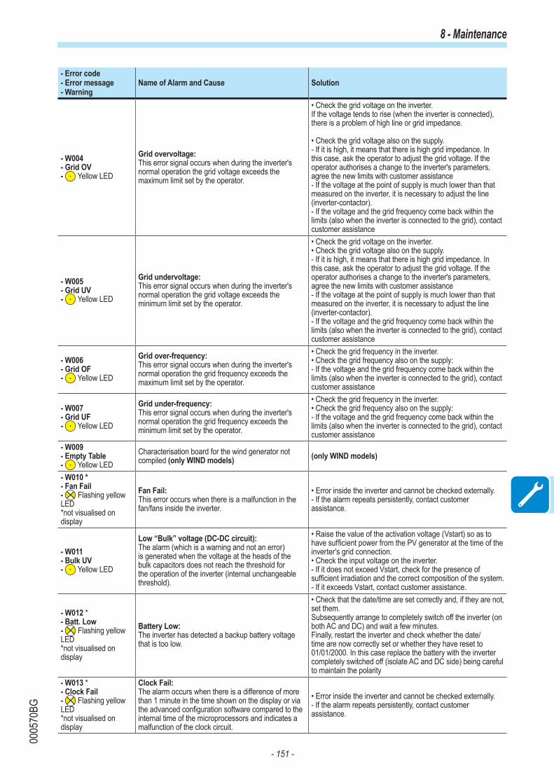
- 151 -
0005
70BG
8 - Maintenance
- Error code- Error message - Warning
Name of Alarm and Cause Solution
- W004- Grid OV- Yellow LED
Grid overvoltage:This error signal occurs when during the inverter's normal operation the grid voltage exceeds the maximum limit set by the operator.
• Check the grid voltage on the inverter. If the voltage tends to rise (when the inverter is connected), there is a problem of high line or grid impedance.
• Check the grid voltage also on the supply. - If it is high, it means that there is high grid impedance. In this case, ask the operator to adjust the grid voltage. If the operator authorises a change to the inverter's parameters, agree the new limits with customer assistance- If the voltage at the point of supply is much lower than that measured on the inverter, it is necessary to adjust the line (inverter-contactor). - If the voltage and the grid frequency come back within the limits (also when the inverter is connected to the grid), contact customer assistance
- W005- Grid UV- Yellow LED
Grid undervoltage:This error signal occurs when during the inverter's normal operation the grid voltage exceeds the minimum limit set by the operator.
• Check the grid voltage on the inverter. • Check the grid voltage also on the supply. - If it is high, it means that there is high grid impedance. In this case, ask the operator to adjust the grid voltage. If the operator authorises a change to the inverter's parameters, agree the new limits with customer assistance- If the voltage at the point of supply is much lower than that measured on the inverter, it is necessary to adjust the line (inverter-contactor). - If the voltage and the grid frequency come back within the limits (also when the inverter is connected to the grid), contact customer assistance
- W006- Grid OF- Yellow LED
Grid over-frequency:This error signal occurs when during the inverter's normal operation the grid frequency exceeds the maximum limit set by the operator.
• Check the grid frequency in the inverter. • Check the grid frequency also on the supply: - If the voltage and the grid frequency come back within the limits (also when the inverter is connected to the grid), contact customer assistance
- W007- Grid UF- Yellow LED
Grid under-frequency:This error signal occurs when during the inverter's normal operation the grid frequency exceeds the minimum limit set by the operator.
• Check the grid frequency in the inverter. • Check the grid frequency also on the supply: - If the voltage and the grid frequency come back within the limits (also when the inverter is connected to the grid), contact customer assistance
- W009- Empty Table- Yellow LED
Characterisation board for the wind generator not compiled (only WIND models) (only WIND models)
- W010 *- Fan Fail- Flashing yellow LED*not visualised on display
Fan Fail:This error occurs when there is a malfunction in the fan/fans inside the inverter.
• Error inside the inverter and cannot be checked externally. - If the alarm repeats persistently, contact customer assistance.
- W011- Bulk UV- Yellow LED
Low “Bulk” voltage (DC-DC circuit):The alarm (which is a warning and not an error) is generated when the voltage at the heads of the bulk capacitors does not reach the threshold for the operation of the inverter (internal unchangeable threshold).
• Raise the value of the activation voltage (Vstart) so as to have sufficient power from the PV generator at the time of the inverter's grid connection.• Check the input voltage on the inverter.- If it does not exceed Vstart, check for the presence of sufficient irradiation and the correct composition of the system. - If it exceeds Vstart, contact customer assistance.
- W012 *- Batt. Low- Flashing yellow LED*not visualised on display
Battery Low:The inverter has detected a backup battery voltage that is too low.
• Check that the date/time are set correctly and, if they are not, set them. Subsequently arrange to completely switch off the inverter (on both AC and DC) and wait a few minutes. Finally, restart the inverter and check whether the date/time are now correctly set or whether they have reset to 01/01/2000. In this case replace the battery with the inverter completely switched off (isolate AC and DC side) being careful to maintain the polarity
- W013 *- Clock Fail- Flashing yellow LED*not visualised on display
Clock Fail:The alarm occurs when there is a difference of more than 1 minute in the time shown on the display or via the advanced configuration software compared to the internal time of the microprocessors and indicates a malfunction of the clock circuit.
• Error inside the inverter and cannot be checked externally. - If the alarm repeats persistently, contact customer assistance.

- 152 -
0005
70BG
8 - Maintenance
- Error code- Error message - Warning
Name of Alarm and Cause Solution
- W015- Island Detect.- Yellow LED
Disconnection due to Anti-Islanding:The inverter has been improperly connected to an island grid.
• Check that the grid to which the inverter is connected is not an island grid.- If the grid to which the inverter is connected is an island grid, switch the inverter off and then on again: if the problem persists, contact customer assistance.
- W017*- String Err.- Flashing yellow LED* (only for models with monitored string fuses)
Error recorded in measuring string currents: Damaged string protection fuse(s)
• Check with a multimeter the state of the fuses (positioned on the fuse boards).- If one or more fuses is open, arrange to replace them and check that the input current on the string(s) does not exceed the rating of the fuses (should parallel strings have been made outside the inverter).- If there are no damaged string fuses and the inverter continues to show the alarm message check whether the settings to be made via the Aurora Manager software are correct (presence or absence of one or more input strings).
- W018 *- SPD DC Err- Flashing yellow LED* (only for models with monitored SPD)
Intervention of overvoltage surge arresters on DC side:Overvoltage surge arresters situated on the DC side are damaged.
• Observe the inspection window on each surge arrester (DC side). If it is red, the surge arrester is damaged and the cartridge must be replaced.- If the alarm status persists, even if all the surge arresters have a green inspection window, contact customer assistance.
- W019 *- SPD AC Err- Flashing yellow LED* (only for models with monitored SPD)
Intervention of overvoltage surge arresters on AC side:Overvoltage surge arresters situated on the AC side are damaged.
• Observe the inspection window on each surge arrester (AC side). If it is red, the surge arrester is damaged and the cartridge must be replaced.- If the alarm status persists, even if all the surge arresters have a green inspection window, contact customer assistance.
W021- P-reductionStart- No LED*not visualised on display
Activation of reduction in power:Indicates that one of the power limitations described in the paragraph "Power limitation messages" has been triggered.
• Check which power limitation code is active and, on the basis of that, carry out the necessary checks that might relate to various factors including:- settings by the user- high grid frequency- high grid voltage- anti-islanding- low grid voltage- high internal temperature - high input voltage
- W022 *- Reactive power mode changed- No LED*not visualised on display
Variation in means of managing reactive power:Variation in the means of managing reactive power; this change can be made through the display or advanced configuration software.
The variation in the means of managing reactive power is done directly by the customer/installer and is not an error. The information is only saved on the historic record of the events memorised by the inverter
- W023 *- date/time changed- No LED*not visualised on display
Variation in the inverter's date and time:Variation of the inverter's date and time; this change can be made through the display or advanced configuration software.
• The variation in the inverter's date and time is done directly by the customer/installer and is not an error. The information is only saved on the historic record of the events memorised by the inverter
- W024 *- Energy data reset- No LED*not visualised on display
Zeroing of the statistical energy data memorised in the EEPROM:Reset of the energy data saved in the inverter; this operation can be handled through the display or advanced configuration software.
The zeroing of the partial energy values memorised by the inverter is done directly by the customer/installer and is not an error. The information is only saved on the historic record of the events memorised by the inverter• The warning may also occur when the Memory Card on which the production statistics are saved is replaced
W025- P-reductionEnd- No LED*not visualised on display
Deactivation of reduction in power:Indicates that the inverter has come out of one of the power limitation states described in the paragraph "Power limitation messages".
This type of warning does not need any check
- W026 *- AFDD user reset- No LED*not visualised on display
Reset of the Arc Fault error:Manual reset of the Arc Fault error; this operation can be made through the display or advanced configuration software.
• The reset of the Arc Fault error is done directly by the customer/installer and is not an error. The information is only saved on the historic record of the events memorised by the inverter
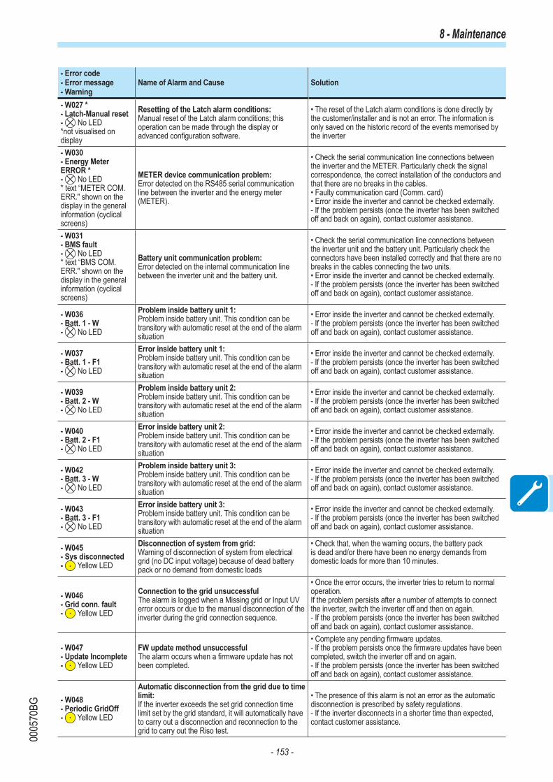
- 153 -
0005
70BG
8 - Maintenance
- Error code- Error message - Warning
Name of Alarm and Cause Solution
- W027 *- Latch-Manual reset- No LED*not visualised on display
Resetting of the Latch alarm conditions:Manual reset of the Latch alarm conditions; this operation can be made through the display or advanced configuration software.
• The reset of the Latch alarm conditions is done directly by the customer/installer and is not an error. The information is only saved on the historic record of the events memorised by the inverter
- W030- Energy Meter ERROR *- No LED* text “METER COM. ERR." shown on the display in the general information (cyclical screens)
METER device communication problem:Error detected on the RS485 serial communication line between the inverter and the energy meter (METER).
• Check the serial communication line connections between the inverter and the METER. Particularly check the signal correspondence, the correct installation of the conductors and that there are no breaks in the cables. • Faulty communication card (Comm. card)• Error inside the inverter and cannot be checked externally.- If the problem persists (once the inverter has been switched off and back on again), contact customer assistance.
- W031- BMS fault- No LED* text “BMS COM. ERR." shown on the display in the general information (cyclical screens)
Battery unit communication problem:Error detected on the internal communication line between the inverter unit and the battery unit.
• Check the serial communication line connections between the inverter unit and the battery unit. Particularly check the connectors have been installed correctly and that there are no breaks in the cables connecting the two units. • Error inside the inverter and cannot be checked externally.- If the problem persists (once the inverter has been switched off and back on again), contact customer assistance.
- W036- Batt. 1 - W- No LED
Problem inside battery unit 1:Problem inside battery unit. This condition can be transitory with automatic reset at the end of the alarm situation
• Error inside the inverter and cannot be checked externally.- If the problem persists (once the inverter has been switched off and back on again), contact customer assistance.
- W037- Batt. 1 - F1- No LED
Error inside battery unit 1:Problem inside battery unit. This condition can be transitory with automatic reset at the end of the alarm situation
• Error inside the inverter and cannot be checked externally.- If the problem persists (once the inverter has been switched off and back on again), contact customer assistance.
- W039- Batt. 2 - W- No LED
Problem inside battery unit 2:Problem inside battery unit. This condition can be transitory with automatic reset at the end of the alarm situation
• Error inside the inverter and cannot be checked externally.- If the problem persists (once the inverter has been switched off and back on again), contact customer assistance.
- W040- Batt. 2 - F1- No LED
Error inside battery unit 2:Problem inside battery unit. This condition can be transitory with automatic reset at the end of the alarm situation
• Error inside the inverter and cannot be checked externally.- If the problem persists (once the inverter has been switched off and back on again), contact customer assistance.
- W042- Batt. 3 - W- No LED
Problem inside battery unit 3:Problem inside battery unit. This condition can be transitory with automatic reset at the end of the alarm situation
• Error inside the inverter and cannot be checked externally.- If the problem persists (once the inverter has been switched off and back on again), contact customer assistance.
- W043- Batt. 3 - F1- No LED
Error inside battery unit 3:Problem inside battery unit. This condition can be transitory with automatic reset at the end of the alarm situation
• Error inside the inverter and cannot be checked externally.- If the problem persists (once the inverter has been switched off and back on again), contact customer assistance.
- W045- Sys disconnected- Yellow LED
Disconnection of system from grid:Warning of disconnection of system from electrical grid (no DC input voltage) because of dead battery pack or no demand from domestic loads
• Check that, when the warning occurs, the battery pack is dead and/or there have been no energy demands from domestic loads for more than 10 minutes.
- W046- Grid conn. fault- Yellow LED
Connection to the grid unsuccessfulThe alarm is logged when a Missing grid or Input UV error occurs or due to the manual disconnection of the inverter during the grid connection sequence.
• Once the error occurs, the inverter tries to return to normal operation.If the problem persists after a number of attempts to connect the inverter, switch the inverter off and then on again.- If the problem persists (once the inverter has been switched off and back on again), contact customer assistance.
- W047- Update Incomplete- Yellow LED
FW update method unsuccessfulThe alarm occurs when a firmware update has not been completed.
• Complete any pending firmware updates.- If the problem persists once the firmware updates have been completed, switch the inverter off and on again.- If the problem persists (once the inverter has been switched off and back on again), contact customer assistance.
- W048- Periodic GridOff- Yellow LED
Automatic disconnection from the grid due to time limit:If the inverter exceeds the set grid connection time limit set by the grid standard, it will automatically have to carry out a disconnection and reconnection to the grid to carry out the Riso test.
• The presence of this alarm is not an error as the automatic disconnection is prescribed by safety regulations.- If the inverter disconnects in a shorter time than expected, contact customer assistance.

- 154 -
0005
70BG
8 - Maintenance
- Error code- Error message - Warning
Name of Alarm and Cause Solution
- W049 *- Global-Settings Event- No LED*not visualised on display
Variation of the grid standardVariation of the inverter's grid standard; this change can be made through the display or advanced configuration software.
• The variation in the inverter's grid standard is done directly by the customer/installer and is not an error. The information is only saved on the historic record of the events memorised by the inverter
- W051- Exit from Stand Alone connection- Yellow LED
Exit from Stand-alone mode:The alarm is logged when the "Stand Alone" mode is deactivated or the inverter reconnects to the grid (this can only be seen if the Stand Alone accessory board has been installed).
• Deactivation of the Stand Alone mode is done directly by the customer/installer or automatically by the inverter and is not an error.
- W053- SOH Low- Flashing yellow LED* text “Bat. Warn-SOH_L" shown on the display in the general information (cyclical screens)
State of health (SOH) of battery pack low:Indicates an accelerated deterioration of the battery
• Check that the installation requirements are met (temperature, minimum air volume, etc.).
- W054- SOH Low ( Fault )- Flashing yellow LED* text “Bat. Fault-SOH_L" shown on the display in the general information (cyclical screens)
Battery pack blocked through low state of health (SOH):Indicates that the SOH level of the battery pack (during normal operation) is below the threshold for use. The alarm is displayed for SOH values below 67%.
• Indicates that the useful life of the battery is over and it must be replaced.
- W055- Battery Low ( 0% )- No Led* text “SOC LOW” shown on the display in general information (cyclical screens)
State of charge (SOC) of battery pack low:Indicates that the battery is completely dead.
• Where permitted by the regulations of the country where it is installed, it is advisable to force the battery to recharge using the electrical grid (charge in AC). Otherwise it is necessary to have good energy production and low absorption of domestic loads to carry out the recharging of the battery (charge in DC).
- W056- Power Engage- Yellow LED* “CHECK BATT CABLE” is displayed in the general information (cyclical screens)
Problem with battery pack (power) connection cables:Error detected on the power cables between the inverter unit and the battery unit.
• Check the power line connections between the inverter unit and the battery unit. Particularly check the connectors have been installed correctly and that there are no breaks in the cables connecting the two units. • Error inside the inverter and cannot be checked externally.- If the problem persists (once the inverter has been switched off and back on again), contact customer assistance.
- W058- System Frozen- Yellow LED
Converter in locked state:The converter lock state is connected to an installation phase in which the starts-up and grid connection conditions are not yet present.
• Complete the commissioning phase of the inverter.- If the problem persists (once the commissioning phase has been completed and the inverter has been switched off and back on again), contact customer assistance.
- W059- Output power Overload- Yellow LED
Overload on Stand-alone output:The alarm occurs when there is an excessive request for power by the grid with the inverter in "Stand Alone" mode (this can only be seen if the Stand Alone accessory board has been installed).
• Disconnect one or more loads from the Stand Alone output.- If the problem persists (once all loads have been disconnected and the inverter has been switched off and back on again), contact customer assistance.
- W060- COMMISSIONING - SOH test - Warning- No LED* text “Bat. Warn-SOH_L" shown on the display in the general information (cyclical screens)
State of health (SOH) of battery pack low:Indicates that the SOH level of the battery pack (during system commissioning) is close to the threshold below which it cannot be used. The alarm is displayed for SOH values between 51 and 60%.
• Indicates that the useful life of the battery is about to end as with SOH values of below 50% it should be replaced.

- 155 -
0005
70BG
8 - Maintenance

- 156 -
0005
70BG
8 - Maintenance
- Error code- Error message - Warning
Name of Alarm and Cause Solution
- E006- Output OC- Yellow LED
Output overcurrent:The alarm occurs when the inverter's output current exceeds the inverter's threshold for maximum output current.
• Error inside the inverter and cannot be checked externally. - If the problem persists (once the inverter has been switched off and back on again), contact customer assistance.
- E007- IGBT Sat- Yellow LED
Saturation recorded on the IGBT components:The alarm appears when one of the active devices of the inverter is in saturation state.
Once the error appears, the inverter attempts to resume normal operation.- Should the error occur sporadically, it may be caused by a brusque transition of the grid voltage or of the input voltage, but is not due to a malfunction by the inverter.- If the error is connected to an internal fault, it will continue to appear and so it is necessary to contact customer assistance.
- E009- Internal error- Yellow LED
Error inside the inverter:Error inside the inverter
• Error inside the inverter and cannot be checked externally.- If the problem persists (once the inverter has been switched off and back on again), contact customer assistance.
- E010- Bulk Low- Yellow LED
Low “Bulk” voltage (DC-DC circuit):The alarm can be caused by causes external to the inverter: a reduced input voltage on the inverter (just above the activation voltage) but which is not accompanied by a sufficient availability of power from the photovoltaic generator (typical condition of the stages with limited irradiation)
- If the error signal occurs sporadically, it may be due to causes external to the inverter (limited irradiation and so limited power availability from the PV generator).- If the problem occurs systematically even in conditions of high irradiation and with input voltage which is significantly higher than the activation voltage, contact customer assistance.
- E011- Ramp Fail- Yellow LED
Long wait for “Booster” regime to start:Error internal to inverter relating to start up time for DC-DC circuit regime (Booster)
• Error inside the inverter and cannot be checked externally.- If the problem persists (once the inverter has been switched off and back on again), contact customer assistance.
- E012- DcDc Fail- Yellow LED
Error in the “Booster” circuit (DC-DC side) recorded by the “Inverter” circuit (DC-AC side):Error inside the inverter regarding the operation of the DC-DC circuit part (Booster).
• Error inside the inverter and cannot be checked externally.- If the problem persists (once the inverter has been switched off and back on again), contact customer assistance.
- E013- Wrong Mode- Yellow LED
Incorrect configuration of inputs (set in parallel rather than independent):The alarm is generated solely when the inverter is configured with parallel inputs. In this particular configuration the inverter checks the input voltage of each of the two channels and if the two voltages differ by more than 20Vdc, the alarm is raised .
• Check that the setting of the "IN MODE" switch is specifically set to "PAR" and that the jumpers between the two input channels have been included.- If the configuration of the inverter is correct, check that the input strings have the usual number of standard panels of the usual brand and with the same inclination/orientation.- If both the configuration of the inverter and the characteristics of the PV generator conform with the specifications, contact customer assistance.
- E014- Over Temp.- Yellow LED
Excessive temperature inside the inverter:External temperature over 60°C. This parameter also depends on the power which the inverter must supply since the measurement of temperatures is done internally and is influenced by the heat dissipated by the components of the inverter itself
• Check that the inverter is not exposed to direct sunlight. Wait for the temperatures to which the inverter is exposed to return to the operating range and for the inverter to cool down.- If the problem persists (once the ambient temperature has returned to within the range), contact customer assistance. You must remember to wait for the time necessary to allow the inverter to cool down.
- E015- Bulk Cap Fail- Yellow LED
Fault recorded on the “Bulk” capacitor:Error inside the inverter regarding a problem in the bulk capacitors.
• Error inside the inverter and cannot be checked externally.- If the problem persists (once the inverter has been switched off and back on again), contact customer assistance.
- E016- Inverter Fail- Yellow LED
Error in the “Inverter” circuit (DC-AC side) recorded by the “Booster” circuit (DC-DC side):The alarm is generated when a problem is detected in the inverter circuit part (DC/AC).
• Error inside the inverter and cannot be checked externally.- If the problem persists (once the inverter has been switched off and back on again), contact customer assistance.
- E017- Start Timeout- Yellow LED
Long wait for “Inverter” regime to start up:Error internal to inverter relating to start-up time for the DC-AC circuit regime (Inverter)The alarm can be caused by causes external to the inverter: a reduced input voltage on the inverter (just above the activation voltage) but which is not accompanied by a sufficient availability of power from the photovoltaic generator (typical condition of the stages with limited irradiation)
- If the error signal occurs sporadically, it may be due to causes external to the inverter (limited irradiation and so limited power availability from the PV generator).
- If the problem occurs systematically even in conditions of high irradiation and with input voltage which is significantly higher than the activation voltage, contact customer assistance.

- 157 -
0005
70BG
8 - Maintenance
- Error code- Error message - Warning
Name of Alarm and Cause Solution
- E018- Ground Fault- Red LED
High leakage current measured on the DC side (photovoltaic generator):The alarm is generated when, during normal operation of the inverter, a ground leakage current is detected in the DC section of the system. It is also possible that the inverter generates the alarm E018 message also due to AC leakage currents connected to the capacitive nature of the photovoltaic generator compared to ground.
• Measure the insulation resistance using a megohmmeter positioned in the photovoltaic field (positive terminal short-circuited at the negative pole) compared to ground. The measurement is strongly influenced by the environmental conditions, so must be made under the same conditions in which the error occurred.- If the value measured is lower than 1 megaohm, a check must be carried out by a technician/installer on the photovoltaic generator to identify and eliminate the problem.- If the value measured is higher than 1 megaohm and the error signal persists, contact customer assistance.
- E019- Ileak sense.fail- Yellow LED
Failure of test on sensor to measure the leakage current (DC side): Before connecting to the grid the inverter runs an autotest regarding the sensor for the leakage current. The test is carried out by “forcing", in the sensor of the leakage current, a current with a known value: the microprocessor compares the value read with the known value. The error is generated if the comparison between the read value and the known value during the test does not fall within the allowed tolerance.
• Error inside the inverter and cannot be checked externally. By its nature, the alarm only occurs prior to connection to the grid- If the problem persists (once the inverter has been switched off and back on again), contact customer assistance.
- E020- Self Test Error 1- Yellow LED
Failure of the test on the relay of the “Booster” (DC-DC circuit):Before connecting to the grid, the inverter carries out some internal tests. One of these tests concerns the correct operation of the booster relay. The test is carried out by “forcing” the switching of the relay and checking its operation. The error is generated if a problem is found in actioning the relay.
• Error inside the inverter and cannot be checked externally.By its nature, the alarm only occurs prior to connection to the grid- If the problem persists (once the inverter has been switched off and back on again), contact customer assistance.
- E021- Self Test Error 2- Yellow LED
Failure of the test on the inverter's relay (DC-AC circuit):Before connecting to the grid, the inverter carries out some internal tests. One of these tests concerns the correct operation of the inverter relay. The test is carried out by “forcing” the switching of the relay and checking its operation. The error is generated if a problem is found in actioning the relay.
• Error inside the inverter and cannot be checked externally.By its nature, the alarm only occurs prior to connection to the grid- If the problem persists (once the inverter has been switched off and back on again), contact customer assistance.
- E022- Self Test Error 4- Yellow LED
Timeout of the tests undertaken on the relays inside the inverter:Execution time for the autotest carried out on the relay of the DC_AC (inverter) circuit too high. It may indicate a problem connected to the aforementioned relays
• Error inside the inverter and cannot be checked externally.- If the problem persists (once the inverter has been switched off and back on again), contact customer assistance.
- E023- DC in error- Yellow LED
Feeding of direct current to grid outside of range:The error is generated if the direct component of the current supplied to the grid exceeds the threshold of 0.5% of the rated operating current. In any case, the inverter does not stop because of the E023 error, but tries to connect to the grid again. The sporadic repetition of the error is a sign of serious grid distortions or sharp irradiation changes, while systematic repetition of the error signal will indicate a fault in the inverter
Once the error appears, the inverter attempts to resume normal operation.- Should the error occur sporadically, it may be caused by a brusque transition of the grid voltage or of the input voltage, but is not due to a malfunction by the inverter.- If the error is connected to an internal fault, it will continue to appear and so it is necessary to contact customer assistance.
- E024- Internal error- Yellow LED
Error inside the inverter:Error inside the inverter
• Error inside the inverter and cannot be checked externally.- If the problem persists (once the inverter has been switched off and back on again), contact customer assistance.

- 158 -
0005
70BG
8 - Maintenance
- Error code- Error message - Warning
Name of Alarm and Cause Solution
- E025*- Riso Low- Yellow LED
*not visualised on display
Low value of insulation resistance:Before connecting to the grid the inverter measures the insulation resistance of the PV generator compared to ground. Should the measurement of the insulation resistance be below 1Mohm, the inverter does not connect to the grid and shows the “Riso Low” error. The causes may be:- Damaged PV panel(s).- Junction box(es) of the panels not correctly sealed, so as to permit infiltration by water and/or humidity;- Problems in connections between panels (not perfectly fit);- Poor quality of cable joints;- Presence in the DC section of unsuitable or damaged overvoltage surge arresters outside the inverter (reduced ignition voltage compared to the characteristics of the strings of the PV generator);- Presence of humidity inside any junction box
• Measure the insulation resistance using a megohmmeter positioned in the photovoltaic field (positive terminal short-circuited at the negative pole) compared to ground. The measurement is strongly influenced by the environmental conditions, so must be made under the same conditions in which the error occurred.- If the value measured is lower than 1 megaohm, a check must be carried out by a technician/installer on the photovoltaic generator to identify and eliminate the problem.- If the value measured is higher than 1 megaohm and the error signal persists, contact customer assistance.
- E026 - Vref Error- Yellow LED
Internal reference voltage outside of range:Wrong measurement of reference voltage inside inverter
• Error inside the inverter and cannot be checked externally.- If the problem persists (once the inverter has been switched off and back on again), contact customer assistance.
- E027- Error Meas V- Yellow LED
Grid voltage outside of range:Error in the internal measurement of grid voltage (set by law) to have a redundant measurement (2 measurements on the same parameter made by two different circuits)
• Error inside the inverter and cannot be checked externally.- If the problem persists (once the inverter has been switched off and back on again), contact customer assistance.
- E028- Error Meas F- Yellow LED
Grid frequency outside of range:Error in the internal measurement of the grid frequency (imposed by regulations) to have a measurement redundancy (2 measurements on the same parameter carried out by two different circuits).
• Error inside the inverter and cannot be checked externally.- If the problem persists (once the inverter has been switched off and back on again), contact customer assistance.
- E029- Mid Bulk OV- Yellow LED
Internal overvoltage on the measurement of the “Mid bulk”:Error inside the inverter (only triphase models)
• Error inside the inverter and cannot be checked externally.- If the problem persists (once the inverter has been switched off and back on again), contact customer assistance.
- E030- Error Meas Ileak- Yellow LED
High leakage current (DC side):- Error on the internal measurement (performed when the inverter is connected to the grid) of the DC side (PV generator) leakage current with respect to ground (required by regulations) to have a measurement redundancy (2 measurements of the same parameter carried out by two independent circuits)
• Error inside the inverter and cannot be checked externally.- If the problem persists (once the inverter has been switched off and back on again), contact customer assistance.
- E031- Error Read V- Yellow LED
Output relay damaged:Measurement of internal voltage on heads of the output relay outside of range. There is too great a difference in voltage between the input and output of the grid connection relay.
• Error inside the inverter and cannot be checked externally.- If the problem persists (once the inverter has been switched off and back on again), contact customer assistance.
- E032 - Error Read I- Yellow LED
Imbalanced output currents:Measurement of the unbalance in the output voltage (made across the three phases) outside of range (only in three-phase models)
• Error inside the inverter and cannot be checked externally.- If the problem persists (once the inverter has been switched off and back on again), contact customer assistance.
- E033- UTH- Yellow LED
Low ambient temperature:Temperature outside the inverter below -25°C
• Wait for the temperatures to which the inverter is exposed to return to the operating range.- If the problem persists, contact customer assistance. You must remember to wait for the time necessary to allow the inverter to warm up.
- E034 - Interlock fail- Yellow LED
“IGBT” circuitry not ready:Error inside the inverter
• Error inside the inverter and cannot be checked externally.- If the problem persists (once the inverter has been switched off and back on again), contact customer assistance.
- E035*- Remote Off- Yellow LED*not visualised on display
Inverter awaiting “remote ON” command:The inverter has been switched off remotely (remote OFF) and remains in waiting state for the signal that will switch it on again (remote ON).
• Switch the inverter back on remotely. If the unit does not switch on, disable the remote on/off function and switch the equipment off completely and then switch it on again.- If the problem persists (once the Remote ON/OFF function has been reactivated), contact customer assistance.

- 159 -
0005
70BG
8 - Maintenance
- Error code- Error message - Warning
Name of Alarm and Cause Solution
- E036- Vout Avg error- Yellow LED
Average of the measurements of grid voltage outside of range:The average value of the grid voltage (sampled every 10 minutes) does not fall within the permitted ranges. The grid voltage in the point connected to the inverter is too high. This may be caused by a grid impedance that is too high. In the final stage of the timeout, the inverter limits the power to check whether the grid voltage has stabilised into regular parameters. If this does not happen, the inverter disconnects from the grid
• Check the grid voltage in the connection point to the inverter.
- If the grid voltage differs from the range due to the conditions of the distribution grid, ask the operator to adjust the grid voltage. If the operator authorises a change to the inverter's parameters, agree the new limits with customer assistance.
- E037- Riso Low- Red LED
Low value of the insulation resistance (only with the “Amorphous” mode activated):This error can appear only if the “Amorphous” mode is enabled. This function is enabled only in inverters equipped with grounding kit and is used to monitor the voltage at the ends of the grounding resistor. The error appears when the voltage at the ends of the resistor connected between ground and pole of the photovoltaic generator exceeds 30V for more than 30 minutes or 120V for more than one second.
• Check for the presence and correct contact between the two terminals of the grounding resistance installed inside the inverter• Measure the insulation resistance using a megohmmeter positioned in the photovoltaic field (positive terminal short-circuited at the negative pole) compared to ground. The measurement is strongly influenced by the environmental conditions, so must be made under the same conditions in which the error occurred.- If the value measured is lower than 1 megaohm, a check must be carried out by a technician/installer on the photovoltaic generator to identify and eliminate the problem.- If the value measured is higher than 1 megaohm and the error signal persists, contact customer assistance.
E046- String self test fail- No LED
Error during the automatic check of the string voltages (only in models with the “fuse-control” board):In some inverter models it is possible to carry out the check test of the polarity of the strings connected to the input (e.g.:TRIO-20.0/27.6kW).This error signal occurs when, during the test stage, an inverted string is recorded
• Section the inverter and check the polarity of the string(s) which the inverter has recorded as inverted.- Once all the strings have been correctly connected, activate the system once again; the inverter will once again check the correct polarity of the string inputs at the end of which it will carry out the checks for the grid connection.- If the problem persists (once the inverter has been switched off and back on again), contact customer assistance.
E049- AC FF Error- Yellow LED
Error in the “AC feed-forward” circuit:Error inside the inverter
• Error inside the inverter and cannot be checked externally.- If the problem persists (once the inverter has been switched off and back on again), contact customer assistance.
E050- AFDD Activated- Yellow LED
Arc Fault protection activated:Possible photovoltaic arc detected on the DC side.
• If it is the first time this problem has occurred, press the ESC button for 5 seconds and wait for the unit to restart.- If the problem persists (once the inverter has been switched off and back on again), contact customer assistance.
E051- Safety mem. Fault- Yellow LED
Error inside the inverter.• Error inside the inverter and cannot be checked externally.- If the problem persists (once the inverter has been switched off and back on again), contact customer assistance.
E053- AFDD Fault- Yellow LED
Arc Fault board autotest failed:Problem detected during the AFDD board autotest phase.
• Error inside the inverter and cannot be checked externally.- If the problem persists (once the inverter has been switched off and back on again), contact customer assistance.
E054- AFDD comm. Fault- Yellow LED
Arc Fault board communication error:Error on the RS485 serial communication detected between the inverter and the AFDD board.
• Error inside the inverter and cannot be checked externally.- If the problem persists (once the inverter has been switched off and back on again), contact customer assistance.
E055- AFDD wrong conf.- Yellow LED
Arc Fault board parameter reading error:Error in the parameter reading by the system.
• Error inside the inverter and cannot be checked externally.- If the problem persists (once the inverter has been switched off and back on again), contact customer assistance.
E056- Over Temp. (from external box)- Yellow LED
Excessive temperature measured inside the inverter's wiring box:High internal temperature. This error relates to the temperature measured on external boxes (e.g.:TRIO-20.0/27.6kW).
• Check that the inverter is not exposed to direct sunlight. Wait for the temperatures to which the inverter is exposed to return to the operating range and for the inverter to cool down.- If the problem persists (once the ambient temperature has returned to within the range), contact customer assistance. Remember to wait the time needed to allow the inverter to cool down
E057- Vbulk reading error- Yellow LED
Input voltage (Vin) higher than booster voltage (Vbulk):The error occurs if the input voltage exceeds the Bulk voltage (voltage on the DC-DC circuit inside the inverter)
• It is necessary to measure the input voltage inside the inverter with a voltmeter.- If it is higher than the maximum voltage of the operating range, the alarm is genuine and it is necessary to check the configuration of the PV generator. If the voltage has also exceeded the maximum input threshold the inverter could be damaged. - If it is lower than the maximum voltage of the operating range, the alarm is caused by an internal malfunction and it is necessary to contact customer assistance.

- 160 -
0005
70BG
8 - Maintenance
- Error code- Error message - Warning
Name of Alarm and Cause Solution
E058- Pin vs Pout check error- Yellow LED
Error in the check of Pin vs Pout:The error occurs if the difference between the measured value of input power and that of output power is greater than the limit imposed internally to the inverter.
• Error inside the inverter and cannot be checked externally. - If the problem persists (once the inverter has been switched off and back on again), contact customer assistance.
E065- Stop Button- Yellow LED
Emergency (stop) button activated:This code marks the activation of the emergency button (button pressed). This warning is activated only where there is DC or AC voltage as, if the emergency button is pressed while it is operating only by battery, it causes the whole system to shut down.
• Check that the emergency button has been pressed and if necessary deactivate it. - If the warning persists even though the button has been deactivated, contact customer assistance.
E066- Charger-Bulk- Yellow LED
Error in the “Charger” circuit:Error internal to inverter relating to the bulk voltage of the circuit linked to battery charger
• Error inside the inverter and cannot be checked externally.- If the problem persists (once the inverter has been switched off and back on again), contact customer assistance.
E067- Charger - OV- Yellow LED
Overvoltage of "battery charger" ("Charger" circuit):Error inside the inverter. The alarm is raised when the battery charger voltage exceeds the overvoltage threshold (internal unchangeable threshold).
• The error might continue when the battery is disconnected (e.g. activation of emergency button).• If the message persists and is not linked to the battery being disconnected, contact customer assistance.
E068- Charger - OC- Yellow LED
Overcurrent of "battery charger" ("Charger" circuit):Error inside the inverter.
• Error inside the inverter and cannot be checked externally.- If the problem persists (once the inverter has been switched off and back on again), contact customer assistance.
E069- Charger-SlowRamp- Yellow LED
Error internal to inverter linked to the battery pack charger circuit ("Charger" circuit"):
• Error inside the inverter and cannot be checked externally.- If the problem persists (once the inverter has been switched off and back on again), contact customer assistance.
E070- Charger-preChar.- Yellow LED
Error inside the inverter.• Error inside the inverter probably linked to the fuse in the damaged battery pack; the error cannot be verified externally.- If the problem persists (once the inverter has been switched off and back on again), contact customer assistance.
E074- Internal error- Yellow LED
Communication error inside the inverter:The alarm occurs when there are communication problems between the control devices inside the inverter.
• Error inside the inverter and cannot be checked externally. - If the problem persists (once the inverter has been switched off and back on again), contact customer assistance.
E077- Internal Error- Yellow LED
Error in the system configuration:Error inside the inverter
• Error inside the inverter and cannot be checked externally. - If the problem persists (once the inverter has been switched off and back on again), contact customer assistance.
E078- Riso Test fail- Yellow LED
Riso test error:Problem detected during the Riso test phase.
• Error inside the inverter and cannot be checked externally. - If the problem persists (once the inverter has been switched off and back on again), contact customer assistance.
E079- Wrong Sequence- Yellow LED
Incorrect Phases connection(Only triphase models) The phases have not been connected correctly to the AC output
• Invert two of the phases of the grid wiring to the AC terminal block of the inverter.

- 161 -
0005
70BG
8 - Maintenance
- Error code- Error message - Warning
Name of Alarm and Cause Solution
E081- Internal Error- Red LED
Inverter fault / Incomplete inverter closing:Fault inside the inverter or incomplete inverter closing (front cover missing or not tightened, cable glands missing or incorrectly tightened, environmental protection IP65 not guaranteed)
• If the problem has occurred during the installation phase or during the inverter maintenance phase (therefore the cover has been removed or the cable glands have been acted upon), carry out the following operations:- Disconnect the AC grid and DC input from the inverter and check for the front cover and all the cable glands, also checking their correct tightening to ensure environmental protection IP65; reconnect the AC grid and the DC input and attempt to switch the inverter on; if the problem persists, contact customer assistance :- If the front cover and all cable glands are present, disconnect the AC grid and DC input from the inverter and wait 15 minutes at a safe distance, then open the inverter cover and if no smoke/smell of burning is present, check the integrity of the components or the presence of moisture or other abnormal conditions; reconnect the AC grid and DC input and attempt to switch on the inverter; if the problem persists contact customer assistance.
• If the problem has occurred after installation or after an inverter maintenance phase (therefore the cover has NOT been removed or the cable glands have NOT been acted upon), disconnect the AC grid and the DC input from the inverter and contact customer assistance.
E084- BackFeed OC- Yellow LED
Return current to photovoltaic field:The error occurs if the input voltage is particularly low (typically in the evening in conditions of low irradiation) and indicates a return current from the inverter to the photovoltaic panels).
If the error occurs in the evening or in conditions of low irradiation, it must not be considered a problem but a protection intervention for the photovoltaic field.- If the error occurs with good irradiation conditions, switch the inverter off and back on again; if the error persists, contact customer assistance.
E086- Batt. 1 - F2- No LED
Error battery pack 1 unusable:Indicates that the battery pack is unusable and must be replaced.
• Error inside battery pack 1 and cannot be checked externally.- If the problem (once the system has been switched off and back on) persists, contact customer assistance.
E087- Batt. 2 - F2- No LED
Error battery pack 2 unusable:Indicates that the battery pack is unusable and must be replaced.
• Error inside battery pack 2 and cannot be checked externally.- If the problem (once the system has been switched off and back on) persists, contact customer assistance.
E088- Batt. 3 - F2- No LED
Error battery pack 3 unusable:Indicates that the battery pack is unusable and must be replaced.
• Error inside battery pack 3 and cannot be checked externally.- If the problem (once the system has been switched off and back on) persists, contact customer assistance.
E089- Wrong Wiring- Yellow LED
Incorrect grid wiring connection on Stand Alone:The error occurs if the grid cables have been incorrectly connected to the Stand Alone output.
• Check that the cables on the Stand Alone output have been installed correctly.

- 162 -
0005
70BG
8 - Maintenance
Power limitation messages
The equipment can signal possible output power limitations which may occur on the basis of:- settings made by the user- settings required by the grid standard of the country of installation- protective devices inside the inverterThe signals and the messages can only be verified using the Aurora Manager LITE software.
The following table gives the complete list of power limitation messages relating to string inverters. Some messages may not be used depending on the inverter model installed.
- Message on display- Warning Name of Derating and Cause Solution
- LIMxxx% CODE:00
Power limitation:The message indicates that the user has set an output power limitation for the inverter.LIM xxx% = Power reduction percentageExamples:LIM 100% = no power limitationLIM 50% = limitation to 50% of the output nominal power
• Check the limitation value in “Settings > Power Reduction”.
- LIMxxx% CODE:01
Power limitation due to over-frequency:The message indicates that the user has set a power limitation due to over frequency in order to reduce the maximum output power of the inverter when the grid frequency exceeds certain limits.LIM xxx% = Power reduction percentageExamples:LIM 100% = no power limitationLIM 50% = limitation to 50% of the output nominal power
• Check the limitation value set in “Settings > Service Power > OF Derating”
- LIMxxx% CODE:02
Power limitation due to over-voltage:The message indicates that the user has set a power limitation due to overvoltage (parameter U >(10 min)) in order to reduce the maximum output power of the inverter when the reading of the average grid voltage exceeds certain limits.The sampling of readings is done every 10 minutes (U>(10min)).LIM xxx% = Power reduction percentageExamples:LIM 100% = no power limitationLIM 50% = limitation to 50% of the output nominal power
• Check the limitation value in “Settings > Service Power > U>(10min) Der.”
- LIMxxx% CODE:03
Anti-islanding power limitation:The message indicates that a power limitation is active because a situation of "islanding" has been recorded.LIM xxx% = Power reduction percentageExamples:LIM 100% = no power limitationLIM 50% = limitation to 50% of the output nominal power
• If the inverter remains connected to the grid and the limitation is active, contact customer assistance
- LIMxxx% CODE:04
Power limitation due to low grid voltage:The message indicates that an output power limitation may occur since a low grid voltage (AC) condition has been recorded. LIM xxx% = Power reduction percentageExamples:LIM 100% = no power limitationLIM 50% = limitation to 50% of the output nominal power
• Check that the grid voltage is lower than the minimal voltage. If this condition persists, contact the grid operator to resolve the problem.

- 163 -
0005
70BG
8 - Maintenance
- Message on display- Warning Name of Derating and Cause Solution
- LIMxxx% CODE:05
Power limitation due to excess temperature:The message indicates that a power limitation is active since an excess temperature condition has been recorded inside the inverter (This parameter depends also on the power which the inverter must provide since the measurement of temperatures is taken internally and is influenced by the heat dissipated by the components of the inverter itself).LIM xxx% = Power reduction percentageExamples:LIM 100% = no power limitationLIM 50% = limitation to 50% of the output nominal power
• Check that the inverter is not exposed to direct sunlight. Wait for the temperatures to which the inverter is exposed to return to the operating range and for the inverter to cool down.
- If the problem persists (once the ambient temperature has returned to within the range), contact customer assistance.
- LIMxxx% CODE:06
Power limitation due to input overvoltage:The message indicates that a power limitation is active since an input overvoltage (DC) has been recorded.LIM xxx% = Power reduction percentageExamples:LIM 100% = no power limitationLIM 50% = limitation to 50% of the output nominal power
• It is necessary to measure the input voltage inside the inverter with a voltmeter.- If it is higher than the maximum voltage of the operating range, the alarm is genuine and it is necessary to check the configuration of the PV generator. If the voltage has also exceeded the maximum input threshold the inverter could be damaged. - If it is lower than the maximum voltage of the operating range, the alarm is caused by an internal malfunction and it is necessary to contact customer assistance.

- 164 -
0005
95AG
8 - Maintenance
Procedure for dismantling of the REACT systemThe REACT system consists of an inverter part (REACT-UNO) and of a battery part (REACT-BATT) which may be dismantled separately.
To dismantling and disassemble the equipment, refer to the chapters:Wall installation of the REACT systemWall installation of the REACT-UNO aloneFollow the indications for the mounting procedure but in the reverse order
Perform the steps for “REACT system switch-off”, before removing one of the parts making up the system.
Never open the system parts in the case of humidity >95%.Always carefully seal all unused openings.
Even though the device is equipped with an anti-condensation valve, air with extremely high levels of humidity can lead to the creation of condensation inside the inverter.As the inverter is almost completely insulated from the outside, condensation can also form after maintenance interventions.
During dismantling must be installed caps on interface quick connectors on the inverter parts.IP65

- 165 -
0003
36BG
8 - Maintenance
Registration on “Registration” website and calculation of second-level password (Service Menu)
In order to obtain the second-level password needed to access the in-verter's service menu, it is necessary to go through the following stages:
Stage 1 - Collection of information relating to the inverter.
Collect the following information relating to each inverter for which you wish to have a password:- S/N - Serial number of the inverter. This information can be found on the label giving the identity details of the inverter or on the display by acces-sing the “INFORMATION" menu"→Serial No.” The serial number consists of 6 digits (the last 6 in models with a label giving a 10-digit S/N)- WK - Production week. This information can be found on the label gi-ving the identity details of the inverter or on the display by accessing the “INFORMATION" menu→Serial No.” The production week consists of 4 figures, indicating the week (first 2 digits) and the year of production (last 2 digits)- Update Version - This information is available only for some inver-ter models and can be found on the display by accessing the menu “INFORMATION→Firmware”.
Stage 2 - Registration on https://registration.abbsolarinverters.com- Go online and access https://registration.abbsolarinverters.com- Set the desired language and click on the specific icon to start registra-tion
- Insert the personal data requested and end the registration stage- An email will be sent to the email address used with a link to complete the registration process. - Once the registration process is over, a further email will be sent with the password to access the website.
The password obtained enables access also to the advanced “Installer” mode present on the configuration software for inverters. The configuration software can be downloaded in a specific section of the website https://registration.abbsolarinverters.com
Password 2°levelENTER
Settings
Service
ENTER Password 0000
ENTER

- 166 -
0003
36BG
8 - Maintenance
Stage 3 - Request for second level password
- Go online and access https://registration.abbsolarinverters.com- Insert the Username (corresponding to the email used during registra-tion) and the Password obtained at the end of Stage 2
- Access the section dedicated to requesting the second-level password
- Choose the inverter model from the drop-down list and insert Update Ver., Serial Number and Week of Production of the inverter which were obtained previously (Stage 1)

- 167 -
0003
36BG
8 - Maintenance
- Click on icon to request password.
Should there be an error in inputting data, the fields containing the error will be highlighted in red. If, on the other hand, the data are correct, the passwords will be shown in a new window and at the same time sent to the email address used for registration.
The second-level password enables access to the service menu which allows the inverter's sensitive parameters to be changed. Proceed to changing the aforementioned parameters only when requested by the grid operator or by customer assistance.

- 168 -
0002
06BG
8 - Maintenance
Resetting the time remaining to change the grid standardFrom the time a valid grid standard is entered and the inverter is turned on, a period of 24 hours is available to modify the grid standard setting.
The 24 hours are counted only when the inverter is turned on. Check that the date and time are set correctly. Otherwise it may not be possible to access the “Service” menu to reset the timer.
After this period of time the system will block changes to the standard; and it will be necessary to carry out the following procedure to reset the remaining time and obtain another 24 hours to select a new grid stan-dard:
1. Access the “SETTINGS” menu by entering the first-level password (default 0000)
2. Access the “Service” sub-menu by entering the second-level password
The password to access the “Service” menu can be obtained by registering at the site https://registration.abbsolarinverters.comBefore accessing the site it will be necessary to locate the information utilized to compute the password: Inverter model Serial number and week of manufacture Update field The “Update” field is available only if the firmware of the inverter has been previously upda-ted. If not available leave the field blank when requesting the password
The password obtained is valid for a period of 15 days
3. Select “Reset Country S.” to reset the 24 hours of operation in which the grid standard may be modified..
Settings
Service
Reset Country S.
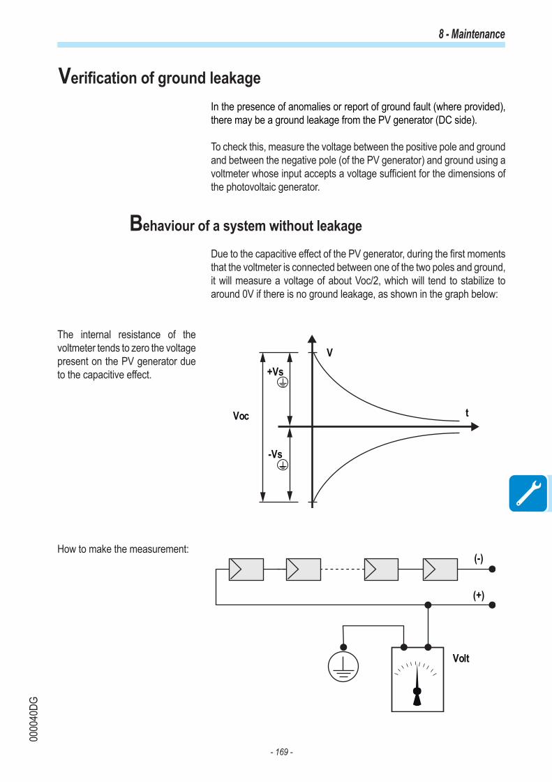
- 169 -
0000
40DG
8 - Maintenance
Verification of ground leakage In the presence of anomalies or report of ground fault (where provided), there may be a ground leakage from the PV generator (DC side).
To check this, measure the voltage between the positive pole and ground and between the negative pole (of the PV generator) and ground using a voltmeter whose input accepts a voltage sufficient for the dimensions of the photovoltaic generator.
Behaviour of a system without leakage
Due to the capacitive effect of the PV generator, during the first moments that the voltmeter is connected between one of the two poles and ground, it will measure a voltage of about Voc/2, which will tend to stabilize to around 0V if there is no ground leakage, as shown in the graph below:
The internal resistance of the voltmeter tends to zero the voltage present on the PV generator due to the capacitive effect.
How to make the measurement:
Voc
V
t
+Vs
-Vs
Volt
(+)
(-)

- 170 -
0000
40DG
8 - Maintenance
Behaviour of a system with leakage
If the voltage measured between one of the two poles and ground does not tend to 0V and stabilizes on a value, there is a ground leakage from the PV generator.
Example: When the measurement is made between positive pole and ground, a voltage of 200V is measured.
This means that if the system is made up of 10 modules in series and each one supplies 50V, the leakage can be located between the 4th and 5th PV module.
Va = voltage measured between + pole and = 200VVb = voltage measured between - pole and = 300VIn all measurements with , the ground of the inverter is indicated.
V
200 V
300 V
t
(+) (-)
50 V 50 V 50 V 50 V
Va
50 V 50 V
1 2 3 4 7 85 6 9 10
Vb
50 V 50 V 50 V 50 V

- 171 -
0000
43DG
8 - Maintenance
Measuring the insulation resistance of photovoltaic generatorTo measure the insulation resistance of the PV generator compared to ground , the two poles of the PV generator must be short-circuited (using a suitably sized switch).
+
_IG
Once the short-circuit has been made, measure the insulation resistance (Riso) using a megohmmeter positioned between the two shorted poles and ground (of the inverter).
MegaInverter
IG
+
_
-TL MODELS (transformerless). If the measured insulation resistance (Riso) is less than 1Mohm the inverter does not connect to the grid due to a low insulation of photovoltaic generator respect to ground.
-I MODELS (with high frequency transformer). If the measured insu-lation resistance ( Riso in case of input poles floating respect to ground or QF=1 if the one of input poles is grounded) is less than 0.2Mohm the inverter does not connect to the grid due to a low insulation of photovol-taic generator respect to ground.
The insulation resistance is affected by the environmental conditions the PV generator is in (E.g.: photovoltaic module wet from dump or rain), and therefore the measurement must be made immediately after the anomaly

- 172 -
0000
39CG
8 - Maintenance
Storage and dismantling
Storage of the equipment or prolonged stop
If the equipment is not used immediately or is stored for long periods, check that it is correctly packed and contact ABB for storage instructions.The equipment must be stored in well-ventilated indoor areas having no characteristics that could damage the components of the equipment.
Restarting after a long or prolonged stop requires a check and, in some cases, the removal of oxidation and dust that will also have settled inside the equipment if not suitably protected.
Dismantling, decommissioning and disposal
ABB is not responsible for any loss of the equipment, or part of it, which does not take place on the basis of the regulations and laws in force in the country of installation.
The symbol of the cancelled bin (where present) indicates that the product must not be disposed of with domestic waste at the end of its useful life.This product must be delivered to the waste collection point of the local community for recycling.For further information, refer to the public body responsible for waste disposal in the country.
Inappropriate disposal of waste can have a negative impact on the environment and human health owing to potentially dangerous substances.By cooperating in the correct disposal of this product, you contribute to the reuse, recycling and recovery of the product, and the protection of our environment.
Dispose of the various types of materials that the parts of the equipment consist of in dumps that are suitable for the purpose.
COMPONENT MATERIAL OF CONSTRUCTIONFrame, brackets, supports Arc-welded steel FE37, aluminiumCasing or covers ABS, plasticPaint RALGaskets and seals Rubber / Teflon / VitonElectrical cables Copper / RubberCable trays Polyethylene / NylonBatteries Nickel / Lead/ Lithium

- 173 -
0003
39AG
Further informationFor more information on ABB solar products and services, visit www.abb.com/solarinverters


![$Tl]DH - E-Journal UIN Jakarta](https://static.fdokumen.com/doc/165x107/63260c1d051fac18490d904c/tldh-e-journal-uin-jakarta.jpg)