Product Manual - IIS Windows Server
46
Product Manual X AIR XR18/X18/XR16/XR12 Digital Mixer Series for iPad/Android Tablets with Programmable MIDAS Preamps, Integrated Wifi Module and USB
-
Upload
khangminh22 -
Category
Documents
-
view
3 -
download
0
Transcript of Product Manual - IIS Windows Server

Product Manual
X AIRXR18/X18/XR16/XR12Digital Mixer Series for iPad/Android Tablets with Programmable MIDAS Preamps, Integrated Wifi Module and USB

2 X AIR User Manual
Table of ContentsImportant Safety Instructions ...................................... 3
Legal Disclaimer ............................................................. 3
Limited warranty ............................................................ 3
1. Introduction ............................................................... 4
2. Callouts ....................................................................... 5
2.1 X18/XR18 Callouts ............................................................... 5
2.2 XR16/XR12 Callouts ............................................................ 6
3. Hookup ....................................................................... 7
3.1 X18/XR18 Hookups ............................................................. 7
3.2 XR16/XR12 Hookups ........................................................ 11
4. Network Connection ............................................... 14
4.1 IP Address and DHCP ....................................................... 14
4.2 Ethernet/LAN ..................................................................... 14
4.3 Wifi Client ............................................................................ 14
4.4 Access Point ........................................................................ 15
4.5 Getting Started.................................................................. 15
5. X AIR for iPad ............................................................ 16
5.1 Main Screen ........................................................................ 16
5.2 Input ...................................................................................... 16
5.3 Sends ..................................................................................... 16
5.4 Gate ....................................................................................... 17
5.5 Dynamics ............................................................................. 17
5.6 Channel EQ ......................................................................... 18
5.7 Insert ..................................................................................... 18
5.8 Presets .................................................................................. 18
5.9 Output .................................................................................. 18
5.10 Meters ................................................................................. 18
5.11 Shows .................................................................................. 18
5.12 Routing ............................................................................... 19
5.13 Effects.................................................................................. 19
5.14 Setup ................................................................................... 19
5.15 Main EQ .............................................................................. 19
6. X AIR for Android ..................................................... 20
6.1 Main View ............................................................................20
6.2 Input ......................................................................................20
6.3 Config ................................................................................... 21
6.4 Gate ....................................................................................... 21
6.5 EQ ........................................................................................... 21
6.6 Dynamics .............................................................................22
6.7 Sends .....................................................................................22
6.8 Main .......................................................................................22
6.9 Meters ...................................................................................23
6.10 Effect Rack .........................................................................23
6.11 Snapshots ..........................................................................23
6.12 Scenes and Shows ..........................................................23
6.13 Routing ...............................................................................23
6.14 Setup ................................................................................... 24
7. X AIR for PC ............................................................... 25
7.1 Main View and Mixer Tab ...............................................25
7.2 Channel Tab ........................................................................25
7.3 Input Tab .............................................................................. 26
7.4 Gate Tab ................................................................................ 26
7.5 EQ Tab ................................................................................... 26
7.6 Comp Tab ............................................................................. 27
7.7 Sends Tab ............................................................................. 27
7.8 Main Tab ............................................................................... 27
7.9 FX Tab .................................................................................... 27
7.10 Meter Tab ...........................................................................28
7.11 Setup Menu .......................................................................28
7.12 Snapshot Page..................................................................29
7.13 Utilities ................................................................................29
7.14 Auto Mix .............................................................................30
8. MIDI ........................................................................... 31
9. Specifications ........................................................... 32
9.1 X18/XR18 Specifications ................................................. 32
9.2 XR16/XR12 Specifications ...............................................34
10. Effect Descriptions ................................................ 35
11. Instructional Videos .............................................. 42
12. Block Diagrams ...................................................... 43
12.1 X18/XR18 Block Diagram .............................................. 43
12.2 XR16/XR12 Block Diagram ...........................................44
3 X AIR User Manual
Terminals marked with this symbol carry electrical current of suffi cient magnitude to constitute risk of electric shock.
Use only high-quality professional speaker cables with ¼" TS or twist-locking plugs pre-installed. All other installation or modifi cation should be performed only by qualifi ed personnel.
This symbol, wherever it appears, alerts you to the presence of uninsulated dangerous voltage inside the
enclosure - voltage that may be suffi cient to constitute a risk of shock.
This symbol, wherever it appears, alerts you to important operating and maintenance instructions in the
accompanying literature. Please read the manual.
CautionTo reduce the risk of electric shock, do not remove the top cover (or the rear section).
No user serviceable parts inside. Refer servicing to qualifi ed personnel.
CautionTo reduce the risk of fi re or electric shock, do not expose this appliance to rain and
moisture. The apparatus shall not be exposed to dripping or splashing liquids and no objects fi lled with liquids, such as vases, shall be placed on the apparatus.
CautionThese service instructions are for use by qualifi ed service personnel only.
To reduce the risk of electric shock do not perform any servicing other than that contained in the operation instructions. Repairs have to be performed by qualifi ed service personnel.
1. Read these instructions.
2. Keep these instructions.
3. Heed all warnings.
4. Follow all instructions.
5. Do not use this apparatus near water.
6. Clean only with dry cloth.
7. Do not block any ventilation openings. Install in accordance with the manufacturer’s instructions.
8. Do not install near any heat sources such as radiators, heat registers, stoves, or other apparatus (including amplifi ers) that produce heat.
9. Do not defeat the safety purpose of the polarized or grounding-type plug. A polarized plug has two blades with one wider than the other. A grounding-type plug has two blades and a third grounding prong. The wide blade or the third prong are provided for your safety. If the provided plug does not fi t into your outlet, consult an electrician for replacement of the obsolete outlet.
10. Protect the power cord from being walked on or pinched particularly at plugs, convenience receptacles, and the point where they exit from the apparatus.
11. Use only attachments/accessories specifi ed by the manufacturer.
12. Use only with the cart, stand, tripod, bracket, or table specifi ed by the manufacturer, or sold with the apparatus. When a cart is used, use caution when moving the cart/apparatus combination to avoid
injury from tip-over.
13. Unplug this apparatus during lightning storms or when unused for long periods of time.
14. Refer all servicing to qualifi ed service personnel. Servicing is required when the apparatus has been damaged in any way, such as power supply cord or plug is damaged, liquid has been spilled or objects have fallen into the apparatus, the apparatus has been exposed to rain or moisture, does not operate normally, or has been dropped.
15. The apparatus shall be connected to a MAINS socket outlet with a protective earthing connection.
16. Where the MAINS plug or an appliance coupler is used as the disconnect device, the disconnect device shall remain readily operable.
17. Correct disposal of this product: This symbol indicates that this product must not be disposed of with household waste, according to the WEEE Directive (2012/19/EU) and your national law. This product
should be taken to a collection center licensed for the recycling of waste electrical and electronic equipment (EEE). The mishandling of this type of waste could have a possible negative impact on the environment and human health due to potentially hazardous substances that are generally associated with EEE. At the same time, your cooperation in the correct disposal of this product will contribute to the effi cient use of natural resources. For more information about where you can take your waste equipment for recycling, please contact your local city offi ce, or your household waste collection service.
18. Do not install in a confi ned space, such as a book case or similar unit.
19. Do not place naked fl ame sources, such as lighted candles, on the apparatus.
20. Please keep the environmental aspects of battery disposal in mind. Batteries must be disposed-of at a battery collection point.
21. Use this apparatus in tropical and/or moderate climates.
MUSIC Group accepts no liability for any loss which may be suff ered by any person who relies either wholly or in part upon any description, photograph, or statement contained herein. Technical specifi cations, appearances and other information are subject to change without notice. All trademarks are the property of their respective owners. MIDAS, KLARK TEKNIK, LAB GRUPPEN, LAKE, TANNOY, TURBOSOUND, TC ELECTRONIC, TC HELICON, BEHRINGER, BUGERA and DDA are trademarks or registered trademarks of MUSIC Group IP Ltd. © MUSIC Group IP Ltd. 2016 All rights reserved.
For the applicable warranty terms and conditions and additional information regarding MUSIC Group’s Limited Warranty, please see complete details online at music-group.com/warranty.
Important Safety Instructions
LEGAL DISCLAIMER
LIMITED WARRANTY

4 X AIR User Manual
1. IntroductionCongratulations on your purchase of the new Behringer X AIR series digital mixer. These mixers offer plenty of analog I/O for most performances in a very compact form factor that is easy to transport, but doesn’t sacrifice any mixing power. With high-end features taken from the flagship X32 mixer, such as MIDAS-designed preamps, high-quality effects, P-16 monitoring on the X18/XR18, and USB recording capability, these consoles far outperform their size.
Mixing live shows can now be done from anywhere in the venue thanks to the wireless control options that allow all software functions to be controlled from an iPad*, Android* tablet or PC. While a dedicated external router can be used, it is not necessary thanks to the integrated Wifi module. This allows monitors to be adjusted while standing on stage, and the main mix to be perfected from anywhere in the crowd.
In addition to dedicated aux buses for monitoring, the X AIR has 4 studio-quality stereo effects processors. In fact, these are the same great effects found in the acclaimed X32 mixer, including legendary reverb, echo and chorus algorithms.
Not just a live sound tool, the X18 and XR18 feature an 18x18 USB audio/MIDI interface, and the XR12 and XR16 allow 2-track stereo recording. This makes for a great mobile recording device, home studio interface, and enables live performances to be multitracked for later mixing.
Continue through this manual to learn all about the functionality of your mixer, as well as the X AIR software.
*iPad is a trademark of Apple Inc. Android is a trademark of Google Inc. iPad and Android tablet are not included.
5 X AIR User Manual
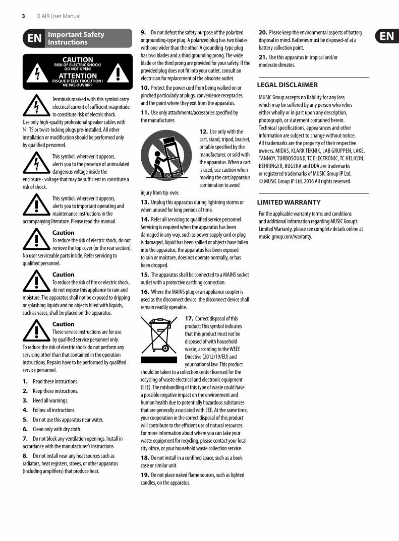
2. Callouts2.1 X18/XR18 Callouts
(1) INPUTS accept balanced and unbalanced XLR and ¼" plugs. Inputs 1 and 2 have high-impedance preamps for direct connection of guitars and basses.
(2) OUT L & R jacks send the main mix signal to PA or monitor speakers via XLR cables.
(3) RCA IN jacks (X18 only) accept unbalanced RCA cables for connecting MP3 players, external mixers, iPad, etc. These inputs have limited processing compared to the other input channels.
(4) RCA OUT jacks (X18 only) send either the main mix signal or headphone signal via unbalanced RCA cables to a pair of active studio monitors.
(5) CONTROL ROOM button (X18 only) determines whether the main mix or headphone/solo signal is routed to the RCA OUT jacks.
(6) HEADPHONE jack accepts a ¼" TRS plug for connecting a pair of headphones.
(7) PHONES LEVEL knob determines the output of the headphones jack.
(8) POWER switch turns the power on and off . The LED on the main input panel will light when the unit is powered on.
(9) USB port (type B) accepts a USB cable for connection to a computer for multi-channel audio and MIDI recording. Up to 18 audio channels can be simultaneously recorded, and 18 channels are available for playback. The mixer application allows assignment of channels for recording and playback. 16 channels of MIDI I/O can also be transmitted on the same USB connection. Check the product page on music-group.com to download
the required Windows* multi-channel driver. The interface is compatible with CoreAudio on Mac* computers, and to ALSA/Jack on Linux* computers.
(10) ETHERNET port allows the mixer to be controlled via LAN or connected Wifi router.
(11) RESET button resets the console to default network parameters when held for 2 seconds. When held for 10 seconds, all console functions are reset to factory default status.
(12) REMOTE switch selects between Ethernet, Wifi client, or Access Point. See the Network Connection chapter for details.
(13) MIDI IN/OUT jacks send and receive MIDI signals to and from external equipment. See the MIDI Implementation chart for details.
(14) ULTRANET port allows connection of BEHRINGER P16-M personal monitoring mixers or P16-D distribution hubs.
(15) AUX SEND jacks send your monitor mixes to active stage monitors or headphone mixers. The XR18 uses XLR connectors, while the X18 uses balanced ¼" jacks.
(16) Inputs 17 and 18 (XR18 only) accept balanced ¼ " cables for connecting line-level sources. These inputs have limited processing compared to the other input channels.
*Mac is a trademark of Apple Inc. Windows is either a registered trademark or trademark of Microsoft Corporation in the United States and/or other countries. Linux is the registered trademark of Linus Torvalds in the U.S. and other countries
PERSONALMONITORINGETHERNET
WIFI CLIENT
ACCESSPOINT
2
1
4
3
6
5
USB REMOTE MIDI ULTRANET AUX SENDS
INOUT
(1)
(15) (2) (6)
(7)
(8)
(10) (12) (11) (13) (9) (14)
(8) (9) (10) (11) (12) (14) (15)(13)
(6) (7)
(5)
(4)(3)(2)(1)
(16)

6 X AIR User Manual
2.2 XR16/XR12 Callouts
(1) ETHERNET port allows the mixer to be controlled via LAN or connected Wifi router.
(2) REMOTE switch selects between Ethernet, Wifi client, or Access Point. See the Network Connection chapter for details.
(3) RESET button resets the console to default network parameters when held for 2 seconds. When held for 10 seconds, all console functions are reset to factory default status.
(4) MIDI IN/OUT jacks send and receive MIDI signals to and from external equipment. See the MIDI Implementation chart for details.
(5) USB port (type A) accepts a flash drive for file storage, stereo recordings and playback. The red LED next to it indicates file access. Do not remove the USB flash drive while it is lit!
(6) XLR COMBO jacks accept balanced and unbalanced XLR and ¼" plugs.
(7) ¼" inputs accept balanced or unbalanced ¼" plugs. Channel 15 and 16 on the XR16 (channel 11 and 12 on the XR12) accept high impedance sources for direct connection of guitars and basses.
(8) AUX SEND jacks send your monitor mixes to stage monitors or headphone mixers. The XR16 uses XLR connectors while the XR12 uses balanced ¼" jacks.
(9) MAIN L/R jacks send the main mix signal to PA or monitor speakers via XLR cables.
(10) HEADPHONE jack accepts a ¼" TRS plug for connecting a pair of headphones.
(11) PHONES LEVEL knob determines the output of the headphones jack.
(12) POWER switch turns the mixer on and off . The front panel LED will light when the unit is powered on.
(5)(4) (9)
(11)
(12)
(10)
(1) (2) (3)
(7) (8)
(6)
(9) (10) (11)
(6)
(7)
(8)
(5)(4)(3)(2)(1)

7 X AIR User Manual
3. Hookup3.1 X18/XR18 Hookups
3.1.1 X18 recording with iPad
B215D active loudspeakers
MP3 Player
BUGERA V22
XM8500
HPS3000Keyboard
TR
S

8 X AIR User Manual
PERSONALMONITORINGETHERNET
WIFI CLIENT
ACCESSPOINT
2
1
4
3
6
5
USB REMOTE MIDI ULTRANET AUX SENDS
INOUT
F1320D active monitors
P16-D
P16-M
iPad with camera connection kit for multi-track recording up to 18 tracks
TR
S
TR
S
Wireless router (optional)iPad for remote control
Laptop for additional remote control
TR
S

9 X AIR User Manual
3.1.2 XR18 live performance
P16-D
P16-M
TR
S
HPX6000
KeyboardF1320D Active Monitors
BUGERA V22
XM8500
iPad for wireless control
B215D active loudspeakers

10 X AIR User Manual
3.1.3 X18/XR18 System Overview
Hi-Z
MIC/LINE INCH. 1-16
AUDIO IN/OUT CH. 1-18
MAIN OUT L-R
MAIN OUT L/R
CTRL/PHONES
AUX SEND 1-6
ULTRANET OUTCH. 1-16
ETHERNET
CH.1-2
LINE INCH. 17-18
PHONES STEREO
AUDIO INPUTS USB AUDIO
AUDIO I/OMIXER CONTROL
DSP ENGINE X18/XR18
MIDI I/O
WIRED CONTROL
ACCESSPOINT*
WIFICLIENT*
WIRELESS CONTROL AUDIO OUTPUTS
LEVEL
DSP
ACCESS POINTWIFI CLIENT
ETHERNET
orRouter
Router
WIFI CLIENT mode (Mobile Devices with Wifi)
ETHERNET mode
Computer with Ethernet port
Mobile Devices with Wifi
CAT-5 cable
CAT-5 cable
ACCESS POINT mode (Mobile Devices with Wifi)
X18:
XR18:
X18:
iOS/Android
X-TOUCH
or any other MIDI / Mackie Control compatible Controller
*ACCESS POINT mode: - available channels: 1-11 - max. 4 Wifi clients - performance limited by Wifi bandwidth
*WIFI CLIENT mode: - available channels: 1-11
4 STEREO FX SLOTS RTA METER
DSP-MIXER CH.MONO IN 1-16USB/AUX IN (STEREO)FX RETURN 1-4 (STEREO)
DSP-MIXER BUSESAUX / GROUP SEND 1-6
Mac/Win/Linux
Mac/Win/Linux
iOS/Android
iOS/Android AndroidMac/Win/Linux
P16-M
P16-D
or
DACs
ADCs
ADCs
DACs
DACs

11 X AIR User Manual
3.2 XR16/XR12 Hookups
3.2.1 XR16 club performance
TR
S
HPX6000
USB Flash Drive
XM8500
FCB1010 MIDI Controller
Laptop for wired or wireless control
Keyboard
BUGERA V22
B215D active loudspeakersF1320D Active Monitors
12 X AIR User Manual
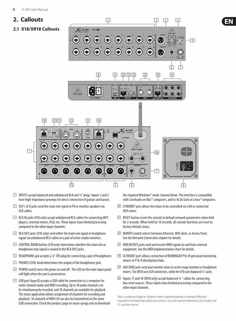
3.2.2 XR12 with Sub Mixer
QX2222USB
F1320D active monitors
TR
S
HPX6000
Wireless router (optional)
iPad for remote control
B215D active loudspeakers
Keyboard
Keyboard
E-Drums

13 X AIR User Manual
3.2.3 XR16/XR12 System Overview
MIC/LINE INXR16: CH. 1-8XR12: CH. 1-4
STEREO REC(VARIOUS SOURCES)
STEREO PLAY(SPECIFIC “USB”
STEREOINPUT CHANNEL) MAIN OUT L-R
XR16:AUX SEND 1-4
XR12: AUX SEND 1-2
ETHERNET
Hi-ZXR16: CH. 15-16XR12: CH. 11-12
LINE INXR16: CH. 9-16XR12: CH. 5-12
PHONES STEREOAUDIO INPUTS USB RECORDER
AUDIO I/OMIXER CONTROL
DSP ENGINEXR16/XR12
MIDI I/O
WIRED CONTROL
ACCESSPOINT*
WIFICLIENT*
WIRELESSCONTROL
AUDIO OUTPUTS
LEVEL
DSP
ACCESS POINTWIFI CLIENT
ETHERNET
Router
Router
WIFI CLIENT mode (Mobile Devices with Wifi)
ETHERNET modeComputer with Ethernet port
Mobile Devices with Wifi
CAT-5 cable
CAT-5 cable
ACCESS POINT mode (Mobile Devices with Wifi)
iOS/Android
X-TOUCH
or any other MIDI / Mackie Control compatible Controller
*ACCESS POINT mode: - available channels: 1-11 - max. 4 Wifi clients - bandwidth limited by Wifi adapter
*WIFI CLIENT mode: - available channels: 1-11
*XR12: CH. 13-16 fed by any IN 1-12 (Signal Split, e.g. for monitoring with different EQ)
*PRE-DEFINED BUSES Also used for monitoring
4 STEREO FX SLOTS
DSP-MIXER CH.MONO IN 1-16USB/AUX IN (STEREO)FX RETURN 1-4 (STEREO)
DSP-MIXER BUSESPRE-DEFINED AS SUBGROUPS*
XR12: BUSES 3/4/5/6XR16: BUSES 5/6
Mac/Win/Linux
Mac/Win/Linux
iOS/Android
iOS/Android AndroidMac/Win/Linux
or DACs
DACs
4 STEREO FX SLOTS
DSP-MIXER CH.MONO IN 1-16*USB/AUX IN (STEREO)FX RETURN 1-4 (STEREO)
DSP-MIXER BUSESPRE-DEFINED AS SUBGROUPS*
XR12: BUSES 3/4/5/6XR16: BUSES 5/6
ADCs
RTA METER
DACs
ADCs

14 X AIR User Manual
4. Network ConnectionThe X AIR mixers offer convenient digital control of the various mixing functions in three different ways - via Ethernet LAN, or wirelessly as a Wifi Client or as an Access Point. Selection is made with the REMOTE switch. You may view or change the network preferences for these on any of the X AIR remote control applications on the ’Setup/Network’ page.
4.1 IP Address and DHCPDepending on the connection scenario, the X AIR mixers offer up to 3 options for connecting a tablet or PC for software control – DHCP Client, DHCP Server, and fixed IP operation. Connection is achieved differently depending on which option you choose:
DHCP Client mode is available in Ethernet LAN or Wifi Client operation. The mixer will automatically request an IP lease from the DHCP server that owns the IP addresses in the network to which you are trying to connect.
DHCP Server (DHCPS) is optionally available for Ethernet LAN connections and is standard in Access Point operation. The mixer will own the IP addresses and provide IP leases to devices requesting access to that network. The mixer will always use IP address 192.168.1.1 and assign IP addresses 192.168.1.101 – 192.168.1.132 to its clients.
Static IP is available for Ethernet LAN and Wifi Client operation. The mixer will use the fixed (static) IP address, subnet mask and gateway that you specify for registering on the network. Make sure that the addresses you specify manually are not conflicting with any other addresses on the same network. We generally recommend using the DHCP mode, unless you have a very specific reason to set it up manually.
Note: Changing parameters of the currently selected connection mode will disconnect the software from the console. If the console is erroneously configured for a fixed IP address that is incompatible with the network it is connected to, the console will be inaccessible. In this case, one of the other two connection modes can be used to regain access and amend the settings. If that does not work, hold the Reset button for 2 seconds to return to default network settings.
Mixer name and Ethernet setup screen
4.2 Ethernet/LANThis mode supports DHCP Client (default), DHCP Server, and fixed IP operation. Note that if the mixer is connected to a network where no DHCP server is present, the mixer will generate an automatic IP address (range 169.254.1.0 – 169.254.254.255). There are no security options for LAN connections, so any device in that network may take control of connected X AIR consoles. When connecting via LAN/Ethernet to a Wifi router, make sure the security settings of that router prevent unauthorized access.
Wifi Client setup screen
4.3 Wifi ClientThis mode supports DHCP Client (default) and fixed IP operation. The X AIR mixers can support WEP, WPA and WPA2 security mechanisms in Wifi Client mode and works on Wifi channels 1-11.
Correct SSID (network name) and password need to be supplied to connect to an existing network. WEP passwords have to be either 5 characters or 13 characters long. If the supplied SSID and password are incorrect, the mixer cannot be accessed. In this case the networking parameters have to be reset and another connection mode has to be used to regain access.
The Ethernet connection mode may be used for configuration of the Wifi Client mode. While being connected in Ethernet mode, the X AIR mixer can scan the available wireless networks and display their SSID network names, field strength and security method. By selecting the preferred wireless network, this information can be copied to the applications’ Wifi Client setup page automatically. You will then be prompted to fill in the security password of that network. After switching from Ethernet to Wifi Client mode, the mixer should connect to the selected wireless network automatically, and will be displayed by remote applications on any device connected to the same network.
Access Point setup screen
15 X AIR User Manual
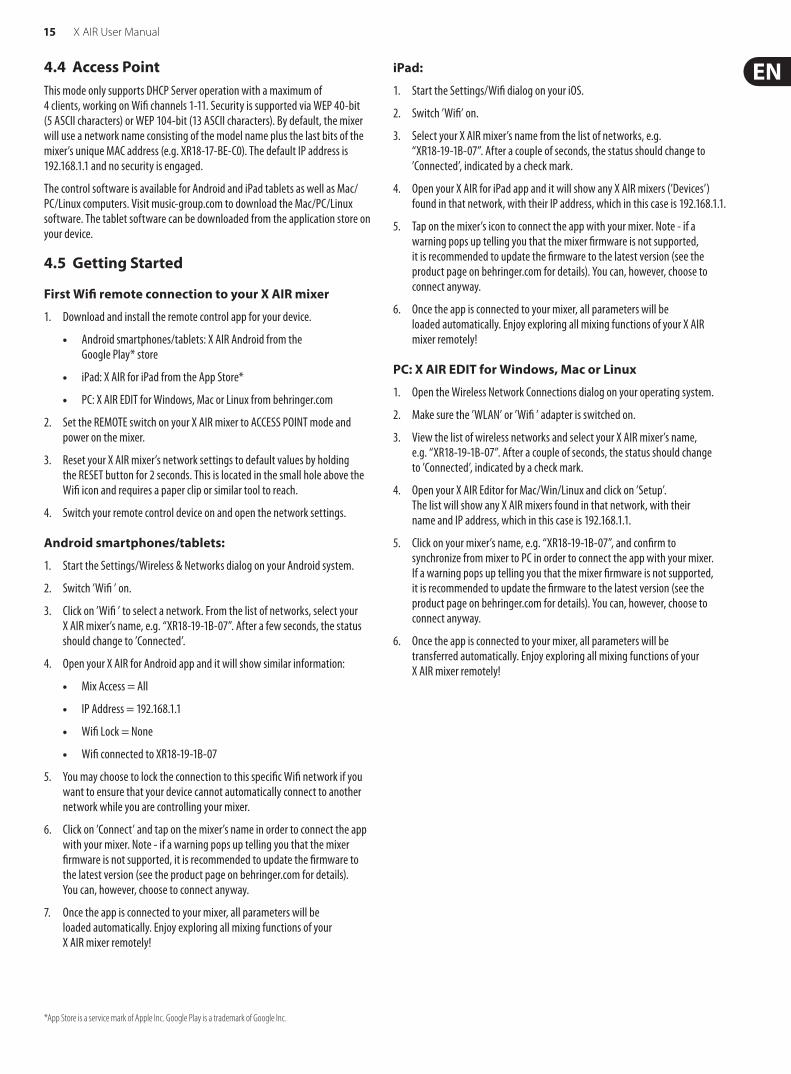
4.4 Access PointThis mode only supports DHCP Server operation with a maximum of 4 clients, working on Wifi channels 1-11. Security is supported via WEP 40-bit (5 ASCII characters) or WEP 104-bit (13 ASCII characters). By default, the mixer will use a network name consisting of the model name plus the last bits of the mixer’s unique MAC address (e.g. XR18-17-BE-C0). The default IP address is 192.168.1.1 and no security is engaged.
The control software is available for Android and iPad tablets as well as Mac/PC/Linux computers. Visit music-group.com to download the Mac/PC/Linux software. The tablet software can be downloaded from the application store on your device.
4.5 Getting Started
First Wifi remote connection to your X AIR mixer
1. Download and install the remote control app for your device.
• Android smartphones/tablets: X AIR Android from the Google Play* store
• iPad: X AIR for iPad from the App Store*
• PC: X AIR EDIT for Windows, Mac or Linux from behringer.com
2. Set the REMOTE switch on your X AIR mixer to ACCESS POINT mode and power on the mixer.
3. Reset your X AIR mixer’s network settings to default values by holding the RESET button for 2 seconds. This is located in the small hole above the Wifi icon and requires a paper clip or similar tool to reach.
4. Switch your remote control device on and open the network settings.
Android smartphones/tablets:
1. Start the Settings/Wireless & Networks dialog on your Android system.
2. Switch ’Wifi ’ on.
3. Click on ’Wifi ’ to select a network. From the list of networks, select your X AIR mixer’s name, e.g. “XR18-19-1B-07”. After a few seconds, the status should change to ’Connected’.
4. Open your X AIR for Android app and it will show similar information:
• Mix Access = All
• IP Address = 192.168.1.1
• Wifi Lock = None
• Wifi connected to XR18-19-1B-07
5. You may choose to lock the connection to this specific Wifi network if you want to ensure that your device cannot automatically connect to another network while you are controlling your mixer.
6. Click on ’Connect’ and tap on the mixer’s name in order to connect the app with your mixer. Note - if a warning pops up telling you that the mixer firmware is not supported, it is recommended to update the firmware to the latest version (see the product page on behringer.com for details). You can, however, choose to connect anyway.
7. Once the app is connected to your mixer, all parameters will be loaded automatically. Enjoy exploring all mixing functions of your X AIR mixer remotely!
iPad:
1. Start the Settings/Wifi dialog on your iOS.
2. Switch ’Wifi’ on.
3. Select your X AIR mixer’s name from the list of networks, e.g. “XR18-19-1B-07”. After a couple of seconds, the status should change to ’Connected’, indicated by a check mark.
4. Open your X AIR for iPad app and it will show any X AIR mixers (’Devices’) found in that network, with their IP address, which in this case is 192.168.1.1.
5. Tap on the mixer’s icon to connect the app with your mixer. Note - if a warning pops up telling you that the mixer firmware is not supported, it is recommended to update the firmware to the latest version (see the product page on behringer.com for details). You can, however, choose to connect anyway.
6. Once the app is connected to your mixer, all parameters will be loaded automatically. Enjoy exploring all mixing functions of your X AIR mixer remotely!
PC: X AIR EDIT for Windows, Mac or Linux
1. Open the Wireless Network Connections dialog on your operating system.
2. Make sure the ’WLAN’ or ’Wifi ’ adapter is switched on.
3. View the list of wireless networks and select your X AIR mixer’s name, e.g. “XR18-19-1B-07”. After a couple of seconds, the status should change to ’Connected’, indicated by a check mark.
4. Open your X AIR Editor for Mac/Win/Linux and click on ’Setup’. The list will show any X AIR mixers found in that network, with their name and IP address, which in this case is 192.168.1.1.
5. Click on your mixer’s name, e.g. “XR18-19-1B-07”, and confirm to synchronize from mixer to PC in order to connect the app with your mixer. If a warning pops up telling you that the mixer firmware is not supported, it is recommended to update the firmware to the latest version (see the product page on behringer.com for details). You can, however, choose to connect anyway.
6. Once the app is connected to your mixer, all parameters will be transferred automatically. Enjoy exploring all mixing functions of your X AIR mixer remotely!
*App Store is a service mark of Apple Inc. Google Play is a trademark of Google Inc.
16 X AIR User Manual
5. X AIR for iPadThe X AIR applications for iOS, Android and Mac/Win/Linux allow all of the physical controls and features normally found on analog mixers to be adjusted digitally, and also allow effects and routing to be fully adjusted, all from a remote location away from the input box. This results in a very compact, yet full-featured mixing solution that can be operated while moving about the venue or studio. This chapter will discuss the software's functionality on an iPad.
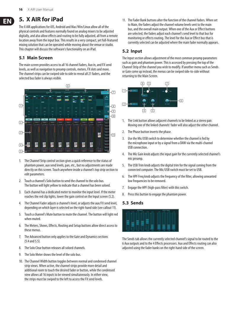
5.1 Main ScreenThe main screen provides access to all 16 channel faders, Aux in, and FX send levels, as well as navigation to preamp controls, meters, FX slots and more. The channel strips can be swiped side to side to reveal all 21 faders, and the selected bus fader is always visible.
1. The Channel Strip control section gives a quick reference to the status of phantom power, aux send levels, pan, etc., but no adjustments are made directly on this screen. Touch anywhere inside a channel’s top strip section to edit parameters.
2. Touch a channel’s Solo button to send the channel to the solo bus. The button will light yellow to indicate that a channel has been soloed.
3. Each channel has a dedicated meter to monitor the input level. If the meter reaches the red clip lights, lower the gain control on the Input screen (5.2).
4. The Channel Fader adjusts a channel’s level, or adjusts the aux/FX send level, depending on which layer is selected on the right-hand side (see callout 11).
5. Touch a channel’s Mute button to mute the channel. The button will light red when muted.
6. The Meters, Shows, Effects, Routing and Setup buttons allow direct access to these menus.
7. The Advanced button only applies to the Gate and Dynamics sections (5.4 and 5.5).
8. The Solo Clear button releases all soloed channels.
9. The Solo Meter shows the level of the solo bus.
10. The Channel Width button toggles between normal and condensed channel strip views. When active, the channel strips provide more detail and additional room to touch the desired fader or button, while the condensed view allows all 16 inputs to be viewed simultaneously. In either view, the strips must be swiped to the left to access the FX send levels.
11. The Fader Bank buttons alter the function of the channel faders. When set to Main, the faders adjust the channel volume levels sent to the main bus, and the overall main output. When one of the Aux or Effect buttons are selected, the faders adjust each channel’s send level to that bus for monitoring or effects routing. The level for the Aux or Effect bus that is currently selected can be adjusted where the main fader normally appears.
5.2 InputThe Input section allows adjustment of the most common preamp parameters such as gain and phantom power. This is accessed by pressing the top of the Channel Strip of the channel you wish to modify. If another menu such as Sends or Gate come up instead, the menus can be swiped side-to-side without returning to the Main Screen.
1. The Link button allows adjacent channels to be linked as a stereo pair. Moving one of the linked channels‘ fader will also adjust the other channel.
2. The Phase button inverts the phase.
3. Use the Mic/USB switch to determine whether the channel is fed by the microphone input or by a signal from a DAW via the multi-channel USB connection.
4. The Mic Gain knob adjusts the input gain for the currently selected channel’s mic preamp.
5. The USB Trim knob adjusts the digital trim for the signal coming from the connected computer. The Mic/USB switch must be set to USB.
6. The HPF Freq knob adjusts the frequency of the filter, allowing unwanted low frequencies to be removed.
7. Engage the HPF (high-pass filter) with this switch.
8. Press this button to engage the phantom power.
5.3 Sends
The Sends tab allows the currently selected channel’s signal to be routed to the 6 Aux outputs and to the 4 Effects processors. Aux and Effects routing can also adjusted using the fader banks on the right-hand side of the screen.
(7)
(8)
(9)
(10)
(11)
(1)
(2)
(3)
(4)
(5)
(6)
(1)
(2)(6)
(3)(8)
(4) (5)
(7)

17 X AIR User Manual
5.4 GateThe Gate tab allows a noise gate to be engaged and adjusted to remove unwanted noise. To accommodate various levels of mixing expertise, a standard or advanced screen can be selected. The standard view offers 4 presets and a threshold adjustment, while the advanced view allows fine adjustment of the gate parameters.
1. Engage the gate with the on/off button.
2. Adjust the Threshold that the audio must reach in order to bypass the gate. Any audio that does not register beyond the threshold setting will be muted automatically.
3. Press this button to open the preset list where your settings can be saved can recalled.
1. Engage the gate with the on/off button.
2. Gate Type buttons allow various types of gates to be selected. The EXP2, 3 and 4 settings reduce the output by varying amounts, allowing a natural-sounding reduction of signals that don’t reach the selected threshold. The Gate setting enables a more aggressive drop in volume for signals below the threshold. An additional Range parameter adjusts the amount of attenuation. The Ducker setting attenuates the signal by a predetermined amount whenever the signal rises beyond the selected threshold. The Range parameter adjusts the amount of attenuation for this setting as well.
3. Adjust the Threshold that the audio must reach in order to bypass the gate or engage the Ducker.
4. The Range parameter adjusts the amount of signal attenuation for the Gate and Ducker settings.
5. Adjust the Attack knob to set how quickly the gate takes effect when the input signal drops below the threshold.
6. Adjust the Hold knob to set how long the input signal must surpass the threshold before bypassing the gate.
7. Adjust the Release knob to set how quickly the gate releases after the audio rises above the threshold.
8. Engage the Key Filter with the on/off button.
9. Select a high-pass, low-pass or mid peak frequency and slope for the key filter. The specific frequency can be selected by dragging the line across the frequency chart.
10. Press the Advanced button to select between normal and advanced gate operation.
11. Access the Key Filter parameters by pressing this button.
12. Select a source for the key filter.
5.5 DynamicsA channel’s dynamics can be adjusted on this page. A compressor is useful for reducing the dynamic range of a signal, allowing the perceived volume in the mix to be raised without clipping. An expander can add dynamics by attenuating a signal when it drops below the predetermined threshold.
1. Engage the compressor with the on/off button.
2. Adjust the Threshold at which the compressor begins to take effect. Audio that falls below this setting will remain unaffected.
3. Press this button to open the preset list where your settings can be saved can recalled.
1. Engage the dynamics processor with the on/off button.
2. Adjust the Threshold at which the compressor begins to take effect. Audio that falls below this setting will remain unaffected.
3. Adjust the Knee to allow the compressor to have a more gradual effect on the signal. When the Knee is set fully to the left (hard knee), any signals that rise above the threshold will receive the full compression ratio right away.
4. Select between a compressor or expander to set the action of the dynamics processor.
(1)
(2)
(3)
(1)
(8)
(4)(3)
(2)
(9)
(11)
(10)
(5) (6) (7)
(12)
(1)
(2)
(3)
(1)
(2) (5) (7)(6) (8)(4) (9)
(11)(3) (10) (12) (13)
(14)
(15)
18 X AIR User Manual
5. Adjust the Ratio to determine how aggressively the dynamics are affected.
6. The Wet/Dry ratio determines how much of the signal is left unaffected by the processor.
7. Use the Gain fader to compensate for changes in level caused by the processor.
8. Engage the Key Filter with the on/off button.
9. Select between an aggressive Linear or smooth Logarithmic operation, and between Peak or RMS input response. RMS is most common in compressors, and responds to the average level of incoming audio, whereas the Peak setting responds to brief spikes in loudness that would be allowed through when set to RMS.
10. Access the Key Filter parameters by pressing this button.
11. Adjust the Attack knob to set how quickly the compressor takes effect when the input signal rises above the threshold.
12. Adjust the Hold knob to set how long the compressor takes to enter the release cycle once the audio drops below the threshold.
13. Adjust the Release knob to set how quickly the compressor releases after the audio drops below the threshold.
14. Select a high-pass, low-pass or mid peak frequency and slope for the key filter. The specific frequency can be selected by dragging the line across the frequency chart.
15. Select a source for the key filter.
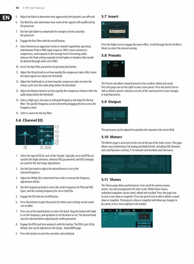
5.6 Channel EQ
1. Select the type of EQ for each of the 4 bands. Typically cut or shelf EQs are used for the highs and lows, whereas PEQ (parametric) and VEQ (vintage) are used for the mid range adjustments.
2. Use the Gain knob to adjust the desired boost or cut to the selected frequency.
3. Adjust the Width (Q) to determine how wide or narrow the frequency adjustment will be.
4. Use the Freq(uency) knob to select the center frequency for PEQ and VEQ types, and the starting frequency for cut or shelf EQs.
5. Engage the EQ with the on/off button.
6. Press this button to open the preset list where your settings can be saved can recalled.
7. Press one of the band buttons to select the band. Drag the button left/right to set the frequency, and up/down to set the boost or cut. The desired band must be selected before adjusting the width parameter.
8. Engage the RTA (real time analyzer) with this button. The RTA is pre-EQ by default, but can be adjusted on the Setup - Audio/MIDI page.
9. Press this button to reset the currently-selected band.
5.7 Insert
Press the folder icon to engage the insert effect. Scroll through the list of effects blocks to select the desired routing.
5.8 Presets
The Presets tab allows channel presets to be recalled, edited and saved. Press the page icon on the right to save a new preset. Press the pencil icon to edit or delete a preset, and press on one of the saved presets to save changes or load that preset.
5.9 Output
The panorama can be adjusted to position the channel in the stereo field.
5.10 MetersThe Meters page is accessed via the icon at the top of the main screen. This page allows easy monitoring of all analog and digital levels, including USB channels, Gate and Dynamics activity, P-16 channels and the Main and Solo buses.
5.11 ShowsThe Shows page allows performances to be saved for various venues, artists, sets and arrangements for later recall. Within those shows, individual snapshots can be saved, edited and recalled. Press the page icon to save a new show or snapshot. Press the pencil icon to edit or delete a saved show or snapshot. Pressing on a show or snapshot will allow any changes to be saved, or for a new snapshot to be loaded.
(1)
(2)
(3)
(6)(5)
(7) (4) (8) (9)
19 X AIR User Manual
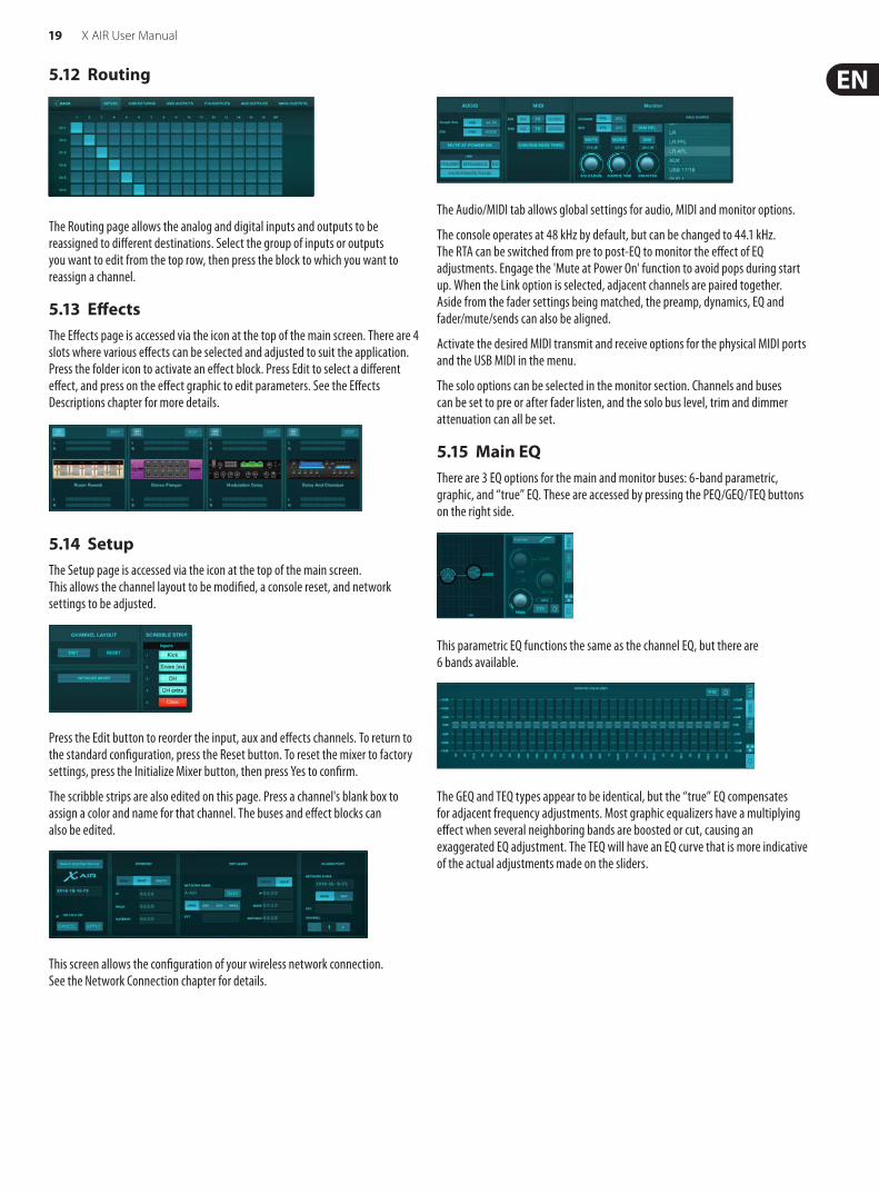
5.12 Routing
The Routing page allows the analog and digital inputs and outputs to be reassigned to different destinations. Select the group of inputs or outputs you want to edit from the top row, then press the block to which you want to reassign a channel.
5.13 EffectsThe Effects page is accessed via the icon at the top of the main screen. There are 4 slots where various effects can be selected and adjusted to suit the application. Press the folder icon to activate an effect block. Press Edit to select a different effect, and press on the effect graphic to edit parameters. See the Effects Descriptions chapter for more details.
5.14 SetupThe Setup page is accessed via the icon at the top of the main screen. This allows the channel layout to be modified, a console reset, and network settings to be adjusted.
Press the Edit button to reorder the input, aux and effects channels. To return to the standard configuration, press the Reset button. To reset the mixer to factory settings, press the Initialize Mixer button, then press Yes to confirm.
The scribble strips are also edited on this page. Press a channel's blank box to assign a color and name for that channel. The buses and effect blocks can also be edited.
This screen allows the configuration of your wireless network connection. See the Network Connection chapter for details.
The Audio/MIDI tab allows global settings for audio, MIDI and monitor options.
The console operates at 48 kHz by default, but can be changed to 44.1 kHz. The RTA can be switched from pre to post-EQ to monitor the effect of EQ adjustments. Engage the 'Mute at Power On' function to avoid pops during start up. When the Link option is selected, adjacent channels are paired together. Aside from the fader settings being matched, the preamp, dynamics, EQ and fader/mute/sends can also be aligned.
Activate the desired MIDI transmit and receive options for the physical MIDI ports and the USB MIDI in the menu.
The solo options can be selected in the monitor section. Channels and buses can be set to pre or after fader listen, and the solo bus level, trim and dimmer attenuation can all be set.
5.15 Main EQThere are 3 EQ options for the main and monitor buses: 6-band parametric, graphic, and “true” EQ. These are accessed by pressing the PEQ/GEQ/TEQ buttons on the right side.
This parametric EQ functions the same as the channel EQ, but there are 6 bands available.
The GEQ and TEQ types appear to be identical, but the “true” EQ compensates for adjacent frequency adjustments. Most graphic equalizers have a multiplying effect when several neighboring bands are boosted or cut, causing an exaggerated EQ adjustment. The TEQ will have an EQ curve that is more indicative of the actual adjustments made on the sliders.

20 X AIR User Manual
6. X AIR for AndroidThe X AIR applications for iOS, Android and Mac/Win/Linux allow all of the physical controls and features normally found on analog mixers to be adjusted digitally, and also allow effects and routing to be fully adjusted, all from a remote location away from the input box. This results in a very compact, yet full-featured mixing solution that can be operated while moving about the venue or studio. This chapter will discuss the software’s functionality on an Android device.
6.1 Main ViewThe Main View screen provides access to all 16 channel faders, Aux in, and FX and bus levels, as well as navigation to preamp controls, meters, FX slots and more.
1. The Channel Strip gives quick reference to the status of various preamp settings, and allows access to Gate, Dynamics, EQ, Pan and Input controls.
2. Touch a channel’s Solo button to send the channel to the solo bus. The corner of the button will light yellow to indicate that a channel has been soloed.
3. Each channel has a dedicated meter to monitor the input level. If the meter reaches the red clip lights, lower the gain control on the Input screen.
4. The Channel Fader adjusts a channel’s level, or adjusts the aux/FX/bus send level, depending on which layer is selected on the right-hand side.
5. Touch a channel’s Mute button to mute the channel. The button will light red when muted.
6. Access the Meters, Effect Rack, Snapshots, Show/Scene, Routing and Setup pages by touching these buttons.
7. Engaging the Fine button causes the faders to be adjusted in smaller increments, allowing more precise control.
8. Select a channel bank 1-8 or 9-16 with these buttons.
9. Access the Mute Group edit screen by pressing the Mutes button:
Engage the Mute Lock button to prevent accidental muting of individual channels. Mute All and Unmute All are quick ways to fully mute or unmute all sources. Tap one of the 4 Mute Group buttons to mute the channels assigned to that group, and hold one of the buttons to edit which channels are assigned to the group.
10. Access the Aux and FX return faders with this button.
11. Activate the Sends on Faders function with this button. When active, the faders control the bus send levels for the currently active bus (see callout 13). Moving between the channel and Aux/FX layers allows the sends for those layers to be adjusted as well.
12. Access the bus master faders with this button. Note that these will not be visible when the Sends on Faders function is active.
13. When using the Sends on Faders function, the bus to which the channel signals are sent is selected with the button directly below the Sends on Faders button. Pressing the Bus Master button will allow the send level for the selected bus to be adjusted.
14. Access the FX Send and Main LR faders with this button.
6.2 InputThe Input section allows adjustment of the most common preamp parameters such as gain, phase and phantom power. This is accessed from the Main View screen by pressing just above the Solo button in the channel strip area. By default, each channel will have a generic name such as “Ch 01” or “Bus 1”, but this can be customized in this section.
1. Touch this top button to access the Scribble Strip page where a custom name and color can be selected.
2. Adjust the Pan by touching this button.
3. The on/off status and basic parameters for several preamp features can be adjusted on this page. To edit in detail, press Config, Gate, EQ, etc.
4. Many preamp functions have factory settings that can be accessed from the folder icon.
5. Current settings can be saved for later recall.
6. Press this button to copy the current settings.
7. Press this button to paste the recently-copied settings from one channel to another.
8. Skip to the previous or next channel with the arrow buttons.
(7)
(9)
(11)(10)
(13)(12)
(14)
(1)
(2)
(3)
(4)
(5)
(6)
(8)
(1)(2)
(4) (5) (6) (7)(3) (8)

21 X AIR User Manual
6.3 Config
1. Invert the phase with this button.
2. Press the Link button to link the adjacent channel for stereo operation.
3. Engage the 48 V phantom power by pressing and holding this button.
4. Adjust the analog input Gain with this control.
5. Engage an effect Insert and select the FX bus that will be inserted.
6. The source for the channel’s physical input and USB input can be selected with these pull-down menus.
7. Select whether the analog input or USB input appears at this channel.
8. The S/E button appears at the top of many edit pages, and offers the option to view a simple or expanded set of controls, especially for the Gate and Dynamics pages.
9. Engage the Low Cut with this button to remove unwanted low frequencies.
10. Adjust the digital Trim for the USB input with this control.
6.4 GateThe Gate tab allows a noise gate to be engaged and adjusted to remove unwanted noise. Using the S/E button, a simple or expanded set of parameters can be selected to accommodate various levels of mixing expertise. Presets can also be selected from the folder icon to automatically load settings that suit your application.
1. Engage the gate with the ON button.
2. The function menu allows various types of gates to be selected. The EXP 2, 3 and 4 settings create an extra-steep taper for signals that fall below the threshold. The Gate setting enables a more aggressive drop in volume for signals below the threshold. The Ducker setting attenuates the signal by a predetermined amount whenever the signal rises beyond the selected threshold.
3. Adjust the Threshold that the audio must reach in order to bypass the gate or engage the Ducker.
4. The Range parameter adjusts the amount of attenuation for the Gate and Ducker.
5. Adjust the Attack knob to set how quickly the gate takes effect when the input signal drops below the threshold.
6. Adjust the Hold knob to set how long the input signal must surpass the threshold before bypassing the gate.
7. Adjust the Release knob to set how quickly the gate releases after the audio rises above the threshold.
8. Engage the key filter with the Key On button.
9. Select a low cut, high cut or mid peak frequency and bandwidth/slope for the key filter.
10. Select the frequency for the key filter.
6.5 EQ
1. Engage the EQ with the ON button.
2. Engage the Lowcut button to remove unwanted low frequencies.
3. Select the type of EQ for the selected band. This menu will only be available when one of the 4 bands are active, not including the lowcut.
4. Drag the band button left and right to determine the specific frequency, and move it up and down to determine the amount of boost or cut. Use a pinch or spread gesture (zoom in/out) to alter the bandwidth/Q.
5. Select the source for the RTA to display.
6. To automatically send the channel that you are currently editing to the RTA, press the Follow button.
7. Press the Post button to display the post-EQ results in the RTA.
(2)
(5)
(3)
(1)
(6) (7) (8)
(9)
(4) (10)
(1)
(2)
(3)
(4)
(5) (6) (7)
(8)
(9)
(10)
(1)
(2)
(3)
(5)
(6)
(7)
(4)
22 X AIR User Manual
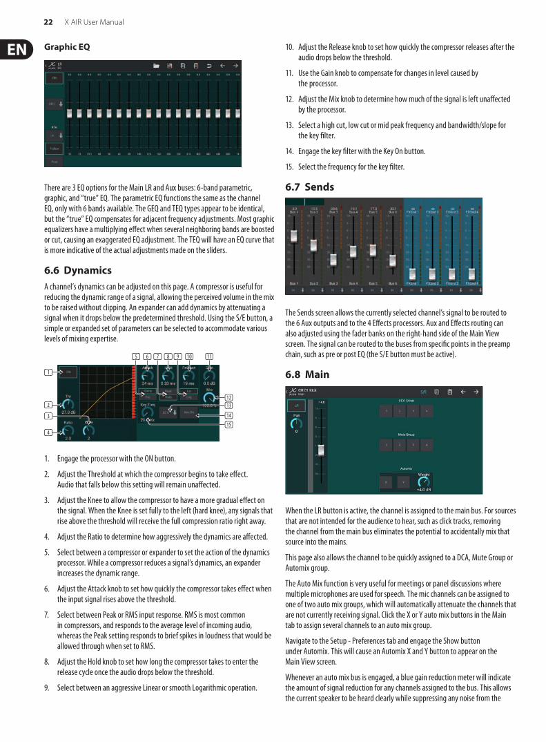
Graphic EQ
There are 3 EQ options for the Main LR and Aux buses: 6-band parametric, graphic, and “true” EQ. The parametric EQ functions the same as the channel EQ, only with 6 bands available. The GEQ and TEQ types appear to be identical, but the “true” EQ compensates for adjacent frequency adjustments. Most graphic equalizers have a multiplying effect when several neighboring bands are boosted or cut, causing an exaggerated EQ adjustment. The TEQ will have an EQ curve that is more indicative of the actual adjustments made on the sliders.
6.6 DynamicsA channel’s dynamics can be adjusted on this page. A compressor is useful for reducing the dynamic range of a signal, allowing the perceived volume in the mix to be raised without clipping. An expander can add dynamics by attenuating a signal when it drops below the predetermined threshold. Using the S/E button, a simple or expanded set of parameters can be selected to accommodate various levels of mixing expertise.
1. Engage the processor with the ON button.
2. Adjust the Threshold at which the compressor begins to take effect. Audio that falls below this setting will remain unaffected.
3. Adjust the Knee to allow the compressor to have a more gradual effect on the signal. When the Knee is set fully to the left (hard knee), any signals that rise above the threshold will receive the full compression ratio right away.
4. Adjust the Ratio to determine how aggressively the dynamics are affected.
5. Select between a compressor or expander to set the action of the dynamics processor. While a compressor reduces a signal’s dynamics, an expander increases the dynamic range.
6. Adjust the Attack knob to set how quickly the compressor takes effect when the input signal rises above the threshold.
7. Select between Peak or RMS input response. RMS is most common in compressors, and responds to the average level of incoming audio, whereas the Peak setting responds to brief spikes in loudness that would be allowed through when set to RMS.
8. Adjust the Hold knob to set how long the compressor takes to enter the release cycle once the audio drops below the threshold.
9. Select between an aggressive Linear or smooth Logarithmic operation.
10. Adjust the Release knob to set how quickly the compressor releases after the audio drops below the threshold.
11. Use the Gain knob to compensate for changes in level caused by the processor.
12. Adjust the Mix knob to determine how much of the signal is left unaffected by the processor.
13. Select a high cut, low cut or mid peak frequency and bandwidth/slope for the key filter.
14. Engage the key filter with the Key On button.
15. Select the frequency for the key filter.
6.7 Sends
The Sends screen allows the currently selected channel’s signal to be routed to the 6 Aux outputs and to the 4 Effects processors. Aux and Effects routing can also adjusted using the fader banks on the right-hand side of the Main View screen. The signal can be routed to the buses from specific points in the preamp chain, such as pre or post EQ (the S/E button must be active).
6.8 Main
When the LR button is active, the channel is assigned to the main bus. For sources that are not intended for the audience to hear, such as click tracks, removing the channel from the main bus eliminates the potential to accidentally mix that source into the mains.
This page also allows the channel to be quickly assigned to a DCA, Mute Group or Automix group.
The Auto Mix function is very useful for meetings or panel discussions where multiple microphones are used for speech. The mic channels can be assigned to one of two auto mix groups, which will automatically attenuate the channels that are not currently receiving signal. Click the X or Y auto mix buttons in the Main tab to assign several channels to an auto mix group.
Navigate to the Setup - Preferences tab and engage the Show button under Automix. This will cause an Automix X and Y button to appear on the Main View screen.
Whenever an auto mix bus is engaged, a blue gain reduction meter will indicate the amount of signal reduction for any channels assigned to the bus. This allows the current speaker to be heard clearly while suppressing any noise from the
(1)
(2)
(4)
(3)
(6)(5) (8)(7) (10) (11)(9)
(12)(13)
(14)(15)

23 X AIR User Manual
other microphones. In each channel's Main tab, a Weight knob is included which allows certain channels to be attenuated more or less to compensate for louder voices or more sensitive microphones.
6.9 Meters
The Meters tab allows easy monitoring of all analog and digital levels, including USB channels, Buses, Ultranet outputs, and the Main and Solo buses.
6.10 Effect Rack
The Effect Rack page is accessed via the “FX” icon at the top of the Main View screen. There are 4 slots where various effects can be selected and adjusted to suit the application. Tap on the effect slot to select an effect and adjust the available parameters.
6.11 SnapshotsThe snapshot function allows specific bits of information to be saved for immediate recall. For example, quick changes can be selected for different acts of a play, performances in a music festival with several bands, or different church services.
Click the camera icon at the top of the main screen. A window will open with a list of parameters to select for recall. You can select individual channels/parameters that will be recalled from a previously saved snapshot, or click the ‘All’ button to choose everything in a category. There may be channels, buses, parameters, etc. that should remain unaffected throughout an event, so this method is beneficial for its highly specific method of recall.
To save a snapshot, press and hold one of the slots in the left-hand list. A new entry will appear in the list where you can type in a name for the new snapshot.
To recall a previously-saved snapshot, press and hold the item in the list and then select the Load option. Note that all aspects of the current arrangement will be saved to a new snapshot slot, and the specific elements of that snapshot can be selected upon recall.
The snapshot recall parameters are listed in 3 categories: channel, parameter and global.
The Channel Section lets you determine which channels or bus masters will be affected during recall.
The Parameter Section lets you determine which specific preamp elements will be recalled for the channels and buses selected in the Channel Section above. Source affects the input vs. USB selection, Input recalls basic preamp settings such as phantom and gain setting, and Config recalls the configuration. EQ, Dyn, Fdr/Pan and Mute recall these settings for the selected channels, and the bus/FX sends can be individually assigned for recall.
Global Settings allow the input/output routing to be recalled, as well as global configuration, DCA assignments, and FX block settings.
To delete a snapshot that is no longer necessary, select it from the list and then select Delete.
6.12 Scenes and Shows
The Scenes/Shows page is accessed via the folder icon at the top of the Main View screen. This page allows you to save, edit and recall specific scenes or entire shows. To prevent certain channels or buses from being affected by scene or show recalls, arm the desired sources in the ’Channel safes’ section.
6.13 RoutingThe Routing menu is accessed via the up/down arrow icon at the top of the Main View screen. This allows the specific routing of input, output, USB and monitor buses to be adjusted freely.
Tap inside an empty box in the grid to move the orange dots and reassign the source for input channels, USB channels and P16 monitoring sources. Modifications to the Inputs/USB routing can be reset by pressing the revert button on the far right. The USB sends and inputs can be selected from a menu in the folder icon, or they can be moved manually.
The Routing – Outputs page allows the Main LR, Phones, Aux and P16 sources to be reassigned.

24 X AIR User Manual
6.14 Setup
The Setup menu is accessed via the top right corner of the Main View screen. This allows access to several global settings, network configurations and layout features.
Preferences
The Preferences screen allows the auto mix X and Y buttons to be viewed on the Main View screen.
The Solo Channel and Solo Bus can operate in pre-fader or after-fader listen mode. The solo level can be adjusted if necessary as well. A dimmer can be engaged and adjusted to cause a drop in volume for the program material whenever a signal is soloed. The solo bus can operate in mono or stereo. The source and tap for the monitor source can be selected from the pull-down menu, which will be heard when no sources are soloed.
The Setup – Audio/MIDI page allows editing of MIDI receive (Rx) and transmit (Tx) settings, as well as several global system parameters.
The transmit, receive and OSC settings can be independently activated for the DIN connectors and USB MIDI. The console can also pass USB MIDI through the MIDI OUT connector.
The console defaults to “soft mutes”, meaning that if a channel has been specifically muted, and is also a part of a mute group, when the mute group is unmuted, the channel that was specifically muted will also be unmuted. Selecting Hard Mutes will cause a channel that has been muted with its dedicated Mute button will remain muted even if a mute group to which it belongs is unmuted. DCA Groups normally just control volume levels without actually having audio routing through them. However, engaging DCA Groups in the Mute System will enable channels to be muted via DCA group assignments.
The console can operate at 48 kHz or 44.1 kHz. Mute the main LR fader before changing clock rates as pops can occur.
The X18/XR18 has an 18x18 channel interface built-in, but sometimes this is overkill for a recording session. For overdubs and simple tracking, the 2x2 interface is more efficient and easier on processing power.
Click the Initialize button to reset all system parameters. All settings will be lost, so make sure to save any scenes or shows to a PC hard drive first.
When the Link option is selected in a channel's Config page, the adjacent channel is linked as a stereo pair. Aside from the fader settings being matched, the preamp, dynamics, EQ and fader/mute/sends can also be aligned, depending which items are activated at the bottom of the Audio/MIDI page.
This screen allows the configuration of your wireless network connection. See the Network Connection chapter for details.
The Setup – Layers page allows the order of channels and buses to be altered. By default, only 8 channels are visible on the Main View screen at one time, but this can be edited to allow, for example, all 16 input channels to be seen at once. A new layer can also be created to contain a custom mix of inputs and buses. By increasing the visible channels per layer to 9, the Main LR fader could be added to all of the fader banks so it is always available for adjustment.
Custom layers can be saved and recalled later, and the layers can be restored to their default settings. The Setup menu also allows quick access to the Scribble Strips for changing channel names and colors.

25 X AIR User Manual
The Scribble Strip page allows a custom name and color to be assigned for each channel, bus, FX send/return, and DCA group.
7. X AIR for PCThe X AIR applications for iOS, Android and Mac/Win/Linux allow all of the physical controls and features normally found on analog mixers to be adjusted digitally, and also allow effects and routing to be fully adjusted, all from a remote location away from the input box. This results in a very compact, yet full-featured mixing solution that can be operated while moving about the venue or studio. This chapter will discuss the software's functionality on a laptop/desktop running Windows, OS X* or Linux.
7.1 Main View and Mixer Tab
1. The Navigation Tabs allow quick access to various edit menus.
2. The Channel Strip area gives a quick reference to the status of phantom power, aux send levels, pan, etc., The gain, aux levels, FX send levels and pan can be adjusted by clicking and dragging left or right inside the respective section. Click the Gate, EQ and Comp sections to jump to the edit pages for that channel.
Note – the following items are always visible regardless of which tab is selected:
3. Left-click the channel number to select that channel. Right-click to change the name and color of the channel.
4. Touch a channel’s Solo button to send the channel to the solo bus. The button will light orange to indicate that the channel has been soloed.
5. The Channel Fader adjusts a channel’s level, or adjusts the aux/FX send level, depending on which layer is selected on the right-hand side.
6. Click a channel’s Mute button to mute the channel. The button will light red when muted.
7. Use the Save and Load icons to save and recall show scenes and saved channel settings.
8. Access the Setup and Routing screens via the icons in the upper right corner. The Utility feature is currently inactive, but will be integrated in future firmware updates. The Resize button allows the window to automatically fit various screen resolutions up to 4k, as well as conform to a custom size.
9. Use the Copy and Paste buttons to transfer information between channels.
10. The Snapshot feature lets you save specific bits of information for later recall. Clicking the Snapshot icon brings up a window where the new snapshot can be named and the content selected for saving. Dedicated controls allow the saved snapshots to be shuffled through and loaded directly from the main mixer view.
11. Engage the Auto Mix X and Y buses here. See section 7.14 for details.
12. The Fader Bank buttons determine which layer is active in the faders. When set to Main LR, the faders adjust the channel volume levels sent to the main bus, and the main output is adjusted with the far-right fader. When one of the bus or FX layers are selected, the faders adjust each channel’s send level to that bus for monitoring or effects routing. The overall bus level is adjusted with the far-right fader. To assign a channel to a DCA, select the DCA group 1-4 and then click the small circle located above each channel fader that you want to assign to that group. The group number will be indicated in the circle.
13. The main level fader adjusts the output of the currently-selected bus.
14. The 4 Mute Group buttons engage the mute groups. Click one of the 4 small boxes below each channel fader to assign that channel to a particular mute group.
7.2 Channel TabThe Channel tab allows quick access to the most common preamp parameters, as well as basic control over the noise gate, compressor and bus sends. Most of the adjustments on this tab can also be found in greater detail on other tabs.
1. Click the FX button to engage an insert effect. The specific FX block is selected with the adjacent pull-down menu.
2. The Stereo Link button allows a channel to be paired with the adjacent channel in a stereo pair. The fader level, gain setting, bus sends, etc. will be the same between the 2 channels, and the pan will default to hard left and right. The odd-numbered channel will always be the lower of the pair.
3. The Phantom button engages the 48 V phantom power for use with condenser microphones and active DI boxes.
4. The Polarity button inverts the phase.
5. Click the USB button to route the USB return signal to the selected channel instead of the analog input.
6. The analog Mic Gain and digital USB Trim can be adjusted independently, though only one source can be used at a time.
(13)
(2)
(3)(4)
(5)
(6)
(1) (8)
(11)
(12)
(11)(10)
(9)(7)
(3) (7) (9)(8)(1) (10)(2) (4) (5)
(6)
(11)
*OS X is a trademark of Apple Inc.

26 X AIR User Manual
7. The Noise Gate can be engaged and the threshold can be adjusted from this page. More detailed controls are available on the Gate tab.
8. The Equalizer and Low Cut can be engaged here, as well as the low cut frequency.
9. The Compressor can be engaged and its threshold adjusted here. More detailed controls are available on the Comp tab.
10. The channel Aux Bus Sends can be adjusted here as well as the Sends tab.
11. The Main Out section allows the channel to be routed to or removed from the main bus. The pan can also be adjusted, and the Auto Mix, DCA Group and Mute Group assignments can be selected here as well.
7.3 Input TabThe Input tab allows adjustment of the most common preamp parameters as well as specific routing for the input and insert.
1. The Stereo Link button allows a channel to be paired with the adjacent channel in a stereo pair. The fader level, gain setting, bus sends, etc. will be the same between the 2 channels, and the pan will default to hard left and right. The odd-numbered channel will always be the lower of the pair.
2. The Polarity button inverts the phase.
3. The Phantom button engages the 48 V phantom power for use with condenser microphones and active DI boxes.
4. The analog Mic Gain and digital USB Trim can be adjusted independently, though only one source can be used at a time.
5. The analog input and USB input channels default to a 1:1 relationship to the channel number, but can be re-routed using the pull-down menus.
6. Select whether the analog mic/line input or the USB input appears in the channel.
7. Engage the Low Cut and adjust the specific frequency to remove unwanted lows.
8. Click the FX button to engage an insert effect. The specific FX block is selected with the adjacent pull-down menu.
7.4 Gate TabThe Gate tab allows a noise gate to be engaged and adjusted to automatically remove unwanted noise.
1. Select one of the 4 Presets to automatically optimize the parameters for one of these common sources.
2. Engage the Noise Gate with this button.
3. Adjust the Threshold that the audio must reach in order to bypass the gate or engage the ducker.
4. The Range parameter adjusts the amount of signal attenuation for the Gate and Ducker settings.
5. Select the type of effect from the 5 options. Expander effects are available with 2:1, 3:1 and 4:1 ratios which reduce the output by varying amounts, allowing a natural sounding reduction of signals that don’t reach the selected threshold. The Gate setting enables a more aggressive drop in volume for signals below the threshold. An additional Range parameter adjusts the amount of attenuation. The Ducker setting attenuates the signal by an adjustable amount whenever the signal rises beyond the selected threshold. The Range parameter adjusts the amount of attenuation for this setting as well.
6. Adjust the Attack parameter to set how quickly the gate takes effect when the input signal drops below the threshold.
7. Adjust the Hold parameter to set how long the input signal must surpass the threshold before bypassing the gate.
8. Adjust the Release parameter to set how quickly the gate releases after the audio rises about the threshold.
9. Engage the key Filter with this button.
10. Select the type of filter and frequencies with these faders.
11. Select a channel or bus for the side chain filter from the pull-down menu.
7.5 EQ Tab
1. Engage the Low Cut and adjust the specific frequency to remove unwanted lows.
2. Turn the equalizer on and off with the PEQ button. This maybe be labeled differently for bus equalizers because they also have graphic EQ options.
(2) (3) (8)(7)(1) (5) (6)(4)
(1) (2) (3) (4) (6) (7) (8) (9) (11)(5) (10)
(1) (10) (11)(4)(2) (3) (5)(6) (12)
(7) (8) (9)

27 X AIR User Manual
3. Use the Reset button to return all bands to their default settings. A confirmation box will pop up to prevent accidental resets.
4. Select the Mode from the pull-down menu. PEQ types will often be used for the first 3 bands, and a high cut or high shelf for the 4th band.
5. The currently-active band will be indicated on this button.
6. Click this button to turn a specific band on and off. This is useful for A/B testing how an adjustment affects the signal.
7. The gain adjustment for each band can be manually entered here, or you can click and drag the band's corresponding number up and down.
8. The bandwidth (Q) can be manually entered here.
9. Each band’s specific frequency can be manually entered, or you can click and drag the band's number to the desired frequency.
10. Engage the Spectrograph function to change from the standard RTA view to a spectrogram, which displays the signal energy over time. This can be useful for identifying feedback or phasing problems.
11. Press the Pre button to display the RTA pre-EQ rather than post-EQ.
12. Engage the RTA (Real Time Analyzer) with this button.
7.6 Comp Tab
1. Select one of the 4 Presets to automatically optimize the parameters for one of these common sources.
2. Engage the Compressor with this button.
3. Adjust the Threshold at which the compressor begins to take effect. Audio that falls below this setting will remain unaffected.
4. Select between a Compressor or Expander to set the action of the dynamics processor. While a compressor reduces a signal's dynamics, an expander increases the dynamic range.
5. Select a Knee angle to set how gradual the compressor takes effect. When set to 0, any signals that rise above the threshold will receive the full compression ratio.
6. Select between Peak and RMS input response. RMS is most common in compressors and responds to the average level of incoming audio, whereas the Peak setting responds to brief spikes in loudness that would be allowed through when set to RMS.
7. Select between an aggressive Linear or smooth Logarithmic operation.
8. Adjust the Ratio to determine how aggressively the dynamics are affected.
9. Adjust the Mix to determine how much of the signal is left unaffected by the processor.
10. Adjust the Gain to compensate for changes in level caused by the processor.
11. Engage the Auto Time to allow several of the more advanced parameters to be automatically adjusted according to the input signal.
12. Adjust the Attack to set how quickly the compressor takes effect when the input signal rises above the threshold.
13. Adjust the Hold to set how long the compressor takes to enter the release cycle once the audio drops below the threshold.
14. Adjust the Release to set how quickly the compressor releases after the audio drops below the threshold.
15. Engage the key Filter with this button.
16. Select the type of filter and frequencies with these faders.
17. Select a channel or bus for the side chain filter from the pull-down menu.
7.7 Sends Tab
The Sends tab allows the currently-selected channel's signal to be routed to the 6 Aux buses and to the 4 FX processors. These adjustments can also be made on the Channel tab, or by selecting one of the Fader Bank layers on the lower right-hand side of the main view screen. The signal can be routed to the buses from specific points in the preamp chain, such as pre or post EQ and pre or post fader. Clicking the globe icon will enable changes to the tap point (pre/post fader, etc) to take effect on all channels.
7.8 Main Tab
All of the controls on the Main tab are also accessible from the Channel tab. The channel’s signal can be unassigned from the main output, which is useful when recording sources that aren’t meant to be heard by the audience, or for sources such as click tracks that are only meant for the performers’ mixes and not the main speakers. The channel’s pan control can be adjusted and DCA, Mute Group and Auto Mix assignments can be made as well.
7.9 FX Tab
The FX tab has 4 effect processors that can be routed and adjusted to various channels and buses. A new effect can be selected by clicking the pull-down menu where the current effect’s name is displayed, or by clicking the Type button which also shows a graphic view of each effect. Once a desired effect is selected, click on the graphic to bring up the edit window where the specific parameters can be
(8) (9) (10) (12) (13) (14)
(1) (2) (5) (11) (15) (17)(6)(7)(3) (4)
(16)

28 X AIR User Manual
adjusted. If applicable, a tap tempo button is available to manually enter the rate of delays or choruses. The button will flash to indicate the tempo. Click the Insert button to engage the effect as an insert instead of side-chain. Select the channel or bus assigned to the effect with the pull-down menu. See the Effects Overview chapter for more details.
7.10 Meter Tab
The Meter tab allows easy monitoring of all analog and digital levels, including USB channels, Buses, Ultranet outputs, and the Main and Solo buses.
7.11 Setup MenuThe Setup menu allows the wireless connection to be configured and allows various global parameters to be selected and adjusted.
Connect Tab
After you connect your computer to the internal Access Point or external router, the software will likely automatically recognize the mixer and ask to connect. Once connected, a prompt will ask if you would like to transfer settings from the mixer to PC, or from the PC to the mixer. Click ‘cancel’ if you don’t want to sync settings. The Connection tab also allows you to manually assign an IP address. If you have firmware 1.09 or later, you can update the firmware directly from this screen as well.
Note - save your settings to your computer’s hard drive before updating the firmware!
By default, a generic name, such as XR18-1B-10-F3, will be assigned to your mixer. This can be changed to something more specific and recognizable. The console can also be initialized back to its factory state, but be aware that all settings will be erased. We highly recommend using the Save function to store any important scenes to your computer's hard drive.
Access Point, WLAN, LAN Tabs
The Access Point, WLAN and LAN tabs allow the wireless connection to be configured. See the 'Network Connection' chapter for details.
Audio/MIDI Tab
The Audio/MIDI tab allows various global settings to be assigned. The console can operate at 48 kHz or 44.1 kHz. Mute the main LR fader before changing clock rates as pops can occur.
Engage the Safe Levels function to automatically mute the outputs during a power cycle. This is particularly useful for situations where the mixer is always connected to a PA system or monitoring setup.
The Link Preferences allow specific preamp elements to be synchronized when adjacent channels are linked.
The console defaults to “soft mutes”, meaning that if a channel has been specifically muted, and is also a part of a mute group, when the mute group is unmuted, the channel that was specifically muted will also be unmuted. Selecting Hard Mutes will cause a channel that has been muted with its dedicated Mute button will remain muted even if a mute group to which it belongs is unmuted. DCA Groups normally just control volume levels without actually having audio routing through them. However, engaging DCA Groups in the Mute System will enable channels to be muted via DCA group assignments.
The X18/XR18 has an 18x18 channel interface built-in, but sometimes this is overkill for a recording session. For overdubs and simple tracking, the 2x2 interface is more efficient and easier on processing power.
Various send (Tx) and receive (Rx) preferences are selectable for the MIDI configuration.
Monitor Tab
The monitor source defaults to the main LR (post-fader), but you can select a bus, aux, USB 17/18 or a combination of buses. Soloed channels and buses can be monitored pre or post-fader. PFL attenuation can be engaged and the relative levels for monitor and source can be set. Click the DIM button to enable dimming and select the attenuation level. The monitor bus can be set to mono and can be muted from this page.

29 X AIR User Manual
Preferences Tab
Select the ‘Apply changes to all channels’ option if you would like changes made to bus send taps (pre/post-EQ, etc) to be applied to all channels.
Auto Select options allow the last soloed channel to be selected automatically, and allow a channel to be automatically selected whenever its fader is adjusted.
Exclusive solo mode allows only one source to be soloed at a time. Pressing a channel’s Solo button will automatically un-solo previously soloed channels.
The ‘Fine’ fader mode allows adjustments to the faders to occur more gradually, allowing more precise control when making small changes.
The update rate defaults to 100%, meaning the meters and RTA display immediate feedback of the audio signals. However, this can be adjusted to 50%, which shows less detail but also conserves on processing power.
The configuration of the application’s windows can be stored and recalled upon launch. Click the Initialize button to clear the stored window configuration.
Use the Always on Top selection to keep certain windows in view regardless of other windows being adjusted.
7.12 Snapshot PageThe snapshot function allows specific bits of information to be saved for immediate recall. For example, quick changes can be selected for different acts of a play, performances in a music festival with several bands, or different church services.
Click the ‘Snapshots’ icon on the right hand side of the main screen. A window will open with a list of parameters to select for recall. You can select individual channels/parameters that will be recalled from a previously saved snapshot, or click the ‘All’ button to choose everything in a category. There may be channels, buses, parameters, etc. that should remain unaffected throughout an event, so this method is beneficial for its highly specific method of recall.
To save a snapshot, click one of the slots in the left-hand list. A new entry will appear in the list where you can type in a name for the new snapshot. Note that all aspects of the current arrangement will be saved to a new snapshot slot, and the specific elements of that snapshot can be selected upon recall.
The snapshots recall parameters are listed in 3 categories: channel, parameter and global.
The Channel Section lets you determine which channels or bus masters will be affected during recall.
The Parameter Section lets you determine which specific preamp elements will be recalled for the channels and buses selected in the Channel Section above. Source affects the input vs. USB selection, Input recalls basic preamp settings such as phantom and gain setting, and Config recalls the configuration. EQ, Dyn, Fdr/Pan and Mute recall these settings for the selected channels, and the bus/FX sends can be individually assigned for recall.
Global Settings allow the input/output routing to be recalled, as well as global configuration, DCA assignments, and FX block settings.
To delete a snapshot that is no longer necessary, select it from the list and click Delete.
7.13 UtilitiesUtilities offer convenient editing and customization of items that are not easily controlled on other windows or menus.
RTA Utility
The RTA utility allows customization of the appearance and functionality of the real time analyzer. The RTA Source pull-down menu allows a specific channel or bus to be fixed to the RTA, or the RTA can follow the active channel. Select Solo Priority to send any soloed channel to the RTA.
The Decay adjustment controls how quickly the frequency bands fall after reaching their initial indication. Peak Hold will leave a small marker to indicate the peak measurement over a longer period of time while still monitoring the fine audio activity. RTA Gain compensates for audio levels, ensuring accurate readings. Select the Auto Gain feature to automatically select an appropriate RTA gain level. The EQ overlay adjustment controls the opacity of the RTA when viewing channel EQ curves. Select Spectrograph to view the audio energy across the spectrum, where blue represents lower levels and red indicates higher levels. Note that this only affects the RTA utility window and not the individual channel EQs.
Channel and Graphic EQs can be preassigned to have spectrograph RTAs, and can operate as pre or post-EQ. These selections can be overridden on the channel/bus EQ tab. Select the ‘Use RTA Source’ option if you want to view a source’s RTA while adjusting another channel's EQ.
Select a 30 or 60 dB gain range, and pre or post EQ results. Select Peak to monitor the rapid changes in frequency response, or RMS to view an average response over a longer period of time.

30 X AIR User Manual
Buses Utility
The Buses utility window gives convenient access to all of the channel strip functions of all 6 buses and the main LR at the same time. This window can be left open so that changes can be made without having to select individual buses in the main window.
DCA Utility
Similar to the Buses utility, the DCA utility window allows all 4 DCA groups to be easily monitored and adjusted.
A custom set of channels, buses and/or DCA groups can also be configured in 2 user-defined windows. This has the added feature of expanding the channel strip to include the gain level, bus sends, and other information that is normally visible in the mixer tab in the main window.
7.14 Auto Mix
The Auto Mix function is very useful for meetings or panel discussions where multiple microphones are used for speech. The mic channels can be assigned to one of two auto mix groups, which will automatically attenuate the channels that are not currently receiving signal. Click the X or Y auto mix buttons on the right side of the main window, then click the right-hand circle just above each channel fader that you want to assign to the auto mix. An X or Y will appear in the circle to indicate the assignment.
Whenever the auto mix bus is engaged, a blue gain reduction meter will indicate the amount of signal reduction. This allows the current speaker to be heard clearly while suppressing any noise from the other microphones. A white arrow also appears next to each fader assigned to the auto mix bus, which allows certain channels to be attenuated more or less to compensate for louder voices or more sensitive microphones.
For situations when one person is speaking for extended periods of time, it may be helpful to select the Last Gate box beneath the auto mix button. This keeps the most recently active channel open, preventing unwanted artifacts of the gate opening and closing during pauses in speech.

31 X AIR User Manual
8. MIDI
MIDI RX / TX CH CMD No. Value Comment
Snapshots 1 Prg Chg 1-64 Program Changes 1-64 on Channel 1 can be used to recall snapshots 1-64 stored inside X AIR mixers.
FaderCH Faders 1 CC 0-15 0...127 Input Channels 1-16
CH Faders 1 CC 16 0...127 AuxLineIn 17-18 / USB Recorder Playback (stereo)
CH Faders 1 CC 17-20 0...127 FX1-4 Return (stereo)
Send Faders 1 CC 21-26 0...127 Aux1-6 / Subgroup
Send Faders 1 CC 27-30 0...127 Fx1-4
Main Fader 1 CC 31 0...127 Main LR (stereo)
MuteCH Mutes 2 CC 0-15 0/127 Input Channels 1-16
CH Mutes 2 CC 16 0/127 AuxLineIn 17-18 / USB Recorder Playback (stereo)
CH Mutes 2 CC 17-20 0/127 FX1-4 Return (stereo)
Send Mutes 2 CC 21-26 0/127 Aux1-6 / Subgroup
Send Mutes 2 CC 27-30 0...127 Fx1-4
Main Mute 2 CC 31 0/127 Main LR (stereo)
Panorama/BalanceCH PAN 3 CC 0-15 1...127 Panorama Input Channels 1-16, 64=center
CH PAN 3 CC 16 1...127 Balance AuxLineIn 17-18 / USB Recorder Playback, 64=center
CH PAN 3 CC 17-20 1...127 Balance FX1-4 Return, 64=center
Aux PAN (Subgroup) 3 CC 21-26 1...127 Panorama Aux1-6 / Subgroup, 64=center
Main Balance 3 CC 31 1...127 Balance Main LR, 64=center
X OSC
Text based OSC SYX
Open Sound Control via Sysex F0 00 20 32 32 TEXT F7With ‘TEXT’ being OSC strings in hex format, up to 39 kB in length

32 X AIR User Manual
9. Specifications
9.1 X18/XR18 SpecificationsX18 XR18
Processing
Number of processing channels 18 input channels, 4 FX return channels, 6 aux buses, main LR
18 input channels, 4 FX return channels, 6 aux buses, main LR
Internal effects engines 4 true stereo 4 true stereo
Signal processing 40-bit floating point 40-bit floating point
A/D-D/A conversion (Cirrus Logic A/D CS5368, D/A CS4385) 24-bit @ 44.1 / 48 kHz, 114 dB dynamic range 24-bit @ 44.1 / 48 kHz, 114 dB dynamic range
Analog I/O latency* 0.8 ms 0.8 msConnectorsProgrammable mic preamps, designed by MIDAS 16 XLR/TRS combo jacks, balanced 16 XLR/TRS combo jacks, balanced
Line / Aux inputs, stereo 2 RCA, unbalanced 2 TRS, balanced
Main outputs 2 XLR, balanced 2 XLR, balanced
Aux outputs 6 TRS, balanced impedance 6 XLR, balanced
Monitoring outputs 2 RCA, unbalanced —
Phones outputs 1 TRS 1 TRS
ULTRANET 1 RJ45 1 RJ45
MIDI inputs / outputs 1/1 DIN 1/1 DIN
Ethernet 1 RJ45 1 RJ45
Audio/Midi interface 1 USB Type B 1 USB Type BMic Input CharacteristicsPreamp design MIDAS MIDAS
THD + noise, 20 dB gain, 0 dBu out < 0.005%, A-weighted < 0.005%, A-weighted
Phantom power, switchable per input 48 V 48 V
Equivalent input noise level, XLR (input shorted) -128 dBu, A-weighted -128 dBu, A-weighted
CMRR, XLR, @ 20 dB gain (typical) > 60 dB > 60 dB
CMRR, XLR, @ 40 dB gain > 65 dB > 65 dBInput/Output CharacteristicsFrequency range, @ 48 kHz sample rate, 0 dB to -1 dB 10 Hz - 22 kHz 10 Hz - 22 kHz
Dynamic range, analog in to analog out (typical) 106 dB 106 dB
A/D dynamic range, preamp to converter (typical) 109 dB 109 dB
D/A dynamic range, converter and output 108 dB 108 dB
Cross talk rejection @ 1 kHz, adjacent channels 90 dB 90 dB
Mic 1-16 Input impedance XLR jack, unbal. / bal. 5 kΩ / 10 kΩ 5 kΩ / 10 kΩ
Non clip maximum input level, XLR +23 dBu +23 dBu
Hi-Z 1-2 Input impedance TRS jack, unbal. / bal. 1 MΩ / 2 MΩ 1 MΩ / 2 MΩ
Line 3-16 Input impedance TRS jack, unbal. / bal. 5 kΩ / 10 kΩ 5 kΩ / 10 kΩ
Line 17-18 Input impedance, RCA / TRS 10 kΩ 10 kΩ
Non clip maximum input level, RCA / TRS +16 dBu +16 dBuOutput CharacteristicsOutput impedance, XLR, unbal. / bal. 50 Ω / 50 Ω 50 Ω / 50 Ω
Output level, XLR, nom./max. +4 dBu / +16 dBu +4 dBu / +16 dBu
Output impedance, TRS, unbal. / bal. 50 Ω / 50 Ω 50 Ω / 50 Ω
Output level, TRS, nom./max. +4 dBu / +16 dBu +4 dBu / +16 dBu
Output impedance, RCA 1 kΩ —
Output level, RCA, nom./max. +4 dBu / +16 dBu —
Phones output impedance / level 40 Ω / +35 dBm (stereo) 40 Ω / +35 dBm (stereo)
Residual noise level, XLR and TRS -92 dBu, A-weighted -92 dBu, A-weighted
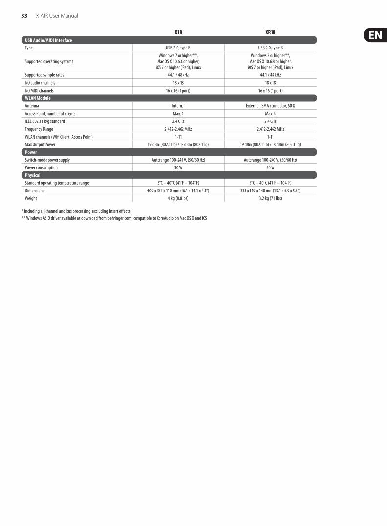
33 X AIR User Manual
X18 XR18USB Audio/MIDI InterfaceType USB 2.0, type B USB 2.0, type B
Supported operating systemsWindows 7 or higher**,
Mac OS X 10.6.8 or higher, iOS 7 or higher (iPad), Linux
Windows 7 or higher**,Mac OS X 10.6.8 or higher,
iOS 7 or higher (iPad), Linux
Supported sample rates 44.1 / 48 kHz 44.1 / 48 kHz
I/O audio channels 18 x 18 18 x 18
I/O MIDI channels 16 x 16 (1 port) 16 x 16 (1 port)WLAN ModuleAntenna Internal External, SMA connector, 50 Ω
Access Point, number of clients Max. 4 Max. 4
IEEE 802.11 b/g standard 2.4 GHz 2.4 GHz
Frequency Range 2,412-2,462 MHz 2,412-2,462 MHz
WLAN channels (Wifi Client, Access Point) 1-11 1-11
Max Output Power 19 dBm (802.11 b) / 18 dBm (802.11 g) 19 dBm (802.11 b) / 18 dBm (802.11 g)PowerSwitch-mode power supply Autorange 100-240 V, (50/60 Hz) Autorange 100-240 V, (50/60 Hz)
Power consumption 30 W 30 WPhysicalStandard operating temperature range 5°C – 40°C (41°F – 104°F) 5°C – 40°C (41°F – 104°F)
Dimensions 409 x 357 x 110 mm (16.1 x 14.1 x 4.3") 333 x 149 x 140 mm (13.1 x 5.9 x 5.5")
Weight 4 kg (8.8 lbs) 3.2 kg (7.1 lbs)
* including all channel and bus processing, excluding insert effects** Windows ASIO driver available as download from behringer.com; compatible to CoreAudio on Mac OS X and iOS
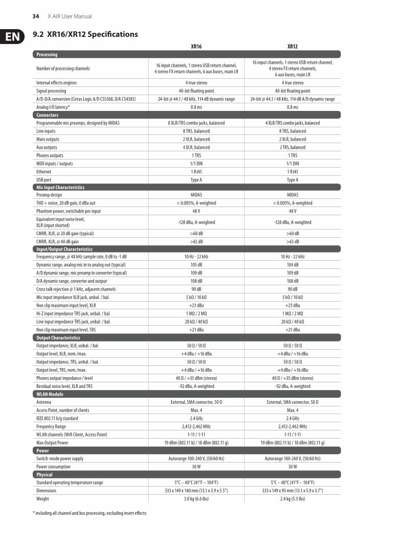
34 X AIR User Manual
9.2 XR16/XR12 SpecificationsXR16 XR12
Processing
Number of processing channels 16 input channels, 1 stereo USB return channel, 4 stereo FX return channels, 6 aux buses, main LR
16 input channels, 1 stereo USB return channel, 4 stereo FX return channels,
6 aux buses, main LR
Internal effects engines 4 true stereo 4 true stereo
Signal processing 40-bit floating point 40-bit floating point
A/D-D/A conversion (Cirrus Logic A/D CS5368, D/A CS4385) 24-bit @ 44.1 / 48 kHz, 114 dB dynamic range 24-bit @ 44.1 / 48 kHz, 114 dB A/D dynamic range
Analog I/O latency* 0.8 ms 0.8 msConnectorsProgrammable mic preamps, designed by MIDAS 8 XLR/TRS combo jacks, balanced 4 XLR/TRS combo jacks, balanced
Line inputs 8 TRS, balanced 8 TRS, balanced
Main outputs 2 XLR, balanced 2 XLR, balanced
Aux outputs 4 XLR, balanced 2 TRS, balanced
Phones outputs 1 TRS 1 TRS
MIDI inputs / outputs 1/1 DIN 1/1 DIN
Ethernet 1 RJ45 1 RJ45
USB port Type A Type AMic Input CharacteristicsPreamp design MIDAS MIDAS
THD + noise, 20 dB gain, 0 dBu out < 0.005%, A-weighted < 0.005%, A-weighted
Phantom power, switchable per input 48 V 48 V
Equivalent input noise level, XLR (input shorted) -128 dBu, A-weighted -128 dBu, A-weighted
CMRR, XLR, @ 20 dB gain (typical) >60 dB >60 dB
CMRR, XLR, @ 40 dB gain >65 dB >65 dBInput/Output CharacteristicsFrequency range, @ 48 kHz sample rate, 0 dB to -1 dB 10 Hz - 22 kHz 10 Hz - 22 kHz
Dynamic range, analog mic in to analog out (typical) 105 dB 104 dB
A/D dynamic range, mic preamp to converter (typical) 109 dB 109 dB
D/A dynamic range, converter and output 108 dB 108 dB
Cross talk rejection @ 1 kHz, adjacent channels 90 dB 90 dB
Mic input impedance XLR jack, unbal. / bal. 5 kΩ / 10 kΩ 5 kΩ / 10 kΩ
Non clip maximum input level, XLR +23 dBu +23 dBu
Hi-Z input impedance TRS jack, unbal. / bal. 1 MΩ / 2 MΩ 1 MΩ / 2 MΩ
Line input impedance TRS jack, unbal. / bal. 20 kΩ / 40 kΩ 20 kΩ / 40 kΩ
Non clip maximum input level, TRS +21 dBu +21 dBuOutput CharacteristicsOutput impedance, XLR, unbal. / bal. 50 Ω / 50 Ω 50 Ω / 50 Ω
Output level, XLR, nom./max. +4 dBu / +16 dBu +4 dBu / +16 dBu
Output impedance, TRS, unbal. / bal. 50 Ω / 50 Ω 50 Ω / 50 Ω
Output level, TRS, nom./max. +4 dBu / +16 dBu +4 dBu / +16 dBu
Phones output impedance / level 40 Ω / +35 dBm (stereo) 40 Ω / +35 dBm (stereo)
Residual noise level, XLR and TRS -92 dBu, A-weighted -92 dBu, A-weightedWLAN ModuleAntenna External, SMA connector, 50 Ω External, SMA connector, 50 Ω
Access Point, number of clients Max. 4 Max. 4
IEEE 802.11 b/g standard 2.4 GHz 2.4 GHz
Frequency Range 2,412-2,462 MHz 2,412-2,462 MHz
WLAN channels (Wifi Client, Access Point) 1-11 / 1-11 1-11 / 1-11
Max Output Power 19 dBm (802.11 b) / 18 dBm (802.11 g) 19 dBm (802.11 b) / 18 dBm (802.11 g)PowerSwitch-mode power supply Autorange 100-240 V, (50/60 Hz) Autorange 100-240 V, (50/60 Hz)
Power consumption 30 W 30 WPhysicalStandard operating temperature range 5°C – 40°C (41°F – 104°F) 5°C – 40°C (41°F – 104°F)
Dimensions 333 x 149 x 140 mm (13.1 x 5.9 x 5.5") 333 x 149 x 95 mm (13.1 x 5.9 x 3.7")
Weight 3.0 kg (6.6 lbs) 2.4 kg (5.3 lbs)
* including all channel and bus processing, excluding insert effects

35 X AIR User Manual
10. Effect DescriptionsHere is a list and brief description of the effects available on the X AIR mixers. When Stereo and Dual versions of an effect are offered, use the Stereo version when the left and right signal are to be altered together (e.g. on linked stereo channels or buses), or Dual when you want to dial different settings for the left and right signal.
Hall, Ambience, Rich Plate, Room, Chamber Reverb
These 5 reverb emulations are inspired by the Lexicon 480L. Hall simulates the reverberation that occurs when sound is recorded in medium to large-sized concert halls. Ambience creates a customizable virtual acoustic space to add warmth and depth without coloring the direct sound.
The PRE DELAY slider controls the amount of time before the reverb is heard following the source signal. DECAY controls the amount of time it takes for the reverb to dissipate. SIZE controls the perceived size of the space being created by the reverb. The DAMP slider adjusts the decay of the high frequencies within the reverb tail. DIFF(usion) controls the initial reflection density, and LEVEL controls the effect output.
LO and HI CUT allow the frequencies affected by the reverb to be narrowed. BASSMULT(iplier) controls the low frequency build-up. SPREAD emphasizes the stereo effect of the reverb. SHAPE adjusts the contour of the reverberation envelope. MOD SPEED controls the reverb tail modulation rate and TAIL GAIN adjusts the volume of the reverb tail. The Rich Plate and Room reverbs allow the stereo ECHO DELAY and the delay FEEDBACK to be adjusted independently for each side. The Chamber reverb allows the stereo REFL(ection) DELAY and GAIN to be adjusted independently.
Plate Reverb
A plate reverb was originally created by sending a signal through a transducer to create vibrations on a plate of sheet metal which were then picked up as an audio signal. Our algorithm simulates that sound with high initial diffusion and a bright colored sound. The Plate Reverb will give your tracks the sound heard on countless hit records since the late 1950s. (Inspired by the Lexicon PCM-70)
PRE DELAY controls the amount of time before the reverberation is heard following the source signal. DECAY controls the amount of time it takes for the reverb to dissipate. SIZE adjusts the size of the virtual room created by the reverb effect. The DAMP knob adjusts the decay of high frequencies within the reverb tail. DIFF(USION) controls the initial reflection density. The LO CUT knob sets the frequency beneath which the source signal will not pass through the reverb. The HI CUT knob sets the frequency above which the source signal will not pass through the reverb. The BASS MULT(IPLIER) knob adjusts the decay time of the bass frequencies. XOVER controls the crossover point for bass. MOD DEPTH and SPEED control the intensity and speed of the reverb tail modulation.
Vintage Reverb
Based on the legendary EMT250, the Vintage Reverb delivers shimmering bright reverb that won’t drown out or overpower your live or recorded tracks. Use Vintage Reverb to sweeten vocals and snare drums without sacrificing clarity.
When layer 1 is selected, the first slider on the left sets the reverb time from 4 milliseconds to 4.5 seconds. Slider 2 controls the low frequency multiplier decay time. Slider 3 controls the high frequency multiplier decay time. Slider 4 controls the amount of modulation in the reverb tail. When layer two is selected, slider 1 adjusts the pre delay. Slider 2 selects the low cut frequency. Slider 3 selects the Hi Cut frequency. Slider 4 adjusts the output level of the reverb.
When Layer 1 is selected, the far left encoder push button allows you to select between virtual front and rear outputs. Rear is suitable for drums due to it being less reflective. Front is well-suited for vocals and other dynamic instruments. The Vintage button enables the simulation of the input transformers.
Vintage Room
Vintage Room simulates the reverberation that occurs when sound is recorded in a small room. When you want to add a bit of warmth and just a touch of reverb, the Vintage Room breathes life into close-miced guitar and drum tracks. (Inspired by the Quantec QRS)
The VU meter displays the input and output levels. Set the early reflection times for the left and right channel with ER DELAY L and ER DELAY R. ER LEVEL sets the loudness of the early reflection level. REV DELAY controls the amount of time before the reverberation is heard following the source signal. HI/LOW MULTIPLY adjusts the decay time of the high and bass frequencies. TIME shows the duration of the reverb effect. ROOM SIZE adjusts the size of the room effect being created incrementally from small to large. HIGH CUT sets the frequency above which the source signal does not pass through the reverb. DENSITY manipulates the reflection density in the simulated room. (This slightly changes the reverb decay time). LOW CUT sets the frequency below which the source signal does not pass through the reverb.
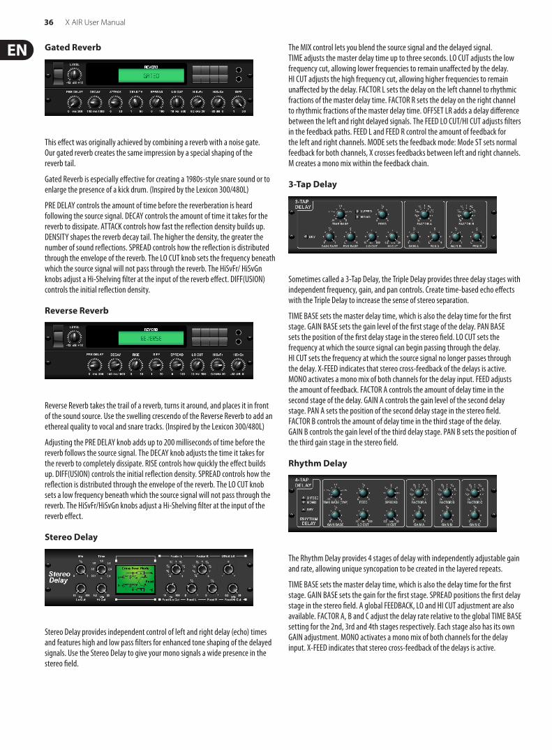
36 X AIR User Manual
Gated Reverb
This effect was originally achieved by combining a reverb with a noise gate. Our gated reverb creates the same impression by a special shaping of the reverb tail.
Gated Reverb is especially effective for creating a 1980s-style snare sound or to enlarge the presence of a kick drum. (Inspired by the Lexicon 300/480L)
PRE DELAY controls the amount of time before the reverberation is heard following the source signal. DECAY controls the amount of time it takes for the reverb to dissipate. ATTACK controls how fast the reflection density builds up. DENSITY shapes the reverb decay tail. The higher the density, the greater the number of sound reflections. SPREAD controls how the reflection is distributed through the envelope of the reverb. The LO CUT knob sets the frequency beneath which the source signal will not pass through the reverb. The HiSvFr/ HiSvGn knobs adjust a Hi-Shelving filter at the input of the reverb effect. DIFF(USION) controls the initial reflection density.
Reverse Reverb
Reverse Reverb takes the trail of a reverb, turns it around, and places it in front of the sound source. Use the swelling crescendo of the Reverse Reverb to add an ethereal quality to vocal and snare tracks. (Inspired by the Lexicon 300/480L)
Adjusting the PRE DELAY knob adds up to 200 milliseconds of time before the reverb follows the source signal. The DECAY knob adjusts the time it takes for the reverb to completely dissipate. RISE controls how quickly the effect builds up. DIFF(USION) controls the initial reflection density. SPREAD controls how the reflection is distributed through the envelope of the reverb. The LO CUT knob sets a low frequency beneath which the source signal will not pass through the reverb. The HiSvFr/HiSvGn knobs adjust a Hi-Shelving filter at the input of the reverb effect.
Stereo Delay
Stereo Delay provides independent control of left and right delay (echo) times and features high and low pass filters for enhanced tone shaping of the delayed signals. Use the Stereo Delay to give your mono signals a wide presence in the stereo field.
The MIX control lets you blend the source signal and the delayed signal. TIME adjusts the master delay time up to three seconds. LO CUT adjusts the low frequency cut, allowing lower frequencies to remain unaffected by the delay. HI CUT adjusts the high frequency cut, allowing higher frequencies to remain unaffected by the delay. FACTOR L sets the delay on the left channel to rhythmic fractions of the master delay time. FACTOR R sets the delay on the right channel to rhythmic fractions of the master delay time. OFFSET LR adds a delay difference between the left and right delayed signals. The FEED LO CUT/HI CUT adjusts filters in the feedback paths. FEED L and FEED R control the amount of feedback for the left and right channels. MODE sets the feedback mode: Mode ST sets normal feedback for both channels, X crosses feedbacks between left and right channels. M creates a mono mix within the feedback chain.
3-Tap Delay
Sometimes called a 3-Tap Delay, the Triple Delay provides three delay stages with independent frequency, gain, and pan controls. Create time-based echo effects with the Triple Delay to increase the sense of stereo separation.
TIME BASE sets the master delay time, which is also the delay time for the first stage. GAIN BASE sets the gain level of the first stage of the delay. PAN BASE sets the position of the first delay stage in the stereo field. LO CUT sets the frequency at which the source signal can begin passing through the delay. HI CUT sets the frequency at which the source signal no longer passes through the delay. X-FEED indicates that stereo cross-feedback of the delays is active. MONO activates a mono mix of both channels for the delay input. FEED adjusts the amount of feedback. FACTOR A controls the amount of delay time in the second stage of the delay. GAIN A controls the gain level of the second delay stage. PAN A sets the position of the second delay stage in the stereo field. FACTOR B controls the amount of delay time in the third stage of the delay. GAIN B controls the gain level of the third delay stage. PAN B sets the position of the third gain stage in the stereo field.
Rhythm Delay
The Rhythm Delay provides 4 stages of delay with independently adjustable gain and rate, allowing unique syncopation to be created in the layered repeats.
TIME BASE sets the master delay time, which is also the delay time for the first stage. GAIN BASE sets the gain for the first stage. SPREAD positions the first delay stage in the stereo field. A global FEEDBACK, LO and HI CUT adjustment are also available. FACTOR A, B and C adjust the delay rate relative to the global TIME BASE setting for the 2nd, 3rd and 4th stages respectively. Each stage also has its own GAIN adjustment. MONO activates a mono mix of both channels for the delay input. X-FEED indicates that stereo cross-feedback of the delays is active.

37 X AIR User Manual
Stereo Chorus
Chorus samples the input, slightly detunes it and mixes it with the original signal to produce a somewhat thicker, shimmering sound. Use it to thicken up background vocals, or to double the sound of brass and woodwind instruments.
Where as DELAY L/R set the total amount of delay for the left and right channel, WIDTH determines the amount of modulated delay. SPEED sets the modulation speed. MIX adjusts the balance of the dry and wet signals. You can further sculpt the sound by trimming some of the low and high end from the effected signal with the LO and HI CUT knobs. Additionally, the PHASE knob can tweak the phase offset of the LFO between left and right channel and the SPREAD knob adjusts how much of the left channel is mixed into the right and vice versa. Finally, the WAVE knob blends between the “Danish-style” digital triangular chorus sound and the classic analog sine wave.
Stereo Flanger
The Flanger emulates the phase-shifting sound (comb-filtering) originally created by applying pressure against the flange of the reel on a tape recorder. This effect creates a unique “wobbly” sound that is quite dramatic when used on vocals and instruments.
The controls of this effect are nearly identical to the Chorus effect block. Additionally, the FEEDBACK can be adjusted with positive and negative amounts and also band-limited with the FEED HC (high-cut) and FEED LC (low-cut) knobs.
Stereo Phaser
A Stereo Phaser, or phase shifter, applies multiple STAGES of modulated filters to the input signal to create a “notch” in the frequency response, and then applies a MIX with the original for a “swirling” effect. Use the Stereo Phaser to add a “spaced-out” sound to vocal or instrument tracks.
SPEED adjusts the LFO rate and DEPTH sets the LFO modulation depth. The BASE knob adjusts the frequency range of the modulated filters. The resonance is adjusted with the RESO knob. The WAVE knob shapes the symmetry of the LFO waveform and PHASE dials in an LFO phase difference between the left and right channel. The modulation source can also be the signal envelope, which produces vowel-like opening and closing tones. The ENV MOD knob adjusts how much this effect takes place (positive and negative modulation is possible), and the ATTACK, HOLD and RELEASE knobs all tailor the response of this feature.
Dimensional Chorus
The Dimensional Chorus offers the most user-friendly and classic sounds, best described as “space” and “dimensional”. The 4 MODE buttons can be engaged individually or simultaneously for light chorus or very thick, exaggerated modulation.
Mood Filter
The Mood Filter uses an LFO generator and an auto-envelope generator to control a VCF (voltage-controlled filter), as well as a side chain function where the channel B signal controls the envelope of channel A. When applied to electronic instruments, the Mood Filter can be used to emulate the natural sound of acoustic instruments. (Inspired by the MiniMoog)
This filter can be modulated with the signal’s envelope using the ENV MOD (with positive and negative amounts), ATTACK and RELEASE knobs, or the LFO can modulate the filter. The WAVE knob selects between 7 different wave forms – triangular, sine, saw plus, saw minus, ramp, square, and random. The PHASE can be off set by up to 180 degrees. The SPEED knob adjusts the rate of the LFO and the DEPTH adjusts the amount of LFO modulation. Adjust the resonance of the filter until self-oscillation with the RESO(nance) knob. BASE adjusts the range of the filter from 20 Hz to 15 kHz. The MODE switch selects between low pass (LP), high-pass (HP), band-pass (BP) and Notch. Use the MIX knob to blend the effected signal with the dry sound. With the 4 POLE switch engaged, there will be a steeper slope than the OFF (2 pole) setting. The DRIVE knob adjusts the level and can also introduce an overdrive effect (as with real analogue filters) if pushed hard. In Sidechain mode, only the left input signal is processed and fed to both outputs. The envelope of the right input signal can be used as a modulation source.
Rotary Speaker
Rotary Speaker emulates the sound of a Leslie rotating speaker. The Rotary Speaker provides more flexibility than its electro-mechanical counterpart, and can be used with a variety of instruments, and even vocals, to create a whirling, psychedelic effect.
The LO SPEED and HI SPEED knobs adjust the rotational speed of the SLOW and FAST Speed selection, and can be toggled with the FAST button. The ACCEL(eration) knob adjusts how quickly the speed increases and decreases from the Slow mode to the Fast mode. The rotation effect can also be disengaged with the STOP button, which will stop the movement of the speakers. DISTANCE adjusts the distance between the Rotary speakers and the virtual microphone.

38 X AIR User Manual
Stereo Tremolo
Stereo Tremolo creates an up and down volume change at a constant and even tempo just like the guitar amps of yesteryear. Use the Stereo Tremolo to add a unique “surf-music” texture to a vocal or instrument track.
SPEED adjusts the LFO rate and DEPTH sets the amount of modulation. PHASE can be used to set an LFO phase difference between the left and right channel, which can be used for panning effects. The WAVE knob blends the LFO waveform between triangular and square shape. The signal envelope, shaped by ATTACK, HOLD and RELEASE, can be used to modulate the LFO speed (ENV SPEED) and the LFO modulation depth (ENV DEPTH).
Sub Octaver
The Sub Octaver provides two channels of sub harmonics generation, one or even two octaves below the input signal.
Adjust the DIRECT knob to blend the “dry” signal with the lower octaves. Use the RANGE switch to optimize the tracking by selecting the frequency range of the input signal. The OCT1 and OCT2 knobs adjust how much 1 octave down and 2 octaves down content is included.
Delay + Chamber
Here we have combined Delay and Chamber reverb, so a single device can provide a variety of delay settings, plus add just the right type and amount of reverb to the selected signal. This device only uses one FX slot. (The Reverb is Inspired by the Lexicon PCM 70)
Use the BALANCE knob to adjust the ratio between delay and reverb. Low frequencies can be excluded with the LO CUT knob, and the MIX adjusts how much of the effect is added to the signal. The TIME knob adjusts the delay time for the left channel delay, and the PATTERN sets the delay ratio for the right channel delay. Adjust the FEEDBACK and trim some high frequencies with the FEED HC (high-cut) knob. The XFEED knob allows you to send the delay sound to the reverb effect, so instead of running completely parallel, the reverb affects the echos to a selected degree. The PREDELAY knob determines the hesitation before the reverb affects the signal. The DECAY knob adjusts how quickly the reverb fades. The SIZE controls how large or small the simulated space is (room, cathedral, etc.). The DAMPING knob determines the decay of high frequencies within the reverb tail.
Chorus + Chamber
Taking up only one FX slot, the Chorus + Chamber effect combines the shimmer and doubling characteristics of a studio-grade Chorus with the sweet sound of a traditional Chamber reverb. (Reverb is Inspired by the Lexicon PCM 70)
The BALANCE knob adjusts the balance between chorus and reverb. Low frequencies can be excluded with the LO CUT knob, and the MIX knob adjusts how much of the effect is added to the signal. SPEED, DELAY and DEPTH adjust the rate, delay, and modulation depth of the chorus. The LFO PHASE between left and right channel can be offset by up to 180 degrees, and WAVE adjusts the LFO waveform from a sine wave to triangular wave. The PREDELAY knob determines the hesitation before the reverb affects the signal. The DECAY knob adjusts how quickly the reverb fades. The SIZE controls how large or small the simulated space is (room, cathedral, etc.). The DAMPING knob determines the decay of high frequencies within the reverb tail.
Flanger + Chamber
Add the mind-bending, filter-sweeping effect of a state-of-the-art Flanger to the elegant sweetening of a traditional Chamber reverb — all in one FX slot. (Reverb is Inspired by the Lexicon PCM 70)
The BALANCE knob adjusts the ratio between flanger and reverb. Low frequencies can be excluded with the LO CUT knob, and the MIX knob adjusts how much of the effect is added to the signal. SPEED, DELAY and DEPTH adjust the rate, delay, and modulation depth of the flanger. FEEDback can be adjusted with positive and negative amounts. The PHASE can be off set by up to 180 degrees. The PREDELAY knob determines the hesitation before the reverb affects the signal. The DECAY knob adjusts how quickly the reverb fades. The SIZE controls how large or small the simulated space is (room, cathedral, etc.). The DAMPING knob determines the decay of high frequencies within the reverb tail.
Delay + Chorus
This combination effect merges a user-definable Delay (echo) with a studio quality Chorus sure to fatten up even the “skinniest” track. Uses only one FX slot. (Inspired by the TC Electronic D-Two)

39 X AIR User Manual
The TIME knob adjusts the delay time, and the PATTERN knob sets the delay ratio for the right channel and negative values activate a cross feedback between the two channels. The FEEDHC knob adjusts the delay high-cut frequency, while the FEEDBACK knob adjusts the number of repeats. The X-FEED knob allows you to send the delay sound to the chorus effect. The BALANCE knob adjusts the ratio between delay and chorus. SPEED, DELAY and DEPTH adjust the rate, delay, and modulation depth of the chorus. The right channel LFO PHASE can be offset by up to 180 degrees, and WAVE adjusts the chorus character by shaping the LFO waveform from sine wave to triangular wave. Use the MIX knob to blend the effected signal with the “dry” sound.
Delay + Flanger
This handy dynamic duo blends the “woosh” of soaring jet planes with classic Delay, and can be adjusted from mild to wild. This combination effect only takes up one FX slot. (Inspired by the TC Electronic D-Two)
The TIME knob adjusts the delay time, and the PATTERN knob sets the delay ratio for the right channel and negative values activate a cross feedback between the two channels. The FEEDHC knob adjusts the delay high-cut frequency, while the FEEDBACK knob adjusts the number of repeats. The X-FEED knob allows you to send the delay sound to the flanger effect. The BALANCE knob adjusts the ratio between delay and flanger. SPEED, DELAY and DEPTH adjust the rate, delay, and modulation depth of the flanger. The right channel LFO PHASE can be offset by up to 180 degrees, and FEED (positive and negative amounts) adjusts the feedback effect. Use the MIX knob to blend the effected signal with the “dry” sound.
Modulation Delay
Modulation Delay combines three of the most used time modulation effects into one easy-to-operate unit, featuring true-stereo delay with a lush chorus, topped off with three reverb models to choose from.
The BALANCE knob adjusts ratio of delay to reverb. The processor chain can operate as serial where one effect flows into the next, or parallel where each effect is applied to the source signal independently. TIME, FEED(back), LOW and HI CUT all affect the delay. Modulation DEPTH and RATE are adjustable. Three types of reverb are available – ambience, club and hall – with adjustable DECAY and HI DAMP.
Graphic and Tru EQ
The dual and stereo EQs are standard graphic equalizers that provide 31 bands of adjustment between 20 Hz and 20 kHz. A master volume slider compensates for changes in volume caused by the equalization. A maximum boost or cut of 15 dB is available for each band.
The TruEQ incorporates a special algorithm that compensates for the gain adjustment overlapping effect that adjacent frequency bands have on one another. On a standard EQ, when neighboring bands are boosted together, the resulting effect is magnified beyond what is visible from the positioning of the sliders.
This compensated EQ will produce an adjustment that is identical to the actual positioning of the sliders.
DeEsser
The DeEsser effect allows the sibilance to be controlled for singers that have a pronounced “S” sound. Separate knobs allow the low and high bands to be adjusted, and the effect can be optimized for male and female voices.
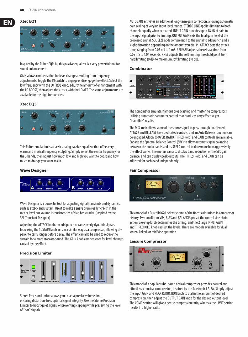
40 X AIR User Manual
Xtec EQ1
Inspired by the Pultec EQP-1a, this passive equalizer is a very powerful tool for sound enhancement.
GAIN allows compensation for level changes resulting from frequency adjustments. Toggle the IN switch to engage or disengage the effect. Select the low frequency with the LO FREQ knob, adjust the amount of enhancement with the LO BOOST, then adjust the attack with the LO ATT. The same adjustments are available for the high frequencies.
Xtec EQ5
This Pultec emulation is a classic analog passive equalizer that offers very warm and musical frequency sculpting. Simply select the center frequency for the 3 bands, then adjust how much low and high you want to boost and how much midrange you want to cut.
Wave Designer
Wave Designer is a powerful tool for adjusting signal transients and dynamics, such as attack and sustain. Use it to make a snare drum really “crack” in the mix or level out volume inconsistencies of slap bass tracks. (Inspired by the SPL Transient Designer)
Adjusting the ATTACK knob can add punch or tame overly dynamic signals. Increasing the SUSTAIN knob acts in a similar way as a compressor, allowing the peaks to carry longer before decay. The effect can also be used to reduce the sustain for a more staccato sound. The GAIN knob compensates for level changes caused by the effect.
Precision Limiter
Stereo Precision Limiter allows you to set a precise volume limit, ensuring distortion-free, optimal signal integrity. Use the Stereo Precision Limiter to boost quiet signals or preventing clipping while preserving the level of “hot” signals.
AUTOGAIN activates an additional long-term gain correction, allowing automatic gain scaling of varying input level ranges. STEREO LINK applies limiting to both channels equally when activated. INPUT GAIN provides up to 18 dB of gain to the input signal prior to limiting. OUTPUT GAIN sets the final gain level of the processed signal. SQUEEZE adds compression to the signal to add punch and a slight distortion depending on the amount you dial in. ATTACK sets the attack time, ranging from 0.05 mS to 1 mS. RELEASE adjusts the release time from 0.05 mS to 1.04 seconds. KNEE adjusts the soft limiting threshold point from hard limiting (0 dB) to maximum soft limiting (10 dB).
Combinator
The Combinator emulates famous broadcasting and mastering compressors, utilizing automatic parameter control that produces very effective yet “inaudible” results.
The MIX knob allows some of the source signal to pass through unaffected. ATTACK and RELEASE have dedicated controls, and an Auto Release function can be engaged. Global X-OVER, RATIO, THRESH(old) and GAIN controls are available. Engage the Spectral Balance Control (SBC) to allow automatic gain balancing between the audio bands and its SPEED control to determine how aggressively the effect works. The meters can also display band reduction or the SBC gain balance, and can display peak outputs. The THRESH(old) and GAIN can be adjusted for each band independently.
Fair Compressor
This model of a Fairchild 670 delivers some of the finest colorations in compressor history. Two small trim VRs, BIAS and BALANCE, preset the control side chain action, a 6-step knob determines the timing, and the 2 large INPUT GAIN and THRESHOLD knobs adjust the levels. There are models available for dual, stereo-linked, or mid/side operation.
Leisure Compressor
This model of a popular tube-based optical compressor provides natural and effortlessly musical compression, inspired by the Teletronix LA-2A. Simply adjust the input GAIN and PEAK REDUCTION knob to dial in the amount of desired compression, then adjust the OUTPUT GAIN knob for the desired output level. The COMP setting will give a gentle compression ratio, whereas the LIMIT setting results in a higher ratio.

41 X AIR User Manual
Ultimo Compressor
The Ultimo Compressor is based on the Urei 1176LN Limiting Amplifier and authentically captures the smooth character of the original class-A output stage in its FET's legendary fast attack.
Start with the INPUT and OUTPUT knobs at the -24 position for unity gain and set the ATTACK and RELEASE knobs fully counterclockwise. Select the compression ratio, then raise the ATTACK knob to lightly compress the signal. Increase the ratio for heavier compression and experiment with ATTACK, RELEASE and INPUT levels to achieve your desired result. Compensate for overall level reduction with the OUTPUT knob.
Enhancer
These Enhancers are so called “Psycho EQs”. They can enhance the signal spectrum in bass, midrange and high frequencies but they differ from traditional equalizers. When you need to generate maximum punch, clarity and detail, without turning up the overall volume, our enhancers are the solution. (Inspired by the SPL Vitalizer)
Adjust the BASS, MID and HI GAIN knobs to add or reduce content in those spectrums. The BASS and HI Frequencies can be specifically selected, while the MID Q (bandwidth) can be adjusted instead. The OUT GAIN knob compensates for changes in level resulting from the effect, and the SPREAD knob (Stereo version only) emphasizes the stereo content for a wider mix. Engage the SOLO MODE to isolate only the audio resulting from the effect so you can hear exactly what you’re adding to the mix.
Exciter
Exciters increase presence and intelligibility in live sound applications, and are indispensable for adding clarity, air and harmonic overtones in the recording studio. This effect is particularly useful for filling out the sound in difficult rooms and for producing a more natural live/recorded sound. (Inspired by the famous Aphex Aural Exciter)
Set the frequency of the side-chain filter with the TUNE knob, and further shape the filter slope with the PEAK and ZERO FILL knobs. Turning the TIMBRE knob left of center adds more odd harmonics, while turning it right of center adds more even harmonics. Adjust the harmonic content added to the signal with the HARMONICS knob, and blend in the effected signal with the MIX knob. Engage the SOLO MODE to isolate only the audio resulting from the effect so you can hear exactly what you’re adding to the mix.
Stereo Imager
A Stereo Imager is typically used to control the placement of a signal within the stereo field during mixdown or mastering. Modeled after the BEHRINGER Edison rack unit, the Stereo Imager will lend a professional quality to your live and recording performances.
The BALANCE knob allows you to emphasize the mono or stereo components of the input signal. The mono and stereo signals can be panned independently with the MONO PAN and STEREO PAN knobs. OUT GAIN is used to compensate for level changes resulting from the effect. The phase can also be shifted using the shelving knobs. Select the frequency and bandwidth (Q) using the corresponding knobs, then adjust the gain with the SHV GAIN knob.
Edison EX1
The EDISON EX1+ is a remarkably effective tool that allows manipulation of the stereo field. The effect offers stereo and mid/side input and output and a phase correlation meter. Exaggerate the stereo field with the ST SPREAD knob and adjust the ratio of mono to stereo content with the BALANCE knob. The CENTER DIST knob allows the mono content to be panned. Compensate for level changes with the OUTPUT GAIN knob.
Sound Maxer
Inspired by the Sonic Maximizer 482i, this effect restores natural brilliance and clarity to any audio signal by adjusting the phase and amplitude integrity to reveal more of the natural texture of the sound. LO CONTOUR adjusts the level of phase-corrected low frequencies and PROCESS adjusts the level of phase-corrected high frequencies. GAIN compensates for level changes caused by the effect.
Guitar Amp
Modeled after the Tech 21 SansAmp, the Stereo / Dual Guitar Amp simulates the sound of plugging into a real guitar amp. From shimmering cleans to saturated crunch, the Stereo / Dual Guitar Amp allows an electric guitar player to sound great without using an amp on stage.
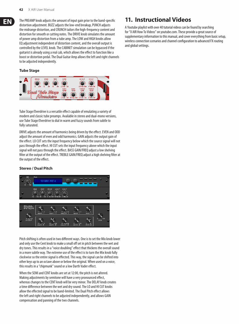
42 X AIR User Manual
The PREAMP knob adjusts the amount of input gain prior to the band-specific distortion adjustment. BUZZ adjusts the low-end breakup, PUNCH adjusts the midrange distortion, and CRUNCH tailors the high-frequency content and distortion for smooth or cutting notes. The DRIVE knob simulates the amount of power amp distortion from a tube amp. The LOW and HIGH knobs allow EQ adjustment independent of distortion content, and the overall output is controlled by the LEVEL knob. The CABINET simulation can be bypassed if the guitarist is already using a real cab, which allows the effect to function like a boost or distortion pedal. The Dual Guitar Amp allows the left and right channels to be adjusted independently.
Tube Stage
Tube Stage/Overdrive is a versatile effect capable of emulating a variety of modern and classic tube preamps. Available in stereo and dual-mono versions, use Tube Stage/Overdrive to dial in warm and fuzzy sounds from subtle to fully saturated.
DRIVE adjusts the amount of harmonics being driven by the effect. EVEN and ODD adjust the amount of even and odd harmonics. GAIN adjusts the output gain of the effect. LO CUT sets the input frequency below which the source signal will not pass through the effect. HI CUT sets the input frequency above which the input signal will not pass through the effect. BASS GAIN/FREQ adjust a low shelving filter at the output of the effect. TREBLE GAIN/FREQ adjust a high shelving filter at the output of the effect.
Stereo / Dual Pitch
Pitch shifting is often used in two different ways. One is to set the Mix knob lower and only use the Cent knob to make a small off set in pitch between the wet and dry tones. This results in a “voice doubling” effect that thickens the overall sound in a more subtle way. The extreme use of the effect is to turn the Mix knob fully clockwise so the entire signal is effected. This way, the signal can be shifted into other keys up to an octave above or below the original. When used on a voice, this results in a “chipmunk” sound or a low Darth Vader effect.
When the SEMI and CENT knobs are set at 12:00, the pitch is not altered. Making adjustments by semitone will have a very pronounced effect, whereas changes to the CENT knob will be very minor. The DELAY knob creates a time difference between the wet and dry sound. The LO and HI CUT knobs allow the effected signal to be band-limited. The Dual Pitch effect allows the left and right channels to be adjusted independently, and allows GAIN compensation and panning of the two channels.
11. Instructional VideosA Youtube playlist with over 40 tutorial videos can be found by searching for “X AIR How To Videos” on youtube.com. These provide a great source of supplementary information to this manual, and cover everything from basic setup, wireless connection scenarios and channel configuration to advanced FX routing and global settings.
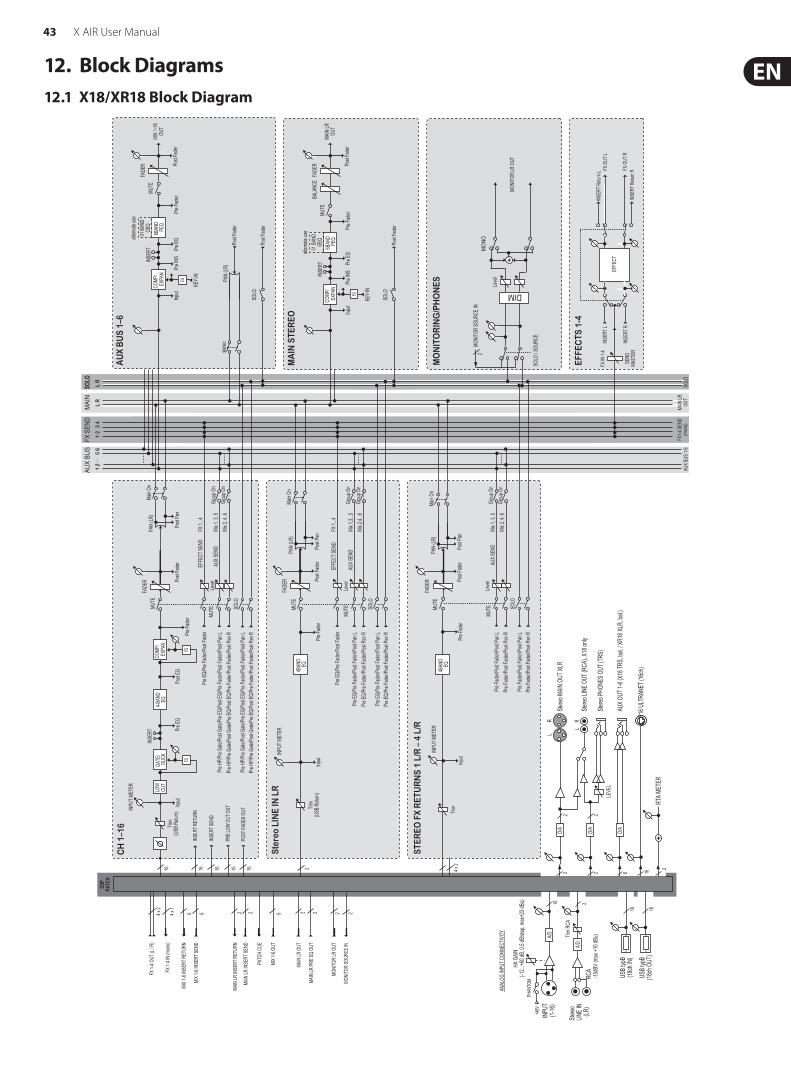
43 X AIR User Manual
MAI
NL
R L
R
SOLO
AUX
BUS
1 2
5
6
FX S
END
1 2
3 4
DSP
PATC
H
FX 1-
4 OUT
(L / R
)
FX 1-
4 IN
(mon
o)
64 x 2
4 x 1
MIX
1-6 IN
SERT
RET
URN
6 M
IX 1-6
INSE
RT SE
ND
6 M
IX 1-6
OUT
MAIN
LR IN
SERT
RET
URN
22MA
IN LR
INSE
RT SE
ND
2MA
IN LR
OUT
2MA
IN LR
PRE E
Q OU
T
PATC
H CU
E
MONI
TOR
LR O
UT
22MO
NITO
R SO
URCE
IN
mute
mute
mute
mutemu
te
mute
mute
stereo
FX1-4
SEND
(mon
o) AU
X BUS
1-6
MAIN
LROU
TSO
LO
2
Ster
eo L
INE
IN L
R
Pre E
Q/Pr
e Fad
er/Po
st Fa
der/P
ost P
an L
Pre E
Q/Pr
e Fad
er/Po
st Fa
der/P
ost P
an R
Pre F
ader
Input
Mix 1
,3...5
Mix 2
,4...6
SOLO
4BAN
DEQ
Pre E
Q/Pr
e Fad
er/Po
st Fa
der/P
ost P
an L
FX 1.
..4Pr
e EQ/
Pre F
ader/
Post
Fade
r
Pre E
Q/Pr
e Fad
er/Po
st Fa
der/P
ost P
an R
MUTEMU
TE
EFFE
CT SE
ND
AUX S
END
Trim
(USB
Retu
rn)
INPU
T MET
ERFA
DER
PAN
(LR)
Leve
lPost
Fade
rPo
st Pa
n
Main
On
Grou
p On
Grou
p On
16 16 16 16 16
CH
1–1
6
LOW
CUT
GATE
/DU
CK
INSE
RT4-B
AND
EQCO
MP/
EXP
AN
Pre E
QInp
utPo
st EQ
Pre F
ader
Mix 1
, 3, 5
Mix 2
, 4, 6
Pre H
P/Pre
Gate/
Post
Gate/
Pre E
Q/Po
st EQ
/Pre F
ader/
Post
Fade
r/Pos
t Pan
LPr
e HP/P
re Ga
te/Po
st Ga
te/Pr
e EQ/
Post
EQ/Pr
e Fad
er/Po
st Fa
der/P
ost P
an R
EQ
Pre H
P/Pre
Gate/
Post
Gate/
Pre E
Q/Po
st EQ
/Pre F
ader/
Post
Fade
r/Pos
t Pan
LPr
e HP/P
re Ga
te/Po
st Ga
te/Pr
e EQ/
Post
EQ/Pr
e Fad
er/Po
st Fa
der/P
ost P
an R
SOLO
INSE
RT R
ETUR
N
INSE
RT SE
ND
PRE L
OW C
UT O
UT
POST
FADE
R OU
T
MUTE
FX 1.
..4Pr
e EQ/
Pre F
ader/
Post
Fade
r
MUTE
FADE
RPA
N (LR
)
AUX S
END
Post
Fade
rPo
st Pa
n
Main
On
INPU
T MET
ER
EFFE
CT SE
ND
EQ
Trim
(USB
Retu
rn)
Leve
l
Grou
p On
Grou
p On
4BAN
DEQ
4 x 2
STER
EO F
X R
ETU
RN
S 1
L/R
– 4
L/R
Pre F
ader/
Post
Fade
r/Pos
t Pan
LPr
e Fad
er/Po
st Fa
der/P
ost P
an R
Pre F
ader
Mix 1
, 3, 5
Mix 2
, 4, 6
SOLO
Pre F
ader/
Post
Fade
r/Pos
t Pan
LPr
e Fad
er/Po
st Fa
der/P
ost P
an R
MUTEMU
TEFA
DER
PAN
(LR)
AUX S
END
Post
Fade
rPo
st Pa
n
Leve
l
Main
On
Input
INPU
T MET
ER
Trim
Grou
p On
Grou
p On
FADE
RBA
LANC
E
MA
IN S
TER
EO
Pre F
ader
Post
Fade
r
MUTE
SOLO
Post
Fade
r
MAIN
LROU
TCO
MP/
EXP
AN
KEY-
IN
Pre E
QPr
e INS
Input
EQ
6BAN
DPE
Q
altern
ate us
e31
BAND
GEQ
INSE
RT
SOLO
Post
Fade
r
AU
X B
US
1–6
Post
Fade
r
MIX 1
-16OU
T
PAN
(LR)
stereo
FADE
R
COMP
/ E
XPAN
KEY-
IN
Pre E
QPr
e INS
Input
EQPr
e Fad
erPo
st Fa
der
MUTE
6BAN
DPE
Q
altern
ate us
e31
BAND
GEQ
INSE
RT
EFFE
CTS
1-4
EFFE
CTFX
OUT
L
FX O
UT R
INSE
RT L
INSE
RT R
INSE
RT R
eturn
L
INSE
RT R
eturn
R
FX IN
1-4
SEND
MAST
ER
+
MON
O
MONI
TOR
LR O
UT
Leve
l
MO
NIT
OR
ING
/PH
ON
ES
SOLO
/ SOU
RCE
MONI
TOR
SOUR
CE IN
MI D
2
ANAL
OG IN
PUT C
ONNE
CTIVI
TY A/DIN
PUT
(1-16
)
Stereo
LIN
E IN
(LR
)RC
A
+48V
PHAN
TOM
A/D
USB t
ypB
(18ch
IN)
USB t
ypB
(18ch
OUT
)1818
216
Trim
RCA
HA G
AIN(-1
2...+6
0 dB,
0.5 dB
/step
, max
+23 d
Bu)
-10dB
V (ma
x +10
dBu)
2D/
ASte
reo M
AIN O
UT XL
R2
LR
22
Stereo
LINE
OUT
(RCA
), X18
only
Stereo
PHON
ES O
UT (T
RS)
LEVE
L
LR
D/A
6AU
X OUT
1-6 (
X18 T
RS, b
al. / X
R18 X
LR, b
al.)
D/A
P16 U
LTRA
NET (
16ch
)16
RTA M
ETER
2+
12. Block Diagrams12.1 X18/XR18 Block Diagram

44 X AIR User Manual
12.2 XR16/XR12 Block Diagram
MAI
NL
R L
R
SOLO
AUX
BUS
1*2*
3
4
FX S
END
1 2
3 4
DSP
PATC
H
FX 1-
4 OUT
(L / R
)
FX 1-
4 IN
(mon
o)
4/2*
4 x 2
4 x 1
MIX
1-4* IN
SERT
RET
URN
4/2*
MIX
1-4* IN
SERT
SEND
4 / 2*
MIX
1-4* O
UT
MAIN
LR IN
SERT
RET
URN
22MA
IN LR
INSE
RT SE
ND
2MA
IN LR
OUT
2MA
IN LR
PRE E
Q OU
T
PATC
H CU
E
MONI
TOR
LR O
UT
22MO
NITO
R SO
URCE
IN
mute
mute
mute
mutemu
te
mute
mute
stereo
FX1-4
SEND
(mon
o) AU
X BUS
1-2*
AUX B
US 1-
4MA
IN LR
OUT
SOLO
2
Ster
eo U
SB R
etur
n
Pre E
Q/Pr
e Fad
er/Po
st Fa
der/P
ost P
an L
Pre E
Q/Pr
e Fad
er/Po
st Fa
der/P
ost P
an R
Pre F
ader
Input
Mix 1
,3Mi
x 2,4
SOLO
4BAN
DEQ
Pre E
Q/Pr
e Fad
er/Po
st Fa
der/P
ost P
an L
FX 1.
..4Pr
e EQ/
Pre F
ader/
Post
Fade
r
Pre E
Q/Pr
e Fad
er/Po
st Fa
der/P
ost P
an R
MUTEMU
TE
EFFE
CT SE
ND
AUX S
END
Trim
(USB
Retu
rn)
INPU
T MET
ERFA
DER
PAN
(LR)
Leve
lPost
Fade
rPo
st Pa
n
Main
On
Grou
p On
Grou
p On
16 16 16 16 16
CH
1–1
6
LOW
CUT
GATE
/DU
CK
INSE
RT4-B
AND
EQCO
MP/
EXP
AN
Pre E
QInp
utPo
st EQ
Pre F
ader
Mix 1
, 3Mi
x 2, 4
Pre H
P/Pre
Gate/
Post
Gate/
Pre E
Q/Po
st EQ
/Pre F
ader/
Post
Fade
r/Pos
t Pan
LPr
e HP/P
re Ga
te/Po
st Ga
te/Pr
e EQ/
Post
EQ/Pr
e Fad
er/Po
st Fa
der/P
ost P
an R
EQ
Pre H
P/Pre
Gate/
Post
Gate/
Pre E
Q/Po
st EQ
/Pre F
ader/
Post
Fade
r/Pos
t Pan
LPr
e HP/P
re Ga
te/Po
st Ga
te/Pr
e EQ/
Post
EQ/Pr
e Fad
er/Po
st Fa
der/P
ost P
an R
SOLO
INSE
RT R
ETUR
N
INSE
RT SE
ND
PRE L
OW C
UT O
UT
POST
FADE
R OU
T
MUTE
FX 1.
..4Pr
e EQ/
Pre F
ader/
Post
Fade
r
MUTE
FADE
RPA
N (LR
)
AUX S
END
Post
Fade
rPo
st Pa
n
Main
On
INPU
T MET
ER
EFFE
CT SE
ND
EQ
Trim
(USB
Retu
rn)
Leve
l
Grou
p On
Grou
p On
4BAN
DEQ
4 x 2
STER
EO F
X R
ETU
RN
S 1
L/R
– 4
L/R
Pre F
ader/
Post
Fade
r/Pos
t Pan
LPr
e Fad
er/Po
st Fa
der/P
ost P
an R
Pre F
ader
Mix 1
, 3Mi
x 2, 4
SOLO
Pre F
ader/
Post
Fade
r/Pos
t Pan
LPr
e Fad
er/Po
st Fa
der/P
ost P
an R
MUTEMU
TEFA
DER
PAN
(LR)
AUX S
END
Post
Fade
rPo
st Pa
n
Leve
l
Main
On
Input
INPU
T MET
ER
Trim
Grou
p On
Grou
p On
FADE
RBA
LANC
E
MA
IN S
TER
EO
Pre F
ader
Post
Fade
r
MUTE
SOLO
Post
Fade
r
MAIN
LROU
TCO
MP/
EXP
AN
KEY-
IN
Pre E
QPr
e INS
Input
EQ
6BAN
DPE
Q
altern
ate us
e31
BAND
GEQ
INSE
RT
SOLO
Post
Fade
r
AU
X B
US
1–4
/ 1-2
*
Post
Fade
r
MIX 1
-4OU
T
PAN
(LR)
stereo
FADE
R
COMP
/ E
XPAN
KEY-
IN
Pre E
QPr
e INS
Input
EQPr
e Fad
erPo
st Fa
der
MUTE
6BAN
DPE
Q
altern
ate us
e31
BAND
GEQ
INSE
RT
EFFE
CTS
1-4
EFFE
CTFX
OUT
L
FX O
UT R
INSE
RT L
INSE
RT R
INSE
RT R
eturn
L
INSE
RT R
eturn
R
FX IN
1-4
SEND
MAST
ER
+
MON
O
MONI
TOR
LR O
UT
Leve
l
MO
NIT
OR
ING
/PH
ON
ES
SOLO
/ SOU
RCE
MONI
TOR
SOUR
CE IN
MI D
2
ANAL
OG IN
PUT C
ONNE
CTIVI
TY A/DMI
C IN
PUT
XR16
(1-8)
XR12
(1-4)
LINE I
NXR
16 (9
-16)
XR12
(5-12
)1/4
” TRS +4
dBu /
-10d
BV (m
ax +2
2 / +1
0 dBu
)
+48V
PHAN
TOM
A/D
USB t
ypA
(2ch I
N)
USB t
ypA
(2ch O
UT)
22
88 / 4*
HA G
AIN(-1
2...+6
0 dB,
0.5 dB
/step
, max
+23 d
Bu)
LineT
rim2
D/A
Stereo
MAIN
OUT
XLR
2
LR
22
Stereo
PHON
ES O
UT (T
RS)
LEVE
LD/
A
4/2*
AUX O
UT 1-
4 / 1-
2* (TR
S, ba
l.)D/
A
RTA M
ETER
2+

45 X AIR User Manual
FEDERAL COMMUNICATIONS COMMISSION COMPLIANCE INFORMATION
Responsible Party Name: MUSIC Group Services NV Inc.
Address: 5270 Procyon Street Las Vegas, NV 89118 USA
Phone Number: +1 702 800 8290
X AIR X18/XR18/XR16/XR12
complies with the FCC rules as mentioned in the following paragraph:
This equipment has been tested and found to comply with the limits for a Class B digital device, pursuant to part 15 of the FCC Rules. These limits are designed to provide reasonable protection against harmful interference in a residential installation. This equipment generates, uses and can radiate radio frequency energy and, if not installed and used in accordance with the instructions, may cause harmful interference to radio communications. However, there is no guarantee that interference will not occur in a particular installation. If this equipment does cause harmful interference to radio or television reception, which can be determined by turning the equipment off and on, the user is encouraged to try to correct the interference by one or more of the following measures:
• Reorient or relocate the receiving antenna.
• Increase the separation between the equipment and receiver.
• Connect the equipment into an outlet on a circuit different from that to which the receiver is connected.
• Consult the dealer or an experienced radio/TV technician for help.
This device complies with Part 15 of the FCC rules. Operation is subject to the following two conditions:
(1) this device may not cause harmful interference, and (2) this device must accept any interference received, including interference that may cause undesired operation.
Important information:
Changes or modifications to the equipment not expressly approved by MUSIC Group can void the user’s authority to use the equipment.
X AIR X18/XR18/XR16/XR12

Dedicate Your Life to Music