
Please call us at 1-800-542-5377 or 1-708-345-7700 for ...
160
® Find the answers to your questions here... If you still need help, give us a call! Find-It-In-Front: Dr. Pinball Section Find-It-In-Front: Dr. Pinball Section The inside cover & the front pages DR. thru DR. covers the basics... ¶ ¿ Your Parts Sales & Technical Support Team Dorothy Brown Parts Sales REPRESENTATIVE X Chas Siddiqi Technical Support ENGINEER X J. Alfer Technical Support Documentation ADMINISTRATOR Joe Blackwell DIRECTOR, Parts Sales & Technical Support Patrick Powers Technical Support ENGINEER X Patty Schraps Parts Sales MANAGER X Please call us at 1-800-542-5377 or 1-708-345-7700 for Technical Support. Visit us at our Web Site www.SternPinball.com. Stern Pinball, Inc. ® All Rights Reserved. Printed in the U.S.A. October 2004 SPI Part Number 780-5087-00 The Portals™Service Menu, Section 3, is your Technical Friend... ® ©H-D. All Rights Reserved. Manufactured by STERN Pinball under license from Harley-Davidson® Motor company
-
Upload
khangminh22 -
Category
Documents
-
view
3 -
download
0
Transcript of Please call us at 1-800-542-5377 or 1-708-345-7700 for ...

®
Find the answers to your questions here...If you still need help, give us a call!
Find-It-In-Front:
Dr. Pinball Section
Find-It-In-Front:
Dr. Pinball SectionThe inside cover & the front pages
DR. thru DR. covers the basics...� �
Your Parts Sales & Technical Support Team
Dorothy Brown
Parts SalesREPRESENTATIVE
X
Chas Siddiqi
Technical SupportENGINEER
XJ. AlferTechnical SupportDocumentationADMINISTRATOR
Joe BlackwellDIRECTOR,Parts Sales &Technical Support
Patrick Powers
Technical SupportENGINEER
X
Patty Schraps
Parts SalesMANAGER
X
Please call us at 1-800-542-5377 or1-708-345-7700 for Technical Support.
Visit us at our Web Site www.SternPinball.com.
Stern Pinball, Inc.®
All Rights Reserved.Printed in the U.S.A.
October 2004
SPI Part Number
780-5087-00
The Portals™Service Menu,Section 3, is your Technical Friend...
®
©H-D. All Rights Reserved. Manufactured by STERN Pinballunder license from Harley-Davidson® Motor company

Harley-Davidson Specific (Motorcycle Test)To initiate, from the DIAGNOSTICS MENU, select the "H-D" Icon with either the Red "LEFT" or Green"RIGHT" Button and press the Black "ENTER" Button (the START Button operates in the samemanner). (New to our Portals Service Menu? Review Section 3, Chapter 1)
This will bring up the HARLEY-DAVIDSON SPECIFIC MENU. Similiar to "BEGIN PLAY TEST," this menu is usedto test and adjust Game Specific Features. The feature in this game is MOTORCYCLE TEST.
Important: The Power Interlock Switch must be pulled out for this Test to Function.
This test is provided to allow the technician a simple method of removing the balls from the trough, to test thefunctionality of the trough (correct operation of the Kick-Out Coil & the Switch Membrane) and Motor Operation.After selecting the "H-D" Icon the display will indicate the position of the Motorcycle (Motor Up, Switch 35, andMotor Down, Switch 36). The position will be highlighted in the box. The next line will indicate if any switchclosures are present over the Switch Membrane in the Kick-Out Trough (Sw. 44 (bottom) through Sw. 41 (top)).
Motor Up/Down Test Procedure:Select the "RUN" Icon to automatically bring the Motor & Trough from the DOWN or UP position to the oppositeposition. Select the "PULSE" Icon to move the motor slowly UP and/or DOWN one pulse at a time. This testallows you to operate the Motor on this mechanism which is controlled by a Relay driven by Q19 on the I/O PowerDriver Board for the purpose of troubleshooting.
Switch & Ball Eject Test Procedure:Hand-Roll 1 ball at a time into the trough (with theMotorcycle in the UP position). Watch the display andnote that each box is high-lighted from left to right as theballs are inserted. This test indicates proper SwitchMembrane function (Switch 44 is the first ball in (bottom) and Switch 41 being the last (4th) ball in (top). To ejectthe balls and to test the Motorcycle Ball Launch (Coil Q5), press the "AUTO LAUNCH" Button (Cabinet FrontRight Side). The 4 boxes should become unhighlighted indicating "no balls are in the trough".
You may wish to activate the "RUN" Icon to bring the Motorcycle back into the DOWN position. If exiting Portalswithout doing so, the Motorcycle will automatically return to the DOWN position upon Game Reset.
New to our Pinball Games?Don’t forget to go over Section 3, Chapter 1, Portals Service Menu Introduction. If using Diagnostics...veryuseful! Got confused? Comments? Questions? Call Technical Support at 800-542-5377 or 708-345-7700.
Kick-Out Trough Assembly,500-6397-00-67
Sw. 41Sw. 42
Sw. 43Sw. 44
Coil Q5(24-940)
SwitchMembrane
Sw. MembraneRibbon Cable to
Diode Board
Lift (Motor) Assembly,500-6396-00-67
UPPositionSw. 35
DOWNPositionSw. 36
Motor to RelayBoard Q19

���������� ����������������������������������� ��������� ���!��
�
��� ���� � � �� ����� � ���� ���� �����CPU Sound U7 512K 965-0320-87CPU Game U210 1 MB 965-0319-87
CPU Voice ROM 1 U17 8 MB 965-0322-87CPU Voice ROM 2 U21 8 MB 965-0323-87CPU Voice ROM 3 U36 8 MB 965-0324-87CPU Voice ROM 4 U37 8 MB 965-0325-87
DISPLAY Controller U5 4 MB 965-0321-87
��� �������� ��������� � ��� � ��
����� ���� � ��� ���������� ����� �� ����� ��
��� �� ������ ��������� ������ �����
G.I.B3
B2
B1
B20
B21
F24 F26
F25F27
F22 F23
F8 F7
F6 F21
F28 F20
BRIDGES
Relay
F9
BRIDGES
Relay
*** All BRIDGES rated35A @ 100v ***
B1 +50v DC HighCurrent Coils
B2 +20v DC LowCurrent Coils
B3+/-12v DCSound / Display / Logic
B20 +18v DCIllumination
B21 +5v DC LogicVoltage
"��� ��#��$��������
F1 �#��%���� ��� %%�����
QUICK REFERENCE FUSE CHARTB a c k b o x F u s e s
LOC: DISPLAY POWER SUPPLY (P.S.) BOARDF1 3 4A 250v S.B. 90v DC High Voltage Display
LOC: I / O POWER DRIVER BOARDF6 7A 250v S.B. 50v DC Primary High Power Coils/FlippersF7 5A 250v S.B. 20v DC Low Power CoilsF8 5A 250v S.B. 12v DC Logic PowerF9 5A 250v S.B. 12v DC Logic PowerF20 4A 250v S.B. 50v DC Magnet(s)F21 3A 250v S.B. 50v DC CoilsF22 8A 250v S.B. 18v DC Controlled LampsF23 4A 250v S.B. 5v DC LogicF24 5A 250v S.B. 6.3v AC G.I. Lamps (BRN-WHT to WHT-BRN)F25 5A 250v S.B. 6.3v AC G.I. Lamps (YEL to WHT-YEL)F26 5A 250v S.B. 6.3v AC G.I. Lamps (GRN to WHT-GRN)F27 5A 250v S.B. 6.3v AC G.I. Lamps (VIO to WHT-VIO)F28 3A 250v S.B. 24v AC Not Used / Spare
C a b i n e t F u s e sLOC: SERVICE (AC) OUTLET BOX (Cabinet Bottom)n/a 8A 250v S.B. 115v AC Main Fuse Line (Domestic or USA)n/a 5A 250v S.B. 220v AC Main Fuse Line (International)LOC: SHAKER MOTOR BD. (Cabinet, Rt. Side Front)F2 2�A 250v S.B. 12v DC Shaker MotorF3 2�A 250v S.B. 12v DC Shaker Motor
P l a y f i e l d ( P / F ) F u s e sLOC: UNDER PLAYFIELD (near Flippers)n/a 3A 250v S.B. 50v DC Rt. Flipper (BLU-YEL�RED-YEL)n/a 3A 250v S.B. 50v DC Lt. Flipper (GRY-YEL�RED-YEL)n/a 3A 250v S.B. 50v DC Magnet (Top Orbit) (VIO-YEL�BLK)For locations & more information on fuses, see Sec. 5, Chapter 2.
Transformer onCabinet Bottom
On/Off Switch(Under Cabinet)
Playfield PowerInterlock Switch
Memory ProtectSwitch (Bottom)
Inside Coin Door
USA: 8 Amp 250vSlo-Blo Fuse
Int’l.: 5 Amp 250vSlo-Blo Fuse
Service Outlet(on Power Box)
Inside Coin Door
Volume Control & Service SwitchesFor operational usage, see Sec. 3, Chapter 1,
Portals Service Menu Introduction.
DISPLAY EPROM U5 / ROM 0DISPLAY EPROM U5 / ROM 0
&�� ���
U5
Dot Matrix DisplayBd. (Reverse Side)
#��%�����������������
U5
��� !����" �� ������ �� �� !����"#�$%& �'���� ( )� � $%& *� ���� +��� �� ����� +��� � ��
,-. / 0- !� &��1 !����" ����
CPUGAME
EPROM CMOSRAM
3x AA
U7 U37 U36 U21 U17
�'��� �����"" �()�*+�
U212SOUND &
VOICE ROMS
&�� ���SW300
U210
����,"�,"�,�����-#�������� #��

���������������������� ���������������������������������The key technical data from various parts of the manual were extracted and combined into the "Find- It-In-Front:Dr. Pinball Section." This section (pages ��� � - �) will assist the technician in locating important technicalinformation needed to troubleshoot the Pinball Machine. Dr. Pinball is also available in a Flow Chart Help Formatin the Game Display. To access, enter the Portals Service Menu.
�������������� � !"�������First, the operator / technician must enter the Service Menu Mode(for a complete description of the Portals Service Menu and ICONSRead! Section 3, Chapter 1). To get into the Service Menu Mode,power-up the game (if not already) and open the Coin Door. On theCoin Door is the Portals Service Switch Set (Red, Green & BlackButtons).
Step 1: Push down the Black "BEGIN TEST" Button. Looking at theVideo Display you will momentarily see the introductory screenfollowed by the MAIN MENU.
Step 2: Move through the Menusby pushing the Red "LEFT"or Green "RIGHT" Buttons.
Step 3: Select or activate the Icons by pushing the Black "ENTER"Button.
While in the Portals Service Menu, the Start Button can be usedin lieu of the Black Button; the Left & Right Flipper Buttons canbe used in lieu of the Red & Green Buttons. However, in Switch orActive Switch Tests only the Red & Green Buttons can be used.
In our Portals Service Menu, selecting the "DR." Iconwill bring the operator/technician into DR. PINBALL (FlowChart Menus), the "on-screen" diagnostic aide. This is afeature that will allow you to utilize the power of the micro-processor assisting in troubleshooting a problem with the
machine in a Flow Chart format (follow the questions & answer by using the Mini-Icons in the display).
After entering Portals , the MAIN MENU now appears with the"DIAG" Icon (GO TO DIAGNOSTICS MENU) flashing; press theBlack "ENTER" Button to activate this ICON. The DIAGNOS-TICS MENU now appears with the "SW" Icon (GO TO SWITCHMENU) flashing; use the Red "LEFT" or Green "RIGHT"Buttons, untilthe "DR." Icon(DR. PINBALL)is flashing:
Press the Black "ENTER" Button to activate this ICON. TheDR. PINBALL MENU (Flow Chart Menus) now appears with theCOIL "DR." Icon flashing. Three (3) Icons, Coil "DR.", Switch"DR." and Lamp "DR." are available for selection. Selecting aparticular Icon will give you a choice of which specific Coil (anyand all coil assemblies such as Flippers, VUKs, Magnets, etc.),Switch or Lamp Circuit needs to be diagnosed. After selection,Dr. Pinball will now display a question or a procedure to followsuch as "Does the lamp turn on?" or "Check bridge rectifierBR-20, if short replace." When Dr. Pinball displays a question orrequests a procedure, Dr. Pinball will expect a response such as"NO" or "YES". You the operator/technician must respond byusing the Red or Green Buttons to "SELECT" a Mini-Icon andthe Black Button to "ACTIVATE or ENTER" your selection.
For Mini-Icons explanations & details, see the end of Section 3,Chapter 2, GO TO DIAGNOSTICS MENU, Dr. Pinball.
�
��������
��
������ ���� ����
������ ������������� ���
�� ��� �������� �������
��� ��!��������� ������� ������ �"�� #�
�"�� �"��
������������ ������������
��� � �����������������

�������������� �� ����������� ��������� ��� �� � �
������� ��!"#$%%&�'�&(�#)�!"&($%%)�*
��������������!$+"�&(!,�$!�&������������If this display flashes, the game is indicating that CMOS RAMmemory (CPU Loc. U212) has been corrupted. This is causedbe either failure in memory (e.g. batteries are dead and/or faultyRAM) or upon installation of updated version of game code.Opening the Coin Door will initiate a Factory Restore (Reset),by opening the Memory Protect Switch. Check battery voltage
at VBATT Test Point on the CPU/Sound Bd. (more details in Section 5, Chapter 4, PCBs).
This display is shown momentarily during Game Mode orPower-Up to alert the operator of a coil malfunction (coil doesn’tenergize or coil fires a multiple number of times). OPERATORALERT! works by monitoring any switch activated coil that hasthe potential to trap a ball when disabled (e.g. in the AutoLaunch, Scoop, Eject, etc.). This alert can also appear if a
switch associated with a coil (e.g. #16 Shooter Lane & #2 Auto Launch) is stuck closed (caused by a switch jam orstuck ball); the CPU/Sound Board will activate the coil approximately ten times and if the switch remains closed,the game will report this switch in Technician Alerts.
����������,����!��&-!(,��&)((!"+&����������Location of Dip Switch [SW300] is on the CPU/Sound Board (Right of CN6, Top Middle)
�
CPU COUNTRY SETTING: Pos. � � � � � � � �
Austria ON �OFF � � � � � � �
CPU COUNTRY SETTING: Pos. � � � � � � � �
Australia ON � �� �OFF � � � � �
CPU COUNTRY SETTING: Pos. � � � � � � � �
Belgium ON �OFF � � � � � � �
CPU COUNTRY SETTING: Pos. � � � � � � � �
Canada ON � �OFF � � � � � �
CPU COUNTRY SETTING: Pos. � � � � � � � �
Denmark ON � �OFF � � � � � �
CPU COUNTRY SETTING: Pos. � � � � � � � �
Finland ON � �OFF � � � � � �
CPU COUNTRY SETTING: Pos. � � � � � � � �
USA ON
OFF � � � � � � � �
CPU COUNTRY SETTING: Pos. � � � � � � � �
France ON � �OFF � � � � � �
CPU COUNTRY SETTING: Pos. � � � � � � � �
Germany ON � � �OFF � � � � �
CPU COUNTRY SETTING: Pos. � � � � � � � �
Greece ON � � � �OFF � � � �
CPU COUNTRY SETTING: Pos. � � � � � � � �
Italy ON �OFF � � � � � � �
CPU COUNTRY SETTING: Pos. � � � � � � � �
Netherlands ON �OFF � � � � � � �
CPU COUNTRY SETTING: Pos. � � � � � � � �
New Zealand ON �OFF � � � � � � �
CPU COUNTRY SETTING: Pos. � � � � � � � �
Norway ON � �OFF � � � � � �
CPU COUNTRY SETTING: Pos. � � � � � � � �
Portugal ON � �OFF � � � � � �
CPU COUNTRY SETTING: Pos. � � � � � � � �
Spain ON � �OFF � � � � � �
CPU COUNTRY SETTING: Pos. � � � � � � � �
Sweden ON � � �OFF � � � � �
CPU COUNTRY SETTING: Pos. � � � � � � � �
Switzerland ON � �OFF � � � � � �
CPU COUNTRY SETTING: Pos. � � � � � � � �
UK ON � � �OFF � � � � �
���������� ��!��! ���� �.����������/��� ��� ��/������
&-!(,��'$(�!0�+�!��1��)�!,$()��&-!(,�)&
%$'��'$(�!0�+�!�
�
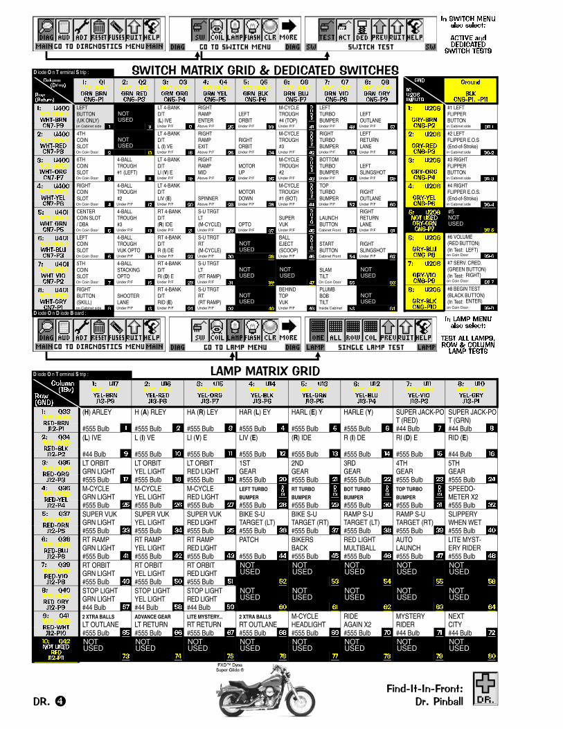
���
����������
������
���� ��� ���
�� ����
��� ����� ��
#1 LEFTFLIPPERBUTTONin Cabinet side ����
�� ����
��� ����� ��
#2 LEFTFLIPPER E.O.S(End-of-Stroke)in Cabinet side ����
�� ����
��� ����� ��
#3 RIGHTFLIPPERBUTTONin Cabinet side ����
�� ����
��� ����� ��
#4 RIGHTFLIPPER E.O.S.(End-of-Stroke)in Cabinet side ����
�� ������� ������� ����� ��
#5NOTUSED
in Cabinet side ����
�� ����
��� ����� �
#6 VOLUME(RED BUTTON)(In Test: LEFT)on Coin Door ���
�� ����
��� !"��� �#
#7 SERV. CRED.(GREEN BUTTON)(In Test: RIGHT)on Coin Door ���
� ����
��� ���� ���
#8 BEGIN TEST(BLACK BUTTON)(In Test: ENTER)on Coin Door ����
�� ������ ��� �� �� ����
����� ����������
������ ����
�� ���� ��� �� �� ����
��� ��� ��������� � �����
���� ����
� �����������
� ���������
�� $���� ������� ����� ��
�� $���� ������� ����� ��
�� $���� ������� ����� ��
�� $���� ������� ����� ��
�� $���� ������� ���� ��
�� $���� ������� ����� ��
�� $���� ������� !"��� �
� $ ��� ������� ����� �#
�� ������� ����%&� ����� �#
LEFTBUTTON(UK ONLY)
NOTUSED
LT 4-BANKD/T(L) IVE
RIGHTRAMPENTER
LEFTORBIT
M-CYCLETROUGH#4 (TOP)
���
LEFTTURBOBUMPER
LEFTOUTLANE
on Cabinet side � � Under P/F � Above P/F �� Under P/F �� Under P/F �� Under P/F �� Under P/F �
�� ������� ����%&� ����� �
4THCOINSLOT
NOTUSED
LT 4-BANKD/TL (I) VE
RIGHTRAMPEXIT
RIGHTORBIT
M-CYCLETROUGH#3
���
RIGHTTURBOBUMPER
LEFTRETURNLANE
On Coin Door � �� Under P/F �� Above P/F � Under P/F �� Under P/F �� Under P/F �� Under P/F ��
�� ������� ����%&� ����� ��
6THCOINSLOT
4-BALLTROUGH#1 (LEFT)
LT 4-BANKD/TLI (V) E
RIGHTRAMPMID
MOTORUP
M-CYCLETROUGH#2
���
BOTTOMTURBOBUMPER
LEFTSLINGSHOT
On Coin Door � �� Under P/F �� Above P/F � Under P/F �� Under P/F �� Under P/F �� Under P/F ��
�� ������� ����%&� ����� ��
RIGHTCOINSLOT
4-BALLTROUGH#2
LT 4-BANKD/TLIV (E) SPINNER
MOTORDOWN
M-CYCLETROUGH#1 (BOT)
���
TOPTURBOBUMPER
RIGHTOUTLANE
On Coin Door � Under P/F �� Under P/F �� Above P/F �� Under P/F � Under P/F �� Under P/F �� Under P/F �
�� ������� ����%&� ����� ��
CENTERCOIN SLOT/ DBA
4-BALLTROUGH#3
RT 4-BANKD/T(R) IDE
S-U TRGTLT(M-CYCLE) OPTO
SUPERVUK
����
LAUNCHBUTTON
RIGHTRETURNLANE
On Coin Door � Under P/F �� Under P/F �� Under P/F �� Under P/F � Under P/F �� Cabinet Front �� Under P/F �
�� ������� ����%&� ����� ��
LEFTCOINSLOT
4-BALLTROUGHVUK OPTO
RT 4-BANKD/TR (I) DE
S-U TRGTRT(M-CYCLE)
NOTUSED
BALLEJECT(SCOOP)
����
STARTBUTTON
RIGHTSLINGSHOT
On Coin Door Under P/F �� Under P/F �� Under P/F �� �� Under P/F � Cabinet Front �� Under P/F �
�� ������� ����%&� !"��� ��
5THCOINSLOT
4-BALLSTACKINGOPTO
RT 4-BANKD/TRI (D) E
S-U TRGTLT(RT RAMP)
NOTUSED
NOTUSED
SLAMTILT
NOTUSED
On Coin Door Under P/F �� Under P/F �� Under P/F �� �� � On Coin Door �� �
� ������� ����%&� ����� ��
RIGHTBUTTON(SKILL)
SHOOTERLANE
RT 4-BANKD/TRID (E)
S-U TRGTRT(RT RAMP)
NOTUSED
BEHINDTOPVUK
PLUMBBOBTILT
NOTUSED
on Cabinet side � Under P/F � Under P/F �� Under P/F �� �� Under P/F �� Inside Cabinet � �
D iode O n T erminal S trip :
D iode O n D iode B oard :
�� ��� !"#$
��% &�$
�� ������ ������� ���'�� �#
�� ������ ������� ���'�� �
�� ������ ������� ���'�� ��
�� ������ ������� ��'�� ��
�� ������ ������� ���'�� ��
�� ������ ������� ���'�� ��
�� ������ ������� !"�'�� ��
� ������ ������� ���'�� ��
�� $����� ������� ���'�� ��
(H) ARLEY H (A) RLEY HA (R) LEY HAR (L) EY HARL (E) Y HARLE (Y) SUPER JACK-POT (RED)
SUPER JACK-POT (GRN)
#555 Bulb � #555 Bulb � #555 Bulb � #555 Bulb � #555 Bulb � #555 Bulb � #44 Bulb � #44 Bulb
�� $����� ������� ��'�� ��
(L) IVE L (I) VE LI (V) E LIV (E) (R) IDE R (I) DE RI (D) E RID (E)
#44 Bulb # #555 Bulb �� #555 Bulb �� #555 Bulb �� #555 Bulb �� #555 Bulb �� #555 Bulb �� #44 Bulb ��
�� $����� ������� ���'�� ��
LT ORBITGRN LIGHT
LT ORBITYEL LIGHT
LT ORBITRED LIGHT
1STGEAR
2NDGEAR
3RDGEAR
4THGEAR
5THGEAR
#555 Bulb �� #555 Bulb � #555 Bulb �# #555 Bulb �� #555 Bulb �� #555 Bulb �� #555 Bulb �� #555 Bulb ��
�� $����� ������� ���'�� ��
M-CYCLEGRN LIGHT
M-CYCLEYEL LIGHT
M-CYCLERED LIGHT
LEFT TURBO
BUMPER
����
RT TURBO
BUMPER
����
BOT TURBO
BUMPER
����
TOP TURBO
BUMPER
����
SPEEDO-METER X2
#555 Bulb �� #555 Bulb �� #555 Bulb �� #555 Bulb � #555 Bulb �# #555 Bulb �� #555 Bulb �� #555 Bulb ��
�� $����� ������� ���'�� ��
SUPER VUKGRN LIGHT
SUPER VUKYEL LIGHT
SUPER VUKRED LIGHT
BIKE S-UTARGET (LT)
BIKE S-UTARGET (RT)
RAMP S-UTARGET (LT)
RAMP S-UTARGET (RT)
SLIPPERYWHEN WET
#555 Bulb �� #555 Bulb �� #555 Bulb �� #555 Bulb �� #555 Bulb �� #555 Bulb � #555 Bulb �# #555 Bulb ��
�� $� ��� ������� ���'�� ��
RT RAMPGRN LIGHT
RT RAMPYEL LIGHT
RT RAMPRED LIGHT
PATCH BIKERSBACK
RED LIGHTMULTIBALL
AUTOLAUNCH
LITE MYST-ERY RIDER
#555 Bulb �� #555 Bulb �� #555 Bulb �� #555 Bulb �� #555 Bulb �� #555 Bulb �� #555 Bulb �� #555 Bulb �
�� $�#��� ������� !"�'�� �
RT ORBITGRN LIGHT
RT ORBITYEL LIGHT
RT ORBITRED LIGHT
NOTUSED
NOTUSED
NOTUSED
NOTUSED
NOTUSED
#555 Bulb �# #555 Bulb �� #555 Bulb �� �� �� �� �� ��
� $����� ������� ���'�� �#
STOP LIGHTGRN LIGHT
STOP LIGHTYEL LIGHT
STOP LIGHTRED LIGHT
NOTUSED
NOTUSED
NOTUSED
NOTUSED
NOTUSED
#44 Bulb �� #44 Bulb � #44 Bulb �# �� �� �� �� ��
#� $����� ������� %&�'�� ���
2 XTRA BALLS
LT OUTLANEADVANCE GEAR
LT RETURNLITE MYSTERY...
RT RETURN2 XTRA BALLS
RT OUTLANEM-CYCLEHEADLIGHT
RIDEAGAIN X2
MYSTERYRIDER
NEXTCITY
#555 Bulb �� #555 Bulb �� #555 Bulb �� #555 Bulb � #555 Bulb �# #555 Bulb �� #44 Bulb �� #44 Bulb ��
��� $����� �������'�� ���
NOTUSED
NOTUSED
NOTUSED
NOTUSED
NOTUSED
NOTUSED
NOTUSED
NOTUSED
�� �� �� �� �� � �# �
D iode O n T erminal S trip :
�����!��!������.����������/ ��/���������������

���������� ��!��! ���� �.����������/��� ��� ��/������
������ ���� ��� �������� ��� ���� ��� ��������
������ ������ ��������� ��������� ������ ��������� ������ ��� ���������
�
Legend Note: = Switches/Lamps mounted above P/F. = Switches/Lamps mounted below the P/F. = ...mounted in/on Cabinet.
��
��
��
��
��
����
��
�
����
��
��
���
�
��
��
��
��
�
�
��
��
��
���
����
��
����
�
��
��
��
��
��
����
��
�
��
����
��
����
����
��
��
��
�
��
��
�� � ������� �� ����
� �
�
��
��
��
��
��
�
��
��
��
��
��
��
��
��
��
��
����
��
��
�
�
��
��
��
�
��
��
��
����
��
�
� �
����
�
�
�
�
�
��
��
��
�� ���
�
��
��
��
��
�
��
-XXX -XXX
Note: All Switch, Lamp & Coil assemblies require diodes. Some diodes are located under the playfield on Terminal Strips or Diode Boards and not on the assemblies. D iode O n T erminal S trip or D iode O n D iode B oard
�
�� ���� ����� �������
���������������
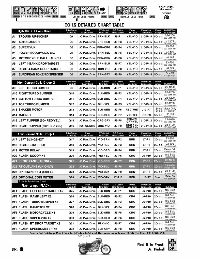
,�!%&��)($!%)��,�$�(�($#%)���� ����� ���� ����� � Drive Trans-
istor (D.T.)Driver
Ouput BoardD.T. ControlLine Color
D.T. ControlLine Connect
PowerLine Color
Power LineConnnection
PowerVoltage
Coil GA/Turnor Bulb Type
#1 TROUGH UP-KICKER Q1 I/O Pwr. Drvr. BRN-BLK J8-P1 YEL-VIO J10-P4/5 50v DC 26-1200090-5044-00T
#2 AUTO LAUNCH Q2 I/O Pwr. Drvr. BRN-RED J8-P3 YEL-VIO J10-P4/5 50v DC 24-940090-5036-00T
#3 SUPER VUK Q3 I/O Pwr. Drvr. BRN-ORG J8-P4 YEL-VIO J10-P4/5 50v DC 23-800090-5001-00T
#4 POWER SCOOP/KICK BIG Q4 I/O Pwr. Drvr. BRN-YEL J8-P5 YEL-VIO J10-P4/5 50v DC 23-800090-5001-00T
#5 MOTORCYCLE BALL LAUNCH Q5 I/O Pwr. Drvr. BRN-GRN J8-P6 YEL-VIO J10-P4/5 50v DC 24-940090-5036-00B
#6 LEFT 4-BANK DROP TARGET Q6 I/O Pwr. Drvr. BRN-BLU J8-P7 YEL-VIO J10-P4/5 50v DC 23-700090-5022-00T
#7 RIGHT 4-BANK DROP TARGET Q7 I/O Pwr. Drvr. BRN-VIO J8-P8 YEL-VIO J10-P4/5 50v DC 23-700090-5022-00T
#8 EUROPEAN TOKEN DISPENSER Q8 I/O Pwr. Drvr. BRN-GRY J8-P9 YEL-VIO J10-P4/5 50v DC DL4SS515-6076-01
���� ����� ���� ����� � Drive Trans-istor (D.T.)
DriverOuput Board
D.T. ControlLine Color
D.T. ControlLine Connect
PowerLine Color
Power LineConnnection
PowerVoltage Coil GA/Turn
#9 LEFT TURBO BUMPER Q9 I/O Pwr. Drvr. BLU-BRN J9-P1 YEL-VIO J10-P4/5 50v DC 26-1200090-5044-00T
#10 RIGHT TURBO BUMPER Q10 I/O Pwr. Drvr. BLU-RED J9-P2 YEL-VIO J10-P4/5 50v DC 26-1200090-5044-00T
#11 BOTTOM TURBO BUMPER Q11 I/O Pwr. Drvr. BLU-ORG J9-P4 YEL-VIO J10-P4/5 50v DC 26-1200090-5044-00T
#12 TOP TURBO BUMPER Q12 I/O Pwr. Drvr. BLU-YEL J9-P5 YEL-VIO J10-P4/5 50v DC 26-1200090-5044-00T
#13 SHAKER MOTOR Q13 I/O Pwr. Drvr. BLU-GRN J9-P6 RED-WHT J17-P7 16v AC12v DC
Motor Only041-5029-01
#14 MAGNET Q14 I/O Pwr. Drvr. BLU-BLK J9-P7 VIO-YEL J10-P3 50v DC 22-650090-5042-01
#15 LEFT FLIPPER (50v RED/YEL) Q15 I/O Pwr. Drvr. ORG-GRY J9-P8 RED-YELGRY-YEL J10-P1/2 50v DC 22-1080
090-5032-00T
#16 RIGHT FLIPPER (50v RED/YEL) Q16 I/O Pwr. Drvr. ORG-VIO J9-P9 RED-YELBLU-YEL J10-P1/2 50v DC 23-1100
090-5030-00T
��� ����� ���� ����� � Drive Trans-istor (D.T.)
DriverOuput Board
D.T. ControlLine Color
D.T. ControlLine Connect
PowerLine Color
Power LineConnnection
PowerVoltage
Coil GA/Turnor Meter #
#17 LEFT SLINGSHOT Q17 I/O Pwr. Drvr. VIO-BRN J7-P2 BRN J7-P1 20v DC 23-800090-5001-00T
#18 RIGHT SLINGSHOT Q18 I/O Pwr. Drvr. VIO-RED J7-P3 BRN J7-P1 20v DC 23-800090-5001-00T
#19 MOTOR RELAY Q19 I/O Pwr. Drvr. VIO-ORG J7-P4 BRN J7-P1 20v DC Relay Bd.520-5010-00
#20 FLASH: SCOOP X1 Q20 I/O Pwr. Drvr. VIO-YEL J7-P6 ORG J6-P10 20v DC #89 Bulb165-5000-89
#21 LT OUTLANE (UK ONLY) Q21 I/O Pwr. Drvr. VIO-GRN J7-P7 BRN J7-P1 20v DC 28-1050090-5046-00
#22 RT OUTLANE (UK ONLY) Q22 I/O Pwr. Drvr. VIO-BLU J7-P8 BRN J7-P1 20v DC 28-1050090-5046-00
#23 UP/DOWN POST (SKILL) Q23 I/O Pwr. Drvr. VIO-BLK J7-P9 BRN J7-P1 20v DC 23-1100090-5030-00T
#24 OPTIONAL COIN METER Q24 I/O Pwr. Drvr. VIO-GRY J7-P10 RED J16-P7 5v DC Meter 5v091-5000-00
D iode O n T erminal S trip (if noted)
��� � ���� ������� Drive Trans-istor (D.T.)
DriverOuput Board
D.T. ControlLine Color
D.T. ControlLine Connect
PowerLine Color
Power LineConnnection
PowerVoltage Bulb Type
#F1 FLASH: LEFT DROP TARGET X2 Q25 I/O Pwr. Drvr. BLK-BRN J6-P1 ORG J6-P10 20v DC #89 Bulb165-5000-89
#F2 FLASH: RAMP LEFT X2 Q26 I/O Pwr. Drvr. BLK-RED J6-P2 ORG J6-P10 20v DC #89 Bulb165-5000-89
#F3 FLASH: TURBO BUMPER X4 Q27 I/O Pwr. Drvr. BLK-ORG J6-P3 ORG J6-P10 20v DC #89 Bulb165-5000-89
#F4 FLASH: RAMP TOP X2 Q28 I/O Pwr. Drvr. BLK-YEL J6-P4 ORG J6-P10 20v DC #89 Bulb165-5000-89
#F5 FLASH: MOTORCYCLE X4 Q29 I/O Pwr. Drvr. BLK-GRN J6-P5 ORG J6-P10 20v DC #89 Bulb165-5000-89
#F6 FLASH: SUPER VUK X2 Q30 I/O Pwr. Drvr. BLK-BLU J6-P6 ORG J6-P10 20v DC #89 Bulb165-5000-89
#F7 FLASH: RT. DROP TARGET X2 Q31 I/O Pwr. Drvr. BLK-VIO J6-P7 ORG J6-P10 20v DC #89 Bulb165-5000-89
#F8 FLASH: SPEEDOMETER X2 Q32 I/O Pwr. Drvr. BLK-GRY J6-P8 ORG J6-P10 20v DC #89 Bulb165-5000-89
����� �� ��� �� ���� ���� ���� � ������ �� �� ����� ��� ��� �� ���� ������� ������� ����� �� ! "���� � # $ � %��� �
�����!��!������.����������/ ��/���������������

���������� ��!��! ���� �.����������/��� ��� ��/������
���� ��������� ��� ���� ���������
� ����� ������ ���� � ���� ������
�
Diode 1N4001
YEL
COMMON
RED
Legend Note: = Coils/Flashers mounted above P/F. = Coils/Flashers mounted below the P/F. = ...mounted in/on Cabinet.
1N4004
����� ������� ��
������� �������
����� ������ ���� �����
� ������� ���� �����
Note: All Switch, Lamp & Coil assemblies require diodes. Some diodes are located under the playfield on Terminal Strips or Diode Boards and not on the assemblies. D iode O n T erminal S trip or D iode O n D iode B oard.
�
�
�
�!�"
�#�$
!
$
%
��
& �'
��
�&
"
�%
�
�&
(�
($
($
�' (#
(#
(
("
(
(
(
("
("
("(!
(!
(�
(% (%
(�
(�

#
��������������� �������������������� ���������������
�
��
�
�
� �
�
�
�
��
�
�
�
�
�
��
�
�
��
�
��
��
�
�
�
�
�
��
�
�
�
�
�
�
�
� �
��������������������������� �������������������
For Parts & Service, call your nearest Distributor. View the above maps & the directories on the next page to locate your closest Distributor in your state, province, orcountry. Distributors and phone numbers are subject to change. Call Stern® Pinball, Inc. (Parts Sales & Technical Support) with any questions or if your Distributorcannot help you: 1-800-542-5377 (in USA or Canada) or 1-708-786-5466. Visit us at www.SternPinball.com for current Distributor Information & other pinball needs.
��������������������������� ������ �����������

Note: Distributors are subject to change. Visit us at www.SternPinball.com for current Distributor Information.
$
����������������� �����
Birmingham (1)1-205-324-7526
���� � ������������Montgomery (2)1-334-834-3455������
����� ���Phoenix
1-480-380-8857�������� ����
Phoenix1-602-269-7596������������� ���
Buena Park (1)1-714-228-7500
So. San Francisco (2)1-650-952-4220���� ��������Los Angeles (3)1-323-735-3001
San Francisco (4)1-650-871-4280�������
�������� ����Denver
1-303-427-2133� ������� ������������
Williamantic1-860-423-1403
����������������� �����
Orlando (1)1-407-425-1505
����� ������������Miami [Miramar] (2)
1-954-874-1100Orlando (1)
1-407-872-1666� �����
����� ������� �����Smyrna
1-770-803-3040�������
���� �� �����Elk Grove Village1-847-439-9400
����� ����� ������������Elk Grove Village1-847-952-7500
����� ��� ������������Elk Grove Village
847-434-0400
��������� ���� � �����
Johnston1-515-278-4455
���� ������������Des Moines
1-515-266-6422�����
����� ����� ������������Indianapolis
1-317-786-6892��� � ������������
Indianapolis1-317-899-2530
�����!���� �����" �� �
Wichita1-316-263-6181��������
��� ������������" �� �Metairie (1)
1-504-835-3232Parts & Service Only:#$ %����� #�&���
New Orleans (2)1-504-888-3500�������
����� '���(����Baltimore
1-410-646-4100Parts & Service Only:���� ������������
Baltimore1-410-525-2600
�������� �������� '��� )#'�%*
Norwood (1)1-781-769-9760
�+�� ����E. Longmeadow (2)
1-413-525-2700������
����� ����� ������������Wyoming (1)
1-616-241-1472��&���� ���� �� ���
Livonia (2)1-734-432-1040�� ����
,������ ���� Minneapolis (1)1-952-887-5299
���� ������������Richfield (2)
1-612-798-8030
������������� ���� � �����
Kansas City (1)1-816-531-4300
���� ������������Kansas City (1)1-816-231-6600
��� � ������������St. Louis (2)
1-314-645-3393 ������������ �����
Omaha1-402-493-5600
����� ���� � �����Omaha
1-402-553-2812 ����
�������� ����Las Vegas (1)
1-702-798-0900��� ��� ����
Reno (2)1-775-829-2080 � � �� �
����� '���(����Carlstadt (1)
1-201-438-1300-� + ��������
��&� ���" �� �).����������� ��*
Lakewood (2)1-732-364-9900 � � ����������� ����Albuquerque
1-505-345-7706 � ����
����� '���(����New Hyde Park (2)
1-516-354-4647Syracuse (3)
1-315-437-2400Parts & Service Only:
��� ����Richmond Hill (1)1-718-291-5757
���� ����������� ������������
Charlotte (1)1-704-357-6284
%(������ ������������Archdale (2)
1-336-884-5714
���� ��������/� ���� ����" �� �
Fargo1-701-282-7877
��������� ����� ������������
Cincinnati (1)1-513-851-4100��&���� ����Cleveland (2)
1-216-692-0960��� � ������������
Columbus (3)1-614-421-6800Macedonia (4)
1-330-467-4850��������
����0� ������������Tulsa
1-918-835-1166�� ��
����� ���Portland
1-503-772-4567�������� ����
Portland1-503-234-5491
�( ����� ���� .���� ��Portland
1-503-786-9200Toll-Free
1-800-987-4946� �������
����� '���(����King Of Prussia (1)
1-610-265-1155Pittsburgh (2)
1-412-331-8703��&���� ���� �� ���
Pittsburgh (2)1-412-920-1300
���� #�&��� )��(����*Wilkes-Barre (3)1-570-824-9994
����� ������Parts & Service Only:
��� ����Mrytle Beach
1-843-626-1900
� �� ����� ������������
Memphis1-901-345-7811
Parts & Service Only:��� ������'���
Memphis1-901-353-1000
� ���������� ������������
San Antonio (3)1-210-225-3844����� �0��
Dallas (1)1-214-638-4900
����� ��� ���� Dallas (1)
1-214-741-6381��� ���� �� �� ����
Crowley (1)1-817-297-0440
/��� ����1" 2 ���Houston (2)
1-713-523-7366San Antonio (3)1-210-226-6322����� ����Corsicana (4)
1-903-874-4740����
�������� ����Salt Lake City
1-801-262-5494����& ������������
Salt Lake City1-801-328-1636���������������� ����
Seattle1-206-682-5700������
.���� ���� 2 �& �Green Bay (1)
1-920-336-5800Menomonee Falls (2)
1-262-781-1420,������3�+��� ���
Menomonee Falls (2)1-262-703-4168
� � � �
��������������� ���� �� ��
Toronto1-416-251-2122
������� �������Parts & Service Only:���� ���� �� ���
Burnaby (1)1-604-420-4008
Parts & Service Only:.� � � �����Vancouver (2)
1-604-324-2164
Note: For states andCanadian Provinceswhich do not haveDistributors, call theneighboring state orprovince with the cityclosest to you (indicatedwith a white dot). Statesor Provinces with morethan 1 city containing adistributor are numbered.View the map on theprevious page.
�������������� �������������������� ������������������
��� �������� ���(���
Mar Del Plata[54] 2234-95-5532
���������������� �� �� �����
Matraville[61] 2931-6-6000
�������
Parts & Service Only:�� ��((Leibnitz
[43] 3452-8-6105Parts & Service Only:
���Ansfelden
[43] 7229-7-8040� �����#��!��%Brussels
[32] 2414-4596
������� !"�!��#Parts & Service Only:
�(��� ����Liege
[32] 4362-7677� ����
-4 �������� �3�Thisted
[45] 9792-0925 ����
� !#��'� 4�#��%������
.��+� �� %�Vantaa
[35] 8 ( 0 ) 9-290-450���
�&��� �� �������� Ducey
[33] 2338-9-6162���Paris
[33] 1532-6-8080
� ������. ���������
Espelkamp[49] 5741-27-3384������� ���5� ������
Rellingen[49] 4101-3-0240
Witten [49] 2302-28-2540
�'6��Espelkamp
[49] 5772-4-9422������
� �/' #'�/'�,�#������� $���%� ��(��� ����
San Marino[39] 5499-0-1508�� �� �����-/ ������ .���� ��
Tilburg[31] 1359-5-3200
� � �������� ��� �� ,���
Christchuch[64] 3338-1411
Parts & Service Only:�� � �� ��� ��((���
Auckland[64] 9846-7606
������� �����
Oslo[47] 2291-8383
��������-� ���� 2 �������" ����
Belas[35] 1214-32-5624 or[35] 1214-32-5638
������%����� ��� �� ����
Moscow[095] 219-2949 or[095] 219-8917
����� �����4 2 � ��������
Port Elizabeth[27] 4148-4-3344 or[27] 4148-4-2940
�������� ��� �� �����
Coslada (Madrid)[34] 9167-1-6980
Parts & Service Only:���" ����
Madrid[34] 9154-1-7112
�� � �7�&�� ������ ��
Bjuv[46] 4238-6900
����� ����#�&����" ����
Harkingen[41] 6238-8-8961
��� � ������'� ��� ���
London, England[44] 2089-65-2055
Parts & Service Only:'� ��� ��� � ������Cardiff, S. Glamorgan
[44] 2920-45-0345
�������������������������� ����������������������
���������������������������������������������� ����������� ���������

This game must be connected to a properly grounded outlet to reduce shock hazard & insure pro-per game operation. See Sec. 5, Schematics & Troubleshooting, Chp. 3, Cabinet Wiring (Transformer
Power Wiring), for transformer connections required for Normal, High, and Low Line conditions.
Normal Line: 110v AC - 125v AC @ 60HzDomestic AVG OPERATION MAX OPERATION
use an 8AMP 250v Slo-Blo Fuse. CURRENT: 2.8AMP CURRENT: 8AMPWATTAGE: 329w WATTAGE: 940w
High Line: 218v AC - 240v AC @ 50HzExport AVG OPERATION MAX OPERATION
use 2x 5AMP 250v Slo-Blo Fuses. CURRENT: 1.8AMP CURRENT: 5AMP | 8AMP* England & HongKong usean 8A Fuse.
(*England & Hong Kong use an 8AMP 250v S/B Fuse.) WATTAGE: 412w WATTAGE: 1145w | 1832w*Low Line: 95v AC - 108v AC @ 50Hz / 60Hz
Export Japan Only AVG OPERATION MAX OPERATIONuse an 8AMP 250v Slo-Blo Fuse. CURRENT: 2.6AMP CURRENT: 8AMP
WATTAGE: 264w WATTAGE: 812w
������������� ���%&��'��������������
(����(������������)('����'���������������
�
16�"
35�"
47�"
75�"
28"
23�"
51�"
Fron
t Hei
ght
Leg Length is: 30 �"
Back Width27�"
22"
Back
Hei
ght *
�"
55"
The overall Front / Back Heightdimensions include the added �"with the Leg Levelers turned allthe way in.
The Cabinet is designed to givethe recommended 6.5° pitch tothe Playfield when all four (4)Legs are installed with the LegLevelers turned all the way in.
With the Leg Levelers turned allthe way out (not recommended),an additional 1�" should beadded to the respective Back orFront Height dimensions.
To reduce the possibilityof damage, observe ALLprecautions whenevertransporting the game.
Read & follow Section 1,Chapter 1, Pinball GameSet-Up Procedures, andHow to Secure the Backboxfor Transporting. Removethe legs and secure the gamewithin the transporting vehicle.
SAVE AND RETAIN ALLPRINTED INFORMATIONINSIDE THE CABINET !
Height 56" Width 31"Depth 31"
Approx. Unboxed Weight:270lbs. (+/- 10)Boxed Weight:
Wt. 290lbs. (+/- 5)
�����������������������
�� �������� ����������

��������2�������3�����4�������������������������See Sections 3 & 5, Table Of Contents, for details of that Section and it’s Chapters.
���3��������������������������������������������������������������������������������������������������������������35��6�� ��4��������������7����������������� �������4����� ����8��3������� �����������������������.��������������3������6�����������8���� ��5� ������������������������������ �����������!"#����������4������������������7�����3�$������ �%������8��3��������7�������� ��������8��3������6�&����������3�����8��3������'2������6�&��� ������������������������������� ��������8��3����'2������6�&����'�3��������(���3���8��3�������3�����8��3�������������������������������������������������������������'2���3��2��3� �������������������������������� ������� ������������� ����(��� ��������������������������������������������������������������������������������� ������� �����������'2��'�3��������(���3�� ���� ����7 ����������������������������������������������� ���������2����3��������������2����������������������������4�������������������������������� ��������2����3��������������2����������������������������4���������3������ ���������������� ��������8�����94���2�������(��������������&2����2������� ���������������������������������� �����
&2����4��&������(�����)� ������� ����������������������������������������������������������������������
�� (��*�: ���������������������������������������������������������������������������������������������������������:�" ������:��$)��������%������������������������������������������������������������������������������������������������� :� ������� ��� �� � �������������������������������������������������������������������������������������������������� �� ������� ��� �� � ����� ��������������������������������������������������������������������������������� ������ ��� �� ��� �� ������ ��� !����������" � #" #$�� ��%������� &��' ����� �$�� '��� � ( ���������������������������������������������������������������������������������(
�� (��*�; �������������������������������������������������������������������������������������������������������<�" ������:��&2����������������4����������������������������������������������������������������������������� <� ���� �� ��� ������ � )����" ��� ������ � &�� �� ��� ������� ��� ������"��" � *���������� +��� ���������������������������������������������������������������������������������,
�� (��*�< �����������������������������������������������������������������������������������������������������=�"> ������:�������� ���+�3�����4�������43������������������������������������������������������������������� =� ������� �$�� -�� !��� �� +������ ./�� ��� �� ������ �� ���� ������0 ����������������������������1� ������� �$�� ����� � ����� 2 � � ��� �� � !��� ����� ��������������������������������� 3�4� ������� �$�� -�� *��� !� ������������������������������������������������������������������������������������ 5�6� ������� �$�� -�� & ���� � & ����" �� ������� �$�� -�� ����������������������������������7��( ������;��&��(����7�����3�����4 ������������������������������������������������������������������������ :<�;= ������<��&��(��$4��������4 ������������������������������������������������������������������������������� ;>�<: ������"��&��(��$�?4��2��������4���������������������������������������������������������������������� <;�"@ ������=��&��(�����������4 �������������������������������������������������������������������������������� ":�"; ������>��&��(���4���(��� ��������������������������������������������������������������������������������� "<�"" ������A��&��(��������3���� ������������������������������������������������������������������������������� "=�">
�� (��*�" ��������������������������������������������������������������������������������������������������� "A�AB ������:�������������)�3�������'�3�����!(������5��7��# ��������������������������������������������� "A
8$�$������������������������������������������������������������������������������������������������������������������������� ,4����'�)�$������ ������ ������'����������������������������������������������������������������������������������,5���� ���� ���'� ��� �� ������ 2 ��������� ����� ������������������������������������������������������,6+����� � ����� ����� 2 �������������������������������������������������������������������������������������17�1����'���� � ����� ����� 2 ������ .����0 ����������������������������������������������������������������������1(���'���� � ����� ����� 2 ������ .���$0 ����������������������������������������������������������������������19
Section 4, Chapter 1, Parts Identification & Location (The Pink Pages) Continued on the Next Page
� ��3������;@@" �
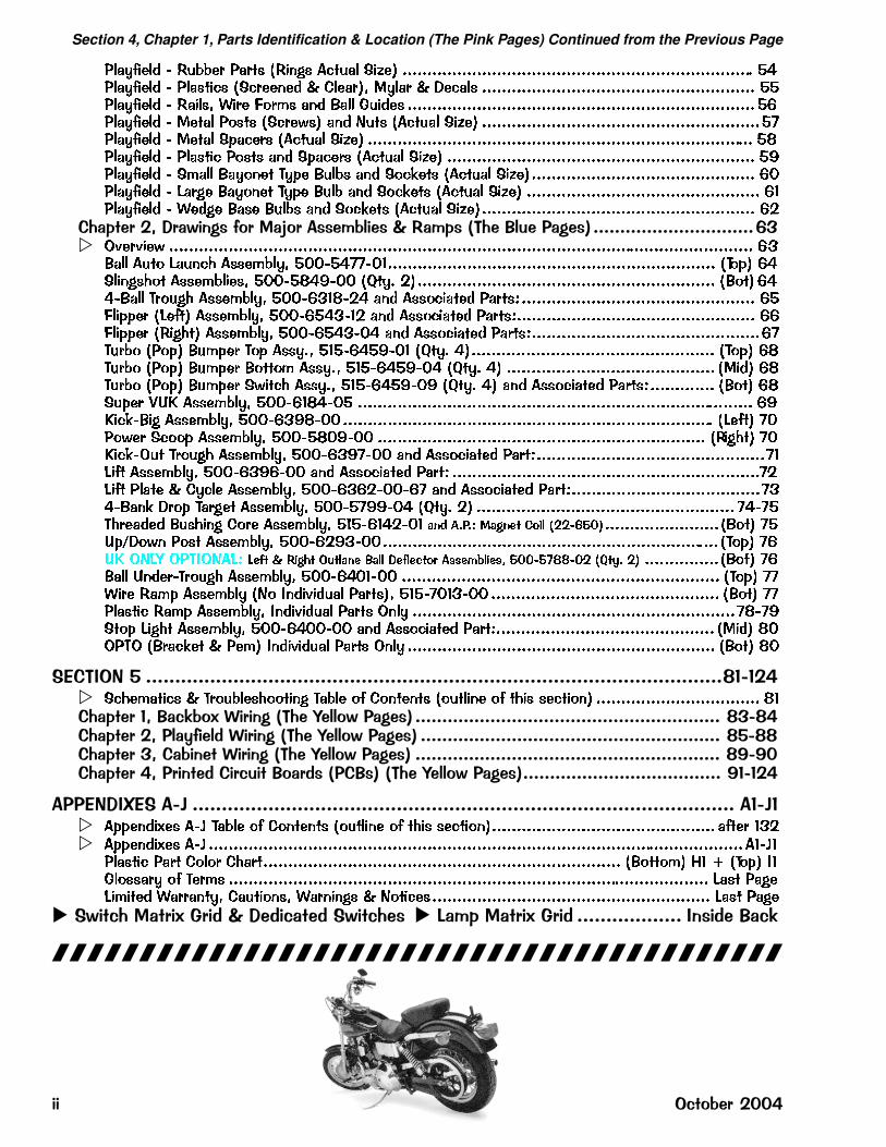
Section 4, Chapter 1, Parts Identification & Location (The Pink Pages) Continued from the Previous Page
��������� ���� �� �� ����� ������ ����� ����������������������������������������������������������������������� ����������� �������� ��� ����� � ���� �� ���� � ������ ������������������������������������������������������� ����������� ����� � � !" #� ��� $��� %����� ���������������������������������������������������������������������� �&��������� ����� �"��� ��� �'�� ��� (��� ������� ����� ���������������������������������������������������������)��������� ����� �*��� � ������� ����� ������������������������������������������������������������������������������ �+��������� ������� �"��� ��� �*��� � ������� ����� �������������������������������������������������������������� �,��������� �#��� $��"��� -�*� $���� ��� �"�.��� ������� �������������������������������������������������� &/��������� 0� �� $��"��� -�*� $��� ��� �"�.��� ������� ����� ����������������������������������������������� &1��������� ���� $��� $���� ��� �"�.��� ������� ������������������������������������������������������������ &2
������;����8��7��)����?���$���2���������2���!(����4���7��# ������������������������������><� 34� 4��' ���������������������������������������������������������������������������������������������������������������������� &5$��� ���" 0����6 ����#���� �//��))/1������������������������������������������������������������������ �-"*� &�������6"� ����#������ �//�+�,// �7��� 2������������������������������������������������������������� �$"�� &��$��� - "��6 ����#���� �//&51+2� ��� ���"������ �� ��8����������������������������������������������� &�!��**� �0���� ����#���� �//&��512 ��� ���"������ �� ��8������������������������������������������������ &&!��**� ���6�� ����#���� �//&��5/� ��� ���"������ �� ��8����������������������������������������������&)-� �" ��"*� $�#*� -"* ������ �1�&��,/1 �7��� ��������������������������������������������������� �-"*� &+-� �" ��"*� $�#*� $"��"# ������ �1�&��,/� �7��� �� ������������������������������������������ ����� &+-� �" ��"*� $�#*� �'���6 ������ �1�&��,/, �7��� �� ��� ���"������ �� ��8������������� �$"�� &+��*� 9:; ����#���� �//&1+�/� �������������������������������������������������������������������������������� &,;��.$�� ����#���� �//&5,+//��������������������������������������������������������������������������� �0���� )/�"'� ��""* ����#���� �//�+/,// ������������������������������������������������������������������ ���6�� )/;��.3�� - "��6 ����#���� �//&5,)// ��� ���"������ �� �8����������������������������������������������)10��� ����#���� �//&5,&// ��� ���"������ �� �8 ��������������������������������������������������������������)20��� ����� � ����� ����#���� �//&5&2//&) ��� ���"������ �� �8��������������������������������������)5�$��. � "* -� ��� ����#���� �//�),,/� �7��� 2� ���������������������������������������������������� )�)�-6 ����� $��6��� �" � ����#���� �1�&1�2/1 ��� ����� ���� � �� ��������������������������������$"�� )�:*<�"'� �"�� ����#���� �//&2,5//�������������������������������������������������������������������� �-"*� )&:; 3(0= 3�->3(�08 ��� � ���� ������ ���� ��� � ! �""#$��"% �����&''��� �(�)� �� ����������������$"�� )&$��� :��� - "��6 ����#���� �//&�/1// ���������������������������������������������������������������� �-"*� )) � � �#* ����#��� �(" >���4����� �� ���� �1�)/15// ���������������������������������������������� �$"�� ))������� �#* ����#���� >���4����� �� �� 3��� �����������������������������������������������������������������)+),��"* 0��6� ����#���� �//&�//// ��� ���"������ �� �8�������������������������������������������� ����� +/3�-3 �$ ��.�� � ��#� >���4����� �� �� 3��� �������������������������������������������������������������� �$"�� +/
�� (��*�= ���������������������������������������������������������������������������������������������������B:�:;"� ��6�#����� � - "�����6""���� -���� "� �"������ �"������ "� �6�� �����"�� ��������������������������������� +1 ������:��35��6� ����7�!(���C����8��7��# ��������������������������������������������������������� B<�B" ������;�����)����� ����7�!(���C����8��7��# �������������������������������������������������������� B=�BB ������<�� ������ ����7�!(���C����8��7��# ��������������������������������������������������������� BD�D@ ������"���������� ��34��������!� �#�!(���C����8��7��#������������������������������������� D:�:;"
$���*��,���$�E ��������������������������������������������������������������������������������������������� $:�E:� �**����?�� �@ -���� "� �"������ �"������ "� �6�� �����"����������������������������������������������� ���� 152� �**����?�� �@ �������������������������������������������������������������������������������������������������������������1@1������� �� � �"�" �6� ������������������������������������������������������������������������� �$"��"#� A1 B �-"*� >1%�"��� � "� -� #� ������������������������������������������������������������������������������������������������� 0��� ����0�#���� � ����� �����"��� � ����� � ("������������������������������������������������������������� 0��� ����
���8��3������6�&����������3�����8��3�������'2������6�&��� ������������������ �������35
������������������������������������������
� ��� �3������;@@"

���� ��� �� ���� � �� �
���� �� ���� ���������������� ������� ���
� ��������������� ������ ���� !"��� � ################################################################################# $
������� ����� ��� ��� ����� � ����� �������� ������ � ��� � ��� �� ��� ��� ������� ��������� !"������ ������� #��� $��� ���� ����������������������������������������������������������������������������������������� % &"������ ������� #��� '(�)*�� ��� '(����+ �� "������ ������� #��� ����������������������������������� ,- ,.
�� ����%� & � !�'&� ������(�"############################################################## ��� �� ����� #��� ��������������������������������������������������������������������������������������������������������,/����� ���� � ������ ����� ���� � 0�������� ����� ���� ����������������������������������������������������,/
� ����� #����( ���� � 0�������� ������� ������������������������������������������������������������������������,/� ����� #����( ���� 0�����*����� ��� "��� 1�)2��� ��� 3������������������������������������������������,4
�� �� 5��� #����������������������������������������������������������������������������������������������������������������,����+�� 5��� ���� � 56����+ 5��� ���� �����������������������������������������������������������������������������������,�
� 5��� � 7��� 3�)* 0�����*��������������������������������������������������������������������������������������������,�� 5��� � 7��� 3�)* 3�������� ������������������������������������������������������������������������������������������ ,!� 5���� 0������� 5��� ��2������������������������������������������������������������������������������������������������ ,%� ����2�( $�8 "���� 0����� ����� 0������� 9����+ 0��+��) �������������������������������������������������� ,&
�� �� 3�)* #��� ���������������������������������������������������������������������������������������������������������.-���+�� 3�)* ���� � ���� ��� 3�)*� � ��� � 5���)� 3�)* ������������������������������������������������.-
� 3�)* #����( ���� ���������������������������������������������������������������������������������������������������������.-� 3�)* #����( ���� 3�������� ��������������������������������������������������������������������������������������������.,
���� 7��� 3�)*������������������������������������������������������������������������������������������������������������..5���� ���� ����+ �����������������������������������������������������������������������������������������������������������..��������� ����� �������������������������������������������������������������������������������������������������������������..������� "��� : �����������������������������������������������������������������������������������������������������������..��+�� "��6 ���� �������������������������������������������������������������������������������������������������������������..7��� ;�����������������������������������������������������������������������������������������������������������������������..����� � �*����� ���������������������������������������������������������������������������������������������������������..
� �*����� "��� ������+��������������������������������������������������������������������������������������������������.<��+�� ���� $�����������������������������������������������������������������������������������������������������������������.<0�� #����( ���� � 0�� #����( 0��*��6 '(*������ �����������������������������������������������������������������.<�����6 0�������= �*���>�� #�����6��� �������������������������������������������������������������������������./0�� "��2��� 7��� 5��� #����? 5��� ����� � 3�)*� ����������������������������������������������������������.4
�� ����� & � '"!����(�"#######################################################################%�� ��)� ����� ��2�����������������������������������������������������������������������������������������������������������.�
'�����+� ������ ������ , ,.�������������������������������������������������������������������������������������������� .!��"�$� ������ ������ ,< 44� �������������������������������������������������������������������������������������� .% .&�����6 0�������= >������� ������ 4� &&� ����������������������������������������������������������������� .& <,�� �� "������ #����������������������������������������������������������������������������������������������������������� <,
@���� "������� 7��� "������� � ����� "������ ������������������������������������������������������������������ <,
�� ����)� & � '!*"���(����(�"############################################################ � ��)� ��A���)��� ��2�� ������������������������������������������������������������������������������������������������<.
��"�$� ��A���)���� ��A���)���� , /%������������������������������������������������������������������������ << <&�����6 0�������= ��A���)���� ��A���)���� /& 44� ������������������������������������������������������� <&5����) #����+� 0����� ������ �� ��A���)��� </������������������������������������������������������������/-7��) ���� ����� �*����� 7�����6 ����� ������+� >�� �� ��)� '������)������������������������������/-
�� ����$� & � �(�(��(�" ######################################################################## )������ 5��� ������ � ����� ��)� ������ � 7�����6 ������������������������������������������������������������/,
� '(�)*�� ���������������������������������������������������������������������������������������������������������������������/.
�� ����+� & � ,"�(�'-.(######################################################################### )�� �� 7��� ��2�� �����������������������������������������������������������������������������������������������������������/<
� '(�)*�� ��� ����2�( 3�6��� 3��������? 7���� ����+�� ����6� � �8#� ���������������������� /< //
�� ������ & � /(.����((� ###################################################################### )$�� �� ���* ������� #���� 3����� �������������������������������������������������������������������������������������/4
���#0###���������#
���� �� ������� ����������������������� � 1�$

������������ ��������������������
� �������������
�������������������� ��!!!!!!!!!!!!!!!!!!!!!!!!!!!!!!!!!!!!!!!!!!!!!!!!!!!!!!!!!!!!!!!!!!!!!!!!! "#
�� $���%& �'��()����� !!!!!!!!!!!!!!!!!!!!!!!!!!!!!!!!!!!!!!!!!!!!!!!!!!!!!!!!!!!!!!!!!!!!!!!!"* �'��(�+�,�-�����.�� � �/��� ���/)������� �� �!!!!!!!!!!!!!!!!!!!!!!!!!!!!!!!!!!!! "* �'��( � �/� 0���)������� �� � !!!!!!!!!!!!!!!!!!!!!!!!!!!!!!!!!!!!!!!!!!!!!!!!!!!!!!!!!!!!! "1
�� $���#&,� 0����/)�����!!!!!!!!!!!!!!!!!!!!!!!!!!!!!!!!!!!!!!!!!!!!!!!!!!!!!!!!!!!!!!!!!!!!!!!!"2���� �������� �������������� ���/)������� �� � !!!!!!!!!!!!!!!!!!!!!!!!!!!!!!!!!!!!!!!!!!! ",� 0����/�-����)������� �� ��,� 0����/� �$)������� �� � !!!!!!!!!!!!!!!!!!!!!!!!!! "3,� 0����/������ �����$�&4�����5���!)�����������$��������� ����� !!!!!!!!!!!!!!!"6#74��$$���������)������� �� � !!!!!!!!!!!!!!!!!!!!!!!!!!!!!!!!!!!!!!!!!!!!!!!!!!!!!!!!!!!!!!!!!!!!!!! ""
�� $���*&� �����)�����!!!!!!!!!!!!!!!!!!!!!!!!!!!!!!!!!!!!!!!!!!!!!!!!!!!!!!!!!!!!!!!!!!!!!!!!!"8�� ��������,�-��)������� �� � !!!!!!!!!!!!!!!!!!!!!!!!!!!!!!!!!!!!!!!!!!!!!!!!!!!!!!!!!!!!!!!!!! "8� �����+��������)������� �� � !!!!!!!!!!!!!!!!!!!!!!!!!!!!!!!!!!!!!!!!!!!!!!!!!!!!!!!!!!!!!!!!!! 89
�� $���1&,�����/������� � �/�:,� �; !!!!!!!!!!!!!!!!!!!!!!!!!!!!!!!!!!!!!!!!!!!!!!!!!!!!!8%������<$7=��'���� ��,�� � �/������0���$�� ���������� ���&���$������ 0����, ��� !!!!!!!!!!!!!!!!!!!!!!!!!!!!! 8%�,����������������� !!!!!!!!!!!!!!!!!!!!!!!!!!!!!!!!!!!!!!!!!!!!!!!!!!!!!!!!!!!!!!!!!!!!!!!!!!!!! :��$;8#�������� ��,�� � �/����������+�����������%����#!!!!!!!!!!!!!!!!!!!!!!!!!!! 8#78*���5 ���(���$� 0+���$� 0���������� /!�������/���$� 0����������� !!!!!!!!!!!!!! 81���$� 0,�-����$$�0 � �/����� ���&���$������ 0����, ��� !!!!!!!!!!!!!!!!!!!!!! 8���$� 0���������� � �/����� ��� !!!!!!!!!!!!!!!!!!!!!!!!!!!!!!!!!!!!!!!!!!!!!!!!!!!!!!!!!!!! 83786���$� 0���������� � �/���$������ 0����, ��� !!!!!!!!!!!!!!!!!!!!!!!!!!!!!!!!!!!!!!!!!! 8"�+�,�-�����.�� � �/�����0���$�� ���� !!!!!!!!!!!!!!!!!!!!!!!!!!!!!!!!!!!!!!!!!!!!!!!!!!!!!!! 88�+�,�-�����.�� � �/����� ��������� � �� � ������ � �� � ������ �� � ������ � �� � ������ �� !!!!!!!!!!!!!!!!!!! %997%98�+�,�-�����.�� � �/���$������ 0��� !!!!!!!!!!!!!!!!!!!!!!!!!!!!!!!!!!!!!!!!!!!!!!!!!!!!!!!! %%9�+�,�-�����.�� � �/, ��� !!!!!!!!!!!!!!!!!!!!!!!!!!!!!!!!!!!!!!!!!!!!!!!!!!!!!!!!!!!!!!!!!!!!!!!!!!!! %%%�,<+����/ � �/��:-�����5��,��������;�����0���$�� ����!!!!!!!!!!!!!!!!!!!!!!!! %%*�,<+����/ � �/��:-�����5��,��������;����� ��������� � �� �� ������ � �� �� ������ �� �� ������ � �� � !!!!!!!!!!!!!!!!!!!!!!!!!!!!!!!!!!!!! %%17%#%�,<+����/ � �/��:-�����5��,��������;���$������ 0��� !!!!!!!!!!!!!!!!!!!!!!!! %##�,<+����/ � �/��:-�����5��,��������;, ��� !!!!!!!!!!!!!!!!!!!!!!!!!!!!!!!!!!!!!!!!!!! %#*,� 0����/�-�����,��>����7��$>,� � �/������0���$�� ���������� ���&���$������ 0����, ��� !!!!!!!!!!!!!!!!!!!!!!!!!!!!! %#1
Vis
it w
ww
.Ste
rnP
inb
all.c
om
/sch
emat
ics.
htm
for
the
late
st 1
1" X
17"
Sch
emat
ics
(or
"Spl
it 8-
1/2"
X 1
1")
for
the
Dis
play
Pow
er S
uppl
y, D
ispl
ay C
ontr
olle
r, I/O
Pow
erD
rive
r &
CP
U/S
ou
nd
Bo
ard
s (W
hite
Sta
rS
yste
m O
nly)
. A
long
with
the
sche
mat
ics
you’
ll fin
d th
e co
mpo
nent
layo
ut a
nd th
eory
of o
pera
tion.
Kee
p vi
sitin
g as
thes
e fil
esar
e co
ntin
uous
ly im
prov
ed w
ith m
ore
"sea
rch"
link
s in
the
docu
men
ts.
The
file
s ar
e in
PD
F F
orm
at (
Ado
be®
Rea
der
requ
ired)
. T
hey
may
be
slow
to o
pen
in th
e w
ebsi
te o
nly,
but o
nce
on y
our
hard
driv
e th
ey’ll
ope
n fa
st.
Insi
de th
e sc
hem
atic
s yo
u ca
n ut
ilize
inte
rnal
link
s w
here
add
ress
es m
ay d
irect
you
to a
noth
er s
heet
in th
e sc
hem
atic
set
(fu
rthe
rin
stru
ctio
ns w
ithin
doc
umen
ts).
To
"dow
nloa
d" o
nce
open
, in
your
bro
wse
r cl
ick
"File
" "S
end"
"P
age
by e
Mai
l". I
t will
be
sent
to y
our
eMai
l Add
ress
, whe
re th
ere
you
can
save
the
file
to y
our
hard
rive.
���!?�����
����!!!
����� ����� ���������������������� , ��"%

Use the below Coils Detailed Chart Table in conjunction with Sec. 5, Chp. 1, Backbox I/O Power Driver BoardDetailed Wiring Diagram (I/O Board Connectors J6, J7, J8 & J9) and Backbox Board Layout Wiring Diagram:
�����
�����
��� ���
��������������������������� ����� ���� ����� � Drive Trans-
istor (D.T.)Driver
Ouput BoardD.T. ControlLine Color
D.T. ControlLine Connect
PowerLine Color
Power LineConnnection
PowerVoltage
Coil GA/Turnor Bulb Type
#1 TROUGH UP-KICKER Q1 I/O Pwr. Drvr. BRN-BLK J8-P1 YEL-VIO J10-P4/5 50v DC 26-1200090-5044-00T
#2 AUTO LAUNCH Q2 I/O Pwr. Drvr. BRN-RED J8-P3 YEL-VIO J10-P4/5 50v DC 24-940090-5036-00T
#3 SUPER VUK Q3 I/O Pwr. Drvr. BRN-ORG J8-P4 YEL-VIO J10-P4/5 50v DC 23-800090-5001-00T
#4 POWER SCOOP/KICK BIG Q4 I/O Pwr. Drvr. BRN-YEL J8-P5 YEL-VIO J10-P4/5 50v DC 23-800090-5001-00T
#5 MOTORCYCLE BALL LAUNCH Q5 I/O Pwr. Drvr. BRN-GRN J8-P6 YEL-VIO J10-P4/5 50v DC 24-940090-5036-00B
#6 LEFT 4-BANK DROP TARGET Q6 I/O Pwr. Drvr. BRN-BLU J8-P7 YEL-VIO J10-P4/5 50v DC 23-700090-5022-00T
#7 RIGHT 4-BANK DROP TARGET Q7 I/O Pwr. Drvr. BRN-VIO J8-P8 YEL-VIO J10-P4/5 50v DC 23-700090-5022-00T
#8 EUROPEAN TOKEN DISPENSER Q8 I/O Pwr. Drvr. BRN-GRY J8-P9 YEL-VIO J10-P4/5 50v DC DL4SS515-6076-01
���� ����� ���� ����� � Drive Trans-istor (D.T.)
DriverOuput Board
D.T. ControlLine Color
D.T. ControlLine Connect
PowerLine Color
Power LineConnnection
PowerVoltage Coil GA/Turn
#9 LEFT TURBO BUMPER Q9 I/O Pwr. Drvr. BLU-BRN J9-P1 YEL-VIO J10-P4/5 50v DC 26-1200090-5044-00T
#10 RIGHT TURBO BUMPER Q10 I/O Pwr. Drvr. BLU-RED J9-P2 YEL-VIO J10-P4/5 50v DC 26-1200090-5044-00T
#11 BOTTOM TURBO BUMPER Q11 I/O Pwr. Drvr. BLU-ORG J9-P4 YEL-VIO J10-P4/5 50v DC 26-1200090-5044-00T
#12 TOP TURBO BUMPER Q12 I/O Pwr. Drvr. BLU-YEL J9-P5 YEL-VIO J10-P4/5 50v DC 26-1200090-5044-00T
#13 SHAKER MOTOR Q13 I/O Pwr. Drvr. BLU-GRN J9-P6 RED-WHT J17-P7 16v AC12v DC
Motor Only041-5029-01
#14 MAGNET Q14 I/O Pwr. Drvr. BLU-BLK J9-P7 VIO-YEL J10-P3 50v DC 22-650090-5042-01
#15 LEFT FLIPPER (50v RED/YEL) Q15 I/O Pwr. Drvr. ORG-GRY J9-P8 RED-YELGRY-YEL J10-P1/2 50v DC 22-1080
090-5032-00T
#16 RIGHT FLIPPER (50v RED/YEL) Q16 I/O Pwr. Drvr. ORG-VIO J9-P9 RED-YELBLU-YEL J10-P1/2 50v DC 23-1100
090-5030-00T
��� ����� ���� ����� � Drive Trans-istor (D.T.)
DriverOuput Board
D.T. ControlLine Color
D.T. ControlLine Connect
PowerLine Color
Power LineConnnection
PowerVoltage
Coil GA/Turnor Meter #
#17 LEFT SLINGSHOT Q17 I/O Pwr. Drvr. VIO-BRN J7-P2 BRN J7-P1 20v DC 23-800090-5001-00T
#18 RIGHT SLINGSHOT Q18 I/O Pwr. Drvr. VIO-RED J7-P3 BRN J7-P1 20v DC 23-800090-5001-00T
#19 MOTOR RELAY Q19 I/O Pwr. Drvr. VIO-ORG J7-P4 BRN J7-P1 20v DC Relay Bd.520-5010-00
#20 FLASH: SCOOP X1 Q20 I/O Pwr. Drvr. VIO-YEL J7-P6 ORG J6-P10 20v DC #89 Bulb165-5000-89
#21 LT OUTLANE (UK ONLY) Q21 I/O Pwr. Drvr. VIO-GRN J7-P7 BRN J7-P1 20v DC 28-1050090-5046-00
#22 RT OUTLANE (UK ONLY) Q22 I/O Pwr. Drvr. VIO-BLU J7-P8 BRN J7-P1 20v DC 28-1050090-5046-00
#23 UP/DOWN POST (SKILL) Q23 I/O Pwr. Drvr. VIO-BLK J7-P9 BRN J7-P1 20v DC 23-1100090-5030-00T
#24 OPTIONAL COIN METER Q24 I/O Pwr. Drvr. VIO-GRY J7-P10 RED J16-P7 5v DC Meter 5v091-5000-00
D iode O n T erminal S trip (if noted)
��� � ���� ������� Drive Trans-istor (D.T.)
DriverOuput Board
D.T. ControlLine Color
D.T. ControlLine Connect
PowerLine Color
Power LineConnnection
PowerVoltage Bulb Type
#F1 FLASH: LEFT DROP TARGET X2 Q25 I/O Pwr. Drvr. BLK-BRN J6-P1 ORG J6-P10 20v DC #89 Bulb165-5000-89
#F2 FLASH: RAMP LEFT X2 Q26 I/O Pwr. Drvr. BLK-RED J6-P2 ORG J6-P10 20v DC #89 Bulb165-5000-89
#F3 FLASH: TURBO BUMPER X4 Q27 I/O Pwr. Drvr. BLK-ORG J6-P3 ORG J6-P10 20v DC #89 Bulb165-5000-89
#F4 FLASH: RAMP TOP X2 Q28 I/O Pwr. Drvr. BLK-YEL J6-P4 ORG J6-P10 20v DC #89 Bulb165-5000-89
#F5 FLASH: MOTORCYCLE X4 Q29 I/O Pwr. Drvr. BLK-GRN J6-P5 ORG J6-P10 20v DC #89 Bulb165-5000-89
#F6 FLASH: SUPER VUK X2 Q30 I/O Pwr. Drvr. BLK-BLU J6-P6 ORG J6-P10 20v DC #89 Bulb165-5000-89
#F7 FLASH: RT. DROP TARGET X2 Q31 I/O Pwr. Drvr. BLK-VIO J6-P7 ORG J6-P10 20v DC #89 Bulb165-5000-89
#F8 FLASH: SPEEDOMETER X2 Q32 I/O Pwr. Drvr. BLK-GRY J6-P8 ORG J6-P10 20v DC #89 Bulb165-5000-89
����� �� ��� �� ���� ���� ���� � ������ �� �� ����� ��� ��� �� ���� ������� ������� ����� �� ! "���� � # $ � %��� �
�������� ���� ������/,��"# ��������
&-� �� � . ,����� .� ��� .
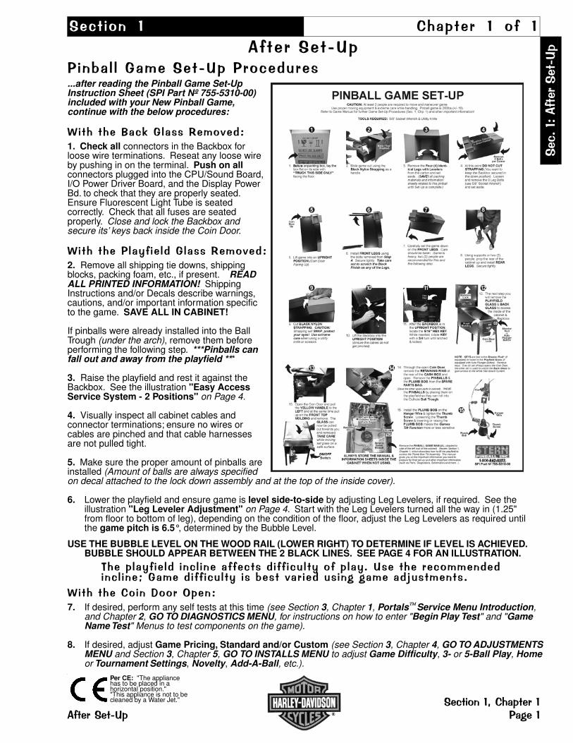
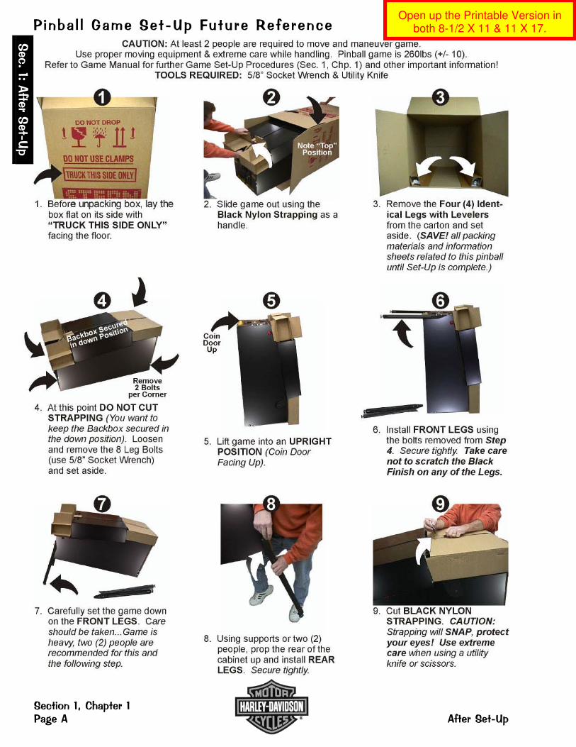
�� ���&������ �� ��+��&�������������...after reading the Pinball Game Set-UpInstruction Sheet (SPI Part Nº 755-5310-00)included with your New Pinball Game,continue with the below procedures:
� � ��������5�+�������.1. Check all connectors in the Backbox forloose wire terminations. Reseat any loose wireby pushing in on the terminal. Push on allconnectors plugged into the CPU/Sound Board,I/O Power Driver Board, and the Display PowerBd. to check that they are properly seated.Ensure Fluorescent Light Tube is seatedcorrectly. Check that all fuses are seatedproperly. Close and lock the Backbox andsecure its’ keys back inside the Coin Door.
� � ���������� � ���+�������.2. Remove all shipping tie downs, shippingblocks, packing foam, etc., if present. READALL PRINTED INFORMATION! ShippingInstructions and/or Decals describe warnings,cautions, and/or important information specificto the game. SAVE ALL IN CABINET!
If pinballs were already installed into the BallTrough (under the arch), remove them beforeperforming the following step. ***Pinballs canfall out and away from the playfield ***
3. Raise the playfield and rest it against theBackbox. See the illustration "Easy AccessService System - 2 Positions" on Page 4.
4. Visually inspect all cabinet cables andconnector terminations; ensure no wires orcables are pinched and that cable harnessesare not pulled tight.
5. Make sure the proper amount of pinballs areinstalled (Amount of balls are always specifiedon decal attached to the lock down assembly and at the top of the inside cover).
6. Lower the playfield and ensure game is level side-to-side by adjusting Leg Levelers, if required. See theillustration "Leg Leveler Adjustment" on Page 4. Start with the Leg Levelers turned all the way in (1.25"from floor to bottom of leg), depending on the condition of the floor, adjust the Leg Levelers as required untilthe game pitch is 6.5°, determined by the Bubble Level.
USE THE BUBBLE LEVEL ON THE WOOD RAIL (LOWER RIGHT) TO DETERMINE IF LEVEL IS ACHIEVED.BUBBLE SHOULD APPEAR BETWEEN THE 2 BLACK LINES. SEE PAGE 4 FOR AN ILLUSTRATION.
������ � � ���� � � � ����������� ��� � ���������/������������ ��� � � � F�+������ ��� � ����������� ������ 7�7���?���� ��/
� � ������,�� ������ � .7. If desired, perform any self tests at this time (see Section 3, Chapter 1, Portals Service Menu Introduction,
and Chapter 2, GO TO DIAGNOSTICS MENU, for instructions on how to enter "Begin Play Test" and "GameName Test" Menus to test components on the game).
8. If desired, adjust Game Pricing, Standard and/or Custom (see Section 3, Chapter 4, GO TO ADJUSTMENTSMENU and Section 3, Chapter 5, GO TO INSTALLS MENU to adjust Game Difficulty, 3- or 5-Ball Play, Homeor Tournament Settings, Novelty, Add-A-Ball, etc.).
Per CE: "The appliancehas to be placed in ahorizontal position.""This appliance is not to becleaned by a Water Jet."
&�
/��.��
���
�&���
�
� &���� ����,�����������&���� �7��
�
�� �� ��+��&������������� �
&�/��.��
����&���
�
&���� ����,������ ��7�� �����&����
Open up the Printable Version in both 8-1/2 X 11 & 11 X 17.

�� �� ��+��&������������� ��,� � � ��
&�
/��.��
���
�&���
�
� &���� ����,�����������&���� �7��

For more Backbox details & part numbers, see Section 4, Chapter 1, Backbox Assembly, Pages 60-61.
��������������������������������������������������
%7�%�����?���� �Attach the four (4) Leg Assemblies to cabinet corners with the eight (8) leg bolts provided .
Start adjustment with the leg levelers turned all the wayin.
View the bubble in the level provided on the right sidewood rail.
Adjust the front or rear levelers as necessary to causethe bubble to float between the two (2) black lines.
Use a pinball to roll down the center of the playfield forside-to-side leveling.
YOUR PLAYFIELD PITCH IS NOW AT 6.5° ASREQUIRED FOR PROPER GAME PLAY!
Note: For custom adjustment greater than >6.5° can be achieved by turning out the rear leg leveler(s), however, it is not recommended.
��������������������������������������������������
)���������&� ���&�������������� �� �With the front molding & glass removed, carefully lift the playfield (take care when using the Bottom Arch to hoist).
Position 1When lifted high enough, the Playfield SupportSlide Brackets (Fig. 1A) can be seen and can clearthe cabinet front (Fig. 1B). At this time, pull the play-field toward the front of the cabinet, checking that themechanical components clear the cabinet front, thenrest the playfield on the Playfield Support SlideBrackets at the front channel of cabinet (Fig. 1C);
Position 2With the playfield at rest, hold the sides & pull towardthe front of the cabinet (approx. 6" to 8"), untilresistance is felt from Edge Slide Brackets stoppingagainst the Slide & Pivot Support Brackets locatedon either side of the cabinet (Fig. 2A). At this time, swivel the playfield toward the Backbox,then rest on the top edge (Fig. 2B & 2C).
Cabinet Leg
38-16HexNut
Leg Levelerturned all
the way in.
�������&���������5���������� ������ 7
Bubbleshould bebetween
the 2 blacklines.
BubbleBubble Level
located onthe wood railnext to the
Shooter Lane.
&�/��.��
����&���
�
&���� ����,������ ��7�� �����&����

���� ��� �� ���� � ��
� ������ � ������ ������� ����� ���� ������� �� ��� ���� �� ��Insert coin(s). The game generates a sound for thefirst coin & for each subsequent coin with the displayindicating the number of credits posted. Press theSTART BUTTON and a start-up sound is produced,and the posted credits are reduced by one. Subse-quent players can be added (up to 6 can play!) bypressing the START BUTTON before the end of ball 1(with sufficient credit in the game).
The display now indicates the player or # of playersselected from the total depressions of the STARTBUTTON. The display indicates the ball in play, and aball is served to the Shooter Lane. An introduction isshown followed by Skill Shot Graphics and/or instruc-tions. Pressing the START BUTTON after ball 1 ofany player will start a new game (if credits areavailable), but only if the START BUTTON isdepressed for 2-3 seconds. This delay is to avoidaccidental "re-starts" of a game. (Note: Any 1 2 creditremaining during game play after the end of ball 1, orpower down, will be eliminated.)
�� �� ����� ��� �� ��!���"#Team Play is a four player game. The totals for players1 & 3 (Team 1) and players 2 & 4 (Team 2) aredisplayed individually as well as the combined scorefor both teams. Team Play only works in a 4-Playergame. In all other cases, the individual scores areshown.
�� �� ���$� ���%����� ������ �After credit is posted, while holding in the LEFTFLIPPER BUTTON, press the START BUTTON.League Play has now begun. The differences betweenNormal Game Play and League/Tournament Play are:There is no "auto-percentaging" (awarding extra balls,specials, etc. to players with very low scores on thesecond or third ball). Mystery Features are awarded ina set order rather than random in Normal Game Play.Percentage Game Features are not automaticallyadvanced as they are for the Regular Play Features.Features subject to change.
�� �� ������! � � &�' �(�� �After credit is posted, while holding in the RIGHTFLIPPER BUTTON, press the START BUTTON.Pinball Wizard Play has now begun. The same asLeague/Tournament Play, but oooooooh! so muchgosh darn harder! Feature subject to change.
������ ���� ������� ����)�(�����!�� ���������Features are lit on the playfield and started bycompleting certain play shots (e.g. completion of targetbanks, orbit(s), ramp(s) and/or any combination of theshots). Combination shots (combos) are a series ofshots completed in many different variations. Thesecombinations vary per game. For feature modes &combos certain points or awards are given aftercompletion. Feature subject to change.
)��� �! � �Multiball is started after completion of certain FeatureModes or may be a mode itself depending on gamerules/play. Multiball may vary with the amount of ballsused in Multiball depending on game style. Typically, ifMultiball play was short, a "restart" option is given.Watch the Display for instructions on the restart.
*��� ��� ����Replay awards are given as the player exceeds a HighScore Level during game play. This can be adjustedwith Adjustment 3, Replay Awards (Default=CREDIT,adjustable). Players exceeding the High Score Levelscan receive: CREDIT, EXTRA BALL, or SPECIAL.Adjust to NONE if a replay award is not desired.
+�(��)�(�The video modes may require the player to "playon-screen". The interactive video play may require theplayer to use the flipper buttons to play the mode.Feature subject to change.
,�(��� ���� ������ ��,�(����When all player(s) have played all balls (including anyExtra Balls), the game ends. If power is interruptedduring the course of a game, it will end that game (seeStarting a Normal Game). Closure of the Plumb BobTilt Switch according to the number of tilts set (Default= 2, adjustable) or its prolonged closure will end thecurrent Ball-In-Play. Closure of the Slam Tilt Switch onthe coin door ends the current game(s).
) ����� ����At the end of each ball, earned bonuses are collected.At the end of the last ball of a game (including anyextra balls, if applicable), earned bonuses are col-lected, then the system produces a random 2-digitnumber (a multiple of 10; 00 to 90). Matching the last2 digits of the player’s score with this number awards acredit. In Adj. 11, Match Percentage (Default=7%,adjustable) can be changed from 0-10%. Changingthe percentage to 0% displays the "Match Animation"at the end of the game, however, will never match (toaward a credit). Changing this adjustment to OFF willnot display the "Match Animation" nor award a credit.
Continued Next Page.
���-.� �
���-
� ������ ���� �������/�� �������� ����� � ��0
,�(��� ���� �������������(
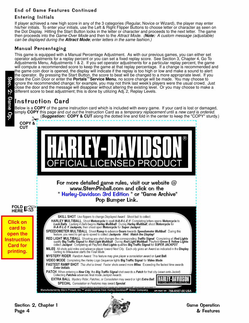
,���� ���1��� � ��If player achieved a new high score in any of the 3 categories (Regular, Novice or Wizard), the player may enterhis/her initials. To enter your initials, use the Left & Right Flipper Buttons to choose letter or character as seen onthe Dot Display. Hitting the Start Button locks in the letter or character and proceeds to the next letter. The gamethen proceeds into the Game-Over Mode and then to the Attract Mode. (Note: A custom message (adjustable)can be displayed during the Attract Mode; enter letters in the same fashion.)
) �� �������� ����This game is equipped with a Manual Percentage Adjustment. As with our previous games, you can either setoperator adjustments for a replay percent or you can set a fixed replay score. See Section 3, Chapter 4, Go ToAdjustments Menu, Adjustments 1 & 2. If you set operator adjustments for a particular replay percent, the gamewill compute a recommended score to keep the game at that replay percentage. If a change is recommended andthe game coin door is opened, the display will indicate if the replay is too high or low and make a sound to alertthe operator. By pressing the Start Button, the score to beat will be changed to a more appropriate level. If youclose the Coin Door or enter the Portals Service Menu, no score change will be made. You may choose toignore the recommended change; for example, you may not think last week’s players were the usual crowd. Justclose the door and the message will disappear without altering the existing level. Or you may choose to make adifferent score to beat adjustment; this is done by utilizing Adj. 2, Replay Levels.
1������� ���� �(Below is a COPY of the game instruction card which is included with every game. If your card is lost or damaged,simply COPY this page and cut out the Instruction Card as a temporary replacement until a new card is ordered.
(Suggestion: COPY & CUT along the dotted line and fold in the center to keep the "COPY" sturdy.)
���-
.� �
���- �
COPY &CUT
�������(�� ���(� �������/2�������3�!����4333-��������! ��-��� �(����5�����
67 ����8 2�(���0�(,(�����6��6� ��9����2�6���:�����$��5-
FOLD �HERE
�������/�� ����� � ������ ����� ��; ��� �����
Click on card to
open the Instruction
Card for printing.

����������������� �������������������������������������The Service Switch Set provides access for three (3)functions available for your use. They are VolumeMenu, Service Credits Menu and Portals ServiceMenu. All are accessed separately depending on whichcolored button (Red, Green or Black) is pushed first.
To access any of these three (3) functions you must first open theCoin Door (see pictorial above) with the Game in the Attract Mode(not already in any Function or Menu stated below).
Please read the remainder of this Chapter for more information on the Portals Service Menu. The remaining six(6) Chapters of this Section explains all Icons & Menus in detail. Read! Read! Read!
��������
���
�� ��� ���� ���� �� ���� ��� ���� �� �����
��� ������������� ������������� � � !�� ���� � �"
��� #����������� ����� � �� !��� ���� ������� ���� � ����$��% ���� ��� ��
���� """&
� ������� ' � ��������������� ��!���
Pushing the Red Button (VOLUME / LEFT) first, enters the VolumeMenu. While in this Mode, to DECREASE the volume, hold downor depress the Red "LEFT" Button until desired the volume isachieved; to INCREASE the volume, hold down or depress theGreen "RIGHT" Button until the desired volume is achieved.
Note: Pushing the Left or Right Flipper Buttons operates the same as the Red or Green Buttons of the Service Switch Set, while in this Volume Mode.
Set between 0 and 31; 15 is the Factory Default. Once youradjustments are made, this menu will automatically exit a fewseconds after the last button depression.
��������"����������#������!���Pushing the Green Button (SERVICE CREDITS / RIGHT) first, addsService Credits (will not affect your audits as "paid" credits). This isuseful for the technician to test games in regular play without affect-ing the game audits. Each depression adds 1 credit; up to 50credits can be applied. Adj. 15, Credit Limit, determines this,however, it can be changed from 04-50; for details see Chapter 4 ofthis Section 3. Once your credits are added, this menu will automa-tically exit a few seconds after the last button depression.
Note: This function is disabled if Adjustment 33, Free Play, is set to YES. TheService Credits are limited to the Credit Limit in addition to any paid credits presentin the game (e.g. If the Credit Limit is 30, and there are 8 paid credits present, only22 Service Credits can be applied.).
� ��������� ' �
��������$��%����� ��������!���Pushing the Black Button (BEGIN TEST / ENTER) first, enters thePortals Service Menu. Once in, navigate through all menusdepressing the Red "LEFT" or Green "RIGHT" Buttons.
Note: Pushing the Left or Right Flipper Buttons operates the same as the Redor Green Buttons of the Service Switch Set, while in this Service Mode.
Select or activate the Icon chosen (the Icon will be "flashing") bypushing down or depressing the Black "ENTER" Button.
Note: Pushing the Start Button operates the same as the Black Buttonof the Service Switch Set, while in this Service Mode.
� ������� ' �
����&�$
'�&&&!����(���
&
�������$��#��)���� %����� �������%�*��+ !����(���������
openAdjustments
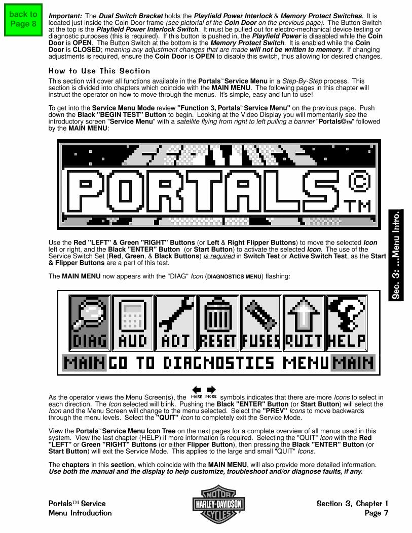
Important: The Dual Switch Bracket holds the Playfield Power Interlock & Memory Protect Switches. It islocated just inside the Coin Door frame (see pictorial of the Coin Door on the previous page). The Button Switchat the top is the Playfield Power Interlock Switch. It must be pulled out for electro-mechanical device testing ordiagnostic purposes (this is required). If this button is pushed in, the Playfield Power is diasabled while the CoinDoor is OPEN. The Button Switch at the bottom is the Memory Protect Switch. It is enabled while the CoinDoor is CLOSED; meaning any adjustment changes that are made will not be written to memory. If changingadjustments is required, ensure the Coin Door is OPEN to disable this switch, thus allowing for desired changes.
,��������-������� ���This section will cover all functions available in the Portals Service Menu in a Step-By-Step process. Thissection is divided into chapters which coincide with the MAIN MENU. The following pages in this chapter willinstruct the operator on how to move through the menus. It’s simple, easy and fun to use!
To get into the Service Menu Mode review "Function 3, Portals Service Menu" on the previous page. Pushdown the Black "BEGIN TEST" Button to begin. Looking at the Video Display you will momentarily see theintroductory screen "Service Menu" with a satellite flying from right to left pulling a banner "Portals©TM" followedby the MAIN MENU:
Use the Red "LEFT" & Green "RIGHT" Buttons (or Left & Right Flipper Buttons) to move the selected Iconleft or right, and the Black "ENTER" Button (or Start Button) to activate the selected Icon. The use of theService Switch Set (Red, Green, & Black Buttons) is required in Switch Test or Active Switch Test, as the Start& Flipper Buttons are a part of this test.
The MAIN MENU now appears with the "DIAG" Icon (DIAGNOSTICS MENU) flashing:
As the operator views the Menu Screen(s), the symbols indicates that there are more Icons to select ineach direction. The Icon selected will blink. Pushing the Black "ENTER" Button (or Start Button) will select theIcon and the Menu Screen will change to the menu selected. Select the "PREV" Icons to move backwardsthrough the menu levels. Select the "QUIT" Icon to completely exit the Service Mode.
View the Portals Service Menu Icon Tree on the next pages for a complete overview of all menus used in thissystem. View the last chapter (HELP) if more information is required. Selecting the "QUIT" Icon with the Red"LEFT" or Green "RIGHT" Buttons (or either Flipper Button), then pressing the Black "ENTER" Button (orStart Button) will exit the Service Mode. This applies to the large and small "QUIT" Icons.
The chapters in this section, which coincide with the MAIN MENU, will also provide more detailed information.Use both the manual and the display to help customize, troubleshoot and/or diagnose faults, if any.
���&�$'�&&&!����(���&
%����� ������� �������$��#��)����!����(��������� %�*��.
back to Page 8

������� ��� ������ ����������� � � � � � � � � � �
Reference current GameManual, Sec. 3, Chapter 4.
Reference current GameManual, Sec. 3, Chapter 3.
Go To Reset Menu
Go To Audits Menu
�� ������������
���
����
����
�� �����������
�� ���� �������
���
�� ����������
Reference current GameManual, Sec. 3, Chapter 6.
�� �����������
GAME FUSESLISTING
��������
�������
������������ ���������
������������
Nº of CopiesPrinted is reset.
������������
Special Equipmentis required.
Reference current GameManual, Sec. 3, Chapter 3.
��������������
�������� ������
REQUESTINSTALLED
Reference current GameManual, Sec. 3, Chapter 5.
���
����
�������� ������
REQUESTINSTALLED
�����������
REQUESTINSTALLED
(Back to Attract Mode)
����������
Direct Access toAdjustment 34,
Custom Message
������������
Special Equipmentis required.
������������
1st Audit ofGame Generic
Group
������������ ������
1st Audit ofGame Specific
Group
��������������
1st Audit ofGame Earnings
Group
����
����
Go To Audits Menu
�� ������� ���
�� ��������
����Reference current GameManual, Sec. 3, Chapter 2.
Go To Diagnostics Menu
�� ����� ���
�� ����� ���
��������� ����
IN TEST
�������� ������
IN TEST
�������������
PLAYFIELD STATUS
����������� �
1-800-KICKERS(USA Setting)
��������� ����
IN TEST
������� �����
REQUESTINSTALLED
(Back to Attract Mode)
�������� �������
1st Adjustment ofGame Generic
Group
����������
����
Go To Adjustments Menu
������������ �� �������
1st Adjustment ofGame Specific
Group
�����
�� ��������� ���
�� ������
�����
See the next page for"Summary of Common Icons"or reference Sec. 3, Chapter 7.
�� �
�����
Go To Help Screen

������� ������ ���
�����
��������� ��
IN TEST
��������� ����
IN TEST
����������
����� ����!�� ����
IN TEST
���������� ����
IN TEST
Reference current GameManual, Sec. 3, Chapter 2.
���� �������"����
Go To Lamp Menu
������� �����
IN TEST
��#���� ����
IN TEST
��������� ����
IN TEST
��������� ����
IN TEST
Reference current GameManual, Sec. 3, Chapter 2.
��� �������"����
Go To Coil Menu
$������� ����
IN TEST
�#��%����
IN TEST
Reference current GameManual, Sec. 3, Chapter 2.
�#��% �������"����
Go To Switch Menu
���&��#��% ����
IN TEST
���������#��% ����
IN TEST
'���!��!��
Reference current GameManual, Sec. 3, Chapter 2.
IN TEST
�� ��������
����
Go To Diagnostics Menu
���'��# %���
Q & A
Reference current GameManual, Sec. 3, Chapter 2.
'��# %������"����
Dr. Pinball Menus
�#��%'��# %���
Q & A
����'��# %���
Q & A
RUN (oractivate)selected
test
View theschematic(DRAWing)of current
display
Go to theNEXT /Move
forwardor RIGHT
Go to thePREVIOUS /
Movebackwardor LEFT
INCREMENT (+)displayed value orselect next...
DECREMENT (-)displayed value orselect previous...
Answer NO or YESin Dr. Pinball FlowChart Menus
PULSE Coilin Dr. Pinball
END Coil selection toselect new Coil in
Dr. Pinball Flow Chart
IndicatesMORE Icons
to theLEFT.
Go back toPREVIOUSmenu
QUIT PortalsService MenuSession
Go to HELPScreen ofcurrent menu
IndicatesMORE Iconsto theRIGHT.
�����
������������ ����'��
IN TEST
������� �(� �� �����)��*�*� �� � *
� �+, � ��-"���.*(( �))����

����� �� ����� )�� �<��� ��This example will demonstrate activation of Icons in the DIAGNOSTICS MENU. The example will show activationof the "SW" Icon (GO TO SWITCH MENU). In this menu, the switches can be tested individually and also all activeswitches can be tested. Use the same technique to access all the Icons in the Portals Service Menu. FollowPortals Service Menu Icon Tree on the previous pages as a guide to help navigate through the entire system(Also, go to the chapter in this manual explaining the icon(s) selected.).
If the display is in any other menu other than the MAIN MENU, use the Red "LEFT" & Green "RIGHT" Buttonsto select the "PREV" Icon and press the Black "ENTER" Button to activate the ICON thus moving back to theprevious menu. Do so until MAIN MENU appears.
Chapters 2 through 7 will cover all menu items within the Portals Service Menu. The Icon is shown precedingthe text. Find the Icon in the Portals Service Menu by navigating with the Red or Green Buttons. Each chapterstarted is from the MAIN MENU. Within the chapter, the sub-menu’s will be covered sequentially with theirexplanation & function. If the operator "gets lost", select and activate the "PREV" Icon until the display indicatesMAIN MENU. For more help, see Chapter 7.
The "MORE" symbols are indicating that "more icons" are available which don’tappear in the display and which way to move the selection to view the Icons.
1�������� ����� Exit any sub-menu and return to the MAIN MENU by selecting & activating the "PREV" Icons. If no Icons appear in the display because of a testing function or special display (e.g. Help, Schematic Display, etc.), press any service button to exit to the previous menu or sub-menu.
Selecting & activating the "QUIT" Icon from any display will exit the Service Session.
Example: From the MAIN MENU, use the Red "LEFT" or Green "RIGHT" Buttons to select the "DIAG" Icon (GOTO DIAGNOSTICS MENU).
Press the Black "ENTER" Button to activate this ICON. This will bring up the DIAGNOSTICS MENU.
The DIAGNOSTICS MENU now appears with the "SW" Icon (GO TO SWITCH MENU) flashing. Press the BlackButton to activate this icon. This will bring up the SWITCH TEST MENU.
Selecting & activating the "HELP" Icon will showa help screen. (An explanation of eachMini-Icon at that level will cycle continuouslyuntil any active button is pressed.)
����-�
�---)��
1����-
�������/�������� ������� ����������= )�� 1����( ����
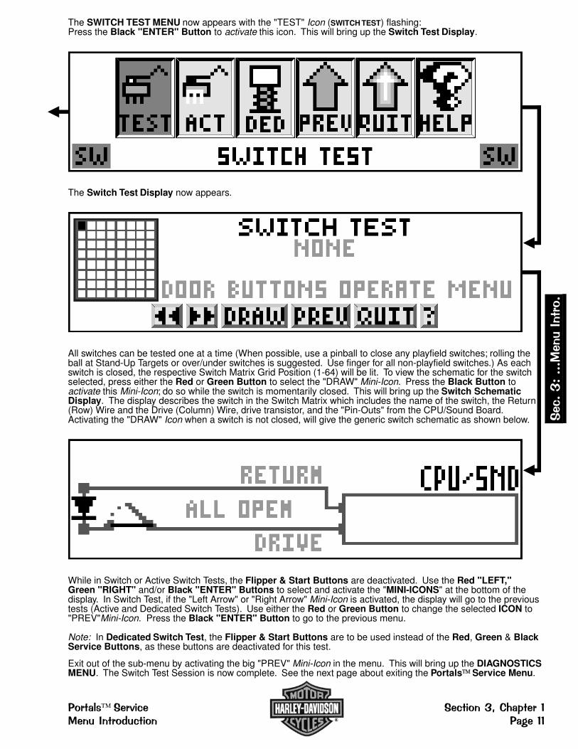
The SWITCH TEST MENU now appears with the "TEST" Icon (SWITCH TEST) flashing:Press the Black "ENTER" Button to activate this icon. This will bring up the Switch Test Display.
The Switch Test Display now appears.
All switches can be tested one at a time (When possible, use a pinball to close any playfield switches; rolling theball at Stand-Up Targets or over/under switches is suggested. Use finger for all non-playfield switches.) As eachswitch is closed, the respective Switch Matrix Grid Position (1-64) will be lit. To view the schematic for the switchselected, press either the Red or Green Button to select the "DRAW" Mini-Icon. Press the Black Button toactivate this Mini-Icon; do so while the switch is momentarily closed. This will bring up the Switch SchematicDisplay. The display describes the switch in the Switch Matrix which includes the name of the switch, the Return(Row) Wire and the Drive (Column) Wire, drive transistor, and the "Pin-Outs" from the CPU/Sound Board.Activating the "DRAW" Icon when a switch is not closed, will give the generic switch schematic as shown below.
While in Switch or Active Switch Tests, the Flipper & Start Buttons are deactivated. Use the Red "LEFT," Green "RIGHT" and/or Black "ENTER" Buttons to select and activate the "MINI-ICONS" at the bottom of thedisplay. In Switch Test, if the "Left Arrow" or "Right Arrow" Mini-Icon is activated, the display will go to the previoustests (Active and Dedicated Switch Tests). Use either the Red or Green Button to change the selected ICON to"PREV"Mini-Icon. Press the Black "ENTER" Button to go to the previous menu.
Note: In Dedicated Switch Test, the Flipper & Start Buttons are to be used instead of the Red, Green & BlackService Buttons, as these buttons are deactivated for this test.
Exit out of the sub-menu by activating the big "PREV" Mini-Icon in the menu. This will bring up the DIAGNOSTICSMENU. The Switch Test Session is now complete. See the next page about exiting the Portals Service Menu.
���-��---)
�� 1����-
������� ����� �������/��������)�� 1����( ���� ������

�< � ����� ����� �� ����� )�� All Icons will be covered in the chapters of this section with the exception of the "QUIT" Icon, in the MAIN MENU.Both the large and small Icons if selected and activated, will exit the user from the Portals Service Menu. Thedisplay will return back to the ATTRACT MODE! To re-enter the Portals Service Menu follow the instructions atthe beginning of this chapter.
If more help is required, see Chapter 7 of this section, and view the various help displays in the game.
>� � �����
����-�
�---)��
1����-
�������/�������� ������� ����������� )�� 1����( ����

���� ��� �� ���� � �� �
������ ����� �������S p e c i a l N o t e : If the display flashes "OPEN THE DOOR" the game is indicating that memory has been corrupted. This is caused be either failure in memory (e.g. batteries are dead and/or faulty RAM) orupon installation of updated version of game code. Opening the Coin Door will initiate a Factory Restore, byopening the Memory Protect Switch. Check battery voltage at CMOS RAM with the power off.
��������The Portals Service Menu System provides tests for sounds, display, lamps, switches and coils. Each featuremay be tested manually or automatically after entering the Portals Service Menu (see Chapter 1 of this section).Select the "DIAG" Icon from the MAIN MENU to go to the DIAGNOSTICS MENU. The automatic tests (e.g.Cycling Coils, Test Flash Lamps) may be used for a quick verification of automatic test functions and themanual tests (Begin Play Test, Single Lamp / All / Row / Column Tests, and Game Specific Test.) may beused for troubleshooting. All Icons and there usages are explained throughout this chapter.
During game play, activation of switches and operation of coils with associated switches are monitored. If theCPU/Sound Board does not detect a switch transition ("Stuck Open" / "Stuck Closed") for 50 games, it isconsidered faulty. When operation of a coil should close or open a switch and does not, the coil is consideredfaulty. In the Attract Mode, faulty switches and coils (if any) are reported (Select the "TECH" Icon, TechnicianAlert, from the DIAGNOSTICS MENU). Note that reporting of an unused switch does not constitute a problemand that a bad coil could mean that the associated switch requires adjustment.
CAUTION: Remove pinballs from the Ball Trough prior to lifting the playfield for servicing. This can easily bedone in the Portals Service Menu System. Select the "DIAG" Icon from the MAIN MENU to go to theDIAGNOSTICS MENU. Select the "CLR" Icon to enter the CLEAR BALL TROUGH MENU. Select the "RUN"Icon & press the Start Button to remove one ball at a time. This is also useful to retrieve one ball for game testingin Begin Play Test & Game Specific Test. Important: The Power Interlock Switch must be pulled out.
���������������� �!With the game in the Attract Mode, open the Coin Door and press the Black "BEGIN TEST" Button.Select the "DIAG" Icon in the MAIN MENU with either Flipper or Red "LEFT" & Green "Right" Buttons(upon entry of the Portals Service Menu, the system defaults with the selection of the "DIAG" Icon
flashing) and press the Start or Black "ENTER" Buttons. The DIAGNOSTICS MENU appears.
The "MORE" symbols are indicating that "more icons" are available which don’tappear in the display and which way to move the selection to view the Icons.
�"���� �������#Exit any sub-menu and return to the MAIN Selecting & activating the "QUIT" Icon fromMENU by selecting & activating the "PREV" any display will exit the Service Session.Icons. If no Icons appear in the displaybecause of a testing function or specialdisplay (e.g. "Help"), press any button to exit.
Selecting & activating the "HELP" Icon from In Diagnostics, selecting & activating the "-" orany display will show a help screen. (An "+" Icons moves test forwards/backwards.explanation of each Mini-Icon at that level will Selecting & activating the "RUN" Icon repeatscycle continuously until any active button the test on the coil or flash lamp left off at. is pressed.) Selecting & activating the "ARROW" Icons
moves between tests in the sub-menu.Selecting & activating the "DRAW" Icon will show the schematic for that switch or coil.
Some tests require navigation through the menu(s) and selection of the Icons with ONLY the Red "LEFT," Green"RIGHT" and Black "ENTER" Buttons. This is required in Switch & Active Switch Tests, as the Flipper &Start Buttons are a part of the test.
In Single Coil Test, Cycling Coil Test, Test Flash Lamps, ClearBall Trough, Begin Play Test & Harley-Davidson Specific Menu’s,the Power Interlock Switch (inside Coin Door) must be pulled out.(See Access & Use in Chapter 1 of this section for the location.)
� � � � � � � � � � � � � � � � � � � � � � � � � � � � � � � � � � � � � � � � � � � �� � � � � � � � � � � � � � � � �� � � � � � � � � � � � � � � � � � � � � � � � � � � � � � � � ! � � � � � � � � � � � � � � � � " � � � � � # � � �
� � � ! � � � � � � � � � � � � � � � � � � $ � � � � � � � � � � � � � � "
���$#$$$�� ��������
���� �������%�� ������� ������������ & ��'
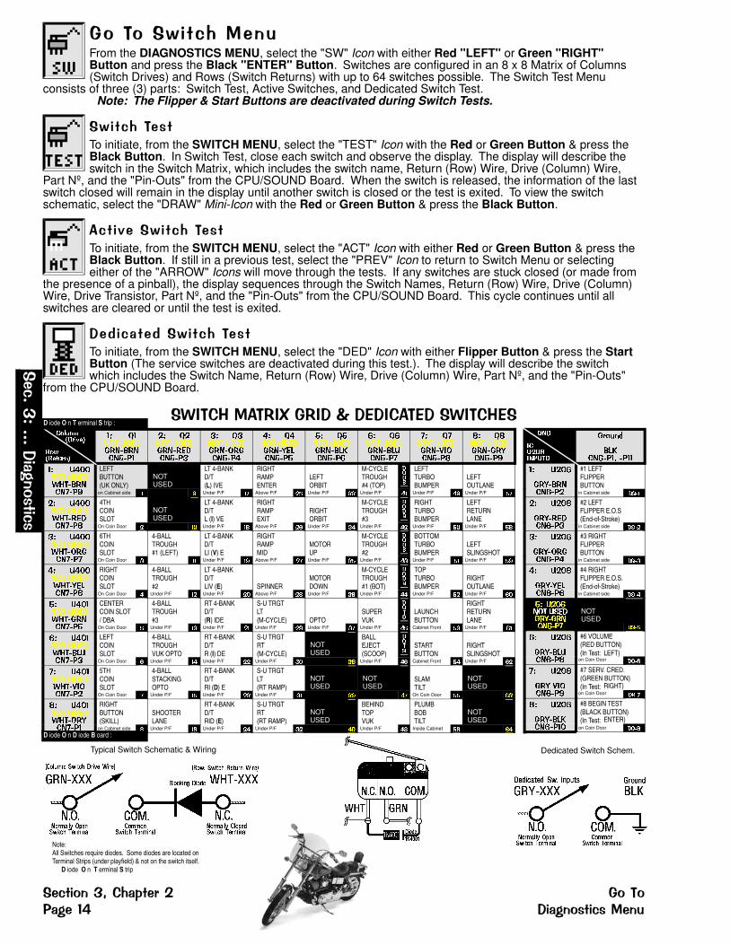
��������������From the DIAGNOSTICS MENU, select the "SW" Icon with either Red "LEFT" or Green "RIGHT"Button and press the Black "ENTER" Button. Switches are configured in an 8 x 8 Matrix of Columns(Switch Drives) and Rows (Switch Returns) with up to 64 switches possible. The Switch Test Menu
consists of three (3) parts: Switch Test, Active Switches, and Dedicated Switch Test.Note: The Flipper & Start Buttons are deactivated during Switch Tests.
����������To initiate, from the SWITCH MENU, select the "TEST" Icon with the Red or Green Button & press theBlack Button. In Switch Test, close each switch and observe the display. The display will describe theswitch in the Switch Matrix, which includes the switch name, Return (Row) Wire, Drive (Column) Wire,
Part Nº, and the "Pin-Outs" from the CPU/SOUND Board. When the switch is released, the information of the lastswitch closed will remain in the display until another switch is closed or the test is exited. To view the switchschematic, select the "DRAW" Mini-Icon with the Red or Green Button & press the Black Button.
����������������To initiate, from the SWITCH MENU, select the "ACT" Icon with either Red or Green Button & press theBlack Button. If still in a previous test, select the "PREV" Icon to return to Switch Menu or selectingeither of the "ARROW" Icons will move through the tests. If any switches are stuck closed (or made from
the presence of a pinball), the display sequences through the Switch Names, Return (Row) Wire, Drive (Column)Wire, Drive Transistor, Part Nº, and the "Pin-Outs" from the CPU/SOUND Board. This cycle continues until allswitches are cleared or until the test is exited.
��(�� ��(����������To initiate, from the SWITCH MENU, select the "DED" Icon with either Flipper Button & press the StartButton (The service switches are deactivated during this test.). The display will describe the switchwhich includes the Switch Name, Return (Row) Wire, Drive (Column) Wire, Part Nº, and the "Pin-Outs"
from the CPU/SOUND Board.
�)���*���+�,�+��-� ����� ��)���* �
Dedicated Switch Schem.
���
����������
������
���� ��� ���
�� ����
��� ����� ��
#1 LEFTFLIPPERBUTTON
in Cabinet side ����
�� ����
��� ����� ��
#2 LEFTFLIPPER E.O.S(End-of-Stroke)
in Cabinet side ����
�� ����
��� ����� ��
#3 RIGHTFLIPPERBUTTON
in Cabinet side ����
�� ����
��� ����� ��
#4 RIGHTFLIPPER E.O.S.(End-of-Stroke)
in Cabinet side ����
�� ������� ������� ����� ��
NOTUSED
����
�� ����
��� ����� �
#6 VOLUME(RED BUTTON)(In Test: LEFT)
on Coin Door ���
�� ����
��� !"��� �#
#7 SERV. CRED.(GREEN BUTTON)(In Test: RIGHT)
on Coin Door ���
� ����
��� ���� ���
#8 BEGIN TEST(BLACK BUTTON)(In Test: ENTER)
on Coin Door ����
Note:All Switches require diodes. Some diodes are located onTerminal Strips (under playfield) & not on the switch itself.
D iode O n T erminal S trip
Typical Switch Schematic & Wiring
� �����������
� ���������
�� $���� ������� ����� ��
�� $���� ������� ����� ��
�� $���� ������� ����� ��
�� $���� ������� ����� ��
�� $���� ������� ���� ��
�� $���� ������� ����� ��
�� $���� ������� !"��� �
� $ ��� ������� ����� �#
�� ������� ����%&� ����� �#
LEFTBUTTON(UK ONLY)
NOTUSED
LT 4-BANKD/T(L) IVE
RIGHTRAMPENTER
LEFTORBIT
M-CYCLETROUGH#4 (TOP)
���
LEFTTURBOBUMPER
LEFTOUTLANE
on Cabinet side � � Under P/F � Above P/F �� Under P/F �� Under P/F �� Under P/F �� Under P/F �
�� ������� ����%&� ����� �
4THCOINSLOT
NOTUSED
LT 4-BANKD/TL (I) VE
RIGHTRAMPEXIT
RIGHTORBIT
M-CYCLETROUGH#3
���
RIGHTTURBOBUMPER
LEFTRETURNLANE
On Coin Door � �� Under P/F �� Above P/F � Under P/F �� Under P/F �� Under P/F �� Under P/F ��
�� ������� ����%&� ����� ��
6THCOINSLOT
4-BALLTROUGH#1 (LEFT)
LT 4-BANKD/TLI (V) E
RIGHTRAMPMID
MOTORUP
M-CYCLETROUGH#2
���
BOTTOMTURBOBUMPER
LEFTSLINGSHOT
On Coin Door � �� Under P/F �� Above P/F � Under P/F �� Under P/F �� Under P/F �� Under P/F ��
�� ������� ����%&� ����� ��
RIGHTCOINSLOT
4-BALLTROUGH#2
LT 4-BANKD/TLIV (E) SPINNER
MOTORDOWN
M-CYCLETROUGH#1 (BOT)
���
TOPTURBOBUMPER
RIGHTOUTLANE
On Coin Door � Under P/F �� Under P/F �� Above P/F �� Under P/F � Under P/F �� Under P/F �� Under P/F �
�� ������� ����%&� ����� ��
CENTERCOIN SLOT/ DBA
4-BALLTROUGH#3
RT 4-BANKD/T(R) IDE
S-U TRGTLT(M-CYCLE) OPTO
SUPERVUK
����
LAUNCHBUTTON
RIGHTRETURNLANE
On Coin Door � Under P/F �� Under P/F �� Under P/F �� Under P/F � Under P/F �� Cabinet Front �� Under P/F �
�� ������� ����%&� ����� ��
LEFTCOINSLOT
4-BALLTROUGHVUK OPTO
RT 4-BANKD/TR (I) DE
S-U TRGTRT(M-CYCLE)
NOTUSED
BALLEJECT(SCOOP)
����
STARTBUTTON
RIGHTSLINGSHOT
On Coin Door Under P/F �� Under P/F �� Under P/F �� �� Under P/F � Cabinet Front �� Under P/F �
�� ������� ����%&� !"��� ��
5THCOINSLOT
4-BALLSTACKINGOPTO
RT 4-BANKD/TRI (D) E
S-U TRGTLT(RT RAMP)
NOTUSED
NOTUSED
SLAMTILT
NOTUSED
On Coin Door Under P/F �� Under P/F �� Under P/F �� �� � On Coin Door �� �
� ������� ����%&� ����� ��
RIGHTBUTTON(SKILL)
SHOOTERLANE
RT 4-BANKD/TRID (E)
S-U TRGTRT(RT RAMP)
NOTUSED
BEHINDTOPVUK
PLUMBBOBTILT
NOTUSED
on Cabinet side � Under P/F � Under P/F �� Under P/F �� �� Under P/F �� Inside Cabinet � �
D iode O n T erminal S trip :
D iode O n D iode B oard :
���$
#$$$�� ���
�����
�������%�� ����� ����& ��'. �� ������������

������� ���/���(����������������& ����"0��� �(1�� �����
= Switches mounted above playfield.
= Switches mounted below playfield.
* The following switches are located in the cabinetand are not noted in the diagram above:
The following switches are not used:
Switches for Up/Down Post:
‡ Sw. 14 / Sw. 15 have both REC/TRANS on 1 board respectively.Sw. 37 has both REC/TRANS on the same board.
DOTS: Diode On Terminal Strip, or DODB: Diode On Diode Board
The Switch locations correspond with the Switch Nº in the Part Number Table shown & the Switch Matrix Grid (previous page).
� � ���� �� ��
Legend Note:
�
� � �
�� ����� ����
��
��
��
�
�
��
�
���
��
��
����
��
�
��
��
��
�
�
�
�
�
����
���
���
����
�
��
��
��
��
�
����
�� ��
����
��
����
���
�
�
Sw.Nº
Col.Nº
RowNº
�������� ����� ������ ����������� ���� Nº
Note: The ¥ Coin Switch (for Japan) is 180-5091-001 1 1 ��� LEFT BUTTON (UK ONLY) 180-5160-002* 1 2 ��� 4TH COIN SLOT 180-5024-003* 1 3 ��� 6TH COIN SLOT (Future Use)4* 1 4 ��� RIGHT COIN SLOT
180-5024-005* 1 5 ��� CENTER COIN SLOT / DBA6* 1 6 ��� LEFT COIN SLOT7* 1 7 ��� 5TH COIN SLOT (Future Use)8 1 8 ��� RIGHT BUTTON (SKILL) 180-5160-009 2 1 ��� NOT USED
10 2 2 ��� NOT USED11 2 3 ��� 4-BALL TROUGH #1 (LEFT)
180-5119-0012 2 4 ��� 4-BALL TROUGH #213 2 5 ��� 4-BALL TROUGH #3
14‡ 2 6��� 4-BALL TROUGH BOT TRANS:
VUK OPTO BOT REC:520-5173-00520-5174-00
15‡ 2 7��� 4-BALL TOP TRANS:
STACKING OPTO TOP REC:520-5173-00520-5174-00
16 2 8 ��� SHOOTER LANE 180-5100-0117 3 1 ��� LT 4-BANK D/T (L) IVE
180-5104-00
18 3 2 ��� LT 4-BANK D/T L (I) VE
19 3 3 ��� LT 4-BANK D/T LI (V) E20 3 4 ��� LT 4-BANK D/T LIV (E)21 3 5 ��� RT 4-BANK D/T (R) IDE
22 3 6 ��� RT 4-BANK D/T R (I) DE
23 3 7 ��� RT 4-BANK D/T RI (D) E24 3 8 ��� RT 4-BANK D/T RID (E) 25 4 1 ��� RIGHT RAMP ENTER (Switch Gate)
180-5087-0026 4 2 ��� RIGHT RAMP EXIT (Switch Gate)
27 4 3 ��� RIGHT RAMP MID (Switch Gate)
28 4 4 ��� SPINNER 180-5010-0429 4 5 ��� S-U TRGT LT (M-CYLE) (Nar. Trgt. Red)
500-6138-0230 4 6 ��� S-U TRGT RT (M-CYLE) (Nar. Trgt. Red)
31 4 7 ��� S-U TRGT LT (RT RAMP) (Nar. Trgt. Red)
32 4 8 ��� S-U TRGT RT (RT RAMP) (Nar. Trgt. Red)
33 5 1 ��� LEFT ORBIT (Lt. Mount Roll-Over Lite Sw.) 500-6227-0334 5 2 ��� RIGHT ORBIT (Rt. Mount Roll-Over Lite Sw.) 500-6227-0435 5 3 ��� MOTOR UP 180-5052-0036 5 4 ��� MOTOR DOWN
37‡ 5 5���
OPTO TRANS 180-5082-00REC 180-5083-01
38 5 6 ��� NOT USED39 5 7 ��� NOT USED40 5 8 ��� NOT USED41 6 1 ��� M-CYCLE TROUGH #4 (TOP) (1) 4-Position
MembraneSwitch:
181-5001-00
42 6 2 ��� M-CYCLE TROUGH #343 6 3 ��� M-CYCLE TROUGH #244 6 4 ��� M-CYCLE TROUGH #1 (BOT)45 6 5 ��� SUPER VUK 180-5052-0046 6 6 ��� BALL EJECT (Power Scoop / Kick Big) 180-5057-0047 6 7 ��� NOT USED48 6 8 ��� BEHIND TOP VUK (Metal Under-Trough) 180-5057-0049 7 4 ��� LEFT TURBO BUMPER
180-5015-0350 7 2 ��� RIGHT TURBO BUMPER51 7 3 ��� BOTTOM TURBO BUMPER52 7 4 ��� TOP TURBO BUMPER53 7 5 ��� LAUNCH BUTTON (Yel.) 500-6121-0654* 7 6 ��� START BUTTON (Red) 500-6090-0255* 7 7 ��� SLAM TILT (On Coin Door) 180-5022-00
56* 7 8���
PLUMB BOB TILTHANGER 535-5319-00CONTACT 535-7563-01
57 8 1 ��� LEFT OUTLANE (Rt. Mount Roll-Over Sw.) 500-6227-0258 8 2 ��� LEFT RETURN LANE (Rt. Mnt. R-O Sw.)
59 8 3 ��� LEFT SLINGSHOT (Double-Switch) 180-5054-0060 8 4 ��� RIGHT OUTLANE (Rt. Mount R-O Sw.) 500-6227-0261 8 5 ��� RT RETURN LANE (Rt. Mount R-O Sw.)
62 8 6 ��� RIGHT SLINGSHOT (Double-Switch) 180-5054-0063 8 7 ��� NOT USED64 8 8 ��� NOT USED
���$#$$$�� ��������
���� �������%�� ������� ������������ & ��'2

������� 3 ����From the DIAGNOSTICS MENU, select the "COIL" Icon with either Red "LEFT" or Green "RIGHT"Button and press the Black "ENTER" Button. The coils are listed in groups. Coils 01-16 are typicallyHigh Current Coils (although Low Current Coils may be used in positions 01-07). Coils 17-24 are
typically Low Current Coils. The remaining positions (F1-F8) are typically for Flash Lamps (although they may beused any positions 01-24, read Single Coil Test). Important: The Power Interlock Switch must be pulled out.
����3���� 3 ����To initiate, from the COIL MENU, select the "TEST" Icon with either Red or Green Button and press theBlack Button. Ensure the Power Interlock Switch is pulled out. Select either the "-" or "+" Icons. Startwith the "+" Icon to start the manual Coil Test from #1 (The test runs through Coils 1-24 and Flash Lamps
F1-F8; Note: Some Flash Lamps are used in Coil Positions; this game: #20). Press the Black Button on the "+"Icon, as each coil is selected, the display will describe the Coil or Flash Lamp Name with the correspondingnumber, the wire with colors, the "Pin-Outs" from the I/O Power Driver Board, the Coil Voltage & Gauge-Turns (e.g.23-800). Press the Black Button again to move forward in the test. To test and view a particular Coil or FlashLamp, select the "RUN" Icon and press the Black Button. Each time the Black Button is pushed, the Coil orFlash Lamp will fire on the Playfield and/or Backbox, with the display indicating the Coil or Flash Lamp information.Continue with the same procedure to run through the entire test.
Important: The Power Interlock Switch must be pulled out.
�4�3 ������ 3 ����To initiate, from the COIL MENU, select the "CYC" Icon with either Red or Green Button and press theBlack Button. If still in a previous test, select the "PREV" Icon to return to Coil Menu or selecting eitherof the "ARROW" Icons will move to Cycling Coil Test (selecting agaIn will return to Coil Test). The test
pulses each regular Coil or Flash Lamp sequentially (cycling) on the Playfield and Backbox. The display indicates"CYCLING COILS." Important: The Power Interlock Switch must be pulled out.
���3-53 ��1 "�������������
See the next three (3) pages for the Coil & Flash Lamp Location Maps (corresponds to above tables),Coils Detailed Chart Table & the Backbox I/O Power Driver Board Detailed Wiring Diagram.
Note:All Coils require diodes. Some diodesare located on Terminal Strips (underplayfield) & not on the coil itself.
D iodeO nT erminalS trip
���� ���� ��� ���� ������������COIL 1 TROUGH UP-KICKER (VUK) (26-1200)COIL 2 AUTO LAUNCH (50V) (24-940)COIL 3 SUPER VUK (23-800)COIL 4 POWER SCOOP/KICK BIG (23-800)COIL 5 MOTORCYCLE BALL LAUNCH (24-940)COIL 6 LEFT 4-BANK DROP TARGET (23-700)COIL 7 RIGHT 4-BANK DROP TARGET (23-700)COIL 8 (EUROPEAN TOKEN DISPENSER)COIL 9 LEFT TURBO BUMPER (26-1200)COIL 10 RIGHT TURBO BUMPER (26-1200)COIL 11 BOTTOM TURBO BUMPER (26-1200)COIL 12 TOP TURBO BUMPER (26-1200)COIL 13 SHAKER MOTOR (041-5029-01)COIL 14 MAGNET (22-650)COIL 15 LEFT FLIPPER [50V RED/YEL] (22-1080)COIL 16 RIGHT FLIPPER [50V RED/YEL] (23-1100)
���� ���� ��� ���� ������������COIL 17 LEFT SLINGSHOT (23-800)COIL 18 RIGHT SLINGSHOT (23-800)COIL 19 MOTOR RELAY (BD.) (520-5010-00)COIL 20 FLASH: SCOOP X2 (#89 Bulb)COIL 21 LT OUTLANE (UK ONLY) (28-1050)COIL 22 RT OUTLANE (UK ONLY) (28-1050)COIL 23 UP/DOWN POST (SKILL) (23-1100)COIL 24 (OPTIONAL COIN METER)#F1 FLASH: LEFT DROP TARGET X2#F2 FLASH: RAMP LEFT X2#F3 FLASH: TURBO BUMPER X4#F4 FLASH: RAMP TOP X2#F5 FLASH: MOTORCYCLE X4#F6 FLASH: SUPER VUK X2#F7 FLASH: RT DROP TARGET X2#F8 FLASH: SPEEDOMETER X2
1N4004
����� �������������
���������������
����� ���� !����� ����"
��� ����!����� ����"
Typical Coil Wiring
���$
#$$$�� ���
�����
�������%�� ����� ����& ��'6 �� ������������
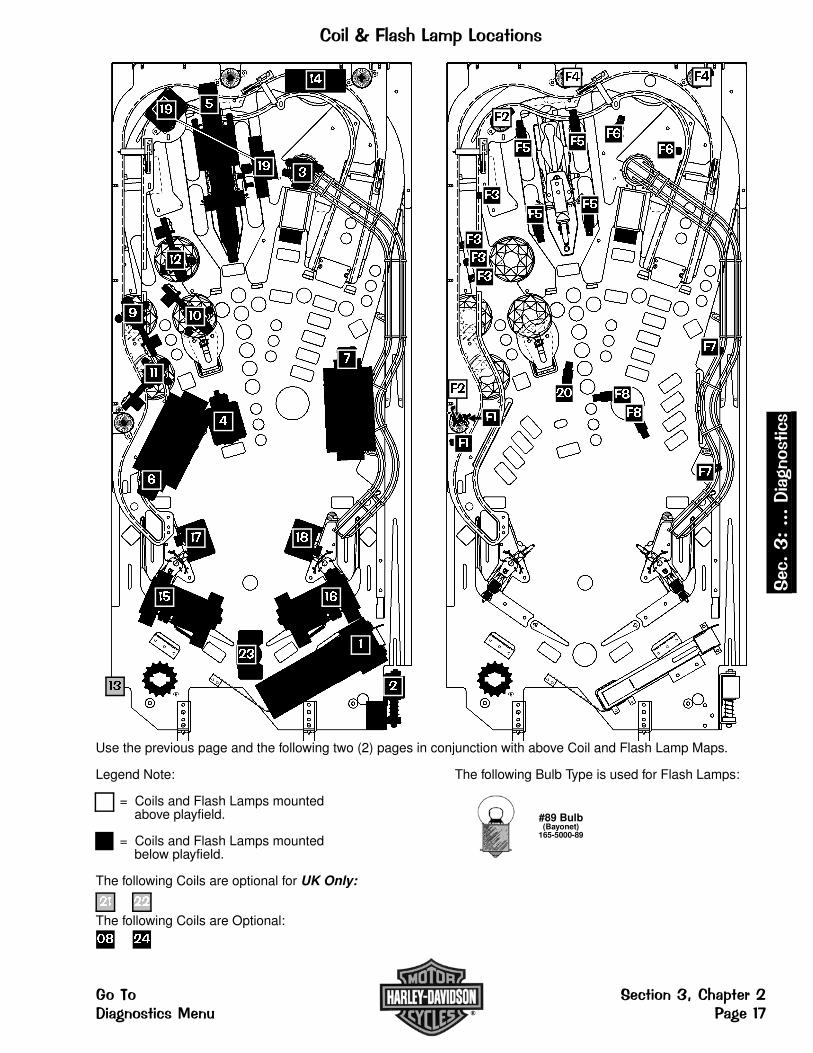
���3-53 ��1 "�1�� �����
Use the previous page and the following two (2) pages in conjunction with above Coil and Flash Lamp Maps.
Legend Note: The following Bulb Type is used for Flash Lamps:
= Coils and Flash Lamps mounted above playfield.
= Coils and Flash Lamps mounted below playfield.
The following Coils are optional for UK Only: The following Coils are Not Used:
The following Coils are Optional: The following Flash Lamp is Not Used:
#906 Bulb(Wedge Base)165-5004-00
�� ����
�� ��
�� ��
� ��
#89 Bulb(Bayonet)
165-5000-89
�
�
��
���
����
�
�
��
� ��
��
��
�
��
�
��
��
�
�
�
�� �
�
�
�
�
�
�
�
�
�
�
� �
�
�
���$#$$$�� ��������
���� �������%�� ������� ������������ & ��'�
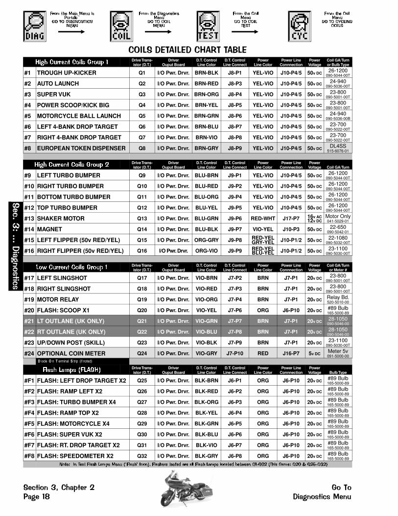
���� ��� �� ���� � �����
�� �� ���������������
���� ��� ������������
�� �� ��������
���� ��� �������
�� �� ��������
���� ��� �������
�� �� ������������
���1�� ���1 ��*�+���71 ���� ����� ���� ����� � Drive Trans-
istor (D.T.)Driver
Ouput BoardD.T. ControlLine Color
D.T. ControlLine Connect
PowerLine Color
Power LineConnnection
PowerVoltage
Coil GA/Turnor Bulb Type
#1 TROUGH UP-KICKER Q1 I/O Pwr. Drvr. BRN-BLK J8-P1 YEL-VIO J10-P4/5 50v DC 26-1200090-5044-00T
#2 AUTO LAUNCH Q2 I/O Pwr. Drvr. BRN-RED J8-P3 YEL-VIO J10-P4/5 50v DC 24-940090-5036-00T
#3 SUPER VUK Q3 I/O Pwr. Drvr. BRN-ORG J8-P4 YEL-VIO J10-P4/5 50v DC 23-800090-5001-00T
#4 POWER SCOOP/KICK BIG Q4 I/O Pwr. Drvr. BRN-YEL J8-P5 YEL-VIO J10-P4/5 50v DC 23-800090-5001-00T
#5 MOTORCYCLE BALL LAUNCH Q5 I/O Pwr. Drvr. BRN-GRN J8-P6 YEL-VIO J10-P4/5 50v DC 24-940090-5036-00B
#6 LEFT 4-BANK DROP TARGET Q6 I/O Pwr. Drvr. BRN-BLU J8-P7 YEL-VIO J10-P4/5 50v DC 23-700090-5022-00T
#7 RIGHT 4-BANK DROP TARGET Q7 I/O Pwr. Drvr. BRN-VIO J8-P8 YEL-VIO J10-P4/5 50v DC 23-700090-5022-00T
#8 EUROPEAN TOKEN DISPENSER Q8 I/O Pwr. Drvr. BRN-GRY J8-P9 YEL-VIO J10-P4/5 50v DC DL4SS515-6076-01
���� ����� ���� ����� � Drive Trans-istor (D.T.)
DriverOuput Board
D.T. ControlLine Color
D.T. ControlLine Connect
PowerLine Color
Power LineConnnection
PowerVoltage Coil GA/Turn
#9 LEFT TURBO BUMPER Q9 I/O Pwr. Drvr. BLU-BRN J9-P1 YEL-VIO J10-P4/5 50v DC 26-1200090-5044-00T
#10 RIGHT TURBO BUMPER Q10 I/O Pwr. Drvr. BLU-RED J9-P2 YEL-VIO J10-P4/5 50v DC 26-1200090-5044-00T
#11 BOTTOM TURBO BUMPER Q11 I/O Pwr. Drvr. BLU-ORG J9-P4 YEL-VIO J10-P4/5 50v DC 26-1200090-5044-00T
#12 TOP TURBO BUMPER Q12 I/O Pwr. Drvr. BLU-YEL J9-P5 YEL-VIO J10-P4/5 50v DC 26-1200090-5044-00T
#13 SHAKER MOTOR Q13 I/O Pwr. Drvr. BLU-GRN J9-P6 RED-WHT J17-P7 16v AC12v DC
Motor Only041-5029-01
#14 MAGNET Q14 I/O Pwr. Drvr. BLU-BLK J9-P7 VIO-YEL J10-P3 50v DC 22-650090-5042-01
#15 LEFT FLIPPER (50v RED/YEL) Q15 I/O Pwr. Drvr. ORG-GRY J9-P8 RED-YELGRY-YEL J10-P1/2 50v DC 22-1080
090-5032-00T
#16 RIGHT FLIPPER (50v RED/YEL) Q16 I/O Pwr. Drvr. ORG-VIO J9-P9 RED-YELBLU-YEL J10-P1/2 50v DC 23-1100
090-5030-00T
��� ����� ���� ����� � Drive Trans-istor (D.T.)
DriverOuput Board
D.T. ControlLine Color
D.T. ControlLine Connect
PowerLine Color
Power LineConnnection
PowerVoltage
Coil GA/Turnor Meter #
#17 LEFT SLINGSHOT Q17 I/O Pwr. Drvr. VIO-BRN J7-P2 BRN J7-P1 20v DC 23-800090-5001-00T
#18 RIGHT SLINGSHOT Q18 I/O Pwr. Drvr. VIO-RED J7-P3 BRN J7-P1 20v DC 23-800090-5001-00T
#19 MOTOR RELAY Q19 I/O Pwr. Drvr. VIO-ORG J7-P4 BRN J7-P1 20v DC Relay Bd.520-5010-00
#20 FLASH: SCOOP X1 Q20 I/O Pwr. Drvr. VIO-YEL J7-P6 ORG J6-P10 20v DC #89 Bulb165-5000-89
#21 LT OUTLANE (UK ONLY) Q21 I/O Pwr. Drvr. VIO-GRN J7-P7 BRN J7-P1 20v DC 28-1050090-5046-00
#22 RT OUTLANE (UK ONLY) Q22 I/O Pwr. Drvr. VIO-BLU J7-P8 BRN J7-P1 20v DC 28-1050090-5046-00
#23 UP/DOWN POST (SKILL) Q23 I/O Pwr. Drvr. VIO-BLK J7-P9 BRN J7-P1 20v DC 23-1100090-5030-00T
#24 OPTIONAL COIN METER Q24 I/O Pwr. Drvr. VIO-GRY J7-P10 RED J16-P7 5v DC Meter 5v091-5000-00
D iode O n T erminal S trip (if noted)
��� � ���� ������� Drive Trans-istor (D.T.)
DriverOuput Board
D.T. ControlLine Color
D.T. ControlLine Connect
PowerLine Color
Power LineConnnection
PowerVoltage Bulb Type
#F1 FLASH: LEFT DROP TARGET X2 Q25 I/O Pwr. Drvr. BLK-BRN J6-P1 ORG J6-P10 20v DC #89 Bulb165-5000-89
#F2 FLASH: RAMP LEFT X2 Q26 I/O Pwr. Drvr. BLK-RED J6-P2 ORG J6-P10 20v DC #89 Bulb165-5000-89
#F3 FLASH: TURBO BUMPER X4 Q27 I/O Pwr. Drvr. BLK-ORG J6-P3 ORG J6-P10 20v DC #89 Bulb165-5000-89
#F4 FLASH: RAMP TOP X2 Q28 I/O Pwr. Drvr. BLK-YEL J6-P4 ORG J6-P10 20v DC #89 Bulb165-5000-89
#F5 FLASH: MOTORCYCLE X4 Q29 I/O Pwr. Drvr. BLK-GRN J6-P5 ORG J6-P10 20v DC #89 Bulb165-5000-89
#F6 FLASH: SUPER VUK X2 Q30 I/O Pwr. Drvr. BLK-BLU J6-P6 ORG J6-P10 20v DC #89 Bulb165-5000-89
#F7 FLASH: RT. DROP TARGET X2 Q31 I/O Pwr. Drvr. BLK-VIO J6-P7 ORG J6-P10 20v DC #89 Bulb165-5000-89
#F8 FLASH: SPEEDOMETER X2 Q32 I/O Pwr. Drvr. BLK-GRY J6-P8 ORG J6-P10 20v DC #89 Bulb165-5000-89
����� �� ���� ���� �� � ���� !"����" ����#$ ������� �����% �� �� ���� �� � �����% &��'��� ()*(+, !��� ���� (,- . (,/*(+,#
���$
#$$$�� ���
�����
�������%�� ����� ����& ��'8 �� ������������
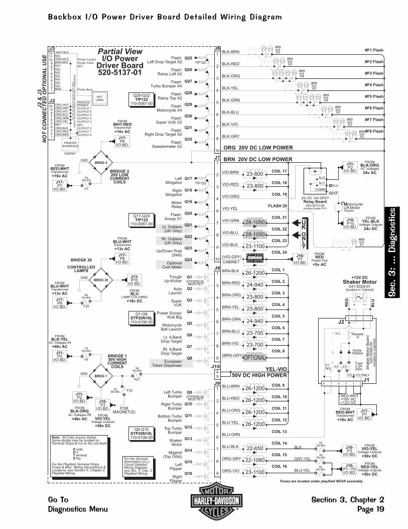
���$#$$$�� ��������
���� �������%�� ������� ������������ & ��'9
0 0 0
23-1100
OPTIONAL
24-940
23-800
23-800
24-940
23-700
23-700
26-1200
#89
X2Bulb
#89
X2Bulb
#89
X2Bulb
#89
X2Bulb
#89
X2Bulb
#89
X2Bulb
23-1100
28-1050
28-1050
23-800
23-800
BLK-BRN
BLK-RED
BLK-ORG
BLK-YEL
BLK-GRN
BLK-BLU
BLK-VIO
BLK-GRY
J6Partial View
I/O PowerDriver Board520-5137-01
CABINET
YEL-VIO50V DC HIGH POWER
Q25
Q26
Q27
Q28
Q29
Q30
Q31
Q32
Note: All Coils require diodes.Some diodes may be located onTerminal Strips & not on the coil itself.
iodenerminaltrip
DOTS
For the Playfield Terminal Strips,Fuses & Misc. Wiring Descriptions &Locations, see Section 5, Chapter 2,Playfield Wiring.
ORG 20V DC LOW POWER
For the GeneralIllumination (G.I.)Circuit DetailedWiring Diagram,see Sec. 5, Chp. 2,Playfield Wiring.
Fuses are located under playfield NEAR assembly.
1
2
3
4
5
6
7
8
10
#89
X4Bulb
#89
X4Bulb
Flash:Left Drop Target X2
Flash:Ramp Left X2
Flash:Turbo Bumper X4
Flash:Ramp Top X2
Flash:Motorcycle X4
Flash:Super VUK X2
Flash:Right Drop Target X2
Flash:Speedometer X2
VIO-BRN
VIO-RED
VIO-ORG
VIO-YEL
VIO-GRN
VIO-BLU
VIO-BLK
(VIO-GRY)
J7
Q17
Q18
Q19
Q20
Q21
Q22
Q23
Q24
1
2
3
4
6
7
8
9
10
LeftSlingshot
RightSlingshot
MotorRelay
Flash:Scoop X1
Lt. Outlane(UK Only)
Rt. Outlane(UK Only)
Up/Down Post(Skill)
OptionalCoin Meter
COIL 17
COIL 18
COIL 19
FLASH 20
COIL 21
COIL 22
COIL 23
COIL 24
BRN-BLK
BRN-RED
BRN-ORG
BRN-YEL
BRN-GRN
BRN-BLU
BRN-VIO
(BRN-GRY)
J8
Q1
Q2
Q3
Q4
Q5
Q6
Q7
Q8
1
3
4
5
6
7
8
9
TroughUp-Kicker
AutoLaunch
SuperVUK
Power Scoop/Kick Big
MotorcycleBall Launch
Lt. 4-BankDrop Target
Rt. 4-BankDrop Target
EuropeanToken Dispenser
COIL 1
COIL 2
COIL 3
COIL 4
COIL 5
COIL 6
COIL 7
COIL 8
UKONLY
26-1200
26-1200
26-1200
22-650
22-1080
26-1200BLU-BRN
BLU-RED
BLU-ORG
BLU-YEL
BLU-GRN
BLU-BLK
ORG-GRY
ORG-VIO
J9
Q9
Q10
Q11
Q12
Q13
Q14
Q15
Q16
1
2
4
5
6
7
8
9
Left TurboBumper
Right TurboBumper
Bottom TurboBumper
Top TurboBumper
ShakerMotor
Magnet(Top Orbit)
LeftFlipper
RightFlipper
COIL 9
COIL 10
COIL 11
COIL 12
COIL 13
COIL 14
COIL 15
COIL 16
BRN 20V DC LOW POWER
BLK
GRY-YEL
BLU-YEL
100 9 9 9
2
#F1 Flash
#F2 Flash
#F3 Flash
#F4 Flash
#F5 Flash
#F6 Flash
#F7 Flash
#F8 Flash
J10
45
BRIDGE 220V LOWCURRENT
COILS
BRDG 2GND
FROM
Transformer
P6I/O BD.
WHT-RED
+16v AC
J17-
FROM
Transformer
P7I/O BD.
RED-WHT
+16v AC
J17-
5ASlo-Blo
F7
BRIDGE 20
CONTROLLEDLAMPS
BRDG 20GND
FROM
Transformer
P8I/O BD.
BLU-WHT
+13v AC
J17-
FROM
Transformer
P9I/O BD.
BLU-WHT
+13v AC
J17-
8ASlo-Blo
F22
P10I/O BD.
J13-
BLU
+18v DC
FROM
LAMP COLUMNS
BRIDGE 150V HIGHCURRENT
COILS
BRDG 1GND
J11-
BLK-ORG
+48v AC
P2I/O BD.
IN
FROM
AC Voltages
FROM
AC Voltages IN
P3I/O BD.
BLK-YEL
+48v AC
J11-
7ASlo-Blo
F6
3ASlo-Blo
F21
3ASlo-Blo F20
J10-
VIO-YEL
+50v DC
P3I/O BD.
FROM
Voltage Outputs
FORMAGNET(S)
C O I N M E T E R
RED-WHT+16V AC+12V DC
F1N/U
S
Shaker Motor
RE
D
BL
U
+ —
N.C.
+12V DC
F2
J1
Fuse2.5A250v
F2 & F3 ONLY
Resistor�
Diode1N5404
Shaker
Moto
rB
oard
520-5
065-0
0(lo
ca
ted
inC
abin
et)
F3
J25 3 2 1
6 7 4 5 1 2
3ASlo-Blo
J10-P3
I/O BD.
FROM
Voltage OutputsVIO-YEL
+50v DC3ASlo-Blo
3ASlo-Blo
J10-P1 / P2I/O BD.
FROM
Voltage OutputsRED-YEL
+50v DC
J17-P7
I/O BD.
FROM
TransformerRED-WHT
+16v AC
J16-P7
I/O BD.
FROM
Power OutRED
+5v AC
S MotorcycleLift MotorPlayfield
Relay Board24v DC 10A DPDT
520-5010-00(located under P-F)
N.U.
WHT
N.O.
N.C.
COMM
J11-P2
I/O BD.
FROM
AC VoltagesBLK-ORG
24v AC
J10-P10
I/O BD.
FROM
Voltage OutputsYEL-BLK
24v DC
TIP122
STP20N10LMOS FET
STP20N10LMOS FET
TIP122
Q25-Q32
110-0067-00TIP122
Q17-Q24
110-0067-00TIP122
Q1-Q8
110-0106-00STP20N10L
Q9-Q16
110-0106-00STP20N10L
NOTUSED
Printer ControlPrinter ClockKEY
Printer Busy
PRINTERINTERFACE
CABINET
WHT-BLKN/UGRN-WHTBRN-WHTKEYN/UN/UN/UN/UN/UN/UBRN
ORG-WHTORG-GRYORG-VIOORG-BLUORG-GRNORG-YELKEYORG-BLKORG-REDORG-BRN
J2
P3
-1
0N
/U&
J3
P1
-P
11
N/U
US
ED
W-O
PT
ION
AL
PR
INT
ER
HA
RN
ES
S
121110
987654321
J3
J2
10987654321
J2
&J3
NO
TC
ON
NE
CT
ED
OP
TIO
NA
LU
SE
PRINTERENABLEOUTPUT 7OUTPUT 6OUTPUT 5OUTPUT 4OUTPUT 3KEYOUTPUT 2OUTPUT 1OUTPUT 0
#89
X1Bulb
041-5029-01(located in Cabinet)
7 �:0�/�;�&������ ����7� �(��� � 3�()�� ����� �� "

������������ From the DIAGNOSTICS MENU, select the "LAMP" Icon with either Red "LEFT" or Green "RIGHT"Button and press the Black "ENTER" Button. Controlled lamps are configured in and 8 x 10 Matrix ofColumns (Lamp Drives) and Rows (Lamp Returns) with up to 80 lamps possible. The Lamp Test Menu
consists of four (4) parts: Single Lamp Test, Test All Lamps, Row Lamp Test and Column Lamp Test.
���������������To initiate, from the LAMP MENU, select the "ONE" Icon with either Red or Green Button and press theBlack Button. Select either the "-" or "+" Icons. Start with the "+" Icon to start the manual Single LampTest from Column 1, Row 1, Lamp 1. Press the Black Button on the "+" Icon, as each lamp is selected,
the lamp will light at it’s location on the playfield as well as the display, indicating the Lamp Matrix Grid Position,lamp name with the corresponding number, Return (Row) Wire & Color, Drive (Column) Wire & Color, andassociated drive transistors. Press the Black Button again to move forward in the test. To test and view aparticular lamp, select the "RUN" Icon and press the Black Button. Each time the Black Button is pushed, thelamp will light-up on the playfield, with the display indicating the lamp information. Continue with the sameprocedure to run through the entire test.
������� � �����To initiate, from the LAMP MENU, select the "ALL" Icon with either Red or Green Button and press theBlack Button. If still in Single Lamp Test (or any 1 of the 4 tests), select the "PREV" Icon to return toLAMP MENU or selecting either of the "ARROW" Icons will move through the tests, keep activating until
Test All Lamps is displayed. The display will indicate "ALL LAMPS ON" and the lamps on the playfield will be lit,alternating between the rows in the Lamp Matrix Grid.
��������� ������������To initiate, from the LAMP MENU, select the "ROW" or "COL" Icon with either Red "LEFT" or Green"RIGHT" Button and press the Black Button. If still in a previous test, select the "PREV" Icon to returnto LAMP MENU or selecting either of the "ARROW" Icons will move through the tests, keep activating untilRow or Column Lamp Test (whichever desired) is displayed. In this test, each set of lamps in each Row orColumn of the Lamp Matrix Grid (respective to each test) will light-up on the playfield and is indicated in thedisplay.
��������������Column (18v)
Row(GND)
�� ������ ���� ������ ��
�� ������ ���� ���� ��
�� ������ ���� ������ ��
�� ������ ���� ������ ��
�� ������ ���� ������ ��
�� ������ ���� ������ ��
�� ������ ���� ������ ��
�� ������ ���� ������ ��
�� ������ ��� ������ ��
(H) ARLEY H (A) RLEY HA (R) LEY HAR (L) EY HARL (E) Y HARLE (Y) SUPER JACK-POT (RED)
SUPER JACK-POT (GRN)
#555 Bulb � #555 Bulb � #555 Bulb � #555 Bulb � #555 Bulb � #555 Bulb � #44 Bulb � #44 Bulb �
�� ������ ��� ������ ��
(L) IVE L (I) VE LI (V) E LIV (E) (R) IDE R (I) DE RI (D) E RID (E)
#44 Bulb � #555 Bulb �� #555 Bulb �� #555 Bulb �� #555 Bulb �� #555 Bulb �� #555 Bulb �� #44 Bulb ��
�� ������ ��� ������ ��
LT ORBITGRN LIGHT
LT ORBITYEL LIGHT
LT ORBITRED LIGHT
1STGEAR
2NDGEAR
3RDGEAR
4THGEAR
5THGEAR
#555 Bulb �� #555 Bulb �� #555 Bulb �� #555 Bulb �� #555 Bulb �� #555 Bulb �� #555 Bulb �� #555 Bulb ��
�� ������ ��� ����� ��
M-CYCLEGRN LIGHT
M-CYCLEYEL LIGHT
M-CYCLERED LIGHT
LEFT TURBO
BUMPER
����
RT TURBO
BUMPER
����
BOT TURBO
BUMPER
����
TOP TURBO
BUMPER
����
SPEEDO-METER X2
#555 Bulb �� #555 Bulb �� #555 Bulb �� #555 Bulb �� #555 Bulb �� #555 Bulb �� #555 Bulb �� #555 Bulb ��
�� ������ ��� ������ ��
SUPER VUKGRN LIGHT
SUPER VUKYEL LIGHT
SUPER VUKRED LIGHT
BIKE S-UTARGET (LT)
BIKE S-UTARGET (RT)
RAMP S-UTARGET (LT)
RAMP S-UTARGET (RT)
SLIPPERYWHEN WET
#555 Bulb �� #555 Bulb �� #555 Bulb �� #555 Bulb �� #555 Bulb �� #555 Bulb �� #555 Bulb �� #555 Bulb ��
�� ������ ��� ������ ��
RT RAMPGRN LIGHT
RT RAMPYEL LIGHT
RT RAMPRED LIGHT
PATCH BIKERSBACK
RED LIGHTMULTIBALL
AUTOLAUNCH
LITE MYST-ERY RIDER
#555 Bulb �� #555 Bulb �� #555 Bulb �� #555 Bulb �� #555 Bulb �� #555 Bulb �� #555 Bulb �� #555 Bulb ��
�� ������ ��� ������ ��
RT ORBITGRN LIGHT
RT ORBITYEL LIGHT
RT ORBITRED LIGHT
NOTUSED
NOTUSED
NOTUSED
NOTUSED
NOTUSED
#555 Bulb �� #555 Bulb �� #555 Bulb �� �� �� �� �� ��
�� ������ ��� ������ ��
STOP LIGHTGRN LIGHT
STOP LIGHTYEL LIGHT
STOP LIGHTRED LIGHT
NOTUSED
NOTUSED
NOTUSED
NOTUSED
NOTUSED
#44 Bulb �� #44 Bulb �� #44 Bulb �� �� �� �� �� ��
�� ������ ��� � ���� ���
2 XTRA BALLS
LT OUTLANEADVANCE GEAR
LT RETURNLITE MYSTERY...
RT RETURN2 XTRA BALLS
RT OUTLANEM-CYCLEHEADLIGHT
RIDEAGAIN X2
MYSTERYRIDER
NEXTCITY
#555 Bulb �� #555 Bulb �� #555 Bulb �� #555 Bulb �� #555 Bulb �� #555 Bulb �� #44 Bulb �� #44 Bulb ��
��������� ������ ���
NOTUSED
NOTUSED
NOTUSED
NOTUSED
NOTUSED
NOTUSED
NOTUSED
NOTUSED
�� �� �� �� �� �� �� ��
D iode O n T erminal S trip :
�������
�����������
�����
���������!��"���#�$ ����������$% ��������������

1 "�� ���/���(1�� �����
The lamp locations correspondwith the Lamp Nº in the LampMatrix Grid on the previous page.
Legend Note:
= Lamps mountedabove playfield.
= Lamps mountedbelow playfield.
The following Lampsare not used:
The following Bulbs are used in the LampMatrix Grid (See Table Grid on previouspage for details):
#555 Bulb(Wedge)165-5002-00
�� � ��
Note:All Lamps require diodes.Some diodes are located on TerminalStrips (under playfield) & not on the lampitself.
D iodeO nT erminal
Diode 1N4001
YEL
COMMON
RED
Typical Lamp Wiring
#44 Bulb(Bayonet)165-5000-44
�� ����
�� � �� � ���� � ��
-XXX -XXX
Typical Lamp Schematic
�
��
��
�
�� � ������� �� ����
� �
��
��
��
�
��
�
��
��
��
��
��
�
�
��
�
�
��
��
�
��
��
�
��
�
�
��
��
��
��
��
��
��
���
��
�
�
�
�
�
�
�
�
�
�� �
�
��
��
�
��
��
��
�
���$#$$$�� ��������
���� �������%�� ������� ������������ & ���'

����5 3 ��1 "��From the DIAGNOSTICS MENU, select the "FLASH" Icon with either Red "LEFT" or Green "RIGHT"Button and press the Black "ENTER" Button. After selecting this Icon the display will indicate"CYCLING FLASHERS" and all the Flash Lamps will cycle continuously until the test is exited. This test
is allows the technician to easily spot any burned-out bulbs and replace them. Flashers tested are Flash Lamps inPositions: Q25-Q32 (F1-F8) and in this game Flash Lamp(s) are also in Position(s): Q20.
Important: The Power Interlock Switch must be pulled out for this Test to Function.
�3� �7 3 3 ������From the DIAGNOSTICS MENU, select the "CLR" Icon with either Red "LEFT" or Green "RIGHT"Button and press the Black "ENTER" Button. This is provided to allow the technician a simple methodof removing the balls from the trough and also, to test functionality of the trough, ensuring proper trough
operation. After selecting this Icon the display will show a graphic of the ball trough with balls in the trough with it’scorresponding switch number. Select the "RUN" Icon to eject the ball in the first position. Simultaneously, thedisplay and the playfield will eject the ball to the Trough Up-Kicker, eject from the Trough Up-Kicker into theShooter Lane and will be ejected onto the playfield where the technician can easily retrieve the pinball or allow theball(s) to re-enter the trough to continue Clear Ball Trough Test. Important: The Power Interlock Switch must bepulled out. Caution: Continuous use of above test may overheat the Trough Up-Kicker Coil.
������� � ��3���From the DIAGNOSTICS MENU, select the "TECH" Icon with either Red "LEFT" or Green "RIGHT"Button and press the Black "ENTER" Button. After selecting this Icon the display will indicate if thereare any faulty switches (i.e., switches that are normally closed but remain open or open switches that
have not been closed (activated) in 50 games.)
�������&����<From the DIAGNOSTICS MENU, select the "SERV" Icon with either Red "LEFT" or Green "RIGHT"Button and press the Black "ENTER" Button. After selecting this Icon the display will indicate a phonenumber to call if technical assistance is required (the phone number is different for each Country Dip
Switch Setting).
7����&3 4����From the DIAGNOSTICS MENU, select the "PLAY" Icon with either Red "LEFT" or Green "RIGHT"Button and press the Black "ENTER" Button. After selecting this Icon the technician can test certainplay functions to insure all switch activated coils function without entering game play. For example, by
rolling the ball over the Shooter Lane switch, the Autoplunger should fire. If it kicks to early or too late, the switchactuator should be adjusted to compensate for this error. If it fails to fire, use the Switch Test or Coil Test to helpdetermine the cause of the failure. During this function, similar tests may be performed on the "Ejects", Sling-shots, Vertical Up-Kickers, Pop Bumpers, etc. in the game. For unique Play Test functions, select the "GAMESPECIFIC" Icon in the DIAGNOSTICS MENU. Important: The Power Interlock Switch must be pulled out.
5���=���:��From the DIAGNOSTICS MENU, select the "KNOCKER" Icon with either Red "LEFT" or Green"RIGHT" Button and press the Black "ENTER" Button. The digitally mastered "Knocker" is sounded.
����(;��� :������From the DIAGNOSTICS MENU, select the "SPKR" Icon with either Red "LEFT" or Green "RIGHT"Button and press the Black "ENTER" Button. The BSMT 2000 Sound System produces true digitalstereo sound from Backbox & Cabinet Speakers or "Mono" on the Cabinet Speaker (when used by itself).
After selecting this Icon, select the "-" or "+" Icons and press the Black "ENTER" Button to activate the first test.Repeat to visually see & hear all tests. Select the "RUN" Icon to activate the test chosen without moving to thenext test. Note: During Sound Tests, the display shows the speaker identification and the correspondingsound(s). The sound functions allow verification that both channels are functioning properly & that the speakerconnections are correct.
Sound / Speaker Test Continued Next Page
���$
#$$$�� ���
�����
�������%�� ����� ����& ���� �� ������������

��� :��&� ������ ���Connections to each of speakers are polarized and each must be connected appropriately for the bestquality sound. If one speaker has the positive and negative connections reversed with respect to theother one, bass frequencies will not be produced properly and the overall sound quality will be poor. Totest for proper speaker phasing, use the sound test to cycle through the Backbox & Cabinet, and Backbox
Sine (repeated) functions. If the Cabinet Sine produces more volume and bass than the Left Sine, the speakersare connected properly. If it produces the same or less, one speaker is connected improperly. To isolate andcorrect reversed speaker connections, one of two methods may be used.
1. Check each speaker for polarity markings. If the speakers have polarity markings, verify that the BackboxSpeaker RED/WHT Wire and the Cabinet Speaker YEL/WHT Wire is connected to the negative (-) terminal.
2. Disconnect the speaker output connector from the CPU / Sound Board and connect a 1.5-volt battery acrosseach speaker pair one at a time while observing the speakers. Make sure the positive battery terminal isconnected to the positive lead (CN4, Pin-3 (RED/BLK) or Pin-6 (YEL/BLK)) each time. As the connection is made,check speaker cone movement; proper connections are indicated by outward movement.
���� � ����� ���� ����� ��������
Speaker Test ToneSound/OPSYS EPROM (Loc. U7) Level 1-3+ (Music Test)
Voice ROMs: 1 (U17) 2 (U21) 3 (U36) & 4 (U37) Speech Pattern 1-4+Note: For ROM Locations, see Page DR. �. For ROM Usage (Summary Table) see Page DR. � in the"Find-It-In-Front: Dr. Pinball Section". Voice ROMs (U17, U21, U36 and U37) which are 8MB must have aJumper at W6 on the CPU/Sound Board to function properly.
7����7�����From the DIAGNOSTICS MENU, select the "BURN" Icon with either Red "LEFT" or Green "RIGHT"Button and press the Black "ENTER" Button. After selecting this Icon the Begin Burn-In Test will start.At this stage the game will exercise all CPU I/O Functions (Dot Matrix Display Test, Coil Testing, LampTesting, Sound, etc.). This is provided to constantly exercise sounds, coils, etc... Cumulative Burn-In
minutes will be displayed. To reset Burn-In minutes to 00, select the "RESET" Icon in the MAIN MENU and selectthe "FACT" Icon (Factory Reset). See Chapter 5, Go To Reset Menu, of this section.
���� �� �/����From the DIAGNOSTICS MENU, select the "DOT TEST" Icon with either Red "LEFT" or Green"RIGHT" Button and press the Black "ENTER" Button. After selecting this Icon the Dot Matrix Testimmediately begins. The display will immediately illuminate & cycle for 1 pass of each test continuously
for each of the following tests:
1. Illuminates 1 vertical column of dots, turning it off & illuminating the next column,until each column has been individually lit, while the other columns are off.
2. Illuminates 1 horizontal row of dots, turning it off & illuminating the next row,until each row has been individually lit, while the other rows are off.
3. Illuminates all the dots, except for one column from left to right.
4. Illuminates all the dots, except for one row from top to bottom.
5. Illuminates every other dot lit, in both the rows and columns.
6. Illuminates all dots at 30%, 70% & 100% brightness.
Note: Pressing any button will exit the test & return to DIAGNOSTICS MENU.
���� ���/����3 4 /�3 ���(The display utilizes a Micro-Processor Control Board mounted in piggyback fashion to the Dot Matrix Display (128 X 32) Driver Board. The purpose behind this board is to provide more information to the operator as well asdisplaying graphics to the player.
The board is controlled by a 6809E Microprocessor and its personality ROM (Unique to the Game). It receivesData, Reset & Clock Information from the CPU/Sound Board via the ribbon cable and sends back multiple Statusand Busy Signals to the CPU. This is to insure synchronized communication between the CPU and the DisplayController Board. The Drivers for the rows and columns are provided on 5 surface mounted integrated circuits onthe Dot Matrix Display Driver Board.
Continued
���$#$$$�� ��������
���� �������%�� ������� ������������ & ���

* � 3�4>� ��(��������� ��?������4�3�����@To initiate, from the DIAGNOSTICS MENU, select the "H-D" Icon with either the Red "LEFT" or Green"RIGHT" Button and press the Black "ENTER" Button (the START Button operates in the samemanner).
This will bring up the HARLEY-DAVIDSON SPECIFIC MENU. Similiar to "BEGIN PLAY TEST," this menu is usedto test and adjust Game Specific Features. The feature in this game is MOTORCYCLE TEST.
Important: The Power Interlock Switch must be pulled out for this Test to Function.
This test is provided to allow the technician a simple method of removing the balls from the trough, to test thefunctionality of the trough (correct operation of the Kick-Out Coil & the Switch Membrane) and Motor Operation.After selecting the "H-D" Icon the display will indicate the position of the Motorcycle (Motor Up, Switch 35, andMotor Down, Switch 36). The position will be highlighted in the box. The next line will indicate if any switchclosures are present over the Switch Membrane in the Kick-Out Trough (Sw. 44 (bottom) through Sw. 41 (top)).
�����!�;��������&����(���#Select the "RUN" Icon to automatically bring the Motor & Trough from the DOWN or UP position to the oppositeposition. Select the "PULSE" Icon to move the motor slowly UP and/or DOWN one pulse at a time. This testallows you to operate the Motor on this mechanism which is controlled by a Relay driven by Q19 on the I/O PowerDriver Board for the purpose of troubleshooting.
������-7 3 3 A�������&����(���#Hand-Roll 1 ball at a time into the trough (with theMotorcycle in the UP position). Watch the display andnote that each box is high-lighted from left to right as theballs are inserted. This test indicates proper SwitchMembrane function (Switch 44 is the first ball in (bottom) and Switch 41 being the last (4th) ball in (top). To ejectthe balls and to test the Motorcycle Ball Launch (Coil Q5), press the "AUTO LAUNCH" Button (Cabinet FrontRight Side). The 4 boxes should become unhighlighted indicating "no balls are in the trough".
You may wish to activate the "RUN" Icon to bring the Motorcycle back into the DOWN position. If exiting Portalswithout doing so, the Motorcycle will automatically return to the DOWN position upon Game Reset.
=��:>�������������"034%2BB>69�>BB>6�
Sw. 41Sw. 42
Sw. 43Sw. 44
Coil Q5(24-940)
SwitchMembrane
Sw. MembraneRibbon Cable to
Diode Board
1���?�����@����"034%2BB>696>BB>6�
UPPositionSw. 35
DOWNPositionSw. 36
Motor to RelayBoard Q19
���$
#$$$�� ���
�����
�������%�� ����� ����& ���. �� ������������

��$&��0 3 3 ?53���� �������@To initiate, from the DIAGNOSTICS MENU, select the Cross "DR." Icon with either the Red "LEFT" orGreen "RIGHT" Button and press the Black "ENTER" Button. This will bring you (the operator /technician) into DR. PINBALL (Flow Chart Menus) which offers you a choice of three sub-menus:
Coil "DR.," Switch "DR." and Lamp "DR." Icons. Selecting a particular sub-menu will give you a choice of whichspecific Coil (any and all coil assemblies such as Flippers, VUKs, Magnets, etc.), Switch or Lamp circuit needs tobe diagnosed. The display will now ask a question or give a procedure to follow such as "Does the lamp turnon?" or "Check bridge rectifier BR-20, if short replace." When Dr. Pinball asks a question or request a procedurethe Dr. will expect a response such as "no" or "yes" (see below examples of the Mini-Icons which will prompt theoperator). You the operator/technician must respond by using your Flipper Buttons to "SELECT" a Mini-Icon andthe Start Button to "ENTER" your selection.
The following are the Mini-Icons with explanations for the Dr. Pinball Sub-Menus to follow:
��� 3 53���� ��To initiate, from the DR. PINBALL MENU, select the Coil "DR." Icon with either the Red or Green Buttonand press the Black Button. This is the Coil Flow Chart. Follow the questions, answering by using theMini-Icons in the display.
������53���� ��To initiate, from the DR. PINBALL MENU, select the Switch "DR." Icon with either the Red or GreenButton and press the Black Button. This is the Switch Flow Chart. Follow the questions, answering byusing the Mini-Icons in the display.
1 "�53���� ��To initiate, from the DR. PINBALL MENU, select the Lamp "DR." Icon with either the Red or GreenButton and press the Black Button. This is the Lamp Flow Chart. Follow the questions, answering byusing the Mini-Icons in the display.
— Select a Coil, Lamp or Switch to diagnosewith "-" or "+" Icon; Then select the "RUN"Icon to activate the choice."PREV" goes back to previous question."QUIT" exits Portals completely. Help "?" gives direction on button usage.
— Seen when question is being asked on theDisplay. Select "YES" or "NO" to answerquestion given."END" lets you select a new item to test."PREV", "QUIT" and "?" (see firstexample above).
— Seen when diagnosis is given. Selectany Icon for your next step."END" lets you select a new item to test."PREV", "QUIT" and "?" (see firstexample above).
— In Coil Flow Chart Menu, select "PULSE"to pulse the coil selected."END" lets you select a new item to test."PREV", "QUIT" and "?" (see firstexample above). �
��$#$$$�� ��������
���� �������%�� ������� ������������ & ���2
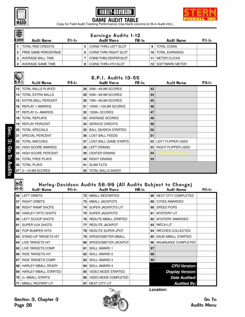
������������ ����
����������������Copy for Field Audit Tracking Performance (Use blank columns to fill-in Audit Info.).
����� ��� ���� � ����� ��� ���� � ����� ��� ���� �
13 TOTAL BALLS PLAYED 28 20M—49.9M SCORES 43
14 TOTAL EXTRA BALLS 29 50M—69.9M SCORES 44
15 EXTRA BALL PERCENT 30 70M—99.9M SCORES 45
16 REPLAY 1 AWARDS 31 100M—129.9M SCORES 46
17 REPLAY 2+ AWARDS 32 130M+ SCORES 47
18 TOTAL REPLAYS 33 AVERAGE SCORES 48
19 REPLAY PERCENT 34 SERVICE CREDITS 49
20 TOTAL SPECIALS 35 BALL SEARCH STARTED 50
21 SPECIAL PERCENT 36 LOST BALL FEEDS 51
22 TOTAL MATCHES 37 LOST BALL GAME STARTS 52 LEFT FLIPPER USED
23 HIGH SCORE AWARDS 38 LEFT DRAINS 53 RIGHT FLIPPER USED
24 HIGH SCORE PERCENT 39 CENTER DRAINS 54 USA 8 BONUS USED
25 TOTAL FREE PLAYS 40 RIGHT DRAINS 55
26 TOTAL PLAYS 41 SLAM TILTS
27 0—19.9M SCORES 42 TOTAL BALLS SAVED
������������� � ������ ��� ���� � ����� ��� ���� � ����� ��� ���� �
1 TOTAL PAID CREDITS 5 COINS THRU LEFT SLOT 9 TOTAL COINS
2 FREE GAME PERCENTAGE 6 COINS THRU RIGHT SLOT 10 TOTAL EARNINGS
3 AVERAGE BALL TIME 7 COINS THRU CENTER SLOT 11 METER CLICKS
4 AVERAGE GAME TIME 8 COINS THRU 4TH SLOT 12 SOFTWARE METER
���� !���"�#��������$�%%�&�� � ��������'( )���#�*+��� ,����� ��� ���� � ����� ��� ���� � ����� ��� ���� �
56 LEFT ORBITS 72 MBALL RESTARTED 88 NEXT CITY COMPLETED
57 RIGHT ORBITS 73 MBALL JACKPOTS 89 CITIES AWARDED
58 RIGHT RAMP SHOTS 74 SUPER JACKPOTS LIT 90 SPEED POPS
59 HARLEY OPTO SHOTS 75 SUPER JACKPOTS 91 MYSTERY LIT
60 LEFT SCOOP SHOTS 76 REDLITE MBALL STARTED 92 MYSTERY AWARDED
61 SUPER VUK SHOTS 77 REDLITE JACKPOT 93 PATCH LIT
62 POP BUMPER HITS 78 REDLITE SUPER JPOT 94 PATCHES COLLECTED
63 STAND-UP TARGETS HIT 79 SPEEDOMETER MBALL 95 MILW. MBALL STARTED
64 LIVE TARGETS HIT 80 SPEEDOMETER JACKPOT 96 MILWAUKEE COMPLETED
65 LIVE TARGETS COMP. 81 SKILL AWARD 1 97
66 RIDE TARGETS HIT 82 SKILL AWARD 2 98
67 RIDE TARGETS COMP. 83 SKILL AWARD 3 99
68 HARLEY MBALL READY 84 SKILL AWARD 4 CPU Version:69 HARLEY MBALL STARTED 85 VIDEO MODE STARTED Display Version:70 2+ MBALL STARTS 86 VIDEO MODE COMPLETED Date Audited:71 MBALL RESTART LIT 87 NEXT CITY LIT Audited By:
Location:
� )���
-��#��#
�����
� )�#���.�*+�/� ��� �#��#��� ��$ ������ ��

� )� #�� � *+�/� �� �� #0� 1
�#��#������� ��2" �" 3The Portals Service Menu System provides 99 Audit Functions for accounting purposes and for evaluation ofGame Difficulty Adjustments. The Audit Functions are divided into 3 groups: 1st— Earnings (Coin) Audits, arethe first 12 most-used Audits; 2nd— S.P.I. Audits, are the Game Play Generic Audits 13-55;3rd— Harley- Davidson Audits, are the Game Play Specific Audits 56-99; Audits left open (blank space in gray,e.g. Audits 43-51, 54 & 55, 97-99) are currently Not Used, allowing for Future Expansion, if any, or areProprietary. If the code version is upgraded, view Audits in the display & write the audit(s) in the blank(s) if anyaudit(s) were added. Each group may be viewed in the Portals Service Menu (see Chapter 1, Portals ServiceMenu Introduction, of this Section). View all audits with the Game Audit Table provided on the previous page.Copy page to fill-in important audit information as required.
�2��2����������4�With the game in the Attract Mode, open the Coin Door and press the Black "BEGIN TEST" Button.Select the "AUD" Icon in the MAIN MENU with either Red "LEFT" or Green "RIGHT" Button and pressthe Black "ENTER" Button. The AUDITS MENU appears.
�5/#������4#� �-Exit any sub-menu and return to the MAIN Selecting & activating the "QUIT" Icon fromMENU by selecting & activating the "PREV" any display will exit the Service Session.Icons. If no Icons appear in the displaybecause of a testing function or specialdisplay (e.g. "Help"), press any button to exit.
Selecting & activating the "HELP" Icon from Selecting & activating the "ARROW" Icons any display will show a help screen. (An selects the next or previous audit in the group.explanation of each Mini-Icon at that level willcycle continuously until any active buttonis pressed.)
�������������& � �,From the AUDITS MENU, select the "EARN" Icon with either Red "LEFT" or Green "RIGHT" Buttonand press the Black "ENTER" Button. Select and activate the "RIGHT ARROW" Icon to view the 1staudit in this group. Continue to select either of the "ARROW" Icons to view each audit one at a time. The
display will describe the audit number, the audit name, and the audit total or value. The current audit will remain inthe display until the next audit is chosen or when the sub-menu is exited.
��� �º ����� �� ����� ��� ����
Au. 1 Total Paid Credits Provides the total number of paid credits.
Au. 2 Free Game Percentage This percentage is derived from dividing Audit 25, Total Free Plays, byAudit 26, Total Plays.
Au. 3 Average Ball Time In seconds, the average ball time is derived from the total play timedivided by Audit 13, Total Balls Played.
Au. 4 Average Game Time The average game time is expressed in minutes and seconds.Au. 5 Coins Thru Left Slot Provides the total number of times Coin Switch (Sw. 6) was closed.Au. 6 Coins Thru Right Slot Provides the total number of times Coin Switch (Sw. 4) was closed.Au. 7 Coins Thru Center Slot Provides the total number of times Coin Switch (Sw. 5) was closed.Au. 8 Coins Thru 4th Slot Provides the total number of times Coin Switch (Sw. 2) was closed.Au. 9 Total Coins Provides the total amount of coins registered through all the slots.
Au. 10 Total Earnings The total cash value accumulated since the last Factory Restoreoccurred (see Chapter 5, Go to Reset Menu, of this section).
Au. 11 Meter Clicks Provides the total number of money clicks accumulated. (Based onthe country’s lowest coin denomination used for the game credit.)
Au. 12 Software Meter Provides the continuing total of Meter Clicks. This audit cannot bereset; the display shows the constant addition of Meter Clicks.
� )���-��#��#�����
�#��# � )�#���.�*+�/� ��������� �� ��� ��1
back to Page 26

������ ������& ����,From the AUDITS MENU, select the "S.P.I." Icon with either Red "LEFT" or Green "RIGHT" Button andpress the Black "ENTER" Button. Select and activate the "RIGHT ARROW" Icon to view the 1st audit inthis group. Continue to select either of the "ARROW" Icons to view each audit one at a time. The display
will describe the audit number, the audit name, and the audit total or value. The current audit will remain in thedisplay until the next audit is chosen or when the sub-menu is exited.
��� �º ����� �� ����� ��� ����
Au. 13 Total Balls Played Provides the total number of regular and extra balls.Au. 14 Total Extra Balls Provides the total number of extra balls awarded.
Au. 15 Extra Balls Percent Provides the percentage total from dividing Audit 14, Total Extra Balls,by Audit 26, Total Plays.
Au. 16 Replay 1 Awards Provides the total awards (Credit, Extra Ball, Or Audit) for level 1.
Au. 17 Replay 2+ Awards Provides the total awards (Credit, Extra Ball, Or Audit) for level(s) 2 orhigher.
Au. 18 Total Replays Provides the total awards (Credits, Extra Balls, Or Audit Only) forexceeding replay score levels.
Au. 19 Replay PercentProvides the percentage total from dividing Audit 18, Total Replays, byAudit 26, Total Plays. The percentage reflects replay total awards forexceeding replay score levels.
Au. 20 Total Specials Provides the total awards (Credits, Extra Balls, Or Scores) for makingspecials.
Au. 21 Special Percent This percentage is derived from dividing Audit 20, Total Specials, byAudit 26, Total Plays.
Au. 22 Total Matches
Provides the total credits awarded for matching the last two digits ofthe score with the system-generated Match Number at the end of thegame. Percentage of match credits is adjustable from 0% to 10% byAdjustment 11, Match Percentage, if enabled. (See Chapter 4, Go toAdjustments Menu, of this section.)
Au. 23 High Score Awards Provides the total credits awarded for exceeding the High-Score-To-Date scores.
Au. 24 High Score Percent This percentage is derived from dividing Audit 23, High Score Awards,by Audit 26, Total Plays.
Au. 25 Total Free Plays Provides the total free credits for replays, High-Score-To-Date,Specials, and Match.
Au. 26 Total PlaysThis total is derived by adding the sum of Audit 1, Total Paid Credits,and Audit 25, Total Free Plays. Note that free credits are not recordedin the Audit until they are actually used.
Au. 27 0—19.9M Scores Provides the total number of games the Player’s final score wasbetween 0 and 19,900,000 points.
Au. 28 20M—49.9M Scores Provides the total number of games the Player’s final score wasbetween 20,000,000 and 49,900,000 points.
Au. 29 50M—69.9M Scores Provides the total number of games the Player’s final score was between 50,000,000 and 69,900,000 points.
Au. 30 70M—99.9M Scores Provides the total number of games the Player’s final score was between 70,000,000 and 99,900,000 points.
Au. 31 100M—129.9M Scores Provides the total number of games the Player’s final score wasbetween 100,000,000 and 129,900,000 points.
Au. 32 130M+ Scores Provides the total number of games the Player’s final score was over130,000,000 points.
Au. 33 Average Scores This total is derived from adding the Final Score of each game to atable and dividing this sum by Audit 26, Total Plays.
Au. 34 Service CreditsProvides the total number of times Dedicated Switch (DS-7) wasclosed, not in the Portals Service Menu. (See Chapter 1, Introduction[Access & Use] for instructions on how to receive Service Credits.)
Au. 35 Ball Search Started Provides the total number of times the game performed a ball search.
Au. 36 Lost Ball Feeds Provides the total number of times the game added a ball to play whenit could not find a ball after ball search.
� )���
-��#��#
�����
� )�#���.�*+�/� ��� �#��#��� ��6 ������ ��

�����������*#���� �
����� ��� ����� ������ �
Au. 37 Lost Ball Game Starts Provides the total number of times the game started with a ballmissing from the ball trough at the start of a game.
Au. 38 Left Drains Provides the total number of times Rollover Switch 57 was closed.
Au. 39 Center Drains Provides the total number of times the game ball had drained with thelast switch closed was not Sw. 57 or Sw. 60.
Au. 40 Right Drains Provides the total number of times Rollover Switch 60 was closed.Au. 41 Slam Tilts Provides the total number of times Contact Switch 55 was closed.
Au. 42 Total Balls SavedProvides the total number of times this feature was used. This featureis enabled at the start of each ball and is disabled as soon as the ballmakes contact with 5 game switches or allocated time expired.
Au. 43-Au. 51
These audits are Not Used, allowing for Future Expansion, if any,and/or Proprietary (used for programming).
Au. 52 Left Flipper Used Provides the total number of times Dedicated Switch (DS-1) was closed.Au. 53 Right Flipper Used Provides the total number of times Dedicated Switch (DS-3) was closed.
Au. 54-Au. 55
These audits are Not Used, allowing for Future Expansion, if any,and/or Proprietary (used for programming).
���� !���"�#�������&�$�%%,�&��'( )� � �#�*+��� ,From the AUDITS MENU, select the "H-D" Icon with either Red "LEFT" or Green "RIGHT" Button andpress the Black "ENTER" Button. Select and activate the "RIGHT ARROW" Icon to view the 1st audit inthis group. Continue to select either of the "ARROW" Icons to view each audit one at a time. The display
will describe the audit number, the audit name, and the audit total or value. The current audit will remain in thedisplay until the next audit is chosen or when the sub-menu is exited.
��� �º ����� ��� ����� ������ �
Au. 56 Left Orbits Provides the total number of times this feature was completed. †
Au. 57 Right Orbits Provides the total number of times this feature was completed. †
Au. 58 Right Ramp Shots Provides the total number of times this feature was completed. †
Au. 59 Harley OPTO Shots Provides the total number of times OPTO Switch 37 was closed.Au. 60 Left Scoop Shots Provides the total number of times Scoop Switch 46 was closed.Au. 61 Super VUK Shots Provides the total number of times SVUK Switch 45 was closed.Au. 62 Pop Bumper Hits Provides the total number of times this feature was completed. †
Au. 63 Stand-Up Targets Hit Provides the total number of times Stand-Up Switches 29-32 wereclosed.
Au. 64 Live Targets Hit Provides the total number of times Left 4-Bank Switches 17-20 wereclosed.
Au. 65 Live Targets Completed Provides the total number of times this feature was completed. †
Au. 66 Ride Targets Hit Provides the total number of times Right 4-Bank Switches 21-24 wereclosed.
Au. 67 Ride Targets Completed Provides the total number of times this feature was completed. †
Au. 68 Harley MBall Ready Provides the total number of times this feature was ready (lit) awaitingMultiball. † ‡
Au. 69 Harley MBall Started Provides the total number of times Harley Multiball was played. †
Au. 70 2+ MBall Starts Provides the total number of times Multiball was played more thanonce by a single player in one game. †
Au. 71 MBall Restart Lit Provides the total number of times Multiball was played and noJackpots were collected. ‡
† Multiple variations of switch closures (see Diagnostics) are used to determine completion of the feature stated.‡ Multiple variations of switch closures (see Diagnostics) are used to determine the lighting of the feature stated.
� )���-��#��#�����
�#��# � )�#���.�*+�/� ��������� �� ��� ��%
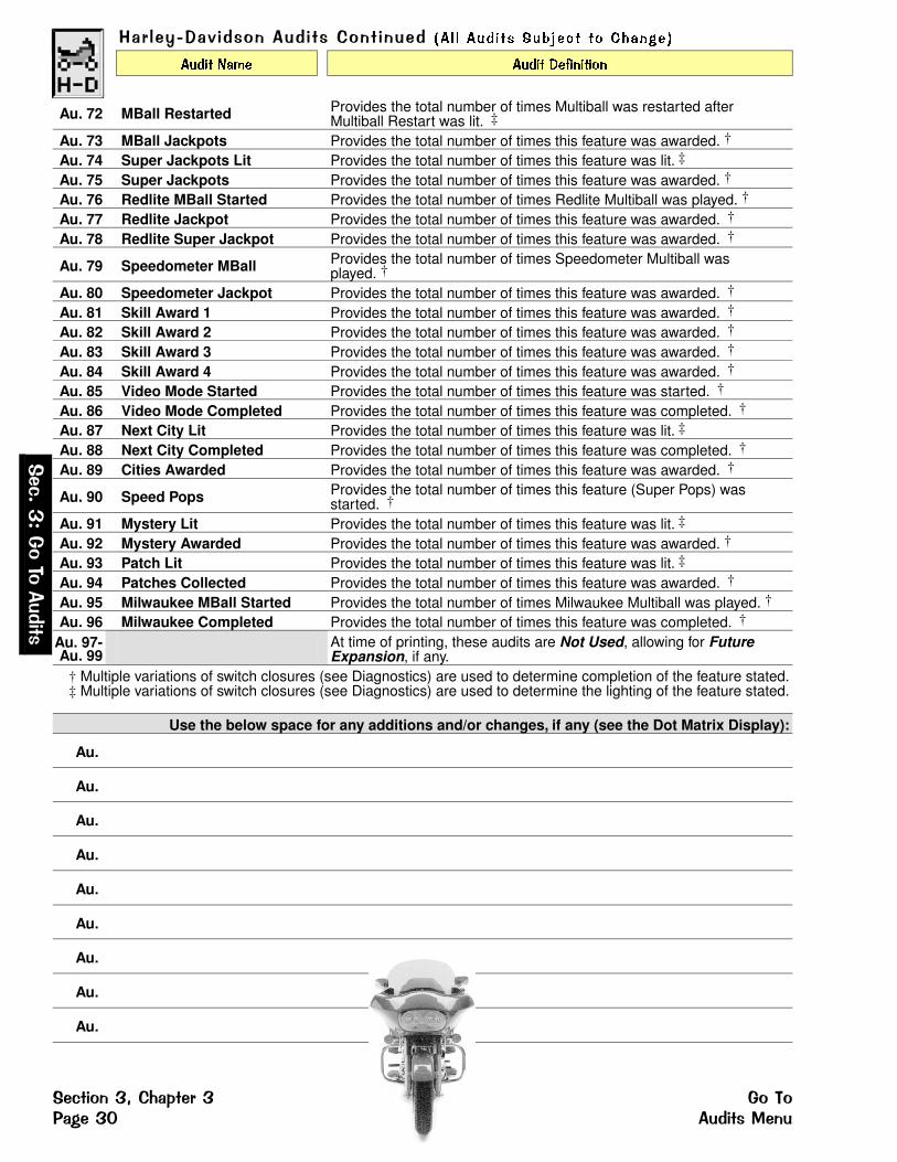
���� !���"�#�������*#�� �� �� � � ��� � �� ��� � �� �������
����� ���� ����� ����������
Au. 72 MBall Restarted Provides the total number of times Multiball was restarted afterMultiball Restart was lit. ‡
Au. 73 MBall Jackpots Provides the total number of times this feature was awarded. †
Au. 74 Super Jackpots Lit Provides the total number of times this feature was lit. ‡
Au. 75 Super Jackpots Provides the total number of times this feature was awarded. †
Au. 76 Redlite MBall Started Provides the total number of times Redlite Multiball was played. †
Au. 77 Redlite Jackpot Provides the total number of times this feature was awarded. †
Au. 78 Redlite Super Jackpot Provides the total number of times this feature was awarded. †
Au. 79 Speedometer MBall Provides the total number of times Speedometer Multiball wasplayed. †
Au. 80 Speedometer Jackpot Provides the total number of times this feature was awarded. †
Au. 81 Skill Award 1 Provides the total number of times this feature was awarded. †
Au. 82 Skill Award 2 Provides the total number of times this feature was awarded. †
Au. 83 Skill Award 3 Provides the total number of times this feature was awarded. †
Au. 84 Skill Award 4 Provides the total number of times this feature was awarded. †
Au. 85 Video Mode Started Provides the total number of times this feature was started. †
Au. 86 Video Mode Completed Provides the total number of times this feature was completed. †
Au. 87 Next City Lit Provides the total number of times this feature was lit. ‡
Au. 88 Next City Completed Provides the total number of times this feature was completed. †
Au. 89 Cities Awarded Provides the total number of times this feature was awarded. †
Au. 90 Speed Pops Provides the total number of times this feature (Super Pops) wasstarted. †
Au. 91 Mystery Lit Provides the total number of times this feature was lit. ‡
Au. 92 Mystery Awarded Provides the total number of times this feature was awarded. †
Au. 93 Patch Lit Provides the total number of times this feature was lit. ‡
Au. 94 Patches Collected Provides the total number of times this feature was awarded. †
Au. 95 Milwaukee MBall Started Provides the total number of times Milwaukee Multiball was played. †
Au. 96 Milwaukee Completed Provides the total number of times this feature was completed. †
Au. 97-Au. 99
At time of printing, these audits are Not Used, allowing for FutureExpansion, if any.
† Multiple variations of switch closures (see Diagnostics) are used to determine completion of the feature stated.‡ Multiple variations of switch closures (see Diagnostics) are used to determine the lighting of the feature stated.
Use the below space for any additions and/or changes, if any (see the Dot Matrix Display):
Au.
Au.
Au.
Au.
Au.
Au.
Au.
Au.
Au.
� )���
-��#��#
�����
� )�#���.�*+�/� ��� �#��#��� ��7 ������ ��

�#��#����� ��� ��From the AUDITS MENU, select the "PRNT" Icon with either Red "LEFT" or Green "RIGHT" Buttonand press the Black "ENTER" Button. The PRINTER MENU appears.
� ��/ )� � � 8�/5 ��� ��� 8�� �0#���+ ����'�� ��The Portals Service Menu System provides 3 Audit Printing Adjustment Functions to print information on a"Hand-Held" printer, download game information to a Laptop PC or clear the printout count. A printer interfaceboard, hand-held printer and/or a special software program is required to run this menu. Entering this menu andselection/activation of the Icons without this equipment/software will not affect the game.
9�):��� ��#���&���� ����� � 0�) ,From the PRINTER MENU, select the "QUIK" Icon with either Red or Green Button and press the BlackButton. Select the "+" Icon and press the Black Button to start the printout. Only the Earnings Auditscan be printed out to a "Hand-Held" Printer.
;�� � �����#���&�� �#����� � 0�) ���#���5,From the PRINTER MENU, select the "ALISON" Icon with either Red or Green Button and press theBlack Button. Select the "+" Icon and press the Black Button to start the download. A special softwareprogram and a Lap Top PC is required. All game audits (Earnings, Sega & Game Specific) can be
retrieved.
< � ���� �� ��&4=�#0�*#/ ���� �� �< � �,From the PRINTER MENU, select the "RESET" Icon with either Red or Green Button and press theBlack Button. Select the "+" Icon and press the Black Button to start the clear the "Nº of copiesprinted" count total.
R E S E T T I N G A U D I T N O T E S :
����4#� -� ���>�!��#�< � ������To reset audits, from the MAIN MENU, select the "ADJ" Icon. See Chapter 4, Go to Adjustments Menu,of this section.
Select the "S.P.I." Icon, from the ADJUSTMENT MENU, and advance to Adj. 8, Reset CoinAudits, with the "RIGHT ARROW" Icon. Select the "+" Icon to change setting to YES. Whenenabled, the Coin Audits (5-11) will be reset to zero.
Advance to Adj. 9, Reset Game Audits, with the "RIGHT ARROW" Icon. Select the "+" Icon tochange setting to YES. When enabled, all the audits will be reset to zero, except for the CoinAudits (5-11) and Audit 12, Software Meter (the only audit which cannot be reset to zero).
����4#� -����>�!��#�< � ������To reset audits, from the MAIN MENU, select the "RESET" Icon. See Chapter 5, Go to Reset Menu, ofthis section.
Selection of the "COIN" Icon, from the RESET MENU, will reset the Coin Audits (5-11) to zero.
Selection of the "AUD" Icon, from the RESET MENU, will reset all audits to zero,
� )���-��#��#�����
�#��# � )�#���.�*+�/� ��������� �� ��� ��

���������������� ��Some adjustments have a "Drop-Down" Table for further customization.
������������������������������� ��� ��� ����� ���
����� ��������� ��� ��� ����� ��� �����
1 REPLAYS: FIXED/AUTO ‡ ...10%... 25 DEFAULT HIGH SCORE #5 300,000,000
2 REPLAY LEVELS ‡ 1 ... 26 DEFAULT HIGH SCORE #6 275,000,000
3 REPLAY AWARD CREDIT 27 DEFAULT HIGH SCORE #7 250,000,000
4 FREE GAME LIMIT 05 28 DEFAULT HIGH SCORE #8 225,000,000
5 EXTRA BALL LIMIT 03 29 DEFAULT HIGH SCORE #9 200,000,000
6 GAME DIFFICULTY ‡ MODERATE 30 DEFAULT HIGH SCORE #10 175,000,000
7 GAME PRICING ‡ USA8 31 HSTD RESET COUNT 2,000
8 RESET COIN AUDITS NO 32 HIGH SCORE INITIALS 3 Initials
9 RESET GAME AUDITS NO 33 FREE PLAY NO
10 RESET HIGH SCORES NO 34 CUSTOM MESSAGE ON
11 MATCH PERCENTAGE 9% 35 ATTRACT MODE MUSIC ON
12 BALLS PER GAME 03 36 FLASH LAMP POWER NORMAL
13 TILT WARNINGS 01 37 COIL PULSE POWER NORMAL
14 REPLAY BOOST YES 38 KNOCKER VOLUME NORMAL
15 CREDIT LIMIT 30 39 MINIMUM GAME TIME OFF
16 ALLOW HIGH SCORES YES 40 BKGRND MUSIC VOLUME 01
17 HIGH SCORE #1 AWARDS 01 41 GAME RESTART YES
18 HIGH SCORE #2 AWARDS 00 42 EXTRA BALL PERCENTAGE 25%
19 HIGH SCORE #3 AWARDS 00 43 BILL VALIDATOR NO
20 HIGH SCORE #4 AWARDS 00 44 TOURNAMENT MODE NONE
21 DEFAULT HIGH SCORE #1 400,000,000 45 EURO. TOKEN DISP. OFF
22 DEFAULT HIGH SCORE #2 375,000,000 46 SPECIAL MEMORY YES
23 DEFAULT HIGH SCORE #3 350,000,000 47 LOCATION ID 00
24 DEFAULT HIGH SCORE #4 325,000,000 48 GAME ID 00
PLEASE NOTE: All Factory Settings (Defaults) described in the tables above/below and within the AdjustmentDefinitions are for USA Settings only (CPU/Snd Bd. Dip Sw. 300 Settings 1-8 are all "OFF"). Different countriesmay have different Factory Settings (Defaults). ‡ Adj. 1, 2, 6 & 7 have "Drop-Down" Tables, see definitions.
�� !�"���#$��%���������������&�''��������� ��� ��� ����� ���
����� ��������� ��� ��� ����� ��� �����
49 EXTRA BALL MEMORY ON 53 UK POST SAVE ENABLED NO
50 HARLEY MBALL RESTART MODERATE 54 UK COIN MECH. TYPE CURRENT:
51 HARLEY MBALL CRITERION MODERATEADJ. (53) CAN ONLY BE ADJUSTED IF THE GAME HAS THE UK EPROM INSTALLED (UK ONLY).ADJ. (54) CAN ONLY BE ADJUSTED IF USING UK DIP SWITCH OPTION SETTING 2.
52 MOTORCYCLE ENABLED YES 55 SPEEDOMETER CRITERION MODERATE
�(��)
*�����
�������
�(�$%��)+�,-�.�� �� �%��%���/��)0 ����������������

�(� $%�� ) ,-�.�� � �� %1� 2
�%��%�����������������3#� # $�4The Portals Service Menu System provides 55 Adjustment Functions to vary game difficulty or to customize(e.g. Adjusting: High Score Levels; Balls per game; Game Pricing; Default High Scores; etc.). The AdjustmentFunctions are divided into 2 groups: 1st— S.P.I. Adjustments, are the Game Play Generic Adjustments (1-48);2nd— Harley-Davidson Adjustments, are the Game Play Specific Adjustments (49-55); Any Adjustment(s) leftopen or are currently Not Used, are allowing for Future Expansion, if any, or are Proprietary. If the code version isupgraded, view Adjustments in the display & write the adjustment(s) in the blank(s) if any adjustment(s) wereadded. Each group may be viewed manually after entering the Portals Service Menu (see Section 3, Chapter 1,Portals Service Menu Introduction). All adjustments can be viewed at a glance with the Game AdjustmentTable provided on the previous page. If a value is changed, the display will indicate REQUEST INSTALLED.
�3��3�������������With the game in the Attract Mode, open the Coin Door and press the Black "BEGIN TEST" Button.Select the "ADJ" Icon in the MAIN MENU with either Red "LEFT" or Green "RIGHT" Button and pressthe Black "ENTER" Button. The ADJUSTMENTS MENU appears.
��.% ������%���*Exit any sub-menu and return to the MAIN Selecting & activating the "QUIT" Icon fromMENU by selecting & activating the "PREV" any display will exit the Service Session.Icons. If no Icons appear in the displaybecause of a testing function or specialdisplay (e.g. "Help"), press any button to exit.
Selecting & activating the "HELP" Icon from In Adjustments, selecting & activating the "-" any display will show a help screen. (An Icon decrements the value setting. Selecting &explanation of each Mini-Icon at that level will activating the "+" Icon increments the valuecycle continuously until any active button setting.is pressed.) Selecting & activating the "ARROW" Icons
selects the next or previous adj. in the group.
������������������5����6From the ADJUSTMENTS MENU, select the "S.P.I." Icon with either Red "LEFT" or Green "RIGHT"Button and press the Black "ENTER" Button. Select and activate the "RIGHT ARROW" Icon to viewthe 1st adjustment in this group. Continue to select either of the "ARROW" Icons to view each adjust-
ment one at a time. Select either the "-" or "+" Icons to change the value, if desired. The display will describe theadjustment number, the adjustment name, and the adjustment total or value. The current adjustment will remain inthe display until the next adjustment is chosen or when the sub-menu is exited.
���� �º �������� �� �������� ��������
Adj. 1 Replays: Fixed / Auto
Set between 01% - 50% and Fixed (0%) for Replay Levels. Default is10%. Four levels may be selected. Adjustments allow awarding of acredit or an extra ball as each level is exceeded. With theAutopercentage Feature, if the actual replay percentage is higher orlower than that desired, the game will automatically adjust for the newrecommended percentage score(s).
Adj. 2 Replay Levels
Set between 1 - 4 or NONE for the number of replay levels to beactive. A "Drop-Down" Table appears (after selection of number ofreplay levels) showing Replay Level 1. Adjust Replay Level 1 between10M - 9.99B. Adjust Replay Level 2, 3 and/or 4 respectively.
Adj. 3 Replay AwardSet for replays to award: CREDIT, EXTRA BALL, NONE or SPECIAL(When score threshold is achieved, a Playfield Special is lit.) Defaultis CREDIT.
Adj. 4 Free Game Limit Set between 01 - 09 or NO FREE GAMES. Default is 05. Adjust themaximum number of Free Games that may be accumulated per game.
Adj. 5 Extra Ball Limit Set between 01 - 09 or NO EXTRA BALLS. Default is 03. Adjust themaximum number of Extra Balls that may be accumulated per game.
�(
��)*�����
���
����
�%��%� �(�$%��)+�,-�.�� ������������������ ��/��))
back to Page 32

������������������,%��$�����
��������� ��� ��������� �� �����
Adj. 6 Game Difficulty
Set to EXTRA EASY, EASY, MODERATE, HARD or EXTRA HARD.(Note: Additional game features which are not adjusted may alsochange when adjusting this adjustment; see below table.) Default isMODERATE. Any one of the INSTALL settings (in a "Drop-Down"Table) for this adjustment may be activated to automatically selectsettings for multiple adjustments affecting game difficulty. Select andactivate the "-" or "+" Icons to choose the difficulty level required. Afteractivation, the individual adjustments may be readjusted, if desired.Refer to the Install Adjustment Table below for details.
Adjustments which change when set to: Extra Easy Easy Moderate Hard Extra Hard
(49) Extra Ball Memory ON ON ON ON OFF(50) Harley MBall Restart EXTRA EASY EASY MODERATE HARD EXTRA HARD(51) Harley MBall Criterion EXTRA EASY EASY MODERATE HARD EXTRA HARD(55) Speedometer Criterion EXTRA EASY EASY MODERATE HARD EXTRA HARD
�!�"�7�!��*���%#�!�"�8��� �!!+�.!��������� �!!����$�/�The following three combinations are recommended for situations where local laws restrict certain game featuresregarding the use of replays or the number of balls per game:
Novelty Play Rules - Set to establish recommended settings for no Free Play or Extra Balls:Adj. Adjustment Name Setting Adj. Adjustment Name Setting
1 Replays: Fixed/Manual Fixed 5 Extra Ball Limit 002 Replay Levels None 11 Match Percentage Off3 Replay Award None 17 High Score #1 Awards 14 Free Game Limit 0 18 High Score #2 Awards 0
4-Ball Play Rules - Set to establish recommended settings for 4-Ball Play:Adj. Adjustment Name Setting Adj. Adjustment Name Setting
1 Replays: Fixed/Manual 07% 5 Extra Ball Limit 32 Replay Levels 1 11 Match Percentage 43 Replay Award Credit 12 Balls Per Game 54 Free Game Limit 5 17 High Score #1 Awards 1
18 High Score #2 Awards 0Add-A-Ball Settings -To disable awarding of credits and provide awards with an Extra Ball:
Adj. Adjustment Name Setting Adj. Adjustment Name Setting3 Replay Award Extra Ball 16 Allow High Scores No4 Free Game Limit 00 17-20 High Score #1 - #4
Awards0
11 Match Percentage Off
Adj. 7 Game Pricing
Set between USA1 thru UK6 or CUSTOM. Default is USA8 (foreignGame Pricing Options are in the Standard Pricing Select Table on thefollowing pages). There are two methods available for coin switchprogramming: Standard & Custom. Standard pricing uses a singleadjustment as seen in the first display. See the Standard PricingTable. If "Custom" is selected, a "Drop-Down" Table appears. Select apricing scheme shown in the Custom Pricing Table as seen below.
With Adjustment 7 set to CUSTOM operating the Black "Enter"Button again initiates a drop down menu representing coin switchpulses for the LEFT, CENTER, RIGHT and 4TH Coin Slots. Theprescribed the number of pulses are required for 1 Credit. Forexample, if Left Coin Pulses, was set to 02 and Coin Switch PulsesRequired for 1 Credit, to 01 a coin in the Left Slot would produce 2Credits. Further, if Left Coin Pulses, was set to 01 and Coin SwitchPulses Required for 1 Credit, to 02, 2 Coins in the Left Slot would berequired for 1 Credit.
Coin Switch Pulses Required for Bonus Credit may be set to postbonus credits when a minimum amount of coins are inserted at onetime. For example, if Left Coin Pulses was set to 01, Coin SwitchPulses Required for 1 Credit to 01 and Coin Switch Pulses Requiredfor Bonus Credit to 04, 1 Credit would be posted for each of the first 3Coins in the Left Slot and 2 Credits for the 4th Coin.
S.P.I. Adjustment 7 Continues on the next page.
�(��)
*�����
�������
�(�$%��)+�,-�.�� �� �%��%���/��)� ����������������

�����������������2�,%��$�����Standard/Custom Pricing - Set for the desired pricing scheme from the Standard Pricing Table asindicated on the Dot Matrix Display. For Custom Pricing, set to CUSTOM. When set to CUSTOM, thefollowing adjustments are utilized to tailor each individual coin chute:
Left Coin Switch Pulses Set the number of pulses registered for closureof the Left Coin Switch; 00 to 99.
Right Coin Switch Pulses Set the number of pulses registered for closureof the Right Coin Switch; 00 to 99.
Center Coin Switch Pulses Set the number of pulses registered for closureof the Center Coin Switch; 00 to 99.
4th Coin Switch Pulses Set the number of pulses registered for closureof the Fourth Coin Switch; 00 to 99.
Coin Switch Pulses Required for 1 Credit Set the number of pulses requiredto post one credit; 00 to 99.
Coin Switch Pulses Required for Bonus Credit Set the number of pulses requiredto award the 1st Bonus credit(s); 00 to 99.
Coin Switch Pulses Required for 2nd Bonus Credit Set the number of pulses requiredto award the 2nd Bonus credit; 00 to 99.
Credits awarded for 1st Bonus Set the number of credits awarded forachieving the first Bonus level; 00 to 99.
,���%��� $($�/���9!����� ������� ��� �������� ���
���� ������ ����� ��� Plays/Coins ��������
����������
���������
�������
������ ����
�����!���
�����"��!���
� �����#�
!���
25¢ $1.00 25¢ N/U1/25¢ 3/50¢1/25¢ 5/$1.001/25¢ 6/$1.00
010105
040420
010105
000000
010104
020420
000000
010101
5SCH 10SCH 10SCH N/U 1/10 S1/10 S 4/30 S
0104
0208
0208
0000
0206
0000
0000
0000
10p 50p £1 20p1/30p 2/50p 5/£11/50p 3/£11/30p 4/£1
010101
060505
151512
020202
030503
000000
000000
000000
20¢ N/U $1.00 N/U 1/60¢ 2/$1.00 01 00 05 00 03 05 00 01
Below and the following page is the Standard Pricing Select Table for the individual countries listed. The PricingScheme is determined in two ways - 1: The CPU/Sound Board Dip Switch (Sw. 300) Setting; and, 2: The CountrySetting Option. For each country listed, the Dip Switch Setting is shown (Column 1). At this time, not all countrieshave a unique Dip Switch Setting. For the countries without a unique setting, the USA Setting (or all positions inthe "OFF" position) is used. In lieu of determining the best Pricing Scheme for your location, "pre-sets" weremade available which would best suit any given situation. If the Factory Default setting is not the selection you feelis best for your location, choose any of the other pre-set settings. If any of these settings do not suit your needs,then CUSTOM PRICING will need to be accomplished (however, any "custom" changes made here will be lostafter a FACTORY RESET so it is suggested to write down your unique set-up).
The Standard Pricing Select Table Explained:
Column 1: CPU/Sound Board Dip Switch 300 Settings: (self-explanatory). Column 2: Country Setting Option:The different available pre-sets are listed. Columns 3-6: Coin Mechanisms - These show the coinage throughthe available slots on the Coin Doors. Different countries use different Coin Doors. For example, USA style CoinDoors, which have only 2 coin acceptors (left & right) may utilize the "Center" slot cable for an optional BillValidator. Different Coin Doors may have up to 4 coin acceptors. Columns 7-10: Pricing Scheme Explained -Shows the number of plays received for the monies required determined by the setting selected.
����� ��� $($�/��!�(����9!�
CPU/SOUND BOARDDIP SWITCH 300
SETTINGS
COUNTRYSETTINGOPTION
Coin Mechanisms Pricing Scheme ExplainedNumber of "Plays" for Price Amount ShownC O I N S T H R U . . . S L O T :
LEFT CENTER RIGHT 4TH$% # 25¢ $1.00 25¢ 1 /25¢$% " 25¢ $1.00 25¢ 1 /50¢ 2 /75¢ 3 /$1.00$% & 25¢ $1.00 25¢ 1 /50¢$% � 25¢ 25¢ 1 /50¢$% ' 25¢ $1.00 25¢ 1 /50¢ 5 /$2.00$% ( 25¢ $1.00 25¢ 1 /50¢ 2 /‘4 X 25¢’ 3 /$1.00 Bill$% ) 25¢ $1.00 25¢ 1 /50¢ 4 /$1.50 6 /$2.00
$% * +,�-���. 25¢ $1.00 25¢ 1 /50¢ 3 /$1.00
Pos. � � � � � � � �
ON
OFF � � � � � � � � Used topromotethe Bill
Validator
�(
��)*�����
���
����
�%��%� �(�$%��)+�,-�.�� ������������������ ��/��)'
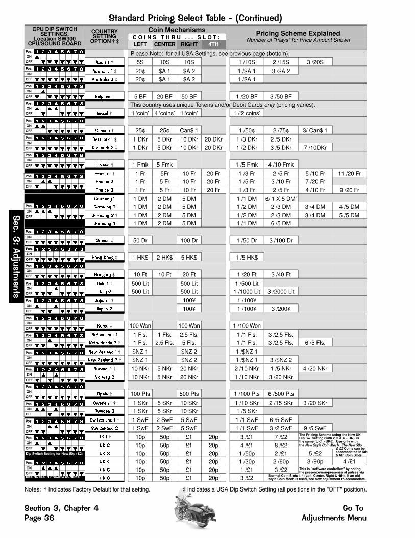
����� ��� $($�/��!�(����9!����5,%��$����6CPU DIP SWITCH
SETTINGS,Location SW300
CPU/SOUND BOARD
COUNTRYSETTING
OPTION † ‡
Coin Mechanisms Pricing Scheme ExplainedNumber of "Plays" for Price Amount ShownC O I N S T H R U . . . S L O T :
LEFT CENTER RIGHT 4TH
������� † 5S 10S 10S 1 /10S 2 /15S 3 /20S
��������� ‡ 20¢ $A 1 $A 2 1 /$A 1 3 /$A 2��������� ‡ 20¢ $A 1 $A 2 1 /$A 1
��� ��� † 5 BF 20 BF 50 BF 1 /20 BF 3 /50 BF
������ † 1 ‘coin’ 4 ‘coins’ 1 ‘coin’ 1 /‘2 coins’
������ † 25¢ 25¢ Can$ 1 1 /50¢ 2 /75¢ 3/ Can$ 1
������� ‡ 1 DKr 5 DKr 10 DKr 20 DKr 1 /3 DKr 2 /5 DKr������� ‡ 1 DKr 5 DKr 10 DKr 20 DKr 1 /2 DKr 3 /5 DKr 7 /10DKr
������� ‡ 1 Fmk 5 Fmk 1 /5 Fmk 4 /10 Fmk
������ † 1 Fr 5Fr 10 Fr 20 Fr 1 /3 Fr 2 /5 Fr 5 /10 Fr 11 /20 Fr������ 1 Fr 5 Fr 10 Fr 20 Fr 1 /5 Fr 3 /10 Fr 7 /20 Fr������ � 1 Fr 5 Fr 10 Fr 20 Fr 1 /3 Fr 2 /5 Fr 4 /10 Fr 9 /20 Fr
������� 1 DM 2 DM 5 DM 1 /1 DM 6/‘1 X 5 DM’������� 1 DM 2 DM 5 DM 1 /2 DM 2 /3 DM 3 /4 DM 4 /5 DM������� � † 1 DM 2 DM 5 DM 1 /2 DM 2 /3 DM 3 /4 DM 5 /5 DM������� � 1 DM 2 DM 5 DM 1 /1 DM 6 /5 DM
������ ‡ 50 Dr 100 Dr 1 /50 Dr 3 /100 Dr
��� ��� ‡ 1 HK$ 2 HK$ 5 HK$ 1 /5 HK$
��� ��� ‡ 10 Ft 10 Ft 20 Ft 1 /20 Ft 3 /40 Ft
����� † 500 Lit 500 Lit 1 /500 Lit����� 500 Lit 500 Lit 1 /1000 Lit 3 /2000 Lit
�� �� † 100¥ 1 /100¥�� �� 100¥ 1 /100¥ 3 /200¥
����� ‡ 100 Won 100 Won 1 /100 Won
!��"������� 1 Fls. 1 Fls. 2.5 Fls. 1 /1 Fls. 3 /2.5 Fls.!��"������� † 1 Fls. 2.5 Fls. 5 Fls. 1 /1 Fls. 3 /2.5 Fls. 6 /5 Fls.
!�# $������ ‡ $NZ 1 $NZ 2 1 /$NZ 1!�# $������ ‡ $NZ 1 $NZ 2 1 /$NZ 1 3 /$NZ 2
!��#�� † 10 NKr 5 NKr 20 NKr 2 /10 NKr 1 /5 NKr 4 /20 NKr!��#�� 10 NKr 5 NKr 20 NKr 1 /10 NKr 3 /20 NKr
% ��� ‡ 100 Pts 500 Pts 1 /100 Pts 6 /500 Pts
%#���� † 1 SKr 5 SKr 10 SKr 1 /10 SKr 2 /15 SKr 3 /20 SKr%#���� 1 SKr 5 SKr 10 SKr 1 /5 SKr
%#��������� † 1 SwF 2 SwF 5 SwF 1 /1 SwF 6 /5 SwF%#��������� 1 SwF 2 SwF 5 SwF 1 /1 SwF 3 /2 SwF 9 /5 SwF
&� † 10p 50p £1 20p 3 /£1 7 /£2&� 10p 50p £1 20p 4 /£1 8 /£2
Dip Switch Setting for New 50p / £2: &� � 10p 50p £1 20p 1 /50p 2 /£1 5 /£2&� � 10p 50p £1 20p 1 /30p 2 /60p 3 /90p 4 /£1&� ' 10p 50p £1 20p 1 /£1 3 /£2
SEE NOTES IN PRICING SCHEME &� ( 10p 50p £1 20p 3 /£2
Pos. � � � � � � � �
ON �OFF � � � � � � �
Pos. � � � � � � � �
ON
OFF � � � � � � � �
Pos. � � � � � � � �
ON �OFF � � � � � � �
Pos. � � � � � � � �
ON � � �OFF � � � � �
Pos. � � � � � � � �
ON � �OFF � � � � � �
Pos. � � � � � � � �
ON
OFF � � � � � � � �
Pos. � � � � � � � �
ON
OFF � � � � � � � �
Pos. � � � � � � � �
ON � �OFF � � � � � �
Pos. � � � � � � � �
ON � � �OFF � � � � �
Pos. � � � � � � � �
ON
OFF � � � � � � � �
Pos. � � � � � � � �
ON
OFF � � � � � � � �
Pos. � � � � � � � �
ON
OFF � � � � � � � �
Pos. � � � � � � � �
ON �OFF � � � � � � �
Pos. � � � � � � � �
ON � �OFF � � � � � �
Pos. � � � � � � � �
ON
OFF � � � � � � � �
Pos. � � � � � � � �
ON �OFF � � � � � � �
Pos. � � � � � � � �
ON
OFF � � � � � � � �
Pos. � � � � � � � �
ON � �OFF � � � � � �
Pos. � � � � � � � �
ON
OFF � � � � � � � �
Pos. � � � � � � � �
ON � � �OFF � � � � �
Pos. � � � � � � � �
ON � �OFF � � � � � �
Pos. � � � � � � � �
ON � �OFF � � � � � �
Pos. � � � � � � � �
ON � � �OFF � � � � �
The Pricing Scheme using the New UKDip Sw. Setting (with 2, 3 & 4 = ON), isthe same (UK1 - UK6). Use only withthe New Style Coin Mech. The New 50p
& £2 Coins can beaccomodated in 5th& 6th Coin Slots.
This is "software controlled" by notingthe presence/non-presense of pulses via
Normal Coin Slots 1-4 (Left, Center, Right & 4th). If an oldstyle Coin Mech is used, see new adjustment to accomodate.
Please Note: for all USA Settings, see previous page (bottom).
This country uses unique Tokens and/or Debit Cards only (pricing varies).
Notes: † Indicates Factory Default for that setting. ‡ Indicates a USA Dip Switch Setting (all positions in the "OFF" position).
�(��)
*�����
�������
�(�$%��)+�,-�.�� �� �%��%���/��): ����������������
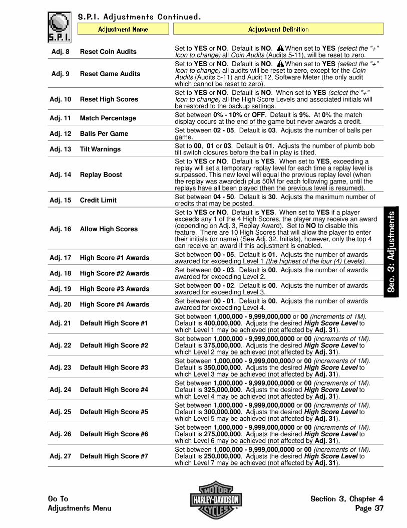
������������������,%��$�����
��������� ��� ��������� �� �����
Adj. 8 Reset Coin Audits Set to YES or NO. Default is NO. When set to YES (select the "+"Icon to change) all Coin Audits (Audits 5-11), will be reset to zero.
Adj. 9 Reset Game Audits
Set to YES or NO. Default is NO. When set to YES (select the "+"Icon to change) all audits will be reset to zero, except for the CoinAudits (Audits 5-11) and Audit 12, Software Meter (the only auditwhich cannot be reset to zero).
Adj. 10 Reset High ScoresSet to YES or NO. Default is NO. When set to YES (select the "+"Icon to change) all the High Score Levels and associated initials willbe restored to the backup settings.
Adj. 11 Match Percentage Set between 0% - 10% or OFF. Default is 9%. At 0% the matchdisplay occurs at the end of the game but never awards a credit.
Adj. 12 Balls Per Game Set between 02 - 05. Default is 03. Adjusts the number of balls pergame.
Adj. 13 Tilt Warnings Set to 00, 01 or 03. Default is 01. Adjusts the number of plumb bobtilt switch closures before the ball in play is tilted.
Adj. 14 Replay Boost
Set to YES or NO. Default is YES. When set to YES, exceeding areplay will set a temporary replay level for each time a replay level issurpassed. This new level will equal the previous replay level (whenthe replay was awarded) plus 50M for each following game, until thereplays have all been played (then the previous level is resumed).
Adj. 15 Credit Limit Set between 04 - 50. Default is 30. Adjusts the maximum number ofcredits that may be posted.
Adj. 16 Allow High Scores
Set to YES or NO. Default is YES. When set to YES if a playerexceeds any 1 of the 4 High Scores, the player may receive an award(depending on Adj. 3, Replay Award). Set to NO to disable thisfeature. There are 10 High Scores that will allow the player to entertheir initials (or name) (See Adj. 32, Initials), however, only the top 4can receive an award if this adjustment is enabled.
Adj. 17 High Score #1 Awards Set between 00 - 05. Default is 01. Adjusts the number of awardsawarded for exceeding Level 1 (the highest of the four (4) Levels).
Adj. 18 High Score #2 Awards Set between 00 - 03. Default is 00. Adjusts the number of awardsawarded for exceeding Level 2.
Adj. 19 High Score #3 Awards Set between 00 - 02. Default is 00. Adjusts the number of awardsawarded for exceeding Level 3.
Adj. 20 High Score #4 Awards Set between 00 - 01. Default is 00. Adjusts the number of awardsawarded for exceeding Level 4.
Adj. 21 Default High Score #1Set between 1,000,000 - 9,999,000,000 or 00 (increments of 1M). Default is 400,000,000. Adjusts the desired High Score Level towhich Level 1 may be achieved (not affected by Adj. 31).
Adj. 22 Default High Score #2Set between 1,000,000 - 9,999,000,0000 or 00 (increments of 1M). Default is 375,000,000. Adjusts the desired High Score Level towhich Level 2 may be achieved (not affected by Adj. 31).
Adj. 23 Default High Score #3Set between 1,000,000 - 9,999,000,0000 or 00 (increments of 1M). Default is 350,000,000. Adjusts the desired High Score Level towhich Level 3 may be achieved (not affected by Adj. 31).
Adj. 24 Default High Score #4Set between 1,000,000 - 9,999,000,0000 or 00 (increments of 1M). Default is 325,000,000. Adjusts the desired High Score Level towhich Level 4 may be achieved (not affected by Adj. 31).
Adj. 25 Default High Score #5Set between 1,000,000 - 9,999,000,0000 or 00 (increments of 1M). Default is 300,000,000. Adjusts the desired High Score Level towhich Level 5 may be achieved (not affected by Adj. 31).
Adj. 26 Default High Score #6Set between 1,000,000 - 9,999,000,0000 or 00 (increments of 1M). Default is 275,000,000. Adjusts the desired High Score Level towhich Level 6 may be achieved (not affected by Adj. 31).
Adj. 27 Default High Score #7Set between 1,000,000 - 9,999,000,0000 or 00 (increments of 1M). Default is 250,000,000. Adjusts the desired High Score Level towhich Level 7 may be achieved (not affected by Adj. 31).
�(
��)*�����
���
����
�%��%� �(�$%��)+�,-�.�� ������������������ ��/��)2

������������������,%��$�����
��������� ��� ��������� �� �����
Adj. 28 Default High Score #8Set between 1,000,000 - 9,999,000,0000 or 00 (increments of 1M). Default is 225,000,000. Adjusts the desired High Score Level towhich Level 8 may be achieved (not affected by Adj. 31).
Adj. 29 Default High Score #9Set between 1,000,000 - 9,999,000,0000 or 00 (increments of 1M). Default is 200,000,000. Adjusts the desired High Score Level towhich Level 9 may be achieved (not affected by Adj. 31).
Adj. 30 Default High Score #10Set between 1,000,000 - 9,999,000,0000 or 00 (increments of 1M). Default is 175,000,000. Adjusts the desired High Score Level towhich Level 10 may be achieved (not affected by Adj. 31).
Adj. 31 HSTD Reset Count
Set between 100 - 9,900 or OFF (increments of 100). Default is2,000. HSTD (High Score To Date). Adjusts the number of gamesbetween automatic resets of high score levels to backup settings andball time averager adjustments. Set to OFF for "no reset oradjustment".
Adj. 32 High Score InitialsSet to 3 INITIALS or 10 LETTER. Default is 3 INITIALS. When set to3 INITIALS, player is allowed only 3 initials to input. When set to 10LETTER NAME, player is allowed to enter 10 initials to input.
Adj. 33 Free Play Set to YES or NO. Default is NO. When set to YES, no coins arerequired for Game Play.
Adj. 34 Custom Message
Set to ON, CHANGE or OFF. Default is ON. When set to CHANGE(select the "+" Icon to change settings until "CHANGE" appears in thedisplay, then select the ">>" Icon to access.) This adjustment can beaccessed in two (2) ways by either selecting the "SEGA" Icon andadvancing to this Adjustment 34, or can be directly accessed byselecting the "ABCD CUST MSG" Icon in the ADJUSTMENTS MENU.
View the definition at the end of this chapter under the Custom Message entry for the operation explanation.
Adj. 35 Attract Mode Music Set to ON or OFF. Default is ON. When set to ON, attraction music /sounds are played between games.
Adj. 36 Flash Lamp PowerSet to NORMAL, DIM or OFF. Default is NORMAL. When set to DIMthe Flash Lamps impulse power is reduced by 25% and when set toOFF the Flash Lamps will not flash.
Adj. 37 Coil Pulse Power
Set to NORMAL, HARD or SOFT. Default is NORMAL. When HARDthe coil pulse power is increased by 12.5% of the normal pulse rate.When set to SOFT the coil pulse power is decreased by 12.5% of thenormal pulse rate. These adjustments are provided to compensate forLow Line or High Line voltage conditions where the solenoids appearto kicking too weak or too hard. Adjust as required.
Adj. 38 Knocker VolumeSet to NORMAL, LOW or OFF. Default is NORMAL. When set toLOW, the volume is decreased 50%. When set to OFF, no sound isheard when the "knocker" is sounded.
Adj. 39 Minimum Game Time
Set between 0:01 - 14:59 or OFF for minimum game time. Default isOFF. If the last ball in play drains prior to what the game time is setfor, another ball will be served into the Shooter Lane and Normal Playwill continue. Subsequent balls will continue to do be served into theshooter lane if the last ball still drains prior to and up until minimumgame time is satisfied.
Adj. 40 Bkgrnd (Background)Music Volume
Set between 01 - 15. Default is 01. After volume is set via PortalsService Buttons (See Sec. 3, Chp. 1, ...Intro) this adjustment can beutilized to adjust the background music (1 all the way on, 15 all theway off) while keeping the Special Sound FX the same level.
Adj. 41 Game Restart
Set to YES or NO. Default is YES. When set to YES, a new gamemay be started during any ball after the first ball is completed (ifcredits are available). Pressing the Start Button during the first ballwill add additional players. When set to NO, the game disables theStart Button after the first ball until the final ball is in play. ReviewSection 2, Chapter 1, Game Operations & Features for details.
Adj. 42 Extra Ball Percentage Set between 0% - 50%. This adjustment allows the operator to adjusthow frequently the Extra Ball Feature is made available to the player.
�(��)
*�����
�������
�(�$%��)+�,-�.�� �� �%��%���/��)� ����������������
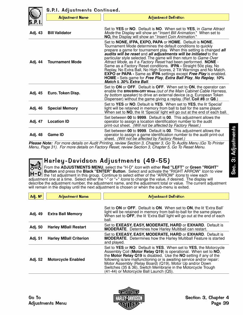
������������������,%��$�����
��������� ��� ��������� �� �����
Adj. 43 Bill ValidatorSet to YES or NO. Default is NO. When set to YES, in Game AttractMode the Display will show an "Insert Bill Animation." When set toNO, the Display will show an "Insert Coin Animation."
Adj. 44 Tournament Mode
Set to NONE, IFPA, EXPO, PAPA or HOME. Default is NONE.Tournament Mode determines the default conditions to quicklyprepare a game for tournament play. When this setting is changed allaudits will be reset and all adjustments will be initiated to theparticular style selected. The game will then return to Game OverAttract Mode, as if a Factory Reset had been performed. NONE -Same as a Factory Reset conditions. IFPA - Straight 50¢ play, NoReplay, No Extra Ball, No High Scores, 2 Tilt Warnings and No Match.EXPO or PAPA - Same as IFPA settings except Free Play is enabled.HOME - Sets game for Free Play, Extra Ball Play, No Replay, 10%Match & 30% Extra Ball.
Adj. 45 Euro. Token Disp.
Set to ON or OFF. Default is OFF. When set to ON, the operator canenable the BRN/BRN-GRY Wires (out of the Main Cabinet Cable Harness,by bottom speaker) to drive an external device (e.g. European TokenDispenser) without the game giving a replay. (Ref. Coil #8 or Q8.)
Adj. 46 Special MemorySet to YES or NO. Default is YES. When set to YES, the lit ‘Special’light will be retained in memory from ball to ball for the same player.When set to NO, the lit ‘Special’ light will go out at the end of each ball.
Adj. 47 Location IDSet between 00 to 9999. Default is 00. This adjustment allows theoperator to assign a location identification number to the auditprint-out sheet. (Will not be affected by Factory Reset.)
Adj. 48 Game IDSet between 00 to 9999. Default is 00. This adjustment allows theoperator to assign a game identification number to the audit print-outsheet. (Will not be affected by Factory Reset.)
Please Note: For more details on Audit Printing, review Section 3, Chapter 3, Go To Audits Menu (Go To PrinterMenu, Page 31). For more details on Factory Reset, review Section 3, Chapter 5, Go To Reset Menu.
�� !�"���#$��%��������������5�&�''6From the ADJUSTMENTS MENU, select the "H-D" Icon with either Red "LEFT" or Green "RIGHT"Button and press the Black "ENTER" Button. Select and activate the "RIGHT ARROW" Icon to viewthe 1st adjustment in this group. Continue to select either of the "ARROW" Icons to view each
adjustment one at a time. Select either the "-" or "+" Icons to change the value, if desired. The display willdescribe the adjustment number, the adjustment name, and the adjustment total or value. The current adjustmentwill remain in the display until the next adjustment is chosen or when the sub-menu is exited.
���� º ��������� ��� ��������� �� �����
Adj. 49 Extra Ball Memory
Set to ON or OFF. Default is ON. When set to ON, the lit ‘Extra Ball’light will be retained in memory from ball-to-ball for the same player.When set to OFF, the lit ‘Extra Ball’ light will go out at the end of eachball.
Adj. 50 Harley MBall Restart Set to EXEASY, EASY, MODERATE, HARD or EXHARD. Default isMODERATE. Determines how Harley Multiball can restart.
Adj. 51 Harley MBall CriterionSet to EXEASY, EASY, MODERATE, HARD or EXHARD. Default isMODERATE. Determines how the Harley Multiball Feature is startedand played.
Adj. 52 Motorcycle Enabled
Set to YES or NO. Default is YES. When set to YES, the MotorcycleAssembly Coil (Motor Relay Q19) is operational. When set to NO,the Motor Relay Q19 is disabled. Use the NO setting if any of thefollowing is/are malfunctioning or is awaiting service and/or repair:Motor Assembly (Relay Board) (Q19), Motor Up and/or DownSwitches (35 & 36), Switch Membrane in the Motorcycle Trough(41-44) or Motorcycle Ball Launch (Q5).
�(
��)*�����
���
����
�%��%� �(�$%��)+�,-�.�� ������������������ ��/��)&
�� !�"���#$��%��������������,%��$�����
��������� ��� ��������� �� �����
Adj. 53 UK Post Save Enabled
/////// THIS ADJUSTMENT CAN ONLY BE ADJUSTED IF THEGAME HAS THE UK EPROM INSTALLED FOR UK SETTINGS ///////
Set to YES or NO. Default is NO, (UK Default is YES). When set toYES this feature is available when lit. Set to NO to disable thisfeature. (UK Games have Outlane & Center Post Save Devices whichare accessed in a different way; Non-UK Games cannot adjust thissetting.)
Adj. 54 UK Coin Mech. Type
/////// THIS ADJUSTMENT CAN ONLY BE ADJUSTED IF THEGAME HAS THE UK EPROM INSTALLED FOR UK SETTINGS and HAS THE DIP SWITCH SETTING OPTION 2 SET (2, 3 & 4 ON) ///////
Set to CURRENT: 2 POUND AT #5 if using a Coin Control Mech74-1129-104U (latest version). Set to OLD: 2 POUND AT #6 if usingolder version Coin Control Mech 74-1129-104. Default is CURRENT:2 POUND AT #5.
Adj. 55 Speedometer CriterionSet to EXEASY, EASY, MODERATE, HARD or EXHARD. Default isMODERATE. Determines how the Speedometer Multiball Feature isstarted and played.
,���%�������/�To go directly to Adjustment 34, Custom Message, from the ADJUSTMENT MENU, select the "CUSTMSG" Icon either Red "LEFT" or Green "RIGHT" Button and press the Black "ENTER" Button. At thetop left corner of the Display, the letter A is indicated (blinking) in the first available position (Thirty-Six
(36) characters including spaces are available). Vary the letter(s) by operating the Left and Right Flipper Buttons(or "RED" or "GREEN" Buttons). With the desired letter indicated, depress the Start Button to lock in the letterand advance to the next character. Repeat this procedure until the desired message is completed in the display.Select the "<" or ">" characters to back-space (erase) and/or to move forward in an already typed message. Aftercompletion, press the "BLACK" Button, "REQUEST INSTALLED" is indicated and then exits this sub-menu.
;$ !���� �7����To reset the game with Special Home Settings (not the normal Factory Setting), from the ADJUSTMENTMENU, select the "STAR" Icon either Red "LEFT" or Green "RIGHT" Button and press the Black"ENTER" Button. This Special Setting automatically changes Adjustment 6, Game Difficulty, to EASY
and Adjustment 33, Free Play, to YES. This setting is determined to be ideal for the home environment.
��<���%��*To Restore or Reset any of the adjustments to the Factory Settings (Default), review Sec. 3,Chp. 5, Go To Reset Menu. Follow the "RESET" Icon or "FACT" Icon and their explanations.
�(��)
*�����
�������
�(�$%��)+�,-�.�� �� �%��%���/���= ����������������
���� ��� � �� ��� � � � �0 � 1
�� ��� ������ �����2���� ��3The Portals Service Menu System provides three (3) functions to reset adjustments and/or audits back to theFactory Setting. See Chapter 3, Go to Audits Menu, and Chapter 4, Go to Adjustments Menu, for the Game Audits& Adjustments Information. If a reset of Coin or Game Audits is performed, the display will indicate REQUESTINSTALLED and return to the RESET MENU. If a Factory Reset is performed, the display will indicateREQUEST INSTALLED, the Service Session is exited & returns to the Attract Mode. Please note that oncereset, all customized settings are lost! Certain Audits & Adjustments cannot be reset (refer to the details below).
�2��2������ ���4�With the game in the Attract Mode, open the Coin Door and press the Black "BEGIN TEST" Button.Select the "RESET" Icon in the MAIN MENU with either Red "LEFT" or Green "RIGHT" Button andpress the Black "ENTER" Button. The RESET MENU appears.
�5 ������ �4�����Exit any sub-menu and return to the MAIN MENU by selecting & activating the "PREV" Icon.
Selecting & activating the "QUIT" Icon from the display will exit the Service Session.
Selecting & activating the "HELP" Icon from the display will show a help screen. (An explanation of each Mini-Icon at that level will cycle continuously until any activebutton is pressed.)
����� �����������From the RESET MENU, select the "COIN" Icon with either Red or Green Button and press the BlackButton. All Coin Audits (See Fig. 1) will be reset to Factory Settings. The display will indicateREQUEST INSTALLED and return to the RESET MENU. Coin Audits can also be reset from the
ADJUSTMENTS MENU, S.P.I. ADJUSTMENT 8. See Chapter 4, Go to Adjustments Menu, of this section. Afterselecting this Icon, all of the Coin Audits (5-11) are reset to zero.
����� ���5� �������From the RESET MENU, select the "AUD" Icon with either Red or Green Button and press the BlackButton. All Game Audits (See Fig. 2) will be reset to Factory Settings. The display will indicateREQUEST INSTALLED and return to the RESET MENU. Game Audits can also be reset from the
ADJUSTMENTS MENU, S.P.I. ADJUSTMENT 9. See Chapter 4, Go to Adjustments Menu, of this section. Afterselecting this Icon, all of the Audits are reset to zero, except for the Coin Audits (Audits 5-11) and Audit 12,Software Meter. Audit 12 is the only audit which cannot be reset.
������� ������From the RESET MENU, select the "FACT" Icon with either Red or Green Button and press the BlackButton. All adjustments will be reset to Factory Settings (except for Proprietary Adjustments). Thedisplay will indicate REQUEST INSTALLED and exit the Service Session. See Chapter 4, Go to
Adjustments Menu, of this section, for the FACTORY SETTINGS in the Game Adjustment Table.
������
Reset Coin AuditsEarnings Audits (Coin Audits Only 5-11)
Au. Nº Description1-4 The first 4 Audits in the game.5 Coins Thru Left Slot6 Coins Thru Right Slot7 Coins Thru Center Slot8 Coins Thru 4th Slot9 Total Coins
10 Total Earnings11 Meter Clicks12 Software Meter
13 + The remainder of the Audits.
������
Reset Game AuditsEarnings (1-4), Generic/Specific Audits (13+)Au. Nº Description
1-4 The first 4 Audits in the game.5 Coins Thru Left Slot6 Coins Thru Right Slot7 Coins Thru Center Slot8 Coins Thru 4th Slot9 Total Coins10 Total Earnings11 Meter Clicks12 Software Meter
13 + The remainder of the Audits.
�����������������
���
����� ��������.��� ��������������� �����?�
�@�5 ���From the MAIN MENU, use the Red or Green Buttons to select the "RESET" Icon (GO TO RESET MENU).
Press the Black Button to activate this ICON. This will bring up the RESET MENU.
The RESET MENU now appears with the "COIN" Icon (RESET COIN AUDITS) flashing:
DO NOT PRESS THE START BUTTON AFTER SELECTING ANY THREE OFTHESE ICONS UNLESS THIS IS WHAT IS DESIRED (SETTINGS WILL BE LOST)!
PLEASE READ THE PREVIOUS PAGE FOR EXACTLY WHAT WILL HAPPENIF ANY OF THESE THREE ICONS ARE ACTIVATED.
From the RESET MENU, select any of the Icons ("COIN", "AUD" or "FACT") with either Red or Green Button andpress the Black Button to activate the ICON chosen.
If the "COIN" or "AUD" Icons are chosen and activated, the affected audits (see previous page) will be reset, thedisplay will indicate REQUEST INSTALLED and the display will return to the RESET MENU.
If the "FACT" Icon is chosen and activated, all adjustments will be reset back to the Factory Settings. The displaywill indicate REQUEST INSTALLED (momentarily), the Service Session is automatically exited and returns to theAttract Mode.
�����
������������
���
��������.��� ����� ����������?� ����������

���� ��� �� ���� � �� �
��������� �����������The Portals Service Menu System provides a current Fuse Table for this game. The fuses are located in theBackbox (on the Display Power Supply Board and the I/O Power Driver Board), and also in the Cabinet (under theplayfield by the Flippers and/or by any unique assembly, such as magnets). For the complete Fuse List in theQuick Reference Fuse Chart & Pictorials, see the next page (identical to page ��� � in the front of this manual).
�����!� ��71 With the game in the Attract Mode, open the Coin Door and press the Black "BEGIN TEST" Button.Select the "FUSES" Icon in the MAIN MENU with either Red "LEFT" or Green "RIGHT" Button andpress the Black "ENTER" Button. Select and activate the "+" Icon to view the 1st fuse in this group.
Continue to select either the "+" or "-" Icons to view each fuse one at a time. The display will describe the fuseidentification number (e.g. F1, F6, F7, etc.), location of fuse (i.e. Backbox: Board name located on; or Cabinet:Under the playfield or in Service Outlet), rating of fuse (e.g. 5A 250v S.B. - i.e. 5 Amp, 250 volt, Slo-Blo), and ‘useof fuse’ (e.g. 90v DC High Voltage Power, etc.). The current fuse listed will remain in the display until the next fuseis chosen or when the sub-menu is exited.
�"���� �������#Exit any sub-menu and return to the MAIN Selecting & activating the "QUIT" Icon fromMENU by selecting & activating the "PREV" any display will exit the Service Session.Icons. If no Icons appear in the displaybecause of a testing function or specialdisplay (e.g. "Help"), press any button to exit.
Selecting & activating the "HELP" Icon from Selecting & activating the "+ " or "-" Icons any display will show a help screen. (An selects the next or previous fuse in this group.explanation of each Mini-Icon at that level willcycle continuously until any active buttonis pressed.)
� "���#From the MAIN MENU, use the Red or Green Buttons to select the "FUSES" Icon (GO TO FUSE TABLE).
Press the Black Button to activate this ICON. This will bring up the MONOPOLY FUSE TABLE.
���$#$$$����� ���
���� �������%�� ���������� ��� & �.

�7��=7�,1�C�!�1��������#�����%7����%+�� ��-+����
F1
���� �&����������7� �
The Display Controller Board(holds the Display ROM Loc: ROM0)is positioned behind the 128 X 32
Dot Matrix Display Board(Neither board contain Fuses.)
��� ����������� ��
��� �������� ��
G.I.B3
B2
B1
B20
B21
F24 F26
F25F27
F22 F23
F8 F7
F6 F21
F28 F20
BRIDGES
Relay
F9
BRIDGES
Relay
*** All BRIDGES rated35A @ 100v ***
B1 +50v DC HighCurrent Coils
B2 +20v DC LowCurrent Coils
B3 +/-12v DCSound / Display / Logic
B20 +18v DCIllumination
B21 +5v DC LogicVoltage
�;�&���� �����7� �
��� ������ ���� �� �� ���� ������ ������ ������ �� ������� ������� ��� ��������� ������� !�� �� � ��"��#$
��� ����%����� � �&�� ��%�� � � ����� � ����� ������� ������������ '� ������� �� ��� ��� ����(�� ������ !�� )����� ��"��#$
Playfield PowerInterlock Switch
Memory ProtectSwitch
Inside Coin Door
���$
#$$$����� ���
��� ������
������ ���
QUICK REFERENCE FUSE CHARTB a c k b o x F u s e s
LOC: DISPLAY POWER SUPPLY (P.S.) BOARDF1 3 4A 250v S.B. 90v DC High Voltage Display
LOC: I / O POWER DRIVER BOARDF6 7A 250v S.B. 50v DC Primary High Power Coils/FlippersF7 5A 250v S.B. 20v DC Low Power CoilsF8 5A 250v S.B. 12v DC Logic PowerF9 5A 250v S.B. 12v DC Logic PowerF20 4A 250v S.B. 50v DC Magnet(s)F21 3A 250v S.B. 50v DC CoilsF22 8A 250v S.B. 18v DC Controlled LampsF23 4A 250v S.B. 5v DC LogicF24 5A 250v S.B. 6.3v AC G.I. Lamps (BRN-WHT to WHT-BRN)F25 5A 250v S.B. 6.3v AC G.I. Lamps (YEL to WHT-YEL)F26 5A 250v S.B. 6.3v AC G.I. Lamps (GRN to WHT-GRN)F27 5A 250v S.B. 6.3v AC G.I. Lamps (VIO to WHT-VIO)F28 3A 250v S.B. 24v AC Not Used / Spare
C a b i n e t F u s e sLOC: SERVICE (AC) OUTLET BOX (Cabinet Bottom)n/a 8A 250v S.B. 115v AC Main Fuse Line (Domestic or USA)n/a 5A 250v S.B. 220v AC Main Fuse Line (International)LOC: SHAKER MOTOR BD. (Cabinet, Rt. Side Front)F2 2�A 250v S.B. 12v DC Shaker MotorF3 2�A 250v S.B. 12v DC Shaker Motor
P l a y f i e l d ( P / F ) F u s e sLOC: UNDER PLAYFIELD (near Flippers)n/a 3A 250v S.B. 50v DC Rt. Flipper (BLU-YEL�RED-YEL)n/a 3A 250v S.B. 50v DC Lt. Flipper (GRY-YEL�RED-YEL)n/a 3A 250v S.B. 50v DC Magnet (Top Orbit) (VIO-YEL�BLK)For locations & more information on fuses, see Sec. 5, Chapter 2.
��� � ���������� �� ���������� ���� �� ��� � ���� ����� ��
�������
ROM0
Service Outlet(on Power Box)
Transformer onCabinet Bottom
On/Off Switch(Under Pwr. Box)
USA: 8 Amp 250vSlo-Blo Fuse
Int’l.: 5 Amp 250vSlo-Blo Fuse
Playfield PowerInterlock Switch
Memory ProtectSwitch
Volume Control & Service SwitchesFor operational usage, see
Section 3, Chapter 1, Portals ServiceMenu Introduction
INSIDE VIEW OFTHE PINBALL CABINET
INSIDE VIEW OFTHE PINBALL CABINET
Inside Coin Door
CPUGAME
EPROM CMOSRAM
3x AA
U7 U37 U36 U21 U17
�&!;����7$���;��� 1
U212SOUND &
VOICE ROMS
�������SW300
U210
�������%�� ����� ����& �.. ����� ���
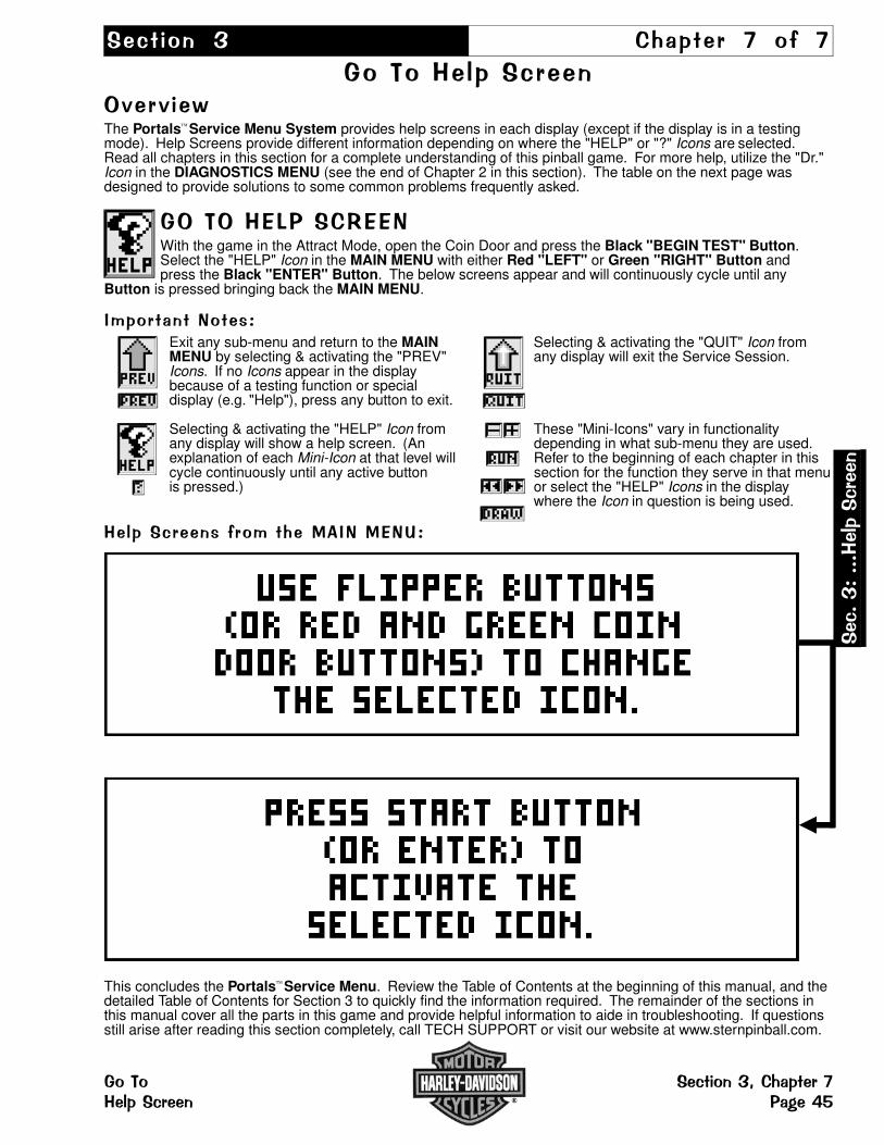
���� ��� �� ���� � �� �
������ ������������� ���The Portals Service Menu System provides help screens in each display (except if the display is in a testingmode). Help Screens provide different information depending on where the "HELP" or "?" Icons are selected.Read all chapters in this section for a complete understanding of this pinball game. For more help, utilize the "Dr."Icon in the DIAGNOSTICS MENU (see the end of Chapter 2 in this section). The table on the next page wasdesigned to provide solutions to some common problems frequently asked.
����� 1� ��+ �With the game in the Attract Mode, open the Coin Door and press the Black "BEGIN TEST" Button.Select the "HELP" Icon in the MAIN MENU with either Red "LEFT" or Green "RIGHT" Button andpress the Black "ENTER" Button. The below screens appear and will continuously cycle until any
Button is pressed bringing back the MAIN MENU.
�"���� �������#Exit any sub-menu and return to the MAIN Selecting & activating the "QUIT" Icon fromMENU by selecting & activating the "PREV" any display will exit the Service Session.Icons. If no Icons appear in the displaybecause of a testing function or specialdisplay (e.g. "Help"), press any button to exit.
Selecting & activating the "HELP" Icon from These "Mini-Icons" vary in functionality any display will show a help screen. (An depending in what sub-menu they are used. explanation of each Mini-Icon at that level will Refer to the beginning of each chapter in this cycle continuously until any active button section for the function they serve in that menu is pressed.) or select the "HELP" Icons in the display
where the Icon in question is being used.
�� ������������"�������� ��#
This concludes the Portals Service Menu. Review the Table of Contents at the beginning of this manual, and thedetailed Table of Contents for Section 3 to quickly find the information required. The remainder of the sections inthis manual cover all the parts in this game and provide helpful information to aide in troubleshooting. If questionsstill arise after reading this section completely, call TECH SUPPORT or visit our website at www.sternpinball.com.
���$#$$$����������
���� �������%�� ��������������� � �.2
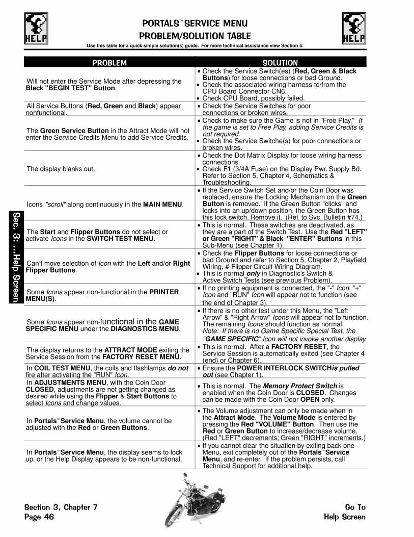
��+��1� � +D�� � ��
�+�71 ���1�������71 Use this table for a quick simple solution(s) guide. For more technical assistance view Section 5.
�+�71 � ��1�����
Will not enter the Service Mode after depressing theBlack "BEGIN TEST" Button.
Check the Service Switch(es) (Red, Green & BlackButtons) for loose connections or bad Ground.Check the associated wiring harness to/from theCPU Board Connector CN6.Check CPU Board, possibly failed.
All Service Buttons (Red, Green and Black) appearnonfunctional.
Check the Service Switches for poorconnections or broken wires.
The Green Service Button in the Attract Mode will notenter the Service Credits Menu to add Service Credits.
Check to make sure the Game is not in "Free Play." Ifthe game is set to Free Play, adding Service Credits isnot required.Check the Service Switche(s) for poor connections orbroken wires.
The display blanks out.
Check the Dot Matrix Display for loose wiring harnessconnections.Check F1 (3/4A Fuse) on the Display Pwr. Supply Bd.Refer to Section 5, Chapter 4, Schematics &Troubleshooting.
Icons "scroll" along continuously in the MAIN MENU.
If the Service Switch Set and/or the Coin Door wasreplaced, ensure the Locking Mechanism on the GreenButton is removed. If the Green Button "clicks" andlocks into an up/down position, the Green Button hasthis lock switch. Remove it. (Ref. to Svc. Bulletin #74.)
The Start and Flipper Buttons do not select oractivate Icons in the SWITCH TEST MENU.
This is normal. These switches are deactivated, asthey are a part of the Switch Test. Use the Red "LEFT"or Green "RIGHT" & Black "ENTER" Buttons in thisSub-Menu (see Chapter 1).
Can’t move selection of Icon with the Left and/or RightFlipper Buttons.
Check the Flipper Buttons for loose connections orbad Ground and refer to Section 5, Chapter 2, PlayfieldWiring, #-Flipper Circuit Wiring Diagram.This is normal only in Diagnostic’s Switch & Active Switch Tests (see previous Problem).
Some Icons appear non-functional in the PRINTERMENU(S).
If no printing equipment is connected, the "-" Icon, "+"Icon and "RUN" Icon will appear not to function (seethe end of Chapter 3).
Some Icons appear non-functional in the GAMESPECIFIC MENU under the DIAGNOSTICS MENU.
If there is no other test under this Menu, the "LeftArrow" & "Right Arrow" Icons will appear not to function.The remaining Icons should function as normal.Note: If there is no Game Specific Special Test, the"GAME SPECIFIC" Icon will not invoke another display.
The display returns to the ATTRACT MODE exiting theService Session from the FACTORY RESET MENU.
This is normal. After a FACTORY RESET, theService Session is automatically exited (see Chapter 4(end) or Chapter 6).
In COIL TEST MENU, the coils and flashlamps do notfire after activating the "RUN" Icon.
Ensure the POWER INTERLOCK SWITCHis pulledout (see Chapter 1).
In ADJUSTMENTS MENU, with the Coin DoorCLOSED, adjustments are not getting changed asdesired while using the Flipper & Start Buttons toselect Icons and change values.
This is normal. The Memory Protect Switch isenabled when the Coin Door is CLOSED. Changescan be made with the Coin Door OPEN only.
In Portals Service Menu, the volume cannot beadjusted with the Red or Green Buttons.
The Volume adjustment can only be made when inthe Attract Mode. The Volume Mode is entered bypressing the Red "VOLUME" Button. Then use theRed or Green Button to increase/decrease volume.(Red "LEFT" decrements; Green "RIGHT" increments.)
In Portals Service Menu, the display seems to lockup, or the Help Display appears to be non-functional.
If you cannot clear the situation by exiting back oneMenu, exit completely out of the Portals ServiceMenu, and re-enter. If the problem persists, callTechnical Support for additional help.
���$
#$$$�����
�����
�������%�� ����� ����� �.6 ����������

�(� ��� � � ����� � � �1 � �
���� � ����� � 1 �(� ��� �� ���(� ������ ����� ������
3���� ��4This section provides the Part Nºs and locations of all the components in this pinball machine. The parts arearranged in three groups: BACKBOX, CABINET & PLAYFIELD. Generic parts which may change as productioncontinues (quantity and/or size) are listed together. Quantities greater than 0 indicates that the part is used in thisgame. Since quantity changes may occur, an item indicating "0" may be used. Compare the item which needs tobe replaced with the drawings provided (the Posts, Sockets, Bulbs & Rubber Rings are drawn actual size). MajorAssemblies & Ramps are detailed in the Blue Pages, Chapter 2. Important: Read all "Take Note:" items.
�(���������9����1���������
3������4�����������������������������������������
���>��(�9�?����"��������������������������������������� ����������������"��1����������(�9�? ��� ������ ������ �&
�������������4��(������������������������������������ '=�'
�������������4��(�����������4��������������������������'� �������������4��(��������9���� ����������������������� '!"�99��������"������(��������@��� ���������������������������'������(���(���������������#"�������(�� ������������������''"�����@����$��������������� ����� ��������������������':#�����������(��4���������%��� �����������������������'�#�����(����������������������������������������� '������(�����������(����������������������������������������� '&�����"������"������9���������(���� ����������������� :=������"������"������9��������(���� ������������������ : @������������9���������(������������������������:�
3������4�������������������������������������� :!
��4�����1���#���������9������"��� �������������������� :���=
�9����
�(�9�?
��"1����
������������������"��
����%��*
���A$����*
���B�3C*
����������������������
������ ���������������
�(
����
*�����
��������
�����������1�(���� �(�������������� ����(���� ������

����"��������>��(�9�?������9�"��'='�:==��������������� ����%����������������9�"����������������������������(����"���D������
����%���** An asterisk ( * ) indicates item(s) are not noted in the pictorials.
† When ordering Item 3, CPU/Sound Bd., please specify theGame Name to receive the board with the correct ROMs.
‡ Item 20, Button Hole Plug (Black) is an optional access hole.
$�����E��4The Backglass is Not Shown in
this Front View for clarity.
��
�
�
����
�
Right SidePivot Hinge
���E��4�
AssociatedParts (AP-)listed in the
Parts Table onthe next page.
���
���
���
�� �
�����
�����
���
�����
�
�
�
Qty. 2
��
�
�����
��
����
��
�
��
��
��
��
�º ���� ���� ���� ���� ��� ���� �º1 Backbox HD3 Screened No Parts 1 525-5631-17-87
Item 1 Note: Chrome T-Molding is installed and cannot be ordered separately.Ist edition Black Molding (old style backbox) use : 525-5558-67
2 PCB Metal Mounting Plate 1 535-5809-14Item 2 is secured to Item 1 by: #8 X 1/2" HWH AB (Zinc) (Qty. 13) (234-5101-00) and#10 Washer 7/32" I.D. X .5" O.D. X 1/16" Thick (Qty. 4) (242-5003-00)
3 † CPU/Sound Board (Mono) 1 520-5300-004 Display Power Supply Board 1 520-5138-005 I/O Power Driver Board 1 520-5137-01
Items 3, 4 & 5 are secured to Item 2 by: #8-32 X 3/8" HWH MS (Qty. 19) (237-5903-00)
6 3X Trans. Drvr. Bd. (UK/Special Apps. Only) 520-5068-017 Fluorescent Light Bracket Assy. Left 1 515-6545-00
For Individual Items use : Fluorescent Light Bracket Left (535-7739-00), Lamp Holder**(Self-Locking) (077-5214-00) and Starter Base (with Leads)*** (077-5213-00).
8 Fluorescent Light Bracket Assy. Right 1 515-6545-01For Individual Items use : Fluorescent Light Bracket Right (535-7739-01), Lamp Holder**(Self-Locking) (077-5214-00) and Starter Base (with Leads)*** (077-5213-00). ** secured by: #6-32 X 5/8" PPH MS (Sems) Zinc (Qty. 1) (232-5203-00)*** secured by: #4-40 X 1/2" PPH MS (Sems) Zinc (Qty. 2) (237-5813-00)
Items 7 & 8 are secured to Item 1 by: #10-24 X 1-1/4" Carriage Bolt Sq. Neck (Qty. 2/per)(231-5012-00), #10-24 Keps Nut (Qty. 2/per) (240-5207-00) and 3/4" X 3" ReinforcedStrapping Tape (Qty. 1, Sold in 12" Lengths only) (626-5040-00)
9 Fluorescent Tube 24" (F18T8CW) 1 165-5061-0010 Starter - Fluorescent (FS2 Light) 1 165-5011-0111 Lock Mounting Plate 1 535-8128-0112 Lock 5/8" Barrel, 3/4"ø, 1.5" Flat Cam 1 355-5055-00
Items 11-12 are secured by: #8 X 5/8" TP Torx T20 (Qty. 4) (237-5947-00)
�º ���� ���� ���� ���� ��� ���� �º13 Ballast Mounting Plate 1 535-8657-00
14Ballast CU45Z-W 1/2" Core 120v 60 Hz 13W 1 010-5015-00
Ballast, EU / UK Only 5/8" Core 50/60 Hz 010-5015-01Items 13 & 14 are secured to Item 1 by: #6 X 5/8" HWH AB (Zinc) (Qty. 2) (234-5102-04)
15* #1 Roto Lock Male (on Cabinet) 1 355-5006-0116 #1 Roto Lock Female (R2-0002-02) 1 355-5006-02
Item 16 is secured by: #10-24 X 1-3/4" CBSN (Qty. 2) (231-5022-00), #10-24 Keps Nut(Qty. 2) (240-5207-00) and #10 Washer 7/32" ID X .5" OD X 1/16" (Qty. 2) (242-5003-00)
17 Back Vent Grill 2-1/2" X 18" 1 545-5072-02Item 17 is secured by: Staple 5/16" (Qty. 24) (631-5000-00)
18 Fuse Description Decal (Generic) 1 820-6152-0219 "CAUTION - VERY HOT" Decal 1 820-6266-0020‡ Button Hole Plug (Blk) (Happ #52-6214-00) 1 500-6566-0021 Fuse Label (UL) 1 820-6143-0022* Backbox Date Label 1 820-5091-0023* Ribbon Cable, 20-Pin (4") 1 036-5000-04Item 23 (20-Pin) connects the CPU/Sound Board to the I/O Power Driver Board.
24* Ribbon Cable, 26-Pin (40") 1 036-5001-40Item 24 (26-Pin) connects the CPU/Sound Board to the Display Controller Board.
25* 1/4" Clamp (Double) 2 040-5000-2326* 1/2", 3/4" & 1" Clamp (Single) 9 040-5000-XXItems 25-26 are secured to Item 1 by: #8 X 1/2" HWH AB (Zinc) (Qty. 13) (234-5101-00)-XX Note: for 1/2" use -06 (Qty. 1); for 3/4" use -08 (Qty. 2); for 1" use -09 (Qty. 6)
27* Ground Strap (5") (by Item 12) 1 600-5006-05
�(����
*��������
�����
�(�������������� �����������1�(���������� ����(����

������������� ��������������������������������� �!"��# �����$�%�� ������� &������'�� �� �#����(�)*���+)'� �!,����(�-)'��$�!"��# ���������.$
/��� ��%�� ���� �#�������%�������)%)*)%0�������! $����0�������10)��%�
Qty. 2Qty. 2
�� ��
�
���� ��
����
���
2����3)�4(Broken View)
�
�)%��3)�4�!,�)%�5�4$For clarity, the below drawing does not show the speaker(s).
6����/���&* An asterisk ( * ) indicates
item(s) are not noted inthe pictorials.
1.Ordering the completeSpeaker Panel Assembly,515-6888-03 (Items 1-15)will include all hardware.
�
�
��
�
�
��
��
For Securing Hardware, see the Parts Table below, under Item 6.
For Securing Hardware, see the Parts Table below, under Item 4.
For Securing Hardware, see the Parts Table below, under Item 3.
º ������� �� �� ���� ��� ���� ��� ���� º1 Speaker Panel (Black Wood) 1 525-5515-002 Dot Matrix Disp. Bd. Mounting Bracket 2 535-8368-01
Item 2 is secured to Item 1 by: #8 X 3/4" HWH AB (Zinc) (Qty. 4/per) (234-5103-00)
3 Dot Matrix Display Board 128 X 32 1 520-5052-00Item 3 is secured to Item 2 by (at corners): 3/16" X 3/8" Spacer Gray (Qty. 4)(254-5000-18) and #6-32 X 1/2" HWH Swage (Serr) Zinc (Qty. 4) (237-5976-03)Item 3 is secured to Item 4 (at the top center) by: 3/4" X 1/4" Hex Spacer #6-32 Tap(Qty. 1) (254-5008-04) and #6-32 X 1/4" PPH MS (Sems) Zinc (Qty. 1) (232-5200-00)
4 Static Shield (Steel Plate) 1 535-6437-00Item 4 is secured to Item 2 by: 1/2" X 1/4" Hex Spacer #6-32 Tap (Qty. 4) (254-5008-03)and #6-32 X 1/2" PPH MS (Sems) Zinc (Qty. 2, on Left Side only) (232-5202-00)
5* Edge Protector (on Item 4) 2 545-5592-016 Display Controller Board FCC-FEB98 1 520-5055-03
Item 6 is secured to Item 4 by: 1/2" X 5/16" X .144 ID Spacer Tap (Qty. 3) (254-5014-00),#6-32 X 3/4" PPH MS (Sems) Zinc (Qty. 3) (237-5504-00), 1/2" X 1/4" Hex Spacer #6-32 Tap.(Qty. 1) (254-5008-03) and #6-32 X 1/4" PPH MS (Sems) Zinc (Qty. 2) (232-5200-00)
7 RF Shield 1 820-5092-00Item 7 is secured inbetween: "Item 6" and its’ mounting hardware described.
8* Ground Strap (25") (on Items 4, 6, 12) 4 600-5006-259* 1/2" Clamp (Single) (on Item 4) 1 040-5000-0610* Ribbon Cable, 14-Pin 1 036-5260-00Item 10 Note: The 14-Pin cable connects the Dot Matrix Disp. Bd. to the Disp. Controller Bd.
11* Foam 3/16" Thk. X 1/4" X 36" 6 626-5026-00Above Item 11 is self-adhesive. Located between Items 3 & 17. Sold in 12" Lengths only.
12 Speaker (Shld.) 4" 8� MG Elec #4060SH 2 031-5004-0113 Speaker Grill (Chrome Plain) 2 535-8081-0414 Speaker Panel Hook Bracket 2 535-7009-02Items 12, 13 & 14 are secured by: #8 X 3/4" HWH AB (Zinc) (Items 12/13: Qty. 4/per;Item 14: Qty. 2/per) (234-5103-00)
º � �������� ���� ��� ���� ��� ���� º15 Plastic Shield (Display Cover) 1 545-5884-00Item 15 is secured to Item 2 by: #6 X 3/8" HWH AB (Zinc) (Qty. 8) (234-5000-00)
The Associated Parts AP-A thru AP-C are also noted in the BackboxAssembly drawings on the previous page.
ASSOC. PARTS ARE NOT INCLUDED WITH BACKBOX/SPKR. PANEL ASSY’S.
º ������ ����� ���� ��� ���� ��� ���� ººAP-A Backglass Assembly (Game Nº 67) 1 See Parts Below
ORDER ONLY INDIVIDUAL PART(S) NEEDED:AP-A1AP-A2
Clear Backglass 25.906" X 19.187"H-D Film Art (#87)
11
660-5038-02830-5287-00
AP-A3AP-A4AP-A5AP-A6*Note:
Top Plastic Channel - 26"Bottom Plastic Lift Channel - 26-1/16"Plastic Edging (Left/Right) - 18-1/8"Tape (double-sided) (12" Length)AP-A6 secures AP-A3--A5 to AP-A1
1121
545-5018-15545-5021-01545-5018-14626-5005-00(only 6" required)
AP-B Chrome Pivot Hinge Left (3rd Ed.) 1 535-7999-06AP-C Chrome Pivot Hinge Right (3rd Ed.) 1 535-7999-07Items AP-B & AP-C are secured to Backbox by: 1/4"-20 X 1-1/4" C.B. Sq. Neck (Qty. 4)(231-5003-00), 1/4"-20 Flange Nut (Qty. 4) (240-5300-00) andFend Washer 1/4" I.D. X 1" O.D. (Qty. 1) (242-5009-00)Items AP-B & AP-C are secured to Cabinet by: 1/4"-20 X 7/8" Carriage Bolt Sq. NeckZinc (Qty. 2) (231-5014-02), Hinge Spacer (Qty. 2) (530-5099-00), Washer 1/4" I.D. X 7/8"O.D. X 1/8" Yellow (Qty. 1/per) (242-5016-01), Fend Washer 1/4" I.D. X 1" O.D. (Qty. 1/per)(242-5009-00) and 1/4"-20 Flange Nut (Qty. 1/per) (240-5300-00)
Note: Inside cabinet holes are covered by BLACK MYLAR COVER DISCS (QTY. 2)(820-5041-00) to hide securing hardware (AP-B & AP-C above) from player view.
<UPDATED AFTER MANUAL PRINTING> 111804
���
���7&���� �"%�����
��� �"%��)�)���)� ����)��7��.��������(�,����)� �'��78

.��������9��������� ������4����� ��
���� ��� ������ ����� �� ����������� ��� ����������� ������ ������������ ��� �� �� �!"
��������������� � ��������*�� ��4���'� �
�
Qty. 4
��
Qty. 2
�
�
�
�
�
�
���
��
�
��
Qty. 2thissideonly
��
��
��
Qty. 2
#�� �� ��� ���$ �� ��� ������ ��� ��� ��$��! � ��� �� %������"
��
��
���
��
�� Qty. 2
���� &' �� ���%��� � ��� ����� ���$ ��� �� ��� ����� ������ �� ��� ������"
��
� �
Qty. 2
��
��
#�� �� ��� ���(��� �%�) ���� *+"
��
�
��
�������
�º ������ ���� ���� ���� ��� ���� �º1 H-D3 Screened Cabinet (No Parts) 525-5395-15P-872 Chrome Leg & Leveler Assy. 3rd Ed. 4 500-5921-10
Item 2 is secured by: Leg Bolt Back Plate (535-5703-00) and Leg Bolt 3/8" X 16 X 2-1/2"Hex 5/8" Hd. (2/per) (231-5001-01) To order just a Leg Leveler (3/8" - 16 X 3") use SPI Nº:500-5017-00. A Leg "without" a Leg Leveler is not available.
3 Start Button Sw. Assy. (Red "Flipper" Style) 1 500-6090-02Item 3 includes the Switch. FOR SWITCH ONLY see Item 25 on the Next Page.
4* #555 Wedge Base Bulb (Clear) 1 165-5002-00Item 4 is included with Item 3, for just a replacement Bulb use the above number.
5 Large Rd. Auto Launch Assy. Yellow 1 500-6121-066 Flipper Button (Red) Assy. (Lt. X1/Rt. X2) 3 500-5026-32
Item 6 is secured by: Pal Nut for Flipper Button (Metal) (Qty. 2) (240-5003-01) andis fitted with: O-Ring 11/32" X 7/32" X 1/16" (Qty. 1/per) (545-5850-00) Item 6 DOES NOTinclude the Switch. FOR SWITCHES ONLY see Items 23A/B on the Next Page.
7 Rear Glass Channel 20-3/8" Length 1 545-5038-008 Plastic Channel 42-5/8" Lg. (Left/Rt.) 2 545-5017-009 Chrome Side Armor 3rd Ed. (Lt./Rt.) 2 535-7297-05
Item 9 is secured @ front by: Pem Stud 1/4 X 1" FH Zinc (Qty. 1/per) (237-6116-00) and1/4-20 Flange Nut (Qty. 1/per) (240-5300-00); @ center by: #8 X 5/8" PPH AB Zinc(Qty. 2/per) (232-5101-00); @ rear (backbox) by: #10-24 X 1" Sq. Neck Carriage Bolt Zinc(Qty. 1/per) (231-5021-01) and #10-24 Hex Nut (Qty. 1/per) (240-5202-00)
10 Front Molding - Chrome 3rd Ed. 1 500-5757-04Item 10 requires: Self-Adhesive Foam Rubber 3/8" X 3/16" X 20-3/8" (626-5001-00).
11‡ Button Hole Plug (Chrome) 1 500-6566-0212* P/F Glass (Tmprd.) 21" X 43" X 3/16" 1 660-5001-00
�º ������ ���� ���� ���� ��� ���� �º13 Hex Key Allen Wrench 5/16" 1 777-0001-0014 Corrugated Tubing Black 11 4"ø X 2.6’ Lg. 2 605-5008-00Above Item 14 covers the Cables Wiring Harnesses going into the Backbox from the Cab.
15 #1 Roto Lock Male (R2-0055-02) 1 355-5006-01Item 15 is secured by: #10-24 X 1-3/4" Carr. Bolt Sq. Neck (Qty. 2) (231-5022-00),#10-24 Nylon Stop Nut (Qty. 2) (240-5206-00) and #10 Washer 7/32" X .5" X 1/16" (Qty. 2)(242-5003-00)
16 #1 Roto Lock Female (on Backbox) 1 355-5006-0217 Coin Door (with Validator) USA only 1 500-5018-172Item 17 is secured by: 1/4"-20 X 1-1/4" Carriage Bolt Sq. Neck (Qty. 4) (231-5003-00)1/4"-20 Flange Nut (Qty. 4) (240-5300-00) and Fend Washer 1/4" I.D. X 1" O.D. (Qty. 3)(242-5009-00) Note: For Coin Door other than USA call Technical Support for SPI Part Nº.
18Coin Door Switch (USA) 2 180-5024-00FYI: Coin Door Switch ( ¥ Japan) 0 180-5091-00
19 Bracket for below Portals Switches 1 535-6860-0319B Push-Button Portals Switch (Black) 1 180-5192-0019R Push-Button Portals Switch (Red) 1 180-5192-0219G Push-Button Portals Switch (Green) 1 180-5192-04Ordering Note: Securing hardware for switches included. For Decal, see Page 55.
20 Dual Switch Assembly 1 500-5808-00ORDERING ABOVE (ITEM 20) ASSEMBLY PART Nº WILL INCLUDE:20A20B20C
Mounting BracketPlayfield Power Interlock Sw. (Top)Memory Protect Switch (Bottom)
111
535-6958-00180-5136-00180-5000-00
Item 20 is secured to Cabinet by: #8 X 1/2" HWH AB (Zinc) (Qty. 2) (234-5101-00)
6����/����* An asterisk ( * ) indicates item(s)are not noted in the pictorials.
Legend Note: Items noted with ablack square � are General Parts.Items noted with a white square �are Switches.
<UPDATED AFTER MANUAL PRINTING> 111804
Green
��
Red
Black
,������#�� �� ���� *-����� ��� ��� (���) ���� *+" �����) ���$�� . (���� ���� ��%�������"��� �����) ��� ������ �) ���%��� *) ����������/��� 0�� ����������) ���� 1"
6����/����‡ Item 11, Button Hole Plug (Blk)
is an access hole.
���
���
���
������7
����� �"
�����
�������7��.������� ��� �" �����������'���� ��,������

�9������� ���������������4��(��������������BREAKDOWN OF ITEM 39, SHAKER MOTOR ASSEMBLY:ORDERING 515-5893-01 WILL INCLUDE:39A Shaker Motor 10.5v DC 2950 RPM CW
(Qty. 1) (041-5029-01)39B Shaker Motor Mounting Bracket (Qty. 1)
(535-6711-01)39C Shaker Motor Leg Bracket (Qty. 1)
(535-6711-02)39D Insulator (Qty. 1) (545-5425-00)39E Shaker Motor Weight (Qty. 2)
(535-6727-01)39F #10-32 X 5/8" Lg. Soc. Set Screw (Qty. 2)
(237-5911-00)39G #8-32 X 1/4" HWH MS (Taptite) (Qty. 4)
(237-5964-01)39H* Capacitor - Tecate .1 MFD 500v (Qty. 1) (130-5000-00)39I* M5X.8X8MM PHMS w/Patch (Qty. 4) (237-6014-00)
���
���
���
��
������ ����� �������� �
������������� ���������������
���������� ��������� ���� ����� �� ���!�
"��#�� $�� �% ������� �� ���� �������
���
Qty. 2
��
���
�
$�� �% &#������'� (���� )%�
���
"��#��$�� )%�
��
���
���
�
�
��
��
� � � ������'�#� %��*�� $���% &��� ����
�
�
�
�� ������
���
��
��
�"��#��$��
� �
����� +#� ,#��#�-� (���� &��� %����� �#�� ����.
�
��
�
� $��#���
�
"��#�� $�� �% ���� �/� &#���� ������ ��'� (���� 0����
���
��
������
���
���
�
$�� �% &#������'� (���� 0����
���
��
�
Qty. 2
���
���
���
���
���
���
�
Qty. 2Qty. 4
Qty. 2��
��Qty. 4
�º ���������� ���� ���� ���� ��� ���� �ºParts Table & Views continue on the previous page.21 Front Molding Lockdown Assembly 1 500-6509-00Item 21 is secured by: #10-24 X 1-1/4" Carr. Bolt (Qty. 2) (231-5012-00), #10-24 Keps Nut(Qty. 2) (240-5207-00), #8 X 5/8" HWH AB Zinc (Qty. 4) (234-5102-04) and#10 Washer 7/32" ID X 1/2" OD X 1/16" (Qty. 2) (242-5003-00)
22 Lockdown Spring (connected to handle) 1 265-5008-0023A Flipper Switch - Self-Cleaning 3 180-5160-0023B Flipper Sw. - X2 Stack for Lwr./Upr. Flipper(s) 0 180-5164-0024* Foam Strip (2 on 23A; 1 on 23B) 3 626-5042-0025 Start Button Switch (ONLY) 1 180-5174-0026 Grills 2-1/2" X 18" (on Back & Bottom) 2 545-5072-0227 Cabinet Plumb Bob Tilt Switch 1 See Parts Below
ORDER ONLY INDIVIDUAL PART(S) NEEDED:27A27B27C27D
Bracket for Hanger WireHanger WireContact Wire FormPlumb Bob Weight (includes Thumb-Screw)
1111
535-5221-00535-5319-00535-7563-01535-5029-00
Items 27A & 27C are secured by: #8 X 1/2" HWH AB (Zinc) (Qty. 4) (234-5101-00)
28A Slide & Pivot Support Bracket - Right 1 535-5990-0028B Slide & Pivot Support Bracket - Left 1 535-5989-00Items 28A & 28B are secured by: #10-24 X 1-1/4" Carriage Bolt Sq. Neck (3/per)(231-5012-00) and #10-24 KEPS Nut (3/per) (240-5207-00)
29 Prop Rod (No Longer Required) 0 535-7553-00Item 29 is secured by: #10-24 X 1-3/4" Carriage Bolt Sq. Neck (Qty. 1) (231-5022-00),Washer #10 7/32" ID X .5" OD X 1/16" Thk (Qty. 1) (242-5003-00) and#10-24 Nylon Stop Nut (Qty. 1) (240-5206-00)
30 Transformer 5.7v AC (with Ballast Winding) 1 010-5012-01Item 30 is secured by: 1/4"-20 X 5/8" PPH MS (Zinc) (Qty. 4) (237-5854-00) and1/4" Split Lock Washer (Qty. 4) (244-5000-00)
31 Speaker 8" ø Rd. 8010 4� 1 031-5007-00
�º ���������� ���� ���� ���� ��� ���� �º32 Speaker Grill 7" X 7" 1 545-5072-03Items 31 & 32 are secured by: #6-32 X 1-1/4" Fin Shank Screw (Qty. 4) (237-5883-00) and#6-32 Keps Nut (Qty. 4) (240-5008-00)
33 Power Input Box Sub-Assy. 1 515-5360-07ORDERING ABOVE (ITEM 33) SUB-ASSY. PART Nº WILL INCLUDE:33A33B33C33D33E*33F*33G33H33I*33J33K
Power Box (Plain)Service Outlet (for USA)Line Cord 10’ ROJ 3" Max.Recessed Cup for Line CordLine FilterVaristor TNR159211KMFuse 8 Amp 250v Slo-Blo (Domestic)Fuse HolderOn/Off Switch BracketOn/Off Rocker Sw. (Arcolectric C1350AB)Power Box Decal
11111111111
535-5932-00180-5008-01034-5000-10545-5122-00150-5000-00150-5001-00200-5000-05205-5001-00535-8318-00180-5001-01820-6123-03
34 Cash Box Plastic Bottom 1 545-5090-0035 Cash Box Cover (Validator) 1 535-5013-0336 Cash Box Lock Bracket (wire) 1 535-7562-0037 Large Hair-Pin Clip 1 535-7772-0038 Black Plastic Back Panel Shield 1 545-5928-00Item 38 is secured by: #6 X 1/2" PPH A Black (Qty. 3) (237-5805-00)
39 Shaker Motor (Vibrator) Assy. 1 515-5893-01Item 39 secured by: #8-32 T-Nut (Qty. 4) (240-5101-00) and #8 X 5/8" HWH SWAGE (Ser)Zinc (Qty. 4) (237-5975-03) FOR A BREAKDOWN OF PARTS, SEE TABLE ABOVE.
40 Shaker Motor Plastic Cover Housing 1 545-5241-00Item 40 secured to Item 39B by: #8-32 X 3/8" HWH MS (Taptite) (Qty. 2) (237-5967-00)
41 Shaker Motor P.C. Board 1 520-5065-00Item 41 secured by: 3/8" Slf. Rtn. Spacer White (Qty. 4) (254-5007-01) and#6 X 3/4" HWH AB (Zinc) (Qty. 4) (234-5003-00)
����%���** An asterisk ( * ) indicates item(s) are not noted in the pictorials.
Legend Note: Items noted with a black square � are GeneralParts. Items noted with a white square � are Switches.
�(
����
*�����
��������
�����������1�(���� �(�������������� ����(���� ����'
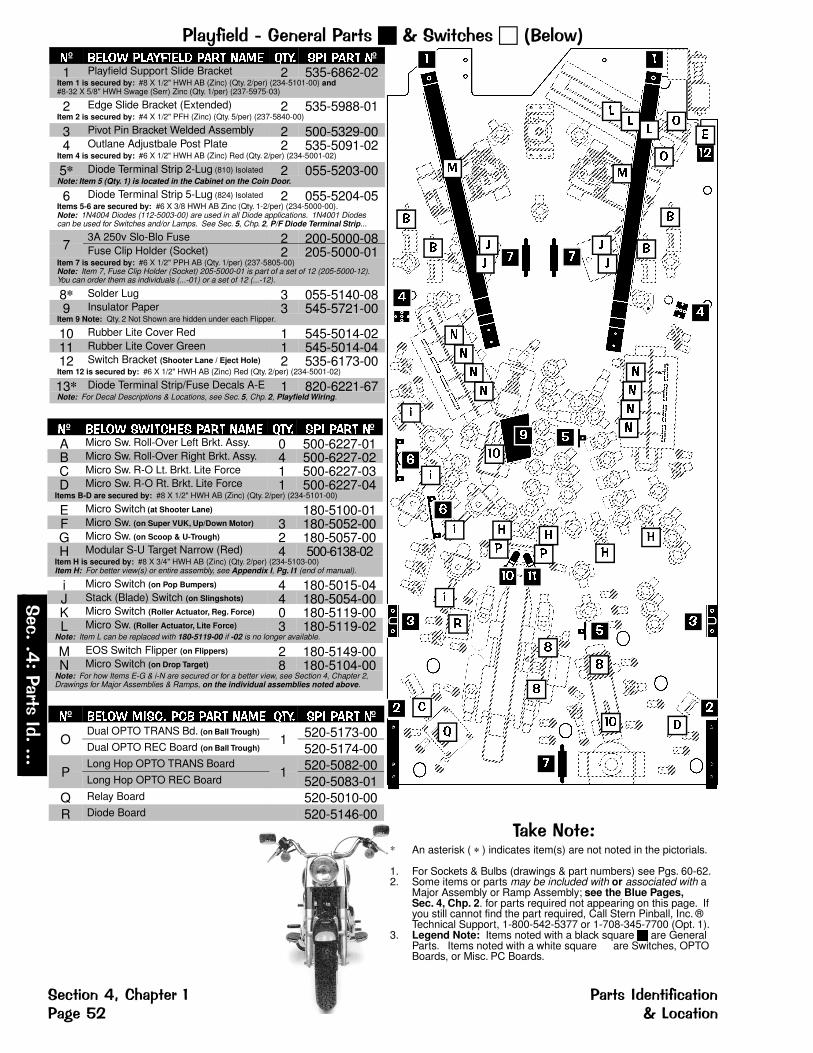
��"1������� ���������������4��(����������4��º ����� ������� �� � ���� ��� ��� �� � �º1 Playfield Support Slide Bracket 2 535-6862-02
Item 1 is secured by: #8 X 1/2" HWH AB (Zinc) (Qty. 2/per) (234-5101-00) and #8-32 X 5/8" HWH Swage (Serr) Zinc (Qty. 1/per) (237-5975-03)
2 Edge Slide Bracket (Extended) 2 535-5988-01Item 2 is secured by: #4 X 1/2" PFH (Zinc) (Qty. 5/per) (237-5840-00)
3 Pivot Pin Bracket Welded Assembly 2 500-5329-004 Outlane Adjustbale Post Plate 2 535-5091-02
Item 4 is secured by: #6 X 1/2" HWH AB (Zinc) Red (Qty. 2/per) (234-5001-02)
5* Diode Terminal Strip 2-Lug (810) Isolated 2 055-5203-00Note: Item 5 (Qty. 1) is located in the Cabinet on the Coin Door.
6 Diode Terminal Strip 5-Lug (824) Isolated 2 055-5204-05Items 5-6 are secured by: #6 X 3/8 HWH AB Zinc (Qty. 1-2/per) (234-5000-00).Note: 1N4004 Diodes (112-5003-00) are used in all Diode applications. 1N4001 Diodescan be used for Switches and/or Lamps. See Sec. 5, Chp. 2, P/F Diode Terminal Strip...
73A 250v Slo-Blo Fuse 2 200-5000-08Fuse Clip Holder (Socket) 2 205-5000-01
Item 7 is secured by: #6 X 1/2" PPH AB (Qty. 1/per) (237-5805-00)Note: Item 7, Fuse Clip Holder (Socket) 205-5000-01 is part of a set of 12 (205-5000-12).You can order them as individuals (...-01) or a set of 12 (...-12).
8* Solder Lug 3 055-5140-089 Insulator Paper 3 545-5721-00
Item 9 Note: Qty. 2 Not Shown are hidden under each Flipper.
10 Rubber Lite Cover Red 1 545-5014-0211 Rubber Lite Cover Green 1 545-5014-0412 Switch Bracket (Shooter Lane / Eject Hole) 2 535-6173-00Item 12 is secured by: #6 X 1/2" HWH AB (Zinc) Red (Qty. 2/per) (234-5001-02)
13* Diode Terminal Strip/Fuse Decals A-E 1 820-6221-67Note: For Decal Descriptions & Locations, see Sec. 5, Chp. 2, Playfield Wiring.
�º ����� �������� �� � ���� ��� ��� �� � �ºA Micro Sw. Roll-Over Left Brkt. Assy. 0 500-6227-01B Micro Sw. Roll-Over Right Brkt. Assy. 4 500-6227-02C Micro Sw. R-O Lt. Brkt. Lite Force 1 500-6227-03D Micro Sw. R-O Rt. Brkt. Lite Force 1 500-6227-04
Items B-D are secured by: #8 X 1/2" HWH AB (Zinc) (Qty. 2/per) (234-5101-00)
E Micro Switch (at Shooter Lane) 180-5100-01F Micro Sw. (on Super VUK, Up/Down Motor) 3 180-5052-00G Micro Sw. (on Scoop & U-Trough) 2 180-5057-00H Modular S-U Target Narrow (Red) 4 500-6138-02
Item H is secured by: #8 X 3/4" HWH AB (Zinc) (Qty. 2/per) (234-5103-00)Item H: For better view(s) or entire assembly, see Appendix I, Pg. I1 (end of manual).
i Micro Switch (on Pop Bumpers) 4 180-5015-04J Stack (Blade) Switch (on Slingshots) 4 180-5054-00K Micro Switch (Roller Actuator, Reg. Force) 0 180-5119-00L Micro Sw. (Roller Actuator, Lite Force) 3 180-5119-02
Note: Item L can be replaced with 180-5119-00 if -02 is no longer available.
M EOS Switch Flipper (on Flippers) 2 180-5149-00N Micro Switch (on Drop Target) 8 180-5104-00
Note: For how Items E-G & i-N are secured or for a better view, see Section 4, Chapter 2,Drawings for Major Assemblies & Ramps, on the individual assemblies noted above.
�º ����� ����� ��� �� � ���� ��� ��� �� � �º
ODual OPTO TRANS Bd. (on Ball Trough)
1 520-5173-00Dual OPTO REC Board (on Ball Trough) 520-5174-00
PLong Hop OPTO TRANS Board
1 520-5082-00Long Hop OPTO REC Board 520-5083-01
Q Relay Board 520-5010-00R Diode Board 520-5146-00
� �
� �
�
�
� �
�
�
� �
�� ��
� �
�
�
��
�
�
�
�
�
�
���
�
�
�
�
�
�
�
�
�
��
�
��
�
��
�
�
�
�
�
�
�� �
� � �
�� �
����%���** An asterisk ( * ) indicates item(s) are not noted in the pictorials.
1. For Sockets & Bulbs (drawings & part numbers) see Pgs. 60-62.2. Some items or parts may be included with or associated with a
Major Assembly or Ramp Assembly; see the Blue Pages,Sec. 4, Chp. 2. for parts required not appearing on this page. If you still cannot find the part required, Call Stern Pinball, Inc. ®Technical Support, 1-800-542-5377 or 1-708-345-7700 (Opt. 1).
3. Legend Note: Items noted with a black square � are GeneralParts. Items noted with a white square � are Switches, OPTOBoards, or Misc. PC Boards.
�(����
*��������
�����
�(�������������� �����������1�(��������'� ����(����
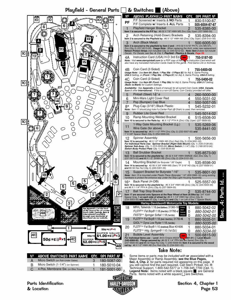
��"1������� ���������������4��(�������9����
�
��� �������� � ��� ���� ���� ���� ��� �� ����������� ����� ���� ���� ������������� ��� ������� � !��� ������ ���� ����"���� �� ��� "� ����#
�
����
�
����
��
��
��
��
�
��
��
�
�
�
� �
���
�
� �
�
�
��
��
��
��
��
��
��
���
�
��
�
�
����%���*1. Some items or parts may be included with or associated with a
Major Assembly or Ramp Assembly; see the Blue Pages,Sec. 4, Chp. 2. for parts required not appearing on this page. If you still cannot find the part required, Call Stern Pinball, Inc. ®Technical Support, 1-800-542-5377 or 1-708-345-7700 (Opt. 1).
2. Legend Note: Items noted with a black square � are GeneralParts. Items noted with a white square � are Switches.
�º ����� ���� ��� ���� ���� ���� ��� ���� �ºA Micro Switch (on Roll-Under Gates) 3 180-5087-00B Micro Switch (1-1/4") (on Spinner) 1 180-5010-04C 4-Pos. Membrane Sw. (on Bike Trough) 1 181-5001-00
�º ����� ��������� ���� ���� ���� ��� ���� �º
PFP/F Screened w/ Inserts & NO Parts 1 830-5100-87P/F Complete w/ Inserts & ALL Parts 1 505-6004-87-87
1 Playfield Hanger Bracket 2 535-8385-00Item 1 is secured to the P/F by: #8-32 X 7/8" HWH MS Zinc (Qty. 2/per) (237-5890-00)
2 Arch Retaining (Hold-Down) Brackets 2 535-8394-00Item 2 is secured to the Playfield by: #8 X 1/2" HWH AB (Zinc) (Qty. 3/per) (234-5101-00)
3 Arch (Black Metal) 1 500-6005-00Item 3 is secured to the playfield by Item 2 and : #10-32 X 5/16" PH FL U/C MS STLZinc (Qty. 2) (237-6013-00). Usage Note: When replacing the Arch, order new replacementNelson Protect Strips (not included) (Qty. 2) (545-5212-02). Note: Item 3 does not includeDecals. For Decals, see Sec. 4, Chp. 1, Playfield - Plastics & Decals, Page 55.
4A Instruction Card (USA) H-D 3rd Ed. 1 755-5187-00Note: Visit www.sternpinball.com for a PDF copy of the Game Instruction Card which willalso have any translated Instruction Cards made for this game. Find Game Link or Archives.
4B Coin Card (2-Sided) 1 755-5400-00Usage Note: Use Item 6A (Back: 1 Play 50¢ - 5 Plays $2) for Adj. 6, Game Pricing,USA 5 Setting, or (Front: 1 Play 50¢ - 3 Plays $1) for Adj. 6, Game Pricing, USA 8 Setting.
4C Coin Card (2-Sided) 1 755-5400-02Usage Note: Use Item 6B (Front: 1 Play 50¢) for Adj. 6, Game Pricing, USA 2-7 Setting,(Back: is Blank) for Custom Settings.
Availability: See Appendix J (back of manual) for all current Coin Cards (USA, Canada,Euro & other International). If this is a non-US Game, Coin Card(s) provided will differ.
5 Pinball (Steel) 1�" ø 4 260-5000-006 Mini-Mars Light Cover Red 4 550-5031-027 Pop (Bumper) Cap Blue 4 550-5057-058* Plug-Cap (3/16") Black Plastic 1 545-5232-01
Note: Item 17 should plug hole if a Center Post (@ Drain) is used, then removed.
9 Rubber Lite Cover Red 1 545-5014-0210 Ramp Mounting Welded Bracket 6 515-6508-00Item 10 is secured to the Rails by: #6 X 1/2" PTH A (Zinc) (Qty. 2/per) (237-5809-00)
111-Way Gate Mounting Bracket (Lg.) 1 535-5269-06Wire Gate (for above) 535-8441-00
Item 11 is secured by: #6 X 1-1/2" PPH Zinc (Qty. 2) (232-5007-00) and1" X 3/8" Spacer Black (Qty. 2) (254-5000-04)
12 Spinner Assembly 1 500-5656-00Item 12 is secured by: #6 X 1/2" HWH AB (Zinc) Red (Qty. 2) (234-5001-02)For Individual Parts Use: Spinner Bracket (Right Side Mount) (Qty. 1) (535-5128-00);Spinner Sub-Assy. (Qty. 1) (515-5553-00); Micro Switch (1-1/4") (Qty. 1) (180-5010-04);Switch Body Protect Plate (Qty. 1) (535-6539-00)
13 Ball Snubber Bracket 1 535-8573-00Item 13 is secured to the playfield by: #8-32 X 5/8" HWH SWAGE (Ser) Zinc (Qty. 1)(237-5975-03) and #8 X 1/2" SHWH AB (Zinc) (Qty. 2) (234-5101-00)
14 Mounting Bracket (for Butyrate "-35" Eagle) 1 535-8598-00Item 14 is secured by: #2-56 X 3/8" HWH MS (Serr) TF 3/16" HD (Qty. 4) (237-5938-01)and #2-56 Hex Nut (Qty. 4) (240-5301-00)
15 Support Bracket for Butyrate "-16" 1 535-8601-00Note: Item 15 is mounted under Plastic Piece (Butyrate) "-16" (830-5960-16) using existinghardware to protect the entrance way under the Stop Light Housing Assembly.
16* Back Panel (H-D®) 1 525-5557-00Item 16 is secured to the playfield by: #6 X 3/4" HWH AB (Zinc) (Qty. 6) (234-5003-00)and #6 X 1-1/4" PFH A (Zinc) (Qty. 6) (237-5804-00)
17 Ball Trap Stop Bracket 2 535-8744-00Item 17 are secured onto Spacers at the Rear Wheel of Item 20 Bike by: 3/4" X3/8"Spacer Gray, 1 on each side of wheel by: #6 X 1-1/4" HWH Ser (Zinc) (Qty. 6)(234-5003-00) with Item 17 (Qty. 1 on Right) and (Qty. 1 on Left of the 1" Spacer Black).
Harley-Davidson® Motorcycle Toy Models:
18 MRVL Tailwinds 1:18 (3rd Edition) 31360-18 1 880-5042-02FLSTF Fat Boy® 1:18 (2nd Ed.) 31760-J 0 880-5042-01FXSTS Springer Softail 1:18 (1st Ed.) 0 880-5042-00
19 FLSTF Fat Boy® 1:18 (3rd / 2nd Ed.) 31760-K 1 880-5035-01GXDL Dyna Low Ryder 1:18 (1st Ed.) 0 880-5035-00
20 FLSTF Fat Boy® 1:10 (3rd/2nd) Blue #31606 1 880-5034-01FLSTS Hrtg. Springer® 1:10 (1st Ed.) 0 880-5034-00
21 Bubble Level Assembly 1 500-6815-00For Individual Items use : Level .8mm Empire #0224 (545-6001-01) or Level Mount(545-6068-00). Flange secured by: #6-32 X 1/4" PPH MS (no Sems) Zinc (Qty. 1)(237-5500-00) and #6-32 Keps Nut (Qty. 1) (240-5008-00) Item 4 is secured to the woodrail by: #6 X 1/2" HWH AB Zinc Red (Qty. 2) (234-5001-02)
Colors
vary!
Cannot
choose.
�(
����
*�����
��������
�����������1�(���� �(�������������� ����(���� ����'!
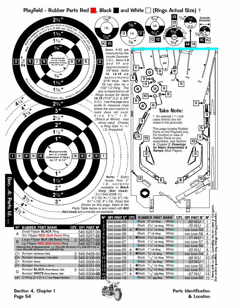
��"1�������"�99��������"��������(�������@�������"������(�����F���†
� �� �� ���
� � � � � � � �
�
��
��
�
��
���
��
��
�
��
��
����%���** An asterisk ( * ) indi-cates item(s) are notnoted in the pictorials.
This page locates RubberParts on the Playfield only.For location or view ofRubber Parts on anyassemblies, see Section4, Chapter 2, Drawingsfor Major Assemblies &Ramps (Blue Pages).
�
�
�
�
�
� �
�
���� ��
��
���
�
�
��
��
�
�� ��
† ����
�������� ����
��������
������
����
����
�����
������
������
���
���
�������
�������
º ��� ���� � ���� ������ ���� ��� ���� ��� ���� � º1 545-5348-10 �Black 3" I.D. Ring White� -60 N/U 12 545-5348-20 �Black 23
4" I.D. Ring White� -70 N/U 23 545-5348-09 4 �Black 21
2" I.D. Ring White� 545-5348-59 34 545-5348-08 �Black 2" I.D. Ring White� 545-5348-58 45 545-5348-21 1 �Black 13
4" I.D. Ring White� -71 N/U 56 545-5348-07 �Black 11
2" I.D. Ring White� 545-5348-57 67 545-5348-06 �Black 11
4" I.D. Ring White� 545-5348-56 78 545-5348-05 4 �Black 1" I.D. Ring White� -55 N/U 89 545-5348-04 1 �Black 3
4" I.D. Ring White� 545-5348-54 910 545-5348-18 �Black 7/16" I.D. Ring White� -68 N/U 1011 545-5348-03 �Black 3
8" I.D. Ring White� -53 N/U 1112 545-5348-02 1 �Black 5/16" I.D. Ring White� 545-5348-52 1213 545-5348-01 4 �Black 3/16" I.D. Ring White� 545-5348-51 1314 ‡ 545-5348-17 4 �Black 7/16" O.D. Ring White� -67 N/U 1415 545-5348-19 �Black 3
8" O.D. Ring White� 545-5348-69 15
º ������ ���� ��� ���� ��� ���� º
ASmall Flipper BLACK Ring 545-5207-00Sm. Flipper RED (Soft Duro) Ring 545-5207-22
BLarge Flipper BLK (50 Duro) Ring 2 545-5277-00Lg. Flipper RED (Soft Duro) Ring 545-5277-22
Optional Item B Replacements: Lg. YELLOW (50 Duro) Ring (545-5277-04) orLarge YELLOW (40 Duro) Ring (545-5277-06)
C* Bumper (Deflector Pad) 2 545-5428-00D* Bumper (Grommet) 1138 (A60) 5 545-5105-00E* Bumper (Post) 545-5009-00F* Bumper (Post Sleeve, Short) 545-5151-00
GBumper BLACK
(Post Sleeve, Tall) 5 545-5308-00Bumper WHITE (Post Sleeve, Tall) 545-5308-08
H* O-Ring �" X �" X �" (on Flipper Button) 545-5850-0011 07
�(����
*��������
�����
�(�������������� �����������1�(��������'� ����(����
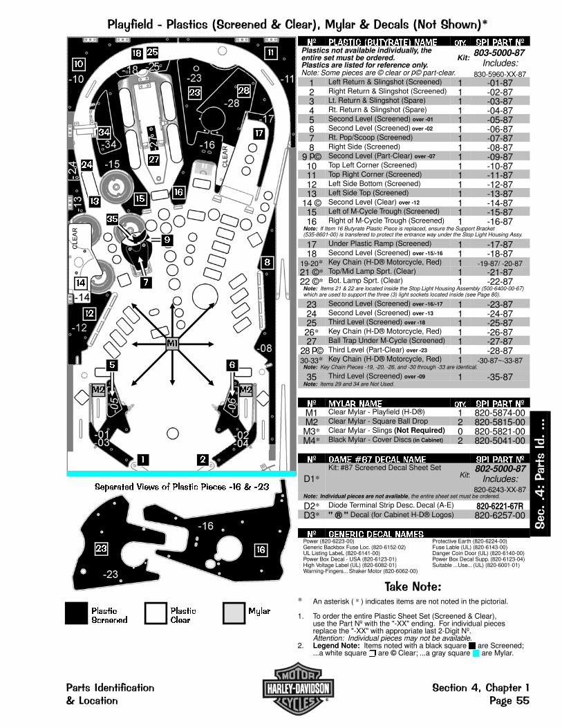
��"1������������(���(����������������#"�������(����%����4��G
���������������
����� ������
�
��
�
��
�
��
�� ��
��
��
��
��
�� ��
��
���� ��
����
�
�
��
����
� �
��
�º ��� ��� � !�"#��$% ���$ ���� �� ��#� �ºPlastics not available individually, theentire set must be ordered. Kit:Plastics are listed for reference only.
803-5000-87 Includes:
Note: Some pieces are © clear or p© part-clear. 830-5960-XX-871 Left Return & Slingshot (Screened) 1 -01-872 Right Return & Slingshot (Screened) 1 -02-873 Lt. Return & Slingshot (Spare) 1 -03-874 Rt. Return & Slingshot (Spare) 1 -04-875 Second Level (Screened) over -01 1 -05-876 Second Level (Screened) over -02 1 -06-877 Rt. Pop/Scoop (Screened) 1 -07-878 Right Side (Screened) 1 -08-87
9 p© Second Level (Part-Clear) over -07 1 -09-8710 Top Left Corner (Screened) 1 -10-8711 Top Right Corner (Screened) 1 -11-8712 Left Side Bottom (Screened) 1 -12-8713 Left Side Top (Screened) 1 -13-87
14 © Second Level (Clear) over -12 1 -14-8715 Left of M-Cycle Trough (Screened) 1 -15-8716 Right of M-Cycle Trough (Screened) 1 -16-87
Note: If Item 16 Butyrate Plastic Piece is replaced, ensure the Support Bracket(535-8601-00) is transfered to protect the entrance way under the Stop Light Housing Assy.
17 Under Plastic Ramp (Screened) 1 -17-8718 Second Level (Screened) over -15/-16 1 -18-87
19-20* Key Chain (H-D® Motorcycle, Red) 1 -19-87/ -20-8721 ©* Top/Mid Lamp Sprt. (Clear) 1 -21-8722 ©* Bot. Lamp Sprt. (Clear) 1 -22-87
Note: Items 21 & 22 are located inside the Stop Light Housing Assembly (500-6400-00-67)which are used to support the three (3) light sockets located inside (see Page 80).
23 Second Level (Screened) over -16/-17 1 -23-8724 Second Level (Screened) over -13 1 -24-8725 Third Level (Screened) over -18 1 -25-8726* Key Chain (H-D® Motorcycle, Red) 1 -26-8727 Ball Trap Under M-Cycle (Screened) 1 -27-87
28 p© Third Level (Part-Clear) over -23 1 -28-8730-33* Key Chain (H-D® Motorcycle, Red) 1 -30-87~-33-87Note: Key Chain Pieces -19, -20, -26, and -30 through -33 are identical.
35 Third Level (Screened) over -09 1 -35-87Note: Items 29 and 34 are Not Used.
�º �"��# ���$ ���� �� ��#� �ºM1 Clear Mylar - Playfield (H-D®) 1 820-5874-00M2 Clear Mylar - Square Ball Drop 2 820-5815-00M3* Clear Mylar - Slings (Not Required) 0 820-5821-00M4* Black Mylar - Cover Discs (in Cabinet) 2 820-5041-00
�º &��$ '�� ($��� ���$ �� ��#� �º
D1*Kit: #87 Screened Decal Sheet Set
Kit:802-5000-87
Includes:820-6243-XX-87
Note: Individual pieces are not available, the entire sheet set must be ordered.
D2* Diode Terminal Strip Desc. Decal (A-E) 820-6221-67RD3* " ® " Decal (for Cabinet H-D® Logos) 820-6257-00
�º &$�$#�� ($��� ���$ �� ���� �ºPower (820-6223-00) Protective Earth (820-6224-00)Generic Backbox Fuse Loc. (820-6152-02) Fuse Lable (UL) (820-6143-00)UL Listing LabeL (820-6141-00) Danger Coin Door (UL) (820-6140-00)Power Box Decal - USA (820-6123-01) Power Box Decal Supp. (820-6123-04)High Voltage Label (UL) (820-6082-01) Suitable ...Use... (UL) (820-6001-01)Warning-Fingers... Shaker Motor (820-6062-00)
�)������ *�+� ,- ����� ���� .�� / .��
����%���** An asterisk ( * ) indicates items are not noted in the pictorial.
1. To order the entire Plastic Sheet Set (Screened & Clear),use the Part Nº with the "-XX" ending. For individual piecesreplace the "-XX" with appropriate last 2-Digit Nº. Attention: Individual pieces may not be available.
2. Legend Note: Items noted with a black square � are Screened;...a white square � are © Clear; ...a gray square � are Mylar.
�(
����
*�����
��������
�����������1�(���� �(�������������� ����(���� ����''

��"1�������"�������@����$����������� ��������†
† ����
�������� ����
��������
������
����
����
�����
������
������
���
���
�������
�������
�
�� �
�
�
�
�
�
�
�
�
�
�
�
� �
�
��
�
�
�
�º ��� � � ��� ���� ��� ���� ��� ���� �º1 Wood Rail (Left Side) 1 525-5553-002 Wood Rail (Top Side) 1 525-5554-003 Wood Rail (Right Side) 1 525-5555-004 Wood Rail (Shooter Lane, Short) 1 525-5556-00
Items 1-4 are secured by: #6 X 1-1/4" PFH A (Zinc) (Qty. 20) (237-5804-00)
5 Metal Rail Weldment (Shooter Lane) 1 515-7018-006 Metal Rail (Center Drain under Arch) 1 535-8393-007 Metal Rail (Full Orbit) (or Loop) 1 535-8556-00
Items 5-7 are secured by: #8 X 1/2" SHWH AB (Zinc) (Qty. 14) (234-5101-00)
8 Metal Rail Ramp (Shooter Lane) 1 535-8145-00Item 8 is secured by: #4 X 1/2" PFH (Zinc) (Qty. 2)(237-5840-00)
�º ��� ���� ���� ��� ���� ��� ���� �ºA Wire Form - 1" 3 535-5300-05B Wire Form - 3" 2 535-5300-02C Wire Form (over Item D) 2 535-5642-00
�º ���� � � ���� ����� ��� ���� ��� ���� �ºD Ball Guide Rail (Plastic) (Return Lane) 2 550-5037-01E Ball Guide Rail - 5/8" 2 535-5356-19F Ball Guide Rail - 4-1/2" 1 535-6492-15G Ball Guide Rail - 8" 1 535-6492-19H Ball Guide Rail - 8-1/2" 1 535-6492-20I Ball Guide Rail - 11.63" 1 535-6492-16J Ball Guide Rail (Left Orbit, Upper) 1 535-8558-00K Ball Guide Rail (Right Orbit, Lower) 1 535-8559-00L Ball Guide Rail (Right Orbit, Upper) 1 535-8560-00M Ball Guide Rail (Inside Upper Right) 1 535-8561-00
�(����
*��������
�����
�(�������������� �����������1�(��������': ����(����
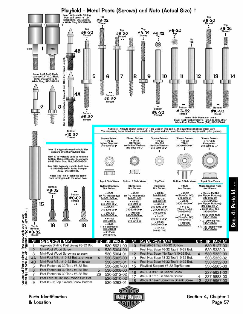
����������� ����� ������������� ���� ��������†
�
��
Top
�����Thread
�
��
�Top &
Bottom
�����Thread
��
Bottom
�����Thread
�
Item 16 is typically used to hold HexSpacers onto the Playfield Top.
Item 17 is typically used to hold thebottom Cabinet Speaker (used with#6-32 Nylon Stop Nut, 240-5005-00).
Item 18 is typically used to hold Item15 (515-5939-00) in Turbo Bumper
Assy., 515-6459-04.
Note: The "Fins" keep the screwfrom turning inside the wood hole.
�
��
Top
�����Thread
�
�Bottom
������Thread
�!
NoTap
�
Items 11-14 Posts can use aBlack Post Rubber Sleeve (Tall), 545-5308-00 orWhite Post Rubber Sleeve (Tall), 545-5308-08.
�"
�Bottom
�����Thread
�����Tap
�
Top
�����Thread
�
# $
Top
�����Thread
�
Top
�����Thread
�
�
�Bottom
�����Thread
�
Top
�����Thread
�
�Bottom
�����Thread
Top & Side Views
Nylon Stop NutsNot Shown:
#6-32(w/ 1 4" Hex Body):
240-5010-00 � #8-32:
240-5102-00 � #10-32:
240-5203-00 � #10-24:
240-5206-00 � #4-40:
240-5303-00 #4-40
(18/8 Stainless):240-5303-01
5/16"-18:240-5316-00
Nut Note: All nuts shown with a " � " are used in this game. The quantities (not specified) vary.The remaining Items listed are not used in this game and are noted for reference only (used in prior games).
Shown Below~ #6-32
Nylon Stop Nut:240-5005-00 �
�
Shown Below~ #6-32
KEPS Nut(with Star Washer):
240-5008-00 �
�
Shown Below~ #6-32
Hex Nut(No Star Washer):
240-5004-00 �
�
Shown Below~ #6-32
T-Nut:240-5002-00 �
�
Shown Below~ 1 4" X 20
Flange Nut:240-5300-00 �
�
Bottom & Side Views
KEPS NutsNot Shown:
#6-32(w/ 1 4" Hex Body):
240-5011-00 #8-32:
240-5104-00 #10-32:
240-5208-00 � #10-24:
240-5207-00 � #4-40:
240-5318-00
Top View
Hex NutsNot Shown:
#8-32:240-5103-00
#10-32:240-5201-00
#10-24:240-5202-00 �
#10-32 X 3 8":240-5209-00
3 4-16:240-5315-00 �
#2-56:240-5301-00 �
7 8"-14:240-5317-00
Bottom & Side Views
T-NutsNot Shown:
#6-32(w/Side Cut Off):
240-5002-01 #8-32:
240-5101-00 � #10-32
(Black Oxide):240-5007-00
#10-32(w/Side Cut Off):
240-5205-00 #10-24:
240-5200-00
Top & Side Views
Miscellaneous NutsNot Shown:
Plastic Pal Nut(on Flipper Buttons):
240-5003-00 Metal Pal Nut
(on Flipper Buttons):240-5003-01 � #6-32 Wing Nut:
240-5001-00 #8-32 Wing Nut:
240-5100-00 1 4"-20 Wing Nut:
240-5302-00 1 4"-20 Toggle Wing:
240-5324-00
�
Item 1 Adjustable SlidingPost can use 5/16" I.D.
Black Ring, 545-5348-02or White Ring 545-5348-52.
FrontSide
��
��
�Bottom
������Thread
�$
�Bottom
�����Thread
�
!
Items 2, 4A & 4B Postscan use 3/8" O.D. Black
Ring, 545-5348-19 orWhite Ring, 545-5348-69.
��
�����Tap
�
�Bottom
������Thread
�%
Th
e d
iffe
ren
ce b
etw
een
Item
s 4A
an
d 4
B is
th
e T
hre
ad L
eng
th.
º �� � ���� � ���� ��� � �� º1 Adjustable Sliding Post (Brass) #8-32 Bot. 530-5621-002 Mini-Post Wood Screw 4 530-5004-003 Mini-Post Wood Screw (no cut-away) 530-5004-01
4A Mini-Post MS / #10-32 Bot. .875" Thread 4 530-5005-004B Mini-Post MS / #10-32 Bot. .4" Thread 530-5005-015 Post Fasten #6-32 Top / #8-32 Bot. 530-5007-006 Post Fasten #8-32 Top / #6-32 Bot. 5 530-5008-007 Post Fasten #6-32 Top / #6-32 Bot. 26 530-5012-028 Post Fstn. #6-32 Top / Wood Scr. Bot. 530-5010-029 Post #6-32 Top / Wood Screw Bottom 530-5263-01
º �� � ���� � ���� ��� � �� º10 Post #6-32 Tap / #6-32 Bottom 530-5127-0011 Post Hex Base #6-32 Tap/#10-32 Bot. 530-5332-0112 Post Hex Base (No Tap)/#10-32 Bot. 4 530-5332-0013 Post Hex Base #8-32 Top/#10-32 Bot. 530-5332-0214 Post Hex Base #6-32 Top/#10-32 Bot. 530-5332-0315 Playfield Support #8-32 Top/Bottom 530-5285-00
16 #6-32 X 3/4" Fin Shank Screw 237-5921-0217 #6-32 X 1�" Fin Shank Screw 4 237-5883-0018 #6-32 X 13/16" Spirol Fin Shank Screw 12 237-5957-00
†����
�����
���
��������
����
�����
�����
����
����
�������������
���
�������
�����
�����
���&�'��� �(&&&&
��� �(�� ����� ��� ��� ����)*+�, ���-.��� ��� ��/��$
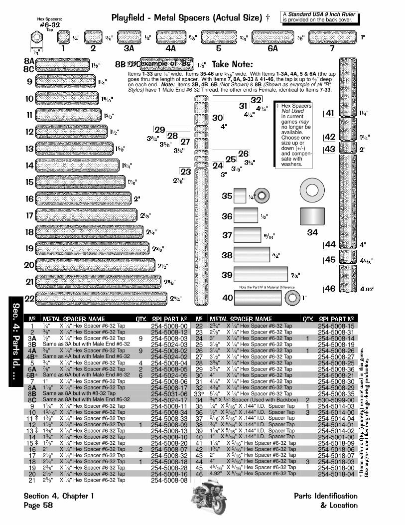
����������� ������������ ��������†
�
��
��
��
��
��
��
��
�
�!
��
��
��
��
����
��
� �!
��
��
����
�� ��
�� ��
�� ��
�� ��
�� ��
�� ��
��
����
����
����
����
����
��
����
�� ��
������
��
����
����
����
����
����
��
������
����
��
�� ��
��
�������
����
��
‡ Hex SpacersNot Usedin currentgames mayno longer beavailable.Choose onesize up ordown (+/-)and compen-sate withwashers.
�� �� ��
�� ��
!" �� ��
����
��
!� #�$�%& �'Items 1-33 are 1 4" wide. Items 35-46 are 5/16" wide. With Items 1-3A, 4A, 5 & 6A (the tapgoes thru the length of spacer. With Items 7, 8A, 9-33 & 41-46, the tap is up to 5 8" deepon each end. Note: Items 3B, 4B, 6B (Not Shown) & 8B (Shown as example of all "B"Styles) have 1 Male End #6-32 Thread, the other end is Female, identical to Items 7-33.
�(�)���&�*"�*
�� �� ��
!+
� � �� �� � ��
����
�� ��� �
�� ��� ���
��
Hex Spacers:
����Tap
���
A Standard USA 9 Inch Ruler is provided on the back cover.
��
��
�
�!
��
���
���
���
�� ��
����
����
Note the Part Nº & Material Difference
��
�� � ���
��� ���
�º � ��� ���� � ��� ���� ��� ���� �º1 1
4" X 1 4" Hex Spacer #6-32 Tap 254-5008-002 3
8" X 1 4" Hex Spacer #6-32 Tap 254-5008-123A 1
2" X 1 4" Hex Spacer #6-32 Tap 9 254-5008-033B Same as 3A but with Male End #6-32 254-5024-034A 5
8" X 1 4" Hex Spacer #6-32 Tap 9 254-5008-024B* Same as 4A but with Male End #6-32 254-5024-02
5 34" X 1 4" Hex Spacer #6-32 Tap 4 254-5008-04
6A 78" X 1 4" Hex Spacer #6-32 Tap 2 254-5008-05
6B* Same as 6A but with Male End #6-32 6 254-5024-057 1" X 1 4" Hex Spacer #6-32 Tap 254-5008-06
8A 118" X 1 4" Hex Spacer #6-32 Tap 254-5008-17
8B Same as 8A but with #8-32 Tap 254-5031-068C Same as 8A but with Male End #6-32 254-5024-179 11
4" X 1 4" Hex Spacer #6-32 Tap 254-5008-1110 15/16" X 1 4" Hex Spacer #6-32 Tap 254-5008-34
11 ‡ 138" X 1 4" Hex Spacer #6-32 Tap 254-5008-33
12 112" X 1 4" Hex Spacer #6-32 Tap 1 254-5008-09
13 ‡ 158" X 1 4" Hex Spacer #6-32 Tap 254-5008-13
14 134" X 1 4" Hex Spacer #6-32 Tap 254-5008-10
15 ‡ 178" X 1 4" Hex Spacer #6-32 Tap 254-5008-20
16 2" X 1 4" Hex Spacer #6-32 Tap 2 254-5008-0717 21
8" X 1 4" Hex Spacer #6-32 Tap 254-5008-3218 21
4" X 1 4" Hex Spacer #6-32 Tap 1 254-5008-1819 23
8" X 1 4" Hex Spacer #6-32 Tap 254-5008-2820 21
2" X 1 4" Hex Spacer #6-32 Tap 254-5008-1621 25
8" X 1 4" Hex Spacer #6-32 Tap 254-5008-08
�º � ��� ���� � ��� ���� ��� ���� �º22 23
4" X 1 4" Hex Spacer #6-32 Tap 254-5008-1523 27
8" X 1 4" Hex Spacer #6-32 Tap 254-5008-3124 3" X 1 4" Hex Spacer #6-32 Tap 1 254-5008-1425 31
8" X 1 4" Hex Spacer #6-32 Tap 254-5008-1926 31
4" X 1 4" Hex Spacer #6-32 Tap 1 254-5008-2627 31
2" X 1 4" Hex Spacer #6-32 Tap 254-5008-2728 35
8" X 1 4" Hex Spacer #6-32 Tap 254-5008-2529 33
4" X 1 4" Hex Spacer #6-32 Tap 254-5008-3630 4" X 1 4" Hex Spacer #6-32 Tap 254-5008-2131 41
4" X 1 4" Hex Spacer #6-32 Tap 254-5008-3032 43
8" X 1 4" Hex Spacer #6-32 Tap 254-5008-2933* 51
4" X 1 4" Hex Spacer #6-32 Tap 254-5008-3534 3
8" X 1 2" Spacer (Used with Backbox) 2 530-5099-0035 1
4" X 5/16" X .144" I.D. Spacer Tap 1 254-5014-0336 1
2" X 5/16" X .144" I.D. Spacer Tap 3 254-5014-0037 9/16"X 5/16" X .144" I.D. Spacer Tap 254-5014-0438 3
4" X 5/16" X .144" I.D. Spacer Tap 254-5014-0139 11
8" X 5/16" X .144" I.D. Spacer Tap 254-5014-0240 1" X 5/16" X .144" I.D. Spacer Tap 254-5001-0041 11
4" X 5/16" Hex Spacer #6-32 Tap 254-5018-0942 13
4" X 5/16" Hex Spacer #6-32 Tap 254-5018-0643 2" X 5/16" Hex Spacer #6-32 Tap 254-5018-0744 4" X 5/16" Hex Spacer #6-32 Tap 3 254-5018-0345 45/16" X 5/16" Hex Spacer #6-32 Tap 254-5018-0046 4.92" X 5/16" Hex Spacer #6-32 Tap 254-5018-04 †
����
�������� ����
��������
������
����
����
�����
������
������
���
���
�������
�������
���,�
'��� �-
,,,,
��� �&.�/+0�� ��� ��� �-�. ����� �&.��1��! 23&�� �&.
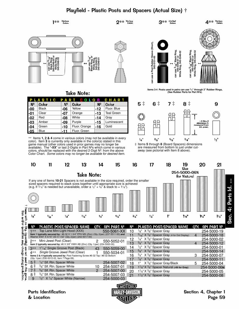
������������� ���&� ��.���������� ��������†
#�$�%& �'� � � � � � � � � � � � � � � � � �
�º �� �� �º �� �� �º �� ��
-00 Black -06 Yellow -12 Fluor. Blue
-01 Clear -07 Orange -13 Teal Green
-02 Red -08 White -14 Gray
-03 Amber -09 Purple -15 Luminescent
-04 Green -10 Fluor. Orange -16 Gold
-05 Blue -11 Fluor. Green
** Items 1, 2 & 4 come in various colors (may not be available in everycolor). Item 3 is currently only available in the color(s) stated in thisgame manual (other colors used in prior games may no longer beavailable). The "-XX" or last 2-Digits in Part Nºs which come in variouscolors, should be replaced with the desired 2-Digit Nº. from the aboveColor Chart. Some colors may no longer be available for desired item.
�** ������������
�ca
n u
se 3
/ 16"
Bla
ck R
ing
, or
Wh
ite
Rin
g,
545-
5348
-51
545-
5348
-01
�ca
n u
se5 /
16"
Bla
ck R
ing
,54
5-53
48-0
2 o
rW
hit
e R
ing
,54
5-53
48-5
2
�** ������������ �**
�ca
n u
se 3
/ 16"
Bla
ck R
ing
,54
5-53
48-0
1 o
rW
hit
e R
ing
, 545
-534
8-02
can
use
a P
ost
Ru
bb
er S
leev
e (S
ho
rt),
545-
5151
-00
���� ������ �** �������
�����
can
use
5/ 1
6" B
lack
Rin
g,
545-
5348
-02
or
Wh
ite
Rin
g, 5
45-5
348-
52
�
Items 3-4 Posts used in pairs can use 3 4" through 3" Rubber Rings,(See Rubber Parts for Part Nºs).
�
���
‡ � ���� ���� ����� ��
� ���� � �������� ������
���
!‡
‡ Items 5 through 8 (Board Spacers) dimensionsare measured from bottom to just under cut-away (see pictorial with Item 8 above).
�‡
���
�‡
���
��
�� ��
��
�� ��
��
�� ��
�!
��
������������������ ������
��
���
��
���
��
���
��
���
��
���
‡
���
�
����
��
�� ��
�� ���
#�$�%& �'If any one of Items 10-21 Spacers is not available in the size required, order the smallersized spacers required to stack sizes together until appropriate size is achieved(e.g. If 11 8" is needed but unavailable, order a 1 2" + 5 8" & stack to = 11 8").
�º ������� ���������� �� � !�"# ��� ���� �º1** Top Lane Mini-Light Hood (XXX) 550-5061-XXItem 1 typically secured by: #6-32 X 1-3/4" PPH MS (Zinc) (Qty. 2/per) (237-5511-00) andWasher 9/64" X 5/16" OD X 1/32" (Qty. 2/per) (242-5017-00)
2** Mini-Jewel Post (Clear) 2 550-5052-01Item 2 typically secured by: #6 X 3/8" HWH AB (Zinc) (Qty. 1/per) (234-5000-00)
3** 11/16" Single Groove Post (Black) 43 550-5059-004** Single Groove Jewel Post (Clear) 1 550-5034-01Items 3 & 4 typically secured by: Post Fastening Screw #6-32 Top / #6-32 Bottom(Qty. 1/per) (530-5012-02, Item 7 Page 69).
5 ‡ 14" Slf. Rtn. Spacer White 254-5007-02
6 ‡ 38" Slf. Rtn. Spacer White 10 254-5007-01
7 ‡ 58" Slf. Rtn. Spacer White 2 254-5007-00
8 ‡ 34" Slf. Rtn. Spacer White 254-5007-03
9 12" X 1 4" Spacer White (Narrow) 254-5000-03
�º ������� ���������� �� � !�"# ��� ���� �º10 1
8" X 3 8" Spacer Gray 254-5000-1911 3/16" X 3 8" Spacer Gray (4 for Dot Display) 4 254-5000-1812 1
4" X 3 8" Spacer Gray 254-5000-0213 3
8" X 3 8" Spacer Gray 4 254-5000-1214 1
2" X 3 8" Spacer Gray 254-5000-0115 5
8" X 3 8" Spacer Gray 254-5000-1416 3
4" X 3 8" Spacer Gray 3 254-5000-0717 7
8" X 3 8" Spacer Gray 254-5000-1118 1" X 3 8" Spacer Gray/Black 5 254-5000-0419 11
8" X 3 8" Spacer Natural (-06 for Gray) 254-5000-06N20 11
4" X 3 8" Spacer Gray 254-5000-0521 11
2" X 3 8" Spacer Gray 254-5000-08
†����
�����
���
��������
����
�����
�����
����
����
�������������
���
�������
�����
�����
���
,�'��� �-,,,,
��� �-�. ����� �&. ��� �&.�/+0�� ���23&�� �&. ��1���

����������)���"��&.� #���"��4��.�&�$� ���� ��������†
�
�
��������
"
�
��
��
�����
�����
���
��� �
���
�
��������
�
�
!
�� ��
º �� �� � � ����� ��� ���� �� ���� ºA #44 Bulb (Clear) Heavy Filament 47 165-5000-44-HFA #44 Bulb (Red) 165-5053-02A #44 Bulb (Amber) 165-5053-03A #44 Bulb (Blue) 165-5053-05A #44 Bulb (Yellow) 165-5053-06B #455 Twinkle Bulb 165-5003-001 2-Lug Staple Down Socket 4 077-5000-002 3-Lug Stand-Up Short Socket 077-5008-003 2-Lug Stand-Up Short Socket 1 077-5002-004 3-Lug Staple Down Socket 077-5001-005 2-Lug Laydown Socket 077-5003-006 3-Lug Stand-Up Long Socket 077-5009-007 3-Lug Laydown Socket (3 Lugs Flat) 5 077-5006-008 2-Lug Stand-Up Long Socket 077-5005-009 3-Lug Stand-Up Long Shell Socket 077-5013-0010 2-Lug Stand-Up Lg. Shell Socket (GIs) 33 077-5031-00
º �� �� � � ����� ��� ���� �� ���� º11 1-Lug Stand-Up Long Shell Socket 077-5012-0012 3-Lug Laydown Socket (2 Lugs Bent) 4 077-5032-00 †
����
�������� ����
��������
������
����
����
�����
������
������
���
���
�������
�������
���,�
'��� �-
,,,,
��� �&.�/+0�� ��� ��� �-�. ����� �&.��1��� 23&�� �&.

���������3��1�"��&.� #���"��4�.�&�$� ���� ��������†
�������
+
� �
70775111s.pcx
�
���
70775112s.pcx
�º �� ��� � ���� � �� ���� ��� ��� �ºC #89 Bulb Heavy Filament 21 165-5000-89-HF1 Laydown Standard Socket 7 077-5100-002 2-Lug Stand-Up Short Socket 11 077-5101-003 2-Lug Stand-Up Long Socket 3 077-5102-00
�º �� ��� � ���� � �� ���� ��� ��� �º4 Stand-Up Socket Rev. Short 077-5103-005 2-Lug Stand-Up Small Socket 077-5106-006 Straight Leg Socket 077-5107-00
†����
�����
���
��������
����
�����
�����
����
����
�������������
���
�������
�����
�����
���
,�'��� �-,,,,
��� �-�. ����� �&. ��� �&.�/+0�� ���23&�� �&. ��1���

���������5�1�"���"��4��.�&�$� ���� ��������†
��������������������������������������������������
�
�
#�$�%& �'* An asterisk ( * ) indicates item(s) are not noted in the pictorials.
1. Item 3 Socket has 2 Wires attached are approximately 12" ea.2. Item 4 Socket was used on PC Light Boards to position bulbs
horizontally; Item 4 Socket is secured by soldering into place.3. Item 5 Socket was used on PC Light Boards to position bulbs
vertically; Item 5 Socket is secured by "twisting" into place.4. Item E Bulb (#906) is normally used in conjunction with Item 6
Socket, but can be used with Items 1, 2, 4 or 7a/b.5. Item 7a Socket is equipped with a bui l t- in Diode, 1N4003
(112-5003-00), however, replacement can be made with a1N4001 Diode (112-5001-00).Item 7b Socket is NOT equipped with a diode (not required).
Note: Always replace with same type bulb in original application.
�
�
6
��������
�����
�����
���
��� �
���
�
7
�����
�����
�����
���
��� �
���
�
squeeze
�
4��8���&99� 0%&7�&�
�&.��
�
!�5/16"
!�:4#&�;��9�!4���;��9��%& �0&9.�
!�:4
#�$��������%& �Item 7a is an IDC (InsulationDisplacement Connection) StyleSocket (this style is solderless).This socket is secured to theplayfield or component by Items8a or 8b Snap-On SocketBrackets, or may also be snappedinto Item 9 Socket MountingPlastic Board (used only whensockets are positioned closely to-gether or in a special application).
Just squeeze the "side arms" ofthe socket together and pull awayfrom the bracket or mountingboard for easy Bulb replacement.
�º � �� ���� � ���� � ��� ���� ��� ���� �ºD #555 Wedge Base Bulb (Clear) 53 165-5002-00D #555 Wedge Base Bulb (Red) 165-5054-02D #555 Wedge Base Bulb (Green) 165-5054-04D #555 Wedge Base Bulb (Blue) 165-5054-05D #555 Wedge Base Bulb (Yellow) 165-5054-06E #906 Wedge Base Bulb (Clear) 165-5004-00E #906 Wedge Base Bulb (Red) 165-5004-02E #906 Wedge Base Bulb (Amber) 165-5004-03E #906 Wedge Base Bulb (Blue) 165-5004-05E #906 Wedge Base Bulb (Yellow) 165-5004-06
�º � �� ���� � ���� � ��� ���� ��� ���� �º1 #555 Wedge Base Socket (Laydown) 077-5026-012 #555 Wedge Base Socket (Offset) 077-5029-003 #555 W.B. Socket (for Pop Bumper) 4 077-5206-004 #555 W.B. Socket (Solder Type) 077-5207-005 #555 Wedge Base Socket (Twist) 077-5007-006 #906 Wedge Base Socket (Twist) 077-5016-007a #555 IDC Snap-On Socket 49 077-5216-007b #555 IDC Snap-On Socket No Diode 077-5216-018a 5/16" Ht. Snap-On Socket Bracket 49 545-5760-188b* 19/32" Ht. Snap-On Socket Bracket 545-5760-19
†����
�������� ����
��������
������
����
����
�����
������
������
���
���
�������
�������
���,�
'��� �-
,,,,
��� �&.�/+0�� ��� ��� �-�. ����� �&.��1��� 23&�� �&.
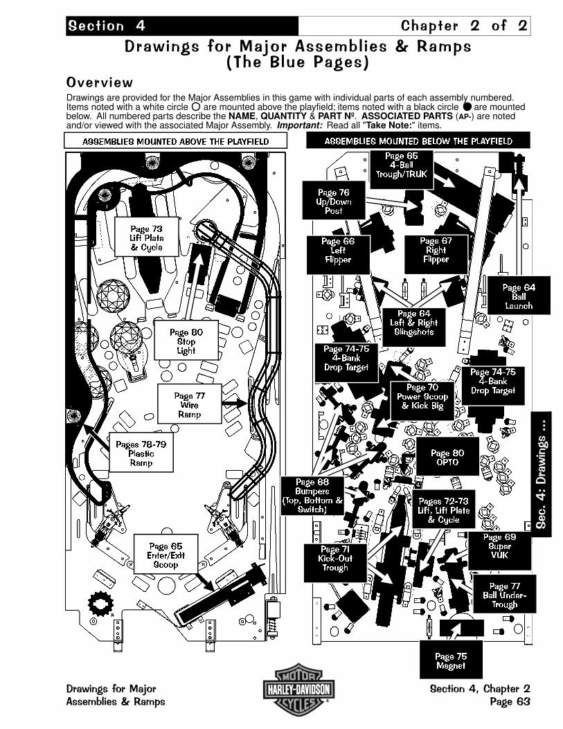
��� �&. � ���� �� � &� �
7��� �.� �&��<&���� � �� � =�������" ��������
>?��?���Drawings are provided for the Major Assemblies in this game with individual parts of each assembly numbered.Items noted with a white circle are mounted above the playfield; items noted with a black circle are mountedbelow. All numbered parts describe the NAME, QUANTITY & PART Nº. ASSOCIATED PARTS (AP-) are notedand/or viewed with the associated Major Assembly. Important: Read all "Take Note:" items.
���� �����
�� ��������
���� ������������
���� �������������
��������� � �!��" �� # �$� ���%����"
���� ������ & �������'�(� �(
���� ��������')
"� � ������
���� �*��+)� ���� ���
���� �,�����-��
���� �����'��
����( �.��/����0 ���� ����& 12+�
���� �����" 3'� (�
���� ��� �'4����� ���
���� 56 ��
���� ���
���'+�
���� ��������')
"� � ���������� �6� 3�� �+ �& ��+) ��
���� �/���� ����& 12+�
��������� � �!��" � -� �$� ���%����"
���� ���'�����7���+ �
���� ��#�����8�
����( �5��,��(��+��8�
���� 56�� ������
���� �5�8���(
9� �0 �� 8 &�3��+�:
���
,�'7����.�,,,
7����.��&��<&� ��� �&.�/���� ������ ����=��� ������

"������ &����.����� ��/������������- �������� &�� ���������.��� �� ����. &����,
��������������������������������������������������
���.��& ���� �=��� ���� ���/������������@ �,���- �������
�º ���������� �� ���� �� ��� �� �º1 Slingshot Bracket Assembly 1 515-5339-01
Item 1 is secured below the playfield by: #8 X 1/2" HWH AB (Zinc) (Qty. 3) (234-5101-00)
2 Coil Retaining Bracket 1 535-5203-03Item 2 is secured to Item 1 by: #8-32 X 3/8" PPH MS (Sems) (Qty. 2) (232-5301-00)
3 Coil, 23-800 1 090-5001-00TORDERING ABOVE (ITEM 3) COIL PART Nº WILL INCLUDE:
— Diode, 1N4004 (positioned at top) 1 112-5003-004 Coil Sleeve 1 545-5031-005 Plunger & Link Assembly 1 515-5338-00
ORDERING ABOVE (ITEM 5) SUB-ASSY. PART Nº WILL INCLUDE:5A5B5C
Plunger 2" Lg.Plunger LinkRoll Pin 1/8" ø x 5/8" Lg.
111
530-5025-01545-5293-00251-5008-00
Item 5B is secured to Item 10A by: Retaining Ring, 1/4" ø Shaft (Qty. 1) (270-5002-00)
Ordering Note: If 515-5338-00 is unavailable, order the individual part(s) actually required.
6 Compression (Return) Spring 1 266-5020-007 Slingshot Stack (Blade) Switch 2 180-5054-008 Switch Body Protect Plate 2 535-5045-00
Items 7 & 8 are secured to Item 1 by: #6-32 X 5/8" HWH Swage (Qty. 4) (237-5976-04)
9 Switch Diode, 1N4001 2 112-5001-0010® Riveted Arm & Tip Assembly 1 515-5340-01ORDERING ABOVE ® RIVETED ASSY. PART Nº WILL INCLUDE:10A10B®10C*
ArmKicker Tip (secured to 1A by 1C)Rivet, 1/8" ø x 1/4" Lg.
111
515-5341-01545-5216-01249-5003-00
Item 10A is secured to Item 1 by: Retaining Ring, 1/4" ø Shaft (Qty. 1) (270-5002-00)
Ordering Note: If 515-5340-01 is unavailable, order the individual part(s) actually required.
�º ���������� �� ���� �� ��� �� �º1 Coil Mounting Bracket 1 515-6385-00
Item 1 is secured below the playfield by: #8-32 X 7/8" HWH MS (Zinc) (Qty. 2)(237-5890-00), #8-32 Nylon Stop Nut (Qty. 2) (240-5102-00) and #8-32 X 5/8" HWH Swage(Serr) Zinc (Qty. 1) (237-5975-03)
2 Coil Retaining Bracket 1 535-5203-03Item 2 is secured to Item 1 by: #8-32 X 3/8" PPH MS (Sems) (Qty. 2) (232-5301-00)
3 Coil, 24-940 1 090-5036-00BORDERING ABOVE (ITEM 3) COIL PART Nº WILL INCLUDE:
— Diode, 1N4004 (positioned at bottom) 1 112-5003-004 Coil Sleeve 1 545-5076-015 Spring Washer (17/32" ID X 3/4" X 1") 1 269-5002-006 Plunger Assembly 1 515-5000-027 Compression (Return) Spring 1 266-5020-008 Rubber Bumper (Grommet) 2 545-5105-00
������
@�
�
�
�
�
�
�
�
�
�
��$�%& �'* An asterisk (*) indicates item(s) are not noted in the pictorials.
® "R" indicates Item noted is secured with rivet(s) as listed.
������
��� /@��
=��� /@��
��
�
�
�
�
�
�� �
Qty. 2
Qty. 2
Qty. 1/per
���
��
��"
�"
��
HingeStud
Armature Stop & Shading Ring
Coil Sleeve thru Coil
�
SW. 59(Qty. 2)
SW. 62(Qty. 2)
���,�
'7���
�.�,,,
��� �&.�/���� ��� 7����.��&��<&������� ��� ����=���

��"�����&������ ��/������������- ��������.��&��� ����� '������ �� �� ��&�,
>�����.�%& �'-��. ���� &���������������� � �&���A����- ����/��&���"���B������� �����&.�����.
���.� �������. �. �������,
��$�%& �'* An asterisk (*) indicates item(s) are not noted in the pictorials.
For a break-down of parts of Items 12 & 13, OPTO Boards(515-0173-00 & 515-0174-00), see Section 5, Chapter 4, TroughUp-Kicker Dual OPTO Boards Theory of Operation & Schematic,Component Layout & Parts.
�������
@�
��$��������%& �'Item AP-A, Enter / Exit Scoop, 535-7329-01(not included with the 4-Ball Trough Assy.),is shown how it is actually positioned
over the 4-Ball Trough Assembly.It is mounted above the playfield.
. ��! �� ��&&�
�
�
�
�
�
��
��
��
�
Qty. 3Qty. 3
���
�
Shown Broken View
�Shown Broken View
to see complete switchesSee securing
hardware underItems 12 & 13.
See securinghardware
under Item 11
��
���>�����.�%& �� &?�,
SW. 11SW. 12
SW. 13
SW. 14
SW. 15
Item 12, Dual OPTO TRANS (Transmitter)Board, 515-0173-00, is mounted on the
other side of the Trough Assembly, in linewith Item 13, Dual OPTO REC (Receiver)
Board, 515-0174-00, using same hardware.
��
SW. 15
SW. 14
�º ���������� �� ���� �� ��� �� �º1 Ball Trough Outhole Mounting Bracket 1 515-6580-01
Item 1 is secured below the playfield by: #8 X 1/2" HWH AB (Zinc) (Qty. 6) (234-5101-00)
2 Micro Switch (Roller Actuator, Lite-Force) 3 180-5119-02Item 2 is secured to Item 1 by: #2-56 X 1/2" HWH (Sr) UNS #4HD TR3 BO (Qty. 6) (237-5937-02)Item 2 requires: Heat Shrink Tubing 1/8" ø PUI-24 (Qty. 1"/per) (605-5006-00)
3 Switch Diode, 1N4001 3 112-5001-004 Coil Mounting Bracket 1 535-7330-01
Item 4 is secured to Item 1 by: #8-32 X 3/8" HWH Swage (Sr.) Zinc (Qty. 4) (237-5975-00)
5 Coil Retaining Bracket 1 535-5203-03Item 5 is secured to Item 4 by: #8-32 X 1/4" HWH MS (Serr) Zinc (Qty. 2) (237-5964-01)
6 Coil, 26-1200 1 090-5044-00TORDERING ABOVE (ITEM 6) COIL PART Nº WILL INCLUDE:
— Diode, 1N4004 (positioned at top) 1 112-5003-007 Coil Sleeve (Short) (Formost #10-7077) 1 545-5076-018 Plunger Assembly 1 515-5941-019 Compression (Return) Spring 1 266-5020-00
�º ���������� �� ���� �� ��� �� �º10 Rubber Bumper (Grommet) 1 545-5105-0011 Trough Ball Guide Plate Not Required 1 535-7801-00Item 11 is secured to Item 1 by: 1/4" X 5/16" X .144" I.D. Spacer Tap. (Qty. 1)(254-5014-03) and #2-56 X 1/2" HWH (Ser) UNS #4HD TR3 BO (Qty. 4) (237-5937-02)
12 Dual OPTO TRANS Board Assembly 1 515-0173-0013 Dual OPTO REC Board Assembly 1 515-0174-00Items 12 & 13 are by: #6-32 X 5/8" HWH Swage (Serr) Zinc (Qty. 3/per) (237-5976-04)For Individual Items use : Dual OPTO TRANS Bd. (Qty. 1) (520-5173-00), Dual OPTO RECBd. (Qty. 1) (520-5174-00), OPTO PCB Tube Spacer (Brass) (Qty. 3/per) (530-5308-02) orOPTO PCB Rubber Grommet (Qty. 3/per) (545-5518-00)
ASSOCIATED PARTS ARE NOT INCLUDED WITH THE ABOVE ASSEMBLY.
�º ��������� �� ���� �� ��� �� �ºAP-A Ball Trough Enter / Exit Scoop 1 535-7329-01Item AP-A secured to the playfield by: #8 X 1/2" HWH AB (Zinc) (Qty. 4) (234-5101-00).
AP-B* Steel Balls (1-1/16" ø) 4 260-5000-00
���
,�'7����.�,,,
7����.��&��<&� ��� �&.�/���� ������ ����=��� ������

C���������� ���� ��/������������- ��������.��&��� ����� '"�� �C������"� ����� ��,/���������������- �������
��$�%& �'® "R" indicates Item noted issecured with rivet(s) as listed.
DEDICATEDSW. 02
The differencesbetween theLeft & Right
Flippers are:
Item 1,Item 4,
andItem 14A
(just theBracket)
The coils may also
differdepending
on the game.�����
��
��� /@��
# ��B=%
# ��B=%
For Securing Hardware, see the PartsTable above, under the item desired.
����
���
��"
�
��
�
�
�
� �
�
��
��� ��
����
��
��D
���
��"D
���
��
E�&>
���� ��C
���������� �=
� ����F� �$�&
���� %
�,'�����������
��.�����- ��
�/��
/��/��
/���
���
�º ���������� �� ���� �� ��� �� �º1 Flipper Base Plate (LEFT) 1 See FRP1
Item 1 is secured below the playfield by: #10 X 1/2" HWH MS (Serr) Zinc ST (Qty. 8)(237-5949-00) Ordering Note: Use Item FRP1, see the end of this Parts Table.
2 Flipper Bat Bushing (White Plastic) 1 545-5070-00Item 2 is secured to Item 1 by: #6-32 X 3/8" HWH Swage (Ser.) Zc. (Qty. 3) (237-5976-02)
3 Power (End of Stroke) Switch 1 180-5149-00Item 3 is secured to Item 1 by: #6-32 X 5/8" HWH Swage (Ser.) Zc. (Qty. 2) (237-5976-04)
4 Sw. Plate/Spring Return Brkt. (LEFT) 1 535-7354-015 Flipper Return Spring 1 265-5035-006* Coil Stop Bracket Sub-Assembly 1 515-6308-01
Item 6 is secured to Item 1 by: #10-32 X 3/8" SHWH Swage (Serr) Zinc (Qty. 2)(237-5985-00) and #10 Split Lock Washer (Qty. 2) (244-5003-00)
7 Spring Washer (17/32" ID X 3/4" X 1") 1 269-5002-008 Coil Support Bracket 1 535-7356-00
Item 8 is secured to Item 1 by: #8-32 X 3/8" HWH Swage (Ser.) Zc. (Qty. 2) (237-5975-00)
9 Coil, 22-1080 (YEL-GRN) (Left) 1 090-5032-00TORDERING ABOVE (ITEM 9) COIL PART Nº WILL INCLUDE:
— Diode, 1N4004 (positioned at top) 1 112-5003-0010* Coil Sleeve 1 545-5388-0011 Deflector Pad (Bumper) 1 545-5428-0012* Flipper Plunger & Link Sub-Assy. 1 515-6304-03ORDERING ABOVE (ITEM 12) SUB-ASSY. PART Nº WILL INCLUDE:12A12B
Flipper Plunger with "Flat"Plunger "Flipper" Link
11
530-5349-01545-5611-01
Item 12B is secured to 12A by: Bushing, .16" ø ID X .281" ø OD X .187" (Qty. 1)(530-5532-00) and Spirol Pin ø 5/32" X 3/4" Lg. (Qty. 1) (251-5015-02)
�º ���������� �� ���� �� ��� �� �º13* Crank Bar 1 530-5070-02Item 13 requires: Bushing, .192" ø ID X .312" ø OD X .195" (Qty. 1) (530-5139-00)
14* ® Switch Actuator (LEFT) Sub-Assy. 1 515-7257-01ORDERING ABOVE (ITEM 14) SUB-ASSY. PART Nº WILL INCLUDE:14A14B
Actuator & Spring Bracket (LEFT)® Switch Actuator (White Plastic)
11
535-9038-01545-5612-00
Item 14B is secured to 14A by: Rivet, 1/8" ø X 1/4" Lg. (Qty. 1) (249-5003-00)
15* Set Screw: #10-32 X 7/8" Socket Hd. 2 237-5966-00Item 15 requires: #10 Split Lock Washer (Qty. 1/per) (244-5003-00) and #10-32 Nylon StopNut (Qty. 1/per) (240-5203-00) Tool Required for Item 15: 5/32" or 4mm Allen Wrench
Flipper Rebuild Parts for Easier Installation, $ave $:
FRP1Flipper Base Plate Kit (LEFT)Includes Item 1 pre-threaded, with theSecuring Hardware for Items 2, 3, 6 & 8.
515-6617-01
FRP2Plunger, Link & Crank (LEFT) Assy.Includes above Items 12, 13, 14 and 15and is pre-assembled.
515-7203-01
FRP3Flipper (LEFT) Rebuild KitSame as FRP2, but also includes aboveItems 6 & 10.
500-6307-10
ASSOCIATED PARTS ARE NOT INCLUDED WITH THE ABOVE ASSEMBLY.
�º ��������� �� ���� �� ��� �� �º
AP-AWHITE Flipper Bat & Shaft (Plain)(Non-Knurled End) Assembly 1 515-5133-08-06Large Flipper BLACK Rubber Ring 1 545-5277-00
���,�
'7���
�.�,,,
��� �&.�/���� ��� 7����.��&��<&������� ��� ����=���

C�������=��� ���� ��/������������- ��������.��&��� ����� '"�� �C������"� ����� ��,/���������������- �������
For Securing Hardware, see the PartsTable above, under the item desired.
DEDICATEDSW. 04
The differencesbetween theLeft & RightFlippers are:
Item 1,Item 4,andItem 14A(just theBracket)
The coils may alsodifferdependingon the game.
�������
=��� /@��
>=�%B
>=�%B
����
���
��"
���
��D
��
��
��
��
�
��
���
��
�� �
�
�
�
���
��"D
��
��$�%& �'® "R" indicates Item noted issecured with rivet(s) as listed.
E�&>
���� ��
C�������=��� �=� ����F� �$�&���� %�,'
�������������.�����- ���/��/��/��/���
���
�º ���������� �� ���� �� ��� �� �º1 Flipper Base Plate (RIGHT) 1 See FRP1
Item 1 is secured below the playfield by: #10 X 1/2" HWH MS (Serr) Zinc ST (Qty. 8)(237-5949-00) Ordering Note: Use Item FRP1, see the end of this Parts Table.
2 Flipper Bat Bushing (White Plastic) 1 545-5070-00Item 2 is secured to Item 1 by: #6-32 X 3/8" HWH Swage (Ser.) Zc. (Qty. 3) (237-5976-02)
3 Power (End of Stroke) Switch 1 180-5149-00Item 3 is secured to Item 1 by: #6-32 X 5/8" HWH Swage (Ser.) Zc. (Qty. 2) (237-5976-04)
4 Sw. Plate/Spring Return Brkt. (RIGHT) 1 535-7354-005 Flipper Return Spring 1 265-5035-006* Coil Stop Bracket Sub-Assembly 1 515-6308-01
Item 6 is secured to Item 1 by: #10-32 X 3/8" SHWH Swage (Serr) Zinc (Qty. 2)(237-5985-00) and #10 Split Lock Washer (Qty. 2) (244-5003-00)
7 Spring Washer (17/32" ID X 3/4" X 1") 1 269-5002-008 Coil Support Bracket 1 535-7356-00
Item 8 is secured to Item 1 by: #8-32 X 3/8" HWH Swage (Ser.) Zc. (Qty. 2) (237-5975-00)
9 Coil, 23-1100 (ORANGE) (Right) 1 090-5030-00TORDERING ABOVE (ITEM 9) COIL PART Nº WILL INCLUDE:
— Diode, 1N4004 (positioned at top) 1 112-5003-0010* Coil Sleeve 1 545-5388-0011 Deflector Pad (Bumper) 1 545-5428-0012* Flipper Plunger & Link Sub-Assy. 1 515-6304-03ORDERING ABOVE (ITEM 12) SUB-ASSY. PART Nº WILL INCLUDE:12A12B
Flipper Plunger with "Flat"Plunger "Flipper" Link
11
530-5349-01545-5611-01
Item 12B is secured to 12A by: Bushing, .16" ø ID X .281" ø OD X .187" (Qty. 1)(530-5532-00) and Spirol Pin ø 5/32" X 3/4" Lg. (Qty. 1) (251-5015-02)
�º ���������� �� ���� �� ��� �� �º13* Crank Bar 1 530-5070-02Item 13 requires: Bushing, .192" ø ID X .312" ø OD X .195" (Qty. 1) (530-5139-00)
14* ® Switch Actuator (RIGHT) Sub-Assy. 1 515-7257-00ORDERING ABOVE (ITEM 14) SUB-ASSY. PART Nº WILL INCLUDE:14A14B
Actuator & Spring Bracket (RIGHT)® Switch Actuator (White Plastic)
11
535-9038-00545-5612-00
Item 14B is secured to 14A by: Rivet, 1/8" ø X 1/4" Lg. (Qty. 1) (249-5003-00)
15* Set Screw: #10-32 X 7/8" Socket Hd. 2 237-5966-00Item 15 requires: #10 Split Lock Washer (Qty. 1/per) (244-5003-00) and #10-32 Nylon StopNut (Qty. 1/per) (240-5203-00) Tool Required for Item 15: 5/32" or 4mm Allen Wrench
Flipper Rebuild Parts for Easier Installation, $ave $:
FRP1Flipper Base Plate Kit (RIGHT)Includes Item 1 pre-threaded, with theSecuring Hardware for Items 2, 3, 6 & 8.
515-6617-00
FRP2Plunger, Link & Crank (RIGHT) Assy.Includes above Items 12, 13, 14 and 15and is pre-assembled.
515-7203-00
FRP3Flipper (RIGHT) Rebuild KitSame as FRP2, but also includes aboveItems 6 & 10.
500-6307-00
ASSOCIATED PARTS ARE NOT INCLUDED WITH THE ABOVE ASSEMBLY.
�º ��������� �� ���� �� ��� �� �º
AP-AWHITE Flipper Bat & Shaft (Plain)(Non-Knurled End) Assembly 1 515-5133-08-06Large Flipper BLACK Rubber Ring 1 545-5277-00
���
,�'7����.�,,,
7����.��&��<&� ��� �&.�/���� ������ ����=��� ������

�������
��������� �
��� ��������
�
�
�
�
�
�
��
��
���
��
��
��
��
��
��
�
���
�
������
LAMPS28-31
SW. 49SW. 50SW. 51
����������
������ ������
���������Individual parts can be ordered.However, if the entire Bumper isrequired, use all three (3)Assembly Part Numbers at thetop of this page.�
������
���
��
SW. 49SW. 50SW. 51
LAMPS 28-31
�º ������ �� ���� ���� ���� ��� ���� �º1 #555 Wedge Base Bulb 1 165-5002-002 #555 Wedge Base Socket 1 077-5206-003 Bumper Body 1 545-5197-00
Item 3 is secured by: #5 X 7/8" PRH AB (Zinc) (Qty. 2) (237-5826-00)
4 Ring Assembly 1 515-5085-00Item 4 is secured by: #6-32 Nylon Stop Nut (Qty. 2) (240-5005-00)
5 Bumper Skirt 1 545-5607-006 Bumper Skirt Compression Spring 1 266-5048-007 Bumper Base 1 545-5195-00
�º ������ ���� ���� ���� ���� ��� ���� �º8 Plunger 1 530-5348-009 Compression (Return) Spring 1 266-5047-0010 Coil, 26-1200 1 090-5044-00T
ORDERING ABOVE (ITEM 10) COIL PART Nº WILL INCLUDE:— Diode, 1N4004 (positioned at top) 1 112-5003-00
11 Coil Sleeve 1 545-5031-0012 Fiber Yoke 1 545-5609-0013 Metal Yoke 1 535-7346-0014 Metal Yoke Stop 1 535-7347-00Item 14 is secured by: #6-32 X 1/4" HWH Swage (Serr.) Zinc (Qty. 2) (237-5976-01)
15 Coil Bracket Welded Assembly 1 515-5939-00Item 15 is secured by: #6-32 X 1-3/16" Spiral Fin Shank (Qty. 3) (237-5957-00) and#6-32 Nylon Stop Nut (Qty. 3) (240-5005-00)
�º ������ ��� ! ���� ���� ���� ��� ���� �º16 Switch Bracket 1 535-7342-00Item 16 is secured by: #8 X 1/2" HWH AB (Zinc) (Qty. 2) (234-5101-00)
17 Bumper Stack (Blade) Switch Assy. 1 180-5015-04Included with Item 17 : Spoon Switch Actuator (545-5610-02).Switch has a Diode (1N4004) (112-5003-00). Can be replaced with (1N4001) (112-5001-00).
18 Switch Body Protect Plate 1 535-7344-00Items 17 & 18 are secured by: #6-32 X 3/4" HWH Swage (Serr) Zc. (Qty. 2) (237-5976-05)
The Top & Bottom Assemblies are secured together by hardware included in assemblies.
ASSOCIATED PART IS NOT INCLUDED WITH THE ABOVE ASSEMBLY.
�º ��� ����� ���� ���� ���� ��� ���� �ºAP-A Bumper Cap (RED) 4 550-5057-02
<UPDATED AFTER MANUAL PRINTING> 111804
Sid
e V
iew
of 1
4 &
15
������
������
�� !����
���������"�#$�%����� ������ !�&���'�(��)� ��� �!!�*+,��!�-�.�*%!
/0*%��� �%��!!�*+,��!"������������1��2���3�14��*!����3"/0*%���/����*��!!2�"������������1��2���3�14��*!����3"/0*%��������$��!!2�"�����������1��2���3�14��*!������3
��5��!!������5�)���1!3������� �+,��/�,���14��*��)��3

�����$GF��� ��/������������- ����������.��� �� ����. & ��"���=���,
>�����.�%& �'For this assembly to come with the CableWiring Harness (036-5450-02-67)installed, add -67 to the 500-6184-05 PartNumber.
������
@�
�
��
��
�
�
�
�
��
SW. 45
�º ���������� �� ���� �� ��� �� �º1 SVUK Mounting Weldment Bracket 1 515-6744-04
Item 1 is secured under the P/F by: #8 X 1/2" HWH AB (Zinc) (Qty. 4) (234-5101-00)
2 Super VUK Switch Bracket 1 535-8144-01Item 2 is secured to Item 1 by: #4-40 X 5/8" MS (Serr) Zinc (Qty. 2) (237-5945-00)
3 Micro-Switch 1 180-5052-00Item 3 secured to Item 2 by: #6-32 X 3/8" HWH Swage (Serr) Zinc (Qty. 2) (237-5976-02)
4 Coil Retaining Bracket 1 535-5203-03Item 4 is secured to Item 1 by: #8-32 X 1/4" PPH MS (Sems) (Qty. 2) (232-5300-00)
5 Coil, 23-800 1 090-5001-00TORDERING ABOVE (ITEM 9) COIL PART Nº WILL INCLUDE:
— Diode, 1N4004 (positioned at top) 1 112-5003-00
�º ���������� �� ���� �� ��� �� �º6 Coil Sleeve 1 545-5076-017 Spring Washer (17/32" ID X 3/4" X 1") 1 269-5002-008 Plunger Assembly 1 515-5941-019 Compression (Relay) Spring 1 266-5020-0010 Rubber Bumper (Grommet) 1 545-5105-00Ordering Note: If 500-6184-05 is unavailable, order the individual part(s) actually required.
��$�%& �'* An asterisk (*) indicates item is Not Shown in pictorial.
1.Note: The Switch Diode, 1N4001, is not located on this assembly(nor included); it’s located on a Terminal Strip under the playfield.
2.SPI Nº 500-6184-04 (prev. game) & 500-6184-05 (-05 used in thisgame) are identical except for the Coils: -04 = Coil 24-940 and-05 = Coil 23-800
���
,�'7����.�,,,
7����.��&��<&� ��� �&.�/���� ������ ����=��� ������

F��$�%�������4�������������- ������
� ���0�������4��� �$���� ����� � ��� 0 0�� ����� �������0 �����0 �
� ����� ������4�������������- �������
� ���0�������4��� �$���� ����� � ��� 0 0�F��$����������0 ��3�� �
� ������ ����� �� �����F��$���
�����@�
�������F��$��� �������� ����� �
�
�
�
�
�
� ��
��
��
���� �� ���� ������ ������� ������������� ���� ��� ���� ����� ������� �������
��$�� ��1.Note: The Sw. Diode, 1N4001,
is not located on this assembly(nor included); it’s located ona Terminal Strip under the
playfield.
SW. 46
>������� ��
For thisassembly tocome with theCable WiringHarness(036-5450-09-67) installed,add -67 to the500-6398-00Part Number.
�º ���������� �� ���� �� ��� �� �º1 Kick-Big Mounting Bracket 1 535-8575-00
Item 1 is secured under the P/F by: #6 X 1/2" HWH AB (Zinc) Red (Qty. 6) (234-5101-02)
2 Coil Retaining Bracket 1 535-5203-03Item 2 is secured to Item 1 by: #8-32 X 1/4" PPH MS (SEMS) (Qty. 2) (232-5300-00)
3 Coil, 23-800 1 090-5001-00TORDERING ABOVE (ITEM 3) COIL PART Nº WILL INCLUDE:
— Diode, 1N4004 (positioned at top) 1 112-5003-004 Coil Sleeve 1 545-5076-015 Spring Washer (17/32" ID X 3/4" X 1") 1 269-5002-006 Plunger Assembly 1 515-5000-027 Compression (Relay) Spring 1 266-5020-008 Rubber Bumper (Grommet) 1 545-5105-00
�º ���������� �� ���� �� ��� �� �º9 Power Scoop Weldment Assembly 1 515-6022-00
Item 9 is secured under the P/F by: #6 X 1/2" HWH AB (Zinc) Red (Qty. 3) (234-5001-02)
10 Micro-Switch Bracket 1 535-6173-00Item 10 is secured to Item 9 by: #6-32 X 3/16" PPH MS (Sems) Zc. (Qty. 2) (232-5209-00)
11 Micro Switch, High-Form 1 180-5057-0012 Switch Body Protect Plate 1 535-6539-00Items 11/12 are secured to Item 10 by: #2-56 X 1/2" PPH MS (Zc.) (Qty. 2) (237-5806-00),#2 Split Lock Washer (Qty. 2) (244-5001-00) and #2-56 Hex Nut (Qty. 2) (240-5301-00)
Ordering Note: If 500-5398-00 or 500-5809-00 are unavailable, order the individual part(s)actually required.
�����
��������
����
��� � ���+0�� ��� ��������� ���� ����� � �����4����2�����

F��$�>� �� ��0�����4��������� ����- ������������� ��� ���� ��� �� ���������������- ������*�
�����@�
�
�
� �
�
�
��
Sw. 41
Sw. 42
Sw. 43
Sw. 44
��� ������ ��� �� ��� �������� �������� �� ����������� ��������� ��� ��� �����
����� � ����
��$�� ��* An asterisk (*) indicates item is Not Shown in pictorial.
Note: The Switch Diodes, 1N4001, are not located on this assembly;they’re located on a Diode Board (Item AP-A) under the playfield.
>������� ��For this assembly to come with the CableWiring Harness (036-5450-08-67) installed,add -67 to the 500-6397-00 Part Number.
���0���� � ��The Switch Membrane (Item 3) is connected to a Diode Board (Assoc. Part Item AP-A) which is required to operate. Beforedetermining the Switch Membrane is malfunctioning, check the connection to the Diode Board, and the diodes on the boardfirst. Testing of this mechanism can be done in Portals , reference the inside front cover or Section 3, Chapter 2, GO TODIAGNOSTICS MENU, Harley-Davidson Specific (Motorcycle Test), Page 24.
�º �� � � �! ���� ���" #�$% �� ���� �º1 Kick-Out Trough Weldment Bracket 1 515-7023-00
Item 1 is secured under the playfield at the top single-hole by: #8 X 1/2" SHWH AB(Zinc) (Qty. 1) (234-5101-00) and Washer .187" ID X .875" OD X .048" Thk (Qty. 1)(242-5059-00) and the front 2 holes by: #8-32 X 3/4" HWH Swage (Serr) Zinc (Qty. 2)(237-5975-02) and the back 6 holes by: #4 X 1/2" PFH (Zinc) (Qty. 6) (237-5840-00)
2 Stop Bracket 1 535-8568-00Item 2 secured to Item 1 by: #8-32 X 1/2" PPH MS (Sems) Zinc (Qty. 3) (232-5302-00)
3 4-Position Membrane Switch w/cable 1 181-5001-004 Coil Retaining Bracket 1 535-5203-03
Item 4 secured to Item 1 by: #8-32 X 1/4" PPH MS (Sems) (Qty. 2) (232-5300-00)
5 Coil, 24-940 1 090-5036-00BORDERING ABOVE (ITEM 5) COIL PART Nº WILL INCLUDE:
— Diode, 1N4004 (positioned at bottom) 1 112-5003-00
�º �� � � �! ���� ���" #�$% �� ���� �º6 Coil Sleeve 1 545-5076-017 Spring Washer (17/32" ID X 3/4" X 1") 1 269-5002-008 Plunger Assembly 1 515-5941-019 Compression (Relay) Spring 1 266-5020-0010 Rubber Bumper (Grommet) 1 545-5105-00
ASSOCIATED PART IS NOT INCLUDED WITH THE ABOVE ASSEMBLY.
�º ���& ��"� ���� ���" ���� �� ���� �ºAP-A * Diode PC Board 1 520-5146-00Item AP-A is secured under the P/F by: #6 X 3/4" HWH AB (Zinc) (Qty. 2) (234-5003-00)and 3/8" Slf. Rtn. Spacer White (Qty. 2) (254-5007-01)
Ordering Note: If 500-5788-02 is unavailable, order the individual part(s) actually required.
�����������������
��������� ���� � ��� � ���+0�� ��������4����2����� ���� �

3�� �����4��������������- ������������ ��� ���� ������� ���������������- ������ �
� ���0�������4��� �$���� ����� � ��� 0 0�3�� ��� �2+������������( �����
���� � ����� ��� �� �� � ����� ���� �������������������� ����� � �� �������� � ����� �������� ��� � �� � ��!"
���� � ����� ��� �� �� � ����� ���� �������������������� ����� � �� �������� � ����� �������� ��� � �� � ��!"
�
�
�
�
�
�
�
�
�
�
�
�
�
UPPositionSwitch
DOWNPositionSwitch
DOWNPositionSwitch
36
UPPositionSwitch
35
��$�� ��* An asterisk (*) indicates item
is Not Shown in pictorial.
>������� ��For this assembly to come with the CableWiring Harness (036-5450-07-67) installed,add -67 to the 500-6396-00 Part Number.
�º ���������� �� ���� �� ��� �� �º1 Motor Mounting Bracket 1 535-8564-00
Item 1 is secured under the P/F by: #8 X 1/2" SHWH AB (Zinc) (Qty. 4) (234-5101-00)
2 Motor & Connector Assembly 1 515-7025-00-67ORDERING ABOVE (ITEM 2) SUB-ASSY. PART Nº WILL INCLUDE:
2A2B*2C*2D*
Motor, Autotrol 20 RPM 24v AC CCW1 X 3, .093" Conn. Male 03-09-2032Capacitor, Tecate .1 MFD 500v DiscNeon Bulb
1111
041-5072-02045-5004-03130-5000-00165-5021-00
Item 2 is secured to Item 1 by: #6-32 X 1/4" PPH MS (Sems) Zinc (Qty. 2) (232-5200-00)Operation Note: Item 2C eliminates Line Noise, Item 2D is used for Spike Suppression.
3 Lift Cam Assembly 1 515-7021-00Item 3 is secured to Item 1 (Shaft) by Item 4 (next column).
�º ���������� �� ���� �� ��� �� �º4 #8-32 X 3/8" Soc. Hd. Cap Scr. (Zinc) 1 237-5897-005 Micro-Switch 2 180-5052-00
Item 5 is secured to Item 1 by: #4-40 X 5/8" PPH MS (Sems) Zc (Qty. 2/per) (237-5832-00)
6 Switch Diode, 1N4001 2 112-5001-00
ASSOCIATED PART IS NOT INCLUDED WITH THE ABOVE ASSEMBLY.
�º ��������� �� ���� ���� ��� �� �ºAP-A * Relay PC Board 1 520-5010-00Item AP-A is secured by: #6 X 3/4" HWH AB (Zinc) (Qty. 4) (234-5003-00) and 3/8" Slf.Rtn. Spacer White (Qty. 4) (254-5007-01)
Note: For Item AP-A PC Bd. to include cable & spacers use (500-6213-00).Ordering Note: If 500-6396-00 is unavailable, order the individual part(s) actually required.
�����
��������
����
��� � ���+0�� ��� ��������� ���� ����� � �����4����2�����

3�� ��� �2+���������4���������������� �- ������������ ��� ���� �������4����� ��- �������2�����
� ���0�������4��� �$���� ����� � ��� 0 0�3�� �����4������!� �������
���� ����� � ���� � ���� �� ���� ���������� �� � � ����
���� � �� ��! � ���� � ���� �� ���� ���������� �� � � ����
"��� � ����! �� � � #$ %� ��&�'�����(� � ��� (��$ �� � � �� � ��� �� � ��� � � �� �� ��� ���� ��)
�
�
�
��
� �
�
�
� � * ���� � � ����� + �� �� %��, ��� �) � � * �� ��� �!�' � + �� �� � ��!� ��� � � '� �� ��� �����)
����
����
����
����
�º ���������� �� ���� �� ��� �� �º1 Lift Plate Weldment Sub-Assembly 1 515-7022-00
Item 1 is secured above the P/F @ Item 2 by: #8-32 X 5/8" PPH MS (Sems) Zc. (Qty. 2)(232-5303-00)
2 Hinge 1 390-5044-00Item 2 is secured to Item 1 by: #8-32 X 3/8" PPH MS (Sems) Zinc (Qty. 2) (232-5301-00)
3 Rubber Sleeve (Modified: unique to game) 1 545-5932-00Item 3 is secured to Item 1 by: #6-32 X 1/4" PPH MS (Sems) Zinc (Qty. 1) (232-5200-00)and #6 Washer (Qty. 1) (242-5001-00)Item 3 is created from a modified Post Black Rubber (Sleeve Tall) (545-5308-00)
4 H-D® FLSTF® Fat Boy 1:10 1 880-5034-015 Clear Dot, Self-Adhesive 1 280-5012-00
�º ���������� �� ���� �� ��� �� �º6 Plastic Piece (Screened) Buty -27 1 from 830-5960-XX
Item 6 secured by: #6-32 X 3/4" PPH TC MS Zinc (Qty. 2) (237-6009-00) and#6 Washer (Qty. 1) (242-5001-00)
ASSOCIATED PART IS NOT INCLUDED WITH THE ABOVE ASSEMBLY.
�º ��������� �� ���� ���� ��� �� �ºAP-A Link (Metal, Slotted) 1 535-8603-00AP-B Spring (works with Item 7 Link) 1 265-5017-01Items AP-A & AP-B are secured onto the PEM Stud of the Lift Assy., 500-6396-00-67(previous page) by: Washer 1/4" ID X 7/16" OD X 1/32" (Qty. 1) (242-5012-00) andRetaining Ring, 1/4" ø Shaft (Qty. 2) (270-5002-00) and onto the PEM Stud of the LiftPlate & Cycle Assy., 500-6362-01-67 by: Washer 1/4" ID X 7/16" OD X 1/32" (Qty. 1)(242-5012-00)
Ordering Note: If 500-6362-00 is unavailable, order the individual part(s) actually required.
�����������������
��������� ���� � ��� � ���+0�� ��������4����2����� ���� �

�����$�� ������ �����4�������� ����@ �����- ���������� ���4�� � 0���( �����
��������� ����� �� ���� ����� ����������� ������������� ���� ��
�
��
��
�
Qty. 4
Qty. 4
Qty. 4
��� ��
C� � ����
��������� ����� �� ���� ����� ��� �������� �������� ����� ���� ��
��������� ����� �� ���� ����� ��� �������� �������� ����� ���� ��
��
�
�
��
���
���
�
��
�
�
Qty. 4
Qty. 4
@�"@
��� ��
@�"@
��������� ������� ���� �������� ���������������� ��������� ��
�� �4-BankRIGHTSW. 21SW. 22SW. 23SW. 24
>������� ��For this assembly to comewith the Cable WiringHarness (Right 036-5450-14-67) installed, use 500-6372-01-67 (Right); or Left 036-5450-15-67) installed, use500-6372-00-67 (Left).
SW. 20or
SW. 21
��� ��
@�"@
���$����
��������� ����� �� ���� ����� ��� �������� �������� ����� ���� ��
��������� ����� �� ���� ����� ��� �������� �������� ����� ���� ��
���
��+���
��
Qty. 4
Qty. 4
Qty. 4
Qty. 4
�
�
�
�
��
�
��
�� ��
�
�
Securing Hardware is listed under each Item in the Parts Table (next page), where applicable.
SW. 18or
SW. 23
SW. 17or
SW. 24
SW. 19or
SW. 22
4-BankLEFT
SW. 17SW. 18SW. 19SW. 20
�����
��������
����
��� � ���+0�� ��� ��������� ���� ����� � �����4����2�����

�����$�� ������ �����4�������� ����@ �����- �������+ � ������������ �4�� ���� ���4�� ����!� �������
��������������������������������������������������
�0�������0���+ �������4���������������- ������������ ��� ���� ������ + ����������������������- �������
�
�
�
����
�º ���������� �� ���� �� ��� �� �º1 Target Frame (4-Bank) 1 535-6159-04
Item 1 is secured under the P/F by: #8 X 1/2" SHWH AB (Zinc) (Qty. 6) (234-5101-00)
Item 1 is secured onto Item 4 (at top) by: #8-32 X 3/8" HWH TF Type C (Qty. 2)(237-5903-00)
2 Mounting Bracket, D/T Springs (4-Bank) 1 535-6510-04Item 2 is secured onto Item 4 (at bottom) by: #8-32 X 3/8" HWH TF Type C (Qty. 2)(237-5903-00)
3 Target Retaining Bracket (4-Bank) 1 535-5042-04Item 3 is secured onto Item 1 (at bottom) by: #8-32 X 3/8" HWH TF Type C (Qty. 2)(237-5903-00)
4 End Plates (Drop Target) 2 535-6162-00Each Item 4 is secured by hardware for Items 1, 2 & 3.
5 Adjustment Bracket 1 535-6508-00Item 5 is secured onto Item 4 (side without Coil) by: #6-32 X 3/8" SHWH MS (Zinc) TCT-23 (Qty. 2) (237-5891-00) and is secured with a: #8-32 X 7/8" SHWH MS (Zinc) (Qty. 1)(237-5890-00) & #8-32 Nylon Stop Nut (Qty. 1) (240-5102-00) through Item 2.
6 Target Lift Bracket (4-Bank) 1 535-6509-04Item 6 is secured onto Item 4 (both sides) by Item 8, Pivot Shaft.
7 Target Shaft (4-Bank) 1 530-5179-04Item 7 is secured by: Retaining Ring, 1/4" ø Shaft (Qty. 2) (270-5002-00)
8 Pivot Shaft (4-Bank) 1 530-5180-04Item 8 is secured by: Retaining Ring, 1/8" ø Shaft (Qty. 2) (270-5000-00)
�º ���������� �� ���� �� ��� �� �º9 Coil Retaining Bracket (Bottom) 1 535-6154-00
Item 9 is secured onto Item 4 (side with Coil) by: #6-32 X 3/8" SHWH MS (Zinc) TC T-23(Qty. 2) (237-5891-00)
10 Coil, 23-700 1 090-5022-00TORDERING ABOVE (ITEM 10) COIL PART Nº WILL INCLUDE:
— Diode, 1N4004 (positioned at top) 1 112-5003-0011 Coil Sleeve 1 545-5031-0012 Coil Stop Bracket Assy. (Top) 1 515-5088-00Item 12 is secured onto Item 4 (side with Coil) by: #6-32 X 3/8" SHWH MS (Zinc) TCT-23 (Qty. 2) (237-5891-00)
13 Plunger & Link Assembly 1 515-5338-00ORDERING ABOVE (ITEM 13) SUB-ASSY. PART Nº WILL INCLUDE:13A13B13C
Plunger 2" Lg.Plunger LinkRoll Pin 1/8" ø x 5/8" Lg.
111
530-5025-01545-5293-00251-5008-00
14 Drop Target (White) (Partec #4-124-1) 4 545-5048-0115 Reset Spring for Drop Targets 4 265-5003-0016 Leaf-Switch (Drop Target Style) 4 180-5104-0017 Switch Protect Plate 4 535-5045-00Items 16 & 17 are secured on Item 1 by: #6-32 X 1/2" HWH Swage (Serr) Zinc(Qty. 2/per) (237-5976-03)
18 Diode, 1N4001 4 112-5001-00Ordering Note: If 500-5799-04 is unavailable, order the individual part(s) actually required.>������� ��
For this assembly to come with the Cable Wiring Harness (Right036-5450-14-67) installed, use 500-6372-01-67 (Right); or Left036-5450-15-67) installed, use 500-6372-00-67 (Left).
�º ���������� �� ���� �� ��� �� �º1 Threaded Bushing Weld Assy. New 1 515-6141-012 Threaded Core Plug 1 530-5320-003 3/4"-16 Hex Nut 1 240-5315-00
ASSOCIATED PART IS NOT INCLUDED WITH THE ABOVE ASSEMBLY.
�º ��������� �� ���� �� ��� �� �ºAP-A Magnet Coil, 22-650 (12" Leads) (1/per) 4 090-5042-01Item AP-A is secured under the P/F by: #8 X 1/2 SHWH AB (Zinc) (Qty. 4) (234-5101-00)
Ordering Note: If 515-6142-01 is unavailable, order the individual part(s) actually required.
�����������������
��������� ���� � ��� � ���+0�� ��������4����2����� ���� �
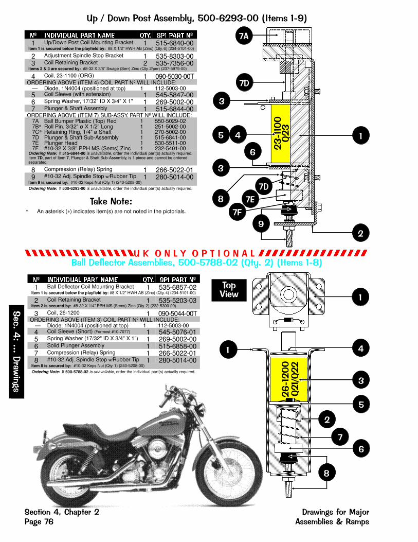
G�"� ��� � �����4��������������- ������
����������������GF>�3#>��->��3 �������������������������� ������4���������� ����@ �����- ������
�º ���������� �� ���� �� ��� �� �º1 Up/Down Post Coil Mounting Bracket 1 515-6840-00
Item 1 is secured below the playfield by: #8 X 1/2" HWH AB (Zinc) (Qty. 6) (234-5101-00)
2 Adjustment Spindle Stop Bracket 1 535-8303-003 Coil Retaining Bracket 2 535-7356-00
Items 2 & 3 are secured by: #8-32 X 3/8" Swage (Serr) Zinc (Qty. 2/per) (237-5975-00)
4 Coil, 23-1100 (ORG) 1 090-5030-00TORDERING ABOVE (ITEM 4) COIL PART Nº WILL INCLUDE:
— Diode, 1N4004 (positioned at top) 1 112-5003-005 Coil Sleeve (with extension) 1 545-5847-006 Spring Washer, 17/32" ID X 3/4" X 1" 1 269-5002-007 Plunger & Shaft Assembly 1 515-6844-00
ORDERING ABOVE (ITEM 7) SUB-ASSY. PART Nº WILL INCLUDE:7A7B*7C*7D7E7F
Ball Bumper Plastic (Top) RedRoll Pin, 3/32" ø X 1/2" LongRetaining Ring, 1/4" ø ShaftPlunger & Shaft Sub-AssemblyPlunger Head#10-32 X 3/8" PPH MS (Sems) Zinc
111111
550-5029-02251-5002-00270-5002-00515-6841-00530-5511-00232-5401-00
Ordering Note: If 515-6844-00 is unavailable, order the individual part(s) actually required.Item 7D, part of Item 7, Plunger & Shaft Sub-Assembly, is 1 piece and cannot be orderedseparated.
8 Compression (Relay) Spring 1 266-5022-019 #10-32 Adj. Spindle Stop w/Rubber Tip 1 280-5014-00
Item 9 is secured by: #10-32 Keps Nut (Qty. 1) (240-5208-00)
Ordering Note: If 500-6293-00 is unavailable, order the individual part(s) actually required.
��$�� ��* An asterisk (*) indicates item(s) are not noted in the pictorials.
@��
�������
�
��
�
�
�
�
C
6
�
�
�
�������
@��"@��
�
�
�
�
�
�
�
� �����
�º ���������� �� ���� �� ��� �� �º1 Ball Deflector Coil Mounting Bracket 1 535-6857-02
Item 1 is secured below the playfield by: #8 X 1/2" HWH AB (Zinc) (Qty. 4) (234-5101-00)
2 Coil Retaining Bracket 1 535-5203-03Item 2 is secured by: #8-32 X 1/4" PPH MS (Sems) Zinc (Qty. 2) (232-5300-00)
3 Coil, 26-1200 1 090-5044-00TORDERING ABOVE (ITEM 3) COIL PART Nº WILL INCLUDE:
— Diode, 1N4004 (positioned at top) 1 112-5003-004 Coil Sleeve (Short) (Formost #10-7077) 1 545-5076-015 Spring Washer (17/32" ID X 3/4" X 1") 1 269-5002-006 Solid Plunger Assembly 1 515-6858-007 Compression (Relay) Spring 1 266-5022-018 #10-32 Adj. Spindle Stop w/Rubber Tip 1 280-5014-00
Item 8 is secured by: #10-32 Keps Nut (Qty. 1) (240-5208-00)
Ordering Note: If 500-5788-02 is unavailable, order the individual part(s) actually required.
�����
��������
����
��� � ���+0�� ��� ��������� ���� ����� � �����4����2�����

����G������ ��0�����4���������������- �������
��������������������������������������������������
5������������4���� -��!������� ������� ������
��$�� ��* An asterisk (*) indicates item is Not Shown in pictorial.
® "R" indicates item has a riveted-on part(s), if removing/adding rivetsis not an option, order the entire ® Sub-Assembly. Please Note: If the ® Sub-Assembly is not available, call Technical Support.
�
�
���
SW. 48
>������� ��For this assembly to come with the CableWiring Harness (036-5450-03-67) installed,add -67 to the 500-6401-00 Part Number.
����������
�º ���������� �� ���� �� ��� �� �º1® Riveted Under-Trough Sub-Assy. 1 515-7020-00-67R
ORDERING ABOVE ® RIVETED ASSY. PART Nº WILL INCLUDE:1A1B1C*
Metal Under-Trough (Plain, No Parts)Mounting Bracket for Micro-Switch Rivet, 1/8" ø X 5/32" Lg.
112
535-8562-00535-7319-05249-5009-00
Item 1 is secured under the Playfield by: #8 X 1/2" HWH AB (Zinc) (Qty. 4) (234-5101-00)
�º ���������� �� ���� �� ��� �� �º2 Micro-Switch (High Form) 1 180-5057-003* Switch Body Protect Plate 1 535-6539-00
Items 2 & 3 are secured on Item 1B by: #2-56 X 1/2" HWH Ser. UNS #4HD TR3 BO(Qty. 2) (237-5937-02)
4 Diode, 1N4001 1 112-5001-00Ordering Note: If 500-6401-00 is unavailable, order the individual part(s) actually required.
� �� ���������������������
��������� ���� � ��� � ���+0�� ��������4����2����� ����
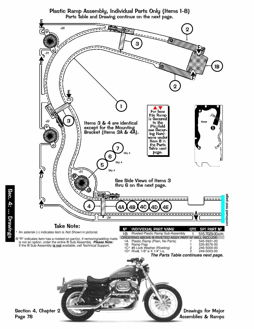
���� �����������4���-��!������� �>����- ��������� ���4������������ � ���� � 0���( �����
��$�� ��* An asterisk (*) indicates item is Not Shown in pictorial.
® "R" indicates item has a riveted-on part(s), if removing/adding rivetsis not an option, order the entire ® Sub-Assembly. Please Note: If the ® Sub-Assembly is not available, call Technical Support.
�C
C�
con
tinu
ed n
ext
pag
e
Qty. 4
Qty. 4
Qty. 4
�
�
� �� �� �+ �� �6
�
��
�
�
����������� �- ���� 0��� � 0���( �����
�
� - ����2������� �����(��� � � 0�� �� �������$� �- �����2����
����� ������� ���� �������� �������������� �������� ������� ��������� � ����� �������� ��������
�+
��
6�
�6
6�
��
����
�
º � !�"�!#$% �$� $&' (�)� �� �$� º1® Riveted Plastic Ramp Sub-Assembly 1 515-7029-00-67R
ORDERING ABOVE ® RIVETED ASSY. PART Nº WILL INCLUDE:1A1B1C*1D*
Plastic Ramp (Plain, No Parts)Ramp Flap#6 Lock Washer (Riveting)Rivet, 1/8" ø X 1/4" Lg.
1122
545-5931-00535-8576-00246-5000-00249-5003-00
The Parts Table continues next page.
�����
��������
����
��� � ���+0�� ��� ��������� ���� ����� �����4����2�����

���������� ��������������������������������������������������� ����!"��#��$�����������������$�%
con
tinu
ed p
rev.
pag
e
&���'��#�(����)��* &���'��#�(�����+�,!-
Qty. 2
Qty. 4
Qty. 4
Qty. 4
������ ���� ����� � �������� ������ ���� ����
���� ������� ���
��� � ���
���� ������ ����� ���� ��� ���� ����
�������� !�� ����� "����"�� ��� #$ �� %&'()&*+(,,-
������ ,, ������������� ���� & ��.��������
Qty. 3
Qty. 4
�
-
,
+
�
)"
)
).
)� )/ + - ,
�
.�
����� ������� ���� �������� �������������� �������� ������� ��������� � ����� ��������������
����
�
�º �� �!� "#$ �#� �#%& '�(� �� �#� �º2 Ramp Protector 2 535-6707-00
Item 2 is secured to Item 1A by: #6-32 X 3/8" PPH MS (Sems) Zinc (Qty. 2/per)(232-5201-00) and #6-32 Nylon Stop Nut, 1/4 Hex Body (Qty. 2/per) (240-5010-00)
3 Gate Assembly 2 515-6556-04ORDERING ABOVE (ITEM 3) SUB-ASSY. PART Nº WILL INCLUDE:
3A3B3C3D3E*
Mounting Brkt. for Wire Form & Sw.Wire FormMicro-Switch (for Wire Gate)Diode, 1N4001#2-56 X 1/2" HWH Ser. UNS #4HD TR3 BO
11112
535-7756-01535-7755-02180-5087-00112-5001-00237-5937-02
4 Gate Assembly (Reverse Mounted) 1 515-6556-02ORDERING ABOVE (ITEM 4) SUB-ASSY. PART Nº WILL INCLUDE:
4A4B4C4D4E*
Mounting Brkt. for Wire Form & Sw.Wire FormMicro-Switch (for Wire Gate)Diode, 1N4001#2-56 X 1/2" HWH Ser. UNS #4HD TR3 BO
11112
535-7756-02535-7755-02180-5087-00112-5001-00237-5937-02
Items 3 & 4 are secured to Item 1A by: #6-32 X 3/8" PPH MS (Sems) Zinc (Qty. 2/per)(232-5201-00) and #6-32 Nylon Stop Nut (Qty. 2/per) (240-5005-00)
�º �� �!� "#$ �#� �#%& '�(� �� �#� �º5 Mini-Mars Light Cover (Red) 4 550-5031-026 Socket, 2-Lug Stand-Up Short 4 077-5101-007 #89 Bulb 4 165-5000-89
Items 5, 6 & 7 are secured to Item 1A by: #6-32 X 1/2" PPH MS (Sems) Zinc (Qty. 2/per)(232-5202-00) and #6-32 Nylon Stop Nut (Qty. 2/per) (240-5005-00)
8 Ramp Exit Protector 1 535-8167-01Item 8 is secured onto Item 1 by: #6-32 X 3/8" PPH MS (Sems) Zinc (Qty. 2)(232-5201-00) and #6-32 Nylon Stop Nut 1/4 Hex Body (Qty. 2) (240-5010-00)
Plastic Ramp Assembly is secured above the Playfield by:A� 2" X 1/4" Hex Spacer #6-32 Top (Qty. 2) (254-5008-07)B� 2-1/4" X 1/4" Hex Spacer #6-32 Top (Qty. 1) (254-5008-18)C� 3" X 1/4" Hex Spacer #6-32 Top (Qty. 1) (254-5008-14)D� 3-1/4" X 1/4" Hex Spacer #6-32 Top (Qty. 1) (254-5008-26)E�� 4" X 5/16" Hex Spacer #6-32 Top (Qty. 3) (254-5018-03)and on the Wood Rail sides with a Ramp Mounting Bracket (Qty. 1/per) (515-6508-00)and at the Ramp with #6-32 X 3/8" PPH MS Sems (Zinc) (Qty. 1/per) (232-5201-00)
and #6 Washer (Qty. 1/per) (242-5001-00)
F�� at the Ramp Flap (Item 1B) with #4 X 1/2" PFH (Zinc) Black (Qty. 2) (237-5840-00)
&��
%*0%%%"��#��$�
"��#��$�(��1�2�� &������*��3�����4 ���������!���� ��$�-5
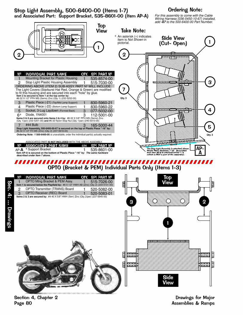
� �3��0 �����4���������������- ����� ������ ��� ���� ����� � ����$� ������������- �������
��������������������������������������������������
>��>�����$� 2�6��-��!������� �>����- �������
��$�� ��* An asterisk (*) indicates
item is Not Shown inpictorial.
��
�
� �����
�������
��������+� �>����
Qty. 3
��� ���� ��� ���� ��� � �������� ����������� ���� ���������� ������ ������������� �� ���� � �������� ����! ������!��� � "#� � ���� �$ ��� ���� �����
Qty. 3
�
�
�
�
�
����
>������� ��For this assembly to come with the CableWiring Harness (036-5450-10-67) installed,add -67 to the 500-6400-00 Part Number.
� �����
�
�
�º ���������� �� ���� �� ��� �� �º1 Mounting Bracket for Plastic Housing 1 535-8574-002 Stop Light Plastic Housing Assembly 1 515-7030-00
ORDERING ABOVE (ITEM 2) SUB-ASSY. PART Nº WILL INCLUDE:The Light Covers (Starburst Hat Red, Orange & Green) are modifiedto fit this housing and are secured into each "hole" by glue.Item 2 is secured to Item 1 at the top center by: #6-32 X 1/2" PPH MS (Sems) Zinc (Qty. 1) (232-5202-00)
3 Plastic Piece (-21) (Top/Mid Lamp Support) 1 830-5960-214 Plastic Piece (-22) (Bottom Lamp Support) 1 830-5960-225 Socket, 3-Lug Laydown (Formed Back) 3 077-5032-006* Diode, 1N4001 3 112-5001-00
Items 5 & 6 are secured onto Items 3 & 4 by: #6-32 X 3/8" PPH MS (Sems) Zinc(Qty. 1/per) (232-5201-00) and #6-32 Nylon Stop Nut (Qty. 1/per) (240-5010-00)
7 #44 Bulb 3 165-5000-44Stop Light Assembly, 500-6400-00-67 is secured on the top of Plastic Piece "-16" by:#6-32 X 1/2" FH MS (Zinc) (Qty. 2) (237-5918-00)
Ordering Note: If 500-6400-00 is unavailable, order the individual part(s) actually required.
ASSOCIATED PART IS NOT INCLUDED WITH THE ABOVE ASSEMBLY.
�º ��������� �� ���� ���� ��� �� �ºAP-A * Support Bracket 1 535-8601-00Item AP-A is secured on the bottom of Plastic Piece "-16" by: The same hardwaredescribed under Item 7 above.
�º ���������� �� ���� �� ��� �� �º1 OPTO Mtng Bracket & PEM Assy. 1 515-7026-00
Item 1 is secured below the Playfield by: #8 X 1/2" HWH AB (Zinc) (Qty. 2) (234-5101-00)
2 OPTO Transmitter (TRANS) Board 1 520-5082-003 OPTO Receiver (REC) Board 1 520-5083-01
Items 2 & 3 are secured by: #4-40 X 5/8" HWH (Serr) Zinc (Qty. 2/per) (237-5945-00)
�����
��������
����
��� � ���+0�� ��� ��������� ���� ������ �����4����2�����
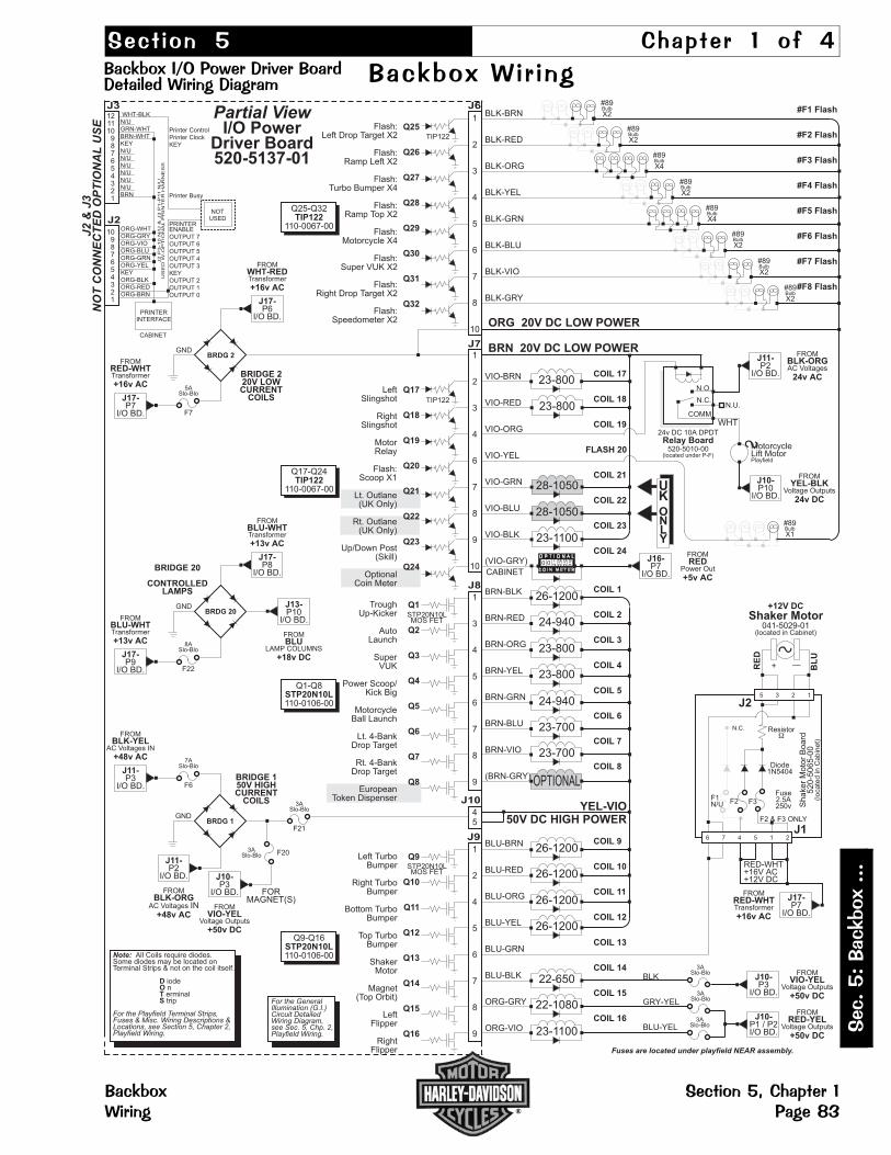
���� ��� �� ���� � �� �
� �������� ���� ��������������������� � ��� �!� �������� �� "
���#$� �����###
� ����� �������%�� ����������� � ��&'
0 0 0
23-1100
OPTIONAL
24-940
23-800
23-800
24-940
23-700
23-700
26-1200
#89
X2Bulb
#89
X2Bulb
#89
X2Bulb
#89
X2Bulb
#89
X2Bulb
#89
X2Bulb
23-1100
28-1050
28-1050
23-800
23-800
BLK-BRN
BLK-RED
BLK-ORG
BLK-YEL
BLK-GRN
BLK-BLU
BLK-VIO
BLK-GRY
J6Partial View
I/O PowerDriver Board520-5137-01
CABINET
YEL-VIO50V DC HIGH POWER
Q25
Q26
Q27
Q28
Q29
Q30
Q31
Q32
Note: All Coils require diodes.Some diodes may be located onTerminal Strips & not on the coil itself.
iodenerminaltrip
DOTS
For the Playfield Terminal Strips,Fuses & Misc. Wiring Descriptions &Locations, see Section 5, Chapter 2,Playfield Wiring.
ORG 20V DC LOW POWER
For the GeneralIllumination (G.I.)Circuit DetailedWiring Diagram,see Sec. 5, Chp. 2,Playfield Wiring.
Fuses are located under playfield NEAR assembly.
1
2
3
4
5
6
7
8
10
#89
X4Bulb
#89
X4Bulb
Flash:Left Drop Target X2
Flash:Ramp Left X2
Flash:Turbo Bumper X4
Flash:Ramp Top X2
Flash:Motorcycle X4
Flash:Super VUK X2
Flash:Right Drop Target X2
Flash:Speedometer X2
VIO-BRN
VIO-RED
VIO-ORG
VIO-YEL
VIO-GRN
VIO-BLU
VIO-BLK
(VIO-GRY)
J7
Q17
Q18
Q19
Q20
Q21
Q22
Q23
Q24
1
2
3
4
6
7
8
9
10
LeftSlingshot
RightSlingshot
MotorRelay
Flash:Scoop X1
Lt. Outlane(UK Only)
Rt. Outlane(UK Only)
Up/Down Post(Skill)
OptionalCoin Meter
COIL 17
COIL 18
COIL 19
FLASH 20
COIL 21
COIL 22
COIL 23
COIL 24
BRN-BLK
BRN-RED
BRN-ORG
BRN-YEL
BRN-GRN
BRN-BLU
BRN-VIO
(BRN-GRY)
J8
Q1
Q2
Q3
Q4
Q5
Q6
Q7
Q8
1
3
4
5
6
7
8
9
TroughUp-Kicker
AutoLaunch
SuperVUK
Power Scoop/Kick Big
MotorcycleBall Launch
Lt. 4-BankDrop Target
Rt. 4-BankDrop Target
EuropeanToken Dispenser
COIL 1
COIL 2
COIL 3
COIL 4
COIL 5
COIL 6
COIL 7
COIL 8
UKONLY
26-1200
26-1200
26-1200
22-650
22-1080
26-1200BLU-BRN
BLU-RED
BLU-ORG
BLU-YEL
BLU-GRN
BLU-BLK
ORG-GRY
ORG-VIO
J9
Q9
Q10
Q11
Q12
Q13
Q14
Q15
Q16
1
2
4
5
6
7
8
9
Left TurboBumper
Right TurboBumper
Bottom TurboBumper
Top TurboBumper
ShakerMotor
Magnet(Top Orbit)
LeftFlipper
RightFlipper
COIL 9
COIL 10
COIL 11
COIL 12
COIL 13
COIL 14
COIL 15
COIL 16
BRN 20V DC LOW POWER
BLK
GRY-YEL
BLU-YEL
100 9 9 9
2
#F1 Flash
#F2 Flash
#F3 Flash
#F4 Flash
#F5 Flash
#F6 Flash
#F7 Flash
#F8 Flash
J10
45
BRIDGE 220V LOWCURRENT
COILS
BRDG 2GND
FROM
Transformer
P6I/O BD.
WHT-RED
+16v AC
J17-
FROM
Transformer
P7I/O BD.
RED-WHT
+16v AC
J17-
5ASlo-Blo
F7
BRIDGE 20
CONTROLLEDLAMPS
BRDG 20GND
FROM
Transformer
P8I/O BD.
BLU-WHT
+13v AC
J17-
FROM
Transformer
P9I/O BD.
BLU-WHT
+13v AC
J17-
8ASlo-Blo
F22
P10I/O BD.
J13-
BLU
+18v DC
FROM
LAMP COLUMNS
BRIDGE 150V HIGHCURRENT
COILS
BRDG 1GND
J11-
BLK-ORG
+48v AC
P2I/O BD.
IN
FROM
AC Voltages
FROM
AC Voltages IN
P3I/O BD.
BLK-YEL
+48v AC
J11-
7ASlo-Blo
F6
3ASlo-Blo
F21
3ASlo-Blo F20
J10-
VIO-YEL
+50v DC
P3I/O BD.
FROM
Voltage Outputs
FORMAGNET(S)
C O I N M E T E R
RED-WHT+16V AC+12V DC
F1N/U
S
Shaker Motor
RE
D
BL
U
+ —
N.C.
+12V DC
F2
J1
Fuse2.5A250v
F2 & F3 ONLY
Resistor�
Diode1N5404
Shaker
Moto
rB
oard
520-5
065-0
0(lo
ca
ted
inC
abin
et)
F3
J25 3 2 1
6 7 4 5 1 2
3ASlo-Blo
J10-P3
I/O BD.
FROM
Voltage OutputsVIO-YEL
+50v DC3ASlo-Blo
3ASlo-Blo
J10-P1 / P2I/O BD.
FROM
Voltage OutputsRED-YEL
+50v DC
J17-P7
I/O BD.
FROM
TransformerRED-WHT
+16v AC
J16-P7
I/O BD.
FROM
Power OutRED
+5v AC
S MotorcycleLift MotorPlayfield
Relay Board24v DC 10A DPDT
520-5010-00(located under P-F)
N.U.
WHT
N.O.
N.C.
COMM
J11-P2
I/O BD.
FROM
AC VoltagesBLK-ORG
24v AC
J10-P10
I/O BD.
FROM
Voltage OutputsYEL-BLK
24v DC
TIP122
STP20N10LMOS FET
STP20N10LMOS FET
TIP122
Q25-Q32
110-0067-00TIP122
Q17-Q24
110-0067-00TIP122
Q1-Q8
110-0106-00STP20N10L
Q9-Q16
110-0106-00STP20N10L
NOTUSED
Printer ControlPrinter ClockKEY
Printer Busy
PRINTERINTERFACE
CABINET
WHT-BLKN/UGRN-WHTBRN-WHTKEYN/UN/UN/UN/UN/UN/UBRN
ORG-WHTORG-GRYORG-VIOORG-BLUORG-GRNORG-YELKEYORG-BLKORG-REDORG-BRN
J2
P3
-1
0N
/U&
J3
P1
-P
11
N/U
US
ED
W-O
PT
ION
AL
PR
INT
ER
HA
RN
ES
S
121110
987654321
J3
J2
10987654321
J2
&J3
NO
TC
ON
NE
CT
ED
OP
TIO
NA
LU
SE
PRINTERENABLEOUTPUT 7OUTPUT 6OUTPUT 5OUTPUT 4OUTPUT 3KEYOUTPUT 2OUTPUT 1OUTPUT 0
#89
X1Bulb
041-5029-01(located in Cabinet)
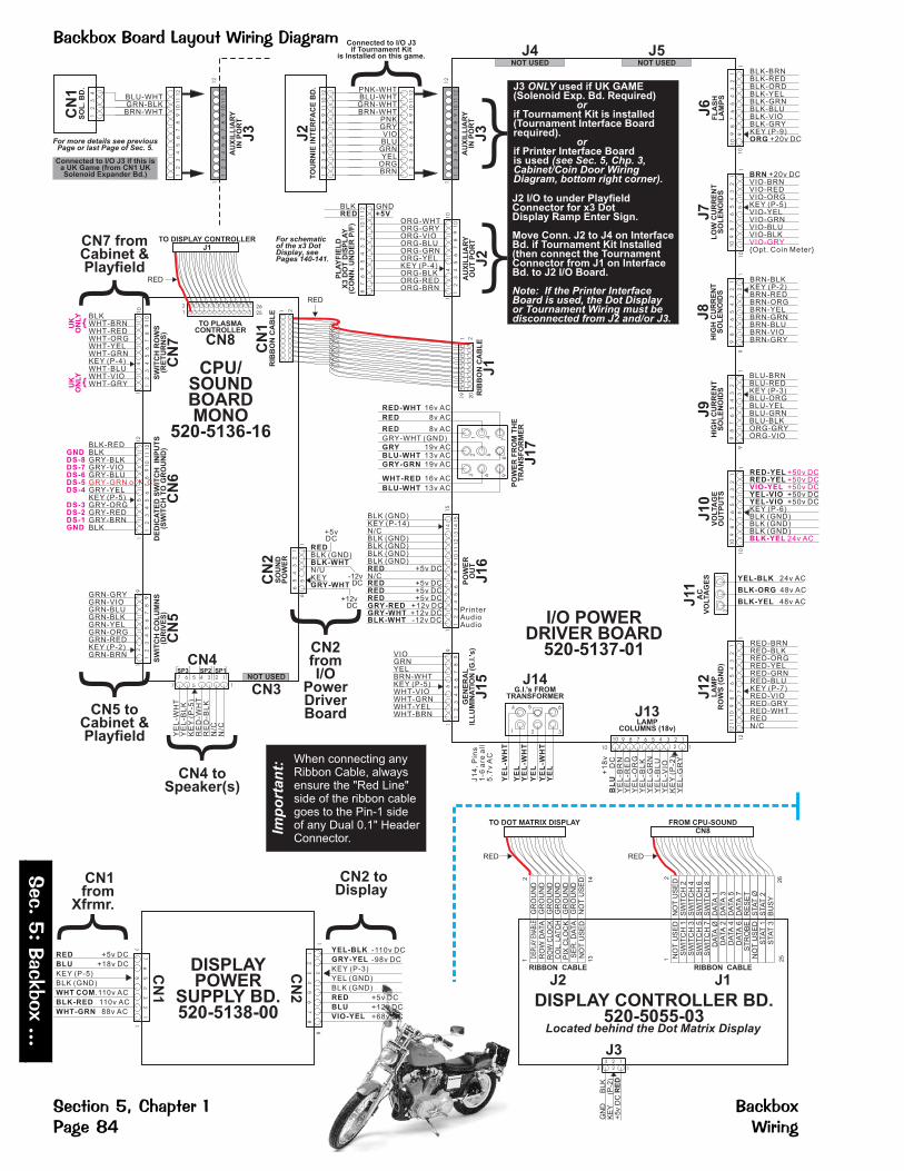
� ������� � ( )�*��������� �� "
���#
$� ����
�###
�������%�� ����� � ������ ��&� ������
POT1
6 5 4 3 2 1NOT USED
CN3
SW
ITC
HR
OW
S(R
ET
UR
NS
)
CN
7
BLKWHT-BRNWHT-REDWHT-ORGWHT-YELWHT-GRNKEY (P-4)WHT-BLUWHT-VIOWHT-GRY
10
12
34
56
78
9
GRN-GRYGRN-VIOGRN-BLUGRN-BLKGRN-YELGRN-ORGGRN-REDKEY (P-2)GRN-BRN
SW
ITC
HC
OL
UM
NS
(DR
IVE
S)
CN
5
91
2
12
34
56
78
91
0
14
{UK
ON
LY
{UK
ON
LY
10
11
12
12
34
56
78
9
DE
DIC
AT
ED
SW
ITC
HIN
PU
TS
(SW
ITC
HT
OG
RO
UN
D)
CN
6
12
15
UNK
KEY
GNDDS-8DS-7DS-6DS-5DS-4
DS-3DS-2DS-1GND
BLK-REDBLKGRY-BLKGRY-VIOGRY-BLU
GRY-YELKEY (P-5)GRY-ORGGRY-REDGRY-BRNBLK
GRY-GRN or N.C.
87
69
54
32
11
01
11
2
YEL-BLK
GRY-YEL
RED
BLU
VIO-YEL
KEY (P-3)
YEL (GND)
BLK (GND)
CN
1
CN
2
18
71
-110v DC
-98v DC
+5v DC
+12v DC
+68v DC
RED
BLU
WHT COM
BLK-RED
WHT-GRN
+5v DC
+18v DC
KEY (P-5)
BLK (GND)
.110v AC
110v AC
88v AC
DISPLAYPOWER
SUPPLY BD.520-5138-00
12
34
56
78
76
54
32
1
5
3
{ CN1from
Xfrmr. {CN2 toDisplay
DISPLAY CONTROLLER BD.520-5055-03
NO
TU
SE
DS
WIT
CH
2S
WIT
CH
4S
WIT
CH
6S
WIT
CH
8D
ATA
1D
ATA
3D
ATA
5D
ATA
7R
ES
ET
STA
TØ
STA
T2
BU
SY
NO
TU
SE
DS
WIT
CH
1S
WIT
CH
3S
WIT
CH
5S
WIT
CH
7D
ATA
ØD
ATA
2D
ATA
4D
ATA
6S
TR
OB
EN
OT
US
ED
STA
T1
STA
T3
RIBBON CABLE
J2
GR
OU
ND
GR
OU
ND
GR
OU
ND
GR
OU
ND
GR
OU
ND
GR
OU
ND
NO
TU
SE
D
RO
WD
ATA
PIX
CL
OC
KS
ER
.D
ATA
NO
TU
SE
D1
41
3
21
CO
L.
LA
TC
HR
OW
CLO
CK
DISP
LAY
ENAB
LE
12
26
25
FROM CPU-SOUNDCN8
TO DOT MATRIX DISPLAY
Located behind the Dot Matrix Display
GN
DB
LK
KE
Y(P
-2)
+5v
DC
RE
D
J313
3 2 1
2
RIBBON CABLE
J1
RED RED
CPU/SOUNDBOARDMONO
520-5136-16
CN
2S
OU
ND
PO
WE
R
61
TO PLASMACONTROLLER
CN8
ORG-WHTORG-GRYORG-VIOORG-BLUORG-GRNORG-YELKEY (P-4)ORG-BLKORG-REDORG-BRN
AU
XIL
LIA
RY
OU
TP
OR
T
J2
11
AU
XIL
LIA
RY
INP
OR
T
J3
10
PO
WE
RF
RO
MT
HE
TR
AN
SF
OR
ME
R
J17
9
1
63
4
7
2
8
5
RIB
BO
NC
AB
LE
J1
20
19
21
I/O POWERDRIVER BOARD
520-5137-01
65
43
21
10
12
34
56
78
91
23
45
67
89
10
11
12
4
RED-WHT
RED
RED
GRYBLU-WHT
GRY-GRN
WHT-RED
BLU-WHT
GRY-WHT (GND)
RED
BLK-WHT
GRY-WHT
BLK (GND)
N/UKEY
5
-12vDC
+12vDC
BLK (GND)KEY (P-14)N/CBLK (GND)BLK (GND)BLK (GND)BLK (GND)
+5v DCN/C
+5v DC+5v DC+5v DC
+12v DC+12v DC-12v DC
RED
REDREDREDGRY-REDGRY-WHTBLK-WHT
+5v DC
PO
WE
RO
UT
J16
15
1
12
34
56
78
9
14
10
11
12
13
14
15
PrinterAudioAudio
GE
NE
RA
LIL
LU
MIN
AT
ION
(G.I
.'s
)
J15
91
VIOGRNYELBRN-WHTKEY (P-5)WHT-VIOWHT-GRNWHT-YELWHT-BRN
12
34
56
78
9
5
J13LAMP
COLUMNS (18v)
10 1
+1
8v
DC
YE
L-B
RN
YE
L-R
ED
YE
L-O
RG
YE
L-B
LK
YE
L-G
RN
YE
L-B
LU
YE
L-V
IOK
EY
(P-2
)Y
EL
-GR
Y
BL
U
9 8 7 6 5 4 3 2 1
2
10
J6
FL
AS
HL
AM
PS
1
98
76
54
32
11
0
9
BLK-BRNBLK-REDBLK-ORDBLK-YELBLK-GRNBLK-BLUBLK-VIOBLK-GRYKEY (P-9)
+20v DCORG
10
12
J7
LO
WC
UR
RE
NT
SO
LE
NO
IDS
10
1
98
76
54
32
11
0
BRN +20v DCVIO-BRNVIO-REDVIO-ORGKEY (P-5)VIO-YELVIO-GRNVIO-BLUVIO-BLK
{Opt. Coin Meter}VIO-GRY
5
J8
HIG
HC
UR
RE
NT
SO
LE
NO
IDS
91
BRN-BLKKEY (P-2)BRN-REDBRN-ORGBRN-YELBRN-GRNBRN-BLUBRN-VIOBRN-GRY
2
98
76
54
32
1
91
98
76
54
32
1
3
BLU-BRNBLU-REDKEY (P-3)BLU-ORGBLU-YELBLU-GRNBLU-BLKORG-GRYORG-VIO
J9
HIG
HC
UR
RE
NT
SO
LE
NO
IDS
+50v DC+50v DC+50v DC
24v AC
+50v DC+50v DC....
J1
0V
OLTA
GE
OU
TP
UT
S
10
1
RED-YELRED-YEL
YEL-VIOYEL-VIOKEY (P-6)BLK (GND)BLK (GND)BLK (GND)
VIO-YEL
BLK-YEL
6
98
76
54
32
11
0
J1
2L
AM
PR
OW
S(G
ND
)
12
17
98
76
54
32
11
21
11
0
RED-BRNRED-BLKRED-ORGRED-YELRED-GRNRED-BLUKEY (P-7)RED-VIORED-GRYRED-WHTREDN/C
J14G.I.'s FROM
TRANSFORMER
1
4
3
6
2
5
J1
4,
Pin
s1
-6a
rea
ll5
.7v
AC
YE
L-W
HT
YE
LY
EL
-WH
T
YE
L
YE
L-W
HT
YE
L
{
CN2fromI/O
PowerDriverBoard
YE
L-W
HT
YE
L-B
LK
KE
Y(P
-5)
RE
D-W
HT
RE
D-B
LK
N/C
N/C
SP1SP2SP3
CN4
7 15
7 6 5 4 3 2 1
CN4 toSpeaker(s)
{C
N1
RIB
BO
NC
AB
LE 1 2
RED
TO DISPLAY CONTROLLERJ1
26
25
2
1
RED{
{
16v AC
8v AC
8v AC
19v AC13v AC
19v AC
16v AC
13v AC
CN7 fromCabinet &Playfield
}
+5vDC
PNK-WHT
BRN-WHTPNKGRYVIOBLUGRNYEL
ORGBRN
BLU-WHTGRN-WHT
12
34
56
78
91
01
11
2}
Connected to I/O J3if Tournament Kit
is Installed on this game.
PL
AY
FIE
LD
X3
DO
TD
ISP
LA
Y(C
ON
N.
UN
DE
RP
/F)
BLK GNDRED +5V
12
34
56
78
91
11
01
2
J2
TO
UR
NIE
INT
ER
FA
CE
BD
.
13
J11
AC
VO
LTA
GE
S YEL-BLK
BLK-ORG
BLK-YEL
24v AC
48v AC
48v AC
When connecting anyRibbon Cable, alwaysensure the "Red Line"side of the ribbon cablegoes to the Pin-1 sideof any Dual 0.1" HeaderConnector.
Imp
ort
an
t:
XBLU-WHTGRN-BLKBRN-WHT
12
34
56
78
91
01
11
2
Connected to I/O J3 if this isa UK Game (from CN1 UKSolenoid Expander Bd.)
12
34
CN
1S
OL
.B
D.
1
AU
XIL
LIA
RY
INP
OR
T
J3
12
34
56
78
91
01
11
2
12
For more details see previousPage or last Page of Sec. 5.
For schematicof the x3 DotDisplay, seePages 140-141.
J4NOT USED
J2 I/O to under PlayfieldConnector for x3 DotDisplay Ramp Enter Sign.
Move Conn. J2 to J4 on InterfaceBd. if Tournament Kit Installed(then connect the TournamentConnector from J1 on InterfaceBd. to J2 I/O Board.
Note: If the Printer InterfaceBoard is used, the Dot Displayor Tournament Wiring must bedisconnected from J2 and/or J3.
J3 used if UK GAME(Solenoid Exp. Bd. Required)
if Tournament Kit is installed(Tournament Interface Boardrequired).
if Printer Interface Boardis used
ONLY
or
or
(see Sec. 5, Chp. 3,Cabinet/Coin Door WiringDiagram, bottom right corner).
J5NOT USED
{
CN5 toCabinet &Playfield
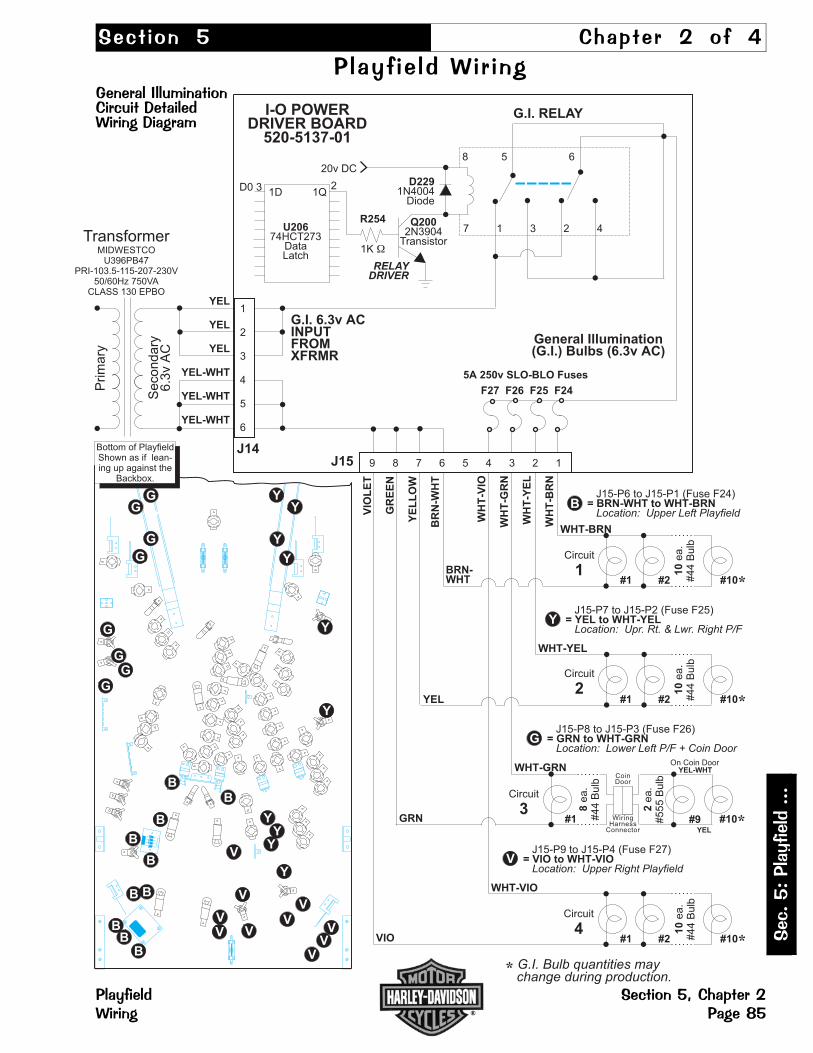
���� ��� �� ���� � �� �
�� �� �� ����� �������� �������� �������������� ������������ �� �
���
��
��
�����
��
��
�� ������ ������� �� ����������� � ��!
V
G
Y
General Illumination(G.I.) Bulbs (6.3v AC)
J15 9 8 7 6 5 4 3 2 1
F27 F26 F25 F24
1
2
3
4
5
6
J14
YEL
YEL
YEL
YEL-WHT
YEL-WHT
YEL-WHT
G.I. 6.3v ACINPUTFROMXFRMR
D2291N4004
Diode
G.I. RELAY
Q2002N3904
Transistor
20v DC
I-O POWERDRIVER BOARD
520-5137-01
R254
1K �
U20674HCT273
DataLatch
7 1 3 2 4
8 5 X 6
Prim
ary
Secondary
6.3
vA
C
TransformerMIDWESTCO
U396PB47PRI-103.5-115-207-230V
50/60Hz 750VACLASS 130 EPBO
WHT-BRN
BRN-WHT #1 #2 #10*
WHT-YEL
#1 #2 #10*
WHT-GRN
GRN #1 #9 #10*
YEL-WHT
YEL
CoinDoor
WiringHarness
Connector
VIO
WHT-VIO
10
ea.
#44
Bulb
#1 #2 #10*
YEL
WH
T-V
IO
WH
T-G
RN
WH
T-Y
EL
WH
T-B
RN
VIO
LE
T
GR
EE
N
YE
LL
OW
BR
N-W
HT
2
5A 250v SLO-BLO Fuses
RELAYDRIVER
D0 31D 1Q
* G.I. Bulb quantities maychange during production.
Bottom of PlayfieldShown as if lean-ing up against the
Backbox.
B = BRN-WHT to WHT-BRNJ15-P6 to J15-P1 (Fuse F24)
Location: Upper Left Playfield
= YEL to WHT-YELJ15-P7 to J15-P2 (Fuse F25)
Location: Upr. Rt. & Lwr. Right P/F
= GRN to WHT-GRNJ15-P8 to J15-P3 (Fuse F26)
Location: Lower Left P/F + Coin Door
= VIO to WHT-VIOJ15-P9 to J15-P4 (Fuse F27)
Location: Upper Right Playfield
On Coin Door
Circuit
4
8ea.
#44
Bulb
2ea.
#555
Bulb
Circuit
3
10
ea.
#44
Bulb
Circuit
210
ea.
#44
Bulb
Circuit
1
Y
V
G
B
Y
Y
Y
Y
Y
Y
Y
YY
V
VV
V
V
V
VV
V
BB
B
B
B
BB
BB
G
GG
G
G
G
G

�� �������"������������ �� �
�� ������# ���������� �� �
����
��� �
��������
������� �� ����� �� ������� ��!$ ������
1
3
4
5
6
7
8
9
Color
GRN-BRNGRN-REDGRN-ORGGRN-YELGRN-BLKGRN-BLUGRN-VIO
GRN-GRY
WHT-BRNWHT-REDWHT-ORGWHT-YEL
WHT-GRNWHT-BLUWHT-VIO
WHT-GRY
10
9
8
7
6
5
3
2
1
Color
Switch
Switch
Switch
Switch
Switch
Switch
Switch
Switch
1
2
3
4
5
6
7
8
Switch
Switch
Switch
Switch
Switch
Switch
Switch
Switch
9
10
11
12
13
14
15
16
Switch
Switch
Switch
Switch
Switch
Switch
Switch
Switch
17
18
19
20
21
22
23
24
Switch
Switch
Switch
Switch
Switch
Switch
Switch
Switch
25
26
27
28
29
30
31
32
Switch
Switch
Switch
Switch
Switch
Switch
Switch
Switch
33
34
35
36
37
38
39
40
Switch
Switch
Switch
Switch
Switch
Switch
Switch
Switch
41
42
43
44
45
46
47
48
Switch
Switch
Switch
Switch
Switch
Switch
Switch
Switch
49
50
51
52
53
54
55
56
N/C
Sw. Return 1:
Sw. Return 2:
Sw. Return 3:
Sw. Return 4:
Sw. Return 5:
Sw. Return 6:
Sw. Return 7:
Sw. Return 8:
U400
U400
U400
U400
U401
U401
U401
U401
Switch ReturnIC
Source Nº:LM339AN
Pin
Row
Sw. Drive 1:
Sw. Drive 2:
Sw. Drive 3:
Sw. Drive 4:
Sw. Drive 5:
Sw. Drive 6:
Sw. Drive 7:
Sw. Drive 8:
Q1
Q2
Q3
Q4
Q5
Q6
Q7
Q8
Pin
Column
Switch DriveTransistor
Source Nº:2N3904
CPU-Snd. Bd. CN5-
CPU-Snd. Bd. CN7-
Switch
Switch
Switch
Switch
Switch
Switch
Switch
Switch
57
58
59
60
61
62
63
64
LeftOutlane
Left Re-turn Lane
LeftSlingshot
RightOutlane
Right Re-turn Lane
RightSlingshot
NotUsed
NotUsed
Lt. TurboBumper
Rt. TurboBumper
Bot. TurboBumper
Top TurboBumper
LaunchButton
StartButton
SlamTilt
PlumbBob Tilt
Lt. 4-BankD/T ( L )
Lt. 4-BankD/T ( I )
Lt. 4-BankD/T ( V )
Lt. 4-BankD/T ( E )
Rt. 4-BankD/T ( R )
Rt. 4-BankD/T ( I )
Rt. 4-BankD/T ( D )
Rt. 4-BankD/T ( E )
NotUsed
NotUsed
4-BallTrough #1
4-BallTrough #2
4-BallTrough #3
4-Ball Tr.VUK Opto
...Stack-ing Opto
ShooterLane
Lt. Button(UK Only)
4th CoinSlot
6th CoinSlot
Rt. CoinSlot
Cnt. CoinSlot-DBA
Lt. CoinSlot
5th CoinSlot
Rt. Button(Skill)
�
�
�F
utu
reE
xpansio
n�
Futu
reE
xpansio
n
Note: All switches require diodes. Some diodes are located on Terminal Strips OR on a Diode Board (under playfield) & not on the switch itself.
iodenerminaltrip
-or-iodeniodeoard
For Switches:41-46
DOTS
DODB
LMP
LMP
LMP
LMP
LMP
LMP
LMP
LMP
LMP
LMP
1
9
17
25
33
41
49
57
65
73
10
9
8
7
6
5
4
3
1
YEL-BRNYEL-REDYEL-ORGYEL-BLK
YEL-GRNYEL-BLUYEL-VIO
YEL-GRYLMP
LMP
LMP
LMP
LMP
LMP
LMP
LMP
LMP
LMP
2
10
18
26
34
42
50
58
66
74
LMP
LMP
LMP
LMP
LMP
LMP
LMP
LMP
LMP
LMP
4
12
20
28
36
44
52
60
68
76
LMP
LMP
LMP
LMP
LMP
LMP
LMP
LMP
LMP
LMP
5
13
21
29
37
45
53
61
69
77
LMP
LMP
LMP
LMP
LMP
LMP
LMP
LMP
LMP
LMP
6
14
22
30
38
46
54
62
70
78
Pin
ColorRow
Lamp ReturnTransistor
Source Nº:STP19N06L
I-O Bd. J12-
Lamp DriveIC
Source Nº:VN02N
Pin
ColumnColorLMP
LMP
LMP
LMP
LMP
LMP
LMP
LMP
LMP
LMP
8
16
24
32
40
48
56
64
72
80
LMP
LMP
LMP
LMP
LMP
LMP
LMP
LMP
LMP
LMP
7
15
23
31
39
47
55
63
71
79
1
2
3
4
5
6
8
9
10
11
12
LMP
LMP
LMP
LMP
LMP
LMP
LMP
LMP
LMP
LMP
3
11
19
27
35
43
51
59
67
75
From I-O Pwr.Driver BoardJ16-Pins 9-15
Power Out for+18v for Disp.Pwr. Sup. Bd.CN1-Pin 6
I-O Bd. J13-
Lamp Drive 1:
Lamp Drive 2:
Lamp Drive 3:
Lamp Drive 4:
Lamp Drive 5:
Lamp Drive 6:
Lamp Drive 7:
Lamp Drive 8:
U17
U16
U15
U14
U13
U12
U11
U10
Lamp Return 1:
Lamp Return 2:
Lamp Return 3:
Lamp Return 4:
Lamp Return 5:
Lamp Return 6:
Lamp Return 7:
Lamp Return 8:
Lamp Return 9:
Lamp Return 10:
Q33
Q34
Q35
Q36
Q37
Q38
Q39
Q40
Q41
Q42
N/C
RED-BRNRED-BLK
RED-ORGRED-YEL
RED-GRNRED-BLURED-VIO
RED-GRYRED-WHT
N/C
BLUE
Note: All lamps require diodes. Some diodes are located on Terminal Strips (under playfield) & not on the lamp itself.
iodenerminaltrip
For Lamps:28-31
DOTS
( H )HARLEY
( L )LIVE
Lt. OrbitGrn. Light
M-cycleGrn. Light
SVUKGrn. Light
Rt. RampGrn. Light
Rt. OrbitGrn. Light
Stop LightGrn. Light
LeftOutlane
NotUsed
N/C
Please Note: Switch Descriptions may differ slightly than that of the Dot Display due to space restraints.
Please Note: Lamp Descriptions may differ slightly than that of the Dot Display due to space restraints.
DOTS
DOTS
DOTS
Rt. RampEnter
Rt. RampExit
Rt. RampMid
Spinner
S-U Lt.M-Cycle
S-U Rt.M-Cycle
S-U Lt.Rt. Ramp
S-U Rt.Rt. Ramp
LeftOrbit
RightOrbit
MotorUp
MotorDown
OPTO
NotUsed
NotUsed
NotUsed
M-CycleTrough #4
M-CycleTrough #3
M-CycleTrough #2
M-CycleTrough #1
SuperVUK
Ball Eject(Scoop)
NotUsed
BehindTop VUK
( L )HARLEY
( E )LIVE
1stGear
Lt. TurboBumper
Bike S-UTrgt. Lt.
Patch
NotUsed
NotUsed
RightOutlane
NotUsed
SuperJackpot
( D )RIDE
4thGear
Top TurboBumper
RampS-U Trgt. Rt.
AutoLaunch
NotUsed
NotUsed
MysteryRider
NotUsed
SuperJackpot
( E )RIDE
5thGear
Speedo-meter X2
SlipperWhen Wet
Lite MysteryRider
NotUsed
NotUsed
NextCity
NotUsed
( A )HARLEY
( I )LIVE
LeftOrbit
M-cycleYel. Light
SVUKYel. Light
Rt. RampYel. Light
Rt. OrbitYel. Light
Stop LightYel. Light
Left Re-turn Lane
NotUsed
( R )HARLEY
( V )LIVE
LeftOrbit
M-cycleRed Light
SVUKRed Light
Rt. RampRed Light
Rt. OrbitRed Light
Stop LightRed Light
Right Re-turn Lane
NotUsed
( E )HARLEY
( R )RIDE
2ndGear
Rt. TurboBumper
Bike S-UTrgt. Rt.
BikersBack
NotUsed
NotUsed
M-cycleHeadlight
NotUsed
( Y )HARLEY
( I )RIDE
3rdGear
Bot TurboBumper
RampS-U Trgt. Lt.
Red LightMultiball
NotUsed
NotUsed
RideAgain X2
NotUsed
DOTS
DOTS
DOTS
DOTS
DODB
DODB
DODB
DODB
DODB
DOTS

�� ������%����� ������& '�&�&()�&����������&��������&(#�� ����&
���
��
��
�����
��
��
�� ������ ������� �� ����������� � ��!*
Harley-DavidsonTerminal Strip:Lamp 29:
Rt. Turbo Bmpr.Lamp 31:
Top Turbo Bmpr.
—BLK
—YEL-GRN—BLK
—YEL-VIO—BLK
—BLK
—RED-YEL
Lam
p29
Lam
p31
Harley-DavidsonTerminal Strip:Lamp 30:
Bot. Trbo. Bmpr.Lamp 28:
Lt. Turbo Bmpr.
—BLK
—YEL-BLU—BLK
—YEL-BLK—BLK
—BLK
—RED-YEL
Lam
p30
Lam
p28
(Page 52) for Terminal Strips,Diodes, Fuses and Fuse Holders Part Nºs.
All switches, lamps, coils require diodes.The diodes not physically located on theswitch, lamp or coil are located on Term-inal Strips or Diode Bd. under the playfield.The Switch & Lamp Matrix Grids also notewhich switch or lamp has a diode on aTerminal Strip (noted by meaning:"Diode on Terminal Strip") or Diode Board(noted by meaning: "Diode onDiode Board"). There is 1 diode locatedon a solder lug for the Magnet Fuse.
All fuses are rated:
See the Pink Pages, Playfield - GeneralParts (Below)
Also Note:
Explanation:
3A 250v Slo-Blo, Do Not Over-Fuse.
Terminal Strip, Diode Board & Fuse Holderlocations shown, represent the generallocation (your game may differ slightly).
"DOTS"
"DODB"
—WHT-GRNGRN-BLUto
—ORG-GRN
Sw
itch
45
Harley-DavidsonTerminal Strip:Switch 45
Super VUK
Harley-DavidsonDiode BoardPin-Out Wiring:
This
Sid
e:
6-P
inR
ibbon
Connecto
rto
Sw
itch
Mem
bra
ne
1234
6
�
Diode Board520-5146-00
PIN-1, WHT-BRN
PIN-2, WHT-RED
PIN-3, WHT-ORG
PIN-4, WHT-YEL
PIN-5, KEYPIN-6, GRN-BLU
Sw. 41: M-CycleTrough #4 Top
Sw. 42: ...Trough #3
Sw. 43: ...Trough #2
Sw. 44: ...Trough #1
Bottom of PlayfieldShown as if lean-ing up against the
Backbox.
D
A
B
C
RIGHTFLIPPER FUSE
BLU-YEL
RED-YEL 3A S.B.
LEFTFLIPPER FUSE
GRY-YEL
RED-YEL 3A S.B.
MAGNETFUSE
BLU-BLK
VIO-YEL 3A S.B.
BLK
Diode Board520-5146-00
(for 4-Position Membrane Switchon Motorcycle Ball Launch)
E
—WHT-BLUGRN-BLUto
—ORG-BLU
Sw
itch
46
Harley-DavidsonTerminal Strip:Switch 46
Ball Eject(Scoop)

�+'��������������������� �� �
����
��� �
��������
������� �� ����� �� ������� ��!! ������
GRY-BRN
BLK(GROUND)
NOTE:N.C. = Normally ClosedN.O. = Normally Open
GRY-RED
GRY-YEL
GRY-ORG
1
O O O O O O O O O O O O O O O
11 15
I/O POWERDRIVER BOARD
(PARTIAL VIEW)
POWER OUT
J16
J10VOLTAGEOUTPUTS
J9HIGH CURRENT
SOLENOIDS
Technical Overview
Ouruses one supply voltage(50v DC) for both &
. Once thedetects a Flipper
Cabinet Switch closure(during game play) itapplies a 40 pulseto the gate of the FlipperDrive Transistor (STP-20N10L). If it continuesto detect a FlipperCabinet Switch closure
it will continueto pulse the flipper drivetransistor 1 every12 for the durationof the hold cycle.
The (End-Of-Stroke) servesthe same function asbefore as it preventsfoldback when the play-er has the flipper ener-gized to capture balls.The is anormally closed switchwhich opens approxi-mately 1/16" when theflipper is energized. The
will detect aswitch closure if the flip-per bat is forced back bya high velocity shot orrebound on the playfieldand will apply another40 pulse of 50v DCto the coil.
Flipper System
kickhold GameCPU
E.O.S.Switch
E.O.S. Switch
Game CPU
msec
(the player holding thebutton in)
msecmsecs
msec
N.O.
RIGHTFLIPPERIN CABINETDEDICATED
SWITCH
DS-3
N.O.
LEFTFLIPPERIN CABINETDEDICATED
SWITCH
DS-1
N.C.
LEFTE.O.S.
ON ASSY.DEDICATED
SWITCH
DS-2
CPU-SOUND BOARD(PARTIAL VIEW)
DEDICATED SWITCH INPUTS(SWITCH TO GROUND)
CN6
1
O O O O O O O O O O O
122 3 4 6
Q15
Q16
Q14
Q13
MOS FETSTP20N10L
LT or RTFLIPPERIN CABINETDEDICATED
SWITCH
DS-5
N.O.
UPPER
GRY-GRN
7
N.C.
RIGHTE.O.S.
ON ASSY.DEDICATED
SWITCH
DS-4
NOTUSED
1
OOOOOOOOOO
210 1
OOOOOOOOO
89
ORG-VIO
ORG-GRY
RED-YEL 50V DC
3A SLO-BLO(Located under Playfield)
BLU-BLK
The 3A 250v Slo-Blo Fusesare located under the playfieldNEAR the Flipper Assembly,
see previous page for locations.
BLU-YEL
LOWERRIGHTFLIPPERCOIL
Coil Wrap: ORANGE
GRY-YEL
LOWERLEFTFLIPPERCOIL
Coil Wrap: YEL-GRN
RED-YEL 50V DC
3A SLO-BLO(Located under Playfield)
� �RED-YEL 50V DC
22-1080
23-1100

���� ��� �� ���� , �� �
� -������� ���%� �&��������"���������� �� �
���
��
� -
����
���
� -���� ������� �� ����,������ � ��!.
TO
I/O
PO
WE
RD
RIV
ER
BO
AR
D
FORGENERALILLUMINATION(G.I.'s)
ONLY ONCOIN DOOR
FLU
OR
ES
CE
NT
TU
BE
,S
TA
RT
ER
&B
ALLA
ST
INT
HE
BA
CK
BO
X
GRY
FOR LOGIC+12/-12v DCTO BRIDGE 3
GRY-WHT
GRY-GRN
19v AC
19v AC
3
5
4
2
5
3
BLU-WHT
FOR 18v DCCONTROL LAMPSTO BRIDGE 20
13v AC
13v AC
9
10
8
9
1F/M2
1F/M4
RED
J17
WHT-RED
WHT-RED
FOR 20v DCCOILSTO BRIDGE 2
16v AC
16v AC
7
6
6
7
RED
RED
FOR +5v DCLOGICTO BRIDGE 21
8v AC
8v AC
13
14
1
4
BLK-YEL
FOR50v DCCOILSTOBRIDGE 1
YEL-BLK
BLK-ORG
48v AC
48v AC
11
15
12
3
1
2
BLU-WHT
WHT-GRN
DISPLAYPOWERSUPPLYBOARD
WHT
BLK-RED
88v AC
100v AC
2
1
8
1
3
2
24v AC
24v AC
1T1
J11
CN1
TO
I/O
PO
WE
RD
RIV
ER
BO
AR
D
YEL
YEL-WHT
1
3
2
1F/M3 J14
1
3
2
4
5
6
4
5
6
BLU
BLU
WHT
BLK
120V AC
BLK-WHT BLK
WHT
STARTER
SPI N : 165-5011-01FLUOR. FS2 LIGHT
1
FLUORESCENT TUBE
SPI N : 165-5031-02(F20T12CW)1
BALLAST
SPI N : 010-5015-00
SP2/K 5/8" Core120V 50/60Hz 13W (UL)
1
LOCATED IN THE BACKBOX
5.7v AC
BLK
WHT
1F/M1
TO
DO
LLA
RB
ILL$
VA
LID
AT
OR
Int'l. = BRN 220V AC
Domestic = BLK 115V AC
Domestic = WHT 115V AC
Int'l. = BLU 220V AC
GRN (to ( )arth Ground)E
SERVICE OUTLET(Domestic / International)Note: Not All International Gameshave or require a Service Outlet.
1F1
8A 250V
5A 250V
Domestic =
Slo-Blo Fuse
International =
Slo-Blo Fuse
1V1VARISTER
130V
275V
Domestic =
International =
1
2
6
9
3
5
4
8
7
2
1 115v AC
DOMESTICCONFIGURATION
GRN
GROUND
LINECORD
( )eutralN
HOT ( )oadL
RF1
LINEFILTER120V / 240V50 Hz / 60 Hz
ON/OFF
1/0
WHT
BLK
1F1= 8A SLO BLO1V1= 130V VARISTOR
EXPORT/ HIGHLINE VOLTAGE
230/218/206 VOLTS
1F1= 5A 250V SLO BLO1V1= 275V VARISTOR
CONFIGURATION OF 220VOR LOWER LINE VOLTAGESFOR INTERNATIONAL USE <
<<
<<
<
JUMPERS FOR VOLTAGE VARIATION
CONFIGURATON FORDOMESTIC 115V
<<<
<<<
115 VOLTS
CONFIGURATON FORJAPAN or
LOW LINE VOLTAGE<<<
<<<
WHT
BLK1 2 3
4 5 6
7 8 9
100/105 VOLTS
WHT
BLK1 2 3
4 5 6
7 8 9
206 VOLTS
WHT
BLK1 2 3
4 5 6
7 8 9
218 VOLTS
WHT
BLK1 2 3
4 5 6
7 8 9
230 VOLTS
WHT
BLK1 2 3
4 5 6
7 8 9

� -����/���������������� �� �
����
�� -�������
������� �� ����, � -����� ��.0 ������
5
� �CN7CPU/SND BD.
RED-WHT
WHT-GRYSW RETURN 8
SW RETURN 7
1
2
SW RETURN 6
SW RETURN 5
SW RETURN 4
SW RETURN 3
3
5
6
7
GRN-VIO
GRN-BRN
SW DRIVE 7
SW RETURN 2
SW DRIVE 1
CPU/SND BD.� �CN7
8
START
BUTTON
GRY-BLU
GRY-VIO
GRY-BLK
BLK
BLK-RED
Memory ProtectSwitch
10
� �CN7CPU/SND BD.
10
12
9
GRY-ORG
GRY-BRN
4
2
BEGIN TEST /ENTER: BLACKBUTTONSERVICE CRED-ITS / RT.: GREENBUTTONVOLUME /LEFT: REDBUTTON
PORTALSSERVICEBUTTONS
TM
COIN DOORCONNECTOR
GRNBLK
PLUMBBOB TILT
G.I.LAMPS
onCOINDOOR
YEL-WHT
YEL
WHT-GRN
GRNG.I.
6.3V AC
3
8
J16-3 +12VDCI/O DRVR BD
J16-7 +5VDCI/O DRVR BD
FOR THE PRINTERSUB-ASSEMBLY
00 BLK
82 GRY-RED
1
2
3
GROUND
22 RED
GRY-BLU
GRY-VIO
GRY-BLK
BLK BLK
BLK
BL
K
COIN DOOR
Connection Notes:
I/O DRVR BD :
I/O DRVR BD :
I/O DRVR BD :
I/O DRVR BD :
I/O DRVR BD :
I/O DRVR BD :
CPU BD :
J16-3+12V DC
J3-10PRNTR CNT
J3-9PRNTR CLK
J2-10PRNTR ENABLE
J3-1PRNTR BUSY
J16-7+5V DC
CN7-10GND
CN2
PRINTER BOARD
DATA LINES
CN1
PRINTER INTERFACE OPTIONAL
Cable Wiring Harness SPI Part N :
RS-232 Printer Interface Board SPI Part N :
1
1
036-5408-00
520-5069-00
ORG-BRN
ORG-RED
ORG-BLK
KEY
ORG-YEL
ORG-GRN
ORG-BLU
ORG-VIO
ORG-GRY
GRY-RED
KEY
GRN-WHT
BRN-WHT
ORG-WHT
N/C
BRN
N/C
RED
BLK
1
2
3
4
5
6
7
8
9
1
2
3
4
5
6
7
8
9
10
8
1
4th Coin SlotEuropean Use
6th Coin SlotFuture Use
Right Coin Slot
U.S. Bill AcceptorCenter Coin Slot
WHT-VIO
WHT-BLU
WHT-GRN
WHT-ORG
WHT-YEL
WHT-RED
Left Coin Slot
5th Coin SlotFuture Use
GRN-BRNfrom CN5-P1 (Sw. Drive 1)
DEDICATEDSWITCHES
WHT-VIO
WHT-BLU
WHT-GRN
WHT-ORG
WHT-YEL
WHT-RED
fromCPUCN7Pin:
2
3
5
6
7
8
fromCPUCN5Pin:
8
1
10
9
fromCPUCN6Pin:
8
COIL POWERINTERLOCK SWITCH
20v DCCOILS
7
Common - 1WHT-RED 16 VAC
Normally Open - 1RED-WHT 16 VAC
50v DCCOILS
Common - 2BLK-YEL 48 VAC
Normally Open - 2BLK-YEL 48 VAC
FOR USA 2 SLOTCOIN DOOR ONLY
RIGHT FLIPPERBUTTON
LEFT FLIPPERBUTTON
GRY-GRN
N.O.N.O.
RIG
HT
BU
TT
ON
LE
FT
BU
TT
ON
BACKBOX LEFTSPEAKER (SP2)
BACKBOX RT.SPEAKER (SP2)
YEL-WHT
4
3
CABINET BOT.SPEAKER (SP3)
RED-BLK
BLK-RED
RED-BLK
RED-BLK
YEL-BLK
------------------------------------------------------------2 Extra Cabinet Buttons for the
Post Save™Feature are used. The Left But-ton operates the Left Outlane Ball Deflector.The Right Button operates the Right OutlaneBall Deflector. Both buttons pushed togetheroperate the Center Up/Down Post. Both but-tons are located under the Flipper Buttons.------------------------------------------------------------
UK ONLY:
J7-10 Q24I/O DRVR BD
J16-7 +5VDCI/O DRVR BD
TO COIN METER
78 VIO-GRY
1
2
3
22 RED
N/C
WHT-YEL
WHT-GRN
WHT-BLU
GRY-VIO
GRY-BLU
GRY-GRN
GRY-YEL
WHT-RED
WHT-YEL
WHT-GRN
WHT-BLU
SENTINELINTERFACE
BOARD520-5037-01
SW RET 5
SW RET 4
20VDC
GND
SW RET 6
CN3
IN 3
SW 4
N/USW 3
SW 2
SW 1
GND
+12VDCN/U
IN 4
N/U
N/U
WHT
REDN/U
IN 2KEY
IN 1+12 VDC
2
3
CN2
1
KEY
RED
WH
T-R
ED
KE
Y
N/U
N/U
N/U
SW
RE
T2
5
11
14
15
13
12
8
10
9
7
6 N/U
4
BRN
BLK
1
2
5
CN1
76
2 31 54
8
5
3
10
6
1
8
7
LEFT UK ONLY
LAUNCH(FIRE)
BUTTON
6
LAUNCH (FIRE) BUTTON LAMP
YEL-VIO3
Lamp47
LaunchRED-BLU
UPPERRIGHT FLIPPER
BUTTON
CPU/SND BD.� �CN5
� �CN6CPU/SND BD.
� �CN4CPU/SND BD.
� �J15I/O PWR DRVR BD.
6
7
� �CN4CPU/SND BD.
� �J12I/O PWR
DRVR BD.� �J13
MONO SPEAKERS X3
WHT-GRY9
GRN-BRN1
1
WHT-BRN
� �CN7CPU/SNDBOARD� �CN5
N.O.
N.O.
N.O.
All Above SwitchesNormally Open (N.O.)
N.O.
N.O.
N.O.
N.O.
N.O.
N.O.
I/O PWRDRVR BD.� �J17
TRANSFORMER(XFRMR)
3
I/O PWRDRVR BD.� �J11
TRANSFORMER(XFRMR)
� �CN7CPU/SND BD.
CPU/SNDBOARD� �CN7
� �J7I/O PWR
DRVR BD.
GRN-BRN SW DRV 141
KEY 3
� �J5CPU/SND
� �CN1C120 INT. BD.� �CN2
5WHT-RED
8
4WHT-VIO
2
3WHT-ORG
7
2KEY
1N.C.
7WHT-YEL
6
6WHT-GRN
5
5WHT-BLU
3
4GRN-BRN
1
3KEY
2BLK (GND)
1BRN 20V DC
1
� �CN7CPU/SND BD.� �CN7
� �CN5CPU/SND BD.
� �J7I/O PWR DRVR BD.
TO SENTINEL COIN MECH.:WIRING CONFIGURATION WILLVARY ACCORDING TO COUNTRY
FOR USE ONLY INSENTINEL COIN DOOR
� �J2I/O PWR
DRVR BD.
P1-P9
9WHT-GRN
8GRN-BRN
7DIODE
6WHT
4BLK
(AC)
(AC)
SW DRV 1
SW RET 5
AMP CONNECTOR TOACCEPTOR (DBA)$ BILL
115v AC LINEVOLTAGE
1N4001 DIODESPI PART No.112-5001-00
1
� �CN5CPU/SND BD.
FOR C120INTERFACE BOARD
----
----
----
----
----
----
----
----
----
----
----
----
----
-T
he
Extr
aB
utton
isused
toopera
teth
eU
p/D
ow
nC
ente
rP
ost.
----
----
----
----
----
----
----
----
----
----
----
----
----
-
US
AO
NLY
:R
igh
t
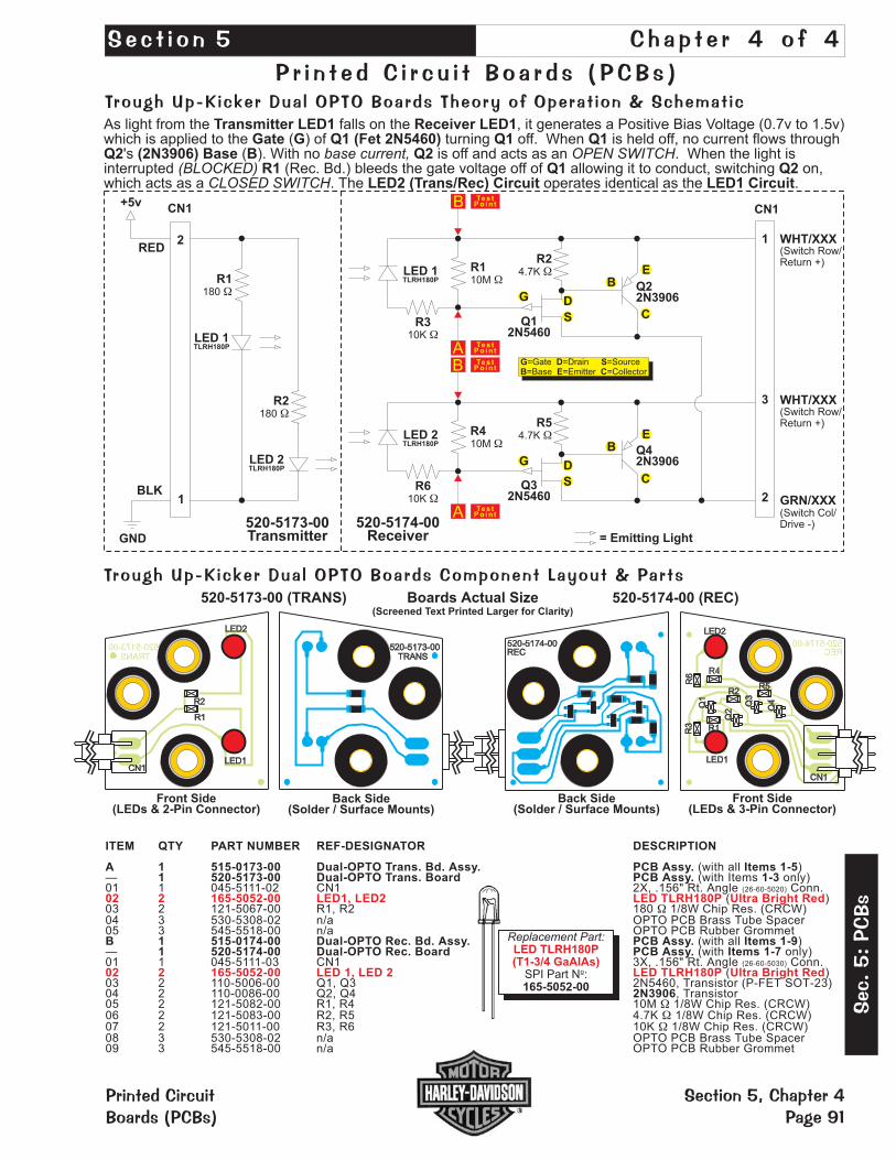
+5vCN1
RED
R310K �
R110M �
R24.7K �
GND
520-5173-00Transmitter
520-5174-00Receiver = Emitting Light
Q12N5460
Q22N3906G D
S
A
B
WHT/XXX
WHT/XXX
GRN/XXX
(Switch Row/Return +)
(Switch Row/Return +)
(Switch Col/Drive -)
CN1
1
3
2BLK
1
520-5173-00 (TRANS) 520-5174-00 (REC)
R610K �
R410M �
R54.7K �
Q32N5460
Q42N3906
A
B
R1180 �
R2180 �
LED 2TLRH180P
2
LED 2TLRH180P
LED 1TLRH180P
LED 1TLRH180P
520-5173-00TRANS
1B1
1B1 2A
7
MG
E3
2A
7
MG
E3
562
562
105
105
103
103
520-5174-00REC
Q4
Boards Actual Size(Screened Text Printed Larger for Clarity)
E
C
B
G D
S
E
C
B
G D SB E C
=Gate =Drain =Source=Base =Emitter =Collector
As light from the falls on the , it generates a Positive Bias Voltage (0.7v to 1.5v)which is applied to the ( ) of turning off. When is held off, no current flows through
's ( ). With no is off and acts as an . When the light isinterrupted (Rec. Bd.) bleeds the gate voltage off of allowing it to conduct, switching on,which acts as a . The operates identical as the .
Transmitter LED1 Receiver LED1Gate G Q1 (Fet 2N5460) Q1 Q1
Q2 (2N3906) Base B Q2R1 Q1 Q2
LED2 (Trans/Rec) Circuit LED1 Circuit
base current, OPEN SWITCH(BLOCKED)
CLOSED SWITCH
Trough Up-Kicker Dual OPTO Boards Component Layout & Parts
Te s tPo in t
Te s tPo in t
Tes tPo in t
Tes tP o i n t
ITEM QTY PART NUMBER REF-DESIGNATOR DESCRIPTION
A 1 515-0173-00 Dual-OPTO Trans. Bd. Assy. PCB Assy. Items 1-51 520-5173-00 Dual-OPTO Trans. Board PCB Assy. 1-3
B 1 515-0174-00 Dual-OPTO Rec. Bd. Assy. PCB Assy. Items 1-91 520-5174-00 Dual-OPTO Rec. Board PCB Assy. Items 1-7
(with all )— (with Items only)
(with all )— (with only)
( )
05 2 121-5082-00 R1, R4 10M 1/8W Chip Res. (CRCW)06 2 121-5083-00 R2, R5 4.7K 1/8W Chip Res. (CRCW)07 2 121-5011-00 R3, R6 10K 1/8W Chip Res. (CRCW)
01 1 045-5111-02 CN1 2X, .156" Rt. Angle Conn.( )
03 2 121-5067-00 R1, R2 180 1/8W Chip Res. (CRCW)04 3 530-5308-02 n/a OPTO PCB Brass Tube Spacer05 3 545-5518-00 n/a OPTO PCB Rubber Grommet
01 1 045-5111-03 CN1 3X, .156" Rt. Angle Conn.
03 2 110-5006-00 Q1, Q3 2N5460, Transistor (P-FET SOT-23)04 2 110-0086-00 Q2, Q4 , Transistor
08 3 530-5308-02 n/a OPTO PCB Brass Tube Spacer09 3 545-5518-00 n/a OPTO PCB Rubber Grommet
(26-60-5020)
(26-60-5030)
2N3906
�
�
�
�
02 2 165-5052-00 LED1, LED2 LED TLRH180P Ultra Bright Red
02 2 165-5052-00 LED 1, LED 2 LED TLRH180P Ultra Bright Red
Front Side(LEDs & 2-Pin Connector)
Back Side(Solder / Surface Mounts)
Front Side(LEDs & 3-Pin Connector)
Back Side(Solder / )Surface Mounts
Replacement Part:
SPI Part N :1165-5052-00
LED TLRH180P(T1-3/4 GaAIAs)
Trough Up-Kicker Dual OPTO Boards Theory of Operat ion & Schemat ic
P r i n t e d C i r c u i t B o a r d s ( PCB s )
S e c t i o n 5 Ch a p t e r 4 o f 4
Sec
.5:
PCBs
Printed CircuitBoards (PCBs)
Section 5, Chapter 4Page 91

��������03� �������' ���3����������� ��(�������" 3 ����� �����(�� ����#
A. OPEN OPTO (Light Falling on LED) = SWITCH OPEN. Place meter leads across points A and B on theLED1 Circuit (Refer to Schematic Drawing on previos page, 520-5174-00 Receiver Side). It should readapproximately 0.8 - 1.2v DC. The LED2 Circuit operates the same.
B. CLOSED OPTO (Light Blocked) = SWITCH CLOSED. Place meter leads across points A and B on theLED1 Circuit (Refer to Schematic Drawing on previous page, 520-5174-00 Receiver Side). It should readapproximately 0.0 - 0.1v DC. The LED2 Circuit operates the same.
��� � 3 3���������� ��(�������" 3 ����� �����(�� ����#
���������� ����� �����#Please Note: To perform this test you must use a spare560� Pull-Up Resistor, SPI Nº: 121-5047-00
Disconnect the OPTO Transmitter / Receiver Board fromthe circuit. Connect one side of a 560 Pull-Up Resistorto Pin-1 of the OPTO Receiver Bd. and the other side ofthe resistor to a 5v DC source. Connect Pin-2 to GND.Connect a +5v DC source to Pin-1 of the Transmitter &GND to Pin-2. Align with the Receiver OPTO approx. 3"distance. Using your Volt-Meter or an Oscilloscope,monitor Pin-1 while BLOCKING and UNBLOCKING theBEAM from the Trans. The output will be approx. +5v DCwhen the BEAM IS NOT BLOCKED and approx. �vwhen the BEAM IS BLOCKED.
��������3�������(��3���"�����������1 �'When a working OPTO is installed and connected in a game, the transmitter should light (LED1 lower & LED2upper) when the power is switched on. With the playfield in Service Position #1 (playfield lifted up and resting onPlayfield Support Slide Brackets) and the game on, the LED lights should show up as a BRIGHT RED RINGSthrough the back of the Receiver Board around the Receivers LED1 & LED2 (See Fig. 1). Testing only LED1: With the game in Switch Test Mode, lifting the Trough Plunger with a fingertip should block the BEAM and causethe Switch Position to trigger (See Fig. 2). View Fig. 2a & 2b (on the next page) for a sectional view of the LightPath (note alignment) and what happens as a ball breaks the light beam.
� ����
� ����
� ����
A. OPEN OPTO (Light Falling on LED) = SWITCH OPEN. Place Scope leadat Pin-1 of OPTO Rec. Board with Scope Grounded (see Schematic). TheScope should display a STEADY +5v as shown in Fig. A, Wave FormDiagram.
B. CLOSED OPTO (Light Blocked) = SWITCH CLOSED. Place Scope leadat Pin-1 of OPTO Rec. Board with Scope Grounded (see Schematic). TheScope should display a PULSE STREAM indicating Q2 has switched "On"as shown in Fig. B, Wave Form Diagram. This is your Switch Drive Pulse.
� ���� ����������� � ��� 34�� �� 3( ������ ����� � � ����'�
�������� ���
���� � ��� ����
�������
� ���'
1 � � �� 3�����
����:�� � ���
������
������� ������ ����
� ���
�
����
#����
�������%������. ������(���������9 ���(�������
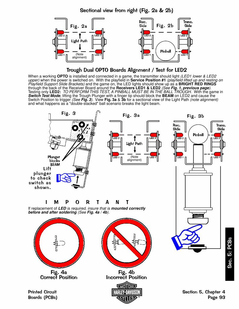
������3�������"���������� - 0�
��������3�������(��3���"�����������1 � When a working OPTO is installed and connected in a game, the transmitter should light (LED1 lower & LED2upper) when the power is switched on. With the playfield in Service Position #1 (playfield lifted up and resting onPlayfield Support Slide Brackets) and the game on, the LED lights should show up as a BRIGHT RED RINGSthrough the back of the Receiver Board around the Receivers LED1 & LED2 (See Fig. 1, previous page).Testing only LED2: TO PERFORM THIS TEST, A PINBALL MUST BE IN THE BALL TROUGH. With the game inSwitch Test Mode, lifting the Trough Plunger with a finger tip should block the BEAM on LED2 and cause theSwitch Position to trigger (See Fig. 3). View Fig. 3a & 3b for a sectional view of the Light Path (note alignment)and what happens as a "double-stacked" ball scenario breaks the light beam.
� � � � + � � � �If replacement of LED is required, insure that is mounted correctlybefore and after soldering (See Fig. 4a / 4b).
����� ����
(Notealignment)
� ��� ����
��������
�������
� ��� 0
1�� �� 3�����
����:�� � ���
������
���������������
� ����
�
����� ����
(Notealignment)
� ����
����
��������
� ����0
�������
����.��������������
����.0���������������
����#����
������(������ �������%������.���(������� ���9�

Do
tM
atr
ixD
isp
lay
Bo
ard
52
0-5
05
2-0
0
Dis
pla
yC
on
tro
lle
rB
oa
rd5
20
-50
55
-03
BLK
—
RED
GND
KEY
+5 VDC
VIO-YEL
BLU
RED
BLK
YEL
—
GRY-YEL
YEL-BLK
P 1
+68v DC
+12v DC
+5v DC
GND
GND
KEY
-98v DC
-110v DC
J 3
R I B B O N C A B L EJ 1
BUSYSTAT 2STAT ØRESETDATA 7DATA 5DATA 3DATA 1SWITCH 8SWITCH 6SWITCH 4SWITCH 2NOT USED
STAT 3STAT 1
NOT USEDSTROBE
DATA 6DATA 4DATA 2DATA Ø
SWITCH 7SWITCH 5SWITCH 3SWITCH 1
NOT USED
CN3-Pin 26 CN3-Pin 25
CN3-Pin 2 CN3-Pin 1
R I B B O N C A B L EJ 2
NOT USEDGROUNDGROUNDGROUNDGROUNDGROUNDGROUND
NOT USEDSER. DATAPIX CLOCK
ROW DATA
CN1-Pin 14 CN1-Pin 13
CN1-Pin 2 CN1-Pin 1
COL. LATCHROW CLOCK
DISPLAY ENABLE
R I B B O N C A B L EP 2
NOT USEDGROUNDGROUNDGROUNDGROUNDGROUNDGROUND
NOT USEDSER. DATAPIX CLOCK
ROW DATA
P2-Pin 14 P2-Pin 13
P2-Pin 2 P2-Pin 1
COL. LATCHROW CLOCK
DISPLAY ENABLE
3
2
1
8
7
6
5
4
3
2
1
Dot Matrix DisplayExplained
The display utilizes a Micro-Processor Control Boardmounted in piggyback fashionto the Dot Matrix Display (128 X32) Driver Board. The purposebehind this board is to providemore information to theoperator as well as displayinggraphics to the player.
The board is controlled by a6809E Micro processor and itspersonality ROM (Unique tothe Game). It receives Data,Reset & Clock Information fromthe CPU/Sound Board via theribbon cable and sends backmultiple Status and BusySignals to the CPU. This is toi n s u r e s y n c h r o n i z e dcommunication between theCPU and the Display ControllerBoard. The Drivers for the rowsand columns are provided on 5surface mounted integratedcircuits on the Dot MatrixDisplay Driver Board.
Dot Matrix Display / Display Controller Bd. Combined Display Connections
Printed CircuitBoards (PCBs)
Sec.
5:
PCBs
Section 5, Chapter 4Page 94

®
R247K1W
�CN1 17PKK156E
88V AC
CN1 27PKK156E
110V AC
CN1 37PKK156E
XFRMR_GND
CN1 47PKK156E
GND
KEY 5
CN1 67PKK156E
+20V
CN1 77PKK156E
+5V +5V
+20V
GND
D21N4004
C2220 uF200V
+
+ C1220 uF200V
D11N4004
R1
1305W
�
D31N52283.9V
R347K1W
�
D41N52283.9V
R4
1.5K1/2W
�
.. Q1MPSA92
.. Q2MPSA42
R5
1.5K1/2W
�
Q3
MJE15030
D51N4760A68V
D61N4764A100V
D71N474313V
C30.1 uF500V
C40.1 uF500V
.. Q4MJE15031
R7330K1/2W
�
R6330K1/2W
�
Q5
MJE15030R82K5W
�
GNDR101.5K1/2W
�
C7
0.1 uF500V
GND
1 CN28PKK156C
-120V
2 CN28PKK156C
-100V
3 KEY
8PKK156C
4 CN28PKK156C
GND
5 CN2
6 CN28PKK156C
+5V
7 CN28PKK156C
+12V+12V
+5V
8 CN28PKK156C
+60V
GND
GND
0.75AS.B. GND
F1
Actu
alB
oa
rdS
ize
5”
X3
.3”
Disp lay Power Supply Board Component Layout & Parts
ITEM QTY PART NUMBER REF-DESIGNATOR DESCRIPTION (NS = Not Stuffed)
— 1 520-5138-00 Display Power Supply Board Complete PCB Assembly01 2 125-5044-00 C1, C2 220uF, 200v, Radial Lytic Cap.02 3 125-5035-00 C3, C4, C7 0.1uF, 500v, Ceramic Disk Cap.
04 1 045-5015-07 CN1 7PKK156E (PIN5=KEY)05 1 045-5015-08 CN2 8PKK156 (PIN3=KEY)06 2 112-5003-00 D1, D2 1N4004, Diode07 2 112-0053-00 D3, D4 1N5228, 3.9v, Diode08 1 112-0062-00 D5 1N4760A, 68v, Diode09 1 112-0049-00A D6 1N4764A, 100v, Diode10 1 112-0061-00 D7 1N4743, 13v, Diode
12 2 205-0004-00 F1 Fuse Clip13 1 110-0100-00 Q1 MPSA92, Transistor14 1 110-0082-00 Q2 MPSA42, Transistor15 2 110-0101-00 Q3, Q5 MJE15030, Transistor16 2 535-5000-11 Q3, Q4 Heatsinks - AAVID #56300217 2 240-5008-00 Q3, Q4 #6-32 KEPS Nut18 2 237-5501-00 Q3, Q4 #6-32 X 3/8" PPH Screw19 1 110-0103-00 Q4 MJE15031, Transistor20 1 121-5061-00 R1 130 5W Res.21 2 121-5060-00 R2, R3 47K 1W Res.22 3 121-5038-00 R4, R5, R10 1.5K 1/2W Res. (R9: NS)23 2 121-5059-00 R6, R7 330K 1/2W Res.
11 1 200-5000-17 F1 3/4A (0.75A) S.B. Fuse
24 1 121-5062-00 R8 2K 5W Res.
�
�
�
�
�
03 0 125-5003-00 (C5, C6: NS) 22uF, 35v, Rad Lytic Cap
25 0 124-5003-00 (VR1: NS) 7812CT
Disp lay Power Supply Board Schemat ic
Sec
.5:
PCBs
Printed CircuitBoards (PCBs)
Section 5, Chapter 4Page 95

Section 5, Chapter 4Page 96
Disp lay Contro l ler Board Schemat ic
Printed CircuitBoards (PCBs)
Sec.
5:
PCBs
A
B
C
D
34
4 3
J4-1
J4-6
J4-5
J4-4
J4-3
J4-2
U1-F
U4
J3-3
J3-2
J3-1
J1
U1-A
U9
U1-E
U1-C U1-D
J5
U2
J2
U10

Section 5, Chapter 4Page 97
Disp lay Contro l ler Board Schemat ic
Sec
.5:
PCBs
Printed CircuitBoards (PCBs)
®
SPI Display Controller BoardSPI Part N : 520-5055-03 JUNE 2001º
Schematic Set
Sheet 1 of 1
Prepared By: Edited By:
Model: Dated:
CES Inc. SPI Inc.237-0255-00 06/17/01
SIZE
DREV.
E
Non-Text Document
D
C
B
A
2 1
2 1
U3
U5 U6
U11
U1-B
U8
U7

ITEM QTY PART NUMBER REF-DESIGNATOR DESCRIPTION (NS = Not Stuffed)
— 1 520-5055-03 Display Controller Bd. (FCC FEB98) Rev. E June 2001 Complete PCB Assembly01 1 045-5015-26 J1 13-Pin, Dual row .1" Hdr. Conn HDR2X1302 1 045-5015-02 J2 7-Pin, Dual Row .1" Hdr. Conn HDR2X703 1 045-5015-03 J3 3-Pin, PKK156B Connector04 1 J4 6-Pin (6P100)05 7 C35-C39, C40, C41 SMT 0.01uF, 50v Cap. 103-0805-X7R06 20 C21, C24, C28-C32, C33, C34, C42, C43, C44, C45, C46 SMT 0.1uF, 50v Cap. 104-0805
C47, C48, C49, C50, C5307 2 C26, C27 SMT 0.22uF, 50v Cap. 224-1206-Z5U08 21 C1-C12, C13-C18, C20, C23, C52 SMT 470pF, 50v Cap. 471-080509 2 C19, C25 100uF, 25v TCap.
11 4 R16-R18 0 1/10W Resistor 0805
12 1 n/a RESET13 2 R11, R13 SMT 1K 1/10W Resistor 0805
14 1 R8 SMT 1M 1/10W Resistor 0805
15 5 R1, R2, R3, R7 SMT 10K 1/10W Resistor 0805
16 9 R21, R22-R29 SMT 33 1/10W Resistor 0805
17 1 R20 SMT 100 1/10W Resistor 0805
18 2 R9, R15 SMT 100K 1/10W Resistor 0805
19 1 R5 SMT 180 1/10W Resistor 0805
20 3 R10, R12, R14 SMT 220 1/10W Resistor 0805
21 1 U1 74HCT04D (74LS04)22 1 U2 74LS245DW23 1 100-0189-01 U3 MC6809E24 1 100-5044-00 U4 XC9572XL, Int. Xilinx®25 2 U5 (ROM0) 4MB ROM 27C040 (M27C401-100)
26 1 U7 74HCT273D27 1 100- U8 K6T0808C1D-GB55, Int. Samsung 046A28 1 U9 74HCT245D29 1 U11 LM3940IMP-3.330 1 RSN1 8MHZRSN (8Mhz) Crystal31 2 n/a FB1, FB2 Ferrite Bead, FB037032 0 FID1-3 FIDTP50M
�
�
�
�
�
�
�
�
�
DO NOT STUFF
(40-Pin Socket, 077-X)
045-125-125-
125-125-125-5015-00
121-
121-
121-
121-
121-
121-
121-
121-
121-
100-100-
100-
100-100-140-
(C51: NS)
(R19: NS)
(R6: NS)
(U6: NS)
10 1 165-5099-00 L1 LED T1-3/4 DIFFUSER RED
(See Pg. Table)DR. � (32-Pin, IC Dip Socket, 077-5217-00)
5045-00
If a part is required where a part number is not provided, call Technical Support (see back of cover).
Actu
alB
oa
rdS
ize
20
.5cm
X1
2.5
cm
XILINX®XC9572XL™TQ100AEN0101F1168339A7C
ROM1
27
C0
40
DIS
P.C
NT
RL
R.
4MB
U5
+L1
C19
+
+
R7
C42
J1
J3
C46
C25
+
+
U11 11AJL52B
J2
6
J4
6 1
1
C18
C17
C16
C15
C14
C13
R10C48
U9
R28
R26
R24
R22
R29
R27
R25
R23
R9
C53
RE
SE
T
C34 C41
U8
R19R19
R6
R16
R18
C33 C40
U10
C51 C49
R13
R17
C22
C43
U1 R21C32
C39
C35
C28
FB2
FB1
C21
C20
C24C26
C27
C29C37
C36 C30
C38C31
U4 U6
RSN1
R8
J5
R20
R11C47
U5
R4
R3
C52
R15
R14
U3
R2
R1
C45
C23
R12
C12
C11
C10
C9
C8
C7
C6
C5
C4
C3
C2
C1
U2 U7
C44C50
R5
ROM0
09AD7YK74HCT245D
08A
51X
X7
4H
CT
04
D
03FC59K74HCT273D
02C5RVK74LS245DW
U3
EF
68B
09E
PW
B2060034
(ST
)P
HIL
IPP
INE
S
SA
MS
UN
G0
46
AK
6T
08
08
C1
D-G
B5
5
Section 5, Chapter 4Page 98
Disp lay Contro l ler Board Component Layout & Parts
Printed CircuitBoards (PCBs)
Sec.
5:
PCBs
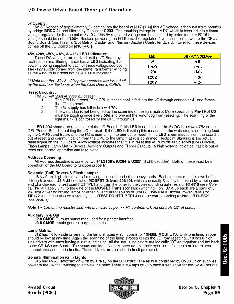
��������� � ������������������ ���
5v Supply:An AC voltage of approximately 9v comes into the board at [J17-(1-4)] this AC voltage is then full-wave rectified
by bridge BRDG 21 and filtered by Capacitor C203. The resulting voltage is 11v DC which is inserted into a linearvoltage regulator for the output of 5v DC. This 5v regulated voltage can be adjusted by potentiometer R116 thevoltage should be set to 5.00v. Besides powering the I/O Board the regulated 5 volts supplies power to the CPU /Sound Board, Gas Plasma (Dot Matrix) Display and Plasma (Display) Controller Board. Power for these devicescomes off the I/O Board on [J16-(4-8)].
+5v, +20v, +50v, +18v, & +12v LED Indicators:These DC voltages are derived on the I/O Board by
rectification and filtering. Each has a LED indicating thatpower is being supplied to each of these voltage sources.The -12v supply comes from the same transformer windingas the +12v thus it does not have a LED indicator.
** Note that the +50v & +20v power sources are turned offby the Interlock Switches when the Coin Door is OPEN.
Reset Circuitry:The I/O will reset in three (3) cases:
1. The CPU is in reset. The CPU’s reset signal is fed into the I/O through connector J1 and forces the I/O into reset.
2. The 5v supply has fallen below 4.75v.3. The watchdog is not being fed by the scanning of the light matrix. More specifically Pin-19 of U6
must be toggling once every 50ms to prevent the watchdog from resetting. The scanning of thelight matrix is controlled by the CPU through J1.
LED L204 shows the reset state of the I/O Board. If this LED is not lit either the 5v DC is below 4.75v or theCPU/Sound Board is holding the I/O in reset. If the LED is flashing this means that the watchdog is not being feedby the CPU/Sound Board and the I/O is oscillating into and out of reset. If the LED is continuously on the board isout of reset and communication from the CPU to the lamp matrix is confirmed. Testpoint Blanking is the actualreset signal on the I/O Board. A low voltage indicates that it is in reset this will turn off all Solenoid (Coil) Drivers,Flash Lamps, Lamp Matrix Drivers, Auxiliary Outputs and Flipper Outputs. A high voltage indicates that it is out ofreset and normal operation can take place.
Address Decoding:All Address decoding is done by two 74LS138’s (U204 & U205) (3 of 8 decoder). Both of these must be in
operation for the I/O Board to function properly.
Solenoid (Coil) Drivers & Flash Lamps:J8 & J9 are high side drivers for driving solenoids and other heavy loads. Each connector has its own buffer
driving 8 drivers. J8 & J9 consist of MOSFET Drivers 20N10L which can easily & safely be tested by clipping oneend of a clip-lead to test point FET TPL1 and then the other to the corresponding gate resistor R1-R16 (see Note1). This will apply 3.4v to the gate of the MOSFET Transistor thus switching it on. J7 & J6 each are a bank of 8low side driver for driving lamps or other lower current solenoids (coils). They use a Bipolar Power TransistorTIP122 which can also be tested by using TEST POINT TIP TPL3 and the corresponding resistors R17-R32*(see Note 1).
Note 1 Clip on the resistor side with the white stripe. R1 controls Q1, R2 controls Q2, et cetera...
Auxiliary In & Out:J2-8 CMOS Outputs sometimes used for a printer interface.J3-8 CMOS Inputs general purpose inputs.
Lamp Matrix:J12 has 10 low side drivers for the lamp strobes which consist of 19N06L MOSFETS. Only one lamp strobe
should be low at any time. Again the scanning of the lamp strobes keeps the I/O from resetting. J13 has 8 highside drivers with each having a status indicator. All the status indicators are logically ’OR’ed together and fed backto the CPU/Sound Board. The status can identify open loads (for example open lamp filaments or intermittentconnections) and short circuits. These drivers are also short-circuit protected.
General Illumination (G.I.) Lights:J15 has 6v AC switched on & off by a relay on the I/O Board. The relay is controlled by Q200 which supplies
power to the 24v coil winding to activate the relay. There are 4 taps on J15 each fused at 5A for this 6v AC source.
��� ������ �����
� ��
� �� � ��
� �� ����
� � ����
� �� �� �
��
�����
����
������������ �������� �������!������"����# ��$�%%
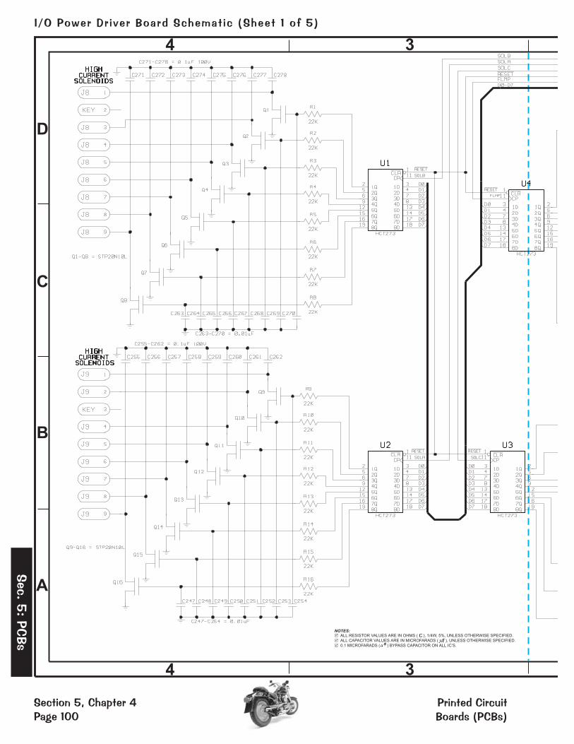
A
B
C
D
34
4 3
NOTES:ALL RESISTOR VALUES ARE IN OHMS ( ), 1/4W, 5%, UNLESS OTHERWISE SPECIFIED.
ALL CAPACITOR VALUES ARE IN MICROFARADS ( , UNLESS OTHERWISE SPECIFIED.
� �
�
�
�
�
F )
0.1 MICROFARADS ( F ) BYPASS CAPACITOR ON ALL IC’S.
Section 5, Chapter 4Page 100
I/O Power Dr iver Board Schemat ic (Sheet 1 of 5)
Printed CircuitBoards (PCBs)
Sec.
5:
PCBs
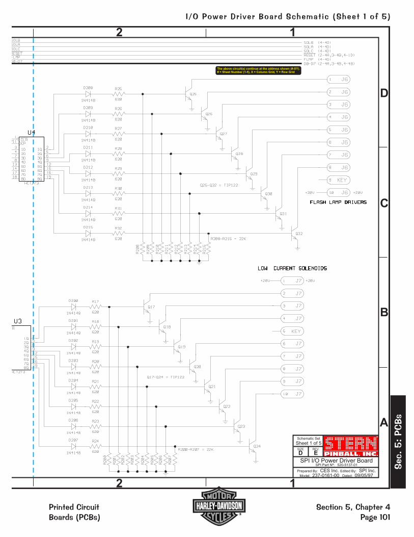
®
SPI I/O Power Driver BoardSPI Part N : 520-5137-01º
Schematic Set
Sheet 1 of 5
Prepared By: Edited By:
Model: Dated:
CES Inc. SPI Inc.237-0161-00 09/05/97
SIZE
DREV.
E
D
C
B
A
2 1
2 1
The above circuit(s) continue at the address shown (#-XY).# = Sheet Number (1-5), X = Column Grid, Y = Row Grid
Section 5, Chapter 4Page 101
I/O Power Dr iver Board Schemat ic (Sheet 1 of 5)
Sec
.5:
PCBs
Printed CircuitBoards (PCBs)

A
B
C
D
34
4 3
The above circuit(s) continue at the address shown (#-XY).# = Sheet Number (1-5), X = Column Grid, Y = Row Grid
Section 5, Chapter 4Page 102
I/O Power Dr iver Board Schemat ic (Sheet 2 of 5)
Printed CircuitBoards (PCBs)
Sec.
5:
PCBs

®
SPI I/O Power Driver BoardSPI Part N : 520-5137-01º
Schematic Set
Sheet 2 of 5
Prepared By: Edited By:
Model: Dated:
CES Inc. SPI Inc.237-0161-00 09/05/97
SIZE
DREV.
E
D
C
B
A
2 1
2 1
NOTES:ALL RESISTOR VALUES ARE IN OHMS ( ), 1/4W, 5%, UNLESS OTHERWISE SPECIFIED.
ALL CAPACITOR VALUES ARE IN MICROFARADS ( , UNLESS OTHERWISE SPECIFIED.
� �
�
�
�
�
F )
0.1 MICROFARADS ( F ) BYPASS CAPACITOR ON ALL IC’S.
Section 5, Chapter 4Page 103
I/O Power Dr iver Board Schemat ic (Sheet 2 of 5)
Sec
.5:
PCBs
Printed CircuitBoards (PCBs)

A
B
C
D
34
4 3
The below circuit(s) continue at the address shown (#-XY).# = Sheet Number (1-5), X = Column Grid, Y = Row Grid
Section 5, Chapter 4Page 104
I/O Power Dr iver Board Schemat ic (Sheet 3 of 5)
Printed CircuitBoards (PCBs)
Sec.
5:
PCBs
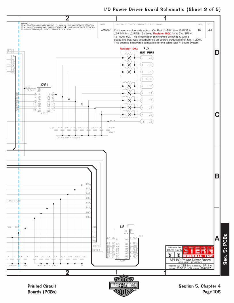
®
SPI I/O Power Driver BoardSPI Part N : 520-5137-01º
Schematic Set
Sheet 3 of 5
Prepared By: Edited By:
Model: Dated:
CES Inc. SPI Inc.237-0161-00 09/05/97
SIZE
DREV.
E
D
C
B
A
2 1
2 1
NOTES:ALL RESISTOR VALUES ARE IN OHMS ( ), 1/4W, 5%, UNLESS OTHERWISE SPECIFIED.
ALL CAPACITOR VALUES ARE IN MICROFARADS ( , UNLESS OTHERWISE SPECIFIED.
� �
�
�
�
�
F )
0.1 MICROFARADS ( F ) BYPASS CAPACITOR ON ALL IC’S. JAN 2001 Cut trace on solder side at Aux. Out Port J2-PIN1 thru J2-PIN3 &J2-PIN5 thru J2-PIN9; Soldered 1/4W 5% (SPI N :
121-5007-00). This Modification (highlighted below at J2 with adotted-line box) was accomplished on boards produced after Jan. 1, 2001.This board is backwards compatible for the White Star™ Board System.
1Resistor 100�
TS JET
Resistor 100�
Section 5, Chapter 4Page 105
I/O Power Dr iver Board Schemat ic (Sheet 3 of 5)
Sec
.5:
PCBs
Printed CircuitBoards (PCBs)

A
B
C
D
34
4 3
The above circuit(s) continue at the address shown (#-XY).# = Sheet Number (1-5), X = Column Grid, Y = Row Grid
The below circuit(s) continue at the address shown (#-XY).# = Sheet Number (1-5), X = Column Grid, Y = Row GridThe below circuit(s) continue at the address shown (#-XY).# = Sheet Number (1-5), X = Column Grid, Y = Row Grid
Section 5, Chapter 4Page 106
I/O Power Dr iver Board Schemat ic (Sheet 4 of 5)
Printed CircuitBoards (PCBs)
Sec.
5:
PCBs

®
SPI I/O Power Driver BoardSPI Part N : 520-5137-01º
Schematic Set
Sheet 4 of 5
Prepared By: Edited By:
Model: Dated:
CES Inc. SPI Inc.237-0161-00 09/05/97
SIZE
DREV.
E
D
C
B
A
2 1
2 1
NOTES:ALL RESISTOR VALUES ARE IN OHMS ( ), 1/4W, 5%, UNLESS OTHERWISE SPECIFIED.
ALL CAPACITOR VALUES ARE IN MICROFARADS ( , UNLESS OTHERWISE SPECIFIED.
� �
�
�
�
�
F )
0.1 MICROFARADS ( F ) BYPASS CAPACITOR ON ALL IC’S.
05-25-99 CUT PIN-3 TO GND ON U210 (4-3D)
The below circuit(s) continue at the address shown (#-XY).# = Sheet Number (1-5), X = Column Grid, Y = Row Grid
The above circuit(s) continue at the address shown (#-XY).# = Sheet Number (1-5), X = Column Grid, Y = Row Grid
Section 5, Chapter 4Page 107
I/O Power Dr iver Board Schemat ic (Sheet 4 of 5)
Sec
.5:
PCBs
Printed CircuitBoards (PCBs)

A
B
C
D
34
4 3
The above circuit(s) continue at the address shown (#-XY).# = Sheet Number (1-5), X = Column Grid, Y = Row Grid
Section 5, Chapter 4Page 108
I/O Power Dr iver Board Schemat ic (Sheet 5 of 5)
Printed CircuitBoards (PCBs)
Sec.
5:
PCBs
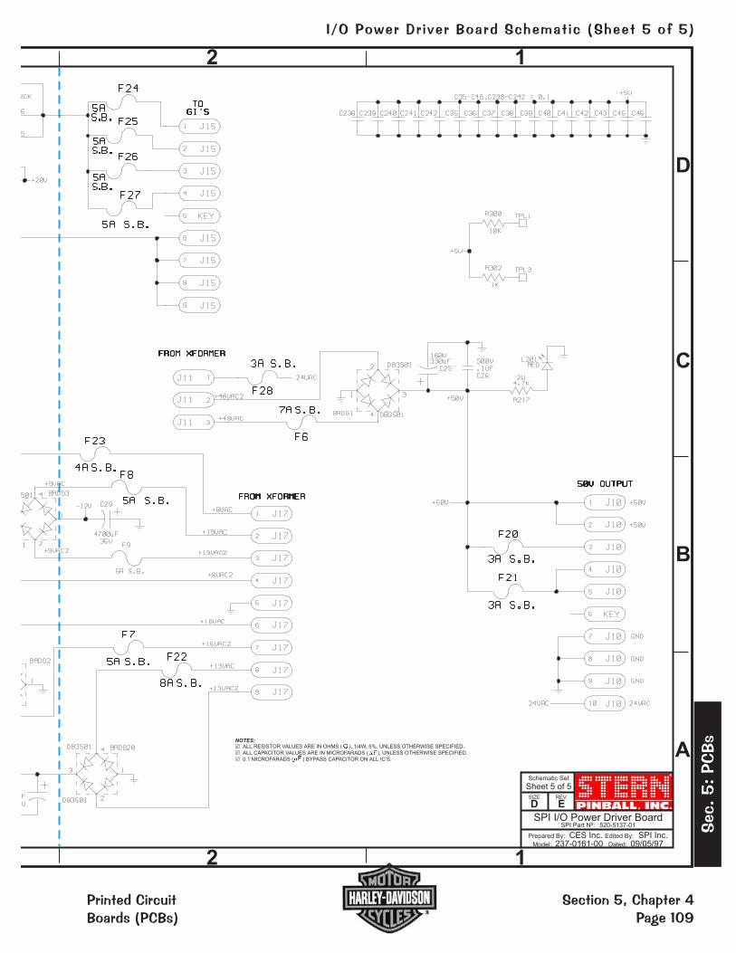
®
SPI I/O Power Driver BoardSPI Part N : 520-5137-01º
Schematic Set
Sheet 5 of 5
Prepared By: Edited By:
Model: Dated:
CES Inc. SPI Inc.237-0161-00 09/05/97
SIZE
DREV.
E
D
C
B
A
2 1
2 1
NOTES:ALL RESISTOR VALUES ARE IN OHMS ( ), 1/4W, 5%, UNLESS OTHERWISE SPECIFIED.
ALL CAPACITOR VALUES ARE IN MICROFARADS ( , UNLESS OTHERWISE SPECIFIED.
� �
�
�
�
�
F )
0.1 MICROFARADS ( F ) BYPASS CAPACITOR ON ALL IC’S.
Section 5, Chapter 4Page 109
I/O Power Dr iver Board Schemat ic (Sheet 5 of 5)
Sec
.5:
PCBs
Printed CircuitBoards (PCBs)
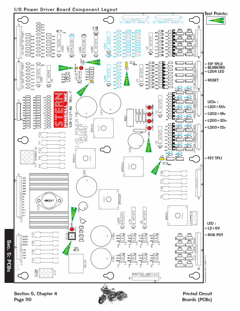
Test Points:
�TIP TPL3�BLANKING�L204 LED
�RESET
�L201+50vLEDs :
�L202+18v
�L200+20v
�L203+12v
�FET TPL1
�L2+5V
�R116 POT
LED :
TEST •
TEST •L
ED
LE
D
LE
Ds
TE
ST•
TE
ST•
TE
ST•
TE
ST•
TE
ST•
TEST•
TEST •
Actu
alB
oa
rdS
ize
15
.69
8”
X11
”
®
Section 5, Chapter 4Page 110
I/O Power Dr iver Board Component Layout
Printed CircuitBoards (PCBs)
Sec.
5:
PCBs

��������� � ����������ITEM QTY PART NUMBER REF-DESIGNATOR DESCRIPTION (NS = Not Stuffed)
— 1 520-5137-01 I/O Power Driver Board Rev. G Complete PCB Assembly01 5 112-5000-00 BRDG1, BRDG2, BRDG3, BRDG20, BRDG21 DB3501 02 13 125-5030-00 C1, C2, C3>C6, C7, C8, C9>C10, C11, C12 220pF, (221), Cap.03 1 125-5033-00 C25 100uF, 150v, Radial Lytic Cap.04 1 125-5035-00 C26 .1UF, 500v, Ceramic Disk Cap.05 5 125-5036-00 C27, C30, C201, C202, C203 15000uF, 25v, Radial Lytic Cap.06 1 125-5034-00 C29 4700uF, 35v, Radial Lytic Cap. 07 1 125-5032-00 C32 100uF, 25v, Radial Lytic Cap.08 17 125-5031-00 C35, C36, C37, C38, C39, C40, C41, C42, C43, C45, 0.1uF, (104), Cap.
C46, C200, C238, C239, C240, C241, C242 09 22 125-5028-00 C212>C219, C228>C237, C243>C246 (C204-C211: NS) 470pF, (471), Axial Cap.10 0 n/a (C220>C227: NS)11 16 125-5029-00 C247>C254, C263>C270 0.01uF, (103), 100v Cap.12 0 125-5027-00 (C255>C262, C271>C278: NS) 0.1uF, (104), 100v, Cap. 13 25 112-0054-00 D200>D207, D208>D215, D220, D221, D222, D223, 1N4148, Diode
D224, D225, D226, D22714 2 112-5003-00 D217, D229 (D216: NS) 1N4004, Diode15 26 205-0004-00 F6, F7, F8, F9, F20, F21, F22, F23, F24> F27, F28 Fuse Clips16 1 200-5000-03 F6 7A 250v S.B. Fuse17 7 200-5000-01 F7, F8, F9, F24>F27 5A 250v S.B. Fuse18 2 200-5000-08 F21, F28 3A 250v S.B. Fuse19 1 200-5000-05 F22 8A 250v S.B. Fuse20 2 200-5000-06 F20, F23 4A 250v S.B. Fuse21 1 045-5015-01 J1 20-Pin, 0.1 Dual Row Header22 1 045-5014-01 J2 (Key Pin-4), J6 (Key Pin-9), J7 (Key Pin-5) 10PKK156
J10 (Key Pin-6), J13 (Key Pin-2)23 1 045-5015-00 J3 (Key Pin-8) 12PKK156
0 n/a (J4, J5: NS)24 1 045-5013-00 J8 (Key Pin-2), J9 (Key Pin-3), J15 (Key Pin-5) 9PKK15625 1 045-0014-03 J11 10-84-4030 (3-Pin MOLEX)26 1 045-5015-00 J12 (Key Pin-7) 12PKK15627 1 045-0014-06 J14 10-84-4060 (6-Pin MOLEX)28 1 045-5016-00 J16 (Key Pin-14) 15PKK15629 1 045-0014-09 J17 10-84-4090 (9-Pin MOLEX)30 6 165-5099-00 L2, L200, L201, L202, L203, L204 LED T1-3/4 DIFFUSER LED 31 16 110-0106-00 Q1>Q16 22NE10L STP, Transistor32 16 110-0067-00 Q17>Q24, Q25>Q32 TIP12233 10 110-0088-00 Q33>Q42 19N06L STP, Transistor34 1 110-0069-00 Q200 2N3904, Transistor.35 32 121-5042-00 R1>R8, R9>R16, R200>R207, R208>R215 22K � 1/4W Res.36 16 121-5003-00 R17>R24, R25>R32 620 � 1/4W Res.37 17 121-5045-00 R33>R42, R236>R242 39K � 1/4W Res.38 8 121-5021-00 R49, R57>R61, R253, R256, R270 (R252: NS) 4.7K � 1/4W Res.39 11 121-5011-00 R50>R56, R255, R271, R300 10K � 1/4W Res.40 13 121-5007-00 R64>R76 100 � 1/4W Res.
Resistors on Solder Side @ J2-Pins: 1-3 & 5-941 8 121-5029-00 R90, R92, R94, R96, R98, R100, R102, R104 6.8K � 1/4W Res.42 2 121-5033-00 R114, R269 220 � 1/4W Res.43 1 121-5030-00 R115 120� 1/4W Res.44 1 121-5039-00 R116 50 � Pot45 2 121-5036-00 R117, R272 330 � 1/4W Res.46 2 121-5038-00 R216, R218 1.5K � 1/2W Res.47 1 121-5050-00 R217 4.7K � 2W Res. (SANDBAR)48 1 121-5009-00 R219, R245>R251, R254, R302 (R228>R235: NS) 1K � 1/4W Res.49 8 121-5016-00 R261, R262, R263, R264, R265, R266, R267, R268 47 � 1/4W Res.50 1 190-5002-00 RELAY FRL264D024/02CK Relay 51 2 n/a TPL1, TPL3 Test Point Wire (24ga.) Loops52 8 100-5012-00 U1, U2, U3, U4, U6, U18, U201, U206 (U200: NS) 74HCT27353 1 110-0058-00 U9 74LS24554 1 100-5023-00 U210 DS123255 8 110-0089-00 U10, U11, U12, U13, U14, U15, U16, U17 VN02N 56 1 100-0356-00 U19 LM338K57 1 n/a U19 Heatsink (5v Reg.)58 1 100-0338-00 U203 (U202: NS) 74HC24559 2 100-0148-00 U204, U205 74LS13860 1 100-0037-00 U209 74LS7461 1 n/a BLANKING, RESET Test Points
��
���������
������������ ���������������������������� ��!�"""

������
������
��������� ��������! ���������������$��&&' ������"����#

��(���������������������������
CPU Section:The CPU is a 68B09E (U209) with up to 8 MBytes of CPU Code Space (U210). The CPU code is bank selected
by the use of U211 and each bank consists of 16 KBytes. 8 KBytes of RAM (U212) is available to the CPU. TheRAM is battery backed and has a write protected area. Battery back up is accomplished by 3-AA Cells (BAT1)Battery Pack which has a TEST POINT (TP): VBATT to check the battery voltage status. The write protected areaconsists of 512 Bytes used for storing game settings. This section of RAM can only be written to when the coindoor is open. The Coin Door switch comes into the CPU on CN6-12 and is fed into the address decoding PALU213. When this memory protect signal is low writes to the protected RAM area are prohibited. Address decodingfor the system is accomplished by one PAL U213 and one 1-of-8 decoder U214.
A watchdog is used to monitor the CPU and the 5v supply. If the 5v supply is below 4.75 the watchdog will holdthe CPU/Sound Board & I/O Board in reset. The watchdog must be fed at a rate of 250ms or faster. The signalused to feed the watchdog comes from the EPROM Bank select signal used to load U211.
The I/O Interface CN1 is buffered by two (2) HC245 Chips (U207 & U208). The CPU’s reset line is buffered byQ10 and fed over to the I/O through CN1. An I/O Strobe Signal is fed through CN1-15 and is used to notify the I/Othat a valid address is being sent.
Switches:The Switch Matrix consists of eight (8) 2N3904 Transistors(Q1-Q8) which pull one of 8 strobes ‘low’ to activate a
Single Column of switches. The Switch Return Signals are fed into CN7 [SWITCH ROWS] and are highly filteredand compared to a 2.5v reference voltage. The Switch Return Voltage must be below 2.5v to make a Valid SwitchClosure. If false switches are appearing, check that none of the 2N3904 Transistors are permanently pulling thestrobe line low. Only one strobe from CN5 [SWITCH COLUMNS] should be low at any time. CN6 [DEDICATEDSWITCH IN] is a Dedicated Bank of Input Switches. Switches connected to CN6 are connected to ground insteadof a strobe and may be read at any time.
Plasma Interface:The data path for communication to and from the Plasma Controller Board is 8 bits wide. There are separate
Input and Output Busses. Data going out to the controller comes from the CPU’s Data Bus through U201 andonto CN8-Pins 11-18. Status back from the Plasma Controller comes in on CN8-Pins 22-26 and is fed into U202for input to the CPU’s Data Bus. Two control signals that go out to the Plasma Controller are PRES [TP17:PLASMA RESET] and CN8-Pin 19 [PSTB - Plasma Strobe]. The Plasma Reset is software controllable throughU216/B and also has a test point "Plasma Reset". The Plasma Strobe Signal to the controller is generated fromU216/A and is used to latch data into the Plasma Controller.
Other Test Points (TP):TP 7: E & TP5: Q - The CPU signals for both 68B09E processors. Should be at 2Mhz with Q leading E by
500 nsec. TP2: P0. TP3: P1. TP4: P2. TP20: (near U402). TP8: (near U219). TP1: +3.3V.
��
�����
����
������������ �������� �������!������"����# ��$�&&)

G FHIJ
G FHIJ
1-5J 1-5I 1-5H 1-5G 1-5F
1-4J 1-4I 1-4H 1-4G 1-4F
1-3J 1-3I 1-3H 1-3G 1-3F
1-2J
1-2I
1-2H 1-2G 1-2F
1-1J 1-1I 1-1H 1-1G 1-1F
5
2
4
3
1
The circuit(s) continue at the address shown [ #-XY ].
# = Sheet Number (3-5), X = Column Grid, Y = Row Grid
[ #, X-Y ] comingfrom ...
[ #, X-Y ] goingto ...
P_D2
P_D9
P_D4P_D5
P_D1
P_D13P_D14
P_D7P_D8
P_D3
P_D10
P_D15
P_D0
P_D11P_D12
P_D6
P[ 2, F-2 ]
_D [ 15..0 ]
DATABUSOF ARM
P_A8P_A7
P_A4
P_A6
P_A3P_A2P_A1
P_A5
P_A9P_A10P_A11P_A12P_A13P_A14P_A15P_A16
P_A [ 16:1 ][ 2, J-2: 2, C-3 ]
ADDRESSBUS
OF ARMTO RAM
(IDT71V016SA)
P_A20
A0 / NLB
P_D
0
P_D
3
P_D
12
P_D
13
P_D
14
P_D
15
P1 / TCLK0P0 / TIOA0
P_D
15
P_D
14
P_D
13
P_D
12
P_D
9P
_D
8
P_D
3
P_D
1
P_D
0
P_D
2
P_D
2
P2 / TIOB0
P3 / TCLK1
P5 / TIOB1P6 / TCLK2P7 / TIOA2P8 / TIOB2P9 / IRQ0
P10 / IRQ1P11 / IRQ2
P12 / FIQP13 / SCK0
P16P17P18P19P20 / SCK1
MC
KI
P23
P24 / BMS
P25
/M
CK
O
TMSTDI
NC
S0
NC
S1
NWAIT
P_A16P_A15P_A14P_A13P_A12P_A11P_A10P_A9P_A20
P_A19P_A18P_A8P_A7P_A6P_A5P_A4P_A3P_A2
P_A17
P_D0P_D8P_D1P_D9P_D2P_D10P_D3P_D11
P_D4P_D12P_D5
P_D14P_D7P_D15
P10
NRD/NOE [ 2, C-1: 1, D-3: 1, I-4 ]
P3P6P9P13
P_
A[
19
:1]
P_D [ 15:8 ]
P_D [ 7:0 ]
P0
P3
P1P2
P5P6P7P8
P11
P9
P12P13
P_A10
P_A8
P_A18
P_A6
P_A17
P_A19
P_A13
P_A1
P_A14
P_A9
P_A2
P_A7
P_A11
P_A16
P_A5
P_A3
P_A15
P_A4
P_A12
P23
P25
P16
P18P19P20
P17
P24
TCK
P_A1
P_D
7
P_D
5P
_D
6
P_D
11
P_D
10
P_D6
P_D
1
P_D
4
P_D13
TD
O
VDD IO
+3.3V
VDD IOVDD IO
VDD CORE
VDD IO
VDD IO
+3.3V
+3.3V
VDD COREVDD IO
+3.3V
+3.3V
+3.3V
NWR0/NWE [ 2, C-2: 1, I-4 ]
P15 / RXD0 [ 2, F-5 ]P14 / TXD0 [ 2, I-5 ]
P21 / TXD1 / NTRI [ 2, I-5 ]
P4 / TIOA1 / SST0 [ 4, J-2 ]
P22
/R
XD
1[
2,
F-5
]N
WR
1/
NU
B[
2,
G-2
]
NR
ST
[2
,F
-5]
NW
DO
VF
[2
,3
-A]
NR
D/
NO
E[
2,
C-1
]**
NW
R0
/N
WE
[2
,C
-2]
*
P_A21 [ 2, C-2 ]
P_A22 [ 2, C-1 ]
JTAG
R4
53
10
0K
R4
50
10
0K
C4
12
10
0n
F
R5
08
1K
R4
48
10
0K
C4
19
47
pF
C4
18
10
0n
F
R4
34
1K
R4
44
10
0K
U8A15
1
A142
A133
A124
A115
A106
A97
A88
A199
A2010
WE#11
RESET#12
VPP13
NC14
RDY/BUSY#15
A1816
A1717
A718
A619
A520
A421
A322
A223
A124
A1648
BYTE#47
GND46
I/O15/A-145
I/O744
I/O1443
I/O642
I/O1341
I/O540
I/O1239
I/O438
VCC37
I/O1136
I/O335
I/O1034
I/O233
I/O932
I/O131
I/O830
I/O029
OE#28
GND27
CE#26
A025
R437100K
R4
43
10
0K
R470
100
C4
11
47
pF
R4
56
10
0K
R4
46
10
0K
R4
57
10
0K
R433
100K
R4
45
10
0K
R4
47
10
0K
R4
54
10
0K
AT91R40008PQFP100
U402
A0 / NLB1
GND2
A13
A24
A35
A46
A57
A68
A79
VDD IO10
A811
A912
A1013
A1114
A1215
A1316
A1417
GND18
GND19
A1520
A1621
A1722
A1823
A1924
A20 /
CS7P28 /
25
P2
926
VD
DC
OR
E27
VD
DIO
28
P3
029
P3
130
D0
31
D1
32
D2
33
D3
34
D4
35
GN
D36
D5
37
D6
38
D7
39
D8
40
D9
41
D1
042
D11
43
VD
DIO
44
D1
245
D1
346
D1
447
D1
548
P0
49
P1
50
P2 51GND 52GND 53
P3 54P4 55P5 56P6 57P7 58P8 59P9 60
VDD CORE 61VDD IO 62
P10 63P11 64GND
65P12 66P13 67P14 68P15 69P16
70P17
71P18
72P19
73P20
7475
RX
D1
76
NW
R1
/N
UB
77
GN
D78
NR
ST
79
NW
DO
VF
80
VD
DIO
81
MC
KI
82
P2
383
P2
484
P2
585
GN
D86
GN
D87
TM
S88
TD
I89
TD
O90
TC
K91
NR
D/
NO
E92
NW
RO
/N
WE
93
VD
DC
OR
E94
VD
DIO
95
NW
AIT
96
NC
S0
97
NC
S1
98
P2
699
P2
7100
R4
52
10
0K
R4
36
1K
J3
1X
7
1 2 3 4 5 6 7
R4
41
10
0K
C4
10
10
0n
F
R4
35
1K
R4
55
10
0K
R4
58
10
0K
C4
13
10
0n
F
R4
51
10
0K
C4
34
47
pF
R4
49
10
0K
R4
42
10
0K
C4
35
47
pF
P [ 25:0 ][ 2, H-5: 2, E-5:2, C-5: 2, A-4:2, A-3 ]
JP3
1X
3Jum
per
1
2
3
P_D [ 15:8 ]
P_D [ 7:0 ]
J_RST[ 2, A-2 ]
+3.3V+3.3V+3.3V
MCKI
+3.3V
40MZ[ 2, C-2 ]
TO ATMEL
TO XILINX
Y1
40.000MHz
OUT3
VCC4
GND2
OE1
R509
33
R502
33
VDDCORE VDD IO
C4
15
10
0n
F
C4
14
47
pF
VDD IO
NC
S3
[2
,I-
2]
NC
S2
[2
,C
-2:
1,
A-5
]
U402
ATMEL
TP20Test Point
+3.3V
R4
79
10
0K
R4
76
10
0K
R4
78
10
0K
R4
77
10
0K
+3.3V+3.3V+3.3V
C4
17
10
0n
F
C4
16
47
pF
VDDCORE
C4
23
10
0n
F
C4
22
47
pF
C4
21
10
0n
F
C4
20
47
pF
VDDCORE VDD IO
P21
P29 / A21 / CS6
P30 / A22 / CS5
P28 / A20 / CS7
P31 / A23 / CS4
C4
25
10
0n
F
C4
24
47
pF
VDD IO
C4
26
10
0n
F
+3.3V
ATMELAT49BV1614
NCS1 NCS0
+3.3V
JP2 Jumper1X3
1
2
3
R4
59
10
0K
IRQ1
[]
[1
,J
-1]
*
[]
[1
,D
-3:
1,
G-1
]**
Section 5, Chapter 4Page 114
CPU/Sound Board I I (wi th ATMEL Processor) Schemat ic (Sheet 1 of 4)
Printed CircuitBoards (PCBs)
Sec.
5:
PCBs

®
CPU/Sound Bd. II w/ ATMEL ProcessorSPI Part N : 520-5300-00º
Schematic Set
Sheet 1 of 4
Prepared By: Edited By:
Model: RHT SCH1008 Dated:
CES Inc. SPI Inc.06/13/03
SIZE
DREV.
A
BCDE A
5
2
4
3
1
BCDE A
1-1A
1-5E 1-5D1-5C 1-5B
1-5A
1-4E 1-4D 1-4C 1-4B1-4A
1-3E 1-3D 1-3C 1-3B 1-3A
1-2E1-2D 1-2C 1-2B 1-2A
1-1E 1-1D 1-1C 1-1B
Sheet 1 of 4 :
Processor / Sound (Microcontroller)
NOTES: � ALL RESISTOR VALUES ARE IN OHMS ( ), 1/4W, 5%, UNLESS OTHERWISE SPECIFIED.
ALL CAPACITOR VALUES ARE IN MICROFARADS ( , UNLESS OTHERWISE SPECIFIED. BYPASS CAPACITORS FOR ALL INTEGRATED CIRCUITS (ICs).
�
� �� �F ) 0.1 F
The circuit(s) continue at the address shown [ #-XY ].
# = Sheet Number (3-5), X = Column Grid, Y = Row Grid
27C040
+5V16
GND VCC32
27C040
+5V16
GND VCC32
27C040
+5V16
GND VCC32
NCS2[ 1, I-4: 2, C-2 ]
P_A20
NCS2
ROE2
P_D6
P_D0
P_D5
P_D1
P_D3
P_D7
P_D4
P_D2
U36A012
A111
A210
A39
A48
A57
A66
A75
A827
A926
A1023
A1125
A124
A1328
A1429
A153
A162
A1730
A1831
VPP1
22
24
D013
D114
D215
D317
D418
D519
D620
D721
P_A17
P_A8P_A7
P_A12
P_A15
P_A3
P_A5
P_A11
P_A18
P_A4
P_A6
P_A2
P_A16
P_A13P_A14
P_A19
P_A9P_A10
P_A1
CS
OE
P_A20
NCS2
P_D14
P_D8
P_D13
P_D9
P_D11
P_D15
P_D12
P_D10
U21A012
A111
A210
A39
A48
A57
A66
A75
A827
A926
A1023
A1125
A124
A1328
A1429
A153
A162
A1730
A1831
VPP1
22
24
D013
D114
D215
D317
D418
D519
D620
D721
P_A17
P_A8P_A7
P_A12
P_A15
P_A3
P_A5
P_A11
P_A18
P_A4
P_A6
P_A2
P_A16
P_A13P_A14
P_A19
P_A9P_A10
P_A1
CS
OE
P_A20
P_D14
P_D8
P_D13
P_D9
P_D11
P_D15
P_D12
P_D10
U17A012
A111
A210
A39
A48
A57
A66
A75
A827
A926
A1023
A1125
A124
A1328
A1429
A153
A162
A1730
A1831
VPP1
22
24
D013
D114
D215
D317
D418
D519
D620
D721
P_A17
P_A8P_A7
P_A12
P_A15
P_A3
P_A5
P_A11
P_A18
P_A4
P_A6
P_A2
P_A16
P_A13P_A14
P_A19
P_A9P_A10
P_A1
CS
OEROE2[ 2, C-3 ]
P_D [7..0][ 2, F-2 ]
ROE1[ 2, C-3 ]
27C040
+5V16
GND VCC32
AO/NLB [ 2, G-2 ]
109876543
25242123
22627
1
P_A20
NCS2
ROE1
P_D6
P_D0
P_D5
P_D1
P_D3
P_D7
P_D4
P_D2
U37A012
A111
A210
A39
A48
A57
A66
A75
A827
A926
A1023
A1125
A124
A1328
A1429
A153
A162
A1730
A1831
VPP1
22
24
D013
D114
D215
D317
D418
D519
D620
D721
P_A17
P_A8P_A7
P_A12
P_A15
P_A3
P_A5
P_A11
P_A18
P_A4
P_A6
P_A2
P_A16
P_A13P_A14
P_A19
P_A9P_A10
P_A1
CS
OE
P_D6
P_D0
P_D5
P_D1
P_D3
P_D7
P_D4
P_D2
U7A0A1A2A3A4A5A6A7A8A9A10A11A12A13A14A15 20
22
D011
D112
D213
D315
D416
D517
D618
D719
P_A8P_A7
P_A12
P_A15
P_A3
P_A5
P_A11
P_A4
P_A6
P_A2
P_A13P_A14
P_A9P_A10
P_A1
CS
OE
27256/27512
+5V14
GND VCC28
NCS1 NCS0
+3.3VNRD / NOE[ 2, C-1: 1, G-1: 1, I-4 ]
JP4 Jumper1X3
1
2
3
R5
10
10
0K
VREFA
-12V
+12V
-5A
+5A
+5A
SND_CLK[ 2, C-2 ]
SND_DATA[ 2, C-2 ]
WS[ 2, C-2 ]
1+1-2+2-
3+3-
KEY PIN 5
C75 2200pF
C34 .1uF
C10122uF
C105.1uF
R16
2.2K
C103.1uF
POT 1APOT 1BPOT 1C
CN3
1X6
123456
470
R3
15
0
U100
TDA2030A
VIN
1
2
-VS3
OUT4
+VS5
C106.1uF
U26
TDA1543
BCK1
WS2
DATA3
GND4
VDD5
AOL6
VREF7
AOR8
D1011N4004
R1031
C35 10uF
R71.5K
R81K
100K
CN4
1X7
1234567
C104100uF
C48 2200pF
C33.1uF
C78 10uF
V+
V-
B
U30B
LM833
6
57
8
4
R102
22K
D100
R151K
R9
22
K
C122.1uF
C100 10uF
C102100uF
R17
2.2K
R-INPUT
-5A
-5A
+5A
-5A
U35
TDA8199
RT_IN8
LT_IN5
VOL7
CREF6
GND2VS4
LT_OUT 3RT_OUT 1
R316
0
R112
2.2K
R101
C52.1uF
R12100K
R19 R100
22K
C76 10uF
R13100K
R25
C7910uF
C46.1uF
R14
22K
AOR
TP11Test Point
-5A
+5A
V+
V-
A
U30A
LM833
2
31
8
4
AOLTP16
Test Point
+
+
+
C77 10uF
C45.1uF
2.2K
+
+
+
1N4004
+
VIN
-12V
+12V
C10822uF
C113.1uF
C111.1uF
470
U101
TDA2030A
VIN
1
2
-VS3
OUT4
+VS5
C110.1uF D103
1N4004
R1071
4.7K
C112100uF
R106
10K
D102
C123.1uF
C107 10uF
C109100uF
R105R21 R104
22K+
+
+
1N4004
VIN
C11522uF
C120.1uF
C118.1uF
470
TDA2030A
2
4
D1051N4004
R1111
C119220uF
R110
33K
C124.1uF
R109R108
39K
+
+
C802200pF
+
-12V
+12V
U102VIN
1
-VS3
OUT
+VS5
C117.1uF
47K
D104
C114 10uF
C116220uF
R24
+
+
1N4004
VIN
R22
47K
+
+
C50 2200pF
VOLUME
SPEAKER
[ #, X-Y ] comingfrom ...
[ #, X-Y ] goingto ...
P_D [ 15:8 ]
P_D [ 7:0 ]
NS: Not Stuffed
NS
NS
NS
NS
NS
NS
NS
NS
NS
NS
NS
NS NS
NS NSNS
NS
NS
NS
NSNS NS
NS
NS
NS
NS
NS
NS NS
NS
Section 5, Chapter 4Page 115
CPU/Sound Board Schemat ic (Sheet 1 of 4)I I (wi th ATMEL Processor)
Sec
.5:
PCBs
Printed CircuitBoards (PCBs)

G FHIJ
G FHIJ
2-5J 2-5I 2-5H 2-5G 2-5F
2-4J 2-4I 2-4H 2-4G 2-4F
2-3J 2-3I 2-3H 2-3G 2-3F
2-2J
2-2I
2-2H 2-2G 2-2F
2-1J 2-1I 2-1H 2-1G 2-1F
5
2
4
3
1
+
The circuit(s) continue at the address shown [ #-XY ].
# = Sheet Number (3-5), X = Column Grid, Y = Row Grid
[ #, X-Y ] comingfrom ...
[ #, X-Y ] goingto ...
P_A7
P_A4
P_A1
P_A5
P_A3
P_A9P_A8
P_A2
P_A6
P_A10
P_A12P_A11
P_A13P_A14P_A15P_A16
P_A [16:1]
ADDRESSBUS
OF ARM
[ 1, J-2: 2, C-3 ]
P_D2P_D1
P_D13
P_D4
P_D7
P_D3
P_D8
P_D5
P_D9
P_D11
P_D6
P_D10
P_D12
P_D15
P_D0
P_D14
P_D [15..0]
DATABUSOF ARM
[ 1, A-4: 1, F-2 ]
ZF4
MTG_SLOT
ZF5
MTG_SLOT
BATTERYTIE WRAP
SLOTS
P_A5P_A4P_A3
P_A12P_A11P_A10P_A9
P_A8P_A7P_A6
P_A2
P_D8P_D9P_D10P_D11
P_D12P_D13P_D14P_D15
+3.3V
NRD/NOENWR1/NUBA0/NLB
+5VGND +3.3V
GND
F1FER_BEAD
U412
IDTSOJ4471V016SA
A41
A32
A234
P_A16P_A15P_A14P_A13
P_D0
P_A1
P_D1P_D2P_D3
P_D4P_D5P_D6P_D7
+3.3V
NCS3
NWR0/NWE
A1A05
CS#6
I/O07
I/O18
I/O29
I/O310
VDD11
VSS12
I/O413
I/O514
I/O615
I/O716
WE#17
A1518
A1419
A1320
A1221
NC22 NC 23A11 24A10 25A9 26A8 27NC 28
I/O8 29I/O9 30
I/O10 31I/O11 32VDD 33VSS 34
I/O12 35I/O13 36I/O14 37I/O15 38BLE# 39BHE# 40OE# 41
A7 42A6 43A5 44
STXD0SRXD0
SRXD1STXD1
+3.3V
CN9
2x5
31
579
2468
10
+5V+3.3V
VDD IO
R465100
LED2REDLED
U405
LT1086
ADJ1
VOUT2
VIN3
C4281000uF
TP1Test Point
C427.1uF
RST OUT
SRXD0SRXD1
STXD1STXD0
+3.3V
+3.3V
+3.3V
P14/TXD0
P15/RXD0P22/RXD1NRST
LED1
R507100K
R506100K
U403
74HC245
A0 2
A1 3
A2 4
A3 5
A4 6
A5 7
A6 8
A7 9
19DIR 1
B018
B117
B216
B315
B414
B513
B612
B711
VCC20
GND10
R505100K
R466
100
R504100K
[ 1, G-4 ]P21/TXD1[ 1, ]G-4
P8[ 1, F-5 ]
OE
[ 1, ]G-4[ 1, H-4 ][ 1, H-4 ]
REDLED
VDDCORE
+3.3V
VDDCORE
+3.3V
C43210uF
C4311.0 uF
U219
LT1503
VOUT1
C1-2
C1+3
VIN4 5
C2+6
GND7
C2-8
C44210uF
TP8Test Point
+ +
+
SHDN/SS
C4331.0uF
+ C4301.0uF
+
RST_IN
+3.3V
+3.3V
U406DS1233
1
RESET#2
VCC3
GND
4
S1
SW200
1 4
2 3
R48010K
C429.1uF
+5V
+5V
+5V
+5V
RESET#IORESET
BSEL
RESETTEST PADS
S2
SW200
1 4
2 3
R3130
R501
10K
U413
DS1232
1
TD2
TOL3
GND4 RST567
VCC8
R3140
R4750
R4004.7K
PBRST
RSTST [ 3, J-2 ]
[ 3, A-2 ][ 3, A-2: 4, J-2: 2, A-2]
[ 1, I-4 ]
[ 1, I-4:1, J-1:2, C-2 ]
[ 1, G-1: 1, I-4, 2, C-1 ][ 1, H-4 ][ 1, E-4 ]
+3.3V
C443.1uF
C436.1uF
C437.1uF
C438.1uF
C439.1uF
C440.1uF
C441.1uF
C444.1uF
+5V
C289.1uF
C283.1uF
C284.1uF
C285.1uF
C286.1uF
C287.1uF
C288.1uF
C291.1uF
C292.1uF
+5V
C278.1uF
C272.1uF
C273.1uF
C274.1uF
C275.1uF
C276.1uF
C277.1uF
C279.1uF
C281.1uF
C280.1uF
C282.1uF
+5V
C1.1uF
C2.1uF
C3.1uF
C4.1uF
C9.1uF
+5V
C18.1uF
C24.1uF
BYPASS CAPACITORS
NS
NS
NS
NS
NSNS
NS
NS
+3.3V
[ F1-F6> 4, I-2: 4, I-1 ]
NS
Section 5, Chapter 4Page 116
CPU/Sound Board I I (wi th ATMEL Processor) Schemat ic (Sheet 2 of 4)
Printed CircuitBoards (PCBs)
Sec.
5:
PCBs

®
CPU/Sound Bd. II w/ ATMEL ProcessorSPI Part N : 520-5300-00º
Schematic Set
Sheet 2 of 4
Prepared By: Edited By:
Model: RHT SCH1008 Dated:
CES Inc. SPI Inc.06/13/03
SIZE
DREV.
A
BCDE A
5
2
4
3
1
BCDE A
2-1A
2-5E 2-5D2-5C 2-5B
2-5A
2-4E 2-4D 2-4C 2-4B2-4A
2-3E 2-3D 2-3C 2-3B 2-3A
2-2E2-2D 2-2C 2-2B 2-2A
2-1E 2-1D 2-1C 2-1B
Sheet 2 of 4 :
Processor Memory /Regulators & Bypass Capacitors
NOTES: � ALL RESISTOR VALUES ARE IN OHMS ( ), 1/4W, 5%, UNLESS OTHERWISE SPECIFIED.
ALL CAPACITOR VALUES ARE IN MICROFARADS ( , UNLESS OTHERWISE SPECIFIED. BYPASS CAPACITORS FOR ALL INTEGRATED CIRCUITS (ICs).
�
� �� �F ) 0.1 F
TP2Test Point
TP3Test Point
TP4Test Point
TP5Test Point
TP7Test Point
The circuit(s) continue at the address shown [ #-XY ].
# = Sheet Number (3-5), X = Column Grid, Y = Row Grid
[ #, X-Y ] comingfrom ...
[ #, X-Y ] goingto ...
ZG7
1X2
1 2
ZG11
1X2
1 2
ZG8
1X2
1 2
ZG2
1X2
1 2
ZG10
1X2
1 2
ZG5
1X2
1 2
ZG3
1X2
1 2
ZG6
1X2
1 2
ZG4
1X2
1 2
GROUND POSTS
MH6
Mounting Hole
1122
MH2
Mounting Hole
1122
MH1
Mounting Hole
1122
MH4
Mounting Hole
1122
MH3
Mounting Hole
1122
MH5
Mounting Hole
1122
MOUNTING HOLES
ZF2ZF1 ZF3
FIDUCIALS
TH1 TH2 TH3
TOOLING HOLES
P0
P1
P2
P16P17P18P19P20P23P24P25
8MHZQ#
D5
D6
D2
D0
D5
D0
D4
D1
D4
D7
D2D1
D6D7
D3
D3
+3.3V
+5V
+5V +5V
+5V
+5V
D [7..0]
PLIN
P16P17P18P19P20P23P24P25
P0
P1
P2
E
Q
E#
DATABUSOF 68B09E
DATABUS OF68B09E
TO XILINX
U407B
74LS74A
12
11
98
1410 713
R462100K
U407A
74LS74A
D2
CLK3
Q 56
VCC14
4GND
71
R463100K
U404
74HC245
A02
A13
A24
A35
A46
A57
A68
A79
19DIR1
B018
B117
B216
B315
B414
B513
B612
B711
VCC20
GND10
R464100K
[ 1, F-5 ]
[ 1, ]F-5
[ 1, ]F-5OE
Q
E
[ 3, J-2 ]
[ 3, J-2 ]
[ 3, J-3 ]
CLRPRE
QD
CLK
Q
VCCGND
CLRPRE
Q
[ 1, ]F-5[ 1, ]F-5[ 1, ]F-5[ 1, ]F-5[ 1, ]F-5[ 1, ]F-5[ 1, ]F-5[ 1, ]F-5
[ 3, C-1 & 4, J-2 ]
[ 3, A-2 & 4, J-2 ]
X_P12
X_P11
+3.3V +3.3V
P11
P12
R468100K
R469100K
[ 1, F-5 ]
[ 1, F-5 ]
+3.3V
C451.1uF
C445.1uF
C446.1uF
C447.1uF
C448.1uF
C449.1uF
C450.1uF
XTDIXTMS
XTCLKXTDO
P_D14P_D1P_D2P_D13P_D12
P_D3
8MHZ
P_D5
P_D11P_D4P_D10
P_D9P_D8
P_D6P_D7
Q#RST_INRST_OUT
P_D0
XTDO
P_D15
X_P11X_P12
D0
D1
D2D3D4D5
D6D7
+3.3V +3.3V
+3.3V
NRD/NOE
ROE2NWDOVF
ROE1SND_DATA
WSSND_CLK
40MHZ
NWR0/NWE
A0NCS2P_A21
P_A22
P5P6SNDSTB
P_A1
INT#J_RSTDPSWRESET#
BUSY
XilinxJTAGXilinxJTAG
U414
XC9572XL
I/O11
NC12
I/O/GTS13
I/O/GTS24
VCC15
I/O26
NC27
I/O38
I/O49
I/O510
I/O611
I/O712
I/O813
I/O914
I/O1015
I/O1116
I/O1217
I/O1318
NC319
I/O1420
GND121
I/O/GCK122
I/O/GCK223
GND224
I/O1525
VCC226
I/O/GCK327
I/O1628
I/O1729
I/O1830
GND331
I/O1932
I/O2033
NC534
I/O2135
I/O2236
I/O2337
VCC338
I/O2439
I/O2540
I/O2641
I/O2742
NC643
GND444
TDI45
NC746
TMS47
TCK48
I/O2849
I/O2950
VCC4 51
I/O30 52
I/O31 53
I/O32 54
I/O33 55
I/O34 56
VCC5 57
I/O35 58
I/O36 59
I/O37 60
I/O38 61
GND5 62
I/O39 63
I/O40 64
I/O41 65
I/O42 66
I/O43 67
I/O44 68
GND6 69
I/O45 70
I/O46 71
I/O47 72
NC8 73
I/O48 74
GND7 75
I/O49 76
I/O50 77
I/O51 78
I/O52 79
NC9 80
I/O53 81
I/O54 82
TDO 83
GND8 84
I/O55 85
I/O56 86
I/O57 87
VCC6 88
I/O58 89
I/O59 90
I/O60 91
I/O61 92
I/O62 93
I/O63 94
I/O64 95
I/O65 96
I/O66 97
VCC7 98
I/O/GSR 99
GND9 100
J2
1x6
123456
[ 1, H-4 ][ 1, A-5 ]
[ 1, J-2: 2, J-2 ]
[ 1, E-2 ]
[ 1, E-2 ]
[ 1, A-4 ]
[ 1, E-2 ]
[ 3, A-2 ]
[ 1, J-3 ][ 1, A-5: 1, I-4 ]
[ 1, G-1: 1, I-4: 1, D-3 ]
[ 1, J-1: 1, I-4: 2, I-2 ]
[ 1, F-4 ]
[ 1, J-3 ]
[ 1, F-5 ]
[ 3, A-2 ]
[ 1, G-5 ]
[ 2, H-3: 3, A-2: 4, J-2 ]
[ 3, E-3 ]
[ 3, C-1: 4, J-2 ]
[ 1, F-5 ]
[ 4, J-2 ]
XILINX®
NS: Not Stuffed
P0
P1
P2
Q
E
Section 5, Chapter 4Page 117
CPU/Sound Board Schemat ic (Sheet 2 of 4)I I (wi th ATMEL Processor)
Sec
.5:
PCBs
Printed CircuitBoards (PCBs)

G FHIJ
G FHIJ
3-5J 3-5I 3-5H 3-5G 3-5F
3-4J 3-4I 3-4H 3-4G 3-4F
3-3J 3-3I 3-3H 3-3G 3-3F
3-2J
3-2I
3-2H 3-2G 3-2F
3-1J 3-1I 3-1H 3-1G 3-1F
5
2
4
3
1
A0
+5V
XA4
A15 A15
BS
EL
XA0
XA3XA2XA1
E#
RW
XA [ 5:0 ]
XA5
POUT
POUT
PLIN
PSTB
AVMA
Q
VMA
VMA
D7
RESET#
BSEL
XA5
AVMARW
A[
15
:0]
A8A9A10
A12
A7
Q
A15A14A13
A11A12
RW
E#
ROMCS#
A10
MPIN
E#
PRES
XA
0
SWLO
BSELSWSTBSWM
POUTSTATUS
PLIN
DPSW
A0
VBATT
+5V
+5V
+5V
+5V
+5V
+5V
+5V
+5V
+5V
ROMCS#
A9A10
XA0IOSTB
IOPORTRAMCS#
SNDSTB
+5V
+5V
+5V
+5V
+5V
BSEL
Q
E#
E
PLASMA_RESET
JP1
U215B
74AHCT74
R3
05
10
K
R432
10K
L201
REDLED
R300
0
D201
1N5817
R414220
BAT1
BAT3
4.5Vx3 AACELLS
12
U213
PAL16V8Q
C290.1uF
R3
03
10
K
R431
10K
R310
0
+5V
R312
330
L200
REDLED
R29910K
U210
27C040
TP17Test Point
U211
74LS374
1
CLK11
D0 3
D1 4
D2 7
D3 8
D4 13
D5 14
D6 17
D7 18
Q02
Q15
Q26
Q39
Q412
Q515
Q616
Q719
VCC20
GND10
D200
1N5817
U216B
74AHCT74
U212
62256
GND
J1
1X
2
12
R3
02
10
K
R3
01
10
K
R3
04
10
K
U214
74LS138
R311
0
+5V
8K 32K
1X3Jumper
12
3R306
10K
AVMARW
D0D1D2D3D4D5D6D7
A1A2A3
A5A6A7
A10A11A12
A8
A4
A9
A0
D0D1D2D3D4D5
[ 2, H-3 ]
[ 2, C-4 ][ 2, C-4 ]
[ 2, C-5 ]
D6D5D4D3D2D1D0
D7
A1A2A3
A5A6A7
A10A11A12A13
A8A9
A4
A0
XA4XA3XA2XA1XA0
+5V
OE
U216A
74AHCT74
+5V
U215A
74AHCT74
+5V
A010
A19
A28
A37
A46
A55
A64
A73
A825
A924
A1021
A1123
A122
D011
D112
D213
D315
D416
D517
D618
D719
VCC28
14
A1326
A141
27
22
20CS
OE
WR/
A012
A111
A210
A39
A48
A57
A66
A75
A827
A926
A1023
A1125
A124
A1328
A1429
A153
A162
A1730
A1831
VPP1
22
24
D013
D114
D215
D317
D418
D519
D620
D721
VCC32
GND16
CS
OE
D12
CLK11
Q98
VCC14
10GND
713
Q
CLRPRE
12
11
98
1410 713
D
CLK
Q
VCCGND
Q
CLRPRE
147
2
3
56
41
D
CLK
Q
VCCGND
Q
CLRPRE
56
2
3
41 14
7
D
CLK
Q
VCCGND
Q
CLRPRE
15141312111097
ABC
G1
123
645
Y0Y1Y2Y3Y4Y5Y6Y7
8GND VCC
16
G2AG2B
123456789
10
11
I1I2I3I4I5I6I7I8I9
GND
I1008
I/07I/06I/05I/04I/03I/0201
VCC
1213141516171819
20
PRESPSTBPLINRESET#
RW
XA0
A10ROMCS#
QE
RAMCS#
MPIN
SWLO
BSELSWSTBSWM
POUTSTATUS
PLIN
DPSW
A9A10
XA0IOSTB
IOPORT
SNDSTB
NS
The circuit(s) continue at the address shown [ #-XY ].
# = Sheet Number (3-5), X = Column Grid, Y = Row Grid
[ #, X-Y ] comingfrom ...
[ #, X-Y ] goingto ...
NS
ROMCS#RAMCS#
BSEL
Section 5, Chapter 4Page 118
CPU/Sound Board I I (wi th ATMEL Processor) Schemat ic (Sheet 3 of 4)
Printed CircuitBoards (PCBs)
Sec.
5:
PCBs

®
CPU/Sound Bd. II w/ ATMEL ProcessorSPI Part N : 520-5300-00º
Schematic Set
Sheet 3 of 4
Prepared By: Edited By:
Model: RHT SCH1008 Dated:
CES Inc. SPI Inc.06/13/03
SIZE
DREV.
A
BCDE A
5
2
4
3
1
BCDE A
3-1A
3-5E 3-5D3-5C 3-5B
3-5A
3-4E 3-4D 3-4C 3-4B3-4A
3-3E 3-3D 3-3C 3-3B 3-3A
3-2E3-2D 3-2C 3-2B 3-2A
3-1E 3-1D 3-1C 3-1B
Sheet 3 of 4 :
Program Memory
The circuit(s) continue at the address shown [ #-XY ].
# = Sheet Number (3-5), X = Column Grid, Y = Row Grid
NOTES: � ALL RESISTOR VALUES ARE IN OHMS ( ), 1/4W, 5%, UNLESS OTHERWISE SPECIFIED.
ALL CAPACITOR VALUES ARE IN MICROFARADS ( , UNLESS OTHERWISE SPECIFIED. BYPASS CAPACITORS FOR ALL INTEGRATED CIRCUITS (ICs).
�
� �� �F ) 0.1 F
[ 4, J-2 ]
AVMARW
D [ 7:0 ]
A[
15
:0]
INT#
U209
68B09E
IOPORT
RW
SWLO
Q
INT#
IORESET
IOPORT
IOS
TB
RE
SE
T#
A0
+5V
+5V
+5V
+5V
+5V
+5V
PRESPSTB
MPIN
DPSW
SWSTBSWMPLINPOUTSTATUS
RESET#IORESET
D [7..0]
SNDSTBA0
FIRQ
U206
U207
74HC245
R29710K
R412
1K
R29610K
R41310K
CN1
2x10
31
57
91113151719
2468
101214161820
Q102N3904
U208
74HC245
23456789
19
1
GND
TP12Test Point
C2
63
C2
58
C2
59
C2
60
C2
56
C2
61
C2
62
C2
57
C2
65
C2
66
C2
67
C2
68
C2
64
C2
69
C2
70
C2
71
MPIN
C255.1uF
RAMCS#
RW
+5V
KEY PIN 5
R2
78
C2
51
R2
84
R2
79
39K
R2
86
C2
50
R2
85
C2
52
R2
80
39K
C2
48
D3
1N4004
C2
47
C2
53
220
R2
83
39K
CN6
1X12
123456789101112
C2
54
39K
R2
81
C2
49
470pF
470pF
470pF
470pF
47
0p
F
470pF
470pF
470pF
39K
39K
39K
R2
82
1K
1K
1K
1K
1K
1K
1K
1K
1K
39K
R293
R288
R295
R291
R294
R287
R292
R289R290
D0D1D2D3D4D5D6D7
+5V
74HC245
[ #, X-Y ] comingfrom ...
[ #, X-Y ] goingto ...
[ 2, 3-A ]
R29810K
E
D6
D0D1D2D3D4D5
D7
A10
A12A13A14A15
A11
A2A1
A3
A6A5
A7A8
A4
A9
A0
A02
A13
A24
A35
A46
A57
A68
A79
19DIR1
B018
B117
B216
B315
B414
B513
B612
B711
VCC20
GND10
OE
A0A1A2A3A4A5A6A7A8A9A10A11A12A13A14A15
AVMA36
BUSY33
BA6
BS5
32
VCC
GNDTSC
EQ
LIC38
D0D1D2D3D4D5D6D7
3130292827262524
7
139
37
2
40
34
3435
89
1011121314151617181920212223
NMIFIRQ
IRQ
HALTRST
R/W
[ 4, J-2 ]
[ 2, A-2: 4, J-2 ]
[ 2, A-5: 4, J-2 ]
[ 4, J-2 ]
[ 4, J-2 ][ 4, J-2 ]
[ 4, J-2 ][ 4, J-2 ]
[ 2, A-3 ]
[ 2, A-5: 4, J-2 ]
[ 2, A-2: 2, H-3: 4, J-2 ]
[ 2, C-2 ]
[ 2, H-3 ]
OE
A0A1A2A3A4A5A6A7DIR
B0B1B2B3B4B5B6B7
VCC
1817161514131211
20
10
47
0p
F
47
0p
F
47
0p
F
47
0p
F
47
0p
F
47
0p
F
47
0p
F
47
0p
F
470pF
470pF
470pF
470pF
47
0p
F
470pF
470pF
470pF
PRESPSTBPLINRESET#
RW
XA0
A10
QE
D0D1D2
D4D5D6D7
D3
23456789
19
1
A0A1A2A3A4A5A6A7
DIR
B0B1B2B3B4B5B6B7
VCC
GND
1817161514131211
20
10OE
MP
IN
BSEL
MPIN
SWLO
BSELSWSTBSWM
POUTSTATUS
PLIN
DPSW
ROMCS#
A9A10
XA0IOSTB
IOPORTRAMCS#
SNDSTB
NS: Not Stuffed
Section 5, Chapter 4Page 119
CPU/Sound Board Schemat ic (Sheet 3 of 4)I I (wi th ATMEL Processor)
Sec
.5:
PCBs
Printed CircuitBoards (PCBs)
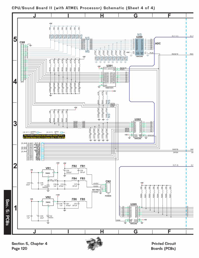
G FHIJ
G FHIJ
4-5J 4-5I 4-5H 4-5G 4-5F
4-4J 4-4I 4-4H 4-4G 4-4F
4-3J 4-3I 4-3H 4-3G 4-3F
4-2J
4-2I
4-2H 4-2G 4-2F
4-1J 4-1I 4-1H 4-1G 4-1F
5
2
4
3
1
The circuit(s) continue at the address shown [ #-XY ].
# = Sheet Number (3-5), X = Column Grid, Y = Row Grid
[ #, X-Y ] comingfrom ...
[ #, X-Y ] goingto ...
+5A
D2C5922uF
C47.1uF
7805C
VR2
11
2
2
33
+5V
R2
05
10
K
R2
06
10
K
R2
01
10
K
R2
02
10
K
R2
00
10
K
R2
03
10
K
R2
07
10
K
R2
04
10
K
SWM
PLIN
D1
D4
D1
D3
D0
D6
D3D2
D5
D0
D4
D7D6
D2
D5
D7
+5V
+5V
ADC
R209 220
R214 220
R210 220
U205
74HC245
A02
A13
A24
A35
A46
A57
A68
A79
19 DIR1
B018
B117
B216
B315
B414
B513
B612
B711
VCC20
GND10
R215 220
R211 220
R208 220
R212 220R213 220
U200
74HC245
A02
A13
A24
A35
A46
A57
A68
A79
19DIR1
B018
B117
B216
B315
B414
B513
B612
B711
VCC20
GND10
C2
02
47
0p
F
C2
03
47
0p
F
C2
04
47
0p
F
C2
05
47
0p
F
C2
06
47
0p
F
C2
07
47
0p
F
C2
01
47
0p
F
C2
00
47
0p
F
PSTB
SST0MPIN
STATUS
POUTRESET#
D6
D0
D5
D4
D1
D1
D3
D0
D5
D2
D6
D2D3
D7
D4
D7
BUSY
+5V
+5V
U201
74HCT273
(MR#)CLR#1
1Q(Q0)2
(D0)1D3
(D1)2D4
2Q(Q1)5
3Q(Q2)6
(D2)3D7
(D3)4D8
4Q(Q3)9
GND10
CP11
5Q(Q4)12
(D4)5D13
(D5)6D14
6Q(Q5)15
7Q(Q6)16
(D6)7D17
(D7)8D18
8Q(Q7)19
VCC20
U202
74HC245
A02
A13
A24
A35
A46
A57
A68
A79
19DIR1
B018
B117
B216
B315
B414
B513
B612
B711
VCC20
GND10
PRESPLIN
+5V
R2
42
4.7
K
R2
43
4.7
K
R4
09
47
0
+5VDC
-12VDC
+12VDC
+5V
-5A
-12V
+12VPOWER
KEY PIN 5
C39.1uF
CN2
1X6
123456
C51.001uF
C37.001uF
C31470uF
FB3
C81470uF
1N4004
C49.1uF
FB4
FB1
C4022uF
FB5FB6
C29.001uF
C125 .1uF
7905C
VR1
1
1
22
33
C.1uF
38
C301000uF
FB2
D [7..0]STATUS
POUTRESET#
SWSTBPLIN
DPSWSWMM NPI
PRESPSTB
SST0BUSY
R231R232
R229
R233
R230
220220
220220220
+5V
+5V
R2
17
4.7
K
C2
12
R2
24
10
K
R2
18
4.7
K
R2
25
10
K
C2
13
R2
19
4.7
K
C2
08
R2
26
10
K
R2
20
4.7
K
C2
14
R2
27
10
K
R2
21
4.7
K
CN8123456789
1011121314151617181920212223242526
R2
28
10
K
C2
15
R2
22
4.7
K
R2
23
4.7
K
C2
10
C2
09
R2
16
4.7
K
C2
11
2X13
47
0p
F
47
0p
F
47
0p
F
47
0p
F
47
0p
F
47
0p
F
47
0p
F
47
0p
F
C2
18
47
0p
F
C2
19
47
0p
F
C2
20
47
0p
F
C2
17
47
0p
F
C2
16
47
0p
F
C2
29
47
0p
F
C2
30
47
0p
F
C4
08
47
0p
F
OE
[ 3, C-1 ][ 2, A-5: 3, A-2 ]
[ 2, H-3: 3, A-2 ][ 3, ]C-1
[ 3, ]C-1[ 2, A-5: 3, C-1 ]
[ 3, ]C-1[ 2, A-2: 3, C-1 ]
[ 3, ]C-1
[ 2, A-2 ][ 1, G-3 ]
[ 3, ]C-1[ 3, ]C-1
OE
OE
++
+
+
+
1817161514131211
+5V
R2
65
10
K
R2
66
10
K
R2
61
10
K
R2
62
10
K
R2
60
10
K
R2
63
10
K
R2
67
10
K
R2
64
10
K
D1
1N4004
D [7..0]
SWSTB
DPSW
RESET#
D [ 7..0 ]
D [7
SWS
DP
RESE
D [ 7
NS
NS
NS
NS
NS
NS
NS
NS
NS
NS
NS
NS
NS
NS
NS
NS
NS
NS
NS
NS
NS
Section 5, Chapter 4Page 120
CPU/Sound Board I I (wi th ATMEL Processor) Schemat ic (Sheet 4 of 4)
Printed CircuitBoards (PCBs)
Sec.
5:
PCBs

®
CPU/Sound Bd. II w/ ATMEL ProcessorSPI Part N : 520-5300-00º
Schematic Set
Sheet 4 of 4
Prepared By: Edited By:
Model: RHT SCH1008 Dated:
CES Inc. SPI Inc.06/13/03
SIZE
DREV.
A
BCDE A
5
2
4
3
1
BCDE A
NOTES: � ALL RESISTOR VALUES ARE IN OHMS ( ), 1/4W, 5%, UNLESS OTHERWISE SPECIFIED.
ALL CAPACITOR VALUES ARE IN MICROFARADS ( , UNLESS OTHERWISE SPECIFIED. BYPASS CAPACITORS FOR ALL INTEGRATED CIRCUITS (ICs).
�
� �� �F ) 0.1 F
4-1A
4-5E 4-5D4-5C 4-5B
4-5A
4-4E 4-4D 4-4C 4-4B4-4A
4-3E 4-3D 4-3C 4-3B 4-3A
4-2E4-2D 4-2C 4-2B 4-2A
4-1E 4-1D 4-1C 4-1B
Sheet 4 of 4 :
Switch Connectors
R419
220KEY PIN 4
SWSTB
VREF
RESET#
D3D2D1D0
D6D5
D7
D4
+5V
+5V
+5V
SWITCHCOLUMNS
KEY PIN 2
SWITCHROWS
V+
V-
B
LM339AN
7
61
12
CN5
1X9
123456789
R4
23
56
0
D400
1N4148
D405
1N4148
D408
1N4004
R4
24
56
0C
40
7.1
uF
D406
1N4148
R4
25
56
0
CN7
1X10
12345678910
R421
220R422
220
R4
26
56
0
D401
1N4148
D407
1N4148
U203
74HCT273
(MR#)CLR#1
1Q(Q0)2
(D0)1D3
(D1)2D4
2Q(Q1)5
3Q(Q2)6
(D2)3D7
(D3)4D8
4Q(Q3)9
GND10
CP11
5Q(Q4)12
(D4)5D13
(D5)6D14
6Q(Q5)15
7Q(Q6)16
(D6)7D17
(D7)8D18
8Q(Q7)19
VCC20
C4
04
.1u
F
C4
05
.1u
F
C4
03
.1u
F
C4
06
.1u
F
R4
27
56
0
C4
02
.1u
F
D402
1N4148
C4
01
.1u
F
R4
28
56
0
C4
00
.1u
F
V+
V-
A
U400A5
42
3
12
D403
1N4148
R4
29
56
0
R236
1K
Q72N3904
R237
1K
Q22N3904
R238
1K
Q32N3904
Q42N3904
R239
1K
R234
1K
R241
1K
Q52N3904
R240
1K
R235
1K
Q12N3904
Q62N3904
R4
30
56
0
D404
1N4148
C2
24
.01
uF
C2
25
.01
uF
C2
26
.01
uF
C2
27
.01
uF
C2
28
.01
uF
C2
21
.01
uF
C2
22
.01
uFQ8
2N3904
C2
23
.01
uF
VREF
+5V
C40922uF
R4
11
3.3
KR
41
03
.3K
+
3 U400B
VREF
LM339AN +5V
VREF
+5V
V+
V-
D
LM339AN
11
1013
12
V+
V-
C
U400C9
814
3
12
3 U400D
VREF
LM339AN +5V
VREF
+5V
V+
V-
B
LM339AN
7
61
12
V+
V-
A
U401A5
42
3
12
3 U401B
VREF
LM339AN +5V
VREF
+5V
V+
V-
D
LM339AN
11
1013
12
V+
V-
C
U401C9
814
3
12
3 U401D
VREF
LM339AN +5V
1817161514131211
DPSW
D6
D0
D2D1
D5D4D3
D7
+5V
SW300
SW DIP8
12345678 9
10111213141516
U204
74HC245
A02
A13
A24
A35
A46
A57
A68
A79
19 DIR1
B018
B117
B216
B315
B414
B513
B612
B711
VCC20
GND10
OE
R420
220
R415
220R416
220R417
220R418
220
ADC
+5V
R2
49
10
K
R2
50
10
K
R2
45
10
K
R2
46
10
K
R2
44
10
K
R2
47
10
K
R2
51
10
K
R2
48
10
K
+5V
R4
06
56
0
R4
07
56
0
R4
02
56
0
R4
03
56
0
R4
01
56
0
R4
04
56
0
R4
08
56
0
R4
05
56
0
D [7..0]
SWSTB
DPSW
RESET#
D [ 7..0 ]
NS: Not Stuffed
Section 5, Chapter 4Page 121
CPU/Sound Board Schemat ic (Sheet 4 of 4)I I (wi th ATMEL Processor)
Sec
.5:
PCBs
Printed CircuitBoards (PCBs)

TP8
TE
ST•
R465
C428
U405
+N
OT
E•
DS
1233
NOTE •
U414
TE
ST•
TE
ST•
SP1SP2SP3
CN4 CN3
6 11
U101
U102
R25
R12
C45
R13
R112
R100
R101
R316
+ C76+
+ C77+
R19
R14
C75
R315
C48
R16
R15
C448
Q8
Q4 11 11
1
R427
R426
R428
R425
R429
R424
R430
R423
D408
C275
+
NO
TE •
U403
74HC245
U403
C444
R477
NO
TE•
NOTE •
NO
TE•
NOTE •
27C040
27C040
27C040
27C040
2
2019
1
TEST•
NOTE •
C277
C220
C219
C218
C217
C216
SW
300
Test Points (TP):
�FIRQ
�S2 RESET
�L201 / L200�GND
�Q
�GND
�AOL & AOR
�PLASMA_RESET�JP1
�VBATT
Actu
alB
oa
rdS
ize
14
.67
”X
9.1
25
”
GN
D
R413
R412
(--
)(
+)
SIZ
EA
A1
.5V
R209
R208
R211
R210
R213
R212
R215
R214
C209
C208
C211
C210
C212
C213
C214
C215
C229
C230
R229
R230
R231
R232
R233
R201
R200
R203
R202
R205
R204
R207
R206
R217
R216
R219
R218
R220
R221
R222
R223
R242
R243
R224
R225
R226
R227
R228
C276
Q10C
279
74HC245
R305
U207 U
207
74AHCT74
U216
R501
R297
R296
C286
U214
U214
74LS138GN
D
S2
D400
D401
R401
R402C
N7
10
1
SW
ITC
HR
OW
S
TEST •
NOTE •
D402
D403
D404
R403
R404
R405
D405
D406
D407
R406
R408
C402
C400
C403
C283
C256
C263
C257
C262
C258
C261
C259
C260
U216
U209
U215
C288
U209
68B09E74AHCT74
U215
U211
C281
74HC245
U208
74LS374
U211
R302
R303
R304
R300
U208 C
280
CN
1
C271
C269
C268
C267
C266
C265
C264
C270
BA
T1 VB
AT
T
U212
D201
U210
27C040CPU GAME
R431
GN
D
C290
D200
R432
R306
R299
JP
1
8K
32K
CN
8
PLASMACNTLR
2 26
251
(--
)(
+)
SIZ
EA
A1
.5V
(--
)(
+)
SIZ
EA
A1
.5V
1M
B
R475
R313
R314
C206
C207
C204
C205
C202
C203
C200
C201
6264 \ MS62256
U212
U201
74HCT273
U201
74HC245
U202
74HC245
U202R R
C408
311
409
R310
C289
U200
U413
DS1232U213
PAL16V8Q
U213 C278
R400
C284
C287
R301
C282
NOTE •
R298
R312
C285
L200
+5V
++NOTE • NOTE •
GN
D
ST
ER
NP
INB
AL
LIN
C.
CP
U/
SO
UN
DB
OA
RD
520-5
300-0
0
RE
VA
R414
C409
+
C405
R420
R419
C404
R422
C407
C401
R416
R417
R415
R418
74LS74U407
U407 C
24
U400
LM339AN
U401
U401
C291
LM339AN
U400
C292
R411
R410
R407
R421
C406
U205
74HC245
U205 C
273
EQ
�E
U17
M27C0400I-I2FIVOICE ROM 1
U17 C1
U21
M27C0400I-I2FIVOICE ROM 2
U21 C2
U36
M27C0400I-I2FIVOICE ROM 3
U36 C3
U37
M27C0400I-I2FIVOICE ROM 4
U37 C4
U7 27256 / 27512
CPU SOUND
U7
C18
210
1
CN
9
C436
8M
B8M
B8M
B8M
B
512K
U210
NOTE •
NC
S1
NC
S0
R510
JP
2
NC
S1
NC
S0
R459C426
C437
U8
R458
R457
NOTE •
JP
3
FL
AS
H
GN
D
�JP2
�JP4
�JP3
EP
RO
M
R267
R266
R265
R264
R263
R262
R261
R260
R464
R455
R453
R451
R449
R447
R445
R443
R441
R463
R456
R454
R452
R450
R448
R446
R444
R442
U8
AT
ME
LA
T49B
V1614
C425
C424
C434
C415
C421
C420
C411
C412
1
U402 U402
AT
ME
LA
T91R
40008
C422C423
C416
C417R462
R479
R478
R476
R469
R468
U204
74HC245
U204 C
272
U404
74HC245
U404
C9
KS
D0
8H
ON 1
23
45
67
8
1
R251
R250
R249
R248
R247
R246
R245
R244
R466
C433
C410
C435
C418
C419
R437
C431
C413
C414
1
Y1
R509
R502
U219
C430
C438
C442 C441
R458
R457
R464
R455
R453
R451
R449
R447
R445
R443
R441
L201
RE
SE
T
PL
AS
MA
_R
ES
ET
P L ESQ3300S40.000M00041N
LE
D1
�LED1
8K/32K
LEDs+
++ ++
+ +
+
011150318C
255
C247
C248
C249
C250
C251
C252
C253
C254
R295
R294
R293
R292
R291
R290
R289
R288
R287
R286
R278
R279
R280
R281
R282
R283
R284
R285
CN
612
1
DE
DIC
AT
ED
SW
ITC
HIN
CN
51
SW
ITC
HC
OL
UM
NS
9
U203
74HCT273
U203
U206
74HC245
U206 C
274
D3
C225
C224
C226
C223
C227
C222
C228
C221
GN
D
1 11
Q1
Q2
Q3
Q5
Q7
Q6
R238
R237
R239
R236
R240
R235
R241
R234
D104
D105
U406
C429
R480
R504
R507
R436
C443
R435
R434R470R508
C450 C451
C440
C439
U412
7
1 JT
AG
J3
Xilin
x1
JT
AGJ2
+
+
C31
+C30
+
FB
2
FB
1
C29
CN
2
61
+5V
GND
–12
+12
+ C81
+F
B4
FB
3
C38
C37
C49
D1
C125
C40
+
+
VR
1
VR
2
C59
+
C115
+
+
+
C47
D2
C39
FB
6
FB
5
C51
C79
+
+
GN
D
JP
4
U26
U26
U406
U30 LM
833U30
+C
78
+
+ C35+
C34
TEST •
TEST •
AO
L
AO
RR
17
TDA1543TDA1543
C33
R7
C52
C50
R8
+C
102
+
+C
104
+
+ C101
+
+ C100
+
C46
U35
TDA8199
U100
R103
C103
C122
POT1
7
+C
114
+
C108
+
+
+C
107
+
TEST •
FIR
Q
R433
�P2, P1, P0
�JTAG J3
�JTAG J2
�LED2�+3.3V�GND_SIGNAL
U414
XIL
INX
®X
C9572X
L
C449 C445
C446
C447
+
GN
D_S
IGN
AL
GN
D_S
IGN
AL
U405LT1086
LE
D2
TEST•
C111
C123C118C124
R107R111
R21
R9
C105
C106
R104
R105
R102
D101
D100
R108
R109
R110
R106
D102
D103
R22
R24
C80
C110
C113
C117
C120
+
C116
+
+
C119
+
+ C109
+
+
C112
+
+
+
C427
+3.3
VF
1
�SW200
[ 3, G-4 ]
[ 3, H-5 ]
TP17: [ 3, H-1 ]
TP12: [ 3, D-2 ]
[ 2, J-3 ]
[ 3, J-5 ] & [ 3, H-2 ]
�GND
TP5: [ 2, C-5 ]
TP7: [ 2, C-5 ]
TE
ST•
P2
P1
P0
P2
P1
P0
TE
ST•
TP4, TP3, TP2: [ 2, D-5 ]
TP20: [ 1, J-2 ]
�JP3 [ 1, G-5 ]
[ 1, G-1 ]
�U219
�U402
TP8: [ 2, H-4 ]
[ 2, G-5 ]
[ 1, I-5 ]
[ 1, E-3 ]
[ 2, C-1 ]
XILINX[ 2, I-5 ]
TP1: [ 2, I-5 ]
TP16: [1, C-1],TP11: [ 1, D-4 ]
S1
C432+
TP11
TP16
TP1
NOTE •
�GND
TP20
TP7
TP5 TP4 TP3 TP2
TP12
TP17
Section 5, Chapter 4Page 122
CPU/Sound Board I I (wi th ATMEL Processor) Component Layout
Printed CircuitBoards (PCBs)
Sec.
5:
PCBs

��(���������������"�����*�+,�������#�����ITEM QTY PART NUMBER REF-DESIGNATOR DESCRIPTION (NS = Not Stuffed)— 1 520-5300-00 CPU/Sound II Board (with Atmel Processor) Complete PCB Assembly01 4 JP1, JP2, JP3, JP4 3-Pin Jumper & 2-Pin Cover02 1 045-5015-06 CN2 (Key Pin-5) 6-Pin, 6PKK15603 1 J2 JTAG Xilinx® 6-Pin, ## Header04 1 045-5015-07 CN4 (Key Pin-5) 7-Pin, 7PKK15605 1 J3 JTAG 7-Pin, ## Header06 1 045-5013-00 CN5 (Key Pin-2) 9-Pin, 9PKK15607 1 CN9 10-Pin, 0.1 Header08 1 045-5014-01 CN7 (Key Pin-4) 10-Pin, 10PKK15609 1 045-5015-00 CN6 (Key Pin-5) 12-Pin, 12PKK15610 1 045-5015-01 CN1 20-Pin, 0.1 Header11 1 045-5015-26 CN8 26-Pin, 0.1 Header12 3 125-5043-00 C29, C37, C51 0.001uF (102), Cap.13 4 125-5039-00 C48, C50, C75, C80 0.0022uF or 2200pF, (222), Cap.14 8 125-5029-00 C221>C228 0.01uF (103), 100v Cap. 15 52 125-5031-00 C1>C4, C9, C18, C24, C33, C34, C38, C39, C47, C49, C110, 0.1uF (104), Axial Cer. Cap.
C111, C113, C117, C118, C120, C123, C124, C125, C255, C272>C277, C279>C292, C400>C407, C444 (C45, C46, C52, C103, C105, C106, C122, C278: NS)
16 3 C430, C431, C433 (near U403, U404) 1.0uF, ##v, Radial Lytic Cap.17 1 125-5017-00 C35 10uF, 16v, Radial Tant. Cap.18 4 125-5017-00 C78, C79, C107, C114 (C76, C77, C100: NS) 10uF, 25v-35v, Radial Lytic Cap.19 2 125-5015-00 C109, C112 (C102, C104: NS) 100uF, 25v, Radial Lytic Cap.20 1 125-5014-00 C409 22uF, 16v, Radial Lytic Cap.21 4 125-5020-00 C40, C59, C108, C115 (C101: NS) 22uF, 25v, Radial Lytic Cap.22 2 125-5012-00 C116, C119 220uF, 25v, Radial Lytic Cap.23 2 125-5019-00 C31, C81 470uF, 25v, Radial Lytic Cap.24 39 125-5028-00 C208>C215, C216>C220, C229, C230, C247>C254, 470pF (471), Cer. Cap.
C256>C263, C264>C271 (C200>C207, C408: NS) 25 2 125-5037-00 C30, C428 1000uF, 16v, Radial Lytic Cap.26 17 C427, C429, C436>C441, C443, C445>C451 SMT .1uF Cap.27 2 C432, C442 (near U403 & U404) SMT 10uF Cap. 28 9 C411, C414, C416, C419, C420, C422, C424, C434, C435 SMT 47pF Cap.29 10 C410, C412, C413, C415, C417, C418, C421, C423, C425, C426 SMT 100nF Cap.30 7 112-5003-00 D1>D3, D102>D105, D408 (D100, D101: NS) 1N4004, Diode31 2 112-5008-00 D200, D201 1N5817, Diode32 8 112-0054-00 D400-D407 1N4148, Diode33 4 165-5099-00 LED1, LED2, L200, L201 LED T1-3/4 DIFFUSER LED34 3 124-5064-00 R310, R315, R316 (R300, R311, R313, R314, R475: NS) 0� Jumper Res. (1-Stripe)35 2 121-5041-00 R107, R111 (R103: NS) 1 � 1/4W Res.35 20 121-5009-00 R8, R15, R234>R241, R278>R286, R412 1K � 1/4W Res.36 1 121-5018-00 R7 1.5K � 1/4W Res.37 2 121-5043-00 R16, R17 (R25, R112: NS) 2.2K � 1/4W Res.38 2 121-5048-00 R410, R411 3.3K � 1/4W Res.39 12 121-5021-00 R21, R216>R223, R242, R243, R400 4.7K � 1/4W Res.40 36 121-5011-00 R106, R224>R228, R244>R251,R260>R267, R296>R299, 10K � 1/4W Res. R301>R306, R413, R431, R432 (R200>R207, R501: NS)41 3 121-5023-00 R9, R14, R104 (R100, R102: NS) 22K � 1/4W Res. 42 1 121-5022-04 R110 33K � 1/4W Res.43 9 121-5045-00 R108, R287>R294 39K � Res.44 2 121-5032-00 R22, R24 47K � 1/4W Res.45 15 121-5014-00 R229>R233, R295, R414>R422 (R208>R215: NS) 220 � 1/4W Res. 46 1 121-5036-00 R312 330 � 1/4W Res.47 2 121-5046-01 R105, R109 (R101, R409: NS) 470 � 1/4W Res.48 16 121-5047-00 R401>R408, R423>R430 560 � 1/4W Res.49 1 F1 SMT xx Res. 50 4 R434, R435, R436, R508 SMT 1K � Res.51 1 R480 SMT 10K � Res.52 2 R502, R509 SMT 33 � Res.53 3 R465, R466, R470 SMT 100 � Res.54 35 R433, R437, R441>R459, R462>R464, R468, R469, SMT 100K � Res.
R476>R479, R504>R507, R51055 9 110-0069-00 Q1-Q8, Q10 2N3904, Transistor56 1 U402 ATMEL, AT91R4000857 1 U8 ATMEL, AT49BV161458 1 U414 XILINX®, XC9572XL59 1 (See Pg. ��� � Table) U7 512K EPROM Sound (27512)60 1 (See Pg. ��� � Table) U210 (32-Pin, IC Socket, 077-5217-00) 1MB EPROM CPU Game (27C040)61 4 (See Pg. ��� � Table) U17, U21, U36, U37 (32-Pin, IC Socket, 077-5217-00) 8MB EPROM Voice 1-4 (M27C0400I-12FI)62 1 965-6504-00 U213 ( BLUE DOT ) PAL16V8Q (Programmed) BLUE DOT63 1 105-5046-00 U212 (28-Pin, IC Dip Socket, 077-5208-00) 6264/MS62256 (MS6264A) (28-Pin)64 1 100-0189-01 U209 (40-Pin, IC Socket, 077-5209-00) 68B09E (40-Pin)65 2 100-5015-00 U215, U216 74AHCT74 (14-Pin)66 8 100-0338-00 U202, U204, U205, U206, U207, U208, U403, U404 (U200: NS) 74HC245 (20-Pin)67 2 100-5012-00 U201, U203 74HCT273 (20-Pin)68 1 100-0037-00 U407 74LS74 (14-Pin)69 1 100-0148-00 U214 74LS138 (16-Pin)70 1 100-0064-00 U211 74LS374 (20-Pin)71 1 U406 3.3v Watchdog, DS1233 (3-Pin)72 1 100-5023-00 U413 5.0v Watchdog, DS1232 (8-Pin)73 1 U219 1.8v Volt. Regulator LT1503 (8-Pin)74 1 U405 3.3v Volt. Regulator LT1086 (3-Pin)75 1 124-5002-00 VR1 -5v Regulator, LM7905CT76 1 124-5001-00 VR2 +5v Regulator, LM7805CT77 2 100-0377-00 U400, U401 LM339AN (14-Pin)78 1 100-0375-00 U30 LM833 (8-Pin)79 1 100-5018-00 U26 TDA1543 (8-Pin)80 2 100-5016-20 U101, U102 (U100: NS) TDA2030A (5-Pin)81 1 Y1 40MHz Clock PLE SQ3300S82 1 181-5002-00 SW300 Dip Switch 8-Pos., (KSD08H Black)83 n/a FB1>FB6 Ferrite Bead84 535-5000-10 HS2, HS3, (HS1: NS) (over U101, U102) Heat Sink (AAVID 531102)85 1 S2 (Reset) Push-Button Switch (B3F4000)
* Sur
face
Mou
nts
(SM
T) a
re n
ot li
sted
.
Conn
ecto
rs
Capa
cito
rs*
Diod
es&
LEDs
*Re
sist
ors
/ Tra
nsis
tors
*IC
s / R
AMs
/ RO
Ms
/ EPR
OM
s* S
urfa
ce M
ount
s (S
MT)
are
not
list
ed.
Mis
cella
neou
s
Test Point Wire (24ga.) Loops: VBATT, GND (near CN7), GND (near CN9), GND (near L200), GND_SIGNAL (near U405)
Test Point Pads: TP1>TP5, TP7, TP8, TP11, TP12, TP16, TP17, TP20
86 1 545-5685-00 BAT1 HOLDER (Always replace all 3, Size AA 1.5v Cells, with new ones, when required)If a part is required where a part number is notprovided, call Tech. Support (see back of cover).
��
�����
����
������������ �������� �������!������"����# ��$�&')

The light fallingon ( )generates avoltage which isapplied to theinput (Pin-2) ofthe
( ).bleeds offexcess charge.At about a voltinput from( ) the
( )either
or the indicator ( ) If a switch line is being strobed, theemitter of drops to the saturation voltage of the about . This plus the dropon the base give a forward bias voltage to , which is lower than the drop on ( ) so the currentflows through the Transistor during strobes. This drives on and . If the strobe line is high,then the path through ( ) is lower than 's bias voltage so current flows through ( ) andthe indicator lights. prevents reverse bleed, and form the voltage divider for the trip point, is acurrent limiter for both and , and are general noise-filter caps.
LED CR1
LM311ComparatorU1 R1
LEDCR1
ComparatorU1
Q1LED CR2
Q1 .3 volts .7 volt1v Q1 1.7v LED CR2
Q11.7v LED CR2 Q1 LED CR2
D1 R2 R3 R4Q1 CR2 C1 C2
trips &drives(during switch line strobes) (in between strobes).
Switch Line Driver,
makes the switch
CR1
R1
CN1
520-5082-00
LONG OPTO XMTR
SOLDER SIDE
ComponentSide (Beige)
SolderSide (Green)
SolderSide (Green) 520-5083-01 (REC)520-5082-00 (TRANS)
ComponentSide (Beige)
R11M � R2
330K �
D11N914
Q12N3904
R36.8K � C1
.1uf, 25v
CR1LED
TLRH180P
CR2RED T1-3/4DIFF. LED
+5v
+5v
+5v +5v
R4220K �2
3
8
4
U1LM311
CN1
C2.1uf, 25v
CR1LED
TLRH180P
R1180 �
GND
BLK
+5v
CN1
1
2
RED
-
+
Playf ie ld Switch OPTO “Long-Hop” Boards Component Layout & Parts
ITEM QTY PART NUMBER REF-DESIGNATOR DESCRIPTION
A 1 520-5083-01 OPTO Receiver Board Complete PCB AssemblyCR1 LED TLRH180PCR2 LED T1-3/4 RED DIFFUSER
B 1 520-5082-00 OPTO Transmitter Board Complete PCB AssemblyCR1 LED TLRH180P
1 1 165-5052-00 ( )2 1 165-5099-003 1 112-5014-00 D1 1N914, Diode4 1 121-5013-00 R1 1M 1/4W Res., 5%5 1 121-5037-00 R2 330K 1/4W Res., 5%6 1 121-5077-00 R3 6.8K 1/4W Res., 5%7 1 121-5014-00 R4 220 1/4W Res., 5%8 2 125-5023-00 C1, C2 .1uF, 25v, Axial Ceramic Cap.6 1 100-5025-00 U1 LM3117 1 110-0069-00 Q1 2N3904, Transistor8 1 045-5200-04 CN1 4X1, .156" Locking Straight Hdr. Conn.
1 1 165-5052-00 ( )2 1 121-5066-00 R1 180 1/4W Res.3 1 045-5206-02 CN1 2X1, .156" Locking Straight Hdr. Conn.
�
�
�
�
�
(Molex 50-84-1040)
(Molex 50-84-1020)
Ultra Bright Red
Ultra Bright Red
Playf ie ld Switch OPTO “Long-Hop” Boards Theory of Operat ion & Schematic
R2
R1CR1 C1
U1 Q1
R3 R4
CR2
CN1
C2 D1
520-5083-01OPTO RCVR.
Pin-1(+5v)RED Pin-4
(GROUNDBLK
)
Pin-1(+5v)RED
SOLDER SIDE
Pin-3(Sw. Drive --)
GRN-BLKPin-2(Sw. Return +)
WHT-GRN
Pin-2(GROUND)
BLK
Note: In this game, this Combo OPTO Board is used as a P/F Detection Switch for the Motorcycle EnterTrough. See the Switch Matrix Grid (Pgs. 16-17 or 86). PCBs are used for Switch 37, (GRN-BLK, WHT-GRN).
1 RED
5 BLK
(+5v DC)from I/O Bd.J16-P8
(Ground) fromI/O PowerDriver Bd.J16-P9-15
2 WHT-BLU
3 GRN-BLK
(Sw. Returnto CPU/Snd.Bd. CN7-P3)
(Sw. Drivefrom CPU/Snd.Bd. CN5-P6)
520-5083-01Receiver
= Emitting Light520-5082-00Transmitter
Printed CircuitBoards (PCBs)
Sec.
5:
PCBs
Section 5, Chapter 4Page 124
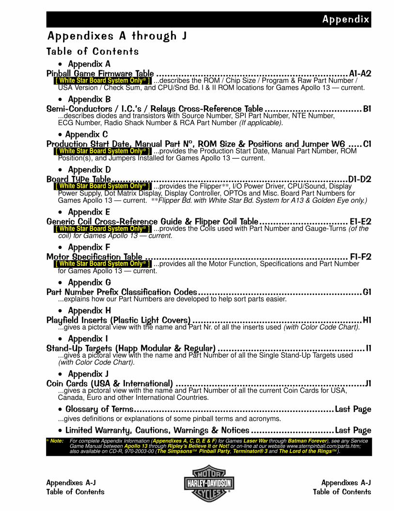
��������
������������ �����
�����������������������
������������� ��� ������ ������������������������������������������������������������������������� [ White Star Board System Only* ] ...describes the ROM / Chip Size / Program & Raw Part Number /USA Version / Check Sum, and CPU/Snd Bd. I & II ROM locations for Games Apollo 13 — current.
��������!"���������#�� $%���&$'���(� ��'��� ��#������ �����������������������������������!�
...describes diodes and transistors with Source Number, SPI Part Number, NTE Number, ECG Number, Radio Shack Number & RCA Part Number (If applicable).
���������� ���#����"�� �)���*+������� �,-*'.+"�/�0��������������� 12 �������
[ White Star Board System Only* ] ...provides the Production Start Date, Manual Part Number, ROMPosition(s), and Jumpers Installed for Games Apollo 13 — current.
��������)!�� ��(��������������������������������������������������������������������������������������������)��)
[ White Star Board System Only* ] ...provides the Flipper**, I/O Power Driver, CPU/Sound, DisplayPower Supply, Dot Matrix Display, Display Controller, OPTOs and Misc. Board Part Numbers forGames Apollo 13 — current. **Flipper Bd. with White Star Bd. System for A13 & Golden Eye only.)
��������3���� �#����� ��'��� ��#������0������ ����������������������������������������� 3��3
[ White Star Board System Only* ] ...provides the Coils used with Part Number and Gauge-Turns (of thecoil) for Games Apollo 13 — current.
���������+��� "��#���#���������� ������������������������������������������������������������������������� ����
[ White Star Board System Only* ] ...provides all the Motor Function, Specifications and Part Numberfor Games Apollo 13 — current.
����������� �,���� � ����������#����������������������������������������������������������������������
...explains how our Part Numbers are developed to help sort parts easier.
��������4���(�����%�� �5�����#6������7� 8 �������������������������������������������������������������4�
...gives a pictoral view with the name and Part Nr. of all the inserts used (with Color Code Chart).
��������%"�����9��� ���54���+����� 0'����� 8 �����������������������������������������������������%�
...gives a pictoral view with the name and Part Number of all the Single Stand-Up Targets used(with Color Code Chart).
��������������� �59"�0%��� ��������8 ����������������������������������������������������������������������
...gives a pictoral view with the name and Part Number of all the current Coin Cards for USA,Canada, Euro and other International Countries.
���� (���� �������������������������������������������������������������������������6������...gives definitions or explanations of some pinball terms and acronyms.
6������1� ���(*�������*1� ����0,���#� ������������������������������6������* Note: For complete Appendix Information (Appendixes A, C, D, E & F) for Games Laser War through Batman Forever), see any Service
Game Manual between Apollo 13 through Ripley’s Believe It or Not! or on-line at our website www.sternpinball.com/parts.htm;also available on CD-R, 970-2003-00 (The Simpsons Pinball Party, Terminator® 3 and The Lord of the Rings ).
[ White Star Board System Only* ]
[ White Star Board System Only* ]
[ White Star Board System Only* ]
[ White Star Board System Only* ]
[ White Star Board System Only* ]
������������ �������������������������� ��������������
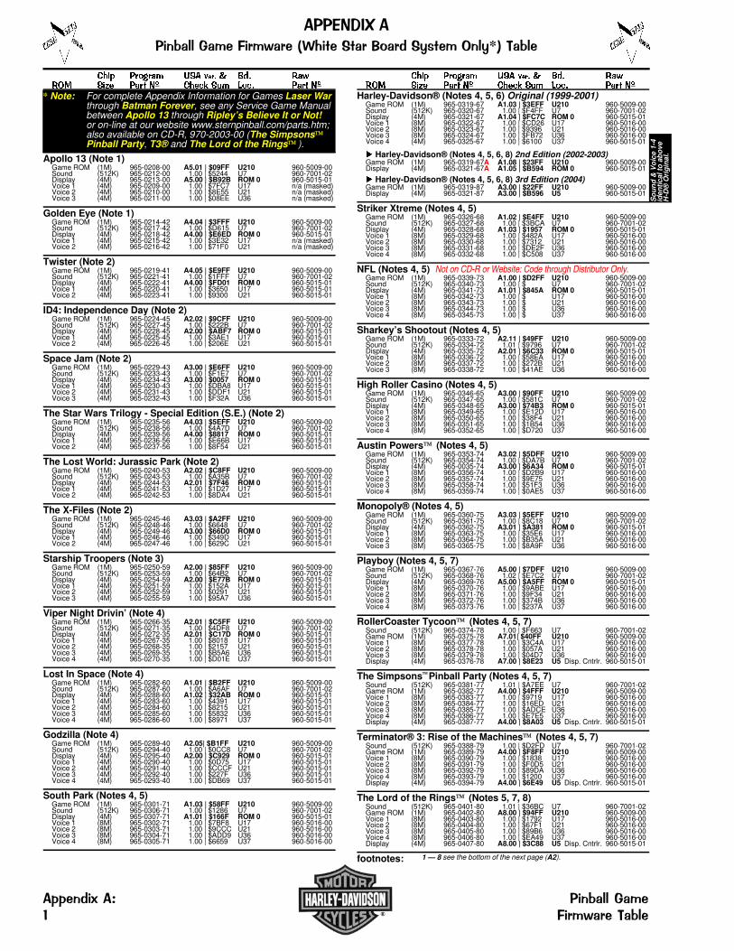
���� ����� �� ���� � ��� ����� ���� ��� �� ����� �� ���� ��� ��
Apollo 13 (Note 1)Game ROM (1M) 965-0208-00 A5.01 | $09FF U210 960-5009-00Sound (512K) 965-0212-00 V1.00 | $5244 U7 960-7001-02Display (4M) 965-0213-00 A5.00 | $B92B ROM 0 960-5015-01Voice 1 (4M) 965-0209-00 V1.00 | $7FC7 U17 n/a (masked)Voice 2 (4M) 965-0210-00 V1.00 | $8E55 U21 n/a (masked)Voice 3 (4M) 965-0211-00 V1.00 | $08EE U36 n/a (masked)
Golden Eye (Note 1)Game ROM (1M) 965-0214-42 A4.04 | $3FFF U210 960-5009-00Sound (512K) 965-0217-42 V1.00 | $D615 U7 960-7001-02Display (4M) 965-0218-42 A4.00 | $E6ED ROM 0 960-5015-01Voice 1 (4M) 965-0215-42 V1.00 | $3E32 U17 n/a (masked)Voice 2 (4M) 965-0216-42 V1.00 | $71F0 U21 n/a (masked)
Twister (Note 2)Game ROM (1M) 965-0219-41 A4.05 | $E9FF U210 960-5009-00Sound (512K) 965-0221-41 V1.00 | $1FFF U7 960-7001-02Display (4M) 965-0222-41 A4.00 | $FD01 ROM 0 960-5015-01Voice 1 (4M) 965-0220-41 V1.00 | $3650 U17 960-5015-01Voice 2 (4M) 965-0223-41 V1.00 | $9300 U21 960-5015-01
ID4: Independence Day (Note 2)Game ROM (1M) 965-0224-45 A2.02 | $9CFF U210 960-5009-00Sound (512K) 965-0227-45 V1.00 | $222B U7 960-7001-02Display (4M) 965-0228-45 A2.00 | $ABF7 ROM 0 960-5015-01Voice 1 (4M) 965-0225-45 V1.00 | $3AE1 U17 960-5015-01Voice 2 (4M) 965-0226-45 V1.00 | $206E U21 960-5015-01
Space Jam (Note 2)Game ROM (1M) 965-0229-43 A3.00 | $E6FF U210 960-5009-00Sound (512K) 965-0233-43 V1.00 | $F1E7 U7 960-7001-02Display (4M) 965-0234-43 A3.00 | $0057 ROM 0 960-5015-01Voice 1 (4M) 965-0230-43 V1.00 | $DBA8 U17 960-5015-01Voice 2 (4M) 965-0231-43 V1.00 | $DDF1 U21 960-5015-01Voice 3 (4M) 965-0232-43 V1.00 | $F32A U36 960-5015-01
The Star Wars Trilogy - Special Edition (S.E.) (Note 2)Game ROM (1M) 965-0235-56 A4.03 | $5EFF U210 960-5009-00Sound (512K) 965-0238-56 V1.00 | $4A7D U7 960-7001-02Display (4M) 965-0239-56 A4.00 | $8817 ROM 0 960-5015-01Voice 1 (4M) 965-0236-56 V1.00 | $E66B U17 960-5015-01Voice 2 (4M) 965-0237-56 V1.00 | $8F54 U21 960-5015-01
The Lost World: Jurassic Park (Note 2)Game ROM (1M) 965-0240-53 A2.02 | $C8FF U210 960-5009-00Sound (512K) 965-0243-53 V1.00 | $A35B U7 960-7001-02Display (4M) 965-0244-53 A2.01 | $7F46 ROM 0 960-5015-01Voice 1 (4M) 965-0241-53 V1.00 | $1D27 U17 960-5015-01Voice 2 (4M) 965-0242-53 V1.00 | $8DA4 U21 960-5015-01
The X-Files (Note 2)Game ROM (1M) 965-0245-46 A3.03 | $A2FF U210 960-5009-00Sound (512K) 965-0248-46 V1.00 | $6648 U7 960-7001-02Display (4M) 965-0249-46 A3.00 | $66D0 ROM 0 960-5015-01Voice 1 (4M) 965-0246-46 V1.00 | $349D U17 960-5015-01Voice 2 (4M) 965-0247-46 V1.00 | $629C U21 960-5015-01
Starship Troopers (Note 3)Game ROM (1M) 965-0250-59 A2.00 | $85FF U210 960-5009-00Sound (512K) 965-0253-59 V1.00 | $64B2 U7 960-7001-02Display (4M) 965-0254-59 A2.00 | $E77B ROM 0 960-5015-01Voice 1 (4M) 965-0251-59 V1.00 | $152A U17 960-5015-01Voice 2 (4M) 965-0252-59 V1.00 | $0291 U21 960-5015-01Voice 3 (4M) 965-0255-59 V1.00 | $95A7 U36 960-5015-01
Viper Night Drivin’ (Note 4)Game ROM (1M) 965-0266-35 A2.01 | $C5FF U210 960-5009-00Sound (512K) 965-0271-35 V1.00 | $4DF8 U7 960-7001-02Display (4M) 965-0272-35 A2.01 | $C17D ROM 0 960-5015-01Voice 1 (4M) 965-0267-35 V1.00 | $8018 U17 960-5015-01Voice 2 (4M) 965-0268-35 V1.00 | $2157 U21 960-5015-01Voice 3 (4M) 965-0269-35 V1.00 | $B5A6 U36 960-5015-01Voice 4 (4M) 965-0270-35 V1.00 | $D01E U37 960-5015-01
Lost In Space (Note 4)Game ROM (1M) 965-0282-60 A1.01 | $B2FF U210 960-5009-00Sound (512K) 965-0287-60 V1.00 | $A6AF U7 960-7001-02Display (4M) 965-0288-60 A1.02 | $32AB ROM 0 960-5015-01Voice 1 (4M) 965-0283-60 V1.00 | $4391 U17 960-5015-01Voice 2 (4M) 965-0284-60 V1.00 | $8215 U21 960-5015-01Voice 3 (4M) 965-0285-60 V1.00 | $5832 U36 960-5015-01Voice 4 (4M) 965-0286-60 V1.00 | $8971 U37 960-5015-01
Godzilla (Note 4)Game ROM (1M) 965-0289-40 A2.05| $B1FF U210 960-5009-00Sound (512K) 965-0294-40 V1.00 | $0CC8 U7 960-7001-02Display (4M) 965-0295-40 A2.00 | $C929 ROM 0 960-5015-01Voice 1 (4M) 965-0290-40 V1.00 | $0D75 U17 960-5015-01Voice 2 (4M) 965-0291-40 V1.00 | $CCCF U21 960-5015-01Voice 3 (4M) 965-0292-40 V1.00 | $227F U36 960-5015-01Voice 4 (4M) 965-0293-40 V1.00 | $DB69 U37 960-5015-01
South Park (Notes 4, 5)Game ROM (1M) 965-0301-71 A1.03 | $58FF U210 960-5009-00Sound (512K) 965-0306-71 V1.00 | $1286 U7 960-7001-02Display (4M) 965-0307-71 A1.01 | $166F ROM 0 960-5015-01Voice 1 (8M) 965-0302-71 V1.00 | $7BF8 U17 960-5016-00Voice 2 (8M) 965-0303-71 V1.00 | $9CCC U21 960-5016-00Voice 3 (8M) 965-0304-71 V1.00 | $ADD9 U36 960-5016-00Voice 4 (8M) 965-0305-71 V1.00 | $6659 U37 960-5016-00
���� ����� �� ���� � ��� ����� ���� ��� �� ����� �� ���� ��� ��
Harley-Davidson® (Notes 4, 5, 6) Original (1999-2001)Game ROM (1M) 965-0319-67 A1.03 | $3EFF U210 960-5009-00Sound (512K) 965-0320-67 V1.00 | $F4FF U7 960-7001-02Display (4M) 965-0321-67 A1.04 | $FC7C ROM 0 960-5015-01Voice 1 (8M) 965-0322-67 V1.00 | $CD26 U17 960-5016-00Voice 2 (8M) 965-0323-67 V1.00 | $9396 U21 960-5016-00Voice 3 (8M) 965-0324-67 V1.00 | $FB72 U36 960-5016-00Voice 4 (4M) 965-0325-67 V1.00 | $6100 U37 960-5015-01
� Harley-Davidson® (Notes 4, 5, 6, 8) 2nd Edition (2002-2003)Game ROM (1M) 965-0319-67A A1.08 | $23FF U210 960-5009-00Display (4M) 965-0321-67A A1.05 | $B594 ROM 0 960-5015-01
� Harley-Davidson® (Notes 4, 5, 6, 8) 3rd Edition (2004)Game ROM (1M) 965-0319-87 A3.00 | $22FF U210 960-5009-00Display (4M) 965-0321-87 A3.00 | $B596 U5 960-5015-01
Striker Xtreme (Notes 4, 5)Game ROM (1M) 965-0326-68 A1.02 | $E4FF U210 960-5009-00Sound (512K) 965-0327-68 V1.00 | $3BCA U7 960-7001-02Display (4M) 965-0328-68 A1.03 | $1957 ROM 0 960-5015-01Voice 1 (8M) 965-0329-68 V1.00 | $482A U17 960-5016-00Voice 2 (8M) 965-0330-68 V1.00 | $7312 U21 960-5016-00Voice 3 (8M) 965-0331-68 V1.00 | $DE2F U36 960-5016-00Voice 4 (8M) 965-0332-68 V1.00 | $C508 U37 960-5016-00
NFL (Notes 4, 5) Not on CD-R or Website: Code through Distributor Only.Game ROM (1M) 965-0339-73 A1.00 | $D2FF U210 960-5009-00Sound (512K) 965-0340-73 V1.00 | $ U7 960-7001-02Display (4M) 965-0341-73 A1.01 | $845A ROM 0 960-5015-01Voice 1 (8M) 965-0342-73 V1.00 | $ U17 960-5016-00Voice 2 (8M) 965-0343-73 V1.00 | $ U21 960-5016-00Voice 3 (8M) 965-0344-73 V1.00 | $ U36 960-5016-00Voice 4 (8M) 965-0345-73 V1.00 | $ U37 960-5016-00
Sharkey’s Shootout (Notes 4, 5)Game ROM (1M) 965-0333-72 A2.11 | $49FF U210 960-5009-00Sound (512K) 965-0334-72 V1.01 | $9796 U7 960-7001-02Display (4M) 965-0335-72 A2.01 | $6C33 ROM 0 960-5015-01Voice 1 (8M) 965-0336-72 V1.00 | $58EA U17 960-5016-00Voice 2 (8M) 965-0337-72 V1.00 | $272B U21 960-5016-00Voice 3 (8M) 965-0338-72 V1.00 | $41AE U36 960-5016-00
High Roller Casino (Notes 4, 5)Game ROM (1M) 965-0346-65 A3.00 | $90FF U210 960-5009-00Sound (512K) 965-0347-65 V1.00 | $581C U7 960-7001-02Display (4M) 965-0348-65 A3.00 | $74B3 ROM 0 960-5015-01Voice 1 (8M) 965-0349-65 V1.00 | $E12D U17 960-5016-00Voice 2 (8M) 965-0350-65 V1.00 | $38F4 U21 960-5016-00Voice 3 (8M) 965-0351-65 V1.00 | $1B54 U36 960-5016-00Voice 4 (8M) 965-0352-65 V1.00 | $D720 U37 960-5016-00
Austin Powers (Notes 4, 5)Game ROM (1M) 965-0353-74 A3.02 | $5DFF U210 960-5009-00Sound (512K) 965-0354-74 V1.00 | $DA7B U7 960-7001-02Display (4M) 965-0035-74 A3.00 | $6A34 ROM 0 960-5015-01Voice 1 (8M) 965-0356-74 V1.00 | $D2B9 U17 960-5016-00Voice 2 (8M) 965-0357-74 V1.00 | $9E75 U21 960-5016-00Voice 3 (8M) 965-0358-74 V1.00 | $51F3 U36 960-5016-00Voice 4 (8M) 965-0359-74 V1.00 | $0AE5 U37 960-5016-00
Monopoly® (Notes 4, 5)Game ROM (1M) 965-0360-75 A3.03 | $5EFF U210 960-5009-00Sound (512K) 965-0361-75 V1.00 | $8C18 U7 960-7001-02Display (4M) 965-0362-75 A3.01 | $A381 ROM 0 960-5015-01Voice 1 (8M) 965-0363-75 V1.00 | $35E6 U17 960-5016-00Voice 2 (8M) 965-0364-75 V1.00 | $B35A U21 960-5016-00Voice 3 (8M) 965-0365-75 V1.00 | $8A9F U36 960-5016-00
Playboy (Notes 4, 5, 7)Game ROM (1M) 965-0367-76 A5.00 | $7DFF U210 960-5009-00Sound (512K) 965-0368-76 V1.02 | $E7C2 U7 960-7001-02Display (4M) 965-0369-76 A5.00 | $A5FF ROM 0 960-5015-01Voice 1 (8M) 965-0370-76 V1.00 | $9ABE U17 960-5016-00Voice 2 (8M) 965-0371-76 V1.00 | $9F34 U21 960-5016-00Voice 3 (8M) 965-0372-76 V1.00 | $374B U36 960-5016-00Voice 4 (8M) 965-0373-76 V1.00 | $237A U37 960-5016-00
RollerCoaster Tycoon (Notes 4, 5, 7)Sound (512K) 965-0374-78 V1.00 | $F663 U7 960-7001-02Game ROM (1M) 965-0375-78 A7.01| $40FF U210 960-5009-00Voice 1 (8M) 965-0377-78 V1.00 | $3C4A U17 960-5016-00Voice 2 (8M) 965-0378-78 V1.00 | $057A U21 960-5016-00Voice 3 (8M) 965-0379-78 V1.00 | $04D7 U36 960-5016-00Display (4M) 965-0376-78 A7.00 | $8E23 U5 Disp. Cntrlr. 960-5015-01
The Simpsons Pinball Party (Notes 4, 5, 7)Sound (512K) 965-0381-77 V1.01 | $A7EE U7 960-7001-02Game ROM (1M) 965-0382-77 A4.00 | $4FFF U210 960-5009-00Voice 1 (8M) 965-0383-77 V1.00 | $9719 U17 960-5016-00Voice 2 (8M) 965-0384-77 V1.00 | $16ED U21 960-5016-00Voice 3 (8M) 965-0385-77 V1.00 | $ADCE U36 960-5016-00Voice 4 (8M) 965-0386-77 V1.00 | $E7E5 U37 960-5016-00Display (4M) 965-0387-77 A4.00 | $8A03 U5 Disp. Cntrlr. 960-5015-01
Terminator® 3: Rise of the Machines (Notes 4, 5, 7)Sound (512K) 965-0388-79 V1.00 | $D2FD U7 960-7001-02Game ROM (1M) 965-0389-79 A4.00 | $F8FF U210 960-5009-00Voice 1 (8M) 965-0390-79 V1.00 | $1838 U17 960-5016-00Voice 2 (8M) 965-0391-79 V1.00 | $F0D5 U21 960-5016-00Voice 3 (8M) 965-0392-79 V1.00 | $89DA U36 960-5016-00Voice 4 (8M) 965-0393-79 V1.00 | $1200 U37 960-5016-00Display (4M) 965-0394-79 A4.00 | $6E49 U5 Disp. Cntrlr. 960-5015-01
The Lord of the Rings (Notes 5, 7, 8)Sound (512K) 965-0401-80 V1.01 | $36BC U7 960-7001-02Game ROM (1M) 965-0402-80 A8.00 | $94FF U210 960-5009-00Voice 1 (8M) 965-0403-80 V1.00 | $1792 U17 960-5016-00Voice 2 (8M) 965-0404-80 V1.00 | $67F1 U21 960-5016-00Voice 3 (8M) 965-0405-80 V1.00 | $89B6 U36 960-5016-00Voice 4 (8M) 965-0406-80 V1.00 | $EA49 U37 960-5016-00Display (4M) 965-0407-80 A8.00 | $3C88 U5 Disp. Cntrlr. 960-5015-01
footnotes:
So
un
d &
Vo
ice
1-4
iden
tica
l to
ab
ove
H-D
® O
rig
inal
.
* Note: For complete Appendix Information for Games Laser War through Batman Forever, see any Service Game Manualbetween Apollo 13 through Ripley’s Believe It or Not!or on-line at our website www.sternpinball.com/parts.htm;also available on CD-R, 970-2003-00 (The SimpsonsPinball Party, T3® and The Lord of the Rings ).
1 — 8 see the bottom of the next page (A2).
������������ ��� ������ ��������� ��� ������������* ! ���
�""���#�$ ��� ��� ��% ���� ��! ���

���� ����� �� ���� � ��� ����� ���� ��� �� ����� �� ���� ��� ��
Ripley’s Believe It or Not!® (Notes 7, 8)Sound (512K) 965-0408-81 V1.00 | $D93D U7 960-7001-02Game ROM (1M) 965-0409-81 A3.02 | $45FF U210 960-5009-00Voice 1 (8M) 965-0410-81 V1.00 | $067B U17 960-5016-00Voice 2 (8M) 965-0411-81 V1.00 | $C8B8 U21 960-5016-00Voice 3 (8M) 965-0412-81 V1.00 | $64C2 U36 960-5016-00Voice 4 (8M) 965-0413-81 V1.00 | $5341 U37 960-5016-00Display (4M) 965-0414-81 A3.00 | $DE4B U5 Disp. Cntrlr. 960-5015-01
Elvis® (Notes 7, 8)Sound (512K) 965-0415-84 V1.00 | $8CD2 U7 960-7001-02Game ROM (1M) 965-0416-84 A3.02 | $93FF U210 960-5009-00Voice 1 (8M) 965-0417-84 V1.00 | $538D U17 960-5016-00Voice 2 (8M) 965-0418-84 V1.00 | $8BCD U21 960-5016-00Voice 3 (8M) 965-0419-84 V1.00 | $60F8 U36 960-5016-00Voice 4 (8M) 965-0420-84 V1.00 | $14D8 U37 960-5016-00Display (4M) 965-0421-84 A3.02 | $B719 U5 Disp. Cntrlr. 960-5015-01
���� ����� �� ���� � ��� ����� ���� ��� �� ����� �� ���� ��� ��
footnotes:1 ROMs on CPU/Sound Bd.: 520-5136-00 (Stereo) & Display Cont. Bd.: 520-5055-012 ROMs on CPU/Sound Bd.: 520-5136-10 (Mono) & Display Cont. Bd.: 520-5055-013 ROMs on CPU/Sound Board: 520-5136-15* (Mono) (*FCC 11-97) & Display Controller Board: 520-5055-02* (*FCC 11-97)4 ROMs on CPU/Sound Bd.: 520-5136-16† (Mono) (†FCC 02-98) & Display Controller Board: 520-5055-03‡ (‡FCC 02-98)5 This game uses 8MB VOICE ROMS at U17, U21, U36 & U37 (if 3 ROMs use U37 will be unused) requiring a Jumper at Loc. W6. Refer to CPU/Snd. Bd. Schematic (2 of 3).6 Harley-Davidson® 2nd Edition: For Game ROM, Sound & Display info (version, check sums, part numbers) call Tech Support or check our website (see back cover) for current versions or other info. Raw Part numbers are identical to the H-D® original.7 ToPS (Tournament Pinball System) READY!8 ROMs on CPU/Sound Board II (with ATMEL Processor): 520-5300-00 & Display Cont. Bd.: 520-5055-03‡ (‡FCC 02-98)
Game Revisions can be updated after the Production Run. This Table is accurate as of the printing of this manual. If anychanges occurred, the next game manual will include the updatedinformation. The version stated is USA. If there is a question ofas to the latest Code Revision & Check Sum call our TechnicalSupport Dept., 1-800-542-5377 or 1-708-345-7700 (Select Opt. 1).
Visit our website www.SternPinball.com where the latest codecan be downloaded (an EPROM Burner is required).
������������ ��� ������ ��������� ��� ������������* ! ���
��� ��� �� �""���#�$���� ��! ��� &
Code also available on CD-R Disc 2
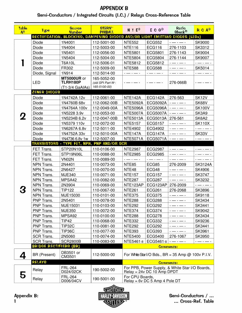
������� ��� �� ��
����� ����������� � � �� � � �� �����
����� � � ��
�������������� ���� ���� !�"������ !��!� ��!#�� ���$� �"������ !��!� %��!&'
�
Diode 1N4001 112-5001-00 NTE552 ECG552 - — - — - SK9000Diode 1N4004 112-5003-00 NTE116 ECG116 276-1103 SK3312Diode 1N5401 112-0056-00 NTE5801 ECG5801 276-1143 SK9004Diode 1N5404 112-5004-00 NTE5804 ECG5804 276-1144 SK9007Diode T6A10L 112-5006-01 NTE5812 ECG5812 - — - — - - — - — -Diode FR302 112-5009-00 NTE588 ECG588 - — - — - SK5014Diode, Signal 1N914 112-5014-00 - — - — - - — - — - - — - — - - — - — -
LEDMT5000UR orTLRH180P
165-5052-00(old SPI Part N�:165-5100-00)
- — - — - - — - — - 276-066B - — - — -(T1-3/4 GaAIAs)
(���� !��!�
�
Diode 1N4742A 12v 112-0061-00 NTE142A ECG142A 276-563 SK12VDiode 1N4760B 68v 112-0062-00B NTE5092A ECG5092A - — - — - SK68VDiode 1N4764A 100v 112-0049-00A NTE5096A ECG5096A - — - — - SK100VDiode 1N5228 3.9v 112-0053-00 NTE5007A ECG5007A - — - — - SK3A9Diode 1N5234B 6.2v 112-0047-00B NTE5013A ECG5013A 276-561 SK6A2Diode 1N5379 110v 112-0072-00 NTE5157 ECG5157 - — - — - SK110XDiode 1N6267A 6.8v 112-5011-00 NTE4902 ECG4902 - — - — - - — - — -Diode 1N4752A 33v 112-5010-00A NTE147A ECG147A - — - — - SK33VDiode 1N4736 6.8v 1w 112-5007-00 NTE5071A ECG5071A - — - — - - — - — -�������� ) �*�� ���� ���� ��� ��!#�� ��
�
FET Trans. STP20N10L 110-0106-00 NTE2987 ECG2987 - — - — - - — - — -FET Trans. STP19N06L 110-0088-00 NTE2985 ECG2985 - — - — - - — - — -FET Trans. VN02N 110-0089-00 - — - — - - — - — - - — - — - - — - — -NPN Trans. 2N4401 110-0073-00 NTE85 ECG85 276-2009 SK3124ANPN Trans. 2N6427 110-0070-00 NTE48 ECG48 - — - — - SK4906NPN Trans. MJE340 110-0071-00 NTE157 ECG157 - — - — - SK3747NPN Trans. MPSA42 110-0082-00 NTE287 ECG287 - — - — - SK3232NPN Trans. 2N3904 110-0069-00 NTE123AP ECG123AP 276-2009 - — - — -NPN Trans. TIP122 110-0067-00 NTE261 ECG261 276-2068 SK3896NPN Trans. MJE15030 110-0101-00 NTE375 ECG375 - — - — - SK9118PNP Trans. 2N5401 110-0078-00 NTE288 ECG288 - — - — - SK3434PNP Trans. MJE15031 110-0103-00 NTE292 ECG292 - — - — - SK3441PNP Trans. MJE350 110-0072-00 NTE374 ECG374 - — - — - SK9042PNP Trans. MPSA92 110-0100-00 NTE288 ECG278 - — - — - SK3434PNP Trans. TIP42 110-0068-00 NTE332 ECG332 - — - — - SK9236PNP Trans. TIP32C 110-0081-00 NTE292 ECG292 - — - — - SK3441PNP Trans. TIP36C 110-0077-00 NTE393 ECG393 - — - — - SK3961SCR Trans. 2N5060 110-0074-00 NTE5400 ECG5400 276-1067 SK3950SCR Trans. SCR2800B 110-0083-00 NTE5461-8 ECG5461-8 - — - — - - — - — -���!�� ��������� %��' �����+,&-
� BR (Present) DB3501 orCM3501 112-5000-00 For White Star I/O Bds., BR = 35 Amp @ 100v P.I.V.
����* �����+,&-
�Relay FRL-264
D024/02CK 190-5002-00 For PPB, Power Supply, & White Star I/O Boards,Relay = 24v DC 10 Amp DPDT
Relay FRL-264D006/04CV 190-5001-00 For CPU Boards,
Relay = 6v DC 5 Amp 4 Pole DT
����� �������������������������� �������������!�"�"#���$�% &��������$�'�������( )%�
�**����+��, ������������������"""� """�������$�'"�( )%�

����� ��������� ����
��� �� ���
������������� ����
��������� ���
CPU/Sound Board Sound U7 512KCPU/Sound Board Game U210 1MB
CPU/Sound Board Voice ROMS:
������
������
�‡ ��������
U17 U21 U36 U37
29 Apollo 13(A13)
NOV 95780-5044-00 4MB 4MB 4MB Not
Used n / a
30 GoldenEye
FEB 96780-5042-00 4MB 4MB Not
UsedNot
Used n / a
31 Twister APR 96780-5041-00 4MB 4MB Not
UsedNot
Used n / a
32 ID4: Independ-ence Day
JUL 96780-5045-00 4MB 4MB Not
UsedNot
Used n / a
33 SpaceJam
OCT 96780-5043-00 4MB 4MB 4MB Not
Used n / a
34 The Star WarsTrilogy - Sp. Ed.
FEB 97780-5056-00 4MB 4MB Not
UsedNot
Used n / a
35 The Lost World:Jurassic Park
JUN 97780-5053-00 4MB 4MB Not
UsedNot
Used n / a
36 TheX-Files
AUG 97780-5046-00 4MB 4MB Not
UsedNot
Used n / a
37 StarshipTroopers
NOV 97780-5059-00 4MB 4MB 4MB Not
Used n / a
38 Viper NightDrivin’
FEB 98780-5035-00 4MB 4MB 4MB 4MB n / a
39 Lost InSpace
JUN 98780-5060-00 4MB 4MB 4MB 4MB n / a
40 Godzilla SEP 98780-5040-00 4MB 4MB 4MB 4MB n / a
41 SouthPark
JAN 99780-5071-00 8MB 8MB 8MB 8MB W6
42a
Harley-Davidson®
AUG 99780-5067-01 8MB 8MB 8MB 8MB W6
42b
Harley-David-son®2nd Ed.
SEP 02780-5067-10 8MB 8MB 8MB 8MB W6
42c
Harley-David-son® 3rd Ed.
OCT 04780-5087-00 8MB 8MB 8MB 8MB W6
43a
StrikerXtreme
MAR 00780-5068-01 8MB 8MB 8MB 8MB W6
43b
NFL OCT 00780-5073-00 8MB 8MB 8MB 8MB W6
44 Sharkey’sShootout
JUL/OCT 00780-5072-01 8MB 8MB 8MB Not
Used W6
45 High RollerCasino
JAN 01780-5065-00 8MB 8MB 8MB 8MB W6
46 AustinPowers
MAY 01780-5074-00 8MB 8MB 8MB 8MB W6
47 MONOPOLY® SEP 01780-5075-00 8MB 8MB 8MB Not
Used W6
48 Playboy FEB 02780-5076-00 8MB 8MB 8MB 8MB W6
49 RollerCoasterTycoon
AUG 02780-5078-00 8MB 8MB 8MB Not
Used W6
50 The SimpsonsPinball Party
JAN 03780-5077-00 8MB 8MB 8MB 8MB W6
51 T3®: Rise ofthe Machines
MAY 03780-5079-00 8MB 8MB 8MB 8MB W6
‡ Additional Information for Installed Jumper (above games 41-51):
Installed W6 so 8MB ROMS can be utilized. See the CPU/Sound BoardSchematic (Sheet 2 of 3, Address Location 3E) in the games’ Service GameManual. Game 52 - current has a new CPU/Sound Board (see Pages 131-141).
See Apdx. A for more detailed information on Pinball Game Firmware (ROMName, Size, Part Numbers, USA Version & Checksum and Board Locations).
����� ��������� ����
��� �� ���
������������� ����
��������� ���
CPU/Sound Board Sound U7 512KCPU/Sound Board Game U210 1MB
CPU/Sound Board Voice ROMS:U17 U21 U36 U37
52 The Lord ofthe Rings
NOV 03780-5080-00 8MB 8MB 8MB 8MB
53 Ripley’s Believe It orNot!®
APR 04780-5081-00 8MB 8MB 8MB 8MB
54 Elvis® AUG 04780-5084-00 8MB 8MB 8MB 8MB
See Apdx. A for more detailed information on Pinball Game Firmware (ROMName, Size, Part Numbers, USA Version & Checksum and Board Locations).
* Note: For complete Appendix Information for Games Laser War through Batman Forever, see any Service Game Manualbetween Apollo 13 through Ripley’s Believe It or Not!or on-line at our website www.sternpinball.com/parts.htm;also available on CD-R, 970-2003-00 (The SimpsonsPinball Party, T3® and The Lord of the Rings ).
����������� ������������������������������������������������ �� !��"#�������� ����‡$"%�������&��� �'��� ���'*(
��� �����������))) �!!�� �*+)))�������� ���� ,

�������� ���� �� ����
������������������
���� ��������
��� �����������
��������������
�� ���������
�� �!����
�� "���!�����
Apollo 13
520-5080-002-Flipper 520-5137-00 520-5136-00 520-5138-00 520-5052-00
128 X 32 520-5055-01 520-5124-00Single OPTO
520-5125-00Single OPTO
5-Ball Troughover Up-Kicker
MiscellaneousPC Boards:
Light Boards 520-5130-01, -04 & -05 Magnet Interface, 7-Segment Display & Light Bd. 520-5130-06 Magnet Driver Board
520-5130-02 Switch Membrane Board 520-5130-03
Relay Board520-5010-00
Golden Eye
520-5080-002-Flipper 520-5137-00 520-5136-00 520-5138-00 520-5052-00
128 X 32 520-5055-01 520-5124-00Single OPTO
520-5125-00Single OPTO
5-Ball Troughover Up-Kicker
MiscellaneousPC Boards:
Light Boards520-5128-05 through -08
Mag. Processor X2 Driver Bd.520-5143-00
Relay Board520-5010-00
GAMES HEREON NO LONGER REQUIRE THE FLIPPER BOARD WITH THE WHITE STAR BOARD SYSTEM
��������
�� ��������
�������������
���� ��������
��� �����������
��������������
�� ���������
�� �!����
�� "���!�����
���! �� # "�
Twister520-5137-01 520-5136-10 520-5138-00 520-5052-00
128 X 32 520-5055-01 520-5124-00Single OPTO
520-5125-00Single OPTO
5-Ball Troughover Up-Kicker
MiscellaneousPC Boards:
Light Boards520-5145-01 through -07
Mag. Drv. Bd. 520-5143-00
Relay Board520-5010-00
IndependenceDay (ID4)
520-5137-01 520-5136-10 520-5138-00 520-5052-00128 X 32 520-5055-01 520-5124-00
Single OPTO520-5125-00Single OPTO
4-Ball Troughover Up-Kicker
MiscellaneousPC Boards:
Light Boards520-5149-01 through -10
Servo Mtr. Bd. 520-5152-00
520-5082-00Long Hop OPTO
520-5083-00Long Hop OPTO
Alien HeadEnter
Space Jam520-5137-01 520-5136-10 520-5138-00 520-5052-00
128 X 32 520-5055-01 520-5124-00Single OPTO
520-5125-00Single OPTO
5-Ball Troughover Up-Kicker
MiscellaneousPC Boards:
2X 7-Segment Display Board520-5153-00
The StarWars Trilolgy- Special Ed.
520-5137-01 520-5136-10 520-5138-00 520-5052-00128 X 32 520-5055-01 520-5124-00
Single OPTO520-5125-00Single OPTO
4-Ball Troughover Up-Kicker
MiscellaneousPC Boards:
Relay Board520-5010-00
The LostWorld: J.P.
520-5137-01 520-5136-10 520-5138-00 520-5052-00128 X 32 520-5055-01 520-5124-00
Single OPTO520-5125-00Single OPTO
4-Ball Troughover Up-Kicker
520-5162-002-Pos. Motor
Sensor onSnagger Motor
MiscellaneousPC Boards:
DC Relay Bd.520-5066-00
Shaker Mtr. Bd.520-5065-00
The X-Files520-5137-01 520-5136-10 520-5138-00 520-5052-00
128 X 32 520-5055-01 520-5124-00Single OPTO
520-5125-00Single OPTO
4-Ball Troughover Up-Kicker
520-5155-003-Pos. MotorSensor on
File Cab. MotorMiscellaneousPC Boards:
520-5082-00Long Hop OPTO
520-5083-00Long Hop OPTO
File CabinetEnter
StarshipTroopers
520-5137-01 520-5136-15 520-5138-00 520-5052-00128 X 32 520-5055-02 520-5124-00
Single OPTO520-5125-00Single OPTO
4-Ball Troughover Up-Kicker
MiscellaneousPC Boards:
4X 7-Segment Display Board520-5166-00
520-5082-00Long Hop OPTO
520-5083-01Long Hop OPTO
L/R Orbit Lane Enter
Viper NightDrivin’
520-5137-01 520-5136-16 520-5138-00 520-5052-00128 X 32 520-5055-03 520-5124-00
Single OPTO520-5125-00Single OPTO
4-Ball Troughover Up-Kicker
MiscellaneousPC Boards:
Relay Board520-5010-00
520-5082-00Long Hop OPTO
520-5083-01Long Hop OPTO
Jump Ramp
Lost In Space520-5137-01 520-5136-16 520-5138-00 520-5052-00
128 X 32 520-5055-03 515-0173-00Dual OPTO
515-0174-00Dual OPTO
4-Ball Troughover Up-Kicker
MiscellaneousPC Boards:
Relay Board520-5010-00
Godzilla520-5137-01 520-5136-16 520-5138-00 520-5052-00
128 X 32 520-5055-03 515-0173-00Dual OPTO
515-0174-00Dual OPTO
4-Ball Troughover Up-Kicker
MiscellaneousPC Boards:
Shaker Mtr. Bd.520-5065-00
South Park520-5137-01 520-5136-16 520-5138-00 520-5052-00
128 X 32 520-5055-03 515-0173-00Dual OPTO
515-0174-00Dual OPTO
5-Ball Troughover Up-Kicker
MiscellaneousPC Boards:
520-5082-00Long Hop OPTO
520-5083-01Long Hop OPTO
Kenny UnderTrough Enter
Harley-Davidson®1st-3rd*Editions
520-5137-01 520-5136-16*520-5300-00* 520-5138-00 520-5052-00
128 X 32 520-5055-03 515-0173-00Dual OPTO
515-0174-00Dual OPTO
4-Ball Troughover Up-Kicker
MiscellaneousPC Boards:
Relay Board520-5010-00
Shaker Mtr. Bd.520-5065-00
Diode Board520-5146-00
520-5082-00Long Hop OPTO
520-5083-01Long Hop OPTO
MotorcycleEnter
StrikerXtreme(NFL)
520-5137-01 520-5136-16 520-5138-00 520-5052-00128 X 32 520-5055-03 515-0173-00
Dual OPTO515-0174-00Dual OPTO
4-Ball Troughover Up-Kicker
520-5155-003-Pos. Motor
Sensor onGoalie Motor
MiscellaneousPC Boards:
DC Relay Bd.520-5066-00
Relay Board520-5010-00
Diode Board520-5146-00
for UK ONLY> Sol-enoid Expander Bd.
520-5192-00
520-5082-00Long Hop OPTO
520-5083-01Long Hop OPTO
Goalie Under-Trough Enter
Sharkey’sShootout
520-5137-64 520-5136-64 520-5138-00 520-5052-00128 X 32 520-5055-03 515-0173-00
Dual OPTO515-0174-00Dual OPTO
4-Ball Troughover Up-Kicker
520-5194-004-Pos. Motor
Sensor on?-Ball Motor
MiscellaneousPC Boards:
Relay Board520-5010-00
Sol. Exp. Bd.520-5192-00
High RollerCasino
520-5137-01 520-5136-16 520-5138-00 520-5052-00128 X 32 520-5055-03 515-0173-00
Dual OPTO515-0174-00Dual OPTO
4-Ball Troughover Up-Kicker
520-5194-004-Pos. Motor
Sensor onRouletteWheelMotor
520-5082-00Long Hop OPTO
520-5083-01Long Hop OPTO
Ball Lockunder Roulette
MiscellaneousPC Boards:
Dot Display (5X7) in Slot Mach.520-5197-00
for UK ONLY> Sol-enoid Expander Bd.
520-5192-00
520-5196-003-Pos. OPTO
520-5195-003-Pos. OPTO
Up/Dn Rampin Slot Mach.
AustinPowers
520-5137-01 520-5136-16 520-5138-00 520-5052-00128 X 32 520-5055-03 515-0173-00
Dual OPTO515-0174-00Dual OPTO
4-Ball Troughover Up-Kicker 520-5212-00
Pulse-StretcherOPTO on Spini-MeMiscellaneousP
C Boards:Relay Bd. (X3)520-5010-00
for UK ONLY> Sol-enoid Expander Bd.
520-5192-00
520-5082-00Long Hop OPTO
520-5083-01Long Hop OPTO
Time MachineRamp
Monopoly®520-5137-01 520-5136-16 520-5138-00 520-5052-00
128 X 32 520-5055-03 515-0173-00Dual OPTO
515-0174-00Dual OPTO
4-Ball Troughover Up-Kicker
MiscellaneousPC Boards:
DC Relay Bd. 520-5066-00
Mini-Dot Display (3 by 5X7)520-5197-00 (Electric C° Sign)
for UK ONLY> Sol-enoid Expander Bd.
520-5192-00
520-5218-004-Pos. OPTO
520-5210-004-Pos. OPTO
BankDoor
Table continued on the next page.
* Note: For complete Appendix Info. for Games Laser War through Batman Forever, see any Service Game Manual between Apollo 13 through Ripley’s BION!or on-line at our website www.sternpinball.com/parts.htm; also available on CD-R, 970-2003-00 (The Simpsons Pinball Party, T3® and The Lord of the Rings ).
����������� �������������� �� �����������*������
������� �! �� �" ���������

��������
��� ��� �����
����������� � ���
���� ���������
� ������ ������
��������������
��������������
����� �����
���!���� ����
��� ���" !���
Playboy520-5137-01 520-5136-16 520-5138-00 520-5052-00
128 X 32 520-5055-03 515-0173-00Dual OPTO
515-0174-00Dual OPTO
4-Ball Troughover Up-Kicker
MiscellaneousPC Boards:
DC Relay Bd. 520-5066-00
Relay Bd.520-5010-00
for UK ONLY> Sol-enoid Expander Bd.
520-5192-00
RollerCoasterTycoon
520-5137-01 520-5136-16 520-5138-00 520-5052-00128 X 32 520-5055-03 515-0173-00
Dual OPTO515-0174-00Dual OPTO
4-Ball Troughover Up-Kicker
520-5222-001-Position
Switch Detecton Wheel Spin
MiscellaneousPC Boards:
DC Relay Bd. 520-5066-00
Mini-Dot Display (3 by 5X7)520-5221-00 (Ramp Enter Sign)
for UK ONLY> Sol-enoid Expander Bd.
520-5192-00
520-5082-00Long Hop OPTO
520-5083-01Long Hop OPTO
Behind 1-BankDrop Target
TheSimpsonsPinballParty
520-5137-01 520-5136-16 520-5138-00 520-5052-00128 X 32 520-5055-03 515-0173-00
Dual OPTO515-0174-00Dual OPTO
4-Ball Troughover Up-Kicker
MiscellaneousPC Boards:
LED Bd.520-5219-00
Color Dot Display (4 by 5X7)520-5225-00 (TV Set)
for UK ONLY ���Aux. Driver Bd.
520-5068-01
Terminator®3:Rise of theMachines
520-5137-01 520-5136-16 520-5138-00 520-5052-00128 X 32 520-5055-03 515-0173-00
Dual OPTO515-0174-00Dual OPTO
4-Ball Troughover Up-Kicker
MiscellaneousPC Boards:
for UK ONLY ���Aux. Driver Bd.
520-5068-01
515-7307-00Single OPTO
515-7308-00Single OPTO
TXCannonTrough
The Lordof theRings
520-5137-01 New520-5300-00 520-5138-00 520-5052-00
128 X 32 520-5055-03 515-0173-00Dual OPTO
515-0174-00Dual OPTO
4-Ball Troughover Up-Kicker
500-6746-00(White Trans.)500-6747-00(Black Rec.)
MiscellaneousPC Boards:
19-LED PCB520-5242-00
OPTO Transmitter / ReceiverAmplifier PCB 520-5239-00
for UK ONLY ���Aux. Driver Bd.
520-5068-01
515-7307-00Single OPTO
515-7308-00Single OPTO
Orthanc TowerTrough
Ripley’sBelieve Itor Not!®
520-5137-01 520-5300-00 520-5138-00 520-5052-00128 X 32 520-5055-03 515-0173-00
Dual OPTO515-0174-00Dual OPTO
4-Ball Troughover Up-Kicker
500-6775-00OPTO Trnscvr
MiscellaneousPC Boards:
520-5236-00X3 Dot Display
OPTO Transmitter / ReceiverAmplifier PCB 520-5239-01
for UK ONLY ���Aux. Driver Bd.
520-5068-01
520-5234-003-Pos. OPTO
520-5234-003-Pos. OPTO Vari-Target 520-5235-03
X3 Aux. Drvr
Elvis®520-5137-01 520-5300-00 520-5138-00 520-5052-00
128 X 32 520-5055-03 515-0173-00Dual OPTO
515-0174-00Dual OPTO
4-Ball Troughover Up-Kicker
MiscellaneousPC Boards:
for UK ONLY ���Aux. Driver Bd.
520-5068-01
����������� �������������� �� �����������*������
�� � ������� �!��������� #

���3,)%:3�������������� �������������
��������51����"���!���"(����.�(*8����
� � � � � � � � � � � � � � � � � � � � � � � � ���� �� � ����������� � ��� ��� �� � ����������� � �������� ���� ����� ����� ����� ���� ����� �����
Apollo 13 �090-5032-0T SAME Not Used Not Used22-1080 -YEL-GRN-
Golden Eye � 090-5032-0T SAME Not Used Not Used22-1080 -YEL-GRN-
Twister �090-5020-20T 090-5032-0T Not Used Not Used22-900 -YELLOW- 22-1080 -YEL-GRN-
ID4: Independence Day � 090-5032-0T SAME Not Used 090-5020-3022-1080 -YEL-GRN- 23-900 -GREEN-
Space Jam † �090-5032-0T 090-5020-20T Not Used Not Used22-1080 -YEL-GRN- 22-900 -YELLOW-
The Star Wars Trilogy -Special Edition † � 090-5032-0T SAME Not Used Not Used22-1080 -YEL-GRN-
The Lost World: Jurassic Park † �090-5032-0T SAME Not Used Not Used22-1080 -YEL-GRN-
The X-Files † � 090-5032-0T SAME Not Used Not Used22-1080 -YEL-GRN-
Starship Troopers † �090-5030-0T SAME Not Used 090-5032-0T
23-1100 -ORANGE- 22-1080 -YEL-GRN-
Viper Night Drivin’ † � 090-5030-0T SAME Not Used Not Used23-1100 -ORANGE-
Lost In Space † �090-5030-0T 090-5032-0T Not Used Not Used23-1100 -ORANGE- 22-1080 -YEL-GRN-
Godzilla † � 090-5032-0T SAME Not Used Not Used22-1080 -YEL-GRN-
South Park † �090-5030-0T SAME Not Used Not Used23-1100 -ORANGE-
Table continued on the next page.
* Note: For complete Appendix Information for Games Laser War through Batman Forever, see any Service Game Manual between Apollo 13 throughRipley’s Believe It or Not!; or order CD-R, 970-2003-00 (The Simpsons Pinball Party, Terminator® 3 and The Lord of the Rings ).
† Coil Part Numbers ending with a "T" signifies the Diode is on the topof the lug (on the coil-winding side); Coil Part Numbers ending with a"B" signifies the Diode is on the bottom of the lugs.
���� �� ����� !�"����� �������������#
20-4000 1.0 � 090-5021-00 Diode Top
22-5000 1.7 � 090-5017-00 Diode (Top)
22-6000 2.2 � 090-5023- use -0B Diode Bottom, -0T Diode Top
23-7000 3.1 � 090-5022- use -00 Diode Bottom, -0T Diode Top
23-7500 3.4 � 090-5019-00 Diode (Top)
23-8000 3.6 � 090-5001- use -0B Diode Bottom, -0T Diode Top,-NL No Lugs-11" Leads
23-8400 4.0 � 090-5005-00 Diode (Top)
231 2-765 3.6 � 090-5037-03 Diode Top
24-9000 5.0 � 090-5002- use -02 Diode (Top), -10 No Lugs-14" Lds
24-9400 5.5 � 090-5036- use -0B Diode Bottom, -0T Diode Top090-5051-01 No Lugs-11" Leads
25-1240 9.3 � 090-5034-00 Diode Bottom
26-1200 10.3 � 090-5044- use -0B Diode Bottom, -0T Diode Top,-NL No Lugs-11" Leads
27-1300 14.2 � 090-5003-00 Diode (Top)
27-1400 14.7 � 090-5015-00 Diode Bottom
27-1500 16.3 � 090-5004- use -0B Diode Bottom, -0T Diode Top
29-2000 33.6 � 090-5016-00 Diode (Top)
$����� ����� !�����% $� ��$ & $���#
20�-480 2.9 � 090-5064-02 Large No Lugs-14" Leads / No Core
22-6500 4.3 � 090-5042-00090-5042-01
Large No Lugs-6" Leads / No CoreLarge No Lugs-12" Leads / No Core
24-7800 8.0 � 090-5061-00 Medium No Lugs-6" Leads / No Core
29-1000 15.2 � 090-5059-00 Mini w/ Magnet Core, w/Lugs + Diode
31-1500 52.0 � 090-5054-00090-5055-00
Mini w/ Mag. Core, Str. Lugs + DiodeMini w/ Mag. Core, 90° Lugs + Diode
����� ����� !�������� & ������� ������������#
21-9000 �
090-5020-01
090-5020-10
Diodes Top X2 1N4004 + 1N5404(3-Lug) <BROWN>Diode (Top), <RED>
22-750/30-2600
2.692.0
�
�
090-5011-00 DUAL-WOUND COIL, Diode Top X21N4004 (3-Lug), <>
22-9000 3.45 � 090-5020-20T Diode Top <YELLOW>
22-1080 4.3 � 090-5032- use -0B Diode Bot., -0T Diode Top, -NLNo Lugs-X" Leads <YEL-GRN> Wrap
23-620/30-2600
2.475.0
�
�
090-5006-00 DUAL-WOUND COIL, Diode Top X21N4004 (3-Lug), <>
23-700/30-2600
3.083.5
�
�
090-5013-00 DUAL-WOUND COIL, Diode (Top)<>
23-800/30-2600
2.890.5
�
�
090-5012-00 DUAL-WOUND COIL, Diode (Top)<>
23-9000 4.05 � 090-5020-30 Diode Top <GREEN>
23-1100 5.1 � 090-5030-0T Diode Top <ORANGE>
23-1200 7.1 � 090-5008-00 Diode Top <BLACK>
23-1500 4.4 � 090-5062-00 Diode Top <BLUE>
24-1570 9.5 � 090-5025-00 Diode Top <BLUE>
25-1400 � 090-5067-0T Diode Top <RED>
25-1600 � 090-5068-0T Diode Top <WHITE>
25-1800 13.8 � 090-5041-0T Diode Top <BLUE-GREEN>
$��������� !����� � ���� ������������#
27-9500 � 090-5046-01 Diode Top, <>
28-1050 11.5 � 090-5046-00 Diode Top, <>
31-5900 � 090-5010-00 Diode (Top), <>
32-1250 35.0 � 515-6916-01 with Flap & Screw, <YELLOW>
32-1800 50.2 � 515-6110-00 w/ Mounting & Armature Brackets, <>090-5031- use -0B Diode Bottom, -0T Diode Top
33-1590 59.0 � 515-6916-00 with Brackets, <WHITE>
Ordering Note: Coils typically should not come with Coil Sleeves. IF A SLEEVE EXISTS, ensure it is the correct sleeve for the application usage. For the correct Coil Sleeve, refer to the Assembly Drawing the coil exists on and order separately. Please Note: Ohm values may vary +/- .03� depending on meter calibration.
�������� �� �� ��� ���� �� �������� �������� �� �� ��� ���� �� ��������
��������3; ������� ��������� �������������

���� ���� �� ��������
� � � � � � � � � � � � � � � � � � � � � � � � � � � � � � � � � � � � ��� �� ���������� ����� �� �� ���������� ��������� ���� ���� ���� �� ���� �� ����
Harley-Davidson® † and1st through 3rd Editions � 090-5032-0T 090-5030-0T Not Used Not Used22-1080 -YEL-GRN- 23-1100 -ORANGE-
Striker Xtreme (NFL) † 090-5032-0T 090-5030-0T 090-5030-0T Not Used22-1080 -YEL-GRN- 23-1100 -ORANGE- 23-1100 -ORANGE-
Sharkey’s Shootout † 090-5030-0T SAME 090-5030-0T Not Used23-1100 -ORANGE- 23-1100 -ORANGE-
High Roller Casino † � 090-5020-20T 090-5032-0T Not Used Not Used22-900 -YELLOW- 22-1080 -YEL-GRN-
Austin Powers † � 090-5020-30 090-5030-0T Not Used Not Used23-900 -GREEN- 23-1100 -ORANGE-
MONOPOLY® † 090-5032-0T SAME Not Used 090-5062-0T22-1080 -YEL-GRN- 23-1500 -BLUE-
Playboy † � 090-5030-0T SAME Not Used Not Used23-1100 -ORANGE-
RollerCoaster Tycoon † ! 090-5032-0T SAME 090-5067-0T 090-5068-0T22-1080 -YEL-GRN- 25-1400 -RED- 25-1600 -WHITE-
The Simpsons Pinball Party †
"##$% �������&&'�()�*+
090-5032-0T SAME Not Used 090-5030-0T22-1080 -YEL-GRN- 23-1100 -ORANGE-
** The Homer Head Assembly is affixed to an ������ � ��������� �� ��� ��� ���������Upr. Rt. Style Flipper ** 090-5020-20T 090-5041-00T 090-5025-00(no E.O.S. Switch): 22-900 -YELLOW- 25-1800 -BLU-GRN- 24-1570 -BLUE-
Terminator® 3:Rise of the Machines † � 090-5032-0T SAME Not Used Not Used22-1080 -YEL-GRN-
The Lord of the Rings † � 090-5020-20T SAME Not Used Not Used22-900 -YELLOW-Ripley’sBelieve It or Not!® † 090-5032-0T SAME Not Used 090-5067-00T
22-1080 -YEL-GRN- 25-1400 -RED-
Elvis® † ! 090-5020-20T SAME 090-5020-30 SAME22-900 -YELLOW- 23-900 -GREEN-
���3,)%:3��������51����"���!���"(����.�(*8����
† Coil Part Numbers ending with a "T" signifies the Diode is on the topof the lug (on the coil-winding side); Coil Part Numbers ending with a"B" signifies the Diode is on the bottom of the lugs.
������� �������� ��������3;������������� �

���� ���� ������ ���������� ��� ��
Apollo 13
RocketUp/Down Movement
Bowman Motor 24v A.C.60Hz 3W 6 RPM CCW
515-6383-00incl. Connector
Moon UnitRotational Orbit
Multi Products Motor 24v A.C.50/60Hz 3W 6 RPM CCW
515-6487-00incl. Connector
Shaker Johnson Motor (Vibrator) 10.5v D.C.10 AMP 2950 RPM CW
041-5029-00MOTOR ONLY
Golden Eye SatelliteLeft/Right Movement
Bowman Motor 24v A.C.60Hz 3W 6 RPM CW
515-6528-00incl. Connector
TwisterSpinning Discwith Magnet
Multi Products Motor 24v A.C. (041-5026-00)50/60Hz 3W 325 RPM CCW
515-6347-00incl. Connector
Backbox Fan (Tornado Wind)
Multi Products Motor 24v A.C. (041-5052-00)50/60Hz 3W 3600 RPM CW
515-6531-00incl. Connector
ID4: Independence Day Alien HeadOpen/Close Movement
Servo Motor(94322)
041-5045-00MOTOR ONLY
SPACE JAM (NO MOTOR USED)
The Star Wars Trilogy - S.E. X-WingLeft/Right Movement
Bowman Motor 24v A.C. (041-5058-00)60Hz 3W 10 RPM CCW
515-6383-01incl. Connector
The Lost World: J.P.Snagger & Center Link
Lift Up/Down MovementMulti Products Motor 20v D.C. (041-5059-03)
9 RPM Non-Directional515-6715-03incl. Connector
Shaker Johnson Motor (Vibrator) 10.5v D.C.10 AMP 2950 RPM CW
041-5029-00MOTOR ONLY
The X-Files X-File CabinetLift Up/Down Movement
Multi Products Motor 20v D.C.9 RPM CCW
041-5057-00MOTOR ONLY
Starship Troopers Warrior BugForward/Reverse Movement
Haydon Switch & Instrument, Inc. Stepper Motor12v D.C. 4.6W (041-5062-00), Series 36000:
1.4"ø (Non-Captive Shaft not incl.) HSI #36864-12(Unipolar) Travel per Step: .004 Step Angle: 15°
515-6794-00incl. ConnectorRequires 7" Shaft:530-5503-00
VIPER NIGHT DRIVIN’ (NO MOTOR USED)
Lost In Space Spinning Discwith Magnet
Multi Products Motor 24v A.C. (041-5046-00)50/60Hz 3W 325 RPM CCW
515-6347-00incl. Connector
Godzilla Shaker ‡ Johnson Motor (Vibrator) 10.5v D.C.10 AMP 2950 RPM CW ‡
041-5029-01MOTOR ONLY
SOUTH PARK (NO MOTOR USED)
Harley-Davidson®1st through 3rd Editions
Shaker ‡ Johnson Motor (Vibrator) 10.5v D.C.10 AMP 2950 RPM CW ‡
041-5029-01MOTOR ONLY
MotorcycleLift Up/Down Movement
Autotrol 24v A.C. (041-5072-02)20 RPM CCW
515-7025-00incl. Connector
Striker Xtreme (NFL) Goalie (Linebacker)Left to Right Movement
Multi #3590 12v D.C. (041-5075-00)60 RPM
515-7071-00incl. Connector
Sharkey’s Shootout Mystery BallRotating Movement
Hankscraft Motor Model-E 24v A.C. (041-5076-00)50/60Hz 3W 20 RPM CW
515-7095-00incl. Connector
High Roller Casino
Roulette WheelRotating Movement
Multi Products Motor 20V D.C. (041-5078-00)17 RPM CCW
515-7153-00incl. Connector
Up/Dn. Ramp in Slot Mach.Lift Up/Down Movement
Haydon Switch & Instrument, Inc. Stepper Motor12v D.C. 4.6W (041-5062-00), Series 36000:
1.4"ø (Non-Captive Shaft not incl.) HSI #36864-12(Unipolar) Travel per Step: .004 Step Angle: 15°
515-6794-00incl. Connector
Requires Shaft 4�": 530-5503-01
Austin Powers
Time MachineRotating Movement
Multi Products Motor 24v A.C. (041-5079-00)50/60Hz 20RPM CCW
515-7141-00incl. Connector
Laser BeamLeft to Right Directional
Autotrol Motor 24V A.C. (041-5081-00)50/60Hz 4W 10RPM Bi-Directional
515-7171-00incl. Connector
Dr. Evil TargetLift Up/Down Movement
Hankscraft Motor Model-E 24v A.C. (041-5030-00)50/60Hz 6RPM CCW
515-5900-00incl. Connector
Monopoly® Mini-Flipper (Waterworks)Rotating Movement
Multi Prod. Motor & Gear Box #7000 EX00159A20v D.C. 50/60Hz 85RPM CC/CCW
041-5083-00MOTOR ONLY
Playboy
Triangular BillboardRotating Movement
Autotrol Motor (BD511 150-1387) 24v A.C.50/60Hz 12RPM Bi-Directional
041-5086-02MOTOR ONLY
Centerfold MechanismOpen/Close Movement
Multi Products (3680) Motor 12v DC10/12 RPM CC/CCW
041-5075-04MOTOR ONLY
Tease Drop ScreenLift Up/Down Movement
Haydon Switch & Instrument, Inc. Stepper Motor12v D.C. 4.6W (041-5062-00), Series 36000:
1.4"ø (Non-Captive Shaft not incl.) HSI #36864-12(Unipolar) Travel per Step: .004 Step Angle: 15°
515-6794-00incl. ConnectorRequires 7" Shaft:530-5503-00
‡ Please Note: "-01" Shaker Motor is Not Compatible with old Shaker Motor 041-5029-00 (Shaker Motor Assy. 515-5893-00). THIS NEW MOTOR CAN ONLY BE USED IN NEW SHAKER MOTOR ASSY. 515-5893-01.
Table continued on the next page.
* Note: For complete Appendix Info. for Games Laser War through Batman Forever, see any Service Game Manual between Apollo 13 through Ripley’s or on-line at our website www.sternpinball.com/parts.htm; also available on CD-R, 970-2003-00 (The Simpsons Pinball Party, T3® and The Lord of the Rings ).
���������� ����������� ������� �� ���������� ���� �*!"�# �
�������$% �� ����������� ���& "�# �
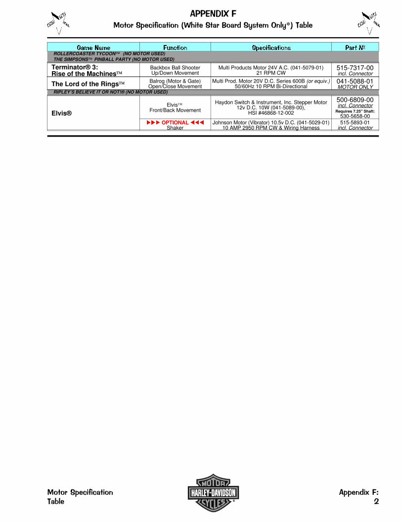
���� ���� ������ ���������� ��� ��ROLLERCOASTER TYCOON (NO MOTOR USED)THE SIMPSONS PINBALL PARTY (NO MOTOR USED)
Terminator® 3:Rise of the Machines
Backbox Ball ShooterUp/Down Movement
Multi Products Motor 24V A.C. (041-5079-01)21 RPM CW
515-7317-00incl. Connector
The Lord of the Rings Balrog (Motor & Gate)Open/Close Movement
Multi Prod. Motor 20V D.C. Series 600B (or equiv.)50/60Hz 10 RPM Bi-Directional
041-5088-01MOTOR ONLY
RIPLEY’S BELIEVE IT OR NOT!® (NO MOTOR USED)
Elvis®Elvis
Front/Back Movement
Haydon Switch & Instrument, Inc. Stepper Motor12v D.C. 10W (041-5089-00),
HSI #46868-12-002
500-6809-00incl. Connector
Requires 7.25" Shaft:530-5658-00
��� OPTIONAL ���Shaker
Johnson Motor (Vibrator) 10.5v D.C. (041-5029-01)10 AMP 2950 RPM CW & Wiring Harness
515-5893-01incl. Connector
���������� ����������� ������� �� ���������� ���� �*!"�# �
�� ����������� ��� �������$%"�# � '

����������� ���������������������� ��������
I. Electrical Source, Energy & Signal Converters010- Transformers031- Speakers090- Solenoids (Coils)
II. Conductors, Connectors & Insulators034- Line Cords036- Cable and Harness Assemblies041- Motors045- Connectors (All Types)077- Lamp Sockets
III. Circuits & Circuit Elements100- ICs110- Transistors112- Diodes121- Resistors123- Resistors (Variable & Adjustable)124- Regulators & Bridge Rectifiers125- CAPS140- Crystals165- Light Bulbs180- Switches190- Relays
IV. Bolts, Screws, Nuts & Washers231- Bolts232- Screws (Pan Head)234- Screws (HWH)237- Screws (Misc.)240- Nuts (Misc.)242- Washers (Flat, Round)244- Washers (Split Lock)246- Washers (Lockers, External Tooth)
V. Mechanical Components249- Rivets251- Pins (Dowel)254- Stand-Offs, Spacers and Shims260- Steel Ball265- Springs (Extension)266- Springs (Compression)269- Springs (Washers - Belleville, Wave)280- Grommets and Bushing
VI. Handles, Locks, Catches & Latches, Keys & Hinges355- Handles, Locks, Catches & Latches and Keys390- Hinges
VII. Fabricated Parts (In-House Assemblies)500- End Product (Systems and Models)515- Sub-Assemblies520- Printed Circuit Boards (PCBs)522- Display Glass525- Wood Parts530- Screw Machined Parts535- Fabricated Parts545- Molded (Extruded) Plastic/Rubber Parts550- Molded (Inserts)
VIII. Bulk Materials600- Braided Ground Wire601- Stranded Wire602- Ribbon Cable605- Sleeving (Shrink Tubing)626- Foam Rubber
IX. Miscellaneous705- Packing & Shipping Items820- Decals and Labels (Sets & Misc.)830- Butyrate (Plastic Pieces)900- Game Posters960- EPROM (Raw Part)965- EPROM (Programmed Part)
��������� ��� ������������� ���������� ��������

������������ ���������� �!���� ��"�#$ ��%���&
Patterns:STARBURST
STIPPLE
STARBURSTCIRCULAR
5 8" ø
550-5000-XX
STARBURSTCIRCULAR
3 4" ø
550-5001-XX
STARBURSTCIRCULAR
1" ø
550-5002-XX
STARBURSTCIRCULAR
1-3/16" ø
550-5003-XX
STARBURSTCIRCULAR
1-1 2" ø
550-5004-XXSTARBURSTCIRCULAR
2-1 4" ø
550-5005-XX
STARBURSTCIRCULAR
2-3 4" ø
550-5006-XX
PLAINCIRCULAR
3 4" ø
550-5007-XX
PLAINCIRCULAR
1" ø
550-5008-XX
PLAINCIRCULAR
1-3/16" ø
550-5009-XX
PLAINCIRCULAR
1-1 2" ø
550-5010-XXPLAIN
CIRCULAR
2-1 4" ø
550-5011-XX
PLAINCIRCULAR
2-3 4" ø
550-5012-XX
STIPPLECIRCULAR
1" ø
550-5048-XX
STIPPLE1" SQUARE
12"
550-5019-XX
ROLLOVERBUTTON BASE
550-5026-XX
WHITE STAR(only in white)
545-5015-00STIPPLE
RECTANGULAR
1-1 2" X 3 4"
550-5018-XX
STIPPLERECTANGULAR
1-5 8" X 1-1 2"
550-5051-XX
STARBURSTRECTANGULAR
2-1 4" X 1-1 8"
550-5044-XX
PLAINRECTANGULAR
2-1 4" X 1-1 8"
550-5049-XX
PLAINRECTANGULAR
1-1 4" X 1-1 2"
550-5050-XX
PLAINRECTANGULAR
2" X 2-1 2"
550-5063-XXSTARBURSTMINI SHIELD
550-5024-XX
STARBURSTLARGE SHIELD
550-5025-XX
MINIHOT DOG
1-5/8"
550-5020-XX
BEVELHOT DOG
3-1 2"
550-5021-XX
PLAINHOT DOG
3-1 2"
550-5022-XX
BANANA
550-5023-XXSTARBURST
ARROW-SMALL
550-5013-XX
STARBURSTARROW-LARGE
550-5070-XX
STARBURSTARROW-HEAD
SMALL
550-5014-XX
STARBURSTARROW-HEAD
550-5015-XX
STARBURSTBULLET
550-5016-XX
STARBURSTTRIANGLE
550-5017-XXNote: The shapes and sizes shown above are not to scale. Some shapes may no longer be available in every color.
Instructions: Parts which may come in various colors (i.e. targets, some posts, playfield inserts, etc.) end in a 2-digit Nº which correspondto the color of that part. The "-XX" in Part Nºs which may come in various colors should be replaced with the desired 2-DigitNº. corresponding to the color desired. Not all colors may be available.
������� ���� ��� ����
�º ����� �º ����� �º ����� �º ����� �º ����� �º �����
-00 Black or Solid Clear -03 Amber -06 Yellow -09 Purple -12 Fluor. Blue -15 Luminescent
-01 Clear -04 Green -07 Orange -10 Fluor. Orange -13 Teal Green -16 Gold
-02 Red -05 Blue -08 White -11 Fluor. Green -14 Gray -17 Trans. Brown
1" X 1"
LARGE
��� ���������� � ����������!���� ��"�#$ ��%���& �

����������� �����������
���������1. For Items A-E, for the Target Assembly use the "500-" SPI Nº;
For the Target Assy. with Rear Mount add "R" to "500-" SPI Nº;For just the «Target Insert» use the "545-" SPI Nº.
2. Items A-E come in various colors. These targets may not beavailable in every color. The "-XX" in should be replaced with thedesired 2-Digit Nº for the color desired described in the Chart �.As of date of print, the following colors were used for Items A-E:
-01 Clear (A, D); -02 Red (A, B, C, D, E); -03 Amber (D, E); -04 Green (A, B);-05 Blue (C); -06 Yellow (A, C), -09 Purple (B, D); -11 Fluorescent Green (A, B, D).
3. See Section 3, Chapter 2, Go To Diagnostics Menu, for switchesused corresponding to the Switch Matrix Grid of this game.
������� ����
��� ����
�º �����-00 Black
-01 Clear
-02 Red
-03 Amber
-04 Green
-05 Blue
-06 Yellow
-07 Orange
-08 White
-09 Purple
-10 Fluor. Orange
-11 Fluor. Green
-12 Fluor. Blue
-13 Teal Green
-14 Gray
-15 Luminescent
-16 Gold
�
Nº ������ �� ��� ���� ��� ���� �º
DModular Stand-Up Target Round Assy. 500-6075-XXStand-Up Target Round (Insert) 545-6075-XX
EMod. Stand-Up Target 1" Spherical Assy. 500-6189-XXStand-Up Target 1" Spherical (Insert) 545-6189-XX
Note: To receive the Target Assembly with the « Target Insert »« Reversed » simply add a "R" at the end of the Part Nº. See SideView picture above to compare (dashed line shows target reversed).
Nº ������ �� ��� ���� ��� ���� �º
AModular Stand-Up Target Narrow Assy. 500-6138-XXStand-Up Target Narrow (Insert) 545-6138-XX
BModular Stand-Up Target Square Assy. 500-6139-XXStand-Up Target Square (Insert) 545-6139-XX
CModular Stand-Up Target Rectangle Assy. 500-6228-XXStand-Up Target Rectangle (Insert) 545-6228-XX
"R" means«TargetInsert» isreversed,allowingfor RearMountedapplication.
���
��
�
�!
�� ��
�
��
���������1. For Items 1-4, "single" components can be ordered. 2. Items 1-4 come in various colors. These targets may not be
available in every color. The "-XX" in Part Nºs should bereplaced with the desired 2-Digit Nº for the color desireddescribed in the above Chart.
3. For switches used corresponding to the Switch MatrixGrid of this game, see Sec. 3, Chp. 2, ...Diagnostics.
Nº ������ ������ �� ��� ���� ��� ���� �º‡ Note: Item 2A, is a riveted Sub-Assy. which includes the following items for reference:A1— Stack Switch Radius End (180-5133-00), A2— Washer 5/16" (242-5017-00),A3— Rivet 1/8" ø X 3/16" (249-5001-00) and A4— Rectangular Target (545-5145-XX).
3 1" Sq. Stand-Up Target Assy. 500-5232-XXORDERING ABOVE (ITEM 3) ASSY. PART Nº WILL INCLUDE:3A‡ Sw. & Target Assy. 1" Square
Items 3B-F are identical to 1B-F515-5162-XXSame as 1B-F
‡ Note: Item 3A, is a riveted Sub-Assy. which includes the following items for reference:A1— Stack Switch Radius End (180-5133-00), A2— Washer 5/16" (242-5017-00),A3— Rivet 1/8" ø X 3/16" (249-5001-00) and A4— 1" Square Target (545-5470-XX).
4 Narrow Stand-Up Target Assy. 500-5857-XXORDERING ABOVE (ITEM 4) ASSY. PART Nº WILL INCLUDE:4A‡ Sw. & Target Assy. Narrow
Items 4B-F are identical to 1B-F515-5967-XXSame as 1B-F
‡ Note: Item 4A, is a riveted Sub-Assy. which includes the following items for reference: A1— Stack Switch Square End (180-5132-00), A2— Washer 5/16" (242-5017-00),
A3— Rivet 1/8" ø X 3/16" (249-5001-00) andA4— Narrow Target (545-5210-XX).
Nº ������ ������ �� ��� ���� ��� ���� �º
1 1" Round Stand-Up Target Assy. 500-5835-XXORDERING ABOVE (ITEM 1) ASSY. PART Nº WILL INCLUDE:1A‡1B1C1D1E1F
Switch & Target Assy. 1" RoundMounting BracketSwitch Back Plate6-32 X 3 4 HWH Swage (Qty. 2)Switch Diode, 1N4001Foam Pad
515-5966-XX535-6896-00535-6452-00237-5976-05112-5001-00626-5029-00
‡ Note: Item 1A, is a riveted Sub-Assy. which includes the following items for reference:A1— Stack Switch Radius End (180-5133-00), A2— Washer 5/16" (242-5017-00),A3— Rivet 1/8" ø X 3/16" (249-5001-00) and A4— 1" Round Target (545-5456-XX).
2 1" X 11 2" Stand-Up Rect. Target Assy. 500-5321-XXORDERING ABOVE (ITEM 2) ASSY. PART Nº WILL INCLUDE:2A‡ Sw. & Target Assy. 1" X 11 2" Rect.
Items 2B-F are identical to 1B-F515-6027-XXSame as 1B-F
Item 2 Table Note continued in the next column.
���� �"#�� �� ����� �������

���������� ������������������� ������ � ��������������� ����!����"���# ���$�������%&��
USA 8or CANADA
Front 755-5400-00
USA 5
Back 755-5400-00
USA 1* (optional)
Front 755-5400-01 *
USA or CANADACustom *†
Back 755-5400-01 *†
USA 2-7or CANADA
Front 755-5400-02
USA or CANADACustom †
Back 755-5400-02 †
ToPS USAor CANADA *‡
Front 755-5400-03 *‡
ToPSUSA *‡
Back 755-5400-03 *‡ Front 755-5400-04 *‡ Back 755-5400-04 *†‡
AUSTRALIA 1 orNEW ZEALAND 2
Front 755-5406-00
AUSTRALIA 2 orNEW ZEALAND 1
Back 755-5406-00CROATIA
Front 755-5410-00
CROATIACustom †
Back 755-5410-00
DENMARK 1
Front 755-5402-00
DENMARK 2
Back 755-5402-00
EURO 1
1-Sided 755-5401-01
EURO 2
1-Sided 755-5401-02EURO 3
1-Sided 755-5401-03
EURO 4
1-Sided 755-5401-04
EURO 5
1-Sided 755-5401-05
EURO 6
1-Sided 755-5401-06
EURO 7
1-Sided 755-5401-07
EURO 8
1-Sided 755-5401-08EURO 9
1-Sided 755-5401-09
EURO 10
1-Sided 755-5401-10
EURO 11
1-Sided 755-5401-11
EURO 12
1-Sided 755-5401-12
ToPS EUROCustom *‡
Front 755-5401-20 *‡
ToPS EUROCustom *†‡
Back 755-5401-20 *†‡
JAPAN
Front 755-5408-00
JAPANCustom †
Back 755-5408-00 †
NORWAY 1
Front 755-5403-00
NORWAY 2
Back 755-5403-00
Republic of S. AFRICA
Front 755-5409-00
Republic of S. AFRICACustom †
Back 755-5409-00SWEDEN 1
Front 755-5404-00
SWEDEN 2
Back 755-5404-00
SWITZERLAND 1
Front 755-5405-00
SWITZERLAND 2
Back 755-5405-00
UK 1
Front 755-5407-00
UK 3
Back 755-5407-00
UK 5
Front 755-5407-01
UK Custom †
Back 755-5407-01 †
ToPS UKCustom *‡
Front 755-5407-02 *‡
ToPS UKCustom *†‡
Back 755-5407-02 *†‡
Coin Card(s) included with this Pinball game is/aredetermined by original shipping country destination.* Optional Coin Card shown is not included with this
game, but is available for sale or download.† Any blank back side of the Coin Cards noted, can be
used for Custom Pricing.‡ ToPS (TOURNAMENT PINBALL SYSTEM) ONLY.
See Sec. 3, Chp. 7, GO TO TOURNAMENT MENU.Note: You can download any Coin Card (in PDFFormat, Adobe® Reader v5.0+ required) from ourwebsite www.sternpinball.com/coinagecards.htm orfollow link(s) for info on getting all Coin Cards on CD-R.Older style Coin Cards (foreign or domestic), not onthe website or no longer available through yourdistributor, are obsolete.
Sec. 3, Chp. 4, Go To Adjustments Menu, Adj. 6, Game Pricing, USA & Int’l. Standard Pricing Select Table, summarizes Custom or Standard Pricing Schemes these Coin Cards represent.
ToPS USA, CANADA, AUSTRALIA or NEWZEALAND Custom *†‡
�� ����������� �''��� ()����*��� � ����������� +
to open Coin Card Files, insert Disc 2

������������ ����������
���� ������� ���� º ��� �� �������� ���� ��������
� ���������
�� �� ����������
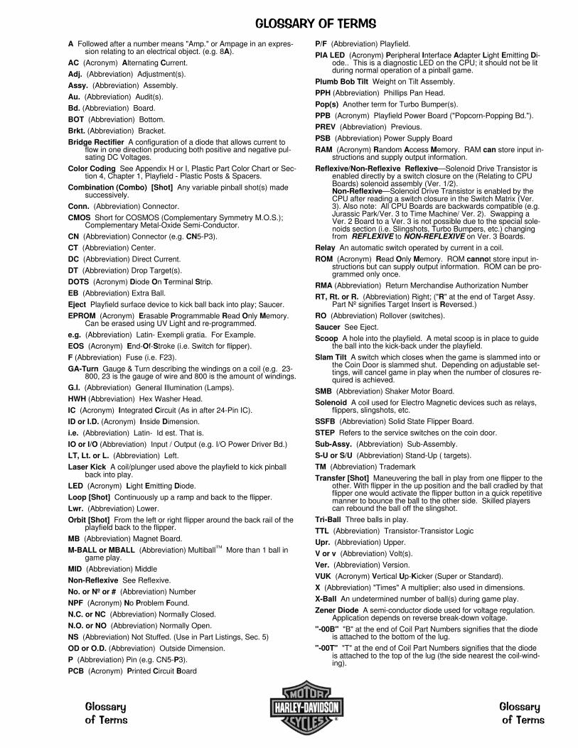
A Followed after a number means "Amp." or Ampage in an expres-sion relating to an electrical object. (e.g. 8A).
AC (Acronym) Alternating Current.
Adj. (Abbreviation) Adjustment(s).
Assy. (Abbreviation) Assembly.
Au. (Abbreviation) Audit(s).
Bd. (Abbreviation) Board.
BOT (Abbreviation) Bottom.
Brkt. (Abbreviation) Bracket.
Bridge Rectifier A configuration of a diode that allows current toflow in one direction producing both positive and negative pul-sating DC Voltages.
Color Coding See Appendix H or I, Plastic Part Color Chart or Sec-tion 4, Chapter 1, Playfield - Plastic Posts & Spacers.
Combination (Combo) [Shot] Any variable pinball shot(s) madesuccessively.
Conn. (Abbreviation) Connector.
CMOS Short for COSMOS (Complementary Symmetry M.O.S.);Complementary Metal-Oxide Semi-Conductor.
CN (Abbreviation) Connector (e.g. CN5-P3).
CT (Abbreviation) Center.
DC (Abbreviation) Direct Current.
DT (Abbreviation) Drop Target(s).
DOTS (Acronym) Diode On Terminal Strip.
EB (Abbreviation) Extra Ball.
Eject Playfield surface device to kick ball back into play; Saucer.
EPROM (Acronym) Erasable Programmable Read Only Memory.Can be erased using UV Light and re-programmed.
e.g. (Abbreviation) Latin- Exempli gratia. For Example.
EOS (Acronym) End-Of-Stroke (i.e. Switch for flipper).
F (Abbreviation) Fuse (i.e. F23).
GA-Turn Gauge & Turn describing the windings on a coil (e.g. 23-800, 23 is the gauge of wire and 800 is the amount of windings.
G.I. (Abbreviation) General Illumination (Lamps).
HWH (Abbreviation) Hex Washer Head.
IC (Acronym) Integrated Circuit (As in after 24-Pin IC).
ID or I.D. (Acronym) Inside Dimension.
i.e. (Abbreviation) Latin- Id est. That is.
IO or I/O (Abbreviation) Input / Output (e.g. I/O Power Driver Bd.)
LT, Lt. or L. (Abbreviation) Left.
Laser Kick A coil/plunger used above the playfield to kick pinballback into play.
LED (Acronym) Light Emitting Diode.
Loop [Shot] Continuously up a ramp and back to the flipper.
Lwr. (Abbreviation) Lower.
Orbit [Shot] From the left or right flipper around the back rail of theplayfield back to the flipper.
MB (Abbreviation) Magnet Board.
M-BALL or MBALL (Abbreviation) Multiball More than 1 ball ingame play.
MID (Abbreviation) Middle
Non-Reflexive See Reflexive.
No. or Nº or # (Abbreviation) Number
NPF (Acronym) No Problem Found.
N.C. or NC (Abbreviation) Normally Closed.
N.O. or NO (Abbreviation) Normally Open.
NS (Abbreviation) Not Stuffed. (Use in Part Listings, Sec. 5)
OD or O.D. (Abbreviation) Outside Dimension.
P (Abbreviation) Pin (e.g. CN5-P3).
PCB (Acronym) Printed Circuit Board
P/F (Abbreviation) Playfield.
PIA LED (Acronym) Peripheral Interface Adapter Light Emitting Di-ode.. This is a diagnostic LED on the CPU; it should not be litduring normal operation of a pinball game.
Plumb Bob Tilt Weight on Tilt Assembly.
PPH (Abbreviation) Phillips Pan Head.
Pop(s) Another term for Turbo Bumper(s).
PPB (Acronym) Playfield Power Board ("Popcorn-Popping Bd.").
PREV (Abbreviation) Previous.
PSB (Abbreviation) Power Supply Board
RAM (Acronym) Random Access Memory. RAM can store input in-structions and supply output information.
Reflexive/Non-Reflexive Reflexive—Solenoid Drive Transistor isenabled directly by a switch closure on the (Relating to CPUBoards) solenoid assembly (Ver. 1/2).Non-Reflexive—Solenoid Drive Transistor is enabled by theCPU after reading a switch closure in the Switch Matrix (Ver.3). Also note: All CPU Boards are backwards compatible (e.g.Jurassic Park/Ver. 3 to Time Machine/ Ver. 2). Swapping aVer. 2 Board to a Ver. 3 is not possible due to the special sole-noids section (i.e. Slingshots, Turbo Bumpers, etc.) changingfrom REFLEXIVE to NON-REFLEXIVE on Ver. 3 Boards.
Relay An automatic switch operated by current in a coil.
ROM (Acronym) Read Only Memory. ROM cannot store input in-structions but can supply output information. ROM can be pro-grammed only once.
RMA (Abbreviation) Return Merchandise Authorization Number
RT, Rt. or R. (Abbreviation) Right; ("R" at the end of Target Assy.Part Nº signifies Target Insert is Reversed.)
RO (Abbreviation) Rollover (switches).
Saucer See Eject.
Scoop A hole into the playfield. A metal scoop is in place to guidethe ball into the kick-back under the playfield.
Slam Tilt A switch which closes when the game is slammed into orthe Coin Door is slammed shut. Depending on adjustable set-tings, will cancel game in play when the number of closures re-quired is achieved.
SMB (Abbreviation) Shaker Motor Board.
Solenoid A coil used for Electro Magnetic devices such as relays,flippers, slingshots, etc.
SSFB (Abbreviation) Solid State Flipper Board.
STEP Refers to the service switches on the coin door.
Sub-Assy. (Abbreviation) Sub-Assembly.
S-U or S/U (Abbreviation) Stand-Up ( targets).
TM (Abbreviation) Trademark
Transfer [Shot] Maneuvering the ball in play from one flipper to theother. With flipper in the up position and the ball cradled by thatflipper one would activate the flipper button in a quick repetitivemanner to bounce the ball to the other side. Skilled playerscan rebound the ball off the slingshot.
Tri-Ball Three balls in play.
TTL (Abbreviation) Transistor-Transistor Logic
Upr. (Abbreviation) Upper.
V or v (Abbreviation) Volt(s).
Ver. (Abbreviation) Version.
VUK (Acronym) Vertical Up-Kicker (Super or Standard).
X (Abbreviation) "Times" A multiplier; also used in dimensions.
X-Ball An undetermined number of ball(s) during game play.
Zener Diode A semi-conductor diode used for voltage regulation.Application depends on reverse break-down voltage.
"-00B" "B" at the end of Coil Part Numbers signifies that the diodeis attached to the bottom of the lug.
"-00T" "T" at the end of Coil Part Numbers signifies that the diodeis attached to the top of the lug (the side nearest the coil-wind-ing).
�����������������
��������� ���������
������ � ������ �

� � � � � � � � � � � � � � � � � � � � � � � � � � � � � � �
������ ������ �� �� ���������� ������ ���� �� ��� ������ ��� ���� �� ��� ����� �� ��� �������� ������ ���� �� ���� ���� ���� �� �� ������ �� ���������� ����� ����� ��� ������� � ��� ���
�� �� � � � � � � � � � �� � � � � � � � � � � � �� � � � � � � � � � �
������� �� ��� ���� ���� ���� �� � ��������� ����� ������ ����� ������
�� ����� ���� �� ������!� ����� � �� ��������
������ ������� �� ���� ���� ���� ��� ������ ��� �� �������� ���� ������ �� ��� ������"��������������
������!� ���� ������� ���� �� � ��� ������� �� ����� �� ���� � ����� �� ��� � �� �������� �������� ������ ��� ������ ������� ��� ������ ���������
#� ������ �� �������� �������� ���� ��� ����� � ��� ���� ��� ����� ����� �� �� ���� ������� �� � ����� �� �� �������� � ���� �� ���� �������� ������� ������� �� ������!� �����
���� ������ ���� ��� ���� �� �� ���� ����� ������ �������� ��$�� ��� �� ���������������� �� ��� �� �������� ���������� �� ����� �� ��������� �� �� ����� ���� ��� ������ ����� ��� �� ��� ����� �������� ���� �� �������� ���� �� ���� ������ �� ����%����������� �� �� ����� ������ �� ����� � ��� ������� �� ���� ���� ���� ��� ��� ��� �� ������ ������ �� � ����� ��
������ ��� �����
�� ��� � ��� ��� ��� �������� �� ������� ���� � ������ ������ �� ��� ����� ����� �� ������� ��������� ������� �� �������� �� ������ �� ������� �������� �� ��� �������� ��������� ��� ���� ��� ��������
� � � � � � � � � � � � � � � � � � � � � � � � �
������ ��� ����� �� ���������� ��������� ���� �� �%������� ������ ����� �� ��� �� ����������� �� ���� �� ���������� ��� �� ���&������ ����� �� � ���� �� ������ ����� �� ���
�� ������ �� �������� ��� � ��� ���� �� �� ��� ��'������ �������� ����� ���� ���������� ��� �� ��� ���� �������� ����( ���� ��� ���� �� ���� ����� ��� �� �������� ��� ��� ����� � ���� ����� ���� ��� �� ����� ��� ���������� ������������ ������ �� �%������� ������ ����� �� ���� � ���� ���� ��
)*+,- �.-/0112/3 �42 �.12 �0)3+52 26072 �278./.15� �092 �+73- �+, �3.)) �0): ;77213 �421 �1<);552:�
��! � ����� �%������� ��������� ����� �� � ����� ���� ���%��� � ������� �� �� ��� ���������� ���� �� ���� � ���� ��� ������ ����� ����� �� ��� ���������� � �� ����
������ ������ �� �� ��� ������ �� ����� �� ����� ���� ��� ������ ��� ��� ������������ � ������� �� ����� ' �� ��� #= �� � ������ ��� � �� �������� �� ������� ������������ ���� ����� �� � ���������� � ���� ������� �� ����� �� ������������ �������� ������ �%������� �� ���������� �� �� ������ �� ��� ���������� � �� ��� � �� ��� ���� � ������ ������� ���� � ��%����� �� ��� ������� ������� �� � ��%����� �� ���� � ������������� ��
�� ���������� � ���� �� �� ������ �� ������ �� ������ ���� ������� �� ���� ��� ������ �������� �� ���� �� ������� �� ���� ���� ������ ������ ����� � ��� � ������ �������� ����� ������� ���������� �������� �� �� ���� � ������ ����� �� ����� ��������� ������� �� ���� � ��� ��� ���� ��� ������ ������� ��
�����"#���� �� ����� �� ��� �� ��� ����� ������ �� �������� �� ��� �� � ������� �� ��� ��� ������������ ���� �� ��������� ��� ����� �� ����� �� �� ��� �� ����� ������� ������� ������ �������� ������ �� �
��������������������� �� �� ���� ����� ��� ����� ��� �� ���� �� �� ���
������ �� ��� ���� ������� �� ����� ��� � ������ ������ ��� ������ ��������� ������������������� �������� �� ���������� ���� ���� � ���� �� ��� ����� �� ������������ ����������� ��� ����� �� �������� �� ���� ��� ��� ����� ������� ����� ���� ��
� ���� �������� � �� �� ��� �������� ���� ����������� � ������ ���� ����� �� ! "# $�� ���� % ���� ��� � ������ �� ���� ��&� � �� ��� �������� ���'�� (��)�� ( � �* �� ��� �� �) +�'�
,���������, �� � � ���� � � ���� ��& �$����� � -� ������ .� �� ��� +� � �� ! � �������
�/� �) ���� 0� ���� 1� /)�!� � �2 �� /-�0/� ���* -� ������ % ���3�� � ���2 � 4551�
�������� � �� �� ����������� ��� ��� � �� �� �� 6��� �7��*������ ����� /��,8 ���� � ���) ��� 6��� �7��*������ ���� ����� ,� ,$) � ��� ) �� �) � ��� ���� ����� ��� &��3 ��#� �� 6��� �7��*�����,� 6��� �7��*������� 67��� 6��� �7��*����� ���� ����� � 67� �/ ����� 67� ������� � ���� � �� �)�� ����� % .� � 8��( 98��(� (��� .��� � :�6 �!����� �� ;;<� 8:��/ �������/���� � 8:� ���� ��! �.��� �� �(=� ����3����� 8���8 8�� ����� 8���� 6 ����� �!���� �� �� ��� ���� ��&�� 67��� ��� � ��! �9�� � ��� � ���� � ��� ���� � �� �� �� 3��) 67������� />������� '�� (��)�� ( � �* �� ���� /� ����? ,���� �� � $���, ���� �� �� ����� ��45@; ������� ����� /�!����)� � ( � 3 �� +� � �� ! � �������'�� (��)�� ������� � ��� �� ����� � � �� ���� /��!������� � ' ���� ���,��� �� �) ��� , � � ������ �����

&-!(,��'$(�!0�+�!��1��)�!,$()��&-!(,�)&
%$'��'$(�!0�+�!�
���
����������
������
���� ��� ���
�� ����
��� ����� ��
#1 LEFTFLIPPERBUTTONin Cabinet side ����
�� ����
��� ����� ��
#2 LEFTFLIPPER E.O.S(End-of-Stroke)in Cabinet side ����
�� ����
��� ����� ��
#3 RIGHTFLIPPERBUTTONin Cabinet side ����
�� ����
��� ����� ��
#4 RIGHTFLIPPER E.O.S.(End-of-Stroke)in Cabinet side ����
�� ������� ������� ����� ��
#5NOTUSED
in Cabinet side ����
�� ����
��� ����� �
#6 VOLUME(RED BUTTON)(In Test: LEFT)on Coin Door ���
�� ����
��� !"��� �#
#7 SERV. CRED.(GREEN BUTTON)(In Test: RIGHT)on Coin Door ���
� ����
��� ���� ���
#8 BEGIN TEST(BLACK BUTTON)(In Test: ENTER)on Coin Door ����
�� ������ ��� �� �� ����
����� ����������
������ ����
�� ���� ��� �� �� ����
��� ��� ��������� � �����
���� ����
� �����������
� ���������
�� $���� ������� ����� ��
�� $���� ������� ����� ��
�� $���� ������� ����� ��
�� $���� ������� ����� ��
�� $���� ������� ���� ��
�� $���� ������� ����� ��
�� $���� ������� !"��� �
� $ ��� ������� ����� �#
�� ������� ����%&� ����� �#
LEFTBUTTON(UK ONLY)
NOTUSED
LT 4-BANKD/T(L) IVE
RIGHTRAMPENTER
LEFTORBIT
M-CYCLETROUGH#4 (TOP)
���
LEFTTURBOBUMPER
LEFTOUTLANE
on Cabinet side � � Under P/F � Above P/F �� Under P/F �� Under P/F �� Under P/F �� Under P/F �
�� ������� ����%&� ����� �
4THCOINSLOT
NOTUSED
LT 4-BANKD/TL (I) VE
RIGHTRAMPEXIT
RIGHTORBIT
M-CYCLETROUGH#3
���
RIGHTTURBOBUMPER
LEFTRETURNLANE
On Coin Door � �� Under P/F �� Above P/F � Under P/F �� Under P/F �� Under P/F �� Under P/F ��
�� ������� ����%&� ����� ��
6THCOINSLOT
4-BALLTROUGH#1 (LEFT)
LT 4-BANKD/TLI (V) E
RIGHTRAMPMID
MOTORUP
M-CYCLETROUGH#2
���
BOTTOMTURBOBUMPER
LEFTSLINGSHOT
On Coin Door � �� Under P/F �� Above P/F � Under P/F �� Under P/F �� Under P/F �� Under P/F ��
�� ������� ����%&� ����� ��
RIGHTCOINSLOT
4-BALLTROUGH#2
LT 4-BANKD/TLIV (E) SPINNER
MOTORDOWN
M-CYCLETROUGH#1 (BOT)
���
TOPTURBOBUMPER
RIGHTOUTLANE
On Coin Door � Under P/F �� Under P/F �� Above P/F �� Under P/F � Under P/F �� Under P/F �� Under P/F �
�� ������� ����%&� ����� ��
CENTERCOIN SLOT/ DBA
4-BALLTROUGH#3
RT 4-BANKD/T(R) IDE
S-U TRGTLT(M-CYCLE) OPTO
SUPERVUK
����
LAUNCHBUTTON
RIGHTRETURNLANE
On Coin Door � Under P/F �� Under P/F �� Under P/F �� Under P/F � Under P/F �� Cabinet Front �� Under P/F �
�� ������� ����%&� ����� ��
LEFTCOINSLOT
4-BALLTROUGHVUK OPTO
RT 4-BANKD/TR (I) DE
S-U TRGTRT(M-CYCLE)
NOTUSED
BALLEJECT(SCOOP)
����
STARTBUTTON
RIGHTSLINGSHOT
On Coin Door Under P/F �� Under P/F �� Under P/F �� �� Under P/F � Cabinet Front �� Under P/F �
�� ������� ����%&� !"��� ��
5THCOINSLOT
4-BALLSTACKINGOPTO
RT 4-BANKD/TRI (D) E
S-U TRGTLT(RT RAMP)
NOTUSED
NOTUSED
SLAMTILT
NOTUSED
On Coin Door Under P/F �� Under P/F �� Under P/F �� �� � On Coin Door �� �
� ������� ����%&� ����� ��
RIGHTBUTTON(SKILL)
SHOOTERLANE
RT 4-BANKD/TRID (E)
S-U TRGTRT(RT RAMP)
NOTUSED
BEHINDTOPVUK
PLUMBBOBTILT
NOTUSED
on Cabinet side � Under P/F � Under P/F �� Under P/F �� �� Under P/F �� Inside Cabinet � �
D iode O n T erminal S trip : D iode O n D iode B oard :
�� ��� !"#$
��% &�$
�� ������ ������� ���'�� �#
�� ������ ������� ���'�� �
�� ������ ������� ���'�� ��
�� ������ ������� ��'�� ��
�� ������ ������� ���'�� ��
�� ������ ������� ���'�� ��
�� ������ ������� !"�'�� ��
� ������ ������� ���'�� ��
�� $����� ������� ���'�� ��
(H) ARLEY H (A) RLEY HA (R) LEY HAR (L) EY HARL (E) Y HARLE (Y) SUPER JACK-POT (RED)
SUPER JACK-POT (GRN)
#555 Bulb � #555 Bulb � #555 Bulb � #555 Bulb � #555 Bulb � #555 Bulb � #44 Bulb � #44 Bulb
�� $����� ������� ��'�� ��
(L) IVE L (I) VE LI (V) E LIV (E) (R) IDE R (I) DE RI (D) E RID (E)
#44 Bulb # #555 Bulb �� #555 Bulb �� #555 Bulb �� #555 Bulb �� #555 Bulb �� #555 Bulb �� #44 Bulb ��
�� $����� ������� ���'�� ��
LT ORBITGRN LIGHT
LT ORBITYEL LIGHT
LT ORBITRED LIGHT
1STGEAR
2NDGEAR
3RDGEAR
4THGEAR
5THGEAR
#555 Bulb �� #555 Bulb � #555 Bulb �# #555 Bulb �� #555 Bulb �� #555 Bulb �� #555 Bulb �� #555 Bulb ��
�� $����� ������� ���'�� ��
M-CYCLEGRN LIGHT
M-CYCLEYEL LIGHT
M-CYCLERED LIGHT
LEFT TURBO
BUMPER
����
RT TURBO
BUMPER
����
BOT TURBO
BUMPER
����
TOP TURBO
BUMPER
����
SPEEDO-METER X2
#555 Bulb �� #555 Bulb �� #555 Bulb �� #555 Bulb � #555 Bulb �# #555 Bulb �� #555 Bulb �� #555 Bulb ��
�� $����� ������� ���'�� ��
SUPER VUKGRN LIGHT
SUPER VUKYEL LIGHT
SUPER VUKRED LIGHT
BIKE S-UTARGET (LT)
BIKE S-UTARGET (RT)
RAMP S-UTARGET (LT)
RAMP S-UTARGET (RT)
SLIPPERYWHEN WET
#555 Bulb �� #555 Bulb �� #555 Bulb �� #555 Bulb �� #555 Bulb �� #555 Bulb � #555 Bulb �# #555 Bulb ��
�� $� ��� ������� ���'�� ��
RT RAMPGRN LIGHT
RT RAMPYEL LIGHT
RT RAMPRED LIGHT
PATCH BIKERSBACK
RED LIGHTMULTIBALL
AUTOLAUNCH
LITE MYST-ERY RIDER
#555 Bulb �� #555 Bulb �� #555 Bulb �� #555 Bulb �� #555 Bulb �� #555 Bulb �� #555 Bulb �� #555 Bulb �
�� $�#��� ������� !"�'�� �
RT ORBITGRN LIGHT
RT ORBITYEL LIGHT
RT ORBITRED LIGHT
NOTUSED
NOTUSED
NOTUSED
NOTUSED
NOTUSED
#555 Bulb �# #555 Bulb �� #555 Bulb �� �� �� �� �� ��
� $����� ������� ���'�� �#
STOP LIGHTGRN LIGHT
STOP LIGHTYEL LIGHT
STOP LIGHTRED LIGHT
NOTUSED
NOTUSED
NOTUSED
NOTUSED
NOTUSED
#44 Bulb �� #44 Bulb � #44 Bulb �# �� �� �� �� ��
#� $����� ������� %&�'�� ���
2 XTRA BALLS
LT OUTLANEADVANCE GEAR
LT RETURNLITE MYSTERY...
RT RETURN2 XTRA BALLS
RT OUTLANEM-CYCLEHEADLIGHT
RIDEAGAIN X2
MYSTERYRIDER
NEXTCITY
#555 Bulb �� #555 Bulb �� #555 Bulb �� #555 Bulb � #555 Bulb �# #555 Bulb �� #44 Bulb �� #44 Bulb ��
��� $����� �������'�� ���
NOTUSED
NOTUSED
NOTUSED
NOTUSED
NOTUSED
NOTUSED
NOTUSED
NOTUSED
�� �� �� �� �� � �# �
D iode O n T erminal S trip :
����

1/8”
1/16”
.0625”
.125”
.25”
.5”1/32”
(.03125”)
1” = 2.54cm /25.4mm1cm = .3937”
1mm = .03937”
· For metric, multiply inchvalue by metric value,
e.g. 5” X 2.54cm =12.7cm or 127mm.
· For US, multiply metricvalue by inch value,e.g. 13cm X .3937” =
5.1181”
MetricConversion
3/4”
.75”
1/2”
1/4”
http://www.SternPinball.comhttp://www.SternPinball.com
Games shipped factory directto Europe from Stern Pinball,Inc. are CE approved and willhave an "E" prefix attached tot h e S e r i a l N u m b e r .
2020 Janice Avenue, Melrose Park, IL 60160
1-8
00
-K
IC
KE
RS
Tel
(Option
1)Fa
xeM
ail
708-3
45-7
700
708-3
45-7
889
par
ts.s
ervi
ce@
Ste
rnPin
ball.
com
��
��
� �U.S.CustomaryInch Ruler
98
72
65
43
1
780-5087-00
Visit our website for Pinball game information, Technical Support &Part Sales (for Service Bulletins and a whole lot more!), Stern
News, Pinball Links and Distributor Listings. HELP US, HELP YOU!If you have any suggestions, questions, need technical advice, finderrors or have comments, contact us through our website or call!
This Game Service Manual and all other documents relating to this product, playfield components, features, rules, programmingand operation are subject to change without notice (Service Bulletins, if applicable, available through our website).