Planning Commission Staff Report - City of Minnetonka
94
City Council Agenda Item #14_ Meeting of May 22, 2017 Brief Description Conditional use permit for a telecommunications tower with a height variance on the property located at 4525 Williston Road Recommendation Recommend the city council adopt the resolution approving the request Proposal Verizon Wireless is requesting a conditional use permit for construction and operation of a 180-foot telecommunications tower and associated ground equipment. The tower and equipment would be located directly south of the existing water tower. Background Verizon previously sought a location on the top of the Williston water tower to achieve coverage needs to the south. The city declined a departure from its public water tower policy to allow Verizon to meet its coverage needs. In doing so, the city suggested that a monopole may be an alternative means to gaining coverage needs. During the concept plan review, Verizon had proposed a 150-foot tower to achieve its coverage needs. Since those review meetings, staff, the city’s telecommunications consultant and representatives from Verizon have continued to discuss details of the proposal. After much discussion, the city’s telecommunications consultant made the recommendation to consider increasing the tower height. In this circumstance, increasing the tower height has the following advantages: 1) The increased height would provide additional collocation opportunities, 2) The increased height and additional collocation opportunities will greatly reduce the need for other monopoles in the area for the foreseeable future; and, 3) The increased height and additional collocation opportunities reduces pressure for additional telecommunications equipment space on the city’s water tower which is at capacity. Given the lack of viable alternatives to collocate telecommunications equipment on existing structures in the area to provide Verizon reasonable coverage, staff views the proposal as reasonable. For clarity, there would be a possibility of locating the facility elsewhere in the area, at a similar height (150-180’). Again, if there are no suitable co- location opportunities (which there are not), a separate structure must be considered.
-
Upload
khangminh22 -
Category
Documents
-
view
0 -
download
0
Transcript of Planning Commission Staff Report - City of Minnetonka

City Council Agenda Item #14_ Meeting of May 22, 2017
Brief Description Conditional use permit for a telecommunications tower with a
height variance on the property located at 4525 Williston Road Recommendation Recommend the city council adopt the resolution approving the
request Proposal Verizon Wireless is requesting a conditional use permit for construction and operation of a 180-foot telecommunications tower and associated ground equipment. The tower and equipment would be located directly south of the existing water tower. Background Verizon previously sought a location on the top of the Williston water tower to achieve coverage needs to the south. The city declined a departure from its public water tower policy to allow Verizon to meet its coverage needs. In doing so, the city suggested that a monopole may be an alternative means to gaining coverage needs. During the concept plan review, Verizon had proposed a 150-foot tower to achieve its coverage needs. Since those review meetings, staff, the city’s telecommunications consultant and representatives from Verizon have continued to discuss details of the proposal. After much discussion, the city’s telecommunications consultant made the recommendation to consider increasing the tower height. In this circumstance, increasing the tower height has the following advantages:
1) The increased height would provide additional collocation opportunities,
2) The increased height and additional collocation opportunities will greatly reduce the need for other monopoles in the area for the foreseeable future; and,
3) The increased height and additional collocation opportunities reduces pressure for additional telecommunications equipment space on the city’s water tower which is at capacity.
Given the lack of viable alternatives to collocate telecommunications equipment on existing structures in the area to provide Verizon reasonable coverage, staff views the proposal as reasonable. For clarity, there would be a possibility of locating the facility elsewhere in the area, at a similar height (150-180’). Again, if there are no suitable co-location opportunities (which there are not), a separate structure must be considered.
Meeting of May 22, 2017 Page 2 Subject: Verizon Tower, 4525 Williston Road Neighborhood Meeting A neighborhood meeting was held on May 2, 2017. City officials, the city’s telecommunications consultant and Verizon Wireless representatives were present. No one else attended the meeting. Planning Commission Hearing The planning commission considered the request on May 4, 2017. The staff report and various plans and documents describing the proposed project from that meeting are attached. At that meeting, a public hearing was opened to take comment but no one was present or provided public input on the item. Planning Commission Recommendation On a 5-0 vote, the commission recommended that the city council approve the proposal. Meeting minutes are attached. Staff Recommendation Staff recommends that the planning commission recommend approval to the city council to adopt a resolution approving a conditional use permit for a telecommunication facility with a height variance at 4525 Williston Road.
Through: Geralyn Barone, City Manager Julie Wischnack, AICP, Community Development Director Originator: Loren Gordon, AICP, City Planner

LOCATION MAPWilliston water tower site monopole4525 Williston Road
±
This map is for illustrative purposes only.
WILL
ISTO
N RD
HIGHWAY 7
WOOD
HILL
RD
KARYL DR
LLOYDS DR
HIGHWOOD DR
HIGHLAND LN
LLOYDS LN
DURHAM RD
WOOD
S WAY
WILDCREST RD
MOONLIGHT HILL RD
HIGH TOWER
HIGH POINT CT
HIGHWAY 7HIGHWAY 7
HIGHWAY 7
WOOD
HILL
RD
SUBJECT PROPERTY

MINNETONKA PLANNING COMMISSION May 4, 2017
Brief Description Conditional use permit for a telecommunications tower with a
height variance on the property located at 4525 Williston Road Recommendation Recommend the city council adopt the resolution approving the
request ______________________________________________________________________ Project No. 05011.17a Property Williston Water Tower site, 4525 Williston Road Applicant Verizon Wireless Proposal Verizon Wireless is requesting a conditional use permit for construction and operation of a telecommunications tower and associated ground equipment. The tower and equipment would be located directly south of the existing water tower. Site Features The site is located on the south side of the Highway 7, south frontage road and east of Williston Road. The property is 1.15 acres in size (excluding the larger city owned property to the east) and is improved with the Williston Water Tower which is approximately 130 feet in height. The site rises approximately 35 feet from the frontage road to the south property line. In addition to providing space for the water tower, the city has managed the landscape as an oak woodland brushland restoration area. This area is part of the broader Tower Hill Park Habitat Restoration. Proposed Location The proposed tower location was determined after a long collaboration with city staff to evaluate various options on the subject property as well as the adjacent Tower Hill Park. Although the nearly 9-acre city owned area between Williston and Woodhill Road appear to provide many potential tower locations, a number of factors limit options including:
• Water and utility lines crossing through the area,
• Underground city water storage tanks,

Meeting of May 4, 2017 Page 2 Subject: Verizon Tower, 4525 Williston Road
• Proximity to surrounding residential neighborhoods,
• Visual impact to the Highway 7 corridor,
• Viable options that work with the carrier’s requirements including equipment
access,
• Topography,
• Wooded and wetland areas; and,
• Accessibility from and proximity to adjacent streets or existing driveways. While it is not customary for the city to engage so directly in project details, in this situation as the property owner, the city has numerous interests in identifying a location that is acceptable. As noted, the proposed tower would be located directly south of the water tower. This location is in an area that is reasonably accessible from the south frontage road, has minimal disruption to habitat and landscape, and does not interfere with the numerous public utilities around the site. From a visual perspective, the location between the water tower and the woods provides sheltering when viewed from many angles. The tower would be located 90 feet directly south of the water tower. The tower base would be approximately 16 feet higher in elevation than the base of the water tower. The tower would be 67 feet higher than the water tower. The ground equipment would be located between the monopole and the water tower. Grading is proposed to “tuck” the equipment better into the hillside to help reduce visual impacts. A 6-foot retaining wall is shown on the south side of equipment pad. Metal fencing 7-feet in height would enclose the ground equipment. A proposed sidewalk would connect the ground equipment and tower to the water tower access road. Proposed Tower The proposed tower total height would be 180 feet. The tower would be of stealth design to blend the tower into the surrounding environment. The tower would incorporate the antennas into the monopole structure so that they do not project out from the side of the structure. The pole would also be painted an ivory/off white color, similar to the nearby water tower, to minimize the visual impact of the structure. The tower design would incorporate features for multiple antennas between 150 and 180 feet on the tower. (See photo simulations). Minnetonka Telecommunication Ordinance The city recognizes the value of wireless communications, while also recognizing that freestanding telecommunications towers may have a visual impact on the areas in which
Meeting of May 4, 2017 Page 3 Subject: Verizon Tower, 4525 Williston Road they are located. In an attempt to balance the technological positive with the aesthetic negative, the city’s current telecommunications ordinance favors the installation of technology on existing support structures – such as water towers, buildings, and high voltage transmission poles – over the construction of freestanding towers. This is evidenced in the ordinance in several ways:
• Administrative Permit vs. Conditional Use Permit. The installation of wireless facilities on existing support structures can often be reviewed and approved administratively. A freestanding telecommunications tower can be approved only by conditional use permit.
• Conditional Use Permit Standards. By conditional use permit standard, an
applicant for a freestanding telecommunications tower must prove that there is no existing antenna support structure that could adequately serve the area if antennas were placed on it.
Staff Analysis In speaking with telecommunication providers, city staff regularly outlines the goals of the telecommunication ordinance and strongly suggests providers look for support structures on which they can install antennas. In the case of the current application, Verizon previously sought a location on the top of the water tower to achieve coverage needs to the south. The city declined a departure from its public water tower policy to allow Verizon to meet its coverage needs. In doing so, the city suggested that a monopole may be an alternative means to gaining coverage needs. During the concept plan review, Verizon had proposed a 150-foot tower to achieve its coverage needs. Since those review meetings, staff, the city’s telecommunications consultant and representatives from Verizon have continued to discuss details of the proposal. After much discussion, the city’s telecommunications consultant made the recommendation to consider increasing the tower height. In this circumstance, increasing the tower height has the following advantages:
1) The increased height would provide additional collocation opportunities,
2) The increased height and additional collocation opportunities will greatly reduce the need for other monopoles in the area for the foreseeable future; and,
3) The increased height and additional collocation opportunities reduces pressure for additional telecommunications equipment space on the city’s water tower which is at capacity.
Given the lack of viable alternatives to collocate telecommunications equipment on existing structures in the area to provide Verizon reasonable coverage, staff views the proposal as reasonable.

Meeting of May 4, 2017 Page 4 Subject: Verizon Tower, 4525 Williston Road Although the proposed telecommunications facility is reasonable for the following reasons:
1) The proposed telecommunications facility would provide the applicant with reasonable coverage,
2) The proposed telecommunications facility would be constructed of stealth design and sited in a manner to minimize visual impacts,
3) The proposed telecommunications facility would allow collocation opportunities for other providers,
4) The proposed telecommunications facility would not create impacts that would negatively jeopardize the delivery of essential public services; and,
5) The proposed telecommunications facility would not negatively impact the health, safety and welfare of the community.
Staff Recommendation Staff recommends that the planning commission recommend approval to the city council to adopt a resolution approving a conditional use permit for a telecommunication facility at 4525 Williston Road.
Originator: Loren Gordon, AICP, City Planner Through: Julie Wischnack, AICP, Community Development Director Corrine Heine, City Attorney

Meeting of May 4, 2017 Page 5 Subject: Verizon Tower, 4525 Williston Road
Supporting Information Surrounding Northerly: Commercial, zoned B-1 Land Uses Easterly: Tower Hill Park; zoned R-1
Southerly: Single-family homes; zoned R-1 Westerly: Single-family homes; zoned R-1
Planning Guide Plan designation: Low Density Residential Zoning: R-1 Previous Reviews Verizon previously sought a location on the top of the water tower
to achieve coverage needs to the south. The city has a policy regarding the use of public water towers for antennas. As stated in city council policy 12.5, priority is granted to public safety and governmental agencies before private entities. Currently, the top of the water tower is exclusively used by public safety and governmental agencies. Private cellular providers have only been allowed on the “flute” of the tower under the bulb of the tank. In the 2015 discussion, the city determined that: 1) The Verizon proposal to locate private equipment on top of
the water tower would not be advantageous to telecommunications equipment already in place, and
2) Exploration of other alternatives such as a monopole antenna on the water tower property was a possibility.
Federal Law Under federal law, communities may not: (1) discriminate
between telecommunications providers; (2) ban the construction, modification, or placement of facilities in a particular area; or (3) regulate the placement, construction, or modification of facilities based on the environmental effects of radio frequency emissions.
Federal law does not prohibit the denial of specific
telecommunications facilities requests. However, the denial must be based on a “reasoned approach” and must be made in writing.
Administrative By ordinance, telecommunication facilities can be reviewed and Review approved administratively when the facility would be located on:
(1) a high-voltage transmission tower; or (2) on an antenna support structure for which a CUP has already been approved. In
Meeting of May 4, 2017 Page 6 Subject: Verizon Tower, 4525 Williston Road
addition, the ordinance allows administrative review and approval of a one-time 15-foot extension of an existing facility.
Variance Standards The proposal meets the variance standard outlined in City Code
§300.07 Subd. 1(a):
PURPOSE AND INTENT OF THE ZONING ORDINANCE: The R-1 District allows telecommunications facilities as a conditional use on public or institutional property guided for low-density residential.
CONSISTENT WITH COMPREHENSIVE PLAN: The comprehensive plan guides the property for low-density residential use. PRACTICAL DIFFICULTIES: There are practical difficulties in complying with the ordinance:
REASONABLENESS:
The request is reasonable for the applicant to achieve reasonable telecommunications coverage. The city’s telecommunications consulting engineer determined the minimum height required to obtain reasonable coverage exceeds the 90 feet telecommunications tower standards established in city code section 300.34 subd. 4(b)(1)(d). Therefore a variance is warranted to comply with the Federal Telecommunications Act.
UNIQUE CIRCUMSTANCE:
Although the water tower would provide the necessary height for reasonable coverage, space is not available for collocation. There are no other facilities or buildings available for collocation in the required coverage area. The construction of a telecommunications tower at this location and height is unique. The city does allow a tower of similar height up to 199 feet high if the applicant can demonstrate that off-site views of the tower will be minimized by the topography of the site and surrounding area, the location of the tower, the tower design, the surrounding tree cover and structures, or the use of screening.
CHARACTER OF LOCALITY:
City code would allow a telecommunications tower as a conditional use permit on many properties in the immediate area. The presence of the water tower, commercial development, tree canopy and topographic change help reduce the visual impact of

Meeting of May 4, 2017 Page 7 Subject: Verizon Tower, 4525 Williston Road
the additional tower height requested. The location of the proposed tower was determined in order to minimize potential visual impacts.
CUP Standards The proposal would not meet the specific conditional use permit standards as outlined in City Code §300.34 Subd.4(b):
1) Telecommunication facilities may be located only on public orinstitutional property: in R-1 and R-2 residential districts andon property guided for low-density residential in the PlannedI-394 District subject the standards listed in subparagraphs bthrough e which follow.
Finding: The proposed facility would be located oninstitutional property.
2) An applicant must provide an analysis prepared by a radio orelectrical engineer demonstrating that the proposed locationof the antennas is necessary to meet the coverage andcapacity needs of its system and that there is no existingantenna support structure that could adequately serve thearea if antennas were placed on it. The applicant must alsopay the reasonable expenses of a radio or electrical engineerretained by the city, at its option, to review this analysis;
Finding: The information supplied by the applicant wasreviewed by the city’s telecommunications consultant. Theconsultant confirmed that the location and height reasonablymeet the applicant’s coverage needs.
3) A telecommunications facility must use as many stealthdesign techniques as reasonably possible. Economicconsiderations alone are not justification for failing to providestealth design techniques. The city council may require that adifferent location be used if it would result in less publicvisibility, is available, and would meet the applicant’sreasonable capacity and coverage needs; and
Finding: The applicant is proposing a stealth designmonopole structure.
4) A telecommunications tower and antennas, includingattachments other than lighting rods, must not exceed 75 feetin height, measured from grade. The city council may increasethis height to 90 feet if the increase in height would not havea significant impact on surrounding properties because of

Meeting of May 4, 2017 Page 8 Subject: Verizon Tower, 4525 Williston Road
proximity, topography or screening by trees or buildings or would accommodate two or more users. The city council may waive this height standard for a tower used wholly or partially for essential public services, such as public safety.
Finding: The city’s telecommunications consultant has confirmed that the minimum height needed to provide reasonable coverage is 150 feet. The council will need to grant a variance to the height requirement in order to provide the applicant with reasonable coverage.
Pyramid of Discretion Motion Options The planning commission has two options:
1) Concur with the staff recommendation. In this case a motion should be made recommending the city council approve the request based on the findings outlined in the staff-drafted resolution.
2) Disagree with staff’s recommendation. In this case, a motion
should be made recommending the city council deny the request. This motion should include findings for approval.
Neighborhood The city sent notices to 180 area property owners and received Comments no comments to date. Deadline for July 18, 2017 Decision
This proposal:

MINC ALADDIN NEW BUILD PROJECT INFORMATION
SITE NAME: MINC ALADDIN
SITE ADDRESS:
COUNTY:
LATITUDE:
LONGITUDE:
DRAWING BASED ON
SITE DATA FORM DATED:
BUILDING TYPE:
SITE AREA:
WILLISTON RD. MINNETONKA, MN 55345
HENNEPIN
N44" 55' 12.9" (NAD83)
W93" 28' 01.6" (NAD83)
11-14-16
liB
16'-0" X 30'-0" = 480 S.F. 16'-0" X 16'-0" = 256 S.F. TOTAL= 736 S.F.
ISSUE SUMMARY REV. DESCRIPTION
A ISSUED FOR REVIEW 12-14-16
B ISSUED FOR OWNER APPROVAL 01-18-17
c ISSUED FOR OWNER APPROVAL 02-27-17
D ISSUED FOR APPROVAL 03-31-17
SHEET INDEX SHEET SHEET DESCRIPTION
SHEET OR DETAIL
ALL
ALL
ALL
ALL
T-1 PROJECT INFORMATION, TOWER ELEVATION, AND SHEET INDEX
A-1 SITE PLAN, DETAIL INDEX, PHOTO
A-1.1 SITE GRADING PLAN
A-2 ENLARGED SITE PLAN
A-3 ANTENNA AND COAX KEY, CABLE BRIDGE PLAN AND SECTION
A-4 ELEVATIONS, MISCELLANEOUS DETAILS
A-5 STAIR DETAIL, STAIR & HANDRAIL SECTION
A-6 OUTLINE SPECIFICATIONS
A-7 EROSION CONTROL PLAN & DETAILS
A-8 LANDSCAPE PLAN & DETAIL
W-# RETAINING WALL, NOTES AND DETAILS (12 SHEET)
G-1 GROUNDING NOTES
G-2 GROUNDING PLAN AND DETAIL INDEX
U-1 SITE UTILITY PLAN
- SURVEY
AREA MAP
DIRECTIONS FROM BLOOMINGTON RNC:
STILLWAT
BAY
HEAD NORTH ON BUSH LAKE RD, TAKE THE 1ST LEFT ONTO W 108TH ST/W OLD SHAKOPEE RD. THEN TURN RIGHT TO MERGE ONTO US-169 N AFTER 3.4 MILES TAKE THE EXIT ONTO 1-494 WIMN-5 W. CONTINUE 1-494 W FOR 6.4 MILES. THEN TAKE EXIT 16B TO MERGE ONTO MN-7 W. AFTER 0.9 Ml TURN LEFT ONTO WILLISTON RD, THEN TAKE A LEFT ON TO THE SERVICE RD. SITE WILL BE ON THE RIGHT.
VICINITY MAP
VERIZON WIRELESS DEPARTMENTAL
APPROVALS
NAME DATE
RF ENGINEER NITHYA JAIPURIYAR 1211912016
OPERATIONS RON SIMMONS 1211512016
MANAGER
CONSTRUCTION STEVE COLLIN 1211512016 ENGINEER
LESSOR I LICENSOR APPROVAL SIGNATURE PRINTED NAME DATE
LESSOR I LICENSOR: PLEASE CHECK THE APPROPRIATE BOX BELOW
D NO CHANGES.
LESSOR I LICENSOR:
LESSEE:
POWER UTILITY COMPANY CONTACT:
TELCO UTILITY COMPANY CONTACT:
ARCHITECT:
SURVEYOR:
RETAINING WALL STRUCTURAL ENGINEER:
ELECTRICAL ENGINEER:
GEOTECHNICAL ENGINEER:
D CHANGES NEEDED. SEE COMMENTS.
CONTACTS CITY OF MINNETONKA 14600 MINNETONKA BLVD MINNETONKA, MN 55345 JIM MALONE (952) 988-8410
VERIZON WIRELESS 10801 BUSH LAKE ROAD BLOOMINGTON, MN 55438 RON REITER (612) 720-0052
XCELENERGY 1518 CHESTNUT AVE MINNEAPOLIS, MN 55403 TAYLOR SPERL (952) 470-3339
T.B.D.
DESIGN 1 OF EDEN PRAIRIE, LLC. 9973 VALLEY VIEW ROAD EDEN PRAIRIE, MN 55344 (952) 903-9299
SUNDE LAND SURVEYING 9001 E. BLOOMINGTON FREEWAY, SUITE 118 BLOOMINGTON, MN 55420 (952) 881-2455
WENZEL ENGINEERING INC. 1567 CIVET DRIVE RIVER FALLS, WI 54022 STEVE RIVARD (715) 625-7136
NIA
T.B.D
TOWER ELEVATION
NQIE;. 1.) TOWER TO BE ERECTED AND INSTALLED IN ACCORDANCE WITH TOWER MANUFACTURER'S DRAWINGS NOT INCLUDED WITH THIS PACKAGE. DISCREPANCIES BETWEEN TOWER DRAWINGS AND ARCHITECTURAL DRAWINGS TO BE REPORTED TO VERIZON WIRELESS AND THE ARCHITECT IMMEDIATELY.
2.) TOWER FOUNDATION AND PLATFORM FOUNDATION TO BE EXCAVATED AND CONSTRUCTED IN ACCORDANCE WITH RECOMMENDATIONS AND SPECIFICATIONS OF THE GEOTECHNICAL REPORT WHICH IS NOT INCLUDED IN THIS PACKAGE. DISCREPANCIES BETWEEN THE REPORT AND THE OTHER DOCUMENTS TO BE IMMEDIATELY REPORTED TO VERIZON WIRELESS AND THE ARCHITECT.
3.} CONTRACTOR TO ENSURE TIP OF ANTENNAS DO NOT EXCEED TOWER HEIGHT.
OVERALL STRUCTURE HEIGHT 1272.0' AMSL I 189' -0" AGL
ANTENNA CENTERUNE HEIGHT 1258.0' AMSL I 175' -0" AGL
ANTENNA CENTERUNE HEIGHT 1248.0' AMSL I 165' -0" AGL
FUTURE PROVIDER 123B.o' AMSL 1 155' -o" AGL
PROPOSED ANTENNAS MOUNTED INSIDE TOWER
PROPOSED 180' S1£ALTH TOWER (FACTORY PAINT - WHITE)
PROPOSED HYBRID CABLE INSIDE TOWER
~ GRADE 0 TOWER 1 083.0' AMSL
PROPOSED TOWER COMPOUND
GRAPHIC SCALE
I J ~-
I hereby certify that this plan, specification or report was
prepared by me or under my direct supervision and that I am a duly
registered Architect under the laws of the State of Minnesota.
ROBERT J. OAVIS, Reg. No. 12427
03-31-17
Date:
DESIGN~ 9973 VALLEY VIEW RD. EDEN PRAIRIE, MN 55344 (952) 903-9299 WWW.DESIGN1EP.COM
verizon" 10801 BUSH LAKE ROAD
BLOOMINGTON, MN 55438 (612) 720-0052
PROJECT 20141112993
LOC. CODE: 308586
MINC ALADDIN
WILLISTON RD. MINNETONKA, MN 55345
SHEET CONTENTS: CONTACTS ISSUE SUMMARY SHEET INDEX DEPARTMENTAL APPROVALS LESSOR APPROVAL PROJECT INFORMATION AREA & VICINITY MAPS GENERAL NOTES
DRAWN BY: CT
DATE: 11-11-16
CHECKED BY: MJS
REV. A 12-14-16
REV.B 01-18-17
REV.C 02-27-17
REV.D 03-31-17
T-1

I
DETAIL INDEX
0 PROPOSED AREA 2
LOOKING SOUTHEAST
llwelly~hlliNipllwl,
opeollolofon or ._t -praparad 1rt me or llld•llll' dhlcl oupontolon oniiiiBII., • du~
"'11---·ndor llollwlctlhe-arM-.-ROBERT J.llO.viS, Roog. No. 12427
03-S1-1T Dill:
DESIGN~
verizon" 101101 BUSH LAKEAQAD
BLOOMI\IGTON, MN 55438 (1112)~
PROJECT 20141112993
LOC. CODE: 308586
MINC ALADDIN
WILLISTON RD. MINNETONKA, MN 55345
SHEET CONTENTS: SITE PLAN DETAIL INDEX PHOTO
A-1

'--- ---.......___
""' \ - ~
--- ---- --- \ --- -- --- \ --- --
---
--- --
-----1082 .........
' ' ' '-' .........
......... .........
......... .........
......... .........
......... .........
------.--------
!083 /
.____....
\
......... .........
WATER TOWER 4525
WILLISTON ROAD
-----
/
--, \
I
? )
' \ \ I
I I I I J I
i
-
\
) \ I I
I ---I I I
~ I \ --- --- ----
~ "_____~ --:_~o?i-!~69 --~----;B?;!O?z; -- ----- -- - -------- ---.L/1 ------ ~ rv-?3 -- ------- -----
--- - - -- -- --- - ~~5-------- - - - ---- --I o-;z.7- -- -
/0 - - - ~ -- - - -f-078 - -::.>..9 --- - - - -
--- --- - --- - --.......-.......-.......- ----=---- --- --IBBB-10~ '--- '--- --:.-- --- ------- - - -108+
--- --- - ---1082------- /-- --- ----~- !083
, I 08 4 - - - - - - - - - - - - - - ~--------==-_____;::::....___:::....__------"'1- - - - - - - - - - I 08 4 - - - -// ------, / -/ ------------ !085
/ --- -- // - -- 6 - ~ -- -- --------- !08 ---------. I 085 --------------------~ ~ ~ ~ ~ ~ ~ ~ ~ ~ ~------ -- --- I 08 7 --- // // / --
1 086-----------------------~~ / .---" ~~~ ~~~ ~~---- IOBP0-89 ___ _ ------------- -....... / // --/ --- --------I ---
------- /087.----- -~ --- - ......-/ / ~- -- _....- ----- /OnDRTH ~ - - / , / - ---- .::;N~ --- -- / / - - -- 91 kfj SITE'oRADINGPLAN - - ~SCH..E
6/ // /----- --- --- /0 -
:---,= / / - -- -- !092- -- b .~/ // / -- -- -- - - -
--------- --- - --- - ------ -- - /088 ----- -----------------------
I honlby cartify lhot this plan, opsctftclllkln or report wee
..-nld byrne or under my dNct IUpewvilian •nd thll.t 1_, B duly
noglolanld An:hllec:t ...... tho IRws of lho staiB of Mim-.
ROBERT J. DAVIS, Rog. No. 12<127
03-31-17 Dote:
DESIGN~ 9973 VAU.EY VIEW RD. EDEN PRAIRIE, MN 55344 (952) 903-9299 WWW.IJESIGN1EP.COM
verizon" 10801 BUSH LAKE ROAD BLOOMINGTON, MN 55438
(612) 720-0052
PROJECT 20141112993
LOC. CODE: 308586
MINC ALADDIN
WILLISTON RD. MINNETONKA, MN 55345
SHEET CONTENTS: SITE GRADING PLAN
DRAWN BY: CT
DATE: 11-11-16 CHECKED BY: MJS REV. A 12-14-16 REV.B 01-18-17 REV.C 02-27-17 REV.D 03-31-17
A-1.1

""'
""' ""'
--- ---
" """ "
""' " """ "
""' " " " ""' ""' " L£SSEE LAND SPACE
" PROPOSED VERSA-l.OK ' RETAINING WALL (SEE A-4)
"
--- --- --- ---
'
"
-
" " "
"
" " "
-
-- -- --
X
X--· X -·-x --· X
--·~-~~---. . . . .
"I
J ~------~-t------------------------------------------t--'
- - ---- --1 tr -J1j c.taE BRIDGE, -
"
-
" "
/_ -- (SEE A-3)
----\ - - -- - --- Ill
-- -- 1!1 -- \ \
\ \
----------- 1-/f-\ - - ~ Ill \"
Ill """" ~"" ~ -JJ I " =.IIlliS;.~· ____ _____;;;;,._____,
" 1. CONTRACTOR TO COORDINATE PUBUC AND PRIVATE UTIUlY r--. " ------- " " LOCATES PRIOR TO CONSTRUCTION START. NOTIFY THE "
Ill ..._____ ..._____ " ARCHITECT AND THE VZW CONSJRIJC1lON ENGINEER " IMMEDIATELY OF ANY UTIUlY UNE ISSUES. "
2. EQUIPMENT PlATFORM PR<MDED ASSEMBLED WITH GIMD " "
Ill ..._____ RAILS, ILC (INTEGRATED LOAD CENTER), CANOPY AND UGHT " ..._____ FIXTURE. CONTRACTOR TO PR<MDE ADEQUATE UFTING "
I I I ~ EQUIPMENT FOR PICKING AND SETIING ON FOUND\110N. " " 3. PROPOSED CONIOURS NOT SHOWN FOR CLARnY '-4. CONTRACTOR SIW.l INFILL OPENING AT UNUSED PlATFORM
STAIR WITH RAIUNG MEETING APPUCABL£ CODES .t STAND\RDS.
ENLARGED TOWER PLAN GRAPHIC SCALf ENLARGED PLATFORM PLAN I f. 1-SCALE: 1/8" = 1'-0" SCALE: 1/8" = 1'-0"
--
b
\ \
---~-PI!OP(ISED CHAIN UNK FENCE ·
.--PIROP(ISED CLEAN ROCK ~II r.A IILL FABRIC
.--I'I«JI'U:iW EDGE OF CLEAN ROCK (lYP.)
--- --- ---- - ---
GRAPHIC SCALf
I 1· 1-
---
I hereby certify that this plan, specification or report was
prepared by me or under my direct supervision and that I am a duly
registered Architect under the laws of the State of Minnesota.
ROBERT J. DAVIS, Reg. No. 12427
03-31-17
Da1e:
DESIGN~ 9973 VALLEY VIEW RD. EDEN PRAIRIE, MN 55344 {952) 903-9299 WWW.DESIGN1 EP.COM
verizon" 10801 BUSH LAKE ROAD
BLOOMINGTON, MN 55438 {612) 720-0052
PROJECT 20141112993
LOC. CODE: 308586
MINC ALADDIN
WILLISTON RD. MINNETONKA, MN 55345
SHEET CONTENTS: ENLARGED SITE PLAN
A-2
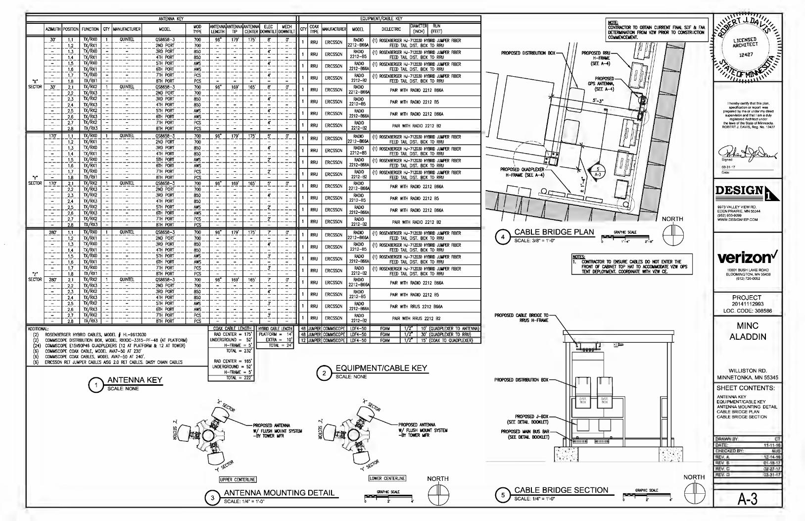
ANTENNA KEY EQUIPMENT/CABLE KEY
AZIMUTH POSmON FUNCTION QlY MANUFACTURER MODEL MOD lYPE
ANTENNA ANTENNA ANTENNA ELEC MECH QlY COAX MANUFAClURER MODEL LENGTH TIP CENTER DOWNTILT DOWNTILT lYPE DIELECTRIC
IDIAIAETERI RUN I (INCH) I (FEET)
_ _l!r _ 1.1 _"fYB_X_Q _ !.._ _ _g\!!.~!- ___ 9._~6~8.=;!___ 700 96" 179' 175' 8' -~-- 1 RRU ERICSSON RADIO (1) ROSENBERGER HJ-712030 HYBRID JUIIPER ABER __ -___ 1_J __ WB_X_! - - 2ND PORT - 700--------------_--r---:-- - -=-- I-+--+-----IF22:..;1:::,2--:'B~6:..;6A+---..:..;FE:ED:......:.TA"'IL::....:::DI::.:STc:... . ..:.BO:::cX:....li:..:Oc...;Rc::.R:::cU ____ ---1
1.3 TX/RXO - :- ---_--- ---JRDPoRT-- -850--------------r--~- RADIO (1) ROSENBERGER HJ 712030 HYBRID JUIIPER ABER ---- _1_J_ ::::w!x} ::::::: ::::::::::::-:=:::::::: ::::::::::::±:T[fo]f:::::::: - 850--------------r----- ---- 1 RRU ERICSSON 2212-85 FEED TAIL-DIST. BOX TO RRU ----- 1.5 TX/RXO - - 5TH PORT -AwS----_----_----_--r--~- - -:-- I-+--+-----II--::-RAD=I0--+-:-(1-:-)-ROS-EN..:..;BE=RG=-E....:.R:..::;HJ::....:.:71::.:20"-30=HYB:....R:..:ID'-'J"'"u"'IIPER--AB-ER-----I
:::::::::::::::: -H- =W;~~~ =~ ::::::::::::~ :::::::: ::::::::::::~~~:::::::: =~~::::::::::::::::::::::::::::::::::::::::::::::::::::::::~::::~ :::: :::::::::::::::: 1-1 +-R-RU--+_E_R_Ics_so_N-+-22-~_-B_1;_6A+-__ ..:..;FE:ED:......:.TA"'IL=--::.:DI::.:STc:... . ..:.BO:::.X:....li.:..:Oc....;Rc.::.R:.::.U ____ ---1
"X" --=-- 1.8 - lX/RXl - :- ---_--- ---BTHPoRT-- - PCS----_----_----_--r--:-- - -:-- 1 RRU ERICSSON 2212-B2 (1) ROSEN~~E~A~-~iir~BO~~~ ~~~PER ABER
~R~_~_.l=!r~_+--~~~L4~TX~/~R~~~-1~-o~u=~=L-~_-_-_~~~!~~~~~-~;!_-_-_+~~~--+~9~r~~16~r~-1~6~f+~8'~~-~~~-~--1 ~ ~~ ~ ~~~m2 ~
__ -___ 2_J_ ::::rxTXY./!RxX]2
::::::: ::::::::::::-:=:::::::: ---~Q.f~-- :::: ::::875~0 ::::::::::::::::-::::::::::::::::-:=::::::::::::-::::::::~::::~:::: - -=-- I-+--+-----II-2-21:-:2-::--B-:-6--t6A-----------------I ____ _2_J_ _ :_ ___ -:.___ ---~Q.fO.B!___ __ ·- _ -· r-· .,. __ 1 RADIO ---- _2_J_ ::::w!x] _ :_ ___ -:.___ _ __ !ltl_fO_ffr___ -550~- ---:_ -~---~--r-~-- --~- 1-+-R-RU--t_E_R_Ics_so_N + 2_2712:=_:=85--t ___ P_AIR_W_ITH_RAD_I0_22_12_B5 _____ ---I
----- _2_,?_ TX/RX2 _ :_ ___ -:.___ ---~Ttl_fO_ffr___ -AwS~-----:_ ------~--- r-~~- - -=~- 1 RRU ERICSSON RADIO PAIR WITH RADIO 2212 B66A ____ _2_,!)_ ::::w!x] _ :.. ----=--- ---~f@___ -'Aw-s~_ ---:_ -~---~--r-~-- --~- l-+--+-----lr-22_12_-B_6_6A+------------------I __ -__ _2_;]_ TX/RX2 - - 7TH PORT -PCS~- ---: __ ----~-- f-~~- --~- 1 ERICSSON RADIO
2.8 - lX/RXJ - :- ---_--- ---BTHPoRT-- - Pes- --_- - _-- - _-- - :-- - -:- RRU 2212-B2 PAIR WITH RADIO 2212 82
__ !7..Q' __ 1.:..! __ "JUB_~ _ !.._ _ _g\!!.~!- ---~!6~8.=;!_ ____ 7700qQ ___ J!r __ l7J __ l 7.L r-_[._ -~-- 1 RRU ERICSSON RADIO (1) ROSENBERGER HJ-712030 HYBRID JUIIPER ABER
1.2 _W!~ _ :.. ___ -:.___ ---~Q.f~-- 2212-B66A FEED TAIL DIST. BOX TO RRU ---- _1_.3_ TX/RXO - - 3RD PORT -850--------------r---~- ---- 1-+--+-----IFRA;.,.,;.DI~O~-(-)_......:..:=....::..:::::....=:::.:.:...:::::::....:..::....:.::.:::..... ____ --I
---- 1.4 ::::w!JIT - ;:- ---_--- ---4THPORT___ - 850----_-- --_----_--r--:-- =~== 1--1 +-R-RU--t_E_R_Ics_so_N +2_2-::-12:-=-,..,..8_5 +-1-ROS_EN..:..;~:~=.E....:.~A:..::;~:;...-::.:~i::.:~030"-" ..:.BO:::c~:....~:..:~c...;~c::.~:::c~PER--AB_ER-----1 ----- _1_.5_ TX/RXO - :- ---_--- ---5THPORT-- - AwS--------------r--z-- RADIO ()
---- 1.6 ::::w!JIT ::::::: ::::::::::::-:=:::::::: :::::::::::: ~f®:::: :::::::: - AwS--------------r---- :::::::::::::::: 1--1 +-R-RU--t_E_R_ICS_so_N+22--:-12:=-B-:-6-6A+-1~ROS-EN..:..;~:RG:=.E....:.~A"'~:;...-::.:~i::.:~030"-" ..:.BO:::c~:....~:..:~c...;~c::.~:::c~PER--AB_ER-----1 --=-- _ 1.:]_ TX/RXO - - 7TH PORT - PCS----_----_----_--r--z- - - 1 RADIO (1) ROSENBERGER HJ-712030 HYBRID JUIIPER ABER "y" t-- -:---:::--::---+---::'1.87-+--::TX:i:'()T.;RF:i::Xl;-t---.- +--- -:::--:::--=:-- ---+-- -_ - -=BTH:::':-i=Po:::-;-;.;RT;;-- -- ---+-----:P:::;CS:------t----:- --::;- ;-t--- ·--:-:_:=_;-_+----:-:--::;--+f--·--::-:---+-- -:-:::-----l-- 1--+-R-RU--t_E_R_Ics_so_N -+--22::-:1-:::2--:::B_2+-__ ..:..;FEED==.....:.TA"'IL::....:.:DI::.:STc:... . ..:.BO:::.X:....li.:..:Oc....;Rc.::.R:.::.U ____ ---1
SECTOR - 17..!!'- -~- _"JUB_~ _ !.._ _ _g\!!.~!- ---~!6~8.=;!_ __ --7700qQ ___ J!r __ l6J--l~Lr-_[._ -~-- 1 RRU ERICSSON RADIO•~• PAIR WITH RADIO 2212 B66A
-· 2.2 _W!~ _ :.. ___ -:.___ ---~Q.E~-- __ ·- _ -· r-· I-+--+-----II-2-21_2_-B_6-+""-----------------I --- _2_J_ TX/RX2 _ :_ ___ -:.___ ---~Q.fO.B!___ - 850 - --- --- --- -~- ---- RRU ERICSSON RADIO
----- 2.4 ::::w!~ - - 4TH PORT - 850----_----_----_--r--:-- - -:-- 1 2212-B5 ---- _2_,?_ TX/RX2 - :- ---_--- ---5THPoRT-- - AwS--------------r--z-- ---- 1-+--+-----11--::-RAD=I0-+-----------------1
PAIR WITH RADIO 2212 B5
---- 2.6 ::::w!~ ::::::: ::::::::::::-:=:::::::: :::::::::::: ~f®:::: :::::::: - AwS--------------r---- ---- 1 RRU ERICSSON 2212_B66A PAIR WITH RADIO 2212 B66A --=-- _2.L TX/RX2 - - 7TH PORT - PCS----_----_----_--r--z- - - -:-- 1--1 +--+-----11--::-RAD=Io--t-----------------1
-----2•8
- lX/RXJ - :- ---_--- ---BTHPoRT ___ - -pc:s----_----_----_--r--:-- - -:-- RRU ERICSSON 2212_B2 PAIR WITH RADIO 2212 82
_ 1_8_Q'_
---__ -__ ---__ -__ __ -__
"z" --_--
SECTOR _ 1_8_Q'_
---__ -__ ---__ -__ __ -__ ----
ADDmONAL:
1.1 _"JUB_X_Q _ !.._ _ _g\!!.~!- ---~!6~8.=;!___ 700 96" 179' 175' 7 -~-- 1 RRU ERICSSON RADIO (1) ROSENBERGER HJ-712030 HYBRID JUIIPER ABER _1_J __ WB_X_! _ :_ ___ -:._ __ ---~Q.f~-- - 700--------------r----- ---- I-+--+-----II-22_1::-:2--:::B-:::6_6A+-~-..:..;FE:ED:......:.TA"'IL::....:::DI::.:STc:... . ..:.BO:::cX:....li:..:Oc....;Rc::.R:::cU ____ ---1
1.3 TX/RXO - - 3RD PORT -850----_----_----_--r--~- - ERICSSON RADIO (1) ROSENBERGER HJ 712030 HYBRID JUIIPER ABER _ 1_J_ ::::w!x} - :- ---_--- ---4THPoRT-- - 850--------------r---- ---- 1 RRU 2212-85 FEED TAIL-DIST. BOX TO RRU
1.5 TX/RXO - :- ---_--- ---5THPoRT ___ - AwS--------------r--S - ---- I-+--+-----II---RAD-I0-+-(1_)_ROS_EN..:..;BE=RG=-E....:.R;.;;;HJ::....:.:71::.:20"-30=HYB:....R.:..:ID'-'Jc.::.U:.::.IIPER--AB-ER-----I
_ 1_,!)_ ::::w!x} - :- ---_--- ---STHPORT-- - AwS----_----_----_--r--:-- =~== 1--1 +-R-RU--t_E_R_Ics_so_N+22=-=12_-B:..;6..::6A+---..:..;FE:ED:......:.TA:..::;IL:;...-::.:DI::.:STc:... . ..:.BO:::cX:....li:..:Oc...;Rc::.R:::cU ____ ---1 1.7 TX/RXO - :- ---_--- ---lTHPoRT ___ - PCS--------------r--S - RADIO (1) ROSENBERGER HJ 712030 HYBRID JUIIPER ABER 1.8 - lX/RXl - :- ---_--- ---BTHPoRT-- - PCS----_----_----_--r--:-- - -:-- 1 RRU ERICSSON 2212-B2 FEED TAIL-DIST. BOX TO RRU
2.1 TX/RX2 _ !.._ _ _g\!!.~!- ---~!6~8.=;!___ 700 96" 169' 165' 7 _2.J_ ::::w!x] _ :.. ----=--- ---~Q.E~-- - 7oo--------------r----
2.3 TX/RX2 - - 3RD PORT -850----_----_----_--r--~-_2_J_ ::::w!x] -=- ---_--- ---4-rHP<>Rf-- - 850--------------r----
2.5 TX/RX2 - :- ---_--- ---5THPoRT ___ - AwS--------------r---.r-_2_,!)_ ::::w!x] - :- ---_--- ---6TH"P6Rf-- - 'Aw-s----_----_----_--r--:--
2.7 TX/RX2 - :- ---_--- ---lTHPoRT ___ - -pc:s--------------r--j'-2.8 -1X;"RX3 - :- ---_--- ---8THP<>Rf-- - -pc:s----_----_----_--r--:--
-~-- 1 RRU ERICSSON RADIO 2212-B66A
---- 1-+--+-----II-RA::-:-:::DI-:::0--t-----------------l - -=-- 1 RRU ERICSSON 2212-85 PAIR WITH RADIO 2212 85 ---- 1-+--+-----11----+------------------1 ---- 1 RRU ERICSSON RADIO PAIR WITH RRUS 2212 B66A - -=-- I-+--+-----II-22=-=12_-B:..;6..::6A+------------------I
RADIO - -:-- 1 RRU ERICSSON 2212_B2
PAIR WITH RADIO 2212 B66A
PAIR WITH RRUS 2212 B2
48 JUMPER COMMSCOPE LDF4-50 FOAM 1 2 1 0' QUADPLEXER TO ANTENNA) (2) ROSENBERGER HYBRID CABLES, MODEL # HL -9612030
COAX CABLE LENGTH RAD CENTER = 175'
UNDERGROUND = 52' H-FRAME = 5'
HYBRID CABLE LENGTH PLATFORM = 14'
EXTRA = 10' TOTAL- 24'
48 JUMPER COMMSCOPE LDF4-50 FOAM 1 2 30' QUADPLEXER TO RRU) (2) COMMSCOPE Dl5miBUTION BOX, MODEL RXXDC-3315-PF-48 (AT PLATIFORM) (24) COMMSCOPE E15V90P46 QUADPLEXERS (12 AT PLATIFORM & 12 AT TOWER) (6) COMMSCOPE COAX CABLE, MODEL AVA7-50 AT 230' (6) COMMSCOPE COAX CABLES, MODEL AVA7-50 AT 240'. (6) ERICSSON RET JUMPER CABLES AISG 2.0 RET CABLES. DAISY CHAIN CABLES
ANTENNA KEY SCALE: NONE
12 JUMPER COMMSCOPE LDF4-50 FOAM 1 2 15' COAX TO QUADPLEXER)
TOTAL= 232'
RAD CENTER = 165' UNDERGROUND = 52'
H-FRAME = 5' TOTAL - 222
PROPOSED ANTENNA W/ FLUSH IIIOUNT SYSTEM -BY TOWER MFR
I UPPER CENTERUNE I
0 EQUIPMENT/CABLE KEY SCALE: NONE
PROPOSED ANTENNA W/ FLUSH MOUNT SYSTEM -BY TOWER MFR
I LOWER CENTERUNE I
GRAPHIC SCALE
b I f. 1·
PROPOSED DISTRIBUTION BOX
'I
4 CABLE BRIDGE PLAN SCALE: 3/B"- 1'-0"
PROPOSED CABlE BRIDGE 1iO RRUS H-FRAIIE
PROPOSED DISIRIBt1110N BOX--..........
~ 1. CONJRACliOR TO ENSURE CABLES DO NOT ENTER THE
FRONT OF CABINET TOP HAT TO ACCOMIIODATE VZW OPS TENT DEPLOYMENT. COORDINATE WITH VZW CE.
\.
= t= DIST. - DIST. r-- = BOX BOX
ruu
CABLE BRIDGE SECTION GRAPHIC SCALE
SCALE: 1/4" = 1'-0" b I 1· 1·
I hereby certify that this plan, specification or report was
prepared by me or under my direct supervision and that I am a duly
registered Architect under the laws of the State of Minnesota.
ROBERT J. DAVIS, Reg. No. 12427
03-31-17
Date:
DESIGN~ 9973 VALLEY VIEW RD. EDEN PRAIRIE, MN 55344 (952) 903-9299 WWW.DESIGN1 EP.COM
verizon" 10801 BUSH LAKE ROAD
BLOOMINGTON, MN 55438 (612) 720-0052
PROJECT 20141112993
LOC. CODE: 308586
MINC ALADDIN
WILLISTON RD. MINNETONKA, MN 55345
SHEET CONTENTS: ANTENNA KEY EQUIPMENT/CABLE KEY ANTENNA MOUNTING DETAIL CABLE BRIDGE PLAN CABLE BRIDGE SECTION
DRAWN BY: CT
DATE: 11-11-16
CHECKED BY: MJS
REV. A 12-14-16
REV. B 01-18-17
REV.C 02-27-17
REV.D 03-31-17
A-3

(UP SLOPE FENCE)
1~ 4'-10"
1~ 4'-10"
1~ 8'-Q"
1~ 8'-Q"
1~ 8'-Q"
~ ~ ~ ~ ~ 4'-10" 4'-10" 12'-0" 6'-0" 6'-0" ,. ,. ,. GAlE
,. ,. (DOWN SLOPE FENCE)
PLATFORM COMPOUND NORTH ELEVATION SCALE: 1/8" = 1'-0"
VERIFY DIM\ W/PLATFORII
CANOPY
~ ...
z :i
~-T-:....:....:"F:"""t
15'-0"
5'-Q"
IliA. PIER FOOTING. ( 4) f4 GR. 60 REBAA W/12"f CIRCLE liES 0 12" O.C. (lYP.)
RRU H-FRAME
1~
~ ,.
GRAPHIC SCALE
I 1-
RRUS & QUADPLEXER H-FRAME ELEVATION SCALE: 1/8" = 1'-0"
--1·
4'-0" 4'-0" 4'-0" 6'-2"
,.!I~
'b I
;....
r
~ GRADE 0 EL 1070.00
PLATFORM COMPOUND EAST ELEVATION SCALE: 1/8" = 1'-0"
~ 4'-8" ~
1 1
QUADPLEXER H-FRAME
GRAPHIC SCALE
I f. 1·
UNDERGROUND CONDUITS THROUGH RETAINING WALL
GRADE 0 EL 1076.00±
I I I
I I I I I I I I I \.1 i I
'b I N PROPOSED PVC PIPE GWED ~ J I J WATERTIGHT, 24" RADIUS BENDS
I / I I WITH 22-1/'Z ELBOWS (lYP.) • I / / I ! I ,/ / / 1 I .,..,."'" ,i' /
It~~~~~---+~~~~~~~~:~:::::>\_ . L..., ~---------T--------- :':':~DU~ SCHEDULE 80
PROPOSED (3) UNDERGROUND CONDUITS, G.C, TO COORDINAlE W/ TOWER MANUFACTURER FOR PENEIRAliON THROUGH TOWER FOUND.\ liON
0 ~c~:;8~ ~~CABLE DETAIL
.llliE;, 1/ERSA-LOK SIWJ. BE STANDAAD UNIT, SPUT -FACE, COLOR GRAY.
RETAINING WALL DETAIL SCALE: 3/8" = 1'-0"
GRAPHIC SCALE
0
PROPOSED UNDERGROUND CONDUITS,
2'-8"
SEE ALSO SHEET W6
GRAPHIC SCALE
1'-4" 2'-8"
5'-4"
I hereby certify that this plan, specification or report was
prepared by me or under my direct supervision and that I am a duly
registered Architect under the laws of the State of Minnesota.
ROBERT J. DAVIS, Reg. No. 12427
03-31-17
Date:
DESIGN~ 9973 VALLEY VIEW RD. EDEN PRAIRIE, MN 55344 {952) 903-9299 WWW.DESIGN1 EP.COM
verizon" 10801 BUSH LAKE ROAD
BLOOMINGTON, MN 55438 {612) 720-0052
PROJECT 20141112993
LOC. CODE: 308586
MINC ALADDIN
WILLISTON RD. MINNETONKA, MN 55345
SHEET CONTENTS: ELEVATIONS MISCELLANEOUS DETAIL
DRAWN BY: CT
DATE: 11-11-16 CHECKED BY: MJS
REV. A 12-14-16 REV. B 01-16-17
REV.C 02-27-17
REV.D 03-31-17
A-4
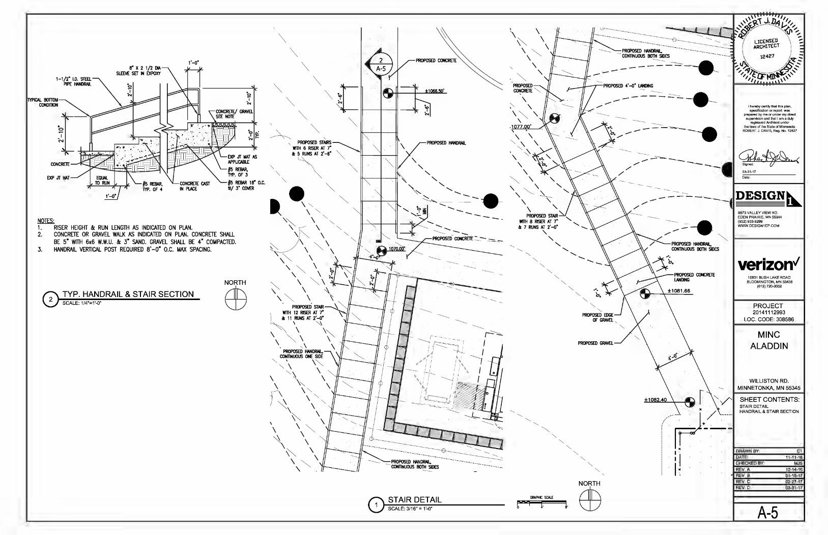
1-1 /2" I. D. STEEL PIPE HANDRAIL
lYPICAI.. BOTTOM CONDITION
1'-o·
TYP. HANDRAIL & STAIR SECTION SCALE: 1/4"=1'-0"
'b "j' ....
""' ""'
""' ""' " ~ ft----~:--+--'~ '
pROPOSEJ) STAIR WI1H 12 RISER AT 7"
11 RUNS AT 2' -o· \ ~
\ \ '" \ ~ \ \ " . ' \ \
PROPOSED HANDRAIL, "-. ~NUOUS ONE SIDE
"- \ \""' \ "- \ \
\ '" ', -r-\ \ "-) ~ ',""-
\ \
\ ""' \ \ ', ~ ~ \
""' \ \ ~ \ \ '
-----
-
---------- PROPOSED ~~~~--<----------- .
CONTINUOUS B01H SIDES ---------------.
\ \ ""' \ \ ~ \ \
\
·. ~ '
' " "" "-"-
"-
GRAPHIC SCALE
I f.
"-"-
"-"-
1.
-------. _,....--- --
" "
------
" PROPOSED EDGE OF GRAVEL ,
------
I hereby certify that this plan specification or report was'
prepared by me or under my direct supen?sion and that 1 am a duly
reg•stered Architect under the laws of the State of Minnesota
ROBERT J. DAVIS, Reg. No. 1242l
..... -:: - -------- ~\Jrrl~.h // --· Signed:~..(
03-31-17 - - lliDa;;;te:__;;__ ____ _
"
/------:___~~DESIGN~
-----
r
9973 VALLEY VIEW RD. EDEN PRAIRIE, MN 55344 {952) 903-9299 WWW.DESIGN1 EP.COM
verizon" 10801 BUSH LAKE ROAD
BLOOMINGTON, MN 55438 {612) 720-0052
PROJECT 20141112993
LOC. CODE: 308586
MINC ALADDIN
WILLISTON RD . ...___ MINNETONKA, MN 55345
SHEET CONTENTS: STAIR DETAIL HANDRAIL & STAIR SECTION
(~---rF-fJ. • . ( --_
I . . I . . . I I X • I I" ~~~------~ 1:
! I ·I DRAWN BY: · DATE: CT
11-11-16
I I CHECKED BY: I X ! ·, . REV.A
MJS 12-14-16
• REV.B 01-16-17 REV.C 02-27-17 REV.D 03-31-17
A-5
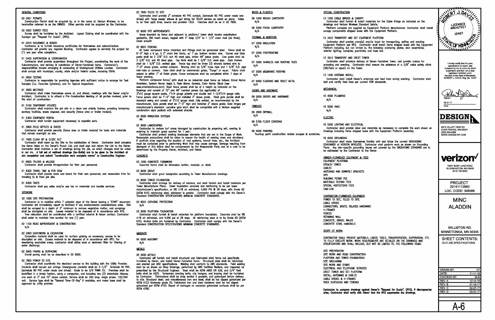
GENERAL CONDmONS
00 0001 PERMITS Construction Permit shall be acquired by, or in the name of, Verizon Wireless, to be
hereinafter referred to as the OWNER. Other permits shall be acquired by the Contractor.
00 0002 SURVEY FEES Survey shall be furnished by the Architect. Layout Staking shall be coordinated with the
Surveyor per "Request For Quote", (RFQ).
01 0010 INSURANCE & BONDS Contractor is to furnish Insurance certificates for themselves and subcontractors.
Contractor will provide any required Bonding. Contractor agrees to warranty the project for {1) one year after completion.
01 0400 SUPERVISION & COORDINATION Contractor shall provide supervision throughout the Project, coordinating the work of the
Subcontractors, and delivery & installation of Owner-furnished items. Contractor's responsibilities include arranging & conducting of Underground Utilities Locates. Contractor shall comply with municipal, county, state and/or federal codes, including OSHA.
01 0600 TESTING Contractor is responsible for providing Agencies with sufficient notice to arrange for Test
Samples (i.e.: Concrete Cylinders), and for Special Inspections.
01 2000 MEETINGS Contractor shall make themselves aware of, and attend, meetings with the Owner and/or
Architect. Contractor is to attend a Pre-Construction Meeting of all parties involved, prior to the start of construction.
01 5100 TEMPORARY UTILmES Contractor shall maintain the job site in a clean and orderly fashion, providing temporary
sanitary facilities, waste disposal, and security (fence area or trailer module).
01 5300 EQUIPMENT RENTAL Contractor shall furnish equipment necessary to expedite work.
01 5900 FIELD OFFICES & SHEDS Contractor shall provide security (fence area or trailer module) for tools and materials
that remain overnight on site.
01 7000 CLEAN UP & CLOSE OUT Contractor shall clean up the Site to the satisfaction of Owner. Contractor shall complete
the items listed on the Owner's Punch Ust, and shall sign and return the Ust to the Owner. Contractor shall maintain a set of drawings during the job, on which changes shall be noted in red ink. A full set of redlined drawings (As-Builts) are to be given to the Architect at Jab completion and submit "conslructian work complete memo" to Construction Engineer.
01 8000 TRUCKS & MILEAGE Contractor shall provide transportation for their own personnel.
01 8300 TRAVEL TIME & PER DIEM Contractor shall provide room and board for their own personnel, and reasonable time for
traveling to & from job site.
01 9200 TAXES Contractor shall pay sales and/or use tax on materials and taxable services.
.sJIEWQBK
02 1000 SITE PREPARATION Contractor is to mobilize within 7 calendar days of the Owner issuing a 'START' document.
Contractor will immediately report to Architect if any environmental considerations arise. Site shall be scraped to a depth of 3" minimum to remove vegetative matter, and scrapings shall be stockpiled on site. Excess material to be disposed of in accordance with RFQ.
Tree relocation shall be coordinated with a certified arborist & lessor contact. Contractor shall water to maintain tree survival for one (1) year.
02 1100 ROAD IMPROVEMENT & CONSTRUCTION N/A
02 2000 EARTHWORK & EXCAVATION Excavation material shall be used for surface grading as necessary; excess to be
stockpiled on site. Excess material to be disposed of in accordance with RFQ. For dewatering excavated areas, contractor shall utilize sock or sediment filter for filtering of water discharge.
02 5000 PAVING & SURFACING Gravel paving shall be as described in 02 8000.
02 7800 POWER TO SITE Contractor shall coordinate the electrical service to the building with the Utility Provider.
Conduits shall include pull strings. Underground conduits shall be 2-1 /2" Schedule 40 PVC. (schedule 80 PVC under roads and drives) Cable to be 3/0 THWN CU. Trenches shall be backfilled in a timely fashion, using a compactor, and including two (2) detectable ribbons; one each at 3" and 15" above conduit. Service shall be 200 amp, single phase, 120/240 volt. Service type shall be "General Time-Of-Day" if available, and meter base shall be approved by utility provider.
02 7900 TELCO TO SITE Contractor shall provide 2" schedule 40 PVC conduit, (schedule 80 PVC under roads and
drives) with 'large sweep' elbows & pull string for TELCO service as noted on plans. Cable to be fiber optic lines, source and provider T.B.D. Trenches shall be as in 02 7800.
02 8000 SITE IMPROVIEMENTS Areas bounded by fence and adjacent to platform/ tower shall receive polyethylene
geotextile, 200 mesh woven, topped with 3" deep 3/4" to 1 1/2" clean rock (no fines), raked smooth
02 8001 FENCING All tower compound fence materials and fittings shall be galvanized steel. Fence shall be
6' -0" high x 9 go. X 2" chain link fabric, w/ 7 go. bottom tension wire. Comer and Gate posts shall be 2 7 /8" O.D. sch 40 steel pipe, driven 48" below grade. Une posts shall be 2 3/8" O.D. sch 40 steel pipe. Top Rails shall be 1 5/8" O.D. steel pipe. Gate frames shall be 1 5/8" O.D. welded pipe. Fence top shall be three {3) strands barbed wire to 7' -o· above grade, canted outward. Bracing shall be 3/8" truss rods and 1 5/8" O.D. pipe mid-rails at corners. Gate latch shall be commercial grade, "Cargo" or equal. Fabric shall extend to within 1" of finish grade. Fence enclosures shall be completed within 7 days of tower erecting.
Platform compound fence/ gate shall be an industrial steel fence as follows: Brand Name: Ameristar, System Name: Aegis II, Style Name: Genesis, Color Name: Black (see www.ameristarfence.com). Steel fence panels shall be of a height as indicated on the Drawings and consist of 72" and 96" nominal panels (as applicable) of 3"x12 gauge square posts, 1"x14 gauge pickets and double wall 1-3/4"x14 gauge rails. Fence panels shall be 7' -0" high and installed 2" above grade. Steel gate panels shall be standard swing and consist of 3"x12 gauge steel, fully welded, as recommended by the manufacturer. Gate panels shall be 7' -o• high and installed 2" above grade. Gate hinges per manufacturer's standard. Lockable gate latch shall be compatible with a Verizon supplied combination style padlock with extended shackle.
02 8500 IRRIGATION SYSTEMS NA
02 9000 LANDSCAPING Contractor to restore turf areas damaged by construction by preparing soil, seeding &
watering to maintain grass survival for 1 year. Contractor shall protect existing landscape elements that are not in the Scope of Work.
Reasonable precautions shall be taken to assure the health of existing trees and shrubbery. If conflicts arise regarding the location of root systems, branch lines, etc., the Architect must be contacted prior to performing Work that may cause damage. Damage resulting from disregard of this Article shall be compensated by the Responsible Party and at a cost to be determined by the Property Owner, Architect, and Owner.
~
03 1000 CONCRETE FORMWORK Concrete forms shall be dimension lumber, modular, or steel.
03 6000 GROUT Contractor shall grout baseplates according to Tower Manufacturer drawings.
03 8000 TOWER FOUNDATION Contractor shall arrange for delivery of anchors, and shall furnish and install materials per
Tower Manufacturer Plans. Tower foundation concrete and reinforcing to be per tower manufacturer's specification, or 6% ±1% air entrained, 4,000 PSI 0 28 days, with Grade 60 (ASTM 615) reinforcing steel, whichever is greater. Contractor shall comply with the Owner's Standard CONSTRUCTION SPECIFICATIONS MINIMUM CONCRETE STANDARDS.
03 8001 CATHODIC PROTECTION N/A
03 9000 PLATFORM FOUNDATION Contractor shall furnish & install materials for platform foundation. Concrete shall be 6%
±1% air entrained, and 4,000 psi at 28 days. All reinforcing steel is to be Grade 60 (ASTM 615). Anchor bolts are furnished by Contractor. Contractor shall comply with the Owner's Standard CONSTRUCTION SPECIFICATIONS MINIMUM CONCRETE STANDARDS.
.M6S!lliBY
04 0000 MASONRY N/A
.MWLS.
05 0000 METALS Contractor will furnish and install structural and fabricated steel items not specifically
furnished by Owner, and install Owner-furnished items. Structural steel shall be fabricated and erected per AISC specifications. Welding shall conform to AWS standards. Field welding shall be as shown on Shop Drawings, performed by AWS Certified Welders, and inspected as prescribed by the Structural Engineer. Steel shall be ASTM A992 OR A36, and 3/4" field bolts shall be A325. Temporary erecting bolts, clip hangers, and bracing shall be furnished by Contractor. Fabrications shall be shop welded if possible, and galvanized before delivery to site. Structural steel, and miscellaneous iran and steel, shall be hot dipped galvanized per ASTM A 123 thickness grade 55. Fabricated iron and steel hardware shall be hot dipped galvanized per ASTM A153. Repair of damaged or uncoated galvanized surfaces shall be per ASTM A780.
WOOD &: PLASTICS
06 1 000 ROUGH CARPENTRY N/A
06 2000 FINISH CARPENTRY N/A
THERMAL & MOISTI!RE
07 2000 INSULATION N/A
07 2500 FIREPROOFING N/A
07 3000 SHINGLES AND ROOFING TILES N/A
07 5000 MEMBRANE ROOFING N/A
07 6000 FLASHING AND SHEET METAL N/A
DOORS AND HARDWARE
08 0000 DOORS AND HARDWARE N/A
WSI::IES.
09 2600 DRYWALL N/A
09 5700 FLOOR COVERING N/A
09 9000 PAINTING Touchup paint construction related scrapes & scratches.
SPECIAL CONSTRUCTION
13 1260 CABLE BRIDGE & CANOPY Contractor shall furnish & install materials for the Cable Bridge as indicated on the
drawings and Verizon Wireless Standard Details. Platform canopies are supplied by Equipment Platform Manufacturer. Contractor shall install
canopy components shipped loose with the Equipment Platform.
13 3423 TRANSPORT AND SET EQUIPMENT PLATFORM Contractor shall provide crane(s) and/or truck for transporting, setting and erecting
Equipment Platform per RFQ. Contractor shall install items shipped loose with the Equipment Platform including, but not limited to, the following: anchoring plates; stair assemblies; exterior lighting; canopies; guardrails; and buss bar.
13 3613 TRANSPORT AND ERECT TOWER Contractor shall schedule delivery of Owner-furnished Tower, and provide cranes for
unloading and erecting. Contractor shall ensure the existence of a 3/8" cable safety climb (DBI/Sala or equal) on the Tower.
13 1400 ANTENNA INSTALL Contractor shall install Owner's antennas and feed lines during erecting. Contractor shall
test and certify feed lines per current V7)ll standards.
MECHANICAL
15 4000 PLUMBING N/A
15 5000 HVAC N/A
.EI..WBik
16 5000 LIGHTING AND ELECTRICAL Contractor shall provide labor and materials as necessary to complete the work shown on
Drawings including items shipped loose with the Equipment Platform assembly.
16 6000 GROUNDING Contractor shall make themselves familiar with and follow the current GROUNDING
STANDARDS of VERIZON WIRELESS. Contractor shall perform work as shown on Grounding Plans. Any site-specific grounding issues not covered by the GROUNDING STANDARD are to be addressed by the Contractor to the Owner.
OWNER-FURNISHED EQUIPMENT &: FEES EQUIPMENT PLATFORM STIEALTH TOWER CABLES ANTENNAS AND DOWNTILT BRACKETS GPS BUILDING PERMIT FEE MATERIALS TESTING FEES SPECIAL INSPECTIONS FEES CAM-LOK
CONTRACTOR FURNISHED EQUIPMENT POWER TO SITE, TELCO TO SITE. CABLE BRIDGE CONNECTORS, BOOTS, RELATED HARDWARE H-FRAMES FENCES RETAINING WALL CONCRETE, GRAVEL WALKS CONCRETE STAIR, HANDRAILS
SCOPE OF WORK:
CONTRACTOR SHALL PROVIDE MATERIALS, LABOR, TOOLS, TRANSPORTATION, SUPERVISION, ETC. TO FULLY EXECUTE WORK. WORK REQUIREMENTS ARE DETAILED ON THE DRAWINGS AND SPECIFICATIONS AND SHALL INCLUDE, BUT NOT BE LIMITED TO, THE FOLLOWING ITEMS:
SITE PREPARATION SITE WORK AND ROAD CONSTRUCTION PLATFORM AND TOWER FOUNDATIONS SITE GROUNDING SITE WORK AND STAIRS ELECTRICAL AND TELEPHONE SERVICES ERECT TOWER AND SET PLATFORM INSTALL ANTENNAS & CABLES CABLE BRIDGE & H-FRAMES ROCK SURFACING AND FENCING
Contractor to compare drawings against Owner's "Request for Quote", (RFQ). If discrepancies arise, Contractor shall verify with Owner that the RFQ supersedes the drawings.
''''1 J ii'''' ,,~~~··········! ...... ~ £//., ~A~····· ···· .. ~-:, ~-4¥. .... .. ~
.: ! LICENSED \ ":: : ( ARCHITECT ) =
\ 12427 j :: ,_~\ ~ ... ~ ... ~ ···... ..···· .::::-., ··.... . ... ·· '
""/,;,'!;t;F······~·~·, \\\ ,,,
I hereby certify that this plan, specification or report was
prepared by me or under my direct supervision and that I am a duly
registered Architect under the laws of the state of Minnesota.
ROBERT J. OAVIS, Reg. No. 12427
03·31·17
Date:
DESIGN~ 9973 VALLEY VIEW RD. EDEN PRAIRIE, MN 55344 (952) 903·9299 WWW.DESIGN1EP.COM
verizon" 10801 BUSH LAKE ROAD
BLOOMINGTON. MN 55438 (612) 720·0052
PROJECT 20141112993
LOC. CODE: 308586
MINC ALADDIN
WILLISTON RD. MINNETONKA, MN 55345
SHEET CONTENTS: OUTLINE SPECIFICATIONS
DRAWN BY: CT
DATE: 11-11-16 CHECKED BY: MJS
REV. A 12-14-16 REV.B 01-18-17 REV.C 02-27-17 REV.D 03-31-17
A-6

~ ~~
I :I: c.... :z :i
SILT FENCE DETAIL SCALE: 1/2" = 1'-0"
ll!liE:. ALL CONSTRUCTION AND POST -coNSTRUCTION PARKING SHALL BE ON-SITE. NO ON-STREET PARKING, LOADING AND/OR UNL!WliNG IS ALLOWED.
---...__ ...__
...__
GRAPHIC SCALE
b I I· l·
I~UBUC SIDEWALKS SHALL NOT BE OBSTRUCTED. I
ll!liE:. STORAGE OF MATERIAlS AND/OR EQUIPMENT SHALL NOT BE ALLOWED ON PUBUC STREE1S OR WITHIN lHE PUBUC RIGHT-OF-WAY.
/
LEGEND: CONSTRUCTION UMIT - -SILT FENCE -x--x-
EXISTING CONTOUR -975---WATER RUNOFF DIRECTION ~
STOCK PILE LOCATION [ ODIJEI J WASH AREA U_7_7_7_7_z]
LESSEE ACCESS ----TEMPORARY CONSTRUCTION ---
.!IllES:. 1) INSTALL EROSION CONTROL PRIOR TO CONSTRUCTION AND
HAVE INSPECTED BEFORE Ntf GROUND DISTURBANCE. EROSION AND SEDIMENT CONTROLS SHALL BE MAINTAINED UNIIL PERMANENT GROUND COYER IS ESTABLISHED. ADDmONAL EROSION CON1ROI. TECHNIQUE & COMPLIANCE CONTACT MINNETONKA NAlURAI.. RESOURCES DMSION 952-988-8422
2) MAINTAIN EROSION CONTROL WHEN 1/3 FULL OF SEDIMENT. OR IF DAMAGED, INSPECT ONCE WEEKLY AND AFTER EVERY 1/2• RAIN EVENT.
3) TRACKING ON STREE1S OR OTHER PAVED SURFACES MUST BE SWEPT DAILY; ESPECIALLY PRIOR TO Ntf STORM EVENT OR WITHIN 24 HOURS AS REQUESTED BY Ntf CITY OR COUNTY OFFlCIAL Ntf OTHER SEDIMENT LEAVING lHE SITE SHALL BE REMOVED AND lHE ARE:A CLEANED AND RESTORED
4) STORM SEWER CATCHBASINS RECEMNG RUNOFF FRoM lHE SITE MUST BE PROTECTED WITH INLET PROTECTION. APPROVED MATERIAlS: BASKET (WIMCO), SACK-STYLE (SILT -SACK) DAM-STYLE (BEAVER-DAM) OR ROCK SNAKE BAG (MAY• REQUIRE A lYPE I RASHER IN TRAFFIC AREAS)
5) CONTAIN ALL CONCRETE TRUCK WASHOUT SWRRv AND SOLIDS IN A POLY-UNED PIT, SE"AI..ED ROLL -QFF CONTAINER OR TRUCK MOUNTED CONTAINMENT DEVICE. MAINTAIN BY PUMPING AND HAUUNG OFF UQUID AND EXCAVATING SOUDS AS REQUIRED. CONCRETE WASHOUT INTO lHE CITY srORM SEWER IS PROHIBITED.
6) TEMPORARY ROCK DRIVEWAYS SHOULD BE CONSTRUCTED IN LOCATIONS WHERE ENTERING lHE WORKSITE IS NECESSARY.
PROPOSED CONSTRUCTION UMIT /
/
GRAPHIC SCALE
b I 1b· b 2'
\
WATER TOWER 4525
WILLISTON ROAD
-
I hereby certify that this plan, specification or report was
prepared by me or under my direct supervision and that 1 am a duly
registered Architect under the laws of the State of Minnesota.
ROBERT J. DAVIS, Reg. No. 12427
03-31-17
Date:
verizon" 10801 BUSH LAKE ROAD
BLOOMINGTON, MN 55438 (612) 720-0052
PROJECT 20141112993
LOC. CODE: 308586
MINC ALADDIN
WILLISTON RD. MINNETONKA, MN 55345
SHEET CONTENTS: EROSION CONTROL PLAN &DETAILS
_.. DRAWN BY: CT
DATE: 11-11-16
CHECKED BY: MJS
REV.D 03-31-17
A-7

n
211POP
!083
/
GRAPHIC SCALE
GARDEN HOSE
3 GUYS OF 1 0 GAUGE lWISTED WIRE 120 DEGREES APART
AROUND TREE
TURNBUCKLE
4" SOIL SAUCER
24"x2"x2" STAKE DRIVEN FLUSH WITH FINISHED GRADE
PLANTING DETAIL SCALE: 1/8" = 1'-0"
2 1 /2" DIA. - 1 0' LONG CEDAR STAKE WITH NOTCHED END (7' EXPOSED), 2 PER TREE
FOLD BACK BURLAP FROM TOP OF BALL
2" MULCH
BACKFILL WITH TOP SOIL AND PEAT MOSS 3:1 RATIO BY VOLUME IN 9" LAYERS. WATER EACH LAYER UNTIL SETTLED
LOOSEN SUBSOIL
PLANDHG D£TA!L NOTES· 1) COORDINATE PLANTING WITH
EXISTING AND PROPOSED UNDERGROUND UTIUTIES.
GRAPHIC SCALE
,,, 1 J 1l ,,, ~~ .......... ! ...... ~ 'i/"
~_......... ·---------¥'~
/ LICENSED \ -::, ! ARCHITECT \
\.__ 12427 _§f -;~~~~,,~
I hereby certify that this plan, specification or report was
prepared by me or under my direct supervision and that I am a duly
registered Architect under the laws of the State of Minnesota.
ROBERT J. DAVIS, Reg. No. 12427
03-31-17
Date:
DESIGN~ 9973 VALLEY VIEW RD. EDEN PRAIRIE, MN 55344 (952) 903-9299 WWW.DESIGN1 EP.COM
verizon" 10801 BUSH LAKE ROAD
BLOOMINGTON, MN 55438 (612) 720-0052
PROJECT 20141112993
LOC. CODE: 308586
MINC ALADDIN
WILLISTON RD. MINNETONKA, MN 55345
SHEET CONTENTS: LANDSCAPING PLAN & DETAIL
DRAWN BY: CT DATE: 11-11-16 CHECKED BY: MJS REV. D 03-31-17
A-8

$ :,:. (9) en PIC CONDUIT - BY OTHERS- COORDINATE LOCATION 'IV ARCH.
I I I RETAINING Y'iALL PLAN
RET AININ6 r\ALL PLAN NOTES: I. COORDINATE THESE DR.AYiiN65 YiiTH ALL OTHER CONTRACT DOCUMENTS. IF
DISCREPANCIES ARE NOTED, CONTRACTOR SHALL RESOLVE PRIOR TO COMMENCEMENT OF CONSTRUCTION.
2. SEE ARCH 4 CIVIL DR.AYiiNGS FOR PRECISE r\ALL LAYOUT DRAYiiN65 4 TO VERIFY INFORMATION INDICA TED ON THESE DR.AYiiNGS.
9. r\ALL SHALL BE CONSTRUCTED YiiTH VERSA LOK STANDARD UNITS AND VERSAGRID 9.0 GEOGRID REINFORCING.
4. SEE MANJFACTLRER INFORMATION FOR ADDITIONAL CONSTRUCTION DETAILS. MANlfACTURER INFORMATION SHALL ACCOMPANY THE CONSTRUCTION PLANS.
RETAINING r\ALL PLAN NOTES: lNJ 5. 5EE SHEETS Yi2-~ FOR TYPICAL r\ALL DETAILS. 6. 5EE SHEETS m 4 Vie FOR r\ALL ELEVATION AND GEOGRID INFORMATION. i. 5EE SHEETS Yi'l-Yil2 FOR r\ALL NOTES. 8. TOP OF r\ALL ELEVATION INDICATED ON PLAN IS TO TOP OF LAST SEGMENTAL r\ALL
BLOCK. CAP BLOCK YiiLL ADD AN ADDITIONAL 9 5/8" TO FINISH HEIGHT. q, ELEVATION INSIDE COMPOUND INDICATED ASIOIO.OO'. VERIFY
I I I / I / I / I I I I I , 1/ v
11 /I
/
~I ~I -I ~I
.I li)l ~I
I I I I I I I I I I I I
/ /
/

/
PIN HOLES AND SLOTS FOR 9/4" SETBACK ;'\All CON5TRIJC,TION
14" .1'--v -----JV
1 IJ
[/
l
0 0
' 0 0 0 "' I' c=:::=:::> c=:::=:::>
~ m 161
,~TRAI GHT SPLIT FACE
L 12" /1
VERSA LOK Qj STANDARD UNIT
9/4• SETBACK
VERSA-TIJf PIN 2 PER UNIT
(J0 PINNING DETAIL
SPLITTING GROOVE FOR HALF UNIT
SPLITTING GROOVE FOR FREEST ANDING ;'\ALLS
PINNING SLOTS FOR FREESTANDING ~
3 l
/J
~ ~
0.48" DIA.
G0 VERSA-TUFF PIN
RANDOMLY STAGGER VERTICAL .!?INT5
Q0 BASE STEPPING DETAIL ~2 SCALE: NONE
tljijl i
:t11n f~!Uii Him~~ I m
II ~ ...:
~ j

ODD COURSES
STD. UNITS CfO DEGREE @INSIDE CORNER DTL.
V'!S SCALE: NONE
16" "".!'-v ------?t11v
12" "'.1'-v ---,r;Y
' !'
6-CAF 'N A-cAP
' ' 14" v
,II• ••: •• , ,, ,•, ... . .... ' . . . ... ·~·~ :;~ · .. ; .. ; .. :. :· ~· ~ ~
VERSA-LOK Ed§) STANDARD CAP UNITS ~S SCALE: NONE
NOTE: • FOLLOv.l GEOSYNTHETIC GRID
MANVFACTIJRERS INSTALLATION INSTRUCTIONS AND SPECIFICATIONS
• GEOGRID LEN6TH AND ELEVATION·
GE OG R I D PLACEMENT SHALL BE DETERMINED 6Y
. v.IALL DESIGN ENGINEER
@INSTALLATION DTL.
FOR STRAIGHT ViALLS, ALTERNATE A-cAP AND 6-CAP
A-cAP 6-CAP
RANDOMLY STAGGER VERTICAL JOINTS
CAPPING DETAIL @ @ STRAIGHT V'IALLS ~S SCALE: NONE

v H/4 v
1 1 ~~ .----.---...--.,....--,---.-"T""""""1'1"--.-....,.__,._......--.,,.._..,..........- - - - - l
INSIDE CORNER N01ES: • AT 51JB5EGUENT REINFORCEMENT
ELEVATIONS EXTEND REINFORCEMENT FROM OPPOSITE rtA1l FACE
• EXTEND REINFORCEMENT BEYOND rtA1l FACE A DISTANCE EGUAL TO 1/4 OF THE HEIGHT OF THE rtA1l (H)
I I I I
I I I
ALTERNATE THE EXTENSION OF REINFORCEMENT AT 51JB5EGI,OO REINFORCEMENT ELEVATIONS
~------~~----------------~~~ I I
I I ~
~------~----------------~X I
u
UJJ
ll]· ndf
u JJ" n • "'ll
~· ~ - - - (RoLL DIRECTIOW - - - - j _ U_i DIRECTION OF STRENGTH
CfO DEGREE INSIDE @ CORNER lA!/ REINFORCEMENT Y'44 SCALE: NONE
....:
[ili;J
!0 ~~
:z:ifi~ \D > -
~~i ~~
W4 )

CAP UNIT ADHERES TO TOP UNIT
NNERSA-LOK CONCRETE ADHESIVE
VERSA-LOK STANDARD MODULAR CONCRETE UNITS
6E05YNTHETIC REINFORCEMENT SEE ELEVATION ~IN6S FOR LEN6TH, TYPE, AND 5PACIN6
DRAINAGE AGGREGATE 12" THICK MIN.
•~REINFORCE!/ BACKFILL
COMPACTEII qs% OF MAXIMUM STANDARD PROCTOR DENSITY
r--~~-__,.,..__..:............,.
GRANULAR LEVELING PAD 24• ViiDE X 6• THICK MIN.
4 n DIA. (MINJ DRAIN PIPE OUTLET @ END OF ViALL OR @ 401 CENTERS MAX. SLOPE TO DRAIN (1/fl!FT J
TYP. REINFORCED @ IAlALL SECTION
CAP UNIT ADHERES TO TOP UNIT
YWERSA-LOK CONCRETE ADHESIVE
VERSA-LOK STANDARD MODULAR CONCRETE UNITS
DRAINA6E AGGREGATE 12" THICK MIN.
4 • DIA DRAIN PIPE OUTLET @ END OF ViALL OR @ 401 CENTERS MAX.
TYP. UNREINF. @ IAlALL SECTION
~~ .;;:~:;
j ~~ ~~ 8 ~ a;"'
::< iil ~ ~

6• TALL X 12• YiiDE CONe. BEAM Yi/ Yi/ (2) #5 BARS PLACED 2• ABOVE BOT. BEAM 4 MIN. 18• BRG. EA. END
CONCRETE HEADYiALL OR CUT MODULAR UNITS
6" TALL X 12" YiiDE CONe. BEAM Yi/ Yil (2) #5 BARS PLACED 2" ABOVE BOT. BEAM 4 MIN. 18" BRG. EA. END
NOTE: GEOGRID NOT SHOY'IN FOR CLARITY
FILTER FABRIC
FILTER FABRIC
V'iALL DETAIL V'iiTH @CONDUIT PENETRATION
J.Ai6 eGALE: NONE .
NOTE: I. MIN. 28 DAY CONC. STRENGTH = 4POO PSI 2. REINFORCING = A5TM A 615 Yi/ Fy = 60 KSI
MAX.
6• TALL X 12 11 YiiDE CONe. BEAM Yi/ Yi/ (2) #5 BARS PLACED 2'' ABOVE BOT. BEAM 4 MIN. 18 11 BRG. EA. END
CONCRETE HEADYiALL OR CUT MODULAR UNITS
6• TALL X 12• YiiDE CONe. BEAM Yi/ Yi/ (2) #5 BARS PLACED t ABOVE BOT. BEAM 4 MIN. 181 BRG. EA. END
V'iALL DETAIL V'iiTH @CONDUIT PENETRATION
J.Ai6 eGALE: NONE
W6

~ C)
I ~ ~ ~ 0
0!:
~ ~
1080
1015
10'10
1065
!= I~ I I ~ I~
:~ ~
0
95 ~ ~ I~ it fH
- VERSAGRID 9.0 X 4. LONG . ELEVATION IOiO.op• · · ·
(1\ RET. V'iALL ELEVATION ~ SCALE: 1/8• = 1•-on
ELEVATION NOTES: I. ELEVATION CHANGES OF TOP 4 BOTTOM OF ViALL BY STATION ARE
APPROXIMATE. ACTUAL STATIONS SHALL BE FIELD ADJJSTED FOR ACTUAL BLOCK DIMENSIONS AND FINISH GRADES.
2. MAXIMJM ELEVATION STEP AT BASE= 12•.

I
* -'F-'..S.'""·· 3.0 X 4.5\P~~ liD B~O X 4.5' LONG fA~ION 10"12.50' .lEr?t!A.-:,Qin BOX 4.C LONG- 11\lf"l~IL''"""' ...... -~ IO~I.oo' _ arEVATioN' 1o11.so' ~· VI'1I'~II,,-UKVI:J.I
. . . . . . . . . . . . . . . . ..... C)· . . . . . . . . . . . . . . . .RE'T ~· .... 1080
r:,~AI?F BEHIND\ . €· ~ B . 0. -~~·ft?. . . . ..... · R S ·~· 8 .. _
. . . . . . . . . ~· ~ ... . (). f!: ~ . . 8 -~:..__------\-+-+--1---+---.=:=--,· ~ ~ . II . ~ ~ . . tn 2 0.
- ·-· ·_· ._ ... '-- ~· ~-.......... ~~~~ a ~ .... ~ .... ·~. ~ § .. ~ .. 8 - 1---·---- ... - -. -. -. =-~ . --- 8h· . ~ 3: -;. b . ~
.___ .__: ' • II ~ . . . . . . . . . . . Q s::;. •, . ...
1- ~· - - - - - - ~ - - - - --- --- __!::, ~ s::; . r- ,.----·-- - - . . . . . . ~· . . r--:~ . :
10"15
1- - - - - -- I- - - - - ; - I- - - - - . . . . ........................
J . I . A
B.O.V-t-= IOM.50'
10"10
1065
~
@ ~~.1:,~_ALL ELEVATION ELEVATION NOTES: I. ELEVATION CHANGES OF TOP 4 BOTTOM OF AAU. BY STATION ARE
APPROXIMATE. ACTUAL STATIONS SHALL BE FIELD ADJJSTED FOR ACTUAL BLOCK DIMENSIONS AND FINISH GRADES.
2. MAXIMJM ELEVATION STEP AT BASE = 12".

SPECIFICATION FOR SEGMENTAL RETAINING ViALL SYSTEMS
PART 1: GENERAL
1.01 Description
A rbrk shall consist or fumlshlng materials, labor, equipment and supervision to Install a segmental retaining Viall s~stem In accordance rilth plans and speciFications and In reasonabl~ close conform!~ rilth the lines, grades, design and dimensions shorin on plans or established bl;j Orioor or Oriner's engineer.
1.02 Reference Standards A Segmental Retaining rt.:lll lh'llts
I. A5TM C 140- Sampling and Testing Concrete Maso~ lh'llts 2. A5TM C 1912 - Standard :peclrlcatlon for ~-cast Segmental Retaining rt.:lll lh'llts
6. Geos~thetlc Reinforcement I. ASTM D 45'15- Standard Test Method for Tensile Properties or Geotextlles bl;j the Wlde-rildth Strip
Method 2. ASTM D 5262 -Standard Test Method for Evaluating the lh'lconTined Tension Creep and Creep
Rupture Behavior or Geos~nthetics 9. ASTMD 5921- Standard Test Method For Determining the CoeFT!clent or Soli and Geos~thetlc or
Ge~nthetlc and Geos~thetlc bl;j Direct Shear Method · 4. ASTM D 5818 -Standard Practice for Exposure and Retrieval of Samples to Evaluate Installation
Damage or Geos~thetlcs 5. ASTM D 6106- Standard Test Method for Measuring Geos~thetlc Pvllovt Resistance In Soli
C. Solis I. ASTM D M8- Standard Test Method for Laborato~ Compaction Characteristics or Soli Using
Standard Effort 2. ASTM D 2481 - Standard Practice for Classification of Solis for Engineering Purposes 9. ASTM D 422- Standard Test Method for Particle-Size Anal~sls of Solis 4. ASTM D 4918 - Standard Test Method For Liquid Limit, Plastic Limit and Plastic!~ Index of Solis 5. ASTM G 51- Standard Test Method for Measuring pH or Soli for Use In Corrosion Testing
D. Drainage Pipe I. ASTM F 158 - Standard q:>eclflcatlon for Smooth-riall Pol~l~l Chloride (PVC) Plastic lh'lderdraln ~stems for Hlghria~, Airport or Similar Drainage
2. ASTM F 405- Standard :peclrlcatlon for Corrugated Pol~e~lene (PE) Pipe and Fittings E. Engineering Design
I. NCMA Design Manual For Segmental Retaining rt.:llls, Third Edition F. Where specifications and reference documents conflict, the riall Design Engineer shall make the final determination or applicable document.
1.09 Submittals A. Materials Submittals: The Contractor shall submit manufacturers' certifications &rio Yieeks prior to start of
riork stating that the SRI'i vnlts and geos~nthetlc reinforcement meet the requirements or Section 2 or this specification.
1.04 Dellve~, Storage and Handling A Contractor shall check materials upon dellve~ to ensure that the speciTied ~e and grade of materials
have been received and proper color and texture of SRI'i units have been received. 6. Contractor shall store and handle materials In accordance rilth manufacturer's recommendations and In a
manner to prevent deterioration or damage dve to moisture, temperature changes, contaminants, corrosion, breaking, chipping or other causes.
c. Contractor shall prevent excessive mud, Viet concrete, epoxies and similar materials that m~ affix themselves from coming In contact rilth materials. .
D. Contractor shall protect materials from damage; no damaged material shall be Incorporated Into the segmental Viall.
E. Ge~thetlc shall be protected from W exposure and the protective covering on geo~thetlc shall remain until Immediate!~ before Installation and shall be stored at temperatures above -10 degrees F.
PART 2: MATERIALS 2.01 Segmental Retaining vtlll lh'llts A. SRI'i units shall be machine formed, Portland cement concrete blocks specifically designed ror retaining Viall
applications. SRI'i units currently approved ror this project are: YERSA-LOK Standard 6. SRI'i vnlt faces shall be or straight geometry. c. SRI'i vnlt height shall be 6 Inches. D. SRW units shall provide a mlnlmvm rielght or 120 psf Viall Pace area. E. SRI'i vnlts shall be solid through the full depth or the vnlt. F. SRI'i units shall have a depth (front race to rear) to height ratio or 2:1, mlnlmvm. G. 5R1'i units shall be capable or being erected rilth the horizontal gap betrieen adjacent vnlts not exceeding
l/81nch. H. SRI'i units shall be Interlocked rilth connecting pins that provide B/4 Inch setback from vnlt belori (~Ieiding a
1-degree cant from vertical). I. SRI'i units shall be sound and free or cracks or other defects that Yiovld Interfere rilth the proper placing or
the unit or significant!~ Impair the strength or permanence or the structure. An~ cracks or chips observed during construction shall fall rilthln the guidelines outlined In ASTM C 1912.
J. Concrete SRI'i vnlts shall conform to the requirements or ASTM 1912 and have a mlnlmvm net average 28 da~ compressive strength or 9000 psi. Compressive strength test specimens shall conform to the sari-cut covpon provisions or ASTM Cl40.
K. SRW vnlt molded dimensions shall not differ more than + 1/8 Inch from that specified, as measured In accordance rilth ASTM c 140. This tolerance does not apply to architectural surfaces, such as split races.
2.02 Segmental Retaining Wall lh'llt Comectlon Pins A 5R1'i units shall be Interlocked rilth VERSA-Tuff comectlon pins. The pins shall consist or
glass-reinforced ~lon made for the expressed vse rilth the SRI'i vnlts supplied.
....:
W9
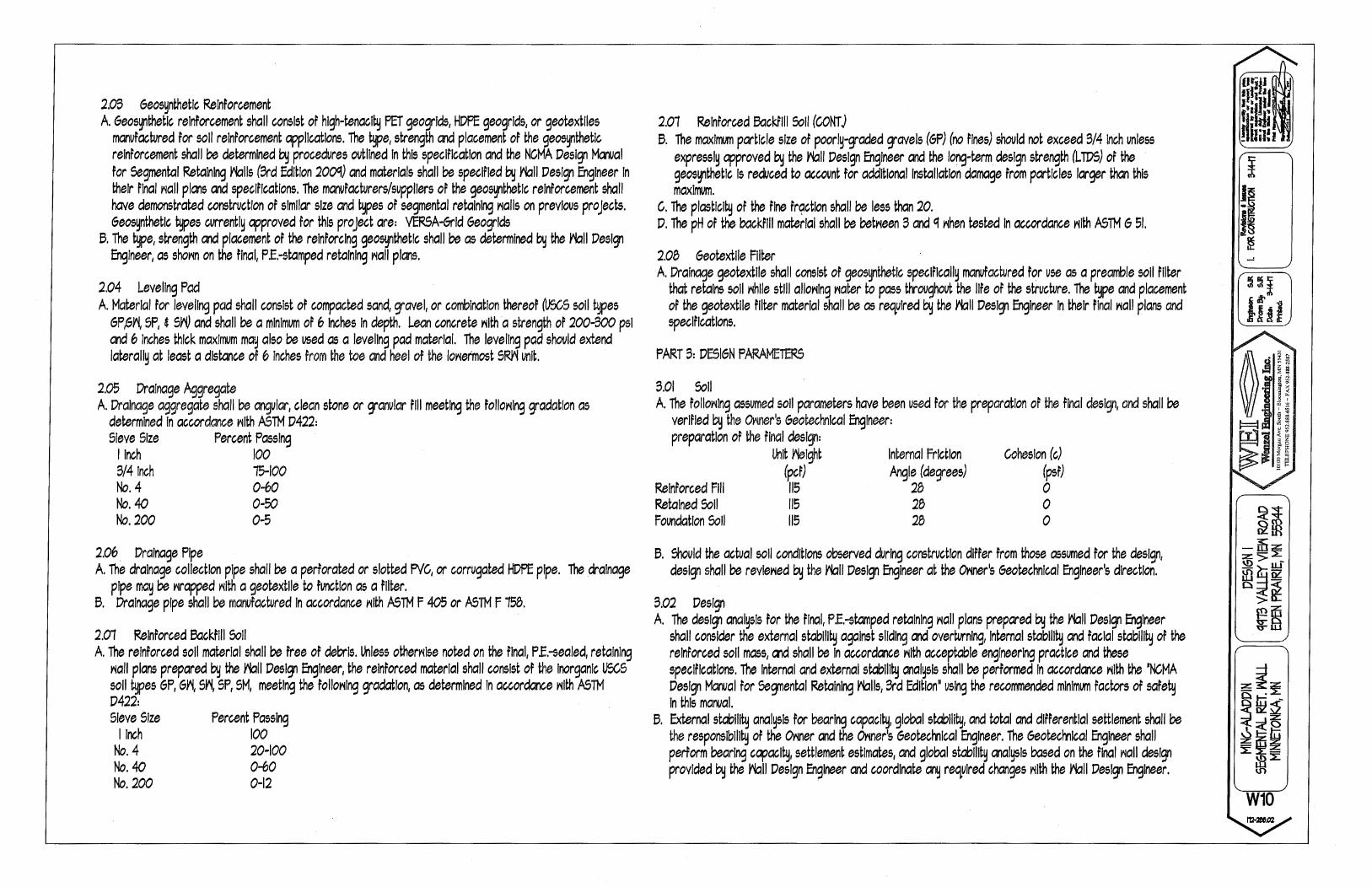
2.0B Geos~thetlc Reinforcement A Geos~thetlc reinforcement shall consist of hlgh-renacl~ PET geogrlds, HDPE geogrlds, or geotextlles
manufactured for soli reinforcement applications. The type, strength and placement or the geos~thetlc reinforcement shall be determined by procedures ovtllned In this specification and the NCMA Design Manual for Segmental Retaining rblls (Brd Edition 200GJ) and materials shall be specified by rbll Design Engineer In their final riall plans and specifications. The manufacturers/suppliers of the geo~thetlc reinforcement shall have demonstrated construction of similar size and ~pes or segmental retaining rial Is on previous projects. Geos~nthetlc types currently approved for this project are: VERSA-Grid Geogrlds
6. The type, strength and placement of the reinforcing geos~thetlc shall be as determined by the rbll Design Engineer, as shorin on the final, P .E.-stamped retaining rial I plans.
2.04 Leveling Pad A. Material for leveling pad shall consist or compacted sand, gravel, or combination thereof (USc,S soli types
GP,Gr\ SP, 4 S~ and shall be a minimum or 6 Inches In depth. Lean concrete rilth a strength or 200-BOO psi and 6 Inches thick maximum may also be used as a leveling pad material. The leveling pad shovld extend lateral!~ at least a distance of 6 Inches from the toe and heel of the loriermost SRY'i unit.
2.05 Drainage Aggregate A Drainage aggregate shall be angular, clean stone or granular fill meeting the follorilng gradation as
determined In accordance rilth ASTM D422: Sieve Size Percent Passing
linch 100 B/4 Inch 15-100 No.4 0-60 No. 40 0-50 No. 200 0-5
2.06 Drainage Pipe A. The drainage collection pipe shall be a perforated or slotted PVC, or corrugated HDPE pipe. The drainage
pipe may be rirapped rilth a geotextlle to function as a filter. 6. Drainage pipe shall be manufactured In accordance rilth ASTM F 405 or ASTM F 158.
2.01 Reinforced Backfill Soli A The reinforced soli material shall be free of debris. Lhless otherrilse noted on the final, P.E.-sealed, retaining
riall plans prepared by the rbll Design Engineer, the reinforced material shall consist of the Inorganic USC.S soli types GP, Gri, Sri, SP, SM, meeting the follorilng gradation, as determined In accordance rilth ASTM D422: Sieve Size
I Inch No.4 No.40 No. 200
Percent Passing 100 20-100 0-60 0-12
2.01 Reinforced Backfill Soli (CONT J 6. The maximum particle size or poorly-graded gravels (GP) (no rloos) shovld not exceed B/4 Inch unless
expressly approved by the rbll Design Engineer and the long-term design strength (L TDS) or the geos~thetlc Is reduced to account for additional Installation damage from particles larger than this maximum.
c. The plastic!~ or the fine fr~ctlon shall be less than 20. D. The pH of the backfill material shall be betrieen B and q rihen rested In accordance rilth ASTM 6 51.
2.08 Goorextlle Filter A. Drainage geotextlle shall consist or geosynthetlc speclflcall~ manufactured for use as a preamble soli filter
that retains soli rihlle still allorilng riater to pass throughout the life of the structure. The ~pe and placement or the geotextlle filter material shall be as required by the rbll Design Engineer In their final riall plans and specifications.
PART B: DESIGN PARAMETERS
B.OI Soli A. The follorilng assumed soli parameters have been used for the preparation of the final design, and shall be
verified by the CMoor's Geotechnical Engineer: preparation or the final design:
Reinforced Fill Retained Soli Foundation Soli
Lhlt ~lght (per)
115 115 115
Internal Friction Angle (degrees)
28 28 28
Cohesion (c) (psf) 0 0 0
6. :OOuld the actual soli conditions observed during construction differ Prom those assumed for the design, design shall be revleried by the rbll Design Engineer at the Orioor's Geotechnical Engineer's direction.
8.02 Design A The design anal~sls for the final, P .E.-stamped retaining ria II plans prepared by the rbll Design Engineer
shall consider the external stablli~ against sliding and overturning, Internal stablll~ and facial stabill~ of the reinforced soli mass, and shall be In accordance rilth acceptable engineering practice and these specifications. The Internal and external stablll~ anal~sls shall be performed In accordance rilth the •NCMA Design Manual for Segmental Retaining rblls, Brd Edition" using the recommended minimum factors or safe~ In this manual.
6. External stablll~ analysis for bearing capac!~, global stablli~, and total and differential settlement shall be the responsiblll~ of the Oriner and the Oriner's Geotecmlcal Engineer. The Geotecmlcal Engineer shall perform bearing capacl~, settlement estimates, and global stablll~ malysls based on the final riall design provided by the rbll Design Engineer and coordinate any required changes rilth the rbll Design Engineer.
~
~ ~~
%16~ \!) > -
~~i i~
W10

9.02 Design (CONTJ C. 11llle vertical spacing bet~een geogrld layers ma~ v~, It shall not exceed 2.0 feet maximum In the ~all
design. D. The geo~thetlc placement In the ~all design shall have 100% continuous coverage parallel to the ~all
face. Gapping be~een horizontal!~ adjacent layers of geos~nthetlc (partial coverage) ~Ill not be allo~ed.
PART 4:CON5TRUCTION 4.01 Inspection A. The O~ner or O~ner's Engineer Is responsible for verlf~lng that the materials supplied by the Contractor
meet all the requirements or the specification. This Includes all submittals for materials and design, qualifications and proper Installation or ~all s~stem.
6. Contractor's field construction supervisor shall have demonstrated experience and be qualified to direct all ~ork at the site.
4.02 Excavation A. Contractor shall excavate to the lines and grades sho~n on the project grading plans. Contractor shall
take precautions to minimize over-excavation. OVer-excavation shall be filled rilth compacted lnflll material, or as directed by the Viall Design Engineer, at the Contractor's expense.
6. Contractor shall verlf~ location or existing structures and utilities prior to excavation. Contractor shall ensure all surrounding structures are protected rrom the effects of riall excavation. Excavation support, If required, Is the responslblll~ or the Contractor.
4.0:3 Foundation Preparation A. Follorilng the excavation, the foundation soli shall be examined by the Oriner's Engineer to assure actual
foundation soli strength meets or exceeds the assumed design bearing strength. 5olls not meeting the required strength shall be removed and replaced rilth lnflll soils, as directed by the Oriner's Geotechnical Engineer.
6. Foundation soli shall be proof-rolled and compacted to CfS% standard Proctor dens!~ and Inspected by the Oriner's Geotechnical Engineer prior to placement or leveling pad materials.
4.04 Leveling Pad Construction
A. Leveling pad shall be placed as shorin on the final, P .E.-sealed retaining ria II plans rilth a minimum thickness of 6 Inches. The leveling pad should extend lateral!~ at least a distance or 6 Inches from the toe and heel of the lo~ermost 5RYi unit.
6. 6rarola leveling pad material shall be compacted to provide a firm, level bearing surface on rihlch to place the Tirst course of units. ~11-graded sand can be used to smooth the top 1/4 Inch to 1/2 Inch of the leveling pad. Compaction rill! be rilth mechanical plate compactors to achieve qs% or maximum standard Proctor dens!~ (ASTM D 6q8).
4.05 5RYi Unit Installation A. All 5RYi units shall be Installed at the proper elevation and orientation as shorin on the final, P .E.-sealed
riall plans and details or as directed by the Viall Design Engineer. The 5RYi units shall be Installed In general accordance ~lth the manufacturer's recommendations. The speclrlcatlons and drarilngs shall govem In any conflict be~een the ~o requirements.
6. First course of 5RYi units shall be placed on the leveling pad. The units shall be leveled side-to-side, front-to-rea and ~lth adjacent units, and allgwd to ensure Intimate contact ~lth the leveling pad. The first course Is the most Important to ensure accurate and acc.ep!:able results. No gaps shall be left betr-~een the front of adjacent units. Alignment ma~ be done by means of a string line or orrset from base line to the back of the units.
C. All excess debris shall be cleaned from top of units and the next course or units Installed on top of the units be Iori.
D. T~o VERSA-Tuff comectlon pins shall be Inserted through the pin holes of each upper-course unit Into receiving slots In lo~er-course units. Pins shall be full~ seated In the pin slot belori. Units shall be pushed for~ad to remove a~ looseness In the unit-to-unit comectlon.
E. Prior to placement or next course, the level and alignment or the units shall be checked and corrected ~here needed.
F. La~t of curves and comers shall be Installed In accordance ~lth the ~all plan details or In general accordance ~lth 5RYi manufacturer's Installation guidelines. Yialls meeting at corners shall be Interlocked by overlapping successive courses.
6. Procedures C. through F. shall be repeated until reaching top of riall units, just be Iori the height of the cap units. Geos~thetlc reinforcement, drainage materials, and reinforced backfill shall be placed In sequence ~lth unit Installation as described In Section 4.06, 4.07 and 4.08.
....:
W11

4.06 Geosynthetlc Reinforcement Placement A. All geos~nthetlc reinforcement shall be Installed at the proper elevation and orientation as shorin on the
final P .E.-sealed retaining Viall plan profiles and details, or as directed by the Viall Design Engineer. 6. At the elevations shorin on the final plans, (after the units, drainage material and backfill have been placed
to this elevation) the geosynthetlc reinforcement shall be laid horizontal!~ on compacted lnflll and on top or the concrete 5~ units, to rilthln I Inch or the front race or the unit be Iori. Embedment or the geosynthetlc In the ~ units shall be consistent rilth 5~ manufacturer's recommendations. Correct orientation or the geosynthetlc reinforcement shall be veriFied by the Contractor to be In accordance rilth the geos~nthetlc manufacturer's recommendations. The highest-strength direction or the ge~nthetlc must be perpendicular to the Viall face.
C. Geosynthetlc reinforcement la~ers shall be one continuous piece for their entire embedment length. Splicing or the geosynthetlc In the design-strength direction (perpendicular to the Viall race) shall not be permitted. Along the length or the Viall, horizontal!~ adjacent sections or geosynthetlc reinforcement shall be b.Jtted In a manner to assure 100% coverage parallel to the r-~all race.
D. Tracked construction equipment shall not be operated direct!~ on the geos~nthetic reinforcement. A minimum or 6 Inches or backTIII Is required prior to operation or tracked vehicles over the geos~nthetlc. Tumlng should be kept to a minimum. Rubber-tired equipment m~ pass over the geosynthetlc reinforcement at slor-~ speeds (less than 5 mph).
E. The geosynthetlc reinforcement shall be free or Yirlnkles prior to placement of soli fill. The nominal tension shall be applied to the reinforcement and secured In place rilth staples, stakes or by hand tensioning until reinforcement Is covered by 6 Inches or fill.
4.01 Drainage. Aggregate and Drainage Material Placement A. Drainage aggregate shall be Installed to the line, grades and sections shol'ln on the final P .E. =sealed
retaining Viall plans. Drainage aggregate shall be placed to the minimum thickness shorin on the construction plans betr-~een and behind units (a minimum of I cubic foot for each exposed square root or r-~all race unless otherrilse noted on the final Viall plans).
6. Drainage collection pipes shall be Installed to maintain gravlt~ Tlori or ~'later outside the reinforced-soli zone. The drainage collection pipe shall be Installed at the locations shorin on the final construction drarilngs. The drainage collection pipe shall da~llght Into a storm seVier or along a slope, at an elevation belori the loriest point of the pipe rilthln the aggregate drain. Drainage laterals shall be spaced at a maximum 40-foot spacing along the Viall face.
4.08 Backfill Placement A. The reinforced backfill shall be placed as shorin In the final Viall plans In the maximum compacted lift
thickness or 8 Inches and shall be corrpacted to a minimum or qs% of standard Proctor dens!~ (ASTM D M8) at a moisture content rilthin -1% point to +9% points or optimum. The backfill shall be placed and spread In such a ma11er as to eliminate Yirlnkles or movement of the geosynthetlc reinforcement and the 5~ units.
6. Onl~ hand-operated compaction equipment shall be alloried rilthln 9 feet of the back of the Viall units. Compaction rilthln the 9 feet behind the Viall units shall be achieved by at least three passes or a llghtrie191t mechanical tanper, plate, or roller.
c. At the end of each da~'s operation, the Contractor shall slope the last level or backfill aria~ from the Viall facing and reinforced backfill to direct Yiater runoff ariay from the Viall face.
4.08 Backfill Placement (CONT) D. At completion or Viall construction, backfill shall be placed level rilth final top of Viall elevation. If final
grading, paving, landscaping and/or storm drainage Installation adjacent to the Viall Is not placed Immediate!~ after Viall completion, tempor~ grading and drainage shall be provided to ensure Yiater runoff Is not directed at the Viall nor alloried to collect or pond behind the Viall until final construction adJacent to the Viall Is completed.
4.0GI s~caps A 5~ caps shall be proper!~ aligned and glued to underl~lng units rilth VERSA-LOK adhesive, a flexible,
. hlgh=strength concrete adhesive. Rigid adhesive or mortar are not acceptable. B. Caps shall overhang the top course or units by 9/4 Inch to I Inch. Slight variation In overhang Is alloried to
correct alignment at the top or the r-~all.
4.10 Construction Adjacent to Completed Viall A. The Oriner or Oriner's Representative Is responsible for ensuring that construction by others adjacent to
the Viall does not disturb the Viall or place tempor~ construction loads on the Viall that exceed design loads, Including loads such as l'later pressure, tempor~ grades, or equipment loading. He~ paving or grading equipment shall be kept Cl minimum or 5 feet behind the back or the r-~all face. Equipment rilth ~'!heel loads In excess of 150 psf live load shall not be operated Yilthln 10 feet of the race or the retaining Viall during construction ac!Jacent to the Viall. care should be taken by the General Contractor to ensure Yiater runoff Is directed at'-la~ Prom the r-~all structure until final grading and surface drainage collection s~stems are completed.
W12

GENERAL GROUNDING NOTES:
An external buried ground ring (Lead 1) shall be established around the equipment shelter and tower foundations. Lead 1 shall be kept 24" from foundations; if foundations are less than 48" apart, keep Lead 1 centered between them. If the tower base is over 20' -0" from the equipment shelter, a separate Lead 1 shall be established around each foundation, and the two Lead 1 s shall be bonded with two parallel leads at least 6 feet apart horizontally. Connections between the two Lead 1 s shall be bi-directional.
All subgrade connections shall be by exothermic weld, brazed weld, or gas-tight UL467-Iisted compression fittings pre-filled with anti-oxidant compound. Subgrade connections shall run be 'cold galvanize' coated.
Lead 1 shall be #2 solid bare tin-clad {SBTC) copper wire buried at local frost depth. Lead 1 bends shall be minimum 24" radius. 'Whip' lead bends may be of 12" radius.
Ground rods shall be galvanized steel, 5/8"121, spaced ten feet apart, or as shown. Rods shall be kept min. 24 inches from foundations. Ground rods are required to be installed at their full specified length. Depth shall be as shown in VZW standard detail booklet.
SPECIAL CONSIDERATIONS FOR GROUND RODS:
When ground rods are not specified to be backfilled w/ Bentonite Slurry: If boulders, bedrock, or other obstructions prevent driving of ground rods, the Contractor will need to have drilling equipment bore a hole for ground rod placement. Hole to be backfilled w/ Bentonite Slurry.
When specified with slurried Bentonite encasement, drilling equipment will be need to be used to be bore a hole for ground rod placement. Slurry shall be made from pelletized material {"Grounding Gravel"); powdered Bentonite is not allowed. If boulders, bedrock, or other obstructions are found, Contractor shall drill to the specified depth and provide Bentonite encasements.
Above-grade connections shall be by lugs w/ two-hole tongues unless noted otherwise, joined to solid leads by welding (T&B 54856BE •BROWN"}, self-threading (RECOGNIZED, EM 2522DH.75.312), or 10,000psi crimping (BURNDY YA3C 2TC 14E2}. Surfaces that are galvanized or coated shall have coating{s) removed prior to bolting. Bolts shall be stainless steel with flat washers on each side of the connection and a lock washer beneath the fastening nut. Star-tooth washers shall be used between lug & dissimilar metal {copper-to-steel, etc) but are not required between tin-clad CU lugs & tin-clad CU bus bars. Lug tongues shall be coated with anti-oxidant compound, and excess compound wiped clean after bolting. The connection shall then be coated with cold-galvanizing compound, or with color-matching paint.
Ground bars exposed to weather shall be tin-clad copper, and shall be clean of any oxidation prior to lug bolting.
Galvanized items shall have zinc removed within 1" of weld area, and below lug surface contact area. After welding or bolting, the joint shall be coated with cold galvanizing compound.
Ground Bgr !egds
Ground bars are isolated electrically from tower bottoms and equipment shelters by their standoff mounts. Leads from each ground bar to the ground ring shall be a pair of #2 SBTC, each connected to Lead 1 bi-directionally with #2 SBTC 'jumpers'. Pairs of #2 SBTC may be required between ground bars. Leads shall be routed to ground bars as follows:
• The Main Ground Bar (MGB), typically mounted inside on the equipment shelter 'back' wall. • The Entry Cable Port Ground Bars {ECPGB), mounted inside and outside on the equipment shelter walls beneath the transmission line part. Note: Transmission line grounds also attach to the ECPGBs. • The Transmission Line Ground Bar {TGB) mounted at the base of the tower to which the transmission line grounds are attached. Transmission line grounds also attach to the TGBs.
NOTE: Contractor shall confirm that TGBs exist at 75-foot vertical intervals on any guyed or self-support tower, and that transmission lines are grounded to each TGB. Only the bottom-most TGB is isolated from the tower steel frame; upper TGBs may use the tower steel frame as common ground, requiring no copper leads between TGBs.
#2 sere Whip !egds
"Whip" leads shall connect the buried external ground ring to the following items:
Monopole Towers: • Three whips to flanges on the monopole base, at least 90" apart. If none are provided, attach to the baseplate or consult tower manufacturer.
Self-Support Towers: • Two whips to flange(s) on each tower leg base. If none are provided, attach to the baseplate or consult tower manufacturer.
Guyed Towers: • Two whips to flange(s) on the tower base. If none are provided, attach to the baseplate or consult tower manufacturer. • Establish a Lead 1 within the fence enclosure of each guy anchor, at least 40 foot perimeter and having 4 ground rods. • #2 SBTC leads shall extend up, and be clamped {bronze clamshell or equal), to any two guy wires. NEVER weld leads to the guy wires. The lead to the guy anchor 'hand' plate may be welded.
~ Metallic fence within 25 feet of tower Lead 1, or within 6 feet of shelter lead 1, shall have whip leads as follows: • Each corner post. • Each pair of gate posts. • Any line post over 20' -0" from a grounded post. • Each gate leaf to its respective gatepost using braided strap (3/ 4", tin-clad copper w/ lug ends). • Fences around guy anchors shall be grounded in similar fashion.
Fuel tanks: NEVER WELD to any fuel enclosure. NEVER penetrate the fuel containment. Metal tanks shall have one whip lead attached. Use an approved clamp or two-hole lug on an available flange.
Equipment Shelter and other General Requirements: • Extend new Lead 21 B up to shelter halo, remaking two-way connections as needed. Generator-equipped shelters have 6 such connections. Connections within the shelter shall be by compression; NEVER weld inside the shelter. • Each vertical support pipe of the exterior cable bridge. Bridge end shall be kept at least 6" from the tower structure. The cable bridge shall be jumpered to the vertical support pipes with #2 SBTC at each vertical support pipe. • Opposite comers of the roof shield over the equipment shelter. • Each HVAC unit shield, if separate (may be 'jumpered' to main roof shield). • Each HVAC package unit. • Commercial electric meter box. • Generator receptacle, if present. • Steel building skid, if shelter is metal frame. • Each air intake or exhaust fan vent louver. • Each generator vent hood or louver. • Generator exhaust stack, external. • Opposite comers of generator support frame, if separate from shelter. • Generator fuel tank, if separate from generator unit. • Host building rain gutter, downspouts, and roof flashings within 25 feet. • Telco MPOP (Main Point of Presence), if external to equipment shelter. • Within cable vaults, one each to the ladder and to the manhole rim.
Note: The door frame is connected to the interior ground halo, and need no separate connection to the external ground ring.
Inspection &: Testjng Test lead #1 and ground rods after installation but before backfilling or connecting to any other grounding, using the 3-point fall of potential method. Contractor to notify Verizon Wireless senior construction engineer at least 48 hours prior to testing. Document installation and test results with photographs.
SYMBOL AND NOTE LEGEND
---(!)--- #2 SBTC AROUND SHELTER, TOWER, OR GUY ANCHOF
e 5/B" X 10'-0" GALVANIZED STEEL GROUND ROD
® TEST WELL PREFERRED LOCATION
#2 SBTC 'WHIP' LEAD
:::®:= (2) #2 SBTC FROM MGB, PGB, OR TGB TO LEAD 1
® AC HVAC UNIT
<ill) BC BUILDING CORNER
® BO BOLLARD
® CBS CABLE BRIDGE SUPPORT POST
® FAN GUY ANCHOR PLATE
® FP FENCE POST
0 GP GATE POST, 3/4" BRAID STRAP TO LEAF
@ GUY GUY WIRE, MECH. CLAMP ONLY - NO WELDS
@ HL HOOD OR LOUVER
@ HB OUTSIDE OF HOFFMAN BOX
@ EM COMMERCIAL ELECTRICAL METER
@ EL ELECTRICAL SERVICE GROUND
@ MU GENERATOR MUFFLER
@ RBR FOUNDATION REINFORCING
@ RS ROOF SHIELD
@ SB STEEL BEAM
@ SP STEEL POST
@ TEL HOFFMAN BOX
@ TWR TOWER BASE
@ VP DIESEL FUEL VENT PIPE
~ Contractor to provide #2 solid bare tin-clad {SBTC) copper wire lead from # 1 ground ring to air conditioner & ice shield if provided by VZW.
~ TOP VIEW
LEAD IPENDACATION c!c PESCRIPDON: 25 RING TO NEAREST LIGHTNING ROD #2 SBTC 26 LGHTNG ROD SYS TO NEARBY MTL NFPA 780
1 RING, EXTERNAL BURIED w/ RODS #2 SBTC 27 RING TO TOWER RING {2) #2 SBTC 1A RING, CONCRETE ENCASED #2 SBTC 28 RING TO SHELTER RING (2) #2 SBTC 2 DEEP ANODE {TO IMPROVE OHMS) ROD OR PIPE 29 BRANCH AC PNL TO BTTY CHG FRM NSTD33-11
3 RING TO BLDG STL FRAME #2 SBTC 30 BRANCH AC PNL TO OUTLETS NSTD33-11
4 MAIN AC PANEL NEUTRAL BUS TO {2) GROUND 31 MGB/FGB TO PWR, BTTY FRAMES #2/0 1-STR
RODS, ISOLATED FROM LEAD #1 NEC 250.66 32 #31 TO BATTERY CHARGER FRAME #6 1-STR
5 RING TO GROUND BAR (2) #~ SBTC 33 #31 TO BATTERY RACK FRAME #6 1-STR
6 RING TO EXT MTL OBJECT #2 SBTC 34 f31 TO PCU FRAME f6 1-STR
7 DEEP ANODE TO MGB NSTD33-9 35 #31 TO DSU FRAME #6 1-STR
B AC PANEL TO WATER METER NEC 250.66 36 #31 TO PDU FRAME #6 1-STR 9 EXT WATER TO INT WATER PIPES NSTD33-9 37 MGB/FGB TO BTTY RETURN NSTD33-14.5
10 INT WATER PIPE TO MGB NSTD33-9 37A MGB/FGB TO RTN TERM CARR SUPP #6 1-STR 11-12 NOT USED 38 FGB TO PDU GB i750MCM 1-STR 13 AC PANEL TO MGB NSTD33-9 3BA FGB TO PDU GB CARRIER SUPPLY #2/0 1-STR 14 MGB[FGB TO BLDG STL FRAME f2[0 1-STR 39 DC BUS DUCT TO NEXT SECTION #6 1-STR 14C MGB/FGB TO ROOF /WALL MTL PNL #1/0 1-STR 40 DC BUS DUCT TO MGB/FGB #6 1-STR 15 MGB/FGB TO FGB-HE SAME FLOOR #2/0 1-STR 41A MGB/FGB TO #58 #2/0 1-STR 16 NOT USED 42-44 NOT USED 16A ECPGB TO CABLE ENTRY RACK #1/0 1-STR 45 t.WN AC PNL TO BRANCH AC PNL NSTD33 11 17 MGB TO CABLE SHIELDING #.6 1-STR 46 BRANCH AC PNL TO OED OUTLET NSTD33-11 17 A ECPGB TO CABLE SHIELDING #6 1-STR 4 7 FGB TO INTEG FRM #2 1-STR 17B MGB/FGB TO F-0 SPLICE SHELF #1 1-STR 48 LEAD #31 TO INTEG FRM #6 1-STR 18 LOWEST MGB/FGB TO HIGHEST FGB #2/0 1-STR 49 INTEG FRM TO EQUIP SHELF BY FASTENERS 19 LEAD 1 B TO OTHER FGBs, <6' #2/0 1-STR 50 PDU BTTY RET TO #51 #2/0 1-STR 20 MGBLFGB TO BRANCH AC PNL f6 1-STR 51 #50 TO TRANS FRM ISO DC PWR #6 1-STR 20A NEAREST GRND TO DISCONNECT PNL NEC 250.66 52 TRANS FRM FUSE TO FRM OR BAR #B 1-STR 20B GWB TO AC DISTR PNL #6 1-STR 53A MGB/FGB TO PDF /BDFB NSTD33-22 21 MGB/FGB TO INT HALO #2 1-STR 54 MGBLFGB TO STATIC DEVICES f6 1-STR 21A INTERIOR 'GREEN' HALO #2 1-STR 55 MGB/FGB TO CABLE AT ENTRY #6 1-STR 2lll ltil t!ALQ IQ EliT BI~G 12 Sll!C 56 MGB/FGB TO AC PWR RADIO XtmR #6 1-STR 21 C INT HALO TO EQUIPMENT MTL #6 1-STR 57A MGB/FGB TO CBL GRID/RUNWAY #2/0 1-STR 22 ROOF TOWER RING TO ROOF GRND NFPA 780 5BA #41 A TO AISLE FRAME #2 1-STR 23 MGB/FGB TO ECPGB, SAME FLOOR #1 1-STR 59A #5BA TO EACH SGL FRAME GRND #6 1-STR 23A MGB/FGB TO CXR-HF LINR PROT #6 1-STR 60-89 NOT USED 24 ECPGB TO EACH PROTECTOR ASSEMBLY #6 1-STR 90 GENERATOR FRAME TO EXT RING #2 SBTC 24A LOWER PROT ASSY TO UPPER #6 1-STR
NOTE: REMOVE GALVANIZING FROM 'a 'a FENCE POSTS IN AREAS LUGS WILL rv """ BURNDY BE INSTALLED. LIGHTLY COAT THE e e YA6C 2TC 14 UNDERSIDE OF THE LUGS W/ ANn-OX COMPOUND BEFORE ~ ~ CRIMP LUG
ATTACHING TO POSTS. r= r= BELDEN
prrnO v 1/2"fl) I.D. TUBULAR BRAIDED
SIDE VIEW STRAP
rn 1WO-HOLE 10,000 PSI COMPRESSION FtmNG
UL 9498 LISTED
GATE BONDED TO FENCE POST (2) 1WO-HOLE 10,000 PSI COMPRESSION FlmNG w/ 3/4" BRAIDED TINNED COPPER JUMPER STRAP
HYTAP CONNECTOR 10,000 PSI COMPRESSION FtmNG FlmNG MUST BE UL467 LISTED ACCEPTABLE FOR DIRECT BURIAL
2 COMPRESSION CONNECTOR DETAILS SCALE: NONE
~TYPE RJ
;iLJI] WELD: THOMAS & BETTS, 54856BE "BROWN33• CRIMP: BURNDY. YA3C 2TC 14E2, 10,000 PSI SCREW: RECOGNIZED, EM 2522DH.75.312
4r~\ TYPE RR
REINF. BAR TYPE VS
ROUND SURFACE TYPE VS
FLAT SURFACE TYPE HS TYPE GT TYPE PT TYPE GL LUG
EXOTHERMIC WELD DETAILS SCALE: NONE
''''1 J ii'''' ,,~~~ .......... ! ...... ~.,, .... .... ~~~.... ····.~-=-~-~...... .... •.. ~
.: ! LICENSED \ ":: : ! ARCHITECT \ = - ' ' -\ 12427 .! :: ~~··· ...... .... ~~ ........ ,;,'!;t;F~~,,,
I hereby certify that this plan, specification or report was
prepared by me or under my direct supervision and that I am a duly
registered Architect under the laws of the state of Minnesota.
ROBERT J. OAVIS, Reg. No. 12427
03·31·17
Date:
DESIGN~ 9973 VALLEY VIEW RD. EDEN PRAIRIE, MN 55344 (952) 903·9299 WWW.DESIGN1EP.COM
verizon" 10801 BUSH LAKE ROAD
BLOOMINGTON, MN 55438 (612) 720·0052
PROJECT 20141112993
LOC. CODE: 308586
MINC ALADDIN
WILLISTON RD. MINNETONKA, MN 55345
SHEET CONTENTS: GROUNDING NOTES
DRAWN BY: CT
DATE: 11-11-16 CHECKED BY: MJS
REV. A 12-14-16 REV.B 01-18-17 REV.C 02-27-17 REV.D 03-31-17
G-1

PROPOSEDJ FUTURE
GENERATOR
r----1 r----------l I ~ i I I ,J
~ P I ?"I I
~ I I I I
'I I I \ I I
PROPOSED EQUIPMENT CABINETS TO BE GROUNDED PER MANUFACTURERS SPECS
AND ATTACHED TO MAIN BUSS BAR
I
I I I I I I I I I
I I I I I I I I I I I I
I I I I I I I • I I I I I I I I I I
PROPOSED GROUND~# RODS 20' -o· o.c. I OR IS SHOWN I
I I
I I I I I I I I I I
I I I I I I I I I I I I I I I I I I I I I I I I I I I I I '
PROPOSED GROUND LEAD FROM MAIN BUSS BAR TO TOWER BUSS BAR, FOUDW CABLE ROI1IE
GROUNDING PLAN SCALE: NONE
TEST WELl PREFERRED
LOCA110N
,,, 1 J J'\ ,,,
GROUNDING DETAIL INDEX ,,~~~ .......... !.~1.£..'.-,. 1---------------------c-~~~.... ····.~-=-
DETAIL DETAIL DESCRIPTION (l'/ \ ~
/ LICENSED \ ..,. PLATFORM 9'-4" X 14'.{)" PLATFORM W/ CANOPY GROUNDING ELEVATIONS l ARCHITECT l
11.1 TESTWELLDETAILGROUNDRING&RODDETAIL \ 12427 j".q:::
11.3 REBARGROUNDINGDETAIL -=-~···.... . ... ~; 1---1-1-.4-+-C-O_N_D-UI_T_D_ET_A-IL----------------1 ".-;:,rtF~~\\'
11.5 TYPICAL GROUNDING CABLE BRIDGE DETAIL
11.6 TYPICAL TOWER GROUNDING DETAIL
NOTE:
TEST WELl PREFERRED LOCA110N
CONTRACTOR SHAll ENSURE THAT E:ACH WHIP IS ROUTED TO LEAD 1 BY THE SHORTEST PATH, AND BENDS SHAll NOT BE LESS THAN 12" RADIUS
I hereby certify that this plan, specification or report was
prepared by me or under my direct supervision and that I am a duly
registered Architect under the laws of the state of Minnesota.
ROBERT J. OAVIS, Reg. No. 12427
03·31-17
Date:
DESIGN~ 9973 VALLEY VIEW RD. EDEN PRAIRIE, MN 55344 (952) 903-9299 WWW.DESIGN1EP.COM
verizon" 10801 BUSH LAKE ROAD
BLOOMINGTON, MN 55438 (612) 720-0052
PROJECT 20141112993
LOC. CODE: 308586
MINC ALADDIN
WILLISTON RD. MINNETONKA, MN 55345
SHEET CONTENTS: GROUNDING PLAN GROUNDING DETAIL INDEX
DRAWN BY: CT DATE: 11-11-16 CHECKED BY: MJS REV. A 12-14-16 REV.B 01-18-17 REV.C 02-27-17 REV.D 03-31-17
G-2
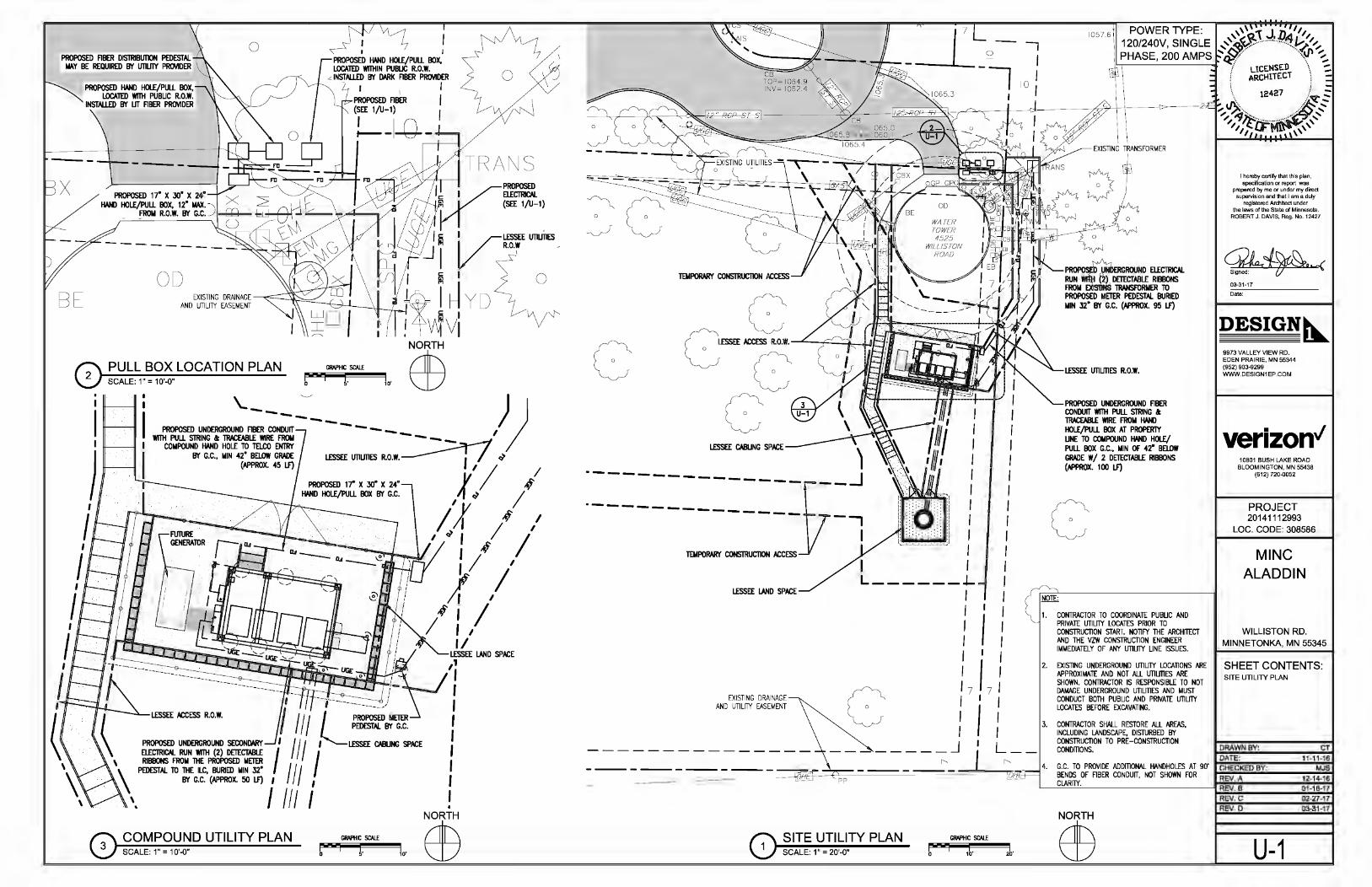
0 ~ ! I PROPOSED ABER DISTRIBUTION PEDESTAL
MAY BE REQUIRED BY UTILRY PROVIDER \j PROPOSED .W.D HOlE/PULL BOX, LOCAlED WITHIN PUBLIC R.O.W •
BE
PROPOSED .W.D HOlE/PULL BOX, LOCAlED WITH PUBUC R.O.W.
INSTALLED BY UT ABER PROVIDER
---
OD
.<: INSTALLED BY DARK ABER PROVIDER
I I I PROPOSEDABER I (SEE 1/U-1) I
L--1-G--TRANS
0 PULL BOX LOCATION PLAN SCALE: 1" = 10'-0"
GRAPHIC SCALE
5' 10' 0
I
I 11---~-11
IH----'----'-rl I 11'---~-11
)
\_ _:__ ) PROPOSED UNDERGROUND A: :NDUIT ---- I
WITH PULL STRING a: TRACE:ABLE WIRE FROM - - - - I COMPOUND .W.D HOLE TO TaCO ENTRY -~
BY G.C., MIN 42" BELOW GRADE LESSEE UTIUTIES R.O.W. --------1: I ~ (APPROX. 45 L.F) I I I
)'.. / ~~ l,f /
I I ,f I 0.,_~ I I I
/. I ,f : II
I I I
1/
I
0 ~~~~~~-a~D UTILITY PLAN ffi GRAPHIC SCALE
5' 10'
c TEMPORARY CONSTRIJC1JON ACCESS
c c~-=onw. c c
---------------·--------------
TEMPORARY CONSTRUCTION ACCESS
EXISTING DRAINAGE AND UTILITY EASEMENT
----------------- ~-
I I I I I I I I I I
I I L------~
I I I I I I 17 I I I
________ j
I
I
I I I I I I I I I I I I I I I I I I I
17 : I I
I : L __
SITE UTILITY PLAN GRAPHIC SCALE
SCALE: 1" = 20'-0" I 1b· l·
PROPOSED UNDERGROUND ABER CONDUIT WITH PULL STRING a: TRACE:ABLE WIRE FROM .W.D HOLE/PULL BOX AT PROPERTY UNE TO COMPOUND .W.D HOLE/ PULL BOX G.C., MIN OF 42" BELOW GRADE W/ 2 DETECTABLE RIBBONS (APPROX. 100 L.F)
c 1. CONTRACTOR TO COORDINATE PUBUC AND
PRIVATE UTILRY LOCATES PRIOR TO CONSTRUCTION START. NOTIFY THE ARCHITECT AND THE VZW CONSTRUCTION ENGINEER IMMEDIATELY OF ANY UTILRY UNE ISSUES.
2. EXISTING UNDERGROUND UTILRY LOCATIONS ARE APPROXIMATE AND NOT ALL UTIUTIES ARE SHOWN. CONTRACTOR IS RESPONSIBLE TO NOT DAMAGE UNDERGROUND UTILmES AND MUST CONDUCT BOTH PUBUC AND PRIVATE UTIUTY LOCATES BEFORE EXCAVATING.
3. CONTRACTOR SHALL RESTORE ALL AREAS, INCLUDING LANDSCAPE, DISTURBED BY CONSTRUCTION TO PRE-CONSTRUCTION CONDmONS.
I hereby certify 1ha11his plan, specification or report was
prepared by me or under my direct supervision and that I am a duly
registered Architect under the laws of the State of Minnesota.
ROBERT J. DAVIS, Reg. No. 12427
03-31-17
Date:
DESIGN~ 9973 VALLEY VIEW RD. EDEN PRAIRIE, MN 55344 (952) 903-9299 WWW.DESIGN1EP.COM
verizon" 10801 BUSH LAKE ROAD
BLOOMINGTON, MN 55438 (612) 720.0052
PROJECT 20141112993
LOC. CODE: 308586
MINC ALADDIN
WILLISTON RD. MINNETONKA, MN 55345
SHEET CONTENTS: SITE UTILITY PLAN
DRAWN BY: CT
REV. C 02-27-17 REV. D 03-31-17
U-1
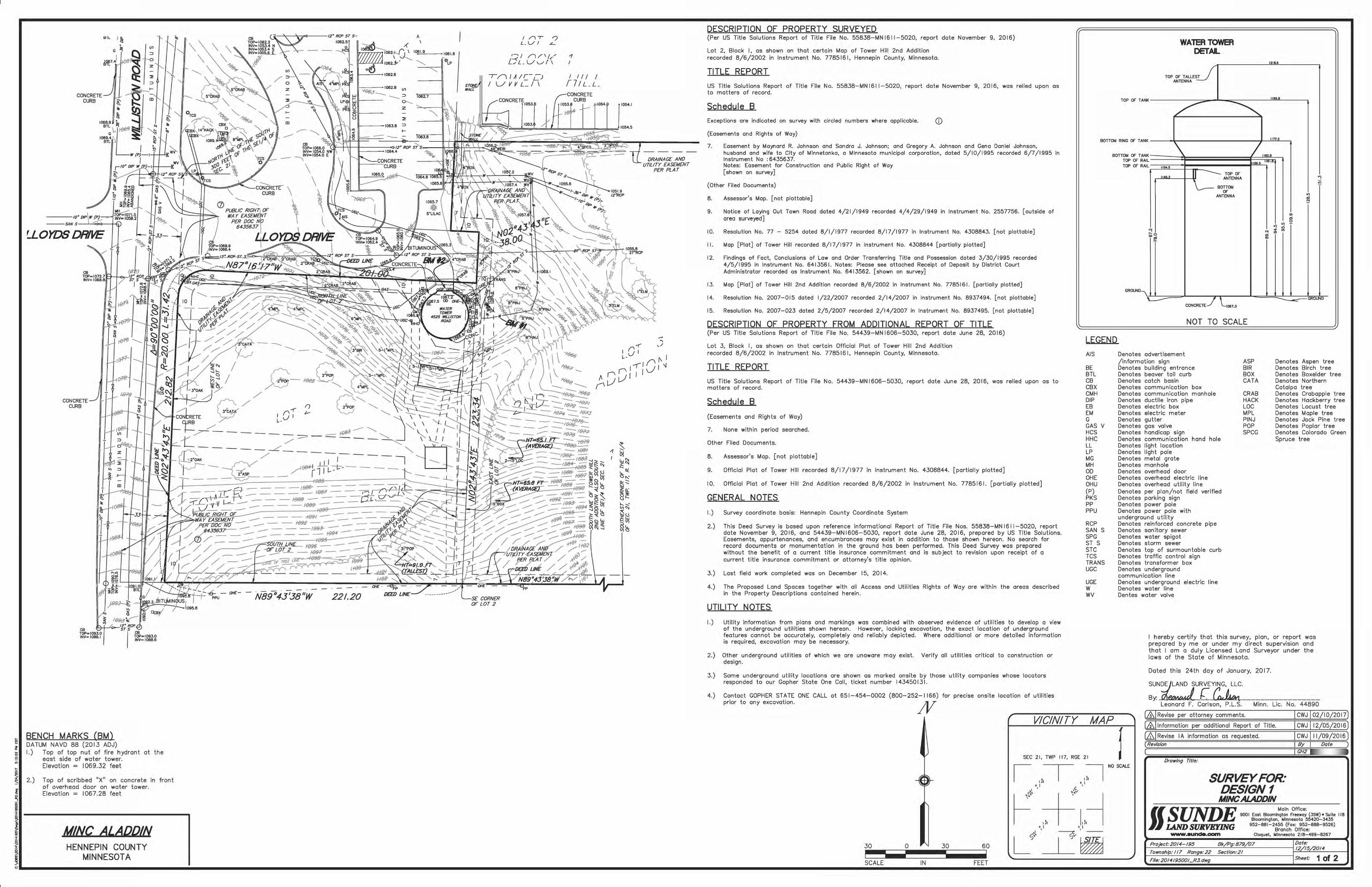
BTL I ~
G ~ ~ ~ ~qt7..1 ~
~ ; CONCRETE ~>-
CURB ~ I;::: en
----to•
CONCRETE CURB
CB TOP=I093.0 INV= 1089.1
.. ~
CB TOP=I093.0 INV= 1088.6
c--'<:----''o;;<>----12" RCP ST S-1062.5
-r , 0 , 1--
--
N89°43'38"W 221.20
I /lT '? L.VI L-
"1/1 I A IC-CJ IL/VVLI\
'--- ,.,_ CORNER OF LOT 2
-1 I
I I I I I r7fLL_
-1
1054.1
~ ~ ""~ ~
"' ..... c:s ..... e5::: ;<g_:
~~ ..___,
"'"' l:'i\..i i!:I'J :::,"l
sn:s
DRAINAGE AND UTILITY EASEMENT
PER PLAT
DESCRIPTION OF PROPERTY SURVEYED (Per US Title Solutions Report of Title File No. 55B3B-MNI611-5020, report date November 9, 2016)
Lot 2, Block I, as shown on that certain Map of Tower Hill 2nd Addition recorded B/6/2002 in Instrument No. 7785161, Hennepin County, Minnesota.
TITLE REPORT
US Title Solutions Report of Title File No. 55838-MN 1611-5020, report date November 9, 2016, was relied upon as to matters of record.
Schedule 8 Exceptions are indicated on survey with circled numbers where applicable. (J)
(Easements and Rights of Way)
7. Easement by Maynard R. Johnson and Sandra J. Johnson; and Gregory A. Johnson and Gena Daniel Johnson, husband and wife to City of Minnetonka, o Minnesota municipal corporation, dated 5/10/1995 recorded 6/7/1995 in Instrument No :6435637. Notes: Easement for Construction and Public Right of Way [shown on survey]
(Other Filed Documents)
8. Assessor's Map. [not plottable]
9. Notice of Laying Out Town Road dated 4/21/1949 recorded 4/4/29/1949 in Instrument No. 2557756. [outside of area surveyed]
10. Resolution No. 77 - 5254 dated B/1/1977 recorded B/17/1977 in Instrument No. 4308843. [not plottable]
II. Map [Plat] of Tower Hill recorded 8/17/1977 in Instrument No. 4308844 [partially plotted]
12. Findings of Fact, Conclusions of Law and Order Transferring Title and Possession dated 3/30/1995 recorded 4/5/1995 in Instrument No. 6413561. Notes: Please see attached Receipt of Deposit by District Court Administrator recorded as Instrument No. 6413562. [shown on survey]
13. Map [Plat] of Tower Hill 2nd Addition recorded B/6/2002 in Instrument No. 7785161. [partially plotted]
14. Resolution No. 2007-015 dated 1/22/2007 recorded 2/14/2007 in Instrument No. 8937494. [not plottable]
15. Resolution No. 2007-023 dated 2/5/2007 recorded 2/14/2007 in Instrument No. 8937495. [not plottable]
DESCRIPTION OF PROPERTY FROM ADDITIONAL REPORT OF TITLE (Per US Title Solutions Report of Title File No. 54439-MN 1606-5030, report date June 28, 2016)
Lot 3, Block I, as shown on that certain Official Plat of Tower Hill 2nd Addition recorded B/6/2002 in Instrument No. 7785161, Hennepin County, Minnesota.
TITLE REPORT
US Title Solutions Report of Title File No. 54439-MN 1606-5030, report date June 28, 2016, was relied upon as to matters of record.
Schedule 8
(Easements and Rights of Way)
7. None within period searched.
Other Filed Documents.
B. Assessor's Map. [not plottable]
9. Official Plat of Tower Hill recorded B/17 /1977 in Instrument No. 4308844. [partially plotted]
10. Official Plat of Tower Hill 2nd Addition recorded B/6/2002 in Instrument No. 7785161. [partially plotted]
GENERAL NOTES
1.) Survey coordinate basis: Hennepin County Coordinate System
2.) This Deed Survey is based upon reference informational Report of Title File Nos. 55838-MN 1611-5020, report date November 9, 2016, and 54439-MN 1606-5030, report date June 28, 2016, prepared by US Title Solutions. Easements, appurtenances, and encumbrances may exist in addition to those shown hereon. No search for record documents or monumentation in the ground has been performed. This Deed Survey was prepared without the benefit of a current title insurance commitment and is subject to revision upon receipt of a current title insurance commitment or attorney's title opinion.
3.) Last field work completed was on December 15, 2014.
4.) The Proposed Land Spaces together with all Access and Utilities Rights of Way are within the areas described in the Property Descriptions contained herein.
UTILITY NOTES
1.) Utility information from plans and markings was combined with observed evidence of utilities to develop a view of the underground utilities shown hereon. However, lacking excavation, the exact location of underground features cannot be accurately, completely and reliably depicted. Where additional or more detailed information is required, excavation may be necessary.
2.) Other underground utilities of which we are unaware may exist. Verify all utilities critical to construction or design.
3.)
4.)
Some underground utility locations are shown as marked onsite by those utility companies whose locators responded to our Gopher State One Call, ticket number 143450131.
Contact GOPHER STATE ONE CALL at 651-454-0002 prior to any excavation.
(800-252-1166)
JV for precise onsite location of utilities
VICINITY
TOP OF T ANK
BOTTON RING OF T ANK
ANK RAIL
BOTTOM OF T TOP OF
TOP OF RAIL
"' "o .,,.
GROUND
WAlERTOWER DETAIL
TOP OF TAll.ESJ ANTENNA
1218.6
1195.8
/ ~
1177.2
\ I,.,_, 1156.5 lltil.6
IIM.O
""'' I TOP OF ANTENNA
BOTTOM ~ OF
ANTENNA
"' "'
... '" "' .,
CONCRETEJ \_1067.3
NOT TO SCALE
'l
"'
"' '" ~ "' '" "' "" .;
"'
GROLND
LEGEND
AIS
BE BTL CB CBX CMH DIP EB EM G GAS V HCS HHC LL LP MG MH OD OHE OHU (P) PKS pp PPU
RCP SAN S SPG ST S STC TCS TRANS UGC
UGE w wv
MAP
Denotes advertisement /information sign Denotes building entrance Denotes beaver tail curb Denotes catch basin Denotes communication box Denotes communication manhole Denotes ductile iron pipe Denotes electric box Denotes electric meter Denotes gutter Denotes gas valve Denotes handicap sign Denotes communication hand hole Denotes light location Denotes light pole Denotes metal grate Denotes manhole Denotes overhead door Denotes overhead electric line Denotes overhead utility line Denotes per plan/not field verified Denotes parking sign Denotes power pole Denotes power pole with underground utility Denotes reinforced concrete pipe Denotes sanitary sewer Denotes water spigot Denotes storm sewer Denotes top of surmountable curb Denotes traffic control sign Denotes transformer box Denotes underground communication line Denotes underground electric line Denotes water line Dentes water valve
ASP BIR BOX CATA
CRAB HACK LOC MPL PINJ POP SPCG
Denotes Aspen tree Denotes Birch tree Denotes Boxelder tree Denotes Northern Catalpa tree Denotes Crabapple tree Denotes Hackberry tree Denotes Locust tree Denotes Maple tree Denotes Jack Pine tree Denotes Poplar tree Denotes Colorado Green Spruce tree
I hereby certify that this survey, plan, or report was prepared by me or under my direct supervision and that I am a duly Licensed Land Surveyor under the laws of the State of Minnesota.
Dated this 24th day of January, 2017.
SUNDEjLAND SURVEYING, LLC.
By: It~ r eu ifM.. ________________ _ Leonard F. Carlson, P.L.S. Minn. Lie. No. 44890
(&I Revise per attorney comments. I CWJ I 02/10/2017)
(,&.!Information per additional Report of Title. I CWJ 112/05/2016)
I Revise I A information as
SEC 21, TWP 117, RGE 21 r NO SCALE
SURVEY FOR: DESIGN1
UINCALADDIN

CONCRETE CURB
LLOYDS DRIVE
CB TOP•I072.7I:::t-+t>INV•I068.8
CONCRETE CURB
CB TOP=I09J.O INV= 1089.1
. p
10
r
r
PROPOSED TEMPORARY CONSTRUC710N ACCESS
12 FEET WIDE
~-S~'.!Tif LINE OF LOT 2
L ___ _
,(
I () I
0
0
0 w ..:.-tJ 0 5
z 0 u
PROPOSED LESS££ ~2£~ ........ RIGHT OF WAY 6 FEET WIDE
------
1 1 I I ~-rlll--
\,'
Ul
::::> 0
z
PROPOSED LESS££ LA~'ID---":'':" SPACE 256 SQ. FT. r,
':::< 1 Cu [_, L-
BITUMINOUS N89°43'38"W 221.20
CB TOP=I093.0 INV= 1088.6
A t n-r '7 LV I "'--
--r-/1 I A I c_-L- J IL/VVLI\
(CONCRETE
~-DRti!Nt4GE AND UTILITY EASEMENT
PER PLAT
'1 I
I II I I {7/L_L_
CONCRETE CURB
r-.PRC1PO'>£D LESS££ CABLING SPACE 5 FEET WIDE
DRAINAGE AND UTILITY EASEMENT
PER PLAT
1060..32 /06.(..5/
1072.34
.... ;:.: ' ~h: ~
R: ~ \..i ~ iJj ~~ .... -.JC5
"-" C) iS~ !!.>>:_:~ ~--.J :§! ....
-.:<:5
1:1~ ~:::1
~ -1 ~ I
"'~ 1!:: ~ ....
C5 .....
[;j:::: ;eg_:
~~ .., "' \..i bl ~
CD
DRAINAGE AND UTILITY EASEMENT
PER PLAT
LEGEND
AIS
BE BTL CB CBX CMH DIP EB EM G GAS V HCS HHC LL LP MG MH OD OHE OHU (P) PKS pp PPU
Denotes advertisement /information sign
PROPOSED LESSEE LAND SPACE 480 SQ. FT.
That part of Lot 2, Block I, Tower Hill 2nd Addition, according to the recorded plat thereof, Hennepin County, Minnesota, described as commencing at the southeast corner of Section 21,Township 117, Range 22; thence on an assumed bearing of North 89 degrees 43 minutes 38 seconds West, along the south line of the Southeast Quarter of said Section 21 and the south line of said Tower Hill 2nd Addition, 1064.51 feet; thence North 00 degrees 16 minutes 22 seconds East 142.27 feet to the point of beginning of the Land Space to be described; thence North 09 degrees 15 minutes 06 seconds East 16.00 feet; thence North 80 degrees 44 minutes 54 seconds West 30.00 feet; thence South 09 degrees 15 minutes 06 seconds West 16.00; South 80 degrees 44 minutes 54 seconds East 30.00 feet to the point of beginning.
PROPOSED LESSEE LAND SPACE 256 SQ. FT.
That part of Lot 2, Block I, Tower Hill 2nd Addition, according to the recorded plat thereof, Hennepin County, Minnesota, described as commencing at the southeast corner of Section 21, Township 117, Range 22; thence on an assumed bearing of North 89 degrees 43 minutes 38 seconds West, along the south line of the Southeast Quarter of said Section 21 and the south line of said Tower Hill 2nd Addition, 1072.34 feet; thence North 00 degrees 16 minutes 22 seconds East 85.39 feet to the point of beginning of the Land Space to be described; thence on a bearing of West 16.00 feet; thence on a bearing of North 16.00 feet; thence on a bearing of East 16.00 feet; thence on a bearing of South 16.00 feet to the point of beginning.
PROPOSED LESSEE CABLING SPACE 5 FEET WIDE
That part of Lot 2, Block I, Tower Hill 2nd Addition, according to the recorded plat thereof, Hennepin County, Minnesota, described as commencing at the southeast corner of said Section 21, Township 117, Range 22; thence on an assumed bearing of North 89 degrees 43 minutes 38 seconds West, along the south line of the Southeast Quarter of said Section 21 and the south line of said Tower Hill 2nd Addition, 1064.51 feet; thence North 00 degrees 16 minutes 22 seconds East 142.27 feet; thence North 80 degrees 44 minutes 54 seconds West 5.07 feet to the point of beginning of the Cabling Space to be described; thence continuing North 80 degrees 44 minutes 54 seconds West 5.00 feet; thence South 09 degrees 26 minutes 16 seconds West 43.04 feet to Line A, described below; thence on a bearing of West, along said Line A, 5.07 feet; thence North 09 degrees 26 minutes 16 seconds East 42.22 feet to the point of beginning.
Line A is described as commencing at the southeast corner of Section 21; thence on an assumed bearing of North 89 degrees 43 minutes 38 seconds West, along said south line of the Southeast Quarter of Section 21 and said south line of Tower Hill 2nd Addition, 1072.34 feet; thence North 00 degrees 16 minutes 22 seconds East I 01.39 feet to the point of beginning of said Line A; thence on a bearing of West 16.00 feet and said Line A there terminating.
PROPOSED LESSEE UTILITIES RIGHT OF WAY 10 FEET WIDE
Those parts of Lot 2 and Lot 3, Block I, Tower Hill 2nd Addition, according to the recorded plat thereof, Hennepin County, Minnesota, described as commencing ot the southeast corner of Section 21,Township 117, Range 22; thence on an assumed bearing of North 89 degrees 43 minutes 38 seconds West, along the south line of the Southeast Quarter of said Section 21 and the south line of said Tower Hill 2nd Addition, 1064.51 feet; thence North 00 degrees 16 minutes 22 seconds East 142.27 feet to the point of beginning of the Utilities Right of Way to be described; thence North 09 degrees 15 minutes 06 seconds East 16.00 feet; thence South 80 degrees 44 minutes 54 seconds East 3.52 feet; thence North 30 degrees 35 minutes 50 seconds East 21.27 feet; thence on a bearing of North 42.26 feet; thence on o bearing of East 19.65 feet; thence on bearing of North 5.81 feet to the north line of said Lot 2; thence South 87 degrees 16 minutes 17 seconds East, along said north line of Lot 2, a distance of 16.95 feet to the northeast corner of said Lot 2; thence North 02 degrees 43 minutes 43 seconds East, along the west line of said Lot 3, a distance of 5.0 I feet; thence on a bearing of East 12.49 feet; thence on a bearing of South 55.00 feet; thence South 30 degrees 35 minutes 50 seconds West 37.28 feet; thence North 80 degrees 44 minutes 54 seconds West 8.00 feet to the point of beginning.
PROPOSED LESSEE ACCESS RIGHT OF WAY 6 FEET WIDE
That part of Lot 2, Block I, Tower Hill 2nd Addition, according to the recorded plat thereof, Hennepin County, Minnesota, described as commencing at the southeast corner of Section 21, Township 117, Range 22; thence on an assumed bearing of North 89 degrees 43 minutes 38 seconds West, along the south line of the Southeast Quarter of said Section 21 and the south line of said Tower Hill 2nd Addition, 1064.51 feet; thence North 00 degrees 16 minutes 22 seconds East 142.27 feet; thence North 09 degrees 15 minutes 06 seconds East 16.00 feet; thence North 80 degrees 44 minutes 54 seconds West 30.00 feet to the point of beginning of the Access Right of Way to be described; thence South 09 degrees 15 minutes 06 seconds West 16.00 feet; North 80 degrees 44 minutes 54 seconds West 2.00 feet; thence South 09 degrees 14 minutes 47 seconds West 11.69 feet; thence South 25 degrees 02 minutes 13 seconds East 38.0 I feet to Line A described below; thence on a bearing of West, along said Line A, 6.62; thence North 25 degrees 02 minutes 13 seconds West 37.06 feet; thence North 09 degrees 14 minutes 47 seconds East 33.64 feet; thence North 00 degrees 10 minutes 09 seconds East 57.16 feet to the north line of said Lot 2; thence South 87 degrees 16 minutes 17 seconds East, along said north line of Lot 2, a distance of 6.0 I feet; thence South 00 degrees I 0 minutes 09 seconds West 62.00 feet; thence South 80 degrees 44 minutes 54 seconds East 1.27 feet to the point of beginning.
Line A is described as commencing at said southeast corner of Section 21; thence on an assumed bearing of North 89 degrees 43 minutes 38 seconds West, clang said south line of the Southeast Quarter of Section 21 and said south line of Tower Hill 2nd Addition, 1072.34 feet; thence North 00 degrees 16 minutes 22 seconds East I 01.39 feet to the point of beginning of said Line A; thence on a bearing of West 16.00 feet and said Line A there terminating.
PROPOSED TEMPORARY CONSTRUCTION ACCESS
That part of Lot 2, Block I, Tower Hill 2nd Addition, according to the recorded plat thereof, Hennepin County, Minnesota, described as commencing at the southeast corner of Section 21, Township 117, Range 22; thence on an assumed bearing of North 89 degrees 43 minutes 38 seconds West, along the south line of the Southeast Quarter of said Section 21 and the south line of said Tower Hill 2nd Addition, 1060.32 feet to the southeast corner of said Lot 2; thence North 02 degrees 43 minutes 43 seconds East, along the east line of said Lot 2, a distance of 69.69 feet to the point of beginning of the Temporary Construction Access; thence on a bearing af West 46.02 feet; thence on a bearing of North 24.68 feet; thence North 87 degrees 16 minutes 17 seconds West 173.85 feet to the west line of said Lot 2; thence North 02 degrees 43 minutes 43 seconds East, along said west line of Lot 2, a distance of 12.00 feet; thence South 87 degrees 16 minutes 17 seconds East 173.28 feet; thence on a bearing of North I 0.35 feet; thence North 25 degrees 00 minutes 00 seconds West 20.04 feet; thence North 09 degrees 14 minutes 47 seconds East 51.59 feet; thence North 30 degrees 56 minutes 37 seconds West 47.89 feet to the north line of said Lot 2; thence South 87 degrees 16 minutes 17 seconds East, along said north line of Lot 2, a distance of 17.93 feet; thence South 31 degrees 00 minutes 45 seconds East 57.95 feet; thence South 80 degrees 44 minutes 52 seconds East 28.30 feet to said east line of Lot 2; thence South 02 degrees 43 minutes 43 seconds West, along said east line of Lot 2, a distance of 102.25 feet to the point of beginning.
Denotes building entrance Denotes beaver tail curb Denotes catch basin
ASP BIR BOX CATA
Denotes Aspen tree Denotes Birch tree Denotes Boxelder tree Denotes Northern Catalpa tree Denotes communication box
Denotes communication manhole Denotes ductile iron pipe Denotes electric box Denotes electric meter Denotes gutter Denotes gas valve Denotes handicap sign Denotes communication hand hole Denotes light location Denotes light pole Denotes metal grate Denotes manhole Denotes overhead door Denotes overhead electric line Denotes overhead utility line Denotes per plan/not field verified Denotes parking sign Denotes power pole Denotes power pole with underground utility
CRAB HACK LOC MPL PINJ POP SPCG
Denotes Crabapple tree Denotes Hackberry tree Denotes Locust tree Denotes Maple tree Denotes Jack Pine tree Denotes Poplar tree Denotes Colorado Green Spruce tree
30
VICINITY (£11nformation per additional Report of Title.
(&I Revise per attorney comments. CWJ I 02/10/2017] MAP
BENCH MARKS (BM\ RCP Denotes reinforced concrete pipe - J. SAN S Denotes sanitary sewer Revise I A information as
DATUM NAVD 88 (2013 ADJ) SPG Denotes water spigot s I.) Top of top nut of fire hydrant at the ST S Denotes storm sewer ~ east side of water tower. STC Denotes top of surmountable curb ~ Elevation = 1069.32 feet TCS Denotes traffic control sign ~ T :l :S TRANS Denotes transformer box ~ 2.) Top of scribbed "X" on concrete in front UGC Denotes underground 1!, , \!'
of overhead door on water tower. communication line • 1 '
! Elevation = 1 067 _28 feet UGE Denotes underground electric line ' ' '~ W Denotes water line
SEC 21, TWP 117, RGE 21
WV Dentes water valve
NO SCALE Drawing Title:
SURVEY FOR: DESIGN1 MINCALADD/N
Main Office: 9001 East Bloomington Freeway (35W) • Suite 118
Bloomington, Minnesota 55420-3435 952-881-2455 (Fa<: 952-888-9526)
Branch Office: WWW.8Unde.aam Cloquet, Minnesota 218-499-8267 ~ M/NC ALADDIN Lc}\ '
1
Cf ~ • HENNEPIN COUNTY
~L---------~M~IN~N~E=S~O~T~A~------~~-------------------------------------------------------------------------------------------------------------------------------------=::::::::::::::::::~~========================~=~=t=2=o=f=2~


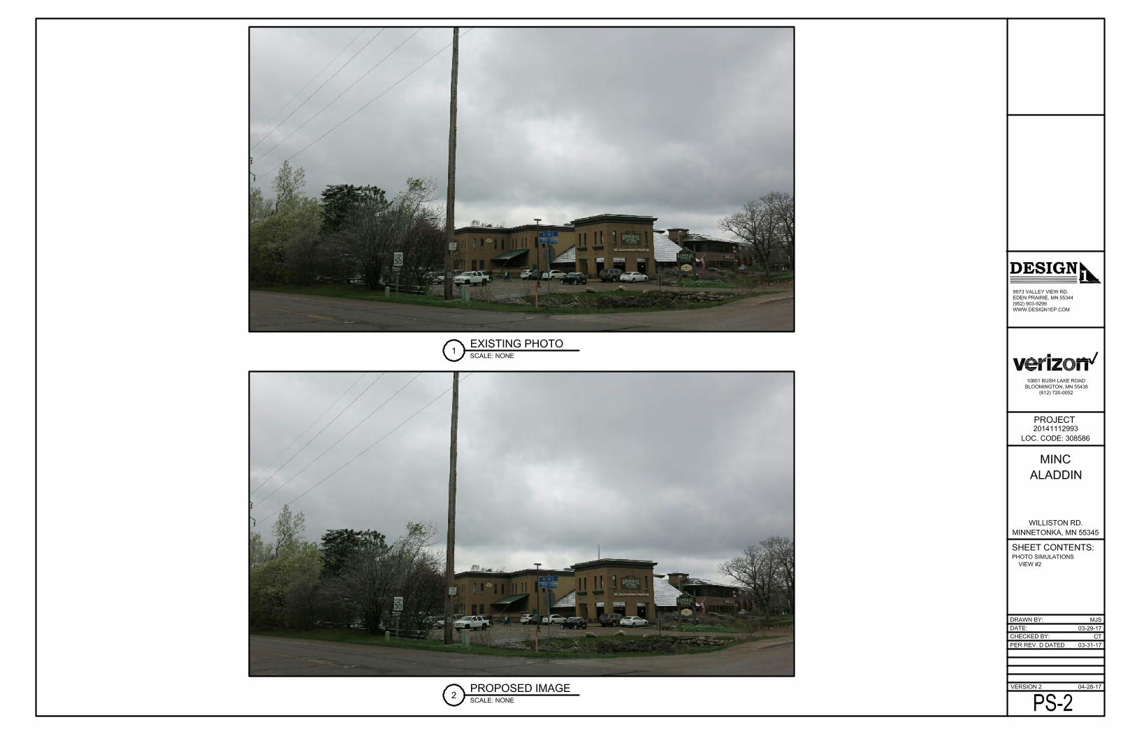

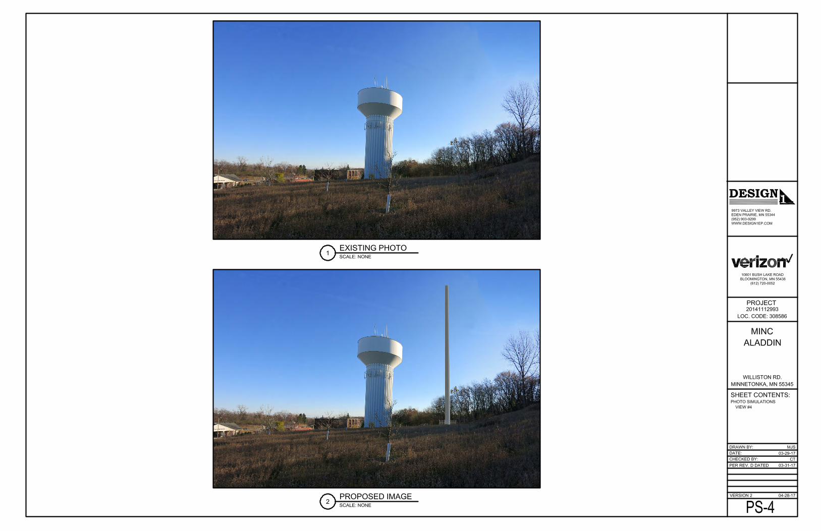
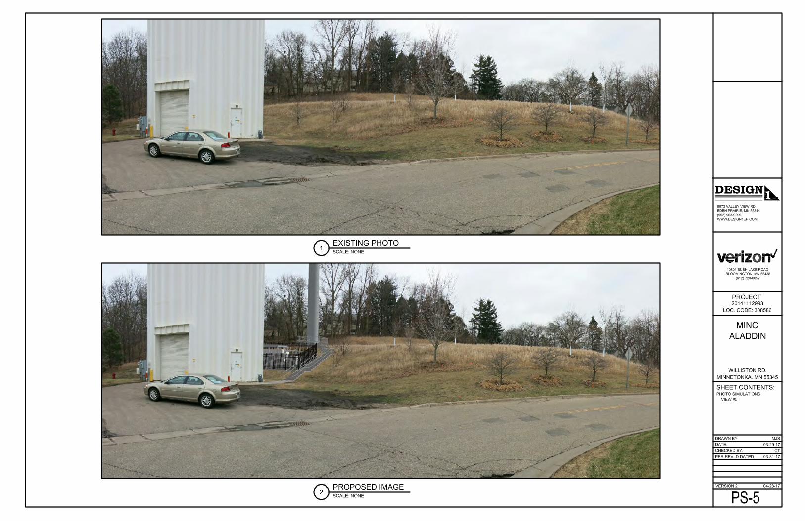


T E L E C O M M U C A T I O N S C O N S U L T A N T S T U D Y

REPORT REGARDING CONSTRUCTION
OF A 180-FOOT COMMUNICATIONS TOWER
ON THE ALADDIN WATER TOWER
MINNETONKA, MINNESOTA
FOR VERIZON WIRELESS
PREPARED BY:
GARRETT G. LYSIAK, P.E.
APRIL 21, 2017

1
Engineering Statement The documents submitted by Verizon Towers to The City of Minnetonka for a new 180-foot tower were reviewed for compliance with the technical requirements of the (Wireless Telecommunications Overlay) of the zoning ordinance. The site is located at the Aladdin Water tower on Williston Road. The proposed site has been evaluated several times in the past for both locating on the top of the water tank and various new tower locations in the surrounding area. The studies showed that a new tower is required to achieve the desired coverage and loading for the communications system. In the proposed location, the water tower will shield the signals so various heights were examined to minimize this condition. Once the new tower location was determined, the coverage was determined and several heights between 140 and 180 feet were analyzed. The minimum height for the tower to provide adequate coverage was determined to be 140-feet. However, one consideration was to have the tower designed for future increase in height to permit other communications systems to be located on the new tower. Verizon submitted the new application with the increased height so future users could be located on it at a minimal disruption to their system operation. This proposed height would eliminate the future need for a tower in the nearby area since the Ordinance requires using existing towers before any new towers could be approved.
Summary
The review of the proposed Verizon tower indicates that:
• It would provide the required wireless system coverage to eliminate the present existing poor coverage area and provide enhanced existing coverage.
• The site is not predicted to cause any interference products to any protected
frequency in the area and is not predicted to be an RF radiation hazard.
• The tower at the proposed height is designed to accommodate additional communications systems.

2
• The proposal is in compliance with the structural requirements of the
ordinance.
• Due to the lack of any existing towers or adequate support structures in the vicinity, the site would need to locate very near to the proposed location to fill the coverage gap.
Respectfully submitted,
Garrett G. Lysiak, P.E.

W A T E R T O W E R H E I G H T V E R I F I C A T I O N S T U D Y

December 15, 2015
City of Minnetonka Ms. Susan M. Thomas, Principal Planner 14600 Minnetonka Blvd. Minnetonka, MN 55435
Reference: Height Verification Study - Verizon Wireless for the Williston Road Water Tank at 4525 Williston Rd., Minnetonka, MN
Dear Ms. Thomas: We have completed the height verification study for the Verizon proposal for one antenna to be located on top of the Williston water tower and the remaining antennas to be located at 70' The first step in the analysis was to perform a shadow study to show the effect of the topography to the south of the water tower (Figure 1) using all the antennas at 70'. The shadow area is apparent to the SE of the water tower on this map. The second step was to perform the same study with the antenna moved to the 132' level on the water tank (Figure 2). This map shows that this new height will significantly reduce the shadow effect of the nearby hills to the water tower. It doesn't eliminate the shadow entirely. Both of these shadow studies considered the terrain, however, foliage such as trees were not considered and would only further increase the path losses. The applicant expressed their concerns: “The problem is further complicated by the fact that this ridge is heavily wooded by trees ranging from fifty to seventy-five feet making signal propagation impossible if the antennas facing south had to be located on the fluted portion of the tank.” 1 We then performed several coverage studies of the Williston site and 2 potential replacements on the Xcel power towers to the east of the water tank. The first of these studies is Figure 3. This shows the coverage if the Williston site were constructed at 70'. As you can see, there are coverage gaps to the SE of the water tank. 1 March 25, 2015 letter : Antenna Placement on the top of the tank

The second study is Figure 4 and this is the Williston site constructed at 132'. It is apparent that the coverage to the south is enhanced with this additional height. We then ran 2 studies with the Williston site not constructed and the Verizon site to be built on one of the existing two (2) Xcel power towers along I494 to the east of the site (Figures 5 & 6). As you can see, both of these locations do cover the area south of the Williston WT, but they create significant coverage gaps to the west of Williston road. In summary, we have verified that the additional height requested by Verizon on the Williston water tower is necessary to provide quality coverage to the south of Hwy. 7 due to the rolling terrain and foliage in the area. Conclusions drawn in this report are based on observations and on information available, known and declared at the date of investigation and/or the time of preparation of this report. Should additional information be uncovered or made available, we retain the right to revise or supplement our report accordingly. If you have any questions in this matter please contact either of us. Sincerely,
Garrett G. Lysiak, P.E.
Michael O'Rourke
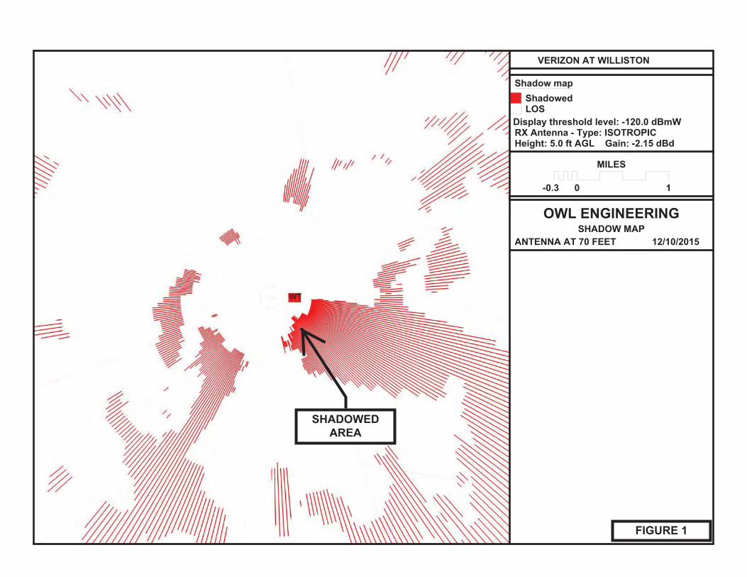
SHADOWEDAREA
FIGURE 1

FIGURE 2
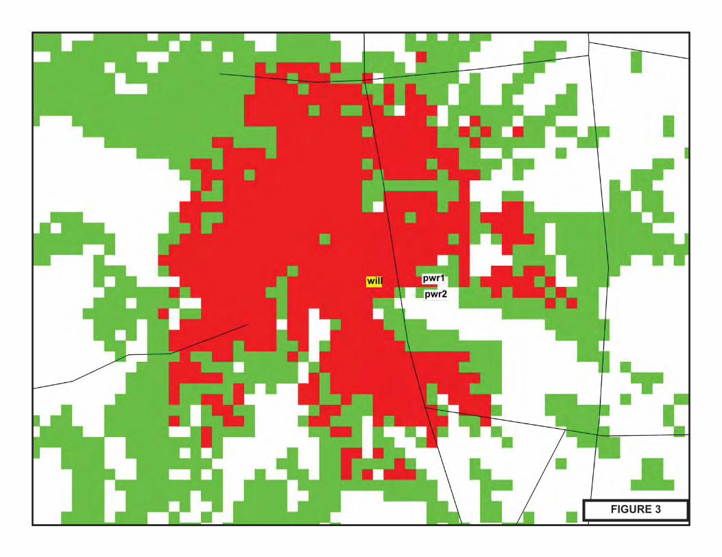
FIGURE 3

FIGURE 4
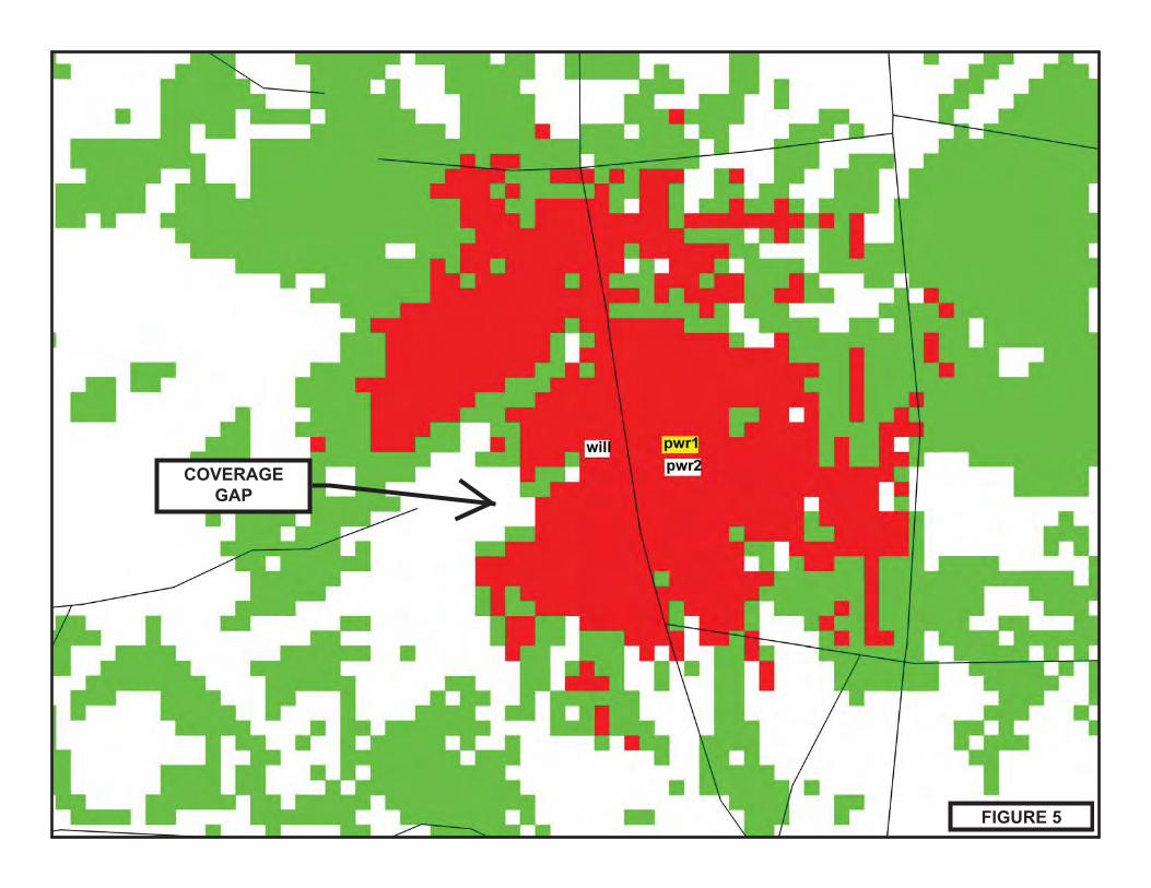
FIGURE 5
COVERAGEGAP

FIGURE 6
COVERAGEGAP

a4565e3cb9074fa7a81154bdb777d11bOverride 1
AddressesMain AddressSub AddressBuildings
Contours10 Ft. Contour2 Ft. Contour100 Year Storm Water AreasWetlands - NWI Inventory
Wetlands - City Inventory Manage 1Manage 2
MCManage1NAPreserveUtilizeParcels With Hookup FeesFlow Meter Location(Caution)CLEAN OUTPIPE FITTINGLIFT STATION
SManholeSDropManholeSSplitManholeSStandardManholeSSummitManhole
Abandoned ManholesSDropManholeSSplitManholeSStandardManholeSSummitManhole
SLateralLineAbandonedActiveProposed
SGravitymainActiveProposedFORCEMAINABANDONED FMABANDONED
DGravityMainWater - Raw Water Hydrants
Raw WaterWater - Hydrants
Adjoining CityMinnetonkaPrivateUnknown
Water - System ValvesButterflyGatePost IndicatorUnknown
April 27, 20170 0.07 0.140.035 mi
0 0.1 0.20.05 km
1:3,076

P L A N N I N G C O M M I S S I O N M E E T I N G M I N U T E S

Unapproved Minnetonka Planning Commission
Minutes
May 4, 2017 C. Conditional use permit for a telecommunications tower on the
property located at 4525 Williston Road. Chair Kirk introduced the proposal and called for the staff report. Gordon reported. He recommended approval of the application based on the findings and subject to the conditions listed in the staff report. Karen O’Brian, representing the applicant, was available to answer questions. She held a neighborhood meeting, but no neighbors attended. City staff have been wonderful to work with. Gary Lysiak, engineering consultant, stated that the proposed tower’s height has been increased to provide the needed height for potential additional users. The tower would be erected in one day. The public hearing was opened. No testimony was submitted and the hearing was closed. In response to Schack’s question, Gordon explained that Verizon would construct the telecommunications tower on city property. Mr. Lysiak added that most cities, including Minnetonka, have an ordinance requiring telecommunication companies to utilize existing towers before constructing a new one. Telecommunication companies are accustomed to the sharing equipment. Schack noted that the neighbors have probably come to terms with having a water tower on the site, so it would make the telecommunications tower less noticeable. It is a good location. She is glad that there would be space for additional users. Chair Kirk noted that the first time around, neighbors did provide comments. Powers thought that the proposal is a good idea. Staff worked hard and figured out the exact right place to locate the tower. The neighbors have already adjusted to the proximity of the water tower. Calvert said that the additional photos in the presentation were extremely helpful.

Unapproved Planning Commission Minutes May 4, 2017 Page 2
Calvert moved, second by Powers, to recommend that the city council adopt a resolution approving a conditional use permit for a telecommunication facility at 4525 Williston Road. Calvert, Powers, Schack, Sewall, and Kirk voted yes. Knight and O’Connell were absent. Motion carried.

CONCEPT PLAN REVIEW

City Council Agenda Item #14_ Meeting of October 24, 2016
Brief Description Concept plan review Williston water tower monopole
Action Requested Discuss concept plan with the applicant. No formal action required.
Background
In 2015, the city was approached by Verizon Wireless to locate telecommunications equipment on the Williston Water Tower located at 4525 Williston Road. Specifically, Verizon’s request was to locate equipment at the top of the water tower to gain improvements to its coverage area to the south.
The city has a policy regarding the use of public water towers for antennas. As stated in city council policy 12.5, priority is granted to public safety and governmental agencies before private entities. Currently, the top of the water tower is exclusively used by public safety and governmental agencies. Private cellular providers have only been allowed on the “flute” of the tower under the bulb of the tank. (See pages 5-9).
In the 2015 discussion, the city determined that:
1) The Verizon proposal to locate private equipment on top of the water tower wouldnot be advantageous to telecommunications equipment already in place, and
2) Exploration of other alternatives such as a monopole antenna on the water towerproperty was a possibility.
Over the past many months, city staff, the city’s wireless consulting engineer and Verizon representatives have worked together on a monopole antenna as an alternative to locating Verizon telecommunications equipment on top of the water tower. The potential monopole would be 140-feet in height (slightly higher than the 135 foot water tower) and be located approximately 100-feet directly south of the water tower on city property at a ground elevation 17 feet higher than the base elevation of the water tower. (See plans on pages 1–4.)
The monopole was sited in this location after a careful review of many factors including:
1) Not disturbing habitat restoration areas of Tower Hill Park,
2) Location of the underground water storage tank at Tower Hill Park,
3) Location of watermains and other underground utilities,
Meeting of October 24, 2016 Page 2 Subject: Williston water tower monopole
4) Proximity to the water tower,
5) Proximity to surrounding residential neighborhoods,
6) Visual impact to the Highway 7 corridor and
7) Viable options that work with the carrier’s requirements. Planning Commission Concept Review The planning commission reviewed the concept plan at their September 22, 2016 meeting. The commission generally agreed that a monopole was appropriate. Discussion comments included questions about the existing capacity for new providers below the bulb, tree impacts, health impacts and design. (See pages 11-12). There were no members of the public in attendance. Review Process Staff has outlined the following review process for the proposal. At this time, a formal application has not been submitted. A formal application would require the following:
1) Consent from the city for use of public property and,
2) An application for a conditional use permit for the construction of a monopole telecommunications tower.
• Neighborhood Meeting. The city hosted a neighborhood meeting along with
Verizon on August 24, 2016. Three neighborhood residents were in attendance. Discussion among residents, city staff and Verizon representative in attendance included:
o What other locations were looked at?
o Why not a location on city property to the east nearer to Woodhill Road?
o Move the tower south up the hill, possibly into the residential neighborhood if the city were to purchase additional residential property.
o What is the size of the tower? Will the tower have guy wires? o Will other providers want to locate on the monopole? o Co-location options for other providers available on the monopole? o Discussion about the two design options: 1) a monopole with stealth design or
internal antennas and 2) a monopole with a “crow’s nest” or external antennas. External antennas may allow for more co-location potential than a stealth design monopole. What would be the possibilities of other providers wanting to locate on a monopole? It would be beneficial to receive additional

Meeting of October 24, 2016 Page 3 Subject: Williston water tower monopole
input on both options as it has implications on future site development and use. A stealth monopole could limit the number of providers. Would limiting colocation opportunities create the need for an additional monopole in the future?
• Planning Commission Concept Plan Review. The planning commission
Concept Plan Review is intended as a follow-up to the neighborhood meeting. The objective of this meeting is to identify major issues and challenges in order to inform the subsequent review and discussion. The meeting will include a presentation by the developer of conceptual sketches and ideas, but not detailed engineering or architectural drawings. No staff recommendations are provided, the public is invited to offer comments, and planning commissioners are afforded the opportunity to ask questions and provide feedback without any formal motions or votes.
• City Council Concept Plan Review. The city council Concept Plan Review is intended as a follow-up to the planning commission meeting and would follow the same format as the planning commission Concept Plan Review. No staff recommendations are provided, the public is invited to offer comments, and council members are afforded the opportunity to ask questions and provide feedback without any formal motions or votes.
Staff Recommendation Staff recommends the city council provide comment and feedback to assist the applicant with future direction that may lead to the preparation of more detailed development plans. Feedback on the notification area for future mailings during the formal review process is also requested. Through: Geralyn Barone, City Manager Julie Wischnack, AICP, Community Development Director Originator: Loren Gordon, AICP, City Planner

Meeting of October 24, 2016 Page 4 Subject: Williston water tower monopole
ADDITIONAL INFORMATION Next Steps • Formal Application. If the developer chooses to file a formal application,
notification of the application would be mailed to area property owners. Property owners are encouraged to view plans and provide feedback via the city’s website. Through recent website updates: (1) staff can provide residents with ongoing project updates, (2) residents can “follow” projects they are particularly interested in by signing up for automatic notification of project updates; (3) residents may provide project feedback on project; and (4) and staff can review resident comments.
• Neighborhood Meeting. Prior to the planning commission meeting and official public hearing, an additional public meeting would be held with neighbors to discuss specific engineering, architectural and other details of the project, and to solicit feedback. This extends the timing that has historically been provided in advance of the planning commission review to allow more public consideration of the project specifics.
• Council Introduction. The proposal would be introduced at a city council meeting. At that time, the council would be provided another opportunity to review the issues identified during the initial concept plan review meeting, and to provide direction about any refinements or additional issues they wish to be researched, and for which staff recommendations should be prepared.
• Planning Commission Review. The planning commission would hold an official
public hearing for the development review and would subsequently recommend action to the city council.
• City Council Action. Based on input from the planning commission, professional
staff and general public, the city council would take final action. Roles and Responsibilities • Applicants. Applicants are responsible for providing clear, complete and timely
information throughout the review process. They are expected to be accessible to both the city and to the public, and to respect the integrity of the public process.
• Public. Neighbors and the general public will be encouraged and enabled to participate in the review process to the extent they are interested. However, effective public participation involves shared responsibilities. While the city has an obligation to provide information and feedback opportunities, interested residents are expected to accept the responsibility to educate themselves about the project

Meeting of October 24, 2016 Page 5 Subject: Williston water tower monopole
and review process, to provide constructive, timely and germane feedback, and to stay informed and involved throughout the entire process.
• Planning Commission. The planning commission hosts the primary forum for public input and provides clear and definitive recommendations to the city council. To serve in that role, the commission identifies and attempts to resolve development issues and concerns prior to the council’s consideration by carefully balancing the interests of applicants, neighbors, and the general public.
• City Council. As the ultimate decision maker, the city council must be in a position to equitably and consistently weigh all input from their staff, the general public, planning commissioners, applicants and other advisors. Accordingly, council members traditionally keep an open mind until all the facts are received. The council ensures that residents have an opportunity to effectively participate in the process.
• City Staff. City staff is neither an advocate for the public nor the applicant. Rather, staff provides professional advice and recommendations to all interested parties, including the city council, planning commission, applicant and residents. Staff advocates for its professional position, not a project. Staff recommendations consider neighborhood concerns, but necessarily reflect professional standards, legal requirements and broader community interests.

LOCATION MAPWilliston water tower site monopole4525 Williston Road
±
This map is for illustrative purposes only.
WILL
ISTO
N RD
HIGHWAY 7
WOOD
HILL
RD
KARYL DR
LLOYDS DR
HIGHWOOD DR
HIGHLAND LN
LLOYDS LN
DURHAM RD
WOOD
S WAY
WILDCREST RD
MOONLIGHT HILL RD
HIGH TOWER
HIGH POINT CT
HIGHWAY 7HIGHWAY 7
HIGHWAY 7
WOOD
HILL
RD
SUBJECT PROPERTY
A1 Williston water tower monopole

Staff Preferred Location
A2 Williston water tower monopole

A3 Williston water tower monopole

Staff Preferred LocationA4 Williston water tower monopole

City of Minnetonka City Council Policy 12.5
Page 1 of 5
Policy Number 12.5 Use of City Water Towers for the Location of Antennas
Purpose of Policy: This policy establishes a uniform policy for reviewing requests for the location of antennas on city water towers.
Introduction The city has received requests for the location of various antennae on its water towers. The council has determined that a uniform policy for reviewing these requests is desirable.
Permitted Locations Antennae not owned by the city of Minnetonka will be permitted only on water towers that have been sufficiently modified, in the opinion of the public works director to adequately accommodate those antennae. The modification must be done at the user’s expense.
Permitted Users Only the following entities may place antennae on city water towers, in order of descending priority:
1. City of Minnetonka
2. Public safety agencies, including law enforcement, fire, and ambulance services, thatare not part of the city of Minnetonka.
3. Other governmental agencies, for uses that are not related to public safety.
4. Government-regulated entities whose antennae offer a service to the general publicfor a fee, in a manner similar to a public utility, such as long distance and cellulartelephone. This does not include radio or television broadcasters.
If there is a conflict in use between potential and existing users, permission for use will be granted in order of priority listed above.
Application Process All applicants who wish to locate antennae on city water towers must submit to the public works director a completed application form and a detailed plan of the proposed installation. Staff will review the application to determine the appropriateness of the request, including the aesthetic impact and the structural integrity of the tower. Staff may retain the services of a structural engineer to analyze the structural capacity. The applicant must reimburse the city for the cost of this analysis.
The technical analysis and other relevant data will be submitted to the city council for its review. City council approval is conditioned on a finding by a professional communications engineer that there will be no interference with other users. The applicant must reimburse the city for the cost of this analysis before installation of the
A5 Williston water tower monopole

City of Minnetonka City Council Policy 12.5
Page 2 of 5
antennas. After approval by the city council, the successful applicant must sign an agreement with the city, in a form acceptable to the city attorney, that requires the application to pay a periodic fee, to obtain adequate liability insurance, and to comply with other appropriate requirements. The fees will be established by the city council after considering comparable rates in other cities, potential expenses and risks to the city, and other appropriate factors. Standards No application will be granted unless the following standards are met : • The potential use must not interfere with other users who have a higher priority. • The user must comply with minimum equipment and site standards prepared by the
city. • The user must have its own sources of electrical power and telephone service. • The user's equipment and personnel must not interfere with normal operation of the
water tower. • The user must reimburse the city for any costs that it incurs because of the user's
existence on city property. • The user must agree to pay a fee for each time it wants admittance into the tower
structure, if required by the city. • The user must be responsible for the security of its own equipment. • The user must have obtained all necessary land use approvals.
• The user must comply with the attached Guidelines for Antennas on City Water Towers.
Revocation The city council may revoke permission to use a city water tower if it determines that any one of the following situations exist:
• A potential user with a higher priority cannot find another adequate location and the
potential use would be incompatible with an existing use; • A user's antennae unreasonably interfere with other users with higher priority,
regardless of whether or not this was adequately predicted in the technical analysis; or
• A user violates any of the standards in this policy or the conditions attached to the
city's permission.
A6 Williston water tower monopole

City of Minnetonka City Council Policy 12.5
Page 3 of 5
• The city council decides to dismantle the water tower.
Before taking action, the city will provide notice to the user of the intended revocation and the reasons for it, and provide an opportunity for the user to address the city council regarding the proposed action. This procedure need not be followed in emergency situations.
Reservation of Right Notwithstanding the above, the city council reserves the right to deny, for any reason, the use of any or all city water towers by any one or all applicants.
Adopted by Resolution No. 88-8767 Council Meeting of November 7, 1988
Amended by Resolution No. 97-043 Council Meeting of March 31, 1997
Amended by Resolution No. 2003-077 Council Meeting of August 25, 2003
Amended by Resolution No. 2006-026 Council Meeting of March 27, 2006
A7 Williston water tower monopole

City of Minnetonka City Council Policy 12.5
Page 4 of 5
Guidelines for Antennas on City Water Towers 1. Design plans. Drawings and specifications detailing equipment installation, cable runs, supports, penetrations, fastening methods, foundations, panels, electrical power connections, grounding, and all other required details for a complete installation must be submitted for review and approval. A drawing depicting the final appearance of the tank must also be included. A certified professional engineer in the utility's state must stamp all drawings and specifications. 2. Operation. Either by design, function, or installation, proposed equipment must not interfere with the facility's operation and its ability to deliver safe, potable water at sufficient pressure to customers. 3. Appearance. The equipment must have minimal detrimental effect on the facility's aesthetic appearance. The design must not significantly alter the appearance of the tank. The use of permanently installed false overflow pipes as cable conduits is not allowed. Wherever possible, tank cable runs must be internal to the tank's structure. No exposed exterior cable runs will be allowed without the written approval of the utility. Color for cables, antennas, and any other visible appurtenances must match the tank colors and be submitted for approval. 4. Coatings. Existing rank interior and exterior coating systems must be protected or repaired with new equivalent coating systems during the work of antenna company equipment installation. Coating repairs must be subject to approval. Existing tank coating specifications are available on request. 5. Enclosures. Proposed communication equipment to be installed at ground level outside a tank's structure must be enclosed in approved, aesthetically pleasing enclosures. All ground structures must be contained within the city owned parcel subject to planning approval. Unsupervised access into the water storage facility is not permitted. Supervised access shall be granted based on the Lease agreement. Wherever possible, a private access to the antenna company 's designated area must be provided by the antenna company. The antenna company will have unlimited access to its designated area through this access point. 6. Exclusion zone. An exclusion perimeter zone of 10 ft (minimum) beyond the outermost tank component (i.e., catwalk or widest tank diameter) must exist (outermost structure from the tank center plus 10 ft). No aboveground appurtenance is permitted within the exclusion zone without the utility's written approval. 7. Installation. All cable runs between the antenna company 's designated area and the tank must be buried. No ice bridges or other exposed (above grade) cable support systems may be installed without written approval. All cable tank penetrations must be sealed. The penetration sealing method and/or detail must be submitted for approval. The utility may request a structural analysis be performed, at antenna company expense, if the number of wall penetrations is a structural concern. No proposed
A8 Williston water tower monopole
City of Minnetonka City Council Policy 12.5
Page 5 of 5
appurtenance may interfere with the periodic maintenance of the site grounds. The antenna company must maintain the grounds inside its designated equipment area.
8. Maintenance. Presence and operation of proposed equipment must have minimalimpact on the tank's periodic maintenance work (e.g., tank inspections and painting). Antennas may be required to be out of service for a period of time during periodic tank maintenance work.
9. Safety. Any and all proposed equipment, installation work, maintenance work, or anyother work performed on the premises by the antenna company, or agents of the antenna company, must not result in any safety hazards or OSHA violations. Such hazards and violations may include, but are not limited to, ladder cage/riser clearance, toe-rung clearance, hatch interference, and vent interference.
10. Security. No antenna company property or activities, including the operation andmaintenance of antenna company equipment and appurtenances, may, in any way, impinge on the ability of the utility to provide security for its facility.
11. Regulations. The proposed communication system design must comply with allfederal, state, and local standards regulations, whether identified by the utility in its review or not. antenna company must correct any design deficiencies discovered subsequent to approval of the installation at its expense and with the approval of the utility. Communication equipment must not interfere with any utility communication or control signals. If interference between the antenna company and other communication equipment is discovered, it must be corrected at the antenna company's expense.
A9 Williston water tower monopole

A10 Williston water tower monopole

PLANNING COMMISSION SEPTEMBER 22, 2016 MEETING MINUTES
A. Concept plan review for Williston water tower monopole.
Chair Kirk introduced the proposal and called for the staff report.
Gordon reported. Staff recommends the planning commission provide comments and feedback to assist the applicant with future direction that may lead to the preparation of more detailed development plans. Feedback on the notification area for future mailings during the formal review process is also requested.
Chair Kirk asked if it would be possible to put the antennae array below the bulb. Gordon answered that the area below the bulb was at capacity.
Chair Kirk asked if a footing would require tree removal. Gordon explained that stabilizing the tower would not cause tree loss, but two trees would have to be relocated because of the ground equipment.
Odland has no service at her house, so she would appreciate having service. She asked what health risks are associated with telecommunications towers.
Gary Lysiak, of Owl Engineering, city consultant, compared possible foundations for the monopole. He stated that:
• The health concerns are not a problem.• More towers could be added to the site. The city would not allow an
antennae on top of the water tower. The problem with Verizon’scoverage is on the other side of the water tower. The tower must betaller than the water tower.
• One more user could be added to the monopole. The city must lookat a stealth design with limited users or putting visible antennae onthe outside of the pole.
• Companies change antennae all of the time. If the use changes,wireless internet or remote meter readers could use the tower. Thetowers are gold mines because they are there, they are tall, andthey are located in residential neighborhoods.
• It would provide revenue and service for the city.• There are federal rules, local laws, and environmental factors to
consider. There are a lot of cogs in the wheel that have to mesh.• The city is in an interesting place because there is no health
problem and there is a need in service.• It would be preferable to have the antennae visible to change
providers because in six months the towers would not be noticedanymore.
A11 Williston water tower monopole

Gordon noted that the city is not interested in the crow’s nest appearance, but prefers the stealth appearance.
Mr. Lysiak stated that every time a provider changes something, then the equipment must change. The challenge is maintaining the band width.
Wischnack clarified that the existing pole would be made wider instead of adding more poles on the site. Mr. Lysiak explained that each provider needs 10 feet of separation between providers. The terrain will limit the separation.
Wischnack noted that the tower by Cub Foods is a stealth tower.
Calvert asked if there would be more visual clutter to have a crow’s nest or a forest of monopoles. Wischnack clarified that a monopole could house another provider on the 149-foot pole. Mr. Lysiak agreed. A monopole could be made modifiable.
Karen O’Brien, representing Verizon, was available for questions.
Chair Kirk obtained agreement from commissioners that the site would be appropriate for a stealth monopole in accordance with staff’s recommendation.
A12 Williston water tower monopole


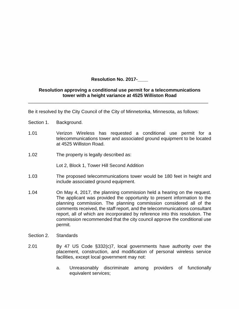
Resolution No. 2017-____
Resolution approving a conditional use permit for a telecommunications tower with a height variance at 4525 Williston Road
_____________________________________________________________________ Be it resolved by the City Council of the City of Minnetonka, Minnesota, as follows: Section 1. Background. 1.01 Verizon Wireless has requested a conditional use permit for a
telecommunications tower and associated ground equipment to be located at 4525 Williston Road.
1.02 The property is legally described as:
Lot 2, Block 1, Tower Hill Second Addition 1.03 The proposed telecommunications tower would be 180 feet in height and
include associated ground equipment. 1.04 On May 4, 2017, the planning commission held a hearing on the request.
The applicant was provided the opportunity to present information to the planning commission. The planning commission considered all of the comments received, the staff report, and the telecommunications consultant report, all of which are incorporated by reference into this resolution. The commission recommended that the city council approve the conditional use permit.
Section 2. Standards 2.01 By 47 US Code §332(c)7, local governments have authority over the
placement, construction, and modification of personal wireless service facilities, except local government may not:
a. Unreasonably discriminate among providers of functionally
equivalent services;

Resolution No. 2017-____ Page 2
b. Prohibit or have the effect of prohibiting the provision of personal
wireless services; and
c. Regulate the placement, construction, and modification of personal wireless service facilities on the basis of the environmental effects of radio frequency emissions to the extent that such facilities comply with the Federal Communication Commission's regulations concerning such emissions.
2.02 City Code 300.34 Subd.4(b) outlines the following conditional use permit
standards for telecommunications facilities within residential and commercial zoning districts:
a. Telecommunication facilities may be located only on public or
institutional property: in R-1 and R-2 residential districts and on property guided for low-density residential in the Planned I-394 District subject to the standards listed in subparagraphs b through e which follow.
b. An applicant must provide an analysis prepared by a radio or
electrical engineer demonstrating that the proposed location of the antennas is necessary to meet the coverage and capacity needs of its system and that there is no existing antenna support structure that could adequately serve the area if antennas were placed on it. The applicant must also pay the reasonable expenses of a radio or electrical engineer retained by the city, at its option, to review this analysis;
c. A telecommunications facility must use as many stealth design techniques as reasonably possible. Economic considerations alone are not justification for failing to provide stealth design techniques. The city council may require that a different location be used if it would result in less public visibility, is available, and would meet the applicant’s reasonable capacity and coverage needs; and
d. A telecommunications tower and antennas, including attachments other than lighting rods, must not exceed 75 feet in height, measured from grade. The city council may increase this height to 90 feet if the increase in height would not have a significant impact on surrounding properties because of proximity, topography or screening by trees or buildings or would accommodate two or more users. The city council may waive this height standard for a tower used wholly or partially for essential public services, such as public safety.

Resolution No. 2017-____ Page 3
e. Telecommunications facilities may be located in public right-of-way
of a major collector or arterial roadway as defined in the comprehensive plan, if they meet all of the following requirements:
1. The facility is not located within a special area designated
subdivision 7;
2. The facility is not located adjacent to residentially zoned property unless the applicant demonstrates by providing a study prepared by a radio or electrical engineer demonstrating that the proposed location of the antennas is necessary to meet the coverage and capacity needs of its system and no other location is feasible in a non-residential zone;
3. The facility must use as many stealth design techniques as reasonably possible. In particular, the antennas must be designed to minimize their size and appearance. Economic considerations alone are not justification for failing to provide stealth design techniques; and
4. The facility must also comply with the requirements in subdivision 6(k).
2.03 By City Code §300.07 Subd. 1, a variance may be granted from the
requirements of the zoning ordinance when: (1) the variance is in harmony with the general purposes and intent of this ordinance; (2) when the variance is consistent with the comprehensive plan; and (3) when the applicant establishes that there are practical difficulties in complying with the ordinance. Practical difficulties means: (1) The proposed use is reasonable; (2) the need for a variance is caused by circumstances unique to the property, not created by the property owner, and not solely based on economic considerations; and (3) the proposed use would not alter the essential character of the surrounding area.
Section 3. Findings. 3.01 The proposal meets the variance standard outlined in City Code §300.07
Subd. 1(a):
1. PURPOSE AND INTENT OF THE ZONING ORDINANCE: The R-1 District allows telecommunications facilities as a conditional use on public or institutional property guided for low-density residential.
Resolution No. 2017-____ Page 4
2. CONSISTENT WITH COMPREHENSIVE PLAN: The comprehensive plan guides the property for low-density residential use.
3. PRACTICAL DIFFICULTIES: There are practical difficulties in
complying with the ordinance:
a. REASONABLENESS:
i. The request is reasonable for the applicant to achieve reasonable telecommunications coverage. The city’s telecommunications consulting engineer determined the minimum height required to obtain reasonable coverage exceeds the 90 feet telecommunications tower standards established in city code section 300.34 subd. 4(b)(1)(d). Therefore a variance is warranted to comply with the Federal Telecommunications Act.
b. UNIQUE CIRCUMSTANCE:
ii. Although the water tower would provide the necessary height for reasonable coverage, space is not available for collocation. There are no other facilities or buildings available for collocation in the required coverage area. The construction of a telecommunications tower at this location and height is unique. The city does allow tower of similar height up to 199 feet high if the applicant can demonstrate that off-site views of the tower will be minimized by the topography of the site and surrounding area, the location of the tower, the tower design, the surrounding tree cover and structures, or the use of screening.
c. CHARACTER OF LOCALITY:
iii. The request is reasonable for the applicant to achieve reasonable telecommunications coverage. The city’s telecommunications consulting engineer determined the minimum height required to obtain reasonable coverage exceeds the 90 feet telecommunications tower standards established in city code section 300.34 subd. 4(b)(1)(d). Therefore a variance is warranted to comply with the Federal Telecommunications Act. City code would allow a telecommunications tower as a conditional use permit on many properties in the immediate area.
Resolution No. 2017-____ Page 5
The presence of the water tower, commercial development, tree canopy and topographic change help reduce the visual impact of the additional tower height requested. The location of the proposed tower was determined in order to minimize potential visual impacts.
3.02 The proposal would not meet the specific conditional use permit standards as outlined in City Code §300.34 Subd.4(b): 1) Telecommunication facilities may be located only on public or institutional property: in R-1 and R-2 residential districts and on property guided for low-density residential in the Planned I-394 District subject the standards listed in subparagraphs b through e which follow. Finding: The proposed facility would be located on institutional property. 2) An applicant must provide an analysis prepared by a radio or electrical engineer demonstrating that the proposed location of the antennas is necessary to meet the coverage and capacity needs of its system and that there is no existing antenna support structure that could adequately serve the area if antennas were placed on it. The applicant must also pay the reasonable expenses of a radio or electrical engineer retained by the city, at its option, to review this analysis; Finding: The information supplied by the applicant was reviewed by the city’s telecommunications consultant. The consultant confirmed that the location and height reasonably meet the applicant’s coverage needs. 3) A telecommunications facility must use as many stealth design techniques as reasonably possible. Economic considerations alone are not justification for failing to provide stealth design techniques. The city council may require that a different location be used if it would result in less public visibility, is available, and would meet the applicant’s reasonable capacity and coverage needs; and Finding: The applicant is proposing a stealth design monopole structure. 4) A telecommunications tower and antennas, including attachments other than lightning rods, must not exceed 75 feet in height, measured from grade. The city council may increase this height to 90 feet if the increase in height would not have a significant impact on surrounding properties because of proximity, topography or screening by trees or buildings or would accommodate two or more users. The city council may waive this

Resolution No. 2017-____ Page 6
height standard for a tower used wholly or partially for essential public services, such as public safety. Finding: The city’s telecommunications consultant has confirmed that the minimum height needed exceeds the city’s 90-foot height maximum. The council will need to approve a height variance in order to provide the applicant with reasonable coverage.
Section 4 Council Action. 4.01 The above-described conditional use permit is hereby approved based on
the findings of section 3 of this resolution. 4.02 The conditional use permit is approved with the following conditions:
a. This resolution must be recorded with Hennepin County.
b. The applicant shall enter into an agreement with the city that addresses the use, maintenance and ownership or leasing arrangements of the telecommunications facility.
c. If the project exceeds 50 cubic yards of excavation/fill or 5,000 square feet of land disturbing activity stormwater management will be required, and the applicant must conform to the following criteria:
1. Rate Control: limit peak runoff flow rates to that from existing
conditions for the 2-, 10-, and 100-year events for all points where stormwater leaves the site.
2. Volume Control: Provide on-site retention of 1" over the
additional impervious surface added through the project. 3. Water Quality Treatment: Provide for all runoff generated by
the additional impervious surface be treated to at least 60% annual phosphorus removal and 90% annual total suspended solid removal. Pollutant removal efficiencies can also be achieved through onsite retention/detention of the 2.5-inch event.
d. Provide an updated landscape plan to address the following:
1. The project will impact 5 honey locust and 1 hawthorn trees that
are unable to be moved. Provide $2,000 to plant and care for six new trees.
Resolution No. 2017-____ Page 7
2. Maintain the temporary access south of the cottonwood and
catalpa trees to avoid any tree damage.
3. Tree protection fencing or silt fence will be required on the west side of the stairway so the grading activity is contained and tree impacts are minimized.
4. The project must not impact the woodland area. Minimize impacts to a 29” black cherry tree on the corner of the woods, (indicated as a 15” box at the SE corner of sheet A-7 on the submitted survey).
5. The closest Ponderosa Pine tree on the east side of the water tower is about 10-feet away from the “underground electrical run”. If the electrical line is not bored underground, any surface disturbance should be kept 15-20 feet away.
e. The building must comply with all requirements of the Minnesota
state building code, fire code, and health code.
f. Submit necessary project escrows as required by the city.
g. The city council may reasonably add or revise conditions to address any future unforeseen problems.
h. The approval will expire on December 31, 2018 if a building permit has not been issued.
Adopted by the City Council of the City of Minnetonka, Minnesota, on May 22, 2017. _______________________________________ Terry Schneider, Mayor Attest: _________________________________ David E. Maeda, City Clerk

Resolution No. 2017-____ Page 8 Action on this resolution: Motion for adoption: Seconded by: Voted in favor of: Voted against: Abstained: Absent: Resolution adopted. I hereby certify that the foregoing is a true and correct copy of a resolution adopted by the City Council of the City of Minnetonka, Minnesota, at a meeting held on May 22, 2017. __________________________________ David E. Maeda, City Clerk