Physical modelling and numerical prediction of defects in sheet metal forming
15
Journal of Materials Processing Technology, 32 (1992) 383-397 383 Elsevier Physical Modelling and Numerical Prediction of Defects in Sheet Metal Formin~ C. Levaillant and J. L. Chenot CEMEF - Centre de Mise en Forme des Matariaux - Ecole Nationale SupSrieure des Mines de Paris - BP 207 - 06904 SOPHIA ANTIPOLIS - FRANCE This paper aims at presenting the various defects involved in sheet metal forming and recalling the experimental procedure that are used to obtain these defects in laboratory type tests. The material and process conditions that have a significant influence on defects are reviewed. Finally, the prediction of defect by numerical simulation and especially by the Finite Element Method is discussed. Emphasis is given to the research domains that require most efforts for the future of defect control. 1. INTRODUCTION The occurence of defects in sheet metal forming is a critical problem for industry especially for mass production like in automotive or canning applications. To address this problem, two research routes are followed : one deals with the improvement of metal formability by controlling inclusion content and optimizing the microstructure (to delay the necking instability) for larger work hardening capacity and Lankford ratio (to reduce sheet thinning). The other one consists in improving the stamping process itself, through better tool design, friction control,blank holder pressure control .... Defect prediction in sheet metal stamping is a hard challenge because of the superposition of multiple parameters influences in a context of complex geometries and boundary conditions : the accurate prediction of stress and strain state during stamping of actual component is not actually achieved but seems possible within few years due to the considerable progress of computer power combined with the development of Finite Element softwares devoted to sheet metal forming. For this reason, the accurate prediction of defects is still not possible for industrial today use but it will be clearly the next step for the sheet metal stamping industry : it is anticipated to introduce defect prediction criterion into the Computer Assisted Design of stamping process. Before these industrial applications, it is necessary to improve and validate these defects criterion especially by the comparison of FEM defect predictions and experimental laboratory (in a first stage) and full scale (in a second stage) results. The aim of this paper is to review the physical results dealing with defect occurrence, obtained experimentally with the numerical simulation of the corresponding experiments, in order to emphasize the areas where further research efforts are needed. 1992 ElsevierSciencePublishersB.V.
-
Upload
independent -
Category
Documents
-
view
0 -
download
0
Transcript of Physical modelling and numerical prediction of defects in sheet metal forming
Journal of Materials Processing Technology, 32 (1992) 383-397 383 Elsevier
P h y s i c a l M o d e l l i n g a n d N u m e r i c a l P r e d i c t i o n o f Defec t s in S h e e t Metal Formin~
C. Levaillant and J. L. Chenot
CEMEF - Centre de Mise en Forme des Matariaux - Ecole Nationale SupSrieure des Mines de Paris - BP 207 - 06904 SOPHIA ANTIPOLIS - FRANCE
This paper aims at presenting the various defects involved in sheet metal forming and recalling the experimental procedure that are used to obtain these defects in laboratory type tests. The material and process conditions that have a significant influence on defects are reviewed. Finally, the prediction of defect by numerical simulation and especially by the Finite Element Method is discussed. Emphasis is given to the research domains that require most efforts for the future of defect control.
1. INTRODUCTION
The occurence of defects in sheet metal forming is a critical problem for indus t ry especially for mass production like in automotive or canning applications. To address this problem, two research routes are followed : one deals with the improvement of metal formability by controlling inclusion content and optimizing the microstructure (to delay the necking instability) for larger work hardening capacity and Lankford ratio (to reduce sheet thinning). The other one consists in improving the stamping process itself, through better tool design, friction control,blank holder pressure control .... Defect prediction in sheet metal stamping is a hard challenge because of the superposition of multiple parameters influences in a context of complex geometries and boundary conditions : the accurate prediction of stress and strain state during stamping of actual component is not actually achieved but seems possible within few years due to the considerable progress of computer power combined with the development of Finite Element softwares devoted to sheet metal forming. For this reason, the accurate prediction of defects is still not possible for industrial today use but it will be clearly the next step for the sheet metal stamping industry : it is anticipated to introduce defect prediction criterion into the Computer Assisted Design of stamping process. Before these industrial applications, it is necessary to improve and validate these defects criterion especially by the comparison of FEM defect predictions and experimental laboratory (in a first stage) and full scale (in a second stage) results. The aim of this paper is to review the physical results dealing with defect occurrence, obtained experimentally with the numerical simulation of the corresponding experiments, in order to emphasize the areas where further research efforts are needed.
1992 Elsevier Science Publishers B.V.
384
2. CLASSIFICATION OF DEFECTS IN SHEET METAL FORMING
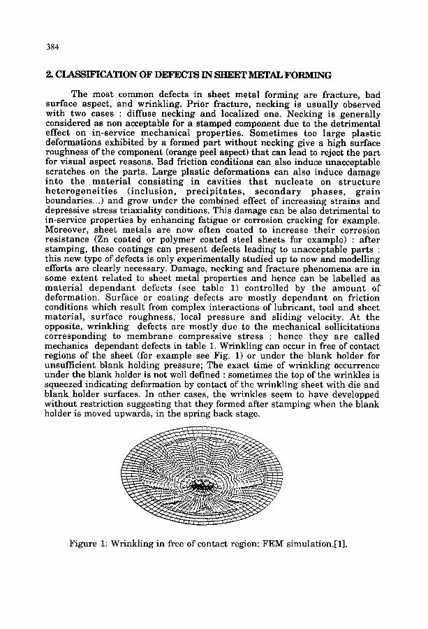
The most common defects in sheet metal forming are fracture, bad surface aspect, and wrinkling. Prior fracture, necking is usually observed with two cases : diffuse necking and localized one. Necking is generally considered as non acceptable for a stamped component due to the detrimental effect on in-service mechanical properties. Sometimes too large plastic deformations exhibited by a formed part without necking give a high surface roughness of the component (orange peel aspect) that can lead to reject the part for visual aspect reasons. Bad friction conditions can also induce unacceptable scratches on the parts. Large plastic deformations can also induce damage into the mater ia l consist ing in cavities t ha t nucleate on s t ruc ture he t e rogene i t i e s ( inclusion, p rec ip i ta tes , secondary phases , g ra in boundaries...) and grow under the combined effect of increasing strains and depressive stress triaxiality conditions. This damage can be also detrimental to in-service properties by enhancing fatigue or corrosion cracking for example. Moreover, sheet metals are now often coated to increase their corrosion resistance (Zn coated or polymer coated steel sheets for example) : after stamping, these coatings can present defects leading to unacceptable parts : this new type of defects is only experimentally studied up to now and modelling efforts are clearly necessary. Damage, necking and fracture phenomena are in some extent related to sheet metal properties and hence can be labelled as mater ia l dependant defects (see table 1) controlled by the amount of deformation. Surface or coating defects are mostly dependant on friction conditions which result from complex interactions of lubricant, tool and sheet material , surface roughness, local pressure and sliding velocity. At the opposite, wrinkling defects are mostly due to the mechanical sollicitations corresponding to membrane compressive stress : hence they are called mechanics dependant defects in table 1. Wrinkling can occur in free of contact regions of the sheet (for example see Fig. 1) or under the blank holder for unsufficient blank holding pressure; The exact time of wrinkling occurrence under the blank holder is not well defined : sometimes the top of the wrinkles is squeezed indicating deformation by contact of the wrinkling sheet with die and blank holder surfaces. In other cases, the wrinkles seem to have developped without restriction suggesting that they formed after stamping when the blank holder is moved upwards, in the spring back stage.
~ . . . . . . . .
Figure 1: Wrinkling in free of contact region: FEM simulation.[1].
385
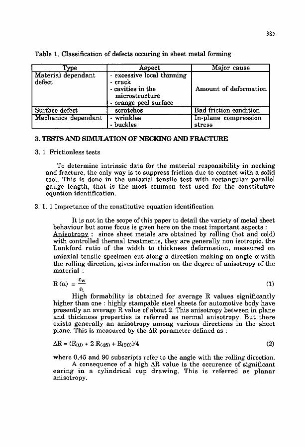
Table 1. Classification of defects occuring in sheet metal forming
T•pe Material dependant defect
Aspect - excessive local thinning - crack - cavities in the
microstructure - orange peel surface - scratches
Major cause
Amount of deformation
Surface defect Bad friction condition Mechanics dependant - wrinkles In-plane compression
- buckles stress
3. TESTS AND SIMULATION OF NECKING AND FRACTURE
3.1 Frictionless tests
To determine intrinsic data for the material responsibility in necking and fracture, the only way is to suppress friction due to contact with a solid tool. This is done in the uniaxial tensile test with rec tangular parallel gauge length, tha t is the most common test used for the consti tutive equation identification.
3 . 1 . 1 Importance of the constitutive equation identification
It is not in the scope of this paper to detail the variety of metal sheet behaviour but some focus is given here on the most important aspects : Anisot roov : since sheet metals are obtained by rolling (hot and cold) with controlled thermal treatments, they are generally non isotropic, the Lankford ratio of the width to thickness deformation, measured on uniaxial tensile specimen cut along a direction making an angle a with the rolling direction, gives information on the degree of anisotropy of the material :
Ew R (a) = - - (1)
Ct High formability is obtained for average R values significantly
higher than one : highly stampable steel sheets for automotive body have presently an average R value of about 2. This anisotropy between in plane and thickness properties is referred as normal anisotropy. But there exists generally an anisotropy among various directions in the sheet plane. This is measured by the AR parameter defined as :
AR = (R(o) + 2 R(45) + R(90))/4 (2)
where 0,45 and 90 subscripts refer to the angle with the rolling direction. A consequence of a high AR value is the occurence of significant
ear ing in a cylindrical cup drawing. This is re fe r red as p lanar anisotropy.
386
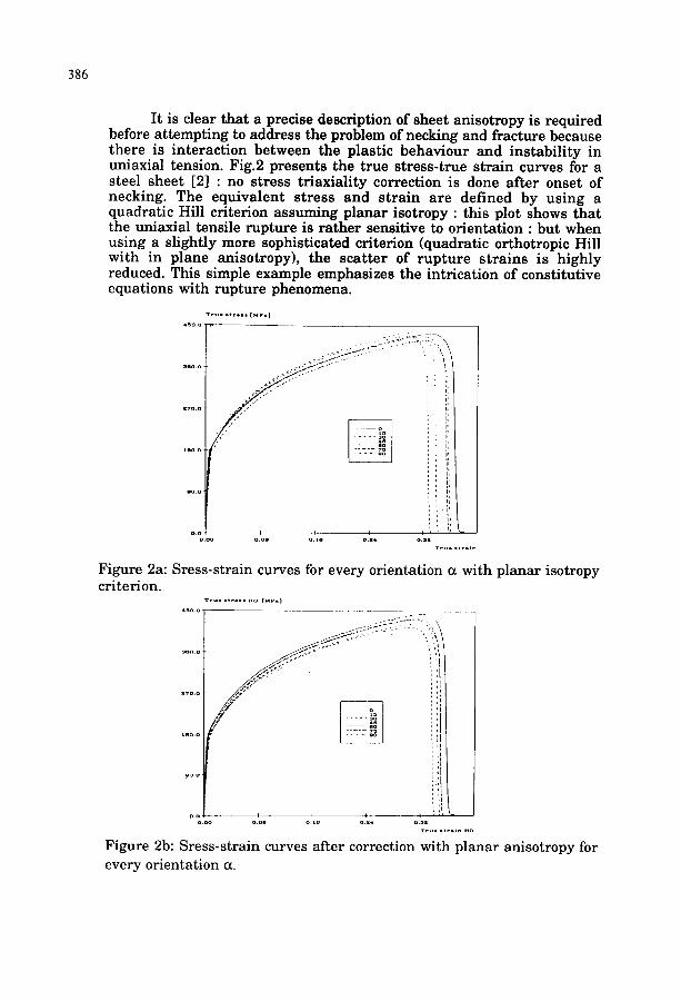
It is clear that a precise description of sheet anisotropy is required before attempting to address the problem of necking and fracture because there is interaction between the plastic behaviour and instabili ty in uniaxial tension. Fig.2 presents the true stress-true strain curves for a steel sheet [2] : no stress triaxiality correction is done after onset of necking. The equivalent stress and strain are defined by using a quadratic Hill criterion assuming planar isotropy : this plot shows that the uniaxial tensile rupture is rather sensitive to orientation : but when using a slightly more sophisticated criterion (quadratic orthotropic Hill with in plane anisotropy), the scat ter of rupture strains is highly reduced. This simple example emphasizes the intrication of constitutive equations with rupture phenomena.
T r y . . t r o . . [ ~ e . ] , S O . O
. . . . . . i?
0 0 o . o o
I I '1
o 2 4 0 3 2
Figure 2a: Sress-strain curves for every orientation a with planar isotropy criterion.
T r u e . t r t . . N O [ M P . I
4 ~ 0 0 . . . . . . . . . . . . . .
..... f , :i
l a o . o
.... il
i. ~ ~ o . o , I I ~
o o o o . o e o l a o e 4
T r u . . t r . J n ~ o
Figure 2b: Sress-strain curves after correction with planar anisotropy for every orientation a.
387
Many choices are possible for the plastic behaviour , according to a large l i t e ra tu re on this subject between : - quadrat ic and non quadrat ic cri ter ia [3] - associated (i.e. with normal i ty rule) or non associated flow rules [4] - constant anisotropy (i.e; corresponding to as received sheet) or induced
anisotropy.(due to local possible high s t ra ins dur ing s tamping tha t involves crystal lographic t ex ture changes)[5]
- isotropic or k inemat ic harden ing [6].
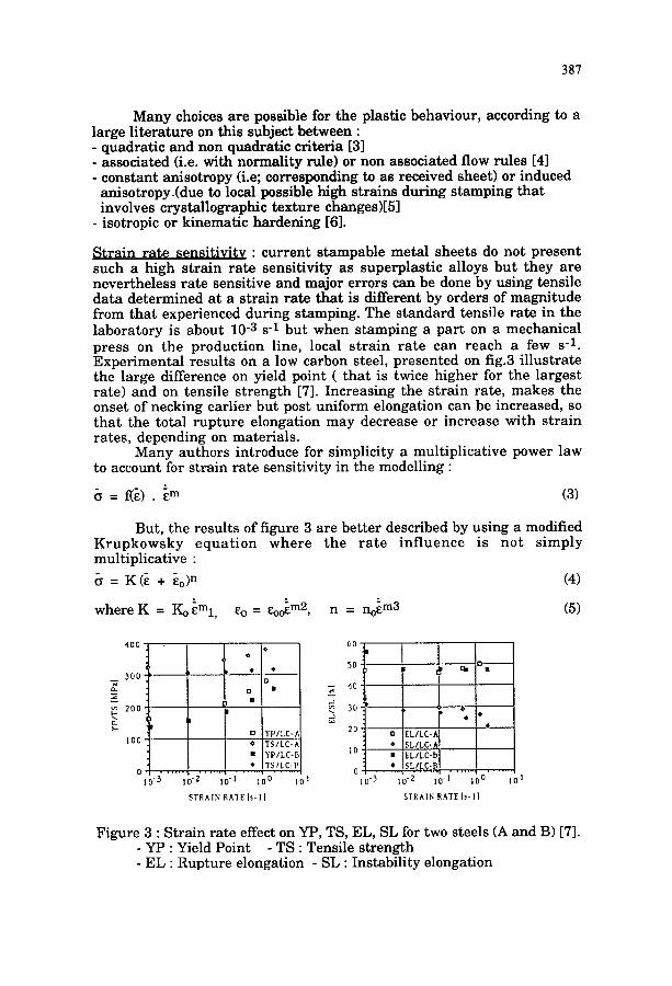
S t r a in ra te sensi t iv i ty : cu r ren t s tampable meta l sheets do not p resen t such a high s t ra in ra te sensi t iv i ty as superplas t ic alloys b u t they are never the less ra te sensit ive and major errors can be done by using tensi le da ta de te rmined at a s t ra in ra te t ha t is different by orders of magni tude from tha t experienced dur ing stamping. The s t andard tensi le ra te in the l abora to ry is about 10 -3 s -1 bu t when s tamping a pa r t on a mechanical press on the p roduc t ion line, local s t r a in r a t e can r each a few s -1. Exper imen ta l resul ts on a low carbon steel, p resen ted on fig.3 i l lus t ra te the large difference on yield point ( t h a t is twice h igher for the larges t ra te) and on tensi le s t reng th [7]. Increas ing the s t ra in ra te , makes the onset of necking ear l ier bu t post uniform elongation can be increased, so t ha t the total r up tu r e elongation may decrease or increase wi th s t ra in ra tes , depending on mater ia ls .
Many au thors in t roduce for simplicity a mul t ipl icat ive power law to account for s t ra in ra te sensit ivity in the modelling :
8 = fiB). ~m (3)
But, the resul ts of figure 3 are be t t e r described by using a modified K r u p k o w s k y e q u a t i o n w h e r e the r a t e i n f l u e n c e is no t s imp ly mult ipl icat ive :
= K(~ + ~o) n (4)
w h e r e g = Koeml, ~o = eooe m2, n = no~ m3 (5)
400
_ 3 0 0
2 0 0
~. •
l O 0 -
0 i o - 3
o
o
IJ
o Y P I L C - A
' ) T S I L C - A
• Y P / L C - D
• T S / L C - D . . . . . . . . l . . . . . . . . . . . . . . . s . . . . . . . .
0-2 lO-I i0 D IO !
STRAIN RATE I s - l ]
5 0 ' ~ ~ •
4° I 3 0
20 a
. . . . . . . . . . . . . . . . . . . . . . . 1 . . . . . . lO'3 10-2 lO'l I0 0 10 I
S T R A I N RATE I s - l ]
Figure 3 : S t ra in ra te effect on YP, TS, EL, SL for two steels (A and B) [7]. - YP : Yield Point - TS : Tensile s t rength - EL : Rupture elongation - SL : Instabil i ty elongation
388
By us ing the H a r t cr i ter ion in t roduced to assess necking as the instabil i ty of a local reduction of section (cf § 3.1.2), in uniaxial tension, it is easy to in te rpre t the earl ier necking at high s t ra in ra tes [7].
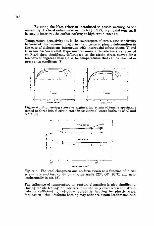
T e m p e r a t u r e sensi t iv i ty : i t is the counte rpar t of s t ra in ra te sensi t ivi ty because of the i r common origin in the physics of plas£ic deformat ion in the case of dislocations in terac t ion with inters t i t ia l solute a toms (C and N in low carbon steels). Exper imenta l uniaxial tensile tes ts as repor ted on Fig.4 show signif icant differences on the s t ra in-s t ress curves for a few tens of degrees Celsius, i. e. for t empera tu res tha t can be reached in press shop conditions [8].
¥
F ,, ,~,,~:
°! . . . . . . . . . 1
Figure 4 : Engineer ing stress vs engineer ing s t ra in of tensi le specimens tes ted at three initial s t ra in ra tes in isothermal wa te r ba ths a t 23°C and 60°C. [8].
4O
z .(
2o
TOTAL [LONGATION Z3"C
L l Z ........................................... r ................... l a i r
UF¢I fORM STRAIN
I ........... t'. I I n ~o9¢c
0 v , J i , a
]O" 10 .2 lO q
INITIAL STRAIN RAIIE IS "l)
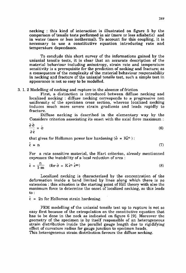
Figure 5 : The total elongation and uniform s t ra in as a function of initial s t ra in ra te and tes t condition - i so thermal ly (23 °, 60 °, 90°C) and non- i so thermal ly in air. [8].
The influence of t empe ra tu r e on rup tu re elongat ion is also significant. Dur ing tensile testing, an intr icate s i tuat ion m ay exist when the s t ra in r a t e is suf f ic ient to i n t roduce ad iaba t ic h e a t i n g by p las t ic work dissipation : this adiabatic hea t ing may enhance s t ra in localization and
389
necking : this kind of interact ion is i l lus t ra ted on figure 5 by the comparison of tensile tests performed in air (more or less adiabatic) and in water (more or less isothermal). To account for this coupling, it is necessa ry to use a cons t i tu t ive equat ion in t roduc ing r a t e and tempera ture dependance.
To conclude this short survey of the informations gained by the uniaxial tensile tests, it is clear tha t an accurate description of the material behaviour including anisotropy, strain rate and tempera ture sensitivity is a prerequisite for the prediction of necking and fracture; as a consequence of the complexity of the material behaviour responsability in necking and fracture of the uniaxial tensile test, such a simple test in appearance is not so easy to be modelled.
3 . 1 . 2 Modelling of necking and rupture in the absence of friction First , a distinction is introduced between diffuse necking and
localized necking : diffuse necking corresponds to a progressive non uniformity of the specimen cross section, whereas localized necking induces much more severe s t ra in gradients and leads rapidly to fracture.
Diffuse necking is described in the e l ementa ry way by the Considere criterion associating its onset with the axial force maximum :
- ~ (6)
tha t gives for Hollomon power law hardening (~ = I~ n ) :
= n (7)
For a rate sensitive material , the Har t criterion, already mentionned expresses the instability of a local reduction of area :
n - 1-m (for~ = K~ n ~m) (8)
Localized necking is characterized by the concentrat ion of the deformation inside a band limited by lines along which there is no extension : this situation is the starting point of Hill theory with also the maximum force to determine the onset of localized necking, so this leads to :
= 2n for Hollomon strain hardening.
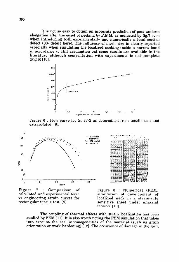
FEM modelling of the uniaxial tensile test up to rupture is not so easy first because of the extrapolation on the constitutive equation that has to be done in the neck as indicated on figure 6 [9]. Moreover the geometry of the specimen is by i tself responsible of an heterogeneous s train distribution inside the parallel gauge length due to rigidifying effect of curvature radius for gauge junction to specimen heads. This heterogeneous strain distribution favours the diffuse necking.
390
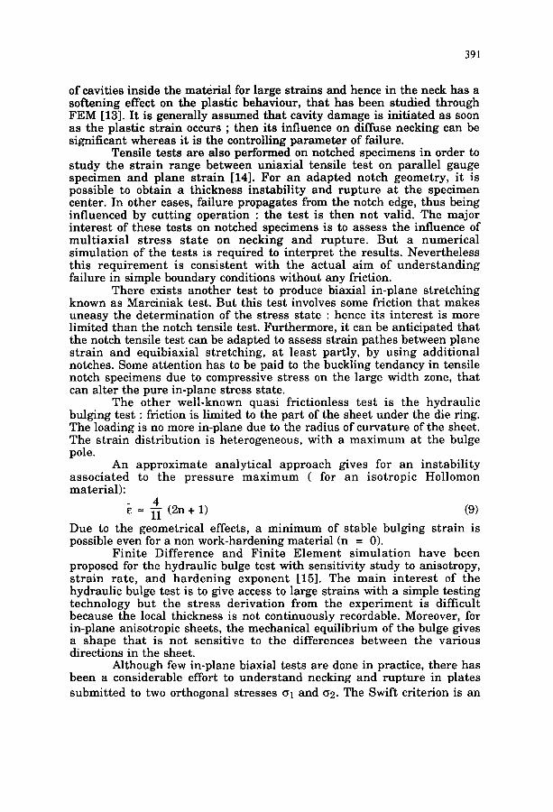
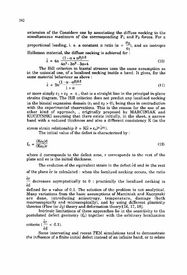
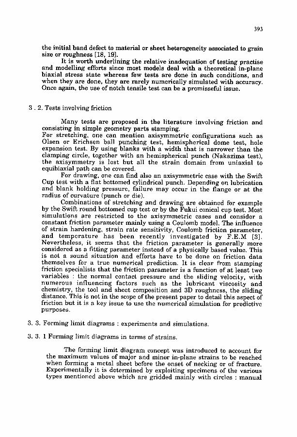
It is not so easy to obtain an acccurate prediction of post uniform elongation after the onset of necking by F.E.M. as indicated by fig.7 even when introducing both experimentally and numerically a local section defect (3% defect here). The influence of mesh size is clearly reported especially when simulating the localized necking inside a narrow band in accordance to Hill assumption but some results are available in the l i terature al though confrontation with experiments is not complete (Fig.8) [10].
J
riO0"
N /mm ~-
600-
500-
~00-
300-
ol
J
0 0,2 0.~ 0.6 0.8 ;.0 1,2 equiva lent ~us t i c s t r a i n
Figure 6 : Flow curve for St 87-2 as determined from tensile test and extrapolated. [9].
SO.
kN
~5
~0
0
• " ~ ' _ ] ~ L J .
' ~" . . . . ~ ' - ' k •
o / . •
o, o2 0'.3 0, 3 t r a i n
Figure 7 : Compar i son of calculated and experimental force vs engineering strain curves for rectangular tensile test. [9]
c> : t cnsJon r a t i o u / L - o ca lcu la t ion o. I 0 . 12 ?
experiment : • a 3 % -no t ch i
a no Notch
Figure 8 : Numerical (FEM) s imula t ion of development of localized neck in a s t ra in-rate sensitive sheet under uniaxial tension. [10].
The coupling of thermal effects with strain localization has been studied by FEM [11]. It is also worth noting the FEM simulation that takes into account the real inhomogeneities of the material (such as grain orientation or work hardening) [12]. The occurrence of damage in the form
391
of cavities inside the material for large strains and hence in the neck has a softening effect on the plastic behaviour, tha t has been studied through FEM [13]. It is generally assumed tha t cavity damage is initiated as soon as the plastic strain occurs ; then its influence on diffuse necking can be significant whereas it is the controlling parameter of failure.
Tensile tests are also performed on notched specimens in order to study the strain range between uniaxial tensile test on parallel gauge specimen and plane strain [14]. For an adapted notch geometry, it is possible to obtain a thickness instabili ty and rupture at the specimen center. In other cases, failure propagates from the notch edge, thus being influenced by cutting operation : the test is then not valid. The major interest of these tests on notched specimens is to assess the influence of mult iaxial stress s tate on necking and rupture . But a numerical simulation of the tests is required to interpret the results. Nevertheless this requirement is consistent with the actual aim of unders tanding failure in simple boundary conditions without any friction.
There exists another test to produce biaxial in-plane stretching known as Marciniak test. But this test involves some friction that makes uneasy the determination of the stress state : hence its interest is more limited than the notch tensile test. Furthermore, it can be anticipated that the notch tensile test can be adapted to assess strain pathes between plane strain and equibiaxial stretching, at least partly, by using additional notches. Some attention has to be paid to the buckling tendancy in tensile notch specimens due to compressive stress on the large width zone, that can alter the pure in-plane stress state.
The other well-known quasi frictionless test is the hydraulic bulging test : friction is limited to the part of the sheet under the die ring. The loading is no more in-plane due to the radius of curvature of the sheet. The strain distribution is heterogeneous, with a maximum at the bulge pole.
An approximate analytical approach gives for an instabi l i ty associated to the pressure maximum ( for an isotropic Hollomon material):
4 ~- ~ (2n+ l ) (9)
Due to the geometrical effects, a minimum of stable bulging strain is possible even for a non work-hardening material (n = 0).
Fini te Difference and Finite Element s imulat ion have been proposed for the hydraulic bulge test with sensitivity study to anisotropy, s t rain rate, and hardening exponent [15]. The main interest of the hydraulic bulge test is to give access to large strains with a simple testing technology but the stress derivation from the experiment is difficult because the local thickness is not continuously recordable. Moreover, for in-plane anisotropic sheets, the mechanical equilibrium of the bulge gives a shape tha t is not sensitive to the differences between the various directions in the sheet.
Although few in-plane biaxial tests are done in practice, there has been a considerable effort to understand necking and rupture in plates submitted to two orthogonal stresses Ol and o2. The Swift criterion is an
392
extens ion of the Considere one by associat ing the diffuse necking to the s imul t aneous m a x i m u m of the cor r respond ing F1 and F2 forces. For a
propor t ional loading, i. e. a cons tan t a rat io (a = o2), and an isotropic Ol
Hollomon mater ia l , the diffuse necking is achieved for : ( 1 - a + a2) 1.5
= 4n (10) 4a 3 - 3a 2 - 3a+4
The Hill cr i ter ion in biaxial s t resses uses the same assumpt ion as in the uniaxial one, of a localized necking inside a band. I t gives, for the same mater ia l behaviour as above :
2n(1 - a - {x2) 0.5 -- (11)
l + ( z
or more simply el + e2 = n , tha t is a s t ra ight line in the principal in-plane s t ra ins diagram. The Hill cri terion does not predict any localized necking in the biaxial expansion domain (el and e2 > 0), being thus in contradiction wi th the exper imenta l observations. This is the reason for the use of an o the r k ind of approach , , o r ig ina l ly proposed by MARCINIAK and KUCZYNSKI assuming tha t there exists initially, in the sheet, a nar row band with a reduced thickness and also a different consistency K (in the
stress s t ra in re la t ionship 6 = K(~ + eo) n ~m). The initial value of the defect is character ized by :
(Keo)d fo - (Keo)r (12)
where d corresponds to the defect zone, r corresponds to the res t of the plate and eo is the initial thickness.
The evolution of the equivalent s t ra in in the defect ~d and in the rest
of the plane ~r is calculated : when the localized necking occurs, the rat io
~r - - decreases asympto t ica l ly to 0 : prac t ica l ly the localized necking is ~d defined for a value of 0.1. The solution of the problem is not analyt ical . Many var ia t ions from the basic assumptions of Marciniak and Kuczynski a r e done , i n t r o d u c i n g a n i s o t r o p y , t e m p e r a t u r e , d a m a g e (bo th macroscopica l ly and microscopically), and by us ing d i f fe ren t p las t ic i ty theories (Flow (or J2) theory and deformation theory)J16, 17, 18].
Intr insic l imitat ions of these approaches lie in the sensi t ivi ty to the pos tu la ted defect geomet ry fro) toge ther with the a r b i t r a r y local izat ion
cri ter ia ( ~r - - < 0.1). ed
Some in te res t ing and recent FEM simulat ions tend to demons t ra te the influence of a finite initial defect ins tead of an infinite band, or to relate
393
the initial band defect to material or sheet heterogeneity associated to grain size or roughness [18, 19].
It is worth underlining the relative inadequation of testing practise and modelling efforts since most models deal with a theoretical in-plane biaxial stress state whereas few tests are done in such conditions, and when they are done, they are rarely numerically simulated with accuracy. Once again, the use of notch tensile test can be a promisseful issue.
3 . 2 . Tests involving friction
Many tests are proposed in the l i terature involving friction and consisting in simple geometry parts stamping. For stretching, one can mention axisymmetric configurations such as Olsen or Erichsen ball punching test, hemispherical dome test, hole expansion test. By using blanks with a width that is narrower than the clamping circle, together with an hemispherical punch (Nakazima test), the axisymmetry is lost but all the strain domain from uniaxial to equibiaxial path can be covered.
For drawing, one can find also an axisymmetric case with the Swift Cup test with a flat bottomed cylindrical punch. Depending on lubrication and blank holding pressure, failure may occur in the flange or at the radius of curvature (punch or die).
Combinations of stretching and drawing are obtained for example by the Swift round bottomed cup test or by the Fukui conical cup test. Most simulations are restricted to the axisymmetric cases and consider a constant friction parameter mainly using a Coulomb model. The influence of strain hardening, strain rate sensitivity, Coulomb friction parameter, and t empera tu re has been recent ly inves t iga ted by F.E.M [3]. Nevertheless, it seems tha t the friction parameter is generally more considered as a fitting parameter instead of a physically based value. This is not a sound situation and efforts have to be done on friction data themselves for a true numerical prediction. It is clear from stamping friction specialists that the friction parameter is a function of at least two variables : the normal contact pressure and the sliding velocity, with numerous influencing factors such as the lubricant viscosity and chemistry, the tool and sheet composition and 3D roughness, the sliding distance. This is not in the scope of the present paper to detail this aspect of friction but it is a key issue to use the numerical simulation for predictive purposes.
3. 3. Forming limit diagrams : experiments and simulations.
3.3. 1 Forming limit diagrams in terms of strains.
The forming limit diagram concept was introduced to account for the maximum values of major and minor in-plane strains to be reached when forming a metal sheet before the onset of necking or of fracture. Experimentally it is determined by exploiting specimens of the various types mentioned above which are gridded mainly with circles : manual
394
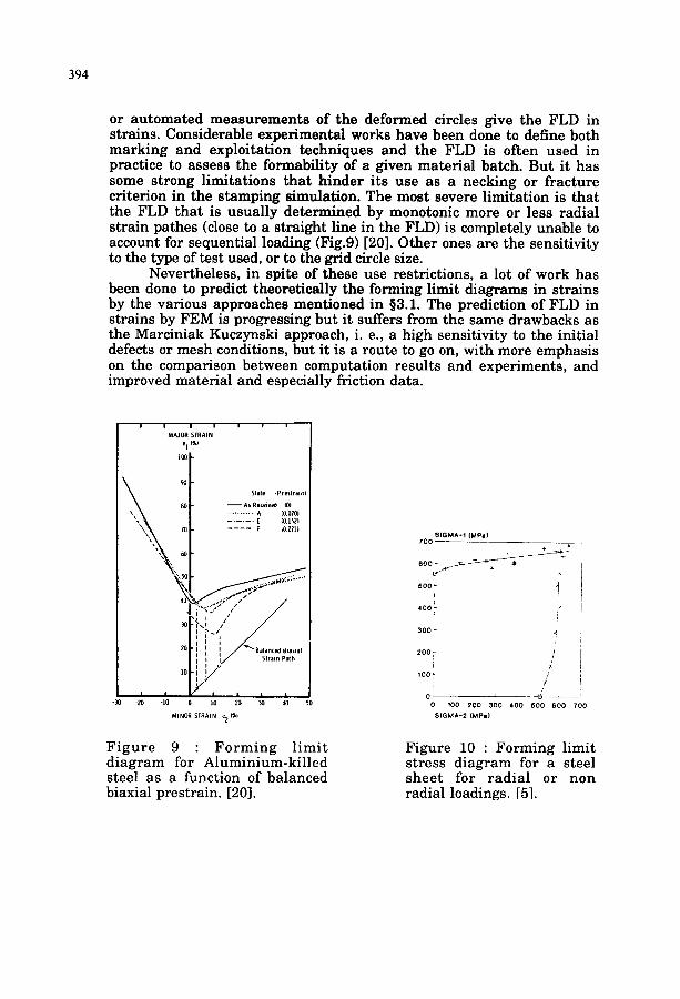
or automated measurements of the deformed circles give the FLD in strains. Considerable experimental works have been done to define both marking and exploitation techniques and the FLD is often used in practice to assess the formability of a given material batch. But it has some strong limitations that hinder its use as a necking or fracture criterion in the stamping simulation. The most severe limitation is that the FLD that is usually determined by monotonic more or less radial strain pathes (dose to a straight line in the FLD) is completely unable to account for sequential loading (Fig.9) [20]. Other ones are the sensitivity to the type of test used, or to the grid circle size.
Nevertheless, in spite of these use restrictions, a lot of work has been done to predict theoretically the forming limit diagrams in strains by the various approaches mentioned in §3.1. The prediction of FLD in strains by FEM is progressing but it suffers from the same drawbacks as the Marciniak Kuczynski approach, i. e., a high sensitivity to the initial defects or mesh conditions, but it is a route to go on, with more emphasis on the comparison between computation results and experiments, and improved material and especially friction data.
| I l I
MAJOR STRAIN e I 19.)
lOO
-30 -20 MINOR SIRAIN e24"/.
Slale ~Prestrain}
- - A s R e c e i v e d 10) . . . . . . . . . . . . . . A (~0101 . . . . . . E (O.15D
0 ]0 20 30 40 50
F i g u r e 9 : F o r m i n g l i m i t d i a g r a m for A l u m i n i u m - k i l l e d s teel as a funct ion of ba l anced biaxial p res t ra in . [20].
SIGMA-1 (MP&) 700 :
BOO ~ ~ .x
500 L ,~ , i
400 '- ,i>
r 300 ~
~°°" /
~ o o . / J
/
o 100 200 300 400 600 600 700 SIGMA-2 (MPa)
Figure 10 : F o r m i n g l imi t s t r e s s d i a g r a m for a s teel s h e e t for r a d i a l or non radia l loadings. [5].
395
3. 3 .2 Forming limit diagram in terms of stresses.
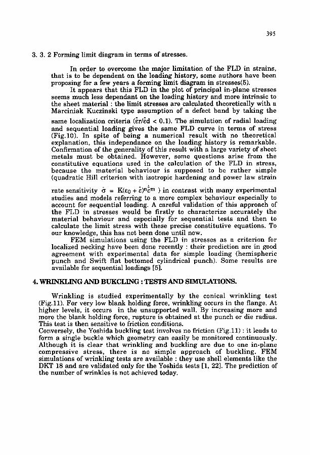
In order to overcome the major limitation of the FLD in strains, that is to be dependent on the loading history, some authors have been proposing for a few years a forming limit diagram in stresses(5).
It appears that this FLD in the plot of principal in-plane stresses seems much less dependant on the loading history and more intrinsic to the sheet material : the limit stresses are calculated theoretically with a Marciniak Kuczinski type assumption of a defect band by taking the
same localization criteria (er/ed < 0.1). The simulation of radial loading and sequential loading gives the same FLD curve in terms of stress (Fig.10). In spite of being a numerical resul t with no theoretical explanation, this independance on the loading history is remarkable. Confirmation of the generality of this result with a large variety of sheet metals must be obtained• However, some questions arise from the constitutive equations used in the calculation of the FLD in stress, because the mater ia l behaviour is supposed to be r a the r simple (quadratic Hill criterion with isotropic hardening and power law strain
rate sensitivity ~ = K(E0 + ~)n~m ) in contrast with many experimental studies and models referring to a more complex behaviour especially to account for sequential loading. A careful validation of this approach of the FLD in stresses would be firstly to characterize accurately the material behaviour and especially for sequential tests and then to calculate the limit stress with these precise constitutive equations• To our knowledge, this has not been done until now.
FEM simulations using the FLD in stresses as a criterion for localized necking have been done recently : their prediction are in good agreement with experimental data for simple loading (hemispheric punch and Swift flat bottomed cylindrical punch). Some results are available for sequential loadings [5].
4. WRINKLING AND BUKCLING : TESTS AND SIMULATIONS.
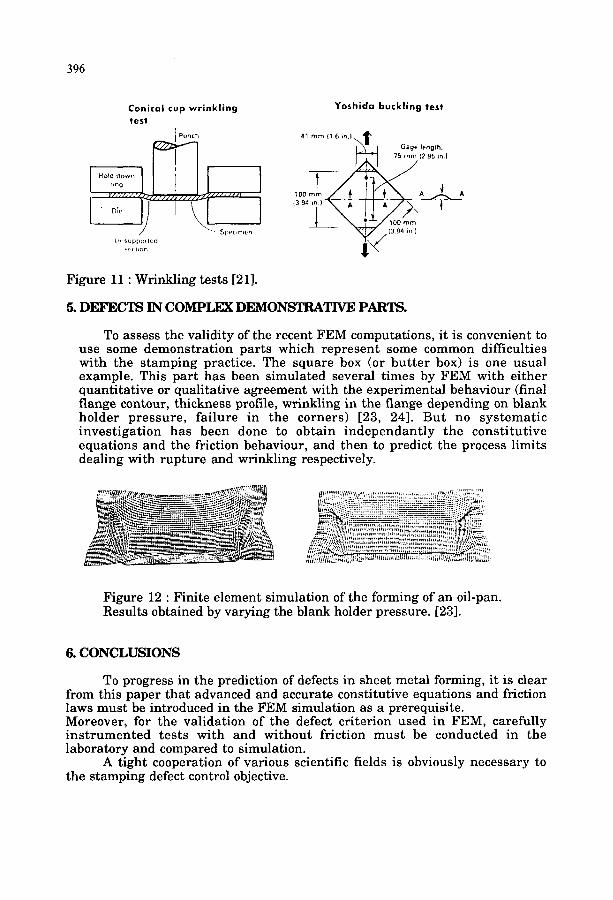
Wrinkling is studied experimentally by the conical wrinkling test (Fig.ll). For very low blank holding force, wrinkling occurs in the flange. At higher levels, it occurs in the unsupported wall. By increasing more and more the blank holding force, rupture is obtained at the punch or die radius. This test is then sensitive to friction conditions. Conversely, the Yoshida buckling test involves no friction (Fig.ll) : it leads to form a single buckle which geometry can easily be monitored continuously. Although it is clear that wrinkling and buckling are due to one in-plane compressive stress, there is no simple approach of buckling. FEM simulations of wrinkling tests are available : they use shell elements like the DKT 18 and are validated only for the Yoshida tests [1, 22]. The prediction of the number of wrinkles is not achieved today.
396
Conical cup w r i n k l i n g test
Punch
)
L~suppo~1( d 5(,c1~on
Yoshida buckling test
41 mm (1 6 ~n.l,~ ~ l Gm~ge length'
75 m (2 95 in.)
7 , , / ( 3 94 *~ )
Figure 11 : Wrinkling tests [21].
5. DEFECTS IN COMPLEX DEMONSTRATIVE PARTS.
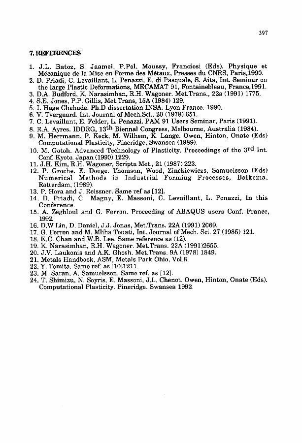
To assess the validity of the recent FEM computations, it is convenient to use some demonstration parts which represent some common difficulties with the stamping practice. The square box (or but ter box) is one usual example. This part has been simulated several times by FEM with either quantitative or qualitative agreement with the experimental behaviour (final flange contour, thickness profile, wrinkling in the flange depending on blank holder pressure, failure in the corners) [23, 24]. But no systematic investigation has been done to obtain independant ly the constitutive equations and the friction behaviour, and then to predict the process limits dealing with rupture and wrinkling respectively.
Figure 12 : Finite element simulation of the forming of an oil-pan. Results obtained by varying the blank holder pressure. [23].
6. CONCLUSIONS
To progress in the prediction of defects in sheet metal forming, it is clear from this paper that advanced and accurate constitutive equations and friction laws must be introduced in the FEM simulation as a prerequisite. Moreover, for the validation of the defect criterion used in FEM, carefully ins t rumented tests with and without friction must be conducted in the laboratory and compared to simulation.
A tight cooperation of various scientific fields is obviously necessary to the stamping defect control objective.
397
"/.REFERENCES
1. J.L. Batoz, S. Jaamei , P.Pol. Moussy, Franciosi (Eds). Phys ique et Mdcanique de la Mise en Forme des Mdtaux, Presses du CNRS, Paris,1990.
2. D. Priadi, C. Levaillant, L. Penazzi, E. di Pasquale, S. Aita, Int. Seminar on the large Plastic Deformations, MECAMAT 91, Fontainebleau, France,1991.
3. D.A. Budford, K. Narasimhan, R.H. Wagoner. Met.Trans., 22a (1991) 1775. 4. S.E. Jones, P.P. Gillis, Met.Trans, 15A (1984) 129. 5. I. Hage Chehade. Ph.D dissertation INSA. Lyon France. 1990. 6. V. Tvergaard. Int. Journal of Mech.Sci., 20 (1978) 651. 7. C. Levaillant, E. Felder, L. Penazzi. PAM 91 Users Seminar, Paris (1991). 8. R.A. Ayres. IDDRG, 13 th Biennal Congress, Melbourne, Australia (1984). 9. M. Herrmann, P. Keck, M. Wilhem, K. Lange. Owen, Hinton, Onate (Eds)
Computational Plasticity, Pineridge, Swansea (1989). 10. M. Gotoh. Advanced Technology of Plasticity. Proceedings of the 3 rd Int.
Conf. Kyoto. Japan (1990) 1229. 11. J.H. Kim, R.H. Wagoner, Scripta Met., 21 (1987) 223. 12. P. Groche. E. Doege. Thomson, Wood, Zinckiewiczs, Samuelsson (Eds)
Numer ica l Methods in Indus t r i a l Forming Processes , Ba lkema, Rotterdam, (1989).
13. P. Hora and J. Reissner. Same ref as [12]. 14. D. Priadi, C Magny, E. Massoni, C. Levaillant, L. Penazzi, In this
Conference. 15. A. Zeghloul and G. Ferron. Proceeding of ABAQUS users Conf. France,
1992. 16. D.W Lin, D. Daniel, J.J. Jonas, Met.Trans. 22A (1991) 2069. 17. G. Ferron and M. Mliha Touati, Int. Journal of Mech. Sci. 27 (1985) 121. 18. K.C. Chan and W.B. Lee. Same reference as (12). 19. K. Narasimhan, R.H. Wagoner. Met.Trans. 22A (1991)2655. 20. J.V. Laukonis and A.K. Ghosh. Met.Trans. 9A (1978) 1849. 21. Metals Handbook, ASM, Metals Park Ohio, Vol.8. 22. Y. Tomita. Same ref. as [1011211. 23. M. Saran, A. Samuelsson. Same ref. as [12]. 24. T. Shimizu, N. Soyris, E. Massoni, J.L. Chenot. Owen, Hinton, Onate (Eds).
Computational Plasticity. Pineridge. Swansea 1992.