Analysis of micro/mesoscale sheet forming process with uniform size dependent material constitutive...
7
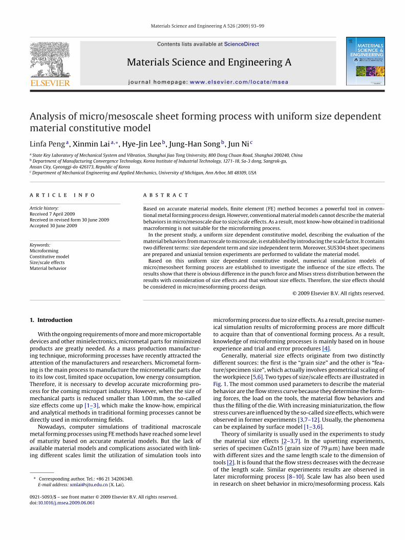
Materials Science and Engineering A 526 (2009) 93–99 Contents lists available at ScienceDirect Materials Science and Engineering A journal homepage: www.elsevier.com/locate/msea Analysis of micro/mesoscale sheet forming process with uniform size dependent material constitutive model Linfa Peng a , Xinmin Lai a,∗ , Hye-Jin Lee b , Jung-Han Song b , Jun Ni c a State Key Laboratory of Mechanical System and Vibration, Shanghai Jiao Tong University, 800 Dong Chuan Road, Shanghai 200240, China b Department of Manufacturing Convergence Technology, Korea Institute of Industrial Technology, 1271-18, Sa-3 dong, Sangrok-gu, Ansan City, Gyeonggi-do 426173, Republic of Korea c Department of Mechanical Engineering and Applied Mechanics, University of Michigan, Ann Arbor, MI 48109, USA article info Article history: Received 7 April 2009 Received in revised form 30 June 2009 Accepted 30 June 2009 Keywords: Microforming Constitutive model Size/scale effects Material behavior abstract Based on accurate material models, finite element (FE) method becomes a powerful tool in conven- tional metal forming process design. However, conventional material models cannot describe the material behaviors in micro/mesoscale due to size/scale effects. As a result, most know-how obtained in traditional macroforming is not suitable for the microforming process. In the present study, a uniform size dependent constitutive model, describing the evaluation of the material behaviors from macroscale to microscale, is established by introducing the scale factor. It contains two different terms: size dependent term and size independent term. Moreover, SUS304 sheet specimens are prepared and uniaxial tension experiments are performed to validate the material model. Based on this uniform size dependent constitutive model, numerical simulation models of micro/mesosheet forming process are established to investigate the influence of the size effects. The results show that there is obvious difference in the punch force and Mises stress distribution between the results with consideration of size effects and that without size effects. Therefore, the size effects should be considered in micro/mesoforming process design. © 2009 Elsevier B.V. All rights reserved. 1. Introduction With the ongoing requirements of more and more microportable devices and other minielectronics, micrometal parts for minimized products are greatly needed. As a mass production manufactur- ing technique, microforming processes have recently attracted the attention of the manufacturers and researchers. Micrometal form- ing is the main process to manufacture the micrometallic parts due to its low cost, limited space occupation, low energy consumption. Therefore, it is necessary to develop accurate microforming pro- cess for the coming micropart industry. However, when the size of mechanical parts is reduced smaller than 1.00 mm, the so-called size effects come up [1–3], which make the know-how, empirical and analytical methods in traditional forming processes cannot be directly used in microforming fields. Nowadays, computer simulations of traditional macroscale metal forming processes using FE methods have reached some level of maturity based on accurate material models. But the lack of available material models and complications associated with link- ing different scales limit the utilization of simulation tools into ∗ Corresponding author. Tel.: +86 21 34206340. E-mail address: [email protected] (X. Lai). microforming process due to size effects. As a result, precise numer- ical simulation results of microforming process are more difficult to acquire than that of conventional forming process. As a result, knowledge of microforming processes is mainly based on in house experience and trial and error procedures [4]. Generally, material size effects originate from two distinctly different sources: the first is the “grain size” and the other is “fea- ture/specimen size”, which actually involves geometrical scaling of the workpiece [5,6]. Two types of size/scale effects are illustrated in Fig. 1. The most common used parameters to describe the material behavior are the flow stress curve because they determine the form- ing forces, the load on the tools, the material flow behaviors and thus the filling of the die. With increasing miniaturization, the flow stress curves are influenced by the so-called size effects, which were observed in former experiments [3,7–12]. Usually, the phenomena can be explained by surface model [1–3,6]. Theory of similarity is usually used in the experiments to study the material size effects [2–3,7]. In the upsetting experiments, series of specimen CuZn15 (grain size of 79 m) have been made with different sizes and the same length scale to the dimension of tools [2]. It is found that the flow stress decreases with the decrease of the length scale. Similar experiments results are observed in later microforming process [8–10]. Scale law has also been used in research on sheet behavior in micro/mesoforming process. Kals 0921-5093/$ – see front matter © 2009 Elsevier B.V. All rights reserved. doi:10.1016/j.msea.2009.06.061
-
Upload
independent -
Category
Documents
-
view
1 -
download
0
Transcript of Analysis of micro/mesoscale sheet forming process with uniform size dependent material constitutive...
Am
La
b
Ac
a
ARRA
KMCSM
1
dpiaitTcmsad
moai
0d
Materials Science and Engineering A 526 (2009) 93–99
Contents lists available at ScienceDirect
Materials Science and Engineering A
journa l homepage: www.e lsev ier .com/ locate /msea
nalysis of micro/mesoscale sheet forming process with uniform size dependentaterial constitutive model
infa Peng a, Xinmin Lai a,∗, Hye-Jin Lee b, Jung-Han Song b, Jun Ni c
State Key Laboratory of Mechanical System and Vibration, Shanghai Jiao Tong University, 800 Dong Chuan Road, Shanghai 200240, ChinaDepartment of Manufacturing Convergence Technology, Korea Institute of Industrial Technology, 1271-18, Sa-3 dong, Sangrok-gu,nsan City, Gyeonggi-do 426173, Republic of KoreaDepartment of Mechanical Engineering and Applied Mechanics, University of Michigan, Ann Arbor, MI 48109, USA
r t i c l e i n f o
rticle history:eceived 7 April 2009eceived in revised form 30 June 2009ccepted 30 June 2009
eywords:
a b s t r a c t
Based on accurate material models, finite element (FE) method becomes a powerful tool in conven-tional metal forming process design. However, conventional material models cannot describe the materialbehaviors in micro/mesoscale due to size/scale effects. As a result, most know-how obtained in traditionalmacroforming is not suitable for the microforming process.
In the present study, a uniform size dependent constitutive model, describing the evaluation of thematerial behaviors from macroscale to microscale, is established by introducing the scale factor. It contains
icroformingonstitutive modelize/scale effectsaterial behavior
two different terms: size dependent term and size independent term. Moreover, SUS304 sheet specimensare prepared and uniaxial tension experiments are performed to validate the material model.
Based on this uniform size dependent constitutive model, numerical simulation models ofmicro/mesosheet forming process are established to investigate the influence of the size effects. Theresults show that there is obvious difference in the punch force and Mises stress distribution between theresults with consideration of size effects and that without size effects. Therefore, the size effects should
esofo
be considered in micro/m. Introduction
With the ongoing requirements of more and more microportableevices and other minielectronics, micrometal parts for minimizedroducts are greatly needed. As a mass production manufactur-
ng technique, microforming processes have recently attracted thettention of the manufacturers and researchers. Micrometal form-ng is the main process to manufacture the micrometallic parts dueo its low cost, limited space occupation, low energy consumption.herefore, it is necessary to develop accurate microforming pro-ess for the coming micropart industry. However, when the size ofechanical parts is reduced smaller than 1.00 mm, the so-called
ize effects come up [1–3], which make the know-how, empiricalnd analytical methods in traditional forming processes cannot beirectly used in microforming fields.
Nowadays, computer simulations of traditional macroscale
etal forming processes using FE methods have reached some levelf maturity based on accurate material models. But the lack ofvailable material models and complications associated with link-ng different scales limit the utilization of simulation tools into
∗ Corresponding author. Tel.: +86 21 34206340.E-mail address: [email protected] (X. Lai).
921-5093/$ – see front matter © 2009 Elsevier B.V. All rights reserved.oi:10.1016/j.msea.2009.06.061
rming process design.© 2009 Elsevier B.V. All rights reserved.
microforming process due to size effects. As a result, precise numer-ical simulation results of microforming process are more difficultto acquire than that of conventional forming process. As a result,knowledge of microforming processes is mainly based on in houseexperience and trial and error procedures [4].
Generally, material size effects originate from two distinctlydifferent sources: the first is the “grain size” and the other is “fea-ture/specimen size”, which actually involves geometrical scaling ofthe workpiece [5,6]. Two types of size/scale effects are illustrated inFig. 1. The most common used parameters to describe the materialbehavior are the flow stress curve because they determine the form-ing forces, the load on the tools, the material flow behaviors andthus the filling of the die. With increasing miniaturization, the flowstress curves are influenced by the so-called size effects, which wereobserved in former experiments [3,7–12]. Usually, the phenomenacan be explained by surface model [1–3,6].
Theory of similarity is usually used in the experiments to studythe material size effects [2–3,7]. In the upsetting experiments,series of specimen CuZn15 (grain size of 79 �m) have been made
with different sizes and the same length scale to the dimension oftools [2]. It is found that the flow stress decreases with the decreaseof the length scale. Similar experiments results are observed inlater microforming process [8–10]. Scale law has also been usedin research on sheet behavior in micro/mesoforming process. Kals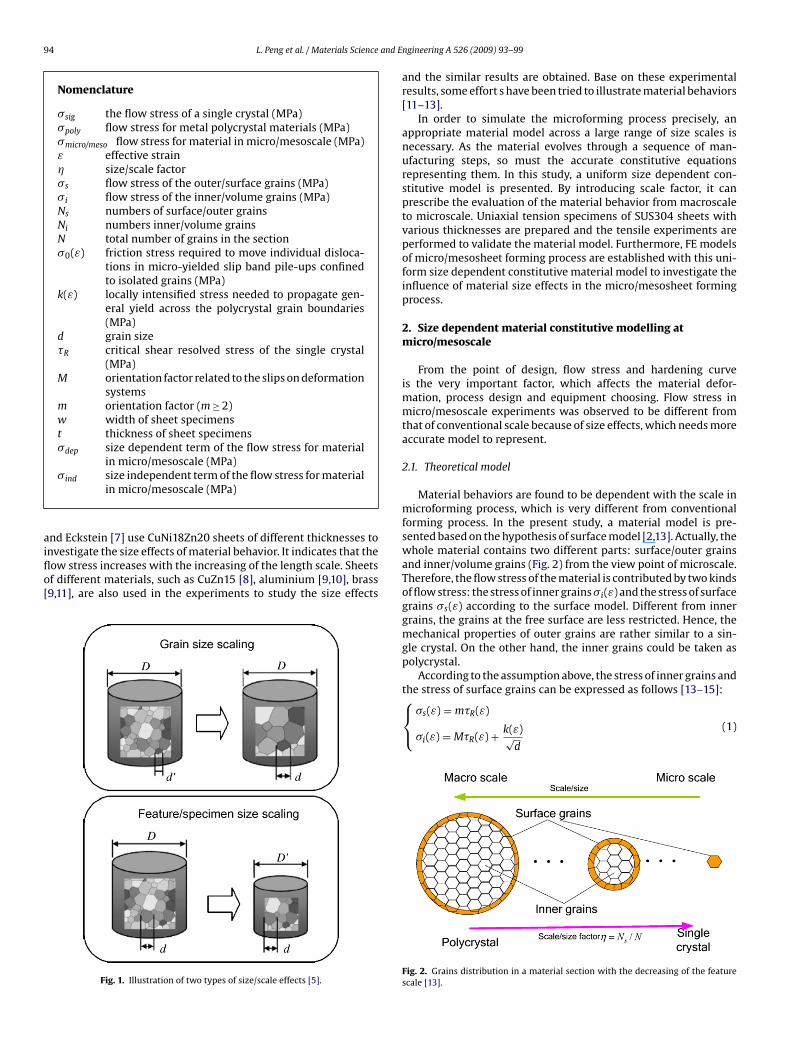
94 L. Peng et al. / Materials Science and E
Nomenclature
�sig the flow stress of a single crystal (MPa)�poly flow stress for metal polycrystal materials (MPa)�micro/meso flow stress for material in micro/mesoscale (MPa)ε effective strain� size/scale factor�s flow stress of the outer/surface grains (MPa)�i flow stress of the inner/volume grains (MPa)Ns numbers of surface/outer grainsNi numbers inner/volume grainsN total number of grains in the section�0(ε) friction stress required to move individual disloca-
tions in micro-yielded slip band pile-ups confinedto isolated grains (MPa)
k(ε) locally intensified stress needed to propagate gen-eral yield across the polycrystal grain boundaries(MPa)
d grain size�R critical shear resolved stress of the single crystal
(MPa)M orientation factor related to the slips on deformation
systemsm orientation factor (m ≥ 2)w width of sheet specimenst thickness of sheet specimens�dep size dependent term of the flow stress for material
in micro/mesoscale (MPa)
aiflo[
�ind size independent term of the flow stress for materialin micro/mesoscale (MPa)
nd Eckstein [7] use CuNi18Zn20 sheets of different thicknesses to
nvestigate the size effects of material behavior. It indicates that theow stress increases with the increasing of the length scale. Sheetsf different materials, such as CuZn15 [8], aluminium [9,10], brass9,11], are also used in the experiments to study the size effectsFig. 1. Illustration of two types of size/scale effects [5].
ngineering A 526 (2009) 93–99
and the similar results are obtained. Base on these experimentalresults, some effort s have been tried to illustrate material behaviors[11–13].
In order to simulate the microforming process precisely, anappropriate material model across a large range of size scales isnecessary. As the material evolves through a sequence of man-ufacturing steps, so must the accurate constitutive equationsrepresenting them. In this study, a uniform size dependent con-stitutive model is presented. By introducing scale factor, it canprescribe the evaluation of the material behavior from macroscaleto microscale. Uniaxial tension specimens of SUS304 sheets withvarious thicknesses are prepared and the tensile experiments areperformed to validate the material model. Furthermore, FE modelsof micro/mesosheet forming process are established with this uni-form size dependent constitutive material model to investigate theinfluence of material size effects in the micro/mesosheet formingprocess.
2. Size dependent material constitutive modelling atmicro/mesoscale
From the point of design, flow stress and hardening curveis the very important factor, which affects the material defor-mation, process design and equipment choosing. Flow stress inmicro/mesoscale experiments was observed to be different fromthat of conventional scale because of size effects, which needs moreaccurate model to represent.
2.1. Theoretical model
Material behaviors are found to be dependent with the scale inmicroforming process, which is very different from conventionalforming process. In the present study, a material model is pre-sented based on the hypothesis of surface model [2,13]. Actually, thewhole material contains two different parts: surface/outer grainsand inner/volume grains (Fig. 2) from the view point of microscale.Therefore, the flow stress of the material is contributed by two kindsof flow stress: the stress of inner grains �i(ε) and the stress of surfacegrains �s(ε) according to the surface model. Different from innergrains, the grains at the free surface are less restricted. Hence, themechanical properties of outer grains are rather similar to a sin-gle crystal. On the other hand, the inner grains could be taken aspolycrystal.
According to the assumption above, the stress of inner grains and
the stress of surface grains can be expressed as follows [13–15]:⎧⎨⎩�s(ε) = m�R(ε)
�i(ε) = M�R(ε) + k(ε)√d
(1)
Fig. 2. Grains distribution in a material section with the decreasing of the featurescale [13].
and Engineering A 526 (2009) 93–99 95
FFm
blfdfvammgf
�
timsbfd
�
wsicb
o
�
wicac
�
Fps
bi⎧⎪⎪⎪⎨⎪⎪⎪⎩
tt
L. Peng et al. / Materials Science
or a single crystal, m is the orientation factor (m ≥ 2) [13,16]. ForCC crystals, M equals to 3.06 and 2.23 for the Taylor and Sachsodellings, respectively [17,18].
As a result, the material properties can be modelled by com-ination of inner grains and our grains. Generally, it leads to
ess hardening and lower resistance against deformation of sur-ace grains because dislocations moving through the grains duringeformation pile up at grain boundaries but not at the free sur-
ace. Moreover, the ratio of these two different kinds of grainsaries dramatically with the change of the feature/specimen sizet micro/mesoscale, so that the decrease of the flow stress with theiniaturization of the feature size was observed in former experi-ents. That is why size effect occurs. Therefore, the ratio of surface
rains to total grains in the specimen’s section is introduced as scaleactor �
= Ns
N(2)
Fig. 2 shows the grain distribution in the material section whilehe grain size is kept constant. It indicates that the material behav-or changes from polycrystal model in macroscale to single crystal
odel in microscale with the decreasing of the scale, while theize/scale factor increasing. It means the influence of size effectsecome much bigger. Therefore, the development of the flow stress
rom macroscale (polycrystal) to microscale (single crystal) can beescribed as Eq. (3) [13]:
sig ≤ �micro/meso ≤ �poly (3)
here �sig is the flow stress of a single crystal. �poly is the flowtress of a polycrystal and �micro/meso is the flow stress for materialsn micro/mesoscale. For materials in micro/mesoscale, the singlerystal model is the lower bound and the polycrystal is the upperound.
According to the analysis above, we can express the flow stressf materials at micro/mesoscale in this form:
micro/meso(ε) = Ns�s + Ni�i
N= Nsm�R(ε) + Ni(M�R(ε) + (k(ε)/
√d))
N(4)
here Ns and Ni are the numbers of surface/outer grains andnner/volume grains, respectively; N is the total number of grains;onsidering Ns = �N, Eq. (4) can be expressed by using scale factor �s a size dependent parameter, by which the influence of size effectsan be evaluated
micro/meso(ε, �) = �m�R(ε) + (1 − �)[
M�R(ε) + k(ε)√d
](5)
or size factor � = 0, Eq. (5) expresses the flow stress for conventionalolycrystal materials. While size factor � = 1, it expresses the flowtress for single crystal.
In order to analyze the influence of size effects, this model cane divided into two different terms: size dependent model and size
ndependent model. And the material model can be expressed as
�micro/meso(ε) = �ind + �dep
�ind = M�R(ε) + k(ε)√d(
k(ε)) (6)
�dep = � m�R(ε) − M�R(ε) − √d
Therefore, the material model can be expressed by the conven-ional polycrystal material model with subtracting the influence ofhe size effects to the flow stress.
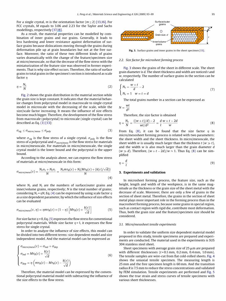
Fig. 3. Surface grains and inner grains in the sheet specimen [13].
2.2. Size factor for microsheet forming process
Fig. 3 shows the grains of the sheet in different scale. The sheetgrain diameter is d. The sheet thickness and width are noticed t andw, respectively. The number of surface grains in the section can becalculated{
Ns = w + t
d− 2
Ns = 1 w = t = d(7)
The total grains number in a section can be expressed as
N = wt
d2
Therefore, the size factor is obtained
� = Ns
N= ((w + t)/d) − 2
wt/d2= d
t
w + t − 2d
w(8)
From Eq. (8), it can be found that the size factor � inmicro/mesosheet forming process is related with two parameters:the sheet width and the sheet thickness. In micro/mesoscale, thesheet width w is usually much larger than the thickness t (w � t),and the width w is also much larger than the grain diameter d(w � d). Therefore, (w + t − 2d)/w ≈ 1. Thus Eq. (8) can be sim-plified
� = d
t(9)
3. Experiments and validation
In microsheet forming process, the feature size, such as theheight, length and width of the workpiece, is in the same mag-nitude as the thickness or the grain size of the sheet metal with thedecrease of scale. Moreover, there are only a few of grains in thesection of sheet metal. Therefore, the grains in the section of sheetmetal plays more important role in the forming process than in themacrosheet forming process, because some grains in special region,such as contact region with rigid die, contribute most deformation.Thus, both the grain size and the feature/specimen size should beconsidered.
3.1. Micro/mesosheet tensile experiments
In order to validate the uniform size dependent material modelproposed in this study, tensile specimens are prepared and experi-ments are conducted. The material used in the experiments is SUS304 stainless steel sheet.
Sheet specimens with average grain size of 25 �m are preparedwith different thicknesses (t = 0.1 mm, 0.2 mm, 0.4 mm, 1.0 mm).The tensile samples are wire-cut from flat cold-rolled sheets. Fig. 4shows the uniaxial tensile specimen. The measuring length is
25 mm and the free specimen length is 60 mm. And the transitionradius R is 7.5 mm to reduce the stress concentrations and validatedby FEM simulation. Tensile experiments are performed and Fig. 5shows the true strain and stress curves of tensile specimens withvarious sheet thicknesses.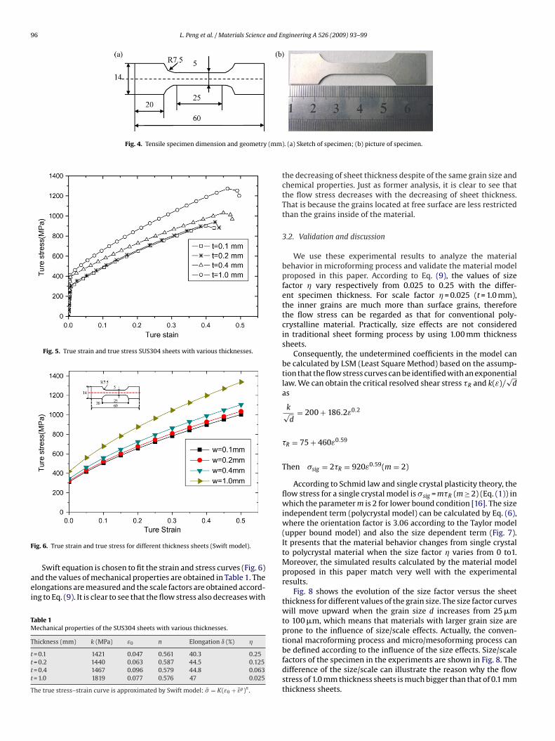
96 L. Peng et al. / Materials Science and Engineering A 526 (2009) 93–99
Fig. 4. Tensile specimen dimension and geometry (mm
Fig. 5. True strain and true stress SUS304 sheets with various thicknesses.
F
aei
TM
T
tttt
T
ig. 6. True strain and true stress for different thickness sheets (Swift model).
Swift equation is chosen to fit the strain and stress curves (Fig. 6)nd the values of mechanical properties are obtained in Table 1. Thelongations are measured and the scale factors are obtained accord-ng to Eq. (9). It is clear to see that the flow stress also decreases with
able 1echanical properties of the SUS304 sheets with various thicknesses.
hickness (mm) k (MPa) ε0 n Elongation ı (%) �
= 0.1 1421 0.047 0.561 40.3 0.25= 0.2 1440 0.063 0.587 44.5 0.125= 0.4 1467 0.096 0.579 44.8 0.063= 1.0 1819 0.077 0.576 47 0.025
he true stress–strain curve is approximated by Swift model: �̄ = K(ε0 + ε̄p)n .
). (a) Sketch of specimen; (b) picture of specimen.
the decreasing of sheet thickness despite of the same grain size andchemical properties. Just as former analysis, it is clear to see thatthe flow stress decreases with the decreasing of sheet thickness.That is because the grains located at free surface are less restrictedthan the grains inside of the material.
3.2. Validation and discussion
We use these experimental results to analyze the materialbehavior in microforming process and validate the material modelproposed in this paper. According to Eq. (9), the values of sizefactor � vary respectively from 0.025 to 0.25 with the differ-ent specimen thickness. For scale factor � = 0.025 (t = 1.0 mm),the inner grains are much more than surface grains, thereforethe flow stress can be regarded as that for conventional poly-crystalline material. Practically, size effects are not consideredin traditional sheet forming process by using 1.00 mm thicknesssheets.
Consequently, the undetermined coefficients in the model canbe calculated by LSM (Least Square Method) based on the assump-tion that the flow stress curves can be identified with an exponentiallaw. We can obtain the critical resolved shear stress �R and k(ε)/
√d
as
k√d
= 200 + 186.2ε0.2
�R = 75 + 460ε0.59
Then �sig = 2�R = 920ε0.59(m = 2)
According to Schmid law and single crystal plasticity theory, theflow stress for a single crystal model is �sig = m�R (m ≥ 2) (Eq. (1)) inwhich the parameter m is 2 for lower bound condition [16]. The sizeindependent term (polycrystal model) can be calculated by Eq. (6),where the orientation factor is 3.06 according to the Taylor model(upper bound model) and also the size dependent term (Fig. 7).It presents that the material behavior changes from single crystalto polycrystal material when the size factor � varies from 0 to1.Moreover, the simulated results calculated by the material modelproposed in this paper match very well with the experimentalresults.
Fig. 8 shows the evolution of the size factor versus the sheetthickness for different values of the grain size. The size factor curveswill move upward when the grain size d increases from 25 �mto 100 �m, which means that materials with larger grain size areprone to the influence of size/scale effects. Actually, the conven-tional macroforming process and micro/mesoforming process can
be defined according to the influence of the size effects. Size/scalefactors of the specimen in the experiments are shown in Fig. 8. Thedifference of the size/scale can illustrate the reason why the flowstress of 1.0 mm thickness sheets is much bigger than that of 0.1 mmthickness sheets.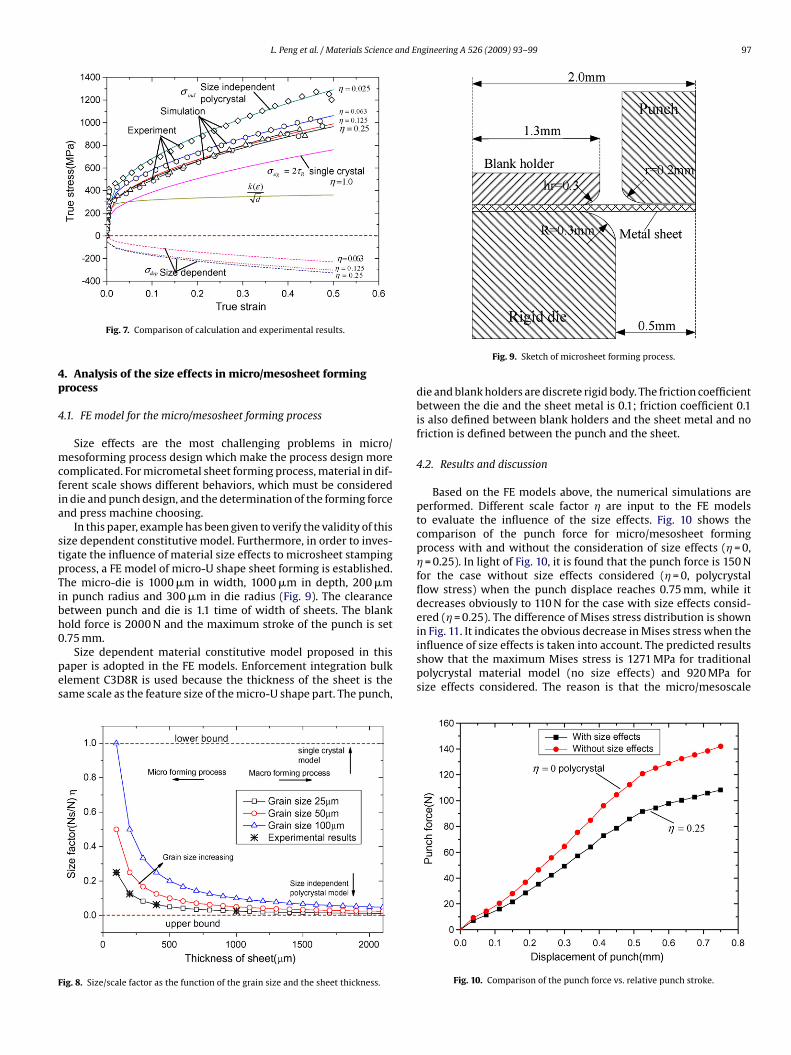
L. Peng et al. / Materials Science and Engineering A 526 (2009) 93–99 97
4p
4
mcfia
stpTibh0
pes
F
Fig. 7. Comparison of calculation and experimental results.
. Analysis of the size effects in micro/mesosheet formingrocess
.1. FE model for the micro/mesosheet forming process
Size effects are the most challenging problems in micro/esoforming process design which make the process design more
omplicated. For micrometal sheet forming process, material in dif-erent scale shows different behaviors, which must be consideredn die and punch design, and the determination of the forming forcend press machine choosing.
In this paper, example has been given to verify the validity of thisize dependent constitutive model. Furthermore, in order to inves-igate the influence of material size effects to microsheet stampingrocess, a FE model of micro-U shape sheet forming is established.he micro-die is 1000 �m in width, 1000 �m in depth, 200 �m
n punch radius and 300 �m in die radius (Fig. 9). The clearanceetween punch and die is 1.1 time of width of sheets. The blankold force is 2000 N and the maximum stroke of the punch is set.75 mm.
Size dependent material constitutive model proposed in thisaper is adopted in the FE models. Enforcement integration bulklement C3D8R is used because the thickness of the sheet is theame scale as the feature size of the micro-U shape part. The punch,
ig. 8. Size/scale factor as the function of the grain size and the sheet thickness.
Fig. 9. Sketch of microsheet forming process.
die and blank holders are discrete rigid body. The friction coefficientbetween the die and the sheet metal is 0.1; friction coefficient 0.1is also defined between blank holders and the sheet metal and nofriction is defined between the punch and the sheet.
4.2. Results and discussion
Based on the FE models above, the numerical simulations areperformed. Different scale factor � are input to the FE modelsto evaluate the influence of the size effects. Fig. 10 shows thecomparison of the punch force for micro/mesosheet formingprocess with and without the consideration of size effects (� = 0,� = 0.25). In light of Fig. 10, it is found that the punch force is 150 Nfor the case without size effects considered (� = 0, polycrystalflow stress) when the punch displace reaches 0.75 mm, while itdecreases obviously to 110 N for the case with size effects consid-ered (� = 0.25). The difference of Mises stress distribution is shownin Fig. 11. It indicates the obvious decrease in Mises stress when the
influence of size effects is taken into account. The predicted resultsshow that the maximum Mises stress is 1271 MPa for traditionalpolycrystal material model (no size effects) and 920 MPa forsize effects considered. The reason is that the micro/mesoscaleFig. 10. Comparison of the punch force vs. relative punch stroke.
98 L. Peng et al. / Materials Science and E
Fe
mimsTc
ptfcdt0ifa
F
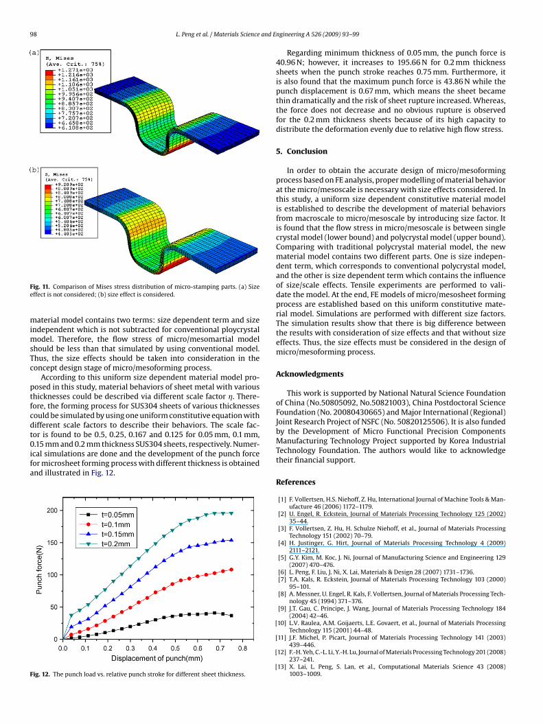
ig. 11. Comparison of Mises stress distribution of micro-stamping parts. (a) Sizeffect is not considered; (b) size effect is considered.
aterial model contains two terms: size dependent term and sizendependent which is not subtracted for conventional ploycrystal
odel. Therefore, the flow stress of micro/mesomartial modelhould be less than that simulated by using conventional model.hus, the size effects should be taken into consideration in theoncept design stage of micro/mesoforming process.
According to this uniform size dependent material model pro-osed in this study, material behaviors of sheet metal with varioushicknesses could be described via different scale factor �. There-ore, the forming process for SUS304 sheets of various thicknessesould be simulated by using one uniform constitutive equation withifferent scale factors to describe their behaviors. The scale fac-or is found to be 0.5, 0.25, 0.167 and 0.125 for 0.05 mm, 0.1 mm,
.15 mm and 0.2 mm thickness SUS304 sheets, respectively. Numer-cal simulations are done and the development of the punch forceor microsheet forming process with different thickness is obtainednd illustrated in Fig. 12.
ig. 12. The punch load vs. relative punch stroke for different sheet thickness.
[
[
[
[
ngineering A 526 (2009) 93–99
Regarding minimum thickness of 0.05 mm, the punch force is40.96 N; however, it increases to 195.66 N for 0.2 mm thicknesssheets when the punch stroke reaches 0.75 mm. Furthermore, itis also found that the maximum punch force is 43.86 N while thepunch displacement is 0.67 mm, which means the sheet becamethin dramatically and the risk of sheet rupture increased. Whereas,the force does not decrease and no obvious rupture is observedfor the 0.2 mm thickness sheets because of its high capacity todistribute the deformation evenly due to relative high flow stress.
5. Conclusion
In order to obtain the accurate design of micro/mesoformingprocess based on FE analysis, proper modelling of material behaviorat the micro/mesoscale is necessary with size effects considered. Inthis study, a uniform size dependent constitutive material modelis established to describe the development of material behaviorsfrom macroscale to micro/mesoscale by introducing size factor. Itis found that the flow stress in micro/mesoscale is between singlecrystal model (lower bound) and polycrystal model (upper bound).Comparing with traditional polycrystal material model, the newmaterial model contains two different parts. One is size indepen-dent term, which corresponds to conventional polycrystal model,and the other is size dependent term which contains the influenceof size/scale effects. Tensile experiments are performed to vali-date the model. At the end, FE models of micro/mesosheet formingprocess are established based on this uniform constitutive mate-rial model. Simulations are performed with different size factors.The simulation results show that there is big difference betweenthe results with consideration of size effects and that without sizeeffects. Thus, the size effects must be considered in the design ofmicro/mesoforming process.
Acknowledgments
This work is supported by National Natural Science Foundationof China (No.50805092, No.50821003), China Postdoctoral ScienceFoundation (No. 20080430665) and Major International (Regional)Joint Research Project of NSFC (No. 50820125506). It is also fundedby the Development of Micro Functional Precision ComponentsManufacturing Technology Project supported by Korea IndustrialTechnology Foundation. The authors would like to acknowledgetheir financial support.
References
[1] F. Vollertsen, H.S. Niehoff, Z. Hu, International Journal of Machine Tools & Man-ufacture 46 (2006) 1172–1179.
[2] U. Engel, R. Eckstein, Journal of Materials Processing Technology 125 (2002)35–44.
[3] F. Vollertsen, Z. Hu, H. Schulze Niehoff, et al., Journal of Materials ProcessingTechnology 151 (2002) 70–79.
[4] H. Justinger, G. Hirt, Journal of Materials Processing Technology 4 (2009)2111–2121.
[5] G.Y. Kim, M. Koc, J. Ni, Journal of Manufacturing Science and Engineering 129(2007) 470–476.
[6] L. Peng, F. Liu, J. Ni, X. Lai, Materials & Design 28 (2007) 1731–1736.[7] T.A. Kals, R. Eckstein, Journal of Materials Processing Technology 103 (2000)
95–101.[8] A. Messner, U. Engel, R. Kals, F. Vollertsen, Journal of Materials Processing Tech-
nology 45 (1994) 371–376.[9] J.T. Gau, C. Principe, J. Wang, Journal of Materials Processing Technology 184
(2004) 42–46.10] L.V. Raulea, A.M. Goijaerts, L.E. Govaert, et al., Journal of Materials Processing
Technology 115 (2001) 44–48.
11] J.F. Michel, P. Picart, Journal of Materials Processing Technology 141 (2003)439–446.12] F.-H. Yeh, C.-L. Li, Y.-H. Lu, Journal of Materials Processing Technology 201 (2008)
237–241.13] X. Lai, L. Peng, S. Lan, et al., Computational Materials Science 43 (2008)
1003–1009.

[
[
L. Peng et al. / Materials Science and E
14] R.W. Armstrong, Journal of the Mechanics and Physics of Solids 9 (1961)196–199.
15] R.W. Armstrong, I. Codd, R.M. Douthwaite, et al., Philosophical Magazine 73(1962) 45–58.
[
[[
ngineering A 526 (2009) 93–99 99
16] E. Schmid, I.W. Boas, Plasticity of Crystals with Special Reference to Metals,Chapman & Hall Ltd, London, 1968.
17] H. Mecking, U.F. Kocks, Acta Metallurgica 29 (1981) 1865–1875.18] B. Clausen, T. Lorentzen, T. Leffers, Acta Materialia 46 (1998) 3087–3098.