Photocatalysis and perovskite oxide-based materials - RSC ...
31
Photocatalysis and perovskite oxide-based materials: a remedy for a clean and sustainable future Muneeb Irshad, * a Quar tul Ain, a Muhammad Zaman, a Muhammad Zeeshan Aslam, a Naila Kousar, a Muhammad Asim, a Muhammad Rafique, b Khurram Siraj, a Asif Nadeem Tabish, c Muhammad Usman, d Masood ul Hassan Farooq, e Mohammed Ali Assiri f and Muhammad Imran f The massive use of non-renewable energy resources by humankind to fulfill their energy demands is causing severe environmental issues. Photocatalysis is considered one of the potential solutions for a clean and sustainable future because of its cleanliness, inexhaustibility, efficiency, and cost- effectiveness. Significant efforts have been made to design highly proficient photocatalyst materials for various applications such as water pollutant degradation, water splitting, CO 2 reduction, and nitrogen fixation. Perovskite photocatalyst materials are gained special attention due to their exceptional properties because of their flexibility in chemical composition, structure, bandgap, oxidation states, and valence states. The current review is focused on perovskite materials and their applications in photocatalysis. Special attention has been given to the structural, stoichiometric, and compositional flexibility of perovskite photocatalyst materials. The photocatalytic activity of perovskite materials in different photocatalysis applications is also discussed. Various mechanisms involved in photocatalysis application from wastewater treatment to hydrogen production are also provided. The key objective of this review is to encapsulate the role of perovskite materials in photocatalysis along with their fundamental properties to provide valuable insight for addressing future environmental challenges. Introduction Rapid industrialization and population growth resulted in increased energy resources utilization and release of harmful pollutants. The increased human activities are depleting the energy resources and polluting our ecosystem. The toxic gasses in the air are causing respiratory diseases, and the direct disposal of industrial and organic waste into the water reser- voirs is causing water-borne diseases. Nearly 663 million people in the world have no access to clean water. The amount of CO 2 in the atmosphere is also increasing due to rapid industriali- zation. The increased concentration of CO 2 is causing is global warming and is the leading cause of acid rain, which is dangerous for all living things on the earth. The current decade 2021–2030, is the decade of ecosystem system restoration. Therefore, it is essential to pay attention to clean ways to tackle environmental issues. The new global challenge is the achievement of ecological sustainability. The research focus of this era is oriented toward the way to achieve the eco-friendly system. 1–6 The blissful gi of Mother Nature, the Sun is an ultimate renewable energy resource that irradiates 3.85 yotta joule (YJ) of energy yearly on the earth's surface. Sunlight is one of the best routes to deal with environmental issues owing to its cleanness and abundant availability. Sunlight can be utilized as an energy medium by photovoltaic, photoelectrochemical catalysis, or photocatalysis in daily activities. 7,8 Photocatalysis is dened as the science of employing a cata- lyst that uses light to speed up the chemical reaction. In pho- tocatalysis, the photocatalyst material is used, and the energy of the light acts as a source to generate electron–hole pair. The photogenerated electron–hole pair then initiates the redox reaction at the surface of the photocatalyst. This redox reaction can be utilized to degrade water pollutants and convert abun- dant earth elements (H 2 O, CO 2, and N 2 ) into fuel (pure H 2 , or organic fuel like CH 4 , CH 3 OH, and NH 3 ). The conversion of water into the fuel (H 2 ) by using light and photocatalyst a Department of Physics, University of Engineering and Technology, Lahore, 54890, Pakistan. E-mail: [email protected]; [email protected] b Department of Physics, University of Sahiwal, Sahiwal, Pakistan c Department of Chemical Engineering, University of Engineering and Technology, New Campus, Lahore, Pakistan d Department of Mechanical Engineering, University of Engineering and Technology, Lahore, 54890, Pakistan e Department of Basic Sciences, University of Engineering and Technology, New Campus, Lahore, Pakistan f Department of Chemistry, Faculty of Science, Research Center for Advanced Materials Science (RCAMS), King Khalid University, P. O. Box 9004, Abha 61413, Saudia Arabia Cite this: RSC Adv. , 2022, 12, 7009 Received 8th November 2021 Accepted 21st February 2022 DOI: 10.1039/d1ra08185c rsc.li/rsc-advances © 2022 The Author(s). Published by the Royal Society of Chemistry RSC Adv. , 2022, 12, 7009–7039 | 7009 RSC Advances REVIEW Open Access Article. Published on 02 March 2022. Downloaded on 3/31/2022 3:37:13 PM. This article is licensed under a Creative Commons Attribution 3.0 Unported Licence. View Article Online View Journal | View Issue
-
Upload
khangminh22 -
Category
Documents
-
view
4 -
download
0
Transcript of Photocatalysis and perovskite oxide-based materials - RSC ...

RSC Advances
REVIEW
Ope
n A
cces
s A
rtic
le. P
ublis
hed
on 0
2 M
arch
202
2. D
ownl
oade
d on
3/3
1/20
22 3
:37:
13 P
M.
Thi
s ar
ticle
is li
cens
ed u
nder
a C
reat
ive
Com
mon
s A
ttrib
utio
n 3.
0 U
npor
ted
Lic
ence
.
View Article OnlineView Journal | View Issue
Photocatalysis an
aDepartment of Physics, University of Engi
Pakistan. E-mail: [email protected] of Physics, University of SahiwcDepartment of Chemical Engineering, Unive
Campus, Lahore, PakistandDepartment of Mechanical Engineering, U
Lahore, 54890, PakistaneDepartment of Basic Sciences, University
Campus, Lahore, PakistanfDepartment of Chemistry, Faculty of Science
Science (RCAMS), King Khalid University, P.
Cite this: RSC Adv., 2022, 12, 7009
Received 8th November 2021Accepted 21st February 2022
DOI: 10.1039/d1ra08185c
rsc.li/rsc-advances
© 2022 The Author(s). Published by
d perovskite oxide-basedmaterials: a remedy for a clean and sustainablefuture
Muneeb Irshad, *a Quar tul Ain,a Muhammad Zaman,a Muhammad Zeeshan Aslam,a
Naila Kousar,a Muhammad Asim,a Muhammad Rafique, b Khurram Siraj,a
Asif Nadeem Tabish,c Muhammad Usman,d Masood ul Hassan Farooq,e
Mohammed Ali Assirif and Muhammad Imran f
The massive use of non-renewable energy resources by humankind to fulfill their energy demands is
causing severe environmental issues. Photocatalysis is considered one of the potential solutions for
a clean and sustainable future because of its cleanliness, inexhaustibility, efficiency, and cost-
effectiveness. Significant efforts have been made to design highly proficient photocatalyst materials for
various applications such as water pollutant degradation, water splitting, CO2 reduction, and nitrogen
fixation. Perovskite photocatalyst materials are gained special attention due to their exceptional
properties because of their flexibility in chemical composition, structure, bandgap, oxidation states, and
valence states. The current review is focused on perovskite materials and their applications in
photocatalysis. Special attention has been given to the structural, stoichiometric, and compositional
flexibility of perovskite photocatalyst materials. The photocatalytic activity of perovskite materials in
different photocatalysis applications is also discussed. Various mechanisms involved in photocatalysis
application from wastewater treatment to hydrogen production are also provided. The key objective of
this review is to encapsulate the role of perovskite materials in photocatalysis along with their
fundamental properties to provide valuable insight for addressing future environmental challenges.
Introduction
Rapid industrialization and population growth resulted inincreased energy resources utilization and release of harmfulpollutants. The increased human activities are depleting theenergy resources and polluting our ecosystem. The toxic gassesin the air are causing respiratory diseases, and the directdisposal of industrial and organic waste into the water reser-voirs is causing water-borne diseases. Nearly 663 million peoplein the world have no access to clean water. The amount of CO2
in the atmosphere is also increasing due to rapid industriali-zation. The increased concentration of CO2 is causing is globalwarming and is the leading cause of acid rain, which is
neering and Technology, Lahore, 54890,
al, Sahiwal, Pakistan
rsity of Engineering and Technology, New
niversity of Engineering and Technology,
of Engineering and Technology, New
, Research Center for Advanced Materials
O. Box 9004, Abha 61413, Saudia Arabia
the Royal Society of Chemistry
dangerous for all living things on the earth. The current decade2021–2030, is the decade of ecosystem system restoration.Therefore, it is essential to pay attention to clean ways to tackleenvironmental issues. The new global challenge is theachievement of ecological sustainability. The research focus ofthis era is oriented toward the way to achieve the eco-friendlysystem.1–6
The blissful gi of Mother Nature, the Sun is an ultimaterenewable energy resource that irradiates 3.85 yotta joule (YJ) ofenergy yearly on the earth's surface. Sunlight is one of the bestroutes to deal with environmental issues owing to its cleannessand abundant availability. Sunlight can be utilized as an energymedium by photovoltaic, photoelectrochemical catalysis, orphotocatalysis in daily activities.7,8
Photocatalysis is dened as the science of employing a cata-lyst that uses light to speed up the chemical reaction. In pho-tocatalysis, the photocatalyst material is used, and the energy ofthe light acts as a source to generate electron–hole pair. Thephotogenerated electron–hole pair then initiates the redoxreaction at the surface of the photocatalyst. This redox reactioncan be utilized to degrade water pollutants and convert abun-dant earth elements (H2O, CO2, and N2) into fuel (pure H2, ororganic fuel like CH4, CH3OH, and NH3). The conversion ofwater into the fuel (H2) by using light and photocatalyst
RSC Adv., 2022, 12, 7009–7039 | 7009
RSC Advances Review
Ope
n A
cces
s A
rtic
le. P
ublis
hed
on 0
2 M
arch
202
2. D
ownl
oade
d on
3/3
1/20
22 3
:37:
13 P
M.
Thi
s ar
ticle
is li
cens
ed u
nder
a C
reat
ive
Com
mon
s A
ttrib
utio
n 3.
0 U
npor
ted
Lic
ence
.View Article Online
material is known as photocatalytic water splitting. Theconversion of CO2 into the hydrocarbons is known as CO2
reduction, and conversion of nitrogen into NH3 is callednitrogen xation. All these application deals with the viable wayto clean the environment. The main challenge while dealingwith photocatalysis is the region of operation of the photo-catalyst in the solar spectrum. Most photocatalysts operateunder UV radiations, which is only 5% of the sunlight reachingearth. Therefore, suitable photocatalysts are required torespond to the extensive range of the solar spectrum.9–18
Fig. 1 Perovskite structure.
History of photocatalysis
The word catalysis was rst used in 1836 by the Jons JakobBerzelius, derived from the Greek word “kata”, meaning downor loosen. Catalysis is the process of fasting or accelerating thereaction in the presence of the catalyst. The catalyst itselfdoesn't participate in the reaction but increases the reactionrate. The term photocatalysis rst appeared in 1911, whenEibner studied the effect of light irradiation on transition metaloxide (ZnO) for the decolorization of Prussian blue. Photo-catalysis term also appeared simultaneously in the title of thearticle investigating the degradation of the oxalic acid in thepresence of the uranyl salts upon light irradiation. In 1921Edward Charles Cyril Baly studied the production of formalde-hyde using colloidal uranium salts and ferric hydroxides asa catalyst. Soon aer, in 1924, the Baur and the Perret at theETH of Zurich reported the effect of light irradiation on the ZnOsuspension and observed that ZnO suspension enhancedreduction of Ag+ salts to Ago upon irradiation. The mobility forthe TiO2 as a photosensitizer for the dyes was rst studied byDoodeve and Kitchener in 1938. This work reported that TiO2
upon light irradiation decolorized the dyes, and TiO2 remainsunchanged during the process.19–22
Many researchers from 1940 to 1972 investigated differentparameters of the photocatalyst. Photocatalysis gained signi-cant attention when electrochemical photolysis of the water wasdone by using titanium dioxide under UV irradiation. The oilcrisis in 1973 also changed the social and economic status ofthe western world. The rst time, the shortage of fossil fuelsbecame a signicant issue, which led to an unprecedentedincrease in the efforts for alternative energy resources,including photocatalysis. The application of photocatalysis isnot limited to energy fuels but can also clean the environment.Much attention has been given to photocatalysis during the lasttwo decades due to its wide range of applications.21,23
Photocatalysis has its application in the pollutant degrada-tion and production of fuel. Material can be an excellent pho-tocatalyst if it is responsive to light, especially (UV or visible),biologically and chemically inert, has low cost, and exhibitsadsorption and absorption capacity. Normally the metal oxidesemiconductors are used in the application of the photo-catalyst. Perovskite materials, due to their unique opticalproperties, also gained importance in the application of pho-tocatalyst during the last decade.24,25
7010 | RSC Adv., 2022, 12, 7009–7039
Perovskite oxide based materials
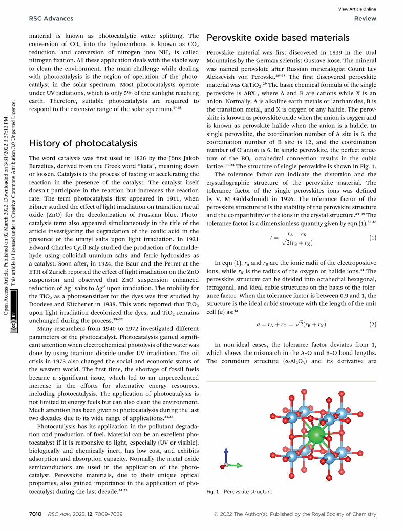
Perovskite material was rst discovered in 1839 in the UralMountains by the German scientist Gustave Rose. The mineralwas named perovskite aer Russian mineralogist Count LevAleksevish von Perovski.26–28 The rst discovered perovskitematerial was CaTiO3.29 The basic chemical formula of the singleperovskite is ABX3, where A and B are cations while X is ananion. Normally, A is alkaline earth metals or lanthanides, B isthe transition metal, and X is oxygen or any halide. The perov-skite is known as perovskite oxide when the anion is oxygen andis known as perovskite halide when the anion is a halide. Insingle perovskite, the coordination number of A site is 6, thecoordination number of B site is 12, and the coordinationnumber of O anion is 6. In single perovskite, the perfect struc-ture of the BO6 octahedral connection results in the cubiclattice.30–33 The structure of single perovskite is shown in Fig. 1.
The tolerance factor can indicate the distortion and thecrystallographic structure of the perovskite material. Thetolerance factor of the single perovskites ions was denedby V. M Goldschmidt in 1926. The tolerance factor of theperovskite structure tells the stability of the perovskite structureand the compatibility of the ions in the crystal structure.34–39 Thetolerance factor is a dimensionless quantity given by eqn (1).38,40
t ¼ rA þ rXffiffiffi
2p ðrB þ rXÞ
(1)
In eqn (1), rA and rB are the ionic radii of the electropositiveions, while rX is the radius of the oxygen or halide ions.41 Theperovskite structure can be divided into octahedral hexagonal,tetragonal, and ideal cubic structures on the basis of the toler-ance factor. When the tolerance factor is between 0.9 and 1, thestructure is the ideal cubic structure with the length of the unitcell (a) as:42
a ¼ rA þ rO ¼ffiffiffi
2p
ðrB þ rXÞ (2)
In non-ideal cases, the tolerance factor deviates from 1,which shows the mismatch in the A–O and B–O bond lengths.The corundum structure (a-Al2O3) and its derivative are
© 2022 The Author(s). Published by the Royal Society of Chemistry
Review RSC Advances
Ope
n A
cces
s A
rtic
le. P
ublis
hed
on 0
2 M
arch
202
2. D
ownl
oade
d on
3/3
1/20
22 3
:37:
13 P
M.
Thi
s ar
ticle
is li
cens
ed u
nder
a C
reat
ive
Com
mon
s A
ttrib
utio
n 3.
0 U
npor
ted
Lic
ence
.View Article Online
considered when the tolerance factor is less than 0.75.43 Thestable bixbite polymorph (a-Mn2O3) is favored when the factordecreases. If the tolerance factor is greater than 1, the structureof perovskite is hexagonal close-packed (HCP), and [BO6]-octahedra share faces with the hexagonal c-axis.30,44
The sum of the charges of cations and anion of the perov-skite structure should equal one for perovskite material to beelectrically neutral. Different cations having different ionic radiiand valences can be doped in the structure of perovskitematerial by employing the method of partial substitution at Aand B-site. Deciency at A and B-site cations and excess ordeciency of oxygen anions can change the composition of ionsand the non-stoichiometry phenomenon.45,46
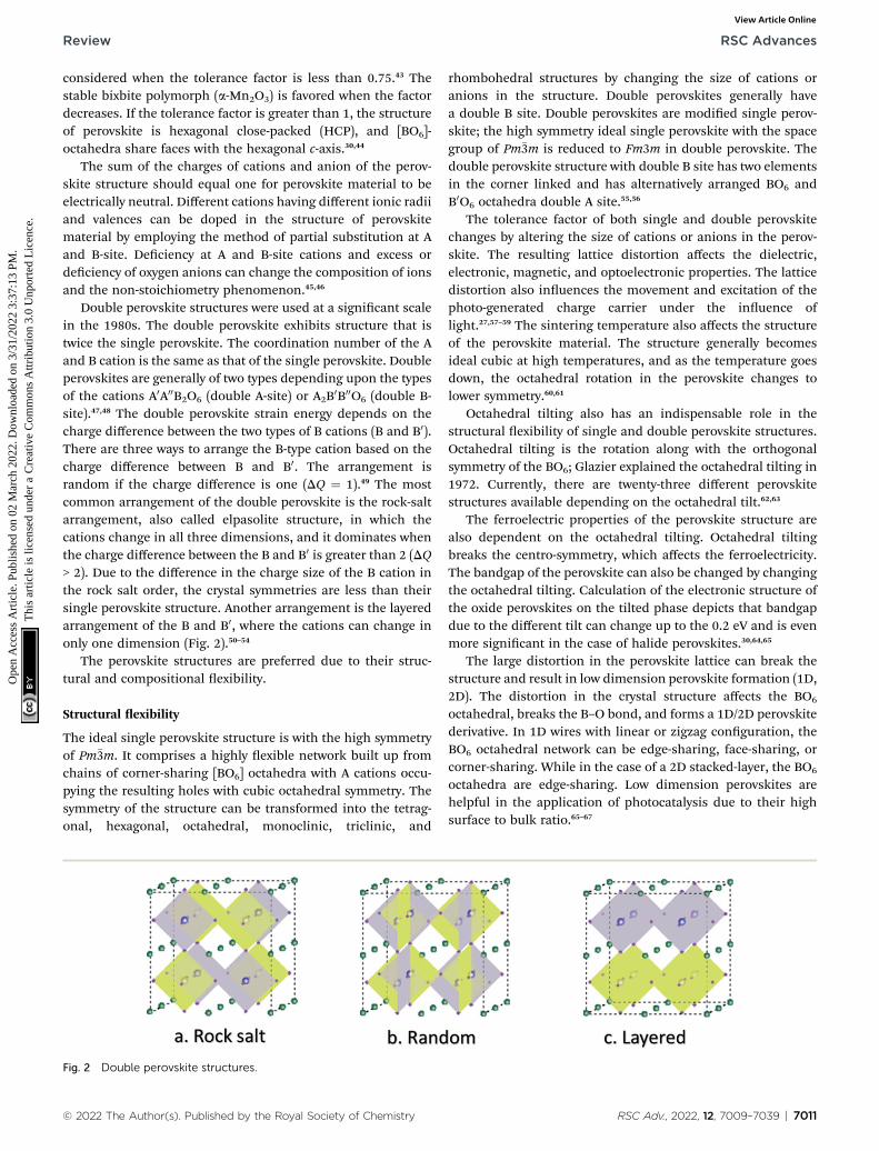
Double perovskite structures were used at a signicant scalein the 1980s. The double perovskite exhibits structure that istwice the single perovskite. The coordination number of the Aand B cation is the same as that of the single perovskite. Doubleperovskites are generally of two types depending upon the typesof the cations A0A00B2O6 (double A-site) or A2B0B00O6 (double B-site).47,48 The double perovskite strain energy depends on thecharge difference between the two types of B cations (B and B0).There are three ways to arrange the B-type cation based on thecharge difference between B and B0. The arrangement israndom if the charge difference is one (DQ ¼ 1).49 The mostcommon arrangement of the double perovskite is the rock-saltarrangement, also called elpasolite structure, in which thecations change in all three dimensions, and it dominates whenthe charge difference between the B and B0 is greater than 2 (DQ> 2). Due to the difference in the charge size of the B cation inthe rock salt order, the crystal symmetries are less than theirsingle perovskite structure. Another arrangement is the layeredarrangement of the B and B0, where the cations can change inonly one dimension (Fig. 2).50–54
The perovskite structures are preferred due to their struc-tural and compositional exibility.
Structural exibility
The ideal single perovskite structure is with the high symmetryof Pm�3m. It comprises a highly exible network built up fromchains of corner-sharing [BO6] octahedra with A cations occu-pying the resulting holes with cubic octahedral symmetry. Thesymmetry of the structure can be transformed into the tetrag-onal, hexagonal, octahedral, monoclinic, triclinic, and
Fig. 2 Double perovskite structures.
© 2022 The Author(s). Published by the Royal Society of Chemistry
rhombohedral structures by changing the size of cations oranions in the structure. Double perovskites generally havea double B site. Double perovskites are modied single perov-skite; the high symmetry ideal single perovskite with the spacegroup of Pm�3m is reduced to Fm3m in double perovskite. Thedouble perovskite structure with double B site has two elementsin the corner linked and has alternatively arranged BO6 andB0O6 octahedra double A site.55,56
The tolerance factor of both single and double perovskitechanges by altering the size of cations or anions in the perov-skite. The resulting lattice distortion affects the dielectric,electronic, magnetic, and optoelectronic properties. The latticedistortion also inuences the movement and excitation of thephoto-generated charge carrier under the inuence oflight.27,57–59 The sintering temperature also affects the structureof the perovskite material. The structure generally becomesideal cubic at high temperatures, and as the temperature goesdown, the octahedral rotation in the perovskite changes tolower symmetry.60,61
Octahedral tilting also has an indispensable role in thestructural exibility of single and double perovskite structures.Octahedral tilting is the rotation along with the orthogonalsymmetry of the BO6; Glazier explained the octahedral tilting in1972. Currently, there are twenty-three different perovskitestructures available depending on the octahedral tilt.62,63
The ferroelectric properties of the perovskite structure arealso dependent on the octahedral tilting. Octahedral tiltingbreaks the centro-symmetry, which affects the ferroelectricity.The bandgap of the perovskite can also be changed by changingthe octahedral tilting. Calculation of the electronic structure ofthe oxide perovskites on the tilted phase depicts that bandgapdue to the different tilt can change up to the 0.2 eV and is evenmore signicant in the case of halide perovskites.30,64,65
The large distortion in the perovskite lattice can break thestructure and result in low dimension perovskite formation (1D,2D). The distortion in the crystal structure affects the BO6
octahedral, breaks the B–O bond, and forms a 1D/2D perovskitederivative. In 1D wires with linear or zigzag conguration, theBO6 octahedral network can be edge-sharing, face-sharing, orcorner-sharing. While in the case of a 2D stacked-layer, the BO6
octahedra are edge-sharing. Low dimension perovskites arehelpful in the application of photocatalysis due to their highsurface to bulk ratio.65–67
RSC Adv., 2022, 12, 7009–7039 | 7011
RSC Advances Review
Ope
n A
cces
s A
rtic
le. P
ublis
hed
on 0
2 M
arch
202
2. D
ownl
oade
d on
3/3
1/20
22 3
:37:
13 P
M.
Thi
s ar
ticle
is li
cens
ed u
nder
a C
reat
ive
Com
mon
s A
ttrib
utio
n 3.
0 U
npor
ted
Lic
ence
.View Article Online
Stoichiometric and compositional exibility. The perovskitestructure exhibits a high degree of stoichiometric and compo-sitional exibility. Theoretically, 346 different kinds of ABO3,264 are experimentally investigated. The ABO3 perovskitestructure is divided into ve groups depending upon the A andB site charges that are A1+B5+O3, A
2+B4+O3, A3+B3+O3, A
4+B2+O3,and A5+B1+O3. Theoretically, there are 105 possible materialdouble perovskite, out of which 103 double perovskites areexperimentally investigated. For material to be double perov-skite, the charge balance of all the charges present in thestructure should be equal to 12. Double perovskite allows theelements with high valence shells to accommodate in structure,thus expanding the compositional exibility.49,68
Perovskites' compositional exibility is oen represented bytheir ease of alloying on A and B sites. Normally, the mixingelement in semiconductors is isovalent, while in perovskite, themixing element is non-isovalent. The simplicity of cation mix-ing in perovskite materials makes it easy to alter its chemicaland physical characteristics. The double perovskite structurealso shows interesting properties like half-metallicity, high-temperature ferromagnetism, and many magnetic interac-tions. The infrastructure of the complicated oxide unit celldepends upon the electronic conguration and the atomslocated at the A and B-site. The B-site atoms are considered to bemore critical than A-sited cations. The size of the A2+ cation islarger compared to the A3+ cation. As the A3+ cation hasa smaller size, it limits the size of B-site cations. More than onethousand double perovskite materials are reported in the liter-ature, all of which are prepared at ambient pressure. Some newmaterials were synthesized at high pressure. More than 720compounds are reported as the divalent A-site compounds and200 as trivalent A-site.30,69–71
The structural network of BO6 octahedra can be maintainedin the presence of vacancies at A, B, and O sites because of theperovskite's excellent structural and compositional exibility.Applications of the perovskite materials are broad due to thesevacancies, and therefore, they carry applications in photo-catalysis, photovoltaics, supercapacitors, batteries and fuelcells, etc.30
Stability of perovskite oxide materials. The challenge tomake use of perovskite photocatalyst materials come from twosignicant restraints: (1) chemical instability in polar solventsand (2) vulnerability of the surface to transform with chemical
Fig. 3 Applications of perovskite materials.
7012 | RSC Adv., 2022, 12, 7009–7039
species present in solution. Recent progress in this eldimproved these issues and illustrated different courses ofactions to make use of perovskite materials in photocatalyticprocesses.72 There are two main stability issues; (1) intrinsicstability–stability issues, and (2) extrinsic stability–stabilityissues of perovskite. Intrinsic stability involves structuralstability, electronic band structure, and thermodynamic phasestability. In contrast, extrinsic stability encompasses interactionwith water molecules and pathways of degradation, thermo-chemical stability, light induced ion redistribution, lightstability, photochemical degradation, and oxidation/photo-oxidation of charge-transporting layers and perovskites.73
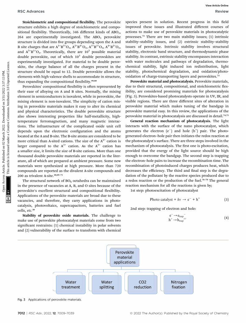
Perovskite material and photocatalysis. Perovskite materials,due to their structural, compositional, and stoichiometric ex-ibility, are considered promising materials for photocatalysis(Fig. 3). Perovskites-based photocatalysts operate in UV, IR, andvisible regions. There are three different sites of alteration inperovskite material which makes tuning of the bandgap inperovskite material easy. In this review, the applications of theperovskite material in photocatalysis are discussed in detail.74,75
General reaction mechanism of photocatalysis. The lightinteracts with the surface of the nano photocatalyst, whichgenerates the electron (e�) and hole (h+) pair. The photo-generated electron–hole pair then initiates the redox reaction atthe photocatalyst's surface. There are three steps involved in themechanism of photocatalysis. The rst one is photo-excitation,provided that the energy of the light source should be highenough to overcome the bandgap. The second step is trappingthe electron–hole pairs to increase the recombination time. Therecombination of photoinduced charges produces heat, whichdecreases the efficiency. The third and nal step is the degra-dation of the pollutant by the reactive species produced due toa redox reaction or the production of the fuel.76–79 The generalreaction mechanism for all the reactions is given by;
1st step: photoexcitation of photocatalyst
Photo catalyst + hv / e� + h+ (3)
2nd step: trapping of electron and hole:
e�/etrap�
hþ/htrapsþ (4)
© 2022 The Author(s). Published by the Royal Society of Chemistry
Review RSC Advances
Ope
n A
cces
s A
rtic
le. P
ublis
hed
on 0
2 M
arch
202
2. D
ownl
oade
d on
3/3
1/20
22 3
:37:
13 P
M.
Thi
s ar
ticle
is li
cens
ed u
nder
a C
reat
ive
Com
mon
s A
ttrib
utio
n 3.
0 U
npor
ted
Lic
ence
.View Article Online
Oragnics (pollutant) + radicals / degarded pollutant (5)
The nal step varies for each application of photocatalysisand governing equations:
For water splitting:
H+ + e� / H2 (6)
For CO2 reduction:
H+ + e� + CO2 / fuel (H2 + CH4) (7)
For nitrogen xation:
6H+ + 6e� + N2 / NH3 (8)
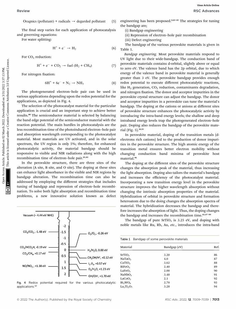
The photogenerated electron–hole pair can be used invarious applications depending upon the redox potential for theapplications, as depicted in Fig. 4.
The selection of the photocatalyst material for the particularapplication is crucial and an important step to achieve betterresults.80 The semiconductor material is selected by balancingthe band edge potential of the semiconductor material with thereaction potential. The main hurdles in photocatalysis are theless recombination time of the photoinduced electron–hole pairand absorption wavelength corresponding to the photocatalystmaterial. Most materials are UV activated, and in the solarspectrum, the UV region is only 5%; therefore, for enhancedphotocatalytic activity, the material bandgap should beresponsive to visible and NIR radiations along with the highrecombination time of electron–hole pair.81,82
In the perovskite structure, there are three sites of thealteration (A site, B site, and O site). The doping at these sitescan enhance light absorbance in the visible and NIR regions bybandgap alteration. The recombination time can also beaddressed by employing the different strategies that includestuning of bandgap and repression of electron–hole recombi-nation. To solve both light absorption and recombination timeproblems, a new innovative solution known as defect
Fig. 4 Redox potential required for the various photocatalyticapplications.10
© 2022 The Author(s). Published by the Royal Society of Chemistry
engineering has been proposed.8,83–85 The strategies for tuningthe bandgap are;
(i) Bandgap engineering(ii) Repression of electron–hole pair recombination(iii) Defect engineeringThe bandgap of the various perovskite materials is given in
Table 1.Bandgap engineering. Most perovskite materials respond to
UV light due to their wide-bandgap. The conduction band ofperovskite materials contains d-orbital, slightly above or equalto zero eV. The valence band has the 2p orbital, due to whichenergy of the valence band in perovskite material is generallygreater than 3 eV. The perovskite bandgap provides enoughredox potential to execute different photocatalytic reactions,like H2 generation, CO2 reduction, contaminants degradation,and nitrogen xation. The donor and acceptor impurities in theperovskite crystal structure can adjust the bandgap. The donorand acceptor impurities in a perovskite can tune the material'sbandgap. The doping at the cations or anions at different sitesof perovskite structure enhances the photocatalytic activity byintroducing the intra-band energy levels; the shallow and deepintraband energy levels trap the photogenerated electron–holepair. Doping also reduces the bandgap of the perovskite mate-rial (Fig. 5).30,95
In perovskite material, doping of the transition metals (d-electrons rich cations) led to the production of donor impuri-ties in the perovskite structure. The high atomic energy of thetransition metal ensures better electron mobility withoutchanging conduction band minima of perovskite hostmaterial.96
The doping at the different sites of the perovskite structurechanges the absorption peak of the material, thus increasingthe light absorption. Doping also tailors the material's bandgapand increases the efficiency of the photocatalyst material.Incorporating a new transition energy level in the perovskitestructure improves the higher wavelength absorption withoutchanging the intrinsic absorption properties of the material.Hybridization of orbital in perovskite structure and formationheteroatom due to the doing changes the absorption spectra ofmaterial. The hybridization decreases the bandgap and there-fore increases the absorption of light. Thus, the doping changesthe bandgap and increases the recombination time.83,97–99
The bandgap of pure SrTiO3 is 3.25 eV, and doping withnoble metals like Ru, Rh, Au, etc., introduces the intra-band
Table 1 Bandgap of some perovskite materials
Material Bandgap (eV) Ref.
SrTiO3 3.20 86NaTaO3 4.0 87CaTiO3 3.62 88BiFeO3 2.40 89LaFeO3 2.00 90NaNbO3 3.48 91LaCoO3 2.1 92Bi2WO6 2.70 93La2Ti2O7 3.28 94
RSC Adv., 2022, 12, 7009–7039 | 7013
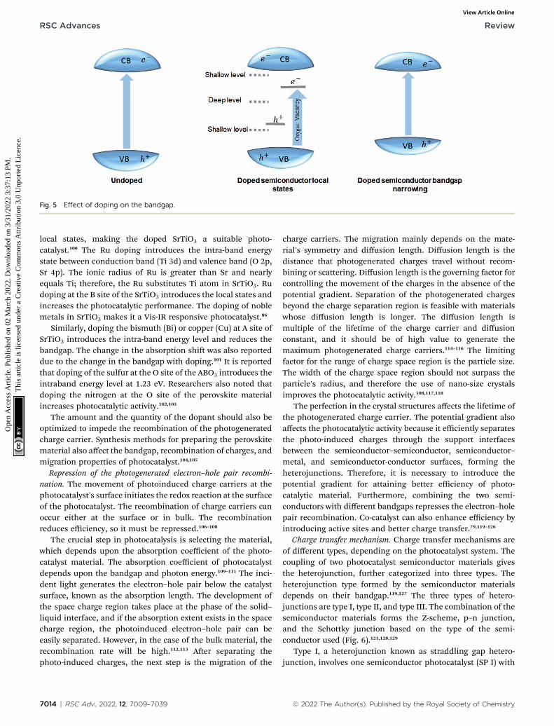
Fig. 5 Effect of doping on the bandgap.
RSC Advances Review
Ope
n A
cces
s A
rtic
le. P
ublis
hed
on 0
2 M
arch
202
2. D
ownl
oade
d on
3/3
1/20
22 3
:37:
13 P
M.
Thi
s ar
ticle
is li
cens
ed u
nder
a C
reat
ive
Com
mon
s A
ttrib
utio
n 3.
0 U
npor
ted
Lic
ence
.View Article Online
local states, making the doped SrTiO3 a suitable photo-catalyst.100 The Ru doping introduces the intra-band energystate between conduction band (Ti 3d) and valence band (O 2p,Sr 4p). The ionic radius of Ru is greater than Sr and nearlyequals Ti; therefore, the Ru substitutes Ti atom in SrTiO3. Rudoping at the B site of the SrTiO3 introduces the local states andincreases the photocatalytic performance. The doping of noblemetals in SrTiO3 makes it a Vis-IR responsive photocatalyst.86
Similarly, doping the bismuth (Bi) or copper (Cu) at A site ofSrTiO3 introduces the intra-band energy level and reduces thebandgap. The change in the absorption shi was also reporteddue to the change in the bandgap with doping.101 It is reportedthat doping of the sulfur at the O site of the ABO3 introduces theintraband energy level at 1.23 eV. Researchers also noted thatdoping the nitrogen at the O site of the perovskite materialincreases photocatalytic activity.102,103
The amount and the quantity of the dopant should also beoptimized to impede the recombination of the photogeneratedcharge carrier. Synthesis methods for preparing the perovskitematerial also affect the bandgap, recombination of charges, andmigration properties of photocatalyst.104,105
Repression of the photogenerated electron–hole pair recombi-nation. The movement of photoinduced charge carriers at thephotocatalyst's surface initiates the redox reaction at the surfaceof the photocatalyst. The recombination of charge carriers canoccur either at the surface or in bulk. The recombinationreduces efficiency, so it must be repressed.106–108
The crucial step in photocatalysis is selecting the material,which depends upon the absorption coefficient of the photo-catalyst material. The absorption coefficient of photocatalystdepends upon the bandgap and photon energy.109–111 The inci-dent light generates the electron–hole pair below the catalystsurface, known as the absorption length. The development ofthe space charge region takes place at the phase of the solid–liquid interface, and if the absorption extent exists in the spacecharge region, the photoinduced electron–hole pair can beeasily separated. However, in the case of the bulk material, therecombination rate will be high.112,113 Aer separating thephoto-induced charges, the next step is the migration of the
7014 | RSC Adv., 2022, 12, 7009–7039
charge carriers. The migration mainly depends on the mate-rial's symmetry and diffusion length. Diffusion length is thedistance that photogenerated charges travel without recom-bining or scattering. Diffusion length is the governing factor forcontrolling the movement of the charges in the absence of thepotential gradient. Separation of the photogenerated chargesbeyond the charge separation region is feasible with materialswhose diffusion length is longer. The diffusion length ismultiple of the lifetime of the charge carrier and diffusionconstant, and it should be of high value to generate themaximum photogenerated charge carriers.114–116 The limitingfactor for the range of charge space region is the particle size.The width of the charge space region should not surpass theparticle's radius, and therefore the use of nano-size crystalsimproves the photocatalytic activity.108,117,118
The perfection in the crystal structures affects the lifetime ofthe photogenerated charge carrier. The potential gradient alsoaffects the photocatalytic activity because it efficiently separatesthe photo-induced charges through the support interfacesbetween the semiconductor–semiconductor, semiconductor–metal, and semiconductor-conductor surfaces, forming theheterojunctions. Therefore, it is necessary to introduce thepotential gradient for attaining better efficiency of photo-catalytic material. Furthermore, combining the two semi-conductors with different bandgaps represses the electron–holepair recombination. Co-catalyst can also enhance efficiency byintroducing active sites and better charge transfer.79,119–126
Charge transfer mechanism. Charge transfer mechanisms areof different types, depending on the photocatalyst system. Thecoupling of two photocatalyst semiconductor materials givesthe heterojunction, further categorized into three types. Theheterojunction type formed by the semiconductor materialsdepends on their bandgap.119,127 The three types of hetero-junctions are type I, type II, and type III. The combination of thesemiconductor materials forms the Z-scheme, p–n junction,and the Schottky junction based on the type of the semi-conductor used (Fig. 6).121,128,129
Type I, a heterojunction known as straddling gap hetero-junction, involves one semiconductor photocatalyst (SP I) with
© 2022 The Author(s). Published by the Royal Society of Chemistry
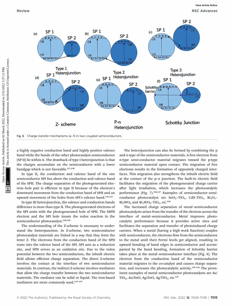
Fig. 6 Charge transfer mechanisms (a–f) in two coupled semiconductors.
Review RSC Advances
Ope
n A
cces
s A
rtic
le. P
ublis
hed
on 0
2 M
arch
202
2. D
ownl
oade
d on
3/3
1/20
22 3
:37:
13 P
M.
Thi
s ar
ticle
is li
cens
ed u
nder
a C
reat
ive
Com
mon
s A
ttrib
utio
n 3.
0 U
npor
ted
Lic
ence
.View Article Online
a highly negative conduction band and highly positive valenceband while the bands of the other photocatalyst semiconductor(SP II) lie within it. The drawback of type I heterojunction is thatthe charges accumulate on the semiconductor with a lowerbandgap which is not favorable.127,130
In type II, the conduction and valence band of the onesemiconductor SPI lies above the conduction and valence bandof the SPII. The charge separation of the photogenerated elec-tron–hole pair is efficient in type II because of the electron'sdownward movement from the conduction band of SPII and anupward movement of the holes from SPI's valence band.131,132
In type III heterojunction, the valence and conduction bandsdifference is more than type II. The photogenerated electrons ofthe SPI unite with the photogenerated hole of SPII. The SSPIIelectron and the SPI hole innate the redox reaction in thesemiconductor photocatalyst.120,130
The understanding of the Z-scheme is necessary to under-stand the heterojunction. In Z-scheme, two semiconductorphotocatalyst materials are linked in a way that they form theletter Z. The electrons from the conduction band of the SPIItrans into the valence band of the SPI. SPI acts as a reductionsite, and SPII serves as an oxidation site. Due to the redoxpotential between the two semiconductors, the inbuilt electriceld allows efficient charge separation. The direct Z-schemeinvolves the contact at the interface of two semiconductormaterials. In contrast, the indirect Z-scheme involves mediatorsthat allow the charge transfer between the two semiconductormaterials. The mediator can be solid or liquid. The iron-basedmediators are more commonly used.133–135
© 2022 The Author(s). Published by the Royal Society of Chemistry
The heterojunction can also be formed by combining the pand n-type of the semiconductor materials. A free-electron fromn-type semi-conductor material migrates toward the p-typesemiconductor material upon contact. The migration of freeelectrons results in the formation of oppositely charged inter-faces. This migration also strengthens the inbuilt electric eldat the contact of the p–n junction. The built-in electric eldfacilitates the migration of the photogenerated charge carrieraer light irradiation, which increases the photocatalyticperformance (Fig. 7).136,137 Examples of semiconductor–semi-conductor photocatalyst are SnO2–TiO2, CdS–TiO2, Bi2O3–
Bi2WO6 and Bi2WO6–TiO2, etc.138
The increased charge separation of metal–semiconductorphotocatalysts arises from the transfer of the electron across theinterface of metal–semiconductor. Metal improves photo-catalytic performance because it provides active sites andfacilitates the separation and transfer of photoinduced chargecarriers. When a metal (having a high work function) coupleswith semiconductor, the electrons ow from the semiconductorto the metal until their Fermi levels get aligned, resulting inupward bending of band edges in semiconductor and accom-panied by the band bending, formation of Schottky barriertakes place at the metal–semiconductor interface (Fig. 8). Theelectron from the conduction band of the semiconductormaterial migrates to the co-catalyst and causes charge separa-tion, and increases the photocatalytic activity.139–141 The prom-inent examples of metal–semiconductor photocatalysts are Au/TiO2, Au/ZnO, Ag/ZnO, Ag/TiO2, etc.142
RSC Adv., 2022, 12, 7009–7039 | 7015
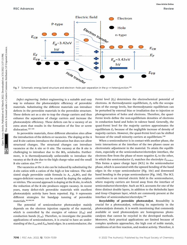
Fig. 7 Schematic energy band structure and electron–hole pair separation in the p–n heterojunction.126
RSC Advances Review
Ope
n A
cces
s A
rtic
le. P
ublis
hed
on 0
2 M
arch
202
2. D
ownl
oade
d on
3/3
1/20
22 3
:37:
13 P
M.
Thi
s ar
ticle
is li
cens
ed u
nder
a C
reat
ive
Com
mon
s A
ttrib
utio
n 3.
0 U
npor
ted
Lic
ence
.View Article Online
Defect engineering. Defect engineering is a suitable and easyway to enhance the photocatalytic efficiency of perovskitematerials. Substituting the different materials can introducedefects in the perovskite materials in the perovskite structure.These defects act as a site to trap the charge carriers and thusenhance the separation of charge carriers and increase thephotocatalytic efficiency. These defects can be a vacancy of anextra atom that results in the formation of the line or screwdislocation.143–145
In perovskite materials, three different alteration sites allowthe introduction of the defects or vacancies. The doping at the Aand B site cations introduces the dislocation but does not allowstructural changes. The structural changes can introducevacancies at the A site or O site. The vacancy at the B site ischallenging to introduce due to the BO6 octahedra. Further-more, it is thermodynamically unfavorable to introduce thevacancy at the B site due to the high charge value and the smallB site cation size.146,147
The vacancies at the A site can be induced by substituting theA-site cation with a cation of the high or low valence. The sub-sisted single perovskite oxide formula is: A1�xAxBO3 and theoxygen-decient vacancy can be created by doping the sulphuror nitrites. The second approach is doping at the B site, in whichthe reduction of the B site produces oxygen vacancy. In recentyears, many defect-rich perovskite materials with excellentphotocatalytic activity have been reported. Fig. 9 representsdifferent strategies for bandgap tunning of perovskitematerials.30,148,149
The potential of semiconductor photocatalyst mainlydepends on the electron injection capacity of the material,which is controlled by the energies of valence (EVB) andconduction bands (ECB). Therefore, to investigate the possibleapplications of semiconductors, it is crucial to have an under-standing of the ECB and EVB band edges. In a semiconductor, the
7016 | RSC Adv., 2022, 12, 7009–7039
Fermi level (EF) determines the electrochemical potential ofelectrons. At thermodynamic equilibrium, EF tells the occupa-tion of the energy levels, but thermodynamic equilibrium canbe perturbed by external bias or irradiation due to injection orphotogeneration of holes and electrons. Therefore, the quasi-Fermi levels dene the non-equilibrium densities of electronsin conduction band and holes in valence band. Generally, thequasi-Fermi level for the majority carriers approximates theequilibrium EF because of the negligible increase of density ofmajority carriers. However, the quasi-Fermi level can be shiedbecause of the small minority carriers at equilibrium.150
When a semiconductor is in contact with another phase, theionic interactions at the interface of the two phases cause anelectrostatic adjustment in the material. To attain the equilib-rium, especially at the semiconductor/electrolyte interface, theelectrons ow from the phase of more negative EF to the other,in which the semiconductor EF matches the electrolyte EF,redox.This forms a space charge layer (SCL) in the semiconductorphase, which is associated with the upward bending of the bandedges in the n-type semiconductor (Fig. 10c) and downwardband bending in the p-type semiconductor (Fig. 10d). The SCLcontributes to an internal electric eld in the semiconductor,where majority carriers are forced away from the interface ofsemiconductor/electrolyte. Such an SCL accounts for one of thethree distinct double layers, in addition to the Helmholtz layerand Gouy–Chapman layer, which are commonly present at theinterface of semiconductor/electrolyte.150
Recyclability of perovskite photocatalyst. Reusability iscrucial for a photocatalyst, reecting its superiority in thephotocatalysis domain. It is worth mentioning that commonlyavailable or used photocatalysts are homogeneous photo-catalysts that cannot be recycled in the developed methods.Moreover, their practical applications are limited because ofcomplex synthesis approaches, the high cost of noble metals,conditions of air-free reaction, andmodest activity. Therefore, it
© 2022 The Author(s). Published by the Royal Society of Chemistry
Review RSC Advances
Ope
n A
cces
s A
rtic
le. P
ublis
hed
on 0
2 M
arch
202
2. D
ownl
oade
d on
3/3
1/20
22 3
:37:
13 P
M.
Thi
s ar
ticle
is li
cens
ed u
nder
a C
reat
ive
Com
mon
s A
ttrib
utio
n 3.
0 U
npor
ted
Lic
ence
.View Article Online
is essential to develop an easily produced heterogeneous pho-tocatalyst that also exhibits the property of easy catalyst sepa-ration along with recyclability. The researchers have recentlystarted reporting heterogeneous perovskite photocatalyst inphotocatalytic organic synthesis. The perovskites-catalyzedselective oxidation of benzyl alcohols to aldehydes undervisible light irradiation has been reported by a group ofresearchers. Another group reported the photoredox CsPbBr3-catalyzed oxidative coupling of thiols to disuldes and cross-dehydrogenative coupling of dialkyl H-phosphonates withtertiary amines to a-phosphoryl tertiary amines. Yan and theirfellows also reported the a-acylmethylation of aldehydes start-ing from aldehydes and a-bromo ketones catalyzed by CsPbBr3under light. The same group also used CsPbBr3 photocatalystfor the formation of C–C bond via C–H activation, formation ofC–N, and C–O via N-heterocyclization, and arylesterication. Agroup of researchers prepared a heterogenous perovskite pho-tocatalyst and used it at least ve times without noticeabledegradation in its activity.151,152
Applications of photocatalysis
There are numerous photocatalysis applications, but during thelast couple of decades, a lot of focus has been given to appli-cations having environmental applications such as wastewatertreatment, nitrogen xation, CO2 reduction, air purication,and water splitting. All of these applications except air puri-cation have been discussed in the current article.
Degradation of water pollutants
Rapid industrial growth, mainly the textile industry, producesincreased chemical wastes in the water. Industrial chemicalwastes or pollutants are known as dyes. The dyes produced bythe textile industry can impede plant growth, impair photo-synthesis, and its accumulation in soil disturbs the food chain.The textile dyes in water also cause genetic problems andcancer. The dyes in water aggravate the regulatory functions ofthe different glands in humans and can also have adverseeffects, like infertility and immune suppression in humans. Thetraditional ways to clean the dyes in water give rise to massivesludge because of adsorbent usage, which can further causebacterial infections and skin problems. The photocatalyticdegradation of the containments in the water is more reliablethan the traditional methods. Recycling the adsorbents inconventional methods generally generates secondary pollut-ants, and recycling adsorbents also requires harshconditions.153–156
The use of the photocatalyst is an eco-friendly way to degradethese water pollutants. The photocatalytic techniques utilize theadvanced oxidation process (AOP) for degradation. The inter-action of the light with the photocatalyst generates electron–hole pair. Generally, oxygen is employed as an electron scav-enger to increase the recombination time for enhanced photo-catalytic activity. The redox reaction of the photogeneratedelectron–hole pair gives reactive species such as (OH*, OH�,H+), and these reactive species then attack the organic
© 2022 The Author(s). Published by the Royal Society of Chemistry
pollutants and degrade them into low molecular weight prod-ucts (environmentally friendly products) within no time.153,157,158
The heterogeneous design and the self-cleaning surface ofthe catalyst make recyclability much easier. The reactions occurat the catalyst's surface, followed by the desorption of thematerials; thus, this method is known as a sustainable solutionto address the water contamination crisis.159,160
The photocatalytic activity can not only be monitored byinvestigating the absorption spectra of the dye molecule butalso involves the investigation of the mineralized productsformed due to the cleavage of the chromosphere. The miner-alized products can be investigated by measuring the chemicaloxygen demand (COD) and total organic carbon (TOC). Thephotocatalytic reaction for degradation of the containmentsoccurs in an aqueous environment. The irradiation of the lighton the aqueous system (consisting of photocatalyst + pollutedwater) generates photogenerated electron–hole pair in water.The oxygen or different impurities are added as an electronscavenger to increase the recombination time.25,104,161,162 Thephotogenerated electron–hole pair then migrates towards thesurface of the photocatalyst and induces the reactive ions (suchas OH*, O2�*, etc.). The redox potential of the created reactiveion species depends upon the bandgap of the photocatalyst.The reactive ion species then degrade the contaminant into thesmaller fragments, which are then changed into greencompounds. The degradation of the contaminants takes placeat the surface of the catalyst. Initially, the dye gets adsorbed atthe catalyst surface, and aer the degradation product getsdesorbed, the new pollutant is adsorbed, and this processcontinues until no contaminant is le. The overall reactionmechanism is shown in (Fig. 11).30,76,135,163,164
Many perovskite materials are used as a photocatalyst, buttitanium, bismuth, and ferrite-based single and double perov-skite are widely reported due to their excellent photocatalyticproperties.165 The rst reported perovskite material CaTiO3
exhibited photocatalytic activity and degraded pollutants. Thewide bandgap of CaTiO3 (3.0–3.5 eV) responds only to the UVlight and efficiently degrade the brilliant green (BG), methylblue (MG), and rhodamine B (RHb).88,166 The synthesis routeand the morphology of the CaTiO3 structure change thebandgap and thus affect the photocatalytic performance forpollutant degradation. CaTiO3 nanocuboid showed the excel-lent photodegradation of the RhB dye upon visible light irra-diation. Zirconium (Zr) doping at the Ti site of CaTiO3 generatesoxygen vacancies, producing defects and increasing photo-catalytic activity by changing the lattice structure.167,168 The re-ported photocatalytic activity of the Zr doped CaTiO3 is thirteentimes greater than the un-doped CaTiO3. Fe-doped CaTiO3
efficiently degraded the methyl blue using the visible lightsource.166 The doping of the Fe in the CaTiO3 increased theabsorption ability of CaTiO3. The photocatalytic activity alsodepends upon the calcination temperature and the irradiationtime of the light. Fe-doped CaTiO3 showed 100% photo-degradation of the methyl blue at optimum condition(temperature, irradiation time, and light source).169 BaTiO3,SrTiO3, and other titanium-based perovskite materials have alsoshown better photodegradation of the pollutants.101,102,170
RSC Adv., 2022, 12, 7009–7039 | 7017
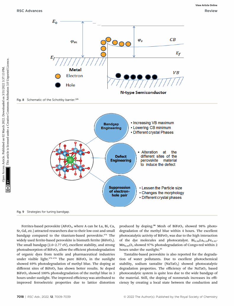
Fig. 8 Schematic of the Schottky barrier.126
Fig. 9 Strategies for tuning bandgap.
RSC Advances Review
Ope
n A
cces
s A
rtic
le. P
ublis
hed
on 0
2 M
arch
202
2. D
ownl
oade
d on
3/3
1/20
22 3
:37:
13 P
M.
Thi
s ar
ticle
is li
cens
ed u
nder
a C
reat
ive
Com
mon
s A
ttrib
utio
n 3.
0 U
npor
ted
Lic
ence
.View Article Online
Ferrites-based perovskite (AFeO3, where A can be La, Bi, Ca,Sr, Gd, etc.) attracted researchers due to their low cost and smallbandgap compared to the titanium-based perovskite.171 Thewidely used ferrite-based perovskite is bismuth ferrite (BiFeO3).The small bandgap (2.0–2.77 eV), excellent stability, and strongphotoabsorption of BiFeO3 allow the efficient photodegradationof organic dyes from textile and pharmaceutical industriesunder visible light.172–174 The pure BiFeO3 in the sunlightshowed 69% photodegradation of methyl blue. The doping atdifferent sites of BiFeO3 has shown better results. Sc dopedBiFeO3 showed 100% photodegradation of the methyl blue in 3hours under sunlight. The improved efficiency was attributed toimproved ferroelectric properties due to lattice distortion
7018 | RSC Adv., 2022, 12, 7009–7039
produced by doping.98 Mesh of BiFeO3 showed 98% photo-degradation of the methyl blue within 4 hours. The excellentphotocatalytic activity of BiFeO3 was due to the high interactionof the dye molecules and photocatalyst. Bi0.90La0.10Fe0.95-Mn0.05O3 showed 97% photodegradation of Congo-red within 2hours under the sunlight.25
Tantalite-based perovskite is also reported for the degrada-tion of water pollutants. Due to excellent photochemicalstability, sodium tantalite (NaTaO3) showed photocatalyticdegradation properties. The efficiency of the NaTaO3 basedphotocatalytic system is quite less due to the wide bandgap ofthe material. Still, the doping of nonmetals increases its effi-ciency by creating a local state between the conduction and
© 2022 The Author(s). Published by the Royal Society of Chemistry

Fig. 10 Energy levels of the semiconductor/electrolyte interface before (a and b) and after contact (c and d).150
Fig. 11 Photocatalytic pollutant degradation.
Review RSC Advances
Ope
n A
cces
s A
rtic
le. P
ublis
hed
on 0
2 M
arch
202
2. D
ownl
oade
d on
3/3
1/20
22 3
:37:
13 P
M.
Thi
s ar
ticle
is li
cens
ed u
nder
a C
reat
ive
Com
mon
s A
ttrib
utio
n 3.
0 U
npor
ted
Lic
ence
.View Article Online
valence band. The reported photodegradation of methyl blue is95.21% by nitrogen-based NaTaO3 photocatalyst using sunlightas an irradiation source.175,176 Different perovskite materialsused for photocatalytic pollutant degradation are given in Table2.
Photocatalytic water splitting. Hydrogen is considereda green and clean fuel and one of the best alternatives to fossil
© 2022 The Author(s). Published by the Royal Society of Chemistry
and other non-renewable energy resources. The photocatalyticsplitting of the water produces H2 and O2 oxygen by the four-electron process. The overall reaction of water splitting isdepicted in eqn (9).
2H2O / 2H2 + O2 DG� ¼ +237 kJ mol�1 (9)
RSC Adv., 2022, 12, 7009–7039 | 7019
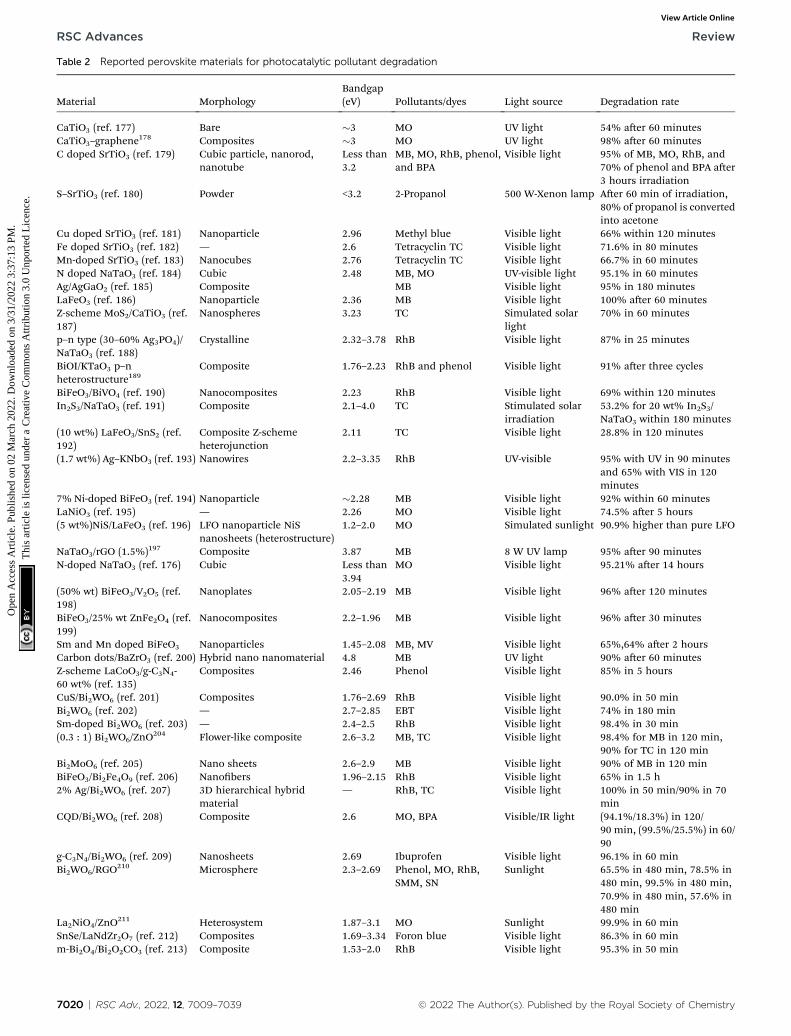
Table 2 Reported perovskite materials for photocatalytic pollutant degradation
Material MorphologyBandgap(eV) Pollutants/dyes Light source Degradation rate
CaTiO3 (ref. 177) Bare �3 MO UV light 54% aer 60 minutesCaTiO3–graphene
178 Composites �3 MO UV light 98% aer 60 minutesC doped SrTiO3 (ref. 179) Cubic particle, nanorod,
nanotubeLess than3.2
MB, MO, RhB, phenol,and BPA
Visible light 95% of MB, MO, RhB, and70% of phenol and BPA aer3 hours irradiation
S–SrTiO3 (ref. 180) Powder <3.2 2-Propanol 500 W-Xenon lamp Aer 60 min of irradiation,80% of propanol is convertedinto acetone
Cu doped SrTiO3 (ref. 181) Nanoparticle 2.96 Methyl blue Visible light 66% within 120 minutesFe doped SrTiO3 (ref. 182) — 2.6 Tetracyclin TC Visible light 71.6% in 80 minutesMn-doped SrTiO3 (ref. 183) Nanocubes 2.76 Tetracyclin TC Visible light 66.7% in 60 minutesN doped NaTaO3 (ref. 184) Cubic 2.48 MB, MO UV-visible light 95.1% in 60 minutesAg/AgGaO2 (ref. 185) Composite MB Visible light 95% in 180 minutesLaFeO3 (ref. 186) Nanoparticle 2.36 MB Visible light 100% aer 60 minutesZ-scheme MoS2/CaTiO3 (ref.187)
Nanospheres 3.23 TC Simulated solarlight
70% in 60 minutes
p–n type (30–60% Ag3PO4)/NaTaO3 (ref. 188)
Crystalline 2.32–3.78 RhB Visible light 87% in 25 minutes
BiOI/KTaO3 p–nheterostructure189
Composite 1.76–2.23 RhB and phenol Visible light 91% aer three cycles
BiFeO3/BiVO4 (ref. 190) Nanocomposites 2.23 RhB Visible light 69% within 120 minutesIn2S3/NaTaO3 (ref. 191) Composite 2.1–4.0 TC Stimulated solar
irradiation53.2% for 20 wt% In2S3/NaTaO3 within 180 minutes
(10 wt%) LaFeO3/SnS2 (ref.192)
Composite Z-schemeheterojunction
2.11 TC Visible light 28.8% in 120 minutes
(1.7 wt%) Ag–KNbO3 (ref. 193) Nanowires 2.2–3.35 RhB UV-visible 95% with UV in 90 minutesand 65% with VIS in 120minutes
7% Ni-doped BiFeO3 (ref. 194) Nanoparticle �2.28 MB Visible light 92% within 60 minutesLaNiO3 (ref. 195) — 2.26 MO Visible light 74.5% aer 5 hours(5 wt%)NiS/LaFeO3 (ref. 196) LFO nanoparticle NiS
nanosheets (heterostructure)1.2–2.0 MO Simulated sunlight 90.9% higher than pure LFO
NaTaO3/rGO (1.5%)197 Composite 3.87 MB 8 W UV lamp 95% aer 90 minutesN-doped NaTaO3 (ref. 176) Cubic Less than
3.94MO Visible light 95.21% aer 14 hours
(50% wt) BiFeO3/V2O5 (ref.198)
Nanoplates 2.05–2.19 MB Visible light 96% aer 120 minutes
BiFeO3/25% wt ZnFe2O4 (ref.199)
Nanocomposites 2.2–1.96 MB Visible light 96% aer 30 minutes
Sm and Mn doped BiFeO3 Nanoparticles 1.45–2.08 MB, MV Visible light 65%,64% aer 2 hoursCarbon dots/BaZrO3 (ref. 200) Hybrid nano nanomaterial 4.8 MB UV light 90% aer 60 minutesZ-scheme LaCoO3/g-C3N4-60 wt% (ref. 135)
Composites 2.46 Phenol Visible light 85% in 5 hours
CuS/Bi2WO6 (ref. 201) Composites 1.76–2.69 RhB Visible light 90.0% in 50 minBi2WO6 (ref. 202) — 2.7–2.85 EBT Visible light 74% in 180 minSm-doped Bi2WO6 (ref. 203) — 2.4–2.5 RhB Visible light 98.4% in 30 min(0.3 : 1) Bi2WO6/ZnO
204 Flower-like composite 2.6–3.2 MB, TC Visible light 98.4% for MB in 120 min,90% for TC in 120 min
Bi2MoO6 (ref. 205) Nano sheets 2.6–2.9 MB Visible light 90% of MB in 120 minBiFeO3/Bi2Fe4O9 (ref. 206) Nanobers 1.96–2.15 RhB Visible light 65% in 1.5 h2% Ag/Bi2WO6 (ref. 207) 3D hierarchical hybrid
material— RhB, TC Visible light 100% in 50 min/90% in 70
minCQD/Bi2WO6 (ref. 208) Composite 2.6 MO, BPA Visible/IR light (94.1%/18.3%) in 120/
90 min, (99.5%/25.5%) in 60/90
g-C3N4/Bi2WO6 (ref. 209) Nanosheets 2.69 Ibuprofen Visible light 96.1% in 60 minBi2WO6/RGO
210 Microsphere 2.3–2.69 Phenol, MO, RhB,SMM, SN
Sunlight 65.5% in 480 min, 78.5% in480 min, 99.5% in 480 min,70.9% in 480 min, 57.6% in480 min
La2NiO4/ZnO211 Heterosystem 1.87–3.1 MO Sunlight 99.9% in 60 min
SnSe/LaNdZr2O7 (ref. 212) Composites 1.69–3.34 Foron blue Visible light 86.3% in 60 minm-Bi2O4/Bi2O2CO3 (ref. 213) Composite 1.53–2.0 RhB Visible light 95.3% in 50 min
7020 | RSC Adv., 2022, 12, 7009–7039 © 2022 The Author(s). Published by the Royal Society of Chemistry
RSC Advances Review
Ope
n A
cces
s A
rtic
le. P
ublis
hed
on 0
2 M
arch
202
2. D
ownl
oade
d on
3/3
1/20
22 3
:37:
13 P
M.
Thi
s ar
ticle
is li
cens
ed u
nder
a C
reat
ive
Com
mon
s A
ttrib
utio
n 3.
0 U
npor
ted
Lic
ence
.View Article Online
Review RSC Advances
Ope
n A
cces
s A
rtic
le. P
ublis
hed
on 0
2 M
arch
202
2. D
ownl
oade
d on
3/3
1/20
22 3
:37:
13 P
M.
Thi
s ar
ticle
is li
cens
ed u
nder
a C
reat
ive
Com
mon
s A
ttrib
utio
n 3.
0 U
npor
ted
Lic
ence
.View Article Online
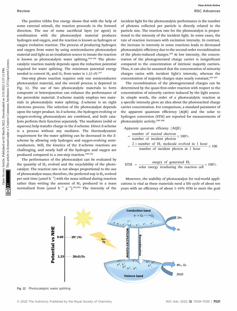
The positive Gibbs free energy shows that with the help ofsome external stimuli, the reaction proceeds in the forwarddirection. The use of some sacricial layer (or agent) incombination with the photocatalyst material produceshydrogen and oxygen, and the reaction is known as hydrogen oroxygen evolution reaction. The process of producing hydrogenand oxygen from water by using semiconductor photocatalystmaterial and light as an irradiation source to innate the reactionis known as photocatalytic water splitting.214–216 The photo-catalytic reaction mainly depends upon the reduction potentialrequired for water splitting. The minimum potential energyneeded to convert H2 and O2 from water is 1.23 eV.217
One-step photo reaction requires only one semiconductorphotocatalyst material, and the overall process is depicted inFig. 12. The use of two photocatalytic materials to formcomposite or heterojunction can enhance the performance ofthe perovskite material. Z-scheme mainly employs two mate-rials in photocatalytic water splitting. Z-scheme is an eightelectrons process. The selection of the photocatalyst dependsupon the target product. In Z-scheme, the hydrogen-evolving oroxygen-evolving photocatalysts are combined, and both cata-lysts perform their function separately. The mediators (solid oraqueous) help transfer charge in the Z-scheme. Direct Z-schemeis a process without any mediator. The thermodynamicrequirement for the water splitting can be decreased in the Z-scheme by allowing only hydrogen and oxygen-evolving semi-conductors. Still, the kinetics of the Z-scheme reactions arechallenging, and nearly half of the hydrogen and oxygen areproduced compared to a one-step reaction.218–221
The performance of the photocatalyst can be evaluated bythe quantity of H2 evolved and the recyclability of the photo-catalyst. The reaction rate is not always proportional to the useof photocatalyst mass; therefore, the preferred way is H2 evolvedper unit time (mmol h�1) with the mass utilized during reactionrather than writing the amount of H2 produced in a massnormalized from (mmol h�1 g�1).222,223 The intensity of the
Fig. 12 Photocatalytic water splitting.
© 2022 The Author(s). Published by the Royal Society of Chemistry
incident light for the photocatalytic performance is the numberof photons collected per particle is directly related to theparticle size. The reaction rate for the photocatalyst is propor-tional to the intensity of the incident light. In some cases, therate of reaction increases with excitation intensity. In contrast,the increase in intensity in some reactions leads to decreasedphotocatalytic efficiency due to the second-order recombinationof the photo-induced charges.224 At low intensity, the concen-tration of the photogenerated charge carrier is insignicantcompared to the concentration of intrinsic majority carriers.Thus, it can also be assumed that the concentration of minoritycharges varies with incident light's intensity, whereas theconcentration of majority charges stays nearly constant.225–227
The recombination of the photogenerated charges can bedetermined by the quasi-rst-order reaction with respect to theconcentration of minority carriers induced by the light source.In simple words, the order of a photocatalytic reaction ata specic intensity gives an idea about the photoexcited chargecarrier concentration. For comparison, a standard parameter ofthe apparent quantum efficiency (AQE) and the solar tohydrogen conversion (STH) are reported for measurements ofphotocatalytic activity.228–230
Apparent qunatum efficieny ðAQEÞ
¼ number of reacted electron
number of incident photon� 100%
¼ 2� number of H2 molecule evolved in 1 hour
number of incident photon in 1 hour� 100
STH ¼ enegry of generated H2
solar energy irradiating the reaction cell� 100%
Moreover, the stability of photocatalyst for real-world appli-cations is vital as these materials need a life cycle of about tenyears with an efficiency of about 5–10% STH to meet the goal
RSC Adv., 2022, 12, 7009–7039 | 7021
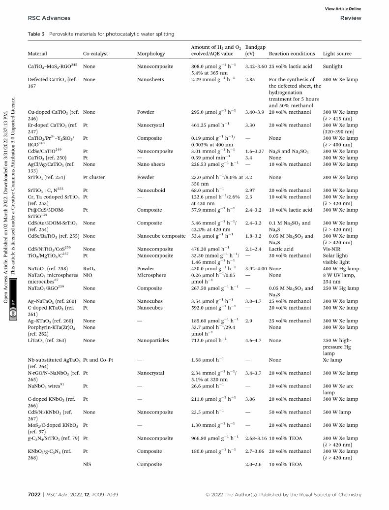
Table 3 Perovskite materials for photocatalytic water splitting
Material Co-catalyst MorphologyAmount of H2 and O2
evolved/AQE valueBandgap(eV) Reaction conditions Light source
CaTiO3–MoS2-RGO245 None Nanocomposite 808.0 mmol g�1 h�1
5.4% at 365 nm3.42–3.60 25 vol% lactic acid Sunlight
Defected CaTiO3 (ref.167
None Nanosheets 2.29 mmol g�1 h�1 2.85 For the synthesis ofthe defected sheet, thehydrogenationtreatment for 5 hoursand 50% methanol
300 W Xe lamp
Cu-doped CaTiO3 (ref.246)
None Powder 295.0 mmol g�1 h�1 3.40–3.9 20 vol% methanol 300 W Xe lamp(l > 415 nm)
Er-doped CaTiO3 (ref.247)
Pt Nanocrystal 461.25 mmol h�1 3.30 20 vol% methanol 300 W Xe lamp(320–390 nm)
CaTiO3/Pr3+–Y2SiO5/
RGO248Pt Composite 0.19 mmol g�1 h�1/
0.003% at 400 nm— None 300 W Xe lamp
(l > 400 nm)CdSe/CaTiO249 Pt Nanocomposite 3.01 mmol g�1 h�1 1.6–3.27 Na2S and Na2SO3 300 W Xe lampCaTiO3 (ref. 250) Pt — 0.39 mmol min�1 3.4 None 300 W Xe lampAgCl/Ag/CaTiO3 (ref.133)
None Nano sheets 226.53 mmol g�1 h�1 — 10 vol% methanol 300 W Xe lamp
SrTiO3 (ref. 251) Pt cluster Powder 23.0 mmol h�1/8.0% at350 nm
3.2 None 300 W Xe lamp
SrTiO3 : C, N252 Pt Nanocuboid 68.0 mmol h�1 2.97 20 vol% methanol 300 W Xe lamp
Cr, Ta codoped SrTiO3
(ref. 253)Pt — 122.6 mmol h�1/2.6%
at 420 nm2.3 10 vol% methanol 300 W Xe lamp
(l > 420 nm)Pt@CdS/3DOM-SrTiO134
Pt Composite 57.9 mmol g�1 h�1 2.4–3.2 10 vol% lactic acid 300 W Xe lamp
CdS/Au/3DOM-SrTiO3
(ref. 254)None Composite 5.46 mmol g�1 h�1/
42.2% at 420 nm2.4–3.2 0.1 M Na2SO3 and
Na2S300 W Xe lamp(l > 420 nm)
CdSe/BaTiO3 (ref. 255) None Nanocube composite 53.4 mmol g�1 h�1 1.8–3.2 0.05 M Na2SO3 andNa2S
300 W Xe lamp(l > 420 nm)
CdS/NiTiO3/CoS256 None Nanocomposite 476.20 mmol h�1 2.1–2.4 Lactic acid Vis-NIR
TiO2/MgTiO3/C257 Pt Nanocomposite 33.30 mmol g�1 h�1/
1.46 mmol g�1 h�1— 30 vol% methanol Solar light/
visible lightNaTaO3 (ref. 258) RuO2 Powder 430.0 mmol g�1 h�1 3.92–4.00 None 400 W Hg lampNaTaO3 microspheresmicrocubes87
NiO Microsphere 0.26 mmol h�1/0.05mmol h�1
— None 8 W UV lamp,254 nm
NaTaO3/RGO259 None Composite 267.50 mmol g�1 h�1 — 0.05 M Na2SO3 and
Na2S250 W Hg lamp
Ag–NaTaO3 (ref. 260) None Nanocubes 3.54 mmol g�1 h�1 3.0–4.7 25 vol% methanol 300 W Xe lampC-doped KTaO3 (ref.261)
Pt Nanocubes 592.0 mmol g�1 h�1 — 20 vol% methanol 300 W Xe lamp
Ag–KTaO3 (ref. 260) None — 185.60 mmol g�1 h�1 2.9 25 vol% methanol 300 W Xe lampPorphyrin-KTa(Zr)O3
(ref. 262)None 53.7 mmol h�1/29.4
mmol h�1None 300 W Xe lamp
LiTaO3 (ref. 263) None Nanoparticles 712.0 mmol h�1 4.6–4.7 None 250 W high-pressure Hglamp
Nb-substituted AgTaO3
(ref. 264)Pt and Co–Pt — 1.68 mmol h�1 — None Xe lamp
N-rGO/N–NaNbO3 (ref.265)
Pt Nanocrystal 2.34 mmol g�1 h�1/5.1% at 320 nm
3.4–3.7 20 vol% methanol 300 W Xe lamp
NaNbO3 wires91 Pt — 26.6 mmol h�1 — 20 vol% methanol 300 W Xe arc
lampC-doped KNbO3 (ref.266)
Pt — 211.0 mmol g�1 h�1 3.06 20 vol% methanol 300 W Xe lamp
CdS/Ni/KNbO3 (ref.267)
None Nanocomposite 23.5 mmol h�1 — 50 vol% methanol 500 W lamp
MoS2/C-doped KNbO3
(ref. 97)Pt — 1.30 mmol g�1 h�1 — 20 vol% methanol 300 W Xe lamp
g-C3N4/SrTiO3 (ref. 79) Pt Nanocomposite 966.80 mmol g�1 h�1 2.68–3.16 10 vol% TEOA 300 W Xe lamp(l > 420 nm)
KNbO3/g-C3N4 (ref.268)
Pt Composite 180.0 mmol g�1 h�1 2.7–3.06 20 vol% methanol 300 W Xe lamp(l > 420 nm)
NiS Composite 2.0–2.6 10 vol% TEOA
7022 | RSC Adv., 2022, 12, 7009–7039 © 2022 The Author(s). Published by the Royal Society of Chemistry
RSC Advances Review
Ope
n A
cces
s A
rtic
le. P
ublis
hed
on 0
2 M
arch
202
2. D
ownl
oade
d on
3/3
1/20
22 3
:37:
13 P
M.
Thi
s ar
ticle
is li
cens
ed u
nder
a C
reat
ive
Com
mon
s A
ttrib
utio
n 3.
0 U
npor
ted
Lic
ence
.View Article Online

Table 3 (Contd. )
Material Co-catalyst MorphologyAmount of H2 and O2
evolved/AQE valueBandgap(eV) Reaction conditions Light source
LaFeO3/g-C3N4 (ref.269)
121.0 mmol g�1 h�1/2.01% at 420 nm
300 W Xe lamp(l > 400 nm)
BiFeO3/Bi2Fe4O9
(12.3% Bi2Fe4O9)206
None Heterostructurenanober
800 mmol g�1 H2 1.96–2.15 A sacricial layer oftriethanolamine
—
Sr2CuWO270 1 wt% Pt for H2
production (waterreduction) and 1 wt%CoO for O2 production(water oxidation)
Nanopowder No H2 was produced,and the quantumefficiency of O2
produced was 0.034
2.07 A sacricial agent suchas sodium sulte forH2 production
Visible light (l$420 nm
g-C3N4/Ba5Ta4O15
(33.47 wt% g-C3N4)218
1 wt% Pt Nanosheets wrappedby g-C3N4 foil/nanosheetsheterostructure
60–70 mmol of H2
evolved in 5 hours2.8–4.3 A sacricial layer of
oxalic acidVisible light
Cs2AgBiBr6 (ref. 271) 2.5% RGO Composite 489 mmol g�1 H2 in 10h
2.77 H2 evolution insaturated HBr aqueoussolution
Visible light
Ba5Ta4O15 (ref. 272) Cr2O3/0.0125 wt% Rh Nanoparticle 465 mmol h�1 H2 and228 mmol h�1 O2/100mmol h�1 H2
4.5 Ba5Ta4O15 prepared bythe citrate method
Visible light
Zn2Ti3O8 (ref. 273) 5 wt% RuO2 Nanorods 4 mmol h�1 (0.1 gram)of H2 and 2 mmol h�1
(0.1 g) of O2
3.56 Before thephotocatalytic activity,the solution isdeaerated byevacuation
300 W Xe lamp
Ca2NiWO6 (ref. 274) None Nanoparticle 1.38 mmol g�1 h�1 O2 2.8 Ca2NiWO6 is preparedby a solid-statereaction
Visible light
W-dopedSr2FeNbO6(Sr2FeNb1�x
WxO6) (x ¼ 0.01–0.09)275
0.2 wt% Pt Nano particles 1.1–33 mmol h�1 of H2
depending upon x and28–605 mmol h�1 of O2
depending upon x
2.17 The reaction is carriedout in an aqueousmethanol solution
Visible light
Cr–PbBi2Nb2O9 (ref.276)
1 wt% of Pt Layered perovskitesystem
9.4 mmol h�1 of H2 and671 mmol h�1 of O2
2.63–2.88 — Visible light
Bi2WO6 (ref. 277) None Nanoparticle 188.25 mmol g�1 h�1 ofH2
3.1 1 : 1 of glycerol–wateris used
Visible light
CrxLa2�xTi2O7 (x ¼0.01–0.05%)216
1.0 wt% Pt Nanopowder 50–90 mmol h�1 of H2
produced2.2 Methanol as hole
scavengerUV irradiation (l> 200 nm)
FexLa2�xTi2O7 x ¼(0.01–0.05%)278
1.0 wt% Pt Nanopowder 32–45 mmol h�1 of H2
produced2.6 Methanol as hole
scavengerUV-visible
Sr2NiWO6 (ref. 279) 1.0 wt% Pt Nanoparticles 420 mmol g�1 h�1 ofO2/8.6 at 420 nm
2.88 AgNO3 and FeNO3 assacricial layer
Visible light
La2Ti2O7 (ref. 280) 1.0 wt% NiO Nanoparticles 400 mmol h�1 of H2
produced< 3.0 Photoreduction
reaction wasperformed in anaqueous CH3OHsolution
UV-visible
MA2CuCl2Br2 (ref. 281) 1.0% loading of CuO Powder 141 mmol of H2/gcal in24 hours/144.11 mmolof O2 produced
— Argon was introducedinto the reactor toavoid the presence ofoxygen and 1 mL ofwater was used asa reagent
Solar simulator
CsCa2Nb3O10 (ref. 282) None/0.05 wt% Rh Nanosheets 450–500 mmole of H2
in 2 hours/1700 mmolein 3 hours
3.6 Photoreductionreaction wasperformed in anaqueous CH3OHsolution
UV light
KCa2Nb3O10 (ref. 283) None Nanosheets 550 mmol of H2 in 2hours
3.6 CH3OH is used UV light
© 2022 The Author(s). Published by the Royal Society of Chemistry RSC Adv., 2022, 12, 7009–7039 | 7023
Review RSC Advances
Ope
n A
cces
s A
rtic
le. P
ublis
hed
on 0
2 M
arch
202
2. D
ownl
oade
d on
3/3
1/20
22 3
:37:
13 P
M.
Thi
s ar
ticle
is li
cens
ed u
nder
a C
reat
ive
Com
mon
s A
ttrib
utio
n 3.
0 U
npor
ted
Lic
ence
.View Article Online
RSC Advances Review
Ope
n A
cces
s A
rtic
le. P
ublis
hed
on 0
2 M
arch
202
2. D
ownl
oade
d on
3/3
1/20
22 3
:37:
13 P
M.
Thi
s ar
ticle
is li
cens
ed u
nder
a C
reat
ive
Com
mon
s A
ttrib
utio
n 3.
0 U
npor
ted
Lic
ence
.View Article Online
price of $ 2.00–4.00 per kg. The absorption wavelength for watersplitting should be around 526 nm (2.36 eV) because below thiswavelength, the photon's energy is not sufficient to achieve STHefficiency of 5–10%, considering that the reaction takes placefor a lower wavelength at the AQE ¼ 1. To meet the industrialdemand, the practical need for the evolution of H2 undersunlight, the photocatalyst with the bandgap of less than 2.36must be developed. The perovskites-based photocatalyticmaterials gained signicant attention for the practical appli-cation of water splitting under UV light and visible light.231–234
Titanium-based perovskite materials are widely reported forphotocatalytic water splitting. Doping and co-doping changethe morphology and bandgap of SrTiO3, thus are making ita suitable visible light photocatalyst for water splitting reaction.The use of the Pt as a co-catalyst induces the Schottky barrierand can make the photocatalyst responsive to visible light. Thepresence of the Pt also provides the site for the proton reduc-tion. The quantum yield efficiency by using the visible light asan irradiation source is 0.9% while using the UV light, thequantum yield efficiency of the system is 1.9%. The use of theother metals as Au, Ag, Fe, Ce, and Ni are also reported.235–239
Alkali tantalates are the best perovskite material reported forphotocatalytic water splitting when the parameters like thedoping of the metal cations and morphology (nanocubes) oftantalates-based material are optimized well. The reportedhydrogen evolution by KTaO3 nanocubes is 375 mmol g�1 h�1.The Ag doping at the surface of the KTaO3 increases thehydrogen evolution in UV light. The irradiation of the UV lightgenerates oscillations in the conduction band of absorbed silverand thus allows the easy excitation of the particles to theconduction band of KTaO3. The local electric eld of KTaO3 wasenhanced with the doping of the silver nanoparticles. Theenhanced eld promotes the electron–hole pair generation, andtherefore, increases the photocatalytic splitting. The reportedevolution of the hydrogen in the presence of Ag as a dopant inKTaO3 is 2072 mmol g�1 h�1.240–243 The lanthanum and ferrite-based perovskite material are also reported.244 Table 3 listsvarious perovskite materials used for water splitting.
Photocatalytic CO2 reduction. The atmospheric concentra-tion of CO2 is increasing at an alarming rate due to increasedhuman activities, deforestation, burning of fuels, and indus-trialization. The increased CO2 emission is causing globalwarming, and for environmental sustainability, it is essential toconvert CO2 into valuable products. Mother Nature blessedhumans with photosynthesis, in which chlorophyll act asa natural photocatalyst and, in the presence of sunlight,converts CO2 into water, oxygen, and food for plants. Thephotocatalyst also converts CO2 into valuable products insunlight.16,277,284,285
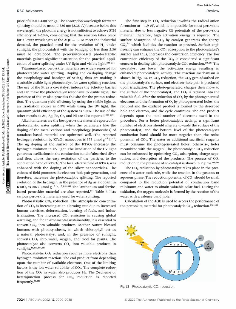
Photocatalytic CO2 reduction requires more electrons thanhydrogen evolution reaction. The end product from dependingupon the number of available electrons. One of the limitingfactors is the low water solubility of CO2. The complete reduc-tion of the CO2 in water also produces H2. The Z-scheme orheterojunction process for CO2 reduction is reportedfrequently.30,122
7024 | RSC Adv., 2022, 12, 7009–7039
The rst step in CO2 reduction involves the radical anionformation at �1.9 eV, which is impossible for most perovskitematerial due to less negative CB potentials of the perovskitematerial; therefore, high activation energy is required. Thesurface adsorption of CO2 by catalyst generates the chargeCO2
d� which facilities the reaction to proceed. Surface engi-neering can enhance the CO2 adsorption to the photocatalyst'ssurface and thus, increases the conversion efficiency. The lowconversion efficiency of the CO2 is considered a signicantconcern in dealing with photocatalytic CO2 reduction.286,287 Theco-catalyst can lower the activation energy resulting inenhanced photocatalytic activity. The reaction mechanism isshown in Fig. 13. In CO2 reduction, the CO2 gets adsorbed onthe photocatalyst's surface, and electron–hole pair is producedupon irradiation. The photo-generated charges then move tothe surface of the photocatalyst, and CO2 is reduced into thevaluable fuel. Aer the reduction of CO2 by the photogeneratedelectrons and the formation of O2 by photogenerated holes, thereduced and the oxidized product is formed by the desorbedhole and electron, and the cycle continues. The end productdepends upon the total number of electrons used in theprocedure. For a better photocatalytic activity, a signicantnumber of electrons should migrate towards the surface of thephotocatalyst, and the bottom level of the photocatalyst'sconduction band should be more negative than the redoxpotential of CO2. The water or additional sacricial reagentsmust consume the photogenerated holes; otherwise, holesrecombine with the oxygen. The photocatalytic CO2 reductioncan be enhanced by optimizing CO2 adsorption, charge sepa-ration, and desorption of the products. The process of CO2
reduction in the presence of co-catalyst is shown in Fig. 14.288,289
The CO2 reduction by photocatalyst takes place in the pres-ence of a water molecule, while the reaction in the gaseous oraqueous phase. The reduction potential of CO2 should be smallcompared to the reduction potential of conduction bandminimum and water to obtain valuable solar fuel. During theoxidation, the oxygen molecule is formed by the reaction of thewater with a valence band hole.
Calculation of the AQE is used to access the performance ofthe perovskite material for photocatalytic CO2 reduction.290–292
Fig. 13 Photocatalytic CO2 reduction.
© 2022 The Author(s). Published by the Royal Society of Chemistry
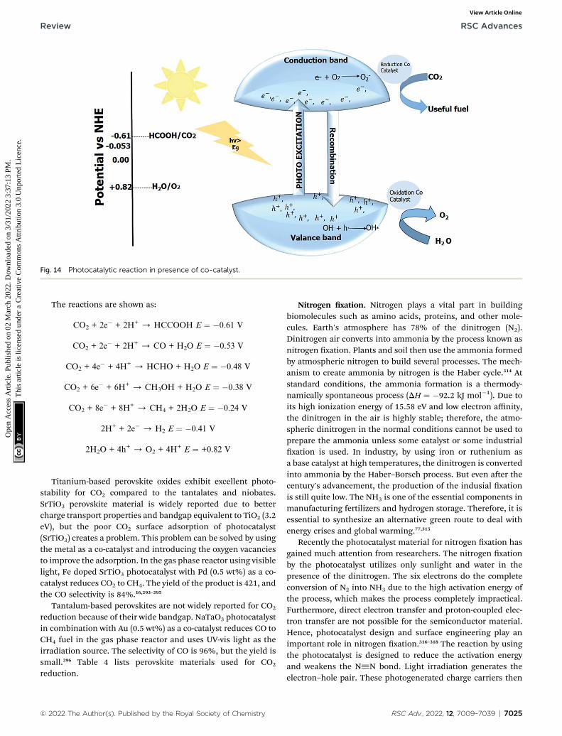
Fig. 14 Photocatalytic reaction in presence of co-catalyst.
Review RSC Advances
Ope
n A
cces
s A
rtic
le. P
ublis
hed
on 0
2 M
arch
202
2. D
ownl
oade
d on
3/3
1/20
22 3
:37:
13 P
M.
Thi
s ar
ticle
is li
cens
ed u
nder
a C
reat
ive
Com
mon
s A
ttrib
utio
n 3.
0 U
npor
ted
Lic
ence
.View Article Online
The reactions are shown as:
CO2 + 2e� + 2H+ / HCCOOH E ¼ �0.61 V
CO2 + 2e� + 2H+ / CO + H2O E ¼ �0.53 V
CO2 + 4e� + 4H+ / HCHO + H2O E ¼ �0.48 V
CO2 + 6e� + 6H+ / CH3OH + H2O E ¼ �0.38 V
CO2 + 8e� + 8H+ / CH4 + 2H2O E ¼ �0.24 V
2H+ + 2e� / H2 E ¼ �0.41 V
2H2O + 4h+ / O2 + 4H+ E ¼ +0.82 V
Titanium-based perovskite oxides exhibit excellent photo-stability for CO2 compared to the tantalates and niobates.SrTiO3 perovskite material is widely reported due to bettercharge transport properties and bandgap equivalent to TiO2 (3.2eV), but the poor CO2 surface adsorption of photocatalyst(SrTiO3) creates a problem. This problem can be solved by usingthe metal as a co-catalyst and introducing the oxygen vacanciesto improve the adsorption. In the gas phase reactor using visiblelight, Fe doped SrTiO3 photocatalyst with Pd (0.5 wt%) as a co-catalyst reduces CO2 to CH4. The yield of the product is 421, andthe CO selectivity is 84%.16,293–295
Tantalum-based perovskites are not widely reported for CO2
reduction because of their wide bandgap. NaTaO3 photocatalystin combination with Au (0.5 wt%) as a co-catalyst reduces CO toCH4 fuel in the gas phase reactor and uses UV-vis light as theirradiation source. The selectivity of CO is 96%, but the yield issmall.296 Table 4 lists perovskite materials used for CO2
reduction.
© 2022 The Author(s). Published by the Royal Society of Chemistry
Nitrogen xation. Nitrogen plays a vital part in buildingbiomolecules such as amino acids, proteins, and other mole-cules. Earth's atmosphere has 78% of the dinitrogen (N2).Dinitrogen air converts into ammonia by the process known asnitrogen xation. Plants and soil then use the ammonia formedby atmospheric nitrogen to build several processes. The mech-anism to create ammonia by nitrogen is the Haber cycle.314 Atstandard conditions, the ammonia formation is a thermody-namically spontaneous process (DH ¼ �92.2 kJ mol�1). Due toits high ionization energy of 15.58 eV and low electron affinity,the dinitrogen in the air is highly stable; therefore, the atmo-spheric dinitrogen in the normal conditions cannot be used toprepare the ammonia unless some catalyst or some industrialxation is used. In industry, by using iron or ruthenium asa base catalyst at high temperatures, the dinitrogen is convertedinto ammonia by the Haber–Borsch process. But even aer thecentury's advancement, the production of the indusial xationis still quite low. The NH3 is one of the essential components inmanufacturing fertilizers and hydrogen storage. Therefore, it isessential to synthesize an alternative green route to deal withenergy crises and global warming.77,315
Recently the photocatalyst material for nitrogen xation hasgained much attention from researchers. The nitrogen xationby the photocatalyst utilizes only sunlight and water in thepresence of the dinitrogen. The six electrons do the completeconversion of N2 into NH3 due to the high activation energy ofthe process, which makes the process completely impractical.Furthermore, direct electron transfer and proton-coupled elec-tron transfer are not possible for the semiconductor material.Hence, photocatalyst design and surface engineering play animportant role in nitrogen xation.316–318 The reaction by usingthe photocatalyst is designed to reduce the activation energyand weakens the N^N bond. Light irradiation generates theelectron–hole pair. These photogenerated charge carriers then
RSC Adv., 2022, 12, 7009–7039 | 7025
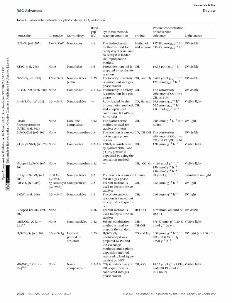
Table 4 Perovskite materials for photocatalytic CO2 reduction
Perovskite Co-catalyst Morphology
Bandgap(eV)
Synthesis method/reaction condition Product
Product concentrationor conversionefficiency Light source
NaTaO3 (ref. 297) 2 wt% CuO Nanocubes 4.1 The hydrothermalmethod is used forcatalyst synthesis. Andco-catalyst is loadedvia impregnationmethod/
Methanoland acetone
137.48 mmol gcat�1 h�1 UV-visible
335.93 mmol gcat�1 h�1
KTaO3 (ref. 298) None Nanoakes 3.6 Perovskite material isprepared by solid-statereaction
CH4 19.35 ppm gcat�1 h�1 UV-visible
NaNbO3 (ref. 299) 1.5 wt% Pt Nanoparticles(cubic)
3.29 Photocatalytic activityis carried out in a gas-phase reactor
CH4 and H2 0.486 mmol gcat�1 h�1 UV-visible
127 mmol gcat�1 h�1
BiFeO3–ZnO (ref. 300) None Composites 2.1–3.2 Photocatalytic activityis carried out in a gas-phase
CH4 The conversionefficiency of CO2 intoCH4 is 21%
UV-visible
Au–SrTiO3 (ref. 301) 0.5 wt% Rh Nanoparticles — Ru is loaded by theimpregnationmethod,and at optimizedconditions, 0.5 wt% ofAu is used
CO, H2, andCH4
66.8 mmol gcat�1 h�1 Visible light
50.5 mmol gcat�1 h�1
2.8 mmol gcat�1 h�1
Basaltber@perovskitePbTiO3 (ref. 302)
None Core–shellcomposites
1.92 The hydrothermalmethod is used forcatalyst synthesis
CH4 290 mmol g�1 L�1 in 6hours
UV light
BiFeO3/ZnS (ref. 303) None Nanocomposites 2.5 The reaction is carriedout in a gas phasereactor
CO, CH3OH The conversionefficiency of CO2 intoCO and CH3OH is 24
UV-visible
g-C3N4/KNbO3 (ref. 79) None Composites 2.7–3.2 KNbO3 is synthesizedby hydrothermal, andg-C3N4 powder isdeposited by using thesonication method
CH4 1.94 mmol g�1 h�1 Visible light
N-doped LaFeO3 (ref.304)
None Nanocomposites 1.82 — CH4, CO, O2 �110 mmol g�1 h�1 Visible light150 mmol g�1 h�1
230 mmol g�1 h�1
RuO2 on SrTiO3 (ref.305)
Ru 0.1–0.4 wt%
Nanoparticles 2.7 The reaction is carriedout in a gas phase
Ethanol 80 mmol g�1 h�1 Simulated sunlight
BaCeO3 (ref. 306) Ag cocatalyst(0.3 wt%)
Nanoparticles 3.2 Pechini method isused to deposit the co-catalyst
CH4 0.55 mmol g�1 h�1 UV light
BaZrO3 (ref. 200) 0.5 wt% Cu Nanoparticles 3.2 The photocatalyticreaction is carried outin a cylindrical quartzcell
CH4 0.98 mmol g�1 h�1 UV light
C-doped LaCoO3 (ref.307)
None — 2.16 Pechini method isused to deposit the co-catalyst
HCOOH A minimal amount ofHCOH
UV-visible
LaNixCo1�xO (x ¼0.4)308
None Nano particles 1.42 Sol–gel combustionmethod is used toprepare the catalyst
CH4–CH3OH
678.57 mmol g�1, 20.83mmol g�1 in 6 h
Visible light
H2SrTa2O7 (ref. 309) 0.5 wt% Ag Layeredperovskitestructure
3.75 H2SrTa2O7
photocatalyst wasprepared by PC andion-exchangemethods, and a photodeposition methodwas used to load Ag co-catalyst on HST
CO and H2 0.39 mmol g�1 h�1 ofCO and 0.25 of H2
mmol g�1 h�1
UV light (l > 200 nm)
xBi2WO6/BiOI (x ¼8%)123
None Nano-composites
2.2–2.9 CO2 is reduced to giveCH4 experiment isconducted into gasphase reactor
CH4/CO 18.32 mmol g�1 of CH4
and 320.19 mmol g�1
in 8 hours
Visible light
7026 | RSC Adv., 2022, 12, 7009–7039 © 2022 The Author(s). Published by the Royal Society of Chemistry
RSC Advances Review
Ope
n A
cces
s A
rtic
le. P
ublis
hed
on 0
2 M
arch
202
2. D
ownl
oade
d on
3/3
1/20
22 3
:37:
13 P
M.
Thi
s ar
ticle
is li
cens
ed u
nder
a C
reat
ive
Com
mon
s A
ttrib
utio
n 3.
0 U
npor
ted
Lic
ence
.View Article Online
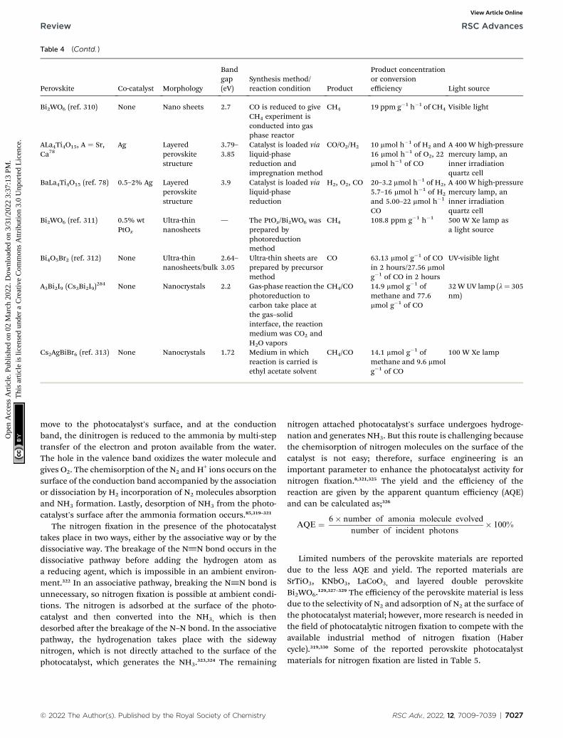
Table 4 (Contd. )
Perovskite Co-catalyst Morphology
Bandgap(eV)
Synthesis method/reaction condition Product
Product concentrationor conversionefficiency Light source
Bi2WO6 (ref. 310) None Nano sheets 2.7 CO is reduced to giveCH4 experiment isconducted into gasphase reactor
CH4 19 ppm g�1 h�1 of CH4 Visible light
ALa4Ti4O15, A ¼ Sr,Ca78
Ag Layeredperovskitestructure
3.79–3.85
Catalyst is loaded vialiquid-phasereduction andimpregnation method
CO/O2/H2 10 mmol h�1 of H2 and16 mmol h�1 of O2, 22mmol h�1 of CO
A 400 W high-pressuremercury lamp, aninner irradiationquartz cell
BaLa4Ti4O15 (ref. 78) 0.5–2% Ag Layeredperovskitestructure
3.9 Catalyst is loaded vialiquid-phasereduction
H2, O2, CO 20–3.2 mmol h�1 of H2,5.7–16 mmol h�1 of H2
and 5.00–22 mmol h�1
CO
A 400 W high-pressuremercury lamp, aninner irradiationquartz cell
Bi2WO6 (ref. 311) 0.5% wtPtOx
Ultra-thinnanosheets
— The PtOx/Bi2WO6 wasprepared byphotoreductionmethod
CH4 108.8 ppm g�1 h�1 500 W Xe lamp asa light source
Bi4O5Br2 (ref. 312) None Ultra-thinnanosheets/bulk
2.64–3.05
Ultra-thin sheets areprepared by precursormethod
CO 63.13 mmol g�1 of COin 2 hours/27.56 mmolg�1 of CO in 2 hours
UV-visible light
A3Bi2I9 (Cs3Bi2I9)284 None Nanocrystals 2.2 Gas-phase reaction the
photoreduction tocarbon take place atthe gas–solidinterface, the reactionmedium was CO2 andH2O vapors
CH4/CO 14.9 mmol g�1 ofmethane and 77.6mmol g�1 of CO
32WUV lamp (l¼ 305nm)
Cs2AgBiBr6 (ref. 313) None Nanocrystals 1.72 Medium in whichreaction is carried isethyl acetate solvent
CH4/CO 14.1 mmol g�1 ofmethane and 9.6 mmolg�1 of CO
100 W Xe lamp
Review RSC Advances
Ope
n A
cces
s A
rtic
le. P
ublis
hed
on 0
2 M
arch
202
2. D
ownl
oade
d on
3/3
1/20
22 3
:37:
13 P
M.
Thi
s ar
ticle
is li
cens
ed u
nder
a C
reat
ive
Com
mon
s A
ttrib
utio
n 3.
0 U
npor
ted
Lic
ence
.View Article Online
move to the photocatalyst's surface, and at the conductionband, the dinitrogen is reduced to the ammonia by multi-steptransfer of the electron and proton available from the water.The hole in the valence band oxidizes the water molecule andgives O2. The chemisorption of the N2 and H+ ions occurs on thesurface of the conduction band accompanied by the associationor dissociation by H2 incorporation of N2 molecules absorptionand NH3 formation. Lastly, desorption of NH3 from the photo-catalyst's surface aer the ammonia formation occurs.85,319–321
The nitrogen xation in the presence of the photocatalysttakes place in two ways, either by the associative way or by thedissociative way. The breakage of the N^N bond occurs in thedissociative pathway before adding the hydrogen atom asa reducing agent, which is impossible in an ambient environ-ment.322 In an associative pathway, breaking the N^N bond isunnecessary, so nitrogen xation is possible at ambient condi-tions. The nitrogen is adsorbed at the surface of the photo-catalyst and then converted into the NH3, which is thendesorbed aer the breakage of the N–N bond. In the associativepathway, the hydrogenation takes place with the sidewaynitrogen, which is not directly attached to the surface of thephotocatalyst, which generates the NH3.323,324 The remaining
© 2022 The Author(s). Published by the Royal Society of Chemistry
nitrogen attached photocatalyst's surface undergoes hydroge-nation and generates NH3. But this route is challenging becausethe chemisorption of nitrogen molecules on the surface of thecatalyst is not easy; therefore, surface engineering is animportant parameter to enhance the photocatalyst activity fornitrogen xation.8,321,325 The yield and the efficiency of thereaction are given by the apparent quantum efficiency (AQE)and can be calculated as;326
AQE ¼ 6� number of amonia molecule evolved
number of incident photons� 100%
Limited numbers of the perovskite materials are reporteddue to the less AQE and yield. The reported materials areSrTiO3, KNbO3, LaCoO3, and layered double perovskiteBi2WO6.129,327–329 The efficiency of the perovskite material is lessdue to the selectivity of N2 and adsorption of N2 at the surface ofthe photocatalyst material; however, more research is needed inthe eld of photocatalytic nitrogen xation to compete with theavailable industrial method of nitrogen xation (Habercycle).319,330 Some of the reported perovskite photocatalystmaterials for nitrogen xation are listed in Table 5.
RSC Adv., 2022, 12, 7009–7039 | 7027
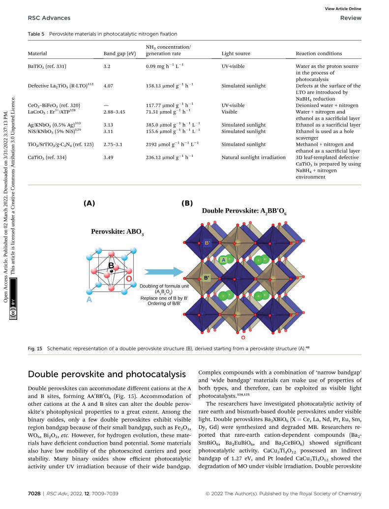
Table 5 Perovskite materials in photocatalytic nitrogen fixation
Material Band gap (eV)NH3 concentration/generation rate Light source Reaction conditions
BaTiO3 (ref. 331) 3.2 0.09 mg h�1 L�1 UV-visible Water as the proton sourcein the process ofphotocatalysis
Defective La2TiO5 (R-LTO)332 4.07 158.13 mmol g�1 h�1 Simulated sunlight Defects at the surface of the
LTO are introduced byNaBH4 reduction
CeO2–BiFeO3 (ref. 320) — 117.77 mmol g�1 h�1 UV-visible Deionized water + nitrogenLaCoO3 : Er
3+/ATP328 2.88–3.45 71.51 mmol g�1 h�1 Visible Water + nitrogen andethanol as a sacricial layer
Ag/KNbO3 (0.5% Ag)333 3.13 385.0 mmol g�1 h�1 L�1 Simulated sunlight Ethanol as a sacricial layerNiS/KNbO3 (5% NiS)129 3.11 155.6 mmol g�1 h�1 L�1 Simulated sunlight Ethanol is used as a hole
scavengerTiO2/SrTiO3/g-C3N4 (ref. 125) 2.75–3.1 2192 mmol g�1 h�1 L�1 Simulated sunlight Methanol + nitrogen and
ethanol as a sacricial layerCaTiO3 (ref. 334) 3.49 236.12 mmol g�1 h�1 Natural sunlight irradiation 3D leaf-templated defective
CaTiO3 is prepared by usingNaBH4 + nitrogenenvironment
Fig. 15 Schematic representation of a double perovskite structure (B), derived starting from a perovskite structure (A).49
RSC Advances Review
Ope
n A
cces
s A
rtic
le. P
ublis
hed
on 0
2 M
arch
202
2. D
ownl
oade
d on
3/3
1/20
22 3
:37:
13 P
M.
Thi
s ar
ticle
is li
cens
ed u
nder
a C
reat
ive
Com
mon
s A
ttrib
utio
n 3.
0 U
npor
ted
Lic
ence
.View Article Online
Double perovskite and photocatalysis
Double perovskites can accommodate different cations at the Aand B sites, forming AA0BB0O6 (Fig. 15). Accommodation ofother cations at the A and B sites can alter the double perov-skite's photophysical properties to a great extent. Among thebinary oxides, only a few double perovskites exhibit visibleregion bandgap because of their small bandgap, such as Fe2O3,WO6, Bi2O3, etc. However, for hydrogen evolution, these mate-rials have decient conduction band potential. Some materialsalso have low mobility of the photoexcited carriers and poorstability. Many binary oxides show efficient photocatalyticactivity under UV irradiation because of their wide bandgap.
7028 | RSC Adv., 2022, 12, 7009–7039
Complex compounds with a combination of ‘narrow bandgap’and ‘wide bandgap’ materials can make use of properties ofboth types, and therefore, can be exploited as visible lightphotocatalysts.124,125
The researchers have investigated photocatalytic activity ofrare earth and bismuth-based double perovskites under visiblelight. Double perovskites Ba2XBiO6 (X ¼ Ce, La, Nd, Pr, Eu, Sm,Dy, Gd) were synthesized and degraded MB. Researchers re-ported that rare-earth cation-dependent compounds (Ba2-SmBiO6, Ba2EuBiO6, and Ba2CeBiO6) showed signicantphotocatalytic activity. CaCu3Ti4O12 possessed an indirectbandgap of 1.27 eV, and Pt loaded CaCu3Ti4O12 showed thedegradation of MO under visible irradiation. Double perovskite
© 2022 The Author(s). Published by the Royal Society of Chemistry
Review RSC Advances
Ope
n A
cces
s A
rtic
le. P
ublis
hed
on 0
2 M
arch
202
2. D
ownl
oade
d on
3/3
1/20
22 3
:37:
13 P
M.
Thi
s ar
ticle
is li
cens
ed u
nder
a C
reat
ive
Com
mon
s A
ttrib
utio
n 3.
0 U
npor
ted
Lic
ence
.View Article Online
materials such as Sr2CoWO6, Ba2CoWO6, and Sr2NiWO6, Ba2-NiWO6, are reported to be stable for O2 evolution with sacricialagents.124,125 Although the photophysical properties of certaindouble perovskites also have been investigated and reported,still a lot of efforts are required before utilizing these materialson an industrial scale.
Summary
In summary, the abundantly available sun energy can be har-vested through photocatalysis to deal with the concerns per-taining to the environment and humankind. This article aimedto discuss the imperative properties of perovskite materialswhich play vital role in photocatalysis, and will assist inunderstanding the fundamentals of photocatalytic mechanismsinvolved in designing highly efficient photocatalysts. The threealtercation sites (A, B, and O sites) of perovskite materials mathem suitable for numerous applications, particularly photo-catalysis. These sites help in tailoring chemical, physical,optical, and photocatalytic properties for desired photocatalyticreactions. The structural and compositional suppleness inperovskite photocatalyst strongly affects photo-generatedcarriers' mobility, separation, and recombination. The currentarticle also describes the defect engineering in perovskitematerials for enhanced photocatalytic performance. Recently,defect engineering gained much attention among researchersbecause it resulted in visible light photocatalytic activity withoutdoping. Furthermore, surface defects provide reactive sitesbenecial for a process like nitrogen xation at ambientconditions. The review also provides an insight into thedifferent applications of photocatalysis, including wastewatertreatment, water splitting, CO2 reduction, and nitrogen xation.The critical perovskite materials for each photocatalytic appli-cation are also listed with their properties in this study. Overall,it can be inferred that although perovskite oxide-based mate-rials have exhibited signicant photocatalytic performance still,extensive challenges are ahead of their design, fabrication, cost,and efficiency for industrial and large-scale production. Thebiggest challenge in the industrialization of photocatalysttechnology is the development of an ideal photocatalyst, whichshould possess four features, including high photocatalyticefficiency, a large specic surface area, full utilization ofsunlight, and recyclability. Nonetheless, there is no doubt thatperovskite-based oxide materials will be investigated moreintensively in the coming years due to their exceptional prop-erties and applications for a sustainable future.
Author contributions
All authors verify their contribution to the current review articleas follows: design, study conception, and supervision of thewhole article is done by Muneeb Irshad and Quar tul Ain; datacollection is done by; Asif Nadeem Tabish, Muhammad Usman,Masood ul Hassan Farooq, Mohammed A. Assiri, MuhammadImran; analysis and interpretation of results by; Muneeb Irshad,Quar tul Ain, Muhammad Zaman, Muhammad Zeeshan Aslam,Naila Kousar, Muhammad Asim, Muhammad Raque, and
© 2022 The Author(s). Published by the Royal Society of Chemistry
Khurram Siraj; dra manuscript preparation and proofreadingby; Muneeb Irshad, Quar tul Ain, and Muhammad Zaman.Moreover, Mohammed A. Assiri and Muhammad Imranprovided the necessary funding to complete the article. Allauthors reviewed the results and approved the nal version ofthe manuscript.
Conflicts of interest
There are no conicts to declare.
Acknowledgements
The authors, especially M. A. Assiri and M. Imran, express theirappreciation to the Deanship of Scientic Research at KingKhalid University, Saudia Arabia, through research groupsprogram, under grant number R.G.P. 2/153/42.
References
1 A. R. Chaurasia, Population effects of the environment, inPopulation and Sustainable Development in India, SpringerSingapore, Singapore, 2020, pp. 243–255.
2 Y. Li, et al., Inuence of Industrialization andEnvironmental Protection on Environmental Pollution: ACase Study of Taihu Lake, China, Int. J. Environ. Res.Public Health, 2018, 15(12), 2628.
3 N. J. Waltham, et al., UN Decade on Ecosystem Restoration2021–2030—What Chance for Success in Restoring CoastalEcosystems?, Front. Mar. Sci., 2020, 7(71), 1–5.
4 Y. Cui, B. A. Schubert and A. H. Jahren, A 23 m.y. record oflow atmospheric CO2, Geology, 2020, 48(9), 888–892.
5 L. Guppy, et al., Global-Water-Crisis-The-Facts, 2017.6 G. Nabi, et al., The crisis of water shortage and pollution inPakistan: risk to public health, biodiversity, and ecosystem,Environ. Sci. Pollut. Res. Int., 2019, 26(11), 10443–10445.
7 W. Wang, M. O. Tade and Z. Shao, Research progress ofperovskite materials in photocatalysis- and photovoltaics-related energy conversion and environmental treatment,Chem. Soc. Rev., 2015, 44(15), 5371–5408.
8 A. Kumar, A. Kumar and V. Krishnan, Perovskite OxideBased Materials for Energy and Environment-OrientedPhotocatalysis, ACS Catal., 2020, 10(17), 10253–10315.
9 S. Zhu and D. Wang, Photocatalysis: Basic Principles,Diverse Forms of Implementations and EmergingScientic Opportunities, Adv. Energy Mater., 2017, 7,1700841.
10 P. Kanhere and Z. Chen, A review on visible light activeperovskite-based photocatalysts, Molecules, 2014, 19(12),19995–20022.
11 X. Yang and D. Wang, Photocatalysis: From FundamentalPrinciples to Materials and Applications, ACS Appl. EnergyMater., 2018, 1(12), 6657–6693.
12 A. A. Yaqoob, et al., Role of Nanomaterials in the Treatmentof Wastewater: A Review, Water, 2020, 12(2), 495.
13 J. Ran, M. Jaroniec and S. Z. Qiao, Cocatalysts inSemiconductor-based Photocatalytic CO2 Reduction:
RSC Adv., 2022, 12, 7009–7039 | 7029

RSC Advances Review
Ope
n A
cces
s A
rtic
le. P
ublis
hed
on 0
2 M
arch
202
2. D
ownl
oade
d on
3/3
1/20
22 3
:37:
13 P
M.
Thi
s ar
ticle
is li
cens
ed u
nder
a C
reat
ive
Com
mon
s A
ttrib
utio
n 3.
0 U
npor
ted
Lic
ence
.View Article Online
Achievements, Challenges, and Opportunities, Adv. Mater.,2018, 30, 1704649.
14 F. J. Beltran, et al., Ozone and photocatalytic processes toremove the antibiotic sulfamethoxazole from water, WaterRes., 2008, 42(14), 3799–3808.
15 M. M. Khan, S. F. Adil and A. Al-Mayouf, Metal oxides asphotocatalysts, J. Saudi Chem. Soc., 2015, 19(5), 462–464.
16 S. Zeng, et al., A review on photocatalytic CO2 reductionusing perovskite oxide nanomaterials, Nanotechnology,2018, 29(5), 052001.
17 T. Garcia, et al., Vapor-Phase Photocatalytic Overall WaterSplitting Using Hybrid Methylammonium Copper andLead Perovskites, Nanomaterials, 2020, 10(5), 960.
18 X. Xue, et al., Efficient photocatalytic nitrogen xationunder ambient conditions enabled by the heterojunctionsof n-type Bi2MoO6 and oxygen-vacancy-rich p-type BiOBr,Nanoscale, 2019, 11(21), 10439–10445.
19 J. M. Coronado, A historical introduction to photocatalysis,in Design of Advanced Photocatalytic Materials for Energy andEnvironmental Applications, 2013, pp. 1–4.
20 A. Eibner, Action of light on pigments I, Chem.-Ztg., 1911,35, 753–755.
21 K. Hashimoto, H. Irie and A. Fujishima,TiO2Photocatalysis: A Historical Overview and FutureProspects, Jpn. J. Appl. Phys., 2005, 44(12), 8269–8285.
22 Chapter 1 history of catalysis, in Studies in Surface Scienceand Catalysis, ed. J. A. Moulijn, P. W. N. M. van Leeuwenand R. A. van Santen, Elsevier, 1993, pp. 3–21.
23 A. Fujishima and K. Honda, Electrochemical Photolysis ofWater at a Semiconductor Electrode, Nature, 1972,238(5358), 37–38.
24 M. B. Tahir, et al., Nanomaterials for photocatalysis, inNanotechnology and Photocatalysis for EnvironmentalApplications, 2020, pp. 65–76.
25 S. Fatima, et al., Congo Red Dye Degradation by GrapheneNanoplatelets/Doped Bismuth Ferrite Nanoparticle HybridCatalysts under Dark and Light Conditions, Catalysts,2020, 10(4), 367.
26 D. B. Mitzi, Introduction: Perovskites, Chem. Rev., 2019,119(5), 3033–3035.
27 J. F. W. Bowles, Oxides, in Encyclopedia of Geology, ed. D.Alderton and S. A. Elias, Academic Press, Oxford, 2ndedn, 2021, pp. 428–441.
28 L. Ortega-San-Martin, Correction to: introduction toperovskites: a historical perspective, in Revolution ofPerovskite: Synthesis, Properties and Applications, ed. N. S.Arul and V. D. Nithya, Springer Singapore, Singapore,2020, p. C1.
29 E. A. Katz, Perovskite: Name Puzzle and German-RussianOdyssey of Discovery, Helv. Chim. Acta, 2020, 103(6), 00061.
30 W.-J. Yin, et al., Oxide perovskites, double perovskites andderivatives for electrocatalysis, photocatalysis, andphotovoltaics, Energy Environ. Sci., 2019, 12(2), 442–462.
31 N. F. Atta, A. Galal and E. H. El-Ads, Perovskitenanomaterials – synthesis, characterization, andapplications, in Perovskite Materials – Synthesis,Characterisation, Properties, and Applications, 2016.
7030 | RSC Adv., 2022, 12, 7009–7039
32 A. S. Bhalla, R. Guo and R. Roy, The perovskite structure—a review of its role in ceramic science and technology,Mater. Res. Innovations, 2016, 4(1), 3–26.
33 M. A. Pena and J. L. G. Fierro, Chemical Structures andPerformance of Perovskite Oxides, Chem. Rev., 2001,101(7), 1981–2018.
34 C. N. R. Rao, Perovskites, in Encyclopedia of Physical Scienceand Technology, ed. R. A. Meyers, Academic Press, New York,3rd edn, 2003, pp. 707–714.
35 M. T. Sebastian, Chapter six – ABO3 type perovskites, inDielectric Materials for Wireless Communication, ed. M. T.Sebastian, Elsevier, Amsterdam, 2008, pp. 161–203.
36 R. Mouta, R. X. Silva and C. W. Paschoal, Tolerance factorfor pyrochlores and related structures, Acta Crystallogr.,Sect. B: Struct. Sci., Cryst. Eng. Mater., 2013, 69(Pt 5), 439–445.
37 V. Goldschmidt, Crystal structure and chemical correlation,Ber. Dtsch. Chem. Ges., 1927, 60, 1263–1296.
38 I. M. Reaney and R. Ubic, Dielectric and structuralcharacteristics of perovskites and related materials asa function of tolerance factor, Ferroelectrics, 1999, 228(1),23–38.
39 R. S. Roth, Classication of Perovskite and Other ABO3-Type, J. Res. Natl. Bur. Stand., 1957, 58(2), 75.
40 J. Atteld, Structure–property relations in doped perovskiteoxides, Int. J. Inorg. Mater., 2001, 3(8), 1147–1152.
41 C. Li, K. C. K. Soh and P. Wu, Formability of ABO3perovskites, J. Alloys Compd., 2004, 372(1–2), 40–48.
42 M. Johnsson and P. Lemmens, Crystallography andchemistry of perovskites, 2005, arXiv preprint cond-mat/0506606.
43 T. K. Todorova, M. V. Ganduglia-Pirovano and J. Sauer,Vanadium Oxides on Aluminum Oxide Supports. 3.Metastable k-Al2O3 (001) Compared to a-Al2O3 (0001), J.Phys. Chem. C, 2007, 111(13), 5141–5153.
44 R. J. Tilley, Perovskites: Structure-Property Relationships, JohnWiley & Sons, 2016.
45 E. A. R. Assirey, Perovskite synthesis, properties and theirrelated biochemical and industrial application, SaudiPharm. J., 2019, 27(6), 817–829.
46 L. Pan and G. Zhu, Perovskite Materials: Synthesis,Characterisation, Properties, and Applications, BoD–Bookson Demand, 2016.
47 N. Solanki, P. D. Lodhi and N. Kaurav, Structural andRaman analysis of double perovskite La2CoTi0.7Ni0.3O6,AIP Conf. Proc., 2019, 2100, 020161.
48 M. T. Anderson, et al., B-cation arrangements in doubleperovskites, Prog. Solid State Chem., 1993, 22(3), 197–233.
49 T. Saha-Dasgupta, Double perovskites with 3d and 4d/5dtransition metals: compounds with promises, Mater. Res.Express, 2020, 7, 014003.
50 G. King and P. M. Woodward, Cation ordering inperovskites, J. Mater. Chem., 2010, 20(28), 5785–5796.
51 S. Vasala and M. Karppinen, A2B0 B 00O6 perovskites:a review, Prog. Solid State Chem., 2015, 43(1–2), 1–36.
© 2022 The Author(s). Published by the Royal Society of Chemistry
Review RSC Advances
Ope
n A
cces
s A
rtic
le. P
ublis
hed
on 0
2 M
arch
202
2. D
ownl
oade
d on
3/3
1/20
22 3
:37:
13 P
M.
Thi
s ar
ticle
is li
cens
ed u
nder
a C
reat
ive
Com
mon
s A
ttrib
utio
n 3.
0 U
npor
ted
Lic
ence
.View Article Online
52 M. J. Winiarski and P. Deren, Electronic structure ofA2B'B''O6-type (A¼ Ca, Sr, Ba; B'¼ Mg, Zn; B''¼ Mo, W)double perovskite oxides, Opt. Mater., 2019, 90, 95–98.
53 P. Ksoll, et al., B-Site Cation Ordering in Films,Superlattices, and Layer-by-Layer-Grown DoublePerovskites, Crystals, 2021, 11(7), 734.
54 J.-W. G. Bos and J. P. Atteld, Structural, Magnetic, andTransport Properties of (La1+xSr1-x)CoRuO6 DoublePerovskites, Chem. Mater., 2004, 16(9), 1822–1827.
55 D. Serrate, J. M. D. Teresa and M. R. Ibarra, Doubleperovskites with ferromagnetism above roomtemperature, J. Phys.: Condens. Matter, 2007, 19, 023201.
56 X. Xu, Y. Zhong and Z. Shao, Double Perovskites inCatalysis, Electrocatalysis, and Photo(electro)catalysis,Trends Chem., 2019, 1(4), 410–424.
57 M. T. Sebastian, Chapter nine – cation-decientperovskites, in Dielectric Materials for WirelessCommunication, ed. M. T. Sebastian, Elsevier, Amsterdam,2008, pp. 335–360.
58 W. Xiao, et al., Cubic perovskite polymorph of strontiummetasilicate at high pressures, Am. Mineral., 2013, 98(11–12), 2096–2104.
59 G. Burns and A. M. Glazer, Chapter 7 – space groupapplications, in Space Groups for Solid State Scientists, ed.G. Burns and A. M. Glazer, Academic Press, Oxford,3rdedn, 2013, pp. 187–274.
60 Chapter 10 ABX3, perovskite-ilmenite structure, inDevelopments in Geochemistry, ed. S. Mitra, Elsevier, 2004,pp. 711–792.
61 B. Kurniawan, et al., Effect of Temperature and Duration ofSintering on Perovskite Material (La1-xAgx)0.8Ca0.2MnO3,IOP Conf. Ser.: Mater. Sci. Eng., 2018, 367, 012055.
62 P. Woodward, Octahedral Tilting in Perovskites. II.Structure Stabilizing Forces, Acta Crystallogr., Sect. B:Struct. Sci., 1997, 53(1), 44–66.
63 J. S. Bechtel and A. Van der Ven, Octahedral tiltinginstabilities in inorganic halide perovskites, Phys. Rev.Mater., 2018, 2(2), 025401.
64 S. Mukherjee, et al., Structure and Electronic Effects fromMn and Nb Co-doping for Low Band Gap BaTiO3Ferroelectrics, J. Phys. Chem. C, 2021, 125(27), 14910–14923.
65 L. Fu, et al., Magnetic, electronic, and optical properties ofperovskite materials, in Revolution of Perovskite: Synthesis,Properties and Applications, ed. N. S. Arul and V. D. Nithya,Springer Singapore, Singapore, 2020, pp. 43–59.
66 Y. Du, et al., Strain accommodation by facile WO(6)octahedral distortion and tilting during WO(3)heteroepitaxy on SrTiO(3)(001), ACS Appl. Mater. Interfaces,2014, 6(16), 14253–14258.
67 M. Madi, M. Tahir and S. Tasleem, Advances in StructuralModication of Perovskite Semiconductors for VisibleLight Assisted Photocatalytic CO2 Reduction toRenewable Solar Fuels: A Review, J. Environ. Chem. Eng.,2021, 9(11), 106264.
68 S. Khaln and Y. Bekenstein, Advances in lead-free doubleperovskite nanocrystals, engineering band-gaps and
© 2022 The Author(s). Published by the Royal Society of Chemistry
enhancing stability through composition tunability,Nanoscale, 2019, 11(18), 8665–8679.
69 R. Alagheband, et al., Synthesis and Evaluation of ABO3Perovskites (A¼La and B¼Mn, Co) with Stoichiometricand Over-stoichiometric Ratios of B/A for CatalyticOxidation of Trichloroethylene, Bull. Chem. React. Eng.Catal., 2018, 13(1), 47–56.
70 S. Krishnamurthy, et al., Organic–inorganic hybrid andinorganic halide perovskites: structural and chemicalengineering, interfaces and optoelectronic properties, J.Phys. D: Appl. Phys., 2021, 54(13), 133002.
71 Y. Zhou, et al., Metal-Doped Lead Halide Perovskites:Synthesis, Properties, and Optoelectronic Applications,Chem. Mater., 2018, 30(19), 6589–6613.
72 K. S. Schanze, et al., Progress in Perovskite Photocatalysis,ACS Energy Lett., 2020, 5(8), 2602–2604.
73 S. Mazumdar, Y. Zhao and X. Zhang, Stability of PerovskiteSolar Cells: Degradation Mechanisms and Remedies,Frontiers in Electronics, 2021, 2, 712785.
74 N. Labhasetwar, et al., Perovskite-type catalytic materialsfor environmental applications, Sci. Technol. Adv. Mater.,2015, 16(3), 036002.
75 B.-M. Bresolin, Y. Park and D. W. Bahnemann, RecentProgresses on Metal Halide Perovskite-Based Material asPotential Photocatalyst, Catalysts, 2020, 10(6), 709.
76 H. Anwer, et al., Photocatalysts for degradation of dyes inindustrial effluents: Opportunities and challenges, NanoRes., 2019, 12(5), 955–972.
77 R. Li, Photocatalytic nitrogen xation: An attractiveapproach for articial photocatalysis, Chin. J. Catal., 2018,39(7), 1180–1188.
78 K. Iizuka, et al., Photocatalytic reduction of carbon dioxideover Ag cocatalyst-loaded ALa4Ti4O15 (A ¼ Ca, Sr, and Ba)using water as a reducing reagent, J. Am. Chem. Soc., 2011,133(51), 20863–20868.
79 D. Xu, et al., Heterojunction composites of g-C3N4/KNbO3enhanced photocatalytic properties for water splitting, Int.J. Hydrogen Energy, 2018, 43(34), 16566–16572.
80 R. Molinari, C. Lavorato and P. Argurio, Visible-LightPhotocatalysts and Their Perspectives for BuildingPhotocatalytic Membrane Reactors for Various LiquidPhase Chemical Conversions, Catalysts, 2020, 10(11), 1334.
81 M. Mishra and D.-M. Chun, a-Fe 2 O 3 as a photocatalyticmaterial: A review, Appl. Catal., A, 2015, 498, 126–141.
82 O. V. Nkwachukwu and O. A. Arotiba, Perovskite Oxide-Based Materials for Photocatalytic andPhotoelectrocatalytic Treatment of Water, Front. Chem.,2021, 9, 634630.
83 C.-H. Lu, et al., Doping and ion substitution in colloidalmetal halide perovskite nanocrystals, Chem. Soc. Rev.,2020, 49(14), 4953–5007.
84 Z. Guo, et al., Band gap engineering in huge-gapsemiconductor SrZrO3 for visible-light photocatalysis, Int.J. Hydrogen Energy, 2014, 39(5), 2042–2048.
85 R. Shi, et al., Defect engineering in photocatalytic nitrogenxation, ACS Catal., 2019, 9(11), 9739–9750.
RSC Adv., 2022, 12, 7009–7039 | 7031

RSC Advances Review
Ope
n A
cces
s A
rtic
le. P
ublis
hed
on 0
2 M
arch
202
2. D
ownl
oade
d on
3/3
1/20
22 3
:37:
13 P
M.
Thi
s ar
ticle
is li
cens
ed u
nder
a C
reat
ive
Com
mon
s A
ttrib
utio
n 3.
0 U
npor
ted
Lic
ence
.View Article Online
86 S. Suzuki, A. Iwase and A. Kudo, Long wavelength visiblelight-responsive SrTiO3 photocatalysts doped withvalence-controlled Ru for sacricial H2 and O2 evolution,Catal. Sci. Technol., 2020, 10(15), 4912–4916.
87 Y. Li, et al., A two-step synthesis of NaTaO3 microspheresfor photocatalytic water splitting, Int. J. Hydrogen Energy,2014, 39(25), 13481–13485.
88 L. Ernawati, et al., Experimental data of CaTiO3photocatalyst for degradation of organic pollutants(Brilliant green dye) – Green synthesis, characterizationand kinetic study, Data Brief, 2020, 32, 106099.
89 S. Sharma and M. Kumar, Band gap tuning and opticalproperties of BiFeO3 nanoparticles, Mater. Today: Proc.,2020, 28, 168–171.
90 M. Ismael and M. Wark, Perovskite-type LaFeO3:Photoelectrochemical Properties and PhotocatalyticDegradation of Organic Pollutants Under Visible LightIrradiation, Catalysts, 2019, 9(4), 342.
91 Q. Liu, et al., Highly efficient Pt/NaNbO3 nanowirephotocatalyst: Its morphology effect and application inwater purication and H2 production, Appl. Catal., B,2017, 205, 505–513.
92 T. Jia, et al., First-principles study on the electronic, opticaland thermodynamic properties of ABO3 (A ¼ La,Sr, B ¼Fe,Co) perovskites, RSC Adv., 2017, 7(62), 38798–38804.
93 C. Huang, et al., Synthesis and application of Bi2WO6 forthe photocatalytic degradation of two typicaluoroquinolones under visible light irradiation, RSC Adv.,2019, 9(48), 27768–27779.
94 D. Arney, et al., New molten-salt synthesis andphotocatalytic properties of La2Ti2O7 particles, J.Photochem. Photobiol., A, 2008, 199(2–3), 230–235.
95 P. Li, H. Abe and J. Ye, Band-Gap Engineering of NaNbO3forPhotocatalytic H2Evolution with Visible Light, Int. J.Photoenergy, 2014, 2014, 1–6.
96 A. Suzuki and T. Oku, Effects of transition metalsincorporated into perovskite crystals on the electronicstructures and magnetic properties by rst-principlescalculation, Heliyon, 2018, 4(8), e00755.
97 J. Yu, et al., Giant enhancement of photocatalytic H2production over KNbO3 photocatalyst obtained via carbondoping and MoS2 decoration, Int. J. Hydrogen Energy,2018, 43(9), 4347–4354.
98 A. Haruna, I. Abdulkadir and S. O. Idris, Photocatalyticactivity and doping effects of BiFeO3 nanoparticles inmodel organic dyes, Heliyon, 2020, 6(1), e03237.
99 N. D. Phu, et al., Photocatalytic activity enhancement ofBi2WO6 nanoparticles by Ag doping and Ag nanoparticlesmodication, J. Alloys Compd., 2020, 824, 153914.
100 A. Kumar, et al., Three-Dimensional CarbonaceousAerogels Embedded with Rh-SrTiO3 for EnhancedHydrogen Evolution Triggered by Efficient ChargeTransfer and Light Absorption, ACS Appl. Energy Mater.,2020, 3(12), 12134–12147.
101 T. S. Jamil, et al., The synthesis of nano-sized undoped, Bidoped and Bi, Cu co-doped SrTiO3 using two sol–gelmethods to enhance the photocatalytic performance for
7032 | RSC Adv., 2022, 12, 7009–7039
the degradation of dibutyl phthalate under visible light,C. R. Chim., 2017, 20(2), 97–106.
102 B. G. Anitha and L. G. Devi, Study of reaction dynamics ofphotocatalytic degradation of 4-chlorophenol usingSrTiO3, sulfur doped SrTiO3, silver metallized SrTiO3 andsilver metallized sulfur doped SrTiO3 catalysts: Detailedanalysis of kinetic results, J. Photochem. Photobiol., A,2019, 16, 50–58.
103 H. Bentour, M. Boujnah, M. Houmad and M. Yadari, DFTStudy of Se and Te Doped SrTiO 3 for Enhanced Visible-Light Driven Phtocatalytic Hydrogen Production, Opt.Quantum Electron., 2021, 53, 589.
104 S. Shajahan, et al., Optimization and detailed stability studyon Pb doped ceria nanocubes for enhancedphotodegradation of several anionic and cationic organicpollutants, Arabian J. Chem., 2020, 13(1), 1309–1322.
105 H. Wang, et al., Synthesis and application of perovskite-based photocatalysts in environmental remediation: Areview, J. Mol. Liq., 2021, 334, 116029.
106 L. Zhang, et al., Kinetics and mechanisms of chargetransfer processes in photocatalytic systems: A review, J.Photochem. Photobiol., C, 2012, 13(4), 263–276.
107 R. Qian, et al., Charge carrier trapping, recombination andtransfer during TiO2 photocatalysis: An overview, Catal.Today, 2019, 335, 78–90.
108 A. Bumajdad and M. Madkour, Understanding the superiorphotocatalytic activity of noble metals modied titaniaunder UV and visible light irradiation, Phys. Chem. Chem.Phys., 2014, 16(16), 7146–7158.
109 S. Natarajan, H. C. Bajaj and R. J. Tayade, Recent advancesbased on the synergetic effect of adsorption for removal ofdyes from waste water using photocatalytic process, J.Environ. Sci., 2018, 65, 201–222.
110 J. Liang, et al., Recent progress and development ininorganic halide perovskite quantum dots forphotoelectrochemical applications, Small, 2020, 16(15),1903398.
111 M. Adly, S. M. El-Dafrawy and S. El-Hakam, Application ofnanostructured graphene oxide/titanium dioxidecomposites for photocatalytic degradation of rhodamineB and acid green 25 dyes, J. Mater. Res. Technol., 2019,8(6), 5610–5622.
112 K. Takanabe, Photocatalytic Water Splitting: QuantitativeApproaches toward Photocatalyst by Design, ACS Catal.,2017, 7(11), 8006–8022.
113 L. M. Peter, Chapter 1 photoelectrochemistry: from basicprinciples to photocatalysis, in Photocatalysis:Fundamentals and Perspectives, The Royal Society ofChemistry, 2016, pp. 1–28.
114 W. Leng, et al., Electron Diffusion Length in MesoporousNanocrystalline TiO2 Photoelectrodes during WaterOxidation, J. Phys. Chem. Lett., 2010, 1(6), 967–972.
115 J. Li and N. Wu, Semiconductor-based photocatalysts andphotoelectrochemical cells for solar fuel generation:a review, Catal. Sci. Technol., 2015, 5(3), 1360–1384.
116 F. M. Pesci, et al., Efficient Suppression of Electron–HoleRecombination in Oxygen-Decient Hydrogen-Treated
© 2022 The Author(s). Published by the Royal Society of Chemistry
Review RSC Advances
Ope
n A
cces
s A
rtic
le. P
ublis
hed
on 0
2 M
arch
202
2. D
ownl
oade
d on
3/3
1/20
22 3
:37:
13 P
M.
Thi
s ar
ticle
is li
cens
ed u
nder
a C
reat
ive
Com
mon
s A
ttrib
utio
n 3.
0 U
npor
ted
Lic
ence
.View Article Online
TiO2 Nanowires for Photoelectrochemical Water Splitting,J. Phys. Chem. C, 2013, 117(48), 25837–25844.
117 W. Wang, M. O. Tade and Z. Shao, Research progress ofperovskite materials in photocatalysis- and photovoltaics-related energy conversion and environmental treatment,Chem. Soc. Rev., 2015, 44(15), 5371–5408.
118 A. Gnanaprakasam, V. M. Sivakumar andM. Thirumarimurugan, Inuencing Parameters in thePhotocatalytic Degradation of Organic Effluent viaNanometal Oxide Catalyst: A Review, Indian Journal ofMaterials Science, 2015, 2015, 1–16.
119 M. Antonopoulou, et al., An overview of homogeneous andheterogeneous photocatalysis applications for the removalof pharmaceutical compounds from real or synthetichospital wastewaters under lab or pilot scale, Sci. TotalEnviron., 2021, 765, 144163.
120 V. Kitsiou, et al., Heterogeneous and homogeneousphotocatalytic degradation of the insecticide imidaclopridin aqueous solutions, Appl. Catal., B, 2009, 86(1–2), 27–35.
121 E. Pelizzetti and N. Serpone, Homogeneous andHeterogeneous Photocatalysis, Springer Science & BusinessMedia, 2012, vol. 174.
122 K. Li, B. Peng and T. Peng, Recent Advances inHeterogeneous Photocatalytic CO2 Conversion to SolarFuels, ACS Catal., 2016, 6(11), 7485–7527.
123 X. Y. Kong, et al., Effective steering of charge ow throughsynergistic inducing oxygen vacancy defects and p–nheterojunctions in 2D/2D surface-engineered Bi2WO6/BiOI cascade: Towards superior photocatalytic CO2reduction activity, Chem. Eng. J., 2019, 372, 1183–1193.
124 A. Kumar, et al., Perovskite-structured CaTiO3 coupled withg-C3N4 as a heterojunction photocatalyst for organicpollutant degradation, Beilstein J. Nanotechnol., 2018, 9,671–685.
125 R. Tao, et al., TiO2/SrTiO3/g-C3N4 ternary heterojunctionnanobers: gradient energy band, cascade chargetransfer, enhanced photocatalytic hydrogen evolution,and nitrogen xation, Nanoscale, 2020, 12(15), 8320–8329.
126 H. Wang, et al., Semiconductor heterojunctionphotocatalysts: design, construction, and photocatalyticperformances, Chem. Soc. Rev., 2014, 43(15), 5234–5244.
127 S. N. Ahmed and W. Haider, Heterogeneous photocatalysisand its potential applications in water and wastewatertreatment: a review, Nanotechnology, 2018, 29(34), 342001.
128 Z. Zhang, et al., Review on constructed strategies ofheterojunctional nanocomposites as efficient visible-lightcatalysts by modulating excited electrons with appropriatethermodynamic energy, J. Mater. Chem. A, 2019, 7, 10879–10897.
129 W. Zhang, et al., Facile preparation of novel nickel suldemodied KNbO3 heterojunction composite and itsenhanced performance in photocatalytic nitrogenxation, J. Colloid Interface Sci., 2021, 590, 548–560.
130 J. Low, et al., Heterojunction Photocatalysts, Adv. Mater.,2017, 29, 01694.
© 2022 The Author(s). Published by the Royal Society of Chemistry
131 H. Cai, et al., Orienting the charge transfer path of type-IIheterojunction for photocatalytic hydrogen evolution,Appl. Catal., B, 2019, 256, 117853.
132 X. Zhang, et al., NiSe2/Cd0. 5Zn0. 5S as a type-IIheterojunction photocatalyst for enhanced photocatalytichydrogen evolution, Int. J. Hydrogen Energy, 2021, 46(29),15389–15397.
133 Z. Jiang, et al., Two dimensional Z-scheme AgCl/Ag/CaTiO3nano-heterojunctions for photocatalytic hydrogenproduction enhancement, Appl. Surf. Sci., 2018, 436, 519–526.
134 Y. Chang, et al., Z-Scheme Pt@CdS/3DOM-SrTiO3composite with enhanced photocatalytic hydrogenevolution from water splitting, Catal. Today, 2019, 327,315–322.
135 Z. Jin, et al., One-step impregnation method to preparedirect Z-scheme LaCoO3/g-C3N4 heterojunctionphotocatalysts for phenol degradation under visible light,Appl. Surf. Sci., 2019, 491, 432–442.
136 X. Wang, et al., Synthesis of p–n heterojunction Ag3PO4/NaTaO3 composite photocatalyst for enhanced visible-light-driven photocatalytic performance, Mater. Lett.,2019, 251, 192–195.
137 J. Ge, et al., Advanced Design and Synthesis of CompositePhotocatalysts for the Remediation of Wastewater: AReview, Catalysts, 2019, 9(2), 122.
138 L. Zhang and M. Jaroniec, Toward designingsemiconductor-semiconductor heterojunctions forphotocatalytic applications, Appl. Surf. Sci., 2018, 430, 2–17.
139 H. Chen, et al., Structuring a TiO2-based photonic crystalphotocatalyst with Schottky junction for efficientphotocatalysis, Environ. Sci. Technol., 2010, 44(1), 451–455.
140 J. S. Jang, H. G. Kim and J. S. Lee, Heterojunctionsemiconductors: A strategy to develop efficientphotocatalytic materials for visible light water splitting,Catal. Today, 2012, 185(1), 270–277.
141 A. Murali, et al., Synergetic effect of surface plasmonresonance and schottky junction in Ag-AgX-ZnO-rGO (X¼Cl & Br) nanocomposite for enhanced visible-light drivenphotocatalysis, Colloids Surf., A, 2020, 595, 124684.
142 Y. S. Fu, J. Li and J. Li, Metal/SemiconductorNanocomposites for Photocatalysis: Fundamentals,Structures, Applications and Properties, Nanomaterials,2019, 9(3), 359.
143 S. Bai, et al., Defect engineering in photocatalytic materials,Nano Energy, 2018, 53, 296–336.
144 W. Zhou and H. Fu, Defect-mediated electron–holeseparation in semiconductor photocatalysis, Inorg. Chem.Front., 2018, 5(6), 1240–1254.
145 A. Kumar and V. Krishnan, Vacancy Engineering inSemiconductor Photocatalysts: Implications in HydrogenEvolution and Nitrogen Fixation Applications, Adv. Funct.Mater., 2021, 31(28), 2009807.
146 H. Arandiyan, et al., Defect engineering of oxide perovskitesfor catalysis and energy storage: synthesis of chemistry andmaterials science, Chem. Soc. Rev., 2021, 50, 10116–10211.
RSC Adv., 2022, 12, 7009–7039 | 7033
RSC Advances Review
Ope
n A
cces
s A
rtic
le. P
ublis
hed
on 0
2 M
arch
202
2. D
ownl
oade
d on
3/3
1/20
22 3
:37:
13 P
M.
Thi
s ar
ticle
is li
cens
ed u
nder
a C
reat
ive
Com
mon
s A
ttrib
utio
n 3.
0 U
npor
ted
Lic
ence
.View Article Online
147 Y. Sun, et al., Defect engineering in perovskite oxide thinlms, Chem. Commun., 2021, 57(68), 8402–8420.
148 Q. Ji, et al., The role of oxygen vacancies of ABO3 perovskiteoxides in the oxygen reduction reaction, Energy Environ.Sci., 2020, 13(5), 1408–1428.
149 Q. Shen, et al., A Review on the Catalytic Decomposition ofNO by Perovskite-Type Oxides, Catalysts, 2021, 11(5), 622.
150 H. L. Tan, F. F. Abdi and Y. H. Ng, Heterogeneousphotocatalysts: an overview of classic and modernapproaches for optical, electronic, and charge dynamicsevaluation, Chem. Soc. Rev., 2019, 48(5), 1255–1271.
151 T. Shi, et al., Recyclable Perovskite as HeterogeneousPhotocatalyst for Aminomethylation of Imidazo-FusedHeterocycles, Adv. Synth. Catal., 2020, 362(11), 2143–2149.
152 A. Kumar, et al., Recyclable, bifunctional composites ofperovskite type N-CaTiO3 and reduced graphene oxide asan efficient adsorptive photocatalyst for environmentalremediation, Mater. Chem. Front., 2017, 1(11), 2391–2404.
153 J. J. Rueda-Marquez, et al., A critical review on applicationof photocatalysis for toxicity reduction of realwastewaters, J. Cleaner Prod., 2020, 258(4), 120694.
154 M. F. Hossain, Water, in Sustainable Design and Build, 2019,pp. 301–418.
155 M. L. Sikosana, et al., Municipal wastewater treatmenttechnologies: A review, Procedia Manuf., 2019, 35, 1018–1024.
156 H. Xiao, et al., Industrial disposal processes for treatmentof polychlorinated dibenzo-p-dioxins and dibenzofuransin municipal solid waste incineration y ash,Chemosphere, 2020, 243, 125351.
157 N. N. Yunus, et al., Effect of Catalyst Loading onPhotocatalytic Degradation of Phenol by Using N, S Co-doped TiO2, IOP Conf. Ser.: Mater. Sci. Eng., 2017, 206,012092.
158 S. Singh, et al., Ti doped BaMnO3 perovskite structure asphotocatalytic agent for the degradation of noxious airand water pollutants, SN Appl. Sci., 2020, (2), 310.
159 K. Khan, et al., Recent Progress, Challenges, and Prospectsin Two-Dimensional Photo-Catalyst Materials andEnvironmental Remediation, Nano-Micro Lett., 2020,12(1), 167.
160 A. Kumar, A Review on the Factors Affecting thePhotocatalytic Degradation of Hazardous Materials,Material Science & Engineering International Journal, 2017,1(3), 106–114.
161 S. Em, et al., Sn-Doped Hematite Nanoparticles forPotential Photocatalytic Dye Degradation, IOP Conf. Ser.:Mater. Sci. Eng., 2020, 739(1), 012042.
162 M. Tsvetkov, J. Zaharieva and M. Milanova, Ferrites,modied with silver nanoparticles, for photocatalyticdegradation of malachite green in aqueous solutions,Catal. Today, 2020, 357, 453–459.
163 W. Zhang, et al., Photocatalytic Performance of SiO2/CNOs/TiO2 to Accelerate the Degradation of Rhodamine B underVisible Light, Nanomaterials, 2019, 9(12), 1671.
7034 | RSC Adv., 2022, 12, 7009–7039
164 K. A. Huynh, et al., Halide perovskite photocatalysis:progress and perspectives, J. Chem. Technol. Biotechnol.,2020, 6342.
165 J. Kong, et al., Perovskite-based photocatalysts for organiccontaminants removal: Current status and futureperspectives, Catal. Today, 2019, 327, 47–63.
166 A. M. Ferrari, et al., CaTiO3 Perovskite in the Photocatalysisof Textile Wastewater, Rev. Ambient. Agua, 2019, 14(3), 2336.
167 J. Cai, et al., Understanding oxygen vacancies in disorder-engineered surface and subsurface of CaTiO3 nanosheetson photocatalytic hydrogen evolution, Appl. Catal., B,2020, 267, 118378.
168 Y. Yan, et al., A Hydrothermal Route to the Synthesis ofCaTiO3 Nanocuboids Using P25 as the Titanium Source,J. Electron. Mater., 2018, 47(5), 3045–3050.
169 H. Yang, C. Han and X. Xue, Photocatalytic activity of Fe-doped CaTiO(3) under UV-visible light, J. Environ. Sci.,2014, 26(7), 1489–1495.
170 S. Kappadan, et al., Tetragonal BaTiO3 nanoparticles: Anefficient photocatalyst for the degradation of organicpollutants, Mater. Sci. Semicond. Process., 2016, 51, 42–47.
171 P. Mehdizadeh, et al., Effective removal of organic pollutionby using sonochemical prepared LaFeO3 perovskite undervisible light, Ultrason. Sonochem., 2020, 61, 104848.
172 S. Irfan, et al., Critical review: Bismuth ferrite as anemerging visible light active nanostructuredphotocatalyst, J. Mater. Res. Technol., 2019, 8(6), 6375–6389.
173 T. Gao, et al., Synthesis of BiFeo 3 nanoparticles for thevisible-light induced photocatalytic property, Mater. Res.Bull., 2014, 59, 6–12.
174 S. R. Khan, et al., A Versatile Material: Perovskite BismuthFerrite Microparticles as a Potential Catalyst forEnhancing Fuel Efficiency and Degradation of VariousOrganic Dyes, J. Inorg. Organomet. Polym. Mater., 2020,30(9), 3761–3770.
175 S. Chang, Y. Sang and H. Liu, Efficient PhotocatalyticDegradation of RhB by Constructing Sn3O4 Nanoakeson Sulfur-Doped NaTaO3 Nanocubes, Crystals, 2021,11(1), 59.
176 D.-R. Liu, Y.-S. Jiang and G.-M. Gao, Photocatalyticdegradation of an azo dye using N-doped NaTaO3synthesized by one-step hydrothermal process,Chemosphere, 2011, 83(11), 1546–1552.
177 L. Ernawati, et al., Experimental data of CaTiO3photocatalyst for degradation of organic pollutants(Brilliant green dye) – Green synthesis, characterizationand kinetic study, Data Brief, 2020, 32, 106099.
178 Y. Yan, et al., Enhanced photocatalytic activity of surfacedisorder-engineered CaTiO 3, Mater. Res. Bull., 2018, 105,286–290.
179 C.-W. Chang and C. Hu, Graphene oxide-derived carbon-doped SrTiO3 for highly efficient photocatalyticdegradation of organic pollutants under visible lightirradiation, Chem. Eng. J., 2020, 383, 123116.
180 T. Ohno, et al., Preparation of S, C cation-codoped SrTiO3and its photocatalytic activity under visible light, Appl.Catal., A, 2005, 288(1–2), 74–79.
© 2022 The Author(s). Published by the Royal Society of Chemistry
Review RSC Advances
Ope
n A
cces
s A
rtic
le. P
ublis
hed
on 0
2 M
arch
202
2. D
ownl
oade
d on
3/3
1/20
22 3
:37:
13 P
M.
Thi
s ar
ticle
is li
cens
ed u
nder
a C
reat
ive
Com
mon
s A
ttrib
utio
n 3.
0 U
npor
ted
Lic
ence
.View Article Online
181 Q. I. Rahman, et al., Efficient degradation of MethyleneBlue dye over highly reactive Cu doped strontium titanate(SrTiO3) nanoparticles photocatalyst under visible light, J.Nanosci. Nanotechnol., 2012, 12(9), 7181–7186.
182 M. Abdi, V. Mahdikhah and S. Sheibani, Visible lightphotocatalytic performance of La-Fe co-doped SrTiO3perovskite powder, Opt. Mater., 2020, 102, 109803.
183 G. Wu, et al., Hydrothermal synthesis and visible-light-driven photocatalytic degradation for tetracycline of Mn-doped SrTiO3 nanocubes, Appl. Surf. Sci., 2015, 333, 39–47.
184 D. R. Liu, Y. S. Jiang and G. M. Gao, Photocatalyticdegradation of an azo dye using N-doped NaTaO3synthesized by one-step hydrothermal process,Chemosphere, 2011, 83(11), 1546–1552.
185 X. Zhang, et al., Enhanced visible-light-drivenphotocatalytic performance of Ag/AgGaO2 metalsemiconductor heterostructures, J. Alloys Compd., 2017,701, 16–22.
186 P. Tang, et al., Microwave-assisted synthesis ofnanoparticulate perovskite LaFeO3 as a high activevisible-light photocatalyst, Curr. Appl. Phys., 2013, 13(2),340–343.
187 E. Jiang, et al., Construction of a Z-scheme MoS2/CaTiO3heterostructure by the morphology-controlled strategytowards enhancing photocatalytic activity, Chem. Eng. J.,2020, 399, 125721.
188 X. Wang, et al., Synthesis of p–n heterojunction Ag3PO4/NaTaO3 composite photocatalyst for enhanced visible-light-driven photocatalytic performance, Mater. Lett.,2019, 251(15), 192–195.
189 X. Lu, et al., Fabrication of a novel BiOI/KTaO3 p–nheterostructure with enhanced photocatalyticperformance under visible-light irradiation, RSC Adv.,2020, 10(18), 10921–10931.
190 T. Soltani, A. Tayyebi and B.-K. Lee, BiFeO3/BiVO4 p�nheterojunction for efficient and stable photocatalytic andphotoelectrochemical water splitting under visible-lightirradiation, Catal. Today, 2020, 340, 188–196.
191 J. Xu, et al., Fabrication of In2S3/NaTaO3 composites forenhancing the photocatalytic activity toward thedegradation of tetracycline, New J. Chem., 2018, 42(7),5052–5058.
192 J. Luo, et al., Rational design of Z-scheme LaFeO3/SnS2hybrid with boosted visible light photocatalytic activitytowards tetracycline degradation, Sep. Purif. Technol.,2019, 210, 417–430.
193 T. Zhang, et al., Organic Pollutant Photodecomposition byAg/KNbO3 Nanocomposites: A Combined Experimentaland Theoretical Study, J. Phys. Chem. C, 2016, 120(5),2777–2786.
194 L. G. Betancourt-Cantera, et al., Structural transitions andmultiferroic properties of high Ni-doped BiFeO3, J. Magn.Magn. Mater., 2018, 456, 381–389.
195 Y. Li, et al., Sol–gel combustion synthesis and visible-light-driven photocatalytic property of perovskite LaNiO3, J.Alloys Compd., 2010, 491(1), 560–564.
© 2022 The Author(s). Published by the Royal Society of Chemistry
196 X.-T. Wang, et al., Design and fabrication of NiS/LaFeO3heterostructures for high efficient photodegradation oforganic dyes, Appl. Surf. Sci., 2020, 504, 144363.
197 Z. Fu, S. Zhang and Z. Fu, Hydrothermal preparation ofNaTaO3/rGO composite photocatalyst to enhance UVphotocatalytic activity, Results Phys., 2019, 15, 102669.
198 V. Jayaraman, et al., Synergistic effect of band edgepotentials on BiFeO3/V2O5 composite: Enhanced photocatalytic activity, J. Environ. Manage., 2019, 247, 104–114.
199 B. Sazade, et al., Photocatalytic activity of BiFeO 3/ZnFe 2O 4 nanocomposites under visible light irradiation, RSCAdv., 2018, 8, 6988–6995.
200 Y. Yuan, et al., Synthesis and photocatalyticcharacterization of a new photocatalyst BaZrO3, Int. J.Hydrogen Energy, 2008, 33(21), 5941–5946.
201 S. Yuan, et al., Investigation of photocatalytic performanceof CuS/Bi2WO6 and degradation pathway of RhB in water,Journal of Water Supply: Research and Technology-Aqua,2020, 69(2), 145–159.
202 M. Shang, et al., Bi2WO6 Nanocrystals with HighPhotocatalytic Activities under Visible Light, J. Phys.Chem. C, 2008, 112(28), 10407–10411.
203 X. Zhang, M. Zhang and K. Cao, Hydrothermal synthesis ofSm-doped Bi2WO6 ower-like microspheres forphotocatalytic degradation of rhodamine B,CrystEngComm, 2019, 21(41), 6208–6218.
204 J. Cheng, et al., Flower-like Bi2WO6/ZnO composite withexcellent photocatalytic capability under visible lightirradiation, Chin. J. Catal., 2018, 39(4), 810–820.
205 L. Zhang, et al., Controllable synthesis of Bi2MoO6 andeffect of morphology and variation in local structure onphotocatalytic activities, Appl. Catal., B, 2010, 98(3), 138–146.
206 T. Zhang, et al., Facial Synthesis and PhotoreactionMechanism of BiFeO3/Bi2Fe4O9 HeterojunctionNanobers, ACS Sustainable Chem. Eng., 2017, 5(6), 4630–4636.
207 L. Zhang, et al., AgBr-Ag-Bi2WO6 nanojunction system: Anovel and efficient photocatalyst with double visible-lightactive components, Appl. Catal., A, 2009, 363(1), 221–229.
208 Y. Liu, et al., In situ assembly of CQDs/Bi2WO6 for highlyefficient photocatalytic degradation of VOCs under visiblelight, New J. Chem., 2020, 44(8), 3455–3462.
209 L. Ge, C. Han and J. Liu, Novel visible light-induced g-C3N4/Bi2WO6 composite photocatalysts for efficient degradationof methyl orange, Appl. Catal., B, 2011, 108–109, 100–107.
210 S. Dong, et al., Self-assembled hollow sphere shapedBi2WO6/RGO composites for efficient sunlight-drivenphotocatalytic degradation of organic pollutants, Chem.Eng. J., 2017, 316, 778–789.
211 S. Boumaza, et al., Photoelectrochemical study of La2NiO4synthesized using citrate sol gel method—application forhydrogen photo-production, J. Solid State Electrochem.,2020, 24(2), 329–337.
212 N. Karamat, et al., Synthesis, characterization andphotocatalytic activity of LaNdZr2O7 supported SnSe
RSC Adv., 2022, 12, 7009–7039 | 7035

RSC Advances Review
Ope
n A
cces
s A
rtic
le. P
ublis
hed
on 0
2 M
arch
202
2. D
ownl
oade
d on
3/3
1/20
22 3
:37:
13 P
M.
Thi
s ar
ticle
is li
cens
ed u
nder
a C
reat
ive
Com
mon
s A
ttrib
utio
n 3.
0 U
npor
ted
Lic
ence
.View Article Online
nanocomposites for the degradation of Foron blue dye,Appl. Surf. Sci., 2019, 463, 1019–1027.
213 Y. Zhang, et al., Hydrothermal synthesis of Bi2O4/NaBiO3heterostructures with enhanced visible lightphotocatalytic properties, J. Phys. Chem. Solids, 2021, 149,109766.
214 S. Tasleem and M. Tahir, Recent progress in structuraldevelopment and band engineering of perovskitesmaterials for photocatalytic solar hydrogen production: Areview, Int. J. Hydrogen Energy, 2020, 45(38), 19078–19111.
215 Y. Qu, et al., Facile Synthesis of Porous Zn2Ti3O8Nanorodsfor Photocatalytic Overall Water Splitting, ChemCatChem,2014, 6(8), 2258–2262.
216 J. S. Lee, Photocatalytic Water Splitting Under Visible Lightwith Particulate Semiconductor Catalysts, Catal. Surv. Asia,2006, 9(4), 217–227.
217 J. Kang, et al., Design of Three-Dimensional Hollow-SphereArchitecture of Ti3C2Tx MXene with Graphitic CarbonNitride Nanoshells for Efficient Photocatalytic HydrogenEvolution, ACS Appl. Energy Mater., 2020, 3(9), 9226–9233.
218 E. Hua, et al., In situ fabrication of two-dimensional g-C3N4/Ba5Ta4O15 nanosheet heterostructures withefficient charge separations and photocatalytic hydrogenevolution under visible light illumination, Dalton Trans.,2018, 47(12), 4360–4367.
219 E. Hua, et al., Double perovskite compounds A2CuWO6 (A¼ Sr and Ba) with p-type semiconductivity forphotocatalytic water oxidation under visible lightillumination, Inorg. Chem. Front., 2019, 6(8), 2096–2103.
220 A. M. Idris, et al., A Novel Double Perovskite OxideSemiconductor Sr2CoWO6as Bifunctional Photocatalystfor Photocatalytic Oxygen and Hydrogen EvolutionReactions from Water under Visible Light Irradiation, Sol.RRL, 2019, 4(3), 00456.
221 A. Kudo and Y. Miseki, Heterogeneous photocatalystmaterials for water splitting, Chem. Soc. Rev., 2009, 38(1),253–278.
222 A. Kudo, H. Kato and S. Nakagawa, Water splitting into H2and O2 on new Sr2M2O7 (M¼ Nb and Ta) photocatalystswith layered perovskite structures: factors affecting thephotocatalytic activity, J. Phys. Chem. B, 2000, 104(3), 571–575.
223 N. Fajrina and M. Tahir, A critical review in strategies toimprove photocatalytic water splitting towards hydrogenproduction, Int. J. Hydrogen Energy, 2019, 44(2), 540–577.
224 M. B. Tahir, et al., Role of nanotechnology inphotocatalysis, in Encyclopedia of Smart Materials, ed. A.-G. Olabi, Elsevier, Oxford, 2022, pp. 578–589.
225 N. M. Gupta, Factors affecting the efficiency of a watersplitting photocatalyst: a perspective, RenewableSustainable Energy Rev., 2017, 71, 585–601.
226 H. Kato and A. Kudo, Photocatalytic water splitting into H2and O2 over various tantalate photocatalysts, Catal. Today,2003, 78(1–4), 561–569.
227 S. Chandrasekaran, et al., Advanced nano-structuredmaterials for photocatalytic water splitting, J. Electrochem.Sci. Technol., 2016, 7(1), 1–12.
7036 | RSC Adv., 2022, 12, 7009–7039
228 T. Takata, et al., Photocatalytic water splitting witha quantum efficiency of almost unity, Nature, 2020,581(7809), 411–414.
229 C.-F. Fu, et al., Intrinsic electric elds in two-dimensionalmaterials boost the solar-to-hydrogen efficiency forphotocatalytic water splitting, Nano Lett., 2018, 18(10),6312–6317.
230 Q. Wang, et al., Scalable water splitting on particulatephotocatalyst sheets with a solar-to-hydrogen energyconversion efficiency exceeding 1%, Nat. Mater., 2016,15(6), 611–615.
231 T. Hisatomi and K. Domen, Reaction systems for solarhydrogen production via water splitting with particulatesemiconductor photocatalysts, Nat. Catal., 2019, 2(5),387–399.
232 S. Cao, L. Piao and X. Chen, Emerging Photocatalysts forHydrogen Evolution, Trends Chem., 2019, 2(1), 57–70.
233 X. Sun, et al., Activating layered perovskite compoundSr2TiO4 via La/N codoping for visible light photocatalyticwater splitting, ACS Catal., 2018, 8(4), 3209–3221.
234 H. Xiao, et al., Ruddlesden–Popper Perovskite Oxides forPhotocatalysis-Based Water Splitting and WastewaterTreatment, Energy Fuels, 2020, 34(8), 9208–9221.
235 C. Wang, et al., Band gap engineering of SrTiO3 for watersplitting under visible light irradiation, Int. J. HydrogenEnergy, 2014, 39(24), 12507–12514.
236 Y. Liu, et al., Synthesis and high photocatalytic hydrogenproduction of SrTiO3 nanoparticles from water splittingunder UV irradiation, J. Power Sources, 2008, 183(2), 701–707.
237 Y. Fan, et al., Photocatalytic Overall Water Splitting bySrTiO3 with Surface Oxygen Vacancies, Nanomaterials,2020, 10(12), 2572.
238 K. Ikeue, Y. Yamamoto and M. Suzuki, PhotocatalyticActivity for Hydrogen Evolution of Heteroatom-DopedSrTiO3 Prepared Using a Graphitic-Carbon NitrideNanosheet, Ceramics, 2020, 3(1), 22–30.
239 A. K. Wahab, et al., Comparing Pt/SrTiO3 to Rh/SrTiO3 forhydrogen photocatalytic production from ethanol, Appl.Petrochem. Res., 2013, 3(3), 83–89.
240 C. R. Kalaiselvi, et al., Synthesis of Ag and N dopedpotassium tantalate perovskite nanocubes for enhancedphotocatalytic hydrogen evolution, Mater. Lett., 2020, 275,128166.
241 T. Ahmad, U. Farooq and R. Phul, Fabrication andphotocatalytic applications of perovskite materials withspecial emphasis on alkali-metal-based niobates andtantalates, Ind. Eng. Chem. Res., 2018, 57(1), 18–41.
242 Y. W. Teh, et al., An insight into perovskite-basedphotocatalysts for articial photosynthesis, SustainableEnergy Fuels, 2020, 4(3), 973–984.
243 T. Fujiwara, et al., Single-Crystal Model of Highly EfficientWater-Splitting Photocatalysts: A KTaO3 Wafer Dopedwith Calcium Cations, Chem. Mater., 2020, 32(4), 1439–1447.
244 L. I. Ibarra-Rodriguez, et al., Photocatalytic evolution of H2over visible-light active LaMO3 (M: Co, Mn, Fe) perovskite
© 2022 The Author(s). Published by the Royal Society of Chemistry
Review RSC Advances
Ope
n A
cces
s A
rtic
le. P
ublis
hed
on 0
2 M
arch
202
2. D
ownl
oade
d on
3/3
1/20
22 3
:37:
13 P
M.
Thi
s ar
ticle
is li
cens
ed u
nder
a C
reat
ive
Com
mon
s A
ttrib
utio
n 3.
0 U
npor
ted
Lic
ence
.View Article Online
materials: Roles of oxygenated species in catalyticperformance, J. Phys. Chem. Solids, 2020, 136, 109189.
245 A. Kumar, et al., Interplay between Mesocrystals of CaTiO3and Edge Sulfur Atom Enriched MoS2 on ReducedGraphene Oxide Nanosheets: Enhanced PhotocatalyticPerformance under Sunlight Irradiation, ChemPhotoChem,2020, 4(6), 427–444.
246 L. Meng, et al., Controlled synthesis of CaTiO3:Ln3+nanocrystals for luminescence and photocatalytichydrogen production, RSC Adv., 2016, 6(7), 5761–5766.
247 S. N. Lim, et al., H2 Production Under Visible LightIrradiation from Aqueous Methanol Solution onCaTiO3:Cu Prepared by Spray Pyrolysis, J. Electron. Mater.,2017, 46(10), 6096–6103.
248 W. Gao, et al., Visible light driven water splitting overCaTiO3/Pr3+-Y2SiO5/RGO catalyst in reactor equippedarticial gill, Appl. Catal., B, 2018, 224, 553–562.
249 J. Han, et al., Fabrication of CdSe/CaTiO3 nanocompostiesin aqueous solution for improved photocatalytic hydrogenproduction, Appl. Surf. Sci., 2018, 459, 520–526.
250 H. Yoshida, R. Yamada and T. Yoshida, PlatinumCocatalyst Loaded on Calcium Titanate Photocatalyst forWater Splitting in a Flow of Water Vapor, ChemSusChem,2019, 12(9), 1958–1965.
251 M. Qureshi, et al., Catalytic consequences of ultrane Ptclusters supported on SrTiO3 for photocatalytic overallwater splitting, J. Catal., 2019, 376, 180–190.
252 I. Tamiolakis, et al., Mesoporous implantable Pt/SrTiO3:C,N nanocuboids delivering enhancedphotocatalytic H2-production activity via plasmon-induced interfacial electron transfer, Appl. Catal., B, 2018,236, 338–347.
253 W. Chen, et al., Polymerizable complex synthesis ofSrTiO3:(Cr/Ta) photocatalysts to improve photocatalyticwater splitting activity under visible light, Appl. Catal., B,2016, 192, 145–151.
254 Y. Chang, et al., Ternary CdS/Au/3DOM-SrTiO3 compositeswith synergistic enhancement for hydrogen productionfrom visible-light photocatalytic water splitting, Appl.Catal., B, 2017, 215, 74–84.
255 D. Zhong, et al., Insights into the synergy effect ofanisotropic {001} and {230}facets of BaTiO3 nanocubessensitized with CdSe quantum dots for photocatalyticwater reduction, Appl. Catal., B, 2018, 227, 1–12.
256 Z. Wang, et al., Wide spectrum responsive CdS/NiTiO3/CoSwith superior photocatalytic performance for hydrogenevolution, Catal. Sci. Technol., 2017, 7(12), 2524–2530.
257 Z. Yang, et al., Solid-State, Low-Cost, and Green Synthesisand Robust Photochemical Hydrogen EvolutionPerformance of Ternary TiO2/MgTiO3/C Photocatalysts,iScience, 2019, 14, 15–26.
258 C. Gomez-Solıs, et al., Facile solvo-combustion synthesis ofcrystalline NaTaO3 and its photocatalytic performance forhydrogen production, Fuel, 2014, 130, 221–227.
259 L. Huang, et al., Improved Photocatalytic HydrogenProduction Performance Over NaTaO3/Reduced Graphene
© 2022 The Author(s). Published by the Royal Society of Chemistry
Oxide Composite Photocatalyst, J. Nanosci. Nanotechnol.,2018, 18(7), 4982–4986.
260 D. Xu, et al., Ag-Decorated ATaO3 (A ¼ K, Na) NanocubePlasmonic Photocatalysts with Enhanced PhotocatalyticWater-Splitting Properties, Langmuir, 2015, 31(35), 9694–9699.
261 Z. Chen, et al., Synthesis of carbon doped KTaO3 and itsenhanced performance in photocatalytic H2 generation,Catal. Commun., 2018, 109, 6–9.
262 H. Hagiwara, et al., Effect of Porphyrin Molecular Structureon Water Splitting Activity of a KTaO3 Photocatalyst,Catalysts, 2016, 6(3), 42.
263 S. Takasugi, et al., The hydrothermal and solvothermalsynthesis of LiTaO3 photocatalyst: Suppressing thedeterioration of the water splitting activity without usinga cocatalyst, Int. J. Hydrogen Energy, 2015, 40(16), 5638–5643.
264 T. Takashima, T. Sano and H. Irie, Cocatalyst modicationof niobium-substituted silver tantalate photocatalyst forenhanced solar water-splitting activity, Int. J. HydrogenEnergy, 2019, 44(42), 23600–23609.
265 F. Yang, et al., Facile synthesis of highly efficient Pt/N-rGO/N-NaNbO3 nanorods toward photocatalytic hydrogenproduction, Appl. Catal., B, 2019, 257, 117901.
266 J. Yu, et al., Synthesis of carbon-doped KNbO3photocatalyst with excellent performance forphotocatalytic hydrogen production, Sol. Energy Mater.Sol. Cells, 2018, 179, 45–56.
267 W. C. Balcerski, S. Y. Ryu and M. R. Hoffmann,Photocatalytic hydrogen production with visible lightusing nanocomposites of CdS and Ni on niobium oxide,Sep. Purif. Technol., 2015, 156, 915–921.
268 J. Yu, et al., Synthesis of KNbO3/g-C3N4 composite and itsnew application in photocatalytic H2 generation undervisible light irradiation, J. Mater. Sci., 2018, 53(10), 7453–7465.
269 K. Xu, et al., Photocatalytic hydrogen evolutionperformance of NiS cocatalyst modied LaFeO3/g-C3N4heterojunctions, New J. Chem., 2017, 41(23), 14602–14609.
270 S. Vasala, et al., Magnetic structure of Sr 2 CuWO 6, J. Phys.:Condens. Matter, 2014, 26, 496001.
271 E. Greul, et al., Highly stable, phase pure Cs2AgBiBr6double perovskite thin lms for optoelectronicapplications, J. Mater. Chem. A, 2017, 5(37), 19972–19981.
272 K. Wang, et al., Ba5Ta4O15 Nanosheet/AgVO3 NanoribbonHeterojunctions with Enhanced Photocatalytic OxidationPerformance: Hole Dominated Charge Transfer Path andPlasmonic Effect Insight, ACS Sustainable Chem. Eng.,2018, 6(5), 6682–6692.
273 J. Yang and J. H. Swisher, The phase stability of Zn2Ti3O8,Mater. Charact., 1996, 37(2), 153–159.
274 C. Lopez, et al., Magnetic behavior of Ca2NiWO6 doubleperovskite, Phys. B, 2007, 398, 256–258.
275 P. Borse, et al., Improved Photolysis of Water from TiIncorporated Double Perovskite Sr2FeNbO6 Lattice, Bull.Korean Chem. Soc., 2012, 33, 3407–3412.
RSC Adv., 2022, 12, 7009–7039 | 7037
RSC Advances Review
Ope
n A
cces
s A
rtic
le. P
ublis
hed
on 0
2 M
arch
202
2. D
ownl
oade
d on
3/3
1/20
22 3
:37:
13 P
M.
Thi
s ar
ticle
is li
cens
ed u
nder
a C
reat
ive
Com
mon
s A
ttrib
utio
n 3.
0 U
npor
ted
Lic
ence
.View Article Online
276 S. Hong, et al., Structure of PbBi2Nb2O9 and Its Cr-DopedLayered Perovskite System and Their PhotocatalyticActivities, J. Korean Phys. Soc., 2007, 51, S27–S31.
277 C. Peng, et al., Perspective: Photocatalytic reduction of CO2to solar fuels over semiconductors, J. Chem. Phys., 2017,147(3), 030901.
278 D. W. Hwang, et al., Photocatalytic Hydrogen Productionfrom Water over M-Doped La2Ti2O7 (M ¼ Cr, Fe) underVisible Light Irradiation (l > 420 nm), J. Phys. Chem. B,2005, 109(6), 2093–2102.
279 A. M. Idris, et al., Sr2NiWO6 Double Perovskite Oxide asa Novel Visible-Light-Responsive Water OxidationPhotocatalyst, ACS Appl. Mater. Interfaces, 2020, 12(23),25938–25948.
280 S. Nanamatsu, et al., A new ferroelectric: La2Ti2o7,Ferroelectrics, 1974, 8(1), 511–513.
281 D. Cortecchia, et al., Lead-Free MA2CuClxBr4-x HybridPerovskites, Inorg. Chem., 2016, 55.
282 N. Kulischow, C. Ladasiu and R. Marschall, Layered Dion-Jacobson type niobium oxides for photocatalytic hydrogenproduction prepared via molten salt synthesis, Catal.Today, 2017, 287, 65–69.
283 H. Fukuoka, T. Isami and S. Yamanaka, Crystal Structure ofa Layered Perovskite Niobate KCa2Nb3O10, J. Solid StateChem., 2000, 151(1), 40–45.
284 S. S. Bhosale, et al., Mechanism of Photocatalytic CO2Reduction by Bismuth-Based Perovskite Nanocrystals atthe Gas-Solid Interface, J. Am. Chem. Soc., 2019, 141(51),20434–20442.
285 R. Shi, G. I. N. Waterhouse and T. Zhang, Recent Progressin Photocatalytic CO2Reduction Over Perovskite Oxides,Sol. RRL, 2017, 1(11), 00126.
286 C. Lu, et al., Synthesis of lead-free Cs3Sb2Br9 perovskitealternative nanocrystals with enhanced photocatalyticCO2 reduction activity, Nanoscale, 2020, 12(5), 2987–2991.
287 A. Razzaq, et al., Layered Double Hydroxide (LDH) BasedPhotocatalysts: An Outstanding Strategy for EfficientPhotocatalytic CO2 Conversion, Catalysts, 2020, 10(10).
288 J. Ran, M. Jaroniec and S. Z. Qiao, Cocatalysts insemiconductor-based photocatalytic CO2 reduction:achievements, challenges, and opportunities, Adv. Mater.,2018, 30(7), 1704649.
289 J. Albero, Y. Peng and H. Garcıa, Photocatalytic CO2reduction to C2+ products, ACS Catal., 2020, 10(10), 5734–5749.
290 Y.-F. Xu, et al., A CsPbBr3 perovskite quantum dot/graphene oxide composite for photocatalytic CO2reduction, J. Am. Chem. Soc., 2017, 139(16), 5660–5663.
291 R. Shi, G. I. Waterhouse and T. Zhang, Recent progress inphotocatalytic CO2 reduction over perovskite oxides, Sol.RRL, 2017, 1(11), 1700126.
292 B. N. Nunes, et al., Recent Advances in Niobium-BasedMaterials for Photocatalytic Solar Fuel Production,Catalysts, 2020, 10(1), 126.
293 K. Kocı, L. Obalova and Z. Lacny, Photocatalytic reductionof CO2 over TiO2 based catalysts, Chem. Pap., 2008, 62(1),1–9.
7038 | RSC Adv., 2022, 12, 7009–7039
294 L. F. Da Silva, et al., An improved method for preparation ofSrTiO3 nanoparticles, Mater. Chem. Phys., 2011, 125(1–2),168–173.
295 S. Kahng, H. Yoo and J. H. Kim, Recent advances in earth-abundant photocatalyst materials for solar H2 production,Adv. Powder Technol., 2020, 31(1), 11–28.
296 F. Fresno, et al., CO2 reduction over NaNbO3 and NaTaO3perovskite photocatalysts, Photochem. Photobiol. Sci., 2017,16(1), 17–23.
297 C.-C. Hu and H. Teng, Inuence of structural features onthe photocatalytic activity of NaTaO3 powders fromdifferent synthesis methods, Appl. Catal., A, 2007, 331,44–50.
298 K. Li, et al., Photocatalytic reduction of CO2 and protonsusing water as an electron donor over potassium tantalatenanoakes, Nanoscale, 2014, 6(16), 9767–9773.
299 H. Shi, et al., Polymeric g-C3N4 Coupled with NaNbO3Nanowires toward Enhanced Photocatalytic Reduction ofCO2 into Renewable Fuel, ACS Catal., 2014, 4(10), 3637–3643.
300 E. Karamian and S. Sharifnia, Enhanced visible lightphotocatalytic activity of BiFeO3-ZnO p–n heterojunctionfor CO2 reduction, Mater. Sci. Eng., B, 2018, 238–239,142–148.
301 D. Li, et al., Synergistic effect of Au and Rh on SrTiO3 insignicantly promoting visible-light-driven syngasproduction from CO2 and H2O, Chem. Commun., 2016,52(35), 5989–5992.
302 J. Y. Do, et al., Preparation of basalt ber@perovskitePbTiO3 core–shell composites and their effects on CH4production from CO2 photoreduction, Ceram. Int., 2016,42(5), 5942–5951.
303 Z. Qu, et al., Preparation of a coated Z-scheme and H-typeSrTiO3/(BiFeO3@ZnS) composite photocatalyst andapplication in degradation of 2,4-dichlorophenol withsimultaneous conversion of Cr(VI), Sep. Purif. Technol.,2020, 240, 116653.
304 M. Humayun, et al., Exceptional Visible-Light Activities ofTiO2-Coupled N-Doped Porous Perovskite LaFeO3 for 2,4-Dichlorophenol Decomposition and CO2 Conversion,Environ. Sci. Technol., 2016, 50(24), 13600–13610.
305 L. O. Paulista, et al., Turning Carbon Dioxide and Ethaneinto Ethanol by Solar-Driven HeterogeneousPhotocatalysis over RuO2- and NiO-co-Doped SrTiO3,Catalysts, 2021, 11(4), 461.
306 Y. Yuan, et al., BaCeO3 as a novel photocatalyst with 4felectronic conguration for water splitting, Solid StateIonics, 2008, 178(33), 1711–1713.
307 L. Jia, et al., Visible-light-induced photocatalyst based on C-doped LaCoO3 synthesized by novel microorganismchelate method, Catal. Commun., 2009, 10(8), 1230–1234.
308 A. A. Shah, S. Ahmad and A. Azam, Investigation ofstructural, optical, dielectric and magnetic properties ofLaNiO3 and LaNi1�xMxO3 (M ¼ Fe, Cr & Co; x ¼ 5%)nanoparticles, J. Magn. Magn. Mater., 2020, 494, 165812.
© 2022 The Author(s). Published by the Royal Society of Chemistry
Review RSC Advances
Ope
n A
cces
s A
rtic
le. P
ublis
hed
on 0
2 M
arch
202
2. D
ownl
oade
d on
3/3
1/20
22 3
:37:
13 P
M.
Thi
s ar
ticle
is li
cens
ed u
nder
a C
reat
ive
Com
mon
s A
ttrib
utio
n 3.
0 U
npor
ted
Lic
ence
.View Article Online
309 Y. Wang, et al., Ag loaded on layered perovskite H2SrTa2O7to enhance the selectivity of photocatalytic CO2 reductionwith H2O, J. Alloys Compd., 2019, 786, 149–154.
310 S. Murcia-Lopez, et al., Photocatalytic reduction of CO2over platinised Bi2WO6-based materials, Photochem.Photobiol. Sci., 2015, 14(4), 678–685.
311 Q. Wang, et al., Photocatalytic reduction of CO2 to methaneover PtOx-loaded ultrathin Bi2WO6 nanosheets, Appl. Surf.Sci., 2019, 470, 832–839.
312 Y. Bai, et al., Ultrathin Bi4O5Br2 nanosheets for selectivephotocatalytic CO2 conversion into CO, Chem. Eng. J.,2019, 360, 473–482.
313 P. Chen, et al., Improving the Catalytic CO2 Reduction onCs2AgBiBr6 by Halide Defect Engineering: A DFT Study,Materials, 2021, 14(10), 2469.
314 J. M. Modak, Haber process for ammonia synthesis,Resonance, 2002, 7(9), 69–77.
315 J. Humphreys, R. Lan and S. Tao, Development and RecentProgress on Ammonia Synthesis Catalysts for Haber–BoschProcess, Advanced Energy and Sustainability Research, 2020,2(1), 00043.
316 Y. Shiraishi, et al., Nitrogen xation with water on carbon-nitride-based metal-free photocatalysts with 0.1% solar-to-ammonia Energy Conversion Efficiency, ACS Appl. EnergyMater., 2018, 1(8), 4169–4177.
317 H. Huang, et al., Toward visible-light-assistedphotocatalytic nitrogen xation: A titanium metal organicframework with functionalized ligands, Appl. Catal., B,2020, 267, 118686.
318 K. Vikrant, et al., Photocatalytic platforms for removal ofammonia from gaseous and aqueous matrixes: status andchallenges, ACS Catal., 2020, 10(15), 8683–8716.
319 S. Mansingh, et al., Recent advances in wirelessphotoxation of dinitrogen to ammonia under theambient condition: A review, J. Photochem. Photobiol., C,2021, 47, 100402.
320 S. Mansingh, et al., Efficient Photon Conversion via DoubleCharge Dynamics CeO2–BiFeO3 p–n HeterojunctionPhotocatalyst Promising toward N2 Fixation and Phenol–Cr(VI) Detoxication, Inorg. Chem., 2020, 59(6), 3856–3873.
321 S. Zhang, et al., Photocatalytic ammonia synthesis: Recentprogress and future, EnergyChem, 2019, 1(2), 100013.
322 K. Ithisuphalap, et al., Photocatalysis andPhotoelectrocatalysis Methods of Nitrogen Reduction forSustainable Ammonia Synthesis, Small Methods, 2018,3(6), 00352.
© 2022 The Author(s). Published by the Royal Society of Chemistry
323 Y. Bo, et al., Altering Hydrogenation Pathways inPhotocatalytic Nitrogen Fixation by Tuning LocalElectronic Structure of Oxygen Vacancy with Dopant,Angew. Chem., Int. Ed., 2021, 60(29), 04001.
324 R. Shi, et al., The journey toward low temperature, lowpressure catalytic nitrogen xation, Adv. Energy Mater.,2020, 10(19), 2000659.
325 G. Zhang, et al., Nanostructured photocatalysts for nitrogenxation, Nano Energy, 2020, 71, 104645.
326 S. Chen, D. Liu and T. Peng, Fundamentals and RecentProgress of Photocatalytic Nitrogen-Fixation Reaction overSemiconductors, Sol. RRL, 2021, 5(2), 2000487.
327 B. Huang, et al., Boosting the photocatalytic activity ofmesoporous SrTiO3for nitrogen xation through multipledefects and strain engineering, J. Mater. Chem. A, 2020,8(42), 22251–22256.
328 H. Zhang, et al., Sol–gel synthesis of upconversionperovskite/attapulgite heterostructures for photocatalyticxation of nitrogen, J. Sol-Gel Sci. Technol., 2019, 92(1),154–162.
329 S. Zhou, et al., Formation of an oriented Bi2WO6photocatalyst induced by in situ Bi reduction and its usefor efficient nitrogen xation, Catal. Sci. Technol., 2019,9(20), 5562–5566.
330 R. Huang, et al., Recent advances in photocatalytic nitrogenxation: from active sites to ammonia quanticationmethods, RSC Adv., 2021, 11(24), 14844–14861.
331 Z. Zhao, et al., Magnetic-Field-Stimulated EfficientPhotocatalytic N2 Fixation over Defective BaTiO3Perovskites, Angew. Chem., Int. Ed. Engl., 2021, 60(21),11910–11918.
332 M. Song, et al., Defect density modulation of La2TiO5: Aneffective method to suppress electron-hole recombinationand improve photocatalytic nitrogen xation, J. ColloidInterface Sci., 2021, 602, 748–755.
333 P. Xing, et al., New Application and Excellent Performanceof Ag/KNbO3 Nanocomposite in Photocatalytic NH3Synthesis, ACS Sustainable Chem. Eng., 2019, 7(14), 12408–12418.
334 A. Kumar, et al., Unraveling the structural andmorphological stability of oxygen vacancy engineered leaf-templated CaTiO3 towards photocatalytic H2 evolutionand N2 xation reactions, J. Mater. Chem. A, 2021, 9(31),17006–17018.
RSC Adv., 2022, 12, 7009–7039 | 7039