Phase Linear 400 Output Relay Installation Procedure
11
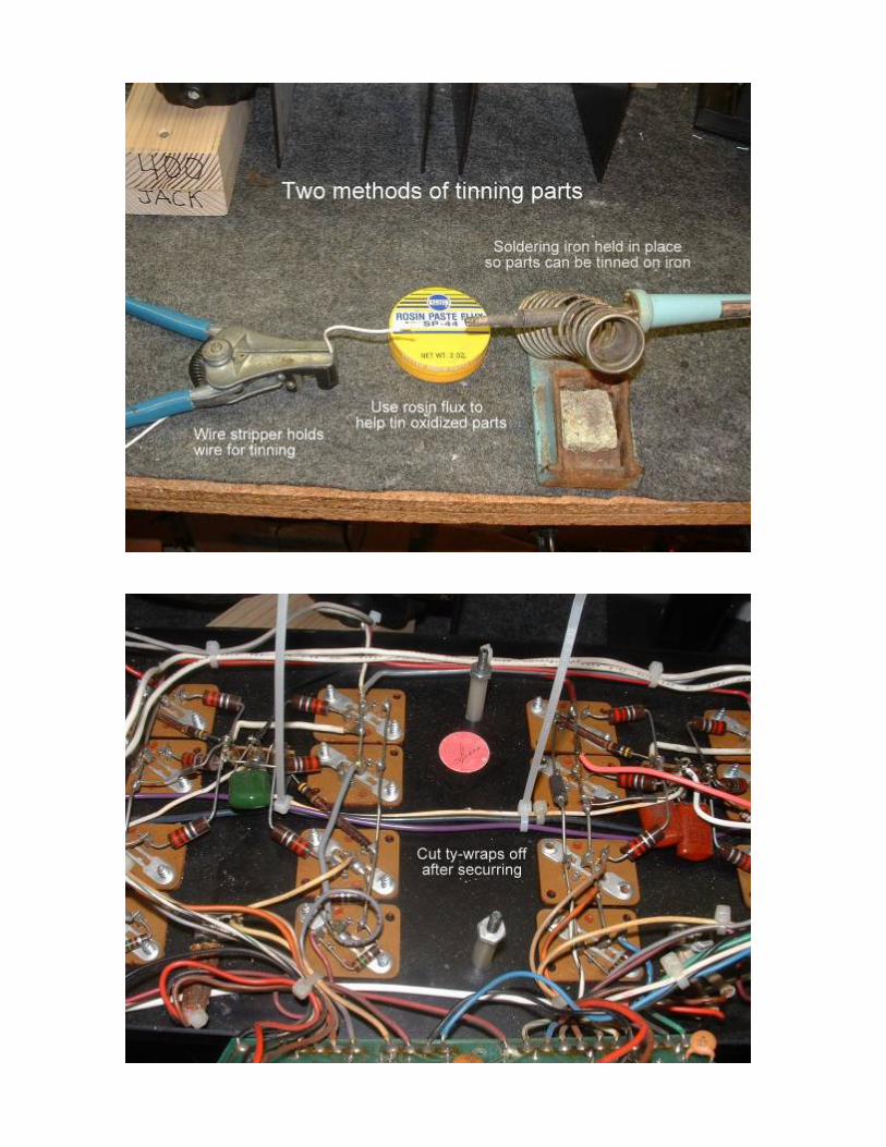
Phase Linear 400 Output Relay Installation Procedure Before Beginning The installation is straightforward and easy. However allow yourself 3-4 hours and take the time to do a good quality job. You will be making a connection to the bridge rectifier for AC power. A high power soldering iron is needed and it is easy to burn other wires nearby. After stripping wires twist the wire so there will be no frayed ends. It is very important when making connections to the PCB that all wires are in the slot. Mods and Upgrades If you are going to do any mods or upgrades (cap replacements) wait until after the relay is installed and operational. If there are any problems this will make trouble shooting easier. Box Contents Relay Board 1 red binding post 1 white binding post 2 black binding posts 2 input jacks 22” white wire (may also be gray or green) 17” black wire (may also be blue or purple) 6” red wire (may also be orange or yellow) Tywraps Tools Required • 1/2” Nut Driver (input jacks) • 7/16” Nut Driver (binding posts) • 3/16” or 1/4“ Nut Driver (binding posts) two different size nuts are available • 1/8” Screwdriver (terminal strips) • Soldering gun or high wattage iron, 60 watt or more (AC power connection) • Soldering iron 35-50 watt (V+ and ground wires) • Solder • Rosin flux (suggested, but not absolutely necessary) • High Quality wire strippers (avoid the bolt cutter/crimper/stripper combo) • Wire cutters • DVM (checking power supply voltages) • Light bulb limiting power supply (See attached drawing, <$10 to build) • Piece of a 2”x4” board, about 4 “ long (supports transformer) • Plastic bowl for hardware. Don’t use a box. Parts get lost in the flaps. • Piece of card board the size of the front panel (to protect it from scratches) • Masking tape (to make labels) • Pocket knife
-
Upload
khangminh22 -
Category
Documents
-
view
2 -
download
0
Transcript of Phase Linear 400 Output Relay Installation Procedure
Phase Linear 400 Output Relay Installation Procedure
Before Beginning The installation is straightforward and easy. However allow yourself 3-4 hours and take the time to do a good quality job. You will be making a connection to the bridge rectifier for AC power. A high power soldering iron is needed and it is easy to burn other wires nearby. After stripping wires twist the wire so there will be no frayed ends. It is very important when making connections to the PCB that all wires are in the slot. Mods and Upgrades If you are going to do any mods or upgrades (cap replacements) wait until after the relay is installed and operational. If there are any problems this will make trouble shooting easier. Box Contents Relay Board 1 red binding post 1 white binding post 2 black binding posts 2 input jacks 22” white wire (may also be gray or green) 17” black wire (may also be blue or purple) 6” red wire (may also be orange or yellow) Tywraps Tools Required • 1/2” Nut Driver (input jacks) • 7/16” Nut Driver (binding posts) • 3/16” or 1/4“ Nut Driver (binding posts) two different size nuts are available • 1/8” Screwdriver (terminal strips) • Soldering gun or high wattage iron, 60 watt or more (AC power connection) • Soldering iron 35-50 watt (V+ and ground wires) • Solder • Rosin flux (suggested, but not absolutely necessary) • High Quality wire strippers (avoid the bolt cutter/crimper/stripper combo) • Wire cutters • DVM (checking power supply voltages) • Light bulb limiting power supply (See attached drawing, <$10 to build) • Piece of a 2”x4” board, about 4 “ long (supports transformer) • Plastic bowl for hardware. Don’t use a box. Parts get lost in the flaps. • Piece of card board the size of the front panel (to protect it from scratches) • Masking tape (to make labels) • Pocket knife

Procedure 1. See the pictures below or go to http://www.flickr.com/photos/watts_abundant/. You can also
search for “Phase Linear relay” at Flickr.com. 2. Check the DC offset voltage for each channel. To do this disconnect the inputs and
speakers. With the amp turned on measure the voltage on the output terminals. If it’s more than 50mv (typical is less than 15), contact us at [email protected].
3. Inspect the relay board for signs of shipping damage. Remove the relay from the socket. 4. Clean off the bench and put away all the tools. Keep things neat and orderly. 5. Put all hardware that came with the kit in the container mentioned above. 6. Remove top and bottom covers. Put hardware in container. 7. Remove front cover. On series II amps remove the 6 screws that secure the sub panel.
Put all hardware in the container. 8. Set amplifier on the bench so that it is resting on the heatsinks. Support the Xfmr with the
2”x4”. The driver PCB inside the amp should be facing up. The front panel (series I) or sub panel (series II) should be folded back and resting against the heatsinks. Use the cardboard between the heat sink and panel to protect from scratches. During the installation you will need to rotate the amp around a few times so make sure to grasp the panel and the amp when doing so.
9. Inspect the amplifier driver board for any signs of heat damage. Locate the bridge rectifier
on the left. Locate the output terminals on the right. 10. Replace the RCA input Jacks, one at a time. Cut the lead as close as possible to the right
input jack. Leave the bare ground wire alone. Remove the jack and replace it with the new one. Make sure the fiber washers are in place. Strip about 1/8” insulation off of the lead and solder it to the new jack.
If you removed both jacks at the same time you didn’t follow directions and now the fiber washers fall out, roll around on the floor and get lost. New ones are $5 each to help you remember to follow directions.
11. Replace the left channel input jack as in the previous step. 12. At the input jacks, cut the solid ground wire off about .50 inch from the copper bar. 13. Use masking tape to label the wires on the binding posts. The labels should be the color
of the binding post, White, Black, Red etc. Cut each wire off as close as possible to it’s binding post.
14. Cut off the resistor/capacitor network off of the binding posts and discard them. 15. Remove each binding post, one at a time and replace it. The nuts are very easy to cross
thread. Use the 7/16” nut driver to start the nut. It should tighten all the way down with ease. If it becomes even slightly difficult to turn, stop at once as it is cross-threaded. Back it out and start over. Use a 4 penny nail or large paper clip in the hole on the binding post to keep it from turning.

1 2 3 1 2 3 1 2 3
J1 J2 J3
RELAY
16. Remove the 4-40 nut off of the binding posts and put them in the container with the rest of the hardware.
IN THE NEXT STEP DO NOT OVERTIGHTEN THE NUTS OR THE STUDS WILL BREAK. 17. Rotate the amplifier so it is in the normal sitting position. Install the board on the binding
posts. The lockwasher goes on next followed by followed by the nut. To start the nut, insert the nut in the 3/16” nutdriver and thread it on the binding post. Start all 4 nuts before tightening. If any nut does not turn easily it is cross threaded. The nut is tight when the lockwasher is compressed.
18. Look at the drawing below. The amplifier output wires and grounds are connected to the
terminal strips next. Start by cutting the first two tywraps from the binding posts along the top of the chassis. Be careful not to nick the wires. Start at connector J1-1. Strip no more than 1/4” of insulation off of the wire you labeled white. If it is stranded twist the wire so that it will not fray when you insert it in the terminal. Insert it at J1-1 and then tighten the screw. Support the board with one hand while tightening the screw with the other. Do not over tighten. Dress the wire similar to how it was originally from the factory. Proceed with the other 3 connection as shown below on J1-3, J2-1, and J2-3. J1-2 and J2-2 have no connection.
J1-1 Left channel output (white) J1-2 No connection J1-3 Left Channel ground (black) J2-1 Right channel output (red) J2-2 No connection J2-3 Right channel ground (black) J3-1 DC input (from + DC) J3-2 Ground J3-3 AC Input (from transformer)
19. Inspect the connections above for frayed wires. 20. Clear your workspace. Remove the 2 nuts that hold the driver board in place. Store the
nuts in the hardware container. Pull the driver board off of its studs and allow it to rest face down on the bench.
IN THE NEXT STEP THE AMPLIFIER MAY HAVE TO REST ON THE HEAT SINK TO SOLDER
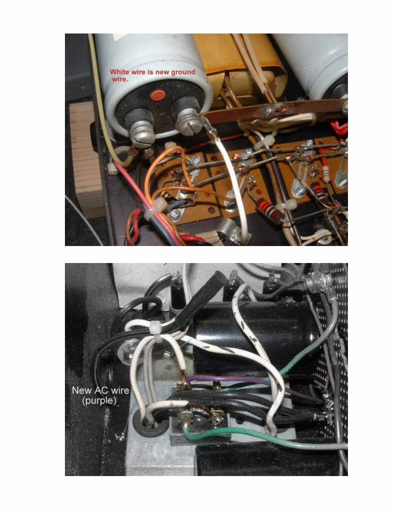
THE WIRE. DO NOT STRESS THE WIRES ON THE DRIVER BOARD 21. You will now install the AC wire from the bridge rectifier. The wire will be routed
horizontally across the middle of the output transistors. Using the black wire supplied with the kit, begin in the middle where the thermal sensor is located and lace the wire in the bundle with the ground wires and AC power wire going to the thermal sensor. See the pictures at flickr.com. While leaving adequate strain relief, solder the wire to one of the AC terminals on the bridge rectifier. There are two AC terminals. Each terminal has a wire coming from the transformer secondary. Use either one. A high wattage iron is mandatory to get a proper connection. Be careful not to burn any other wires nearby.
22. Terminate the other end of the AC wire to the relay board at terminal J3-3 . Make sure to
twist the wire before inserting it in the terminal. Leave adequate strain relief. Make sure all strands are in the terminal.
23. The white wire will connect the input jack ground wire to the power supply common. Strip
1/4” of insulation off one end of the white wire. Use a pocket knife to scrape away any oxidation on the bare ground wire on the input jacks. Solder the white wire to the ground
lead. Some rosin flux may be required for a good connection. Run the white wire in parallel with the input wires and along the bottom of the driver board. Cut it to length and connect it to the copper buss bar on the power supply caps. Save the remaining piece of white wire. It can be soldered to the copper bar or the terminal lug can be installed under the screw on the cap and the wire soldered to the lug.
24. Locate the terminal strip between the two output transistor columns on the right. The
middle terminal should have a ground wire connected to it. Solder the remaining white wire to this terminal. Route it over to the relay board and terminate it at J3-2.
25. This step refers to the DC connection. Look at the pictures for this step. There are 4
columns of output transistor sockets. You will work with the second column from the right. There are three connections on each socket. There is a buss wire that connects all 4 transistor sockets together and has an orange wire at the bottom that goes to the driver board. Using your multimeter, verify zero ohms from this point back to the positive terminal on the power supply capacitors.
26. Scrape away the oxidation on the buss wire you identified in the previous step. Tin a
small area on the buss wire between the second and third sockets. Solder the red wire to the buss where you just tinned. You may need rosing flux to get a good solder joint. Lace it over to the board and connect to the J3-1.
27. Installation is complete. Recheck all connections. Double check the AC and DC
connections on J3. Fasten the driver board to the studs. Install the sheet metal and secure the front panel.
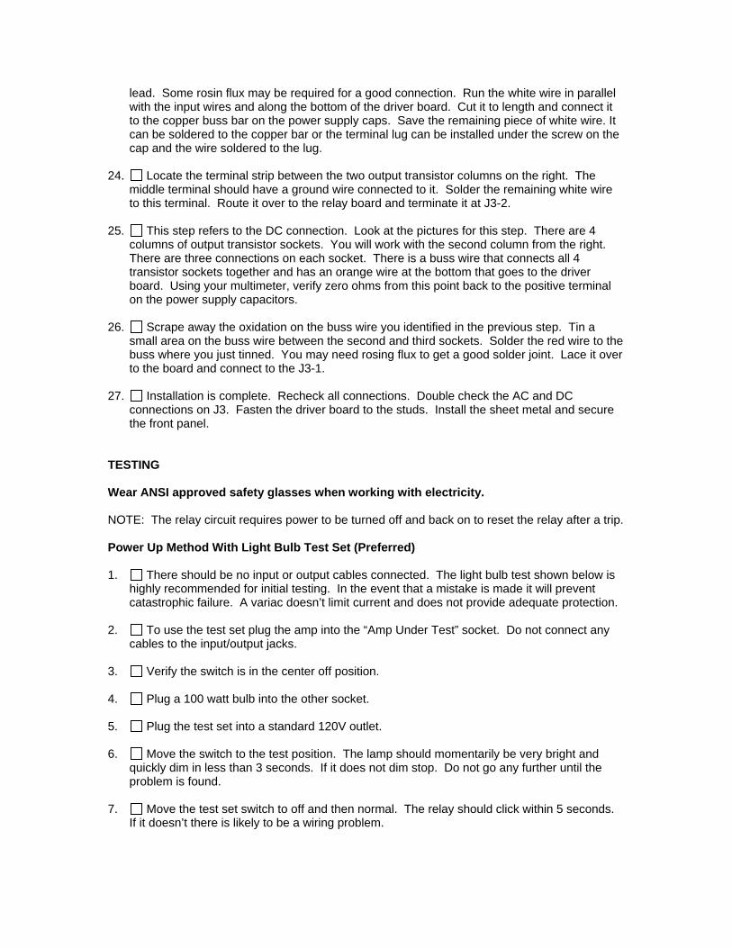
TESTING Wear ANSI approved safety glasses when working with electricity. NOTE: The relay circuit requires power to be turned off and back on to reset the relay after a trip. Power Up Method With Light Bulb Test Set (Preferred) 1. There should be no input or output cables connected. The light bulb test shown below is
highly recommended for initial testing. In the event that a mistake is made it will prevent catastrophic failure. A variac doesn’t limit current and does not provide adequate protection.
2. To use the test set plug the amp into the “Amp Under Test” socket. Do not connect any
cables to the input/output jacks. 3. Verify the switch is in the center off position. 4. Plug a 100 watt bulb into the other socket. 5. Plug the test set into a standard 120V outlet. 6. Move the switch to the test position. The lamp should momentarily be very bright and
quickly dim in less than 3 seconds. If it does not dim stop. Do not go any further until the problem is found.
7. Move the test set switch to off and then normal. The relay should click within 5 seconds.
If it doesn’t there is likely to be a wiring problem.
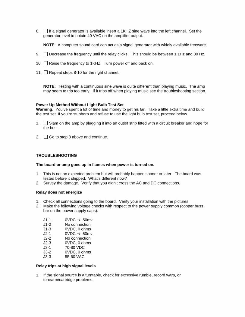
8. If a signal generator is available insert a 1KHZ sine wave into the left channel. Set the generator level to obtain 40 VAC on the amplifier output.
NOTE: A computer sound card can act as a signal generator with widely available freeware.
9. Decrease the frequency until the relay clicks. This should be between 1.1Hz and 30 Hz. 10. Raise the frequency to 1KHZ. Turn power off and back on. 11. Repeat steps 8-10 for the right channel.
NOTE: Testing with a continuous sine wave is quite different than playing music. The amp may seem to trip too early. If it trips off when playing music see the troubleshooting section.
Power Up Method Without Light Bulb Test Set Warning. You’ve spent a lot of time and money to get his far. Take a little extra time and build the test set. If you’re stubborn and refuse to use the light bulb test set, proceed below. 1. Slam on the amp by plugging it into an outlet strip fitted with a circuit breaker and hope for
the best. 2. Go to step 8 above and continue. TROUBLESHOOTING The board or amp goes up in flames when power is turned on. 1. This is not an expected problem but will probably happen sooner or later. The board was
tested before it shipped. What’s different now? 2. Survey the damage. Verify that you didn’t cross the AC and DC connections. Relay does not energize 1. Check all connections going to the board. Verify your installation with the pictures. 2. Make the following voltage checks with respect to the power supply common (copper buss
bar on the power supply caps). J1-1 0VDC +/- 50mv J1-2 No connection J1-3 0VDC, 0 ohms J2-1 0VDC +/- 50mv J2-2 No connection J2-3 0VDC, 0 ohms J3-1 70-80 VDC J3-2 0VDC, 0 ohms J3-3 55-60 VAC
Relay trips at high signal levels 1. If the signal source is a turntable, check for excessive rumble, record warp, or
tonearm/cartridge problems.

2. High levels at sub bass frequencies may appear to the relay circuit as a high DC voltage. Capacitor C7 can be increased in value. Please contact the factory for additional assistance.
Relay takes several seconds to drop out when power is turned off 1. The wire that connects to the bridge rectifier is on the DC terminal instead of the AC. I know
this because I’ve done it.
THEORY OF OPERATION The circuit is based on the UPC1237 IC that is intended for this application. Essentially it is a voltage monitor that engages the relay. The voltage monitor must be able to discriminate between very low bass signals and DC. A timing capacitor allows the voltage monitor to ignore the low bass but will quickly release the relay if DC is present. Another time delay circuit is used on turn on to allow the amplifier to stabilize before closing in the relay. Once powered up there will be about a 3 second delay. Just the opposite holds true on power down. The monitor quickly disconnects the relay if AC power is turned off or lost. The designer feels that it is best to latch the relay off when ever it senses a high DC so that the user can determine the cause. Power must be cycled off and back on to reset the relay. If the user finds this to be a nuisance contact the factory for options to reduce the incident rate.


LIGHTBULB TEST SET
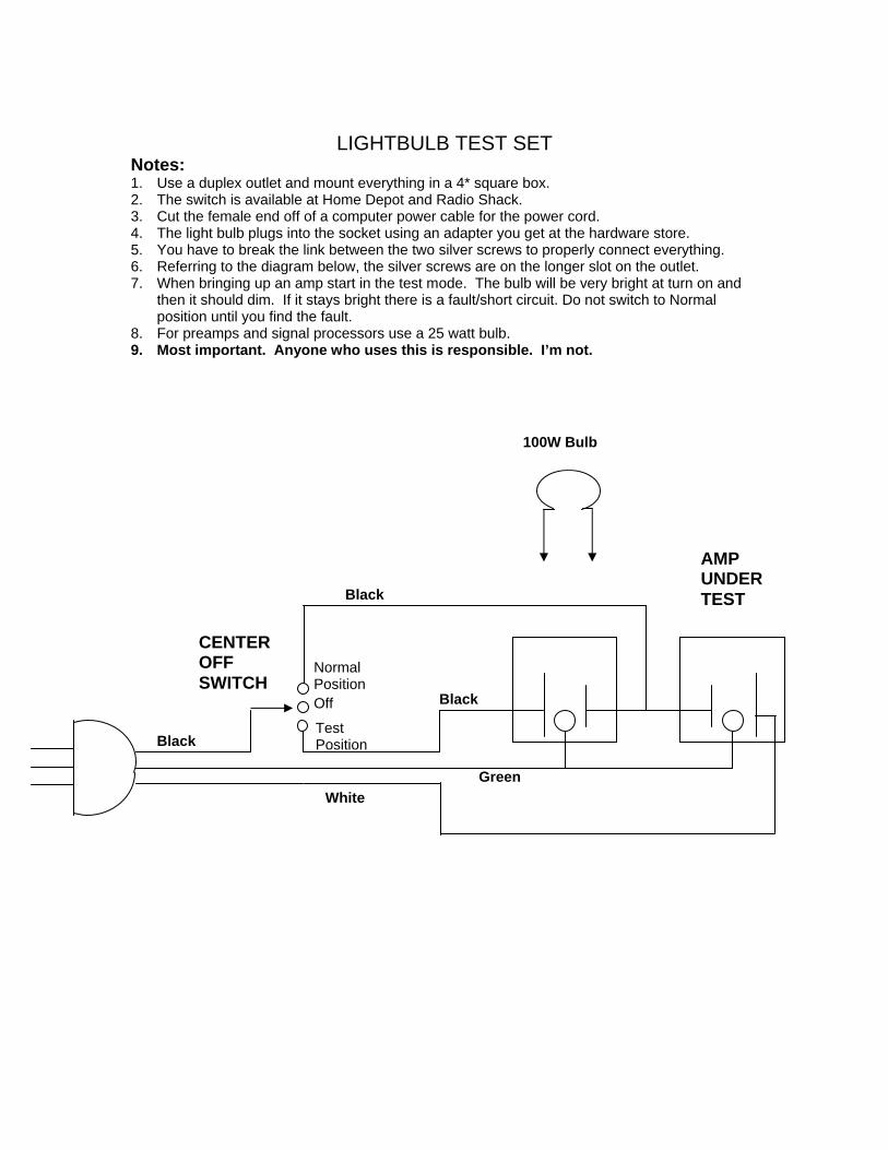
Notes: 1. Use a duplex outlet and mount everything in a 4* square box. 2. The switch is available at Home Depot and Radio Shack. 3. Cut the female end off of a computer power cable for the power cord. 4. The light bulb plugs into the socket using an adapter you get at the hardware store. 5. You have to break the link between the two silver screws to properly connect everything. 6. Referring to the diagram below, the silver screws are on the longer slot on the outlet. 7. When bringing up an amp start in the test mode. The bulb will be very bright at turn on and
then it should dim. If it stays bright there is a fault/short circuit. Do not switch to Normal position until you find the fault.
8. For preamps and signal processors use a 25 watt bulb. 9. Most important. Anyone who uses this is responsible. I’m not.
Black
White
Off
Test Position
Normal Position
Black
CENTER OFF SWITCH
Black
Green
100W Bulb
AMP UNDER TEST