Petri Isomäki | Nastooh Avessta An Overview of Software Defined Radio Technologies
56
Petri Isomäki | Nastooh Avessta An Overview of Software Defined Radio Technologies TUCS Technical Report No 652, December 2004
-
Upload
independent -
Category
Documents
-
view
1 -
download
0
Transcript of Petri Isomäki | Nastooh Avessta An Overview of Software Defined Radio Technologies
Petri Isomäki | Nastooh Avessta
An Overview of Software DefinedRadio Technologies
TUCS Technical ReportNo 652, December 2004


An Overview of Software DefinedRadio Technologies
Petri IsomäkiUniversity of Turku, Department of Information TechnologyLemminkäisenkatu 14 A, 20520 Turku, [email protected]
Nastooh AvesstaUniversity of Turku, Department of Information TechnologyLemminkäisenkatu 14 A, 20520 Turku, [email protected]
TUCS Technical Report
No 652, December 2004

Abstract
Software Defined Radio is an emerging technology that has been an active re-search topic for over a decade. The terms software defined radio and softwareradio are used to describe radios whose implementation is largely software-based.These radios are reconfigurable through software updates. There are also widerdefinitions of the concept.
Various military software defined radio programs were the pathfinders thatproved the viability of the concept. Latests of these projects have produced radiosthat are already replacing legacy systems.
The software radio technology is rapidly advancing, at least on most fronts.There is an ongoing standardisation process of framework architectures that en-able portability of e.g. waveform processing software across radios for variousdomains.
Software defined radios are beginning to find also commercial potential. Whenthe software defined radio becomes mainstream, the full potential of adaptabilitymay create possibilities for new kind of services. From the users’ point of view,seamless operation across networks, without caring about the underlying technol-ogy, would be a very desirable feature.
Keywords: Software Defined Radio (SDR), Radio Frequency (RF) front end,Analog-to-Digital Converter (ADC), Digital Signal Processor (DSP), SoftwareCommunications Architecture (SCA), SWRadio, programmable, reconfigurable
TUCS LaboratoryCommunication Systems Laboratory

Contents
1 Introduction 1
2 Implementation Aspects 32.1 Radio Frequency Front End . . . . . . . . . . . . . . . . . . . . .3
2.1.1 Superheterodyne Architecture . . . . . . . . . . . . . . .42.1.2 Direct Conversion Architecture . . . . . . . . . . . . . .52.1.3 Tuned RF Receiver . . . . . . . . . . . . . . . . . . . . .62.1.4 Other Architectures . . . . . . . . . . . . . . . . . . . . .6
2.2 A/D and D/A Conversion . . . . . . . . . . . . . . . . . . . . . . 72.2.1 Noise and Distortions in Converters . . . . . . . . . . . .82.2.2 Sampling Methods . . . . . . . . . . . . . . . . . . . . .102.2.3 Converter Structures . . . . . . . . . . . . . . . . . . . .11
2.3 Digital Processing . . . . . . . . . . . . . . . . . . . . . . . . . .112.3.1 Selection of the Processing Hardware . . . . . . . . . . .122.3.2 Multirate Processing . . . . . . . . . . . . . . . . . . . .132.3.3 Digital Generation of Signals . . . . . . . . . . . . . . . .132.3.4 Bandpass Waveform Processing . . . . . . . . . . . . . .142.3.5 Baseband Waveform Processing . . . . . . . . . . . . . .142.3.6 Bit-stream Processing . . . . . . . . . . . . . . . . . . .15
2.4 Reconfiguration and Resource Management . . . . . . . . . . . .152.5 Summary . . . . . . . . . . . . . . . . . . . . . . . . . . . . . .16
3 Standards 173.1 Air Interfaces . . . . . . . . . . . . . . . . . . . . . . . . . . . .173.2 Hardware . . . . . . . . . . . . . . . . . . . . . . . . . . . . . .193.3 Middleware . . . . . . . . . . . . . . . . . . . . . . . . . . . . .20
3.3.1 Model Driven Architecture (MDA) . . . . . . . . . . . .213.3.2 Common Object Request Broker Architecture (CORBA) .213.3.3 Interface Definition Language (IDL) . . . . . . . . . . . .223.3.4 Unified Modeling Language (UML) . . . . . . . . . . . .233.3.5 Extensible Markup Language (XML) . . . . . . . . . . .23
3.4 Software Communications Architecture (SCA) . . . . . . . . . .243.4.1 Application Layer . . . . . . . . . . . . . . . . . . . . .253.4.2 Waveform Development . . . . . . . . . . . . . . . . . .263.4.3 SCA Reference Implementation (SCARI) . . . . . . . . .27
3.5 SWRadio . . . . . . . . . . . . . . . . . . . . . . . . . . . . . .273.5.1 SWRadio Platform . . . . . . . . . . . . . . . . . . . . .283.5.2 SWRadio Architecture . . . . . . . . . . . . . . . . . . .28
3.6 Summary . . . . . . . . . . . . . . . . . . . . . . . . . . . . . .29
4 Software Defined Radio Projects 304.1 SPEAKeasy . . . . . . . . . . . . . . . . . . . . . . . . . . . . .30
4.1.1 SPEAKeasy Phase I . . . . . . . . . . . . . . . . . . . .304.1.2 SPEAKeasy Phase II . . . . . . . . . . . . . . . . . . . .32
4.2 Joint Tactical Radio System (JTRS) . . . . . . . . . . . . . . . .334.2.1 Background . . . . . . . . . . . . . . . . . . . . . . . . .344.2.2 Architecture . . . . . . . . . . . . . . . . . . . . . . . . .354.2.3 Wireless Information Transfer System (WITS) . . . . . .354.2.4 SDR-3000 . . . . . . . . . . . . . . . . . . . . . . . . .36
4.3 Other SDR Projects . . . . . . . . . . . . . . . . . . . . . . . . .364.3.1 Joint Combat Information Terminal (JCIT) . . . . . . . .364.3.2 CHARIOT . . . . . . . . . . . . . . . . . . . . . . . . .374.3.3 SpectrumWare . . . . . . . . . . . . . . . . . . . . . . .384.3.4 European Perspective: ACTS and IST Projects . . . . . .384.3.5 GNU Radio . . . . . . . . . . . . . . . . . . . . . . . . .39
4.4 Summary . . . . . . . . . . . . . . . . . . . . . . . . . . . . . .40
5 Conclusions 42
Abbreviations 44
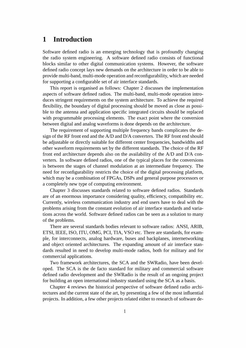
1 Introduction
Software defined radio is an emerging technology that is profoundly changingthe radio system engineering. A software defined radio consists of functionalblocks similar to other digital communication systems. However, the softwaredefined radio concept lays new demands on the architecture in order to be able toprovide multi-band, multi-mode operation and reconfigurability, which are neededfor supporting a configurable set of air interface standards.
This report is organised as follows: Chapter 2 discusses the implementationaspects of software defined radios. The multi-band, multi-mode operation intro-duces stringent requirements on the system architecture. To achieve the requiredflexibility, the boundary of digital processing should be moved as close as possi-ble to the antenna and application specific integrated circuits should be replacedwith programmable processing elements. The exact point where the conversionbetween digital and analog waveforms is done depends on the architecture.
The requirement of supporting multiple frequency bands complicates the de-sign of the RF front end and the A/D and D/A converters. The RF front end shouldbe adjustable or directly suitable for different center frequencies, bandwidths andother waveform requirements set by the different standards. The choice of the RFfront end architecture depends also on the availability of the A/D and D/A con-verters. In software defined radios, one of the typical places for the conversionsis between the stages of channel modulation at an intermediate frequency. Theneed for reconfigurability restricts the choice of the digital processing platform,which may be a combination of FPGAs, DSPs and general purpose processors ora completely new type of computing environment.
Chapter 3 discusses standards related to software defined radios. Standardsare of an enormous importance considering quality, efficiency, compatibility etc.Currently, wireless communication industry and end users have to deal with theproblems arising from the constant evolution of air interface standards and varia-tions across the world. Software defined radios can be seen as a solution to manyof the problems.
There are several standards bodies relevant to software radios: ANSI, ARIB,ETSI, IEEE, ISO, ITU, OMG, PCI, TIA, VSO etc. There are standards, for exam-ple, for interconnects, analog hardware, buses and backplanes, internetworkingand object oriented architectures. The expanding amount of air interface stan-dards resulted in need to develop multi-mode radios, both for military and forcommercial applications.
Two framework architectures, the SCA and the SWRadio, have been devel-oped. The SCA is the de facto standard for military and commercial softwaredefined radio development and the SWRadio is the result of an ongoing projectfor building an open international industry standard using the SCA as a basis.
Chapter 4 reviews the historical perspective of software defined radio archi-tectures and the current state of the art, by presenting a few of the most influentialprojects. In addition, a few other projects related either to research of software de-
1

fined radio technology or to development of deployable radio sets are presented.An interesting question is, what the architectures used in these projects have incommon, and whether there is an architecture that has proven to be optimal.
The conclusions summarise this overview of software defined radios in Chap-ter 5.
2

2 Implementation Aspects
A software defined radio (SDR) consists of, for the most part, the same basicfunctional blocks as any digital communication system [19]. Software definedradio lays new demands on many of these blocks in order to provide multiple band,multiple service operation and reconfigurability needed for supporting various airinterface standards. To achieve the required flexibility, the boundary of digitalprocessing should be moved as close as possible to the antenna, and applicationspecific integrated circuits, which are used for baseband signal processing, shouldbe replaced with programmable implementations [8].
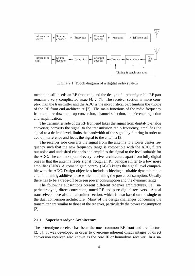
Functions of a typical digital communication system can be divided into bit-stream processing, baseband waveform processing and bandpass processing. Thetransmitter of a digital radio can be further divided into an information source, asource encoder, an encryptor, a channel encoder, a modulator, a digital-to-analogconverter (DAC) and a radio frequency (RF) front end block. Correspondingly,the receiver consists of an RF front end, an analog-to-digital converter (ADC), asynchronisation block, a demodulator, a detector, a channel decoder, a decryptor,a source decoder and an information sink [1, 2]. The exact point where the conver-sion between digital and analog waveforms is done depends on the architecture.The converters have been deliberately left out from Figure 2.1. In conventionalradio architectures, the conversion is done at the baseband, whereas in softwaredefined radios, one of the typical places for the conversion is between the stagesof channel modulation, at an intermediate frequency.
The multi-band, multi-mode operation of an SDR introduces stringent require-ments on the underlying system architecture. The requirement of supporting mul-tiple frequency bands affects the design of the RF front end and the A/D and D/Aconverters [2]. The RF front end should be adjustable or directly suitable for dif-ferent center frequencies and bandwidths required by the different standards thatthe SDR supports. The front end architectures differ also in suitability consider-ing the waveform requirements of different operating modes. The RF front endarchitectures are discussed in section 2.1. The choice of the RF front end archi-tecture depends also on the availability of suitable ADCs and DACs. These dataconverters are discussed in Section 2.2. The need for reconfigurability and repro-grammability restrict the choice of the digital processing platform. For instance,the platform may be a combination of field programmable gate arrays (FPGAs),digital signal processors (DSPs) and general purpose processors (GPPs). The as-pects related to digital processing are discussed in Section 2.3. The reconfigura-bility and the need for resource management are discussed in Section 2.4. Thechapter is summarised in Section 2.5.
2.1 Radio Frequency Front End
Although an ideal software radio would have a very minimal analog front end,consisting of an analog-to-digital converter at the antenna, any practical imple-
3
DecryptorInformationdecoder
ChannelSourcedecodersink
EncryptorInformationsource encoder
ChannelSourceencoder Modulator RF front end
Detector DemodulatorRF frontend
Timing & synchronisation
Figure 2.1: Block diagram of a digital radio system
mentation still needs an RF front end, and the design of a reconfigurable RF partremains a very complicated issue [4, 2, 7]. The receiver section is more com-plex than the transmitter and the ADC is the most critical part limiting the choiceof the RF front end architecture [2]. The main functions of the radio frequencyfront end are down and up conversion, channel selection, interference rejectionand amplification.
The transmitter side of the RF front end takes the signal from digital-to-analogconverter, converts the signal to the transmission radio frequency, amplifies thesignal to a desired level, limits the bandwidth of the signal by filtering in order toavoid interference and feeds the signal to the antenna [3].
The receiver side converts the signal from the antenna to a lower center fre-quency such that the new frequency range is compatible with the ADC, filtersout noise and undesired channels and amplifies the signal to the level suitable forthe ADC. The common part of every receiver architecture apart from fully digitalones is that the antenna feeds signal trough an RF bandpass filter to a low noiseamplifier (LNA). Automatic gain control (AGC) keeps the signal level compati-ble with the ADC. Design objectives include achieving a suitable dynamic rangeand minimising additive noise while minimising the power consumption. Usuallythere has to be a trade-off between power consumption and the dynamic range.
The following subsections present different receiver architectures, i.e. su-perheterodyne, direct conversion, tuned RF and pure digital receivers. Actualtransceivers have also a transmitter section, which is also based on the single orthe dual conversion architecture. Many of the design challenges concerning thetransmitter are similar to those of the receiver, particularly the power consumption[2].
2.1.1 Superheterodyne Architecture
The heterodyne receiver has been the most common RF front end architecture[2, 3]. It was developed in order to overcome inherent disadvantages of directconversion receiver, also known as the zero IF or homodyne receiver. In a su-
4
BPF BPF BPF LPF AGCAGC ADCLNA
IF LO1 IF LO2
Figure 2.2: Superheterodyne receiver
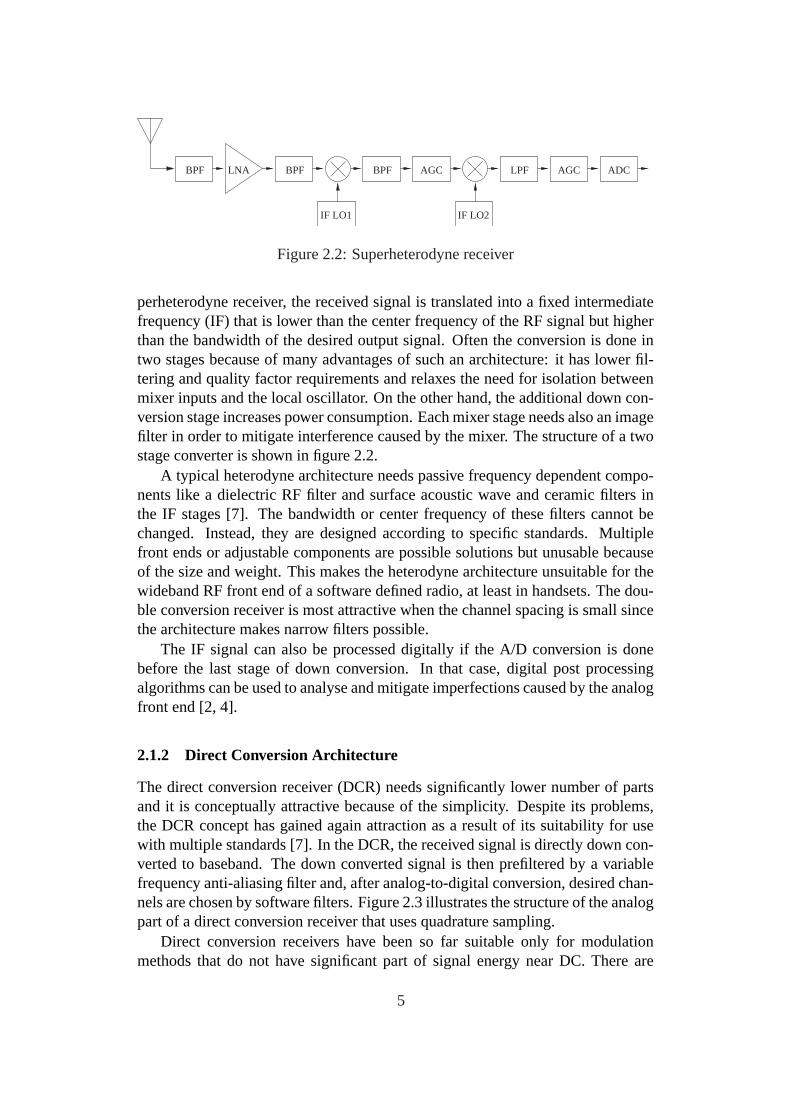
perheterodyne receiver, the received signal is translated into a fixed intermediatefrequency (IF) that is lower than the center frequency of the RF signal but higherthan the bandwidth of the desired output signal. Often the conversion is done intwo stages because of many advantages of such an architecture: it has lower fil-tering and quality factor requirements and relaxes the need for isolation betweenmixer inputs and the local oscillator. On the other hand, the additional down con-version stage increases power consumption. Each mixer stage needs also an imagefilter in order to mitigate interference caused by the mixer. The structure of a twostage converter is shown in figure 2.2.
A typical heterodyne architecture needs passive frequency dependent compo-nents like a dielectric RF filter and surface acoustic wave and ceramic filters inthe IF stages [7]. The bandwidth or center frequency of these filters cannot bechanged. Instead, they are designed according to specific standards. Multiplefront ends or adjustable components are possible solutions but unusable becauseof the size and weight. This makes the heterodyne architecture unsuitable for thewideband RF front end of a software defined radio, at least in handsets. The dou-ble conversion receiver is most attractive when the channel spacing is small sincethe architecture makes narrow filters possible.
The IF signal can also be processed digitally if the A/D conversion is donebefore the last stage of down conversion. In that case, digital post processingalgorithms can be used to analyse and mitigate imperfections caused by the analogfront end [2, 4].
2.1.2 Direct Conversion Architecture
The direct conversion receiver (DCR) needs significantly lower number of partsand it is conceptually attractive because of the simplicity. Despite its problems,the DCR concept has gained again attraction as a result of its suitability for usewith multiple standards [7]. In the DCR, the received signal is directly down con-verted to baseband. The down converted signal is then prefiltered by a variablefrequency anti-aliasing filter and, after analog-to-digital conversion, desired chan-nels are chosen by software filters. Figure 2.3 illustrates the structure of the analogpart of a direct conversion receiver that uses quadrature sampling.
Direct conversion receivers have been so far suitable only for modulationmethods that do not have significant part of signal energy near DC. There are
5

AGC
AGC
BPF LNA90 o
LPF
LPF
ADC
ADC
Figure 2.3: Direct conversion receiver with quadrature sampling
also problems associated with the fact that the local oscillator of a DCR is at thesignal band, including possible unauthorised emissions and internal interference.One of the problems is that phase noise falls within the baseband. Thus, the DCRarchitecture needs an extremely stable local oscillator. Some of the problems canbe compensated with digital post processing.
Apart from the possibility to switch between some specific bands and modes,direct conversion receivers do not offer prominent flexibility. There are some airinterface standards that are very difficult to support by a direct conversion receiver.On the other hand, the concept has been proven to be commercially usable, for atleast some purposes, by an existing GSM receiver. Some sources suggest that theDCR is the most promising RF front end architecture for software defined radio[7].
2.1.3 Tuned RF Receiver
The analog part of the tuned radio frequency receiver is composed of only anantenna connected to a tunable RF bandpass filter and a low noise amplifier withautomatic gain control [2], as shown in Figure 2.4. The main difficulty of thisarchitecture is the need for an ADC with a very high sampling rate due to thewide bandwidth of the RF filter. Additionally, the roll-off factor of the filter has tobe taken into account in order to avoid aliasing. The high sampling rate togetherwith high dynamic range results in a relatively high power consumption. Demandsfor the RF filter are also challenging and practically the filter can only select somelarger band that has to be filtered digitally afterwards to get only the band of thedesired channel. Gain control is also more difficult than in multistage receivers.
In the tuned RF receiver, some of the biggest problems of the direct conversionare absent [2]. It is suitable for multiple mode receiver that supports differentbands. This makes the architecture well suited for software defined radio.
2.1.4 Other Architectures
Pure digital RF front end architectures provide a potential advantage, i.e. the flex-ibility of software based solutions that is desired in all parts of software defined
6

BPF LNA AGC ADC
Figure 2.4: Tuned RF receiver
radios. Such a solution puts an ADC at the antenna and does everything else,including down conversion and filtering, using digital signal processing [4, 2, 3].The architecture needs A/D conversion and digital processing at very high band-widths, which results in a high power consumption. Furthermore, the incomingsignal cannot be equalised and as a consequence, error rates are higher. Puredigital RF processing has yet to see any commercially viable applications.
2.2 A/D and D/A Conversion
Considering the performance and cost of a software defined radio, the analog-to-digital converter and digital-to-analog converter are among the most importantcomponents [2]. In many cases, they define the bandwidth, the dynamic rangeand the power consumption of the radio. The wideband ADC is one of the mostchallenging task in software radio design. The bandwidth and the dynamic rangeof the analog signal has to be compatible with the ADC. An ideal software radiowould use data converters at RF, which would result in conflicting needs: a veryhigh sampling rate, a bandwidth up to several GHz and a high effective dynamicrange while avoiding intolerable power consumption. The physical upper boundfor capabilities of ADCs can be derived from Heisenberg’s uncertainty principle.For instance at 1 GHz the upper limit for dynamic range is 20 bits or 120 dB[4]. However, there are other limiting factors including aperture jitter and thermaleffects. Unfortunately, the advances in ADC performance are very slow, unlike inmany other technology areas related to software defined radio.
The Nyquist ratefs/2 determines the maximum frequency for which the ana-log signal can be faithfully reconstructed from the signal consisting of samples atthe sampling ratefs. Higher frequencies cause aliasing and therefore the ADC ispreceded by an anti-aliasing filter. The number of bits in the ADC defines the up-per limit for achievable dynamic range. The higher is the needed dynamic range,the higher has to be the stop-band attenuation of the filter. For instance, a 16-bitADC needs over 100 dB attenuation in order to reduce the power of aliased signalunder the half of the energy of the least sensitive bit (LSB) [4]. The state of the artADCs for wireless devices operate at bandwidth of over 100 MHz with 14-bit res-olution and 100 dB spurious free dynamic range, but there is already commercialdemand for even better converters for base stations [3].
7

The analog front end of an ADC has a direct influence on the dynamic range.The non-linearities of the front end cause intermodulation. The spurious free dy-namic range (SFDR) denotes the difference between the minimum detectable in-put (noise floor) and the point where the third order distortion becomes strongerthan that [2]. Different air interface types and standards have different demandson the dynamic range. A large SFDR is needed to allow recovery of small scalesignals when strong interferers are present.
Different types of receiver architectures need different sampling methods [3].A superheterodyne receiver or a direct conversion receiver may have an I/Q base-band signal as the analog output, for which quadrature baseband sampling isneeded. Another possibility is an intermediate frequency analog output, for whicha suitable sampling strategy is for example IF band-pass sampling by using asigma-delta ADC. Direct sampling is a suitable method for low IF analog signals.
Although the ADC performance is often the limiting factor in the SDR con-cept and usually more widely discussed in this context, the transmit path is alsoa design problem of comparable complexity [3]. The requirements for DACs in-clude high linearity, sufficient filtering and isolation of the clock from the output,in order to avoid distortion and out-of-band emissions.
The following subsection discusses distortions in converters and related con-siderations from the point of view of different air interfaces. The subsequent sub-sections present different sampling methods and converter structures, taking intoaccount issues related to the suitability for SDRs.
2.2.1 Noise and Distortions in Converters
Distortions in data converters include quantisation noise, overload distortion, lin-ear transfer errors, non-linear errors, aperture jitter and thermal noise [2].
Quantisation noise denotes the unavoidable error caused by the approxima-tion of continuous valued signal by discrete levels, modelled as a noisy source.Its effects can be reduced by oversampling and noise shaping. Oversampling in-creases the SNR of the system because a part of the noise power can be removedby filtering. The latter method is discussed in the end of this subsection.
Overload distortion is caused by input signals exceeding the allowed rangethat the ADC can represent. It is difficult to fully avoid overload and, althoughoverload distortion may significantly reduce SNR, it is sometimes useful to al-low some distortion. Lowering the gain reduces the number of bits actually used.Also, spread spectrum signals have different requirements than non-spread signalsbecause of the different impact of individual symbol errors on the overall perfor-mance. The response time of the automatic gain control is a critical parameter.Both too slow and too fast response may degrade the performance. The responseshould be fast enough to allow full-scale range utilisation while avoiding overload-ing, but excessively fast response introduces undesired amplitude modulation. Ingeneral, the optimal time constant depends on channel effects and waveform spe-cific aspects [2]. Thus, the optimal automatic gain control strategy depends on
8

the air interface standard used, which has to be taken into account in SDR design.Avoiding clipping due to overload may effectively use the entire most significantbit. Therefore, the usable dynamic range may be one or two bits lower than theresolution of ADC [4].
Offset and gain errors are linear transfer characteristic errors. Non-linearitiescan be described with two measures: integral non-linearity denotes the maximumdeviation of the transfer characteristic from the ideal straight line and differentialnon-linearity denotes the variation of the distances of quantisation levels from thedesired step size.
Thermal noise is an unavoidable property of resistive components. Softwaredefined radios work with multiple bandwidths, which results in varying noisefloor. Concerning wideband signals, thermal noise may considerably reduce thedynamic range.
The uncertainty in spacing between sampling instances is called aperture jitter.This causes uncertainty in the phase, deteriorates the noise floor performance andincreases intersymbol interference. Glitches are transient differences from thecorrect output voltage in DACs. Aperture jitter and glitches are the most importanttiming problems of ADCs and DACs.
The effective number of bits (ENOB) of a converter can be calculated fromthe signal-to-noise-and-distortion (SINAD) ratio [2].
ENOB =SINAD − 1.763dB
6.02
and the SNR of a system in which other effects are negligible compared to aperturejitter is given by [2]
SNR = −10log10(2π2f 2∆a
2)
wheref is the frequency of input signal and∆a2 is the variance of the aperture
jitter. By using these equations, an upper limit of the effective number of bits atdifferent frequencies can be calculated. The limit is shown for one value of theaperture jitter in Figure 2.5. Thermal noise may also be the dominant limitingfactor, whereas conversion ambiguity may become dominant at high frequencies.The performance of currently available ADCs lies usually below the line show inthe figure. There are more detailed graphs in [4] and [2].
Dithering is a method that is used to increase spurious free dynamic range [3].SFDR is essential from the point of view of narrow band air interfaces. Ditheris pseudo random noise that is added to the input of ADC. The main goal is tomaximise the SFDR, while minimising the effect adverse on SNR. Small-scaledithering is used to decorrelate quantisation noise, which leads to reduction of theharmonics caused by correlated noise. Dithering may also reduce errors caused bydifferential non-linearities. There are two large-scale dithering techniques that areused to mitigate effects of non-linearities: out-of-band dithering and subtractivedithering [2]. In out-of-band dithering, noise is added outside the frequency band
9

106
107
108
109
8
10
12
14
16
18
20
Sampling rate
Effe
ctiv
e nu
mbe
r of
bits
Figure 2.5: The effect of 0.5 ps aperture jitter on the performance of ADC
of the desired signal. This can be accomplished by using a band-reject filter.The added noise can be easily filtered out in the digital domain. In subtractivedithering, digital pseudo noise is converted to the analog domain and added toinput of ADC. Then, the noise is subtracted after the analog-to-digital conversion.
2.2.2 Sampling Methods
Direct sampling, or Nyquist sampling, is based on the sampling theorem, whichrequires the sampling rate to be at least twice the highest frequency componentof the analog low-pass signal. In practical implementations, anti-alias filtering isamong the central issues of the converter design. By oversampling, the filteringrequirements may be relaxed. On the other hand, oversampling requires higherspeed ADCs and increases data rate in digital processing [2].
In the case of quadrature sampling, the input signal is split into in-phase andquadrature components. Their bandwidth is half of the bandwidth of the originalsignal. Thus, quadrature sampling reduces the required sampling rate. Corre-spondingly, the downside is the need for two phase synchronised converters. Thedemodulation of phase or frequency modulated signals needs both in-phase andquadrature samples because these components have different information. Byusing digital processing, e.g. Hilbert transform filter, this splitting can also beperformed in the digital domain.
10

RF bands of radio systems have band-pass characteristics instead of low-passcharacteristics. Bandpass sampling, or sub-sampling, also utilises the Nyquist’stheorem, i.e. the sampling rate has to be at least twice the bandwidth of the inputsignal. In this method, images are viewed as frequency translated versions of thedesired spectrum instead of only harmful by-products. It is necessary that infor-mation in any Nyquist zone will not interfere with information in other Nyquistzones. By using this approach, down conversion is also provided by the samplingprocess.
2.2.3 Converter Structures
Although there are a lot of different ADCs available, only a few widely used corearchitectures exist [3]. The suitability of a particular architecture depends on therequirements of a given system. Common converter architectures include parallel,segmented, iterative and sigma-delta structures [2].
A flash converter consists of parallel comparators and a resistor ladder. Thebenefits of this architecture are simple design and very low conversion times.This makes flash converters an attractive choice when only a minimal dynamicis needed. The complexity of the architecture increases exponentially as the num-ber of bits increases, and 10 bits is the practical upper limit [3]. Another drawbackis that there are difficulties with linearity. Additional bits make this problem evenworse and the main benefit, the high speed, is lost as the effective bandwidth de-creases, when more comparators are connected together.
In contrast, multistage converters are scalable, i.e. high speed, high resolutionconverters can be constructed. The converted digital signal is converted back ananalog signal by a DAC between each stage. After a subtraction, only the residualsignal is fed to the next stage. Multistage ADCs have many advantages: highprecision without exponential growth of complexity or long delays. However, thearchitecture has some challenges. The resolution of the DAC at the first stage hasto be greater than the resolution of the entire ADC.
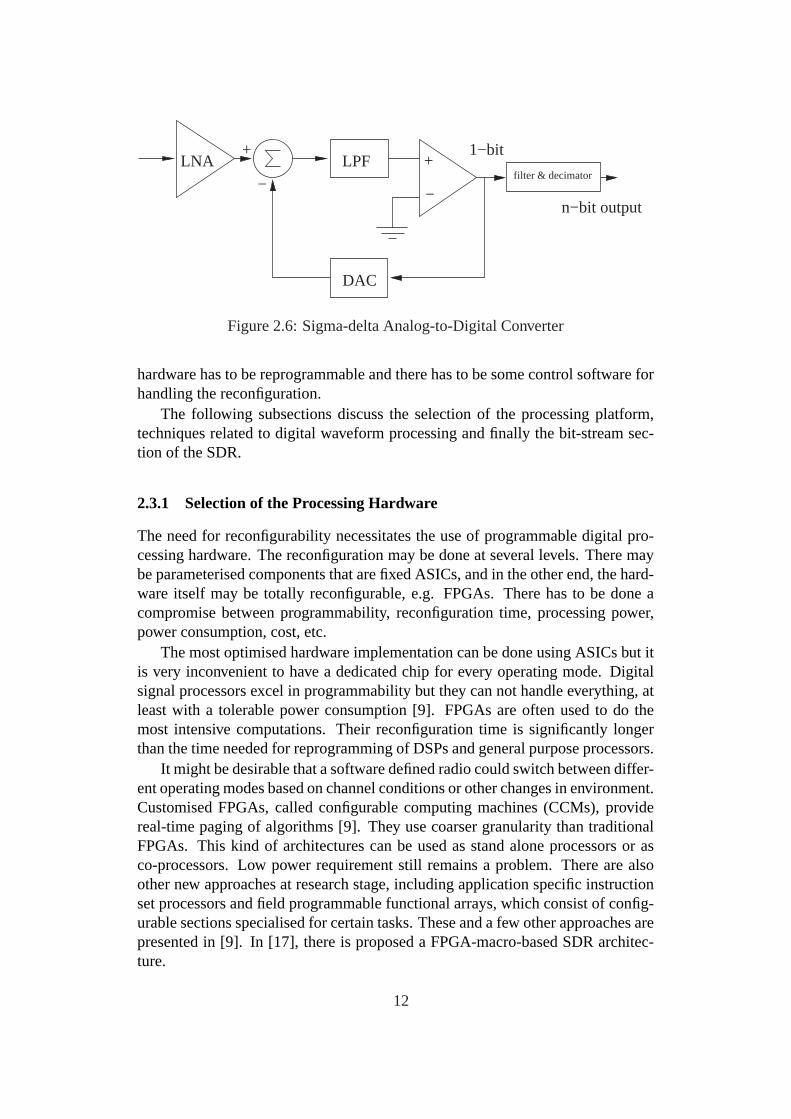
The sigma-delta ADC consists of an analog filter, a comparator, a DAC anda decimator with a digital filter, as shown in Figure 2.6. The comparator tellsthe output signal if it should be increasing or decreasing. The sigma-delta ADCswork by using oversampling. An advantage is that they remove quantisation noisefrom narrowband signals. In many cases, this architecture is suitable for softwaredefined radios. Sigma-delta modulators can be used for both direct and bandpasssampling.
2.3 Digital Processing
Digital processing is the key part of any software defined radio, i.e. the pro-grammable digital processing environment makes it possible to reconfigure to anyair interface. The digital processing segment of an SDR is functionally similarto other digital communication systems. Differences include that the underlying
11
filter & decimatorLNA
+
−
+
−
DAC
1−bit
n−bit output
LPF
Figure 2.6: Sigma-delta Analog-to-Digital Converter
hardware has to be reprogrammable and there has to be some control software forhandling the reconfiguration.
The following subsections discuss the selection of the processing platform,techniques related to digital waveform processing and finally the bit-stream sec-tion of the SDR.
2.3.1 Selection of the Processing Hardware
The need for reconfigurability necessitates the use of programmable digital pro-cessing hardware. The reconfiguration may be done at several levels. There maybe parameterised components that are fixed ASICs, and in the other end, the hard-ware itself may be totally reconfigurable, e.g. FPGAs. There has to be done acompromise between programmability, reconfiguration time, processing power,power consumption, cost, etc.
The most optimised hardware implementation can be done using ASICs but itis very inconvenient to have a dedicated chip for every operating mode. Digitalsignal processors excel in programmability but they can not handle everything, atleast with a tolerable power consumption [9]. FPGAs are often used to do themost intensive computations. Their reconfiguration time is significantly longerthan the time needed for reprogramming of DSPs and general purpose processors.
It might be desirable that a software defined radio could switch between differ-ent operating modes based on channel conditions or other changes in environment.Customised FPGAs, called configurable computing machines (CCMs), providereal-time paging of algorithms [9]. They use coarser granularity than traditionalFPGAs. This kind of architectures can be used as stand alone processors or asco-processors. Low power requirement still remains a problem. There are alsoother new approaches at research stage, including application specific instructionset processors and field programmable functional arrays, which consist of config-urable sections specialised for certain tasks. These and a few other approaches arepresented in [9]. In [17], there is proposed a FPGA-macro-based SDR architec-ture.
12

The total amount of processing capacity sets another limit for implementablesystems. In [4], there are presented a few simple equations for calculating theneeded processing capacity. An illustrative calculation shows that a GSM receiverrequires the capacity of over 40 millions of operations per second (in standardisedMOPS) when the IF processing is excluded. Vanu Inc. has also published a tablecontaining the number of operations needed by a few air interfaces implementedin their line of SDR products. For instance, a GSM transceiver needs 96 Mcyclesper second on a Pentium III platform, whereas a 802.11b WLAN receiver requires512 Mcycles per second [31].
2.3.2 Multirate Processing
Multirate signal processing is needed for many purposes in software defined ra-dios [2]. First of all, the output of the ADC and the input to the DAC is mostconveniently performed at a fixed rate, whereas for digital processing, it is rea-sonable to use as low data rates as possible without loss of information in order toavoid excessive computational burden. Also, each supported standard may havea different symbol rate and it is desirable to use sampling rates that are integermultiplies of the symbol rate.
Channelisation of data for parallel computing at lower sampling rate may beuseful particularly at base stations since it is a more cost effective method thanusing high-speed DSPs. Multirate processing allows also a trade-off between res-olution and speed in ADCs, which is useful for supporting different operatingmodes of an SDR.
Digital synchronisation of sampling instant is yet another example of applica-tions of sampling rate conversion. The idea is that the input signal is interpolatedto a higher rate and the best sampling point is chosen. Early-late gate synchronisa-tion is a method for determining the location of the peak, i.e. the optimal samplingpoint.
The principles of sampling rate conversion can be found for example in [2].Cascaded integrator comb (CIC) filter is a suitable structure for both interpolationan decimation in SDRs. It has reduced computational demands and it is alsoparticularly suitable for FPGA implementation owing to simple basic operations.
2.3.3 Digital Generation of Signals
In software defined radios, the parameters of the system are required to be ad-justable, even dynamically during runtime. This lays demands for versatility ofprocessing hardware at all stages. It is the availability of programmable, fast digi-tal techniques that has made the concept of software defined radio a feasible archi-tecture for implementing radio systems. The synthesis of waveforms is an essen-tial part of any radio communication system. Particularly generation sinusoidalsignal is of a great importance. They are used for many purposes: modulation,filtering and pulse shaping [2].
13

Direct digital synthesis produces purely digitally signals that are discrete intime. In comparison to analog methods, the benefits include high accuracy, im-munity to noise, ability to generate arbitrary waveforms, low switching time andthe physical size of circuits.
There are a number of approaches for generating digital signals. One of thebasic methods is to store a sampled waveform in a look-up table (LUT). The sam-pled values are then sent to the output periodically. Sinusoidal signals can begenerated this way. There are three sources of error in direct digital synthesis:amplitude error due to the limited number of bits used in quantisation, phase trun-cation due to a limited number of bits used to address the locations of the table,and the resolution of the DAC. The phase truncation is a significant source of errorand many methods have been developed to cure problem.
There are many approaches to reduce the size of LUT or to avoid spurioussignals caused by phase truncation. Interpolation reduces the required size signif-icantly. There are also sine wave generators that do not need a LUT for generatinga wave of a fixed frequency. These include the CORDIC algorithm and IIR oscil-lators.
2.3.4 Bandpass Waveform Processing
In software defined radios, the typical placement of wideband ADC and DAC isbefore the final IF and channelisation filters. It allows digital processing beforedemodulation, and it is a cost effective solution for supporting multiple channelaccess standards since IF processing is done using programmable hardware [5].
The bandpass processing segment provides the mapping between modulatedbaseband signals and intermediate frequency. In a receiver, a wideband digitalfilter selects the band defined by selected standard. IF processing also selectsthe desired channel by filtering and down converts the signal into baseband. Be-cause the sample rate is very high, decimation is needed before passing the signalto baseband processing. A typical application requires about 100 operations persample, which results in very high total computational requirements.
Spreading and despreading in CDMA systems are also bandpass processingfunctions. Like any other digital processing at IF, they are computationally inten-sive.
2.3.5 Baseband Waveform Processing
The baseband waveform segment processes digital baseband waveforms. This isthe stage where the first part of channel modulation is done [5]. Pulse modulationproduces a digital waveform from a bit-stream. Pulse shaping is used to avoidinter symbol interference. Predistortion for non-linear channels may also be doneat the baseband processing stage. In a receiver, soft decision parameter estimation,if used, is also done in this segment. Digital baseband modulations require alsosynchronisation in the receiver.
14
Analog modulation methods may also be emulated using digital waveformprocessing with very reasonable computational requirements.
2.3.6 Bit-stream Processing
The bit-stream processing segment of a transmitter handles encryption, multiplex-ing and coding of the bit-stream, and conversely, the receiver handles correspond-ing inverse functionality [5].
Different source coded bit-streams are encrypted and channel encoded andmultiplexed into one stream. Forward error control (FEC) consists of channelcoding (convolutional and/or block coding), interleaving and automatic repeat re-quest (ARQ) functionality. Interleaving is needed for efficient use of coding forerror detection and correction.
Bit-stream processing blocks of an SDR are very similar to fixed standardradios. As an additional requirement, they have to be parameterisable or repro-grammable in order to ensure ability to adapt to needs of different standards. Inmilitary software radios, encryption and other information security functions aremore challenging design problems.
2.4 Reconfiguration and Resource Management
The reconfigurability, which is an essential part of the SDR concept, is a com-plicated and wide issue. Many aspects related to reconfiguration and resourcemanagement are discussed in [6]. The object oriented representation of resourcesis discussed, for instance, in [2]. Object broker technologies are presented in thenext chapter.
The reconfiguration can be done at multiple levels. At an early stage, softwareradios were defined as radios whose air interface functionality is reconfigurableby software. A newer definition would be a radio whose functionality is softwarereconfigurable [32].
The reconfiguration can be performed by software download over the air orby using e.g. wired connections. The reconfigurable functionality may be locatedat any of the protocol layers. The low layer reconfigurability allows roaming orbridging, whereas at the highest layers, reconfigurability enables possibilities fornew, e.g. context aware, services and applications.
In the simplest case, the requirements set by the reconfigurability of SDRsconcern only the user terminals. The previous sections discussed the issues mostlyrelated to the physical layer. In a more complex case, the system negotiates an op-timal configuration based on the environment, the queried services and the capa-bilities of the user terminal an the network. Thus, the management of network re-configurability and adaptive protocols are needed. The requirement of on-demandservice data flows with Quality of Service (QoS) parameters is a major reason forneed for parameterisable protocols [6]. The flexible provision of services calls foropen APIs and reconfiguration management.
15

Communication profiles are needed for the management of reconfiguration.Profiles have to be defined for users, terminals, services and networks [6]. Therehas to be also means for monitoring and identification of available air interfacesand for the management radio resources. One of the challenges of future wirelesssystems is finding means for more flexible, dynamic and efficient allocation ofspectrum. Technical and regulatory work is needed for setting rules for moreoptimal spectrum management.
2.5 Summary
The implementation of software defined radios is a wide and challenging issue.The starting point in this chapter was the general structure of digital communi-cation systems. The requirements set by the need for multi-mode operation andreconfigurability have effects on implementation of various parts of a radio node,ranging from the selection of processing hardware to the RF front end. Thereare a few critical points, such as the analog-to-digital conversion and the powerconsumption of many of the components, that limit the choice of physical layerarchitecture and, in the end, the achievable performance. The sections of thischapter discussed these implementation aspects.
SDR has often been seen as a design problem mostly related to the low-levelimplementation of a radio node capable of operating in multiple modes. Manyother issues, such as the management of resources and the handling of reconfig-uration, suggest that there are also other significant aspects. The next chapterintroduces various standards related to SDRs and the current efforts related to thestandardisation process of frameworks for SDR development.
16

3 Standards
Standards are of an enormous importance considering quality, reliability, effi-ciency and compatibility. Information technology industry is not an exception:standards are essential from the point of view of e.g. compatibility, portability ofsoftware components and the development process of products in general.
Currently, wireless communication industry and end users have to deal withthe problems arising from the constant evolution of air interface standards anddifferent standards in different countries, incompatibilities between wireless net-works, and existence of legacy devices. SDRs can be seen as a solution to manyof these problems. On the other hand, SDRs have to conform to an exceptionallylarge number of standards due to the multi-mode operation.
There are several standards bodies relevant to SDRs [4]: ANSI, TIA and IEEEare responsible for interconnect standards, e.g. serial lines and LANs. Theseorganisations and ETSI define standards for analog hardware, e.g. antennas, RFconnectors and cables. Bus and backplane standards bodies include VSO and PCI.Organisation responsible for internetworking standards, e.g. TCP/IP and ATM,include ITU, ISO, ETSI, ARIB, IEEE, TIA and ANSI. OMG and Open Groupdefine standards for object oriented software.
Section 3.1 discusses the role of air interface standards as a reason for the needto develop multi-mode radios, from the point of view of military and commercialapplications. Section 3.2 presents various types of hardware standards relatedto SDRs. Section 3.3 discusses middleware technologies, which are currentlyon the central focus of the most significant SDR projects. Sections 3.4 and 3.5present two framework architectures for SDRs, i.e. the SCA and the SWRadio.The SCA is the de facto standard for military and commercial SDR developmentand the SWRadio is the result of an ongoing project for building an internationalcommercial standard based on the SCA. The chapter is summarised in Section3.6.
3.1 Air Interfaces
In [4], there is an overview of air interface modes and related applications in thefrequency bands in the range of HF through EHF (30 MHz - 300 GHz ).
The intensive role of military organisations in the development of SDR tech-niques is a result from the fact that there is a huge number of global, national andregional standards [4]. In the US, the army, the navy, and the air force have had agreat number of incompatible systems, which is a disadvantage considering jointoperations and it also results in excessive costs. For instance, the implementationsof JTRS compliant military SDRs may support over 40 modes.
Especially in the military jargon, air interface modes and standards are calledwaveforms, although the support of a radio standard involves also bit-stream pro-cessing and the implementation of higher protocol layers of the standard in ques-tion. The originally planned and the actually accomplished waveform support of
17

the SPEAKeasy are listed for instance in [21]. The JCIT and multiple JTRS im-plementations are examples of military SDRs currently in field use. For the JCIT,the provided modulation formats can be found from [4] and the operating modesand supported radio system standards are listed in [36]. In Table 1, there is the listof the currently approved JTRS waveforms.
Table 1: JTRS Waveforms (by priority: KPP / Threshold / Objective) [13]
An example of civilian applications of the SDR concept would be a phone thatsupports modes for different areas of world and different generations of mobilecellular standards. Actually, SDR techniques have already been deployed in basestations. In Europe, there has not been immediate demand for true multi-modemobile phones since the widespread use of GSM has allowed roaming across Eu-rope and many other areas [32], whereas in North America, there are multiple
18

competing digital cellular radio standards. The adoption of the third generationmobile phone standards may somewhat change the situation.
Commercially used air interfaces supported by future reconfigurable radiosmay include mobile cellular standards, audio and video broadcasts, satellite com-munications, local area networks, wireless local loops etc. Table 2 shows exam-ples of these wireless systems [34]. The commercial demand for SDRs may risefrom the needs of users for roaming seamlessly across networks and getting ac-cess to services anywhere without paying attention to the underlying technology,which is queried by the services [34, 35].
Table 2: Examples of wireless systemsIndoor Personal Wireless
local loopCellular Broadcast Satellite
W-LAN PANs WFA GSM DVB-T DVB-SBluetooth Ad Hoc
NetworksMWS EDGE DVB-H Satellite
broadbandDECT Body
LANsxMDS UMTS DAB S-UMTS
3.2 Hardware
Even though one of the main goals of the SDR concept is to perform as manyradio functions as possible in the programmable digital domain, i.e. in software,hardware standards still play a considerable role from the point of view of modu-larity. Ideally, different vendors should be able to design hardware modules usingstandard interfaces.
For physically connecting separate hardware elements of the radio system, anumber of standardised buses can be used, for example VME, PCI, cPCI, PC-104,IEEE-1394 and Ethernet [4, 11]. For instance, the SPEAKeasy Phase I used theVME bus, while the Phase 2 used the PCI bus. A radio peripheral designed for theGNU Software Radio [37] uses USB2 for connecting to the PC that performs mostof the digital processing. Many of the buses have various physically different oreven non-standard connectors, for instance for different form factors. Thus, sig-nalling within the buses and the possible external connectivity are separate issues.
The VME is also a chassis standard. The standardised mechanical specifica-tions become important when commercial of-the-shelf (COTS) components areused. Use of COTS components has become preferable also for military radios, inorder to reduce acquisition, operation and support costs and to gain upgradeabil-ity [11]. A radio node may have serial and network interfaces. Possible physicalinterfaces include for example RS-232, RS-422, RS-423, RS-485, Ethernet and802.x [11]. At least base stations and military radios may also need different an-tennas or other RF components for supporting a wide range of frequency bands
19

and operating modes. There are standards for the required connectors, waveg-uides, cables etc.
Of course, the handsets of wireless cellular systems have demands differentfrom base stations or physically large military radios. At least currently, thereare no practical possibilities to add daughterboards or any other functional units,apart from memory cards, after manufacturing. Therefore, the hardware standardsmay seem less important in this context. Yet, the handsets have often an externalconnector for data transfer, and the SDRs requiring reconfigurability may lay newneeds for standardisation. Certainly, there are also a lot of other standards relatedto e.g. electronic circuit and board design, but they are usually unspecific to SDRs.
For the processing needs of SDRs, there are not yet even de facto standardsand in the most significant SDR projects, such as [11], there is a hardware ab-straction layer for maximising independence from the underlying hardware. Thefollowing section presents an object oriented method for the management and in-terconnection hardware elements in heterogeneous processing environments. Ac-tually, there is still a lack of high level tools for describing the systems and thenautomatically generating code, especially concerning the partitioning of the pro-cessing tasks into parts suitable for the heterogeneous processing environments ofSDRs, which include software and reconfigurable hardware [8]. There may be aneed for standardised procedures for also this kind of tasks.
3.3 Middleware
In the context of computer networks, the termmiddlewareis used to denote thecore set of functions that enable easy use of communication services and dis-tributed application services [33]. In other words, it provides means for manage-ment of applications or services, the mapping of names to objects that providethem, connection control, etc. In mobile communications, the middleware mayhave functions for link monitoring and notifications to user or components ofsignificant events. The middleware is also one of the parts that is essential forseamless use of services when multiple wireless standards are used.
Object oriented concepts can be used for partitioning of both software andhardware. This practice provides the broadest reusability and portability. It is es-pecially advantageous for software defined radios since reconfigurability makesobject oriented techniques and independence of the actual platform used essen-tially necessary.
The JTRS military radio development program chose OMG’s object manage-ment technologies for its framework for SDRs, called Software CommunicationsArchitecture (SCA). The JTRS is discussed in the next chapter and the SCA istreated in more detail at the end of this chapter.
The Object Management Group (OMG) is an open membership, non-profitconsortium that produces and maintains specifications for interoperable applica-tions [10]. There are hundreds of members in the OMG, including most of thelarge companies in computer industry. The next subsections introduce several
20
Object implementationClient
IDL stub IDL skeleton
Request
Object Request Broker
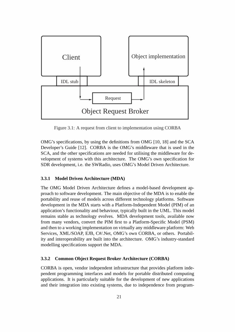
Figure 3.1: A request from client to implementation using CORBA
OMG’s specifications, by using the definitions from OMG [10, 18] and the SCADeveloper’s Guide [12]. CORBA is the OMG’s middleware that is used in theSCA, and the other specifications are needed for utilising the middleware for de-velopment of systems with this architecture. The OMG’s own specification forSDR development, i.e. the SWRadio, uses OMG’s Model Driven Architecture.
3.3.1 Model Driven Architecture (MDA)
The OMG Model Driven Architecture defines a model-based development ap-proach to software development. The main objective of the MDA is to enable theportability and reuse of models across different technology platforms. Softwaredevelopment in the MDA starts with a Platform-Independent Model (PIM) of anapplication’s functionality and behaviour, typically built in the UML. This modelremains stable as technology evolves. MDA development tools, available nowfrom many vendors, convert the PIM first to a Platform-Specific Model (PSM)and then to a working implementation on virtually any middleware platform: WebServices, XML/SOAP, EJB, C#/.Net, OMG’s own CORBA, or others. Portabil-ity and interoperability are built into the architecture. OMG’s industry-standardmodelling specifications support the MDA.
3.3.2 Common Object Request Broker Architecture (CORBA)
CORBA is open, vendor independent infrastructure that provides platform inde-pendent programming interfaces and models for portable distributed computingapplications. It is particularly suitable for the development of new applicationsand their integration into existing systems, due to independence from program-
21

Object implementationClient
IDL stub IDL skeleton
Object Request Broker 1
Object implementationClient
IDL stub IDL skeleton
Object Request Broker 2
IIOP
protocol
Figure 3.2: Interoperability of CORBA ORBs
ming languages, computing platforms and networking protocols.A CORBA object is a virtual entity that is capable of being located by an ob-
ject request broker (ORB) and having client requests invoked on it. It is virtual inthe sense that it does not really exist unless it is made concrete by an implemen-tation written in a programming language. A target object, within the context of aCORBA request invocation, is the CORBA object that is the target of that request.A client is an entity that invokes a request on a CORBA object. A server is anapplication in which one or more CORBA objects exist.
A request is an invocation of an operation on a CORBA object by a client, asshown in Figure 3.1. An object reference, also known as an IOR (InteroperableObject Reference) is a handle used to identify, locate, and address a CORBAobject. A servant is a programming language entity that realises (i.e., implements)one or more CORBA objects. Servants are said to be incarnate CORBA objectsbecause they provide bodies, or implementations, for those objects. Servants existwithin the context of a server application. In C++, servants are object instances ofa particular class.
In order to invoke the remote object instance, the client first obtains its objectreference. When the ORB examines the object reference and discovers that thetarget object is remote, it routes the invocation out over the network to the remoteobject’s ORB, as shown in Figure 3.2. OMG has standardised this process at twokey levels: First, the client knows the type of object it’s invoking and the clientstub and object skeleton are generated from the same IDL. Second, the client’sORB and object’s ORB must agree on a common protocol. OMG has defined thisalso - it’s the standard protocol IIOP.
3.3.3 Interface Definition Language (IDL)
The OMG IDL is CORBA’s fundamental abstraction mechanism for separatingobject interfaces from their implementations. OMG IDL establishes a contractbetween client and server that describes the types and object interfaces used byan application. This description is independent of the implementation language,so it does not matter whether the client is written in the same language as theserver. IDL definitions are compiled for a particular implementation language byan IDL compiler. The compiler translates the language-independent definitions
22

into language-specific type definitions and APIs (Application Program Interfaces).These type definitions and APIs are used by the developer to provide applicationfunctionality and to interact with the ORB.
The translation algorithms for various implementation languages are specifiedby CORBA and are known as language mappings. CORBA defines a numberof language mappings including those for C++, Ada, and Java (along with manyothers). An IDL compiler produces source files that must be combined with appli-cation code to produce client and server executables. Details, such as the namesand numbers of generated source files, vary from ORB to ORB. However, theconcepts are the same for all ORBs and implementation languages. The outcomeof the development process is a client executable and a server executable.
3.3.4 Unified Modeling Language (UML)
UML is a standard modelling language for writing software blueprints. By usingUML, system builders can create models that capture their visions in a standard,easily understandable way and communicate them to others. It may be used tovisualise, specify, construct and document software systems. The UML is morethan just a graphical language. Rather, behind every part of its graphical notationthere is a specification that provides a textual statement of the syntax and seman-tics of that building block. For example, behind a class icon is a specification thatprovides the full set of attributes, operations (including their full signatures), andbehaviours that the class embodies; visually, that class icon might only show asmall part of this specification.
UML diagrams are used in numerous ways within the SCA, however, the fo-cus is on two of them: to specify models from which an executable system isconstructed (forward engineering) and to reconstruct models from parts of an ex-ecutable system (reverse engineering).
3.3.5 Extensible Markup Language (XML)
XML is a markup language designed specifically for delivering information overthe World Wide Web. XML’s definition consists of only a bare-bones syntax. Bycreating an XML document, rather than using a limited set of predefined elements,new elements can be created and any names can be assigned to them, hence theterm extensible. Therefore, XML can be used to describe virtually any type ofdocument, from a musical score to a reconfigurable digital radio.
XML is used within the SCA to define a profile for the domain in which wave-form applications can be managed. For SCA, the extensibility of XML is limitedto the SCA-defined Document Type Definitions (DTDs). A DTD provides a list ofthe elements, attributes, notations, and entities contained in a document, as well astheir relationship to one another. DTDs specify a set of rules for the structure of adocument. The DTD defines exactly what is allowed to appear inside a document.
23
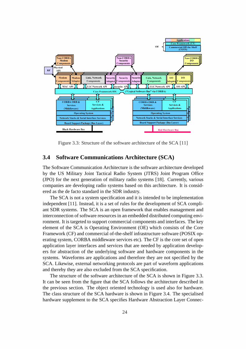
Figure 3.3: Structure of the software architecture of the SCA [11]
3.4 Software Communications Architecture (SCA)
The Software Communication Architecture is the software architecture developedby the US Military Joint Tactical Radio System (JTRS) Joint Program Office(JPO) for the next generation of military radio systems [18]. Currently, variouscompanies are developing radio systems based on this architecture. It is consid-ered as the de facto standard in the SDR industry.
The SCA is not a system specification and it is intended to be implementationindependent [11]. Instead, it is a set of rules for the development of SCA compli-ant SDR systems. The SCA is an open framework that enables management andinterconnection of software resources in an embedded distributed computing envi-ronment. It is targeted to support commercial components and interfaces. The keyelement of the SCA is Operating Environment (OE) which consists of the CoreFramework (CF) and commercial of-the-shelf infrastructure software (POSIX op-erating system, CORBA middleware services etc). The CF is the core set of openapplication layer interfaces and services that are needed by application develop-ers for abstraction of the underlying software and hardware components in thesystems. Waveforms are applications and therefore they are not specified by theSCA. Likewise, external networking protocols are part of waveform applicationsand thereby they are also excluded from the SCA specification.
The structure of the software architecture of the SCA is shown in Figure 3.3.It can be seen from the figure that the SCA follows the architecture described inthe previous section. The object oriented technology is used also for hardware.The class structure of the SCA hardware is shown in Figure 3.4. The specialisedhardware supplement to the SCA specifies Hardware Abstraction Layer Connec-
24
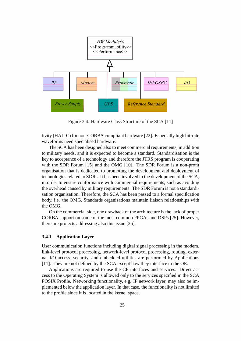
Figure 3.4: Hardware Class Structure of the SCA [11]
tivity (HAL-C) for non-CORBA compliant hardware [22]. Especially high bit-ratewaveforms need specialised hardware.
The SCA has been designed also to meet commercial requirements, in additionto military needs, and it is expected to become a standard. Standardisation is thekey to acceptance of a technology and therefore the JTRS program is cooperatingwith the SDR Forum [15] and the OMG [10]. The SDR Forum is a non-profitorganisation that is dedicated to promoting the development and deployment oftechnologies related to SDRs. It has been involved in the development of the SCA,in order to ensure conformance with commercial requirements, such as avoidingthe overhead caused by military requirements. The SDR Forum is not a standardi-sation organisation. Therefore, the SCA has been passed to a formal specificationbody, i.e. the OMG. Standards organisations maintain liaison relationships withthe OMG.
On the commercial side, one drawback of the architecture is the lack of properCORBA support on some of the most common FPGAs and DSPs [25]. However,there are projects addressing also this issue [26].
3.4.1 Application Layer
User communication functions including digital signal processing in the modem,link-level protocol processing, network-level protocol processing, routing, exter-nal I/O access, security, and embedded utilities are performed by Applications[11]. They are not defined by the SCA except how they interface to the OE.
Applications are required to use the CF interfaces and services. Direct ac-cess to the Operating System is allowed only to the services specified in the SCAPOSIX Profile. Networking functionality, e.g. IP network layer, may also be im-plemented below the application layer. In that case, the functionality is not limitedto the profile since it is located in the kernel space.
25

Applications consist of Resources and use Devices. Devices are types of Re-sources that are used as software proxies for actual hardware devices. ModemDe-vice, LinkResource, SecurityDevice, I/ODevice and NetworkResource are inter-face extensions of the CF. They implement APIs for waveform and networkingapplications. They conform to the functional entities of the SCA Software Refer-ence Model that is based on the PMCS model.
3.4.2 Waveform Development
The API Supplement [22] contains requirements for the development of APIs .Waveform APIs are located at such interfaces that provide the widest portability.A common API for all waveforms would be too complicated and large for domainswith limited resources. Thus, there have been defined building blocks for buildingthe specific APIs [23].
Implementing a SCA-compliant waveform follows defined steps. The SCADeveloper’s Guide outlines the process as a checklist [12]:
1. Identify functionality to be provided by the waveform software
2. Determine which API Service Groups are needed
3. Determine what services are needed beyond the API Service Groups
4. Build UML model of interface
5. Generate IDL from UML model of interface
6. Translate IDL into language-appropriate implementation files
7. Compile code generated in step 6
8. Reverse engineer UML model from language-specific implementation files(optional)
9. Build UML model of waveform software
10. Generate language-appropriate template files for servant and user software
11. Write servant and user software
12. Write XML for each component
13. Build User Interface (optional)
14. Integrate software and hardware
15. Test resultant application
26

3.4.3 SCA Reference Implementation (SCARI)
Interpretations of specifications can easily limit interoperability between imple-mentations. Therefore, it was useful to develop a reference implementation of theSCA specifications for clarifying the technical aspects. The reference implemen-tation aims to reduce the level of ambiguity of the SCA specification, to increasethe potential for interoperability, to support understanding of the architecture andto stimulate the emergence of SDRs by reducing the cost and development time[14].
The Military Satellite Communications Research (RMSC) group [14] of theCommunications Research Centre (CRC) was contracted by the SDR Forum todeveloped an open source reference implementation of the SCA. Thus, RMSCproduced an open implementation of the SCA version 2.1. The available opensource implementation is written in Java.
The mandatory components of the SCA core framework are provided by thereference implementation, as well as the most used other features, e.g. CoreFramework with the XML Domain Profile, tools that are needed to operate theradio and simple demonstration of waveform applications.
3.5 SWRadio
The SWRadio is a specification of radio infrastructure facilities. The SWRadiopromotes portability of waveforms across SDRs [18]. The SCA has been used asa basis for OMG’s work on the SWRadio. The SWRadio specification uses theOMG’s Model Driven Architecture.
The specification supports an approach where the SWRadio platform providesa standardised extensible set of software services that abstracts hardware and sup-ports applications, such as waveforms and management applications. In the spec-ification, there is defined a set of platform-independent interfaces. Applicationscan be developed and ported onto various implementations. This approach pro-vides a possibility for an open market where waveforms can be produced inde-pendently of platforms and their providers.
There is a physical partitioning of the SWRadio specification into three mainchapters: UML profile for SWRadio, and PIM and PSM for the CORBA IDL.A language for modelling SWRadio elements is defined in the UML profile forSWRadio by extending the UML language with radio domain specific definitions.A behavioral model of an SWRadio system, standardised APIs and example com-ponent definitions that realise the interfaces are provided by the PIM. The PIMspecification is independent from the underlying middleware technology. Formodelling a software radio system defined in the PIM, UML and its extensionsprovided by the UML profile for SWRadio are used. The SWRadio specificationalso provides a mechanism for transforming the elements of the PIM model intothe platform specific model for the CORBA IDL.
27

Figure 3.5: SWRadio Layers [18]
3.5.1 SWRadio Platform
The SWRadio Platform consists of several layers, as shown in Figure 3.5. Thelayers are [18]:
• Hardware layer that is a set of heterogeneous hardware resources includingboth general purpose devices and specialised devices
• Operating Environment layer that provides operating system and middle-ware services
• Facilities layer that provides sets of services to the application developer
• Application layer that represents the stand-alone capabilities of the radioset.
There are three types of applications supported by the SWRadio Platform: Wave-form applications that are the main focus, management applications and otherapplications, such as network and end user applications.
3.5.2 SWRadio Architecture
In the SWRadio Architecture, there are two main concepts: services and wave-form layering. Services depend on the provided interfaces. A component can offerone or more services trough realisation relationships in the platform independentmodel. SWRadio vendors may provide services that are required for their platformor they can acquire services from third party vendors. For waveform functionalitygrouping, the specification follows the Open System Interconnection (OSI) model
28

(ISO IS 7498) of the International Standard Organization, which defines that thecommunications functions should be structured into a stack of seven layers.
The use of reconfigurable components through standard interfaces and welldefined modules is encouraged by the approach. The specification uses extendedOSI model which allows Management and QoS interfaces to communicate withany layer. The focus the SWRadio architecture is only on physical and link layers.
3.6 Summary
In general, multiple aspects, such as compatibility, reliability, portability and easeof development, call for standardisation. In the context of radio systems, the mul-titude of air interface standards has resulted in need for interoperable, reconfig-urable systems. Different applications and systems need different air interfacemodes and therefore reconfigurability is the only feasible solution to support agreat number of standards with a single radio set. There are also other emerg-ing motives for reconfigurability, e.g. context aware services. For the hardwarerequired by these reconfigurable radio systems, there are standards, which werediscussed in this chapter.
A detailed architecture defined for the processing platform of SDRs wouldlead to portability problems. Therefore, the focus has been on defining a com-mon middleware that provides abstraction of the software and hardware platformsand thus endorses portability and modularity. The SCA and the SWRadio areopen SDR framework architectures that make extensive use of object orientedtechniques, i.e. the middleware. They are the key elements leading to SDR stan-dardisation.
The next chapter focuses on the research projects related to the SDRs. Earlyprojects have proven the viability of the SDR concept and there are projects inprogress, which aim to bring the SDR concept into mainstream radio architecturesby using the industry standard components discussed in this chapter.
29

4 Software Defined Radio Projects
This chapter reviews the historical perspective of the evolution of the SDR archi-tectures and the current state of the art SDRs by presenting a few of the most in-fluential SDR projects. Section 4.1 presents the SPEAKeasy program that provedthe potential of the SDR concept for military radios. Section 4.2 discusses theongoing JTRS program, which will replace the hardware intensive military radioswith the more flexible, interoperable SDRs [22]. The program is also developingan open architecture framework for SDRs, i.e. the SCA. Section 4.3 presents afew other projects that are either associated to research on SDR related topics orto the development of SDR sets. Section 4.4 summarises the chapter.
4.1 SPEAKeasy
The SPEAKeasy was a US Department of Defence program whose aim was, incooperation with industry, to prove the concept of multi-band, multi-mode soft-ware programmable radio operating from 2 MHz to 2 GHz [20]. It was intendedto be able to operate with multiple military radios by employing waveforms thatcan be selected from memory, or downloaded from external storage or over-the-air (OTA) [19]. The SPEAKeasy was designed as a totally open architecture thatcan provide secure connections, interoperability and programmability. The bene-fits of the architecture include seamless connection of various radios and bridgingbetween different systems. Military applications include tactical radio systemsas well as voice and data communications to aircraft and onto battlefield. Civil-ian applications also exist: emergency communications, law enforcement radiocommunications and public safety.
The SPEAKeasy program evolved from the earlier technologies of the AirForce, i.e. Tactical Anti Jam Programmable Signal Processor (TAJPSP) initi-ated in 1989 and the Integrated Communications, Navigation, Identification andAvionics (ICNIA) system, which was one of the first systems to use a digital pro-grammable modem, from the late 1970’s [20].
4.1.1 SPEAKeasy Phase I
The main goal of the SPEAKeasy Phase I (1992-1995) was to develop a recon-figurable modem with an open architecture and demonstrate its feasibility. Theobjectives were to prove the potential of the SDR to solve interoperability is-sues and problems related to product lifecycle shortening, due to rapidly evolvingtechnologies [2, 20]. To achieve this, the addition of new technology had to besimplified. Related to this, an objective was to form a software architecture thatwould support the addition of new waveforms.
The wide bandwidth was divided into three sub-bands with independent RFchannel components feeding the same ADCs, which was an important concept inthe sense that it became a standard procedure used in many SDR projects. Only the
30

Figure 4.1: SPEAKeasy Phase I Architecture [21]
midband, 30 MHz to 400 MHz , was implemented in the feasibility demonstration[20].
The Phase 1 design included RF up- and down-converters with wide band-width, high speed-speed, high dynamic range ADCs, four 40 MHz Texas In-struments C40 digital signal processors and a 40 Mhz RISC information security(INFOSEC) module called CYPRIS [20]. The INFOSEC module included bothcommunication security (COMSEC) and transmission security (TRANSEC). Theterm COMSEC denotes the functionality for encryption of message data, whereasthe term TRANSEC denotes the support for modulation functionality designed toprotect transmissions from interception, e.g. by frequency hopping. CYPRIS wasprogrammable and the cryptographic algorithms were implemented in software(however, in [2], it is mentioned that CYPRIS was not actually used until Phase2).
The hardware was built into a VME chassis. The VME bus was used for con-trol and there was a specialised high-speed bus for data. A Sun SPARC worksta-tion was used as a part of the user interface. The SPEAKeasy Phase I architectureis shown in Figure 4.1.
The wide frequency range was divided into three sub-bands with differentanalog radio parts. Wideband waveforms would have needed more processingpower than the Phase 1 equipment had, i.e. FFT (e.g. on ASICs) would havebeen needed [20]. The generic narrowband waveform support of the SPEAKeasyPhase I included the following modulation methods: support of non-hopped andhopped amplitude modulation from 50 Hz to 20 kHz (DSB, USB-SC, LSB-SC),non-hopped amplitude modulation (ASK, CW), frequency modulation (FM, FSKwith 2-8 tones), phase modulation (MPSK, hopped and non-hopped DPSK andQDPSK, OQPSK), and 4, 16, 64 and 256 QAM. Data rates are supported up to20 kbps. For digital modulations, the supported error detection and correction
31

methods are (16, 7) and (31, 15) Reed-Solomon and convolutional codes of K=7,R=1/2 and T=133 or 171 [19].
The Phase 1 system was first demonstrated in August 1994 to operate withHAVE QUICK, HF modem, automatic link establishment and SINCARS [19].Simultaneous frequency hopping transmission on HAVE QUICK and SINCARSas well as bridging networks that use these waveforms were also demonstrated.Programmability was also shown by modifying a waveform on two units. AtJWID-95 interoperability demonstration the system was demonstrated on-the-air[20]. The Phase-1 modem and software performed well but lack of ease of useremained a disadvantage.
4.1.2 SPEAKeasy Phase II
The most important objective of the SPEAKeasy Phase II was to extend the opera-tional scope from the modem to an open, modular and reconfigurable architecturefor the whole radio. To make the architecture cost-effective, commercial standardsand commercial of-the-shelf components were chosen. The capabilities were sup-posed to include reprogrammable security, wideband modem and continuous RFcoverage up to 2 GHz [20].
Motorola, the main contractor of the Phase 2, designed a wideband RF trans-ceiver, which reduced distortion caused by the IF processing by using the homo-dyne design [20]. The signal processing hardware consisted of C40 DSPs sup-ported by FPGAs. A commercial palmtop computer with Windows 95 was usedas the user interface. The SPEAKeasy Phase II architecture is shown in Figure4.2.
One of the challenges of the Phase 2 was to increase the number of simul-taneous conversations, which required quicker reconfiguration of the INFOSECmodule in order to allow fast context switching [20]. The initially used CYPRISINFOSEC module had to use context switching between data encryption and gen-eration of hop sequences for transmission security. However, advanced wave-forms cannot tolerate the long switching delays. The Advanced INFOSEC Mod-ule (AIM), which was designed in order to overcome the problem, consisted ofthree 100 MHz, 32-bit RISC processors [20]. As shown in Figure 4.2, resourcesare attached to either the red (unencrypted) or the black (encrypted) PCI bus,which is a typical requirement for military radios. The buses are separate and thecrypto processors (CP) of the INFOSEC services provide the inter-bus communi-cation. The CP is required for each active channel, while the key processor (KP)of the INFOSEC module is needed only when the channel is set up [20].
The RF subsystem of the Phase 2 architecture could transmit and receive mul-tiple channels simultaneously and in the modem subsystem, the parameters couldbe changed and the channels could be reallocated without interrupting the opera-tion of concurrently established channels [20].
The software architecture defined modules, which include RF Control, Mo-dem Control, Waveform Processing etc. This was a significant distinction from
32
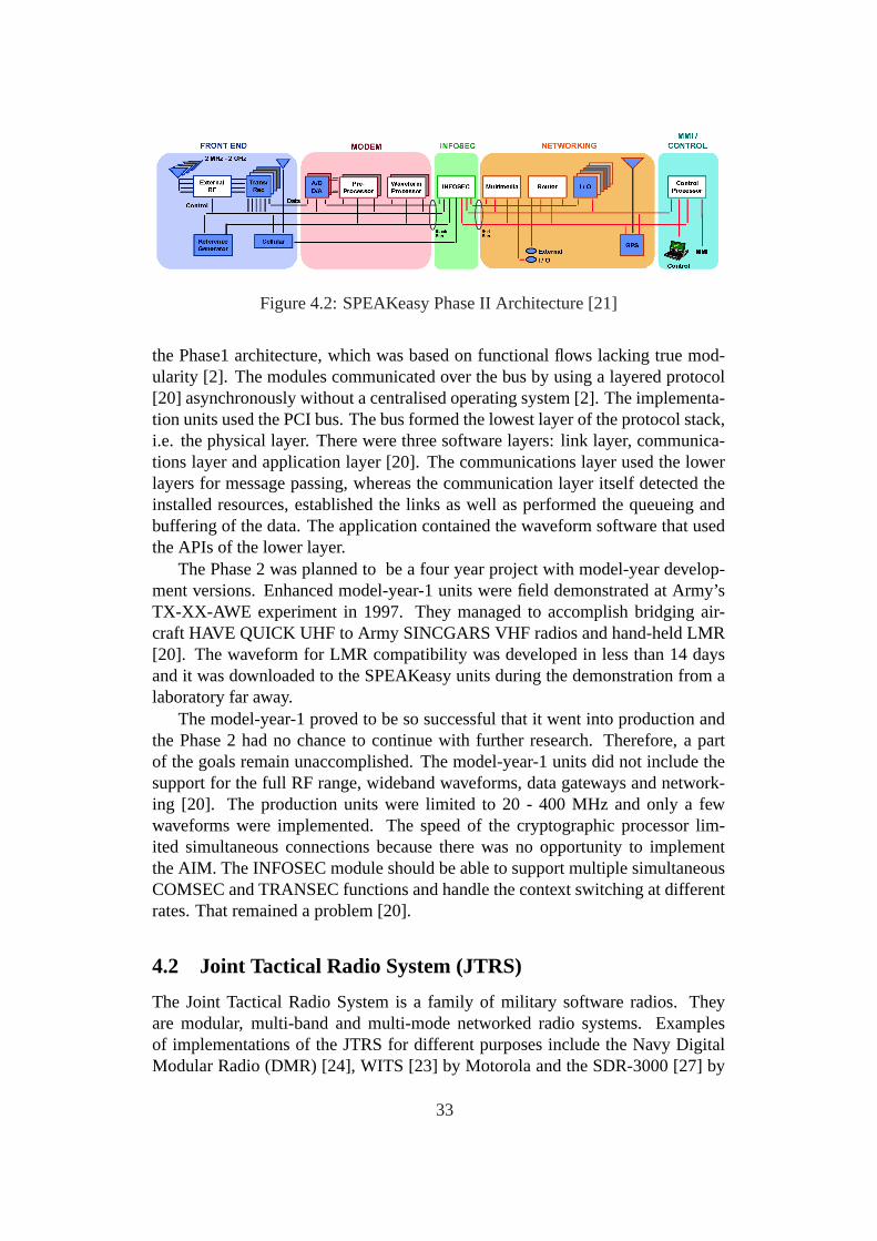
Figure 4.2: SPEAKeasy Phase II Architecture [21]
the Phase1 architecture, which was based on functional flows lacking true mod-ularity [2]. The modules communicated over the bus by using a layered protocol[20] asynchronously without a centralised operating system [2]. The implementa-tion units used the PCI bus. The bus formed the lowest layer of the protocol stack,i.e. the physical layer. There were three software layers: link layer, communica-tions layer and application layer [20]. The communications layer used the lowerlayers for message passing, whereas the communication layer itself detected theinstalled resources, established the links as well as performed the queueing andbuffering of the data. The application contained the waveform software that usedthe APIs of the lower layer.
The Phase 2 was planned to be a four year project with model-year develop-ment versions. Enhanced model-year-1 units were field demonstrated at Army’sTX-XX-AWE experiment in 1997. They managed to accomplish bridging air-craft HAVE QUICK UHF to Army SINCGARS VHF radios and hand-held LMR[20]. The waveform for LMR compatibility was developed in less than 14 daysand it was downloaded to the SPEAKeasy units during the demonstration from alaboratory far away.
The model-year-1 proved to be so successful that it went into production andthe Phase 2 had no chance to continue with further research. Therefore, a partof the goals remain unaccomplished. The model-year-1 units did not include thesupport for the full RF range, wideband waveforms, data gateways and network-ing [20]. The production units were limited to 20 - 400 MHz and only a fewwaveforms were implemented. The speed of the cryptographic processor lim-ited simultaneous connections because there was no opportunity to implementthe AIM. The INFOSEC module should be able to support multiple simultaneousCOMSEC and TRANSEC functions and handle the context switching at differentrates. That remained a problem [20].
4.2 Joint Tactical Radio System (JTRS)
The Joint Tactical Radio System is a family of military software radios. Theyare modular, multi-band and multi-mode networked radio systems. Examplesof implementations of the JTRS for different purposes include the Navy DigitalModular Radio (DMR) [24], WITS [23] by Motorola and the SDR-3000 [27] by
33

Spectrum Signal Processing Inc. and the NRL Software Radio [28], which is anoutgrowth of the JCIT. There is a group of specified domains, e.g. the hand-helddomain and fixed maritime domain, that have different needs. However, the JTRSarchitecture ensures interoperability across radios designed for different domains.
The JTRS program is a process consisting of three steps that aim to define,standardise and implement an architecture for software defined radios. The resultof step 1 was the definition of the base architecture. Step 2 refined the baselinearchitecture to the SCA, which will be the basis for future military radios [2]. TheSCA has also been used as a starting point for standardisation process of commer-cial SDRs, as described in the previous chapter. The next subsection describes thefirst two phases, whereas the last two subsections discuss two already deployedproduct families.
4.2.1 Background
The Programmable Modular Communications System (PMCS) team suggestedthat the US Department of Defence should replace old discrete radio systems witha single SDR family [25]. The PMCS research program was a successor of theSPEAKeasy program. By using the knowledge and technology gained from theSPEAKeasy as a basis, the PMCS program developed a reference model [2]. TheJTRS Joint Program Office (JTRS JPO) is a successor of the PMCS [25]. Thereference model of the PMCS was also adopted by the SDR Forum.
Three consortiums lead by Raytheon, Boeing and Motorola were contractedto make initial proposals [2]. The Modular Software Defined Radio Consortium(MRSC), composed of Raytheon, BAE Systems, ITT Industries and Rockwell-Collins, was contracted in 1999 to develop the JTRS SCA [23]. The MRSC con-tract integrated validation and development processes of the architecture. Sevenother contracts were awarded to other companies, in order to have a third partyvalidation and thus, to reduce risk. Each of the MRSC members provided a pro-totype for validation. For instance, the Raytheon prototype was a 4 channel radiocontaining a 2 MHz - 2 GHz RF front end and an implementation of the SCA CF.A set of waveforms was provided, e.g. VHF-AM, VHF-FM, VHF-ATC, HQ I/II,UHF DAMA/DASA and HF-ALE ported from the Rockwell prototype.
The contract of Assurance Technology Corporation consisted of developing aSINCGARS/ESIP waveform and a test suite. The Boieng contract included devel-oping an open-source implementation of OE and CF requirements, validation of aSCA 2.0 compliant CF on a testbed, and integration studies. Harris was contractedto build a manpack domain radio and to develop a compliant CF. Motorola evalu-ated the SCA on their existing WITS and DMR product lines. Rockwell-Collinsvalidated critical timing issues of the Link-16 waveform. Thales was contracted toevaluate impact of the SCA on military hand-held radios and to build a compliantprototype. The Vanu Inc. was contracted to evaluate the technology and variantsof the SCA for handhelds.
34
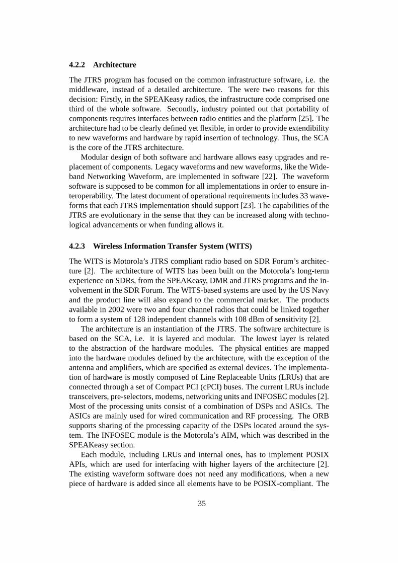
4.2.2 Architecture
The JTRS program has focused on the common infrastructure software, i.e. themiddleware, instead of a detailed architecture. The were two reasons for thisdecision: Firstly, in the SPEAKeasy radios, the infrastructure code comprised onethird of the whole software. Secondly, industry pointed out that portability ofcomponents requires interfaces between radio entities and the platform [25]. Thearchitecture had to be clearly defined yet flexible, in order to provide extendibilityto new waveforms and hardware by rapid insertion of technology. Thus, the SCAis the core of the JTRS architecture.
Modular design of both software and hardware allows easy upgrades and re-placement of components. Legacy waveforms and new waveforms, like the Wide-band Networking Waveform, are implemented in software [22]. The waveformsoftware is supposed to be common for all implementations in order to ensure in-teroperability. The latest document of operational requirements includes 33 wave-forms that each JTRS implementation should support [23]. The capabilities of theJTRS are evolutionary in the sense that they can be increased along with techno-logical advancements or when funding allows it.
4.2.3 Wireless Information Transfer System (WITS)
The WITS is Motorola’s JTRS compliant radio based on SDR Forum’s architec-ture [2]. The architecture of WITS has been built on the Motorola’s long-termexperience on SDRs, from the SPEAKeasy, DMR and JTRS programs and the in-volvement in the SDR Forum. The WITS-based systems are used by the US Navyand the product line will also expand to the commercial market. The productsavailable in 2002 were two and four channel radios that could be linked togetherto form a system of 128 independent channels with 108 dBm of sensitivity [2].
The architecture is an instantiation of the JTRS. The software architecture isbased on the SCA, i.e. it is layered and modular. The lowest layer is relatedto the abstraction of the hardware modules. The physical entities are mappedinto the hardware modules defined by the architecture, with the exception of theantenna and amplifiers, which are specified as external devices. The implementa-tion of hardware is mostly composed of Line Replaceable Units (LRUs) that areconnected through a set of Compact PCI (cPCI) buses. The current LRUs includetransceivers, pre-selectors, modems, networking units and INFOSEC modules [2].Most of the processing units consist of a combination of DSPs and ASICs. TheASICs are mainly used for wired communication and RF processing. The ORBsupports sharing of the processing capacity of the DSPs located around the sys-tem. The INFOSEC module is the Motorola’s AIM, which was described in theSPEAKeasy section.
Each module, including LRUs and internal ones, has to implement POSIXAPIs, which are used for interfacing with higher layers of the architecture [2].The existing waveform software does not need any modifications, when a newpiece of hardware is added since all elements have to be POSIX-compliant. The
35

available RF units, which use direct down-conversion, do not support high datarates, but for the present military applications, the WITS is very suitable and thecapabilities can be expanded [2].
4.2.4 SDR-3000
The SDR-3000 software defined radio transceiver platform is a product familydesigned for implementing dynamically reconfigurable, high-performance, cPCI-based SDRs [27]. Hundreds of simultaneous transmit and receive channels withindependent air interfaces are supported. An optional SCA CF is available, but theplatform is not exclusively a JTRS implementation. US DoD chose SDR-3000development platform, including Version 2.2 of SCA CF developed by HarrisCorporation, as a commercially available JTRS representative hardware set forwaveform development [27].
In addition to the waveforms required for JTRS, the SDR-3000 platform isable to support various mobile cellular air interface standards, including multiple2nd generation systems and WCDMA [2]. The SDR-3000 consists of a selectionof modules, such as the PRO-3100 software defined I/O (SDIO) module, the PRO-3500 baseband engine and the TM1-3300 transition module. The SDIO processormodule contains four Xilinx Virtex II FPGAs. The baseband processing moduleincludes two PowerPC G4 processor for modem and coding as well as expansionslots for additional processing capacity. Differential signalling in the I/O bus at2.4GB/s is used for achieving the peak rate of the transition module, which is theA/D and D/A interface within a suitable range for most standard IF frequencies.It is designed to be capable of achieving a very high SNR performance [27].
4.3 Other SDR Projects
The JCIT is another military SDR, whereas the CHARIOT and SpectrumWarewere academic projects, although funded by DARPA. European projects as wellas the GNU Radio are also discussed in the following subsections.
4.3.1 Joint Combat Information Terminal (JCIT)
The JCIT is a multi-band multi-mode SDR developed by the US Navy ResearchLaboratory (NRL) [4]. The JCIT was designed as deployable product for Armyavionics, operating in frequency bands from HF up to 2.5 GHz. The focus of thedesign was on the hardware capacity, i.e. the extensive use of FPGA and DSPs.The radio sets include a huge number of processing elements. A wide varietyof modulation formats and standards are supported [4, 36]. The JCIT programhas also made a significant contribution to the SDR Forum’s architecture, i.e. thedomain manager, which loads waveform objects onto the resources of the system[4].
36

4.3.2 CHARIOT
The CHARIOT (Changeable Advanced Radio for Inter-Operable Telecommuni-cations) was designed at Virginia Tech during the DARPA GloMo programs [2].The Virginia Tech’s contribution to the program involved several wireless tech-nologies. The CHARIOT is most closely related to the mobile and hand-helddomain. This domain is specially challenging from the point of view the digitalsignal processing capacity, when high data rates are needed. The CHARIOT’s ap-proach to this issue consists of a formalised structure for implementing an SDR,using reconfigurable hardware [2]. This was challenging since the reconfigurationtime of FPGAs is prohibitevily long [2] and implementation using only DSP pro-cessors would be large and expensive [29]. Additionally, the power consumptionis an important factor in this domain. There are three new ideas used in the CHAR-IOT in order to solve the problems: configurable computing machines, hardwarepaging and stream-based processing. These techniques enabled small hand-helddevices to maintain the reconfigurability while providing enough processing ca-pacity for high data rates.
The focus was on the formalised architecture that allowed the use of dynam-ically reconfigurable hardware in SDRs [2]. The architecture was designed to bescalable and flexible by using a layered model. The Layered Radio Architecturefor interfacing comprises three layers: the Soft Radio Interface (SRI), the Con-figuration Layer and the Processing Layer. The SRI Layer handles the externalinterfaces as well as control of the Configuration Layer. It also decides whichwaveform should be used. The Communications Layer handles the setup of dataand algorithm programming flows, and provides status information to the upperlayer. This layer also sends command messages, which form together the algo-rithm that is performed, to the Processing layer. The Processing layer performsthe actual computations based on the received commands.
The stream-based processing is used for communication between the layersand in the Processing Layer. Data and programming information streams con-sist of packets delivered through the same paths and interfaces. This architecturelends itself to pipelining [2]. Algorithms are divided into modules, which shouldbe designed in a such way that they can perform their operation independently.By using the stream-based processing approach, new processing modules can beeasily added, i.e. system is scalable. This approach also simplifies interface de-sign.
The stream concept can used at multiple levels: a super stream handles thelayers as modules. Control packets change the operation of modules. In orderto improve the processing capacity per physical area, the CCMs were selected tobe used in the modules for the Processing Layer [2]. A CCM is a customisedFPGA that uses a higher level of abstraction, i.e. higher granularity. They useconventional DSP blocks that may be linked and controlled in order to implementalgorithms. The CCM developed by Virginia Tech is called STALLION. TheSTALLION consists of independent reconfigurable functional units. In the run-
37

time reconfiguration concept, the leading packet of a stream is used to reconfigurethe unit at the head of the stream. This leads to fast distributed reconfigurationsince the streams control the flow independently [2].
4.3.3 SpectrumWare
The SpectrumWare project at MIT utilised the constantly advancing performanceof general purpose processors. An advantage of this processing platform is thatthe radio subsystem and the applications use the same hardware and operatingsystem, which simplifies programming [2]. The development environment, i.e.a UNIX OS, is widely known and mature. The core of the system consists ofthe radio algorithms implemented on a workstation. The I/O between an externalwideband tuner and the workstation was a problem that had to solved.
In typical non-real-time operating system, user-space applications cannot per-form even near real-time processing using I/O devices. There are many factorsthat make the data transfer delays unpredictable. The SpectrumWare system usesa modified UNIX OS and DMA-transfers pass data to buffers in kernel-space [2].The buffers are mapped to user-space by using a virtual memory approach. Thevariable delays and low capacity of the standard PCI bus resulted in need to designa dedicated I/O solution, i.e. the General Purpose PCI I/O (GuPPI). The GuPPIbuffers data between a daughtercard and the workstation, thus relaxing the timingissues. The transfers are performed using blocks of data.
The Signal Processing Environment for Continuous Real-Time Applications(SPECtRA) was implemented to allow rapid development of reusable real-timeradio software [2]. The SPECtRA consists of a library of signal processing mod-ules, a set of interface modules and a scripting language for defining SDRs. Itsupports several adaptation methods based on environment and user needs. Oneof the innovations was to pull data in the processing flow instead of pushing. Thismakes multi-rate processing easier and decreases redundant processing.
An experimental system, which implemented a GSM base-station, was built.In 1998, the project team left to start Vanu Inc. [3]. Vanu has build varioussoftware implementations of waveforms, e.g. cellular standards. The signal pro-cessing software is mostly written in a high level language.
SDRs were recently recognised by the FCC as a new category of radios. TheVanu Software Radio GSM Base Station by Vanu Inc. was the first SDR deviceto fulfil the FCC’s certification process [30]. This is a positive sign for the futureof the SDR concept since regulatory issues have been seen as one of the keychallenges [4].
4.3.4 European Perspective: ACTS and IST Projects
In the context of the ACTS (Advanced Communications Technologies and Ser-vices) programme, the European Union has funded several R&D projects relatedto SDR [33, 32]. Figure 4.3 from [33] shows the coverage and focus of the
38

Figure 4.3: ACTS Projects [33]
projects. There are areas where the coverage has been minimal within the ACTSprogramme, i.e. the network and spectrum issues and business models.
Currently the work continues in the scope of the IST (Information SocietyTechnologies) programme within the EU’s Sixth Framework Programme (2002-2006). The TRUST project adopted a user-centric perspective by examining theuser requirements in order to identify what is needed to support reconfigurableradios. The SCOUT project is continuing the research initiated in TRUST onreconfigurable terminal and network architectures. The research areas of SCOUTinclude a number of technical, regulatory and business issues [35].
4.3.5 GNU Radio
GNU Radio is a software project that, combined with a minimal hardware, canbe used for building radios whose waveform processing is defined in software[37]. The purpose of GNU Radio is to do signal processing needed by differentradios in free software, in order to give software developers an easy access toelectromagnetic spectrum so that they can get an understanding of it and developnew ways to utilise it. Compared to ordinary hardware radios, GNU Radio offersreconfigurability just like any other SDR project. Currently only a couple of typesof radio have been implemented but if one has adequate understanding of a radiosystem, GNU Radio can be programmed to support it.
GNU Radio consists of Gnu Radio Software and Gnu Radio Hardware. Thehardware required for building a receiver is composed of an RF Front End andan Analog to Digital Converter. There are no kind of actual specifications of thehardware. Any suitable components can be used. For low bandwidths, the ADCcan be a PC sound card, and there is also project for a dedicated hardware, calledUniversal Software Radio Peripheral (USRP). The basic architecture of the USRPis shown in Figure 4.4. The FPGA is used for performing the most intensiveprocessing, i.e. it contains up and down converters, decimators and interpolators,in order to reduce the bit rate to a level suitable for the USB2 connection.
Gnu Radio Software is organised in a such way that a graph which describesthe data flow in the radio system is handed off to the runtime system for exe-cution. The vertices are signal processing blocks and the edges are the connec-
39
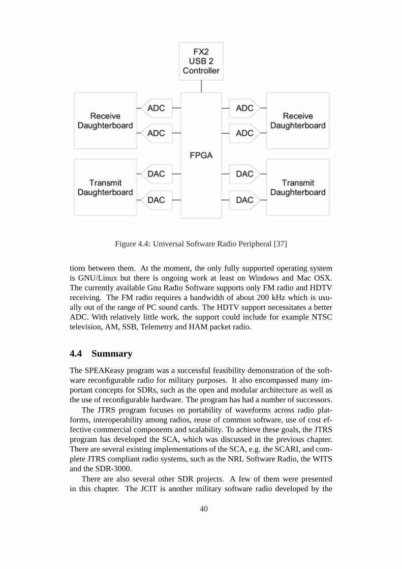
Figure 4.4: Universal Software Radio Peripheral [37]
tions between them. At the moment, the only fully supported operating systemis GNU/Linux but there is ongoing work at least on Windows and Mac OSX.The currently available Gnu Radio Software supports only FM radio and HDTVreceiving. The FM radio requires a bandwidth of about 200 kHz which is usu-ally out of the range of PC sound cards. The HDTV support necessitates a betterADC. With relatively little work, the support could include for example NTSCtelevision, AM, SSB, Telemetry and HAM packet radio.
4.4 Summary
The SPEAKeasy program was a successful feasibility demonstration of the soft-ware reconfigurable radio for military purposes. It also encompassed many im-portant concepts for SDRs, such as the open and modular architecture as well asthe use of reconfigurable hardware. The program has had a number of successors.
The JTRS program focuses on portability of waveforms across radio plat-forms, interoperability among radios, reuse of common software, use of cost ef-fective commercial components and scalability. To achieve these goals, the JTRSprogram has developed the SCA, which was discussed in the previous chapter.There are several existing implementations of the SCA, e.g. the SCARI, and com-plete JTRS compliant radio systems, such as the NRL Software Radio, the WITSand the SDR-3000.
There are also several other SDR projects. A few of them were presentedin this chapter. The JCIT is another military software radio developed by the
40
NRL. Two significant academic projects were presented: the CHARIOT is Vir-ginia Tech’s SDR and the SpectrumWare was developed in MIT until the projectevolved to founding of the Vanu Inc. and a commercial product line. In Europe,many SDR related projects have been conducted within ACTS and IST technol-ogy programmes. The open source community has also launched an SDR project,i.e. the GNU Radio.
Different radios for various application domains serve different purposes [2].There has to be done trade-offs that depend on the domain. For example, hand-held devices are limited by size and power consumption, whereas fixed station ra-dios may e.g. relax RF front end requirements by employing multiple RF modulesor use high power DSPs. Therefore, none of the architectures proves to be betterthan all the others. For instance, the WITS performs well in the main militarydomains, while the CHARIOT’s approach is suitable for the low-power hand-heldradios, which need high bit-rates. Nevertheless, at a high level, the architecturesare usually very similar to reference models, such as the PMCS model.
41
5 Conclusions
The software defined radio is a far reaching topic, since it is an all encompassingsolution, for which only imagination limits the capabilities that can be planned.Thus, in the scope of a short report, only a part of related items can be treated.A relatively traditional view was chosen, omitting potential future trends like theCognitive Radio.
Chapter 2 discussed the implementation issues mainly focusing on the physi-cal layer. The implementation of software defined radios is a wide and challengingissue. The starting point of the chapter was the general structure of digital com-munication systems. The requirements set by the need for multi-band, multi-modeoperation and reconfigurability have implications on implementations of variousparts of a software defined radio set, ranging from the selection of processinghardware to the RF front end.
There are a few critical points: considering the physical implementation, theanalog-to-digital conversion and the power consumption of many of the compo-nents are among the most important issues, which limit the choice of physicallayer architecture and eventually the achievable performance
Software defined radio has often been seen as a design problem, mostly relatedto the low-layer air interface implementation of a radio node, capable of operat-ing in multiple frequency bands and multiple modes. There are a lot of othersignificant tasks, such as the resource management and the handling of reconfig-uration, which suggest that the scope of the concept is wider. There was also ashort discussion of these topics in Chapter 2.
Chapter 3 introduced various standards related to software defined radios andthe current efforts related to the standardisation process of frameworks for efficientdevelopment process.
In general, multiple aspects, including compatibility, portability and rapid de-velopment cycles, lay demand for standardisation. Considering radio systems, thegreat number of air interface standards has resulted in the need for reconfigurablesystems capable of operating together with a wide variety of legacy systems. Dif-ferent services and communication environments need different modes, thus mak-ing the reconfigurability the only feasible solution for integrating a wide range ofapplications in a single radio set. There are also other emerging techniques thatneed reconfigurability, such as context aware services that dynamically optimisethe air interface.
The framework architectures include the SCA and the SWRadio. They incor-porate industry standard object oriented techniques into the processing environ-ment of software defined radios. A detailed architecture defined for the process-ing platform would lead to weak portability of software modules. Therefore, thefocus has been on defining a common middleware that provides modular abstrac-tion of the software and hardware platforms. The SCA and the SWRadio are openarchitectures that extensively use the middleware. They are an essential path tostandardisation.
42
Chapter 4 focused on the research projects related to the software defined ra-dios. Early projects have proven the viability of the concept and there are projectsin progress aiming to bring software defined radios into mainstream radio archi-tectures by using the industry standard components that were discussed in thechapter.
The SPEAKeasy program was a successful feasibility demonstration of thesoftware reconfigurable radio for military purposes. It has had a number of suc-cessors. The JTRS program focuses on the portability of waveforms across ra-dio platforms, interoperability among radios, reuse of common software, use ofcost effective commercial components and scalability. To achieve these goals thatare common to many projects, the JTRS program has developed the SCA, whichwas discussed in Chapter 3. The SDR Forum, which is a non-profit organisationpromoting software defined radio technologies, has also contributed to the SCA.There are several existing instantiations of the JTRS architecture, including theWITS and the SDR-3000.
A number of other significant projects were also presented in Chapter 4. Thesewere the JCIT military radio, and two academic projects: Virginia Tech’s CHAR-IOT and MIT’s SpectrumWare. One of the main contributions of CHARIOT wasa new kind of a reconfigurable processor, i.e. the configurable computing ma-chine called STALLION. SpectrumWare has evolved to a company called VanuInc. that has a line of software radio products, which use conventional general pur-pose computer processors instead of more specialised hardware. In Europe, manyprojects related to software defined radio have been organised within EU’s tech-nology programmes. The open source community has also had a project calledthe GNU Radio.
A few critical issues were identified. The wideband A/D conversion and powerconsumption may be problematic in part of the application domains. The com-plexity of the management of networks, capable of supporting dynamically re-configurable services, may at least slow down the adoption of some of the ideas.However, the adopted systems have proven the viability of the concept of softwaredefined radio. None of the architectures is optimal for all applications. Instead,different approaches serve different purposes. The problem has been addressed:the frameworks, i.e. SCA and SWRadio, attempt to promote the portability andreuse of software across different architectures. The FCC approval of Vanu Soft-ware Radio was a positive sign considering the future possibilities of softwarereconfigurable radios.
43

Abbreviations
ACTS Advanced Communications Technologies and ServicesADC Analog-to-Digital ConverterAGC Automatic Gain ControlAIM Advanced INFOSEC ModuleANSI American National Standards InstituteAPI Application Program InterfaceARIB Association of Radio Industries and BusinessARQ Automatic Repeat RequestASIC Application Specific Integrated CircuitASK Amplitude Shift KeyingATC Air Traffic ControlBER Bit-Error RateCCM Configurable Computing CachineCDMA Code Division Multiple AccessCF Core FrameworkCHARIOT Changeable Advanced Radio for Inter-Operable
TelecommunicationsCIC Cascaded Integrator CombCOMSEC Communication SecurityCORBA Common Object Request Broker ArchitectureCOTS Commercial of-the-ShelfCP Crypto ProcessorcPCI Compact PCICW Contiuous WaveDAB Digital Audio BroadcastingDAC Digital-to-Analog ConverterDAMA Demand Assigned Multiple AccessDCR Direct Conversion ReceiverDECT Digital Enhanced Cordless TelecommunicationsDMR Navy Digital Modular RadioDPSK Differential Phase Shift KeyingDSB Double SidebandDSP Digital Signal ProcessorDTD Document Type DefinitionDVB-H Digital Video Broadcast - HandheldDVB-S Digital Video Broadcasting over SatelliteDVB-T Digital Video Broadcasting - TerrestrialEHF Extremely High FrequencyENOB Effective Number of BitsEDGE Enhanced Data for GSM EvolutionETSI European Telecommunications Standards Institute
44

FEC Forward Error ControlFFT Fast Fourier TransferFM Frequency ModulationFPGA Field Programmable Gate ArrayFSK Frequency Shift KeyingGPP General Purpose ProcessorGSM Global System for Mobile CommunicationsGuPPI General Purpose PCI I/OHAL-C Hardware Abstraction Layer ConnectivityHF High FrequencyICNIA Integrated Communications, Navigation, Identification
and AvionicsIDL Interface Definition LanguageIEEE Institute of Electrical and Electronics EngineeringIF Intermediate FrequencyINFOSEC Information SecurityIOR Interoperable Object ReferenceISO International Standard OrganizationIST Information Society TechnologiesITU International Telecommunication UnionJCIT Joint Combat Information TerminalJPO Joint Program OfficeJTRS Joint Tactical Radio SystemKP Key ProcessorKPP Key Performance ParameterLAN Local Area NetworkLMR Land Mobile RadioLNA Low Noise AmplifierLRU Line Replaceable UnitLSB Least Sensitive BitLSB-SC Lower Sideband - Suppressed CarrierLUT Look-Up TableMAC Medium Access ControlMDA Model Driven ArchitectureMPSK M-ary Phase Shift KeyingMOPS Millions of Operations Per SecondMRSC Modular Software Defined Radio ConsortiumMWS multimedia wireless systemsOE Operating EnvironmentOMG Object Management GroupOQPSK Offset Quadrature Phase Shift KeyingORB Object Request BrokerOSI Open System InterconnectionOTA Over-the-Air
45
PAN Personal Area NetworkPCI Peripheral Component InterconnectPMCS Programmable Modular Communications SystemPIM Platform-Independent ModelPSK Phase Shift KeyingPSM Platform-Specific ModelQAM Quadrature Amplitude ModulationQDPSK Quadrature Differential Phase Shift KeyingQoS Quality of ServiceRISC Reduced Instruction Set ComputerRF Radio FrequencyRLC Radio Link ControlSCA Software Communications ArchitectureSCARI SCA Reference ImplementationSDR Software Defined RadioSFDR Spurious Free Dynamic RangeSINAD Signal-to-Noise-and-DistortionSINCGARS Single Channel Ground to Air Radio SystemSNR Signal-to-Noise RatioSPECtRA Signal Processing Environment for Continuous Real-Time
ApplicationsSRI Soft Radio InterfaceTAJPSP Tactical Anti Jam Programmable Signal ProcessorTIA Telecommunication Industry AssociationTRANSEC Transmission SecurityUHF Ultra High FrequencyUML Unified Modeling LanguageUMTS Universal Mobile Telecommunications SystemUSB Universal Serial BusUSB-SC Upper Sideband - Suppressed CarrierUSRP Universal Software Radio PeripheralVHF Very High FrequencyVME Versa Module EuropaVSO VITA Standards OrganizationWFA Work Force AdministrationWITS Wireless Information Transfer SystemWNW Wideband Networking WaveformxMDS Multichannel Multipoint Distribution SystemXML Extensible Markup Language
46

References
[1] R. E. Ziemer, R. L. Petterson,Introduction to Digital Communication, 2ndedition, Prentice Hall, 2000
[2] J. H. Reed,Software Radio: A modern Approach to Radio Engineering,Prentice Hall, 2002
[3] Walter Tuttlebee,Software Defined Radio: Enabling Technologies, Wiley,2002
[4] J. Mitola III, Software Radio Architecture, Wiley, 2000
[5] J. Mitola, “The Software Radio Architecture”,IEEE Communications Mag-azine, May 1995
[6] M. Dillinger, K. Madani, N. Alonistioti,Software Defined Radio: Architec-tures, Systems and Functions, Wiley, 2003
[7] H. Tsurumi, Y. Suzuki, ”Broadband RF Stage Architecture for Software-Defined Radio in Handheld Applications”,IEEE Communications Maga-zine, February 1999
[8] Z. Salcic, C. F. Mecklenbrauker, “Software Radio - Architectural Require-ments, Research and Development Challenges”,The 8th International Con-ference on Communication Systems, Volume 2, November 2002
[9] S. Srikanteswara, R. C. Palat, J. H. Reed, P. Athanas, “An Overview of Con-figurable Computing Machines for Software Radio Handsets”,IEEE Com-munications Magazine, July 2003
[10] Object Management Group,http://www.omg.org
[11] Software Communications Architecture Specification V3.0, JTRS JPO, Au-gust 2004
[12] SCA Developer’s Guide Rev 1.1, Raytheon Company, 2002
[13] JTRS ORD Waveform Extract, Version a, April 2003
[14] Communications Research Centre, “SCARI”,http://www.crc.ca/en/html/rmsc/home/sdr/projects/scari
[15] Software Defined Radio Forum,www.sdrforum.org
[16] SDR Forum, “Modular Multifunctional Information Transfer System(MMITS) Task Group”,http://www.sdrforum.org/MTGS/formins.html
[17] P. Ting, B. H. Wang, C. S. Tao et al,An Adaptive Hardware Platform forSDR, SDR Forum Contribution, 2001
47

[18] PIM and PSM for Software Radio Components, Final Adopted Specification,OMG, May 2004
[19] R. L. Lackey, D. W. Upmal, “Speakeasy: The Military Software Radio”,IEEE Communications Magazine, May 1995
[20] P. G. Cook, W. Bonser, “Architectural Overview of the SPEAKeasy System”,IEEE Communications Magazine, April 1999
[21] W. Bonser,SPEAKeasy Military Software Defined Radio, International Sym-posium on Advanced Radio Technologies, 1998
[22] JTRS JPO, “Joint Tactical Radio System”,http://jtrs.army.mil/sections/technicalinformation/fset_technical_sca.html
[23] P. A. Eyermann, M. A. Powell “Maturing the Software CommunicationsArchitecture for JTRS”,Proceedings of the IEEE Military CommunicationsConference, vol 1, 2001
[24] B. Tarver, E. Christensen, A. Miller et al, “Digital Modular Radio (DMR) asa Maritime/Fixed Joint Tactical Radio System (JTRS)”,Proceedings of theIEEE Military Communications Conference, vol 1, 2001
[25] J. Mitola III, “SDR Architecture Refinement for JTRS”,Proceedings of theMilitary Communications Conference, vol 1, 2000
[26] L. Pucker, G. Holt, “Extending the SCA Core Framework Inside the ModemArchitecture of a Software Defined Radio”,IEEE Radio Communications,March 2004
[27] Spectrum Signal Processing, “SDR-3000 cPCI Software Defined Ra-dio Tranceiver Platform” http://www.spectrumsignal.com/products/sdr/sdr_3000.asp
[28] Telenetics, Inc., “Software Radio”, http://www.telenetics-inc.com/SW%20Radio.html
[29] Mobile and Portable Radio Research Group / Virginia Tech, “Virginia Tech’sGloMo Effort”, http://www.mprg.org/research/glomo-archive/index.shtml
[30] Vanu, Inc., “The Software in Software Radio”,www.vanu.com
[31] J. Chapin,Overview of Vanu Software Radio, Vanu, Inc, 2002
[32] W. H. Tuttlebee, “Software Radio Technology: A European Perspective”,IEEE Communications Magazine, February 1999
[33] D. Ikonomou, J. M. Pereira, J. da Silva,“EU funded R&D on Re-configurableRadio Systems and Networks: The story so far”,Infowin Thematic Issue -Mobile Communications,ACTS, 2000
48

[34] Information Society Technologies, “IST - Strategic Objectives - Mobile andWireless”,http://www.cordis.lu/ist/so/mobile-wireless/home.html
[35] SCOUT Project, “Smart user-centric communication environment”,http://www.ist-scout.org/
[36] Assurance Technology Corporation, “Joint Combat Information Terminal(JCIT)”, http://www.assurancetechnology.com/jcit.asp
[37] Free Software Foundation, “GNU Radio, The GNU Software Radio”,http://www.gnu.org/software/gnuradio
49

Lemminkäisenkatu 14 A, 20520 Turku, Finland | www.tucs.fi
University of Turku• Department of Information Technology
• Department of Mathematical Sciences
Åbo Akademi University• Department of Computer Science
• Institute for Advanced Management Systems Research
Turku School of Economics and Business Administration• Institute of Information Systems Sciences
ISBN 952-12-1486-4ISSN 1239-1891