Informal introduction to petri nets
11
Informal Introduction to Petri Nets W. Reisig 1 and G. Rozenberg 2 1 Humboldt-Universit~it zu Berlin, Germany 2 Leiden University, Netherlands Introduction "Petri Nets" is a collective term that, in the course of time, has come to designate a large number of system models, analysis techniques, graphical representations and notational conventions that are based on specific assumptions about the world of information processing. The most basic are the notions of local states and local actions and their mutual relationships. In general, a local action is influenced by a subset of local states only. Moreover, in Petri nets local states and local actions are considered to be on an equal footing. The fundamental role of local states and local actions is also expressed in the standardized graphical convention, where local states are represented by circles and local actions are represented by boxes. In this paper we give two examples which illustrate the process of construct- ing a formal model from an informal description using Petri nets. In the process of doing this we obtain examples of basic classes of Petri nets that are adressed in this volume. 1 Example 1: A Library The following example has been taken from the initial phases of a software devel- opment process, where the initial system requirements are formulated with the impreciseness and incompleteness which is typical for the everyday use of natural languages. Then we gradually formalize, clarify and complete these requirements. The goal is to obtain a formal description of actions of a public library. We begin with the very basic description of the structure of a library: there is a stock of books that can be accessed by users. Thus we are dealing here with two com- ponents. It seems very natural to describe the stock of books as being passive and the users as being active. If we represent the passive component by a circle and the active component by a box, then we get the configuration shown in Fig. 1.1. The arrows between the components indicate the flow of objects and information. users ~ stacks Figure 1.1. A simple meaningful description of a library
-
Upload
khangminh22 -
Category
Documents
-
view
2 -
download
0
Transcript of Informal introduction to petri nets

Informal I n t r o d u c t i o n to Petr i N e t s
W. Reisig 1 and G. Rozenberg 2
1 Humboldt-Universit~it zu Berlin, Germany 2 Leiden University, Netherlands
Introduct ion
"Petri Nets" is a collective term that, in the course of time, has come to designate a large number of system models, analysis techniques, graphical representations and notational conventions that are based on specific assumptions about the world of information processing.
The most basic are the notions of local states and local actions and their mutual relationships. In general, a local action is influenced by a subset of local states only. Moreover, in Petri nets local states and local actions are considered to be on an equal footing. The fundamental role of local states and local actions is also expressed in the standardized graphical convention, where local states are represented by circles and local actions are represented by boxes.
In this paper we give two examples which illustrate the process of construct- ing a formal model from an informal description using Petri nets. In the process of doing this we obtain examples of basic classes of Petri nets that are adressed in this volume.
1 Example 1: A Library
The following example has been taken from the initial phases of a software devel- opment process, where the initial system requirements are formulated with the impreciseness and incompleteness which is typical for the everyday use of natural languages. Then we gradually formalize, clarify and complete these requirements. The goal is to obtain a formal description of actions of a public library. We begin with the very basic description of the structure of a library: there is a stock of books tha t can be accessed by users. Thus we are dealing here with two com- ponents. It seems very natural to describe the stock of books as being passive and the users as being active. If we represent the passive component by a circle and the active component by a box, then we get the configuration shown in Fig. 1.1. The arrows between the components indicate the flow of objects and information.
users ~ stacks
Figure 1.1. A simple meaningful description of a library

In bigger libraries a user may not have free access to the books. Instead, there may be one (or several) counters where the library staff is available to the users. Hence the organizational structure is as given in Fig. 1.2.
users counter staff stacks
Figure 1.2. Organisation of a large library
A large volume of book borrowing requires a more "sophisticated" organiza- tion. First of all, we need to distinguish the lending (outflow) and return (inflow) of books. In Fig. 1.3 we assume that a book has to be ordered by the user before the library staff provides it. In other words, there has to be a flow of information
outflow
ussrsl ~ c o ~ stacks
inflow
Figure 1.3. Organisational distinction between outflow and inflow of books
from the user to the provider before the required book is given to the user. We refine the picture even further by identifying different interactions of the
user with the library as illustrated in Fig. 1.4. In order to be able to deal with
outflow orders[
pickups I
returns I
inflow
stacks
Figure 1.4. Decompostion of user interactions with the library into the acts of order- ing, picking up and returning books

large numbers of people at the same time, it seems reasonable to establish sepa- rate counters for ordering, picking up and returning books (Fig. 1.5). The library
outflow
pickups I I = pickup-
counter
retoms I I 0 i retum- inflow counter
stacks
Figure 1.5. Introduction of separate counters
keeps a record of the borrowed books, in the simplest case just by using index cards that are stored with the books in the stacks. When a book is borrowed, its card is placed in a borrowed-book file, and when the book is returned, its card is taken out from this file and returned with the book to the stacks. Figure 1.6 shows the addition of the borrowed-book file to the system.
outflow
o,c uo , pickup- \ .lu~x /)1 counter ~ /
retumsl b - -C) return-
inflow counter
stacks
Figure 1.6. Introduction of a borrowed-book index
1.1 Pass ive and Act ive C o m p o n e n t s
The library example has been developed far enough to demonstrate a number of some central principles of system design using Petri nets. First of all, a system is parti t ioned into various components, and every component is designated as either passive or active. In our example this was quite obvious. The passive

components (i.e., various counters, the stacks, and the borrowed-books index cards) are able to store things or to make them "visible" (traceable). The active components (in our example the users in their three roles of ordering, picking up or returning a book as well as the actions of retrieving a book from the stacks and returning a book back to the stacks) are able to produce, t ranspor t or change things.
I t goes without saying tha t the arrows are important . An arrow does not rep- resent a system component, but rather an abst ract relationship between compo- nents, e.g., logical connections, access rights, physical proximity, or direct links.
As a mat te r of fact, there are no arrows connecting two passive or two active components. Instead, each arrow connects two components of different sorts. This represents the separation of components tha t we have mentioned already.
Whenever this principle is violated in a modeled system, it can be assumed tha t the criteria tha t led to a separation of individual components from their environment were wrongly assessed. Let us illustrate this with an example. Figure 1.7 shows a wrong and a right way (in terms of Petr i nets) of model-
computer 1 computer 2
-x._.2 computer 1 communications- computer 2
channel
Figure 1.7. Representations of a simple computer link
ing a communication channel in a computer network. In the upper drawing the communicat ion channel is either not modeled as a separate component, or it is (wrongly) modeled as an arrow. This would apply tha t a communication channel always links exactly two components. This may prove to be not realistic, since a communication channel is in fact quite complex: da ta may get corrupted or lost in the channel. In modeling this situation in a right way, a communication channel becomes a passive component. In this way we may model corrupting or losing da ta - see Fig. 1.8. The advantage of "right modeling" is very clearly seen, when a communication channel links several computers, as illustrated in Fig. 1.9.
1.2 Dynamic Behavior
What we have obtained until now, is a static representation of passive and ac- tive components, and the relationship between them. We move now to model the dynamic behavior of the represented system. To this aim, let us return to our l ibrary example, as represented in Fig. 1.6. We will inscribe now passive

noise I ,,I
-i I computer 1 communications- computer 2
channel
Figure 1.8. Extension of Fig. 1.7
c o m e r 2
computer 3 computer 4
Figure 1.9. Several computers linked via one channel
orders I
pickups I
returns I
r
outflow
pickup- \ . . . . . ?
return- inflow counter
stacks
Figure 1.10. Order forms, books, index cards
components by concrete objects. Thus a (filled out) order form is at the order counter, a book is at the pickup counter waiting for the person who ordered it, and at the return counter there is a book that has been returned but not yet put back to the stacks. The books in the stacks and the cards in the borrowed book file are also shown.
The active components can now redistribute these objects. Typically, one would expect the following rules. The outflow component ac-
cepts an order form, retrieves the corresponding book together with its index card from the stacks, brings the book to the pickup counter, and the index card to the borrowed-book index. The inflow component accepts a book from the return counter, and returns it to the stacks, together with the corresponding index card. The orders and returns components deliver orders and books to the respective counters, and the pickups component removes books from the pickup counter.
The Petri Net approach provides formal, yet intuitive concepts to describe such a behavior. To this end, the arcs of Fig. 1.10 are inscribed by terms, as shown in Fig. 1.11. The variable x stands for books; order(x) and card(x) stand for an
outflow orders~ order(x) . ~
ordoF-
pickups I I ~ x ~ ~ .uuu2. ~ stacks pickup- \ ,nut~x )l counter ~.card(x) J
x
retu m- inflow counter
Figure 1.11. The library as a predicate/transition net
order of the book x and the index card of the book x, respectively. There is a universal occurrence rule for active components, which yields the above described behavior for the active components of Fig. 1.11. Formulated in a general setting, the occurrence rule assumes an interpretation of the variable x, by a concrete book; for example, x -- "...". Occurrence of an active component moves then the corresponding items as indicated by the inscriptions and directions of arcs.
Thus we have arrived, through a sequence of modifications, at a formal de- scription of our library system by a Petri net. The change from Fig. 1.2 to Fig. 1.3 yields a more detailed description of the functions exercised by library staff. A similar relationship exists in the change from Fig. 1.3 to Fig. 1.4, and in the change from Fig. 1.4 to Fig. 1.5, where more detailed descriptions were given of the roles played by library users and the counters of the library staff. On the other hand, the change from Fig. 1.5 to Fig. 1.6 is different. In this case, a new
component is added to the model, viz., the borrowed-book file. Thus, Petri net models of real world systems are systematically developed through two kinds of modifications: replacing a component with a more detailed subnet (a refinement step), or by adding components to the system, i.e., specifying an environment for a given net.
2 E x a m p l e 2: A C o n t a i n e r I n t e r c h a n g e S t a t i o n
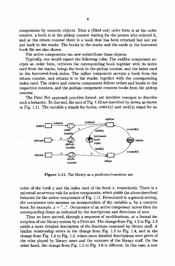
Heavy freight is frequently transported in containers on top of train cars. Such train cars form container trains. They can be driven to container interchange stations, where the containers are rearranged, thus forming new container trains. A container interchange station has container cranes which can pick up contain- ers from train cars and drop them at other train cars.
Figure 2.1 shows a typical container interchange station.
container
I 1 1 2 I 3 I 4 I 6 I
container cranes
train 1
- 7 train 2
crane tracks
Figure 2.1. A container interchange station
Two trains may be positioned side by side, bridged by three container cranes. For the sake of simplicity, the range of the cranes is divided into seven sections, with each section covering one car of each train.
The situation outlined in Fig. 2.1 shows container cranes A and B over the second and fifth section, respectively. Crane C is moving in between sections 6 and 7.
Figure 2.2 represents the behavior of a single container crane. In the depicted state, the crane is idle, loaded by a container, and its left
neighboring section is free, whereas its right neighboring section is occupied by its right neighboring crane.

r s s e f v 8
left section right section is free is free
Figure 2.2. Behavior of a single container crane
Two actions are enabled in this state, drop and reserve left section. Both actions have two preconditions, (idle and loaded, and idle and left section is free, respectively), which are fulfilled in Fig. 2.2. Occurrence of drop leads to free and pending, and reorg is the only enabled action then. Alternatively to drop, the action reserve left section may occur in the initial state of Fig. 2.2. This leads to moving left, which in turn enables release right. To sum up, an action may occur ff all of its preconditions and none of its postconditions are fulfilled. Its occurrence leads to a state where none of its preconditions and all of its postconditions are fulfilled. Graphically, this is depicted by Fig. 2.3.
>
Figure 2.3. Occurrence of an event
Here, actions and conditions are represented as squares and circles, respec- tively. Arrows ending and starting at the square indicate preconditions and post-

conditions of the action. A dot ("token") in a circle indicates that the correspond- ing condition is fulfilled.
Petr i Nets of this kind are called Elementary Net Systems. Figure 2.4 extends the environment of the above described container crane.
~ g
reorg
section
free left free right sectionis section
Figure 2.4. Counting the free sections in a container crane's environment
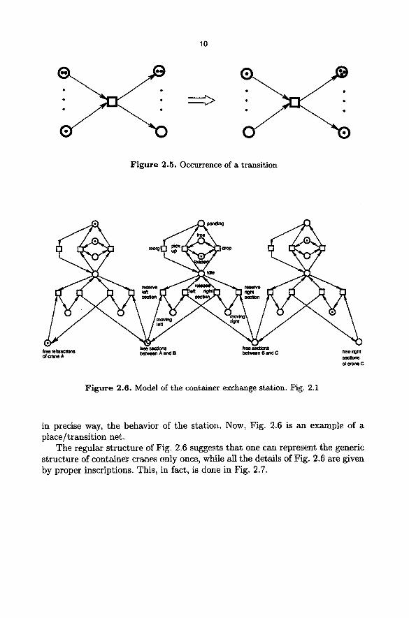
Not only the most adjacent left and right sections are represented, but the number of all adjacent free sections is given: each dot in free left sections and in free right sections represents a free section. Boxes and circles in Fig. 2.4 are called places and transitions, respectively. Each circle may carry any number of tokens (not at most one, as is the case with Elementary Net Systems). Preptaces and postplaces of transitions are defined analogously to pre- and postconditions, as above. A transit ion is enabled whenever each preplace carries at least one token. Occurrence of a transition can graphically be depicted as e.g. in Fig. 2.5.
The initial s ta te of Fig. 2.4 enables three transitions: drop, reserve left section, and reserve right section, respectively. Occurrence of reserve left section would decrease the token load of free left sections to one token, and brings one token to moving left. This enables release left section, which increases the token load of free right sections to four. Petri Nets of this kind are denoted as place/transition nets.
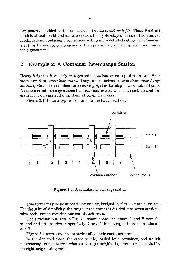
Figure 2.6 shows three container cranes, with neighboring cranes sharing their right or left free sections.
The depicted situation describes the state of the container interchange sta- tion, as in Fig. 2.1. The occurrence rule for transitions described above reflex,
10
Figure 2.5. Occurrence of a transition
r~Cg
~ee lensectk)ns between A and B ~ B and C ~ right of crane A
~c~ne C
Figure 2.6. Model of the container exchange station. Fig. 2.1
in precise way, the behavior of the station. Now, Fig. 2.6 is an example of a place/transit ion net.
The regular s tructure of Fig. 2.6 suggests tha t one can represent the generic structure of container cranes only once, while all the details of Fig. 2.6 are given by proper inscriptions. This, in fact, is done in Fig. 2.7.

11
(x,y) free cranes
(x, y)l ~ r + cranes loaded
b pending
idle cranes
free sections
drop
Figure 2.7. A high level representation, corresponding to Fig. 2.4
This figure is an example of a h~gh level net which is a kind of nets tha t has been considered in the first example already.
References
[Reisig 92] W. Reisig: A Primer in Petri Net Design. Springer-Verlag (1992)