Peristaltic Flow of A Couple Stress Fluids in an Inclined Channel
Upload
independentCategory
view
0download
0
49
Australasian Physical & Engineering Sciences in Medicine Volume 27 Number 2, 2004
Peristaltic transport of a Casson fluid in an asymmetricchannel*
P. Naga Rani and G. Sarojamma
Department of Applied Mathematics, Sri Padmavati Women’s University, Tirupati, India
AbstractThe peristaltic transport of a Casson fluid in a two - dimensional asymmetric channel is studied under long- wavelengthand low-Reynolds number assumption. The asymmetry in the channel is created by considering the peristaltic wavesimposed on the boundary walls to possess different amplitude and phase. The analysis of the flow is carried out in awave frame of reference moving with the velocity of the wave. Due to the asymmetry in the channel two yield planesexist and they are calculated by solving the transcendental equation in terms of the core width. In an asymmetricchannel the yield planes are skewed towards the boundary with higher amplitude or a phase difference in relation to theother boundary. While in a symmetric channel the yield planes are located symmetrically on either side of the axis ofthe channel. The phenomena of trapping and reflux have been discussed in the symmetric case of the channel. It isnoticed that trapping of fluid occurs and the trapping zone extends for an increase in the time average flux. It is foundthat reflux occurs for higher values of amplitude of the peristaltic wave and the reflux zone extends for increasedamplitudes.
Key words casson fluid, peristalsis, asymmetricchannel, mathematical modelling
Introduction
The phenomenon of peristalsis is well known tophysiologists and engineers as one of the major mechanismfor transport of fluid in several biological systems andindustrial pumping. The peristaltic pumping of a fluid in adistensible tube occurs by a progressive wave ofcontraction and expansion along the tube. Peristalsis is aninherent property of many biological systems consisting ofsmooth tubes, which transports bio-fluids by its propulsivemovements. The peristaltic mechanism can be found in thetransport of urine from kidney to bladder through the ureter,the movement of chyme in the gastrointestinal tract,transport of lymph in the lymphatic vessels, the intra-uterine fluid motion, vasomotion of the small blood vesselsand in several other glandular ducts. In industry theperistaltic mechanism is applied to transport corrosivefluids where the contact of fluid with the machinery parts is
*Presented at the XI congress of Andhra Pradesh Society forMathematical Sciences, Tirupati, A.P. India, 31 Jan-2 Feb 2003Corresponding author: G. Sarojamma, Department of AppliedMathematics, Sri Padmavati Mahila Women’s University,Tirupati-517 502, A. P., India,Email: [email protected]: 8 June 2003; Accepted: 28 June 2004Copyright © 2004 ACPSEM/EA
prohibited, slurries, noxious fluids in the nuclear industryand sanitary fluids. Based on the principle of peristalsismechanical roller pumps, heart–lung machines, cellseparators etc. have been fabricated.
Following the first study of Latham9 on peristalsis,several experimental and theoretical studies were developedto understand the fluid mechanical aspects of peristaltictransport in different situations. Many of these studies dealwith the characteristics of pumping, reflux and trapping.Most of these studies have been carried out by treating thatblood and other physiological fluids as Newtonian fluids.Although this approach provides a satisfactoryunderstanding of the peristaltic mechanism in the ureter, itfails to provide a satisfactory model to describe theperistaltic mechanism in small blood vessels, lymphaticvessels and other glandular ducts. The study of peristalsisthrough non-Newtonian fluids is significant as blood insmall arteries and fluids in the lymphatic vessels, intestine,urine under certain pathological conditions etc. behave asnon-Newtonian fluids. Modelling of these fluids as non-Newtonian provides a realistic model. Raju andDevanathan15 are the first researchers to study the peristaltictransport of non-Newtonian fluids. Srivastava17 investigatedthe problem of peristaltic transport of blood by assuming asingle layer/ Canada Casson fluid, which ignores thepresence of peripheral layer. Srivastava and Srivastava18
studied the peristaltic transport of blood in a uniform andnon-uniform tube, when blood is represented by a two-layered fluid model, consisting of a core region ofsuspension of all erythrocytes, assumed to be a Cassonfluid, and peripheral layer of plasma as a Newtonian fluid.
Australas. Phys. Eng. Sci. Med. Vol. 27, No 2, 2004 Naga Rani et al • Peristaltic transport of a Casson fluid
50
Siddique et al.19 analysed the peristaltic motion of a non-Newtonian fluid modelled with a constitutive equation for asecond order fluid in a planar channel. Tang and Rankin20
proposed mathematical model for peristaltic transport of anonlinear viscous flow where they used iterative methods tosolve a free boundary problem. Elshehawey et al.5analysed the peristaltic transport of a non-Newtonian(Carreau) fluid in a non-uniform channel under zeroReynolds number with long wavelength approximation.Mernone and Mazumdar10 analysed a mathematical modelfor the peristaltic transport of a Power law fluid in a planargeometry. In their subsequent papers11, 12 they studied theperistaltic transport of a Casson fluid in a two-dimensionalchannel using the generalized form of constitutive equationfor Casson fluid, proposed by Fung7, 8.
The peristaltic transport of fluids in asymmetricchannels has application in physiology. In the studies of DeVries et al.4 it was mentioned that the intra-uterinecontraction due to myometrial contraction is peristaltic typemotion and the myometrial contractions may occur in bothsymmetric and asymmetric directions. Eytan and Elad6
studied the wall - induced peristaltic fluid flow in a planarchannel with wave trains having a phase difference movingindependently on the upper and lower walls to simulateintra-uterine fluid motion in a sagittal cross -section of theuterus. Pozrikidis14 analysed the peristaltic transport of aviscous fluid in an asymmetric channel under long-wavelength and low-Reynolds number assumptions. Theflow was investigated in a wave frame of reference movingwith the velocity of the wave and the effects of phasedifference, varying channel width and wave amplitudes onthe pumping characteristics, streamline pattern, trappingand reflux were discussed. Mishra and Rao13 studied theperistaltic transport of an incompressible viscous fluid in anasymmetric channel under long-wavelength and low-Reynolds number assumptions. The flow was investigatedin a wave frame of reference moving with velocity of thewave and the effects of phase difference, varying channelwidth and wave amplitudes on the pumping characteristics,streamline pattern, trapping and reflux were discussed.
In this paper the peristaltic transport of a Casson fluidin a two-dimensional asymmetric channel is studied underlong-wavelength and low-Reynolds number assumption.The motivation for studying this problem is to understandthe effects of peristalsis on the flow characteristics ofphysiological fluids modelled as a Casson fluid. The resultsin symmetric and asymmetric channels are discussed. Theresults are compared and found to be in agreement withthose of Shapiro et al. 16 when the channel is symmetric andthe fluid is Newtonian with Mernone and Mazumdar12 inthe case of a symmetric channel and with those of Mishraand Rao13 in the Newtonian fluid case.
Mathematical formulation
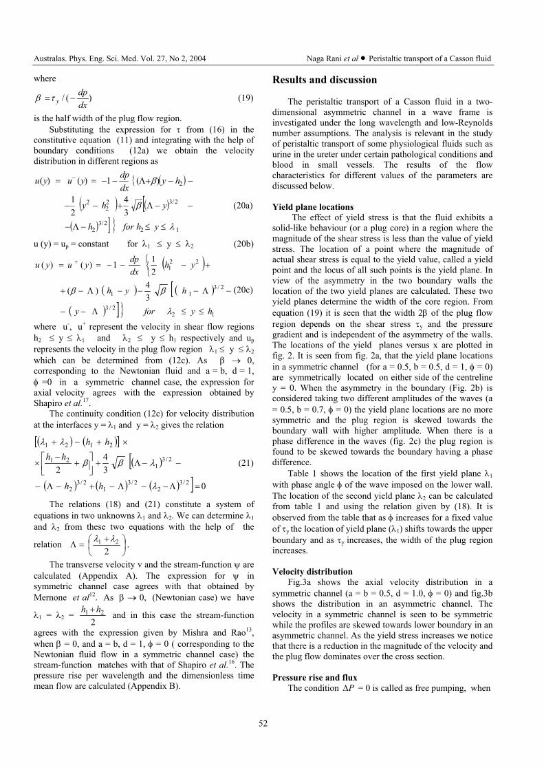
We consider the peristaltic transport of a non-Newtonian fluid, modelled as a Casson fluid in a twodimensional channel, (shown in Fig.1) induced by
sinusoidal wave trains propagating with constant speed calong the channel walls defined by
Y = H1 = d1 + a1 ( )ctX −λπ2cos (1a)
Y = H2 = -d2 – b1 ( )
+− φλπ ctX2cos (1b)
where a1, b1 are the amplitudes of the waves, λ is the wavelength d1 + d2 is the width of the channel, φ is the phasedifference which varies in the range 0 ≤ φ ≤ π. a1 = b1, d1
= d2, φ = 0, correspond to a symmetric channel. Under theassumption of infinite wavelength and neglecting theinertial terms the equations of motion reduce to
)( τρ YYX
Pt
U∂∂
−∂∂
−=∂∂ (2a)
YP∂∂ = 0 (2b)
where ρ is the density, U is the axial velocity, t is thetime, P is the pressure and τ is the shear stress. In order toobtain the flow fields completely the constitutive equationis required.
Casson’s constitutive equationThe Casson’s constitutive equation corresponding to
the flow is given by
21
21
21
∂∂
−+= ∞ YU
y µττ if yττ ≥ (3a)
YU∂∂ = 0 if yττ ≤ (3b)
where yτ is the yield stress and µ∞ is the Newtonianviscosity (viscosity at high rate of shear). From the relation(3b) it is seen that the velocity gradient vanishes in theregion where the shear stress is less than the yield stress. Asa result plug flow sets in whenever yττ ≤ . The above
relations between the shear stress and shear rate YU∂∂ are
appropriate for positive values of τ and negative values of
YU∂∂ . The equivalent form of these relations for more
general situation where the shear stress and shear rate can
Figure 1. Schematic diagram of a two dimensional asymmetricchannel.

Australas. Phys. Eng. Sci. Med. Vol. 27, No 2, 2004 Naga Rani et al • Peristaltic transport of a Casson fluid
51
change the sign (as in the case of a annulus, Bird et al.3)may be written as (Aroesty and Gross1, 2 )
ττ
τττ
µ
−+−=
∂∂
∞ 2/1
2/1
||2
||1 yy
YU if yττ ≥ (4a)
YU∂∂ = 0 if yττ ≤ (4b)
It is clear from equation (4) that the flow of a Casson fluidin the asymmetric channel is three phase in nature in whichthe central core region corresponds to the plug region. Ifthe plug region is represented by λ1 ≤ Y ≤ λ2 where H2 ≤λ1, λ2 ≤ H1, and the two shear flow regions by H2 ≤ Y ≤ λ1
and λ2 ≤ Y ≤ H1, then the Casson’s constitutive equation(4) in these regions can be rewritten as
=∂∂
∞ YUµ 2/12/12 ττττ yy −+− if H2 ≤ Y ≤ λ1 (5a)
0=∂∂
YU if λ1 ≤ Y ≤ λ2 (5b)
=∂∂
∞ YUµ ( )2/12/12 ττττ yy −+− if λ2 ≤ Y ≤ H1 (5c)
Y = λ1 and Y = λ2 are the two yield plane locations to bedetermined as part of solution to the problem underinvestigation.
The corresponding boundary conditions are given byU(Y = H1) = 0 = U(Y = H2) (6a)-τ (Y = λ1) = τy = τ (Y = λ2) (6b)U(Y = λ1) = U(Y = λ2) = Up (6c)where Up is the plug flow velocity.
If the tube length is finite but equal to an integralnumber of wavelengths, and if the pressure differencebetween the ends of the tube is constant, the flow is steadyin the wave frame (Shapiro et al.16). We assume that theseconditions are met, and we study the problem in the waveframe. The transformations between fixed frame O(X, Y)and moving frame o(x, y) are given byx = X – ct , y = Y (7a)u (x, y) = U (X – ct , Y) – c , v(x , y) = V(X – ct, Y) (7b)and p(x) = P(X, t), where (u, v) and (U, V) are velocitycomponents, p and P are pressures in wave and fixed frameof references respectively. The pressure p remains aconstant across any axial station of the channel under theassumption that the wavelength is large and the curvatureeffects are negligible.
We introduce the following non-dimensionalquantities:
λxx = ,
1dyy = ,
cuu = ,
δcvv = ,
λδ 1d
=
λµ cpdp
∞=
21 ,
1/ dc∞=µ
ττ , 1/ dc
yy
∞=µτ
τ h1 = 1
1
dH ,
h2 = 1
2
dH , (8)
d = 1
2
dd , a =
1
1
da , b =
1
1
db , ,
1
11 d
λλ = 1
22 d
λλ =
After dropping bars, the non-dimensional wallequations are given byy = h1 = 1 + a cos (2π x) (9a)y = h2 = - d – b cos (2π x + φ) (9b)
The equations of motion in dimensionless form,become
0=∂∂
yp (10a)
- 0=∂∂
−∂∂
yxp τ (10b)
The Casson’s constitutive equation in the non-dimensionalform is
122/12/12 λττττ ≤≤−+−=
∂∂ yhif
yu
yy (11a)
210 λλ ≤≤=∂∂ yif
yu (11b)
( ) 122/12/12 hyif
yu
yy ≤≤−+−=∂∂ λττττ (11c)
The corresponding boundary conditions in non-dimensional form areu (y = h1) = -1 = u (y = h2) (12a)- ( ) )( 21 λττλτ ==== yy y (12b)
u ( y = λ1) = up = u (y = λ2) (12c)The instantaneous wall flux Q(X , t) across the
channel in fixed frame is given by
Q = dYUh
h∫
1
2
(13)
If q is the rate of flow independent of x and t in waveframe then
q = dyuh
h∫
1
2
(14)
It follows that Q = q + h1 – h2
The average volume flow rate over one period (T = cλ )
of the peristaltic wave is defined as
∫ ∫ −+==T T
dthhqT
dtQT
Q0 0
21 ][11 = q + 1 + d (15)
Method of solution
The solution of (10) using (12b) is given by
( )Λ−−= ydxdpτ (16)
where
+
=Λ2
21 λλ (17)
Using (16) and (12b), we obtain
βλλ=
−2
12 (18)
Australas. Phys. Eng. Sci. Med. Vol. 27, No 2, 2004 Naga Rani et al • Peristaltic transport of a Casson fluid
52
where
)(/dxdp
y −=τβ (19)
is the half width of the plug flow region.Substituting the expression for τ from (16) in the
constitutive equation (11) and integrating with the help ofboundary conditions (12a) we obtain the velocitydistribution in different regions as
( ){
( ) ( )[( ) ] } 12
2/32
2/322
2
2
34
21
)(1)()(
λ
β
β
≤≤−Λ−
−−Λ+−−
−−+Λ−−== −
yhforh
yhy
hydxdpyuyu
(20a)
u (y) = up = constant for λ1 ≤ y ≤ λ2 (20b)
( )
( ) ( )[( ) ]} 12
2/3
2/311
221
34)(
211)()(
hyfory
hyh
yhdxdpyuyu
≤≤Λ−−
−Λ−−−Λ−+
+−−−== +
λ
ββ (20c)
where u-, u+ represent the velocity in shear flow regionsh2 ≤ y ≤ λ1 and λ2 ≤ y ≤ h1 respectively and up
represents the velocity in the plug flow region λ1 ≤ y ≤ λ2
which can be determined from (12c). As β → 0,corresponding to the Newtonian fluid and a = b, d = 1,φ =0 in a symmetric channel case, the expression foraxial velocity agrees with the expression obtained byShapiro et al.17.
The continuity condition (12c) for velocity distributionat the interfaces y = λ1 and y = λ2 gives the relation
( ) ( )[ ]
( )[( ) ( ) ( ) ] 0
34
22/3
22/3
12/3
2
2/31
21
2121
=Λ−−Λ−+−Λ−
−−Λ+
+
−×
×+−+
λ
λββ
λλ
hh
hhhh
(21)
The relations (18) and (21) constitute a system ofequations in two unknowns λ1 and λ2. We can determine λ1
and λ2 from these two equations with the help of the
relation
+
=Λ2
21 λλ .
The transverse velocity v and the stream-function ψ arecalculated (Appendix A). The expression for ψ insymmetric channel case agrees with that obtained byMernone et al12. As β → 0, (Newtonian case) we have
λ1 = λ2 = 2
21 hh + and in this case the stream-function
agrees with the expression given by Mishra and Rao13,when β = 0, and a = b, d = 1, φ = 0 ( corresponding to theNewtonian fluid flow in a symmetric channel case) thestream-function matches with that of Shapiro et al.16. Thepressure rise per wavelength and the dimensionless timemean flow are calculated (Appendix B).
Results and discussion
The peristaltic transport of a Casson fluid in a two-dimensional asymmetric channel in a wave frame isinvestigated under the long wavelength and low-Reynoldsnumber assumptions. The analysis is relevant in the studyof peristaltic transport of some physiological fluids such asurine in the ureter under certain pathological conditions andblood in small vessels. The results of the flowcharacteristics for different values of the parameters arediscussed below.
Yield plane locationsThe effect of yield stress is that the fluid exhibits a
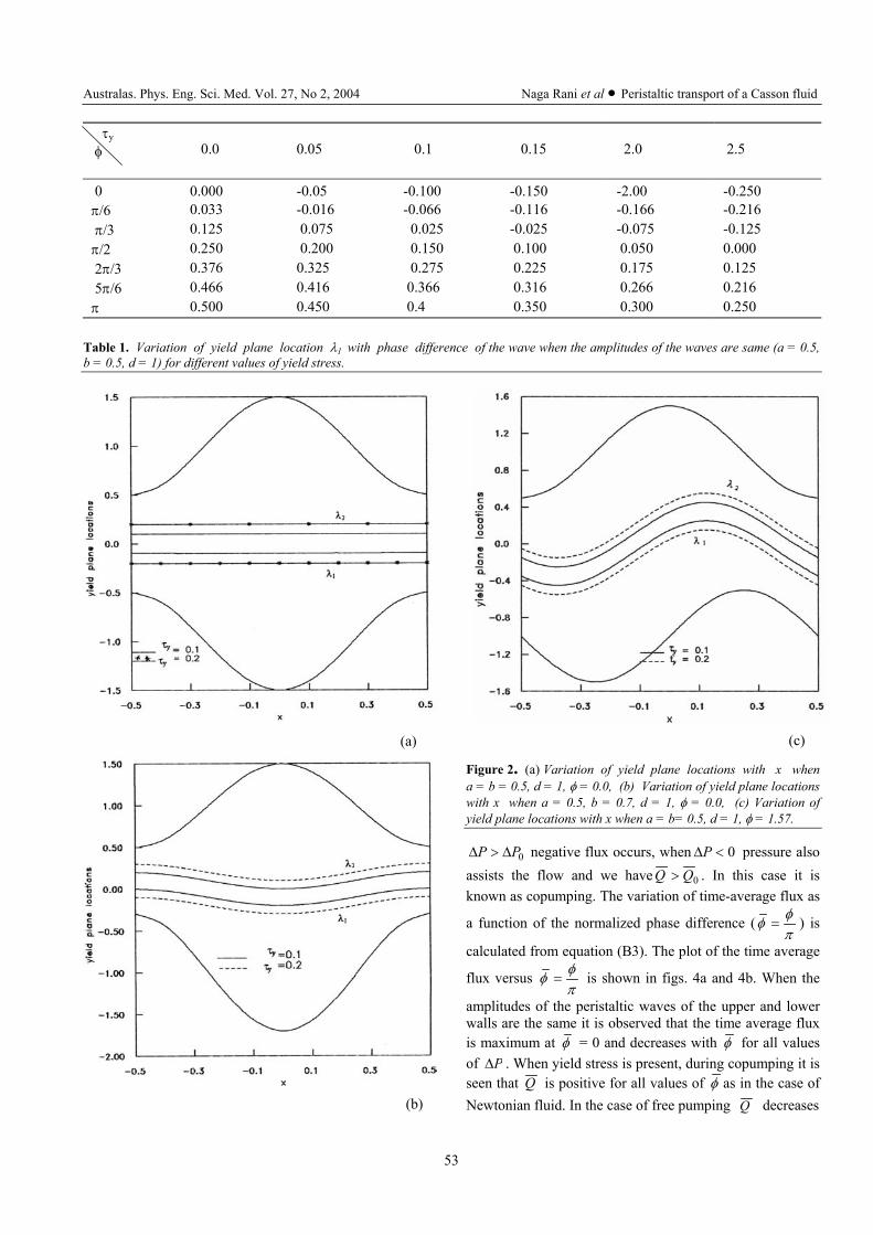
solid-like behaviour (or a plug core) in a region where themagnitude of the shear stress is less than the value of yieldstress. The location of a point where the magnitude ofactual shear stress is equal to the yield value, called a yieldpoint and the locus of all such points is the yield plane. Inview of the asymmetry in the two boundary walls thelocation of the two yield planes are calculated. These twoyield planes determine the width of the core region. Fromequation (19) it is seen that the width 2β of the plug flowregion depends on the shear stress τy and the pressuregradient and is independent of the asymmetry of the walls.The locations of the yield planes versus x are plotted infig. 2. It is seen from fig. 2a, that the yield plane locationsin a symmetric channel (for a = 0.5, b = 0.5, d = 1, φ = 0)are symmetrically located on either side of the centreliney = 0. When the asymmetry in the boundary (Fig. 2b) isconsidered taking two different amplitudes of the waves (a= 0.5, b = 0.7, φ = 0) the yield plane locations are no moresymmetric and the plug region is skewed towards theboundary wall with higher amplitude. When there is aphase difference in the waves (fig. 2c) the plug region isfound to be skewed towards the boundary having a phasedifference.
Table 1 shows the location of the first yield plane λ1
with phase angle φ of the wave imposed on the lower wall.The location of the second yield plane λ2 can be calculatedfrom table 1 and using the relation given by (18). It isobserved from the table that as φ increases for a fixed valueof τy the location of yield plane (λ1) shifts towards the upperboundary and as τy increases, the width of the plug regionincreases.
Velocity distributionFig.3a shows the axial velocity distribution in a
symmetric channel (a = b = 0.5, d = 1.0, φ = 0) and fig.3bshows the distribution in an asymmetric channel. Thevelocity in a symmetric channel is seen to be symmetricwhile the profiles are skewed towards lower boundary in anasymmetric channel. As the yield stress increases we noticethat there is a reduction in the magnitude of the velocity andthe plug flow dominates over the cross section.
Pressure rise and fluxThe condition P∆ = 0 is called as free pumping, when
Australas. Phys. Eng. Sci. Med. Vol. 27, No 2, 2004 Naga Rani et al • Peristaltic transport of a Casson fluid
53
τy
φ 0.0 0.05 0.1 0.15 2.0 2.5
0 0.000 -0.05 -0.100 -0.150 -2.00 -0.250π/6 0.033 -0.016 -0.066 -0.116 -0.166 -0.216 π/3 0.125 0.075 0.025 -0.025 -0.075 -0.125π/2 0.250 0.200 0.150 0.100 0.050 0.000 2π/3 0.376 0.325 0.275 0.225 0.175 0.125 5π/6 0.466 0.416 0.366 0.316 0.266 0.216π 0.500 0.450 0.4 0.350 0.300 0.250
Table 1. Variation of yield plane location λ1 with phase difference of the wave when the amplitudes of the waves are same (a = 0.5,b = 0.5, d = 1) for different values of yield stress.
(a)
(b)
(c)
Figure 2. (a) Variation of yield plane locations with x whena = b = 0.5, d = 1, φ = 0.0, (b) Variation of yield plane locationswith x when a = 0.5, b = 0.7, d = 1, φ = 0.0, (c) Variation ofyield plane locations with x when a = b= 0.5, d = 1, φ = 1.57.
0PP ∆>∆ negative flux occurs, when 0<∆P pressure alsoassists the flow and we have 0QQ > . In this case it isknown as copumping. The variation of time-average flux as
a function of the normalized phase difference (πφφ = ) is
calculated from equation (B3). The plot of the time average
flux versus πφφ = is shown in figs. 4a and 4b. When the
amplitudes of the peristaltic waves of the upper and lowerwalls are the same it is observed that the time average fluxis maximum at φ = 0 and decreases with φ for all valuesof P∆ . When yield stress is present, during copumping it isseen that Q is positive for all values of φ as in the case ofNewtonian fluid. In the case of free pumping Q decreases

Australas. Phys. Eng. Sci. Med. Vol. 27, No 2, 2004 Naga Rani et al • Peristaltic transport of a Casson fluid
54
(a)
(b)
Figure 3. (a) Variation of axial velocity with y when a = b = 0.5,d = 1, φ = 0.0, Q = 1.0, x = 0.25, (b) Variation of axial velocity
with y when a = 0.5, b = 1.2, d = 1, Q = 1.0, x = 0.25
from its maximum value (0.7409) at φ = 0 as φ increasesand approaches zero value at φ = 1. When 1=∆P , Q
decreases from its maximum at φ = 0 and becomes zero at
φ = 0.42 and it remains negative for the remaining values
of φ until it assumes the value 1. For ∆P = 1.5 thebehaviour of Q is similar to the case when ∆P = 1.0. Thepositive flux for 0 ≤ ∆P ≤ ∆P0 is purely due to peristalsis.When ∆P = 2.5 the average flux is totally negative. In thecase of Newtonian fluid Q becomes totally negative when
(a)
(b)
Figure 4. (a) Variation of Q with φ for different P∆ when
a = b= 0.7, d = 2.0, (b) Variation of Q with φ for differentplug width and P∆ when a = 0.7, b = 1.2, d = 2.0.
∆P = 1.0 . The effect of yield stress on Q is significantwhen ∆P > 0 while it has less effect during pumping andcopumping (i.e. ∆P ≤ 0) . The effect of yield stress on Qis significant at φ = 0. In the case of free pumpingat φ = 0, Q decreases from 0.9716 (β = 0.1) to 0.8839 inthe case of Newtonian fluid when β = 0 and thenapproaches zero as φ →1. When the amplitudes of the twoperistaltic waves are different (fig. 4b), the time averageflux is totally positive during copumping and pumping forall values of φ . When ∆P = 1.5 the flux is seen to be
Australas. Phys. Eng. Sci. Med. Vol. 27, No 2, 2004 Naga Rani et al • Peristaltic transport of a Casson fluid
55
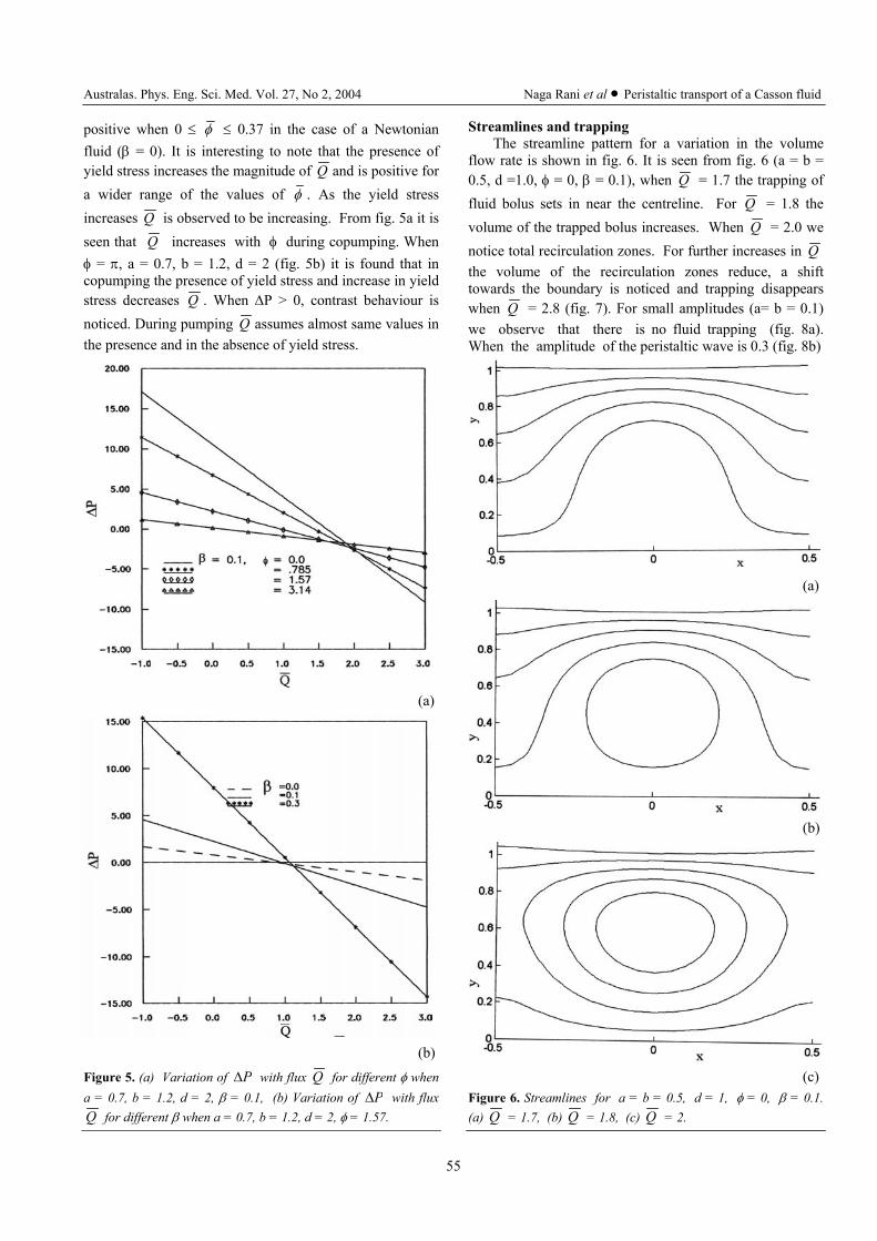
positive when 0 ≤ φ ≤ 0.37 in the case of a Newtonianfluid (β = 0). It is interesting to note that the presence ofyield stress increases the magnitude of Q and is positive fora wider range of the values of φ . As the yield stressincreases Q is observed to be increasing. From fig. 5a it isseen that Q increases with φ during copumping. Whenφ = π, a = 0.7, b = 1.2, d = 2 (fig. 5b) it is found that incopumping the presence of yield stress and increase in yieldstress decreases Q . When ∆P > 0, contrast behaviour isnoticed. During pumping Q assumes almost same values inthe presence and in the absence of yield stress.
(a)
(b)Figure 5. (a) Variation of P∆ with flux Q for different φ whena = 0.7, b = 1.2, d = 2, β = 0.1, (b) Variation of P∆ with fluxQ for different β when a = 0.7, b = 1.2, d = 2, φ = 1.57.
Streamlines and trappingThe streamline pattern for a variation in the volume
flow rate is shown in fig. 6. It is seen from fig. 6 (a = b =0.5, d =1.0, φ = 0, β = 0.1), when Q = 1.7 the trapping offluid bolus sets in near the centreline. For Q = 1.8 thevolume of the trapped bolus increases. When Q = 2.0 wenotice total recirculation zones. For further increases in Qthe volume of the recirculation zones reduce, a shifttowards the boundary is noticed and trapping disappearswhen Q = 2.8 (fig. 7). For small amplitudes (a= b = 0.1)we observe that there is no fluid trapping (fig. 8a).When the amplitude of the peristaltic wave is 0.3 (fig. 8b)
(a)
(b)
(c)Figure 6. Streamlines for a = b = 0.5, d = 1, φ = 0, β = 0.1.(a) Q = 1.7, (b) Q = 1.8, (c) Q = 2.

Australas. Phys. Eng. Sci. Med. Vol. 27, No 2, 2004 Naga Rani et al • Peristaltic transport of a Casson fluid
56
(a)
(b)
Figure 7. Streamlines for a = b = 0.5, d = 1, φ = 0, β = 0.1.(a) Q = 2.4, (b) Q = 2.8.
trapping occurs and the volume of the trapped bolusincreases with the amplitude (fig.8c, when a = b = 0.5, d =1.0, Q = 2.2, β = 0.1, φ = 0).
Reflux phenomenonThe phenomenon reflux means that the existence of
mean motion of some fluid particles over a cycle againstthe net pumping direction. Since the flow in fixed frame isunsteady the path lines of the material particle are differentfrom streamlines while in the moving frame path lines andstreamlines coincide as the flow becomes steady. They aresimilar to the wall shape, but with lesser amplitude near theaxis. Following Shapiro et al.16, Qψ defined asdimensionless volume flow rate in the fixed frame between
the centreline of the channel 2
h h 21 + and the wave
streamline ψ, which is an indicator of material particles infixed frame, is given by
∫+
=),,(
221
),,(tXY
hhdYtYXUQ
ψ
ψ (22)
By using the transformation between fixed frame and waveframe given in equation (7) and integrating (30), we get
2),,( 21 hhtXyQ +−+= ψψψ (23)
Averaging over the one period of the wave
(a)
(b)
(c)Figure 8. Streamlines for d = 1, φ = 0, β = 0.1, Q = 2.2.(a) a = b = 0.1, (b) a = b = 0.3 (c) a = b = 0.5.
21),(
1
0
ddxxyQ −−+= ∫ ψψψ (24)
Defining ,/*wQQQ ψ= ,/*
wψψψ = where wQ and
wψ are the values of ψQ and ψ at the wall y = h1, wQ =
2/Q and wψ = 2/)1( dQ −− . According to Shapiro et
al.16 reflux layer exists near the wall, whenever *Qincreases to a value greater than one and decreases to one atthe wall. Following the analysis of Shapiro et al.16
expressing y in terms of ψ using (A3c) and givingexpansion in small amplitudes the integrand of (24) is

Australas. Phys. Eng. Sci. Med. Vol. 27, No 2, 2004 Naga Rani et al • Peristaltic transport of a Casson fluid
57
(a)
(b)
Figure 9. (a) Variation of Q* with ψ* when β = 0.1, Q = 0.1,d = 1, φ = 0, (b) Variation of Q* with ψ* when β = 0.1,Q = 0.05, d = 1, φ = 0
calculated. The integral is evaluated numerically by usingSimpson’s rule.
Fig. 9a depicts the variation of *Q as a function of *ψ
for different amplitudes of the peristaltic wave for a = b, d =1, φ = 0, β = 0.1, Q = 0.1. It is observed that there is noreflux for small values of the amplitude. Reflux is seen tooccur for higher values of amplitudes (a ≥ 0.3) and thereflux zone extends with an increase in amplitude. In fig. 9bthe variation of *Q for a variation in amplitudes, when Qis half of the value considered in fig. 9a. It is found thatreflux occurs even for small amplitude i.e. a = 0.1. In thiscase for higher values of the amplitude, the reflux zones aredoubled to those in the case of fig. 9a.
The reflux limits are obtained (Appendix C). In asymmetric channel (a = b, d = 1, φ = 0), for a Newtonianfluid (β = 0), the reflux limits are found to agree with thoseobtained by Mishra and Rao13.
Conclusions
The peristaltic transport of a Casson fluid in anasymmetric channel is studied in the wave frame under longwavelength and low Reynolds number assumption. Due tothe asymmetry in the channel, the yield stress of the fluidtends to form two yield planes in the plug core region.When the channel is symmetric the yield planes are foundto be located symmetrically on either side of the centreliney = 0 and in an asymmetric channel the plug region isskewed towards the boundary wall with higher amplitude(or phase difference). The presence of yield stress is foundto enhance the time average flux. It is noticed that trappingof fluid flows occurs and the trapping zone extends for anincrease in the time average flux ( Q = 2.0) and itdisappears for Q = 2.8. In the case of channel symmetry,reflux occurs for higher values of amplitude of theperistaltic wave and the reflux zone extends for anincreased in the amplitude. The model can further beredefined by considering the effects of the elasticity of thewalls, which will effect the yield plane locations and flowcharacteristics.
Acknowledgements
The authors are thankful to the referees for theirconstructive suggestions.
Appendix A
We may calculate the transverse velocity v from theequation of continuity
xu
yv
∂∂
−=∂∂ (A1)
Defining the stream function as
dψ = u dy - v dx (A2)
and using the conditions 2q
=ψ at y = h1 2q
−=ψ at
y = h2 we obtain the stream-function in the three regions as
Australas. Phys. Eng. Sci. Med. Vol. 27, No 2, 2004 Naga Rani et al • Peristaltic transport of a Casson fluid
58
−−−β+Λ−−=ψ )yh3
y(21)yh
2y()(
dxdpy 2
2
3
2
2
1
( ) −Λβ− 2/5y52
34 ( ) 12
3
2 Cyh +
−Λ+
12 yhfor λ≤≤ (A3a)
ppp Cyu +=ψ 21 yfor λ≤≤λ (A3b)
−Λ−β+
−−−=ψ
2yyh)(
3yyh
21
dxdpy
2
1
3212
( )
λ−β− yh
34
23
1 ( ) 225
Cy52
+
Λ−−
12 hyλfor ≤≤ (A3c)
where
{2h
3h
2h
dxdp
h2q
C22
32
22
21β
−+Λ−
++−
=
( ) ( ) }223
2 h32h154
+Λ−Λβ−
( )
−λ+
λ−β+Λ−+−= 3
231
21
22
2p h31
2h
)(dxdph
2qC
[ ( ) ( )]
+Λ−Λ−+Λ−Λ− 223
2123
1 32)32()(154 hhλλβ
2h
)(3
hdxdph
2qC
21
31
12 Λ−β+
++= -
( ) ( )
Λ+Λ−β− 2h3h154
123
1
Appendix B
The pressure gradient is obtained by using (14) as
( ))(
21
xFhhq
dxdp −+
−= (B1)
where
F(x)= ( ) ( )21
22
21
22
32
31
32
31 hh
2hh
31
λ−λ+−Λ
+λ−λ+− +
( )22
21
22
21 hh
2λ−λ−+
β+
( ) ( )
λ+Λλ−Λβ− 12
3
1 32154
( ) ( )223
2 h32h +Λ−Λ−
( ) ( )Λ+Λ−+ 23 123
1 hh ( ) ( )
+ΛΛ−− 22
3
2 32 λλ
The pressure rise per wavelength is given by
∫=∆1
0
dxdxdpP = ( 1 + d - Q ) I1 + I2 (B2)
where
I1 = ∫1
0 )(1 dxxF
, I2 = ∫−1
0
12
)(dx
xFhh
and Q can be written as
Q = ( 1 + d) + 11
2
IP
II ∆
− (B3)
The dimensionless time mean flow Q 0 for zeropressure rise is given by
0Q = (1 + d) + 1
2
II (B4)
Also the dimensionless pressure rise for zero time meanflow is obtained as
00)( PP Q ∆=∆ = = (1 + d) I1 + I2 (B5)
Appendix C
The reflux limits may be obtained as follows. Weconsider wave frame streamlines close to the wall andintroduce a small parameter
2)1( dQ
w−−
−=−= ψψψδ (C1)
The equation of streamline near the wall may beexpressed as
)........1( 22
11 +++= aahy δδ (C2)
Substituting (C1) and (C2) in (A3c) we obtain
11
1h
a −= (C3)
[ ]2/111
12 )(2
21
Λ−−+Λ−= hhdxdp
ha ββ (C4)
and hence y can be written as
[ ] +Λ−−+Λ−+−= 2/111
2
1 )(22
hhdxdphy ββδδ (C5)
Substituting (C5) in (24) we obtain
( )∫
−+−−δ−=ψ
1
0
212
xF)hhd1Q(
21
2QQ
( ) dx]h2h[ 21
11
Λ−β−β+λ− (C6)
Using this, we obtain
Australas. Phys. Eng. Sci. Med. Vol. 27, No 2, 2004 Naga Rani et al • Peristaltic transport of a Casson fluid
59
( )( )∫
−+−−δ−=ψ
1
0
212
w xFhhd1Q
Q1
Q
Q
( ) dx]h2h[ 21
11
Λ−β−β+λ− (C7)
Reflux occurs when ,1>wQ
Qψ from which the reflux
limit is obtained as[ ]
( )
∫
∫−++
< 1
0
1
0
12
)(/)(
)(1
dxxFxG
dxxF
xGhhd
Q (C8)
where
G (x) = ( )
Λ−−+− 2
1
11 2 hh ββλ
The same procedure can be repeated to obtain the limitsnear the other boundary wall y = h2.
References1. Aroesty, J. and Gross, J. F., The mathematics of pulsatile flow
in small blood vessels, I. Casson theory. Microvasc. Res. 4: 1-12, 1972.
2. Aroesty, J. and Gross, J. F. Pulsatile flow in small bloodvessels I. Casson theory, Biorheology 9: 33-42, 1972.
3. Bird, R. B., Stewart, W. E. and Lightfoot, E. N., TransportPhenomena, John Wiley and Sons, New York., 1960.
4. DeVries, K., Lyons, E. A., Ballard. J., Levi, C. S. and Lindsay,D. J., Contractions of the inner third of the Myometrium, Am.J. Obstetrics Gynecol. 162: 679-682, 1990.
5. Elshehawey. J. et al., Peristaltic motion of generalizedNewtonian fluid in a non-uniform channel, J. Phys. Soc.Japan 67: 434- 440, 1998.
6. Eytan, O. and Elad, D., Analysis of Intra-Uterine fluid motioninduced by uterine contractions, Bull. Math. Biology. 61: 221-238, 1999.
7. Fung, Y. C., Biomechanics: Mechanical Properties of LivingTissue, Springer Verlag, New York, 1981.
8. Fung, Y. C., Biodynamics Circulation, Springer Verlag, NewYork, 1984.
9. Latham, T. W., Fluid motion in a peristaltic pump, M. Sthesis M. I. T., Cambridge, 1966.
10. Mernone, A. V. and Mazumdar J. N., Mathematical Modellingof Peristaltic transport of a non-Newtonian Fluid,Australasian J. Physical and Engineering Sciences inMedicine, 23, 3: 94-100, 1998.
11. Mernone, A. V. and Mazumdar, J. N., Biomathematicalmodeling of physiological fluids using a Casson fluid withemphasis to peristalsis, Australasian Physical and EngineeringSciences in Medicine, 23, 3:94-100, 2000.
12. Mernone, A. V. and Mazumdar, J. N., Lucas, S. K., AMathematical study of peristaltic transport of a Cassonfluid, Mathematical and Computer Modelling 35, 894 -912, 2002.
13. Mishra, M. and Rao, A. R., Peristaltic transport of aNewtonian fluid in an asymmetric channel, ZAMP, 54, 532-550, 2003-5.
14. Pozrikidis, C., A study of peristaltic flow, J. Fluid Mech.180: 515-527, 1987.
15. Raju, K. K. and Devanathan, R., Peristaltic motion of a non-Newtonian fluid. Rheol. Acta,11: 170-179, 1972.
16. Shapiro, A. H., Jaffrin, M. Y. and Weinberg, S. L., PeristalticPumping with long Wavelengths at low Reynolds number. J.Fluid Mech. 37: 799-825, 1969.
17. Srivastava, L. M., Peristaltic transport of a Casson fluid, Nig.J.Sci.Res.1: 71-82, 1987.
18. Srivastava, L. M. and Srivastava, V. P., Peristaltic transportof blood: Casson model II, J. Biomechanics 17: No.11: 821-829, 1984.
19. Siddiqui, A. M., Provost, A. & Schwarz W. H., PeristalticPumping of a Second –Order Fluid in a Planar Channel,Rheol Acta 30: 249-262, 1991.
20. Tang, D. and Rankin, S., Numerical and asymptotic solutionsfor peristaltic motion of non-linear viscous flows with elasticboundaries. SIAM J. Sci. Compt. 14: No.6: 300-1319, 1993.
Copyright © 2022 FDOKUMEN