Performance of the CMS Level1 trigger during commissioning with cosmic ray muons and LHC beams
53
Performance of the CMS Level-1 trigger during commissioning with cosmic ray muons and LHC beams This article has been downloaded from IOPscience. Please scroll down to see the full text article. 2010 JINST 5 T03002 (http://iopscience.iop.org/1748-0221/5/03/T03002) Download details: IP Address: 131.215.220.185 The article was downloaded on 24/01/2011 at 16:53 Please note that terms and conditions apply. View the table of contents for this issue, or go to the journal homepage for more Home Search Collections Journals About Contact us My IOPscience
-
Upload
independent -
Category
Documents
-
view
0 -
download
0
Transcript of Performance of the CMS Level1 trigger during commissioning with cosmic ray muons and LHC beams

Performance of the CMS Level-1 trigger during commissioning with cosmic ray muons and
LHC beams
This article has been downloaded from IOPscience. Please scroll down to see the full text article.
2010 JINST 5 T03002
(http://iopscience.iop.org/1748-0221/5/03/T03002)
Download details:
IP Address: 131.215.220.185
The article was downloaded on 24/01/2011 at 16:53
Please note that terms and conditions apply.
View the table of contents for this issue, or go to the journal homepage for more
Home Search Collections Journals About Contact us My IOPscience
2010 JINST 5 T03002
PUBLISHED BY IOP PUBLISHING FOR SISSA
RECEIVED: December 1, 2009REVISED: March 1, 2010
ACCEPTED: March 3, 2010PUBLISHED: March 19, 2010
COMMISSIONING OF THE CMS EXPERIMENT WITH COSMIC RAYS
Performance of the CMS Level-1 trigger duringcommissioning with cosmic ray muons and LHCbeams
CMS Collaboration
ABSTRACT: The CMS Level-1 trigger was used to select cosmic ray muons and LHC beam eventsduring data-taking runs in 2008, and to estimate the level of detector noise. This paper describesthe trigger components used, the algorithms that were executed, and the trigger synchronisation.Using data from extended cosmic ray runs, the muon, electron/photon, and jet triggers have beenvalidated, and their performance evaluated. Efficiencies were found to be high, resolutions werefound to be good, and rates as expected.
KEYWORDS: Trigger concepts and systems (hardware and software); Trigger algorithms
ARXIV EPRINT: 0911.5422
c© 2010 IOP Publishing Ltd and SISSA doi:10.1088/1748-0221/5/03/T03002
2010 JINST 5 T03002
Contents
1 Introduction 1
2 CMS Level-1 trigger 22.1 Muon triggers 2
2.1.1 DT trigger 32.1.2 CSC trigger 32.1.3 RPC trigger 42.1.4 Global Muon Trigger 5
2.2 Calorimeter triggers 52.2.1 ECAL trigger primitives 52.2.2 HCAL trigger primitives 62.2.3 Regional calorimeter trigger 62.2.4 Global calorimeter trigger 7
2.3 Global trigger 72.4 Trigger software and operation 8
3 L1 trigger during CRAFT and LHC single beam operations 83.1 Muon triggers 83.2 Calorimeter triggers 93.3 Global triggers 10
4 Synchronisation 114.1 DT synchronisation 114.2 CSC synchronisation 124.3 RPC synchronisation 144.4 Calorimeter synchronisation 144.5 Global synchronisation 144.6 Synchronisation with LHC beam 15
5 Hardware validation using emulators 165.1 Muon triggers 175.2 Calorimeter triggers 18
6 Drift-tube trigger performance 19
7 Cathode strip chamber trigger performance 21
8 Resistive plate chamber trigger performance 24
9 Electron/photon trigger performance 269.1 Data selection 279.2 Resolution and efficiency 28
– i –
2010 JINST 5 T03002
10 Jet trigger performance 29
11 Summary and outlook 31
The CMS collaboration 35
1 Introduction
The primary goal of the Compact Muon Solenoid (CMS)1 experiment [1] is to explore particlephysics at the TeV energy scale exploiting the proton-proton collisions delivered by the LargeHadron Collider (LHC) [2]. During October-November 2008 the CMS collaboration conducteda month-long data taking exercise, known as the Cosmic Run At Four Tesla (CRAFT), with thegoal of commissioning the experiment for extended operation [3]. With all installed detector sys-tems participating, CMS recorded 270 Million cosmic ray triggered events with the solenoid atits nominal axial field strength of 3.8 T. Prior to CRAFT, in September 2008, CMS observed themuon halo from single circulating beams and received several single shot “beam splash” events.In a beam splash event, the beam is steered onto closed collimators upstream of CMS, releasingO(105) muons that produce signals in most channels of the detector.
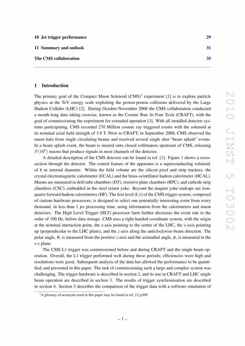
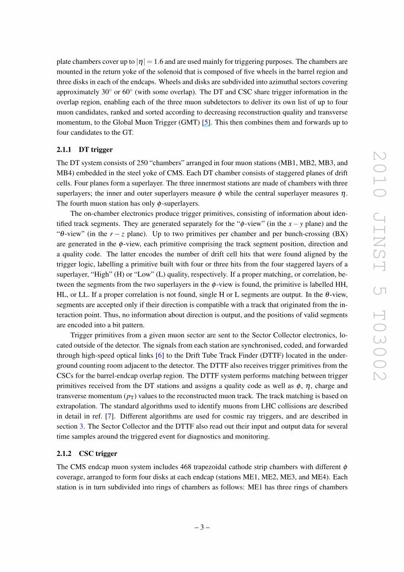
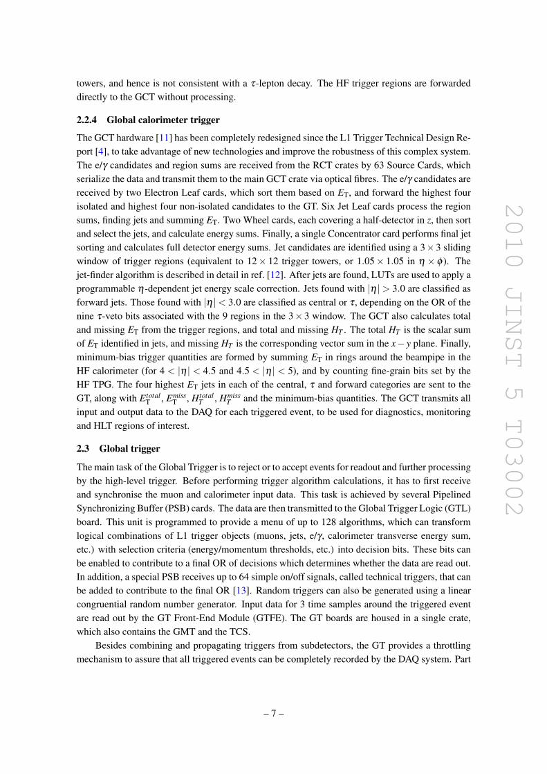
A detailed description of the CMS detector can be found in ref. [1]. Figure 1 shows a cross-section through the detector. The central feature of the apparatus is a superconducting solenoid,of 6 m internal diameter. Within the field volume are the silicon pixel and strip trackers, thecrystal electromagnetic calorimeter (ECAL) and the brass-scintillator hadron calorimeter (HCAL).Muons are measured in drift tube chambers (DT), resistive plate chambers (RPC), and cathode stripchambers (CSC), embedded in the steel return yoke. Beyond the magnet yoke endcaps are iron-quartz forward hadron calorimeters (HF). The first level (L1) of the CMS trigger system, composedof custom hardware processors, is designed to select one potentially interesting event from everythousand, in less than 1 µs processing time, using information from the calorimeters and muondetectors. The High Level Trigger (HLT) processor farm further decreases the event rate to theorder of 100 Hz, before data storage. CMS uses a right-handed coordinate system, with the originat the nominal interaction point, the x-axis pointing to the centre of the LHC, the y-axis pointingup (perpendicular to the LHC plane), and the z-axis along the anticlockwise-beam direction. Thepolar angle, θ , is measured from the positive z-axis and the azimuthal angle, φ , is measured in thex-y plane.
The CMS L1 trigger was commissioned before and during CRAFT and the single beam op-eration. Overall, the L1 trigger performed well during these periods; efficiencies were high andresolutions were good. Subsequent analysis of the data has allowed the performance to be quanti-fied, and presented in this paper. The task of commissioning such a large and complex system waschallenging. The trigger hardware is described in section 2, and its use in CRAFT and LHC singlebeam operation are described in section 3. The results of trigger synchronisation are describedin section 4. Section 5 describes the comparison of the trigger data with a software emulation of
1A glossary of acronyms used in this paper may be found in ref. [1] p309
– 1 –
2010 JINST 5 T03002
1.26
8 m
3.95
4 m
6.61
m
5.68
m
6.66
m
7.24
m
8.49
5 m
9.75
m
10.6
3 m
10.8
3 m
6.45
m
10.8
6 m
10.9
1 m
14.5
3 m
14.5
6 m
14.9
6 m
m 509.4
m 118.1
1/FH
ME
/1/3
1/EY
ME
/3/2
ME
/2/2
ME
/2/1
ME
/3/1
ME
/4/1
ME
/1/1 1/EH
1/BE
ME
/1/2
1/BHY
E/3
YE
/2
EE
/1
0/BC
1/ES
1/BS
Y
Z
% 32.1
g
η 13.5 =
4.33
2 m
3.90
m
m 117.1m 5149.1
0.00
m
η 0.3 =
η 4.2 =
η 974.1 =
η 1 = η 5.0 = η 1.1 =
m 044.0
m 559.6
m 468.2m 007.2
m 008.3
m 083.7m 000.7
m 579.5
m 020.4
m 034.7
m 00.0
m 581.1m 092.1
0.00
0 m
2.93
5 m
m 059.2
1/2/BM
2/2/BM
3/2/BM
4/2/BM
1/2/BY
2/2/BY
3/2/BY
1/1/BM
2/1/BM
3/1/BM
4/1/BM
1/1/BY
2/1/BY
3/1/BY
1/0/BM
2/0/BM
3/0/BM
4/0/BM
1/0/BY
2/0/BY
3/0/BY
Figure 1. Cross-section through the CMS detector in the y-z plane.
the system. The performance measurements are described in sections 6–10, covering muon trig-gers from three subdetectors, e/γ and jet triggers. In general, these analyses use only fractions ofthe CRAFT dataset, because the performance is evaluated using events similar to those of LHCcollisions for which the L1 trigger design was optimised.
2 CMS Level-1 trigger
The CMS L1 trigger is described in detail in ref. [4]. In brief, the calorimeters and the muonsubdetectors provide trigger primitives in the form of local energy deposits in calorimeter triggertowers and track segments or hits in muon chambers. Regional and global processors identify trig-ger objects: electron, jet, and muon candidates, and energy sums. A full set of trigger primitivesare produced every 25 ns, a period known as a “bunch-crossing” (BX). For LHC collisions, thisidentifies the trigger primitives and resulting trigger objects with a particular proton-proton colli-sion. Objects are ranked and sorted. They form the basis for trigger decisions taken by the finalL1 stage, the Global Trigger (GT), according to programmable algorithms. The Trigger ControlSystem (TCS) determines if the subdetectors are ready to read out the event, and if the data ac-quisition (DAQ) system is ready to receive it. Data from trigger primitives, regional energy sums,muon candidates from each sub-detector, and final trigger objects are sent in parallel to the DAQfor each accepted event. Control and monitoring of the L1 trigger operation are performed centrallyby dedicated software.
2.1 Muon triggers
Drift tube chambers in the barrel of the detector and cathode strip chambers in the endcap regionsprovide tracking up to pseudorapidity |η |= 2.4 and trigger information up to |η |= 2.1. Resistive
– 2 –
2010 JINST 5 T03002
plate chambers cover up to |η |= 1.6 and are used mainly for triggering purposes. The chambers aremounted in the return yoke of the solenoid that is composed of five wheels in the barrel region andthree disks in each of the endcaps. Wheels and disks are subdivided into azimuthal sectors coveringapproximately 30◦ or 60◦ (with some overlap). The DT and CSC share trigger information in theoverlap region, enabling each of the three muon subdetectors to deliver its own list of up to fourmuon candidates, ranked and sorted according to decreasing reconstruction quality and transversemomentum, to the Global Muon Trigger (GMT) [5]. This then combines them and forwards up tofour candidates to the GT.
2.1.1 DT trigger
The DT system consists of 250 “chambers” arranged in four muon stations (MB1, MB2, MB3, andMB4) embedded in the steel yoke of CMS. Each DT chamber consists of staggered planes of driftcells. Four planes form a superlayer. The three innermost stations are made of chambers with threesuperlayers; the inner and outer superlayers measure φ while the central superlayer measures η .The fourth muon station has only φ -superlayers.
The on-chamber electronics produce trigger primitives, consisting of information about iden-tified track segments. They are generated separately for the “φ -view” (in the x− y plane) and the“θ -view” (in the r− z plane). Up to two primitives per chamber and per bunch-crossing (BX)are generated in the φ -view, each primitive comprising the track segment position, direction anda quality code. The latter encodes the number of drift cell hits that were found aligned by thetrigger logic, labelling a primitive built with four or three hits from the four staggered layers of asuperlayer, “High” (H) or “Low” (L) quality, respectively. If a proper matching, or correlation, be-tween the segments from the two superlayers in the φ -view is found, the primitive is labelled HH,HL, or LL. If a proper correlation is not found, single H or L segments are output. In the θ -view,segments are accepted only if their direction is compatible with a track that originated from the in-teraction point. Thus, no information about direction is output, and the positions of valid segmentsare encoded into a bit pattern.
Trigger primitives from a given muon sector are sent to the Sector Collector electronics, lo-cated outside of the detector. The signals from each station are synchronised, coded, and forwardedthrough high-speed optical links [6] to the Drift Tube Track Finder (DTTF) located in the under-ground counting room adjacent to the detector. The DTTF also receives trigger primitives from theCSCs for the barrel-endcap overlap region. The DTTF system performs matching between triggerprimitives received from the DT stations and assigns a quality code as well as φ , η , charge andtransverse momentum (pT) values to the reconstructed muon track. The track matching is based onextrapolation. The standard algorithms used to identify muons from LHC collisions are describedin detail in ref. [7]. Different algorithms are used for cosmic ray triggers, and are described insection 3. The Sector Collector and the DTTF also read out their input and output data for severaltime samples around the triggered event for diagnostics and monitoring.
2.1.2 CSC trigger
The CMS endcap muon system includes 468 trapezoidal cathode strip chambers with different φ
coverage, arranged to form four disks at each endcap (stations ME1, ME2, ME3, and ME4). Eachstation is in turn subdivided into rings of chambers as follows: ME1 has three rings of chambers
– 3 –
2010 JINST 5 T03002
(ME1/n, n=1,2,3), ME2 and ME3 stations have two rings of chambers, and ME4 has one ring ofchambers. Each chamber consists of six layers equipped with anode wires and cathode strips.
In each chamber, the track segment position, angle and bunch crossing, are first determinedseparately in the nearly orthogonal anode and cathode views. The cathode readout is optimised tomeasure the φ -coordinate, while the anode readout is optimised to identify the bunch crossing. Thefront-end electronics boards reconstruct track segments using pattern-recognition firmware basedon pattern templates. These templates require track segments in cathode as well as anode viewsto point towards the interaction point, with an angular acceptance, of order one Radian, dependingon the station. The track segments from the cathode and anode readout from each chamber arefinally combined into 3-dimensional local tracks, which are the CSC trigger primitives. The triggerprimitives are collected by the Muon Port Cards, which sort them and send up to three candidatesto the CSC Track Finder (CSCTF) via optical fibres.
The CSCTF matches trigger primitives to form complete tracks and determine their pT, η , φ
and charge. The CSCTF functionality is described in more detail in ref. [8]. For the purpose oftrack finding, the CSC detector is logically partitioned into six 60◦ azimuthal sectors per endcap.The trigger primitives from each sector are received and processed by single Sector Processorboards. The CSCTF also receives trigger primitives from the DT system for the barrel-endcapoverlap region. The CSCTF is optimized to cope with the non-axial magnetic field present inthe endcap region. Thus, the algorithms of the CSCTF are inherently 3-dimensional to achievemaximum background rejection, in particular for low momentum tracks. In addition to the pT,η , φ , and charge, each track identified by the CSCTF carries a quality code. This quality codeis used along with the pT to sort the candidates; the highest ranking four are sent to the GlobalMuon Trigger. The quality code is a two-bit word that is used to indicate the expected coarse pT
resolution. Quality 3 (high pT resolution) refers to a three- or four-segment track with one of thesegments in ME1. Quality 2 (medium pT resolution) refers to a 2-segment coincidence with oneof the segments in ME1. Quality 1 (low pT resolution) refers to any other 2-segment coincidence.Quality 3 candidates, with 5 < pT < 35 GeV/c, are expected to have about 20% resolution in pT,while quality 2 are expected to have about 30%. In addition to identifying muons originating fromthe interaction point, the CSCTF identifies tracks from “halo muons”, coming from the interactionof the LHC beam with the gas particles in the beam pipe or with the beam pipe itself. This setof muons, parallel to the beam line, has proven to be very useful at the LHC start-up to align theseveral endcap disks [9].
2.1.3 RPC trigger
In the barrel and endcap regions, the DT and CSC chambers are complemented by double-gapresistive plate chambers. The RPCs are arranged in six layers in the barrel region and three layersin the forward regions. They have excellent timing resolution, of the order of 1 ns. Their mainpurpose is to identify the bunch-crossing in which the detected muon was emitted. They alsoassign track parameters. The RPC trigger is based on the spatial and temporal coincidence of hitsin several layers. The Pattern Comparator trigger logic [10] compares signals from all four muonstations to predefined hit patterns in order to find muon candidates. Muon pT , charge, η , and φ
are assigned according to the matched pattern. The algorithm requires a minimum number of hitplanes, which varies with the pT and location of the muon. Either 4/6 (four out of six), 4/5, 3/4 or
– 4 –
2010 JINST 5 T03002
3/3 hit layers are minimally required. A quality value, encoded in two bits, reflects the number of hitlayers. Analog signals from the chambers are digitized by Front End Boards, then zero-suppressedand assigned to the proper bunch crossing by a system of Link Boards located in the vicinity ofthe detector. They are then sent via optical links to Trigger Boards located in the undergroundcounting room. Each of the 84 Trigger Boards can produce up to four muon candidates for everybunch crossing. A system of two Half-Sorter Boards followed by a Final Sorter Board sorts thecandidates by quality and pT, and sends up to eight muon candidates, four from the barrel and fourfrom the endcaps, to the GMT.
2.1.4 Global Muon Trigger
The Global Muon Trigger receives up to 4 candidates from each of the DTTF and CSCTF and up to8 candidates (4 in the barrel, and 4 in the endcap) from the RPC trigger. Look-up tables (LUTs) areused to combine candidates identified by more than one sub-detector, and to assign a quality codebased on the number of subdetectors involved, as well as on the quality of the track candidates, asassigned by the track-finders. The four highest quality muon candidates are forwarded to the GT.The GMT also reads out its input and output data for 3 time samples around each triggered event,for diagnostics, monitoring, and to indicate regions of interest to HLT.
2.2 Calorimeter triggers
For triggering purposes the barrel and endcap calorimeters are subdivided in trigger towers. Thepattern of energy deposited in those towers is analyzed to identify electron/photon and jet candi-dates, and the tower energies are summed to obtain the candidate transverse energy (ET). A triggerprimitive is generated for each trigger tower in the ECAL and HCAL, up to |η |= 3.0. The towershave the same segmentation in both the ECAL and HCAL. Their size is ∆η×∆φ = 0.087×0.087in the barrel and in the endcaps up to |η | = 1.8. For |η | > 1.8, the tower segmentation in η in-creases to ∆η = 0.1− 0.35. Trigger primitives from the forward region, which covers the range3.0 < |η | < 5.0, are used for jet and energy sum triggers only. A single trigger primitive is gen-erated for each HF trigger region, which are equal to 3η×2φ readout towers, and are of constantsize; ∆η ×∆φ = 0.5× 0.349. The initial energy scale for calorimeter triggers was derived fromtest beam results, and in the case of HCAL was further fine-tuned using Monte-Carlo simulations.
2.2.1 ECAL trigger primitives
The ECAL trigger primitive generation (TPG) starts in the on-detector front-end electronics afterdigitisation of the signal, by summing the energy from each PbWO4 crystal in a strip of five in theφ direction and converting the result to ET, taking into account the electronics gains and calibrationcoefficients. An amplitude filter is applied to the strip sum consisting of the weighted sum offive 25 ns time samples, taking into account the expected signal shape and residual pedestal tobe dynamically subtracted. Finally, a peak finder applied to three consecutive time samples in asliding window requires the amplitude of the central sample to be maximum, keeping this valueas a measure of the transverse energy contained in the strip. The ET values from five adjacentstrips in η are then summed and the ET estimate for the trigger tower is transferred to the RegionalCalorimeter Trigger (RCT). The ET value is encoded in 8 bits. In addition, a fine-grain veto bit is
– 5 –
2010 JINST 5 T03002
set for each trigger tower if the highest two adjacent strips in the tower contain less than 90% ofthe total ET. This gives some indication of the lateral shower shape, and can be used to reject L1electron/photon (e/γ) candidates that result from physical jets.
2.2.2 HCAL trigger primitives
HCAL signals are digitised on-detector and the data transmitted to the HCAL trigger and readoutboards via optical fibres. The TPG processing for barrel and endcap is different from the forwardcalorimeter, and is described first. The barrel and endcap trigger primitives are formed by firstlinearising the received signal, using LUTs that are programmed to account for individual channelgains and pedestals. The trigger towers are the same size in η × φ as the readout towers, butenergies from separate longitudinal readout channels are summed. The pulse energy is obtained bysumming two adjacent 25 ns time samples and the peak time is found by a peak finder applied tothree consecutive samples, as described for ECAL trigger data. The resulting energy value for thetrigger tower is compressed before being sent to the RCT, using an analytical compression functionthat has no loss of precision at low energies and matches the calorimeter resolution at high energies.The forward calorimeter trigger primitives are generated by linearising signals from the front-endand converting to ET, again accounting for channel gains and pedestals. These are then summedover 3η×2φ towers to give a trigger region of 0.5×0.349, which is not too large since the forwardcalorimeter is only used in jet and energy sum triggers. The pulses are short, so no temporal sumsor peak detection are required. ET values are sent to the RCT. A fine-grain bit, used by dedicatedminimum bias triggers, is set for each HF trigger region if one or more of the 6 readout towersentering the sum has ET above a programmable threshold.
The CMS barrel HCAL includes a “tail catcher” outside the magnet solenoid (HO). Signalsfrom this detector are not included in the HCAL trigger primitives, but a technical trigger is gener-ated that requires a single readout segment to be above a threshold.
2.2.3 Regional calorimeter trigger
The RCT receives the ECAL and HCAL trigger primitives in 18 electronics crates, each coveringone half of the detector in z and 40◦ in φ . The RCT Receiver Cards use LUTs to decompress theHCAL values to ET. The Electron Identification Cards then identify e/γ candidates up to |η | ∼ 2.5,using a sliding window algorithm based on 3×3 trigger towers, with the central tower of the 3×3window required to have greater ET than its neighbours. The resulting candidates are classifiedas isolated or non-isolated, according to the ECAL trigger primitive fine-grain veto information,and the ratio of HCAL to ECAL ET, calculated in the RCT [1]. The ET of the e/γ candidate istaken as the sum of that in the central tower and its highest ET neighbour, and a coarse positionis assigned as the centre of the 4×4 tower region in which the candidate is contained. Each RCTcrate transmits up to four isolated and four non-isolated e/γ candidates to the Global CalorimeterTrigger (GCT).
In addition, the Receiver Cards sum the ECAL and HCAL tower ET values over non-overlapping4× 4 towers (for barrel and endcaps) and forward these region sums via the Jet Summary card tothe GCT. For each region, the RCT sends a τ-veto bit to the GCT, which indicates that the towerenergy is spread out over multiple towers, rather than contained in a small number of contiguous
– 6 –
2010 JINST 5 T03002
towers, and hence is not consistent with a τ-lepton decay. The HF trigger regions are forwardeddirectly to the GCT without processing.
2.2.4 Global calorimeter trigger
The GCT hardware [11] has been completely redesigned since the L1 Trigger Technical Design Re-port [4], to take advantage of new technologies and improve the robustness of this complex system.The e/γ candidates and region sums are received from the RCT crates by 63 Source Cards, whichserialize the data and transmit them to the main GCT crate via optical fibres. The e/γ candidates arereceived by two Electron Leaf cards, which sort them based on ET, and forward the highest fourisolated and highest four non-isolated candidates to the GT. Six Jet Leaf cards process the regionsums, finding jets and summing ET. Two Wheel cards, each covering a half-detector in z, then sortand select the jets, and calculate energy sums. Finally, a single Concentrator card performs final jetsorting and calculates full detector energy sums. Jet candidates are identified using a 3×3 slidingwindow of trigger regions (equivalent to 12× 12 trigger towers, or 1.05× 1.05 in η × φ ). Thejet-finder algorithm is described in detail in ref. [12]. After jets are found, LUTs are used to apply aprogrammable η-dependent jet energy scale correction. Jets found with |η |> 3.0 are classified asforward jets. Those found with |η |< 3.0 are classified as central or τ , depending on the OR of thenine τ-veto bits associated with the 9 regions in the 3× 3 window. The GCT also calculates totaland missing ET from the trigger regions, and total and missing HT . The total HT is the scalar sumof ET identified in jets, and missing HT is the corresponding vector sum in the x− y plane. Finally,minimum-bias trigger quantities are formed by summing ET in rings around the beampipe in theHF calorimeter (for 4 < |η | < 4.5 and 4.5 < |η | < 5), and by counting fine-grain bits set by theHF TPG. The four highest ET jets in each of the central, τ and forward categories are sent to theGT, along with Etotal
T , EmissT , Htotal
T , HmissT and the minimum-bias quantities. The GCT transmits all
input and output data to the DAQ for each triggered event, to be used for diagnostics, monitoringand HLT regions of interest.
2.3 Global trigger
The main task of the Global Trigger is to reject or to accept events for readout and further processingby the high-level trigger. Before performing trigger algorithm calculations, it has to first receiveand synchronise the muon and calorimeter input data. This task is achieved by several PipelinedSynchronizing Buffer (PSB) cards. The data are then transmitted to the Global Trigger Logic (GTL)board. This unit is programmed to provide a menu of up to 128 algorithms, which can transformlogical combinations of L1 trigger objects (muons, jets, e/γ , calorimeter transverse energy sum,etc.) with selection criteria (energy/momentum thresholds, etc.) into decision bits. These bits canbe enabled to contribute to a final OR of decisions which determines whether the data are read out.In addition, a special PSB receives up to 64 simple on/off signals, called technical triggers, that canbe added to contribute to the final OR [13]. Random triggers can also be generated using a linearcongruential random number generator. Input data for 3 time samples around the triggered eventare read out by the GT Front-End Module (GTFE). The GT boards are housed in a single crate,which also contains the GMT and the TCS.
Besides combining and propagating triggers from subdetectors, the GT provides a throttlingmechanism to assure that all triggered events can be completely recorded by the DAQ system. Part
– 7 –
2010 JINST 5 T03002
of this mechanism is the application of programmable trigger rules, which prevent accumulation oftriggers in short time intervals. The rules used are: no more than 1 trigger in 3 BX’s, 2 in 25, 3 in100, 4 in 240. Moreover, front-end buffers of subdetectors can signal to the GT that they are fillingup, which results in the GT interrupting trigger activity until the buffers are emptied and the flagremoved. Counters in the GT record the overall trigger rate and the individual rate of each triggeralgorithm and technical trigger, as well as dead time counters that record the amount of time duringwhich triggers were inhibited.
2.4 Trigger software and operation
The trigger system is controlled and monitored centrally, using the Trigger Supervisor [14] andXDAQ [15] software frameworks. The configuration of the trigger electronics is managed by theTrigger Supervisor, using predefined configuration conditions stored in a database. At run start, theshift personnel are able to choose the configuration of each subsystem from a list of keys providedby subsystem experts, allowing flexibility in the trigger configuration whilst also ensuring repro-ducibility and reducing possibility for human error. The shift personnel are also able to enable,mask, or prescale individual trigger algorithms, providing robustness against unexpected detectorconditions. The configuration data and trigger masks used for each run are recorded in onlinedatabases and stored offline for use in offline analysis, such as validation of the trigger operationusing emulators. During the run, shift personnel monitor the trigger system through direct moni-toring of system status, via hardware registers and the GT counters described above, and throughdata quality monitoring histograms of the actual data recorded.
3 L1 trigger during CRAFT and LHC single beam operations
In this section, the trigger operation during CRAFT and LHC single beam periods is described,including the hardware that was operational and how the trigger was configured for cosmic rays,beam splash events, and single circulating beams.
3.1 Muon triggers
The muon trigger systems are designed to identify muons originating from the interaction point(IP) with high acceptance and efficiency. However, cosmic ray muons arrive from many directionsand the vast majority that traverse the detector do not come close to the IP. As a result, the detectoracceptance and/or the track segment matching efficiency is not optimal for cosmic rays. DuringCRAFT, the muon trigger configuration was adjusted to give the highest possible rate of cosmicray muons.
Unlike muons from bunched beam interactions, cosmic ray muons arrive uniformly distributedin time. The DT electronics devoted to the bunch crossing identification requires a fine synchroni-sation to the phase of LHC collisions. Cosmic ray muons arriving at a marginal time with respectto the optimal phase can be detected as lower quality, or out of time trigger primitives. Segmentsreconstructed using a single superlayer, called uncorrelated triggers, were allowed only if of H type(section 2.1.1) and confirmed by a coincidence with the trigger primitives from the θ -view. Detailsof the DT trigger primitives configuration and performance can be found in [16].
– 8 –
2010 JINST 5 T03002
To improve the cosmic ray muon acceptance, the DTTF extrapolation mechanism was relaxed.A track was generated if a muon in one sector, or crossing two neighbouring sectors, produced atleast two trigger primitives at the same bunch-crossing (BX) in two different stations - with norequirements on their position or direction. This configuration is referred to as “open LUTs”, whilethe configuration used for muons originating from LHC collisions is known as “closed LUTs”. Aconsequence of this was that no pT assignment to DTTF track candidates was possible.
Five DTTF modules were not operational and thus masked (7% of the system) and the internalconnections to allow track finding across sector boundaries were installed but not commissioned.Finally, the link system connecting the θ -view output of the DT trigger primitive generators wasnot yet commissioned; as a consequence the DTTF system could only assign low-resolution η
values to track candidates.Similarly, to improve the cosmic muon acceptance, the CSCTF was operated in a mode where
a muon candidate is generated from a single trigger primitive, and assigned quality 0. The CSCtrigger primitives were formed using standard LHC collision pattern templates. This was performedin addition to the regular mode of operation, where muon candidates are generated from severalmatching trigger primitives, and assigned higher quality codes. The halo muon algorithm wasoperational during CRAFT and first beam. DT trigger primitives were not yet included in theCSCTF track finding in the region of the DT-CSC overlap.
For the RPC system, triggers were supplied only by the barrel. The RPC Pattern Comparatortrigger electronics were fully installed and functional. The hit patterns that can be identified by theRPC trigger are constrained by the connectivity between RPC strips and the Pattern Comparator.The strips that can be compared to a given pattern template are arranged in cones radiating from theIP. To achieve good acceptance for cosmic muons, the Pattern Comparator was programmed withpatterns that produce a muon candidate from the logical OR of all strips in each cone. Measurementof muon sign and pT is not possible with these pattern template. In addition to this, the coincidencerequirements were loosened by allowing the coincidence of 3 out of 6 detector layers in the barrel.Muon candidates were assigned a quality value based solely on the number of planes that fired (0 to3, corresponding to 3 to 6 firing planes). The standard “ghost busting” algorithm [17] was appliedto prevent single muons producing more than one candidate in logical cones that overlap in space.A single candidate was selected on the basis of higher quality followed by higher φ value.
The main function of the Global Muon Trigger during CRAFT was to synchronise triggersfrom the three muon systems. Another important function was to record L1 muon track candidatesin a unified format in the event data such that the performance of individual muon trigger systemscould be conveniently analyzed. Other functions, like smart quality assignment and cancellation ormerging of duplicate candidates (described in ref. [5]) were applied but not actively used.
3.2 Calorimeter triggers
During CRAFT, the calorimeter triggers were configured to trigger on instrumental noise and en-ergy deposited by cosmic rays. Only the ECAL barrel was used to provide e/γ triggers, since theECAL endcap trigger electronics were not installed yet. The ECAL trigger primitive transverseenergy was sent to the RCT on a linear scale, with a least significant bit (LSB) correspondingto 250 MeV, the maximum possible value being 63.75 GeV. In order to minimize the contributionfrom noise, trigger primitives below 750 MeV were suppressed. This value corresponds to between
– 9 –
2010 JINST 5 T03002
three and four times the noise. HCAL was operated in the standard way for cosmic and LHC runs.For most of CRAFT, all three calorimeter parts (barrel, endcap and forward) were active. The bar-rel and endcap HCAL trigger primitives were sent to the RCT using an 8-bit non-linear scale inenergy. The HF trigger primitives were sent on a linear transverse energy scale, with the LSB of250 MeV.
The full Regional Calorimeter Trigger was used during CRAFT. The default RCT configura-tion used during cosmic ray runs produced e/γ candidates from ECAL barrel trigger primitives,and region sums from the sum of ECAL (barrel) and HCAL (barrel, endcap and forward) triggerprimitives. Noisy or absent ECAL and HCAL channels were masked in the RCT LUTs. A totalof 8.5% of ECAL trigger towers were masked; the number has since been reduced through finer-granularity (crystal) masks. Less than 1% of HCAL channels were masked. The RCT input LUTswere generated from the scales provided by ECAL and HCAL, to give linear ET with a 250 MeVLSB. The isolation, “fine-grain”, and H/E criteria were ignored in the production of e/γ candidates.The e/γ candidate ET, which is the sum of ET in a pair of contiguous ECAL trigger towers, wastransmitted to GCT (and thence to GT) on a linear scale with a LSB of 500 MeV. This algorithm isreferred to as an e/γ trigger, although the requirement is simply an ECAL energy deposit above aconfigurable cut.
The GCT jet and e/γ trigger algorithms were enabled during CRAFT. The global energy sumand minimum-bias algorithms had not been commissioned at that time. No jet energy correctionswere applied to the jet ET. The output jet ET scale was chosen to be linear with 2 GeV steps fromzero to 126 GeV.
3.3 Global triggers
During cosmics data taking, only the simplest single object algorithms were enabled in the GT, withno threshold for muons and the lowest energy threshold allowed by the noise rate for calorimeterobjects. The trigger algorithms enabled in the Global Trigger during CRAFT were:
• L1 SingleMuOpen: any muon candidate from any sub-detector with any pT
• L1 SingleEG1: single e/γ candidate with ET > 1GeV
• L1 SingleJet10: single jet candidate with ET > 10GeV
Since the outer section of the hadron calorimeter (placed behind the magnet coil in the centralpart of CMS), called the HO, does not contribute to the jet trigger, a self-triggering HO technicaltrigger was introduced to provide insight into the noise behavior of this device, and to investi-gate timing.
The average rate of each of these triggers during CRAFT is given in table 1, along with thetotal overall rate. The DT in coincidence with the RPC trigger gave 120 Hz rate, and the CSCwith the RPC trigger yielded 20 Hz. The rate of coincidence between calorimeter triggers and thesingle open muon trigger was: 0.5 Hz for the single e/γ trigger, 0.9 Hz for the single jet trigger, and0.15 Hz for the HO technical trigger.
Complementary to these “physics” triggers, the GT system routinely provided calibration trig-gers with a rate of 100 Hz preceded by control signals used to fire calibration systems in various
– 10 –
2010 JINST 5 T03002
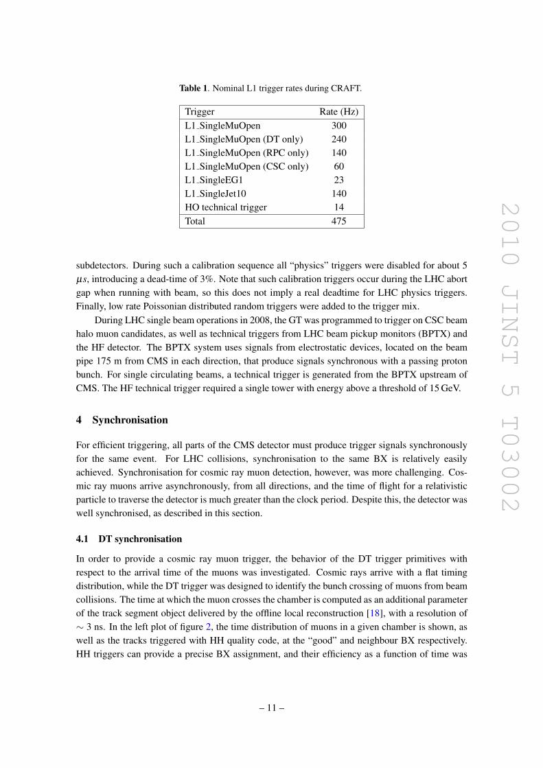
Table 1. Nominal L1 trigger rates during CRAFT.
Trigger Rate (Hz)L1 SingleMuOpen 300L1 SingleMuOpen (DT only) 240L1 SingleMuOpen (RPC only) 140L1 SingleMuOpen (CSC only) 60L1 SingleEG1 23L1 SingleJet10 140HO technical trigger 14Total 475
subdetectors. During such a calibration sequence all “physics” triggers were disabled for about 5µs, introducing a dead-time of 3%. Note that such calibration triggers occur during the LHC abortgap when running with beam, so this does not imply a real deadtime for LHC physics triggers.Finally, low rate Poissonian distributed random triggers were added to the trigger mix.
During LHC single beam operations in 2008, the GT was programmed to trigger on CSC beamhalo muon candidates, as well as technical triggers from LHC beam pickup monitors (BPTX) andthe HF detector. The BPTX system uses signals from electrostatic devices, located on the beampipe 175 m from CMS in each direction, that produce signals synchronous with a passing protonbunch. For single circulating beams, a technical trigger is generated from the BPTX upstream ofCMS. The HF technical trigger required a single tower with energy above a threshold of 15 GeV.
4 Synchronisation
For efficient triggering, all parts of the CMS detector must produce trigger signals synchronouslyfor the same event. For LHC collisions, synchronisation to the same BX is relatively easilyachieved. Synchronisation for cosmic ray muon detection, however, was more challenging. Cos-mic ray muons arrive asynchronously, from all directions, and the time of flight for a relativisticparticle to traverse the detector is much greater than the clock period. Despite this, the detector waswell synchronised, as described in this section.
4.1 DT synchronisation
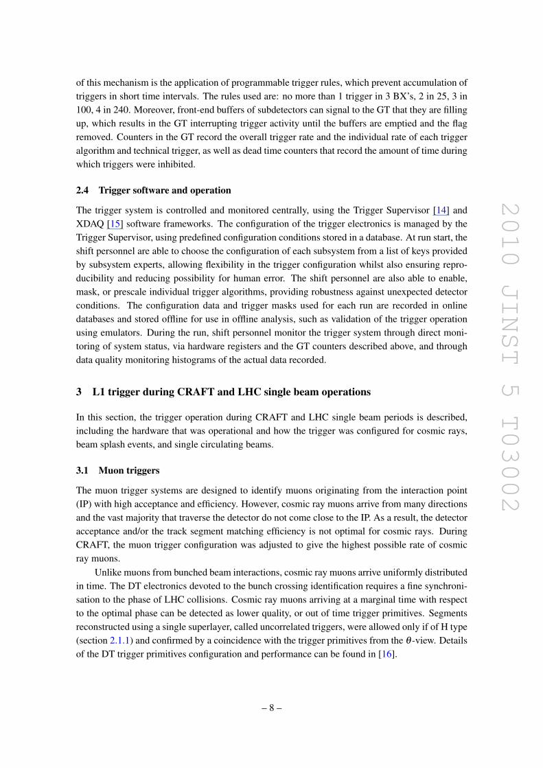
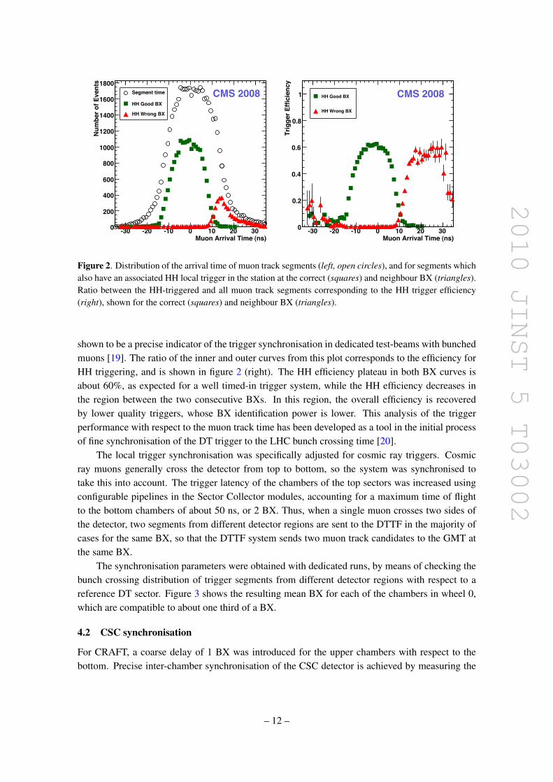
In order to provide a cosmic ray muon trigger, the behavior of the DT trigger primitives withrespect to the arrival time of the muons was investigated. Cosmic rays arrive with a flat timingdistribution, while the DT trigger was designed to identify the bunch crossing of muons from beamcollisions. The time at which the muon crosses the chamber is computed as an additional parameterof the track segment object delivered by the offline local reconstruction [18], with a resolution of∼ 3 ns. In the left plot of figure 2, the time distribution of muons in a given chamber is shown, aswell as the tracks triggered with HH quality code, at the “good” and neighbour BX respectively.HH triggers can provide a precise BX assignment, and their efficiency as a function of time was
– 11 –
2010 JINST 5 T03002
Muon Arrival Time (ns)-30 -20 -10 0 10 20 30
Num
ber o
f Eve
nts
0
200
400
600
800
1000
1200
1400
1600
1800Segment time
HH Good BX
HH Wrong BX
CMS 2008
Muon Arrival Time (ns)-30 -20 -10 0 10 20 30
Trig
ger E
ffici
ency
0
0.2
0.4
0.6
0.8
1 HH Good BX
HH Wrong BX
CMS 2008
Figure 2. Distribution of the arrival time of muon track segments (left, open circles), and for segments whichalso have an associated HH local trigger in the station at the correct (squares) and neighbour BX (triangles).Ratio between the HH-triggered and all muon track segments corresponding to the HH trigger efficiency(right), shown for the correct (squares) and neighbour BX (triangles).
shown to be a precise indicator of the trigger synchronisation in dedicated test-beams with bunchedmuons [19]. The ratio of the inner and outer curves from this plot corresponds to the efficiency forHH triggering, and is shown in figure 2 (right). The HH efficiency plateau in both BX curves isabout 60%, as expected for a well timed-in trigger system, while the HH efficiency decreases inthe region between the two consecutive BXs. In this region, the overall efficiency is recoveredby lower quality triggers, whose BX identification power is lower. This analysis of the triggerperformance with respect to the muon track time has been developed as a tool in the initial processof fine synchronisation of the DT trigger to the LHC bunch crossing time [20].
The local trigger synchronisation was specifically adjusted for cosmic ray triggers. Cosmicray muons generally cross the detector from top to bottom, so the system was synchronised totake this into account. The trigger latency of the chambers of the top sectors was increased usingconfigurable pipelines in the Sector Collector modules, accounting for a maximum time of flightto the bottom chambers of about 50 ns, or 2 BX. Thus, when a single muon crosses two sides ofthe detector, two segments from different detector regions are sent to the DTTF in the majority ofcases for the same BX, so that the DTTF system sends two muon track candidates to the GMT atthe same BX.
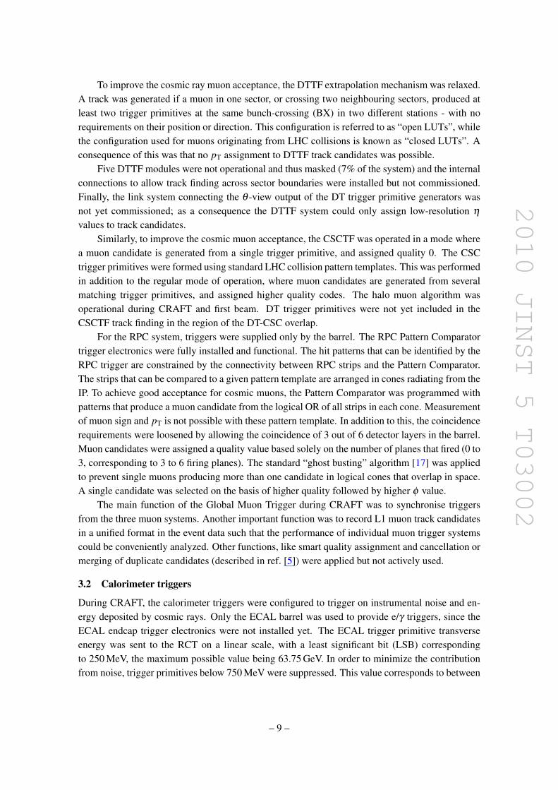
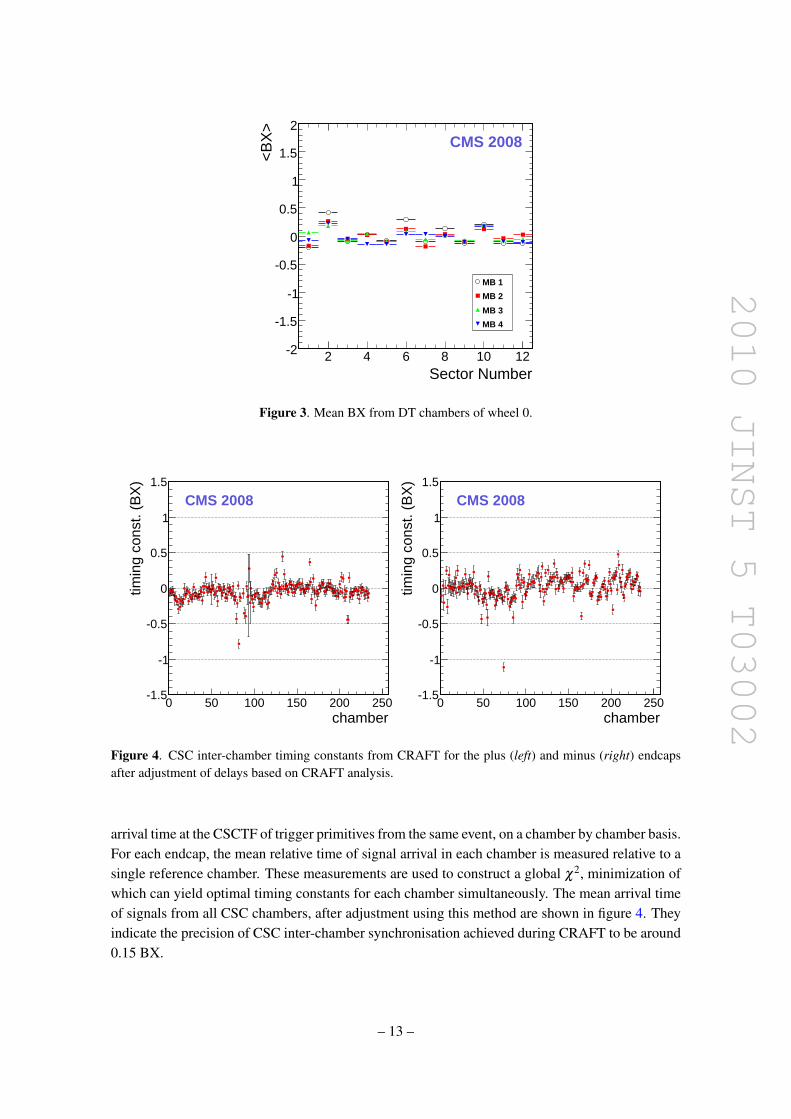
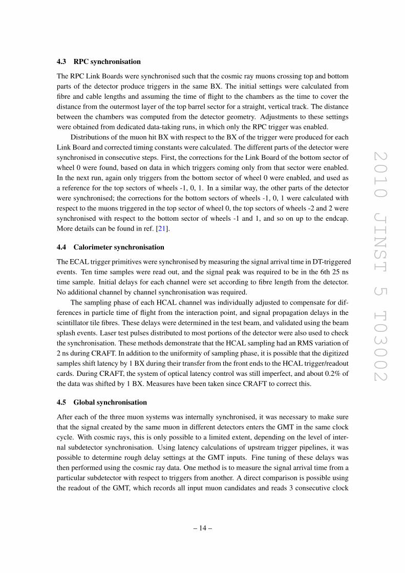
The synchronisation parameters were obtained with dedicated runs, by means of checking thebunch crossing distribution of trigger segments from different detector regions with respect to areference DT sector. Figure 3 shows the resulting mean BX for each of the chambers in wheel 0,which are compatible to about one third of a BX.
4.2 CSC synchronisation
For CRAFT, a coarse delay of 1 BX was introduced for the upper chambers with respect to thebottom. Precise inter-chamber synchronisation of the CSC detector is achieved by measuring the
– 12 –
2010 JINST 5 T03002
Sector Number2 4 6 8 10 12
<B
X>
-2
-1.5
-1
-0.5
0
0.5
1
1.5
2
MB 1
MB 2
MB 3
MB 4
CMS 2008
Figure 3. Mean BX from DT chambers of wheel 0.
chamber0 50 100 150 200 250
timin
g co
nst.
(BX
)
-1.5
-1
-0.5
0
0.5
1
1.5
CMS 2008
chamber0 50 100 150 200 250
timin
g co
nst.
(BX
)
-1.5
-1
-0.5
0
0.5
1
1.5
CMS 2008
Figure 4. CSC inter-chamber timing constants from CRAFT for the plus (left) and minus (right) endcapsafter adjustment of delays based on CRAFT analysis.
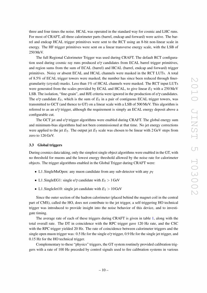
arrival time at the CSCTF of trigger primitives from the same event, on a chamber by chamber basis.For each endcap, the mean relative time of signal arrival in each chamber is measured relative to asingle reference chamber. These measurements are used to construct a global χ2, minimization ofwhich can yield optimal timing constants for each chamber simultaneously. The mean arrival timeof signals from all CSC chambers, after adjustment using this method are shown in figure 4. Theyindicate the precision of CSC inter-chamber synchronisation achieved during CRAFT to be around0.15 BX.
– 13 –
2010 JINST 5 T03002
4.3 RPC synchronisation
The RPC Link Boards were synchronised such that the cosmic ray muons crossing top and bottomparts of the detector produce triggers in the same BX. The initial settings were calculated fromfibre and cable lengths and assuming the time of flight to the chambers as the time to cover thedistance from the outermost layer of the top barrel sector for a straight, vertical track. The distancebetween the chambers was computed from the detector geometry. Adjustments to these settingswere obtained from dedicated data-taking runs, in which only the RPC trigger was enabled.
Distributions of the muon hit BX with respect to the BX of the trigger were produced for eachLink Board and corrected timing constants were calculated. The different parts of the detector weresynchronised in consecutive steps. First, the corrections for the Link Board of the bottom sector ofwheel 0 were found, based on data in which triggers coming only from that sector were enabled.In the next run, again only triggers from the bottom sector of wheel 0 were enabled, and used asa reference for the top sectors of wheels -1, 0, 1. In a similar way, the other parts of the detectorwere synchronised; the corrections for the bottom sectors of wheels -1, 0, 1 were calculated withrespect to the muons triggered in the top sector of wheel 0, the top sectors of wheels -2 and 2 weresynchronised with respect to the bottom sector of wheels -1 and 1, and so on up to the endcap.More details can be found in ref. [21].
4.4 Calorimeter synchronisation
The ECAL trigger primitives were synchronised by measuring the signal arrival time in DT-triggeredevents. Ten time samples were read out, and the signal peak was required to be in the 6th 25 nstime sample. Initial delays for each channel were set according to fibre length from the detector.No additional channel by channel synchronisation was required.
The sampling phase of each HCAL channel was individually adjusted to compensate for dif-ferences in particle time of flight from the interaction point, and signal propagation delays in thescintillator tile fibres. These delays were determined in the test beam, and validated using the beamsplash events. Laser test pulses distributed to most portions of the detector were also used to checkthe synchronisation. These methods demonstrate that the HCAL sampling had an RMS variation of2 ns during CRAFT. In addition to the uniformity of sampling phase, it is possible that the digitizedsamples shift latency by 1 BX during their transfer from the front ends to the HCAL trigger/readoutcards. During CRAFT, the system of optical latency control was still imperfect, and about 0.2% ofthe data was shifted by 1 BX. Measures have been taken since CRAFT to correct this.
4.5 Global synchronisation
After each of the three muon systems was internally synchronised, it was necessary to make surethat the signal created by the same muon in different detectors enters the GMT in the same clockcycle. With cosmic rays, this is only possible to a limited extent, depending on the level of inter-nal subdetector synchronisation. Using latency calculations of upstream trigger pipelines, it waspossible to determine rough delay settings at the GMT inputs. Fine tuning of these delays wasthen performed using the cosmic ray data. One method is to measure the signal arrival time from aparticular subdetector with respect to triggers from another. A direct comparison is possible usingthe readout of the GMT, which records all input muon candidates and reads 3 consecutive clock
– 14 –
2010 JINST 5 T03002
mottobTDXB - potTDXB5.1- 1- 5.0- 0 5.0 1 5.1
even
ts
0
01
02
03
04
05301!
CMS 2008
mottobCPRXB - potCPRXB5.1- 1- 5.0- 0 5.0 1 5.1
even
ts
0246801214161810222
301!
CMS 2008
TDXB - CPRXB5.1- 1- 5.0- 0 5.0 1 5.1
even
ts
0
02
04
06
08
001
301!
CMS 2008
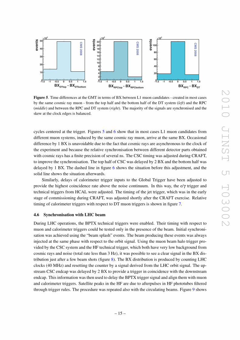
Figure 5. Time differences at the GMT in terms of BX between L1 muon candidates - created in most casesby the same cosmic ray muon - from the top half and the bottom half of the DT system (left) and the RPC(middle) and between the RPC and DT system (right). The majority of the signals are synchronised and theskew at the clock edges is balanced.
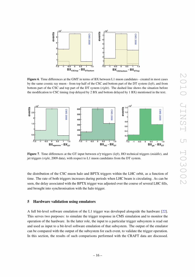
cycles centered at the trigger. Figures 5 and 6 show that in most cases L1 muon candidates fromdifferent muon systems, induced by the same cosmic ray muon, arrive at the same BX. Occasionaldifference by 1 BX is unavoidable due to the fact that cosmic rays are asynchronous to the clock ofthe experiment and because the relative synchronisation between different detector parts obtainedwith cosmic rays has a finite precision of several ns. The CSC timing was adjusted during CRAFT,to improve the synchronisation. The top half of CSC was delayed by 2 BX and the bottom half wasdelayed by 1 BX. The dashed line in figure 6 shows the situation before this adjustment, and thesolid line shows the situation afterwards.
Similarly, delays of calorimeter trigger inputs to the Global Trigger have been adjusted toprovide the highest coincidence rate above the noise continuum. In this way, the e/γ trigger andtechnical triggers from HCAL were adjusted. The timing of the jet trigger, which was in the earlystage of commissioning during CRAFT, was adjusted shortly after the CRAFT exercise. Relativetiming of calorimeter triggers with respect to DT muon triggers is shown in figure 7.
4.6 Synchronisation with LHC beam
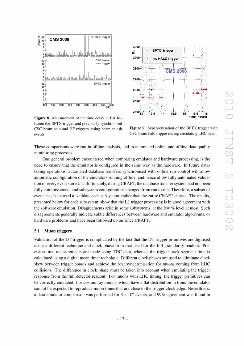
During LHC operations, the BPTX technical triggers were enabled. Their timing with respect tomuon and calorimeter triggers could be tested only in the presence of the beam. Initial synchroni-sation was achieved using the “beam splash” events. The beam producing these events was alwaysinjected at the same phase with respect to the orbit signal. Using the muon beam halo trigger pro-vided by the CSC system and the HF technical trigger, which both have very low background fromcosmic rays and noise (total rate less than 3 Hz), it was possible to see a clear signal in the BX dis-tribution just after a few beam shots (figure 8). The BX distribution is produced by counting LHCclocks (40 MHz) and resetting the counter by a signal derived from the LHC orbit signal. The up-stream CSC endcap was delayed by 2 BX to provide a trigger in coincidence with the downstreamendcap. This information was then used to delay the BPTX trigger signal and align them with muonand calorimeter triggers. Satellite peaks in the HF are due to afterpulses in HF phototubes filteredthrough trigger rules. The procedure was repeated also with the circulating beams. Figure 9 shows
– 15 –
2010 JINST 5 T03002
mottobTDXB - potCSCXB5.1- 1- 5.0- 0 5.0 1 5.1
even
ts
0
1
2
3
4
5
301! CMS 2008
potTDXB - mottobCSCXB5.1- 1- 5.0- 0 5.0 1 5.1
even
ts
0
12
34
567
301! CMS 2008
Figure 6. Time differences at the GMT in terms of BX between L1 muon candidates - created in most casesby the same cosmic ray muon - from top half of the CSC and bottom part of the DT system (left), and frombottom part of the CSC and top part of the DT system (right). The dashed line shows the situation beforethe modification to CSC timing (top delayed by 2 BX and bottom delayed by 1 BX) mentioned in the text.
TDXB - ammageXB5.1- 1- 5.0- 0 5.0 1 5.1
even
ts
0
5.0
1
5.1
2
5.2
301! CMS 2008
TDXB - OHXB5.1- 1- 5.0- 0 5.0 1 5.10
001
002
003
004
005
006 CMS 2008
TDXB - tejXB5.1- 1- 5.0- 0 5.0 1 5.1
even
ts
0
2.0
4.0
6.0
8.0
1
2.1
4.1301!
CMS 2009
Figure 7. Time differences at the GT input between e/γ triggers (left), HO technical triggers (middle), andjet triggers (right, 2009 data), with respect to L1 muon candidates from the DT system.
the distribution of the CSC muon halo and BPTX triggers within the LHC orbit, as a function oftime. The rate of both triggers increases during periods when LHC beam is circulating. As can beseen, the delay associated with the BPTX trigger was adjusted over the course of several LHC fills,and brought into synchronisation with the halo trigger.
5 Hardware validation using emulators
A full bit-level software emulation of the L1 trigger was developed alongside the hardware [22].This serves two purposes: to simulate the trigger response in CMS simulation and to monitor theoperation of the hardware. In the latter role, the input to a particular trigger subsystem is read outand used as input to a bit-level software emulation of that subsystem. The output of the emulatorcan be compared with the output of the subsystem for each event, to validate the trigger operation.In this section, the results of such comparisons performed with the CRAFT data are discussed.
– 16 –
2010 JINST 5 T03002
even
ts HF tech. trigger
CSC beamhalo trigger
BPTX trigger
BX
Figure 8. Measurement of the time delay in BX be-tween the BPTX trigger and previously synchronisedCSC beam halo and HF triggers, using beam splashevents.
Figure 9. Synchronisation of the BPTX trigger withCSC beam halo trigger during circulating LHC beam.
These comparisons were run in offline analysis, and in automated online and offline data qualitymonitoring processes.
One general problem encountered when comparing emulator and hardware processing, is theneed to ensure that the emulator is configured in the same way as the hardware. In future data-taking operations, automated database transfers synchronised with online run control will allowautomatic configuration of the emulators running offline, and hence allow fully automated valida-tion of every event stored. Unfortunately, during CRAFT, the database transfer system had not beenfully commissioned, and subsystem configurations changed from run to run. Therefore, a subset ofevents has been used to validate each subsystem, rather than the entire CRAFT dataset. The results,presented below for each subsystem, show that the L1 trigger processing is in good agreement withthe software emulation. Disagreements arise in some subsystems, at the few % level at most. Suchdisagreements generally indicate subtle differences between hardware and emulator algorithms, orhardware problems and have been followed up on since CRAFT.
5.1 Muon triggers
Validation of the DT trigger is complicated by the fact that the DT trigger primitives are digitisedusing a different technique and clock phase from that used for the full granularity readout. Pre-cision time measurements are made using TDC data, whereas the trigger track segment time iscalculated using a digital mean timer technique. Different clock phases are used to eliminate clockskew between trigger boards and achieve the best synchronisation for muons coming from LHCcollisions. The difference in clock phase must be taken into account when emulating the triggerresponse from the full detector readout. For muons with LHC timing, the trigger primitives canbe correctly emulated. For cosmic ray muons, which have a flat distribution in time, the emulatorcannot be expected to reproduce muon times that are close to the trigger clock edge. Neverthless,a data-emulator comparison was performed for 3× 10⁶ events, and 99% agreement was found in
– 17 –
2010 JINST 5 T03002
the trigger efficiency as a function of track position and impact angle. This result is consistent withwhat can be expected from the emulator given the timing issue outlined above.
The remaining muon trigger subsystems, apart from CSCTF, were validated by emulatingoutputs from read out input data. The DTTF validation was performed for 1 Million events in arun that used “closed LUTs” (the “open LUTs” used for cosmic ray data taking are not emulated)where the muon remains in a single DT sector. 100% agreement was observed between emulatorand data. For a typical run, the emulated CSC trigger primitives agreed with those in the datain 99.5% of events. The remaining 0.5% were due to a minor firmware error that has since beencorrected. The RPC trigger validation showed disagreement between data and emulator in ∼2%of cases, again for a typical run, coming almost exclusively from muon candidates in particulardetector regions. The GMT validation was performed regularly, with a typical run showing 100%agreement between data and emulator.
5.2 Calorimeter triggers
The calorimeter readout includes full granularity ECAL crystal and HCAL tower data, as well asthe trigger primitives sent to RCT. The trigger readout includes e/γ candidates and region sumsat the output of the RCT, and the e/γ and jet candidates at the output of GCT. Validation of thecalorimeter trigger processing therefore involves emulation of:
• ECAL trigger primitives from full granularity crystal data;
• HCAL trigger primitives from full granularity HCAL towers;
• RCT e/γ candidates and region sums from ECAL trigger primitives in data;
• GCT e/γ and jet candidates from RCT e/γ candidates and region sums in data.
The ECAL validation was performed on 10 Million events, constituting the bulk of runs whereECAL crystal data was not zero-suppressed. After accounting for masked channels, agreement wasobserved between the emulated ET and fine-grain bit and the data in more than 99.9% of triggerprimitives.
The HCAL validation was performed on over 50 Million events. Both ET sums and the HFfine-grain bit were compared between emulator and data. The level of disagreement observedbetween emulator and data was less than 1×10⁻⁶.
The RCT validation takes ECAL and HCAL towers from ECAL/HCAL readout data and pro-duces emulated e/γ candidates, which are then compared with those read out by the GCT. Dis-agreements at the level of a few percent were observed in 2008 due to masked channels that werenot emulated and latency instability in the HCAL data. During cosmic ray data-taking in 2009,the comparison is performed on a regular basis and shows perfect agreement between data andemulator.
The GCT emulator validation was performed on 20 Million CRAFT events. Agreement wasobserved between hardware and emulator for 100% of e/γ candidates. A small error in the imple-mentation of the jet-finding algorithm was discovered in the comparison of the jet candidates. Inapproximately 0.05% of cases a jet was incorrectly labeled as passing the τ-lepton veto. This hasno impact on the efficiency and resolution studies presented later in this paper, and the firmwarehas since been corrected.
– 18 –
2010 JINST 5 T03002
rate (Hz)
lum
inos
ity se
ctio
ns
Sector Rate (Hz)0 2 4 6 8 10 12 14 16 18
/Mea
nσ
0.02
0.04
0.06
0.08
0.1
0.12
0.14
0.16
0.18
/ ndf 2χ 66.95 / 63
p0 0.001129± 0.1156
/ ndf 2χ 66.95 / 63
p0 0.001129± 0.1156
CMS 2008
Figure 10. The rate distribution of a particular sector of wheel 0 (left). Fit to the σ/mean of all measuredsector rates (right).
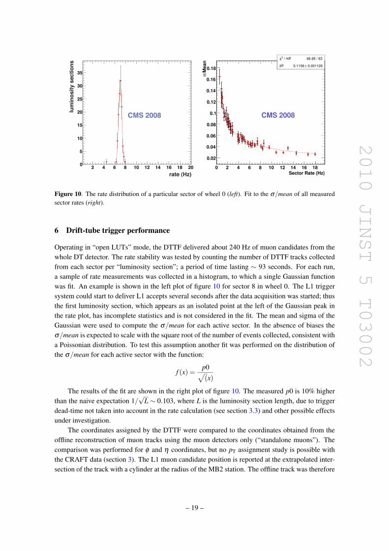
6 Drift-tube trigger performance
Operating in “open LUTs” mode, the DTTF delivered about 240 Hz of muon candidates from thewhole DT detector. The rate stability was tested by counting the number of DTTF tracks collectedfrom each sector per “luminosity section”; a period of time lasting ∼ 93 seconds. For each run,a sample of rate measurements was collected in a histogram, to which a single Gaussian functionwas fit. An example is shown in the left plot of figure 10 for sector 8 in wheel 0. The L1 triggersystem could start to deliver L1 accepts several seconds after the data acquisition was started; thusthe first luminosity section, which appears as an isolated point at the left of the Gaussian peak inthe rate plot, has incomplete statistics and is not considered in the fit. The mean and sigma of theGaussian were used to compute the σ/mean for each active sector. In the absence of biases theσ/mean is expected to scale with the square root of the number of events collected, consistent witha Poissonian distribution. To test this assumption another fit was performed on the distribution ofthe σ/mean for each active sector with the function:
f (x) =p0√(x)
The results of the fit are shown in the right plot of figure 10. The measured p0 is 10% higherthan the naive expectation 1/
√L ∼ 0.103, where L is the luminosity section length, due to trigger
dead-time not taken into account in the rate calculation (see section 3.3) and other possible effectsunder investigation.
The coordinates assigned by the DTTF were compared to the coordinates obtained from theoffline reconstruction of muon tracks using the muon detectors only (“standalone muons”). Thecomparison was performed for φ and η coordinates, but no pT assignment study is possible withthe CRAFT data (section 3). The L1 muon candidate position is reported at the extrapolated inter-section of the track with a cylinder at the radius of the MB2 station. The offline track was therefore
– 19 –
2010 JINST 5 T03002
Entries 302633Constant 1.5e+04Mean 0.008Sigma 0.027
(rad)DTTF
φ - SA
φ-0.3 -0.2 -0.1 0 0.1 0.2 0.3
DT
TF
Tra
cks
0
2000
4000
6000
8000
10000
12000
14000
16000
Entries 302633Constant 1.5e+04Mean 0.008Sigma 0.027
Entries 64152Constant 4309Mean 0.003218Sigma 0.02112
Entries 302633Constant 1.5e+04Mean 0.008Sigma 0.027
Entries 302633Constant 1.5e+04Mean 0.008Sigma 0.027
CMS 2008
All Sectors
Bottom Sectors
Dphi DTTF-muon - cuts, with scale offset
Mean 0.003Sigma 0.021
Mean 0.0003RMS 0.032
DTTFη -
SAη
-0.6 -0.4 -0.2 0 0.2 0.4 0.6
DT
TF
Tra
cks
0
200
400
600
800
1000
Mean 0.0003RMS 0.032Mean 0.0003RMS 0.032Mean 0.0003RMS 0.032
Mean -0.006215RMS 0.1289
CMS0
20
40
60
80
100
120
140
(2009)ηFine
(CRAFT)ηRough
Deta DTTF-muon - fine eta - cuts
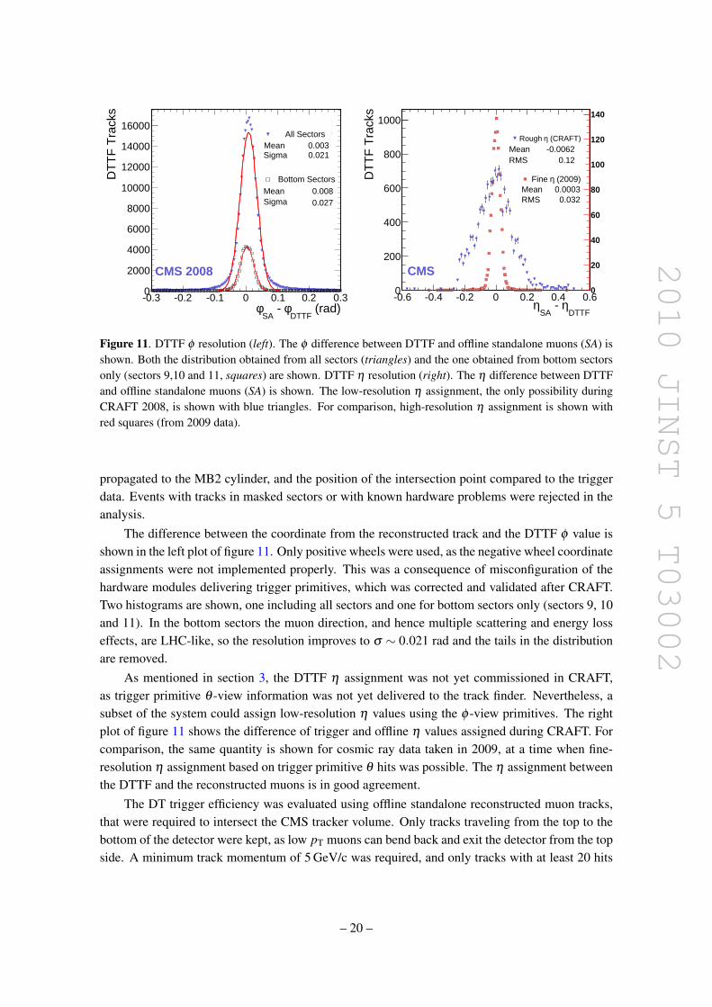
Figure 11. DTTF φ resolution (left). The φ difference between DTTF and offline standalone muons (SA) isshown. Both the distribution obtained from all sectors (triangles) and the one obtained from bottom sectorsonly (sectors 9,10 and 11, squares) are shown. DTTF η resolution (right). The η difference between DTTFand offline standalone muons (SA) is shown. The low-resolution η assignment, the only possibility duringCRAFT 2008, is shown with blue triangles. For comparison, high-resolution η assignment is shown withred squares (from 2009 data).
propagated to the MB2 cylinder, and the position of the intersection point compared to the triggerdata. Events with tracks in masked sectors or with known hardware problems were rejected in theanalysis.
The difference between the coordinate from the reconstructed track and the DTTF φ value isshown in the left plot of figure 11. Only positive wheels were used, as the negative wheel coordinateassignments were not implemented properly. This was a consequence of misconfiguration of thehardware modules delivering trigger primitives, which was corrected and validated after CRAFT.Two histograms are shown, one including all sectors and one for bottom sectors only (sectors 9, 10and 11). In the bottom sectors the muon direction, and hence multiple scattering and energy losseffects, are LHC-like, so the resolution improves to σ ∼ 0.021 rad and the tails in the distributionare removed.
As mentioned in section 3, the DTTF η assignment was not yet commissioned in CRAFT,as trigger primitive θ -view information was not yet delivered to the track finder. Nevertheless, asubset of the system could assign low-resolution η values using the φ -view primitives. The rightplot of figure 11 shows the difference of trigger and offline η values assigned during CRAFT. Forcomparison, the same quantity is shown for cosmic ray data taken in 2009, at a time when fine-resolution η assignment based on trigger primitive θ hits was possible. The η assignment betweenthe DTTF and the reconstructed muons is in good agreement.
The DT trigger efficiency was evaluated using offline standalone reconstructed muon tracks,that were required to intersect the CMS tracker volume. Only tracks traveling from the top to thebottom of the detector were kept, as low pT muons can bend back and exit the detector from the topside. A minimum track momentum of 5 GeV/c was required, and only tracks with at least 20 hits
– 20 –
2010 JINST 5 T03002
(cm)SAz-800 -600 -400 -200 0 200 400 600 800
(rad
.)S
AΦ
0
0.5
1
1.5
2
2.5
3
0
0.1
0.2
0.3
0.4
0.5
0.6
0.7
0.8
0.9
1
CMS 2008
effic
ienc
y
(GeV/c)SAT
p1 10 210 310
effic
ienc
y
0.65
0.7
0.75
0.8
0.85
0.9
0.95
1After acceptence cuts
No acceptence cuts
CMS 2008
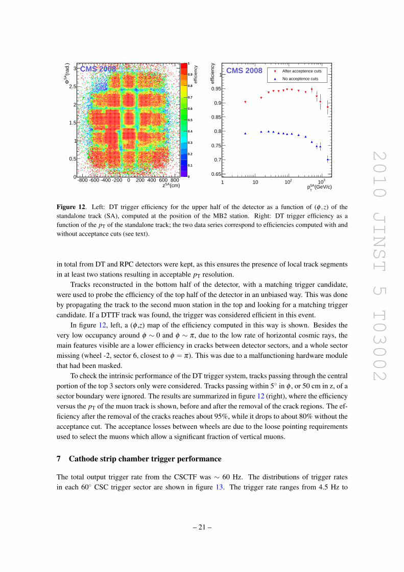
Figure 12. Left: DT trigger efficiency for the upper half of the detector as a function of (φ ,z) of thestandalone track (SA), computed at the position of the MB2 station. Right: DT trigger efficiency as afunction of the pT of the standalone track; the two data series correspond to efficiencies computed with andwithout acceptance cuts (see text).
in total from DT and RPC detectors were kept, as this ensures the presence of local track segmentsin at least two stations resulting in acceptable pT resolution.
Tracks reconstructed in the bottom half of the detector, with a matching trigger candidate,were used to probe the efficiency of the top half of the detector in an unbiased way. This was doneby propagating the track to the second muon station in the top and looking for a matching triggercandidate. If a DTTF track was found, the trigger was considered efficient in this event.
In figure 12, left, a (φ ,z) map of the efficiency computed in this way is shown. Besides thevery low occupancy around φ ∼ 0 and φ ∼ π , due to the low rate of horizontal cosmic rays, themain features visible are a lower efficiency in cracks between detector sectors, and a whole sectormissing (wheel -2, sector 6, closest to φ = π). This was due to a malfunctioning hardware modulethat had been masked.
To check the intrinsic performance of the DT trigger system, tracks passing through the centralportion of the top 3 sectors only were considered. Tracks passing within 5◦ in φ , or 50 cm in z, of asector boundary were ignored. The results are summarized in figure 12 (right), where the efficiencyversus the pT of the muon track is shown, before and after the removal of the crack regions. The ef-ficiency after the removal of the cracks reaches about 95%, while it drops to about 80% without theacceptance cut. The acceptance losses between wheels are due to the loose pointing requirementsused to select the muons which allow a significant fraction of vertical muons.
7 Cathode strip chamber trigger performance
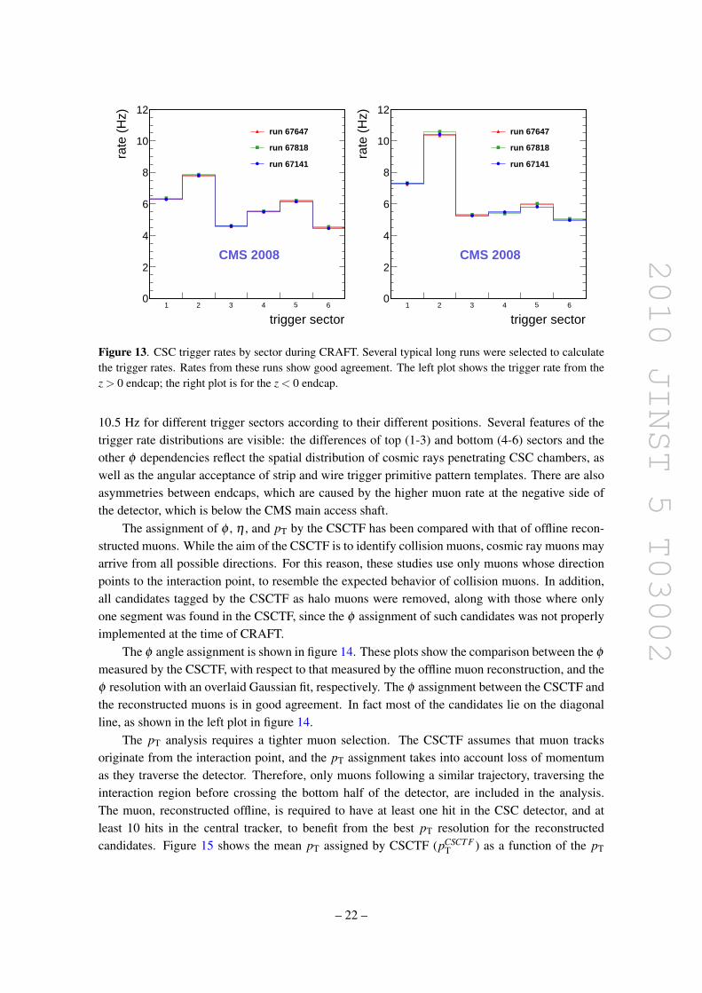
The total output trigger rate from the CSCTF was ∼ 60 Hz. The distributions of trigger ratesin each 60◦ CSC trigger sector are shown in figure 13. The trigger rate ranges from 4.5 Hz to
– 21 –
2010 JINST 5 T03002
trigger sector1 2 3 4 5 6
rate
(H
z)
0
2
4
6
8
10
12
run 67647
run 67818
run 67141
CMS 2008
trigger sector1 2 3 4 5 6
rate
(H
z)
0
2
4
6
8
10
12
run 67647
run 67818
run 67141
CMS 2008
Figure 13. CSC trigger rates by sector during CRAFT. Several typical long runs were selected to calculatethe trigger rates. Rates from these runs show good agreement. The left plot shows the trigger rate from thez > 0 endcap; the right plot is for the z < 0 endcap.
10.5 Hz for different trigger sectors according to their different positions. Several features of thetrigger rate distributions are visible: the differences of top (1-3) and bottom (4-6) sectors and theother φ dependencies reflect the spatial distribution of cosmic rays penetrating CSC chambers, aswell as the angular acceptance of strip and wire trigger primitive pattern templates. There are alsoasymmetries between endcaps, which are caused by the higher muon rate at the negative side ofthe detector, which is below the CMS main access shaft.
The assignment of φ , η , and pT by the CSCTF has been compared with that of offline recon-structed muons. While the aim of the CSCTF is to identify collision muons, cosmic ray muons mayarrive from all possible directions. For this reason, these studies use only muons whose directionpoints to the interaction point, to resemble the expected behavior of collision muons. In addition,all candidates tagged by the CSCTF as halo muons were removed, along with those where onlyone segment was found in the CSCTF, since the φ assignment of such candidates was not properlyimplemented at the time of CRAFT.
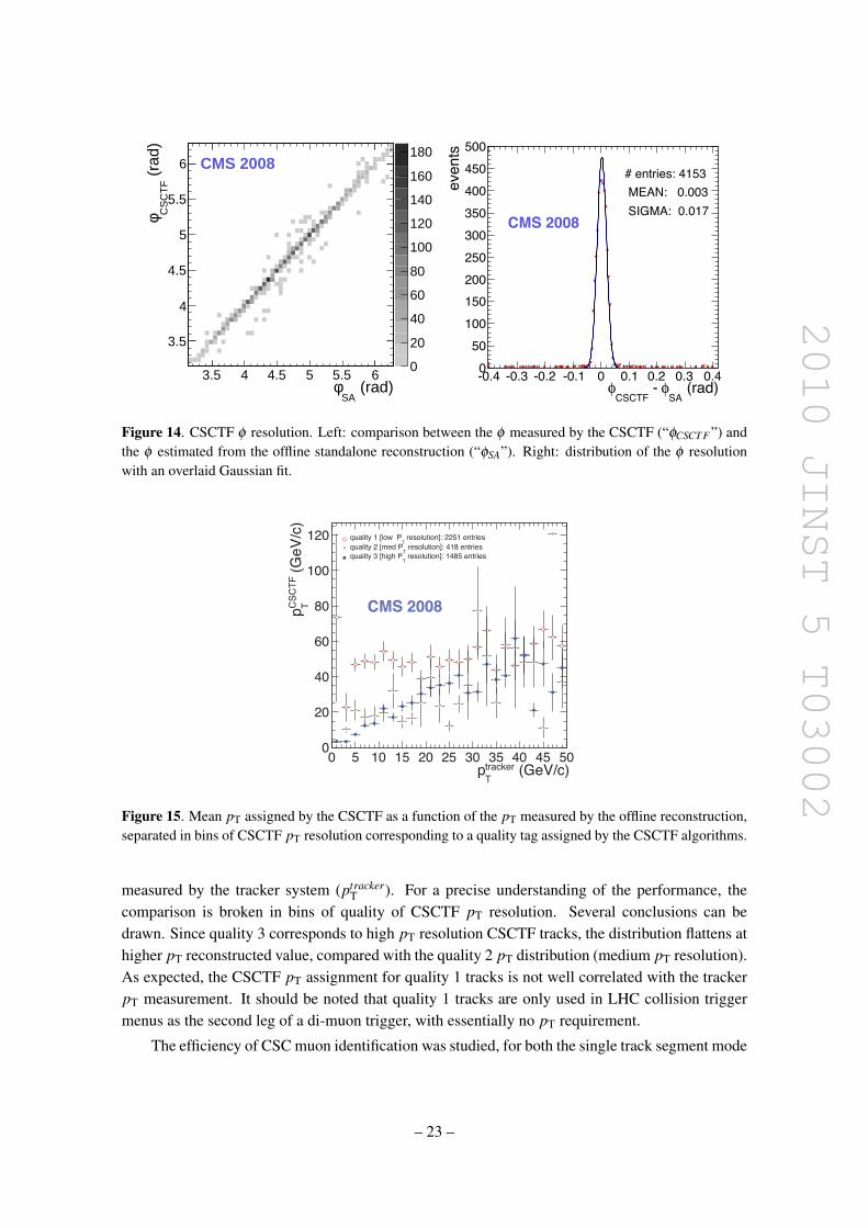
The φ angle assignment is shown in figure 14. These plots show the comparison between the φ
measured by the CSCTF, with respect to that measured by the offline muon reconstruction, and theφ resolution with an overlaid Gaussian fit, respectively. The φ assignment between the CSCTF andthe reconstructed muons is in good agreement. In fact most of the candidates lie on the diagonalline, as shown in the left plot in figure 14.
The pT analysis requires a tighter muon selection. The CSCTF assumes that muon tracksoriginate from the interaction point, and the pT assignment takes into account loss of momentumas they traverse the detector. Therefore, only muons following a similar trajectory, traversing theinteraction region before crossing the bottom half of the detector, are included in the analysis.The muon, reconstructed offline, is required to have at least one hit in the CSC detector, and atleast 10 hits in the central tracker, to benefit from the best pT resolution for the reconstructedcandidates. Figure 15 shows the mean pT assigned by CSCTF (pCSCT F
T ) as a function of the pT
– 22 –
2010 JINST 5 T03002
(rad)SA
φ3.5 4 4.5 5 5.5 6
(ra
d)C
SC
TF
φ
3.5
4
4.5
5
5.5
6
0
20
40
60
80
100
120
140
160
180CMS 2008
(rad)SA
! - CSCTF
!-0.4 -0.3 -0.2 -0.1 0 0.1 0.2 0.3 0.4
even
ts
0
50
100
150200
250
300
350
400
450
500
# entries: 4153 MEAN: 0.003 SIGMA: 0.017
CMS 2008
Figure 14. CSCTF φ resolution. Left: comparison between the φ measured by the CSCTF (“φCSCT F ”) andthe φ estimated from the offline standalone reconstruction (“φSA”). Right: distribution of the φ resolutionwith an overlaid Gaussian fit.
(GeV/c)trackerTp
0 5 10 15 20 25 30 35 40 45 50
)c/VeG( FTCSC Tp
0
20
40
60
80
100
120 resolution]: 2251 entriesT
quality 1 [low P resolution]: 418 entries
T quality 2 [med P
resolution]: 1485 entriesT
quality 3 [high P
CMS 2008
Figure 15. Mean pT assigned by the CSCTF as a function of the pT measured by the offline reconstruction,separated in bins of CSCTF pT resolution corresponding to a quality tag assigned by the CSCTF algorithms.
measured by the tracker system (ptrackerT ). For a precise understanding of the performance, the
comparison is broken in bins of quality of CSCTF pT resolution. Several conclusions can bedrawn. Since quality 3 corresponds to high pT resolution CSCTF tracks, the distribution flattens athigher pT reconstructed value, compared with the quality 2 pT distribution (medium pT resolution).As expected, the CSCTF pT assignment for quality 1 tracks is not well correlated with the trackerpT measurement. It should be noted that quality 1 tracks are only used in LHC collision triggermenus as the second leg of a di-muon trigger, with essentially no pT requirement.
The efficiency of CSC muon identification was studied, for both the single track segment mode
– 23 –
2010 JINST 5 T03002
(GeV/c)trackerT
p1 10 210
effic
ienc
y
0.4
0.6
0.8
1
ME+
ME-
CMS 2008
(GeV/c)trackerT
p1 10 210
effic
ienc
y
0.4
0.6
0.8
1
Quality 3 (1119 tracks)
Quality 2 (248 tracks)
Quality 1 (696 tracks)
CMS 2008
Figure 16. Left: efficiency of CSCTF in “singles” mode as a function of offline reconstructed pT in thetracker, ptracker
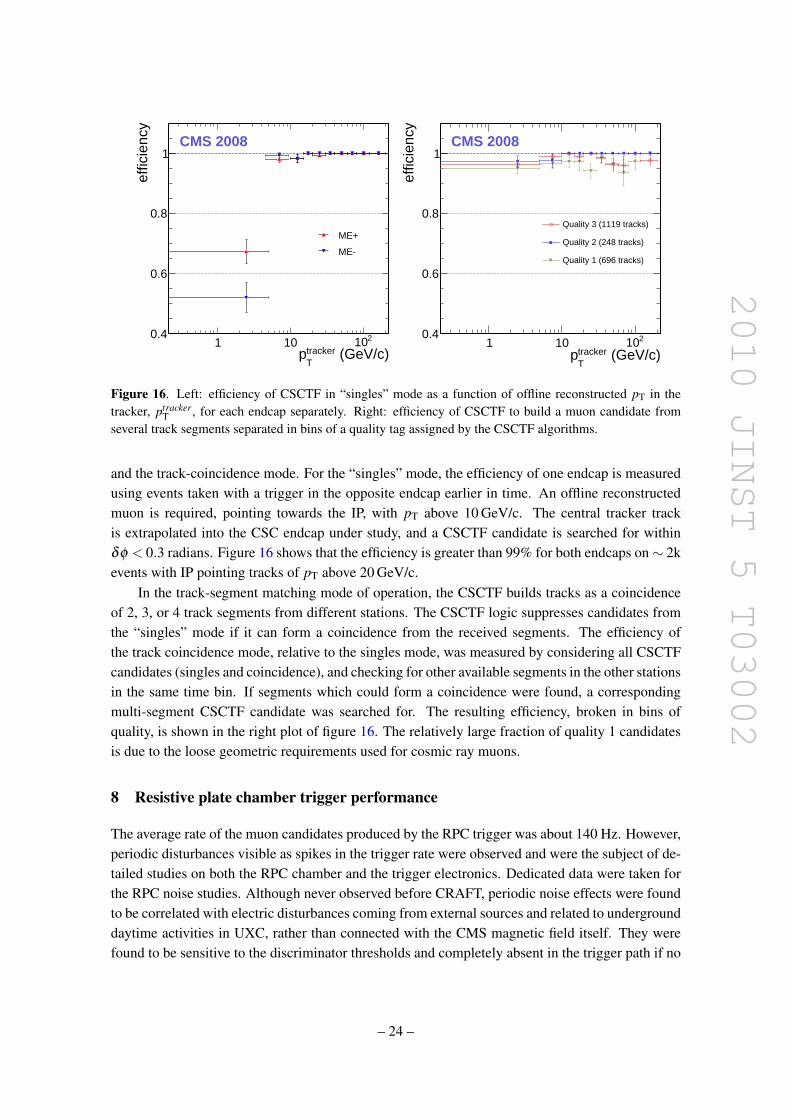
T , for each endcap separately. Right: efficiency of CSCTF to build a muon candidate fromseveral track segments separated in bins of a quality tag assigned by the CSCTF algorithms.
and the track-coincidence mode. For the “singles” mode, the efficiency of one endcap is measuredusing events taken with a trigger in the opposite endcap earlier in time. An offline reconstructedmuon is required, pointing towards the IP, with pT above 10 GeV/c. The central tracker trackis extrapolated into the CSC endcap under study, and a CSCTF candidate is searched for withinδφ < 0.3 radians. Figure 16 shows that the efficiency is greater than 99% for both endcaps on∼ 2kevents with IP pointing tracks of pT above 20 GeV/c.
In the track-segment matching mode of operation, the CSCTF builds tracks as a coincidenceof 2, 3, or 4 track segments from different stations. The CSCTF logic suppresses candidates fromthe “singles” mode if it can form a coincidence from the received segments. The efficiency ofthe track coincidence mode, relative to the singles mode, was measured by considering all CSCTFcandidates (singles and coincidence), and checking for other available segments in the other stationsin the same time bin. If segments which could form a coincidence were found, a correspondingmulti-segment CSCTF candidate was searched for. The resulting efficiency, broken in bins ofquality, is shown in the right plot of figure 16. The relatively large fraction of quality 1 candidatesis due to the loose geometric requirements used for cosmic ray muons.
8 Resistive plate chamber trigger performance
The average rate of the muon candidates produced by the RPC trigger was about 140 Hz. However,periodic disturbances visible as spikes in the trigger rate were observed and were the subject of de-tailed studies on both the RPC chamber and the trigger electronics. Dedicated data were taken forthe RPC noise studies. Although never observed before CRAFT, periodic noise effects were foundto be correlated with electric disturbances coming from external sources and related to undergrounddaytime activities in UXC, rather than connected with the CMS magnetic field itself. They werefound to be sensitive to the discriminator thresholds and completely absent in the trigger path if no
– 24 –
2010 JINST 5 T03002
(rad)RPC
φ-SA
φ-0.5 -0.4 -0.3 -0.2 -0.1 0 0.1 0.2 0.3 0.4 0.5
RP
C t
rack
s
10
210
310
410
(rad)RPC
φ-SA
φ-0.5 -0.4 -0.3 -0.2 -0.1 0 0.1 0.2 0.3 0.4 0.5
RP
C t
rack
s
10
210
310
410LHC patternsMean 0.018Sigma 0.022
cosmic ray patterns
CMS 2008
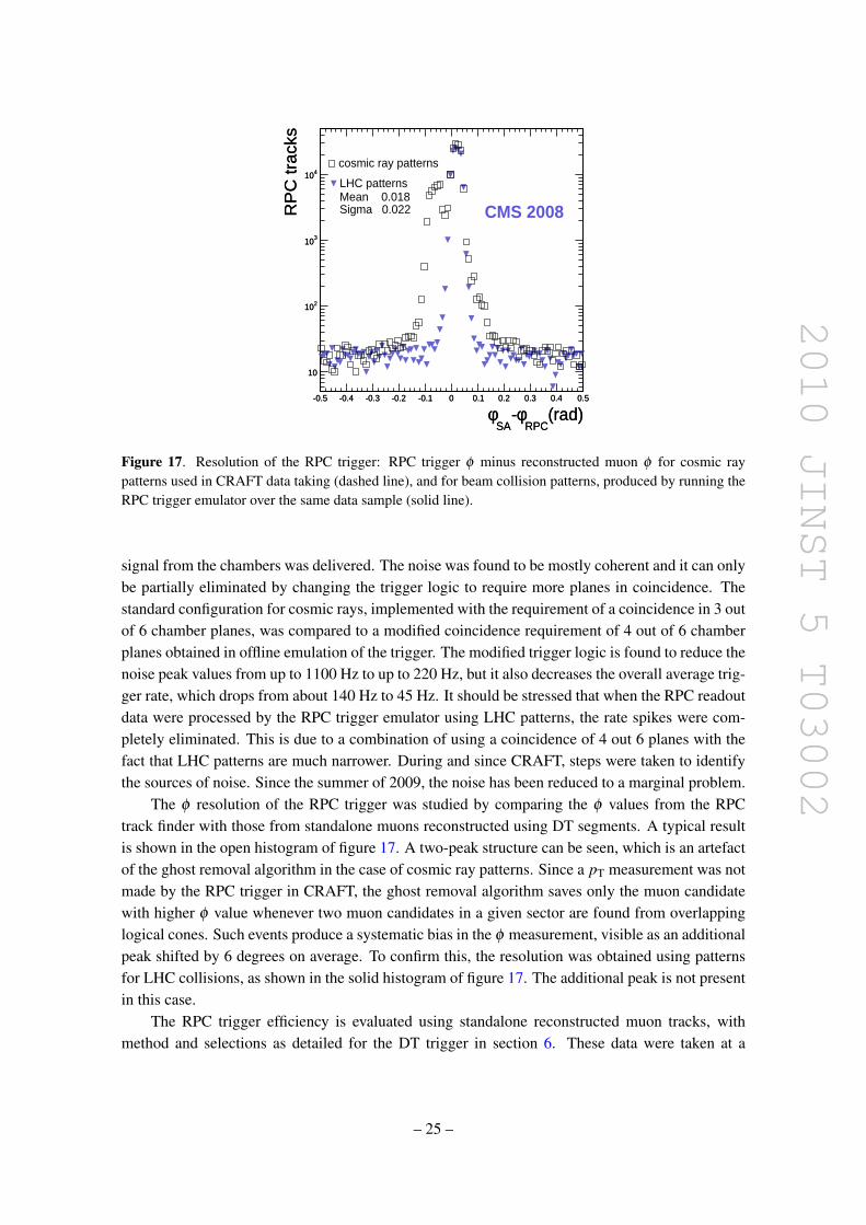
Figure 17. Resolution of the RPC trigger: RPC trigger φ minus reconstructed muon φ for cosmic raypatterns used in CRAFT data taking (dashed line), and for beam collision patterns, produced by running theRPC trigger emulator over the same data sample (solid line).
signal from the chambers was delivered. The noise was found to be mostly coherent and it can onlybe partially eliminated by changing the trigger logic to require more planes in coincidence. Thestandard configuration for cosmic rays, implemented with the requirement of a coincidence in 3 outof 6 chamber planes, was compared to a modified coincidence requirement of 4 out of 6 chamberplanes obtained in offline emulation of the trigger. The modified trigger logic is found to reduce thenoise peak values from up to 1100 Hz to up to 220 Hz, but it also decreases the overall average trig-ger rate, which drops from about 140 Hz to 45 Hz. It should be stressed that when the RPC readoutdata were processed by the RPC trigger emulator using LHC patterns, the rate spikes were com-pletely eliminated. This is due to a combination of using a coincidence of 4 out 6 planes with thefact that LHC patterns are much narrower. During and since CRAFT, steps were taken to identifythe sources of noise. Since the summer of 2009, the noise has been reduced to a marginal problem.
The φ resolution of the RPC trigger was studied by comparing the φ values from the RPCtrack finder with those from standalone muons reconstructed using DT segments. A typical resultis shown in the open histogram of figure 17. A two-peak structure can be seen, which is an artefactof the ghost removal algorithm in the case of cosmic ray patterns. Since a pT measurement was notmade by the RPC trigger in CRAFT, the ghost removal algorithm saves only the muon candidatewith higher φ value whenever two muon candidates in a given sector are found from overlappinglogical cones. Such events produce a systematic bias in the φ measurement, visible as an additionalpeak shifted by 6 degrees on average. To confirm this, the resolution was obtained using patternsfor LHC collisions, as shown in the solid histogram of figure 17. The additional peak is not presentin this case.
The RPC trigger efficiency is evaluated using standalone reconstructed muon tracks, withmethod and selections as detailed for the DT trigger in section 6. These data were taken at a
– 25 –
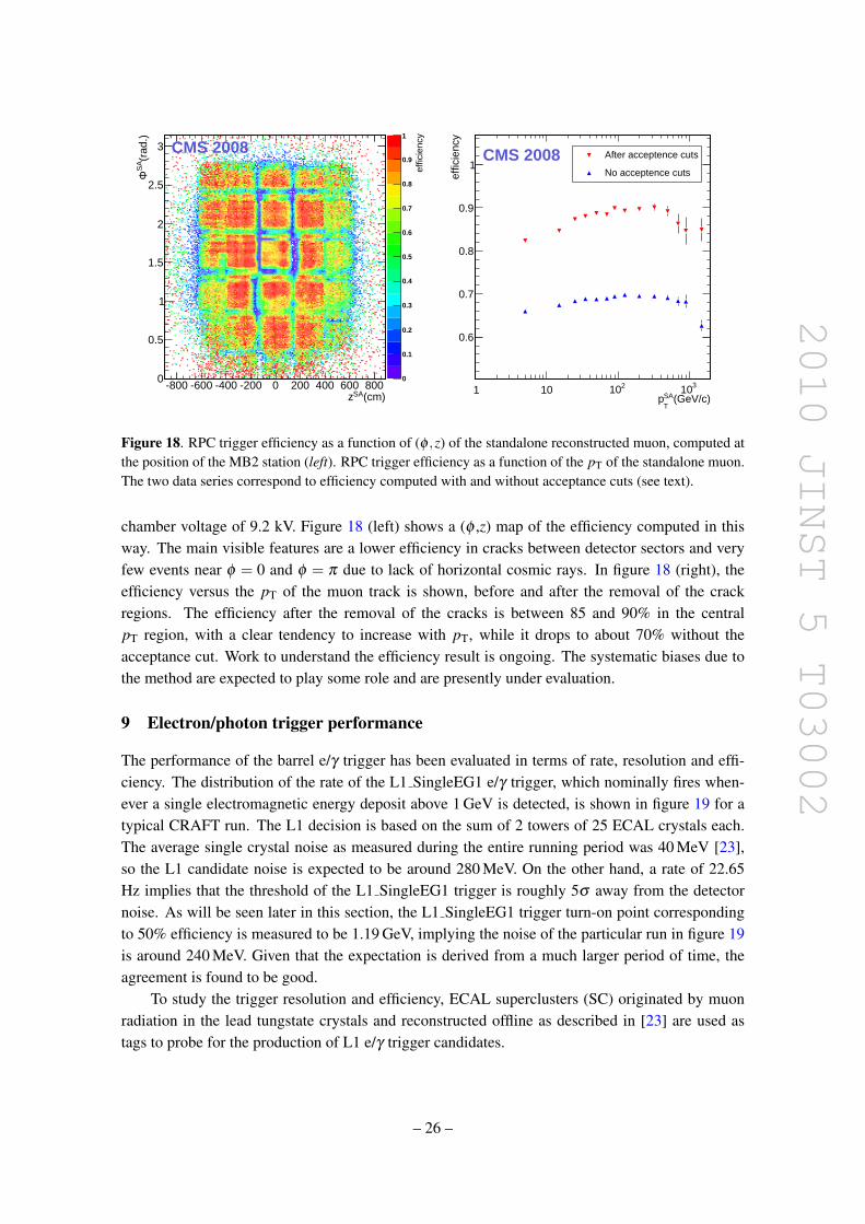
2010 JINST 5 T03002
(cm)SAz-800 -600 -400 -200 0 200 400 600 800
(rad
.)S
AΦ
0
0.5
1
1.5
2
2.5
3
0
0.1
0.2
0.3
0.4
0.5
0.6
0.7
0.8
0.9
1
CMS 2008
effic
ienc
y
(GeV/c)SAT
p1 10 210 310
effic
ienc
y
0.6
0.7
0.8
0.9
1After acceptence cuts
No acceptence cuts
CMS 2008
Figure 18. RPC trigger efficiency as a function of (φ ,z) of the standalone reconstructed muon, computed atthe position of the MB2 station (left). RPC trigger efficiency as a function of the pT of the standalone muon.The two data series correspond to efficiency computed with and without acceptance cuts (see text).
chamber voltage of 9.2 kV. Figure 18 (left) shows a (φ ,z) map of the efficiency computed in thisway. The main visible features are a lower efficiency in cracks between detector sectors and veryfew events near φ = 0 and φ = π due to lack of horizontal cosmic rays. In figure 18 (right), theefficiency versus the pT of the muon track is shown, before and after the removal of the crackregions. The efficiency after the removal of the cracks is between 85 and 90% in the centralpT region, with a clear tendency to increase with pT, while it drops to about 70% without theacceptance cut. Work to understand the efficiency result is ongoing. The systematic biases due tothe method are expected to play some role and are presently under evaluation.
9 Electron/photon trigger performance
The performance of the barrel e/γ trigger has been evaluated in terms of rate, resolution and effi-ciency. The distribution of the rate of the L1 SingleEG1 e/γ trigger, which nominally fires when-ever a single electromagnetic energy deposit above 1 GeV is detected, is shown in figure 19 for atypical CRAFT run. The L1 decision is based on the sum of 2 towers of 25 ECAL crystals each.The average single crystal noise as measured during the entire running period was 40 MeV [23],so the L1 candidate noise is expected to be around 280 MeV. On the other hand, a rate of 22.65Hz implies that the threshold of the L1 SingleEG1 trigger is roughly 5σ away from the detectornoise. As will be seen later in this section, the L1 SingleEG1 trigger turn-on point correspondingto 50% efficiency is measured to be 1.19 GeV, implying the noise of the particular run in figure 19is around 240 MeV. Given that the expectation is derived from a much larger period of time, theagreement is found to be good.
To study the trigger resolution and efficiency, ECAL superclusters (SC) originated by muonradiation in the lead tungstate crystals and reconstructed offline as described in [23] are used astags to probe for the production of L1 e/γ trigger candidates.
– 26 –
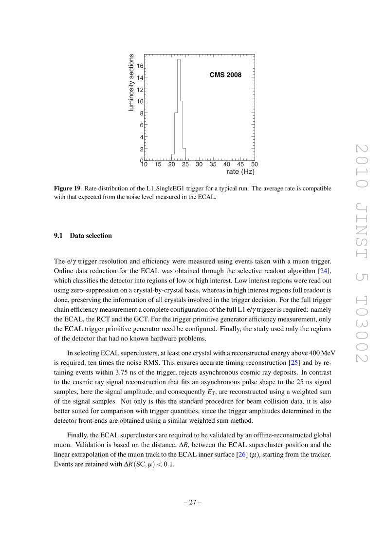
2010 JINST 5 T03002
lumino
sity s
ectio
ns
Figure 19. Rate distribution of the L1 SingleEG1 trigger for a typical run. The average rate is compatiblewith that expected from the noise level measured in the ECAL.
9.1 Data selection
The e/γ trigger resolution and efficiency were measured using events taken with a muon trigger.Online data reduction for the ECAL was obtained through the selective readout algorithm [24],which classifies the detector into regions of low or high interest. Low interest regions were read outusing zero-suppression on a crystal-by-crystal basis, whereas in high interest regions full readout isdone, preserving the information of all crystals involved in the trigger decision. For the full triggerchain efficiency measurement a complete configuration of the full L1 e/γ trigger is required: namelythe ECAL, the RCT and the GCT. For the trigger primitive generator efficiency measurement, onlythe ECAL trigger primitive generator need be configured. Finally, the study used only the regionsof the detector that had no known hardware problems.
In selecting ECAL superclusters, at least one crystal with a reconstructed energy above 400 MeVis required, ten times the noise RMS. This ensures accurate timing reconstruction [25] and by re-taining events within 3.75 ns of the trigger, rejects asynchronous cosmic ray deposits. In contrastto the cosmic ray signal reconstruction that fits an asynchronous pulse shape to the 25 ns signalsamples, here the signal amplitude, and consequently ET, are reconstructed using a weighted sumof the signal samples. Not only is this the standard procedure for beam collision data, it is alsobetter suited for comparison with trigger quantities, since the trigger amplitudes determined in thedetector front-ends are obtained using a similar weighted sum method.
Finally, the ECAL superclusters are required to be validated by an offline-reconstructed globalmuon. Validation is based on the distance, ∆R, between the ECAL supercluster position and thelinear extrapolation of the muon track to the ECAL inner surface [26] (µ), starting from the tracker.Events are retained with ∆R(SC,µ) < 0.1.
– 27 –
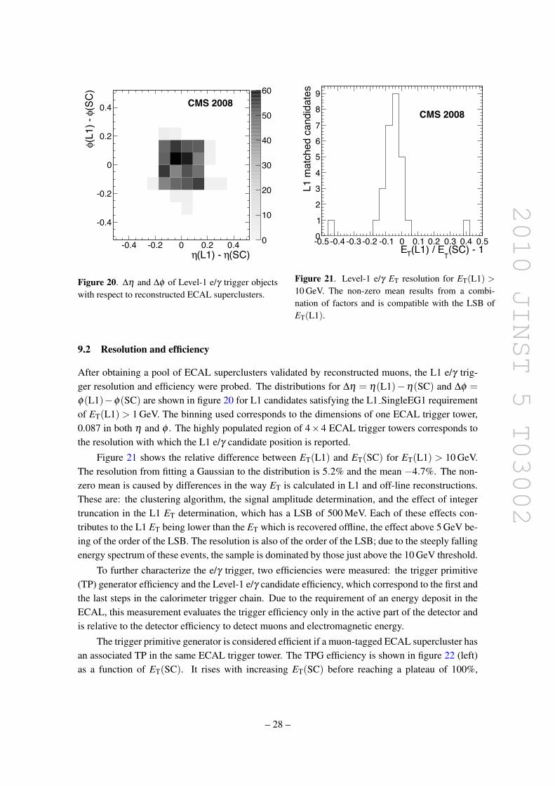
2010 JINST 5 T03002
(SC)!(L1) - !-0.4 -0.2 0 0.2 0.4
(SC
)"
(L1)
- "
-0.4
-0.2
0
0.2
0.4
0
10
20
30
40
50
60CMS 2008
Figure 20. ∆η and ∆φ of Level-1 e/γ trigger objectswith respect to reconstructed ECAL superclusters.
(SC) - 1T
(L1) / ETE-0.5 -0.4 -0.3 -0.2 -0.1 0 0.1 0.2 0.3 0.4 0.5
L1 m
atch
ed c
andi
date
s
0
1
2
3
4
5
6
7
8
9
CMS 2008
Figure 21. Level-1 e/γ ET resolution for ET(L1) >
10 GeV. The non-zero mean results from a combi-nation of factors and is compatible with the LSB ofET(L1).
9.2 Resolution and efficiency
After obtaining a pool of ECAL superclusters validated by reconstructed muons, the L1 e/γ trig-ger resolution and efficiency were probed. The distributions for ∆η = η(L1)−η(SC) and ∆φ =φ(L1)−φ(SC) are shown in figure 20 for L1 candidates satisfying the L1 SingleEG1 requirementof ET(L1) > 1 GeV. The binning used corresponds to the dimensions of one ECAL trigger tower,0.087 in both η and φ . The highly populated region of 4×4 ECAL trigger towers corresponds tothe resolution with which the L1 e/γ candidate position is reported.
Figure 21 shows the relative difference between ET(L1) and ET(SC) for ET(L1) > 10 GeV.The resolution from fitting a Gaussian to the distribution is 5.2% and the mean −4.7%. The non-zero mean is caused by differences in the way ET is calculated in L1 and off-line reconstructions.These are: the clustering algorithm, the signal amplitude determination, and the effect of integertruncation in the L1 ET determination, which has a LSB of 500 MeV. Each of these effects con-tributes to the L1 ET being lower than the ET which is recovered offline, the effect above 5 GeV be-ing of the order of the LSB. The resolution is also of the order of the LSB; due to the steeply fallingenergy spectrum of these events, the sample is dominated by those just above the 10 GeV threshold.
To further characterize the e/γ trigger, two efficiencies were measured: the trigger primitive(TP) generator efficiency and the Level-1 e/γ candidate efficiency, which correspond to the first andthe last steps in the calorimeter trigger chain. Due to the requirement of an energy deposit in theECAL, this measurement evaluates the trigger efficiency only in the active part of the detector andis relative to the detector efficiency to detect muons and electromagnetic energy.
The trigger primitive generator is considered efficient if a muon-tagged ECAL supercluster hasan associated TP in the same ECAL trigger tower. The TPG efficiency is shown in figure 22 (left)as a function of ET(SC). It rises with increasing ET(SC) before reaching a plateau of 100%,
– 28 –
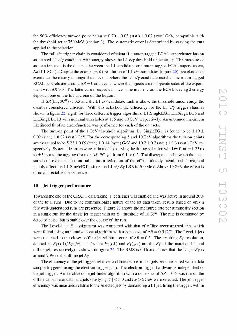
2010 JINST 5 T03002
the 50% efficiency turn-on point being at 0.70± 0.03 (stat.)± 0.02 (syst.) GeV, compatible withthe threshold set at 750 MeV (section 3). The systematic error is determined by varying the cutsapplied to the selection.
The full e/γ trigger chain is considered efficient if a muon-tagged ECAL supercluster has anassociated L1 e/γ candidate with energy above the L1 e/γ threshold under study. The measure ofassociation used is the distance between the L1 candidates and muon-tagged ECAL superclusters,∆R(L1,SCµ). Despite the coarse (η ,φ) resolution of L1 e/γ candidates (figure 20) two classes ofevents can be clearly distinguished: events where the L1 e/γ candidate matches the muon-taggedECAL supercluster around ∆R = 0 and events where the objects are in opposite sides of the experi-ment with ∆R > 3. The latter case is expected since some muons cross the ECAL leaving 2 energydeposits, one on the top and one on the bottom.
If ∆R(L1,SCµ) < 0.5 and the L1 e/γ candidate rank is above the threshold under study, theevent is considered efficient. With this selection the efficiency for the L1 e/γ trigger chain isshown in figure 22 (right) for three different trigger algorithms: L1 SingleEG1, L1 SingleEG5 andL1 SingleEG10 with nominal thresholds at 1, 5 and 10 GeV, respectively. An unbinned maximumlikelihood fit of an error-function was performed for each of the datasets.
The turn-on point of the 1 GeV threshold algorithm, L1 SingleEG1, is found to be 1.19±0.02 (stat.)± 0.02 (syst.) GeV. For the corresponding 5 and 10 GeV algorithms the turn-on pointsare measured to be 5.23±0.09 (stat.)±0.14 (syst.) GeV and 10.2±0.2 (stat.)±0.3 (syst.) GeV, re-spectively. Systematic errors were estimated by varying the timing selection window from±1.25 nsto ±5 ns and the tagging distance ∆R(SC,µ) from 0.1 to 0.5. The discrepancies between the mea-sured and expected turn-on points are a reflection of the effects already mentioned above, andmainly affect the L1 SingleEG1, since the L1 e/γ ET LSB is 500 MeV. Above 10 GeV the effect isof no appreciable consequence.
10 Jet trigger performance
Towards the end of the CRAFT data taking, a jet trigger was enabled and was active in around 20%of the total runs. Due to the commissioning nature of the jet data taken, results based on only afew well-understood runs are presented. Figure 23 shows the measured rate per luminosity sectionin a single run for the single jet trigger with an ET threshold of 10GeV. The rate is dominated bydetector noise, but is stable over the course of the run.
The Level-1 jet ET assignment was compared with that of offline reconstructed jets, whichwere found using an iterative cone algorithm with a cone size of ∆R = 0.5 [27]. The Level-1 jetswere matched to the closest offline jet within a cone of ∆R = 0.5. The resulting ET resolution,defined as ET (L1)/ET ( jet)− 1 (where ET(L1) and ET( jet) are the ET of the matched L1 andoffline jet, respectively), is shown in figure 24. The RMS is 0.16 and shows that the L1 jet ET isaround 70% of the offline jet ET.
The efficiency of the jet trigger, relative to offline reconstructed jets, was measured with a datasample triggered using the electron trigger path. The electron trigger hardware is independent ofthe jet trigger. An iterative cone jet-finder algorithm with a cone size of ∆R = 0.5 was run on theoffline calorimeter data, and jets satisfying |η |< 3.0 and ET > 5GeV were selected. The jet triggerefficiency was measured relative to the selected jets by demanding a L1 jet, firing the trigger, within
– 29 –
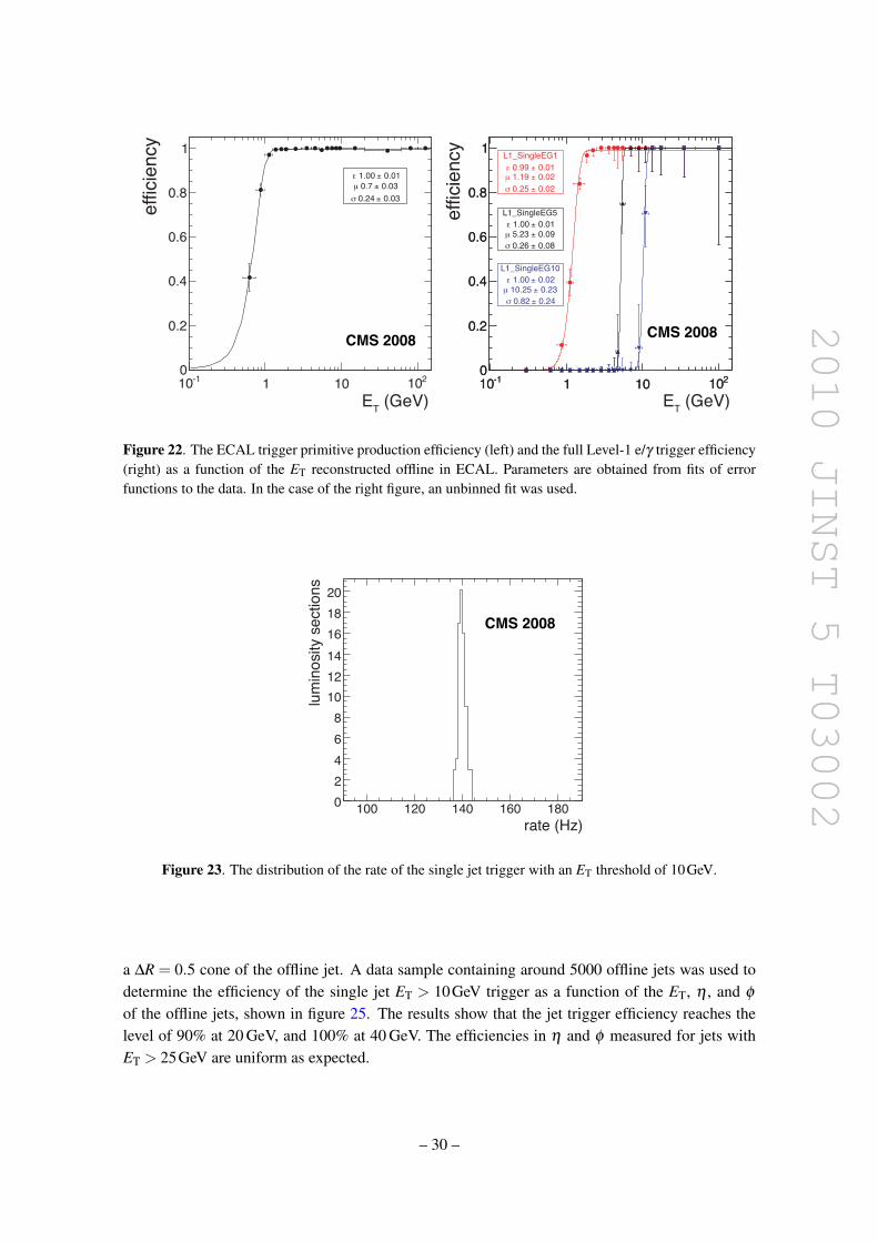
2010 JINST 5 T03002
effici
ency
ET (GeV)
effici
ency
ET (GeV)
Figure 22. The ECAL trigger primitive production efficiency (left) and the full Level-1 e/γ trigger efficiency(right) as a function of the ET reconstructed offline in ECAL. Parameters are obtained from fits of errorfunctions to the data. In the case of the right figure, an unbinned fit was used.
lumino
sity s
ectio
ns
rate (Hz)
Figure 23. The distribution of the rate of the single jet trigger with an ET threshold of 10GeV.
a ∆R = 0.5 cone of the offline jet. A data sample containing around 5000 offline jets was used todetermine the efficiency of the single jet ET > 10GeV trigger as a function of the ET, η , and φ
of the offline jets, shown in figure 25. The results show that the jet trigger efficiency reaches thelevel of 90% at 20 GeV, and 100% at 40 GeV. The efficiencies in η and φ measured for jets withET > 25GeV are uniform as expected.
– 30 –
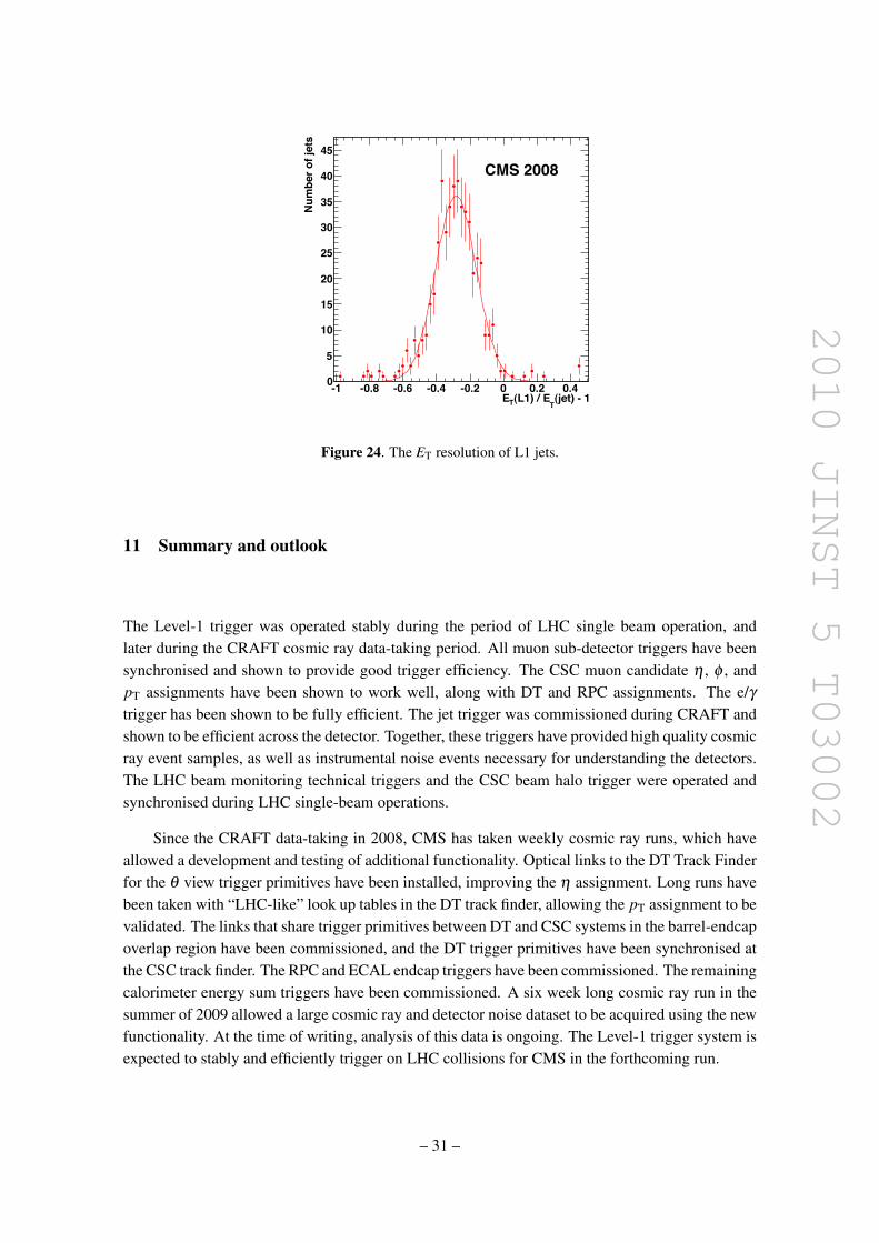
2010 JINST 5 T03002
(jet) - 1T
(L1) / ETE-1 -0.8 -0.6 -0.4 -0.2 0 0.2 0.4
Num
ber o
f jet
s
0
5
10
15
20
25
30
35
40
45
CMS 2008
Figure 24. The ET resolution of L1 jets.
11 Summary and outlook
The Level-1 trigger was operated stably during the period of LHC single beam operation, andlater during the CRAFT cosmic ray data-taking period. All muon sub-detector triggers have beensynchronised and shown to provide good trigger efficiency. The CSC muon candidate η , φ , andpT assignments have been shown to work well, along with DT and RPC assignments. The e/γtrigger has been shown to be fully efficient. The jet trigger was commissioned during CRAFT andshown to be efficient across the detector. Together, these triggers have provided high quality cosmicray event samples, as well as instrumental noise events necessary for understanding the detectors.The LHC beam monitoring technical triggers and the CSC beam halo trigger were operated andsynchronised during LHC single-beam operations.
Since the CRAFT data-taking in 2008, CMS has taken weekly cosmic ray runs, which haveallowed a development and testing of additional functionality. Optical links to the DT Track Finderfor the θ view trigger primitives have been installed, improving the η assignment. Long runs havebeen taken with “LHC-like” look up tables in the DT track finder, allowing the pT assignment to bevalidated. The links that share trigger primitives between DT and CSC systems in the barrel-endcapoverlap region have been commissioned, and the DT trigger primitives have been synchronised atthe CSC track finder. The RPC and ECAL endcap triggers have been commissioned. The remainingcalorimeter energy sum triggers have been commissioned. A six week long cosmic ray run in thesummer of 2009 allowed a large cosmic ray and detector noise dataset to be acquired using the newfunctionality. At the time of writing, analysis of this data is ongoing. The Level-1 trigger system isexpected to stably and efficiently trigger on LHC collisions for CMS in the forthcoming run.
– 31 –

2010 JINST 5 T03002
η-2 -1.5 -1 -0.5 0 0.5 1 1.5 2
Effi
cien
cy
0
0.2
0.4
0.6
0.8
1
CMS 2008
(rad)φ-3 -2 -1 0 1 2 3
Effi
cien
cy
0
0.2
0.4
0.6
0.8
1
CMS 2008
(GeV)TE0 20 40 60 80 100
Effic
ienc
y
0
0.2
0.4
0.6
0.8
1
CMS 2008
Figure 25. The efficiency of the single jet trigger with a L1 ET threshold of 10GeV, as a function of offlinejet η , φ , and ET (with ET > 25GeV for the η and φ plots).
Acknowledgments
We thank the technical and administrative staff at CERN and other CMS Institutes, and acknowl-edge support from: FMSR (Austria); FNRS and FWO (Belgium); CNPq, CAPES, FAPERJ, andFAPESP (Brazil); MES (Bulgaria); CERN; CAS, MoST, and NSFC (China); COLCIENCIAS(Colombia); MSES (Croatia); RPF (Cyprus); Academy of Sciences and NICPB (Estonia); Academyof Finland, ME, and HIP (Finland); CEA and CNRS/IN2P3 (France); BMBF, DFG, and HGF(Germany); GSRT (Greece); OTKA and NKTH (Hungary); DAE and DST (India); IPM (Iran);SFI (Ireland); INFN (Italy); NRF (Korea); LAS (Lithuania); CINVESTAV, CONACYT, SEP,and UASLP-FAI (Mexico); PAEC (Pakistan); SCSR (Poland); FCT (Portugal); JINR (Armenia,Belarus, Georgia, Ukraine, Uzbekistan); MST and MAE (Russia); MSTDS (Serbia); MICINN
– 32 –
2010 JINST 5 T03002
and CPAN (Spain); Swiss Funding Agencies (Switzerland); NSC (Taipei); TUBITAK and TAEK(Turkey); STFC (United Kingdom); DOE and NSF (USA). Individuals have received support fromthe Marie-Curie IEF program (European Union); the Leventis Foundation; the A. P. Sloan Founda-tion; and the Alexander von Humboldt Foundation.
References
[1] CMS collaboration, The CMS experiment at the CERN LHC, 2008 JINST 3 S08004.
[2] L. Evans and P. Bryant eds., LHC Machine, 2008 JINST 3 S08001.
[3] CMS collaboration, Commissioning of the CMS experiment and the cosmic run at four tesla, 2010JINST 5 T03001.
[4] CMS collaboration, The TriDAS Project Technical Design Report: The Level-1 Trigger,CERN-LHCC-2000-038 (2000).
[5] H. Sakulin and A. Taurok, Implementation and test of the first-level Global Muon Trigger of the CMSexperiment, in Proceedings of the 11th Workshop on Electronics for LHC and Future Experiments(2005).
[6] L. Guiducci et al., DT Sector Collector electronics design and construction, in Proceedings of theTopical Workshop on Electronics for Particle Physics (2007).
[7] J. Ero et al., The CMS drift tube trigger track finder, 2008 JINST 3 P08006.
[8] D. Acosta et al., A 3-D track-finding processor for the CMS level-1 muon trigger, in Proceedings ofthe Conference for Computing in High-Energy and Nuclear Physics (2003).
[9] CMS collaboration, Alignment of the CMS muon system with cosmic-ray and beam-halo muons, 2010JINST 5 T03020.
[10] RD5 collaboration, Pattern Comparator Trigger (PACT) for the muon system of the CMS experiment,Nucl. Instrum. Meth. A 370 (1996) 389.
[11] M. Stettler et al., The CMS Global Calorimeter Trigger hardware design, in Proceedings of the 12thWorkshop on Electronics for LHC and Future Experiments (2006).
[12] G. Iles et al., Revised CMS global calorimeter trigger functionality and algorithms, in Proceedings ofthe 12th Workshop on Electronics for LHC and Future Experiments (2006).
[13] M. Jeitler et al., The level-1 global trigger for the CMS experiment at LHC, in Proceedings of the12th Workshop on Electronics for LHC and Future Experiments (2006).
[14] I. Magrans de Abril, C.E. Wulz and J. Varela, Concept of the CMS trigger supervisor, IEEE Trans.Nucl. Sci. 53 (2006) 474.
[15] J. Gutleber, S. Murray and L. Orsini, Towards a homogeneous architecture for high-energy physicsdata acquisition systems, Comput. Phys. Commun. 153 (2003) 155.
[16] CMS collaboration, Performance of the CMS drift-tube chamber local trigger with cosmic rays, 2010JINST 5 T03003.
[17] CMS collaboration, Link System and Crate Layout of the RPC Pattern Comparator Trigger for theCMS Detector, CMS-NOTE-2002-022 (2002).
[18] CMS collaboration, Performance of the CMS drift tube chambers with cosmic rays, 2010 JINST 5T03015.
– 33 –
2010 JINST 5 T03002
[19] M. Aldaya et al., Fine synchronization of the muon drift tubes local trigger, Nucl. Instrum. Meth. A564 (2006) 169.
[20] CMS collaboration, Fine synchronization of the CMS muon drift-tube local trigger using cosmic rays,2010 JINST 5 T03004.
[21] CMS collaboration, Performance study of the CMS barrel resistive plate chambers with cosmic rays,2010 JINST 5 T03017.
[22] CMS collaboration, CMS Level-1 Trigger Emulator, in Proceedings of the International Conferenceon Computing in High Energy and Nuclear Physics (2009).
[23] CMS collaboration, Performance and operation of the CMS electromagnetic calorimeter, 2010 JINST5 T03010.
[24] N. Almeida et al., Data filtering in the readout of the CMS electromagnetic calorimeter, 2008 JINST3 P02011.
[25] CMS collaboration, Time reconstruction and performance of the CMS electromagnetic calorimeter,2010 JINST 5 T03011.
[26] CMS collaboration, Measurement of the muon stopping power in lead tungstate, 2010 JINST 5P03007.
[27] CMS collaboration, CMS Physics: Technical Design Report, CERN-LHCC-2006-001 (2006).
– 34 –
2010 JINST 5 T03002
The CMS collaboration
Yerevan Physics Institute, Yerevan, ArmeniaS. Chatrchyan, V. Khachatryan, A.M. Sirunyan
Institut fur Hochenergiephysik der OeAW, Wien, AustriaW. Adam, B. Arnold, H. Bergauer, T. Bergauer, M. Dragicevic, M. Eichberger, J. Ero, M. Friedl,R. Fruhwirth, V.M. Ghete, J. Hammer1, S. Hansel, M. Hoch, N. Hormann, J. Hrubec, M. Jeitler,G. Kasieczka, K. Kastner, M. Krammer, D. Liko, I. Magrans de Abril, I. Mikulec, F. Mittermayr,B. Neuherz, M. Oberegger, M. Padrta, M. Pernicka, H. Rohringer, S. Schmid, R. Schofbeck,T. Schreiner, R. Stark, H. Steininger, J. Strauss, A. Taurok, F. Teischinger, T. Themel, D. Uhl,P. Wagner, W. Waltenberger, G. Walzel, E. Widl, C.-E. Wulz
National Centre for Particle and High Energy Physics, Minsk, BelarusV. Chekhovsky, O. Dvornikov, I. Emeliantchik, A. Litomin, V. Makarenko, I. Marfin, V. Mossolov,N. Shumeiko, A. Solin, R. Stefanovitch, J. Suarez Gonzalez, A. Tikhonov
Research Institute for Nuclear Problems, Minsk, BelarusA. Fedorov, A. Karneyeu, M. Korzhik, V. Panov, R. Zuyeuski
Research Institute of Applied Physical Problems, Minsk, BelarusP. Kuchinsky
Universiteit Antwerpen, Antwerpen, BelgiumW. Beaumont, L. Benucci, M. Cardaci, E.A. De Wolf, E. Delmeire, D. Druzhkin, M. Hashemi,X. Janssen, T. Maes, L. Mucibello, S. Ochesanu, R. Rougny, M. Selvaggi, H. Van Haevermaet,P. Van Mechelen, N. Van Remortel
Vrije Universiteit Brussel, Brussel, BelgiumV. Adler, S. Beauceron, S. Blyweert, J. D’Hondt, S. De Weirdt, O. Devroede, J. Heyninck,A. Kalogeropoulos, J. Maes, M. Maes, M.U. Mozer, S. Tavernier, W. Van Doninck1, P. VanMulders, I. Villella
Universite Libre de Bruxelles, Bruxelles, BelgiumO. Bouhali, E.C. Chabert, O. Charaf, B. Clerbaux, G. De Lentdecker, V. Dero, S. Elgammal,A.P.R. Gay, G.H. Hammad, P.E. Marage, S. Rugovac, C. Vander Velde, P. Vanlaer, J. Wickens
Ghent University, Ghent, BelgiumM. Grunewald, B. Klein, A. Marinov, D. Ryckbosch, F. Thyssen, M. Tytgat, L. Vanelderen,P. Verwilligen
Universite Catholique de Louvain, Louvain-la-Neuve, BelgiumS. Basegmez, G. Bruno, J. Caudron, C. Delaere, P. Demin, D. Favart, A. Giammanco, G. Gregoire,V. Lemaitre, O. Militaru, S. Ovyn, K. Piotrzkowski1, L. Quertenmont, N. Schul
Universite de Mons, Mons, BelgiumN. Beliy, E. Daubie
Centro Brasileiro de Pesquisas Fisicas, Rio de Janeiro, BrazilG.A. Alves, M.E. Pol, M.H.G. Souza
– 35 –
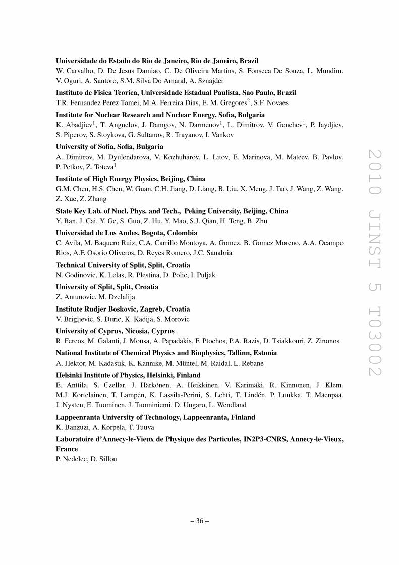
2010 JINST 5 T03002
Universidade do Estado do Rio de Janeiro, Rio de Janeiro, BrazilW. Carvalho, D. De Jesus Damiao, C. De Oliveira Martins, S. Fonseca De Souza, L. Mundim,V. Oguri, A. Santoro, S.M. Silva Do Amaral, A. Sznajder
Instituto de Fisica Teorica, Universidade Estadual Paulista, Sao Paulo, BrazilT.R. Fernandez Perez Tomei, M.A. Ferreira Dias, E. M. Gregores2, S.F. Novaes
Institute for Nuclear Research and Nuclear Energy, Sofia, BulgariaK. Abadjiev1, T. Anguelov, J. Damgov, N. Darmenov1, L. Dimitrov, V. Genchev1, P. Iaydjiev,S. Piperov, S. Stoykova, G. Sultanov, R. Trayanov, I. Vankov
University of Sofia, Sofia, BulgariaA. Dimitrov, M. Dyulendarova, V. Kozhuharov, L. Litov, E. Marinova, M. Mateev, B. Pavlov,P. Petkov, Z. Toteva1
Institute of High Energy Physics, Beijing, ChinaG.M. Chen, H.S. Chen, W. Guan, C.H. Jiang, D. Liang, B. Liu, X. Meng, J. Tao, J. Wang, Z. Wang,Z. Xue, Z. Zhang
State Key Lab. of Nucl. Phys. and Tech., Peking University, Beijing, ChinaY. Ban, J. Cai, Y. Ge, S. Guo, Z. Hu, Y. Mao, S.J. Qian, H. Teng, B. Zhu
Universidad de Los Andes, Bogota, ColombiaC. Avila, M. Baquero Ruiz, C.A. Carrillo Montoya, A. Gomez, B. Gomez Moreno, A.A. OcampoRios, A.F. Osorio Oliveros, D. Reyes Romero, J.C. Sanabria
Technical University of Split, Split, CroatiaN. Godinovic, K. Lelas, R. Plestina, D. Polic, I. Puljak
University of Split, Split, CroatiaZ. Antunovic, M. Dzelalija
Institute Rudjer Boskovic, Zagreb, CroatiaV. Brigljevic, S. Duric, K. Kadija, S. Morovic
University of Cyprus, Nicosia, CyprusR. Fereos, M. Galanti, J. Mousa, A. Papadakis, F. Ptochos, P.A. Razis, D. Tsiakkouri, Z. Zinonos
National Institute of Chemical Physics and Biophysics, Tallinn, EstoniaA. Hektor, M. Kadastik, K. Kannike, M. Muntel, M. Raidal, L. Rebane
Helsinki Institute of Physics, Helsinki, FinlandE. Anttila, S. Czellar, J. Harkonen, A. Heikkinen, V. Karimaki, R. Kinnunen, J. Klem,M.J. Kortelainen, T. Lampen, K. Lassila-Perini, S. Lehti, T. Linden, P. Luukka, T. Maenpaa,J. Nysten, E. Tuominen, J. Tuominiemi, D. Ungaro, L. Wendland
Lappeenranta University of Technology, Lappeenranta, FinlandK. Banzuzi, A. Korpela, T. Tuuva
Laboratoire d’Annecy-le-Vieux de Physique des Particules, IN2P3-CNRS, Annecy-le-Vieux,FranceP. Nedelec, D. Sillou
– 36 –
2010 JINST 5 T03002
DSM/IRFU, CEA/Saclay, Gif-sur-Yvette, FranceM. Besancon, R. Chipaux, M. Dejardin, D. Denegri, J. Descamps, B. Fabbro, J.L. Faure, F. Ferri,S. Ganjour, F.X. Gentit, A. Givernaud, P. Gras, G. Hamel de Monchenault, P. Jarry, M.C. Lemaire,E. Locci, J. Malcles, M. Marionneau, L. Millischer, J. Rander, A. Rosowsky, D. Rousseau,M. Titov, P. Verrecchia
Laboratoire Leprince-Ringuet, Ecole Polytechnique, IN2P3-CNRS, Palaiseau, FranceS. Baffioni, L. Bianchini, M. Bluj3, P. Busson, C. Charlot, L. Dobrzynski, R. Granier de Cassagnac,M. Haguenauer, P. Mine, P. Paganini, Y. Sirois, C. Thiebaux, A. Zabi
Institut Pluridisciplinaire Hubert Curien, Universite de Strasbourg, Universite de HauteAlsace Mulhouse, CNRS/IN2P3, Strasbourg, FranceJ.-L. Agram4, A. Besson, D. Bloch, D. Bodin, J.-M. Brom, E. Conte4, F. Drouhin4, J.-C. Fontaine4,D. Gele, U. Goerlach, L. Gross, P. Juillot, A.-C. Le Bihan, Y. Patois, J. Speck, P. Van Hove
Universite de Lyon, Universite Claude Bernard Lyon 1, CNRS-IN2P3, Institut de PhysiqueNucleaire de Lyon, Villeurbanne, FranceC. Baty, M. Bedjidian, J. Blaha, G. Boudoul, H. Brun, N. Chanon, R. Chierici, D. Contardo,P. Depasse, T. Dupasquier, H. El Mamouni, F. Fassi5, J. Fay, S. Gascon, B. Ille, T. Kurca, T. LeGrand, M. Lethuillier, N. Lumb, L. Mirabito, S. Perries, M. Vander Donckt, P. Verdier
E. Andronikashvili Institute of Physics, Academy of Science, Tbilisi, GeorgiaN. Djaoshvili, N. Roinishvili, V. Roinishvili
Institute of High Energy Physics and Informatization, Tbilisi State University, Tbilisi,GeorgiaN. Amaglobeli
RWTH Aachen University, I. Physikalisches Institut, Aachen, GermanyR. Adolphi, G. Anagnostou, R. Brauer, W. Braunschweig, M. Edelhoff, H. Esser, L. Feld,W. Karpinski, A. Khomich, K. Klein, N. Mohr, A. Ostaptchouk, D. Pandoulas, G. Pierschel,F. Raupach, S. Schael, A. Schultz von Dratzig, G. Schwering, D. Sprenger, M. Thomas, M. Weber,B. Wittmer, M. Wlochal
RWTH Aachen University, III. Physikalisches Institut A, Aachen, GermanyO. Actis, G. Altenhofer, W. Bender, P. Biallass, M. Erdmann, G. Fetchenhauer1,J. Frangenheim, T. Hebbeker, G. Hilgers, A. Hinzmann, K. Hoepfner, C. Hof, M. Kirsch,T. Klimkovich, P. Kreuzer1, D. Lanske†, M. Merschmeyer, A. Meyer, B. Philipps, H. Pieta,H. Reithler, S.A. Schmitz, L. Sonnenschein, M. Sowa, J. Steggemann, H. Szczesny, D. Teyssier,C. Zeidler
RWTH Aachen University, III. Physikalisches Institut B, Aachen, GermanyM. Bontenackels, M. Davids, M. Duda, G. Flugge, H. Geenen, M. Giffels, W. Haj Ahmad,T. Hermanns, D. Heydhausen, S. Kalinin, T. Kress, A. Linn, A. Nowack, L. Perchalla,M. Poettgens, O. Pooth, P. Sauerland, A. Stahl, D. Tornier, M.H. Zoeller
Deutsches Elektronen-Synchrotron, Hamburg, GermanyM. Aldaya Martin, U. Behrens, K. Borras, A. Campbell, E. Castro, D. Dammann, G. Eckerlin,A. Flossdorf, G. Flucke, A. Geiser, D. Hatton, J. Hauk, H. Jung, M. Kasemann, I. Katkov,C. Kleinwort, H. Kluge, A. Knutsson, E. Kuznetsova, W. Lange, W. Lohmann, R. Mankel1,
– 37 –
2010 JINST 5 T03002
M. Marienfeld, A.B. Meyer, S. Miglioranzi, J. Mnich, M. Ohlerich, J. Olzem, A. Parenti,C. Rosemann, R. Schmidt, T. Schoerner-Sadenius, D. Volyanskyy, C. Wissing, W.D. Zeuner1
University of Hamburg, Hamburg, GermanyC. Autermann, F. Bechtel, J. Draeger, D. Eckstein, U. Gebbert, K. Kaschube, G. Kaussen,R. Klanner, B. Mura, S. Naumann-Emme, F. Nowak, U. Pein, C. Sander, P. Schleper, T. Schum,H. Stadie, G. Steinbruck, J. Thomsen, R. Wolf
Institut fur Experimentelle Kernphysik, Karlsruhe, GermanyJ. Bauer, P. Blum, V. Buege, A. Cakir, T. Chwalek, W. De Boer, A. Dierlamm, G. Dirkes, M. Feindt,U. Felzmann, M. Frey, A. Furgeri, J. Gruschke, C. Hackstein, F. Hartmann1, S. Heier, M. Heinrich,H. Held, D. Hirschbuehl, K.H. Hoffmann, S. Honc, C. Jung, T. Kuhr, T. Liamsuwan, D. Martschei,S. Mueller, Th. Muller, M.B. Neuland, M. Niegel, O. Oberst, A. Oehler, J. Ott, T. Peiffer, D. Piparo,G. Quast, K. Rabbertz, F. Ratnikov, N. Ratnikova, M. Renz, C. Saout1, G. Sartisohn, A. Scheurer,P. Schieferdecker, F.-P. Schilling, G. Schott, H.J. Simonis, F.M. Stober, P. Sturm, D. Troendle,A. Trunov, W. Wagner, J. Wagner-Kuhr, M. Zeise, V. Zhukov6, E.B. Ziebarth
Institute of Nuclear Physics ”Demokritos”, Aghia Paraskevi, GreeceG. Daskalakis, T. Geralis, K. Karafasoulis, A. Kyriakis, D. Loukas, A. Markou, C. Markou,C. Mavrommatis, E. Petrakou, A. Zachariadou
University of Athens, Athens, GreeceL. Gouskos, P. Katsas, A. Panagiotou1
University of Ioannina, Ioannina, GreeceI. Evangelou, P. Kokkas, N. Manthos, I. Papadopoulos, V. Patras, F.A. Triantis
KFKI Research Institute for Particle and Nuclear Physics, Budapest, HungaryG. Bencze1, L. Boldizsar, G. Debreczeni, C. Hajdu1, S. Hernath, P. Hidas, D. Horvath7, K. Krajczar,A. Laszlo, G. Patay, F. Sikler, N. Toth, G. Vesztergombi
Institute of Nuclear Research ATOMKI, Debrecen, HungaryN. Beni, G. Christian, J. Imrek, J. Molnar, D. Novak, J. Palinkas, G. Szekely, Z. Szillasi1, K. Tokesi,V. Veszpremi
University of Debrecen, Debrecen, HungaryA. Kapusi, G. Marian, P. Raics, Z. Szabo, Z.L. Trocsanyi, B. Ujvari, G. Zilizi
Panjab University, Chandigarh, IndiaS. Bansal, H.S. Bawa, S.B. Beri, V. Bhatnagar, M. Jindal, M. Kaur, R. Kaur, J.M. Kohli,M.Z. Mehta, N. Nishu, L.K. Saini, A. Sharma, A. Singh, J.B. Singh, S.P. Singh
University of Delhi, Delhi, IndiaS. Ahuja, S. Arora, S. Bhattacharya8, S. Chauhan, B.C. Choudhary, P. Gupta, S. Jain, S. Jain,M. Jha, A. Kumar, K. Ranjan, R.K. Shivpuri, A.K. Srivastava
Bhabha Atomic Research Centre, Mumbai, IndiaR.K. Choudhury, D. Dutta, S. Kailas, S.K. Kataria, A.K. Mohanty, L.M. Pant, P. Shukla, A. Topkar
Tata Institute of Fundamental Research - EHEP, Mumbai, IndiaT. Aziz, M. Guchait9, A. Gurtu, M. Maity10, D. Majumder, G. Majumder, K. Mazumdar, A. Nayak,A. Saha, K. Sudhakar
– 38 –
2010 JINST 5 T03002
Tata Institute of Fundamental Research - HECR, Mumbai, IndiaS. Banerjee, S. Dugad, N.K. Mondal
Institute for Studies in Theoretical Physics & Mathematics (IPM), Tehran, IranH. Arfaei, H. Bakhshiansohi, A. Fahim, A. Jafari, M. Mohammadi Najafabadi, A. Moshaii,S. Paktinat Mehdiabadi, S. Rouhani, B. Safarzadeh, M. Zeinali
University College Dublin, Dublin, IrelandM. Felcini
INFN Sezione di Bari a, Universita di Bari b, Politecnico di Bari c, Bari, ItalyM. Abbresciaa,b, L. Barbonea, F. Chiumaruloa, A. Clementea, A. Colaleoa, D. Creanzaa,c,G. Cuscelaa, N. De Filippisa, M. De Palmaa,b, G. De Robertisa, G. Donvitoa, F. Fedelea, L. Fiorea,M. Francoa, G. Iasellia,c, N. Lacalamitaa, F. Loddoa, L. Lusitoa,b, G. Maggia,c, M. Maggia,N. Mannaa,b, B. Marangellia,b, S. Mya,c, S. Natalia,b, S. Nuzzoa,b, G. Papagnia, S. Piccolomoa,G.A. Pierroa, C. Pintoa, A. Pompilia,b, G. Pugliesea,c, R. Rajana, A. Ranieria, F. Romanoa,c,G. Rosellia,b, G. Selvaggia,b, Y. Shindea, L. Silvestrisa, S. Tupputia,b, G. Zitoa
INFN Sezione di Bologna a, Universita di Bologna b, Bologna, ItalyG. Abbiendia, W. Bacchia,b, A.C. Benvenutia, M. Boldinia, D. Bonacorsia, S. Braibant-Giacomellia,b, V.D. Cafaroa, S.S. Caiazzaa, P. Capiluppia,b, A. Castroa,b, F.R. Cavalloa,G. Codispotia,b, M. Cuffiania,b, I. D’Antonea, G.M. Dallavallea,1, F. Fabbria, A. Fanfania,b,D. Fasanellaa, P. Giacomellia, V. Giordanoa, M. Giuntaa,1, C. Grandia, M. Guerzonia,S. Marcellinia, G. Masettia,b, A. Montanaria, F.L. Navarriaa,b, F. Odoricia, G. Pellegrinia,A. Perrottaa, A.M. Rossia,b, T. Rovellia,b, G. Sirolia,b, G. Torromeoa, R. Travaglinia,b
INFN Sezione di Catania a, Universita di Catania b, Catania, ItalyS. Albergoa,b, S. Costaa,b, R. Potenzaa,b, A. Tricomia,b, C. Tuvea
INFN Sezione di Firenze a, Universita di Firenze b, Firenze, ItalyG. Barbaglia, G. Broccoloa,b, V. Ciullia,b, C. Civininia, R. D’Alessandroa,b, E. Focardia,b,S. Frosalia,b, E. Galloa, C. Gentaa,b, G. Landia,b, P. Lenzia,b,1, M. Meschinia, S. Paolettia,G. Sguazzonia, A. Tropianoa
INFN Laboratori Nazionali di Frascati, Frascati, ItalyL. Benussi, M. Bertani, S. Bianco, S. Colafranceschi11, D. Colonna11, F. Fabbri, M. Giardoni,L. Passamonti, D. Piccolo, D. Pierluigi, B. Ponzio, A. Russo
INFN Sezione di Genova, Genova, ItalyP. Fabbricatore, R. Musenich
INFN Sezione di Milano-Biccoca a, Universita di Milano-Bicocca b, Milano, ItalyA. Benagliaa, M. Callonia, G.B. Ceratia,b,1, P. D’Angeloa, F. De Guioa, F.M. Farinaa, A. Ghezzia,P. Govonia,b, M. Malbertia,b,1, S. Malvezzia, A. Martellia, D. Menascea, V. Miccioa,b, L. Moronia,P. Negria,b, M. Paganonia,b, D. Pedrinia, A. Pulliaa,b, S. Ragazzia,b, N. Redaellia, S. Salaa,R. Salernoa,b, T. Tabarelli de Fatisa,b, V. Tancinia,b, S. Taronia,b
INFN Sezione di Napoli a, Universita di Napoli ”Federico II” b, Napoli, ItalyS. Buontempoa, N. Cavalloa, A. Cimminoa,b,1, M. De Gruttolaa,b,1, F. Fabozzia,12, A.O.M. Iorioa,L. Listaa, D. Lomidzea, P. Nolia,b, P. Paoluccia, C. Sciaccaa,b
– 39 –
2010 JINST 5 T03002
INFN Sezione di Padova a, Universita di Padova b, Padova, ItalyP. Azzia,1, N. Bacchettaa, L. Barcellana, P. Bellana,b,1, M. Bellatoa, M. Benettonia, M. Biasottoa,13,D. Biselloa,b, E. Borsatoa,b, A. Brancaa, R. Carlina,b, L. Castellania, P. Checchiaa, E. Contia,F. Dal Corsoa, M. De Mattiaa,b, T. Dorigoa, U. Dossellia, F. Fanzagoa, F. Gasparinia,b,U. Gasparinia,b, P. Giubilatoa,b, F. Gonellaa, A. Greselea,14, M. Gulminia,13, A. Kaminskiya,b,S. Lacapraraa,13, I. Lazzizzeraa,14, M. Margonia,b, G. Marona,13, S. Mattiazzoa,b, M. Mazzucatoa,M. Meneghellia, A.T. Meneguzzoa,b, M. Michelottoa, F. Montecassianoa, M. Nespoloa,M. Passaseoa, M. Pegoraroa, L. Perrozzia, N. Pozzobona,b, P. Ronchesea,b, F. Simonettoa,b,N. Tonioloa, E. Torassaa, M. Tosia,b, A. Triossia, S. Vaninia,b, S. Venturaa, P. Zottoa,b,G. Zumerlea,b
INFN Sezione di Pavia a, Universita di Pavia b, Pavia, ItalyP. Baessoa,b, U. Berzanoa, S. Bricolaa, M.M. Necchia,b, D. Paganoa,b, S.P. Rattia,b, C. Riccardia,b,P. Torrea,b, A. Vicinia, P. Vituloa,b, C. Viviania,b
INFN Sezione di Perugia a, Universita di Perugia b, Perugia, ItalyD. Aisaa, S. Aisaa, E. Babuccia, M. Biasinia,b, G.M. Bileia, B. Caponeria,b, B. Checcuccia,N. Dinua, L. Fanoa, L. Farnesinia, P. Laricciaa,b, A. Lucaronia,b, G. Mantovania,b, A. Nappia,b,A. Pilusoa, V. Postolachea, A. Santocchiaa,b, L. Servolia, D. Tonoiua, A. Vedaeea, R. Volpea,b
INFN Sezione di Pisa a, Universita di Pisa b, Scuola Normale Superiore di Pisa c, Pisa, ItalyP. Azzurria,c, G. Bagliesia, J. Bernardinia,b, L. Berrettaa, T. Boccalia, A. Boccia,c, L. Borrelloa,c,F. Bosia, F. Calzolaria, R. Castaldia, R. Dell’Orsoa, F. Fioria,b, L. Foaa,c, S. Gennaia,c, A. Giassia,A. Kraana, F. Ligabuea,c, T. Lomtadzea, F. Mariania, L. Martinia, M. Massaa, A. Messineoa,b,A. Moggia, F. Pallaa, F. Palmonaria, G. Petragnania, G. Petrucciania,c, F. Raffaellia, S. Sarkara,G. Segneria, A.T. Serbana, P. Spagnoloa,1, R. Tenchinia,1, S. Tolainia, G. Tonellia,b,1, A. Venturia,P.G. Verdinia
INFN Sezione di Roma a, Universita di Roma ”La Sapienza” b, Roma, ItalyS. Baccaroa,15, L. Baronea,b, A. Bartolonia, F. Cavallaria,1, I. Dafineia, D. Del Rea,b, E. DiMarcoa,b, M. Diemoza, D. Francia,b, E. Longoa,b, G. Organtinia,b, A. Palmaa,b, F. Pandolfia,b,R. Paramattia,1, F. Pellegrinoa, S. Rahatloua,b, C. Rovellia
INFN Sezione di Torino a, Universita di Torino b, Universita del Piemonte Orientale (No-vara) c, Torino, ItalyG. Alampia, N. Amapanea,b, R. Arcidiaconoa,b, S. Argiroa,b, M. Arneodoa,c, C. Biinoa,M.A. Borgiaa,b, C. Bottaa,b, N. Cartigliaa, R. Castelloa,b, G. Cerminaraa,b, M. Costaa,b,D. Dattolaa, G. Dellacasaa, N. Demariaa, G. Dugheraa, F. Dumitrachea, A. Grazianoa,b,C. Mariottia, M. Maronea,b, S. Masellia, E. Migliorea,b, G. Milaa,b, V. Monacoa,b, M. Musicha,b,M. Nervoa,b, M.M. Obertinoa,c, S. Oggeroa,b, R. Paneroa, N. Pastronea, M. Pelliccionia,b,A. Romeroa,b, M. Ruspaa,c, R. Sacchia,b, A. Solanoa,b, A. Staianoa, P.P. Trapania,b,1,D. Trocinoa,b, A. Vilela Pereiraa,b, L. Viscaa,b, A. Zampieria
INFN Sezione di Trieste a, Universita di Trieste b, Trieste, ItalyF. Ambroglinia,b, S. Belfortea, F. Cossuttia, G. Della Riccaa,b, B. Gobboa, A. Penzoa
Kyungpook National University, Daegu, KoreaS. Chang, J. Chung, D.H. Kim, G.N. Kim, D.J. Kong, H. Park, D.C. Son
– 40 –
2010 JINST 5 T03002
Wonkwang University, Iksan, KoreaS.Y. Bahk
Chonnam National University, Kwangju, KoreaS. Song
Konkuk University, Seoul, KoreaS.Y. Jung
Korea University, Seoul, KoreaB. Hong, H. Kim, J.H. Kim, K.S. Lee, D.H. Moon, S.K. Park, H.B. Rhee, K.S. Sim
Seoul National University, Seoul, KoreaJ. Kim
University of Seoul, Seoul, KoreaM. Choi, G. Hahn, I.C. Park
Sungkyunkwan University, Suwon, KoreaS. Choi, Y. Choi, J. Goh, H. Jeong, T.J. Kim, J. Lee, S. Lee
Vilnius University, Vilnius, LithuaniaM. Janulis, D. Martisiute, P. Petrov, T. Sabonis
Centro de Investigacion y de Estudios Avanzados del IPN, Mexico City, MexicoH. Castilla Valdez1, A. Sanchez Hernandez
Universidad Iberoamericana, Mexico City, MexicoS. Carrillo Moreno
Universidad Autonoma de San Luis Potosı, San Luis Potosı, MexicoA. Morelos Pineda
University of Auckland, Auckland, New ZealandP. Allfrey, R.N.C. Gray, D. Krofcheck
University of Canterbury, Christchurch, New ZealandN. Bernardino Rodrigues, P.H. Butler, T. Signal, J.C. Williams
National Centre for Physics, Quaid-I-Azam University, Islamabad, PakistanM. Ahmad, I. Ahmed, W. Ahmed, M.I. Asghar, M.I.M. Awan, H.R. Hoorani, I. Hussain,W.A. Khan, T. Khurshid, S. Muhammad, S. Qazi, H. Shahzad
Institute of Experimental Physics, Warsaw, PolandM. Cwiok, R. Dabrowski, W. Dominik, K. Doroba, M. Konecki, J. Krolikowski, K. Pozniak16,R. Romaniuk, W. Zabolotny16, P. Zych
Soltan Institute for Nuclear Studies, Warsaw, PolandT. Frueboes, R. Gokieli, L. Goscilo, M. Gorski, M. Kazana, K. Nawrocki, M. Szleper, G. Wrochna,P. Zalewski
Laboratorio de Instrumentacao e Fısica Experimental de Partıculas, Lisboa, PortugalN. Almeida, L. Antunes Pedro, P. Bargassa, A. David, P. Faccioli, P.G. Ferreira Parracho, M. FreitasFerreira, M. Gallinaro, M. Guerra Jordao, P. Martins, G. Mini, P. Musella, J. Pela, L. Raposo,P.Q. Ribeiro, S. Sampaio, J. Seixas, J. Silva, P. Silva, D. Soares, M. Sousa, J. Varela, H.K. Wohri
– 41 –
2010 JINST 5 T03002
Joint Institute for Nuclear Research, Dubna, RussiaI. Altsybeev, I. Belotelov, P. Bunin, Y. Ershov, I. Filozova, M. Finger, M. Finger Jr., A. Golunov,I. Golutvin, N. Gorbounov, V. Kalagin, A. Kamenev, V. Karjavin, V. Konoplyanikov, V. Korenkov,G. Kozlov, A. Kurenkov, A. Lanev, A. Makankin, V.V. Mitsyn, P. Moisenz, E. Nikonov, D. Oleynik,V. Palichik, V. Perelygin, A. Petrosyan, R. Semenov, S. Shmatov, V. Smirnov, D. Smolin,E. Tikhonenko, S. Vasil’ev, A. Vishnevskiy, A. Volodko, A. Zarubin, V. Zhiltsov
Petersburg Nuclear Physics Institute, Gatchina (St Petersburg), RussiaN. Bondar, L. Chtchipounov, A. Denisov, Y. Gavrikov, G. Gavrilov, V. Golovtsov, Y. Ivanov,V. Kim, V. Kozlov, P. Levchenko, G. Obrant, E. Orishchin, A. Petrunin, Y. Shcheglov,A. Shchetkovskiy, V. Sknar, I. Smirnov, V. Sulimov, V. Tarakanov, L. Uvarov, S. Vavilov,G. Velichko, S. Volkov, A. Vorobyev
Institute for Nuclear Research, Moscow, RussiaYu. Andreev, A. Anisimov, P. Antipov, A. Dermenev, S. Gninenko, N. Golubev, M. Kirsanov,N. Krasnikov, V. Matveev, A. Pashenkov, V.E. Postoev, A. Solovey, A. Solovey, A. Toropin,S. Troitsky
Institute for Theoretical and Experimental Physics, Moscow, RussiaA. Baud, V. Epshteyn, V. Gavrilov, N. Ilina, V. Kaftanov†, V. Kolosov, M. Kossov1, A. Krokhotin,S. Kuleshov, A. Oulianov, G. Safronov, S. Semenov, I. Shreyber, V. Stolin, E. Vlasov, A. Zhokin
Moscow State University, Moscow, RussiaE. Boos, M. Dubinin17, L. Dudko, A. Ershov, A. Gribushin, V. Klyukhin, O. Kodolova, I. Lokhtin,S. Petrushanko, L. Sarycheva, V. Savrin, A. Snigirev, I. Vardanyan
P.N. Lebedev Physical Institute, Moscow, RussiaI. Dremin, M. Kirakosyan, N. Konovalova, S.V. Rusakov, A. Vinogradov
State Research Center of Russian Federation, Institute for High Energy Physics, Protvino,RussiaS. Akimenko, A. Artamonov, I. Azhgirey, S. Bitioukov, V. Burtovoy, V. Grishin1, V. Kachanov,D. Konstantinov, V. Krychkine, A. Levine, I. Lobov, V. Lukanin, Y. Mel’nik, V. Petrov, R. Ryutin,S. Slabospitsky, A. Sobol, A. Sytine, L. Tourtchanovitch, S. Troshin, N. Tyurin, A. Uzunian,A. Volkov
Vinca Institute of Nuclear Sciences, Belgrade, SerbiaP. Adzic, M. Djordjevic, D. Jovanovic18, D. Krpic18, D. Maletic, J. Puzovic18, N. Smiljkovic
Centro de Investigaciones Energeticas Medioambientales y Tecnologicas (CIEMAT),Madrid, SpainM. Aguilar-Benitez, J. Alberdi, J. Alcaraz Maestre, P. Arce, J.M. Barcala, C. Battilana, C. BurgosLazaro, J. Caballero Bejar, E. Calvo, M. Cardenas Montes, M. Cepeda, M. Cerrada, M. ChamizoLlatas, F. Clemente, N. Colino, M. Daniel, B. De La Cruz, A. Delgado Peris, C. Diez Pardos,C. Fernandez Bedoya, J.P. Fernandez Ramos, A. Ferrando, J. Flix, M.C. Fouz, P. Garcia-Abia,A.C. Garcia-Bonilla, O. Gonzalez Lopez, S. Goy Lopez, J.M. Hernandez, M.I. Josa, J. Marin,G. Merino, J. Molina, A. Molinero, J.J. Navarrete, J.C. Oller, J. Puerta Pelayo, L. Romero,J. Santaolalla, C. Villanueva Munoz, C. Willmott, C. Yuste
– 42 –
2010 JINST 5 T03002
Universidad Autonoma de Madrid, Madrid, SpainC. Albajar, M. Blanco Otano, J.F. de Troconiz, A. Garcia Raboso, J.O. Lopez Berengueres
Universidad de Oviedo, Oviedo, SpainJ. Cuevas, J. Fernandez Menendez, I. Gonzalez Caballero, L. Lloret Iglesias, H. Naves Sordo,J.M. Vizan Garcia
Instituto de Fısica de Cantabria (IFCA), CSIC-Universidad de Cantabria, Santander, SpainI.J. Cabrillo, A. Calderon, S.H. Chuang, I. Diaz Merino, C. Diez Gonzalez, J. Duarte Campderros,M. Fernandez, G. Gomez, J. Gonzalez Sanchez, R. Gonzalez Suarez, C. Jorda, P. Lobelle Pardo,A. Lopez Virto, J. Marco, R. Marco, C. Martinez Rivero, P. Martinez Ruiz del Arbol, F. Matorras,T. Rodrigo, A. Ruiz Jimeno, L. Scodellaro, M. Sobron Sanudo, I. Vila, R. Vilar Cortabitarte
CERN, European Organization for Nuclear Research, Geneva, SwitzerlandD. Abbaneo, E. Albert, M. Alidra, S. Ashby, E. Auffray, J. Baechler, P. Baillon, A.H. Ball,S.L. Bally, D. Barney, F. Beaudette19, R. Bellan, D. Benedetti, G. Benelli, C. Bernet, P. Bloch,S. Bolognesi, M. Bona, J. Bos, N. Bourgeois, T. Bourrel, H. Breuker, K. Bunkowski, D. Campi,T. Camporesi, E. Cano, A. Cattai, J.P. Chatelain, M. Chauvey, T. Christiansen, J.A. CoarasaPerez, A. Conde Garcia, R. Covarelli, B. Cure, A. De Roeck, V. Delachenal, D. Deyrail, S. DiVincenzo20, S. Dos Santos, T. Dupont, L.M. Edera, A. Elliott-Peisert, M. Eppard, M. Favre,N. Frank, W. Funk, A. Gaddi, M. Gastal, M. Gateau, H. Gerwig, D. Gigi, K. Gill, D. Giordano,J.P. Girod, F. Glege, R. Gomez-Reino Garrido, R. Goudard, S. Gowdy, R. Guida, L. Guiducci,J. Gutleber, M. Hansen, C. Hartl, J. Harvey, B. Hegner, H.F. Hoffmann, A. Holzner, A. Honma,M. Huhtinen, V. Innocente, P. Janot, G. Le Godec, P. Lecoq, C. Leonidopoulos, R. Loos,C. Lourenco, A. Lyonnet, A. Macpherson, N. Magini, J.D. Maillefaud, G. Maire, T. Maki,L. Malgeri, M. Mannelli, L. Masetti, F. Meijers, P. Meridiani, S. Mersi, E. Meschi, A. MeynetCordonnier, R. Moser, M. Mulders, J. Mulon, M. Noy, A. Oh, G. Olesen, A. Onnela, T. Orimoto,L. Orsini, E. Perez, G. Perinic, J.F. Pernot, P. Petagna, P. Petiot, A. Petrilli, A. Pfeiffer, M. Pierini,M. Pimia, R. Pintus, B. Pirollet, H. Postema, A. Racz, S. Ravat, S.B. Rew, J. Rodrigues Antunes,G. Rolandi21, M. Rovere, V. Ryjov, H. Sakulin, D. Samyn, H. Sauce, C. Schafer, W.D. Schlatter,M. Schroder, C. Schwick, A. Sciaba, I. Segoni, A. Sharma, N. Siegrist, P. Siegrist, N. Sinanis,T. Sobrier, P. Sphicas22, D. Spiga, M. Spiropulu17, F. Stockli, P. Traczyk, P. Tropea, J. Troska,A. Tsirou, L. Veillet, G.I. Veres, M. Voutilainen, P. Wertelaers, M. Zanetti
Paul Scherrer Institut, Villigen, SwitzerlandW. Bertl, K. Deiters, W. Erdmann, K. Gabathuler, R. Horisberger, Q. Ingram, H.C. Kaestli,S. Konig, D. Kotlinski, U. Langenegger, F. Meier, D. Renker, T. Rohe, J. Sibille23, A. Starodumov24
Institute for Particle Physics, ETH Zurich, Zurich, SwitzerlandB. Betev, L. Caminada25, Z. Chen, S. Cittolin, D.R. Da Silva Di Calafiori, S. Dambach25,G. Dissertori, M. Dittmar, C. Eggel25, J. Eugster, G. Faber, K. Freudenreich, C. Grab, A. Herve,W. Hintz, P. Lecomte, P.D. Luckey, W. Lustermann, C. Marchica25, P. Milenovic26, F. Moortgat,A. Nardulli, F. Nessi-Tedaldi, L. Pape, F. Pauss, T. Punz, A. Rizzi, F.J. Ronga, L. Sala,A.K. Sanchez, M.-C. Sawley, V. Sordini, B. Stieger, L. Tauscher†, A. Thea, K. Theofilatos,D. Treille, P. Trub25, M. Weber, L. Wehrli, J. Weng, S. Zelepoukine27
– 43 –
2010 JINST 5 T03002
Universitat Zurich, Zurich, SwitzerlandC. Amsler, V. Chiochia, S. De Visscher, C. Regenfus, P. Robmann, T. Rommerskirchen,A. Schmidt, D. Tsirigkas, L. Wilke
National Central University, Chung-Li, TaiwanY.H. Chang, E.A. Chen, W.T. Chen, A. Go, C.M. Kuo, S.W. Li, W. Lin
National Taiwan University (NTU), Taipei, TaiwanP. Bartalini, P. Chang, Y. Chao, K.F. Chen, W.-S. Hou, Y. Hsiung, Y.J. Lei, S.W. Lin, R.-S. Lu,J. Schumann, J.G. Shiu, Y.M. Tzeng, K. Ueno, Y. Velikzhanin, C.C. Wang, M. Wang
Cukurova University, Adana, TurkeyA. Adiguzel, A. Ayhan, A. Azman Gokce, M.N. Bakirci, S. Cerci, I. Dumanoglu, E. Eskut,S. Girgis, E. Gurpinar, I. Hos, T. Karaman, T. Karaman, A. Kayis Topaksu, P. Kurt, G. Onengut,G. Onengut Gokbulut, K. Ozdemir, S. Ozturk, A. Polatoz, K. Sogut28, B. Tali, H. Topakli, D. Uzun,L.N. Vergili, M. Vergili
Middle East Technical University, Physics Department, Ankara, TurkeyI.V. Akin, T. Aliev, S. Bilmis, M. Deniz, H. Gamsizkan, A.M. Guler, K. Ocalan, M. Serin, R. Sever,U.E. Surat, M. Zeyrek
Bogazici University, Department of Physics, Istanbul, TurkeyM. Deliomeroglu, D. Demir29, E. Gulmez, A. Halu, B. Isildak, M. Kaya30, O. Kaya30,S. Ozkorucuklu31, N. Sonmez32
National Scientific Center, Kharkov Institute of Physics and Technology, Kharkov, UkraineL. Levchuk, S. Lukyanenko, D. Soroka, S. Zub
University of Bristol, Bristol, United KingdomF. Bostock, J.J. Brooke, T.L. Cheng, D. Cussans, R. Frazier, J. Goldstein, N. Grant,M. Hansen, G.P. Heath, H.F. Heath, C. Hill, B. Huckvale, J. Jackson, C.K. Mackay, S. Metson,D.M. Newbold33, K. Nirunpong, V.J. Smith, J. Velthuis, R. Walton
Rutherford Appleton Laboratory, Didcot, United KingdomK.W. Bell, C. Brew, R.M. Brown, B. Camanzi, D.J.A. Cockerill, J.A. Coughlan, N.I. Geddes,K. Harder, S. Harper, B.W. Kennedy, P. Murray, C.H. Shepherd-Themistocleous, I.R. Tomalin,J.H. Williams†, W.J. Womersley, S.D. Worm
Imperial College, University of London, London, United KingdomR. Bainbridge, G. Ball, J. Ballin, R. Beuselinck, O. Buchmuller, D. Colling, N. Cripps, G. Davies,M. Della Negra, C. Foudas, J. Fulcher, D. Futyan, G. Hall, J. Hays, G. Iles, G. Karapostoli,B.C. MacEvoy, A.-M. Magnan, J. Marrouche, J. Nash, A. Nikitenko24, A. Papageorgiou,M. Pesaresi, K. Petridis, M. Pioppi34, D.M. Raymond, N. Rompotis, A. Rose, M.J. Ryan, C. Seez,P. Sharp, G. Sidiropoulos1, M. Stettler, M. Stoye, M. Takahashi, A. Tapper, C. Timlin, S. Tourneur,M. Vazquez Acosta, T. Virdee1, S. Wakefield, D. Wardrope, T. Whyntie, M. Wingham
Brunel University, Uxbridge, United KingdomJ.E. Cole, I. Goitom, P.R. Hobson, A. Khan, P. Kyberd, D. Leslie, C. Munro, I.D. Reid,C. Siamitros, R. Taylor, L. Teodorescu, I. Yaselli
– 44 –
2010 JINST 5 T03002
Boston University, Boston, U.S.A.T. Bose, M. Carleton, E. Hazen, A.H. Heering, A. Heister, J. St. John, P. Lawson, D. Lazic,D. Osborne, J. Rohlf, L. Sulak, S. Wu
Brown University, Providence, U.S.A.J. Andrea, A. Avetisyan, S. Bhattacharya, J.P. Chou, D. Cutts, S. Esen, G. Kukartsev, G. Landsberg,M. Narain, D. Nguyen, T. Speer, K.V. Tsang
University of California, Davis, Davis, U.S.A.R. Breedon, M. Calderon De La Barca Sanchez, M. Case, D. Cebra, M. Chertok, J. Conway,P.T. Cox, J. Dolen, R. Erbacher, E. Friis, W. Ko, A. Kopecky, R. Lander, A. Lister, H. Liu,S. Maruyama, T. Miceli, M. Nikolic, D. Pellett, J. Robles, M. Searle, J. Smith, M. Squires, J. Stilley,M. Tripathi, R. Vasquez Sierra, C. Veelken
University of California, Los Angeles, Los Angeles, U.S.A.V. Andreev, K. Arisaka, D. Cline, R. Cousins, S. Erhan1, J. Hauser, M. Ignatenko, C. Jarvis,J. Mumford, C. Plager, G. Rakness, P. Schlein†, J. Tucker, V. Valuev, R. Wallny, X. Yang
University of California, Riverside, Riverside, U.S.A.J. Babb, M. Bose, A. Chandra, R. Clare, J.A. Ellison, J.W. Gary, G. Hanson, G.Y. Jeng, S.C. Kao,F. Liu, H. Liu, A. Luthra, H. Nguyen, G. Pasztor35, A. Satpathy, B.C. Shen†, R. Stringer, J. Sturdy,V. Sytnik, R. Wilken, S. Wimpenny
University of California, San Diego, La Jolla, U.S.A.J.G. Branson, E. Dusinberre, D. Evans, F. Golf, R. Kelley, M. Lebourgeois, J. Letts, E. Lipeles,B. Mangano, J. Muelmenstaedt, M. Norman, S. Padhi, A. Petrucci, H. Pi, M. Pieri, R. Ranieri,M. Sani, V. Sharma, S. Simon, F. Wurthwein, A. Yagil
University of California, Santa Barbara, Santa Barbara, U.S.A.C. Campagnari, M. D’Alfonso, T. Danielson, J. Garberson, J. Incandela, C. Justus, P. Kalavase,S.A. Koay, D. Kovalskyi, V. Krutelyov, J. Lamb, S. Lowette, V. Pavlunin, F. Rebassoo, J. Ribnik,J. Richman, R. Rossin, D. Stuart, W. To, J.R. Vlimant, M. Witherell
California Institute of Technology, Pasadena, U.S.A.A. Apresyan, A. Bornheim, J. Bunn, M. Chiorboli, M. Gataullin, D. Kcira, V. Litvine, Y. Ma,H.B. Newman, C. Rogan, V. Timciuc, J. Veverka, R. Wilkinson, Y. Yang, L. Zhang, K. Zhu,R.Y. Zhu
Carnegie Mellon University, Pittsburgh, U.S.A.B. Akgun, R. Carroll, T. Ferguson, D.W. Jang, S.Y. Jun, M. Paulini, J. Russ, N. Terentyev, H. Vogel,I. Vorobiev
University of Colorado at Boulder, Boulder, U.S.A.J.P. Cumalat, M.E. Dinardo, B.R. Drell, W.T. Ford, B. Heyburn, E. Luiggi Lopez, U. Nauenberg,K. Stenson, K. Ulmer, S.R. Wagner, S.L. Zang
Cornell University, Ithaca, U.S.A.L. Agostino, J. Alexander, F. Blekman, D. Cassel, A. Chatterjee, S. Das, L.K. Gibbons, B. Heltsley,W. Hopkins, A. Khukhunaishvili, B. Kreis, V. Kuznetsov, J.R. Patterson, D. Puigh, A. Ryd, X. Shi,S. Stroiney, W. Sun, W.D. Teo, J. Thom, J. Vaughan, Y. Weng, P. Wittich
– 45 –
2010 JINST 5 T03002
Fairfield University, Fairfield, U.S.A.C.P. Beetz, G. Cirino, C. Sanzeni, D. Winn
Fermi National Accelerator Laboratory, Batavia, U.S.A.S. Abdullin, M.A. Afaq1, M. Albrow, B. Ananthan, G. Apollinari, M. Atac, W. Badgett, L. Bagby,J.A. Bakken, B. Baldin, S. Banerjee, K. Banicz, L.A.T. Bauerdick, A. Beretvas, J. Berryhill,P.C. Bhat, K. Biery, M. Binkley, I. Bloch, F. Borcherding, A.M. Brett, K. Burkett, J.N. Butler,V. Chetluru, H.W.K. Cheung, F. Chlebana, I. Churin, S. Cihangir, M. Crawford, W. Dagenhart,M. Demarteau, G. Derylo, D. Dykstra, D.P. Eartly, J.E. Elias, V.D. Elvira, D. Evans,L. Feng, M. Fischler, I. Fisk, S. Foulkes, J. Freeman, P. Gartung, E. Gottschalk, T. Grassi,D. Green, Y. Guo, O. Gutsche, A. Hahn, J. Hanlon, R.M. Harris, B. Holzman, J. Howell,D. Hufnagel, E. James, H. Jensen, M. Johnson, C.D. Jones, U. Joshi, E. Juska, J. Kaiser, B. Klima,S. Kossiakov, K. Kousouris, S. Kwan, C.M. Lei, P. Limon, J.A. Lopez Perez, S. Los, L. Lueking,G. Lukhanin, S. Lusin1, J. Lykken, K. Maeshima, J.M. Marraffino, D. Mason, P. McBride,T. Miao, K. Mishra, S. Moccia, R. Mommsen, S. Mrenna, A.S. Muhammad, C. Newman-Holmes,C. Noeding, V. O’Dell, O. Prokofyev, R. Rivera, C.H. Rivetta, A. Ronzhin, P. Rossman, S. Ryu,V. Sekhri, E. Sexton-Kennedy, I. Sfiligoi, S. Sharma, T.M. Shaw, D. Shpakov, E. Skup, R.P. Smith†,A. Soha, W.J. Spalding, L. Spiegel, I. Suzuki, P. Tan, W. Tanenbaum, S. Tkaczyk1, R. Trentadue1,L. Uplegger, E.W. Vaandering, R. Vidal, J. Whitmore, E. Wicklund, W. Wu, J. Yarba, F. Yumiceva,J.C. Yun
University of Florida, Gainesville, U.S.A.D. Acosta, P. Avery, V. Barashko, D. Bourilkov, M. Chen, G.P. Di Giovanni, D. Dobur,A. Drozdetskiy, R.D. Field, Y. Fu, I.K. Furic, J. Gartner, D. Holmes, B. Kim, S. Klimenko,J. Konigsberg, A. Korytov, K. Kotov, A. Kropivnitskaya, T. Kypreos, A. Madorsky, K. Matchev,G. Mitselmakher, Y. Pakhotin, J. Piedra Gomez, C. Prescott, V. Rapsevicius, R. Remington,M. Schmitt, B. Scurlock, D. Wang, J. Yelton
Florida International University, Miami, U.S.A.C. Ceron, V. Gaultney, L. Kramer, L.M. Lebolo, S. Linn, P. Markowitz, G. Martinez, J.L. Rodriguez
Florida State University, Tallahassee, U.S.A.T. Adams, A. Askew, H. Baer, M. Bertoldi, J. Chen, W.G.D. Dharmaratna, S.V. Gleyzer, J. Haas,S. Hagopian, V. Hagopian, M. Jenkins, K.F. Johnson, E. Prettner, H. Prosper, S. Sekmen
Florida Institute of Technology, Melbourne, U.S.A.M.M. Baarmand, S. Guragain, M. Hohlmann, H. Kalakhety, H. Mermerkaya, R. Ralich,I. Vodopiyanov
University of Illinois at Chicago (UIC), Chicago, U.S.A.B. Abelev, M.R. Adams, I.M. Anghel, L. Apanasevich, V.E. Bazterra, R.R. Betts, J. Callner,M.A. Castro, R. Cavanaugh, C. Dragoiu, E.J. Garcia-Solis, C.E. Gerber, D.J. Hofman, S. Khalatian,C. Mironov, E. Shabalina, A. Smoron, N. Varelas
The University of Iowa, Iowa City, U.S.A.U. Akgun, E.A. Albayrak, A.S. Ayan, B. Bilki, R. Briggs, K. Cankocak36, K. Chung, W. Clarida,P. Debbins, F. Duru, F.D. Ingram, C.K. Lae, E. McCliment, J.-P. Merlo, A. Mestvirishvili,M.J. Miller, A. Moeller, J. Nachtman, C.R. Newsom, E. Norbeck, J. Olson, Y. Onel, F. Ozok,J. Parsons, I. Schmidt, S. Sen, J. Wetzel, T. Yetkin, K. Yi
– 46 –
2010 JINST 5 T03002
Johns Hopkins University, Baltimore, U.S.A.B.A. Barnett, B. Blumenfeld, A. Bonato, C.Y. Chien, D. Fehling, G. Giurgiu, A.V. Gritsan,Z.J. Guo, P. Maksimovic, S. Rappoccio, M. Swartz, N.V. Tran, Y. Zhang
The University of Kansas, Lawrence, U.S.A.P. Baringer, A. Bean, O. Grachov, M. Murray, V. Radicci, S. Sanders, J.S. Wood, V. Zhukova
Kansas State University, Manhattan, U.S.A.D. Bandurin, T. Bolton, K. Kaadze, A. Liu, Y. Maravin, D. Onoprienko, I. Svintradze, Z. Wan
Lawrence Livermore National Laboratory, Livermore, U.S.A.J. Gronberg, J. Hollar, D. Lange, D. Wright
University of Maryland, College Park, U.S.A.D. Baden, R. Bard, M. Boutemeur, S.C. Eno, D. Ferencek, N.J. Hadley, R.G. Kellogg, M. Kirn,S. Kunori, K. Rossato, P. Rumerio, F. Santanastasio, A. Skuja, J. Temple, M.B. Tonjes,S.C. Tonwar, T. Toole, E. Twedt
Massachusetts Institute of Technology, Cambridge, U.S.A.B. Alver, G. Bauer, J. Bendavid, W. Busza, E. Butz, I.A. Cali, M. Chan, D. D’Enterria, P. Everaerts,G. Gomez Ceballos, K.A. Hahn, P. Harris, S. Jaditz, Y. Kim, M. Klute, Y.-J. Lee, W. Li, C. Loizides,T. Ma, M. Miller, S. Nahn, C. Paus, C. Roland, G. Roland, M. Rudolph, G. Stephans, K. Sumorok,K. Sung, S. Vaurynovich, E.A. Wenger, B. Wyslouch, S. Xie, Y. Yilmaz, A.S. Yoon
University of Minnesota, Minneapolis, U.S.A.D. Bailleux, S.I. Cooper, P. Cushman, B. Dahmes, A. De Benedetti, A. Dolgopolov, P.R. Dudero,R. Egeland, G. Franzoni, J. Haupt, A. Inyakin37, K. Klapoetke, Y. Kubota, J. Mans, N. Mirman,D. Petyt, V. Rekovic, R. Rusack, M. Schroeder, A. Singovsky, J. Zhang
University of Mississippi, University, U.S.A.L.M. Cremaldi, R. Godang, R. Kroeger, L. Perera, R. Rahmat, D.A. Sanders, P. Sonnek,D. Summers
University of Nebraska-Lincoln, Lincoln, U.S.A.K. Bloom, B. Bockelman, S. Bose, J. Butt, D.R. Claes, A. Dominguez, M. Eads, J. Keller, T. Kelly,I. Kravchenko, J. Lazo-Flores, C. Lundstedt, H. Malbouisson, S. Malik, G.R. Snow
State University of New York at Buffalo, Buffalo, U.S.A.U. Baur, I. Iashvili, A. Kharchilava, A. Kumar, K. Smith, M. Strang
Northeastern University, Boston, U.S.A.G. Alverson, E. Barberis, O. Boeriu, G. Eulisse, G. Govi, T. McCauley, Y. Musienko38, S. Muzaffar,I. Osborne, T. Paul, S. Reucroft, J. Swain, L. Taylor, L. Tuura
Northwestern University, Evanston, U.S.A.A. Anastassov, B. Gobbi, A. Kubik, R.A. Ofierzynski, A. Pozdnyakov, M. Schmitt, S. Stoynev,M. Velasco, S. Won
University of Notre Dame, Notre Dame, U.S.A.L. Antonelli, D. Berry, M. Hildreth, C. Jessop, D.J. Karmgard, T. Kolberg, K. Lannon, S. Lynch,N. Marinelli, D.M. Morse, R. Ruchti, J. Slaunwhite, J. Warchol, M. Wayne
– 47 –
2010 JINST 5 T03002
The Ohio State University, Columbus, U.S.A.B. Bylsma, L.S. Durkin, J. Gilmore39, J. Gu, P. Killewald, T.Y. Ling, G. Williams
Princeton University, Princeton, U.S.A.N. Adam, E. Berry, P. Elmer, A. Garmash, D. Gerbaudo, V. Halyo, A. Hunt, J. Jones, E. Laird,D. Marlow, T. Medvedeva, M. Mooney, J. Olsen, P. Piroue, D. Stickland, C. Tully, J.S. Werner,T. Wildish, Z. Xie, A. Zuranski
University of Puerto Rico, Mayaguez, U.S.A.J.G. Acosta, M. Bonnett Del Alamo, X.T. Huang, A. Lopez, H. Mendez, S. Oliveros, J.E. RamirezVargas, N. Santacruz, A. Zatzerklyany
Purdue University, West Lafayette, U.S.A.E. Alagoz, E. Antillon, V.E. Barnes, G. Bolla, D. Bortoletto, A. Everett, A.F. Garfinkel, Z. Gecse,L. Gutay, N. Ippolito, M. Jones, O. Koybasi, A.T. Laasanen, N. Leonardo, C. Liu, V. Maroussov,P. Merkel, D.H. Miller, N. Neumeister, A. Sedov, I. Shipsey, H.D. Yoo, Y. Zheng
Purdue University Calumet, Hammond, U.S.A.P. Jindal, N. Parashar
Rice University, Houston, U.S.A.V. Cuplov, K.M. Ecklund, F.J.M. Geurts, J.H. Liu, D. Maronde, M. Matveev, B.P. Padley,R. Redjimi, J. Roberts, L. Sabbatini, A. Tumanov
University of Rochester, Rochester, U.S.A.B. Betchart, A. Bodek, H. Budd, Y.S. Chung, P. de Barbaro, R. Demina, H. Flacher, Y. Gotra,A. Harel, S. Korjenevski, D.C. Miner, D. Orbaker, G. Petrillo, D. Vishnevskiy, M. Zielinski
The Rockefeller University, New York, U.S.A.A. Bhatti, L. Demortier, K. Goulianos, K. Hatakeyama, G. Lungu, C. Mesropian, M. Yan
Rutgers, the State University of New Jersey, Piscataway, U.S.A.O. Atramentov, E. Bartz, Y. Gershtein, E. Halkiadakis, D. Hits, A. Lath, K. Rose, S. Schnetzer,S. Somalwar, R. Stone, S. Thomas, T.L. Watts
University of Tennessee, Knoxville, U.S.A.G. Cerizza, M. Hollingsworth, S. Spanier, Z.C. Yang, A. York
Texas A&M University, College Station, U.S.A.J. Asaadi, A. Aurisano, R. Eusebi, A. Golyash, A. Gurrola, T. Kamon, C.N. Nguyen, J. Pivarski,A. Safonov, S. Sengupta, D. Toback, M. Weinberger
Texas Tech University, Lubbock, U.S.A.N. Akchurin, L. Berntzon, K. Gumus, C. Jeong, H. Kim, S.W. Lee, S. Popescu, Y. Roh, A. Sill,I. Volobouev, E. Washington, R. Wigmans, E. Yazgan
Vanderbilt University, Nashville, U.S.A.D. Engh, C. Florez, W. Johns, S. Pathak, P. Sheldon
University of Virginia, Charlottesville, U.S.A.D. Andelin, M.W. Arenton, M. Balazs, S. Boutle, M. Buehler, S. Conetti, B. Cox, R. Hirosky,A. Ledovskoy, C. Neu, D. Phillips II, M. Ronquest, R. Yohay
– 48 –

2010 JINST 5 T03002
Wayne State University, Detroit, U.S.A.S. Gollapinni, K. Gunthoti, R. Harr, P.E. Karchin, M. Mattson, A. Sakharov
University of Wisconsin, Madison, U.S.A.M. Anderson, M. Bachtis, J.N. Bellinger, D. Carlsmith, I. Crotty1, S. Dasu, S. Dutta, J. Efron,F. Feyzi, K. Flood, L. Gray, K.S. Grogg, M. Grothe, R. Hall-Wilton1, M. Jaworski, P. Klabbers,J. Klukas, A. Lanaro, C. Lazaridis, J. Leonard, R. Loveless, M. Magrans de Abril, A. Mohapatra,G. Ott, G. Polese, D. Reeder, A. Savin, W.H. Smith, A. Sourkov40, J. Swanson, M. Weinberg,D. Wenman, M. Wensveen, A. White
†: Deceased1: Also at CERN, European Organization for Nuclear Research, Geneva, Switzerland2: Also at Universidade Federal do ABC, Santo Andre, Brazil3: Also at Soltan Institute for Nuclear Studies, Warsaw, Poland4: Also at Universite de Haute-Alsace, Mulhouse, France5: Also at Centre de Calcul de l’Institut National de Physique Nucleaire et de Physique desParticules (IN2P3), Villeurbanne, France6: Also at Moscow State University, Moscow, Russia7: Also at Institute of Nuclear Research ATOMKI, Debrecen, Hungary8: Also at University of California, San Diego, La Jolla, U.S.A.9: Also at Tata Institute of Fundamental Research - HECR, Mumbai, India10: Also at University of Visva-Bharati, Santiniketan, India11: Also at Facolta’ Ingegneria Universita’ di Roma ”La Sapienza”, Roma, Italy12: Also at Universita della Basilicata, Potenza, Italy13: Also at Laboratori Nazionali di Legnaro dell’ INFN, Legnaro, Italy14: Also at Universita di Trento, Trento, Italy15: Also at ENEA - Casaccia Research Center, S. Maria di Galeria, Italy16: Also at Warsaw University of Technology, Institute of Electronic Systems, Warsaw, Poland17: Also at California Institute of Technology, Pasadena, U.S.A.18: Also at Faculty of Physics of University of Belgrade, Belgrade, Serbia19: Also at Laboratoire Leprince-Ringuet, Ecole Polytechnique, IN2P3-CNRS, Palaiseau, France20: Also at Alstom Contracting, Geneve, Switzerland21: Also at Scuola Normale e Sezione dell’ INFN, Pisa, Italy22: Also at University of Athens, Athens, Greece23: Also at The University of Kansas, Lawrence, U.S.A.24: Also at Institute for Theoretical and Experimental Physics, Moscow, Russia25: Also at Paul Scherrer Institut, Villigen, Switzerland26: Also at Vinca Institute of Nuclear Sciences, Belgrade, Serbia27: Also at University of Wisconsin, Madison, U.S.A.28: Also at Mersin University, Mersin, Turkey29: Also at Izmir Institute of Technology, Izmir, Turkey30: Also at Kafkas University, Kars, Turkey31: Also at Suleyman Demirel University, Isparta, Turkey32: Also at Ege University, Izmir, Turkey
– 49 –

2010 JINST 5 T03002
33: Also at Rutherford Appleton Laboratory, Didcot, United Kingdom34: Also at INFN Sezione di Perugia; Universita di Perugia, Perugia, Italy35: Also at KFKI Research Institute for Particle and Nuclear Physics, Budapest, Hungary36: Also at Istanbul Technical University, Istanbul, Turkey37: Also at University of Minnesota, Minneapolis, U.S.A.38: Also at Institute for Nuclear Research, Moscow, Russia39: Also at Texas A&M University, College Station, U.S.A.40: Also at State Research Center of Russian Federation, Institute for High Energy Physics,Protvino, Russia
– 50 –