
Performance of RTK Positioning in Forest Conditions: Case Study
7
TECHNICAL NOTES Performance of RTK Positioning in Forest Conditions: Case Study Mieczyslaw Bakula 1 ; Stanislaw Oszczak 2 ; and Renata Pelc-Mieczkowska 3 Abstract: This paper presents the performance of the real-time kinematic RTK technique in very severe conditions. The measurements were conducted in forest conditions during two different experiments. Two Global Positioning System receivers were used: an Ashtech Z-Surveyor and a Z-Xtreme. Radiomodems were used for transmitting RTK corrections from a reference station to a rover. The RTK measurements were performed during quite good satellite configuration. The use of RTK technology, based on the Ashtech Z-Xtreme receiver as a rover in forest terrain, allowed centimeter accuracy to be obtained. However, practical experiments showed that there is a need for redundant independent RTK solutions based on repeated independent ambiguity reinitializations. Although gross errors might occur, the RTK technique can be very helpful technology for centimeter positioning in woodland areas. DOI: 10.1061/ASCE0733-94532009135:3125 CE Database subject headings: Global positioning; Geographic information systems; Satellites; Geodetic surveys; Kinematics. Introduction Nowadays, it is well known that the real-time kinematic RTK mode of Global Positioning System GPS can provide a user with centimeter precision and accuracy in open terrain. It involves a reference station transmitting its raw measurements or observa- tion corrections to a rover receiver via a telemetry link. RTK uses the carrier signal in addition to the code signal. The remote re- ceivers use transmitted RTK data to compute a corrected position. A communication link must exist between the base and remote receivers such as a very high frequency or ultrahigh frequency radio, a cellular telephone, or any other medium that can transfer digital data. The data processing at the rover site includes ambi- guity resolution of the differenced carrier phase data and coordi- nate estimation of the rover position. That goal is achieved by the phase observation of L1 and L2 frequencies. Carrier phase mea- surements are extremely precise, but they contain an unknown integer initialization constant called “phase ambiguity.” There- fore, RTK positioning has to first resolve integer ambiguities to achieve a high level of precision and accuracy. The process of ambiguity resolution is referred to as initialization. If there are no obstacles between satellites and a GPS antenna, the RTK positioning is extremely efficient for surveying applica- tions and navigation, but there are some situations where visibil- ity to the satellites is limited due to buildings, trees, and the like Hasegawa and Yoshimura 2003; El-Mowafy 2000; Naesset 2001; Naesset and Jonmeister 2002; Sigrist et al. 1999; Yoshimura and Hasegawa 2003; Bakula et al. 2006. In such situations, a GPS operator might have some problems with ambiguity resolution and its validation. Following practical problems with RTK gross errors and vali- dation in forest conditions, this paper investigates the use of the same equipment hardware and software as was presented in the paper by Bakula and Oszczak 2006 in a practical GPS RTK project performed under very difficult observational conditions, such as heavy shrubbery and under trees. When desired, RTK technology could provide more precise positioning in forest envi- ronments than typical handheld low-cost GPS receivers Rodríguez-Pérez et al. 2007. The RTK technique has one big advantage over postprocessing positioning—calculated positions are available directly in the terrain. However, in the postprocess- ing positioning techniques in forest conditions, it is never known how long the static GPS sessions should last in order to obtain approval results in terms of accuracy and reliability. In such situ- ations, even with an experienced GPS operator, one point to be measured needs to be occupied several times Oszczak et al. 2002 and acceptable accuracy is not guaranteed. Nevertheless, the RTK technique seems to be a more economical and efficient method in difficult observational conditions due to many addi- tional reinitializations of ambiguity solutions allowing indepen- dent redundant results to be obtained. Hardware and Software Configuration The GPS FieldMate is a real-time GPS for surveying applications. The system operates in geodetic or local coordinate systems and allows the user to perform layout or pickup surveys Ashtech 1998a. Data can be stored in the handheld or the receiver, 1 Assistant Professor, Chair of Satellite Geodesy and Navigation, 5 Heweliusza St., 10-724 Olsztyn, Univ. of Warmia and Mazury, Poland 10-724. E-mail: [email protected] 2 Full Professor, Head of the Chair of Satellite Geodesy and Naviga- tion, 5 Heweliusza St., 10-724 Olsztyn, Univ. of Warmia and Mazury, Poland 10-724. E-mail: [email protected] 3 Ph.D. Student, Chair of Satellite Geodesy and Navigation, 5 Hewe- liusza St., 10-724 Olsztyn, Univ. of Warmia and Mazury, Poland 10-724. E-mail: [email protected] Note. This manuscript was submitted on March 8, 2007; approved on January 14, 2009; published online on July 15, 2009. Discussion period open until January 1, 2010; separate discussions must be submitted for individual papers. This technical note is part of the Journal of Surveying Engineering, Vol. 135, No. 3, August 1, 2009. ©ASCE, ISSN 0733- 9453/2009/3-125–130/$25.00. JOURNAL OF SURVEYING ENGINEERING © ASCE / AUGUST 2009 / 125
Transcript of Performance of RTK Positioning in Forest Conditions: Case Study
TECHNICAL NOTES
Performance of RTK Positioning in Forest Conditions:Case Study
Mieczysław Bakuła1; Stanisław Oszczak2; and Renata Pelc-Mieczkowska3
Abstract: This paper presents the performance of the real-time kinematic �RTK� technique in very severe conditions. The measurementswere conducted in forest conditions during two different experiments. Two Global Positioning System receivers were used: an AshtechZ-Surveyor and a Z-Xtreme. Radiomodems were used for transmitting RTK corrections from a reference station to a rover. The RTKmeasurements were performed during quite good satellite configuration. The use of RTK technology, based on the Ashtech Z-Xtremereceiver as a rover in forest terrain, allowed centimeter accuracy to be obtained. However, practical experiments showed that there is aneed for redundant independent RTK solutions based on repeated independent ambiguity reinitializations. Although gross errors mightoccur, the RTK technique can be very helpful technology for centimeter positioning in woodland areas.
DOI: 10.1061/�ASCE�0733-9453�2009�135:3�125�
CE Database subject headings: Global positioning; Geographic information systems; Satellites; Geodetic surveys; Kinematics.
Introduction
Nowadays, it is well known that the real-time kinematic �RTK�mode of Global Positioning System �GPS� can provide a userwith centimeter precision and accuracy in open terrain. It involvesa reference station transmitting its raw measurements or observa-tion corrections to a rover receiver via a telemetry link. RTK usesthe carrier signal in addition to the code signal. The remote re-ceivers use transmitted RTK data to compute a corrected position.A communication link must exist between the base and remotereceivers such as a very high frequency or ultrahigh frequencyradio, a cellular telephone, or any other medium that can transferdigital data. The data processing at the rover site includes ambi-guity resolution of the differenced carrier phase data and coordi-nate estimation of the rover position. That goal is achieved by thephase observation of L1 and L2 frequencies. Carrier phase mea-surements are extremely precise, but they contain an unknowninteger initialization constant called “phase ambiguity.” There-fore, RTK positioning has to first resolve integer ambiguities toachieve a high level of precision and accuracy. The process ofambiguity resolution is referred to as initialization.
If there are no obstacles between satellites and a GPS antenna,
the RTK positioning is extremely efficient for surveying applica-tions and navigation, but there are some situations where visibil-ity to the satellites is limited due to buildings, trees, and the like�Hasegawa and Yoshimura 2003; El-Mowafy 2000; Naesset 2001;Naesset and Jonmeister 2002; Sigrist et al. 1999; Yoshimura andHasegawa 2003; Bakuła et al. 2006�. In such situations, a GPSoperator might have some problems with ambiguity resolutionand its validation.
Following practical problems with RTK gross errors and vali-dation in forest conditions, this paper investigates the use of thesame equipment �hardware and software� as was presented in thepaper by Bakuła and Oszczak �2006� in a practical GPS RTKproject performed under very difficult observational conditions,such as heavy shrubbery and under trees. When desired, RTKtechnology could provide more precise positioning in forest envi-ronments than typical handheld low-cost GPS receivers�Rodríguez-Pérez et al. 2007�. The RTK technique has one bigadvantage over postprocessing positioning—calculated positionsare available directly in the terrain. However, in the postprocess-ing positioning techniques in forest conditions, it is never knownhow long the static GPS sessions should last in order to obtainapproval results in terms of accuracy and reliability. In such situ-ations, even with an experienced GPS operator, one point to bemeasured needs to be occupied several times �Oszczak et al.2002� and acceptable accuracy is not guaranteed. Nevertheless,the RTK technique seems to be a more economical and efficientmethod in difficult observational conditions due to many addi-tional reinitializations of ambiguity solutions allowing indepen-dent redundant results to be obtained.
Hardware and Software Configuration
The GPS FieldMate is a real-time GPS for surveying applications.The system operates in geodetic or local coordinate systems andallows the user to perform layout or pickup surveys �Ashtech1998a�. Data can be stored in the handheld or the receiver,
1Assistant Professor, Chair of Satellite Geodesy and Navigation, 5Heweliusza St., 10-724 Olsztyn, Univ. of Warmia and Mazury, Poland10-724. E-mail: [email protected]
2Full Professor, Head of the Chair of Satellite Geodesy and Naviga-tion, 5 Heweliusza St., 10-724 Olsztyn, Univ. of Warmia and Mazury,Poland 10-724. E-mail: [email protected]
3Ph.D. Student, Chair of Satellite Geodesy and Navigation, 5 Hewe-liusza St., 10-724 Olsztyn, Univ. of Warmia and Mazury, Poland 10-724.E-mail: [email protected]
Note. This manuscript was submitted on March 8, 2007; approved onJanuary 14, 2009; published online on July 15, 2009. Discussion periodopen until January 1, 2010; separate discussions must be submitted forindividual papers. This technical note is part of the Journal of SurveyingEngineering, Vol. 135, No. 3, August 1, 2009. ©ASCE, ISSN 0733-9453/2009/3-125–130/$25.00.
JOURNAL OF SURVEYING ENGINEERING © ASCE / AUGUST 2009 / 125
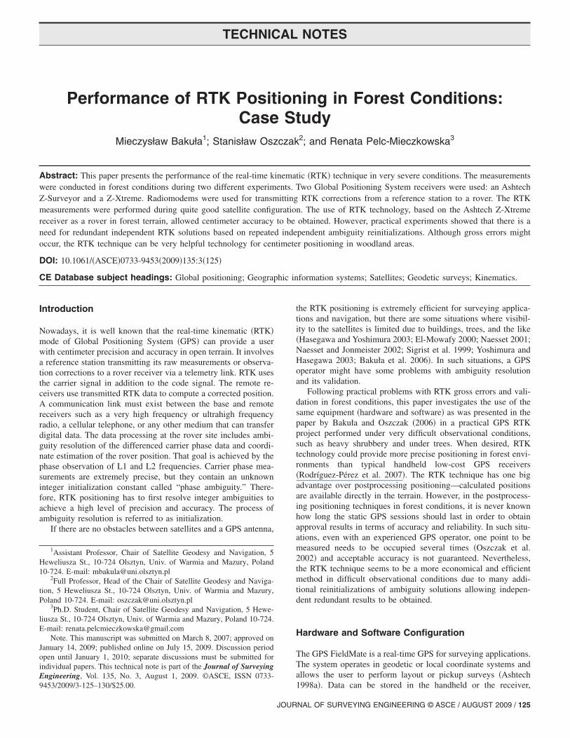
depending on the operational mode of GPS positioning. The sys-tem can operate in Radio Technical Commission for MaritimeServices or carrier phase differential �CPD� modes. The CPDmessage can provide more complete information on position, ve-locity, solution status, position root mean square �RMS� and co-variance, number of satellites, and position dilution of precision�PDOP�, �Ashtech 1998b�. In the real-time modes, the systemdisplays a constant precision value and ambiguity resolution re-sults, i.e., fixed or float. The handheld software provides the userwith multipoint logging and offset options and offers several dif-ferent modes of navigation. The GPS FieldMate system consistsof two main components: the base and the rover. The base systemis composed of a GPS base receiver, a radiomodem, and a radioantenna; but the rover system is also composed of a GPS receiver,a radio antenna, and an additional handheld controller, e.g., aHusky computer �Fig. 1�.
The base GPS antenna is located over a reference point thatthe coordinates are known �fixed coordinates� and entered into thebase receiver. Having calculated correction data, based on thereference point coordinates and GPS measurements, the base GPSreceiver sends it to the base radio via a serial cable. Next, the baseradio broadcasts the corrections to the rover receiver. In real time,the rover radio receives the correction information through theremote radio antenna and sends the data to the rover GPS receivervia a serial cable. The rover GPS receiver uses measurementsfrom the base and applies them to derive a corrected position forthe rover GPS antenna. The position information is transferred tothe Husky controller though a serial cable where the GPS Field-Mate software converts the position data into local coordinatesusing transformation parameters. Local coordinates are displayedalong with the current positional precision. The Ashtech InstantRTK technique applied in Z-Xtreme receivers allows centimeteraccuracy to be obtained within a few seconds in open areas�Abousalem et al. 2001�.
Practical RTK Tests
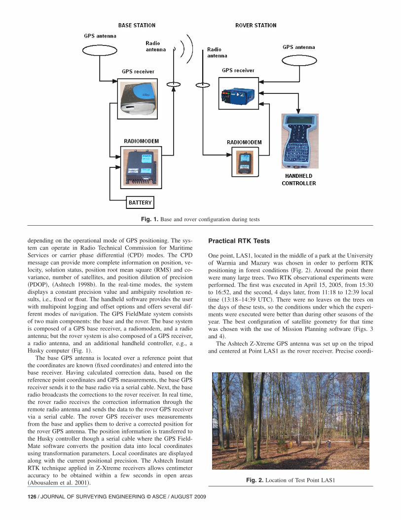
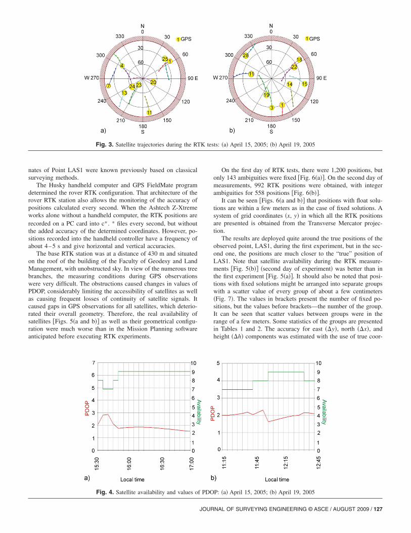
One point, LAS1, located in the middle of a park at the Universityof Warmia and Mazury was chosen in order to perform RTKpositioning in forest conditions �Fig. 2�. Around the point therewere many large trees. Two RTK observational experiments wereperformed. The first was executed in April 15, 2005, from 15:30to 16:52, and the second, 4 days later, from 11:18 to 12:39 localtime �13:18–14:39 UTC�. There were no leaves on the trees onthe days of these tests, so the conditions under which the experi-ments were executed were better than during other seasons of theyear. The best configuration of satellite geometry for that timewas chosen with the use of Mission Planning software �Figs. 3and 4�.
The Ashtech Z-Xtreme GPS antenna was set up on the tripodand centered at Point LAS1 as the rover receiver. Precise coordi-
Fig. 1. Base and rover configuration during tests
Fig. 2. Location of Test Point LAS1
126 / JOURNAL OF SURVEYING ENGINEERING © ASCE / AUGUST 2009
nates of Point LAS1 were known previously based on classicalsurveying methods.
The Husky handheld computer and GPS FieldMate programdetermined the rover RTK configuration. That architecture of therover RTK station also allows the monitoring of the accuracy ofpositions calculated every second. When the Ashtech Z-Xtremeworks alone without a handheld computer, the RTK positions arerecorded on a PC card into c* . * files every second, but withoutthe added accuracy of the determined coordinates. However, po-sitions recorded into the handheld controller have a frequency ofabout 4–5 s and give horizontal and vertical accuracies.
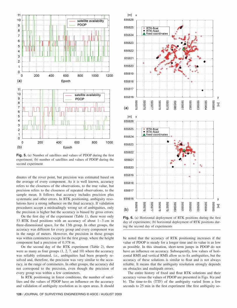
The base RTK station was at a distance of 430 m and situatedon the roof of the building of the Faculty of Geodesy and LandManagement, with unobstructed sky. In view of the numerous treebranches, the measuring conditions during GPS observationswere very difficult. The obstructions caused changes in values ofPDOP, considerably limiting the accessibility of satellites as wellas causing frequent losses of continuity of satellite signals. Itcaused gaps in GPS observations for all satellites, which deterio-rated their overall geometry. Therefore, the real availability ofsatellites �Figs. 5�a and b�� as well as their geometrical configu-ration were much worse than in the Mission Planning softwareanticipated before executing RTK experiments.
On the first day of RTK tests, there were 1,200 positions, butonly 143 ambiguities were fixed �Fig. 6�a��. On the second day ofmeasurements, 992 RTK positions were obtained, with integerambiguities for 558 positions �Fig. 6�b��.
It can be seen �Figs. 6�a and b�� that positions with float solu-tions are within a few meters as in the case of fixed solutions. Asystem of grid coordinates �x, y� in which all the RTK positionsare presented is obtained from the Transverse Mercator projec-tion.
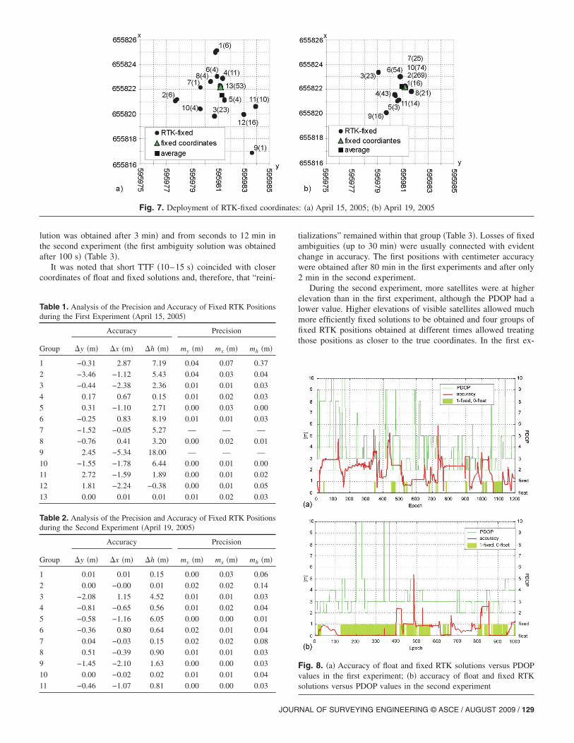
The results are deployed quite around the true positions of theobserved point, LAS1, during the first experiment, but in the sec-ond one, the positions are much closer to the “true” position ofLAS1. Note that satellite availability during the RTK measure-ments �Fig. 5�b�� �second day of experiment� was better than inthe first experiment �Fig. 5�a��. It should also be noted that posi-tions with fixed solutions might be arranged into separate groupswith a scatter value of every group of about a few centimeters�Fig. 7�. The values in brackets present the number of fixed po-sitions, but the values before brackets—the number of the group.It can be seen that scatter values between groups were in therange of a few meters. Some statistics of the groups are presentedin Tables 1 and 2. The accuracy for east ��y�, north ��x�, andheight ��h� components was estimated with the use of true coor-
Fig. 3. Satellite trajectories during the RTK tests: �a� April 15, 2005; �b� April 19, 2005
Fig. 4. Satellite availability and values of PDOP: �a� April 15, 2005; �b� April 19, 2005
JOURNAL OF SURVEYING ENGINEERING © ASCE / AUGUST 2009 / 127
dinates of the rover point, but precision was estimated based onthe average of every component. As it is well known, accuracyrefers to the closeness of the observations, to the true value, butprecision refers to the closeness of repeated observations, to thesample mean. It follows that accuracy includes precision plussystematic and other errors. In RTK positioning, ambiguity reso-lutions have a strong influence on the final accuracy. If validationprocedures accept a misleadingly wrong set of ambiguities, onlythe precision is higher but the accuracy is biased by gross errors.
On the first day of the experiment �Table 1�, there were only53 RTK fixed positions with an accuracy of about 1–3 cm inthree-dimensional space, for the 13th group. In other groups, theaccuracy was different for every group and every component wasin the range of meters. However, the precision in those groupswas within centimeters except for the first group, where the heightcomponent had a precision of 0.378 m.
On the second day of the RTK experiment �Table 2�, therewere as many as four groups �1, 2, 7, and 10� where the accuracywas reliably estimated, i.e., ambiguities had been properly re-solved and, therefore, the precision was very similar to the accu-racy, in the range of centimeters. In other groups, the accuracy didnot correspond to the precision, even though the precision ofevery group was within a few centimeters.
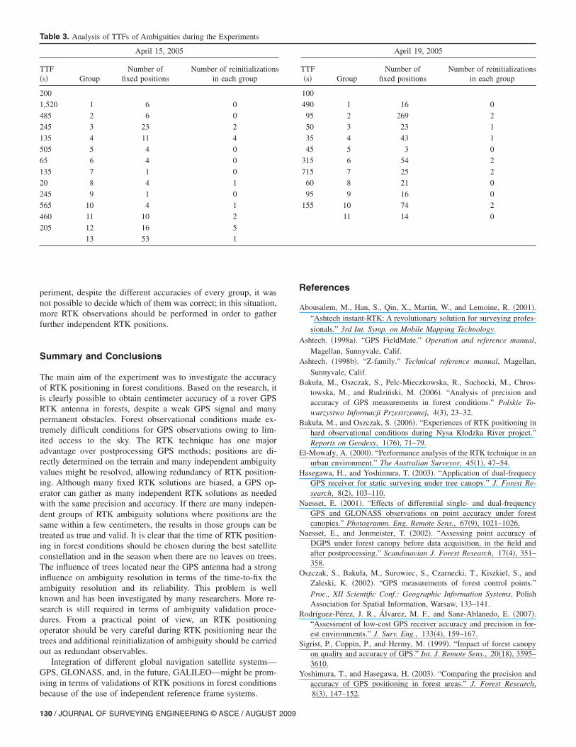
In RTK positioning in forest conditions, the number of satel-lites and the values of PDOP have an influence on the accuracyand validation of ambiguity resolution as in open areas. It should
be noted that the accuracy of RTK positioning increases if thevalue of PDOP is steady for a longer time and its value is as lowas possible. In this situation, short-term jumps in PDOP do nothave an influence on accuracy. Subsequently, low values of hori-zontal RMS and vertical RMS allow us to fix ambiguities, but theaccuracy of these solutions is similar to float and is not alwaysreliable. It means that the ambiguity resolution strongly dependson obstacles and multipath errors.
The entire history of fixed and float RTK solutions and theiraccuracy versus the values of PDOP are presented in Figs. 8�a andb�. The time-to-fix �TTF� of the ambiguity varied from a fewseconds to 25 min in the first experiment �the first ambiguity so-
Fig. 5. �a� Number of satellites and values of PDOP during the firstexperiment; �b� number of satellites and values of PDOP during thesecond experiment
Fig. 6. �a� Horizontal deployment of RTK positions during the firstday of experiments; �b� horizontal deployment of RTK positions dur-ing the second day of experiments
128 / JOURNAL OF SURVEYING ENGINEERING © ASCE / AUGUST 2009
lution was obtained after 3 min� and from seconds to 12 min inthe second experiment �the first ambiguity solution was obtainedafter 100 s� �Table 3�.
It was noted that short TTF �10–15 s� coincided with closercoordinates of float and fixed solutions and, therefore, that “reini-
tializations” remained within that group �Table 3�. Losses of fixedambiguities �up to 30 min� were usually connected with evidentchange in accuracy. The first positions with centimeter accuracywere obtained after 80 min in the first experiments and after only2 min in the second experiment.
During the second experiment, more satellites were at higherelevation than in the first experiment, although the PDOP had alower value. Higher elevations of visible satellites allowed muchmore efficiently fixed solutions to be obtained and four groups offixed RTK positions obtained at different times allowed treatingthose positions as closer to the true coordinates. In the first ex-
Fig. 7. Deployment of RTK-fixed coordinates: �a� April 15, 2005; �b� April 19, 2005
Table 1. Analysis of the Precision and Accuracy of Fixed RTK Positionsduring the First Experiment �April 15, 2005�
Group
Accuracy Precision
�y �m� �x �m� �h �m� my �m� mx �m� mh �m�
1 −0.31 2.87 7.19 0.04 0.07 0.37
2 −3.46 −1.12 5.43 0.04 0.03 0.04
3 −0.44 −2.38 2.36 0.01 0.01 0.03
4 0.17 0.67 0.15 0.01 0.02 0.03
5 0.31 −1.10 2.71 0.00 0.03 0.00
6 −0.25 0.83 8.19 0.01 0.01 0.03
7 −1.52 −0.05 5.27 — — —
8 −0.76 0.41 3.20 0.00 0.02 0.01
9 2.45 −5.34 18.00 — — —
10 −1.55 −1.78 6.44 0.00 0.01 0.00
11 2.72 −1.59 1.89 0.00 0.01 0.02
12 1.81 −2.24 −0.38 0.00 0.01 0.05
13 0.00 0.01 0.01 0.01 0.02 0.03
Table 2. Analysis of the Precision and Accuracy of Fixed RTK Positionsduring the Second Experiment �April 19, 2005�
Group
Accuracy Precision
�y �m� �x �m� �h �m� my �m� mx �m� mh �m�
1 0.01 0.01 0.15 0.00 0.03 0.06
2 0.00 −0.00 0.01 0.02 0.02 0.14
3 −2.08 1.15 4.52 0.01 0.01 0.03
4 −0.81 −0.65 0.56 0.01 0.02 0.04
5 −0.58 −1.16 6.05 0.00 0.00 0.01
6 −0.36 0.80 0.64 0.02 0.01 0.04
7 0.04 −0.03 0.15 0.02 0.02 0.08
8 0.51 −0.39 0.90 0.01 0.01 0.03
9 −1.45 −2.10 1.63 0.00 0.00 0.03
10 0.00 −0.02 0.02 0.01 0.01 0.04
11 −0.46 −1.07 0.81 0.00 0.00 0.03
Fig. 8. �a� Accuracy of float and fixed RTK solutions versus PDOPvalues in the first experiment; �b� accuracy of float and fixed RTKsolutions versus PDOP values in the second experiment
JOURNAL OF SURVEYING ENGINEERING © ASCE / AUGUST 2009 / 129
periment, despite the different accuracies of every group, it wasnot possible to decide which of them was correct; in this situation,more RTK observations should be performed in order to gatherfurther independent RTK positions.
Summary and Conclusions
The main aim of the experiment was to investigate the accuracyof RTK positioning in forest conditions. Based on the research, itis clearly possible to obtain centimeter accuracy of a rover GPSRTK antenna in forests, despite a weak GPS signal and manypermanent obstacles. Forest observational conditions made ex-tremely difficult conditions for GPS observations owing to lim-ited access to the sky. The RTK technique has one majoradvantage over postprocessing GPS methods; positions are di-rectly determined on the terrain and many independent ambiguityvalues might be resolved, allowing redundancy of RTK position-ing. Although many fixed RTK solutions are biased, a GPS op-erator can gather as many independent RTK solutions as neededwith the same precision and accuracy. If there are many indepen-dent groups of RTK ambiguity solutions where positions are thesame within a few centimeters, the results in those groups can betreated as true and valid. It is clear that the time of RTK position-ing in forest conditions should be chosen during the best satelliteconstellation and in the season when there are no leaves on trees.The influence of trees located near the GPS antenna had a stronginfluence on ambiguity resolution in terms of the time-to-fix theambiguity resolution and its reliability. This problem is wellknown and has been investigated by many researchers. More re-search is still required in terms of ambiguity validation proce-dures. From a practical point of view, an RTK positioningoperator should be very careful during RTK positioning near thetrees and additional reinitialization of ambiguity should be carriedout as redundant observables.
Integration of different global navigation satellite systems—GPS, GLONASS, and, in the future, GALILEO—might be prom-ising in terms of validations of RTK positions in forest conditionsbecause of the use of independent reference frame systems.
References
Abousalem, M., Han, S., Qin, X., Martin, W., and Lemoine, R. �2001�.“Ashtech instant-RTK: A revolutionary solution for surveying profes-sionals.” 3rd Int. Symp. on Mobile Mapping Technology.
Ashtech. �1998a�. “GPS FieldMate.” Operation and reference manual,Magellan, Sunnyvale, Calif.
Ashtech. �1998b�. “Z-family.” Technical reference manual, Magellan,Sunnyvale, Calif.
Bakuła, M., Oszczak, S., Pelc-Mieczkowska, R., Suchocki, M., Chros-towska, M., and Rudziński, M. �2006�. “Analysis of precision andaccuracy of GPS measurements in forest conditions.” Polskie To-warzystwo Informacji Przestrzennej, 4�3�, 23–32.
Bakuła, M., and Oszczak, S. �2006�. “Experiences of RTK positioning inhard observational conditions during Nysa Kłodzka River project.”Reports on Geodesy, 1�76�, 71–79.
El-Mowafy, A. �2000�. “Performance analysis of the RTK technique in anurban environment.” The Australian Surveyor, 45�1�, 47–54.
Hasegawa, H., and Yoshimura, T. �2003�. “Application of dual-frequecyGPS receiver for static surveying under tree canopy.” J. Forest Re-search, 8�2�, 103–110.
Naesset, E. �2001�. “Effects of differential single- and dual-frequencyGPS and GLONASS observations on point accuracy under forestcanopies.” Photogramm. Eng. Remote Sens., 67�9�, 1021–1026.
Naesset, E., and Jonmeister, T. �2002�. “Assessing point accuracy ofDGPS under forest canopy before data acquisition, in the field andafter postprocessing.” Scandinavian J. Forest Research, 17�4�, 351–358.
Oszczak, S., Bakuła, M., Surowiec, S., Czarnecki, T., Kiszkiel, S., andZaleski, K. �2002�. “GPS measurements of forest control points.”Proc., XII Scientific Conf.: Geographic Information Systems, PolishAssociation for Spatial Information, Warsaw, 133–141.
Rodríguez-Pérez, J. R., Álvarez, M. F., and Sanz-Ablanedo, E. �2007�.“Assessment of low-cost GPS receiver accuracy and precision in for-est environments.” J. Surv. Eng., 133�4�, 159–167.
Sigrist, P., Coppin, P., and Hermy, M. �1999�. “Impact of forest canopyon quality and accuracy of GPS.” Int. J. Remote Sens., 20�18�, 3595–3610.
Yoshimura, T., and Hasegawa, H. �2003�. “Comparing the precision andaccuracy of GPS positioning in forest areas.” J. Forest Research,8�3�, 147–152.
Table 3. Analysis of TTFs of Ambiguities during the Experiments
April 15, 2005 April 19, 2005
TTF�s� Group
Number offixed positions
Number of reinitializationsin each group
TTF�s� Group
Number offixed positions
Number of reinitializationsin each group
200 100
1,520 1 6 0 490 1 16 0
485 2 6 0 95 2 269 2
245 3 23 2 50 3 23 1
135 4 11 4 35 4 43 1
505 5 4 0 45 5 3 0
65 6 4 0 315 6 54 2
135 7 1 0 715 7 25 2
20 8 4 1 60 8 21 0
245 9 1 0 95 9 16 0
565 10 4 1 155 10 74 2
460 11 10 2 11 14 0
205 12 16 5
13 53 1
130 / JOURNAL OF SURVEYING ENGINEERING © ASCE / AUGUST 2009