INVERTED PSEUDOLITE POSITIONING AND SOME APPLICATIONS
8
INVERTED PSEUDOLITE POSITIONING AND ITS APPLICATIONS Liwen Dai, Jinling Wang, Toshiaki Tsujii, Chris Rizos School of Geomatic Engineering The University of New South Wales Sydney, NSW 2052 Australia ABSTRACT In this paper the inverted pseudolite positioning system, comprising a ‘constellation’ of GPS receivers that tracks a mobile pseudolite, is discussed. Two configurations of the inverted positioning system are described. The implementation challenges for the pseudolite-based inverted positioning system, including geometry optimization, multipath mitigation and minimization of the impact of GPS receiver location errors, have been investigated. Several applications of the inverted positioning concept have been identified, including deformation monitoring and navigation services based on pseudolite installed on stratospheric airships. A static experiment was carried out using six NovAtel GPS receivers and two IntegriNautics IN200CXL pseudolite instruments, on the UNSW campus, on the 4 th April 2001. The experimental setup and operational procedures are described in detail. The carrier phase measurements have been processed in an 'inverted' mode. The results indicate that the potential accuracy of 'inverted' phase-based positioning is better than 5mm. The static experiment has indicated that the two configurations for the inverted positioning are feasible in practice. INTRODUCTION Over the last decade or so GPS positioning has played an increasing role in both surveying and navigation, and has become an indispensable tool for precise relative positioning. However, in some situations, such as in urban canyons, dam monitoring in valleys and in deep open-cut mines, the number of visible satellites may not be sufficient to reliably determine precise coordinates. Furthermore, it is impossible to use GPS for precise indoor positioning. Pseudolites, which are ground-based transmitters of GPS-like signals (i.e. “pseudo-satellite”), can significantly enhance the satellite geometry, and even replace the GPS satellite constellation in some circumstances. The pseudolites typically transmit pseudo-range and carrier phase measurements signals at one or both the GPS frequency bands (L 1 : 1575.42MHz; L 2 : 1227.6MHz). The use of pseudolites can be traced back to the early stages of GPS development in the late 1970s, at the Army Yuma Proving Ground in Arizona [9], where the pseudolites were used to validate the GPS concept before launch of the first satellites. In the mid 1980s, the RTCM committee SC-104 ('Recommended Standards for Differential NAVSTAR GPS Service') designated the Type 8 Message for the pseudolite almanac, containing the location, code and health information of pseudolites [1]. With the development of the pseudolite techniques and GPS user equipment during the last decade, pseudolites can now be used to enhance the availability, reliability, integrity and accuracy in many applications, such as aircraft landing [7-8], deformation monitoring applications [3-4], Mars exploration [9], precision approach applications, and others [1, 16]. INVERTED PSEUDOLITE POSITIONING CONCEPT The concept of inverted pseudolite-based positioning was first introduced by Raquet et al. [13]. In their experiment, a ground-based test was conducted to investigate the feasibility of using mobile pseudolites for the precise positioning of military aircraft. O’Keefe et al. [11] presented experimental results and also discussed the inverted pseudolite GPS concept for local area positioning.
-
Upload
independent -
Category
Documents
-
view
4 -
download
0
Transcript of INVERTED PSEUDOLITE POSITIONING AND SOME APPLICATIONS

INVERTED PSEUDOLITE POSITIONING AND ITS APPLICATIONS
Liwen Dai, Jinling Wang, Toshiaki Tsujii, Chris Rizos
School of Geomatic EngineeringThe University of New South Wales
Sydney, NSW 2052Australia
ABSTRACT
In this paper the inverted pseudolite positioning system, comprising a ‘constellation’ of GPS receivers thattracks a mobile pseudolite, is discussed. Two configurations of the inverted positioning system aredescribed. The implementation challenges for the pseudolite-based inverted positioning system, includinggeometry optimization, multipath mitigation and minimization of the impact of GPS receiver location errors,have been investigated. Several applications of the inverted positioning concept have been identified,including deformation monitoring and navigation services based on pseudolite installed on stratosphericairships. A static experiment was carried out using six NovAtel GPS receivers and two IntegriNauticsIN200CXL pseudolite instruments, on the UNSW campus, on the 4th April 2001. The experimental setup andoperational procedures are described in detail. The carrier phase measurements have been processed in an'inverted' mode. The results indicate that the potential accuracy of 'inverted' phase-based positioning isbetter than 5mm. The static experiment has indicated that the two configurations for the inverted positioningare feasible in practice.
INTRODUCTION
Over the last decade or so GPS positioning has played an increasing role in both surveying and navigation,and has become an indispensable tool for precise relative positioning. However, in some situations, such asin urban canyons, dam monitoring in valleys and in deep open-cut mines, the number of visible satellitesmay not be sufficient to reliably determine precise coordinates. Furthermore, it is impossible to use GPS forprecise indoor positioning.
Pseudolites, which are ground-based transmitters of GPS-like signals (i.e. “pseudo-satellite”), cansignificantly enhance the satellite geometry, and even replace the GPS satellite constellation in somecircumstances. The pseudolites typically transmit pseudo-range and carrier phase measurements signals atone or both the GPS frequency bands (L1: 1575.42MHz; L2: 1227.6MHz). The use of pseudolites can betraced back to the early stages of GPS development in the late 1970s, at the Army Yuma Proving Ground inArizona [9], where the pseudolites were used to validate the GPS concept before launch of the first satellites.In the mid 1980s, the RTCM committee SC-104 ('Recommended Standards for Differential NAVSTARGPS Service') designated the Type 8 Message for the pseudolite almanac, containing the location, code andhealth information of pseudolites [1]. With the development of the pseudolite techniques and GPS userequipment during the last decade, pseudolites can now be used to enhance the availability, reliability,integrity and accuracy in many applications, such as aircraft landing [7-8], deformation monitoringapplications [3-4], Mars exploration [9], precision approach applications, and others [1, 16].
INVERTED PSEUDOLITE POSITIONING CONCEPT
The concept of inverted pseudolite-based positioning was first introduced by Raquet et al. [13]. In theirexperiment, a ground-based test was conducted to investigate the feasibility of using mobile pseudolites forthe precise positioning of military aircraft. O’Keefe et al. [11] presented experimental results and alsodiscussed the inverted pseudolite GPS concept for local area positioning.
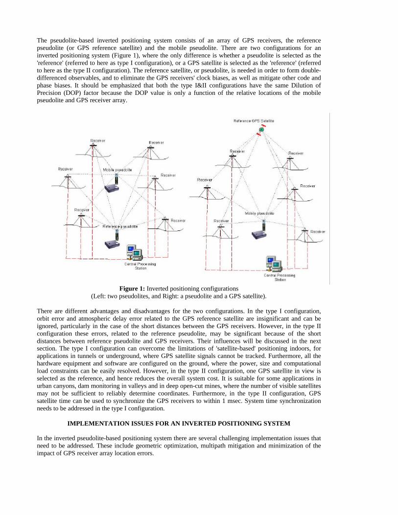
The pseudolite-based inverted positioning system consists of an array of GPS receivers, the referencepseudolite (or GPS reference satellite) and the mobile pseudolite. There are two configurations for aninverted positioning system (Figure 1), where the only difference is whether a pseudolite is selected as the'reference' (referred to here as type I configuration), or a GPS satellite is selected as the 'reference' (referredto here as the type II configuration). The reference satellite, or pseudolite, is needed in order to form double-differenced observables, and to eliminate the GPS receivers' clock biases, as well as mitigate other code andphase biases. It should be emphasized that both the type I&II configurations have the same Dilution ofPrecision (DOP) factor because the DOP value is only a function of the relative locations of the mobilepseudolite and GPS receiver array.
Figure 1: Inverted positioning configurations(Left: two pseudolites, and Right: a pseudolite and a GPS satellite).
There are different advantages and disadvantages for the two configurations. In the type I configuration,orbit error and atmospheric delay error related to the GPS reference satellite are insignificant and can beignored, particularly in the case of the short distances between the GPS receivers. However, in the type IIconfiguration these errors, related to the reference pseudolite, may be significant because of the shortdistances between reference pseudolite and GPS receivers. Their influences will be discussed in the nextsection. The type I configuration can overcome the limitations of 'satellite-based' positioning indoors, forapplications in tunnels or underground, where GPS satellite signals cannot be tracked. Furthermore, all thehardware equipment and software are configured on the ground, where the power, size and computationalload constraints can be easily resolved. However, in the type II configuration, one GPS satellite in view isselected as the reference, and hence reduces the overall system cost. It is suitable for some applications inurban canyons, dam monitoring in valleys and in deep open-cut mines, where the number of visible satellitesmay not be sufficient to reliably determine coordinates. Furthermore, in the type II configuration, GPSsatellite time can be used to synchronize the GPS receivers to within 1 msec. System time synchronizationneeds to be addressed in the type I configuration.
IMPLEMENTATION ISSUES FOR AN INVERTED POSITIONING SYSTEM
In the inverted pseudolite-based positioning system there are several challenging implementation issues thatneed to be addressed. These include geometric optimization, multipath mitigation and minimization of theimpact of GPS receiver array location errors.
Geometric Optimization
The GPS receiver array geometric optimization refers to the need to find locations for the GPS receivers andthe pseudolite transmitter that will minimize the Position Dilution of Precision (PDOP), the RelativePosition Dilution of Precision (RDOP), or some other geometry factor (in this paper, RDOP is used).
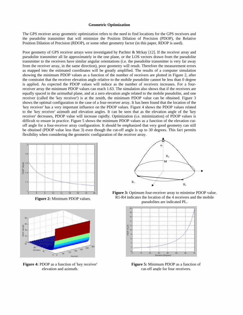
Poor geometry of GPS receiver arrays were investigated by Pachter & Mckay [12]. If the receiver array andpseudolite transmitter all lie approximately in the one plane, or the LOS vectors drawn from the pseudolitetransmitter to the receivers have similar angular orientations (i.e. the pseudolite transmitter is very far awayfrom the receiver array, in the same direction), poor geometry will result. Therefore the measurement errorsas mapped into the estimated coordinates will be greatly amplified. The results of a computer simulationshowing the minimum PDOP values as a function of the number of receivers are plotted in Figure 2, afterthe constraint that the receiver elevation angle relative to the mobile pseudolite cannot be less than 0 degreeis applied. As expected the PDOP values will reduce as the number of receivers increases. For a four-receiver array the minimum PDOP values can reach 1.63. The simulation also shows that if the receivers areequally spaced in the azimuthal plane, and at a zero elevation angle related to the mobile pseudolite, and onereceiver (called the 'key receiver') is at the zenith, the minimum PDOP value can be obtained. Figure 3shows the optimal configuration in the case of a four-receiver array. It has been found that the location of the'key receiver' has a very important influence on the PDOP values. Figure 4 shows the PDOP values relatedto the 'key receiver' azimuth and elevation angles. It can be seen that as the elevation angle of the 'keyreceiver' decreases, PDOP value will increase rapidly. Optimization (i.e. minimization) of PDOP values isdifficult to ensure in practice. Figure 5 shows the minimum PDOP values as a function of the elevation cut-off angle for a four-receiver array configuration. It should be emphasized that very good geometry can stillbe obtained (PDOP value less than 3) even though the cut-off angle is up to 30 degrees. This fact permitsflexibility when considering the geometric configuration of the receiver array.
PL
R2
R3
R4
R1
Figure 2: Minimum PDOP values.
Figure 3: Optimum four-receiver array to minimise PDOP value.R1-R4 indicates the location of the 4 receivers and the mobile
pseudolites are indicated PL.
Figure 5: Minimum PDOP as a function ofcut-off angle for four receivers.
Figure 4: PDOP as a function of 'key receiver'elevation and azimuth.
Receiver Array Location Error
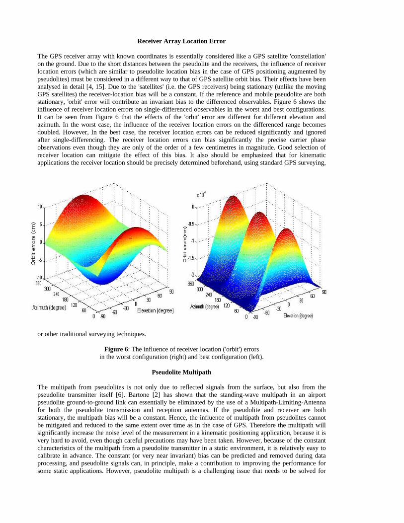
The GPS receiver array with known coordinates is essentially considered like a GPS satellite 'constellation'on the ground. Due to the short distances between the pseudolite and the receivers, the influence of receiverlocation errors (which are similar to pseudolite location bias in the case of GPS positioning augmented bypseudolites) must be considered in a different way to that of GPS satellite orbit bias. Their effects have beenanalysed in detail [4, 15]. Due to the 'satellites' (i.e. the GPS receivers) being stationary (unlike the movingGPS satellites) the receiver-location bias will be a constant. If the reference and mobile pseudolite are bothstationary, 'orbit' error will contribute an invariant bias to the differenced observables. Figure 6 shows theinfluence of receiver location errors on single-differenced observables in the worst and best configurations.It can be seen from Figure 6 that the effects of the 'orbit' error are different for different elevation andazimuth. In the worst case, the influence of the receiver location errors on the differenced range becomesdoubled. However, In the best case, the receiver location errors can be reduced significantly and ignoredafter single-differencing. The receiver location errors can bias significantly the precise carrier phaseobservations even though they are only of the order of a few centimetres in magnitude. Good selection ofreceiver location can mitigate the effect of this bias. It also should be emphasized that for kinematicapplications the receiver location should be precisely determined beforehand, using standard GPS surveying,
or other traditional surveying techniques.
Figure 6: The influence of receiver location ('orbit') errorsin the worst configuration (right) and best configuration (left).
Pseudolite Multipath
The multipath from pseudolites is not only due to reflected signals from the surface, but also from thepseudolite transmitter itself [6]. Bartone [2] has shown that the standing-wave multipath in an airportpseudolite ground-to-ground link can essentially be eliminated by the use of a Multipath-Limiting-Antennafor both the pseudolite transmission and reception antennas. If the pseudolite and receiver are bothstationary, the multipath bias will be a constant. Hence, the influence of multipath from pseudolites cannotbe mitigated and reduced to the same extent over time as in the case of GPS. Therefore the multipath willsignificantly increase the noise level of the measurement in a kinematic positioning application, because it isvery hard to avoid, even though careful precautions may have been taken. However, because of the constantcharacteristics of the multipath from a pseudolite transmitter in a static environment, it is relatively easy tocalibrate in advance. The constant (or very near invariant) bias can be predicted and removed during dataprocessing, and pseudolite signals can, in principle, make a contribution to improving the performance forsome static applications. However, pseudolite multipath is a challenging issue that needs to be solved for
kinematic applications. Good hardware design, including receivers, receiver antennas and pseudolitetransmitter antennas, as well as software-based multipath mitigation techniques will be needed.
INVERTED PSEUDOLITE POSITIONING APPLICATIONS
Based on the pseudolite inverted positioning concept, two applications – deformation monitoring andnavigation services based on pseudolite installed on stratospheric airships – have been investigated at TheUniversity of New South Wales (UNSW).
Deformation Monitoring
As is well known, GPS techniques cannot be used when the signals are completely blocked by obstacles –natural and man-made. However, monitoring of structures by GPS-only techniques is not possible. Thepotential deformation monitoring applications using the pseudolite-based inverted positioning concept havebeen investigated by the authors [5]. This can extend the concept of 'satellite-based' deformation monitoringindoors, for applications in tunnels or underground, where GPS satellite signals cannot be tracked.Applications with implementation constraints such as solution reliability and availability, and severe designconstraints such as space and weight, could be addressed by the pseudolite-based inverted positioningtechnique. In this system, more flexibility is obtained and cost is reduced because all of the hardwareequipment and software are configured on the ground, where the power, size and computational loadconstraints can be easily resolved. Furthermore, the whole system may be able to operate in the presence ofjamming at GPS frequencies. In practice, constant systematic biases from multipath, and the GPS receiverlocation errors can be calibrated beforehand.
Navigation Services Based on Pseudolites Installed on Stratospheric Airships
Feasibility studies and R&D projects on high altitude platform systems are being conducted in a number ofcountries. Japan has been investigating the use of an airship system that will function as a stratosphericplatform (altitude of about 20km) for applications such as environmental monitoring, communications andbroadcasting. Remote sensing from such an airship would be very effective because it floats above the sameground area, permitting continuous monitoring of the surface. However, the precise positioning of theairship is one of the most important technical challenges for such a project. If the pseudolite transmitter isinstalled on the underside of the airship, its position can be precisely determined by the receiver array on theground using the inverted positioning method [14]. In addition, the pseudolites could be considered asadditional GPS satellites, which would improve the accuracy, availability, and integrity of GPS-basedpositioning systems.
TEST RESULTS AND ANALYSIS
A static test was carried out to investigate the feasibility of the pseudolite-based inverted positioningconcept.
Data Acquisition
The experiment was conducted using six NovAtel receivers (four MillenniumTM and two BeelineTM) and twoIntegriNautics IN200CXL pseudolite instruments on the UNSW campus, on the 4th April 2001. The twopseudolites were configured as PRN codes 12 and 16. The six receivers were sited on the roof of theElectrical Engineering Building (Figure 7). The pseudolites transmitted only GPS L1 signals. In order toavoid signal interference, the RTCM recommended pulsing of signals at 1/11 cycle was used, and 32 dBattenuation was applied to the signal power.

Figure 7: Location of instruments for inverted positioning experiment, 4th April 2001. A1-A6 indicates thelocation of the 6 GPS receivers, and the two pseudolites are indicated as Ref PL and Mobile PL.
In the case of the NovAtel GPS receivers, channels can be easily assigned to the specified PRNs to trackpseudolite signals. The remaining channels were used to track GPS satellite signals. About 40 minutes ofGPS and pseudolite measurements were collected with one-second sampling rate. The coordinates of the sixGPS receivers and the two pseudolite sites were precisely determined beforehand using the data collected bythe GPS receivers. The number of receivers tracking both pseudolites was either 5 or 6.
Result Analysis
Figure 8 shows the HDOP (Horizontal Dilution of Precision) and VDOP (Vertical Dilution of Precision)values for the mobile pseudolite PL16 during the experiment. 5-6 receivers tracked both pseudolite signals,therefore different combinations of receivers result in different HDOP and VDOP values. It can be seenfrom Figure 8 that very good geometry (HDOP and VDOP both less than 2) was obtained because of theoptimized receiver locations (through careful selection of antenna locations).
Figure 8: The HDOP (Left) and VDOP (Right) values.
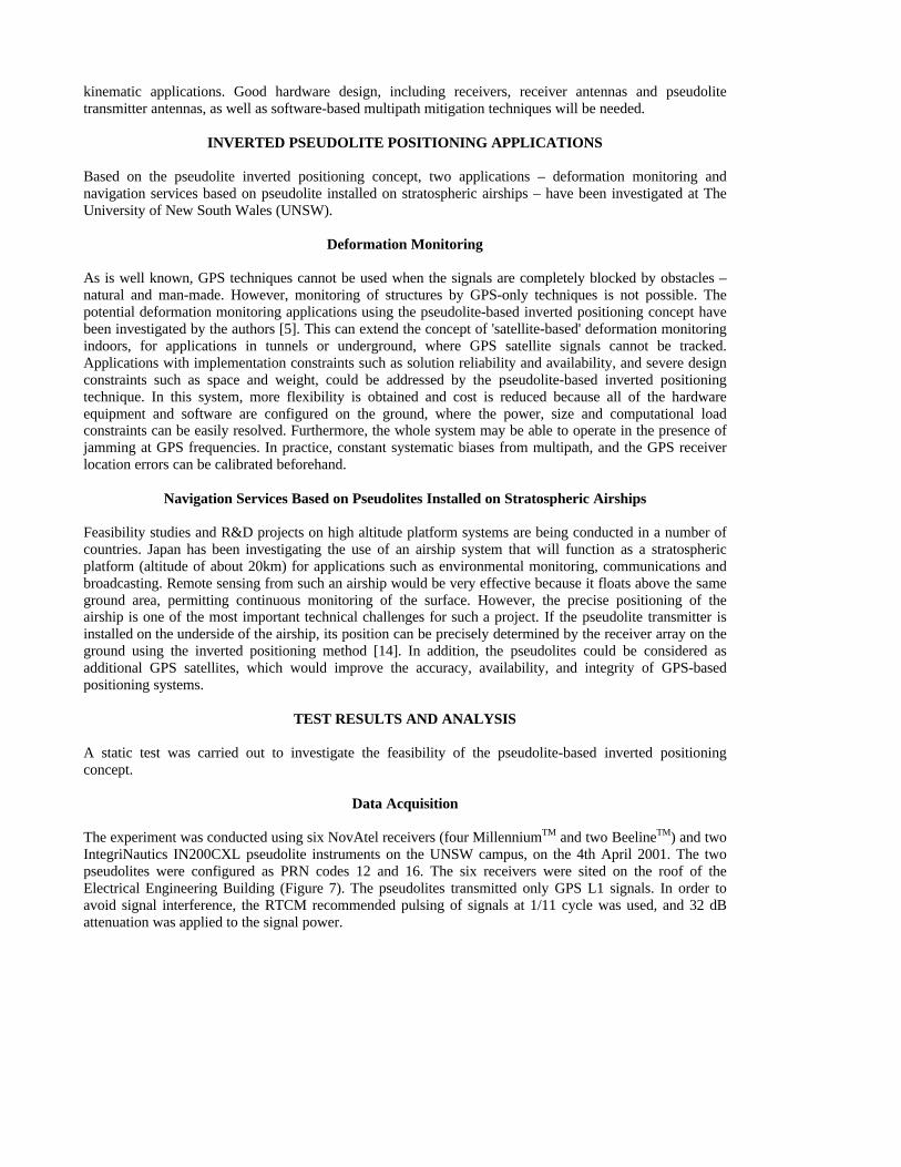
Carrier phase ambiguity resolution could not be attempted in the normal manner because the receivers andpseudolites are stationary. The carrier phase processing was conducted by rounding-off the double-differenced ambiguity to the nearest integer using the known initial position of the mobile pseudolite.During data processing it was found that significant constant biases existed in the pseudolite carrier phasemeasurements. The constant biases may come from the invariant multipath, attributed to the high multipathenvironment on the roof. The carrier phase multipath for the one-way signal does not exceed about one-quarter of the wavelength (5-6cm for L1 or L2). However, the double-differenced measurements, involvingfour one-way signals, could be seriously contaminated by multipath. It is therefore necessary to calibrate theconstant biases, for static environments, before data processing. In this experiment, each receiver not only
tracks the two pseudolite signals but also the GPS signals. Therefore GPS measurements can be used tocalibrate the residual biases in the pseudolite measurements. Figure 9 shows the values of the double-differenced L1 residual biases between receivers and the two pseudolites, or one pseudolite and one GPSsatellite. The constant biases for receivers 1, 2, 3, 4, 5 are -0.0742, 0.0918, 0.2048, 0.0446 and 0.1663 cyclesin the type II configuration, and 0.3374, -0.3477, 0.0747, -0.0688, -0.1288 cycles in the type I configuration(receiver 6 was selected as the reference 'satellite' in this configuration). It should be pointed out that theRMS of these bias values are less than 1cm (0.05 cycle).
Figure 9: Double-differenced L1 residuals (Left: type II, and Right: type I).
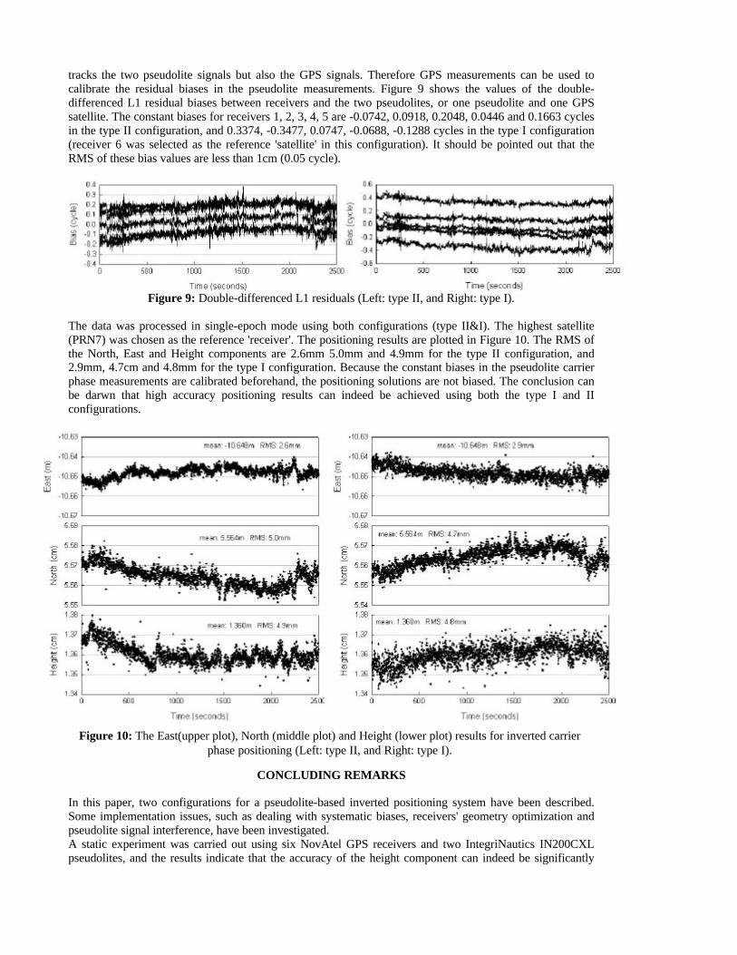
The data was processed in single-epoch mode using both configurations (type II&I). The highest satellite(PRN7) was chosen as the reference 'receiver'. The positioning results are plotted in Figure 10. The RMS ofthe North, East and Height components are 2.6mm 5.0mm and 4.9mm for the type II configuration, and2.9mm, 4.7cm and 4.8mm for the type I configuration. Because the constant biases in the pseudolite carrierphase measurements are calibrated beforehand, the positioning solutions are not biased. The conclusion canbe darwn that high accuracy positioning results can indeed be achieved using both the type I and IIconfigurations.
CONCLUDING REMARKS
In this paper, two configurations for a pseudolite-based inverted positioning system have been described.Some implementation issues, such as dealing with systematic biases, receivers' geometry optimization andpseudolite signal interference, have been investigated.A static experiment was carried out using six NovAtel GPS receivers and two IntegriNautics IN200CXLpseudolites, and the results indicate that the accuracy of the height component can indeed be significantly
Figure 10: The East(upper plot), North (middle plot) and Height (lower plot) results for inverted carrierphase positioning (Left: type II, and Right: type I).
improved (the RMS of the vertical was reduced by a factor 4), to approximately the same level as thehorizontal components. Pseudolite multipath is a challenging issue that needs to be addressed for kinematicapplications. Good hardware design, including receivers, receiver antennas and pseudolite transmitterantennas, as well as software-based multipath mitigation techniques will be needed.
ACKNOWLEDGEMENTS
The first author is supported by an International Postgraduate Research Scholarship at UNSW. The authorsalso would like to thank Graham Boyd, Normandy Exploration, for kindly providing four NovAtel GPSreceivers, and their colleagues Joel Barnes and Craig Roberts for their assistance in collecting data.
REFERENCES
1. Barltrop K.J., J.F. Stafford & B.D. Elrod, 1996. Local DGPS with pseudolite augmentation andimplementation considerations for LAAS, 9th Int. Tech. Meeting of the Satellite Division of the U.S. Inst.of Navigation, Kansas City, Missouri, 17-20 Sept., 449-459.
2. Bartone C.G., 1999. Multipath considerations for ground based ranging sources, 12th Int. Tech. Meetingof the Satellite Division of the U.S. Inst. of Navigation, Nashville, Tennessee, 14-17 Sept., 1491-1498.
3. Dai L., J. Zhang, C. Rizos, S. Han & J. Wang, 2000. GPS and pseudolite integration for deformationmonitoring applications, 13th Int. Tech. Meeting of the Satellite Division of the U.S. Inst. of Navigation,Salt Lake City, Utah, 19-22 Sept., 1-8.
4. Dai L., J. Wang, C. Rizos & S. Han, 2001a. Applications of pseudolites for deformation monitoringsystems, 10th FIG Int. Symp. on Deformation Measurements, Orange, California, 19-22 March, 11-22.
5. Dai L., J. Wang, C. Rizos & S. Han (2001b), Pseudo-satellite applications in deformation monitoring, tobe published in GPS solutions.
6. Ford T., J. Neumann, W. Petersen, C. Anderson, P. Fenton, T. Holden & K.J. Barltrop, 1996. HAPPI - aHigh Accuracy Pseudolite/GPS Positioning Integration, 9th Int. Tech. Meeting of the Satellite Divisionof the U.S. Inst. of Navigation, Kansas City, Missouri, 17-20 Sept., 1719-1728.
7. Hein G.W., B. Eissfeller, W. Werner, B. Ott, B.D. Elrod, K.J. Barltrop & J.F. Stafford, 1997. Practicalinvestigations on DGPS for aircraft precision approaches augmented by pseudolite carrier phasetracking, 10th Int. Tech. Meeting of the Satellite Division of the U.S. Inst. of Navigation, Kansas City,Missouri, 16-19 Sept., 1851-1960.
8. Holden T. & T. Morley, 1997. Pseudolite augmented DGPS for land applications, 10th Int. Tech.Meeting of the Satellite Division of the U.S. Inst. of Navigation, Kansas City, Missouri, 16-19 Sept.,1397-1403.
9. Kalafus R.M., A.J. Van Dierendonck & N. Pealer, 1986. Special Committee 104 Recommendations forDifferential GPS Service, Global Positioning System (red book), The Institute of Navigation, Vol. III,101-126.
10. Lemaster E. & S. Rock, 1999. Mars exploration using self-calibrating pseudolite arrays, 12th Int. Tech.Meeting of the Satellite Division of the U.S. Inst. of Navigation, Nashville, Tennessee, 14-17 Sept.,1549-1558.
11. O’Keefe K., J. Sharma, M.E. Cannon & G. Lachapelle, 1999. Pseudolite-based inverted GPS conceptfor local area positioning, 12th Int. Tech. Meeting of the Satellite Division of the U.S. Inst. of Navigation,Nashville, Tennessee, 14-17 Sept., 1523-1530.
12. Pachter M. & J.B. Mckay, 1998. Geometry optimization of a GPS-based navigation reference system,Navigation, 44(4), 457-470.
13. Raquet J., G. Lachapelle, W. Qui, C. Pelletier, A. Nash, P. Fenton & T. Holden, 1995. Development andtesting of a mobile pseudolite concept for precise positioning, 8th Int. Tech. Meeting of the SatelliteDivision of the U.S. Inst. of Navigation, Palm Springs, California, 12-15 Sept., 817-825.
14. Tsujii T., C. Rizos, J. Wang, L. Dai, C. Roberts & M. Harigae, 2001. A navigation/positioning servicebased on pseudolites installed on stratospheric airships, 5th Int. Symp. on Satellite NavigationTechnology & Applications, Canberra, Australia, July 24-27.
15. Wang J., T. Tsujii, C. Rizos, L. Dai & M. Moore, 2000. Integrating GPS and pseudolite signals forposition and attitude determination: Theoretical analysis and experiment results, 13th Int. Tech. Meetingof the Satellite Division of the U.S. Inst. of Navigation, Salt Lake City, Utah, 19-22 Sept, 2252-2262.
16. Wang J., T. Tsujii, C. Rizos, L. Dai & M. Moore, 2001. GPS and pseudo-satellites integration forprecise positioning, to be published in Geomatics Research Australasia.