Performance evaluation of the push-mode-multicast based candidate access router discovery (PMM CARD
47
Performance Evaluation of the Push-Mode-Multicast based Candidate Access Router Discovery (PMM CARD) Dario Di Sorte, Mauro Femminella, Leonardo Piacentini, Gianluca Reali Dipartimento di Ingegneria Elettronica e dell’Informazione (D.I.E.I.), University of Perugia via G. Duranti 93, 06125 Perugia, Italy {dario.disorte, mauro.femminella, leonardo.piacentini, gianluca.reali}@diei.unipg.it Abstract In order to provide nomadic users with QoS-enabled services, advanced mobility management will prove to be of fundamental importance in the future Internet. It has been widely recognized that the basic Mobile IPv4/v6 protocols could perform poorly, especially with QoS-demanding applications. One of the main steps to achieve seamless handover is the quick discovery of the surrounding wireless coverage at each access router (AR), i.e., the discovery of IP addresses and service capabilities (SCs) of candidate access routers (CARs) to hand over to. The rapid knowledge of IP addresses allows mobile nodes (MNs) to speed up the handover process, whereas information about SCs are important for the selection of the most appropriate wireless access (target access router, TAR) among the set of CARs, according to a given criterion (e.g., load balancing). In this paper, we first describe the candidate access router discovery (CARD) solutions proposed within the framework of the IETF SEAMOBY WG, which has inspired research in this field. Then, we propose the distributed Push-Mode-Multicast based CARD (PMM CARD) approach and compare it with the IETF proposals. The novelty of our solution is the use of push-mode multicast transmissions, which enables an efficient distribution of CARD information within the network, together with a significant reduction in latency due to explicit queries to a remote entity. Then, we develop a theoretical model to compute the signaling burden associated with different CARD solutions. Our analysis shows that, even though the amount of signaling required to implement all CARD approaches is generally low, our approach gives a certain improvement over the IETF proposals in terms of the average signaling load. In addition, the results obtained by a simulation campaign show the effectiveness of the PMM CARD solution in terms of the time needed by ARs to discover the surrounding wireless coverage. Keywords-- advanced IP mobility, wireless access discovery, signaling burden analysis, discovery time evaluation Corresponding Author: Mauro Femminella, Ph.D. Dipartimento di Ingegneria Elettronica e dell’Informazione (DIEI) University of Perugia Via G. Duranti, 93 – 06125 Perugia – Italy Tel: +39 075 585 3630 Fax: +39 075 585 3654 e-mail: [email protected] Abstract + paper body + references
Transcript of Performance evaluation of the push-mode-multicast based candidate access router discovery (PMM CARD
Performance Evaluation of the Push-Mode-Multicast based
Candidate Access Router Discovery (PMM CARD) Dario Di Sorte, Mauro Femminella, Leonardo Piacentini, Gianluca Reali
Dipartimento di Ingegneria Elettronica e dell’Informazione (D.I.E.I.), University of Perugia
via G. Duranti 93, 06125 Perugia, Italy
{dario.disorte, mauro.femminella, leonardo.piacentini, gianluca.reali}@diei.unipg.it
Abstract
In order to provide nomadic users with QoS-enabled services, advanced mobility management will prove to be of fundamental importance in the future Internet. It has been widely recognized that the basic Mobile IPv4/v6 protocols could perform poorly, especially with QoS-demanding applications. One of the main steps to achieve seamless handover is the quick discovery of the surrounding wireless coverage at each access router (AR), i.e., the discovery of IP addresses and service capabilities (SCs) of candidate access routers (CARs) to hand over to. The rapid knowledge of IP addresses allows mobile nodes (MNs) to speed up the handover process, whereas information about SCs are important for the selection of the most appropriate wireless access (target access router, TAR) among the set of CARs, according to a given criterion (e.g., load balancing). In this paper, we first describe the candidate access router discovery (CARD) solutions proposed within the framework of the IETF SEAMOBY WG, which has inspired research in this field. Then, we propose the distributed Push-Mode-Multicast based CARD (PMM CARD) approach and compare it with the IETF proposals. The novelty of our solution is the use of push-mode multicast transmissions, which enables an efficient distribution of CARD information within the network, together with a significant reduction in latency due to explicit queries to a remote entity. Then, we develop a theoretical model to compute the signaling burden associated with different CARD solutions. Our analysis shows that, even though the amount of signaling required to implement all CARD approaches is generally low, our approach gives a certain improvement over the IETF proposals in terms of the average signaling load. In addition, the results obtained by a simulation campaign show the effectiveness of the PMM CARD solution in terms of the time needed by ARs to discover the surrounding wireless coverage.
Keywords-- advanced IP mobility, wireless access discovery, signaling burden analysis, discovery time evaluation
Corresponding Author:
Mauro Femminella, Ph.D. Dipartimento di Ingegneria Elettronica e dell’Informazione (DIEI) University of Perugia Via G. Duranti, 93 – 06125 Perugia – Italy Tel: +39 075 585 3630 Fax: +39 075 585 3654 e-mail: [email protected]
Abstract + paper body + references
A. INTRODUCTION
Some of the latest novelties in the IP world have been introduced with the aim of harmonizing the interworking of
heterogeneous wired and wireless networks. The final goal of this trend is summarized by the frequently heard
statement “information anywhere anytime”. Thus, what is needed is both a multipurpose network infrastructure and
open service platforms, which allow such integration. From the networking perspective, the management of portable
computing devices is referred to as Mobile Computing, which means to provide mobile terminals with a seamless,
ubiquitous computing environment, through the merging of the recent advances in computing and communication
technologies. In this framework, handover management is extremely important and challenging, particularly if it has
to be seamless. In [1], the Authors define the seamless handover as “a handover in which there is no change in
service capability, security, and quality”.
IP mobility protocols (i.e., Mobile IPv4/v6, [5] [6]) enable mobile nodes (MNs) to execute IP layer handover between
access routers (ARs). It is well known that the basic Mobile IP (MIP) protocols perform poorly in supporting real
time applications. A number of approaches have been proposed so far to improve MIP performance: (i) micro-
mobility solutions [7], which aim to limit the scope of the MIP procedures, thus reducing handover latency and
signaling burden; (ii) context transfer solutions [3] [4], the goal of which is to quickly re-establish information states
(context) associated with the MN in the new AR upon handover; (iii) solutions that minimize packet loss and delay
(fast handover and smooth handover) [10] [11].
All the proposed enhancements assume the awareness of the new AR to hand over to. The process to obtain this
information is indeed the missing step, which plays a crucial role in the overall, seamless handover procedure. Thus,
in advanced mobility scenarios, it is very important that an MN is able not only to discover the set of candidate ARs
(CARs) to hand over to, but also to select the most appropriate one before handing over. For this reason, some
candidate access router discovery (CARD) procedures have been recently proposed, with the aim of discovering and
collecting the set of CARs, together with their service capabilities [2] [8] [9]. Through this information, it is possible
to select the target AR (TAR) to hand over to, that optimizes a given metric.
The CARD requires two essential functions to be performed:
- reverse address translation, which means to use layer 2 addresses to determine the coverage areas which can be
served through a port of an AR, thus with its IP address (layer 3 coverage). This is important to speed-up MIP
handovers, and is implemented by binding the layer 2 identifier (L2 ID) of each access point (AP) with the IP
address of the CAR connected to it. MNs are assumed to listen to the L2 beacons transmitted by surrounding
APs periodically and to learn their L2 IDs. This information is then exchanged with the current AR. The CARD
procedures described below can then support MNs with layer 3 information. Thus, in order to execute the
handover, MNs do not have to wait for the MIP router adversiment from the new AR. Note that the capacity of
performing frequency scanning is actually a minimum requirement for all wireless technologies;
- discovery and update of service capabilities (SCs) of CARs. In general, an SC is the set of parameters (available
bandwidth, price, security support, radio access technology, etc.) that characterizes the network service provided
to the MN. An SC includes all the most important parameters that influence the handover decisions. Thus, the
final aim is to drive the MN operation according to specific objectives, such as (i) to balance the traffic load on
the access network, (ii) to drive the MN towards the cheapest wireless access, (iii) to drive the MN towards an
access with enough bandwidth to maintain the same level of QoS.
A CARD protocol entity runs at each AR. It has to collect information concerning the surrounding wireless coverage
map. This information is the address mapping and service capabilities of every AR which has part of its coverage
area superimposed by that of its neighboring AR. Starting from layer 2 information from an MN, the outcome of the
protocol is the set of CARs for that MN, together with the relevant SCs. This set of information is used by the TAR
algorithm to select the “best” AR, on the basis of a specific metric. Clearly, this mechanism can be used in the case
of a wireless coverage, which offers many options for selecting an AR. This assumption will be referred to below as
dense wireless coverage. This assumption is realistic for an operator offering a seamless wireless network service,
which can deploy a CARD mechanism to support TAR.
A CARD procedure is typically network-assisted. No signaling is exchanged between the MN and any of the CARs
before handing over. The procedure runs in the background within the network while the MN is connected to any
AR. It is worth noting that, if mobile terminals have multiple network cards and are able to contemporarily manage
multiple IP connections, then the MN may be directly informed by CARs, without any assistance from the network.
However, this is not a typical scenario and it is not taken into account in this paper. We assume only that MNs can
listen to the L2 beacons transmitted by APs which cover the MN position.
We remark that, in principle, a CARD solution can work in a heterogeneous wireless access scenario and can assist
inter-technology handovers, if mobile terminals are multi-mode.
The aim of this paper is threefold.
1. Our first goal is to describe and analyze the CARD approaches defined by the IETF Seamoby WG, which has
inspired the research in this field. They present both a distributed solution (handover-based solution) and a
server-based solution [2] to build the wireless coverage map at ARs (discovery phase). The basic idea of the
handover-based solution is that two ARs are discovered to be neighboring after a plain handover of an MN has
occurred between them. As regards the server-based approach, the idea is that each AR must register with a
centralized server by providing its own IP address, together with all the L2 IDs of its APs. In both cases, the SCs
update mechanism (steady phase) is pull-mode oriented.
2. The second goal of this paper is to present a novel CARD approach. We assume that the network is managed by
a single operator (Connection Service Provider, CSP), which provides IP connectivity. The result of this
assumption is that without any commercial agreement, there are no logical reasons for a CSP to induce its
mobile customer to move to other access domains, since this would imply a loss of traffic and revenues in favor
of competitors. In addition, any CSP is typically unwilling to give other organizations, such as competitor CSPs,
confidential information regarding its own network (current bandwidth, security policies, etc). Thus, our CARD
procedure is assumed to be confined within a single administrative domain. The proposed Push-Mode-Multicast
CARD (PMM CARD) is fully distributed and allows each AR to dynamically self-construct a map of the
surrounding wireless coverage. The PMM CARD is distributed; this avoids the classic problems associated with
centralized solutions (single point of failure, scalability, performance bottleneck, denial of service attacks to
centralized servers…). The main innovation of our approach with respect to the Seamoby proposal [2] is the use
of push-mode multicast transmissions. Two levels of multicast are defined. The former is a global, domain-wide,
high level multicast group. It is used to implement address translation functions during the discovery phase. The
latter consists of local, AR-relevant, low-level multicast groups. They are used for updating service capabilities
during the steady phase. Push-mode multicast transmissions are used in order to both highly reduce the latency
due to explicit queries to a remote entity and efficiently distribute CARD information.
3. The final step of this paper is the performance evaluation of the PMM CARD approach and the comparison with
the other IETF solutions in a homogeneous 802.11b access network. To this end, we have developed a
theoretical analysis to evaluate the signaling burden (i.e., the cost of CARD in terms of network resources) of
the different CARD solutions. In addition, we have adapted the NS-2 simulator [17] to evaluate the time needed
to complete the wireless coverage map at each AR (discovery time) for the PMM and IETF solutions. Results
show the effectiveness of the PMM solution.
This paper is structured as follows. In the next section, we summarize the state of the art about CARD. In section C,
our PMM CARD procedure is described in detail, together with some considerations on security aspects. In section
D, we present the approach used to analyze and compare the performance of both the PMM CARD procedure and
the IETF solutions, in terms of signaling burden. The corresponding numerical results are shown in section E, along
with the simulation results regarding the discovery time. Section F includes an overall critical analysis of the
different CARD solutions. Finally, Section G reports some concluding remarks.
B. RELATED WORK
In order to enable seamless IP-layer handover, a CARD solution must cover two important tasks: (i) the reverse
address translation from L2 IDs; (ii) the discovery and update of SCs.
The former function is needed to speed up the handover process. An AP is candidate if the MN listens to its L2
beacons during frequency scanning. Through reverse address translation, MN is quickly informed of the IP address
of the AR to hand over to, thus it does not need to wait for the MIP router advertisement. The latter function
provides the TAR selection process with the necessary information about the service capabilities of the candidate
wireless accesses, in order to drive the MN towards the most appropriate AP and AR.
In principle, the TAR selection may run on either the MN or the AR. The TAR selection may also be triggered either
by the terminal when it is about to lose the current AR association, or by the AR according to specific operator
policies (e.g., for load balancing purposes).
Some papers in literature present architectures and protocols to manage layer 2 handovers in a homogeneous
wireless access section. In [19], the Authors propose a distributed architecture based on agents running on 802.11
APs, which exchange traffic load information to cooperatively balance the traffic among them. In [20], a load-
balancing scheme, based on a centralized access server, is presented.
The CARD approach is intrinsically different, since the scope of a CARD solution is an IP network with a number of
ARs that control a set of APs. The most important advantage obtained is that the wireless access technologies may
be heterogeneous. Handovers can be both inter and intra-technology, intra and inter AR, at both layer 2 and layer 3.
Since MNs are generally assumed to be able to periodically listen to the L2 beacons transmitted by the surrounding
APs, in [16], the Authors propose an initial, straightforward solution to enable the two CARD functions, which
consists of embedding the IP address, IP prefix, and service capabilities in L2 beacons. This approach has two main
drawbacks. The former is strictly conceptual: encapsulating layer 3 data within layer 2 control frames violates the
protocol layer architecture. The latter is that this approach would require some modifications to the standard of
existing technologies (e.g., the size and the structure of an IEEE 802.11b beacon does not enable all the necessary
information to be included). In this regard, some vendors have introduced proprietary solutions for load balancing
purposes in 802.11 wireless networks. They add information about the traffic load to the beacon frames. MNs should
then use this information in addition to the signal strength to select the AP. This solution also leads to a lack of
interoperability between different vendors. In addition, if an operator wishes to hide network-related information for
security and/or business reasons, it is not acceptable embedding such an information into beacons, which are
accessible by everyone.
To overcome the aforementioned drawbacks, it is necessary to define a network-assisted CARD process. The
solution presented in the framework of the IETF Seamoby WG is as follows. When an MN, staying under the
coverage of an AR (current AR), obtains L2 IDs from the beacons of some other APs, it passes them to its current
AR at a TAR event. The current AR is in charge of providing the MN with either the IP addresses of CARs and the
relevant service capabilities (if the TAR algorithm is run in the MN), or the TAR IP address (if the selection
algorithm is carried out at the current AR). This means that, apart from the signaling exchange to resolve L2
addresses between an MN and its current AR, service capabilities must also be exchanged.
Thus, a basic requirement is that each AR is able to obtain information about the state of the neighboring wireless
coverage (i.e., the AR-AP pairs) and store it in a local cache. This information may be used by the current AR to
offer an alternative wireless access to an MN under its own coverage. Since the configuration of a wireless access
network may be dynamic, the operations described need a continuous, dynamic signaling exchange among the
network entities involved in the CARD process. Generally speaking, each AR is connected with a number of APs;
consequently, the coverage area of an AR is the union of the coverage areas of the relevant APs. Two ARs are
neighbors if their wireless coverage areas overlap. The state stored by the AR should contain the IP address of the
neighboring ARs, the L2 IDs of the relevant APs, and the service capabilities associated with the AR-AP pairs.
The complete message exchange between the MN, its current AR, and a CAR is depicted in Fig. 1. This exchange
takes place during the “steady phase” of the CARD process, on completion of the coverage map in the current AR.
The capability exchange between the current AR and CARs (steps 3 and 4 in Fig. 1) may be performed either upon
an MN request, or when the capability lifetime expires. In Fig. 1, we have assumed that the MN is in charge of both
triggering and performing the TAR selection. The MN communicates the latest list of L2 IDs received (step 2), since
they are candidate wireless access for a possible handover, and must be considered for the TAR selection.
As regards the message exchange in the steady phase, some security considerations apply [2]. Since the SC exchange
is the key element of any CARD process, IPsec Security Associations (SAs) [21] among ARs is a valuable tool to
protect it. Integrity check and authentication (through Authentication Header, AH) are mandatory IPsec functions,
whereas ensuring confidentiality (through Encapsulation Security Payload, ESP) is up to the specific operator's
policy. As regards message exchange between an MN and an AR, an SA is definitely needed for integrity check and
authentication when the AR sends CARD/TAR information to the MN, since false information would drive the MN
towards an incorrect, or bogus TAR. In addition, if an operator wishes to hide information exchanged on the air
interface about network capabilities, confidentiality also has to be supported.
Furthermore, in order to prevent denial of service (DoS) attacks, ARs should implement a rate limiting policy
concerning the processing of queries from MNs. If the number of queries exceeds a given rate, X, the AR should
begin to randomly drop messages until the rate is reduced. It is worth noting that, if a total of X queries per second
are allowed at an AR, an attacker could generate X+1 or more queries. The X queries the AR can handle are likely to
be chosen from the attacker's queries, thus any single request of all other users is likely to be rejected. Thus, an
additional rate limit of Y queries per mobile node should be able to improve the solution, if MNs cannot impersonate
other nodes to generate extra queries.
An important issue of any CARD approach is the discovery of the IP addresses of the neighboring ARs ("discovery
phase"), and the determination of the (L2 ID)→(IP address) mapping to be stored in the local cache. Specifically, the
discovery phase consists of discovering the neighboring ARs/APs, so as to build a map of the wireless coverage of
the surrounding area at both layer 2 and layer 3 for each AR. This information is clearly useful only in the case of
dense wireless coverage. This situation is realistic for an operator offering a seamless wireless network service,
which can deploy a CARD mechanism to support TAR.
The accuracy of a CARD solution greatly depends on the ability of an AR to obtain accurate information about
geographically neighboring ARs, and to exchange SCs with them. A general consideration is that the tables
maintained in ARs have to be used to manage all MNs, since to maintain a separate table for each MN, although
more secure (MN would be less motivated to provide false information [12], since this would not cause problems to
other MNs), would imply high scalability problems.
A further consideration is that a manual address-mapping configuration at AR would not be a good solution for the
following reasons:
1. it is not feasible in large wireless networks;
2. it would not permit the adaptation to variable network topologies;
3. the coverage area of an AR (i.e., of its APs) could not be easily and exactly determined.
For these reasons, a solution for automatically building the coverage map at each AR is needed.
In the following, we illustrate the solutions proposed in literature, which can be classified in two different general
schemes:
1. handover-based solutions, which use the first plain MIP handover between two ARs to infer knowledge about
the surrounding wireless coverage;
2. solutions which analyze and estimate the radio coverage situation by using the information obtained by MNs
from L2 beacons.
B.1 Handover-based CARD approach
The basic idea of a handover-based solution [2] [9] is that two ARs discover they are neighbors after that a MN
executes a plain MIP handover between them. Thus, an AP connected with a neighboring AR is discovered after that
a plain MIP handover is accomplished through that AP, which implies a layer 2 handover. After this handover, the
MN has to send a signaling message to the new current AR containing the IP address of the old AR and the L2
address of the old AP. Thus, if the association (L2 ID)→(IP address) was unknown, the current AR can create a new
entry in its cache. Then, the new current AR is in charge of informing the old one, through a specific signaling
message, that both of them are neighbors, so that the old AR can update its own coverage map as well. The process
is illustrated by the flow diagram shown in Fig. 2.
This message exchange can be used by the new AR to check with the old AR to see whether the MN was indeed
attached to it during a reasonable past interval so as to trust its information.
The handover-based approach presents some drawbacks. Firstly, the first handover, involving an as yet undiscovered
AP by the old AR towards an AR (bootstrap handover), cannot be driven by the CARD procedure; this could be a
weakness for delay-sensitive applications and in a highly dynamic access network topology. In addition, the time
needed to complete the discovery phase could increase in the case of dense wireless coverage. In fact, in this case,
handovers are driven by the TAR towards those APs already discovered, so that a non-driven handover (discovery
event) is carried out only when there is no alternative. Finally, if an MN switches between two APs, the coverage
areas of which are very close but do not overlap, then this would result in a false coverage information sent to the
network. In other words, it would imply an enlargement of the CARD table with useless coverage data.
B.2 Centralized L2 beacon-based approach
This solution is illustrated in [2] and [8]. The basic idea is that each AR must register with a centralized server, by
indicating its own IP address and the L2 IDs of the APs associated with it. This server is a database that is
dynamically updated by ARs. Its task is to process queries from ARs to resolve L2 IDs and, therefore, to contribute
to the building of the wireless coverage map in ARs.
The process develops as follows. When an MN discovers the L2 IDs of APs during frequency scanning, the MN
passes one or more of them to its current AR. The latter sends it to the IP address of the relevant AR. This
mechanism enables those (AR,AP) pairs with wireless coverage overlapping with the one of the current (AR,AP)
pair to be identified. Thus, MNs can be regarded as L2 sensors used for identifying candidate wireless accesses to
hand over to. The process is described by the flow diagram shown in Fig. 3.
It is important to consider that a discovery procedure based on MNs listening to L2 beacons strongly depends on the
MN capability to pick up the L2 beacons transmitted by the surrounding APs. In general, we can expect the
mechanism to work better when (i) the overlapping area between neighbor APs is substantial; (ii) the frequency
scanning period performed by the terminals is short; (iii) the period of L2 beacon transmission from APs is short.
However, we can expect an L2 beacon-based solution to speed up the discovery phase when compared with the
handover-based approach, due to the higher number of events (L2 beacon listening), which trigger the discovery of
new wireless resources.
Clearly, this centralized discovery clearly introduces an additional signaling message exchange between ARs and the
server to resolve layer 2 addresses.
As regards security considerations, this message exchange must establish specific SAs to guarantee integrity,
authentication and, if needed, confidentiality. In addition, malicious MNs could communicate false information (e.g.,
L2 IDs of APs that do not have a wireless coverage overlapping with the current AR). This would cause storing of
incorrect wireless coverage information in routers, thus producing inefficiencies in the procedure. Therefore, as
highlighted in [12], if MNs cannot be trusted, an L2 beacon-based procedure is inefficient from a security point of
view.
The server-based solution proposed by the Seamoby WG extends the CARD protocol to support an AR-server
message exchange, whereas in [8], the Authors make use of the SLP (Service Location Protocol) architecture with a
centralized Directory Agent. ARs act as SLP User Agents, that is they send service requests to the Directory Agent.
A distributed SLP architecture has also been proposed [8].
C. THE PMM CARD
In this section, we present the Push-Mode-Multicast CARD (PMM CARD), which is a proposal for performing
the CARD procedure within an administrative domain.
The PMM CARD is network-assisted, distributed and based on push-mode multicast transmission. As regards the
discovery phase, we follow a distributed L2 beacon-based approach. It allows us:
- to avoid the drawbacks of a centralized solution;
- to avoid the bootstrap handover;
- to improve the precision and accuracy of the coverage information;
- to speed up the discovery phase.
The network operator establishes a multicast group (MGOP), including all the ARs that provide wireless connectivity.
In the control plane these ARs act as multicast hosts, and are leaves of the multicast tree constructed by using the
routers in the core network. MGOP is used by ARs to exchange signaling messages about address mapping (IP
address-L2 ID).
A further improvement is obtained by push-mode updates of the service capabilities, as an alternative to them being
updated upon request. In fact, to reduce the time needed to accomplish the TAR process, each AR builds up a local
multicast group. Specifically, the generic i-th access router, ARi, builds up the multicast group MGi, which includes
all its neighboring ARs. We wish to recall that the coverage area of each AR is the union of the coverage areas of all
APs connected to it. This MGi is used by the ARi to efficiently distribute information about the SCs of its APs to the
neighboring ARs.
The phases of the procedure are presented below.
C.1 The discovery phase
In this section we present an L2 beacon-based procedure to allow ARs to self-construct a coverage map, consisting
of the wireless coverage of the neighboring ARs. Each AR organizes this information in a specific table format, the
CARD table, which is stored in a local cache. An example of a CARD table within an ARh is reported in Table 1,
where the notation APi,j denotes the j-th AP connected to the i-th AR (ARi). The first column of the table contains
the IP addresses of the neighboring ARs, and for each of them the rows on the right hand side specify the L2 IDs and
the relevant service capabilities, respectively, of each AP connected with it. To reduce the complexity of the table
management, the entries of the CARD table are soft states, i.e., they are deleted if they are not refreshed within a
given time interval. This also helps save memory in the case of a dynamic access network topology.
Part of the procedure is based on the use of a domain-wide multicast group MGOP defined by the network operator.
MGOP includes all the ARs that provide wireless connectivity and act as multicast hosts. MGOP is used to resolve the
IP address of the AR from the L2 ID of any of its APs. For this purpose, when an AR starts offering wireless
connectivity through some APs, it has to join MGOP and to send to its multicast address its IP address, together with
the L2 IDs of the active APs under its IP scope. Thus, all ARs in MGOP are informed of all the L2 and L3
configuration parameters of the new arrival. In turn, one of the participants (e.g., the latest AR that has joined MGOP)
sends a unicast reply with the address mapping of all the ARs currently active in MGOP. Below, this preliminary
phase will be referred to as the “initialization phase”.
Since the coverage area of the new AR does not typically overlap with the coverage of all ARs, only a subset of the
received information will be used to build the CARD table. Nevertheless, we remark that the amount of address
mapping data to be exchanged during the initialization phase and to be managed within ARs is very limited and
simple. For instance, in the case of an IPv6 network with 20 ARs (the length of an IPv6 address is equal to 16 bytes),
each one with one IP interface towards the wireless section, and 10 802.11 APs (the length of an MAC address is
equal to 6 bytes), the multicast packets transmitted by an AR which has turned on have a payload of 76 bytes, i.e.,
the size of the IP address of the considered interface and of the MAC addresses of its APs. The unicast reply from
one active AR contains the coverage information of the other active ARs (equal to 19 at most); thus, the maximum
payload of this packet is equal to 1444 bytes. If the number of ARs increases tenfold, then the maximum size of
unicast is equal to about 15 Kbytes, i.e., roughly a quarter the maximum IP datagram size, whereas the size of the
multicast packet remains unchanged. Please note that the maximum size of the payload of the reply packet also
represents the storage requirement within ARs needed to maintain these data.
Active ARs must promptly notify all ARs of all variations in their radio coverage (e.g., (de)activation of APs) via
MGOP. Consequently, the interested ARs can quickly update their CARD table. Moreover, this mechanism speeds up
the address resolution phase, thus avoiding the latency of consulting a remote entity. In this sense, the mechanism is
proactive with respect to the time in which the information is needed. This feature gives a clear advantage over the
IETF solutions, which are pull-mode based.
Once each active AR has stored the complete L2 and L3 address list, the discovery phase may take place. The reader
is invited not to mistake the address list for the CARD table, which contains the information related to radio
coverage at each AR.
Let us assume that an MN, located under coverage of the s-th AP connected to ARh (APh,s), enters the coverage area
of another AP connected to ARz (say, APz,k),. The steps of the discovery phase are (see Fig. 4):
1. the MN listens to the beacons of the new AP;
2. the MN notifies its current AR (ARh) of the L2 ID of the new AP, through the current AP (APh,s);
3. if the detected AP does not appear in any row of its table, ARh gets the IP address directly from the address list
and asks ARz for the SC relevant to APz,k. In addition, it invites ARz to join its own local multicast group
(namely, MGh) and sends the SC associated with APh,s;
4. ARz sends a unicast reply, containing the SC associated with the ARz-APz,k pair and the invitation to ARh to join
MGz;
5. the process ends when ARz and ARh join the multicast groups MGh and MGz, respectively.
Clearly, the reciprocal invitations to join the local multicast groups are sent only when two ARs are discovered to be
neighboring, i.e., the first time they discover they have two APs overlapping. The issue of selecting one particular
multicast scheme is beyond the scope of this paper (e.g., see [23]).
As regards the second step of the discovery phase, a question arises: when does the MN send the list of L2 IDs to the
current AR? This may occur either (i) at a TAR event or (ii) periodically, if only new L2 IDs have been received.
The latter option would result in a larger use of signaling and would be particularly useful to follow changes in the
wireless network better. Note that the same consideration applies for the centralized L2 beacon-based discovery
mechanism.
Step No. 4 is carried out to update the CARD table maintained in ARh (see Fig. 5), as well as the CARD table
maintained in ARz. If two ARs are discovered to be neighboring, subsequent discovery events can also create new
entries on the CARD tables relevant to other APs. In this case, a discovery event can create either a new entry in
both the ARs involved (when two APs are discovered), or a new entry only in the AR the MN is attached to (if only
an AP is discovered while the other was already known). Note that an AR could build its CARD table even though
there are no MNs under its coverage.
The PMM discovery process is described by the flow diagram in Fig. 6.
After the transient discovery phase, the SC information stored in CARD tables needs to be maintained. For this
purpose, a specific procedure must be used. The next section illustrates our proposal.
C.2 The steady phase
As regards the SC update, local multicast groups are used to manage the geographical proximity of ARs. The generic
ARh, managing the multicast group MGh, multicasts update messages containing the SCs associated with its APs.
This event may occur either periodically or upon significant variations of the SCs. These updates are received by all
the ARs included in MGh, which are neighbors of ARh. This process enables ARs to continuously update the
relevant SCs of their neighbors stored in their CARD table. It is important to remark that updates relevant to a given
AR are sent in a push-mode. In other words, they are controlled by the sending AR, which decides when additional
information needs to be sent through its local multicast group. The SCs update process runs in the background and is
based on the local exchange of multicast messages. Such a message exchange is limited in a network scenario which
is not highly dynamic. The update process can also be considered proactive, in the sense that any AR always has all
information updated without issuing an explicit query, as happens in the IETF procedure (Fig. 1).
C.3 Security considerations
As underlined in [14] [15], in order to extend MIP to support advanced network services, some additional
mechanisms are needed to authenticate MNs and to authorize connectivity according to local policies, which could
depend above all on pricing strategies. RFC 2977 [14] describes an infrastructure which enables AAA servers to
authenticate MNs and authorize them to access the network, whereas, in [15], the Authors propose some extensions
to MIP registration messages to create Mobility SA between the MN and its home agent, and/or between the MN
and a foreign agent.
Since we propose a procedure to support advanced network services, we assume that MNs are authenticated when
they access the network. Thus, the coverage information provided by them and used in the network to build wireless
coverage maps is assumed reliable. False or inexact coverage information provided by MNs may be due to
malfunction only. This unlucky event could cause an incorrect expansion of the CARD tables and additional
signaling traffic in the network. Thus, incorrect TAR selections might be performed, even if only for the MN
providing inexact information about its set of candidate accesses. However, since the entries of the CARD tables are
soft states, as mentioned above, that incorrect (and hopefully sporadic) information is not renewed, and is deleted
after a given lifetime.
As regards possible DoS attacks, as mentioned previously in section B, they can be limited by imposing a limit on
the number of queries that an AR has to process.
To support a secure message exchange, an IPsec-based solution has to be exploited to guarantee authentication,
integrity, and confidentiality. The extension of the standardized point-to-point IPsec architecture towards multicast is
currently being investigated (e.g., see [13]).
C.4 Management of multicast packet losses
A crucial role in the PMM mechanism is the management of packet losses in multicast transmission. In this regard,
we analyze the steady phase and the discovery phase separately.
As concerns the steady phase, i.e., the exchange of SCs through local multicast groups, sporadic packet losses do not
irreparably affect the functioning of the process, since they only imply the failure to renew isolated SCs. This
problem can be easily overcome by using an SC update frequency, such that a single loss will not trigger the deletion
procedure of the relevant, soft-state entries in the CARD tables; below, we will show that the signaling burden
associated with the steady phase is very low, even though the update period is shortened. Only in the extreme
situation of subsequent renewal messages being lost along the same path, so that an AR repeatedly fails to receive
the SC update from a neighboring AR, could the timeout associated with the relevant soft states expire. In this case,
we envisage that an AR should attempt to get in touch with the AR in question in a reliable way, to verify if it is
actually turned off before deleting any relevant state from its CARD table.
As regards the discovery phase, the situation is more complex. When an AR (ARx) is turned on, it multicasts a
packet with the information about its own wireless coverage. Let us assume that this packet is lost in one of the links
of the MGOP tree, thus, the packet will not be forwarded in some downstream links of the tree. This implies two
critical situations. The first is that one or more ARs do not have the address mapping relevant to ARx. Thus, if an AR
does not know the address mapping in its address list when it receives an L2 ID from an MN, it may issue a
multicast query to MGOP with the L2 ID of the unknown AP, and waits for an answer from the ARx which manages
it; then, the two ARs reciprocally join the corresponding local multicast groups. The multicast query may be
repeated for a maximum number of times, set with the aim to have a negligible probability that all attempts fail. If
this happens, clearly the consequence is that the discovery phase becomes longer. The second critical situation
occurs when the initialization data sent by the ARx is not received by the AR (say ARy) in charge of sending the
coverage information of the overall network to ARx itself. This can be due to either a loss in any of the upstream
links of MGOP or in the link where ARy is located. In this situation, ARx cannot receive the expected information and,
after a timer expiration, it may reattempt the transmission up to a maximum number of times. In the very unlucky
case in which all transmissions fail, ARx erroneously considers it to be the only active AR in the network.
Nevertheless, when ARx receives an L2 ID from an MN, it realizes that at least another AR is active and something
has gone wrong. Thus, it may issue a multicast query to MGOP with the L2 ID of the unknown AP, and waits for an
answer from the AR which manages it. Note that, if another AR is then turned on and sends on the MGOP its
initialization data, ARx will send it its address mapping, since it erroneously considers it to be the only active AR.
However, such an AR will also receive the coverage information from ARy, which is relevant to the part of the
network unknown by ARx due to the previous losses, since ARy, which is unaware of the presence of ARx, considers
itself to be the AR which has been turned on most recently.
D. SIGNALING LOAD EVALUATION
In this section, we evaluate the signaling burden of both the PMM CARD and IETF solutions.
To this end, we analyze the discovery phase (construction of CARD tables) and the steady phase (SC update)
separately.
The analysis does not take into account the amount of signaling exchanged on the radio interface. The rationale of
this choice is that the CARD signaling load is generally more significant in the core network, and in the wireless
segment it is nearly the same for each solution, and therefore does not contribute to the comparison significantly.
As regards the signaling load evaluation on the wired network, we proceed by evaluating the number of signaling
packets generated and multiply them by their size and by the number of crossed links. The result represents a
measure of the network resource consumption (expressed in transmitted bytes). We consider the packet size at layer
3, without considering eventual security headers and protocol control information introduced by lower protocol
layers, since they are domain-dependent and would produce a load proportional to the signaling burden, and thus
useless for the comparison. This means that we take into account: (i) the CARD protocol data unit exchanged by the
CARD agents at the application layer, which includes both a fixed length header line and a CARD body; (ii) at the
transport layer the header of the UDP protocol1; (iii) at layer 3 the IP header.
In order to perform an explicit calculation, we have to define a suitable reference network scenario, which is
depicted in Fig. 7. This kind of network topology is quite general. It can represent both the network of a regional
provider serving a limited area (the core router GW acts as a gateway towards the Internet) and a portion of a
nationwide network consisting of some sub-networks connected through an IP backbone. We assume that all ARs
have one IP interface serving the wireless access section.
The parameters used to formalize the problem and to perform the subsequent analysis are reported in Table 2.
1 Note that the transport protocol suggested in [2] is the SCTP protocol, which cannot support multicast. To compare the IETF solutions with
the PMM approach, we assume that UDP is the transport protocol used.

D.1 Signaling burden for the discovery phase
In this sub-section, we evaluate the amount of data (i.e., bytes) exchanged to complete the discovery phase, i.e., to
allow each AR to develop a complete map of the coverage provided by neighboring ARs. The discovery phase may
also include an initialization phase, during which some preliminary information is distributed either to a single
network entity (server-based approach), or to more than one network entity (PMM approach). In section E.1, we also
show the results obtained from simulations concerning the time needed to complete the discovery phase. This will
allow computing the average signaling rate associated with the discovery phase.
We recommend the reader tracks the discovery mechanisms described above and depicted in the flow diagrams
shown in Fig. 2, Fig. 3, and Fig. 6.
In the analysis below, D denoted the average number of IP hops between two neighboring ARs. This parameter
clearly depends on the specific network topology, which, in our case, is depicted in Fig. 7. Let us consider a generic
AR. Since Q1 is defined as the average number of ARs which are neighbors of that AR and which are connected with
the same CR, the number of IP hops among the AR and those neighbors is 2. All the other neighboring ARs (forming
a set with cardinality equal to G-Q1), which are connected to a different CR, are 4 IP hops away from the considered
AR. Thus, the average distance in terms of IP hops is equal to
GQGGQGGQD /)24(/)(4/2 111 −=−+= (1)
The following analysis of the signaling load during the discovery phase will be carried out for each CARD approach
separately.
D.1.a Handover-based solution
Let us consider a generic AR. In order to create an entry in its CARD table, a handover event between an AP of this
AR and another AP of a neighboring AR is necessary. The total number of discovery events, E, to complete the
discovery phase in the network is
2/)( NGgfE ⋅⋅= , (2)
where GN/2 is the number of pairs of ARs, and f(g) is a function of g, providing the number of discovery events for
each pair of ARs. A discovery event can imply the creation of either a new entry in both the ARs involved (i.e.,
when two APs are mutually discovered by ARs), or of a new entry only in the old AR (i.e., one AP is discovered).
The total number of discovery events between two ARs depends on the sequence according to which the overlapping
APs are discovered, and thus on the movement patterns of MNs. The minimum value of f(g) is equal to ggf =)(
(best case, when each event corresponds to the discovery of two APs), whereas its maximum value is 12)( −= ggf
(worst case, when each event, with the exception of the first, corresponds to the discovery of one AP).
Please note that the amount of signaling data (expressed in bytes) exchanged during the discovery phase is not
strictly related to the discovery time. For instance, a given movement pattern of MNs could imply both a high
signaling exchange (i.e., only one AP is discovered for each event) and a low discovery time, when MNs quickly
move through the coverage of different APs. This consideration is quite general and applies to both the server-based
and PMM solutions as well.
The size of the first signaling packet exchanged between ARs in each discovery event is Sdisc,1=H+2(LIP+LL2)+LSC.
In fact, the new AR has to provide the old AR with the L2 addresses of both its own AP involved and the remote
one, the IP addresses of both its own wireless interface and the MN involved in the handover, as well as the SCs of
the new access (AR,AP). The IP address of the MN is needed to check the veracity of the information provided by
the MN. The reply packet (from the old to the new AR) has a size equal to Sdisc,2=H+LIP+LL2+LSC. The old AR
provides the new one with the SC of the old access (AR,AP).
Thus, the total signaling overhead (expressed in bytes) is given by
=+++−=+++
=
=+++=+=
caseorst w)2332(2/)12(casebest )2332(2/)2332(2/)()(
,2
,2
22,1,
worstHOSCLIP
bestHOSCLIP
SCLIPdiscdiscHO
OLLLHDGNgOLLLHDgGN
LLLHDGNgfSSDEO, (3)
where D is the average number of IP hops between the two overlapping ARs. The value of OHO clearly ranges
within [OHO,best, OHO,worst].
D.1.b Server-based solution
The server-based solution requires a preliminary initialization phase, in which each AR has to upload to the
centralized server its own coverage information (i.e., its IP address and the L2 addresses of its APs, k on average).
The server is reasonably assumed to be directly connected to CRM (see Fig. 7). This additional phase implies a total
amount of signaling, IS, equal to
)(3 2LIPinitARS LkLHNSNDI ⋅++⋅⋅=⋅⋅= , (4)
where DAR=3 is the distance between the server and any AR.
Let us now consider the explicit discovery phase. The number of discovery events is equal to f(g)GN/2, as explained
in the previous sub-section. The signaling burden in this centralized L2 beacon-based solution also depends on the
function f(g), since a discovery event can imply the creation either of a new entry in both the ARs involved (i.e., two
APs are discovered), or of a new entry only in the current AR (i.e., one AP is discovered).
For each event, the current AR sends an inquiry to the server with the L2 address of the discovered AP. The message
size is equal to H +LL2 bytes and the number of links crossed is equal to 3. The size of the relevant reply message is
equal to H+LIP+LL2 bytes. The AR then directly contacts the remote AR with a message of size
Sdisc,1=H+LIP+2LL2+LSC bytes; the payload includes the L2 IDs of the APs involved, the IP address of the current AR,
and the SCs of the current access. The remote AR will answer with a message, the size of which is equal to
Sdisc,2=H+LIP+LL2+LSC bytes. The message contains the SC of the discovered access. The messages between ARs
cross a number of links equal to D , on average.
To sum up, the number of bytes associated with the server-based discovery phase is:
=++++++−=++++++
=++++++=
casest wor])32/3()2/3()3[()12(casebest ])32/3()2/3()3[(
)]22(3)2322([2
)(
,2
,2
22
worstSSCLIP
bestSSCLIP
LIPSCLIPS
OLDLDLDHDGNgOLDLDLDHDgGN
LLHLLLHDNGgfO (5)
Thus, the total signaling burden associated with the initialization and discovery phase ranges within
[OS,best+IS, OS,worst+IS].
D.1.c PMM solution
The PMM solution consists of an initialization phase followed by the discovery phase.
Let us first consider the initialization phase, during which each AR multicasts on the MGOP its coverage information
when it starts offering the wireless connectivity, and then it waits for the reply from the latest AR turned on
containing the coverage information relevant to all the currently active ARs. We determine the upper and the lower
bounds of the amount of signaling exchanged during this phase. This depends on the sequence by which the ARs are
turned on. If two consecutively turned-on ARs are connected to different CRs, then the number of links crossed by
the signaling messages is higher than if they were connected to the same CR.
Worst case: this case occurs when the AR which turns on at step i, together with those activated at steps i-1 and i+1
are connected to different CRs. This implies that the AR which multicasts its own coverage information over MGOP
and the AR which answers with the information about all the other active ARs are at a distance of 4 hops. The size
of the unicast reply is equal to
)()1()( 2LIPback LkLiHiS ⋅+⋅−+= . (6)
As regards multicast signaling, it is easy to show that, in the worst case, the number of crossed links at step i is
>+=−+≤=
MiMiMiMMiiiD
)(2 2)( . (7)
In fact, in the first M steps (M is the number of CRs), only the ARs connected to different CRs turn on. This implies
adding 2 hops (the path connecting the GW and the new AR) to the multicast tree of the MGOP at each step. Clearly,
after M steps, all CRs are involved in the MGOP, and the activation of a further AR implies only an additional IP hop
to the multicast tree.
The size of multicast packets is clearly equal to H+LIP+kLL2.
From (6) and (7), the total amount of signaling, IPMM, associated with the PMM initialization phase is (worst case):
( ) ( )
2/)1()(4)1(4)2/)1(2/)1()((
))(1(4)(2
22
222
11,
−++−++−−+++=
=⋅+−++⋅++
++= ∑∑∑
=+==
NNkLLNHNMMMNNkLLH
LkLiHLkLHMiiI
LIPLIP
N
iLIPLIP
N
Mi
M
iworstPMM . (8)
Best case: this case occurs when two ARs which turn on at steps i-1 and i, respectively, are connected to the same
CR. In this case, the AR which multicasts its own coverage information over MGOP and the AR which answers with

the information about all the other active ARs are at a distance of 2 hops. Clearly, since the average number of ARs
connected to the same CR is equal to n, at each n discovery event the distance between the two most recently
activated ARs is equal to 4 hops, since they are connected to different CRs. In other words, the number of links
crossed by the unicast reply can be formalized as follows:
≠≥=
otherwise 4 1),mod( and 2 2)( niiiDr , (9)
The size of the unicast reply packet is given once again by (6).
As regards multicast signaling, the multicast tree clearly increases by 2 hops only at each n AR activation event
(from the AR to the GW); otherwise, it increases by one hop only (from the AR to its CR). Thus, in the best case, the
number of crossed links at step i is
>+≤+= ninii
niiiDf / 1)( . (10)
The size of multicast packets is the same as that of the worst case (H+LIP+kLL2).
To sum up, the total amount of signaling for initialization is (best case):
( ) ( ) ( )∑∑∑=+==
⋅+−++⋅++
+++=
N
iLIPrLIP
N
ni
n
ibestPMM LkLiHiDLkLHniiiI
222
11, ))(1()(/)1( . (11)
As regards the explicit discovery phase, the number of discovery events is always equal to 2/)( NGgfE ⋅⋅= ,
whereas the number of events required for each AR to discover all its neighbors is equal to G/2; thus, all ARs can
discover each other by NG/2 events.
As illustrated above, when two ARs discover they are neighbors, they exchange some messages. The first of these is
sent by the AR which receives the L2 ID by an MN. The size of this message is equal to Sdisc,1,M=H+2LIP+2LL2+LSC
bytes; the payload includes the L2 IDs of the APs involved, and the IP addresses of the current AR and of its local
multicast group, and the SCs of the current access. The remote AR will answer with a message with size equal to
Sdisc,2,M=H+2LIP+LL2+LSC bytes. The message contains the SCs of the discovered access and the IP address of its
local multicast group.
The other (f(g)-1)GN/2 discovery events do not trigger a reciprocal invitation to join local multicast groups. Thus,
the size of the two messages are Sdisc,1=H+LIP+2LL2+LSC bytes and Sdisc,1=H+LIP+LL2+LSC bytes, respectively.
The messages between ARs cross a number of links equal to D , on average.
Thus, the signaling burden of the real discovery phase is equal to
( ) ( )( )( )
( )( )
=++++−=++++
=
=++++==+++−++++=
caserst wo2/3)12(casebest 2/3
)()(2/3)1)(()(2322)1)((23422/
2
2
2
22
PMM,worstIPSCLIP
PMM,bestIPSCLIP
SCLIP
SCLIPSCLIPPMM
ONGLLLLHDgNGONGLLLLHDNGg
LgfLgfLgfgHfDNGLLLHgfLLLHDNGO
(12)
In summary, the total signaling burden for the discovery phase associated with the PMM solution ranges within
[OPMM,best+IPMM,best, OPMM,worst+IPMM,worst].
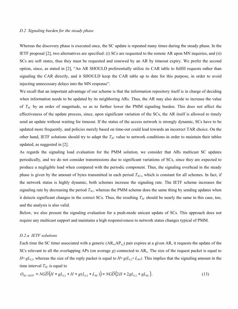
D.2 Signaling burden for the steady phase
Whereas the discovery phase is executed once, the SC update is repeated many times during the steady phase. In the
IETF proposal [2], two alternatives are specified: (i) SCs are requested to the remote AR upon MN inquiries, and (ii)
SCs are soft states, thus they must be requested and renewed by an AR by timeout expiry. We prefer the second
option, since, as stated in [2], “An AR SHOULD preferentially utilize its CAR table to fulfill requests rather than
signaling the CAR directly, and it SHOULD keep the CAR table up to date for this purpose, in order to avoid
injecting unnecessary delays into the MN response”.
We recall that an important advantage of our scheme is that the information repository itself is in charge of deciding
when information needs to be updated by its neighboring ARs. Thus, the AR may also decide to increase the value
of TSC by an order of magnitude, so as to further lower the PMM signaling burden. This does not affect the
effectiveness of the update process, since, upon significant variation of the SCs, the AR itself is allowed to timely
send an update without waiting for timeout. If the status of the access network is strongly dynamic, SCs have to be
updated more frequently, and policies merely based on time-out could lead towards an incorrect TAR choice. On the
other hand, IETF solutions should try to adapt the TSC value to network conditions in order to maintain their tables
updated, as suggested in [2].
As regards the signaling load evaluation for the PMM solution, we consider that ARs multicast SC updates
periodically, and we do not consider transmissions due to significant variations of SCs, since they are expected to
produce a negligible load when compared with the periodic component. Thus, the signaling overhead in the steady
phase is given by the amount of bytes transmitted in each period TSC,, which is constant for all schemes. In fact, if
the network status is highly dynamic, both schemes increase the signaling rate. The IETF scheme increases the
signaling rate by decreasing the period TSC, whereas the PMM scheme does the same thing by sending updates when
it detects significant changes in the correct SCs. Thus, the resulting TSC should be nearly the same in this case, too,
and the analysis is also valid.
Below, we also present the signaling evaluation for a push-mode unicast update of SCs. This approach does not
require any multicast support and maintains a high responsiveness to network status changes typical of PMM.
D.2.a IETF solutions
Each time the SC timer associated with a generic (ARx,APx,j) pair expires at a given AR, it requests the update of the
SCs relevant to all the overlapping APs (on average g) connected to ARx. The size of the request packet is equal to
H+gLL2, whereas the size of the reply packet is equal to H+g(LL2+LSC). This implies that the signaling amount in the
time interval TSC is equal to
( ) ( )SCLSCLLIETFSC gLgLHDNGLLgHgLHDNGO ++=++++=− 222 22)( . (13)
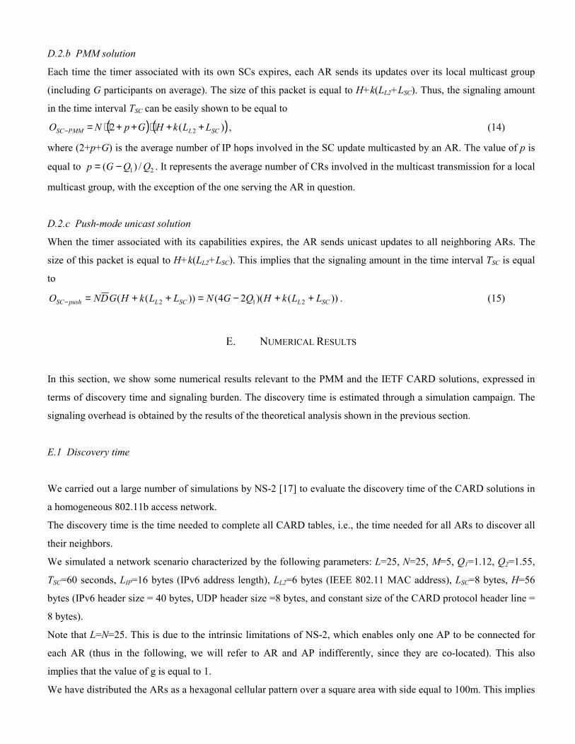
D.2.b PMM solution
Each time the timer associated with its own SCs expires, each AR sends its updates over its local multicast group
(including G participants on average). The size of this packet is equal to H+k(LL2+LSC). Thus, the signaling amount
in the time interval TSC can be easily shown to be equal to
( ) ( ))(2 2 SCLPMMSC LLkHGpNO ++⋅++⋅=− , (14)
where (2+p+G) is the average number of IP hops involved in the SC update multicasted by an AR. The value of p is
equal to 21 /)( QQGp −= . It represents the average number of CRs involved in the multicast transmission for a local
multicast group, with the exception of the one serving the AR in question.
D.2.c Push-mode unicast solution
When the timer associated with its capabilities expires, the AR sends unicast updates to all neighboring ARs. The
size of this packet is equal to H+k(LL2+LSC). This implies that the signaling amount in the time interval TSC is equal
to
))()(24())(( 212 SCLSCLpushSC LLkHQGNLLkHGDNO ++−=++=− . (15)
E. NUMERICAL RESULTS
In this section, we show some numerical results relevant to the PMM and the IETF CARD solutions, expressed in
terms of discovery time and signaling burden. The discovery time is estimated through a simulation campaign. The
signaling overhead is obtained by the results of the theoretical analysis shown in the previous section.
E.1 Discovery time
We carried out a large number of simulations by NS-2 [17] to evaluate the discovery time of the CARD solutions in
a homogeneous 802.11b access network.
The discovery time is the time needed to complete all CARD tables, i.e., the time needed for all ARs to discover all
their neighbors.
We simulated a network scenario characterized by the following parameters: L=25, N=25, M=5, Q1=1.12, Q2=1.55,
TSC=60 seconds, LIP=16 bytes (IPv6 address length), LL2=6 bytes (IEEE 802.11 MAC address), LSC=8 bytes, H=56
bytes (IPv6 header size = 40 bytes, UDP header size =8 bytes, and constant size of the CARD protocol header line =
8 bytes).
Note that L=N=25. This is due to the intrinsic limitations of NS-2, which enables only one AP to be connected for
each AR (thus in the following, we will refer to AR and AP indifferently, since they are co-located). This also
implies that the value of g is equal to 1.
We have distributed the ARs as a hexagonal cellular pattern over a square area with side equal to 100m. This implies
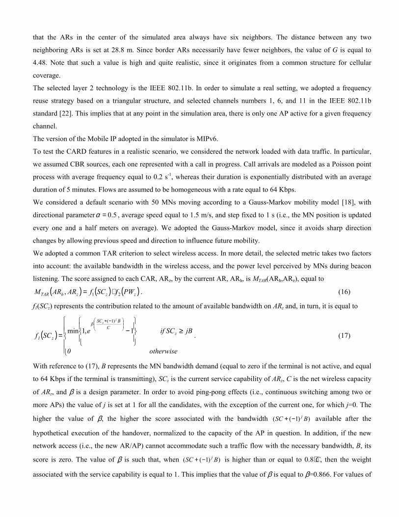
that the ARs in the center of the simulated area always have six neighbors. The distance between any two
neighboring ARs is set at 28.8 m. Since border ARs necessarily have fewer neighbors, the value of G is equal to
4.48. Note that such a value is high and quite realistic, since it originates from a common structure for cellular
coverage.
The selected layer 2 technology is the IEEE 802.11b. In order to simulate a real setting, we adopted a frequency
reuse strategy based on a triangular structure, and selected channels numbers 1, 6, and 11 in the IEEE 802.11b
standard [22]. This implies that at any point in the simulation area, there is only one AP active for a given frequency
channel.
The version of the Mobile IP adopted in the simulator is MIPv6.
To test the CARD features in a realistic scenario, we considered the network loaded with data traffic. In particular,
we assumed CBR sources, each one represented with a call in progress. Call arrivals are modeled as a Poisson point
process with average frequency equal to 0.2 s-1, whereas their duration is exponentially distributed with an average
duration of 5 minutes. Flows are assumed to be homogeneous with a rate equal to 64 Kbps.
We considered a default scenario with 50 MNs moving according to a Gauss-Markov mobility model [18], with
directional parameter 5.0=α , average speed equal to 1.5 m/s, and step fixed to 1 s (i.e., the MN position is updated
every one and a half meters on average). We adopted the Gauss-Markov model, since it avoids sharp direction
changes by allowing previous speed and direction to influence future mobility.
We adopted a common TAR criterion to select wireless access. In more detail, the selected metric takes two factors
into account: the available bandwidth in the wireless access, and the power level perceived by MNs during beacon
listening. The score assigned to each CAR, ARz, by the current AR, ARh, is MTAR(ARh,ARz), equal to
( ) ( ) ( )zzzhTAR PWfSCfARARM 21, ⋅= . (16)
f1(SCz) represents the contribution related to the amount of available bandwidth on ARz and, in turn, it is equal to
( )
≥
−=
−+
otherwise 0
jBif SC eSCf zC
BSCβ
z1
jz
1,1min)1(
. (17)
With reference to (17), B represents the MN bandwidth demand (equal to zero if the terminal is not active, and equal
to 64 Kbps if the terminal is transmitting), SCz is the current service capability of ARz, C is the net wireless capacity
of ARz, and β is a design parameter. In order to avoid ping-pong effects (i.e., continuous switching among two or
more APs) the value of j is set at 1 for all the candidates, with the exception of the current one, for which j=0. The
higher the value of β, the higher the score associated with the bandwidth ))1(( BSC j−+ available after the
hypothetical execution of the handover, normalized to the capacity of the AP in question. In addition, if the new
network access (i.e., the new AR/AP) cannot accommodate such a traffic flow with the necessary bandwidth, B, its
score is zero. The value of β is such that, when ))1(( BSC j−+ is higher than or equal to 0.8⋅C, then the weight
associated with the service capability is equal to 1. This implies that the value of β is equal to β=0.866. For values of

service capability below 0.8⋅C, such a weight rapidly decreases, and consequently the importance of the load-
balancing criterion increases. In the simulator, C=5 Mbit/s (this is a realistic value for the net bandwidth of an
802.11b AP).
f2(PWz) is the factor related to the power level of APz, and it is equal to
( )
>−=
−−−
e otherwis 0 PW if PWePWf z
PWPPWPW
zzT
z
min2
min
1γ
. (18)
We define PWopt, so that f2(PWopt)=0.95. We have made this choice to make the power-based score affect the overall
metric only when the MN is outside the optimum area. The weight then rapidly decreases for values of received
power lower than PWopt. The coverage radius is equal to 22.4 m (corresponding to a coverage area equal to 1576 m2),
the overlapping area between two adjacent APs is equal to 381 m2 (PWmin equal to 6.677 nW), and the overlapping
between their “optimal” zone is equal to 125 m2 (PWopt equal to 9.889 nW). PT is equal to 33.96 mW and γ is set
equal to 33.2*106.
In the simulator, MIP advertisements are sent each second, whereas the L2 beacons are sent each 100 ms. Since
three 802.11b channels are used, the duration of the beacon listening phase is bounded by 200 ms; this is the time
needed to scan the two channels which differ from the one currently used. This operation is repeated either
periodically (the period Tscan=60 s) or upon a TAR event due to a power level lower than PWopt. The new L2 IDs
listened to by MNs are sent to the current AR.
We implemented the TAR in the current AR.
We evaluated the discovery time of both the L2 beacon-based solutions (PMM and server based) and the handover-
based solution. Clearly, the discovery time strongly depends on the movement patterns of MNs, and thus can vary
with the simulation runs. For this reason, we performed 60 runs and the figures show the average values with the
relevant 95% confidence intervals.
Fig. 8 shows the discovery time for the L2 beacon-based approach and the handover-based approach, as a function of
the MN average speed, ranging from 0.5 to 2.5 m/s, with 50 MNs. It is worth noting that the PMM and server-based
solutions exhibit essentially the same performance. The server-based approach is slightly delayed by the query to the
centralized server, but the difference is practically negligible. For this reason, in the figures relevant to the discovery
time, we have shown only one curve (the PMM one) which may be considered as representative of both L2 beacon-
based approaches. As the reader can observe in the figure, in order to appreciate the behavior of both the L2 beacon-
based and the handover-based solutions, we have divided the overall plot into two subplots, since the time scales of
the two schemes are quite different. For the PMM approach, we show three curves, with Tscan set as a parameter and
by assuming values equal to 60 s, 30 s, and 10 s.
For all schemes the discovery time decreases with the speed of MNs. In fact, when the speed increases, MNs may
approach or cross cell borders more frequently, and this results in a higher number of discovery events. The main
comment is that the L2 beacon-based solutions definitely outperform the handover-based one. We stress that the
noticeable difference of performance is due to the fact that, in the L2 beacon-based schemes the discovery events are
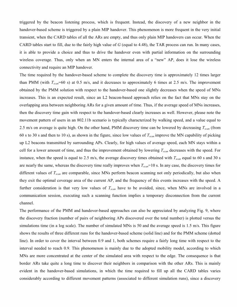
triggered by the beacon listening process, which is frequent. Instead, the discovery of a new neighbor in the
handover-based scheme is triggered by a plain MIP handover. This phenomenon is more frequent in the very initial
transient, when the CARD tables of all the ARs are empty, and thus only plain MIP handovers can occur. When the
CARD tables start to fill, due to the fairly high value of G (equal to 4.48), the TAR process can run. In many cases,
it is able to provide a choice and thus to drive the handover even with partial information on the surrounding
wireless coverage. Thus, only when an MN enters the internal area of a “new” AP, does it lose the wireless
connectivity and require an MIP handover.
The time required by the handover-based scheme to complete the discovery time is approximately 12 times larger
than PMM (with Tscan=60 s) at 0.5 m/s, and it decreases to approximately 6 times at 2.5 m/s. The improvement
obtained by the PMM solution with respect to the handover-based one slightly decreases when the speed of MNs
increases. This is an expected result, since an L2 beacon-based approach relies on the fact that MNs stay on the
overlapping area between neighboring ARs for a given amount of time. Thus, if the average speed of MNs increases,
then the discovery time gain with respect to the handover-based clearly increases as well. However, please note the
movement pattern of users in an 802.11b scenario is typically characterized by walking speed, and a value equal to
2.5 m/s on average is quite high. On the other hand, PMM discovery time can be lowered by decreasing Tscan (from
60 s to 30 s and then to 10 s), as shown in the figure, since low values of Tscan improve the MN capability of picking
up L2 beacons transmitted by surrounding APs. Clearly, for high values of average speed, each MN stays within a
cell for a lower amount of time, and thus the improvement obtained by lowering Tscan decreases with the speed. For
instance, when the speed is equal to 2.5 m/s, the average discovery times obtained with Tscan equal to 60 s and 30 s
are nearly the same, whereas the discovery time really improves when Tscan=10 s. In any case, the discovery times for
different values of Tscan are comparable, since MNs perform beacon scanning not only periodically, but also when
they exit the optimal coverage area of the current AP, and the frequency of this events increases with the speed. A
further consideration is that very low values of Tscan have to be avoided, since, when MNs are involved in a
communication session, executing such a scanning function implies a temporary disconnection from the current
channel.
The performance of the PMM and handover-based approaches can also be appreciated by analyzing Fig. 9, where
the discovery fraction (number of pairs of neighboring APs discovered over the total number) is plotted versus the
simulations time (in a log scale). The number of simulated MNs is 50 and the average speed is 1.5 m/s. This figure
shows the results of three different runs for the handover-based scheme (solid line) and for the PMM scheme (dotted
line). In order to cover the interval between 0.9 and 1, both schemes require a fairly long time with respect to the
interval needed to reach 0.9. This phenomenon is mainly due to the adopted mobility model, according to which
MNs are more concentrated at the center of the simulated area with respect to the edge. The consequence is that
border ARs take quite a long time to discover their neighbors in comparison with the other ARs. This is mainly
evident in the handover-based simulations, in which the time required to fill up all the CARD tables varies
considerably according to different movement patterns (associated to different simulation runs), since a discovery
event happens only when a plain MIP handover occurs.
Another important piece of information obtainable from Fig. 9 is the slopes of the discovery percentage for both the
handover-based and the PMM CARD approach. In fact, in the first part of the curves (below 0.9), the lines are nearly
overlapping, independent of the simulation run (and thus of the specific MNs trajectories). Clearly, the slope of the
L2 beacon-based scheme is far higher than that of the handover-based scheme. The time required by the former
scheme to reach 0.9 times the discovery percentage is but a few tens of seconds, whereas the time required by the
latter scheme is approximately a few hundreds of seconds. This implies that, independent of border effects due the
particular mobility model adopted in the simulations, the discovery time of the handover-based strategy is definitely
higher than the discovery time of L2 beacon-based schemes.
Finally, Fig. 10 shows the discovery time for both schemes (L2 beacon-based and handover-based) versus the
number of MNs, with the relevant 95% confidence intervals; the average speed is set at 1.5 m/s. As expected, an
increased number of MNs triggers an increased number of discovery events, and thus the discovery time decreases
with the number of MNs in both the handover-based and the PMM solution. However, as in previous cases (see Fig.
8 and Fig. 9), the difference always remains noticeable.
E.2 Signaling burden
To obtain quantitative results from the theoretical analysis of the signaling burden presented in section D, we
consider the simulated network scenario, with a higher number of APs (L=150), and values of Q1and Q2 set to 1.5
and 2, respectively.
We start considering the signaling overhead associated with the discovery phase. Fig. 11 shows the overhead of the
different solutions (handover-based, server-based, and PMM, for the best and worst case) as a function of the
average number, G, of neighbors of a generic AR. Fig. 11.a is relevant to g=3, whereas in Fig. 11.b g is assumed to
be equal to 4. We recall that g is the average number of APs (connected to the same AR) which overlap with the
coverage area of a neighboring AR, whereas G is the average number of ARs neighboring to a given AR. We have
selected the values of G and g as always greater than 1, thus representing a dense wireless coverage. The rationale of
this choice is that the essential goal of CARD is to provide the inputs to drive an appropriate choice of TAR.
Clearly, if the overlapping of the coverage areas of ARs is scarce, the CARD protocol cannot achieve this goal.
Fig. 11 shows that the handover-based approach exhibits the best performance in terms of the amount of data to be
exchanged during the discovery phase. This result is expected, since the handover-based approach does not need any
initialization phase. In any case, the signaling overhead is very low (no more than 1 Mbyte over a network of 31
routers) for all three CARD schemes. A further comment is that the signaling load increases with a constant slope
for the three schemes, since the higher the number of overlapping ARs to be discovered, the higher the number of
messages to be exchanged. As regards the comparison between the server-based scheme and the PMM scheme, their
performance is really similar, even though the slope of the server-based curve is higher. In addition, the PMM

scheme performs slightly better for high values of g, (i.e., when the overlapping between two ARs involves many
APs). In fact, in this case, a single signaling message is sent to MGOP with all the coverage information relevant to an
AR, whereas the server-based scheme requires, a dedicated inquiry to the server for each AP to be discovered.
Fig. 12 shows the signaling rates in the steady state (expressed in Kbit/s) required by IETF solutions, the proposed
PMM, and the push-mode unicast. These quantities are depicted as a function of G, with g and LSC (the size of the
payload of update messages) as parameters, with the same values of Fig. 11. Note that the values of the signaling
rate proportionally increase when TSC decreases, and vice versa (TSC is fixed to 60 s).
The advantage of the PMM scheme is really significant and increases considerably with both G and g. This is due to
our design philosophy, which is based on a push multicast approach. This result was expected, since it represents the
classic advantage of multicast transmissions over repeated unicast transmissions. As expected, the signaling rate of
the push-mode unicast solution is comparable to the pull-mode unicast IETF solution. In fact, request messages are
saved, but all the SCs are sent to all the neighbors.
Note that we first set the size of the payload of packets exchanged during the steady phase equal to LSC=8 bytes. This
value is sufficient to enable a value of bandwidth to be coded, but it could be enlarged to allow ARs to exchange
other types of information, such as, for instance, the number of MNs attached, security capabilities, management
information. Higher values of LSC clearly imply a greater amount of signaling data to be exchanged, and this effect is
more evident in the PMM scheme and the push-mode unicast approach, where each AR disseminates all its coverage
information. On the other hand, in the IETF scheme, AR provides specific data on request. In Fig. 12, we present the
curves relevant to a value of LSC equal to 24 bytes. An important observation is that the signaling rate of the PMM
scheme is always very low, and even lower than that of the IETF scheme with LSC=8 bytes. The push-mode unicast
solution deteriorates its performance, while maintaining the signaling rate comparable to the IETF approach.
Finally, Fig. 13 shows the signaling burden in both the discovery (Fig. 13.a and Fig. 13.b) and the steady phase (Fig.
13.c and Fig. 13.d) as a function of the network “size” (number of APs, L, and number of ARs, N), with g=4 and
G=5 constant. The main comment is that the signaling load (slightly) increases with the system size.
During the discovery phase (Fig. 13.a), the PMM and the server-based approaches seem to be slightly sensitive to
the number of APs. In fact, a higher number of APs in the network implies a greater amount of data to be
disseminated among ARs (PMM) and to be communicated to the server (server-based) during the initialization
phase. However, the dependence on L of the signaling burden of the server-based solution is even slighter than in the
PMM solution.
In the steady phase, the number of APs does not affect the signaling rate in the IETF solutions (Fig. 13.c). In fact,
they perform SC updates essentially on request, and thus the amount of information exchanged among ARs is the
one that is actually needed (depending on g, see Fig. 12). On the other hand, in the push-mode approaches, ARs
distribute all the information about their coverage, and the signaling overhead clearly increases with the amount of
the overall information to be distributed, which clearly increases with the number of APs, L, and is not dependent on
g (see Fig. 12).
The amount of signaling data to be exchanged during the discovery phase and the steady phase clearly depends on
the number of ARs, N, in all the CARD approaches (Fig. 13.b and Fig. 13.d). In fact it is clear that the higher the
number of ARs, the higher the number of messages to be exchanged to complete the discovery phase and to update
the SCs among ARs. As regards the steady phase, the IETF solutions are more sensitive to N than the PMM
approach, which operates according to push-mode multicast transmissions. This result is expected, since it is a well
known advantage of multicast transmissions over repeated unicast transmissions, i.e., bandwidth saving. A further
consideration is that, in the steady phase, the slope of the signaling rate of the push-mode unicast solution is
definitely lower than the IETF one and comparable with the PMM one.
Please note that the sensitivity of the signaling burden to variations of M is not worthy of note. Only the signaling
burden during the discovery phase of the PMM scheme presents a dependency on M, but it is negligible and the
relevant curves are omitted.
We stress that, contrary to the discovery phase, which is generally executed once at the beginning and, if necessary,
upon topology changes, the update operation is constantly running. Consequently, bandwidth saving in the steady
phase is far more important than in the discovery phase.
To conclude this section, Table 3 reports the signaling burden in both the discovery and steady phase for the PMM,
server-based, and handover-based approaches in the simulated network topology (Q1=1.12, Q2=1.55, G=4.48,
L=N=25, M=5). Since g=1, quantities relevant to the worst case and best case for the discovery phase coincide (f(g)
is always equal to 1). In the PMM approach, the worst case and best case are only relevant to the sequence in which
ARs are turned on; we simulated the worst case.
We remark that the data collected from the simulations exactly confirm the correctness of the theoretical analysis. In
some simulation runs, we noted that the amount of data exchanged during the discovery phase of the server-based
approach is slightly lower than the theoretical one. This happens when an MN listens simultaneously to two or more
new L2 IDs. In this case, they are resolved by a single query to the server, whereas, in the theoretical computation,
we implicitly assumed that a query to the server solves only one address mapping at a time.
From Fig. 8 (MNs speed equal to 1.5 m/s), we can see that the discovery time for PMM and server-based solutions is
about 235 s, whereas for the handover-based approach it is equal to 1850 s. From the values in Table 3, we can
deduce that the average signaling rates during the discovery phase are: (i) approximately 3.65 Kbps for the PMM
(worst case); (ii) approximately 2.18 Kbps for the server-based; (iii) 0.16 Kbps for the handover-based. All values
are very low. The one associated with the handover-based solutions is the lowest, since the duration of the discovery
phase is the highest.
F. COMPARISON OF CARD SOLUTIONS
In conclusion, Table 4 reports a comparison of the main peculiarities of the different CARD approaches.
Note that all CARD/TAR mechanisms need a mobile terminal to be able to listen to the L2 beacons and to

communicate them to the network side. Thus, CARD/TAR functions need to be implemented on both the terminals
and ARs. This feature would also imply a number of business aspects, such as: (i) has the TAR selection to be
triggered by the user or by the operator? (ii) who is in charge of providing terminals with the CARD/TAR
software/hardware equipment? These questions are definitely beyond the scope of this paper.
The proposed PMM CARD shows the typical advantages of an L2 beacon-based solution: no bootstrap handover,
lower discovery time, and shows high responsiveness to network topology changes. In addition, the PMM CARD is
proactive, in the sense that each AR (the repository of information about the current status of its APs) is in charge of
deciding when the information needs to be updated by its neighboring ARs. This guarantees an exact picture of the
status of the network, and thus an appropriate TAR selection.
In addition, due to the use of multicast transmissions, the PMM CARD produces a very low amount of signaling in
the steady phase, while maintaining the signaling burden in the discovery phase low. It is worth noting that the
overall amount of signaling associated with all CARD solutions is low and does not affect the performance of the
network in terms of resource consumption.
Another peculiarity of the PMM scheme is its distributed nature, which avoids single points of failure, performance
bottleneck, and scalability problems.
As regards security, all L2 beacons-based solutions needs MNs to be authenticated in order to trust their coverage
information. In our opinion this is not a main drawback, since AAA mechanisms are still needed to enable users to
access advanced wireless network services for many reasons (e.g., for accounting/billing purposes).
The main drawback of the PMM proposal is the complexity introduced by the multicast support. In fact, even if it
may easily be supported nowadays within IP domains, it is more likely to be deployed in backbones rather than in
access networks. We believe this additional complexity is justified in large access networks, with a large number of
ARs and APs.
However, in particular situations, such as in small networks, CARD could also be implemented through a centralized
L2 beacon-based solution for the discovery phase, in order to maintain high responsiveness to changes of network
topology. As regards the SC exchange, in order to have a proactive distribution of information concerning network
status, we suggest the use of push-mode unicast transmissions. In this case, the signaling overhead of pull-mode
unicast transmissions would prove comparable to that of the pull-mode.
A final consideration is that inter-domain deployment implies further complexity for L2 beacon-based solutions. For
example, a possible solution could use a network node acting as CARD gateway for each CSP. Inter-domain
multicast transmissions for the PMM in particular could be hampered by the current multicast deployment, which is
usually administratively scoped, i.e., multicast transmissions do not extend beyond the originating domain
boundaries. In any case, plain deployment of inter-domain procedures is generally critical, since it requires both
technical and business agreements among the parties involved, sufficient to convince them to both exchange some
confidential information such as the ongoing network status and support users roaming.
G. CONCLUSION AND FUTURE WORK
The framework of this paper is an administrative domain which provides advanced network support in a
heterogeneous wireless scenario. In this scenario, we propose an intra-domain, distributed CARD procedure (named
PMM CARD), able to dynamically self-construct a map at each AR of the surrounding wireless coverage, and to
discover and update the service capabilities. The main novelty of our proposal is the use of push-mode multicast
transmissions. This approach enables some aspects of the performance of the CARD process to be improved in
comparison with other known solutions defined within the IETF, which are based on the use of the pull-mode
unicast. The analysis was made both theoretically and via simulations.
Some theoretical results show that, in the steady phase, the signaling burden associated with the PMM CARD is
reduced in comparison with the corresponding IETF solutions. In addition, the overall amount of signaling
associated with all CARD solutions is always very low. Thus, in our opinion the benefits that can be obtained by
implementing a CARD mechanism (improved MIP performance, load balancing) justify the relevant cost in terms of
the network resource consumption and the complexity of implementation.
As regards the discovery phase, simulation results show that the time required by our PMM scheme to complete the
surrounding wireless coverage map at each AR is very low (some tens of seconds), and definitely outperforms the
handover-based solution. The reason is that the frequency of discovery events is higher than in the handover-based
solution.
In further developments, we will pursue some other expected improvements in terms of load balancing in a
CARD-enabled 802.11 access network and in terms of UDP/TCP throughput.
A test bed demonstrator is currently being implemented to also show the feasibility of the CARD/TAR mechanisms.
ACKNOWLEDGMENT
The authors would like to thank the anonymous referees for their suggestions and comments that have improved the
quality of the paper.
This work was performed under co-financing by the Italian Ministry of Education, University, and Research (MIUR)
within the FIRB project PRIMO.
REFERENCES [1] J. Manner, M. Kojo, “Mobility related terminology”, IETF RFC 3753, June 2004.
[2] M. Liebsch et alii, “Candidate access router discovery”, Internet draft, draft-ietf-seamoby-card-protocol-08.txt, work in
progress, September 2004.
[3] J. Loughney, M. Nakhjiri, C. Perkins, R. Koodli, “Context transfer protocol”, Internet draft, draft-ietf-seamoby-ctp-11.txt,
work in progress, August 2004.
[4] J. Kempf, “Problem description: reasons for performing context transfers between nodes in an IP access network ”, IETF
RFC 3374, September 2002.
[5] C. Perkins, “IP mobility support for IPv4”, IETF RFC 3344, Aug. 2002.
[6] D. B. Johnson, C. E. Perkins, “Mobility support in IPv6”, MobiCom’96, Rye, NY, USA, November 1996.
[7] A.T. Campbell et alii, “Comparison of IP micromobility protocols”, IEEE Wireless Communications, February 2002.
[8] D. Funato et alii, "Geographically adjacent access router discovery protocol", Internet draft, draft-funato-seamoby-gaard-
01.txt, June 2002
[9] D. Trossen, G. Krishnamurthi, H. Chaskar, R.C. Chalmers, E. Shim, "A dynamic protocol for candidate access-router
discovery", Internet draft, draft-trossen-seamoby-dycard-01.txt, March 2003.
[10] R. Koodli, “Fast handovers for mobile IPv6”, Internet draft, work in progress, draft-ietf-mipshop-fast-mipv6-03.txt, October
2004.
[11] K. El Malki et alii, “Low latency handoffs in mobile IPv4”, Internet draft, draft-ietf-mobileip-lowlatency-handoffs-v4-
09.txt, work in progress, June 2004.
[12] E.Shim, J.P. Redlich, R.D. Gitlin, "Secure candidate access router discovery," Proceedings of IEEE WCNC, New Orleans,
USA, March 2003.
[13] http://www.ietf.org/html.charters/msec-charter.html, IETF MSEC WG.
[14] S. Glass, T. Hiller, S. Jacobs, C. Perkins, “Mobile IP authentication, authorization, and accounting requirements,” IETF
RFC 2977, October 2000.
[15] C. E. Perkins, P. R. Calhoun, “AAA registration keys for mobile IPv4,” Internet draft, draft-ietf-mip4-aaa-key-01.txt, work
in progress, October 2003.
[16] W. Zhang, J. Jähnert, K. Dolzer, "Design and evaluation of a hand-over decision strategy for 4th generation mobile
networks," IEEE VTC 2003 Spring, Jeju, Korea, 2003.
[17] The Network Simulator Home Page, http://www.isi.edu/nsnam/ns/.
[18] T. Camp, J. Boleng, V. Davies, “A survey of mobility models for ad hoc network research”, Wireless Communication &
Mobile Computing (WCMC): Special issue on Mobile Ad Hoc Networking: Research, Trends and Applications, vol. 2, N. 5,
pp. 483-502, 2002.
[19] H. Velayos V. Aleo, G. Karlsson, "Load Balancing in Overlapping Wireless LAN Cells," IEEE ICC 2004, Paris, France,
June 2004.
[20] A. Balachandran, P. Bahl, G. M. Voelker, “Hot-Spot Congestion Relief in Public-area Wireless Networks,” 4th IEEE
Workshop on Mobile Computing Systems and Applications, Callicoon, USA, June 2002.
[21] Atkinson, R., and S. Kent, "Security Architecture for the Internet Protocol", IETF RFC 2401, November 1998.
[22] IEEE 802.11b Standard, "IEEE 802.11, Part 11: Wireless LAN Medium Access Control (MAC) And Physical Layer (PHY)
Specifications: Higher-speed Physical Layer Extension In The 2.4 GHz Band", 2000.
[23] R. Wittmann, M. Zitterbart, “Multicast communication, protocols and applications”, Morgan Kaufmann Publishers, 1999.
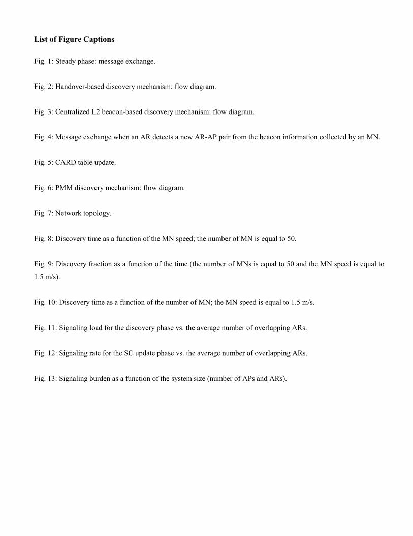
List of Figure Captions
Fig. 1: Steady phase: message exchange.
Fig. 2: Handover-based discovery mechanism: flow diagram.
Fig. 3: Centralized L2 beacon-based discovery mechanism: flow diagram.
Fig. 4: Message exchange when an AR detects a new AR-AP pair from the beacon information collected by an MN.
Fig. 5: CARD table update.
Fig. 6: PMM discovery mechanism: flow diagram.
Fig. 7: Network topology.
Fig. 8: Discovery time as a function of the MN speed; the number of MN is equal to 50.
Fig. 9: Discovery fraction as a function of the time (the number of MNs is equal to 50 and the MN speed is equal to
1.5 m/s).
Fig. 10: Discovery time as a function of the number of MN; the MN speed is equal to 1.5 m/s.
Fig. 11: Signaling load for the discovery phase vs. the average number of overlapping ARs.
Fig. 12: Signaling rate for the SC update phase vs. the average number of overlapping ARs.
Fig. 13: Signaling burden as a function of the system size (number of APs and ARs).

List of Table Captions
Table 1: Example of CARD table stored in ARh.
Table 2: Parameters of the network scenario.
Table 3: Signaling burden in the simulated network topology.
Table 4: Comparison among CARD approaches.
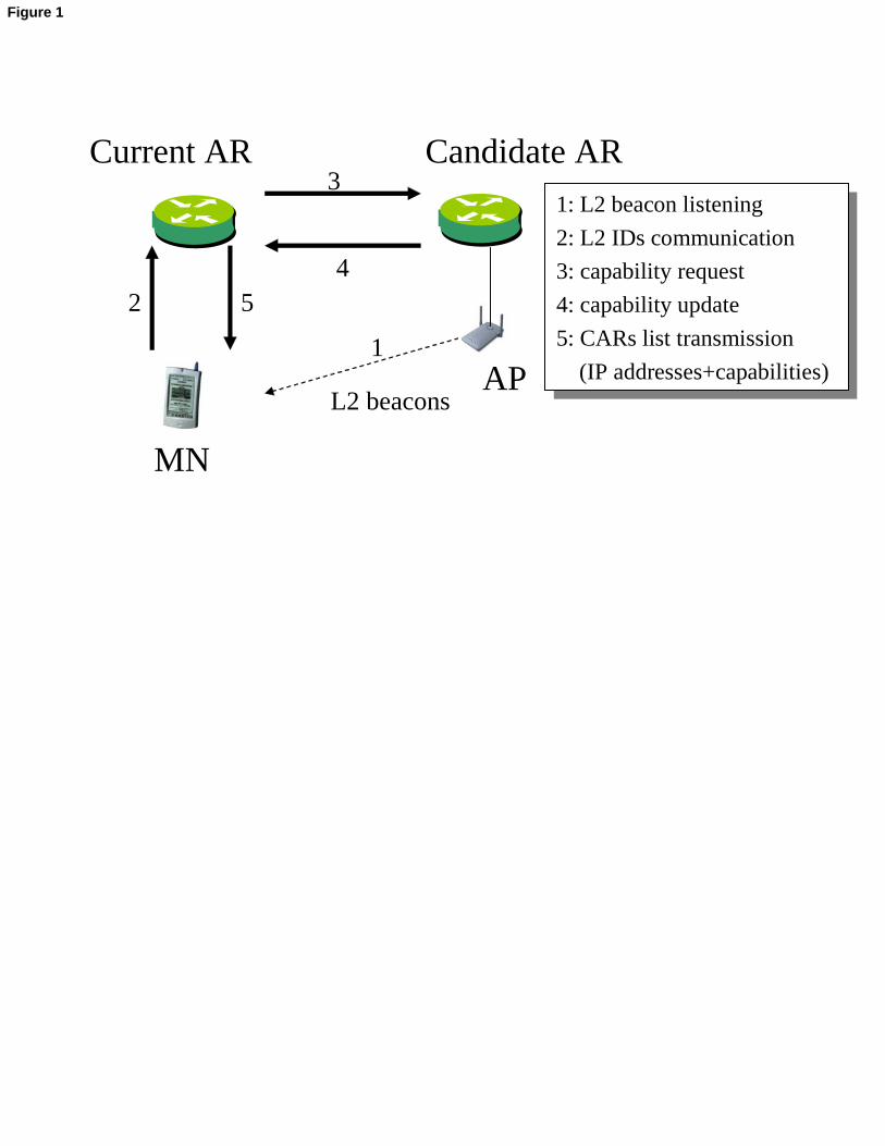
MN
Current AR Candidate AR
1
42
31: L2 beacon listening
2: L2 IDs communication
3: capability request
4: capability update
5: CARs list transmission
(IP addresses+capabilities)
1: L2 beacon listening
2: L2 IDs communication
3: capability request
4: capability update
5: CARs list transmission
(IP addresses+capabilities)L2 beacons
5
AP
Figure 1
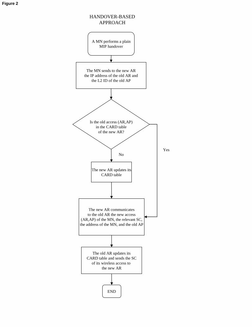
A MN performs a plainMIP handover
The MN sends to the new ARthe IP address of the old AR and
the L2 ID of the old AP
Is the old access (AR,AP)in the CARD table
of the new AR?
Yes
END
The new AR updates itsCARD table
No
The old AR updates itsCARD table and sends the SC
of its wireless access to the new AR
HANDOVER-BASED APPROACH
The new AR communicatesto the old AR the new access
(AR,AP) of the MN, the relevant SC,the address of the MN, and the old AP
Figure 2
A MN listens to a L2 IDfrom a surrounding AP
The MN sends to the current ARthe L2 ID
Is the L2 IDin the CARD tableof the current AR?
Yes
END
The current AR issues a queryto the server to resolve the L2 ID
No
Once the reply from the serveris received, the current AR updatesits CARD table and communicatesto the neighboring AR the current
access (AR,AP) of the MN, along withthe discovered AP
The neighboring AR sends to the new ARthe SC of its wireless access
Is the current access of the MNin the CARD table ofthe neighboring AR?
Yes
The neighboring AR updates its CARD table
No
CENTRALIZED L2 BEACON-BASED
APPROACH
Figure 3
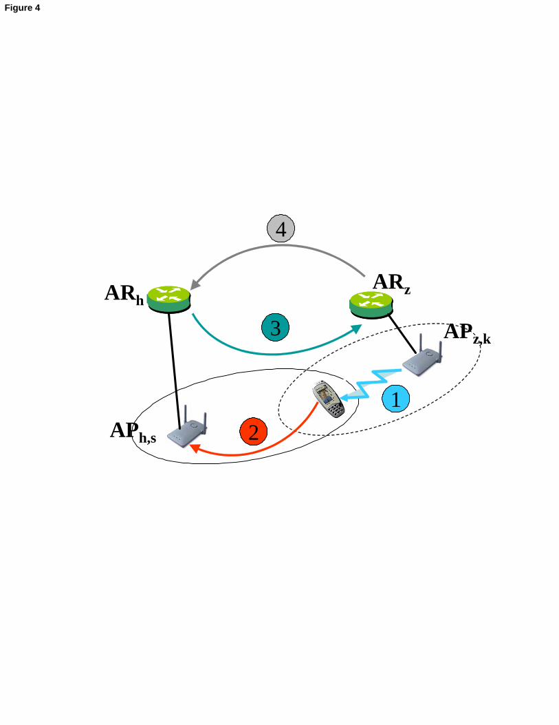
ARh
APh,s
ARz
APz,k
1
3
4
2
Figure 4
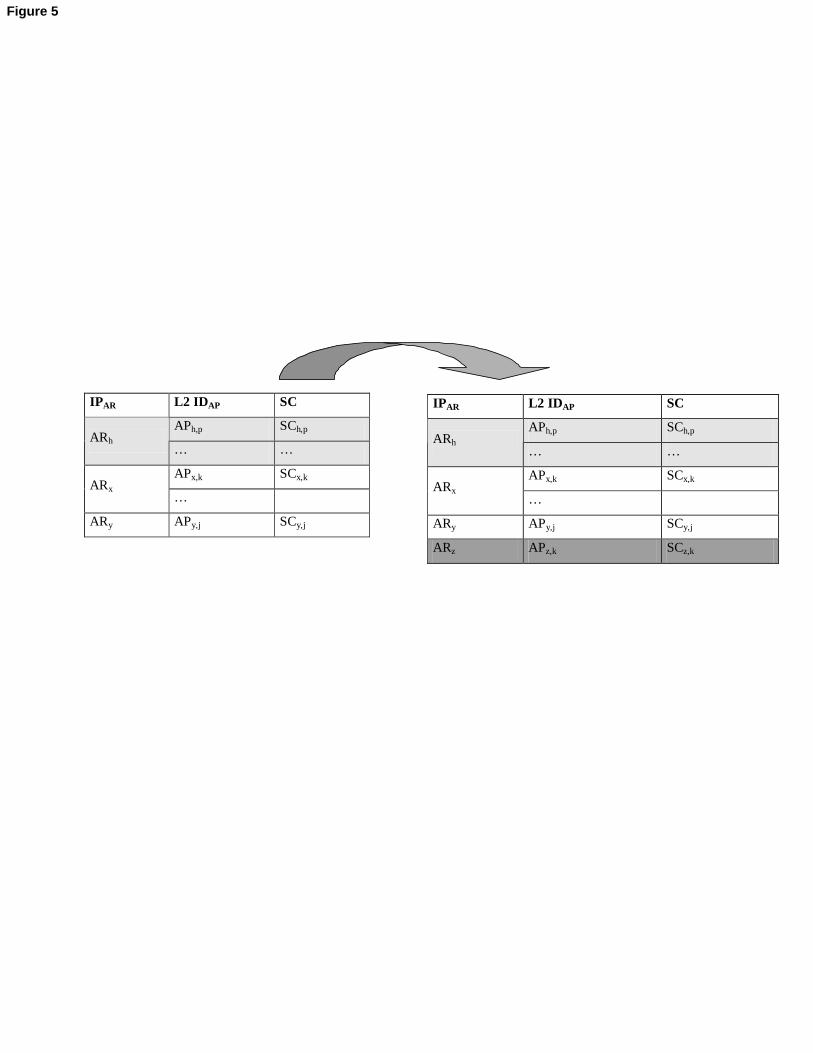
IPAR L2 IDAP SC
APh,p SCh,p ARh
… …
APx,k SCx,k ARx
…
ARy APy,j SCy,j
IPAR L2 IDAP SC
APh,p SCh,p ARh
… …
APx,k SCx,k ARx
…
ARy APy,j SCy,j
ARz APz,k SCz,k
Figure 5
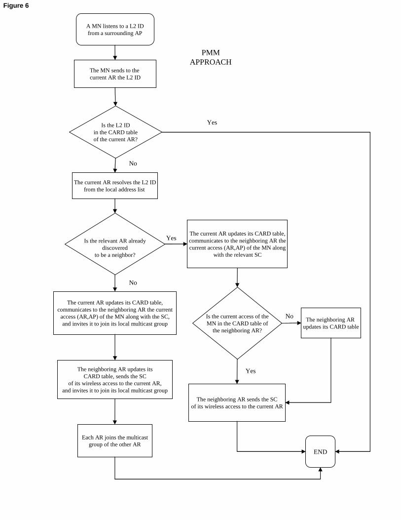
A MN listens to a L2 IDfrom a surrounding AP
The MN sends to the current AR the L2 ID
Is the L2 IDin the CARD tableof the current AR?
Yes
END
The current AR resolves the L2 IDfrom the local address list
No
The current AR updates its CARD table,communicates to the neighboring AR the current
access (AR,AP) of the MN along with the SC,and invites it to join its local multicast group
The neighboring AR updates itsCARD table, sends the SC
of its wireless access to the current AR,and invites it to join its local multicast group
YesNo
PMMAPPROACH
Is the relevant AR alreadydiscovered
to be a neighbor?
The current AR updates its CARD table,communicates to the neighboring AR thecurrent access (AR,AP) of the MN along
with the relevant SC
No
Yes
Is the current access of theMN in the CARD table of
the neighboring AR?
Each AR joins the multicastgroup of the other AR
The neighboring AR sends the SCof its wireless access to the current AR
The neighboring AR updates its CARD table
Yes
Figure 6
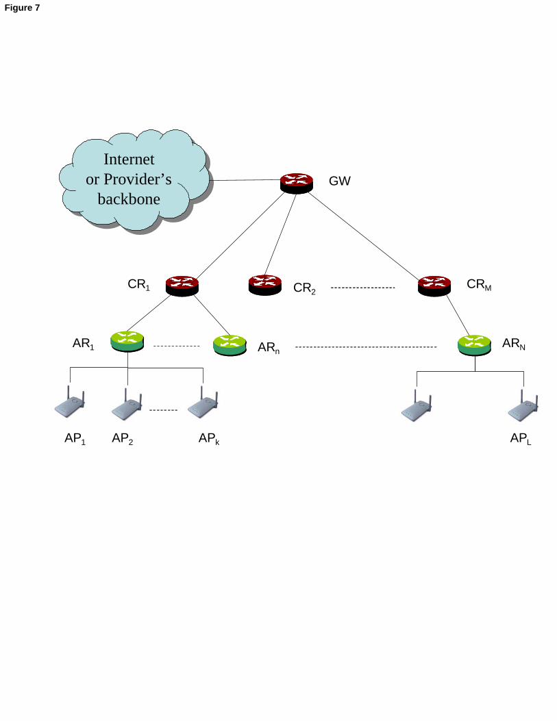
Internetor Provider’s
backbone
Internetor Provider’s
backboneGW
CR1 CRM
AR1 ARnARN
APLAP1 AP2 APk
CR2
Figure 7

0.5 1 1.5 2 2.50
100
200
300
400
500
600
MNs speed (m/s)
Dis
cove
ry ti
me
(s)
PMM, Tscan
= 60 sPMM, T
scan = 30 s
PMM, Tscan
= 10 s
0.5 1 1.5 2 2.50
1000
2000
3000
4000
5000
6000
7000
MNs speed (m/s)
Dis
cove
ry ti
me
(s)
HO
Figure 8
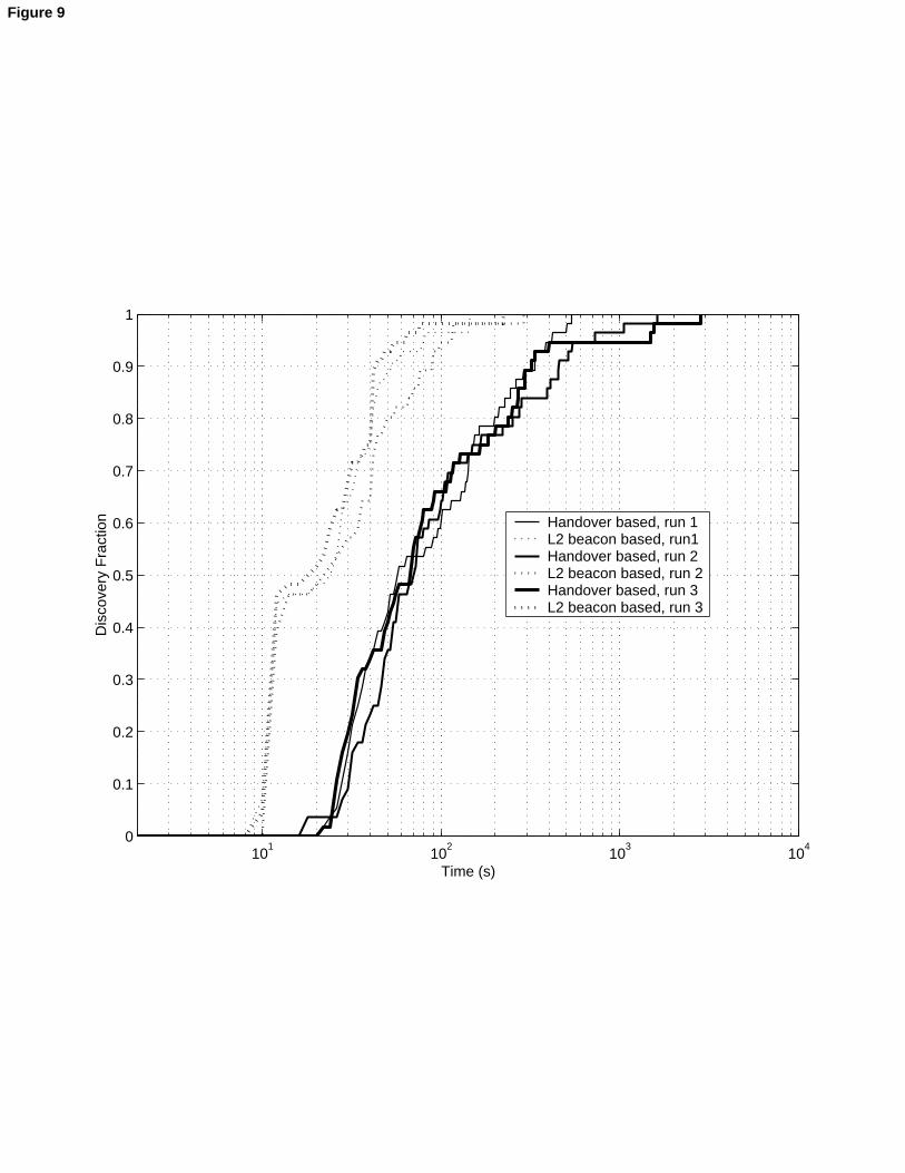
101
102
103
104
0
0.1
0.2
0.3
0.4
0.5
0.6
0.7
0.8
0.9
1
Time (s)
Dis
cove
ry F
ract
ion Handover based, run 1
L2 beacon based, run1 Handover based, run 2L2 beacon based, run 2Handover based, run 3L2 beacon based, run 3
Figure 9
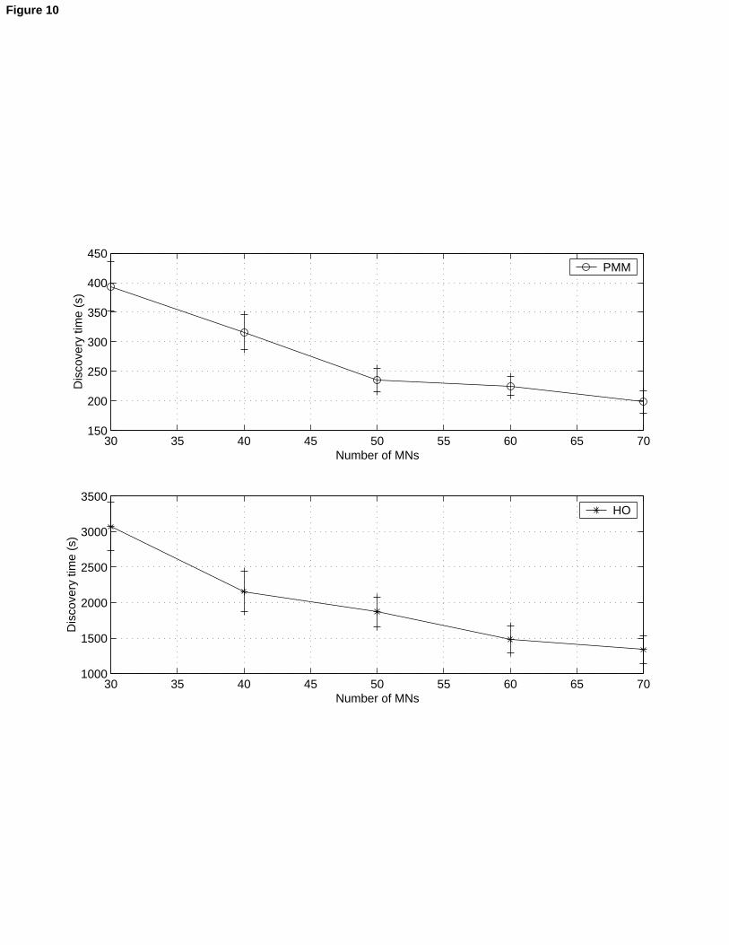
30 35 40 45 50 55 60 65 70150
200
250
300
350
400
450
Number of MNs
Dis
cove
ry ti
me
(s)
PMM
30 35 40 45 50 55 60 65 701000
1500
2000
2500
3000
3500
Number of MNs
Dis
cove
ry ti
me
(s)
HO
Figure 10
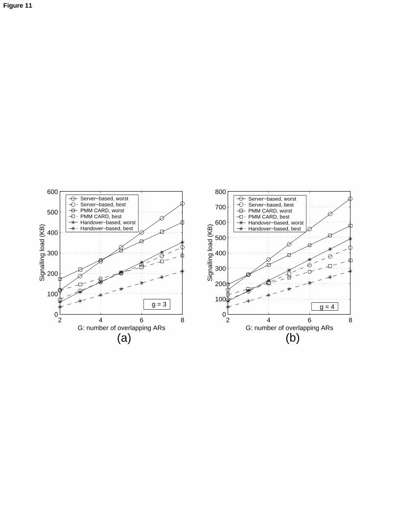
2 4 6 80
100
200
300
400
500
600
G: number of overlapping ARs
Sig
nalli
ng lo
ad (
KB
)
g = 3
Server−based, worstServer−based, bestPMM CARD, worstPMM CARD, bestHandover−based, worstHandover−based, best
2 4 6 80
100
200
300
400
500
600
700
800
G: number of overlapping ARs
Sig
nalli
ng lo
ad (
KB
)
g = 4
Server−based, worstServer−based, bestPMM CARD, worstPMM CARD, bestHandover−based, worstHandover−based, best
(a) (b)
Figure 11
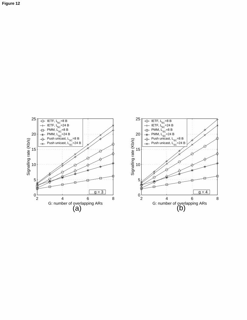
2 4 6 80
5
10
15
20
25
G: number of overlapping ARs
Sig
nalli
ng r
ate
(Kb/
s)
g = 3
IETF, LSC
=8 BIETF, L
SC=24 B
PMM, LSC
=8 BPMM, L
SC=24 B
Push unicast, LSC
=8 BPush unicast, L
SC=24 B
2 4 6 80
5
10
15
20
25
G: number of overlapping ARs
Sig
nalli
ng r
ate
(Kb/
s)
g = 4
IETF, LSC
=8 BIETF, L
SC=24 B
PMM, LSC
=8 BPMM, L
SC=24 B
Push unicast, LSC
=8 BPush unicast, L
SC=24 B
(a) (b)
Figure 12
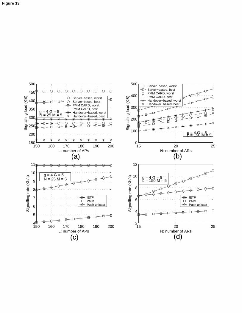
150 160 170 180 190 200150
200
250
300
350
400
450
500
L: number of APs
Sig
nalli
ng lo
ad (
KB
)
g = 4 G = 5N = 25 M = 5
Server−based, worstServer−based, bestPMM CARD, worstPMM CARD, bestHandover−based, worstHandover−based, best
150 160 170 180 190 2004
5
6
7
8
9
10
11
L: number of APs
Sig
nalli
ng r
ate
(Kb/
s) g = 4 G = 5N = 25 M = 5
IETFPMMPush unicast
15 20 250
100
200
300
400
500
N: number of ARs
Sig
nalli
ng lo
ad (
KB
)g = 4 G = 5L = 150 M = 5
Server−based, worstServer−based, bestPMM CARD, worstPMM CARD, bestHandover−based, worstHandover−based, best
15 20 252
4
6
8
10
12
N: number of ARs
Sig
nalli
ng r
ate
(Kb/
s) g = 4 G = 5L = 150 M = 5
IETFPMMPush unicast
(a)
(d) (c)
(b)
Figure 13
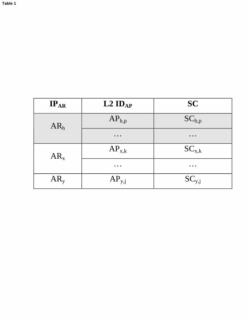
IPAR L2 IDAP SC
APh,p SCh,p ARh
… …
APx,k SCx,k ARx
… …
ARy APy,j SCy,j
Table 1
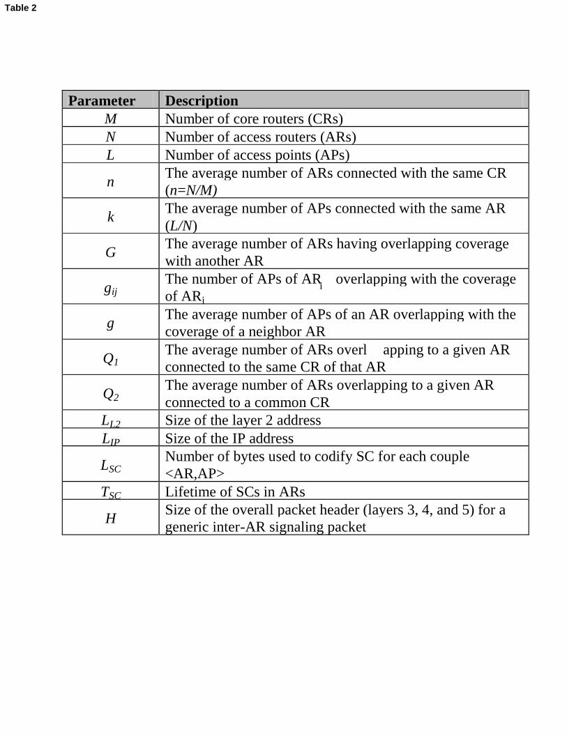
Parameter DescriptionM Number of core routers (CRs)N Number of access routers (ARs)L Number of access points (APs)
nThe average number of ARs connected with the same CR (n=N/M)
kThe average number of APs connected with the same AR (L/N)
GThe average number of ARs having overlapping coveragewith another AR
gijThe number of APs of AR overlapping with the coverageof ARj
gThe average number of APs of an AR overlapping with the coverage of a neighbor AR
Q1The average number of ARs overl apping to a given AR connected to the same CR of that AR
Q2The average number of ARs overlapping to a given AR connected to a common CR
LL2 Size of the layer 2 addressLIP Size of the IP address
LSCNumber of bytes used to codify SC for each couple<AR,AP>
TSC Lifetime of SCs in ARs
HSize of the overall packet header (layers 3, 4, and 5) for a generic inter-AR signaling packet
i
Table 2

Discovery Phase(Kbytes)
Steady Phase(Kbps)
Worst-case 107.25PMM
Best-case 90.502.02
Server-based 64.26
Handover-based 38.026.90
Table 3
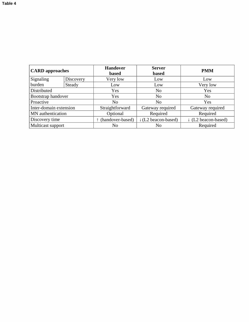
CARD approaches Handover based
Server based
PMM
Discovery Very low Low Low Signaling burden Steady Low Low Very low Distributed Yes No Yes Bootstrap handover Yes No No Proactive No No Yes Inter-domain extension Straightforward Gateway required Gateway required MN authentication Optional Required Required Discovery time ↑ (handover-based) ↓ (L2 beacon-based) ↓ (L2 beacon-based) Multicast support No No Required
Table 4