Performance Evaluation of Motion Estimation In DCT Transform Domain
10
Performance Evaluation of Motion Estimation in DCT Transform Domain PETRESCU CATALIN-DUMITRU, STEFANOIU DAN, LUPU CIPRIAN Department of Automatic Systems and Computer Science “Politehnica” University of Bucharest Splaiul Independentei no. 313 ROMANIA [email protected] , [email protected] , [email protected] Abstract: - Motion estimation is one of the most important steps in video compression algorithms. It reduces temporal redundancy present in frame sequences and allows a better compression of video material. Most of the actual video compression algorithms use “block matching” methods which operate on the bitmap form of the frames. This paper presents a method for computing the values of DCT coefficients of a block of pixels positioned on certain coordinates over four adjacent blocks using only the DCT coefficients of these four blocks. Performance of this method is analyzed for both integer and non-integer displacements. Also, an equivalent of the full-search algorithm translated in 2D-DCT domain is presented. Key-Words: - motion estimation, block matching, discrete cosine transform, video compression, match function 1 Introduction Video sequences are characterized by a high level of information redundancy. Video compression algorithms use this feature of the video material to achieve high levels of data reduction. In fact, video compression is based on the similarity between successive frames. Most of the actual video compression algorithms encode each frame in two steps [1]. In the first step (motion estimation), they try to create an as good as possible version of the current frame from other frames which were already encoded. For doing this, the current frame is divided in square blocks of NxN pixels. Then, for a maximum motion displacement of R pixels per frame, each block of pixels is matched against a corresponding block at the same coordinates but in the previous frames, within the square window of width/height N+2R. The best match is selected by testing a matching function like mean squared error (MSE) or mean absolute difference (MAD). In this step only the information about the position of the best matched blocks from previous frames (motion vectors) are encoded. The searching can be performed for each possible position in the search area (Full Search algorithm). In this case the best match is found but the computing effort involved is huge. For this reason, some strategies for reducing the number or search steps were proposed like Three Step Search - TSS [2], Two Dimensional Logarithmic Search -TDL [3], Hierarchical Search – HS [4] [5], Adaptive Search [6], Fast and Robust Search [7], etc.. Because real motion in video frames is not carried out over integer pixels, motion estimation is performed at sub-pixel level [10]. This kind of search involves interpolation of pixel values and searching over an enhanced resolution images which increase the complexity of the procedure. In the second step (motion compensation) the difference between the reconstructed frame created in the first step and the actual frame is encoded using a still image compression algorithm (usually based on discrete cosine transform, quantization and entropy coding). Usually this search is performed on the bitmap form of the frames. Many video formats like MJPEG [8], DV25, DV50 [9], use Discrete Cosine Transform (DCT) for compressing frames. In these cases it would be better to do the searching and matching tests directly in the transformed domain. There are some proposed methods for motion estimation based on pseudo phase techniques [11] or phase correlation [12]. Other approaches focus on refinement of the estimations at sub-pixel level using DCT coefficients [13]. This paper presents a method for computing the values of DCT coefficients of a block of pixels positioned on certain coordinates over four adjacent blocks using only the DCT coefficients of these four blocks. WSEAS TRANSACTIONS on SIGNAL PROCESSING Petrescu Catalin-Dumitru, Stefanoiu Dan and Lupu Ciprian ISSN: 1790-5052 371 Issue 6, Volume 4, June 2008
-
Upload
independent -
Category
Documents
-
view
3 -
download
0
Transcript of Performance Evaluation of Motion Estimation In DCT Transform Domain

Performance Evaluation of Motion Estimation in DCT Transform
Domain
PETRESCU CATALIN-DUMITRU, STEFANOIU DAN, LUPU CIPRIAN
Department of Automatic Systems and Computer Science
“Politehnica” University of Bucharest
Splaiul Independentei no. 313
ROMANIA
[email protected], [email protected], [email protected]
Abstract: - Motion estimation is one of the most important steps in video compression algorithms. It reduces
temporal redundancy present in frame sequences and allows a better compression of video material. Most of
the actual video compression algorithms use “block matching” methods which operate on the bitmap form of
the frames. This paper presents a method for computing the values of DCT coefficients of a block of pixels
positioned on certain coordinates over four adjacent blocks using only the DCT coefficients of these four
blocks. Performance of this method is analyzed for both integer and non-integer displacements. Also, an
equivalent of the full-search algorithm translated in 2D-DCT domain is presented.
Key-Words: - motion estimation, block matching, discrete cosine transform, video compression, match
function
1 Introduction
Video sequences are characterized by a high
level of information redundancy. Video compression
algorithms use this feature of the video material to
achieve high levels of data reduction. In fact, video
compression is based on the similarity between
successive frames.
Most of the actual video compression algorithms
encode each frame in two steps [1]. In the first step
(motion estimation), they try to create an as good as
possible version of the current frame from other
frames which were already encoded. For doing this,
the current frame is divided in square blocks of NxN
pixels. Then, for a maximum motion displacement
of R pixels per frame, each block of pixels is
matched against a corresponding block at the same
coordinates but in the previous frames, within the
square window of width/height N+2R. The best
match is selected by testing a matching function like
mean squared error (MSE) or mean absolute
difference (MAD). In this step only the information
about the position of the best matched blocks from
previous frames (motion vectors) are encoded.
The searching can be performed for each possible
position in the search area (Full Search algorithm).
In this case the best match is found but the
computing effort involved is huge. For this reason,
some strategies for reducing the number or search
steps were proposed like Three Step Search - TSS
[2], Two Dimensional Logarithmic Search -TDL
[3], Hierarchical Search – HS [4] [5], Adaptive
Search [6], Fast and Robust Search [7], etc..
Because real motion in video frames is not
carried out over integer pixels, motion estimation is
performed at sub-pixel level [10]. This kind of
search involves interpolation of pixel values and
searching over an enhanced resolution images which
increase the complexity of the procedure.
In the second step (motion compensation) the
difference between the reconstructed frame created
in the first step and the actual frame is encoded
using a still image compression algorithm (usually
based on discrete cosine transform, quantization and
entropy coding).
Usually this search is performed on the bitmap
form of the frames. Many video formats like
MJPEG [8], DV25, DV50 [9], use Discrete Cosine
Transform (DCT) for compressing frames.
In these cases it would be better to do the
searching and matching tests directly in the
transformed domain.
There are some proposed methods for motion
estimation based on pseudo phase techniques [11] or
phase correlation [12]. Other approaches focus on
refinement of the estimations at sub-pixel level
using DCT coefficients [13].
This paper presents a method for computing the
values of DCT coefficients of a block of pixels
positioned on certain coordinates over four adjacent
blocks using only the DCT coefficients of these four
blocks.
WSEAS TRANSACTIONS on SIGNAL PROCESSING Petrescu Catalin-Dumitru, Stefanoiu Dan and Lupu Ciprian
ISSN: 1790-5052 371 Issue 6, Volume 4, June 2008

The presentation is organized as follows. The
problem to solve is stated within the next section.
The proposed solution for 1D and 2D cases and
simulation results are succinctly described in section
3. Section 4 contains some concluding remarks and
a references list completes the article.
2 Problem Formulation
The general case in a search step is the one
presented in the Figure 1. We have a block from the
current frame and we want to compare it with a
candidate block X which stand over four adjacent
blocks (A, B, C and D). These four main blocks are
located in a previous encoded frame (reference
frame). The candidate block X is positioned at
(dx,dy) pixels relative to the bottom-left corner of
the block D.
XD
XC
XB XA
dx
dy
A B
C D
X
N
N
Fig.1 Position of the candidate block
The problem is to compute the DCT coefficients
of the candidate block X directly from the DCT
coefficients of the four adjacent blocks.
The candidate block X is a sum of 4 partial
blocks (XA, XB, XC and XD), each of them
containing parts of main blocks A, B, C respectively
D like in the following figure:
XA block
part of
block A
XB block
part of
block B
XC block
part of
block C
XD block
part of
block D
Fig.2: The structure of partial blocks
Each of the four partial blocks can be obtained
from the main blocks by shifting the image inside
them.
For example, the XA component can be obtained
from the main block A by shifting the image inside
it dx pixels to the left and N-dy pixel up like in the
Figure 3 below:
A
dx
N-d
y
XA
N-dx
dy
zero padded
Fig.3: Obtaining XA from A
The shifts necessary for obtaining all the
components are summarized in the next table:
Horizontal Vertical Component Main
Dir. Amount Dir. Amount
XA A Left dx Up N-dy
XB B Right N-dx Up N-dy
XC C Left dx Down dy
XD D Right N-dx Down dy
Table 1: Generation of candidate block components
Because Discrete Cosine Transform is linear, the
transform applied to a sum of elements is equal to
the sum of the transform applied to each element.
For this reason, the 2D-DCT transform of the
candidate block Tx can be determined from the 2D-
DCT transform of its components, by using the
following equation:
XDXCXBXA
X
TTTT
XDDCTXCDCT
XBDCTXADCT
XDXCXBXADCTT
+++=
++
++=
+++=
)()(
)()(
)(
(1)
It can be noticed that 2D-DCT transform of the
shifted components XA, XB, XC and XD are
needed.
Therefore, the problem is to determine a method
for compute 2D-DCT transform of a shifted matrix
directly from its own 2D-DCT coefficients and
amounts of vertical and horizontal shifts.
3 Problem Solution
The first step to find the method to determine the
DCT coefficients of a shifted matrix is to analyze
the 1D case of this problem. Next, the 2D case will
be derived from the results obtained in the fist step.
WSEAS TRANSACTIONS on SIGNAL PROCESSING Petrescu Catalin-Dumitru, Stefanoiu Dan and Lupu Ciprian
ISSN: 1790-5052 372 Issue 6, Volume 4, June 2008

3.1 The one-dimensional case
Suppose that the values of an initial vector y are
moved down by s positions. The result is a shifted
vector ys. The upper-most s positions are filled with
zeros like in the Figure 4:
V0
V1
V2
V3
V4
VN-1
Initial
vector y
Shifted
vector ys
V0
V1
VN-s-1
0
0
0
s =3
Fig.4: Initial and shifted vector
The elements of discrete cosine transform Ty
applied to the initial vector y can be computed using
the following equation [14]:
≠
+
=
+
=
∑
∑−
=
−
=
0,2
)12(cos
2
0,2
)12(cos
1
1
0
1
0
iN
jiy
N
iN
jiy
NT
N
j
j
N
j
j
iyπ
π
(2)
This equation can be written in a matrix form like
the following:
yQTy = (3)
where matrix Q is defined by:
≠
+
=
+
=
0,2
)12(cos
2
0,2
)12(cos
1
,
iN
ji
N
iN
ji
Nq ji
π
π
(4)
For integer values of the displacement s, the
shifted vector ys can be obtained from intial vector y
by:
ysSys )(= (5)
where the S(s) matrix have 1 on the s-the
subdiagonal and 0 in rest.
Initial vector y can be computed from its DCT
transform Tys using:
yT
TQy = (6)
DCT coefficients of the shifted vector (Tys) can
be obtained from the DCT coefficients of the initial
vector (Ty), by using:
y
yT
sys
TsD
TQsSQysSQyQT
)(
)()(
=
=== (7)
Analyzing the displacement matrix D(s) for all
possible integer values from 0 to 7, we found that its
elements can be described by the next formula:
( )
≠
+
=
+
−=
jiN
js
N
is
jiN
is
N
is
N
s
sd
jiji
i
ji
,sinsin
,sincos1
,,
, πβ
πα
πγ
π
(8)
Although the values of constants ji,α , ji,β and iγ
can be evaluated in closed form, the manipulations
are rather difficult. Therefore, the coefficients can
be obtained in a simpler way, with the help of Least
Squares Method (LSM) [15]. The following
algorithm leads to the desired result:
1. For each (i,j) with 1:0 −= Ni and 1:0 −= Nj
1.1. For 1:0 −= Ns (integer values)
1.1.1. Generate initial vector y using:
( )
702
12cos :k,
N
kjyk =
+=
π
1.1.2. Generate shifted vector yd with:
≥
<=
− sky
skyd
skk
,
,0
1.1.3. Compute 1D-DCT of the two vectors:
ydQT
yQT
yd
y
=
=
1.1.4. Determine the value of )(, sd ji as:
jiyd
jiyji
T
Tsd
,
,, )( =
1.2. If ji = , then
1.2.1. Solve the superimposed system
below, by using LSM:
i
NN a
a
a
b
b
b
γ
=
−− 1
1
0
1
1
0
MM
WSEAS TRANSACTIONS on SIGNAL PROCESSING Petrescu Catalin-Dumitru, Stefanoiu Dan and Lupu Ciprian
ISSN: 1790-5052 373 Issue 6, Volume 4, June 2008
where:
=
−=
N
ika
N
ik(k)db
k
i,jk
π
π
sin
cos
else
1.2.2. Solve the superimposed system
below, by using LSM:
=
−−−
i,j
i,j
,N,N
,,
.,
N
β
α
aa
aa
aa
b
b
b
0101
1101
1000
1
1
0
MMM
where:
=
=
=
N
jka
N
ika
(k)db
k
k
i,jk
π
π
sin
sin
1,
0,
For example, the values of these constants were
determined for the case of N=8 (usual size in
image/video compression applications):
=
0000043290251701877015600138901301009010
2079000000395502310017620150901389009570
0749024520000003841022580176201560010630
0373009570256600000038410231001877012500
0207004880100802566000000395502517015910
0114002590048800957024520000004329023100
0051001140020700373007490207900000045310
0000000000000000000000000000000000000000
..-.-.-.-.-.-.-
...-.-.-.-.-.-
....-.-.-.-.-
.....-.-.-.-
......-.-.-
.......-.-
........-
........
α
=
0000020790074900373002070011400051000000
4329000000245200957004880025900114000000
2517039550000002566010080048800207000000
1877023100384100000025660095700373000000
1560017620225803841000000245200749000000
1389015090176202310039550000002079000000
1301013890156001877025170432900000000000
0901009570106301250015910231004531000000
..-..-..-..
...-..-..-.
.-...-..-..
..-...-..-.
.-..-...-..
..-..-...-.
.-..-..-...
..-..-..-..
β
=
32660
17680
13530
12500
13530
17680
32660
00000
.-
.-
.-
.-
.-
.-
.-
.
γ
For this case (N=8), the maximum error in
approximation of the real )(, sd ji coefficients was
about 7.4e-16 (using double precision arithmetic).
The matrix D(s) is used only for down-shift case.
For the up-shift (s<0) another matrix (U(s)) must be
used. Elements of the U(s) matrix are defined by:
)(1)( ,, sdsu jiji
ji+−= (9)
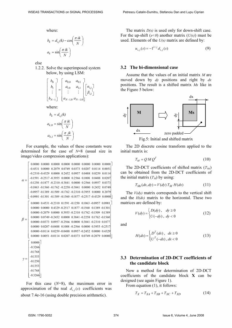
3.2 The bi-dimensional case
Assume that the values of an initial matrix M are
moved down by dy positions and right by dx
positions. The result is a shifted matrix Ms like in
the Figure 5 below:
M
dx
dy Ms
dx
dy
zero padded
Fig.5: Initial and shifted matrix
The 2D discrete cosine transform applied to the
initial matrix is:
TM QMQT = (10)
The 2D-DCT coefficients of shifted matrix (TMs)
can be obtained from the 2D-DCT coefficients of
the initial matrix (TM) by using:
)()(),( dxHTdyVdydxT MMs = (11)
The V(dy) matrix corresponds to the vertical shift
and the H(dx) matrix to the horizontal. These two
matrices are defined by:
<−
≥=
0,)(
0,)()(
dydyU
dydyDdyV (12)
and
<−
≥=
0,)(
0,)()(
dxdxU
dxdxDdxH
T
T
(13)
3.3 Determination of 2D-DCT coefficients of
the candidate block
Now a method for determination of 2D-DCT
coefficients of the candidate block X can be
designed (see again Figure 1).
From equation (1), it follows:
XDXCXBXAX TTTTT +++= (14)
WSEAS TRANSACTIONS on SIGNAL PROCESSING Petrescu Catalin-Dumitru, Stefanoiu Dan and Lupu Ciprian
ISSN: 1790-5052 374 Issue 6, Volume 4, June 2008

Matrices XA, XB, XC and XD are shifted
versions of matrices A, B, C respectively D. The
amounts of shift on horizontal and vertical directions
needed for each matrix are given in Table 1.
Using this information and equation (11), the
four components of TX can be determined as follows:
)()(
)()(
)()(
)()(
dxNHTdyVT
dxHTdyVT
dxNHTNdyVT
dxHTNdyVT
DXD
CXC
BXB
AXA
−=
−=
−−=
−−=
(15)
It can be noticed that we need only the 2D-DCT
transforms of the four initial blocks (TXA, TXB, TXC
and TXD) and the values of displacements on the two
directions dx and dy.
3.4 Tests
The accuracy of the proposed method was
evaluated using several tests.
Generation of DCT coefficients of a shifted
vector from DCT coefficients of the initial vector
described by equations (7) and (8) do not require
any accuracy evaluations for integer values of the
displacement. Its accuracy was already tested
when ji,α , ji,β and iγ coefficients were determined
using the Least Squares Method.
The first test was performed to evaluate accuracy
of determination for 2D-DCT coefficients of the
candidate block described by equations (14) and
(15).
For this test, the next image was considered (size
16x16 pixels):
dx
dy
Fig.6: The test image
This image is a part of a larger size real image
(luminance component) and pixel values are integer
numbers between 0 and 255.
Extracted block
Fig.7: Source image for the test block
The 2D-DCT coefficients of block with size of
8x8 located at (dx,dy) pixels from the bottom-left
corner of the image were computed by the following
methods:
• applying 2D-DC transform over the image block
extracted directly from initial bitmap;
• using equations (14) and (15) applied to the 2D-
DCT coefficients of the four sub-blocks.
The all 64 coefficient values obtained by the two
methods were compared and the maximum absolute
difference was found.
This test was performed for all possible integer
pairs (dx,dy) between (0,0) and (8,8). The maximum
absolute differences noticed for each case were
arranged in a matrix where the element from line i
and column j correspond to the maximum absolute
difference noticed for a vertical displacement dy=i
and a horizontal one dx=j. This matrix is:
1310
133693842991562562711991711133842693982133133272133562842842842562272562991422711
133133413562842702133562421562413693413982562272272991562413983693842842272272851133842693133772133991991991
133842983413562413991562272413693983842562842272991851
−
=
.........
.........
.........
.........
.........
.........
.........
.........
.........
ε
The values are very small and are very likely
caused by approximation errors inherent in floating
point operations.
Another category of tests were focused on
accuracy in the case of non-integer displacements.
This kind of test is difficult to be done in 2D or
using real images. For this reason, we performed the
following tests only in 1D case:
• accuracy evaluation of shifted vector DCT
coefficients obtained by equations (7) and (8);
• accuracy evaluation for a 1D version of the
candidate block DCT coefficients determination
described by equations (14) and (15).
WSEAS TRANSACTIONS on SIGNAL PROCESSING Petrescu Catalin-Dumitru, Stefanoiu Dan and Lupu Ciprian
ISSN: 1790-5052 375 Issue 6, Volume 4, June 2008

The second test assumes the following situation:
XA A B
X
XB
N
N N
dx
Fig.8: The 1D case of the candidate block DCT
coefficients determination
We have the 1D-DCT transform of the two main
vectors and is necessary to determine the 1D-DCT
transform of the X vector.
The candidate vector X is a sum of 2 partial
vectors (XA and XB), each of them containing parts
of main vectors A respectively B like in the
following figure:
XA vector
part of A vector
XB vector
part of B vector
Fig.9: The structure of partial blocks
The shifts necessary for obtaining the two
components are summarized in the next table:
Horizontal Component Main
Direction Amount
XA A Left dx
XB B Right N-dx
Table 2: Generation of candidate block components
Like in the 2D case, DCT transform of the
candidate vector Tx can be determined from the DCT
transform of its components, using a correspondent
equation:
XBXAX TTT += (16)
where:
( )
( )dxNHTT
dxHTT
BXB
AXA
−=
−= (17)
Both tests will be performed using some test-
vectors chosen for an easy evaluation of the DCT
coefficients determination accuracy.
Evaluation will be performed on the non-
transformed vectors obtained from the DCT
coefficients after applying the inverse transform.
3.4.1. Results of shift evaluation tests
The first test vectors tried were the 8 base
functions which define the DCT transform. The
values of the K base vector are defined by:
( )7:0,
16
12cos =
+= i
iky
Ki
π (18)
In the ideal case, shifting these vectors to the
right by s positions will produce the following
values for elements:
• for 5.0≤s :
( ) ( )
−+=
16
212cos
πsiksy
Ki (19)
• for 5.0>s :
( ) ( )
≠
−+
=
=0
16
212cos
0,0
isik
i
syKi π (20)
All these vectors were tested for displacements to
the right between 0 and 1 position with a resolution
of 0.05.
To not exceed the page limit, in this paper, will
be presented only the results for the extreme values
of the K (1 and 7) and for displacements by 0.25,
0.5, 0.75 and 1 positions.
In the next plots, the dotted line represent the
ideal shifted vector determined by equations (19)
and (20) and the solid line represent the vector
obtained performing shift in transformed domain
followed by inverse transform:
• for K=1:
Fig.10: K=1, shift by s=0.25 positions
WSEAS TRANSACTIONS on SIGNAL PROCESSING Petrescu Catalin-Dumitru, Stefanoiu Dan and Lupu Ciprian
ISSN: 1790-5052 376 Issue 6, Volume 4, June 2008

Fig.11: K=1, shift by s=0.5 positions
Fig.12: K=1, shift by s=0.75 positions
Fig.13: K=1, shift by s=1 position
• for K=1:
Fig.14: K=7, shift by s=0.25 positions
Fig.14: K=7, shift by s=0.5 positions
Fig.15: K=7, shift by s=0.75 positions
Fig.16: K=7, shift by s=1 position
It can be noticed that there are some errors in
determination of shifted vectors especially for the
displacement values around 0.5 positions, the
magnitude of these errors increasing as K become
higher.
These errors are more visible for the elements
located on the left side of the vector. This side
corresponds to the place where the values of the
vector are not defined for displacements greater than
0.5 positions and zero padding is performed.
Another test vector which was tried is a linear
ramp defined by:
iyi = (21)
WSEAS TRANSACTIONS on SIGNAL PROCESSING Petrescu Catalin-Dumitru, Stefanoiu Dan and Lupu Ciprian
ISSN: 1790-5052 377 Issue 6, Volume 4, June 2008

In the ideal case, shifting these vectors to the
right by s positions will produce the following
values for elements:
• for 5.0≤s :
( ) sisyi −= (22)
• for 5.0>s :
( )
≠−
=
=
0
0,0
isi
i
syi (23)
This vector was tested for displacements to the
right between 0 and 1 position with a resolution of
0.05 but, like in the base vector case, only the results
for 0.25, 0.5, 0.75 and 1 values are presented in the
following plots.
Fig.17: shift by s=0.25 positions
Fig.18: shift by s=0.5 positions
Fig.19: shift by s=0.75 positions
Fig.20: shift by s=1 position
For this vector, errors are still present but their
magnitudes are smaller than in the base vector cases.
3.4.2. Results of candidate vector determination
evaluation tests
The first test vectors were the same 8 base
functions which define the DCT transform. These
base vectors were used as the main vectors A. For
continuity reasons, the base vectors B were chosen
to be the extensions of the base functions as follows:
( )
( )( )7:0,
16
182cos
7:0,16
12cos
=
++=
=
+=
iik
b
iik
a
Ki
Ki
π
π
(24)
In the ideal case, the candidate vector X obtained
for a displacement dx will have the following values:
( ) ( )
++=
16
212cos
πdxikdxx
Ki (25)
Testing these vectors for displacement values
between 0 and 1 position with a resolution of 0.05 a
very small error (about 10-15
…10-14
) was noticed.
This fact leads to the conclusion that shift
estimation errors corresponding to the A and B main
vectors have almost same values but with opposite
signs and canceling themselves.
The second test vectors were a linear ramp
extended to both A and B vectors as follows:
7:0,8
7:0,
=+=
==
iib
iia
i
i (26)
In the ideal case, the candidate vector X obtained
for a displacement dx will have the following values:
dxixi += (27)
Testing for displacement values between 0 and 1
position with a resolution of 0.05, an error of
maximum 0.0479 was noticed. Although this error is
WSEAS TRANSACTIONS on SIGNAL PROCESSING Petrescu Catalin-Dumitru, Stefanoiu Dan and Lupu Ciprian
ISSN: 1790-5052 378 Issue 6, Volume 4, June 2008

bigger than in the base vectors case, its value is
small enough to be considered almost null.
3.5 Motion estimation
In the motion compensation step, the difference
between the “reconstructed” frame and the actual
frame is encoded using a still image compression
algorithm (usually based on discrete cosine
transform, quantization and entropy coding). Classic
matching functions like mean squared error (MSE)
or mean absolute difference (MAD) do not
guarantee that the difference frame is easy to
compress because they try to minimize the energy of
the difference frame in the bitmap domain not in
transformed one.
Using the proposed method for the estimation of
transformed coefficients of the candidate block, the
matching functions can evaluate the energy of the
DCT coefficients which are actually encoded.
One idea of matching function likely to be used
in the transformed domain is:
( ) ∑∑−
=
−
=
−=
1
0
1
0,
,, ),(),,(
N
i
N
jji
jiji
h
ydydxxYdydxXF (28)
where:
• X is the matrix of 2D-DCT coefficients of the
candidate block from the reference frame;
• Y is the matrix of 2D-DCT coefficients of the
current block;
• jih , are the quantization coefficients used in the
motion compensation step for compressing the
difference frame.
It can be noticed that the differences between
DCT coefficients of the current and candidate block
are weighted by quantization coefficients. The
reason is to make the matching function less
sensitive to the high frequency components which
are however reduced in the quantization step.
Another reason behind this weighting can be the
fact that noise tend to affect more the high
frequency components, hence, this weighting will
reduce the sensitivity of the matching function to the
noises too.
Using this matching function defined above, its
equivalent in transformed domain for the full-search
algorithm can be developed.
Suppose that the current block is known by its
2D-DCT transform Y. The search area cover four
adjacent blocks (see Figure 1). All 2D-DCT
transforms of these four blocks are known as TA, TB,
TC and TD. The result is a motion vector (vx,vy)
which gives the relative displacement of the best
matched block from the reference frame.
1. ∑∑−
=
−
=
=1
0
1
0,
,N
i
N
jji
ji
h
yfmin , vx=-1, vy=-1
2. For dx=0:8 (allowed in fractionar steps)
2.1. For dy=0:8 (allowed in factionary steps)
2.1.1. determine 2D-DCT transform of
the candidate block X(dx,dy) using
equations (11) and (12)
2.1.2. evaluate the match function:
( )YdydxXFf ),,(= using equation (13)
2.1.3. if f < fmin then
2.1.3.1. fmin = f
2.1.3.2. vx = dx
2.1.3.3. vy = dy
At the end, vx and vy will contain the horizontal
and vertical components of the motion vector. If vx
and vy will have -1 value, this means that no
candidate block from the search area would offer a
smaller coefficients energy of the difference than the
actual coefficients of the current block.
4 Conclusion
The method for motion estimation in DCT
transformed domain has some advantages over
classic methods:
• if the video material is already compressed with
a DCT based algorithm (like MJPEG or DV25)
it is not necessary to perform conversions from
transformed to bitmap domain before motion
estimation and then another conversion back for
the difference block;
• this method allows to test candidate blocks
shifted by non-integer amount of pixels, hence
pixel interpolation and searching with greater
resolution are avoided;
• it allows using of some match functions more
appropriated to the motion compensation step.
It can be noticed that number of operations
needed by the full-search algorithm version
presented here is much bigger than for classic
version. This fact leads to the need of extending the
research for finding efficient versions of the search
step.
Another weak point of this method is the
presence of the errors in the non-integer
displacement cases. However, the tests showed that
the magnitude of these errors is small enough to be
considered important.
WSEAS TRANSACTIONS on SIGNAL PROCESSING Petrescu Catalin-Dumitru, Stefanoiu Dan and Lupu Ciprian
ISSN: 1790-5052 379 Issue 6, Volume 4, June 2008

References:
[1] L. Hanzo, P. J. Cherriman and J. Streit, Video
Compression and Communications - >From
Basics to H.261, H.263, H.264, MPEG4 for DVB
and HSDPA-Style Adaptive Turbo-Transceivers
(Second Edition), John Wiley & Sons, Ltd, 2007
[2] T. Koga, K. Iinuma, A. Hirano, Y. Iijima, T.
Ishiguro Motion-compensated interframe coding
for video conferencing, Proceedings NTC'81
(IEEE), p G.5.3.1 - G.5.3.4
[3] Jaswant R. Jain, Anil K. Jain Displacement
measurement and its application in interframe
image coding, IEEE Transactions on
Communications, Volume COM-29, Number 12,
p 1799 - 1808, December 1981
[4] Kwon Moon Nam, Joon-Seek Kim, Rae-Hong
Park, Young Serk Shim, A fast hierarchical
motion vector estimation algorithm using mean
pyramid, IEEE Transactions on Circuits and
Systems on Video Technology, Vol.5, No.4, pp
344-351, (1995)
[5] M. Tun, K. K. Loo, J. Cosmas, Semi-
Hierarchical Based Motion Estimation
Algorithm for the Dirac Video Encoder, WSEAS
Transactions on Signal Processing, Issue 5,
Volume 4, May 2008
[6] C. L. Lin, J. J. Leou, An Adaptive Fast Search
Motion Estimation Algorithm for H.264,
WSEAS Transactions on Communications, Issue
7, Volume 4, July 2005, pp. 396-406.
[7] H. Nam, S. Lim, A New Motion Estimation
Scheme Using a Fast and Robust Block
Matching Algorithm, WSEAS Transactions On
Information Science & Applications, Issue 11,
Volume 3, November 2006, pp. 2292-2299.
[8] ISO/IEC 10918-1, Information technology -
Digital compression and coding of continuous-
tone still images - Part 1: Requirements and
guidelines, International Electrotechnical
Commission, 1994
[9] IEC 61834-2, Recording - Helical-scan digital
video cassette recording system using 6,35 mm
magnetic tape for consumer use (525-60, 625-50,
1125-60 and 1250-50 systems) - Part 2: SD
format for 525-60 and 625-50 systems,
International Electrotechnical Commission, 1998
[10] ISO/IEC 14496-10, Information technology -
Coding of audio-visual objects - Part 10:
Advanced Video Coding, International
Electrotechnical Commission, 2005
[11] Ut-Va Koc and K. J. R. Liu, DCT-based
motion estimation, IEEE Trans. On Image
Processing, Vol. 7, July 1998, pp.948-965
[12] Li, M.; Biswas, M.; Kumar, S.; Truong
Nguyen, DCT-based phase correlation motion
estimation, International Conference on Image
Processing ICIP'04, Volume 1, 24-27 Oct. 2004
Page(s):445 - 448 Vol. 1
[13] Ut-Va Koc and K. J. R. Liu, DCT-based
subpixel motion estimation, Acoustics, Speech,
and Signal Processing, 1996 (ICASSP-96),
Conference Proceedings., 1996 IEEE
International Conference on, 1930-1933, 1996
[14] Proakis J.G., Manolakis D.G., Digital Signal
Processing. Principles, Algorithms and
Applications, third edition, Prentice Hall, Upper
Saddle River, New Jersey, USA, 1996.
[15] Stefanoiu D., Culita J., Stoica P., Foundation of
Systems Modeling and Identification, Printech
Press, Bucharest, Romania, 2005.
WSEAS TRANSACTIONS on SIGNAL PROCESSING Petrescu Catalin-Dumitru, Stefanoiu Dan and Lupu Ciprian
ISSN: 1790-5052 380 Issue 6, Volume 4, June 2008