perfectIO N G uidebook - Lab-Set d.o.o.
51
perfectION ™ Combination Nitrate Electrode Successful Ion Measurement perfectION ™ Guidebook
-
Upload
khangminh22 -
Category
Documents
-
view
5 -
download
0
Transcript of perfectIO N G uidebook - Lab-Set d.o.o.

perfectION™ Combination Nitrate ElectrodeSuccessful Ion Measurement
perfe
ctIO
N™ G
uide
book
Mettler-Toledo AGAnalyticalSonnenbergstrasse 74CH-8603 SchwerzenbachSwitzerlandPhone ++41 (0)44 806 77 11 Fax ++41 (0)44 806 73 50 Internet: www.mt.com
Subject to technical changes©04/2011 Mettler-Toledo AGPrinted in Switzerland 1001/2.12ME-51710849
www.mt.comFor more information
MT_Nitrate_Cover.indd 1-2 05.05.11 11:07

Cont
ents
Intro
duct
ion
Requ
ired
Equi
pmen
tEl
ectro
de a
nd
Mea
sure
men
t Set
upAn
alyt
ical
Tec
hniq
ues
Elec
trode
Ch
arac
teris
tics
Trou
bles
hoot
ing
Ord
erin
g In
form
atio
nEl
ectro
de
Spec
ifica
tions
Table of Contents
1. Introduction 1 2. Required Equipment 3 3. Electrode and Measurement Setup 4 Electrode Preparation 4 Checking Electrode Operation (Slope) 6 Sample Requirements 7 Measuring Hints 8 Electrode Storage and Maintenance 10 Serial Delutions 12 4. Analytical Techniques 13 Direct Calibration Technique 15 Small Volume Direct Calibration Technique 19 Low-Level Calibration Technique 23 Known Addition Technique 25 5. Electrode Characteristics 32 Electrode Response 32 Reproducibility 33 Limits of Detection 33 Electrode Life 33 Temperature Effects 34 Interferences 35 Theory of Operation 38 6. Troubleshooting 41 Troubleshooting Checklist 43 7. Ordering Information 45 8. Electrode Specifications 47
MT_Nitrate_inhalt_en.indd 1 07.04.11 17:03

Intro
duct
ion
MT_Nitrate_inhalt_en.indd 2 07.04.11 17:03

1
Intro
duct
ion 1. Introduction
This user guide contains information on the preparation, oper-ation and maintenance for the nitrate ion selective electrode (ISE). General analytical procedures, electrode characteristics and electrode theory are also included in this user guide. Nitrate electrodes measure free nitrate ions in aqueous solu-tions quickly, simply, accurately and economically.
perfectION™ Combination Nitrate Electrode
The reference and sensing electrodes are built into one elec-trode, which decreases the amount of required solution and reduces waste. The built-in Click & Clear™ reference junction prevents clogging of the diaphragm and provides fast and stable readings.The perfectION™ Combination Nitrate Electrode is available with a BNC connector (P/N 51344727) and a Lemo connector (P/N 51344827) for METTLER TOLEDO titrators.
MT_Nitrate_inhalt_en.indd 1 07.04.11 17:03

2
MT_Nitrate_inhalt_en.indd 2 07.04.11 17:03

3
2. Required Equipment
1. METTLER TOLEDO ISE meter, such as the SevenMulti™ benchtop meter or the SevenGo pro™ portable meter, or a METTLER TOLEDO titrator, such as the Tx (T50, T70, T90) Excellence or G20 Compact titrators.
METTLER TOLEDO combined ISEs can be used on any ISE meter with a BNC connection.
2. perfectION™ combined nitrate ion selective electrode
3. Stirrer
4. Volumetric flasks, graduated cylinders, beakers and pipettes. Plastic labware is required for low-level nitrate analysis.
5. Distilled or deionized water
6. Ion Electrolyte F Reference filling solution (P/N 51344755)
7. Nitrate standard solution 1000 mg/L (P/N 51344779)
8. Nitrate ionic strength adjuster (ISA) (P/N 51344763) provides a constant background ionic strength for samples and standards.
9. Nitrate interference suppressor solution (ISS) (P/N 51344764) can be used in place of the nitrate ISA to remove a variety of interfering anions, including chloride ions, present in samples such as drinking water, waste water and soils. Refer to the Interferences section for details.
10. Preservative solution (Customer prepared) – add 1 mL of preservative solution to every 100 mL of standards and samples to prevent biological degradation of the solutions. Preparation note:
Prepare a 1 mol/L boric acid preservative solution by dissolv-ing 6.2 g of reagent-grade boric acid in 100 mL of boiling water. Let the solution cool.
Requ
ired
Equi
pmen
t
MT_Nitrate_inhalt_en.indd 3 07.04.11 17:03

4
3. Electrode and Measurement Setup
Electrode Preparation
Note: Do not touch the sensing membrane or reference pellet during the electrode assembly!
1. Remove the sensing module from the vial and save the vial for
storage. Make sure that both O-rings are in place on the module.
Remove the electrode handle from the box.
2. Unscrew the electrode cap. Slide the cap and spring down the
electrode cable.
3. Hold the outer body sleeve and gently push the inner stem through
the outer body. Slide the outer body sleeve down the electrode
cable until it is beyond the inner stem.
4. Grasp the middle of the inner stem without touching the reference
pellet. If a red storage tip is connected to the inner stem, unscrew it
and save it for storage.
5. Screw the sensing module into the stem until it stops and the mod-
ule is flush against the stem. Tighten the module an additional
one-quarter turn. The module should be firmly attached to the
stem. Do not overtighten the module.
6. Hold the electrode cable and slide the outer body, spring and cap
over the inner stem.
7. Grasp the outer body sleeve, without touching the sensing mem-
brane, and gently screw the cap onto the inner stem while pulling
on the cable. Stop when an opposite force is felt. Do not over-
tighten or continue to turn the cap. The cap will not completely
stop. If the inner body turns at all, the cap is too tight. Remove the
cap and reassemble.
8. Press on the top of the cap with your thumb to make sure that the
electrode has a smooth flushing motion and the outer body sleeve
returns to its original position.
9. Install the flip spout cap onto the Ion Electrolyte F Reference filling
solution bottle and lift the flip spout to a vertical position. Insert the
spout into the electrode fill hole and add a small amount of filling
solution to the reference chamber.
Elec
trode
and
Mea
sure
men
t
MT_Nitrate_inhalt_en.indd 4 07.04.11 17:03

5
10. Hold the electrode body and use your thumb to push down on the
electrode cap to allow a few drops of filling solution to drain out of
the electrode. Release the electrode cap.
11. If the sleeve does not return to its original position, add filling solu-
tion and repeat step 10 until the sleeve returns to its original
position.
12. Add filling solution to the electrode up to the fill hole.
13. Rinse the electrode with distilled water and soak it in a 100 mg/L
or 10-2 mol/L nitrate standard for 1 to 2 hours prior to use.
Note: Add filling solution each day before using the electrode. The filling solution level should be at least 2.5 cm above the level of sample in the beaker to ensure a proper flow rate. The fill hole should always be open when taking measurements.
cap
spring
fill hole
outer body sleeve
inner stem
reference pellet
O-ringssensing module
sensing membrane
Figure 1 – perfectION™ Nitrate combination electrode
MT_Nitrate_inhalt_en.indd 5 07.04.11 17:03

6
Elec
trode
and
Mea
sure
men
t Set
up Checking Electrode Operation (Slope)
These are general instructions that can be used with most meters to check the electrode operation.
This procedure measures the electrode slope. Slope is defined as the change in millivolts observed with every tenfold change in concentration. The slope value provides the best means for checking the electrode operation.
1. If the electrode has been stored dry, prepare
the electrode as described in the Electrode
Preparation section.
2. Connect the electrode to a meter with a mV
mode. Set the meter to the mV mode.
3. Add 100 mL of distilled water and 2 mL of
ISA into a 150 mL beaker. Stir the solution
thoroughly.
4. Rinse the electrode with distilled water and
place the electrode into the solution pre-
pared in step 3.
5. Select either a 0.1 mol/L or 1000 mg/L
nitrate standard. Pipette 1 mL of the stan-
dard into the beaker and stir the solution
thoroughly.
When a stable reading is displayed, record
the electrode potential in millivolts.
100 mL
1000 mg/L
MT_Nitrate_inhalt_en.indd 6 07.04.11 17:03

7
6. Pipette 10 mL of the same standard into
the same beaker and stir the solution thor-
oughly. When a stable reading is displayed,
record the electrode potential in millivolts.
7. There should be a -54 to -60 mV difference
between the two millivolt readings when
the solution temperature is between 20 to
25 °C. If the millivolt potential is not within
this range, refer to the Troubleshooting
section.
Sample Requirements
All samples must be aqueous and must not contain organic solvents.
The solution temperature must be less than 40 °C. Samples and standards should be at the same temperature. A 1 °C dif-ference in temperature for a 10-3 mol/L nitrate solution will give rise to about a 1.5% error.
Interferences should be absent from all samples. See the Inter-ferences section for a list of possible interferences. If interfer-ences are present in the sample and cannot be removed, use the nitrate interference suppressor solution (ISS) in a 1:1 ratio of solution to nitrate ISS. Do not use ISA when using the nitrate interference suppressor solution.
In all analytical procedures, ISA or nitrate ISS must be added to all samples and standards before measurements are taken.
to
to
1000 mg/L
MT_Nitrate_inhalt_en.indd 7 07.04.11 17:03

8
Elec
trode
and
Mea
sure
men
t Set
up Measuring Hints
Nitrate concentration can be measured in moles per liter (mol/L), milligrams per liter (mg/L) or any convenient concen-tration unit.
Table 1 – Nitrate Concentration Unit Conversion Factors
mol/L mg/L as NO3- mg/L as N
1.0 62000 14000
10-1 6200 1400
10-2 620 140
10-3 62.0 14.0
10-4 6.20 1.40
• Stir all standards and samples at a uniform, moderate rate. Place a piece of insulating material, such as Styrofoam or cardboard, between the magnetic stir plate and beaker to prevent measurement errors from the transfer of heat to the sample.
• Always use freshly prepared standards for calibration.
• Always rinse the electrode with distilled water between measurements and shake the electrode to remove the water and prevent sample carryover. Do not wipe or rub the elec-trode sensing module.
• Store the nitrate electrode in a 10-2 mol/L or 100 mg/L nitrate standard between measurements.
• Allow all standards and samples to reach the same temper-ature for precise measurements.
• Verify the electrode calibration every two hours by placing the electrode in a fresh aliquot of the least concentrated standard used for calibration. If the value has changed by more than 2%, recalibrate the electrode.
• After immersing the electrode in a solution, check the elec-trode sensing surface for air bubbles and remove air bub-bles by reimmersing the electrode in the solution and gently tapping it.
MT_Nitrate_inhalt_en.indd 8 07.04.11 17:03

9
• For high ionic strength samples, prepare standards with a background composition similar to the sample.
• The fill hole cover must be open during measurements to ensure a uniform flow of reference filling solution.
• If the electrode is used in dirty or viscous samples or the electrode response becomes sluggish, empty the electrode completely, hold the junction open and flush the junction with distilled water. Empty any water from the electrode and refill it with fresh filling solution. Press down on the elec-trode cap to let a few drops of the filling solution flow out of the electrode and then replenish any lost solution.
• Start the calibration or measurement with the lowest con-centrated standard or sample.
MT_Nitrate_inhalt_en.indd 9 07.04.11 17:03

10
Elec
trode
and
Mea
sure
men
t Set
up Electrode Storage and Maintenance
Electrode Storage
For storage between measurements and up to three days, store the electrode in a 10 mol/L or 100 mg/L nitrate standard. The filling solution inside the electrode should not be allowed to evaporate, as crystallization will result.
For storage longer than one week, drain the electrode, flush the reference chamber with distilled water, disassemble the electrode and store the sensing module in the glass vial.
1. Grasp the outer body sleeve and unscrew the electrode cap. Slide
the cap and spring assembly down the electrode cable.
2. Push the inner stem of the electrode handle out through the outer
electrode sleeve, exposing the sensing module.
3. Rinse the inner stem and module well with distilled water. Gently
blot dry to prevent damaging the sensing module.
4. Carefully unscrew the sensing module from the inner stem, taking
care not to touch the sensing membrane.
5. Place the nitrate sensing module in the glass vial until it is needed
again. Gently blot dry the inside of the inner stem and O-ring area,
reassemble the electrode handle without the module and store it dry.
Cleaning the Nitrate Sensing Module
If the electrode is exposed to high levels of interfering ions, it may drift and become sluggish in response. When this hap-pens, restore normal performance by soaking the electrode for an hour in distilled water, emptying the old filling solution, fill-ing the electrode with fresh filling solution and then soaking the electrode for a few hours a 10-2 mol/L or 100 mg/L nitrate standard. If soaking the electrode does not restore normal electrode performance, replace the nitrate sensing module.
MT_Nitrate_inhalt_en.indd 10 07.04.11 17:03

11
Flushing the Nitrate Combination Electrode
If the area between the electrode outer body and inner cone becomes clogged with sample or precipitate, flush the area with filling solution or distilled water.
1. Hold the electrode body with one hand and use your thumb to
push down on the electrode cap to drain all of the filling solution
out of the electrode.
2. Fill the electrode with distilled water and then push down on the
cap until all the water is drained from the chamber. Repeat this
procedure until all of the sample or precipitate is removed from the
electrode.
3. Fill the electrode with fresh filling solution up to the fill hole. Push
down on the cap to allow a few drops of filling solution to drain out
of the electrode and then replenish the lost filling solution.
4. Rinse the electrode with distilled water and soak it in a 10-2 mol/L
or 100 mg/L nitrate standard for 1 to 2 hours.
Replacing the Nitrate Sensing Module
The sensing membrane of plastic membrane electrodes will wear over time, indicated by low slope values, drift, poor repro-ducibility and loss of response in low-level samples. The elec-trode response can be restored by replacing the sensing mod-ule. Each sensing module will last about three months with nor-mal laboratory use, but the actual lifespan of the sensing mod-ule will depend on the type of samples that are measured.
Drain the electrode and flush the reference chamber with dis-tilled water. Hold the outer body sleeve and unscrew the elec-trode cap. Slide the cap and spring assembly down the elec-trode cable. Push the inner stem of the electrode handle out through the outer electrode sleeve, exposing the sensing mod-ule. Rinse the inner stem and module well with distilled water. Gently blot dry to prevent damaging the sensing module. Care-fully unscrew the sensing module from the inner stem and dis-pose of the old sensing module. Obtain a new nitrate mem-brane module, (P/N 51344852), and refer to the Electrode Preparation section for detailed instructions on assembling the electrode.
MT_Nitrate_inhalt_en.indd 11 07.04.11 17:03

12
Serial Delutions
Serial dilution is the best method for the preparation of stan-dards. Serial dilution means that an initial standard is diluted, using volumetric glassware, to prepare a second standard solution. The second standard is similarly diluted to prepare a third standard, and so on, until the desired range of standards has been prepared.
1. To prepare a 100 mg/L nitrate standard – Pipette 10 mL of the
1000 mg/L standard into a 100 mL volumetric flask. Dilute to the
mark with deionized water and mix well.
2. To prepare a 10 mg/L standard – Pipette 10 mL of the 100 mg/L
standard into a 100 mL volumetric flask. Dilute to the mark with
deionized water and mix well.
3. To prepare a 1 mg/L standard – Pipette 10 mL of the 10 mg/L
standard into a 100 mL volumetric flask. Dilute to the mark with
deionized water and mix well.
To prepare standards with a different concentration use the fol-lowing formula:
C1 * V1 = C2 * V2
C1 = concentration of original standard V1 = volume of original standard C2 = concentration of standard after dilution V2 = volume of standard after dilution
For example, to prepare 100 mL of a 100 mg/L nitrate stan-dard from a 1400 mg/L nitrate standard: C1 = 1400 mg/L nitrate V1 = unknown C2 = 100 mg/L nitrate V2 = 100 mL 1400 mg/L * V1 = 100 mg/L * 100 mL V1 = (100 mg/L * 100 mL) / 1400 mg/L = 7.14 mL
Elec
trode
and
Mea
sure
men
t Set
up
Anal
ytic
al T
echn
ique
s
MT_Nitrate_inhalt_en.indd 12 07.04.11 17:03

13
4. Analytical Techniques
A variety of analytical techniques are available to the analyst. The following is a description of these techniques.
Direct Calibration is a simple procedure for measuring a large number of samples. Only one meter reading is required for each sample. Calibration is performed using a series of stan-dards. The concentration of the samples is determined by comparison to the standards. ISA is added to all solutions to ensure that samples and standards have similar ionic strength.
Low-Level Calibration is similar to the direct calibration tech-nique. This method is recommended when the expected sam-ple concentration is less than 10-4 mol/L or 1.4 mg/L nitrate as nitrogen (N). A minimum three point calibration is recom-mended to compensate for the electrode’s non-linear response at these concentrations. A special calibration standard prepara-tion procedure is the best means of preparing low-level calibra-tion standards.
Incremental Techniques provide a useful method for measur-ing samples, since a calibration is not required. The different incremental techniques are described below. They can be used to measure the total concentration of a specific ion in the pres-ence of a large (50 to 100 times) excess of complexing agents. As in direct calibration, any convenient concentration unit can be used.
• Known Addition is useful for measuring dilute samples, checking the results of direct calibration (when no complex-ing agents are present), or measuring the total concentra-tion of an ion in the presence of an excess complexing agent. The electrode is immersed in the sample solution and an aliquot of a standard solution containing the mea-sured species is added to the sample. From the change in potential before and after the addition, the original sample concentration is determined.
Anal
ytic
al T
echn
ique
s
MT_Nitrate_inhalt_en.indd 13 07.04.11 17:03

14
Anal
ytic
al T
echn
ique
s
Direct Small Volume Direct
Low-Level Known Addition
[N] < 1.4 mg/L ✔
[N] > 1.4 mg/L ✔ ✔ ✔
Occasional Sampling
✔
Small sample volume
✔ ✔
Large number of samples
✔ ✔ ✔
Reduce chemical usage ✔
Field measurement
✔
Ionic strength greater than 0.1 mol/L
✔ ✔
MT_Nitrate_inhalt_en.indd 14 07.04.11 17:03

15
Direct Calibration Technique
Typical Direct Calibration Curve
In the direct calibration procedure, a calibration curve is con-structed either in the meter memory or on semi-logarithmic paper. Electrode potentials of standard solutions are measured and plotted on the linear axis against their concentrations on the log axis. In the linear regions of the curves, only two stan-dards are needed to determine a calibration curve. In non-lin-ear regions, more points must be taken. These direct calibra-tion procedures are given for concentrations in the region of linear electrode response. Low-level measurement procedures are given in a following section for measurements in the non-linear electrode region.
electrodepotential(relative mV)
10-foldchange
Figure 2 – Typical Direct Calibration Curve
mg/L Nitrateas Nmg/L Nitrateas NO3
molarity
MT_Nitrate_inhalt_en.indd 15 07.04.11 17:03
16
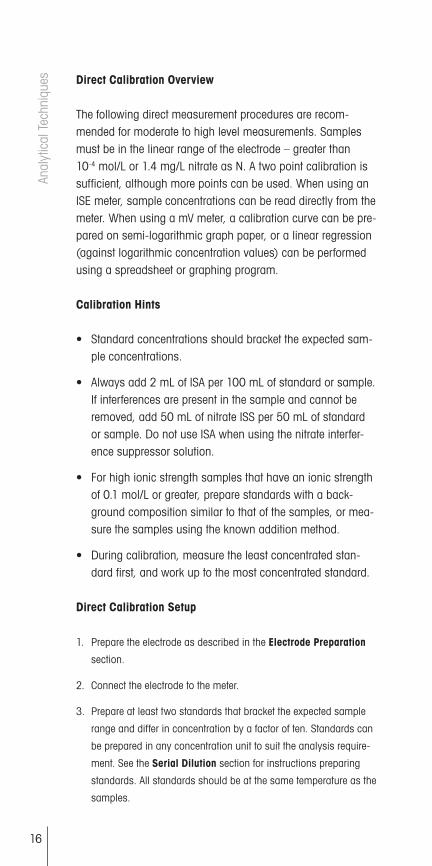
Direct Calibration Overview
The following direct measurement procedures are recom-mended for moderate to high level measurements. Samples must be in the linear range of the electrode – greater than 10-4 mol/L or 1.4 mg/L nitrate as N. A two point calibration is sufficient, although more points can be used. When using an ISE meter, sample concentrations can be read directly from the meter. When using a mV meter, a calibration curve can be pre-pared on semi-logarithmic graph paper, or a linear regression (against logarithmic concentration values) can be performed using a spreadsheet or graphing program.
Calibration Hints
• Standard concentrations should bracket the expected sam-ple concentrations.
• Always add 2 mL of ISA per 100 mL of standard or sample. If interferences are present in the sample and cannot be removed, add 50 mL of nitrate ISS per 50 mL of standard or sample. Do not use ISA when using the nitrate interfer-ence suppressor solution.
• For high ionic strength samples that have an ionic strength of 0.1 mol/L or greater, prepare standards with a back-ground composition similar to that of the samples, or mea-sure the samples using the known addition method.
• During calibration, measure the least concentrated stan-dard first, and work up to the most concentrated standard.
Direct Calibration Setup
1. Prepare the electrode as described in the Electrode Preparation
section.
2. Connect the electrode to the meter.
3. Prepare at least two standards that bracket the expected sample
range and differ in concentration by a factor of ten. Standards can
be prepared in any concentration unit to suit the analysis require-
ment. See the Serial Dilution section for instructions preparing
standards. All standards should be at the same temperature as the
samples.
Anal
ytic
al T
echn
ique
s
MT_Nitrate_inhalt_en.indd 16 07.04.11 17:03

17
Direct Calibration Procedure Using a Meter with an ISE Mode
Note: See the meter user guide for more specific information.
1. Add 100 mL of the less concentrated standard and 2 mL of ISA to
a 150 mL beaker and stir the solution thoroughly.
2. Rinse the electrode with distilled water, blot it dry and place it into
the beaker with the less concentrated standard. Wait for a stable
reading and adjust the meter to display the value of the standard,
as described in the meter user guide.
3. Add 100 mL of the more concentrated standard and 2 mL of ISA to
a second 150 mL beaker and stir the solution thoroughly.
4. Rinse the electrode with distilled water, blot it dry and place it into
the beaker with the more concentrated standard. Wait for a stable
reading and adjust the meter to display the value of the second
standard, as described in the meter user guide.
5. Record the resulting slope value. The slope should be between -54
and -60 mV when the standards are between 20 and 25 °C.
6. Add 100 mL of sample and 2 mL of ISA to a clean 150 mL beaker
and stir the solution thoroughly.
7. Rinse the electrode with distilled water, blot it dry and place it into
the sample. The concentration of the sample will be displayed on
the meter.
Note: Other solution volumes may be used, as long as the ratio of solution to ISA remains 50:1.
Note: If interferences are present in the sample and cannot be removed, add 50 mL of nitrate ISS per 50 mL of standard or sam-ple. Do not use ISA when using the nitrate interference suppres-sor solution. Other solution volumes may be used, as long as the ratio of solution to nitrate ISS remains 1:1.
MT_Nitrate_inhalt_en.indd 17 07.04.11 17:03

18
Direct Calibration Procedure Using a Meter with a mV Mode
Note: See the meter user guide for more specific information.
1. Set the meter to the mV mode.
2. Add 100 mL of the less concentrated standard and 2 mL of ISA to
a 150 mL beaker and stir the solution thoroughly.
3. Rinse the electrode with distilled water, blot it dry and place it into
the beaker with the less concentrated standard. When a stable
reading is displayed, record the mV value and corresponding stan-
dard concentration.
4. Add 100 mL of the more concentrated standard and 2 mL of ISA to
a second 150 mL beaker and stir the solution thoroughly.
5. Rinse the electrode with distilled water, blot it dry and place it into
the beaker with the more concentrated standard. When a stable
reading is displayed, record the mV value and corresponding stan-
dard concentration.
6. Using semi-logarithmic graph paper, prepare a calibration curve
by plotting the millivolt values on the linear axis and the standard
concentration values on the logarithmic axis.
7. Add 100 mL of sample and 2 mL of ISA to a clean 150 mL beaker
and stir the solution thoroughly.
8. Rinse the electrode with distilled water, blot it dry and place it into
the beaker. When a stable reading is displayed, record the mV
value.
9. Use the calibration curve prepared in step 6 in order to determine
the unknown concentration of the sample.
Note: Other solution volumes may be used, as long as the ratio of solution to ISA remains 50:1.
Note: If interferences are present in the sample and cannot be removed, add 50 mL of nitrate ISS per 50 mL of standard or sam-ple. Do not use ISA when using the nitrate interference suppres-sor solution. Other solution volumes may be used, as long as the ratio of solution to nitrate ISS remains 1:1.
Anal
ytic
al T
echn
ique
s
MT_Nitrate_inhalt_en.indd 18 07.04.11 17:03

19
Small Volume Direct Calibration Technique
Take advantage of special design features available with the perfectION™ combination nitrate electrode to meet your mea-suring needs. Due to the Click & Clear™ reference, this elec-trode is able to measure sample volumes as small as 5 mL using a modified direct measurement procedure. Because less solution volume is required, the chemical usage of nitrate standards and ISA is reduced. All samples should have a con-centration greater than 10-4 mol/L or 1.4 mg/L nitrate as N. A two point calibration is sufficient, although more points can be used. The following procedure recommends using 25 mL of sample. Smaller sample volumes can be used, as long as the final volume of solution is sufficient to cover the bottom of the electrode.
Calibration Hints
• Standard concentrations should bracket the expected sam-ple concentrations.
• Always add 0.5 mL of ISA, per 25 mL of standard or sam-ple. Always keep the ratio of standard or sample to ISA at 50:1.
• If interferences are present in the sample and cannot be removed, add 25 mL of nitrate ISS, per 25 mL of standard or sample. Do not use ISA when using the nitrate interfer-ence suppressor solution. Always keep the ratio of standard or sample to nitrate ISS at 1:1.
• For high ionic strength samples that have an ionic strength of 0.1 mol/L or greater, prepare standards with a back-ground composition similar to that of the samples, or mea-sure the samples using the known addition method.
• During calibration, measure the least concentrated stan-dard first, and work up to the most concentrated standard.
• Calibrate with the same volume of standard as the volume of sample that is available for analysis.
MT_Nitrate_inhalt_en.indd 19 07.04.11 17:03

20
Anal
ytic
al T
echn
ique
s Small Volume Direct Calibration Setup
1. Prepare the electrode as described in the Electrode Preparation
section.
2. Connect the electrode to the meter.
3. Prepare at least two standards that bracket the expected sample
range and differ in concentration by a factor of ten. Standards can
be prepared in any concentration unit to suit the particular analy-
sis requirement. See the Serial Dilution section for instructions on
how to prepare standards. All standards should be at the same
temperature as the samples. For details on temperature effects on
electrode performance, refer to the Temperature Effects section.
MT_Nitrate_inhalt_en.indd 20 07.04.11 17:03

21
Small Volume Direct Calibration Procedure Using a Meter with an ISE Mode
Note: See the meter user guide for more specific information.
1. Add 25 mL of the less concentrated standard and 0.5 mL of ISA to
a 50 mL beaker and swirl the solution to mix.
2. Rinse the electrode with distilled water, blot it dry and place it into
the beaker with the less concentrated standard. Wait for a stable
reading and adjust the meter to display the value of the standard,
as described in the meter user guide.
3. Add 25 mL of the more concentrated standard and 0.5 mL of ISA
to a second 50 mL beaker and swirl the solution to mix.
4. Rinse the electrode with distilled water, blot it dry and place it into
the beaker with the more concentrated standard. Wait for a stable
reading and adjust the meter to display the value of the second
standard, as described in the meter user guide.
5. Record the resulting slope value. The slope should be between
-54 and -60 mV when the standards are between 20 and 25 °C.
6. Add 25 mL of sample and 0.5 mL of ISA to a clean 50 mL beaker
and swirl the solution to mix.
7. Rinse the electrode with distilled water, blot it dry and place it into
the sample. The concentration of the sample will be displayed on
the meter.
Note: Other solution volumes may be used, as long as the ratio of solution to ISA remains 50:1.
Note: If interferences are present in the sample and cannot be removed, add 25 mL of nitrate ISS per 25 mL of standard or sam-ple. Do not use ISA when using the nitrate interference suppres-sor solution. Other solution volumes may be used, as long as the ratio of solution to nitrate ISS remains 1:1.
MT_Nitrate_inhalt_en.indd 21 07.04.11 17:03

22
Small Volume Direct Calibration Procedure Using a Meter with a mV Mode
Note: See the meter user guide for more specific information.
1. Set the meter to the mV mode.
2. Add 25 mL of the less concentrated standard and 0.5 mL of ISA to
a 50 mL beaker and swirl the solution to mix.
3. Rinse the electrode with distilled water, blot it dry and place it into
the beaker with the less concentrated standard. When a stable
reading is displayed, record the mV value and corresponding stan-
dard concentration.
4. Add 25 mL of the more concentrated standard and 0.5 mL of ISA
to a second 50 mL beaker and swirl the solution to mix.
5. Rinse the electrode with distilled water, blot it dry and place it into
the beaker with the more concentrated standard. When a stable
reading is displayed, record the mV value and corresponding stan-
dard concentration.
6. Using semi-logarithmic graph paper, prepare a calibration curve
by plotting the millivolt values on the linear axis and the standard
concentration values on the logarithmic axis.
7. Add 25 mL of sample and 0.5 mL of ISA to a clean 50 mL beaker
and swirl the solution to mix.
8. Rinse the electrode with distilled water, blot it dry and place it into
the beaker. When a stable reading is displayed, record the mV
value.
9. Use the calibration curve prepared in step 6 in order to determine
the unknown concentration of the sample.
Note: Other solution volumes may be used, as long as the ratio of solution to ISA remains 50:1.
Note: If interferences are present in the sample and cannot be removed, add 25 mL of nitrate ISS per 25 mL of standard or sam-ple. Do not use ISA when using the nitrate interference suppres-sor solution. Other solution volumes may be used, as long as the ratio of solution to nitrate ISS remains 1:1.
Anal
ytic
al T
echn
ique
s
MT_Nitrate_inhalt_en.indd 22 07.04.11 17:03

23
Low-Level Calibration Technique
These procedures are for solutions that have a nitrate concen-tration of less than 10-4 mol/L or 1.4 mg/L nitrate as N. For solutions low in nitrate but high in total ionic strength (greater than 10-1 mol/L), perform the same procedure by preparing a calibrating solution with a composition similar to the sample. Accurate results require following conditions to be met:
• Prepare at least three calibration standards that bracket the expected sample concentration.
• Always use low-level ISA for standards and samples. If interferences are present in the sample and cannot be removed, use nitrate ISS instead of low-level ISA.
• Plastic labware must be used for all low-level nitrate mea-surements.
• Adequate time must be allowed for electrode stabilization. Lon-ger response time will be needed at low-level measurements.
• Stir all standards and samples at a uniform rate.
Low-Level Setup
1. Prepare the electrode as described in the Electrode Preparation
section.
2. Connect the electrode to the meter. Set the meter to the mV mode.
3. Prepare the low-level ISA by pipetting 20 mL of the nitrate ISA, into
a 100 mL volumetric flask and diluting to the mark with distilled
water. Use low-level ISA for low-level measurements only.
If interferences are present in the sample and cannot be removed,
use nitrate ISS instead of low-level ISA. Add 10.1 mL of nitrate ISS
per 90.9 mL of distilled water or sample.
4. Select a standard solution. Use either a 100 mg/L nitrate as N or
10-3 mol/L nitrate standard.
MT_Nitrate_inhalt_en.indd 23 07.04.11 17:03

24
Low-Level Calibration and Measurement
1. Add 100 mL of distilled water and 1 mL of low-level ISA to a
150 mL beaker.
2. Rinse the electrode with distilled water, blot it dry and place it into
the beaker. Stir the solution thoroughly.
3. Add increments of the 100 mg/L or 10-3 mol/L nitrate standard to
the beaker using the steps outlined in Table 3. Record the stable
millivolt reading after each increment.
4. On semi-logarithmic paper, plot the concentration (log axis)
against the millivolt potential (linear axis). Prepare a new calibra-
tion curve with fresh standards each day.
5. Measure 100 mL of sample and 1 mL of low-level ISA and pour
the solutions into a clean 150 mL beaker. Rinse the electrode with
distilled water, blot it dry and place the electrode into the sample.
6. Stir the solution thoroughly. When a stable reading is displayed,
record the mV value.
7. Determine the sample concentration corresponding to the mea-
sured potential from the low-level calibration curve.
Table 3 – Calibration Curve For Low-level CalibrationsAdditions of standard to 100 mL distilled water and 1 mL low-level ISA solution
Step Pipette SizeVolume Added
Concentration mg/L as N mol/L
1 1 mL 0.1 mL 0.1 1.0 x 10⁻⁶
2 1 mL 0.1 mL 0.2 2.0 x 10⁻⁶
3 1 mL 0.2 mL 0.4 3.9 x 10⁻⁶
4 1 mL 0.2 mL 0.6 5.9 x 10⁻⁶
5 1 mL 0.4 mL 1.0 9.8 x 10⁻⁶
6 2 mL 2.0 mL 2.9 2.9 x 10⁻⁵
7 2 mL 2.0 mL 4.7 4.7 x 10⁻⁵
Anal
ytic
al T
echn
ique
s
MT_Nitrate_inhalt_en.indd 24 07.04.11 17:03

25
Known Addition Technique
Known addition is a convenient technique for measuring sam-ples in the linear range of the electrode (greater than 10-4 mol/L or 1.4 mg/L nitrate as N) because no calibration curve is required. It can be used to verify the results of a direct cali-bration or to measure the total concentration of an ion in the presence of a large excess of a complexing agent. The sample potential is measured before and after addition of a standard solution.
Accurate results require following conditions to be met:
• Concentration should approximately double as a result of the addition.
• Sample concentration should be known to within a factor of three.
• Either no complexing agent or a large excess of the com-plexing agent may be present.
• The ratio of the uncomplexed ion to complexed ion must not be changed by addition of the standard.
• All samples and standards should be at the same tempera-ture.
• With double or multiple known addition, the final addition should be 10 to 100 times the sample concentration.
• Add 2 mL of ISA to every 100 mL of sample before analy-sis. If interferences are present in the sample and cannot be removed, add 50 mL of nitrate ISS per 50 mL of standard or sample. Do not use ISA when using the nitrate interfer-ence suppressor solution.
MT_Nitrate_inhalt_en.indd 25 07.04.11 17:03

26
Known Addition Setup
1. Prepare the electrode as described in the Electrode Preparation
section.
2. Connect the electrode to the meter.
3. Prepare a standard solution that will cause the nitrate concentra-
tion of the sample to double when added to the sample solution.
Refer to Table 4 for guidelines.
4. Determine the electrode slope by performing the procedure in the
Checking Electrode Operation (Slope) section.
5. Rinse the electrode with distilled water.
Table 4 – Guideline For Known Addition
Volume of Addition Concentration of Standard
1 mL 100 times sample concentration
5 mL 20 times sample concentration
10 mL* 10 times sample concentration* Most convenient volume to use
Known Addition Using a Meter with a Known Addition Mode
Note: See the meter user guide for more specific information.
1. Set the meter to measure in the known addition mode.
2. Measure 100 mL of the sample and 2 mL of ISA and pour the
solutions into a beaker. Rinse the electrode with distilled water and
place it into the sample solution. Stir the solution thoroughly.
3. When a stable reading is displayed, set the meter as described in
the meter user guide, if required.
4. Pipette the appropriate amount of the standard solution into the
beaker. Stir the solution thoroughly.
5. When a stable reading is displayed, record the sample
concentration.
Anal
ytic
al T
echn
ique
s
MT_Nitrate_inhalt_en.indd 26 07.04.11 17:03

27
Known Addition Using a Meter with a Millivolt Mode
1. Set the meter to the relative millivolt mode. If a relative millivolt
mode is not available, use the millivolt mode.
2. Measure 100 mL of sample and 2 mL of ISA and pour the solu-
tions into a 150 mL beaker. Stir the solution thoroughly.
3. Rinse the electrode with distilled water, blot it dry and place the
electrode into the beaker. When a stable reading is displayed, set
the meter to read 0.0 mV. If the reading cannot be adjusted to 0.0
mV, record the actual mV value.
4. Pipette the appropriate amount of standard solution into the bea-
ker. Stir the solution thoroughly.
5. When a stable reading is displayed, record the mV value. If the
meter could not be set to 0.0 mV in step 3, subtract the first read-
ing from the second reading to calculate ∆E.
6. Use Table 6 to find the Q value that corresponds to the change in
potential, ∆E. To determine the original sample concentration, mul-
tiply Q by the concentration of the added standard:
Csample = Q * Cstandard
Cstandard = standard concentration Csample = sample concentration Q = value from Table 6
The table of Q values is calculated for a 10% volume change. The equation for the calculation of Q for different slopes and volume changes is given below.
Q = (p * r) / {[(1 + p) * 10 ∆E/S] - 1} Q = value from Table 6 ∆E = E2 - E1
S = slope of the electrode p = volume of standard / volume of sample and ISA r = volume of sample and ISA / volume of sample
MT_Nitrate_inhalt_en.indd 27 07.04.11 17:03

28
Calculating Known Addition for Samples using Excel Spreadsheets
If it is more convenient, a simple spreadsheet can be set up to calculate the known addition results, using any ratio of sample to addition. A typical worksheet is shown in Table 5. The num-bers shown are examples, but the formulas and their locations should be copied exactly.
Table 5 – Known Addition Calculations using Excel Spreadsheets
A B C
1 Enter Value
2 Volume of sample and ISA (mL)
101
3 Volume of addition (mL) 10
4 Concentration of addition 10
5 Volume of sample 100
6 Initial mV reading -45.3
7 Final mV reading -63.7
8 Electrode slope -59.2
9
10 Derived Values
11 Delta E =C7 - C6
12 Solution volume ratio =C3/C2
13 Antilog term =10^ (C11/C8)
14 Sample volume ratio =C2/C5
15 Q term =C12*C14/(((1+C12)*C13)-1)
16 Calculated initial concentra-tion in same units as addi-tion
=C15*C4
Anal
ytic
al T
echn
ique
s
MT_Nitrate_inhalt_en.indd 28 07.04.11 17:03

29
Table 6 – Q Values for a 10% volume change, slopes (in column heading) are in units of mV/decade
∆E Q Concentration Ratio
-57.2 -58.2 -59.2 -60.1
5.0 0.2917 0.2957 0.2996 0.30315.2 0.2827 0.2867 0.2906 0.29405.4 0.2742 0.2781 0.2820 0.28545.6 0.2662 0.2700 0.2738 0.27725.8 0.2585 0.2623 0.2660 0.2693
6.0 0.2512 0.2550 0.2586 0.26196.2 0.2443 0.2480 0.2516 0.25486.4 0.2377 0.2413 0.2449 0.24806.6 0.2314 0.2349 0.2384 0.24166.8 0.2253 0.2288 0.2323 0.2354
7.0 0.2196 0.2230 0.2264 0.22957.2 0.2140 0.2174 0.2208 0.22387.4 0.2087 0.2121 0.2154 0.21847.6 0.2037 0.2070 0.2102 0.21317.8 0.1988 0.2020 0.2052 0.2081
8.0 0.1941 0.1973 0.2005 0.20338.2 0.1896 0.1927 0.1959 0.19878.4 0.1852 0.1884 0.1914 0.19428.6 0.1811 0.1841 0.1872 0.18998.8 0.1770 0.1801 0.1831 0.1858
9.0 0.1732 0.1762 0.1791 0.18189.2 0.1694 0.1724 0.1753 0.17799.4 0.1658 0.1687 0.1716 0.17429.6 0.1623 0.1652 0.1680 0.17069.8 0.1590 0.1618 0.1646 0.1671
10.0 0.1557 0.1585 0.1613 0.163810.2 0.1525 0.1553 0.1580 0.160510.4 0.1495 0.1522 0.1549 0.157310.6 0.1465 0.1492 0.1519 0.154310.8 0.1437 0.1463 0.1490 0.1513
11.0 0.1409 0.1435 0.1461 0.148511.2 0.1382 0.1408 0.1434 0.145711.4 0.1356 0.1382 0.1407 0.143011.6 0.1331 0.1356 0.1381 0.140411.8 0.1306 0.1331 0.1356 0.1378
12.0 0.1282 0.1307 0.1331 0.135312.2 0.1259 0.1283 0.1308 0.132912.4 0.1236 0.1260 0.1284 0.130612.6 0.1214 0.1238 0.1262 0.128312.8 0.1193 0.1217 0.1240 0.1261
13.0 0.1172 0.1195 0.1219 0.123913.2 0.1152 0.1175 0.1198 0.121813.4 0.1132 0.1155 0.1178 0.119813.6 0.1113 0.1136 0.1158 0.117813.8 0.1094 0.1117 0.1139 0.1159
MT_Nitrate_inhalt_en.indd 29 07.04.11 17:03

30
∆E Q Concentration Ratio
-57.2 -58.2 -59.2 -60.1
15.0 0.0992 0.1012 0.1033 0.105215.5 0.0953 0.0973 0.0994 0.101216.0 0.0917 0.0936 0.0956 0.097416.5 0.0882 0.0902 0.0921 0.093817.0 0.0850 0.0869 0.0887 0.0904
17.5 0.0819 0.0837 0.0856 0.087218.0 0.0790 0.0808 0.0825 0.084118.5 0.0762 0.0779 0.0797 0.081319.0 0.0736 0.0753 0.0770 0.078519.5 0.0711 0.0727 0.0744 0.0759
20.0 0.0687 0.0703 0.0719 0.073420.5 0.0664 0.0680 0.0696 0.071021.0 0.0642 0.0658 0.0673 0.068721.5 0.0621 0.0637 0.0652 0.066622.0 0.0602 0.0617 0.0631 0.0645
22.5 0.0583 0.0597 0.0612 0.062523.0 0.0564 0.0579 0.0593 0.060623.5 0.0547 0.0561 0.0575 0.058824.0 0.0530 0.0544 0.0558 0.057024.5 0.0514 0.0528 0.0541 0.0553
25.0 0.0499 0.0512 0.0525 0.053725.5 0.0484 0.0497 0.0510 0.052226.0 0.0470 0.0483 0.0495 0.050726.5 0.0456 0.0469 0.0481 0.049227.0 0.0443 0.0455 0.0468 0.0479
27.5 0.0431 0.0443 0.0455 0.046528.0 0.0419 0.0430 0.0442 0.045228.5 0.0407 0.0418 0.0430 0.044029.0 0.0395 0.0407 0.0418 0.042829.5 0.0385 0.0396 0.0407 0.0417
30.0 0.0374 0.0385 0.0396 0.040630.5 0.0364 0.0375 0.0385 0.039531.0 0.0354 0.0365 0.0375 0.038431.5 0.0345 0.0355 0.0365 0.037432.0 0.0335 0.0345 0.0356 0.0365
32.5 0.0327 0.0336 0.0346 0.035533.0 0.0318 0.0328 0.0337 0.034633.5 0.0310 0.0319 0.0329 0.033734.0 0.0302 0.0311 0.0320 0.032934.5 0.0294 0.0303 0.0312 0.0321
35.0 0.0286 0.0295 0.0305 0.031335.5 0.0279 0.0288 0.0297 0.030536.0 0.0272 0.0281 0.0290 0.029836.5 0.0265 0.0274 0.0282 0.029034.5 0.0294 0.0303 0.0312 0.0321
35.0 0.0286 0.0295 0.0305 0.031335.5 0.0279 0.0288 0.0297 0.030536.0 0.0272 0.0281 0.0290 0.029836.5 0.0265 0.0274 0.0282 0.029037.0 0.0258 0.0267 0.0275 0.0283
Anal
ytic
al T
echn
ique
s
MT_Nitrate_inhalt_en.indd 30 07.04.11 17:03

31
∆E Q Concentration Ratio
-57.2 -58.2 -59.2 -60.1
37.0 0.0258 0.0267 0.0275 0.028337.5 0.0252 0.0260 0.0269 0.027638.0 0.0246 0.0254 0.0262 0.027038.5 0.0240 0.0248 0.0256 0.026339.0 0.0234 0.0242 0.0250 0.0257
39.5 0.0228 0.0236 0.0244 0.025140.0 0.0223 0.0230 0.0238 0.024540.5 0.0217 0.0225 0.0232 0.023941.0 0.0212 0.0219 0.0227 0.023441.5 0.0207 0.0214 0.0221 0.0228
42.0 0.0202 0.0209 0.0216 0.022342.5 0.0197 0.0204 0.0211 0.021843.0 0.0192 0.0199 0.0206 0.021343.5 0.0188 0.0195 0.0202 0.020844.0 0.0183 0.0190 0.0197 0.0203
44.5 0.0179 0.0186 0.0192 0.019845.0 0.0175 0.0181 0.0188 0.019445.5 0.0171 0.0177 0.0184 0.019046.0 0.0167 0.0173 0.0179 0.018546.5 0.0163 0.0169 0.0175 0.0181
47.0 0.0159 0.0165 0.0171 0.017747.5 0.0156 0.0162 0.0168 0.017348.0 0.0152 0.0158 0.0164 0.016948.5 0.0148 0.0154 0.0160 0.016649.0 0.0145 0.0151 0.0157 0.0162
49.5 0.0142 0.0147 0.0153 0.015850.0 0.0139 0.0144 0.0150 0.015550.5 0.0135 0.0141 0.0146 0.015151.0 0.0132 0.0138 0.0143 0.014851.5 0.0129 0.0135 0.0140 0.0145
52.0 0.0126 0.0132 0.0137 0.014252.5 0.0124 0.0129 0.0134 0.013953.0 0.0121 0.0126 0.0131 0.013653.5 0.0118 0.0123 0.0128 0.013354.0 0.0116 0.0120 0.0125 0.0130
54.5 0.0113 0.0118 0.0123 0.012755.0 0.0110 0.0115 0.0120 0.012555.5 0.0108 0.0113 0.0118 0.012256.0 0.0106 0.0110 0.0115 0.011956.5 0.0103 0.0108 0.0113 0.0117
57.0 0.0101 0.0106 0.0110 0.011457.5 0.0099 0.0103 0.0108 0.011258.0 0.0097 0.0101 0.0105 0.011058.5 0.0095 0.0099 0.0103 0.010759.0 0.0093 0.0097 0.0101 0.010559.5 0.0091 0.0095 0.0099 0.010360.0 0.0089 0.0093 0.0097 0.0101
MT_Nitrate_inhalt_en.indd 31 07.04.11 17:03

32
5. Electrode Characteristics
Electrode Response
The electrode potential plotted against concentration on semi-logarithmic paper results in a straight line with a slope of about -54 to -60 mV per decade change in concentration.
The time response of the electrode (the time required to reach 99% of the stable potential reading) varies from several sec-onds in concentrated solutions to several minutes near the limit of detection.
10-3 M to 10-2 M NaNO3
10-3 M to 10-4 M NaNO3
10-3 M to 10-5 M NaNO3
10-3 M to 10-6 M NaNO3
electrodepotential (mV)
time (minutes)
Figure 3 – Typical Electrode Response to Nitrate Concentration
Elec
trode
Cha
ract
eris
tics
MT_Nitrate_inhalt_en.indd 32 07.04.11 17:03

33
Reproducibility
Reproducibility is limited by factors such as temperature fluctu-ations, drift and noise. Within the operating range of the elec-trode, the reproducibility is independent of concentration. With hourly calibrations, direct electrode measurements reproduc-ible to ± 2 % can be obtained.
Limits of Detection
In pure nitrate solutions, the upper limit of detection is 1 mol/L. When possible, dilute the sample into the linear range of the electrode. If samples are not diluted, the possibility of a liquid reference junction potential and the salt extraction effect, need to be considered. At high salt concentrations, salts may be extracted into the electrode membrane, causing deviation from theoretical response. To measure samples between 10-1 and 1 mol/L, calibrate the electrode at 4 or 5 intermediate points or dilute the sample.
The lower limit of detection is determined by the slight water solubility of the ion exchanger, which causes deviation from theoretical response. Figure 3 shows the theoretical response at low levels of nitrate chloride compared to the actual response. If nitrate measurements are made below 10-4 mol/L or 1.4 mg/L nitrate as N, a low-level measurement procedure is recommended.
Electrode Life
Each sensing module will last approximately three months with normal laboratory use, but the actual lifespan of the sens-ing module will depend on the type of samples that the elec-trode is used in. Refer to the Electrode Maintenance section for instructions on changing the sensing module. In time, the electrode slope will decrease and readings will start to drift, indicating that the module should be changed. Before replace-ment, refer to the Troubleshooting section to make sure that the difficulties are caused by the sensing module.
MT_Nitrate_inhalt_en.indd 33 07.04.11 17:03

34
Temperature Effects
Since electrode potentials are affected by changes in tempera-ture, samples and standard solutions should be within ± 1 °C (± 2 °F) of each other. At the 10-3 mol/L level, a 1 °C differ-ence in temperature results in errors greater than 1.5 %. The absolute potential of the reference electrode changes slowly with temperature because of the solubility equilibria on which the electrode depends. The slope of the electrode also varies with temperature, as indicated by the factor S in the Nernst equation. Theoretical values of the slope at different tempera-tures are given in Table 7. If the temperature changes, the meter and electrode should be recalibrated.
The electrode can be used at temperatures from 0 to 40 °C, provided that temperature equilibrium has occurred. For use at temperatures substantially different from room temperature, cali-bration standards should be at the same temperature as samples.
Table 7 – Theoretical Slope vs. Temperature Values
Temperature (°C) Slope (mV)
0 - 54.20
10 - 56.18
20 - 58.16
25 - 59.16
30 - 60.15
40 - 62.13
Elec
trode
Cha
ract
eris
tics
MT_Nitrate_inhalt_en.indd 34 07.04.11 17:03

35
The Ion Electrolyte F Reference filling solution that is included with the electrode will minimize junction potentials and provide optimum temperature and time response. Ion Electrolyte F Reference filling solution produces an isopotential point of 3.2 x 10⁻³ mol/L nitrate. The isopotential point is the concen-tration at which the potential of the electrode does not vary with temperature. Since the isopotential point of this electrode is known, the combination nitrate electrode may be used on meters that allow automatic temperature compensation for ISE measurements. By programming in the isopotential point and placing an ATC probe into the sample, any time the temperature changes the meter will automatically adjust the slope of the cali-bration curve, resulting in more accurate measurements.
Interferences
Some anions, if present at high enough levels, are electrode interferences and will cause measurement errors. Table 8 indi-cates levels of common cations that will cause 10% errors at different concentrations of nitrate.
The nitrate interference suppressor solution (ISS) is recom-mended for the removal of a variety of interfering anions pres-ent in samples such as soils, drinking water, waste water and plant tissues. The nitrate interference suppressor solution is mixed in an equal volume with samples and standards. For example, add 50 mL of nitrate ISS per 50 mL of standard or sample. This procedure ensures that samples and standards have a similar background and that no correction factor is needed for the dilution. Do not use ISA when using the nitrate interference suppressor solution.
If the electrode is exposed to high levels of interfering ions, it may drift and become sluggish in response. When this happens, restore normal performance by soaking the electrode for an hour in distilled water, emptying the old filling solution, filling the elec-trode with fresh filling solution and then soaking the electrode for a few hours in a 10-2 mol/L or 100 mg/L nitrate standard. If soaking the electrode does not restore normal electrode perfor-mance, refer to the Electrode Maintenance section for instruc-tions on how to replace the sensing module.
MT_Nitrate_inhalt_en.indd 35 07.04.11 17:03

36
Elec
trode
Cha
ract
eris
tics When the level of interferences in samples is constant, it is
sometimes possible to measure nitrate accurately when inter-ference levels are higher than those in Table 8. For example, nitrate can be measured in sea water by using synthetic ocean water for calibration.
Table 8 – Nitrate Electrode Interferences
Interferences mol/L
10-4 mol/L Nitrate
10-3 mol/L Nitrate
10-2 mol/L Nitrate
(d) ClO4- 1 x 10⁻⁸ 1 x 10⁻⁷ 1 x 10⁻⁶
(b) I- 5 x 10⁻⁷ 5 x 10⁻⁶ 5 x 10⁻⁵
(d) ClO3- 5 x 10⁻⁶ 5 x 10⁻⁵ 5 x 10⁻⁴
(b) CN- 1 x 10⁻⁵ 1 x 10⁻⁴ 1 x 10⁻³
(b) Br- 7 x 10⁻⁵ 7 x 10⁻⁴ 7 x 10⁻³
(c) NO2- 7 x 10⁻⁵ 7 x 10⁻⁴ 7 x 10⁻³
(b) HS- 1 x 10⁻⁴ 1 x 10⁻³ 1 x 10⁻²
(a) HCO3- 1 x 10⁻³ 1 x 10⁻² 0.1
(a) CO3-2 2 x 10⁻³ 2 x 10⁻² 0.2
(b) Cl- 3 x 10⁻³ 3 x 10⁻² 0.3
(b) H2PO4- 5 x 10⁻³ 5 x 10⁻² 0.5
(b) HPO4-2 5 x 10⁻³ 5 x 10⁻² 0.5
(b) PO4-3 5 x 10⁻³ 5 x 10⁻² 0.5
(e) OAc- 2 x 10⁻² 0.2 2
F- 6 x 10⁻² 0.6 6
SO4-2 0.1 1.0 10
MT_Nitrate_inhalt_en.indd 36 07.04.11 17:03
37
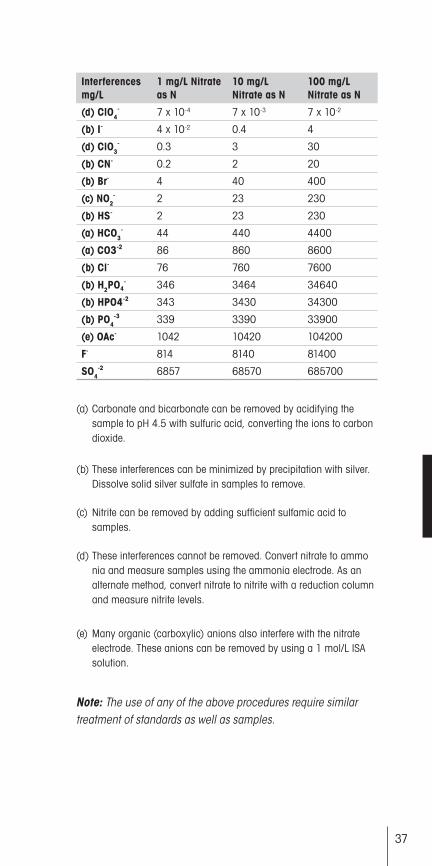
Interferences mg/L
1 mg/L Nitrate as N
10 mg/L Nitrate as N
100 mg/L Nitrate as N
(d) ClO4- 7 x 10⁻⁴ 7 x 10⁻³ 7 x 10⁻²
(b) I- 4 x 10⁻² 0.4 4
(d) ClO3- 0.3 3 30
(b) CN- 0.2 2 20
(b) Br- 4 40 400
(c) NO2- 2 23 230
(b) HS- 2 23 230
(a) HCO3- 44 440 4400
(a) CO3-2 86 860 8600
(b) Cl- 76 760 7600
(b) H2PO4- 346 3464 34640
(b) HPO4-2 343 3430 34300
(b) PO4-3 339 3390 33900
(e) OAc- 1042 10420 104200
F- 814 8140 81400
SO4-2 6857 68570 685700
(a) Carbonate and bicarbonate can be removed by acidifying the sample to pH 4.5 with sulfuric acid, converting the ions to carbon dioxide.
(b) These interferences can be minimized by precipitation with silver. Dissolve solid silver sulfate in samples to remove.
(c) Nitrite can be removed by adding sufficient sulfamic acid to samples.
(d) These interferences cannot be removed. Convert nitrate to ammo nia and measure samples using the ammonia electrode. As an alternate method, convert nitrate to nitrite with a reduction column and measure nitrite levels.
(e) Many organic (carboxylic) anions also interfere with the nitrate electrode. These anions can be removed by using a 1 mol/L ISA solution.
Note: The use of any of the above procedures require similar treatment of standards as well as samples.
MT_Nitrate_inhalt_en.indd 37 07.04.11 17:03

38
Theory of Operation
The nitrate electrode consists of a replaceable, pretested sens-ing module connected to an epoxy body. The sensing module contains a liquid internal filling solution in contact with a gelled organophilic membrane that contains a nitrate selective ion exchanger.
modulehousing
electricalcontact
internalaqueousreferencesolution
ion sensitivearea
internalreference
element(Ag/AgCl)
porousplastic
organphilicmembrane
Figure 4 – Example of an Ion Sensing Module
When the module is in contact with a solution containing nitrate ions, an electrode potential develops across the mod-ule. This potential, which depends on the level of free nitrate ion in solution, is measured against a constant reference potential with a digital pH/mV meter or ISE (concentration) meter. The measured potential corresponding to the level of nitrate ion in solution is described by the Nernst equation.
Elec
trode
Cha
ract
eris
tics
MT_Nitrate_inhalt_en.indd 38 07.04.11 17:03

39
E = Eo + S * log (A)
E = measured electrode potential Eo = reference potential (a constant) A = nitrate ion activity level in solution S = electrode slope (about -57 mV per decade) S = (2.3 R T) / nF R and F are constants, T = temperature in kelvin and n = ionic charge
The level of nitrate ions, A, is the activity or “effective concen-tration” of free nitrate ions in solution. The nitrate ion activity is related to free nitrate ion concentration, Cf, by the activity coefficient, y. A = y * Cf
Ionic activity coefficients are variable and largely depend on total ionic strength. The ionic strength of a solution is deter-mined by all of the ions present. It is calculated by multiplying the concentration of each individual ion by the square of its charge, adding all these values up and then dividing by two. Ionic strength = 1/2 ∑ (CiZi
2)
Ci = concentration of ion i Zi = charge of ion i ∑ symbolizes the sum of all the types of ions in solution
MT_Nitrate_inhalt_en.indd 39 07.04.11 17:03

40
If background ionic strength is high and constant relative to the sensed ion concentration, the activity coefficient is constant and activity is directly proportional to the concentration. Ionic strength adjustor (ISA) is added to all nitrate standards and samples so that the background ionic strength is high and constant relative to variable concentrations of nitrate. For nitrate, the recommended ISA is (NH4)2SO4. Nitrate interference suppression solution (ISS), a specific solution for removal of nitrate-interfering ions, is recommended for samples with competing ions. Other solutions can be used as long as they do not contain ions that would interfere with the electrode response to nitrate.
If samples have a high ionic strength (above 0.1 mol/L), stan-dards should be prepared with a composition similar to the samples.
Reference electrode conditions must also be considered. Liquid junction potentials arise any time when two solutions of differ-ent composition are brought into contact. The potential results from the interdiffusion of ions in the two solutions. Since ions diffuse at different rates, the electrode charge will be carried unequally across the solution boundary resulting in a potential difference between the two solutions. In making electrode measurements, it is important that this potential is the same when the reference is in the standardizing solution as well as in the sample solution; otherwise, the change in liquid junction potential will appear as an error in the measured specific ion electrode potential.
The most important variable that analysts have under their control is the composition of the liquid junction filling solution. The filling solution should be equitransferent. That is, the speed with which the positive and negative ions in the filling solution diffuse into the sample should be nearly as equal as possible. If the rate at which positive and negative charge is carried into the sample solution is equal, then no junction potential can result. perfectION™ reference filling solutions are specifically designed to meet all reference electrode conditions.
Trou
bles
hoot
ing
Elec
trode
Cha
ract
eris
tics
MT_Nitrate_inhalt_en.indd 40 07.04.11 17:03

41
6. Troubleshooting
Follow a systematic procedure to isolate the problem. The measuring system can be divided into four components for ease in troubleshooting: meter, electrode, sample/application and technique.
Meter/Titrator
The meter/titrator is the easiest component to eliminate as a possible cause of error. Consult the meter/titrator user guide for directions.
Electrode
1. Rinse the electrode thoroughly with distilled water.
2. Verify the electrode performance by performing the procedure in
the Checking Electrode Operation (Slope) section.
3. If the electrode fails this procedure, review the Measuring Hints
section. Clean the electrode thoroughly as directed in the Elec-
trode Maintenance section. Drain and refill the electrode with
fresh filling solution.
4. Repeat the procedure in the Checking Electrode Operation
(Slope) section.
5. If the electrode passes the procedure, but measurement problems
persist, the sample may contain interferences or complexing
agents, or the technique may be in error.
6. Before replacing a faulty electrode, review this user guide and
be sure to thoroughly clean the electrode; correctly prepare the
electrode; use the proper filling solution, ISA or nitrate ISS and
standards; correctly measure the samples and review the
Troubleshooting Checklist section.
Trou
bles
hoot
ing
MT_Nitrate_inhalt_en.indd 41 07.04.11 17:03

42
Sample/Application
The quality of results depends greatly upon the quality of the standards. Always prepare fresh standards when problems arise, it could save hours of frustrating troubleshooting! Errors may result from contamination of prepared standards, accu-racy of dilution, quality of distilled water, or a mathematical error in calculating the concentrations.
The best method for preparation of standards is serial dilution. Refer to the Serial Dilution section. The electrode and meter may operate with standards, but not with the sample. In this case, check the sample composition for interferences, incom-patibilities or temperature effects. Refer to the Sample Require-ments, Temperature Effects and Interferences sections.
Technique
If trouble persists, review operating procedures. Review calibra-tion and measurement sections to be sure proper technique has been followed. Verify that the expected concentration of the ion of interest is within the limit of detection of the electrode.
Check the method of analysis for compatibility with your sam-ple. Direct measurement may not always be the method of choice. If a large amount of complexing agents are present, Known Addition may be the best method. If working with low-level samples, follow the procedure in the Low-level Calibra-tion section.
Trou
bles
hoot
ing
MT_Nitrate_inhalt_en.indd 42 07.04.11 17:03

43
Troubleshooting Checklist
• No reference filling solution added – Fill the electrode with filling solution up to the fill hole. Refer to the Electrode Preparation section for details.
• Incorrect reference filling solution used – Refer to the Electrode Preparation section to verify that the correct electrode filling solution was used.
• Electrode junction is dry – Push down on the electrode cap to allow a few drops of filling solution to drain out of the electrode.
• Electrode is clogged or dirty – Refer to the Electrode Maintenance section for electrode cleaning and flushing instructions.
• Sensing module is not installed properly, dirty or defective – Refer to the Electrode Preparation section and verify that the electrode was assembled correctly. Refer to the Elec-trode Maintenance section for instructions on installing a new sensing module.
• Standards are contaminated or made incorrectly – Prepare fresh standards. Refer to the Serial Dilution, Measurement Hints and Analytical Techniques sections.
• ISA not used or incorrect ISA used – ISA must be added to all standards and samples. Refer to the Required Equip-ment section for information on the ISA.
• Interferences present – Use the nitrate interference suppres-sor solution (ISS) instead of ISA.
• Samples and standards at different temperatures – Allow solutions to reach the same temperature.
• Air bubble on sensing module – Remove air bubble by reimmersing the electrode in solution.
MT_Nitrate_inhalt_en.indd 43 07.04.11 17:03

44
Ord
erin
g In
form
atio
n• Electrode not properly connected to meter/titrator – Unplug and reconnect the electrode to the meter/titrator. Meter/Titrator or stir plate not properly grounded – Check the meter/titrator and stir plate for proper grounding.
• Static electricity present – Wipe plastic parts on the meter/titrator with a detergent solution.
• Defective meter/titrator – Check the meter/titrator perfor-mance. See the meter/titrator user guide.
MT_Nitrate_inhalt_en.indd 44 07.04.11 17:03

45
7. Ordering Information
Parts Order No.
Combined Nitrate electrode with BNC connector
perfectION™ comb NO3
-: 51344727
Combined Nitrate electrode with Lemo connector
perfectION™ comb NO3
- Lemo: 51344827
perfectION™ Nitrate membrane module: 51344852
Ion Electrolyte F: 51344755
Nitrate Standard Solution 1000 mg/L: 51344779
Nitrate ISA: 51344763
Nitrate Interference Suppressor Solution: 51344764
Removable cone: 00022986
Ord
erin
g In
form
atio
n
MT_Nitrate_inhalt_en.indd 45 07.04.11 17:03

Elec
trode
Spe
cific
atio
ns
MT_Nitrate_inhalt_en.indd 46 07.04.11 17:03

47
Elec
trode
Spe
cific
atio
ns 8. Electrode Specifications
Membrane type
Polymer
Concentration Range
7 x 10⁻⁶ mol/L to 1 mol/L 0.1 mg/L to 14'000 mg/L nitrate as N
pH Range
pH 2.5 to 11
Low-level measurements may be influenced by hydrogen or hydroxide ion interferences.
Temperature Range
0 to 40 °C
Electrode Resistance
0.1 to 5 MΩ
Reproducibility
± 2%
Minimum Sample Size
5 mL in a 50 mL beaker
Size
Body Diameter: 13 mmBody Length: 110 mmCap Diameter: 16 mmCable Length: 1.2 m
* Specifications are subject to change without notice
MT_Nitrate_inhalt_en.indd 47 07.04.11 17:03

perfectION™ Combination Nitrate ElectrodeSuccessful Ion Measurement
perfe
ctIO
N™ G
uide
book
Mettler-Toledo AGAnalyticalSonnenbergstrasse 74CH-8603 SchwerzenbachSwitzerlandPhone ++41 (0)44 806 77 11 Fax ++41 (0)44 806 73 50 Internet: www.mt.com
Subject to technical changes©04/2011 Mettler-Toledo AGPrinted in Switzerland 1001/2.12ME-51710849
www.mt.comFor more information
MT_Nitrate_Cover.indd 1-2 05.05.11 11:07


![[Lab Report] PSpice](https://static.fdokumen.com/doc/165x107/631a338ebb40f9952b01e638/lab-report-pspice.jpg)