Pelco KBD200A Universal Keyboard_manual
36
® Installation/Operation KBD200A Universal Keyboard C526M-J (3/04) SHIFT SEQUENCE F1 F2 F3 F4 F5 MON ACK PREV NEXT HOLD PATTERN PRESET MACRO PGM ZOOM WIDE CLOSE FAR IRIS 1 2 3 4 5 6 7 8 9 0 CLEAR CAM KBD200A MADE IN USA. Pelco World Headquarters • 3500 Pelco Way, Clovis, CA 93612-5699 USA • www.pelco.com USA & Canada: Tel: 800/289-9100 • Fax: 800/289-9150 International: Tel: 1-559/292-1981 • Fax: 1-559/348-1120
-
Upload
khangminh22 -
Category
Documents
-
view
1 -
download
0
Transcript of Pelco KBD200A Universal Keyboard_manual

®
Installation/Operation
KBD200AUniversal Keyboard
C526M-J (3/04)
SHIFT
SEQUENCE
F1
F2
F3
F4
F5
MON
ACKPREV
NEXTHOLD
PATTERN PRESETMACRO
PGM
ZOOM
WIDE
CLOSE
FAR
IRIS
12
345
678
90
CLEAR
CAM
KBD200AMADE IN USA.
Pelco World Headquarters • 3500 Pelco Way, Clovis, CA 93612-5699 USA • www.pelco.comUSA & Canada: Tel: 800/289-9100 • Fax: 800/289-9150
International: Tel: 1-559/292-1981 • Fax: 1-559/348-1120
[ 2 ] Pelco Manual C526M-J (3/04)
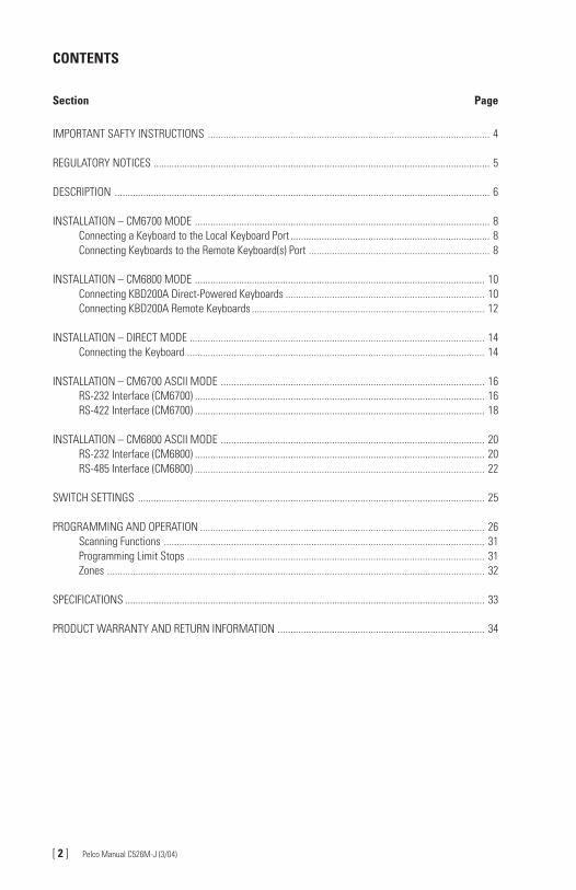
CONTENTS
Section Page
IMPORTANT SAFTY INSTRUCTIONS ............................................................................................................. 4
REGULATORY NOTICES .................................................................................................................................. 5
DESCRIPTION ................................................................................................................................................. 6
INSTALLATION – CM6700 MODE .................................................................................................................. 8Connecting a Keyboard to the Local Keyboard Port ............................................................................. 8Connecting Keyboards to the Remote Keyboard(s) Port ...................................................................... 8
INSTALLATION – CM6800 MODE ................................................................................................................ 10Connecting KBD200A Direct-Powered Keyboards ............................................................................. 10Connecting KBD200A Remote Keyboards .......................................................................................... 12
INSTALLATION – DIRECT MODE .................................................................................................................. 14Connecting the Keyboard ................................................................................................................... 14
INSTALLATION – CM6700 ASCII MODE ...................................................................................................... 16RS-232 Interface (CM6700) ................................................................................................................ 16RS-422 Interface (CM6700) ................................................................................................................ 18
INSTALLATION – CM6800 ASCII MODE ...................................................................................................... 20RS-232 Interface (CM6800) ................................................................................................................ 20RS-485 Interface (CM6800) ................................................................................................................ 22
SWITCH SETTINGS ...................................................................................................................................... 25
PROGRAMMING AND OPERATION .............................................................................................................. 26Scanning Functions ............................................................................................................................ 31Programming Limit Stops ................................................................................................................... 31Zones .................................................................................................................................................. 32
SPECIFICATIONS ........................................................................................................................................... 33
PRODUCT WARRANTY AND RETURN INFORMATION ................................................................................ 34

Pelco Manual C526M-J (3/04) [ 3 ]
List of Illustrations
Figure PageFigure 1. Wiring Diagram for Local/Remote Keyboards 9Figure 2. Keyboard Cabling Diagram ............................................................................................................ 9Figure 3. Data Cables Plugged into COM 5 and 6 (CM6800-48X8 Shown) ................................................ 11Figure 4. Connecting Remote Keyboards (CM6800-48X8 Shown) .............................................................. 13Figure 5. Direct Mode Keyboard and Receiver Wiring ............................................................................... 15Figure 6. RS-232 Interface connections (CM6700) ..................................................................................... 17Figure 7. RS-422 Interface Connections (CM6700) ..................................................................................... 19Figure 8. RS-232 Interface Connections (CM6800-48X8 Shown) ............................................................... 21Figure 9. RS-485 Interface Connections (CM6800-48X8 Shown) ............................................................... 23Figure 10. COM Port Connections and RJ-45 Connector Pin-Outs ............................................................. 24Figure 11. Keyboard Rear Panel .................................................................................................................. 25Figure 12. Keyboard Functions .................................................................................................................... 29
List of Tables
Table A. KBD200A Operational Features ..................................................................................................... 7Table B. Keyboard Addresses ...................................................................................................................... 25Table C. Keyboard Modes ........................................................................................................................... 25Table D. Keyboard Functions ....................................................................................................................... 26Table E. KBD200A Button Functions ........................................................................................................... 30Table F. Operating Scan Functions with Various Receivers ........................................................................ 31Table G. Limit Set Codes ............................................................................................................................. 31Table H. Zone Programming Procedure ....................................................................................................... 32

[ 4 ] Pelco Manual C526M-J (3/04)
IMPORTANT SAFTY INSTRUCTIONS
� Read these instructions.
� Keep these instructions.
� Heed all warnings.
� Follow all instructions.
� Do not use this apparatus near water.
� Clean only with dry cloth.
� Do not block any ventilation openings. Install in accordance with the manufacturer’s instructions.
� Do not install near any heat sources such as radiators, heat registers, stoves, or other apparatus(including amplifiers) that produce heat.
Only use attachments/accessories specified by the manufacturer.
� Refer all servicing to qualified service personnel. Servicing is required when the apparatus has beendamaged in any way, such as power-supply cord or plug is damaged, liquid has been spilled or objectshave fallen into the apparatus, the apparatus has been exposed to rain or moisture, does not operatenormally, or has been dropped.
� Apparatus shall not be exposed to dripping or splashing and that no objects filled with liquids, such asvases shall be placed on the apparatus.
WARNING: To reduce the risk of fire or electric shock, do not expose this apparatus to rain ormoisture.
� Installation should be done only by qualified personnel and conform to all local codes.
� Unless the unit is specifically marked as a NEMA Type 3, 3R, 3S, 4, 4X, 6, or 6P enclosure, it is designed forindoor use only and it must not be installed where exposed to rain and moisture.
CAUTION: These servicing instructions are for use by qualified service personnel only. To reduce the risk ofelectric shock do not perform any servicing other that contained in the operating instructions unless you arequalified to do so.
Only use replacement parts recommended by Pelco.
Pelco Manual C526M-J (3/04) [ 5 ]
REGULATORY NOTICES
This device complies with part 15 of the FCC Rules. Operation is subject to the following two conditions:(1) this device may not cause harmful interference, and (2) this device must accept any interference re-ceived, including interference that may cause undesired operation.
RADIO AND TELEVISION INTERFERENCEThis equipment has been tested and found to comply with the limits of a Class B digital device, pursuantto part 15 of the FCC rules. These limits are designed to provide reasonable protection against harmful in-terference in a residential installation. This equipment generates, uses, and can radiate radio frequencyenergy and, if not installed and used in accordance with the instructions, may cause harmful interferenceto radio communications. However there is no guarantee that the interference will not occur in a particu-lar installation. If this equipment does cause harmful interference to radio or television reception, whichcan be determined by turning the equipment off and on, the user is encouraged to try to correct the inter-ference by one or more of the following measures:
• Reorient or relocate the receiving antenna.• Increase the separation between the equipment and the receiver.• Connect the equipment into an outlet on a circuit different from that to which the receiver is
connected.• Consult the dealer or an experienced radio/TV technician for help.
You may also find helpful the following booklet, prepared by the FCC: How to Identify and Resolve Radio-TV Interference Problems. This booklet is available from the U.S. Government Printing Office, WashingtonD.C. 20402.
Changes and Modifications not expressly approved by the manufacturer or registrant of this equipmentcan void your authority to operate this equipment under Federal Communications Commissions rules.
[ 6 ] Pelco Manual C526M-J (3/04)
DESCRIPTIONThe KBD200A Universal Keyboard has many operational features (refer to Table A) and can be used innumerous operational modes:
CM6700 Mode: Program and operate the CM6700 Matrix Switcher/Controller Unit (SCU). Also control aGenex® multiplexer from a CM6700 SCU. Multiple keyboards can be used in this mode.
CM6800 Mode: Program and operate the CM6800 Matrix Switcher/Controller Unit (SCU). Also control aGenex multiplexer from a CM6800. Multiple keyboards can be used in this mode.
Direct P Mode: Control up to 16 receivers connected directly to the keyboard. Only one keyboard can beused in this mode. A separate system, such as an MS500 or VA6100 Switcher, is needed to route video tothe monitor.
NOTE: The KBD200A keyboard also can be used in Direct Mode to program aCM9760-MDA Master Distribution Amplifier. Refer to the CM9760-MDA manual for details.
CM6700 ASCII Mode: Use an RS-232 or RS-422 interface to operate the CM6700 and RS-232 or RS-485to operate the CM6800. Also control a Genex multiplexer from a CM6700 or CM6800. Use this mode withcommunication facilities that introduce any type of delay, such as dial-up or fiber optic. The ASCII Modeuses a non-polling protocol that is immune to delays. One keyboard can be used in ASCII Mode, but oth-ers may be connected at the local and remote keyboard ports (CM6700 Mode or CM6800 Mode). TheCM6700 and CM6800 cannot be programmed from a keyboard operating in ASCII Mode.
The latest firmware release (version 5.00) allows two additional modes:
CM6800 ASCII Mode: This mode supports the CM6800 GPI commands. The F1, F2, and F3 keys controlthe relays on an REL2064 that is connected to a CM6800 switcher. To enable this mode, DIP switch 6must be ON and DIP switch 8 must be ON.
Direct D Mode: This mode is similar to the Direct P Protocol that already exists, except that the sameset of commands are now sent in Direct D Protocol. To enable this mode, DIP switches 5 and 6 mustbe ON.
NOTE: You must upgrade your KBD firmware to version 5.00 if the application requires you to selecttwo-digit monitor numbers.

Pelco Manual C526M-J (3/04) [ 7 ]
Table A. KBD200A Operational Features
CM6700/ Direct CM6700 CM6800 DirectFunction CM6800 P* ASCII** ASCII*** D***
Automatically recognize the mode Yes Yes No No No
Select cameras Yes Yes Yes Yes Yes
Select monitors Yes No Yes Yes No
Control lenses Yes Yes Yes Yes Yes
Set and call presets/patterns Yes Yes Yes Yes Yes
Create Zones Yes Yes Yes Yes Yes
Control latching receiver auxiliaries Yes Yes Yes Yes Yes
Control momentary receiver auxiliaries Yes Yes Yes Yes Yes
Control multiplexer Yes No Yes Yes NoControl Matrix Switcher Yes No Yes Yes NoProgram Matrix Switcher Yes No No No No
Sequencing Yes No Yes Yes No
Operate frame, auto, and random scans Yes Yes Yes Yes Yes
Program and operate patterns Yes Yes Yes Yes Yes
Control CM6700 auxiliaries Yes No Yes No No
Control CM6800 GPIs Yes No No Yes No
***Firmware version 2.00 and higher***Firmware version 3.00 and higher***Firmware version 5.00 and higher

[ 8 ] Pelco Manual C526M-J (3/04)
INSTALLATION – CM6700 MODE
There are two keyboard ports on the CM6700 SCU.
The LOCAL KEYBOARD port is for connecting a single keyboard within a distance of 25 feet (7.6 meters).
The REMOTE KEYBOARD(S) port is for connecting additional remote keyboards.
Connecting a Keyboard to the Local Keyboard Port� Use the data cable that is supplied with the keyboard. Plug one end of the cable into the RJ-45 connec-
tor on the rear of the keyboard and the other end into the LOCAL KEYBOARD port on the SCU (refer toFigure 1). Set the switches according to the instructions in the Switch Settings section.Go to step 2 to install remote keyboards, or go to step 10.
Connecting Keyboards to the Remote Keyboard(s) PortNOTE: A KBDKIT or KBDKIT-X is required for this application. The KBDKIT consists of two RJ-45 wallblocks and a 120 VAC to 12 VAC transformer. The KBDKIT-X is for 230 VAC. Use one KBDKIT for eachkeyboard.
Refer to Figures 1 and 2 for the following steps.
� Decide on a suitable location for each keyboard and wall block. Keyboards must be within 25 feet (7.6meters) of the wall block. Wall blocks must be within 6 feet (1.8 m) of the nearest suitable electrical out-let. Do not mount the wall block at this time.
� Run wall block interconnect cable (user-supplied) from the SCU to the closest keyboard location, thento the next nearest location, and the next, etc.
Communication to the keyboards is RS-485. Maximum cable distance for RS-485 communication over 24-gauge wire is 4,000 feet (1,219 m). Pelco recommends using shielded twisted pairs cable that meets orexceeds the basic requirements for EIA RS-485 applications.
� Remove the wall block cover and make cable connections at each wall block.
� At each wall block, wire the transformer to pins 3 and 4. Polarity is unimportant.
� Replace the cover on the wall block. Secure the wall block to a suitable surface. A double-sided stickypad is provided to mount the wall block.
� Set the switches for each keyboard according to the instructions in the Switch Settings section.
� Plug in all keyboard data cables.
Plug the KBDKIT or KBDKIT-X transformer into a suitable outlet.
� To initialize the keyboard, wait five seconds after powering-up the CM6700, enter the number for themonitor you are viewing (1-4), and press MON. The LED display shows the number entered.
NOTE: You must re-initialize whenever power is cycled.
� Go to the Programming and Operation section and program and test for proper operation.

Pelco Manual C526M-J (3/04) [ 9 ]
KBDKIT
25-FOOT KEYBOARDDATA CABLE
KBD KBD
ADDITIONALKEYBOARDS
USER-SUPPLIED CABLE
25-FOOT KEYBOARD DATA CABLE
KBD
LOCALKEYBO ARD
LOCALKEYBOARD
REMOTE KEYBOARDS
8 82 2
3
1
CM6700
6 REPLACECOVER
7
6 REPLACECOVER
7
25-FOOT KEYBOARDDATA CABLE
SET SWITCHES(PAGE 12)
Figure 1. Wiring Diagram for Local/Remote Keyboards
TERMINAL
1
2
3
4
5
6
7
8
TERMINAL
1
2
3
4
5
6
7
8
R+R-T-T+
LOCAL
RJ-45WALL BLOCK TERMINALS
1
2
3
4 5
6
7
8
12 VAC12 VAC
4 4TX+
TX-
AC
AC
GND
RX-
RX+
5 5
9 9
USER-SUPPLIED CABLETX+
TX-
AC
AC
GND
RX-
RX+
Figure 2. Keyboard Cabling Diagram

[ 10 ] Pelco Manual C526M-J (3/04)
INSTALLATION – CM6800 MODE
You can connect up to eight KBD200A keyboards to any of the following ports:
For the CM6800-48X8:COM 5 (one direct-powered keyboard or up to eight remotely connected keyboards)COM 6 (same as COM 5)COM 7 (up to eight remotely connected keyboards)COM 8 (same as COM 7)
The total number of KBD200A Series keyboards connected to the CM6800-48X8 cannot exceed 16.
For the CM6800-32X6:COM 4 (up to eight remotely connected keyboards)COM 5 (one direct-powered keyboard or up to eight remotely connected keyboards)
The total number of KBD200A Series keyboards connected to the CM6800-32X6 cannot exceed eight.
Connecting KBD200A Direct-Powered KeyboardsFor direct-powered local keyboards, use COM 5 and 6 (serial ports 5 and 6) for the CM6800-48X8 andCOM 5 (serial port 5) for the CM6800-32X6. Each port can power one KBD200A keyboard. A KBDKIT(-X) isrequired if the distance between the CM6800 and the keyboard exceeds 25 feet.
Refer to Figure 3 (CM6800-48X8 shown).
� Using the 25-foot (7.62 m) straight data cable supplied with the keyboard, plug one end into the RJ-45connector on the rear of the keyboard. Plug the other end into either COM 5 or 6 on the CM6800-48X8or COM 5 on the CM6800-32X6.
� Set the keyboard switches according to the instructions in the Switch Settings section. Go to the nextsection, Connecting KBD200A Remote Keyboards. Go to step 1 to install remote keyboards, or go tostep 9.

Pelco Manual C526M-J (3/04) [ 11 ]
C O M 1
1
2
3
4
5
6
7
8
16
87
3231
43
VIDE O O UTPUTS120/230~50/60 HZ
25 WATT S
C O M
AL AR M1 2 3 4 5 6 7 8
C O NTR O L
PTZ
O UT
A T+
T-
R+
R-
T+
T-
R+
R-
B
1 2
F3
MAXIMUM NUMBER OF KEYBOARDS POWERED BY COM 5 & 6: 1 PER PORTNOTE: THE TOTAL NUMBER OF KBD200A SERIESKEYBOARDS CONNECTED TO THE CM6800 CANNOT EXCEED 16.KBDKIT(-X) REQUIRED WHEN WIRING MORE THAN 1 KEYBOARDTO A PORT.
KBD200ARJ-45 PIN-OUTS
1 Tx+2 Tx-3 12V4 12V5 GROUND6 NC7 Rx-8 Rx+
CM6800 COM 5 & 6RJ-45 PIN-OUTS
1 Rx+2 Rx-3 KBD 12V4 KBD GROUND5 GROUND6 NC7 Tx-8 Tx+
KBD200AKBD200A
01233
Figure 3. Data Cables Plugged into COM 5 and 6 (CM6800-48X8 Shown)

[ 12 ] Pelco Manual C526M-J (3/04)
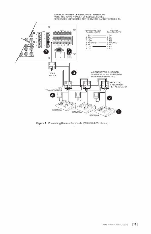
Connecting KBD200A Remote Keyboards
For remote keyboard connections, use COM 5, 6, 7, or 8 for the CM6800-48X8 and COM 4 or 5 for theCM6800-32X6. Each port can support up to eight KBD200A keyboards. Do not exceed 16 total keyboards forthe CM6800-48X8 and eight total keyboards for the CM6800-32X6.
A KBDKIT or KBDKIT(-X) is required to connect remote keyboards. Each kit contains two RJ-45 wall blocksand a transformer. Use one wall block for each keyboard.
Refer to Figure 4 (CM6800-48X8 shown).
� Pick a suitable location for each keyboard and wall block. Wall blocks must be within 6 feet (1.8 m) ofa suitable electrical outlet. Do not mount the wall blocks yet.
� Connect each keyboard to a wall block, using the supplied keyboard data cable.
� Remove the wall block covers and wire the connections between each wall block. Connect to a finalwall block (which will be connected to the CM6800).
Communication to the keyboards is RS-485. Maximum cable distance for RS-485 communication over24-gauge wire is 4,000 feet (1,219 m). Pelco recommends using shielded twisted pair cable thatmeets or exceeds the basic requirements for EIA RS-485 applications.
� At each wall block, wire the KBDKIT or KBDKIT(-X) transformer to pins 3 and 4. Polarity is unimportant.
� Replace the wall block cover. Secure the wall block to a suitable surface using the double-sided sticky pad.
� Set the address switches for each keyboard (refer to the Switch Settings section). (If using COM 7 or 8, theport settings on the CM6800-48X8 must be changed from the default settings. Refer to the CM6800 manual.)
� Connect the final wall block to COM 5, 6, 7, or 8 on the CM68000-48X8 or COM 4 or 5 for theCM6800-32X6 using a straight data cable (supplied with the CM6800).
� Plug the KBDKIT or KBDKIT-X transformers into a suitable outlet.
To initialize the keyboard, wait five seconds after powering-up the CM6800, enter the number for themonitor you are viewing, and press MON. The LED display shows the number entered.
NOTE: You must re-initialize whenever power is cycled.
� Go to the Programming and Operation section and program and test for proper operation.
Pelco Manual C526M-J (3/04) [ 13 ]
COM 1
1
2
3
4
5
6
7
8
16
87
3231
43
VIDEO OUTPUTS120/230~
50/60 HZ
25 WATTS
COM
ALARM
1 2 3 4 5 6 7 8
CONTROL
PTZ
OUT
A T+
T-
R+
R-
T+
T-
R+
R-
B
1 2
F3
MAXIMUM NUMBER OF KEYBOARDS: 8 PER PORTNOTE: THE TOTAL NUMBER OF KBD200A SERIESKEYBOARDS CONNECTED TO THE CM6800 CANNOT EXCEED 16.
KBD200ARJ-45 PIN-OUTS
1 Tx+2 Tx-3 NC4 NC5 GROUND6 NC7 Rx-8 Rx+
CM6800 COM 7 & 8RJ-45 PIN-OUTS
1 Rx+2 Rx-3 12V4 12V5 GROUND6 NC7 Tx-8 Tx+
2
3
4 5
6
7
1 8
2
3
4 5
6
7
1 8
2
3
4 5
6
7
1 8
2
3
4 5
6
7
1 8
KBD200A
KBDKIT(-X)1 REQUIREDPER KEYBOARD
WALLBLOCK
12VTRANSFORMER
4-CONDUCTOR, SHIELDED,24-GAUGE, SUCH AS BELDEN9843 (USER-SUPPLIED)
KBD200A
KBD200A
�
�
��
�
Figure 4. Connecting Remote Keyboards (CM6800-48X8 Shown)

[ 14 ] Pelco Manual C526M-J (3/04)
INSTALLATION – DIRECT MODE
Direct Mode is for a single-keyboard installation only. You can communicate using Pelco P or Pelco D Pro-tocol. The keyboard is wired directly to a maximum of 16 receivers. Direct Mode installation/operation isnot the same as CM6700 Mode or CM6800 Mode installation/operation. A separate system, such as anMS500 or VA6100 switcher, is required for routing video to the monitor(s).
In Direct P and Direct D modes you can now change the zoom speed of a PTZ by entering a number from 1to 4 followed by a zoom command. This causes the zoom speed command to be sent.
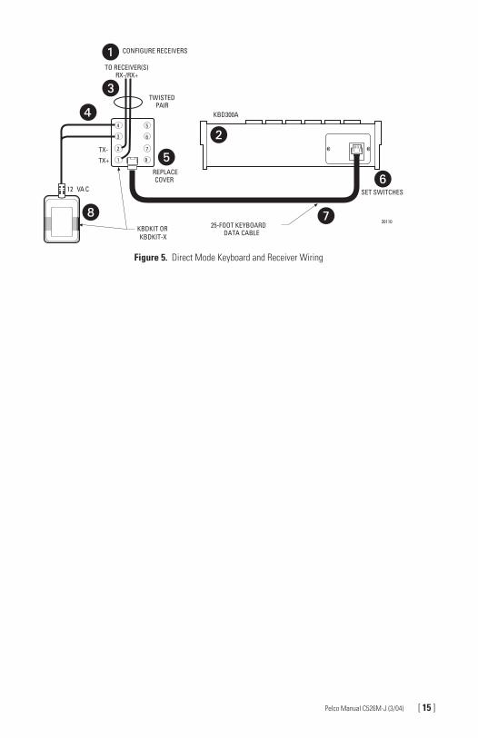
Connecting the KeyboardRefer to Figure 5.
� Make sure all receivers are configured to communicate using Pelco P or Pelco D Protocol and thateach receiver has a unique address. Refer to your receiver manual for switch settings.
NOTE: A KBDKIT or KBDKIT-X is required to use the keyboard in Direct Mode. The KBDKIT consists oftwo RJ-45 wall blocks and a 120 VAC to 12 VAC transformer. The KBDKIT-X is for 230 VAC. Only one wallblock is required for this application.
� Decide on a suitable location for the keyboard and wall block. The keyboard must be within 25 feet(7.6 meters) of the wall block. The wall block must be within 6 feet (1.8 m) of the nearest suitableelectrical outlet. Do not mount the wall block at this time.
� Remove the cover from the KBDKIT or KBDKIT-X wall block. Connect the transmission wires from thereceiver (Spectra/Esprit system) to the wall block. Refer to Figure 10 and do the following:• Connect RX+ from receiver/driver to TX+ (terminal 1) on the wall block.• Connect RX- from receiver/driver to TX- (terminal 2) on the wall block
NOTE: Communication to the keyboards is RS-422. Maximum cable distance for RS-422 communica-tion over 24-gauge wire is 4,000 feet (1,219 m). Pelco recommends using shielded twisted pair cablethat meets or exceeds the basic requirements for EIA RS-422 applications.
� At the wall block wire the transformer to pins 3 and 4. Polarity is unimportant.
� Replace the cover on the wall block. A double-sided sticky pad is provided to mount the wall block.Secure the wall block to a suitable surface.
� Set the keyboard DIP switches according to the instructions in the Switch Settings section.
� Plug in the keyboard data cable.
� Plug the KBDKIT or KBDKIT-X transformer into a suitable outlet. The LED display shows number 1,which is the default camera number.
Go to the Programming and Operation section and program and test for proper operation.
Pelco Manual C526M-J (3/04) [ 15 ]
6REPLACECOVER
2
3
4 5
6
7
1 8
KBD300A
25-FOOT KEYBOARDDATA CABLE
TO RECEIVER(S)RX-/RX+
TWISTEDPAIR
12 VA C
TX-
TX+
KBDKIT ORKBDKIT-X
9
CONFIGURE RECEIVERS
6SET SWITCHES
20110
�
�
�
�
�
�
�
�
Figure 5. Direct Mode Keyboard and Receiver Wiring
[ 16 ] Pelco Manual C526M-J (3/04)
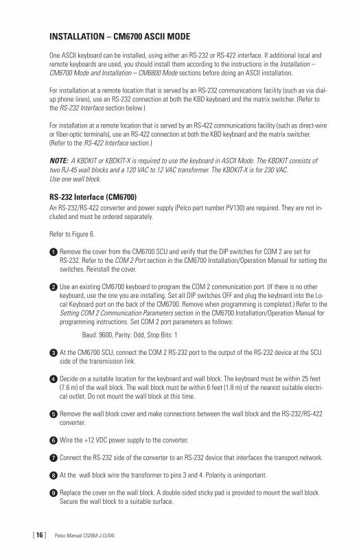
INSTALLATION – CM6700 ASCII MODE
One ASCII keyboard can be installed, using either an RS-232 or RS-422 interface. If additional local andremote keyboards are used, you should install them according to the instructions in the Installation –CM6700 Mode and Installation – CM6800 Mode sections before doing an ASCII installation.
For installation at a remote location that is served by an RS-232 communications facility (such as via dial-up phone lines), use an RS-232 connection at both the KBD keyboard and the matrix switcher. (Refer tothe RS-232 Interface section below.)
For installation at a remote location that is served by an RS-422 communications facility (such as direct-wireor fiber-optic terminals), use an RS-422 connection at both the KBD keyboard and the matrix switcher.(Refer to the RS-422 Interface section.)
NOTE: A KBDKIT or KBDKIT-X is required to use the keyboard in ASCII Mode. The KBDKIT consists oftwo RJ-45 wall blocks and a 120 VAC to 12 VAC transformer. The KBDKIT-X is for 230 VAC.Use one wall block.
RS-232 Interface (CM6700)An RS-232/RS-422 converter and power supply (Pelco part number PV130) are required. They are not in-cluded and must be ordered separately.
Refer to Figure 6.
� Remove the cover from the CM6700 SCU and verify that the DIP switches for COM 2 are set forRS-232. Refer to the COM 2 Port section in the CM6700 Installation/Operation Manual for setting theswitches. Reinstall the cover.
� Use an existing CM6700 keyboard to program the COM 2 communication port. (If there is no otherkeyboard, use the one you are installing. Set all DIP switches OFF and plug the keyboard into the Lo-cal Keyboard port on the back of the CM6700. Remove when programming is completed.) Refer to theSetting COM 2 Communication Parameters section in the CM6700 Installation/Operation Manual forprogramming instructions. Set COM 2 port parameters as follows:
Baud: 9600, Parity: Odd, Stop Bits: 1
� At the CM6700 SCU, connect the COM 2 RS-232 port to the output of the RS-232 device at the SCUside of the transmission link.
� Decide on a suitable location for the keyboard and wall block. The keyboard must be within 25 feet(7.6 m) of the wall block. The wall block must be within 6 feet (1.8 m) of the nearest suitable electri-cal outlet. Do not mount the wall block at this time.
� Remove the wall block cover and make connections between the wall block and the RS-232/RS-422converter.
� Wire the +12 VDC power supply to the converter.
� Connect the RS-232 side of the converter to an RS-232 device that interfaces the transport network.
� At the wall block wire the transformer to pins 3 and 4. Polarity is unimportant.
Replace the cover on the wall block. A double-sided sticky pad is provided to mount the wall block.Secure the wall block to a suitable surface.

Pelco Manual C526M-J (3/04) [ 17 ]
LOCALKEYBOARD
1
2
3
4
5
6
7
8
12 VA C
KBDKITRJ-45 WALL BLOCK
TERMINALS
RS-232 RS-422
CM6700SCU
RS-232 DEVICE
RS-232 DEVICE
PV130RS-232/RS-422
CONVERTERRD (B)RD (A)
TD (A)TD (B)
TX+TX-
TERMINAL
RX-RX+
POWERSUPPLY
+12 VDC GND
9-PIN, MALECONNECTORON CONVERTER
CUSTOMER SUPPLIED WIRING.50 FEET MAXIMUM DISTANCE.
MAXIMUM DISTANCEOF 4,000 FEET. USESHIELDED TWISTEDPAIRS SUCH AS BELDEN9843 OR EQUIVALENT.
SCU COM 2 PIN 7 (TX+) 9 (GND) 12 (RX+)
12
6
7
13
5 8
RS-232 CUSTOMER SUPPLIED WIRING.50 FEET MAXIMUM DISTANCE.
3
KBD200A
4
25-FOOTKEYBOARDDATA CABLE
10
WALL BLOCK
1
2
3
14POWERUP
SCU
9REPLACECOVER
11SET SWITCHES
DB9 PINS3(TX+)2(RX+)
5(GND)
ANY RS-232 NETWORK
TRANSPORTNETWORK
1
2
3
4 5
6
7
8
NOTE: A SEPARATE PATH MUST BE PROVIDED FOR VIDEO TO THE MONITOR.
� Set the keyboard DIP switches for ASCII Mode according to the instructions in the Switch Settingssection.
� Plug in the keyboard data cable.
Plug the +12 VDC power supply into a suitable outlet.
� Plug the KBDKIT or KBDKIT-X transformer into a suitable outlet.
� Apply power to the CM6700 SCU (if not already powered). To initialize the keyboard, wait five sec-onds after power-up, enter the number for the monitor you are viewing (1-4), and press MON. The LEDdisplay shows the number entered. You can now use the keyboard to perform all normal keyboardfunctions except you cannot program the CM6700.
� Go to the Programming and Operation section and program and test for proper operation.
Figure 6. RS-232 Interface connections (CM6700)
[ 18 ] Pelco Manual C526M-J (3/04)
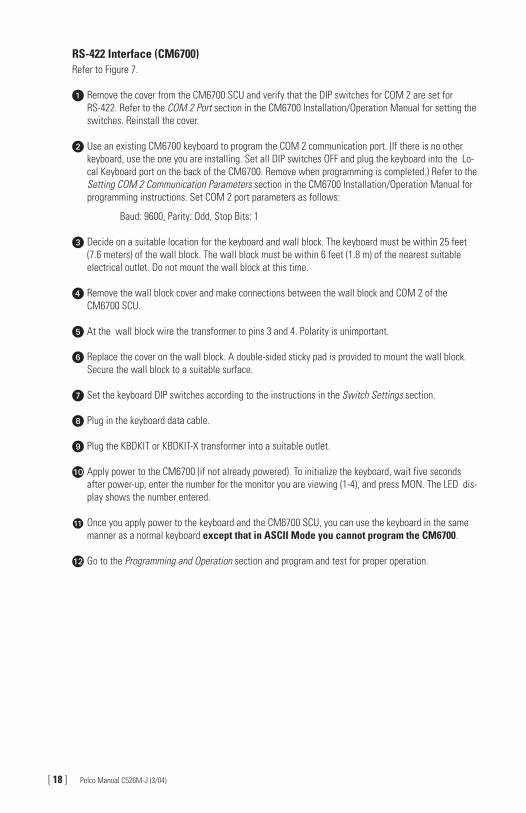
RS-422 Interface (CM6700)Refer to Figure 7.
� Remove the cover from the CM6700 SCU and verify that the DIP switches for COM 2 are set forRS-422. Refer to the COM 2 Port section in the CM6700 Installation/Operation Manual for setting theswitches. Reinstall the cover.
� Use an existing CM6700 keyboard to program the COM 2 communication port. (If there is no otherkeyboard, use the one you are installing. Set all DIP switches OFF and plug the keyboard into the Lo-cal Keyboard port on the back of the CM6700. Remove when programming is completed.) Refer to theSetting COM 2 Communication Parameters section in the CM6700 Installation/Operation Manual forprogramming instructions. Set COM 2 port parameters as follows:
Baud: 9600, Parity: Odd, Stop Bits: 1
� Decide on a suitable location for the keyboard and wall block. The keyboard must be within 25 feet(7.6 meters) of the wall block. The wall block must be within 6 feet (1.8 m) of the nearest suitableelectrical outlet. Do not mount the wall block at this time.
� Remove the wall block cover and make connections between the wall block and COM 2 of theCM6700 SCU.
� At the wall block wire the transformer to pins 3 and 4. Polarity is unimportant.
� Replace the cover on the wall block. A double-sided sticky pad is provided to mount the wall block.Secure the wall block to a suitable surface.
� Set the keyboard DIP switches according to the instructions in the Switch Settings section.
� Plug in the keyboard data cable.
Plug the KBDKIT or KBDKIT-X transformer into a suitable outlet.
� Apply power to the CM6700 (if not already powered). To initialize the keyboard, wait five secondsafter power-up, enter the number for the monitor you are viewing (1-4), and press MON. The LED dis-play shows the number entered.
� Once you apply power to the keyboard and the CM6700 SCU, you can use the keyboard in the samemanner as a normal keyboard except that in ASCII Mode you cannot program the CM6700.
Go to the Programming and Operation section and program and test for proper operation.
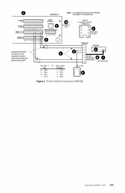
Pelco Manual C526M-J (3/04) [ 19 ]
KBDKITRJ-45 WALL BLOCK
TERMINALSPOWERUP
SCU
REPLACECOVER
SCU COM 2 PIN 12 (RX+) 11 (RX-) 8 (TX-) 7 (TX+)
WALL BLOCK TERMINAL 1 (TX+) 2 (TX-) 7 (RX-) 8 (RX+)
TO
1
2
3
4 5
6
7
8
10
SET SWITCHES
LOCALKEYBOARD
1
2
3
4
5
6
7
8
12 VA C
CM6700SCU
TERMINAL
MAXIMUM DISTANCEOF 4,000 FEET. USESHIELDED TWISTEDPAIRS SUCH AS BELDEN9843 OR EQUIVALENT.
KBD200A
25-FOOTKEYBOARDDATA CABLE
1
2
4
35
74
9
6
8
NOTE: A SEPARATE PATH MUST BE PROVIDED FOR VIDEO TO THE MONITOR.
Figure 7. RS-422 Interface Connections (CM6700)

[ 20 ] Pelco Manual C526M-J (3/04)
INSTALLATION – CM6800 ASCII MODE
RS-232 Interface (CM6800)An RS-232/RS-422 converter and power supply (Pelco part number PV130) are required. They are not in-cluded and must be ordered separately.
Refer to Figures 8 (CM6800-48X8 shown) and 10.
� Use an existing CM6800 keyboard to program the COM 1, 2, 7, or 8 communication port for theCM6800-48X8 or COM 1 or 2 communication port for the CM6800-32X6. (If there is no other key-board, use the one you are installing. Set all DIP switches OFF and plug the keyboard into the LocalKeyboard port on the back of the CM6800. Remove when programming is complete.)
� Do the following to program the COM port:
a. Press the PGM key. At the prompt, enter the password (default is 2899100). The CM6800 MainMenu appears.
b. Select PORT. The Set Serial Port screen appears.
c. Select the number of the desired port.
d. Set COM port parameters as follows: Device: ASCII, Type: RS-232, Baud: 9600, Parity: Odd, DataBits: 8, Stop Bits: 1.
e. Select RETURN, and RETURN again.
� At the CM6800, connect the COM 1, 2, 7, or 8 RS-232 port (CM6800-48X8) or COM 1 or 2 RS-232 port(CM6800-32X6) to the output of the RS-232 device on the CM6800 side of the transmission link.
� Decide on a suitable location for the keyboard and wall block. The keyboard must be within 25 feet(7.6 m) of the wall block. The wall block must be within 6 feet (1.8 m) of the nearest suitable electri-cal outlet. Do not mount the wall block yet.
� Remove the wall block cover and make the connections between the wall block and theRS-232/RS-422 converter.
� Wire the +12 VDC power supply to the converter.
� Connect the RS-232 side of the converter to an RS-232 device that interfaces the transport network.
� At the wall block, wire the transformer to pins 3 and 4. Polarity is unimportant.
Replace the cover on the wall block. Use the double-sided sticky pad to mount the wall block to asuitable surface.
� Set the keyboard DIP switches according to the instructions in the Switch Settings section.
� Plug in the keyboard data cable.
Plug the +12 VDC power supply into a suitable outlet.
� Plug the KBDKIT or KBDKIT-X transformer into a suitable outlet.

Pelco Manual C526M-J (3/04) [ 21 ]
1
2
3
4
5
67
8
12 VAC
KBDKITRJ-45 WALL BLOCK
TERMINALS
RS-232 RS-422
RS-232 DEVICE
RS-232 DEVICE
PV130RS-232/RS-422CONVERTER
RD (B)RD (A)
TD (A)TD (B)
TX+TX-
TERMINAL
RX-RX+
POWERSUPPLY
+12 VDC GND
9-PIN, MALECONNECTORON CONVERTER
CUSTOMER -SUPPLIED WIRING.50 FEET MAXIMUM DISTANCE.
TX
GNDRX
7KBD200A
25-FOOTKEYBOARDDATA CABLE
WALLBLOCK
REPLACECOVER
SETSWITCHES
DB9 PINS3(TX+)2(RX+)5(GND)
ANY RS-232 NETWORK
TRANSPORTNETWORK
1
2
3
4 5
6
7
8
6
12 13
5 84
11 10
9
3
MAXIMUM DISTANCEOF 4,000 FEET. USESHIELDED TWISTEDPAIRS SUCH AS BELDEN9843 OR EQUIVALENT.
CUSTOMER -SUPPLIED WIRING.50 FEET MAXIMUM DISTANCE.
C O M 1
1
2
3
4
5
6
7
8
16
87
3231
43
VIDE O O UTPUTS120/230~50/60 HZ
25 WATT S
C O M
AL AR M1 2 3 4 5 6 7 8
C O NTR O L
PTZ
O UT
A T+
T-
R+
R-
T+
T-
R+
R-
B
1 2
F3
COM 1, 2, 7, OR 8
14 POWER UP SCU
NOTE: A SEPARATE PATH MUST BE PROVIDED FOR VIDEO TO THE MONITOR.
1
NOTE: SEE FIGURE 11 FOR PIN-OUTS
PELCO SWITCHERMODEL CM6800
MAIN MENU
1 CAMERA2 LOGICAL CAMERA3 MONITOR4 ACCESS5 TIME & DATE6 PORT7 PRIORITY8 SEQUENCE9 MACRO
10 ALARM CONTACTS11 EVENT TIMER12 SET AUXILIARY MENU13 SET PASSWORD14 ABOUT CM6800
ENGLISH
RETURN
SET SERIAL PORT 05
2
CM6800
DEVICE:TYPE:BAUD RATE:PARITY:DATA BITS:STOP BITS:
ASCIIRS2329600ODD81
RETURN
RS-232
4
01235
� Apply power to the CM6800 (if not already powered). To initialize the keyboard, wait five secondsafter power-up, enter the number for the monitor you are viewing, and press MON. The LED displayshows the number entered. You can now use the keyboard to perform all normal keyboard functions,except you cannot program the CM6800.
� Go to the Programming and Operation section and program and test for proper operation.
Figure 8. RS-232 Interface Connections (CM6800-48X8 Shown)

[ 22 ] Pelco Manual C526M-J (3/04)
RS-485 Interface (CM6800)Refer to Figures 9 (CM6800-48X8 shown) and 10.
� Use an existing CM6800 keyboard to program the COM 4, 7, or 8 communication port (CM6800-48X8) orCOM 4 communications port (CM6800-32X6). (If there is no other keyboard, use the one you are install-ing. Set all DIP switches OFF and plug the keyboard into the Local Keyboard port on the back of theCM6800. Remove when programming is complete.)
� Do the following to program the COM port:
a. Press the PGM key. At the prompt, enter the password (default is 2899100). The CM6800 MainMenu appears.
b. Select PORT. The Set Serial Port screen appears.
c. Select the number of the desired port.
d. Set COM port parameters as follows: Device: ASCII, Type: RS-485, Baud: 9600, Parity: Odd, DataBits: 8, Stop Bits: 1.
e. Select RETURN, and RETURN again.
� Decide on a suitable location for the keyboard and wall block. The keyboard must be within 25 feet(7.6 m) of the wall block. The wall block must be within 6 feet (1.8 m) of the nearest suitable electri-cal outlet. Do not mount the wall block yet.
� Remove the wall block cover and make connections between the wall block and COM 4, 7, or 8 of theCM6800-48X8 or COM 4 of the CM6800-32X6.
� At the wall block, wire the transformer to pins 3 and 4. Polarity is unimportant.
� Replace the cover on the wall block. Use the double-sided sticky pad to mount the wall block to asuitable surface.
� Set the keyboard DIP switches according to the instructions in the Switch Settings section.
� Plug in the keyboard data cable.
Plug the KBDKIT or KBDKIT-X transformer into a suitable outlet.
� Apply power to the CM6800 (if not already powered). To initialize the keyboard, wait five secondsafter power-up, enter the number for the monitor you are viewing (1-8), and press MON. The LED dis-play shows the number entered. Once you apply power to the keyboard and the CM6800, you can usethe keyboard in the same way as a normal keyboard except that in ASCII Mode you cannot pro-gram the CM6800.
� Go to the Programming and Operation section and program and test for proper operation.

Pelco Manual C526M-J (3/04) [ 23 ]
C O M 1
1
2
3
4
5
6
7
8
16
87
3231
43
VIDE O O UTPUTS120/230~50/60 HZ
25 WATT S
C O M
AL AR M1 2 3 4 5 6 7 8
C O NTR O L
PTZ
O UT
A T+
T-
R+
R-
T+
T-
R+
R-
B
1 2
F3
COM 4, 7, OR 8
6
NOTE: A SEPARATE PATH MUST BE PROVIDED FOR VIDEO TO THE MONITOR.
10
NOTE: SEE FIGURE 11 FOR PIN-OUTS
CM6800
1 (TX+) 2 (TX-) 7 (RX-) 8 (RX+)
1
2
3
4 5
6
7
8
1
2
3
4
56
7
8
1 2 VAC
KBD200A
MAXIMUM DISTANCEOF 4,000 FEET. USESHIELDED TWISTEDPAIRS SUCH AS BELDEN9843 OR EQUIVALENT.
WALL BLOCKTERMINAL
TERMINAL
3
8 7
9
45
4
SET SWITCHES
25-FOOTKEYBOARDDATA CABLE
1
POWER UPSCU
PELCO SWITCHERMODEL CM6800
MAIN MENU
1 CAMERA2 LOGICAL CAMERA3 MONITOR4 ACCESS5 TIME & DATE6 PORT7 PRIORITY8 SEQUENCE9 MACRO
10 ALARM CONTACTS11 EVENT TIMER12 SET AUXILIARY MENU13 SET PASSWORD14 ABOUT CM6800
ENGLISH
RETURN
SET SERIAL PORT 05
2
DEVICE:TYPE:BAUD RATE:PARITY:DATA BITS:STOP BITS:
ASCIIRS4859600ODD81
RETURN
KBDKITRJ-45 WALL BLOCK
TERMINALS
REPLACECOVER
01231
Figure 9. RS-485 Interface Connections (CM6800-48X8 Shown)

[ 24 ] Pelco Manual C526M-J (3/04)
Figure 10. COM Port Connections and RJ-45 Connector Pin-Outs
PIN 1
PIN 8
COM PORTS 1, 2RS-232
PIN 1
PIN 8
COM PORT 3M, RS-485
PIN 1
PIN 8
COM PORT 4RS-485
PIN 1
PIN 8
COM PORTS 5, 6RS-485
1-----Rx2-----NC3-----NC45-----GROUND678-----Tx
-----NC
-----NC-----NC
1-----MRx+2-----MRx-345-----GROUND6-----NC7-----MTx-8-----MTx+
-----NC-----NC
1-----Rx+2-----Rx-345-----GROUND6-----NC7-----Tx-8-----Tx+
-----NC-----NC
PIN 1
PIN 8
COM PORTS 7, 8RS-485 (PROGRAMMABLETO RS-232)
RS-232 FUNCTIONRS-485 FUNCTION
1-----Rx+2-----Rx-345-----GROUND6-----NC7-----Tx-8-----Tx+
-----KBD 12V-----KBD GROUND
1-----Rx+2-----Rx-345-----GROUND6-----NC7-----Tx-8-----Tx+
-----NC-----NC
1-----Rx2345-----GROUND6-----NC7-----NC8-----Tx
-----NC-----NC-----NC
NC = NO CONNECTION01232

Pelco Manual C526M-J (3/04) [ 25 ]
ON
1 2 3 4 5 6 7 8
}
PIN 1
1 TX+ 5 GND2 TX– 63 12 VAC/DC 7 RX–4 NONPOLAR 8 RX+
KBD200 RJ-45JACK PINOUTS1
3
1
32
DOWN = ON
Figure 11. Keyboard Rear Panel
SWITCH SETTINGS
To set the switches on the keyboard (refer to Figure 11):
� Remove the two screws and the DIP switch cover plate from the rear of the keyboard.
� Set the switches:
• Address (Switches 1-4)Position the switches according to Table B. Each keyboard in the system must have a differentaddress, including the local keyboard. To make programming easier, address keyboards in as-cending order.NOTE: CM6700 accepts only eight addresses.
Table B. Keyboard Addresses
Keyboard Switch Settings1 2 3 4
1 OFF OFF OFF OFF2 ON OFF OFF OFF3 OFF ON OFF OFF4 ON ON OFF OFF5 OFF OFF ON OFF6 ON OFF ON OFF7 OFF ON ON OFF8 ON ON ON OFF9 OFF OFF OFF ON
10 ON OFF OFF ON11 OFF ON OFF ON12 ON ON OFF ON13 OFF OFF ON ON14 ON OFF ON ON15 OFF ON ON ON16 ON ON ON ON
• Mode (Switches 5, 6, 8)Position the switches according to Table C. Switch 7 is not used.
Table C. Keyboard Modes
CM6700/CM6800** Direct P** CM6700 ASCII CM6800 ASCII Direct D CM9760-MDA*Switch 5 OFF ON OFF OFF ON ONSwitch 6 OFF OFF ON ON ON OFFSwitch 8 OFF OFF OFF ON OFF ON
**Firmware version 4.00 and higher. **Firmware version 4.20 and higher automatically recognizes CM6700/CM800 and Direct P Mode.
� Replace the cover plate.

[ 26 ] Pelco Manual C526M-J (3/04)
PROGRAMMING AND OPERATION
Table D. Keyboard FunctionsCircled numbers refer to Figure 13.
Function ProcedureSelect Monitor* LED display � shows monitor number in run mode.
Enter monitor number (1-4) � and press MON � to select.Select Camera Enter camera number (1-16) � and press CAM � to select.
NOTE: The CM6700 and CM6800 can be programmed to restrict some monitorsfrom viewing certain cameras. To display a camera’s view on your monitor, besure that your keyboard shows the number of the monitor you are viewing andbe sure that the CM6700 or CM6800 has not been programmed to restrict view-ing of that camera.
Pan/Tilt Press and hold the appropriate pan/tilt key until the camera reaches the de-sired position. To change the speed of movement, press a number (1-9) key �first (1=slowest, 9=fastest).
Lens Control Focus, zoom, iris – Press and hold the appropriate lens control key � until thedesired effect is seen. To change the speed of focus, press a number(1-4) key �, then press FAR �.
Presets Enter preset number (1-66) � and press PRESET to put camera in preset po-sition.To program, position camera, enter desired preset number (1-66) �, and holddown PRESET for two seconds.In CM6700 and CM6800 modes, a label appears on the monitor. Use F1 andF2 � to edit the label, and then select SET and press ACK � or the pan rightkey .
Patterns Programming and operation varies with the receiver type.Spectra® domes (before version 3.0) can use one long (1 minute) or twoshort (0.5 minute) patterns. Spectra domes (version 3.0), Spectra II™ domesand Esprit® Integrated Positioning Systems can use one long (1.5, 3 or 6minutes) or two short (0.75, 1.5 or 3 minutes) patterns. (Select pattern lengths atthe positioning system’s menu.) Spectra III™ can use four patterns of varyinglength (all drawing from the same block of memory, which is almost infinite).To program Spectra and Esprit, select a camera (1-16) �, select a long pattern byholding down PATTERN � for two seconds, or select short pattern 1 or 2 by en-tering 1 or 2 � and holding down PATTERN � for two seconds. The monitorwill indicate the programming function is active. Move the camera position asdesired for the pattern and press ACK � to close the programming function.To run a long pattern, press PATTERN �. To run a short pattern, enter 1 or 2 �and press PATTERN �. Press a pan/tilt key or call a preset to stop.Direct Mode is the same as above, except:Do not program a pattern with pan/tilt speed set to 9.To program Spectra III, enter 95, an then hold down PRESET for about fiveseconds until the main menu appears. Use the PAN/TILT keys to position thecursor beside Patterns, and then press IRIS OPEN �. Position the cursor besidePattern Number, and then press IRIS OPEN. Position the cursor beside ProgramPattern, and then press IRIS OPEN. Follow the directions displayed on themonitor.Another way to program the Spectra III is by pressing the pattern number (1-4)� and then PATTERN � for two seconds.To run a Spectra III pattern, press the pattern number (1-4) � and thenPATTERN �. Press a PAN/TILT key to stop.
*This function is not used in Direct Mode.

Pelco Manual C526M-J (3/04) [ 27 ]
Continued on next page
Table D. Keyboard Functions (continued)
Function Procedure
Sequence* Sequence steps through all 16 cameras. Camera number, camera title,sequence status, and time/date are shown on the monitor.Press PREV 4A to step back one camera. Hold for two seconds for a backwardsequence. Monitor shows B. Press during sequence to speed up. Press during aforward sequence to reverse.Press NEXT 4B to step forward one camera. Hold for two seconds for a forwardsequence. Monitor shows F. Press during sequence to speed up. Press during abackward sequence to go forward.Press HOLD 4C to hold a sequence. Monitor shows H. Press HOLD to resume.Manually select a camera or press CAM � to turn off a sequence. Monitorshows O.
Macro Sequence* Enter 1 or 2 � and press MACRO � to start a group camera sequence. Monitorshows M. Refer to the CM6700 manual for macro/sequence programming.
Multiplexer Press SHIFT �. Shift key LED � lights. The function keys F1 through F5Displays* can now be used to display the images from multiple cameras on the monitor.
F1/LATCH: ZoomF2/OFF: PIP displayF3/MOM: Quad displayAUX ON: 9-screen displayAUX OFF: 16-screen display
Auxiliaries/Relays For the CM6700:F1 – F3 � control only the auxiliaries built into the CM6700 SCU.These outputs can be programmed for momentary, keyed, latched, or alarm op-eration. Refer to the CM6700 manual for programming instructions.F1/LATCH: Activate/deactivate auxiliary 1 relay.*F2/OFF: Activate/deactivate switcher auxiliary 2 TTL output.*F3/MOM: Activate/deactivate switcher auxiliary 3 TTL output.*The AUX ON and AUX OFF keys � control the auxiliaries in receivers.Enter the auxiliary number, and then press AUX ON key to turn on. Hold, andthen release for momentary functions.Enter the auxiliary number, and then press the AUX OFF key to turn off.
For the CM6800:F1 – F3 � can address auxiliary functions on the CM6800 and on the REL2064(a separate auxiliary relay box) to provide additional auxiliary points.F1/LATCH: Enter the auxiliary number and press and release F1 to turn on anauxiliary (latching).F2/OFF: Enter the auxiliary number and press and release F2 to turn off an auxil-iary (latching).F3/MOM: Enter the auxiliary number and press and hold down F3 to turn on anauxiliary (momentary). Release F3 to turn off the auxiliary.
Direct Mode:In Direct Mode, F1- F3 � have no function. LED � shows receiver auxiliary num-ber for two seconds after the AUX ON or AUX OFF � is pressed.
Acknowledge Alarm* Press ACK � to acknowledge an alarm. Refer to the CM6700 or CM6800manual for further information on alarms.

[ 28 ] Pelco Manual C526M-J (3/04)
Table D. Keyboard Functions (continued)
Function Procedure
Program For the CM6700:
(CM6700) To program the CM6700 switcher, press PGM �.(CM6800) Follow the programming procedure in the CM6700 manual. LED display �
** shows P in program mode. To exit, naviate to the RETURN field and press ACK� or the pan right key .For the CM6800:
To program the CM6800 switcher, press PGM �.Follow the programming procedure in the CM6800 manual. To exit, navigate tothe RETURN field and press the pan right key . Or, press the PGM key � to return to the previous screen or menu.
LED LED � shows monitor number (in CM6700, CM6800, and ASCII modes) or camera/receiver number (in Direct Mode) and P (in Program Mode).
Firmware Version LED � flashes for a few seconds to show firmware version on power up (notfunctional on versions prior to 4.0).
Clear Press CLEAR � to cancel a number that has been entered (CM6700/CM6800modes only). In Direct Mode, this key erases any numerical entries andredisplays the current camera number selected.
Infrared Filter This function applies to Spectra® color/black-white model SD5BCBW only.(IR Cut Filter) a. To turn on the filter: press 8, 8, PRESET .
b. To turn off the filter: press 8, 9, PRESET .Shift* Press SHIFT � to allow the keyboard to send multiplexer commands.
*This function is not used in Direct Mode.**This function is not used in ASCII Mode.
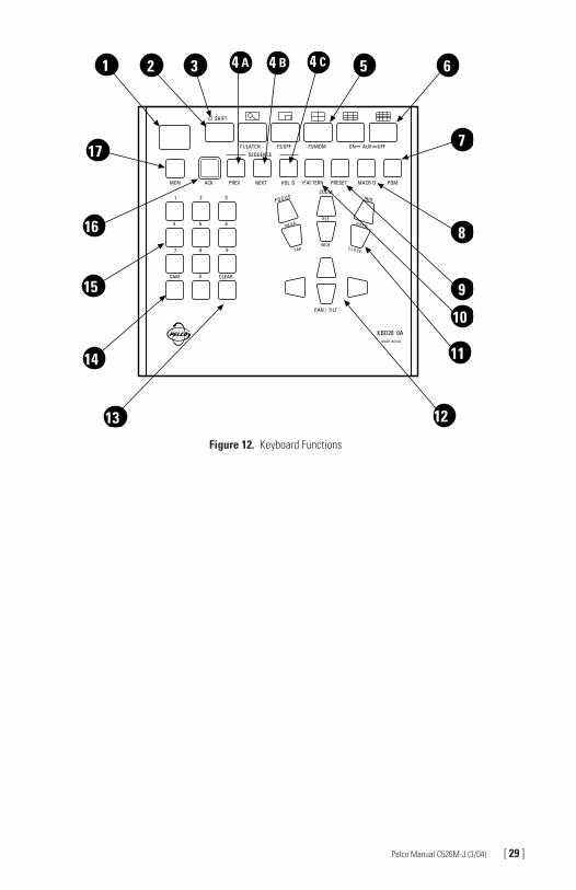
Pelco Manual C526M-J (3/04) [ 29 ]
SHIFT
SEQUENCE
MON ACK PREV NEXT HOL D P AT TERN PRESET MACR O PGM
F1/LATCH F2/OFF F3/MOM ON AUX OFF
ZOOM
PAN / TILT
KBD20 0A
TELE
WIDEC LO SEFAR
NE AR O PE N
FOCUS IRIS1 2 3
4 5 6
7 8 9
0 CLEARCAM
MADE IN USA.
11 2 3 4 5 6
7
8
9
10
11
1213
14
15
16
17
A 4 B 4 C
Figure 12. Keyboard Functions

[ 30 ] Pelco Manual C526M-J (3/04)
Table E. KBD200A Button Functions
Reference DescriptionNumber
1 LED display2 Shift key3 Shift key LED
4A-C Sequence keys: Previous, Next, Hold
5Function keys F1, F2, F3 control auxiliaries. With Shift on theycontrol multiplexer display.
6The AUX ON and AUX OFF keys control receiver auxiliaries. WithShift on they control multiplexer display.
7 Program key8 Macro sequence key9 Preset key
10 Pattern key11 Focus, zoom, iris keys
(iris keys can be used to scroll through menus on the CM6800 only)12 Pan and tilt keys13 Clear key14 Camera selection key15 Keypad (numbers 1 through 0)16 Acknowledge key17 Monitor selection key

Pelco Manual C526M-J (3/04) [ 31 ]
Table F. Operating Scan Functions with Various ReceiversFunction
Receiver Controlling Auto Random Frame Preset StopModel Protocol Scan Scan Scan Scan
All15-bit 97 97
96Pelco
(standard) Preset Preset N/A (2)PresetCoaxitron® (1) (3) (1)
98 PresetIRD2024 Extended or 97
N/A N/A96
ERD2200 Coaxitron 99 Preset Preset Preset(3)
All SpectraExt. Coax.,
99 97 9896
All EspritSerial Pelco
Preset Preset PresetN/A Preset
P or D or PTZ
LRD41C Ext. Coax., 99 9996(before Serial Pelco Preset Preset N/A N/A
Presetver. 2.98) P or D (1) (3) (1)
LRD41C Ext. Coax., 9997 96(ver 2.98 Serial Pelco Preset
PresetN/A N/A
Presetand later) P or D (3)
ERD97P21-U Serial Pelco P N/A 97 Preset 98 Preset N/A 96 Preset
(1) First entry starts random scan, next entry changes to auto scan, etc.(2) Enter dwell time (5-64 sec.) and press IRIS CLOSE.(3) Changes to random scan after 30 minutes.
Programming Limit StopsSpectra and Esprit can be programmed for scan and manual limit stops.
Program left limit before programming right limit. Locate camera at desired limit. Enter the set code fromTable G. Hold the PRESET key for two seconds. In CM6700 and CM6800 modes, a label appears on themonitor. Use F1 and F2 to edit the label, and then select SET and press ACK or the pan right key.
To cancel all limit stops, enter 95. Hold the preset key for two seconds. Use the up down tilt keys to movethe pointer to Other. Press IRIS OPEN. Move the pointer to Limit Stops. Press IRIS OPEN. Use the tilt keysto change limit stops to off. Press IRIS OPEN. Move the pointer to EXIT. Press IRIS OPEN. Move pointer toexit. Press IRIS OPEN.
Table G. Limit Set Codes
Direction Scan Limit Manual Limit
Left Limit 92 90
Right Limit 93 91
Scanning FunctionsOperation of the scanning functions depends on the kind of receiver or pan/tilt mechanism you have andthe operating mode of your keyboard (CM6700, CM6800, or Direct Mode).
There are four types of scanning functions: auto (moves camera back and forth between stops), random(moves camera in a random pattern), frame (moves camera back and forth in 10 degree steps), and preset (se-quences camera through all programmed presets, pausing between each).
Operate scans according to Table F.

[ 32 ] Pelco Manual C526M-J (3/04)
Zones
The Zone function is available on Esprit and Spectra positioning systems. This function puts a label on thescreen to identify the viewing area. Zones can also be blanked to prevent viewing while the camera is po-sitioned in the zone.
Up to eight pan (horizontal) zones can be defined (zones are not affected by tilt or zoom). Higher num-bered zones take precedence so that if zones overlap, the one with the higher number is in effect. Zoneprogramming is outlined in Table H.
Table H. Zone Programming Procedure
Step Procedure
1. Set left zone limit. a. Use the pan left/right keys to position the camera at the start (leftlimit) of the zone.
2. Access zone a. Press 8, followed by the zone number N (N = 1 through 8), and F4programming. to display the zone menu.
3. Define a label. a. Use F1 and F2 to find the characters for each position in the labelHINT: To ease (26 upper case letters, 26 lower case letters and 10 numbers).future title editing, b. Pan left/right to move between character positions. Continuestart each title with selecting characters until the title is completed (up to 20 charac-
ters).Z(N), where c. Move down to the SET field and press ACK or the pan right key.N = zone number.
4. Set right zone limit. a. Position camera at the right limit of the zone.b. Press 8, followed by the zone number, and F5.c. To view zone titles go to step 6.
5. Clear zones. a. Press 8, followed by the zone number, and F4.b. Move down to the SET field and press ACK.
NOTE: DO NOT pan right.c. Press 8, followed by the zone number, and F5.
6. Turn on zone labeling. a. Press 9, 1, F4.
7. Turn off zone labeling. a. Press 9, 2, F4.
8. Blank zones. a. Press 9, 5 and hold Preset for about 2 seconds to display the EditPreset 95 menu.
b. Move down to the SET field and press ACK.c. Move down to the <Alarms, Zone Blank> field and press Iris Open to
display the Alarms, Zone Blank menu.d. Move down to the <Zone Blank> field and press Iris Open to display
the Zone Blank menu.e. Move down to the zone number you wish to blank and press Iris
Open to move the cursor arrow to the zone blanking status value.f. Pan up to turn blanking on, pan down to turn blanking off.g. Press Iris Open to accept new status; press Iris Close to cancel.h. Repeat steps 8e through 8g for each zone you wish to change, and
then go to step 8i.i. Move down to Exit and press Iris Open repeatedly to move up
through the menus and return to the normal display.

Pelco Manual C526M-J (3/04) [ 33 ]
SPECIFICATIONS
GENERAL
Keyboard Keypad: Electromechanical
Digital Display: Red LED, 7-segment, 2 cells
Shift Mode Indicator: Green LED
Ambient Operating Temperature: 20° to 120°F (-7° to 49°C)
Humidity: 10–90% non-condensing
Dimensions: 8.125 (W) x 7.125 (D) x 2.25 (H) inches(20.64 x 18.10 x 5.72 cm)
Weight: 2.1 lb (0.95 kg)
ELECTRICAL
Input Voltage: 12 VAC or ±12 VDC
Power Consumption: 5 watts
Connector Type: RJ-45, 8-pin, modular (female)
Keyboard CommunicationCM6700/CM6800 Mode
Interface: RS-485Protocol: Pelco ASCIIBaud: 9600CommunicationParameters: 8 data bits, 1 stop bit, odd parity
CM6700 ASCII ModeInterface: RS-422Protocol: Pelco ASCIIBaud: 9600CommunicationParameters: 8 data bits, 1 stop bit, odd parity
CM6800 ASCII ModeInterface: RS-485Protocol: Pelco ASCIIBaud: 9600CommunicationParameters: 8 data bits, 1 stop bit, odd parity
Direct P ModeInterface: RS-485Protocol: Pelco PBaud: 4800CommunicationParameters: 8 data bits, 1 stop bit, no parity
Direct D ModeInterface: RS-485Protocol: Pelco DBaud: 2400CommunicationParameters: 8 data bits, 1 stop bit, no parity
(Design and product specifications subject to change without notice.)
[ 34 ] Pelco Manual C526M-J (3/04)
® Pelco, the Pelco logo, Spectra, Genex, Legacy, Coaxitron, Esprit and Camclosure are registered trademarks of Pelco.™ Spectra II and Spectra III are trademarks of Pelco.
© Copyright 2004, Pelco. All rights reserved.
WARRANTYPelco will repair or replace, without charge, any merchandise proved defective in material or workmanship for a period of one yearafter the date of shipment.
Exceptions to this warranty are as noted below:• Five years on Pelco manufactured cameras (CC3500/CC3600/CC3700 and MC3500/MC3600/MC3700 Series); two years on all
other cameras.• Three years on Genex® Series (multiplexers, server, and keyboard) and 090 Series Camclosure® Camera System.• Two years on 100/150, 200 and 300 Series Camclosure® Camera Systems.• Two years on cameras and all standard motorized or fixed focal length lenses.• Two years on Legacy®, CM6700/CM6800/CM8500/CM9500/CM9740/CM9760 Matrix, DF5 and DF8 Series Fixed Dome products.• Two years on Spectra®, Esprit®, and PS20 Scanners, including when used in continuous motion applications.• Two years on Esprit® and WW5700 series window wiper (excluding wiper blades).• Eighteen months on DX Series digital video recorders.• One year (except video heads) on video cassette recorders (VCRs). Video heads will be covered for a period of six months.• Six months on all pan and tilts, scanners or preset lenses used in continuous motion applications (that is, preset scan, tour and auto
scan modes).
Pelco will warrant all replacement parts and repairs for 90 days from the date of Pelco shipment. All goods requiring warranty repairshall be sent freight prepaid to Pelco, Clovis, California. Repairs made necessary by reason of misuse, alteration, normal wear, oraccident are not covered under this warranty.
Pelco assumes no risk and shall be subject to no liability for damages or loss resulting from the specific use or application made of theProducts. Pelco’s liability for any claim, whether based on breach of contract, negligence, infringement of any rights of any party orproduct liability, relating to the Products shall not exceed the price paid by the Dealer to Pelco for such Products. In no event will Pelcobe liable for any special, incidental or consequential damages (including loss of use, loss of profit and claims of third parties) howevercaused, whether by the negligence of Pelco or otherwise. The above warranty provides the Dealer with specific legal rights. The Dealermay also have additional rights, which are subject to variation from state to state.
If a warranty repair is required, the Dealer must contact Pelco at (800) 289-9100 or (559) 292-1981 to obtain a Repair Authorizationnumber (RA), and provide the following information:
1. Model and serial number2. Date of shipment, P.O. number, Sales Order number, or Pelco invoice number3. Details of the defect or problem
If there is a dispute regarding the warranty of a product which does not fall under the warranty conditionsstated above, please include a written explanation with the product when returned.Method of return shipment shall be the same or equal to the method by which the item was received byPelco.
RETURNSIn order to expedite parts returned to the factory for repair or credit, please call the factory at (800) 289-9100 or (559) 292-1981 toobtain an authorization number (CA number if returned for credit, and RA number if returned for repair).All merchandise returned for credit may be subject to a 20% restocking and refurbishing charge.Goods returned for repair or credit should be clearly identified with the assigned CA or RA number and freight should be prepaid.Ship to the appropriate address below.
If you are located within the continental U.S., Alaska, Hawaii or Puerto Rico, send goods to:Service DepartmentPelco3500 Pelco WayClovis, CA 93612-5699
If you are located outside the continental U.S., Alaska, Hawaii or Puerto Rico and are instructed to return goods to the USA, you maydo one of the following:
If the goods are to be sent by a COURIER SERVICE,send the goods to:Pelco3500 Pelco WayClovis, CA 93612-5699 USA
If the goods are to be sent by a FREIGHT FORWARDER,send the goods to:Pelco c/o Expeditors473 Eccles AvenueSouth San Francisco, CA 94080 USAPhone: 650-737-1700Fax: 650-737-0933
PRODUCT WARRANTY AND RETURN INFORMATION

Pelco Manual C526M-J (3/04) [ 35 ]
REVISION HISTORY
Manual # Date CommentsC526M 6/97 Original version.
4/98 Revised to add 230 VAC transformer and keyboard to parts list in Section 2.0. Clarified installationinstructions. Changed manual pagination.
C526M-A 5/98 Revised installation instructions as a result of hardware changes to the rear panel of the CM6700 SCU.Removed references to KBD200-X because model has been replaced with KBDKIT-X.
6/98 Added Section 1.2, Regulatory Notices and Section 2.1, Certifications.9/98 Revised Table A and Figure 4.
C526M-B 4/99 Completely revised manual.6/99 Revised the sequence key definitions. Added material on programming Spectra® features to the Direct
Mode Operation section.C526M-C 3/00 Added pattern programming and operation in Direct Mode Operation section to support revision 4
firmware. Added CM9760-MDA mode.C526M-D 7/00 Revised format.C526M-E 10/01 Added information about the CM6800 Matrix Switcher and additional functionality of the iris and pan right
keys.C526M-F 7/02 Revised keyboard drawings to reflect key labeling changes. Several procedures revised because of the
labeling change. Revised pattern programming in Table D to include procedures for Spectra III. Statedthat firmware versions 4.20 and higher automatically recognize CM6700/CM6800 and direct mode.
C526M-G 11/02 Updated with firmware version 5.00 information as per ECO 02-8447. Added two modes to theDescription and Installation sections and renamed ASCII Mode to CM6700 ASCII Mode. Revised TablesA, C, and D. Updated Specifications.
C526M-H 12/02 Revised Tables A, D, and H. Removed RS-232 from Specifications.C526M-I 9/03 Added UL certification seal and changed power specification.C526M-J 3/04 Revised directions for direct mode installation. Revised safety instructions. Changed FCC notice.
Removed references to use 18-gauge wiring for EIA RS-485 communication.
Luis Linarez
ROHS SMALL

®
World Headquarters3500 Pelco Way
Clovis, California 93612 USA
USA & CanadaTel: 800/289-9100Fax: 800/289-9150
InternationalTel: 1-559/292-1981Fax: 1-559/348-1120
www.pelco.com
ISO9001
Orangeburg, New York | Las Vegas, Nevada | Eindhoven, The Netherlands | Wokingham, United Kingdom | Montreal, Canada | Singapore