Pedestrian detection for driver assistance using multiresolution infrared vision
13
1666 IEEE TRANSACTIONS ON VEHICULAR TECHNOLOGY, VOL. 53, NO. 6, NOVEMBER 2004 Pedestrian Detection for Driver Assistance Using Multiresolution Infrared Vision Massimo Bertozzi, Associate Member, IEEE, Alberto Broggi, Associate Member, IEEE, Alessandra Fascioli, Member, IEEE, Thorsten Graf, and Marc-Michael Meinecke Abstract—This paper describes a system for pedestrian detec- tion in infrared images, which has been implemented on an exper- imental vehicle equipped with an infrared camera. The proposed system has been tested in many situations and has proven to be ef- ficient and with a very low false-positive rate. It is based on a mul- tiresolution localization of warm symmetrical objects with specific size and aspect ratio; anyway, because road infrastructures and other road participants may also have such characteristics, a set of matched filters is included in order to reduce false detections. A final validation process, based on human shape’s morphological characteristics, is used to build the list of pedestrian appearing in the scene. Neither temporal correlation nor motion cues are used in this first part of the project: the processing is based on the anal- ysis of single frames only. Index Terms—Infrared imagery, machine vision, multiresolu- tion, pedestrian detection. I. INTRODUCTION T HE development of in-vehicle assistance systems dedi- cated to reducing the number of fatalities and the severity of traffic accidents is an important and active research field. Since pedestrian accidents represent the second largest source of traffic-related injuries (annually, more than 200 000 pedestrians are injured and approximately 9000 are killed in traffic accidents in the European Union), systems that are capable of reducing the number or effects of traffic accidents involving pedestrians are of major interest. The tasks of such driver-assistance systems are extremely complex; the use of vision sensors and image-processing methods provides a promising approach. Several different image-processing methods and systems dedicated to detecting and classifying pedestrians have been developed in the last years, including shape-based [5], [6], texture-based [7], stereo [8], and motion [9] methods. An approach that combines motion and appearance information is presented in [10]. All of these approaches have to overcome the difficulties of different appearances of pedestrians in the visual domain, mainly caused by clothes, carryons, illumination changes, and—indeed—different postures. Manuscript received July 21, 2003; revised March 5, 2004 and May 13, 2004. This work was supported by Volkswagen AG. M. Bertozzi, A. Broggi, and A. Fascioli are with the Dipartimento di In- gegneria dell’Informazione, Università di Parma, Parma I-43100, Italy (e-mail: [email protected]; [email protected]; [email protected]). T. Graf and M.-M. Meinecke are with Electronic Research, Volkswagen AG, Wolfsburg D-38436, Germany (e-mail: [email protected]; [email protected]). Digital Object Identifier 10.1109/TVT.2004.834878 Only recently, thanks to the decreasing cost of infrared devices, the benefits and advantages of using infrared cameras have been actually considered (e.g., [3] and [11]). Some first pedestrian-detection systems have been developed, showing that infrared images can facilitate the recognition process [1], [12]. In this paper, we present a new pedestrian-detection method employing far infrared images. It is based on the following: 1) localization of warm symmetrical objects with specific aspect ratio and size; 2) filtering process to avoid a number of false positives; 3) final validation procedure based on human shape and thermal characteristics. The result is a list of pedestrians appearing in the scene, each detected by position, angle of view, height, and an approximate posture. The process is iterated at different image resolutions in order to detect both close and faraway pedestrians. The following as- sumptions have been made: 1) pedestrians are not occluded; 2) complete shape of the pedestrian appears in the image; 3) a number of pedestrians appear simultaneously in the image but they do not occlude each other. Although the proposed method does not perform tracking, ex- perimental results demonstrate its robustness and effectiveness. In Section II, considerations on the infrared domain are pro- vided. Section III shows how design choices affect the detection range and Section IV describes the approach and algorithm. Fi- nally, Section V discusses the results and concludes the paper with some final considerations. The images produced by our software have been modified by hand in order to adapt to grayscale printing. II. CHARACTERIZATION OF THE INFRARED (IR) DOMAIN Images in the IR domain convey a type of information that is very different from images in the visible spectrum. Basically, in the visible spectrum, the image of an object depends on the amount of incident light on its surface and on how well the sur- face reflects it. On the other hand, in the IR domain, the image of an object relates to its temperature and the amount of heat it emits. Generally, the temperature of people is higher than the envi- ronment temperature and their heat radiation is sufficiently high compared to the background. Therefore, in IR, images pedes- trians belong to the upper range in the gray-level scale and are sufficiently contrasted with respect to the surroundings, thus 0018-9545/04$20.00 © 2004 IEEE
-
Upload
independent -
Category
Documents
-
view
1 -
download
0
Transcript of Pedestrian detection for driver assistance using multiresolution infrared vision

1666 IEEE TRANSACTIONS ON VEHICULAR TECHNOLOGY, VOL. 53, NO. 6, NOVEMBER 2004
Pedestrian Detection for Driver Assistance UsingMultiresolution Infrared Vision
Massimo Bertozzi, Associate Member, IEEE, Alberto Broggi, Associate Member, IEEE,Alessandra Fascioli, Member, IEEE, Thorsten Graf, and Marc-Michael Meinecke
Abstract—This paper describes a system for pedestrian detec-tion in infrared images, which has been implemented on an exper-imental vehicle equipped with an infrared camera. The proposedsystem has been tested in many situations and has proven to be ef-ficient and with a very low false-positive rate. It is based on a mul-tiresolution localization of warm symmetrical objects with specificsize and aspect ratio; anyway, because road infrastructures andother road participants may also have such characteristics, a setof matched filters is included in order to reduce false detections.A final validation process, based on human shape’s morphologicalcharacteristics, is used to build the list of pedestrian appearing inthe scene. Neither temporal correlation nor motion cues are usedin this first part of the project: the processing is based on the anal-ysis of single frames only.
Index Terms—Infrared imagery, machine vision, multiresolu-tion, pedestrian detection.
I. INTRODUCTION
THE development of in-vehicle assistance systems dedi-cated to reducing the number of fatalities and the severity
of traffic accidents is an important and active research field.Since pedestrian accidents represent the second largest source oftraffic-related injuries (annually, more than 200 000 pedestriansare injured and approximately 9000 are killed in traffic accidentsin the European Union), systems that are capable of reducing thenumber or effects of traffic accidents involving pedestrians areof major interest.
The tasks of such driver-assistance systems are extremelycomplex; the use of vision sensors and image-processingmethods provides a promising approach.
Several different image-processing methods and systemsdedicated to detecting and classifying pedestrians have beendeveloped in the last years, including shape-based [5], [6],texture-based [7], stereo [8], and motion [9] methods. Anapproach that combines motion and appearance information ispresented in [10]. All of these approaches have to overcomethe difficulties of different appearances of pedestrians in thevisual domain, mainly caused by clothes, carryons, illuminationchanges, and—indeed—different postures.
Manuscript received July 21, 2003; revised March 5, 2004 and May 13, 2004.This work was supported by Volkswagen AG.
M. Bertozzi, A. Broggi, and A. Fascioli are with the Dipartimento di In-gegneria dell’Informazione, Università di Parma, Parma I-43100, Italy (e-mail:[email protected]; [email protected]; [email protected]).
T. Graf and M.-M. Meinecke are with Electronic Research, VolkswagenAG, Wolfsburg D-38436, Germany (e-mail: [email protected];[email protected]).
Digital Object Identifier 10.1109/TVT.2004.834878
Only recently, thanks to the decreasing cost of infrareddevices, the benefits and advantages of using infrared camerashave been actually considered (e.g., [3] and [11]). Some firstpedestrian-detection systems have been developed, showingthat infrared images can facilitate the recognition process [1],[12].
In this paper, we present a new pedestrian-detection methodemploying far infrared images. It is based on the following:
1) localization of warm symmetrical objects with specificaspect ratio and size;
2) filtering process to avoid a number of false positives;3) final validation procedure based on human shape and
thermal characteristics.The result is a list of pedestrians appearing in the scene, eachdetected by position, angle of view, height, and an approximateposture.
The process is iterated at different image resolutions in orderto detect both close and faraway pedestrians. The following as-sumptions have been made:
1) pedestrians are not occluded;2) complete shape of the pedestrian appears in the image;3) a number of pedestrians appear simultaneously in the
image but they do not occlude each other.Although the proposed method does not perform tracking, ex-perimental results demonstrate its robustness and effectiveness.
In Section II, considerations on the infrared domain are pro-vided. Section III shows how design choices affect the detectionrange and Section IV describes the approach and algorithm. Fi-nally, Section V discusses the results and concludes the paperwith some final considerations.
The images produced by our software have been modified byhand in order to adapt to grayscale printing.
II. CHARACTERIZATION OF THE INFRARED (IR) DOMAIN
Images in the IR domain convey a type of information thatis very different from images in the visible spectrum. Basically,in the visible spectrum, the image of an object depends on theamount of incident light on its surface and on how well the sur-face reflects it. On the other hand, in the IR domain, the imageof an object relates to its temperature and the amount of heat itemits.
Generally, the temperature of people is higher than the envi-ronment temperature and their heat radiation is sufficiently highcompared to the background. Therefore, in IR, images pedes-trians belong to the upper range in the gray-level scale and aresufficiently contrasted with respect to the surroundings, thus
0018-9545/04$20.00 © 2004 IEEE

BERTOZZI et al.: PEDESTRIAN DETECTION FOR DRIVER ASSISTANCE USING MULTIRESOLUTION INFRARED VISION 1667
Fig. 1. The position of the infrared camera on the VW test vehicle.
making IR imagery particularly suited to pedestrians localiza-tion. Obviously, other objects that actively radiate heat, such asautomobiles, trucks, busses, and motorcycles, have a similar be-havior; however, people can be recognized thanks to their shapeand aspect ratio.
One major point in favor of IR cameras is their independenceof light conditions: they can be used in the daytime or nighttimewith little or no difference, extending vision beyond the usuallimitations of daylight cameras. Moreover, the absence of colorsor textures eases the processing toward interpretation. Further-more, the problem of shadows is greatly reduced. In fact, even ifpersistent shadows are still present in IR images—due to the dif-ferent temperatures caused by shadows themselves—incidentalshadows, which do not modify the temperature of bodies, arenot perceivable.
Nevertheless, the problem of detecting humans in IR imagesis far from being trivial. Weather conditions, such as heavy fogor rain, can modify the thermal footprint of bodies, limiting theeffectiveness of IR systems.
Moreover, conditions of high temperature and strong sunheating can decrease the difference of temperature betweenpedestrians and other objects. In fact, objects that have apassive heat radiation behavior, such as traffic signs, barriers,trees, buildings, and road markings, may be strongly heatedby the sun, making the scene more complex or even causingheat radiations or reflections. In addition, in the case of strongexternal heat radiation, clothes that people wear can havedifferent thermal behavior depending on their type and color,thus adding texture to the image.
Conversely, in the case of low external temperature, clothescan significantly shield the heat emission and only parts ofthe body (such as head or hands) can be perceivable. Anotherproblem, even if less critical than in the visible domain, isrepresented by objects carried by people.
The problems mentioned above make the detection of pedes-trians more difficult. Nevertheless, the IR domain seems to bepromising and justifies deep investigation.
III. DESIGN CHOICES AND DETECTION RANGE
Two issues have to be defined when designing the system:
• setup of the vision system, considering physical and aes-thetical automotive requirements;
Fig. 2. Window of the graphical calibration tool showing the calibration setup.
Fig. 3. Two small bounding boxes, enclosing (a) a faraway pedestrian and (b)a fake pedestrian.
• desired target, i.e., the range of pedestrians’ height andwidth.
Moreover, the algorithm has to be designed considering thatthe input data are low resolution (320 240) digital images. Allthese design choices influence the performance of the system interms of the distance range of the detection.
A. Setup of the Vision System
The camera position is fixed by physical constraints and aes-thetical choices (see Fig. 1). The mapping between image pixelsand world coordinates has to be known for a correct localiza-tion. The calibration is performed on a flat stretch of road byplacing markers at known distances up to 40 m (see Fig. 2); therelation between three-dimensional (3-D) coordinates of these

1668 IEEE TRANSACTIONS ON VEHICULAR TECHNOLOGY, VOL. 53, NO. 6, NOVEMBER 2004
Fig. 4. Pedestrians of different heights standing at different distances and a bounding box containing a 170-cm-tall pedestrian at different distances; in white, thefeasible detection range for a 170-cm-tall pedestrian.
points and the corresponding pixels in the image is used to com-pute camera extrinsic parameters.
The computed parameters are then used for all future relation-ships between 3-D world coordinates and image pixels, underthe assumption of a flat road in front of the vision system andnegligible vehicle pitch. Indeed, these strict assumptions canbe supposed to hold in the area close to the vehicle (up to 20m) even in the presence of hills or bumps. Conversely, in thefaraway area (more than 20 m), less confident results may beobtained. To reduce these errors, a software image-stabilizationprocedure has been developed [13].
B. Definition of the Target
Specific size and aspect ratio are used to define targets. Thesize of a pedestrian is chosen as follows: 1) height: cm
cm and 2) width: cm cm. The large tolerance on thewidth takes into account different pedestrian postures (e.g., thetypical walking positions of pedestrians crossing the observer’strajectory). Actually, only the combinations of height and widthsatisfying specific limits on aspect ratio are considered (a rangeof 2.4–4.0 is assumed for the height/width ratio).
C. Detection Range
The presence of a pedestrian is checked for in different-sizedbounding boxes placed at different positions in the image. Inthe assumption of a flat road, perspective constraints allow us tolimit the search, decreasing computational time.
Moreover, since this attentive technique relies on symmetryand morphological characteristics, not all bounding boxes needto be checked due to detail content. In fact, too large boundingboxes may contain a too detailed shape, showing too many dis-turbing small details. In other words, the presence of texture (notonly caused by clothing) and the many different human posturesthat must be taken into account would make the detection diffi-cult.
On the other hand, very small bounding boxes feature a verylow information content. In these situations, it is easy to obtainfalse positives, since many road participants (other than pedes-trians) and even road infrastructures may present morphologicalcharacteristics similar to a human shape. An example of the lowinformation content in small bounding boxes is shown in Fig. 3.
It is, therefore, imperative to define a range of reasonablysized bounding boxes in which detection may lead to a suffi-ciently accurate result. In this paper, the considered size is asfollows:
• smallest bounding box is 28 7 pixels;• largest bounding box: 100 40 pixels.
The limits on the bounding box height (28 and 100 pixels)were experimentally determined, while the limits on thebounding box width (7 and 40 pixels) were computed usingthe limit values for the target height and width.1 Indeed, thischoice leads to a limited detection area in front of the vehicle,as described in the following.
Assuming a flat road, the calibration is used to fix the corre-spondence between
• distances in the 3-D world and lines of the image• size of 3-D targets and the size of bounding boxes in the
image.Distances from 7 to 70 m are considered in Fig. 4 as an
example. For reference purposes, the image also shows thebounding box corresponding to a 170-cm-tall pedestrian at thedifferent distances (the farther, the smaller).
Fig. 4 shows in gray the bounding boxes that comply withthe above specifications on the bounding box size. The distancerange in which the detection of a 170-cm-tall pedestrian cantake place m m is also shown in white. As can beseen, not all pedestrians can be detected, due to their size inthe image. Indeed, the extension of the search to a 160–200-cmheight range for the target would further narrow the detectionrange.
The graph in Fig. 5 shows the working area of the system. Theminimum distance, given by the setup, at which pedestrians canbe completely seen is represented by the vertical dashed line. Onthe other hand, the specifications about pedestrian height deter-mine the limits represented by the two horizontal dashed lines.Therefore, the search area extends to the right of the verticaldashed line and between the two horizontal dashed lines.
Moreover, some additional considerations, deriving from thedefinition of the bounding box size, need to be made in orderto localize the region of the graph that represents the actual
17 = 28=(160=40), 40 = 100=(200=80).

BERTOZZI et al.: PEDESTRIAN DETECTION FOR DRIVER ASSISTANCE USING MULTIRESOLUTION INFRARED VISION 1669
Fig. 5. Detection range.
Fig. 6. After subsampling, close pedestrians fall in the detection range.
working area of the system. The additional curves on the dia-gram represent the iso-bounding box mappings: each curve de-scribes the relationship between the distance and height of ob-jects enclosed by a bounding box with a given height in pixels.Given the range of bounding boxes height ,the working range of the systems is depicted as the intersectionof the search area described above with the area that extendsbetween the two iso-bounding box mappings corresponding to
pixels and pixels, shaded in Fig. 5.In order to be sure that for a given distance all pedestrians in
the height range (from the shortest to the tallest) can be detected,the working area has to be further limited to the portion of theshaded area delimited by the two vertical dotted lines. The arrowhighlights the actual detection range. Assuming all the valuesgiven before, the resulting detection range is m m.
Considerations may be made on the behavior of the detec-tion range with the increment or decrement of the target heightrange; in other words, extending the target height range to in-clude children would shorten the system detection range.
D. A Multiresolution Approach for an Extended DetectionRange
As mentioned before, processing the original image doesnot allow for the detection of all pedestrians; conversely, only
pedestrians in a specific detection range can be localized. Whilethe low information content for too distant pedestrians cannotbe compensated for, a subsampling of the image can extendthe detection range to include close pedestrians. Namely, aftersubsampling, the original image the size of bounding boxes en-closing close pedestrians falls within the limits imposed by thealgorithm on maximum bounding box size. The subsamplingprocess also requires a new mapping between pixels and 3-Dworld (see Fig. 6).
Thus, in order to extend the detection range to a closerregion, processing is performed on a smaller version of theoriginal image. Actually, the image is first subsampled andprocessed to look for pedestrians in a close distance range,then processed again at the original resolution to search forpedestrians in a farther distance range (as justified in Sec-tion IV-D).
In the processing of the subsampled image, the size of theinvestigated bounding boxes is the same used for the originalimage. Given that the image is now smaller by a factor (
subsampling), the use of the same bounding box size bringsto the localization of pedestrians that in the original image arecontained into bounding boxes times larger and wider than thepredefined size range. In other words, the system is now able todetect larger—and, thus, closer—pedestrians.

1670 IEEE TRANSACTIONS ON VEHICULAR TECHNOLOGY, VOL. 53, NO. 6, NOVEMBER 2004
Fig. 7. Extended detection range.
Fig. 8. (a) Block diagram of the algorithm and (b) detailed flow chart of candidates’ generation.
For example, Fig. 7 shows the new detection range whenusing a 1:2 subsampled image (which is equivalent to use therange of bounding boxes height onthe original image). The graph shows the two detection rangesfor the original and subsampled images. In general, they havethe following characteristics:
• the higher the subsampling rate, the closer the new detec-tion range and the shorter it gets;
• the two detection ranges can overlap.With the current setup and design choices, the distance exploredwhen the original image is used ranges from 15 to 43.5 m, whilethe detection range investigated when using a 1:2.15 subsam-pled image is m m. The subsampling rate has been com-puted so as to push the minimum explored distance to the limit
imposed by the setup constraints (7 m). The two areas overlapand, thus, one search area needs to be reduced in order to avoidduplicate analysis. Therefore, the search for distant pedestriansis actually performed from 20 to 43.5 m.
IV. ALGORITHM DESCRIPTION
As mentioned in Section III-D, the core of the algorithm isrepeated for two different image resolutions [see Fig. 8(a)]. It isdivided into the following parts:
1) localization of areas of interest (focus of attention) andgeneration of possible candidates based on symmetry;
2) candidates filtering to remove errors, based on non-pedestrian characteristics;

BERTOZZI et al.: PEDESTRIAN DETECTION FOR DRIVER ASSISTANCE USING MULTIRESOLUTION INFRARED VISION 1671
Fig. 9. Computation of symmetries and focus of attention. (a) Original image;(b) vertical edges image; (c) symmetry of gray levels (dark gray), symmetry ofvertical edges (black), density of vertical edges (light gray), and a combination(white); (d) histogram of gray levels together with its global average and localaverage; (e) positions of possible vertical symmetry axes (in white) and searchstripe; (f) histograms are computed only in correspondence to the white dashesshown in the bottom of (e).
3) candidates validation on the basis of a match with amodel of a pedestrian;
4) fusion of the results of the two iterations.
A. Candidates Generation
The low-level part of the algorithm, depicted in Fig. 8(b), ismainly based on the computation of symmetries. First, the inputimage is processed to focus the attention on interesting regions,then vertical edges are extracted. Both the input image and theimage containing vertical edges are searched for symmetricalareas. These areas need to match specific aspect-ratio and sizeconstraints that are typical of a pedestrian shape, also taking intoaccount perspective issues. The density of edges in these areasis also considered.
Fig. 9 shows as an example: the original input image[Fig. 9(a)], a binary image containing its vertical edges[Fig. 9(b)], and a number of histograms [Fig. 9(c)] computedby maximizing, for each vertical symmetry axis as follows:
• symmetry of gray levels (dark gray);• symmetry of vertical edges (black);• density of vertical edges (light gray)
among the different bounding boxes centered on the same axis.The white histogram presents a combination of all the above; it
Fig. 10. Bounding box framing a tree. (a) Vertical edges histogram and thethreshold value and (b) vertical contours.
Fig. 11. Elimination of bounding boxes after the resize step: for each boundingbox, the original base is displayed with a segment while the horizontal lineindicates the horizon. The black box is not modified by the resize step.
Fig. 12. Models representing different clothings, postures, and points of view.
Fig. 13. Examples of eight points of view for a standing and walkingpedestrian.
can be observed that the pedestrian presents high local peaks inall histograms and in their combination, as well.

1672 IEEE TRANSACTIONS ON VEHICULAR TECHNOLOGY, VOL. 53, NO. 6, NOVEMBER 2004
Fig. 14. Example of the fusion of the results achieved working at the tworesolutions. (a) Input image, (b) results of low resolution processing, (c) resultsof original resolution processing, and (d) final results.
Candidates are generated by thresholding the resulting his-togram. Each over-threshold peak corresponds to a boundingbox containing the shape of a potential pedestrian.
Instead of performing an exhaustive search, which would def-initely take a long time and consume a great amount of compu-tational resources, specific areas of interest are determined. Per-spective constraints limit the search to a stripe of the image [seeFig. 9(e)]. Moreover, considerations that are generally true for
Fig. 15. False-positives result if the area covered by the close pedestrian is noteliminated when looking for far pedestrians.
images in the IR domain permit to reduce the number of sym-metry axes to be examined: a filter has been defined to selectsymmetry axes in warm image areas only. For this purpose, ahistogram encoding the presence of white (hot) pixels is com-puted; its local average (computed on a small window) as well asits overall average are also computed. The low-pass filter is usedto smooth the histogram and to remove small peaks close to highpeaks, while the overall average is used to mask out histogrampeaks in cold areas. Fig. 9(d) shows the histogram, its averageand its low-pass filtered version. As explained before, assumingthat a pedestrian is hotter than its background, the symmetriesare computed only in the areas in which the histogram presentsvalues larger than the overall average and the local average. Asan example, as shown in Fig. 9(e), vertical symmetry axes inter-secting the white portions of the bottom of the image are con-sidered, while the remaining ones (intersecting black dashes)are neglected. Fig. 9(f) shows the actual histograms computedin correspondence to the white dashes only. This technique im-proves both the detection (false positives are reduced in number)and computational time.
The bounding box list is then passed on to the next phase,which is in charge of removing false positives.
B. Candidates Filtering
Unfortunately, artifacts featuring strong vertical edges arelikely to confuse the bounding boxes generation phase. Aspecific filter has been designed to discard such false positives.
The vertical binarized edges inside each bounding box areconsidered. Actually, the edges above and below the boundingbox are also considered, since objects (e.g., poles, columns,trees, road signs, edges of building, etc.) can extend outside thebox. A vertical histogram is computed using vertical edges; thepeaks of the histogram higher than a given threshold indicate thepositions of a significant amount of vertical edges. These areasare further investigated to detect the exact position of verticalcontours by building chains of contiguous edges. Short contoursare discarded. If the bounding box is centered on a high amountof vertical contours, it is discarded as a false positive.
An example of the application of this filter is shown inFig. 10. This figure shows a bounding box framing a treetrunk; Fig. 10(a) displays the vertical edges histogram and thethreshold value, while Fig. 10(b) shows the vertical contours.

BERTOZZI et al.: PEDESTRIAN DETECTION FOR DRIVER ASSISTANCE USING MULTIRESOLUTION INFRARED VISION 1673
Fig. 16. Results of pedestrian detection in different situations: with complex or simple scenarios or with one or more pedestrians. The distance (in meters) isdisplayed below the boxes; the two horizontal lines encode the range for which pedestrians are searched.
Other criteria based on the analysis of the vertical histogramof edges are used to eliminate false positives [13]. A boundingbox is removed in the following cases.
• When the center of the histogram is empty: This is truefor large poles, pylons, and columns, even if they are notperfectly vertical.
• When more than half of the histogram is empty: This istrue for large vertical poles, pylons, and columns.
• When the histogram is confined to the central part of thebounding box, namely when the left and/or right parts are
empty or when the histogram is concentrated in two smallareas that contain more than 80% of the contributions:This is true for thin vertical poles, pylons, and columns.
Each surviving bounding box is then reduced in height andwidth in order to fit the internal presence of edges. The boundingboxes that have been resized too much, due to the absence ofedges in their border regions, are removed, since pedestrians arecharacterized by a uniform distribution of edges.
The surviving bounding boxes are further examined in orderto eliminate bounding boxes that

1674 IEEE TRANSACTIONS ON VEHICULAR TECHNOLOGY, VOL. 53, NO. 6, NOVEMBER 2004
Fig. 17. Other results of pedestrian detection in different situations: with complex or simple scenarios or with one or more pedestrians. The distance (in meters)is displayed below the boxes; the two horizontal lines encode the range for which pedestrians are searched.
• due to this resize operation are completely over thehorizon (arrow 1 in Fig. 11);
• no longer meet perspective constraints (arrow 2 inFig. 11);
• no longer meet the original assumptions on aspect ratio(arrow 3 in Fig. 11).
The resize operation can move the base of the box. After thisoperation, some boxes may lie beyond the actual search area.These boxes are considered to be guesses and are not passed onto the validation step.
C. Candidates’ Validation
Each surviving bounding box is validated through a matchwith a 3-D model of the human shape. This filter, based on shapeand/or thermal patterns, is used to remove candidates that donot present a human shape. The 3-D models represent differentpostures and viewing angles of the human shape.
The idea of generating the models at run-time and performingan exhaustive search for the best configuration has been dis-carded, since it is time consuming and does not fit real-time

BERTOZZI et al.: PEDESTRIAN DETECTION FOR DRIVER ASSISTANCE USING MULTIRESOLUTION INFRARED VISION 1675
Fig. 18. ROC curve on (a) test sequence 1 and (b) test sequence 2.
criteria. A selection of precomputed configurations has beenchosen.
The possibility of adapting the models to real images at-tributing different gray values to the body parts in order toencode different body temperatures has also been consideredand tested. In fact, generally, the head and hands are notcovered by clothes and, thus, more heat escapes from themwith respect to the trunk or limbs both in winter and summer.Fig. 12 shows some examples of models representing differentclothing. Anyway, detailed investigations about models en-coding thermal differences have not be made so far. Instead,most of the investigation is focused on using a large number ofdifferent shapes.
Two degrees of freedom are sufficient to obtain a goodmatch in most situations and are used to generate the completematching set: postures and point of view. A third degree offreedom (size) is implicit in the match process. A first set ofeight configurations obtained combining four points of viewwith two positions were initially tested but demonstrated tobe not sufficiently reliable. A new set of 72 configurationswere finally chosen. They were obtained by combining eightdifferent points of view with nine positions (one standing andeight walking). Fig. 13 shows the 72 configurations generatedusing a smoother model, also taking into account the actualviewing angle, orientation, and height of the camera on the testvehicle.
Each model is scaled to the bounding box size and overlappedto it using different displacements to cope with small errors inlocalization of the box. The matching is implemented througha simple and fast cross-correlation function. The result is a per-
centage rating the quality of the match. A threshold is appliedfor the final evaluation.
This filter has proven to be effective in most cases, both in theidentification of pedestrians and in the exclusion of boundingboxes that do not contain humans.
Anyway, the localization of pedestrians is difficult in somesituations, such as bikers, running people, or when the boundingbox is not precise.
D. Fusion of the Results
The results obtained by separately processing the undersam-pled image and the original-sized one need to be fused together.Indeed, even if the two detection ranges are disjoint, they arecontiguous anyway. Therefore, a trivial joining of these two re-sults may lead to double detections and a method has been de-vised to join the two results more effectively, which is based onthe following considerations.
First, a correct detection in the close area eliminates the needto perform the search in the same direction in the faraway area.For this reason, as mentioned before, the close-range processingis performed first and the position of close pedestrians found isconsidered to limit the search area in the second far range phase[see close pedestrians to be used as mask in Fig. 8(a)].
Second, as explained in Section IV-B, due to the resize step,the candidate filtering can output some results that are beyondthe actual close search area and, thus, are not passed on to thevalidation step. These low confidence results are worth beingpropagated anyway to the far-range processing [see Fig. 8(a)]for a validation using correct criteria, which are only availableduring the search in the faraway area.
1676 IEEE TRANSACTIONS ON VEHICULAR TECHNOLOGY, VOL. 53, NO. 6, NOVEMBER 2004
An example is shown in Fig. 14. As can be seen in Fig. 14(b),the close-range processing detects a near pedestrian (the whitebox with the model superimposed) and a guess just beyond thesearch area (the black box). A bird’s eye view of the results isalso sketched.
Following the above considerations, the results of the firstphase (low resolution) are taken into account to limit the searcharea in the second phase (original resolution). More specifically,no further search for symmetries is performed in the image areawhere the close pedestrian was found. Furthermore, the guessesattained in the first phase is passed on to the second phase andadded to the list of new candidates generated by the search forsymmetries. Together with the new candidates, the guess will befiltered and resized, and possibly validated. Fig. 14(c) displaysthe results of the far detection range processing. Two boxes arevisible for the far pedestrian: the black one corresponds to theapproximate localization deriving from the guess [the black boxin Fig. 14(b)], while the white one corresponds to the new cor-rect detection. Both boxes have been validated as representinga pedestrian by the 3-D models. As displayed in the bird’s eyeview, the area covered by the close pedestrian is not investigatedin the second phase. Besides speeding up the search, this avoidsfalse detections that may originate by misinterpretations of partsof the close pedestrian (see Fig. 15).
As in this example, generally pairs of similar bounding boxesmay be generated when a guess generated in the first stage is val-idated in the second stage and, at the same time, a new detectionis obtained in the second stage for the same pedestrian. An extrastep devoted to the fusion of similar bounding boxes is needed.In case two, bounding boxes are overlapped (similar in positionand size) and the selection is based on their detection confidenceand match with the 3-D model.
• Whether one of them was rated as a guess and the other asa correct result, the guess will be dropped and the correctresult maintained.
• In the case that both bounding boxes received the sameconfidence, two criteria are adopted: the larger is preferredif both are guesses, while the vote assigned by the matchwith the 3-D models is used to decide which one shouldbe kept and which one should be discarded when both arevalidated boxes.
Fig. 14(d) shows the final result of the discussed example afterthe fusion procedure.
V. DISCUSSION OF RESULTS AND CONCLUSION
Figs. 16 and 17 show a few results of pedestrian detectionin IR images in a number of different situations. The two hor-izontal lines encode the detection range in which pedestriansare searched for m m . In correspondence to a de-tected pedestrian, the image shows a white bounding box andthe model that best matches the pedestrian. The guesses out ofthe detection range are also displayed using a black boundingbox. Please note that, as mentioned in the introduction, the im-ages produced by our software have been modified by hand inorder to adapt to grayscale printing. The result shows that the
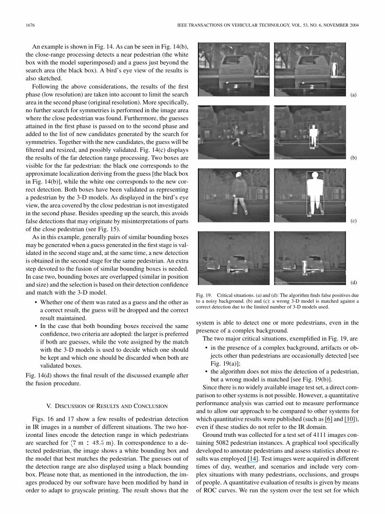
Fig. 19. Critical situations. (a) and (d): The algorithm finds false positives dueto a noisy background. (b) and (c): a wrong 3-D model is matched against acorrect detection due to the limited number of 3-D models used.
system is able to detect one or more pedestrians, even in thepresence of a complex background.
The two major critical situations, exemplified in Fig. 19, are
• in the presence of a complex background, artifacts or ob-jects other than pedestrians are occasionally detected [seeFig. 19(a)];
• the algorithm does not miss the detection of a pedestrian,but a wrong model is matched [see Fig. 19(b)].
Since there is no widely available image test set, a direct com-parison to other systems is not possible. However, a quantitativeperformance analysis was carried out to measure performanceand to allow our approach to be compared to other systems forwhich quantitative results were published (such as [6] and [10]),even if these studies do not refer to the IR domain.
Ground truth was collected for a test set of 4111 images con-taining 5082 pedestrian instances. A graphical tool specificallydeveloped to annotate pedestrians and assess statistics about re-sults was employed [14]. Test images were acquired in differenttimes of day, weather, and scenarios and include very com-plex situations with many pedestrians, occlusions, and groupsof people. A quantitative evaluation of results is given by meansof ROC curves. We run the system over the test set for which

BERTOZZI et al.: PEDESTRIAN DETECTION FOR DRIVER ASSISTANCE USING MULTIRESOLUTION INFRARED VISION 1677
ground truth is available and computed the number of correctdetections and false positives. Results were considered correct ifthey adequately overlapped with the annotated boxes (see [14]).
The detection and false positives rates depend on the param-eters and thresholds used in each stage of the system. Since theexecution flow chart of our system is complex (stages are re-peated twice and there is a feedback of the output from the firstlow resolution run to the second high resolution run, see Fig. 8),a separate analysis of the different stages (candidates genera-tion, filtering, and validation) poses severe problems. We de-cided to evaluate the behavior of the whole system with a singleROC curve obtained by varying the correlation threshold usedin the matching with the models. In fact, due to the high com-plexity of the system, optimizing the thresholds one at a timewould have been prohibitive.
The graph in Fig. 18(a) presents the ROC curve obtained forthe complete test set. The false-positive rate is very low, but thedetection rate is affected by the very high number of complexscenes with groups of people.
The graph in Fig. 18(b) shows the curve obtained running thesystem over a part of the test sequence: complex scene wereeliminated and significantly occluded pedestrians maintained, inorder to reflect the assumptions upon which the algorithm wasdesigned. The same choice was adopted in other studies ( [6]and [10]); therefore, this second sequence represents a testingcondition similar to theirs. Moreover, this is a reasonable as-sumption, since the most dangerous pedestrian is the closestone, who is least occluded. This new test set is composed of2152 images with 1496 pedestrian samples. A high number offrames without pedestrians was left to particularly challenge thesystem with respect to false alarms. In this case, a detection rateof 70% is achieved with 0.2 false positives per image. This verylow false-alarm rate is a good result in order to not to flood thedriver with too many unnecessary warnings, which could de-crease the driver’s confidence in the system.
Currently, the system is based on the processing of singleshots only; one of the most important enhancements will bethe integration of a tracking procedure that will allow us to im-prove the final results, both reducing temporary misdetectionscaused by noise or occlusions and decreasing the number offalse alarms. In addition, tracking would permit us to speed upthe processing; in fact, due to the similarity between two sub-sequent images, only a subset of the models can be used in thecorrelation.
Moreover, in the case of walking pedestrians, the sequenceof 3-D models to be used in the correlation may suggest thepedestrian moving direction. Furthermore, improvements maybe obtained by using a more representative set of 3-D models toreproduce the average pedestrian appearance with more accu-racy. In fact, we realized that the models described in this work(see Fig. 13) are too thin compared to a dressed person.
Concerning time performance, the system has been testedon a 1.8 GHz Athlon XP (FSB 266 MHz) with 512 MBytesDDR@400 MHz. The pedestrian detector proved to be very ef-ficient: the average time required for the processing of a frame is
127 ms (correspondent to a frame rate of about 8 frames/s). In-deed, the actual frame-processing time depends on the numberof pedestrians.
The algorithm developed so far proves to be effective indifferent situations. Extensive tests are being carried out indifferent seasons (winter/summer). The results are promising,though the system is not ready for deployment. We believe thatsignificant improvements could be achieved by using stereoIR vision and making the system more robust by fusing visualinformation with radar data.
REFERENCES
[1] H. Nanda and L. Davis, “Probabilistic template based pedestrian detec-tion in infrared videos,” presented at the IEEE Intelligent Vehicles Sym-posium 2002, Paris, France, June 2002.
[2] F. Xu and K. Fujimura, “Pedestrian detection and tracking with night vi-sion,” presented at the Proc. IEEE Intelligent Vehicles Symposium 2002,Paris, France, June 2002.
[3] Y. L. Guilloux and J. Lonnoy, “PAROTO project: The benefit of infraredimagery for obstacle avoidance,” presented at the Proc. IEEE IntelligentVehicles Symposium 2002, Paris, France, June 2002.
[4] T. Tsuji, H. Hattori, M. Watanabe, and N. Nagaoka, “Development ofnight-vision system,” IEEE Trans. Intell. Transport. Syst., vol. 3, pp.203–209, Sept. 2002.
[5] M. Bertozzi, A. Broggi, A. Fascioli, and M. Sechi, “Shape-based pedes-trian detection,” in Proc. IEEE Intelligent Vehicles Symp., Detroit, MI,Oct. 2000, pp. 215–220.
[6] D. M. Gavrila and J. Geibel, “Shape-based pedestrian detection andtracking,” presented at the Proc. IEEE Intelligent Vehicles Symposium,Paris, France, June 2002.
[7] C. Curio, J. Edelbrunner, T. Kalinke, C. Tzomakas, and W. von Seelen,“Walking pedestrian recognition,” IEEE Trans. Intell. Transport. Syst.,vol. 1, pp. 155–163, Sept. 2000.
[8] L. Zhao and C. Thorpe, “Stereo and neural network-based pedestrian de-tection,” IEEE Trans. Intell. Transport. Syst., vol. 1, pp. 148–154, Sept.2000.
[9] R. Cutler and L. S. Davis, “Robust real-time periodic motion detection,analysis and applications,” IEEE Trans. Pattern Anal. Machine Intell.,vol. 22, pp. 781–796, Aug. 2000.
[10] P. Viola, M. J. Jones, and D. Snow, “Detecting pedestrians using patternsof motion and appearance,” in Procs. IEEE Int. Conf. Computer Vision,Nice, France, Sept. 2003, pp. 734–741.
[11] Y. Fang, K. Yamada, Y. Ninomiya, B. Horn, and I. Masaki, “Comparisonbetween infrared-image-based and visible-image-based approachesfor pedestrian detection,” in Proc. IEEE Intelligent Vehicles Symp.,Columbus, OH, June 2003, pp. 505–510.
[12] M. Bertozzi, A. Broggi, T. Graf, P. Grisleri, and M. Meinecke, “Pedes-trian detection in infrared images,” in Proc. IEEE Intelligent VehiclesSymp., Columbus, OH, June 2003, pp. 662–667.
[13] M. Bertozzi, A. Broggi, M. Carletti, A. Fascioli, T. Graf, P. Grisleri, andM. Meinecke, “IR pedestrian detection for advanced driver assistancesystems,” Lecture Notes Comp. Sci., vol. 2781, pp. 582–590, 2003.
[14] M. Bertozzi, A. Broggi, P. Grisleri, A. Tibaldi, and M. D. Rose, “A toolfor vision based pedestrian detection performance evaluation,” in Proc.IEEE Intelligent Vehicles Symp., Parma, Italy, June 2004, pp. 784–789.
Massimo Bertozzi (S’95–A’98) received the Dr.Eng.(M.S.) degree in electronic engineering and the Ph.D.degree in information technology, both from the Uni-versità di Parma, Parma, Italy, in 1994 and 1997, re-spectively. His thesis was on the implementation ofsimulation of Petri nets on the CM-2 massive parallelarchitecture.
He is a Researcher in the Dipartimento di Ingeg-neria dell’Informazione, Università di Parma. His re-search interests focused mainly on the application ofimage processing to real-time systems and to vehicle
guidance, the optimization of machine code at assembly level, and parallel anddistributed computing.
Dr. Bertozzi chaired the local IEEE student branch from 1994 to 1997.

1678 IEEE TRANSACTIONS ON VEHICULAR TECHNOLOGY, VOL. 53, NO. 6, NOVEMBER 2004
Alberto Broggi (S’93–A’96) received the Dr.Eng.degree in electronic engineering and the Ph.D. degreein information technology from the Università diParma, Parma, Italy, in 1990 and 1994, respectively.
From 1994 to 1998, he was an Associate Re-searcher in the Dipartimento di Ingegneria dellInformazione, Università di Parma. From 1998 to2001, he was a Professor of Artificial Intelligencein the Dipartimento di Informatica e Sistemistica,Università di Pavia. He is now again with theUniversità di Parma, where he has obtained full
Professor recognition. He has authored more than 120 refereed publicationsin international journals, book chapters, and conference proceedings and hasdelivered invited talks at many international conferences His research interestsmainly include real-time computer vision approaches for the navigation ofunmanned vehicles and visual perception for intelligent vehicles.
Dr. Broggi is the Editor-in-Chief of the IEEE TRANSACTIONS ON
INTELLIGENT TRANSPORTATION SYSTEMS and is a Member of the IEEEITS Council Executive Committee.
Alessandra Fascioli (S’97–M’99) received theDr.Eng. (M.S.) degree in electronic engineering andthe Ph.D. degree in information engineering from theUniversità di Parma, Parma, Italy. Her M.S. thesiswas on stereo vision-based obstacle localization inautomotive environments.
Alessandra Fascioli is currently temporary re-searcher at the University of Parma. Her researchinterests focus on Real-Time Computer Vision andComputer Architectures for Automatic VehicleGuidance. She is also interested in image-processing
techniques based on the Mathematical Morphology computational model.Dr. Fascioli chaired the local IEEE student branch from 1997 to 1999.
Thorsten Graf received the diploma (M.Sc.) degreein computer science and the Ph.D. degree (his thesiswas on “Flexible Object Recognition Based onInvariant Theory and Agent Technology”) from theUniversity of Bielefeld, Bielefeld, Germany, in 1997and 2000, respectively.
In 1997, he became a Member of the “Task Ori-ented Communication” graduate program, Universityof Bielefeld, funded by the German research founda-tion DFG. In June 2001, he joined Volkswagen GroupResearch, Wolfsburg, Germany. Since then, he has
worked on different projects in the area of driver assistance systems as a Re-searcher and Project Leader. He is the author or coauthor of more than 15 pub-lications and owns several patents. His research interests include image pro-cessing and analysis dedicated to advanced comfort/safety automotive applica-tions.
Marc-Michael Meinecke received the Dipl.Ing.degree in electronical engineering from the Tech-nical University of Braunschweig, Braunschweig,Germany, in 1997 and the Ph.D. degree from theTechnical University of Hamburg-Harburg, Ham-burg, Germany, in 2001 (his Ph.D. dissertation wason “Optimized Waveform Design for AutomotiveRadars.”)
In January 2001, he joined the Volkswagen GroupResearch, Wolfsburg, Germany. Since then, he hasworked on several research projects in the area of
driver assistance electronics as a Project Leader, where he is responsible forradar technology, precrash detection, and pedestrian recognition systems. Cur-rently, he is involved in the SAVE-U research project (precrash and pedestrianrecognition), which is funded by the European Commission. He is the author orcoauthor of more than 25 publications and ows about 30 patents.
Dr. Meinecke was awarded the Volkswagen Research Prize in 2002.