Parallel Coil Resonators for Time-Domain Radiofrequency Electron Paramagnetic Resonance Imaging of...
9
Parallel Coil Resonators for Time-Domain Radiofrequency Electron Paramagnetic Resonance Imaging of Biological Objects N. Devasahayam, S. Subramanian, R. Murugesan, J. A. Cook, M. Afeworki, R. G. Tschudin, J. B. Mitchell, and M. C. Krishna Radiation Biology Branch, Division of Clinical Sciences, National Cancer Institute, National Institutes of Health, Bethesda, Maryland 20892 Received June 3, 1999; accepted September 3, 1999 Resonators suitable for time-domain electron paramagnetic res- onance spectroscopy and imaging at a radiofrequency capable of accommodating experimental animals such as mice are described. Design considerations included B 1 field homogeneity, optimal Q, spectral bandwidth, resonator ring-down, and sensitivity. Typi- cally, a resonator with 25-mm diameter and 25-mm length was constructed by coupling 11 single loops in parallel with a separa- tion of 2.5 mm. To minimize the resonator ring-down time and provide the necessary spectral bandwidth for in vivo imaging experiments, the Q was reduced predominantly by overcoupling. Capacitative coupling was utilized to minimize microphonic ef- fects. The B 1 field in the resonator was mapped both radially and axially and found to be uniform and adequate for imaging studies. Imaging studies with phantom objects containing a narrow-line spin probe as well as in vivo objects administered with the spin probe show the suitability of these resonators for valid reproduc- tion of the spin probe distribution in three dimensions. The fabri- cation of such resonators is simple and can be scaled up with relative ease to accommodate larger objects as well. © 2000 Academic Press INTRODUCTION Electron paramagnetic resonance (EPR) spectroscopy is a direct and sensitive technique for detecting paramagnetic spe- cies such as free radicals. With the increasing importance of free radicals in biology, EPR spectroscopy is used to under- stand the basic mechanisms of several disease processes with putative free radical pathways (1). EPR imaging can be imple- mented for in vivo biological studies (2), using physical prin- ciples similar to those of magnetic resonance imaging (MRI) (3). Recent studies have reported on the EPR imaging of intact objects such as isolated organs as well as experimental animals to detect endogenously generated free radicals as well as the spatial distribution of exogenously administered free radicals (4–9). Such experiments have established the capability of EPR imaging to provide valuable physiological information such as tissue oxygen status as well as tissue redox status (5, 10, 11). Obtaining such information noninvasively is of importance in characterizing pathological states as well as guiding effective treatments, making EPR imaging a poten- tially useful tool in diagnostic radiology (10). Several studies have obtained useful physiological information using spin probes such as nitroxides and particulates such as glucose char and India ink, (8, 12–14). The linewidths of these compounds are in the 0.5–5 G range requiring the use of continuous wave (CW) EPR detection since the transverse relaxation time T 2 is in the order of 250 –50 ns. With the recent availability of biologically compatible, non- toxic, water-soluble spin probes exhibiting a single-line EPR spectrum with oxygen-dependent linewidth in the range of 50 –200 mG, time-domain EPR techniques are receiving in- creasing attention because of the sensitivity inherent to the pulsed EPR techniques as well as minimal artifacts associated with object motion (15–19). In addition, substantially shorter times for a three-dimensional imaging experiment (,5 min) compared to CW EPR imaging (25–30 min) make it possible to collect several three-dimensional images after administration of the spin probe and thereby allow monitoring of pharmaco- kinetic data. The feasibility of performing in vivo imaging experiments using time-domain radiofrequency (RF) EPR has been shown at 300 MHz by administering water-soluble tri- arylmethyl (TAM)-based paramagnetic spin probes to mice and examining regional anatomies (16). Subsequent efforts have been directed to: (1) provide capability to study whole animals (17); and (2) evaluate receiver configurations and data acquisition methodologies to enhance sensitivity (20). In this paper, design considerations for a resonator capable of accom- modating an experimental animal such as a mouse are de- scribed with emphasis on B1 field homogeneity, minimization of dead time, efficient utilization of RF power, and optimal spectral bandwidth. Imaging data from phantom objects and from in vivo experiments are presented. RESONATOR DESIGN CONSIDERATION Resonator Ring-Down Time, Sensitivity, and Spectral Bandwidth For the detection of a paramagnetic spin probe with pulsed EPR, the time-domain response after a pulsed excitation should Journal of Magnetic Resonance 142, 168 –176 (2000) Article ID jmre.1999.1926, available online at http://www.idealibrary.com on 168 1090-7807/00 $35.00 Copyright © 2000 by Academic Press All rights of reproduction in any form reserved.
-
Upload
independent -
Category
Documents
-
view
0 -
download
0
Transcript of Parallel Coil Resonators for Time-Domain Radiofrequency Electron Paramagnetic Resonance Imaging of...

2
Cf
Journal of Magnetic Resonance142,168–176 (2000)Article ID jmre.1999.1926, available online at http://www.idealibrary.com on
Parallel Coil Resonators for Time-Domain Radiofrequency ElectronParamagnetic Resonance Imaging of Biological Objects
N. Devasahayam, S. Subramanian, R. Murugesan, J. A. Cook, M. Afeworki,R. G. Tschudin, J. B. Mitchell, and M. C. Krishna
Radiation Biology Branch, Division of Clinical Sciences, National Cancer Institute, National Institutes of Health, Bethesda, Maryland 2089
Received June 3, 1999; accepted September 3, 1999
y issp
cedes
e--R
ntaims
icatytionstaofllten
sspine chardswave
in-
t PRs e of5 g in-c thep iatedw ertc le toc ationo aco-ke hasb tri-a icea tsh holea dataap ccom-m e de-s tiono als andf
lsedhould
Resonators suitable for time-domain electron paramagnetic res-onance spectroscopy and imaging at a radiofrequency capable ofaccommodating experimental animals such as mice are described.Design considerations included B1 field homogeneity, optimal Q,spectral bandwidth, resonator ring-down, and sensitivity. Typi-cally, a resonator with 25-mm diameter and 25-mm length wasconstructed by coupling 11 single loops in parallel with a separa-tion of 2.5 mm. To minimize the resonator ring-down time andprovide the necessary spectral bandwidth for in vivo imagingexperiments, the Q was reduced predominantly by overcoupling.
apacitative coupling was utilized to minimize microphonic ef-ects. The B1 field in the resonator was mapped both radially and
axially and found to be uniform and adequate for imaging studies.Imaging studies with phantom objects containing a narrow-linespin probe as well as in vivo objects administered with the spinprobe show the suitability of these resonators for valid reproduc-tion of the spin probe distribution in three dimensions. The fabri-cation of such resonators is simple and can be scaled up withrelative ease to accommodate larger objects as well. © 2000 Academic
Press
INTRODUCTION
Electron paramagnetic resonance (EPR) spectroscopdirect and sensitive technique for detecting paramagneticcies such as free radicals. With the increasing importanfree radicals in biology, EPR spectroscopy is used to unstand the basic mechanisms of several disease processeputative free radical pathways (1). EPR imaging can be implmented forin vivo biological studies (2), using physical principles similar to those of magnetic resonance imaging (M(3). Recent studies have reported on the EPR imaging of iobjects such as isolated organs as well as experimental anto detect endogenously generated free radicals as well aspatial distribution of exogenously administered free rad(4–9). Such experiments have established the capabiliEPR imaging to provide valuable physiological informasuch as tissue oxygen status as well as tissue redox(5, 10, 11). Obtaining such information noninvasively isimportance in characterizing pathological states as weguiding effective treatments, making EPR imaging a po
1681090-7807/00 $35.00Copyright © 2000 by Academic PressAll rights of reproduction in any form reserved.
ae-ofr-with
I)ctalsthelsof
tus
as-
tially useful tool in diagnostic radiology (10). Several studiehave obtained useful physiological information usingprobes such as nitroxides and particulates such as glucosand India ink, (8, 12–14). The linewidths of these compounare in the 0.5–5 G range requiring the use of continuous(CW) EPR detection since the transverse relaxation timeT2 isn the order of 250–50 ns.
With the recent availability of biologically compatible, nooxic, water-soluble spin probes exhibiting a single-line Epectrum with oxygen-dependent linewidth in the rang0–200 mG, time-domain EPR techniques are receivinreasing attention because of the sensitivity inherent toulsed EPR techniques as well as minimal artifacts associth object motion (15–19). In addition, substantially short
imes for a three-dimensional imaging experiment (,5 min)ompared to CW EPR imaging (25–30 min) make it possibollect several three-dimensional images after administrf the spin probe and thereby allow monitoring of pharminetic data. The feasibility of performingin vivo imagingxperiments using time-domain radiofrequency (RF) EPReen shown at 300 MHz by administering water-solublerylmethyl (TAM)-based paramagnetic spin probes to mnd examining regional anatomies (16). Subsequent efforave been directed to: (1) provide capability to study wnimals (17); and (2) evaluate receiver configurations andcquisition methodologies to enhance sensitivity (20). In thisaper, design considerations for a resonator capable of aodating an experimental animal such as a mouse ar
cribed with emphasis on B1 field homogeneity, minimizaf dead time, efficient utilization of RF power, and optimpectral bandwidth. Imaging data from phantom objectsrom in vivo experiments are presented.
RESONATOR DESIGN CONSIDERATION
Resonator Ring-Down Time, Sensitivity, and SpectralBandwidth
For the detection of a paramagnetic spin probe with puEPR, the time-domain response after a pulsed excitation s
Thdstimalle-
d
eait
(Ess
rob
h-Wan
ans
-spsoI.
NRs
fre
w ro
pinp ectr
n
c timalQ ertieso givenb
sorp-
w d in
the
nperi-–15
cmricalwithodateon of
oidalen
f -coilp beena atorsw ages ots ancel ystemf eend umv 300n lledw a
rriedwidthl
ng ofllel,df a
ging
169TIME-DOMAIN EPR IMAGING OF BIOLOGICAL OBJECTS
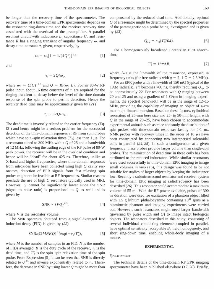
be longer than the recovery time of the spectrometer.recovery time of a time-domain EPR spectrometer depenthe resonator ring-down time and the receiver recoveryassociated with the overload of the preamplifier. A parresonant circuit with inductanceL, capacitanceC, and resistanceR has a ringing transient of angular frequencyvr and
ecay time constanttr given, respectively, by
v r 5 v0@1 2 1/~4Q2!# 0.5 [1]
and
t r 5 2Q/v0, [2]
wherev 0 5 (LC)20.5 and Q 5 R/(v 0 L). For an 80-W RFpulse input, about 16 time constants oftr are required for thringing transient to decay below the level of the time-domresponse of the spin probe to permit detection. Hencereceiver dead time may be approximately given by (21)
td , 32Q/v0. [3]
The dead time is inversely related to the carrier frequency[3]) and hence might be a serious problem for the succedetection of the time-domain responses at RF from spin pwhich have spin–spin relaxation times (T2) less than 1ms. Fora resonator tuned to 300 MHz with aQ of 25 and a bandwidtof 12 MHz, following the trailing edge of the RF pulse of 80peak power, the receiver will be in the overload conditionhence will be “dead” for about 425 ns. Therefore, unlikeX-band and higher frequencies, where time-domain respofrom nitroxides have been collected using highQ cavity resonators, detection of EPR signals from fast relaxingprobes might not be feasible at RF frequencies. Similar reapreclude the use of highQ resonators typically used in MRHowever, Q cannot be significantly lower since the S(signal to noise ratio) is proportional toQ as well and igiven by
SNR } ~VQ! 0.5, [4]
whereV is the resonator volume.The SNR spectrum obtained from a signal-averaged
induction decay (FID) is given by (22)
SNRa~2MNKQ! 0.5exp~2td/T*2!, [5]
hereM is the number of samples in an FID,N is the numbef FIDs averaged,K is the duty cycle of the receiver,td is the
dead time, andT*2 is the spin–spin relaxation time of the srobe. From Expression [5], it can be seen that SNR is direlated toQ0.5 and inverse exponentially related totd. There-
fore, the decrease in SNR by using lowerQ might be more tha
eonel
nhe
q.fules
dtes
inns
e
ly
ompensated by the reduced dead time. Additionally, opof a resonator might be determined by the spectral prop
f the paramagnetic spin probe being investigated and isy (23)
Qopt 5 v0~T*2/64!. [6]
For a homogeneously broadened Lorentzian EPR abtion,
T*2 5 1/pDB, [7]
here DB is the linewidth of the resonance, expressefrequency units (for free radicals withg 5 2, 1 G5 2.8 MHz).
For an EPR probe with a linewidth of 150 mG (typical ofTAM radicals),T*2 becomes 760 ns, thereby requiringQopt tobe approximately 22. For resonators withQ ranging betwee20 and 25 and using a gradient of 1 G/cm in imaging exments, the spectral bandwidth will be in the range of 12MHz, providing the capability of imaging an object of 4-maximum linear dimension. Based on these factors, cylindresonators of 25-mm bore size and 25- to 50-mm length,Q in the range of 20–25, have been chosen to accommexperimental animals such as mice and study the distributispin probes with time-domain responses lasting for.1 ms.NMR probes with recovery times in the order of 10ms havebeen constructed by connecting two interspersed solencoils in parallel (24, 25). In such a configuration at a givrequency, these probes provide larger volume than singlerobes. The minimization of dead time in these coils hasttributed to the reduced inductance. While similar resonere used successfully in time-domain EPR imaging to immall volumesin vivo (16), this design was found to be nuitable for studies of larger objects by keeping the inductow. Recently a submicrosecond resonator and receiver sor time-domain EPR imaging at radiofrequency has bescribed (26). This resonator could accommodate a maximolume of 55 ml. With the RF power available, pulses ofs duration were used for excitation of a phantom object fiith 1.5 g lithium phthalocyanine containing 1021 spins as
biomimetic phantom and imaging experiments were caout. However, such resonators might need larger band(governed by pulse width andQ) to image intact biologicaobjects. The resonators described in this study, consistiseveral individual conducting elements coupled in parahave optimal sensitivity, acceptableB1 field homogeneity, anshort ring-down time, enabling whole-body imaging omouse.
EXPERIMENTAL
Spectrometer
The technical details of the time-domain RF EPR imaspectrometer have been published elsewhere (17, 20). Briefly,

ivitramh irlyth
n 4p
theth
exivinbeterajognam
anomringnnctaith5
erowee
gu
R
pici pler coe dut
anredenof
C er cy3
oft t bw 26s Thd eci rst f thc l a
-hingacts
ultinguntedr was
og-robeg thee forfig-uct-e.ce RFverti-ngth
e 900160
aln
l. Aencys ofll be
tialof
atornd C3il. (B)axialies,ntal
170 DEVASAHAYAM ET AL.
the spectrometer consists of a transmitting arm, a recearm, and a resonator. RF pulses are delivered from themitting arm to the resonator through a diplexer. The transting arm consists of a 300-MHz frequency source whicderived from an 800-MHz oscillator. The 300 MHz is propegated to obtain pulses of required width, depending onresonator volume. Pulse widths typically ranged betweeand 160 ns. The pulse-modulated 300-MHz radiation is amfied by two class A 100-W amplifiers. The outputs fromamplifiers were combined to obtain 160 W and delivered toresonator through the diplexer; a 3-dB loss at the diplresults in net power of 80 W at the resonator. The recearm collects the time-domain responses from the spin prothe resonator after the receiver gate was opened 450 ns afdelivery of the power to the resonator. By this time the mpart of the ringing gets diminished to a level at which the sifrom the spin probe can be recovered. However, the ssystematic ringing, present in the region of 450–650 ns, cfurther minimized from the acquired FID by subtracting it fra signal collected in the absence of magnetic field. This bdown the overall dead time from 650 to 450 ns. The sireceived at 300 MHz is amplified and mixed with a frequeof 350 MHz derived from the same 800-MHz source to oban intermediate frequency (IF) signal at 50 MHz containingFID. The output from the mixer which is centered aroundMHz is digitized by the 1 GS/s two-channel Analytek digitizFor signal averaging, alternate pulses were applied 180°of-phase with each other and the resulting responsescombined to reduce the systematic buildup of the spectromnoise. The details of the digitizer/averager in the IF confiration have been described elsewhere (20).
esonator Construction
Figure 1A provides the electrical schematic diagram deng the various components of the resonator. For examesonator of 25-mm diameter was constructed with 11lements, 2.5 mm apart to give a 25-mm height. The in
ance of each individual coil was measured to be 0.0936mH.Under the absence of mutual coupling, the total inductwould be 0.0085mH. However, the experimentally measuinductance was 0.049mH, due to mutual inductance betweindividual coil elements (27). With the capacitance values
1 5 9.58 pF, C25 9.779 pF, and C35 14.26 pF, thesonator could readily be tuned to the operating frequen00 MHz.
Longitudinal B1 field. Figure 1B provides schematicshe coil positioning and winding. The resonator was builinding and supporting individual coil elements (AWGilver wire with circular cross section) on a lucite mandrel.iameter of the individual loops and the length of the conn
ng leads were maintained equal to minimize phase errohe RF energy delivered to the resonator. The interior ooil was used to house the sample such that the cylindrica
ngns-it-s
e5
li-
eergintherl
allbe
gsalyne0.ut-re
ter-
t-a
ilc-
ce
of
y
et-ine
xis
of the resonator is maintained perpendicular toB0. The connecting leads of the resonator to the tuning and matccapacitors were supported by a dielectric supporter whichas insulation between the input and output leads. The resstructure and the tuning and matching capacitors were moon a copper-coated glass epoxy board. The resonatoenergized through a semirigid cable.
Transversal B1 field. Resonator design supporting homenous fields transverse to the cylindrical axis of the ppermits access to the active volume of the resonator alonaxis of the main magnet; such a configuration is desirablin vivo imaging experiments. A resonator with such a conuration can be constructed by winding the individual conding elements running along the long axis of the lucite tub
The resonators are shielded with a copper sheet to reduinterference from extraneous sources. Several axial andcal resonators with diameter in the range 15–50 mm and lein the range 15–80 mm were constructed and tested. Thpulse width at an RF power of 80 W varied between 45 andns for the active volume ranging from 8 to 100 cm3. In thispaper, however, we present the results from the longitudinB1
field resonators. The transverseB1 field resonator configuratiowill, of course, permit an easier handling of the animatechnical evaluation of such a resonator, its size–frequrelationship, and comparison with bird cage resonatorcomparable size, etc., are yet to be carried out and wireported subsequently.
RESULTS
Resonator Characteristics
Bandwidth. For a field gradient of 1.5 G/cm, the spadimensions of a 253 25 mm resonator sets an upper limit
FIG. 1. (A) The components of the LCR circuit that make up the resonassembly. The values of C1 (tuning capacitor), C2 (coupling capacitor), a(matching capacitor) depend on the frequency and dimensions of the coSchematics of the parallel coil resonator with the RF magnetic axis cowith the cylindrical axis. This configuration will be useful for phantom studbut will require loading small animals in a vertical orientation in a horizoB0 field.

tra30
istirvrn-na
ntlin
p asu elyo rv Thr die
c yr ctralb t ofl livem att as nos mali hea ck
gese ofTheeter
e ap-f theen ared.ns-ohmns iseso-lses
0 W)diatelylusivein (A),ofotal of
Thnimnim
.salthe
171TIME-DOMAIN EPR IMAGING OF BIOLOGICAL OBJECTS
28.5 to the Q of the resonator, governed by the specbandwidth of 10.5 MHz, when the resonator is tuned toMHz. Q can be reduced to the desired value either by resdamping or by capacitive overcoupling. It has been obsethat, for the same RF power, higherB1 fields are achieved foovercoupling (28). For example, the ratio of the signal intesities from an overcoupled resonator to a matched reso(Q-spoiled) is given by
S(overcoupled)/S(matched)5 @2b/~1 1 b!# 0.5, [8]
whereb is the coupling coefficient (21). Hence, in the presestudy,Q damping was carried out by capacitive overcoup
rimarily. Additionally, a resistance (3.3 kohm) in parallel wsed to reduceQ whenever it was not possible by solvercoupling. Figure 2A shows the typical arrangement foinivo experiments as well as phantom imaging studies.esonator is placed in the active volume of the magnet/gra
FIG. 2. (A) Cartoon of a mouse placed in the parallel coil resonator.dimensions of the coil used in murine studies allow the placing of the atransverse to the field and infusion of drugs and anesthetics while the ais inside the assembly. (B) The RF reflectance profiles of the 253 25 mmparallel coil resonator tuned to 300 MHz with an overcoupledQ of around 20It can be seen that loading the resonator to nearly 90% capacity withsolution does not change theQ or the frequency appreciably. In presence ofmouse a marginal increase inQ was observed.
l0veed
tor
g
ent
oil assembly. Figure 2B shows theQ-profiles of an emptesonator tuned to 300 MHz, when adjusted to a speandwidth of 15 MHz. Figure 2B also shows the effec
oading the resonator with 20 ml saline solution and aouse of 20 g body wt. From theQ-profiles, it can be seen th
he resonator is sufficiently overcoupled such that there wignificant loading either by saline solution or by the anitself. In fact, a slight increase inQ was observed when tnimal was placed in the resonator. TheQ was readjusted ba
to 20 to maintain the desired spectral bandwidth.
Ring-down time. Figure 3A shows the signal (an averaof 100,000 time-domain responses) when a 80-W RF pul70 ns duration was delivered to a 50-ohm dummy load.ring-down time, which can be attributed to the spectromrecovery independent of the resonator, was found to bproximately 500 ns. Figure 3B shows the ring-down time oparallel coil resonator tuned and matched to 300 MHz whtransmit pulse of 80 W of identical duration was deliveWith a resonator ofQ 20, a ring-down time of nearly 650was observed in contrast to the 500 ns observed for the 50termination. This result suggests that an additional 150contributed to the receiver recovery by the parallel coil rnator. This recovery time might be reduced further using puof shorter width or by active damping (26).
FIG. 3. (A) The plot of the receiver response after a 70-ns pulse (8was transmitted to a 50-ohm load. The receiver gate was opened immeafter the transmit pulse. It can be seen that the ringing of the circuit, incof preamplifier recovery, is around 500 ns. (B)The receiver response asbut this time the 50-ohm load is replaced by the parallel coil resonatorQaround 20. It can be seen that the ringing time has now increased to a t650 ns after the trailing edge of the pulse. In both the figures, thex-axis origincorresponds to time “zero” after the transmit pulse.
ealal
ine

t is
icnereecta nlued
eo
th
heingel
c ctri ms argt i-m
ithanoreEenovPR
wae
cth
o bre-rofi
nd
iessp
em-of a
thed themmhees.arets
se.,s). Theroundth a
ourceof theth thethe RFo be
172 DEVASAHAYAM ET AL.
RF field. The flip angle in a single pulse experimengiven by
u 5 gB1tp, [9]
where t p is the RF pulse duration in seconds,B1 is the RFmagnetic field flux density in Gauss, andg is the gyromagnetratio, 1.76083 107 radians/s/G for ag 5 2 species. For a80-W RF pulse (70 ns) corresponding to a 90° pulse delivto the resonator (matched as a 50-ohm load), the reflpower was measured to be 8 W, which corresponds toinput of 72 W. The flux density calculated from these vacorresponds to aB1 field of 1.2 G.B1 can also be calculatefrom the inductance and the current and is given by
B1~T! 5 current~Amp! 3 ~inductance~H!/coil area~m2!!.
[10]
From the measured inductance of 0.049mH for the coil and thcoil dimensions (25 mm diameter), theB1 field is calculated tbe 1.76 G, which is comparable to that computed frompulse width and the power.
RF field distribution. Homogeneity and magnitude of tRF field in the resonator are critical factors for EPR imagIn order to examine theB1 field homogeneity in the paralloil resonator prior to imaging experiments, EPR spentensities of a point source paramagnetic species wereured at various locations in the resonator. The solid chransfer complex, N-methylpyridinium tetracyanoquinodethane (NMP-TCNQ), occupying a total volume of;5 ml,
with its EPR spectrum consisting of a single narrow line wwidth of approximately 200 mG, was used (see Figs. 4A4B). The volume occupied by NMP-TCNQ was therefmaintained less than the expected spatial resolution in theimage with the gradient strength used in imaging experimand hence could be considered as a point source. By mthis point source radially and axially in steps of 1.5 mm, Espectra were collected at each location to map theB1 field. Thevariation of the spectral intensity of this point source,10% axially and,5% radially within the volume of thylindrical resonator. A radial profile of theB1 field in the
middle of the resonator is shown in Fig. 4C. However, inpresence of imaging gradients the spectral profile is tcorrected usingQ-profile of the coil depending upon the fquency bandwidth. This has a characteristic Gaussian pcentered around the carrier frequency. The so-calledQ-profilecan be mapped and was used to correct any offset depeintensity changes in the images.
3D Imaging Experiments
Phantom imaging. In order to test the imaging capabilitof the parallel coil resonators, phantom objects containing
dedets
e
.
alea-e-
d
PRts
ing
s
ee
le
ent
in
probes distributed in defined physical configurations wereployed. One of the phantoms reported here is composedlucite cylinder of 25-mm diameter which fits snugly inparallel coil resonator. The schematics of the phantom anlaboratory axes are shown in Fig. 5A. Two holes (4diameter) drilled in the lucite cylinder were filled with twater-soluble spin probe TAM (1 mM) for imaging studiThe chemical structure and spectral properties of TAMdescribed in (29). The spectrum of TAM at 300 MHz consis
FIG. 4. (A) The FID of a sample of TCNQ occupying a volume of 5mLat the center of a 253 25 mm parallel coil resonator following a 900 pulTheQ of the resonator was 20. A total of 100,000 FIDs of 4 K record lengthcollected at a sampling rate of 1 Gs/s, were averaged (averaging time, 2averaged FID shows an effective dead time of 450 ns after the backgsubtraction. (B) Fourier transform of the FID in (A) after apodization wiKaiser filter of order 5. The magnitude mode of the spectrum (sqrt (u2 1 v 2))is shown, and this has a linewidth of 250 mG. (C) Using the above point sof TCNQ the RF flux density was mapped in a radial plane at the middleresonator perpendicular to the axis. This is shown as a 3D profile, wihorizontal axis representing the measurement plane and the vertical axisflux density in terms of the EPR line intensity. The RF flux was found tuniform within 5% of the mean.
ngnre00
th
cted,
h ndi ths ere
achimes/s.ori-
les (l offil-
f 20fre-
ero-ctra
rilling withningspin pr
rientationIndigo2
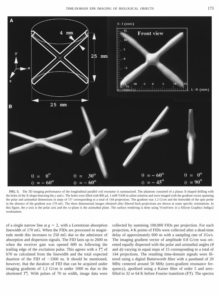
173TIME-DOMAIN EPR IMAGING OF BIOLOGICAL OBJECTS
of a single narrow line atg 5 2, with a Lorentzian absorptiolinewidth of 170 mG. When the FIDs are processed in matude mode this increases to 250 mG due to the admixtuabsorption and dispersion signals. The FID lasts up to 26when the receiver gate was opened 600 ns followingtrailing edge of the excitation pulse. This agrees with aT*2 of670 ns calculated from the linewidth and the total expeduartion of the FID of;3300 ns. It should be mentione
owever, that the duration of FID that can be acquired umaging gradients of 1.2 G/cm is under 1000 ns due tohortenedT* . With pulses of 70 ns width, image data w
FIG. 5. The 3D imaging performance of the longitudinal parallel coithe holes of the X-shape bisecting they andz. The holes were filled with 800mLthe polar and azimuthal dimensions in steps of 15° corresponding to ain the absence of the gradient was 170 mG. The three dimensional imthis figure, they-axis is the polar axis and thexz-plane is the azimuthal plaworkstation.
2
i-ofnse
d
ere
collected by summing 100,000 FIDs per projection. For eprojection, 4 K points of FIDs were collected after a dead-tdelay of approximately 600 ns with a sampling rate of 1GThe imaging gradient vector of amplitude 0.8 G/cm wasented equally dispersed with the polar and azimuthal anguandf) varying in equal steps of 15 corresponding to a tota144 projections. The resulting time-domain signals weretered using a digital Butterworth filter with a passband oMHz centered around 50 MHz (zero-gradient resonancequency), apodized using a Kaiser filter of order 5 and zfilled to 32 or 64 K before Fourier transform (FT). The spe
onator is summarized. The phantom consisted of a planar X-shaped dM TAM in saline solution and were imaged with the gradient vector span
l of 144 projections. The gradient was 1.2 G/cm and the linewidth of theobes obtained after filtered back-projections are shown at some specific os. In. The surface rendering is done using Voxelview in a Silicon Graphics
l res1 m
totaagene

cesdin25thsinfacrk
d ahysfortoleica
a(6de
oda; anin t
heseu-
ssem-ad-
cere
of then inl coilbdom-ce ofade-ime-ions.thetentarallelrobe
si acer a gradien1
174 DEVASAHAYAM ET AL.
after FT were taken in absolute value mode for image proing. The frequency range of all the projections corresponto the volume of interest was adjusted to be within 128 orpoints of an image window centered around 50 MHz indigitized spectrum and used for image reconstruction ufiltered back-projection. The resulting images were surrendered using Voxelview in a Silicon Graphics Indigo2 wostation. The various perspectives of the images obtaineshown in Fig. 5B. The images correspond well with the pical dimensions of the phantom and represent the unidistribution of the spin density. These results from the phanstudies suggest that the parallel coil resonators are suitabdetecting and imaging spin probe distribution in biologobjects, provided that: (1) the spins have their time-domresponse lasting longer than the resonator ring-down timens); (2) the spin probe distribution can be spatially encowith gradients of appropriate strength so as to accommthe signals within the bandwidth provided by the resonator(3) adequate concentration of the spin probes is availableresonator to achieve satisfactory SNR.
FIG. 6. Three dimensional EPR imaging of C3H mouse administerenitiated immediately after the infusion of the spin probe. Prior to imagesonator. The resonator sampled the animal from the neck to pelvic re
G/cm. The three dimensional image was obtained by filtered back-pr
s-g6ege-re-mmforlin50dtedhe
In vivo imaging. In order to test the feasibility of using tparallel resonator forin vivo imaging, an anesthetized mouwas placed in a 253 50 mm resonator after tail vein cannlation. The resonator was placed in the magnet/gradient ably as shown in Fig. 2A. The animal was intravenouslyministered with a 100-ml solution of a 20-mM TAM in isotonisaline and the data collection was initiated. The FIDs wcollected and processed as outlined above. The imagespin probe distribution obtained from the mouse is showFig. 6. Based on the placement of the animal in the paralleand the images obtained, several areas in the thoracic, ainal, and pelvic regions could be recognized. The absenimage intensity from other regions could be a result of inquate accumulation of the spin probe or faster relaxing tdomain responses corresponding to well-oxygenated regBased on the linewidth of the spin probe, resolution ofimage was found to be in the millimeter range, consiswith the gradients used. These results suggest that the pcoil resonator provides valid representation of the spin pin vivo.
travenously with the TAM spin probe (100ml, 20 mM). The image collection wa, the animal was anesthetized using ketamine/xylazine mixture and pld in thens as shown in the cartoon. EPR projection data were collected usingt oftion methods.
d ininggio
ojec

oluadonc
tsiliti
o ingm how l( n-
bevesolelat
deize
eveofabo
atudea
deus
lsesicspoagompleThntanou
umThuethof
pinnd-g oso
geanbe
eri-ntagee can
and
lmo,d Mr.n of
175TIME-DOMAIN EPR IMAGING OF BIOLOGICAL OBJECTS
DISCUSSION
In vivo EPR spectroscopy and imaging, with the useexogenous spin probes, have been employed to obtain vaphysiological information such as tissue oxygen and restatus (4–9). Such information has been monitored as a fution of treatment procedures to guide effective treatmenwell (10). These studies together have validated the capab
f EPR imaging as a potentially useful functional imagodality. Most of these studies have used CW EPR methere resonators of the loop–gap type (4, 5, 30), surface coi
31), or reentrant configuration (6) were advantageous to ehance sensitivity. Recently available narrow-line spin pro(16, 29, 32, 33) which are water soluble and nontoxic haprovided the capability for EPR imaging to obtain high-relution spatial images. Moreover, these agents are amenabin vivo studies with time-domain EPR imaging (17). Severafactors need to be considered in the development of resonfor time-domain EPR imaging methodology forin vivo appli-cations. While in MRI, the frequency bandwidth is in the orof ,20 kHz to obtain high-resolution images of large-sobjects, in EPR the required bandwidth is at least 10 MHzfor a resonator of 25-mm bore size. Desirable featuresresonator for such time-domain EPR applications are: (1)ity to accept narrow and intense pulses and convert tB1
efficiently; (2) short resonator ring-down time; (3) optimQ-profiles with adequate spectral bandwidth for imaging sies; (4) adequateB1 field homogeneity; and (5) ability to bscaled up for larger objects. When field gradients of 1 G/cmused, a spectral band width of at least 10–12 MHz is neeTherefore, pulses of width no more than 100 ns should beto provide an excitation bandwidth of 10–12 MHz. The puRF EPR images obtained from phantoms of defined phyarchitecture containing the spin probes show good corredence in terms of the dimension as well as uniformity of imintensity. In vivo pulsed RF EPR imaging experiments frmice administered with the spin probe could, in principrovide images with resolution in the millimeter range.present study shows that pulsed RF EPR imaging caperformed in live objects of moderate size and imporphysiological information can be collected. The parallel cpling of coil elements enables the scaling up of the volwithout a significant increase in the overall inductance.helps in the construction of large-volume resonators at freqcies around 200–300 MHz without drastic changes invalues of the tuning and matching capacitors. The usejudicious combination of overcoupling and resistive damproduces the desired lowQ, short dead-time, and broad bawidth required in resonators for pulsed RF EPR imaginintact biological objects. In this article, the parallel coil renators which have been described and evaluated forin vivoimaging may well be an attractive alternative to bird-casolenoidal, and loop–gap resonators in magnetic resonimaging. TheB field homogeneity has been found to
1fblex-ases
ds
s
-for
ors
r
na
il-
l-
red.eddaln-e
,ebet-eisn-ea
g
f-
,ce
suitable for performing three-dimensional imaging expments. The current resonator design is of particular advafor studying large-size objects because the usable volumbe readily increased and the construction is inexpensiverelatively simple to fabricate.
ACKNOWLEDGMENTS
We are grateful to Dr. Klaes Golman, Nycomed Innovations, MaSweden, for the generous gift of the triarylmethyl contrast agents anFrank Harrington, Radiation Oncology Branch, NCI, for help in fabricatiothe resonators.
REFERENCES
1. B. Halliwell and J. M. C. Gutteridge, “Free Radicals in Biology andMedicine,” Oxford University Press, Oxford, pp. 416–509 (1989).
2. J. L. Berliner and H. Fujii, Magnetic resonance imaging of biologicalspecimens by electron paramagnetic resonance of nitroxide spinlabels, Science 227, 517–519 (1985).
3. P. C. Lauterbur, Image formation by induced local interactions:Examples employing nuclear magnetic resonance, Nature 242,190–191 (1973).
4. H. J. Halpern, D. P. Spencer, J. van Polen, M. K. Bowman, A. C.Nelson, E. M. Dowey, and B. A. Teicher, Imaging radio frequencyelectron-spin-resonance spectrometer with high resolution andsensitivity for in vivo measurements, Rev. Sci. Instrum. 60, 1040–1050 (1989).
5. P. Kuppusamy, M. Chzhan, K. Vij, M. Shteynbuk, D. J. Lefer, E.Giannella, and J. L. Zweier, Three-dimensional spectral-spatialEPR imaging of free radicals in the heart: A technique for imagingtissue metabolism and oxygenation, Proc. Natl. Acad. Sci. USA 91,3388–3392 (1994).
6. M. Alecci, S. Della Penna, A. Sotgiu, L. Testa, and I. Vannuci,Electron paramagnetic resonance spectrometer for three dimen-sional in vivo imaging at very low frequencies, Rev. Sci. Instrum. 63,4263–4270 (1992).
7. H. Utsumi, E. Muto, S. Masuda, and A. Hamada, In vivo ESRmeasurement of free radicals in whole mice, Biochem. Biophys.Res. Commun. 172, 1342–1345 (1990).
8. K. J. Liu, P. Gast, M. Moussavi, S. W. Norby, N. Vahidi, T. Walzak,M. Wu, and H. M. Swartz, Lithium phthalocyanine: A probe forelectron paramagnetic resonance oximetry in viable biologic sys-tems, Proc. Natl. Acad. Sci. USA 90, 5438–5442 (1993).
9. H. Togashi, H. Shinzawa, T. Ogata, T. Matsuo, S. Ohno, K. Saito, N.Yamada, H. Yokoyama, H. Noda, K. Oikawa, and H. T. T. Kamada,Spatiotemporal measurement of free radical elimination in the ab-domen using an in vivo ESR-CT imaging system, Free Rad. Biol.Med. 25, 1–8 (1998).
10. F. Goda, J. A. O’Hara, E. S. Rhodes, K. J. Liu, J. F. Dunn, G. Bacic,and H. M. Swartz, Changes in oxygen tension in experimentaltumors after a single dose of x-ray irradiation, Cancer Res. 55,2249–2252 (1995).
11. H. J. Halpern, C. Yu, M. Peric, E. Barth, D. J. Grdina, and B. A.Teicher, Oximetry deep in tissues with low-frequency electronparamagnetic resonance, Proc. Natl. Acad. Sci. USA 91, 13047–13051 (1994).
12. C. S. Lai, L. E. Hopwood, J. S. Hyde, and S. Lukiewicz, ESR studiesof O2 uptake by Chinese hamster ovary cells during the cell cycle,Proc. Natl. Acad. Sci. USA 79, 1166–1170 (1982).
176 DEVASAHAYAM ET AL.
13. J. L. Zweier, M. Chzhan, U. Ewert, G. Schneider, and P. Kup-pusamy, Development of a highly sensitive probe for measuringoxygen in biological tissue, J. Magn. Reson. B 105, 52–57 (1994).
14. B. Gallez, R. Debuyst, F. Dejehet, K. J. Liu, T. Walczak, F. Goda, R.Demeure, H. Taper, and H. M. Swartz, Small particles of fusiniteand carbohydrate chars coated with aqueous soluble polymers:Preparation and applications for in vivo EPR oximetry, Magn.Reson. Med. 40, 152–159 (1998).
15. J. Bourg, M. C. Krishna, J. B. Mitchell, R. G. Tschudin, T. J. Pohida,W. S. Friauf, P. D. Smith, J. Metcalfe, F. Harrington, and S. Sub-ramanian, Radiofrequency FT EPR spectroscopy and imaging, J.Magn. Reson. 102, 112–115 (1993).
16. R. Murugesan, J. A. Cook, N. Devasahayam, M. Afeworki, S. Sub-ramanian, R. Tschudin, J. H. A. Larsen, J. B. Mitchell, A. Russo,and M. C. Krishna, In vivo imaging of a stable paramagnetic probeby pulsed-radiofrequency electron paramagnetic resonance spec-troscopy, Magn. Reson. Med. 38, 409–414 (1997).
17. R. Murugesan, M. Afeworki, J. A. Cook, N. Devasahayam, R.Tschudin, J. B. Mitchell, S. Subramanian, and M. C. Krishna, Abroadband pulsed radio frequency electron paramagnetic reso-nance spectrometer for biological applications, Rev. Sci. Instrum.69, 1869–1876 (1998).
18. A. Coy, N. Kaplan, and P. T. Callaghan, Three-dimensional pulsedESR imaging, J. Magn. Reson. A 121, 201–205 (1996).
19. M. Alecci, J. A. Brivati, G. Placidi, and A. Sotgiu, A radiofrequency(220 MHz) Fourier transform EPR spectrometer, J. Magn. Reson.130, 272–280 (1998).
20. S. Subramanian, R. Murugesan, N. Devasahayam, J. A. Cook, M.Afeworki, T. Pohida, R. G. Tschudin, J. B. Mitchell, and M. C.Krishna, High-speed data acquisition system and receiver config-urations for time-domain radiofrequency electron paramagneticresonance spectroscopy and imaging, J. Magn. Reson. 137, 379–388 (1999).
21. S. Pfenninger, W. Froncisz, J. Forrer, J. Luglio, and J. S. Hyde,General method for adjusting the quality factor of EPR resonators,Rev. Sci. Instrum. 68, 4857–4865 (1995).
22. J. Gorcester and J. H. Freed, Two dimensional fourier transformESR correlation spectroscopy, J. Chem. Phys. 88, 4678–4693(1986).
23. J. Gorcester, G. L. Millhauser, and J. H. Freed, Two-dimensionalelectron spin resonance, In “Modern Pulsed and Continuous-WaveElectron Spin Resonance” (L. Kevan and M. K. Bowman, Eds.),Wiley, New York, pp. 119–194 (1990).
24. G. C. Chingas, Overcoupling NMR probes to improve transientresponse, J. Magn. Reson. 54, 153–157 (1983).
25. S. B. W. Roeder, E. Fukushima, and A. A. V. Gibson, NMR coils withsegments in parallel achieve higher frequencies or larger samplevolumes, J. Magn. Reson. 59, 307–317 (1984).
26. M. Alecci, J. A. Brivati, G. Placidi, L. Testa, D. J. Lurie, and A.Sotgiu, A submicrosecond resonator and receiver system forpulsed magnetic resonance with large samples, J. Magn. Reson.132, 162–166 (1998).
27. C. G. Fry, J. H. Iwamiya, T. M. Apple, and B. C. Gerstein, Doublywound coils for solid-state double resonance and multiple pulseNMR, J. Magn. Reson. 63, 214–216 (1985).
28. G. A. Rinard, R. W. Quine, S. S. Eaton, G. R. Eaton, and W.Froncisz, Relative benefits of overcoupled resobators vs inherentlylow-Q resonators for pulsed magnetic resonance, J. Magn. Reson.A 108, 71–81 (1994).
29. J. H. Ardenkjaer-Larsen, I. Laursen, I. Leunbach, G. Ehnholm, L.-G.Wistrand, J. S. Petersson, and K. Golman, EPR and DNP propertiesof certain novel single electron contrast agents intended for oxi-metric imaging, J. Magn. Reson. 133, 1–12 (1998).
30. W. Froncisz and J. S. Hyde, The loop gap resonator: A newlumped circuit ESR sample structure, J. Magn. Reson. 47, 515–521 (1982).
31. M. Ono, K. Ito, N. Kawamura, K. Hsieh, H. Hirata, N. Tsuchihashi,and H. Kamada, A surface-coil-type resonator for in vivo ESRmeasurements, J. Magn. Reson. B 104, 180–182 (1994).
32. K. Golman, I. Leunbach, J. H. Ardenkjaer-Larsen, G. J. Ehnholm,L. G. Wistrand, J. S. Petersson, A. Jarvi, and S. Vahasalo, Over-hauser-enhanced MR imaging (OMRI), Acta Radiol. 39, 10–17(1998).
33. P. Kuppusamy, P. H. Wang, M. Chzhan, and J. L. Zweier, Highresolution electron paramagnetic resonance imaging of biologicalsamples with a single line paramagnetic label, Magn. Reson. Med.37, 479–483 (1997).