
Paper Number A serial hydraulic hybrid drive train for off-road vehicles
7
Paper Number (Assigned by IFPE Staff) A serial hydraulic hybrid drive train for off-road vehicles Peter A.J. Achten Innas BV ABSTRACT The fuel consumption of off-road machines is strongly reduced if part load operation of the engine, and throttled control of the hydraulic implements are avoided. This is the aim of the ‘Hydrid’: a full hybrid hydrostatic drive train and control system. The Hydrid has hydraulic accumu- lators for energy storage and power management, hydraulic transformers for efficient power control, and highly efficient and compact in-wheel motors. INTRODUCTION The cost of ownership of loaders, excavators and other off-road machines is nowadays often dominated by the fuel cost. Moreover, there is growing concern about CO 2 - emissions caused by the burning of fossil fuels as well as about the long-term availability of these fuels. The fuel economy and efficiencies of the drive train and the hydraulic implements have therefore become extremely important parameters in the design of future off-road machines. Hybrid transmissions are normally not considered to be a solution for off-road machines. Hybrid drive trains are foremost developed for passenger cars where they can benefit from the recuperation of brake energy. But for many off-road vehicles, brake energy recuperation is not an option. Furthermore, hybrid electric vehicles need sophisticated electric transmissions with delicate and expensive inverters, converters and batteries. Taking the extreme power transients in mobile machinery and the rough operational conditions of off-road drive trains into account, it is questionable whether the delicate hybrid electric drive trains can be considered a viable, in- expensive and robust option for off-road applications. Yet, there is still the alternative of the hydraulic hybrid drive train. These are for some years developed for busses, refuse and delivery trucks [1-6]. This paper describes a hybrid drive train for off-road machines. The drive train –coined the ‘Hydrid’ [7, 8]– is a full serial hybrid system with an in-wheel motor in each wheel and hydraulic transformers for efficient power control. HYBRID ELECTRIC DEVELOPMENTS There is a common consensus that hybrid drive trains can strongly increase the efficiency of a drive train. Especially in the passenger car market segment, the Toyota Prius has proven the viability of the concept. However, the increased efficiency does not by itself result in a reduction of the fuel consumption or the cost of ownership. The electric drive train components result in an increased vehicle weight, which increases the fuel consumption of the vehicles. Moreover the added cost for the electric components gives doubt about the cost- benefit-relationship, especially of the full hybrid drive train concepts [9-15]. Nevertheless, the trend of hybrid electric transmissions has also come to the off-road market. Kobelco and New Holland have presented an excavator, in which the swing movement of the upper carriage is realized by means of a hybrid electric drive ([16], see Figure 1). Because of the hybrid system, a smaller internal combustion engine could be applied. The fuel con- sumption is reduced by 40%, according to Kobelco. Fig. 1: Hybrid electric swing drive for an excavator [16] In Europe, Deutz and Atlas Weyhausen have shown a hybrid electric wheel loader, in which the flywheel of the internal combustion engine is replaced by an electric motor/generator [17]. According to the developers, the fuel consumption is reduced by 20%.
-
Upload
independent -
Category
Documents
-
view
6 -
download
0
Transcript of Paper Number A serial hydraulic hybrid drive train for off-road vehicles
Paper Number (Assigned by IFPE Staff)
A serial hydraulic hybrid drive train for off-road vehicles
Peter A.J. Achten Innas BV
ABSTRACT
The fuel consumption of off-road machines is strongly reduced if part load operation of the engine, and throttled control of the hydraulic implements are avoided. This is the aim of the ‘Hydrid’: a full hybrid hydrostatic drive train and control system. The Hydrid has hydraulic accumu-lators for energy storage and power management, hydraulic transformers for efficient power control, and highly efficient and compact in-wheel motors.
INTRODUCTION
The cost of ownership of loaders, excavators and other off-road machines is nowadays often dominated by the fuel cost. Moreover, there is growing concern about CO2-emissions caused by the burning of fossil fuels as well as about the long-term availability of these fuels. The fuel economy and efficiencies of the drive train and the hydraulic implements have therefore become extremely important parameters in the design of future off-road machines.
Hybrid transmissions are normally not considered to be a solution for off-road machines. Hybrid drive trains are foremost developed for passenger cars where they can benefit from the recuperation of brake energy. But for many off-road vehicles, brake energy recuperation is not an option. Furthermore, hybrid electric vehicles need sophisticated electric transmissions with delicate and expensive inverters, converters and batteries. Taking the extreme power transients in mobile machinery and the rough operational conditions of off-road drive trains into account, it is questionable whether the delicate hybrid electric drive trains can be considered a viable, in-expensive and robust option for off-road applications.
Yet, there is still the alternative of the hydraulic hybrid drive train. These are for some years developed for busses, refuse and delivery trucks [1-6]. This paper describes a hybrid drive train for off-road machines. The drive train –coined the ‘Hydrid’ [7, 8]– is a full serial hybrid system with an in-wheel motor in each wheel and hydraulic transformers for efficient power control.
HYBRID ELECTRIC DEVELOPMENTS
There is a common consensus that hybrid drive trains can strongly increase the efficiency of a drive train. Especially in the passenger car market segment, the Toyota Prius has proven the viability of the concept. However, the increased efficiency does not by itself result in a reduction of the fuel consumption or the cost of ownership. The electric drive train components result in an increased vehicle weight, which increases the fuel consumption of the vehicles. Moreover the added cost for the electric components gives doubt about the cost-benefit-relationship, especially of the full hybrid drive train concepts [9-15].
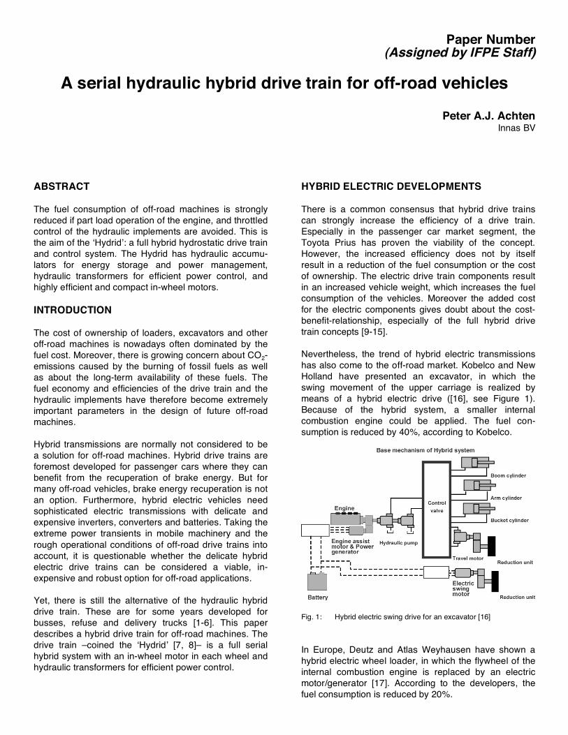
Nevertheless, the trend of hybrid electric transmissions has also come to the off-road market. Kobelco and New Holland have presented an excavator, in which the swing movement of the upper carriage is realized by means of a hybrid electric drive ([16], see Figure 1). Because of the hybrid system, a smaller internal combustion engine could be applied. The fuel con-sumption is reduced by 40%, according to Kobelco.
Fig. 1: Hybrid electric swing drive for an excavator [16]
In Europe, Deutz and Atlas Weyhausen have shown a hybrid electric wheel loader, in which the flywheel of the internal combustion engine is replaced by an electric motor/generator [17]. According to the developers, the fuel consumption is reduced by 20%.

Finally, also Volvo Construction Equipment (Volvo CE) has announced a concept of a hybrid electric loader cal-led the Gryphin [17, 18]. Unlike the developments of Kobelco and Weyhausen, the mechanical drive train in the Gryphin is completely replaced by an electric drive, having in-wheel electric motors in all 4 wheels.
The hydraulic hybrid system, which is described in this paper, is the hydraulic equivalent of the Gryphin, at least for the drive train part of the system. It has an in-wheel hydrostatic machine in each wheel, hydraulic transfor-mers instead of electric power controllers and hydraulic accumulators instead of batteries. Added to this, the hydraulic hybrid system also includes recuperation modes for the hydraulic cylinders.
FLOATING CUP AND HYDRAULIC TRANSFORMERS
A full hydrostatic drive requires highly efficient pumps and motors. Current piston pumps and motors have a peak efficiency of around 93%. A pump-motor-combination could therefore – in theory – have an effi-ciency of maximum 86%. In reality, the part load ope-ration of the hydrostatic machines reduces the efficiency of both the pump and the motor. If, for instance, an average efficiency of 80% for both the pump and motor is assumed, the total average efficiency of the hydro-static drive is limited to 64%.
The new Floating Cup Principle [19-25] strongly impro-ves the efficiency of hydraulic pumps and motors. Recent tests have proven a maximum total efficiency of up to 98%.
Fig. 2: Measured total efficiency of a 28 cc floating cup pump/motor
The floating cup principle is a multi piston pump, having 24 pistons. This creates an almost constant torque output. In addition, the floating cup principle has extre-mely low friction losses at low rotational speeds. The smooth torque and the low friction result in a start-up torque, which is nearly equal to the maximum theoretical output torque of the hydrostatic motor.
Fig. 3: Low speed torque relative to the maximum theoretical torque
The figure above shows the torque efficiency of a floating cup motor compared to two other motor principles, measured at low speed (< 1 rpm). The floating cup principle offers a starting torque, which is about twice as high as the radial piston motor. For the same output torque at start-up, the floating cup motor can therefore be half the size of a radial piston motor. This is not only important for reducing the size and weight of the hydraulic components, but also for increa-sing the drive train efficiency. If, due to a low starting torque, the motor size needs to be increased, then the same motor will have to run in strong part load conditions during normal operation, which often results in a reduced efficiency.
The Floating Cup Principle is also applied in the design of hydraulic transformers. A hydraulic transformer is the hydraulic equivalent of a mechanical CVT. Where a CVT converts torque and speed, a hydraulic transformer converts pressure and flow, without principal energy losses. In the hydraulic transformer developed by Innas (the Innas Hydraulic Transformer or IHT [26-37]), the control of the transformer is realized by rotating the port plate. Whereas the port plate in hydrostatic pumps and motors only has two ports, the port plate in the IHT has three ports:
• one connected to the load, • one connected to the high pressure supply side • and one to the low pressure supply side.
There are also hydraulic transformers developed for hydrostatic drive applications, allowing 4-quadrant operation of the wheel motors (i.e. forward propulsion,

forward breaking, reverse propulsion and reverse braking). These transformers have four ports: two for the supply side and two for the load side.
Unlike valves, hydraulic transformers are based on a positive displacement principle, and therefore have no principle throttle losses. Being a non-dissipative prin-ciple, it is also possible to convert hydraulic power to a higher pressure level. This creates the opportunity for re-cuperating energy from any hydraulic load, both wheels and hydraulic cylinders. For instance in a fork lift truck it is possible to recuperate the break energy of the vehicle as well as the energy from the lift cylinders while lowering a load at the fork boom [28].
HYDROSTATIC HYBRID DRIVE
In a wheel loader, about half of the fuel consumption is used for the hydraulic cylinders. The other half goes to the wheels for the propulsion of the vehicle [38, 39]. Figure 4 shows the operating points of the diesel engine of loader for a typical cycle [38]. For a large part the engine is operated at a load of less then 50% of the maximum load. In this area the engine efficiency strongly deteriorates (at a load of 20% the specific fuel consumption of an engine can be twice as high as in the optimum or sweet point).
Fig 4: Operating points of the diesel engine of a loader [38]
In the proposed hydraulic hybrid (or Hydrid) transmission (figure 5) the engine is supplying all its power to a so-called common pressure rail (CPR). The pressure at the high and low pressure side of the CPR-system is defined by the accumulators. Due to the design of the accu-mulators, the pressure difference between the high and low pressure side can only be varied in a limited pres-sure range, for instance between 200 and 350 bar. In the Hydrid, the internal combustion engine is connected to a constant displacement pump. If this would for instance be a 28 cc pump, then the pressure range of the accu-mulator would result in an engine torque, which can only vary between 89 Nm (at 200 bar) and 156 Nm (at 350 bar). As a result the engine will always be operated at a medium to high load, and the operating points with a low efficiency of the engine (and the pump) will be avoided completely.
Fig. 5: Hydraulic circuit of the hydraulic hybrid (‘Hydrid’)
The new driveline is similar to the design of the stationary electricity production and distribution, having a separation between the power plants and loads, and a simple grid for energy and power distribution. As with electricity production, more then one power plant can be connected to the Common Pressure Rail. The combined power of all power plants will be chosen as such that it can deliver the maximum power that the vehicle needs for extended periods. This can be lower than the maximum power demanded in a conventional drive train, since the increased efficiency also reduces the maximum power demand. In addition the accumulators can also deliver extra power to the system, thereby acting as peak shaving devices. In most operating points, the power demand of the vehicle is much lower than the maximum power demand. Having two power plants, one of the power plants can be switched off, and the power management can be optimized better for average operating points.
HYDRAULIC IMPLEMENTS
Like the electricity grid, there can be any number of loads connected to the power grid, including hydraulic cylinders. The accumulators will avoid load disturbance reactions from one load to the other and also allow the recuperation of energy. The hydraulic transformers convert the pressure level offered by the high pressure rail to the pressure level required by the load, thereby avoiding the throttle losses that would occur with valve control.

6a: rod side always pressurized
6b: rod side can be switched
Fig. 6: Hydraulic circuit for the control of a hydraulic cylinder by means of a hydraulic transformer
Figure 6 shows two configurations for the control of a double acting hydraulic cylinder by means of a single hydraulic transformer. In the second configuration, the rod side can be switch between the low-pressure rail and the high-pressure side of the CPR-system. In the upper design (figure 6a), the rod side is always connected to the high-pressure side and the hydraulic transformer must amplify the pressure at the bottom side of the cylinder in order to compensate for the hydrostatic force from the rod side. More details about the control of hydraulic cylinders by means of hydraulic transformers can be found in the literature [28-37].
Not all hydraulic cylinders need to be controlled by means of a hydraulic transformer. If cylinders are only used occasionally and don’t consume a large amount of energy, a simple and less expensive throttle valve is perfectly acceptable for controlling the cylinder. Figure 7 shows two hydraulic diagrams for a forklift truck. The upper diagram is the conventional system with a hydrostatic drive and a load-sensing system for the cylinders. The second diagram shows the CPR-alternative with hydraulic transformers for the hydrostatic wheel motors as well as for the lift cylinder. The other cylinders for tilting and clamping are controlled directly with valves, thereby accepting the (limited) throttle losses.
7a: Conventional load sensing and hydrostatic drive system
7b: Common pressure rail (CPR) system
Fig. 7: Comparison of hydraulic circuits for a fork lift truck [28]
The CPR-system offers a simple lay-out, and strongly reduces the complex design and maintenance of current load-sensing systems. In principle, the CPR-system treats the hydraulic loads (and the power plants) as modules, which can be attached or detached from the system as long as there is enough power capacity available.
ENERGY RECUPERATION
The possibilities for brake energy recuperation in loaders, excavators and other mobile machineries are often less than in on-road applications like garbage trucks and city busses. This is for a part due to the fact that loaders and other machines don’t drive on asphalt but on sand, mud and dirt, which results in a much higher rolling resistance. Moreover a loader needs the kinetic energy of the vehicle to dig into a pile of dirt.
Still, there are many applications in which brake energy recuperation can be of importance. Examples are forklift trucks, dump trucks and articulated haulers, but also for the swing movement of the upper carriage of an excavator, energy recuperation could be a significant

contributor to a better fuel economy of the vehicle. Depending of the size, the accumulators in the CPR-system can store at least part of the recuperated energy. But, first and for all, the accumulators are important for allowing power management and load separation. The diagram of Figure 8 shows the variation of the engine power of a loader during a typical loading cycle. The graph is split for the drive power and the power needed for the hydraulic implements.
Fig. 8: (Normalized) engine power for a wheel loader during a typical loading cycle [38]
The diagram clearly shows the strong transient power demand of both the drive and the implement functions of the loader. Hydraulic accumulators are ideal storage devices for power management in these vehicles. They are simple and robust, and they have a high power density, much higher than electric batteries. Also their efficiency can be higher than of batteries.
In the Hydrid, batteries are however not excluded as an option for storing larger amounts of energy. By combi-ning a hydraulic and an electric machine, energy from the CPR-system can be exchanged with electric batte-ries. Because the hydraulic machine will always operate at a high pressure and load, the efficiency of this unit can be high.
Another function of the accumulators is to avoid load dependency. In a hydraulic system, the oil flow has to be distributed across the various hydraulic loads. Thereby, the oil always follows the path of least resistance and a load change on one of the hydraulic motors or cylinders can cause a change in the operating speed of all the other motors and cylinders. Load sensing systems com-pensate for these load disturbance reactions. In the CPR-system, the loads are controlled at the motors and cylinders (often referred to as secondary control). The accumulators act as system capacitance separating the individual loads.
It is to be expected that the accumulators can play an important role in recuperating energy from the hydraulic cylinders. Hydraulic cylinders have by definition a limited stroke and hence a limited amount of energy. On the other hand, the power transients generated by the
hydraulic cylinders can be very high, too high to handle for electric batteries, but excellent for hydraulic accu-mulators. The hydraulic transformer is the key enabling technology for dynamically managing the power stream between the accumulators and the hydraulic cylinders, without loss of productivity.
IMPROVED FUEL ECONOMY
The hydraulic hybrid improves the fuel economy in seve-ral ways:
• Idle losses of the engine are avoided • Losses of the hydrodynamic torque converter are
avoided • The engine is always operated around the sweet
point • Throttle losses in the control of hydraulic cylinders
are minimized • Energy recuperation can be maximized • Auxiliaries like steering systems and cooling fans
can be decoupled from the engine and optimized from an efficiency point of view.
It will depend on the kind of application how much all of these factors will contribute to an improvement of the fuel economy. Eriksson [40] has calculated that a load sensing control of a double acting hydraulic cylinder has an efficiency of around 37%. By means of a hydraulic transformer, most of these losses could be avoided. As for the drive train, the total efficiency of a pump, a transformer and the hydraulic in-wheel motors will not be higher than the current mechanical drive train, but it will certainly improve the average cycle efficiency of the engine. The effects on the fuel consumption will be similar to the full hydrostatic drive train, which is deve-loped for a truck application [5, 6].
CONCLUSION
Off-road machines are workhorses. Productivity is the most important requirement. Fuel economy however has become equally important. The proposed Hydrid drive and control system enables the design of a new gene-ration of off-road vehicles with a strongly reduced fuel consumption, while maintaining (or even improving) the productivity. The Hydrid completely eliminates the mechanical drive train, thereby creating extra degrees of freedom for the suspension and traction control of the vehicle. The hydraulic Common Pressure Rail is a clear power grid to which power plants, loads and energy storage devices (including electric batteries) can easily be connected, without needing a complete re-engineering of the whole system. The floating cup principle and the hydraulic transformers are the key to the proposed system.

REFERENCES
1. Wendel G.R. (2000) Regenerative hydraulic systems for increased efficiency, Proc. int. exposition for power transmission and technical conf., NFPA
2. Wu, B. et al (2002) Optimization of power management strategies for a hydraulic hybrid medium truck, Proc. of the 2002 advanced vehicle control conf., Hiroshima, Japan, Sept. 2002
3. Drozdz (2005) Hybrid refuse truck feasibility study, Transportation Development Centre (TDC) of Transport Canada, Report nr. TP 14431E
4. Okoye, V.N. et al (2006) Energy recovery and management in pressure coupled hydraulic hybrid bus using new hydraulic transformer and clean diesel combustion technology, Proc. 5.IFK, March 20-22, Aachen Germany
5. Kovach, J. (2007) Hydraulic hybrid vehicle drive technology, http://parker.mediaroom.com/file.php/ 363/2+Kovach,+Hydraulic+Truck.pdf
6. EPA (2006) World’s first full hydraulic hybrid in a delivery truck, http://www.epa.gov/otaq/technology/ 420f06054.pdf
7. Achten, P.A.J. (2007) Changing the paradigm, Proc. of the 10th Scandinavian International Conference on Fluid Power (SICFP’07), May 21-23, 2007, Tampere Finland
8. Achten, P.A.J. (2007) The Hydrid transmission, SAE 2007-01-4152
9. Graham R. (2001) Comparing the benefits and im-pacts of hybrid electric vehicle options, final report, EPRI, USA
10. Alson (2005) Interim report: New powertrain technologies and their projected costs, EPA (USA) report nr. EPA420-R-05-012
11. Heywood, J.B. et al (2004), The performance of future ICE and fuel cell powered vehicles and their potential fleet impact, SAE-paper 2004-01-1011
12. Weiss, M.A. et al (2000) On the road in 2020, MIT (USA). Energy Laboratory Report nr. MIT EL 00-003
13. Smokers R. et al (2006) Review and analysis of the reduction potential and costs of technological and other measures to reduce CO2-emissions form passenger cars, final report, TNO (the Netherlands) report nr. 06.OR.PT.040.2/RSM
14. Greene D.L. et al (2004) Future potential of hybrid and diesel powertrains in the U.S. light-duty vehicle market, ORNL (USA) report nr.: ORNL/TM-2004/181
15. Rousseau, A, et al (2005), Trade-off between fuel economy and cost for advanced vehicle configura-tions, 20th Int. Electric Vehicle Symposium (EVS20), Monaco, (April 2-6 2005)
16. Fenoglio, F. (2006) Built around you, http://media. corporate-ir.net/media_files/nys/cnh/fid/fenoglio.pdf
17. Lang, T. (2007) Hydraulik in Baumaschinen, Ölhydraulik + Pneumatik, nr. 7, p. 404-413.
18. O’Sullivan, B. (2007) Hit or Myth?, IVT International, Sept. 2007, p. 62-66
19. Achten, P.A.J. et al (2003) Design and testing of an axial piston pump based on the floating cup principle, Proc. of the 8th Scandinavian International Conference on Fluid Power, SICFP’03, Tampere, Finland, May 7-9, 2003
20. Achten, P.A.J. (2003) Designing the impossible pump, Proc. Hydraulikdagarna 2003, Linköping, Sweden, June 3-4, 2003
21. Achten, P., van den Brink, T., Schellekens M., Design of a variable displacement floating cup pump, Proc. 9th Scandinavian Int. Conf. on Fluid Power, SICFP’05, Linköping, Sweden.
22. Achten, P.A.J., 2005, Volumetric Losses of a Multi Piston Floating Cup Pump, NFPA/IFPE 2005, Las Vegas, March 16-18, 2005
23. Achten, P.A.J., 2004, Power Density of the Floating Cup Axial Piston Principle, IMECE2004-59006, 2004 ASME Int. Mech. Eng. Congress and Exposition, Novem¬ber 13-20, 2004, Anaheim, California USA
24. Achten, P.A.J., Schellekens, M., Murrenhoff, H., Deeken, M., 2004, Efficiency and Low Speed Behavior of the Floating Cup Pump, SAE 2004-01-2653
25. Post, W., 2004, Determination of steady-state perfor-mance of Innas Floating Cup type of axial piston pumps (ISO 4409), DCT-report 2004-127, Eindhoven Technical University
26. Achten, P.A.J., Fu, Z., Vael, G.E.M. (1997) Transforming future hydraulics: a new design of a hydraulic transformer, Proc of the Fifth Scandinavian Int. Conf. on Fluid Power, SICFP '97, Linköping, Sweden
27. Achten, P.A.J., Palmberg, J-O. (1999) What a difference a hole makes – the commercial value of the Innas Hydraulic Transformer, Proc. SICFP'99, May 26-28, 1999, Tampere, Finland
28. G.E.M. Vael, P.A.J. Achten (1998) The Innas Fork Lift Truck - Working under constant pressure, Proc. of 1. IFK, Aachen, Germany, Vol 1, March 17-18, 1998
29. Werndin R. et al (1999) Efficiency performance and control aspects of a hydraulic transformer, Proc. of the Sixth Scandinavian Int. Conf. on Fluid Power May 26-28 1999 Tampere, Finland
30. Werndin, R. et al (1999) Efficiency performance and control aspects of a Hydraulic Transformer, Proc. SICFP'99, May 26-28, 1999, Tampere, Finland
31. Werndin, R. (1999) Efficiency performance and control aspects of a Hydraulic Transformer, Thesis Linköping University
32. Werndin, R. (2001) Controller design for a hydraulic transformer, Fifth Int. conf. on fluid power transmission and control (ICFP2001), 3-5 April, 2001 Hangzhou, China
33. Xu Bing et al (2005) The CPR System adopting a new hydraulic transformer to drive loads and its design, Sixth Int. Conf. on Fluid Power Transmission and Control (ICFP 2005), Hangzhou, 2005

34. Vael, G.E.M et al (2000) The Innas Hydraulic Transformer - The key to the hydrostatic common pressure rail, SAE paper 2000- 01-2561
35. Vael, G.E.M. et al (2003) Cylinder Control with the floating cup hydraulic transformer, Proc. SICFP'03 - Tampere Finland
36. Achten, P.A.J., 2002. “Dedicated design of the Hydraulic Transformer”, Proc. IFK.3, Vol. 2, IFAS Aachen, pp. 233-248
37. Van Malsen R. et al (2002) Design of dynamic and efficient hydraulic systems around a simple hydraulic grid, Proc. Int. Exp. for Power Transmission and Techn. Conf. and the SAE Int. Off-Highway Con-gress, Las Vegas, Nevada, USA, 19-21 March 2002
38. Filla, R. (2005) Dynamic simulation of construction machinery - towards an operator model, Proc. Int. Fluid Power Exhibition (IFPE) 2005 Technical Conference, pp. 429-438.
39. Filla, R. (2005) Operator and machine models for dynamic simulation of construction machinery,
Thesis Linköping University Institute of Technology, Linköping Sweden
40. Eriksson, B. (2006) Study on individual pressure control in energy efficient cylinder drives, Proc. of the 4th FPNI-PhD Symposium-Sarasota, June 13-17, 2006
CONTACT
Peter Achten Innas BV Nikkelstr. 15 4823 AE Breda the Netherlands tel: +31-76-5424080 fax: +31-76-5424090 email: [email protected] URL: http://www.innas.com


![Yackety yack [serial] - Internet Archive](https://static.fdokumen.com/doc/165x107/63276564e491bcb36c0b431c/yackety-yack-serial-internet-archive.jpg)


![North Carolina register [serial] - NC.gov](https://static.fdokumen.com/doc/165x107/6327f539e491bcb36c0b8a23/north-carolina-register-serial-ncgov.jpg)

