
pantograph condition monitoring system for automated ...
10
PANTOGRAPH CONDITION MONITORING SYSTEM FOR AUTOMATED MAINTENANCE INSPECTIONS AND PREVENTION OF OVERHEAD WIRING TEAR DOWNS Shane Doyle 1 , Codruta Bastucescu 1 , Tim Vale 2 1 Engineering & Maintenance Directorate, Sydney Trains, NSW, AUSTRALIA 2 Australian Rail Technology Projects, Sydney, NSW, AUSTRALIA Corresponding Author: [email protected] SUMMARY Pantograph maintenance has been a long standing issue for overhead electric train networks. Damaged pantographs can cause overhead wiring tear-downs resulting in lengthy network delays, costly infrastructure and rolling stock repairs and presenting serious safety concerns. As such, timely and costly manual inspections are employed to ensure the satisfactory condition of pantograph heads. Despite this, damaged and worn pantographs still cause high-profile dewirement incidents for major rail operators worldwide. Automatic condition monitoring of pantograph heads is a technical challenge which until recently has not been resolved to a satisfactory level. This paper details the development of a Pantograph Condition Monitoring System (PCMS) that accurately and reliably monitors the state of carbon strips and pantograph heads on electrified trains whilst they are in motion at mainline speeds. This paper presents an in depth look at the PCMS and the image processing technology behind the system. It also details the engineering challenges faced and the results that have been achieved during the Sydney Trains project to deliver the technology. It specifies how the system is being used in the Sydney network to prevent potential overhead wiring tear-downs and reduce maintenance requirements. The PCMS is a new and innovative technology that is one of few systems worldwide with its capabilities and is being effectively used to improve efficiency and reliability. 1. INTRODUCTION Five Pantograph Condition Monitoring Systems using the latest laser and image processing technology have been installed on Sydney Trains' rail network. These systems are called PantoInspect and were manufactured by PantoInspect (PI), Denmark and supplied to Sydney Trains by Australian Rail Technology Projects Ltd. The main roles of these systems are to automate pantograph inspections, prevent dewirements in real time and reduce pantograph maintenance costs and material waste. The integration of these systems with the specific rail infrastructure environment, rolling stock and processes within various business groups at Sydney Trains required systems customisation, design and construction of multi-disciplined associated infrastructure, testing and change management. This paper describes the engineering challenges and lessons learnt encountered by the multi- discipline multi-organisational team during the deployment of these systems on Sydney Trains' network in order to realise the expected benefits. 2. NOTATION AEI – Automatic Equipment Identification ART – Australian Rail Technology EMU – Electric Multiple Unit PCMS – Pantograph Condition Monitoring System TCM – Train Condition Monitoring TMP – Technical Maintenance Plan PI – PantoInspect (PCMS Supplier) 3. SYDNEY TRAINS' CONDITION MONITORING STRATEGY AND THE PCMS PROJECT The early detection of defective rolling stock is essential to ensure network safety and reliability. Defects have the potential to cause infrastructure and rolling stock damage, resulting in prolonged service disruptions, repair costs, passenger and train crew injury. Sydney Trains' predecessor organisations introduced Condition Monitoring systems to detect critical rolling stock defects in the mid-1990s. The INSPECTION AND CONDITION MONITORING SYSTEMS SUPPORTED BY
-
Upload
khangminh22 -
Category
Documents
-
view
2 -
download
0
Transcript of pantograph condition monitoring system for automated ...
PANTOGRAPH CONDITION MONITORING SYSTEM FOR AUTOMATED
MAINTENANCE INSPECTIONS AND PREVENTION OF OVERHEAD
WIRING TEAR DOWNS
Shane Doyle1, Codruta Bastucescu1, Tim Vale2 1Engineering & Maintenance Directorate, Sydney Trains, NSW, AUSTRALIA
2Australian Rail Technology Projects, Sydney, NSW, AUSTRALIA
Corresponding Author: [email protected]
SUMMARY
Pantograph maintenance has been a long standing issue for overhead electric train networks. Damaged pantographs can cause overhead wiring tear-downs resulting in lengthy network delays, costly infrastructure and rolling stock repairs and presenting serious safety concerns. As such, timely and costly manual inspections are employed to ensure the satisfactory condition of pantograph heads. Despite this, damaged and worn pantographs still cause high-profile dewirement incidents for major rail operators worldwide.
Automatic condition monitoring of pantograph heads is a technical challenge which until recently has not been resolved to a satisfactory level. This paper details the development of a Pantograph Condition Monitoring System (PCMS) that accurately and reliably monitors the state of carbon strips and pantograph heads on electrified trains whilst they are in motion at mainline speeds.
This paper presents an in depth look at the PCMS and the image processing technology behind the system. It also details the engineering challenges faced and the results that have been achieved during the Sydney Trains project to deliver the technology. It specifies how the system is being used in the Sydney network to prevent potential overhead wiring tear-downs and reduce maintenance requirements. The PCMS is a new and innovative technology that is one of few systems worldwide with its capabilities and is being effectively used to improve efficiency and reliability.
1. INTRODUCTION
Five Pantograph Condition Monitoring Systems using the latest laser and image processing technology have been installed on Sydney Trains' rail network. These systems are called PantoInspect and were manufactured by PantoInspect (PI), Denmark and supplied to Sydney Trains by Australian Rail Technology Projects Ltd.
The main roles of these systems are to automate pantograph inspections, prevent dewirements in real time and reduce pantograph maintenance costs and material waste.
The integration of these systems with the specific rail infrastructure environment, rolling stock and processes within various business groups at Sydney Trains required systems customisation, design and construction of multi-disciplined associated infrastructure, testing and change management.
This paper describes the engineering challenges and lessons learnt encountered by the multi-discipline multi-organisational team during the
deployment of these systems on Sydney Trains' network in order to realise the expected benefits.
2. NOTATION
AEI – Automatic Equipment Identification
ART – Australian Rail Technology
EMU – Electric Multiple Unit
PCMS – Pantograph Condition Monitoring System
TCM – Train Condition Monitoring
TMP – Technical Maintenance Plan
PI – PantoInspect (PCMS Supplier)
3. SYDNEY TRAINS' CONDITIONMONITORING STRATEGY AND THE PCMSPROJECT
The early detection of defective rolling stock is essential to ensure network safety and reliability. Defects have the potential to cause infrastructure and rolling stock damage, resulting in prolonged service disruptions, repair costs, passenger and train crew injury.
Sydney Trains' predecessor organisations introduced Condition Monitoring systems to detect critical rolling stock defects in the mid-1990s. The
RBroc
SUPPORTED BY
PLATINUM PARTNER
HOST SPONSORS
RBroc
SUPPORTED BY
PLATINUM PARTNER
HOST SPONSORS
RBroc
SUPPORTED BY
PLATINUM PARTNER
HOST SPONSORS
INSPECTION AND CONDITION MONITORING SYSTEMS
RBroc
SUPPORTED BY
PLATINUM PARTNER
HOST SPONSORS
systems use predictive analysis and detection technology to identify defects and deliver real-time warnings of impending failures to the driver, train controllers and rolling stock maintainers.
Over the last two decades, several types of Condition Monitoring (Wayside) Systems have been deployed across the Sydney Trains network, based on extensive assessment and evaluation of available technologies, historical data on rolling stock incidents, and high risk locations.
The PantoInspect PCMS are the newest type of Condition Monitoring Systems acquired by Sydney Trains as part of its Wayside Strategy. The deployment of these systems is being delivered in two stages: trial and rollout.
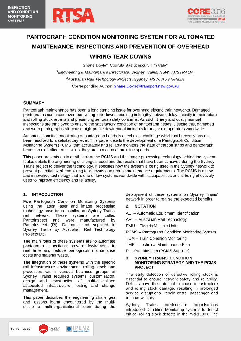
The trial phase of this project comprised a business case for a trial PCMS, the procurement of the trial PantoInspect system following an open international tender, the design and construction of the civil, electrical, communication and signalling infrastructure at one site (Thornleigh) and a six month technical trial.
Figure 1: Thornleigh trial PCMS
Following the successful PCMS trial, a business case for PCMS rollout at four additional locations on the Sydney Trains network was approved. This was followed by the rollout project which included: procurement of the rollout systems; design and construction of multi-disciplined infrastructure at the proposed PCMS sites; integration with various systems and business groups at Sydney Trains; benefits monitoring and validation.
4. PCMS OVERVIEW
4.1 PCMS System Description
The PCMS combines laser and computer vision technology to provide automated analysis of the condition of pantographs on electrified rolling stock during operation. The system is used to generate alarms that require immediate action to prevent potential damage to the overhead wire and train, as well as providing measurements used for
predictive pantograph maintenance. Analysis is performed at mainline speeds allowing continuous real time data capture of vehicles in service. This greatly reduces the time between inspections and allows trending of condition throughout the life of the pantograph.
The PCMS takes three types of measurement when inspecting a pantograph; carbon strip profile, pantograph geometry and uplift displacement.
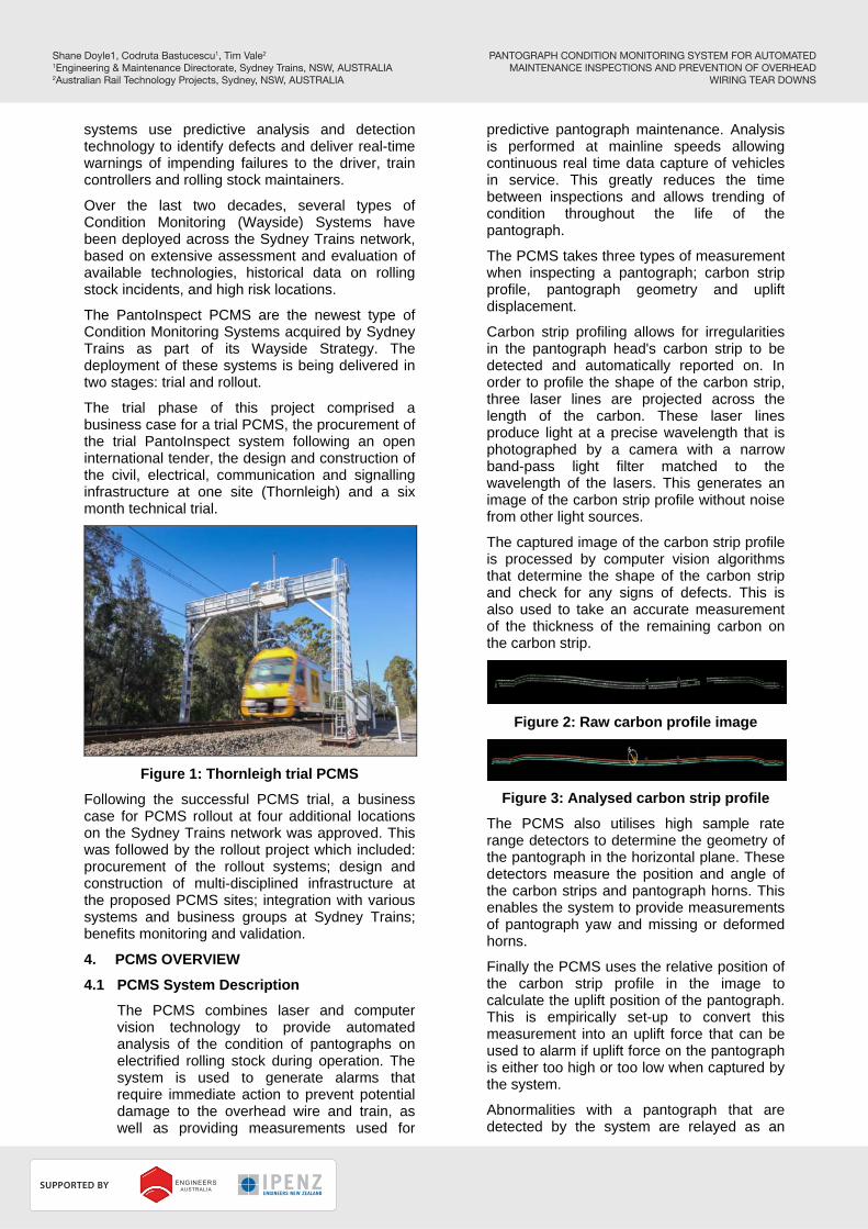
Carbon strip profiling allows for irregularities in the pantograph head's carbon strip to be detected and automatically reported on. In order to profile the shape of the carbon strip, three laser lines are projected across the length of the carbon. These laser lines produce light at a precise wavelength that is photographed by a camera with a narrow band-pass light filter matched to the wavelength of the lasers. This generates an image of the carbon strip profile without noise from other light sources.
The captured image of the carbon strip profile is processed by computer vision algorithms that determine the shape of the carbon strip and check for any signs of defects. This is also used to take an accurate measurement of the thickness of the remaining carbon on the carbon strip.
Figure 2: Raw carbon profile image
Figure 3: Analysed carbon strip profile
The PCMS also utilises high sample rate range detectors to determine the geometry of the pantograph in the horizontal plane. These detectors measure the position and angle of the carbon strips and pantograph horns. This enables the system to provide measurements of pantograph yaw and missing or deformed horns.
Finally the PCMS uses the relative position of the carbon strip profile in the image to calculate the uplift position of the pantograph. This is empirically set-up to convert this measurement into an uplift force that can be used to alarm if uplift force on the pantograph is either too high or too low when captured by the system.
Abnormalities with a pantograph that are detected by the system are relayed as an
PANTOGRAPH CONDITION MONITORING SYSTEM FOR AUTOMATEDMAINTENANCE INSPECTIONS AND PREVENTION OF OVERHEAD
WIRING TEAR DOWNS
Shane Doyle1, Codruta Bastucescu1, Tim Vale2
1Engineering & Maintenance Directorate, Sydney Trains, NSW, AUSTRALIA2Australian Rail Technology Projects, Sydney, NSW, AUSTRALIA
RBroc
SUPPORTED BY
PLATINUM PARTNER
HOST SPONSORS
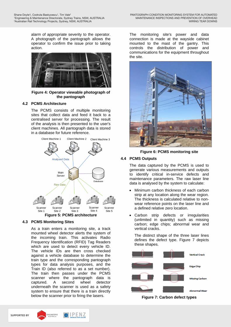
alarm of appropriate severity to the operator. A photograph of the pantograph allows the operator to confirm the issue prior to taking action.
Figure 4: Operator viewable photograph of the pantograph
4.2 PCMS Architecture
The PCMS consists of multiple monitoring sites that collect data and feed it back to a centralised server for processing. The result of the analysis is then presented to the user's client machines. All pantograph data is stored in a database for future reference.
Analysed Data
Raw Data
Main Server
Client Machine 1 Client Machine 2 Client Machine 3
Scanner Site 1
Scanner Site 4
Scanner Site 2
Scanner Site 3
Scanner Site 5
Database
Figure 5: PCMS architecture
4.3 PCMS Monitoring Sites
As a train enters a monitoring site, a track mounted wheel detector alerts the system of the incoming train. This activates Radio Frequency Identification (RFID) Tag Readers which are used to detect every vehicle ID. The vehicle IDs are then cross checked against a vehicle database to determine the train type and the corresponding pantograph types for data analysis purposes, and the Train ID (also referred to as a set number). The train then passes under the PCMS scanner where the pantograph data is captured. A second wheel detector underneath the scanner is used as a safety system to ensure that there is a train directly below the scanner prior to firing the lasers.
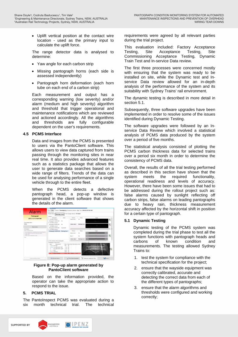
The monitoring site's power and data connection is made at the wayside cabinet mounted to the mast of the gantry. This controls the distribution of power and communications for the equipment throughout the site.
Figure 6: PCMS monitoring site
4.4 PCMS Outputs
The data captured by the PCMS is used to generate various measurements and outputs to identify critical in-service defects and maintenance parameters. The raw laser line data is analysed by the system to calculate:
Minimum carbon thickness of each carbon strip at any location along the wear region. The thickness is calculated relative to non-wear reference points on the laser line and a defined relative zero location.
Carbon strip defects or irregularities (unlimited in quantity) such as missing carbon; edge chips; abnormal wear and vertical cracks.
The distinct shape of the three laser lines defines the defect type. Figure 7 depicts these shapes.
Figure 7: Carbon defect types
PANTOGRAPH CONDITION MONITORING SYSTEM FOR AUTOMATEDMAINTENANCE INSPECTIONS AND PREVENTION OF OVERHEAD
WIRING TEAR DOWNS
Shane Doyle1, Codruta Bastucescu1, Tim Vale2
1Engineering & Maintenance Directorate, Sydney Trains, NSW, AUSTRALIA2Australian Rail Technology Projects, Sydney, NSW, AUSTRALIA
RBroc
SUPPORTED BY
PLATINUM PARTNER
HOST SPONSORS
Uplift vertical position at the contact wire location - used as the primary input to calculate the uplift force.
The range detector data is analysed to determine:
Yaw angle for each carbon strip
Missing pantograph horns (each side is assessed independently)
Pantograph horn deformation (each horn tube on each end of a carbon strip)
Each measurement and output has a corresponding warning (low severity) and/or alarm (medium and high severity) algorithm and threshold that trigger operational and maintenance notifications which are reviewed and actioned accordingly. All the algorithms and thresholds are fully configurable dependent on the user’s requirements.
4.5 PCMS Interface
Data and images from the PCMS is presented to users via the PantoClient software. This allows users to view data captured from trains passing through the monitoring sites in near real time. It also provides advanced features such as a statistics package that allows the user to generate data searches based on a wide range of filters. Trends of the data can be used for analysing performance of a single vehicle through to the entire fleet.
When the PCMS detects a defective pantograph head, a pop-up window is generated in the client software that shows the details of the alarm.
Figure 8: Pop-up alarm generated by PantoClient software
Based on the information provided, the operator can take the appropriate action to respond to the issue.
5. PCMS TRIAL
The PantoInspect PCMS was evaluated during a six month technical trial. The technical
requirements were agreed by all relevant parties during the trial project.
This evaluation included: Factory Acceptance Testing, Site Acceptance Testing, Site Commissioning Acceptance Testing, Dynamic Train Test and In-service Data review.
The first three processes were concerned mostly with ensuring that the system was ready to be installed on site, while the Dynamic test and In-service Data review allowed for an in-depth analysis of the performance of the system and its suitability with Sydney Trains' rail environment.
The dynamic testing is described in more detail in section 5.1.
Subsequently, three software upgrades have been implemented in order to resolve some of the issues identified during Dynamic Testing.
The software upgrades were followed by an In-service Data Review which involved a statistical analysis of PCMS data produced by the system over a period of five months.
The statistical analysis consisted of plotting the PCMS carbon thickness data for selected trains over a period six month in order to determine the consistency of PCMS data.
Overall, the results of all the trial testing performed as described in this section have shown that the system meets the required functionality, operational readiness and levels of accuracy. However, there have been some issues that had to be addressed during the rollout project such as: false alarms caused by sunlight reflecting off carbon strips, false alarms on leading pantographs due to heavy rain, thickness measurement accuracy affected by the horizontal shift in position for a certain type of pantograph.
5.1 Dynamic Testing
Dynamic testing of the PCMS system was completed during the trial phase to test all the system functions with pantograph heads and carbons of known condition and measurements. The testing allowed Sydney Trains to:
1. test the system for compliance with the technical specification for the project;
2. ensure that the wayside equipment was correctly calibrated, accurate and detecting the correct data from each of the different types of pantographs;
3. ensure that the alarm algorithms and thresholds were configured and working correctly;
PANTOGRAPH CONDITION MONITORING SYSTEM FOR AUTOMATEDMAINTENANCE INSPECTIONS AND PREVENTION OF OVERHEAD
WIRING TEAR DOWNS
Shane Doyle1, Codruta Bastucescu1, Tim Vale2
1Engineering & Maintenance Directorate, Sydney Trains, NSW, AUSTRALIA2Australian Rail Technology Projects, Sydney, NSW, AUSTRALIA
RBroc
SUPPORTED BY
PLATINUM PARTNER
HOST SPONSORS
4. simulate a variety of different conditions and faults to determine the typical results that the system will display;
5. calibrate the system for uplift force;
6. validate the accuracy and sensitivity of the uplift force measurements.
Each of the three different pantograph head types on the Sydney Trains fleet were tested across four days and multiple passes were completed with each head type. Test passes included:
Various pass speeds ranging from 10 to 95 km/h (max track speed)
Accelerating and braking through the site
Stopping on the site and proceeding
Various AEI tag configurations to test missing tags and read through scenarios
Constant uplift forces of 8kg, 9.5kg, 11kg and 12.5kg.
Various ambient conditions such as sun positions, ambient temperature and rain.
Dynamic testing of the four additional PCMS installations is also scheduled to be completed prior to commissioning to ensure they are functioning correctly.
6. PCMS DESIGN
The PCMS was designed by PantoInspect and Australian Rail Technology. The core of the technology is PantoInspect’s hardware and software, which was adapted to meet the requirements of Sydney Trains installations. The project included development of a unique arming and train identification system and improved scanner mounting arrangement.
Previous installations of PantoInspect systems used radar to detect incoming trains and information fed from a time table system to identify the train being inspected. For Sydney Trains installations, there was concern that the radar system would interfere with the Automatic Train Protection system being implemented. Furthermore, Sydney Trains fleet was fitted with RFID tags that allowed its vehicles to be identified by wayside equipment. As a result the project required that a new arming and train identification system be integrated with PantoInspect's core technology. This consisted of Frausher wheel detectors and Transcore AEI tag readers to perform these tasks.
The PantoInspect system had been mounted to existing bridges for other installations of this equipment. For Sydney Trains installation it was determined that it would be more cost effective over the life of the equipment to design and build a
special purpose gantry to support the scanner in a position over the running line. In order to maintain the scanner, it was required that access to the unit was possible whilst trains where still running through the site. This led to the gantry design incorporating a caged ladder, full perimeter hand rails and a fine mesh fixed to the floor and hand rails to reduce the risk of maintenance tools being dropped on to the track or trains below.
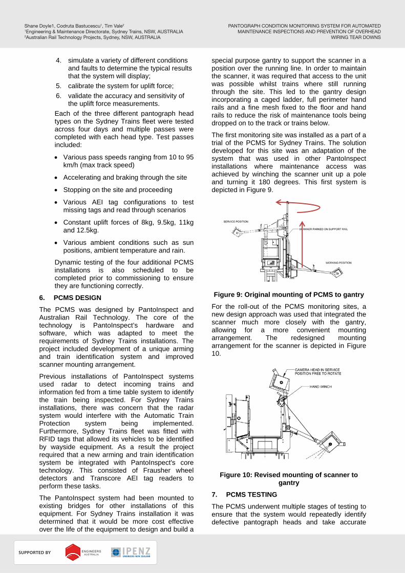
The first monitoring site was installed as a part of a trial of the PCMS for Sydney Trains. The solution developed for this site was an adaptation of the system that was used in other PantoInspect installations where maintenance access was achieved by winching the scanner unit up a pole and turning it 180 degrees. This first system is depicted in Figure 9.
Figure 9: Original mounting of PCMS to gantry
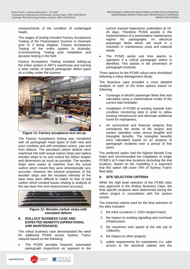
For the roll-out of the PCMS monitoring sites, a new design approach was used that integrated the scanner much more closely with the gantry, allowing for a more convenient mounting arrangement. The redesigned mounting arrangement for the scanner is depicted in Figure 10.
Figure 10: Revised mounting of scanner to gantry
7. PCMS TESTING
The PCMS underwent multiple stages of testing to ensure that the system would repeatedly identify defective pantograph heads and take accurate
PANTOGRAPH CONDITION MONITORING SYSTEM FOR AUTOMATEDMAINTENANCE INSPECTIONS AND PREVENTION OF OVERHEAD
WIRING TEAR DOWNS
Shane Doyle1, Codruta Bastucescu1, Tim Vale2
1Engineering & Maintenance Directorate, Sydney Trains, NSW, AUSTRALIA2Australian Rail Technology Projects, Sydney, NSW, AUSTRALIA
RBroc
SUPPORTED BY
PLATINUM PARTNER
HOST SPONSORS
measurements of the condition of undamaged heads.
The stages of testing included Factory Acceptance Testing of the PantoInspect Scanner in Denmark prior to it being shipped, Factory Acceptance Testing of the entire system in Australia, Commissioning Testing post installation and dynamic testing in the field.
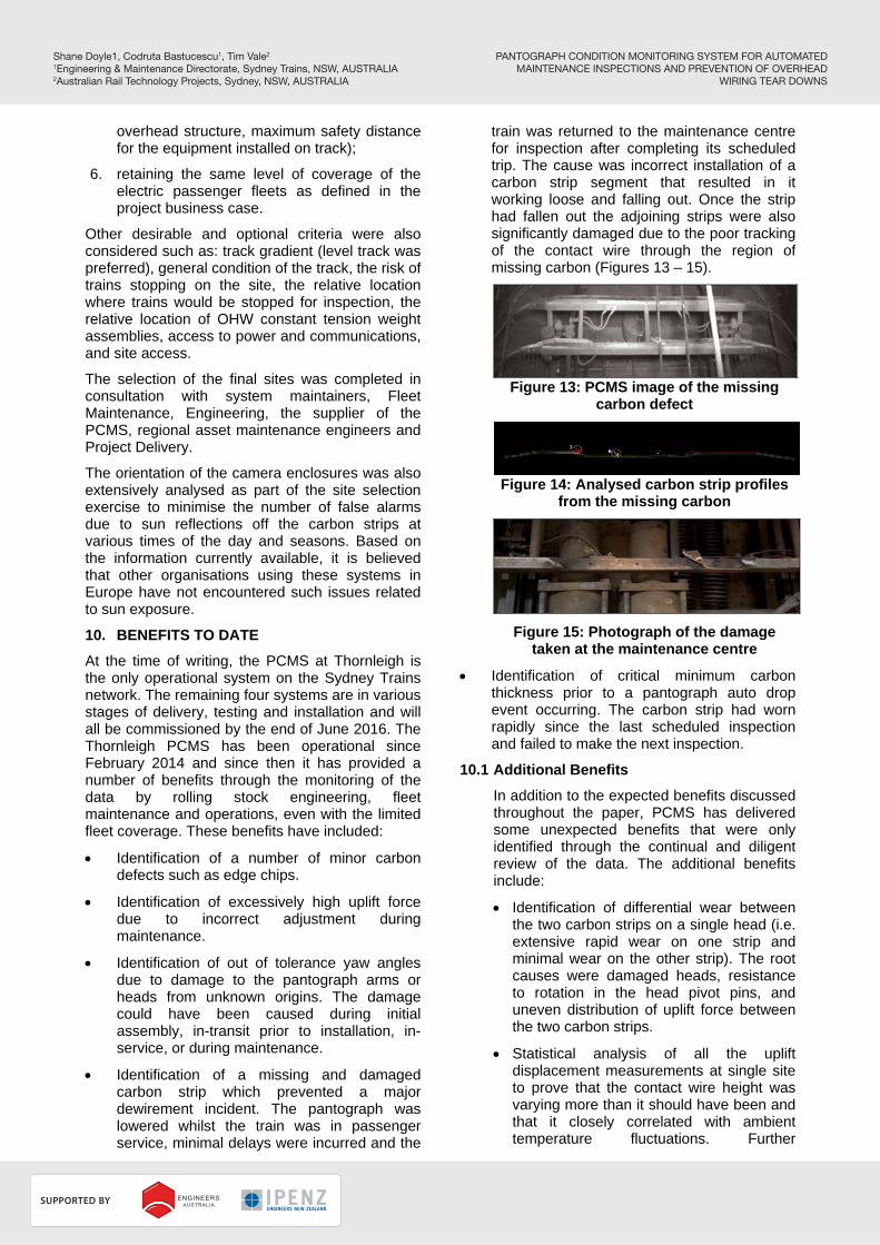
Factory Acceptance Testing included setting-up the entire system in ART's warehouse and running a wide variety of typical pantograph defect types on a trolley under the scanner.
Figure 11: Factory acceptance test set-up.
The Factory Acceptance testing was completed with all pantograph head types of both new and worn condition and with simulated carbon, yaw and horn defects. The simulated carbon defects were machined into both actual carbon strips and replica wooden strips to try and control the defect shapes and dimensions as much as possible. The wooden strips were easier to machine than the actual carbon which meant they were dimensionally very accurate. However the infrared properties of the wooden strips and the resultant intensity of the laser lines were difficult to match to that of real carbon which created issues relating to analysis of the raw laser line and measurement accuracy.
Figure 12: Wooden carbon strips with
simulated defects
8. ROLLOUT BUSINESS CASE AND EXPECTED BENEFITS (OPERATIONAL AND MAINTENANCE)
The rollout business case demonstrated the need for additional PCMS across Sydney Trains' network based on the following:
The PCMS provides frequent, automated pantograph inspections as opposed to the
current manual inspections undertaken at 15-45 days. Therefore PCMS assists in the implementation of a preventative maintenance regime for pantographs on electrical passenger fleets which will result in a reduction in maintenance costs and material waste.
The PCMS sends real time alarms to operators if a critical pantograph defect is identified. This assists in the prevention of pantograph incidents.
Three options for the PCMS rollout were shortlisted following a Value Management Study.
The Business case provided a more detailed analysis of each of the three options based on following:
Coverage of electric passenger fleets that was calculated using a mathematical model of the current train timetable;
Installation of PCMS at existing wayside train condition monitoring sites in order to utilise existing infrastructure and eliminate additional travel for maintainers;
An economical and financial analysis that considered the whole of life project and system operation costs versus tangible and intangible benefits. The intangible benefits were calculated based on an analysis of pantograph incidents over a period of five years.
The preferred option had the highest Benefit Cost Ratio and recommended the installation of single PCMS’s at 5 main-line locations (including the trial location). Based on the modelling it is expected that this option will cover 75% of Sydney Trains' fleet daily.
9. SITE SELECTION CRITERIA
While the high level selection of the PCMS sites was approved in the Rollout Business Case, the final specific locations were determined during the rollout project in consultation with the system vendor.
The essential criteria used for the final selection of the sites included:
1. the track curvature (> 120m tangent track);
2. the impact on existing signalling and overhead infrastructure;
3. the maximum train speed at the site (up to 130km/h);
4. the impact on other projects;
5. safety requirements for maintainers (i.e. safe access to the electrical cabinet and the
PANTOGRAPH CONDITION MONITORING SYSTEM FOR AUTOMATEDMAINTENANCE INSPECTIONS AND PREVENTION OF OVERHEAD
WIRING TEAR DOWNS
Shane Doyle1, Codruta Bastucescu1, Tim Vale2
1Engineering & Maintenance Directorate, Sydney Trains, NSW, AUSTRALIA2Australian Rail Technology Projects, Sydney, NSW, AUSTRALIA
RBroc
SUPPORTED BY
PLATINUM PARTNER
HOST SPONSORS
overhead structure, maximum safety distance for the equipment installed on track);
6. retaining the same level of coverage of the electric passenger fleets as defined in the project business case.
Other desirable and optional criteria were also considered such as: track gradient (level track was preferred), general condition of the track, the risk of trains stopping on the site, the relative location where trains would be stopped for inspection, the relative location of OHW constant tension weight assemblies, access to power and communications, and site access.
The selection of the final sites was completed in consultation with system maintainers, Fleet Maintenance, Engineering, the supplier of the PCMS, regional asset maintenance engineers and Project Delivery.
The orientation of the camera enclosures was also extensively analysed as part of the site selection exercise to minimise the number of false alarms due to sun reflections off the carbon strips at various times of the day and seasons. Based on the information currently available, it is believed that other organisations using these systems in Europe have not encountered such issues related to sun exposure.
10. BENEFITS TO DATE
At the time of writing, the PCMS at Thornleigh is the only operational system on the Sydney Trains network. The remaining four systems are in various stages of delivery, testing and installation and will all be commissioned by the end of June 2016. The Thornleigh PCMS has been operational since February 2014 and since then it has provided a number of benefits through the monitoring of the data by rolling stock engineering, fleet maintenance and operations, even with the limited fleet coverage. These benefits have included:
Identification of a number of minor carbon defects such as edge chips.
Identification of excessively high uplift force due to incorrect adjustment during maintenance.
Identification of out of tolerance yaw angles due to damage to the pantograph arms or heads from unknown origins. The damage could have been caused during initial assembly, in-transit prior to installation, in-service, or during maintenance.
Identification of a missing and damaged carbon strip which prevented a major dewirement incident. The pantograph was lowered whilst the train was in passenger service, minimal delays were incurred and the
train was returned to the maintenance centre for inspection after completing its scheduled trip. The cause was incorrect installation of a carbon strip segment that resulted in it working loose and falling out. Once the strip had fallen out the adjoining strips were also significantly damaged due to the poor tracking of the contact wire through the region of missing carbon (Figures 13 – 15).
Figure 13: PCMS image of the missing carbon defect
Figure 14: Analysed carbon strip profiles from the missing carbon
Figure 15: Photograph of the damage taken at the maintenance centre
Identification of critical minimum carbon thickness prior to a pantograph auto drop event occurring. The carbon strip had worn rapidly since the last scheduled inspection and failed to make the next inspection.
10.1 Additional Benefits
In addition to the expected benefits discussed throughout the paper, PCMS has delivered some unexpected benefits that were only identified through the continual and diligent review of the data. The additional benefits include:
Identification of differential wear between the two carbon strips on a single head (i.e. extensive rapid wear on one strip and minimal wear on the other strip). The root causes were damaged heads, resistance to rotation in the head pivot pins, and uneven distribution of uplift force between the two carbon strips.
Statistical analysis of all the uplift displacement measurements at single site to prove that the contact wire height was varying more than it should have been and that it closely correlated with ambient temperature fluctuations. Further
PANTOGRAPH CONDITION MONITORING SYSTEM FOR AUTOMATEDMAINTENANCE INSPECTIONS AND PREVENTION OF OVERHEAD
WIRING TEAR DOWNS
Shane Doyle1, Codruta Bastucescu1, Tim Vale2
1Engineering & Maintenance Directorate, Sydney Trains, NSW, AUSTRALIA2Australian Rail Technology Projects, Sydney, NSW, AUSTRALIA
RBroc
SUPPORTED BY
PLATINUM PARTNER
HOST SPONSORS
investigation by the infrastructure maintainer found that the OHW constant tension system responsible for the section had seized and required urgent maintenance. Following the maintenance the latest PCMS measurement were able to prove that the rectification work had been successful.
Detection of an abnormal roll angle of some pantograph heads that needed to be investigated further. The investigation found that the bogie air suspension airbag heights had been incorrectly set from side to side which caused permanent body roll and thus pantograph head roll. The air bag heights were corrected and new PCMS images confirmed the improvement. PI are working on providing a pantograph carbon roll angle measurements for all heads in the near future.
11. FALSE ALARMS
During the trial and the pre-commissioning phases a number of false alarm scenarios were identified that have since been resolved by PI. The scenarios included:
Heavy rain was generating false alarms due to water build up on the contact wire which creates a “splash” effect of the lead carbon strip and impacts the laser images being recorded by PCMS. See Figure 16 for an example. This was resolved by PI improving the filtering of the laser line images.
Figure 16: Heavy rain example
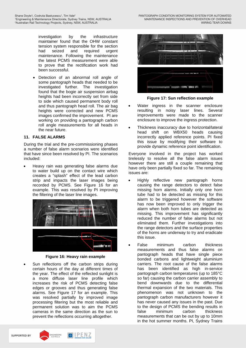
Sun reflections off the carbon strips during certain hours of the day at different times of the year. The effect of the reflected sunlight is a more diffuse laser line profile which increases the risk of PCMS detecting false edges or grooves and thus generating false alarms. See Figure 17 for an example. This was resolved partially by improved image processing filtering but the most reliable and permanent solution was to aim the PCMS cameras in the same direction as the sun to prevent the reflections occurring altogether.
Figure 17: Sun reflection example
Water ingress in the scanner enclosure resulting in noisy laser lines. Several improvements were made to the scanner enclosure to improve the ingress protection.
Thickness inaccuracy due to horizontal/lateral head shift on WBX50 heads causing incorrectly applied reference points. PI fixed this issue by modifying their software to provide dynamic reference point identification.
Everyone involved in the project has worked tirelessly to resolve all the false alarm issues however there are still a couple remaining that have only been partially fixed so far. The remaining issues are:
Highly reflective new pantograph horns causing the range detectors to detect false missing horn alarms. Initially only one horn tube had to be detected as missing for this alarm to be triggered however the software has now been improved to only trigger the alarm when both horn tubes are detected as missing. This improvement has significantly reduced the number of false alarms but not eliminated them. Further investigations into the range detectors and the surface properties of the horns are underway to try and eradicate this issue.
False minimum carbon thickness measurements and thus false alarms on pantograph heads that have single piece bonded carbons and lightweight aluminium carriers. The root cause of the false alarms has been identified as high in-service pantograph carbon temperatures (up to 185°C so far) causing the carbon carrier assembly to bend downwards due to the differential thermal expansion of the two materials. This phenomenon was not unknown to the pantograph carbon manufacturers however it has never caused any issues in the past. Due to the design of PCMS the bending results in false minimum carbon thickness measurements that can be out by up to 10mm in the hot summer months. PI, Sydney Trains
PANTOGRAPH CONDITION MONITORING SYSTEM FOR AUTOMATEDMAINTENANCE INSPECTIONS AND PREVENTION OF OVERHEAD
WIRING TEAR DOWNS
Shane Doyle1, Codruta Bastucescu1, Tim Vale2
1Engineering & Maintenance Directorate, Sydney Trains, NSW, AUSTRALIA2Australian Rail Technology Projects, Sydney, NSW, AUSTRALIA
RBroc
SUPPORTED BY
PLATINUM PARTNER
HOST SPONSORS
and the pantograph carbon manufacturers are currently working on a number of potential solutions to the problem. In the meantime minimum carbon thickness alarms for these head types have been removed and a warning threshold has been applied that compensates for the bending.
12. UPLIFT FORCE CALIBRATION
The PCMS is capable of measuring the vertical position of the pantograph head (also referred to as Pantograph Displacement) to an accuracy of +/- 2mm which provides the primary input for attempting to calculate the uplift force in newtons. Unfortunately there is no simple correlation between the displacement and uplift force and Sydney Trains is working with PI to develop an algorithm that will consider all the variables that affect the pantograph head height when it passes through PCMS. These variables include:
The aerodynamic effects on each of the different pantograph heads which are controlled by pass speed, position in the consist, pantograph orientation to the direction of travel and the design of pantograph arm and head.
Ambient temperature which can affect the height of the contact wire.
Once all the variables are understood and controlled then each of the PCMS sites can be individually calibrated against known constant uplift force pantographs, over a range of uplift forces. The calibration tests will be conducted using a full range of pass speeds and ambient temperatures.
13. PCMS INTEGRATION WITH THE BUSINESS
The integration of the PCMS with various business groups at Sydney Trains has a critical role in the successful rollout of these systems.
The PCMS has to be integrated with six main business areas within Sydney Trains: Fleet Maintenance Centres, Mechanical Control, Train Operations, Infrastructure Control Operations, Systems and Infrastructure Maintainers, and Asset Management.
This integration not only has a significant change management component but it also has an impact on the overall design of the PCMS and associated infrastructure.
More details regarding the integration with some of the business groups mentioned above are presented in sections 13.1 – 13.3.
13.1 Operational Integration
Real time PCMS alarms received and validated by Mechanical Control operators are communicated to train drivers via the Rail
Operations staff in order minimise disruptions to rail network services.
The pantograph alarms validation and communication flow as well as the relevant instructions to address these have been developed by a multi-disciplined team of subject matter experts including Fleet and Systems Maintainers, Engineering, Train and Infrastructure Control Operators, Network Rules, Train Crew, Safety, Risk and Human Factors.
Training was developed and delivered to the recipients of the PCMS alarms and all the other users of the new procedures have been briefed.
The communications design for the PCMS had to address the requirements for the operational users which involved a change to the original Client PC solution. The location of the screen for Mechanical Control Operators was determined based on a Human Factors analysis which also covered the customisation of the PCMS visual and audio notifications that are sent simultaneously with pantograph alarms.
13.2 Fleet Maintenance Integration
One of the major intended benefits for the PCMS is to use the data for predictive and condition based maintenance which can eliminate time based visual inspections that are both costly and difficult to manage with the limited availability of both the rolling stock and maintenance inspection roads and staff. The other maintenance benefit is using the data to minimise the wastage of pantograph carbon material. Both of these benefits need to be properly managed throughout the business to be successful.
Changes to the Technical Maintenance Plan (TMP) need to be determined, reviewed and implemented by Asset Management, Engineering and System Integrity, and Fleet Maintenance. The changes need to provide clear directions on how to use the PMCS data when it is available and what to do in the event that the data is not available or the vehicle has not been monitored by PCMS for an extended period of time. The system needs to be capable of providing the rolling stock maintainers with concise reports that require minimal interpretation or analysis. Something as simple as a traffic light status for each pantograph head and carbon strip is ideal. Sydney Trains will be using status severities of “Ok”, “Check”, “Replace” and “Do Not Run” to clearly indicate the maintenance state and action required. The
PANTOGRAPH CONDITION MONITORING SYSTEM FOR AUTOMATEDMAINTENANCE INSPECTIONS AND PREVENTION OF OVERHEAD
WIRING TEAR DOWNS
Shane Doyle1, Codruta Bastucescu1, Tim Vale2
1Engineering & Maintenance Directorate, Sydney Trains, NSW, AUSTRALIA2Australian Rail Technology Projects, Sydney, NSW, AUSTRALIA
RBroc
SUPPORTED BY
PLATINUM PARTNER
HOST SPONSORS
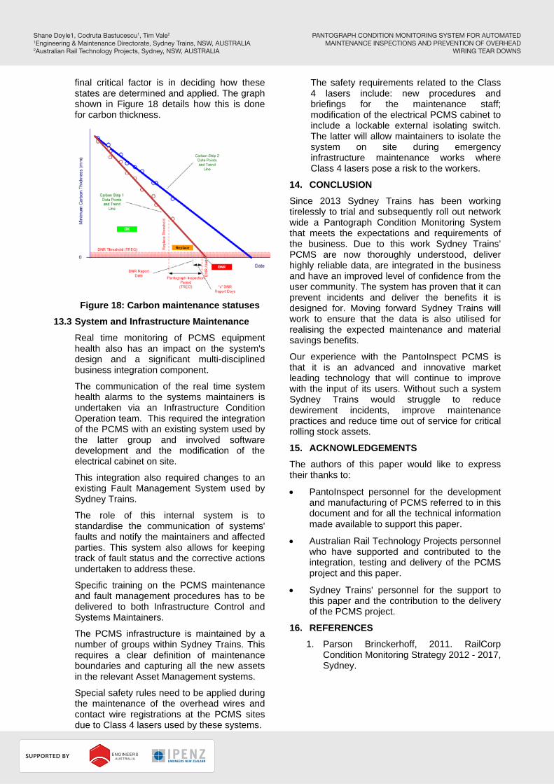
final critical factor is in deciding how these states are determined and applied. The graph shown in Figure 18 details how this is done for carbon thickness.
Figure 18: Carbon maintenance statuses
13.3 System and Infrastructure Maintenance
Real time monitoring of PCMS equipment health also has an impact on the system's design and a significant multi-disciplined business integration component.
The communication of the real time system health alarms to the systems maintainers is undertaken via an Infrastructure Condition Operation team. This required the integration of the PCMS with an existing system used by the latter group and involved software development and the modification of the electrical cabinet on site.
This integration also required changes to an existing Fault Management System used by Sydney Trains.
The role of this internal system is to standardise the communication of systems' faults and notify the maintainers and affected parties. This system also allows for keeping track of fault status and the corrective actions undertaken to address these.
Specific training on the PCMS maintenance and fault management procedures has to be delivered to both Infrastructure Control and Systems Maintainers.
The PCMS infrastructure is maintained by a number of groups within Sydney Trains. This requires a clear definition of maintenance boundaries and capturing all the new assets in the relevant Asset Management systems.
Special safety rules need to be applied during the maintenance of the overhead wires and contact wire registrations at the PCMS sites due to Class 4 lasers used by these systems.
The safety requirements related to the Class 4 lasers include: new procedures and briefings for the maintenance staff; modification of the electrical PCMS cabinet to include a lockable external isolating switch. The latter will allow maintainers to isolate the system on site during emergency infrastructure maintenance works where Class 4 lasers pose a risk to the workers.
14. CONCLUSION
Since 2013 Sydney Trains has been working tirelessly to trial and subsequently roll out network wide a Pantograph Condition Monitoring System that meets the expectations and requirements of the business. Due to this work Sydney Trains’ PCMS are now thoroughly understood, deliver highly reliable data, are integrated in the business and have an improved level of confidence from the user community. The system has proven that it can prevent incidents and deliver the benefits it is designed for. Moving forward Sydney Trains will work to ensure that the data is also utilised for realising the expected maintenance and material savings benefits.
Our experience with the PantoInspect PCMS is that it is an advanced and innovative market leading technology that will continue to improve with the input of its users. Without such a system Sydney Trains would struggle to reduce dewirement incidents, improve maintenance practices and reduce time out of service for critical rolling stock assets.
15. ACKNOWLEDGEMENTS
The authors of this paper would like to express their thanks to:
PantoInspect personnel for the development and manufacturing of PCMS referred to in this document and for all the technical information made available to support this paper.
Australian Rail Technology Projects personnel who have supported and contributed to the integration, testing and delivery of the PCMS project and this paper.
Sydney Trains' personnel for the support to this paper and the contribution to the delivery of the PCMS project.
16. REFERENCES
1. Parson Brinckerhoff, 2011. RailCorp Condition Monitoring Strategy 2012 - 2017, Sydney.
PANTOGRAPH CONDITION MONITORING SYSTEM FOR AUTOMATEDMAINTENANCE INSPECTIONS AND PREVENTION OF OVERHEAD
WIRING TEAR DOWNS
Shane Doyle1, Codruta Bastucescu1, Tim Vale2
1Engineering & Maintenance Directorate, Sydney Trains, NSW, AUSTRALIA2Australian Rail Technology Projects, Sydney, NSW, AUSTRALIA
RBroc
SUPPORTED BY
PLATINUM PARTNER
HOST SPONSORS