
PacketStar PSAX System Connections Provisioning Guide for ...
696
Doc. No.: 255-700-377 PacketStar ® PSAX System Connections Provisioning Guide for PacketStar ® PSAX Multiservice Media Gateways Issue 1, July 2002 System Software Release 8.0.0 AQueView ® EMS Software Release 6.0
-
Upload
khangminh22 -
Category
Documents
-
view
0 -
download
0
Transcript of PacketStar PSAX System Connections Provisioning Guide for ...

Doc. No.: 255-700-377
PacketStar® PSAX System Connections Provisioning Guidefor PacketStar®PSAX Multiservice Media Gateways
Issue 1, July 2002
System Software Release 8.0.0
AQueView® EMS Software Release 6.0

Copyright © 2002 by Lucent Technologies. All rights reserved.
For trademark, regulatory compliance, and related legal information, see the "Copyright and Legal Notices" section.

PacketStar® PSAX System Connections Provisioning Guide, Issue 1 Release 8.0.0
255-700-377 iii
Legal Notices, Safety, and RegulatoryInformation
Copyright
Copyright © 2002 by Lucent Technologies. All rights reserved.
This material is protected by the copyright laws of the United States and other countries. It may not be reproduced, distributed, or altered in any fash-ion by any entity (either internal or external to Lucent Technologies), except in accordance with applicable agreements, contracts or licensing, without the express written consent of the originating organization and the business management owner of the material.
This document was prepared by the Information Design and Development Team of Lucent Technologies, PacketStar PSAX products. Offices are located in Landover, Maryland, USA.
Trademarks
PacketStar, AQueView, Lucent, Lucent Technologies, and the Lucent Technolo-gies logo are registered trademarks of Lucent Technologies in the USA. Other product and brand names mentioned in this guide are trademarks or regis-tered trademarks of their respective owners.
Notices
The information in this document is for informational use only, is subject to change without notice, and should not be construed as a commitment by Lucent Technologies, Inc. This document is without warranty of any kind, either expressed or implied. Lucent Technologies, Inc. assumes no responsi-bility for any errors, inaccuracies, or omissions. Neither is any liability assumed for damages resulting from the use of the information or instruc-tions contained herein. Lucent Technologies, Inc. is not responsible for any damage or loss to your data or equipment resulting either directly or indi-rectly from use of this document.
Legal Notices, Safety, and Regulatory InformationNotices
iv 255-700-377
PacketStar® PSAX System Connections Provisioning Guide, Issue 1 Release 8.0.0

255-700-377 v
PacketStar® PSAX System Connections Provisioning Guide, Issue 1 Release 8.0.0
Contents
Legal Notices, Safety, and Regulatory Information . . . . . . . . . . . . . . . . . iii
Copyright . . . . . . . . . . . . . . . . . . . . . . . . . . . . . . . . . . . . . . . . . . . . . . . . . . . . . . . . . . . . . iii
Trademarks . . . . . . . . . . . . . . . . . . . . . . . . . . . . . . . . . . . . . . . . . . . . . . . . . . . . . . . . . . . iii
Notices . . . . . . . . . . . . . . . . . . . . . . . . . . . . . . . . . . . . . . . . . . . . . . . . . . . . . . . . . . . . . . . iii
List of Figures . . . . . . . . . . . . . . . . . . . . . . . . . . . . . . . . . . . . . . . . . . . . . . xiv
List of Tables . . . . . . . . . . . . . . . . . . . . . . . . . . . . . . . . . . . . . . . . . . . . . xxviii
1 Getting Started. . . . . . . . . . . . . . . . . . . . . . . . . . . . . . . . . . . . . . . . . . . . . . 1-1
Purpose of This Guide . . . . . . . . . . . . . . . . . . . . . . . . . . . . . . . . . . . . . . . . . . . . . . . . . .1-1
Audience for This Guide . . . . . . . . . . . . . . . . . . . . . . . . . . . . . . . . . . . . . . . . . . . . . . . .1-1
What You Should Know . . . . . . . . . . . . . . . . . . . . . . . . . . . . . . . . . . . . . . . . . . . . . . . .1-1
Related Reading . . . . . . . . . . . . . . . . . . . . . . . . . . . . . . . . . . . . . . . . . . . . . . . . . . . . . . .1-1
Lucent Technologies Information Products . . . . . . . . . . . . . . . . . . . . . . . . . . . . . . . . .1-1
Product Information Library . . . . . . . . . . . . . . . . . . . . . . . . . . . . . . . . . . . . . . . . .1-1
Printed Documents. . . . . . . . . . . . . . . . . . . . . . . . . . . . . . . . . . . . . . . . . . . . . . . .1-1
Other Publications . . . . . . . . . . . . . . . . . . . . . . . . . . . . . . . . . . . . . . . . . . . . . . . . . . .1-2
About Lucent Technologies . . . . . . . . . . . . . . . . . . . . . . . . . . . . . . . . . . . . . . . . . . . . . .1-2
About the PacketStar PSAX Product Family. . . . . . . . . . . . . . . . . . . . . . . . . . . . . . . . .1-2
PSAX 1000 Multiservice Media Gateway. . . . . . . . . . . . . . . . . . . . . . . . . . . . . . . . . . .1-2
PSAX 1250 Multiservice Media Gateway. . . . . . . . . . . . . . . . . . . . . . . . . . . . . . . . . . .1-3
PSAX 2300 Multiservice Media Gateway. . . . . . . . . . . . . . . . . . . . . . . . . . . . . . . . . . .1-3
PSAX 4500 Multiservice Media Gateway. . . . . . . . . . . . . . . . . . . . . . . . . . . . . . . . . . .1-4
Text Conventions . . . . . . . . . . . . . . . . . . . . . . . . . . . . . . . . . . . . . . . . . . . . . . . . . . . . . .1-4
Technical Support . . . . . . . . . . . . . . . . . . . . . . . . . . . . . . . . . . . . . . . . . . . . . . . . . . . . . .1-5
Before You Begin . . . . . . . . . . . . . . . . . . . . . . . . . . . . . . . . . . . . . . . . . . . . . . . . . . . . . .1-5
Comments on This Guide. . . . . . . . . . . . . . . . . . . . . . . . . . . . . . . . . . . . . . . . . . . . . . . .1-5
Part A: Connections Using the Console Interface
.1-5
.1-5
.1-5
.1-4
.1-4
.1-3
.1-3
.1-2
.1-2
.1-2
.1-2
.1-1
.1-1
.1-1
.1-1
.1-1
.1-1
.1-1
1-1
xxviii
xiv
iii
iii
iii
iii
Contents
vi 255-700-377
PacketStar® PSAX System Connections Provisioning Guide, Issue 1 Release 8.0.0
2 Provisioning PVC Connections Using the Console Interface. . . . . . . . . . 2-1
Overview of This Chapter. . . . . . . . . . . . . . . . . . . . . . . . . . . . . . . . . . . . . . . . . . . . . . . 2-1
Connection Types Supported . . . . . . . . . . . . . . . . . . . . . . . . . . . . . . . . . . . . . . . . . . . . 2-1
Data Flow in PVC Connections . . . . . . . . . . . . . . . . . . . . . . . . . . . . . . . . . . . . . . . . . . . 2-2
Connections With I/O Modules for Compressed Voice . . . . . . . . . . . . . . . . . . . . . 2-2
Provisioning PVC Connections . . . . . . . . . . . . . . . . . . . . . . . . . . . . . . . . . . . . . . . . . . . 2-3
Configuring an AAL2 Trunking Connection . . . . . . . . . . . . . . . . . . . . . . . . . . . . . . . . 2-4
Adding ATM-to-ATM VCC PVC Connection . . . . . . . . . . . . . . . . . . . . . . . . . . . . . . . 2-17
Viewing ATM-to-ATM VCC PVC Statistics . . . . . . . . . . . . . . . . . . . . . . . . . . . . . 2-26
Adding/Viewing a Backup PVC Connection . . . . . . . . . . . . . . . . . . . . . . . . . . . . . . . 2-28
Adding ATM-to-ATM VPC PVC Connections . . . . . . . . . . . . . . . . . . . . . . . . . . . . . . 2-31
Creating a ATM-to-ATM VPC Connection . . . . . . . . . . . . . . . . . . . . . . . . . . . . . 2-31
Viewing ATM-to-ATM VPC Statistics . . . . . . . . . . . . . . . . . . . . . . . . . . . . . . . . . 2-41
Adding/Viewing a Backup ATM-to-ATM VPC Connection . . . . . . . . . . . . . . . . . 2-43
Adding Bridge-to-ATM VCC PVC Connections . . . . . . . . . . . . . . . . . . . . . . . . . . . . . 2-46
Accessing the Bridge-to-ATM VCC PVC Table Window. . . . . . . . . . . . . . . . . . . . . . . 2-47
Creating a Bridge-to-ATM VCC PVC Connection . . . . . . . . . . . . . . . . . . . . . . . . . . . 2-49
Creating a Backup Bridge-to-ATM VCC PVC Connection . . . . . . . . . . . . . . . . . . . . . 2-56
Viewing Connection Parameters for a Bridge-to-ATM VCC PVC Connection . . . . . . 2-59
Viewing Statistics for a Bridge-to-ATM VCC PVC Connection. . . . . . . . . . . . . . . . . . 2-60
Deleting a Bridge-to-ATM VCC PVC Connection . . . . . . . . . . . . . . . . . . . . . . . . . . . 2-62
Adding Bridge-to-Bridge Connections . . . . . . . . . . . . . . . . . . . . . . . . . . . . . . . . . . . 2-64
Viewing Statistics. . . . . . . . . . . . . . . . . . . . . . . . . . . . . . . . . . . . . . . . . . . . . . . . . . . 2-68
Adding Circuit Emulation-to-ATM VCC PVC Connections. . . . . . . . . . . . . . . . . . . . . 2-70
Creating a Circuit Emulation-to-ATM VCC Connection . . . . . . . . . . . . . . . . . . . 2-71
Connection Capacity of DSP2x Modes. . . . . . . . . . . . . . . . . . . . . . . . . . . . . . . . 2-73
Connection Statistics . . . . . . . . . . . . . . . . . . . . . . . . . . . . . . . . . . . . . . . . . . . . . 2-83
Backup Connection . . . . . . . . . . . . . . . . . . . . . . . . . . . . . . . . . . . . . . . . . . . . . . 2-85
Adding Circuit Emulation-to-Circuit Emulation PVC Connections . . . . . . . . . . . . . . . 2-88
Creating a Circuit Emulation-to-Circuit Emulation Connection . . . . . . . . . . . . . . 2-89
Connection Capacity of DSP2x Modes. . . . . . . . . . . . . . . . . . . . . . . . . . . . . . . . 2-90
Viewing Connection Statistics . . . . . . . . . . . . . . . . . . . . . . . . . . . . . . . . . . . . . . . . . 2-95
Adding a Frame Relay-to-ATM VCC PVC Connection . . . . . . . . . . . . . . . . . . . . . . . . 2-97
Creating a Frame Relay-to-ATM VCC PVC Connection. . . . . . . . . . . . . . . . . . . . 2-97
Configuring Traffic Parameters . . . . . . . . . . . . . . . . . . . . . . . . . . . . . . . . . . . . 2-103
Viewing the Statistics Window . . . . . . . . . . . . . . . . . . . . . . . . . . . . . . . . . . . . 2-107
Adding a Frame Relay-to-Frame Relay PVC Connection . . . . . . . . . . . . . . . . . . . . . 2-109
2-103
2-97
2-97
2-95
2-90
2-89
2-88
2-85
2-83
2-73
2-71
2-70
2-68
2-64
2-62
2-60
2-59
2-56
2-49
2-47
2-46
2-43
2-41
2-31
2-31
2-28
2-26
2-17
2-4
2-3
2-2
2-2
2-1
2-1
2-1
2-109
2-107
Contents
255-700-377 vii
PacketStar® PSAX System Connections Provisioning Guide, Issue 1 Release 8.0.0
Creating a Frame Relay-to-Frame PVC Relay Connection . . . . . . . . . . . . . . . . .2-109
Configuring Traffic Parameters . . . . . . . . . . . . . . . . . . . . . . . . . . . . . . . . . . . . .2-113
Viewing the Statistics Window . . . . . . . . . . . . . . . . . . . . . . . . . . . . . . . . . . . . .2-115
Adding a GR-303-to-AAL2 VCC PVC Connection . . . . . . . . . . . . . . . . . . . . . . . . . .2-118
Setting Up the PSAX System for In-Band Management Connections. . . . . . . . .2-118
Creating an In-Band-to-ATM VCC Connection . . . . . . . . . . . . . . . . . . . . . . . . .2-119
Configuring an In-Band ATM Backup PVC Connection . . . . . . . . . . . . . . . . . . .2-126
Creating a VBR-to-ATM VCC PVC Connection . . . . . . . . . . . . . . . . . . . . . . . . .2-128
Viewing the VBR-to-ATM Connection Statistics . . . . . . . . . . . . . . . . . . . . . . . .2-137
Adding/Viewing a Backup PVC Connection . . . . . . . . . . . . . . . . . . . . . . . . . . .2-139
Adding VBR-to-VBR VCC PVC Connections . . . . . . . . . . . . . . . . . . . . . . . . . . . . . .2-142
3 Provisioning SPVC Connections Using the Console Interface. . . . . . . . . 3-1
Overview of This Chapter . . . . . . . . . . . . . . . . . . . . . . . . . . . . . . . . . . . . . . . . . . . . . . .3-1
Connection Types Supported . . . . . . . . . . . . . . . . . . . . . . . . . . . . . . . . . . . . . . . . . . . .3-1
Connections With I/O Modules for Compressed Voice . . . . . . . . . . . . . . . . . . . . .3-2
. . . . . . . . . . . . . . . . . . . . . . . . . . . . . . . . . . . . . . . . . . . . . . . . . . . . . . . . . . . . . .3-2
SPVC Reconnection Prioritization for IMA Interfaces . . . . . . . . . . . . . . . . . . . . . . . . .3-2
Setting Up Call Control Resource Allocations . . . . . . . . . . . . . . . . . . . . . . . . . . . . . . .3-3
Setting Up an ATM AAL2 SPVC Trunk . . . . . . . . . . . . . . . . . . . . . . . . . . . . . . . . . . . . .3-8
Provisioning SPVC Connections . . . . . . . . . . . . . . . . . . . . . . . . . . . . . . . . . . . . . . . . .3-28
Adding ATM-to-ATM VCC SPVC Connections. . . . . . . . . . . . . . . . . . . . . . . . . . . . . .3-33
Creating an ATM-to-ATM VCC SPVC Connection . . . . . . . . . . . . . . . . . . . . . . . .3-33
Viewing Connection Statistics . . . . . . . . . . . . . . . . . . . . . . . . . . . . . . . . . . . . . .3-44
Adding NSAP Addresses . . . . . . . . . . . . . . . . . . . . . . . . . . . . . . . . . . . . . . . . . .3-46
Adding ATM-to-ATM VPC SPVC Connections . . . . . . . . . . . . . . . . . . . . . . . . . . . . . .3-48
Creating a Connection . . . . . . . . . . . . . . . . . . . . . . . . . . . . . . . . . . . . . . . . . . . .3-48
Viewing Connection Statistics . . . . . . . . . . . . . . . . . . . . . . . . . . . . . . . . . . . . . .3-56
Adding NSAP Addresses. . . . . . . . . . . . . . . . . . . . . . . . . . . . . . . . . . . . . . . . . . .3-59
Adding Circuit Emulation-to-ATM VCC SPVC Connections . . . . . . . . . . . . . . . . . . . .3-61
Creating a Circuit Emulation-to-ATM Connection . . . . . . . . . . . . . . . . . . . . . . . .3-61
Connection Capacity of DSP2x Modes . . . . . . . . . . . . . . . . . . . . . . . . . . . . . . . .3-63
Configuring Digital Signal Processing (DSP2) Parameters . . . . . . . . . . . . . . . . . .3-69
Viewing Connection Statistics . . . . . . . . . . . . . . . . . . . . . . . . . . . . . . . . . . . . . .3-73
Adding Circuit Emulation-to-ATM Standard AAL2 VCC SPVC Connections . . . . . . . .3-75
Adding Frame Relay-to-ATM VCC SPVC Connections . . . . . . . . . . . . . . . . . . . . . . . .3-82
Creating a Frame Relay-to-ATM VCC SPVC Connection . . . . . . . . . . . . . . . . . . .3-82
Configuring Traffic Parameters . . . . . . . . . . . . . . . . . . . . . . . . . . . . . . . . . . . . . .3-91.3-91
.3-82
.3-82
.3-75
.3-73
.3-69
.3-63
.3-61
.3-61
.3-59
.3-56
.3-48
.3-48
.3-46
.3-44
.3-33
.3-33
.3-28
.3-8
.3-3
.3-2
.3-2
.3-2
.3-1
.3-1
3-1
.2-142
.2-139
.2-137
.2-128
.2-126
.2-119
.2-118
.2-118
.2-115
.2-113
.2-109

Contents
viii 255-700-377
PacketStar® PSAX System Connections Provisioning Guide, Issue 1 Release 8.0.0
Viewing Connection Statistics . . . . . . . . . . . . . . . . . . . . . . . . . . . . . . . . . . . . . . 3-94
Adding VBR-to-ATM VCC SPVC Connections. . . . . . . . . . . . . . . . . . . . . . . . . . . . . . 3-97
Creating a VBR-to-ATM VCC SPVC Connection . . . . . . . . . . . . . . . . . . . . . . . . . 3-97
Viewing Connection Statistics . . . . . . . . . . . . . . . . . . . . . . . . . . . . . . . . . . . . . 3-106
Adding VBR-to-ATM Standard AAL2 VCC SPVC Connections. . . . . . . . . . . . . . . . . 3-109
4 Provisioning SVC Connections Using the Console Interface. . . . . . . . . . 4-1
Overview of This Chapter. . . . . . . . . . . . . . . . . . . . . . . . . . . . . . . . . . . . . . . . . . . . . . . 4-1
Connection Types Supported . . . . . . . . . . . . . . . . . . . . . . . . . . . . . . . . . . . . . . . . . . . . 4-1
Provisioning SVC Connections . . . . . . . . . . . . . . . . . . . . . . . . . . . . . . . . . . . . . . . . . . . 4-2
Setting Up a PNNI Link . . . . . . . . . . . . . . . . . . . . . . . . . . . . . . . . . . . . . . . . . . . . 4-2
Setting Up an IISP Link. . . . . . . . . . . . . . . . . . . . . . . . . . . . . . . . . . . . . . . . . . . . . 4-2
Viewing ATM-to-ATM VCC SVC Connections. . . . . . . . . . . . . . . . . . . . . . . . . . . . . . . 4-3
Editing ATM-to-ATM VCC SVC Connection Entries. . . . . . . . . . . . . . . . . . . . . . . . . . . 4-4
Viewing or Editing an ATM-to-ATM SVC Connection. . . . . . . . . . . . . . . . . . . . . . 4-4
Viewing Connection Statistics . . . . . . . . . . . . . . . . . . . . . . . . . . . . . . . . . . . . . . 4-12
Configuring In-Band Management SVC Connections. . . . . . . . . . . . . . . . . . . . . . . . 4-15
Preparing to Create an In-Band Management SVC Connection . . . . . . . . . . . . . . . . 4-16
Creating an In-Band Management SVC Connection . . . . . . . . . . . . . . . . . . . . . . . . . 4-17
Adding Destination IP Addresses . . . . . . . . . . . . . . . . . . . . . . . . . . . . . . . . . . . . . . . 4-22
Viewing In-Band Management Interface Statistics . . . . . . . . . . . . . . . . . . . . . . . 4-26
Deleting an In-Band Management SVC Route . . . . . . . . . . . . . . . . . . . . . . . . . . 4-28
Adding Entries to the ATM IISP CBR Routing Table . . . . . . . . . . . . . . . . . . . . . . . . . 4-28
Creating IISP CBR Entries . . . . . . . . . . . . . . . . . . . . . . . . . . . . . . . . . . . . . . . . . . 4-28
Adding Entries to the IISP VBR Routing Table. . . . . . . . . . . . . . . . . . . . . . . . . . . . . . 4-30
Creating IISP VBR Entries . . . . . . . . . . . . . . . . . . . . . . . . . . . . . . . . . . . . . . . . . . 4-30
Part B: Connections Using the AQueView® EMS System
5 Managing Connections Using the AQueView® EMS System . . . . . . . . . 5-1
Overview of This Chapter. . . . . . . . . . . . . . . . . . . . . . . . . . . . . . . . . . . . . . . . . . . . . . . 5-1
Connection Types Supported . . . . . . . . . . . . . . . . . . . . . . . . . . . . . . . . . . . . . . . . . . . . 5-1
Using the Right-Click Menu . . . . . . . . . . . . . . . . . . . . . . . . . . . . . . . . . . . . . . . . . . . . . 5-15-1
5-1
5-1
5-1
4-30
4-30
4-28
4-28
4-28
4-26
4-22
4-17
4-16
4-15
4-12
4-4
4-4
4-3
4-2
4-2
4-2
4-1
4-1
4-1
3-109
3-106
3-97
3-97
3-94

Contents
255-700-377 ix
PacketStar® PSAX System Connections Provisioning Guide, Issue 1 Release 8.0.0
Connection Provisioning . . . . . . . . . . . . . . . . . . . . . . . . . . . . . . . . . . . . . . . . . . . . . . .5-2
Context-Sensitive Help . . . . . . . . . . . . . . . . . . . . . . . . . . . . . . . . . . . . . . . . . . . . . . . .5-2
Managing Connections . . . . . . . . . . . . . . . . . . . . . . . . . . . . . . . . . . . . . . . . . . . . . . . . .5-3
Listing Page . . . . . . . . . . . . . . . . . . . . . . . . . . . . . . . . . . . . . . . . . . . . . . . . . . . . . . . .5-3
Searching for Specific Connection Entries . . . . . . . . . . . . . . . . . . . . . . . . . . . . . . . . . .5-4
Viewing Connection Details . . . . . . . . . . . . . . . . . . . . . . . . . . . . . . . . . . . . . . . . . . . .5-6
Displaying and Updating Connection Information . . . . . . . . . . . . . . . . . . . . . . . .5-6
Display Connection Tabs. . . . . . . . . . . . . . . . . . . . . . . . . . . . . . . . . . . . . . . . . . . .5-6
Utilization Information . . . . . . . . . . . . . . . . . . . . . . . . . . . . . . . . . . . . . . . . . . . . . . . .5-7
Filtering the Listing Page by Connection Type . . . . . . . . . . . . . . . . . . . . . . . . . . . . . . .5-8
SPVC NSAP Addresses . . . . . . . . . . . . . . . . . . . . . . . . . . . . . . . . . . . . . . . . . . . . . . .5-10
AAL2 Trunk Configuration . . . . . . . . . . . . . . . . . . . . . . . . . . . . . . . . . . . . . . . . . . . .5-12
Adding an AAL2 Trunk Entry. . . . . . . . . . . . . . . . . . . . . . . . . . . . . . . . . . . . . . . . . . .5-12
Viewing an AAL2 Trunk Entry . . . . . . . . . . . . . . . . . . . . . . . . . . . . . . . . . . . . . . . . . .5-21
Deleting an AAL2 Trunk Entry . . . . . . . . . . . . . . . . . . . . . . . . . . . . . . . . . . . . . . . . . .5-22
Standard AAL2 SPVC Configuration . . . . . . . . . . . . . . . . . . . . . . . . . . . . . . . . . . . . . .5-23
Setting the Values for the Wireless Backhaul SPVC Application . . . . . . . . . . . . . . . . .5-24
Allocating Call Control Resources . . . . . . . . . . . . . . . . . . . . . . . . . . . . . . . . . . . . . . .5-24
Configuring AAL2 Trunking . . . . . . . . . . . . . . . . . . . . . . . . . . . . . . . . . . . . . . . . . . .5-25
Configuring Local and Remote IWFs. . . . . . . . . . . . . . . . . . . . . . . . . . . . . . . . . .5-25
Adding AAL2 SPVC Trunks . . . . . . . . . . . . . . . . . . . . . . . . . . . . . . . . . . . . . . . . .5-25
Adding Standard AAL2 SPVCs to the Trunk . . . . . . . . . . . . . . . . . . . . . . . . . . . .5-26
Copying Connections to Multiple Channels. . . . . . . . . . . . . . . . . . . . . . . . . . . . . . . .5-27
Restoring Connections. . . . . . . . . . . . . . . . . . . . . . . . . . . . . . . . . . . . . . . . . . . . . . . . .5-29
Saving a Connection. . . . . . . . . . . . . . . . . . . . . . . . . . . . . . . . . . . . . . . . . . . . . . . . .5-29
Restoring a Connection . . . . . . . . . . . . . . . . . . . . . . . . . . . . . . . . . . . . . . . . . . . . . .5-31
Deleting the Connection Restore List . . . . . . . . . . . . . . . . . . . . . . . . . . . . . . . . . . . .5-33
Filter-based Loading of Connections . . . . . . . . . . . . . . . . . . . . . . . . . . . . . . . . . . . . .5-34
Connection Display Enhancement. . . . . . . . . . . . . . . . . . . . . . . . . . . . . . . . . . . . . . .5-34
Errors Creating Connections . . . . . . . . . . . . . . . . . . . . . . . . . . . . . . . . . . . . . . . . . . .5-34
Saving Connections . . . . . . . . . . . . . . . . . . . . . . . . . . . . . . . . . . . . . . . . . . . . . . . . . . .5-35
Deleting Connections. . . . . . . . . . . . . . . . . . . . . . . . . . . . . . . . . . . . . . . . . . . . . . . . . .5-35
Saving Your Configuration . . . . . . . . . . . . . . . . . . . . . . . . . . . . . . . . . . . . . . . . . . . . .5-36
6 Provisioning PVC Connections Using the AQueView® EMS . . . . . . . . . . 6-1
Data Flow in PVC Connections . . . . . . . . . . . . . . . . . . . . . . . . . . . . . . . . . . . . . . . . . . .6-1.6-1
6-1
.5-36
.5-35
.5-35
.5-34
.5-34
.5-34
.5-33
.5-31
.5-29
.5-29
.5-27
.5-26
.5-25
.5-25
.5-25
.5-24
.5-24
.5-23
.5-22
.5-21
.5-12
.5-12
.5-10
.5-8
.5-7
.5-6
.5-6
.5-6
.5-4
.5-3
.5-3
.5-2
.5-2

Contents
x 255-700-377
PacketStar® PSAX System Connections Provisioning Guide, Issue 1 Release 8.0.0
Provisioning PVC Connections . . . . . . . . . . . . . . . . . . . . . . . . . . . . . . . . . . . . . . . . . . . 6-1
Adding ATM-to-ATM VCC PVC Connections . . . . . . . . . . . . . . . . . . . . . . . . . . . . . . . 6-1
Primary Page . . . . . . . . . . . . . . . . . . . . . . . . . . . . . . . . . . . . . . . . . . . . . . . . . . . 6-10
Statistics Page . . . . . . . . . . . . . . . . . . . . . . . . . . . . . . . . . . . . . . . . . . . . . . . . . . 6-11
Polling Statistics Using the Odometer Delta Window . . . . . . . . . . . . . . . . . . . . . 6-14
Backup Page . . . . . . . . . . . . . . . . . . . . . . . . . . . . . . . . . . . . . . . . . . . . . . . . . . . 6-17
Utilization Page . . . . . . . . . . . . . . . . . . . . . . . . . . . . . . . . . . . . . . . . . . . . . . . . . 6-19
Adding ATM-to-ATM VPC PVC Connections . . . . . . . . . . . . . . . . . . . . . . . . . . . . . . 6-21
Primary Page . . . . . . . . . . . . . . . . . . . . . . . . . . . . . . . . . . . . . . . . . . . . . . . . . . . 6-29
Statistics Page . . . . . . . . . . . . . . . . . . . . . . . . . . . . . . . . . . . . . . . . . . . . . . . . . . 6-30
Polling Statistics Using the Odometer Delta Window . . . . . . . . . . . . . . . . . . . . . 6-32
Backup Page . . . . . . . . . . . . . . . . . . . . . . . . . . . . . . . . . . . . . . . . . . . . . . . . . . . 6-36
Utilization Page . . . . . . . . . . . . . . . . . . . . . . . . . . . . . . . . . . . . . . . . . . . . . . . . . 6-38
Adding Bridge-to-ATM VCC PVC Connections . . . . . . . . . . . . . . . . . . . . . . . . . . . . . 6-40
Primary Page . . . . . . . . . . . . . . . . . . . . . . . . . . . . . . . . . . . . . . . . . . . . . . . . . . . 6-48
Statistics Page . . . . . . . . . . . . . . . . . . . . . . . . . . . . . . . . . . . . . . . . . . . . . . . . . . 6-49
Backup Page . . . . . . . . . . . . . . . . . . . . . . . . . . . . . . . . . . . . . . . . . . . . . . . . . . . 6-53
Utilization Page . . . . . . . . . . . . . . . . . . . . . . . . . . . . . . . . . . . . . . . . . . . . . . . . . 6-56
Adding Bridge-to-Bridge VCC PVC Connections . . . . . . . . . . . . . . . . . . . . . . . . . . . 6-57
Primary Page . . . . . . . . . . . . . . . . . . . . . . . . . . . . . . . . . . . . . . . . . . . . . . . . . . . 6-60
Statistics Page . . . . . . . . . . . . . . . . . . . . . . . . . . . . . . . . . . . . . . . . . . . . . . . . . . 6-61
Utilization Page . . . . . . . . . . . . . . . . . . . . . . . . . . . . . . . . . . . . . . . . . . . . . . . . . 6-63
Adding Circuit Emulation-to-ATM VCC PVC Connections. . . . . . . . . . . . . . . . . . . . . 6-64
Primary Page . . . . . . . . . . . . . . . . . . . . . . . . . . . . . . . . . . . . . . . . . . . . . . . . . . . 6-71
Statistics Page . . . . . . . . . . . . . . . . . . . . . . . . . . . . . . . . . . . . . . . . . . . . . . . . . . 6-72
Backup Page . . . . . . . . . . . . . . . . . . . . . . . . . . . . . . . . . . . . . . . . . . . . . . . . . . . 6-75
Utilization Page . . . . . . . . . . . . . . . . . . . . . . . . . . . . . . . . . . . . . . . . . . . . . . . . . 6-77
Adding Circuit Emulation-to-Circuit Emulation VCC PVC Connections . . . . . . . . . . . 6-79
Primary Page . . . . . . . . . . . . . . . . . . . . . . . . . . . . . . . . . . . . . . . . . . . . . . . . . . . 6-85
Statistics Page . . . . . . . . . . . . . . . . . . . . . . . . . . . . . . . . . . . . . . . . . . . . . . . . . . 6-85
Utilization Page . . . . . . . . . . . . . . . . . . . . . . . . . . . . . . . . . . . . . . . . . . . . . . . . . 6-87
Adding Frame Relay-to-ATM VCC PVC Connections . . . . . . . . . . . . . . . . . . . . . . . . 6-89
Primary Page . . . . . . . . . . . . . . . . . . . . . . . . . . . . . . . . . . . . . . . . . . . . . . . . . . . 6-97
Statistics Page . . . . . . . . . . . . . . . . . . . . . . . . . . . . . . . . . . . . . . . . . . . . . . . . . . 6-98
Backup Page . . . . . . . . . . . . . . . . . . . . . . . . . . . . . . . . . . . . . . . . . . . . . . . . . . 6-101
Utilization Page . . . . . . . . . . . . . . . . . . . . . . . . . . . . . . . . . . . . . . . . . . . . . . . . 6-104
Adding GR-303 AAL2 PVC Connections . . . . . . . . . . . . . . . . . . . . . . . . . . . . . . . . 6-105
Updating a GR-303 AAL2 PVC Connection . . . . . . . . . . . . . . . . . . . . . . . . . . . . . . 6-107
Primary Page . . . . . . . . . . . . . . . . . . . . . . . . . . . . . . . . . . . . . . . . . . . . . . . . . . 6-1086-108
6-107
6-105
6-104
6-101
6-98
6-97
6-89
6-87
6-85
6-85
6-79
6-77
6-75
6-72
6-71
6-64
6-63
6-61
6-60
6-57
6-56
6-53
6-49
6-48
6-40
6-38
6-36
6-32
6-30
6-29
6-21
6-19
6-17
6-14
6-11
6-10
6-1
6-1

Contents
255-700-377 xi
PacketStar® PSAX System Connections Provisioning Guide, Issue 1 Release 8.0.0
Adding In-band Management ATM VCC PVC Connections . . . . . . . . . . . . . . . . . . .6-114
Disabling an SVC Connection. . . . . . . . . . . . . . . . . . . . . . . . . . . . . . . . . . . . . .6-115
Creating an In-Band-to-ATM Connection . . . . . . . . . . . . . . . . . . . . . . . . . . . . .6-117
Primary Page . . . . . . . . . . . . . . . . . . . . . . . . . . . . . . . . . . . . . . . . . . . . . . . . . .6-123
Backup Page . . . . . . . . . . . . . . . . . . . . . . . . . . . . . . . . . . . . . . . . . . . . . . . . . .6-123
Adding VBR-to-ATM VCC PVC Connections . . . . . . . . . . . . . . . . . . . . . . . . . . . . . .6-126
Primary Page . . . . . . . . . . . . . . . . . . . . . . . . . . . . . . . . . . . . . . . . . . . . . . . . . .6-135
Statistics Page . . . . . . . . . . . . . . . . . . . . . . . . . . . . . . . . . . . . . . . . . . . . . . . . .6-135
Backup Page . . . . . . . . . . . . . . . . . . . . . . . . . . . . . . . . . . . . . . . . . . . . . . . . . .6-139
Utilization Page . . . . . . . . . . . . . . . . . . . . . . . . . . . . . . . . . . . . . . . . . . . . . . . .6-142
Adding VBR-to-VBR VCC PVC Connections . . . . . . . . . . . . . . . . . . . . . . . . . . . . . .6-143
Primary Page . . . . . . . . . . . . . . . . . . . . . . . . . . . . . . . . . . . . . . . . . . . . . . . . . .6-148
Statistics Page . . . . . . . . . . . . . . . . . . . . . . . . . . . . . . . . . . . . . . . . . . . . . . . . .6-148
Utilization Page . . . . . . . . . . . . . . . . . . . . . . . . . . . . . . . . . . . . . . . . . . . . . . . .6-151
Saving Your Configuration . . . . . . . . . . . . . . . . . . . . . . . . . . . . . . . . . . . . . . . . . . . .6-152
7 Provisioning SPVC Connections Using the AQueView® EMS . . . . . . . . . 7-1
Provisioning SPVC Connections . . . . . . . . . . . . . . . . . . . . . . . . . . . . . . . . . . . . . . . . . .7-1
NSAP Address Database . . . . . . . . . . . . . . . . . . . . . . . . . . . . . . . . . . . . . . . . . . . . . . .7-1
Setting Up Local NSAP Addresses . . . . . . . . . . . . . . . . . . . . . . . . . . . . . . . . . . . . . . . .7-1
Setting Up the Local NSAP Address During Interface Configuration . . . . . . . . . . .7-2
Setting Up the Local NSAP Address Using the SPVC NSAP Page . . . . . . . . . . . . . .7-4
Adding ATM-to-ATM VCC SPVC Connections. . . . . . . . . . . . . . . . . . . . . . . . . . . . . . .7-6
Primary Page . . . . . . . . . . . . . . . . . . . . . . . . . . . . . . . . . . . . . . . . . . . . . . . . . . .7-14
Statistics Page . . . . . . . . . . . . . . . . . . . . . . . . . . . . . . . . . . . . . . . . . . . . . . . . . .7-15
Utilization Page . . . . . . . . . . . . . . . . . . . . . . . . . . . . . . . . . . . . . . . . . . . . . . . . .7-18
Adding ATM-to-ATM VPC SPVP Connections . . . . . . . . . . . . . . . . . . . . . . . . . . . . . .7-20
Primary Page . . . . . . . . . . . . . . . . . . . . . . . . . . . . . . . . . . . . . . . . . . . . . . . . . . .7-26
Statistics Page . . . . . . . . . . . . . . . . . . . . . . . . . . . . . . . . . . . . . . . . . . . . . . . . . .7-28
Utilization Page . . . . . . . . . . . . . . . . . . . . . . . . . . . . . . . . . . . . . . . . . . . . . . . . .7-31
Adding Circuit Emulation-to-ATM VCC SPVC Connections . . . . . . . . . . . . . . . . . . . .7-32
Primary Page . . . . . . . . . . . . . . . . . . . . . . . . . . . . . . . . . . . . . . . . . . . . . . . . . . .7-41
Statistics Page . . . . . . . . . . . . . . . . . . . . . . . . . . . . . . . . . . . . . . . . . . . . . . . . . .7-42
Utilization Page . . . . . . . . . . . . . . . . . . . . . . . . . . . . . . . . . . . . . . . . . . . . . . . . .7-45
Adding Circuit Emulation-to-ATM Standard AAL2 VCC SPVC Connections . . . . . . . .7-46
Primary Page . . . . . . . . . . . . . . . . . . . . . . . . . . . . . . . . . . . . . . . . . . . . . . . . . . .7-53
Adding Frame Relay-to-ATM VCC SPVC Connections . . . . . . . . . . . . . . . . . . . . . . . .7-53
Primary Page . . . . . . . . . . . . . . . . . . . . . . . . . . . . . . . . . . . . . . . . . . . . . . . . . . .7-60.7-60
.7-53
.7-53
.7-46
.7-45
.7-42
.7-41
.7-32
.7-31
.7-28
.7-26
.7-20
.7-18
.7-15
.7-14
.7-6
.7-4
.7-2
.7-1
.7-1
.7-1
7-1
.6-152
.6-151
.6-148
.6-148
.6-143
.6-142
.6-139
.6-135
.6-135
.6-126
.6-123
.6-123
.6-117
.6-115
.6-114

Contents
xii 255-700-377
PacketStar® PSAX System Connections Provisioning Guide, Issue 1 Release 8.0.0
Statistics Page . . . . . . . . . . . . . . . . . . . . . . . . . . . . . . . . . . . . . . . . . . . . . . . . . . 7-61
Utilization Page . . . . . . . . . . . . . . . . . . . . . . . . . . . . . . . . . . . . . . . . . . . . . . . . . 7-65
Adding VBR-to-ATM VCC SPVC Connections. . . . . . . . . . . . . . . . . . . . . . . . . . . . . . 7-66
Primary Page . . . . . . . . . . . . . . . . . . . . . . . . . . . . . . . . . . . . . . . . . . . . . . . . . . . 7-75
Statistics Page . . . . . . . . . . . . . . . . . . . . . . . . . . . . . . . . . . . . . . . . . . . . . . . . . . 7-76
Utilization Page . . . . . . . . . . . . . . . . . . . . . . . . . . . . . . . . . . . . . . . . . . . . . . . . . 7-79
Adding VBR-to-ATM Standard AAL2 VCC SPVC Connections. . . . . . . . . . . . . . . . . . 7-80
Primary Page . . . . . . . . . . . . . . . . . . . . . . . . . . . . . . . . . . . . . . . . . . . . . . . . . . . 7-86
Viewing DSP Connections . . . . . . . . . . . . . . . . . . . . . . . . . . . . . . . . . . . . . . . . . . . . . 7-87
Saving Your Configuration . . . . . . . . . . . . . . . . . . . . . . . . . . . . . . . . . . . . . . . . . . . . . 7-87
8 Provisioning SVC Connections Using the AQueView® EMS . . . . . . . . . . 8-1
Provisioning SVC Connections . . . . . . . . . . . . . . . . . . . . . . . . . . . . . . . . . . . . . . . . . . . 8-1
Enabling SVC Connections. . . . . . . . . . . . . . . . . . . . . . . . . . . . . . . . . . . . . . . . . . . . . 8-1
Setting Up a PNNI Link . . . . . . . . . . . . . . . . . . . . . . . . . . . . . . . . . . . . . . . . . . . . 8-1
Setting Up an IISP Link. . . . . . . . . . . . . . . . . . . . . . . . . . . . . . . . . . . . . . . . . . . . . 8-1
Editing ATM-to-ATM VCC SVC Connection Entries. . . . . . . . . . . . . . . . . . . . . . . . . . . 8-2
Viewing or Editing an ATM-to-ATM SVC Connection. . . . . . . . . . . . . . . . . . . . . . 8-2
Primary Page . . . . . . . . . . . . . . . . . . . . . . . . . . . . . . . . . . . . . . . . . . . . . . . . . . . . 8-3
Statistics Page . . . . . . . . . . . . . . . . . . . . . . . . . . . . . . . . . . . . . . . . . . . . . . . . . . . 8-8
Utilization Page . . . . . . . . . . . . . . . . . . . . . . . . . . . . . . . . . . . . . . . . . . . . . . . . . 8-10
Configuring In-Band Management . . . . . . . . . . . . . . . . . . . . . . . . . . . . . . . . . . . . . . 8-12
Adding an In-Band Management ATM SVC Connection. . . . . . . . . . . . . . . . . . . . . . 8-12
Preparing for an In-Band Management SVC Connection . . . . . . . . . . . . . . . . . . 8-13
Creating an In-Band-Management SVC Connection . . . . . . . . . . . . . . . . . . . . . 8-14
Adding an In-band Route . . . . . . . . . . . . . . . . . . . . . . . . . . . . . . . . . . . . . . . . . 8-18
Viewing an In-band Route . . . . . . . . . . . . . . . . . . . . . . . . . . . . . . . . . . . . . . . . . 8-19
Updating an In-band Route . . . . . . . . . . . . . . . . . . . . . . . . . . . . . . . . . . . . . . . . 8-19
Viewing In-Band Statistics Data . . . . . . . . . . . . . . . . . . . . . . . . . . . . . . . . . . . . . 8-22
Deleting an In-Band Management SVC Route . . . . . . . . . . . . . . . . . . . . . . . . . . . . . 8-22
IISP Routing Data . . . . . . . . . . . . . . . . . . . . . . . . . . . . . . . . . . . . . . . . . . . . . . . . . . . . 8-23
Menu Options . . . . . . . . . . . . . . . . . . . . . . . . . . . . . . . . . . . . . . . . . . . . . . . . . . 8-24
Creating a VBR or CBR Routing Table Entry . . . . . . . . . . . . . . . . . . . . . . . . . . . . 8-25
Creating a VBR or CBR Routing Table Entry . . . . . . . . . . . . . . . . . . . . . . . . . . . . 8-26
Deleting a Routing Table Entry. . . . . . . . . . . . . . . . . . . . . . . . . . . . . . . . . . . . . . 8-30
Saving Your Configuration . . . . . . . . . . . . . . . . . . . . . . . . . . . . . . . . . . . . . . . . . . . . . 8-318-31
8-30
8-26
8-25
8-24
8-23
8-22
8-22
8-19
8-19
8-18
8-14
8-13
8-12
8-12
8-10
8-8
8-3
8-2
8-2
8-1
8-1
8-1
8-1
8-1
7-87
7-87
7-86
7-80
7-79
7-76
7-75
7-66
7-65
7-61

Contents
255-700-377 xiii
PacketStar® PSAX System Connections Provisioning Guide, Issue 1 Release 8.0.0
A Reference Information . . . . . . . . . . . . . . . . . . . . . . . . . . . . . . . . . . . . . . . . . A-1
Overview of This Appendix . . . . . . . . . . . . . . . . . . . . . . . . . . . . . . . . . . . . . . . . . . . . A-1
ATM Traffic Descriptors . . . . . . . . . . . . . . . . . . . . . . . . . . . . . . . . . . . . . . . . . . . . . . . . A-1
Purpose of Traffic Descriptors . . . . . . . . . . . . . . . . . . . . . . . . . . . . . . . . . . . . . . . . . . A-1
Connections Supporting Traffic Descriptors. . . . . . . . . . . . . . . . . . . . . . . . . . . . . . . . A-1
Traffic Descriptors Supported . . . . . . . . . . . . . . . . . . . . . . . . . . . . . . . . . . . . . . . . . . A-2
SPVC Connection Cause Codes Table for Connection Retry . . . . . . . . . . . . . . . . . . . A-3
DSP Tone Detection Modes Table . . . . . . . . . . . . . . . . . . . . . . . . . . . . . . . . . . . . . . . . A-7
DSP2C Module Channel Reduction When Using Fax Relay Mode . . . . . . . . . . . . . . A-8
Industry Compliance Specifications Table . . . . . . . . . . . . . . . . . . . . . . . . . . . . . . . . . A-8
Interface Type by Connection Type Table. . . . . . . . . . . . . . . . . . . . . . . . . . . . . . . . . A-26
Interface Type by I/O Module Type Table. . . . . . . . . . . . . . . . . . . . . . . . . . . . . . . . . A-28
Minimum AAL2 Trunk Size Requirements Tables. . . . . . . . . . . . . . . . . . . . . . . . . . . A-32
Multiplexed AAL2 . . . . . . . . . . . . . . . . . . . . . . . . . . . . . . . . . . . . . . . . . . . . . . A-32
Standard AAL2 Calculation Example . . . . . . . . . . . . . . . . . . . . . . . . . . . . . . . . . . . . A-33
Non-Multiplexed AAL2. . . . . . . . . . . . . . . . . . . . . . . . . . . . . . . . . . . . . . . . . . . A-33
Quality of Service (QoS) Table . . . . . . . . . . . . . . . . . . . . . . . . . . . . . . . . . . . . . . . . . A-34
Traffic Shaping, Usage Parameter Control, and Virtual Interface Configuration Compatibilities Table . . . . . . . . . . . . . . . . . . . . . . . . . . . . . . . . . . . . . . . . . . . . . . . A-36A-36
A-34
A-33
A-33
A-32
A-32
A-28
A-26
A-8
A-8
A-7
A-3
A-2
A-1
A-1
A-1
A-1
A-1

255-700-377 xiv
PacketStar® PSAX System Connections Provisioning Guide, Issue 1 Release 8.0.0
List of Figures
2-1 Console Interface Main Menu Window (Connection Configuration Selected). . . . . . . . . . . . . .2-3
2-2 Connection Configuration Menu Window (ATM-to-ATM VCC Option Selected) . . . . . . . . . . .2-4
2-3 Connection Configuration Menu . . . . . . . . . . . . . . . . . . . . . . . . . . . . . . . . . . . . . . . . . . . . . . .2-5
2-4 AAL2 Trunk Table . . . . . . . . . . . . . . . . . . . . . . . . . . . . . . . . . . . . . . . . . . . . . . . . . . . . . . . . . .2-6
2-5 AAL2 Trunk Connection Configuration Window . . . . . . . . . . . . . . . . . . . . . . . . . . . . . . . . . . .2-7
2-6 AAL2 Trunk Connection Configuration Window . . . . . . . . . . . . . . . . . . . . . . . . . . . . . . . . . . .2-8
2-7 ATM-to-ATM VCC PVC Table Window . . . . . . . . . . . . . . . . . . . . . . . . . . . . . . . . . . . . . . . . .2-17
2-8 ATM-to-ATM VCC PVC Connection Window. . . . . . . . . . . . . . . . . . . . . . . . . . . . . . . . . . . . .2-19
2-9 ATM-to-ATM VCC PVC Statistics Window . . . . . . . . . . . . . . . . . . . . . . . . . . . . . . . . . . . . . . .2-26
2-10 ATM-to-ATM VCC Backup PVC Connection Window . . . . . . . . . . . . . . . . . . . . . . . . . . . . . .2-29
2-11 ATM-to-ATM VPC PVC Table Window. . . . . . . . . . . . . . . . . . . . . . . . . . . . . . . . . . . . . . . . . .2-32
2-12 ATM-to-ATM VPC PVC Connection Window . . . . . . . . . . . . . . . . . . . . . . . . . . . . . . . . . . . .2-34
2-13 ATM-to-ATM VPC PVC Statistics Window . . . . . . . . . . . . . . . . . . . . . . . . . . . . . . . . . . . . . . .2-41
2-14 ATM-to-ATM VPC Backup PVC Connection Window. . . . . . . . . . . . . . . . . . . . . . . . . . . . . . .2-44
2-15 Bridge-to-ATM VCC PVC Table Window . . . . . . . . . . . . . . . . . . . . . . . . . . . . . . . . . . . . . . . .2-48
2-16 Bridge-to-ATM VCC PVC Connection Window . . . . . . . . . . . . . . . . . . . . . . . . . . . . . . . . . . .2-50
2-17 Bridge-to-ATM VCC Backup PVC Connection Window . . . . . . . . . . . . . . . . . . . . . . . . . . . . .2-57
2-18 Bridge-to-ATM VCC PVC Statistics Window. . . . . . . . . . . . . . . . . . . . . . . . . . . . . . . . . . . . . .2-60
2-19 Bridge-to-Bridge PVC Table Window . . . . . . . . . . . . . . . . . . . . . . . . . . . . . . . . . . . . . . . . . . .2-65
2-20 Bridge-to-Bridge PVC Connection Window . . . . . . . . . . . . . . . . . . . . . . . . . . . . . . . . . . . . . .2-66
2-21 Bridge-to-Bridge PVC Statistics . . . . . . . . . . . . . . . . . . . . . . . . . . . . . . . . . . . . . . . . . . . . . . .2-68
2-22 Circuit Emulation-to-ATM VCC PVC Table Window . . . . . . . . . . . . . . . . . . . . . . . . . . . . . . . .2-71
2-23 Circuit Emulation-to-ATM VCC PVC Connection Window. . . . . . . . . . . . . . . . . . . . . . . . . . .2-74
2-24 Circuit Emulation-to-ATM VCC PVC Connection Parameters Window. . . . . . . . . . . . . . . . . .2-79
2-25 Circuit Emulation-to-ATM VCC PVC Statistics Window . . . . . . . . . . . . . . . . . . . . . . . . . . . . .2-83
2-26 Circuit Emulation -to-ATM VCC Backup PVC Connection Window . . . . . . . . . . . . . . . . . . . .2-86
2-27 Circuit Emulation-to-Circuit Emulation PVC Table Window . . . . . . . . . . . . . . . . . . . . . . . . . .2-89
2-28 Circuit Emulation-to-Circuit Emulation PVC Connection Window. . . . . . . . . . . . . . . . . . . . . .2-92
2-29 Circuit Emulation-to-Circuit Emulation Statistics Window. . . . . . . . . . . . . . . . . . . . . . . . . . . .2-96
2-30 Frame Relay-to-ATM VCC PVC Table Window . . . . . . . . . . . . . . . . . . . . . . . . . . . . . . . . . . . .2-98
2-31 Frame Relay-to-ATM VCC PVC Connection Window. . . . . . . . . . . . . . . . . . . . . . . . . . . . . .2-100
2-32 Frame Relay-to-ATM PVC Traffic Parameters Window . . . . . . . . . . . . . . . . . . . . . . . . . . . . .2-104
2-33 Frame Relay-to-ATM VCC PVC Statistics Window . . . . . . . . . . . . . . . . . . . . . . . . . . . . . . . .2-107
2-34 Frame Relay-to-Frame Relay PVC Table Window . . . . . . . . . . . . . . . . . . . . . . . . . . . . . . . . .2-110
2-35 Frame Relay-to-Frame Relay PVC Connection Window. . . . . . . . . . . . . . . . . . . . . . . . . . . . .2-111
2-36 Frame Relay-to-Frame Relay PVC Traffic Parameters Window. . . . . . . . . . . . . . . . . . . . . . . .2-114
2-37 Frame Relay-to-Frame Relay PVC Statistics Window . . . . . . . . . . . . . . . . . . . . . . . . . . . . . . .2-116.2-116
.2-114
.2-111
.2-110
.2-107
.2-104
.2-100
.2-98
.2-96
.2-92
.2-89
.2-86
.2-83
.2-79
.2-74
.2-71
.2-68
.2-66
.2-65
.2-60
.2-57
.2-50
.2-48
.2-44
.2-41
.2-34
.2-32
.2-29
.2-26
.2-19
.2-17
.2-8
.2-7
.2-6
.2-5
.2-4
.2-3

List of Figures
255-700-377 xv
PacketStar® PSAX System Connections Provisioning Guide, Issue 1 Release 8.0.0
2-38 In-Band Management IP PVC Connection Table Window. . . . . . . . . . . . . . . . . . . . . . . . . . .2-120
2-39 In-Band ATM PVC Connection Configuration Window . . . . . . . . . . . . . . . . . . . . . . . . . . . .2-121
2-40 INBAND-ATM PVC Connection Configuration Window . . . . . . . . . . . . . . . . . . . . . . . . . . . .2-127
2-41 VBR-to-ATM VCC PVC Table Window . . . . . . . . . . . . . . . . . . . . . . . . . . . . . . . . . . . . . . . . .2-129
2-42 VBR-to-ATM VCC PVC Connection Window . . . . . . . . . . . . . . . . . . . . . . . . . . . . . . . . . . . .2-130
2-43 VBR-to-ATM VCC PVC Statistics Window . . . . . . . . . . . . . . . . . . . . . . . . . . . . . . . . . . . . . .2-137
2-44 VBR-to-ATM VCC PVC Statistics Window . . . . . . . . . . . . . . . . . . . . . . . . . . . . . . . . . . . . . .2-140
2-45 VBR-to-VBR PVC Table Window. . . . . . . . . . . . . . . . . . . . . . . . . . . . . . . . . . . . . . . . . . . . . .2-142
2-46 VBR-to-VBR PVC Connection Window. . . . . . . . . . . . . . . . . . . . . . . . . . . . . . . . . . . . . . . . .2-143
2-47 VBR-to-VBR PVC Statistics Window . . . . . . . . . . . . . . . . . . . . . . . . . . . . . . . . . . . . . . . . . . .2-146
3-1 Call Control Resource Allocation Configuration Window . . . . . . . . . . . . . . . . . . . . . . . . . . . . .3-4
3-2 ATM Trunking Local Node Configuration Window. . . . . . . . . . . . . . . . . . . . . . . . . . . . . . . . . .3-8
3-3 ATM Trunking Remote IWF Table Window . . . . . . . . . . . . . . . . . . . . . . . . . . . . . . . . . . . . . .3-11
3-4 ATM Trunking Remote IWF Configuration Window . . . . . . . . . . . . . . . . . . . . . . . . . . . . . . . .3-12
3-5 ATM Trunking Bearer VCC Table Window . . . . . . . . . . . . . . . . . . . . . . . . . . . . . . . . . . . . . . .3-15
3-6 ATM Trunking Bearer VCC Configuration Window . . . . . . . . . . . . . . . . . . . . . . . . . . . . . . . .3-16
3-7 ATM Trunking Bearer VCC Parameters Window . . . . . . . . . . . . . . . . . . . . . . . . . . . . . . . . . .3-17
3-8 Example of SPVC Configuration. . . . . . . . . . . . . . . . . . . . . . . . . . . . . . . . . . . . . . . . . . . . . . .3-28
3-9 Console Interface Main Menu Window (Connection Configuration Selected). . . . . . . . . . . . .3-29
3-10 Connection Configuration Menu Window (SPVC Configuration Screen Selected) . . . . . . . . .3-30
3-11 SPVC Connection Configuration Menu Window (Configure Local Address Option Selected) .3-31
3-12 SPVC Address Table Window. . . . . . . . . . . . . . . . . . . . . . . . . . . . . . . . . . . . . . . . . . . . . . . . .3-31
3-13 SPVC Address Table Window. . . . . . . . . . . . . . . . . . . . . . . . . . . . . . . . . . . . . . . . . . . . . . . . .3-33
3-14 SPVC Connection Configuration Menu Window . . . . . . . . . . . . . . . . . . . . . . . . . . . . . . . . . .3-34
3-15 ATM-to-ATM VCC SPVC Table Window . . . . . . . . . . . . . . . . . . . . . . . . . . . . . . . . . . . . . . . .3-35
3-16 ATM-to-ATM VCC SPVC Connection Window. . . . . . . . . . . . . . . . . . . . . . . . . . . . . . . . . . . .3-36
3-17 ATM-to-ATM VCC SPVC Statistics Window . . . . . . . . . . . . . . . . . . . . . . . . . . . . . . . . . . . . . .3-44
3-18 SPVC Address Table Window. . . . . . . . . . . . . . . . . . . . . . . . . . . . . . . . . . . . . . . . . . . . . . . . .3-47
3-19 SPVC Connection Configuration Menu Window . . . . . . . . . . . . . . . . . . . . . . . . . . . . . . . . . .3-48
3-20 ATM-to-ATM VPC SPVC Table Window. . . . . . . . . . . . . . . . . . . . . . . . . . . . . . . . . . . . . . . . .3-49
3-21 ATM-to-ATM VCC SPVC Connection Window. . . . . . . . . . . . . . . . . . . . . . . . . . . . . . . . . . . .3-51
3-22 ATM-to-ATM VCC SPVC Statistics Window . . . . . . . . . . . . . . . . . . . . . . . . . . . . . . . . . . . . . .3-57
3-23 SPVC Address Table Window. . . . . . . . . . . . . . . . . . . . . . . . . . . . . . . . . . . . . . . . . . . . . . . . .3-60
3-24 Circuit Emulation-to-ATM VCC SPVC Table Window . . . . . . . . . . . . . . . . . . . . . . . . . . . . . . .3-61
3-25 Circuit Emulation-to-ATM VCC SPVC Connection Window . . . . . . . . . . . . . . . . . . . . . . . . . .3-64
3-26 Circuit Emulation-to-ATM VCC SPVC DSP2 Parameters Window . . . . . . . . . . . . . . . . . . . . . .3-70
3-27 Circuit Emulation-to-ATM VCC SPVC Statistics Window . . . . . . . . . . . . . . . . . . . . . . . . . . . .3-73
3-28 CE-to-ATM Standard AAL2 VCC SPVC Connection Option . . . . . . . . . . . . . . . . . . . . . . . . . .3-76
3-29 CE-to-ATM Standard AAL2 SPVC Table . . . . . . . . . . . . . . . . . . . . . . . . . . . . . . . . . . . . . . . . .3-76
3-30 CE-to-ATM Standard AAL2 SPVC TConnection Configuration Window . . . . . . . . . . . . . . . . .3-78
3-31 SPVC Connection Configuration Menu Window . . . . . . . . . . . . . . . . . . . . . . . . . . . . . . . . . .3-83.3-83
.3-78
.3-76
.3-76
.3-73
.3-70
.3-64
.3-61
.3-60
.3-57
.3-51
.3-49
.3-48
.3-47
.3-44
.3-36
.3-35
.3-34
.3-33
.3-31
.3-31
.3-30
.3-29
.3-28
.3-17
.3-16
.3-15
.3-12
.3-11
.3-8
.3-4
.2-146
.2-143
.2-142
.2-140
.2-137
.2-130
.2-129
.2-127
.2-121
.2-120

List of Figures
xvi 255-700-377
PacketStar® PSAX System Connections Provisioning Guide, Issue 1 Release 8.0.0
3-32 Frame Relay-to-ATM VCC SPVC Table Window. . . . . . . . . . . . . . . . . . . . . . . . . . . . . . . . . . . 3-84
3-33 Frame Relay-to-ATM VCC SPVC Connection Window. . . . . . . . . . . . . . . . . . . . . . . . . . . . . . 3-85
3-34 Frame Relay-to-ATM SPVC Traffic Parameters Window . . . . . . . . . . . . . . . . . . . . . . . . . . . . . 3-92
3-35 Frame Relay-to-ATM VCC SPVC Statistics Window . . . . . . . . . . . . . . . . . . . . . . . . . . . . . . . . 3-95
3-36 VBR-to-ATM VCC SPVC Table Window. . . . . . . . . . . . . . . . . . . . . . . . . . . . . . . . . . . . . . . . . 3-98
3-37 VBR-to-ATM VCC SPVC Connection Window . . . . . . . . . . . . . . . . . . . . . . . . . . . . . . . . . . . 3-100
3-38 VBR-to-ATM VCC SPVC Statistics Window . . . . . . . . . . . . . . . . . . . . . . . . . . . . . . . . . . . . . 3-107
3-39 VBR-to-ATM Std AAL2 VCC SPVC Connection Option . . . . . . . . . . . . . . . . . . . . . . . . . . . . 3-110
3-40 VBR-to-ATM Std AAL2 SPVC Table Window . . . . . . . . . . . . . . . . . . . . . . . . . . . . . . . . . . . . 3-110
3-41 VBR-to-ATM Std AAL2 SPVC Connection Configuration Window . . . . . . . . . . . . . . . . . . . . 3-112
4-1 ATM-to-ATM VCC SVC Table Window . . . . . . . . . . . . . . . . . . . . . . . . . . . . . . . . . . . . . . . . . . 4-3
4-2 ATM-to-ATM VCC/VPC SVC/SVP Table Window . . . . . . . . . . . . . . . . . . . . . . . . . . . . . . . . . . . 4-4
4-3 ATM-to-ATM VCC/VPC SVC/SVP Connection Window . . . . . . . . . . . . . . . . . . . . . . . . . . . . . . 4-5
4-4 ATM-to-ATM VCC/VPC SVC/SVP Table Window (Displaying Entries) . . . . . . . . . . . . . . . . . . . 4-12
4-5 ATM-to-ATM VCC/VPC SVC/SVP Statistics Window . . . . . . . . . . . . . . . . . . . . . . . . . . . . . . . 4-13
4-6 In-Band SVC Connections . . . . . . . . . . . . . . . . . . . . . . . . . . . . . . . . . . . . . . . . . . . . . . . . . . . 4-16
4-7 Site-Specific Menu Window (In-band Management Option Selected) . . . . . . . . . . . . . . . . . . 4-18
4-8 In-Band Management Configuration Window (SVC Connections Disabled) . . . . . . . . . . . . . . 4-19
4-9 In-Band Management Configuration Window (ATM ARP Server Disabled). . . . . . . . . . . . . . . 4-20
4-10 In-Band Management Configuration Window (ATM ARP Server Enabled) . . . . . . . . . . . . . . . 4-20
4-11 Inband Management Route Table Window. . . . . . . . . . . . . . . . . . . . . . . . . . . . . . . . . . . . . . 4-23
4-12 Inband Management IP Route Configuration . . . . . . . . . . . . . . . . . . . . . . . . . . . . . . . . . . . . 4-24
4-13 Inband Management Route Table (Route Displayed) . . . . . . . . . . . . . . . . . . . . . . . . . . . . . . . 4-26
4-14 In-Band Management Interface Statistics Window . . . . . . . . . . . . . . . . . . . . . . . . . . . . . . . . 4-27
4-15 IISP CBR Routing Table . . . . . . . . . . . . . . . . . . . . . . . . . . . . . . . . . . . . . . . . . . . . . . . . . . . . . 4-29
4-16 IISP VBR Routing Table Window . . . . . . . . . . . . . . . . . . . . . . . . . . . . . . . . . . . . . . . . . . . . . . 4-31
5-1 Connection Configuration Right-Click Menu Options . . . . . . . . . . . . . . . . . . . . . . . . . . . . . . . 5-2
5-2 Sample of Context-Sensitive Help (As Displayed on a Display Connection Window). . . . . . . . . 5-3
5-3 Listing Page . . . . . . . . . . . . . . . . . . . . . . . . . . . . . . . . . . . . . . . . . . . . . . . . . . . . . . . . . . . . . . 5-4
5-4 Listing Page (Displaying Multiple Entries). . . . . . . . . . . . . . . . . . . . . . . . . . . . . . . . . . . . . . . . . 5-5
5-5 Listing Page (Displaying Search Results). . . . . . . . . . . . . . . . . . . . . . . . . . . . . . . . . . . . . . . . . . 5-6
5-6 Filter Page. . . . . . . . . . . . . . . . . . . . . . . . . . . . . . . . . . . . . . . . . . . . . . . . . . . . . . . . . . . . . . . . 5-8
5-7 SPVC NSAP Address Page . . . . . . . . . . . . . . . . . . . . . . . . . . . . . . . . . . . . . . . . . . . . . . . . . . . 5-11
5-8 AAL2 Trunk Page (Displaying Menu) . . . . . . . . . . . . . . . . . . . . . . . . . . . . . . . . . . . . . . . . . . . 5-13
5-9 ADD AAL2 Trunk Config Entry Window . . . . . . . . . . . . . . . . . . . . . . . . . . . . . . . . . . . . . . . . 5-14
5-10 VIEW AAL2 Trunk Config Entry Window (Statistics Page) . . . . . . . . . . . . . . . . . . . . . . . . . . . 5-22
5-11 Delete AAL2 Trunk Config Entry Confirmation Window . . . . . . . . . . . . . . . . . . . . . . . . . . . . 5-23
5-12 Copy Connection Configuration Window (ATM-to-ATM VPC) . . . . . . . . . . . . . . . . . . . . . . . 5-28
5-13 Interface Delete Confirmation Window. . . . . . . . . . . . . . . . . . . . . . . . . . . . . . . . . . . . . . . . . 5-29
5-14 Save Connection Confirmation Window . . . . . . . . . . . . . . . . . . . . . . . . . . . . . . . . . . . . . . . . 5-30
5-15 Connection Restore Confirmation Window (During Interface Configuration). . . . . . . . . . . . . 5-315-31
5-30
5-29
5-28
5-23
5-22
5-14
5-13
5-11
5-8
5-6
5-5
5-4
5-3
5-2
4-31
4-29
4-27
4-26
4-24
4-23
4-20
4-20
4-19
4-18
4-16
4-13
4-12
4-5
4-4
4-3
3-112
3-110
3-110
3-107
3-100
3-98
3-95
3-92
3-85
3-84
List of Figures
255-700-377 xvii
PacketStar® PSAX System Connections Provisioning Guide, Issue 1 Release 8.0.0
5-16 Restore Connection Confirmation Window (Using Connection Menu) . . . . . . . . . . . . . . . . . .5-33
5-17 Delete Connection Restore Confirmation Window. . . . . . . . . . . . . . . . . . . . . . . . . . . . . . . . .5-34
5-18 Sample Delete Connection Confirmation Window . . . . . . . . . . . . . . . . . . . . . . . . . . . . . . . . .5-36
6-1 Create Connection Window . . . . . . . . . . . . . . . . . . . . . . . . . . . . . . . . . . . . . . . . . . . . . . . . . .6-2
6-2 Create ATM-to-ATM_VCC Connection Window . . . . . . . . . . . . . . . . . . . . . . . . . . . . . . . . . . .6-3
6-3 Display Connection: ATM-to-ATM PVC (Primary Page) . . . . . . . . . . . . . . . . . . . . . . . . . . . . . .6-11
6-4 Display Connection: ATM-to-ATM_VCC (Statistics Page) . . . . . . . . . . . . . . . . . . . . . . . . . . . .6-12
6-5 Odometer Delta Window. . . . . . . . . . . . . . . . . . . . . . . . . . . . . . . . . . . . . . . . . . . . . . . . . . . .6-15
6-6 Odometer Delta Window (Displaying Message) . . . . . . . . . . . . . . . . . . . . . . . . . . . . . . . . . . .6-16
6-7 Odometer Delta Window (Displaying Results) . . . . . . . . . . . . . . . . . . . . . . . . . . . . . . . . . . . .6-16
6-8 Display Connection: ATM-to-ATM_VCC (Backup Page) . . . . . . . . . . . . . . . . . . . . . . . . . . . . .6-17
6-9 Display Connection: ATM-to-ATM VCC (Utilization Page) . . . . . . . . . . . . . . . . . . . . . . . . . . .6-20
6-10 Create Connection Window . . . . . . . . . . . . . . . . . . . . . . . . . . . . . . . . . . . . . . . . . . . . . . . . .6-22
6-11 Create ATM-to-ATM_VPC Connection Window. . . . . . . . . . . . . . . . . . . . . . . . . . . . . . . . . . .6-23
6-12 Display Connection: ATM-to-ATM VPC (Primary Page) . . . . . . . . . . . . . . . . . . . . . . . . . . . . . .6-30
6-13 Display Connection: ATM-to-ATM VPC (Statistics Page) . . . . . . . . . . . . . . . . . . . . . . . . . . . . .6-31
6-14 Odometer Delta Window. . . . . . . . . . . . . . . . . . . . . . . . . . . . . . . . . . . . . . . . . . . . . . . . . . . .6-33
6-15 Odometer Delta Window (Displaying Message) . . . . . . . . . . . . . . . . . . . . . . . . . . . . . . . . . . .6-34
6-16 Odometer Delta Window (Displaying Results) . . . . . . . . . . . . . . . . . . . . . . . . . . . . . . . . . . . .6-35
6-17 Display Connection: ATM-to-ATM VPC (Backup Page) . . . . . . . . . . . . . . . . . . . . . . . . . . . . . .6-36
6-18 Display Connection: ATM-to-ATM VPC (Utilization Page) . . . . . . . . . . . . . . . . . . . . . . . . . . . .6-39
6-19 Create Connection Window . . . . . . . . . . . . . . . . . . . . . . . . . . . . . . . . . . . . . . . . . . . . . . . . .6-41
6-20 Create Bridge_to_ATM VCC Connection Window . . . . . . . . . . . . . . . . . . . . . . . . . . . . . . . . .6-42
6-21 Display Connection: Bridge-to-ATM PVC (Primary Page). . . . . . . . . . . . . . . . . . . . . . . . . . . . .6-49
6-22 Display Connection: Bridge-to-ATM PVC Statistics Page. . . . . . . . . . . . . . . . . . . . . . . . . . . . .6-50
6-23 Display Connection: Bridge-to-ATM PVC (Backup Page). . . . . . . . . . . . . . . . . . . . . . . . . . . . .6-53
6-24 Display Connection: Bridge-to-ATM VCC (Utilization Page) . . . . . . . . . . . . . . . . . . . . . . . . . .6-56
6-25 Create Connection Window . . . . . . . . . . . . . . . . . . . . . . . . . . . . . . . . . . . . . . . . . . . . . . . . .6-58
6-26 Create Bridge_to_Bridge Connection Window. . . . . . . . . . . . . . . . . . . . . . . . . . . . . . . . . . . .6-59
6-27 Display Connection: Bridge-to-Bridge PVC (Primary Page) . . . . . . . . . . . . . . . . . . . . . . . . . . .6-60
6-28 Display Connection: Bridge-to-Bridge PVC (Statistics Page) . . . . . . . . . . . . . . . . . . . . . . . . . .6-61
6-29 Display Connection: Bridge-to-Bridge VCC (Utilization Page) . . . . . . . . . . . . . . . . . . . . . . . . .6-63
6-30 Create Connection Window . . . . . . . . . . . . . . . . . . . . . . . . . . . . . . . . . . . . . . . . . . . . . . . . .6-65
6-31 Create Circuit Emulation_to_ATM VCC Connection Window. . . . . . . . . . . . . . . . . . . . . . . . .6-66
6-32 Display Connection: Circuit_Emulation-to-ATM_VCC (Primary Page) . . . . . . . . . . . . . . . . . . .6-71
6-33 Display Connection: Circuit_Emulation-to-ATM_VCC (Statistics Page) . . . . . . . . . . . . . . . . . .6-72
6-34 Display Connection: Circuit_Emulation-to-ATM_VCC (Backup Page) . . . . . . . . . . . . . . . . . . .6-75
6-35 Display Connection: Circuit Emulation-to-ATM VCC (Utilization Page) . . . . . . . . . . . . . . . . . .6-78
6-36 Create Connection Window . . . . . . . . . . . . . . . . . . . . . . . . . . . . . . . . . . . . . . . . . . . . . . . . .6-80
6-37 Create Circuit Emulation_to_Circuit Emulation Connection Window . . . . . . . . . . . . . . . . . . .6-81
6-38 Display Connection: Circuit_Emulation-to-Circuit_Emulation (Primary Page) . . . . . . . . . . . . . .6-85.6-85
.6-81
.6-80
.6-78
.6-75
.6-72
.6-71
.6-66
.6-65
.6-63
.6-61
.6-60
.6-59
.6-58
.6-56
.6-53
.6-50
.6-49
.6-42
.6-41
.6-39
.6-36
.6-35
.6-34
.6-33
.6-31
.6-30
.6-23
.6-22
.6-20
.6-17
.6-16
.6-16
.6-15
.6-12
.6-11
.6-3
.6-2
.5-36
.5-34
.5-33

List of Figures
xviii 255-700-377
PacketStar® PSAX System Connections Provisioning Guide, Issue 1 Release 8.0.0
6-39 Display Connection: Circuit_Emulation-to-Circuit_Emulation Statistics Page . . . . . . . . . . . . . 6-86
6-40 Display Connection: Circuit Emulation-to-Circuit Emulation VCC (Utilization Page) . . . . . . . . 6-88
6-41 Create Connection Window . . . . . . . . . . . . . . . . . . . . . . . . . . . . . . . . . . . . . . . . . . . . . . . . . 6-90
6-42 Create Frame_Relay_to_ATM_VCC Connection Window . . . . . . . . . . . . . . . . . . . . . . . . . . . 6-91
6-43 Display Connection: Frame_Relay-to-ATM_VCC (Primary Page) . . . . . . . . . . . . . . . . . . . . . . . 6-97
6-44 Display Connection: Frame_Relay-to-ATM_VCC Window (Statistics Page) . . . . . . . . . . . . . . . 6-98
6-45 Display Connection: Frame_Relay-to-ATM_VCC (Backup Page) . . . . . . . . . . . . . . . . . . . . . . 6-101
6-46 Display Connection: Frame_Relay-to-ATM (Utilization Page) . . . . . . . . . . . . . . . . . . . . . . . . 6-104
6-47 Listing Page with GR-303 AAL2 Entry Selected (Displaying Menu) . . . . . . . . . . . . . . . . . . . . 6-107
6-48 Display Connection:GR303_AAL2_PVC_VCC . . . . . . . . . . . . . . . . . . . . . . . . . . . . . . . . . . . 6-108
6-49 Site Specific Page (Displaying Site-Specific Page) . . . . . . . . . . . . . . . . . . . . . . . . . . . . . . . . . 6-115
6-50 In-Band Mgmt Page . . . . . . . . . . . . . . . . . . . . . . . . . . . . . . . . . . . . . . . . . . . . . . . . . . . . . . 6-116
6-51 Create Connection Window . . . . . . . . . . . . . . . . . . . . . . . . . . . . . . . . . . . . . . . . . . . . . . . . 6-117
6-52 In-Band_Management_IP_PVC Connection Window . . . . . . . . . . . . . . . . . . . . . . . . . . . . . 6-118
6-53 Display Connection: In-Band_Management_IP_PVC (Primary Page) . . . . . . . . . . . . . . . . . . . 6-123
6-54 Display Connection: In-Band Management IP PVC (Backup Page) . . . . . . . . . . . . . . . . . . . . 6-124
6-55 Create Connection Window . . . . . . . . . . . . . . . . . . . . . . . . . . . . . . . . . . . . . . . . . . . . . . . . 6-127
6-56 Create VBR_to_ATM VCC Connection Window . . . . . . . . . . . . . . . . . . . . . . . . . . . . . . . . . 6-128
6-57 Display Connection: VBR-to-ATM_VCC Window (Primary Page) . . . . . . . . . . . . . . . . . . . . . 6-135
6-58 Display Connection: VBR-to-ATM_VCC Window (Statistics Page) . . . . . . . . . . . . . . . . . . . . 6-136
6-59 Display Connection: VBR-to-ATM_VCC Window (Backup Page) . . . . . . . . . . . . . . . . . . . . . 6-139
6-60 Display Connection: VBR-to-ATM (Utilization Page). . . . . . . . . . . . . . . . . . . . . . . . . . . . . . . 6-142
6-61 Create Connection Window . . . . . . . . . . . . . . . . . . . . . . . . . . . . . . . . . . . . . . . . . . . . . . . . 6-144
6-62 Create VBR-to-VBR Connection Window . . . . . . . . . . . . . . . . . . . . . . . . . . . . . . . . . . . . . . 6-145
6-63 Display Connection: VBR-to-VBR PVC (Primary Page). . . . . . . . . . . . . . . . . . . . . . . . . . . . . . 6-148
6-64 Display Connection: VBR-to-VBR PVC (Statistics Page). . . . . . . . . . . . . . . . . . . . . . . . . . . . . 6-149
6-65 Display Connection: VBR-to-VBR (Utilization Page) . . . . . . . . . . . . . . . . . . . . . . . . . . . . . . . 6-151
7-1 Example of SPVC Configuration. . . . . . . . . . . . . . . . . . . . . . . . . . . . . . . . . . . . . . . . . . . . . . . 7-1
7-2 Sample Interface Configuration Window . . . . . . . . . . . . . . . . . . . . . . . . . . . . . . . . . . . . . . . . 7-2
7-3 Select NSAP Window. . . . . . . . . . . . . . . . . . . . . . . . . . . . . . . . . . . . . . . . . . . . . . . . . . . . . . . 7-4
7-4 SPVC NSAP Address Page . . . . . . . . . . . . . . . . . . . . . . . . . . . . . . . . . . . . . . . . . . . . . . . . . . . 7-5
7-5 Create Connection Window . . . . . . . . . . . . . . . . . . . . . . . . . . . . . . . . . . . . . . . . . . . . . . . . . . 7-7
7-6 Create ATM-to-ATM_SPVC Connection Window . . . . . . . . . . . . . . . . . . . . . . . . . . . . . . . . . . 7-8
7-7 Display Connection:ATM-to-ATM_SPVC (Primary Page). . . . . . . . . . . . . . . . . . . . . . . . . . . . . 7-14
7-8 Display Connection:ATM-to-ATM SPVC (Statistics Page) . . . . . . . . . . . . . . . . . . . . . . . . . . . . 7-15
7-9 Display Connection: ATM-to-ATM VCC SPVC (Utilization Page) . . . . . . . . . . . . . . . . . . . . . . 7-18
7-10 Create Connection Window . . . . . . . . . . . . . . . . . . . . . . . . . . . . . . . . . . . . . . . . . . . . . . . . . 7-20
7-11 Create ATM-to-ATM_SPVP Connection Window. . . . . . . . . . . . . . . . . . . . . . . . . . . . . . . . . . 7-21
7-12 Display Connection:ATM-to-ATM_SPVP (Primary Page) . . . . . . . . . . . . . . . . . . . . . . . . . . . . . 7-27
7-13 Display Connection:ATM-to-ATM SPVP (Statistics Page) . . . . . . . . . . . . . . . . . . . . . . . . . . . . 7-28
7-14 Display Connection: ATM-to-ATM VCC SPVP (Utilization Page) . . . . . . . . . . . . . . . . . . . . . . . 7-317-31
7-28
7-27
7-21
7-20
7-18
7-15
7-14
7-8
7-7
.7-5
7-4
7-2
7-1
6-151
6-149
6-148
6-145
6-144
6-142
6-139
6-136
6-135
6-128
6-127
6-124
6-123
6-118
6-117
.6-116
6-115
6-108
6-107
6-104
6-101
6-98
6-97
6-91
6-90
6-88
6-86
List of Figures
255-700-377 xix
PacketStar® PSAX System Connections Provisioning Guide, Issue 1 Release 8.0.0
7-15 Create Connection Window . . . . . . . . . . . . . . . . . . . . . . . . . . . . . . . . . . . . . . . . . . . . . . . . .7-33
7-16 Create Circuit Emulation_to_ATM SPVC Connection Window . . . . . . . . . . . . . . . . . . . . . . . .7-34
7-17 Display Connection: Circuit_Emulation-to-ATM SPVC (Primary Page) . . . . . . . . . . . . . . . . . . .7-41
7-18 Display Connection: Circuit_Emulation-to-ATM SPVC (Statistics Page) . . . . . . . . . . . . . . . . . .7-42
7-19 Display Connection: Circuit Emulation -to-ATM VCC SPVC (Utilization Page) . . . . . . . . . . . . .7-45
7-20 Create Connection Window . . . . . . . . . . . . . . . . . . . . . . . . . . . . . . . . . . . . . . . . . . . . . . . . .7-47
7-21 Create CE-to-ATM_Std_AAL2_VCC Connection Window . . . . . . . . . . . . . . . . . . . . . . . . . . .7-48
7-22 Display Connection: Circuit_Emulation-to-ATM Std_AAL2_VCC_SPVC Window (Primary Page) . . 7-53
7-23 Create Connection Window . . . . . . . . . . . . . . . . . . . . . . . . . . . . . . . . . . . . . . . . . . . . . . . . .7-54
7-24 Create Frame Relay-to-ATM_SPVC Connection Window . . . . . . . . . . . . . . . . . . . . . . . . . . . .7-55
7-25 Display Connection: Frame_Relay-to-ATM SPVC (Primary Page) . . . . . . . . . . . . . . . . . . . . . . .7-60
7-26 Display Connection: Frame_Relay-to-ATM SPVC (Statistics Page) . . . . . . . . . . . . . . . . . . . . . .7-62
7-27 Display Connection: Frame_Relay-to-ATM VCC SPVC (Utilization Page) . . . . . . . . . . . . . . . . .7-65
7-28 Create Connection Window . . . . . . . . . . . . . . . . . . . . . . . . . . . . . . . . . . . . . . . . . . . . . . . . .7-67
7-29 Create VBR_to_ATM SPVC Connection Window . . . . . . . . . . . . . . . . . . . . . . . . . . . . . . . . . .7-68
7-30 Display Connection: VBR-to-ATM SPVC (Primary Page) . . . . . . . . . . . . . . . . . . . . . . . . . . . . .7-75
7-31 Display Connection: VBR-to-ATM_VCC Window (Statistics Page) . . . . . . . . . . . . . . . . . . . . . .7-76
7-32 Display Connection: VBR-to-ATM VCC SPVC (Utilization Page) . . . . . . . . . . . . . . . . . . . . . . .7-79
7-33 Create Connection Window . . . . . . . . . . . . . . . . . . . . . . . . . . . . . . . . . . . . . . . . . . . . . . . . .7-81
7-34 Create VBR-to-ATM_Std_AAL2_VCC Connection Window . . . . . . . . . . . . . . . . . . . . . . . . . .7-82
7-35 Display Connection:VBR-to-ATM_Std_AAL2_VCC_SPVC Window (Primary Page) . . . . . . . . . . . . . . . . . . . . . . . . . . . . . . . . . . . . . . . . . . . . . . . . . . . . . . . . . . . .7-86
7-36 DSP Interface Connection Table Window. . . . . . . . . . . . . . . . . . . . . . . . . . . . . . . . . . . . . . . .7-87
8-1 Listing Page (ATM-to-ATM SVC Connections Selected) . . . . . . . . . . . . . . . . . . . . . . . . . . . . . .8-2
8-2 Listing Page (Menu Displayed) . . . . . . . . . . . . . . . . . . . . . . . . . . . . . . . . . . . . . . . . . . . . . . . . .8-3
8-3 Display Connection:ATM-to-ATM SVC (Primary Page) . . . . . . . . . . . . . . . . . . . . . . . . . . . . . . .8-3
8-4 Display Connection:ATM-to-ATM SVC (Statistics Page) . . . . . . . . . . . . . . . . . . . . . . . . . . . . . .8-9
8-5 Display Connection: ATM-to-ATM VCC (Utilization Page) . . . . . . . . . . . . . . . . . . . . . . . . . . .8-11
8-6 In-Band SVC Connections . . . . . . . . . . . . . . . . . . . . . . . . . . . . . . . . . . . . . . . . . . . . . . . . . . .8-13
8-7 In-Band Management Page (SVC Disabled) . . . . . . . . . . . . . . . . . . . . . . . . . . . . . . . . . . . . . .8-15
8-8 In-Band Management Page (SVC Enabled). . . . . . . . . . . . . . . . . . . . . . . . . . . . . . . . . . . . . . .8-16
8-9 In-Band Management Route Table Window. . . . . . . . . . . . . . . . . . . . . . . . . . . . . . . . . . . . . .8-19
8-10 In-Band Management Route Table Window (Displaying Menu) . . . . . . . . . . . . . . . . . . . . . . .8-19
8-11 ADD In-Band Management Entry Window. . . . . . . . . . . . . . . . . . . . . . . . . . . . . . . . . . . . . . .8-20
8-12 VIEW In-Band Management Entry Window . . . . . . . . . . . . . . . . . . . . . . . . . . . . . . . . . . . . . .8-21
8-13 UPDATE In-Band Management Entry Window . . . . . . . . . . . . . . . . . . . . . . . . . . . . . . . . . . . .8-21
8-14 IISP Routing Page. . . . . . . . . . . . . . . . . . . . . . . . . . . . . . . . . . . . . . . . . . . . . . . . . . . . . . . . . .8-23
8-15 IISP CBR Routing Table (Displaying Menu). . . . . . . . . . . . . . . . . . . . . . . . . . . . . . . . . . . . . . .8-24
8-16 IISP VBR Routing Table (Displaying Menu) . . . . . . . . . . . . . . . . . . . . . . . . . . . . . . . . . . . . . . .8-24
8-17 ATM UNI 3.1 Interface Configuration Page (Displaying ATM Signaling as Enabled). . . . . . . . .8-26
8-18 VBR IISP Routing Entry Window . . . . . . . . . . . . . . . . . . . . . . . . . . . . . . . . . . . . . . . . . . . . . .8-27.8-27
.8-26
.8-24
.8-24
.8-23
.8-21
.8-21
.8-20
.8-19
.8-19
.8-16
.8-15
.8-13
.8-11
.8-9
.8-3
.8-3
.8-2
.7-87
.7-86
.7-82
.7-81
.7-79
.7-76
.7-75
.7-68
.7-67
.7-65
.7-62
.7-60
.7-55
.7-54
.7-48
.7-47
.7-45
.7-42
.7-41
.7-34
.7-33
7-53

List of Figures
xx 255-700-377
PacketStar® PSAX System Connections Provisioning Guide, Issue 1 Release 8.0.0
8-19 CBR IISP Routing Entry Window. . . . . . . . . . . . . . . . . . . . . . . . . . . . . . . . . . . . . . . . . . . . . . 8-27
8-20 IISP VBR Delete Confirmation Window (Using the Right-Click Menu). . . . . . . . . . . . . . . . . . . 8-30
8-21 IISP CBR Delete Confirmation Window (Using the Right-Click Menu) . . . . . . . . . . . . . . . . . . 8-30
8-22 Delete Confirmation Window (Using the Delete Button) . . . . . . . . . . . . . . . . . . . . . . . . . . . . 8-318-31
8-30
8-30
8-27

List of Figures
255-700-377 xxi
PacketStar® PSAX System Connections Provisioning Guide, Issue 1 Release 8.0.0
List of Figures
xxii 255-700-377
PacketStar® PSAX System Connections Provisioning Guide, Issue 1 Release 8.0.0

List of Figures
255-700-377 xxiii
PacketStar® PSAX System Connections Provisioning Guide, Issue 1 Release 8.0.0

List of Figures
xxiv 255-700-377
PacketStar® PSAX System Connections Provisioning Guide, Issue 1 Release 8.0.0

List of Figures
255-700-377 xxv
PacketStar® PSAX System Connections Provisioning Guide, Issue 1 Release 8.0.0

List of Figures
xxvi 255-700-377
PacketStar® PSAX System Connections Provisioning Guide, Issue 1 Release 8.0.0

List of Figures
255-700-377 xxvii
PacketStar® PSAX System Connections Provisioning Guide, Issue 1 Release 8.0.0

255-700-377 xxviii
PacketStar® PSAX System Connections Provisioning Guide, Issue 1 Release 8.0.0
List of Tables
1-1 Text Conventions . . . . . . . . . . . . . . . . . . . . . . . . . . . . . . . . . . . . . . . . . . . . . . . . . . . . . . . . . 1-4
2-1 Field Descriptions for the AAL2 Trunk Table Window . . . . . . . . . . . . . . . . . . . . . . . . . . . . . . 2-7
2-2 Field Descriptions for the AAL2 Trunk Connection Window . . . . . . . . . . . . . . . . . . . . . . . . . 2-9
2-3 ATM-to-ATM VCC PVC Table Window Field Descriptions . . . . . . . . . . . . . . . . . . . . . . . . . . 2-18
2-4 Field Descriptions for the ATM-to-ATM VCC PVC Connection Window . . . . . . . . . . . . . . . 2-20
2-5 Field Descriptions for the ATM-to-ATM VCC PVC and the ATM-to-ATM VPC PVC Connection Statistics Windows . . . . . . . . . . . . . . . . . . . . . . . . . . . . . . . . . . . . . . . . . . . . . . . . . . . . . . 2-27
2-6 Field Descriptions for the ATM-to-ATM Backup VCC PVC Connection Window . . . . . . . . . 2-30
2-7 ATM-to-ATM VCC PVC Table Window Field Descriptions . . . . . . . . . . . . . . . . . . . . . . . . . . 2-33
2-8 Field Descriptions for the ATM-to-ATM VPC PVC Connection Window. . . . . . . . . . . . . . . . 2-35
2-9 Field Descriptions for the ATM-to-ATM VCC PVC and the ATM-to-ATM VPC PVC Connection Statistics Windows . . . . . . . . . . . . . . . . . . . . . . . . . . . . . . . . . . . . . . . . . . . . . . . . . . . . . . 2-42
2-10 Field Descriptions for the ATM-to-ATM Backup VPC PVC Connection Window . . . . . . . . . 2-45
2-11 Field Descriptions for the Bridge-to-ATM VCC PVC Connection Window . . . . . . . . . . . . . . 2-51
2-12 Field Descriptions for the Bridge-to-ATM VCC Backup PVC Connection Window . . . . . . . . 2-58
2-13 . . . . . . . . . . . . . . . . . . . . . . . . . . . . . . . . . . . . . . . . . . . . . . . . . . . . . . . . . . . . . . . . . . . . . 2-58
2-14 Field Descriptions for the Bridge-to-ATM VCC Connection Statistics Window . . . . . . . . . 2-61
2-15 Deleting a Bridge-to-ATM VCC PVC Connection . . . . . . . . . . . . . . . . . . . . . . . . . . . . . . . . 2-63
2-16 Field Descriptions for the Bridge-to-Bridge Connection Window . . . . . . . . . . . . . . . . . . . . 2-67
2-17 Field Descriptions for the Bridge-to-Bridge VCC Connection Statistics Window . . . . . . . . . 2-69
2-18 Field Descriptions for the CE to ATM VCC PVC Table Window . . . . . . . . . . . . . . . . . . . . . . 2-72
2-19 Connection Capacity of DSP2x Algorithm Sets. . . . . . . . . . . . . . . . . . . . . . . . . . . . . . . . . . 2-73
2-20 Field Descriptions for the Circuit Emulation-to-ATM VCC PVC Connection Window. . . . . . 2-75
2-21 Field Descriptions for the Circuit Emulation-to-ATM VCC PVC Connection Parameters Window. 2-80
2-22 Field Descriptions for the Circuit Emulation-to-ATM VCC PVC Statistics Window . . . . . . . . 2-84
2-23 Field Descriptions for the Circuit Emulation-to-ATM VCC Backup PVC Window . . . . . . . . . 2-87
2-24 Field Descriptions for the CE to CE PVC Table Window . . . . . . . . . . . . . . . . . . . . . . . . . . . 2-90
2-25 Connection Capacity of DSP2x Algorithm Sets. . . . . . . . . . . . . . . . . . . . . . . . . . . . . . . . . . 2-90
2-26 Field Descriptions for the Circuit Emulation-to-Circuit Emulation PVC Connection Window 2-93
2-27 Field Descriptions for Circuit Emulation-to-Circuit Emulation PVC Connection Statistics Window 2-97
2-28 Field Descriptions for the Frame Relay-to-ATM VCC PVC Table Window. . . . . . . . . . . . . . . 2-99
2-29 Field Descriptions for the Frame Relay-to-ATM VCC PVC Connection Window. . . . . . . . . 2-101
2-30 Field Descriptions for the Frame Relay-to-ATM VCC PVC Traffic Parameters Window . . . . 2-105
2-31 Field Descriptions for the Frame Relay-to-ATM VCC Connection Statistics Window . . . . . 2-108
2-32 Field Descriptions for the Frame Relay-to-Frame Relay PVC Connection Window. . . . . . . 2-1122-112
2-108
2-105
2-101
2-99
2-93
2-90
2-90
2-87
2-84
2-75
2-73
2-72
2-69
2-67
2-63
2-61
2-58
2-58
2-51
2-45
2-42
2-35
2-33
2-30
2-27
2-20
2-18
2-9
2-7
1-4
2-97
2-80

List of Tables
255-700-377 xxix
PacketStar® PSAX System Connections Provisioning Guide, Issue 1 Release 8.0.0
2-33 Field Descriptions for the Frame Relay-to-Frame Relay PVC Traffic Parameters Window . . 2-115
2-34 Field Descriptions for the Frame Relay-to-Frame Relay PVC Connection Statistics Window 2-117
2-35 Field Descriptions for the In-Band Management IP PVC Connection Table . . . . . . . . . . . . 2-121
2-36 Field Descriptions for the In-Band ATM PVC Connection Configuration Window . . . . . . . 2-122
2-37 Field Descriptions for the INBAND-ATM Backup PVC Connection Window. . . . . . . . . . . . 2-127
2-38 Field Descriptions for the VBR-to-ATM VCC PVC Connection Window. . . . . . . . . . . . . . . 2-131
2-39 Field Descriptions for the VBR-to-ATM VCC PVC Connection Statistics Window. . . . . . . . 2-138
2-40 Field Descriptions for the VBR-to-ATM VCC Backup PVC Window . . . . . . . . . . . . . . . . . . 2-141
2-41 Field Descriptions for the VBR-to-VBR PVC Connection Window . . . . . . . . . . . . . . . . . . . 2-144
2-42 Field Descriptions for the VBR-to-VBR PVC Connection Statistics Window . . . . . . . . . . . . 2-147
3-1 Field Descriptions for the Call Control Resource Allocation Configuration Window . . . . . . . 3-5
3-2 Field Descriptions for the ATM Trunking Local Node Configuration Window . . . . . . . . . . . 3-10
3-3 Field Descriptions for the ATM Trunking Remote IWF Configuration Window . . . . . . . . . . 3-13
3-4 Field Descriptions for the ATM Trunking Bearer VCC Configuration Window . . . . . . . . . . . 3-18
3-5 Field Descriptions for the ATM Trunking Bearer VCC Parameters Window . . . . . . . . . . . . . 3-25
3-6 Field Descriptions for the ATM-to-ATM VCC SPVC Table Window . . . . . . . . . . . . . . . . . . . 3-36
3-7 Field Descriptions for the ATM-to-ATM VCC SPVC Connection Window . . . . . . . . . . . . . . 3-37
3-8 Field Descriptions for the ATM-to-ATM VCC SPVC Statistics Window. . . . . . . . . . . . . . . . . 3-45
3-9 Field Descriptions for the ATM-to-ATM VPC SPVC Table Window. . . . . . . . . . . . . . . . . . . . 3-50
3-10 Field Descriptions for the ATM-to-ATM VPC SPVC Connection Window. . . . . . . . . . . . . . . 3-52
3-11 Field Descriptions for the ATM-to-ATM VPC SPVC Statistics Window . . . . . . . . . . . . . . . . . 3-58
3-12 Field Descriptions for the CE to ATM VCC SPVC Table Window . . . . . . . . . . . . . . . . . . . . . 3-62
3-13 Connection Capacity of DSP2x Algorithm Sets. . . . . . . . . . . . . . . . . . . . . . . . . . . . . . . . . . 3-63
3-14 Field Descriptions for the Circuit Emulation-to-ATM SPVC Connection Window . . . . . . . . . 3-65
3-15 Field Descriptions for the Circuit Emulation-to-ATM SPVC DSP2 Parameters Window. . . . . 3-71
3-16 Field Descriptions for the Circuit Emulation-to-ATM VCC SPVC Statistics Window . . . . . . . 3-74
3-17 Field Descriptions for the CE-to-ATM Std AAL2 SPVC Table . . . . . . . . . . . . . . . . . . . . . . . . 3-77
3-18 Field Descriptions for the CE-to-ATM Standard AAL2 SPVC Connection Window . . . . . . . . 3-79
3-19 Field Descriptions for the Frame Relay-to-ATM SPVC Connection Window. . . . . . . . . . . . . 3-87
3-20 Field Descriptions for the Frame Relay-to-ATM VCC SPVC Traffic Parameters Window . . . . 3-93
3-21 Field Descriptions for the Frame Relay-to-ATM VCC SPVC Connection Statistics Window. . 3-96
3-22 Field Descriptions for the VBR-to-ATM VCC SPVC Table Window . . . . . . . . . . . . . . . . . . . . 3-99
3-23 Field Descriptions for the VBR-to-ATM SPVC Connection Window . . . . . . . . . . . . . . . . . . 3-101
3-24 Field Descriptions for the VBR-to-ATM VCC SPVC Statistics Window . . . . . . . . . . . . . . . . 3-108
3-25 Field Descriptions for the VBR-to-ATM Std AAL2 SPVC Table Window . . . . . . . . . . . . . . . 3-111
3-26 Field Descriptions for the VBR-to-ATM Std AAL2 SPVC Connection Window . . . . . . . . . . 3-113
4-1 Field Descriptions for the ATM-to-ATM VCC/VPC SVC/SVP Window. . . . . . . . . . . . . . . . . . . 4-6
4-2 Field Descriptions for the ATM-to-ATM VCC /VPC SVC/SVP Statistics Window . . . . . . . . . 4-14
4-3 Field Descriptions for the In-Band Management IP Configuration Window. . . . . . . . . . . . . 4-21
4-4 Field Descriptions for the In-Band Management IP Routing Table . . . . . . . . . . . . . . . . . . . . 4-23
4-5 Field Descriptions for the In-Band Management IP Route Configuration Window. . . . . . . . 4-254-25
4-23
4-21
4-14
4-6
3-113
3-111
3-108
3-101
3-99
3-96
3-93
3-87
3-79
3-77
3-74
3-71
3-65
3-63
3-62
3-58
3-52
3-50
3-45
3-37
3-36
3-25
3-18
3-13
3-10
3-5
2-147
2-144
2-141
2-138
2-131
2-127
2-122
2-121
2-117
2-115

List of Tables
xxx 255-700-377
PacketStar® PSAX System Connections Provisioning Guide, Issue 1 Release 8.0.0
4-6 4-27
5-1 Descriptions of the Connection Provisioning Right-Click Menu Options . . . . . . . . . . . . . . . . 5-2
5-2 Field Descriptions for the AAL2 Trunk Config Entry Window . . . . . . . . . . . . . . . . . . . . . . . 5-15
5-3 Correct Syntax For Copying Connection Configurations . . . . . . . . . . . . . . . . . . . . . . . . . . 5-28
5-4 Selecting Yes or No on the Delete Interface Confirmation Window . . . . . . . . . . . . . . . . . . 5-29
5-5 Selecting Yes or No on the Save Connection Confirmation Window . . . . . . . . . . . . . . . . . 5-30
5-6 Restore Connection Confirmation Window Choices (First Method) . . . . . . . . . . . . . . . . . . 5-32
5-7 Restore Connection Confirmation Window Choices (Second Method) . . . . . . . . . . . . . . . 5-33
5-8 Delete Restore Connection Confirmation Window Choices . . . . . . . . . . . . . . . . . . . . . . . . 5-34
6-1 Field Descriptions for the ATM-to-ATM VCC PVC Connection Window . . . . . . . . . . . . . . . . 6-4
6-2 Field Descriptions for the ATM-to-ATM VCC PVC and the ATM-to-ATM VPC PVC Connection Statistics Page. . . . . . . . . . . . . . . . . . . . . . . . . . . . . . . . . . . . . . . . . . . . . . . . . . . . . . . . . . 6-13
6-3 Field Descriptions for the Display Connection: ATM-to-ATM_VCC Backup Page. . . . . . . . . 6-18
6-4 Field Descriptions for the ATM-to-ATM VPC PVC Connection Window . . . . . . . . . . . . . . . 6-24
6-5 Field Descriptions for the ATM-to-ATM VCC PVC and the ATM-to-ATM VPC PVC Connection Statistics Page. . . . . . . . . . . . . . . . . . . . . . . . . . . . . . . . . . . . . . . . . . . . . . . . . . . . . . . . . . 6-32
6-6 Field Descriptions for the ATM-to-ATM_VPC Backup Page. . . . . . . . . . . . . . . . . . . . . . . . . 6-37
6-7 Field Descriptions for the Bridge-to-ATM_PVC Connection Window . . . . . . . . . . . . . . . . . 6-43
6-8 Field Descriptions for the Bridge-to-ATM VCC Connection Statistics Page . . . . . . . . . . . 6-51
6-9 Field Descriptions for the Display Connection: Bridge-to-ATM_VCC Backup Page . . . . . . . 6-54
6-10 Field Descriptions for the Bridge-to-Bridge PVC Connection Window . . . . . . . . . . . . . . . . 6-59
6-11 Field Descriptions for the Bridge-to-Bridge VCC Connection Statistics Page. . . . . . . . . . . . 6-62
6-12 Field Descriptions for the Circuit Emulation-to-ATM VCC PVC Connection Window . . . . . 6-67
6-13 Field Descriptions for the Circuit Emulation-to-ATM VCC PVC StatisticsPage . . . . . . . . . . . 6-73
6-14 Field Descriptions for the Display Connection: Circuit Emulation-to-ATM VCC Backup Page 6-76
6-15 Field Descriptions for the Circuit Emulation-to-Circuit Emulation PVC Connection Window 6-82
6-16 Field Descriptions for Circuit Emulation-to-Circuit Emulation PVC Connection StatisticsPage 6-87
6-17 Field Descriptions for the Frame_Relay-to-ATM_VCC PVC Connection Page . . . . . . . . . . . 6-92
6-18 Field Descriptions for the Frame Relay-to-ATM VCC Connection Statistics Page. . . . . . . . . 6-99
6-19 Field Descriptions for the Display Connection: Frame Relay_to_ATM_VCC Backup Page . 6-102
6-20 Field Descriptions for the Display Connection: GR303_AAL2_VCC_PVC Window . . . . . . 6-109
6-21 Valid Encoding/Compression Settings . . . . . . . . . . . . . . . . . . . . . . . . . . . . . . . . . . . . . . . 6-114
6-22 Valid Encoding/Compression Settings (Cellpipe IAD V3.0.0) . . . . . . . . . . . . . . . . . . . . . . 6-114
6-23 Field Descriptions for the In-Band ATM PVC Connection Configuration Window. . . . . . . 6-119
6-24 Field Descriptions for the Display Connection: In-Band_Management_IP_PVC Backup Page 6-125
6-25 Field Descriptions for the VBR-to-ATM _VCC Connection Window . . . . . . . . . . . . . . . . . 6-129
6-26 Field Descriptions for the VBR-to-ATM VCC PVC/SPVC Connection Statistics Page . . . . . 6-137
6-27 Field Descriptions for the Display Connection: VBR-to-ATM_VCC Backup Page . . . . . . . . 6-140
6-28 Field Descriptions for the VBR-to-VBR PVC Connection Window . . . . . . . . . . . . . . . . . . . 6-145
6-29 Field Descriptions for the VBR-to-VBR PVC Connection StatisticsPage . . . . . . . . . . . . . . . 6-150
7-1 Field Descriptions for the ATM-to-ATM VCC SPVC Connection Window . . . . . . . . . . . . . . . 7-9
7-2 Field Descriptions for the ATM-to-ATM VCC SPVC Statistics Window . . . . . . . . . . . . . . . . 7-167-16
7-9
6-150
6-145
6-140
6-137
6-129
6-125
6-119
6-114
6-114
6-109
6-102
6-99
6-92
6-87
6-82
6-76
6-73
6-67
6-62
6-59
6-54
6-51
6-43
6-37
6-32
6-24
6-18
6-13
6-4
5-34
5-33
5-32
5-30
5-29
5-28
5-15
5-2
4-27
List of Tables
255-700-377 xxxi
PacketStar® PSAX System Connections Provisioning Guide, Issue 1 Release 8.0.0
7-3 Field Descriptions for the ATM-to-ATM VPC SPVC Connection Window. . . . . . . . . . . . . . . 7-22
7-4 Field Descriptions for the ATM-to-ATM VPC SPVC Statistics Window . . . . . . . . . . . . . . . . . 7-29
7-5 Field Descriptions for the Circuit Emulation-to-ATM SPVC Connection Window . . . . . . . . . 7-35
7-6 Field Descriptions for the Circuit Emulation-to-ATM VCC SPVC Statistics Window . . . . . . . 7-43
7-7 Field Descriptions for the CE-to-ATM Std AAL2 SPVC Connection Window . . . . . . . . . . . . 7-49
7-8 Field Descriptions for the Frame Relay-to-ATM SPVC Connection Window. . . . . . . . . . . . . 7-56
7-9 Field Descriptions for the Frame Relay-to-ATM VCC SPVC Connection Statistics Page . . . . 7-63
7-10 Field Descriptions for the VBR-to-ATM_SPVC Connection Window . . . . . . . . . . . . . . . . . . 7-69
7-11 Field Descriptions for the VBR-to-ATM VCC SPVC Statistics Page . . . . . . . . . . . . . . . . . . . . 7-77
7-12 Field Descriptions for the VBR-to-ATM_Std_AAL2_VCC Connection Window. . . . . . . . . . . 7-83
8-1 Field Descriptions for the Display Connection: ATM-to-ATM_SVC Window . . . . . . . . . . . . . 8-4
8-2 Field Descriptions for the ATM-to-ATM VCC /VPC SVC/SVP Statistics Window . . . . . . . . . 8-10
8-3 Field Descriptions for the In-Band Management IP Configuration Window. . . . . . . . . . . . . 8-17
8-4 Field Descriptions for the In-Band Management IP Route Configuration Window. . . . . . . . 8-20
8-5 Field Descriptions for the In-Band Management Statistics Panel . . . . . . . . . . . . . . . . . . . . . 8-22
8-6 Menu Options for the IISP Routing Page . . . . . . . . . . . . . . . . . . . . . . . . . . . . . . . . . . . . . . 8-25
8-7 Field Descriptions for the IISP VBR and IISP CBR Routing Entry Windows . . . . . . . . . . . . . . 8-28
A-1 Connection Cause Codes for SPVCs . . . . . . . . . . . . . . . . . . . . . . . . . . . . . . . . . . . . . . . . . . A-3
A-2 DSP Tone Detection Modes and Associated Processing Performed . . . . . . . . . . . . . . . . . . . . A-7
A-3 Channel Reduction Availability Caused by Fax Relay Connections vs. Voice Processing Connections on a DSP2C Module . . . . . . . . . . . . . . . . . . . . . . . . . . . . . . . . . . . . . . . . . . . . . . . . . . . . . . A-8
A-4 Industry Compliance Specifications . . . . . . . . . . . . . . . . . . . . . . . . . . . . . . . . . . . . . . . . . . . A-9
A-5 Connection Type by Interface Type Table . . . . . . . . . . . . . . . . . . . . . . . . . . . . . . . . . . . . . . A-26
A-6 Interface Types by I/O Module Types. . . . . . . . . . . . . . . . . . . . . . . . . . . . . . . . . . . . . . . . . . A-28
A-7 Standard (Multiplexed) AAL2 Bandwidth Calculation . . . . . . . . . . . . . . . . . . . . . . . . . . . . . A-33
A-8 Non-Multiplexed AAL2 Transmission Rates. . . . . . . . . . . . . . . . . . . . . . . . . . . . . . . . . . . . . A-33
A-9 PSAX System-Supported Quality of Service Classes . . . . . . . . . . . . . . . . . . . . . . . . . . . . . . A-34
A-10 Class of Service Descriptions . . . . . . . . . . . . . . . . . . . . . . . . . . . . . . . . . . . . . . . . . . . . . . . A-34
A-11 Cell Loss and Cell Delay Characteristics of ATM Service Classes . . . . . . . . . . . . . . . . . . . . . A-35
A-12 Mapping ATM Service Classes to PSAX System Priority Levels . . . . . . . . . . . . . . . . . . . . . . . A-35
A-13 Traffic Shaping, UPC Support, and VI SupportConfiguration Compatibility . . . . . . . . . . . . . . . . . . . . . . . . . . . . . . . . . . . . . . . . . . . . . . . A-36A-36
A-35
A-35
A-34
A-34
A-33
A-33
A-28
A-26
A-9
A-8
A-7
A-3
8-28
8-25
8-22
8-20
8-17
8-10
8-4
7-83
7-77
7-69
7-63
7-56
7-49
7-43
7-35
7-29
7-22

List of Tables
xxxii 255-700-377
PacketStar® PSAX System Connections Provisioning Guide, Issue 1 Release 8.0.0

List of Tables
255-700-377 xxxiii
PacketStar® PSAX System Connections Provisioning Guide, Issue 1 Release 8.0.0

List of Tables
xxxiv 255-700-377
PacketStar® PSAX System Connections Provisioning Guide, Issue 1 Release 8.0.0

List of Tables
255-700-377 xxxv
PacketStar® PSAX System Connections Provisioning Guide, Issue 1 Release 8.0.0
List of Tables
xxxvi 255-700-377
PacketStar® PSAX System Connections Provisioning Guide, Issue 1 Release 8.0.0

List of Tables
255-700-377 xxxvii
PacketStar® PSAX System Connections Provisioning Guide, Issue 1 Release 8.0.0

List of Tables
xxxviii 255-700-377
PacketStar® PSAX System Connections Provisioning Guide, Issue 1 Release 8.0.0

List of Tables
255-700-377 xxxix
PacketStar® PSAX System Connections Provisioning Guide, Issue 1 Release 8.0.0

List of Tables
xl 255-700-377
PacketStar® PSAX System Connections Provisioning Guide, Issue 1 Release 8.0.0

List of Tables
255-700-377 xli
PacketStar® PSAX System Connections Provisioning Guide, Issue 1 Release 8.0.0

List of Tables
xlii 255-700-377
PacketStar® PSAX System Connections Provisioning Guide, Issue 1 Release 8.0.0

List of Tables
255-700-377 xliii
PacketStar® PSAX System Connections Provisioning Guide, Issue 1 Release 8.0.0

List of Tables
xliv 255-700-377
PacketStar® PSAX System Connections Provisioning Guide, Issue 1 Release 8.0.0
PacketStar® PSAX System Connections Provisioning Guide, Issue 1 Release 8.0.0
255-700-377 1-1
1 Getting Started
Purpose of This Guide
The PacketStar® PSAX System Connections Provisioning Guide provides informa-tion and instructions for configuring connections in the PSAX Multiservice Media Gateway system. This guide provides procedures for provisioning the following types of connections:
• Permanent virtual circuits
• Soft permanent virtual circuits
• Switched virtual circuits
Audience for This Guide
The information in this guide is intended for users who will configure con-nections on the PSAX system I/O and server modules, whether using the console interface or the AQueView Element Management System (EMS).
What You Should Know
Before you use this document or operate a PacketStar PSAX device, you should already understand and have experience with the following:
• ATM Forum, Frame Relay Forum, and other telecommunications specifica-tions
• Ethernet network capabilities
• Internet Protocol capabilities
• Data network design
• Telephony network design
Related Reading
Lucent Technologies Information Products
Product Information Library To install, operate, and configure your PSAX system and I/O and server mod-
ules, read the PSAX publications provided on your Lucent Technologies Pack-etStar PSAX Multiservice Media Gateways Products, Product Information Library CD-ROM.
Printed Documents

Chapter 1 Getting StartedAbout Lucent Technologies
1-2 255-700-377
PacketStar® PSAX System Connections Provisioning Guide, Issue 1 Release 8.0.0
For your convenience, many of the documents included on the PacketStar PSAX Multiservice Media Gateways Product Information Library CD-ROM are also available in printed form. You can order these documents through the Lucent Technologies Customer Information Center Web site at: www.lucentdocs.com.
Other Publications
Numerous books are currently available on the subject of basic telecommuni-cations technology and specific protocols. In addition to such general reading, you should also be familiar with the specifications identified in the appendix entitled “Reference Information” at the end of this guide.
About Lucent TechnologiesLucent Technologies is the communications systems and technology com-pany formed through the restructuring of AT&T. We bring with us a tradition of more than 125 years of experience and a dedication to superior customer service.
Lucent Technologies manufactures, sells, and services a complete line of cus-tomer premises communications units, and commercial and multimedia communications and messaging systems designed and supported by our research and development unit, Bell Laboratories.
Our legacy and our spirit of innovation allow Lucent to provide our custom-ers with the tools needed to communicate effectively, any time and any-where, and to integrate the latest technologies into real-life solutions that help make business work.
About the PacketStar PSAX Product FamilyLucent Technologies provides a complete range of PSAX Multiservice Media Gateways in the PacketStar PSAX family.
PSAX 1000 Multiservice Media Gateway
The PSAX 1000 Multiservice Media Gateway system, a member of the Lucent Technologies PacketStar PSAX product line, provides high-capacity, universal connectivity over an asynchronous transfer mode (ATM) wide area network (WAN).
The PSAX 1000 system provides high-density DS3/E3 access to the ATM net-work at hubs (wireless and wired); broadband access; channelized DS3/STS-1e at the toll, tandem, and access switch to the telephony network; fiber optic (OC-3c/STM-1) access for an ATM edge switch; CDMA soft hand-off; and connection to SONET/SDH ready ATM network elements (for exam-ple, large routers). The PSAX 1000 system focuses on providing a highly reli-able carrier-class, multiservice access switch that can be deployed at the ATM network edge to carry voice, data, and video. The PSAX 1000 system

255-700-377 1-3
PacketStar® PSAX System Connections Provisioning Guide, Issue 1 Release 8.0.0
Chapter 1 Getting StartedAbout the PacketStar PSAX Product Family
includes a high-capacity midplane architecture that allows for 1:1 DS3/E3/STS-1e protection and OC-3/STM-1 trunking. The system capacity for switched traffic is up to 1.2 Gbps in a fully redundant, mostly nonblock-ing design.
The 1:1 protection scheme is achieved through the midplane dual bus archi-tecture by allowing DS3/E3/STS-1e physical connections to be made on the rear of the chassis, with virtual connections processed in front-mounted modules. If a processing module fails, associated traffic is routed across the midplane to the protection module. The midplane design is achieved by extending the connector pins through the midplane to allow connectivity to both sides of the chassis. The 3-Port Line Interface modules can be plugged into the rear of the chassis in the slots behind the I/O modules to be pro-tected.
PSAX 1250 Multiservice Media Gateway
The PacketStar PSAX 1250 Multiservice Media Gateway provides high-capac-ity, universal connectivity over an ATM wide area network (WAN).
Ideal for central office or large enterprise customer multi-services access con-centration, the PSAX 1250 system provides highly reliable network access for TDM voice, frame relay, and ATM data applications. The PSAX 1250 I/O interfaces, which include 75 Bps to 30 Mbps serial, DS0A, T1/E1, DS3/E3/STS-1e, OC-3, OC-3c/STM-1, Ethernet, and 2-Wire Station/Office, are supported by a sophisticated package of features, such as PNNI (private network-node interface), ILMI (integrated local management interface), 1+1 APS (automatic protection switching), trunk alarming, and a SS7 signaling gateway interface. Echo cancellation and silence suppression features make the PSAX 1250 system to a true multi-service platform. Featuring a 1.2 Gbps ATM cell bus architecture (non-redundant), carrier-class reliability, and full redundancy at 600 Mbps, the PSAX 1250 system is a cost-effective access switch solution for connecting to legacy equipment.
PSAX 2300 Multiservice Media Gateway
The PacketStar PSAX 2300 Multiservice Media Gateway provides high-capac-ity, universal connectivity over an asynchronous transfer mode (ATM) wide area network (WAN).
The PSAX 2300 system is a carrier-grade, high-density ATM multiservice media gateway that provides network access for TDM voice, frame relay, and ATM data applications. The PSAX 2300 system I/O interfaces are supported by a sophisticated package of features, such as PNNI (private network-node interface), ILMI (integrated local management interface), 1+1 APS (auto-matic protection switching) and 1+1 MSP (multisection protection), trunk conditioning, a connection gateway API, and redundant common equipment modules. Echo cancellation and silence suppression features make the PSAX 2300 a true multiservice platform. Featuring a 3.9 Gbps ATM cell bus architecture, carrier-class reliability, provisions for OC-12c interfaces and N:1 DS3/E3/STS-1e module protection-switching, the PSAX 2300 system solves demanding and diverse network design challenges.
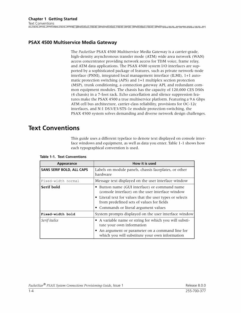
Chapter 1 Getting StartedText Conventions
1-4 255-700-377
PacketStar® PSAX System Connections Provisioning Guide, Issue 1 Release 8.0.0
PSAX 4500 Multiservice Media Gateway
The PacketStar PSAX 4500 Multiservice Media Gateway is a carrier-grade, high-density asynchronous transfer mode (ATM) wide area network (WAN) access concentrator providing network access for TDM voice, frame relay, and ATM data applications. The PSAX 4500 system I/O interfaces are sup-ported by a sophisticated package of features, such as private network-node interface (PNNI), integrated local management interface (ILMI), 1+1 auto-matic protection switching (APS) and 1+1 multiplex section protection (MSP), trunk conditioning, a connection gateway API, and redundant com-mon equipment modules. The chassis has the capacity of 120,000 CES DS0s (4 chassis) in a 7-foot rack. Echo cancellation and silence suppression fea-tures make the PSAX 4500 a true multiservice platform. Featuring a 9.6 Gbps ATM cell bus architecture, carrier-class reliability, provisions for OC-12c interfaces, and N:1 DS3/E3/STS-1e module protection-switching, the PSAX 4500 system solves demanding and diverse network design challenges.
Text Conventions
This guide uses a different typeface to denote text displayed on console inter-face windows and equipment, as well as data you enter. Table 1-1 shows how each typographical convention is used.
Table 1-1. Text Conventions
Appearance How it is used
SANS SERIF BOLD, ALL CAPS Labels on module panels, chassis faceplates, or other hardware
Fixed-width normal Message text displayed on the user interface window
Serif bold • Button name (GUI interface) or command name (console interface) on the user interface window
• Literal text for values that the user types or selects from predefined sets of values for fields
• Commands or literal argument values
Fixed-width bold System prompts displayed on the user interface window
Serif italics • A variable name or string for which you will substi-tute your own information
• An argument or parameter on a command line for which you will substitute your own information

255-700-377 1-5
PacketStar® PSAX System Connections Provisioning Guide, Issue 1 Release 8.0.0
Chapter 1 Getting StartedTechnical Support
Technical Support
If you experience a problem with your PSAX Multiservice Media Gatteway system, refer to the Lucent Technologies InterNetworking Systems Global Warranty, which accompanied your shipment, for instructions on obtaining support in your area.
Before You Begin
Before you start configuring the connections for your PSAX system, be sure you have your master network configuration plan available. You will need to consult this plan to determine all you connection configurations.
Comments on This Guide
To comment on the PacketStar® PSAX System Connections Provisioning Guide, please complete the comment card that accompanied your shipment and mail it to the following address:
Senior Manager, Information Design and Development TeamLucent TechnologiesPacketStar PSAX Products8301 Professional PlaceLandover, MD 20785USA
You can also fax the comment card to us at: 301-809-4540.
Chapter 1 Getting StartedComments on This Guide
1-6 255-700-377
PacketStar® PSAX System Connections Provisioning Guide, Issue 1 Release 8.0.0

Part A: Connections Using the ConsoleInterface

PacketStar® PSAX System Connections Provisioning Guide, Issue 1 Release 8.0.0
255-700-377 2-1
2 Provisioning PVC Connections Usingthe Console Interface
Overview of This Chapter
This chapter describes how to set up permanent virtual circuit (PVC), switched virtual circuit (SVC), and soft permanent virtual circuit (SPVC) con-nections in the PSAX system for service provisioning and how to view statis-tics data for billing and performance monitoring. Before you provision con-nections for this module, you must have first completed the following tasks, which are detailed in the appropriate PacketStar PSAX Module Guide:
• Setting the configuration values for one or more ports
• Setting the configuration values for the types of interfaces you want to use on this module
This chapter contains instructions for configuring the following types of con-nections, with the exception of the PVC and the SVC supporting the GR-303 Interface.
Note: For instructions on configuring a GR-303 interface group on an I/O module, see the application note entitled PacketStar® PSAX Config-uring the GR-303 Voice Gateway User Guide, Issue 3
Connection Types Supported
The PSAX I/O modules support at least one the following connection types:
• PVC connections
• SVC connections
Note: SVC connections are not directly configurable on a PSAX system. Configure them through an interface with a call controller, such as the Lucent Softswitch–T3 (Toll/Tandem/ Transit), a 7R/E™, or a ConnectStar™ Interworking Call Router. Call controllers send call setup information to the PSAX System. See the section, “Enabling SVCs Connections.”
• SPVC connections
For a matrix of connection types by interface types, see the Connection Types by Interface Types table in the appendix, “Reference Information.”

Chapter 2 Provisioning PVC Connections Using the Console InterfaceData Flow in PVC Connections
2-2 255-700-377
PacketStar® PSAX System Connections Provisioning Guide, Issue 1 Release 8.0.0
Data Flow in PVC Connections
PVCs consist of connections between ports on the various PSAX I/O modules. When setting up some types of connections, you can set up data traffic to flow in several ways, depending on the type of connection as follows:
• Duplex (Point-to-Point)
Data flows in two directions between the two connection points (inter-face side A and interface side B).
• Simplex
Data flows in only one direction, from side A to side B, or from side B to side A.
• Point-to-Multipoint
Data flows in only one direction, from one point on side A to several points on side B, or from one point on side B to several points on side A.
Connection Types by Interface Type For a matrix of connection types by interface types, see the Connection Types
by Interface Types table in the appendix, “Reference Information.”
Before you can provision connections, you must select an interface type value other than Unconfigured in the Interface Type field on the Enhanced DS1 Port and Channel Configuration window.
Connections With I/O Modules for Compressed Voice Begin
Using Compressed Voice with I/O Module Connections
Connections from the DSP2x Voice Server modules to the 8-Port Voice 2-Wire Station module are not directly supported. To use compressed voice with the 8-Port Voice 2-Wire Station and the 6-Port Enhanced DS1/T1 Multi-service modules, perform the steps in the following procedure.
1 On the Console Interface Main Menu, select the Connection Configura-tion option and press Enter.
2 Provision a connection from the 8-Port Voice 2-Wire Station module to the Enhanced DS1 module.
3 Use a short loopback cable between two ports on the 6-Port Enhanced DS1/T1 Multiservice module to a DSP2x Voice Server module.
4 For this connection, turn echo cancellation off on a DSP2x Voice Server module.
Note: When using the DSP2x Voice Server module with the 6-Port Enhanced DS1/T1 Multiservice module, the analog levels at the T1/E1 access from the customer premises equipment (CPE) must be set to the value -10dBm.
End

255-700-377 2-3
PacketStar® PSAX System Connections Provisioning Guide, Issue 1 Release 8.0.0
Chapter 2 Provisioning PVC Connections Using the Console InterfaceProvisioning PVC Connections
Provisioning PVC Connections
Begin
1 Log onto the PSAX system (see the appropriate PacketStar PSAX Multiser-vice Media Gateway user guide for instructions).
The Console Interface Main Menu window (see Figure 2-1) is displayed.
2 Select the Connection Configuration command and press Enter.
The Connection Configuration Menu window (see Figure 2-2) is dis-played.
Figure 2-1. Console Interface Main Menu Window (Connection Configuration Selected)

Chapter 2 Provisioning PVC Connections Using the Console InterfaceProvisioning PVC Connections
2-4 255-700-377
PacketStar® PSAX System Connections Provisioning Guide, Issue 1 Release 8.0.0
3 Follow the procedures in the appropriate sections of this chapter for the types of connections you want to configure.
End
Configuring an AAL2 Trunking Connection
An AAL2 trunk can be created on any module which supports an ATM inter-face. Each AAL2 channel can have media processing attributes which are performed by the DSP hardware.
1. To set up a AAL1 or non-multiplexed AAL2 data connection, the user needs to configure a circuit emulation service (CES) interface. For instructions, see the Adding Circuit Emulation-to-ATM VCC PVC Connections
procedure in the PacketStar® PSAX Connections Provisioning Guide for Packet-
Star® PSAX Central Office Multiservice Media Gateways.
2. To set up a standard AAL2 data connection, the user configures a CES interface (see Step 1 above), and an AAL2 trunk by completing “Steps to Configure the AAL2 Trunk Connection” below in this Guide. Loop emu-lation services must use standard AAL2 data connections.
3. For details on adding and modifying DSP parameters (voice compression, silence detection, echo cancellation, tone detection, and coding transla-tion), see the Field Descriptions in the procedure entitled Adding Circuit
Figure 2-2. Connection Configuration Menu Window (ATM-to-ATM VCC Option Selected)

255-700-377 2-5
PacketStar® PSAX System Connections Provisioning Guide, Issue 1 Release 8.0.0
Chapter 2 Provisioning PVC Connections Using the Console InterfaceProvisioning PVC Connections
Emulation to an ATM PVC Connection procedure in the PacketStar® PSAX
Connections Provisioning Guide for PacketStar® PSAX Central Office Multiservice Media Gateways.
Note: On GR-303 applications, you cannot split an AAL2 trunk across DSP2C or DSP2D modules. All PVCs on any given trunk must be routed through the same module. (A DSP2C module can support up to 64 trunks; a DSP2D module can support up to 336 trunk groups using AlsoSet 1 and 384 trunk groups using AlgoSet 6).
Note: Leave the OAM Status field value on the AAL2 Trunk Connection Configuration window on the setting Unsupp; the OAM feature is not available on AAL2 trunks to IADs for V.5 and GR-303 applica-tions.
Begin
Steps to Configure an AAL2 Trunk Connection
1 From the Console Interface Main Menu, select the Connection Configu-ration Menu option (see Figure 2-3).
2 Under PVC Configuration, select the AAL2 Trunk Connection option (or press Ctrl+W).
The AAL2 Trunk Table window is displayed (see Figure 2-4).
Figure 2-3. Connection Configuration Menu
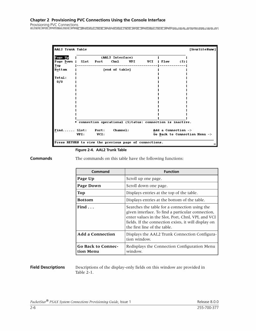
Chapter 2 Provisioning PVC Connections Using the Console InterfaceProvisioning PVC Connections
2-6 255-700-377
PacketStar® PSAX System Connections Provisioning Guide, Issue 1 Release 8.0.0
Commands The commands on this table have the following functions:
Field Descriptions Descriptions of the display-only fields on this window are provided in Table 2-1.
Figure 2-4. AAL2 Trunk Table
Command Function
Page Up Scroll up one page.
Page Down Scroll down one page.
Top Displays entries at the top of the table.
Bottom Displays entries at the bottom of the table.
Find . . . Searches the table for a connection using the given interface. To find a particular connection, enter values in the Slot, Port, Chnl, VPI, and VCI fields. If the connection exists, it will display on the first line of the table.
Add a Connection Displays the AAL2 Trunk Connection Configura-tion window.
Go Back to Connec-tion Menu
Redisplays the Connection Configuration Menu window.

255-700-377 2-7
PacketStar® PSAX System Connections Provisioning Guide, Issue 1 Release 8.0.0
Chapter 2 Provisioning PVC Connections Using the Console InterfaceProvisioning PVC Connections
3 Select the Add a Connection command and press Enter (or press Ctrl+A).
The AAL2 Trunk Connection Configuration window is displayed (see Figure 2-5Figure 2-6).
Table 2-1. Field Descriptions for the AAL2 Trunk Table Window
Field Names Field Values Description
Total:(display only)
Default: 0/0
Range: Module Dependent
Format: Numeric
The first number in this field indicates the identi-fication number of the connection table entry on the first line of the currently displayed window. The second number indicates the total number of connection table entries for this connection type.
Flow Default: DuplexRange: N/A
Format: Predefined
This field shows the direction of data traffic flow in this connection. Data flows in two directions between the two connection points (interface side A and interface side B).
(S)(display only)
See definition for the * character at right.
An asterisk in this field indicates an operational connection. No asterisk indicates an inactive con-nection.
Figure 2-5. AAL2 Trunk Connection Configuration Window

Chapter 2 Provisioning PVC Connections Using the Console InterfaceProvisioning PVC Connections
2-8 255-700-377
PacketStar® PSAX System Connections Provisioning Guide, Issue 1 Release 8.0.0
Commands The commands on this window have the following functions:
Field Descriptions 4 Enter values in the fields on this window according to the information provided in Table 2-2.
Figure 2-6. AAL2 Trunk Connection Configuration Window
Command Function
Display Next Connection Displays the next connection of this type in the table.
Add This Connection Adds a connection having the values cur-rently displayed on the window.
Delete Connection Deletes the connection having the values currently displayed on the window.
Go Back to Connection Table
Redisplays the AAL2 Trunk Table window.

255-700-377 2-9
PacketStar® PSAX System Connections Provisioning Guide, Issue 1 Release 8.0.0
Chapter 2 Provisioning PVC Connections Using the Console InterfaceProvisioning PVC Connections
Table 2-2. Field Descriptions for the AAL2 Trunk Connection Window
Field Name Field Values Description
AAL2 Interface (Left Panel)
Slot Default: 0Range: Variable
Format: Numeric
Indicates the slot number for the module for which you want to add an AAL2 trunk on the ATM side output. The range of slot numbers varies with the chassis type.
Port Default: 1
Range: Variable
Format: Numeric
Indicates the port number on the module indicated in the Slot field to which you want to add an AAL2 trunk on the ATM side output. The range of port numbers varies with the module type.
Channel Default: 1
Range: Variable
Format: Numeric
Indicates the channel number associated with the port indicated on the Port field to which you want to add an AAL2 trunk on the ATM side output. The range of channel numbers varies with the module type.
VPI Default: 0
Range: 0–255 (user-to-user interface, out-put side), 0–4095 (network-to-net-work interface, out-put side)
Format: Numeric
Indicates a virtual path identifier value for the ATM output side of the connection. User-to-user and net-work-to-network interface types are configured on the ATM UNI or PNNI Configuration windows.
Note: If using FaxRelayMode on the DSP2C or DSP2D Voice Server Module, the send and receive sides must use the same value.
VCI Default: 0
Range: 32–65535, 5–32 (signaling dis-abled)
Format: Numeric
Indicates a virtual channel identifier value for the ATM output side of the connection. If using FaxRelayMode on the DSP2C Voice Server Module, the send and receive sides must use the same value.
VI Default: 0Range: 0–255
Format: Numeric
Indicates a virtual interface value, which provides bandwidth allocation restrictions for the ATM output side. VI support must be enabled on the appropriate Interface Configuration window. Currently available only on OC-3c 1+1 APS and STM-1 1+1 MSP modules. When the virtual interface is disabled, the default value is 0.
Traffic Parameters In (Left Panel)
Peak Rate Default: 1
Range: 0–999999999
Format: cps
Indicates the Peak Rate into the ATM side of the con-nection. Enter a peak rate value to set the maximum allowed cell transmission rate (cells per second), defin-ing the shortest time period allowed between cells. When setting this value, calculate the line rate for the module and the amount of bandwidth you are setting up for each interface for the module.
Note: Ensure that the peak cell rate for the connection is correct. The CAC function uses this value to deter-mine whether or not a call can be completed to the sub-scriber line.

Chapter 2 Provisioning PVC Connections Using the Console InterfaceProvisioning PVC Connections
2-10 255-700-377
PacketStar® PSAX System Connections Provisioning Guide, Issue 1 Release 8.0.0
SCR/PCR(0) Default: 1
Range: 0–999999999
Format: cps
Indicates the sustained cell rate into the ATM side of the connection. Enter a SCR with CLP (cell loss priority) =0 (high priority) cells or the peak cell rate (PCR) with CLP=0 cells. For VBR traffic, the value you set is the SCR, or the average cell transmission rate (cells per sec-ond), for the CLP=0 cells, as allowed by your traffic contract. For CBR traffic, the value you set is the PCR, or the maximum allowed transmission rate (cells per second), for the CLP=0 cells, as allowed by your traffic contract. When setting this value, calculate the line rate for the module and the amount of bandwidth you are allotting for each interface on the module.
Max Burst Size Default: 1 Range: 0–999999999
Format: cps
Indicates the maximum burst size into the ATM side of the connection. Enter a value for the maximum num-ber of cells that can be received at the peak cell rate. This setting allows a burst of cells to arrive at a rate higher than that of the sustained cell rate. If the burst is larger than anticipated, the additional cells are either tagged or dropped. When setting this value, calculate the line rate for the module and the amount of band-width you are setting up for each interface for the mod-ule.OC-3c APS Module: When the Traffic Shaping field is set to Enabled, the cell queue depth for the Max Burst Size field is internally set to 1000, regardless of the value you enter. If you enter values other than 1000, these values matter for incoming signalling SPVC/SVC setup from the remote end of the connection.
Table 2-2. Field Descriptions for the AAL2 Trunk Connection Window
Field Name Field Values Description

255-700-377 2-11
PacketStar® PSAX System Connections Provisioning Guide, Issue 1 Release 8.0.0
Chapter 2 Provisioning PVC Connections Using the Console InterfaceProvisioning PVC Connections
Conformance Type Default: Best-effort
Range: N/A
Format: Predefined
Indicates the type of traffic control option used for ATM cells. The traffic descriptor combination specifies which traffic parameters are used for traffic control, deter-mines the number and type of cells that are admitted into a congested queue, and determines whether high-priority cells are tagged as low-priority cells when traf-fic exceeds traffic parameter thresholds.
Best-effort This traffic descriptor allows the system to attempt to send all cells in a “best-effort” fashion, without specify-ing traffic parameters, similar to the AQueMan algo-rithm.
1B-NT-0+1 This traffic descriptor uses the parameters one bucket, no tagging, cell loss priority (CLP)=0+1 cells (high and low priority).
2B-NT-0+1-0+1 This traffic descriptor uses the parameters two buckets, no tagging, CLP=0+1 cells (high and low priority) for bucket 1, and CLP=0+1 cells (high and low priority) for bucket 2.
2B-NT-0+1-0 This traffic descriptor uses the parameters two buckets, no tagging, CLP=0+1 cells (high and low priority) for bucket 1, and CLP=0 cells (high priority) for bucket 2.
2B-T-0+1-0 This traffic descriptor uses the parameters two buckets, CLP=0+1 cells (high and low priority) for bucket 1, and tagging for CLP=0 cells (high priority) in bucket 2.
Best-effort-tag This traffic descriptor allows the system to tag all CLP=0 (high priority) cells to always change them to CLP=1 (low priority) cells. The system then attempts to send all cells in a “best-effort” fashion, without specifying any other traffic parameters, similar to the AQueMan algorithm.
Connection Features (Left Panel)
[FailCause B](display only)
Default: Null
Range: N/A
Format: Predefined
Indicates the AAL2 connection status reason code.
Table 2-2. Field Descriptions for the AAL2 Trunk Connection Window
Field Name Field Values Description

Chapter 2 Provisioning PVC Connections Using the Console InterfaceProvisioning PVC Connections
2-12 255-700-377
PacketStar® PSAX System Connections Provisioning Guide, Issue 1 Release 8.0.0
Oam Status Default: Unsupp
Range: N/A
Format: Predefined
Indicates the type of OAM to be used for the connec-tion.
GR-303 Applications: OAM is not required. Any failure on the ATM side will be detected by the DSP2x module through CAS monitoring.
Unsupp OAM is not in use.
GR-303/V.5 Applications: Do not select a value other than Unsupp if you are configuring AAL2 trunks to an IAD; the feature is not available on AAL2 trunks to IADs.
End-Pt The PSAX system is used as a termination point for ATM traffic, and will process AIS/RDI cells.
OAM loopback test is supported for end-to-end con-nections only.
Note: You must use Release 7.1.0 or later for the value End-Pt to work for GR-303 connections.
End-Seg-Pt Has the characteristics of both an end point and a seg-ment point.
Note: You must use Release 7.1.0 or later for the value End-Seg-Pt to work for GR-303 connections.
Service Type Default: Cbr-1
Range: N/A
Format: Predefined
Cbr-1, Cbr-2, Cbr-3,Cbr-4, Ubr,Vbr-nrt2, Vbr-nrt1,Vbr-rt2, Vbr-rt1, Vbr-express
Specifies a PSAX system-supported quality of service (QoS) class. For a description for the QOS classes, see the section, “Quality of Service Classes for ATM Traffic,” in the reference appendix of any PacketStar PSAX Multi-service Media Gateway user guide.
Flow Default: DuplexRange: N/A
Format: Predefined
Presents the direction of the flow of data traffic in this connection. Duplex data flows in two directions between the two connection points (interface side A and interface side B).
Duplex Data flows back and forth between connection termina-tions.
SimplexA2B Data flows in only one direction from side A to side B
SimplexB2A Data flows in only one direction from side B to side A.
PointToMultipointA2B
Point-to-multipoint data flows in only one direction, from one point on side A to several points on side B, or from one point on side B to several points on side A.
Table 2-2. Field Descriptions for the AAL2 Trunk Connection Window
Field Name Field Values Description

255-700-377 2-13
PacketStar® PSAX System Connections Provisioning Guide, Issue 1 Release 8.0.0
Chapter 2 Provisioning PVC Connections Using the Console InterfaceProvisioning PVC Connections
[Av. BW I/E](display only)
Default: N/A
Range: N/A
Format: cps
Specifies the total ingress and egress bandwidth avail-able for the trunk on the ATM side. This value is based on line rate, or on what the user sets in the Peak Rate and Sustained Rate fields. Adding CE connections to the trunk decreases the amount of available bandwidth, as indicated in this field. Available Bandwidth Ingress is the bandwidth into the ATM side. Available Bandwidth Egress is the bandwidth out of the ATM side.
GR303 Supp Default: Disabled
Range: N/A
Format: Predefined
Disables or enables support for the GR-303 interface.
Disabled Disables the GR-303 interface.
Enabled Enables the GR-303 interface. This field must be enabled if you are using AAL2 trunking on a GR-303 interface.
[Conn Status](display only)
Default: Inactive
Range: N/A
Format: Predefined
Indicates the current status of the connection. The value indicates whether the connection is passing traf-fic.
Inactive The connection is inactive and not passing traffic.
Active The connection is active and passing traffic.
Combined Use Timer
Default: 4
Range: 0–99
Format: Numeric
Specifies the amount of time the host processor will wait for a cell to fill. The combined use timer (CuTimer) is set to zero, so that every ATM cell transmitted con-tains only one AAL2 packet. The first octet of the AAL2 packet header follows immediately after the Start Field in the ATM cell payload. If the AAL2 packet payload is less than 44 octets, the remainder of the ATM cell pay-load following the end of the AAL2 packet is filled with zeros as padding. Each increment of CuTimer is 5 msec waiting time. The default value 4 indicates a wait of 20 msec (4 x 5 msec) before an ATM cell is sent out.
If using the DSP2E/F Voice/Data Server modules, set this value to 1 (5 msec.).
In a GR-303 configuration, set the value to 0 if using non-Lucent IADs.
Table 2-2. Field Descriptions for the AAL2 Trunk Connection Window
Field Name Field Values Description

Chapter 2 Provisioning PVC Connections Using the Console InterfaceProvisioning PVC Connections
2-14 255-700-377
PacketStar® PSAX System Connections Provisioning Guide, Issue 1 Release 8.0.0
Traffic Parameters Out (Right Panel)
Peak Rate Default: 1
Range: 0–999999999
Format: cps
Indicates the Peak Rate exiting the ATM side of the con-nection. Enter a peak rate value to set the maximum allowed cell transmission rate (cells per second), defin-ing the shortest time period allowed between cells. When setting this value, calculate the line rate for the module and the amount of bandwidth you are setting up for each interface for the module.
Note: Ensure that the peak cell rate for the connection is correct. The call admission control (CAC) function uses this value to determine whether or not a call can be completed to the subscriber line.
SCR/PCR(0) Default: 1 Range: 0–999999999
Format: cps
Indicates the sustained cell rate exiting the ATM side of the connection. Enter a sustained cell rate (SCR) with CLP (cell loss priority) =0 (high priority) cells or the peak cell rate (PCR) with CLP=0 cells. For VBR traffic, the value you set is the SCR, or the average cell trans-mission rate (cells per second), for the CLP=0 cells, as allowed by your traffic contract. For CBR traffic, the value you set is the PCR, or the maximum allowed transmission rate (cells per second), for the CLP=0 cells, as allowed by your traffic contract. When setting this value, calculate the line rate for the module and the amount of bandwidth you are allotting for each inter-face on the module.
Max Burst Size Default: 1
Range: 0–999999999
Format: cps
Indicates the maximum burst size exiting the ATM side of the connection. Enter a value for the maximum number of cells that can be received at the peak cell rate. This setting allows a burst of cells to arrive at a rate higher than that of the sustained cell rate. If the burst is larger than anticipated, the additional cells are either tagged or dropped. When setting this value, calculate the line rate for the module and the amount of band-width you are setting up for each interface for the mod-ule.OC-3c APS Module: When the Traffic Shaping field is set to Enabled, the cell queue depth for the Max Burst Size field is internally set to 1000, regardless of the value you enter. If you enter values other than 1000, these values matter for incoming signalling SPVC/SVC setup from the remote end of the connection.
Table 2-2. Field Descriptions for the AAL2 Trunk Connection Window
Field Name Field Values Description

255-700-377 2-15
PacketStar® PSAX System Connections Provisioning Guide, Issue 1 Release 8.0.0
Chapter 2 Provisioning PVC Connections Using the Console InterfaceProvisioning PVC Connections
Connection Features, Right Panel
IWF Type Default: None
Range: As noted below
Format: Predefined
Specifies the Interworking function type on assigning AAL2 connections to compatible DSP chips on the DSP2C through DSP2F Voice Server modules.
None Allows the assignment of standard AAL2 connections to DSP chips on the DSP2C Voice Server module that are configured as AlgoSet1 through AlgoSet3, and on the DSP2E/F as AlgoSet1 and AlgoSet6. This parame-ter allows the mixture of pure voice (CE-to-ATM) with data (VBR-to-ATM) in the same AAL2 trunk group, such as is used in the European LES trunking standard V.5.2. This parameter supports applicable connection types of previous PSAX system software releases.
Packet-pipeNote: Packet-pipe cannot be used on the DSP2C Voice Server module.
Allows the assignment of standard AAL2 connections to DSP chips on the DSP2E/F modules that are config-ured as AlgoSet7. This parameter will not allow the mixture of pure voice (CE-to-ATM) with data (VBR-to-ATM) in the same AAL2 trunk group. This parameter supports applicable connection types for pure data (VBR-to-ATM) in wireless applications.
Table 2-2. Field Descriptions for the AAL2 Trunk Connection Window
Field Name Field Values Description

Chapter 2 Provisioning PVC Connections Using the Console InterfaceProvisioning PVC Connections
2-16 255-700-377
PacketStar® PSAX System Connections Provisioning Guide, Issue 1 Release 8.0.0
5 Select the Add this Connection command and press Enter (or press Ctrl+A).
6 Select the Go Back to Connection Table command and press Enter (or press Ctrl+B).
End
Dsp ResourceSelection
Default: Automatic
Range: As noted below
Format: Predefined
Specifies whether the DSP resources are allocated.
The setting you select in this field must match the set-ting in the Selection Type column on the Dsp Resource Management Table (after the site-specific DSP Resource Configuration option), or your connections will not be made.
Automatic The DSP resource manager selects DSPs from a chassis-wide pool.
Manual The DSP resource manager selects DSPs from a particu-lar module designated in Dsp Slot Id field.
Dsp Slot Id Default: 0Range: Chassis dependent
Format: Numeric
Specifies the slot number of the DSP2x Voice Server module from which the DSP Resource Manager selects DSPs. If you selected Manual in the Dsp Resource Selection field, you must specify the DSP2x Voice Server module slot number in the Dsp Slot Id field from which you want the DSP Resource Manager to select DSPs. If no DSP resource is available on the DSP2x module in the specified slot, the connection is rejected. If you selected Automatic in the Dsp Resource Selec-tion field, the Dsp Slot Id field displays which DSP2x module slot the trunk is using after it has been bound to a DSP2x module.
Num of DSP Chnl Default: 0Range: 0–384
Format: Numeric
Specifies the number of DS0s that can be reserved as DSP channels. If the IWF Type is Packet-pipe, the bandwidth configured by you for the trunk calculates how many DS0s fit into the trunk. For example, the DS0 line rate is approximately 171 cps. If you want 200 cps, the bw actually alloocated is 200/171, or 1.16 DS0s.
The CAC reserves the DS0 resource when the first con-nection is made on the trunk.
If the value is left at the default 0, the number of reserved DS0s is best-effort.
Table 2-2. Field Descriptions for the AAL2 Trunk Connection Window
Field Name Field Values Description

255-700-377 2-17
PacketStar® PSAX System Connections Provisioning Guide, Issue 1 Release 8.0.0
Chapter 2 Provisioning PVC Connections Using the Console InterfaceProvisioning PVC Connections
Adding ATM-to-ATM VCC PVC Connection
Perform the steps in the following procedure to add an ATM-to-ATM VCC PVC connection, starting at the Connection Configuration Menu window.
Begin
Creating an ATM-to-ATM VCC PVC Connection
Note: On the DS1 IMA and E1 IMA modules, you must provision PVC connections on the virtual port (port 7). You can use up to three groups on port 7 (the groups you provision on port 7).
Note: On the DS3 IMA module, you must provision PVC connections on the virtual port (port 30). You can use up to 14 groups on port 30 (the groups you provision on port 30).
Note: The OAM feature is supported for this connection type and can be enabled on the Connection window. Statistical OAM information is provided on the related Connection Statistics window. Parame-ters for OAM operation can be configured from the Diagnostics Menu window. See the appropriate PacketStar PSAX Multiservice Media Gateway user guide for more details.
1 Select the ATM-to-ATM VCC option on the Connection Configuration Menu window and press Enter.
The ATM-to-ATM VCC PVC Table window is displayed (see Figure 2-7).
Figure 2-7. ATM-to-ATM VCC PVC Table Window

Chapter 2 Provisioning PVC Connections Using the Console InterfaceProvisioning PVC Connections
2-18 255-700-377
PacketStar® PSAX System Connections Provisioning Guide, Issue 1 Release 8.0.0
The ATM-to-ATM VCC PVC Table window provides a way to view, create, delete, and monitor connections and connection statistics. This table loads and displays all current ATM-to-ATM VCC PVC connections.
Note: At the time of initial installation, the ATM-to-ATM VCC PVC Table window is empty. After you have set up connections, this window displays all the connections of this type in the system.
Commands The commands on this window have the following functions:
Field Descriptions The field descriptions for the display-only fields on this window are provided in Table 2-7.
Command Function
Page Up Scrolls up one page.
Page Down Scrolls down one page.
Top Displays entries at the top of the table.
Bottom Displays entries at the bottom of the table.
Find . . . Searches the table for a connection using the given interface. To find a particular connection, enter val-ues in the Slot, Port, Channel, and VPI fields. If the connection exists, it displays on the first line of the table.
Add a Connection Displays the ATM-to-ATM VCC PVC Connection window.
Go Back to Con-nection Menu
Redisplays the Connection Configuration Menu window.
Table 2-3. ATM-to-ATM VCC PVC Table Window Field Descriptions
Field Description
ATM Interface A Displays the information for all interface A sides of the connections. The connection entries are displayed in ascending numerical order by slot, then by port, channel, and VPI.
ATM Interface B Displays the information for all interface B sides of the connections.
Flow Displays the direction of the data traffic flow for the connections. An asterisk (*) indicates if the connection is inactive.
Total: 0/0 The first number in this field indicates the identification number of the connection table entry on the first line of the currently dis-played window. The second number indi-cates the total number of connection table entries for this connection type.

255-700-377 2-19
PacketStar® PSAX System Connections Provisioning Guide, Issue 1 Release 8.0.0
Chapter 2 Provisioning PVC Connections Using the Console InterfaceProvisioning PVC Connections
2 Select the Add a Connection command and press Enter.
The ATM-to-ATM VCC PVC Connection window is displayed (see Figure 2-8).
Commands The commands on this window have the following functions:
3 Enter values in the fields on this window according to the information provided in Table 2-4.
Figure 2-8. ATM-to-ATM VCC PVC Connection Window
Command Function
Display Next Connection Displays the next connection of this type in the table.
Add This Connection Adds a connection having the values cur-rently displayed on the window.
Delete Connection Deletes the connection having the values currently displayed on the window.
View Connection Statistics Displays the ATM-to-ATM VPC PVC Sta-tistics window.
Add/View Backup PVC Displays window to add or view a backup PVC.
Go Back to Connection Table
Redisplays the ATM-to-ATM VPC PVC Connection Table window.
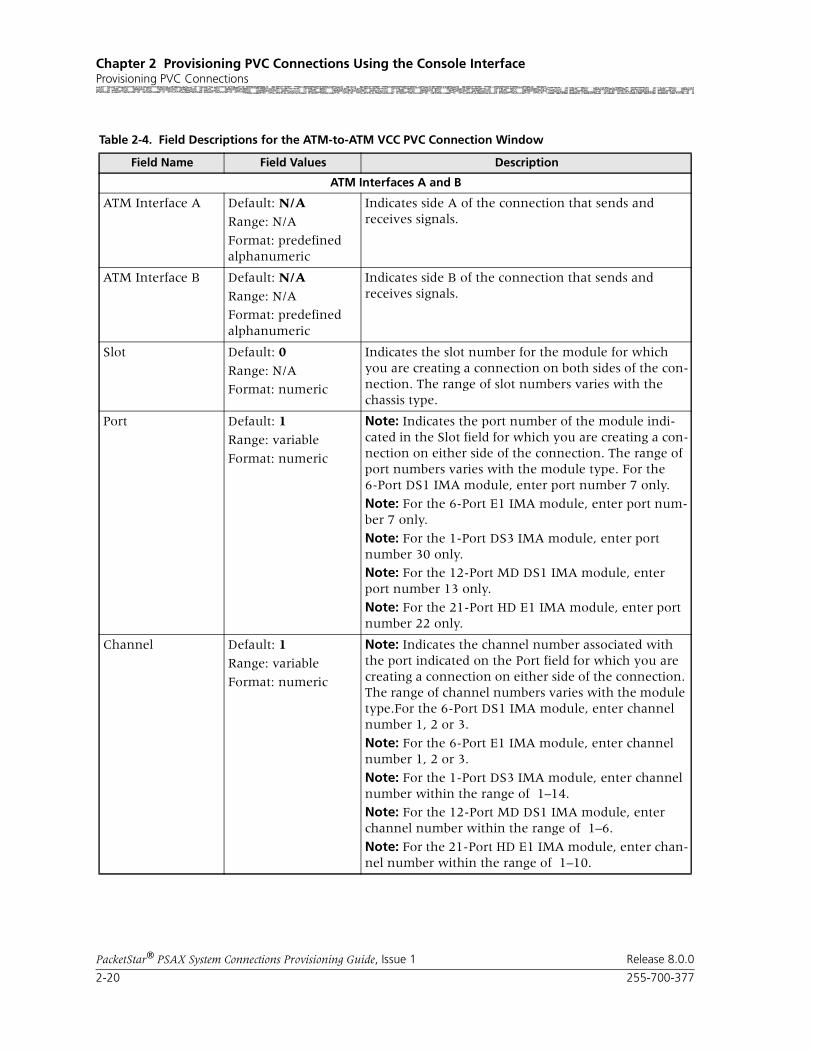
Chapter 2 Provisioning PVC Connections Using the Console InterfaceProvisioning PVC Connections
2-20 255-700-377
PacketStar® PSAX System Connections Provisioning Guide, Issue 1 Release 8.0.0
Table 2-4. Field Descriptions for the ATM-to-ATM VCC PVC Connection Window
Field Name Field Values Description
ATM Interfaces A and B
ATM Interface A Default: N/A
Range: N/A
Format: predefined alphanumeric
Indicates side A of the connection that sends and receives signals.
ATM Interface B Default: N/A
Range: N/A
Format: predefined alphanumeric
Indicates side B of the connection that sends and receives signals.
Slot Default: 0
Range: N/A
Format: numeric
Indicates the slot number for the module for which you are creating a connection on both sides of the con-nection. The range of slot numbers varies with the chassis type.
Port Default: 1
Range: variable
Format: numeric
Note: Indicates the port number of the module indi-cated in the Slot field for which you are creating a con-nection on either side of the connection. The range of port numbers varies with the module type. For the 6-Port DS1 IMA module, enter port number 7 only.
Note: For the 6-Port E1 IMA module, enter port num-ber 7 only.
Note: For the 1-Port DS3 IMA module, enter port number 30 only.
Note: For the 12-Port MD DS1 IMA module, enter port number 13 only.
Note: For the 21-Port HD E1 IMA module, enter port number 22 only.
Channel Default: 1
Range: variable
Format: numeric
Note: Indicates the channel number associated with the port indicated on the Port field for which you are creating a connection on either side of the connection. The range of channel numbers varies with the module type.For the 6-Port DS1 IMA module, enter channel number 1, 2 or 3.
Note: For the 6-Port E1 IMA module, enter channel number 1, 2 or 3.
Note: For the 1-Port DS3 IMA module, enter channel number within the range of 1–14.
Note: For the 12-Port MD DS1 IMA module, enter channel number within the range of 1–6.
Note: For the 21-Port HD E1 IMA module, enter chan-nel number within the range of 1–10.

255-700-377 2-21
PacketStar® PSAX System Connections Provisioning Guide, Issue 1 Release 8.0.0
Chapter 2 Provisioning PVC Connections Using the Console InterfaceProvisioning PVC Connections
VPI Default: N/A
Range: 0–255 (ATM UNI); 0–4095 (NNI)
Format: numeric
Indicates the virtual path identifier. Enter a value for both sides of the connection.
VCI Default: N/ARange: 32–65535
Format: numeric
Indicates the virtual channel identifier. Enter a value for both sides of the connection.
VI/VUNI Default: 0
Range: 0–255
Format: numeric
Indicates the virtual interface/Virtual ATM UNI, which provides bandwidth allocation restrictions. Currently available only on the OC-12c/STM-4c APS/MSP, OC-3c APS, and STM-1 MSP modules. The VUNI associates itself with the egress part of the A2B or B2A side of the connection.
Traffic Parameters A to B and B to A
Service Type Default: Ubr
Range: N/A
Format: predefined alphanumeric
Indicates the PSAX system-supported QoS class. See the appropriate PacketStar PSAX Multiservice Media Gateway user guide for a description of each service type.
Ubr Unspecified bit rate
Vbr-nrt2 Variable bit rate, non-real time queue 2
Vbr-nrt1 Variable bit rate, non-real time queue 1
Vbr-rt2 Variable bit rate, real time queue 2
Vbr-rt1 Variable bit rate, real time queue 1
Vbr-express Variable bit rate, express
Cbr4 Constant bit rate, queue 4
Cbr3 Constant bit rate, queue 3
Cbr2 Constant bit rate, queue 2
Cbr1 Constant bit rate, queue 1
Gfr2 rate, queue 2
Table 2-4. Field Descriptions for the ATM-to-ATM VCC PVC Connection Window
Field Name Field Values Description

Chapter 2 Provisioning PVC Connections Using the Console InterfaceProvisioning PVC Connections
2-22 255-700-377
PacketStar® PSAX System Connections Provisioning Guide, Issue 1 Release 8.0.0
Conformance Type Default: Best-effort
Range: N/A
Format: predefined alphanumeric
Indicates the type of traffic control option used for ATM cells. The traffic descriptor combination specifies which traffic parameters are used for traffic control, determines the number and type of cells that are admitted into a congested queue, and determines whether high-priority cells are tagged as low-priority cells when traffic exceeds the traffic parameter thresh-olds.
Note: See the appendix in the appropriate PacketStar PSAX Multiservice Media Gateway User Guide for a detailed description of the values for this field, includ-ing representative examples.
Best-effort Allows the system to attempt to send all cells in a “best effort” fashion, without specifying traffic parameters, similar to the AQueMan algorithm.
1B-NT-0+1 Uses the parameters one bucket, no tagging, cell loss priority (CLP)=0+1 cells (high and low priority).
2B-NT-0+1-0+1 Uses the parameters two buckets, no tagging, CLP=0+1 cells (high and low priority) for bucket 1, and CLP=0+1 cells (high and low priority) for bucket 2.
2B-NT-0+1-0 Uses the parameters two buckets, no tagging, CLP=0+1 cells (high and low priority) for bucket 1, and CLP=0 cells (high priority) for bucket 2.
2B-T-0+1-0 Uses the parameters two buckets, CLP=0+1 cells (high and low priority) for bucket 1, and tagging for CLP=0 cells (high priority) in bucket 2.
Best-effort-tag Allows the system to tag all CLP=0 (high priority) cells to always change them to CLP=1 (low priority) cells, and then attempt to send all cells in a “best effort” fashion, without specifying any other traffic parame-ters, similar to the AQueMan algorithm.
SAR Type Default: AAL-5
Range: AAL-3/4, AAL-2, AAL-1, Null
Format: predefined alphanumeric
Indicates the segmentation and reassembly (SAR) type. The ATM adaptation layer segments the protocol data unit (PDU) into 48-octet payloads at the transmit end. The SAR extracts and reassembles the octets at the receive end. The SAR type on the receiving end should correspond to the SAR type of the incoming data stream.
Frwd Error Correct Default: None
Range: Eighth Rate Quarter Rate, Half Rate, Auto Hi Q, Auto, Auto Lo Q
Format: predefined alphanumeric
Specifies the forward error correction method. Indi-cates the values Eighth Rate, Quarter Rate, and Half Rate, a Reed-Solomon encoding rate with a spe-cific error-correction capability. The values Auto Hi Q, Auto, and Auto Lo Q are dynamically changing rate options.
Table 2-4. Field Descriptions for the ATM-to-ATM VCC PVC Connection Window
Field Name Field Values Description

255-700-377 2-23
PacketStar® PSAX System Connections Provisioning Guide, Issue 1 Release 8.0.0
Chapter 2 Provisioning PVC Connections Using the Console InterfaceProvisioning PVC Connections
Peak Rate(0+1) (cps)
Default: 1
Range: 1–(232-1)(theoretical range, except for modules noted in the Descrip-tion column)
Format: numeric (cells per second)
When setting this value, take into account the line rate for the module and the amount of bandwidth you are setting up for each interface for the module. Refer to the ATM UNI 3.1 specifications for more information.
Note: If you select the value SimplexA2B in the Flow field, set the value of this field to 0.If you are using the traffic shaping Enabled value on the bulleted modules listed below, entering a minimum cps value below the minimum listed below causes traffic-shaped connec-tions to default to the minimum cps value when the connection passes traffic.
• On the 1-Port OC-3c MM/SM and the 1-Port STM-1 MM/SM modules, the range is 18–999999999 cps.
• On the OC-12c/STM-4c SM/MM modules, the range is 87–999999999 cps.
• On the 3-Port DS3/E3 ATM module, the range is 7–999999999 cps.
Note: The peak cell rate cannot exceed the maximum cell rate for the interface.
If you need to calculate ingress PCRs for the OC-3c APS or the STM-1 MSP modules, see the PCR calcula-tion formula in the reference information appendix of the OC-3c 1+1 APS MM/SM Modules User Guide or the STM-1 1+1 MSP MM/SM Modules User Guide.
SCR/PCR (0) (cps) Default: 1
Range: 0–999999999
Format: numeric
When setting this value, take into account the line rate for the module and the amount of bandwidth you are setting up for each interface for the module. Refer to the ATM UNI 3.1 specifications for more information.
If you select the value SimplexA2B in the Flow field, set the value of this field to 0.
If using traffic shaping on the OC-3c or STM-1 mod-ules, the modules will not pass data until these param-eters are set to a specified rate. Very large bursts of traf-fic may exceed the 8 MB memory typically available on the module, resulting in dropped cells. If very large bursts are typical for a specific network configuration, the module memory can be upgraded to 64 MB.
Table 2-4. Field Descriptions for the ATM-to-ATM VCC PVC Connection Window
Field Name Field Values Description

Chapter 2 Provisioning PVC Connections Using the Console InterfaceProvisioning PVC Connections
2-24 255-700-377
PacketStar® PSAX System Connections Provisioning Guide, Issue 1 Release 8.0.0
Max Burst Size (cells)
Default: 1
Range: 0–999999999
Format: Numeric (cells)
Indicates the maximum burst size, a traffic parameter which specifies the maximum number of cells that can be transmitted at the peak cell rate. The MBS allows a burst of cells to arrive at a rate higher than that of the sustained cell rate. If the burst is larger than antici-pated, the additional cells are either tagged or dropped.
When setting this value, calculate the line rate for the module and the amount of bandwidth you are setting up for each interface for the module.
Note: If you select the value SimplexA2B in the Flow field, set the value for peak rate to 0.
OC-3c APS Module: When the Traffic Shaping field is set to Enabled, the cell queue depth for the Max Burst Size field is internally set to 1000, regardless of the value you enter. If you enter values other than 1000, these values matter for incoming signalling SPVC/SVC setup from the remote end of the connection.
Traffic Shaping Default: DisabledRange: As noted below
Format: Predefined
Indicates the method for controlling the outgoing flow of data traffic. This feature is implemented on the fol-lowing modules:
• 1-Port OC-3c Multimode and Single-Mode with Traffic Shaping modules
• 1-Port STM-1 Multimode and Single-Mode with Traffic Shaping modules
• 3-Port DS3/E3 ATM module
• 1-Port OC-12c/STM-4c MM/SM 1+1 APS/MSP modules
See the Peak Rate field on this table for minimum cps ranges restrictions on these modules.
Disabled Disables traffic shaping in the outgoing direction.
Enabled Enables traffic shaping on the outgoing direction. When enabled, traffic shaping ensures that the vari-able bit-rate (VBR) traffic entering the PSAX system (via these modules) complies with the parameters of the established service contracts.
ATM Interface A, Lower Left Panel
[FailCause A/B](display only)
Default: Null/Null
Range: A or B
Format: predefined alphanumeric
Presents the AAL2 status reason failure cause code for both sides of the connection.
Table 2-4. Field Descriptions for the ATM-to-ATM VCC PVC Connection Window
Field Name Field Values Description
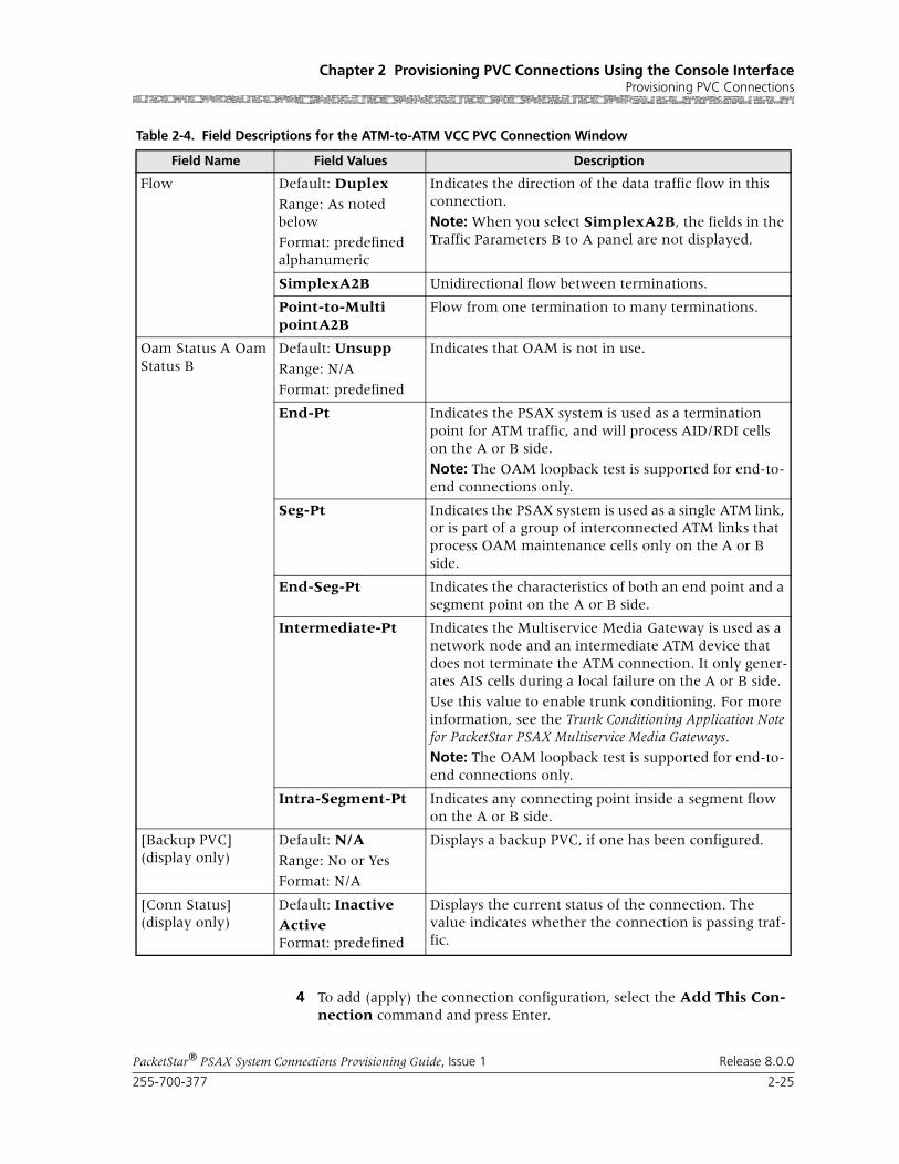
255-700-377 2-25
PacketStar® PSAX System Connections Provisioning Guide, Issue 1 Release 8.0.0
Chapter 2 Provisioning PVC Connections Using the Console InterfaceProvisioning PVC Connections
4 To add (apply) the connection configuration, select the Add This Con-nection command and press Enter.
Flow Default: Duplex
Range: As noted below
Format: predefined alphanumeric
Indicates the direction of the data traffic flow in this connection.
Note: When you select SimplexA2B, the fields in the Traffic Parameters B to A panel are not displayed.
SimplexA2B Unidirectional flow between terminations.
Point-to-MultipointA2B
Flow from one termination to many terminations.
Oam Status A Oam Status B
Default: Unsupp
Range: N/A
Format: predefined
Indicates that OAM is not in use.
End-Pt Indicates the PSAX system is used as a termination point for ATM traffic, and will process AID/RDI cells on the A or B side.
Note: The OAM loopback test is supported for end-to-end connections only.
Seg-Pt Indicates the PSAX system is used as a single ATM link, or is part of a group of interconnected ATM links that process OAM maintenance cells only on the A or B side.
End-Seg-Pt Indicates the characteristics of both an end point and a segment point on the A or B side.
Intermediate-Pt Indicates the Multiservice Media Gateway is used as a network node and an intermediate ATM device that does not terminate the ATM connection. It only gener-ates AIS cells during a local failure on the A or B side.
Use this value to enable trunk conditioning. For more information, see the Trunk Conditioning Application Note for PacketStar PSAX Multiservice Media Gateways.
Note: The OAM loopback test is supported for end-to-end connections only.
Intra-Segment-Pt Indicates any connecting point inside a segment flow on the A or B side.
[Backup PVC](display only)
Default: N/A
Range: No or Yes
Format: N/A
Displays a backup PVC, if one has been configured.
[Conn Status](display only)
Default: InactiveActiveFormat: predefined
Displays the current status of the connection. The value indicates whether the connection is passing traf-fic.
Table 2-4. Field Descriptions for the ATM-to-ATM VCC PVC Connection Window
Field Name Field Values Description
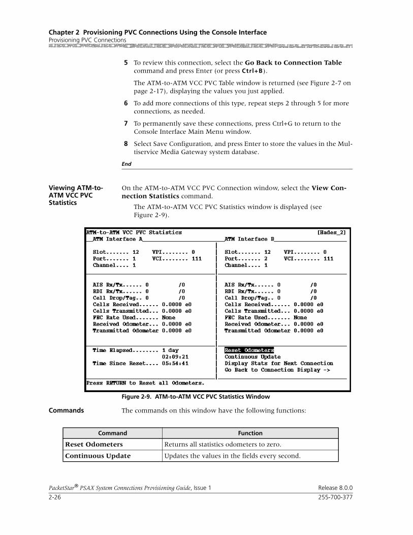
Chapter 2 Provisioning PVC Connections Using the Console InterfaceProvisioning PVC Connections
2-26 255-700-377
PacketStar® PSAX System Connections Provisioning Guide, Issue 1 Release 8.0.0
5 To review this connection, select the Go Back to Connection Table command and press Enter (or press Ctrl+B).
The ATM-to-ATM VCC PVC Table window is returned (see Figure 2-7 on page 2-17), displaying the values you just applied.
6 To add more connections of this type, repeat steps 2 through 5 for more connections, as needed.
7 To permanently save these connections, press Ctrl+G to return to the Console Interface Main Menu window.
8 Select Save Configuration, and press Enter to store the values in the Mul-tiservice Media Gateway system database.
End
Viewing ATM-to-ATM VCC PVC Statistics
On the ATM-to-ATM VCC PVC Connection window, select the View Con-nection Statistics command.
The ATM-to-ATM VCC PVC Statistics window is displayed (see Figure 2-9).
Commands The commands on this window have the following functions:
Figure 2-9. ATM-to-ATM VCC PVC Statistics Window
Command Function
Reset Odometers Returns all statistics odometers to zero.
Continuous Update Updates the values in the fields every second.
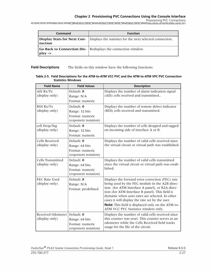
255-700-377 2-27
PacketStar® PSAX System Connections Provisioning Guide, Issue 1 Release 8.0.0
Chapter 2 Provisioning PVC Connections Using the Console InterfaceProvisioning PVC Connections
Field Descriptions The fields on this window have the following functions:
Display Stats for Next Con-nection
Displays the statistics for the next selected connection.
Go Back to Connection Dis-play –>
Redisplays the connection window.
Command Function
Table 2-5. Field Descriptions for the ATM-to-ATM VCC PVC and the ATM-to-ATM VPC PVC Connection Statistics Windows
Field Name Field Values Description
AIS Rx/Tx(display only)
Default: 0
Range: N/A
Format: numeric
Displays the number of alarm indication signal (AIS) cells received and transmitted..
RDI Rx/Tx(display only)
Default: 0
Range: 32 bits
Format: numeric(exponent notation)
Displays the number of remote defect indicator (RDI) cells received and transmitted.
cell Drop/Tag(display only)
Default: 0Range: 32 bits
Format: numeric
Displays the number of cells dropped and tagged on incoming side of interface A or B.
Cells Received(display only)
Default: 0
Range: 64 bits
Format: numeric(exponent notation)
Displays the number of valid cells received since the virtual circuit or virtual path was established.
Cells Transmitted(display only)
Default: 0
Range: 64 bits
Format: numeric(exponent notation)
Displays the number of valid cells transmitted since the virtual circuit or virtual path was estab-lished.
FEC Rate Used(display only)
Default: 0Range: N/A
Format: predefined
Displays the forward error correction (FEC) rate being used by the FEC module in the A2B direc-tion (for ATM Interface A panel), or B2A direc-tion (for ATM Interface B panel). This field is dymanic when auto rates are selected. In other cases it will display the rate set by the user.
Note: This field is displayed only on the ATM-to-ATM VCC PVC Statistics window only.
Received Odometer(display only)
Default: 0Range: 64 bits
Format: numeric(exponent notation)
Displays the number of valid cells received since this counter was reset. This counter serves as an odometer while the Cells Received field tracks usage for the life of the circuit.
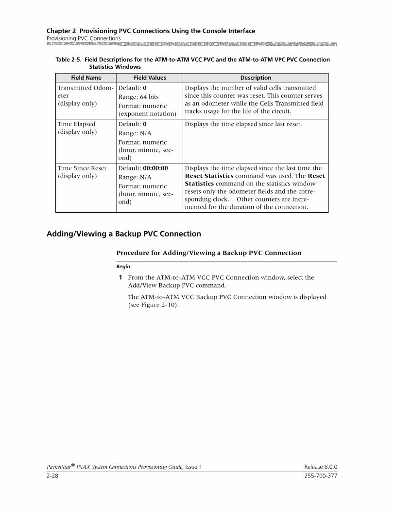
Chapter 2 Provisioning PVC Connections Using the Console InterfaceProvisioning PVC Connections
2-28 255-700-377
PacketStar® PSAX System Connections Provisioning Guide, Issue 1 Release 8.0.0
Adding/Viewing a Backup PVC Connection
Begin
Procedure for Adding/Viewing a Backup PVC Connection
1 From the ATM-to-ATM VCC PVC Connection window, select the Add/View Backup PVC command.
The ATM-to-ATM VCC Backup PVC Connection window is displayed (see Figure 2-10).
Transmitted Odom-eter(display only)
Default: 0Range: 64 bits
Format: numeric(exponent notation)
Displays the number of valid cells transmitted since this counter was reset. This counter serves as an odometer while the Cells Transmitted field tracks usage for the life of the circuit.
Time Elapsed(display only)
Default: 0
Range: N/A
Format: numeric(hour, minute, sec-ond)
Displays the time elapsed since last reset.
Time Since Reset(display only)
Default: 00:00:00
Range: N/A
Format: numeric(hour, minute, sec-ond)
Displays the time elapsed since the last time the Reset Statistics command was used. The Reset Statistics command on the statistics window resets only the odometer fields and the corre-sponding clock. . Other counters are incre-mented for the duration of the connection.
Table 2-5. Field Descriptions for the ATM-to-ATM VCC PVC and the ATM-to-ATM VPC PVC Connection Statistics Windows
Field Name Field Values Description

255-700-377 2-29
PacketStar® PSAX System Connections Provisioning Guide, Issue 1 Release 8.0.0
Chapter 2 Provisioning PVC Connections Using the Console InterfaceProvisioning PVC Connections
Commands The commands on this window have the following functions:
2 The fields on this window are described in Table 2-6:
Figure 2-10. ATM-to-ATM VCC Backup PVC Connection Window
Command Function
Add This Connection Adds the connection entered on the backup ATM interface right panel.
Delete Connection Deletes the backup connection.
Go Back to Primary PVC Connection
Returns to the ATM-to-ATM VCC PVC Connection window.
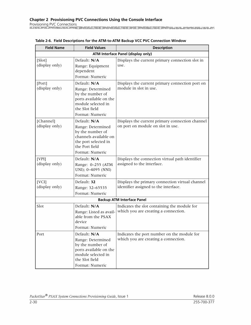
Chapter 2 Provisioning PVC Connections Using the Console InterfaceProvisioning PVC Connections
2-30 255-700-377
PacketStar® PSAX System Connections Provisioning Guide, Issue 1 Release 8.0.0
Table 2-6. Field Descriptions for the ATM-to-ATM Backup VCC PVC Connection Window
Field Name Field Values Description
ATM Interface Panel (display only)
[Slot](display only)
Default: N/A
Range: Equipment dependent
Format: Numeric
Displays the current primary connection slot in use.
[Port](display only)
Default: N/A
Range: Determined by the number of ports available on the module selected in the Slot field
Format: Numeric
Displays the current primary connection port on module in slot in use.
[Channel](display only)
Default: N/A
Range: Determined by the number of channels available on the port selected in the Port field
Format: Numeric
Displays the current primary connection channel on port on module on slot in use.
[VPI](display only)
Default: N/ARange: 0–255 (ATM UNI); 0–4095 (NNI)
Format: Numeric
Displays the connection virtual path identifier assigned to the interface.
[VCI](display only)
Default: 32
Range: 32–65535
Format: Numeric
Displays the primary connection virtual channel identifier assigned to the interface.
Backup ATM Interface Panel
Slot Default: N/A
Range: Listed as avail-able from the PSAX device
Format: Numeric
Indicates the slot containing the module for which you are creating a connection.
Port Default: N/ARange: Determined by the number of ports available on the module selected in the Slot field
Format: Numeric
Indicates the port number on the module for which you are creating a connection.

255-700-377 2-31
PacketStar® PSAX System Connections Provisioning Guide, Issue 1 Release 8.0.0
Chapter 2 Provisioning PVC Connections Using the Console InterfaceProvisioning PVC Connections
Adding ATM-to-ATM VPC PVC Connections
Creating a ATM-to-ATM VPC Connection
Perform the steps in the following procedure to create an ATM-to-ATM VPC connection, starting at the Connection Configuration Menu window.
Channel Default: N/A
Range: Determined by the number of channels available on the port selected in the Port field
Format: Numeric
Indicates the channel number of the port on the module for which you are creating a connection.
VPI Default: N/ARange: 0–255 (ATM UNI); 0–4095 (NNI)
Format: Numeric
Indicates the backup connection.virtual path identifier assigned to this interface.
VCI Default: 32Range: 32–65535
Format: Numeric
Indicates the backup connection virtual channel identifier assigned to the interface
VI Default: 0
Range: 0–255
Format: Numeric
Indicates the backup connection virtual interface, which provides bandwidth allocation restrictions. Currently available only on the OC-3c APS and STM-1 MSP modules.
[Current Active PVC](display only)
Default: NoneRange: N/A
Format: Numeric
Displays an inactive connection.
Primary Displays the active primary connection carrying user traffic.
Backup Displays the active backup connection carrying user traffic.
[Switch Back to Pri-mary Automati-cally](display only)
Default: Yes
Range: N/A
Format: Predefined
Displays CPU monitors primary connection. If primary connection becomes available, backup will switch back connection to primary.
No This option is not currently supported.
Once active, the backup connection will not switch back to primary connection automatically if primary becomes available.
Table 2-6. Field Descriptions for the ATM-to-ATM Backup VCC PVC Connection Window
Field Name Field Values Description
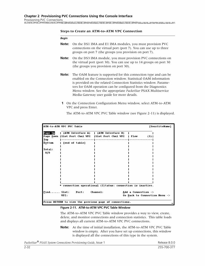
Chapter 2 Provisioning PVC Connections Using the Console InterfaceProvisioning PVC Connections
2-32 255-700-377
PacketStar® PSAX System Connections Provisioning Guide, Issue 1 Release 8.0.0
Begin
Steps to Create an ATM-to-ATM VPC Connection
Note: On the DS1 IMA and E1 IMA modules, you must provision PVC connections on the virtual port (port 7). You can use up to three groups on port 7 (the groups you provision on port 7).
Note: On the DS3 IMA module, you must provision PVC connections on the virtual port (port 30). You can use up to 14 groups on port 30 (the groups you provision on port 30).
Note: The OAM feature is supported for this connection type and can be enabled on the Connection window. Statistical OAM information is provided on the related Connection Statistics window. Parame-ters for OAM operation can be configured from the Diagnostics Menu window. See the appropriate PacketStar PSAX Multiservice Media Gateway user guide for more details.
1 On the Connection Configuration Menu window, select ATM-to-ATM VPC and press Enter.
The ATM-to-ATM VPC PVC Table window (see Figure 2-11) is displayed.
The ATM-to-ATM VPC PVC Table window provides a way to view, create, delete, and monitor connections and connection statistics. This table loads and displays all current ATM-to-ATM VPC PVC connections.
Note: At the time of initial installation, the ATM-to-ATM VPC PVC Table window is empty. After you have set up connections, this window is displayed all the connections of this type in the system.
Figure 2-11. ATM-to-ATM VPC PVC Table Window

255-700-377 2-33
PacketStar® PSAX System Connections Provisioning Guide, Issue 1 Release 8.0.0
Chapter 2 Provisioning PVC Connections Using the Console InterfaceProvisioning PVC Connections
Commands The commands on this window have the following functions:
Field Descriptions The display-only fields on this window provide the following information about all the ATM-to-ATM VPC PVC connections in the PSAX system:
2 Select the Add a Connection command and press Enter.
The ATM-to-ATM VPC PVC Connection window (see Figure 2-12) is dis-played.
Command Function
Page Up Scroll up one page.
Page Down Scrolls down one page.
Top Displays entries at the top of the table.
Bottom Displays entries at the bottom of the table.
Find . . . Searches the table for a connection using the given interface. To find a particular connection, enter values in the Slot, Port, Chnl, and VPI fields. If the connec-tion exists, it will display on the first line of the table.
Add a Connection Displays the ATM-to-ATM VPC PVC Con-nection window.
Go Back to Connection Menu
Redisplays the Connection Configuration Menu window.
Table 2-7. ATM-to-ATM VCC PVC Table Window Field Descriptions
Field Description
ATM Interface A Displays the information for all interface A sides of the connections. The connection entries are displayed in ascending numerical order by slot, then by port, channel, and VPI.
ATM Interface B Displays the information for all interface B sides of the connections.
Flow Displays the direction of the data traffic flow for the connections. An asterisk (*) indicates if the connection is inactive.
Total: 0/0 The first number in this field indicates the identification number of the connection table entry on the first line of the currently dis-played window. The second number indi-cates the total number of connection table entries for this connection type.

Chapter 2 Provisioning PVC Connections Using the Console InterfaceProvisioning PVC Connections
2-34 255-700-377
PacketStar® PSAX System Connections Provisioning Guide, Issue 1 Release 8.0.0
Commands The commands on this window have the following functions:
Field Descriptions 3 Enter values in the fields on this window according to the information provided in Table 2-8.
Figure 2-12. ATM-to-ATM VPC PVC Connection Window
Command Function
Display Next Connection Displays the next connection of this type in the table.
Add This Connection Adds a connection having the values cur-rently displayed on the window.
Delete Connection Deletes the connection having the values currently displayed on the window.
View Connection Statistics Displays the ATM-to-ATM VPC PVC Sta-tistics window.
Add/View Backup PVC Displays window to add or view a backup PVC.
Go Back to Connection Table
Redisplays the ATM-to-ATM VPC PVC Connection Table window.

255-700-377 2-35
PacketStar® PSAX System Connections Provisioning Guide, Issue 1 Release 8.0.0
Chapter 2 Provisioning PVC Connections Using the Console InterfaceProvisioning PVC Connections
Table 2-8. Field Descriptions for the ATM-to-ATM VPC PVC Connection Window
Field Name Field Values Description
ATM Interface A Default: N/ARange: N/A
Format: Predefined
One side of the connection that will send and receive signals.
ATM Interface B Default: N/A
Range: N/A
Format: Predefined
The other side of the connection that will send and receive signals.
Slot Default: 0
Range: N/A
Format: Numeric
Enter the slot number for the module for which you are creating a connection on both sides of the connec-tion. The range of slot numbers varies with the chassis type.
Port Default: 1Range: Variable
Format: Numeric
Enter the port number of the module indicated in the Slot field for which you are creating a connection on either side of the connection. The range of port num-bers varies with the module type.
Note: For the DS1 IMA module, enter port number 7 only.For the E1 IMA module, enter port number 7 only.For the DS3 IMA module, enter port number 30 only.For the MD DS1 IMA module, enter port number 13 only.For the HD E1 IMA module, enter port num-ber 22 only.
Channel Default: 1Range: Variable
Format: Numeric
Enter the channel number associated with the port indicated on the Port field for which you are creating a connection on either side of the connection. The range of channel numbers varies with the module type.
Note: For the DS1 IMA module, enter channel num-ber 1, 2 or 3.For the E1 IMA module, enter channel number 1, 2 or 3.For the DS3 IMA module, enter channel number within the range of 1–14.For the MD DS1 IMA module, enter channel number within the range of 1–6.For the HD E1 IMA module, enter chan-nel number within the range of 1–10.
VPI Default: 0Range: 0–255 (AtmUNI); 0-4095 (NNI)
Format: Numeric
Virtual path identifier. Enter a value for both sides of the connection.
VI Default: 0
Range: 0–255
Format: Numeric
Virtual interface, which provides bandwidth allocation restrictions. Currently available only on the OC-3c APS and STM-1 MSP modules. When disabled, default is 0.
VUNI Default: 0
Range: 0–255
Format: Numeric
The virtual UNI (VUNI) associates itself with the egress part of the A2B or B2A side of the connection.
Traffic Parameters A to B and B to A
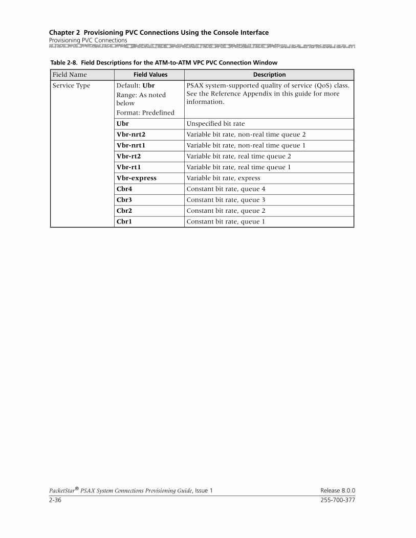
Chapter 2 Provisioning PVC Connections Using the Console InterfaceProvisioning PVC Connections
2-36 255-700-377
PacketStar® PSAX System Connections Provisioning Guide, Issue 1 Release 8.0.0
Service Type Default: Ubr
Range: As noted below
Format: Predefined
PSAX system-supported quality of service (QoS) class. See the Reference Appendix in this guide for more information.
Ubr Unspecified bit rate
Vbr-nrt2 Variable bit rate, non-real time queue 2
Vbr-nrt1 Variable bit rate, non-real time queue 1
Vbr-rt2 Variable bit rate, real time queue 2
Vbr-rt1 Variable bit rate, real time queue 1
Vbr-express Variable bit rate, express
Cbr4 Constant bit rate, queue 4
Cbr3 Constant bit rate, queue 3
Cbr2 Constant bit rate, queue 2
Cbr1 Constant bit rate, queue 1
Table 2-8. Field Descriptions for the ATM-to-ATM VPC PVC Connection Window
Field Name Field Values Description
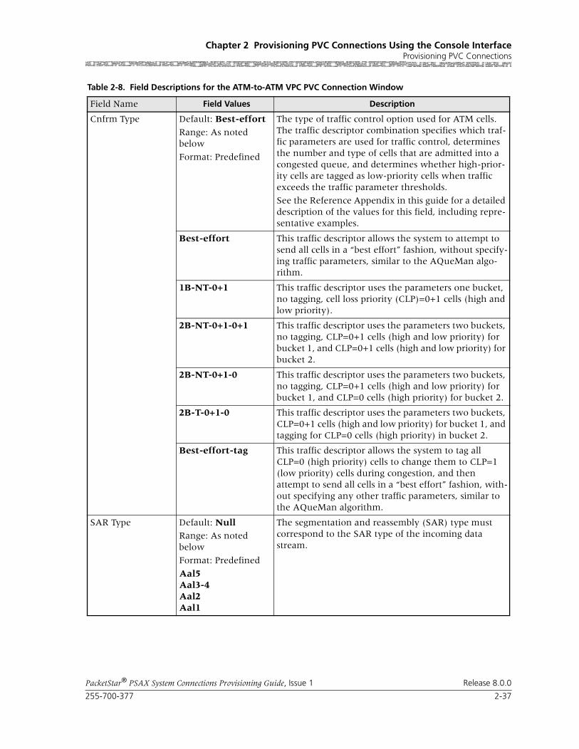
255-700-377 2-37
PacketStar® PSAX System Connections Provisioning Guide, Issue 1 Release 8.0.0
Chapter 2 Provisioning PVC Connections Using the Console InterfaceProvisioning PVC Connections
Cnfrm Type Default: Best-effort
Range: As noted below
Format: Predefined
The type of traffic control option used for ATM cells. The traffic descriptor combination specifies which traf-fic parameters are used for traffic control, determines the number and type of cells that are admitted into a congested queue, and determines whether high-prior-ity cells are tagged as low-priority cells when traffic exceeds the traffic parameter thresholds.
See the Reference Appendix in this guide for a detailed description of the values for this field, including repre-sentative examples.
Best-effort This traffic descriptor allows the system to attempt to send all cells in a “best effort” fashion, without specify-ing traffic parameters, similar to the AQueMan algo-rithm.
1B-NT-0+1 This traffic descriptor uses the parameters one bucket, no tagging, cell loss priority (CLP)=0+1 cells (high and low priority).
2B-NT-0+1-0+1 This traffic descriptor uses the parameters two buckets, no tagging, CLP=0+1 cells (high and low priority) for bucket 1, and CLP=0+1 cells (high and low priority) for bucket 2.
2B-NT-0+1-0 This traffic descriptor uses the parameters two buckets, no tagging, CLP=0+1 cells (high and low priority) for bucket 1, and CLP=0 cells (high priority) for bucket 2.
2B-T-0+1-0 This traffic descriptor uses the parameters two buckets, CLP=0+1 cells (high and low priority) for bucket 1, and tagging for CLP=0 cells (high priority) in bucket 2.
Best-effort-tag This traffic descriptor allows the system to tag all CLP=0 (high priority) cells to change them to CLP=1 (low priority) cells during congestion, and then attempt to send all cells in a “best effort” fashion, with-out specifying any other traffic parameters, similar to the AQueMan algorithm.
SAR Type Default: NullRange: As noted below
Format: Predefined
Aal5Aal3-4Aal2Aal1
The segmentation and reassembly (SAR) type must correspond to the SAR type of the incoming data stream.
Table 2-8. Field Descriptions for the ATM-to-ATM VPC PVC Connection Window
Field Name Field Values Description

Chapter 2 Provisioning PVC Connections Using the Console InterfaceProvisioning PVC Connections
2-38 255-700-377
PacketStar® PSAX System Connections Provisioning Guide, Issue 1 Release 8.0.0
Peak Rate(0+1) Default: 1
Range: 1–(232-1)(theoretical range, except for modules noted at right, see Description column)
Range:
Format: numeric (cells per second)
When setting this value, take into account the line rate for the module and the amount of bandwidth you are setting up for each interface for the module. Refer to the ATM UNI 3.1 specifications for more information.
Note: If you select the value SimplexA2B in the Flow field, set the value of this field to 0. The value in this field should be greater than the Sustained Rate field.If you are using the traffic shaping Enabled setting on the bulleted modules listed below, entering a minimum cps value below the minimum listed below will cause traf-fic-shaped connections to default back to the mini-mum cps value when the connection passes traffic.
• On the 1-Port OC-3c MM/SM and the 1-Port STM-1 MM/SM, the cps range is 18–999999999.
• On the OC-12c/STM-4c SM/MM, the cps range is 87–999999999.
• On the 3-Port DS3/E3 ATM, the cps range is 7–999999999.
Note: The peak cell rate cannot exceed the maximum cell rate for the interface.
SCR/PCR(0) Default: 1
Range: 0–999999999
Format: cps
When setting this value, take into account the line rate for the module and the amount of bandwidth you are setting up for each interface for the module. Refer to the ATM UNI 3.1 specifications for more information.
If you select the value SimplexA2B in the Flow field, set the value of this field to 0. The value in this field should be greater than the Sustained Rate field.If using traffic shaping on the OC-3c or STM-1 modules, the modules will not pass data until these parameters are set to a specified rate. Very large bursts of traffic may exceed the 8 MB memory typically available on the module, resulting in dropped cells. If very large bursts are typical for a specific network configuration, the module memory can be upgraded to 64 MB.
Table 2-8. Field Descriptions for the ATM-to-ATM VPC PVC Connection Window
Field Name Field Values Description

255-700-377 2-39
PacketStar® PSAX System Connections Provisioning Guide, Issue 1 Release 8.0.0
Chapter 2 Provisioning PVC Connections Using the Console InterfaceProvisioning PVC Connections
Max Burst Size (cells)
Default: 1
Range: 0–999999999
Format: cps
Maximum burst size. The maximum number of cells that can be received at the peak cell rate. This allows a burst of cells to arrive at a rate higher than that of the sustained cell rate. If the burst is larger than antici-pated, the additional cells are either tagged or dropped.
When setting this value, take into account the line rate for the module and the amount of bandwidth you are setting up for each interface for the module.
If you select the value SimplexA2B in the Flow field, set the value for maximum burst size to 0.
OC-3c APS Module: When the Traffic Shaping field is set to Enabled, the cell queue depth for the Max Burst Size field is internally set to 1000, regardless of the value you enter. If you enter values other than 1000, these values matter for incoming signalling SPVC/SVC setup from the remote end of the connection.
Traffic Shaping Default: Disabled
Range: As noted below.
Format: Predefined alphanumeric
Indicates the method for controlling the flow of data traffic. This feature is implemented on the following modules:
• 1-Port OC-3c Multimode and Single-Mode with Traffic Shaping modules
• 1-Port STM-1 Multimode and Single-Mode with Traffic Shaping modules
• 3-Port DS3/E3 ATM
• 1-Port OC-12c/STM-4c MM/SM 1+1 APS/MSP modules
See the Peak Rate field on this table for minimum cps ranges restrictions on these modules.
Disabled Traffic Shaping is disabled.
Enabled When enabled, traffic shaping ensures that the variable bit-rate (VBR) traffic entering the PSAX system via these modules complies with the parameters of the established service contracts.
Connection Features, Lower Left Panel
[FailCause A/B](display only)
Default: NoneRange: True/False
Format: Predefined
Displays a transmission failure cause on the A or B side of the connection.
Flow Default: Duplex
Range: As noted below
Format: Predefined
SimplexA2BPoint-to-point-Multi-point A2B
Direction of the flow of data traffic in this connection.
When you select SimplexA2B, the fields in the Traffic Parameters B to A panel do not display.
Table 2-8. Field Descriptions for the ATM-to-ATM VPC PVC Connection Window
Field Name Field Values Description

Chapter 2 Provisioning PVC Connections Using the Console InterfaceProvisioning PVC Connections
2-40 255-700-377
PacketStar® PSAX System Connections Provisioning Guide, Issue 1 Release 8.0.0
4 To add (apply) the connection configuration, select the Add This Con-nection command and press Enter.
5 To review this connection, select the Go Back to Connection Table command and press Enter (or press Ctrl+B).
Oam Status AOam Status B
Default: Unsupp
Range: As noted below
Format: Predefined
Indicates on what portion of the transmission path the operations and maintenance status AIS and RDI cells will be processed.
Unsupp OAM is not in use.
End-Pt The PSAX system is used as a termination point for ATM, and will process AIS/RDI cells on the A or B side.
The OAM loopback test is supported for end-to-end connections only.
Seg-Pt The PSAX system is used as a single ATM link, or is part of a group of inter-connected ATM links that pro-cess OAM maintenance cells only on the A or B side.
End-Seg-Pt Has the characteristics of both an end point and a seg-ment point on the A or B side.
Intermediate-Pt The PSAX system is used as a network node and an intermediate ATM device that does not terminate the ATM connection. It only generates AIS cells during a local failure on the A or B side.
Use this value to enable trunk conditioning. For more information, see the Trunk Conditioning Application Note for PacketStar PSAX Multiservice Media Gateways (Docu-ment No. 255-700-072).
The OAM loopback test is supported for end-to-end connections only.
Intra-Segment-Pt OAM will be performed on any connecting point inside a segment flow on the A or B side.
[Backup PVC](display only)
Default: No
Range: Yes/No
Format: Predefined
Specified whether a backup PVC is displayed, if one has been configured.
No A backup PVC will not be displayed.
Yes A backup PVC will be displayed.
[Conn Status] (display only)
Default: InactiveRange: Inac-tive/Active
Format: Predefined
This field displays the current status of the connection. The value indicates whether the connection is passing traffic.
Inactive The connection is not passing traffic.
Active The connection is passing traffic.
Table 2-8. Field Descriptions for the ATM-to-ATM VPC PVC Connection Window
Field Name Field Values Description

255-700-377 2-41
PacketStar® PSAX System Connections Provisioning Guide, Issue 1 Release 8.0.0
Chapter 2 Provisioning PVC Connections Using the Console InterfaceProvisioning PVC Connections
The ATM-to-ATM VPC PVC Table window is returned (see Figure 2-11), displaying the values you just applied.
6 To add more connections of this type, repeat steps 2 through 5 for more connections as needed.
7 To permanently save these connections, press Ctrl+G to return to the Console Interface Main Menu window.
8 Select Save Configuration and press Enter to store the values in the PSAX system database.
End
Viewing ATM-to-ATM VPC Statistics
Begin
Steps to View ATM-to-ATM VPC Statistics
1 From the ATM-to-ATM VPC PVC Connection window, select the View Connection Statistics command and press Enter.
The ATM-to-ATM VPC PVC Statistics window is displayed, as shown in Figure 2-13.
Commands The commands on this window have the following functions:
Figure 2-13. ATM-to-ATM VPC PVC Statistics Window

Chapter 2 Provisioning PVC Connections Using the Console InterfaceProvisioning PVC Connections
2-42 255-700-377
PacketStar® PSAX System Connections Provisioning Guide, Issue 1 Release 8.0.0
Field Descriptions The field descriptions for the display-only fields on this window are provided in Table 2-5:
Command Function
Reset Odometers Returns all statistics odometers to the value 0.
Continuous Update Updates the values in the fields every sec-ond.
Display Stats for Next Con-nection
Displays the statistics for the next selected connection.
Go Back to Connection Dis-play
Redisplays the Connection Configuration window.
Table 2-9. Field Descriptions for the ATM-to-ATM VCC PVC and the ATM-to-ATM VPC PVC Connection Statistics Windows
Field Name Field Values Description
AIS Rx/Tx(display only)
Default: 0
Range: N/A
Format: numeric
Displays the number of alarm indication signal (AIS) cells received and transmitted..
RDI Rx/Tx(display only)
Default: 0Range: 32 bits
Format: numeric(exponent notation)
Displays the number of remote defect indicator (RDI) cells received and transmitted.
cell Drop/Tag(display only)
Default: 0
Range: 32 bits
Format: numeric
Displays the number of cells dropped and tagged on incoming side of interface A or B.
Cells Received(display only)
Default: 0
Range: 64 bits
Format: numeric(exponent notation)
Displays the number of valid cells received since the virtual circuit or virtual path was established.
Cells Transmitted(display only)
Default: 0Range: 64 bits
Format: numeric(exponent notation)
Displays the number of valid cells transmitted since the virtual circuit or virtual path was estab-lished.
FEC Rate Used(display only)
Default: 0
Range: N/A
Format: predefined
Displays the forward error correction (FEC) rate being used by the FEC module in the A2B direc-tion (for ATM Interface A panel), or B2A direc-tion (for ATM Interface B panel). This field is dymanic when auto rates are selected. In other cases it will display the rate set by the user.
Note: This field is displayed only on the ATM-to-ATM VCC PVC Statistics window only.

255-700-377 2-43
PacketStar® PSAX System Connections Provisioning Guide, Issue 1 Release 8.0.0
Chapter 2 Provisioning PVC Connections Using the Console InterfaceProvisioning PVC Connections
Adding/Viewing a Backup ATM-to-ATM VPC Connection Begin
Steps for Adding/Viewing a Backup ATM-to-ATM VPC Connection
1 From the ATM-to-ATM VPC Connection window, select the Add/View Backup PVC command and press Enter.
The ATM-to-ATM VPC Backup Connection window is displayed, as shown in Figure 2-14.
Received Odometer(display only)
Default: 0Range: 64 bits
Format: numeric(exponent notation)
Displays the number of valid cells received since this counter was reset. This counter serves as an odometer while the Cells Received field tracks usage for the life of the circuit.
Transmitted Odom-eter(display only)
Default: 0
Range: 64 bits
Format: numeric(exponent notation)
Displays the number of valid cells transmitted since this counter was reset. This counter serves as an odometer while the Cells Transmitted field tracks usage for the life of the circuit.
Time Elapsed(display only)
Default: 0
Range: N/A
Format: numeric(hour, minute, sec-ond)
Displays the time elapsed since last reset.
Time Since Reset(display only)
Default: 00:00:00
Range: N/A
Format: numeric(hour, minute, sec-ond)
Displays the time elapsed since the last time the Reset Statistics command was used. The Reset Statistics command on the statistics window resets only the odometer fields and the corre-sponding clock. . Other counters are incre-mented for the duration of the connection.
Table 2-9. Field Descriptions for the ATM-to-ATM VCC PVC and the ATM-to-ATM VPC PVC Connection Statistics Windows
Field Name Field Values Description

Chapter 2 Provisioning PVC Connections Using the Console InterfaceProvisioning PVC Connections
2-44 255-700-377
PacketStar® PSAX System Connections Provisioning Guide, Issue 1 Release 8.0.0
Commands The commands on this window have the following functions:
Field Descriptions The fields on this window have the following values:
Figure 2-14. ATM-to-ATM VPC Backup PVC Connection Window
Command Function
Add This Connection Adds the connection entered on backup ATM interface right panel.
Delete Connection Deletes the selected connection.
Go Back to Primary PVC Connection
Returns to the ATM-to-ATM VCC PVC Connection window.

255-700-377 2-45
PacketStar® PSAX System Connections Provisioning Guide, Issue 1 Release 8.0.0
Chapter 2 Provisioning PVC Connections Using the Console InterfaceProvisioning PVC Connections
Table 2-10. Field Descriptions for the ATM-to-ATM Backup VPC PVC Connection Window
Field Name Field Values Description
ATM Interface Panel
[Slot](display only)
Default: Equipment Dependent
Range: Varies depending on equipment
Format: Numeric
Displays the current primary connection slot in use.
[Port](display only)
Default: Equipment Dependent
Range: Determined by the number of ports available on the module selected in the Slot field
Format: Numeric
Displays the current primary connection port on module in slot in use.
[Channel](display only)
Default: Equipment Dependent
Range: Determined by the number of channels avail-able on the port selected in the Port field
Format: Numeric
Displays the current primary connection channel on port on module on slot in use.
[VPI](display only)
Default: Default: 0Range: 0–255
Format: Numeric
Displays the primary connection virtual path identi-fier assigned to the interface
Backup ATM Interface Panel
Slot Default: Equipment Dependent
Range: Listed as available from the PSAX device
Format: Numeric
Indicates the slot containing the module for which you are creating a connection.
Port Default: Equipment Dependent
Range: Determined by the number of ports available on the module selected in the Slot field
Format: Numeric
Indicates the port number on the module for which you are creating a connection.
Channel Default: Equipment DependentRange: Determined by the number of channels avail-able on the port selected in the Port field
Format: Numeric
Indicates the channel number of the port on the module for which you are creating a connection.
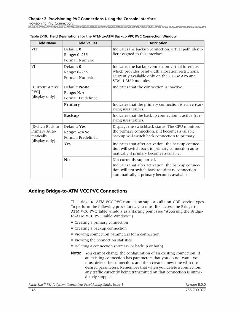
Chapter 2 Provisioning PVC Connections Using the Console InterfaceProvisioning PVC Connections
2-46 255-700-377
PacketStar® PSAX System Connections Provisioning Guide, Issue 1 Release 8.0.0
Adding Bridge-to-ATM VCC PVC Connections
The bridge-to-ATM VCC PVC connection supports all non-CBR service types. To perform the following procedures, you must first access the Bridge-to-ATM VCC PVC Table window as a starting point (see “Accessing the Bridge-to-ATM VCC PVC Table Window””):
• Creating a primary connection
• Creating a backup connection
• Viewing connection parameters for a connection
• Viewing the connection statistics
• Deleting a connection (primary or backup or both)
Note: You cannot change the configuration of an existing connection. If an existing connection has parameters that you do not want, you must delete the connection, and then create a new one with the desired parameters. Remember that when you delete a connection, any traffic currently being transmitted on that connection is imme-diately stopped.
VPI Default: 0
Range: 0–255
Format: Numeric
Indicates the backup connection.virtual path identi-fier assigned to this interface.
VI Default: 0Range: 0–255
Format: Numeric
Indicates the backup connection virtual interface, which provides bandwidth allocation restrictions. Currently available only on the OC-3c APS and STM-1 MSP modules.
[Current Active PVC](display only)
Default: None
Range: N/A
Format: Predefined
Indicates that the connection is inactive.
Primary Indicates that the primary connection is active (car-rying user traffic).
Backup Indicates that the backup connection is active (car-rying user traffic).
[Switch Back to Primary Auto-matically](display only)
Default: YesRange: Yes/No
Format: Predefined
Displays the switchback status. The CPU monitors the primary connection, if it becomes available, backup will switch back connection to primary.
Yes Indicates that after activation, the backup connec-tion will switch back to primary connection auto-matically if primary becomes available.
No Not currently supported.
Indicates that after activation, the backup connec-tion will not switch back to primary connection automatically if primary becomes available.
Table 2-10. Field Descriptions for the ATM-to-ATM Backup VPC PVC Connection Window
Field Name Field Values Description

255-700-377 2-47
PacketStar® PSAX System Connections Provisioning Guide, Issue 1 Release 8.0.0
Chapter 2 Provisioning PVC Connections Using the Console InterfaceProvisioning PVC Connections
Note: On the DS1 IMA and E1 IMA modules, this connection type must be provisioned on the virtual port (port 7). You can use up to three groups on port 7 (the groups you provision on port 7.)
Note: On the DS3 IMA module, this connection type must be provi-sioned on the virtual port (port 30). You can use up to 14 groups on port 30 (the groups you provision on port 30.)
Note: The OAM feature is supported for this connection type and can be enabled on the Connection window. Statistical OAM information is provided on the related Connection Statistics window. Parame-ters for OAM operation can be configured from the Diagnostics Menu window. See the appropriate PacketStar PSAX Multiservice Media Gateway user guide for more details.
Accessing the Bridge-to-ATM VCC PVC Table Window
To access the Bridge-to-ATM VCC PVC Table window, perform the steps in the following procedure.
Begin1 On the Console Interface Main Menu window, select the Connection
Configuration option -> Connection Configuration Menu window.
2 On the Connection Configuration Menu window, select the Bridge-to-ATM VCC option.
The Bridge-to-ATM VCC PVC Table window is displayed (see Figure 2-15). The commands for this window are described in Table 1-1. The display-only fields for this window are described in Table 1-2.
Note: At the time of initial installation, the Bridge-to-ATM VCC PVC Table window is empty. After you have set up connections, this window displays all the connections of this type in the PSAX system.
3 Go to one of the following procedures, depending on the task you want to perform:
• ”Creating a Bridge-to-ATM VCC PVC Connection” on page 2-49
• ”Creating a Backup Bridge-to-ATM VCC PVC Connection” on page 2-56
• ”Viewing Connection Parameters for a Bridge-to-ATM VCC PVC Con-nection” on page 2-59
• ”Viewing Statistics for a Bridge-to-ATM VCC PVC Connection” on page 2-60
• ”Deleting a Bridge-to-ATM VCC PVC Connection” on page 2-62
End
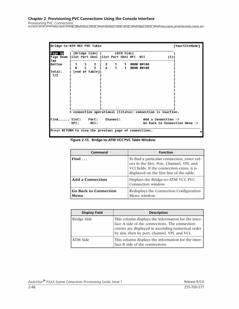
Chapter 2 Provisioning PVC Connections Using the Console InterfaceProvisioning PVC Connections
2-48 255-700-377
PacketStar® PSAX System Connections Provisioning Guide, Issue 1 Release 8.0.0
Figure 2-15. Bridge-to-ATM VCC PVC Table Window
Command Function
Find . . . To find a particular connection, enter val-ues in the Slot, Port, Channel, VPI, and VCI fields. If the connection exists, it is displayed on the first line of the table.
Add a Connection Displays the Bridge-to-ATM VCC PVC Connection window.
Go Back to Connection Menu
Redisplays the Connection Configuration Menu window.
Display Field Description
Bridge Side This column displays the information for the inter-face A side of the connections. The connection entries are displayed in ascending numerical order by slot, then by port, channel, VPI, and VCI.
ATM Side This column displays the information for the inter-face B side of the connections.
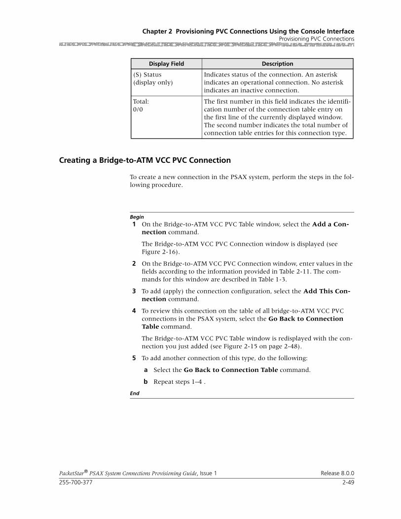
255-700-377 2-49
PacketStar® PSAX System Connections Provisioning Guide, Issue 1 Release 8.0.0
Chapter 2 Provisioning PVC Connections Using the Console InterfaceProvisioning PVC Connections
Creating a Bridge-to-ATM VCC PVC Connection
To create a new connection in the PSAX system, perform the steps in the fol-lowing procedure.
Begin1 On the Bridge-to-ATM VCC PVC Table window, select the Add a Con-
nection command.
The Bridge-to-ATM VCC PVC Connection window is displayed (see Figure 2-16).
2 On the Bridge-to-ATM VCC PVC Connection window, enter values in the fields according to the information provided in Table 2-11. The com-mands for this window are described in Table 1-3.
3 To add (apply) the connection configuration, select the Add This Con-nection command.
4 To review this connection on the table of all bridge-to-ATM VCC PVC connections in the PSAX system, select the Go Back to Connection Table command.
The Bridge-to-ATM VCC PVC Table window is redisplayed with the con-nection you just added (see Figure 2-15 on page 2-48).
5 To add another connection of this type, do the following:
a Select the Go Back to Connection Table command.
b Repeat steps 1–4 .
End
(S) Status(display only)
Indicates status of the connection. An asterisk indicates an operational connection. No asterisk indicates an inactive connection.
Total:0/0
The first number in this field indicates the identifi-cation number of the connection table entry on the first line of the currently displayed window. The second number indicates the total number of connection table entries for this connection type.
Display Field Description

Chapter 2 Provisioning PVC Connections Using the Console InterfaceProvisioning PVC Connections
2-50 255-700-377
PacketStar® PSAX System Connections Provisioning Guide, Issue 1 Release 8.0.0
Figure 2-16. Bridge-to-ATM VCC PVC Connection Window
Command Function
Display Next Connection Displays the next Bridge-to-ATM VCC PVC connection in the table.
Add This Connection Adds a connection having the values cur-rently displayed on the window.
Delete Connection Deletes the connection having the values currently displayed on the window.
View Connection Statistics Displays the Bridge-to-ATM VCC PVC Connection Statistics window.
Add/View Backup PVC Displays the backup PVC for this connec-tion or gives you the option to add a backup Bridge-to-ATM VCC PVC.
Go Back to Connection Table
Redisplays the Bridge-to-ATM VCC PVC Table window.

255-700-377 2-51
PacketStar® PSAX System Connections Provisioning Guide, Issue 1 Release 8.0.0
Chapter 2 Provisioning PVC Connections Using the Console InterfaceProvisioning PVC Connections
Table 2-11. Field Descriptions for the Bridge-to-ATM VCC PVC Connection Window
Field Name Field Values Description
Bridge Interface A Default: N/A
Range: N/A
Format: Alphanumeric
Indicates that this is the bridge side of the con-nection that will send and receive signals.
ATM Interface B Default: N/ARange: N/A
Format: Alphanumeric
Indicates that this is the ATM interface side of the connection that will send and receive signals.
Slot Default: 0Range: Varies depending on chassis type
Format: Numeric
Ethernet and 4-Port Ethernet Modules: Indicates the slot number containing this module for which you are creating a connection.
4-Port Ethernet Module: To enable ATM traffic shaping, specify a slot containing one of the appropriate modules on the ATM side of this con-nection (see the section, “ATM Traffic Shaping,” in Chapter 2).
Port Default: 6Default: 5
Default: 0
Range: N/A
Format: Numeric
Indicates the virtual port number of this module.
4-Port Ethernet Module: To enable ATM traffic shaping, specify a port containing one of the appropriate modules on the ATM side of this con-nection (see the section, “ATM Traffic Shaping,” in Chapter 2).
Channel Default: 1Range: 1–70 for the Ethernet module; 1–56 for the 4-Port Ethernet module
Format: Numeric
Ethernet and 4-Port Modules: Indicates the vir-tual channel number containing this module for which you are creating a connection.
4-Port Ethernet Module: To enable ATM traffic shaping, specify a channel containing one of the appropriate modules on the ATM side of this con-nection (see the section, “ATM Traffic Shaping,” in Chapter 2).
VPI Default: 0Range: 0–255 (AtmUNI); 0–4095 (IISP)
Format: Numeric
Indicates the virtual path identifier. Enter a value for the ATM side of the connection.
VCI Default: 0
Range: 32–65535
Format: Numeric
Indicates the virtual channel identifier. Enter a value for the ATM side of the connection.
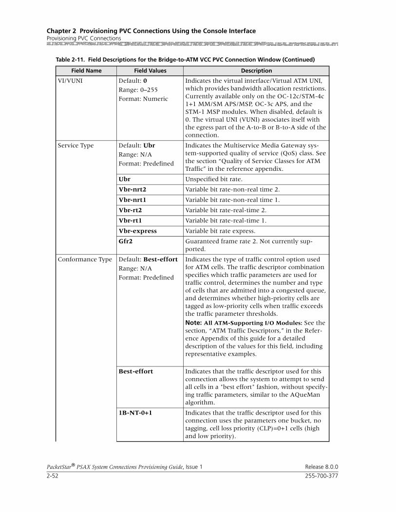
Chapter 2 Provisioning PVC Connections Using the Console InterfaceProvisioning PVC Connections
2-52 255-700-377
PacketStar® PSAX System Connections Provisioning Guide, Issue 1 Release 8.0.0
VI/VUNI Default: 0
Range: 0–255
Format: Numeric
Indicates the virtual interface/Virtual ATM UNI, which provides bandwidth allocation restrictions. Currently available only on the OC-12c/STM-4c 1+1 MM/SM APS/MSP, OC-3c APS, and the STM-1 MSP modules. When disabled, default is 0. The virtual UNI (VUNI) associates itself with the egress part of the A-to-B or B-to-A side of the connection.
Service Type Default: Ubr
Range: N/A
Format: Predefined
Indicates the Multiservice Media Gateway sys-tem-supported quality of service (QoS) class. See the section “Quality of Service Classes for ATM Traffic” in the reference appendix.
Ubr Unspecified bit rate.
Vbr-nrt2 Variable bit rate-non-real time 2.
Vbr-nrt1 Variable bit rate-non-real time 1.
Vbr-rt2 Variable bit rate-real-time 2.
Vbr-rt1 Variable bit rate-real-time 1.
Vbr-express Variable bit rate express.
Gfr2 Guaranteed frame rate 2. Not currently sup-ported.
Conformance Type Default: Best-effort
Range: N/A
Format: Predefined
Indicates the type of traffic control option used for ATM cells. The traffic descriptor combination specifies which traffic parameters are used for traffic control, determines the number and type of cells that are admitted into a congested queue, and determines whether high-priority cells are tagged as low-priority cells when traffic exceeds the traffic parameter thresholds.
Note: All ATM-Supporting I/O Modules: See the section, “ATM Traffic Descriptors,” in the Refer-ence Appendix of this guide for a detailed description of the values for this field, including representative examples.
Best-effort Indicates that the traffic descriptor used for this connection allows the system to attempt to send all cells in a "best effort" fashion, without specify-ing traffic parameters, similar to the AQueMan algorithm.
1B-NT-0+1 Indicates that the traffic descriptor used for this connection uses the parameters one bucket, no tagging, cell loss priority (CLP)=0+1 cells (high and low priority).
Table 2-11. Field Descriptions for the Bridge-to-ATM VCC PVC Connection Window (Continued)
Field Name Field Values Description
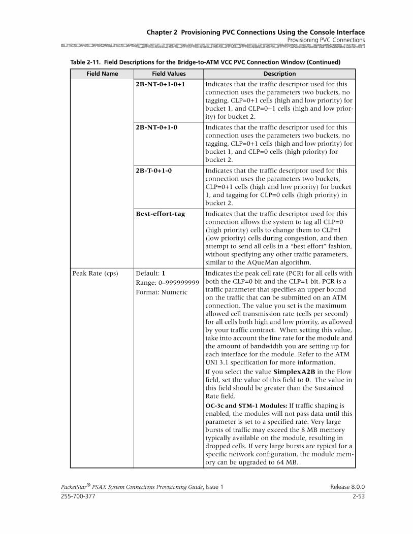
255-700-377 2-53
PacketStar® PSAX System Connections Provisioning Guide, Issue 1 Release 8.0.0
Chapter 2 Provisioning PVC Connections Using the Console InterfaceProvisioning PVC Connections
2B-NT-0+1-0+1 Indicates that the traffic descriptor used for this connection uses the parameters two buckets, no tagging, CLP=0+1 cells (high and low priority) for bucket 1, and CLP=0+1 cells (high and low prior-ity) for bucket 2.
2B-NT-0+1-0 Indicates that the traffic descriptor used for this connection uses the parameters two buckets, no tagging, CLP=0+1 cells (high and low priority) for bucket 1, and CLP=0 cells (high priority) for bucket 2.
2B-T-0+1-0 Indicates that the traffic descriptor used for this connection uses the parameters two buckets, CLP=0+1 cells (high and low priority) for bucket 1, and tagging for CLP=0 cells (high priority) in bucket 2.
Best-effort-tag Indicates that the traffic descriptor used for this connection allows the system to tag all CLP=0 (high priority) cells to change them to CLP=1 (low priority) cells during congestion, and then attempt to send all cells in a “best effort” fashion, without specifying any other traffic parameters, similar to the AQueMan algorithm.
Peak Rate (cps) Default: 1Range: 0–999999999
Format: Numeric
Indicates the peak cell rate (PCR) for all cells with both the CLP=0 bit and the CLP=1 bit. PCR is a traffic parameter that specifies an upper bound on the traffic that can be submitted on an ATM connection. The value you set is the maximum allowed cell transmission rate (cells per second) for all cells both high and low priority, as allowed by your traffic contract. When setting this value, take into account the line rate for the module and the amount of bandwidth you are setting up for each interface for the module. Refer to the ATM UNI 3.1 specification for more information.
If you select the value SimplexA2B in the Flow field, set the value of this field to 0. The value in this field should be greater than the Sustained Rate field.
OC-3c and STM-1 Modules: If traffic shaping is enabled, the modules will not pass data until this parameter is set to a specified rate. Very large bursts of traffic may exceed the 8 MB memory typically available on the module, resulting in dropped cells. If very large bursts are typical for a specific network configuration, the module mem-ory can be upgraded to 64 MB.
Table 2-11. Field Descriptions for the Bridge-to-ATM VCC PVC Connection Window (Continued)
Field Name Field Values Description
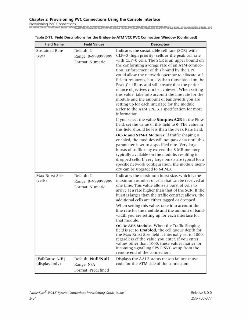
Chapter 2 Provisioning PVC Connections Using the Console InterfaceProvisioning PVC Connections
2-54 255-700-377
PacketStar® PSAX System Connections Provisioning Guide, Issue 1 Release 8.0.0
Sustained Rate (cps)
Default: 1
Range: 0–999999999
Format: Numeric
Indicates the sustainable cell rate (SCR) with CLP=0 (high priority) cells or the peak cell rate with CLP=0 cells. The SCR is an upper bound on the conforming average rate of an ATM connec-tion. Enforcement of this bound by the UPC could allow the network operator to allocate suf-ficient resources, but less than those based on the Peak Cell Rate, and still ensure that the perfor-mance objectives can be achieved. When setting this value, take into account the line rate for the module and the amount of bandwidth you are setting up for each interface for the module. Refer to the ATM UNI 3.1 specification for more information.
If you select the value SimplexA2B in the Flow field, set the value of this field to 0. The value in this field should be less than the Peak Rate field.
OC-3c and STM-1 Modules: If traffic shaping is enabled, the modules will not pass data until this parameter is set to a specified rate. Very large bursts of traffic may exceed the 8 MB memory typically available on the module, resulting in dropped cells. If very large bursts are typical for a specific network configuration, the module mem-ory can be upgraded to 64 MB.
Max Burst Size (cells)
Default: 1
Range: 0–999999999
Format: Numeric
Indicates the maximum burst size, which is the maximum number of cells that can be received at one time. This value allows a burst of cells to arrive at a rate higher than that of the SCR. If the burst is larger than the traffic contract allows, the additional cells are either tagged or dropped.
When setting this value, take into account the line rate for the module and the amount of band-width you are setting up for each interface for that module.OC-3c APS Module: When the Traffic Shaping field is set to Enabled, the cell queue depth for the Max Burst Size field is internally set to 1000, regardless of the value you enter. If you enter values other than 1000, these values matter for incoming signalling SPVC/SVC setup from the remote end of the connection.
[FailCause A/B](display only)
Default: Null/Null
Range: N/A
Format: Predefined
Displays the AAL2 status reason failure cause code for the ATM side of the connection.
Table 2-11. Field Descriptions for the Bridge-to-ATM VCC PVC Connection Window (Continued)
Field Name Field Values Description
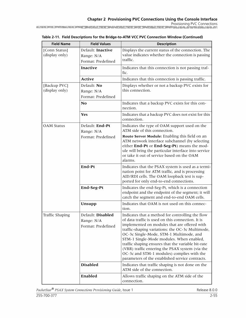
255-700-377 2-55
PacketStar® PSAX System Connections Provisioning Guide, Issue 1 Release 8.0.0
Chapter 2 Provisioning PVC Connections Using the Console InterfaceProvisioning PVC Connections
[Conn Status](display only)
Default: Inactive
Range: N/A
Format: Predefined
Displays the current status of the connection. The value indicates whether the connection is passing traffic.
Inactive Indicates that this connection is not passing traf-fic.
Active Indicates that this connection is passing traffic.
[Backup PVC](display only)
Default: No
Range: N/A
Format: Predefined
Displays whether or not a backup PVC exists for this connection.
No Indicates that a backup PVC exists for this con-nection.
Yes Indicates that a backup PVC does not exist for this connection.
OAM Status Default: End-Pt
Range: N/A
Format: Predefined
Indicates the type of OAM support used on the ATM side of this connection.
Route Server Module: Enabling this field on an ATM network interface subchannel (by selecting either End-Pt or End-Seg-Pt) means the mod-ule will bring the particular interface into service or take it out of service based on the OAM alarms.
End-Pt Indicates that the PSAX system is used as a termi-nation point for ATM traffic, and is processing AID/RDI cells. The OAM loopback test is sup-ported for only end-to-end connections.
End-Seg-Pt Indicates the end-Seg-Pt, which is a connection endpoint and the endpoint of the segment; it will catch the segment and end-to-end OAM cells.
Unsupp Indicates that OAM is not used on this connec-tion.
Traffic Shaping Default: Disabled
Range: N/A
Format: Predefined
Indicates that a method for controlling the flow of data traffic is used on this connection. It is implemented on modules that are offered with traffic-shaping variations: the OC-3c Multimode, OC-3c Single-Mode, STM-1 Multimode, and STM-1 Single-Mode modules. When enabled, traffic shaping ensures that the variable bit-rate (VBR) traffic entering the PSAX system (via the OC-3c and STM-1 modules) complies with the parameters of the established service contracts.
Disabled Indicates that traffic shaping is not done on the ATM side of the connection.
Enabled Allows traffic shaping on the ATM side of the connection.
Table 2-11. Field Descriptions for the Bridge-to-ATM VCC PVC Connection Window (Continued)
Field Name Field Values Description
Chapter 2 Provisioning PVC Connections Using the Console InterfaceProvisioning PVC Connections
2-56 255-700-377
PacketStar® PSAX System Connections Provisioning Guide, Issue 1 Release 8.0.0
Creating a Backup Bridge-to-ATM VCC PVC Connection
You must create a primary connection first before you can create a backup connection. To create a backup bridge-to-ATM VCC PVC connection or view a backup connection you created previously, perform the steps in the follow-ing procedure.
Begin1 Make sure you have added the primary connection according to the pro-
cedure in ”Creating a Bridge-to-ATM VCC PVC Connection” on page 2-49.
2 On the Bridge-to-ATM VCC PVC Connection window (see Figure 2-16 on page 2-50), select the Add/View Backup PVC command.
The Bridge-to-ATM VCC Backup PVC Connection window is displayed (see Figure 2-17).
3 Enter values in the fields in the Backup ATM Interface panel on this win-dow according to the information provided in Table 2-12. The commands for this window are described in Table 1-5.
4 Select the Add This Connection command.
5 To return to the Connection window, select the Go Back to Primary PVC Connection command.
The Bridge-to-ATM VCC PVC Connection window is redisplayed (see Figure 2-16 on page 2-50).
End
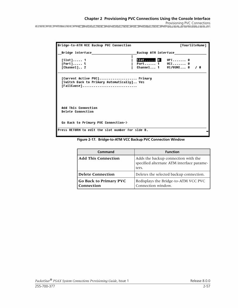
255-700-377 2-57
PacketStar® PSAX System Connections Provisioning Guide, Issue 1 Release 8.0.0
Chapter 2 Provisioning PVC Connections Using the Console InterfaceProvisioning PVC Connections
Figure 2-17. Bridge-to-ATM VCC Backup PVC Connection Window
Command Function
Add This Connection Adds the backup connection with the specified alternate ATM interface parame-ters.
Delete Connection Deletes the selected backup connection.
Go Back to Primary PVC Connection
Redisplays the Bridge-to-ATM VCC PVC Connection window.

Chapter 2 Provisioning PVC Connections Using the Console InterfaceProvisioning PVC Connections
2-58 255-700-377
PacketStar® PSAX System Connections Provisioning Guide, Issue 1 Release 8.0.0
Table 2-12. Field Descriptions for the Bridge-to-ATM VCC Backup PVC Connection WindowTable 2-13.
Field Name Field Values Description
Slot Default: N/A
Range: varies depending on module type
Format: numeric
Specifies the slot containing the module config-ured with an ATM interface, for which you are creating a backup connection. Enter a value in this field that is for a different module from the one specified for the primary connection.
Note: This field is display only on the bridge interface side of the connection.
Port Default: N/A
Range: varies depending on module type
Format: numeric
Specifies the port number on the module config-ured with an ATM interface, for which you are creating a backup connection. Enter a value in this field that is for a different module from the one specified for the primary connection..
Note: This field is display only on the bridge interface side of the connection.
Channel Default: 0
Range: varies depending on chassis type
Format: numeric
Specifies the channel number of the port on the module configured with an ATM interface, for which you are creating a backup connection. Enter a value in this field that is for a different module from the one specified for the primary connection.
Note: This field is display only on the bridge interface side of the connection.
VPI Default: 0
Range: 0–255
Format: numeric
Specifies the virtual path identifier assigned to the ATM side of the connection. Enter a value in this field that is for a different module from the one specified for the primary connection.
VCI Default: 32Range: 32–4000
Format: numeric
Specifies the virtual channel identifier assigned to the ATM side of the connection. Enter a value in this field that is for a different module from the one specified for the primary connection.
VI/VUNI Default: 0
Range: 0–255
Format: numeric
Specifies the virtual interface, which provides bandwidth allocation restrictions. Enter a value in this field that is for a different module from the one specified for the primary connection.
Note: Currently this field is applicable only to the 1-Port OC-3c 1+1 APS and the 1-Port STM-1 1+1 MSP modules.

255-700-377 2-59
PacketStar® PSAX System Connections Provisioning Guide, Issue 1 Release 8.0.0
Chapter 2 Provisioning PVC Connections Using the Console InterfaceProvisioning PVC Connections
Viewing Connection Parameters for a Bridge-to-ATM VCC PVC Connection
To view connection parameters for a primary or backup connection, perform the steps in the following procedure.
Begin1 On the Bridge-to-ATM VCC PVC Table window (see Figure 2-15 on
page 2-48), select the line in the table displaying the connection for which you want to view the parameters.
The Bridge-to-ATM VCC PVC Connection window is displayed (see Figure 2-16 on page 2-50). All connection parameters, except connec-tion statistics, are displayed on this window.
2 To view the backup connection for the displayed connection, select the Add/View Backup PVC command.
The Bridge-to-ATM VCC Backup PVC Connection window is displayed (see Figure 2-17 on page 2-57). The backup connection parameters are displayed on this window.
End
[Current Active PVC](display only)
Default: NoneRange: N/A
Format: Predefined
Indicates whether the primary or backup connec-tion is active.
None Indicates that the connection is inactive.
Primary Indicates that the primary connection is active (carrying user traffic).
Backup Indicates that the backup connection is active (carrying user traffic).
[Switch Back to Pri-mary Automati-cally](display only)
Default: Yes Range: N/A
Format: predefined alphanumeric
Indicates whether the traffic on the backup con-nection will revert to the primary connection when it becomes available.
Yes Indicates that once the primary connection becomes available, traffic will revert to the pri-mary connection automatically.
No Not currently supported.
Indicates that if the backup connection is active, traffic will not revert to the primary connection automatically if it becomes available.
Table 2-12. Field Descriptions for the Bridge-to-ATM VCC Backup PVC Connection WindowTable 2-13.
Field Name Field Values Description

Chapter 2 Provisioning PVC Connections Using the Console InterfaceProvisioning PVC Connections
2-60 255-700-377
PacketStar® PSAX System Connections Provisioning Guide, Issue 1 Release 8.0.0
Viewing Statistics for a Bridge-to-ATM VCC PVC Connection
To view the statistics for this connection, perform the steps in the following procedure.
Begin1 On the Bridge-to-ATM VCC PVC Connection window (see Figure 2-16
on page 2-50), select the View Connection Statistics command.
The Bridge-to-ATM VCC PVC Statistics window is displayed (see Figure 2-18). The commands for this window are described in Table 1-3. The display-only fields for this window are described in Table 1-8.
2 To view connection statistics for the next connection in the PSAX system, select the Display Stats for Next Connection command.
3 To return to the Bridge-to-ATM VCC PVC Table window on which you can create a new connection, select the Go Back to Connection Dis-play command on the Statistics window, and then select the Go Back to Connection Table command on the Connection window.
The Bridge-to-ATM VCC PVC Table window is displayed (see Figure 2-15 on page 2-48).
End
Figure 2-18. Bridge-to-ATM VCC PVC Statistics Window

255-700-377 2-61
PacketStar® PSAX System Connections Provisioning Guide, Issue 1 Release 8.0.0
Chapter 2 Provisioning PVC Connections Using the Console InterfaceProvisioning PVC Connections
Command Function
Reset Odometers Returns all statistics odometers to zero.
Continuous Update Updates the values in the fields every second.
Display Stats for Next Connection
Displays the statistics for the next selected connection.
Go Back to Connection Display
Redisplays the Bridge-to-ATM VCC PVC Connection window.
Table 2-14. Field Descriptions for the Bridge-to-ATM VCC Connection Statistics Window
Field Name Field Values Description
Slot(display only)
Default: 0Range: N/A
Format: Numeric
Indicates the slot identifier of the ATM interface for either the Bridge Interface panel or the ATM Interface panel.
Port(display only)
Default: 0
Range: N/A
Format: Numeric
Indicates the port identifier of the ATM interface for either the Bridge Interface panel or the ATM Interface panel.
Channel(display only)
Default: 0
Range: N/A
Format: Numeric
Indicates the channel identifier for either Inter-face A or Interface B.
VPI (ATM Interface panel only)(display only)
Default: 0Range: N/A
Format: Numeric
Indicates the virtual path identifier of the ATM side (SVC side) of the connection.
VCI (ATM Interface panel only)(display only)
Default: 0
Range: N/A
Format: Numeric
Indicates the virtual channel identifier of the ATM side (SVC side) of the connection.
[Cells Encoded](display only)
Default: 0
Range: N/A
Format: Scientific Notation
Indicates the number of cells encoded going into interface side Aor B during the amount of time shown in Time Elapsed field since the circuit was established.
[Cells Decoded](display only)
Default: 0Range: N/A
Format: Scientific Notation
Indicates the number of cells decoded going out of interface side Aor B during the amount of time shown in Time Elapsed field since the circuit was established.
[Encoded Odometer](display only)
Default: 0
Range: N/A
Format: Scientific Notation
Indicates the total number of cells encoded going into interface side A or B since this counter was reset.
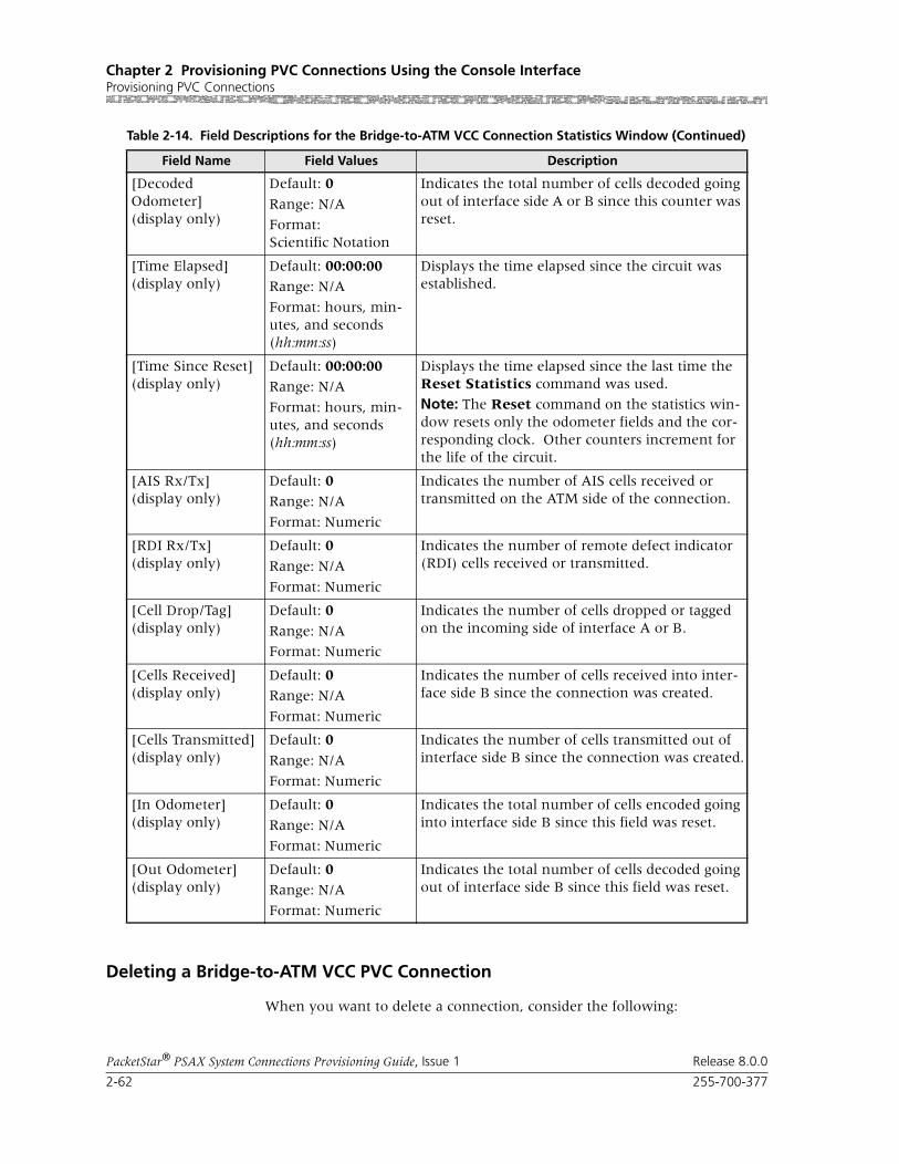
Chapter 2 Provisioning PVC Connections Using the Console InterfaceProvisioning PVC Connections
2-62 255-700-377
PacketStar® PSAX System Connections Provisioning Guide, Issue 1 Release 8.0.0
Deleting a Bridge-to-ATM VCC PVC Connection
When you want to delete a connection, consider the following:
[Decoded Odometer](display only)
Default: 0
Range: N/A
Format: Scientific Notation
Indicates the total number of cells decoded going out of interface side A or B since this counter was reset.
[Time Elapsed](display only)
Default: 00:00:00Range: N/A
Format: hours, min-utes, and seconds (hh:mm:ss)
Displays the time elapsed since the circuit was established.
[Time Since Reset](display only)
Default: 00:00:00Range: N/A
Format: hours, min-utes, and seconds (hh:mm:ss)
Displays the time elapsed since the last time the Reset Statistics command was used.
Note: The Reset command on the statistics win-dow resets only the odometer fields and the cor-responding clock. Other counters increment for the life of the circuit.
[AIS Rx/Tx](display only)
Default: 0Range: N/A
Format: Numeric
Indicates the number of AIS cells received or transmitted on the ATM side of the connection.
[RDI Rx/Tx](display only)
Default: 0
Range: N/A
Format: Numeric
Indicates the number of remote defect indicator (RDI) cells received or transmitted.
[Cell Drop/Tag](display only)
Default: 0
Range: N/A
Format: Numeric
Indicates the number of cells dropped or tagged on the incoming side of interface A or B.
[Cells Received](display only)
Default: 0Range: N/A
Format: Numeric
Indicates the number of cells received into inter-face side B since the connection was created.
[Cells Transmitted](display only)
Default: 0
Range: N/A
Format: Numeric
Indicates the number of cells transmitted out of interface side B since the connection was created.
[In Odometer](display only)
Default: 0
Range: N/A
Format: Numeric
Indicates the total number of cells encoded going into interface side B since this field was reset.
[Out Odometer](display only)
Default: 0Range: N/A
Format: Numeric
Indicates the total number of cells decoded going out of interface side B since this field was reset.
Table 2-14. Field Descriptions for the Bridge-to-ATM VCC Connection Statistics Window (Continued)
Field Name Field Values Description

255-700-377 2-63
PacketStar® PSAX System Connections Provisioning Guide, Issue 1 Release 8.0.0
Chapter 2 Provisioning PVC Connections Using the Console InterfaceProvisioning PVC Connections
• If you delete the primary connection, both the primary connection and the backup connection are deleted.
• If you delete only the backup connection, the primary connection still exists.
! CAUTION:When a primary connection is deleted, all traffic on the connection is immediately stopped.
To delete a primary connection or a backup connection or both from the PSAX system, perform the steps in the following procedure.
Begin1 On the Bridge-to-ATM VCC PVC Table window (see Figure 2-15 on
page 2-48), select the line in the table displaying the connection you want to delete.
The Bridge-to-ATM VCC PVC Connection window is displayed (see Figure 2-16 on page 2-50), showing the parameters for the selected con-nection.
! CAUTION:Review the parameters for this connection, and be sure that you want to delete it. If you delete a primary connection accidentally, you cannot restore it. You would need to create a new connection to replace the accidentally deleted one.
2 Choose one of the following actions.
End
Table 2-15. Deleting a Bridge-to-ATM VCC PVC Connection
If you want to delete a: perform the following steps on the Connection window.
The PSAX system:
primary and a backup connection,
Select the Delete Connection com-mand.
deletes the primary connection and its backup connection (if one was created), and immedi-ately stops traffic.
backup connection only, 1 Select the Add/View Backup PVC command.
2 On the Bridge-to-ATM VCC Backup PVC Connection win-dow, select the Delete Connec-tion command.
deletes only the backup connec-tion.

Chapter 2 Provisioning PVC Connections Using the Console InterfaceProvisioning PVC Connections
2-64 255-700-377
PacketStar® PSAX System Connections Provisioning Guide, Issue 1 Release 8.0.0
Adding Bridge-to-Bridge Connections
A bridge-to-bridge VCC PVC connection can be created between virtual channels on the Ethernet module and the 4-Port Ethernet module.
Perform the steps in the following procedure to add a bridge-to-bridge VCC PVC connection.
Begin
1 On the Connection Configuration Menu window, select the Bridge-to-Bridge option.
The Bridge-to-Bridge PVC Table window is displayed (see Figure 2-19).
Note: At the time of initial installation, the Bridge-to-Bridge PVC Table window is empty. After you have set up connections, this window displays all the connections of this type in the system.
2 Select the Add a Connection command.
The Bridge-to-Bridge PVC Connection window is displayed (see Figure 2-20).
3 Enter values in the fields on this window according to the information provided Table 2-16.
4 To add (apply) the connection configuration, select the Add This Con-nection command.
5 To review this connection, select the Go Back to Connection Table command.
The Bridge-to-Bridge PVC Table window is returned, displaying the val-ues you just applied.
6 To add more connections of this type, repeat steps 2–5 for more connec-tions as needed.

255-700-377 2-65
PacketStar® PSAX System Connections Provisioning Guide, Issue 1 Release 8.0.0
Chapter 2 Provisioning PVC Connections Using the Console InterfaceProvisioning PVC Connections
Commands The commands on this window have the following functions:
Display-Only Fields The display fields on this window provide the following information about all the Bridge-to-Bridge VCC PVC connections in the PSAX system system:
Figure 2-19. Bridge-to-Bridge PVC Table Window
Command Function
Page Up Scrolls up one page.
Page Down Scrolls down one page.
Top Displays entries at the top of the table.
Bottom Displays entries at the bottom of the table.
Find . . . Searches the table for a connection using the given interface. To find a particular connection, enter values in the Slot, Port, and Channel fields. If the connection exists, it is displayed on the first line of the table.
Add a Connection Displays the Bridge-to-Bridge PVC Con-nection window.
Go Back to Connection Menu
Redisplays the Connection Configuration Menu window.
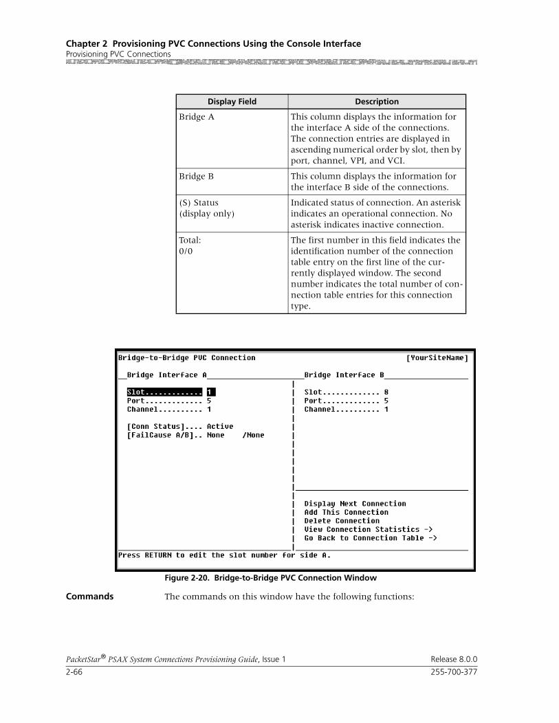
Chapter 2 Provisioning PVC Connections Using the Console InterfaceProvisioning PVC Connections
2-66 255-700-377
PacketStar® PSAX System Connections Provisioning Guide, Issue 1 Release 8.0.0
Commands The commands on this window have the following functions:
Display Field Description
Bridge A This column displays the information for the interface A side of the connections. The connection entries are displayed in ascending numerical order by slot, then by port, channel, VPI, and VCI.
Bridge B This column displays the information for the interface B side of the connections.
(S) Status(display only)
Indicated status of connection. An asterisk indicates an operational connection. No asterisk indicates inactive connection.
Total:0/0
The first number in this field indicates the identification number of the connection table entry on the first line of the cur-rently displayed window. The second number indicates the total number of con-nection table entries for this connection type.
Figure 2-20. Bridge-to-Bridge PVC Connection Window

255-700-377 2-67
PacketStar® PSAX System Connections Provisioning Guide, Issue 1 Release 8.0.0
Chapter 2 Provisioning PVC Connections Using the Console InterfaceProvisioning PVC Connections
Field Descriptions
Command Function
Display Next Connection Displays the next connection of this type in the table.
Add This Connection Adds a connection having the values cur-rently displayed on the window.
Delete Connection Deletes the connection having the values currently displayed on the window.
View Connection Statistics Displays the Bridge-to-Bridge VCC PVC Statistics window.
Go Back to Connection Table
Redisplays the Bridge-to-Bridge VCC PVC Connection Table window.
Table 2-16. Field Descriptions for the Bridge-to-Bridge Connection Window
Field Name Field Values Description
Bridge Interface A Default: N/A
Range: N/A
Format: Text
Indicates the side of the connection that will send signals.
Bridge Interface B Default: N/A
Range: N/A
Format: Alphanumeric
Indicates the side of the connection that will receive signals.
Slot Default: 0Range: (Varies depending on chassis type)
Format: Numeric
Indicates the slot number containing this module for which you are creating a connection.
Port Default: Ethernet Module: 6
Default: 4-Port Ethernet Module: 5
Range: N/A
Format: Numeric
Indicates the virtual port number of this module.
Channel Default: 1Range: 1–70 for the Ethernet module; 1–56 for the 4-Port Ethernet module
Format: Numeric
Indicates the channel number associated with the port number on this module for which you are creating a connection.

Chapter 2 Provisioning PVC Connections Using the Console InterfaceProvisioning PVC Connections
2-68 255-700-377
PacketStar® PSAX System Connections Provisioning Guide, Issue 1 Release 8.0.0
Viewing Statistics
Begin
1 To view the statistics for this connection, select the View Connection Statistics command.
The Bridge-to-Bridge VCC PVC Statistics window is displayed.
2 Press Ctrl+G to display the Console Interface Main Menu window.
[Conn Status](display only)
Default: Inactive
Range: N/A
Format: Predefined
Indicates the current status of the connection. The value indicates whether the connection is passing traffic.
Inactive Indicates that this connection is not passing traf-fic.
Active Indicates that this connection is passing traffic.
[FailCause A/B](display only)
Default: Null/Null
Range: N/A
Format: Predefined
Indicates the AAL2 status reason code for both sides of the connection.
Table 2-16. Field Descriptions for the Bridge-to-Bridge Connection Window
Field Name Field Values Description
Figure 2-21. Bridge-to-Bridge PVC Statistics

255-700-377 2-69
PacketStar® PSAX System Connections Provisioning Guide, Issue 1 Release 8.0.0
Chapter 2 Provisioning PVC Connections Using the Console InterfaceProvisioning PVC Connections
3 Select the Save Configuration command (or press Ctrl+A).
End
Commands The commands on this window have the following functions:
Field Descriptions The values for the fields on this window are described in Table 2-17.
Command Function
Reset Odometers Returns all statistics odometers to zero.
Continuous Update Updates the values in the fields every sec-ond.
Display Stats for Next Con-nection
Displays the statistics for the next selected connection.
Go Back to Connection Dis-play
Redisplays the Bridge-to-Bridge VCC PVC Connection window.
Table 2-17. Field Descriptions for the Bridge-to-Bridge VCC Connection Statistics Window
Field Name Field Value Description
Slot Default: 0
Range: Depends on chassis type
Format: Numeric
Displays the slot identifier of the ATM interface for either the Bridge Interface panel or the ATM Interface panel.
Port Default: 1
Range: Depends on module type
Format: Numeric
Displays the port identifier of the ATM interface for either the Bridge Interface panel or the ATM Interface panel.
Channel Default: 1Range: Depends on module type
Format: Numeric
Displays the channel identifier for either Interface A or Interface B.
[Cells Encoded ]
(display only)
Default: 0
Range: N/A
Format: Scientific Notation
Indicates the number of cells encoded going into interface side Aor B during the amount of time shown in Time Elapsed field since the circuit was established.
[Cells Decoded]
(display only)
Default: 0
Range: N/A
Format: Scientific Notation
Indicates the number of cells decoded going out of interface side Aor B during the amount of time shown in Time Elapsed field since the circuit was established.

Chapter 2 Provisioning PVC Connections Using the Console InterfaceProvisioning PVC Connections
2-70 255-700-377
PacketStar® PSAX System Connections Provisioning Guide, Issue 1 Release 8.0.0
Adding Circuit Emulation-to-ATM VCC PVC Connections
This is a CBR type of connection. A DSP2x Voice Server module must be present and configured in the PSAX system to enable coding translation, voice compression, silence detection, echo cancellation, and tone detection features. This type of connection also supports the use of a backup ATM interface with the option of automatic switchback.
You can process voice traffic using circuit emulation-to-ATM VCC PVC con-nection through a DSP2x Voice Server module by selecting one of the pulse code modulation (PCM) types in the Coding Translation field.
Note: On the DS1 IMA and E1 IMA modules, PVC connections must be provisioned on the virtual port (port 7). You can use up to three groups on port 7 (the groups you provision on port 7.)
Note: On the DS3 IMA module, PVC connections must be provisioned on the virtual port (port 30). You can use up to 14 groups on port 30 (the groups you provision on port 30.)
Note: The OAM feature is supported for this connection type and can be enabled on the Connection window. Statistical OAM information is provided on the related Connection Statistics window. Parame-
[Encoded Odometer]
(display only)
Default: 0
Range: N/A
Format: Scientific Notation
Indicates the total number of cells encoded going into interface side A or B since this counter was reset.
[Decoded Odometer]
(display only)
Default: 0Range: N/A
Format: Scientific Notation
Indicates the total number of cells decoded going out of interface side A or B since this counter was reset.
[Time Elapsed]
(display only)
Default: 00:00:00
Range: N/A
Format: hours, min-utes, and seconds (hh:mm:ss)
Displays the time elapsed since the circuit was established.
[Time Since Reset]
(display only)
Default: 00:00:00
Range: N/A
Format: hours, min-utes, and seconds (hh:mm:ss)
Displays the time elapsed since the last time the Clear button was used.
Note: The Clear button on the statistics page resets only the odometer fields (labelled as Odometer) and the corresponding clock. Other counters increment for the life of the circuit.
Table 2-17. Field Descriptions for the Bridge-to-Bridge VCC Connection Statistics Window
Field Name Field Value Description

255-700-377 2-71
PacketStar® PSAX System Connections Provisioning Guide, Issue 1 Release 8.0.0
Chapter 2 Provisioning PVC Connections Using the Console InterfaceProvisioning PVC Connections
ters for OAM operation can be configured from the Diagnostics Menu window. See the appropriate PacketStar PSAX Multiservice Media Gateway user guide for more details.
Perform the steps in the following procedure to create a circuit emulation-to-ATM VCC PVC connection.
Creating a Circuit Emulation-to-ATM VCC Connection Begin
Provisioning a Circuit Emulation-to-ATM PVC Connection
1 On the Connection Configuration Menu window, select Circuit Emula-tion-to-ATM VCC and press Enter.
The Circuit Emulation-to-ATM VCC PVC Table (see Figure 2-22) window is displayed.
Note: At the time of initial installation, the Circuit Emulation-to-ATM VCC PVC Table window is empty. After you have set up connec-tions, this window displays all the connections of this type in the system.
Commands The commands on this window have the following functions:
Figure 2-22. Circuit Emulation-to-ATM VCC PVC Table Window
Command Function
Page Up Scroll up one page.
Page Down Scrolls down one page.
Top Displays entries at the top of the table.
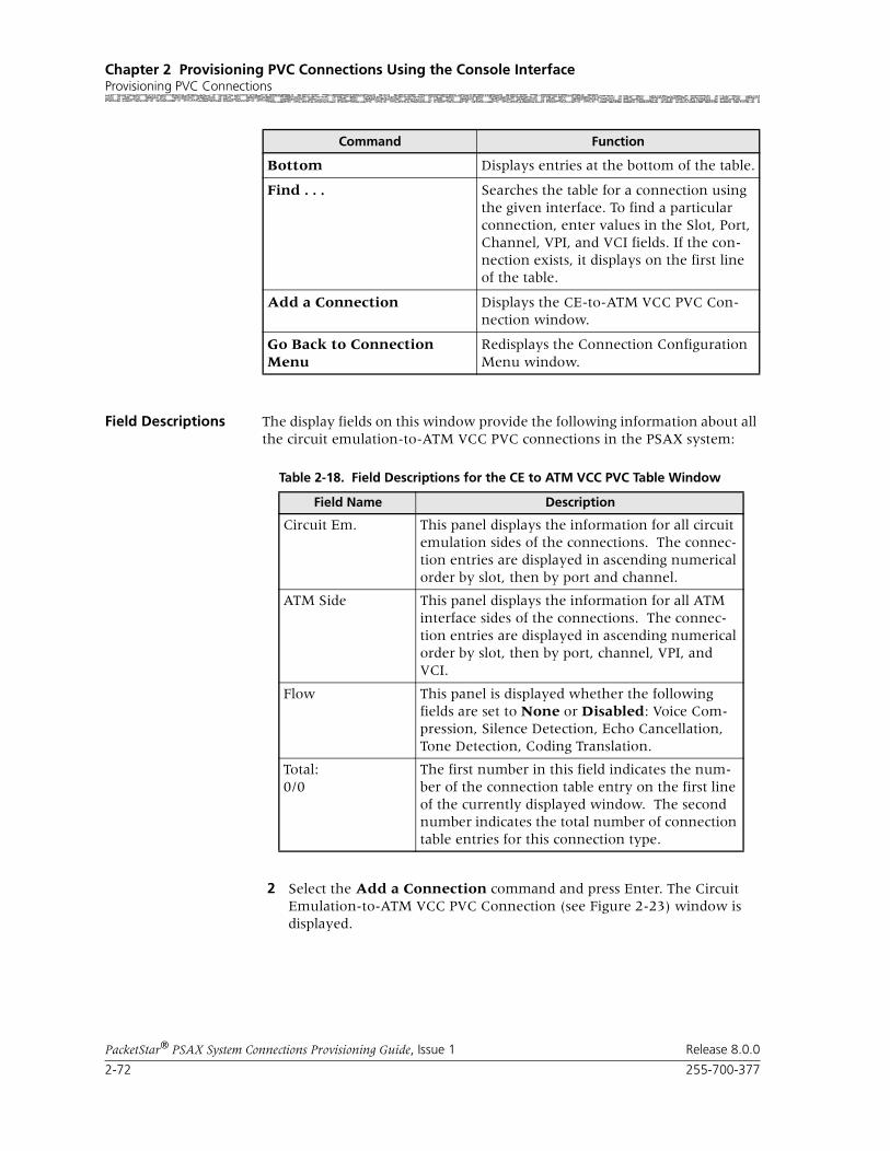
Chapter 2 Provisioning PVC Connections Using the Console InterfaceProvisioning PVC Connections
2-72 255-700-377
PacketStar® PSAX System Connections Provisioning Guide, Issue 1 Release 8.0.0
Field Descriptions The display fields on this window provide the following information about all the circuit emulation-to-ATM VCC PVC connections in the PSAX system:
2 Select the Add a Connection command and press Enter. The Circuit Emulation-to-ATM VCC PVC Connection (see Figure 2-23) window is displayed.
Bottom Displays entries at the bottom of the table.
Find . . . Searches the table for a connection using the given interface. To find a particular connection, enter values in the Slot, Port, Channel, VPI, and VCI fields. If the con-nection exists, it displays on the first line of the table.
Add a Connection Displays the CE-to-ATM VCC PVC Con-nection window.
Go Back to Connection Menu
Redisplays the Connection Configuration Menu window.
Command Function
Table 2-18. Field Descriptions for the CE to ATM VCC PVC Table Window
Field Name Description
Circuit Em. This panel displays the information for all circuit emulation sides of the connections. The connec-tion entries are displayed in ascending numerical order by slot, then by port and channel.
ATM Side This panel displays the information for all ATM interface sides of the connections. The connec-tion entries are displayed in ascending numerical order by slot, then by port, channel, VPI, and VCI.
Flow This panel is displayed whether the following fields are set to None or Disabled: Voice Com-pression, Silence Detection, Echo Cancellation, Tone Detection, Coding Translation.
Total:0/0
The first number in this field indicates the num-ber of the connection table entry on the first line of the currently displayed window. The second number indicates the total number of connection table entries for this connection type.

255-700-377 2-73
PacketStar® PSAX System Connections Provisioning Guide, Issue 1 Release 8.0.0
Chapter 2 Provisioning PVC Connections Using the Console InterfaceProvisioning PVC Connections
Connection Capacity of DSP2x Modes
If the user is configuring DSP parameters on the connection, see the follow-ing table for connection limits.
Table 2-19. Connection Capacity of DSP2x Algorithm Sets
DSP2x Voice Server Module Configuration Scenarios
Connections per DSP Chip (D)
Chips per Module (N)
Maximum Number of Connections (D X
N) per Module
DSP2C Voice Server (32 DSP chips per module)
Std. AAL2 and Non-Mux AAL2, AlgoSet 1 (Echo Cancellation to 128 msec) 7 32 224
Std. AAL2 and Non-Mux AAL2, AlgoSet 2 (DSP2A, G726), AlgoSet 3 (DSP2B, G729a),AlgoSet 4 (fax relay)
4 32 128
DSP2D Voice Server (48 DSP chips per module)
Std. and Non-mux AAL2, AlgoSet 1 7 48 336
Non-mux AAL2, AlgoSets 2 and 3 4 48 192
AAL1 AlgoSet5 (Echo Cancellation to 64 msec) 21 48 1008
Std. AAL2 AlgoSet 6 (G726, G729a/b, G168, v17, v29, v21, v27) 8 48 384
GR-303 Monitoring 24 48 1152
DSP2E Voice/Data Server (8 DSP chips per module)
Std. AAL2, or AAL5-to-AAL2, AlgoSet 6 6 voice chips support pure voice
8 48
2 chips support wireless voice/data pack-ets in 15 to 256 byte frame sizes
84 168
DSP2F Data Server (8 DSP chips per module)
Std. AAL2 AlgoSet 7 8 chips support wireless voice/data pack-ets in 15 to 256 byte frame sizes
84 672
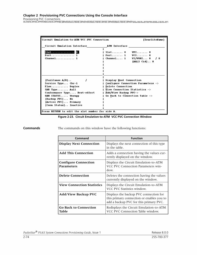
Chapter 2 Provisioning PVC Connections Using the Console InterfaceProvisioning PVC Connections
2-74 255-700-377
PacketStar® PSAX System Connections Provisioning Guide, Issue 1 Release 8.0.0
Commands The commands on this window have the following functions:
Figure 2-23. Circuit Emulation-to-ATM VCC PVC Connection Window
Command Function
Display Next Connection Displays the next connection of this type in the table.
Add This Connection Adds a connection having the values cur-rently displayed on the window.
Configure Connection Parameters
Displays the Circuit Emulation-to-ATM VCC PVC Connection Parameters win-dow.
Delete Connection Deletes the connection having the values currently displayed on the window.
View Connection Statistics Displays the Circuit Emulation-to-ATM VCC PVC Statistics window.
Add/View Backup PVC Displays the backup PVC connection for this primary connection or enables you to add a backup PVC for this primary PVC.
Go Back to Connection Table
Redisplays the Circuit Emulation-to-ATM VCC PVC Connection Table window.
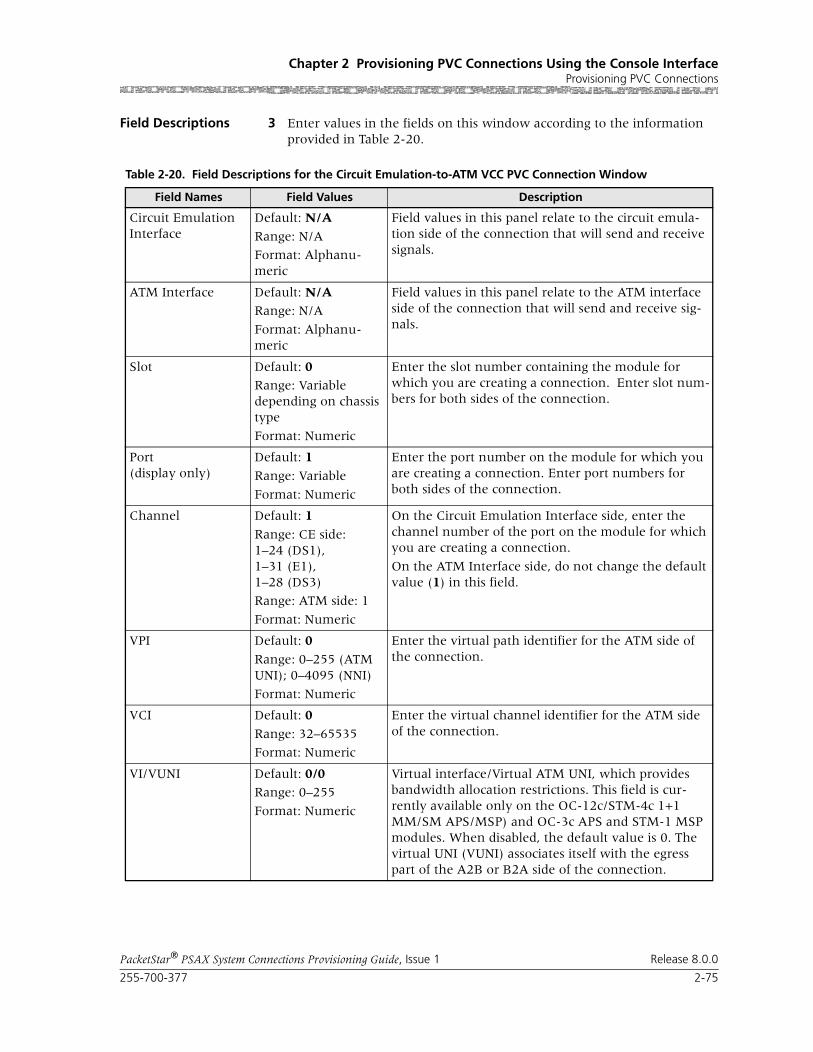
255-700-377 2-75
PacketStar® PSAX System Connections Provisioning Guide, Issue 1 Release 8.0.0
Chapter 2 Provisioning PVC Connections Using the Console InterfaceProvisioning PVC Connections
Field Descriptions 3 Enter values in the fields on this window according to the information provided in Table 2-20.
Table 2-20. Field Descriptions for the Circuit Emulation-to-ATM VCC PVC Connection Window
Field Names Field Values Description
Circuit Emulation Interface
Default: N/A
Range: N/A
Format: Alphanu-meric
Field values in this panel relate to the circuit emula-tion side of the connection that will send and receive signals.
ATM Interface Default: N/ARange: N/A
Format: Alphanu-meric
Field values in this panel relate to the ATM interface side of the connection that will send and receive sig-nals.
Slot Default: 0Range: Variable depending on chassis type
Format: Numeric
Enter the slot number containing the module for which you are creating a connection. Enter slot num-bers for both sides of the connection.
Port(display only)
Default: 1
Range: Variable
Format: Numeric
Enter the port number on the module for which you are creating a connection. Enter port numbers for both sides of the connection.
Channel Default: 1
Range: CE side:1–24 (DS1),1–31 (E1),1–28 (DS3)
Range: ATM side: 1
Format: Numeric
On the Circuit Emulation Interface side, enter the channel number of the port on the module for which you are creating a connection.
On the ATM Interface side, do not change the default value (1) in this field.
VPI Default: 0
Range: 0–255 (ATM UNI); 0–4095 (NNI)
Format: Numeric
Enter the virtual path identifier for the ATM side of the connection.
VCI Default: 0
Range: 32–65535
Format: Numeric
Enter the virtual channel identifier for the ATM side of the connection.
VI/VUNI Default: 0/0Range: 0–255
Format: Numeric
Virtual interface/Virtual ATM UNI, which provides bandwidth allocation restrictions. This field is cur-rently available only on the OC-12c/STM-4c 1+1 MM/SM APS/MSP) and OC-3c APS and STM-1 MSP modules. When disabled, the default value is 0. The virtual UNI (VUNI) associates itself with the egress part of the A2B or B2A side of the connection.

Chapter 2 Provisioning PVC Connections Using the Console InterfaceProvisioning PVC Connections
2-76 255-700-377
PacketStar® PSAX System Connections Provisioning Guide, Issue 1 Release 8.0.0
AAL2 Cid(display only unless SAR type is Aal2Std)
Default: 0
Range: 8–255 per trunk (0–7 not avail-able; reserved)
Format: Numeric
Enter a channel identifier only if the value Aal2Std is selected in the SAR Type field described below.
[FailCause A/B](display only)
Default: N/A Presents the AAL2 status reason code for both sides of the connection.
Service Type Default: Cbr-1
Range: Cbr-1 DS1 IMA, E1 IMACbr-2Cbr-3Cbr-4
Format: Alpha-mumeric
Default: Cbr-4
Multiservice Media Gateway system-supported qual-ity of service (QoS) class. See the PacketStar Multiservice Media Gateway User Guide for a description of each ser-vice type.
Only CBR (constant bit rate) values are applicable for DS3 IMA.
Flow Default: Duplex
Range: N/A
Format: Character
Direction of the flow of data traffic in this connection.
Note: The values change on either side of the connec-tion window as you scroll through this field.
SimplexA2B,SimplexB2A,PointToMultipointA2B,PointToMultipointB2A
Select the appropriate value.
SAR Type Default: Aal1
Range: Variable
Format: Alphanu-meric
Indicates the segmentation and reassembly (SAR) type of the incoming data stream.
Aal1 AAL1
Aal2Std AAL2 Standard.
Note: Choose this type for AAL2 trunking. Enter the associated channel identifier in the AAL2 field in the upper right panel.
Non-Mux-Aal2 Non-multiplexed AAL2 (Lucent proprietary)
Table 2-20. Field Descriptions for the Circuit Emulation-to-ATM VCC PVC Connection Window
Field Names Field Values Description
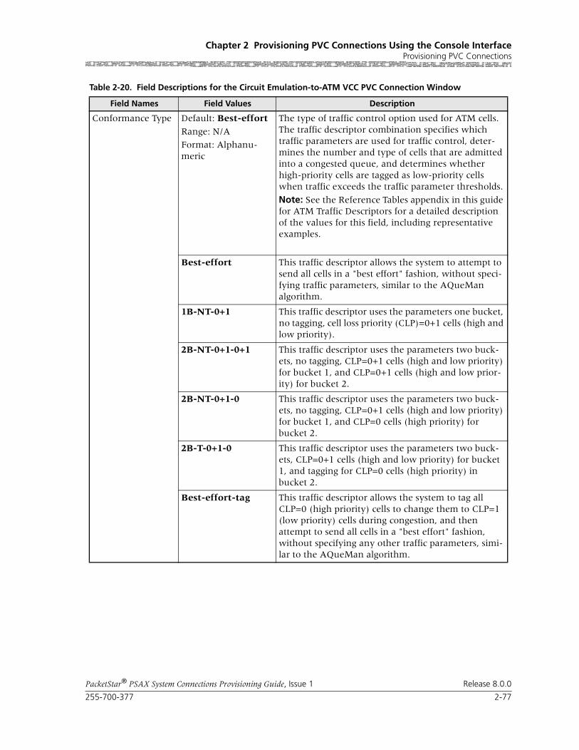
255-700-377 2-77
PacketStar® PSAX System Connections Provisioning Guide, Issue 1 Release 8.0.0
Chapter 2 Provisioning PVC Connections Using the Console InterfaceProvisioning PVC Connections
Conformance Type Default: Best-effort
Range: N/A
Format: Alphanu-meric
The type of traffic control option used for ATM cells. The traffic descriptor combination specifies which traffic parameters are used for traffic control, deter-mines the number and type of cells that are admitted into a congested queue, and determines whether high-priority cells are tagged as low-priority cells when traffic exceeds the traffic parameter thresholds.
Note: See the Reference Tables appendix in this guide for ATM Traffic Descriptors for a detailed description of the values for this field, including representative examples.
Best-effort This traffic descriptor allows the system to attempt to send all cells in a "best effort" fashion, without speci-fying traffic parameters, similar to the AQueMan algorithm.
1B-NT-0+1 This traffic descriptor uses the parameters one bucket, no tagging, cell loss priority (CLP)=0+1 cells (high and low priority).
2B-NT-0+1-0+1 This traffic descriptor uses the parameters two buck-ets, no tagging, CLP=0+1 cells (high and low priority) for bucket 1, and CLP=0+1 cells (high and low prior-ity) for bucket 2.
2B-NT-0+1-0 This traffic descriptor uses the parameters two buck-ets, no tagging, CLP=0+1 cells (high and low priority) for bucket 1, and CLP=0 cells (high priority) for bucket 2.
2B-T-0+1-0 This traffic descriptor uses the parameters two buck-ets, CLP=0+1 cells (high and low priority) for bucket 1, and tagging for CLP=0 cells (high priority) in bucket 2.
Best-effort-tag This traffic descriptor allows the system to tag all CLP=0 (high priority) cells to change them to CLP=1 (low priority) cells during congestion, and then attempt to send all cells in a "best effort" fashion, without specifying any other traffic parameters, simi-lar to the AQueMan algorithm.
Table 2-20. Field Descriptions for the Circuit Emulation-to-ATM VCC PVC Connection Window
Field Names Field Values Description

Chapter 2 Provisioning PVC Connections Using the Console InterfaceProvisioning PVC Connections
2-78 255-700-377
PacketStar® PSAX System Connections Provisioning Guide, Issue 1 Release 8.0.0
4 To add (apply) the connection configuration, select the Add This Con-nection command and press Enter.
5 To review this connection, select the Go Back to Connection Table command and press Enter (or press Ctrl+B).
The Circuit Emulation-to-ATM VCC PVC Table window is displayed with the values you just applied.
6 To add more connections of this type, repeat steps 2–5 for more connec-tions as needed.
7 To permanently save these connections, press Ctrl+G to return to the Console Interface Main Menu window.
OAM STATUS Default: Unsupp
Range: N/A
Format: Character
The PSAX system is used as a termination point for ATM traffic, and will process AIS/RDI cells.
Note: Enable the type of OAM you want on the DSP2D Voice Server in this field.
Unsupp OAM is not in use.
End-Pt Use this value to enable trunk conditioning.
For more information, see the Trunk Conditioning Application Note for PacketStar® PSAX Multiservice Media Gateways.
End-Seg-Pt The PSAX system is used as both a termination point and a segment point for ATM traffic.
[Backup PVC](display only)
Default: No Yes
Range: N/A
Format: Character
Indicates whether a backup PVC has been configured.
[Active PVC] Default: No (before connection parameters are con-figured)
Default: Primary
(after connection parameters are con-figured)
Range: N/A
Format: Character
Indicates whether a backup PVC has been configured.
When Primary is displayed, the backup PVC is not in use.
[Conn Status](display only)
Default: Inactive
Range: N/A
Format: Character
Indicates whether the connection is passing traffic.
Inactive The connection is not passing traffic.
Active The connection is passing traffic.
Table 2-20. Field Descriptions for the Circuit Emulation-to-ATM VCC PVC Connection Window
Field Names Field Values Description
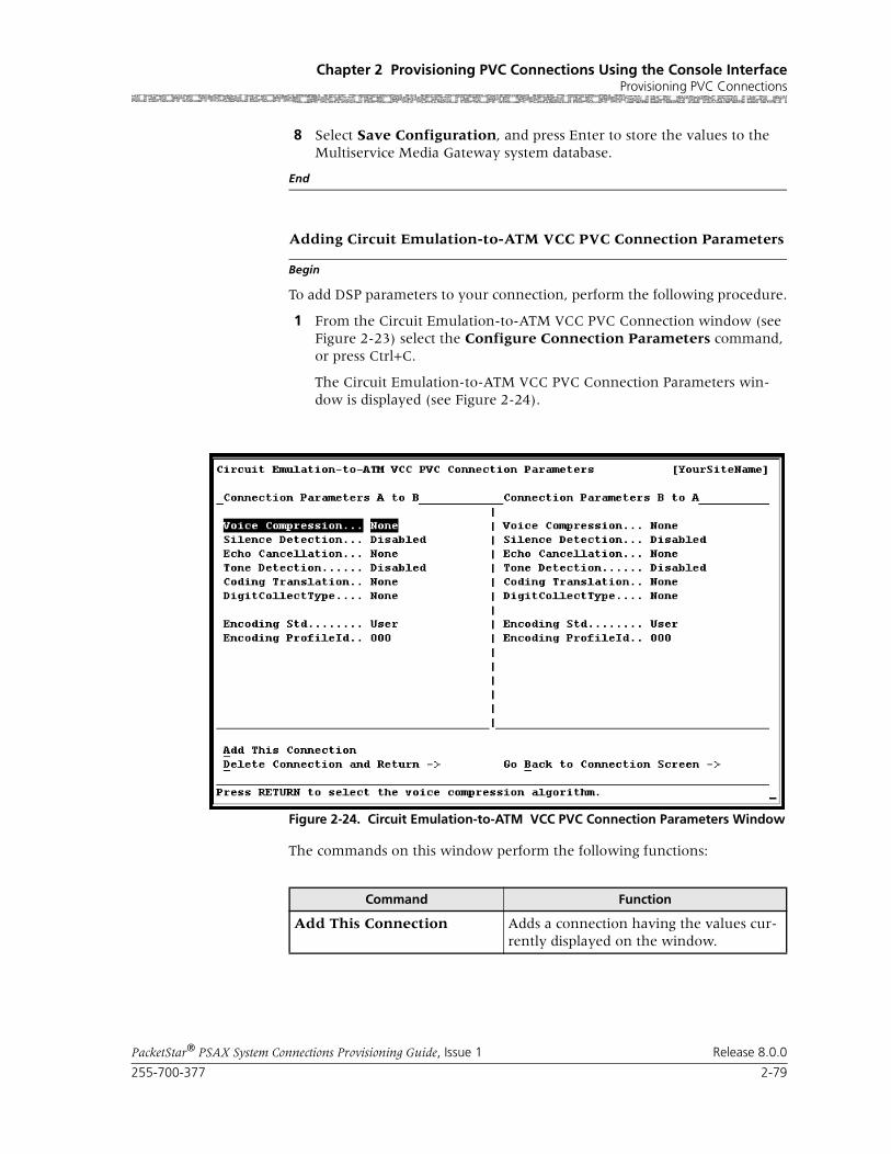
255-700-377 2-79
PacketStar® PSAX System Connections Provisioning Guide, Issue 1 Release 8.0.0
Chapter 2 Provisioning PVC Connections Using the Console InterfaceProvisioning PVC Connections
8 Select Save Configuration, and press Enter to store the values to the Multiservice Media Gateway system database.
End
Begin
Adding Circuit Emulation-to-ATM VCC PVC Connection Parameters
To add DSP parameters to your connection, perform the following procedure.
1 From the Circuit Emulation-to-ATM VCC PVC Connection window (see Figure 2-23) select the Configure Connection Parameters command, or press Ctrl+C.
The Circuit Emulation-to-ATM VCC PVC Connection Parameters win-dow is displayed (see Figure 2-24).
The commands on this window perform the following functions:
Figure 2-24. Circuit Emulation-to-ATM VCC PVC Connection Parameters Window
Command Function
Add This Connection Adds a connection having the values cur-rently displayed on the window.

Chapter 2 Provisioning PVC Connections Using the Console InterfaceProvisioning PVC Connections
2-80 255-700-377
PacketStar® PSAX System Connections Provisioning Guide, Issue 1 Release 8.0.0
2 Enter values in the fields on this window according to the information provided in the following table:
Delete Connection and Return
Deletes the connection having the values currently displayed on the window.
Go Back to Connection Table
Redisplays the Circuit Emulation-to-ATM VCC PVC Connection Table window.
Command Function
Table 2-21. Field Descriptions for the Circuit Emulation-to-ATM VCC PVC Connection Parameters Window
Field Name Field Values Description
Connection Parameters A to B Left Panel; Connection Parameters B to A Right Panel
Voice Compression Default: None
Range: N/A
Format: predefined alphanumeric
G726-16k G726-24k G726-32k G726-40k G729a-8k
Not supported.If you want data traffic for this connection to be processed through the DSP2x Voice Server modules, do not use the default value. Instead, select the desired type and rate of voice compression from the list of choices.
Silence Detection Default: Disabled
Range: N/A
Format: predefined alphanumeric
Enabled
Not supported.If you want data traffic for this connection to be processed through the DSP2x Voice Server modules, do not use the default value. Choosing Enabled enables Silence Detec-tion.
Echo Cancellation Default: NoneRange: N/A
Format: predefined alphanumeric
G.165-nearEndG.168
Not supported.If you want data traffic for this connection to be processed through the DSP2x Voice Server modules, do not use the default value. Select G165-nearEnd if you want to enable Echo Cancellation on this connection.
Tone Detection Default: Disabled
Range: N/A
Format: predefined alphanumeric
Not supported.If you want data traffic for this connection to be processed through the DSP2x Voice Server modules, use Bypass.
Bypass The value Bypass indicates that the fax tones are to be recognized and data sent by fax is not to be processed by compression and echo cancellation.
FaxRelay The fax calling tone is detected.
FxRlyMdmBypass Fax Relay Modem Bypass. Fax Relay is detected and modem is done in bypass mode.

255-700-377 2-81
PacketStar® PSAX System Connections Provisioning Guide, Issue 1 Release 8.0.0
Chapter 2 Provisioning PVC Connections Using the Console InterfaceProvisioning PVC Connections
Coding Translation Default: NoneRange: N/A
Format: predefined alphanumeric
MuLaw2muLaw ALaw2aLawMuLaw2aLaw ALaw2MuLaw
Not supported on the DS3/E3 CES module.If you want data traffic for this connection to be pro-cessed through the DSP2x Voice Server modules, do not use the default value. The other values indicate the desired type of PCM translation. You must specify one of these PCM types to enable data traffic processing through the DSP2x mod-ules.
Note: If configuring the Voice 2-Wire Office or the Voice 2-Wire Station modules for this param-eter, you must select MuLaw2muLaw.
[DigitCollectType](display only unless SAR type selected is Aal2Std in the SAR Type field on lower left panel of win-dow).
Default: NoneRange: N/A
Format: Predefined alphanumeric
This feature is currently not supported. Specifies the tone types you want collected by the DSP2x module during call processing.
Table 2-21. Field Descriptions for the Circuit Emulation-to-ATM VCC PVC Connection Parameters Window
Field Name Field Values Description

Chapter 2 Provisioning PVC Connections Using the Console InterfaceProvisioning PVC Connections
2-82 255-700-377
PacketStar® PSAX System Connections Provisioning Guide, Issue 1 Release 8.0.0
3 To add (apply) the connection configuration, select the Add This Con-nection command and press Enter.
4 To review this connection, select the Go Back to Connection Screen command and press Enter (or press Ctrl+B).
The Circuit Emulation-to-ATM VCC PVC Connection window is dis-played.
5 To add more connections of this type, repeat steps 1–3 for more connec-tions as needed.
6 To permanently save these connections, press Ctrl+G to return to the Console Interface Main Menu window.
Encoding Std Default: UserRange: N/A
Format: predefined alphanumeric
Defined encoding profiles from industry stan-dards.
Note: Values chosen for this field must be com-patible with the Encoding Profile ID (next field).
User No restrictions or checks are done. The user may select any combination of parameters.
ATMForum ATM Forum profile defined by af-vmoa-0145.000, Voice and Multimedia Over ATM–Loop Emulation Ser-vice Using AAL2 and af-vtoa-0113.000, ATM Trunk-ing Using AAL2 for Narrowband Services.
Itu-t ITU-T profile defined by I-366-2, AAL2 Service-Spe-cific Convergence Sublayer for Narrowband Services.
Encoding ProfileID Default: 0 Range: 1–256.
Note: Do not leave the value in this field as 0, as 0 is not usu-ally used, and there-fore meaningless.
Note: Values chosen for this field must be com-patible with the Encoding Std (previous field).
If the encoding profile is user-defined, both ends of the connection must use the same profile.
If the encoding profile is ITU-T, use the encoding profile from ITU-T I.366.2 Annex P.
If the encoding profile is ATM Forum, use the encoding profiles from af-vmoa-0145.000 and/or af-vtoa-0113.000.
The encoding method for each channel is based on packet length and the received user-to-user indication (UUI) of that channel, according to whatever encoding standard you are using.
Enter the encoding profile ID for the AAL2 con-nection. For example, the encoding profile for PCM-64 is “1”.
Table 2-21. Field Descriptions for the Circuit Emulation-to-ATM VCC PVC Connection Parameters Window
Field Name Field Values Description

255-700-377 2-83
PacketStar® PSAX System Connections Provisioning Guide, Issue 1 Release 8.0.0
Chapter 2 Provisioning PVC Connections Using the Console InterfaceProvisioning PVC Connections
7 Select Save Configuration, and press Enter (or press Ctrl+A) to store the values to the Multiservice Media Gateway system database.
End
Connection Statistics
Begin
Viewing Connection Statistics
1 From the Circuit Emulation-to-ATM VCC PVC Connection window, select the View Connection Statistics command press Enter. The Cir-cuit Emulation-to-ATM VCC PVC Statistics window is displayed.
Commands The commands in this window have the following functions:
Figure 2-25. Circuit Emulation-to-ATM VCC PVC Statistics Window
Command Function
Reset Odometers Returns all statistics odometers to the value 0.
Continuous Update Updates the values in the fields every sec-ond.
Display Stats for Next Con-nection
Displays the statistics for the next selected connection.
Go Back to Connection Dis-play
Redisplays the Circuit Emulation-to-ATM VCC PVC Connection window.

Chapter 2 Provisioning PVC Connections Using the Console InterfaceProvisioning PVC Connections
2-84 255-700-377
PacketStar® PSAX System Connections Provisioning Guide, Issue 1 Release 8.0.0
Field Descriptions 2 Enter values in the fields on this window according to the information provided in Table 2-22.
Table 2-22. Field Descriptions for the Circuit Emulation-to-ATM VCC PVC Statistics Window
Field Name Field Values Description
Circuit Emulation Interface
The circuit emulation side of the connection that will send and receive signals.
ATM Interface The ATM interface side of the connection that will send and receive signals.
Slot Default: 0
Range: Variable depending on the chassis type
Format: Numeric
Enter the slot number containing the module for which you are creating a connection. Enter slot numbers for both sides of the connection.
Port Default: 1
Range:1 to 8
Format: Numeric
Enter the port number on the module for which you are creating a connection. Enter port num-bers for both sides of the connection.
Channel Default: 1
(both sides)
Range: 1 to 24 (DS1)1 to 31 (E1)
Format: Numeric
On the Circuit Emulation Interface side, enter the channel number of the port on the module for which you are creating a connection. On the ATM Interface side, do not change the default value (1) in this field.
VPI Default: 0
Range: 0 to 255
Format: Numeric
Virtual path identifier. Enter a value for ATM side of the connection.
VCI Default: 32
Range: 32 to 65535
Format: Numeric
Virtual channel identifier. Enter a value for the ATM side of the connection.
Cells Encoded(display only)
Default: 0.0000 e0Range: 0-(231-1)
Format: Numeric
The total number of encoded (transmitted) user cells going into interface side A during the amount of time shown in the Time Elapsed field (that is, since the circuit was created).
Cells Decoded(display only)
Default: 0.0000 e0
Range: 0-(231-1)
Format: Numeric
The total number of decoded (received) user cells going out of interface side A during the amount of time shown in the Time Elapsed field (that is, since the circuit was created).
Encoded Odometer(display only)
Default: 0.0000 e0
Range: 0-(231-1)
Format: Numeric
The total number of encoded user cells going into interface side B since the connection was created.
Decoded Odometer(display only)
Default: 0.0000 e0
Range: 0-(231-1)
Format: Numeric
The total number of decoded user cells decoded going out of interface side B since the connection was created.
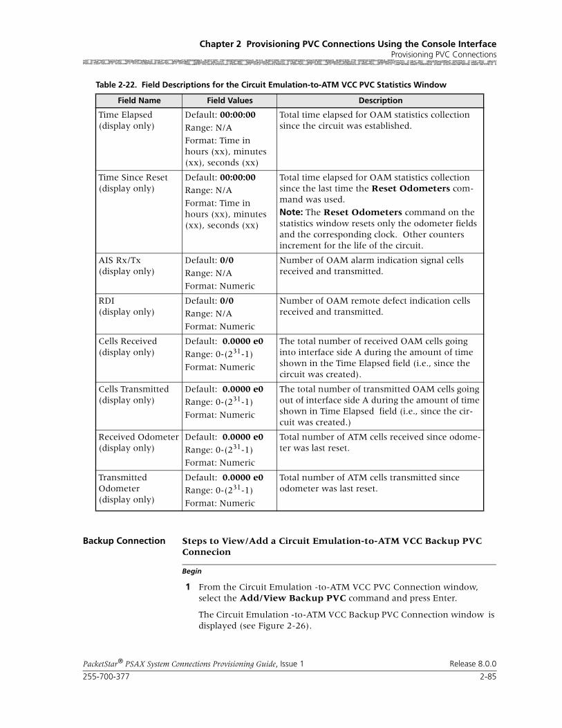
255-700-377 2-85
PacketStar® PSAX System Connections Provisioning Guide, Issue 1 Release 8.0.0
Chapter 2 Provisioning PVC Connections Using the Console InterfaceProvisioning PVC Connections
Backup Connection Steps to View/Add a Circuit Emulation-to-ATM VCC Backup PVC
Begin
Connecion
1 From the Circuit Emulation -to-ATM VCC PVC Connection window, select the Add/View Backup PVC command and press Enter.
The Circuit Emulation -to-ATM VCC Backup PVC Connection window is displayed (see Figure 2-26).
Time Elapsed(display only)
Default: 00:00:00
Range: N/A
Format: Time in hours (xx), minutes (xx), seconds (xx)
Total time elapsed for OAM statistics collection since the circuit was established.
Time Since Reset(display only)
Default: 00:00:00Range: N/A
Format: Time in hours (xx), minutes (xx), seconds (xx)
Total time elapsed for OAM statistics collection since the last time the Reset Odometers com-mand was used.
Note: The Reset Odometers command on the statistics window resets only the odometer fields and the corresponding clock. Other counters increment for the life of the circuit.
AIS Rx/Tx(display only)
Default: 0/0
Range: N/A
Format: Numeric
Number of OAM alarm indication signal cells received and transmitted.
RDI(display only)
Default: 0/0Range: N/A
Format: Numeric
Number of OAM remote defect indication cells received and transmitted.
Cells Received(display only)
Default: 0.0000 e0
Range: 0-(231-1)
Format: Numeric
The total number of received OAM cells going into interface side A during the amount of time shown in the Time Elapsed field (i.e., since the circuit was created).
Cells Transmitted(display only)
Default: 0.0000 e0Range: 0-(231-1)
Format: Numeric
The total number of transmitted OAM cells going out of interface side A during the amount of time shown in Time Elapsed field (i.e., since the cir-cuit was created.)
Received Odometer(display only)
Default: 0.0000 e0
Range: 0-(231-1)
Format: Numeric
Total number of ATM cells received since odome-ter was last reset.
Transmitted Odometer(display only)
Default: 0.0000 e0Range: 0-(231-1)
Format: Numeric
Total number of ATM cells transmitted since odometer was last reset.
Table 2-22. Field Descriptions for the Circuit Emulation-to-ATM VCC PVC Statistics Window
Field Name Field Values Description

Chapter 2 Provisioning PVC Connections Using the Console InterfaceProvisioning PVC Connections
2-86 255-700-377
PacketStar® PSAX System Connections Provisioning Guide, Issue 1 Release 8.0.0
Commands The commands on this window have the following functions:
Field Descriptions 2 Enter values in the fields on this window according to the information provided in Table 2-23.
Figure 2-26. Circuit Emulation -to-ATM VCC Backup PVC Connection Window
Command Function
Add This Connection Adds connection entered on Backup ATM inter-face right panel.
Delete Connection Deletes backup connection.
Go Back to Primary PVC Connection
Returns to ATM-to-ATM VCC PVC Connection window.

255-700-377 2-87
PacketStar® PSAX System Connections Provisioning Guide, Issue 1 Release 8.0.0
Chapter 2 Provisioning PVC Connections Using the Console InterfaceProvisioning PVC Connections
Table 2-23. Field Descriptions for the Circuit Emulation-to-ATM VCC Backup PVC Window
Field Name Field Values Description
Slot Default: N/A
Range: Listed as avail-able from the PSAX device
Format: Numeric
Select the slot containing the module for which you are creating a connection.
Note: This field is display only for the circuit emulation interface.
Port Default: N/A
Range: Determined by the number of ports available on the module selected in the Slot field
Format: Numeric
Select the port number on the module for which you are creating a connection.
Note: This field is display only for the circuit emulation interface.
Channel Default: N/A
Range: Determined by the number of channels available on the port selected in the Port field
Format: Numeric
Select the channel number of the port on the module for which you are creating a connection.
Note: This field is display only for the circuit emulation interface.
[Current Active PVC](display only)
Default: NoneRange: N/A
Format: Character
Indicates that the connection is inactive.
Primary Indicates that the primary connection is active (carrying user traffic).
Backup Indicates that the backup connection is active (carrying user traffic).
[Switch Back to Pri-maryAutomati-cally](display only)
Default: Yes
Range: N/A
Format: Character
CPU monitors primary connection. If primary connection becomes available, backup will switch back connection to Primary.
No Not currently supported.
Once active, the backup connection will not switch back to primary connection automatically if Primary becomes available.
Backup ATM Interface (right panel)
Slot Default: N/ARange: Listed as avail-able from the PSAX device
Format: Numeric
Select the slot containing the module for which you are creating a backup connection.

Chapter 2 Provisioning PVC Connections Using the Console InterfaceProvisioning PVC Connections
2-88 255-700-377
PacketStar® PSAX System Connections Provisioning Guide, Issue 1 Release 8.0.0
3 Press Ctrl+G and select the Save Configuration option.
End
Adding Circuit Emulation-to-Circuit Emulation PVC Connections
This connection type has fixed-rate [constant bit rate (CBR)] traffic. To enable coding translation and echo cancellation, at least one DSP2x Voice Server module (DSP2A through DSP2F series) must be present and config-ured.
You can process voice traffic using circuit emulation connections through a DSP2x Voice Server module by selecting one of the pulse code modulation (PCM) types in the Coding Translation field.
Perform the steps in the following procedure to create a circuit-emulation-to-circuit emulation connection.
Port Default: N/A
Range: Determined by the number of ports available on the module selected in the Slot field
Format: Numeric
Select the port number on the module for which you are creating a backup connection.
Channel Default: N/ARange: Determined by the number of channels available on the port selected in the Port field
Format: Numeric
Select the channel number of the port on the module for which you are creating a backup connection.
VPI Default: 0Range: 0–255
Format: Numeric
The virtual path identifier assigned to this backup interface.
VCI Default: 32
Range: 32–4000
Format: Numeric
The virtual channel identifier assigned to this backup interface.
VI Default: 0
Range: 0-255
Format: Numeric
Backup virtual interface, which provides band-width allocation restrictions. Currently available only on theOC-3c APS and STM-1 MSP modules.
Table 2-23. Field Descriptions for the Circuit Emulation-to-ATM VCC Backup PVC Window (Continued)
Field Name Field Values Description

255-700-377 2-89
PacketStar® PSAX System Connections Provisioning Guide, Issue 1 Release 8.0.0
Chapter 2 Provisioning PVC Connections Using the Console InterfaceProvisioning PVC Connections
Creating a Circuit Emulation-to-Circuit Emulation Connection
Begin
Provisioning a Circuit Emulation-to-Circuit Emulation Connection
Use the steps in the following procedure to add a circuit-emulation-to-circuit emulation connection, starting at the Connection Configuration Menu win-dow.
1 On the Connection Configuration Menu window, select Circuit Emula-tion-to-Circuit Emulation and press Enter.
The Circuit Emulation-to-Circuit Emulation PVC Table window is dis-played (see Figure 2-27).
Note: At the time of initial installation, the Circuit Emulation-to-Circuit Emulation PVC Table is empty. After you have set up connections, this window displays all the connections of this type in the system.
Commands The commands on this window have the following functions:
Figure 2-27. Circuit Emulation-to-Circuit Emulation PVC Table Window
Command Function
Find . . . To find a particular connection, enter val-ues in the Slot, Port, Channel, VPI, and VCI fields. If the connection exists, it dis-plays on the first line of the table.
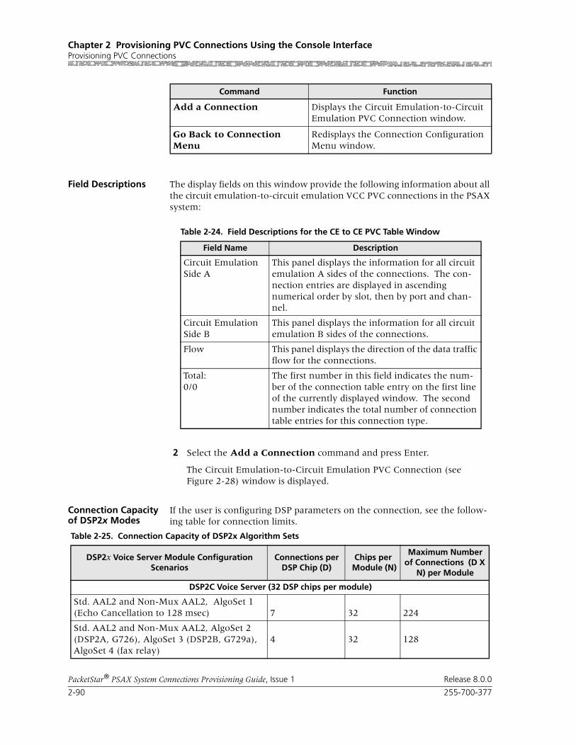
Chapter 2 Provisioning PVC Connections Using the Console InterfaceProvisioning PVC Connections
2-90 255-700-377
PacketStar® PSAX System Connections Provisioning Guide, Issue 1 Release 8.0.0
Field Descriptions The display fields on this window provide the following information about all the circuit emulation-to-circuit emulation VCC PVC connections in the PSAX system:
2 Select the Add a Connection command and press Enter.
The Circuit Emulation-to-Circuit Emulation PVC Connection (see Figure 2-28) window is displayed.
Connection Capacity of DSP2x Modes
If the user is configuring DSP parameters on the connection, see the follow-ing table for connection limits.
Add a Connection Displays the Circuit Emulation-to-Circuit Emulation PVC Connection window.
Go Back to Connection Menu
Redisplays the Connection Configuration Menu window.
Command Function
Table 2-24. Field Descriptions for the CE to CE PVC Table Window
Field Name Description
Circuit Emulation Side A
This panel displays the information for all circuit emulation A sides of the connections. The con-nection entries are displayed in ascending numerical order by slot, then by port and chan-nel.
Circuit Emulation Side B
This panel displays the information for all circuit emulation B sides of the connections.
Flow This panel displays the direction of the data traffic flow for the connections.
Total:0/0
The first number in this field indicates the num-ber of the connection table entry on the first line of the currently displayed window. The second number indicates the total number of connection table entries for this connection type.
Table 2-25. Connection Capacity of DSP2x Algorithm Sets
DSP2x Voice Server Module Configuration Scenarios
Connections per DSP Chip (D)
Chips per Module (N)
Maximum Number of Connections (D X
N) per Module
DSP2C Voice Server (32 DSP chips per module)
Std. AAL2 and Non-Mux AAL2, AlgoSet 1 (Echo Cancellation to 128 msec) 7 32 224
Std. AAL2 and Non-Mux AAL2, AlgoSet 2 (DSP2A, G726), AlgoSet 3 (DSP2B, G729a),AlgoSet 4 (fax relay)
4 32 128
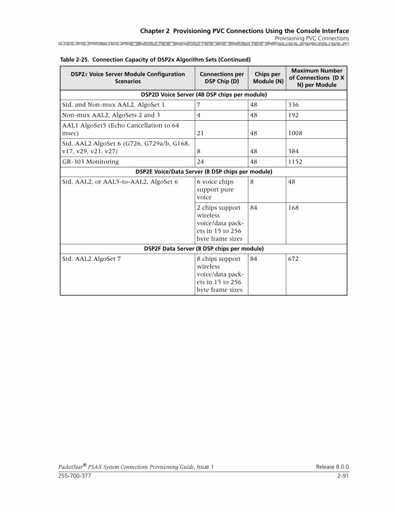
255-700-377 2-91
PacketStar® PSAX System Connections Provisioning Guide, Issue 1 Release 8.0.0
Chapter 2 Provisioning PVC Connections Using the Console InterfaceProvisioning PVC Connections
DSP2D Voice Server (48 DSP chips per module)
Std. and Non-mux AAL2, AlgoSet 1 7 48 336
Non-mux AAL2, AlgoSets 2 and 3 4 48 192
AAL1 AlgoSet5 (Echo Cancellation to 64 msec) 21 48 1008
Std. AAL2 AlgoSet 6 (G726, G729a/b, G168, v17, v29, v21, v27) 8 48 384
GR-303 Monitoring 24 48 1152
DSP2E Voice/Data Server (8 DSP chips per module)
Std. AAL2, or AAL5-to-AAL2, AlgoSet 6 6 voice chips support pure voice
8 48
2 chips support wireless voice/data pack-ets in 15 to 256 byte frame sizes
84 168
DSP2F Data Server (8 DSP chips per module)
Std. AAL2 AlgoSet 7 8 chips support wireless voice/data pack-ets in 15 to 256 byte frame sizes
84 672
Table 2-25. Connection Capacity of DSP2x Algorithm Sets (Continued)
DSP2x Voice Server Module Configuration Scenarios
Connections per DSP Chip (D)
Chips per Module (N)
Maximum Number of Connections (D X
N) per Module

Chapter 2 Provisioning PVC Connections Using the Console InterfaceProvisioning PVC Connections
2-92 255-700-377
PacketStar® PSAX System Connections Provisioning Guide, Issue 1 Release 8.0.0
Commands The commands on this window have the following functions:
Field Descriptions 3 Enter values in the fields on this window according to the information provided in Table 2-26.
Figure 2-28. Circuit Emulation-to-Circuit Emulation PVC Connection Window
Command Function
Display Next Connec-tion
Displays the next connection of this type in the table.
Add This Connection Adds a connection having the values currently dis-played on the window.
Delete Connection Deletes the connection having the values currently dis-played on the window.
View Connection Sta-tistics
Displays the Circuit Emulation-to-Circuit Emulation PVC Statistics window.
Go Back to Connection Table
Redisplays the Circuit Emulation-to-Circuit Emulation PVC Connection Table window.

255-700-377 2-93
PacketStar® PSAX System Connections Provisioning Guide, Issue 1 Release 8.0.0
Chapter 2 Provisioning PVC Connections Using the Console InterfaceProvisioning PVC Connections
Table 2-26. Field Descriptions for the Circuit Emulation-to-Circuit Emulation PVC Connection Window
Field Name Field Values Description
Circuit Emulation Interface Side A
Default: Predefined
Range: N/A
Format: Predefined
Specifies Side A of the connection that sends and receives signals. This is the near-end side of the connection, closest to the hybrid digital-to-analog circuit, where the echo is created. The DSP2x module will cancel the echo before the traffic is transmitted out the Side B interface. To cancel the near-end echo, select a voice processing parameter other than None in the Echo Cancel-lation field below.
Circuit Emulation Interface Side B
Default: Predefined
Range: N/A
Format: Predefined
Specifies Side B of the connection that will send and receive signals. Far-end echo on this side must be canceled at the far end.
Slot Default: VariableRange: Chassis dependent
Format: Numeric
Specifies the user-supplied slot number contain-ing the module for both sides of the connection.
Port Default: Variable
Range: Module dependent
Format: Numeric
Specifies the user-supplied port number on the module for both sides of the connection.
Channel Default: N/A
Range: 1–25, CE side (DS1)
Format: Numeric
Specifies the channel number of the port on the module for both sides of the connection.

Chapter 2 Provisioning PVC Connections Using the Console InterfaceProvisioning PVC Connections
2-94 255-700-377
PacketStar® PSAX System Connections Provisioning Guide, Issue 1 Release 8.0.0
Coding Translation Default: None
Range: As noted below
Format: Predefined
If you want data traffic for this connection to be processed through any DSP2x Voice Server mod-ule with a coding translation parameter, do not use the default value. The other values indicate the desired type of pulse code modulation (PCM) translation. You must specify one of these PCM types to enable data traffic processing through any DSP2x Voice Server modules.
If configuring the Voice 2-Wire Office or Voice 2-Wire Station modules for this parameter, you must select MuLaw2muLaw. The other choices are not supported.
Not supported.
None No coding translation is selected on the connec-tion.
MuLaw2muLaw American and Japanese compression and expan-sion (companding) standard is used on Sides A and B of the connection.
ALaw2aLaw European companding standard is used on Sides A and B of the connection.
MuLaw2aLaw American/Japanese to European companding standard is used between sending Side A and receiving Side B of the connection.
ALaw2MuLaw European to American/Japanese companding standard is used between sending Side A and receiving Side B of the connection.
Echo Cancellation Default: NoneRange: As noted below
Format: Predefined
If you using voice applications, an echo cancella-tion algorithm is recommended (select a value other than None). Not supported.
None No echo cancellation is used on the connection.
G165-nearEnd, ITU-T G.165 echo cancellation for the near end of the connection is used.
G168 ITU-T G.1658 echo cancellation is used.
[FailCause A/B](display only)
Default: Null/Null
Range: N/A
Format: Predefined
Presents the AAL2 status reason failure cause code for both sides of the connection.
Flow Default: Duplex
Range: As noted below
Format: Predefined
Specifies the direction of the flow of data traffic in this connection.
Duplex Traffic flows in both directions.
SimplexA2B Traffic flows from Side A to Side B only.
Table 2-26. Field Descriptions for the Circuit Emulation-to-Circuit Emulation PVC Connection Window
Field Name Field Values Description

255-700-377 2-95
PacketStar® PSAX System Connections Provisioning Guide, Issue 1 Release 8.0.0
Chapter 2 Provisioning PVC Connections Using the Console InterfaceProvisioning PVC Connections
4 To add (apply) the connection configuration, select the Add This Con-nection command and press Enter.
5 To review this connection, select the Go Back to Connection Table command and press Enter (or press Ctrl+B).
The Circuit Emulation-to-Circuit Emulation PVC Table window is dis-played with the values you just applied.
6 To add more connections of this type, repeat steps 2 through 5 for more connections as needed.
7 To permanently save these connections, press Ctrl+G to return to the Console Interface Main Menu window.
8 Select the Save Configuration command, and press Enter to store the values in the PSAX system database.
End
Viewing Connection Statistics
To view statistics for this connection, use the following procedure.
From the Circuit Emulation-to-Circuit Emulation PVC Connection window, select the View Connection Statistics command and press Enter.
The Circuit Emulation-to-Circuit Emulation Statistics window is displayed (see Figure 2-29).
Interworking Default: Disabled
Range: As noted below
Format: Predefined
Specifies the conversion between ATM OAM cells and circuit emulation alarms.
Disabled Disables the conversion between ATM OAM cells and circuit emulation alarms.
Enabled Enables the conversion between ATM OAM cells and circuit emulation alarms.
Service Type Default: Cbr-1
Range: As noted below
Format: Predefined
Multiservice Media Gateway system-supported quality of service (QoS) class.
Cbr-1 Constant bit rate, queue 1
Cbr-2 Constant Bit rate, queue 2
Cbr-3, Constant Bit rate, queue 3
Cbr-4 Constant Bit rate, queue 4
Table 2-26. Field Descriptions for the Circuit Emulation-to-Circuit Emulation PVC Connection Window
Field Name Field Values Description

Chapter 2 Provisioning PVC Connections Using the Console InterfaceProvisioning PVC Connections
2-96 255-700-377
PacketStar® PSAX System Connections Provisioning Guide, Issue 1 Release 8.0.0
Commands The commands in this window have the following functions:
Field Descriptions The fields on this window are described in Table 2-27.
Figure 2-29. Circuit Emulation-to-Circuit Emulation Statistics Window
Command Function
Reset Odometers Returns all statistics odometers to zero.
Continuous Update Updates the values in the fields every second.
Display Stats for Next Connection
Displays the statistics for the next selected connection.
Go Back to Connection Display
Redisplays the connection window.

255-700-377 2-97
PacketStar® PSAX System Connections Provisioning Guide, Issue 1 Release 8.0.0
Chapter 2 Provisioning PVC Connections Using the Console InterfaceProvisioning PVC Connections
Adding a Frame Relay-to-ATM VCC PVC Connection
Creating a Frame Relay-to-ATM VCC PVC Connection
Perform the steps in the following procedure to create a frame relay-to-ATM VCC PVC connection, starting at the Connection Configuration Menu win-dow.
Begin
Steps to Create a Frame Relay-to-ATM VCC PVC Connection
Note: On the DS1 IMA and E1 IMA modules, you must provision PVC connections on the virtual port (port 7). You can use up to three groups on port 7 (the groups you provision on port 7.)
Note: On the DS3 IMA module, you must provision PVC connections on the virtual port (port 30). You can use up to 14 groups on port 30 (the groups you provision on port 30.)
Table 2-27. Field Descriptions for Circuit Emulation-to-Circuit Emulation PVC Connection Statistics Window
Field Name Field Values Description
Cells Encoded(display only)
Default: 0
Range: N/A
Format: numeric
Number of cells encoded going into interface side A or B during the amount of time shown in Time Elapsed field since the circuit was established.
Cells Decoded(display only)
Default: 0
Range: N/A
Format: numeric
Number of cells decoded going out of interface side Aor B during the amount of time shown in Time Elapsed field since the circuit was estab-lished.
Encoded Odometer(display only)
Default: 0
Range: N/A
Format: numeric
Total number of cells encoded going into inter-face side A or B since this counter was reset.
Decoded Odometer(display only)
Default: 0
Range: N/A
Format: numeric
Total number of cells decoded going out of inter-face side A or B since this counter was reset.
Time Elapsed(display only)
Default: 00:00:00Range: N/A
Format: numeric
Time elapsed since the circuit was established.
Time Since Reset(display only)
Default: 00:00:00
Range: N/A
Format: numeric
Time elapsed since the last time the Reset Sta-tistics command was used.
The Reset Statisticscommand on the statistics window resets only the odometer fields and the corresponding clock. Other counters increment for the duration of the circuit.
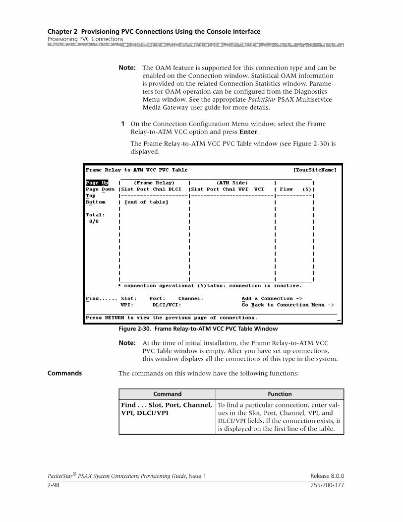
Chapter 2 Provisioning PVC Connections Using the Console InterfaceProvisioning PVC Connections
2-98 255-700-377
PacketStar® PSAX System Connections Provisioning Guide, Issue 1 Release 8.0.0
Note: The OAM feature is supported for this connection type and can be enabled on the Connection window. Statistical OAM information is provided on the related Connection Statistics window. Parame-ters for OAM operation can be configured from the Diagnostics Menu window. See the appropriate PacketStar PSAX Multiservice Media Gateway user guide for more details.
1 On the Connection Configuration Menu window, select the Frame Relay-to-ATM VCC option and press Enter.
The Frame Relay-to-ATM VCC PVC Table window (see Figure 2-30) is displayed.
Note: At the time of initial installation, the Frame Relay-to-ATM VCC PVC Table window is empty. After you have set up connections, this window displays all the connections of this type in the system.
Commands The commands on this window have the following functions:
Figure 2-30. Frame Relay-to-ATM VCC PVC Table Window
Command Function
Find . . . Slot, Port, Channel, VPI, DLCI/VPI
To find a particular connection, enter val-ues in the Slot, Port, Channel, VPI, and DLCI/VPI fields. If the connection exists, it is displayed on the first line of the table.

255-700-377 2-99
PacketStar® PSAX System Connections Provisioning Guide, Issue 1 Release 8.0.0
Chapter 2 Provisioning PVC Connections Using the Console InterfaceProvisioning PVC Connections
Field Descriptions The display-only fields on this window provide the following information about all the frame relay-to-ATM PVC connections in the PSAX system:
2 Select the Add a Connection command and press Enter.
The Frame Relay-to-ATM VCC PVC Connection window (see Figure 2-31) is displayed.
Add a Connection Displays the Frame Relay-to-ATM VCC PVC Connection window.
Go Back to Connection Menu
Redisplays the Connection Configuration Menu window.
Command Function
Table 2-28. Field Descriptions for the Frame Relay-to-ATM VCC PVC Table Window
Field Name Description
Frame Relay(Side A)
This field displays the information for all interface Side A of the connections. The connection entries are displayed in ascending numerical order by slot, then by port, channel, and DLCI or VPI.
Frame Relay(Side B)
This field displays the information for all interface Side B of the connections.
Flow This field displays the direction of the data traffic flow for the connections.
Total:0/0
The first number in this field indicates the num-ber of the connection table entry on the first line of the currently displayed window. The second number indicates the total number of connection table entries for this connection type.

Chapter 2 Provisioning PVC Connections Using the Console InterfaceProvisioning PVC Connections
2-100 255-700-377
PacketStar® PSAX System Connections Provisioning Guide, Issue 1 Release 8.0.0
Commands The commands on this window have the following functions:
Field Descriptions 3 Select the values for the fields on this window from the values in Table 2-29.
Figure 2-31. Frame Relay-to-ATM VCC PVC Connection Window
Command Function
Display Next Connection Displays the next connection of this type in the table.
Delete Connection Deletes the connection having the values currently displayed on the window.
Configure Traffic Parame-ters
Displays the Frame Relay-to-ATM VCC PVC Traffic Parameters window.
View Connection Statistics Displays the Frame Relay-to-ATM VCC PVC Statistics window.
Add/View Backup PVC Displays the backup PVC or option to add a backup PVC.
Go Back to Connection Table
Redisplays the Frame Relay-to-ATM VCC PVC Table window.

255-700-377 2-101
PacketStar® PSAX System Connections Provisioning Guide, Issue 1 Release 8.0.0
Chapter 2 Provisioning PVC Connections Using the Console InterfaceProvisioning PVC Connections
Table 2-29. Field Descriptions for the Frame Relay-to-ATM VCC PVC Connection Window
Field Names Field Values Description
Frame Relay Inter-face
Default: NA
Range: NA
Format: NA
The fields in the Frame Relay Interface panel are used to configure the frame relay side of the con-nection.
ATM Interface Default: N/A
Range: N/A
Format: N/A
The fields in the ATM Interface panel are used to configure the ATM side of the connection.
Slot Default: 0Range: variable
Format: numeric
Enter the slot number containing the module for both sides of the connection. The range of slot numbers varies with the chassis type.
Port Default: 1Range: variable
Format: numeric
Enter the port number on the module for both sides of the connection. The range of port num-bers varies with the module type.
Channel Default: 1
Range: variable
Format: numeric
ATM side: 1FR side: 1–32
The channel on which you are creating a connec-tion. On the ATM Interface side, do not change the value 1 in this field. On the Frame Relay Interface side, enter the channel number of the port on the module for which you are creating a connection.
DLCI Default: 0Range: 16–1007
Format: numeric
Data link connection identifier. DLCI is used when the remote end-point is frame relay.
VPI Default: 0
Range: 0–225 (ATM UNI), 0-4095 (NNI)
Format: numeric
Virtual path identifier.
VCI Default: 0
Range: 0–65535
Format: numeric
Virtual channel identifier.
VI/VUNI Default: 0Range: 0–255
Format: numeric
Virtual interface/virtual ATM UNI, which pro-vides bandwidth allocation restrictions. Currently available only on the OC-3c 1+1 APS, STM-1 1+1 MSP, and OC-12c/STM-4c 1+1 APS/MSP modules. When disabled, the default value is 0. The virtual UNI (VUNI) associates itself with the egress part of the A-to-B or the B-to-A side of the connection.

Chapter 2 Provisioning PVC Connections Using the Console InterfaceProvisioning PVC Connections
2-102 255-700-377
PacketStar® PSAX System Connections Provisioning Guide, Issue 1 Release 8.0.0
Service Type Default: Ubr
Range: N/A
Format: predefined alphanumeric
Ubr,Vbr-nrt2,Vbr-nrt1,Vbr-rt2,Vbr-rt1,Vbr-express
PSAX system-supported quality of service (QoS) class. For a description of the QoS classes, see the reference appendix in this guide.
Cnfrmnce Type Default: Best-effort
Range: N/A
Format: predefined alphanumeric
The type of traffic control option used for ATM cells. The traffic descriptor combination specifies which traffic parameters are used for traffic con-trol, determines the number and type of cells that are admitted into a congested queue, and deter-mines whether high-priority cells are tagged as low-priority cells when traffic exceeds the traffic parameter thresholds.
Best-effort This traffic descriptor allows the system to attempt to send all cells in a “best effort” fashion, without specifying traffic parameters, similar to the AQueMan algorithm.
1B-NT-0+1 This traffic descriptor uses the parameters one bucket, no tagging, cell loss priority (CLP)=0+1 cells (high and low priority).
2B-NT-0+1-0+1 This traffic descriptor uses the parameters two buckets, no tagging, CLP=0+1 cells (high and low priority) for bucket 1, and CLP=0+1 cells (high and low priority) for bucket 2.
2B-NT-0+1-0 This traffic descriptor uses the parameters two buckets, no tagging, CLP=0+1 cells (high and low priority) for bucket 1, and CLP=0 cells (high pri-ority) for bucket 2.
2B-T-0+1-0 This traffic descriptor uses the parameters two buckets, CLP=0+1 cells (high and low priority) for bucket 1, and tagging for CLP=0 cells (high priority) in bucket 2.
Best-effort-tag This traffic descriptor allows the system to tag all CLP=0 (high priority) cells to change them to CLP=1 (low priority) cells during congestion, and then attempt to send all cells in a “best effort” fashion, without specifying any other traffic parameters, similar to the AQueMan algorithm.
Table 2-29. Field Descriptions for the Frame Relay-to-ATM VCC PVC Connection Window
Field Names Field Values Description
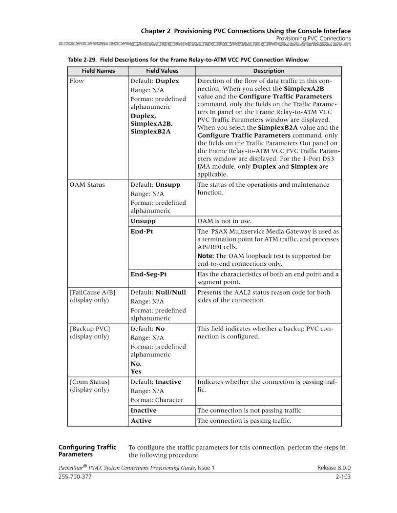
255-700-377 2-103
PacketStar® PSAX System Connections Provisioning Guide, Issue 1 Release 8.0.0
Chapter 2 Provisioning PVC Connections Using the Console InterfaceProvisioning PVC Connections
Configuring Traffic Parameters
To configure the traffic parameters for this connection, perform the steps in the following procedure.
Flow Default: Duplex
Range: N/A
Format: predefined alphanumeric
Duplex,SimplexA2B,SimplexB2A
Direction of the flow of data traffic in this con-nection. When you select the SimplexA2B value and the Configure Traffic Parameters command, only the fields on the Traffic Parame-ters In panel on the Frame Relay-to-ATM VCC PVC Traffic Parameters window are displayed. When you select the SimplexB2A value and the Configure Traffic Parameters command, only the fields on the Traffic Parameters Out panel on the Frame Relay-to-ATM VCC PVC Traffic Param-eters window are displayed. For the 1-Port DS3 IMA module, only Duplex and Simplex are applicable.
OAM Status Default: UnsuppRange: N/A
Format: predefined alphanumeric
The status of the operations and maintenance function.
Unsupp OAM is not in use.
End-Pt The PSAX Multiservice Media Gateway is used as a termination point for ATM traffic, and processes AIS/RDI cells.
Note: The OAM loopback test is supported for end-to-end connections only.
End-Seg-Pt Has the characteristics of both an end point and a segment point.
[FailCause A/B](display only)
Default: Null/Null
Range: N/A
Format: predefined alphanumeric
Presents the AAL2 status reason code for both sides of the connection
[Backup PVC](display only)
Default: NoRange: N/A
Format: predefined alphanumeric
No,Yes
This field indicates whether a backup PVC con-nection is configured.
[Conn Status](display only)
Default: Inactive
Range: N/A
Format: Character
Indicates whether the connection is passing traf-fic.
Inactive The connection is not passing traffic.
Active The connection is passing traffic.
Table 2-29. Field Descriptions for the Frame Relay-to-ATM VCC PVC Connection Window
Field Names Field Values Description

Chapter 2 Provisioning PVC Connections Using the Console InterfaceProvisioning PVC Connections
2-104 255-700-377
PacketStar® PSAX System Connections Provisioning Guide, Issue 1 Release 8.0.0
Begin
Configuring Traffic Parameters
1 On the Frame Relay-to-ATM VCC PVC Connection window (see Figure 2-31), select the Configure Traffic Parameters command and press Enter.
The Frame Relay-to-ATM VCC PVC Traffic Parameters window is dis-played (see Figure 2-32).
Commands The commands on this window have the following functions:
Field Descriptions 2 Select the values for the traffic parameter fields on this window from the values given in Table 2-30.
Figure 2-32. Frame Relay-to-ATM PVC Traffic Parameters Window
Command Function
Add This Connection Adds a connection having the values cur-rently displayed on the window.
Delete Connection and Return
Deletes the connection having the values currently displayed on the window.
Go Back to Connection Table
Redisplays the Frame Relay-to-ATM VCC PVC Connection Table window.

255-700-377 2-105
PacketStar® PSAX System Connections Provisioning Guide, Issue 1 Release 8.0.0
Chapter 2 Provisioning PVC Connections Using the Console InterfaceProvisioning PVC Connections
Table 2-30. Field Descriptions for the Frame Relay-to-ATM VCC PVC Traffic Parameters Window
Field Name Field Values Description
Frame Size for Rate Cal.
Default: 4096
Range:
Format: numeric (bytes)
Specifies the size the frame (in bytes) that is used to calculate .
Committed Burst Size
Default: 0
Range:
Format: numeric
Use the default value.
Excess Burst Size Default: 45000000
Range:
Format: numeric (bps)
Measured in bits per second.
Committed Info Rate
Default: 0Range:
Format: numeric (bps)
Committed information rate is the rate of traffic for a given connection that the system will attempt to provide guaranteed delivery. If using traffic shaping on the OC-3c or STM-1 Single-Mode or Multimode modules, set this parameter on the frame relay side of the connection on both ends of the link to control the cell transmission rate. This action is necessary because the SCR field is not available on the ATM side of the con-nection.
Interworking Func-tion
Default: Frf8-Transl
Range: N/A
Format: predefined alphanumeric
Default: Frf8-Transl FRF.8 (Frame Relay Forum Implementation Agreement)—frame relay to ATM PVC service interworking.
Default: Frf8-Pass FRF.8 (Frame Relay Forum Implementation Agreement)—frame relay to ATM PVC service interworking.
Default: Frf5 FRF.5 (Frame Relay Forum Implementation Agreement)—frame relay to ATM PVC service interworking.

Chapter 2 Provisioning PVC Connections Using the Console InterfaceProvisioning PVC Connections
2-106 255-700-377
PacketStar® PSAX System Connections Provisioning Guide, Issue 1 Release 8.0.0
3 To add (apply) the connection configuration, select the Add This Con-nection command and press Enter.
4 To review this connection, select the Go Back to Connection Table command and press Enter.
The Frame Relay-to-ATM VCC PVC Table window is redisplayed with the values you just applied.
5 To add more connections of this type, repeat steps 2 through 5 for more connections as needed.
End
Traffic Shaping Default: Disabled
Range: N/A
Format: predefined alphanumeric
A method for controlling the flow of data traffic. This feature is implemented on modules that are offered with the traffic-shaping feature: the 1-Port OC-3c Multimode and Single-Mode mod-ules, and the 1-Port STM-1 Multimode and Sin-gle-Mode modules. When enabled, traffic shap-ing ensures that the variable bit-rate (VBR) traffic entering the PSAX system (via the OC-3c and STM-1 modules) complies with the parameters of the established service contracts.
Default: Disabled Selecting this value disables traffic shaping.
Default: Enabled Selecting this value enables traffic shaping.
[Time Interval](display only)
Default: 1000
Range:
Format: numeric (sec)
Specifices the amount of time (in seconds) since the last reset.
[Peak Cell Rate](display only)
Default: 1
Range:
Format: numeric
Refer to the ATM UNI 3.0 specifications for more information. When setting this value, take into account the line rate for the module and the amount of bandwidth you are setting up for each interface for the module.
[Sustained Cell Rate](display only)
Default: 1
Range:
Format: numeric
Sustained cell rate. Refer to the ATM UNI 3.0 specifications for more information. When set-ting this value, take into account the line rate for the module and the amount of bandwidth you are setting up for each interface for the module.
[Max Burst Size](display only)
Default: 1Range:
Format: numeric
Maximum burst size. Refer to the ATM UNI 3.0 specifications for more information. When set-ting this value, take into account the line rate for the module and the amount of bandwidth you are setting up for each interface for the module.
Table 2-30. Field Descriptions for the Frame Relay-to-ATM VCC PVC Traffic Parameters Window
Field Name Field Values Description

255-700-377 2-107
PacketStar® PSAX System Connections Provisioning Guide, Issue 1 Release 8.0.0
Chapter 2 Provisioning PVC Connections Using the Console InterfaceProvisioning PVC Connections
Viewing the Statistics Window
On the Frame Relay-to-ATM VCC PVC Connection window, select the View Connection Statistics command.
The Frame Relay-to-ATM VCC PVC Statistics window is displayed (see Figure 2-33).
Commands The commands on this window have the following functions:
Field Descriptions The fields on this window have the following values:
Figure 2-33. Frame Relay-to-ATM VCC PVC Statistics Window
Command Function
Reset Odometers Resets the Encoded Odometer, Decoded Odometer, In Odometer, and Out Odome-ter fields to 0. If a call is disconnected, all odometers are reset to 0.
Continuous Update Updates the values in the fields every sec-ond.
Display Stats for Next Con-nection
Displays the statistics for the next connec-tion of this type.
Go Back to Connection Dis-play
Redisplays the Frame Relay-to-ATM VCC PVC Connection window.

Chapter 2 Provisioning PVC Connections Using the Console InterfaceProvisioning PVC Connections
2-108 255-700-377
PacketStar® PSAX System Connections Provisioning Guide, Issue 1 Release 8.0.0
Table 2-31. Field Descriptions for the Frame Relay-to-ATM VCC Connection Statistics Window
Field Name Field Values Description
Cells Encoded(display only)
Default: 0
Range: N/A
Format: numeric
Number of cells encoded going into Frame Relay Interface Side A during the amount of time shown in Time Elapsed field since the connection was established.
Cells Decoded(display only)
Default: 0Range: N/A
Format: numeric
Number of cells decoded going out of Frame Relay Interface Side A during the amount of time shown in Time Elapsed field since the connection was established.
Frames Dropped(display only)
Default: 0
Range: N/A
Format: numeric
Number of frames going out of Frame Relay Interface Side A during the amount of time shown in Time Elapsed field since the connection was established.
Encoded Odometer(display only)
Default: 0Range: N/A
Format: numeric
Total number of cells encoded going into Frame Relay Interface Side A since this counter was reset.
Decoded Odometer(display only)
Default: 0
Range: N/A
Format: numeric
Total number of cells decoded going out of Frame Relay Interface Side A since this counter was reset.
AAL5 Error Frames(display only)
Default: 0
Range: N/A
Format: numeric
Number of AAL5 errored frames which are not dropped due to UPC in A2B direction. This counter is applicable applicable to only the input side.
Frames Tagged(display only)
Default: 0
Range: N/A
Format: numeric
Number of frames tagged due to UPC in A2B direction. This counter is applicable applicable to only the input side.
Time Elapsed(display only)
Default: 00:00:00
Range: N/A
Format: numericHH:MM:SS (hours, minutes, seconds)
Time elapsed (in hours, minutes, seconds) since the connection was established.
Time Since Reset(display only)
Default: 00:00:00Range: N/A
Format: numericHH:MM:SS (hours, minutes, seconds)
Time elapsed (in hours, minutes, seconds) since the last time the Reset Statistics command was used. The Reset Statistics command on the sta-tistics window resets only the odometer fields and the corresponding clock. Other counters increment for the life of the connection.
AIS Rx/Tx(display only)
Default: 0
Range: N/A
Format: numeric
Number of alarm indication signal (AIS) cells received and transmitted.
RDI Rx/Tx(display only)
Default: 0Range: N/A
Format: numeric
Number of remote defect indicator (RDI) cells received and transmitted.

255-700-377 2-109
PacketStar® PSAX System Connections Provisioning Guide, Issue 1 Release 8.0.0
Chapter 2 Provisioning PVC Connections Using the Console InterfaceProvisioning PVC Connections
Adding a Frame Relay-to-Frame Relay PVC Connection
Creating a Frame Relay-to-Frame PVC Relay Connection
Perform the steps in the following procedure to add a frame relay-to-frame relay PVC connection, starting at the Connection Configuration Menu win-dow.
Begin
Steps to Create a Frame Relay-to-Frame Relay PVC Connection
1 On the Connection Configuration Menu window, select Frame Relay-to-Frame Relay and press Enter.
The Frame Relay-to-Frame Relay PVC Table window (see Figure 2-34) is displayed.
cell Drop/Tag(display only)
Default: 0
Range: N/A
Format: numeric
Number of cells dropped and tagged on incoming side of ATM interface Side B.
Cells Received(display only)
Default: 0Range: N/A
Format: numeric
Number of cells Received into ATM Interface Side B during the amount of time shown in Time Elapsed field since the connection was estab-lished.
Cells Transmitted(display only)
Default: 0
Range: N/A
Format: numeric
Number of cells Transmitted out of ATM Interface Side B during the amount of time shown in Time Elapsed field since the connection was estab-lished.
In Odometer(display only)
Default: 0Range: N/A
Format: numeric
Total number of cells encoded going into ATM Interface Side B since this counter was last reset.
Out Odometer(display only)
Default: 0
Range: N/A
Format: numeric
Total number of cells decoded going out of ATM Interface Side B since ince this counter was last reset.
Table 2-31. Field Descriptions for the Frame Relay-to-ATM VCC Connection Statistics Window
Field Name Field Values Description
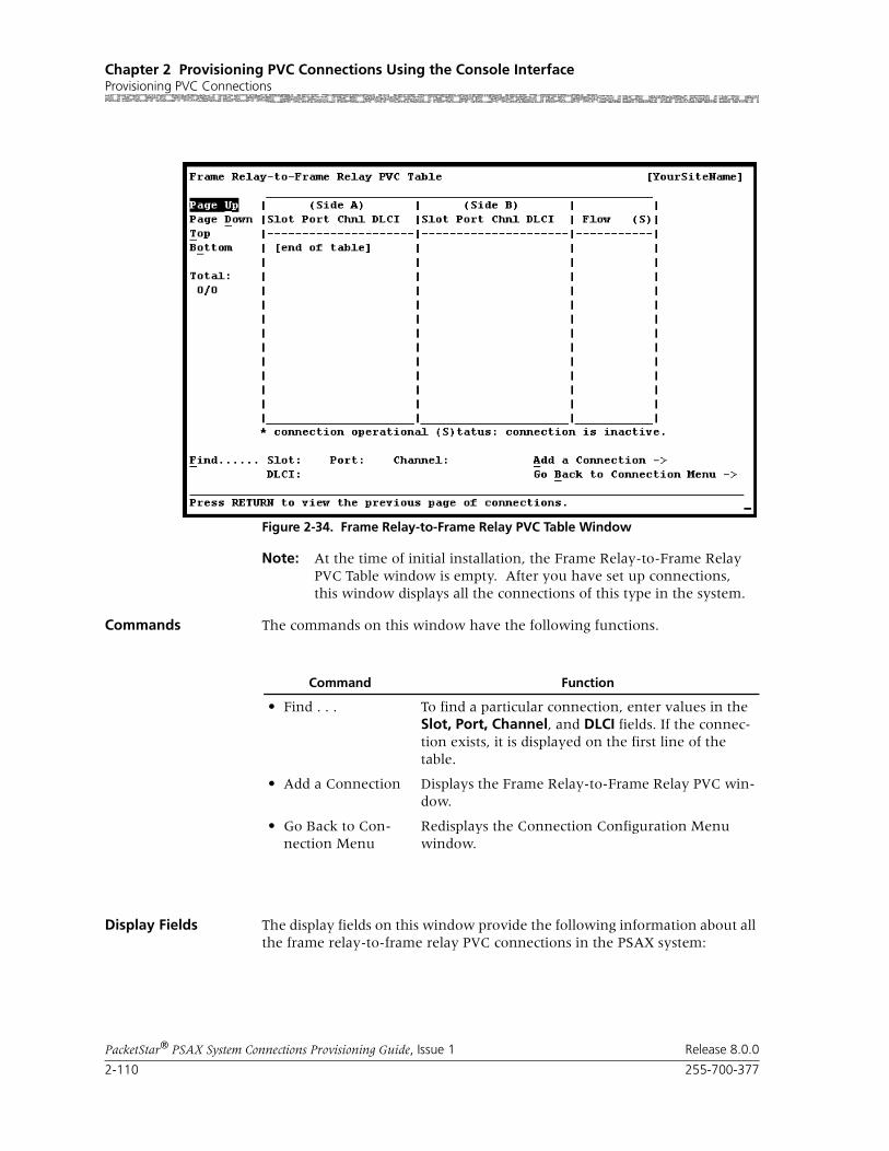
Chapter 2 Provisioning PVC Connections Using the Console InterfaceProvisioning PVC Connections
2-110 255-700-377
PacketStar® PSAX System Connections Provisioning Guide, Issue 1 Release 8.0.0
Note: At the time of initial installation, the Frame Relay-to-Frame Relay PVC Table window is empty. After you have set up connections, this window displays all the connections of this type in the system.
Commands The commands on this window have the following functions.
Display Fields The display fields on this window provide the following information about all the frame relay-to-frame relay PVC connections in the PSAX system:
Figure 2-34. Frame Relay-to-Frame Relay PVC Table Window
Command Function
• Find . . . To find a particular connection, enter values in the Slot, Port, Channel, and DLCI fields. If the connec-tion exists, it is displayed on the first line of the table.
• Add a Connection Displays the Frame Relay-to-Frame Relay PVC win-dow.
• Go Back to Con-nection Menu
Redisplays the Connection Configuration Menu window.

255-700-377 2-111
PacketStar® PSAX System Connections Provisioning Guide, Issue 1 Release 8.0.0
Chapter 2 Provisioning PVC Connections Using the Console InterfaceProvisioning PVC Connections
2 Select the Add a Connection command and press Enter.
The Frame Relay-to-Frame Relay PVC Connection window (see Figure 2-35) is displayed.
Commands The commands on this window have the following functions:
Field Description
• Frame Relay Side A
This panel displays the information for all A sides of the connections. The connection entries are displayed in ascending numerical order by slot, then by port, chan-nel, and DLCI.
• Frame Relay Side B
This panel displays the information for all B sides of the connections.
• Flow
•This panel displays the direction of the data traffic flow for the connections.
• Total:0/0
The first number in this field indicates the number of the connection table entry on the first line of the currently displayed window. The second number indicates the total number of connection table entries for this connec-tion type.
Figure 2-35. Frame Relay-to-Frame Relay PVC Connection Window

Chapter 2 Provisioning PVC Connections Using the Console InterfaceProvisioning PVC Connections
2-112 255-700-377
PacketStar® PSAX System Connections Provisioning Guide, Issue 1 Release 8.0.0
Field Descriptions 3 Select the values for the fields on this window from the values given in Table 2-32.
Command Function
• Display Next Connection Displays the next connection of this type in the table.
• Add This Connection Adds a connection having the values cur-rently displayed on the window.
• Delete Connection Deletes the connection having the values currently displayed on the window.
• Configure Traffic Parameters Displays the Frame Relay-to-Frame Relay PVC Traffic Parameters window.
• View Connection Statistics Displays the Frame Relay-to-Frame Relay window.
• Go Back to Connection Table Redisplays the Frame Relay-to-Frame Relay PVC Statistics window.
Table 2-32. Field Descriptions for the Frame Relay-to-Frame Relay PVC Connection Window
Field Name Field Values Description
Frame Relay Inter-face A
Default: N/A
Range: N/A
Format: Predefined
The side of the connection that will send signals.
Frame Relay Inter-face B
Default: N/A
Range: N/A
Format: Predefined
The side of the connection that will receive sig-nals.
Slot Default: N/ARange: Chassis dependent
Format: Numeric
Enter the slot number containing the module for which you are creating a connection. Enter slot numbers for both sides of the connection.
Port Default: N/A
Range: Module dependent
Format: Numeric
Enter the port number on the module for which you are creating a connection. Enter port numbers for both sides of the connection.
Channel Default:
Range: 1–321–24 for DS1/T11–31 for E1
Format: Numeric
Range: 1–32
Enter the channel number of the port on the module for which you are creating a connection. Enter channel numbers for both sides of the con-nection.

255-700-377 2-113
PacketStar® PSAX System Connections Provisioning Guide, Issue 1 Release 8.0.0
Chapter 2 Provisioning PVC Connections Using the Console InterfaceProvisioning PVC Connections
End
Configuring Traffic Parameters
To configure the traffic parameters for this connection, perform the steps in the following procedure.
DLCI Default: 0
Range: 16–1007
Format: Numeric
Data link connection identifier.
Frf8-Transl
Frf8-Pass FRF.8 (Frame Relay Forum Implementation Agreement)—frame relay to ATM PVC service interworking
Frf5 FRF.5 (Frame Relay Forum Implementation Agreement)—frame relay to ATM PVC service interworking.
Service Type Default: Ubr
Range: As noted below.
Format: Predefined
Vbr-nrt2,Vbr-nrt1,Vbr-rt2,Vbr-rt1,Vbr-express,Cbr-4, Cbr-3,Cbr-2, Cbr-1
PSAX system-supported quality of service (QoS) class.
Flow Default: Duplex
Range: N/A
Format: Predefined
Direction of the flow of data traffic in this con-nection.
When you select SimplexA2B, only fields in the Traffic Parameters A to B side display.
Duplex Traffic flows back and forth between the connec-tion terminations.
SimplexA2B Traffic flows from termination A to B only.
[ConnectionStatus]
(display only)
Default: Inactive
Range: N/A
Format: Predefined
This field displays the current status of the con-nection. The value indicates whether the connec-tion is passing traffic.
Inactive The connection is not passing traffic.
Active The connection is passing traffic.
[FailCause A/B](display only)
Default: Null/Null
Range: N/A
Format: Predefined
Presents the AAL2 status reason code for both sides of the connection.
Table 2-32. Field Descriptions for the Frame Relay-to-Frame Relay PVC Connection Window
Field Name Field Values Description

Chapter 2 Provisioning PVC Connections Using the Console InterfaceProvisioning PVC Connections
2-114 255-700-377
PacketStar® PSAX System Connections Provisioning Guide, Issue 1 Release 8.0.0
Begin
Steps to Configure Traffic Parameters
1 On the Frame Relay-to-Frame Relay PVC Connection window (see Figure 2-35), select Configure Traffic Parameters and press Enter.
The Frame Relay-to-Frame Relay PVC Traffic Parameters window is dis-played (see Figure 2-36).
Commands The commands on this window have the following functions:
Field Descriptions 2 Select the values for the traffic parameter fields on this window from the values given in Table 2-33.
Figure 2-36. Frame Relay-to-Frame Relay PVC Traffic Parameters Window
Command Function
Add This Connection Adds a connection having the values cur-rently displayed on the window.
Delete and Return Deletes the connection having the values currently displayed on the window.
Go Back to Connection Screen
Redisplays the Frame Relay-to-Frame Relay VCC PVC Connection Table win-dow.

255-700-377 2-115
PacketStar® PSAX System Connections Provisioning Guide, Issue 1 Release 8.0.0
Chapter 2 Provisioning PVC Connections Using the Console InterfaceProvisioning PVC Connections
3 To add (apply) the connection configuration, select the Add This Con-nection command and press Enter.
4 To review this connection, select the Go Back to Connection Table com-mand and press Enter (or press Ctrl + b).
The Frame Relay-to-Frame Relay PVC Table window returns, displaying the values you just applied.
5 To add more connections of this type, repeat steps 2 through 5 for more connections as needed.
End
Viewing the Statistics Window
From the Frame Relay-to-Frame Relay PVC window, select the View Statis-tics command.
The Frame Relay-to-Frame Relay PVC Statistics window is displayed (see Figure 2-37).
Table 2-33. Field Descriptions for the Frame Relay-to-Frame Relay PVC Traffic Parameters Window
Field Name Field Values Description
Frame Size for Rate Cal.
Default: 4096 Measured in bytes.
Committed Burst Size
Default: 0 Use the default value.
Excess Burst Size Default: 45000000 Measured in bits per second.
Committed Info Rate
Default: 0 Committed information rate is the rate of traffic (measured in bits per second) for a given connec-tion that the system will attempt to provide guar-anteed delivery.
[Time Interval](display only)
Default: 1000 Time, in seconds, since last reset.
[Peak Cell Rate](display only)
Default: 1 Refer to the ATM UNI 3.0 specifications for more information. When setting this value, take into account the line rate for the module and the amount of bandwidth you are setting up for each interface for the module.
[Sustained Cell Rate](display only)
Default: 1 Sustained cell rate. Refer to the ATM UNI 3.0 specifications for more information. When set-ting this value, take into account the line rate for the module and the amount of bandwidth you are setting up for each interface for the module.
[Max Burst Size](display only)
Default: 1 Maximum burst size. Refer to the ATM UNI 3.0 specifications for more information. When set-ting this value, take into account the line rate for the module and the amount of bandwidth you are setting up for each interface for the module.

Chapter 2 Provisioning PVC Connections Using the Console InterfaceProvisioning PVC Connections
2-116 255-700-377
PacketStar® PSAX System Connections Provisioning Guide, Issue 1 Release 8.0.0
Commands The commands on this window have the following functions:
Field Descriptions The fields on this window have the following values:
Figure 2-37. Frame Relay-to-Frame Relay PVC Statistics Window
Command Function
Reset Odometers Returns all statistics odometers to zero.
Continuous Update Updates the values in the fields every sec-ond.
Display Stats for Next Con-nection
Displays the statistics for the next selected connection.
Go Back to Connection Dis-play
Redisplays the connection window.
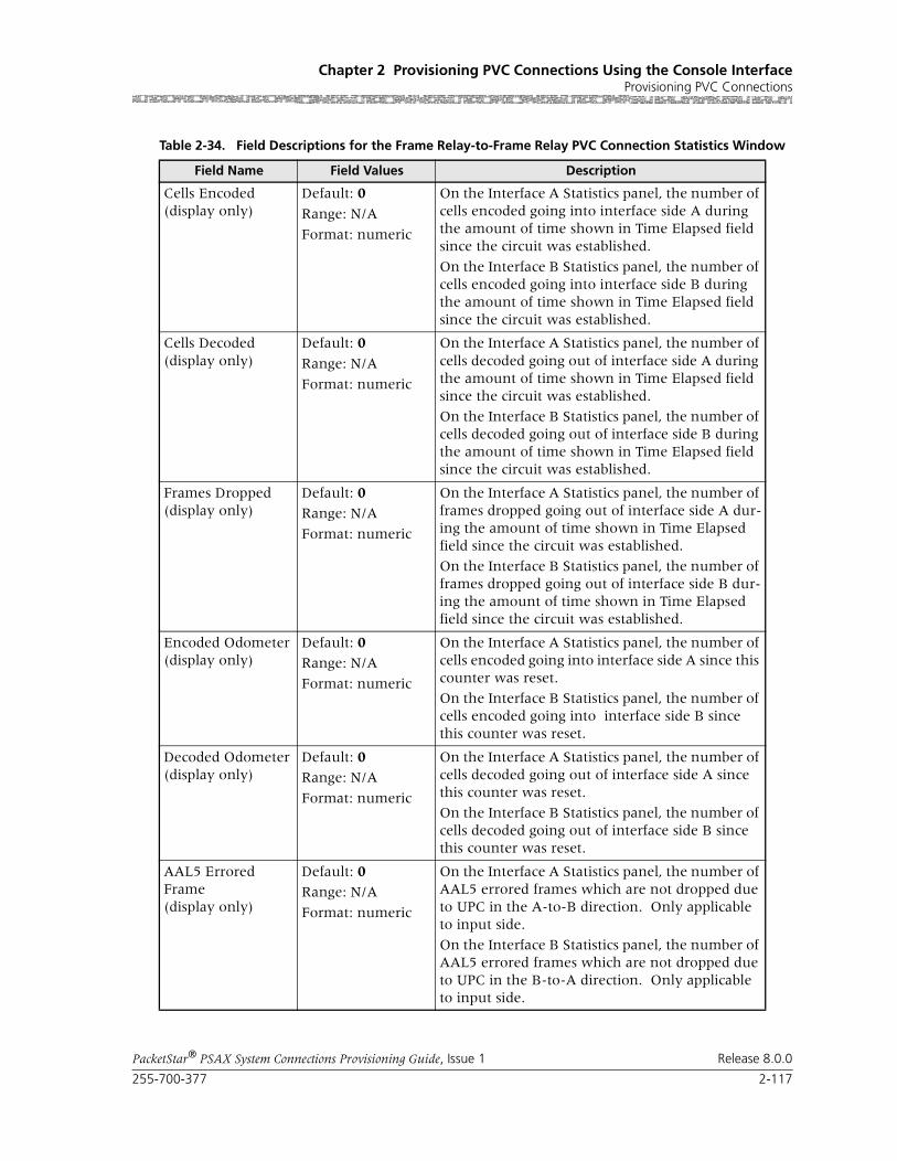
255-700-377 2-117
PacketStar® PSAX System Connections Provisioning Guide, Issue 1 Release 8.0.0
Chapter 2 Provisioning PVC Connections Using the Console InterfaceProvisioning PVC Connections
Table 2-34. Field Descriptions for the Frame Relay-to-Frame Relay PVC Connection Statistics Window
Field Name Field Values Description
Cells Encoded(display only)
Default: 0
Range: N/A
Format: numeric
On the Interface A Statistics panel, the number of cells encoded going into interface side A during the amount of time shown in Time Elapsed field since the circuit was established.
On the Interface B Statistics panel, the number of cells encoded going into interface side B during the amount of time shown in Time Elapsed field since the circuit was established.
Cells Decoded(display only)
Default: 0
Range: N/A
Format: numeric
On the Interface A Statistics panel, the number of cells decoded going out of interface side A during the amount of time shown in Time Elapsed field since the circuit was established.
On the Interface B Statistics panel, the number of cells decoded going out of interface side B during the amount of time shown in Time Elapsed field since the circuit was established.
Frames Dropped(display only)
Default: 0Range: N/A
Format: numeric
On the Interface A Statistics panel, the number of frames dropped going out of interface side A dur-ing the amount of time shown in Time Elapsed field since the circuit was established.
On the Interface B Statistics panel, the number of frames dropped going out of interface side B dur-ing the amount of time shown in Time Elapsed field since the circuit was established.
Encoded Odometer(display only)
Default: 0Range: N/A
Format: numeric
On the Interface A Statistics panel, the number of cells encoded going into interface side A since this counter was reset.
On the Interface B Statistics panel, the number of cells encoded going into interface side B since this counter was reset.
Decoded Odometer(display only)
Default: 0Range: N/A
Format: numeric
On the Interface A Statistics panel, the number of cells decoded going out of interface side A since this counter was reset.
On the Interface B Statistics panel, the number of cells decoded going out of interface side B since this counter was reset.
AAL5 Errored Frame(display only)
Default: 0Range: N/A
Format: numeric
On the Interface A Statistics panel, the number of AAL5 errored frames which are not dropped due to UPC in the A-to-B direction. Only applicable to input side.
On the Interface B Statistics panel, the number of AAL5 errored frames which are not dropped due to UPC in the B-to-A direction. Only applicable to input side.

Chapter 2 Provisioning PVC Connections Using the Console InterfaceProvisioning PVC Connections
2-118 255-700-377
PacketStar® PSAX System Connections Provisioning Guide, Issue 1 Release 8.0.0
Adding a GR-303-to-AAL2 VCC PVC Connection
See the application note entitled PacketStar® PSAX Configuring the GR-303 Voice Gateway User Guide, Issue 3, for instructions on configuring this connection.
Adding an In-Band Management ATM PVC Connection
You can create an in-band management PVC connection between a config-ured in-band management address and any module that supports ATM inter-faces. This connection supports the UBR and VBR-express service types.
Perform the steps in the following procedure to create an in-band manage-ment-to-ATM VCC connection.
Note: As a prerequisite to enable in-band PVC provisioning, you must select and apply the value Disabled in the SVC Connections field on the In-Band Management Configuration window. For more information, see the appropriate PacketStar PSAX Multiservice Media Gateway user guide.
Setting Up the PSAX System for In-Band Management Connections
Perform the steps in the following procedure, which is a test to verify the cor-rect functioning of the console interface windows for configuring the in-band management IP address and the PVC connection.
Begin
Setting Up for Direct In-Band Connections
1 Configure the primary IP address for in-band management on the PSAX system using the console interface. This IP address must be different from the IP address of Ethernet interface for the CPU module.
c On the Console Interface Main Menu window, select the Site-Spe-cific Configuration option.
Frame Tagged(display only)
Default: 0
Range: N/A
Format: numeric
On the Interface A Statistics panel, the number of frames tagged due to UPC in the A-to-B direction. Only applicable to input side.
On the Interface B Statistics panel, the number of frames tagged due to UPC in the B-to-A direction. Only applicable to input side.
Time Elapsed(display only)
Default: 00:00:00
Range: N/A
Format: numeric
Time elapsed since the circuit was established.
Time Since Reset(display only)
Default: 00:00:00
Range: N/A
Format: numeric
Time elapsed since the last time the Reset com-mand was used.
Note: The Reset command on the statistics win-dow resets only the odometer fields and the cor-responding clock. Other counters increment for the life of the circuit.
Table 2-34. Field Descriptions for the Frame Relay-to-Frame Relay PVC Connection Statistics Window
Field Name Field Values Description

255-700-377 2-119
PacketStar® PSAX System Connections Provisioning Guide, Issue 1 Release 8.0.0
Chapter 2 Provisioning PVC Connections Using the Console InterfaceProvisioning PVC Connections
d On the Site-Specific Menu window, select the In-Band Management option to access the In-Band Management Configuration window.
Example:
Primary IP Address: 136.242.140.223
Primary IP Mask : 255.255.255.000
2 Set up the in-band management ATM PVC connection for the PSAX sys-tem. For setting up a connection from the OC-3c module to the CPU module, configure the OC-3c module and put it into service.
a Configure the PVC on the PSAX system side of the connection. See the procedure, “Creating an In-Band-to-ATM VCC Connection,” below.
b Configure the PVC on the FORECARD side of the connection, using the PSAX system console interface.
• On the Console Interface Main Menu window, select the Connec-tion Configuration option.
• On the Connection Configuration Menu window, select the In-Band Management IP PVC option.
• On the In-Band Management IP PVC Connection Table window, select the Add a Connection command.
Example:
Slot<OC3 Slot> VPI: 0 IP Address: 136.242.140.222
Port1VCI: 300IP Mask: 255.255.255.000
Channel 1
You can set up similar connections on other remote PSAX systems.
3 Use ping, telnet, rlogin and ftp commands on the SUN workstation to test the TCP/IP connection to the CPU module using the primary and backup IP addresses.
4 During an FTP session for the in-band management connection, discon-nect one of the cables out of the pair of cables connecting the PSAX sys-tem to the SUN workstation. Reconnect the cable and check whether the FTP session is still active, and whether the software recovers from a momentary connection loss.
End
Creating an In-Band-to-ATM VCC Connection
Perform the steps in the following procedure to add an in-band management ATM PVC connection, starting at the Connection Configuration Menu win-dow.
Begin
Creating an In-Band ATM PVC Connection
1 On the Connection Configuration Menu window, select the In-Band Management IP PVC option and press Enter.

Chapter 2 Provisioning PVC Connections Using the Console InterfaceProvisioning PVC Connections
2-120 255-700-377
PacketStar® PSAX System Connections Provisioning Guide, Issue 1 Release 8.0.0
The In-Band Management IP PVC Connection Table window (see Figure 2-38) is displayed.
Note: At the time of initial installation, the In-Band Management IP PVC Connection Table window is empty. After you have set up connec-tions, this window displays all the connections of this type in the system.
Commands The commands on this window have the following functions:
Figure 2-38. In-Band Management IP PVC Connection Table Window
Command Function
Page Up Scrolls up one page.
Page Down Scrolls down one page.
Top Displays entries at the top of the table.
Bottom Displays entries at the bottom of the table.
Find Slot, Port, Channel, VPI, VCI:
Searches the table for a particular in-band management ATM PVC connection. To find a particular connection, enter values in the Slot, Port, Channel, VPI, and VCI fields. If the connection exists, it is dis-played on the first line of the table.
Add a Connection Displays the In-band ATM PVC Connec-tion Configuration window.
Go Back to Connection Menu
Redisplays the Connection Configuration Menu window.

255-700-377 2-121
PacketStar® PSAX System Connections Provisioning Guide, Issue 1 Release 8.0.0
Chapter 2 Provisioning PVC Connections Using the Console InterfaceProvisioning PVC Connections
Field Descriptions The fields on this window are described in Table 2-35:
2 Select the Add a Connection command and press Enter.
The In-Band Management ATM PVC Connection Configuration window is displayed (see Figure 2-39).
Table 2-35. Field Descriptions for the In-Band Management IP PVC Connection Table
Field Name Description
IP Address, Mask This column displays the IP addresses and masks for the PSAX systems being managed from the management workstation.
In-Band Manage-ment PVC
This column displays the slot, port, channel, VPI, and VCI of the connection to each managed PSAX system.
Type If the connection is inactive, the indicator S is dis-played in this column.
Total:0/0
The first number in this field indicates the num-ber of the connection table entry on the first line of the currently displayed window. The second number indicates the total number of connection table entries for this connection type.
Figure 2-39. In-Band ATM PVC Connection Configuration Window

Chapter 2 Provisioning PVC Connections Using the Console InterfaceProvisioning PVC Connections
2-122 255-700-377
PacketStar® PSAX System Connections Provisioning Guide, Issue 1 Release 8.0.0
Commands The commands on this window have the following functions:
Field Descriptions 3 Select the values for the fields on this window from the values in Table 2-36.
Command Function
Add Connection Adds a connection having the values cur-rently displayed on the window.
Delete Connection Deletes the connection having the values currently displayed on the window.
Add/View Backup PVC Displays backup PVC or option to add backup PVC.
Display Next Connection Displays the next connection of this type in the table.
Go Back to Connection Table
Redisplays the In-Band Management IP PVC Connection Table window.
Table 2-36. Field Descriptions for the In-Band ATM PVC Connection Configuration Window
Field Name Field Values Description
Slot, Port, Chan-nel, VPI, VCI, and VI/VUNI
Default: N/A
Range: Varies
Format: numeric
The values for slot, port, channel, VPI, VCI, VI , and VUNI for the interface in the PSAX system to which you are connecting.
Service Type Default: Ubr
Range: N/A
Format: predefined alphanumeric
PSAX system-supported quality of service (QoS) class. For a description of the QoS classes, see the reference appendix in this guide.
Ubr Unspecified bit rate express class of service.
Vbr-express Variable bit rate express class of service.

255-700-377 2-123
PacketStar® PSAX System Connections Provisioning Guide, Issue 1 Release 8.0.0
Chapter 2 Provisioning PVC Connections Using the Console InterfaceProvisioning PVC Connections
Conformance Type Default: Best-effort
Range: N/A
Format: predefined alphanumeric
The type of traffic control option used for ATM cells. The traffic descriptor combination specifies which traffic parameters are used for traffic con-trol, determines the number and type of cells that are admitted into a congested queue, and deter-mines whether high-priority cells are tagged as low-priority cells when traffic exceeds the traffic parameter thresholds. For a detailed description of the conformance types, see the reference appendix.
Best-effort The PSAX system attempts to send all cells in a “best effort” fashion, without specifying traffic parameters, similar to the AQueMan algorithm.
1B-NT-0+1 Uses the parameters one bucket, no tagging, cell loss priority (CLP)=0+1 cells (high and low prior-ity).
2B-NT-0+1-0+1 Uses the parameters two buckets, no tagging, CLP=0+1 cells (high and low priority) for bucket 1, and CLP=0+1 cells (high and low priority) for bucket 2.
2B-NT-0+1-0 Uses the parameters two buckets, no tagging, CLP=0+1 cells (high and low priority) for bucket 1, and CLP=0 cells (high priority) for bucket 2.
2B-T-0+1-0 Uses the parameters two buckets, CLP=0+1 cells (high and low priority) for bucket 1, and tagging for CLP=0 cells (high priority) in bucket 2.
Best-effort-tag The PSAX system tags all CLP=0 (high priority) cells to change them to CLP=1 (low priority) cells during congestion, and then attempt to send all cells in a “best effort” fashion, without specifying any other traffic parameters, similar to the AQue-Man algorithm.
Peak Rate (cps) Default: 1Range:
Format: numeric (cells per sec)
The peak cell rate used for this connection. The peak cell rate displays the frame relay parameters in ATM terms. Peak cell rate (PCR) for all cells with both the CLP=0 bit and the CLP=1 bit. The value you set is the maximum allowed cell trans-mission rate (cells per second) for all cells both high and low priority, as allowed by your traffic contract. When setting this value, take into account the line rate for the module and the amount of bandwidth you are setting up for each interface for the module. Refer to the ATM UNI 3.1 specifications for more information. The value in this field should be greater than the Sus-tained Rate field.
Table 2-36. Field Descriptions for the In-Band ATM PVC Connection Configuration Window
Field Name Field Values Description

Chapter 2 Provisioning PVC Connections Using the Console InterfaceProvisioning PVC Connections
2-124 255-700-377
PacketStar® PSAX System Connections Provisioning Guide, Issue 1 Release 8.0.0
Sustained Rate (cps)
Default: 1
Range:
Format: numeric (cells per sec)
The sustained cell rate used for this connection. The sustained cell rate displays the frame relay parameters in ATM terms. Sustainable cell rate (SCR) with CLP=0 (high priority) cells or the peak cell rate with CLP=0 cells. When setting this value, take into account the line rate for the module and the amount of bandwidth you are setting up for each interface for the module. Refer to the ATM UNI 3.1 specifications for more information. The value in this field should be less than the Peak Rate field.
Max Burst Size (cells)
Default: 1Range:
Format: numeric
The maximum burst size used for this connec-tion. The maximum burst size displays the frame relay parameters in ATM terms. Refer to the ATM UNI 3.1 specifications for more information. When setting this value, take into account the line rate for the module and amount of band-width you are setting up for each interface on the module.
Oam Status Default: Unsupp Indicates the current OAM status of this connec-tion.
Unsupp OAM is not used in this connection.
End-Pt The PSAX system is used as a termination point for ATM traffic, and is processing AIS/RDI cells. The OAM loopback test is supported for only end-to-end connections. Enabling OAM status on an in-band management ATM interface means that in-band management will bring the particu-lar interface into service or out of service based on the OAM alarms.
End-Seg-Pt End-Seg-Pt is an connection endpoint and the endpoint of the segment; it will catch the seg-ment and end-to-end OAM cells. Enabling OAM status on an in-band management ATM interface means that in-band management will bring the particular interface in service or out of service based on the OAM alarms.
Table 2-36. Field Descriptions for the In-Band ATM PVC Connection Configuration Window
Field Name Field Values Description

255-700-377 2-125
PacketStar® PSAX System Connections Provisioning Guide, Issue 1 Release 8.0.0
Chapter 2 Provisioning PVC Connections Using the Console InterfaceProvisioning PVC Connections
Traffic Shaping Default: Disabled A method for controlling the flow of data traffic. This feature is implemented on modules that are offered with traffic-shaping variations: the OC-3c Multimode, OC-3c Single-Mode, STM-1 Multi-mode, and STM-1 Single-Mode modules.
Disabled Disables traffic shaping on the ATM side of the connection. The traffic shaping is done only on the outgoing direction.
Enabled When enabled, traffic shaping ensures that the variable bit-rate (VBR) traffic exiting the PSAX system (via the OC-3c and STM-1 modules) com-plies with the parameters of the established ser-vice contracts. Enables traffic shaping on the ATM side of the connection. The traffic shaping is done only on the outgoing direction.
[Failure Cause](display only)
Default: None The general connection failure cause code for both sides of the connection.
None This connection has no reported errors.
Physical This connection has detected a physical error on one or both sides of the connection.
IP AddressIP Mask
Default: 000.000.000.000
Range: N/A
Format: Valid dotted quad
The IP address and the IP mask for one of the fol-lowing depending on your in-band management scheme:
• The in-band IP address of the management workstation. This IP address must be different from the one for the management worksta-tion’s same network.
• The in-band IP address of the “router” PSAX system. This IP address must be different from the one for the Ethernet interface on the CPU module.
• The in-band IP address of the managed PSAX system. This IP address must be different from the one for the Ethernet interface on the CPU module.
[Connection Type](display only)
Default: PrimaryRange: N/A
Format: predefined alphanumeric
Displays that this connection is the primary con-nection.
Primary The connection being displayed is the primary connection. This is the only possible value for this field.
Table 2-36. Field Descriptions for the In-Band ATM PVC Connection Configuration Window
Field Name Field Values Description

Chapter 2 Provisioning PVC Connections Using the Console InterfaceProvisioning PVC Connections
2-126 255-700-377
PacketStar® PSAX System Connections Provisioning Guide, Issue 1 Release 8.0.0
4 Select the Add Connection command and press Enter.
5 Repeat steps 2 through 4 to set up as many connections as needed.
6 To permanently save these connections, press Ctrl+G to return to the Console Interface Main Menu window.
7 Select Save Configuration, and press Enter to store the values in the PSAX system database.
End
Configuring an In-Band ATM Backup PVC Connection
Perform the steps in the following procedure to add a backup PVC connec-tion.
Begin
Configuring an In-Band ATM Backup PVC Connection
1 On the In-Band ATM PVC Connection Configuration window, select the Add/View Backup PVC command.
The In-Band ATM Backup Connection window is displayed, (see Figure 2-40).
[Backup PVC](display only)
Default: No
Range: N/A
Format: predefined alphanumeric
This field displays whether a backup PVC exists.
No A backup PVC does not exist for this connection.
Yes A backup PVC exists for this connection.
[Conn Status](display only)
Default: Inactive This field displays the current status of the con-nection.
Inactive The connection is not passing traffic.
Active The connection is passing traffic.
Table 2-36. Field Descriptions for the In-Band ATM PVC Connection Configuration Window
Field Name Field Values Description

255-700-377 2-127
PacketStar® PSAX System Connections Provisioning Guide, Issue 1 Release 8.0.0
Chapter 2 Provisioning PVC Connections Using the Console InterfaceProvisioning PVC Connections
Commands The commands on this window have the following functions:
2 Select the values for the fields on this window from Table 2-37:
Figure 2-40. INBAND-ATM PVC Connection Configuration Window
Command Function
Add This Connection Adds the backup connection for the speci-fied slot, port, channel, VPI, VCI, and VI.
Delete Connection Deletes the backup connection.
Go Back to Primary PVC Connection
Redisplays the Inband ATM PVC Connec-tion Configuration window.
Table 2-37. Field Descriptions for the INBAND-ATM Backup PVC Connection Window
Field Name Field Values Description
Backup ATM Interface side:
Slot
(display only)
Listed as available from the PSAX device
Select the slot containing the module for which you are creating a backup connection.
Port
(display only)
Determined by the number of ports available on the mod-ule selected in the Slot field
Select the port number on the module for which you are creating a backup connection.

Chapter 2 Provisioning PVC Connections Using the Console InterfaceProvisioning PVC Connections
2-128 255-700-377
PacketStar® PSAX System Connections Provisioning Guide, Issue 1 Release 8.0.0
Adding VBR-to-ATM VCC PVC Connections
Creating a VBR-to-ATM VCC PVC Connection
Perform the steps in the following procedure to create a VBR-to-ATM VCC PVC connection.
Begin
Steps to Create a VBR-to-ATM VCC PVC Connection
Note: On the DS1 IMA and E1 IMA modules, PVC connections must be provisioned on the virtual port (port 7). You can use up to three groups on port 7 (the groups you provision on port 7.)
Channel
(display only)
Determined by the number of channels available on the port selected in the Port field
Select the channel number of the port on the module for which you are creating a backup con-nection.
VPI Default: 0 Range: 0–255
The virtual path identifier assigned to this inter-face.
VCI Default: 32 Range: 32–4000
The virtual channel identifier assigned to this interface.
VI Default: 0
Range: 0-255
Virtual interface, which provides bandwidth allo-cation restrictions. Currently available only on the OC-3c APS, and STM-1 MSP modules.
[Current Active PVC]
(display only)
None Indicates that the connection is inactive.
Primary Indicates that the primary connection is active (carrying user traffic).
Backup Indicates that the backup connection is active (carrying user traffic).
[Switch Back to Pri-maryAutomatically](display only)
Yes (default) The CPU monitors the primary connection. If the primary connection becomes available, the con-nection on the backup circuit will be switched back to the primary circuit.
No Not currently supported.
Once active, the backup connection will not switch back to primary connection automatically if primary becomes available.
IP Interface side
[IP Address], and [IP Mask]
(display only, IP Interface side)
Variable The IP address and the IP mask you entered for the primary connection. See these field descrip-tions on the primary In-band Connection win-dow.
Table 2-37. Field Descriptions for the INBAND-ATM Backup PVC Connection Window
Field Name Field Values Description

255-700-377 2-129
PacketStar® PSAX System Connections Provisioning Guide, Issue 1 Release 8.0.0
Chapter 2 Provisioning PVC Connections Using the Console InterfaceProvisioning PVC Connections
Note: On the DS3 IMA module, PVC connections must be provisioned on the virtual port (port 30). You can use up to 14 groups on port 30 (the groups you provision on port 30).
Note: The OAM feature is supported for this connection type and can be enabled on the Connection window. Statistical OAM information is provided on the related Connection Statistics window. Parame-ters for OAM operation can be configured from the Diagnostics Menu window. See the appropriate PacketStar PSAX Multiservice Media Gateway user guide for more details.
Use the steps in the following procedure to add a VBR-to-ATM VCC PVC connection, starting at the Connection Configuration Menu window.
1 On the Connection Configuration Menu window, select VBR-to-ATM VCC Connection and press Enter.
The VBR-to-ATM VCC PVC Table window (see Figure 2-41) is displayed.
Note: At the time of initial installation, the VBR-to-ATM VCC PVC Table window is empty. After you have set up connections, this window displays all the connections of this type in the system.
Commands The commands on this window have the following functions:
Figure 2-41. VBR-to-ATM VCC PVC Table Window

Chapter 2 Provisioning PVC Connections Using the Console InterfaceProvisioning PVC Connections
2-130 255-700-377
PacketStar® PSAX System Connections Provisioning Guide, Issue 1 Release 8.0.0
2 Select the Add a Connection command and press Enter.
The VBR-to-ATM VCC PVC Connection window (see Figure 2-42) is dis-played.
Commands The commands on this window have the following functions:
Command Function
Find . . . To find a particular connection, enter val-ues in the Slot, Port, Channel, VPI, and VCI fields. If the connection exists, it is displayed on the first line of the table.
Add a Connection Displays the VBR-to-ATM VCC PVC Con-nection window.
Go Back to Connection Menu
Redisplays the Connection Configuration Menu window.
Figure 2-42. VBR-to-ATM VCC PVC Connection Window
Command Function
Display Next Connection Displays the next connection of this type in the PSAX system.
Add This Connection Adds a connection having the values you entered on this window.

255-700-377 2-131
PacketStar® PSAX System Connections Provisioning Guide, Issue 1 Release 8.0.0
Chapter 2 Provisioning PVC Connections Using the Console InterfaceProvisioning PVC Connections
Field Descriptions 3 The fields on this window are described on the following table:
Delete Connection Deletes the connection having the values currently displayed on the window.
View Connection Statistics Displays the VBR-to-ATM VCC PVC Sta-tistics window.
Add/View Backup PVC Adds a backup PVC or, if you have already added a backup PVC, displays its values.
Go Back to Connection Table
Redisplays the VBR-to-ATM VCC PVC Connection Table window on which you can view all the connections of this type you have added.
Command Function
Table 2-38. Field Descriptions for the VBR-to-ATM VCC PVC Connection Window
Field Names Field Values Description
VBR Interface A Default: N/ARange: N/A
Format: Predefined
Indicates the VBR side of the connection that will send and receive signals.
ATM Interface B Default: N/A
Range: N/A
Format: Predefined
Indicates the ATM side of the connection that will send and receive signals.
Slot Default: 0
Range: (Varies depending on chassis type)
Format: Numeric
Indicates the slot. Enter the slot number contain-ing the module for which you are creating a con-nection. Enter slot numbers for both sides of the connection.
Port Default: 0Range: 1–28, depend-ing on the type of module selected
Format: Numeric
Indicates the port. Enter the port number on the module for which you are creating a connection. Enter port numbers for both sides of the connec-tion.
Channel Default: 1
Range: 1–32, depend-ing on the type of module selected
Format: Numeric
Indicates the channel. Do not change the value 1 in this field.
VPI Default: 0
Range: 0–225 (ATM UNI); 0–4095 (NNI)
Format: Numeric
Indicates the virtual path identifier. Enter a value for both sides of the connection.
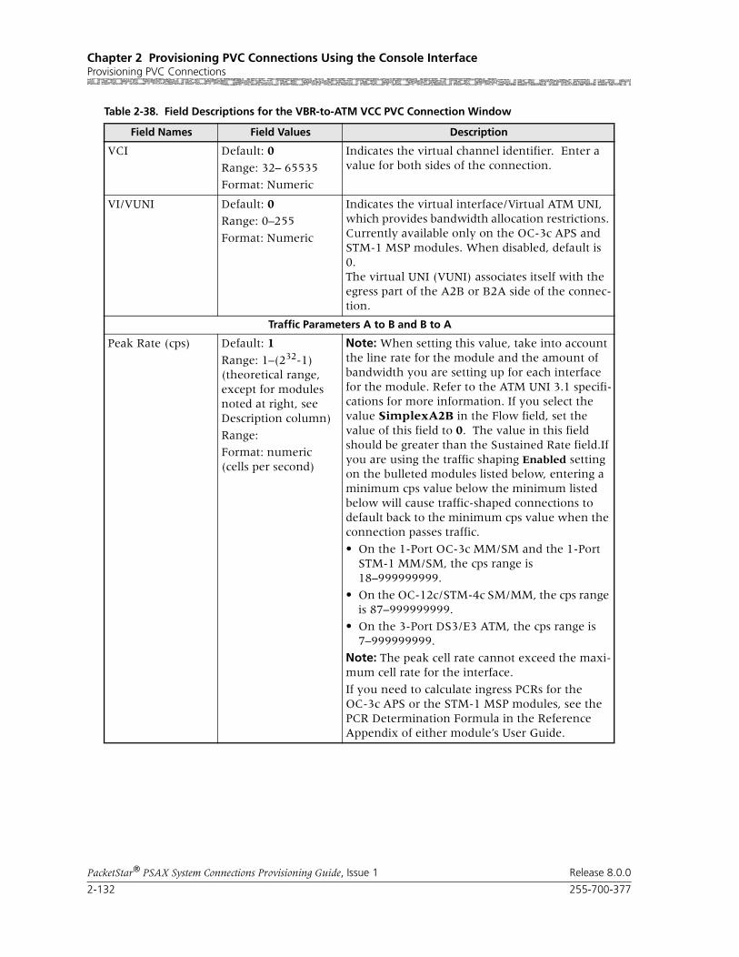
Chapter 2 Provisioning PVC Connections Using the Console InterfaceProvisioning PVC Connections
2-132 255-700-377
PacketStar® PSAX System Connections Provisioning Guide, Issue 1 Release 8.0.0
VCI Default: 0
Range: 32– 65535
Format: Numeric
Indicates the virtual channel identifier. Enter a value for both sides of the connection.
VI/VUNI Default: 0Range: 0–255
Format: Numeric
Indicates the virtual interface/Virtual ATM UNI, which provides bandwidth allocation restrictions. Currently available only on the OC-3c APS and STM-1 MSP modules. When disabled, default is 0.The virtual UNI (VUNI) associates itself with the egress part of the A2B or B2A side of the connec-tion.
Traffic Parameters A to B and B to A
Peak Rate (cps) Default: 1
Range: 1–(232-1)(theoretical range, except for modules noted at right, see Description column)
Range:
Format: numeric (cells per second)
Note: When setting this value, take into account the line rate for the module and the amount of bandwidth you are setting up for each interface for the module. Refer to the ATM UNI 3.1 specifi-cations for more information. If you select the value SimplexA2B in the Flow field, set the value of this field to 0. The value in this field should be greater than the Sustained Rate field.If you are using the traffic shaping Enabled setting on the bulleted modules listed below, entering a minimum cps value below the minimum listed below will cause traffic-shaped connections to default back to the minimum cps value when the connection passes traffic.
• On the 1-Port OC-3c MM/SM and the 1-Port STM-1 MM/SM, the cps range is 18–999999999.
• On the OC-12c/STM-4c SM/MM, the cps range is 87–999999999.
• On the 3-Port DS3/E3 ATM, the cps range is 7–999999999.
Note: The peak cell rate cannot exceed the maxi-mum cell rate for the interface.
If you need to calculate ingress PCRs for the OC-3c APS or the STM-1 MSP modules, see the PCR Determination Formula in the Reference Appendix of either module’s User Guide.
Table 2-38. Field Descriptions for the VBR-to-ATM VCC PVC Connection Window
Field Names Field Values Description

255-700-377 2-133
PacketStar® PSAX System Connections Provisioning Guide, Issue 1 Release 8.0.0
Chapter 2 Provisioning PVC Connections Using the Console InterfaceProvisioning PVC Connections
Sustained Rate (cps)
Default: 1
Range: 0–999999999
Format: cps
When setting this value, take into account the line rate for the module and the amount of band-width you are setting up for each interface for the module. Refer to the ATM UNI 3.1 specifications for more information. If you select the value SimplexA2B in the Flow field, set the value of this field to 0. The value in this field should be less than the Peak Rate field.
Max Burst Size (cells)
Default: 1
Range: 0–999999999
Format: cps
Maximum burst size. The maximum number of cells that can be received at the peak cell rate. This allows a burst of cells to arrive at a rate higher than that of the sustained cell rate. If the burst is larger than anticipated, the additional cells are either tagged or dropped. When setting this value, take into account the line rate for the module and the amount of bandwidth you are setting up for each interface for the module. Refer to the ATM UNI 3.1 specifications for more information.
If you select the value SimplexA2B in the Flow field, set the value of this field to 0.OC-3c APS Module: When the Traffic Shaping field is set to Enabled, the cell queue depth for the Max Burst Size field is internally set to 1000, regardless of the value you enter. If you enter values other than 1000, these values matter for incoming signalling SPVC/SVC setup from the remote end of the connection.
Traffic Shaping Default: Disabled
Range: As noted below.
Format: Predefined
Indicates the method for controlling the flow of data traffic. This feature is implemented on the following modules:
• 1-Port OC-3c Multimode and Single-Mode with Traffic Shaping modules
• 1-Port STM-1 Multimode and Single-Mode with Traffic Shaping modules
• 3-Port DS3/E3 ATM
• 1-Port OC-12c/STM-4c MM/SM 1+1 APS/MSP modules
See the Peak Rate field on this table for minimum cps ranges restrictions on these modules.
Disabled Indicates that traffic shaping is not done on the ATM side of the connection.
Enabled Ensures that the variable bit-rate (VBR) traffic entering the PSAX system via these modules complies with the parameters of the established service contracts.
Table 2-38. Field Descriptions for the VBR-to-ATM VCC PVC Connection Window
Field Names Field Values Description
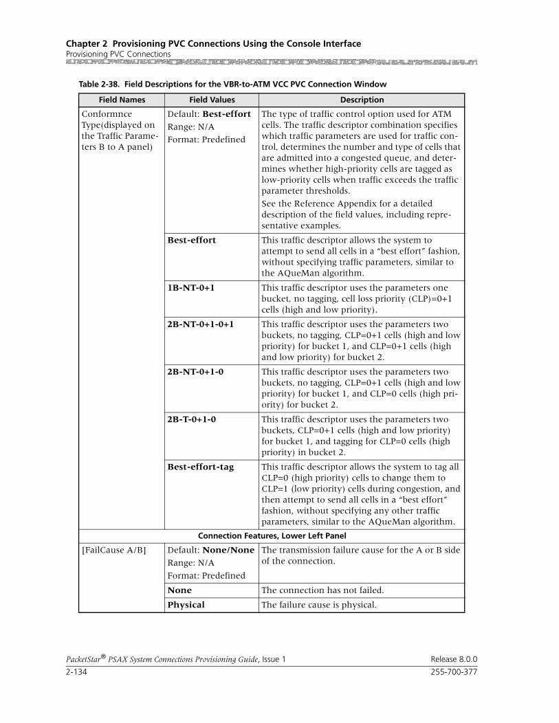
Chapter 2 Provisioning PVC Connections Using the Console InterfaceProvisioning PVC Connections
2-134 255-700-377
PacketStar® PSAX System Connections Provisioning Guide, Issue 1 Release 8.0.0
Conformnce Type(displayed on the Traffic Parame-ters B to A panel)
Default: Best-effort
Range: N/A
Format: Predefined
The type of traffic control option used for ATM cells. The traffic descriptor combination specifies which traffic parameters are used for traffic con-trol, determines the number and type of cells that are admitted into a congested queue, and deter-mines whether high-priority cells are tagged as low-priority cells when traffic exceeds the traffic parameter thresholds.
See the Reference Appendix for a detailed description of the field values, including repre-sentative examples.
Best-effort This traffic descriptor allows the system to attempt to send all cells in a “best effort” fashion, without specifying traffic parameters, similar to the AQueMan algorithm.
1B-NT-0+1 This traffic descriptor uses the parameters one bucket, no tagging, cell loss priority (CLP)=0+1 cells (high and low priority).
2B-NT-0+1-0+1 This traffic descriptor uses the parameters two buckets, no tagging, CLP=0+1 cells (high and low priority) for bucket 1, and CLP=0+1 cells (high and low priority) for bucket 2.
2B-NT-0+1-0 This traffic descriptor uses the parameters two buckets, no tagging, CLP=0+1 cells (high and low priority) for bucket 1, and CLP=0 cells (high pri-ority) for bucket 2.
2B-T-0+1-0 This traffic descriptor uses the parameters two buckets, CLP=0+1 cells (high and low priority) for bucket 1, and tagging for CLP=0 cells (high priority) in bucket 2.
Best-effort-tag This traffic descriptor allows the system to tag all CLP=0 (high priority) cells to change them to CLP=1 (low priority) cells during congestion, and then attempt to send all cells in a “best effort” fashion, without specifying any other traffic parameters, similar to the AQueMan algorithm.
Connection Features, Lower Left Panel
[FailCause A/B] Default: None/None
Range: N/A
Format: Predefined
The transmission failure cause for the A or B side of the connection.
None The connection has not failed.
Physical The failure cause is physical.
Table 2-38. Field Descriptions for the VBR-to-ATM VCC PVC Connection Window
Field Names Field Values Description

255-700-377 2-135
PacketStar® PSAX System Connections Provisioning Guide, Issue 1 Release 8.0.0
Chapter 2 Provisioning PVC Connections Using the Console InterfaceProvisioning PVC Connections
Service Type Default: Ubr
Range: N/A
Format: Predefined
Vbr-nrt2,Vbr-nrt1,Vbr-rt2,Vbr-rt1,Vbr-express
Multiservice Media Gateway system-supported quality of service (QoS) class.
See the section, “Quality of Service Classes for ATM Traffic,” in the Reference Appendix in the appropriate User Guide for a detailed description of the values for this field, including representa-tive examples.
Flow Default: Duplex
Range: N/A
Format: Predefined
Direction of the flow of data traffic in this con-nection.
When you select SimplexA2B or SimplexB2A, the fields in the Traffic Parameters B to A or the Traffic Parameters A to B panels, respectively, are not displayed.
Duplex Traffic flows back and forth between termination A and B.
SimplexA2B Traffic flows from termination A to B only.
SimplexB2A Traffic flows from termination B to A only.
SAR Type Default: AAL5Range: N/A
Format: Predefined
Indicates which Segmentation and Reassembly algorithm is used. SAR is used to convert larger unfilled packets to smaller filled packets before transmission, a process that conserves transmis-sion bandwidth. A packet size re-conversion pro-cess to the original packet size occurs at the receive end.
AAL5 VBR, connection-oriented, delay tolerant data.
AAL2Std Standard AAL2. VBR, delay-intolerant data with compression.
None No AAL layer parameters used.
Table 2-38. Field Descriptions for the VBR-to-ATM VCC PVC Connection Window
Field Names Field Values Description

Chapter 2 Provisioning PVC Connections Using the Console InterfaceProvisioning PVC Connections
2-136 255-700-377
PacketStar® PSAX System Connections Provisioning Guide, Issue 1 Release 8.0.0
4 To add (apply) the connection configuration, select the Add This Con-nection command and press Enter.
5 To review this connection, select the Go Back to Connection Table command and press Enter (or press Ctrl+B).
The VBR-to-ATM VCC PVC Table window (see Figure 2-41) is returned, displaying the values you just applied.
6 To add more connections of this type, repeat steps 2–5 for more connec-tions as needed.
7 To permanently save these connections, press Ctrl+G to return to the Console Interface Main Menu window.
OAM Status Default: Unsupp
Range: N/A
Range: Predefined
Indicates on what portion of the connection OAM cells (AIS, RDI) are processed.
Unsupp OAM is not supported.
End-Pt The PSAX system is used as a termination point for ATM traffic, and will process AIS/RDI cells.
The OAM loopback test is supported for end-to-end connections only.
Seg-Pt. Segment point. The A side will only respond to aintenance OAM cells and fault cells.
End-Seg-Pt End segment point, which has the characteristics of both an end point and a segment point.
Intermediate-Pt Side A will only generate AISs during local fail-ure.
Intra-Segment-Pt Connecting point with a segment. Generates end-to-end as well as segment flows.
[Backup PVC](display only)
Default: NoRange: No/Yes
Format: Predefined
This field displays whether or not the backup PVC is designated.
Yes The backup PVC is displayed if designated.
No The backup PVC is not designated.
[Conn Status] (dis-play only)
Default: Inactive
Range: Inactive/Active
Format: Predefined
Indicates whether or not the connection is trans-mitting traffic.
Inactive The connection is not transmitting traffic.
Active The connection is transmitting traffic.
Table 2-38. Field Descriptions for the VBR-to-ATM VCC PVC Connection Window
Field Names Field Values Description

255-700-377 2-137
PacketStar® PSAX System Connections Provisioning Guide, Issue 1 Release 8.0.0
Chapter 2 Provisioning PVC Connections Using the Console InterfaceProvisioning PVC Connections
8 Select Save Configuration, and press Enter to store the values to the PSAX system database.
End
Viewing the VBR-to-ATM Connection Statistics
From the VBR-to-ATM VCC PVC Connection window, select the View Con-nection Statistics command and press Enter.
The VBR-to-ATM VCC PVC Statistics window is displayed, as shown in Figure 2-43.
Commands The commands on this window have the following functions:
Field Descriptions The fields on this window are described in the following table.
Figure 2-43. VBR-to-ATM VCC PVC Statistics Window
Command Function
Reset Odometers Returns all statistics odometers to the value 0.
Continuous Update Updates the values in the fields every sec-ond.
Display Stats for Next Con-nection
Displays the statistics for the next selected connection.
Go Back to Connection Dis-play
Redisplays the connection window.

Chapter 2 Provisioning PVC Connections Using the Console InterfaceProvisioning PVC Connections
2-138 255-700-377
PacketStar® PSAX System Connections Provisioning Guide, Issue 1 Release 8.0.0
Table 2-39. Field Descriptions for the VBR-to-ATM VCC PVC Connection Statistics Window
Field Name Field Values Description
VBR Interface Panel
Slot Range: Varies depending on chassis type
Format: Numeric
Slot number of VBR interface
Port Range: Varies depending on module type
Format: Numeric
Port number of VBR interface
Channel Range: Varies depending on module type
Format: Numeric
Channel number on port of VBR interface.
Cells Encoded(display only)
Default: 0.0000 e0Range: N/A
Format: Exponent notation
Number of cells encoded going into interface side Aor B during the amount of time shown in Time Elapsed field since the circuit was established.
Cells Decoded(display only)
Default: 0.0000 e0
Range: N/A
Format: Exponent notation
Number of cells decoded going out of interface side A or B during the amount of time shown in Time Elapsed field since the circuit was estab-lished.
Encoded Odometer(display only)
Default: 0.0000 e0
Range: N/A
Format: Exponent notation
Total number of cells encoded going into inter-face side A or B since this counter was reset.
Decoded Odometer(display only)
Default: 0Range: N/A
Format: Exponent notation
Total number of cells decoded going out of inter-face side A or B since this counter was reset.
Time Elapsed(display only)
Default: 0
Range: N/A
Format: Numeric
Time elapsed since the circuit was established.
Time Since Reset(display only)
Default: 0
Range: N/A
Format: Numeric
Time elapsed since the last time the Reset Statistics command was used.
The Reset Statistics command on the statistics window resets only the odometer fields and the corresponding clock. Other counters increment for the life of the circuit.
ATM Interface Panel
AIS Rx/Tx(display only)
Default: 0
Range: N/A
Format: numeric
Number of alarm indication signal (AIS) cells received/transmitted.

255-700-377 2-139
PacketStar® PSAX System Connections Provisioning Guide, Issue 1 Release 8.0.0
Chapter 2 Provisioning PVC Connections Using the Console InterfaceProvisioning PVC Connections
Adding/Viewing a Backup PVC Connection Begin
Steps to Add/View a Backup VBR-to-ATM VCC PVC Connection
1 From the VBR-to-ATM VCC PVC Connection window, select the Add/View Backup PVC command.
The VBR to-ATM VCC PVC Backup Connection window is displayed (Figure Figure 2-44).
RDI Rx/Tx(display only)
Default: 0
Range: N/A
Format: numeric
Number of remote defect indicator signal (AIS) cells received/transmitted.
cell Drop/Tag(display only)
Default: 0Range: N/A
Format: numeric
Number of cells dropped/tagged.
Cells Received(display only)
Default: 0
Range: N/A
Format: exponent notation
Total number of cells received.
Cells Transmited(display only)
Default: 0
Range: N/A
Format: exponent notation
Total number of cells transmitted.
In Odometer(display only)
Default: 0
Range: N/A
Format: numeric
Total number of cells encoded going into inter-face side B since the connection statistics were reset.
Out Odometer(display only)
Default: 0Range: N/A
Format: exponent notation
Total number of cells decoded going out of inter-face side A since the connection statistics were reset.
Table 2-39. Field Descriptions for the VBR-to-ATM VCC PVC Connection Statistics Window
Field Name Field Values Description

Chapter 2 Provisioning PVC Connections Using the Console InterfaceProvisioning PVC Connections
2-140 255-700-377
PacketStar® PSAX System Connections Provisioning Guide, Issue 1 Release 8.0.0
Commands The commands on this window have the following functions:
Field Descriptions 2 The fields on this window are described in the following table.
Figure 2-44. VBR-to-ATM VCC PVC Statistics Window
Command Function
Add This Connection Adds connection entered on Backup ATM interface right panel.
Delete Connection Deletes backup connection.
Go Back to Primary PVC Connection
Returns to VBR-to-ATM VCC PVC Con-nection window.
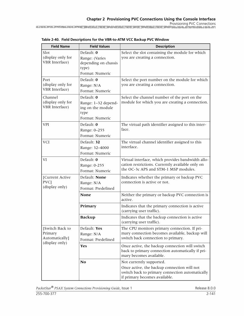
255-700-377 2-141
PacketStar® PSAX System Connections Provisioning Guide, Issue 1 Release 8.0.0
Chapter 2 Provisioning PVC Connections Using the Console InterfaceProvisioning PVC Connections
Table 2-40. Field Descriptions for the VBR-to-ATM VCC Backup PVC Window
Field Name Field Values Description
Slot(display only for VBR Interface)
Default: 0
Range: (Varies depending on chassis type)
Format: Numeric
Select the slot containing the module for which you are creating a connection.
Port(display only for VBR Interface)
Default: 0
Range: N/A
Format: Numeric
Select the port number on the module for which you are creating a connection.
Channel(display only for VBR Interface)
Default: 0
Range: 1–32 depend-ing on the module type
Format: Numeric
Select the channel number of the port on the module for which you are creating a connection.
VPI Default: 0Range: 0–255
Format: Numeric
The virtual path identifier assigned to this inter-face.
VCI Default: 32
Range: 32–4000
Format: Numeric
The virtual channel identifier assigned to this interface.
VI Default: 0
Range: 0-255
Format: Numeric
Virtual interface, which provides bandwidth allo-cation restrictions. Currently available only on the OC-3c APS and STM-1 MSP modules.
[Current Active PVC] (display only)
Default: NoneRange: N/A
Format: Predefined
Indicates whether the primary or backup PVC connection is active or not.
None Neither the primary or backup PVC connection is active.
Primary Indicates that the primary connection is active (carrying user traffic).
Backup Indicates that the backup connection is active (carrying user traffic).
[Switch Back to PrimaryAutomatically](display only)
Default: Yes
Range: N/A
Format: Predefined
The CPU monitors primary connection. If pri-mary connection becomes available, backup will switch back connection to primary.
Yes Once active, the backup connection will switch back to primary connection automatically if pri-mary becomes available.
No Not currently supported.
Once active, the backup connection will not switch back to primary connection automatically if primary becomes available.
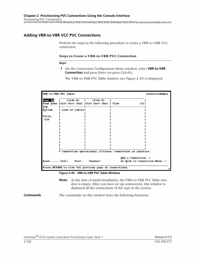
Chapter 2 Provisioning PVC Connections Using the Console InterfaceProvisioning PVC Connections
2-142 255-700-377
PacketStar® PSAX System Connections Provisioning Guide, Issue 1 Release 8.0.0
Adding VBR-to-VBR VCC PVC Connections
Perform the steps in the following procedure to create a VBR-to-VBR VCC connection.
Begin
Steps to Create a VBR-to-VBR PVC Connection
1 On the Connection Configuration Menu window, select VBR-to-VBR Connection and press Enter (or press Ctrl+O).
The VBR-to-VBR PVC Table window (see Figure 2-45) is displayed.
Note: At the time of initial installation, the VBR-to-VBR PVC Table win-dow is empty. After you have set up connections, this window is displayed all the connections of this type in the system.
Commands The commands on this window have the following functions:
Figure 2-45. VBR-to-VBR PVC Table Window

255-700-377 2-143
PacketStar® PSAX System Connections Provisioning Guide, Issue 1 Release 8.0.0
Chapter 2 Provisioning PVC Connections Using the Console InterfaceProvisioning PVC Connections
2 Select the Add a Connection command and press Enter (or press Ctrl+A).
The VBR-to-VBR PVC Connection window (see Figure 2-46) is dis-played.
Commands The commands on this window have the following functions:
Command Function
Find . . . To find a particular connection, enter val-ues in the Slot, Port, Channel, VPI, and VCI fields. If the connection exists, it will display on the first line of the table.
Add a Connection Displays the VBR-to-VBR PVC Connec-tion window.
Go Back to Connection Menu
Redisplays the Connection Configuration Menu window.
Figure 2-46. VBR-to-VBR PVC Connection Window
Command Function
Display Next Connection Displays the next connection of this type in the table.
Add This Connection Adds a connection having the values cur-rently displayed on the window.

Chapter 2 Provisioning PVC Connections Using the Console InterfaceProvisioning PVC Connections
2-144 255-700-377
PacketStar® PSAX System Connections Provisioning Guide, Issue 1 Release 8.0.0
Field Descriptions 3 The fields on this window are described in Table 2-41.
Delete Connection Deletes the connection having the values currently displayed on the window.
View Connection Statistics Displays the VBR-to-VBR PVC Statistics window.
Go Back to Connection Table
Redisplays the VBR-to-VBR PVC Table window.
Command Function
Table 2-41. Field Descriptions for the VBR-to-VBR PVC Connection Window
Field Names Field Values Description
VBR Interface A Default:
Range:
Format:
Side A of the connection that will send and receive signals.
VBR Interface B Side B of the connection that will send and receive signals.
Slot Variable depending on chassis type
Enter the slot number containing the module for which you are creating a connection. Enter slot numbers for both sides of the connection.
Port Range: 1–6 Enter the port number on the module for which you are creating a connection. Enter port num-bers for both sides of the connection.
Channel 1 Do not change the value 1 in this field.
Traffic Parameters A to B and B to A
Peak Rate (cps) Default: 1 When setting this value, take into account the line rate for the module and the amount of band-width you are setting up for each interface for the module. Refer to the ATM UNI 3.1 specifications for more information.
If you select the value SimplexA2B in the Flow field, set the value of this field to 0.
Sustained Rate (cps)
Default: 1 When setting this value, take into account the line rate for the module and the amount of band-width you are setting up for each interface for the module. Refer to the ATM UNI 3.1 specifications for more information.
If you select the value SimplexA2B in the Flow field, set the value of this field to 0.

255-700-377 2-145
PacketStar® PSAX System Connections Provisioning Guide, Issue 1 Release 8.0.0
Chapter 2 Provisioning PVC Connections Using the Console InterfaceProvisioning PVC Connections
4 To add (apply) the connection configuration, select the Add This Con-nection command and press Enter (or press Ctrl+A).
5 To review this connection, select the Go Back to Connection Table com-mand and press Enter (or press Ctrl+B).
The VBR-to-VBR PVC Table window is returned, displaying the values you just applied.
Max Burst Size (cells)
1 (default) Maximum burst size. The maximum number of cells that can be received at the peak cell rate. This allows a burst of cells to arrive at a rate higher than that of the sustained cell rate. If the burst is larger than anticipated, the additional cells are either tagged or dropped.
When setting this value, take into account the line rate for the module and the amount of band-width you are setting up for each interface for the module. Refer to the ATM UNI 3.1 specifications for more information.
If you select the value SimplexA2B in the Flow field, set the value of this field to 0.OC-3c APS Module: When the Traffic Shaping field is set to Enabled, the cell queue depth for the Max Burst Size field is internally set to 1000, regardless of the value you enter. If you enter values other than 1000, these values matter for incoming signalling SPVC/SVC setup from the remote end of the connection.
Connection Features, Lower Left Panel
[FailCause A/B](display only)
Default: Null/Null Presents the AAL2 status reason code for both sides of the connection
Flow Default: Duplex, SimplexA2B
Direction of the flow of data traffic in this con-nection.
Note: When you select SimplexA2B, the fields in the Traffic Parameters B to A panel do not dis-play.
Service Type Ubr (default)
Vbr-nrt2,Vbr-nrt1,Vbr-rt2,Vbr-rt1,Vbr-express
Multiservice Media Gateway system-supported quality of service (QoS) class. See the section, “Quality of Service Classes for ATM Traffic,” in the appendix.
[Conn Status]
(display only)
Inactive, Active This field displays the current status of the con-nection. The value indicates whether the con-nection is passing traffic.
Table 2-41. Field Descriptions for the VBR-to-VBR PVC Connection Window
Field Names Field Values Description

Chapter 2 Provisioning PVC Connections Using the Console InterfaceProvisioning PVC Connections
2-146 255-700-377
PacketStar® PSAX System Connections Provisioning Guide, Issue 1 Release 8.0.0
6 To add more connections of this type, repeat steps 2–5 for more connec-tions as needed.
7 To permanently save these connections, press Ctrl+G to return to the Console Interface Main Menu window.
8 Select Save Configuration and press Enter (or press Ctrl+A) to store the values to the PSAX system database.
End
Begin
Viewing VBR-to-VBR PVC Statistics
1 From the VBR-to-VBR PVC Connection window, select the View Con-nection Statistics command.
The VBR-to-VBR PVC Statistics window is displayed, as shown in Figure 2-47.
Commands The commands on this window have the following functions:
Figure 2-47. VBR-to-VBR PVC Statistics Window
Command Function
Reset Odometers Returns all statistics odometers to zero.
Continuous Update Updates the values in the fields every sec-ond.

255-700-377 2-147
PacketStar® PSAX System Connections Provisioning Guide, Issue 1 Release 8.0.0
Chapter 2 Provisioning PVC Connections Using the Console InterfaceProvisioning PVC Connections
Field Descriptions The fields on this window are described in Table 2-42.
Display Stats for Next Connection
Displays the statistics for the next selected connection.
Go Back to Connection Display
Redisplays the connection window.
Command Function
Table 2-42. Field Descriptions for the VBR-to-VBR PVC Connection Statistics Window
Field Name Field Values Description
Cells Encoded(display only)
Default: 0
Range: N/A
Format: numeric
Displays the number of cells encoded going in interface side A or B during the amount of time shown in Time Elapsed field (that is, since the cir-cuit was created).
Cells Decoded(display only)
Default: 0
Range: N/A
Format: numeric
Displays the number of cells decoded going out interface side A or B during the amount of time shown in Time Elapsed field (that is, since the cir-cuit was created).
Encoded Odometer(display only)
Default: 0Range: N/A
Format: numeric
Displays the total number of cells encoded going in interface side A or B since the connection was created.
Decoded Odometer(display only)
Default: 0
Range: N/A
Format: numeric
Displays the total number of cells decoded going out interface side A or B since the connection was created.
Time Elapsed(display only)
Default: 00:00:00
Range: N/A
Format: numeric
Displays the time elapsed since the circuit was established.
Time Since Reset(display only)
Default: 00:00:00Range: N/A
Format: numeric
Displays the time elapsed since the last time the Reset Odometers command was used.
Note: The Reset Odometers command on the statistics window resets only the odometer fields and the corresponding clock. Other counters increment for the life of the connection.
Chapter 2 Provisioning PVC Connections Using the Console InterfaceProvisioning PVC Connections
2-148 255-700-377
PacketStar® PSAX System Connections Provisioning Guide, Issue 1 Release 8.0.0

PacketStar® PSAX System Connections Provisioning Guide, Issue 1 Release 8.0.0
255-700-377 3-1
3 Provisioning SPVC ConnectionsUsing the Console Interface
Overview of This Chapter
This chapter describes how to set up permanent virtual circuit (PVC), switched virtual circuit (SVC), and soft permanent virtual circuit (SPVC) con-nections in the PSAX system for service provisioning and how to view statis-tics data for billing and performance monitoring. Before you provision con-nections for this module, you must have first completed the following tasks, which are detailed in the appropriate PacketStar PSAX Module Guide:
• Setting the configuration values for one or more ports
• Setting the configuration values for the types of interfaces you want to use on this module
This chapter contains instructions for configuring the following types of con-nections, with the exception of the PVC and the SVC supporting the GR-303 Interface.
Note: For instructions on configuring a GR-303 interface group on an I/O module, see the application note entitled PacketStar® PSAX Config-uring the GR-303 Voice Gateway User Guide, Issue 3
Before you can provision connections, you must select an interface type value other than Unconfigured in the Interface Type field on the Enhanced DS1 Port and Channel Configuration window.
Connection Types Supported
The PSAX I/O modules support at least one the following connection types:
• PVC connections
• SVC connections
Note: SVC connections are not directly configurable on a PSAX system. Configure them through an interface with a call controller, such as the Lucent Softswitch–T3 (Toll/Tandem/ Transit), a 7R/E™, or a ConnectStar™ Interworking Call Router. Call controllers send call setup information to the PSAX System. See the section, “Enabling SVCs Connections.”
• SPVC connections
For a matrix of connection types by interface types, see the Connection Types by Interface Types table in the appendix, “Reference Information.”
Connection Types by Interface Type

Chapter 3 Provisioning SPVC Connections Using the Console InterfaceSPVC Reconnection Prioritization for IMA Interfaces
3-2 255-700-377
PacketStar® PSAX System Connections Provisioning Guide, Issue 1 Release 8.0.0
For a matrix of connection types by interface types, see the Connection Types by Interface Types table in the appendix, “Reference Information.”
Connections With I/O Modules for Compressed Voice Begin
Using Compressed Voice with I/O Module Connections
Connections from the DSP2x Voice Server modules to the 8-Port Voice 2-Wire Station module are not directly supported. To use compressed voice with the 8-Port Voice 2-Wire Station and the 6-Port Enhanced DS1/T1 Multi-service modules, perform the steps in the following procedure.
1 On the Console Interface Main Menu, select the Connection Configura-tion option and press Enter.
2 Provision a connection from the 8-Port Voice 2-Wire Station module to the Enhanced DS1 module.
3 Use a short loopback cable between two ports on the 6-Port Enhanced DS1/T1 Multiservice module to a DSP2x Voice Server module.
4 For this connection, turn echo cancellation off on a DSP2x Voice Server module.
Note: When using the DSP2x Voice Server module with the 6-Port Enhanced DS1/T1 Multiservice module, the analog levels at the T1/E1 access from the customer premises equipment (CPE) must be set to the value -10dBm.
End
SPVC Reconnection Prioritization for IMA Interfaces
Setting the SPVC prioritization on an IMA link comprises the following major tasks.
1. Planning how many of each SPVC trunk types you need and what their assigned priority levels will be
You need to allocate call control resources according to this plan. When you set up the PSAX systemwide prioritization scheme, this configura-tion allows up to 32 SPVC trunk connections in one IMA group per chas-sis, with 247 CIDs in each SPVC trunk. If you are using more than one SPVC type, determine the priority level you want to assign to each type. You can assign priority level 1 to 6, with level 1 having the highest prior-ity and level 6 having the lowest priority.
2. Configuring the 6-Port DS1 IMA module with only one IMA group

255-700-377 3-3
PacketStar® PSAX System Connections Provisioning Guide, Issue 1 Release 8.0.0
Chapter 3 Provisioning SPVC Connections Using the Console InterfaceSPVC Reconnection Prioritization for IMA Interfaces
The 6-Port DS1 IMA module has the capacity for being configured for three groups; however, you should configure only one group when set-ting up your PSAX system for wireless backhaul. See the PacketStar PSAX 6-Port DS1 IMA Module User Guide for information on configuring this module.
3. Changing the call control resource allocation configuration for on the PSAX system and enabling the priority scheme on the Call Control Resource Allocation Configuration window.
4. Setting the priority code for ATM AAL2 trunking for SPVCs on the ATM Trunking Bearer VCC Configuration window. The priority code set up on this window applies to connections created on the CE-to-ATM Standard AAL2 VCC SPVC Connection window.
Setting Up Call Control Resource Allocations
The following call control resource allocation configuration applies to the base station only. To set up the SPVC reconnection prioritization, perform the following procedure.
Begin
Setting Parameters for Call Control Resources
1 To access the Call Control Resource Allocation Configuration window, follow this path:
Console Interface Main Menu window –> select the Site-Specific Config-uration option –> Site-Specific Menu window –> select the Call Control Resource Allocation Configuration option –> Call Control Resource Allo-cation Configuration window (see Figure 3-1)

Chapter 3 Provisioning SPVC Connections Using the Console InterfaceSPVC Reconnection Prioritization for IMA Interfaces
3-4 255-700-377
PacketStar® PSAX System Connections Provisioning Guide, Issue 1 Release 8.0.0
The commands on this window perform the following functions:
2 On the window in Fix x, change the fields highlighted in light gray to the values indicated on the window. The sum of all call fields should not fields in should not exceed 32.
3 Change the fields highlighted in dark gray to the values indicated on the window.
4 Enter the value 0 for all other fields.
See the descriptions of the commands and fields at the end of this proce-dure for more information.
Note: In an existing PSAX system with configured SVCs and SPVCs, setting the fields to the value 0 deletes all SVCs and SPVCs from the system.
5 In the spvcGlobalPriorityScheme field, select the value Enabled.
6 Select the Apply Configuration command. The status line on the win-dow will display:
Need to save configuration and reboot system to take effect.
Figure 3-1. Call Control Resource Allocation Configuration Window
Command Function
Apply Configuration Applies the values you entered on this window.
Go Back to Site-Specific Menu
Redisplays the Site-Specific Menu win-dow.

255-700-377 3-5
PacketStar® PSAX System Connections Provisioning Guide, Issue 1 Release 8.0.0
Chapter 3 Provisioning SPVC Connections Using the Console InterfaceSPVC Reconnection Prioritization for IMA Interfaces
7 Press Ctrl+G to return to the Console Interface Main Menu window.
8 select the Save Configuration (modified) command.
9 To reboot the chassis to reset the system to the new call control resource parameters, follow this path:
• From the Console Interface Main Menu window, select the Diagnostics option
• On the Diagnostics Menu window, select the Reboot Hardware Compo-nents option Remote Reboot Configuration window
• On the Remote Reboot Configuration window, select the Reboot Chassis command.
The PSAX system reboots.
The descriptions of the commands and fields on the Call Control Resource Allocation Configuration window are provided in the following tables.
Table 3-1. Field Descriptions for the Call Control Resource Allocation Configuration Window
Field Name Field Values Description
Note: The ranges of values for numeric fields are software imposed. Read the configuration guide-lines and the PSAX System Performance Capabilities per Node table in the preceding section before you enter values in the fields on this window.
svcPtToPtCalls Default: 002000Range: 0–15000
Format: numeric
Specifies the maximum number of SVC point-to-point calls to be supported by the PSAX system.
svcPtToMultiPtCalls
Default: 002000
Range: 0–4000
Format: numeric
Specifies the maximum number of SVC point-to-mul-tipoint calls to be supported by the PSAX system.
svcPtToMultiPtParties
Default: 002000
Range: 0–4000
Format: numeric
Specifies the maximum number of parties on SVC point-to-multipoint calls to be supported by the PSAX system.
spvcCePtToPtCalls Default: 001000Range: 0–10000
Format: numeric
Specifies the maximum number of SPVC circuit emu-lation point-to-point calls to be supported by the PSAX system.
Note: The total of all call fields and atmTrunkVccs can-not exceed 32 when the spvcGlobalPriorityScheme field is Enabled.
spvcTePtToPtCalls Default: 000100Range: 0–10000
Format: numeric
Specifies the maximum number of SPVC terminal emulation point-to-point calls to be supported by the PSAX system.
Note: The total of all call fields and atmTrunkVccs can-not exceed 32 when the spvcGlobalPriorityScheme field is Enabled.

Chapter 3 Provisioning SPVC Connections Using the Console InterfaceSPVC Reconnection Prioritization for IMA Interfaces
3-6 255-700-377
PacketStar® PSAX System Connections Provisioning Guide, Issue 1 Release 8.0.0
spvcAtmPtToPtCalls Default: 002000
Range: 0–10000
Format: numeric
Specifies the maximum number of SPVC ATM point-to-point calls to be supported by the PSAX system.
Note: The total of all call fields and atmTrunkVccs can-not exceed 32 when the spvcGlobalPriorityScheme field is Enabled.
spvcFRPtToPtCalls Default: 000900
Range: 0–10000
Format: numeric
Specifies the maximum number of SPVC frame relay point-to-point calls to be supported by the PSAX sys-tem.
spvcPtToMultiPtCalls
Default: 000500
Range: 0–500
Format: numeric
Specifies the maximum number of SPVC point-to-mul-tipoint calls to be supported by the PSAX system.
spvcPtToMultiPtParties
Default: 001000Range: 0–1000
Format: numeric
Specifies the maximum number of parties on SPVC point-to-multipoint calls to be supported by the PSAX system.
aal2CirAtmSpvcVccCalls
Default: 001000
Range: 0–4000
Format: numeric
Specifies the maximum number of circuit emulation-to-ATM standard AAL2 SPVC calls to be supported by the PSAX system.
aal2VbrAtmSpvcVccCalls
Default: 000100
Range: 0–4000
Format: numeric
Specifies the maximum number of VBR-to-ATM stan-dard AAL2 SPVC calls to be supported by the PSAX system.
sgApiCirEmEndPts Default: 001000Format: numeric
Specifies the maximum number of circuit emulation endpoints for the Connection Gateway API to be sup-ported by the PSAX system.
sgApiAtmSvcEndPts
Default: 000000
Format: numeric
Specifies the maximum number of ATM SVC end-points for the Connection Gateway API to be sup-ported by the PSAX system.
sgApiPtToPtSvcCalls
Default: 000000
Format: numeric
Specifies the maximum number of SVC point-to-point calls for the Connection Gateway API to be supported by the PSAX system.
sgApiPtToMultiPtSvcCalls
Default: 000000Format: numeric
Specifies the maximum number of SVC point-to-mul-tipoint calls for the Connection Gateway API to be sup-ported by the PSAX system.
sgApiPtToMultiPtParties
Default: 000000
Format: numeric
Specifies the maximum number of parties on SVC point-to-multipoint calls for the Connection Gateway API to be supported by the PSAX system.
Table 3-1. Field Descriptions for the Call Control Resource Allocation Configuration Window (Continued)
Field Name Field Values Description

255-700-377 3-7
PacketStar® PSAX System Connections Provisioning Guide, Issue 1 Release 8.0.0
Chapter 3 Provisioning SPVC Connections Using the Console InterfaceSPVC Reconnection Prioritization for IMA Interfaces
atmTrunkVccs Default: 000100
Range: 1–1024
Range: 1–4096
Format: numeric
Specifies the maximum number of VCCs supported by ATM trunking.
SPVC Priority Configurations: The total of all call fields and atmTrunkVccs cannot exceed 32 when the spvcGlobalPriorityScheme field is Enabled.
V5.2 Applications: You can enter up to the value 4096. If you enter 4096, be sure that you have first freed enough resources in other fields in order to enter a high value in the atmTrunkVccs field.
atmTrunkNarrowBandCalls
Default: 001000Range: 1–4000
Format: numeric
Specifies the maximum number of switched narrow-band calls supported by ATM trunking.
[callContrlResAllocUsage %](display only)
Default: 0098
Range: 0–100
Format: numeric
Displays the percentage of memory allocated to call control. A portion of the total system memory is allo-cated for call control. The value in this field represents the amount of this allocation that is currently in use. This percentage value is calculated by the system from the values you enter in the other fields.
cgSvcCutThroughOption
Default: cgSvcAcImplicitCutThroughRange: N/A
Format: predefined alphanumeric
Specifies whether the PSAX system or the connection gateway device (connection manager) sends a cut-through message to initiate an SVC connection.
Note: The value in this field is not operational if you do not have the Connection Gateway API feature enabled.
cgSvcAcImplicitCutThrough
Indicates that the PSAX system sends a cut-through message to the connection gateway device to initiate an SVC connection.
cgSvcAcExplicitCutThrough
Indicates that the connection gateway device deter-mines when to send a cut-through message to the con-nection manager to initiate an SVC connection.
Note: You must use this value if you are using the H.248 Media Gateway Control protocol feature.
spvcGlobalPriorityScheme
Default: DisabledRange: N/A
Format: predefined alphanumeric
Specifies whether the PSAX systemwide priority scheme must be supported for all SPVCs and SPVC trunks.
Disabled Indicates that the priority scheme is not in force (dis-abled).
Enabled Indicates that the priority scheme is in force (enabled).
Note: For SPVC reconnections in priority scheme-enabled trunks in an IMA link, the limit is 32 SPVCs.
Table 3-1. Field Descriptions for the Call Control Resource Allocation Configuration Window (Continued)
Field Name Field Values Description

Chapter 3 Provisioning SPVC Connections Using the Console InterfaceSPVC Reconnection Prioritization for IMA Interfaces
3-8 255-700-377
PacketStar® PSAX System Connections Provisioning Guide, Issue 1 Release 8.0.0
End
Setting Up an ATM AAL2 SPVC Trunk
To set up an ATM AAL2 SPVC trunk for SPVC prioritization, perform the fol-lowing procedures.
Begin
Configuring the Local Node
1 To access the ATM Trunking Local Node Configuration window, follow this path:
Console Interface Main Menu window –> select the Site-Specific Config-uration option –> Site-Specific Menu window –> select the ATM Trunk-ing Configuration option –> ATM Trunking Local Node Configuration window (see Figure 3-2)
2 Enter the local IWF ID, the ATM Address, and the maximum number of remote IWFs. See the descriptions of the commands and fields at the end of this procedure for more information.
3 Select the Go to Remote IWF Table command.
The ATM Trunking Remote IWF Table window is displayed (see Figure 3-3 in the next procedure).
The descriptions of the commands and fields on the ATM Trunking Local Node Configuration window are provided in the following tables.
Figure 3-2. ATM Trunking Local Node Configuration Window

255-700-377 3-9
PacketStar® PSAX System Connections Provisioning Guide, Issue 1 Release 8.0.0
Chapter 3 Provisioning SPVC Connections Using the Console InterfaceSPVC Reconnection Prioritization for IMA Interfaces
Command Function
Apply Configuration Applies the values you set on this win-dow.
Bring Admin Status Up Enables the transmission of calls between the configured local IWF node and the remote IWF nodes.
Bring Admin Status Down Disables the transmission of calls between the local IWF node and the remote IWF nodes while preserving local and remote node configuration settings.
Delete Node Deletes the configuration settings of the local IWF node that is not in service. You must use the Bring Admin Status Down command before you can use the Delete Node command.
Go to Remote IWF Table Displays the ATM Trunking Remote IWF Table window.
Go to Broadband Routing Table
Displays the ATM Trunking Broadband Routing Table window.
Go to Narrowband Routing Table
Displays the ATM Trunking Narrowband Routing Table window.
Go Back to Site-Specific Menu
Redisplays the Site-Specific Menu win-dow.

Chapter 3 Provisioning SPVC Connections Using the Console InterfaceSPVC Reconnection Prioritization for IMA Interfaces
3-10 255-700-377
PacketStar® PSAX System Connections Provisioning Guide, Issue 1 Release 8.0.0
End
Table 3-2. Field Descriptions for the ATM Trunking Local Node Configuration Window
Field Name Field Values Description
Local IWF ID Default: 0
Range: 1–255
Format: numeric
Specifies the local interworking function (IWF) identifier for the local endpoint.
Wireless Applications: The Cell Site and the MSC must have different IDs. The Cell site is the local IWF; the MSC is the remote.
ATM Address Default: 0
Range: N/A
Format: valid dotted quad
Specifies the IWF ATM address for the local end-point. Type an address in hexadecimal format up to 20 bytes (160 bits) long (10 groups of 4 charac-ters each).
Wireless Applications: The Cell Site and MSC must have different addresses.
Max Remote IWF Default: 100Range: 1–1024
Format: numeric
Specifies the maximum number of remote IWF IDs that can be connected to the local endpoint in the PSAX system. If you enter a value higher than the default value in this field, you must also increase the value of the atmTrunkVCCs field on the Call Control Resource Allocation window accordingly
Wireless Applications: For the Cell Site to MSC applications, the MSC is the remote IWF.
[Admin Status](display only)
Default: UpRange: N/A
Format: predefined alphanumeric
Specifies whether the local IWF is active.
Up Indicates that the local IWF is active.
Down Indicates that the local IWF is inactive.

255-700-377 3-11
PacketStar® PSAX System Connections Provisioning Guide, Issue 1 Release 8.0.0
Chapter 3 Provisioning SPVC Connections Using the Console InterfaceSPVC Reconnection Prioritization for IMA Interfaces
Begin
Configuring the Remote IWF Identifier
1 Select the Add Remote IWF Entry command.
The ATM Trunking Remote IWF Configuration window is displayed (see Figure 3-4).
Figure 3-3. ATM Trunking Remote IWF Table Window

Chapter 3 Provisioning SPVC Connections Using the Console InterfaceSPVC Reconnection Prioritization for IMA Interfaces
3-12 255-700-377
PacketStar® PSAX System Connections Provisioning Guide, Issue 1 Release 8.0.0
2 Enter the remote IWF ID, the remote IWF ATM address, and the value Switched in the Remote IWF Trnk Mode field. See the descriptions of the commands and fields at the end of this procedure for more informa-tion.
3 Select the Add Configuration command.
The window now displays the following additional commands on the lower right side of the window: Go to Sig VCC Table, Go to Bearer VCC Table, and Go to Data Channel Table.
Note: You can view this remote IWF ID (and all the remote IWF IDs currently on the system) on the ATM Trunking Remote IWF Table window (see Figure 3-3) by selecting the Go Back to Pre-vious Screen command.
4 Select the Go to Bearer VCC Table command.
The ATM Trunking Bearer VCC Table window is displayed (see Figure 3-5 in the next procedure).
The descriptions of the commands and fields on the ATM Trunking Remote IWF Configuration window are provided in the following tables.
Figure 3-4. ATM Trunking Remote IWF Configuration Window
Command Function
Add Configuration Applies the values you set on this win-dow.
Update Configuration This command is not currently supported.

255-700-377 3-13
PacketStar® PSAX System Connections Provisioning Guide, Issue 1 Release 8.0.0
Chapter 3 Provisioning SPVC Connections Using the Console InterfaceSPVC Reconnection Prioritization for IMA Interfaces
Bring Admin Status Up When the value in the [Admin Status] field is Down, brings the remote IWF node to the status Up.
Bring Admin Status Down When the value in the [Admin Status] field is Up, brings the remote IWF node to the status Down.
Delete and Return Deletes the remote IWF node that is not in service.
Go to Sig VCC Table This command is not currently supported.
Displays the ATM Trunking Sig VCC Table window. This command is displayed only after you have added a remote IWF ID.
Go to Bearer VCC Table Displays the ATM Trunking Bearer VCC Table window. This command is displayed only after you have added a remote IWF ID.
Go to Data Channel Table Displays the ATM Trunking Data Channel Table window. This command is displayed only after you have added a remote IWF ID.
Go Back to Previous Screen Redisplays the ATM Trunking Remote IWF Table window
Command Function
Table 3-3. Field Descriptions for the ATM Trunking Remote IWF Configuration Window
Field Name Field Values Description
Remote IWF ID Default: 0
Range: 1–1024
Format: numeric
Specifies the remote interworking function (IWF) identifier for the remote endpoint. The value in this field must be less than the value for the max-imum number of remote IWFs in the PSAX sys-tem. You specify the maximum number of IWFs on the ATM Trunking Local Node Configuration window.
Remote IWF ATM Address
Default: 0
Range: N/A
Format: hexadecimal
Specifies the IWF ATM address for the remote endpoint. Type an address in hexadecimal format up to 20 bytes (160) bits long (10 groups of 4 characters each).Wireless Applications: If configuring a cell site with an MSC, the MSC is the remote IWF.

Chapter 3 Provisioning SPVC Connections Using the Console InterfaceSPVC Reconnection Prioritization for IMA Interfaces
3-14 255-700-377
PacketStar® PSAX System Connections Provisioning Guide, Issue 1 Release 8.0.0
End
Remote IWF Trnk Mode
Default: Switched
Range: N/A
Format: predefined alphanumeric
Specifies whether the remote IWF trunk is in switched mode or non-switched mode.Currently only the nonswitched mode is sup-ported.
Switched This mode is currently not supported. Indicates that the specified signaling VCC is used for the connection trunk.
Non-switched Indicates that no signaling is used for the connec-tion trunk.Wireless Applications: If configuring a cell site with an MSC, select this value.
[Admin Status](display only)
Default: UpRange: N/A
Format: predefined alphanumeric
Specifies whether the remote IWF is active.
Up Indicates that the remote IWF is active.
Down Indicates that the remote IWF is inactive.
Table 3-3. Field Descriptions for the ATM Trunking Remote IWF Configuration Window
Field Name Field Values Description
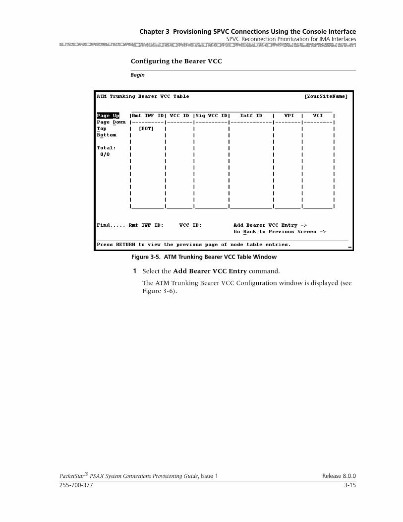
255-700-377 3-15
PacketStar® PSAX System Connections Provisioning Guide, Issue 1 Release 8.0.0
Chapter 3 Provisioning SPVC Connections Using the Console InterfaceSPVC Reconnection Prioritization for IMA Interfaces
Begin
Configuring the Bearer VCC
1 Select the Add Bearer VCC Entry command.
The ATM Trunking Bearer VCC Configuration window is displayed (see Figure 3-6).
Figure 3-5. ATM Trunking Bearer VCC Table Window

Chapter 3 Provisioning SPVC Connections Using the Console InterfaceSPVC Reconnection Prioritization for IMA Interfaces
3-16 255-700-377
PacketStar® PSAX System Connections Provisioning Guide, Issue 1 Release 8.0.0
2 Enter Spvc in the VCC Conn Type field, Spvc in the Apply Type field, and the desired priority level in the Priority field. For information on entering values in the fields, see the descriptions of the commands and fields provided at the end of this procedure.
3 Select the Add Configuration command.
The bearer VCC ID is added to the system
4 Select the Configure DSP Parameters command.
The ATM Trunking Bearer VCC Parameters window is displayed (see Figure 3-7).
Figure 3-6. ATM Trunking Bearer VCC Configuration Window

255-700-377 3-17
PacketStar® PSAX System Connections Provisioning Guide, Issue 1 Release 8.0.0
Chapter 3 Provisioning SPVC Connections Using the Console InterfaceSPVC Reconnection Prioritization for IMA Interfaces
5 Enter values in the fields. See the descriptions of the commands and fields at the end of this procedure for more information.
6 Select the Add Configuration command.
7 Repeat the procedures, “Configuring the Remote IWF Identifier” and “Configuring the Bearer VCC”, in this section as many times as needed to set up as many ATM AAL2 SPVC trunks as needed.
The descriptions of the commands and fields on the ATM Trunking Bearer VCC Configuration window are provided in the following tables.
Figure 3-7. ATM Trunking Bearer VCC Parameters Window
Command Function
Add Configuration Applies the values you set on this win-dow.
Delete Configuration Deletes the configuration.
Restart Connection Restarts the connection.
Display Next Connection Displays the next connecion.
Continuous Update Continuously update the window data every ___ msec.
Configure DSP Parameters Configures DSP parameters.
Note: If DSP parameters are configured on a per connection basis, the settings on this window are overridden by the applicable per connection configuration.
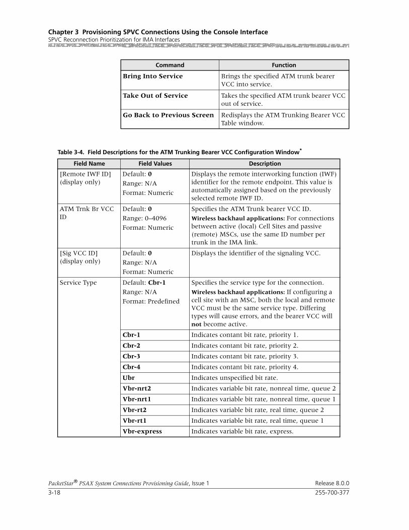
Chapter 3 Provisioning SPVC Connections Using the Console InterfaceSPVC Reconnection Prioritization for IMA Interfaces
3-18 255-700-377
PacketStar® PSAX System Connections Provisioning Guide, Issue 1 Release 8.0.0
Bring Into Service Brings the specified ATM trunk bearer VCC into service.
Take Out of Service Takes the specified ATM trunk bearer VCC out of service.
Go Back to Previous Screen Redisplays the ATM Trunking Bearer VCC Table window.
Command Function
Table 3-4. Field Descriptions for the ATM Trunking Bearer VCC Configuration Window*
Field Name Field Values Description
[Remote IWF ID](display only)
Default: 0
Range: N/A
Format: Numeric
Displays the remote interworking function (IWF) identifier for the remote endpoint. This value is automatically assigned based on the previously selected remote IWF ID.
ATM Trnk Br VCC ID
Default: 0Range: 0–4096
Format: Numeric
Specifies the ATM Trunk bearer VCC ID.
Wireless backhaul applications: For connections between active (local) Cell Sites and passive (remote) MSCs, use the same ID number per trunk in the IMA link.
[Sig VCC ID](display only)
Default: 0Range: N/A
Format: Numeric
Displays the identifier of the signaling VCC.
Service Type Default: Cbr-1
Range: N/A
Format: Predefined
Specifies the service type for the connection.
Wireless backhaul applications: If configuring a cell site with an MSC, both the local and remote VCC must be the same service type. Differing types will cause errors, and the bearer VCC will not become active.
Cbr-1 Indicates contant bit rate, priority 1.
Cbr-2 Indicates contant bit rate, priority 2.
Cbr-3 Indicates contant bit rate, priority 3.
Cbr-4 Indicates contant bit rate, priority 4.
Ubr Indicates unspecified bit rate.
Vbr-nrt2 Indicates variable bit rate, nonreal time, queue 2
Vbr-nrt1 Indicates variable bit rate, nonreal time, queue 1
Vbr-rt2 Indicates variable bit rate, real time, queue 2
Vbr-rt1 Indicates variable bit rate, real time, queue 1
Vbr-express Indicates variable bit rate, express.

255-700-377 3-19
PacketStar® PSAX System Connections Provisioning Guide, Issue 1 Release 8.0.0
Chapter 3 Provisioning SPVC Connections Using the Console InterfaceSPVC Reconnection Prioritization for IMA Interfaces
SAR Type Default: Aal2
Range: N/A
Format: Predefined
Specifies the segmentation and reassembly type for the connection.
Aal2 Indicates that compressed, connection-oriented, delay-sensitive VBR traffic will be transmitted on this connection.
Wireless backhaul applications: Select this SAR Type for connections between cell sites and MSCs on both sides of the connection.
Aal1 Indicates that uncompressed, connection-ori-ented, time-sensitive CBR traffic will be transmit-ted on this connection.
Fwd/Bwd PCR (cps)
Default: 172 (Fwd and Bwd)
Range:
Format: Numeric (cells per second)
Specifies the forward and backward peak cell rate (cells per second) for the connection.
Wireless backhaul applications: This value must be the same on the local and remote VCC or the bearer VCC will not become active.
Fwd/Bwd SCR (cps)
Default: 172 (Fwd and Bwd)
Range:
Format: Numeric (cells per second)
Specifies the forward and backward sustained cell rate (cells per second) for the connection.
Note: This field is displayed only when the value in the Service Type field is one of the following: Vbr-nrt2, Vbr-nrt1, Vbr-rt2, Vbr-rt1, Vbr-express.
Fwd/Bwd MBS (cells)
Default: 172 (Fwd and Bwd)
Range:
Format: Numeric (cells)
Specifies the forward and backward maximum burst size (cells) for the connection.
Note: This field is displayed only when the value in the Service Type field is one of the following: Vbr-nrt2, Vbr-nrt1, Vbr-rt2, Vbr-rt1, Vbr-express.
Table 3-4. Field Descriptions for the ATM Trunking Bearer VCC Configuration Window* (Continued)
Field Name Field Values Description

Chapter 3 Provisioning SPVC Connections Using the Console InterfaceSPVC Reconnection Prioritization for IMA Interfaces
3-20 255-700-377
PacketStar® PSAX System Connections Provisioning Guide, Issue 1 Release 8.0.0
OAM Status Default: Unsupp
Range: N/A
Format: Predefined
Specifies the OAM support used.
Unsupp Indicates that OAM is not in use.
Wireless backhaul applications: The CID range is 8 to 255 when OAM is unsupported.
GR-303/V.5 applications: Select this value. Do not activate OAM; the feature is not available on AAL2 trunks to IADs.
End-Pt The PSAX system is used as a termination point for ATM traffic.
The OAM loopback test is supported for end-to-end connections only.
Wireless backhaul applications: Select End-Pt to enable OAM for Std AAL2 SPVCs. However, these restrictions apply:
• The CE channel range is 32 to 255. In addition, the CIDs for each CE channel are fixed. Channel 1 must be CID 32, channel 2 must be CID 33, etc., up to 255 CIDs.
• Only one DS1 per AAL2 SPVC trunk (bearer VCC) is allowed.
• No OAM flows are sent toward the ATM side. Instead, a proprietary OAM implementation scheme is used.
• Only Upstream Interworking Unframed 1’s are supported. A configuration of an SPVC trunk, OAM enablement, and Trunk Conditioning upstream interworking is not supported.
• When LOS, AIS or RDI is received on the CE port, the trunk is torn down and AIS or RDI is sent to the far end.
VCC Conn Type Default: Svc
Range: As noted below
Format: Predefined
Specifies the VCC connection type.
Svc Switched virtual circuit.
Spvc Software-switched permanent virtural circuit.
Wireless backhaul applications: If the spvcGlo-balPriorityScheme field is enabled on the Call Control Resource Allocation Configuration win-dow, you must select Spvc as the VCC Conn Type.
Table 3-4. Field Descriptions for the ATM Trunking Bearer VCC Configuration Window* (Continued)
Field Name Field Values Description

255-700-377 3-21
PacketStar® PSAX System Connections Provisioning Guide, Issue 1 Release 8.0.0
Chapter 3 Provisioning SPVC Connections Using the Console InterfaceSPVC Reconnection Prioritization for IMA Interfaces
[VCC Interface ID](display only)
Default: 00/00/00
Range: N/A
Format: Numeric
VCC interface ID for the outgoing interface. The trunk bearer VCC does not become active until both the local and remote trunk terminations are configured and brought into service. After this is done, the values assigned to the trunk are dis-played in this field and the VCC VPI/VCI field below.
You can enter a value in this field if you first select Pvc in the VCC Conn Type field.
[VCC VPI/VCI](display only)
Default: 0 / 0
Range: 0–4095 (VPI); 0–65535 (VCI)
Format: Numeric
VPI and VCI for outgoing interface. The trunk bearer VCC does not become active until both the local and remote trunk terminations are config-ured and brought into service. After this is done, the values assigned to the trunk are displayed in this field and the VCC Interface ID field above.
[VCC VIB/VUNIB](display only)
Default: 0/0Range: N/A
Format: Numeric
Specifies the egress part of the A to B side of the the VI/VUNI.
[VCC Owner](display only)
Default: Local
Range: N/A
Format: Predefined
Indicates whether the bearer VCC owner is the active (local) side or the passive (remote) side of the connection. If the values are improperly set, the bearer VCC will not become active.
Local The VCC owner is local.
Wireless backhaul applications: Select this VCC Owner Type for the cell site (caller) side of the connection.
Remote The VCC owner is remote.
Wireless backhaul applications: Select this VCC Owner Type for the MSC (called) side of the con-nection.
[Retry Timer/Limit](display only)
Default: 30/0Range:
Format: numeric(timer: sec; limit: integer)
Timer: Specifies the amount of time(seconds) to wait before attempting to establish the signaling side of the connection after a previously failed call attempt. The value 0 indicates that the call attempt is to be retried immediately.
Limit: Specifies the maximum limit on how many retried calls are to be attempted. The value 0 indi-cates no limit on how many call attempts can be made.
Wireless backhaul applications: On active (local) side SPVCs, this is a configurable parameter.
Inactive Timer Default: 3600
Range: 0–999999999
Format: numeric (msec)
Specifies the time period during which no activity is taking place before the signaling side of the connection clears the call.
Table 3-4. Field Descriptions for the ATM Trunking Bearer VCC Configuration Window* (Continued)
Field Name Field Values Description

Chapter 3 Provisioning SPVC Connections Using the Console InterfaceSPVC Reconnection Prioritization for IMA Interfaces
3-22 255-700-377
PacketStar® PSAX System Connections Provisioning Guide, Issue 1 Release 8.0.0
[Admin Status](display only)
Default: OutOfService
Range: N/A
Format: predefined alphanumeric
Indicates whether the connection is attempting to make calls or receive calls.
OutOfService Indicates that the connection is not available to attempt making or receiving calls.
InService Indicates that the connection is available to attempt making calls or receiving calls.
Priority Default: 3Range: 1–6
Format: numeric
Specifies the the user-defined priority level of this connection. Assigning Priority 1 to all wireless calls ensure they will be reconnected first in the event that an ATM IMA link failure. Typically, level 1 is the highest priority and level 6 is the lowest. This value overrides the QoS class, end-point type, and/or AAL type with regard to prior-ity. The AAL2 VCC that is assigned to the bearer VCC will be transmitted according to the priority value. If the passive side of the bearer VCC does not have the same value as the active side, it will not affect the priority because the active side con-trols priority.
Application Type Default: Narrowband
Range: N/A
Format: Predefined
Specifies the PSAX application that will use this trunk connection.
Narrowband Indicates the the trunk will be used for narrow-band connections.
V5 This value is not currently supported.
Gr303 Indicates the the trunk will be used for GR-303 connections.
H248 Indicates the the trunk will be used for H.248 connections.
Spvc Indicates the the trunk will be used for SPVC connections.
Wireless backhaul applications: If the spvcGlo-balPriorityScheme field is enabled on the Call Control Resource Allocation Configuration win-dow, you must select the value Spvc in the Application Type field.
Table 3-4. Field Descriptions for the ATM Trunking Bearer VCC Configuration Window* (Continued)
Field Name Field Values Description

255-700-377 3-23
PacketStar® PSAX System Connections Provisioning Guide, Issue 1 Release 8.0.0
Chapter 3 Provisioning SPVC Connections Using the Console InterfaceSPVC Reconnection Prioritization for IMA Interfaces
Dsp Iwf Type Default: None
Range: N/A
Format: Predefined alphanumeric
Specifies the Interworking function type on assigning AAL2 connections to compatible DSP chips on the DSP2C through DSP2F Voice Server modules.
None Allows the assignment of standard AAL2 connec-tions to DSP chips on the DSP2C Voice Server module that are configured as AlgoSet1 through AlgoSet3, and on the DSP2E/F as AlgoSet1 and AlgoSet6. This parameter allows the mixture of pure voice (CE-to-ATM) with data (VBR-to-ATM) in the same AAL2 trunk group, such as is used in the European LES trunking standard V.5.2. This parameter supports applica-ble connection types of previous PSAX system software releases.
Packet-pipe Allows the assignment of standard AAL2 connec-tions to DSP chips on the DSP2E/F modules that are configured as AlgoSet7. This parameter will not allow the mixture of pure voice (CE-to-ATM) with data (VBR-to-ATM) in the same AAL2 trunk group. This parameter supports applicable connection types for pure data (VBR-to-ATM) in wireless applications.
Note: The value Packet-pipe cannot be used with the DSP2C Voice Server module.
Dsp Select Type Default: Automatic
Range: N/A
Format: Predefined alphanumeric
Specifies whether the DSP resources are allo-cated. The setting you select in this field must match the setting in the Selection Type column on the Dsp Resource Management Table (after the site-specific DSP Resource Configuration option), or your connections will not be made.
Automatic Indicates that the DSP resource manager selects DSPs from a chassiswide pool automatically.
Manual Indicates that the DSP resource manager selects DSPs from a particular module specified in the Dsp Card Slot Id field.
Table 3-4. Field Descriptions for the ATM Trunking Bearer VCC Configuration Window* (Continued)
Field Name Field Values Description

Chapter 3 Provisioning SPVC Connections Using the Console InterfaceSPVC Reconnection Prioritization for IMA Interfaces
3-24 255-700-377
PacketStar® PSAX System Connections Provisioning Guide, Issue 1 Release 8.0.0
Dsp Card Slot Id Default: 0
Range: Chassis dependent
Format: Numeric
Specifies the slot number of the DSP2x Voice Server module from which the DSP Resource Manager selects DSPs. If you selected Manual in the Dsp Select Type field, you must specify the DSP2x Voice Server module slot number in the Dsp Card Slot Id field from which you want the DSP Resource Manager to select DSPs. If no DSP resource is available on the DSP2x module in the specified slot, the connection is rejected. If you selected Automatic in the Dsp Select Type field, the Dsp Card Slot Id field is not displayed.
Num of DSP Chnl Default: 0Range: 0–384
Format: Numeric
Specifies the number of DS0s that can be reserved as DSP channels. If the IWF Type is Packet-pipe, the bandwidth configured by you for the trunk calculates how many DS0s fit into the trunk. For example, the DS0 line rate is approximately 171 cps. If you want 200 cps, the bw actually alloocated is 200/171, or 1.16 DS0s.
The CAC reserves the DS0 resource when the first connection is made on the trunk. If the value is left at the default 0, the number of reserved DS0s is best-effort.
[Last Rls Cause](display only)
Default: 0Range: N/A
Format: numeric
Displays the last release cause code. The cause code indicates a reason why the last attempted call was released. See the reference appendix in this guide for the description of SPVC Connection Cause Codes.
[Last Rls Diag](display only)
Default: N/A
Range: N/A
Format: predefined alphanumeric
Displays the last release diagnosis. The value in this field explains how the connection was released and reported by the far end of the con-nection.
[Retry Counter](display only)
Default: N/ARange: N/A
Format: numeric
Displays how many attempts to establish the con-nection have failed. The counter is reset when-ever a connection is successfully established or the signaling side of the connection is restarted.
Table 3-4. Field Descriptions for the ATM Trunking Bearer VCC Configuration Window* (Continued)
Field Name Field Values Description

255-700-377 3-25
PacketStar® PSAX System Connections Provisioning Guide, Issue 1 Release 8.0.0
Chapter 3 Provisioning SPVC Connections Using the Console InterfaceSPVC Reconnection Prioritization for IMA Interfaces
The descriptions of the commands and fields on the ATM Trunking Bearer VCC Parameters window are provided in the following tables.
[Oper Status](display only)
Default: Idle
Range: N/A
Format: Predefined
Displays the operational status of the bearer VCC.
Idle Indicates that the bearer VCC is not transmitting.
OutOfService Indicates that the bearer VCC is not operational.
Init Indicates that the bearer VCC is initializing.
Active Indicates that the bearer VCC is transmitting.
Release Indicates that the bearer VCC has been released.
[Active Chnl Cnt](display only)
Default: 0Range: N/A
Format: Numeric
Displays the number of currently active channels for the bearer VCC
[Avail Bandwidth](display only)
Default: 0
Range: N/A
Format: Numeric
Displays the available bandwidth remaining for the bearer VCC.
Wireless backhaul applications: This value is static and does not change when bandwidth is used; you must manually keep a record.
* If you are configuring wireless backhaul applications, all parameters selected for the local and remote VCC must have the same value (symmetric), or the bearer VCC will not become active.
Table 3-4. Field Descriptions for the ATM Trunking Bearer VCC Configuration Window* (Continued)
Field Name Field Values Description
Command Function
Add Configuration Applies the values you set on this window.
Go Back to Previous Screen Redisplays the ATM Trunking Bearer VCC Configuration window.
Table 3-5. Field Descriptions for the ATM Trunking Bearer VCC Parameters Window
Field Name Field Values Description
PCM Encoding Default: A-law
Range: N/A
Format: Predefined
Specifies the type of pulse code modulation encoding used.
A-law European companding standard is used.
U-law Mu-law is the North American and Japanese companding standard.
None No companding is done on the connection.

Chapter 3 Provisioning SPVC Connections Using the Console InterfaceSPVC Reconnection Prioritization for IMA Interfaces
3-26 255-700-377
PacketStar® PSAX System Connections Provisioning Guide, Issue 1 Release 8.0.0
Compression Type Default: None
Range: N/A
Format: Predefined
Specifies the type of voice compression used in this connection.
None No compression is used on the connection.
G726-16K Voice compression ITU-T G.726 standard at 16-Kbps.
G726-24K Voice compression ITU-T G.726 standard at 24-Kbps.
G726-32K Voice compression ITU-T G.726 standard at 32-Kbps.
G726-40K Voice compression ITU-T G.726 standard at 40-Kbps.
G729a-8K Voice compression ITU-T G.729a standard at 8-Kbps.
Audio Profile Src Default: Itu-t
Range: N/A
Format: Predefined
Select the type of audio profile source.
Itu-t ITU-T predefined profile.
Other ATM Forum predefined or user-defined profile.
Audio Profile ID Default: 1Range: 1–255
Format: Numeric
Audio profile identifier.
Max AAL2 Channel ID
Default: 255
Range: 9–255
Format: Numeric
Specifies the maximum number of channel IDs within this bearer VCC.
Max Frame Length Default: 4095
Range: 1–65535
Format: Numeric
Maximum length of frame mode data.
Combined Use Timer
Default: 4Range: 0–99
Format: Numeric
Specifies the amount of time the host processor will wait for a cell to fill. The combined use timer (CuTimer) is set to zero, so that every ATM cell transmitted contains only one AAL2 packet. The first octet of the AAL2 packet header follows immediately after the Start Field in the ATM cell payload. If the AAL2 packet payload is less than 44 octets, the remainder of the ATM cell payload following the end of the AAL2 packet is filled with zeros as padding. Each increment of CuTimer is 5 msec waiting time. The default value 4 indicates a wait of 20 msec (4 x 5 msec) before an ATM cell is sent out.
If using the DSP2E/F Voice/Data Server modules, set this value to 1 (5 msec.).
Table 3-5. Field Descriptions for the ATM Trunking Bearer VCC Parameters Window (Continued)
Field Name Field Values Description

255-700-377 3-27
PacketStar® PSAX System Connections Provisioning Guide, Issue 1 Release 8.0.0
Chapter 3 Provisioning SPVC Connections Using the Console InterfaceSPVC Reconnection Prioritization for IMA Interfaces
Circuit Data Supp Default: Enable
Range: N/A
Format: Predefined
Indicates whether support for circuit data is dis-abled or enabled.
Disable Support for circuit data is disabled.
Enable Support for circuit data is enabled.
Frame Mode Supp Default: DisableRange: N/A
Format: Predefined
Indicates whether support for frame mode is dis-abled or enabled.
Disable Support for frame mode is disabled.
Enable Support for frame mode is enabled.
Fax Mode Supp Default: Enable
Range: N/A
Format: Predefined
Indicates whether support for fax mode is dis-abled or enabled.
Enable Support for fax mode is enabled.
Disable Support for fax mode is disabled.
CAS Pkt Xport Sup Default: DisableRange: N/A
Format: Predefined
Indicates whether support for CAS packet export is disabled or enabled.
Disable Support for CAS packet export is disabled.
Enable Support for CAS packet export is enabled.
DTMF Pkt Xport Sup
Default: Enable
Range: N/A
Format: Predefined
Indicates whether support for DTMF packet export is disabled or enabled.
Enable Support for DTMF packet export is enabled.
Disable Support for DTMF packet export is disabled.
MF-R1 Pkt Xport Sup
Default: Disable
Range: N/A
Format: Predefined
Indicates whether support for multi-frame R1 packet export is disabled or enabled.
Disable Support for MF-R1 packet export is disabled.
Enable Support for MF-R1 packet export is enabled.
MF-R2 Pkt Xport Sup
Default: DisableRange: N/A
Format: Predefined
Indicates whether support for multi-frame R2 packet export is disabled or enabled.
Disable Support for MF-R2 packet export is disabled.
Enable Support for MF-R2 packet export is enabled.
Table 3-5. Field Descriptions for the ATM Trunking Bearer VCC Parameters Window (Continued)
Field Name Field Values Description

Chapter 3 Provisioning SPVC Connections Using the Console InterfaceProvisioning SPVC Connections
3-28 255-700-377
PacketStar® PSAX System Connections Provisioning Guide, Issue 1 Release 8.0.0
End
Begin
Saving Your Configured ATM AAL2 Trunks
1 To go back to Console Interface Main Menu window, press Ctrl+G
2 To save the system configuration, select the Save Configuration (modified) command.
All configuration data is saved to the database on the PSAX system.
End
Provisioning SPVC ConnectionsAn illustration of an SPVC connection is illustrated in Figure 3-8.
Perform the steps in the following procedure to configure your local SPVC address.
Idle Chan Supr Sup Default: Enable
Range: N/A
Format: Predefined
Indicates whether support for idle channel sup-pression is disabled or enabled.
Enable Support for idle channel suppression is enabled.
Disable Support for idle channel suppression is disabled.
Silence Detect Sup Default: EnableRange: N/A
Format: Predefined
Indicates whether support for silence detection is disabled or enabled.
Enable Support for silence detection is enabled.
Disable Support for silence detection is disabled.
Table 3-5. Field Descriptions for the ATM Trunking Bearer VCC Parameters Window (Continued)
Field Name Field Values Description
Figure 3-8. Example of SPVC Configuration
ATMPSAX
Local NSAP Address
SPVC EndpointRemote NSAP Address
SPVC Endpoint
Passive Endpoint
PSAX
Active Endpoint

255-700-377 3-29
PacketStar® PSAX System Connections Provisioning Guide, Issue 1 Release 8.0.0
Chapter 3 Provisioning SPVC Connections Using the Console InterfaceProvisioning SPVC Connections
To set up SPVCs, start at the Console Interface Main Menu window (see Figure 3-9).
Begin
1 Select Connection Configuration.
The Connection Configuration Menu window (see Figure 3-10) is dis-played.
Figure 3-9. Console Interface Main Menu Window (Connection Configuration Selected)

Chapter 3 Provisioning SPVC Connections Using the Console InterfaceProvisioning SPVC Connections
3-30 255-700-377
PacketStar® PSAX System Connections Provisioning Guide, Issue 1 Release 8.0.0
2 Select SPVC Configuration Screen (y).
The SPVC Configuration Menu (see Figure 3-11) is displayed.
Figure 3-10. Connection Configuration Menu Window (SPVC Configuration Screen Selected)

255-700-377 3-31
PacketStar® PSAX System Connections Provisioning Guide, Issue 1 Release 8.0.0
Chapter 3 Provisioning SPVC Connections Using the Console InterfaceProvisioning SPVC Connections
3 To configure a local SPVC address, select Configure Local Address.
The SPVC Address Table window (see Figure 3-12) is displayed.
Figure 3-11. SPVC Connection Configuration Menu Window (Configure Local Address Option Selected)
Figure 3-12. SPVC Address Table Window
Chapter 3 Provisioning SPVC Connections Using the Console InterfaceProvisioning SPVC Connections
3-32 255-700-377
PacketStar® PSAX System Connections Provisioning Guide, Issue 1 Release 8.0.0
Note: At the time of initial installation, the SPVC Address Table window is empty.
Commands The commands on this window have the following functions:
4 Select Add an Entry field.
a. Type a network service access point (NSAP) address up to 20 bytes (160 bits) long (10 groups of 4 characters each), and press the Tab key.
b. In the Slot Port Chnl field, type the slot, port, and channel values for the endpoint ATM cell-bearing I/O module that has a configured ATM IISP (User or Network), ATM UNI 3.0, 3.1 or 4.0, or ATM PNNI 1.0 interface.
c. Press Enter to add the entry to the table.
5 Repeat step 2 as many times as needed to add NSAP addresses.
6 To permanently save these connections, press Ctrl+G to return to the Console Interface Main Menu window.
7 Select Save Configuration to store the values in the Multiservice Media Gateway system database.
End
Viewing Local NSAP Addresses
To view NSAP addresses, select Configure Local Address command on the SPVC Connection Configuration Menu window (see Figure 3-11 on page 3-31).
The SPVC Address Table window is displayed (see Figure 3-13).
Command Function
Find: " " To find a particular SPVC address, enter the address values after the Find field. If the address exists, it is displayed on the first line of the table.
Add an Entry: Highlights the line under the Add an Entry field. Press Enter to activate edit mode, then enter your address in the field.
Go Back to connection table
Redisplays the Connection Configuration Menu window.

255-700-377 3-33
PacketStar® PSAX System Connections Provisioning Guide, Issue 1 Release 8.0.0
Chapter 3 Provisioning SPVC Connections Using the Console InterfaceProvisioning SPVC Connections
Adding ATM-to-ATM VCC SPVC Connections
Creating an ATM-to-ATM VCC SPVC Connection
Perform the steps in the following procedure to create an ATM-to-ATM VCC SPVC connection.
Figure 3-13. SPVC Address Table Window

Chapter 3 Provisioning SPVC Connections Using the Console InterfaceProvisioning SPVC Connections
3-34 255-700-377
PacketStar® PSAX System Connections Provisioning Guide, Issue 1 Release 8.0.0
Begin
Creating an ATM-to-ATM VCC SPVC Connection
1 On the Connection Configuration Menu window, select the SPVC Con-figuration Screen option and press Enter. The SPVC Connection Configu-ration Menu window is displayed (see Figure 3-14).
2 On the SPVC Connection Configuration Menu window, select the ATM-to-ATM VCC option, and press Enter.
The ATM-to-ATM VCC SPVC Table window is displayed (see Figure 3-15).
Figure 3-14. SPVC Connection Configuration Menu Window

255-700-377 3-35
PacketStar® PSAX System Connections Provisioning Guide, Issue 1 Release 8.0.0
Chapter 3 Provisioning SPVC Connections Using the Console InterfaceProvisioning SPVC Connections
Note: At the time of initial installation, the ATM-to-ATM VCC SPVC Table window is empty. After you have set up connections, this window is displayed all the connections of this type in the system.
Commands The commands on this window have the following functions:
Field Descriptions The display-only fields on this window provide the following information about all the ATM-to-ATM VCC SPVC connections in the PSAX system:
Figure 3-15. ATM-to-ATM VCC SPVC Table Window
Command Function
Find . . . To find a particular connection, enter val-ues in the Slot, Port, Channel, VPI, and VCI fields. If the connection exists, it is displayed on the first line of the table.
Add a Connection Displays the ATM-to-ATM VCC SPVC Connection window.
Restart all Unconnected Restarts connection establishment proce-dure for all active ATM-to-ATM VCC SPVC connections that are not previously set up.
Go Back to Connection Menu
Redisplays the Connection Configuration Menu window.

Chapter 3 Provisioning SPVC Connections Using the Console InterfaceProvisioning SPVC Connections
3-36 255-700-377
PacketStar® PSAX System Connections Provisioning Guide, Issue 1 Release 8.0.0
3 Select the Add a Connection command and press Enter.
The ATM-to-ATM VCC SPVC Connection window is displayed (see Figure 3-16).
Commands The commands on this window have the following functions:
Table 3-6. Field Descriptions for the ATM-to-ATM VCC SPVC Table Window
Field Name Description
ATM PVC Interface This column displays the information for all Interface A (PVC) sides of the connections. The connection entries are shown in ascending numerical order by slot, then by port, channel, VPI, and VCI.
Remote Port Address
This column displays the ATM NSAP address for the remote end of the connection in hexadecimal notation.
Total: 0/0 The first number in this field indicates the num-ber of the connection table entry on the first line of the currently displayed window. The second number indicates the total number of connection table entries for this connection type.
Figure 3-16. ATM-to-ATM VCC SPVC Connection Window

255-700-377 3-37
PacketStar® PSAX System Connections Provisioning Guide, Issue 1 Release 8.0.0
Chapter 3 Provisioning SPVC Connections Using the Console InterfaceProvisioning SPVC Connections
Field Descriptions 4 The fields on this window are described in Table 3-7.
Command Function
Add Connection Adds a connection having the values cur-rently displayed on the window.
Delete Connection Deletes the out-of-service connection cur-rently displayed on the window.
Restart Connection Restarts the connection establishment procedure for this connection when the value InService is displayed in the [Admin Status] field.
Display Next Connection Displays the next connection of this type in the PSAX system (all connections of this type are displayed on the ATM-to-ATM VCC SPVC Connection Table win-dow).
View Connection Statistics Displays the ATM-to-ATM VCC SPVC Sta-tistics window.
Go Back to Connection Table
Redisplays the ATM-to-ATM VCC SPVC Connection Table window.
Bring Into Service Brings this out-of-service connection into service so that the connection is available to make or receive calls.
Take Out Of Service Takes this in-service connection out of service so that the connection is not avail-able to make or receive calls.
Continuous Update Updates the values in the fields every sec-ond.
Table 3-7. Field Descriptions for the ATM-to-ATM VCC SPVC Connection Window
Field Name Field Values Description
ModuleGuide Default: N/ARange: N/A
Format: N/A
Indicates Side A (local PVC side) of the connec-tion that will send and receive signals.
ATM Interface B Default: N/A
Range: N/A
Format: N/A
Indicates Side B (remote PVC side) of the connec-tion that will send and receive signals.
Slot Default: 0
Range: variable
Format: numeric
Indicates the slot number containing the module (or modules) for both sides of the connection. The range of slot numbers varies with the chassis type.

Chapter 3 Provisioning SPVC Connections Using the Console InterfaceProvisioning SPVC Connections
3-38 255-700-377
PacketStar® PSAX System Connections Provisioning Guide, Issue 1 Release 8.0.0
Port Default: 1
Range: variable
Format: numeric
Indicates the port number on the module (or modules) for both sides of the connection. The range of port numbers varies with the module type.
Channel Default: 1
Range: variable
Format: numeric
Indicates the channel where the call originates. The range of channel numbers varies with the module type.
VPI Default: 0
Range: 0–4095
Format: numeric
Indicates the virtual path identifier, an addressing identifier that routes cell traffic.
VCI Default: 0
Range: 0–4095
Format: numeric
Indicates the virtual channel identifier, an addressing identifier that routes cell traffic.
VUNI Default: 0Range: 0–255
Format: numeric
Indicates the virtual ATM UNI, which provides bandwidth allocation restrictions. ModuleGuide-The virtual UNI (VUNI) associates itself with the egress part of the A to B or B to A side of the con-nection. Currently this function is available only on the OC-12c/STM-4c APS/MSP, OC-3c APS, and STM-1 MSP modules.
Conn Type Default: ActiveSvc
Range: N/A
Format: predefined alphanumeric
Indicates the type of SPVC connection.
ActiveSvc Indicates that the PSAX system attempts calls.
PassiveSvc Indicates that the PSAX system accepts calls from another device. When you select this value, sev-eral fields on this window are not displayed.
Remote VPI/VCI Default: Required
Format: numeric
Indicates whether you select the VPI and VCI val-ues for the remote device or the remote device selects its own VPI and VCI values.
Note: This field is displayed only when you select the value ActiveSvc in the Conn Type field.
Required Indicates that you must enter the values for the remote (destination) in the VPI and VCI fields.
Any Indicates that the remote (destination) device selects the VPI and VCI values. The VPI and VCI fields are not displayed when you select this value.
VPI(for the remote endpoint)
Default: 0
Range: 0-4095
Format: numeric
Indicates the virtual path identifier for the remote endpoint.
Note: This field is displayed only when you select the value Required in the Remote VPI/VCI field.
Table 3-7. Field Descriptions for the ATM-to-ATM VCC SPVC Connection Window (Continued)
Field Name Field Values Description

255-700-377 3-39
PacketStar® PSAX System Connections Provisioning Guide, Issue 1 Release 8.0.0
Chapter 3 Provisioning SPVC Connections Using the Console InterfaceProvisioning SPVC Connections
VCI(for the remote endpoint)
Default: 0
Range: 32–65535
Format: numeric
Indicates the virtual channel identifier for the remote endpoint.
Note: This field is displayed only when you select the value Required in the Remote VPI/VCI field.
Flow Default: Duplex Indicates the direction of the flow of data traffic in this connection.
Duplex Indicates that data flows in two directions between the two connection points: interface Side A and interface Side B.
SimplexA2B Indicates that data flows in only one direction, from Side A to Side B.
PointToMultipointA2B
Indicates that data flows in only one direction, from one point on Side A to several points on Side B.
Simplex B2A Indicates that data flows in only one direction, from Side B to Side A.
PointToMultipointB2A
Indicates that data flows in only one direction, from one point on Side B to several points on Side A.
Retry Limit Default: 0
Range: 0–65535
Format: numeric
Indicates the maximum limit on how many con-secutive unsuccessful call setup attempts the PSAX system makes before it stops making attempts to set up the connection. The value 0 indicates no limits on the number of attempts to set up the connection. Certain connection cause codes sent by the remote (destination) device instruct the PSAX system to retry the call. The cause code is displayed in the [Last Rls Cause] field.
Retry Interval (sec) Default: 1Range: 0–3600
Format: numeric (sec)
Indicates the number of seconds elapsing between retried connection setups. The value 0 results in a retried connection setup with no delay.
Remote NSAP Addr Default: N/A
Range: N/A
Format: Hexadecimal
Indicates the ATM NSAP address of the remote end of the connection, that contains the NSAP of the side B interface selected for this connection. Enter the NSAP address of the remote ATM inter-face.
Note: This field is displayed only when you select the value ActiveSvc in the Conn Type field.
Table 3-7. Field Descriptions for the ATM-to-ATM VCC SPVC Connection Window (Continued)
Field Name Field Values Description

Chapter 3 Provisioning SPVC Connections Using the Console InterfaceProvisioning SPVC Connections
3-40 255-700-377
PacketStar® PSAX System Connections Provisioning Guide, Issue 1 Release 8.0.0
[Oper Status](display only)
Default: Other
Range: N/A
Format: predefined alphanumeric
Displays the operational status of the connection.
Other Indicates that none of the types specified below applies to the current operational status.
EstablishmentInProgress
Indicates that the connection is not operational, but call attempts are ongoing.
Connected Indicates that the connection is currently opera-tional.
RetriesExhausted Indicates that the retry limit has been reached and connection setup attempts have ceased.
NoAddressSupplied
Indicates that no remote address has been config-ured, so no connection attempts are initiated.
LowerLayerDown Indicates that the SPVC endpoint is out of service.
WaitingForCall Indicates that the passive endpoint of an SPVC connection is waiting for a call from the active side.
WaitingForRetryTimer
Indicates that the active endpoint of an SPVC connection is waiting for the retry timer to expire so that it can retry the call.
[Retry Failure Count](display only)
Default: N/ARange: N/A
Format: numeric
Displays how many times the call retry failed since the last successful call setup. When a call is released, the PSAX system will continue to retry up to the retry limit that is specified in the Retry Limit field. See the ATM UNI 3.0 specification for more information.
Note: This field is displayed only when you select the value ActiveSVC in the Conn Type field.
[Last Rls Diag](display only)
Default: N/ARange: N/A
Format: predefined alphanumeric
Displays the last release diagnosis. The value in this field explains how the connection was released and reported by the far end of the con-nection.
Note: This field is displayed only when you select the value ActiveSVC in the Conn Type field.
[Last Rls Cause](display only)
Default: 0Range: N/A
Format: numeric
Displays the last release cause code. The cause code indicates a reason why the last attempted call was released. See the reference appendix in this guide for the description of SPVC Connection Cause Codes.See the SPVC Connection Cause Codes table in the help window for the SPVC Connection Configuration Menu window.
Note: This field is displayed only when you select the value ActiveSVC in the Conn Type field.
Table 3-7. Field Descriptions for the ATM-to-ATM VCC SPVC Connection Window (Continued)
Field Name Field Values Description

255-700-377 3-41
PacketStar® PSAX System Connections Provisioning Guide, Issue 1 Release 8.0.0
Chapter 3 Provisioning SPVC Connections Using the Console InterfaceProvisioning SPVC Connections
[Admin Status](display only)
Default: OutOfService
Range: N/A
Format: predefined alphanumeric
Indicates whether the connection is attempting to make calls or receive calls.
OutOfService Indicates that the connection is not available to attempt making or receiving calls.
InService Indicates that the connection is available to attempt making calls or receiving calls.
Priority Default: 3Range: 1–6
Format: numeric
Specifies the the user-defined priority level of this connection. To ensure that a wireless SPVC con-nections is not affected in the event that an ATM IMA link fails, you can assign a priority level that you define. Typically, level 1 is the highest prior-ity and level 6 is the lowest.
Service Type Default: Ubr
Range: N/A
Format: predefined alphanumeric
Specifies the PSAX system-supported quality of service (QoS) class. For a description of the QoS classes, see the reference appendix in this guide.See the QoS tables in the help window for the SPVC Connection Configuration Menu win-dow. The type selected causes the conformance type for the connection to be derived from the class of service. This derived value is enforced by the UPC setting of the I/O module.
Ubr Indicates unspecified bit rate.
Vbr-nrt2 Indicates variable bit rate, non-real time, queue 2
Vbr-nrt1 Indicates variable bit rate, non-real time, queue 1
Vbr-rt2 Indicates variable bit rate, real time, queue 2
Vbr-rt1 Indicates variable bit rate, real time, queue 1
Vbr-express Indicates variable bit rate, express
Cbr4 Indicates constant bit rate, queue 4
Cbr3 Indicates constant bit rate, queue 3
Cbr2 Indicates constant bit rate, queue 2
Table 3-7. Field Descriptions for the ATM-to-ATM VCC SPVC Connection Window (Continued)
Field Name Field Values Description

Chapter 3 Provisioning SPVC Connections Using the Console InterfaceProvisioning SPVC Connections
3-42 255-700-377
PacketStar® PSAX System Connections Provisioning Guide, Issue 1 Release 8.0.0
Peak Rate(0+1) Default: 1
Range: 1–(232-1)(theoretical range, except for modules noted at right, see Description column)
Range: 1–(2E32-1)(theoretical range, except for modules noted at right, see Description column)
Format: numeric (cells per second)
Indicates peak cell rate. The maximum allowed cell transmission rate (in cells per second), which defines the shortest time period between cells. When setting this value, take into account the line rate for the module and the amount of band-width you are setting up for each interface for the module. If you select the value SimplexA2B in the Flow field, set the value for peak rate to 0.
Note: If you are using the traffic shaping Enabled setting on the bulleted modules listed below, entering a minimum cps value below the mini-mum listed below will cause traffic-shaped con-nections to default back to the minimum cps value when the connection passes traffic.
• On the 1-Port OC-3c MM/SM and the 1-Port STM-1 MM/SM, the cps range is 18–999999999.
• On the OC-12c/STM-4c SM/MM, the cps range is 87–999999999.
• On the 3-Port DS3/E3 ATM, the cps range is 7–999999999.
Note: The peak cell rate cannot exceed the maxi-mum cell rate for the interface.
SCR/PCR (0) (cps) Default: 1
Range: 1–(232-1)(theoretical range)
Range: 1–(2E32-1)(theoretical range)
Format: numeric (cells per second)
Indicates the sustainable cell rate (SCR) with CLP=0 (high priority) cells or the PCR with CLP=0 cells. When setting this value, take into account the line rate for the module and the amount of bandwidth you are setting up for each interface for the module. If you select the value SimplexA2B in the Flow field, set the value of this field to 0. The value in this field should be less than the Peak Cell Rate field. Refer to the ATM UNI 3.1 specifications for more information.
Note: The sustained cell rate cannot exceed the maximum cell rate for the interface.
Table 3-7. Field Descriptions for the ATM-to-ATM VCC SPVC Connection Window (Continued)
Field Name Field Values Description

255-700-377 3-43
PacketStar® PSAX System Connections Provisioning Guide, Issue 1 Release 8.0.0
Chapter 3 Provisioning SPVC Connections Using the Console InterfaceProvisioning SPVC Connections
Max Burst Size (cells)
Default: 1
Range: 0–65535
Format: numeric
Indicates the maximum burst size. The maximum number of cells that can be received at the peak cell rate. This allows a burst of cells to arrive at a rate higher than that of the sustained cell rate. If the burst is larger than anticipated, the additional cells are either tagged or dropped. When setting this value, take into account the line rate for the module and the amount of bandwidth you are setting up for each interface for the module.
If you select the value SimplexA2B in the Flow field, set the value for peak rate to 0.OC-3c APS Module: When the Traffic Shaping field is set to Enabled, the cell queue depth for the Max Burst Size field is internally set to 1000, regardless of the value you enter. If you enter values other than 1000, these values matter for incoming signalling SPVC/SVC setup from the remote end of the connection.
TS Default: DisabledRange: N/A
Format: predefined alphanumeric
Indicates whether traffic shaping for controlling the flow of data traffic is used. This feature is implemented on the following modules:
• 1-Port OC-3c Multimode and Single-Mode with Traffic Shaping modules
• 1-Port STM-1 Multimode and Single-Mode with Traffic Shaping modules
• 1-Port OC-12c/STM-4c 1+1 APS/MSP Multi-mode and Single-Mode modules
• 3-Port DS3/E3 ATM module
• 3-Port DS3/E3 ATM Protection module
See the Peak Rate field on this table for restric-tions on the minimum range for the cells per sec-ond parameter on these modules.
Disabled Inactivates the traffic shaping function.
Enabled Ensures that the variable bit-rate (VBR) traffic entering the PSAX system via these modules complies with the parameters of the established service contracts.
SarType Default: Aal5Range:
Format:
Aal5
Aal3-4
Aal2
Aal1
Null
Table 3-7. Field Descriptions for the ATM-to-ATM VCC SPVC Connection Window (Continued)
Field Name Field Values Description
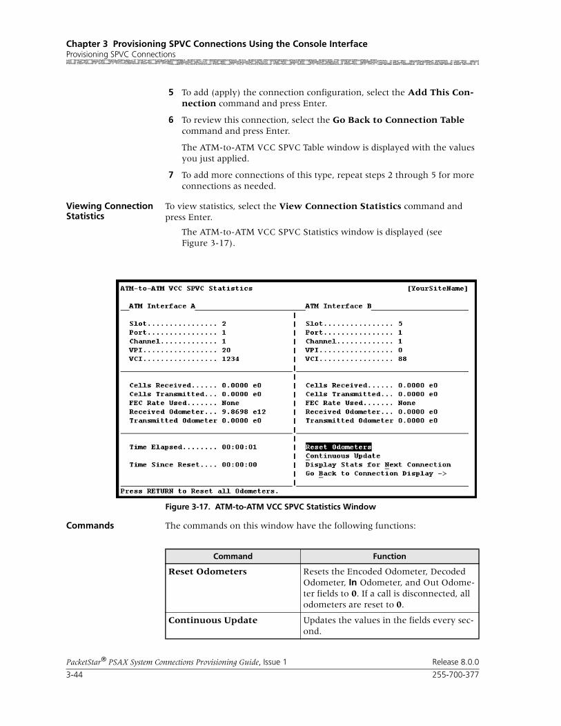
Chapter 3 Provisioning SPVC Connections Using the Console InterfaceProvisioning SPVC Connections
3-44 255-700-377
PacketStar® PSAX System Connections Provisioning Guide, Issue 1 Release 8.0.0
5 To add (apply) the connection configuration, select the Add This Con-nection command and press Enter.
6 To review this connection, select the Go Back to Connection Table command and press Enter.
The ATM-to-ATM VCC SPVC Table window is displayed with the values you just applied.
7 To add more connections of this type, repeat steps 2 through 5 for more connections as needed.
Viewing Connection Statistics
To view statistics, select the View Connection Statistics command and press Enter.
The ATM-to-ATM VCC SPVC Statistics window is displayed (see Figure 3-17).
Commands The commands on this window have the following functions:
Figure 3-17. ATM-to-ATM VCC SPVC Statistics Window
Command Function
Reset Odometers Resets the Encoded Odometer, Decoded Odometer, In Odometer, and Out Odome-ter fields to 0. If a call is disconnected, all odometers are reset to 0.
Continuous Update Updates the values in the fields every sec-ond.

255-700-377 3-45
PacketStar® PSAX System Connections Provisioning Guide, Issue 1 Release 8.0.0
Chapter 3 Provisioning SPVC Connections Using the Console InterfaceProvisioning SPVC Connections
Field Descriptions The fields on this window are described in Table 3-8.
Display Stats for Next Con-nection
Displays the statistics for the next connec-tion of this type.
Go Back to Connection Dis-play
Redisplays the ATM-to-ATM VCC SPVC Connection window.
Command Function
Table 3-8. Field Descriptions for the ATM-to-ATM VCC SPVC Statistics Window
Field Name Field Values Description
Slot Default: N/A
Range: Varies depending on chassis type
Format: numeric
Slot identifier of the ATM interface for either the ATM Interface A panel or the ATM Interface B panel.
Port Default: N/ARange: Varies depending on module type
Format: numeric
Port identifier of the ATM interface for either the ATM Interface A panel or the ATM Interface B panel.
Channel Default: N/A
Range: Varies depending on module type
Format: numeric
Channel identifier of the ATM interface for either Interface A or Interface B.
VPI Default: 0
Range: 0–255
Format: numeric
Virtual path identifier of the ATM side (SVC side) of the connection.
VCI Default: 0Range: 32–65535
Format: numeric
Virtual channel identifier of the ATM side (SVC side) of the connection.
Cells Received Default: 0
Range: N/A
Format: numeric
Number of valid cells received since the virtual circuit or virtual path was established.
Cells Transmitted Default: 0
Range: N/A
Format: numeric
Number of valid cells transmitted since the virtual circuit or virtual path was established.
FEC Rate Used Default: 0Range: N/A
Format: numeric
Displays the forward error correction (FEC) rate being used by the FEC module in the A to B direction (for ATM Interface A panel), or the B to A direction (for ATM Interface B panel). This field is dymanic when auto rates are selected. In other cases it will display the rate set by the user.
Chapter 3 Provisioning SPVC Connections Using the Console InterfaceProvisioning SPVC Connections
3-46 255-700-377
PacketStar® PSAX System Connections Provisioning Guide, Issue 1 Release 8.0.0
Adding NSAP Addresses
To add NSAP addresses for SPVC connections, perform the steps in the fol-lowing procedure.
Begin
Adding NSAP Addresses to the SPVC Address Table
1 On the SPVC Connection Configuration Menu window, select the Con-figure Local Address command and press Enter.
The SPVC Address Table window is displayed (see Figure 3-14).
Received Odometer Default: 0
Range: N/A
Format: numeric
Number of valid cells received since this counter was reset. This counter serves as an odometer while the cell transmit/receive counters track usage for the life of the circuit.
Transmitted Odom-eter
Default: 0
Range: N/A
Format: numeric
Number of valid cells transmitted since this counter was reset. This counter serves as an odometer while the cell transmit/receive counters track usage for the life of the circuit.
Time Elapsed Default: 00:00:00
Range: N/A
Format: numeric
Time, in hours, minutes, and seconds, since last reset.
Time Since Reset Default: 00:00:00Range: N/A
Format: numeric
Time elapsed since the last time the Reset Odometers command was used.
Table 3-8. Field Descriptions for the ATM-to-ATM VCC SPVC Statistics Window
Field Name Field Values Description

255-700-377 3-47
PacketStar® PSAX System Connections Provisioning Guide, Issue 1 Release 8.0.0
Chapter 3 Provisioning SPVC Connections Using the Console InterfaceProvisioning SPVC Connections
The SPVC Address Table window is displayed (see Figure 3-13).
Commands The commands on this window have the following functions:
2 Select the Add an Entry field, and press Enter.
a Type a network service access point (NSAP) address up to 20 bytes (160 bits) long (10 groups of 4 characters each), and press the Tab key.
b In the Slot Port Chnl field, type the slot, port, and channel values for the ATM-cell-bearing I/O module that has a configured ATM IISP (User or Network) or ATM UNI 3.0 or 3.1 interface.
Figure 3-18. SPVC Address Table Window
Command Function
Page Up Scrolls up one page.
Page Down Scrolls down one page.
Top Displays entries at the top of the table.
Bottom Displays entries at the bottom of the table.
Add an Entry: Adds to the table a new NSAP address, slot, port, and channel for an I/O module configured with an ATM interface.
Find: " " Finds the address entry with the specified NSAP address.
Go Back to connection table Redisplays the SPVC Connection Configu-ration Menu window.

Chapter 3 Provisioning SPVC Connections Using the Console InterfaceProvisioning SPVC Connections
3-48 255-700-377
PacketStar® PSAX System Connections Provisioning Guide, Issue 1 Release 8.0.0
c Press Enter to add the entry to the table.
3 Repeat Step 2 as many times as needed to add additional NSAP addresses.
4 To permanently save these connections, press Ctrl+G to return to the Console Interface Main Menu window.
5 Select the Save Configuration command, and press Enter to store the values in the PSAX system database.
End
Adding ATM-to-ATM VPC SPVC Connections
Creating a Connection
Perform the steps in the following procedure to create an ATM-to-ATM VPC SPVC connection.
Begin
1 On the Connection Configuration Menu window, select the SPVC Con-figuration Screen option and press Enter. The SPVC Connection Configu-ration Menu window is displayed (see Figure 3-14).
2 On the SPVC Connection Configuration Menu window, select the ATM-to-ATM VPC option, and press Enter.
Figure 3-19. SPVC Connection Configuration Menu Window
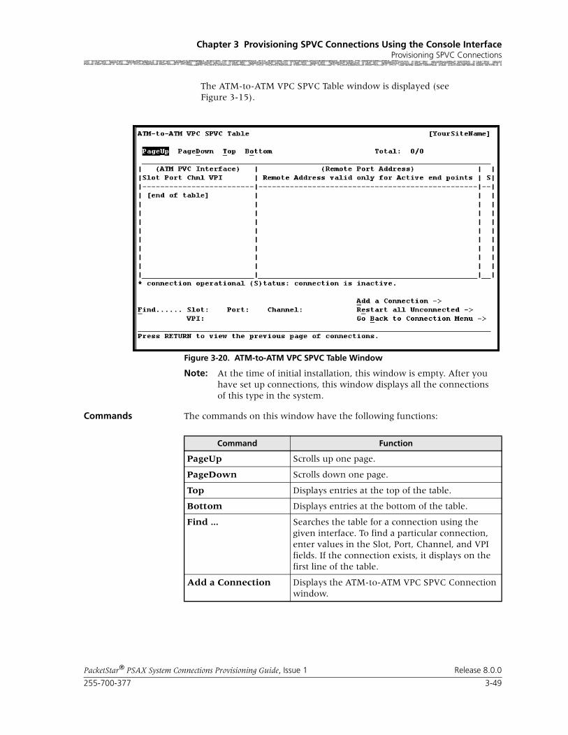
255-700-377 3-49
PacketStar® PSAX System Connections Provisioning Guide, Issue 1 Release 8.0.0
Chapter 3 Provisioning SPVC Connections Using the Console InterfaceProvisioning SPVC Connections
The ATM-to-ATM VPC SPVC Table window is displayed (see Figure 3-15).
Note: At the time of initial installation, this window is empty. After you have set up connections, this window displays all the connections of this type in the system.
Commands The commands on this window have the following functions:
Figure 3-20. ATM-to-ATM VPC SPVC Table Window
Command Function
PageUp Scrolls up one page.
PageDown Scrolls down one page.
Top Displays entries at the top of the table.
Bottom Displays entries at the bottom of the table.
Find ... Searches the table for a connection using the given interface. To find a particular connection, enter values in the Slot, Port, Channel, and VPI fields. If the connection exists, it displays on the first line of the table.
Add a Connection Displays the ATM-to-ATM VPC SPVC Connection window.
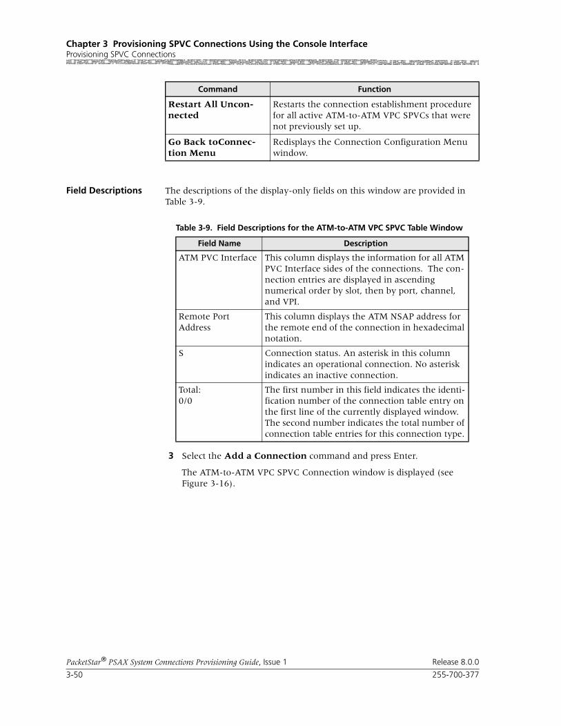
Chapter 3 Provisioning SPVC Connections Using the Console InterfaceProvisioning SPVC Connections
3-50 255-700-377
PacketStar® PSAX System Connections Provisioning Guide, Issue 1 Release 8.0.0
Field Descriptions The descriptions of the display-only fields on this window are provided in Table 3-9.
3 Select the Add a Connection command and press Enter.
The ATM-to-ATM VPC SPVC Connection window is displayed (see Figure 3-16).
Restart All Uncon-nected
Restarts the connection establishment procedure for all active ATM-to-ATM VPC SPVCs that were not previously set up.
Go Back toConnec-tion Menu
Redisplays the Connection Configuration Menu window.
Command Function
Table 3-9. Field Descriptions for the ATM-to-ATM VPC SPVC Table Window
Field Name Description
ATM PVC Interface This column displays the information for all ATM PVC Interface sides of the connections. The con-nection entries are displayed in ascending numerical order by slot, then by port, channel, and VPI.
Remote Port Address
This column displays the ATM NSAP address for the remote end of the connection in hexadecimal notation.
S Connection status. An asterisk in this column indicates an operational connection. No asterisk indicates an inactive connection.
Total:0/0
The first number in this field indicates the identi-fication number of the connection table entry on the first line of the currently displayed window. The second number indicates the total number of connection table entries for this connection type.

255-700-377 3-51
PacketStar® PSAX System Connections Provisioning Guide, Issue 1 Release 8.0.0
Chapter 3 Provisioning SPVC Connections Using the Console InterfaceProvisioning SPVC Connections
Commands The commands on this window have the following functions:
Figure 3-21. ATM-to-ATM VCC SPVC Connection Window
Command Function
Add Connection Adds a connection having the values cur-rently displayed on the window.
Delete Connection Deletes the out-of-service connection cur-rently displayed on the window.
Restart Connection Restarts the connection establishment procedure for this connection when the value InService is displayed in the [Admin Status] field.
Display Next Connection Displays the next connection of this type in the PSAX system (all connections of this type are displayed on the ATM-to-ATM VCC SPVC Connection Table win-dow).
View Connection Statistics Displays the ATM-to-ATM VCC SPVC Sta-tistics window.
Go Back to Connection Table
Redisplays the ATM-to-ATM VCC SPVC Connection Table window.
Bring Into Service Brings this out-of-service connection into service so that the connection is available to make or receive calls.
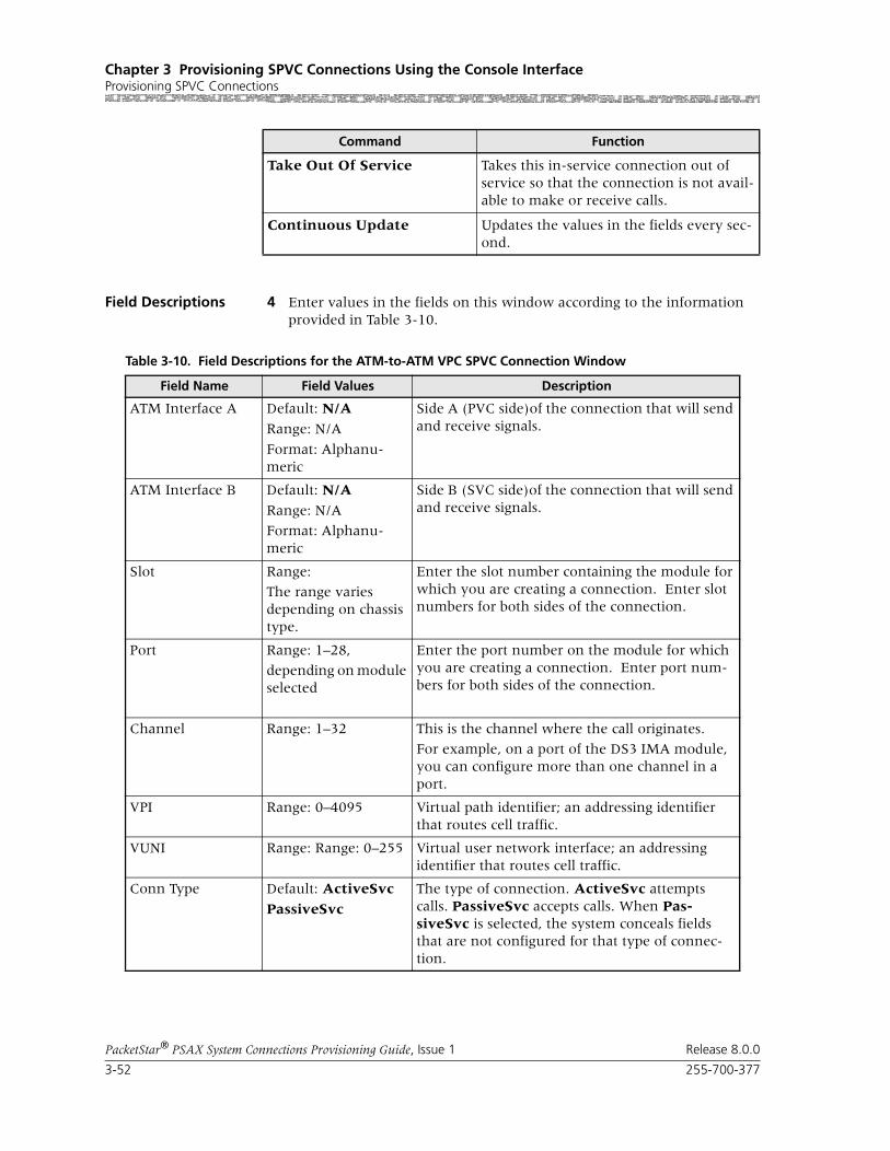
Chapter 3 Provisioning SPVC Connections Using the Console InterfaceProvisioning SPVC Connections
3-52 255-700-377
PacketStar® PSAX System Connections Provisioning Guide, Issue 1 Release 8.0.0
Field Descriptions 4 Enter values in the fields on this window according to the information provided in Table 3-10.
Take Out Of Service Takes this in-service connection out of service so that the connection is not avail-able to make or receive calls.
Continuous Update Updates the values in the fields every sec-ond.
Command Function
Table 3-10. Field Descriptions for the ATM-to-ATM VPC SPVC Connection Window
Field Name Field Values Description
ATM Interface A Default: N/A
Range: N/A
Format: Alphanu-meric
Side A (PVC side)of the connection that will send and receive signals.
ATM Interface B Default: N/A
Range: N/A
Format: Alphanu-meric
Side B (SVC side)of the connection that will send and receive signals.
Slot Range:
The range varies depending on chassis type.
Enter the slot number containing the module for which you are creating a connection. Enter slot numbers for both sides of the connection.
Port Range: 1–28,
depending on module selected
Enter the port number on the module for which you are creating a connection. Enter port num-bers for both sides of the connection.
Channel Range: 1–32 This is the channel where the call originates.
For example, on a port of the DS3 IMA module, you can configure more than one channel in a port.
VPI Range: 0–4095 Virtual path identifier; an addressing identifier that routes cell traffic.
VUNI Range: Range: 0–255 Virtual user network interface; an addressing identifier that routes cell traffic.
Conn Type Default: ActiveSvc
PassiveSvc
The type of connection. ActiveSvc attempts calls. PassiveSvc accepts calls. When Pas-siveSvc is selected, the system conceals fields that are not configured for that type of connec-tion.

255-700-377 3-53
PacketStar® PSAX System Connections Provisioning Guide, Issue 1 Release 8.0.0
Chapter 3 Provisioning SPVC Connections Using the Console InterfaceProvisioning SPVC Connections
Flow Default: Duplex Direction of flow of data traffic in this connection. Data flows in two directions between the two connection points (interface side A and interface side B).
SimplexA2B, Sim-plex B2A
Data flows in only one direction, from side A to side B, or from side B to side A.
PointToMultipointA2B
Data flows in only one direction, from one point on side A to several points on side B, or from one point on side B to several points on side A.
Retry Limit Default: 0
Range: 0–65535
Maximum limit on how many consecutive unsuccessful call setup attempts can be made before stopping the attempts to set up the con-nection. A value of zero indicates no limits. This will result in an infinite number of retries.
Remote NSAP Addr (shown when ActiveSvc is selected as the con-nection type)
The ATM NSAP address of the remote end of the connection, in hexadecimal notation. Enter the NSAP address of the remote ATM interface.
Service Type Default: Ubr
Range: N/A
Format: predefined alphanumeric
Specifies the PSAX system-supported quality of service (QoS) class. For a description of the QoS classes, see the reference appendix in this guide. The type selected causes the conformance type for the connection to be derived from the class of service. This derived value is enforced by the UPC setting of the I/O module.
Ubr Unspecified bit rate.
Vbr-nrt2 Variable bit rate, non-real time, queue 2.
Vbr-nrt1 Variable bit rate, non-real time, queue 1.
Vbr-rt2 Variable bit rate, real time, queue 2.
Vbr-rt1 Variable bit rate, real time, queue 1.
Vbr-express Variable bit rate, express.
Cbr4 Constant bit rate, queue 4.
Cbr3 Constant bit rate, queue 3.
Cbr2 Constant bit rate, queue 2.
Cbr1 Constant bit rate, queue 1.
Table 3-10. Field Descriptions for the ATM-to-ATM VPC SPVC Connection Window
Field Name Field Values Description

Chapter 3 Provisioning SPVC Connections Using the Console InterfaceProvisioning SPVC Connections
3-54 255-700-377
PacketStar® PSAX System Connections Provisioning Guide, Issue 1 Release 8.0.0
Peak Rate(0+1) Default: 1
Range: 1–(232-1)(theoretical range, except for modules noted at right, see Description column)
Range:
Format: numeric (cells per second)
Note: Peak cell rate (PCR) for all cells with both the CLP=0 bit and the CLP=1 bit. The value you set is the maximum allowed cell transmission rate (cells per second) for all cells both high and low priority, as allowed by your traffic contract. When setting this value, calculate the line rate for the module and the amount of bandwidth you are setting up for each interface for the module. Refer to the ATM UNI 3.1 specifications for more information. If you select the value SimplexA2B in the Flow field, set the value of this field to 0. The value in this field should be greater than the Sustained Rate field.If you are using the traffic shaping Enabled setting on the bulleted modules listed below, entering a minimum cps value below the minimum listed below will cause traf-fic-shaped connections to default back to the minimum cps value when the connection passes traffic.
• On the 1-Port OC-3c MM/SM and the 1-Port STM-1 MM/SM, the cps range is 18–999999999.
• On the OC-12c/STM-4c SM/MM, the cps range is 87–999999999.
• On the 3-Port DS3/E3 ATM, the cps range is 7–999999999.
Note: The peak cell rate cannot exceed the maxi-mum cell rate for the interface.
Table 3-10. Field Descriptions for the ATM-to-ATM VPC SPVC Connection Window
Field Name Field Values Description
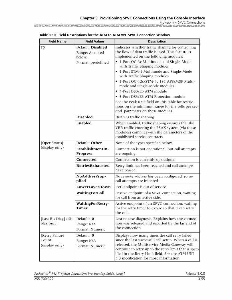
255-700-377 3-55
PacketStar® PSAX System Connections Provisioning Guide, Issue 1 Release 8.0.0
Chapter 3 Provisioning SPVC Connections Using the Console InterfaceProvisioning SPVC Connections
TS Default: Disabled
Range: As noted below.
Format: predefined
Indicates whether traffic shaping for controlling the flow of data traffic is used. This feature is implemented on the following modules:
• 1-Port OC-3c Multimode and Single-Mode with Traffic Shaping modules
• 1-Port STM-1 Multimode and Single-Mode with Traffic Shaping modules
• 1-Port OC-12c/STM-4c 1+1 APS/MSP Multi-mode and Single-Mode modules
• 3-Port DS3/E3 ATM module
• 3-Port DS3/E3 ATM Protection module
See the Peak Rate field on this table for restric-tions on the minimum range for the cells per sec-ond parameter on these modules.
Disabled Disables traffic shaping.
Enabled When enabled, traffic shaping ensures that the VBR traffic entering the PSAX system (via these modules) complies with the parameters of the established service contracts.
[Oper Status](display only)
Default: Other None of the types specified below.
EstablishmentIn-Progress
Connection is not operational, but call attempts are ongoing.
Connected Connection is currently operational.
RetriesExhausted Retry limit has been reached and call attempts have ceased.
NoAddressSup-plied
No remote address has been configured, so no call attempts are initiated.
LowerLayerDown PVC endpoint is out of service.
WaitingForCall Passive endpoint of a SPVC connection, waiting for call from an active side.
WaitingForRetry-Timer
Active endpoint of an SPVC connection, waiting for the retry timer to expire so that it can retry the call.
[Last Rls Diag] (dis-play only)
Default: 0
Range: N/A
Format: Numeric
Last release diagnosis. Explains how the connec-tion was released and reported by the far end of the connection.
[Retry Failure Count]
(display only)
Default: 0Range: N/A
Format: Numeric
Displays how many times the call retry failed since the last successful call setup. When a call is released, the Multiservice Media Gateway will continue to retry up to the retry limit that is spec-ified in the Retry Limit field. See the ATM UNI 3.0 specification for more information.
Table 3-10. Field Descriptions for the ATM-to-ATM VPC SPVC Connection Window
Field Name Field Values Description

Chapter 3 Provisioning SPVC Connections Using the Console InterfaceProvisioning SPVC Connections
3-56 255-700-377
PacketStar® PSAX System Connections Provisioning Guide, Issue 1 Release 8.0.0
5 To add (apply) the connection configuration, select the Add Connec-tion command and press Enter.
6 To view this connection on the table for this connection type, select the Go Back to Connection Table command and press Enter.
The ATM-to-ATM VPC SPVC Table window is returned, displaying the connection you just added.
7 To add more connections of this type, repeat steps 2 through 5.
Viewing Connection Statistics
To view connection statistics, select the View Connection Statistics com-mand on the ATM-to-ATM VPC SPVC Connection window and press Enter. The ATM-to-ATM VPC SPVC Statistics window is displayed (see Figure 3-17).
[Last Rls Cause](display only)
Default: 0
Range: N/A
Format: numeric
Displays the last release cause code. The cause code indicates a reason why the last attempted call was released. See the reference appendix in this guide for the description of SPVC Connection Cause Codes.
Note: This field is displayed only when you select the value ActiveSVC in the Conn Type field.
[Admin Status](display only)
Default: OutOfService
Range: N/A
Format: predefined alphanumeric
Indicates whether the connection is attempting to make calls or receive calls.
OutOfService Indicates that the connection is not available to attempt making or receiving calls.
InService Indicates that the connection is available to attempt making calls or receiving calls.
Priority Default: 3Range: 1–6
Format: numeric
Specifies the the user-defined priority level of this connection. To ensure that a wireless SPVC con-nection is not affected in the event that an ATM IMA link fails, you can assign a priority level that you define. Typically, level 1 is the highest prior-ity and level 6 is the lowest.
Table 3-10. Field Descriptions for the ATM-to-ATM VPC SPVC Connection Window
Field Name Field Values Description

255-700-377 3-57
PacketStar® PSAX System Connections Provisioning Guide, Issue 1 Release 8.0.0
Chapter 3 Provisioning SPVC Connections Using the Console InterfaceProvisioning SPVC Connections
Commands The commands on this window have the following functions:
Field Descriptions The descriptions of the display-only fields on this window are provided in Table 3-11.
Figure 3-22. ATM-to-ATM VCC SPVC Statistics Window
Command Function
Reset Odometers Resets the Encoded Odometer, Decoded Odometer, In Odometer, and Out Odome-ter fields to 0. If a call is disconnected, all odometers are reset to 0.
Continuous Update Updates the values in the fields every sec-ond.
Display Stats for Next Con-nection
Displays the statistics for the next connec-tion of this type.
Go Back to Connection Dis-play
Redisplays the ATM-to-ATM VPC SPVC Connection window.

Chapter 3 Provisioning SPVC Connections Using the Console InterfaceProvisioning SPVC Connections
3-58 255-700-377
PacketStar® PSAX System Connections Provisioning Guide, Issue 1 Release 8.0.0
Table 3-11. Field Descriptions for the ATM-to-ATM VPC SPVC Statistics Window
Field Name Field Values Description
Slot Default: NA
Range: Chassis-dependent
Format: Numeric
Slot identifier of the ATM interface for either the ATM Interface A panel or the ATM Interface B panel.
Port Default: NA
Range: 1–28
Format: Numeric
Port identifier of the ATM interface for either the ATM Interface A panel or the ATM Interface B panel.
Channel Default: NA
Range: 1–32
Format: Numeric
Channel identifier of the ATM interface for either Interface A or Interface B.
VPI Default: NARange: 0–4095
Format: Numeric
Virtual path identifier of the ATM side (SVC side) of the connection.
Cells Received Default: 0.0000 e0
Range: 0-(231-1)
Format: Numeric
Number of valid cells received since the virtual circuit or virtual path was established.
Cells Transmitted Default: 0.0000 e0
Range: 0-(231-1)
Format: Numeric
Number of valid cells transmitted since the virtual circuit or virtual path was established.
FEC Rate Used Default: NoneeighthRatequarterRatehalfRateautoHiQautoautoLoQRange: NA
Format: Character
Displays the forward error correction (FEC) rate being used by the FEC module in the A2B direc-tion (for ATM Interface A panel), or B2A direc-tion (for ATM Interface B panel). This field is dynamic when auto rates are selected. In other cases it will display the rate set by the user.
Note: This field is not used in SPVC connections.
Received Odometer Default: 0.0000 e0
Range: 0-(231-1)
Format: Numeric
Number of valid cells received since this counter was reset.
This counter serves as an odometer while the cells Tx/Rx counters track usage for the life of the circuit.
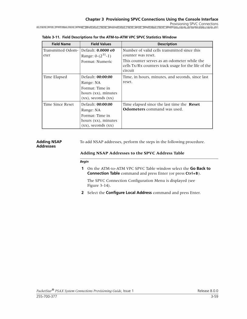
255-700-377 3-59
PacketStar® PSAX System Connections Provisioning Guide, Issue 1 Release 8.0.0
Chapter 3 Provisioning SPVC Connections Using the Console InterfaceProvisioning SPVC Connections
Adding NSAP Addresses
To add NSAP addresses, perform the steps in the following procedure.
Begin
Adding NSAP Addresses to the SPVC Address Table
1 On the ATM-to-ATM VPC SPVC Table window select the Go Back to Connection Table command and press Enter (or press Ctrl+B).
The SPVC Connection Configuration Menu is displayed (see Figure 3-14).
2 Select the Configure Local Address command and press Enter.
Transmitted Odom-eter
Default: 0.0000 e0
Range: 0-(231-1)
Format: Numeric
Number of valid cells transmitted since this counter was reset.
This counter serves as an odometer while the cells Tx/Rx counters track usage for the life of the circuit
Time Elapsed Default: 00:00:00
Range: NA
Format: Time in hours (xx), minutes (xx), seconds (xx)
Time, in hours, minutes, and seconds, since last reset.
Time Since Reset Default: 00:00:00
Range: NA
Format: Time in hours (xx), minutes (xx), seconds (xx)
Time elapsed since the last time the Reset Odometers command was used.
Table 3-11. Field Descriptions for the ATM-to-ATM VPC SPVC Statistics Window
Field Name Field Values Description

Chapter 3 Provisioning SPVC Connections Using the Console InterfaceProvisioning SPVC Connections
3-60 255-700-377
PacketStar® PSAX System Connections Provisioning Guide, Issue 1 Release 8.0.0
The SPVC Address Table window is displayed (see Figure 3-13).
Commands The commands on this window have the following functions.
3 Select the Add an Entry field, and press Enter.
a. Type a network service access point (NSAP) address up to 20 bytes (160 bits) long (10 groups of 4 characters each), and press the Tab key.
b. In the Slot Port Chnl field, type the slot, port, and channel values for the ATM-cell-bearing I/O module that has a configured ATM IISP (User or Network) or ATM UNI 3.0, 3.1, or 4.0 interface.
Figure 3-23. SPVC Address Table Window
Command Function
Page Up Scrolls up one page.
Page Down Scrolls down one page.
Top Displays entries at the top of the table.
Bottom Displays entries at the bottom of the table.
Add an Entry: Adds to the table a new NSAP address, slot, port, and channel for an I/O module configured with an ATM interface.
Find: " " Finds the address entry with the specified NSAP address.
Go Back to connection table Redisplays the SPVC Connection Configu-ration Menu window.
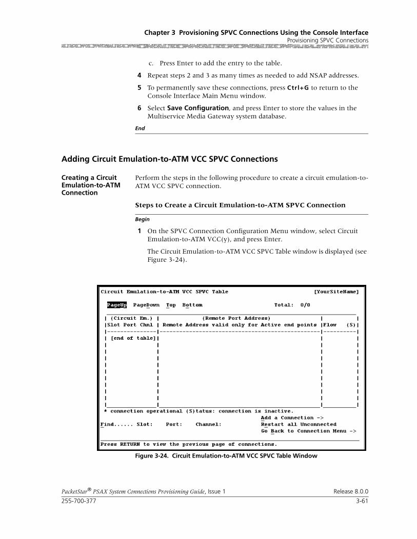
255-700-377 3-61
PacketStar® PSAX System Connections Provisioning Guide, Issue 1 Release 8.0.0
Chapter 3 Provisioning SPVC Connections Using the Console InterfaceProvisioning SPVC Connections
c. Press Enter to add the entry to the table.
4 Repeat steps 2 and 3 as many times as needed to add NSAP addresses.
5 To permanently save these connections, press Ctrl+G to return to the Console Interface Main Menu window.
6 Select Save Configuration, and press Enter to store the values in the Multiservice Media Gateway system database.
End
Adding Circuit Emulation-to-ATM VCC SPVC Connections
Creating a Circuit Emulation-to-ATM Connection
Perform the steps in the following procedure to create a circuit emulation-to-ATM VCC SPVC connection.
Begin
Steps to Create a Circuit Emulation-to-ATM SPVC Connection
1 On the SPVC Connection Configuration Menu window, select Circuit Emulation-to-ATM VCC(y), and press Enter.
The Circuit Emulation-to-ATM VCC SPVC Table window is displayed (see Figure 3-24).
Figure 3-24. Circuit Emulation-to-ATM VCC SPVC Table Window

Chapter 3 Provisioning SPVC Connections Using the Console InterfaceProvisioning SPVC Connections
3-62 255-700-377
PacketStar® PSAX System Connections Provisioning Guide, Issue 1 Release 8.0.0
Note: At the time of initial installation, the Circuit Emulation-to-ATM VCC SPVC Table window is empty. After you have set up connec-tions, this window will display all the connections of this type in the system.
Commands The commands on this window have the following functions:
Display Field Descriptions
The display-only fields on this window provide the following information about all the circuit emulation-to-ATM VCC SPVC connections in the PSAX system:
2 Select the Add a Connection command and press Enter.
The Circuit Emulation-to-ATM VCC SPVC Connection window is dis-played (see Figure 3-25).
Command Function
Find . . . To find a particular connection, enter values in the Slot, Port, and Channel fields. If the connection exists, it will display on the first line of the table.
Add a Connection Displays the Circuit Emulation-to-ATM VCC SPVC Connection window. Enter the CE side slot, port, channel, and parameters of the new connection on this window.
Restart all unconnected Restarts connection establishment procedure for all inactive Circuit Emulation-to-ATM VCC SPVCs which were not previously operationally active.
Go Back to Connection Menu
Redisplays the Circuit Emulation-to-ATM VCC SPVC Table window.
Table 3-12. Field Descriptions for the CE to ATM VCC SPVC Table Window
Field Name Description
Circuit Emulation Side This column displays the information for all circuit emula-tion sides of the connections. The connection entries are displayed in ascending numerical order by slot, then by port and channel.
Remote Port Address This column displays the ATM NSAP address for the remote end of the connection in hexadecimal notation.
Flow This column displays the direction of the data traffic flow for the connections.
Total:0/0
The first number in this field indicates the number of the connection table entry on the first line of the currently displayed window. The second number indicates the total number of connection table entries for this connection type.
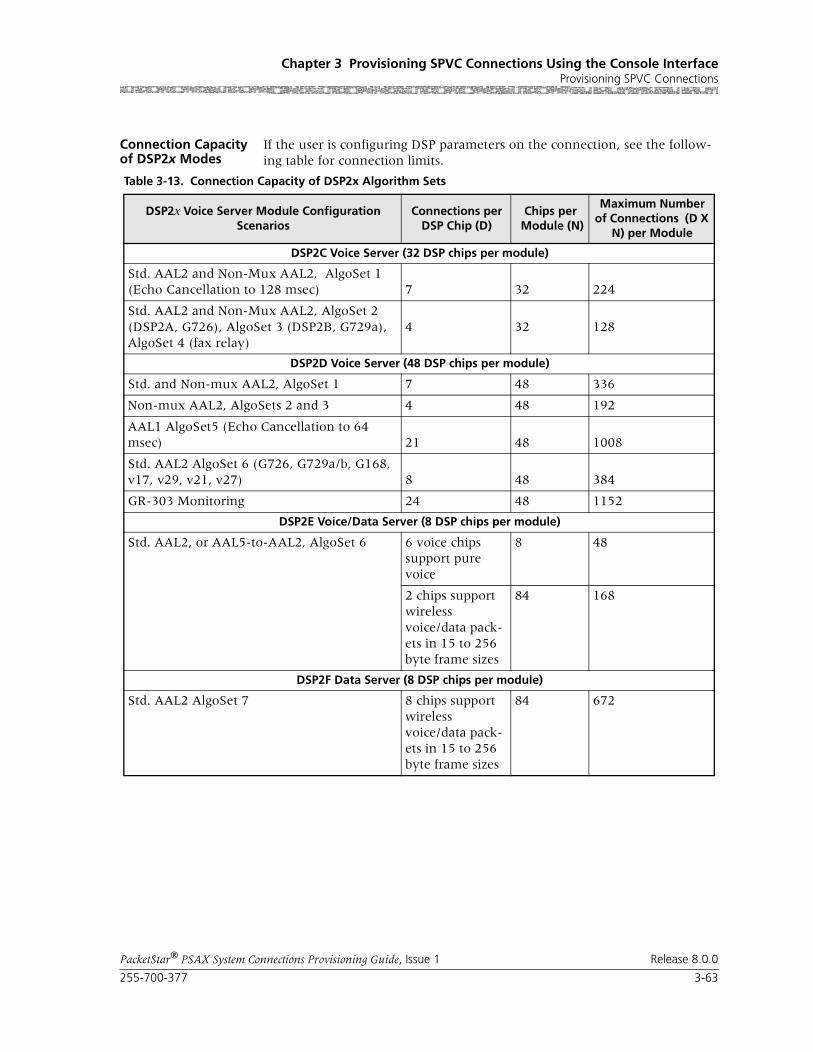
255-700-377 3-63
PacketStar® PSAX System Connections Provisioning Guide, Issue 1 Release 8.0.0
Chapter 3 Provisioning SPVC Connections Using the Console InterfaceProvisioning SPVC Connections
Connection Capacity of DSP2x Modes
If the user is configuring DSP parameters on the connection, see the follow-ing table for connection limits.
Table 3-13. Connection Capacity of DSP2x Algorithm Sets
DSP2x Voice Server Module Configuration Scenarios
Connections per DSP Chip (D)
Chips per Module (N)
Maximum Number of Connections (D X
N) per Module
DSP2C Voice Server (32 DSP chips per module)
Std. AAL2 and Non-Mux AAL2, AlgoSet 1 (Echo Cancellation to 128 msec) 7 32 224
Std. AAL2 and Non-Mux AAL2, AlgoSet 2 (DSP2A, G726), AlgoSet 3 (DSP2B, G729a),AlgoSet 4 (fax relay)
4 32 128
DSP2D Voice Server (48 DSP chips per module)
Std. and Non-mux AAL2, AlgoSet 1 7 48 336
Non-mux AAL2, AlgoSets 2 and 3 4 48 192
AAL1 AlgoSet5 (Echo Cancellation to 64 msec) 21 48 1008
Std. AAL2 AlgoSet 6 (G726, G729a/b, G168, v17, v29, v21, v27) 8 48 384
GR-303 Monitoring 24 48 1152
DSP2E Voice/Data Server (8 DSP chips per module)
Std. AAL2, or AAL5-to-AAL2, AlgoSet 6 6 voice chips support pure voice
8 48
2 chips support wireless voice/data pack-ets in 15 to 256 byte frame sizes
84 168
DSP2F Data Server (8 DSP chips per module)
Std. AAL2 AlgoSet 7 8 chips support wireless voice/data pack-ets in 15 to 256 byte frame sizes
84 672

Chapter 3 Provisioning SPVC Connections Using the Console InterfaceProvisioning SPVC Connections
3-64 255-700-377
PacketStar® PSAX System Connections Provisioning Guide, Issue 1 Release 8.0.0
Commands The commands on this window have the following functions:
Figure 3-25. Circuit Emulation-to-ATM VCC SPVC Connection Window
Command Function
Bring Into Service Brings this out-of-service connection into service so that the connection is available to make or receive calls.
Take Out Of Service Takes this in-service connection out of service so that the connection is not avail-able to make or receive calls.
Display Next Connection Displays the next connection of this type in the PSAX system (all connections of this type are displayed on the Circuit Emulation-to-ATM VCC SPVC Table win-dow).
Continuous Update Updates the values in the fields every sec-ond.
Restart This Connection Restarts the connection establishment procedure for this connection when the value InService is displayed in the [Admin Status] field.
Configure DSP2 Parameters Displays the DSP2 Parameter Configura-tion window. This command is not sup-ported.

255-700-377 3-65
PacketStar® PSAX System Connections Provisioning Guide, Issue 1 Release 8.0.0
Chapter 3 Provisioning SPVC Connections Using the Console InterfaceProvisioning SPVC Connections
Field Descriptions 3 Enter values in the fields on this window according to the information provided in Table 3-14.
Add This Connection Adds a connection having the values cur-rently displayed on the window.
Delete Connection Deletes the out-of-service connection cur-rently displayed on the window.
View Connection Statistics Displays the Circuit Emulation-to-ATM VCC SPVC Statistics window.
Go Back to Connection Table
Redisplays the Circuit Emulation-to-ATM VCC SPVC Table window.
Command Function
Table 3-14. Field Descriptions for the Circuit Emulation-to-ATM SPVC Connection Window
Field Name Field Values Description
Circuit Emulation Interface
Default: N/ARange: N/A
Format: N/A
The circuit emulation side of the connection that will send and receive signals.
ATM Interface Default: N/A
Range: N/A
Format: N/A
The ATM interface side of the connection that will send and receive signals.
Slot Default: N/A
Range: variable
Format: Numeric
Enter the circuit emulation-side slot number con-taining the module for which you are creating a connection. The range of slot numbers varies with the chassis type.
Port Default: N/A
Range: variable
Format: Numeric
Enter the circuit emulation-side port number on the module for which you are creating a connec-tion. The range of port numbers varies with the module type.
Channel Default: N/ARange: variable
Format: Numeric
Enter circuit emulation-side channel number for the port on the module for which you are creat-ing a connection. The range of channel numbers varies with the module type.
[VPI ](display only)
Default: 0
Range: 0–225 (ATM UNI); 0–4095 (NNI)
Format: numeric
Virtual path identifier (ATM side).
[VCI](display only)
Default: 0Range: 0– 65535
Format: numeric
Virtual channel identifier (ATM side).

Chapter 3 Provisioning SPVC Connections Using the Console InterfaceProvisioning SPVC Connections
3-66 255-700-377
PacketStar® PSAX System Connections Provisioning Guide, Issue 1 Release 8.0.0
VI Default: 0
Range: 0–1024
Format: numeric
Virtual interface, which provides bandwidth allo-cation restrictions. Currently available only on the 1-Port OC-12c/STM-4c 1+1 MM/SM APS/MSP, the 1-Port OC-3c 1+1 APS, and the 1-Port STM-1 1+1 MSP modules. When disabled, the default value is 0.
Connection Type Default: ActiveSvc
Range: N/A
Format: predefined alphanumeric
The type of SPVC connection. See Chapter 2 of the PacketStar® PSAX DSP2x Voice Server Module User Guide for rules.
ActiveSvc Selecting the value ActiveSvc attempts calls.
PassiveSvc Selecting the value PassiveSvc accepts calls. Sev-eral fields are not displayed when this value is selected.
Service Type Default: Cbr-2
Range: N/A
Format: predefined alphanumeric
Specifies the PSAX system-supported quality of service (QoS) class. For a description of the QoS classes, see the reference appendix in this guide. The type selected causes the conformance type for the connection to be derived from the class of service. This derived value is enforced by the UPC setting of the I/O module.
Cbr-2 Constant bit rate, queue 2
Cbr-3 Constant bit rate, queue 3
Cbr-4 Constant bit rate, queue 4
Flow Default: Duplex
Range: N/A
Format: alphanu-meric
Direction of flow of data traffic in this connection.
Duplex Data flows in two directions between the two connection points (interface side A and interface side B).
SimplexA2B Data flows in only one direction, from side A to side B.
PointToMultipointA2B
Data flows in only one direction, from one point on side A to several points on side B.
Simplex B2A Data flows in only one direction, from side B to side A.
PointToMultipointB2A
Data flows in only one direction, from one point on side B to several points on side A.
Table 3-14. Field Descriptions for the Circuit Emulation-to-ATM SPVC Connection Window
Field Name Field Values Description
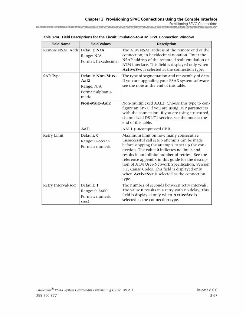
255-700-377 3-67
PacketStar® PSAX System Connections Provisioning Guide, Issue 1 Release 8.0.0
Chapter 3 Provisioning SPVC Connections Using the Console InterfaceProvisioning SPVC Connections
Remote NSAP Addr Default: N/A
Range: N/A
Format: hexadecimal
The ATM NSAP address of the remote end of the connection, in hexidecimal notation. Enter the NSAP address of the remote circuit emulation or ATM interface. This field is displayed only when ActiveSvc is selected as the connection type.
SAR Type Default: Non-Mux-Aal2
Range: N/A
Format: alphanu-meric
The type of segmentation and reassembly of data. If you are upgrading your PSAX system software, see the note at the end of this table.
Non-Mux-Aal2 Non-multiplexed AAL2. Choose this type to con-figure an SPVC if you are using DSP parameters with the connection. If you are using structured, channelized DS1/T1 service, see the note at the end of this table.
Aal1 AAL1 (uncompressed CBR).
Retry Limit Default: 0
Range: 0–65535
Format: numeric
Maximum limit on how many consecutive unsuccessful call setup attempts can be made before stopping the attempts to set up the con-nection. The value 0 indicates no limits and results in an infinite number of retries. See the reference appendix in this guide for the descrip-tion of ATM User-Network Specification, Version 3.1, Cause Codes. This field is displayed only when ActiveSvc is selected as the connection type.
Retry Interval(sec) Default: 1
Range: 0–3600
Format: numeric (sec)
The number of seconds between retry intervals. The value 0 results in a retry with no delay. This field is displayed only when ActiveSvc is selected as the connection type.
Table 3-14. Field Descriptions for the Circuit Emulation-to-ATM SPVC Connection Window
Field Name Field Values Description
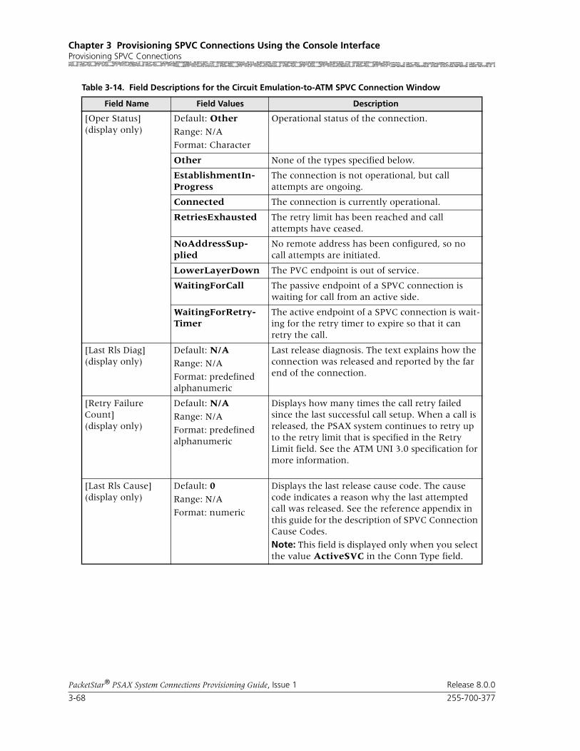
Chapter 3 Provisioning SPVC Connections Using the Console InterfaceProvisioning SPVC Connections
3-68 255-700-377
PacketStar® PSAX System Connections Provisioning Guide, Issue 1 Release 8.0.0
[Oper Status](display only)
Default: Other
Range: N/A
Format: Character
Operational status of the connection.
Other None of the types specified below.
EstablishmentIn-Progress
The connection is not operational, but call attempts are ongoing.
Connected The connection is currently operational.
RetriesExhausted The retry limit has been reached and call attempts have ceased.
NoAddressSup-plied
No remote address has been configured, so no call attempts are initiated.
LowerLayerDown The PVC endpoint is out of service.
WaitingForCall The passive endpoint of a SPVC connection is waiting for call from an active side.
WaitingForRetry-Timer
The active endpoint of a SPVC connection is wait-ing for the retry timer to expire so that it can retry the call.
[Last Rls Diag](display only)
Default: N/ARange: N/A
Format: predefined alphanumeric
Last release diagnosis. The text explains how the connection was released and reported by the far end of the connection.
[Retry Failure Count](display only)
Default: N/A
Range: N/A
Format: predefined alphanumeric
Displays how many times the call retry failed since the last successful call setup. When a call is released, the PSAX system continues to retry up to the retry limit that is specified in the Retry Limit field. See the ATM UNI 3.0 specification for more information.
[Last Rls Cause](display only)
Default: 0
Range: N/A
Format: numeric
Displays the last release cause code. The cause code indicates a reason why the last attempted call was released. See the reference appendix in this guide for the description of SPVC Connection Cause Codes.
Note: This field is displayed only when you select the value ActiveSVC in the Conn Type field.
Table 3-14. Field Descriptions for the Circuit Emulation-to-ATM SPVC Connection Window
Field Name Field Values Description

255-700-377 3-69
PacketStar® PSAX System Connections Provisioning Guide, Issue 1 Release 8.0.0
Chapter 3 Provisioning SPVC Connections Using the Console InterfaceProvisioning SPVC Connections
Note: SAR type for using structured, channelized DS1/T1 service: You must select nonmultiplexed AAL2 when using structured, chan-nelized DS1/T1 service on the following modules: 1-Port Channel-ized DS3 Multiservice, 1-port Channelized DS3 CES, 1-Port Chan-nelized STS-1e, T1 Format, 3-Port Channelized DS3/STS-1e CES, 6-Port Enhanced DS1 Multiservice, 6-Port Enhanced E1 Multiser-vice, 21-Port High-Density E1 Multiservice, and 12-Port Medium-Density DS1 Multiservice. Save your SPVC connection configura-tions before upgrading your PSAX system software, or you will have to re-enter these configurations.
4 To add (apply) the connection configuration, select the Add This Con-nection command and press Enter.
End
Configuring Digital Signal Processing (DSP2) Parameters
Configuring DSP2 Parameters on the Circuit Emulation-to-ATM VCC
Begin
SPVC Connection
1 From the Circuit Emulation-to-ATM VCC SPVC Connection window, select the Configure DSP2 Parameters command and press Enter (or press Ctrl+C).
The Circuit Emulation-to-ATM VCC SPVC DSP2 Parameters window is displayed.
[Admin Status](display only)
Default: OutOfService
Range: N/A
Format: predefined alphanumeric
Indicates whether the connection is attempting to make calls or receive calls.
OutOfService Indicates that the connection is not available to attempt making or receiving calls.
InService Indicates that the connection is available to attempt making calls or receiving calls.
Priority Default: 3Range: 1–6
Format: numeric
Specifies the the user-defined priority level of this connection. To ensure that a wireless SPVC con-nections is not affected in the event that an ATM IMA link fails, you can assign a priority level that you define. Typically, level 1 is the highest prior-ity and level 6 is the lowest.
Table 3-14. Field Descriptions for the Circuit Emulation-to-ATM SPVC Connection Window
Field Name Field Values Description

Chapter 3 Provisioning SPVC Connections Using the Console InterfaceProvisioning SPVC Connections
3-70 255-700-377
PacketStar® PSAX System Connections Provisioning Guide, Issue 1 Release 8.0.0
Commands The commands on this window have the following functions:
Field Descriptions 2 Enter values in the fields on this window according to the information provided in Table 3-15.
Figure 3-26. Circuit Emulation-to-ATM VCC SPVC DSP2 Parameters Window
Command Function
Add This Connection Adds a connection having the values currently displayed on the window.
Delete Connection and Return Deletes the connection having the values cur-rently displayed on the window.
Go Back to Connection Table Redisplays the Circuit Emulation-to-ATM VCC SPVC Connection window.

255-700-377 3-71
PacketStar® PSAX System Connections Provisioning Guide, Issue 1 Release 8.0.0
Chapter 3 Provisioning SPVC Connections Using the Console InterfaceProvisioning SPVC Connections
Table 3-15. Field Descriptions for the Circuit Emulation-to-ATM SPVC DSP2 Parameters Window
Field Names Field Values Description
Voice Compression Default: None
Range: N/A
Format: Predefined alphanumeric
None,G726-16k,G726-24k,G726-32k,G726-40k,G729a-8k
If you want data traffic for this connection to be processed through a DSP2x Voice Server module, do not select the default value None. To enable voice compression, select the desired type and rate of voice compression from the list of values.
Note: Not supported on the 3-Port Unstructured DS3/E3 CES module.
Silence Detection Default: Disabled
Range: N/A
Format: Predefined alphanumeric
If you want data traffic for this connection to be processed through a DSP2x Voice Server module, do not select the default value Disabled.
Note: Not supported on the 3-Port Unstructured DS3/E3 CES module.
Disabled Disables silence detection.
Enabled Enables silence detection.
Echo Cancellation Default: NoneRange: N/A
Format: Predefined alphanumeric
None,G165-nearEnd,G168
If you want data traffic for this connection to be processed through a DSP2x Voice Server module, do not select the default value None. If you want to enable echo cancellation on this connection, select G165-nearEnd or G168.
Note: Not supported on the 3-Port Unstructured DS3/E3 CES module.

Chapter 3 Provisioning SPVC Connections Using the Console InterfaceProvisioning SPVC Connections
3-72 255-700-377
PacketStar® PSAX System Connections Provisioning Guide, Issue 1 Release 8.0.0
3 After entering the values you want for the DSP2 parameters, select the Add This Connection command (or press Ctrl+A).
4 To review this connection, select the Go Back to Connection Table command and press Enter (or press Ctrl+B).
The Circuit Emulation-to-ATM VCC SPVC Table window is returned, dis-playing the values you just applied.
5 To add more connections of this type, repeat steps 2 through 5 for more connections as needed.
6 To permanently save these connections, press Ctrl+G to return to the Console Interface Main Menu window, select Save Configuration, and press Enter to store the values to the PSAX system database.
End
Tone Detection Default: Disabled
Range: N/A
Format: Predefined alphanumeric
If you want data traffic for this connection to be processed through a DSP2x Voice Server module, select the value Bypass.
Note: Not supported on the 3-Port Unstructured DS3/E3 CES module.
Disabled Disables tone detection.
Bypass Indicates that the fax tones are to be recognized and data sent by fax is not to be processed by compression and echo cancellation algorithms.
Coding Translation Default: None
Range: N/A
Format: predefined alphanumeric
None,MuLaw2muLaw,ALaw2aLaw,MuLaw2aLaw,ALaw2MuLaw
Note: If you want data traffic for this connection to be processed through a DSP2x Voice Server module, do not select the default value None. To enable coding translation, select one of the values for pulse code modulation (PCM) translation. Selecting the value None actually uses Mu-law to Mu-law as the default PCM type. If used, noise will result on E1 circuits.
Note: Not supported on the 3-Port Unstructured DS3/E3 CES module.
Note: If you are configuring this parameter for the 6-Port Enhanced DS1 or E1 modules, select the value ALaw2aLaw.
Note: If you are configuring this parameter for the Voice 2-Wire Office or the Voice 2-Wire Sta-tion module, select the value MuLaw2muLaw. The other values are not supported.
Table 3-15. Field Descriptions for the Circuit Emulation-to-ATM SPVC DSP2 Parameters Window
Field Names Field Values Description

255-700-377 3-73
PacketStar® PSAX System Connections Provisioning Guide, Issue 1 Release 8.0.0
Chapter 3 Provisioning SPVC Connections Using the Console InterfaceProvisioning SPVC Connections
Viewing Connection Statistics
From the Circuit Emulation-to-ATM VCC SPVC Connection window, select the View Connection Statistics command and press Enter. The Circuit Emulation-to-ATM VCC SPVC Statistics window is displayed (see Figure 3-27).
Commands The commands in this window have the following functions:
Field Descriptions The fields on this window are described in Table 3-16.
Figure 3-27. Circuit Emulation-to-ATM VCC SPVC Statistics Window
Command Function
Reset Odometers Returns all statistics odometers to zero.
Continuous Update Updates the values in the fields every second.
Display Stats for Next Connection
Displays the statistics for the next selected con-nection.
Go Back to Connec-tion Display
Redisplays the Circuit Emulation-to-ATM VCC SPVC Connection window.

Chapter 3 Provisioning SPVC Connections Using the Console InterfaceProvisioning SPVC Connections
3-74 255-700-377
PacketStar® PSAX System Connections Provisioning Guide, Issue 1 Release 8.0.0
Table 3-16. Field Descriptions for the Circuit Emulation-to-ATM VCC SPVC Statistics Window
Field Names Field Values Description
Circuit Emulation Interface
The circuit emulation side of the connection that will send and receive signals.
ATM Interface The ATM interface side of the connection that will send and receive signals.
Slot(display only)
Default: 0
Range: Chassis-dependent
Format: numeric
The slot number containing the module for which you are creating a connection.
Port(display only)
Default:
Range: Module-dependent
Format: numeric
The port number on the module for which you are creating a connection.
Channel(display only)
Default: 1Range: CE side:1–24 (DS1)1–31 (E1)ATM side:1
Format: numeric
On the Circuit Emulation Interface side, enter the channel number of the port on the module for which you are creating a connection. On the ATM Interface side, do not change the default value (1) in this field.
VPI(display only)
Default: 0
Range: 0–255
Format: numeric
Virtual path identifier (ATM side).
VCI(display only)
Default: 32
Range: 32–65535
Format: numeric
Virtual channel identifier (ATM side).
Cells Encoded(display only)
Default: 0.0000 e0 Range: 0-(231-1)
Format: numeric
Number of cells encoded going into either inter-face side during the amount of time shown in Time Elapsed field (that is, since the circuit was created).
Cells Decoded(display only)
Default: 0.0000 e0
Range: 0-(231-1)
Format: numeric
Number of cells decoded going out of either inter-face side during the amount of time shown in Time Elapsed field (that is, since the circuit was created).
Encoded Odometer(display only)
Default: 0.0000 e0
Range: 0-(231-1)
Format: numeric
Total number of cells encoded going into either interface side since the odometer was last reset.
Decoded Odometer
(display only)
Default: 0.0000 e0
Range: 0-(231-1)
Format: numeric
Total number of cells decoded going out of either interface side since the odometer was last reset.

255-700-377 3-75
PacketStar® PSAX System Connections Provisioning Guide, Issue 1 Release 8.0.0
Chapter 3 Provisioning SPVC Connections Using the Console InterfaceProvisioning SPVC Connections
Adding Circuit Emulation-to-ATM Standard AAL2 VCC SPVC Connections
Begin
CE-to-ATM Standard AAL2 VCC SPVC
1 From the Connection Configuration Menu, select the SPVC Configura-tion screen command under the SPVC Configuration option. The SPVC Connection Configuration Menu is displayed (see Figure 3-28).
Time Elapsed(display only)
Default: 00:00:00
Range: N/A
Format: Time in hours (xx), minutes (xx), seconds (xx)
Time elapsed since the circuit was established.
Time Since Reset(display only)
Default: 00:00:00Range: NA
Format: Time in hours (xx), minutes (xx), seconds (xx)
Time elapsed since the last time the Reset Odometers command was used. This command resets only the odometer fields and the corre-sponding clock. Other counters increment for the life of the circuit.
Cells Received(display only)
6.5000 e1 (default) Number of valid cells received since the virtual circuit or virtual path was established.
Cells Transmitted(display only)
6.5000 e1 (default) Number of valid cells transmitted since the virtual circuit or virtual path was established.
Received Odometer(display only)
6.5000 e1 (default) Total number of ATM cells received since odome-ter was last reset.
Transmitted Odom-eter(display only)
6.5000 e1 (default) Total number of ATM cells transmitted since odometer was last reset.
Table 3-16. Field Descriptions for the Circuit Emulation-to-ATM VCC SPVC Statistics Window
Field Names Field Values Description

Chapter 3 Provisioning SPVC Connections Using the Console InterfaceProvisioning SPVC Connections
3-76 255-700-377
PacketStar® PSAX System Connections Provisioning Guide, Issue 1 Release 8.0.0
2 Select the CE-to-ATM Standard AAL2 VCC menu option. The CE-to-ATM Standard AAL2 SPVC Table is displayed (see Figure 3-29). (Upon first display, the table will be empty if you are configuring this connec-tionfor the first time).
Figure 3-28. CE-to-ATM Standard AAL2 VCC SPVC Connection Option
Figure 3-29. CE-to-ATM Standard AAL2 SPVC Table

255-700-377 3-77
PacketStar® PSAX System Connections Provisioning Guide, Issue 1 Release 8.0.0
Chapter 3 Provisioning SPVC Connections Using the Console InterfaceProvisioning SPVC Connections
The display fields on this window indicate the following:
Table 3-17. Field Descriptions for the CE-to-ATM Std AAL2 SPVC Table
Field Name Description
CE Side
Slot Displays the slot for all CE interface sides of these types of connections.
Port Displays the port for all CE interface sides of these types of connections.
Channel Displays the channel for all CE interface sides of these types of connections.
ATM Side
RemoteIwfId Displays the unique ID of the receive end of the con-nection.
VccId Displays the unique VCC ID of the receive end of the connection.
Cid Displays the unique channel ID of the receive end of the connection. The CID path is located inside the VCC.
Connection
Status Displays Active if the connection is alive; displays Inactive if the connection is not.
Total: 0/0 First number in this field indicates the number of the connection table entry on the first line of the currently displayed window. Second number in this field indi-cates the total number of connection table entries for this connection type.
Command Function
Page Up Scroll up one page.
Page Down Scrolls down one page.
Top Displays entries at the top of the table.
Bottom Displays entries at the bottom of the table.
Find . . . Searches the table for a connection using the search parameters you specify. To find a particular connection, enter values in the Slot, Port, and Channel fields. If the connection exists, it is displayed on the first line of the table.
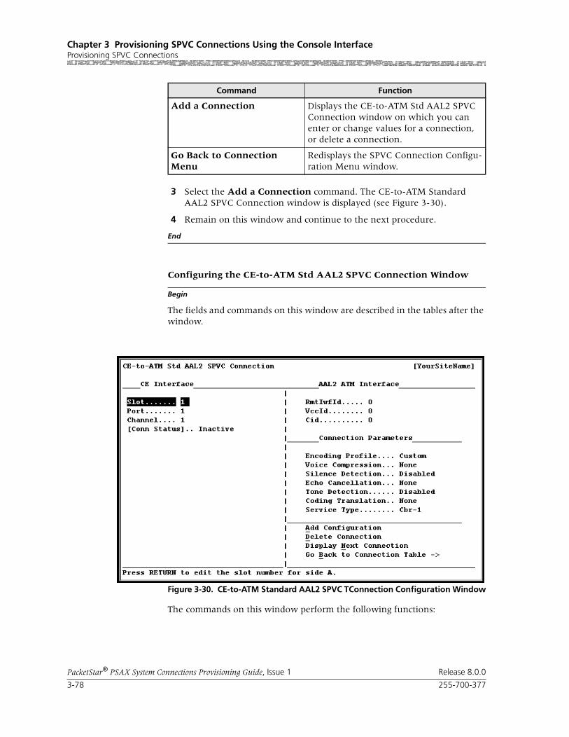
Chapter 3 Provisioning SPVC Connections Using the Console InterfaceProvisioning SPVC Connections
3-78 255-700-377
PacketStar® PSAX System Connections Provisioning Guide, Issue 1 Release 8.0.0
3 Select the Add a Connection command. The CE-to-ATM Standard AAL2 SPVC Connection window is displayed (see Figure 3-30).
4 Remain on this window and continue to the next procedure.
End
Begin
Configuring the CE-to-ATM Std AAL2 SPVC Connection Window
The fields and commands on this window are described in the tables after the window.
The commands on this window perform the following functions:
Add a Connection Displays the CE-to-ATM Std AAL2 SPVC Connection window on which you can enter or change values for a connection, or delete a connection.
Go Back to Connection Menu
Redisplays the SPVC Connection Configu-ration Menu window.
Figure 3-30. CE-to-ATM Standard AAL2 SPVC TConnection Configuration Window
Command Function
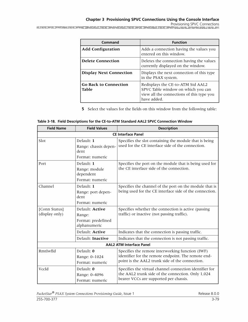
255-700-377 3-79
PacketStar® PSAX System Connections Provisioning Guide, Issue 1 Release 8.0.0
Chapter 3 Provisioning SPVC Connections Using the Console InterfaceProvisioning SPVC Connections
5 Select the values for the fields on this window from the following table:
Command Function
Add Configuration Adds a connection having the values you entered on this window.
Delete Connection Deletes the connection having the values currently displayed on the window.
Display Next Connection Displays the next connection of this type in the PSAX system.
Go Back to Connection Table
Redisplays the CE-to-ATM Std AAL2 SPVC Table window on which you can view all the connections of this type you have added.
Table 3-18. Field Descriptions for the CE-to-ATM Standard AAL2 SPVC Connection Window
Field Name Field Values Description
CE Interface Panel
Slot Default: 1
Range: chassis depen-dent
Format: numeric
Specifies the slot containing the module that is being used for the CE interface side of the connection.
Port Default: 1Range: module dependent
Format: numeric
Specifies the port on the module that is being used for the CE interface side of the connection.
Channel Default: 1
Range: port depen-dent
Format: numeric
Specifies the channel of the port on the module that is being used for the CE interface side of the connection.
[Conn Status](display only)
Default: Active
Range:
Format: predefined alphanumeric
Specifies whether the connection is active (passing traffic) or inactive (not passing traffic).
Default: Active Indicates that the connection is passing traffic.
Default: Inactive Indicates that the connection is not passing traffic.
AAL2 ATM Interface Panel
RmtIwfId Default: 0
Range: 0–1024
Format: numeric
Specifies the remote interworking function (IWF) identifier for the remote endpoint. The remote end-point is the AAL2 trunk side of the connection.
VccId Default: 0
Range: 0–4096
Format: numeric
Specifies the virtual channel connection identifier for the AAL2 trunk side of the connection. Only 1,024 bearer VCCs are supported per chassis.

Chapter 3 Provisioning SPVC Connections Using the Console InterfaceProvisioning SPVC Connections
3-80 255-700-377
PacketStar® PSAX System Connections Provisioning Guide, Issue 1 Release 8.0.0
Cid Default: 0
Range: 8–255 for non-OAM trunks;32–255 for End-Pt OAM trunks (0–15 is reserved)
Format: numeric
Specifies the channel identifier for the AAL2 trunk side of the connection. This identifier is unique for each AAL2 connection. For trunks with End-Pt selected as the OAM support type, the starting CID is 32. In this case, CIDs are preassigned to each CE channel; that is, channel 1 always has to be on CID 32, channel 2 always has to be on CID 33, and so on, up to CID 63 for channel 31 on an E1 interface.
Connection Parameters Panel
Note: For Release 8.0.0 and subsequent, the CAS refresh rate for all ITU-T profiles below is 5 sec-onds for the LES on-hook monitoring state.
Encoding Profile Default: Itut-profile-1
Range: N/A
Format: predefined alphanumeric
Specifies the ITU-T or ATM Forum parameter set that applies to the connection. A parameter set specifies the compression algorithm used, packet size, whether silence detection is included, and so on. For more information on ATM Forum profiles, see the reference appendix in this guide..
Note: See the ITU-T Transmission Profile Tables in the reference appendix of this guide.
Itut-profile-1 Indicates that the connection uses the ITU-T Standard profile-1. This profile supports PCM G.711-64 Kbps (no compression).
Itut-profile-3 Indicates that the connection uses the ITU-T Standard Profile 3. This profile supports ADPCM G.726 at 16, 24, 32, and 40 Kbps compression and silence detection.
Itut-profile-7 Indicates that the connection uses the ITU-T Standard Profile 7. This profile supports CS-ACELP G.729 8 Kbps compression and G.729 silence detection.
Af-profile-7 Indicates that the connection uses the ATM Form Stan-dard Profile 7. This profile supports PCM-64, ADPCM-32, and silence detection. Data is transmitted in 44-octet packets.
Af-profile-8 Indicates that the connection uses the ATM Form Stan-dard Profile 7. This profile supports PCM-64, ADPCM-32, and silence detection. Data is transmitted in 44-octet packets.
Af-profile-9 Indicates that the connection uses the ATM Form Stan-dard Profile 9. This profile supports PCM-64, ADPCM-32, and silence detection. Data is transmitted in 44-octet packets.
Af-profile-10 Indicates that the connection uses the ATM Form Stan-dard Profile 10. This profile supports PCM-64, ADPCM-32, without silence detection. Data is trans-mitted in 44-octet packets.
Table 3-18. Field Descriptions for the CE-to-ATM Standard AAL2 SPVC Connection Window (Continued)
Field Name Field Values Description

255-700-377 3-81
PacketStar® PSAX System Connections Provisioning Guide, Issue 1 Release 8.0.0
Chapter 3 Provisioning SPVC Connections Using the Console InterfaceProvisioning SPVC Connections
Af-profile-11 Indicates that the connection uses the ATM Form Stan-dard Profile 11. This profile supports PCM-64, ADPCM-32, without silence detection. Data is trans-mitted in 40-octet packets.
Af-profile-12 Indicates that the connection uses the ATM Form Stan-dard Profile 12. This profile supports PCM-64, ADPCM-32, with silence detection. Data is transmitted in 40-octet packets.
Custom Indicates that the connection uses user-defined voice encoding.
Default Indicates that the connection uses the default encoding profile of the AAL2 trunk configuration.
Voice Compression Default: NoneFormat: predefined alphanumeric
G726-16kG726-24kG726-32kG726-40kG729a-8k
Specifies the ITU-T standard of compression in Kbps.
Silence Detection Default: Disabled
Range: N/A
Format: predefined alphanumeric
Specifies whether silence detection will be used on this connection or not. You can specify if you want periods of silence in the connection to generate cells or not. To conserve bandwidth, select enabled.
Disabled Disables silence detection. Cells will be sent during silent periods in the connection.
Enabled Enables silence detection. No cells will be sent during silent periods in a connection. On the DSP2D Voice Server module, silence packets are sent every 100 msec.
Echo Cancellation Default: NoneRange: N/A
Format: predefined alphanumeric
Specifies what type of echo cancellation will be used on the connections. Echo is a portion of the transmis-sion that returns to the caller. Echo cancellation allows for the isolation and filtering out of unwanted signals caused by echoes from the main transmitted signal. Echo strength is measured in msec “tails”.
None Echo cancellation is not enabled.
G165-nearEnd ITU-T Standard G.165 (for near end only).
G168 ITU-T Standard G.168.
Table 3-18. Field Descriptions for the CE-to-ATM Standard AAL2 SPVC Connection Window (Continued)
Field Name Field Values Description
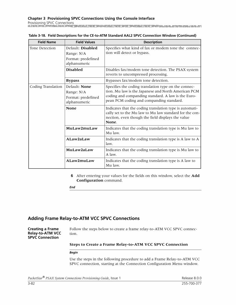
Chapter 3 Provisioning SPVC Connections Using the Console InterfaceProvisioning SPVC Connections
3-82 255-700-377
PacketStar® PSAX System Connections Provisioning Guide, Issue 1 Release 8.0.0
6 After entering your values for the fields on this window, select the Add Configuration command.
End
Adding Frame Relay-to-ATM VCC SPVC Connections
Creating a Frame Relay-to-ATM VCC SPVC Connection
Follow the steps below to create a frame relay-to-ATM VCC SPVC connec-tion.
Begin
Steps to Create a Frame Relay-to-ATM VCC SPVC Connection
Use the steps in the following procedure to add a Frame Relay-to-ATM VCC SPVC connection, starting at the Connection Configuration Menu window.
Tone Detection Default: Disabled
Range: N/A
Format: predefined alphanumeric
Specifies what kind of fax or modem tone the connec-tion will detect or bypass.
Disabled Disables fax/modem tone detection. The PSAX system reverts to uncompressed processing.
Bypass Bypasses fax/modem tone detection.
Coding Translation Default: None
Range: N/A
Format: predefined alphanumeric
Specifies the coding translation type on the connec-tion. Mu law is the Japanese and North American PCM coding and companding standard. A law is the Euro-pean PCM coding and companding standard.
None Indicates that the coding translation type is automati-cally set to the Mu law to Mu law standard for the con-nection, even though the field displays the value None.
MuLaw2muLaw Indicates that the coding translation type is Mu law to Mu law.
ALaw2aLaw Indicates that the coding translation type is A law to A law.
MuLaw2aLaw Indicates that the coding translation type is Mu law to A law.
ALaw2muLaw Indicates that the coding translation type is A law to Mu law.
Table 3-18. Field Descriptions for the CE-to-ATM Standard AAL2 SPVC Connection Window (Continued)
Field Name Field Values Description
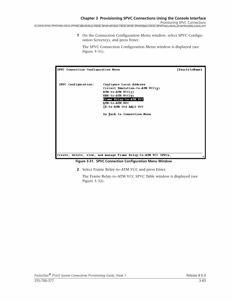
255-700-377 3-83
PacketStar® PSAX System Connections Provisioning Guide, Issue 1 Release 8.0.0
Chapter 3 Provisioning SPVC Connections Using the Console InterfaceProvisioning SPVC Connections
1 On the Connection Configuration Menu window, select SPVC Configu-ration Screen(y), and press Enter.
The SPVC Connection Configuration Menu window is displayed (see Figure 3-31).
2 Select Frame Relay-to-ATM VCC and press Enter.
The Frame Relay-to-ATM VCC SPVC Table window is displayed (see Figure 3-32).
Figure 3-31. SPVC Connection Configuration Menu Window

Chapter 3 Provisioning SPVC Connections Using the Console InterfaceProvisioning SPVC Connections
3-84 255-700-377
PacketStar® PSAX System Connections Provisioning Guide, Issue 1 Release 8.0.0
Note: At the time of initial installation, the Frame Relay-to-ATM VCC SPVC Table window is empty. After you have set up connections, this window displays all the connections of this type in the system.
Commands The commands on this window have the following functions:
Display Fields The display fields on this window provide the following information about all the Frame Relay-to-ATM VCC SPVC connections in the Multiservice Media Gateway system:
Figure 3-32. Frame Relay-to-ATM VCC SPVC Table Window
Command Function
Find . . . To find a particular connection, enter val-ues in the Slot, Port, Channel, and DLCI fields. If the connection exists, it will dis-play on the first line of the table.
Add a Connection Displays the Frame Relay-to ATM VCC SPVC Connection window.
Restart all unconnected Restarts connection establishment proce-dure for all active Frame Relay-to ATM VCC SPVCs that are not previously set up.
Go Back to Connection Menu
Redisplays the Connection Configuration Menu window.

255-700-377 3-85
PacketStar® PSAX System Connections Provisioning Guide, Issue 1 Release 8.0.0
Chapter 3 Provisioning SPVC Connections Using the Console InterfaceProvisioning SPVC Connections
3 Select the Add a Connection command and press Enter.
The Frame Relay-to-ATM VCC SPVC Connection window is displayed (see Figure 3-33).
Commands The commands on this window have the following functions:
Display Field Description
(Frame Relay) This column displays the information for all interface A (PVC) sides of the connections. The connection entries are displayed in ascending numerical order by slot, then by port, channel, and DLCI.
(ATM Side) This column displays the information for all interface B (SVC) sides of the connections.
Flow (S) This column displays the data traffic flow for the connections.
Total:0/0
The first number in this field indicates the num-ber of the connection table entry on the first line of the currently displayed window. The second number indicates the total number of connec-tion table entries for this connection type.
Figure 3-33. Frame Relay-to-ATM VCC SPVC Connection Window

Chapter 3 Provisioning SPVC Connections Using the Console InterfaceProvisioning SPVC Connections
3-86 255-700-377
PacketStar® PSAX System Connections Provisioning Guide, Issue 1 Release 8.0.0
Command Function
Bring Into Service Brings this out-of-service connection into service so that the connection is available to make or receive calls.
Take Out Of Service Takes this in-service connection out of service so that the connection is not avail-able to make or receive calls.
Delete Connection Deletes the out-of-service connection cur-rently displayed on the window.
Continuous Update Updates the values in the fields every sec-ond.
Restart This Connection Restarts the connection establishment procedure for this connection when the value InService is displayed in the [Admin Status] field.
Configure Traffic Parameters
Displays the Frame Relay-to-ATM VCC SPVC Traffic Parameters window.
View Connection Statistics Displays the Frame Relay-to-ATM VCC SPVC Statistics window.
Display Next Connection Displays the next connection of this type in the PSAX system (all connections of this type are displayed on the Frame Relay-to-ATM VCC SPVC Table window).
Go Back to Connection Table
Redisplays the Frame Relay-to-ATM VCC SPVC Connection Table window.
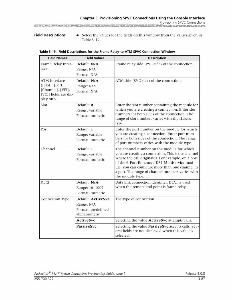
255-700-377 3-87
PacketStar® PSAX System Connections Provisioning Guide, Issue 1 Release 8.0.0
Chapter 3 Provisioning SPVC Connections Using the Console InterfaceProvisioning SPVC Connections
Field Descriptions 4 Select the values for the fields on this window from the values given in Table 3-19.
Table 3-19. Field Descriptions for the Frame Relay-to-ATM SPVC Connection Window
Field Names Field Values Description
Frame Relay Inter-face
Default: N/ARange: N/A
Format: N/A
Frame relay side (PVC side) of the connection.
ATM Interface ([Slot], [Port], [Channel], [VPI], [VCI] fields are dis-play only)
Default: N/A
Range: N/A
Format: N/A
ATM side (SVC side) of the connection.
Slot Default: 0
Range: variable
Format: numeric
Enter the slot number containing the module for which you are creating a connection. Enter slot numbers for both sides of the connection. The range of slot numbers varies with the chassis type.
Port Default: 1
Range: variable
Format: numeric
Enter the port number on the module for which you are creating a connection. Enter port num-bers for both sides of the connection. The range of port numbers varies with the module type.
Channel Default: 1Range: variable
Format: numeric
The channel number on the module for which you are creating a connection. This is the channel where the call originates. For example, on a port of the 6-Port Enhanced DS1 Multiservice mod-ule, you can configure more than one channel in a port. The range of channel numbers varies with the module type.
DLCI Default: N/A
Range: 16–1007
Format: numeric
Data link connection identifier. DLCI is used when the remote end point is frame relay.
Connection Type Default: ActiveSvc Range: N/A
Format: predefined alphanumeric
The type of connection.
ActiveSvc Selecting the value ActiveSvc attempts calls.
PassiveSvc Selecting the value PassiveSvc accepts calls. Sev-eral fields are not displayed when this value is selected.

Chapter 3 Provisioning SPVC Connections Using the Console InterfaceProvisioning SPVC Connections
3-88 255-700-377
PacketStar® PSAX System Connections Provisioning Guide, Issue 1 Release 8.0.0
Service Type Default: Ubr
Range: N/A
Format: Predefined alphanumeric
Specifies the PSAX system-supported quality of service (QoS) class. For a description of the QoS classes, see the reference appendix in this guide. The type selected causes the conformance type for the connection to be derived from the class of service. This derived value is enforced by the UPC setting of the I/O module.
Ubr Unspecified bit rate.
Vbr-nrt2 Variable bit rate, non-real time, queue 2
Vbr-nrt1 Variable bit rate, non-real time, queue 1
Vbr-rt2 Variable bit rate, real time, queue 2
Vbr-rt1 Variable bit rate, real time, queue 1
Vbr-express Variable bit rate, express
Flow Default: DuplexRange: N/A
Format: predefined alphanumeric
Direction of flow of data traffic in this connection.
Duplex Data flows in two directions between the two connection points (interface side A and interface side B).
SimplexA2B Data flows in only one direction, from side A to side B.
Simplex B2A Data flows in only one direction, from side B to side A.
Interworking Func-tion
Default: Frf8-Transl
Range: N/A
Format: predefined alphanumeric
Type of interworking to be done.
Frf8-Transl FRF.8 (Frame Relay Forum Implementation Agreement)—frame relay to ATM PVC service interworking.
Frf8-Pass FRF.8 (Frame Relay Forum Implementation Agreement)—frame relay to ATM PVC service interworking.
Frf5 FRF.5 (Frame Relay Forum Implementation Agreement)—frame relay to ATM PVC service interworking.
Table 3-19. Field Descriptions for the Frame Relay-to-ATM SPVC Connection Window
Field Names Field Values Description

255-700-377 3-89
PacketStar® PSAX System Connections Provisioning Guide, Issue 1 Release 8.0.0
Chapter 3 Provisioning SPVC Connections Using the Console InterfaceProvisioning SPVC Connections
Remote VPI, VCI/DLCI
Default: Required
Range: N/A
Format: predefined alphanumeric
Indicates whether the remote VPI and VCI/DLCI values are to be used at the destination. This field is displayed only when ActiveSvc is selected as the connection type.
Required The destination device uses the values specified at this end.
Any The destination device selects the VPI and VCI/DLCI values. The VPI and the VCI/DLCI fields are not displayed when Any is selected.
VPI Default: 0Range: 0–225 (ATM UNI);0–4095 (NNI)
Format: numeric
Virtual path identifier. The VPI field is displayed when Required is selected in the Remote VPI,VCI/DLCI field.
VCI/DLCI Default: 0
Range: 32–65535 (VCI);16-1007 (DLCI)
Format: numeric
Virtual channel identifier/data link connection identifier. The VCI/DLCI field is displayed when Required is selected in the Remote VPI,VCI/DLCI field.
Retry Limit Default: 0
Range: 0–65535
Format: numeric
Maximum limit on how many consecutive unsuccessful call setup attempts can be made before stopping the attempts to set up the con-nection. The value 0 indicates no limits and results in an infinite number of retries. See the reference appendix in this guide for the descrip-tion of ATM User-Network Interface Specifica-tion, Version 3.1, Cause Codes. This field is dis-played only when ActiveSvc is selected as the connection type.
Retry Interval (sec) Default: 2
Range: N/A
Format: numeric (sec)
The waiting period before attempting to establish the SPVC after one call attempt has failed. This field is displayed only when ActiveSvc is selected as the connection type.
Remote NSAP Addr Default: N/A
Range: N/A
Format: hexadecimal
The ATM NSAP address of the remote end of the connection, in hexidecimal notation. Enter the NSAP address of the remote frame relay or ATM interface in hexadecimal notation. This field is displayed only when ActiveSvc is selected as the connection type.
Table 3-19. Field Descriptions for the Frame Relay-to-ATM SPVC Connection Window
Field Names Field Values Description

Chapter 3 Provisioning SPVC Connections Using the Console InterfaceProvisioning SPVC Connections
3-90 255-700-377
PacketStar® PSAX System Connections Provisioning Guide, Issue 1 Release 8.0.0
[Admin Status](display only)
Default: OutOfService
Range: N/A
Format: predefined alphanumeric
Indicates whether the connection is attempting to make calls or receive calls.
OutOfService Indicates that the connection is not available to attempt making or receiving calls.
InService Indicates that the connection is available to attempt making calls or receiving calls.
Priority Default: 3Range: 1–6
Format: numeric
Specifies the the user-defined priority level of this connection. To ensure that a wireless SPVC con-nections is not affected in the event that an ATM IMA link fails, you can assign a priority level that you define. Typically, level 1 is the highest prior-ity and level 6 is the lowest.
[Oper Status](display only)
Default: Other
Range: N/A
Format: predefined alphanumeric
Operational status of the connection.
Other None of the types specified below.
EstablishmentInProgress
Connection is not operational, but call attempts are ongoing.
Connected Connection is currently operational.
RetriesExhausted Retry limit has been reached and call attempts have ceased.
NoAddressSupplied
No remote address has been configured, so no call attempts are initiated.
LowerLayerDown PVC endpoint is out of service.
WaitingForCall Passive endpoint of a SPVC connection, waiting for call from an active side.
WaitingForRetryTimer
Active endpoint of a SPVC connection, waiting for the retry timer to expire so that it can retry the call.
Table 3-19. Field Descriptions for the Frame Relay-to-ATM SPVC Connection Window
Field Names Field Values Description

255-700-377 3-91
PacketStar® PSAX System Connections Provisioning Guide, Issue 1 Release 8.0.0
Chapter 3 Provisioning SPVC Connections Using the Console InterfaceProvisioning SPVC Connections
Configuring Traffic Parameters
To configure the traffic parameters for this connection, perform the steps in the following procedure.
Begin
Steps to Configure Traffic Parameters
1 On the Frame Relay-to-ATM VCC SPVC Connection window (see Figure 3-31), select Configure Traffic Parameters and press Enter.
The Frame Relay-to-ATM VCC SPVC Traffic Parameters window is dis-played (see Figure 3-34).
[Last Rls Diag](display only)
Default: N/A
Range: N/A
Format: predefined alphanumeric
Last release diagnosis. Explains how the connec-tion was released and reported by the far end of the connection.
[Retry Failure Count](display only)
Default: N/ARange: N/A
Format: predefined alphanumeric
Displays how many times the call retry failed since the last successful call setup. When a call is released, the PSAX system will continue to retry up to the retry limit that is specified in the Retry Limit field. See the ATM UNI 3.0 specification for more information.
[Last Rls Cause](display only)
Default: 0
Range: N/A
Format: numeric
Displays the last release cause code. The cause code indicates a reason why the last attempted call was released. See the reference appendix in this guide for the description of SPVC Connection Cause Codes.
Note: This field is displayed only when you select the value ActiveSVC in the Conn Type field.
Table 3-19. Field Descriptions for the Frame Relay-to-ATM SPVC Connection Window
Field Names Field Values Description

Chapter 3 Provisioning SPVC Connections Using the Console InterfaceProvisioning SPVC Connections
3-92 255-700-377
PacketStar® PSAX System Connections Provisioning Guide, Issue 1 Release 8.0.0
Commands The commands on this window have the following functions:
Field Descriptions 2 Select the values for the traffic parameter fields on this window from the values given in Table 3-20.
Figure 3-34. Frame Relay-to-ATM SPVC Traffic Parameters Window
Command Function
Add This Connection Adds a connection having the values cur-rently displayed on the window.
Delete Connection and Return
Deletes the connection having the values currently displayed on the window.
Go Back to Connection Screen
Redisplays the Frame Relay-to-ATM VCC SPVC Connection Table window.

255-700-377 3-93
PacketStar® PSAX System Connections Provisioning Guide, Issue 1 Release 8.0.0
Chapter 3 Provisioning SPVC Connections Using the Console InterfaceProvisioning SPVC Connections
Table 3-20. Field Descriptions for the Frame Relay-to-ATM VCC SPVC Traffic Parameters Window
Field Name Field Values Description
Frame Size for Rate Cal.
Default: 4096
Range: N/A
Format: numeric
Measured in bytes.
Committed Burst Size
Default: 0
Range: N/A
Format: numeric
Use the default value.
Excess Burst Size Default: 45000000Range: N/A
Format: numeric
Measured in bits per second.
Committed Info Rate
Default: 0Range: N/A
Format: numeric
Committed information rate is the rate of traffic (measured in bits per second) for a given connec-tion that the system will attempt to provide guar-anteed delivery.
Note: If using traffic shaping on the STM-1 or OC-3 modules, set this parameter on the FR side of the connection on both ends of the link to con-trol the cell transmission rate. This is necessary because the SCR field is not available on the ATM side of the connection.
Traffic Shaping Default: Disabled
Range: N/A
Format: character (predetermined)
A method for controlling the flow of data traffic. It is implemented on modules that are offered with traffic-shaping variations: the OC-3c Multi-mode, OC-3c Single-Mode, STM-1 Multimode, and STM-1 Single-Mode modules.
Disabled Traffic shaping does not function.
Enabled Traffic shaping ensures that the variable bit-rate (VBR) traffic entering the PSAX system (via the OC-3c and STM-1 modules) complies with the parameters of the established service contracts.
[Time Interval](display only)
Default: 1000
Range: N/A
Format: numeric
Time, in seconds, since the last reset.

Chapter 3 Provisioning SPVC Connections Using the Console InterfaceProvisioning SPVC Connections
3-94 255-700-377
PacketStar® PSAX System Connections Provisioning Guide, Issue 1 Release 8.0.0
3 To add (apply) the connection configuration, select the Add This Con-nection command and press Enter.
4 To review this connection, select the Go Back to Connection Table command and press Enter (or press Ctrl+B).
The Frame Relay-to-ATM VCC SPVC Table window returns, displaying the values you just applied.
5 To add more connections of this type, repeat steps 2 through 4 for more connections as needed.
End
Viewing Connection Statistics
To view the statistics for this connection, on the Frame Relay-to-ATM VCC SPVC Connection window (see Figure 3-33), select View Connection Sta-tistics and press Enter.
The Frame Relay-to-ATM VCC SPVC Statistics window is displayed.
[Peak Cell Rate](display only)
Default: 1
Range: N/A
Format: numeric
Refer to the ATM UNI 3.0 specifications for more information. When setting this value, take into account the line rate for the module and the amount of bandwidth you are setting up for each interface for the module.
[Sustained Cell Rate](display only)
Default: 1
Range: N/A
Format: numeric
Sustained cell rate. Refer to the ATM UNI 3.0 specifications for more information. When set-ting this value, take into account the line rate for the module and the amount of bandwidth you are setting up for each interface for the module.
[Max Burst Size](display only)
Default: 1
Range: N/A
Format: numeric
Maximum burst size. Refer to the ATM UNI 3.0 specifications for more information. When set-ting this value, take into account the line rate for the module and the amount of bandwidth you are setting up for each interface for the module.
Table 3-20. Field Descriptions for the Frame Relay-to-ATM VCC SPVC Traffic Parameters Window
Field Name Field Values Description

255-700-377 3-95
PacketStar® PSAX System Connections Provisioning Guide, Issue 1 Release 8.0.0
Chapter 3 Provisioning SPVC Connections Using the Console InterfaceProvisioning SPVC Connections
Commands The commands on this window ha ve the following functions:
Field Descriptions The connection statistics on this window as described in Table 1-3.
Figure 3-35. Frame Relay-to-ATM VCC SPVC Statistics Window
Command Function
Reset Odometers Resets the Encoded Odometer, Decoded Odometer, In Odometer, and Out Odome-ter fields to zero.
If a call is disconnected, all odometers are reset to zero.
Continuous Update Updates the values in the fields every sec-ond.
Display Stats for Next Con-nection
Displays the statistics for the next connec-tion of this type.
Go Back to Connection Dis-play
Redisplays the Frame Relay-to-ATM VCC SPVC Connection window.

Chapter 3 Provisioning SPVC Connections Using the Console InterfaceProvisioning SPVC Connections
3-96 255-700-377
PacketStar® PSAX System Connections Provisioning Guide, Issue 1 Release 8.0.0
Table 3-21. Field Descriptions for the Frame Relay-to-ATM VCC SPVC Connection Statistics Window
Field Name Field Values Description
Slot Default: 0
Range: variable
Format: numeric
Slot identifier of the frame relay interface (Inter-face A). The range of slot numbers varies with the chassis type.
Port Default: 1
Range: variable
Format: numeric
Port identifier of the frame relay interface (Inter-face A). The range of port numbers varies with the module type.
Channel Default: 1Range: variable
Format: numeric
Channel identifier of the frame relay interface (Interface A). The range of channel numbers var-ies with the module type.
DLCI Default: N/ARange: 16-1007
Format: numeric
Data link control identifier of the frame relay interface in which the call is configured.
VPI Default: 0
Range: 0–255
Format: numeric
Virtual path identifier of the ATM side (SVC side) of the connection.
VCI Default: 0
Range: 32–65535
Format: numeric
Virtual channel identifier of the ATM side (SVC side) of the connection.
Cells Encoded Default: 0.0000 e0 Range: 0-(231-1)
Format: numeric
Number of cells encoded going into interface side A during the amount of time shown in Time Elapsed field.
Cells Decoded Default: 0.0000 e0
Range: 0-(231-1)
Format: numeric
Number of cells decoded going out of interface side B during the amount of time shown in Time Elapsed field.
Frames Dropped Default: 0
Range: N/A
Format: numeric
Number of frames dropped for a given DLCI in the A2B direction. This field is only applicable to the input side.
Encoded Odometer Default: 0.0000 e0 Range: 0-(231-1)
Format: numeric
Total number of cells encoded going into inter-face side A since the connection was created or statistics were reset.
Decoded Odometer Default: 0.0000 e0
Range: 0-(231-1)
Format: numeric
Total number of cells decoded going out of inter-face side B since the connection was created or statistics were reset.
Time Elapsed Default: 00:00:00
Range: N/A
Format: Time in hours (xx), minutes (xx), seconds (xx)
Default:
Time, in hours, minutes, and seconds, since the circuit was established.

255-700-377 3-97
PacketStar® PSAX System Connections Provisioning Guide, Issue 1 Release 8.0.0
Chapter 3 Provisioning SPVC Connections Using the Console InterfaceProvisioning SPVC Connections
Adding VBR-to-ATM VCC SPVC Connections
This connection is supported on the Ethernet and the 4-Port Ethernet mod-ules beginning with PacketStar PSAX Release 6.5.0, and AQueView EMS Release 4.5.
Creating a VBR-to-ATM VCC SPVC Connection
Perform the steps in the following procedure to create an VBR-to-ATM VCC SPVC connection.
Begin
1 On the SPVC Connection Configuration Menu window, select the VBR-to-ATM VCC option, and press Enter.
2 Select the Add a Connection command and press Enter.
The VBR-to-ATM VCC SPVC Connection window is displayed (see Figure 3-37).
3 Enter values in the fields on this window according to the information provided in Table 3-23.
4 To add (apply) the connection configuration, select the Add This Con-nection command and press Enter.
5 To review this connection, select the Go Back to Connection Table command and press Enter.
Time Since Reset Default: 00:00:00
Range: NA
Format: Time in hours (xx), minutes (xx), seconds (xx)
Time elapsed since the last time the Reset Odometers command was used.
The Reset Odometers command on the statis-tics window resets only the odometer fields and the corresponding clock. Other counters incre-ment for the life of the circuit.
Cells Received Default: 0.0000 e0
Range: 0-(231-1)
Format: numeric
Number of cells received into interface side A during the amount of time shown in Time Elapsed field.
Cells Transmitted Default: 0.0000 e0
Range: 0-(231-1)
Format: numeric
Number of cells transmitted out of interface side B during the amount of time shown in Time Elapsed field.
In Odometer Default: 0.0000 e0 Range: 0-(231-1)
Format: numeric
Total number of cells encoded going into inter-face side B since the connection statistics were reset.
Out Odometer Default: 0.0000 e0
Range: 0-(231-1)
Format: numeric
Total number of cells decoded going out of inter-face side A since the connection statistics were reset.
Table 3-21. Field Descriptions for the Frame Relay-to-ATM VCC SPVC Connection Statistics Window
Field Name Field Values Description

Chapter 3 Provisioning SPVC Connections Using the Console InterfaceProvisioning SPVC Connections
3-98 255-700-377
PacketStar® PSAX System Connections Provisioning Guide, Issue 1 Release 8.0.0
The VBR-to-ATM VCC SPVC Table window is displayed with the values you just applied.
6 To add more connections of this type, repeat steps 2–5 for more connec-tions as needed.
End
The VBR-to-ATM VCC SPVC Table window is displayed (see Figure 3-36).
Note: At the time of initial installation, the VBR-to-ATM VCC SPVC Table window is empty. After you have set up connections, this window displays all the connections of this type in the system.
Commands The commands on this window have the following functions:
Figure 3-36. VBR-to-ATM VCC SPVC Table Window
Command Function
Find . . . To find a particular connection, enter val-ues in the Slot, Port, and Channel fields. If the connection exists, it is displayed on the first line of the table.
Add a Connection Displays the VBR-to-ATM VCC SPVC Con-nection window.
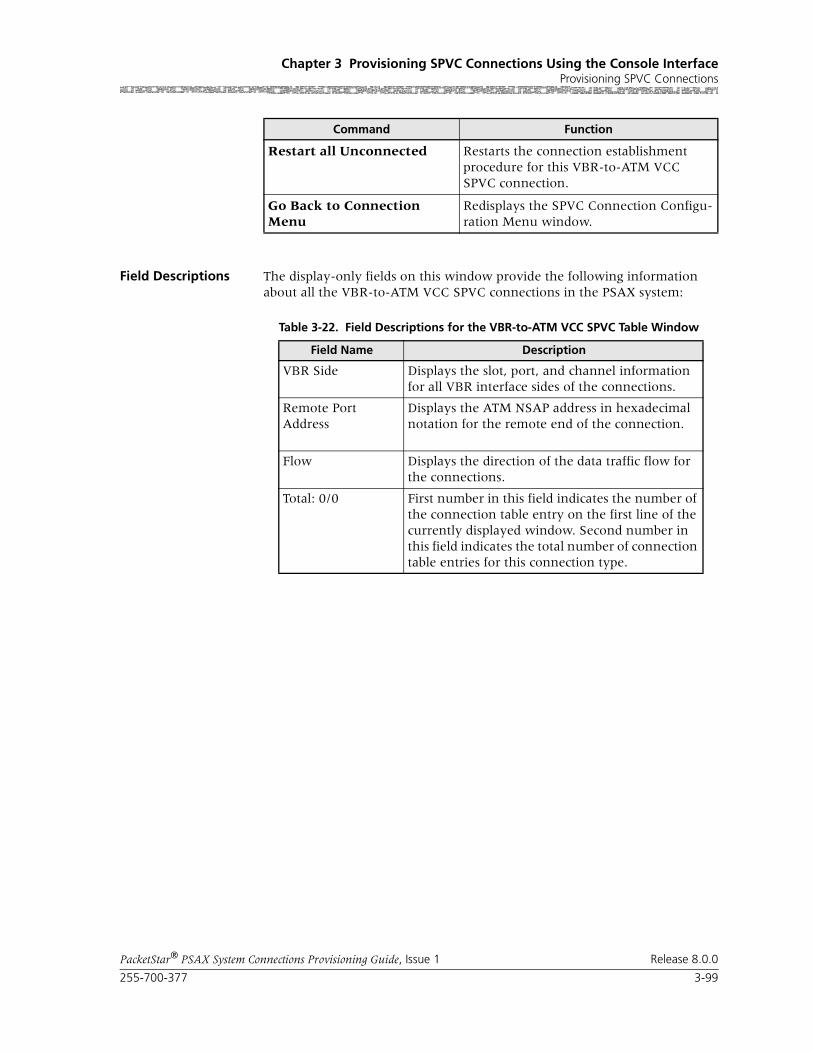
255-700-377 3-99
PacketStar® PSAX System Connections Provisioning Guide, Issue 1 Release 8.0.0
Chapter 3 Provisioning SPVC Connections Using the Console InterfaceProvisioning SPVC Connections
Field Descriptions The display-only fields on this window provide the following information about all the VBR-to-ATM VCC SPVC connections in the PSAX system:
Restart all Unconnected Restarts the connection establishment procedure for this VBR-to-ATM VCC SPVC connection.
Go Back to Connection Menu
Redisplays the SPVC Connection Configu-ration Menu window.
Command Function
Table 3-22. Field Descriptions for the VBR-to-ATM VCC SPVC Table Window
Field Name Description
VBR Side Displays the slot, port, and channel information for all VBR interface sides of the connections.
Remote Port Address
Displays the ATM NSAP address in hexadecimal notation for the remote end of the connection.
Flow Displays the direction of the data traffic flow for the connections.
Total: 0/0 First number in this field indicates the number of the connection table entry on the first line of the currently displayed window. Second number in this field indicates the total number of connection table entries for this connection type.

Chapter 3 Provisioning SPVC Connections Using the Console InterfaceProvisioning SPVC Connections
3-100 255-700-377
PacketStar® PSAX System Connections Provisioning Guide, Issue 1 Release 8.0.0
Commands The commands on this window have the following functions:
Figure 3-37. VBR-to-ATM VCC SPVC Connection Window
Command Function
Bring Into Service Brings this out-of-service connection into service so that the connection is available to make or receive calls.
Take Out Of Service Takes this in-service connection out of service so that the connection is not avail-able to make or receive calls.
View Connection Statistics Displays the VBR-to-ATM VCC SPVC Sta-tistics window.
Continuous Update Updates the values in the fields every sec-ond.
Restart This Connection Restarts the connection establishment procedure for this connection when the value InService is displayed in the [Admin Status] field.
Display Next Connection Displays the next connection of this type in the PSAX system (all connections of this type are displayed on the VBR-to-ATM VCC SPVC Connection Table win-dow).
Add This Connection Adds a connection having the values cur-rently displayed on the window.

255-700-377 3-101
PacketStar® PSAX System Connections Provisioning Guide, Issue 1 Release 8.0.0
Chapter 3 Provisioning SPVC Connections Using the Console InterfaceProvisioning SPVC Connections
Field Descriptions
Delete Connection Deletes the out-of-service connection cur-rently displayed on the window.
Go Back to Connection Table
Redisplays the VBR-to-ATM VCC SPVC Connection Table window.
Command Function
Table 3-23. Field Descriptions for the VBR-to-ATM SPVC Connection Window
Field Name Field Values Description
VBR Interface A Default: N/ARange: N/A
Format: N/A
Specifies the VBR interface side of the connection that will send and receive traffic. This side is used for the Ethernet side of the connection.
ATM Interface B Default: N/A
Range: N/A
Format: N/A
Specifies the ATM side of the connection that will send and receive traffic.
Slot Default: N/A
Range: chassis depen-dent
Format: numeric
Specifies the slot number containing the module for which you are creating a connection. Enter a slot numbes for Side A of the connection.
Port Default: N/ARange: module dependent
Format: numeric
Specifies the port number on the module for which you are creating a connection. Enter a port number for Side A of the connection.
Channel Default: N/A
Range: port depen-dent
Format: numeric
Specifies the channel number on the module for which you are creating a connection. Do not change the value 1 in this field.
[VPI](display only)
Default: N/A
Range: 0–4095
Format: numeric
Displays the virtual path identifier (ATM side). This value must be set up on the SPVC Address Table window.
[VCI](display only)
Default: N/ARange: 0–4095
Format: numeric
Displays the virtual channel identifier (ATM side). This value must be set up on the SPVC Address Table window.
[VUNI](display only)
Default: 0
Range: 0–255
Format: numeric
Displays the virtual ATM UNI, which provides bandwidth allocation restrictions. Currently this field is applicable only on the OC-12c/STM-4c APS/MSP), OC-3c APS, and STM-1 MSP mod-ules. When disabled, the default value is 0. The virtual UNI (VUNI) is associated with the egress part of the A-to-B or B-to-A side of the connec-tion.

Chapter 3 Provisioning SPVC Connections Using the Console InterfaceProvisioning SPVC Connections
3-102 255-700-377
PacketStar® PSAX System Connections Provisioning Guide, Issue 1 Release 8.0.0
Conn Type Default: ActiveSvc
Range: N/A
Format: predefined alphanumeric
Specifies whether the connection is active or pas-sive.
ActiveSvc Indicates that the connection attempts calls.
PassiveSvc Indicates that the connection accepts calls. Once you select this value, fields associated with the connection type set to ActiveSvc are hidden on this window.
Peak Rate Default: 1Range: 1–(232-1)(theoretical range, except for modules noted at right, see Description column)
Range:
Format: numeric (cells per second)
Peak cell rate (PCR) for all cells with both the CLP=0 bit and the CLP=1 bit. The value you set is the maximum allowed cell transmission rate (cells per second) for all cells both high and low priority, as allowed by your traffic contract. When setting this value, take into account the line rate for the module and the amount of bandwidth you are setting up for each interface for the mod-ule. Refer to the ATM UNI 3.1 specifications for more information. If you select the value SimplexA2B in the Flow field, set the value of this field to 0. The value in this field should be greater than the Sustained Cell Rate field.
Note: If you are using the traffic shaping Enabled setting on the bulleted modules listed below, entering a minimum cps value below the mini-mum listed below will cause traffic-shaped con-nections to default back to the minimum cps value when the connection passes traffic.
• On the 1-Port OC-3c MM/SM and the 1-Port STM-1 MM/SM, the cps range is 18–999999999.
• On the OC-12c/STM-4c SM/MM, the cps range is 87–999999999.
• On the 3-Port DS3/E3 ATM, the cps range is 7–999999999.
Note: The peak cell rate cannot exceed the maxi-mum cell rate for the interface.
Table 3-23. Field Descriptions for the VBR-to-ATM SPVC Connection Window
Field Name Field Values Description

255-700-377 3-103
PacketStar® PSAX System Connections Provisioning Guide, Issue 1 Release 8.0.0
Chapter 3 Provisioning SPVC Connections Using the Console InterfaceProvisioning SPVC Connections
Sustained Rate Default: 1
Range: 1–(232-1)(theoretical range)
Format: numeric (cells per second)
Specifies the sustainable cell rate (SCR) with CLP=0 (high priority) cells or the peak cell rate with CLP=0 cells. When setting this value, take into account the line rate for the module and the amount of bandwidth you are setting up for each interface for the module. Refer to the ATM UNI 3.1 specifications for more information. If you select the value SimplexA2B in the Flow field, set the value of this field to 0. The value in this field should be less than the Peak Cell Rate field.
Note: The sustained cell rate cannot exceed the maximum cell rate for the interface.
Max Burst Size (cells)
Default: 1
Range: 0–65535
Format: numeric
Indicates the maximum burst size. The maximum number of cells that can be received at the peak cell rate. This allows a burst of cells to arrive at a rate higher than that of the sustained cell rate. If the burst is larger than anticipated, the additional cells are either tagged or dropped. When setting this value, take into account the line rate for the module and the amount of bandwidth you are setting up for each interface for the module.
If you select the value SimplexA2B in the Flow field, set the value for peak rate to 0.
OC-3c APS Module: When the Traffic Shaping field is set to Enabled, the cell queue depth for the Max Burst Size field is internally set to 1000, regardless of the value you enter. If you enter values other than 1000, these values matter for incoming signalling SPVC/SVC setup from the remote end of the connection.
Service Type Default: Ubr
Range: N/A
Format: predefined alphanumeric
Specifies the PSAX system-supported quality of service (QoS) class. For a description of the QoS classes, see the reference appendix in this guide. The type selected causes the conformance type for the connection to be derived from the class of service. This derived value is enforced by the UPC setting of the I/O module.
Ubr Unspecified bit rate. If you select this value, the Sustained Cell Rate (cps) and Max Burst Size fields are hidden on this window.
Vbr-nrt2 Variable bit rate—nonreal-time 2.
Vbr-nrt1 Variable bit rate—nonreal-time 1.
Vbr-rt2 Variable bit rate—real-time 2.
Vbr-rt1 Variable bit rate—real-time 1.
Vbr-express Variable bit rate—express.
Table 3-23. Field Descriptions for the VBR-to-ATM SPVC Connection Window
Field Name Field Values Description

Chapter 3 Provisioning SPVC Connections Using the Console InterfaceProvisioning SPVC Connections
3-104 255-700-377
PacketStar® PSAX System Connections Provisioning Guide, Issue 1 Release 8.0.0
Remote NSAP Addr Default: N/A
Range: N/A
Format: hexadecimal
Indicates the ATM NSAP address of the remote end of the connection. Enter the NSAP address of the remote VBR or ATM interface.
Note: This field is displayed only when you select the value ActiveSvc in the Conn Type field.
Flow Default: DuplexRange: N/A
Format: predefined alphanumeric
Specifies the direction of flow of data traffic in this connection.
Duplex Indicates that data flows in two directions between the two connection points (interface side A and interface side B).
SimplexA2B Indicates that data flows in only one direction, from side A to side B.
Simplex B2A Indicates that data flows in only one direction, from side B to side A.
Retry Limit Default: 0 Range: 0–65535
Format: numeric
Specifies the maximum limit on how many con-secutive unsuccessful call setup attempts can be made before stopping the attempts to set up the connection. The value 0 indicates no limits, results in an infinite number of retries.
Retry Interval (sec) Default: 12
Range: 0–3600
Format: numeric (sec)
Specifies the number of seconds between retry intervals. The value 0 will result in a retry with no delay.
Peak Rate (cps) Default: 1 Range:
Format: numeric (cells per second)
When setting this value, take into account the line rate for the module and the amount of band-width you are setting up for each interface for the module. Refer to the ATM UNI 3.1 specifications for more information. If you select the value SimplexA2B in the Flow field, set the value for peak rate to 0.
Table 3-23. Field Descriptions for the VBR-to-ATM SPVC Connection Window
Field Name Field Values Description

255-700-377 3-105
PacketStar® PSAX System Connections Provisioning Guide, Issue 1 Release 8.0.0
Chapter 3 Provisioning SPVC Connections Using the Console InterfaceProvisioning SPVC Connections
Traffic Shaping Default: Disabled
Range: N/A
Format: predefined alphanumeric
Indicates the method for controlling the flow of data traffic. This feature is implemented on the following modules:
• 1-Port OC-3c Multimode and Single-Mode with Traffic Shaping modules
• 1-Port STM-1 Multimode and Single-Mode with Traffic Shaping modules
• 3-Port DS3/E3 ATM
• 1-Port OC-12c/STM-4c MM/SM 1+1 APS/MSP modules
See the Peak Rate field on this table for minimum cps ranges restrictions on these modules.
Disabled Indicates that traffic shaping is not used on this connection.
Enabled Ensures that the variable bit-rate (VBR) traffic entering the PSAX system via these modules complies with the parameters of the established service contracts.
[Oper Status](display only)
Default: OtherRange: N/A
Format: predefined alphanumeric
Displays the operational status of this connection.
Other Indicates that the operational status of this con-nection is not described by the types specified any other field values below.
EstablishmentInProgress
Indicates that the connection is not operational, but call attempts are ongoing.
Connected Indicates that the connection is currently opera-tional.
RetriesExhausted Indicates that the retry limit has been reached and call attempts have ceased.
NoAddressSupplied
Indicates that no remote address has been config-ured, so no call attempts are initiated.
LowerLayerDown Indicates that the PVC endpoint is out of service.
WaitingForCall Indicates that the passive endpoint of a SPVC connection is waiting for call from an active side.
WaitingForRetryTimer
Indicates that the active endpoint of a SPVC con-nection is waiting for the retry timer to expire so that it can retry the call.
[Last Rls Diag](display only)
Default: N/A
Range: N/A
Format: predefined alphanumeric
Displays the last release diagnosis, which explains how the connection was released and reported by the far end of the connection.
Table 3-23. Field Descriptions for the VBR-to-ATM SPVC Connection Window
Field Name Field Values Description
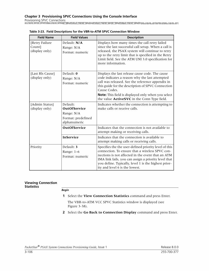
Chapter 3 Provisioning SPVC Connections Using the Console InterfaceProvisioning SPVC Connections
3-106 255-700-377
PacketStar® PSAX System Connections Provisioning Guide, Issue 1 Release 8.0.0
Viewing Connection Statistics
Begin
1 Select the View Connection Statistics command and press Enter.
The VBR-to-ATM VCC SPVC Statistics window is displayed (see Figure 3-38).
2 Select the Go Back to Connection Display command and press Enter.
[Retry Failure Count](display only)
Default: N/A
Range: N/A
Format: numeric
Displays how many times the call retry failed since the last successful call setup. When a call is released, the PSAX system will continue to retry up to the retry limit that is specified in the Retry Limit field. See the ATM UNI 3.0 specification for more information.
[Last Rls Cause](display only)
Default: 0
Range: N/A
Format: numeric
Displays the last release cause code. The cause code indicates a reason why the last attempted call was released. See the reference appendix in this guide for the description of SPVC Connection Cause Codes.
Note: This field is displayed only when you select the value ActiveSVC in the Conn Type field.
[Admin Status](display only)
Default: OutOfService
Range: N/A
Format: predefined alphanumeric
Indicates whether the connection is attempting to make calls or receive calls.
OutOfService Indicates that the connection is not available to attempt making or receiving calls.
InService Indicates that the connection is available to attempt making calls or receiving calls.
Priority Default: 3Range: 1–6
Format: numeric
Specifies the the user-defined priority level of this connection. To ensure that a wireless SPVC con-nections is not affected in the event that an ATM IMA link fails, you can assign a priority level that you define. Typically, level 1 is the highest prior-ity and level 6 is the lowest.
Table 3-23. Field Descriptions for the VBR-to-ATM SPVC Connection Window
Field Name Field Values Description

255-700-377 3-107
PacketStar® PSAX System Connections Provisioning Guide, Issue 1 Release 8.0.0
Chapter 3 Provisioning SPVC Connections Using the Console InterfaceProvisioning SPVC Connections
3 To permanently save these connections, press Ctrl+G to redisplay the Console Interface Main Menu window, select the Save Configuration command, and press Enter to store the values to the PSAX system data-base.
End
Commands The commands on this window have the following functions:
Field Descriptions The descriptions of the display-only fields on this window are provided in Table 3-24.
Figure 3-38. VBR-to-ATM VCC SPVC Statistics Window
Command Function
Reset Odometers Resets the Encoded Odometer, Decoded Odometer, In Odometer, and Out Odome-ter fields to zero. If a call is disconnected, all odometers are reset to 0.
Continuous Update Updates the values in the fields every sec-ond.
Display Stats for Next Con-nection
Displays the statistics for the next connec-tion of this type.
Go Back to Connection Dis-play
Redisplays the Frame Relay-to-ATM VCC SPVC Connection window.

Chapter 3 Provisioning SPVC Connections Using the Console InterfaceProvisioning SPVC Connections
3-108 255-700-377
PacketStar® PSAX System Connections Provisioning Guide, Issue 1 Release 8.0.0
Table 3-24. Field Descriptions for the VBR-to-ATM VCC SPVC Statistics Window
Field Name Field Values Description
Slot Default: Varies depending on selected slot
Range: Varies depending on chassis type
Format: Numeric
Indicates the slot identifier of the ATM interface for either the ATM Interface A panel or the ATM Interface B panel on this connection.
Port Default: Varies depending on selected slot
Range: Varies depending on module type
Format: Numeric
Indicates the port identifier of the ATM interface for either the ATM Interface A panel or the ATM Interface B panel on this connection.
Channel Default: Varies depending on selected slot
Range: Varies depending on module type
Format: Numeric
Indicates the channel identifier of the ATM inter-face for either Interface A or Interface B on this connection.
VPI (ATM Interface panel only)
Default: 0Range: 0–255
Format: Numeric
Indicates the virtual path identifier of the ATM side (SVC side) on this connection.
VCI (ATM Interface panel only)
Default: 0
Range: 32–65535
Format: Numeric
Indicates the virtual channel identifier of the ATM side (SVC side) on this connection.
Cells Encoded Default: 0
Range: N/A
Format: Numeric
Displays the number of cells encoded going into interface Side A on this connection during the amount of time shown in Time Elapsed field.
Cells Decoded Default: 0Range: N/A
Format: Numeric
Displays the number of cells decoded going out of interface Side B on this connection during the amount of time shown in Time Elapsed field.
Encoded Odometer Default: 0
Range: N/A
Format: Numeric
Displays the total number of cells encoded going into interface Side A since the connection was created or statistics were reset.
Decoded Odometer Default: 0
Range: N/A
Format: Numeric
Displays the total number of cells decoded going out of interface Side A since the connection was created or statistics were reset.
Cells Received Default: 0Range: N/A
Format: Numeric
Displays the number of valid cells received since the virtual circuit or virtual path was established.

255-700-377 3-109
PacketStar® PSAX System Connections Provisioning Guide, Issue 1 Release 8.0.0
Chapter 3 Provisioning SPVC Connections Using the Console InterfaceProvisioning SPVC Connections
Adding VBR-to-ATM Standard AAL2 VCC SPVC Connections
Accessing the VBR-to-ATM Std AAL2 VCC SPVC Connection
Begin
Window
1 On the Connection Configuration Menu window, select the SPVC Con-figuration Screen option under the SPVC Configuration option.
The SPVC Connection Configuration Menu window is displayed (see Figure 3-39).
Cells Transmitted Default: 0
Range: N/A
Format: Numeric
Displays the number of valid cells transmitted since the virtual circuit or virtual path was estab-lished.
In Odometer Default: 0Range: N/A
Format: Numeric
Displays the total number of cells encoded going into interface Side B since the connection statis-tics were reset.
Out Odometer Default: 0
Range: N/A
Format: Numeric
Displays the total number of cells decoded going out of interface Side A since the connection sta-tistics were reset.
Time Elapsed Default: 00:00:00
Range: N/A
Format: hh:mm:ss
Displays the time, in hours, minutes, and sec-onds, since last reset.
Time Since Reset Default: 00:00:00
Range: N/A
Format: hh:mm:ss
Time elapsed in hours, minutes, and seconds, since the last time the Reset Odometers com-mand was used.
Table 3-24. Field Descriptions for the VBR-to-ATM VCC SPVC Statistics Window
Field Name Field Values Description

Chapter 3 Provisioning SPVC Connections Using the Console InterfaceProvisioning SPVC Connections
3-110 255-700-377
PacketStar® PSAX System Connections Provisioning Guide, Issue 1 Release 8.0.0
2 Select the VBR-to-ATM Std AAL2 VCC command. The VBR-to-ATM Std AAL2 SPVC Table is displayed (see Figure 3-40).
Note: At the time of initial installation, the VBR-to-ATM Std AAL2 SPVC Table window is empty. After you have set up connections,
Figure 3-39. VBR-to-ATM Std AAL2 VCC SPVC Connection Option
Figure 3-40. VBR-to-ATM Std AAL2 SPVC Table Window

255-700-377 3-111
PacketStar® PSAX System Connections Provisioning Guide, Issue 1 Release 8.0.0
Chapter 3 Provisioning SPVC Connections Using the Console InterfaceProvisioning SPVC Connections
this window displays all the connections of this type in the sys-tem.
Descriptions of the display-only fields on this window are provided in Table 3-25.
The commands on this window perform the following functions:
3 Select the Add a Connection command.
The VBR-to-ATM Std AAL2 SPVC Connection window is displayed (see Figure 3-41).
Table 3-25. Field Descriptions for the VBR-to-ATM Std AAL2 SPVC Table Window
Field Name Description
(VBR Side) Displays the slot, port, and channel information for all VBR interface sides of the connections.
RemoteIwfId Displays the ATM NSAP address in hexadecimal nota-tion, the VCC ID, and the CID for the remote end of the connection.
Status Displays the direction of the data traffic flow for the connections.
Total: 0/0 First number in this field indicates the number of the connection table entry on the first line of the currently displayed window. Second number in this field indi-cates the total number of connection table entries for this connection type.
Command Function
Page Up Scroll up one page.
Page Down Scrolls down one page.
Top Displays entries at the top of the table.
Bottom Displays entries at the bottom of the table.
Find . . . Searches the table for a connection using the search parameters you specify. To find a particular connection, enter values in the Slot, Port, and Channel fields. If the connection exists, it is displayed on the first line of the table.
Add a Connection Displays the VBR-to-ATM Std AAL2 SPVC Connection window on which you can enter or change values for a connection, or delete a connection.
Go Back to Connection Menu
Redisplays the SPVC Connection Configu-ration Menu window.
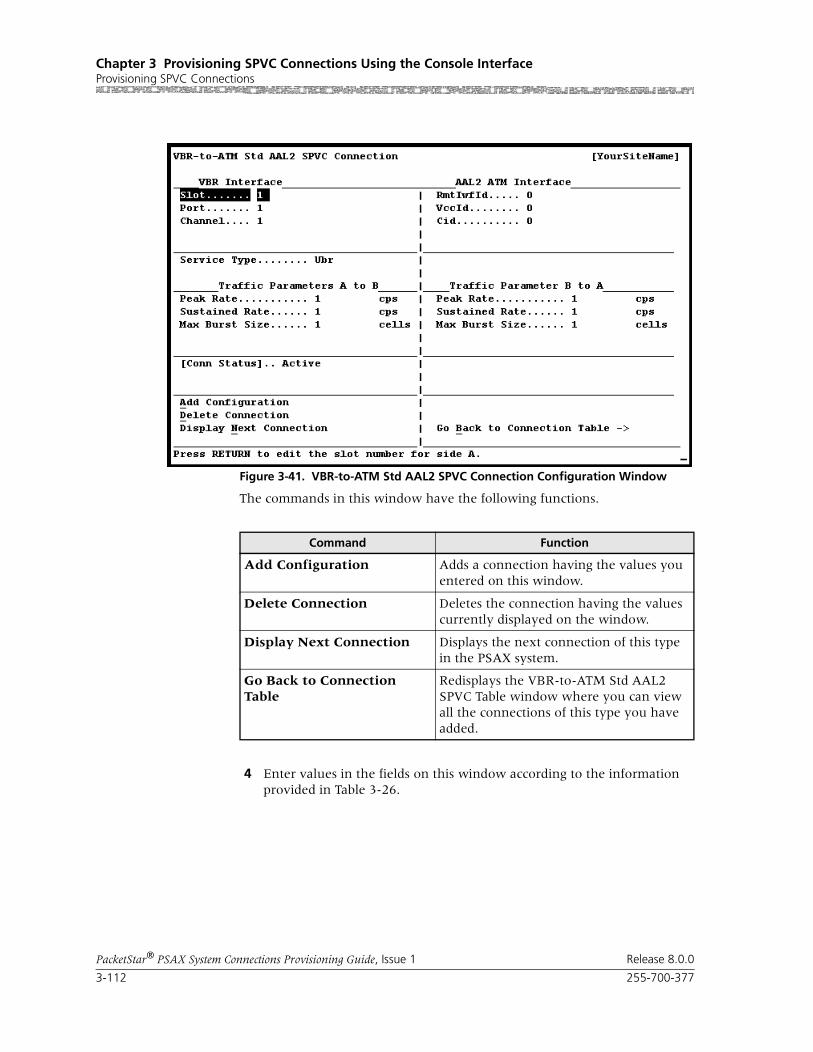
Chapter 3 Provisioning SPVC Connections Using the Console InterfaceProvisioning SPVC Connections
3-112 255-700-377
PacketStar® PSAX System Connections Provisioning Guide, Issue 1 Release 8.0.0
The commands in this window have the following functions.
4 Enter values in the fields on this window according to the information provided in Table 3-26.
Figure 3-41. VBR-to-ATM Std AAL2 SPVC Connection Configuration Window
Command Function
Add Configuration Adds a connection having the values you entered on this window.
Delete Connection Deletes the connection having the values currently displayed on the window.
Display Next Connection Displays the next connection of this type in the PSAX system.
Go Back to Connection Table
Redisplays the VBR-to-ATM Std AAL2 SPVC Table window where you can view all the connections of this type you have added.

255-700-377 3-113
PacketStar® PSAX System Connections Provisioning Guide, Issue 1 Release 8.0.0
Chapter 3 Provisioning SPVC Connections Using the Console InterfaceProvisioning SPVC Connections
Table 3-26. Field Descriptions for the VBR-to-ATM Std AAL2 SPVC Connection Window
Field Name Field Values Field Description
VBR Interface (Left Panel)
Slot Default: 1
Range: chassis depen-dent
Format: numeric
Specifies the slot containing the module that is being used for the VBR interface side of the con-nection.
Port Default: 1
Range: module dependent
Format: numeric
Specifies the port on the module that is being used for the VBR interface side of the connection.
Channel Default: 1
Range: port depen-dent
Format: numeric
Specifies the channel of the port on the module that is being used for the VBR interface side of the connection.
AAL2 ATM Interface (Right Panel)
RmtIwfId Default: 0Range: 0–1024
Format: numeric
Specifies the remote interworking function (IWF) identifier for the remote endpoint. The remote endpoint is the AAL2 trunk side of the connec-tion.
VccId Default: 0
Range: 0–4096
Format: numeric
Specifies the virtual channel connection identifier for the AAL2 trunk side of the connection. Only 1,024 bearer VCCs are supported per chassis.
Cid Default: 0Range: 8–255 for non-OAM trunks;32–255 for End-Pt OAM trunks (0–15 is reserved)
Format: numeric
Specifies the channel identifier for the AAL2 trunk side of the connection. This identifier is unique for each AAL2 connection. For trunks with End-Pt selected as the OAM support type, the starting CID is 32. In this case, CIDs are preas-signed to each circuit emulation channel, that is channel 1 always has to be on CID 32, channel 2 always has to be on CID 33, and so on up to CID 63 for channel 31 on an E1 interface.
General Connection Parameters (Left Panel)
Service Type Default: Ubr
Range: N/A
Format: predefined alphanumeric
Indicates the PSAX system-supported quality of service (QoS) class. See the appropriate PacketStar PSAX Multiservice Media Gateway user guide for a description of each service type.
Ubr Unspecified bit rate
Vbr-nrt2 Variable bit rate, non-real time queue 2
Vbr-nrt1 Variable bit rate, non-real time queue 1
Vbr-rt2 Variable bit rate, real time queue 2
Vbr-rt1 Variable bit rate, real time queue 1
Vbr-express Variable bit rate, express

Chapter 3 Provisioning SPVC Connections Using the Console InterfaceProvisioning SPVC Connections
3-114 255-700-377
PacketStar® PSAX System Connections Provisioning Guide, Issue 1 Release 8.0.0
[Conn Status](display only)
Default: Active
Range: N/A
Format: predefined alphanumeric
Specifies whether the connection is active (pass-ing traffic) or inactive (not passing traffic).
Active Indicates that the connection is passing traffic.
Inactive Indicates that the connection is not passing traffic.
Traffic Parameters A to B (Left Panel)
Peak Rate (cps) Default: 1Range: 1–(232-1)(theoretical range)
Range: 1–(2E32-1)(theoretical range)
Format: numeric (cells per second)
Indicates peak cell rate on the VBR interface side of the connection. The maximum allowed cell transmission rate (in cells per second), which defines the shortest time period between cells. When setting this value, calculate the line rate for the module and the amount of bandwidth you are setting up for each interface for the module. The value in this field must be greater than the value in the Sustained Rate field. Refer to the ATM UNI 3.1 specifications for more information.
In Packet Pipe Mode on the DSP2 Voice Server Modules, this value cannot exceed 22,092 cps.
Note: The peak cell rate cannot exceed the maxi-mum cell rate for the interface.
Sustained Rate (cps)
Default: 1
Range: 1–(232-1)(theoretical range)
Range: 1–(2E32-1)(theoretical range)
Format: numeric (cells per second)
Indicates the sustainable cell rate (SCR) with CLP=0 (high priority) cells or the peak cell rate with CLP=0 cells on the VBR interface side of the connection. When setting this value, calculate the line rate for the module and the amount of bandwidth you are setting up for each interface for the module. The value in this field must be less than the Peak Rate field. Refer to the ATM UNI 3.1 specifications for more information.
In Packet Pipe Mode on the DSP2 Voice Server modules, this value cannot exceed 22,092 cps.
Note: The sustained cell rate cannot exceed the maximum cell rate for the interface.
Max Burst Size (cells)
Default: 1
Range: 0–65535
Format: numeric (cells)
Indicates the maximum burst size on the VBR interface side of the connection. This traffic parameter specifies the maximum number of cells that can be transmitted at the peak cell rate. The MBS allows a burst of cells to arrive at a rate higher than that of the sustained cell rate. If the burst is larger than anticipated, the additional cells are either tagged or dropped. When setting this value, calculate the line rate for the module and the amount of bandwidth you are setting up for each interface for the module.
Table 3-26. Field Descriptions for the VBR-to-ATM Std AAL2 SPVC Connection Window (Continued)
Field Name Field Values Field Description

255-700-377 3-115
PacketStar® PSAX System Connections Provisioning Guide, Issue 1 Release 8.0.0
Chapter 3 Provisioning SPVC Connections Using the Console InterfaceProvisioning SPVC Connections
Traffic Parameters B to A (Right Panel)
Peak Rate (cps) Default: 1
Range: 1–(232-1)(theoretical range)
Range: 1–(2E32-1)(theoretical range)
Format: numeric (cells per second)
Indicates peak cell rate on the AAL2 ATM inter-face side of the connection. The maximum allowed cell transmission rate (in cells per sec-ond), which defines the shortest time period between cells. When setting this value, calculate the line rate for the module and the amount of bandwidth you are setting up for each interface for the module. The value in this field must be greater than the value in the Sustained Rate field. Refer to the ATM UNI 3.1 specifications for more information.
In Packet Pipe Mode on the DSP2 Voice Server Modules, this value cannot exceed 22,092 cps.
Note: The peak cell rate cannot exceed the maxi-mum cell rate for the interface.
Sustained Rate (cps)
Default: 1
Range: 1–(232-1)(theoretical range)
Range: 1–(2E32-1)(theoretical range)
Format: numeric (cells per second)
Indicates the sustainable cell rate (SCR) with CLP=0 (high priority) cells or the peak cell rate with CLP=0 cells on the AAL2 ATM interface side of the connection. When setting this value, calcu-late the line rate for the module and the amount of bandwidth you are setting up for each inter-face for the module. The value in this field must be less than the Peak Rate field. Refer to the ATM UNI 3.1 specifications for more information.
In Packet Pipe Mode on the DSP2 Voice Server Modules, this value cannot exceed 22,092 cps.
Note: The sustained cell rate cannot exceed the maximum cell rate for the interface.
Max Burst Size (cells)
Default: 1Range: 0–65535
Format: numeric (cells)
Indicates the maximum burst size on the AAL2 ATM interface side of the connection. This traffic parameter specifies the maximum number of cells that can be transmitted at the peak cell rate. The MBS allows a burst of cells to arrive at a rate higher than that of the sustained cell rate. If the burst is larger than anticipated, the additional cells are either tagged or dropped. When setting this value, calculate the line rate for the module and the amount of bandwidth you are setting up for each interface for the module.
Table 3-26. Field Descriptions for the VBR-to-ATM Std AAL2 SPVC Connection Window (Continued)
Field Name Field Values Field Description

Chapter 3 Provisioning SPVC Connections Using the Console InterfaceProvisioning SPVC Connections
3-116 255-700-377
PacketStar® PSAX System Connections Provisioning Guide, Issue 1 Release 8.0.0

PacketStar® PSAX System Connections Provisioning Guide, Issue 1 Release 8.0.0
255-700-377 4-1
4 Provisioning SVC Connections Usingthe Console Interface
Overview of This Chapter
This chapter describes how to set up permanent virtual circuit (PVC), switched virtual circuit (SVC), and soft permanent virtual circuit (SPVC) con-nections in the PSAX system for service provisioning and how to view statis-tics data for billing and performance monitoring. Before you provision con-nections for this module, you must have first completed the following tasks, which are detailed in the appropriate PacketStar PSAX Module Guide:
• Setting the configuration values for one or more ports
• Setting the configuration values for the types of interfaces you want to use on this module
This chapter contains instructions for configuring the following types of con-nections, with the exception of the PVC and the SVC supporting the GR-303 Interface.
Note: For instructions on configuring a GR-303 interface group on an I/O module, see the application note entitled PacketStar® PSAX Config-uring the GR-303 Voice Gateway User Guide, Issue 3
Connection Types Supported
The PSAX I/O modules support at least one the following connection types:
• PVC connections
• SVC connections
Note: SVC connections are not directly configurable on a PSAX system. Configure them through an interface with a call controller, such as the Lucent Softswitch–T3 (Toll/Tandem/ Transit), a 7R/E™, or a ConnectStar™ Interworking Call Router. Call controllers send call setup information to the PSAX System. See the section, “Enabling SVCs Connections.”
• SPVC connections
For a matrix of connection types by interface types, see the Connection Types by Interface Types table in the appendix, “Reference Information.”
Connection Types by Interface Type For a matrix of connection types by interface types, see the Connection Types
by Interface Types table in the appendix, “Reference Information.”

Chapter 4 Provisioning SVC Connections Using the Console InterfaceProvisioning SVC Connections
4-2 255-700-377
PacketStar® PSAX System Connections Provisioning Guide, Issue 1 Release 8.0.0
Before you can provision connections, you must select an interface type value other than Unconfigured in the Interface Type field on the Enhanced DS1 Port and Channel Configuration window.
Provisioning SVC Connections
Note: SVC connections are not supported on the STM-1 MM/SM Traffic Shaping modules.
To display SVC connections on the ATM-to-ATM VCC/VPC SVC/SVP Table window, they must be enabled by configuring IISP or PNNI links on the PSAX system. To enable SVC connections, you must first set up a PNNI link or an IISP link.
Setting Up a PNNI Link
To set up a PNNI link, do the following:
1. Configure a PNNI node and bring it into service. Be sure that Up is dis-played in the [Admin Status] field.
For instructions on PNNI node configuration, the appropriate PacketStar PSAX Multiservice Media Gateway user guide.
2. Configure a channel on an I/O module with the ATM PNNI interface, and bring the interface into service.
For instructions on ATM PNNI interface configuration, see the appropri-ate PacketStar PSAX module user guide.
After enabling this PNNI link, ATM-to-ATM SVC connections can be dynamically created by the PSAX system through an interface with a call controller such as a Lucent Softswitch–T3 (Toll/Tandem/ Transit), a Lucent 7R/E™, or aLucent ConnectStar™ Interworking Call Router. If you enable a PNNI link and an IISP link, the PSAX system will use the PNNI link first to create an SVC. If the PNNI link goes down, the IISP link will be used to sustain the SVC.
Setting Up an IISP Link
To set up a IISP link, do the following:
1. Configure a channel on an I/O module with the ATM IISP user or ATM IISP network interface, and bring the interface into service.
For instructions on ATM IISP interface configuration, see the appropriate PacketStar PSAX module user guide.
2. Add an entry to the IISP VBR routing table or the IISP CBR routing table.
For instructions on adding IISP VBR and IISP CBR routing entries, see the appropriate PacketStar PSAX module user guide.
After enabling this IISP link, ATM-to-ATM SVC connections can be dynamically created by the PSAX system through an interface with a call controller such as a Lucent Softswitch–T3 (Toll/Tandem/Transit), a Lucent 7R/E™, or a Lucent ConnectStar™ Interworking Call Router. If you enable a PNNI link and an IISP link, the PSAX system will use the PNNI link first to create an SVC. If the PNNI link goes down, the IISP link will be used to sustain the SVC.

255-700-377 4-3
PacketStar® PSAX System Connections Provisioning Guide, Issue 1 Release 8.0.0
Chapter 4 Provisioning SVC Connections Using the Console InterfaceProvisioning SVC Connections
Viewing ATM-to-ATM VCC SVC Connections
Note: SVC connections are not supported on the OC-3c or the STM-1 MM/SM Traffic Shaping modules.
The SVC connections that display on the ATM-to-ATM VCC SVC Table win-dow change dynamically as they are created and then torn down. Use the following steps to display SVC connections, starting at the Connection Con-figuration Menu window.
In the Connection Configuration Menu window, select the ATM-to-ATM VCC/VPC option and press Enter.
The ATM-to-ATM VCC/VPC SVC/SVP Table window is displayed (see Figure 4-1).
Commands The commands on this window have the following functions:
To refresh the display of SVCs, select the Go Back to Connection Menu command, and then select the ATM-to-ATM VCC option again.
Figure 4-1. ATM-to-ATM VCC SVC Table Window
Command Function
Find To find a particular connection, enter values in the Slot, Port, Chnl, VPI, and VCI fields If the connection exists, it is displayed on the first line of the table.
Go Back to Con-nection Menu→
Redisplays the Connection Configuration Menu win-dow.

Chapter 4 Provisioning SVC Connections Using the Console InterfaceProvisioning SVC Connections
4-4 255-700-377
PacketStar® PSAX System Connections Provisioning Guide, Issue 1 Release 8.0.0
Editing ATM-to-ATM VCC SVC Connection Entries
Note: SVC connections are not supported on the OC-3c or the STM-1 MM/SM Traffic Shaping modules.
The SVC connections that display on the ATM-to-ATM VCC SVC Table win-dow change dynamically as they are created and then torn down.
Viewing or Editing an ATM-to-ATM SVC Connection
Perform the steps in the following procedure to view or edit an ATM-to-ATM SVC connection, starting at the Connection Configuration Menu window.
Begin
Steps to View or Edit an ATM-to-ATM VCC SVC Connection
1 On the Connection Configuration Menu window, select the ATM-to-ATM VCC/VPC option and press Enter.
The ATM-to-ATM VCC/VPC SVC/SVP Table window is displayed (see Figure 4-2).
Commands The commands on this window have the following functions:
Figure 4-2. ATM-to-ATM VCC/VPC SVC/SVP Table Window
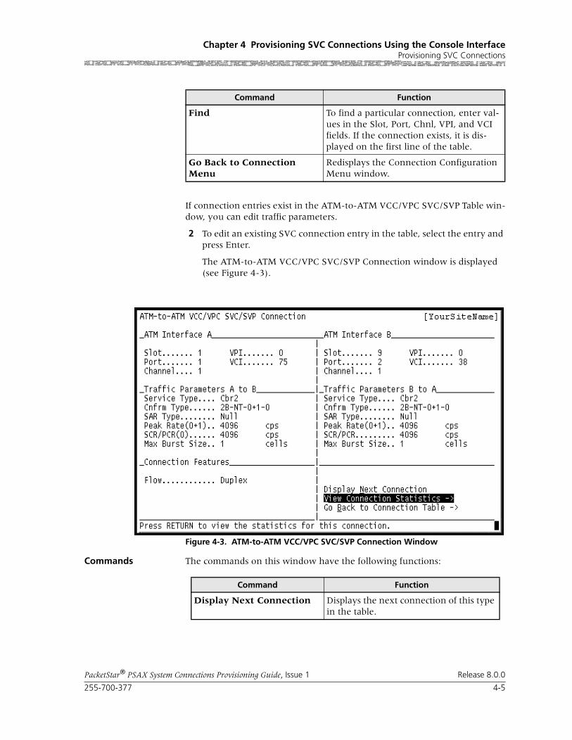
255-700-377 4-5
PacketStar® PSAX System Connections Provisioning Guide, Issue 1 Release 8.0.0
Chapter 4 Provisioning SVC Connections Using the Console InterfaceProvisioning SVC Connections
If connection entries exist in the ATM-to-ATM VCC/VPC SVC/SVP Table win-dow, you can edit traffic parameters.
2 To edit an existing SVC connection entry in the table, select the entry and press Enter.
The ATM-to-ATM VCC/VPC SVC/SVP Connection window is displayed (see Figure 4-3).
Commands The commands on this window have the following functions:
Command Function
Find To find a particular connection, enter val-ues in the Slot, Port, Chnl, VPI, and VCI fields. If the connection exists, it is dis-played on the first line of the table.
Go Back to Connection Menu
Redisplays the Connection Configuration Menu window.
Figure 4-3. ATM-to-ATM VCC/VPC SVC/SVP Connection Window
Command Function
Display Next Connection Displays the next connection of this type in the table.

Chapter 4 Provisioning SVC Connections Using the Console InterfaceProvisioning SVC Connections
4-6 255-700-377
PacketStar® PSAX System Connections Provisioning Guide, Issue 1 Release 8.0.0
Field Descriptions 3 You may edit this entry by entering the values for the fields on this win-dow as described in Table 4-1.
View Connection Statistics Displays the ATM-to-ATM VCC/VPC SVC/SVP Connection window.
Go Back to Connection Table
Redisplays the ATM-to-ATM VCC/VPC SVC/SVP Table window.
Command Function
Table 4-1. Field Descriptions for the ATM-to-ATM VCC/VPC SVC/SVP Window
Field Name Field Values Description
Slot Default: 0
Range: variable
Format: numeric
Select the slot number containing the module for which you are creating a connection. Select slot numbers for both sides of the connection. The range of slot numbers varies with the chassis type.
Port Default: 1Range: variable
Format: numeric
Select the port number containing the module for which you are creating a connection. Select slot numbers for both sides of the connection. The range of port numbers varies with the module type.
Channel Default: 1
Range: variable
Format: numeric
The channel number of the port on the module for which this connection was created. The range of channel numbers varies with the module type.
VPI Default: 0 Range: 0–4095
Format: numeric
Virtual path identifier. Enter a value for both sides of the connection.
VCI Default: 0
Range: 32–65535
Format: numeric
Virtual channel identifier.
VI Default: 0
Range: 0–1024
Format: numeric
Virtual interface, which provides bandwidth allo-cation restrictions. Currently available only on the OC-3c APS and STM-1 MSP modules. When disabled, default is 0.

255-700-377 4-7
PacketStar® PSAX System Connections Provisioning Guide, Issue 1 Release 8.0.0
Chapter 4 Provisioning SVC Connections Using the Console InterfaceProvisioning SVC Connections
Service Type Default: Ubr
Range: Vbr-nrt2,Vbr-nrt1Vbr-rt2Vbr-rt1Gfr-1Vbr-expressCbr4Cbr3Cbr2 Cbr1 Gfr-2
Format: alphanu-meric
Multiservice Media Gateway system-supported quality of service (QoS) class.
See the appendix in the appropriate PacketStar PSAX Multiservice Media Gateway user guide for a detailed description of the values for this field.
Table 4-1. Field Descriptions for the ATM-to-ATM VCC/VPC SVC/SVP Window
Field Name Field Values Description

Chapter 4 Provisioning SVC Connections Using the Console InterfaceProvisioning SVC Connections
4-8 255-700-377
PacketStar® PSAX System Connections Provisioning Guide, Issue 1 Release 8.0.0
Conformance Type Default: Best-effort
Range: N/A
Format: Character
The type of traffic control option used for ATM cells. The traffic descriptor combination specifies which traffic parameters are used for traffic con-trol, determines the number and type of cells that are admitted into a congested queue, and deter-mines whether high-priority cells are tagged as low-priority cells when traffic exceeds the traffic parameter thresholds.
Note: See the section, “ATM Traffic Descriptors,” in the Reference Appendix for a detailed descrip-tion of the values for this field, including repre-sentative examples.
Best-effort This traffic descriptor allows the system to attempt to send all cells in a “best effort” fashion, without specifying traffic parameters, similar to the AQueMan algorithm.
1B-NT-0+1 This traffic descriptor uses the parameters one bucket, no tagging, cell loss priority (CLP)=0+1 cells (high and low priority).
2B-NT-0+1-0+1 This traffic descriptor uses the parameters two buckets, no tagging, CLP=0+1 cells (high and low priority) for bucket 1, and CLP=0+1 cells (high and low priority) for bucket 2.
2B-NT-0+1-0 This traffic descriptor uses the parameters two buckets, no tagging, CLP=0+1 cells (high and low priority) for bucket 1, and CLP=0 cells (high pri-ority) for bucket 2.
2B-T-0+1-0 This traffic descriptor uses the parameters two buckets, CLP=0+1 cells (high and low priority) for bucket 1, and tagging for CLP=0 cells (high priority) in bucket 2.
Best-effort-tag This traffic descriptor allows the system to tag all CLP=0 (high priority) cells to always change them to CLP=1 (low priority) cells, and then attempt to send all cells in a “best effort” fashion, without specifying any other traffic parameters, similar to the AQueMan algorithm.
SAR Type Default: Null
Range: Aal5Aal3/4Aal2Aal1
Format: alphanu-meric
Range:
The segmentation and reassembly (SAR) type should correspond to the SAR type of the incom-ing data stream.
Table 4-1. Field Descriptions for the ATM-to-ATM VCC/VPC SVC/SVP Window
Field Name Field Values Description
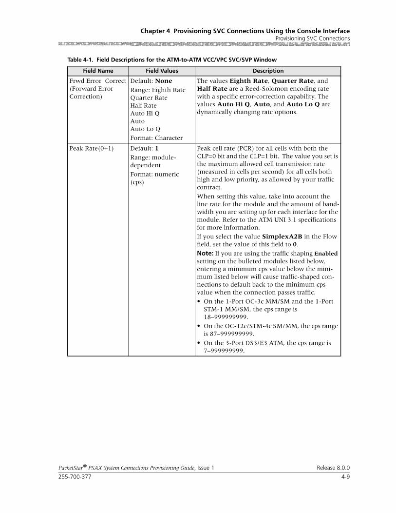
255-700-377 4-9
PacketStar® PSAX System Connections Provisioning Guide, Issue 1 Release 8.0.0
Chapter 4 Provisioning SVC Connections Using the Console InterfaceProvisioning SVC Connections
Frwd Error Correct(Forward Error Correction)
Default: None
Range: Eighth RateQuarter RateHalf RateAuto Hi QAutoAuto Lo Q
Format: Character
The values Eighth Rate, Quarter Rate, and Half Rate are a Reed-Solomon encoding rate with a specific error-correction capability. The values Auto Hi Q, Auto, and Auto Lo Q are dynamically changing rate options.
Peak Rate(0+1) Default: 1
Range: module-dependent
Format: numeric (cps)
Peak cell rate (PCR) for all cells with both the CLP=0 bit and the CLP=1 bit. The value you set is the maximum allowed cell transmission rate (measured in cells per second) for all cells both high and low priority, as allowed by your traffic contract.
When setting this value, take into account the line rate for the module and the amount of band-width you are setting up for each interface for the module. Refer to the ATM UNI 3.1 specifications for more information.
If you select the value SimplexA2B in the Flow field, set the value of this field to 0.
Note: If you are using the traffic shaping Enabled setting on the bulleted modules listed below, entering a minimum cps value below the mini-mum listed below will cause traffic-shaped con-nections to default back to the minimum cps value when the connection passes traffic.
• On the 1-Port OC-3c MM/SM and the 1-Port STM-1 MM/SM, the cps range is 18–999999999.
• On the OC-12c/STM-4c SM/MM, the cps range is 87–999999999.
• On the 3-Port DS3/E3 ATM, the cps range is 7–999999999.
Table 4-1. Field Descriptions for the ATM-to-ATM VCC/VPC SVC/SVP Window
Field Name Field Values Description

Chapter 4 Provisioning SVC Connections Using the Console InterfaceProvisioning SVC Connections
4-10 255-700-377
PacketStar® PSAX System Connections Provisioning Guide, Issue 1 Release 8.0.0
SCR/PCR (0) Default: 1
Range: module-dependent
Format: numeric
Sustainable cell rate (SCR) with CLP=0 (high pri-ority) cells or the peak cell rate with CLP=0 cells, measured in cells per second.
When setting this value, take into account the line rate for the module and the amount of band-width you are setting up for each interface for the module. Refer to the ATM UNI 3.1 specifications for more information.
If you select the value SimplexA2B in the Flow field, set the value of this field to 0. The value in this field should be less than or equal to the Peak Rate(0+1) field.
If using traffic shaping on the OC-3c or STM-1 modules, the modules will not pass data until these parameters are set to a specified rate. Very large bursts of traffic may exceed the 8 MB mem-ory typically available on the module, resulting in dropped cells. If very large bursts are typical for a specific network configuration, the module mem-ory can be upgraded to 64 MB.
Max Burst Size Default: 1Range: module-dependent
Format: numeric
Maximum burst size. The maximum number of cells that can be received at the peak cell rate. This allows a burst of cells to arrive at a rate higher than that of the sustained cell rate. If the burst is larger than anticipated, the additional cells are either tagged or dropped.
When setting this value, take into account the line rate for the module and the amount of band-width you are setting up for each interface for the module.
If you select the value SimplexA2B in the Flow field, set the value for peak rate to 0.
Flow(display only) Default: Duplex
Range: SimplexA2BPoint-to-Multi-point A2B
Format: Alphanu-meric
Direction of the flow of data traffic in this con-nection.
Table 4-1. Field Descriptions for the ATM-to-ATM VCC/VPC SVC/SVP Window
Field Name Field Values Description

255-700-377 4-11
PacketStar® PSAX System Connections Provisioning Guide, Issue 1 Release 8.0.0
Chapter 4 Provisioning SVC Connections Using the Console InterfaceProvisioning SVC Connections
4 To view the updated SVC entry, select the Go Back to Connection Table command.
This entry is displayed in the ATM-to-ATM VCC/VPC SVC/SVP Table window (Figure 4-3 on page 4-5) with the values you set in the ATM-to-ATM VCC/VPC SVC/SVP Connection window(see Figure 4-2).
Oam Status Default: Unsupp
Range: N/A
Format: Character
OAM is not in use.
End-Pt The Multiservice Media Gateway is used as a ter-mination point for ATM.
Note: The OAM loopback test is supported for end-to-end connections only.
Seg-Pt Not supported.
End-Seg-Pt Not supported.
Intermediate-Pt The Multiservice Media Gateway is used as a net-work node and an intermediate ATM device that does not terminate the ATM connection.
Use this value to enable trunk conditioning. For more information, see the Trunk Conditioning Application Note for PacketStar PSAX Multiservice Media Gateways.
Note: The OAM loopback test is supported for end-to-end connections only.
[Conn Status](dis-play only)
Default: Inactive
Range: N/A
Format: Character
Active
This field displays the current status of the con-nection. The value indicates whether the connec-tion is passing traffic.
Table 4-1. Field Descriptions for the ATM-to-ATM VCC/VPC SVC/SVP Window
Field Name Field Values Description
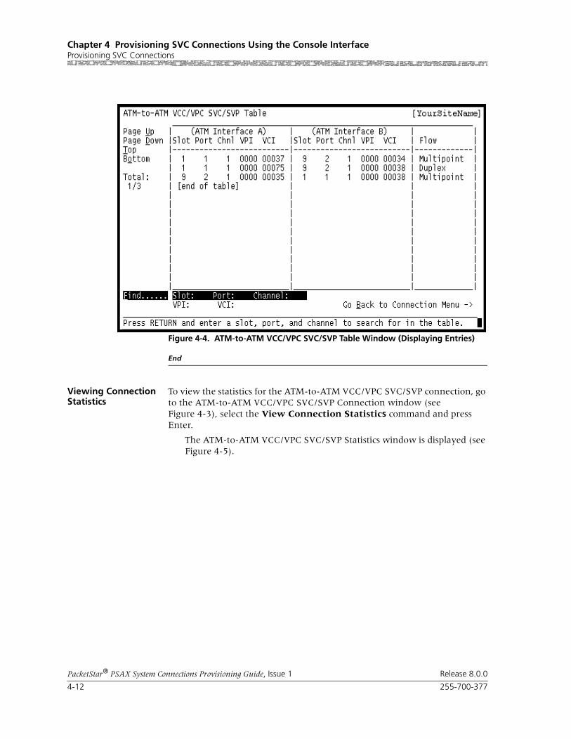
Chapter 4 Provisioning SVC Connections Using the Console InterfaceProvisioning SVC Connections
4-12 255-700-377
PacketStar® PSAX System Connections Provisioning Guide, Issue 1 Release 8.0.0
End
Viewing Connection Statistics
To view the statistics for the ATM-to-ATM VCC/VPC SVC/SVP connection, go to the ATM-to-ATM VCC/VPC SVC/SVP Connection window (see Figure 4-3), select the View Connection Statistics command and press Enter.
The ATM-to-ATM VCC/VPC SVC/SVP Statistics window is displayed (see Figure 4-5).
Figure 4-4. ATM-to-ATM VCC/VPC SVC/SVP Table Window (Displaying Entries)

255-700-377 4-13
PacketStar® PSAX System Connections Provisioning Guide, Issue 1 Release 8.0.0
Chapter 4 Provisioning SVC Connections Using the Console InterfaceProvisioning SVC Connections
Commands The commands on this window have the following functions:
Field Descriptions The fields on this window are described in Table 4-2.
Figure 4-5. ATM-to-ATM VCC/VPC SVC/SVP Statistics Window
Command Function
Reset Odometers Returns all statistics odometers to zero.
Continuous Update Updates the values in the fields every sec-ond.
Display Stats for Next Con-nection
Displays the statistics for the next selected connection.
Go Back to Connection Dis-play
Redisplays the connection window.

Chapter 4 Provisioning SVC Connections Using the Console InterfaceProvisioning SVC Connections
4-14 255-700-377
PacketStar® PSAX System Connections Provisioning Guide, Issue 1 Release 8.0.0
Table 4-2. Field Descriptions for the ATM-to-ATM VCC /VPC SVC/SVP Statistics Window
Field Name Field Values Description
Interface A Statis-tics
Default: Varies depending on ATM interface type
Range: N/A
Format: text
The ATM interface side of the connection that will send and receive signals.
Interface B Statis-tics
Default: Varies depending on ATM interface type
Range: N/A
Format: text
The ATM interface side of the connection that will send and receive signals.
Slot(display only)
Default: Varies depending on selected slot
Range: Varies depending on chassis type
Format: numeric
Select the slot number containing the module for which you are creating a connection. Select slot numbers for both sides of the connection.
Port(display only)
Default: Varies depending on selected slotRange: Varies depending on module type
Format: numeric
Select the port number on the module for which you are creating a connection. Select port num-bers for both sides of the connection.
Channel(display only)
Default: Varies depending on selected slot
Range: Varies depending on module type
Format: numeric
Select the channel number of the port on the module for which you are creating a connection. Select channel numbers for both sides of the con-nection.
VPI Default: 0
Range: 0–255
Format: numeric
Virtual path identifier. Enter a value for ATM side of the connection.
VCI Default: 0Range: 32–65535
Format: numeric
Virtual channel identifier. Enter a value for the ATM side of the connection.
cell Drop/Tag Default: 0
Range: N/A
Format: numeric
Cells dropped or tagged due to UPC/traffic polic-ing.

255-700-377 4-15
PacketStar® PSAX System Connections Provisioning Guide, Issue 1 Release 8.0.0
Chapter 4 Provisioning SVC Connections Using the Console InterfaceConfiguring In-Band Management SVC Connections
5 Press Ctrl+G and select the Save Configuration menu option.
End
Configuring In-Band Management SVC Connections
If you want to manage one or more PSAX systems over an ATM wide-area network (WAN), you can set up a PSAX system or a network management system (NMS) computer to provision either PVC or SVC connections to the remote PSAX systems being managed.
For a PVC connection, you set up the management host, which is typically a Unix workstation running an SNMP client that manages one or more PSAX systems over an Ethernet network.
Three basic methods for configuration are possible:
• Direct connection
• Routed connection
• Hybrid connection
For more information on these connections, see the appendix, “Configuring In-band Management.”
To configure the primary IP address for the management host, perform the steps in the following sections, “Adding an In-Band Management ATM SVC Connection,” and ”Creating an In-Band-Management SVC Connection.”
Cells Received Default: 6.5000 e1
Range: N/A
Format: numeric
Total number of OAM cells received on Interface A or B.
Cells Transmitted Default: 6.5000 e1Range: N/A
Format: numeric
Total number of OAM cells transmitted on Inter-face A or B.
Received Odometer Default: 6.5000 e1
Range: N/A
Format: numeric
Total number of ATM cells received on Interface A or B since odometer was last reset.
Transmitted Odom-eter
Default: 6.5000 e1
Range: N/A
Format: numeric
Total number of ATM cells transmitted on Inter-face A or B since odometer was last reset.
Time Elapsed Default: 00:00:00
Range: N/A
Format: numeric
Total time elapsed for OAM statistics collection.
Time Since Reset Default: 00:00:00Range: N/A
Format: numeric
Total time elapsed for OAM statistics collection since the last odometer reset.
Table 4-2. Field Descriptions for the ATM-to-ATM VCC /VPC SVC/SVP Statistics Window
Field Name Field Values Description

Chapter 4 Provisioning SVC Connections Using the Console InterfaceConfiguring In-Band Management SVC Connections
4-16 255-700-377
PacketStar® PSAX System Connections Provisioning Guide, Issue 1 Release 8.0.0
A Unix workstation is used as the address resolution protocol (ARP) server. The host PSAX system and all remote systems on the same ATM network register their IP addresses on the ARP server when they are initialized (booted). When you want to create an in-band management SVC connection to one or more remote PSAX systems, you use the host PSAX system to request the IP addresses of the remote PSAX systems. After you obtain these IP addresses, you can create the SVC connections (see Figure 4-6).
Preparing to Create an In-Band Management SVC Connection
Before creating an SVC connection, you need to set up the Unix workstation as the ARP server, and each of the PSAX systems. To do this, perform the steps in the following procedure.
Begin
1 To configure the Solaris workstation to act as an ARP router, you must install an ATM Network Interface Card (NIC) and configure the card as an ATM ARP Server. To do this, consult the procedures in the appropriate section of your Sun Solaris ATM User Guide.
2 Log on to your PSAX system, and go to the Equipment Configuration window.
Figure 4-6. In-Band SVC Connections
Unix Unix
PSAX System
PSAX System
Primary ARP Backup ARP Server
Local Host Sys-
Remote Systems
PSAX System
Workstation Workstation
255-700-377 4-17
PacketStar® PSAX System Connections Provisioning Guide, Issue 1 Release 8.0.0
Chapter 4 Provisioning SVC Connections Using the Console InterfaceConfiguring In-Band Management SVC Connections
3 In the Equipment Configuration window, select the module you will use. The OC-3c module is the most often used I/O module for this connec-tion.
4 Configure the OC-3c module (or the module you have selected) for the ATM UNI 3.1 interface type and select the Apply Port and Channel Configuration command.
5 Select the Configure the Interface command.
6 On the ATM UNI 3.1 Configuration window, in the ATM Signaling field, select Enabled. In the Interface Type field, select Network.
7 Enter an appropriate value in the Address Prefix field.
This is the Address Prefix of the node address of the OC-3c module.
8 Configure the ILMI interface. (This is an optional step, but strongly rec-ommended.)
9 On the ILMI Configuration window select Enabled in the ILMI Protocol, Address Registration, and Connectivity Procedure fields.
10 Select the Apply ILMI Configuration > Go Back to Previous Screen commands.
11 Check the ILMI Registered User Address window to see that the address has been created, and return to the Main Menu.
12 From the Site-Specific Menu, select PNNI System-Wide Configura-tion command.
13 Select the Create a Node command.
14 Follow the instructions in the “PNNI System-Wide Configuration” sec-tion in this chapter.
15 Return to the Site-Specific Configuration window to create the in-band SVC Connection.
End
Creating an In-Band Management SVC Connection
An in-band management SVC connection can be created between a config-ured in-band management address and any module that supports ATM inter-faces. This connection supports the UBR and VBR-express service types.
Perform the steps in the following procedure to create an in-band manage-ment SVC connection.
Begin
1 From the Console Interface Main Menu window, select the Site Specific Configuration option.

Chapter 4 Provisioning SVC Connections Using the Console InterfaceConfiguring In-Band Management SVC Connections
4-18 255-700-377
PacketStar® PSAX System Connections Provisioning Guide, Issue 1 Release 8.0.0
The Site-Specific Menu window is displayed (see Figure 4-7).
2 Select the In-band Management IP Configuration option.
The In-Band Management IP Configuration window is displayed (see Figure 4-8).
3 Enter the primary IP address and primary IP mask for the PSAX system.
Note: This address must be on a different subnet from the subnet that is assigned to the Ethernet interface for the management host.
4 In the SVC Connections field, select Enabled.
The In-Band Management IP Configuration Window with additional fields is displayed (see Figure 4-9 ). Note that the default value for the ATM ARP Server field is Disabled.
5 If you want to designate the PSAX system as an ATM address resolution protocol (ARP) server, select Enabled in the ATM ARP Server field.
Additional fields are displayed on the window (see Figure 4-10).
6 Enter values in the fields on this window according to the information provided in Table 4-3.
7 Select the Apply Configuration command.
End
Figure 4-7. Site-Specific Menu Window (In-band Management Option Selected)

255-700-377 4-19
PacketStar® PSAX System Connections Provisioning Guide, Issue 1 Release 8.0.0
Chapter 4 Provisioning SVC Connections Using the Console InterfaceConfiguring In-Band Management SVC Connections
The commands on this window have the following functions:
Figure 4-8. In-Band Management Configuration Window (SVC Connections Disabled)
Function
Applies the configuration.
Resets the display.
Alternate Gateway Address Config.
Displays the Site Alternate Gateway Con-figuration window.
In-Band Management IP Route Table
Displays the In-Band Management IP Routing Table window.

Chapter 4 Provisioning SVC Connections Using the Console InterfaceConfiguring In-Band Management SVC Connections
4-20 255-700-377
PacketStar® PSAX System Connections Provisioning Guide, Issue 1 Release 8.0.0
Figure 4-9. In-Band Management Configuration Window (ATM ARP Server Disabled)
Figure 4-10. In-Band Management Configuration Window (ATM ARP Server Enabled)

255-700-377 4-21
PacketStar® PSAX System Connections Provisioning Guide, Issue 1 Release 8.0.0
Chapter 4 Provisioning SVC Connections Using the Console InterfaceConfiguring In-Band Management SVC Connections
Table 4-3. Field Descriptions for the In-Band Management IP Configuration Window
Field Name Field Values Description
Primary IP Address Default: 0000.0000.0000.0000
Range: N/A
Format: valid dotted quad
Specifies the in-band management IP address of the PSAX system.
Primary IP Mask Default: 0000.0000.0000.0000
Range: N/A
Format: valid dotted quad
Specifies the in-band management IP mask of the PSAX system
SVC Connections Default: Disabled
Range: N/A
Format: predefined alphanumeric
Specifies whether you want to use SVC connec-tion provisioning for in-band management.
Disabled Indicates that SVC connection provisioning for in-band management is disabled. You can config-ure only PVC connections for in-band manage-ment when you choose this value.
Enabled Indicates that SVC connection provisioning for in-band management is enabled.
ATM ARP Server Default: DisabledRange: N/A
Format: predefined alphanumeric
Specifies whether you want to use the PSAX sys-tem as an ATM ARP server.
Disabled
Enabled
Application ATM Address
Default: 0
Range: N/A
Format: hexadecimal
Specifies the application ATM address of the PSAX system.
App. ATM Address Type
Default: NsapRange: N/A
Nsap, E164, E164nsap
Specifies the type of application ATM address for the PSAX system.
Arp Server ATM Address
Default: 0
Range: N/A
Format: hexadecimal
Specifies the ATM address of the ARP server.
Note: This field is displayed only if you selected Enabled in the ATM ARP Server field.
Arp Server ATM Address Type
Default: Nsap
Range: N/A
Nsap, E164, E164nsap
Specifies the type of ATM address for the ARP server.
Note: This field is displayed only if you selected Enabled in the ATM ARP Server field.

Chapter 4 Provisioning SVC Connections Using the Console InterfaceConfiguring In-Band Management SVC Connections
4-22 255-700-377
PacketStar® PSAX System Connections Provisioning Guide, Issue 1 Release 8.0.0
Adding Destination IP Addresses
After configuring an in-band management SVC connection, you can add des-tination IP addresses to create the route for in-band management. Use the following procedure to create these addresses.
Begin
1 On the In-Band Management IP Configuration window, select the In-Band Management IP Route Table command.
The Inband Management Route Table window is displayed (see Figure 4-11).
Note: At the time of initial setup, the In-Band Management IP Routing Table window is empty. After you have set up destination IP addresses, this window displays all these addresses for the PSAX system.
The descriptions of the display-only fields on this window are provided in Table 4-4.
2 Select the Add a New Route command.
The Inband Management IP Route Configuration window is displayed (see Figure 4-12).
3 Enter values in the fields on this window according to the information provided in Table 4-5.
4 Select the Add a Route command.
The route is now added.
Primary ARP ATM Address
Default: 0
Range: N/A
Format: hexadecimal
Specifies the primary ATM address for the ARP server. Enter the ATM address for the Solaris workstation.
Primary ATM Address Type
Default: NsapRange: N/A
Nsap, E164, E164nsap
Specifies the type of primary ATM address for the ARP server.
Backup ARP ATM Address
Default: 0
Range: N/A
Format: hexadecimal
Specifies the backup ATM address for the ARP server. Enter the ATM address for the Solaris workstation.
Backup ATM Address Type
Default: Nsap
Range: N/A
Nsap, E164, E164nsap
Specifies the type of backup ATM address for the ARP server.
Table 4-3. Field Descriptions for the In-Band Management IP Configuration Window
Field Name Field Values Description

255-700-377 4-23
PacketStar® PSAX System Connections Provisioning Guide, Issue 1 Release 8.0.0
Chapter 4 Provisioning SVC Connections Using the Console InterfaceConfiguring In-Band Management SVC Connections
5 Select the Go Back to Routing Table command.
The In-Band Management IP Routing Table window is redisplayed with the new route added (see Figure 4-13).
End
The commands on this window have the following functions:
Figure 4-11. Inband Management Route Table Window
Command Function
Add a New Route Use to add a new route.
Go Back to In-Band Man-agement IP Configuration
Redisplays the In-Band Management IP Configuration window.
Table 4-4. Field Descriptions for the In-Band Management IP Routing Table
Field Name Description
Destination IP Displays the destination network IP address.

Chapter 4 Provisioning SVC Connections Using the Console InterfaceConfiguring In-Band Management SVC Connections
4-24 255-700-377
PacketStar® PSAX System Connections Provisioning Guide, Issue 1 Release 8.0.0
The commands on this window have the following functions:
Mask Displays the destination network IP mask.
Metric Displays the number of hops to reach to the desti-nation.
Total:0/0
The first number in this field indicates the num-ber of the connection table entry on the first line of the currently displayed window. The second number indicates the total number of connection table entries for this connection type.
Figure 4-12. Inband Management IP Route Configuration
Command Function
Reset Resets the display.
Add a Route Adds a destination IP address (route).
Delete a Route Deletes a destination IP address (route).
Go Back to Routing Table Redisplays the In-Band Management IP Routing Table window.
Table 4-4. Field Descriptions for the In-Band Management IP Routing Table
Field Name Description
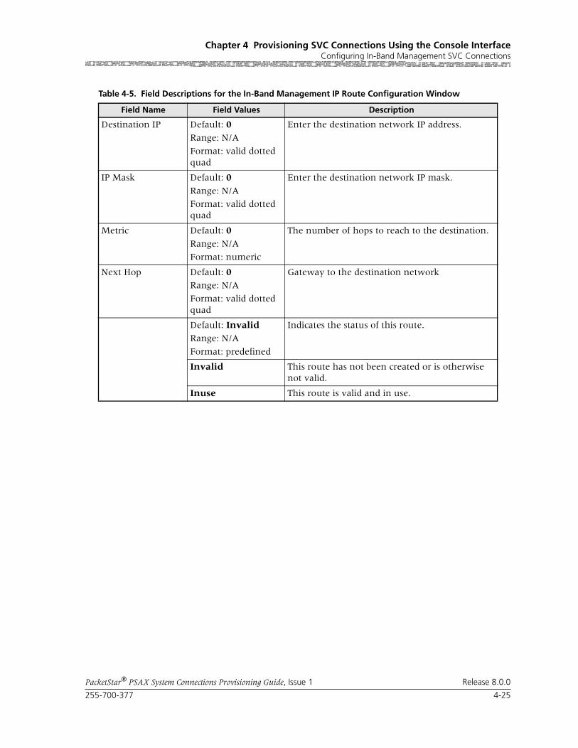
255-700-377 4-25
PacketStar® PSAX System Connections Provisioning Guide, Issue 1 Release 8.0.0
Chapter 4 Provisioning SVC Connections Using the Console InterfaceConfiguring In-Band Management SVC Connections
Table 4-5. Field Descriptions for the In-Band Management IP Route Configuration Window
Field Name Field Values Description
Destination IP Default: 0
Range: N/A
Format: valid dotted quad
Enter the destination network IP address.
IP Mask Default: 0
Range: N/A
Format: valid dotted quad
Enter the destination network IP mask.
Metric Default: 0
Range: N/A
Format: numeric
The number of hops to reach to the destination.
Next Hop Default: 0Range: N/A
Format: valid dotted quad
Gateway to the destination network
Default: Invalid
Range: N/A
Format: predefined
Indicates the status of this route.
Invalid This route has not been created or is otherwise not valid.
Inuse This route is valid and in use.

Chapter 4 Provisioning SVC Connections Using the Console InterfaceConfiguring In-Band Management SVC Connections
4-26 255-700-377
PacketStar® PSAX System Connections Provisioning Guide, Issue 1 Release 8.0.0
Viewing In-Band Management Interface Statistics
To view the In-Band Management Interface Statistics window, perform the steps in the following procedure.
Begin
1 From the In-Band Management Configuration window, select the View In-Band Mgmt Statistics command.
The In-Band Management Interface Statistics window is displayed (see Figure 4-14).
2 View the statistics in this window, which are described in Table 4-6.
End
Figure 4-13. Inband Management Route Table (Route Displayed)

255-700-377 4-27
PacketStar® PSAX System Connections Provisioning Guide, Issue 1 Release 8.0.0
Chapter 4 Provisioning SVC Connections Using the Console InterfaceConfiguring In-Band Management SVC Connections
The commands on this window have the following functions:
Figure 4-14. In-Band Management Interface Statistics Window
Command Function
Continuous Update Continuously updates the information in the fields every second. Use this command to turn the continuous updating on and off as needed.
Go Back to In-Band Mgmt Redisplays the In-Band ManagementCon-figuration window.
Table 4-6.
Field Name Field Values Description
Packets Received(display only)
Default: 0Range: N/A
Format: numeric
Displays the number of packets received.

Chapter 4 Provisioning SVC Connections Using the Console InterfaceAdding Entries to the ATM IISP CBR Routing Table
4-28 255-700-377
PacketStar® PSAX System Connections Provisioning Guide, Issue 1 Release 8.0.0
Deleting an In-Band Management SVC Route
Perform the steps in the following procedure to delete an In-Band SVC route.
Begin
1 In the Inband Management Route Configuration window, select the Delete a route command.
2 Select the Go Back to Route Table command to check that the Inband Management Route Table window does not contain the route you just deleted.
End
Adding Entries to the ATM IISP CBR Routing Table
Creating IISP CBR Entries
Note: SVC connections are not supported on the STM-1 or the OC-3c MM/SM Traffic Shaping modules.
Use the steps in the following procedure to add an entry to the CBR Routing table, starting at the Connection Configuration Menu window.
Begin
Creating Entries in the IISP CBR Routing Table
1 On the Connection Configuration Menu window, select the IISP CBR Routing Table option and press Enter.
The IISP CBR Routing Table window will display (see Figure 4-15).
Default: 0
Range: N/A
Format: numeric
Displays the number of packet receive errors.
Packets Transmitted(display only)
Default: 0Range: N/A
Format: numeric
Displays the number of packets transmitted.
Default: 0
Range: N/A
Format: numeric
Displays the number of packet transmit errors.
Table 4-6.
Field Name Field Values Description

255-700-377 4-29
PacketStar® PSAX System Connections Provisioning Guide, Issue 1 Release 8.0.0
Chapter 4 Provisioning SVC Connections Using the Console InterfaceAdding Entries to the ATM IISP CBR Routing Table
Commands The commands on this window have the following functions:
2 Select the Add an Entry field, and press Enter.
a. In the Address (Hex) field, type a network service access point address up to 20 bytes (160 bits) long (10 groups of 4 characters each), and press the Tab key. If configuring the OMG side, enter the TMG Master ATM address from the Site Specific Configuration win-dow. If configuring the TMG side, enter the OMG Master ATM address from the Site Specific Configuration window.
b. In the # Bits field, type a value from 1–152 for the NSAP address mask, and press the Tab key. Enter 152.
c. In the Sl Pt Chn field, type the slot, port, and channel values for the ATM-cell-bearing I/O module that has a configured ATM IISP (User or Network) interface. If configuring the OMG side, enter the slot, port, and channel of the TMG’s ATM UNI 4.0 ATM module in the Sl Pt Chn field. If configuring the TMG side, enter the slot, port, and channel of the OMG’s ATM UNI 4.0 ATM module in the Sl Pt Chn field.
Figure 4-15. IISP CBR Routing Table
Command Function
Find Finds the routing entry with the specified NSAP address.
Go Back to Connection Menu→
Redisplays the Connection Configuration window.

Chapter 4 Provisioning SVC Connections Using the Console InterfaceAdding Entries to the IISP VBR Routing Table
4-30 255-700-377
PacketStar® PSAX System Connections Provisioning Guide, Issue 1 Release 8.0.0
d. If applicable to your configuration, enter a value in the Vuni ID field. Enter a 0 if configuring H.248.
e. Press Enter to add the entry to the table.
3 Repeat step 2 as many times as needed to add entries to the table.
4 To permanently save these table entries, press Ctrl+G to return to the Console Interface Main Menu window.
5 Select Save Configuration, and press Enter to store the values to the Multiservice Media Gateway system database.
End
Adding Entries to the IISP VBR Routing Table
Creating IISP VBR Entries
Use the steps in the following procedure to add an entry to the VBR routing table, starting at the Connection Configuration Menu window.
Begin
Adding NSAP Address Entries
1 On the Connection Configuration Menu window, select the IISP VBR Routing Table option and press Enter.
The IISP VBR Routing Table window is displayed (see Figure 4-16).

255-700-377 4-31
PacketStar® PSAX System Connections Provisioning Guide, Issue 1 Release 8.0.0
Chapter 4 Provisioning SVC Connections Using the Console InterfaceAdding Entries to the IISP VBR Routing Table
Commands The commands on this window have the following functions:
2 Select the Add an Entry field, and press Enter.
a. Type a network service access point (NSAP) address in hexadecimal format up to 20 bytes (160 bits) long (10 groups of 4 characters each), and press the Tab key.
b. In the # Bits field, type a value from 1–152 for the NSAP address mask, and press the Tab key.
c. In the Sl Pt Chn field, type the slot, port, and channel values for the ATM-cell-bearing I/O module that has a configured ATM IISP (User or Network) interface.
d. If applicable to your configuration, enter a value for the Vuni ID field.
e. Press Enter to add the entry to the table.
3 Repeat step 2 as many times as needed to add entries to the table.
4 To permanently save these table entries, press Ctrl+G to return to the Console Interface Main Menu window.
Figure 4-16. IISP VBR Routing Table Window
Command Function
Find Finds the routing entry with the specified NSAP address.
Go Back to Connection Menu→
Redisplays the Connection Configuration window.

Chapter 4 Provisioning SVC Connections Using the Console InterfaceAdding Entries to the IISP VBR Routing Table
4-32 255-700-377
PacketStar® PSAX System Connections Provisioning Guide, Issue 1 Release 8.0.0
5 Select Save Configuration, and press Enter to store the values to the Multiservice Media Gateway system database.
End

Part B: Connections Using theAQueView® EMS System

PacketStar® PSAX System Connections Provisioning Guide, Issue 1 Release 8.0.0
255-700-377 5-1
5 Managing Connections Using theAQueView® EMS System
Overview of This Chapter
This chapter describes how to set up permanent virtual circuit (PVC), switched virtual circuit (SVC), and soft permanent virtual circuit (SPVC) con-nections in the PSAX system for service provisioning and how to view statis-tics data for billing and performance monitoring. Before you provision con-nections for this module, you must have first completed the following tasks, which are detailed in the appropriate PacketStar PSAX Module Guide:
• Setting the configuration values for one or more ports
• Setting the configuration values for the types of interfaces you want to use on this module
Connection Types Supported
The PSAX I/O modules support at least one the following connection types:
• PVC connections
• SVC connections
Note: SVC connections are not directly configurable on a PSAX system. Configure them through an interface with a call controller, such as the Lucent Softswitch–T3 (Toll/Tandem/ Transit), a 7R/E™, or a ConnectStar™ Interworking Call Router. Call controllers send call setup information to the PSAX System. See the section, “Enabling SVCs Connections.”
• SPVC connections
For a matrix of connection types by interface types, see the Connection Types by Interface Types table in the appendix, “Reference Information.”
Using the Right-Click Menu
You can perform various functions in the AQueView system by clicking the right mouse button. This section describes the right-click menu options you can use in the various windows in the AQueView system when creating con-nections.

Chapter 5 Managing Connections Using the AQueView® EMS SystemUsing the Right-Click Menu
5-2 255-700-377
PacketStar® PSAX System Connections Provisioning Guide, Issue 1 Release 8.0.0
Connection Provisioning
Context-Sensitive Help
When you right-click on a field in a connection configuration window, a description of that field appears (see Figure 5-2):
Figure 5-1. Connection Configuration Right-Click Menu Options
Table 5-1. Descriptions of the Connection Provisioning Right-Click Menu Options
Option Description
Display Displays the Display Connection window for the specified connection
Delete Eliminates all selected con-nections
You can select multiple con-nections to delete simulta-neously by holding the Ctrl key while highlighting the connections with the mouse.
Create New Makes a new connection on any existing interfaces

255-700-377 5-3
PacketStar® PSAX System Connections Provisioning Guide, Issue 1 Release 8.0.0
Chapter 5 Managing Connections Using the AQueView® EMS SystemManaging Connections
Managing Connections
Within the Connections tab are four tabs that open the following pages:
• By default, the Listing page appears when you click the Connections tab. The Listing page displays all existing connections established on the device by default, that you can filter. Connections can be created from this win-dow by clicking the right mouse button to display the connections menu. The number in parentheses on the tab is the number of connections in the list.
• The Filter page enables you to sort and view connection types listed on the Listing page by connection type, slot, port, and channel
• The SPVC NSAP Address page allows you to enter new SPVC NSAP addresses and to view a list of existing SPVC NSAP addresses
• The AAL2 Trunk page allows you to add AAL2 trunk entries
Note: AAL2 is not supported on all I/O and server modules.
Listing Page
To access the Listing page, click the Connections tab in the Device window.
Figure 5-2. Sample of Context-Sensitive Help (As Displayed on a Display Connection Window)

Chapter 5 Managing Connections Using the AQueView® EMS SystemManaging Connections
5-4 255-700-377
PacketStar® PSAX System Connections Provisioning Guide, Issue 1 Release 8.0.0
The buttons on the Listing page have the following functions:
Searching for Specific Connection Entries
In the Listing and the SPVC NSAP Address pages, you can search for any combination of letters or numbers (a text string), and the page will change its display to show only the entries that contain the text string you enter.
For example, the Listing page shown in Figure 5-4 has hundreds of connec-tion entries. It is quicker to search this page based on a text string than to scroll up and down the page looking for a specific entry.
Perform the steps in the following procedure to search for entries using a text string.
Note: This procedure uses the Listing page, but the procedure is the same for the SPVC NSAP Address page.
Figure 5-3. Listing Page
Button Function
Find Searches the table and displays a matching text string entered in the Show connections containing: field.
Reset Removes text entered in the Show connections containing: field.
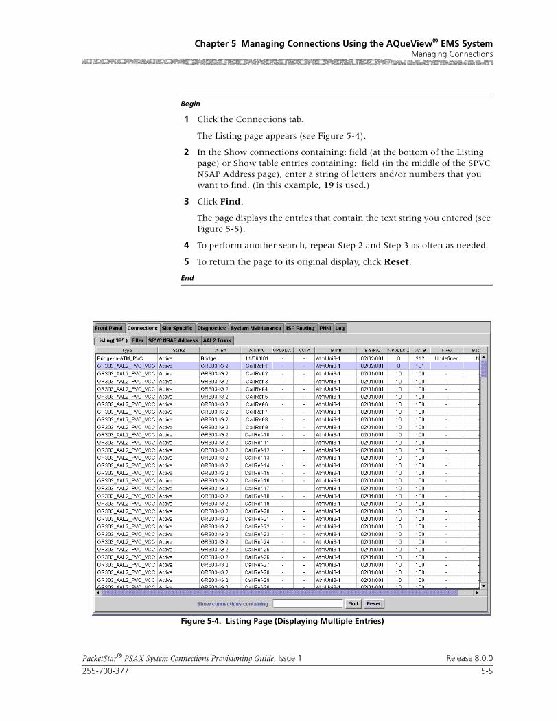
255-700-377 5-5
PacketStar® PSAX System Connections Provisioning Guide, Issue 1 Release 8.0.0
Chapter 5 Managing Connections Using the AQueView® EMS SystemManaging Connections
Begin
1 Click the Connections tab.
The Listing page appears (see Figure 5-4).
2 In the Show connections containing: field (at the bottom of the Listing page) or Show table entries containing: field (in the middle of the SPVC NSAP Address page), enter a string of letters and/or numbers that you want to find. (In this example, 19 is used.)
3 Click Find.
The page displays the entries that contain the text string you entered (see Figure 5-5).
4 To perform another search, repeat Step 2 and Step 3 as often as needed.
5 To return the page to its original display, click Reset.
End
Figure 5-4. Listing Page (Displaying Multiple Entries)
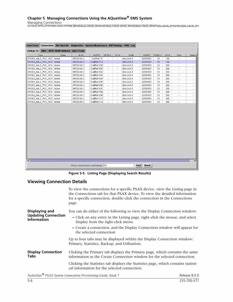
Chapter 5 Managing Connections Using the AQueView® EMS SystemManaging Connections
5-6 255-700-377
PacketStar® PSAX System Connections Provisioning Guide, Issue 1 Release 8.0.0
Viewing Connection Details
To view the connections for a specific PSAX device, view the Listing page in the Connections tab for that PSAX device. To view the detailed information for a specific connection, double-click the connection in the Connections page.
Displaying and Updating Connection Information
You can do either of the following to view the Display Connection window:
~ Click on any entry in the Listing page, right-click the mouse, and select Display from the right-click menu
~ Create a connection, and the Display Connection window will appear for the selected connection
Up to four tabs may be displayed within the Display Connection window: Primary, Statistics, Backup, and Utilization.
Display Connection Tabs
Clicking the Primary tab displays the Primary page, which contains the same information as the Create Connection window for the selected connection.
Clicking the Statistics tab displays the Statistics page, which contains statisti-cal information for the selected connection.
Figure 5-5. Listing Page (Displaying Search Results)
255-700-377 5-7
PacketStar® PSAX System Connections Provisioning Guide, Issue 1 Release 8.0.0
Chapter 5 Managing Connections Using the AQueView® EMS SystemManaging Connections
Clicking the Backup tab displays the Backup page, which can be displayed for all PVC and SPVC connection types. You can use the Backup page to establish a backup PVC or SPVC connection. Backup connections can be created at any time after the primary connection has been established.
Clicking the Utilization tab displays the Utilization page, which can be dis-played for all PVC and SPVC connection types. You can use the Utilization page to calculate and display the average number of cells per second, the average number of bits per second for a given PVC or SPVC and for a given time interval (from 20 seconds to 5 minutes).
Utilization Information
The Utilization page can be displayed for some interface and connection types. You can use the Utilization page to calculate and display the average number of cells per second, average number of bits per second for a given ATM interface and for a given time interval.
The following information describes the Utilization page for each supported connection type.
• The Average Bits/Sec and Average Cells/Sec panels display the percentage of traffic that is passing through the channel.
• The Time column displays the time in hours, minutes and seconds, when the traffic was polled.
• The Out A/Encoded A/Decoded A column displays cells or bits transmitted from side B to side A (also displayed on the Statistics page in the Cells Transmitted field on the Interface A Statistics panel).
• The Out B/Encoded B/Decoded B column displays cells or bits transmitted from side A to side B (also displayed on the Statistics page in the Cells Transmitted field on the Interface B Statistics panel).
Perform the steps in the following procedure to use the Utilization page.
Begin
1 Select a time interval from the pull-down menu.
2 Average bits per second is displayed by default. If you want to display uti-lization by average cells per second, click Average Cells/Sec.
3 Click Poll+ and the polling begins. Click Poll- to terminate polling.
4 To refresh this window, click Clear.
5 To close the Display Connection window, click Close.
6 To save this connection to the PSAX configuration database, click Device > Save PSAX Configuration in the Device Menu Bar.
End

Chapter 5 Managing Connections Using the AQueView® EMS SystemManaging Connections
5-8 255-700-377
PacketStar® PSAX System Connections Provisioning Guide, Issue 1 Release 8.0.0
Filtering the Listing Page by Connection Type
This section describes how to filter the Listing page in the Connections tab by choosing the types of connections that should be displayed. You can deter-mine which connection types appear in the Listing page of the Connections tab. This is accomplished by making selections in the Filter By Connection Type and Filter By Interface panels in the Filter page of the Connections tab (see Figure 5-6).
Perform the steps in the following procedure to filter the Listing page by the types of connections you select in the Filter page.
Begin
1 In the Device window, click the Connections tab.
The Listing page appears.
2 Click the Filter tab and the Filter page appears (see Figure 5-6).
Figure 5-6. Filter Page
255-700-377 5-9
PacketStar® PSAX System Connections Provisioning Guide, Issue 1 Release 8.0.0
Chapter 5 Managing Connections Using the AQueView® EMS SystemManaging Connections
The Filter page contains the Connection Type and Filter By Interface pan-els.
Buttons The buttons in this window have the following functions:
3 Remove the check mark next to any connection type that you do not wish to view in the Listing page.
4 If you want to filter the Listing page further, make selections in the Filter By Interface panel (see “The Filter By Interface panel in the Filter page lets you select specific locations on the PSAX device by which to filter the list of connections. This panel contains the following user-selectable options:”).
5 When finished selecting all the desired filters, click Apply Filter.
Note: Only the connection types you selected will appear in the Listing page.
End
The Filter By Interface panel in the Filter page lets you select specific loca-tions on the PSAX device by which to filter the list of connections. This panel contains the following user-selectable options:
• Slot—Allows you to view only connections from a specific module or from all modules.
• Port—Allows you to view only connections from a specific port or from all ports
• Channel—Allows you to view only connections from a specific channel or from all channels
Perform the steps in the following procedure to filter the Connection List by PSAX hardware.
Button Function
De-select All Removes check marks from all connection types and changes the button label to Select All.
Select All Places check marks in all connection types and changes the button label to De-select All.
Apply Filter Filters the connection types that you checked, or that you selected on the Filter By Interface panel (see “The Filter By Interface panel in the Filter page lets you select specific locations on the PSAX device by which to filter the list of connec-tions. This panel contains the following user-selectable options:”).

Chapter 5 Managing Connections Using the AQueView® EMS SystemManaging Connections
5-10 255-700-377
PacketStar® PSAX System Connections Provisioning Guide, Issue 1 Release 8.0.0
Begin
1 In the Device window, click the Connections tab.
The Listing page appears.
2 Click the Filter tab and the Filter page appears.
3 In the Filter by Interface panel (see Figure 5-6), select the following val-ues:
a. A module in the Slot field to remove any connection that does not begin or end at the module from the Listing page.
b. A port number in the Port field to remove any connection that does not begin or end at a port with that number from the Listing page.
c. A channel number in the Channel field to remove any connection that doesn’t begin or end at a port with that channel from the Listing page.
4 If you want to filter the Listing page further, make selections in the Filter By Connection Type panel (see “This section describes how to filter the Listing page in the Connections tab by choosing the types of connections that should be displayed. You can determine which connection types appear in the Listing page of the Connections tab. This is accomplished by making selections in the Filter By Connection Type and Filter By Interface panels in the Filter page of the Connections tab (see Figure 5-6).”).
5 When finished selecting all the needed filters, click Apply Filter.
Note: Only the types of connections you selected will appear in the List-ing page.
End
SPVC NSAP Addresses
You can enter new SPVC NSAP addresses and view a list of existing SPVC NSAP addresses on the SPVC NSAP Address page (see Figure 5-7).

255-700-377 5-11
PacketStar® PSAX System Connections Provisioning Guide, Issue 1 Release 8.0.0
Chapter 5 Managing Connections Using the AQueView® EMS SystemManaging Connections
Buttons The buttons on this window have the following functions:
Figure 5-7. SPVC NSAP Address Page
Button Function
Find Searches the table and displays a matching text string entered in the Show table entry containing: field.
Reset Removes text entered in the Show table entry containing: field and de-selects any selected entries.
Retrieve from NSAP database
Searches the entries listed on this page for the NSAP address entered in the NSAP Address (Hex) field.
Add Address Adds the information you entered in the fields on the bottom right panel to the SPVC NSAP Address page.

Chapter 5 Managing Connections Using the AQueView® EMS SystemManaging Connections
5-12 255-700-377
PacketStar® PSAX System Connections Provisioning Guide, Issue 1 Release 8.0.0
For information about using the NSAP address database, see the appropriate Navis™ AQueView® Element Management System User Guide.
End
AAL2 Trunk Configuration
You can add an AAL2 trunk entry using the slot, port, and channel of an I/O module that supports ATM and circuit emulation on the AAL2 Trunk page.
Note: This module does not support AAL2 trunking. For information on AAL2 trunking, see the appropriate PacketStar® PSAX Module User Guide.
Adding an AAL2 Trunk Entry
To create a non-multiplexed AAL2 or AAL1 connection, you need a config-ured circuit emulation interface. To create a standard AAL2 connection, you need a configured circuit emulation interface and an AAL2 trunk.
Perform the steps in the following procedure to add an AAL2 trunk.
Begin
Steps to Configure an AAL2 Trunk Connection
1 Click the AAL2 Trunk tab in the Connections tab.
The AAL2 Trunk page appears, displaying the AAL2 Trunk Configuration Table (see Figure 5-8).
If the AAL2 Trunk Configuration Table is empty before you perform Step 2, the AAL2 Trunk Config Entry window will appear with the default values.
Delete Selected Removes the selected entry from the SPVC NSAP Address page.
Update Refreshes the SPVC NSAP Address page manually.
Button Function

255-700-377 5-13
PacketStar® PSAX System Connections Provisioning Guide, Issue 1 Release 8.0.0
Chapter 5 Managing Connections Using the AQueView® EMS SystemManaging Connections
If you select an existing AAL2 trunk entry before performing Step 2, the AAL2 Trunk Config Entry window will appear as a template, containing the values of the original AAL2 trunk entry.
2 Right-click the mouse and a menu appears. Select Create.
The AAL2 Trunk Config Entry window appears (see Figure 5-9).
3 Click Add.
The AAL2 trunk is added to the AAL2 Trunk Configuration Table.
4 Click Close.
End
Figure 5-8. AAL2 Trunk Page (Displaying Menu)

Chapter 5 Managing Connections Using the AQueView® EMS SystemManaging Connections
5-14 255-700-377
PacketStar® PSAX System Connections Provisioning Guide, Issue 1 Release 8.0.0
Note: Upon initial configuration, this window displays “ADD” in its title; upon updating this configuration, this window displays “VIEW” in its title.
Buttons The buttons in these windows have the following functions:
Field Descriptions 5 Select the values for the fields in this window as described in Table 5-2.
Figure 5-9. ADD AAL2 Trunk Config Entry Window
Button Function
Add Adds this entry to the AAL2 Trunk Configuration table.
Close Closes this window.

255-700-377 5-15
PacketStar® PSAX System Connections Provisioning Guide, Issue 1 Release 8.0.0
Chapter 5 Managing Connections Using the AQueView® EMS SystemManaging Connections
Table 5-2. Field Descriptions for the AAL2 Trunk Config Entry Window
Field Name Field Values Description
Slot Default: N/A
Range: Variable
Format: Numeric
Indicates the slot number for the module for which you want to add an AAL2 trunk on the ATM side output. The range of slot numbers varies with the chassis type.
Port Default: N/A
Range: Variable
Format: Numeric
Indicates the port number on the module indicated in the Slot field to which you want to add an AAL2 trunk on the ATM side output. The range of port numbers varies with the module type.
Channel Default: N/A
Range: Variable
Format: Numeric
Indicates the channel number associated with the port indicated on the Port field to which you want to add an AAL2 trunk on the ATM side output. The range of channel numbers varies with the module type.
VPI Default: 0
Range: 0–255 (user-to-user interface, out-put side), 0–4095 (network-to-net-work interface, out-put side)
Format: Numeric
Indicates a virtual path identifier value for the ATM output side of the connection. User-to-user and net-work-to-network interface types are configured on the ATM UNI or PNNI Configuration windows.
Note: If using FaxRelayMode on the DSP2C or DSP2D Voice Server Module, the send and receive sides must use the same value.
VCI Default: 0Range: 32–65535, 5–32 (signaling dis-abled)
Format: Numeric
Indicates a virtual channel identifier value for the ATM output side of the connection.
VI Default: 0
Range: 0–255
Format: Numeric
Indicates a virtual interface value, which provides bandwidth allocation restrictions for the ATM output side. VI support must be enabled on the appropriate Interface Configuration window. Currently available only on OC-3c 1+1 APS and STM-1 1+1 MSP modules. When the virtual interface is disabled, the default value is 0.
Traffic Parameters In and Out Panels
Peak Rate(cps) Default: 1
Range: 0–999999999
Format: cps
Enter a peak rate value to set the maximum allowed cell transmission rate (cells per second), defining the shortest time period allowed between cells. When set-ting this value, calculate the line rate for the module and the amount of bandwidth you are setting up for each interface for the module.
Note: Ensure that the peak cell rate for the connection is correct. The CAC function uses this value to deter-mine whether or not a call can be completed to the sub-scriber line.

Chapter 5 Managing Connections Using the AQueView® EMS SystemManaging Connections
5-16 255-700-377
PacketStar® PSAX System Connections Provisioning Guide, Issue 1 Release 8.0.0
Sustained Rate(cps) Default: 1
Range: 0–999999999
Format: cps
Enter a SCR with CLP (cell loss priority) =0 (high prior-ity) cells or the peak cell rate (PCR) with CLP=0 cells. For VBR traffic, the value you set is the SCR, or the average cell transmission rate (cells per second), for the CLP=0 cells, as allowed by your traffic contract. For CBR traffic, the value you set is the PCR, or the maxi-mum allowed transmission rate (cells per second), for the CLP=0 cells, as allowed by your traffic contract. When setting this value, calculate the line rate for the module and the amount of bandwidth you are allotting for each interface on the module.
Max Burst Size(cells)
Default: 1 Range: 0–999999999
Format: cps
Enter a value for the maximum number of cells that can be received at the peak cell rate. This setting allows a burst of cells to arrive at a rate higher than that of the sustained cell rate. If the burst is larger than antici-pated, the additional cells are either tagged or dropped. When setting this value, calculate the line rate for the module and the amount of bandwidth you are setting up for each interface for the module.OC-3c APS Module: When the Traffic Shaping field is set to Enabled, the cell queue depth for the Max Burst Size field is internally set to 1000, regardless of the value you enter. If you enter values other than 1000, these values matter for incoming signalling SPVC/SVC setup from the remote end of the connection.
Available Bandwidth(display only)
Default: N/ARange: variable
Format: cps
Indicates the total ingress and egress bandwidth avail-able for the trunk. This value is based on line rate, or on what you set in the Peak Rate and Sustained Rate fields. Adding CE connections to the trunk decreases the amount of available bandwidth, as indicated in this field.
Table 5-2. Field Descriptions for the AAL2 Trunk Config Entry Window
Field Name Field Values Description

255-700-377 5-17
PacketStar® PSAX System Connections Provisioning Guide, Issue 1 Release 8.0.0
Chapter 5 Managing Connections Using the AQueView® EMS SystemManaging Connections
Conformance Type(displayed on the Traffic Parameters In Panel only)
Default: Best-effort
Range: N/A
Format: Predefined
Indicates the type of traffic control option used for ATM cells. The traffic descriptor combination specifies which traffic parameters are used for traffic control, deter-mines the number and type of cells that are admitted into a congested queue, and determines whether high-priority cells are tagged as low-priority cells when traf-fic exceeds traffic parameter thresholds.
Best-effort This traffic descriptor allows the system to attempt to send all cells in a “best-effort” fashion, without specify-ing traffic parameters, similar to the AQueMan algo-rithm.
One-bucket-notag-0plus1
This traffic descriptor uses the parameters one bucket, no tagging, cell loss priority (CLP)=0+1 cells (high and low priority).
Two-bucket-notag-0plus1-0plus1
This traffic descriptor uses the parameters two buckets, no tagging, CLP=0+1 cells (high and low priority) for bucket 1, and CLP=0+1 cells (high and low priority) for bucket 2.
Two-bucket-notag-0plus1
This traffic descriptor uses the parameters two buckets, no tagging, CLP=0+1 cells (high and low priority) for bucket 1, and CLP=0 cells (high priority) for bucket 2.
Two-bucket-tag-0plus1
This traffic descriptor uses the parameters two buckets, CLP=0+1 cells (high and low priority) for bucket 1, and tagging for CLP=0 cells (high priority) in bucket 2.
Best-effort-tag This traffic descriptor allows the system to tag all CLP=0 (high priority) cells to always change them to CLP=1 (low priority) cells. The system then attempts to send all cells in a “best-effort” fashion, without specifying any other traffic parameters, similar to the AQueMan algorithm.
Connection Features Panel
FailCause B(display only)
Default: None
Range: N/A
Format: Predefined
Indicates the AAL2 connection status reason code.
Table 5-2. Field Descriptions for the AAL2 Trunk Config Entry Window
Field Name Field Values Description

Chapter 5 Managing Connections Using the AQueView® EMS SystemManaging Connections
5-18 255-700-377
PacketStar® PSAX System Connections Provisioning Guide, Issue 1 Release 8.0.0
Oam Status Default: Unsupp
Range: N/A
Format: Predefined
Indicates the type of OAM to be used for the connec-tion.
GR-303 Applications: OAM is not required. Any failure on the ATM side will be detected by the DSP2x module through CAS monitoring.
Unsupp OAM is not in use.
GR-303/V.5 Applications: Do not select a value other than Unsupp if you are configuring AAL2 trunks to an IAD; the feature is not available on AAL2 trunks to IADs.
End-Pt The PSAX system is used as a termination point for ATM traffic, and will process AIS/RDI cells.
OAM loopback test is supported for end-to-end con-nections only.
Note: You must use Release 7.1.0 or later for the value End-Pt to work for GR-303 connections.
End-Seg-Pt Has the characteristics of both an end point and a seg-ment point.
Note: You must use Release 7.1.0 or later for the value End-Seg-Pt to work for GR-303 connections.
Service Type Default: Cbr-1
Range: N/A
Format: Predefined
Cbr-1, Cbr-2, Cbr-3,Cbr-4, Ubr,Vbr-nrt2, Vbr-nrt1,Vbr-rt2, Vbr-rt1, Vbr-express
Specifies a PSAX system-supported quality of service (QoS) class. For a description for the QOS classes, see the section, “Quality of Service Classes for ATM Traffic,” in the reference appendix of any PacketStar PSAX Multi-service Media Gateway user guide.
Traffic Flow(display only)
Default: DuplexRange: N/A
Format: Predefined
Presents the direction of the flow of data traffic in this connection. Duplex data flows in two directions between the two connection points (interface side A and interface side B).
Duplex Data flows back and forth between connection termina-tions.
SimplexA2B Data flows in only one direction from side A to side B.
SimplexB2A Data flows in only one direction from side B to side A.
PointToMultipointA2B
Point-to-multipoint data flows in only one direction, from one point on side A to several points on side B, or from one point on side B to several points on side A.
Table 5-2. Field Descriptions for the AAL2 Trunk Config Entry Window
Field Name Field Values Description

255-700-377 5-19
PacketStar® PSAX System Connections Provisioning Guide, Issue 1 Release 8.0.0
Chapter 5 Managing Connections Using the AQueView® EMS SystemManaging Connections
GR303 Support Default: Disabled
Range: N/A
Format: Predefined
Disables or enables support for the GR-303 interface.
Disabled Disables the GR-303 interface.
Enabled Enables the GR-303 interface. This field must be enabled if you are using AAL2 trunking on a GR-303 interface.
Connection Status(display only)
Default: Inactive
Range: N/A
Format: Predefined
Indicates the current status of the connection. The value indicates whether the connection is passing traf-fic.
Inactive The connection is inactive and not passing traffic.
Active The connection is active and passing traffic.
Combined Use Timer
Default: 4
Range: 0–99
Format: Numeric
Specifies the amount of time the host processor will wait for a cell to fill. The combined use timer (CuTimer) is set to zero, so that every ATM cell transmitted con-tains only one AAL2 packet. The first octet of the AAL2 packet header follows immediately after the Start Field in the ATM cell payload. If the AAL2 packet payload is less than 44 octets, the remainder of the ATM cell pay-load following the end of the AAL2 packet is filled with zeros as padding. Each increment of CuTimer is 5 msec waiting time. The default value 4 indicates a wait of 20 msec (4 x 5 msec) before an ATM cell is sent out.
If using the DSP2E/F Voice/Data Server modules, set this value to 1 (5 msec.).
Table 5-2. Field Descriptions for the AAL2 Trunk Config Entry Window
Field Name Field Values Description

Chapter 5 Managing Connections Using the AQueView® EMS SystemManaging Connections
5-20 255-700-377
PacketStar® PSAX System Connections Provisioning Guide, Issue 1 Release 8.0.0
IWF Type Default: None
Range: As noted below
Format: Predefined
Specifies the Interworking function type on assigning AAL2 connections to compatible DSP chips on the DSP2C through DSP2F Voice Server modules.
None Allows the assignment of standard AAL2 connections to DSP chips on the DSP2C Voice Server module that are configured as AlgoSet1 through AlgoSet3, and on the DSP2E/F as AlgoSet1 and AlgoSet6. This parame-ter allows the mixture of pure voice (CE-to-ATM) with data (VBR-to-ATM) in the same AAL2 trunk group, such as is used in the European LES trunking standard V.5.2. This parameter supports applicable connection types of previous PSAX system software releases.
Packet-pipe
Note: Packet-pipe cannot be used on the DSP2C Voice Server module.
Allows the assignment of standard AAL2 connections to DSP chips on the DSP2E/F modules that are config-ured as AlgoSet7. This parameter will not allow the mixture of pure voice (CE-to-ATM) with data (VBR-to-ATM) in the same AAL2 trunk group. This parameter supports applicable connection types for pure data (VBR-to-ATM) in wireless applications.
Table 5-2. Field Descriptions for the AAL2 Trunk Config Entry Window
Field Name Field Values Description

255-700-377 5-21
PacketStar® PSAX System Connections Provisioning Guide, Issue 1 Release 8.0.0
Chapter 5 Managing Connections Using the AQueView® EMS SystemManaging Connections
Viewing an AAL2 Trunk Entry
To view an existing AAL2 trunk entry, perform the steps in the following procedure.
Begin
1 Click the AAL2 Trunk tab in the Connections tab.
The AAL2 Trunk page appears, displaying the AAL2 Trunk Configuration Table (see Figure 5-8).
2 Do one of the following (a or b):
DSP Resource Selection
Default: Automatic
Range: As noted below
Format: Predefined
Specifies whether the DSP resources are allocated.
Automatic The DSP resource manager selects DSPs from a chassis-wide pool.
Manual The DSP resource manager selects DSPs from a particu-lar module designated in DSP Slot ID field.
DSP Slot ID Default: 1
Range: Chassis dependent
Format: Numeric
When the Dsp Resource Selection field is set to Man-ual, you designate the DSP2x Voice Server Module slot number in the DSP Slot ID field that you want the DSP Resource Manager to select DSPs from. If no DSP resource is available on the DSP2x module in the desig-nated slot, the connecion will be rejected. If the Dsp Resource Selection field is set to Automatic, the DSP Slot ID field displays which DSP2x module slot the trunk is using after it has been bound to a DSP2x mod-ule.
Num of DSP Reserved Chnl
Default: 0
Range: 0–384
Format: Dependent on number of mod-ules inserted into chassis
Format: Numeric
Specifies the number of DS0s that can be reserved as DSP channels. If the IWF Type is Packetpipe, the bandwidth configured by you for the trunk calculates how many DS0s fit into the trunk. For example, the DS0 line rate is approximately 171 cps. If you want 200 cps, the bw actually alloocated is 200/171, or 1.16 DS0s.
The CAC reserves the DS0 resource when the first con-nection is made on the trunk.
If the value is left at the default 0, the number of reserved DS0s is best-effort.
Table 5-2. Field Descriptions for the AAL2 Trunk Config Entry Window
Field Name Field Values Description

Chapter 5 Managing Connections Using the AQueView® EMS SystemManaging Connections
5-22 255-700-377
PacketStar® PSAX System Connections Provisioning Guide, Issue 1 Release 8.0.0
a. Select the entry that you want to delete in the AAL2 Trunk Configu-ration Table. Click the right mouse button and a menu appears. Select Display.
b. Double-click the entry you want to view.
The VIEW AAL2 Trunk Config Entry Primary Page appears, displaying the Primary page.
3 To view statistics for this trunk, click the Statistics tab.
The VIEW AAL2 Trunk Config Entry Statistics page appears, displaying the Primary page (see Figure 5-10).
4 Click Close.
End
Deleting an AAL2 Trunk Entry
To delete an AAL2 trunk entry, perform the steps in the following procedure.
Figure 5-10. VIEW AAL2 Trunk Config Entry Window (Statistics Page)

255-700-377 5-23
PacketStar® PSAX System Connections Provisioning Guide, Issue 1 Release 8.0.0
Chapter 5 Managing Connections Using the AQueView® EMS SystemStandard AAL2 SPVC Configuration
Begin
1 Click the AAL2 Trunk tab in the Connections tab.
The AAL2 Trunk page appears, displaying the AAL2 Trunk Configuration Table (see Figure 5-8).
2 Do one of the following (a or b):
a. Select the entry that you want to delete in the AAL2 Trunk Configu-ration Table. Click the right mouse button and a menu appears. Select Delete.
A confirmation window appears (see Figure 5-11). Proceed to Step 4.
b. Do one of the following:
~ Double-click the entry you want to delete.
~ Click the entry you want to delete, and select Display from the right mouse menu.
The VIEW AAL2 Trunk Config Entry window appears.
3 Click Delete.
A confirmation window appears (see Figure 5-11).
4 Click Yes.
The AAL2 trunk entry is removed from the AAL2 Trunk Configuration Table. Proceed to Step 4.
5 Click Close.
6 In the Provisioning Menu Bar, click Device > Save PSAX Configuration.
End
Standard AAL2 SPVC Configuration
The standard AAL2 SPVC connections have three segments:
• Circuit emulation-to-ATM or VBR-to-ATM connections on the near end
• AAL2 SPVC trunk (bearer VCC) across the ATM network
Figure 5-11. Delete AAL2 Trunk Config Entry Confirmation Window
Chapter 5 Managing Connections Using the AQueView® EMS SystemStandard AAL2 SPVC Configuration
5-24 255-700-377
PacketStar® PSAX System Connections Provisioning Guide, Issue 1 Release 8.0.0
• Circuit emulation-to-ATM or VBR-to-ATM connections at the far end
The circuit emulation side of the connection should not have an NSAP. If an NSAP is configured on the circuit emulation side, the standard AAL2 connec-tion cannot be configured. Only the setup and teardown of the AAL2 SPVC trunk needs signaling.
To configure an AAL2 SPVC trunk between two PSAX devices, define each PSAX device as a local IWF with a valid ATM NSAP assigned to it. Enter the address of the far end PSAX device to the remote IWF table on each side of the connection. One or more AAL2 SPVC trunks can be configured on each remote IWF.
PSAX R7.1.3 supports up to 255 Remote IWFs per chassis, up to 1024 Bearer VCCs total, and up to 4000 circuit emulation-ATM Standard AAL2 SPVC connections. PSAX R7.1.4 supports up to 1024 Remote IWFs per chassis and up to 1024 VCCs total.
Setting the Values for the Wireless Backhaul SPVC Application
Perform the steps in the following procedures to set the values for the Wire-less Backhaul SPVC Enhancement feature.
Note: When you perform the steps below that are done on the Call Con-trol page, all but 32 connections must be deleted.
The steps to configure Standard AAL2 SPVC connections between two PSAX devices are the following:
• Configure Local and Remote IWF
• Add AAL2 SPVC trunks
• Add Standard AAL2 SPVC connections to the trunk
• DSP resource Allocation for Standard AAL2 SPVC connections
Allocating Call Control Resources
Begin
1From the Device window, click the Site-Specific tab.
The Site-Specific page appears.
2 Click the Call Control tab.
The Call Control page appears.
3 Select Enabled the SPVC Global Priority Scheme field.
4Enter 0 in the following fields: SG API Cir Em Points, Aal2 Cir-Em SPVC Calls, Aal2 Vbr-Em SPVC Calls, and Narrowband Calls.
5Click Apply.

255-700-377 5-25
PacketStar® PSAX System Connections Provisioning Guide, Issue 1 Release 8.0.0
Chapter 5 Managing Connections Using the AQueView® EMS SystemStandard AAL2 SPVC Configuration
6 In the Device Menu Bar, click Device > Save PSAX Configuration. (See the section, “Saving Configuration Values.”)
End
Configuring AAL2 Trunking
Configuring Local and Remote IWFs
Perform the steps in the following procedure to configure two PSAX devices for ATM trunking.
Begin
PSAX Device 1
1 Configure a local node as described in the section, “Configuring the Local Node” in Chapter 4.
a Select Up in the Admin Status field.
b Click Apply.
2 Configure a remote IWF as described in the section, “Configuring the Remote IWF” in Chapter 4.
a Select Non-switched in the Remote IWF Trunk Mode field.
b Click Add.
PSAX Device 2
3 Repeat steps 1 and 2 above in this procedure.
4 Ensure that the field values for the Local IWF ID and ATM Address are the same as the Remote IWF field value for PSAX device 1.
5 Ensure that the field value for the Remote IWF for PSAX device 2 is the same as the Local IWF field value for PSAX device 1.
End
Adding AAL2 SPVC Trunks
Begin
1 Configure a bearer VCC as described in the section, “Configuring the Bearer VCC” in Chapter 4.
a Enter the same value in the Rmt IWF ID field that you entered in the Remote IWF field on the ADD ATM Trunking Remote Entry window.
b Select Spvc in the Vcc Conn Type field.
c Select Spvc in the App Type field.
The mandatory settings are:

Chapter 5 Managing Connections Using the AQueView® EMS SystemStandard AAL2 SPVC Configuration
5-26 255-700-377
PacketStar® PSAX System Connections Provisioning Guide, Issue 1 Release 8.0.0
a Select a value between 1 and 4096 in the ATM Trunk Bearer VCC ID field.
b Select AAL2 in the SAR Type field.
c Select SPVC in the VCC Conn Type field.
d Select SPVC in the Apply Type field.
e Select Local or Remote in the Vcc Owner field.
If one side of the trunk is Local, the other side must be configured as Remote.
2 Optionally, go to the Configure DSP Parameters window and select the appropriate value in the Combined Use Timer field.
The only field that is relevant to this application on this window is the Combined Use Timer. All other field values on this window are config-urable on per-connection basis, and will be ignored by this application.
3 Add trunk configuration.
If a signaling link is present between the two PSAX devices and the local side of the trunks knows the route to the remote side, the SPVC trunk will be established.
End
Adding Standard AAL2 SPVCs to the Trunk
To add standard AAL2 SPVC, the circuit emulation side has to be configured and there must be enough DSP resources in the PSAX device. DSP chips on the DSP2D module must be configured for one of the algorithm sets, support-ing AAL2 Standard (AlgoSet 1 or 6). AlgoSet 6 for DSP2D can process 8 con-nections per chip for a total of 384 connections per module, all compression rates, and all the other DSP functionality. AlgoSet 1 can do echo cancellation only (no compression).
If there is not enough DSP resource in the PSAX device, connections will be rejected, unless the circuit emulation side of the connection is out of service. If the circuit emulation side is out of service, connections can be added, but will be inactive.
Begin
1 On the Create CE-to-ATM_Std_AAL2_VCC window, configure the fol-lowing fields:
a Slot Port, and Channel (for the circuit emulation interface)
b RmtIwfId and VccId (to identify the outgoing SPVC trunk)
c CID
The DSP parameters in both directions (side A-to-side B and side B-to-side A) are assumed the same.
2 Add Connection

255-700-377 5-27
PacketStar® PSAX System Connections Provisioning Guide, Issue 1 Release 8.0.0
Chapter 5 Managing Connections Using the AQueView® EMS SystemCopying Connections to Multiple Channels
Once the connection is added, it should become active if three conditions are met:
• The circuit emulation side is in service
• The SPVC trunk is active
• There is enough DSP resource
Once the connection is active on both sides, calls can be made.
End
Copying Connections to Multiple Channels
Begin
1 To copy an existing connection configuration (the values selected in the Traffic Parameters and Connection Features panels) to a range of chan-nels, begin by opening the Display Connection window with the connec-tion configuration you wish to copy.
2 Click Copy.
A Copy Connection Configuration window appears (see Figure 5-12) with the appropriate interface types displayed in the Start At and Stop At panels.
3 Select the values for the fields that correspond to the configuration you want to be copied.
Be sure to select a valid, unique range of values for the Slot, Port, and Channel fields. Those fields must correspond to a valid interface type to be used in this connection type.
This means that for Figure 5-12 to be a valid configuration, the following must be true:
• The slot/port/channel combinations of 4/5/1 and 3/2/1 must corre-spond to ATM interfaces, and
• No existing connections for this PSAX device are using the same field values (or are within the range of the specified values) and slot/port/channel combinations.
The number of new connections created depends on the range you spec-ify.
The field values in the Start At panel must be lower than the field values in the Stop At panel. Use the same range distance for each of the like fields in both panels for Interface Side A as you use in both panels for Interface Side B. Both of these items are illustrated in Figure 5-12 and Table 5-3.
4 Click Copy.
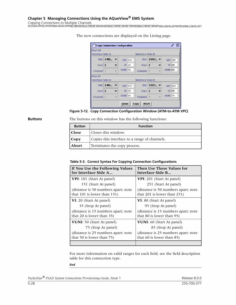
Chapter 5 Managing Connections Using the AQueView® EMS SystemCopying Connections to Multiple Channels
5-28 255-700-377
PacketStar® PSAX System Connections Provisioning Guide, Issue 1 Release 8.0.0
The new connections are displayed on the Listing page.
Buttons The buttons on this window has the following functions:
For more information on valid ranges for each field, see the field description table for this connection type.
End
Figure 5-12. Copy Connection Configuration Window (ATM-to-ATM VPC)
Button Function
Close Closes this window.
Copy Copies this interface to a range of channels.
Abort Terminates the copy process.
Table 5-3. Correct Syntax For Copying Connection Configurations
If You Use the Following Values for Interface Side A...
Then Use These Values for Interface Side B...
VPI: 101 (Start At panel)
151 (Start At panel)
(distance is 50 numbers apart; note that 101 is lower than 151)
VPI: 201 (Start At panel)
251 (Start At panel)
(distance is 50 numbers apart; note that 201 is lower than 251)
VI: 20 (Start At panel)
35 (Stop At panel)
(distance is 15 numbers apart; note that 20 is lower than 35)
VI: 80 (Start At panel)
95 (Stop At panel)
(distance is 15 numbers apart; note that 80 is lower than 95)
VUNI: 50 (Start At panel)
75 (Stop At panel)
(distance is 25 numbers apart; note that 50 is lower than 75)
VUNI: 60 (Start At panel)
85 (Stop At panel)
(distance is 25 numbers apart; note that 60 is lower than 85)
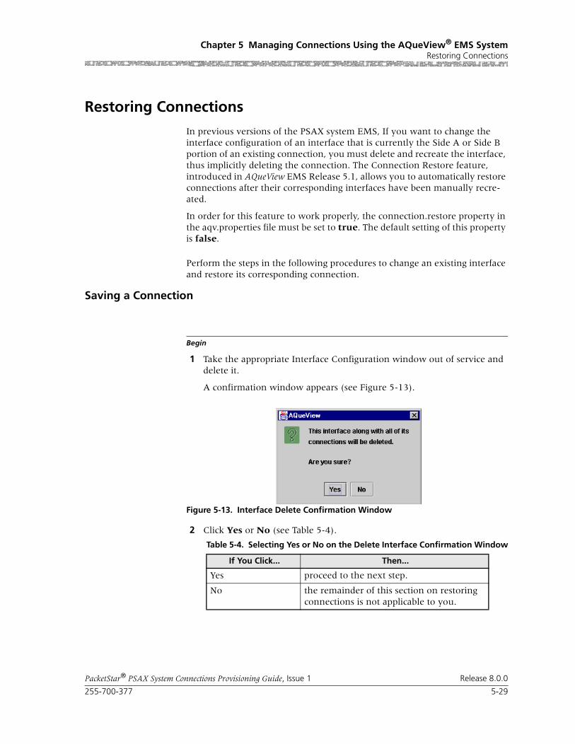
255-700-377 5-29
PacketStar® PSAX System Connections Provisioning Guide, Issue 1 Release 8.0.0
Chapter 5 Managing Connections Using the AQueView® EMS SystemRestoring Connections
Restoring Connections
In previous versions of the PSAX system EMS, If you want to change the interface configuration of an interface that is currently the Side A or Side B portion of an existing connection, you must delete and recreate the interface, thus implicitly deleting the connection. The Connection Restore feature, introduced in AQueView EMS Release 5.1, allows you to automatically restore connections after their corresponding interfaces have been manually recre-ated.
In order for this feature to work properly, the connection.restore property in the aqv.properties file must be set to true. The default setting of this property is false.
Perform the steps in the following procedures to change an existing interface and restore its corresponding connection.
Saving a Connection
Begin
1 Take the appropriate Interface Configuration window out of service and delete it.
A confirmation window appears (see Figure 5-13).
2 Click Yes or No (see Table 5-4).
Figure 5-13. Interface Delete Confirmation Window
Table 5-4. Selecting Yes or No on the Delete Interface Confirmation Window
If You Click... Then...
Yes proceed to the next step.
No the remainder of this section on restoring connections is not applicable to you.

Chapter 5 Managing Connections Using the AQueView® EMS SystemRestoring Connections
5-30 255-700-377
PacketStar® PSAX System Connections Provisioning Guide, Issue 1 Release 8.0.0
A confirmation window appears (see Figure 5-14).
3 Click Yes, No, or Cancel (see Table 5-5).
Note: The next procedure is only applicable if you clicked Yes in steps 2 and 3.
End
Figure 5-14. Save Connection Confirmation Window
Table 5-5. Selecting Yes or No on the Save Connection Confirmation Window
If You Click... This is What Happens
Yes The interface and its corresponding connection are deleted. The system has temporarily saved the connection. Proceed to step 5.
No The interface and its corresponding connec-tion are deleted. After clicking this button, the connection cannot be restored using the Connection Restoral feature.
Note: The remainder of this procedure is not applicable to you if you click this button.
Cancel The interface is not deleted. No connections are lost.
Note: The remainder of this procedure is not applicable to you if you click this button.

255-700-377 5-31
PacketStar® PSAX System Connections Provisioning Guide, Issue 1 Release 8.0.0
Chapter 5 Managing Connections Using the AQueView® EMS SystemRestoring Connections
Restoring a Connection
Begin
WARNING:!The Connection Restore feature cannot be used after the AQueView sys-tem is terminated, nor if you lose power to your workstation while the AQueView system is running. Lucent recommends that you immediately reconfigure the desired interface after deleting it, and then restore its corresponding connection.
1 Recreate the interface with the desired values using the same slot, port, and channel as the interface that you deleted.
Note: The interface you reconfigure must be the same interface type that you deleted unless it is an ATM interface.
2 Bring the interface into service.
A confirmation window appears (see Figure 5-15).
Figure 5-15. Connection Restore Confirmation Window (During Interface Configuration)
Chapter 5 Managing Connections Using the AQueView® EMS SystemRestoring Connections
5-32 255-700-377
PacketStar® PSAX System Connections Provisioning Guide, Issue 1 Release 8.0.0
3 Click Yes, No, or Cancel (see Table 5-6).
Note: The remainder of this procedure is only applicable if you clicked Cancel in step 7.
4 Do one of the following to restore the connection:
a On the Device Menu Bar, select Connection > Restore.
b Click the Connections tab. Then click the right mouse button within the Listing page, and a menu appears. Select Restore.
Table 5-6. Restore Connection Confirmation Window Choices (First Method)
If You Click... Then...
Yes the connection is restored. The connection reappears on the Listing page.
After the connection is restored, the con-nection restore list is maintained by the PSAX system system until you manually delete it (see “”). If you delete another interface that results in a loss of connec-tions, the connection restore list will be overwritten. Thus, the old connection restore list will be lost if the connection has not already been restored.
Note: The remainder of this procedure is not applicable to you if you click this button.
No the interface is deleted and all associated connections are lost. After clicking this but-ton, the connection cannot be restored using the Connection Restoral feature.
Note: The remainder of this procedure is not applicable to you if you click this button.
Cancel connections are not restored but can be restored at a later time as long as power is supplied to the AQueView system and the AQueView system is running (see the warn-ing on the previous page). When you are ready to restore the connection, proceed to step 8.

255-700-377 5-33
PacketStar® PSAX System Connections Provisioning Guide, Issue 1 Release 8.0.0
Chapter 5 Managing Connections Using the AQueView® EMS SystemRestoring Connections
A confirmation window appears (see Figure 5-16).
5 Click Yes or No (see Table 5-7).
End
Deleting the Connection Restore List
Begin
1 Do one of the following to delete the connection restore list from the PSAX system system:
a On the Device Menu Bar, select Connection > Clear Restore.
b Click the Connections tab. Then click the right mouse button within the Listing page, and a menu appears. Select Clear Restore.
Figure 5-16. Restore Connection Confirmation Window (Using Connection Menu)
Table 5-7. Restore Connection Confirmation Window Choices (Second Method)
If You Click... This is What Happens
Yes The connection is restored. The connection reappears on the Listing page.
No Connections are not restored but can be restored at a later time as long as power is supplied to the AQueView system and the AQueView system is running (see the warn-ing on the previous page). When you are ready to restore the connection, begin this procedure from step 8.
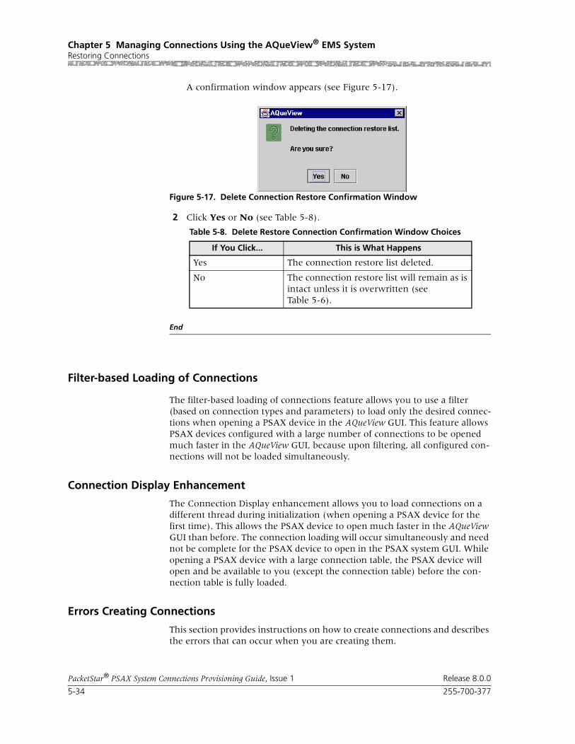
Chapter 5 Managing Connections Using the AQueView® EMS SystemRestoring Connections
5-34 255-700-377
PacketStar® PSAX System Connections Provisioning Guide, Issue 1 Release 8.0.0
A confirmation window appears (see Figure 5-17).
2 Click Yes or No (see Table 5-8).
End
Filter-based Loading of Connections
The filter-based loading of connections feature allows you to use a filter (based on connection types and parameters) to load only the desired connec-tions when opening a PSAX device in the AQueView GUI. This feature allows PSAX devices configured with a large number of connections to be opened much faster in the AQueView GUI, because upon filtering, all configured con-nections will not be loaded simultaneously.
Connection Display Enhancement
The Connection Display enhancement allows you to load connections on a different thread during initialization (when opening a PSAX device for the first time). This allows the PSAX device to open much faster in the AQueView GUI than before. The connection loading will occur simultaneously and need not be complete for the PSAX device to open in the PSAX system GUI. While opening a PSAX device with a large connection table, the PSAX device will open and be available to you (except the connection table) before the con-nection table is fully loaded.
Errors Creating Connections
This section provides instructions on how to create connections and describes the errors that can occur when you are creating them.
Figure 5-17. Delete Connection Restore Confirmation Window
Table 5-8. Delete Restore Connection Confirmation Window Choices
If You Click... This is What Happens
Yes The connection restore list deleted.
No The connection restore list will remain as is intact unless it is overwritten (see Table 5-6).

255-700-377 5-35
PacketStar® PSAX System Connections Provisioning Guide, Issue 1 Release 8.0.0
Chapter 5 Managing Connections Using the AQueView® EMS SystemSaving Connections
If an error occurs while creating a connection, the AQueView system displays an error message. There are many causes for these errors, but the errors that occur the most frequently are described below:
• Using an out-of-range VPI, VCI, or DCLI
• Selecting an interface that does not support flow settings that are entered
• Selecting out-of-range transmission parameters
• Attempting to create a connection on an unconfigured interface or an interface that has never been brought into service
• Exceeding the maximum bandwidth available for a VBR and CBR connec-tion
• Attempting to create a connection that already exists
• Attempting to use a VCI, VPI, DCLI, or channel that is already allocated elsewhere
For more information about these SNMP trap messages, see the appendix “SNMP Trap Messages” in the appropriate PacketStar® PSAX Multiservice Media Gateway User Guide.
Note: An interface for the appropriate port and channels must be applied and the interfaces must be brought into service at least once before creating a connection.
Note: To create a non-UBR connection type, the committed rates and burst sizes must be adjusted to match a portion of the available bandwidth.
Saving Connections
! CAUTION:Select Device > Save PSAX Configuration to permanently save the con-figuration.
Applied, but unsaved, configuration data will not be lost unless the PSAX system is restarted, or if power to the PSAX system is lost. Terminating the AQueView EMS will not cause the applied values to be lost because the con-figuration data is stored on the PSAX system, not in the AQueView EMS.
Deleting Connections
Perform the steps in the following procedure to delete a connection.
Begin
Procedure to Delete a Connection
1 In the Device window, click the Connections tab.
The Listing page appears.

Chapter 5 Managing Connections Using the AQueView® EMS SystemSaving Your Configuration
5-36 255-700-377
PacketStar® PSAX System Connections Provisioning Guide, Issue 1 Release 8.0.0
2 Do one of the following:
~ Double-click the connection to be deleted in the Connections List. The Display Connection window appears. Click Delete.
~ Right-click the entry of the connection you wish to delete. A menu appears. Select Delete.
A window appears, prompting you to confirm the deletion (see Figure 5-18).
3 Click Yes to delete the connection.
End
Saving Your Configuration
! CAUTION:Select Device > Save PSAX Configuration to permanently save the con-figuration.
Applied, but unsaved, configuration data will not be lost unless the PSAX system is restarted, or if power to the PSAX system is lost. Terminating the AQueView EMS will not cause the applied values to be lost because the con-figuration data is stored on the PSAX system, not in the AQueView EMS.
Figure 5-18. Sample Delete Connection Confirmation Window
PacketStar® PSAX System Connections Provisioning Guide, Issue 1 Release 8.0.0
255-700-377 6-1
6 Provisioning PVC Connections Usingthe AQueView® EMS
Data Flow in PVC Connections
PVCs consist of connections between ports on the various PSAX I/O modules. When setting up some types of connections, you can set up data traffic to flow in several ways, depending on the type of connection as follows:
• Duplex (Point-to-Point)
Data flows in two directions between the two connection points (inter-face side A and interface side B).
• Simplex
Data flows in only one direction, from side A to side B, or from side B to side A.
• Point-to-Multipoint
Data flows in only one direction, from one point on side A to several points on side B, or from one point on side B to several points on side A.
Provisioning PVC Connections
Adding ATM-to-ATM VCC PVC Connections
Perform the steps in the following procedure to create an ATM-to-ATM PVC connection.
Begin
Note: On the DS1 IMA and E1 IMA modules, you must provision PVC connections on the virtual port (port 7). You can use up to three channels on port 7 (the channels you provision on port 7).
Note: On the DS3 IMA module, you must provision PVC connections on the virtual port (port 30). You can use up to 14 channels on port 30 (the channels you provision on port 30).
1 In the Device window, click the Connections tab.
The Listing page appears.
2 Click the right mouse button and a menu appears. Click Create New.

Chapter 6 Provisioning PVC Connections Using the AQueView® EMSProvisioning PVC Connections
6-2 255-700-377
PacketStar® PSAX System Connections Provisioning Guide, Issue 1 Release 8.0.0
The Create Connection window appears (see Figure 6-1).
3 On the Side A and Side B panels, select the appropriate slot, port, and channel combinations to indicate the type of connection being created. The type of connection will be displayed in the ATM Connection Type field at the bottom of the window. If the connection is not a valid type of connection, None will be displayed in the ATM Connection Type field.
4 Once the desired connection type appears in the ATM Connection Type field, click Create.
The Create ATM-to-ATM_VCC Connection window appears (see Figure 6-2).
Figure 6-1. Create Connection Window

255-700-377 6-3
PacketStar® PSAX System Connections Provisioning Guide, Issue 1 Release 8.0.0
Chapter 6 Provisioning PVC Connections Using the AQueView® EMSProvisioning PVC Connections
The buttons on this window have the following functions:
Field Descriptions 5 Select the values for the fields on this window from the values given in Table 6-1.
Figure 6-2. Create ATM-to-ATM_VCC Connection Window
Button Function
Close Closes this window.
Create Establishes the connection you configured.
Copy Copies this configuration information to a range of interfaces.
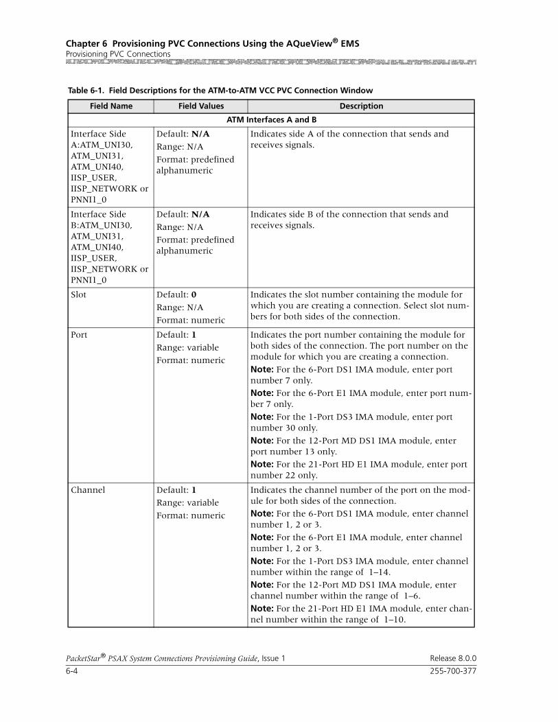
Chapter 6 Provisioning PVC Connections Using the AQueView® EMSProvisioning PVC Connections
6-4 255-700-377
PacketStar® PSAX System Connections Provisioning Guide, Issue 1 Release 8.0.0
Table 6-1. Field Descriptions for the ATM-to-ATM VCC PVC Connection Window
Field Name Field Values Description
ATM Interfaces A and B
Interface Side A:ATM_UNI30, ATM_UNI31, ATM_UNI40, IISP_USER, IISP_NETWORK or PNNI1_0
Default: N/A
Range: N/A
Format: predefined alphanumeric
Indicates side A of the connection that sends and receives signals.
Interface Side B:ATM_UNI30, ATM_UNI31, ATM_UNI40, IISP_USER, IISP_NETWORK or PNNI1_0
Default: N/A
Range: N/A
Format: predefined alphanumeric
Indicates side B of the connection that sends and receives signals.
Slot Default: 0
Range: N/A
Format: numeric
Indicates the slot number containing the module for which you are creating a connection. Select slot num-bers for both sides of the connection.
Port Default: 1
Range: variable
Format: numeric
Indicates the port number containing the module for both sides of the connection. The port number on the module for which you are creating a connection.
Note: For the 6-Port DS1 IMA module, enter port number 7 only.
Note: For the 6-Port E1 IMA module, enter port num-ber 7 only.
Note: For the 1-Port DS3 IMA module, enter port number 30 only.
Note: For the 12-Port MD DS1 IMA module, enter port number 13 only.
Note: For the 21-Port HD E1 IMA module, enter port number 22 only.
Channel Default: 1Range: variable
Format: numeric
Indicates the channel number of the port on the mod-ule for both sides of the connection.
Note: For the 6-Port DS1 IMA module, enter channel number 1, 2 or 3.
Note: For the 6-Port E1 IMA module, enter channel number 1, 2 or 3.
Note: For the 1-Port DS3 IMA module, enter channel number within the range of 1–14.
Note: For the 12-Port MD DS1 IMA module, enter channel number within the range of 1–6.
Note: For the 21-Port HD E1 IMA module, enter chan-nel number within the range of 1–10.
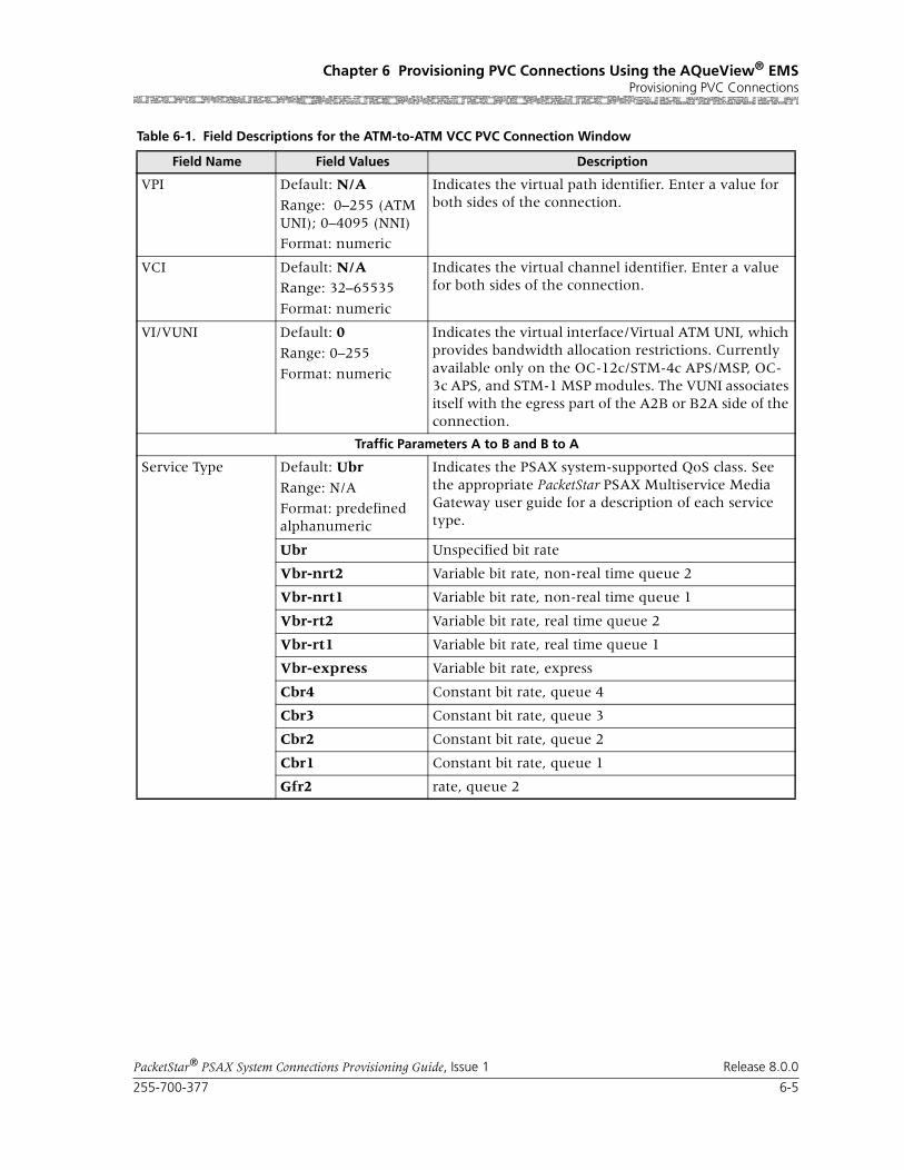
255-700-377 6-5
PacketStar® PSAX System Connections Provisioning Guide, Issue 1 Release 8.0.0
Chapter 6 Provisioning PVC Connections Using the AQueView® EMSProvisioning PVC Connections
VPI Default: N/A
Range: 0–255 (ATM UNI); 0–4095 (NNI)
Format: numeric
Indicates the virtual path identifier. Enter a value for both sides of the connection.
VCI Default: N/ARange: 32–65535
Format: numeric
Indicates the virtual channel identifier. Enter a value for both sides of the connection.
VI/VUNI Default: 0
Range: 0–255
Format: numeric
Indicates the virtual interface/Virtual ATM UNI, which provides bandwidth allocation restrictions. Currently available only on the OC-12c/STM-4c APS/MSP, OC-3c APS, and STM-1 MSP modules. The VUNI associates itself with the egress part of the A2B or B2A side of the connection.
Traffic Parameters A to B and B to A
Service Type Default: Ubr
Range: N/A
Format: predefined alphanumeric
Indicates the PSAX system-supported QoS class. See the appropriate PacketStar PSAX Multiservice Media Gateway user guide for a description of each service type.
Ubr Unspecified bit rate
Vbr-nrt2 Variable bit rate, non-real time queue 2
Vbr-nrt1 Variable bit rate, non-real time queue 1
Vbr-rt2 Variable bit rate, real time queue 2
Vbr-rt1 Variable bit rate, real time queue 1
Vbr-express Variable bit rate, express
Cbr4 Constant bit rate, queue 4
Cbr3 Constant bit rate, queue 3
Cbr2 Constant bit rate, queue 2
Cbr1 Constant bit rate, queue 1
Gfr2 rate, queue 2
Table 6-1. Field Descriptions for the ATM-to-ATM VCC PVC Connection Window
Field Name Field Values Description

Chapter 6 Provisioning PVC Connections Using the AQueView® EMSProvisioning PVC Connections
6-6 255-700-377
PacketStar® PSAX System Connections Provisioning Guide, Issue 1 Release 8.0.0
Cnfrm Type Default: Best-effort
Range: N/A
Format: predefined alphanumeric
Indicates the type of traffic control option used for ATM cells. The traffic descriptor combination specifies which traffic parameters are used for traffic control, determines the number and type of cells that are admitted into a congested queue, and determines whether high-priority cells are tagged as low-priority cells when traffic exceeds the traffic parameter thresh-olds.
Best-effort Allows the system to attempt to send all cells in a “best effort” fashion, without specifying traffic parameters, similar to the AQueMan algorithm.
One-bucket-notag-0plus1
Uses the parameters one bucket, no tagging, cell loss priority (CLP)=0+1 cells (high and low priority).
Two-bucket-notag-0plus1-0plus1
Uses the parameters two buckets, no tagging, CLP=0+1 cells (high and low priority) for bucket 1, and CLP=0+1 cells (high and low priority) for bucket 2.
Two-bucket-notag-0plus1
Uses the parameters two buckets, no tagging, CLP=0+1 cells (high and low priority) for bucket 1, and CLP=0 cells (high priority) for bucket 2.
Two-bucket-tag-0plus1
Uses the parameters two buckets, CLP=0+1 cells (high and low priority) for bucket 1, and tagging for CLP=0 cells (high priority) in bucket 2.
Best-effort-tag Allows the system to tag all CLP=0 (high priority) cells to always change them to CLP=1 (low priority) cells, and then attempt to send all cells in a “best effort” fashion, without specifying any other traffic parame-ters, similar to the AQueMan algorithm.
SAR Type Default: Null
Range: Aal5, Aal3-4, Aal2, Aal1
Format: predefined alphanumeric
Indicates the segmentation and reassembly (SAR) type. The ATM adaptation layer segments the protocol data unit (PDU) into 48-octet payloads at the transmit end. The SAR extracts and reassembles the octets at the receive end. The SAR type on the receiving end should correspond to the SAR type of the incoming data stream.
Forward Error Cor-rection
Default: NoneRange: Eighth Rate Quarter Rate, Half Rate, Auto Hi Q, Auto, Auto Lo Q
Format: predefined alphanumeric
Specifies the forward error correction method. Indi-cates the values Eighth Rate, Quarter Rate, and Half Rate, a Reed-Solomon encoding rate with a spe-cific error-correction capability. The values Auto Hi Q, Auto, and Auto Lo Q are dynamically changing rate options.
Table 6-1. Field Descriptions for the ATM-to-ATM VCC PVC Connection Window
Field Name Field Values Description

255-700-377 6-7
PacketStar® PSAX System Connections Provisioning Guide, Issue 1 Release 8.0.0
Chapter 6 Provisioning PVC Connections Using the AQueView® EMSProvisioning PVC Connections
Peak Rate(0+1) (cps)
Default: 1
Range: 1–(232-1)(theoretical range, except for modules noted in the Descrip-tion column)
Format: numeric (cells per second)
Indicates the peak cell rate (PCR) for all cells with both the CLP=0 bit and the CLP=1 bit. The value you set is the maximum allowed cell transmission rate (cells per second) for all cells both high and low priority, as allowed by your traffic contract.
When setting this value, take into account the line rate for the module and the amount of bandwidth you are setting up for each interface for the module. Refer to the ATM UNI 3.1 specifications for more information.
If you select the value SimplexA2B in the TrafficFlow field, set the value of this field to 0.The value in this field should be greater than the Sustained Cell Rate field.
Note: If you are using the traffic shaping Enabled value on the bulleted modules listed below, entering a minimum cps value below the minimum listed below causes traffic-shaped connections to default to the minimum cps value when the connection passes traf-fic.
• On the 1-Port OC-3c MM/SM and the 1-Port STM-1 MM/SM modules, the range is 18–999999999 cps.
• On the OC-12c/STM-4c SM/MM modules, the range is 87–999999999 cps.
• On the 3-Port DS3/E3 ATM module, the range is 7–999999999 cps.
Note: The peak cell rate cannot exceed the maximum cell rate for the interface.
If you need to calculate ingress PCRs for the OC-3c APS or the STM-1 MSP modules, see the PCR calcula-tion formula in the reference information appendix of the OC-3c 1+1 APS MM/SM Modules User Guide or the STM-1 1+1 MSP MM/SM Modules User Guide.
Table 6-1. Field Descriptions for the ATM-to-ATM VCC PVC Connection Window
Field Name Field Values Description

Chapter 6 Provisioning PVC Connections Using the AQueView® EMSProvisioning PVC Connections
6-8 255-700-377
PacketStar® PSAX System Connections Provisioning Guide, Issue 1 Release 8.0.0
Sustained Cell Rate(0) (cps)
Default: 1
Range: 0–999999999
Format: numeric
Indicates the sustainable cell rate (SCR) with CLP=0 (high priority) cells or the peak cell rate with CLP=0 cells.
When setting this value, take into account the line rate for the module and the amount of bandwidth you are setting up for each interface for the module. Refer to the ATM UNI 3.1 specifications for more information.
If you select the value SimplexA2B in the Traffic Flow field, set the value of this field to 0. The value in this field should be less than the Peak Cell Rate field.
If using traffic shaping on the OC-3c or STM-1 mod-ules, the modules will not pass data until these param-eters are set to a specified rate. Very large bursts of traf-fic may exceed the 8 MB memory typically available on the module, resulting in dropped cells. If very large bursts are typical for a specific network configuration, the module memory can be upgraded to 64 MB.
Max Burst Size (cells)
Default: 1Range: 0–999999999
Format: Numeric (cells)
Indicates the maximum burst size, a traffic parameter which specifies the maximum number of cells that can be transmitted at the peak cell rate. The MBS allows a burst of cells to arrive at a rate higher than that of the sustained cell rate. If the burst is larger than antici-pated, the additional cells are either tagged or dropped.
When setting this value, calculate the line rate for the module and the amount of bandwidth you are setting up for each interface for the module.
Note: If you select the value SimplexA2B in the Traf-fic Flow field, set the value for peak rate to 0.
OC-3c APS Module: When the Traffic Shaping field is set to Enabled, the cell queue depth for the Max Burst Size field is internally set to 1000, regardless of the value you enter. If you enter values other than 1000, these values matter for incoming signalling SPVC/SVC setup from the remote end of the connection.
Table 6-1. Field Descriptions for the ATM-to-ATM VCC PVC Connection Window
Field Name Field Values Description

255-700-377 6-9
PacketStar® PSAX System Connections Provisioning Guide, Issue 1 Release 8.0.0
Chapter 6 Provisioning PVC Connections Using the AQueView® EMSProvisioning PVC Connections
Traffic Shaping Default: Disabled
Range: As noted below
Format: Predefined
Indicates the method for controlling the outgoing flow of data traffic. This feature is implemented on the fol-lowing modules:
• 1-Port OC-3c Multimode and Single-Mode with Traffic Shaping modules
• 1-Port STM-1 Multimode and Single-Mode with Traffic Shaping modules
• 3-Port DS3/E3 ATM module
• 1-Port OC-12c/STM-4c MM/SM 1+1 APS/MSP modules
See the Peak Rate field on this table for minimum cps ranges restrictions on these modules.
Disabled Disables traffic shaping in the outgoing direction.
Enabled Enables traffic shaping on the outgoing direction. When enabled, traffic shaping ensures that the vari-able bit-rate (VBR) traffic entering the PSAX system (via these modules) complies with the parameters of the established service contracts.
ATM Interface A, Lower Left Panel
Traffic Flow Default: DuplexRange: As noted below
Format: predefined alphanumeric
Indicates the direction of the data traffic flow in this connection.
Note: When you select SimplexA2B, the fields in the Traffic Parameters B to A panel are not displayed.
SimplexA2B Unidirectional flow between terminations.
Point-to-MultipointA2B
Flow from one termination to many terminations.
Table 6-1. Field Descriptions for the ATM-to-ATM VCC PVC Connection Window
Field Name Field Values Description

Chapter 6 Provisioning PVC Connections Using the AQueView® EMSProvisioning PVC Connections
6-10 255-700-377
PacketStar® PSAX System Connections Provisioning Guide, Issue 1 Release 8.0.0
If the parameters are valid, the Connections window appears with the new connection in the Listing page, and the Display Connection window appears with tabs that contain details about the connection (see Figure 6-3): Primary, Statistics, and Backup.
If a parameter is invalid, a Connection Creation Failed message appears, stating the reason for the failure.
End
Primary Page The Primary page displays the information used to create the connection. See Table 6-1 for field descriptions.
OAM Status Default: Unsupp
Range: N/A
Format: predefined
Indicates that OAM is not in use.
End-Pt Indicates the PSAX system is used as a termination point for ATM traffic, and will process AID/RDI cells on the A or B side.
Note: The OAM loopback test is supported for end-to-end connections only.
Seg-Pt Indicates the PSAX system is used as a single ATM link, or is part of a group of interconnected ATM links that process OAM maintenance cells only on the A or B side.
End-Seg-Pt Indicates the characteristics of both an end point and a segment point on the A or B side.
Intermediate-Pt Indicates the Multiservice Media Gateway is used as a network node and an intermediate ATM device that does not terminate the ATM connection. It only gener-ates AIS cells during a local failure on the A or B side.
Note: The OAM loopback test is supported for end-to-end connections only.
Intra-Segment-Pt Indicates any connecting point inside a segment flow on the A or B side.
Connection Status(display only)
Default: Inactive
ActiveFormat: predefined
Displays the current status of the connection. The value indicates whether the connection is passing traf-fic.
Table 6-1. Field Descriptions for the ATM-to-ATM VCC PVC Connection Window
Field Name Field Values Description

255-700-377 6-11
PacketStar® PSAX System Connections Provisioning Guide, Issue 1 Release 8.0.0
Chapter 6 Provisioning PVC Connections Using the AQueView® EMSProvisioning PVC Connections
The buttons on the Primary page have the following functions:
Statistics Page The Statistics page displays the statistics for this connection (see Figure 6-4).
Figure 6-3. Display Connection: ATM-to-ATM PVC (Primary Page)
Button Function
Close Closes this window.
Create Establishes the connection youconfigured.
Copy Copies this configuration information to a range of interfaces.
Delete Deletes the connection.

Chapter 6 Provisioning PVC Connections Using the AQueView® EMSProvisioning PVC Connections
6-12 255-700-377
PacketStar® PSAX System Connections Provisioning Guide, Issue 1 Release 8.0.0
The buttons on the Statistics page have the following functions:
Figure 6-4. Display Connection: ATM-to-ATM_VCC (Statistics Page)
Button Description
Update Refreshes the statistics manually.
Clear Resets the resetable statistics to zero.
Poll Poll + continuously update the statistics and changes the button label to Poll-.
Poll- terminates polling and changes the button label to Poll+.
Odometer Restarts counting in the Cells Transmitted and Cells Received fields iin the Interface Side A and Interface Side B panels, and to view the trans-mitted cells and received cells in the Interface Side A and Interface Side B panels. This button is displayed only on the ATM-to-ATM VCC PVC and ATM-to-ATM VPC PVC Statistics pages.
Close Closes this window.
Restart Restarts connection establishment procedure for the connections that were not previously set up.

255-700-377 6-13
PacketStar® PSAX System Connections Provisioning Guide, Issue 1 Release 8.0.0
Chapter 6 Provisioning PVC Connections Using the AQueView® EMSProvisioning PVC Connections
Field Descriptions The fields on this window are described in Table 6-2.
Table 6-2. Field Descriptions for the ATM-to-ATM VCC PVC and the ATM-to-ATM VPC PVC Connection Statistics Page
Field Name Field Values Description
AIS Received(display only)
Default: 0Range: N/A
Format: numeric
Displays the number of alarm indication signal (AIS) cells received.
AIS Transmitted(display only)
Default: 0
Range: 32 bits
Format: numeric
Displays the number of AIS cells transmitted.
RDI Received(display only)
Default: 0
Range: 32 bits
Format: numeric(exponent notation)
Displays the number of remote defect indicator (RDI) cells received.
RDI Transmitted(display only)
Default: 0
Range: 32 bits
Format: numeric(exponent notation)
Displays the number of remote defect indicator (RDI) cells transmitted.
Cell Drop(display only)
Default: 0Range: 32 bits
Format: numeric
Displays the number of cells dropped on incom-ing side of interface A or B.
Cell Tag(display only)
Default: 0
Range: 32 bits
Format: Numeric
Displays the number of cell tagged on incoming side of interface A or B.
Cells Received(display only)
Default: 0
Range: 64 bits
Format: numeric(exponent notation)
Displays the number of valid cells received since the virtual circuit or virtual path was established.
Cells Transmitted(display only)
Default: 0Range: 64 bits
Format: numeric(exponent notation)
Displays the number of valid cells transmitted since the virtual circuit or virtual path was estab-lished.
FEC Rate Used(display only)
Default: 0
Range: N/A
Format: predefined
Displays the forward error correction (FEC) rate being used by the FEC module in the A2B direc-tion (for ATM Interface A panel), or B2A direc-tion (for ATM Interface B panel). This field is dymanic when auto rates are selected. In other cases it will display the rate set by the user.
Note: This field is displayed only on the ATM-to-ATM VCC PVC Statistics window only.

Chapter 6 Provisioning PVC Connections Using the AQueView® EMSProvisioning PVC Connections
6-14 255-700-377
PacketStar® PSAX System Connections Provisioning Guide, Issue 1 Release 8.0.0
Polling Statistics Using the Odometer Delta Window
Perform the steps in the following procedure to use the odometer on the Sta-tistics page.
Begin
Using the Odometer Delta to Poll Statistics
1 Click Odometer.
Received Odometer(display only)
Default: 0Range: 64 bits
Format: numeric(exponent notation)
Displays the number of valid cells received since this counter was reset. This counter serves as an odometer while the Cells Received field tracks usage for the life of the circuit.
Transmitted Odom-eter(display only)
Default: 0
Range: 64 bits
Format: numeric(exponent notation)
Displays the number of valid cells transmitted since this counter was reset. This counter serves as an odometer while the Cells Transmitted field tracks usage for the life of the circuit.
Time Elapsed(display only)
Default: 0
Range: N/A
Format: numeric(hour, minute, sec-ond)
Displays the time elapsed since last reset.
Time Since Reset(display only)
Default: 00:00:00
Range: N/A
Format: numeric(hour, minute, sec-ond)
Displays the time elapsed since the last time the Clear button was used. The Clear button resets only the odometer fields (labeled as Odometer) and the corresponding clock. Other counters are incremented for the duration of the connection.
Table 6-2. Field Descriptions for the ATM-to-ATM VCC PVC and the ATM-to-ATM VPC PVC Connection Statistics Page
Field Name Field Values Description
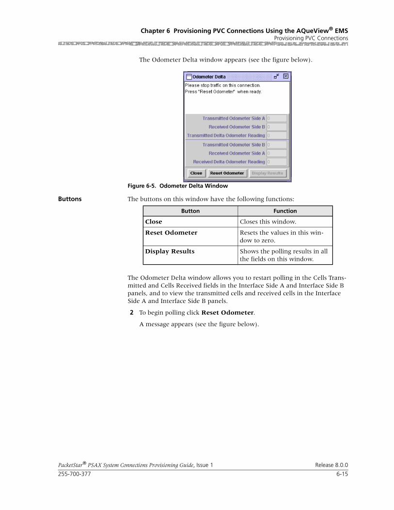
255-700-377 6-15
PacketStar® PSAX System Connections Provisioning Guide, Issue 1 Release 8.0.0
Chapter 6 Provisioning PVC Connections Using the AQueView® EMSProvisioning PVC Connections
The Odometer Delta window appears (see the figure below).
Buttons The buttons on this window have the following functions:
The Odometer Delta window allows you to restart polling in the Cells Trans-mitted and Cells Received fields in the Interface Side A and Interface Side B panels, and to view the transmitted cells and received cells in the Interface Side A and Interface Side B panels.
2 To begin polling click Reset Odometer.
A message appears (see the figure below).
Figure 6-5. Odometer Delta Window
Button Function
Close Closes this window.
Reset Odometer Resets the values in this win-dow to zero.
Display Results Shows the polling results in all the fields on this window.

Chapter 6 Provisioning PVC Connections Using the AQueView® EMSProvisioning PVC Connections
6-16 255-700-377
PacketStar® PSAX System Connections Provisioning Guide, Issue 1 Release 8.0.0
3 To terminate polling, click Display Results.
The resulting odometer values are displayed (see the figure below).
4 To reset the values in this window to zero, click Reset Odometer.
5 To close the window, click Close.
End
Figure 6-6. Odometer Delta Window (Displaying Message)
Figure 6-7. Odometer Delta Window (Displaying Results)

255-700-377 6-17
PacketStar® PSAX System Connections Provisioning Guide, Issue 1 Release 8.0.0
Chapter 6 Provisioning PVC Connections Using the AQueView® EMSProvisioning PVC Connections
Backup Page The Backup page displays the information used to create a backup connec-tion (see Figure 6-8). Creating a backup connection is optional.
The buttons on the Backup page have the following functions:
Select the values from the fields as described in Table 6-3.
Figure 6-8. Display Connection: ATM-to-ATM_VCC (Backup Page)
Button Function
Create Backup PVC Establishes the backup VCC PVC connection you configured.
You cannot create a backup VCC PVC connection without selecting an ATM interface type in the Backup ATM Interface panel. Therefore, this button is active when the Slot, Port, and Channel fields correspond to an ATM interface type in the Interface field. Otherwise, the button will be ghosted.
Close Closes this window.

Chapter 6 Provisioning PVC Connections Using the AQueView® EMSProvisioning PVC Connections
6-18 255-700-377
PacketStar® PSAX System Connections Provisioning Guide, Issue 1 Release 8.0.0
Table 6-3. Field Descriptions for the Display Connection: ATM-to-ATM_VCC Backup Page
Field Name Field Values Description
Slot Default: N/A
Range: Listed as avail-able from the PSAX device
Format: Numeric
Indicates the slot containing the module for which you are creating a connection.
Port Default: N/A
Range: Determined by the number of ports available on the module selected in the Slot field
Format: Numeric
Indicates the port number on the module for which you are creating a connection.
Channel Default: N/A
Range: Determined by the number of channels available on the port selected in the Port field
Format: Numeric
Indicates the channel number of the port on the module for which you are creating a connection.
Interface(display only)
Default: Unconfig-uredAtmUni3_0AtmUni3_1AtmUni4_0IispUserIispNetworkCircuitEmulation DbCirEmFrameRelayUniFrameRelayNniPri_Isdn_NetworkPri_Isdn_UserHldcPassThroughAtmPnni1-0Format: Predefined
Indicates the interface type that is configured on the slot, port, and channel (selected in the Slot, Port, and Channel fields).
OperStatus(display only)
InService Indicates that the interface is operational.
OutOfService Indicates that the interface is not operational.
AdminStatus (display only)
InService Indicates that no conditions are preventing the port from being fully operational.
OutOfService Indicates that some condition is preventing the port from being configured with an interface.

255-700-377 6-19
PacketStar® PSAX System Connections Provisioning Guide, Issue 1 Release 8.0.0
Chapter 6 Provisioning PVC Connections Using the AQueView® EMSProvisioning PVC Connections
Utilization Page The Utilization page measures the amount of traffic running through this connection (see Figure 6-9).
VPI Default: N/A
Range: 0–255 (ATM UNI); 0–4095 (NNI)
Format: Numeric
Indicates the backup connection.virtual path identifier assigned to this interface.
VCI Default: 32Range: 32–65535
Format: Numeric
Indicates the backup connection virtual channel identifier assigned to the interface
VI Default: 0
Range: 0–255
Format: Numeric
Indicates the backup connection virtual interface, which provides bandwidth allocation restrictions. Currently available only on the OC-3c APS and STM-1 MSP modules.
Automatic Switch-back
Default: Yes
Range: N/A
Format: Predefined
Indicates the CPU monitors the primary connec-tion. If the primary connection becomes avail-able, backup will switch back connection to pri-mary.
No This option is not currently supported.
Once active, the backup connection will not switch back to primary connection automatically if primary becomes available.
Current Active PVC Default: None
Range: N/A
Format: predefined
Indicates that the connection is inactive.
Primary Indicates that the primary connection is active (carrying user traffic).
Backup Indicates that the backup connection is active (carrying user traffic).
Table 6-3. Field Descriptions for the Display Connection: ATM-to-ATM_VCC Backup Page
Field Name Field Values Description

Chapter 6 Provisioning PVC Connections Using the AQueView® EMSProvisioning PVC Connections
6-20 255-700-377
PacketStar® PSAX System Connections Provisioning Guide, Issue 1 Release 8.0.0
Figure 6-9. Display Connection: ATM-to-ATM VCC (Utilization Page)
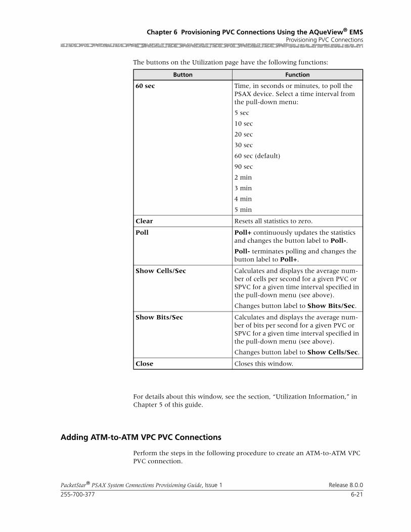
255-700-377 6-21
PacketStar® PSAX System Connections Provisioning Guide, Issue 1 Release 8.0.0
Chapter 6 Provisioning PVC Connections Using the AQueView® EMSProvisioning PVC Connections
The buttons on the Utilization page have the following functions:
For details about this window, see the section, “Utilization Information,” in Chapter 5 of this guide.
Adding ATM-to-ATM VPC PVC Connections
Perform the steps in the following procedure to create an ATM-to-ATM VPC PVC connection.
Button Function
60 sec Time, in seconds or minutes, to poll the PSAX device. Select a time interval from the pull-down menu:
5 sec
10 sec
20 sec
30 sec
60 sec (default)
90 sec
2 min
3 min
4 min
5 min
Clear Resets all statistics to zero.
Poll Poll+ continuously updates the statistics and changes the button label to Poll-.
Poll- terminates polling and changes the button label to Poll+.
Show Cells/Sec Calculates and displays the average num-ber of cells per second for a given PVC or SPVC for a given time interval specified in the pull-down menu (see above).
Changes button label to Show Bits/Sec.
Show Bits/Sec Calculates and displays the average num-ber of bits per second for a given PVC or SPVC for a given time interval specified in the pull-down menu (see above).
Changes button label to Show Cells/Sec.
Close Closes this window.
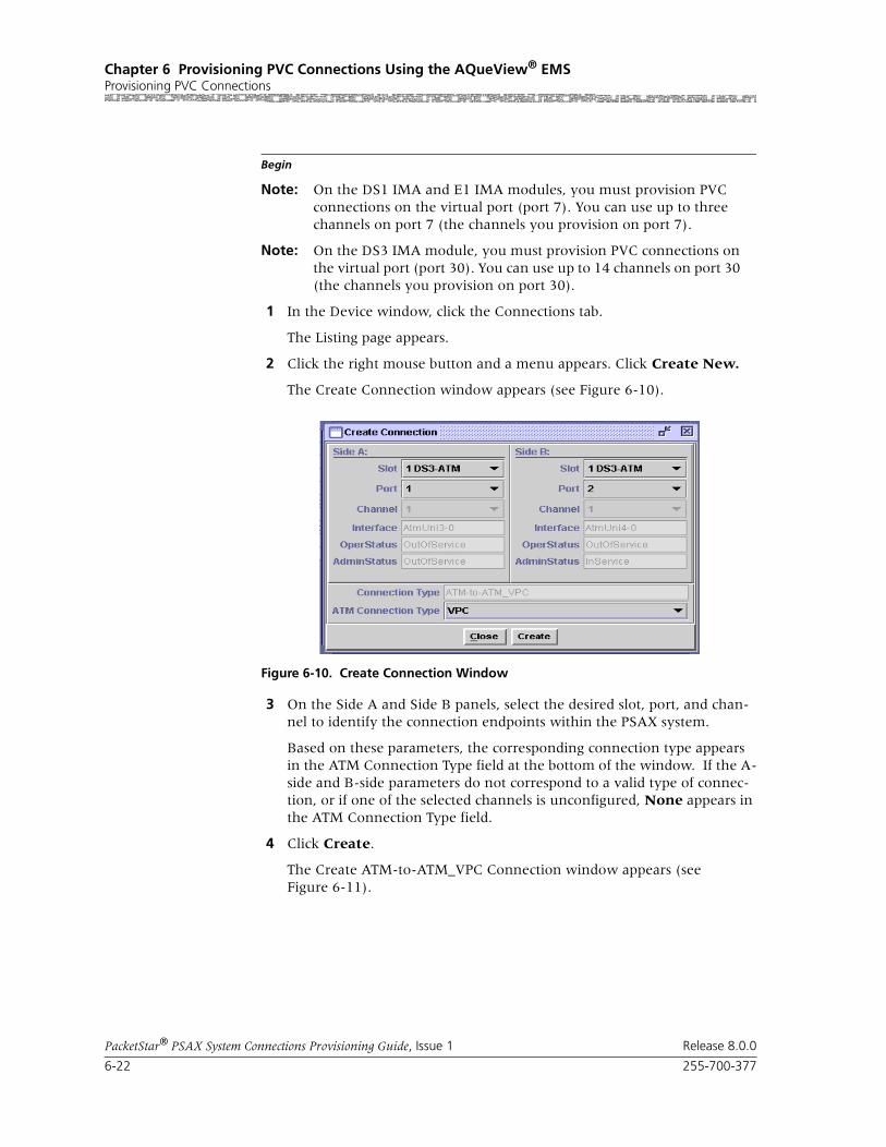
Chapter 6 Provisioning PVC Connections Using the AQueView® EMSProvisioning PVC Connections
6-22 255-700-377
PacketStar® PSAX System Connections Provisioning Guide, Issue 1 Release 8.0.0
Begin
Note: On the DS1 IMA and E1 IMA modules, you must provision PVC connections on the virtual port (port 7). You can use up to three channels on port 7 (the channels you provision on port 7).
Note: On the DS3 IMA module, you must provision PVC connections on the virtual port (port 30). You can use up to 14 channels on port 30 (the channels you provision on port 30).
1 In the Device window, click the Connections tab.
The Listing page appears.
2 Click the right mouse button and a menu appears. Click Create New.
The Create Connection window appears (see Figure 6-10).
3 On the Side A and Side B panels, select the desired slot, port, and chan-nel to identify the connection endpoints within the PSAX system.
Based on these parameters, the corresponding connection type appears in the ATM Connection Type field at the bottom of the window. If the A-side and B-side parameters do not correspond to a valid type of connec-tion, or if one of the selected channels is unconfigured, None appears in the ATM Connection Type field.
4 Click Create.
The Create ATM-to-ATM_VPC Connection window appears (see Figure 6-11).
Figure 6-10. Create Connection Window

255-700-377 6-23
PacketStar® PSAX System Connections Provisioning Guide, Issue 1 Release 8.0.0
Chapter 6 Provisioning PVC Connections Using the AQueView® EMSProvisioning PVC Connections
The buttons on this window have the following functions:
Field Descriptions 5 Select the values for the fields on this window from the values given in Table 6-4.
Figure 6-11. Create ATM-to-ATM_VPC Connection Window
Button Function
Close Closes this window.
Create Establishes the connection you configured.
Copy Copies this configuration information to a range of interfaces.
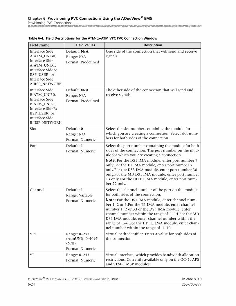
Chapter 6 Provisioning PVC Connections Using the AQueView® EMSProvisioning PVC Connections
6-24 255-700-377
PacketStar® PSAX System Connections Provisioning Guide, Issue 1 Release 8.0.0
Table 6-4. Field Descriptions for the ATM-to-ATM VPC PVC Connection Window
Field Name Field Values Description
Interface Side A:ATM_UNI30, Interface Side A:ATM_UNI31, Interface SideA: IISP_USER, or Interface Side A:IISP_NETWORK
Default: N/ARange: N/A
Format: Predefined
One side of the connection that will send and receive signals.
Interface Side B:ATM_UNI30, Interface Side B:ATM_UNI31, Interface SideB: IISP_USER, or Interface Side B:IISP_NETWORK
Default: N/A
Range: N/A
Format: Predefined
The other side of the connection that will send and receive signals.
Slot Default: 0Range: N/A
Format: Numeric
Select the slot number containing the module for which you are creating a connection. Select slot num-bers for both sides of the connection.
Port Default: 1
Format: Numeric
Select the port number containing the module for both sides of the connection. The port number on the mod-ule for which you are creating a connection.
Note: For the DS1 IMA module, enter port number 7 only.For the E1 IMA module, enter port number 7 only.For the DS3 IMA module, enter port number 30 only.For the MD DS1 IMA module, enter port number 13 only.For the HD E1 IMA module, enter port num-ber 22 only.
Channel Default: 1
Range: Variable
Format: Numeric
Select the channel number of the port on the module for both sides of the connection.
Note: For the DS1 IMA module, enter channel num-ber 1, 2 or 3.For the E1 IMA module, enter channel number 1, 2 or 3.For the DS3 IMA module, enter channel number within the range of 1–14.For the MD DS1 IMA module, enter channel number within the range of 1–6.For the HD E1 IMA module, enter chan-nel number within the range of 1–10.
VPI Range: 0–255 (AtmUNI); 0-4095 (NNI)
Format: Numeric
Virtual path identifier. Enter a value for both sides of the connection.
VI Range: 0–255
Format: Numeric
Virtual interface, which provides bandwidth allocation restrictions. Currently available only on the OC-3c APS and STM-1 MSP modules.

255-700-377 6-25
PacketStar® PSAX System Connections Provisioning Guide, Issue 1 Release 8.0.0
Chapter 6 Provisioning PVC Connections Using the AQueView® EMSProvisioning PVC Connections
VUNI Range: 0–255
Format: Numeric
The virtual UNI (VUNI) associates itself with the egress part of the A2B or B2A side of the connection.
Traffic Parameters A to B and B to A
Service Type Default: UbrRange: As noted below
Format: Predefined
PSAX system-supported quality of service (QoS) class. See the Reference Appendix in this guide for more information.
Ubr Unspecified bit rate
Vbr-nrt2 Variable bit rate, non-real time queue 2
Vbr-nrt1 Variable bit rate, non-real time queue 1
Vbr-rt2 Variable bit rate, real time queue 2
Vbr-rt1 Variable bit rate, real time queue 1
Vbr-express Variable bit rate, express
Cbr4 Constant bit rate, queue 4
Cbr3 Constant bit rate, queue 3
Cbr2 Constant bit rate, queue 2
Cbr1 Constant bit rate, queue 1
Table 6-4. Field Descriptions for the ATM-to-ATM VPC PVC Connection Window
Field Name Field Values Description

Chapter 6 Provisioning PVC Connections Using the AQueView® EMSProvisioning PVC Connections
6-26 255-700-377
PacketStar® PSAX System Connections Provisioning Guide, Issue 1 Release 8.0.0
Cnfrm Type Default: Best-effort
Range: As noted below
Format: Predefined
The type of traffic control option used for ATM cells. The traffic descriptor combination specifies which traf-fic parameters are used for traffic control, determines the number and type of cells that are admitted into a congested queue, and determines whether high-prior-ity cells are tagged as low-priority cells when traffic exceeds the traffic parameter thresholds.
See the Reference Appendix in this guide for a detailed description of the values for this field, including repre-sentative examples.
Best-effort This traffic descriptor allows the system to attempt to send all cells in a “best effort” fashion, without specify-ing traffic parameters, similar to the AQueMan algo-rithm.
One-bucket-notag-0plus1
This traffic descriptor uses the parameters one bucket, no tagging, cell loss priority (CLP)=0+1 cells (high and low priority).
Two-bucket-notag-0plus1-0plus1
This traffic descriptor uses the parameters two buckets, no tagging, CLP=0+1 cells (high and low priority) for bucket 1, and CLP=0+1 cells (high and low priority) for bucket 2.
Two-bucket-notag-0plus1
This traffic descriptor uses the parameters two buckets, no tagging, CLP=0+1 cells (high and low priority) for bucket 1, and CLP=0 cells (high priority) for bucket 2.
Two-bucket-tag-0plus1
This traffic descriptor uses the parameters two buckets, CLP=0+1 cells (high and low priority) for bucket 1, and tagging for CLP=0 cells (high priority) in bucket 2.
Best-effort-tag This traffic descriptor allows the system to tag all CLP=0 (high priority) cells to change them to CLP=1 (low priority) cells during congestion, and then attempt to send all cells in a “best effort” fashion, with-out specifying any other traffic parameters, similar to the AQueMan algorithm.
SAR Type Default: NullRange: As noted below
Format: Predefined
Aal5Aal3-4Aal2Aal1
The segmentation and reassembly (SAR) type must correspond to the SAR type of the incoming data stream.
Table 6-4. Field Descriptions for the ATM-to-ATM VPC PVC Connection Window
Field Name Field Values Description

255-700-377 6-27
PacketStar® PSAX System Connections Provisioning Guide, Issue 1 Release 8.0.0
Chapter 6 Provisioning PVC Connections Using the AQueView® EMSProvisioning PVC Connections
Peak Rate(0+1) (cps)
Default: 1
Range: 1–(232-1)(theoretical range, except for modules noted at right, see Description column)
Range:
Format: numeric (cells per second)
Peak cell rate (PCR) for all cells with both the CLP=0 bit and the CLP=1 bit. The value you set is the maxi-mum allowed cell transmission rate (cells per second) for all cells both high and low priority, as allowed by your traffic contract.
When setting this value, take into account the line rate for the module and the amount of bandwidth you are setting up for each interface for the module. Refer to the ATM UNI 3.1 specifications for more information.
If you select the value SimplexA2B in the Traffic Flow field, set the value of this field to 0. The value in this field should be greater than the Sustained Cell Rate field.
Note: If you are using the traffic shaping Enabled set-ting on the bulleted modules listed below, entering a minimum cps value below the minimum listed below will cause traffic-shaped connections to default back to the minimum cps value when the connection passes traffic.
• On the 1-Port OC-3c MM/SM and the 1-Port STM-1 MM/SM, the cps range is 18–999999999.
• On the OC-12c/STM-4c SM/MM, the cps range is 87–999999999.
• On the 3-Port DS3/E3 ATM, the cps range is 7–999999999.
Note: The peak cell rate cannot exceed the maximum cell rate for the interface.
Sustained Cell Rate(0) (cps)
Default: 1Range: 0–999999999
Format: cps
Sustainable cell rate (SCR) with CLP=0 (high priority) cells or the peak cell rate with CLP=0 cells.
When setting this value, take into account the line rate for the module and the amount of bandwidth you are setting up for each interface for the module. Refer to the ATM UNI 3.1 specifications for more information.
If you select the value SimplexA2B in the Traffic Flow field, set the value of this field to 0. The value in this field should be greater than the Sustained Cell Rate field.
If using traffic shaping on the OC-3c or STM-1 mod-ules, the modules will not pass data until these param-eters are set to a specified rate. Very large bursts of traf-fic may exceed the 8 MB memory typically available on the module, resulting in dropped cells. If very large bursts are typical for a specific network configuration, the module memory can be upgraded to 64 MB.
Table 6-4. Field Descriptions for the ATM-to-ATM VPC PVC Connection Window
Field Name Field Values Description

Chapter 6 Provisioning PVC Connections Using the AQueView® EMSProvisioning PVC Connections
6-28 255-700-377
PacketStar® PSAX System Connections Provisioning Guide, Issue 1 Release 8.0.0
Max Burst Size (cells)
Default: 1
Range: 0–999999999
Format: cps
Maximum burst size. The maximum number of cells that can be received at the peak cell rate. This allows a burst of cells to arrive at a rate higher than that of the sustained cell rate. If the burst is larger than antici-pated, the additional cells are either tagged or dropped.
When setting this value, take into account the line rate for the module and the amount of bandwidth you are setting up for each interface for the module.
If you select the value SimplexA2B in the Traffic Flow field, set the value for maximum burst size to 0.
OC-3c APS Module: When the Traffic Shaping field is set to Enabled, the cell queue depth for the Max Burst Size field is internally set to 1000, regardless of the value you enter. If you enter values other than 1000, these values matter for incoming signalling SPVC/SVC setup from the remote end of the connection.
Traffic Shaping Default: Disabled
Range: As noted below.
Format: Predefined alphanumeric
Indicates the method for controlling the flow of data traffic. This feature is implemented on the following modules:
• 1-Port OC-3c Multimode and Single-Mode with Traffic Shaping modules
• 1-Port STM-1 Multimode and Single-Mode with Traffic Shaping modules
• 3-Port DS3/E3 ATM
• 1-Port OC-12c/STM-4c MM/SM 1+1 APS/MSP modules
See the Peak Rate field on this table for minimum cps ranges restrictions on these modules.
Disabled Traffic Shaping is disabled.
Enabled When enabled, traffic shaping ensures that the variable bit-rate (VBR) traffic entering the PSAX system via these modules complies with the parameters of the established service contracts.
Connection Features, Lower Left Panel
[FailCause A/B](display only)
Default: NoneRange: True/False
Format: Predefined
Displays a transmission failure cause on the A or B side of the connection.
Traffic Flow Default: Duplex
Range: As noted below
Format: Predefined
SimplexA2BPoint-to-point-Multi-point A2B
Direction of the flow of data traffic in this connection.
When you select SimplexA2B, the fields in the Traffic Parameters B to A panel do not display.
Table 6-4. Field Descriptions for the ATM-to-ATM VPC PVC Connection Window
Field Name Field Values Description

255-700-377 6-29
PacketStar® PSAX System Connections Provisioning Guide, Issue 1 Release 8.0.0
Chapter 6 Provisioning PVC Connections Using the AQueView® EMSProvisioning PVC Connections
If the parameters are valid, the Connections window appears with the new connection in the Listing page, and the Display Connection window appears with tabs that contain details about the connection (see Figure 6-12): Primary, Statistics, and Backup.
If a parameter is invalid, a Connection Creation Failed message appears, stating the reason for the failure.
End
Primary Page The Primary page displays the information used to create the connection. See Table 6-4 for field descriptions.
OAM Status Default: Unsupp
Range: As noted below
Format: Predefined
Indicates on what portion of the transmission path the operations and maintenance status AIS and RDI cells will be processed.
Unsupp OAM is not in use.
End-Pt The PSAX system is used as a termination point for ATM, and will process AIS/RDI cells on the A or B side.
The OAM loopback test is supported for end-to-end connections only.
Seg-Pt The PSAX system is used as a single ATM link, or is part of a group of inter-connected ATM links that pro-cess OAM maintenance cells only on the A or B side.
End-Seg-Pt Has the characteristics of both an end point and a seg-ment point on the A or B side.
Intermediate-Pt The PSAX system is used as a network node and an intermediate ATM device that does not terminate the ATM connection. It only generates AIS cells during a local failure on the A or B side.
Use this value to enable trunk conditioning. For more information, see the Trunk Conditioning Application Note for PacketStar PSAX Multiservice Media Gateways (Docu-ment No. 255-700-072).
The OAM loopback test is supported for end-to-end connections only.
Intra-Segment-Pt OAM will be performed on any connecting point inside a segment flow on the A or B side.
Connection Status(display only)
Default: Inactive
Range: Inac-tive/Active
Format: Predefined
This field displays the current status of the connection. The value indicates whether the connection is passing traffic.
Inactive The connection is not passing traffic.
Active The connection is passing traffic.
Table 6-4. Field Descriptions for the ATM-to-ATM VPC PVC Connection Window
Field Name Field Values Description

Chapter 6 Provisioning PVC Connections Using the AQueView® EMSProvisioning PVC Connections
6-30 255-700-377
PacketStar® PSAX System Connections Provisioning Guide, Issue 1 Release 8.0.0
Statistics Page The Statistics page displays the statistics for this connection (see Figure 6-13).
Figure 6-12. Display Connection: ATM-to-ATM VPC (Primary Page)

255-700-377 6-31
PacketStar® PSAX System Connections Provisioning Guide, Issue 1 Release 8.0.0
Chapter 6 Provisioning PVC Connections Using the AQueView® EMSProvisioning PVC Connections
The buttons on the Statistics page have the following functions:
Field Descriptions The values for the fields in this window are described in the following table.
Figure 6-13. Display Connection: ATM-to-ATM VPC (Statistics Page)
Button Description
Update Refreshes the statistics manually.
Clear Resets the resetable statistics to zero.
Poll Poll + continuously update the statistics and changes the button label to Poll-.
Poll- terminates polling and changes the button label to Poll+.
Odometer Restarts counting in the Cells Transmitted and Cells Received fields iin the Interface Side A and Interface Side B panels, and to view the trans-mitted cells and received cells in the Interface Side A and Interface Side B panels. This button is displayed only on the ATM-to-ATM VCC PVC and ATM-to-ATM VPC PVC Statistics pages.
Close Closes this window.
Restart Restarts connection establishment procedure for the connections that were not previously set up.

Chapter 6 Provisioning PVC Connections Using the AQueView® EMSProvisioning PVC Connections
6-32 255-700-377
PacketStar® PSAX System Connections Provisioning Guide, Issue 1 Release 8.0.0
Polling Statistics Using the Odometer Delta Window
Table 6-5. Field Descriptions for the ATM-to-ATM VCC PVC and the ATM-to-ATM VPC PVC Connection Statistics Page
Field Name Field Values Description
AIS Received(display only)
Default: 0
Range: N/A
Format: numeric
Displays the number of alarm indication signal (AIS) cells received.
AIS Transmitted(display only)
Default: 0
Range: 32 bits
Format: numeric
Displays the number of AIS cells transmitted.
RDI Received(display only)
Default: 0
Range: 32 bits
Format: numeric(exponent notation)
Displays the number of remote defect indicator (RDI) cells received.
RDI Transmitted(display only)
Default: 0Range: 32 bits
Format: numeric(exponent notation)
Displays the number of remote defect indicator (RDI) cells transmitted.
Cell Drop(display only)
Default: 0
Range: 32 bits
Format: numeric
Displays the number of cells dropped on incom-ing side of interface A or B.
Cell Tag(display only)
Default: 0
Range: 32 bits
Format: Numeric
Displays the number of cell tagged on incoming side of interface A or B.
Cells Received(display only)
Default: 0Range: 64 bits
Format: numeric(exponent notation)
Displays the number of valid cells received since the virtual circuit or virtual path was established.
Cells Transmitted(display only)
Default: 0
Range: 64 bits
Format: numeric(exponent notation)
Displays the number of valid cells transmitted since the virtual circuit or virtual path was estab-lished.
FEC Rate Used(display only)
Default: 0
Range: N/A
Format: predefined
Displays the forward error correction (FEC) rate being used by the FEC module in the A2B direc-tion (for ATM Interface A panel), or B2A direc-tion (for ATM Interface B panel). This field is dymanic when auto rates are selected. In other cases it will display the rate set by the user.
Note: This field is displayed only on the ATM-to-ATM VCC PVC Statistics window only.

255-700-377 6-33
PacketStar® PSAX System Connections Provisioning Guide, Issue 1 Release 8.0.0
Chapter 6 Provisioning PVC Connections Using the AQueView® EMSProvisioning PVC Connections
Perform the steps in the following procedure to use the odometer on the Sta-tistics page.
Begin
Using the Odometer Delta to Poll Statistics
1 Click Odometer.
The Odometer Delta window appears (see the figure below).
Received Odometer(display only)
Default: 0Range: 64 bits
Format: numeric(exponent notation)
Displays the number of valid cells received since this counter was reset. This counter serves as an odometer while the Cells Received field tracks usage for the life of the circuit.
Transmitted Odom-eter(display only)
Default: 0
Range: 64 bits
Format: numeric(exponent notation)
Displays the number of valid cells transmitted since this counter was reset. This counter serves as an odometer while the Cells Transmitted field tracks usage for the life of the circuit.
Time Elapsed(display only)
Default: 0
Range: N/A
Format: numeric(hour, minute, sec-ond)
Displays the time elapsed since last reset.
Time Since Reset(display only)
Default: 00:00:00
Range: N/A
Format: numeric(hour, minute, sec-ond)
Displays the time elapsed since the last time the Clear button was used. The Clear button resets only the odometer fields (labeled as Odometer) and the corresponding clock. Other counters are incremented for the duration of the connection.
Table 6-5. Field Descriptions for the ATM-to-ATM VCC PVC and the ATM-to-ATM VPC PVC Connection Statistics Page
Field Name Field Values Description
Figure 6-14. Odometer Delta Window

Chapter 6 Provisioning PVC Connections Using the AQueView® EMSProvisioning PVC Connections
6-34 255-700-377
PacketStar® PSAX System Connections Provisioning Guide, Issue 1 Release 8.0.0
Buttons The buttons on this window have the following functions:
The Odometer Delta window allows you to restart polling in the Cells Trans-mitted and Cells Received fields in the Interface Side A and Interface Side B panels, and to view the transmitted cells and received cells in the Interface Side A and Interface Side B panels.
2 To begin polling click Reset Odometer.
A message appears (see the figure below).
3 To terminate polling, click Display Results.
Button Function
Close Closes this window.
Reset Odometer Resets the values in this win-dow to zero.
Display Results Shows the polling results in all the fields on this window.
Figure 6-15. Odometer Delta Window (Displaying Message)

255-700-377 6-35
PacketStar® PSAX System Connections Provisioning Guide, Issue 1 Release 8.0.0
Chapter 6 Provisioning PVC Connections Using the AQueView® EMSProvisioning PVC Connections
The resulting odometer values are displayed (see the figure below).
4 To reset the values in this window to zero, click Reset Odometer.
5 To close the window, click Close.
End
Figure 6-16. Odometer Delta Window (Displaying Results)
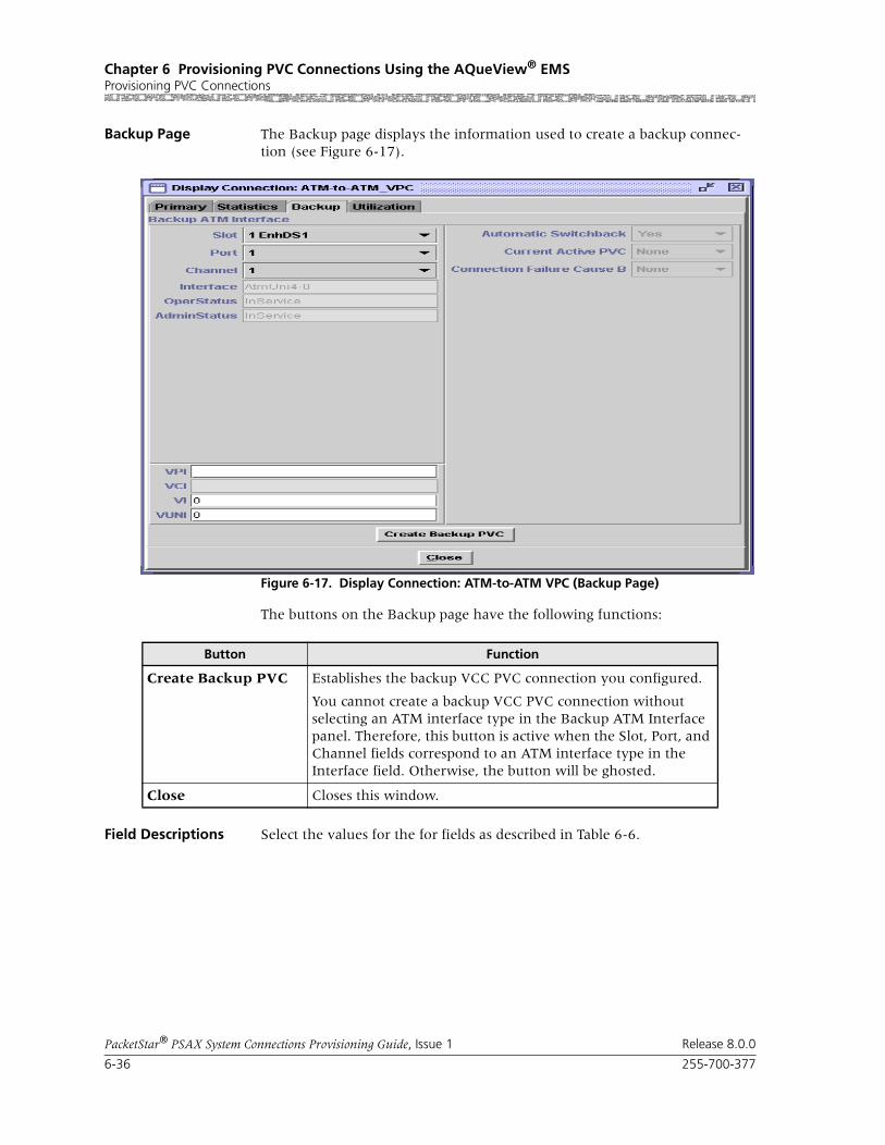
Chapter 6 Provisioning PVC Connections Using the AQueView® EMSProvisioning PVC Connections
6-36 255-700-377
PacketStar® PSAX System Connections Provisioning Guide, Issue 1 Release 8.0.0
Backup Page The Backup page displays the information used to create a backup connec-tion (see Figure 6-17).
The buttons on the Backup page have the following functions:
Field Descriptions Select the values for the for fields as described in Table 6-6.
Figure 6-17. Display Connection: ATM-to-ATM VPC (Backup Page)
Button Function
Create Backup PVC Establishes the backup VCC PVC connection you configured.
You cannot create a backup VCC PVC connection without selecting an ATM interface type in the Backup ATM Interface panel. Therefore, this button is active when the Slot, Port, and Channel fields correspond to an ATM interface type in the Interface field. Otherwise, the button will be ghosted.
Close Closes this window.

255-700-377 6-37
PacketStar® PSAX System Connections Provisioning Guide, Issue 1 Release 8.0.0
Chapter 6 Provisioning PVC Connections Using the AQueView® EMSProvisioning PVC Connections
Table 6-6. Field Descriptions for the ATM-to-ATM_VPC Backup Page
Field Name Field Values Description
Slot Default: Equipment Dependent
Range: Listed as available from the PSAX device
Format: Numeric
Indicates the slot containing the module for which you are creating a connection.
Port Default: Equipment Dependent
Range: Determined by the number of ports available on the module selected in the Slot field
Format: Numeric
Indicates the port number on the module for which you are creating a connection.
Channel Default: Equipment Dependent
Range: Determined by the number of channels avail-able on the port selected in the Port field
Format: Numeric
Indicates the channel number of the port on the module for which you are creating a connection.
Interface(display only)
Default: UnconfiguredAtmUni3-0AtmUni3-1IispUserIispNetworkCircuitEmulation DbCirEmFrameRelayUniFrameRelayNniPri_Isdn_NetworkPri_Isdn_UserHldcPassThroughAtmPnni1-0Format: Predefined
Displays the interface type that is configured on the slot, port, and channel (selected in the Slot, Port, and Channel fields).
OperStatus(display only)
Default: OutOfServiceRange: N/A
Format: Predefined
Indicates whether the connection is capable of transmitting traffic or not.
InService Indicates that the connection is operational.
OutOfService Indicates that the connection is not operational.

Chapter 6 Provisioning PVC Connections Using the AQueView® EMSProvisioning PVC Connections
6-38 255-700-377
PacketStar® PSAX System Connections Provisioning Guide, Issue 1 Release 8.0.0
Utilization Page The Utilization page measures the amount of traffic running through this connection (see Figure 6-18).
AdminStatus (display only)
Default: OutOfService
Range: NA
Format: Predefined
Indicates whether any condition is preventing the port from being fully operational or not.
InService Indicates that no conditions are preventing the port from being fully operational.
OutOfService Indicates that some condition is preventing the port from being configured with an interface.
VPI Default: 0
Range: 0–255
Format: Numeric
Indicates the backup connection.virtual path identi-fier assigned to this interface.
VI Default: 0
Range: 0–255
Format: Numeric
Indicates the backup connection virtual interface, which provides bandwidth allocation restrictions. Currently available only on the OC-3c APS and STM-1 MSP modules.
Automatic Switchback
Default: YesRange: Yes/No
Format: Predefined
Indicates whether automatic switchback is selected or not.
Yes Indicates that after the backup is activated, it will switch back to primary connection automatically if primary becomes available.
No Not currently supported.
Indicates that after the backup is activated, it will not switch back to primary connection automati-cally if primary becomes available.
Current Active PVC
Default: NoneRange: N/A
Format: Predefined
Indicates whether the current active PVC is func-tioning as the primary, the backup, or is inactive.
None Indicates the connection is inactive.
Primary Indicates that the primary connection is active (car-rying user traffic).
Backup Indicates that the backup connection is active (car-rying user traffic).
Table 6-6. Field Descriptions for the ATM-to-ATM_VPC Backup Page
Field Name Field Values Description

255-700-377 6-39
PacketStar® PSAX System Connections Provisioning Guide, Issue 1 Release 8.0.0
Chapter 6 Provisioning PVC Connections Using the AQueView® EMSProvisioning PVC Connections
Figure 6-18. Display Connection: ATM-to-ATM VPC (Utilization Page)

Chapter 6 Provisioning PVC Connections Using the AQueView® EMSProvisioning PVC Connections
6-40 255-700-377
PacketStar® PSAX System Connections Provisioning Guide, Issue 1 Release 8.0.0
The buttons on the Utilization page have the following functions:
For details about this window, see the section, “Utilization Information,” in Chapter 5 of this guide.
Adding Bridge-to-ATM VCC PVC Connections
This type of connection supports all non-CBR service types. Perform the steps in the following procedure to create a Bridge-to-ATM VCC PVC connection.
Note: On the DS1 IMA and E1 IMA modules, PVC connections must be provisioned on the virtual port (port 7). You can use up to three channels on port 7 (the channels you provision on port 7.)
Button Function
60 sec Time, in seconds or minutes, to poll the PSAX device. Select a time interval from the pull-down menu:
5 sec
10 sec
20 sec
30 sec
60 sec (default)
90 sec
2 min
3 min
4 min
5 min
Clear Resets all statistics to zero.
Poll Poll+ continuously updates the statistics and changes the button label to Poll-.
Poll- terminates polling and changes the button label to Poll+.
Show Cells/Sec Calculates and displays the average num-ber of cells per second for a given PVC or SPVC for a given time interval specified in the pull-down menu (see above).
Changes button label to Show Bits/Sec.
Show Bits/Sec Calculates and displays the average num-ber of bits per second for a given PVC or SPVC for a given time interval specified in the pull-down menu (see above).
Changes button label to Show Cells/Sec.
Close Closes this window.

255-700-377 6-41
PacketStar® PSAX System Connections Provisioning Guide, Issue 1 Release 8.0.0
Chapter 6 Provisioning PVC Connections Using the AQueView® EMSProvisioning PVC Connections
Note: On the DS3 IMA module, PVC connections must be provisioned on the virtual port (port 30). You can use up to 14 channels on port 30 (the channels you provision on port 30.)
Begin
1 In the Device window, click the Connections tab.
The Listing page appears.
2 Click the right mouse button in the Listing page and a menu appears. Click Create New.
The Create Connection window appears (see Figure 6-19).
3 Select the appropriate slot, port, and channel for each side to select a Bridge and ATM interface.
The type of connection appears in the Connection Type field at the bot-tom of the window. If the connection is not a valid type of connection, None appears in the Connection Type field.
4 Click Create.
The Create Bridge_to_ATM_VCC Connection window will appear (see Figure 6-20).
5 Enter values in the fields on this window according to the information provided in Table 6-7.
If the parameters are valid, the Connections window appears with the new connection in the Listing page, and the Display Connection window appears with tabs that contain details about the connection (see Figure 6-21): Primary, Statistics, and Backup.
If a parameter is invalid, a Connection Creation Failed message appears, stating the reason for the failure.
Figure 6-19. Create Connection Window

Chapter 6 Provisioning PVC Connections Using the AQueView® EMSProvisioning PVC Connections
6-42 255-700-377
PacketStar® PSAX System Connections Provisioning Guide, Issue 1 Release 8.0.0
The buttons on this window have the following functions:
Figure 6-20. Create Bridge_to_ATM VCC Connection Window
Button Function
Close Closes this window.
Create Establishes the connection you configured.
Copy Copies this configuration information to a range of interfaces.

255-700-377 6-43
PacketStar® PSAX System Connections Provisioning Guide, Issue 1 Release 8.0.0
Chapter 6 Provisioning PVC Connections Using the AQueView® EMSProvisioning PVC Connections
Field Descriptions
Table 6-7. Field Descriptions for the Bridge-to-ATM_PVC Connection Window
Field Name Field Values Description
Interface Side A: Bridge
Default: N/ARange: N/A
Format: Alphanumeric
Indicates that this is the bridge side of the con-nection that will send and receive signals.
Interface Side B:ATM_UNI30, ATM_UNI31, ATM_UNI40, IISP_USER, IISP_NETWORK or PNNI1_0
Default: N/A
Range: N/A
Format: Alphanumeric
Indicates that this is the ATM interface side of the connection that will send and receive signals.
Slot(display only)
Default: N/A
Range: Varies depending on chassis type
Format: Numeric
Ethernet and 4-Port Ethernet Modules: Indicates the slot number containing this module for which you are creating a connection.
4-Port Ethernet Module: To enable ATM traffic shaping, specify a slot containing one of the appropriate modules on the ATM side of this con-nection (see the section, “ATM Traffic Shaping,” in Chapter 2).
Port Default: 6
Default: 5Default: 0
Range: N/A
Format: Numeric
Indicates the virtual port number of this module.
4-Port Ethernet Module: To enable ATM traffic shaping, specify a port containing one of the appropriate modules on the ATM side of this con-nection (see the section, “ATM Traffic Shaping,” in Chapter 2).
Channel(display only)
Default: 1
Range: 1–70 for the Ethernet module; 1–56 for the 4-Port Ethernet module
Format: Numeric
Ethernet and 4-Port Modules: Indicates the vir-tual channel number containing this module for which you are creating a connection.
Indicatesthe channel number associated with the port number on this module for which you are creating a connection.
4-Port Ethernet Module: To enable ATM traffic shaping, specify a channel containing one of the appropriate modules on the ATM side of this con-nection (see the section, “ATM Traffic Shaping,” in Chapter 2).
VPI Default: 0Range: 0–255 (AtmUNI); 0–4095 (IISP)
Format: Numeric
Indicates the virtual path identifier. Enter a value for the ATM side of the connection.

Chapter 6 Provisioning PVC Connections Using the AQueView® EMSProvisioning PVC Connections
6-44 255-700-377
PacketStar® PSAX System Connections Provisioning Guide, Issue 1 Release 8.0.0
VCI Default: 0
Range: 32–65535
Format: Numeric
Indicates the virtual channel identifier. Enter a value for the ATM side of the connection.
VI/VUNI Default: 0Range: 0–255
Format: Numeric
Indicates the virtual interface/Virtual ATM UNI, which provides bandwidth allocation restrictions. Currently available only on the OC-12c/STM-4c 1+1 MM/SM APS/MSP, OC-3c APS, and the STM-1 MSP modules. When disabled, default is 0. The virtual UNI (VUNI) associates itself with the egress part of the A-to-B or B-to-A side of the connection.
Service Type Default: Ubr
Range: N/A
Format: Predefined
Indicates the Multiservice Media Gateway sys-tem-supported quality of service (QoS) class. See the section “Quality of Service Classes for ATM Traffic” in the reference appendix.
Ubr Unspecified bit rate.
Vbr-nrt2 Variable bit rate-non-real time 2.
Vbr-nrt1 Variable bit rate-non-real time 1.
Vbr-rt2 Variable bit rate-real-time 2.
Vbr-rt1 Variable bit rate-real-time 1.
Vbr-express Variable bit rate express.
Gfr2 Guaranteed frame rate 2. Not currently sup-ported.
Cnfrm Type Default: Best-effort
Range: N/A
Format: Predefined
Indicates the type of traffic control option used for ATM cells. The traffic descriptor combination specifies which traffic parameters are used for traffic control, determines the number and type of cells that are admitted into a congested queue, and determines whether high-priority cells are tagged as low-priority cells when traffic exceeds the traffic parameter thresholds.
Note: All ATM-Supporting I/O Modules: See the section, “ATM Traffic Descriptors,” in the Refer-ence Appendix of this guide for a detailed description of the values for this field, including representative examples.
Best-effort Indicates that the traffic descriptor used for this connection allows the system to attempt to send all cells in a "best effort" fashion, without specify-ing traffic parameters, similar to the AQueMan algorithm.
Table 6-7. Field Descriptions for the Bridge-to-ATM_PVC Connection Window (Continued)
Field Name Field Values Description

255-700-377 6-45
PacketStar® PSAX System Connections Provisioning Guide, Issue 1 Release 8.0.0
Chapter 6 Provisioning PVC Connections Using the AQueView® EMSProvisioning PVC Connections
One-bucket-notag-0plus1
Indicates that the traffic descriptor used for this connection uses the parameters one bucket, no tagging, cell loss priority (CLP)=0+1 cells (high and low priority).
Two-bucket-notag-0plus1-0plus1
Indicates that the traffic descriptor used for this connection uses the parameters two buckets, no tagging, CLP=0+1 cells (high and low priority) for bucket 1, and CLP=0+1 cells (high and low prior-ity) for bucket 2.
Two-bucket-notag-0plus1
Indicates that the traffic descriptor used for this connection uses the parameters two buckets, no tagging, CLP=0+1 cells (high and low priority) for bucket 1, and CLP=0 cells (high priority) for bucket 2.
Two-bucket-tag-0plus1
Indicates that the traffic descriptor used for this connection uses the parameters two buckets, CLP=0+1 cells (high and low priority) for bucket 1, and tagging for CLP=0 cells (high priority) in bucket 2.
Best-effort-tag Indicates that the traffic descriptor used for this connection allows the system to tag all CLP=0 (high priority) cells to change them to CLP=1 (low priority) cells during congestion, and then attempt to send all cells in a “best effort” fashion, without specifying any other traffic parameters, similar to the AQueMan algorithm.
Table 6-7. Field Descriptions for the Bridge-to-ATM_PVC Connection Window (Continued)
Field Name Field Values Description

Chapter 6 Provisioning PVC Connections Using the AQueView® EMSProvisioning PVC Connections
6-46 255-700-377
PacketStar® PSAX System Connections Provisioning Guide, Issue 1 Release 8.0.0
Peak Cell Rate (cps) Default: 1
Range: 0–999999999
Format: Numeric
Indicates the peak cell rate (PCR) for all cells with both the CLP=0 bit and the CLP=1 bit. PCR is a traffic parameter that specifies an upper bound on the traffic that can be submitted on an ATM connection. The value you set is the maximum allowed cell transmission rate (cells per second) for all cells both high and low priority, as allowed by your traffic contract. When setting this value, take into account the line rate for the module and the amount of bandwidth you are setting up for each interface for the module. Refer to the ATM UNI 3.1 specification for more information.
If you select the value SimplexA2B in the Flow field, set the value of this field to 0. The value in this field should be greater than the Sustained Cell Rate field.
OC-3c and STM-1 Modules: If traffic shaping is enabled, the modules will not pass data until this parameter is set to a specified rate. Very large bursts of traffic may exceed the 8 MB memory typically available on the module, resulting in dropped cells. If very large bursts are typical for a specific network configuration, the module mem-ory can be upgraded to 64 MB.
Table 6-7. Field Descriptions for the Bridge-to-ATM_PVC Connection Window (Continued)
Field Name Field Values Description

255-700-377 6-47
PacketStar® PSAX System Connections Provisioning Guide, Issue 1 Release 8.0.0
Chapter 6 Provisioning PVC Connections Using the AQueView® EMSProvisioning PVC Connections
Sustained Cell Rate (cps)
Default: 1
Range: 0–999999999
Format: Numeric
Indicates the sustainable cell rate (SCR) with CLP=0 (high priority) cells or the peak cell rate with CLP=0 cells. The SCR is an upper bound on the conforming average rate of an ATM connec-tion. Enforcement of this bound by the UPC could allow the network operator to allocate suf-ficient resources, but less than those based on the Peak Cell Rate, and still ensure that the perfor-mance objectives can be achieved. When setting this value, take into account the line rate for the module and the amount of bandwidth you are setting up for each interface for the module. Refer to the ATM UNI 3.1 specification for more information.
If you select the value SimplexA2B in the Flow field, set the value of this field to 0. The value in this field should be less than the Peak Cell Rate field.
OC-3c and STM-1 Modules: If traffic shaping is enabled, the modules will not pass data until this parameter is set to a specified rate. Very large bursts of traffic may exceed the 8 MB memory typically available on the module, resulting in dropped cells. If very large bursts are typical for a specific network configuration, the module mem-ory can be upgraded to 64 MB.
Max Burst Size (cells)
Default: 1
Range: 0–999999999
Format: Numeric
Indicates the maximum burst size, which is the maximum number of cells that can be received at one time. This value allows a burst of cells to arrive at a rate higher than that of the SCR. If the burst is larger than the traffic contract allows, the additional cells are either tagged or dropped.
When setting this value, take into account the line rate for the module and the amount of band-width you are setting up for each interface for that module.OC-3c APS Module: When the Traffic Shaping field is set to Enabled, the cell queue depth for the Max Burst Size field is internally set to 1000, regardless of the value you enter. If you enter values other than 1000, these values matter for incoming signalling SPVC/SVC setup from the remote end of the connection.
Table 6-7. Field Descriptions for the Bridge-to-ATM_PVC Connection Window (Continued)
Field Name Field Values Description

Chapter 6 Provisioning PVC Connections Using the AQueView® EMSProvisioning PVC Connections
6-48 255-700-377
PacketStar® PSAX System Connections Provisioning Guide, Issue 1 Release 8.0.0
Primary Page The Primary tab displays the information used to create the connection. See Table 6-7 for field descriptions.
Connection Status(display only)
Default: Inactive
Range: N/A
Format: Predefined
Displays the current status of the connection. The value indicates whether the connection is passing traffic.
Inactive Indicates that this connection is not passing traf-fic.
Active Indicates that this connection is passing traffic.
OAM Status Default: End-Pt
Range: N/A
Format: Predefined
Indicates the type of OAM support used on the ATM side of this connection.
Route Server Module: Enabling this field on an ATM network interface subchannel (by selecting either End-Pt or End-Seg-Pt) means the mod-ule will bring the particular interface into service or take it out of service based on the OAM alarms.
End-Pt Indicates that the PSAX system is used as a termi-nation point for ATM traffic, and is processing AID/RDI cells. The OAM loopback test is sup-ported for only end-to-end connections.
End-Seg-Pt Indicates the end-Seg-Pt, which is a connection endpoint and the endpoint of the segment; it will catch the segment and end-to-end OAM cells.
Unsupp Indicates that OAM is not used on this connec-tion.
Traffic Shaping Default: Disabled Range: N/A
Format: Predefined
Indicates that a method for controlling the flow of data traffic is used on this connection. It is implemented on modules that are offered with traffic-shaping variations: the OC-3c Multimode, OC-3c Single-Mode, STM-1 Multimode, and STM-1 Single-Mode modules. When enabled, traffic shaping ensures that the variable bit-rate (VBR) traffic entering the PSAX system (via the OC-3c and STM-1 modules) complies with the parameters of the established service contracts.
Disabled Indicates that traffic shaping is not done on the ATM side of the connection.
Enabled Allows traffic shaping on the ATM side of the connection.
Table 6-7. Field Descriptions for the Bridge-to-ATM_PVC Connection Window (Continued)
Field Name Field Values Description

255-700-377 6-49
PacketStar® PSAX System Connections Provisioning Guide, Issue 1 Release 8.0.0
Chapter 6 Provisioning PVC Connections Using the AQueView® EMSProvisioning PVC Connections
The buttons on the Primary page have the following functions:
Statistics Page The Statistics page displays the statistics for this connection (see Figure 6-22).
Figure 6-21. Display Connection: Bridge-to-ATM PVC (Primary Page)
Button Function
Close Closes this window.
Create Establishes the connection youconfigured.
Copy Copies this configuration information to a range of interfaces.
Delete Deletes the connection.

Chapter 6 Provisioning PVC Connections Using the AQueView® EMSProvisioning PVC Connections
6-50 255-700-377
PacketStar® PSAX System Connections Provisioning Guide, Issue 1 Release 8.0.0
The buttons on the Statistics page have the following functions:
Field Descriptions The values for the fields on this window are described in Table 6-8.
Figure 6-22. Display Connection: Bridge-to-ATM PVC Statistics Page
Button Description
Update Refreshes the statistics manually.
Clear Resets the resetable statistics to zero.
Poll Poll + continuously update the statistics and changes the button label to Poll-.
Poll- terminates polling and changes the button label to Poll+.
Odometer Restarts counting in the Cells Transmitted and Cells Received fields iin the Interface Side A and Interface Side B panels, and to view the trans-mitted cells and received cells in the Interface Side A and Interface Side B panels. This button is displayed only on the ATM-to-ATM VCC PVC and ATM-to-ATM VPC PVC Statistics pages.
Close Closes this window.
Restart Restarts connection establishment procedure for the connections that were not previously set up.

255-700-377 6-51
PacketStar® PSAX System Connections Provisioning Guide, Issue 1 Release 8.0.0
Chapter 6 Provisioning PVC Connections Using the AQueView® EMSProvisioning PVC Connections
Table 6-8. Field Descriptions for the Bridge-to-ATM VCC Connection Statistics Page
Field Name Field Values Description
[Cells Encoded](display only)
Default: 0
Range: N/A
Format: Scientific Notation
Indicates, on the Interface A Statistics panel, the number of cells encoded going into interface side A during the amount of time shown in Time Elapsed field since the circuit was established. Indicates, on the Interface B Statistics panel, the number of cells encoded going into interface side B during the amount of time shown in Time Elapsed field since the circuit was established.
[Cells Decoded](display only)
Default: 0
Range: N/A
Format: Scientific Notation
Indicates, on the Interface A Statistics panel, the number of cells decoded going out of interface side A during the amount of time shown in Time Elapsed field since the circuit was established. Indicates, on the Interface B Statistics panel, the number of cells decoded going out of interface side B during the amount of time shown in Time Elapsed field since the circuit was established.
[Encoded Odometer](display only)
Default: 0
Range: N/A
Format: Scientific Notation
Indicates, on the Interface A Statistics panel, the number of cells encoded going into interface side A since this counter was reset. Indicates, on the Interface B Statistics panel, the number of cells encoded going into interface side B since this counter was reset.
[Decoded Odometer](display only)
Default: 0Range: N/A
Format: Scientific Notation
Indicates, on the Interface A Statistics panel, the number of cells decoded going out of interface side A since this counter was reset. Indicates, on the Interface B Statistics panel, the number of cells decoded going out of interface side B since this counter was reset.
Time Elapsed(display only)
Default: 00:00:00
Range: N/A
Format: days, hours, minutes, and seconds (days hh:mm:ss)
Displays the time elapsed since the circuit was established.
Cells Received(display only)
Default: 0Range: N/A
Format: Numeric
Indicates the number of cells received into inter-face side B since the connection was created.
Cells Transmitted(display only)
Default: 0
Range: N/A
Format: Numeric
Indicates the number of cells transmitted out of interface side B since the connection was created.
In Odometer(display only)
Default: 0
Range: N/A
Format: Numeric
Indicates the total number of cells encoded going into interface side B since this counter was reset.

Chapter 6 Provisioning PVC Connections Using the AQueView® EMSProvisioning PVC Connections
6-52 255-700-377
PacketStar® PSAX System Connections Provisioning Guide, Issue 1 Release 8.0.0
Out Odometer (display only)
Default: 0
Range: N/A
Format: Numeric
Indicates the total number of cells decoded going out of interface side B since this counter was reset.
Time Since Reset(display only)
Default: 0Range: N/A
Format: Numeric
Displays the time elapsed since the last time the Clear button was used.
Note: The Clear button on the statistics page resets only the odometer fields (labelled as Odometer) and the corresponding clock. Other counters increment for the life of the circuit.
AIS Received(display only)
Default: 0
Range: N/A
Format: Numeric
Indicates the number of AIS cells received on the ATM side of the connection.
AIS Transmitted(display only)
Default: 0Range: N/A
Format: Numeric
Indicates the number of AIS cells transmitted on the ATM side of the connection.
Cells Dropped(display only)
Default: 0
Range: N/A
Format: Numeric
Indicates the number of cells dropped on incom-ing side of on the ATM side of the connection.
Cells Tagged(display only)
Default: 0
Range: N/A
Format: Numeric
Indicates the number of cells tagged on incoming side of on the ATM side of the connection.
RDI Received(display only)
Default: 0Range: N/A
Format: Numeric
Indicates the number of remote defect indicator (RDI) cells received.
RDI Transmitted(display only)
Default: 0
Range: N/A
Format: Numeric
Indicates the number of remote defect indicator (RDI) cells transmitted on the ATM side of the connection.
Table 6-8. Field Descriptions for the Bridge-to-ATM VCC Connection Statistics Page (Continued)
Field Name Field Values Description
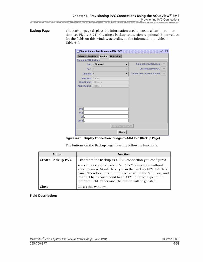
255-700-377 6-53
PacketStar® PSAX System Connections Provisioning Guide, Issue 1 Release 8.0.0
Chapter 6 Provisioning PVC Connections Using the AQueView® EMSProvisioning PVC Connections
Backup Page The Backup page displays the information used to create a backup connec-tion (see Figure 6-23). Creating a backup connection is optional. Enter values for the fields on this window according to the information provided in Table 6-9.
The buttons on the Backup page have the following functions:
Field Descriptions
Figure 6-23. Display Connection: Bridge-to-ATM PVC (Backup Page)
Button Function
Create Backup PVC Establishes the backup VCC PVC connection you configured.
You cannot create a backup VCC PVC connection without selecting an ATM interface type in the Backup ATM Interface panel. Therefore, this button is active when the Slot, Port, and Channel fields correspond to an ATM interface type in the Interface field. Otherwise, the button will be ghosted.
Close Closes this window.

Chapter 6 Provisioning PVC Connections Using the AQueView® EMSProvisioning PVC Connections
6-54 255-700-377
PacketStar® PSAX System Connections Provisioning Guide, Issue 1 Release 8.0.0
Table 6-9. Field Descriptions for the Display Connection: Bridge-to-ATM_VCC Backup Page
Field Name Field Values Description
Slot Default: N/A
Range: varies depending on module type
Format: numeric
Specifies the slot containing the module config-ured with an ATM interface, for which you are creating a backup connection. Enter a value in this field that is for a different module from the one specified for the primary connection.
Note: This field is display only on the bridge interface side of the connection.
Port Default: N/A
Range: varies depending on module type
Format: numeric
Specifies the port number on the module config-ured with an ATM interface, for which you are creating a backup connection. Enter a value in this field that is for a different module from the one specified for the primary connection..
Note: This field is display only on the bridge interface side of the connection.
Channel Default: N/ARange: varies depending on chassis type
Format: numeric
Specifies the channel number of the port on the module configured with an ATM interface, for which you are creating a backup connection. Enter a value in this field that is for a different module from the one specified for the primary connection.
Note: This field is display only on the bridge interface side of the connection.
Interface(display only)
Default: Unconfig-uredRange: N/A
Format: predefined alphanumeric
AtmUni3_0AtmUni3_1AtmUni4_0IispUserIispNetworkCircuitEmulation DbCirEmFrameRelayUniFrameRelayNniPri_Isdn_NetworkPri_Isdn_UserHldcPassThroughAtmPnni1-0
Displays the interface type that is configured on the slot, port, and channel (selected in the Slot, Port, and Channel fields).

255-700-377 6-55
PacketStar® PSAX System Connections Provisioning Guide, Issue 1 Release 8.0.0
Chapter 6 Provisioning PVC Connections Using the AQueView® EMSProvisioning PVC Connections
OperStaus (display only)
Default: OutOfService
Range: N/A
Format: predefined alphanumeric
Displays the operational status of the connection.
OutOfService Indicates that the connection is not operational.
InService Indicates that the connection is operational.
AdminStatus (display only)
Default: OutOfService
Range: N/A
predefined alphanu-meric
Displays the administrative status of the connec-tion.
OutOfService Indicates that some condition is preventing the port from being configured with an interface.
InService Indicates that no conditions are preventing the port from being fully operational.
VPI Default: 0
Range: 0–255
Format: numeric
Specifies the virtual path identifier assigned to the ATM side of the connection. Enter a value in this field that is for a different module from the one specified for the primary connection.
VCI Default: 32
Range: 32–4000
Format: numeric
Specifies the virtual channel identifier assigned to the ATM side of the connection. Enter a value in this field that is for a different module from the one specified for the primary connection.
VI/VUNI Default: 0 Range: 0–255
Format: numeric
Specifies the virtual interface, which provides bandwidth allocation restrictions. Enter a value in this field that is for a different module from the one specified for the primary connection.
Note: Currently this field is applicable only to the 1-Port OC-3c 1+1 APS and the 1-Port STM-1 1+1 MSP modules.
Automatic Switchback
Default: Yes Range: N/A
Format: predefined alphanumeric
Indicates whether the traffic on the backup con-nection will revert to the primary connection when it becomes available.
Yes Indicates that once the primary connection becomes available, traffic will revert to the pri-mary connection automatically.
No Not currently supported.
Indicates that if the backup connection is active, traffic will not revert to the primary connection automatically if it becomes available.
Table 6-9. Field Descriptions for the Display Connection: Bridge-to-ATM_VCC Backup Page
Field Name Field Values Description

Chapter 6 Provisioning PVC Connections Using the AQueView® EMSProvisioning PVC Connections
6-56 255-700-377
PacketStar® PSAX System Connections Provisioning Guide, Issue 1 Release 8.0.0
Utilization Page The Utilization page measures the amount of traffic running through this connection (see Figure 6-24).
Current Active PVC Default: None
Range: N/A
Format: Predefined
Indicates whether the primary or backup connec-tion is active.
None Indicates that the connection is inactive.
Primary Indicates that the primary connection is active (carrying user traffic).
Backup Indicates that the backup connection is active (carrying user traffic).
Table 6-9. Field Descriptions for the Display Connection: Bridge-to-ATM_VCC Backup Page
Field Name Field Values Description
Figure 6-24. Display Connection: Bridge-to-ATM VCC (Utilization Page)

255-700-377 6-57
PacketStar® PSAX System Connections Provisioning Guide, Issue 1 Release 8.0.0
Chapter 6 Provisioning PVC Connections Using the AQueView® EMSProvisioning PVC Connections
The buttons on the Utilization page have the following functions:
For details about this window, see the section, “Utilization Information,” in Chapter 5 of this guide.
Adding Bridge-to-Bridge VCC PVC Connections
A bridge-to-bridge VCC PVC connection can be created between virtual channels on the Ethernet module and the 4-Port Ethernet module. Perform the steps in the following procedure to add a bridge-to-bridge VCC PVC con-nection.
Button Function
60 sec Time, in seconds or minutes, to poll the PSAX device. Select a time interval from the pull-down menu:
5 sec
10 sec
20 sec
30 sec
60 sec (default)
90 sec
2 min
3 min
4 min
5 min
Clear Resets all statistics to zero.
Poll Poll+ continuously updates the statistics and changes the button label to Poll-.
Poll- terminates polling and changes the button label to Poll+.
Show Cells/Sec Calculates and displays the average num-ber of cells per second for a given PVC or SPVC for a given time interval specified in the pull-down menu (see above).
Changes button label to Show Bits/Sec.
Show Bits/Sec Calculates and displays the average num-ber of bits per second for a given PVC or SPVC for a given time interval specified in the pull-down menu (see above).
Changes button label to Show Cells/Sec.
Close Closes this window.

Chapter 6 Provisioning PVC Connections Using the AQueView® EMSProvisioning PVC Connections
6-58 255-700-377
PacketStar® PSAX System Connections Provisioning Guide, Issue 1 Release 8.0.0
Begin
1 In the Device window, click the Connections tab.
The Listing page appears.
2 Click the right mouse button and a menu appears. Click Create New.
The Create Connection window appears (see Figure 6-19). On the Side A and Side B panels, select appropriate slot, port, and channel combina-tions to indicate the type of connection being created.
The type of connection will appear in the Connection Type field at the bottom of the window. If the connection is not a valid type of connec-tion, None will appear in the Connection Type field.
3 Once the desired connection type appears in the Connection Type field, click Create.
The Create Bridge_to_Bridge Connection window appears (see Figure 6-26).
4 Enter values in the fields in this window according to the information provided in Table 6-10.
If the parameters are valid, the Connections window appears with the new connection in the Listing page, and the Display Connection window appears (see Figure 6-27) with tabs that contain details about the con-nection: Primary, Statistics, and Utilization.
If a parameter is invalid, a Connection Creation Failed message appears, stating the reason for the failure.
Figure 6-25. Create Connection Window
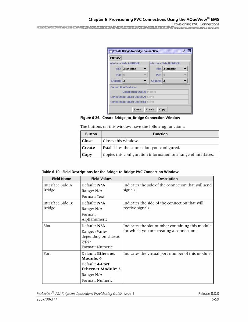
255-700-377 6-59
PacketStar® PSAX System Connections Provisioning Guide, Issue 1 Release 8.0.0
Chapter 6 Provisioning PVC Connections Using the AQueView® EMSProvisioning PVC Connections
The buttons on this window have the following functions:
Figure 6-26. Create Bridge_to_Bridge Connection Window
Button Function
Close Closes this window.
Create Establishes the connection you configured.
Copy Copies this configuration information to a range of interfaces.
Table 6-10. Field Descriptions for the Bridge-to-Bridge PVC Connection Window
Field Name Field Values Description
Interface Side A: Bridge
Default: N/A
Range: N/A
Format: Text
Indicates the side of the connection that will send signals.
Interface Side B: Bridge
Default: N/A
Range: N/A
Format: Alphanumeric
Indicates the side of the connection that will receive signals.
Slot Default: N/ARange: (Varies depending on chassis type)
Format: Numeric
Indicates the slot number containing this module for which you are creating a connection.
Port Default: Ethernet Module: 6
Default: 4-Port Ethernet Module: 5
Range: N/A
Format: Numeric
Indicates the virtual port number of this module.

Chapter 6 Provisioning PVC Connections Using the AQueView® EMSProvisioning PVC Connections
6-60 255-700-377
PacketStar® PSAX System Connections Provisioning Guide, Issue 1 Release 8.0.0
Primary Page The Primary tab displays the information used to create the connection. See Table 6-10 for field descriptions.
Channel Default: 1
Range: 1–70 for the Ethernet module; 1–56 for the 4-Port Ethernet module
Format: Numeric
Indicates the channel number associated with the port number on this module for which you are creating a connection.
Connection Status(display only)
Default: InactiveRange: N/A
Format: Predefined
Indicates the current status of the connection. The value indicates whether the connection is passing traffic.
Inactive Indicates that this connection is not passing traf-fic.
Active Indicates that this connection is passing traffic.
[FailCause A/B](display only)
Default: Null/Null
Range: N/A
Format: Predefined
Indicates the AAL2 status reason code for both sides of the connection.
Table 6-10. Field Descriptions for the Bridge-to-Bridge PVC Connection Window
Field Name Field Values Description
Figure 6-27. Display Connection: Bridge-to-Bridge PVC (Primary Page)
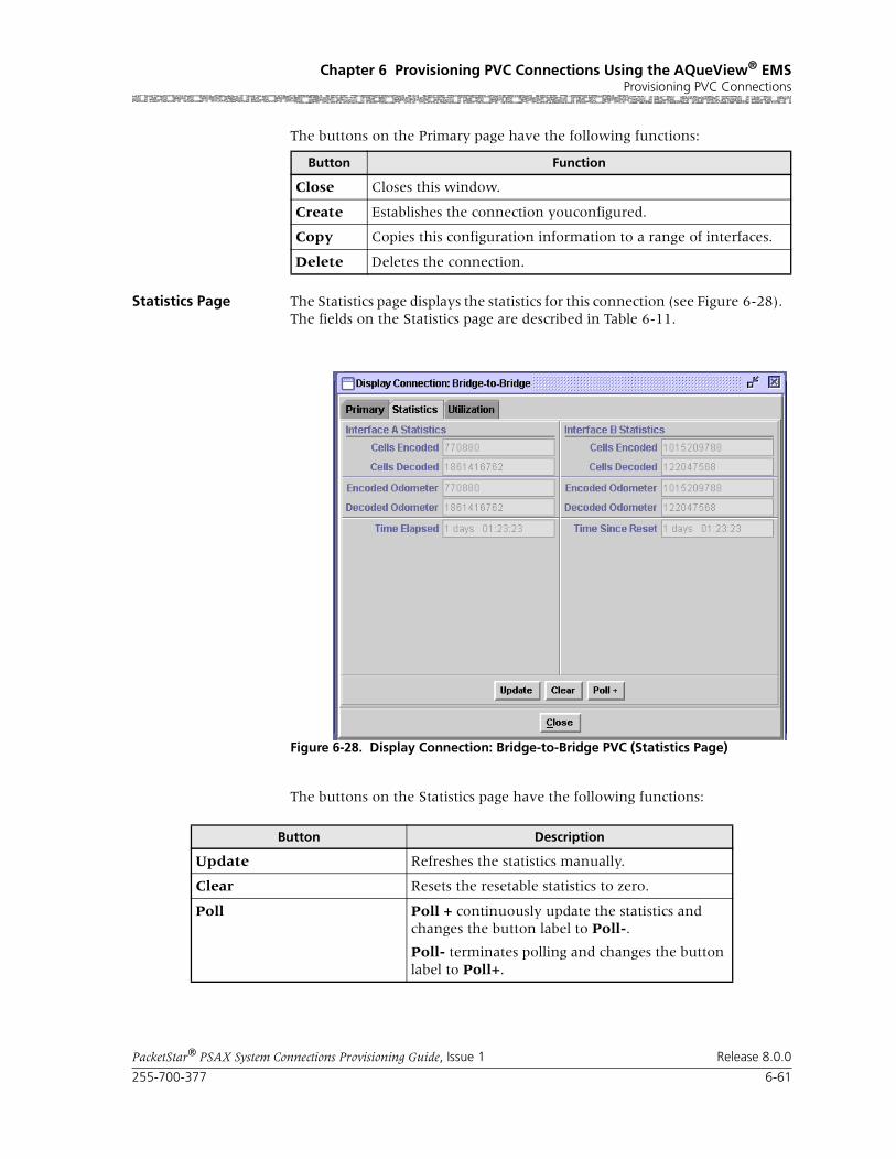
255-700-377 6-61
PacketStar® PSAX System Connections Provisioning Guide, Issue 1 Release 8.0.0
Chapter 6 Provisioning PVC Connections Using the AQueView® EMSProvisioning PVC Connections
The buttons on the Primary page have the following functions:
Statistics Page The Statistics page displays the statistics for this connection (see Figure 6-28). The fields on the Statistics page are described in Table 6-11.
The buttons on the Statistics page have the following functions:
Button Function
Close Closes this window.
Create Establishes the connection youconfigured.
Copy Copies this configuration information to a range of interfaces.
Delete Deletes the connection.
Figure 6-28. Display Connection: Bridge-to-Bridge PVC (Statistics Page)
Button Description
Update Refreshes the statistics manually.
Clear Resets the resetable statistics to zero.
Poll Poll + continuously update the statistics and changes the button label to Poll-.
Poll- terminates polling and changes the button label to Poll+.

Chapter 6 Provisioning PVC Connections Using the AQueView® EMSProvisioning PVC Connections
6-62 255-700-377
PacketStar® PSAX System Connections Provisioning Guide, Issue 1 Release 8.0.0
Field Descriptions
Odometer Restarts counting in the Cells Transmitted and Cells Received fields iin the Interface Side A and Interface Side B panels, and to view the trans-mitted cells and received cells in the Interface Side A and Interface Side B panels. This button is displayed only on the ATM-to-ATM VCC PVC and ATM-to-ATM VPC PVC Statistics pages.
Close Closes this window.
Restart Restarts connection establishment procedure for the connections that were not previously set up.
Button Description
Table 6-11. Field Descriptions for the Bridge-to-Bridge VCC Connection Statistics Page
Field Name Field Value Description
[Cells Encoded ]
(display only)
Default: 0Range: N/A
Format: Scientific Notation
Indicates, on the Interface A Statistics panel, the number of cells encoded going into interface side A during the amount of time shown in Time Elapsed field since the circuit was established.
Indicates, on the Interface B Statistics panel, the number of cells encoded going into interface side B during the amount of time shown in Time Elapsed field since the circuit was established.
[Cells Decoded]
(display only)
Default: 0Range: N/A
Format: Scientific Notation
Indicates, on the Interface A Statistics panel, the number of cells decoded going out of interface side A during the amount of time shown in Time Elapsed field since the circuit was established.
Indicates, on the Interface B Statistics panel, the number of cells decoded going out of interface side B during the amount of time shown in Time Elapsed field since the circuit was established.
[Encoded Odometer]
(display only)
Default: 0Range: N/A
Format: Scientific Notation
Indicates, on the Interface A Statistics panel, the number of cells encoded going into interface side A since this counter was reset.
Indicates, on the Interface B Statistics panel, the number of cells encoded going into interface side B since this counter was reset.
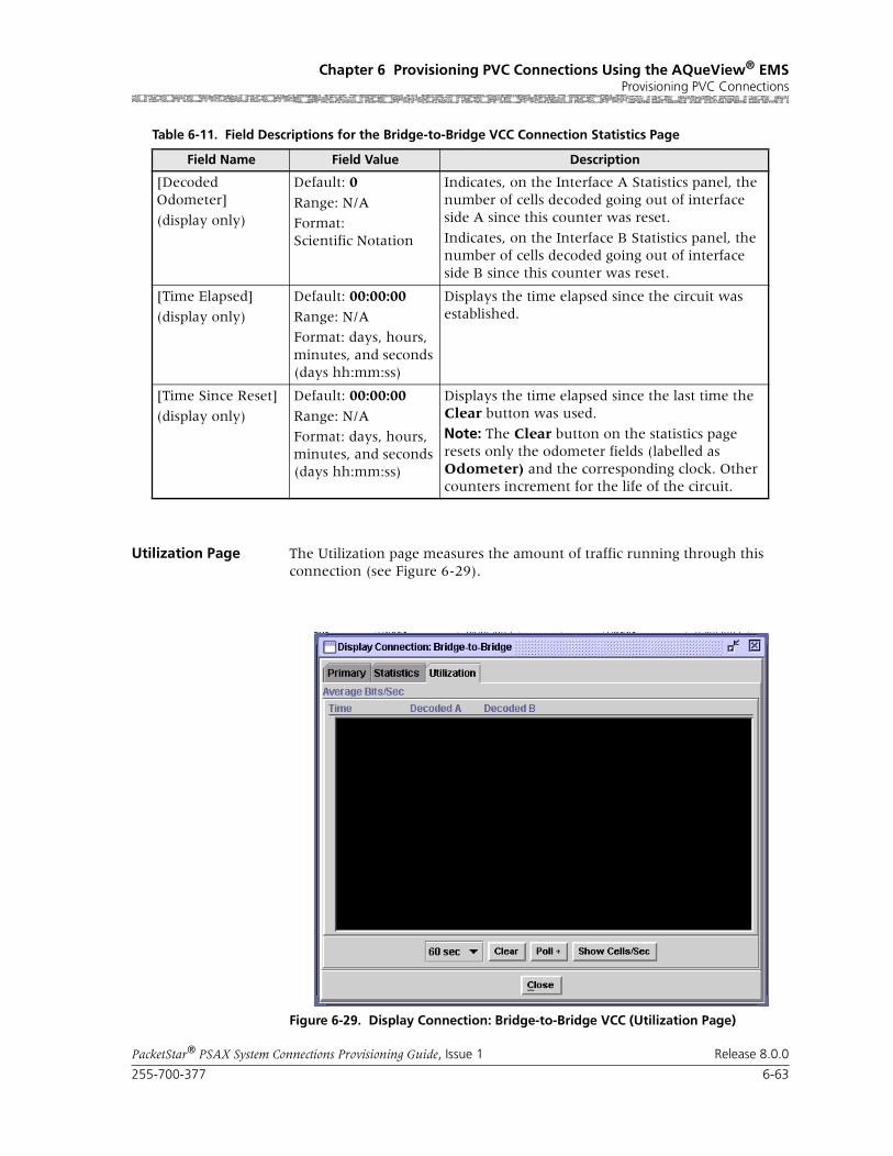
255-700-377 6-63
PacketStar® PSAX System Connections Provisioning Guide, Issue 1 Release 8.0.0
Chapter 6 Provisioning PVC Connections Using the AQueView® EMSProvisioning PVC Connections
Utilization Page The Utilization page measures the amount of traffic running through this connection (see Figure 6-29).
[Decoded Odometer]
(display only)
Default: 0
Range: N/A
Format: Scientific Notation
Indicates, on the Interface A Statistics panel, the number of cells decoded going out of interface side A since this counter was reset.
Indicates, on the Interface B Statistics panel, the number of cells decoded going out of interface side B since this counter was reset.
[Time Elapsed]
(display only)
Default: 00:00:00
Range: N/A
Format: days, hours, minutes, and seconds (days hh:mm:ss)
Displays the time elapsed since the circuit was established.
[Time Since Reset]
(display only)
Default: 00:00:00
Range: N/A
Format: days, hours, minutes, and seconds (days hh:mm:ss)
Displays the time elapsed since the last time the Clear button was used.
Note: The Clear button on the statistics page resets only the odometer fields (labelled as Odometer) and the corresponding clock. Other counters increment for the life of the circuit.
Table 6-11. Field Descriptions for the Bridge-to-Bridge VCC Connection Statistics Page
Field Name Field Value Description
Figure 6-29. Display Connection: Bridge-to-Bridge VCC (Utilization Page)
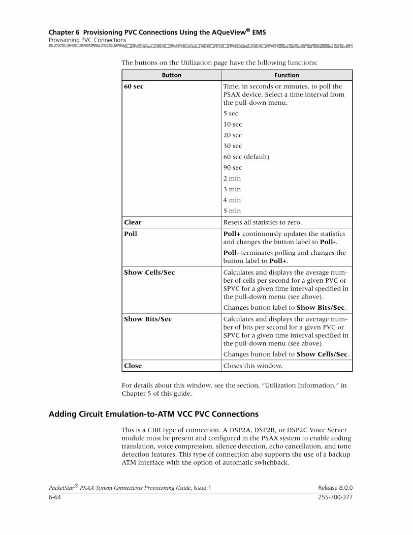
Chapter 6 Provisioning PVC Connections Using the AQueView® EMSProvisioning PVC Connections
6-64 255-700-377
PacketStar® PSAX System Connections Provisioning Guide, Issue 1 Release 8.0.0
The buttons on the Utilization page have the following functions:
For details about this window, see the section, “Utilization Information,” in Chapter 5 of this guide.
Adding Circuit Emulation-to-ATM VCC PVC Connections
This is a CBR type of connection. A DSP2A, DSP2B, or DSP2C Voice Server module must be present and configured in the PSAX system to enable coding translation, voice compression, silence detection, echo cancellation, and tone detection features. This type of connection also supports the use of a backup ATM interface with the option of automatic switchback.
Button Function
60 sec Time, in seconds or minutes, to poll the PSAX device. Select a time interval from the pull-down menu:
5 sec
10 sec
20 sec
30 sec
60 sec (default)
90 sec
2 min
3 min
4 min
5 min
Clear Resets all statistics to zero.
Poll Poll+ continuously updates the statistics and changes the button label to Poll-.
Poll- terminates polling and changes the button label to Poll+.
Show Cells/Sec Calculates and displays the average num-ber of cells per second for a given PVC or SPVC for a given time interval specified in the pull-down menu (see above).
Changes button label to Show Bits/Sec.
Show Bits/Sec Calculates and displays the average num-ber of bits per second for a given PVC or SPVC for a given time interval specified in the pull-down menu (see above).
Changes button label to Show Cells/Sec.
Close Closes this window.

255-700-377 6-65
PacketStar® PSAX System Connections Provisioning Guide, Issue 1 Release 8.0.0
Chapter 6 Provisioning PVC Connections Using the AQueView® EMSProvisioning PVC Connections
You can process voice traffic using circuit emulation-to-ATM VCC PVC con-nection through the DSP2A Voice Server module by selecting one of the pulse code modulation (PCM) types in the Coding Translation field.
Note: On the DS1 IMA and E1 IMA modules, you must provision PVC connections on the virtual port (port 7). You can use up to three channels on port 7 (the channels you provision on port 7).
Note: On the DS3 IMA module, you must provision PVC connections on the virtual port (port 30). You can use up to 14 channels on port 30 (the channels you provision on port 30).
Perform the steps in the following procedure to create a circuit emulation-to-ATM VCC PVC connection.
Begin
1 In the Device window, click the Connections tab.
The Listing page appears.
2 Click the right mouse button and a menu appears. Click Create New.
The Create Connection window appears (see Figure 6-30).
3 On the Side A and Side B panels, select the desired slot, port, and chan-nel to identify the connection endpoints within the PSAX system.
Based on these parameters, the corresponding connection type appears in the Connection Type field at the bottom of the window. If the values selected in the Side A and Side B panels do not correspond to a valid type of connection, or if one of the selected channels is unconfigured, None appears in the Connection Type field.
4 Click Create.
Figure 6-30. Create Connection Window

Chapter 6 Provisioning PVC Connections Using the AQueView® EMSProvisioning PVC Connections
6-66 255-700-377
PacketStar® PSAX System Connections Provisioning Guide, Issue 1 Release 8.0.0
The Create Circuit Emulation_to_ATM Virtual Circuit Connection win-dow appears (see Figure 6-31).
The buttons on this window have the following functions:
Field Descriptions 5 Select the values for the fields on this window from the values given in Table 6-12.
Figure 6-31. Create Circuit Emulation_to_ATM VCC Connection Window
Button Function
Close Closes this window.
Create Establishes the connection you configured.
Copy Copies this configuration information to a range of interfaces.

255-700-377 6-67
PacketStar® PSAX System Connections Provisioning Guide, Issue 1 Release 8.0.0
Chapter 6 Provisioning PVC Connections Using the AQueView® EMSProvisioning PVC Connections
Table 6-12. Field Descriptions for the Circuit Emulation-to-ATM VCC PVC Connection Window
Field Names Field Values Description
Interface Side A:CIRCUIT_EM
Default: N/A
Range: N/A
Format: Alphanu-meric
Field values in this panel relate to the circuit emula-tion side of the connection that will send and receive signals.
Interface Side B:ATM_UNI30,ATM_UNI31, ATM_IISP, PNNI10
Default: N/A
Range: N/A
Format: Alphanu-meric
Field values in this panel relate to the ATM interface side of the connection that will send and receive sig-nals.
Slot(display only)
Default: 0
Range: Variable depending on chassis type
Format: Numeric
The slot number containing the module for which you are creating a connection.
Port(display only)
Default: 1Range: Variable
Format: Numeric
The port number on the module for which you are creating a connection.
Channel(display only)
Default: 1
Range: CE side:1–24 (DS1),1–31 (E1),1–28 (DS3)
Range: ATM side: 1
Format: Numeric
The channel on which you are creating a connection.
VPI(displayed on Inter-face Side B panel only)
Default: 0Range: 0–255 (ATM UNI); 0–4095 (NNI)
Format: Numeric
Enter the virtual path identifier for the ATM side of the connection.
VCI(displayed on Inter-face Side B panel only)
Default: 0
Range: 32–65535
Format: Numeric
Enter the virtual channel identifier for the ATM side of the connection.
VI/VUNI(displayed on Inter-face Side B panel only)
Default: 0/0Range: 0–255
Format: Numeric
Virtual interface/Virtual ATM UNI, which provides bandwidth allocation restrictions. This field is cur-rently available only on the OC-12c/STM-4c 1+1 MM/SM APS/MSP) and OC-3c APS and STM-1 MSP modules. The virtual UNI (VUNI) associates itself with the egress part of the A2B or B2A side of the connec-tion.
AAL2 Cid(display only unless SAR type is Aal2Std)
Default: 0
Range: 8–255 per trunk (0–7 not avail-able; reserved)
Format: Numeric
Enter a channel identifier only if the value Aal2Std is selected in the SAR Type field described below.

Chapter 6 Provisioning PVC Connections Using the AQueView® EMSProvisioning PVC Connections
6-68 255-700-377
PacketStar® PSAX System Connections Provisioning Guide, Issue 1 Release 8.0.0
Traffic Flow Default: Duplex
Range: N/A
Format: Character
Direction of the flow of data traffic in this connection.
Note: The values change on either side of the connec-tion window as you scroll through this field.
SimplexA2B,SimplexB2A,PointToMultipointA2B,PointToMultipointB2A
Select the appropriate value.
SAR Type Default: Aal1
Range: Variable
Format: Alphanu-meric
Indicates the segmentation and reassembly (SAR) type of the incoming data stream.
Aal1 AAL1
Aal2Std AAL2 Standard.
Note: Choose this type for AAL2 trunking. Enter the associated channel identifier in the AAL2 field in the upper right panel.
Non-Mux-Aal2 Non-multiplexed AAL2 (Lucent proprietary)
Table 6-12. Field Descriptions for the Circuit Emulation-to-ATM VCC PVC Connection Window
Field Names Field Values Description

255-700-377 6-69
PacketStar® PSAX System Connections Provisioning Guide, Issue 1 Release 8.0.0
Chapter 6 Provisioning PVC Connections Using the AQueView® EMSProvisioning PVC Connections
Cnfrm Type(displayed on the Traffic Parameters B to A panel only)
Default: Best-effort
Range: N/A
Format: Alphanu-meric
The type of traffic control option used for ATM cells. The traffic descriptor combination specifies which traffic parameters are used for traffic control, deter-mines the number and type of cells that are admitted into a congested queue, and determines whether high-priority cells are tagged as low-priority cells when traffic exceeds the traffic parameter thresholds.
Best-effort This traffic descriptor allows the system to attempt to send all cells in a "best effort" fashion, without speci-fying traffic parameters, similar to the AQueMan algorithm.
One-bucket-notag-0plus1
This traffic descriptor uses the parameters one bucket, no tagging, cell loss priority (CLP)=0+1 cells (high and low priority).
Two-bucket-notag-0plus1-0plus1
This traffic descriptor uses the parameters two buck-ets, no tagging, CLP=0+1 cells (high and low priority) for bucket 1, and CLP=0+1 cells (high and low prior-ity) for bucket 2.
Two-bucket-notag-0plus1
This traffic descriptor uses the parameters two buck-ets, no tagging, CLP=0+1 cells (high and low priority) for bucket 1, and CLP=0 cells (high priority) for bucket 2.
Two-bucket-tag-0plus1
This traffic descriptor uses the parameters two buck-ets, CLP=0+1 cells (high and low priority) for bucket 1, and tagging for CLP=0 cells (high priority) in bucket 2.
Best-effort-tag This traffic descriptor allows the system to tag all CLP=0 (high priority) cells to change them to CLP=1 (low priority) cells during congestion, and then attempt to send all cells in a "best effort" fashion, without specifying any other traffic parameters, simi-lar to the AQueMan algorithm.
Service Type Default: Ubr
nVbr-nrt2Vbr-nrt1Vbr-rt2Vbr-rt1Vbr-expressCbr-4 Cbr-3Cbr-2 Cbr-1(default, DS3 IMA)
PSAX system-supported quality of service (QoS) class. See the Reference Tables appendix in this guide for a detailed description of the values for this field.
Note: Only CBR (constant bit rate) values are applica-ble for DS3 IMA.
Table 6-12. Field Descriptions for the Circuit Emulation-to-ATM VCC PVC Connection Window
Field Names Field Values Description
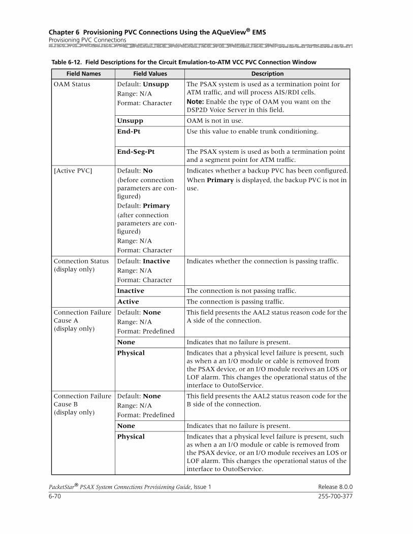
Chapter 6 Provisioning PVC Connections Using the AQueView® EMSProvisioning PVC Connections
6-70 255-700-377
PacketStar® PSAX System Connections Provisioning Guide, Issue 1 Release 8.0.0
OAM Status Default: Unsupp
Range: N/A
Format: Character
The PSAX system is used as a termination point for ATM traffic, and will process AIS/RDI cells.
Note: Enable the type of OAM you want on the DSP2D Voice Server in this field.
Unsupp OAM is not in use.
End-Pt Use this value to enable trunk conditioning.
End-Seg-Pt The PSAX system is used as both a termination point and a segment point for ATM traffic.
[Active PVC] Default: No
(before connection parameters are con-figured)
Default: Primary
(after connection parameters are con-figured)
Range: N/A
Format: Character
Indicates whether a backup PVC has been configured.
When Primary is displayed, the backup PVC is not in use.
Connection Status(display only)
Default: InactiveRange: N/A
Format: Character
Indicates whether the connection is passing traffic.
Inactive The connection is not passing traffic.
Active The connection is passing traffic.
Connection Failure Cause A(display only)
Default: None
Range: N/A
Format: Predefined
This field presents the AAL2 status reason code for the A side of the connection.
None Indicates that no failure is present.
Physical Indicates that a physical level failure is present, such as when a an I/O module or cable is removed from the PSAX device, or an I/O module receives an LOS or LOF alarm. This changes the operational status of the interface to OutofService.
Connection Failure Cause B(display only)
Default: None
Range: N/A
Format: Predefined
This field presents the AAL2 status reason code for the B side of the connection.
None Indicates that no failure is present.
Physical Indicates that a physical level failure is present, such as when a an I/O module or cable is removed from the PSAX device, or an I/O module receives an LOS or LOF alarm. This changes the operational status of the interface to OutofService.
Table 6-12. Field Descriptions for the Circuit Emulation-to-ATM VCC PVC Connection Window
Field Names Field Values Description

255-700-377 6-71
PacketStar® PSAX System Connections Provisioning Guide, Issue 1 Release 8.0.0
Chapter 6 Provisioning PVC Connections Using the AQueView® EMSProvisioning PVC Connections
If the parameters are valid, the Connections window appears with the new connection in the Listing page, and the Display Connection window appears with tabs that contain details about the connection (see Figure 6-32): Primary, Statistics, and Backup.
If a parameter is invalid, a Connection Creation Failed message appears, stating the reason for the failure.
End
Primary Page The Primary page displays the information used to create the connection. See Table 6-12 for field descriptions.
Figure 6-32. Display Connection: Circuit_Emulation-to-ATM_VCC (Primary Page)
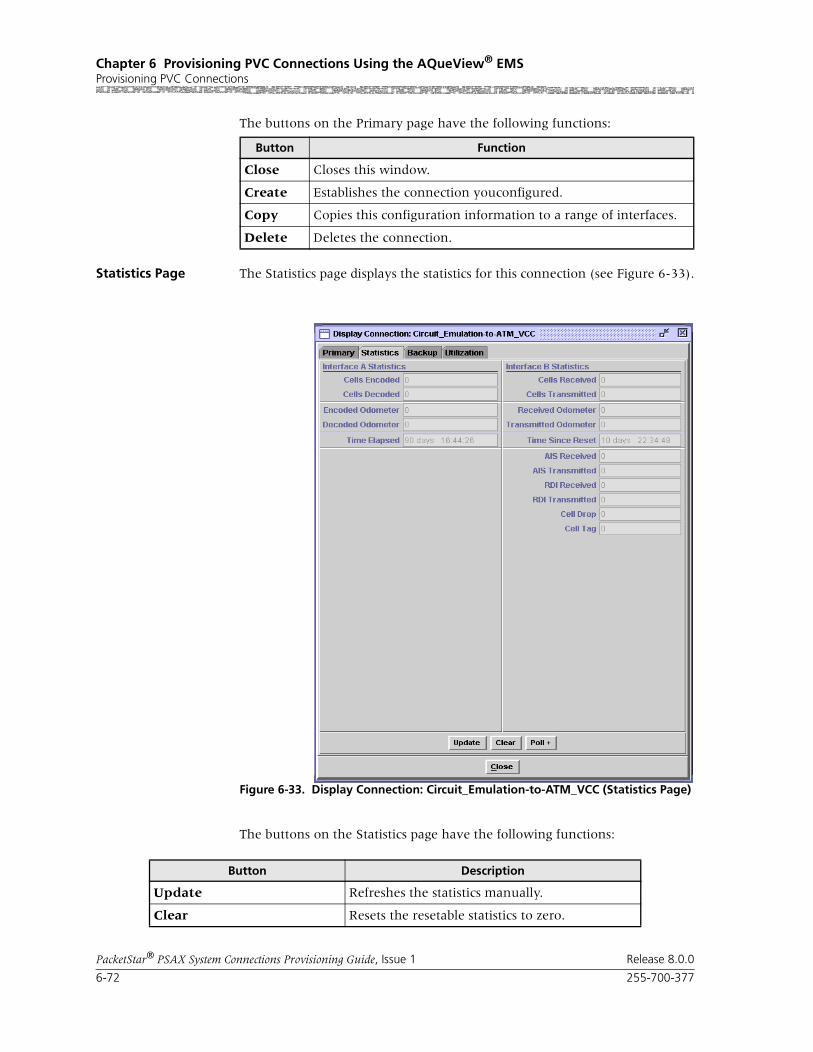
Chapter 6 Provisioning PVC Connections Using the AQueView® EMSProvisioning PVC Connections
6-72 255-700-377
PacketStar® PSAX System Connections Provisioning Guide, Issue 1 Release 8.0.0
The buttons on the Primary page have the following functions:
Statistics Page The Statistics page displays the statistics for this connection (see Figure 6-33).
The buttons on the Statistics page have the following functions:
Button Function
Close Closes this window.
Create Establishes the connection youconfigured.
Copy Copies this configuration information to a range of interfaces.
Delete Deletes the connection.
Figure 6-33. Display Connection: Circuit_Emulation-to-ATM_VCC (Statistics Page)
Button Description
Update Refreshes the statistics manually.
Clear Resets the resetable statistics to zero.

255-700-377 6-73
PacketStar® PSAX System Connections Provisioning Guide, Issue 1 Release 8.0.0
Chapter 6 Provisioning PVC Connections Using the AQueView® EMSProvisioning PVC Connections
Field Descriptions The values for the fields on this window are given in Table 6-13.
Poll Poll + continuously update the statistics and changes the button label to Poll-.
Poll- terminates polling and changes the button label to Poll+.
Odometer Restarts counting in the Cells Transmitted and Cells Received fields iin the Interface Side A and Interface Side B panels, and to view the trans-mitted cells and received cells in the Interface Side A and Interface Side B panels. This button is displayed only on the ATM-to-ATM VCC PVC and ATM-to-ATM VPC PVC Statistics pages.
Close Closes this window.
Restart Restarts connection establishment procedure for the connections that were not previously set up.
Button Description
Table 6-13. Field Descriptions for the Circuit Emulation-to-ATM VCC PVC StatisticsPage
Field Name Field Values Description
Cells Encoded(display only)
Default: 0.0000 e0
Range: 0-(231-1)
Format: Numeric
The total number of encoded (transmitted) user cells going into interface side A during the amount of time shown in the Time Elapsed field (that is, since the circuit was created).
Cells Decoded(display only)
Default: 0.0000 e0Range: 0-(231-1)
Format: Numeric
The total number of decoded (received) user cells going out of interface side A during the amount of time shown in the Time Elapsed field (that is, since the circuit was created).
Encoded Odometer(display only)
Default: 0.0000 e0
Range: 0-(231-1)
Format: Numeric
The total number of encoded user cells going into interface side B since the connection was created.
Decoded Odometer(display only)
Default: 0.0000 e0Range: 0-(231-1)
Format: Numeric
The total number of decoded user cells decoded going out of interface side B since the connection was created.
Time Elapsed(display only)
Default: 00:00:00
Range: N/A
Format: Time in hours (xx), minutes (xx), seconds (xx)
Total time elapsed for OAM statistics collection since the circuit was established.
Cells Received(display only)
Default: 0.0000 e0
Range: 0-(231-1)
Format: Numeric
The total number of received OAM cells going into interface side A during the amount of time shown in the Time Elapsed field (i.e., since the circuit was created).

Chapter 6 Provisioning PVC Connections Using the AQueView® EMSProvisioning PVC Connections
6-74 255-700-377
PacketStar® PSAX System Connections Provisioning Guide, Issue 1 Release 8.0.0
Cells Transmitted(display only)
Default: 0.0000 e0
Range: 0-(231-1)
Format: Numeric
The total number of transmitted OAM cells going out of interface side A during the amount of time shown in Time Elapsed field (i.e., since the cir-cuit was created.)
Received Odometer(display only)
Default: 0.0000 e0
Range: 0-(231-1)
Format: Numeric
Total number of ATM cells received since odome-ter was last reset.
Transmitted Odometer(display only)
Default: 0.0000 e0
Range: 0-(231-1)
Format: Numeric
Total number of ATM cells transmitted since odometer was last reset.
Time Since Reset(display only)
Default: 00:00:00
Range: N/A
Format: Time in hours (xx), minutes (xx), seconds (xx)
Time elapsed since the last time the Clear button was used.
AIS Received(display only)
Default: 0Range: N/A
Format: numeric
Number of alarm indication signal (AIS) cells received.
AIS Transmitted(display only)
Default: 0
Range: N/A
Format: numeric
Number of AIS cells transmitted.
RDI Received(display only)
Default: 0
Range: N/A
Format: numeric
Number of remote defect indicator (RDI) cells received.
RDI Transmitted(display only)
Default: 0Range: N/A
Format: numeric
Number of remote defect indicator (RDI) cells transmitted.
Cell Drop(display only)
Default: 0
Range: N/A
Format: numeric
Number of cells dropped on incoming side of interface A or B.
Cell Tag(display only)
Default: 0
Range: N/A
Format: numeric
Number of cells tagged on incoming side of inter-face A or B.
Table 6-13. Field Descriptions for the Circuit Emulation-to-ATM VCC PVC StatisticsPage
Field Name Field Values Description

255-700-377 6-75
PacketStar® PSAX System Connections Provisioning Guide, Issue 1 Release 8.0.0
Chapter 6 Provisioning PVC Connections Using the AQueView® EMSProvisioning PVC Connections
Backup Page The Backup page displays the information used to create the connection (see Figure 6-34).
The buttons on the Backup page have the following functions:
Field Descriptions Select the values for the for fields as described in Table 6-14.
Figure 6-34. Display Connection: Circuit_Emulation-to-ATM_VCC (Backup Page)
Button Function
Create Backup PVC Establishes the backup VCC PVC connection you configured.
You cannot create a backup VCC PVC connection without selecting an ATM interface type in the Backup ATM Interface panel. Therefore, this button is active when the Slot, Port, and Channel fields correspond to an ATM interface type in the Interface field. Otherwise, the button will be ghosted.
Close Closes this window.

Chapter 6 Provisioning PVC Connections Using the AQueView® EMSProvisioning PVC Connections
6-76 255-700-377
PacketStar® PSAX System Connections Provisioning Guide, Issue 1 Release 8.0.0
Table 6-14. Field Descriptions for the Display Connection: Circuit Emulation-to-ATM VCC Backup Page
Field Name Field Values Description
Slot Default: N/A
Range: Listed as avail-able from the PSAX device
Format: Numeric
Select the slot containing the module for which you are creating a connection.
Note: This field is display only for the circuit emulation interface.
Port Default: N/A
Range: Determined by the number of ports available on the module selected in the Slot field
Format: Numeric
Select the port number on the module for which you are creating a connection.
Note: This field is display only for the circuit emulation interface.
Channel Default: N/A
Range: Determined by the number of channels available on the port selected in the Port field
Format: Numeric
Select the channel number of the port on the module for which you are creating a connection.
Note: This field is display only for the circuit emulation interface.
Interface(display only)
Default: Unconfig-uredRange: AtmUni3-0AtmUni3-1IispUserIispNetworkCircuitEmulation DbCirEmFrameRelayUniFrameRelayNniPri_Isdn_NetworkPri_Isdn_UserHldcPassThroughAtmPnni1-0
Format: Alphanu-meric
The interface type that is configured on the slot, port, and channel (selected in the Slot, Port, and Channel fields).
OperStatus(display only)
Default: OutOfSer-vice
Range: N/A
Format: Character
Indicates that the interface is not operational.
InService Indicates that the interface is operational.

255-700-377 6-77
PacketStar® PSAX System Connections Provisioning Guide, Issue 1 Release 8.0.0
Chapter 6 Provisioning PVC Connections Using the AQueView® EMSProvisioning PVC Connections
Utilization Page The Utilization page measures the amount of traffic running through this connection (see Figure 6-35).
AdminStatus(display only)
Default: OutOfSer-vice
Range: N/A
Format: Character
Indicates that some condition is preventing the port from being configured with an interface..
InService Indicates that no conditions are preventing the port from being fully operational
VPI Default: 0
Range: 0–255
Format: Numeric
The virtual path identifier assigned to this backup interface.
VCI Default: 32
Range: 32–4000
Format: Numeric
The virtual channel identifier assigned to this backup interface.
VI Default: 0Range: 0-255
Format: Numeric
Backup virtual interface, which provides band-width allocation restrictions. Currently available only on theOC-3c APS and STM-1 MSP modules.
Automatic Switch-back
Default: Yes
Range: N/A
Format: Character
CPU monitors primary connection. If primary connection becomes available, backup will switch back connection to Primary.
No Not currently supported.
Once active, the backup connection will not switch back to primary connection automatically if Primary becomes available.
Current Active PVC Default: None
Range: N/A
Format: Character
Indicates that the connection is inactive.
Primary Indicates that the primary connection is active (carrying user traffic).
Backup Indicates that the backup connection is active (carrying user traffic).
Table 6-14. Field Descriptions for the Display Connection: Circuit Emulation-to-ATM VCC Backup Page
Field Name Field Values Description
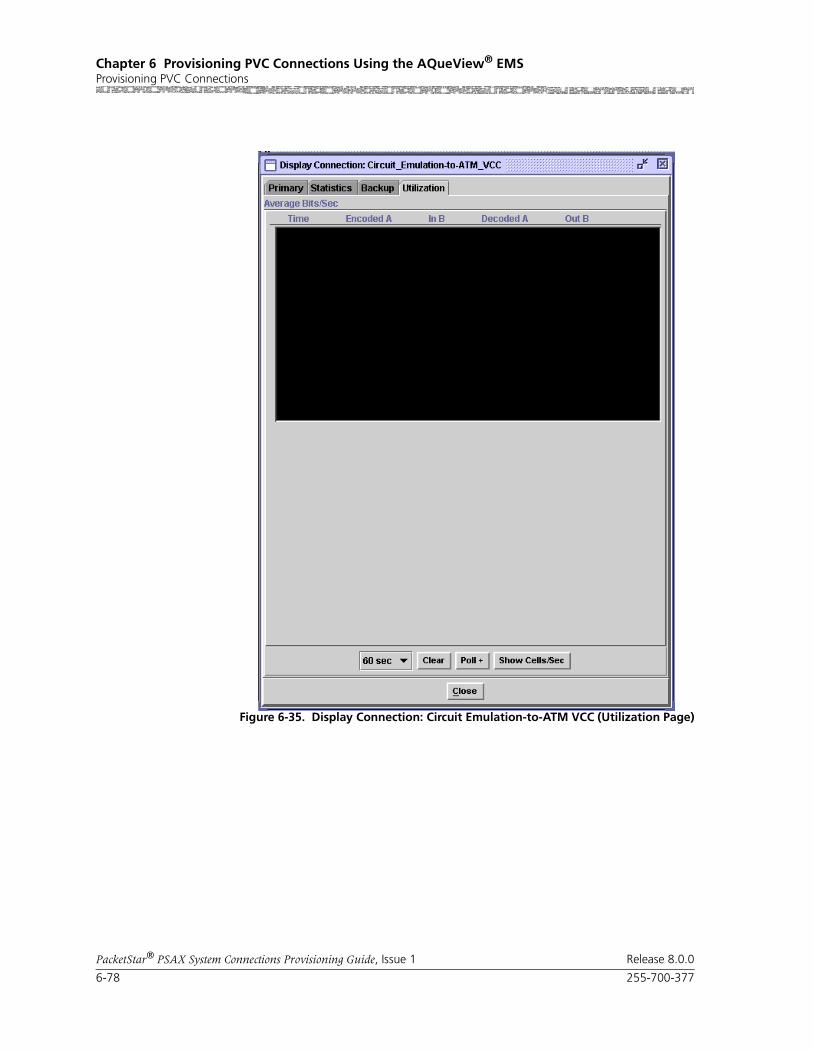
Chapter 6 Provisioning PVC Connections Using the AQueView® EMSProvisioning PVC Connections
6-78 255-700-377
PacketStar® PSAX System Connections Provisioning Guide, Issue 1 Release 8.0.0
Figure 6-35. Display Connection: Circuit Emulation-to-ATM VCC (Utilization Page)
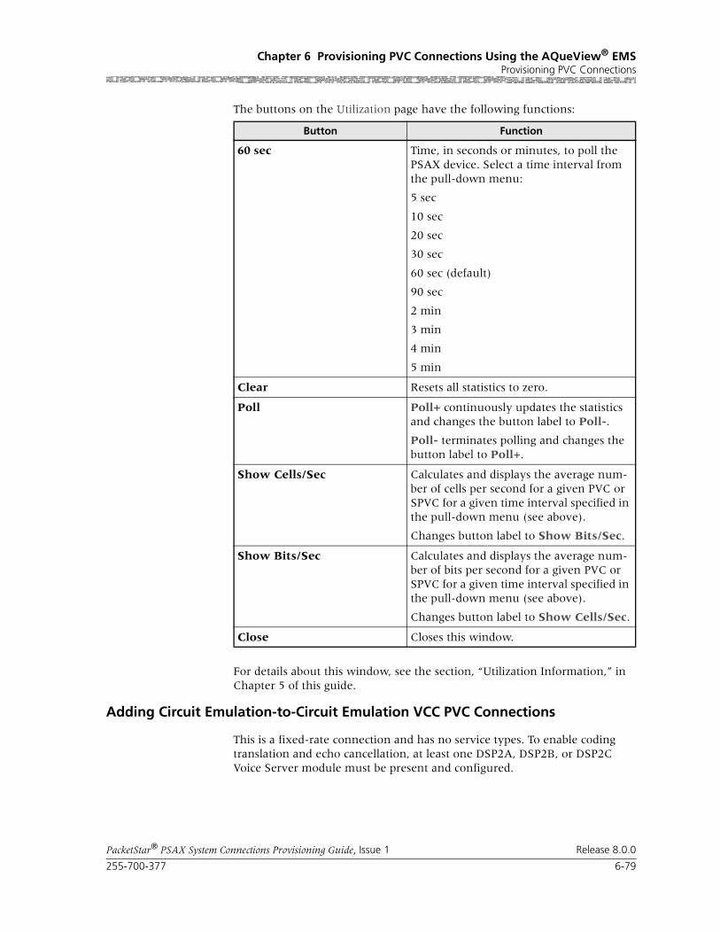
255-700-377 6-79
PacketStar® PSAX System Connections Provisioning Guide, Issue 1 Release 8.0.0
Chapter 6 Provisioning PVC Connections Using the AQueView® EMSProvisioning PVC Connections
The buttons on the Utilization page have the following functions:
For details about this window, see the section, “Utilization Information,” in Chapter 5 of this guide.
Adding Circuit Emulation-to-Circuit Emulation VCC PVC Connections
This is a fixed-rate connection and has no service types. To enable coding translation and echo cancellation, at least one DSP2A, DSP2B, or DSP2C Voice Server module must be present and configured.
Button Function
60 sec Time, in seconds or minutes, to poll the PSAX device. Select a time interval from the pull-down menu:
5 sec
10 sec
20 sec
30 sec
60 sec (default)
90 sec
2 min
3 min
4 min
5 min
Clear Resets all statistics to zero.
Poll Poll+ continuously updates the statistics and changes the button label to Poll-.
Poll- terminates polling and changes the button label to Poll+.
Show Cells/Sec Calculates and displays the average num-ber of cells per second for a given PVC or SPVC for a given time interval specified in the pull-down menu (see above).
Changes button label to Show Bits/Sec.
Show Bits/Sec Calculates and displays the average num-ber of bits per second for a given PVC or SPVC for a given time interval specified in the pull-down menu (see above).
Changes button label to Show Cells/Sec.
Close Closes this window.
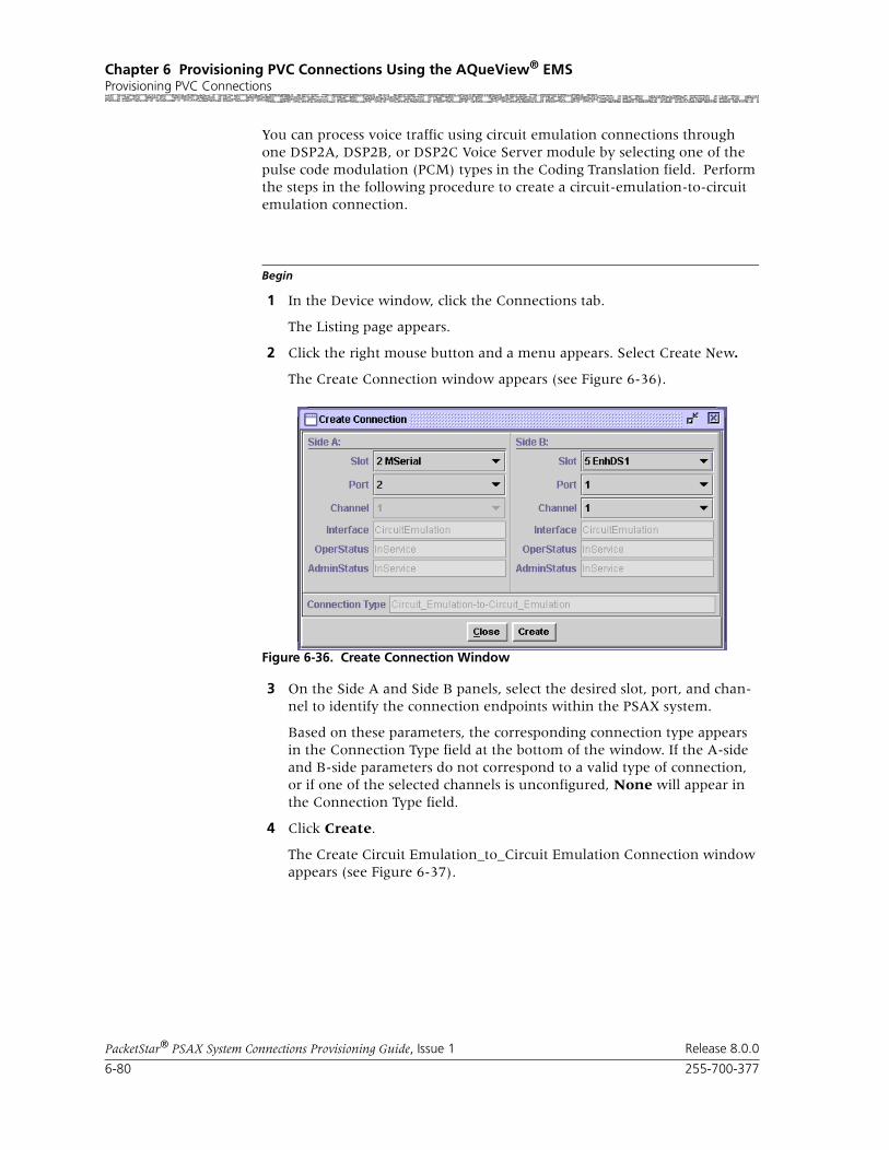
Chapter 6 Provisioning PVC Connections Using the AQueView® EMSProvisioning PVC Connections
6-80 255-700-377
PacketStar® PSAX System Connections Provisioning Guide, Issue 1 Release 8.0.0
You can process voice traffic using circuit emulation connections through one DSP2A, DSP2B, or DSP2C Voice Server module by selecting one of the pulse code modulation (PCM) types in the Coding Translation field. Perform the steps in the following procedure to create a circuit-emulation-to-circuit emulation connection.
Begin
1 In the Device window, click the Connections tab.
The Listing page appears.
2 Click the right mouse button and a menu appears. Select Create New.
The Create Connection window appears (see Figure 6-36).
3 On the Side A and Side B panels, select the desired slot, port, and chan-nel to identify the connection endpoints within the PSAX system.
Based on these parameters, the corresponding connection type appears in the Connection Type field at the bottom of the window. If the A-side and B-side parameters do not correspond to a valid type of connection, or if one of the selected channels is unconfigured, None will appear in the Connection Type field.
4 Click Create.
The Create Circuit Emulation_to_Circuit Emulation Connection window appears (see Figure 6-37).
Figure 6-36. Create Connection Window

255-700-377 6-81
PacketStar® PSAX System Connections Provisioning Guide, Issue 1 Release 8.0.0
Chapter 6 Provisioning PVC Connections Using the AQueView® EMSProvisioning PVC Connections
Note: For circuit emulation range limits for DSP Algosets 1 through 7, see the Connection Capacity of DSP2x Algorithm Sets Table in the Ref-erence Information Appendix of the DSP2x Voice Server Module User Guide.
The buttons on this window have the following functions:
Field Descriptions 5 Select the values for the fields on this window from the values in Table 6-15.
Figure 6-37. Create Circuit Emulation_to_Circuit Emulation Connection Window
Button Function
Close Closes this window.
Create Establishes the connection you configured.
Copy Copies this configuration information to a range of interfaces.

Chapter 6 Provisioning PVC Connections Using the AQueView® EMSProvisioning PVC Connections
6-82 255-700-377
PacketStar® PSAX System Connections Provisioning Guide, Issue 1 Release 8.0.0
Table 6-15. Field Descriptions for the Circuit Emulation-to-Circuit Emulation PVC Connection Window
Field Name Field Values Description
Interface Side A:CIRCUIT_EM
Default: Predefined
Range: N/A
Format: Predefined
Specifies Side A of the connection that sends and receives signals. This is the near-end side of the connection, closest to the hybrid digital-to-analog circuit, where the echo is created. The DSP2x module will cancel the echo before the traffic is transmitted out the Side B interface. To cancel the near-end echo, select a voice processing parameter other than None in the Echo Cancel-lation field below.
Interface Side B:CIRCUIT_EM
Default: Predefined
Range: N/A
Format: Predefined
Specifies Side B of the connection that will send and receive signals. Far-end echo on this side must be canceled at the far end.
Slot Default: VariableRange: Chassis dependent
Format: Numeric
Select the slot number containing the module for both sides of the connection.
Port Default: Variable
Range: Module dependent
Format: Numeric
Select the port number containing the module for both sides of the connection.
Channel Format: Numeric Select the channel number containing the mod-ule for both sides of the connection.

255-700-377 6-83
PacketStar® PSAX System Connections Provisioning Guide, Issue 1 Release 8.0.0
Chapter 6 Provisioning PVC Connections Using the AQueView® EMSProvisioning PVC Connections
Coding Translation Default: None
Range: As noted below
Format: Predefined
If you want data traffic for this connection to be processed through any DSP2x Voice Server mod-ule with a coding translation parameter, do not use the default value. The other values indicate the desired type of pulse code modulation (PCM) translation. You must specify one of these PCM types to enable data traffic processing through any DSP2x Voice Server modules.
If configuring the Voice 2-Wire Office or Voice 2-Wire Station modules for this parameter, you must select MuLaw2muLaw. The other choices are not supported.
Not supported.
None No coding translation is selected on the connec-tion.
MuLaw2muLaw American and Japanese compression and expan-sion (companding) standard is used on Sides A and B of the connection.
ALaw2aLaw European companding standard is used on Sides A and B of the connection.
MuLaw2aLaw American/Japanese to European companding standard is used between sending Side A and receiving Side B of the connection.
ALaw2MuLaw European to American/Japanese companding standard is used between sending Side A and receiving Side B of the connection.
Echo Cancellation Default: NoneRange: As noted below
Format: Predefined
If you using voice applications, an echo cancella-tion algorithm is recommended (select a value other than None). Not supported.
None No echo cancellation is used on the connection.
G165-nearEnd, ITU-T G.165 echo cancellation for the near end of the connection is used.
G168 ITU-T G.1658 echo cancellation is used.
Traffic Flow Default: Duplex
Range: As noted below
Format: Predefined
Specifies the direction of the flow of data traffic in this connection.
Duplex Traffic flows in both directions.
SimplexA2B Traffic flows from Side A to Side B only.
Table 6-15. Field Descriptions for the Circuit Emulation-to-Circuit Emulation PVC Connection Window
Field Name Field Values Description

Chapter 6 Provisioning PVC Connections Using the AQueView® EMSProvisioning PVC Connections
6-84 255-700-377
PacketStar® PSAX System Connections Provisioning Guide, Issue 1 Release 8.0.0
If the parameters are valid, the Connections window appears with the new connection in the Listing page, and the Display Connection window
Interworking Default: Disabled
Range: As noted below
Format: Predefined
Specifies the conversion between ATM OAM cells and circuit emulation alarms.
Disabled Disables the conversion between ATM OAM cells and circuit emulation alarms.
Enabled Enables the conversion between ATM OAM cells and circuit emulation alarms.
Service Type Default: Cbr-1
Range: As noted below
Format: Predefined
Multiservice Media Gateway system-supported quality of service (QoS) class.
Cbr-1 Constant bit rate, queue 1
Cbr-2 Constant Bit rate, queue 2
Cbr-3, Constant Bit rate, queue 3
Cbr-4 Constant Bit rate, queue 4
Connection Status (display only)
Default: Inactive,
Active
Displays the current status of the connection. The value indicates whether the connection is passing traffic.
Connection Failure Cause A(display only)
Default: None
Range: N/A
Format: Predefined
General connection failure cause.
None Indicates that no failure is present.
Physical Indicates that a physical level failure is present, such as when a an I/O module or cable is removed from the PSAX device, or an I/O mod-ule receives an LOS or LOF alarm. This changes the operational status of the interface to Outof-Service.
Connection Failure Cause B(display only)
Default: None
Range: N/A
Format: Predefined
General connection failure cause.
None Indicates that no failure is present.
Physical Indicates that a physical level failure is present, such as when a an I/O module or cable is removed from the PSAX device, or an I/O mod-ule receives an LOS or LOF alarm. This changes the operational status of the interface to Outof-Service.
Table 6-15. Field Descriptions for the Circuit Emulation-to-Circuit Emulation PVC Connection Window
Field Name Field Values Description

255-700-377 6-85
PacketStar® PSAX System Connections Provisioning Guide, Issue 1 Release 8.0.0
Chapter 6 Provisioning PVC Connections Using the AQueView® EMSProvisioning PVC Connections
appears with tabs that contain details about the connection (see Figure 6-38): Primary and Statistics.
If a parameter is invalid, a Connection Creation Failed message appears, stating the reason for the failure.
End
Primary Page The Primary page displays the information used to create the connection. See Table 6-15 for field descriptions.
The buttons on the Primary page have the following functions:
Statistics Page The Statistics page displays the statistics for this connection.
Figure 6-38. Display Connection: Circuit_Emulation-to-Circuit_Emulation (Primary Page)
Button Function
Close Closes this window.
Create Establishes the connection youconfigured.
Copy Copies this configuration information to a range of interfaces.
Delete Deletes the connection.

Chapter 6 Provisioning PVC Connections Using the AQueView® EMSProvisioning PVC Connections
6-86 255-700-377
PacketStar® PSAX System Connections Provisioning Guide, Issue 1 Release 8.0.0
The buttons on the Statistics page have the following functions:
Figure 6-39. Display Connection: Circuit_Emulation-to-Circuit_Emulation Statistics Page
Button Description
Update Refreshes the statistics manually.
Clear Resets the resetable statistics to zero.
Poll Poll + continuously update the statistics and changes the button label to Poll-.
Poll- terminates polling and changes the button label to Poll+.
Odometer Restarts counting in the Cells Transmitted and Cells Received fields iin the Interface Side A and Interface Side B panels, and to view the trans-mitted cells and received cells in the Interface Side A and Interface Side B panels. This button is displayed only on the ATM-to-ATM VCC PVC and ATM-to-ATM VPC PVC Statistics pages.
Close Closes this window.
Restart Restarts connection establishment procedure for the connections that were not previously set up.

255-700-377 6-87
PacketStar® PSAX System Connections Provisioning Guide, Issue 1 Release 8.0.0
Chapter 6 Provisioning PVC Connections Using the AQueView® EMSProvisioning PVC Connections
Field Descriptions The values for the fields on this window are described in Table 6-16.
Utilization Page The Utilization page measures the amount of traffic running through this connection (see Figure 6-35).
Table 6-16. Field Descriptions for Circuit Emulation-to-Circuit Emulation PVC Connection StatisticsPage
Field Name Field Values Description
Cells Encoded(display only)
Default: 0Range: N/A
Format: numeric
On the Interface A Statistics panel, the number of cells encoded going into interface side A during the amount of time shown in Time Elapsed field since the circuit was established.
On the Interface B Statistics panel, the number of cells encoded going into interface side B during the amount of time shown in Time Elapsed field since the circuit was established.
Cells Decoded(display only)
Default: 0
Range: N/A
Format: numeric
On the Interface A Statistics panel, the number of cells decoded going out of interface side A during the amount of time shown in Time Elapsed field since the circuit was established.
On the Interface B Statistics panel, the number of cells decoded going out of interface side B during the amount of time shown in Time Elapsed field since the circuit was established.
Encoded Odometer(display only)
Default: 0
Range: N/A
Format: numeric
On the Interface A Statistics panel, the number of cells encoded going into interface side A since this counter was reset.
On the Interface B Statistics panel, the number of cells encoded going into interface side B since this counter was reset.
Decoded Odometer(display only)
Default: 0
Range: N/A
Format: numeric
On the Interface A Statistics panel, the number of cells decoded going out of interface side A since this counter was reset.
On the Interface B Statistics panel, the number of cells decoded going out of interface side B since this counter was reset.
Time Elapsed(display only)
Default: 00:00:00
Range: N/A
Format: numeric
Time elapsed since the circuit was established.
Time Since Reset(display only)
Default: 00:00:00Range: N/A
Format: numeric
Time elapsed since the last time the Clear button command was used.
The Clear button on the statistics page resets only the odometer fields (labelled as Odometer) and the corresponding clock. Other counters increment for the duration of the circuit.

Chapter 6 Provisioning PVC Connections Using the AQueView® EMSProvisioning PVC Connections
6-88 255-700-377
PacketStar® PSAX System Connections Provisioning Guide, Issue 1 Release 8.0.0
The buttons on the Utilization page have the following functions:
Figure 6-40. Display Connection: Circuit Emulation-to-Circuit Emulation VCC (Uti-lization Page)
Button Function
60 sec Time, in seconds or minutes, to poll the PSAX device. Select a time interval from the pull-down menu:
5 sec
10 sec
20 sec
30 sec
60 sec (default)
90 sec
2 min
3 min
4 min
5 min
Clear Resets all statistics to zero.

255-700-377 6-89
PacketStar® PSAX System Connections Provisioning Guide, Issue 1 Release 8.0.0
Chapter 6 Provisioning PVC Connections Using the AQueView® EMSProvisioning PVC Connections
For details about this window, see the section, “Utilization Information,” in Chapter 5 of this guide.
Adding Frame Relay-to-ATM VCC PVC Connections
Perform the steps in the following procedure to create a frame relay-to-ATM VCC connection.
Begin
Note: On the DS1 IMA and E1 IMA modules, you must provision PVC connections on the virtual port (port 7). You can use up to three channels on port 7 (the channels you provision on port 7.)
Note: On the DS3 IMA module, you must provision PVC connections on the virtual port (port 30). You can use up to 14 channels on port 30 (the channels you provision on port 30.)
1 In the Device window, click the Connections tab.
The Listing page appears.
2 Click the right mouse button and a menu appears. Click Create New.
Poll Poll+ continuously updates the statistics and changes the button label to Poll-.
Poll- terminates polling and changes the button label to Poll+.
Show Cells/Sec Calculates and displays the average num-ber of cells per second for a given PVC or SPVC for a given time interval specified in the pull-down menu (see above).
Changes button label to Show Bits/Sec.
Show Bits/Sec Calculates and displays the average num-ber of bits per second for a given PVC or SPVC for a given time interval specified in the pull-down menu (see above).
Changes button label to Show Cells/Sec.
Close Closes this window.
Button Function

Chapter 6 Provisioning PVC Connections Using the AQueView® EMSProvisioning PVC Connections
6-90 255-700-377
PacketStar® PSAX System Connections Provisioning Guide, Issue 1 Release 8.0.0
The Create Connection window appears (see Figure 6-41).
3 On the Side A and Side B panels, select the desired slot, port, and chan-nel to identify the connection endpoints within the PSAX system.
Based on these parameters, the corresponding connection type appears in the Connection Type field at the bottom of the window. If the A-side and B-side parameters do not correspond to a valid type of connection, or if one of the selected channels is unconfigured, None appears in the Connection Type field.
4 Click Create.
Figure 6-41. Create Connection Window

255-700-377 6-91
PacketStar® PSAX System Connections Provisioning Guide, Issue 1 Release 8.0.0
Chapter 6 Provisioning PVC Connections Using the AQueView® EMSProvisioning PVC Connections
The Create Frame_Relay-to-ATM_VCC Connection window appears (see Figure 6-42).
The buttons on this window have the following functions:
Field Descriptions 5 Select the values for the fields on this window from the values in Table 6-17.
Figure 6-42. Create Frame_Relay_to_ATM_VCC Connection Window
Button Function
Close Closes this window.
Create Establishes the connection you configured.
Copy Copies this configuration information to a range of interfaces.

Chapter 6 Provisioning PVC Connections Using the AQueView® EMSProvisioning PVC Connections
6-92 255-700-377
PacketStar® PSAX System Connections Provisioning Guide, Issue 1 Release 8.0.0
Table 6-17. Field Descriptions for the Frame_Relay-to-ATM_VCC PVC Connection Page
Field Names Field Values Description
Interface Side A:FR_UNI or FR_NNI
Default: NA
Range: NA
Format: NA
The fields in the Frame Relay Interface panel are used to configure the frame relay side of the con-nection.
Interface Side B:ATM_UNI30, ATM_UNI31, ATM_UNI40, IISP_USER, IISP_NETWORK
Default: N/A
Range: N/A
Format: N/A
The fields in the ATM Interface panel are used to configure the ATM side of the connection.
Slot Default: 0Range: variable
Format: numeric
Select the slot number containing the module for both sides of the connection. The range of slot numbers varies with the chassis type.
Port Format: Select the port number containing the module for both sides of the connection. The range of port numbers varies with the module type.
Channel(display only)
The channel on which you are creating a connec-tion.
DLCI Default: 0
Range: 16–1007
Format: numeric
Data link connection identifier. DLCI is used when the remote end-point is frame relay.
VPI Default: 0Range: 0–225 (ATM UNI), 0-4095 (NNI)
Format: numeric
Virtual path identifier.
VCI Default: 0
Range: 0–65535
Format: numeric
Virtual channel identifier.
VI/VUNI Default: 0
Range: 0–255
Format: numeric
Virtual interface/virtual ATM UNI, which pro-vides bandwidth allocation restrictions. Currently available only on the OC-3c 1+1 APS, STM-1 1+1 MSP, and OC-12c/STM-4c 1+1 APS/MSP modules. When disabled, the default value is 0. The virtual UNI (VUNI) associates itself with the egress part of the A-to-B or the B-to-A side of the connection.
Interworking Func-tion
Default: Frf8-Transl
Range: N/A
Format: predefined alphanumeric
Frf8-Transl,Frf8-Pass,Frf5
FRF.8 (Frame Relay Forum Implementation Agreement)—frame relay to ATM PVC service interworking.
FRF.5 (Frame Relay Forum Implementation Agreement)—frame relay to ATM PVC service interworking.

255-700-377 6-93
PacketStar® PSAX System Connections Provisioning Guide, Issue 1 Release 8.0.0
Chapter 6 Provisioning PVC Connections Using the AQueView® EMSProvisioning PVC Connections
Frame Size (bytes) Default: 4096
Range: N/A
Format: numeric (bytes)
Size of the frame (in bytes).
Committed Burst Size (bits/second)
Default: 0Range:
Format: numeric (bits/sec)
Committed burst size. Use the default value.
Excess Burst Size (bits)
Default: 45000000
Range:
Format: numeric (bits)
Excess burst size (in bits per second).
Committed Info Rate
Default: 0
Range:
Format: numeric (bits/sec)
Committed information rate is the rate of traffic (measured in bits per second) for a given connec-tion that the system will attempt to provide guar-anteed delivery.
Time Interval (mil-liseconds)(display only)
Default: 1000
Range: variable
Format: numeric (msec)
Time elapsed since the last reset (in msec).
Peak Cell Rate(display only)
Default: 1Range: variable
Format: numeric (cells/sec)
Refer to the ATM UNI 3.0 specifications for more information. When setting this value, take into account the line rate for the module and the amount of bandwidth you are setting up for each interface for the module.
Sustained Cell Rate(display only)
Default: 1
Range: variable
Format: numeric (cells/sec)
Sustained cell rate. Refer to the ATM UNI 3.0 specifications for more information. When set-ting this value, take into account the line rate for the module and the amount of bandwidth you are setting up for each interface for the module.
Max Burst Size(display only)
Default: 1
Range: variable
Format: numeric (cells)
Maximum burst size. Refer to the ATM UNI 3.0 specifications for more information. When setting this value, take into account the line rate for the module and the amount of bandwidth you are setting up for each interface for the module.
Traffic Flow Default: DuplexRange: N/A
Format: predefined alphanumeric
Duplex,SimplexA2B,SimplexB2A
Direction of the flow of data traffic in this con-nection. When you select SimplexA2B and Configure Traffic Parameters, only the fields in the Traffic Parameters In side are displayed. When you select SimplexB2A and Configure Traffic Parameters, only the fields in the Traffic Parameters Out side are displayed. For the 1-Port DS3 IMA module, only Duplex and Simplex are applicable.
Table 6-17. Field Descriptions for the Frame_Relay-to-ATM_VCC PVC Connection Page
Field Names Field Values Description

Chapter 6 Provisioning PVC Connections Using the AQueView® EMSProvisioning PVC Connections
6-94 255-700-377
PacketStar® PSAX System Connections Provisioning Guide, Issue 1 Release 8.0.0
Service Type Default: Ubr
Range: N/A
Format: predefined alphanumeric
Ubr,Vbr-nrt2,Vbr-nrt1,Vbr-rt2,Vbr-rt1,Vbr-express
PSAX system-supported quality of service (QoS) class. For a description of the QoS classes, see the reference appendix in this guide.
Cnfrm Type Default: Best-effort
Range: N/A
Format: predefined alphanumeric
The type of traffic control option used for ATM cells. The traffic descriptor combination specifies which traffic parameters are used for traffic con-trol, determines the number and type of cells that are admitted into a congested queue, and deter-mines whether high-priority cells are tagged as low-priority cells when traffic exceeds the traffic parameter thresholds.
Best-effort This traffic descriptor allows the system to attempt to send all cells in a “best effort” fashion, without specifying traffic parameters, similar to the AQueMan algorithm.
One-bucket-notag-0plus1
This traffic descriptor uses the parameters one bucket, no tagging, cell loss priority (CLP)=0+1 cells (high and low priority).
Two-bucket-notag-0plus1-0plus1
This traffic descriptor uses the parameters two buckets, no tagging, CLP=0+1 cells (high and low priority) for bucket 1, and CLP=0+1 cells (high and low priority) for bucket 2.
Two-bucket-notag-0plus1-0
This traffic descriptor uses the parameters two buckets, no tagging, CLP=0+1 cells (high and low priority) for bucket 1, and CLP=0 cells (high pri-ority) for bucket 2.
Two-bucket-tag-0plus1-0
This traffic descriptor uses the parameters two buckets, CLP=0+1 cells (high and low priority) for bucket 1, and tagging for CLP=0 cells (high priority) in bucket 2.
Best-effort-tag This traffic descriptor allows the system to tag all CLP=0 (high priority) cells to change them to CLP=1 (low priority) cells during congestion, and then attempt to send all cells in a “best effort” fashion, without specifying any other traffic parameters, similar to the AQueMan algorithm.
Table 6-17. Field Descriptions for the Frame_Relay-to-ATM_VCC PVC Connection Page
Field Names Field Values Description

255-700-377 6-95
PacketStar® PSAX System Connections Provisioning Guide, Issue 1 Release 8.0.0
Chapter 6 Provisioning PVC Connections Using the AQueView® EMSProvisioning PVC Connections
OAM Status Default: Unsupp
Range: N/A
Format: predefined alphanumeric
The status of the operations and maintenance function.
Unsupp OAM is not in use.
End-Pt The PSAX Multiservice Media Gateway is used as a termination point for ATM traffic, and processes AIS/RDI cells.
Note: The OAM loopback test is supported for end-to-end connections only.
End-Seg-Pt Has the characteristics of both an end point and a segment point.
[FailCause A/B](display only)
Default: Null/NullRange: N/A
Format: predefined alphanumeric
Presents the AAL2 status reason code for both sides of the connection
Connection Status(display only)
Default: Inactive
Range: N/A
Format: Character
Indicates whether the connection is passing traf-fic.
Inactive The connection is not passing traffic.
Active The connection is passing traffic.
Connection Failure Cause A(display only)
Default: NoneFormat: N/A
Format: Predefined
The cause of the connection failure on side A of the connection.
None The connection has not failed.
Physical The failure cause is physical.
LMI
DLCI
Table 6-17. Field Descriptions for the Frame_Relay-to-ATM_VCC PVC Connection Page
Field Names Field Values Description

Chapter 6 Provisioning PVC Connections Using the AQueView® EMSProvisioning PVC Connections
6-96 255-700-377
PacketStar® PSAX System Connections Provisioning Guide, Issue 1 Release 8.0.0
If the parameters are valid, the Connections window appears with the new connection in the Listing page, and the Display Connection window appears with tabs that contain details about the connection (see Figure 6-43): Primary, and Statistics.
If a parameter is invalid, a Connection Creation Failed message appears, stating the reason for the failure.
End
Connection Failure Cause B(display only)
Default: None
Range: N/A
Format: Predefined
The cause of the connection failure on side B of the connection.
None Indicates that no failure is present.
Physical Indicates that a physical level failure is present, such as when a an I/O module or cable is removed from the PSAX device, or an I/O mod-ule receives an LOS or LOF alarm. This changes the operational status of the interface to Outof-Service.
LMI Indicates that the layer manager has failed, but there is no physical level failure; for example, an lmiDce- or LmiDte-related failure.
DLCI Indicates that this connection has failed, but no physical or LMI failure is related with this con-nection.
Table 6-17. Field Descriptions for the Frame_Relay-to-ATM_VCC PVC Connection Page
Field Names Field Values Description
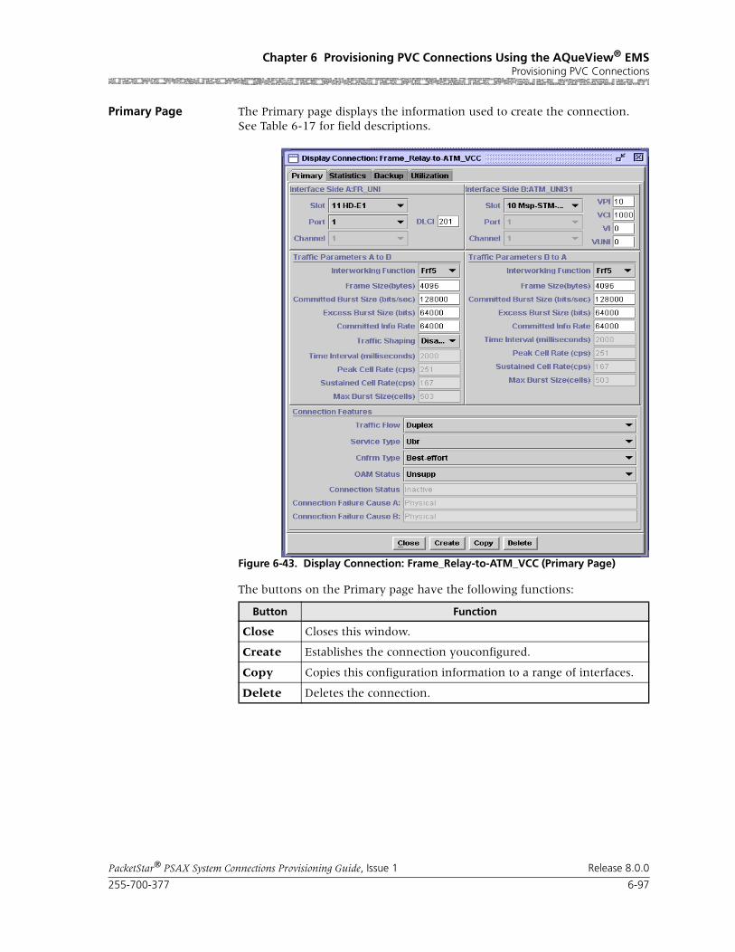
255-700-377 6-97
PacketStar® PSAX System Connections Provisioning Guide, Issue 1 Release 8.0.0
Chapter 6 Provisioning PVC Connections Using the AQueView® EMSProvisioning PVC Connections
Primary Page The Primary page displays the information used to create the connection. See Table 6-17 for field descriptions.
The buttons on the Primary page have the following functions:
Figure 6-43. Display Connection: Frame_Relay-to-ATM_VCC (Primary Page)
Button Function
Close Closes this window.
Create Establishes the connection youconfigured.
Copy Copies this configuration information to a range of interfaces.
Delete Deletes the connection.
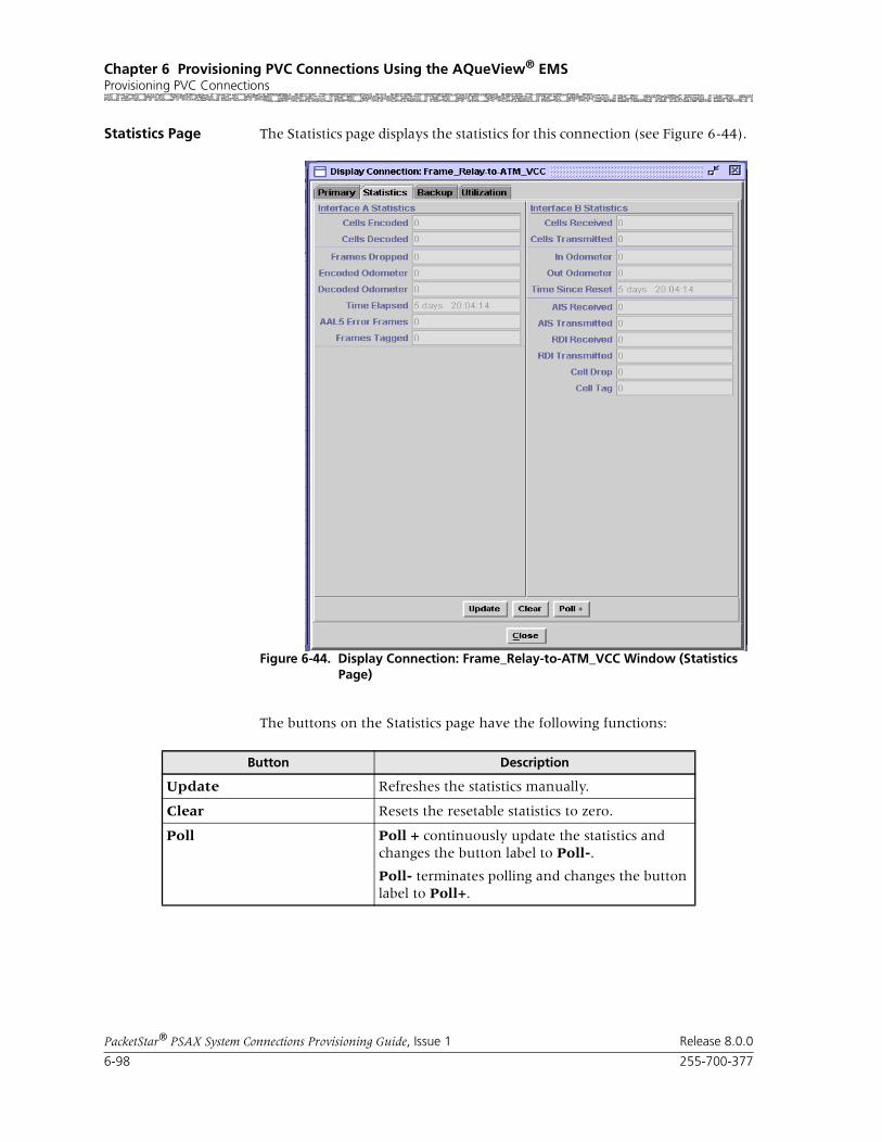
Chapter 6 Provisioning PVC Connections Using the AQueView® EMSProvisioning PVC Connections
6-98 255-700-377
PacketStar® PSAX System Connections Provisioning Guide, Issue 1 Release 8.0.0
Statistics Page The Statistics page displays the statistics for this connection (see Figure 6-44).
The buttons on the Statistics page have the following functions:
Figure 6-44. Display Connection: Frame_Relay-to-ATM_VCC Window (Statistics Page)
Button Description
Update Refreshes the statistics manually.
Clear Resets the resetable statistics to zero.
Poll Poll + continuously update the statistics and changes the button label to Poll-.
Poll- terminates polling and changes the button label to Poll+.
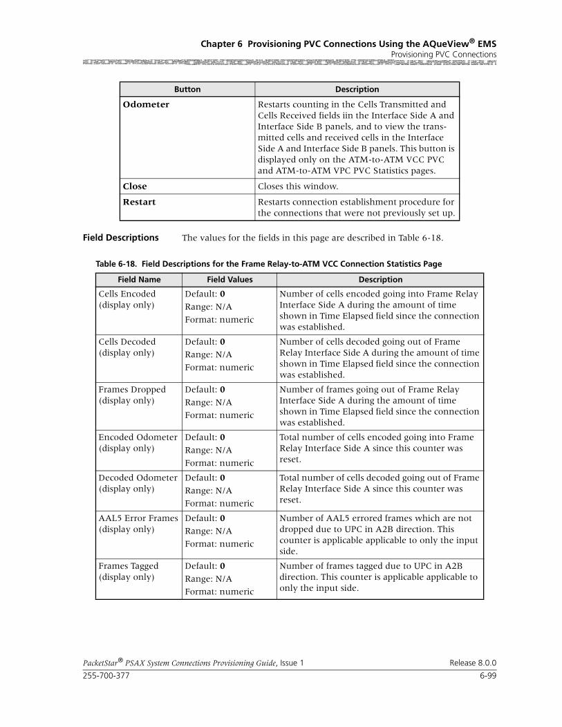
255-700-377 6-99
PacketStar® PSAX System Connections Provisioning Guide, Issue 1 Release 8.0.0
Chapter 6 Provisioning PVC Connections Using the AQueView® EMSProvisioning PVC Connections
Field Descriptions The values for the fields in this page are described in Table 6-18.
Odometer Restarts counting in the Cells Transmitted and Cells Received fields iin the Interface Side A and Interface Side B panels, and to view the trans-mitted cells and received cells in the Interface Side A and Interface Side B panels. This button is displayed only on the ATM-to-ATM VCC PVC and ATM-to-ATM VPC PVC Statistics pages.
Close Closes this window.
Restart Restarts connection establishment procedure for the connections that were not previously set up.
Button Description
Table 6-18. Field Descriptions for the Frame Relay-to-ATM VCC Connection Statistics Page
Field Name Field Values Description
Cells Encoded(display only)
Default: 0
Range: N/A
Format: numeric
Number of cells encoded going into Frame Relay Interface Side A during the amount of time shown in Time Elapsed field since the connection was established.
Cells Decoded(display only)
Default: 0Range: N/A
Format: numeric
Number of cells decoded going out of Frame Relay Interface Side A during the amount of time shown in Time Elapsed field since the connection was established.
Frames Dropped(display only)
Default: 0
Range: N/A
Format: numeric
Number of frames going out of Frame Relay Interface Side A during the amount of time shown in Time Elapsed field since the connection was established.
Encoded Odometer(display only)
Default: 0
Range: N/A
Format: numeric
Total number of cells encoded going into Frame Relay Interface Side A since this counter was reset.
Decoded Odometer(display only)
Default: 0
Range: N/A
Format: numeric
Total number of cells decoded going out of Frame Relay Interface Side A since this counter was reset.
AAL5 Error Frames(display only)
Default: 0Range: N/A
Format: numeric
Number of AAL5 errored frames which are not dropped due to UPC in A2B direction. This counter is applicable applicable to only the input side.
Frames Tagged(display only)
Default: 0
Range: N/A
Format: numeric
Number of frames tagged due to UPC in A2B direction. This counter is applicable applicable to only the input side.

Chapter 6 Provisioning PVC Connections Using the AQueView® EMSProvisioning PVC Connections
6-100 255-700-377
PacketStar® PSAX System Connections Provisioning Guide, Issue 1 Release 8.0.0
Time Elapsed(display only)
Default: 00:00:00
Range: N/A
Format: numericHH:MM:SS (hours, minutes, seconds)
Time elapsed (in hours, minutes, seconds) since the connection was established.
Time Since Reset(display only)
Default: 00:00:00Range: N/A
Format: numericHH:MM:SS (hours, minutes, seconds)
Time elapsed (in hours, minutes, seconds) since the last time the Clear button was used. The Clear button on the statistics page resets only the odometer fields and the corresponding clock. Other counters increment for the life of the con-nection.
AIS Rx/Tx(display only)
Default: 0
Range: N/A
Format: numeric
Number of alarm indication signal (AIS) cells received and transmitted.
RDI Rx/Tx(display only)
Default: 0
Range: N/A
Format: numeric
Number of remote defect indicator (RDI) cells received and transmitted.
cell Drop/Tag(display only)
Default: 0Range: N/A
Format: numeric
Number of cells dropped and tagged on incoming side of ATM interface Side B.
Cells Received(display only)
Default: 0
Range: N/A
Format: numeric
Number of cells Received into ATM Interface Side B during the amount of time shown in Time Elapsed field since the connection was estab-lished.
Cells Transmitted(display only)
Default: 0Range: N/A
Format: numeric
Number of cells Transmitted out of ATM Interface Side B during the amount of time shown in Time Elapsed field since the connection was estab-lished.
In Odometer(display only)
Default: 0
Range: N/A
Format: numeric
Total number of cells encoded going into ATM Interface Side B since this counter was last reset.
Out Odometer(display only)
Default: 0Range: N/A
Format: numeric
Total number of cells decoded going out of ATM Interface Side B since ince this counter was last reset.
Table 6-18. Field Descriptions for the Frame Relay-to-ATM VCC Connection Statistics Page
Field Name Field Values Description
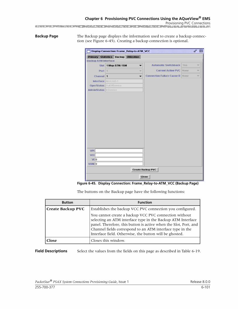
255-700-377 6-101
PacketStar® PSAX System Connections Provisioning Guide, Issue 1 Release 8.0.0
Chapter 6 Provisioning PVC Connections Using the AQueView® EMSProvisioning PVC Connections
Backup Page The Backup page displays the information used to create a backup connec-tion (see Figure 6-45). Creating a backup connection is optional.
The buttons on the Backup page have the following functions:
Field Descriptions Select the values from the fields on this page as described in Table 6-19.
Figure 6-45. Display Connection: Frame_Relay-to-ATM_VCC (Backup Page)
Button Function
Create Backup PVC Establishes the backup VCC PVC connection you configured.
You cannot create a backup VCC PVC connection without selecting an ATM interface type in the Backup ATM Interface panel. Therefore, this button is active when the Slot, Port, and Channel fields correspond to an ATM interface type in the Interface field. Otherwise, the button will be ghosted.
Close Closes this window.

Chapter 6 Provisioning PVC Connections Using the AQueView® EMSProvisioning PVC Connections
6-102 255-700-377
PacketStar® PSAX System Connections Provisioning Guide, Issue 1 Release 8.0.0
Table 6-19. Field Descriptions for the Display Connection: Frame Relay_to_ATM_VCC Backup Page
Field Name Field Values Description
Slot Listed as available from the PSAX device
Select the slot containing the module for which you are creating a backup connection.
Note: This field is display only for the frame relay interface.
Port Determined by the number of ports available on the mod-ule selected in the Slot field
Select the port number on the module for which you are creating a backup connection.
Note: This field is display only for the frame relay interface.
Channel Determined by the number of channels available on the port selected in the Port field
Select the channel number of the port on the module for which you are creating a backup con-nection.
Note: This field is display only for the frame relay interface.
Interface(display only)
AtmUni3-0
AtmUni3-1
IispUser
IispNetwork
CircuitEmulation
DbCirEm
FrameRelayUni
FrameRelayNni
Pri_Isdn_Network
Pri_Isdn_User
HldcPassThrough
AtmPnni1-0
The interface type that is configured on the slot, port, and channel (selected in the Slot, Port, and Channel fields).
OperStatus(display only)
InService Indicates that the interface is operational.
OutOfService Indicates that the interface is not operational.
AdminStatus (display only)
InService Indicates that no conditions are preventing the port from being fully operational.
OutOfService Indicates that some condition is preventing the port from being configured with an interface.
VPI Default: 0 Range: 0–255
The virtual path identifier assigned to this inter-face.
VCI Default: 32 Range: 32–4000
The virtual channel identifier assigned to this interface.
VI Default: 0
Range: 0–255
Virtual interface, which provides bandwidth allo-cation restrictions. Currently available only on the OC-3c APS and STM-1 MSP modules.

255-700-377 6-103
PacketStar® PSAX System Connections Provisioning Guide, Issue 1 Release 8.0.0
Chapter 6 Provisioning PVC Connections Using the AQueView® EMSProvisioning PVC Connections
Automatic Switch-back
Yes (default) CPU monitors primary connection. If primary connection becomes available, backup will switch back connection to primary.
No Not currently supported.
Once active, the backup connection will not switch back to primary connection automatically if primary becomes available.
Current Active PVC None Indicates that the connection is inactive.
Primary Indicates that the primary connection is active (carrying user traffic).
Backup Indicates that the backup connection is active (carrying user traffic).
Table 6-19. Field Descriptions for the Display Connection: Frame Relay_to_ATM_VCC Backup Page
Field Name Field Values Description

Chapter 6 Provisioning PVC Connections Using the AQueView® EMSProvisioning PVC Connections
6-104 255-700-377
PacketStar® PSAX System Connections Provisioning Guide, Issue 1 Release 8.0.0
Utilization Page The Utilization page measures the amount of traffic running through this connection (see Figure 6-46).
Figure 6-46. Display Connection: Frame_Relay-to-ATM (Utilization Page)
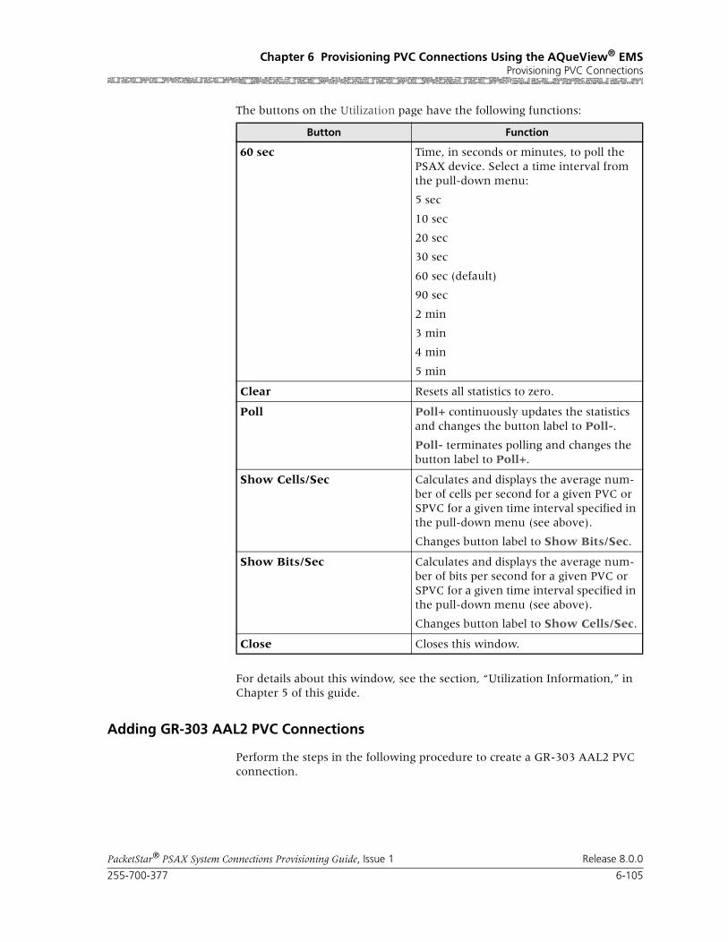
255-700-377 6-105
PacketStar® PSAX System Connections Provisioning Guide, Issue 1 Release 8.0.0
Chapter 6 Provisioning PVC Connections Using the AQueView® EMSProvisioning PVC Connections
The buttons on the Utilization page have the following functions:
For details about this window, see the section, “Utilization Information,” in Chapter 5 of this guide.
Adding GR-303 AAL2 PVC Connections
Perform the steps in the following procedure to create a GR-303 AAL2 PVC connection.
Button Function
60 sec Time, in seconds or minutes, to poll the PSAX device. Select a time interval from the pull-down menu:
5 sec
10 sec
20 sec
30 sec
60 sec (default)
90 sec
2 min
3 min
4 min
5 min
Clear Resets all statistics to zero.
Poll Poll+ continuously updates the statistics and changes the button label to Poll-.
Poll- terminates polling and changes the button label to Poll+.
Show Cells/Sec Calculates and displays the average num-ber of cells per second for a given PVC or SPVC for a given time interval specified in the pull-down menu (see above).
Changes button label to Show Bits/Sec.
Show Bits/Sec Calculates and displays the average num-ber of bits per second for a given PVC or SPVC for a given time interval specified in the pull-down menu (see above).
Changes button label to Show Cells/Sec.
Close Closes this window.

Chapter 6 Provisioning PVC Connections Using the AQueView® EMSProvisioning PVC Connections
6-106 255-700-377
PacketStar® PSAX System Connections Provisioning Guide, Issue 1 Release 8.0.0
Begin
1 From the Site-Specific page, enable the GR-303 feature for your PSAX device.
2 Using one of the following modules (Channelized DS3, Channelized STS1-e, Enhanced DS1, or Medium-Density DS1), create a GR-303 inter-face (the primary interface) including the following:
a Select 12 in the EOC Channel No field.
b Select 24 in the TMC Channel No field.
c Apply the configuration and bring the interface into service.
Note: For the procedure to configure a GR-303 interface, see Chapter 6, “Configuring the Interfaces Using the AQueView® System.“
3 Repeat Step 2 to create a second GR-303 interface (the backup interface).
4 Using the DSP2C Voice Server module, configure the DSP2 interface including the following:
a Select DSP2A in the DSP Mode field.
Compression less than 32 Kbps will not accurately pass tones between subscriber equipment and voice switch.
b Select Standard in the AAL2 Mode field.
c Apply the configuration and bring the interface into service.
Note: For the procedure to configure the DSP2 interface, see the DSP2x Voice Server Modules User Guide.
5 Using the DS3 ATM module, create an ATM interface (IISP, UNI, or PNNI) including the following:
a Select Enabled in the ATM Signaling field.
b Apply the configuration and bring the interface into service.
6 Create an AAL2 trunk for the ATM interfaces created in Step 5, including the following:
a Enter appropriate values in the VPI and VCI fields.
b Select Enabled in the GR303 Support field on the Connection Fea-tures panel.
c Apply the configuration and bring it into service.
Note: When creating the AAL2 trunk connection, ensure that the peak cell rate for the connection needs to be correct as the PSAX Call Admission Control (CAC) function uses this value to determine whether or not a call can be completed to the subscriber line. For the procedure to create an AAL2 trunk connection, see “AAL2 Trunk Configuration” in this chapter.
7 From the GR303 System-Wide tab, create interface group 1, using the primary and backup channel IDs as created in Step 2 and Step 3.

255-700-377 6-107
PacketStar® PSAX System Connections Provisioning Guide, Issue 1 Release 8.0.0
Chapter 6 Provisioning PVC Connections Using the AQueView® EMSProvisioning PVC Connections
Note: For the procedure to configure GR-303 system-wide, see Chapter 4 of the appropriate Navis™ AQueView® Element Management System User Guide.
8 Configure at least two DS1 GR-303 interfaces for an Interface Group (one for primary and one for backup). Primary interface should be assigned as interface ID 1. Bring interface group 1 into service.
9 From the Connections tab, select GR303 for the Side A panel, and the ATM interface created in Step 5 for the Side B panel. Click Create.
The Display Connection window appears, displaying the Primary page (see Figure 6-48 on page 6-108).
Continue with the section, “Primary Page” on page -108.
End
Updating a GR-303 AAL2 PVC Connection
Perform the steps in the following procedure to view or update a GR-303 AAL2 PVC connection.
Begin
1 In the Device window, click the Connections tab.
The Listing page appears.
2 Select a GR-303 AAL2 entry in the Listing page and click the right mouse button.
3 Select Display in the menu that appears (see Figure 6-47).
The Display Connection window appears, displaying the Primary page (see Figure 6-48).
Figure 6-47. Listing Page with GR-303 AAL2 Entry Selected (Displaying Menu)

Chapter 6 Provisioning PVC Connections Using the AQueView® EMSProvisioning PVC Connections
6-108 255-700-377
PacketStar® PSAX System Connections Provisioning Guide, Issue 1 Release 8.0.0
Primary Page The Primary page displays the information used to create the connection.
4 You may edit this connection by selecting the values for the fields in this window as described in Table 6-20.
5 Click Create > Close.
6 To save this connection in the PSAX system configuration database, click Device > Save PSAX Configuration in the Device Menu Bar.
! CAUTION:Select Device > Save PSAX Configuration to permanently save the con-figuration.
Applied, but unsaved, configuration data will not be lost unless the PSAX system is restarted, or if power to the PSAX system is lost. Terminating the AQueView EMS will not cause the applied values to be lost because the con-figuration data is stored on the PSAX system, not in the AQueView EMS.
End
Figure 6-48. Display Connection:GR303_AAL2_PVC_VCC

255-700-377 6-109
PacketStar® PSAX System Connections Provisioning Guide, Issue 1 Release 8.0.0
Chapter 6 Provisioning PVC Connections Using the AQueView® EMSProvisioning PVC Connections
Table 6-20. Field Descriptions for the Display Connection: GR303_AAL2_VCC_PVC Window
Field Name Field Values Description
GR303 Interface Panel
Ig ID Default: 0
Range: 1–84
Format: Numeric
Specifies the interface group identifier number.
Call Reference Default: 0
Range: 1–2048
Format: Numeric
Specifies a number mapped to the customer phone number on a current connection. Used by the system management entity for call status tracking purposes.
[Conn Status](display only)
Default: InactiveFormat: predefined alphanumeric
Specifies whether the connection is active (pass-ing traffic) or inactive (not passing traffic).
Inactive Indicates that the connection is not passing traf-fic.
Active Indicates that the connection is passing traffic.
Interface AAL2 Interface Panel
Slot Default: 0
Range: Chassis depen-dent
Format: Numeric
Specifies the slot in use for the AAL2 trunk side of the connection.
Port Default: 0
Range: Module dependent
Format: Numeric
Specifies the port in use in the slot for the AAL2 side of the connection.
Channel Default: 0Range: Port depen-dent
Format: Numeric
Specifies the channel of the port in use in the slot for the AAL2 side of the connection.
VPI Default: 0
Range: 1–4095
Format: Numeric
Specifies the virtual path indicator.
VCI Default: 0
Range: 1–65535
Format: Numeric
Specifies the virtual channel indicator, a 16-bit field in the ATM cell header identifying the VC in which the data will travel from transmit device to receive device. The VC is located within the vir-tual path.
AAL2 Cid Default: 0
Range: 16–255 (0–15 is reserved)
Format: Numeric
Specifies the AAL2 Channel Identifier. The AAL2 CIDs are located within the VCC.
ConnectionFeatures

Chapter 6 Provisioning PVC Connections Using the AQueView® EMSProvisioning PVC Connections
6-110 255-700-377
PacketStar® PSAX System Connections Provisioning Guide, Issue 1 Release 8.0.0
Note: In the on-hook monitoring state, the CAS refresh rate for all ITU-T profiles below is 5 seconds.
Encoding Profile Default: Itut-profile-1
Range: N/A
Format: predefined alphanumeric
Specifies the ITU-T or ATM Forum parameter set that applies to the connection. A parameter set specifies the compression algorithm used, packet size, whether silence detection is included, and so on. For more information on ATM Forum pro-files, see the reference appendix in this guide.
Note: See the Valid Encoding/Compression Set-tings table following this table for a list of the compression and silence detection settings that are valid for the PSAX system and the CellPipe IAD when they are configured as interoperating devices. See also the ITU-T Transmission Profile Tables in the reference appendix of this guide.
Note: The Cellpipe IAD supports only the follow-ing profiles: ITU-T Standard Profile 1 and ATM Form Standard Profiles 9–11.
Itut-profile-1 Indicates that the connection uses the ITU-T Standard profile-1. This profile supports PCM G.711-64 Kbps (no compression).
Itut-profile-3 Indicates that the connection uses the ITU-T Standard Profile 3. This profile supports ADPCM G.726 at 16, 24, 32, and 40 Kbps compression and silence detection.
Note: The CellPipe IAD does not support this encoding profile.
Itut-profile-7 Indicates that the connection uses the ITU-T Standard Profile 7. This profile supports CS-ACELP G.729 8 Kbps compression and G.729 silence detection.
Note: The CellPipe IAD does not support this encoding profile.
Note: In the on-hook monitoring state, the CAS refresh rate for all ATM Forum profiles below is 5 minutes.
Af-profile-7 Indicates that the connection uses the ATM Form Standard Profile 7. This profile supports PCM-64, ADPCM-32, and silence detection. Data is trans-mitted in 44-octet packets.
Note: The CellPipe IAD does not support this encoding profile.
Table 6-20. Field Descriptions for the Display Connection: GR303_AAL2_VCC_PVC Window
Field Name Field Values Description
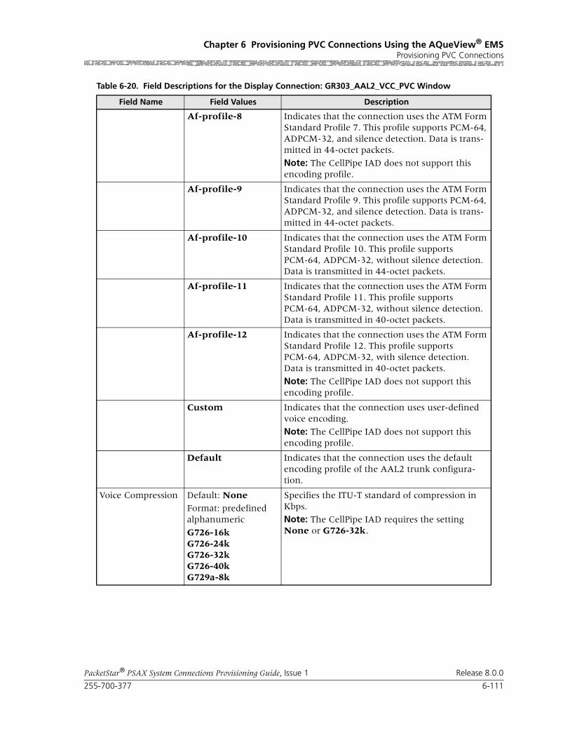
255-700-377 6-111
PacketStar® PSAX System Connections Provisioning Guide, Issue 1 Release 8.0.0
Chapter 6 Provisioning PVC Connections Using the AQueView® EMSProvisioning PVC Connections
Af-profile-8 Indicates that the connection uses the ATM Form Standard Profile 7. This profile supports PCM-64, ADPCM-32, and silence detection. Data is trans-mitted in 44-octet packets.
Note: The CellPipe IAD does not support this encoding profile.
Af-profile-9 Indicates that the connection uses the ATM Form Standard Profile 9. This profile supports PCM-64, ADPCM-32, and silence detection. Data is trans-mitted in 44-octet packets.
Af-profile-10 Indicates that the connection uses the ATM Form Standard Profile 10. This profile supports PCM-64, ADPCM-32, without silence detection. Data is transmitted in 44-octet packets.
Af-profile-11 Indicates that the connection uses the ATM Form Standard Profile 11. This profile supports PCM-64, ADPCM-32, without silence detection. Data is transmitted in 40-octet packets.
Af-profile-12 Indicates that the connection uses the ATM Form Standard Profile 12. This profile supports PCM-64, ADPCM-32, with silence detection. Data is transmitted in 40-octet packets.
Note: The CellPipe IAD does not support this encoding profile.
Custom Indicates that the connection uses user-defined voice encoding.
Note: The CellPipe IAD does not support this encoding profile.
Default Indicates that the connection uses the default encoding profile of the AAL2 trunk configura-tion.
Voice Compression Default: NoneFormat: predefined alphanumeric
G726-16kG726-24kG726-32kG726-40kG729a-8k
Specifies the ITU-T standard of compression in Kbps.
Note: The CellPipe IAD requires the setting None or G726-32k.
Table 6-20. Field Descriptions for the Display Connection: GR303_AAL2_VCC_PVC Window
Field Name Field Values Description

Chapter 6 Provisioning PVC Connections Using the AQueView® EMSProvisioning PVC Connections
6-112 255-700-377
PacketStar® PSAX System Connections Provisioning Guide, Issue 1 Release 8.0.0
Silence Detection Default: Disabled
Range: N/A
Format: predefined alphanumeric
Specifies whether silence detection will be used on this connection or not. You can specify if you want periods of silence in the connection to gen-erate cells or not. To conserve bandwidth, select enabled.
Note: You must select Disabled if using the Cell-Pipe IAD.
Disabled Disables silence detection. Cells will be sent dur-ing silent periods in the connection.
Enabled Enables silence detection. No cells will be sent during silent periods in a connection.
Echo Cancellation Default: None
Range: N/A
Format: predefined alphanumeric
Specifies what type of echo cancellation will be used on the connections. Echo cancellation allows for the isolation and filtering out of unwanted signals caused by echoes from the main transmitted signal. Echo strength is mea-sured in “tails” in msec.
None Echo cancellation is not enabled.
G165-nearEnd ITU-T Standard G.165 (for near end only).
G168 ITU-T Standard G.168.
Note: Select this value for the GR-303 Interface.
Tone Detection Default: Disabled
Range: N/A
Format: predefined alphanumeric
Specifies what kind of fax or modem tone the connection will detect or bypass.
Disabled Disables fax/modem tone detection. The PSAX system reverts to uncompressed processing.
Note: This value is not recommended for GR-303 Interface Interface.
Bypass Bypasses fax/modem tone detection.
Note: This value is recommended for the GR-303 Interface.
Table 6-20. Field Descriptions for the Display Connection: GR303_AAL2_VCC_PVC Window
Field Name Field Values Description
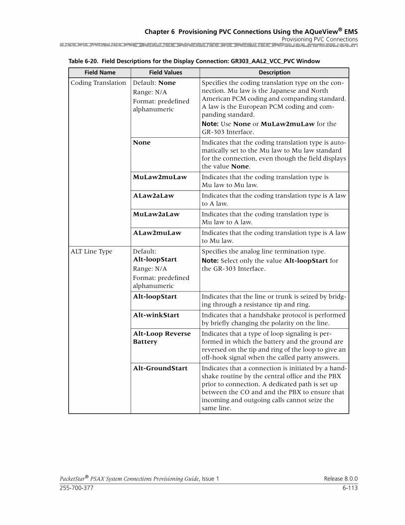
255-700-377 6-113
PacketStar® PSAX System Connections Provisioning Guide, Issue 1 Release 8.0.0
Chapter 6 Provisioning PVC Connections Using the AQueView® EMSProvisioning PVC Connections
Coding Translation Default: None
Range: N/A
Format: predefined alphanumeric
Specifies the coding translation type on the con-nection. Mu law is the Japanese and North American PCM coding and companding standard. A law is the European PCM coding and com-panding standard.
Note: Use None or MuLaw2muLaw for the GR-303 Interface.
None Indicates that the coding translation type is auto-matically set to the Mu law to Mu law standard for the connection, even though the field displays the value None.
MuLaw2muLaw Indicates that the coding translation type is Mu law to Mu law.
ALaw2aLaw Indicates that the coding translation type is A law to A law.
MuLaw2aLaw Indicates that the coding translation type is Mu law to A law.
ALaw2muLaw Indicates that the coding translation type is A law to Mu law.
ALT Line Type Default: Alt-loopStart
Range: N/A
Format: predefined alphanumeric
Specifies the analog line termination type.
Note: Select only the value Alt-loopStart for the GR-303 Interface.
Alt-loopStart Indicates that the line or trunk is seized by bridg-ing through a resistance tip and ring.
Alt-winkStart Indicates that a handshake protocol is performed by briefly changing the polarity on the line.
Alt-Loop ReverseBattery
Indicates that a type of loop signaling is per-formed in which the battery and the ground are reversed on the tip and ring of the loop to give an off-hook signal when the called party answers.
Alt-GroundStart Indicates that a connection is initiated by a hand-shake routine by the central office and the PBX prior to connection. A dedicated path is set up between the CO and and the PBX to ensure that incoming and outgoing calls cannot seize the same line.
Table 6-20. Field Descriptions for the Display Connection: GR303_AAL2_VCC_PVC Window
Field Name Field Values Description

Chapter 6 Provisioning PVC Connections Using the AQueView® EMSProvisioning PVC Connections
6-114 255-700-377
PacketStar® PSAX System Connections Provisioning Guide, Issue 1 Release 8.0.0
Currently, users are allowed to set up a GR303-to-AAL2 connection with combinations of voice compression and silence detection settings that are not valid. Note that only the combinations listed in the following table will work:
Note: When using the PSAX system with the Cellpipe IAD V3.0.0, only the settings in the following table will work:
Adding In-band Management ATM VCC PVC Connections
You can create an in-band management PVC connection between a config-ured in-band management address and any module that supports ATM inter-faces. This connection supports the UBR and VBR-express service types.
The in-band management PVC connection is configured in two steps:
1. Disabling SVC connections in the Site-Specific tab within the Device win-dow
2. Creating the in-band management PVC connection from the Connec-tions tab within the Device window
Perform the steps in the following procedure to create an in-Band manage-ment-to-ATM VCC connection.
Table 6-21. Valid Encoding/Compression Settings
Encoding Profile Voice Compression Silence Detection
Itut-profile-1 none disabled
Itut-profile-3 none enabled
Itut-profile-3 G726-16K enabled
Itut-profile-3 G726-24k enabled
Itut-profile-3 G726-32k enabled
Itut-profile-3 G726-40k enabled
Itut-profile-7 none disabled
Itut-profile-7 G729a-8k disabled
Itut-profile-7 G729a-8k enabled
Af-profile-11 none disabled
Af-profile-11 G726-32k disabled
Table 6-22. Valid Encoding/Compression Settings (Cellpipe IAD V3.0.0)
Encoding Profile Voice Compression Silence Detection
Itut-profile-1 none disabled
Af-profile-11 none disabled
Af-profile-11 G726-32k disabled

255-700-377 6-115
PacketStar® PSAX System Connections Provisioning Guide, Issue 1 Release 8.0.0
Chapter 6 Provisioning PVC Connections Using the AQueView® EMSProvisioning PVC Connections
Disabling an SVC Connection
Begin
1 In the Device window, click the Site-Specific tab.
The Site-Specific page appears (see Figure 6-49).
2 Click the In-Band Mgmt tab.
The In-Band Mgmt page appears (see Figure 6-50).
Figure 6-49. Site Specific Page (Displaying Site-Specific Page)

Chapter 6 Provisioning PVC Connections Using the AQueView® EMSProvisioning PVC Connections
6-116 255-700-377
PacketStar® PSAX System Connections Provisioning Guide, Issue 1 Release 8.0.0
3 In the In-Band Mgmt page, enter the primary in-band management IP address and IP mask for the PSAX device.
Note: This address must be on a different subnet from the subnet that is assigned to the Ethernet interface for the management host.
4 In the SVC Connections field, select Disabled.
5 Click Apply.
6 Save the configuration by clicking Device > Save PSAX Configuration.
! CAUTION:Select Device > Save PSAX Configuration to permanently save the con-figuration.
Figure 6-50. In-Band Mgmt Page

255-700-377 6-117
PacketStar® PSAX System Connections Provisioning Guide, Issue 1 Release 8.0.0
Chapter 6 Provisioning PVC Connections Using the AQueView® EMSProvisioning PVC Connections
Applied, but unsaved, configuration data will not be lost unless the PSAX system is restarted, or if power to the PSAX system is lost. Terminating the AQueView EMS will not cause the applied values to be lost because the con-figuration data is stored on the PSAX system, not in the AQueView EMS.
End
Creating an In-Band-to-ATM Connection
Begin
Creating an In-Band-to-ATM VCC PVC Connection
1 Click the Connections tab.
The Listing page appears.
2 Click the right mouse button and a menu appears. Click Create New.
The Create Connection window appears (see Figure 6-51).
3 On the Side A panel in the Slot field, select In-Band Management.
4 Select the appropriate slot, port, and channel for a module that is config-ured with one of the following interfaces on the Side B panel:
~ ATM UNI 3.0
~ ATM UNI 3.1
~ ATM IISP
~ ATM PNNI
The interface name appears in the Interface field on the Side B panel. In-Band_Management_IP_PVC appears in the Connection Type field.
5 Click Create.
The Create In-Band_to_ATM IP PVC Connection window appears (see Figure 6-52).
6 Enter values for the fields on this window according to the information provided in Table 6-23.
Figure 6-51. Create Connection Window
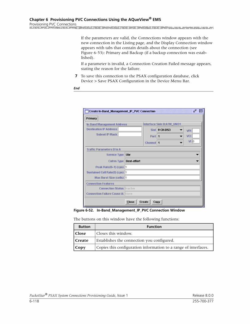
Chapter 6 Provisioning PVC Connections Using the AQueView® EMSProvisioning PVC Connections
6-118 255-700-377
PacketStar® PSAX System Connections Provisioning Guide, Issue 1 Release 8.0.0
If the parameters are valid, the Connections window appears with the new connection in the Listing page, and the Display Connection window appears with tabs that contain details about the connection (see Figure 6-53): Primary and Backup (if a backup connection was estab-lished).
If a parameter is invalid, a Connection Creation Failed message appears, stating the reason for the failure.
7 To save this connection to the PSAX configuration database, click Device > Save PSAX Configuration in the Device Menu Bar.
End
The buttons on this window have the following functions:
Figure 6-52. In-Band_Management_IP_PVC Connection Window
Button Function
Close Closes this window.
Create Establishes the connection you configured.
Copy Copies this configuration information to a range of interfaces.

255-700-377 6-119
PacketStar® PSAX System Connections Provisioning Guide, Issue 1 Release 8.0.0
Chapter 6 Provisioning PVC Connections Using the AQueView® EMSProvisioning PVC Connections
Table 6-23. Field Descriptions for the In-Band ATM PVC Connection Configuration Window
Field Name Field Values Description
Destination IP Address, and Sub-net IP Mask
Default: N/A
Range: Varies
Format: Valid dotted quad
The IP address and the IP mask for one of the fol-lowing depending on your in-band management scheme:
• The in-band IP address of the management workstation. This IP address must be different from the one for the management worksta-tion’s same network.
• The in-band IP address of the “router” PSAX system. This IP address must be different from the one for the Ethernet interface on the CPU module.
• The in-band IP address of the managed PSAX system. This IP address must be different from the one for the Ethernet interface on the CPU module.
Slot, Port, Chan-nel, VI, and VUNI(display only)
Default: N/A
Range: Varies
Format: numeric
The values for slot, port, channel, VPI, VCI, VI, and VUNI for the interface in the PSAX system to which you are connecting.
Service Type Default: UbrRange: N/A
Format: predefined alphanumeric
PSAX system-supported quality of service (QoS) class. For a description of the QoS classes, see the reference appendix in this guide.
Ubr Unspecified bit rate express class of service.
Vbr-express Variable bit rate express class of service.
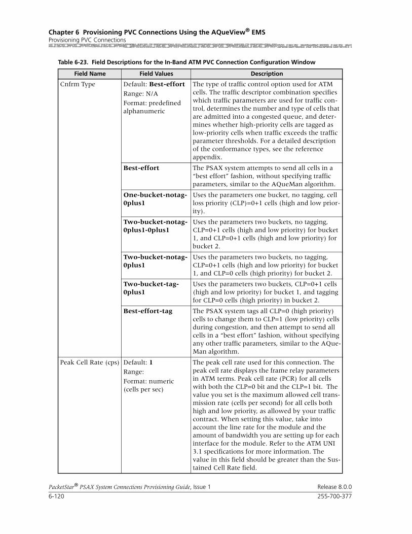
Chapter 6 Provisioning PVC Connections Using the AQueView® EMSProvisioning PVC Connections
6-120 255-700-377
PacketStar® PSAX System Connections Provisioning Guide, Issue 1 Release 8.0.0
Cnfrm Type Default: Best-effort
Range: N/A
Format: predefined alphanumeric
The type of traffic control option used for ATM cells. The traffic descriptor combination specifies which traffic parameters are used for traffic con-trol, determines the number and type of cells that are admitted into a congested queue, and deter-mines whether high-priority cells are tagged as low-priority cells when traffic exceeds the traffic parameter thresholds. For a detailed description of the conformance types, see the reference appendix.
Best-effort The PSAX system attempts to send all cells in a “best effort” fashion, without specifying traffic parameters, similar to the AQueMan algorithm.
One-bucket-notag-0plus1
Uses the parameters one bucket, no tagging, cell loss priority (CLP)=0+1 cells (high and low prior-ity).
Two-bucket-notag-0plus1-0plus1
Uses the parameters two buckets, no tagging, CLP=0+1 cells (high and low priority) for bucket 1, and CLP=0+1 cells (high and low priority) for bucket 2.
Two-bucket-notag-0plus1
Uses the parameters two buckets, no tagging, CLP=0+1 cells (high and low priority) for bucket 1, and CLP=0 cells (high priority) for bucket 2.
Two-bucket-tag-0plus1
Uses the parameters two buckets, CLP=0+1 cells (high and low priority) for bucket 1, and tagging for CLP=0 cells (high priority) in bucket 2.
Best-effort-tag The PSAX system tags all CLP=0 (high priority) cells to change them to CLP=1 (low priority) cells during congestion, and then attempt to send all cells in a “best effort” fashion, without specifying any other traffic parameters, similar to the AQue-Man algorithm.
Peak Cell Rate (cps) Default: 1Range:
Format: numeric (cells per sec)
The peak cell rate used for this connection. The peak cell rate displays the frame relay parameters in ATM terms. Peak cell rate (PCR) for all cells with both the CLP=0 bit and the CLP=1 bit. The value you set is the maximum allowed cell trans-mission rate (cells per second) for all cells both high and low priority, as allowed by your traffic contract. When setting this value, take into account the line rate for the module and the amount of bandwidth you are setting up for each interface for the module. Refer to the ATM UNI 3.1 specifications for more information. The value in this field should be greater than the Sus-tained Cell Rate field.
Table 6-23. Field Descriptions for the In-Band ATM PVC Connection Configuration Window
Field Name Field Values Description

255-700-377 6-121
PacketStar® PSAX System Connections Provisioning Guide, Issue 1 Release 8.0.0
Chapter 6 Provisioning PVC Connections Using the AQueView® EMSProvisioning PVC Connections
Sustained Cell Rate (cps)
Default: 1
Range:
Format: numeric (cells per sec)
The sustained cell rate used for this connection. The sustained cell rate displays the frame relay parameters in ATM terms. Sustainable cell rate (SCR) with CLP=0 (high priority) cells or the peak cell rate with CLP=0 cells. When setting this value, take into account the line rate for the module and the amount of bandwidth you are setting up for each interface for the module. Refer to the ATM UNI 3.1 specifications for more information. The value in this field should be less than the Peak Cell Rate field.
Max Burst Size (cells)
Default: 1Range:
Format: numeric
The maximum burst size used for this connec-tion. The maximum burst size displays the frame relay parameters in ATM terms. Refer to the ATM UNI 3.1 specifications for more information. When setting this value, take into account the line rate for the module and amount of band-width you are setting up for each interface on the module.
Oam Status Default: Unsupp Indicates the current OAM status of this connec-tion.
Unsupp OAM is not used in this connection.
End-Pt The PSAX system is used as a termination point for ATM traffic, and is processing AIS/RDI cells. The OAM loopback test is supported for only end-to-end connections. Enabling OAM status on an in-band management ATM interface means that in-band management will bring the particu-lar interface into service or out of service based on the OAM alarms.
End-Seg-Pt End-Seg-Pt is an connection endpoint and the endpoint of the segment; it will catch the seg-ment and end-to-end OAM cells. Enabling OAM status on an in-band management ATM interface means that in-band management will bring the particular interface in service or out of service based on the OAM alarms.
Table 6-23. Field Descriptions for the In-Band ATM PVC Connection Configuration Window
Field Name Field Values Description
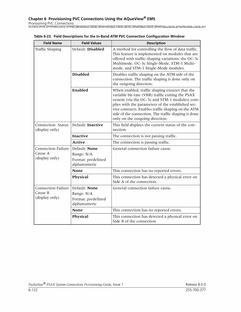
Chapter 6 Provisioning PVC Connections Using the AQueView® EMSProvisioning PVC Connections
6-122 255-700-377
PacketStar® PSAX System Connections Provisioning Guide, Issue 1 Release 8.0.0
Traffic Shaping Default: Disabled A method for controlling the flow of data traffic. This feature is implemented on modules that are offered with traffic-shaping variations: the OC-3c Multimode, OC-3c Single-Mode, STM-1 Multi-mode, and STM-1 Single-Mode modules.
Disabled Disables traffic shaping on the ATM side of the connection. The traffic shaping is done only on the outgoing direction.
Enabled When enabled, traffic shaping ensures that the variable bit-rate (VBR) traffic exiting the PSAX system (via the OC-3c and STM-1 modules) com-plies with the parameters of the established ser-vice contracts. Enables traffic shaping on the ATM side of the connection. The traffic shaping is done only on the outgoing direction.
Connection Status(display only)
Default: Inactive This field displays the current status of the con-nection.
Inactive The connection is not passing traffic.
Active The connection is passing traffic.
Connection Failure Cause A(display only)
Default: None
Range: N/A
Format: predefined alphanumeric
General connection failure cause.
None This connection has no reported errors.
Physical This connection has detected a physical error on Side A of the connection.
Connection Failure Cause B(display only)
Default: NoneRange: N/A
Format: predefined alphanumeric
General connection failure cause.
None This connection has no reported errors.
Physical This connection has detected a physical error on Side B of the connection.
Table 6-23. Field Descriptions for the In-Band ATM PVC Connection Configuration Window
Field Name Field Values Description

255-700-377 6-123
PacketStar® PSAX System Connections Provisioning Guide, Issue 1 Release 8.0.0
Chapter 6 Provisioning PVC Connections Using the AQueView® EMSProvisioning PVC Connections
Primary Page The Primary page displays the information used to create the connection. See Table 6-23 for field descriptions.
The buttons on the Primary page have the following functions:
Backup Page The Backup page displays the information used to create a backup connec-tion (see Figure 6-54). Creating a backup connection is optional.
Begin
1 Enter the values in the fields on this window according to the informa-tion provided in Table 6-24.
2 To save this configuration to the PSAX configuration database, click Device > Save PSAX Configuration in the Device Menu Bar.
End
Figure 6-53. Display Connection: In-Band_Management_IP_PVC (Primary Page)
Button Function
Close Closes this window.
Create Establishes the connection youconfigured.
Copy Copies this configuration information to a range of interfaces.
Delete Deletes the connection.
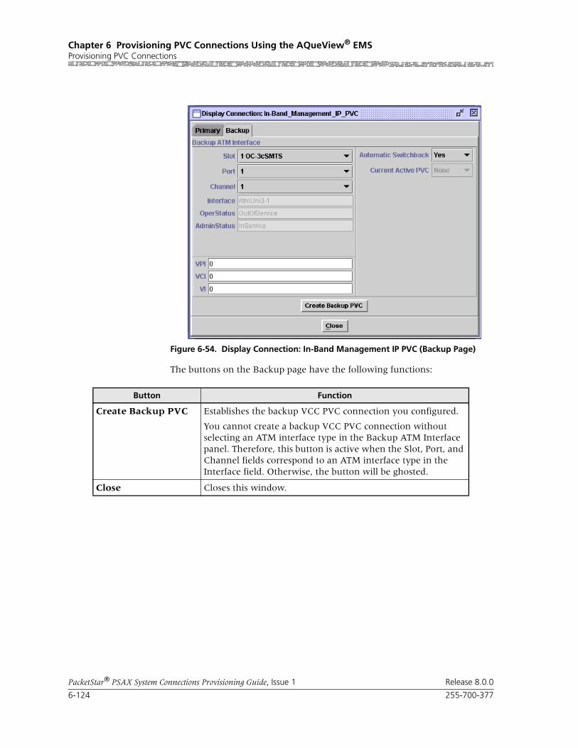
Chapter 6 Provisioning PVC Connections Using the AQueView® EMSProvisioning PVC Connections
6-124 255-700-377
PacketStar® PSAX System Connections Provisioning Guide, Issue 1 Release 8.0.0
The buttons on the Backup page have the following functions:
Figure 6-54. Display Connection: In-Band Management IP PVC (Backup Page)
Button Function
Create Backup PVC Establishes the backup VCC PVC connection you configured.
You cannot create a backup VCC PVC connection without selecting an ATM interface type in the Backup ATM Interface panel. Therefore, this button is active when the Slot, Port, and Channel fields correspond to an ATM interface type in the Interface field. Otherwise, the button will be ghosted.
Close Closes this window.

255-700-377 6-125
PacketStar® PSAX System Connections Provisioning Guide, Issue 1 Release 8.0.0
Chapter 6 Provisioning PVC Connections Using the AQueView® EMSProvisioning PVC Connections
Table 6-24. Field Descriptions for the Display Connection: In-Band_Management_IP_PVC Backup Page
Field Name Field Values Description
Slot
(display only)
Listed as available from the PSAX device
Select the slot containing the module for which you are creating a backup connection.
Port
(display only)
Determined by the number of ports available on the mod-ule selected in the Slot field
Select the port number on the module for which you are creating a backup connection.
Channel
(display only)
Determined by the number of channels available on the port selected in the Port field
Select the channel number of the port on the module for which you are creating a backup con-nection.
Interface
(display only)
AtmUni3_0
AtmUni3_1
AtmUni4_0
IispUser
IispNetwork
CircuitEmulation
DbCirEm
FrameRelayUni
FrameRelayNni
Pri_Isdn_Network
Pri_Isdn_User
HldcPassThrough
AtmPnni1-0
The interface type that is configured on the slot, port, and channel (selected in the Slot, Port, and Channel fields).
OperStatus (display only)
InService Indicates that the interface is operational.
OutOfService Indicates that the interface is not operational.
AdminStatus
(display only)
InService Indicates that no conditions are preventing the port from being fully operational.
OutOfService Indicates that some condition is preventing the port from being configured with an interface.
VPI Default: 0 Range: 0–255
The virtual path identifier assigned to this inter-face.
VCI Default: 32 Range: 32–4000
The virtual channel identifier assigned to this interface.
VI Default: 0
Range: 0-255
Virtual interface, which provides bandwidth allo-cation restrictions. Currently available only on the OC-3c APS, and STM-1 MSP modules.

Chapter 6 Provisioning PVC Connections Using the AQueView® EMSProvisioning PVC Connections
6-126 255-700-377
PacketStar® PSAX System Connections Provisioning Guide, Issue 1 Release 8.0.0
Adding VBR-to-ATM VCC PVC Connections
Perform the steps in the following procedure to create a VBR-to-ATM VCC PVC connection.
Begin
Note: On the DS1 IMA and E1 IMA modules, PVC connections must be provisioned on the virtual port (port 7). You can use any one of the three channels on port 7 to create this connection (the channels you provision on port 7.)
Note: On the DS3 IMA module, you must provision PVC connections on the virtual port (port 30). You can use up to 14 channels on port 30 (the channels you provision on port 30.)
1 In the Device window, click the Connections tab.
The Listing page appears.
2 Click the right mouse button and a menu appears. Click Create New.
Automatic Switch-back
Yes (default) CPU monitors primary connection. If primary connection becomes available, backup will switch back connection to primary.
No Not currently supported.
Once active, the backup connection will not switch back to primary connection automatically if primary becomes available.
Current Active PVC None Indicates that the connection is inactive.
Primary Indicates that the primary connection is active (carrying user traffic).
Backup Indicates that the backup connection is active (carrying user traffic).
Table 6-24. Field Descriptions for the Display Connection: In-Band_Management_IP_PVC Backup Page
Field Name Field Values Description

255-700-377 6-127
PacketStar® PSAX System Connections Provisioning Guide, Issue 1 Release 8.0.0
Chapter 6 Provisioning PVC Connections Using the AQueView® EMSProvisioning PVC Connections
The Create Connection window is displayed (see Figure 6-55).
3 Select the appropriate slot, port, and channel for a module that is config-ured with one of the following interfaces for Side A:
~ HDLC Passthrough
~ Terminal Emulation
The interface name is displayed at the bottom.
4 Select a slot, port, and channel on Side B that is configured with an ATM interface (ATM UNI, ATM IISP, or ATM PNNI).
5 Once the desired connection type is displayed in the Connection Type field, click Create to begin creating the connection.
Figure 6-55. Create Connection Window

Chapter 6 Provisioning PVC Connections Using the AQueView® EMSProvisioning PVC Connections
6-128 255-700-377
PacketStar® PSAX System Connections Provisioning Guide, Issue 1 Release 8.0.0
The Create VBR_to_ATM VCC Connection window is displayed (see Figure 6-56).
The buttons on this window have the following functions:
Field Descriptions 6 Select the values for the fields on this window from the values given in Table 6-25.
Figure 6-56. Create VBR_to_ATM VCC Connection Window
Button Function
Close Closes this window.
Create Establishes the connection you configured.
Copy Copies this configuration information to a range of interfaces.

255-700-377 6-129
PacketStar® PSAX System Connections Provisioning Guide, Issue 1 Release 8.0.0
Chapter 6 Provisioning PVC Connections Using the AQueView® EMSProvisioning PVC Connections
Table 6-25. Field Descriptions for the VBR-to-ATM _VCC Connection Window
Field Names Field Values Description
Interface SideA:HDLC_PASSTHRU
Default: N/A
Range: N/A
Format: Predefined
Indicates the VBR side of the connection that will send and receive signals.
Interface SideB: ATM_UNI30, ATM_UNI31, ATM_UNI40, IISP_USER, IISP_NETWORK, ATMPNNI1_0
Default: N/A
Range: N/A
Format: Predefined
Indicates the ATM side of the connection that will send and receive signals.
Slot Default: N/ARange: (Varies depending on chassis type)
Format: Numeric
Indicates the slot. Select the slot number contain-ing the module for both sides of the connection.
Port Default: 0
Range: 1–28, depend-ing on the type of module selected
Format: Numeric
Indicates the port. Select the port number con-taining the module for both sides of the connec-tion.
Channel Default: 1
Range: 1–32, depend-ing on the type of module selected
Format: Numeric
Indicates the channel. Select the channel number on which you are creating a connection.
VPI Default: 0Range: 0–225 (ATM UNI); 0–4095 (NNI)
Format: Numeric
Indicates the virtual path identifier. Enter a value for both sides of the connection.
VCI Default: 0
Range: 32– 65535
Format: Numeric
Indicates the virtual channel identifier. Enter a value for both sides of the connection.
VI/VUNI Default: 0
Range: 0–255
Format: Numeric
Indicates the virtual interface/Virtual ATM UNI, which provides bandwidth allocation restrictions. Currently available only on the OC-3c APS and STM-1 MSP modules. When disabled, default is 0.The virtual UNI (VUNI) associates itself with the egress part of the A2B or B2A side of the connec-tion.

Chapter 6 Provisioning PVC Connections Using the AQueView® EMSProvisioning PVC Connections
6-130 255-700-377
PacketStar® PSAX System Connections Provisioning Guide, Issue 1 Release 8.0.0
Peak Cell Rate (cps) Default: 1
Range: 1–(232-1)(theoretical range, except for modules noted at right, see Description column)
Range:
Format: numeric (cells per second)
Peak cell rate (PCR) for all cells with both the CLP=0 bit and the CLP=1 bit. The value you set is the maximum allowed cell transmission rate (cells per second) for all cells both high and low priority, as allowed by your traffic contract.
When setting this value, take into account the line rate for the module and the amount of band-width you are setting up for each interface for the module. Refer to the ATM UNI 3.1 specifications for more information. If you select the value SimplexA2B in the Traffic Flow field, set the value of this field to 0. The value in this field should be greater than the Sustained Cell Rate field.
Note: If you are using the traffic shaping Enabled setting on the bulleted modules listed below, entering a minimum cps value below the mini-mum listed below will cause traffic-shaped con-nections to default back to the minimum cps value when the connection passes traffic.
• On the 1-Port OC-3c MM/SM and the 1-Port STM-1 MM/SM, the cps range is 18–999999999.
• On the OC-12c/STM-4c SM/MM, the cps range is 87–999999999.
• On the 3-Port DS3/E3 ATM, the cps range is 7–999999999.
Note: The peak cell rate cannot exceed the maxi-mum cell rate for the interface.
If you need to calculate ingress PCRs for the OC-3c APS or the STM-1 MSP modules, see the PCR Determination Formula in the Reference Appendix of either module’s User Guide.
Sustained Cell Rate (cps)
Default: 1
Range: 0–999999999
Format: cps
Sustainable cell rate (SCR) with CLP=0 (high pri-ority) cells or the peak cell rate with CLP=0 cells.
When setting this value, take into account the line rate for the module and the amount of band-width you are setting up for each interface for the module. Refer to the ATM UNI 3.1 specifications for more information. If you select the value SimplexA2B in the Traffic Flow field, set the value of this field to 0. The value in this field should be less than the Peak Cell Rate field.
Table 6-25. Field Descriptions for the VBR-to-ATM _VCC Connection Window
Field Names Field Values Description

255-700-377 6-131
PacketStar® PSAX System Connections Provisioning Guide, Issue 1 Release 8.0.0
Chapter 6 Provisioning PVC Connections Using the AQueView® EMSProvisioning PVC Connections
Max Burst Size (cells)
Default: 1
Range: 0–999999999
Format: cps
Maximum burst size. The maximum number of cells that can be received at the peak cell rate. This allows a burst of cells to arrive at a rate higher than that of the sustained cell rate. If the burst is larger than anticipated, the additional cells are either tagged or dropped. When setting this value, take into account the line rate for the module and the amount of bandwidth you are setting up for each interface for the module. Refer to the ATM UNI 3.1 specifications for more information.
If you select the value SimplexA2B in the Traffic Flow field, set the value of this field to 0.
OC-3c APS Module: When the Traffic Shaping field is set to Enabled, the cell queue depth for the Max Burst Size field is internally set to 1000, regardless of the value you enter. If you enter values other than 1000, these values matter for incoming signalling SPVC/SVC setup from the remote end of the connection.
Traffic Shaping Default: Disabled
Range: As noted below.
Format: Predefined
Indicates the method for controlling the flow of data traffic. This feature is implemented on the following modules:
• 1-Port OC-3c Multimode and Single-Mode with Traffic Shaping modules
• 1-Port STM-1 Multimode and Single-Mode with Traffic Shaping modules
• 3-Port DS3/E3 ATM
• 1-Port OC-12c/STM-4c MM/SM 1+1 APS/MSP modules
See the Peak Rate field on this table for minimum cps ranges restrictions on these modules.
Disabled Indicates that traffic shaping is not done on the ATM side of the connection.
Enabled Ensures that the variable bit-rate (VBR) traffic entering the PSAX system via these modules complies with the parameters of the established service contracts.
Table 6-25. Field Descriptions for the VBR-to-ATM _VCC Connection Window
Field Names Field Values Description

Chapter 6 Provisioning PVC Connections Using the AQueView® EMSProvisioning PVC Connections
6-132 255-700-377
PacketStar® PSAX System Connections Provisioning Guide, Issue 1 Release 8.0.0
Cnfrm Type
(displayed on the Traffic Parameters B to A panel)
Default: Best-effort
Range: N/A
Format: Predefined
The type of traffic control option used for ATM cells. The traffic descriptor combination specifies which traffic parameters are used for traffic con-trol, determines the number and type of cells that are admitted into a congested queue, and deter-mines whether high-priority cells are tagged as low-priority cells when traffic exceeds the traffic parameter thresholds.
See the Reference Appendix for a detailed description of the field values, including repre-sentative examples.
Best-effort This traffic descriptor allows the system to attempt to send all cells in a “best effort” fashion, without specifying traffic parameters, similar to the AQueMan algorithm.
One-bucket-notag-0plus1
This traffic descriptor uses the parameters one bucket, no tagging, cell loss priority (CLP)=0+1 cells (high and low priority).
Two-bucket-notag-0plus1-0plus1
This traffic descriptor uses the parameters two buckets, no tagging, CLP=0+1 cells (high and low priority) for bucket 1, and CLP=0+1 cells (high and low priority) for bucket 2.
Two-bucket-notag-0plus1
This traffic descriptor uses the parameters two buckets, no tagging, CLP=0+1 cells (high and low priority) for bucket 1, and CLP=0 cells (high pri-ority) for bucket 2.
Two-bucket-tag-0plus1
This traffic descriptor uses the parameters two buckets, CLP=0+1 cells (high and low priority) for bucket 1, and tagging for CLP=0 cells (high priority) in bucket 2.
Best-effort-tag This traffic descriptor allows the system to tag all CLP=0 (high priority) cells to change them to CLP=1 (low priority) cells during congestion, and then attempt to send all cells in a “best effort” fashion, without specifying any other traffic parameters, similar to the AQueMan algorithm.
Service Type Default: Ubr
Range: N/A
Format: Predefined
Vbr-nrt2,Vbr-nrt1,Vbr-rt2,Vbr-rt1,Vbr-express
Multiservice Media Gateway system-supported quality of service (QoS) class.
See the section, “Quality of Service Classes for ATM Traffic,” in the Reference Appendix in the appropriate User Guide for a detailed description of the values for this field, including representa-tive examples.
Table 6-25. Field Descriptions for the VBR-to-ATM _VCC Connection Window
Field Names Field Values Description

255-700-377 6-133
PacketStar® PSAX System Connections Provisioning Guide, Issue 1 Release 8.0.0
Chapter 6 Provisioning PVC Connections Using the AQueView® EMSProvisioning PVC Connections
Traffic Flow Default: Duplex
Range: N/A
Format: Predefined
Direction of the flow of data traffic in this con-nection.
When you select SimplexA2B or SimplexB2A, the fields in the Traffic Parameters B to A or the Traffic Parameters A to B panels, respectively, are not displayed.
Duplex Traffic flows back and forth between termination A and B.
SimplexA2B Traffic flows from termination A to B only.
SimplexB2A Traffic flows from termination B to A only.
SAR Type Default: AAL5
Range: N/A
Format: Predefined
Indicates which Segmentation and Reassembly algorithm is used. SAR is used to convert larger unfilled packets to smaller filled packets before transmission, a process that conserves transmis-sion bandwidth. A packet size re-conversion pro-cess to the original packet size occurs at the receive end.
AAL5 VBR, connection-oriented, delay tolerant data.
AAL2Std Standard AAL2. VBR, delay-intolerant data with compression.
None No AAL layer parameters used.
OAM Status Default: UnsuppRange: N/A
Range: Predefined
Indicates on what portion of the connection OAM cells (AIS, RDI) are processed.
Unsupp OAM is not supported.
End-Pt The PSAX system is used as a termination point for ATM traffic, and will process AIS/RDI cells.
The OAM loopback test is supported for end-to-end connections only.
Seg-Pt. Segment point. The A side will only respond to aintenance OAM cells and fault cells.
End-Seg-Pt End segment point, which has the characteristics of both an end point and a segment point.
Intermediate-Pt Side A will only generate AISs during local fail-ure.
Intra-Segment-Pt Connecting point with a segment. Generates end-to-end as well as segment flows.
Table 6-25. Field Descriptions for the VBR-to-ATM _VCC Connection Window
Field Names Field Values Description

Chapter 6 Provisioning PVC Connections Using the AQueView® EMSProvisioning PVC Connections
6-134 255-700-377
PacketStar® PSAX System Connections Provisioning Guide, Issue 1 Release 8.0.0
If the parameters are valid, the Connections window appears with the new connection in the Listing page, and the Display Connection window appears with tabs that contain details about the connection (see Figure 6-57): Primary, Statistics, and Backup.
If a parameter is invalid, a Connection Creation Failed message appears, stating the reason for the failure.
End
Connection Status (display only)
Default: Inactive
Range: Inactive/Active
Format: Predefined
Indicates whether or not the connection is trans-mitting traffic.
Inactive The connection is not transmitting traffic.
Active The connection is transmitting traffic.
Connection Failure Cause A(display only)
Default: None
Range: N/A
Format: Predefined
General connection failure cause.
None Indicates that no failure is present.
Physical Indicates that a physical level failure is present, such as when a an I/O module or cable is removed from the PSAX device, or an I/O mod-ule receives an LOS or LOF alarm. This changes the operational status of the interface to Outof-Service.
Connection Failure Cause B(display only)
Default: None
Range: N/A
Format: Predefined
General connection failure cause.
None Indicates that no failure is present.
Physical Indicates that a physical level failure is present, such as when a an I/O module or cable is removed from the PSAX device, or an I/O mod-ule receives an LOS or LOF alarm. This changes the operational status of the interface to Outof-Service.
Table 6-25. Field Descriptions for the VBR-to-ATM _VCC Connection Window
Field Names Field Values Description

255-700-377 6-135
PacketStar® PSAX System Connections Provisioning Guide, Issue 1 Release 8.0.0
Chapter 6 Provisioning PVC Connections Using the AQueView® EMSProvisioning PVC Connections
Primary Page The Primary page displays the information used to create the connection. See Table 6-25 for field descriptions.
The buttons on the Primary page have the following functions:
Statistics Page The Statistics page displays the statistics for this connection (see Figure 6-58).
Figure 6-57. Display Connection: VBR-to-ATM_VCC Window (Primary Page)
Button Function
Close Closes this window.
Create Establishes the connection youconfigured.
Copy Copies this configuration information to a range of interfaces.
Delete Deletes the connection.

Chapter 6 Provisioning PVC Connections Using the AQueView® EMSProvisioning PVC Connections
6-136 255-700-377
PacketStar® PSAX System Connections Provisioning Guide, Issue 1 Release 8.0.0
The buttons on the Statistics page have the following functions:
Figure 6-58. Display Connection: VBR-to-ATM_VCC Window (Statistics Page)
Button Description
Update Refreshes the statistics manually.
Clear Resets the resetable statistics to zero.
Poll Poll + continuously update the statistics and changes the button label to Poll-.
Poll- terminates polling and changes the button label to Poll+.
Odometer Restarts counting in the Cells Transmitted and Cells Received fields iin the Interface Side A and Interface Side B panels, and to view the trans-mitted cells and received cells in the Interface Side A and Interface Side B panels. This button is displayed only on the ATM-to-ATM VCC PVC and ATM-to-ATM VPC PVC Statistics pages.

255-700-377 6-137
PacketStar® PSAX System Connections Provisioning Guide, Issue 1 Release 8.0.0
Chapter 6 Provisioning PVC Connections Using the AQueView® EMSProvisioning PVC Connections
Field Descriptions The fields on this window are described in Table 6-26:
Close Closes this window.
Restart Restarts connection establishment procedure for the connections that were not previously set up.
Button Description
Table 6-26. Field Descriptions for the VBR-to-ATM VCC PVC/SPVC Connection Statistics Page
Field Name Field Values Description
Interface A Statistics Panel
Cells Encoded(display only)
Default: 0.0000 e0Range: N/A
Format: Exponent notation
Number of cells encoded going into interface side Aor B during the amount of time shown in Time Elapsed field since the circuit was established.
Cells Decoded(display only)
Default: 0.0000 e0
Range: N/A
Format: Exponent notation
Number of cells decoded going out of interface side A during the amount of time shown in Time Elapsed field since the circuit was established.
Encoded Odometer(display only)
Default: 0.0000 e0
Range: N/A
Format: Exponent notation
On the Interface A Statistics panel, the number of cells encoded going into interface side A since this counter was reset.
On the Interface B Statistics panel, the number of cells encoded going into interface side B since this counter was reset.
Decoded Odometer(display only)
Default: 0
Range: N/A
Format: Exponent notation
On the Interface A Statistics panel, the number of cells decoded going out of interface side A since this counter was reset.
On the Interface B Statistics panel, the number of cells decoded going out of interface side B since this counter was reset.
Time Elapsed(display only)
Default: 0
Range: N/A
Format: Numeric
Time elapsed since the circuit was established.
Cells Received(display only)
Default: 0Range: N/A
Format: Numeric
Number of cells encoded going into interface side B during the amount of time shown in Time Elapsed field since the circuit was established.
Cells Transmited(display only)
Default: 0
Range: N/A
Format: Numeric
Number of cells decoded going out of interface side B during the amount of time shown in Time Elapsed field since the circuit was established.
In Odometer(display only)
Default: 0
Range: N/A
Format: Numeric
Total number of cells encoded going into inter-face side B since the connection statistics were reset.
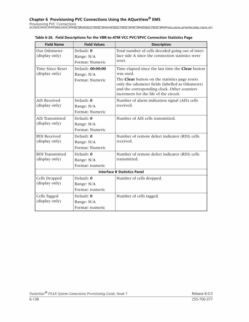
Chapter 6 Provisioning PVC Connections Using the AQueView® EMSProvisioning PVC Connections
6-138 255-700-377
PacketStar® PSAX System Connections Provisioning Guide, Issue 1 Release 8.0.0
Out Odometer(display only)
Default: 0
Range: N/A
Format: Numeric
Total number of cells decoded going out of inter-face side A since the connection statistics were reset.
Time Since Reset(display only)
Default: 00:00:00Range: N/A
Format: Numeric
Time elapsed since the last time the Clear button was used.
The Clear button on the statistics page resets only the odometer fields (labelled as Odometer) and the corresponding clock. Other counters increment for the life of the circuit.
AIS Received(display only)
Default: 0
Range: N/A
Format: Numeric
Number of alarm indication signal (AIS) cells received.
AIS Transmitted(display only)
Default: 0Range: N/A
Format: Numeric
Number of AIS cells transmitted.
RDI Received(display only)
Default: 0
Range: N/A
Format: Numeric
Number of remote defect indicator (RDI) cells received.
RDI Transmitted(display only)
Default: 0
Range: N/A
Format: numeric
Number of remote defect indicator (RDI) cells transmitted.
Interface B Statistics Panel
Cells Dropped(display only)
Default: 0Range: N/A
Format: numeric
Number of cells dropped.
Cells Tagged(display only)
Default: 0
Range: N/A
Format: numeric
Number of cells tagged.
Table 6-26. Field Descriptions for the VBR-to-ATM VCC PVC/SPVC Connection Statistics Page
Field Name Field Values Description
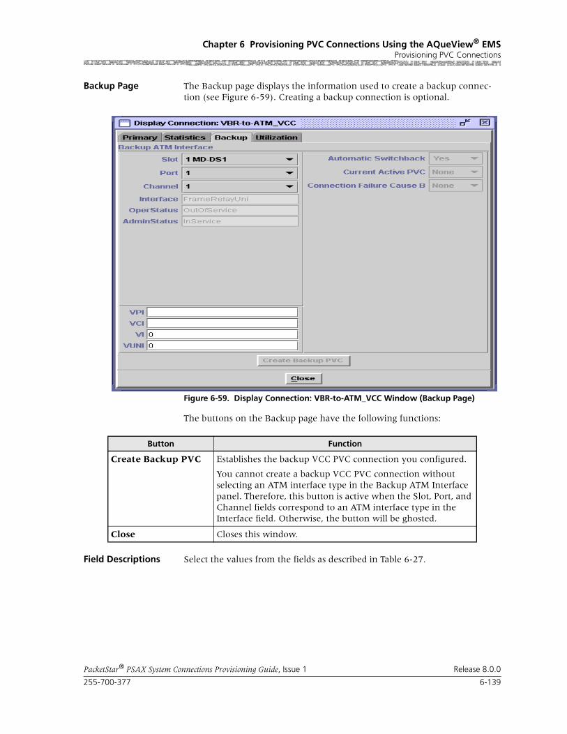
255-700-377 6-139
PacketStar® PSAX System Connections Provisioning Guide, Issue 1 Release 8.0.0
Chapter 6 Provisioning PVC Connections Using the AQueView® EMSProvisioning PVC Connections
Backup Page The Backup page displays the information used to create a backup connec-tion (see Figure 6-59). Creating a backup connection is optional.
The buttons on the Backup page have the following functions:
Field Descriptions Select the values from the fields as described in Table 6-27.
Figure 6-59. Display Connection: VBR-to-ATM_VCC Window (Backup Page)
Button Function
Create Backup PVC Establishes the backup VCC PVC connection you configured.
You cannot create a backup VCC PVC connection without selecting an ATM interface type in the Backup ATM Interface panel. Therefore, this button is active when the Slot, Port, and Channel fields correspond to an ATM interface type in the Interface field. Otherwise, the button will be ghosted.
Close Closes this window.
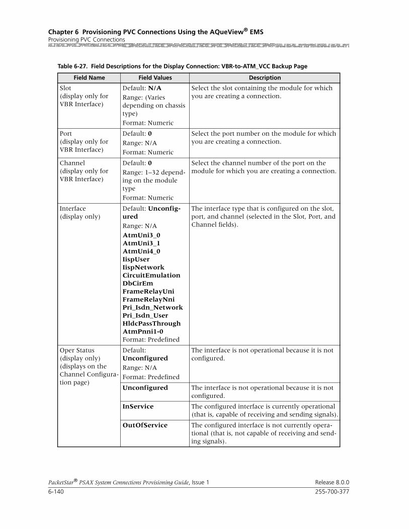
Chapter 6 Provisioning PVC Connections Using the AQueView® EMSProvisioning PVC Connections
6-140 255-700-377
PacketStar® PSAX System Connections Provisioning Guide, Issue 1 Release 8.0.0
Table 6-27. Field Descriptions for the Display Connection: VBR-to-ATM_VCC Backup Page
Field Name Field Values Description
Slot(display only for VBR Interface)
Default: N/A
Range: (Varies depending on chassis type)
Format: Numeric
Select the slot containing the module for which you are creating a connection.
Port(display only for VBR Interface)
Default: 0
Range: N/A
Format: Numeric
Select the port number on the module for which you are creating a connection.
Channel(display only for VBR Interface)
Default: 0
Range: 1–32 depend-ing on the module type
Format: Numeric
Select the channel number of the port on the module for which you are creating a connection.
Interface(display only)
Default: Unconfig-uredRange: N/A
AtmUni3_0AtmUni3_1AtmUni4_0IispUserIispNetworkCircuitEmulation DbCirEmFrameRelayUniFrameRelayNniPri_Isdn_NetworkPri_Isdn_UserHldcPassThroughAtmPnni1-0Format: Predefined
The interface type that is configured on the slot, port, and channel (selected in the Slot, Port, and Channel fields).
Oper Status(display only)(displays on the Channel Configura-tion page)
Default: Unconfigured
Range: N/A
Format: Predefined
The interface is not operational because it is not configured.
Unconfigured The interface is not operational because it is not configured.
InService The configured interface is currently operational (that is, capable of receiving and sending signals).
OutOfService The configured interface is not currently opera-tional (that is, not capable of receiving and send-ing signals).

255-700-377 6-141
PacketStar® PSAX System Connections Provisioning Guide, Issue 1 Release 8.0.0
Chapter 6 Provisioning PVC Connections Using the AQueView® EMSProvisioning PVC Connections
Admin Status(display only)(displays on the Channel Configura-tion page)
Default: OutofService
Range: N/A
Format: Predefined
Indicates the whether a user has attempted to bring this channel into service.
OutOfService The interface has not yet been brought into ser-vice, or in-service interface has been set to out of service with the Take Out of Service button.
InService The interface has been brought into service with the Bring Into Service button.
VPI Default: 0Range: 0–255
Format: Numeric
The virtual path identifier assigned to this inter-face.
VCI Default: 32
Range: 32–4000
Format: Numeric
The virtual channel identifier assigned to this interface.
VI Default: 0
Range: 0-255
Format: Numeric
Virtual interface, which provides bandwidth allo-cation restrictions. Currently available only on the OC-3c APS and STM-1 MSP modules.
Automatic Switchback
Default: YesRange: N/A
Format: Predefined
The CPU monitors primary connection. If pri-mary connection becomes available, backup will switch back connection to primary.
Yes Once active, the backup connection will switch back to primary connection automatically if pri-mary becomes available.
No Not currently supported.
Once active, the backup connection will not switch back to primary connection automatically if primary becomes available.
Current Active PVC Default: NoneRange: N/A
Format: Predefined
Indicates whether the primary or backup PVC connection is active or not.
None Neither the primary or backup PVC connection is active.
Primary Indicates that the primary connection is active (carrying user traffic).
Backup Indicates that the backup connection is active (carrying user traffic).
Table 6-27. Field Descriptions for the Display Connection: VBR-to-ATM_VCC Backup Page
Field Name Field Values Description

Chapter 6 Provisioning PVC Connections Using the AQueView® EMSProvisioning PVC Connections
6-142 255-700-377
PacketStar® PSAX System Connections Provisioning Guide, Issue 1 Release 8.0.0
Utilization Page The Utilization page measures the amount of traffic running through this connection (see Figure 6-60).
Figure 6-60. Display Connection: VBR-to-ATM (Utilization Page)
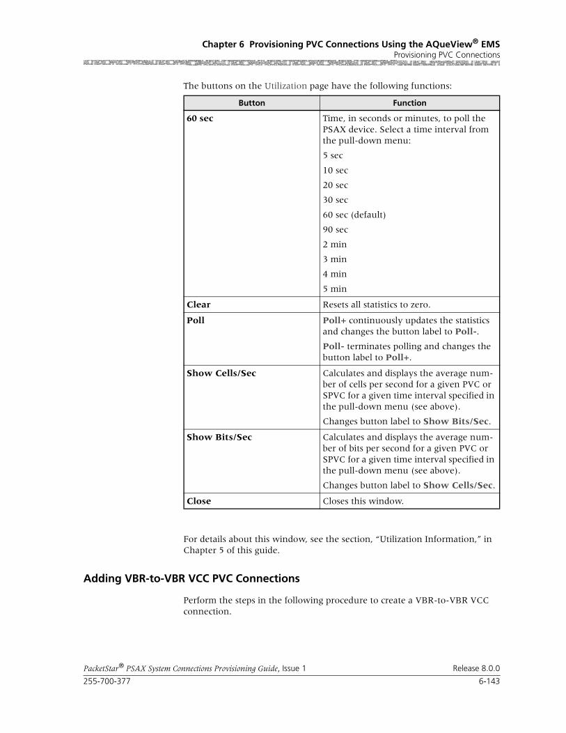
255-700-377 6-143
PacketStar® PSAX System Connections Provisioning Guide, Issue 1 Release 8.0.0
Chapter 6 Provisioning PVC Connections Using the AQueView® EMSProvisioning PVC Connections
The buttons on the Utilization page have the following functions:
For details about this window, see the section, “Utilization Information,” in Chapter 5 of this guide.
Adding VBR-to-VBR VCC PVC Connections
Perform the steps in the following procedure to create a VBR-to-VBR VCC connection.
Button Function
60 sec Time, in seconds or minutes, to poll the PSAX device. Select a time interval from the pull-down menu:
5 sec
10 sec
20 sec
30 sec
60 sec (default)
90 sec
2 min
3 min
4 min
5 min
Clear Resets all statistics to zero.
Poll Poll+ continuously updates the statistics and changes the button label to Poll-.
Poll- terminates polling and changes the button label to Poll+.
Show Cells/Sec Calculates and displays the average num-ber of cells per second for a given PVC or SPVC for a given time interval specified in the pull-down menu (see above).
Changes button label to Show Bits/Sec.
Show Bits/Sec Calculates and displays the average num-ber of bits per second for a given PVC or SPVC for a given time interval specified in the pull-down menu (see above).
Changes button label to Show Cells/Sec.
Close Closes this window.

Chapter 6 Provisioning PVC Connections Using the AQueView® EMSProvisioning PVC Connections
6-144 255-700-377
PacketStar® PSAX System Connections Provisioning Guide, Issue 1 Release 8.0.0
Begin
1 In the Device window, click the Connections tab.
The Listing page appears.
2 Click the right mouse button and a menu appears. Click Create New.
The Create Connection window appears (see Figure 6-61).
3 Select the appropriate slot, port, and channel for a module that is config-ured with one of the following interfaces on the Side A panel:
~ HDLC Passthrough interface
~ Terminal Emulation
The interface name appears at the bottom.
4 Select the appropriate slot, port, and channel on the Side B panel.
Note: For a VBR-to-VBR connection, the same interface type must be used for both sides of the connection.
5 Once the desired connection type appears in the Connection Type field, click Create to begin creating the connection.
The Create VBR-to-VBR Connection window appears (see Figure 6-62).
Figure 6-61. Create Connection Window

255-700-377 6-145
PacketStar® PSAX System Connections Provisioning Guide, Issue 1 Release 8.0.0
Chapter 6 Provisioning PVC Connections Using the AQueView® EMSProvisioning PVC Connections
The buttons on this window have the following functions:
Field Descriptions 6 Select the values for the fields on this window from the values in Table 6-28.
Figure 6-62. Create VBR-to-VBR Connection Window
Button Function
Close Closes this window.
Create Establishes the connection you configured.
Copy Copies this configuration information to a range of interfaces.
Table 6-28. Field Descriptions for the VBR-to-VBR PVC Connection Window
Field Names Field Values Description
Interface SideA: HDLC_ PASSTHRU
Default:
Range:
Format:
Side A of the connection that will send and receive signals.
Interface SideB: HDLC_ PASSTHRU
Side B of the connection that will send and receive signals.
Slot
(display only)
The slot number containing the module for which you are creating a connection.
Port
(display only)
The port number on the module for which you are creating a connection.

Chapter 6 Provisioning PVC Connections Using the AQueView® EMSProvisioning PVC Connections
6-146 255-700-377
PacketStar® PSAX System Connections Provisioning Guide, Issue 1 Release 8.0.0
Channel
(display only)
1 The channel number on the module for which you are creating a connection.
Traffic Parameters A to B and B to A
Peak Cell Rate (cps) Default: 1 Peak cell rate (PCR) for all cells with both the CLP=0 bit and the CLP=1 bit. The value you set is the maximum allowed cell transmission rate (cells per second) for all cells both high and low priority, as allowed by your traffic contract.
When setting this value, take into account the line rate for the module and the amount of band-width you are setting up for each interface for the module. Refer to the ATM UNI 3.1 specifications for more information.
If you select the value SimplexA2B in the Traffic Flow field, set the value of this field to 0.
Sustained Cell Rate (cps)
Default: 1 Sustainable cell rate (SCR) with CLP=0 (high pri-ority) cells or the peak cell rate with CLP=0 cells.
When setting this value, take into account the line rate for the module and the amount of band-width you are setting up for each interface for the module. Refer to the ATM UNI 3.1 specifications for more information.
If you select the value SimplexA2B in the Traffic Flow field, set the value of this field to 0.
Max Burst Size (cells)
1 (default) Maximum burst size. The maximum number of cells that can be received at the peak cell rate. This allows a burst of cells to arrive at a rate higher than that of the sustained cell rate. If the burst is larger than anticipated, the additional cells are either tagged or dropped.
When setting this value, take into account the line rate for the module and the amount of band-width you are setting up for each interface for the module. Refer to the ATM UNI 3.1 specifications for more information.
If you select the value SimplexA2B in the Traffic Flow field, set the value of this field to 0.OC-3c APS Module: When the Traffic Shaping field is set to Enabled, the cell queue depth for the Max Burst Size field is internally set to 1000, regardless of the value you enter. If you enter values other than 1000, these values matter for incoming signalling SPVC/SVC setup from the remote end of the connection.
Connection Features, Lower Left Panel
Table 6-28. Field Descriptions for the VBR-to-VBR PVC Connection Window
Field Names Field Values Description

255-700-377 6-147
PacketStar® PSAX System Connections Provisioning Guide, Issue 1 Release 8.0.0
Chapter 6 Provisioning PVC Connections Using the AQueView® EMSProvisioning PVC Connections
If the parameters are valid, the Connections window appears with the new connection in the Listing page, and the Display Connection window appears with tabs that contain details about the connection (see Figure 6-63): Primary, Statistics, and Utilization.
If a parameter is invalid, a Connection Creation Failed message appears, stating the reason for the failure.
End
[FailCause A/B](display only)
Default: Null/Null Presents the AAL2 status reason code for both sides of the connection
Traffic Flow Duplex (default) SimplexA2B
Direction of the flow of data traffic in this con-nection.
Note: When you select SimplexA2B, the fields in the Traffic Parameters B to A panel do not display.
Service Type Ubr (default)
Vbr-nrt2,Vbr-nrt1,Vbr-rt2,Vbr-rt1,Vbr-express
Multiservice Media Gateway system-supported quality of service (QoS) class. See the section, “Quality of Service Classes for ATM Traffic,” in the appendix.
Connection Status
(display only)
Inactive, Active This field displays the current status of the con-nection. The value indicates whether the con-nection is passing traffic.
Table 6-28. Field Descriptions for the VBR-to-VBR PVC Connection Window
Field Names Field Values Description

Chapter 6 Provisioning PVC Connections Using the AQueView® EMSProvisioning PVC Connections
6-148 255-700-377
PacketStar® PSAX System Connections Provisioning Guide, Issue 1 Release 8.0.0
Primary Page The Primary page displays the information used to create the connection. See Table 6-28 for field descriptions.
The buttons on the Primary page have the following functions:
Statistics Page The Statistics page (see Figure 6-64) displays the statistics for this connection.
Figure 6-63. Display Connection: VBR-to-VBR PVC (Primary Page)
Button Function
Close Closes this window.
Create Establishes the connection youconfigured.
Copy Copies this configuration information to a range of interfaces.
Delete Deletes the connection.
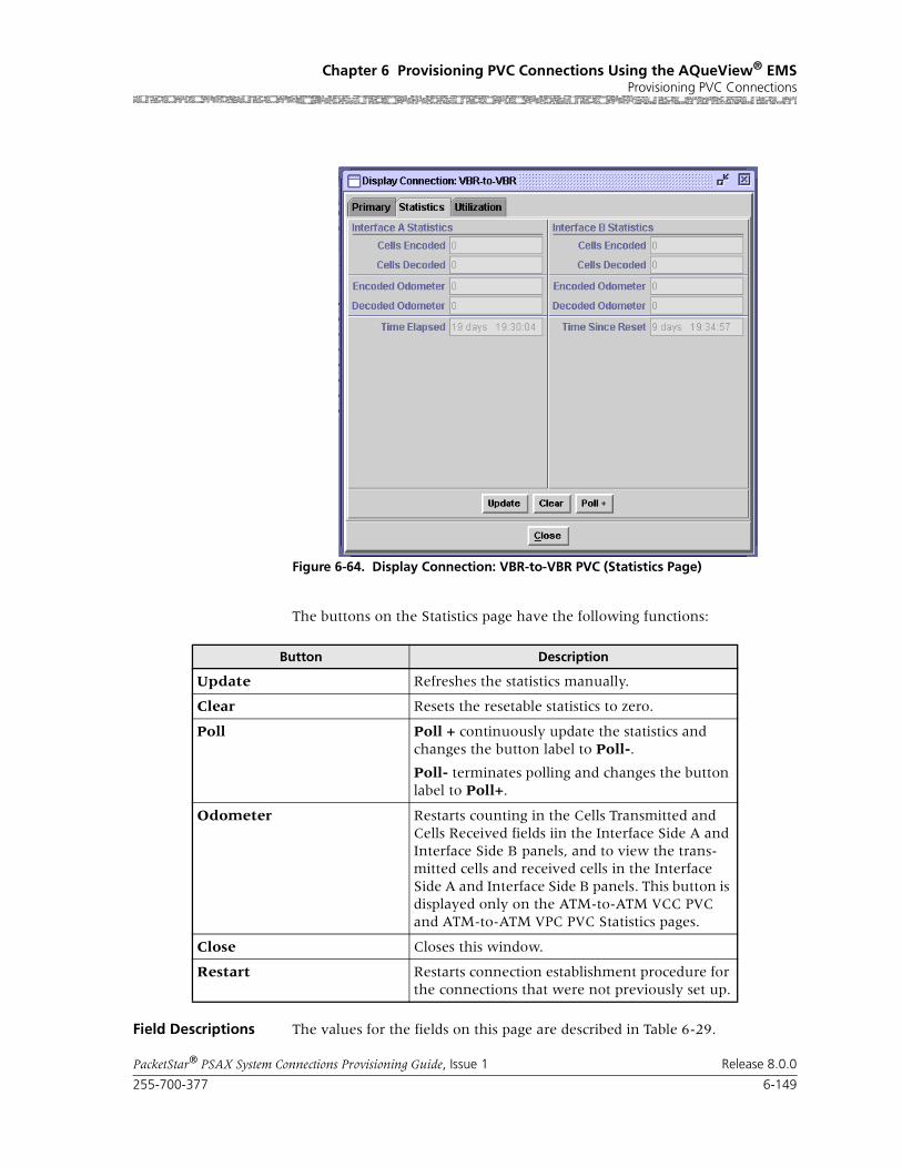
255-700-377 6-149
PacketStar® PSAX System Connections Provisioning Guide, Issue 1 Release 8.0.0
Chapter 6 Provisioning PVC Connections Using the AQueView® EMSProvisioning PVC Connections
The buttons on the Statistics page have the following functions:
Field Descriptions The values for the fields on this page are described in Table 6-29.
Figure 6-64. Display Connection: VBR-to-VBR PVC (Statistics Page)
Button Description
Update Refreshes the statistics manually.
Clear Resets the resetable statistics to zero.
Poll Poll + continuously update the statistics and changes the button label to Poll-.
Poll- terminates polling and changes the button label to Poll+.
Odometer Restarts counting in the Cells Transmitted and Cells Received fields iin the Interface Side A and Interface Side B panels, and to view the trans-mitted cells and received cells in the Interface Side A and Interface Side B panels. This button is displayed only on the ATM-to-ATM VCC PVC and ATM-to-ATM VPC PVC Statistics pages.
Close Closes this window.
Restart Restarts connection establishment procedure for the connections that were not previously set up.
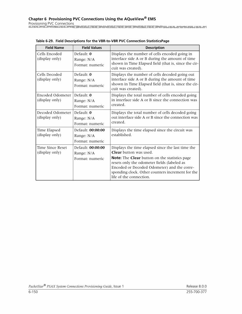
Chapter 6 Provisioning PVC Connections Using the AQueView® EMSProvisioning PVC Connections
6-150 255-700-377
PacketStar® PSAX System Connections Provisioning Guide, Issue 1 Release 8.0.0
Table 6-29. Field Descriptions for the VBR-to-VBR PVC Connection StatisticsPage
Field Name Field Values Description
Cells Encoded(display only)
Default: 0Range: N/A
Format: numeric
Displays the number of cells encoded going in interface side A or B during the amount of time shown in Time Elapsed field (that is, since the cir-cuit was created).
Cells Decoded(display only)
Default: 0
Range: N/A
Format: numeric
Displays the number of cells decoded going out interface side A or B during the amount of time shown in Time Elapsed field (that is, since the cir-cuit was created).
Encoded Odometer(display only)
Default: 0Range: N/A
Format: numeric
Displays the total number of cells encoded going in interface side A or B since the connection was created.
Decoded Odometer(display only)
Default: 0
Range: N/A
Format: numeric
Displays the total number of cells decoded going out interface side A or B since the connection was created.
Time Elapsed(display only)
Default: 00:00:00
Range: N/A
Format: numeric
Displays the time elapsed since the circuit was established.
Time Since Reset(display only)
Default: 00:00:00Range: N/A
Format: numeric
Displays the time elapsed since the last time the Clear button was used.
Note: The Clear button on the statistics page resets only the odometer fields (labeled as Encoded or Decoded Odometer) and the corre-sponding clock. Other counters increment for the life of the connection.

255-700-377 6-151
PacketStar® PSAX System Connections Provisioning Guide, Issue 1 Release 8.0.0
Chapter 6 Provisioning PVC Connections Using the AQueView® EMSProvisioning PVC Connections
Utilization Page The Utilization page measures the amount of traffic running through this connection (see Figure 6-65).
The buttons on the Utilization page have the following functions:
Figure 6-65. Display Connection: VBR-to-VBR (Utilization Page)
Button Function
60 sec Time, in seconds or minutes, to poll the PSAX device. Select a time interval from the pull-down menu:
5 sec
10 sec
20 sec
30 sec
60 sec (default)
90 sec
2 min
3 min
4 min
5 min
Clear Resets all statistics to zero.
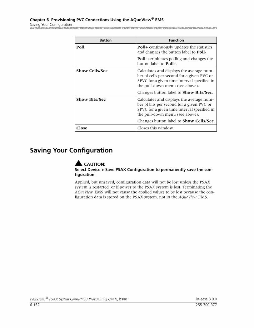
Chapter 6 Provisioning PVC Connections Using the AQueView® EMSSaving Your Configuration
6-152 255-700-377
PacketStar® PSAX System Connections Provisioning Guide, Issue 1 Release 8.0.0
Saving Your Configuration
! CAUTION:Select Device > Save PSAX Configuration to permanently save the con-figuration.
Applied, but unsaved, configuration data will not be lost unless the PSAX system is restarted, or if power to the PSAX system is lost. Terminating the AQueView EMS will not cause the applied values to be lost because the con-figuration data is stored on the PSAX system, not in the AQueView EMS.
Poll Poll+ continuously updates the statistics and changes the button label to Poll-.
Poll- terminates polling and changes the button label to Poll+.
Show Cells/Sec Calculates and displays the average num-ber of cells per second for a given PVC or SPVC for a given time interval specified in the pull-down menu (see above).
Changes button label to Show Bits/Sec.
Show Bits/Sec Calculates and displays the average num-ber of bits per second for a given PVC or SPVC for a given time interval specified in the pull-down menu (see above).
Changes button label to Show Cells/Sec.
Close Closes this window.
Button Function

PacketStar® PSAX System Connections Provisioning Guide, Issue 1 Release 8.0.0
255-700-377 7-1
7 Provisioning SPVC ConnectionsUsing the AQueView® EMS
Provisioning SPVC Connections
NSAP Address Database
The AQueView system supports the use of a network service access point (NSAP) address flat file database to simplify the task of provisioning SPVCs on PSAX devices.The PSAX system supports the use of a network service access point (NSAP) address flat file database to simplify the task of provi-sioning SPVCs on PSAX devices. The database enables you to map NSAP addresses to a particular device, slot, port, and channel at configuration time, rather than during the creation of a connection.
The NSAP address database allows you to store and retrieve local and remote NSAP addresses. If the NSAP addresses are entered ahead of time, you can establish SPVCs quickly by simply specifying slot, port, and channel for both sides of the connection in addition to the standard traffic parameters and fea-tures. The NSAP address database can be created in Microsoft Excel or another text editor, and can be edited (to add, delete, or update NSAP entries) through the AQueView system.The NSAP address database can be cre-ated in Microsoft Excel or another text editor, and can be edited (to add, delete, or update NSAP entries) through the PSAX system.
Note: NSAP addresses are not stored in the PSAX device until you add the NSAP address to an interface and save the interface configura-tion.
Setting Up Local NSAP Addresses
An illustration of an SPVC connection is illustrated in Figure 7-1. You can retrieve local and remote NSAP addresses from the NSAP database.
You can set up the local NSAP address in several ways:
• On an Interface Configuration window (see the following procedure)
Figure 7-1. Example of SPVC Configuration
ATMPSAX
Local NSAP Address
SPVC EndpointRemote NSAP Address
SPVC Endpoint
Passive Endpoint
PSAX
Active Endpoint

Chapter 7 Provisioning SPVC Connections Using the AQueView® EMSProvisioning SPVC Connections
7-2 255-700-377
PacketStar® PSAX System Connections Provisioning Guide, Issue 1 Release 8.0.0
• On the SPVC NSAP Address page (see “” on page -4)
Setting Up the Local NSAP Address During Interface Configuration
Perform the steps in the following procedure to set up the local NSAP address from an Interface Configuration window (see Figure 7-2).
Begin
Note: Step 1 through Step 3 are optional. If you do not want to add or retrieve an NSAP address, skip to Step 4.
If an NSAP address exists in the NSAP address database for a given device, the local NSAP address automatically retrieved and displayed on the Interface Configuration window. You may choose to add an NSAP address for a slot, port, and channel in the NSAP address database and retrieve it by clicking Retrieve from NSAP database.
1 To add or retrieve an NSAP address, enter a valid NSAP address in the Local NSAP Address (Hex) field and click Retrieve from NSAP data-base.
Figure 7-2. Sample Interface Configuration Window
255-700-377 7-3
PacketStar® PSAX System Connections Provisioning Guide, Issue 1 Release 8.0.0
Chapter 7 Provisioning SPVC Connections Using the AQueView® EMSProvisioning SPVC Connections
If the value entered in the Local NSAP Address (Hex) field is valid, the field becomes ghosted. The Select NSAP window appears (see the follow-ing figure).
You can populate the Slot, Port, Channel, and NSAP Address fields for an existing device, or add a new entry, and click Add.
2 To display the NSAP addresses previously configured for a PSAX device, either select a remote device from the pull-down menu, or type the IP address of the remote device in the Remote Switch IP field.
The list of NSAP addresses previously configured for that PSAX device is displayed in the table.
3 Select the desired entry (slot, port, channel, and NSAP address) and click Retrieve.
The Local NSAP Address (Hex) field becomes populated in the window.
Note: If the desired remote device does not appear in the Remote Switch IP pull-down menu, do the following:
a. Highlight the Remote Switch IP field and enter the IP address that corresponds to the PSAX device you want to include.
b. Type the desired values into the Slot, Port, and Channel fields and
c. Click Add.
The AQueView system adds this information to the database file.
Note: If you want to include a new entry for an existing device already in the database, select the device from the pull-down menu in the Remote Switch IP field, and type the desired values into the Slot, Port, and Channel fields and click Add. The AQueView system adds this entry to the database file.
Note: If you add database entries through the AQueView system, save these database changes to the text editor file by using the main AQueView Menu Bar. Click View > NSAP Database > Save.

Chapter 7 Provisioning SPVC Connections Using the AQueView® EMSProvisioning SPVC Connections
7-4 255-700-377
PacketStar® PSAX System Connections Provisioning Guide, Issue 1 Release 8.0.0
4 To apply the interface configuration values, click Apply.
Buttons The buttons in this window have the following functions:
End
Setting Up the Local NSAP Address Using the SPVC NSAP Page
Perform the steps in the following procedure to set up the local NSAP address from the SPVC NSAP page (see Figure 7-4).
Begin
1 In the Device window, click the Connections tab and the Listing page appears.
2 Click the SPVC NSAP Address tab.
The SPVC NSAP Address page appears (see Figure 7-4).
Figure 7-3. Select NSAP Window
Button Function
Retrieve Enters the NSAP address for a device that is selected on the Select Remote NSAP window into the Remote NSAP Address field of the Interface Configuration window.
Add Adds a new slot, port, channel, NSAP address mapping entry for the specified device.
Save Stores any modifications to the NSAP address database.
Close Closes this window.

255-700-377 7-5
PacketStar® PSAX System Connections Provisioning Guide, Issue 1 Release 8.0.0
Chapter 7 Provisioning SPVC Connections Using the AQueView® EMSProvisioning SPVC Connections
Buttons You can enter and update SPVC NSAP address information by using the but-tons on this page:
Figure 7-4. SPVC NSAP Address Page
Button Function
Find Searches the table and displays a matching text string entered in the Show table entry containing: field.
Reset Removes text entered in the Show table entry containing: field and de-selects any selected entries.
Retrieve from NSAP data-base
Searches the entries listed on this page for the NSAP address entered in the NSAP Address (Hex) field.
Note: Calculate Navis NSAP Address This button appears only when you configure user properties to include the Navis NSAP format.
Automatically calculates the local NSAP address, and populates the NSAP address in the NSAP Address (Hex) field using the Navis algorithm for the slot, port, and channel selected in the fields on the bot-tom right panel.

Chapter 7 Provisioning SPVC Connections Using the AQueView® EMSProvisioning SPVC Connections
7-6 255-700-377
PacketStar® PSAX System Connections Provisioning Guide, Issue 1 Release 8.0.0
3 Select the desired values in the Slot, Port, and Channel fields.
4 Click Retrieve from NSAP database.
5 Click Add Address.
6 Create an SPVC connection as described in this chapter.
7 Create an SPVC connection as described in ”Provisioning SPVCs Using the NSAP Address Database” on page 8-5.
End
Adding ATM-to-ATM VCC SPVC Connections
Perform the steps in the following procedure to create an ATM-to-ATM VCC SPVC connection.
Begin
1 In the Device window, click the Connections tab.
The Listing page appears.
2 Click the right mouse button and a menu appears. Click Create New.
Add Address Adds the information you entered in the fields on the bottom right panel to the SPVC NSAP Address page.
Delete Selected Removes the selected entry from the SPVC NSAP Address page.
Update Refreshes the SPVC NSAP Address page manually.
Button Function

255-700-377 7-7
PacketStar® PSAX System Connections Provisioning Guide, Issue 1 Release 8.0.0
Chapter 7 Provisioning SPVC Connections Using the AQueView® EMSProvisioning SPVC Connections
The Create Connection window appears (see Figure 7-5).
3 On the Side A panel, select the appropriate slot, port, and channel for a module that is configured with an ATM interface. The interface name appears in the Interface field.
4 On the Side B panel, select SPVC.
The SPVC Connection Type field displayed.
5 Select VCC.
6 Click Create.
The Create ATM-to-ATM_SPVC Connection window appears (see Figure 7-6).
Figure 7-5. Create Connection Window

Chapter 7 Provisioning SPVC Connections Using the AQueView® EMSProvisioning SPVC Connections
7-8 255-700-377
PacketStar® PSAX System Connections Provisioning Guide, Issue 1 Release 8.0.0
The buttons on this window have the following functions:
Field Descriptions 7 Select the values for the fields on this window from the values given in Table 7-1.
Figure 7-6. Create ATM-to-ATM_SPVC Connection Window
Button Function
Retrieve Remote NSAP Address
If you have previously established an NSAP address database, click this button to retrieve an entry from this list to populate the Remote NSAP Address (Hex) field.
Close Closes this window.
Create Establishes the connection you configured.
Copy Copies this configuration information to a range of interfaces.

255-700-377 7-9
PacketStar® PSAX System Connections Provisioning Guide, Issue 1 Release 8.0.0
Chapter 7 Provisioning SPVC Connections Using the AQueView® EMSProvisioning SPVC Connections
Table 7-1. Field Descriptions for the ATM-to-ATM VCC SPVC Connection Window
Field Name Field Values Description
Interface Side A:ATM_UNI30, ATM_UNI31, ATM_UNI40, IISP_USER, IISP_NETWORK or PNNI1_0
Default: N/A
Range: N/A
Format: N/A
Indicates Side A (local PVC side) of the connec-tion that will send and receive signals.
Interface Side B:ATM_UNI30, ATM_UNI31, ATM_UNI40, IISP_USER, IISP_NETWORK or PNNI1_0
Default: N/ARange: N/A
Format: N/A
Indicates Side B (remote PVC side) of the connec-tion that will send and receive signals.
Slot Default: 0
Range: variable
Format: numeric
Indicates the slot number containing the module for which you are creating a connection on Side A. The range of slot numbers varies with the chassis type.
Port Default: 1Range: variable
Format: numeric
Indicates the port number on the module for which you are creating a connection on Side A. The range of port numbers varies with the mod-ule type.
Channel(display only)
Default: 1
Range: variable
Format: numeric
Indicates the channel on which you are creating a connection. The range of channel numbers var-ies with the module type.
VPI Default: 0Range: 0–4095
Format: numeric
Indicates the virtual path identifier, an addressing identifier that routes cell traffic.
VCI Default: 0
Range: 0–4095
Format: numeric
Indicates the virtual channel identifier, an addressing identifier that routes cell traffic.
VUNI Default: 0
Range: 0–255
Format: numeric
Indicates the virtual ATM UNI, which provides bandwidth allocation restrictions. When disabled, the default value is 0. The virtual UNI (VUNI) associates itself with the egress part of the A to B or B to A side of the connection. Currently this function is available only on the OC-12c/STM-4c APS/MSP, OC-3c APS, and STM-1 MSP modules.

Chapter 7 Provisioning SPVC Connections Using the AQueView® EMSProvisioning SPVC Connections
7-10 255-700-377
PacketStar® PSAX System Connections Provisioning Guide, Issue 1 Release 8.0.0
Service Type Default: Ubr
Range: N/A
Format: predefined alphanumeric
Specifies the PSAX system-supported quality of service (QoS) class. For a description of the QoS classes, see the reference appendix in this guide. The type selected causes the conformance type for the connection to be derived from the class of service. This derived value is enforced by the UPC setting of the I/O module.
Ubr Indicates unspecified bit rate.
Vbr-nrt2 Indicates variable bit rate, non-real time, queue 2
Vbr-nrt1 Indicates variable bit rate, non-real time, queue 1
Vbr-rt2 Indicates variable bit rate, real time, queue 2
Vbr-rt1 Indicates variable bit rate, real time, queue 1
Vbr-express Indicates variable bit rate, express
Cbr4 Indicates constant bit rate, queue 4
Cbr3 Indicates constant bit rate, queue 3
Cbr2 Indicates constant bit rate, queue 2
Peak Rate (0+1) Default: 1Range: 1–(232-1)(theoretical range, except for modules noted at right, see Description column)
Range:
Format: numeric (cells per second)
Indicates peak cell rate (PCR). The maximum allowed cell transmission rate (in cells per sec-ond), which defines the shortest time period between cells. When setting this value, take into account the line rate for the module and the amount of bandwidth you are setting up for each interface for the module. If you select the value SimplexA2B in the Flow field, set the value for peak rate to 0.
Note: If you are using the traffic shaping Enabled setting on the bulleted modules listed below, entering a minimum cps value below the mini-mum listed below will cause traffic-shaped con-nections to default back to the minimum cps value when the connection passes traffic.
• On the 1-Port OC-3c MM/SM and the 1-Port STM-1 MM/SM, the cps range is 18–999999999.
• On the OC-12c/STM-4c SM/MM, the cps range is 87–999999999.
• On the 3-Port DS3/E3 ATM, the cps range is 7–999999999.
Note: The peak cell rate cannot exceed the maxi-mum cell rate for the interface.
Table 7-1. Field Descriptions for the ATM-to-ATM VCC SPVC Connection Window (Continued)
Field Name Field Values Description

255-700-377 7-11
PacketStar® PSAX System Connections Provisioning Guide, Issue 1 Release 8.0.0
Chapter 7 Provisioning SPVC Connections Using the AQueView® EMSProvisioning SPVC Connections
SCR/PCR (0) Default: 1
Range: 1–(232-1)(theoretical range)
Format: numeric (cells per second)
Indicates the PCR and sustainable cell rate (SCR) with CLP=0 (high priority) cells or the peak cell rate with CLP=0 cells. When setting this value, take into account the line rate for the module and the amount of bandwidth you are setting up for each interface for the module. If you select the value SimplexA2B in the Flow field, set the value of this field to 0. The value in this field should be less than the Peak Rate (0+1) field. Refer to the ATM UNI 3.1 specifications for more information.
Note: The sustained cell rate cannot exceed the maximum cell rate for the interface.
Max Burst Size (cells)
Default: 1
Range: 0–65535
Format: numeric
Indicates the maximum burst size. The maximum number of cells that can be received at the peak cell rate. This allows a burst of cells to arrive at a rate higher than that of the sustained cell rate. If the burst is larger than anticipated, the additional cells are either tagged or dropped. When setting this value, take into account the line rate for the module and the amount of bandwidth you are setting up for each interface for the module. If you select the value SimplexA2B in the Flow field, set the value for peak rate to 0.OC-3c APS Module: When the Traffic Shaping field is set to Enabled, the cell queue depth for the Max Burst Size field is internally set to 1000, regardless of the value you enter. If you enter values other than 1000, these values matter for incoming signalling SPVC/SVC setup from the remote end of the connection.
Table 7-1. Field Descriptions for the ATM-to-ATM VCC SPVC Connection Window (Continued)
Field Name Field Values Description

Chapter 7 Provisioning SPVC Connections Using the AQueView® EMSProvisioning SPVC Connections
7-12 255-700-377
PacketStar® PSAX System Connections Provisioning Guide, Issue 1 Release 8.0.0
Traffic Shaping Default: Disabled
Range: N/A
Format: predefined alphanumeric
Indicates the method for controlling the flow of data traffic. This feature is implemented on the following modules:
• 1-Port OC-3c Multimode and Single-Mode with Traffic Shaping modules
• 1-Port STM-1 Multimode and Single-Mode with Traffic Shaping modules
• 3-Port DS3/E3 ATM
• 1-Port OC-12c/STM-4c MM/SM 1+1 APS/MSP modules
See the Peak Rate field on this table for minimum cps ranges restrictions on these modules.
Disabled Inactivates the traffic shaping function.
Enabled Ensures that the variable bit-rate (VBR) traffic entering the PSAX system via these modules complies with the parameters of the established service contracts.
Traffic Flow Default: DuplexRange: N/A
Format: predefined alphanumeric
Indicates the direction of flow of data traffic in this connection.
Duplex Indicates that the data flows in two directions between the two connection points (Side A and Side B).
SimplexA2B Indicates that the data flows in only one direc-tion, from Side A to Side B.
PointToMultipointA2B
Indicates that the data flows in only one direc-tion, from one point on Side A to several points on Side B.
Simplex B2A Indicates that the data flows in only one direc-tion, from Side B to Side A.
Connection Type Default: ActiveSvcRange: N/A
Format: predefined alphanumeric
Indicates the type of SVC connection.
ActiveSvc Indicates that the PSAX system attempts calls.
PassiveSvc Indicates that the PSAX system accepts calls from another device. When you select this value, sev-eral fields on this window are not displayed.
Table 7-1. Field Descriptions for the ATM-to-ATM VCC SPVC Connection Window (Continued)
Field Name Field Values Description

255-700-377 7-13
PacketStar® PSAX System Connections Provisioning Guide, Issue 1 Release 8.0.0
Chapter 7 Provisioning SPVC Connections Using the AQueView® EMSProvisioning SPVC Connections
If the parameters are valid, the Connections window appears with the new connection in the Listing page, and the Display Connection window
Retry Limit Default: 0
Range:
Format: numeric
Indicates the maximum limit on how many con-secutive unsuccessful call setup attempts the PSAX system makes before it stops making attempts to set up the connection. The value 0 indicates no limits on the number of attempts to set up the connection. Certain connection cause codes sent by the remote (destination) device instruct the PSAX system to retry the call. The cause code is displayed in the Last Release Cause field.
Note: This field is displayed only when you select the value ActiveSvc in the Connection Type field.
Retry Interval (sec) Default: 1
Range: 0–3600
Format: numeric (sec)
Indicates the number of seconds elapsing between retried connection setups. The value 0 results in a retried connection setup with no delay.
Remote VPI/VCI Default: Required
Format:
Indicates whether you select the VPI and VCI val-ues for the remote device or the remote device selects its own VPI and VCI values.
Note: This field is displayed only when you select the value ActiveSvc in the Conn Type field.
Required Indicates that you must enter the values for the remote (destination) in the VPI and VCI fields.
Any Indicates that the remote (destination) device selects the VPI and VCI values. The VPI and VCI fields are not displayed when you select this value.
VPI Range: 0-4095
Format: numeric
Virtual path identifier.
VCIRange: 32–65535
Format: numeric
Virtual channel identifier.
Remote NSAP Address
Default: N/ARange: N/A
Format: hexadecimal
Indicates the ATM NSAP address of the remote end of the connection, that contains the NSAP of the side B interface selected for this connection. Enter the NSAP address of the remote ATM inter-face.
Note: This field is displayed only when you select the value ActiveSvc in the Conn Type field.
Table 7-1. Field Descriptions for the ATM-to-ATM VCC SPVC Connection Window (Continued)
Field Name Field Values Description

Chapter 7 Provisioning SPVC Connections Using the AQueView® EMSProvisioning SPVC Connections
7-14 255-700-377
PacketStar® PSAX System Connections Provisioning Guide, Issue 1 Release 8.0.0
appears with tabs that contain details about the connection (see Figure 7-7): Primary and Statistics.
If a parameter is invalid, a Connection Creation Failed message appears, stating the reason for the failure.
End
Primary Page The Primary page displays the information used to create the connection. See Table 7-1 for field descriptions.
The buttons at the bottom of the window have the following functions:
Figure 7-7. Display Connection:ATM-to-ATM_SPVC (Primary Page)
Button Function
Retrieve Remote NSAP Address
If you have previously established an NSAP address database, click this button to retrieve an entry from this list to populate the Remote NSAP Address (Hex) field.
Close Closes this window.
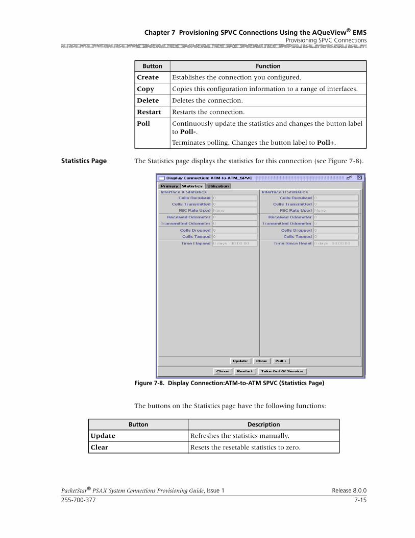
255-700-377 7-15
PacketStar® PSAX System Connections Provisioning Guide, Issue 1 Release 8.0.0
Chapter 7 Provisioning SPVC Connections Using the AQueView® EMSProvisioning SPVC Connections
Statistics Page The Statistics page displays the statistics for this connection (see Figure 7-8).
The buttons on the Statistics page have the following functions:
Create Establishes the connection you configured.
Copy Copies this configuration information to a range of interfaces.
Delete Deletes the connection.
Restart Restarts the connection.
Poll Continuously update the statistics and changes the button label to Poll-.
Terminates polling. Changes the button label to Poll+.
Button Function
Figure 7-8. Display Connection:ATM-to-ATM SPVC (Statistics Page)
Button Description
Update Refreshes the statistics manually.
Clear Resets the resetable statistics to zero.

Chapter 7 Provisioning SPVC Connections Using the AQueView® EMSProvisioning SPVC Connections
7-16 255-700-377
PacketStar® PSAX System Connections Provisioning Guide, Issue 1 Release 8.0.0
Field Descriptions The values for the fields on this window are described in Table 7-2.
Poll Poll + continuously update the statistics and changes the button label to Poll-.
Poll- terminates polling and changes the button label to Poll+.
Odometer Restarts counting in the Cells Transmitted and Cells Received fields iin the Interface Side A and Interface Side B panels, and to view the trans-mitted cells and received cells in the Interface Side A and Interface Side B panels. This button is displayed only on the ATM-to-ATM VCC PVC and ATM-to-ATM VPC PVC Statistics pages.
Close Closes this window.
Restart Restarts connection establishment procedure for the connections that were not previously set up.
Button Description
Table 7-2. Field Descriptions for the ATM-to-ATM VCC SPVC Statistics Window
Field Name Field Values Description
Slot Default: N/A
Range: Varies depending on chassis type
Format: numeric
Slot identifier of the ATM interface for either the ATM Interface A panel or the ATM Interface B panel.
Port Default: N/A
Range: Varies depending on module type
Format: numeric
Port identifier of the ATM interface for either the ATM Interface A panel or the ATM Interface B panel.
Channel Default: N/ARange: Varies depending on module type
Format: numeric
Channel identifier of the ATM interface for either Interface A or Interface B.
VPI Default: 0
Range: 0–255
Format: numeric
Virtual path identifier of the ATM side (SVC side) of the connection.
VCI Default: 0
Range: 32–65535
Format: numeric
Virtual channel identifier of the ATM side (SVC side) of the connection.
Cells Received Default: 0Range: N/A
Format: numeric
Number of valid cells received since the virtual circuit or virtual path was established.
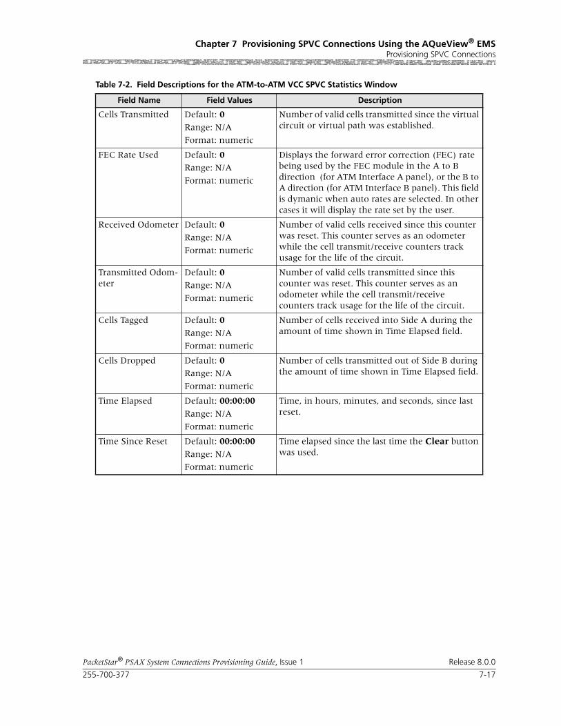
255-700-377 7-17
PacketStar® PSAX System Connections Provisioning Guide, Issue 1 Release 8.0.0
Chapter 7 Provisioning SPVC Connections Using the AQueView® EMSProvisioning SPVC Connections
Cells Transmitted Default: 0
Range: N/A
Format: numeric
Number of valid cells transmitted since the virtual circuit or virtual path was established.
FEC Rate Used Default: 0Range: N/A
Format: numeric
Displays the forward error correction (FEC) rate being used by the FEC module in the A to B direction (for ATM Interface A panel), or the B to A direction (for ATM Interface B panel). This field is dymanic when auto rates are selected. In other cases it will display the rate set by the user.
Received Odometer Default: 0
Range: N/A
Format: numeric
Number of valid cells received since this counter was reset. This counter serves as an odometer while the cell transmit/receive counters track usage for the life of the circuit.
Transmitted Odom-eter
Default: 0Range: N/A
Format: numeric
Number of valid cells transmitted since this counter was reset. This counter serves as an odometer while the cell transmit/receive counters track usage for the life of the circuit.
Cells Tagged Default: 0
Range: N/A
Format: numeric
Number of cells received into Side A during the amount of time shown in Time Elapsed field.
Cells Dropped Default: 0Range: N/A
Format: numeric
Number of cells transmitted out of Side B during the amount of time shown in Time Elapsed field.
Time Elapsed Default: 00:00:00
Range: N/A
Format: numeric
Time, in hours, minutes, and seconds, since last reset.
Time Since Reset Default: 00:00:00
Range: N/A
Format: numeric
Time elapsed since the last time the Clear button was used.
Table 7-2. Field Descriptions for the ATM-to-ATM VCC SPVC Statistics Window
Field Name Field Values Description

Chapter 7 Provisioning SPVC Connections Using the AQueView® EMSProvisioning SPVC Connections
7-18 255-700-377
PacketStar® PSAX System Connections Provisioning Guide, Issue 1 Release 8.0.0
Utilization Page The Utilization page measures the amount of traffic running through this connection (see Figure 7-9).
Figure 7-9. Display Connection: ATM-to-ATM VCC SPVC (Utilization Page)

255-700-377 7-19
PacketStar® PSAX System Connections Provisioning Guide, Issue 1 Release 8.0.0
Chapter 7 Provisioning SPVC Connections Using the AQueView® EMSProvisioning SPVC Connections
The buttons on the Utilization page have the following functions:
For details about this window, see the section, “Utilization Information,” in Chapter 5 of this guide.
Button Function
60 sec Time, in seconds or minutes, to poll the PSAX device. Select a time interval from the pull-down menu:
5 sec
10 sec
20 sec
30 sec
60 sec (default)
90 sec
2 min
3 min
4 min
5 min
Clear Resets all statistics to zero.
Poll Poll+ continuously updates the statistics and changes the button label to Poll-.
Poll- terminates polling and changes the button label to Poll+.
Show Cells/Sec Calculates and displays the average num-ber of cells per second for a given PVC or SPVC for a given time interval specified in the pull-down menu (see above).
Changes button label to Show Bits/Sec.
Show Bits/Sec Calculates and displays the average num-ber of bits per second for a given PVC or SPVC for a given time interval specified in the pull-down menu (see above).
Changes button label to Show Cells/Sec.
Close Closes this window.
Restart Restarts connection establishment proce-dure for this SPVC.
Bring Into Service Brings this connection into service.
Take Out of Service Takes this connection out of service.

Chapter 7 Provisioning SPVC Connections Using the AQueView® EMSProvisioning SPVC Connections
7-20 255-700-377
PacketStar® PSAX System Connections Provisioning Guide, Issue 1 Release 8.0.0
Adding ATM-to-ATM VPC SPVP Connections
Perform the steps in the following procedure to create an ATM-to-ATM VPC SPVP connection.
Begin
1 In the Device window, click the Connections tab.
The Listing page appears.
2 Click the right mouse button and a menu appears. Click Create New.
The Create Connection window appears (see Figure 7-5).
3 On the Side A panel, select the appropriate slot, port, and channel for a module that is configured with an ATM interface. The interface name appears in the Interface field.
4 On the Side B panel, select SPVP.
The SPVP Connection Type field displayed.
5 Select VPC.
6 Click Create.
The Create ATM-to-ATM_SPVP Connection window appears (see Figure 7-6).
Figure 7-10. Create Connection Window

255-700-377 7-21
PacketStar® PSAX System Connections Provisioning Guide, Issue 1 Release 8.0.0
Chapter 7 Provisioning SPVC Connections Using the AQueView® EMSProvisioning SPVC Connections
The buttons on this window have the following functions:
Field Descriptions 7 Select the values for the fields on this window from the values given in Table 7-3.
Figure 7-11. Create ATM-to-ATM_SPVP Connection Window
Button Function
Retrieve Remote NSAP Address
If you have previously established an NSAP address database, click this button to retrieve an entry from this list to populate the Remote NSAP Address (Hex) field.
Close Closes this window.
Create Establishes the connection you configured.
Copy Copies this configuration information to a range of interfaces.

Chapter 7 Provisioning SPVC Connections Using the AQueView® EMSProvisioning SPVC Connections
7-22 255-700-377
PacketStar® PSAX System Connections Provisioning Guide, Issue 1 Release 8.0.0
Table 7-3. Field Descriptions for the ATM-to-ATM VPC SPVC Connection Window
Field Name Field Values Description
Interface Side A:ATM_UNI30, ATM_UNI31, ATM_UNI40, IISP_USER, IISP_NETWORK or PNNI1_0
Default: N/A
Range: N/A
Format: Alphanu-meric
Side A (PVC side)of the connection that will send and receive signals.
Interface Side B:ATM_UNI30, ATM_UNI31, ATM_UNI40, IISP_USER, IISP_NETWORK or PNNI1_0
Default: N/ARange: N/A
Format: Alphanu-meric
Side B (SVC side)of the connection that will send and receive signals.
Slot Range:
The range varies depending on chassis type.
Select the slot number containing the module for which you are creating a connection on side A.
Port Range: 1–28,
depending on module selected
Select the port number on the module for which you are creating a connection on side A.
Channel(display only)
Range: This is the channel where the call originates. The channel on which you are creating a connection.
For example, on a port of the DS3 IMA module, you can configure more than one channel in a port.
VPI Range: 0–4095 Virtual path identifier; an addressing identifier that routes cell traffic.
VUNI Range: Range: 0–255 Virtual user network interface; an addressing identifier that routes cell traffic.
Connection Type Default: ActiveSvc
PassiveSvc
The type of connection. ActiveSvc attempts calls. PassiveSvc accepts calls. When Pas-siveSvc is selected, the system conceals fields that are not configured for that type of connec-tion.
Remote NSAP Address (shown when ActiveSvc is selected as the con-nection type)
The ATM NSAP address of the remote end of the connection, in hexadecimal notation. Enter the NSAP address of the remote ATM interface.

255-700-377 7-23
PacketStar® PSAX System Connections Provisioning Guide, Issue 1 Release 8.0.0
Chapter 7 Provisioning SPVC Connections Using the AQueView® EMSProvisioning SPVC Connections
Service Type Default: Ubr
Range: N/A
Format: predefined alphanumeric
Specifies the PSAX system-supported quality of service (QoS) class. For a description of the QoS classes, see the reference appendix in this guide. The type selected causes the conformance type for the connection to be derived from the class of service. This derived value is enforced by the UPC setting of the I/O module.
Ubr Unspecified bit rate.
Vbr-nrt2 Variable bit rate, non-real time, queue 2.
Vbr-nrt1 Variable bit rate, non-real time, queue 1.
Vbr-rt2 Variable bit rate, real time, queue 2.
Vbr-rt1 Variable bit rate, real time, queue 1.
Vbr-express Variable bit rate, express.
Cbr4 Constant bit rate, queue 4.
Cbr3 Constant bit rate, queue 3.
Cbr2 Constant bit rate, queue 2.
Cbr1 Constant bit rate, queue 1.
Table 7-3. Field Descriptions for the ATM-to-ATM VPC SPVC Connection Window
Field Name Field Values Description

Chapter 7 Provisioning SPVC Connections Using the AQueView® EMSProvisioning SPVC Connections
7-24 255-700-377
PacketStar® PSAX System Connections Provisioning Guide, Issue 1 Release 8.0.0
Peak Rate(0+1) (cps)
Default: 1
Range: 1–(232-1)(theoretical range, except for modules noted at right, see Description column)
Range:
Format: numeric (cells per second)
Peak cell rate (PCR) for all cells with both the CLP=0 bit and the CLP=1 bit. The value you set is the maximum allowed cell transmission rate (cells per second) for all cells both high and low priority, as allowed by your traffic contract. When setting this value, calculate the line rate for the module and the amount of bandwidth you are setting up for each interface for the module. Refer to the ATM UNI 3.1 specifications for more information. If you select the value SimplexA2B in the Traffic Flow field, set the value of this field to 0. The value in this field should be greater than the Sustained Cell Rate field.
Note: If you are using the traffic shaping Enabled setting on the bulleted modules listed below, entering a minimum cps value below the mini-mum listed below will cause traffic-shaped con-nections to default back to the minimum cps value when the connection passes traffic.
• On the 1-Port OC-3c MM/SM and the 1-Port STM-1 MM/SM, the cps range is 18–999999999.
• On the OC-12c/STM-4c SM/MM, the cps range is 87–999999999.
• On the 3-Port DS3/E3 ATM, the cps range is 7–999999999.
Note: The peak cell rate cannot exceed the maxi-mum cell rate for the interface.
Table 7-3. Field Descriptions for the ATM-to-ATM VPC SPVC Connection Window
Field Name Field Values Description
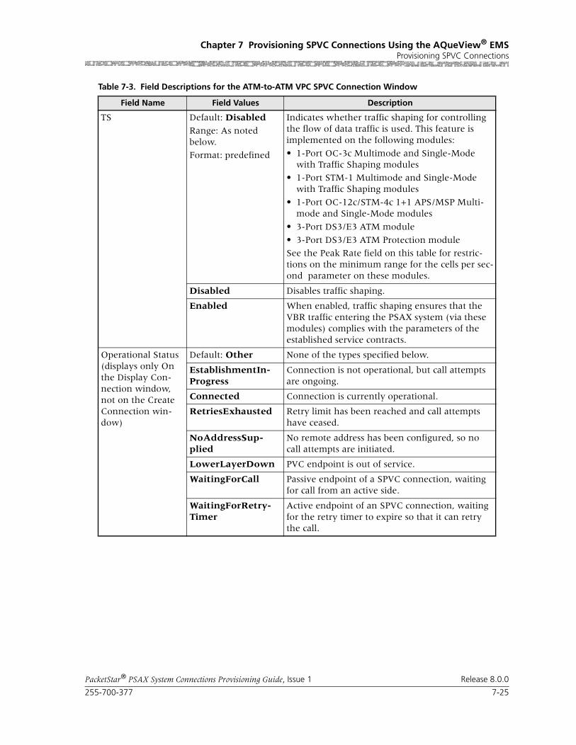
255-700-377 7-25
PacketStar® PSAX System Connections Provisioning Guide, Issue 1 Release 8.0.0
Chapter 7 Provisioning SPVC Connections Using the AQueView® EMSProvisioning SPVC Connections
TS Default: Disabled
Range: As noted below.
Format: predefined
Indicates whether traffic shaping for controlling the flow of data traffic is used. This feature is implemented on the following modules:
• 1-Port OC-3c Multimode and Single-Mode with Traffic Shaping modules
• 1-Port STM-1 Multimode and Single-Mode with Traffic Shaping modules
• 1-Port OC-12c/STM-4c 1+1 APS/MSP Multi-mode and Single-Mode modules
• 3-Port DS3/E3 ATM module
• 3-Port DS3/E3 ATM Protection module
See the Peak Rate field on this table for restric-tions on the minimum range for the cells per sec-ond parameter on these modules.
Disabled Disables traffic shaping.
Enabled When enabled, traffic shaping ensures that the VBR traffic entering the PSAX system (via these modules) complies with the parameters of the established service contracts.
Operational Status(displays only On the Display Con-nection window, not on the Create Connection win-dow)
Default: Other None of the types specified below.
EstablishmentIn-Progress
Connection is not operational, but call attempts are ongoing.
Connected Connection is currently operational.
RetriesExhausted Retry limit has been reached and call attempts have ceased.
NoAddressSup-plied
No remote address has been configured, so no call attempts are initiated.
LowerLayerDown PVC endpoint is out of service.
WaitingForCall Passive endpoint of a SPVC connection, waiting for call from an active side.
WaitingForRetry-Timer
Active endpoint of an SPVC connection, waiting for the retry timer to expire so that it can retry the call.
Table 7-3. Field Descriptions for the ATM-to-ATM VPC SPVC Connection Window
Field Name Field Values Description

Chapter 7 Provisioning SPVC Connections Using the AQueView® EMSProvisioning SPVC Connections
7-26 255-700-377
PacketStar® PSAX System Connections Provisioning Guide, Issue 1 Release 8.0.0
If the parameters are valid, the Connections window appears with the new connection in the Listing page, and the Display Connection window appears with tabs that contain details about the connection (see Figure 7-7): Primary and Statistics.
If a parameter is invalid, a Connection Creation Failed message appears, stating the reason for the failure.
End
Primary Page The Primary page displays the information used to create the connection. See Table 7-3 for field descriptions.
Last Releases Diag-nostic(displays only On the Display Con-nection window, not on the Create Connection win-dow)
Default: 0
Range: N/A
Format: Numeric
Last release diagnosis. Explains how the connec-tion was released and reported by the far end of the connection.
Retry Failure Count
(displays only On the Display Con-nection window, not on the Create Connection win-dow)
Default: 0
Range: N/A
Format: Numeric
Displays how many times the call retry failed since the last successful call setup. When a call is released, the Multiservice Media Gateway will continue to retry up to the retry limit that is spec-ified in the Retry Limit field. See the ATM UNI 3.0 specification for more information.
Last Release Cause(display only)
Default: 0Range: N/A
Format: numeric
Displays the last release cause code. The cause code indicates a reason why the last attempted call was released. See the reference appendix in this guide for the description of SPVC Connection Cause Codes.
Note: This field is displayed only on the Display Connection window, not on the Create Connec-tion window.
Table 7-3. Field Descriptions for the ATM-to-ATM VPC SPVC Connection Window
Field Name Field Values Description

255-700-377 7-27
PacketStar® PSAX System Connections Provisioning Guide, Issue 1 Release 8.0.0
Chapter 7 Provisioning SPVC Connections Using the AQueView® EMSProvisioning SPVC Connections
The buttons at the bottom of the window have the following functions:
Figure 7-12. Display Connection:ATM-to-ATM_SPVP (Primary Page)
Button Function
Retrieve Remote NSAP Address
If you have previously established an NSAP address database, click this button to retrieve an entry from this list to populate the Remote NSAP Address (Hex) field.
Close Closes this window.
Create Establishes the connection you configured.
Copy Copies this configuration information to a range of interfaces.
Delete Deletes the connection.
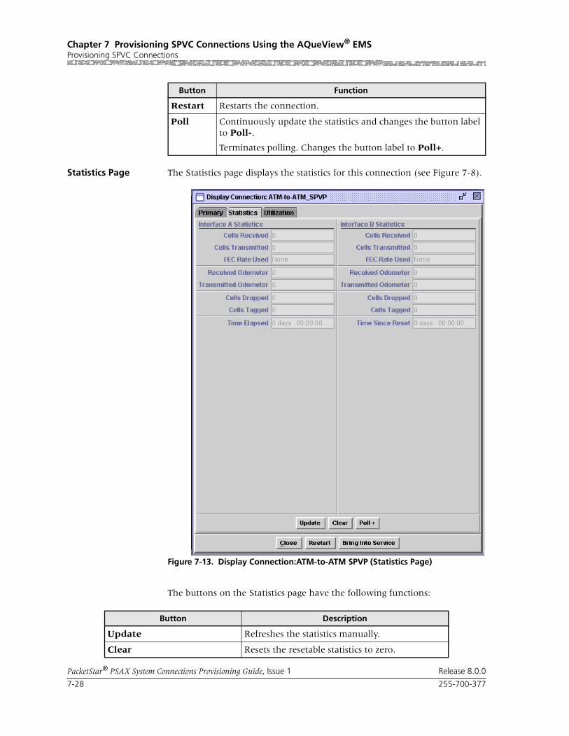
Chapter 7 Provisioning SPVC Connections Using the AQueView® EMSProvisioning SPVC Connections
7-28 255-700-377
PacketStar® PSAX System Connections Provisioning Guide, Issue 1 Release 8.0.0
Statistics Page The Statistics page displays the statistics for this connection (see Figure 7-8).
The buttons on the Statistics page have the following functions:
Restart Restarts the connection.
Poll Continuously update the statistics and changes the button label to Poll-.
Terminates polling. Changes the button label to Poll+.
Button Function
Figure 7-13. Display Connection:ATM-to-ATM SPVP (Statistics Page)
Button Description
Update Refreshes the statistics manually.
Clear Resets the resetable statistics to zero.

255-700-377 7-29
PacketStar® PSAX System Connections Provisioning Guide, Issue 1 Release 8.0.0
Chapter 7 Provisioning SPVC Connections Using the AQueView® EMSProvisioning SPVC Connections
Field Descriptions The values for the fields on this window are described in Table 7-4.
Poll Poll + continuously update the statistics and changes the button label to Poll-.
Poll- terminates polling and changes the button label to Poll+.
Odometer Restarts counting in the Cells Transmitted and Cells Received fields iin the Interface Side A and Interface Side B panels, and to view the trans-mitted cells and received cells in the Interface Side A and Interface Side B panels. This button is displayed only on the ATM-to-ATM VCC PVC and ATM-to-ATM VPC PVC Statistics pages.
Close Closes this window.
Restart Restarts connection establishment procedure for the connections that were not previously set up.
Button Description
Table 7-4. Field Descriptions for the ATM-to-ATM VPC SPVC Statistics Window
Field Name Field Values Description
Slot Default: NA
Range: Chassis-dependent
Format: Numeric
Slot identifier of the ATM interface for either the ATM Interface A panel or the ATM Interface B panel.
Port Default: NA
Range: 1–28
Format: Numeric
Port identifier of the ATM interface for either the ATM Interface A panel or the ATM Interface B panel.
Channel Default: NARange: 1–32
Format: Numeric
Channel identifier of the ATM interface for either Interface A or Interface B.
VPI Default: NA
Range: 0–4095
Format: Numeric
Virtual path identifier of the ATM side (SVC side) of the connection.
Cells Received Default: 0.0000 e0
Range: 0-(231-1)
Format: Numeric
Number of valid cells received since the virtual circuit or virtual path was established.
Cells Transmitted Default: 0.0000 e0Range: 0-(231-1)
Format: Numeric
Number of valid cells transmitted since the virtual circuit or virtual path was established.

Chapter 7 Provisioning SPVC Connections Using the AQueView® EMSProvisioning SPVC Connections
7-30 255-700-377
PacketStar® PSAX System Connections Provisioning Guide, Issue 1 Release 8.0.0
FEC Rate Used Default: None
eighthRatequarterRatehalfRateautoHiQautoautoLoQRange: NA
Format: Character
Displays the forward error correction (FEC) rate being used by the FEC module in the A2B direc-tion (for ATM Interface A panel), or B2A direc-tion (for ATM Interface B panel). This field is dynamic when auto rates are selected. In other cases it will display the rate set by the user.
Note: This field is not used in SPVC connections.
Received Odometer Default: 0.0000 e0
Range: 0-(231-1)
Format: Numeric
Number of valid cells received since this counter was reset.
This counter serves as an odometer while the cells Tx/Rx counters track usage for the life of the circuit.
Transmitted Odom-eter
Default: 0.0000 e0
Range: 0-(231-1)
Format: Numeric
Number of valid cells transmitted since this counter was reset.
This counter serves as an odometer while the cells Tx/Rx counters track usage for the life of the circuit
Cells Tagged Default: 0.0000 e0
Range: 0-(231-1)
Format: Numeric
Number of cells received into interface side A during the amount of time shown in Time Elapsed field.
Cells Dropped Default: 0.0000 e0Range: 0-(231-1)
Format: Numeric
Number of cells transmitted out of interface side B during the amount of time shown in Time Elapsed field.
Time Elapsed Default: 00:00:00
Range: NA
Format: Time in hours (xx), minutes (xx), seconds (xx)
Time, in hours, minutes, and seconds, since last reset.
Time Since Reset Default: 00:00:00
Range: NA
Format: Time in hours (xx), minutes (xx), seconds (xx)
Time elapsed since the last time the Clear button was used.
Table 7-4. Field Descriptions for the ATM-to-ATM VPC SPVC Statistics Window
Field Name Field Values Description

255-700-377 7-31
PacketStar® PSAX System Connections Provisioning Guide, Issue 1 Release 8.0.0
Chapter 7 Provisioning SPVC Connections Using the AQueView® EMSProvisioning SPVC Connections
Utilization Page The Utilization page measures the amount of traffic running through this connection (see Figure 7-14).
Figure 7-14. Display Connection: ATM-to-ATM VCC SPVP (Utilization Page)

Chapter 7 Provisioning SPVC Connections Using the AQueView® EMSProvisioning SPVC Connections
7-32 255-700-377
PacketStar® PSAX System Connections Provisioning Guide, Issue 1 Release 8.0.0
The buttons on the Utilization page have the following functions:
For details about this window, see the section, “Utilization Information,” in Chapter 5 of this guide.
Adding Circuit Emulation-to-ATM VCC SPVC Connections
Button Function
60 sec Time, in seconds or minutes, to poll the PSAX device. Select a time interval from the pull-down menu:
5 sec
10 sec
20 sec
30 sec
60 sec (default)
90 sec
2 min
3 min
4 min
5 min
Clear Resets all statistics to zero.
Poll Poll+ continuously updates the statistics and changes the button label to Poll-.
Poll- terminates polling and changes the button label to Poll+.
Show Cells/Sec Calculates and displays the average num-ber of cells per second for a given PVC or SPVC for a given time interval specified in the pull-down menu (see above).
Changes button label to Show Bits/Sec.
Show Bits/Sec Calculates and displays the average num-ber of bits per second for a given PVC or SPVC for a given time interval specified in the pull-down menu (see above).
Changes button label to Show Cells/Sec.
Close Closes this window.
Restart Restarts connection establishment proce-dure for this SPVC.
Bring Into Service Brings this connection into service.
Take Out of Service Takes this connection out of service.
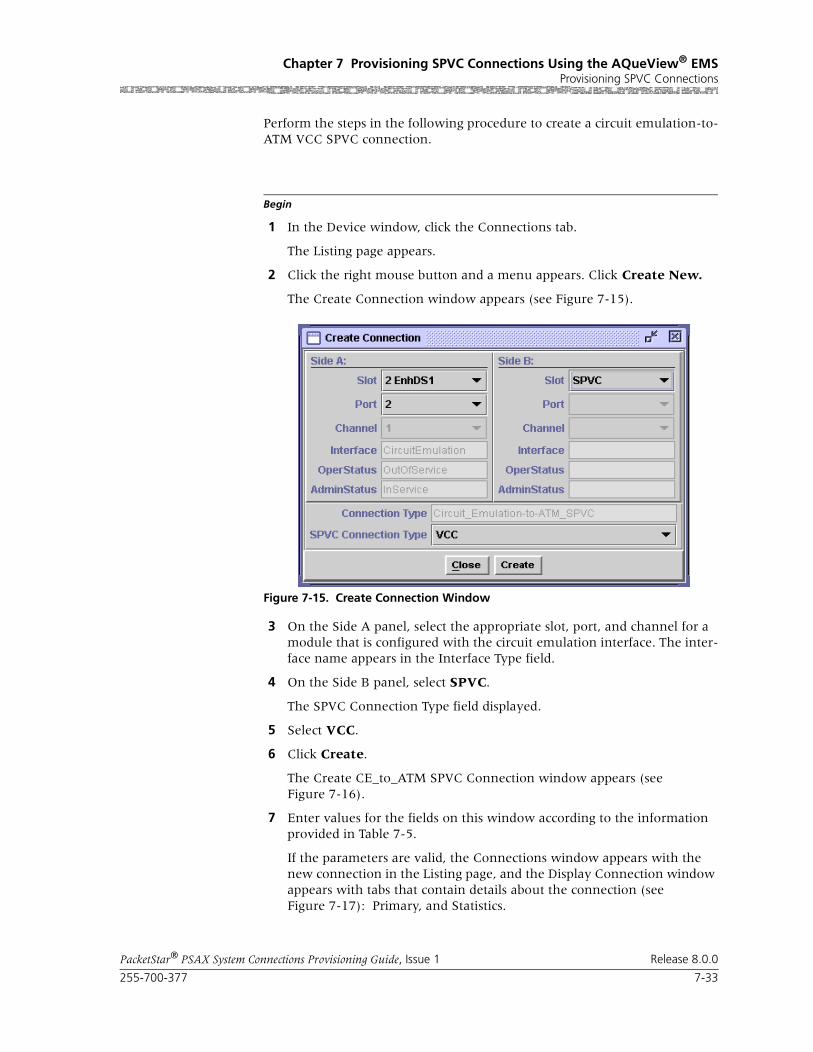
255-700-377 7-33
PacketStar® PSAX System Connections Provisioning Guide, Issue 1 Release 8.0.0
Chapter 7 Provisioning SPVC Connections Using the AQueView® EMSProvisioning SPVC Connections
Perform the steps in the following procedure to create a circuit emulation-to-ATM VCC SPVC connection.
Begin
1 In the Device window, click the Connections tab.
The Listing page appears.
2 Click the right mouse button and a menu appears. Click Create New.
The Create Connection window appears (see Figure 7-15).
3 On the Side A panel, select the appropriate slot, port, and channel for a module that is configured with the circuit emulation interface. The inter-face name appears in the Interface Type field.
4 On the Side B panel, select SPVC.
The SPVC Connection Type field displayed.
5 Select VCC.
6 Click Create.
The Create CE_to_ATM SPVC Connection window appears (see Figure 7-16).
7 Enter values for the fields on this window according to the information provided in Table 7-5.
If the parameters are valid, the Connections window appears with the new connection in the Listing page, and the Display Connection window appears with tabs that contain details about the connection (see Figure 7-17): Primary, and Statistics.
Figure 7-15. Create Connection Window

Chapter 7 Provisioning SPVC Connections Using the AQueView® EMSProvisioning SPVC Connections
7-34 255-700-377
PacketStar® PSAX System Connections Provisioning Guide, Issue 1 Release 8.0.0
If a parameter is invalid, a Connection Creation Failed message appears, stating the reason for the failure.
End
Note: For circuit emulation range limits for DSP Algosets 1 through 7, see the Connection Capacity of DSP2x Algorithm Sets Table in the Ref-erence Information Appendix of the DSP2x Voice Server Module User Guide.
Figure 7-16. Create Circuit Emulation_to_ATM SPVC Connection Window

255-700-377 7-35
PacketStar® PSAX System Connections Provisioning Guide, Issue 1 Release 8.0.0
Chapter 7 Provisioning SPVC Connections Using the AQueView® EMSProvisioning SPVC Connections
The buttons on this window have the following functions:
Button Function
Retrieve Remote NSAP Address
If you have previously established an NSAP address database, click this button to retrieve an entry from this list to populate the Remote NSAP Address (Hex) field.
Close Closes this window.
Create Establishes the connection you configured.
Copy Copies this configuration information to a range of interfaces.
Table 7-5. Field Descriptions for the Circuit Emulation-to-ATM SPVC Connection Window
Field Name Field Values Description
Circuit Emulation Interface
Default: N/ARange: N/A
Format: N/A
The circuit emulation side of the connection that will send and receive signals.
Slot Default: N/A
Range: variable
Format: Numeric
Enter the slot number on side A containing the module for which you are creating a connection. The range of slot numbers varies with the chassis type.
Port Default: N/ARange: variable
Format: Numeric
Enter the port number on side A for the module for which you are creating a connection. The range of port numbers varies with the module type.
Channel Default: N/A
Range: variable
Format: Numeric
Enter the channel on side A for the port on the module for which you are creating a connection. The range of channel numbers varies with the module type.
[VPI ](display only)
Default: 0
Range: 0–225 (ATM UNI); 0–4095 (NNI)
Format: numeric
Virtual path identifier (ATM side).
[VCI](display only)
Default: 0
Range: 0– 65535
Format: numeric
Virtual channel identifier (ATM side).
VI Default: 0Range: 0–1024
Format: numeric
Virtual interface, which provides bandwidth allo-cation restrictions. Currently available only on the 1-Port OC-12c/STM-4c 1+1 MM/SM APS/MSP, the 1-Port OC-3c 1+1 APS, and the 1-Port STM-1 1+1 MSP modules. When disabled, the default value is 0.
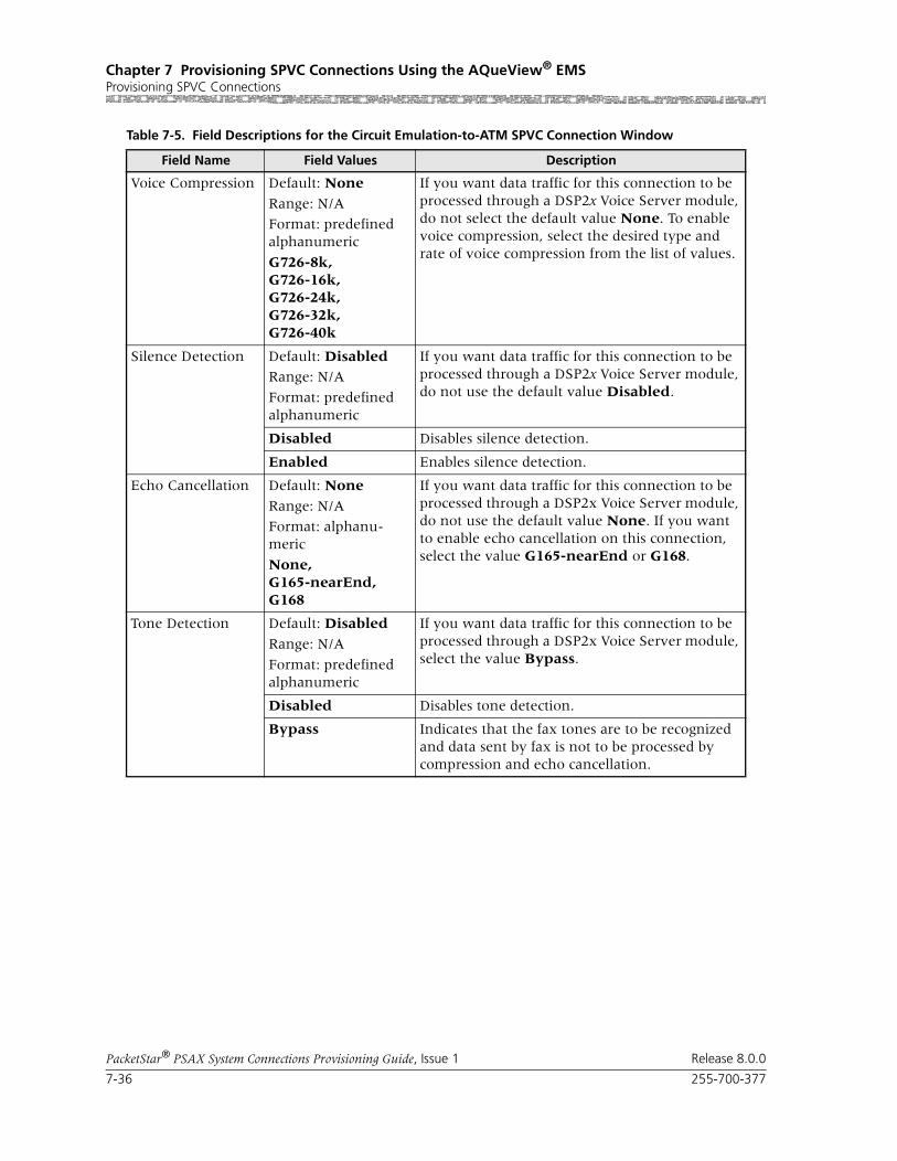
Chapter 7 Provisioning SPVC Connections Using the AQueView® EMSProvisioning SPVC Connections
7-36 255-700-377
PacketStar® PSAX System Connections Provisioning Guide, Issue 1 Release 8.0.0
Voice Compression Default: None
Range: N/A
Format: predefined alphanumeric
G726-8k,G726-16k,G726-24k,G726-32k,G726-40k
If you want data traffic for this connection to be processed through a DSP2x Voice Server module, do not select the default value None. To enable voice compression, select the desired type and rate of voice compression from the list of values.
Silence Detection Default: DisabledRange: N/A
Format: predefined alphanumeric
If you want data traffic for this connection to be processed through a DSP2x Voice Server module, do not use the default value Disabled.
Disabled Disables silence detection.
Enabled Enables silence detection.
Echo Cancellation Default: None
Range: N/A
Format: alphanu-meric
None,G165-nearEnd,G168
If you want data traffic for this connection to be processed through a DSP2x Voice Server module, do not use the default value None. If you want to enable echo cancellation on this connection, select the value G165-nearEnd or G168.
Tone Detection Default: Disabled
Range: N/A
Format: predefined alphanumeric
If you want data traffic for this connection to be processed through a DSP2x Voice Server module, select the value Bypass.
Disabled Disables tone detection.
Bypass Indicates that the fax tones are to be recognized and data sent by fax is not to be processed by compression and echo cancellation.
Table 7-5. Field Descriptions for the Circuit Emulation-to-ATM SPVC Connection Window
Field Name Field Values Description

255-700-377 7-37
PacketStar® PSAX System Connections Provisioning Guide, Issue 1 Release 8.0.0
Chapter 7 Provisioning SPVC Connections Using the AQueView® EMSProvisioning SPVC Connections
Coding Translation Default: None
Range: N/A
Format: predefined alphanumeric
None,MuLaw2muLaw,ALaw2aLaw,MuLaw2aLaw,ALaw2MuLaw
If you want data traffic for this connection to be processed through a DSP2x Voice Server module, do not use the default value None. To enabale coding translation, select one of the values for pulse code modulation (PCM) translation. Select-ing the value None actually uses Mu-law to Mu-law as the default PCM type.
Note: If you are configuring this parameter for the 6-Port Enhanced DS1 or E1 modules, select the value ALaw2aLaw.
Note: If you are configuring this parameter for the Voice 2-Wire Office or the Voice 2-Wire Sta-tion module, select the value MuLaw2muLaw. The other values are not supported.
Traffic Flow Default: DuplexRange: N/A
Format: predefined alphanumeric
Direction of flow of data traffic in this connection.
Duplex Data flows in two directions between the two connection points (interface side A and interface side B).
SimplexA2B Data flows in only one direction, from side A to side B.
PointToMultipointA2B
Data flows in only one direction, from one point on side A to several points on side B.
Simplex B2A Data flows in only one direction, from side B to side A.
PointToMultipointB2A
Data flows in only one direction, from one point on side B to several points on side A.
Service Type Default: Cbr-2
Range: N/A
Format: Predefined alphanumeric
Specifies the PSAX system-supported quality of service (QoS) class. For a description of the QoS classes, see the reference appendix in this guide. The type selected causes the conformance type for the connection to be derived from the class of service. This derived value is enforced by the UPC setting of the I/O module.
Cbr-2 Constant bit rate, queue 2.
Cbr-3 Constant bit rate, queue 3.
Cbr-4 Constant bit rate, queue 4.
Table 7-5. Field Descriptions for the Circuit Emulation-to-ATM SPVC Connection Window
Field Name Field Values Description

Chapter 7 Provisioning SPVC Connections Using the AQueView® EMSProvisioning SPVC Connections
7-38 255-700-377
PacketStar® PSAX System Connections Provisioning Guide, Issue 1 Release 8.0.0
Connection Type Default: ActiveSvc
Range: N/A
Format: Predefined alphanumeric
The type of SPVC connection.
ActiveSvc Selecting the value ActiveSvc attempts calls.
PassiveSvc Selecting the value PassiveSvc accepts calls. Sev-eral fields are not displayed when this value is selected.
SAR Type Default: Non-Mux-Aal2Range: N/A
Format: predefined alphanumeric
The type of segmentation and reassembly of data. If you are upgrading your PSAX system software, see the note at the end of this table.
Non-Mux-Aal2 Non-multiplexed AAL2. Choose this type to con-figure an SPVC if you are using DSP parameters with the connection. If you are using structured, channelized DS1/T1 service, see the note at the end of this table.
Aal1 AAL1 (uncompressed CBR).
Retry Limit Default: 0
Range: N/A
Format: numeric
Maximum limit on how many consecutive unsuccessful call setup attempts can be made before stopping the attempts to set up the con-nection. A value of zero indicates no limits. See the reference appendix in this guide for the description of ATM User-Network Specification, Version 3.1, Cause Codes. This field is displayed only when ActiveSvc is selected as the connec-tion type.
Retry Interval (sec) Default: 12
Range: N/A
Format: numeric (sec)
The number of seconds between attempts to retry call setup after a failed attempt. The value 0 results in a retry with no delay. This field is dis-played only when ActiveSvc is selected as the connection type.
Remote NSAP Address
Default: N/ARange: N/A
Format: hexadecimal
The ATM NSAP address of the remote end of the connection, in hexadecimal notation. Enter the NSAP address of the remote ATM interface. This field is displayed only when ActiveSvc is selected as the connection type.
Table 7-5. Field Descriptions for the Circuit Emulation-to-ATM SPVC Connection Window
Field Name Field Values Description

255-700-377 7-39
PacketStar® PSAX System Connections Provisioning Guide, Issue 1 Release 8.0.0
Chapter 7 Provisioning SPVC Connections Using the AQueView® EMSProvisioning SPVC Connections
Provision Passive End-Point
Default: Automatic
Range: N/A
Format: predefined alphanumeric
Provides the ability to automatically set up end-to-end provisioning (provisioning SPVCs at two different points).
Automatic When an active SPVC connection is created using the AQueView system, selecting this value results in the passive end-point being provisioned auto-matically. The information about where to provi-sion the passive end-point is obtained from the NSAP database using the Remote NSAP Address (Hex) field for the active SPVC connection. You must already have configured your NSAP addresses so that automatic provisioning works properly.
None Disables automatic end-to-end provisioning.
Operational Status Default: OtherRange: N/A
Format: Character
Operational status of the connection.
Note: This field is displayed only on the Display Connection window, not on the Create Connec-tion window.
Other None of the types specified below.
EstablishmentIn-Progress
The connection is not operational, but call attempts are ongoing.
Connected The connection is currently operational.
RetriesExhausted The retry limit has been reached and call attempts have ceased.
NoAddressSup-plied
No remote address has been configured, so no call attempts are initiated.
LowerLayerDown The PVC endpoint is out of service.
WaitingForCall The passive endpoint of a SPVC connection is waiting for call from an active side.
WaitingForRetry-Timer
The active endpoint of a SPVC connection is wait-ing for the retry timer to expire so that it can retry the call.
Table 7-5. Field Descriptions for the Circuit Emulation-to-ATM SPVC Connection Window
Field Name Field Values Description

Chapter 7 Provisioning SPVC Connections Using the AQueView® EMSProvisioning SPVC Connections
7-40 255-700-377
PacketStar® PSAX System Connections Provisioning Guide, Issue 1 Release 8.0.0
Note: SAR type for using structured, channelized DS1/T1 service: You must select nonmultiplexed AAL2 when using structured, chan-nelized DS1/T1 service on the following modules: 1-Port Channel-ized DS3 Multiservice, 1-port Channelized DS3 CES, 1-Port Chan-nelized STS-1e, T1 Format, 3-Port Channelized DS3/STS-1e CES, 6-Port Enhanced DS1 Multiservice, 6-Port Enhanced E1 Multiser-vice, 21-Port High-Density E1 Multiservice, and 12-Port Medium-Density DS1 Multiservice. Save your SPVC connection configura-tions before upgrading your PSAX system software, or you will have to re-enter these configurations.
Last Releases Diag-nostic
Default: N/A
Range: N/A
Format: predefined alphanumeric
Last release diagnosis. The text explains how the connection was released and reported by the far end of the connection.
Note: This field is displayed only on the Display Connection window, not on the Create Connec-tion window.
Retry Failure Count Default: N/ARange: N/A
Format: predefined alphanumeric
Displays how many times the call retry failed since the last successful call setup. When a call is released, the PSAX system continues to retry up to the retry limit that is specified in the Retry Limit field. See the ATM UNI 3.0 specification for more information.
Note: This field is displayed only on the Display Connection window, not on the Create Connec-tion window.
Last Release Cause(display only)
Default: 0Range: N/A
Format: numeric
Displays the last release cause code. The cause code indicates a reason why the last attempted call was released. See the reference appendix in this guide for the description of SPVC Connection Cause Codes.
Note: This field is displayed only on the Display Connection window, not on the Create Connec-tion window.
Table 7-5. Field Descriptions for the Circuit Emulation-to-ATM SPVC Connection Window
Field Name Field Values Description
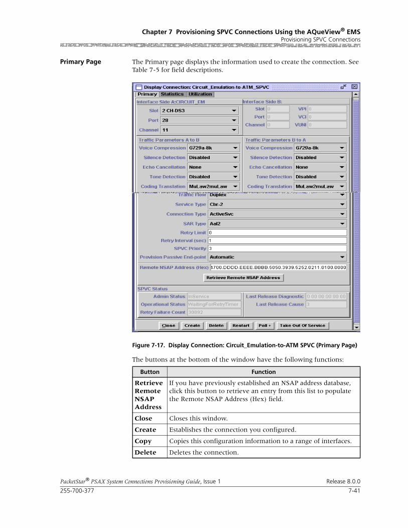
255-700-377 7-41
PacketStar® PSAX System Connections Provisioning Guide, Issue 1 Release 8.0.0
Chapter 7 Provisioning SPVC Connections Using the AQueView® EMSProvisioning SPVC Connections
Primary Page The Primary page displays the information used to create the connection. See Table 7-5 for field descriptions.
The buttons at the bottom of the window have the following functions:
Figure 7-17. Display Connection: Circuit_Emulation-to-ATM SPVC (Primary Page)
Button Function
Retrieve Remote NSAP Address
If you have previously established an NSAP address database, click this button to retrieve an entry from this list to populate the Remote NSAP Address (Hex) field.
Close Closes this window.
Create Establishes the connection you configured.
Copy Copies this configuration information to a range of interfaces.
Delete Deletes the connection.

Chapter 7 Provisioning SPVC Connections Using the AQueView® EMSProvisioning SPVC Connections
7-42 255-700-377
PacketStar® PSAX System Connections Provisioning Guide, Issue 1 Release 8.0.0
Statistics Page The Statistics page displays the statistics for this connection (see Figure 7-18).
The buttons on the Statistics page have the following functions:
Restart Restarts the connection.
Poll Continuously update the statistics and changes the button label to Poll-.
Terminates polling. Changes the button label to Poll+.
Button Function
Figure 7-18. Display Connection: Circuit_Emulation-to-ATM SPVC (Statistics Page)
Button Description
Update Refreshes the statistics manually.
Clear Resets the resetable statistics to zero.

255-700-377 7-43
PacketStar® PSAX System Connections Provisioning Guide, Issue 1 Release 8.0.0
Chapter 7 Provisioning SPVC Connections Using the AQueView® EMSProvisioning SPVC Connections
The values for the fields on this window are described in Table 7-6.
Poll Poll + continuously update the statistics and changes the button label to Poll-.
Poll- terminates polling and changes the button label to Poll+.
Odometer Restarts counting in the Cells Transmitted and Cells Received fields iin the Interface Side A and Interface Side B panels, and to view the trans-mitted cells and received cells in the Interface Side A and Interface Side B panels. This button is displayed only on the ATM-to-ATM VCC PVC and ATM-to-ATM VPC PVC Statistics pages.
Close Closes this window.
Restart Restarts connection establishment procedure for the connections that were not previously set up.
Button Description
Table 7-6. Field Descriptions for the Circuit Emulation-to-ATM VCC SPVC Statistics Window
Field Names Field Values Description
Cells Encoded(display only)
Default: 0.0000 e0
Range: 0-(231-1)
Format: numeric
Number of cells encoded going into either inter-face side during the amount of time shown in Time Elapsed field (that is, since the circuit was created).
Cells Decoded(display only)
Default: 0.0000 e0
Range: 0-(231-1)
Format: numeric
Number of cells decoded going out of either inter-face side during the amount of time shown in Time Elapsed field (that is, since the circuit was created).
Encoded Odometer(display only)
Default: 0.0000 e0 Range: 0-(231-1)
Format: numeric
Total number of cells encoded going into either interface side since the odometer was last reset.
Decoded Odometer
(display only)
Default: 0.0000 e0
Range: 0-(231-1)
Format: numeric
Total number of cells decoded going out of either interface side since the odometer was last reset.
Time Elapsed(display only)
Default: 00:00:00
Range: N/A
Format: Time in hours (xx), minutes (xx), seconds (xx)
Time elapsed since the circuit was established.
Cells Received(display only)
6.5000 e1 (default) Number of valid cells received since the virtual circuit or virtual path was established.
Cells Transmitted(display only)
6.5000 e1 (default) Number of valid cells transmitted since the virtual circuit or virtual path was established.

Chapter 7 Provisioning SPVC Connections Using the AQueView® EMSProvisioning SPVC Connections
7-44 255-700-377
PacketStar® PSAX System Connections Provisioning Guide, Issue 1 Release 8.0.0
Received Odometer(display only)
6.5000 e1 (default) Total number of ATM cells received since odome-ter was last reset.
Transmitted Odom-eter(display only)
6.5000 e1 (default) Total number of ATM cells transmitted since odometer was last reset.
Time Since Reset(display only)
Default: 00:00:00Range: N/A
Format: Time in hours (xx), minutes (xx), seconds (xx)
Time elapsed since the last time the Clear button was used. This button resets only the odometer fields (labelled as Odometer) and the corre-sponding clock. Other counters increment for the life of the circuit.
Table 7-6. Field Descriptions for the Circuit Emulation-to-ATM VCC SPVC Statistics Window
Field Names Field Values Description

255-700-377 7-45
PacketStar® PSAX System Connections Provisioning Guide, Issue 1 Release 8.0.0
Chapter 7 Provisioning SPVC Connections Using the AQueView® EMSProvisioning SPVC Connections
Utilization Page The Utilization page measures the amount of traffic running through this connection (see Figure 7-19).
Figure 7-19. Display Connection: Circuit Emulation -to-ATM VCC SPVC (Utilization Page)
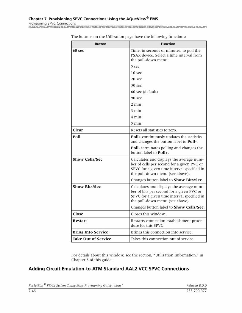
Chapter 7 Provisioning SPVC Connections Using the AQueView® EMSProvisioning SPVC Connections
7-46 255-700-377
PacketStar® PSAX System Connections Provisioning Guide, Issue 1 Release 8.0.0
The buttons on the Utilization page have the following functions:
For details about this window, see the section, “Utilization Information,” in Chapter 5 of this guide.
Adding Circuit Emulation-to-ATM Standard AAL2 VCC SPVC Connections
Button Function
60 sec Time, in seconds or minutes, to poll the PSAX device. Select a time interval from the pull-down menu:
5 sec
10 sec
20 sec
30 sec
60 sec (default)
90 sec
2 min
3 min
4 min
5 min
Clear Resets all statistics to zero.
Poll Poll+ continuously updates the statistics and changes the button label to Poll-.
Poll- terminates polling and changes the button label to Poll+.
Show Cells/Sec Calculates and displays the average num-ber of cells per second for a given PVC or SPVC for a given time interval specified in the pull-down menu (see above).
Changes button label to Show Bits/Sec.
Show Bits/Sec Calculates and displays the average num-ber of bits per second for a given PVC or SPVC for a given time interval specified in the pull-down menu (see above).
Changes button label to Show Cells/Sec.
Close Closes this window.
Restart Restarts connection establishment proce-dure for this SPVC.
Bring Into Service Brings this connection into service.
Take Out of Service Takes this connection out of service.

255-700-377 7-47
PacketStar® PSAX System Connections Provisioning Guide, Issue 1 Release 8.0.0
Chapter 7 Provisioning SPVC Connections Using the AQueView® EMSProvisioning SPVC Connections
Before you can a circuit emulation-to-ATM Standard AAL2 VCC SPVC con-nection, you must:
• Configure the appropriate ATM trunking parameters from the Site-Specific > ATM Trunking tab, and
• Have a DSP2D module present in a PSAX device involved in this configura-tion.
Perform the steps in the following procedure to create a circuit emulation-to-ATM Standard AAL2 VCC SPVC connection.
Begin
1 In the Device window, click the Connections tab.
The Listing page appears.
2 Click the right mouse button and a menu appears. Click Create New.
The Create Connection window appears (see Figure 7-15).
3 On the Side A panel, select the appropriate slot, port, and channel for a module that is configured with the circuit emulation interface. The inter-face name appears in the Interface Type field.
4 On the Side B panel, select SPVC.
The SPVC Connection Type field is displayed.
5 Select STD AAL2.
6 Click Create.
Figure 7-20. Create Connection Window

Chapter 7 Provisioning SPVC Connections Using the AQueView® EMSProvisioning SPVC Connections
7-48 255-700-377
PacketStar® PSAX System Connections Provisioning Guide, Issue 1 Release 8.0.0
The Create CE-to-ATM_Std_AAL2_VCC_SPVC Connection window appears (see Figure 7-21).
Note: For circuit emulation range limits for DSP Algosets 1 through 7, see the Connection Capacity of DSP2x Algorithm Sets Table in the Ref-erence Information Appendix of the DSP2x Voice Server Module User Guide.
Buttons The buttons on this window have the following functions:
Field Descriptions 7 Select the values for the fields on this window from the values given in Table 7-7.
Figure 7-21. Create CE-to-ATM_Std_AAL2_VCC Connection Window
Button Function
Close Closes this window.
Create Establishes the connection you configured.
Copy Copies this configuration infor-mation to to a range of inter-faces.

255-700-377 7-49
PacketStar® PSAX System Connections Provisioning Guide, Issue 1 Release 8.0.0
Chapter 7 Provisioning SPVC Connections Using the AQueView® EMSProvisioning SPVC Connections
Table 7-7. Field Descriptions for the CE-to-ATM Std AAL2 SPVC Connection Window
Field Name Field Values Description
Interface Side A
Slot Default: 1
Range: chassis depen-dent
Format: numeric
Specifies the slot containing the module that is being used for the CE interface side of the con-nection.
Port Default: 1
Range: module dependent
Format: numeric
Specifies the port on the module that is being used for the CE interface side of the connection.
Channel Default: 1
Range: port depen-dent
Format: numeric
Specifies the channel of the port on the module that is being used for the CE interface side of the connection.
AAL2 ATM Interface Panel
RmtIwfId Default: 0Range: 0–1024
Format: numeric
Specifies the remote interworking function (IWF) identifier for the remote endpoint. The remote endpoint is the AAL2 trunk side of the connec-tion.
VccId Default: 0
Range: 0–4096
Format: numeric
Specifies the virtual channel connection identifier for the AAL2 trunk side of the connection. Only 1,024 bearer VCCs are supported per chassis.
Cid Default: 0Range: 8–255 for non-OAM trunks; 32–255 for End-Pt OAM trunks (0–15 is reserved)
Format: numeric
Specifies the channel identifier for the AAL2 trunk side of the connection. This identifier is unique for each AAL2 trunk. For trunks with End-Pt selected as the OAM support type, the starting CID is 32. In this case, CIDs are preas-signed to each circuit emulation channel, that is channel 1 always has to be on CID 32, channel two always has to be on CID 33, and so on up to CID 63 for channel 31 on an E1 interface.
Connection Features
Encoding Profile Default: Itut-profile-1
Range: N/A
Format: predefined alphanumeric
Specifies the ITU-T or ATM Forum parameter set that applies to the connection. A parameter set specifies the compression algorithm used, packet size, whether silence detection is included, and so on. For more information on ATM Forum pro-files, see the reference appendix in this guide.
Note: See also the ITU-T Transmission Profile Tables in the reference appendix of this guide.
Itut-profile-1 Indicates that the connection uses the ITU-T Standard profile-1. This profile supports PCM G.711-64 Kbps (no compression).

Chapter 7 Provisioning SPVC Connections Using the AQueView® EMSProvisioning SPVC Connections
7-50 255-700-377
PacketStar® PSAX System Connections Provisioning Guide, Issue 1 Release 8.0.0
Itut-profile-3 Indicates that the connection uses the ITU-T Standard Profile 3. This profile supports ADPCM G.726 at 16, 24, 32, and 40 Kbps compression and silence detection.
Itut-profile-7 Indicates that the connection uses the ITU-T Standard Profile 7. This profile supports CS-ACELP G.729 8 Kbps compression and G.729 silence detection.
Af-profile-7 Indicates that the connection uses the ATM Form Standard Profile 7. This profile supports PCM-64, ADPCM-32, and silence detection. Data is trans-mitted in 44-octet packets.
Af-profile-8 Indicates that the connection uses the ATM Form Standard Profile 7. This profile supports PCM-64, ADPCM-32, and silence detection. Data is trans-mitted in 44-octet packets.
Af-profile-9 Indicates that the connection uses the ATM Form Standard Profile 9. This profile supports PCM-64, ADPCM-32, and silence detection. Data is trans-mitted in 44-octet packets.
Af-profile-10 Indicates that the connection uses the ATM Form Standard Profile 10. This profile supports PCM-64, ADPCM-32, without silence detection. Data is transmitted in 44-octet packets.
Af-profile-11 Indicates that the connection uses the ATM Form Standard Profile 11. This profile supports PCM-64, ADPCM-32, without silence detection. Data is transmitted in 40-octet packets.
Af-profile-12 Indicates that the connection uses the ATM Form Standard Profile 12. This profile supports PCM-64, ADPCM-32, with silence detection. Data is transmitted in 40-octet packets.
Custom Indicates that the connection uses user-defined voice encoding.
Default Indicates that the connection uses the default encoding profile of the AAL2 trunk configura-tion.
Voice Compression Default: NoneFormat: predefined alphanumeric
G726-16kG726-24kG726-32kG726-40kG729a-8k
Specifies the ITU-T standard of compression in Kbps.
Table 7-7. Field Descriptions for the CE-to-ATM Std AAL2 SPVC Connection Window (Continued)
Field Name Field Values Description

255-700-377 7-51
PacketStar® PSAX System Connections Provisioning Guide, Issue 1 Release 8.0.0
Chapter 7 Provisioning SPVC Connections Using the AQueView® EMSProvisioning SPVC Connections
Silence Detection Default: Disabled
Range: N/A
Format: predefined alphanumeric
Specifies whether silence detection will be used on this connection or not. You can specify if you want periods of silence in the connection to gen-erate cells or not. To conserve bandwidth, select enabled.
Disabled Disables silence detection. Cells will be sent dur-ing silent periods in the connection.
Enabled Enables silence detection. No cells will be sent during silent periods in a connection.
Echo Cancellation Default: NoneRange: N/A
Format: predefined alphanumeric
Specifies what type of echo cancellation will be used on the connections. Echo cancellation allows for the isolation and filtering out of unwanted signals caused by echoes from the main transmitted signal. Echo strength is mea-sured in msec “tails”.
None Echo cancellation is not enabled.
G165-nearEnd ITU-T Standard G.165 (for near end only).
G168 ITU-T Standard G.168.
Tone Detection Default: Disabled
Range: N/A
Format: predefined alphanumeric
Specifies what kind of fax or modem tone the connection will detect or bypass.
Disabled Disables fax/modem tone detection. The PSAX system reverts to uncompressed processing.
Bypass Bypasses fax/modem tone detection.
Code Translation Default: None
Range: N/A
Format: predefined alphanumeric
Specifies the coding translation type on the con-nection. Mu law is the Japanese and North American PCM coding and companding standard. A law is the European PCM coding and com-panding standard.
None Indicates that the coding translation type is auto-matically set to the Mu law to Mu law standard for the connection, even though the field displays the value None.
MuLaw2muLaw Indicates that the coding translation type is Mu law to Mu law.
ALaw2aLaw Indicates that the coding translation type is A law to A law.
MuLaw2aLaw Indicates that the coding translation type is Mu law to A law.
ALaw2muLaw Indicates that the coding translation type is A law to Mu law.
Table 7-7. Field Descriptions for the CE-to-ATM Std AAL2 SPVC Connection Window (Continued)
Field Name Field Values Description

Chapter 7 Provisioning SPVC Connections Using the AQueView® EMSProvisioning SPVC Connections
7-52 255-700-377
PacketStar® PSAX System Connections Provisioning Guide, Issue 1 Release 8.0.0
If the parameters are valid, the Connections window appears with the new connection in the Listing page, and the Display Connection window appears with the Primary tab (see Figure 7-17).
If a parameter is invalid, a Connection Creation Failed message appears, stating the reason for the failure.
Service Type Default: Ubr
Range: N/A
Format: predefined alphanumeric
Specifies the PSAX system-supported quality of service (QoS) class. For a description of the QoS classes, see the reference appendix in this guide. The type selected causes the conformance type for the connection to be derived from the class of service. This derived value is enforced by the UPC setting of the I/O module.
Ubr Indicates unspecified bit rate.
Vbr-nrt2 Indicates variable bit rate, non-real time, queue 2
Vbr-nrt1 Indicates variable bit rate, non-real time, queue 1
Vbr-rt2 Indicates variable bit rate, real time, queue 2
Vbr-rt1 Indicates variable bit rate, real time, queue 1
Vbr-express Indicates variable bit rate, express
Cbr4 Indicates constant bit rate, queue 4
Cbr3 Indicates constant bit rate, queue 3
Cbr2 Indicates constant bit rate, queue 2
Connection Status(display only)
Default: ActiveRange:
Format: predefined alphanumeric
Specifies whether the connection is active (pass-ing traffic) or inactive (not passing traffic).
Default: Active Indicates that the connection is passing traffic.
Default: Inactive Indicates that the connection is not passing traf-fic.
Table 7-7. Field Descriptions for the CE-to-ATM Std AAL2 SPVC Connection Window (Continued)
Field Name Field Values Description

255-700-377 7-53
PacketStar® PSAX System Connections Provisioning Guide, Issue 1 Release 8.0.0
Chapter 7 Provisioning SPVC Connections Using the AQueView® EMSProvisioning SPVC Connections
Primary Page The Primary page displays the information used to create the connection. See Table 7-7 for field descriptions.
Primary Page Buttons The buttons at the bottom of the window have the following functions:
End
Adding Frame Relay-to-ATM VCC SPVC Connections
Perform the steps in the following procedure to create a frame relay-to-ATM VCC SPVC connection.
Figure 7-22. Display Connection: Circuit_Emulation-to-ATM Std_AAL2_VCC_SPVC Window (Primary Page)
Button Function
Close Closes this window.
Create Establishes the connection youconfigured.
Copy Copies this configuration infor-mation to to a range of inter-faces.
Delete Deletes the connection.

Chapter 7 Provisioning SPVC Connections Using the AQueView® EMSProvisioning SPVC Connections
7-54 255-700-377
PacketStar® PSAX System Connections Provisioning Guide, Issue 1 Release 8.0.0
Begin
1 In the Device window, click the Connections tab.
The Listing page appears.
2 Click the right mouse button and a menu appears. Click Create New.
The Create Connection window appears (see Figure 7-23).
3 Select the appropriate slot, port, and channel for a module that is config-ured with a frame relay interface interface on the Side A panel. The interface name is displayed in the Interface field.
4 On the Side B panel, select SPVC.
5 Click Create.
The Create Frame Relay-to-ATM_SPVC Connection window is displayed (see Figure 7-24).
Figure 7-23. Create Connection Window
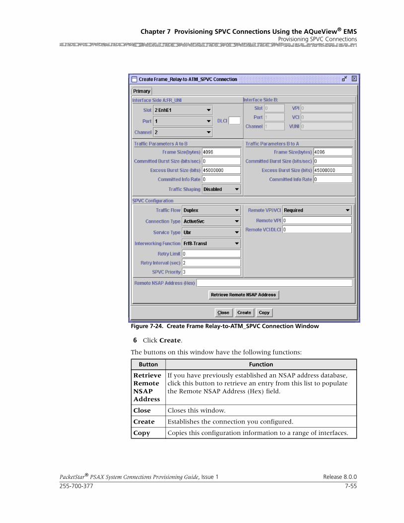
255-700-377 7-55
PacketStar® PSAX System Connections Provisioning Guide, Issue 1 Release 8.0.0
Chapter 7 Provisioning SPVC Connections Using the AQueView® EMSProvisioning SPVC Connections
6 Click Create.
The buttons on this window have the following functions:
Figure 7-24. Create Frame Relay-to-ATM_SPVC Connection Window
Button Function
Retrieve Remote NSAP Address
If you have previously established an NSAP address database, click this button to retrieve an entry from this list to populate the Remote NSAP Address (Hex) field.
Close Closes this window.
Create Establishes the connection you configured.
Copy Copies this configuration information to a range of interfaces.

Chapter 7 Provisioning SPVC Connections Using the AQueView® EMSProvisioning SPVC Connections
7-56 255-700-377
PacketStar® PSAX System Connections Provisioning Guide, Issue 1 Release 8.0.0
Field Descriptions 7 Select the values for the fields on this window from the values given in the following table.
Table 7-8. Field Descriptions for the Frame Relay-to-ATM SPVC Connection Window
Field Names Field Values Description
Interface Side A:FR_UNI or FR_NNI
Default: N/ARange: N/A
Format: N/A
Frame relay side (PVC side) of the connection.
Slot(display only)
Default: 0
Range: variable
Format: numeric
The slot number on the module for which you are creating a connection.
Port(display only)
Default: 1
Range: variable
Format: numeric
The port number on the module for which you are creating a connection.
Channel(display only)
Default: 1
Range: variable
Format: numeric
The channel number on the module for which you are creating a connection. This is the channel where the call originates. For example, on a port of the 6-Port Enhanced DS1 Multiservice mod-ule, you can configure more than one channel in a port. The range of channel numbers varies with the module type.
DLCI Default: N/A
Range: 16–1007
Format: numeric
Data link connection identifier. DLCI is used when the remote end point is frame relay.
Frame Size(bytes) Default: 4096
Range: N/A
Format: numeric
Measured in bytes.
Committed Burst Size (bits/sec)
Default: 0Range: N/A
Format: numeric
Use the default value.
Excess Burst Size (bits)
Default: 45000000
Range: N/A
Format: numeric
Excess burst size, measured in bits per second.
Committed Info Rate
Default: 0
Range: N/A
Format: numeric
Committed information rate is the rate of traffic (measured in bits per second) for a given connec-tion that the system will attempt to provide guar-anteed delivery.

255-700-377 7-57
PacketStar® PSAX System Connections Provisioning Guide, Issue 1 Release 8.0.0
Chapter 7 Provisioning SPVC Connections Using the AQueView® EMSProvisioning SPVC Connections
Traffic Flow Default: Duplex
Range: N/A
Format: predefined alphanumeric
Direction of flow of data traffic in this connection.
Duplex Data flows in two directions between the two connection points (interface side A and interface side B).
SimplexA2B Data flows in only one direction, from side A to side B.
Simplex B2A Data flows in only one direction, from side B to side A.
Connection Type Default: ActiveSvc
Range: N/A
Format: predefined alphanumeric
The type of connection.
ActiveSvc Selecting the value ActiveSvc attempts calls.
PassiveSvc Selecting the value PassiveSvc accepts calls.Sev-eral fields are not displayed when this value is selected.
Service Type Default: Ubr
Range: N/A
Format: Predefined alphanumeric
Specifies the PSAX system-supported quality of service (QoS) class. For a description of the QoS classes, see the reference appendix in this guide. The type selected causes the conformance type for the connection to be derived from the class of service. This derived value is enforced by the UPC setting of the I/O module.
Ubr Unspecified bit rate.
Vbr-nrt2 Variable bit rate, non-real time, queue 2
Vbr-nrt1 Variable bit rate, non-real time, queue 1
Vbr-rt2 Variable bit rate, real time, queue 2
Vbr-rt1 Variable bit rate, real time, queue 1
Vbr-express Variable bit rate, express
Table 7-8. Field Descriptions for the Frame Relay-to-ATM SPVC Connection Window
Field Names Field Values Description

Chapter 7 Provisioning SPVC Connections Using the AQueView® EMSProvisioning SPVC Connections
7-58 255-700-377
PacketStar® PSAX System Connections Provisioning Guide, Issue 1 Release 8.0.0
Interworking Func-tion
Default: Frf8-Transl
Range: N/A
Format: predefined alphanumeric
Type of interworking to be done.
Frf8-Transl FRF.8 (Frame Relay Forum Implementation Agreement)—frame relay to ATM PVC service interworking.
Frf8-Pass FRF.8 (Frame Relay Forum Implementation Agreement)—frame relay to ATM PVC service interworking.
Frf5 FRF.5 (Frame Relay Forum Implementation Agreement)—frame relay to ATM PVC service interworking.
Retry Interval (sec) Default: 12
Range: N/A
Format: numeric (sec)
The waiting period before attempting to establish the SPVC after one call attempt has failed. This field is displayed only when ActiveSvc is selected as the connection type.
Remote NSAP Address (Hex)
Default: N/ARange: N/A
Format: hexadecimal
The ATM NSAP address of the remote end of the connection, in hexidecimal notation. Enter the NSAP address of the remote frame relay or ATM interface in hexadecimal notation. This field is displayed only when ActiveSvc is selected as the connection type.
Remote VPI/VCI Default: Required
Range: N/A
Format: predefined alphanumeric
This field indicates whether the remote VPI/VCI values are to be used at the destination. This field is displayed only when ActiveSvc is selected as the connection type.
Required The destination device uses the values specified at this end.
Any The destination device selects the VPI/VCI values.
VPI Default: 0
Range: 0–225 (ATM UNI);0–4095 (NNI)
Format: numeric
Virtual path identifier.
VCI Default: 0
Range: 32–65535
Format: numeric
Virtual channel identifier.
Table 7-8. Field Descriptions for the Frame Relay-to-ATM SPVC Connection Window
Field Names Field Values Description

255-700-377 7-59
PacketStar® PSAX System Connections Provisioning Guide, Issue 1 Release 8.0.0
Chapter 7 Provisioning SPVC Connections Using the AQueView® EMSProvisioning SPVC Connections
Operational Status Default: Other
Range: N/A
Format: predefined alphanumeric
Operational status of the connection.
Note: This field is displayed only on the Display Connection window, not on the Create Connec-tion window.
Other None of the types specified below.
EstablishmentInProgress
Connection is not operational, but call attempts are ongoing.
Connected Connection is currently operational.
RetriesExhausted Retry limit has been reached and call attempts have ceased.
NoAddressSupplied
No remote address has been configured, so no call attempts are initiated.
LowerLayerDown PVC endpoint is out of service.
WaitingForCall Passive endpoint of a SPVC connection, waiting for call from an active side.
WaitingForRetryTimer
Active endpoint of a SPVC connection, waiting for the retry timer to expire so that it can retry the call.
Last Releases Diag-nostic
Default: N/ARange: N/A
Format: predefined alphanumeric
Last release diagnosis. Explains how the connec-tion was released and reported by the far end of the connection.
Note: This field is displayed only on the Display Connection window, not on the Create Connec-tion window.
Retry Failure Count Default: N/A
Range: N/A
Format: predefined alphanumeric
Displays how many times the call retry failed since the last successful call setup. When a call is released, the PSAX system will continue to retry up to the retry limit that is specified in the Retry Limit field. See the ATM UNI 3.0 specification for more information.
Note: This field is displayed only on the Display Connection window, not on the Create Connec-tion window.
Last Release Cause(display only)
Default: 0
Range: N/A
Format: numeric
Displays the last release cause code. The cause code indicates a reason why the last attempted call was released. See the reference appendix in this guide for the description of SPVC Connection Cause Codes.
Note: This field is displayed only on the Display Connection window, not on the Create Connec-tion window.
Table 7-8. Field Descriptions for the Frame Relay-to-ATM SPVC Connection Window
Field Names Field Values Description

Chapter 7 Provisioning SPVC Connections Using the AQueView® EMSProvisioning SPVC Connections
7-60 255-700-377
PacketStar® PSAX System Connections Provisioning Guide, Issue 1 Release 8.0.0
If the parameters are valid, the Connections window appears with the new connection in the Listing page, and the Display Connection window appears with tabs that contain details about the connection (see Figure 7-25): Primary, and Statistics.
If a parameter is invalid, a Connection Creation Failed message appears, stating the reason for the failure.
End
Primary Page The Primary page displays the information used to create the connection. See Table 7-8 on page 56 for field descriptions.
Figure 7-25. Display Connection: Frame_Relay-to-ATM SPVC (Primary Page)
255-700-377 7-61
PacketStar® PSAX System Connections Provisioning Guide, Issue 1 Release 8.0.0
Chapter 7 Provisioning SPVC Connections Using the AQueView® EMSProvisioning SPVC Connections
The buttons at the bottom of the window have the following functions:
Statistics Page The Statistics page displays the statistics for this connection.
Button Function
Retrieve Remote NSAP Address
If you have previously established an NSAP address database, click this button to retrieve an entry from this list to populate the Remote NSAP Address (Hex) field.
Close Closes this window.
Create Establishes the connection you configured.
Copy Copies this configuration information to a range of interfaces.
Delete Deletes the connection.
Restart Restarts the connection.
Poll Continuously update the statistics and changes the button label to Poll-.
Terminates polling. Changes the button label to Poll+.
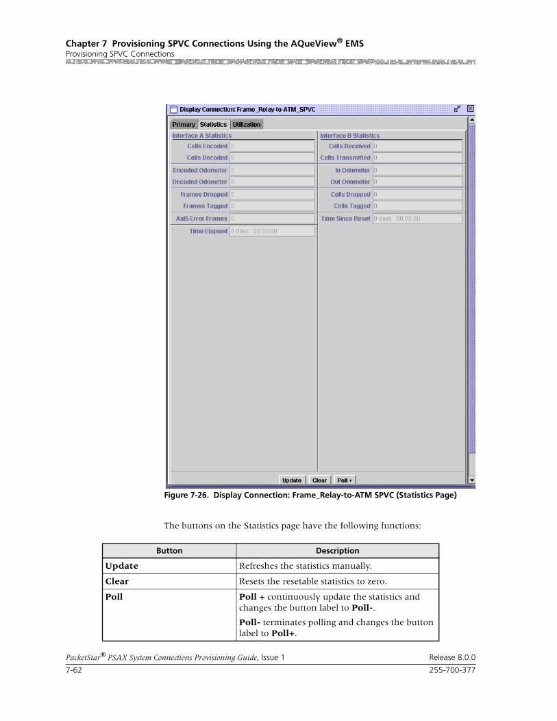
Chapter 7 Provisioning SPVC Connections Using the AQueView® EMSProvisioning SPVC Connections
7-62 255-700-377
PacketStar® PSAX System Connections Provisioning Guide, Issue 1 Release 8.0.0
The buttons on the Statistics page have the following functions:
Figure 7-26. Display Connection: Frame_Relay-to-ATM SPVC (Statistics Page)
Button Description
Update Refreshes the statistics manually.
Clear Resets the resetable statistics to zero.
Poll Poll + continuously update the statistics and changes the button label to Poll-.
Poll- terminates polling and changes the button label to Poll+.

255-700-377 7-63
PacketStar® PSAX System Connections Provisioning Guide, Issue 1 Release 8.0.0
Chapter 7 Provisioning SPVC Connections Using the AQueView® EMSProvisioning SPVC Connections
Field Descriptions 8 Enter values in the fields on this window according to the information provided Table 7-9.
Odometer Restarts counting in the Cells Transmitted and Cells Received fields iin the Interface Side A and Interface Side B panels, and to view the trans-mitted cells and received cells in the Interface Side A and Interface Side B panels. This button is displayed only on the ATM-to-ATM VCC PVC and ATM-to-ATM VPC PVC Statistics pages.
Close Closes this window.
Restart Restarts connection establishment procedure for the connections that were not previously set up.
Button Description
Table 7-9. Field Descriptions for the Frame Relay-to-ATM VCC SPVC Connection Statistics Page
Field Name Field Values Description
Cells Encoded Default: 0.0000 e0
Range: 0-(231-1)
Format: numeric
Number of cells encoded going into interface side A during the amount of time shown in Time Elapsed field.
Cells Decoded Default: 0.0000 e0 Range: 0-(231-1)
Format: numeric
Number of cells decoded going out of interface side B during the amount of time shown in Time Elapsed field.
Frames Dropped Default: 0
Range: N/A
Format: numeric
Number of frames dropped for a given DLCI in the A2B direction. This field is only applicable to the input side.
Encoded Odometer Default: 0.0000 e0
Range: 0-(231-1)
Format: numeric
Total number of cells encoded going into inter-face side A since the connection was created or statistics were reset.
Decoded Odometer Default: 0.0000 e0 Range: 0-(231-1)
Format: numeric
Total number of cells decoded going out of inter-face side B since the connection was created or statistics were reset.
Time Elapsed Default: 00:00:00
Range: N/A
Format: Time in hours (xx), minutes (xx), seconds (xx)
Default:
Time, in hours, minutes, and seconds, since the circuit was established.
Time Since Reset Default: 00:00:00Range: NA
Format: Time in hours (xx), minutes (xx), seconds (xx)
Time elapsed since the last time the Clear button was used.
The Clear button on the statistics page resets only the odometer fields (labelled as Odometer) and the corresponding clock. Other counters increment for the life of the circuit.

Chapter 7 Provisioning SPVC Connections Using the AQueView® EMSProvisioning SPVC Connections
7-64 255-700-377
PacketStar® PSAX System Connections Provisioning Guide, Issue 1 Release 8.0.0
Cells Received Default: 0.0000 e0
Range: 0-(231-1)
Format: numeric
Number of cells received into interface side A during the amount of time shown in Time Elapsed field.
Cells Transmitted Default: 0.0000 e0 Range: 0-(231-1)
Format: numeric
Number of cells transmitted out of interface side B during the amount of time shown in Time Elapsed field.
In Odometer Default: 0.0000 e0
Range: 0-(231-1)
Format: numeric
Total number of cells encoded going into inter-face side B since the connection statistics were reset.
Out Odometer Default: 0.0000 e0
Range: 0-(231-1)
Format: numeric
Total number of cells decoded going out of inter-face side A since the connection statistics were reset.
Table 7-9. Field Descriptions for the Frame Relay-to-ATM VCC SPVC Connection Statistics Page
Field Name Field Values Description

255-700-377 7-65
PacketStar® PSAX System Connections Provisioning Guide, Issue 1 Release 8.0.0
Chapter 7 Provisioning SPVC Connections Using the AQueView® EMSProvisioning SPVC Connections
Utilization Page The Utilization page measures the amount of traffic running through this connection (see Figure 7-27).
Figure 7-27. Display Connection: Frame_Relay-to-ATM VCC SPVC (Utilization Page)

Chapter 7 Provisioning SPVC Connections Using the AQueView® EMSProvisioning SPVC Connections
7-66 255-700-377
PacketStar® PSAX System Connections Provisioning Guide, Issue 1 Release 8.0.0
The buttons on the Utilization page have the following functions:
For details about this window, see the section, “Utilization Information,” in Chapter 5 of this guide.
Adding VBR-to-ATM VCC SPVC Connections
Button Function
60 sec Time, in seconds or minutes, to poll the PSAX device. Select a time interval from the pull-down menu:
5 sec
10 sec
20 sec
30 sec
60 sec (default)
90 sec
2 min
3 min
4 min
5 min
Clear Resets all statistics to zero.
Poll Poll+ continuously updates the statistics and changes the button label to Poll-.
Poll- terminates polling and changes the button label to Poll+.
Show Cells/Sec Calculates and displays the average num-ber of cells per second for a given PVC or SPVC for a given time interval specified in the pull-down menu (see above).
Changes button label to Show Bits/Sec.
Show Bits/Sec Calculates and displays the average num-ber of bits per second for a given PVC or SPVC for a given time interval specified in the pull-down menu (see above).
Changes button label to Show Cells/Sec.
Close Closes this window.
Restart Restarts connection establishment proce-dure for this SPVC.
Bring Into Service Brings this connection into service.
Take Out of Service Takes this connection out of service.

255-700-377 7-67
PacketStar® PSAX System Connections Provisioning Guide, Issue 1 Release 8.0.0
Chapter 7 Provisioning SPVC Connections Using the AQueView® EMSProvisioning SPVC Connections
This connection is supported on the Ethernet module and the 4-Port Ethernet module beginning with PacketStar PSAX Release 6.5.0, and AQueView EMS Release 4.5.
Perform the steps in the following procedure to create an VBR-to-ATM SPVC connection.
Begin
1 In the Device window, click the Connections tab.
The Listing page appears.
2 Click the right mouse button and a menu appears. Click Create New.
The Create Connection window appears (see Figure 7-28).
3 Select the appropriate slot, port, and channel for a module that is config-ured with one of the following interfaces for Side A:
• HDLC Passthrough
• Terminal Emulation
The interface name appears at the bottom.
4 On Side B, select SPVC.
5 Once the desired connection type appears in the Connection Type field, click Create.
The Create VBR_to_ATM VCC SPVC Connection window appears (see Figure 7-29).
Figure 7-28. Create Connection Window

Chapter 7 Provisioning SPVC Connections Using the AQueView® EMSProvisioning SPVC Connections
7-68 255-700-377
PacketStar® PSAX System Connections Provisioning Guide, Issue 1 Release 8.0.0
Buttons The buttons on this window have the following functions:
Field Descriptions 6 Select the values for the fields on this window from the values given in Table 7-10.
Figure 7-29. Create VBR_to_ATM SPVC Connection Window
Button Function
Retrieve Remote NSAP Address
If you have previously established an NSAP address database, click this button to retrieve an entry from this list to populate the Remote NSAP Address (Hex) field.
Close Closes this window.
Create Establishes the connection you configured.
Copy Copies this configuration information to to a range of inter-faces.

255-700-377 7-69
PacketStar® PSAX System Connections Provisioning Guide, Issue 1 Release 8.0.0
Chapter 7 Provisioning SPVC Connections Using the AQueView® EMSProvisioning SPVC Connections
Table 7-10. Field Descriptions for the VBR-to-ATM_SPVC Connection Window
Field Name Field Values Description
Interface Side A Default: N/A
Range: N/A
Format: N/A
Specifies the VBR interface side of the connection that will send and receive traffic. This side is used for the Ethernet side of the connection.
Interface Side B Default: N/A
Range: N/A
Format: N/A
Specifies the ATM side of the connection that will send and receive traffic.
Slot Default: N/ARange: chassis depen-dent
Format: numeric
Specifies the slot number on the module for which you are creating a connection.
Port Default: N/ARange: module dependent
Format: numeric
Specifies the port number on the module for which you are creating a connection.
Channel Default: N/A
Range: port depen-dent
Format: numeric
Specifies the channel number on the module for which you are creating a connection.
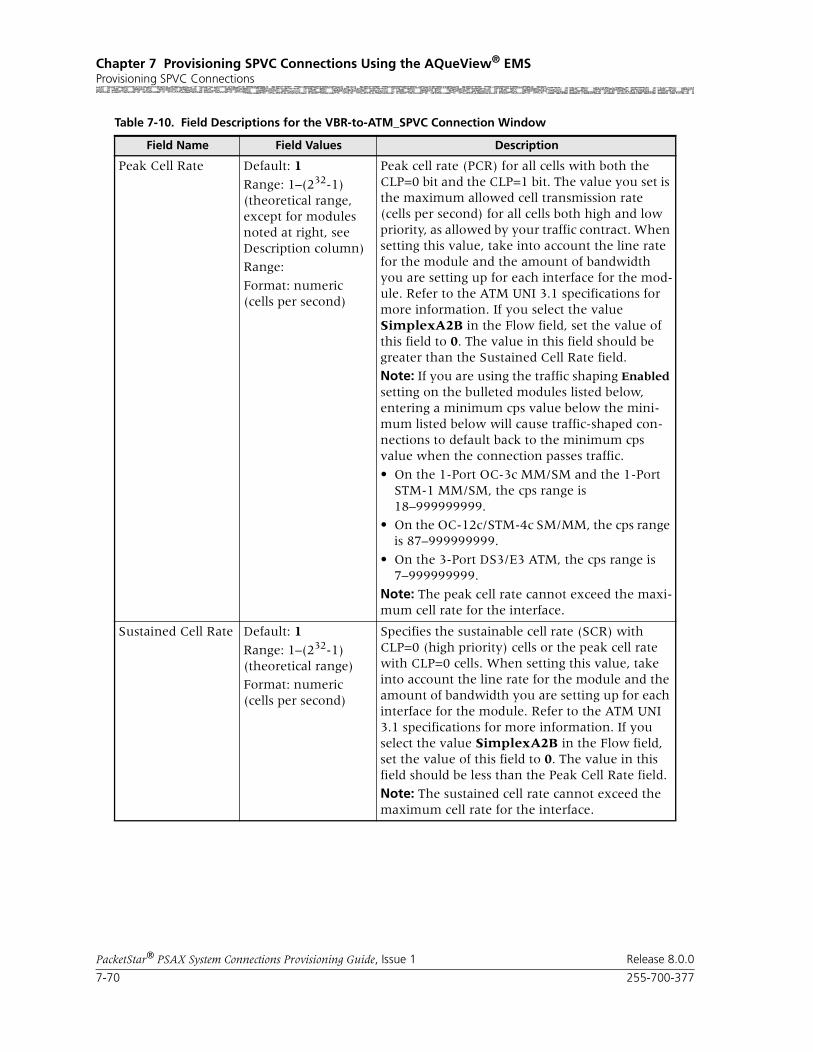
Chapter 7 Provisioning SPVC Connections Using the AQueView® EMSProvisioning SPVC Connections
7-70 255-700-377
PacketStar® PSAX System Connections Provisioning Guide, Issue 1 Release 8.0.0
Peak Cell Rate Default: 1
Range: 1–(232-1)(theoretical range, except for modules noted at right, see Description column)
Range:
Format: numeric (cells per second)
Peak cell rate (PCR) for all cells with both the CLP=0 bit and the CLP=1 bit. The value you set is the maximum allowed cell transmission rate (cells per second) for all cells both high and low priority, as allowed by your traffic contract. When setting this value, take into account the line rate for the module and the amount of bandwidth you are setting up for each interface for the mod-ule. Refer to the ATM UNI 3.1 specifications for more information. If you select the value SimplexA2B in the Flow field, set the value of this field to 0. The value in this field should be greater than the Sustained Cell Rate field.
Note: If you are using the traffic shaping Enabled setting on the bulleted modules listed below, entering a minimum cps value below the mini-mum listed below will cause traffic-shaped con-nections to default back to the minimum cps value when the connection passes traffic.
• On the 1-Port OC-3c MM/SM and the 1-Port STM-1 MM/SM, the cps range is 18–999999999.
• On the OC-12c/STM-4c SM/MM, the cps range is 87–999999999.
• On the 3-Port DS3/E3 ATM, the cps range is 7–999999999.
Note: The peak cell rate cannot exceed the maxi-mum cell rate for the interface.
Sustained Cell Rate Default: 1
Range: 1–(232-1)(theoretical range)
Format: numeric (cells per second)
Specifies the sustainable cell rate (SCR) with CLP=0 (high priority) cells or the peak cell rate with CLP=0 cells. When setting this value, take into account the line rate for the module and the amount of bandwidth you are setting up for each interface for the module. Refer to the ATM UNI 3.1 specifications for more information. If you select the value SimplexA2B in the Flow field, set the value of this field to 0. The value in this field should be less than the Peak Cell Rate field.
Note: The sustained cell rate cannot exceed the maximum cell rate for the interface.
Table 7-10. Field Descriptions for the VBR-to-ATM_SPVC Connection Window
Field Name Field Values Description

255-700-377 7-71
PacketStar® PSAX System Connections Provisioning Guide, Issue 1 Release 8.0.0
Chapter 7 Provisioning SPVC Connections Using the AQueView® EMSProvisioning SPVC Connections
Max Burst Size (cells)
Default: 1
Range: 0–65535
Format: numeric
Indicates the maximum burst size. The maximum number of cells that can be received at the peak cell rate. This allows a burst of cells to arrive at a rate higher than that of the sustained cell rate. If the burst is larger than anticipated, the additional cells are either tagged or dropped. When setting this value, take into account the line rate for the module and the amount of bandwidth you are setting up for each interface for the module.
If you select the value SimplexA2B in the Flow field, set the value for peak rate to 0.
OC-3c APS Module: When the Traffic Shaping field is set to Enabled, the cell queue depth for the Max Burst Size field is internally set to 1000, regardless of the value you enter. If you enter values other than 1000, these values matter for incoming signalling SPVC/SVC setup from the remote end of the connection.
Traffic Flow Default: Duplex
Range: N/A
Format: predefined alphanumeric
Specifies the direction of flow of data traffic in this connection.
Duplex Indicates that data flows in two directions between the two connection points (interface side A and interface side B).
SimplexA2B Indicates that data flows in only one direction, from side A to side B.
Simplex B2A Indicates that data flows in only one direction, from side B to side A.
Service Type Default: Ubr Range: N/A
Format: predefined alphanumeric
Specifies the PSAX system-supported quality of service (QoS) class. For a description of the QoS classes, see the reference appendix in this guide. The type selected causes the conformance type for the connection to be derived from the class of service. This derived value is enforced by the UPC setting of the I/O module.
Ubr Unspecified bit rate. If you select this value, the Sustained Cell Rate (cps) and Max Burst Size fields are hidden on this window.
Vbr-nrt2 Variable bit rate—nonreal-time 2.
Vbr-nrt1 Variable bit rate—nonreal-time 1.
Vbr-rt2 Variable bit rate—real-time 2.
Vbr-rt1 Variable bit rate—real-time 1.
Vbr-express Variable bit rate—express.
Table 7-10. Field Descriptions for the VBR-to-ATM_SPVC Connection Window
Field Name Field Values Description

Chapter 7 Provisioning SPVC Connections Using the AQueView® EMSProvisioning SPVC Connections
7-72 255-700-377
PacketStar® PSAX System Connections Provisioning Guide, Issue 1 Release 8.0.0
Connection Type Default: ActiveSvc
Range: N/A
Format: predefined alphanumeric
Specifies whether the connection is active or pas-sive.
ActiveSvc Indicates that the connection attempts calls.
PassiveSvc Indicates that the connection accepts calls. Once you select this value, fields associated with the connection type set to ActiveSvc are hidden on this window.
Retry Limit Default: 0 Range: 0–65535
Format: numeric
Indicates the maximum limit on how many con-secutive unsuccessful call setup attempts can be made before stopping the attempts to set up the connection. The value 0 indicates no limits.
Note: This field is displayed only when you select the value ActiveSvc in the Connection Type field.
Retry Interval (sec) Default: 12 Range: 0–3600
Format: numeric
Indicates the waiting period before attempting to establish the SPVC after one call attempt has failed.
Note: This field is displayed only when you select the value ActiveSvc in the Connection Type field.
Provision Passive End-Point
Default: AutomaticRange: N/A
Format: predefined alphanumeric
Specifies whether end-to-end provisioning (pro-visioning SPVCs at two different points) is done automatically. When an active SPVC connection is created using the AQueView system, selecting Automatic in this field results in the passive end-point being provisioned automatically by the AQueView system. The information about where to provision the passive end-point is obtained from the NSAP database using the Remote NSAP Address (Hex) field for the active SPVC connec-tion. The Remote NSAP Address (Hex) field should exist in the NSAP address database.
Automatic Enables automatic end-to-end provisioning
None Disables automatic end-to-end provisioning.
Remote NSAP Address (Hex)
Default: N/ARange: N/A
Format: hexadecimal (shown when ActiveSvc is selected as the connection type)
Indicates the ATM NSAP address of the remote end of the connection. Enter the NSAP address of the remote VBR or ATM interface.
Note: This field is displayed only when you select the value ActiveSvc in the Connection Type field.
Table 7-10. Field Descriptions for the VBR-to-ATM_SPVC Connection Window
Field Name Field Values Description

255-700-377 7-73
PacketStar® PSAX System Connections Provisioning Guide, Issue 1 Release 8.0.0
Chapter 7 Provisioning SPVC Connections Using the AQueView® EMSProvisioning SPVC Connections
Traffic Shaping Default: Disabled
Range: N/A
Format: predefined alphanumeric
Indicates the method for controlling the flow of data traffic. This feature is implemented on the following modules:
• 1-Port OC-3c Multimode and Single-Mode with Traffic Shaping modules
• 1-Port STM-1 Multimode and Single-Mode with Traffic Shaping modules
• 3-Port DS3/E3 ATM
• 1-Port OC-12c/STM-4c MM/SM 1+1 APS/MSP modules
See the Peak Rate field on this table for minimum cps ranges restrictions on these modules.
Disabled Indicates that traffic shaping is not used on this connection.
Enabled Ensures that the variable bit-rate (VBR) traffic entering the PSAX system via these modules complies with the parameters of the established service contracts.
Operational Status Default: OtherRange: N/A
Format: predefined alphanumeric
Displays the operational status of this connection.
Note: This field is displayed only on the Display Connection window, not on the Create Connec-tion window.
Other Indicates that the operational status of this con-nection is not described by the types specified any other field values below.
EstablishmentInProgress
Indicates that the connection is not operational, but call attempts are ongoing.
Connected Indicates that the connection is currently opera-tional.
RetriesExhausted Indicates that the retry limit has been reached and call attempts have ceased.
NoAddressSupplied
Indicates that no remote address has been config-ured, so no call attempts are initiated.
LowerLayerDown Indicates that the PVC endpoint is out of service.
WaitingForCall Indicates that the passive endpoint of a SPVC connection is waiting for call from an active side.
WaitingForRetryTimer
Indicates that the active endpoint of a SPVC con-nection is waiting for the retry timer to expire so that it can retry the call.
Table 7-10. Field Descriptions for the VBR-to-ATM_SPVC Connection Window
Field Name Field Values Description

Chapter 7 Provisioning SPVC Connections Using the AQueView® EMSProvisioning SPVC Connections
7-74 255-700-377
PacketStar® PSAX System Connections Provisioning Guide, Issue 1 Release 8.0.0
If the parameters are valid, the Connections window appears with the new connection in the Listing page, and the Display Connection window appears with tabs that contain details about the connection (see Figure 7-30): Primary, Statistics, and Utilization.
If a parameter is invalid, a Connection Creation Failed message appears, stating the reason for the failure.
End
Last Releases Diag-nostic
Default: N/A
Range: N/A
Format: predefined alphanumeric
Displays the last release diagnosis, which explains how the connection was released and reported by the far end of the connection.
Note: This field is displayed only on the Display Connection window, not on the Create Connec-tion window.
Retry Failure Count Default: N/ARange: N/A
Format: numeric
Displays how many times the call retry failed since the last successful call setup. When a call is released, the PSAX system will continue to retry up to the retry limit that is specified in the Retry Limit field. See the ATM UNI 3.0 specification for more information.
Note: This field is displayed only on the Display Connection window, not on the Create Connec-tion window.
Last Release Cause(display only)
Default: 0Range: N/A
Format: numeric
Displays the last release cause code. The cause code indicates a reason why the last attempted call was released. See the reference appendix in this guide for the description of SPVC Connection Cause Codes.
Note: This field is displayed only on the Display Connection window, not on the Create Connec-tion window.
Table 7-10. Field Descriptions for the VBR-to-ATM_SPVC Connection Window
Field Name Field Values Description

255-700-377 7-75
PacketStar® PSAX System Connections Provisioning Guide, Issue 1 Release 8.0.0
Chapter 7 Provisioning SPVC Connections Using the AQueView® EMSProvisioning SPVC Connections
Primary Page The Primary page displays the information used to create the connection. See Table 7-10 for field descriptions.
The buttons at the bottom of the window have the following functions:
Figure 7-30. Display Connection: VBR-to-ATM SPVC (Primary Page)
Button Function
Retrieve Remote NSAP Address
If you have previously established an NSAP address database, click this button to retrieve an entry from this list to populate the Remote NSAP Address (Hex) field.
Close Closes this window.
Create Establishes the connection you configured.
Copy Copies this configuration information to a range of interfaces.
Delete Deletes the connection.
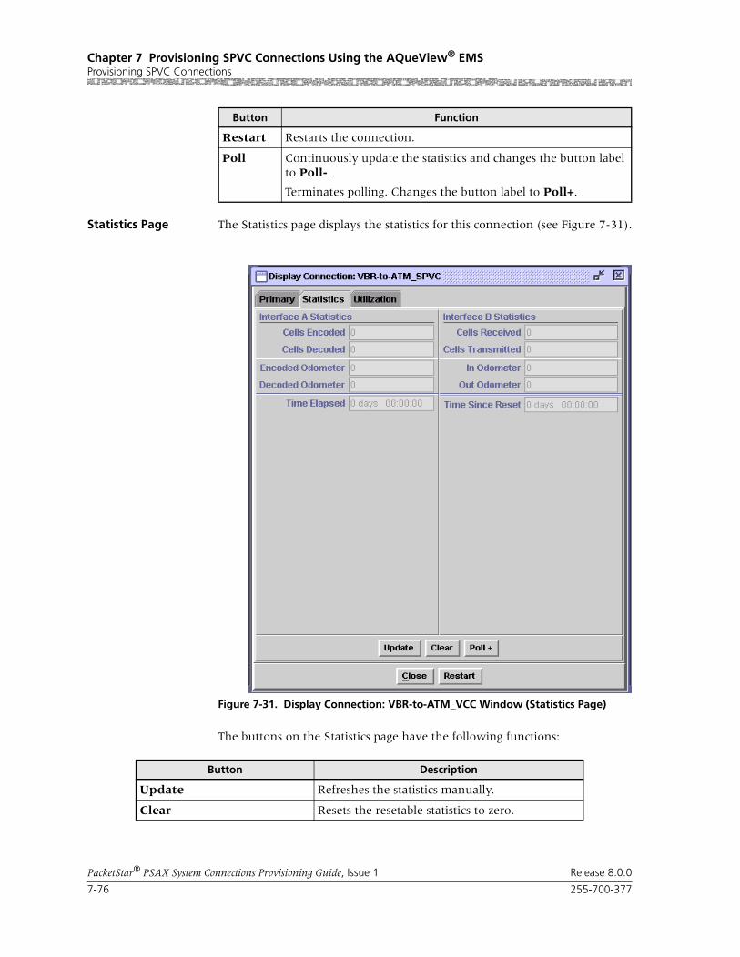
Chapter 7 Provisioning SPVC Connections Using the AQueView® EMSProvisioning SPVC Connections
7-76 255-700-377
PacketStar® PSAX System Connections Provisioning Guide, Issue 1 Release 8.0.0
Statistics Page The Statistics page displays the statistics for this connection (see Figure 7-31).
The buttons on the Statistics page have the following functions:
Restart Restarts the connection.
Poll Continuously update the statistics and changes the button label to Poll-.
Terminates polling. Changes the button label to Poll+.
Button Function
Figure 7-31. Display Connection: VBR-to-ATM_VCC Window (Statistics Page)
Button Description
Update Refreshes the statistics manually.
Clear Resets the resetable statistics to zero.

255-700-377 7-77
PacketStar® PSAX System Connections Provisioning Guide, Issue 1 Release 8.0.0
Chapter 7 Provisioning SPVC Connections Using the AQueView® EMSProvisioning SPVC Connections
Field Descriptions The fields on this window are described in Table 7-11.
Poll Poll + continuously update the statistics and changes the button label to Poll-.
Poll- terminates polling and changes the button label to Poll+.
Odometer Restarts counting in the Cells Transmitted and Cells Received fields iin the Interface Side A and Interface Side B panels, and to view the trans-mitted cells and received cells in the Interface Side A and Interface Side B panels. This button is displayed only on the ATM-to-ATM VCC PVC and ATM-to-ATM VPC PVC Statistics pages.
Close Closes this window.
Restart Restarts connection establishment procedure for the connections that were not previously set up.
Button Description
Table 7-11. Field Descriptions for the VBR-to-ATM VCC SPVC Statistics Page
Field Name Field Values Description
Cells Encoded Default: 0
Range: N/A
Format: Numeric
Displays the number of cells encoded going into interface Side A on this connection during the amount of time shown in Time Elapsed field.
Cells Decoded Default: 0
Range: N/A
Format: Numeric
Displays the number of cells decoded going out of interface Side B on this connection during the amount of time shown in Time Elapsed field.
Encoded Odometer Default: 0Range: N/A
Format: Numeric
Displays the total number of cells encoded going into interface Side A since the connection was created or statistics were reset.
Decoded Odometer Default: 0
Range: N/A
Format: Numeric
Displays the total number of cells decoded going out of interface Side A since the connection was created or statistics were reset.
Cells Received Default: 0
Range: N/A
Format: Numeric
Displays the number of valid cells received since the virtual circuit or virtual path was established.
Cells Transmitted Default: 0Range: N/A
Format: Numeric
Displays the number of valid cells transmitted since the virtual circuit or virtual path was estab-lished.
In Odometer Default: 0
Range: N/A
Format: Numeric
Displays the total number of cells encoded going into interface Side B since the connection statis-tics were reset.

Chapter 7 Provisioning SPVC Connections Using the AQueView® EMSProvisioning SPVC Connections
7-78 255-700-377
PacketStar® PSAX System Connections Provisioning Guide, Issue 1 Release 8.0.0
Out Odometer Default: 0
Range: N/A
Format: Numeric
Displays the total number of cells decoded going out of interface Side A since the connection sta-tistics were reset.
Time Elapsed Default: 00:00:00Range: N/A
Format: hh:mm:ss
Displays the time, in hours, minutes, and sec-onds, since last reset.
Time Since Reset Default: 00:00:00
Range: N/A
Format: hh:mm:ss
Time elapsed in hours, minutes, and seconds, since the last time the Clear button was used.
Table 7-11. Field Descriptions for the VBR-to-ATM VCC SPVC Statistics Page
Field Name Field Values Description

255-700-377 7-79
PacketStar® PSAX System Connections Provisioning Guide, Issue 1 Release 8.0.0
Chapter 7 Provisioning SPVC Connections Using the AQueView® EMSProvisioning SPVC Connections
Utilization Page The Utilization page measures the amount of traffic running through this connection (see Figure 7-32).
Figure 7-32. Display Connection: VBR-to-ATM VCC SPVC (Utilization Page)

Chapter 7 Provisioning SPVC Connections Using the AQueView® EMSProvisioning SPVC Connections
7-80 255-700-377
PacketStar® PSAX System Connections Provisioning Guide, Issue 1 Release 8.0.0
The buttons on the Utilization page have the following functions:
For details about this window, see the section, “Utilization Information,” in Chapter 5 of this guide.
Adding VBR-to-ATM Standard AAL2 VCC SPVC Connections
Button Function
60 sec Time, in seconds or minutes, to poll the PSAX device. Select a time interval from the pull-down menu:
5 sec
10 sec
20 sec
30 sec
60 sec (default)
90 sec
2 min
3 min
4 min
5 min
Clear Resets all statistics to zero.
Poll Poll+ continuously updates the statistics and changes the button label to Poll-.
Poll- terminates polling and changes the button label to Poll+.
Show Cells/Sec Calculates and displays the average num-ber of cells per second for a given PVC or SPVC for a given time interval specified in the pull-down menu (see above).
Changes button label to Show Bits/Sec.
Show Bits/Sec Calculates and displays the average num-ber of bits per second for a given PVC or SPVC for a given time interval specified in the pull-down menu (see above).
Changes button label to Show Cells/Sec.
Close Closes this window.
Restart Restarts connection establishment proce-dure for this SPVC.
Bring Into Service Brings this connection into service.
Take Out of Service Takes this connection out of service.

255-700-377 7-81
PacketStar® PSAX System Connections Provisioning Guide, Issue 1 Release 8.0.0
Chapter 7 Provisioning SPVC Connections Using the AQueView® EMSProvisioning SPVC Connections
Before you can a circuit emulation-to-ATM Standard AAL2 VCC SPVC con-nection, you must:
• Configure the appropriate ATM trunking parameters from the Site-Specific > ATM Trunking tab, and
• Have a DSP2F module present in a PSAX device involved in this configura-tion.
Perform the steps in the following procedure to create a VBR-to-ATM Stan-dard AAL2 VCC SPVC connection.
Begin
1 In the Device window, click the Connections tab.
The Listing page appears.
2 Click the right mouse button and a menu appears. Click Create New.
The Create Connection window appears (see Figure 7-15).
3 On the Side A panel, select the appropriate slot, port, and channel for a module that is configured with the VBR interface. The interface name appears in the Interface Type field.
4 On the Side B panel, select SPVC.
The SPVC Connection Type field is displayed.
5 Select STD AAL2.
6 Click Create.
The Create VBR-to-ATM_Std_AAL2_VCC_SPVC Connection window appears (see Figure 7-21).
Figure 7-33. Create Connection Window

Chapter 7 Provisioning SPVC Connections Using the AQueView® EMSProvisioning SPVC Connections
7-82 255-700-377
PacketStar® PSAX System Connections Provisioning Guide, Issue 1 Release 8.0.0
If the parameters are valid, the Connections window appears with the new connection in the Listing page, and the Display Connection window appears with the Primary tab (see Figure 7-17).
If a parameter is invalid, a Connection Creation Failed message appears, stating the reason for the failure.
End
The buttons on this window have the following functions:
7 Select the values for the fields on this window from the values given in Table 7-12.
Figure 7-34. Create VBR-to-ATM_Std_AAL2_VCC Connection Window
Button Function
Close Closes this window.
Create Establishes the connection you configured.
Copy Copies this configuration infor-mation to to a range of inter-faces.

255-700-377 7-83
PacketStar® PSAX System Connections Provisioning Guide, Issue 1 Release 8.0.0
Chapter 7 Provisioning SPVC Connections Using the AQueView® EMSProvisioning SPVC Connections
Table 7-12. Field Descriptions for the VBR-to-ATM_Std_AAL2_VCC Connection Window
Field Name Field Values Field Description
Interface Side A Panel
Slot Default: 1
Range: chassis depen-dent
Format: numeric
Specifies the slot containing the module that is being used for the VBR interface side of the con-nection.
Port Default: 1
Range: module dependent
Format: numeric
Specifies the port on the module that is being used for the VBR interface side of the connection.
Channel Default: 1
Range: port depen-dent
Format: numeric
Specifies the channel of the port on the module that is being used for the VBR interface side of the connection.
AAL2 ATM Interface Panel
RmtIwfId Default: 0Range: 0–1024
Format: numeric
Specifies the remote interworking function (IWF) identifier for the remote endpoint. The remote endpoint is the AAL2 trunk side of the connec-tion.
VccId Default: 0
Range: 0–4096
Format: numeric
Specifies the virtual channel connection identifier for the AAL2 trunk side of the connection. Only 1,024 bearer VCCs are supported per chassis.
Cid Default: 0Range: 8–255 for non-OAM trunks;32–255 for End-Pt OAM trunks (0–15 is reserved)
Format: numeric
Specifies the channel identifier for the AAL2 trunk side of the connection. This identifier is unique for each AAL2 trunk. For trunks with End-Pt selected as the OAM support type, the starting CID is 32. In this case, CIDs are preas-signed to each circuit emulation channel, that is channel 1 always has to be on CID 32, channel 2 always has to be on CID 33, and so on up to CID 63 for channel 31 on an E1 interface.

Chapter 7 Provisioning SPVC Connections Using the AQueView® EMSProvisioning SPVC Connections
7-84 255-700-377
PacketStar® PSAX System Connections Provisioning Guide, Issue 1 Release 8.0.0
Traffic Parameters A to B
Peak Cell Rate (cps) Default: 1
Range: 1–(232-1)(theoretical range)
Format: numeric (cells per second)
Indicates peak cell rate on the VBR interface side of the connection. The maximum allowed cell transmission rate (in cells per second), which defines the shortest time period between cells. When setting this value, calculate the line rate for the module and the amount of bandwidth you are setting up for each interface for the module. The value in this field must be greater than the value in the Sustained Rate field. Refer to the ATM UNI 3.1 specifications for more information.
In Packet Pipe Mode on the DSP2 Voice Server Modules, this value cannot exceed 22,092 cps.
Note: The peak cell rate cannot exceed the maxi-mum cell rate for the interface.
Sustained Cell Rate (cps)
Default: 1
Range: 1–(232-1)(theoretical range)
Format: numeric (cells per second)
Indicates the sustainable cell rate (SCR) with CLP=0 (high priority) cells or the peak cell rate with CLP=0 cells on the VBR interface side of the connection. When setting this value, calculate the line rate for the module and the amount of bandwidth you are setting up for each interface for the module. The value in this field must be less than the Peak Rate field. Refer to the ATM UNI 3.1 specifications for more information.
In Packet Pipe Mode on the DSP2 Voice Server Modules, this value cannot exceed 22,092 cps.
Note: The sustained cell rate cannot exceed the maximum cell rate for the interface.
Max Burst Size (cells)
Default: 1Range: 0–65535
Format: numeric (cells)
Indicates the maximum burst size on the VBR interface side of the connection. This traffic parameter specifies the maximum number of cells that can be transmitted at the peak cell rate. The MBS allows a burst of cells to arrive at a rate higher than that of the sustained cell rate. If the burst is larger than anticipated, the additional cells are either tagged or dropped.
When setting this value, calculate the line rate for the module and the amount of bandwidth you are setting up for each interface for the module.OC-3c APS Module: When the Traffic Shaping field is set to Enabled, the cell queue depth for the Max Burst Size field is internally set to 1000, regardless of the value you enter. If you enter values other than 1000, these values matter for incoming signalling SPVC/SVC setup from the remote end of the connection.
Table 7-12. Field Descriptions for the VBR-to-ATM_Std_AAL2_VCC Connection Window
Field Name Field Values Field Description

255-700-377 7-85
PacketStar® PSAX System Connections Provisioning Guide, Issue 1 Release 8.0.0
Chapter 7 Provisioning SPVC Connections Using the AQueView® EMSProvisioning SPVC Connections
Traffic Parameters B to A
Peak Cell Rate (cps) Default: 1
Range: 1–(232-1)(theoretical range)
Format: numeric (cells per second)
Indicates peak cell rate on the AAL2 ATM inter-face side of the connection. The maximum allowed cell transmission rate (in cells per sec-ond), which defines the shortest time period between cells. When setting this value, calculate the line rate for the module and the amount of bandwidth you are setting up for each interface for the module. The value in this field must be greater than the value in the Sustained Rate field. Refer to the ATM UNI 3.1 specifications for more information.
In Packet Pipe Mode on the DSP2 Voice Server Modules, this value cannot exceed 22,092 cps.
Note: The peak cell rate cannot exceed the maxi-mum cell rate for the interface.
Sustained Cell Rate (cps)
Default: 1
Range: 1–(232-1)(theoretical range)
Format: numeric (cells per second)
Indicates the sustainable cell rate (SCR) with CLP=0 (high priority) cells or the peak cell rate with CLP=0 cells on the AAL2 ATM interface side of the connection. When setting this value, calcu-late the line rate for the module and the amount of bandwidth you are setting up for each inter-face for the module. The value in this field must be less than the Peak Rate field. Refer to the ATM UNI 3.1 specifications for more information.
In Packet Pipe Mode on the DSP2 Voice Server Modules, this value cannot exceed 22,092 cps.
Note: The sustained cell rate cannot exceed the maximum cell rate for the interface.
Max Burst Size (cells)
Default: 1Range: 0–65535
Format: numeric (cells)
Indicates the maximum burst size on the AAL2 ATM interface side of the connection. This traffic parameter specifies the maximum number of cells that can be transmitted at the peak cell rate. The MBS allows a burst of cells to arrive at a rate higher than that of the sustained cell rate. If the burst is larger than anticipated, the additional cells are either tagged or dropped.
When setting this value, calculate the line rate for the module and the amount of bandwidth you are setting up for each interface for the module.
Table 7-12. Field Descriptions for the VBR-to-ATM_Std_AAL2_VCC Connection Window
Field Name Field Values Field Description

Chapter 7 Provisioning SPVC Connections Using the AQueView® EMSProvisioning SPVC Connections
7-86 255-700-377
PacketStar® PSAX System Connections Provisioning Guide, Issue 1 Release 8.0.0
Primary Page The Primary page displays the information used to create the connection. See Table 7-12 for field descriptions.
Connection Features
Service Type Default: Ubr
Range: N/A
Format: predefined alphanumeric
Indicates the PSAX system-supported quality of service (QoS) class. See the appropriate PacketStar PSAX Multiservice Media Gateway user guide for a description of each service type.
Ubr Unspecified bit rate
Vbr-nrt2 Variable bit rate, non-real time queue 2
Vbr-nrt1 Variable bit rate, non-real time queue 1
Vbr-rt2 Variable bit rate, real time queue 2
Vbr-rt1 Variable bit rate, real time queue 1
Vbr-express Variable bit rate, express
Connection Status(display only)
Default: Active
Range:
Format: predefined
Specifies whether the connection is active (pass-ing traffic) or inactive (not passing traffic).
Default: Active Indicates that the connection is passing traffic.
Default: Inactive Indicates that the connection is not passing traf-fic.
Table 7-12. Field Descriptions for the VBR-to-ATM_Std_AAL2_VCC Connection Window
Field Name Field Values Field Description
Figure 7-35. Display Connection:VBR-to-ATM_Std_AAL2_VCC_SPVC Window (Primary Page)

255-700-377 7-87
PacketStar® PSAX System Connections Provisioning Guide, Issue 1 Release 8.0.0
Chapter 7 Provisioning SPVC Connections Using the AQueView® EMSViewing DSP Connections
Primary Page Buttons The buttons at the bottom of the window have the following functions:
Viewing DSP ConnectionsFrom the DSP2 Interface Configuration window, click DSP Interface Con-nection.
The DSP Interface Configuration Table window appears (see Figure 7-36).
From this window, you can view all DSP connections provisioned on this PSAX system, and their attributes.
Saving Your Configuration
! CAUTION:Select Device > Save PSAX Configuration to permanently save the con-figuration.
Applied, but unsaved, configuration data will not be lost unless the PSAX system is restarted, or if power to the PSAX system is lost. Terminating the AQueView EMS will not cause the applied values to be lost because the con-figuration data is stored on the PSAX system, not in the AQueView EMS.
Button Function
Close Closes this window.
Create Establishes the connection youconfigured.
Copy Copies this configuration infor-mation to to a range of inter-faces.
Delete Deletes the connection.
Figure 7-36. DSP Interface Connection Table Window

Chapter 7 Provisioning SPVC Connections Using the AQueView® EMSSaving Your Configuration
7-88 255-700-377
PacketStar® PSAX System Connections Provisioning Guide, Issue 1 Release 8.0.0

PacketStar® PSAX System Connections Provisioning Guide, Issue 1 Release 8.0.0
255-700-377 8-1
8 Provisioning SVC Connections Usingthe AQueView® EMS
Provisioning SVC Connections
Enabling SVC Connections
Note: SVC connections are not supported on the STM-1 MM/SM Traffic Shaping modules.
You cannot create SVC connections in the same manner as creating PVC and SPVC connections in the AQueView EMS. However, you can view SVC con-nections on the Listing page of the Connections tab.
The SVC connections that are displayed on the Listing page change dynami-cally as they are created and then torn down.
To display SVC connections on the Listing page, they must be enabled by configuring IISP or PNNI links on the PSAX system. To enable SVC connec-tions, you must first set up a PNNI link or an IISP link.
Setting Up a PNNI Link
To set up a PNNI link, do the following:
1. Configure a PNNI node and bring it into service. Be sure that Up is dis-played in the Admin Status field.
For instructions on PNNI node configuration, see the appropriate AQue-View Element Management System user guide.
2. Configure a channel on an I/O module with the ATM PNNI interface, and bring the interface into service.
For instructions on ATM PNNI interface configuration, see the appropri-ate PacketStar PSAX module user guide.
After enabling this PNNI link, ATM-to-ATM SVC connections can be dynamically created by the PSAX system through an interface with a call controller such as a Lucent Softswitch–T3 (Toll/Tandem/ Transit), a Lucent 7R/E™, or aLucent ConnectStar™ Interworking Call Router. If you enable a PNNI link and an IISP link, the PSAX system will use the PNNI link first to create an SVC. If the PNNI link goes down, the IISP link will be used to sustain the SVC.
Setting Up an IISP Link
To set up a IISP link, do the following:
1. Configure a channel on an I/O module with the ATM IISP User or ATM IISP Network interface, and bring the interface into service.
For instructions on ATM IISP interface configuration, see the appropriate PacketStar PSAX module user guide.
2. Add an entry to the IISP VBR routing table or the IISP CBR routing table.
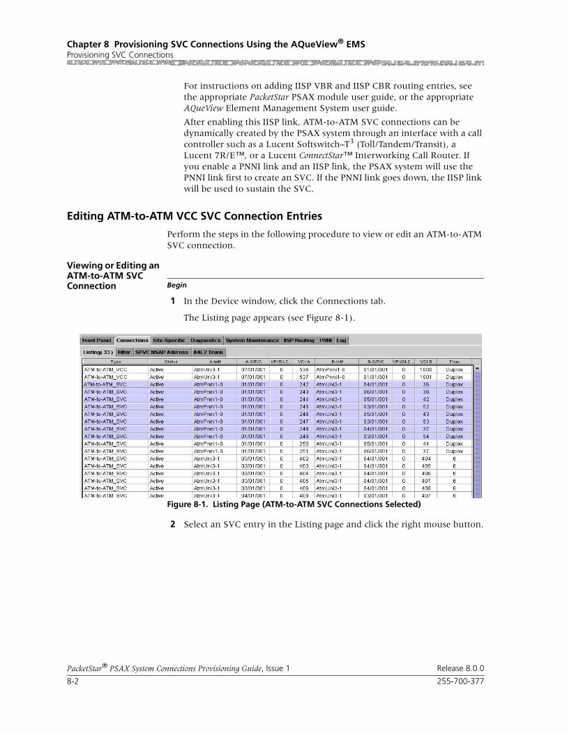
Chapter 8 Provisioning SVC Connections Using the AQueView® EMSProvisioning SVC Connections
8-2 255-700-377
PacketStar® PSAX System Connections Provisioning Guide, Issue 1 Release 8.0.0
For instructions on adding IISP VBR and IISP CBR routing entries, see the appropriate PacketStar PSAX module user guide, or the appropriate AQueView Element Management System user guide.
After enabling this IISP link, ATM-to-ATM SVC connections can be dynamically created by the PSAX system through an interface with a call controller such as a Lucent Softswitch–T3 (Toll/Tandem/Transit), a Lucent 7R/E™, or a Lucent ConnectStar™ Interworking Call Router. If you enable a PNNI link and an IISP link, the PSAX system will use the PNNI link first to create an SVC. If the PNNI link goes down, the IISP link will be used to sustain the SVC.
Editing ATM-to-ATM VCC SVC Connection Entries
Perform the steps in the following procedure to view or edit an ATM-to-ATM SVC connection.
Viewing or Editing an ATM-to-ATM SVC Connection Begin
1 In the Device window, click the Connections tab.
The Listing page appears (see Figure 8-1).
2 Select an SVC entry in the Listing page and click the right mouse button.
Figure 8-1. Listing Page (ATM-to-ATM SVC Connections Selected)

255-700-377 8-3
PacketStar® PSAX System Connections Provisioning Guide, Issue 1 Release 8.0.0
Chapter 8 Provisioning SVC Connections Using the AQueView® EMSProvisioning SVC Connections
3 Select Display in the menu that appears (see Figure 8-2).
The Display Connection window appears with tabs that contain details about the connection (see Figure 8-3): Primary and Statistics.
Primary Page The Primary page displays the information used to create the connection (see Figure 8-3).
The button on the Primary page has the following function:
4 Select the values for the fields in this window as described in Table 8-1.
Figure 8-2. Listing Page (Menu Displayed)
Figure 8-3. Display Connection:ATM-to-ATM SVC (Primary Page)
Button Function
Close Closes this window.
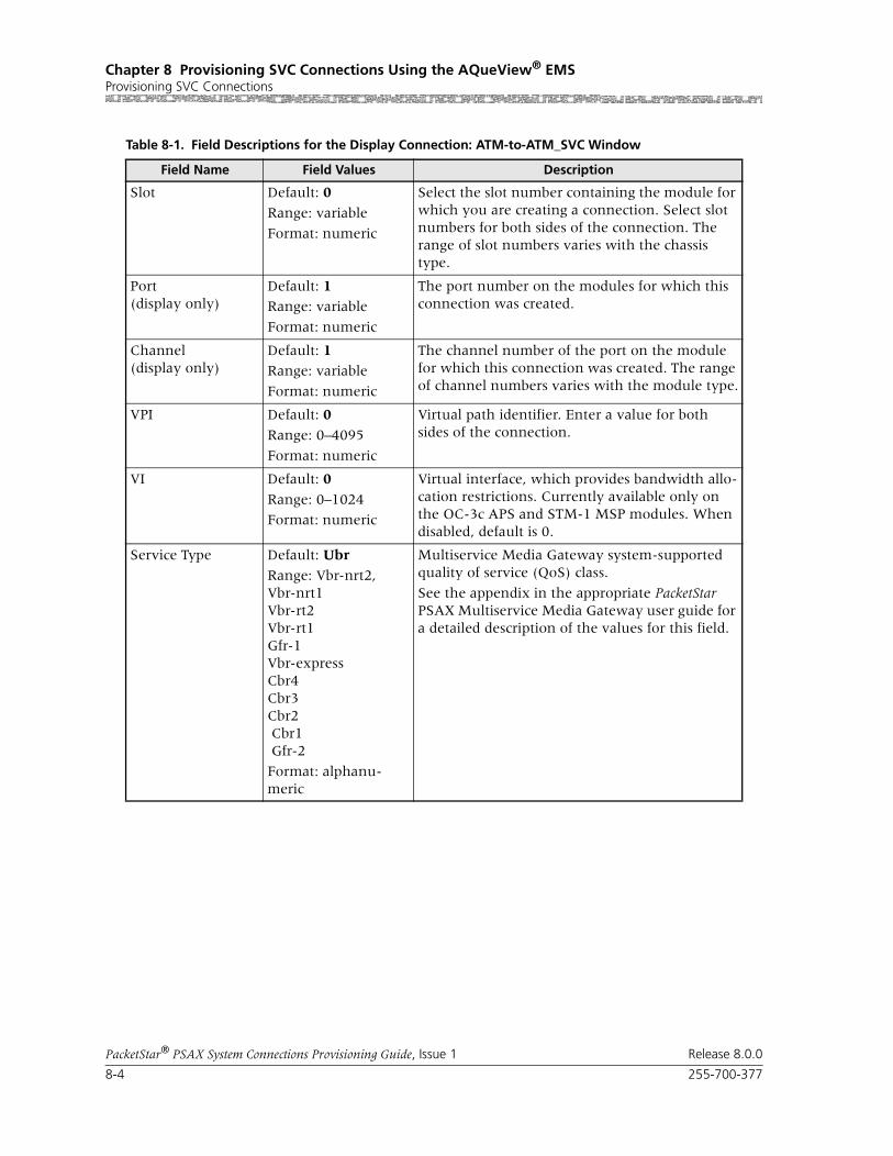
Chapter 8 Provisioning SVC Connections Using the AQueView® EMSProvisioning SVC Connections
8-4 255-700-377
PacketStar® PSAX System Connections Provisioning Guide, Issue 1 Release 8.0.0
Table 8-1. Field Descriptions for the Display Connection: ATM-to-ATM_SVC Window
Field Name Field Values Description
Slot Default: 0
Range: variable
Format: numeric
Select the slot number containing the module for which you are creating a connection. Select slot numbers for both sides of the connection. The range of slot numbers varies with the chassis type.
Port(display only)
Default: 1Range: variable
Format: numeric
The port number on the modules for which this connection was created.
Channel(display only)
Default: 1Range: variable
Format: numeric
The channel number of the port on the module for which this connection was created. The range of channel numbers varies with the module type.
VPI Default: 0
Range: 0–4095
Format: numeric
Virtual path identifier. Enter a value for both sides of the connection.
VI Default: 0
Range: 0–1024
Format: numeric
Virtual interface, which provides bandwidth allo-cation restrictions. Currently available only on the OC-3c APS and STM-1 MSP modules. When disabled, default is 0.
Service Type Default: Ubr
Range: Vbr-nrt2,Vbr-nrt1Vbr-rt2Vbr-rt1Gfr-1Vbr-expressCbr4Cbr3Cbr2 Cbr1 Gfr-2
Format: alphanu-meric
Multiservice Media Gateway system-supported quality of service (QoS) class.
See the appendix in the appropriate PacketStar PSAX Multiservice Media Gateway user guide for a detailed description of the values for this field.
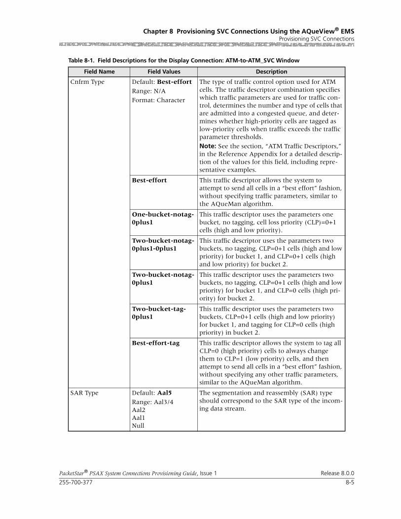
255-700-377 8-5
PacketStar® PSAX System Connections Provisioning Guide, Issue 1 Release 8.0.0
Chapter 8 Provisioning SVC Connections Using the AQueView® EMSProvisioning SVC Connections
Cnfrm Type Default: Best-effort
Range: N/A
Format: Character
The type of traffic control option used for ATM cells. The traffic descriptor combination specifies which traffic parameters are used for traffic con-trol, determines the number and type of cells that are admitted into a congested queue, and deter-mines whether high-priority cells are tagged as low-priority cells when traffic exceeds the traffic parameter thresholds.
Note: See the section, “ATM Traffic Descriptors,” in the Reference Appendix for a detailed descrip-tion of the values for this field, including repre-sentative examples.
Best-effort This traffic descriptor allows the system to attempt to send all cells in a “best effort” fashion, without specifying traffic parameters, similar to the AQueMan algorithm.
One-bucket-notag-0plus1
This traffic descriptor uses the parameters one bucket, no tagging, cell loss priority (CLP)=0+1 cells (high and low priority).
Two-bucket-notag-0plus1-0plus1
This traffic descriptor uses the parameters two buckets, no tagging, CLP=0+1 cells (high and low priority) for bucket 1, and CLP=0+1 cells (high and low priority) for bucket 2.
Two-bucket-notag-0plus1
This traffic descriptor uses the parameters two buckets, no tagging, CLP=0+1 cells (high and low priority) for bucket 1, and CLP=0 cells (high pri-ority) for bucket 2.
Two-bucket-tag-0plus1
This traffic descriptor uses the parameters two buckets, CLP=0+1 cells (high and low priority) for bucket 1, and tagging for CLP=0 cells (high priority) in bucket 2.
Best-effort-tag This traffic descriptor allows the system to tag all CLP=0 (high priority) cells to always change them to CLP=1 (low priority) cells, and then attempt to send all cells in a “best effort” fashion, without specifying any other traffic parameters, similar to the AQueMan algorithm.
SAR Type Default: Aal5
Range: Aal3/4Aal2Aal1Null
The segmentation and reassembly (SAR) type should correspond to the SAR type of the incom-ing data stream.
Table 8-1. Field Descriptions for the Display Connection: ATM-to-ATM_SVC Window
Field Name Field Values Description

Chapter 8 Provisioning SVC Connections Using the AQueView® EMSProvisioning SVC Connections
8-6 255-700-377
PacketStar® PSAX System Connections Provisioning Guide, Issue 1 Release 8.0.0
Forward Error Cor-rection
Default: None
Range: Eighth RateQuarter RateHalf RateAuto Hi QAutoAuto Lo Q
Format: Character
The values Eighth Rate, Quarter Rate, and Half Rate are a Reed-Solomon encoding rate with a specific error-correction capability. The values Auto Hi Q, Auto, and Auto Lo Q are dynamically changing rate options.
Peak Rate(0+1) (cps)
Default: 1
Range: module-dependent
Format: numeric (cps)
Peak cell rate (PCR) for all cells with both the CLP=0 bit and the CLP=1 bit. The value you set is the maximum allowed cell transmission rate (measured in cells per second) for all cells both high and low priority, as allowed by your traffic contract.
When setting this value, take into account the line rate for the module and the amount of band-width you are setting up for each interface for the module. Refer to the ATM UNI 3.1 specifications for more information.
If you select the value SimplexA2B in the Traffic Flow field, set the value of this field to 0.
Note: If you are using the traffic shaping Enabled setting on the bulleted modules listed below, entering a minimum cps value below the mini-mum listed below will cause traffic-shaped con-nections to default back to the minimum cps value when the connection passes traffic.
• On the 1-Port OC-3c MM/SM and the 1-Port STM-1 MM/SM, the cps range is 18–999999999.
• On the OC-12c/STM-4c SM/MM, the cps range is 87–999999999.
• On the 3-Port DS3/E3 ATM, the cps range is 7–999999999.
Table 8-1. Field Descriptions for the Display Connection: ATM-to-ATM_SVC Window
Field Name Field Values Description
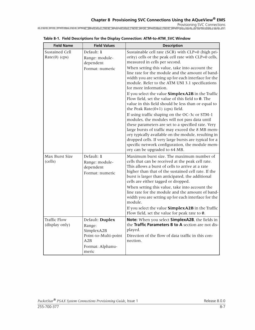
255-700-377 8-7
PacketStar® PSAX System Connections Provisioning Guide, Issue 1 Release 8.0.0
Chapter 8 Provisioning SVC Connections Using the AQueView® EMSProvisioning SVC Connections
Sustained Cell Rate(0) (cps)
Default: 1
Range: module-dependent
Format: numeric
Sustainable cell rate (SCR) with CLP=0 (high pri-ority) cells or the peak cell rate with CLP=0 cells, measured in cells per second.
When setting this value, take into account the line rate for the module and the amount of band-width you are setting up for each interface for the module. Refer to the ATM UNI 3.1 specifications for more information.
If you select the value SimplexA2B in the Traffic Flow field, set the value of this field to 0. The value in this field should be less than or equal to the Peak Rate(0+1) (cps) field.
If using traffic shaping on the OC-3c or STM-1 modules, the modules will not pass data until these parameters are set to a specified rate. Very large bursts of traffic may exceed the 8 MB mem-ory typically available on the module, resulting in dropped cells. If very large bursts are typical for a specific network configuration, the module mem-ory can be upgraded to 64 MB.
Max Burst Size (cells)
Default: 1Range: module-dependent
Format: numeric
Maximum burst size. The maximum number of cells that can be received at the peak cell rate. This allows a burst of cells to arrive at a rate higher than that of the sustained cell rate. If the burst is larger than anticipated, the additional cells are either tagged or dropped.
When setting this value, take into account the line rate for the module and the amount of band-width you are setting up for each interface for the module.
If you select the value SimplexA2B in the Traffic Flow field, set the value for peak rate to 0.
Traffic Flow(display only)
Default: Duplex
Range: SimplexA2BPoint-to-Multi-point A2B
Format: Alphanu-meric
Note: When you select SimplexA2B, the fields in the Traffic Parameters B to A section are not dis-played.
Direction of the flow of data traffic in this con-nection.
Table 8-1. Field Descriptions for the Display Connection: ATM-to-ATM_SVC Window
Field Name Field Values Description

Chapter 8 Provisioning SVC Connections Using the AQueView® EMSProvisioning SVC Connections
8-8 255-700-377
PacketStar® PSAX System Connections Provisioning Guide, Issue 1 Release 8.0.0
End
Statistics Page1 Click the Statistics tab.
The Statistics page appears (Figure 8-4). The Statistics page displays the statistics for this connection.
OAM Status Default: Unsupp
Range: N/A
Format: Character
OAM is not in use.
End-Pt The Multiservice Media Gateway is used as a ter-mination point for ATM.
Note: The OAM loopback test is supported for end-to-end connections only.
Seg-Pt Not supported.
End-Seg-Pt Not supported.
Intermediate-Pt The Multiservice Media Gateway is used as a net-work node and an intermediate ATM device that does not terminate the ATM connection.
Use this value to enable trunk conditioning. For more information, see the Trunk Conditioning Application Note for PacketStar PSAX Multiservice Media Gateways.
Note: The OAM loopback test is supported for end-to-end connections only.
Connection Status(display only)
Default: Inactive
Range: N/A
Format: Character
Active
This field displays the current status of the con-nection. The value indicates whether the connec-tion is passing traffic.
Table 8-1. Field Descriptions for the Display Connection: ATM-to-ATM_SVC Window
Field Name Field Values Description

255-700-377 8-9
PacketStar® PSAX System Connections Provisioning Guide, Issue 1 Release 8.0.0
Chapter 8 Provisioning SVC Connections Using the AQueView® EMSProvisioning SVC Connections
The buttons on the Statistics page have the following functions:
The fields on this window are described in Table 8-2.
Figure 8-4. Display Connection:ATM-to-ATM SVC (Statistics Page)
Button Description
Update Refreshes the statistics manually.
Clear Resets the resetable statistics to zero.
Poll Poll + continuously update the statistics and changes the button label to Poll-.
Poll- terminates polling and changes the button label to Poll+.
Odometer Restarts counting in the Cells Transmitted and Cells Received fields iin the Interface Side A and Interface Side B panels, and to view the trans-mitted cells and received cells in the Interface Side A and Interface Side B panels. This button is displayed only on the ATM-to-ATM VCC PVC and ATM-to-ATM VPC PVC Statistics pages.
Close Closes this window.
Restart Restarts connection establishment procedure for the connections that were not previously set up.
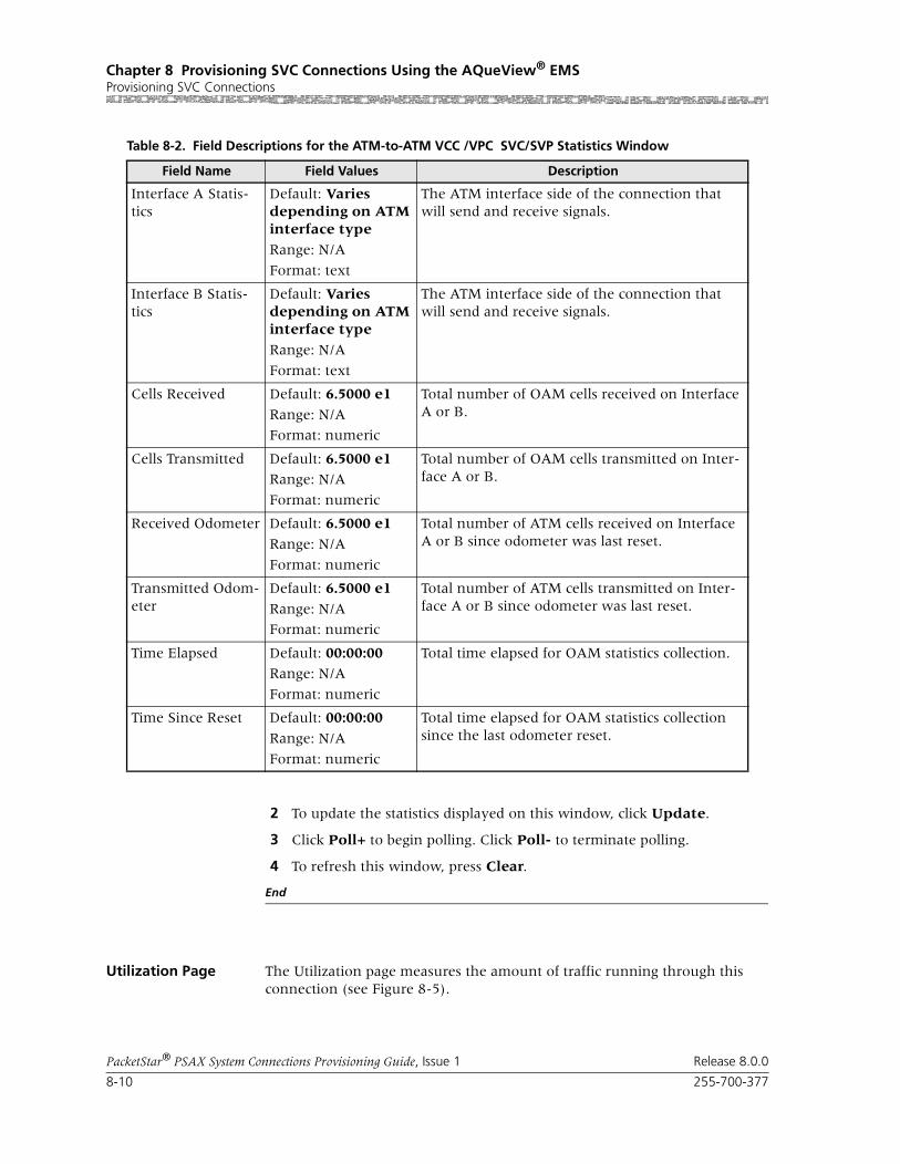
Chapter 8 Provisioning SVC Connections Using the AQueView® EMSProvisioning SVC Connections
8-10 255-700-377
PacketStar® PSAX System Connections Provisioning Guide, Issue 1 Release 8.0.0
2 To update the statistics displayed on this window, click Update.
3 Click Poll+ to begin polling. Click Poll- to terminate polling.
4 To refresh this window, press Clear.
End
Utilization Page The Utilization page measures the amount of traffic running through this connection (see Figure 8-5).
Table 8-2. Field Descriptions for the ATM-to-ATM VCC /VPC SVC/SVP Statistics Window
Field Name Field Values Description
Interface A Statis-tics
Default: Varies depending on ATM interface type
Range: N/A
Format: text
The ATM interface side of the connection that will send and receive signals.
Interface B Statis-tics
Default: Varies depending on ATM interface type
Range: N/A
Format: text
The ATM interface side of the connection that will send and receive signals.
Cells Received Default: 6.5000 e1
Range: N/A
Format: numeric
Total number of OAM cells received on Interface A or B.
Cells Transmitted Default: 6.5000 e1Range: N/A
Format: numeric
Total number of OAM cells transmitted on Inter-face A or B.
Received Odometer Default: 6.5000 e1
Range: N/A
Format: numeric
Total number of ATM cells received on Interface A or B since odometer was last reset.
Transmitted Odom-eter
Default: 6.5000 e1
Range: N/A
Format: numeric
Total number of ATM cells transmitted on Inter-face A or B since odometer was last reset.
Time Elapsed Default: 00:00:00Range: N/A
Format: numeric
Total time elapsed for OAM statistics collection.
Time Since Reset Default: 00:00:00
Range: N/A
Format: numeric
Total time elapsed for OAM statistics collection since the last odometer reset.

255-700-377 8-11
PacketStar® PSAX System Connections Provisioning Guide, Issue 1 Release 8.0.0
Chapter 8 Provisioning SVC Connections Using the AQueView® EMSProvisioning SVC Connections
The buttons on the Utilization page have the following functions:
Figure 8-5. Display Connection: ATM-to-ATM VCC (Utilization Page)
Button Function
60 sec Time, in seconds or minutes, to poll the PSAX device. Select a time interval from the pull-down menu:
5 sec
10 sec
20 sec
30 sec
60 sec (default)
90 sec
2 min
3 min
4 min
5 min
Clear Resets all statistics to zero.
Poll Poll+ continuously updates the statistics and changes the button label to Poll-.
Poll- terminates polling and changes the button label to Poll+.

Chapter 8 Provisioning SVC Connections Using the AQueView® EMSConfiguring In-Band Management
8-12 255-700-377
PacketStar® PSAX System Connections Provisioning Guide, Issue 1 Release 8.0.0
For details about this window, see the section, “Utilization Information,” in Chapter 5 of this guide.
Configuring In-Band Management
Use the In-Band Mgmt tab in the Site-Specific tab to configure IP address information used to manage PSAX systems remotely through in-band signal-ing. Use the Connections tab to establish, delete, or view details about ATM connections.
To configure the primary IP address for the management host, perform the steps in the following sections, “Adding an In-Band Management ATM SVC Connection” and “Adding an In-Band Management ATM SVC Connection”.
Adding an In-Band Management ATM SVC Connection
A Unix workstation is used as the address resolution protocol (ARP) server. The host Multiservice Media Gateway system and all remote systems on the same ATM network register their IP addresses on the ARP server when they are initialized (booted). When you want to create an in-band management SVC connection to one or more remote Multiservice Media Gateway systems, you use the host Multiservice Media Gateway system to request the IP addresses of the remote Multiservice Media Gateway systems. After you
Show Cells/Sec Calculates and displays the average num-ber of cells per second for a given PVC or SPVC for a given time interval specified in the pull-down menu (see above).
Changes button label to Show Bits/Sec.
Show Bits/Sec Calculates and displays the average num-ber of bits per second for a given PVC or SPVC for a given time interval specified in the pull-down menu (see above).
Changes button label to Show Cells/Sec.
Close Closes this window.
Button Function
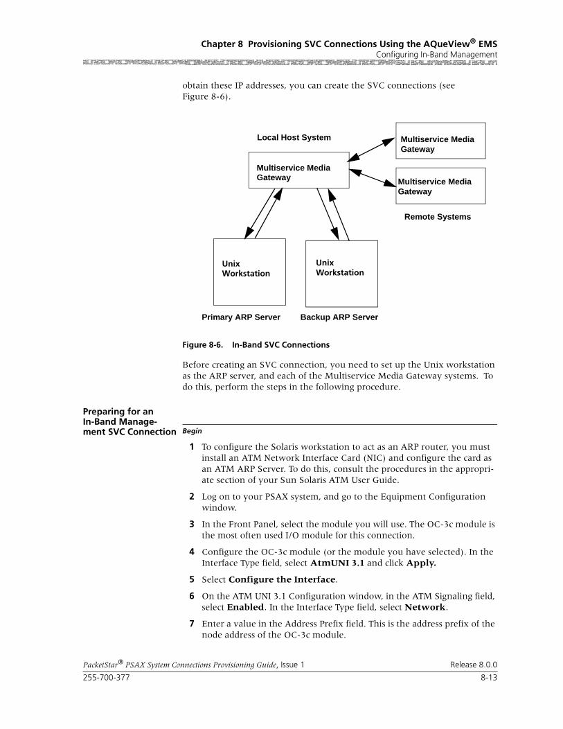
255-700-377 8-13
PacketStar® PSAX System Connections Provisioning Guide, Issue 1 Release 8.0.0
Chapter 8 Provisioning SVC Connections Using the AQueView® EMSConfiguring In-Band Management
obtain these IP addresses, you can create the SVC connections (see Figure 8-6).
Before creating an SVC connection, you need to set up the Unix workstation as the ARP server, and each of the Multiservice Media Gateway systems. To do this, perform the steps in the following procedure.
Preparing for an In-Band Manage-ment SVC Connection Begin
1 To configure the Solaris workstation to act as an ARP router, you must install an ATM Network Interface Card (NIC) and configure the card as an ATM ARP Server. To do this, consult the procedures in the appropri-ate section of your Sun Solaris ATM User Guide.
2 Log on to your PSAX system, and go to the Equipment Configuration window.
3 In the Front Panel, select the module you will use. The OC-3c module is the most often used I/O module for this connection.
4 Configure the OC-3c module (or the module you have selected). In the Interface Type field, select AtmUNI 3.1 and click Apply.
5 Select Configure the Interface.
6 On the ATM UNI 3.1 Configuration window, in the ATM Signaling field, select Enabled. In the Interface Type field, select Network.
7 Enter a value in the Address Prefix field. This is the address prefix of the node address of the OC-3c module.
Figure 8-6. In-Band SVC Connections
Unix Unix
Multiservice Media
Multiservice Media
Primary ARP Server Backup ARP Server
Local Host System
Remote Systems
Multiservice Media
Workstation Workstation
Gateway
Gateway
Gateway

Chapter 8 Provisioning SVC Connections Using the AQueView® EMSConfiguring In-Band Management
8-14 255-700-377
PacketStar® PSAX System Connections Provisioning Guide, Issue 1 Release 8.0.0
8 Configure the ILMI interface. (This is an optional step, but strongly rec-ommended.)
9 On the ILMI Configuration window select Enabled in the ILMI Proto-col, Address Registration, and Connectivity Procedure fields
10 Click Apply.
11 Check the ILMI Registered User Address window to see that the address has been created.
12 Create a PNNI node using the instructions in the "Configuring PNNI" section of Chapter 7, "Configuring ATM Routing Data Using IISP and PNNI."
13 Click the Site-Specific tab and the In-Band Mgmt tab to create the in-band SVC connection.
14 An in-band management SVC connection can be created between a con-figured in-band management address and any module that supports ATM interfaces. This connection supports the UBR and VBR-express ser-vice types.
End
Creating an In-Band-Management SVC Connection
Perform the steps in the following procedure to create an in-band manage-ment SVC connection.
Begin
1 In the Device window, click the Site Specific tab.
The Site Specific page appears.
2 Click the In-Band Mgmt tab.
The In-Band Mgmt page appears (see Figure 8-7).
3 In the In-Band Management Configuration window, enter the IP address and IP Mask for the PSAX device.
Note: This address must be on a different subnet from the subnet that is assigned to the Ethernet interface for the management host.
4 In the SVC Connections field, select Enabled.
The In-Band Management Configuration page with SVC enabled dis-plays (see Table 8-8).
5 Select the values for the fields on this window from the values given in Table 8-3.
6 Click Apply.

255-700-377 8-15
PacketStar® PSAX System Connections Provisioning Guide, Issue 1 Release 8.0.0
Chapter 8 Provisioning SVC Connections Using the AQueView® EMSConfiguring In-Band Management
7 In the Provisioning Menu Bar, click Device > Save PSAX Configuration. (See the section, “Saving Configuration Values.”)
End
Buttons The buttons on this window have the following functions:
Figure 8-7. In-Band Management Page (SVC Disabled)
Button Function
In-Band Mgmt Route Table Displays the In-Band Mgmt Route Table.
This button is ghosted if Disabled is selected in the ATM ARP Server field, and active if Enabled is selected in the ATM ARP Server field.
Apply Applies the configuration.
Reset Resets the display.
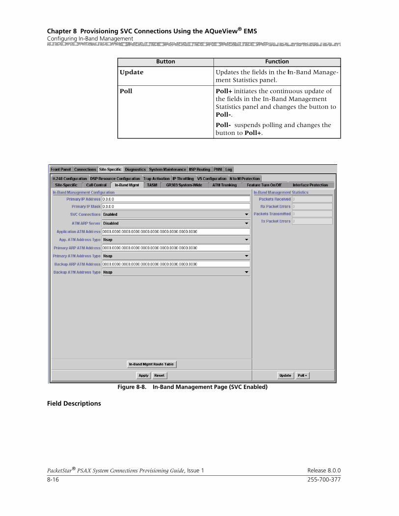
Chapter 8 Provisioning SVC Connections Using the AQueView® EMSConfiguring In-Band Management
8-16 255-700-377
PacketStar® PSAX System Connections Provisioning Guide, Issue 1 Release 8.0.0
Field Descriptions
Update Updates the fields in the In-Band Manage-ment Statistics panel.
Poll Poll+ initiates the continuous update of the fields in the In-Band Management Statistics panel and changes the button to Poll-.
Poll- suspends polling and changes the button to Poll+.
Figure 8-8. In-Band Management Page (SVC Enabled)
Button Function

255-700-377 8-17
PacketStar® PSAX System Connections Provisioning Guide, Issue 1 Release 8.0.0
Chapter 8 Provisioning SVC Connections Using the AQueView® EMSConfiguring In-Band Management
Table 8-3. Field Descriptions for the In-Band Management IP Configuration Window
Field Name Field Values Description
Primary IP Address Default: 0000.0000.0000.0000Range: N/A
Format: valid dotted quad
Specifies the in-band management IP address of the PSAX system.
Primary IP Mask Default: 0000.0000.0000.0000
Range: N/A
Format: valid dotted quad
Specifies the in-band management IP mask of the PSAX system
SVC Connections Default: Disabled
Range: N/A
Format: predefined alphanumeric
Specifies whether you want to use SVC connec-tion provisioning for in-band management.
Disabled Indicates that SVC connection provisioning for in-band management is disabled. You can config-ure only PVC connections for in-band manage-ment when you choose this value.
Enabled Indicates that SVC connection provisioning for in-band management is enabled.
The following fields are editable only when you select the value Enabled in the SVC Connec-tions field:
ATM ARP Server Default: Disabled
Range: N/A
Format: predefined alphanumeric
Specifies whether you want to use the PSAX sys-tem as an ATM ARP server.
Note: To make this field editable, select Enabled in the SVC Connections field.
Disabled Indicates that this device is not acting as an ATM ARP server.
Enabled Indicates that this device is acting as an ATM ARP server, and enables the In-Band Mgmt Route Table button.
Application ATM Address
Default: 0
Range: N/A
Format: hexadecimal
Specifies the application ATM address of the PSAX system.
App. ATM Address Type
Default: Nsap
Range: N/A
Nsap, E164, E164nsap
Specifies the type of application ATM address for the PSAX system.
Arp Server ATM Address
Default: 0Range: N/A
Format: hexadecimal
Specifies the ATM address of the ARP server.
Note: This field is displayed only if you selected Enabled in the ATM ARP Server field.

Chapter 8 Provisioning SVC Connections Using the AQueView® EMSConfiguring In-Band Management
8-18 255-700-377
PacketStar® PSAX System Connections Provisioning Guide, Issue 1 Release 8.0.0
Adding an In-band Route
Perform the steps in the following procedure to add an in-band management route.
Begin
1 Click In-Band Mgmt Route Table.
The In-Band Management Route Table window appears (see Figure 8-9).
2 Click the right mouse button, and a menu appears (see Figure 8-10).
Note: At the time of initial setup, the In-Band Management Table win-dow is empty. After you have set up routes, this window displays all the routes of this type in the system.
3 Select Create.
The ADD In-Band Management Entry window appears (see Figure 8-11).
4 Select the values for the fields in this window as described in Table 8-4.
5 Click Add.
The route is now added. If you click Close, the Route Table window dis-plays with the new route added.
Arp Server ATM Address Type
Default: Nsap
Range: N/A
Nsap, E164, E164nsap
Specifies the type of ATM address for the ARP server.
Note: This field is displayed only if you selected Enabled in the ATM ARP Server field.
Primary ARP ATM Address
Default: 0
Range: N/A
Format: hexadecimal
Specifies the primary ATM address for the ARP server. Enter the ATM address for the Solaris workstation.
Primary ATM Address Type
Default: NsapRange: N/A
Nsap, E164, E164nsap
Specifies the type of primary ATM address for the ARP server.
Backup ARP ATM Address
Default: 0Range: N/A
Format: hexadecimal
Specifies the backup ATM address for the ARP server. Enter the ATM address for the Solaris workstation.
Backup ATM Address Type
Default: Nsap
Range: N/A
Nsap, E164, E164nsap
Specifies the type of backup ATM address for the ARP server.
Table 8-3. Field Descriptions for the In-Band Management IP Configuration Window
Field Name Field Values Description

255-700-377 8-19
PacketStar® PSAX System Connections Provisioning Guide, Issue 1 Release 8.0.0
Chapter 8 Provisioning SVC Connections Using the AQueView® EMSConfiguring In-Band Management
6 In the Provisioning Menu Bar, click Device > Save PSAX Configuration. (See the section, “Saving Configuration Values.”)
Viewing an In-band Route
7 To view the in-band entry, click the right-mouse button and a menu appears. Select Display.
The VIEW In-Band Management Entry window appears (see Figure 8-12).
Updating an In-band Route
8 To update the in-band entry, click the right-mouse button and a menu appears. Select Update.
The UPDATE In-Band Management Entry window appears (see Figure 8-13).
Buttons The buttons on this window have the following functions:
Figure 8-9. In-Band Management Route Table Window
Button Function
Find Searches the table and displays a matching text string entered in the Show table entry containing: field.
Reset Removes text entered in the Show table entry containing: field and de-selects any selected entries.
Close Closes this window.
Figure 8-10. In-Band Management Route Table Window (Displaying Menu)

Chapter 8 Provisioning SVC Connections Using the AQueView® EMSConfiguring In-Band Management
8-20 255-700-377
PacketStar® PSAX System Connections Provisioning Guide, Issue 1 Release 8.0.0
Buttons The buttons on this window have the following functions:
Field Descriptions
Figure 8-11. ADD In-Band Management Entry Window
Button Function
Add Use to add the newly configured route.
Reset Sets the values of the fields on this window to their default val-ues.
Close Closes the ADD In-Band Management Entry window.
Table 8-4. Field Descriptions for the In-Band Management IP Route Configuration Window
Field Name Field Values Description
Destination IP Default: 0
Range: N/A
Format: valid dotted quad
Enter the destination network IP address.
IP Mask Default: 0
Range: N/A
Format: valid dotted quad
Enter the destination network IP mask.
Metric Default: 0Range: ?
Format: numeric
The number of hops to reach to the destination.
Next Hop Default: 0
Range: N/A
Format: valid dotted quad
Gateway to the destination network
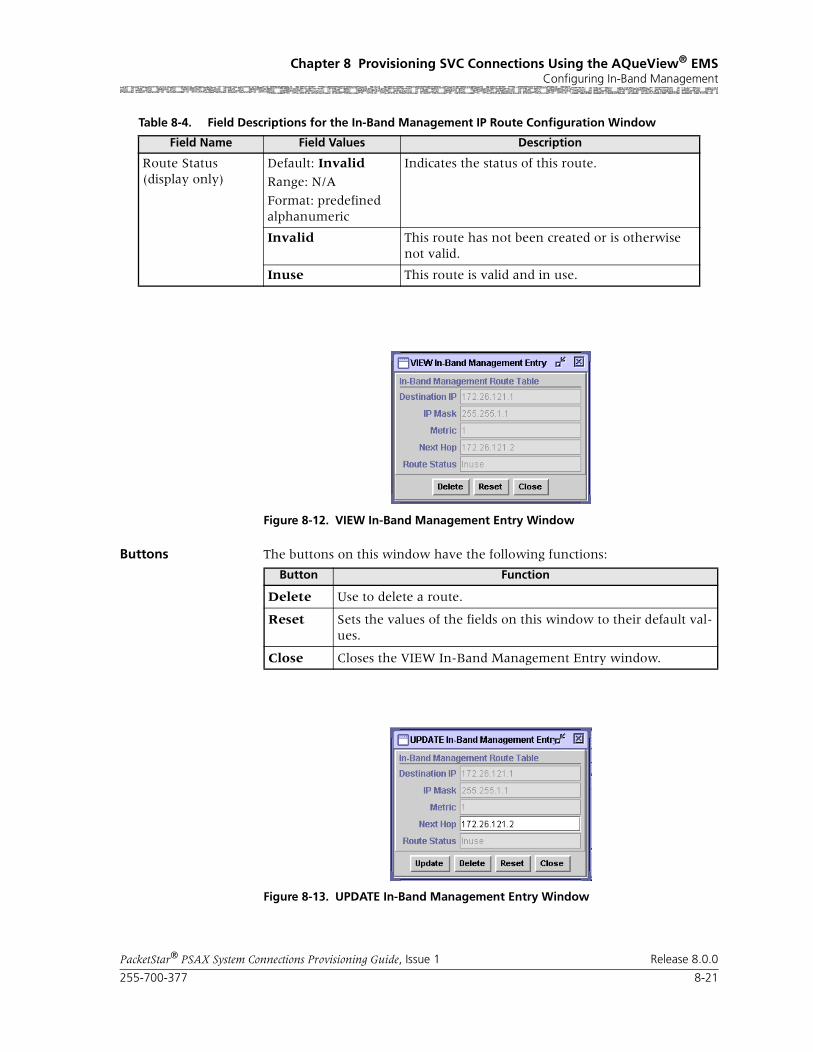
255-700-377 8-21
PacketStar® PSAX System Connections Provisioning Guide, Issue 1 Release 8.0.0
Chapter 8 Provisioning SVC Connections Using the AQueView® EMSConfiguring In-Band Management
Buttons The buttons on this window have the following functions:
Route Status(display only)
Default: Invalid
Range: N/A
Format: predefined alphanumeric
Indicates the status of this route.
Invalid This route has not been created or is otherwise not valid.
Inuse This route is valid and in use.
Table 8-4. Field Descriptions for the In-Band Management IP Route Configuration Window
Field Name Field Values Description
Figure 8-12. VIEW In-Band Management Entry Window
Button Function
Delete Use to delete a route.
Reset Sets the values of the fields on this window to their default val-ues.
Close Closes the VIEW In-Band Management Entry window.
Figure 8-13. UPDATE In-Band Management Entry Window

Chapter 8 Provisioning SVC Connections Using the AQueView® EMSConfiguring In-Band Management
8-22 255-700-377
PacketStar® PSAX System Connections Provisioning Guide, Issue 1 Release 8.0.0
Buttons The buttons on this window have the following functions:
Viewing In-Band Sta-tistics Data
You can view the statistics for your in-band management configuration in the In-Band Management Statistics panel of the In-Band Mgmt tab (see Figure 8-7).
Field Descriptions The fields on this window are described in Table 8-5.
Deleting an In-Band Management SVC Route
Perform the steps in the following procedure to delete an In-Band SVC route.
Begin
1 In the In-Band Management Route Table (see Figure 8-9), select and double-click the route you wish to delete.
The UPDATE In-Band Management Entry window is displayed (similar to Figure 8-11).
2 Click Delete.
Button Function
Update Applies the changes you set on this window.
Delete Use to delete a route.
Reset Sets the values of the fields on this window to their default val-ues.
Close Closes the UPDATE In-Band Management Entry window.
Table 8-5. Field Descriptions for the In-Band Management Statistics Panel
Field Name Field Values Description
Packets Received(display only)
Default: 0Range: N/A
Format: numeric
Displays the number of packets received.
Rx Packet Errors(display only)
Default: 0
Range: N/A
Format: numeric
Displays the number of packet receive errors.
Packets Transmitted(display only)
Default: 0
Range: N/A
Format: numeric
Displays the number of packets transmitted.
Tx Packet Errors(display only)
Default: 0Range: N/A
Format: numeric
Displays the number of packet transmit errors.
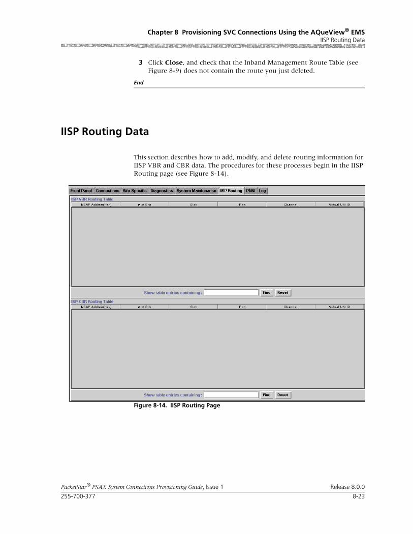
255-700-377 8-23
PacketStar® PSAX System Connections Provisioning Guide, Issue 1 Release 8.0.0
Chapter 8 Provisioning SVC Connections Using the AQueView® EMSIISP Routing Data
3 Click Close, and check that the Inband Management Route Table (see Figure 8-9) does not contain the route you just deleted.
End
IISP Routing Data
This section describes how to add, modify, and delete routing information for IISP VBR and CBR data. The procedures for these processes begin in the IISP Routing page (see Figure 8-14).
Figure 8-14. IISP Routing Page

Chapter 8 Provisioning SVC Connections Using the AQueView® EMSIISP Routing Data
8-24 255-700-377
PacketStar® PSAX System Connections Provisioning Guide, Issue 1 Release 8.0.0
Buttons The buttons on this page have the following functions:
When you click the IISP Routing tab, the IISP Routing page opens, contain-ing the IISP VBR and IISP CBR Routing Table panels. Options can be obtained by clicking the right mouse button within either of these panels.
Menu Options When you click the right mouse button in either of the panels, a menu appears (see Figure 8-15 and Figure 8-16) with options as described in Table 8-6.
Button Function
Find Searches the table and displays a matching text string entered in the Show table entries containing: field.
Reset Removes text entered in the Show table entries containing: field and de-selects any selected entries.
Figure 8-15. IISP CBR Routing Table (Displaying Menu)
Figure 8-16. IISP VBR Routing Table (Displaying Menu)

255-700-377 8-25
PacketStar® PSAX System Connections Provisioning Guide, Issue 1 Release 8.0.0
Chapter 8 Provisioning SVC Connections Using the AQueView® EMSIISP Routing Data
Creating a VBR or CBR Routing Table Entry
Before you can set up IISP routing, you must first configure the port from which you want to route traffic with the ATM UNI or ATM IISP interface. Perform the steps in the following procedure to enable ATM signaling.
Begin
Enabling ATM Signaling
1 From the Front Panel, open the Port and Channel Configuration win-dow for the port you want to route.
2 Select an ATM UNI or ATM IISP interface type.
3 Click Apply to Selected.
4 In the Channel Configuration window, double-click the channel that you want to configure.
Table 8-6. Menu Options for the IISP Routing Page
Menu Option Description
Display Displays the selected routing entry in the VBR or CBR routing table.
Create Creates a new VBR or CBR routing entry in the VBR or CBR routing table.
Delete Deletes the selected routing entry from the VBR or CBR routing table.
Refresh Refreshes the selected routing entry in the VBR or CBR routing table.

Chapter 8 Provisioning SVC Connections Using the AQueView® EMSIISP Routing Data
8-26 255-700-377
PacketStar® PSAX System Connections Provisioning Guide, Issue 1 Release 8.0.0
5 On the Interface Configuration window, select Enabled in the ATM Sig-naling field (see Figure 8-17).
6 In the Interface Configuration window, click Apply > Bring Into Ser-vice > Close.
End
Creating a VBR or CBR Routing Table Entry
Perform the steps in the following procedure to add a VBR or CBR routing entry.
Begin
1 Click the IISP Routing tab in the Device window.
The IISP Routing page appears (see Figure 8-14).
2 To create an IISP VBR routing entry, click the right mouse button within the IISP VBR Routing Table panel. To create an IISP CBR routing entry, click the right mouse button within the IISP CBR Routing Table panel.
3 Click Create in the menu that appears.
Figure 8-17. ATM UNI 3.1 Interface Configuration Page (Displaying ATM Signal-ing as Enabled)
Signaling is Enabled
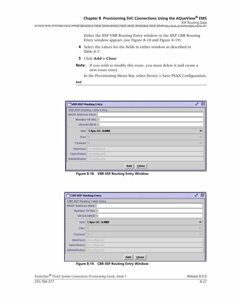
255-700-377 8-27
PacketStar® PSAX System Connections Provisioning Guide, Issue 1 Release 8.0.0
Chapter 8 Provisioning SVC Connections Using the AQueView® EMSIISP Routing Data
Either the IISP VBR Routing Entry window or the IISP CBR Routing Entry window appears (see Figure 8-18 and Figure 8-19).
4 Select the values for the fields in either window as described in Table 8-7.
5 Click Add > Close.
Note: If you wish to modify this route, you must delete it and create a new route entry.
In the Provisioning Menu Bar, select Device > Save PSAX Configuration.
End
Figure 8-18. VBR IISP Routing Entry Window
Figure 8-19. CBR IISP Routing Entry Window

Chapter 8 Provisioning SVC Connections Using the AQueView® EMSIISP Routing Data
8-28 255-700-377
PacketStar® PSAX System Connections Provisioning Guide, Issue 1 Release 8.0.0
Buttons The buttons in these windows have the following functions:
Field Descriptions
Button Function
Add Saves the entry into the system.
Delete Deletes the entry from the table. This button appears only after the routing entry has been created.
Close Closes the window.
Table 8-7. Field Descriptions for the IISP VBR and IISP CBR Routing Entry Windows
Field Name Values Description
NSAP Address (Hex)
Default: N/A
Range: N/A
Format: Valid-dotted quad
Type a network service access point (NSAP) address up to 20 bytes (160 bits) long (10 groups of 4 characters each) containing the digits 0 through 9 or the letters a through f.
Number of Bits Default: 0
Range: 1–152
Format: numeric
Enter the value of the mask that is applied to the NSAP address.
Virtual UNI ID Default: 0Range:
Format: numeric
Enter the number that represents the virtual UNI interface identifier.
Slot Default: Varies
Range: Varies depending on chassis type
Format: numeric
Select the slot of the module on which you con-figured the ATM interface and enabled ATM sig-naling.
Port Default: Varies
Range: Varies depending on module type
Format: numeric
Select the port on the module on which you con-figured the ATM interface and enabled ATM sig-naling.
Channel Default: VariesRange: Varies depending on module type
Format: numeric
Select the channel on the port of the module on which you configured the ATM interface and enabled ATM signaling.

255-700-377 8-29
PacketStar® PSAX System Connections Provisioning Guide, Issue 1 Release 8.0.0
Chapter 8 Provisioning SVC Connections Using the AQueView® EMSIISP Routing Data
Interface(display only)
Default: Unconfigured
Range: N/A
Format: Predefined
Displays the interface configured for this slot, port, channel combination. If the channel has not been configured, the default value will be dis-played.
AtmUni3-0,AtmUni3-1,IispUser,IispNetwork,DbCirEm,CircuitEmulation, DbCirEm,ATMPnni-0,FrameRelayUni,HldcPassThrough,Pri-isdn-network,FrameRelayNni,Pri-isdn-user
Indicates that the channel is configured for the displayed interface.
Note: An ATM interface type must be dis-played in this field to create an IISP route.
Oper Status (display only)
Default: UnconfiguredRange: N/A
Format: Predefined
Displays whether the interface is operational.
Unconfigured Indicates that this channel is not operational because the interface is not configured.
InService Indicates that this channel is capable of receiving and sending signals.
OutOfService This channel is not capable of receiving and send-ing signals.
Admin Status (display only)
Default: Unconfigured
Range: N/A
Format: Predefined
Displays whether a user has placed the interface in service.
Unconfigured Indicates that this channel is not operational because the interface is not configured.
InService Indicates that the no conditions are preventing the port from being fully operational.
OutOfService Indicates that some condition is preventing the port from being configured with an interface.
Table 8-7. Field Descriptions for the IISP VBR and IISP CBR Routing Entry Windows
Field Name Values Description

Chapter 8 Provisioning SVC Connections Using the AQueView® EMSIISP Routing Data
8-30 255-700-377
PacketStar® PSAX System Connections Provisioning Guide, Issue 1 Release 8.0.0
Deleting a Routing Table Entry
Use the following procedure to delete a VBR or CBR IISP Routing table entry.
Begin
1 Click the IISP Routing tab in the Device window.
The IISP Routing page appears (see Figure 8-14).
2 In the IISP Routing table, do one of the following (a or b):
a. Select the entry that you want to delete in the routing table. Click the right mouse button and a menu appears. Click Delete.
A confirmation window appears (see Figure 8-20 and Figure 8-21).
The entry is removed from the routing table. Proceed to Step 4.
b. Do one of the following:
~ Double-click the entry you want to delete.
~ Click the entry you want to delete, and select Display from the right mouse menu.
The VBR IISP Routing Entry window or CBR IISP Routing Entry win-dow appears (see Figure 8-18 and Figure 8-19). Click Delete.
Figure 8-20. IISP VBR Delete Confirmation Window (Using the Right-Click Menu)
Figure 8-21. IISP CBR Delete Confirmation Window (Using the Right-Click Menu)
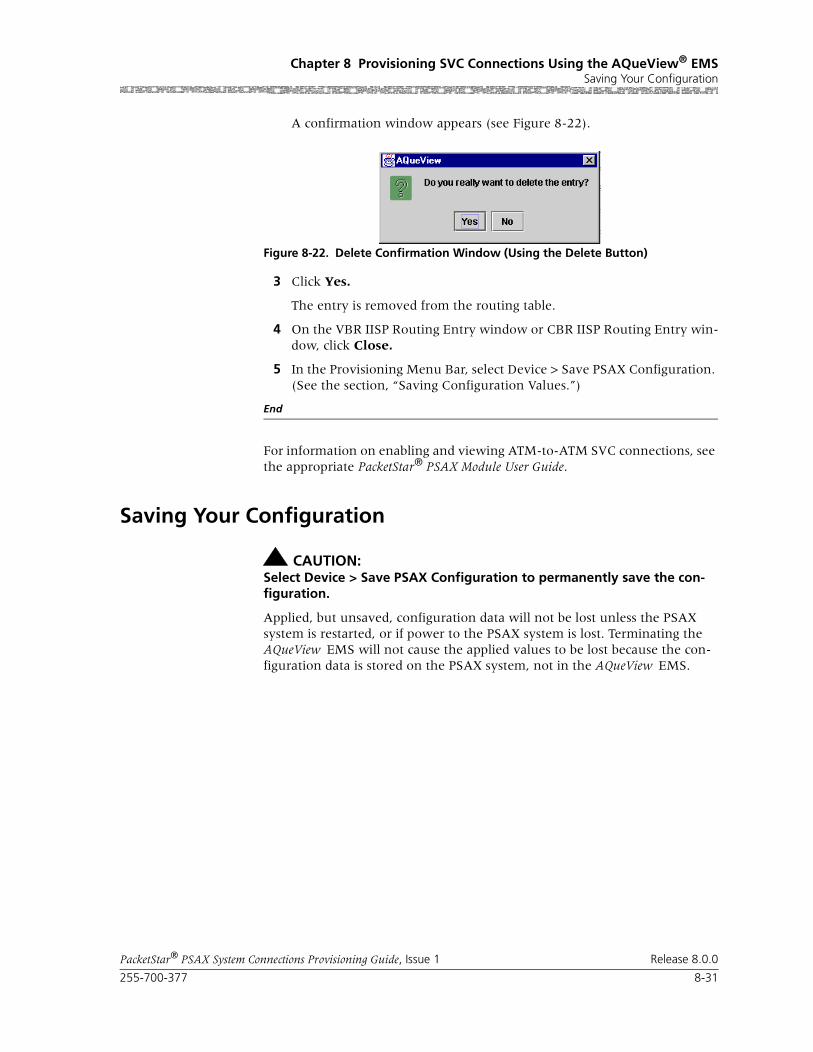
255-700-377 8-31
PacketStar® PSAX System Connections Provisioning Guide, Issue 1 Release 8.0.0
Chapter 8 Provisioning SVC Connections Using the AQueView® EMSSaving Your Configuration
A confirmation window appears (see Figure 8-22).
3 Click Yes.
The entry is removed from the routing table.
4 On the VBR IISP Routing Entry window or CBR IISP Routing Entry win-dow, click Close.
5 In the Provisioning Menu Bar, select Device > Save PSAX Configuration. (See the section, “Saving Configuration Values.”)
End
For information on enabling and viewing ATM-to-ATM SVC connections, see the appropriate PacketStar® PSAX Module User Guide.
Saving Your Configuration
! CAUTION:Select Device > Save PSAX Configuration to permanently save the con-figuration.
Applied, but unsaved, configuration data will not be lost unless the PSAX system is restarted, or if power to the PSAX system is lost. Terminating the AQueView EMS will not cause the applied values to be lost because the con-figuration data is stored on the PSAX system, not in the AQueView EMS.
Figure 8-22. Delete Confirmation Window (Using the Delete Button)

Chapter 8 Provisioning SVC Connections Using the AQueView® EMSSaving Your Configuration
8-32 255-700-377
PacketStar® PSAX System Connections Provisioning Guide, Issue 1 Release 8.0.0

PacketStar® PSAX System Connections Provisioning Guide, Issue 1 Release 8.0.0
255-700-377 A-1
A Reference Information
Overview of This Appendix
This appendix contains reference information that is helpful while configur-ing your PSAX system. The following types of information are provided:
• ATM Traffic Descriptors
• ATM UNI Specification Cause Codes, Version 3.1 (for Connection Retry)
• DSP Tone Detection Modes Table
• DSP2C Module Channel Reduction When Using Fax Relay Mode Table
• Industry Compliance Specifications Table
• Interface Type by Connection Type Table
• Interface Type by Input/Output Module Type Table
• Minimum AAL2 Trunk Size Requirements Tables
• Module Line Status Table
• Quality of Service (QoS) Class Tables
• ATM Traffic Shaping Sample CPS Calculation Table
• PCR Calculation Formula for Traffic Shaping
• Traffic shaping, Usage Parameter Control, and Virtual Interface Configura-tion Compatibilities Table
ATM Traffic Descriptors
Purpose of Traffic Descriptors
When you create a PVC, you can select one of several traffic descriptors by entering the desired value in the Conformance Type field on the user inter-face windows for certain connection types. The traffic descriptor specifies which traffic parameters are used for traffic control. It also determines the number and type of cells that are admitted into a congested queue, and whether high-priority cells are tagged as low-priority cells when traffic exceeds the traffic parameter thresholds.
Connections Supporting Traffic Descriptors
The traffic descriptors used in the PacketStar Multiservice Media Gateway sys-tem software are supported for the following types of connections:
• ATM-to-ATM VCC PVC
• ATM-to-ATM VPC PVC
• Bridge-to-ATM VCC PVC
• Circuit Emulation-to-ATM VCC PVC

Chapter ATM Traffic Descriptors
A-2 255-700-377
PacketStar® PSAX System Connections Provisioning Guide, Issue 1 Release 8.0.0
• Frame Relay-to-ATM VCC PVC
• In-band ATM PVC
• VBR-to-ATM VCC PVC
Traffic Descriptors Supported
The available traffic descriptors are as follows:
• Best effort (Best-effort)
This traffic descriptor allows the system to attempt to send all cells in a “best effort” fashion, without specifying traffic parameters, similar to the AQueMan algorithm. The Multiservice Media Gateway might drop some or all cells during congestion.
• Best effort with tagging (Best-effort-tag)
This traffic descriptor allows the system to tag all CLP=0 (high priority) cells to change them to CLP=1 (low priority) cells, and then attempt to send all cells in a “best effort” fashion, without specifying any other traffic parame-ters, similar to the AQueMan algorithm. The network might drop some or all cells during congestion.
• One bucket, with no tagging for cells with both CLP bit=0 and CLP bit=1 (1B-NT-0+1)
This traffic descriptor uses the parameters one bucket, no tagging, cell loss priority (CLP)=0+1 cells (high and low priority). The Multiservice Media Gateway ignores the CLP bit value and drops all cells violating the value set for the peak cell rate (PCR).
• Two buckets, with no tagging for cells with both CLP bit=0 and CLP bit=1 (2B-NT-0+1-0+1)
This traffic descriptor uses the parameters two buckets, no tagging, CLP=0+1 cells (high and low priority) for bucket 1, and CLP=0+1 cells (high and low priority) for bucket 2. The Multiservice Media Gateway ignores the CLP bit value for cells passing into bucket 1 and drops all cells violating the value set for the PCR. The remainder of the cells are passed to bucket 2. The Multiservice Media Gateway ignores the CLP bit value for cells passing into bucket 2, and drops all cells violating the value set for the sustainable cell rate (SCR).
• Two buckets, with no tagging for cells with both CLP bit=0+1 and CLP bit=0 (2B-NT-0+1-0)
This traffic descriptor uses the parameters two buckets, no tagging, CLP=0+1 cells (high and low priority) for bucket 1, and CLP=0 cells (high priority) for bucket 2. For bucket 1, the Multiservice Media Gateway ignores the CLP bit value for cells passing into bucket 1 and drops all cells violating the value set for the PCR. For bucket 2, the system takes one of the following actions:
~ When the connection is configured for variable bit rate (VBR) traffic, the Multiservice Media Gateway drops all CLP=0 cells violating the value set for the SCR in bucket 2.

255-700-377 A-3
PacketStar® PSAX System Connections Provisioning Guide, Issue 1 Release 8.0.0
ChapterSPVC Connection Cause Codes Table for Connection Retry
~ When the connection is configured for constant bit rate (CBR) traffic, the Multiservice Media Gateway drops all CLP=0 cells violating the value set for the PCR in bucket 2.
• Two buckets, for cells with CLP bit=0 and CLP bit=0 (2B-NT-0+1-0)
This traffic descriptor uses the parameters two buckets, tagging, CLP=0+1 cells (high and low priority) for bucket 1, and CLP=0 cells (high priority) for bucket 2. For bucket 1, the Multiservice Media Gateway ignores the CLP bit value for cells passing into bucket 1 and drops all cells violating the value set for the PCR. For bucket 2, the system takes one of the following actions:
~ When the connection is configured for variable bit rate (VBR) traffic, the Multiservice Media Gateway tags all CLP=0 cells violating the value set for the SCR to CLP=1 in bucket 2.
~ When the connection is configured for constant bit rate (CBR) traffic, the Multiservice Media Gateway tags all CLP=0 cells violating the value set for the PCR to CLP=1 in bucket 2.
The network then might drop some or all cells during congestion.
SPVC Connection Cause Codes Table for Connection Retry
SPVC connection cause codes, displayed in the Last Rls Cause field on all the SPVC connection configuration windows, are provided in Table A-1. The word Yes in the “Prompts a Retry” column indicates that if the cause code number, shown in the “Cause Code” column, is reported by the equipment at the far (remote) end, the PSAX system will try to establish the connection again up to the number of times specified in the Retry Limit field on the SPVC connection configuration windows. The ATM Forum UNI and Frame Relay Forum FRF.4 standards use many (but not all) of the same cause codes, and these standards reference ITU-T standards for many of the cause codes.
Table A-1. Connection Cause Codes for SPVCs
Cause Code
DescriptionPrompts a Retry
ReferencedStandard
1 Unallocated (unassigned) number. The called party number is not currently assigned. As a result, the called party cannot be reached.
No ITU-T Q.850
2 No route to specified transit network. The equipment sending this cause code received a request to route the call through an unknown transit network. The transit network is unknown to the equipment because it does not exist or does not serve the equipment.
No ITU-T Q.850
3 No route to destination. The network through which the call was routed does not serve the destination. As a result, the called party cannot be reached.
Yes ITU-T Q.850
10 VCC is unacceptable. The VPI/VCI is unacceptable to the sending entity for use in the call.
No ATM Forum UNI 3.0/3.1
16 Normal call clearing. No ITU-T Q.850

Chapter SPVC Connection Cause Codes Table for Connection Retry
A-4 255-700-377
PacketStar® PSAX System Connections Provisioning Guide, Issue 1 Release 8.0.0
17 User is busy. The called party is unable to accept another call because the user-busy condition has been encountered.
Yes ITU-T Q.850
18 No user is responding. A called party did not respond to a call establishment message with either an alerting or connect indication within a designated time period.
No ITU-T Q.850
21 Call was rejected. Although the equipment sending this cause code is neither busy nor incompatible, the equipment sending this cause code does not want to accept the call. The cause can be generated by the network to indicate that the call might have been cleared as a result of a supplementary ser-vice constraint.
No ITU-T Q.850
22 Number was changed. The number of the called party is no longer assigned. A new number must be used to call the called party.
No ITU-T Q.850
23 User rejects all calls with calling line identification restriction (CLIR). The called party returns this cause code when the call comes in without calling party number information and the called party requires this information.
No ATM Forum UNI 3.0/3.1
27 Destination is out of order. The user cannot reach the destina-tion because the interface to the destination is not function-ing properly; that is, a signaling message could not be deliv-ered to the destination.
Yes ITU-T Q.850
28 Number format is not valid (address incomplete). The called party is unreachable because the number of the called party is not in the proper format or it is not complete.
No ITU-T Q.850
30 Response to STATUS ENQUIRY. A STATUS message was sent in response to receipt of a STATUS ENQUIRY message.
Yes ITU-T Q.850
31 Normal unspecified. A normal event occurred for which no other cause applies. As a result, the event is normal but unspecified.
No ITU-T Q.850
32 Too many pending ADD PARTY requests currently exist. Yes ATM Forum PNNI 1.0
35 Requested VPCI/VCI is not available. The SPVC attempted to use a VPCI/VCI that is unavailable.
Yes ITU-T Q.2610
36 VPCI/VCI assignment failure. A VPCI/VCI could not be assigned to the SPVC.
Yes ITU-T Q.2610
37 User cell rate is unavailable. The requested cell rate is unavailable for the SPVC.
Yes ITU-T Q.2610
38 Network is out of order (not used in this implementation agreement). The problem will probably last a long period of time; that is, an immediate retry of the call is not likely to suc-ceed.
Yes ITU-T Q.850
Table A-1. Connection Cause Codes for SPVCs (Continued)
Cause Code
DescriptionPrompts a Retry
ReferencedStandard

255-700-377 A-5
PacketStar® PSAX System Connections Provisioning Guide, Issue 1 Release 8.0.0
ChapterSPVC Connection Cause Codes Table for Connection Retry
41 Temporary failure. The problem will probably last a short period of time; that is, an immediately retry of the call has a good chance to succeed.
Yes ITU-T Q.850
43 Access information was discarded. The network failed to deliver access information to the remote user (for example, user-to-user, low-layer compatibility, high-layer compatibil-ity, or subaddress).
Yes ITU-T Q.850
44 Circuit is unavailable. The requested circuit or channel is not available.
No ITU-T Q.850
45 No VPCI/VCI is available. A VPCI/VCI is not available for the SPVC.
Yes ITU-T Q.2610
47 Resource is unavailable or unspecified. A resource is unavail-able, and no other cause code exists to report this event.
Yes ITU-T Q.850
49 Quality of service is unavailable. The requested QoS class is unavailable for the SPVC.
No ITU-T Q.850
51 User cell rate is unavailable. The requested cell rate is unavailable for the SPVC.
Yes ATM Forum UNI 3.0/3.1
53 PGL was changed. The call was cleared due to a change in the peer group leader (PGL).
No ATM Forum PNNI 1.0
57 Bearer capability is not authorized. The SPVC user requested a bearer capability for which the user is not authorized.
No ITU-T Q.850
58 Bearer capability is not presently available. The SPVC user requested a bearer capability that is not available at this time.
No ITU-T Q.850
63 Service or option is unavailable or unspecified. A service or option is unavailable, and no other cause code exists to report this event.
No ITU-T Q.850
65 Bearer capability is not implemented. The equipment that generated this cause code does not support the requested bearer capability.
No ITU-T Q.850
73 Combination of traffic parameters is not supported. No ATM Forum UNI 3.0/3.1
78 AAL parameters cannot be supported. No ITU-T Q.2610
81 Call reference value is not valid. The equipment that sends this cause code has received a message with a call reference that is not currently in use on the user-network interface.
No ITU-T Q.850
82 Identified channel does not exist. The equipment sending this cause code received a request to use a channel that was not activated on the call interface. For example, if a user sub-scribed to those channels on a primary rate interface num-bered from 1 to 12, this cause code would be generated if the user equipment or the network attempts to use channels 13 through 23.
No ITU-T Q.850
Table A-1. Connection Cause Codes for SPVCs (Continued)
Cause Code
DescriptionPrompts a Retry
ReferencedStandard

Chapter SPVC Connection Cause Codes Table for Connection Retry
A-6 255-700-377
PacketStar® PSAX System Connections Provisioning Guide, Issue 1 Release 8.0.0
88 Incompatible destination. The equipment sending this cause code received a request to establish a call with low-layer com-patibility, or other compatibility attributes that cannot be accommodated, for example, data rate.
No ITU-T Q.850
89 Endpoint reference is not valid. The equipment sending this cause code received a message with an endpoint reference that is currently not in use on the user-network interface.
No ATM Forum UNI 3.0/3.1
91 Transit network selection is not valid. A transit network iden-tification was received that is not formatted correctly. Correct formats are defined in the standard, Q.931, Annex C.
No ITU-T Q.850
92 Too many pending ADD PTY requests were generated on the SPVC. This condition occurs when the calling party sends an ADD PTY request, but the network cannot accept another ADD PTY message because its queues are full. This condition is temporary.
No ATM Forum UNI 3.0/3.1
93 AAL parameters cannot be supported. No ITU-T Q.2610
95 Unspecified message is not valid. This cause code reports a message event that is not valid when no other message cause code that is not valid applies.
No ITU-T Q.850
96 Mandatory information element is missing. The equipment sending the cause code received a message that is missing a mandatory information element.
No ITU-T Q.850
97 Message type is nonexistent or not implemented. The equip-ment sending the cause code received one of the following message types:
• Not defined
• Defined but not implemented by the equipment sending the cause code
No ITU-T Q.850
99 Information element is nonexistent or not implemented. The equipment sending the cause code received a message that includes information elements or parameters that meet one of the following criteria:
• Not recognized because the elements or parameters are not defined
• Defined but not implemented by the equipment sending the cause code
The cause code indicates that the elements or parameters were discarded. However, the information element is not required to be present in the message so that the equipment sending the cause code can process the message.
No ITU-T Q.850
Table A-1. Connection Cause Codes for SPVCs (Continued)
Cause Code
DescriptionPrompts a Retry
ReferencedStandard

255-700-377 A-7
PacketStar® PSAX System Connections Provisioning Guide, Issue 1 Release 8.0.0
ChapterDSP Tone Detection Modes Table
DSP Tone Detection Modes Table
100 Information element content is not valid. The equipment sending this cause code received an information element that the equipment has implemented, but one or more fields in the information element are coded in a way that has not been implemented.
No ITU-T Q.850
101 Message type is not compatible with call state. A message was received that is incompatible with the call state.
Yes ITU-T Q.850
102 Recovery on timer expiration. A procedure has been initiated by the expiration of a timer that is related to error handling procedures.
Yes ITU-T Q.850
104 Message length is not correct. No ATM Forum UNI 3.0/3.1
111 Unspecified protocol error. A protocol error occurred for which no defined protocol error exists.
No ITU-T Q.850
127 Optional information element content error (nonstandard). This cause code indicates the occurrence of internetworking with a network that does not provide cause codes for actions that it takes. The precise cause for any message that is sent cannot be determined.
No ITU-T Q.850
128 Next node is unreachable. No ATM Forum PNNI 1.0
160 DTL transit is not my node ID. No ATM Forum PNNI 1.0
Table A-1. Connection Cause Codes for SPVCs (Continued)
Cause Code
DescriptionPrompts a Retry
ReferencedStandard
Table A-2. DSP Tone Detection Modes* and Associated Processing Performed
Tone Mode Processing Performed
Disabled Ignores fax tones and modem tones
Bypass If a fax tone or modem tone is received, the firmware switches to G.711 mode (64 Kbps) and bypasses echo cancellation, if enough bandwidth is available.
Fax Relay If a fax tone is received, the firmware switches to a channel configured for FaxRelayMode and performs fax demodulation / remodulation. If a modem tone is received, the firmware ignores it
Fax Relay/Modem Bypass
If a fax tone is received, the firmware switches to a channel configured for FaxRelayMode and performs fax demodulation/remodulation. If a modem tone is received, the firmware switches to G.711 mode (64 Kbps) and bypasses echo cancellation, if enough bandwidth is available.
* Modes selected on the Circuit Emulation-to-ATM VCC PVC Connection window

Chapter DSP2C Module Channel Reduction When Using Fax Relay Mode
A-8 255-700-377
PacketStar® PSAX System Connections Provisioning Guide, Issue 1 Release 8.0.0
DSP2C Module Channel Reduction When Using Fax Relay Mode
Industry Compliance Specifications Table
Compliance specifications for the PacketStar®PSAX Multiservice Media Gate-ways I/O and server modules are contained in Table A-4.
Table A-3. Channel Reduction Availability Caused by Fax Relay Connections vs. Voice Processing Connections on a DSP2C Module
Number of DSPs for Fax Relay
Total Connections Assigned for
Fax Relay
Percent of All DSP Connections
Assigned for Fax Relay
Remaining Voice Processing Available
Channels*
* For every fax transmission call, both the originally assigned DSP resource, plus the fax relay DSP resource, are consumed for the duration of the call. Thus, the total remaining DSP connections is reduced by twice the number of con-nections using fax mode service.
1 4 3% 124
2 8 6% 120
3 12 9% 116
4 16 13% 112
5 20 16% 108
6 24 19% 104
7 28 22% 100
8 32 25% †
† Utilization of DSP resources for fax relay above 25% is not considered realistic for most service provider environments. If this value exceeds 25%, then the number of available DSP connections for pure voice mode calls is reduced to less than 50% of connections available on the DSP2C module.
96
9 36 28% 92
10 40 31% 88
11 44 34% 84
12 48 38% 80
13 52 41% 76
14 56 44% 72
15 60 47% 68
16 64 50% 64

255-700-377 A-9
PacketStar® PSAX System Connections Provisioning Guide, Issue 1 Release 8.0.0
ChapterIndustry Compliance Specifications Table
Table A-4. Industry Compliance Specifications
Feature Name/Product Name Specification Title Notes
Integrated Local Management Interface (ILMI)
ILMI over PNNI
Channelized DS3, Channelized STS-1e, DS1 IMA, DS3 IMA, E1 IMA, DS3 ATM, E3 ATM, Enhanced DS1, Enhanced E1, High-Density E1, High Speed, Medium-Density DS1, Multi-Serial, OC-3c Single-Mode/Multi-Mode/APS, STM-1 Single-Mode/Multi-Mode/MSP, OC-12c/STM-4c, and Quadserial modules
af-ilmi-0065.000
Integrated Local Management Interface (ILMI)
DS1 IMA and DS3 IMA modules af-phy-0016.000
DS1 Physical Layer Specification
Channelized DS3 module af-phy-0054.000
DS3 Physical Interface Specifica-tion
E1 IMA module af-phy-0064.000
E1 Physical Layer Specification
DS1 IMA, DS3 IMA, and E1 IMA modules
af-phy-0086.000
Inverse Multiplexing over ATM (IMA), Version 1.0
DS1 IMA, DS3 IMA, and E1 IMA modules
af-phy-0086.001
Inverse Multiplexing over ATM (IMA), Version 1.1
Obsoletes af-phy-0086.000 but PSAX is compatible with both versions
Channelized DS3, Channelized STS-1e, DS1 IMA, DS3 IMA, E1 IMA, DS3 ATM, E3 ATM, Enhanced DS1, Enhanced E1,High-Density E1, High Speed, Medium-Density DS1, OC-3c Single-Mode/Multi-Mode/APS, STM-1 Single-Mode/Multi-Mode/MSP, OC-12c/STM-4c, and Quadserial modules
af-pnni-0026.000
Interim Inter-Switch Signaling Protocol (IISP)

Chapter Industry Compliance Specifications Table
A-10 255-700-377
PacketStar® PSAX System Connections Provisioning Guide, Issue 1 Release 8.0.0
ATM Maintenance Mode
ATM PNNI 1.0 interface
ETSI ISDN Support
In-band Management SVC
Soft Permanent Virtual Circuits (SPVCs)
SPVC Support for CES with DSP2 Modules
Channelized DS3, Channelized STS-1e, DS1 IMA, DS3 IMA, E1 IMA, DS3 ATM, E3 ATM, DSP2A/B/C/D Voice Server, Enhanced DS1, High-Density E1, Medium-Density DS1, OC-3c Single-Mode/Multi-Mode/APS, STM-1 Single-Mode/Multi-Mode/MSP, OC-12c/STM-4c, and Quadserial modules
af-pnni-0055.000
Private Network-Network Inter-face (PNNI)
SPVCs- Annex C: Soft PVC Procedures for circuit emulation, frame relay, and terminal emulation
Annex G, mandatory require-ments
ATM Maintenance Mode
In-band Management SVC
af-pnni-0066000
Private Network-Network Inter-face (PNNI) Addendum (Soft PVC)
Channelized DS3, Channelized STS-1e, DS1 IMA, DS3 IMA, E1 IMA, DS3 ATM, E3 ATM, Enhanced DS1, Enhanced E1, High-Density E1, High Speed, Medium-Density DS1, Multi-Serial, OC-3c Single-Mode/Multi-Mode/APS, STM-1 Single-Mode/Multi-Mode/MSP, OC-12c/STM-4c, and Quadserial modules
af-sig-0061.000
User-Network Interface (UNI) 4.0
Traffic Management (UPC Sup-port)
Route Server-to-ATM Interworking
af-tm-0121.000
Traffic Management, Usage Parameter Control
Route Server-to-ATM Interworking: Section 5.5
Table A-4. Industry Compliance Specifications (Continued)
Feature Name/Product Name Specification Title Notes

255-700-377 A-11
PacketStar® PSAX System Connections Provisioning Guide, Issue 1 Release 8.0.0
ChapterIndustry Compliance Specifications Table
Channelized DS3, Channelized STS-1e, DS1 IMA, DS3 IMA, E1 IMA, DS3 ATM, E3 ATM, Enhanced DS1, Enhanced E1,High-Density E1, High Speed, Medium-Density DS1, Multi-Serial, OC-3c Single-Mode/Multi-Mode/APS, STM-1 Single-Mode/Multi-Mode/MSP, OC-12c/STM-4c, and Quadserial modules
af-uni-0010.001
User-Network Interface (UNI) 3.0
PSAX 1000 Multiservice Media Gateway
Channelized DS3, Channelized STS-1e, DS1 IMA, DS3 IMA, E1 IMA, DS3 ATM, E3 ATM, Enhanced DS1, Enhanced E1, High-Density E1, High Speed, Medium-Density DS1, Multi-Serial, OC-3c Single-Mode/Multi-Mode/APS, STM-1 Single-Mode/Multi-Mode/MSP, OC-12c/STM-4c, and Quadserial modules
af-uni-0010.002
User-Network Interface (UNI) 3.1
44.736 Mbps Ds3 Layer
GR-303 DLC Services
VTOA AAL2 Trunking Narrow-band Services
af-vmoa-0145.000
Voice and Multimedia Over ATM–Loop Emulation Service Using AAL2
Carrier Group AIS Alarm
I.610 OAM F4/F5 Processing (remote defect indication [RDI] and alarm indication signal [AIS])
Channelized DS3, Channelized STS-1e, Channelized DS3/STS-1e CES, DS1 IMA, DS3 IMA, E1 IMA, Enhanced DS1, Enhanced E1, High-Density E1, Medium-Density DS1, Multi-Serial, Quadserial and Unstructured DS3/E3 CES modules
af-vtoa-0078.000
Circuit Emulation Service 2.0
Includes 56 (DS1), Nx64 (DS1, E1)
Table A-4. Industry Compliance Specifications (Continued)
Feature Name/Product Name Specification Title Notes

Chapter Industry Compliance Specifications Table
A-12 255-700-377
PacketStar® PSAX System Connections Provisioning Guide, Issue 1 Release 8.0.0
Channelized DS3, Channelized STS-1e, and Enhanced DS1 modules
af-vtoa-0085.000
(DBCES) Dynamic Bandwith Utilization in 64 Kbps Time Slot Trunking Over ATM—Using Cir-cuit Emulation Service (CES)
• AAL1 Trunking CCS (Q.931)
• AAL1 Trunking CCS (Q.931/QSIG), AAL1 Trunk-ing CAS
AAL2 Trunking af-vtoa-0089.000
ATM Trunking Using AAL1 for Narrow Band Services V1.0
I.610 OAM F4/F5 Processing (remote defect indication [RDI] and alarm indication signal [AIS])
af-vtoa-0098.000
VTOA AAL1 Trunking Services
Quadserial af-vtoa-0113.000
ATM Trunking Using AAL2
af-vtoa-0119.000
Low Speed Circuit Emulation Service
CSU/DSU loopback
Enhanced DS1, DS3 ATM, OC-3c Single-Mode/Multi-Mode/APS modules
ANSI T1.105
Synchronous Optical Network-Basic Description
DS1 IMA and E1 IMA modules ANSI T1.107
T1.107a–DS1 and DS3 Format Specifications
DS1 IMA, DSP2C Voice Server, and E1 IMA modules
ANSI T1.231
DS1/DS3 Performance Monitor-ing Characteristics
GR-303 DLC Services ANSI T1.401
Interface Between Carriers and Customer Installations- Analog Voice Grade Switched Access Lines Using Loops-start and Ground-start Signaling
Table A-4. Industry Compliance Specifications (Continued)
Feature Name/Product Name Specification Title Notes

255-700-377 A-13
PacketStar® PSAX System Connections Provisioning Guide, Issue 1 Release 8.0.0
ChapterIndustry Compliance Specifications Table
CSU/DSU loopback
Facsimile Demodulation/Remodulation
VTOA AAL2 Trunking Narrow-band Services
DS1 IMA, E1 IMA, Enhanced DS1, DS3 ATM, DSP2C Voice Server, and OC-3c Single-Mode or Multi-Mode modules
ANSI T1.403
Network-to-Customer Installa-tion-DS1 Metallic Interface
CSU/DSU loopback
Enhanced DS1, DS3 ATM, OC-3c Single-Mode or Multi-Mode modules
ANSI T1.404
Network-to-Customer Installa-tion-DS3 Metallic Interface
GR-303 DLC Services ANSI T1.405
Network-to-customer Installa-tion Interfaces- Direct-inward Dialing Analog Voice Grade Switched Access Using Loop-reverse Battery Signaling
GR-303 DLC Services ANSI T1.409
Network-to-Customer Installa-tion Interfaces- Analog Voice Grade Special Access Lines Using E&M Signaling
GR-303 DLC Services
VTOA AAL2 Trunking Narrow-band Services
ANSI T1.602
Integrated Services Digital Net-work (ISDN)- Data-link Layer Signaling Specification for Application at the User-Network Interface
GR-303 DLC Services
VTOA AAL2 Trunking Narrow-band Services
ANSI T1.607; T1.607a
Digital Subscriber Signaling Sys-tem Number 1 (DSS1)-Layer 3 Signaling Specification for Cir-cuit-switched Bearer Services
T1.607a is for GR-303 DLC Ser-vices
DS3 Frame Relay module CCITT G.703
Physical/Electrical Characteris-tics of Hierarchical DIgital Inter-faces
DS3 Frame Relay module CCITT G.704
Synchronous Frame Structures Used at Primary and Secondary Hierarchical Levels
Table A-4. Industry Compliance Specifications (Continued)
Feature Name/Product Name Specification Title Notes

Chapter Industry Compliance Specifications Table
A-14 255-700-377
PacketStar® PSAX System Connections Provisioning Guide, Issue 1 Release 8.0.0
DSL Forum TR 017
ATM over ADSL Recommenda-tions
Multi-serial and Quadserial module
EIA-232
Electrical, mechanical, and func-tional standards for communica-tion between computers, termi-nals and modems
High Speed, Multi-serial, and Quadserial modules
EIA-449
Faster version of RS-232-C; capable of longer cable runs
GR-303 DLC Services
VTOA AAL2 Trunking Narrow-band Services
EIA-464-B
Requirements for Private Branch Exchange (PBX) Switch-ing Equipment
High Speed, Multi-serial mod-ule, and Quadserial modules
EIA-530
Defines mechanical/electrical interfaces between DTEs and DCEs that transmit serial binary data
ETSI 300 012-1
Integrated Services Digital Net-work (ISDN); Basic User-Net-work Interface; Layer 1 Specifi-cation and Test Principles
ETSI ISDN Support ETSI 300 125 Annex C: Soft PVC Procedures
ETSI 300 324-1
V5.1 Interface for the Support of Access Network (AN) Part 1: V5.1 Interface Specification
ITU-T G. 964 and G.965 are functionally equivalent to ETSI EN 300 324-1 and ETSI EN 300 347-1 respectively. In cases where detail differences exist between the ITU-T and ETSI versions of the specifications, the ETSI versions of the specifi-cations should apply.
ETSI 300 347-1
V5.2 Interface for the Support of Access Network (AN) Part 1: V5.2 Interface Specification
ITU-T G. 964 and G.965 are functionally equivalent to ETSI EN 300 324-1 and ETSI EN 300 347-1 respectively. In cases where detail differences exist between the ITU-T and ETSI versions of the specifications, the ETSI versions of the specifi-cations should apply.
Table A-4. Industry Compliance Specifications (Continued)
Feature Name/Product Name Specification Title Notes

255-700-377 A-15
PacketStar® PSAX System Connections Provisioning Guide, Issue 1 Release 8.0.0
ChapterIndustry Compliance Specifications Table
ETSI 300 402-1
Integrated Services Digital Net-work (ISDN), Digital Subscriber Signaling System No. 1 (DSS1) Protocol; Data Link Layer, Part 1: General Aspects
ETSI 300 402-2
Integrated Services Digital Net-work (ISDN); Digital Subscriber System No. 1 (DSS1) protocol; Data Link Layer, Part 2: General Protocol Specification
Channelized DS3, Channelized STS-1e, DS3 Frame Relay, Enhanced DS1, Enhanced E1, High-Density E1, Medium-Den-sity DS1, Multi-Serial and Quad-serial modules
FRF.1.1
User-to-Network (UNI) Imple-mentation Agreement
Channelized DS3, Channelized STS-1e, DS3 Frame Relay, Enhanced DS1, Enhanced E1, High-Density E1, Medium-Den-sity DS1, Multi-Serial and Quad-serial modules
link management interface (LMI) services between two net-work-network interface (NNI) services
FRF.2.1
Frame Relay Network-to-Net-work (NNI) Implementation Agreement
LMI services between two NNI services
Channelized DS3, Channelized STS-1e, DS3 Frame Relay, Enhanced DS1, Enhanced E1, High-Density E1, Medium-Den-sity DS1, Quadserial, and Route Server modules
FRF.5
Frame Relay ATM/PVC Network Internetworking Implementa-tion Agreement
In-band Management
Channelized DS3, Channelized STS-1e, DS3 Frame Relay, Enhanced DS1, Enhanced E1, High-Density E1, Medium-Den-sity DS1, Multi-Serial, Quadse-rial, and Route Server modules
FRF.8
Frame Relay ATM/PVC Service Internetworking Implementa-tion Agreement
Tones and Announcements Server module
GR-246-CORE for test capability
Table A-4. Industry Compliance Specifications (Continued)
Feature Name/Product Name Specification Title Notes

Chapter Industry Compliance Specifications Table
A-16 255-700-377
PacketStar® PSAX System Connections Provisioning Guide, Issue 1 Release 8.0.0
Channelized STS-1e, Channel-ized DS3/STS-1e CES OC-3c APS, OC-12c/STM-4c 1+1 APS/MSP MMSM modules
GR-253-CORE
SONET Transport Systems Revi-sion 1, Dec 1997: Common Generic Criteria
OC-3c APS modules GR-474-CORE
Alarm and Control for Network Elements
Section 8.3.1, Trouble Notifica-tions for Protection Switches
OC-3c APS and OC-12c/STM-4c 1+1 APS/MSP MM/SM modules
PSAX 1000 Multiservice Media Gateway
GR-499-CORE
Common Requirements
GR-820-CORE
OTGR Section 5.1 Generic Transmission Surveillance
Channelized DS3, Channelized STS-1e, Enhanced DS1, Medium Density DS1, and Tones and Announcements Server mod-ules
GR-822-CORE For milliwatt test refer to Sec-tion 5.2.1.2 T1.207a
For type 105 termination test, refer to Section 5.2.5 T1.207a and Section 6.1.2.3
For type 108 termination test, refer to Section 5.3.1 T1.207a and Section 6.1.2.4
I.610 OAM F4/F5 Processing (remote defect indication [RDI] and alarm indication signal [AIS])
OC-3c APS modules
PSAX 1000 Multiservice Media Gateway
GR-1248-CORE
Generic Requirements for oper-ations of ATM Network Ele-ments
For OAM, refer to Table 4-1 OAM Type/Function
For OC-3c APS modules, refer to Section 6.3 ATM APS Protection Switching
I.610 OAM F4/F5 Processing (remote defect indication [RDI] and alarm indication signal [AIS])
OC-3c APS modules
GR-2980-CORE
General Criteria for ATM Layer Protection Switching Mecha-nism
Coordination protocol cell is used for automatic protection switching (APS)
I.610 OAM F4/F5 Processing (remote defect indication [RDI] and alarm indication signal [AIS])
TR-NWT-00170
Bellcore Digital Cross-Connect System Generic Requirements and Objectives
Spanning Tree Protocol
Ethernet module
IEEE 802.1D
Media Access Control (MAC) Bridges
Table A-4. Industry Compliance Specifications (Continued)
Feature Name/Product Name Specification Title Notes

255-700-377 A-17
PacketStar® PSAX System Connections Provisioning Guide, Issue 1 Release 8.0.0
ChapterIndustry Compliance Specifications Table
Ethernet module IEEE 802.3
Carrier Sense Multiple Access with Collision Detection (CSMA/CD) Access Method and Physical Layer Specifications
Route Server module IETF RFC 792
Internet Control Message Proto-col
Route Server module IETF RFC 1058
Routing Information Protocol
IETF RFC 1157
Simple Network Management Protocol (SNMP) Version 1.0
DS1 IMA, E1 IMA, Enhanced DS1, and Enhanced E1 modules
IETF RFC 1406
Definitions of Managed Objects for the DS1 and E1 Interface Types
DS3 IMA, DS3 ATM, and E3 ATM modules
IETF RFC 1407
Definitions of Managed Objects for the DS3 and E3 Interface Types
Ethernet Bridging
In-band Management
Ethernet and Route Server mod-ules
IETF RFC 1483
Multi-Protocol Encapsulation and Layer 2 Bridging Service
Inverse ARP not supported
Route Server module IETF RFC 1490
Multiprotocol Interconnect over Frame Relay
IETF RFC 1595
Definitions of Managed Objects for the SONET/SDH Interface Types
IETF RFC 1661
Point-to-Point Protocol
IETF RFC 1662
PPP in HDLC-like Framing
IETF RFC 1700
Assigned Numbers
Route Server module IETF RFC 1723
RIP Version 2
Table A-4. Industry Compliance Specifications (Continued)
Feature Name/Product Name Specification Title Notes

Chapter Industry Compliance Specifications Table
A-18 255-700-377
PacketStar® PSAX System Connections Provisioning Guide, Issue 1 Release 8.0.0
Route Server module IETF RFC 1783
Trivial File Transfer Protocol Blocksize Option
Section 3.1 (authentication) and 3.5 (multicasting)only
Route Server module IETF RFC 1972
A Method for the Transmission of IPv6 Packets over Ethernet Networks
IETF RFC 2364
PPP Over AAL5
Route Server module IETF RFC 2427
Multiprotocol Interconnect over Frame Relay
Obsoletes RFC 1490
Route Server module IETF RFC 2464
Transmission of IPv6 Packets over Ethernet Networks
Obsoletes RFC 1972
Ethernet Bridging
Ethernet and Route Server mod-ules
IETF RFC 2684
Multiprotocol Encapsulation over ATM Adaptation Layer 5
Obsoletes RFC 1483
RFC 2685 (VPN identification) not supported
ITU-T E.164
Overall Network Operation, telephone service, service opera-tion, and human factors: Opera-tion, numbering, routing and mobile services
International operation- Num-bering plan of the international telephone service
ITU-T G.702
General Aspects of Digital Trans-mission Systems— Terminal Equipment: Digital Hierarchy Bit Rates
1.544 Mbps, 2.048 Mbps, 44.736 Mbps; includes channel-associated signaling (CAS) ABCD in-band signaling
ITU-T G.704
Synchronous frame structures used at 1544, 6312, 2048, 8488 and 44 736 Kbps hierarchical levels
ITU-T G.706
Frame alignment and cyclic redundancy check (CGC) proce-dures relating to basic frame structures defined in Recom-mendation G.704
Table A-4. Industry Compliance Specifications (Continued)
Feature Name/Product Name Specification Title Notes

255-700-377 A-19
PacketStar® PSAX System Connections Provisioning Guide, Issue 1 Release 8.0.0
ChapterIndustry Compliance Specifications Table
ITU-T G.707
Transmission Systems and Media—Digital transmission sys-tems— Terminal equipment— General: Network node interface for the synchronous digital hier-archy (SDH)
Annex A: Voice compression (8 Kbps)
Annex B: Silence suppression
ITU-T G.729
General Aspects of Digital Trans-mission Systems: Coding of Speech at 8 Kbps Using Conju-gate-Structure Algebraic-Code-Excited Linear-Prediction (CS-ACELP)
ITU-T G.732
General Aspects of Digital Trans-mission Systems Terminal Equipments: Characteristics of Primary PCM Multiplex Equip-ment Operating at 2048 Kbit/s
ITU-T G.736
General Aspects of Digital Trans-mission: Characteristics of a Synchronous Digital Multiplex Equipment Operating at 2048 kbits/sec
ITU-T G.751
Digital multiplex equipments operating at the third order bit rate of 34 368 kbit/s and the fourth order bit rate of 139 264 Kbps and using positive justifica-tion
OC-3c APS modules
PSAX 1000 Multiservice Media Gateway
ITU-T G.783
Transmission Systems and Media, Digital Systems and Net-works— Digital Transmission Systems—Terminal Equip-ment—Principal Characteristics of Multiplexing Equipment for the Synchronous Digital Hierar-chy: Characteristics of Synchro-nous Digital Hierarchy (SDH) Equipment Functional Blocks
Table A-4. Industry Compliance Specifications (Continued)
Feature Name/Product Name Specification Title Notes
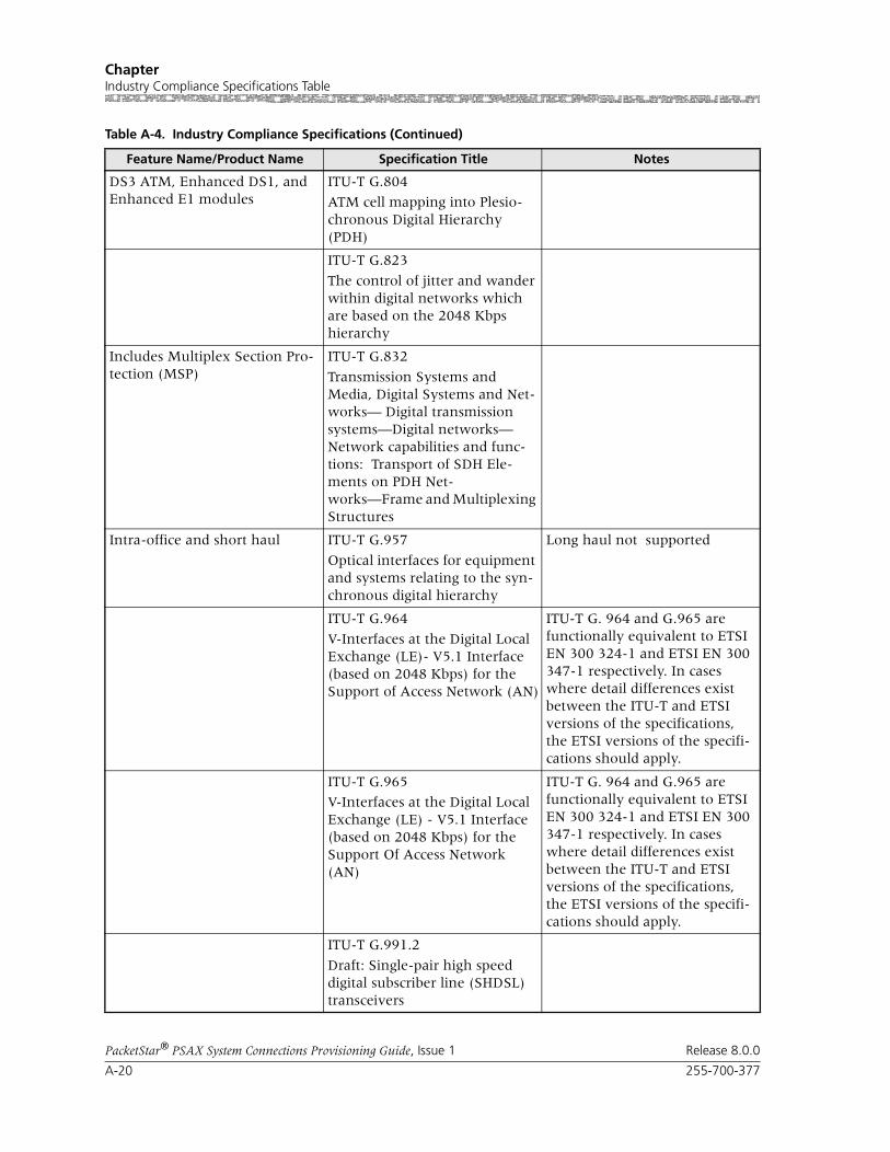
Chapter Industry Compliance Specifications Table
A-20 255-700-377
PacketStar® PSAX System Connections Provisioning Guide, Issue 1 Release 8.0.0
DS3 ATM, Enhanced DS1, and Enhanced E1 modules
ITU-T G.804
ATM cell mapping into Plesio-chronous Digital Hierarchy (PDH)
ITU-T G.823
The control of jitter and wander within digital networks which are based on the 2048 Kbps hierarchy
Includes Multiplex Section Pro-tection (MSP)
ITU-T G.832
Transmission Systems and Media, Digital Systems and Net-works— Digital transmission systems—Digital networks— Network capabilities and func-tions: Transport of SDH Ele-ments on PDH Net-works—Frame and Multiplexing Structures
Intra-office and short haul ITU-T G.957
Optical interfaces for equipment and systems relating to the syn-chronous digital hierarchy
Long haul not supported
ITU-T G.964
V-Interfaces at the Digital Local Exchange (LE)- V5.1 Interface (based on 2048 Kbps) for the Support of Access Network (AN)
ITU-T G. 964 and G.965 are functionally equivalent to ETSI EN 300 324-1 and ETSI EN 300 347-1 respectively. In cases where detail differences exist between the ITU-T and ETSI versions of the specifications, the ETSI versions of the specifi-cations should apply.
ITU-T G.965
V-Interfaces at the Digital Local Exchange (LE) - V5.1 Interface (based on 2048 Kbps) for the Support Of Access Network (AN)
ITU-T G. 964 and G.965 are functionally equivalent to ETSI EN 300 324-1 and ETSI EN 300 347-1 respectively. In cases where detail differences exist between the ITU-T and ETSI versions of the specifications, the ETSI versions of the specifi-cations should apply.
ITU-T G.991.2
Draft: Single-pair high speed digital subscriber line (SHDSL) transceivers
Table A-4. Industry Compliance Specifications (Continued)
Feature Name/Product Name Specification Title Notes
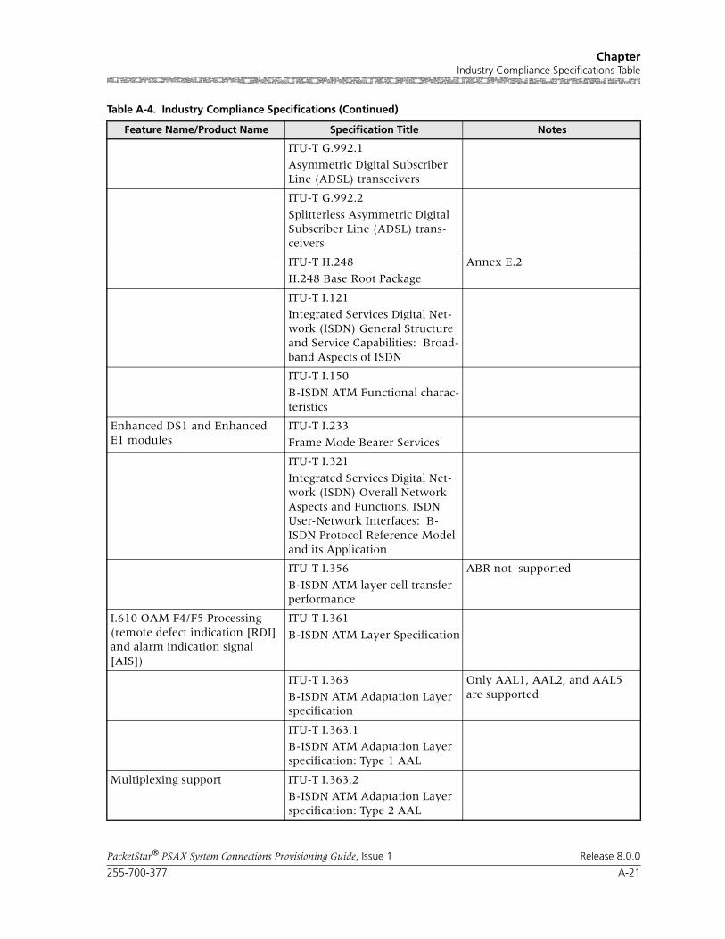
255-700-377 A-21
PacketStar® PSAX System Connections Provisioning Guide, Issue 1 Release 8.0.0
ChapterIndustry Compliance Specifications Table
ITU-T G.992.1
Asymmetric Digital Subscriber Line (ADSL) transceivers
ITU-T G.992.2
Splitterless Asymmetric Digital Subscriber Line (ADSL) trans-ceivers
ITU-T H.248
H.248 Base Root Package
Annex E.2
ITU-T I.121
Integrated Services Digital Net-work (ISDN) General Structure and Service Capabilities: Broad-band Aspects of ISDN
ITU-T I.150
B-ISDN ATM Functional charac-teristics
Enhanced DS1 and Enhanced E1 modules
ITU-T I.233
Frame Mode Bearer Services
ITU-T I.321
Integrated Services Digital Net-work (ISDN) Overall Network Aspects and Functions, ISDN User-Network Interfaces: B-ISDN Protocol Reference Model and its Application
ITU-T I.356
B-ISDN ATM layer cell transfer performance
ABR not supported
I.610 OAM F4/F5 Processing (remote defect indication [RDI] and alarm indication signal [AIS])
ITU-T I.361
B-ISDN ATM Layer Specification
ITU-T I.363
B-ISDN ATM Adaptation Layer specification
Only AAL1, AAL2, and AAL5 are supported
ITU-T I.363.1
B-ISDN ATM Adaptation Layer specification: Type 1 AAL
Multiplexing support ITU-T I.363.2
B-ISDN ATM Adaptation Layer specification: Type 2 AAL
Table A-4. Industry Compliance Specifications (Continued)
Feature Name/Product Name Specification Title Notes

Chapter Industry Compliance Specifications Table
A-22 255-700-377
PacketStar® PSAX System Connections Provisioning Guide, Issue 1 Release 8.0.0
ITU-T I.363.5
B-ISDN ATM Adaptation Layer specification: Type 5 AAL
VTOA AAL2 Trunking Narrow-band Services
ITU-T I.366.1
Segmentation and Reassembly Service Specific Convergence Sublayer for the AAL type 2
Channelized DS3, Channelized STS-1e, DS3 Frame Relay, Enhanced DS1, Enhanced E1, High-Density E1,Medium-Den-sity DS1, Multi-Serial, and Quadserial modules
ITU-T I.370
Congestion Management for ISDN Frame Relay Bearing Ser-vice
Channelized DS3, Channelized STS-1e, DS3 Frame Relay, High-Density E1, Medium-Density DS1, Multi-Serial and Quadse-rial modules
ITU-T I.371
Traffic control and congestion control in B-ISDN
ABR not supported
ITU-T I.372
Integrated Services Digital Net-work (ISDN) Overall Network Aspects and Functions: Frame Relaying Bearer Service Net-work-to-Network Interface Requirements
ITU-T I.413
Integrated Services Digital Net-work (ISDN) User-Network Interfaces: B-ISDN User-Net-work Interface
ITU-T I.430
Basic User-Network Interface - Layer 1 Specification
Channelized DS3, Channelized STS-1e, Channelized DS3/STS-1e CES, DS3 Frame Relay, Enhanced DS1, Enhanced E1, High-Density E1, Medium-Den-sity DS1, Multi-Serial, and Quadserial modules
ITU-T I.431
Integrated Services Digital Net-work (ISDN) User-Network Interfaces: Primary Rate User-Network Interface—Layer 1 Specification
Scrambling, header error control (HEC) processing, cell delinea-tion
ITU-T I.432
B-ISDN User-Network Inter-face—Physical layer Specifica-tion
Table A-4. Industry Compliance Specifications (Continued)
Feature Name/Product Name Specification Title Notes

255-700-377 A-23
PacketStar® PSAX System Connections Provisioning Guide, Issue 1 Release 8.0.0
ChapterIndustry Compliance Specifications Table
ITU-T I.432.1
B-ISDN User-Network Inter-face: Physical Layer Specifica-tion- General Characteristics
ITU-T I.432.2
B-ISDN User-Network- Physical Layer Specification: 155 520 Kbps and 622 080 Kbps opera-tion
ITU-T I.432.3
B-ISDN User-Network Inter-face: Physical Layer Specifica-tion for 1.544 Mbps and 2.048 Mbps
ITU-T I.432.4
B-ISDN User-Network- Physical Layer Specification: 51 840 Kbps Operation
Carrier Group AIS Alarm
Dual-homed PVCs
I.610 OAM F4/F5 Processing (remote defect indication [RDI] and alarm indication signal [AIS])
Channelized DS3, Channelized STS-1e, Channelized DS3/STS-1e CES, DS3 ATM, E3 ATM, DS1 IMA, DS3 IMA, E1 IMA, Enhanced DS1, Enhanced E1, DSP2A/B/C/D Voice Server, Route Server, High-Density E1, High Speed, Medium-Density DS1, Multi-Serial, Quadserial, OC-3c Single-Mode/Multi-Mode/APS, STM-1 Single-Mode/Multi-Mode/MSP, OC-12c/STM-4c modules and Unstructured DS3/E3 CES mod-ules
ITU-T I.610
B-ISDN operation and mainte-nance principles and functions
ITU-T Q.922
Digital Subscriber Signaling Sys-tem No.1 (DSS 1) Data Link Layer: ISDN Data Link Layer Specification for Frame Mode Bearer Services
Annex A
Table A-4. Industry Compliance Specifications (Continued)
Feature Name/Product Name Specification Title Notes

Chapter Industry Compliance Specifications Table
A-24 255-700-377
PacketStar® PSAX System Connections Provisioning Guide, Issue 1 Release 8.0.0
ITU-T Q.921
Digital Subscriber Signaling sys-tem No. 1, ISDN User-Network interface- Data Link Layer Spec-ification
• AAL1 Trunking CCS (Q.931)
• AAL1 Trunking CCS (Q.931/QSIG), AAL1 Trunk-ing CAS
• AAL2 Trunking CCS (Q.931)
ITU-T Q.931
Switching and Signaling - Digital subscriber Signalling System No. 1 - Network layer: Digital Sub-scriber Signaling System No. 1 (DSS 1) - ISDN User-Network Interface Layer 3 Specification for Basic Call Control
ITU-T Q.933 Annex A
Digital Subscriber Signaling Sys-tem No. 1—Integrated Services Digital Network (ISDN) Digital Subscriber Signaling System No. 1 (DSS 1)—Signaling Specifica-tions for Frame Mode Switched and Permanent Virtual Connec-tion Control and Status Moni-toring
ATM UNI interfaces (3.0, 3.1, 4.0)
ITU-T Q.2110
B-ISDN SAAL Service Specific Connection Oriented Protocol (SSCOP)
ATM UNI interfaces (3.0, 3.1, 4.0)
ITU-T Q.2130
B-ISDN SAAL Service Specific Coordination Function (SSCF) for Support of Signaling at the User-Network Interface
ITU-T Q.2931
B-ISDN Application protocols for access signalling—Broad-band Integrated Services Digital Network (B-ISDN)— Digital Subscriber Signalling System No. 2 (DSS 2)—User Network Interface (UNI) Layer 3 Specifi-cation For Basic Call/Connec-tion Control
Table A-4. Industry Compliance Specifications (Continued)
Feature Name/Product Name Specification Title Notes

255-700-377 A-25
PacketStar® PSAX System Connections Provisioning Guide, Issue 1 Release 8.0.0
ChapterIndustry Compliance Specifications Table
ITU-T Q.2941.2
Draft: Broadband Integrated Services Digital Network (B-ISDN)- Digital Subscriber Signal-ing System No. 2 (DSS2): Generic identifier transport (
ITU-T Q.2971
B-ISDN—DSS 2—User-network interface layer 3 specification for point-to-multipoint call/connec-tion control
ITU-T V.8
Procedures For Starting Ses-sions of Data Transmission Over the General Switched Telephone Network
ITU-T V.25
Automatic Answering Equip-ment and General Procedures for Automatic Calling Equip-ment on the General Switched Telephone Network Including Procedures for Disabling of Echo Control Devices for Both Manu-ally and Automatically Estab-lished Calls
Enhanced DS1 and Enhanced E1 modules
TR-TSU-001369
Generic Requirement for Frame Relay PVC Exchange Services
Table A-4. Industry Compliance Specifications (Continued)
Feature Name/Product Name Specification Title Notes
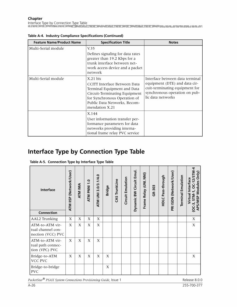
Chapter Interface Type by Connection Type Table
A-26 255-700-377
PacketStar® PSAX System Connections Provisioning Guide, Issue 1 Release 8.0.0
Interface Type by Connection Type Table
Multi-Serial module V.35
Defines signaling for data rates greater than 19.2 Kbps for a trunk interface between net-work access device and a packet network
Multi-Serial module X.21 bis
CCITT Interface Between Data Terminal Equipment and Data Circuit-Terminating Equipment for Synchronous Operation of Public Data Networks, Recom-mendation X.21
Interface between data terminal equipment (DTE) and data cir-cuit-terminating equipment for synchronous operation on pub-lic data networks
X.144
User information transfer per-formance parameters for data networks providing interna-tional frame relay PVC service
Table A-4. Industry Compliance Specifications (Continued)
Feature Name/Product Name Specification Title Notes
Table A-5. Connection Type by Interface Type Table
Interface
ATM
IISP
(N
etw
ork
/Use
r)
ATM
IMA
ATM
PN
NI 1
.0
ATM
UN
I 3.0
/3.1
/4.0
Bri
dg
e
CA
S Tr
un
kLin
e
Cir
cuit
Em
ula
tio
n
Dyn
amic
BW
Cir
cuit
Em
ul.
Fram
e R
elay
(UN
I, N
NI)
GR
-303
HD
LC P
ass-
thro
ug
h
PRI I
SDN
(N
etw
ork
/Use
r)
Term
inal
Em
ula
tio
n
Vir
tual
Inte
rfac
e (
OC
-3, S
TM-1
, OC
-12/
STM
-4A
PS/M
SP M
od
ule
s O
nly
)
Connection
AAL2 Trunking X X X X X
ATM-to-ATM vir-tual channel con-nection (VCC) PVC
X X X X X
ATM-to-ATM vir-tual path connec-tion (VPC) PVC
X X X X
Bridge-to-ATM VCC PVC
X X X X X X
Bridge-to-bridge PVC
X

255-700-377 A-27
PacketStar® PSAX System Connections Provisioning Guide, Issue 1 Release 8.0.0
ChapterInterface Type by Connection Type Table
Circuit emulation-to ATM VCC PVC
X X X X X X X
Circuit emulation-to circuit emula-tion PVC
X X
Frame relay-to-ATM VCC PVC
X X X X X X
Frame relay-to-frame relay PVC
X
In-band manage-ment ATM PVC
X X X X
Variable bit rate (VBR)-to-ATM VCC PVC
X X X X X X X
VBR-to-VBR PVC X X
ATM-to-ATM IISP constant bit rate (CBR) SVC
X X X X
ATM-to-ATM IISP VBR SVC
X X X X
ATM-to-ATM VCC SPVC
X X X X
Circuit emulation-to-ATM VCC SPVC
X X X X X X X
CE-to-ATM Std AAL2 VCC SPVC
X X X X
Frame relay-ATM VCC SPVC
X X X X X
VBR-to-ATM VCC SPVC
X X X X X X X
VBR-to-ATM Std AAL2 VCC SPVC
X X X X X
Table A-5. Connection Type by Interface Type Table (Continued)
Interface
ATM
IISP
(N
etw
ork
/Use
r)
ATM
IMA
ATM
PN
NI 1
.0
ATM
UN
I 3.0
/3.1
/4.0
Bri
dg
e
CA
S Tr
un
kLin
e
Cir
cuit
Em
ula
tio
n
Dyn
amic
BW
Cir
cuit
Em
ul.
Fram
e R
elay
(UN
I, N
NI)
GR
-303
HD
LC P
ass-
thro
ug
h
PRI I
SDN
(N
etw
ork
/Use
r)
Term
inal
Em
ula
tio
n
Vir
tual
Inte
rfac
e (
OC
-3, S
TM-1
, OC
-12/
STM
-4A
PS/M
SP M
od
ule
s O
nly
)
Connection

Chapter Interface Type by I/O Module Type Table
A-28 255-700-377
PacketStar® PSAX System Connections Provisioning Guide, Issue 1 Release 8.0.0
Interface Type by I/O Module Type Table
Table A-6 shows the available interface types for each PacketStar PSAX I/O module used in the PacketStar®PSAX Multiservice Media Gateways. This table does not include other PSAX modules that are not I/O modules, which include: the Alarm module, the DSP2x Voice Server modules, the Route Server module, and the Tones and Announcements Server module.
Table A-6. Interface Types by I/O Module Types
Interface
ATM
IISP
(N
etw
ork
/Use
r)
ATM
IMA
ATM
PN
NI 1
.0
ATM
UN
I 4.0
ATM
UN
I 3.0
/3.1
Bri
dg
e
CA
S Tr
un
klin
e
Cir
cuit
Em
ula
tio
n
Dyn
amic
Ban
dw
idth
C
ircu
it E
mu
lati
on
Fram
e R
elay
(UN
I, N
NI)
GR
-303
HD
LC P
ass-
thro
ug
h
PR
I ISD
N
(Net
wo
rk/U
ser)
Ro
uti
ng
Term
inal
Em
ula
tio
n
Module
DS1/T1 Interface Modules
6-Port DS1 IMA (IMA DS1)
X X X X X
6-Port Enhanced DS1/T1 Multiservice (DS1/T1 Enh)
X X X X X X X X X X
12-Port Medium-Density DS1 Multiservice (MD DS1)
X X X X X X X X X
12-Port Medium-Density DS1 IMA (MD DS1 IMA)
X X X X X X
12-Port Medium-Density DS1/E1/DS0A CES (MD DS1/E1/DS0A CES)
X
E1 Interface Modules
6-Port E1 IMA (IMA E1) X X X X X
6-Port Enhanced E1 Multiservice (E1 Enh)
X X X X X X X X X
21-Port High-Density E1 Multiservice (HD E1)
X X X X X X X X

255-700-377 A-29
PacketStar® PSAX System Connections Provisioning Guide, Issue 1 Release 8.0.0
ChapterInterface Type by I/O Module Type Table
21-Port High-Density E1 IMA (HD E1 IMA)
X X X X X
DS3, E3, and STS-1e Interface Modules
1-Port Channelized DS3 Multiservice (CH DS3)
X X X X X X X X X X
1-Port Channelized DS3 CES (CH DS3)
1-Port DS3 IMA (DS3 IMA)
X X X X X
1-Port Unchannelized DS3 Frame Relay (DS3 FR)
X
2-Port DS3 ATM (DS3 ATM)
X X X X
2-Port E3 ATM (E3 ATM)
X X X X
3-Port Channelized DS3/STS-1e CES (CH DS3/STS-1e)
X X X X
3-Port Channelized DS3/STS-1e CES Protection (CH DS3/STS-1e)
X X X X
3-Port DS3/E3 ATM (DS3/E3 ATM)
X X X X
3-Port Unstructured DS3/E3 CES (UNSTR DS3/E3 CES)
X
Table A-6. Interface Types by I/O Module Types (Continued)
Interface
ATM
IISP
(N
etw
ork
/Use
r)
ATM
IMA
ATM
PN
NI 1
.0
ATM
UN
I 4.0
ATM
UN
I 3.0
/3.1
Bri
dg
e
CA
S Tr
un
klin
e
Cir
cuit
Em
ula
tio
n
Dyn
amic
Ban
dw
idth
C
ircu
it E
mu
lati
on
Fram
e R
elay
(UN
I, N
NI)
GR
-303
HD
LC P
ass-
thro
ug
h
PR
I ISD
N
(Net
wo
rk/U
ser)
Ro
uti
ng
Term
inal
Em
ula
tio
n
Module

Chapter Interface Type by I/O Module Type Table
A-30 255-700-377
PacketStar® PSAX System Connections Provisioning Guide, Issue 1 Release 8.0.0
STS-1e Interface Modules
1-Port Channelized STS-1e, T1 Format (CH STS-1e T1)
X X X X X X X X
OC-3/OC-3c Interface Modules
1-Port Channelized OC-3/STM-1 CES Multimode (CH OC-3/STM-1 CES MM)
X X
1-Port Channelized OC-3/STM-1 CES Single-mode (CH OC-3/STM-1 CES SM)
X X
1-Port OC-3c Multimode with AQueMan (OC-3c (MM AQ))
X X X X
1-Port OC-3c Single-Mode with AQueMan (OC-3c (SM AQ))
X X X X
1-Port OC-3c Multimode with Traffic Shaping (OC-3c (MM TS))
X X X X
1-Port OC-3c Single-Mode with Traffic Shaping (OC-3c (SM TS))
X X X X
1-Port OC-3c 1+1 APS Multimode (OC-3c MM APS)
X X X X
Table A-6. Interface Types by I/O Module Types (Continued)
Interface
ATM
IISP
(N
etw
ork
/Use
r)
ATM
IMA
ATM
PN
NI 1
.0
ATM
UN
I 4.0
ATM
UN
I 3.0
/3.1
Bri
dg
e
CA
S Tr
un
klin
e
Cir
cuit
Em
ula
tio
n
Dyn
amic
Ban
dw
idth
C
ircu
it E
mu
lati
on
Fram
e R
elay
(UN
I, N
NI)
GR
-303
HD
LC P
ass-
thro
ug
h
PR
I ISD
N
(Net
wo
rk/U
ser)
Ro
uti
ng
Term
inal
Em
ula
tio
n
Module
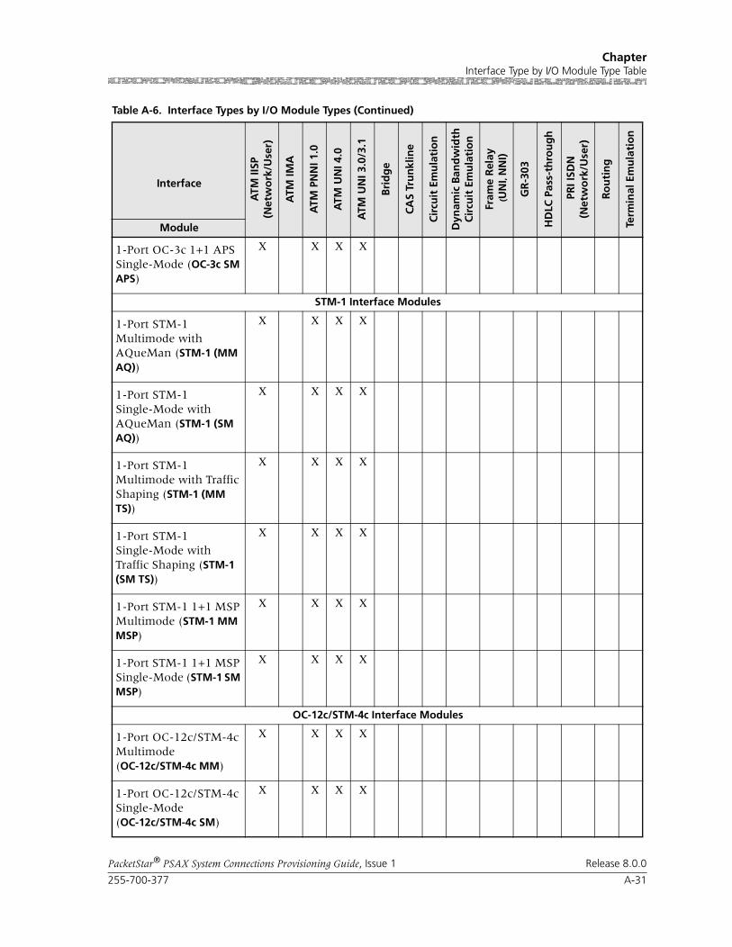
255-700-377 A-31
PacketStar® PSAX System Connections Provisioning Guide, Issue 1 Release 8.0.0
ChapterInterface Type by I/O Module Type Table
1-Port OC-3c 1+1 APS Single-Mode (OC-3c SM APS)
X X X X
STM-1 Interface Modules
1-Port STM-1 Multimode with AQueMan (STM-1 (MM AQ))
X X X X
1-Port STM-1 Single-Mode with AQueMan (STM-1 (SM AQ))
X X X X
1-Port STM-1 Multimode with Traffic Shaping (STM-1 (MM TS))
X X X X
1-Port STM-1 Single-Mode with Traffic Shaping (STM-1 (SM TS))
X X X X
1-Port STM-1 1+1 MSP Multimode (STM-1 MM MSP)
X X X X
1-Port STM-1 1+1 MSP Single-Mode (STM-1 SM MSP)
X X X X
OC-12c/STM-4c Interface Modules
1-Port OC-12c/STM-4c Multimode (OC-12c/STM-4c MM)
X X X X
1-Port OC-12c/STM-4c Single-Mode (OC-12c/STM-4c SM)
X X X X
Table A-6. Interface Types by I/O Module Types (Continued)
Interface
ATM
IISP
(N
etw
ork
/Use
r)
ATM
IMA
ATM
PN
NI 1
.0
ATM
UN
I 4.0
ATM
UN
I 3.0
/3.1
Bri
dg
e
CA
S Tr
un
klin
e
Cir
cuit
Em
ula
tio
n
Dyn
amic
Ban
dw
idth
C
ircu
it E
mu
lati
on
Fram
e R
elay
(UN
I, N
NI)
GR
-303
HD
LC P
ass-
thro
ug
h
PR
I ISD
N
(Net
wo
rk/U
ser)
Ro
uti
ng
Term
inal
Em
ula
tio
n
Module

Chapter Minimum AAL2 Trunk Size Requirements Tables
A-32 255-700-377
PacketStar® PSAX System Connections Provisioning Guide, Issue 1 Release 8.0.0
Minimum AAL2 Trunk Size Requirements Tables
Multiplexed AAL2 Setting up channels with standard AAL2 multiplexing helps reduce traffic delay, as voice samples from at two channels or more are multiplexed into one VC, decreasing the amount of time necessary to fill one ATM cell before it is transmitted. (Without multiplexing, only one VC is allowed per ATM cell. The cell must wait to fill with samples from one channel before transmis-sion). If a trunk is configured to have at least one active channel, one cell must be sent out every 20 ms; thus, the minimum trunk size is 50 cps. At 8 Kbps, Lucent recommends two multiplexed channels. On the DSP2C mod-ule, you can configure up to 64 AAL2 trunk groups, so that if you want to
Voice 2-Wire Interface Modules
4-Port Voice 2-Wire Office (VOICE 2WO)
X*
8-Port Voice 2-Wire Station (VOICE 2WS)
X*
Serial Interface Modules
2-Port High Speed (HIGH SPEED)
X X X X †
Quadserial (QUAD SERIAL)
X X X X X X
6-Port Multiserial (SERIAL)
X X X X X
Ethernet Interface Modules
Ethernet (ENET) X X
4-Port Ethernet (ENET) X X
* European modules do not support this interface with the 8-Port Voice 2-Wire Station or 4-Port 2-Wire Office module.
† Port 2 only.
Table A-6. Interface Types by I/O Module Types (Continued)
Interface
ATM
IISP
(N
etw
ork
/Use
r)
ATM
IMA
ATM
PN
NI 1
.0
ATM
UN
I 4.0
ATM
UN
I 3.0
/3.1
Bri
dg
e
CA
S Tr
un
klin
e
Cir
cuit
Em
ula
tio
n
Dyn
amic
Ban
dw
idth
C
ircu
it E
mu
lati
on
Fram
e R
elay
(UN
I, N
NI)
GR
-303
HD
LC P
ass-
thro
ug
h
PR
I ISD
N
(Net
wo
rk/U
ser)
Ro
uti
ng
Term
inal
Em
ula
tio
n
Module
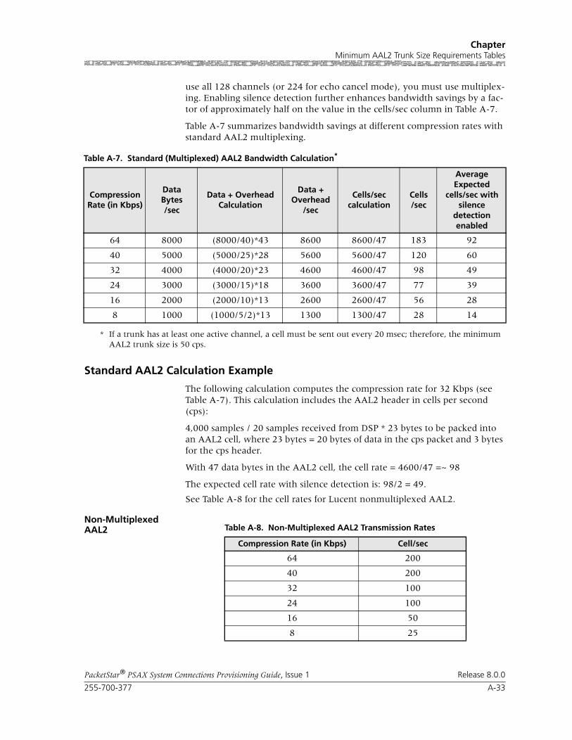
255-700-377 A-33
PacketStar® PSAX System Connections Provisioning Guide, Issue 1 Release 8.0.0
ChapterMinimum AAL2 Trunk Size Requirements Tables
use all 128 channels (or 224 for echo cancel mode), you must use multiplex-ing. Enabling silence detection further enhances bandwidth savings by a fac-tor of approximately half on the value in the cells/sec column in Table A-7.
Table A-7 summarizes bandwidth savings at different compression rates with standard AAL2 multiplexing.
Standard AAL2 Calculation Example
The following calculation computes the compression rate for 32 Kbps (see Table A-7). This calculation includes the AAL2 header in cells per second (cps):
4,000 samples / 20 samples received from DSP * 23 bytes to be packed into an AAL2 cell, where 23 bytes = 20 bytes of data in the cps packet and 3 bytes for the cps header.
With 47 data bytes in the AAL2 cell, the cell rate = 4600/47 =~ 98
The expected cell rate with silence detection is: 98/2 = 49.
See Table A-8 for the cell rates for Lucent nonmultiplexed AAL2.
Non-Multiplexed AAL2
Table A-7. Standard (Multiplexed) AAL2 Bandwidth Calculation*
Compression Rate (in Kbps)
DataBytes/sec
Data + Overhead Calculation
Data +Overhead
/sec
Cells/seccalculation
Cells/sec
Average Expected
cells/sec with silence
detection enabled
64 8000 (8000/40)*43 8600 8600/47 183 92
40 5000 (5000/25)*28 5600 5600/47 120 60
32 4000 (4000/20)*23 4600 4600/47 98 49
24 3000 (3000/15)*18 3600 3600/47 77 39
16 2000 (2000/10)*13 2600 2600/47 56 28
8 1000 (1000/5/2)*13 1300 1300/47 28 14
* If a trunk has at least one active channel, a cell must be sent out every 20 msec; therefore, the minimum AAL2 trunk size is 50 cps.
Table A-8. Non-Multiplexed AAL2 Transmission Rates
Compression Rate (in Kbps) Cell/sec
64 200
40 200
32 100
24 100
16 50
8 25
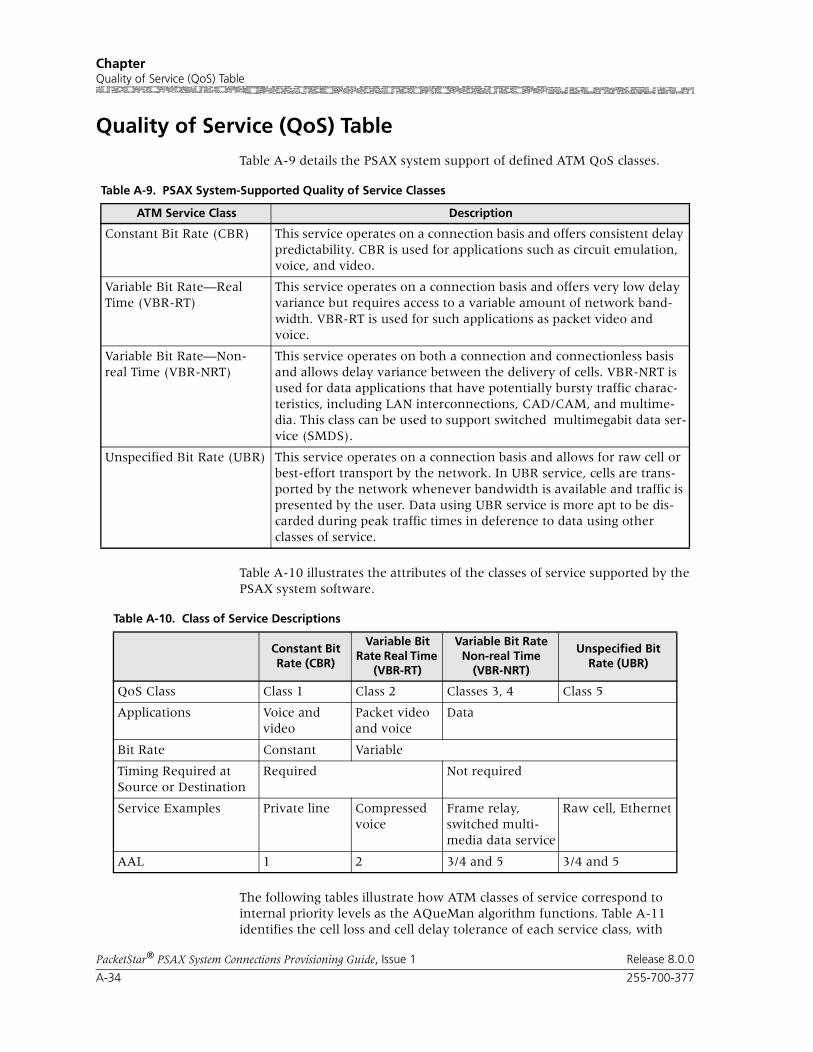
Chapter Quality of Service (QoS) Table
A-34 255-700-377
PacketStar® PSAX System Connections Provisioning Guide, Issue 1 Release 8.0.0
Quality of Service (QoS) Table
Table A-9 details the PSAX system support of defined ATM QoS classes.
Table A-10 illustrates the attributes of the classes of service supported by the PSAX system software.
The following tables illustrate how ATM classes of service correspond to internal priority levels as the AQueMan algorithm functions. Table A-11 identifies the cell loss and cell delay tolerance of each service class, with
Table A-9. PSAX System-Supported Quality of Service Classes
ATM Service Class Description
Constant Bit Rate (CBR) This service operates on a connection basis and offers consistent delay predictability. CBR is used for applications such as circuit emulation, voice, and video.
Variable Bit Rate—Real Time (VBR-RT)
This service operates on a connection basis and offers very low delay variance but requires access to a variable amount of network band-width. VBR-RT is used for such applications as packet video and voice.
Variable Bit Rate—Non-real Time (VBR-NRT)
This service operates on both a connection and connectionless basis and allows delay variance between the delivery of cells. VBR-NRT is used for data applications that have potentially bursty traffic charac-teristics, including LAN interconnections, CAD/CAM, and multime-dia. This class can be used to support switched multimegabit data ser-vice (SMDS).
Unspecified Bit Rate (UBR) This service operates on a connection basis and allows for raw cell or best-effort transport by the network. In UBR service, cells are trans-ported by the network whenever bandwidth is available and traffic is presented by the user. Data using UBR service is more apt to be dis-carded during peak traffic times in deference to data using other classes of service.
Table A-10. Class of Service Descriptions
Constant Bit Rate (CBR)
Variable Bit Rate Real Time
(VBR-RT)
Variable Bit Rate Non-real Time
(VBR-NRT)
Unspecified Bit Rate (UBR)
QoS Class Class 1 Class 2 Classes 3, 4 Class 5
Applications Voice and video
Packet video and voice
Data
Bit Rate Constant Variable
Timing Required at Source or Destination
Required Not required
Service Examples Private line Compressed voice
Frame relay, switched multi-media data service
Raw cell, Ethernet
AAL 1 2 3/4 and 5 3/4 and 5

255-700-377 A-35
PacketStar® PSAX System Connections Provisioning Guide, Issue 1 Release 8.0.0
ChapterQuality of Service (QoS) Table
internal priorities. Table A-12 lists the class-of-service choices available when configuring PVC connections on a PSAX system and shows service examples for each PVC connection type. The service examples in Table A-12 are intended simply as illustrations and you should choose your service class based on your network applications supported by the PSAX system. The flex-ibility of the PSAX system allows you to tailor the system based on the required service applications by selecting the appropriate priority levels.
Table A-11. Cell Loss and Cell Delay Characteristics of ATM Service Classes
ATM Classes of Service
QoS Classes Supported by
the PSAXSystem
Cell LossTolerance
Cell DelayTolerance
InternalPriority
Constant Bit Rate (CBR) Class 1 High Very Low CBR-1
Class 1 High Very Low CBR-2
Class 1 High Low CBR-3
Class 1 High Low CBR-4
Variable Bit Rate (VBR)
Variable Bit Rate—Real Time (VBR-RT)
Class 2 Very Low Very Low VBR-1
Class 2 Low Low VBR-2
Class 2 Low Low VBR-3
Variable Bit Rate—Non-real Time (VBR-NRT)
Classes 3, 4 Low Medium VBR-4
Classes 3, 4 Low High VBR-5
Unspecified Bit Rate (UBR) Class 5 Very High Very High VBR-6
Table A-12. Mapping ATM Service Classes to PSAX System Priority Levels
ATM Classes of ServiceInternal Priority
PVC Connection Configuration
SelectionsService Examples
Constant Bit Rate (CBR) CBR-1 CBR1 911 calls
CBR-2 CBR2 Preferred customers
CBR-3 CBR3 Standard
CBR-4 CBR4 Cellular
Variable Bit Rate (VBR) VBR-1 VBR-express Network management
Variable Bit Rate—Real Time (VBR-RT)
VBR-2 VBR-RT1 Real-time videos
VBR-3 VBR-RT2 MPEG 1-2/JPEG
Variable Bit Rate—Non-real Time (VBR-NRT)
VBR-4 VBR-NRT1 Frame relay data
VBR-5 VBR-NRT2 FTP/e-mail transfer
Unspecified Bit Rate (UBR) VBR-6 UBR Internet Protocol data

Chapter Traffic Shaping, Usage Parameter Control, and Virtual Interface Configuration Compatibilities Table
A-36 255-700-377
PacketStar® PSAX System Connections Provisioning Guide, Issue 1 Release 8.0.0
Traffic Shaping, Usage Parameter Control, and Virtual Interface Configuration Compatibilities Table
The following table shows configuration capatibility among the Traffic Shap-ing, UPC Support, and VI Support fields for all modules and interfaces sup-porting these features, except as indicated by a footnote. “Yes” indicates the two indicated features can be configured together; “No” indicates they can-not.
Table A-13. Traffic Shaping, UPC Support, and VI SupportConfiguration Compatibility
Fields on ATM UNI, PNNI, and IISP
Traffic Shaping
VISupport
UPCSupport
Traffic Shaping N/A Yes*
* This combination is valid only on the ATM UNI 3.0 through 4.0 inter-face on the 3P DS3/E3 ATM and the 1P OC-12c/STM-4c 1+1 APS/MSP SM/MM modules.
No
VI Support Yes* N/A Yes
UPC Support No Yes N/A


Part Number: 955M0A8001A1Copyright © 2002 Lucent TechnologiesAll rights reserved.