Ahnen - Helden - Götter. Die großplastischen Skulpturen der frühen Kelten.
Upload
khangminh22Category
view
0download
0
Wid
e Tole
ranc
eDe
dica
ted
PE S
olutio
nsCl
amps
& Ta
pswww.helden-web.com
Printed in the UK
■ Designed and manufactured under quality management systems
in accordance with BS EN ISO 9001.
■ Environmental Management System accredited to ISO 14001.
■ For full terms and conditions, please visit our website.
■ We hope our communications have an impact on you - but not
the environment - we have taken steps to ensure this brochure
is printed on Forestry Stewardship Council material and the
paper is made by a totally chlorine free process.
DR
1078
7_09
_202
1_IS
SU
E 7
46-48 WILBURY WAY HITCHIN, HERTFORDSHIRE SG4 0UD. UNITED KINGDOM
TELEPHONE: +44 (0)1462 443322 FAX: +44 (0)1462 443311 EMAIL: [email protected]
DUBAI SALES OFFICE CRANE BS&U BUILDING 4, OFFICE 901 THE GALLERIES PO BOX 17415 DOWNTOWN JEBEL ALI DUBAI. UAE
TELEPHONE: +971 4816 5800
*BS EN 14525 - Ductile Iron wide tolerance couplings and flange adaptors for use with pipes of different materials : ductile iron, steel, PVC-U, PE, fibre-cement.
Every effort has been made to ensure that the information contained in this publication is accurate at the time of publishing. Crane Ltd assumes no responsibility or liability for typographical errors or omissions or for any misinterpretation of the information within the publication and reserves the right to change without notice.
To visit our Video Library go to:www.youtube.com/user/CraneBSU
Distributor stamp
I S S U E 7
Product Portfolio› Couplings
› Flange Adaptors
› Pipe Repairs
› Flow Control
Product P
ortfolio
EMS 553775FM 00311
www.cranebsu.com
Keeping Our World ConnectedKeeping Our World Connected
ISS
UE
7

22 Helden Telephone: +44 (0)1462 44332222
Wide Tolerance PE Solutions
Couplings & Flange Adaptors
INCLUDES MaxiFit
Plus
Pipe Materials
Note: The choice of gasket material must be appropriate for each service to ensure successful operation (see pages 289-292 for further information)
MaxiFit 37 - 70
MegaFit 71 - 78
AquaFast 185 - 200
UltraGrip 79 - 98
AquaGrip 201 - 210
AVAILABLE UP TO DN600
NOWAVAILABLE
355 TO 450 DIAMETER
Contents
Product Portfolio 2 - 3
Helden’s Evolution 4 - 5
Our Heritage 6
Our Processes 7
Our Brands 8 - 9
Timeline 10 - 11
World Leaders - Quality 12 - 13
Manufacturing Excellence 14 - 15
Manufacturing Investment 16 - 21
International Locations 22 - 23
Corrosion Protection - Rilsan Coating
24 - 25
Gas & Industrial Applications
26 - 27
Good People Make Good Things Happen
28 - 29
We Operate Around the World
30 - 31
Applications Selector 32 - 33
Outside Diameter Chart 35
Pipe Materials Selector 36
Case Study Index 293 - 296
Datasheet Index 297
Industrial
Applications including:Oil based & petroleum productsChemicalsSewageGeneral industrial processing
Water Products
Gas Products
Applications

3Heldenwww.helden-web.com 3
Pipe Repairs Flow Control
Design Data
Dedicated Clamps & Taps Through Bore Hydrant
Glossary of Terms 272
Glossary of Standards 273
Design & Specifications 274
The Concept 275
System Overview 276
Angular Deflection 277 - 278
Setting Gaps 279
Pressure Forces, Coupling Movement Under Pressure
280
Accommodating End Load Forces, FlexLock, UltraGrip, Dismantling Joint
281
Pipe Supports, Anchored Couplings, Cathodic Protection
282
Locating Plugs, Inclined Pipelines
283
Shear Strength, Expansion & Contraction, Pipe End Preparation
284
Couplings & Stepped Couplings
285 - 286
Flange Adaptors & Flange Comparison Chart
287 - 288
Gaskets 289 - 290
Corrosion Protection 291
Chemical Resistance Chart 292
Dismantling Joint 99 - 122 EasiRange 211 - 244 265 - 270
FlexLock 123 - 132 HandiRange 245 - 263
Large Diameter 133 - 158
QuickFit 159 - 171
Marine 173 - 178
Wall Couplings 179 - 184
NOWAVAILABLE
UP TO DN700
DR
1078
7_15
_08_
2021
_IS
SU
E 7

44 Helden Telephone: +44 (0)1462 44332244

5Heldenwww.helden-web.com 5
DR
1078
7_15
_08_
2021
_IS
SU
E 7
Helden’s Evolution
Helden started life in the 1970’s as part of the
worldwide Dresser Corporation but in the early 1990’s,
the Dresser Couplings facility in the Netherlands was
purchased by Victaulic PLC and the company name
was changed to Helden Couplings. In 1995, Victaulic
PLC was acquired by Glynwed Pipe Systems and the
Dutch operation became GPS Couplings BV. In 2003,
the GPS coupling businesses were sold to Crane Ltd.
and the Helden brand became part of Crane Building
Services & Utilities portfolio of products.
In 2019, Crane Ltd celebrated its 100 years, with
a history dating back to the 1st of July 1919 when
Crane Co. purchased James E. Bennett & Sons,
a Coppersmiths from London who had been an
importer of Crane pipe fittings & valves.
Helden today are pioneers in the manufacturing of
couplings, flange adaptors, and pipe repair solutions
for the water, wastewater, gas and industrial markets.

66 Helden Telephone: +44 (0)1462 44332266
Crane Building Services & Utilities forms part
of the Process Flow Technologies segment within
Crane Co., which was founded in 1855, and is now
a multi-industry manufacturer that generated net
sales of $2.9bn in 2020.
Crane Limited was founded in 1919 making malleable
iron fittings and valves and Crane Building Services
& Utilities has been created as a result of Crane Ltd.
acquiring Viking Johnson, Helden and WASK in 2003,
and Hattersley in 2004. The most recent acquisition
was Delta Fluid Products in 2008. Each of these
companies has a long and distinguished history:
• Crane Limited founded in Ipswich in 1919
• Viking Johnson founded in Hitchin in the 1930’s
• WASK founded in Keighley in 1888
• Delta Fluid Products founded in St Helens in 1900
The name Crane speaks of who we are, what we stand
for and how our customers perceive us: a company
with history and tradition, but also a company that is
innovative, quality minded and one which acts with
integrity, still holding to the resolution of its founder.
Crane Co. was founded on 4th July 1855 by Richard
Teller Crane who made the following resolution:
“I am resolved to conduct my business in the
strictest honesty and fairness; to avoid all deception
and trickery; to deal fairly with both customers and
competitors; to be liberal and just towards employees;
and to put my whole mind upon the business.”
The essence of this resolution is the business policy
of Crane Co. today.
Our Heritage
Richard Teller Crane

77Heldenwww.helden-web.com • Telephone: +44 (0)1462 443322 7Heldenwww.helden-web.com
DR
1078
7_15
_08_
2021
_IS
SU
E 7
Operational Excellence is the Crane Business
System that is the cornerstone of all our activities.
It ensures that each of our business units follows
a systematic approach using a variety of tools
to generate profitable growth by eliminating
waste, reducing variability and focusing on
customer needs.
• Lean manufacturing
• Kaizen projects to improve all processes
• Strategic selling, planning, and supply
chain management
• Six Sigma tools to measure, map
and reduce variability
Standard processes are in place throughout
our value streams to improve our key metrics:
Safety, Quality, Delivery, Leadtime and Cost to
drive growth.
Our Processes

Helden Telephone: +44 (0)1462 44332288
PosiFlex Expansion Joint WASK Lats & RisersHelden Coupling Sperryn Regulator
PosiFlex expansion joints provide relief for piping
system stress caused by thermal and mechanical
vibration and/or movement, and can also be utilised to
overcome problems of noise. These flexible connectors
are fabricated from a wide range of rubber compounds,
open or filled, single or multiple arch and are designed
to accommodate the needs of individual pipe systems
moving materials as diverse as fluids, foodstuffs,
chemicals or crude oil.
Sperryn is a leading supplier of meter installation kits
and emergency control valves for domestic, commercial
and industrial applications. Using the latest design
facilities and technologies, Sperryn regulators offer
increased capacity, accuracy and lower pressure drops
.Market leader in the supply of specialist mains and
service fittings, along with pipeline equipment of
the highest quality, WASK is renowned in the global
gas distribution market. WASK Teeset and bagging-
off equipment has become a standard in the UK gas
industry and in many markets overseas.
Latest additions to the range include a unique riser and
lateral modular system which allows PE pipework to
supply gas into single or multiple occupancy dwellings.
Our Brands

Heldenwww.helden-web.com 9
NABIC Safety Relief ValveCrane FS TCV & Tee Wade Compression FittingHattersley Hook Up
DR
1078
7_15
_08_
2021
_IS
SU
E 7
For over 100 years the Hattersley brand has
become synonymous with quality, reliability and
excellent service.
A variety of traditional valves, including ball, butterfly,
check, gate & globe valves as well as a range of
balancing solutions - for constant & variable flow
systems are available. In addition there is a range of
public health valves which includes thermal circulation
valves which help to prevent Legionnaires’ disease.
One of the UK’s leading suppliers of gunmetal
safety valves, NABIC has long been recognised as
the industry standard for commercial and industrial
hot water applications. NABIC valves are ideal
for hot water supply, heating, pump relief, bypass
relief, outside installation and for use with different
gases and liquids.
Crane Fluid Systems has manufactured for more
than 100 years a range of malleable iron and bronze
pipe fittings, traditional valves, as well as a range of
commissioning valves for static and variable flow
systems which includes a PICV terminal unit range.
An extensive range of low and medium pressure,
brass compression fittings, valves and accessories.
The range also covers SISTEM-P and compact push-
in fittings, nickel-plated BSP fittings, quick release
couplings, and tubing.

1010 Helden Telephone: +44 (0)1462 4433221010
19
27 Company name was
changed to Victaulic Company Ltd. Stewarts & Lloyds steel producers acquired 70% stake
19
19
The Victory Pipe Joint Company was formed shortly after World War 1
19
14
WW1 begins
19
08
London hosts Olympic Games
18
61
-65
American Civil War
19
03
Wright Brothers achieve sustained controlled powered flight
19
66 England
win the World Cup
19
69 Neil Armstrong
is the first man on the moon
19
79 Margaret
Thatcher Firstfemale PrimeMinister
19
45 WW2
ends
19
18 Women vote
in a general election for the first time
19
04 Trans-
Siberian Railway completed
18
88
WASK founded by Walter A. Slingsby of Keighley (hence the acronym)
19
30 Original Johnson
Couplings made by The Victaulic Company Ltd. (part of Stewarts & Lloyds group)
19
80
Introductionof many newproducts -MaxiFit,FlexLock,EasiClamp
18
55 Crane Co.
founded
Richard Teller Crane
19
42 Victaulic moved to ten acre
green field site in Hitchin
19
12 Titanic sinks
19
38 Mallard
breaks world speed record for steam locomotives
19
39
WW2 begins
19
33
Victaulic Joints supplied for the Sunderijal Hydro Electric Power Scheme, in Nepal, India
19
76 Concorde
enters service
19
18
WW1 ends
1855 198019401920
Crane Building Services & Utilities - Timeline

11Heldenwww.helden-web.com 11
19
90 AquaGrip,
HandiClamp,Juno,MegaFit,LinerGrip
19
93 Nelson Mandela
wins Nobel Peace Prize
19
82
Falklands War
20
12 Felix
Baumgartner sets world record for skydiving
20
00
UltraGrip, AquaFast
20
08 Delta Fluid
Products acquired by Crane Co.
20
14
Large Diameter high pressure couplings for the mining sector, Chile
19
94 Eurotunnel
officially opens
19
83 Water
pipelines in El Arish, Egypt
19
92 The Great Man
Made River,Libya
20
02 The Euro
enters circulation
20
12
20
12
Multi-million pound investment in manufacturing plant at Hitchin
London hosts Olympic Games. LinerGrips are supplied to the Olympic Village
20
03
20
04 Hattersley
acquired by Crane Co.
19
89
Berlin Wall comes down
20
09
Through Bore Hydrant SBWWI best product innovation award
20
10 Next Generation UltraGrip and
Remote Repair Clamp - the latter won SBWWI best product innovation award
20
13 5 million MaxiFit
sold worldwide
2014 2017 2018 2019 20212000
20
17 AquaFast
Large Diameter (355 – 450mm)
20
19
20
19
Qatar Mega Reservoirs, Primary Reservoir Pumping Station
20
15
Queen Elizabeth II becomes the longest reigning UK monarch
20
15
20
15 UltraGrip
DN600
LiverpoolWwTW Project
20
18
20
21
A14Cambridge AquaFast LDfor Anglian Water
Kingdom of Saudi Arabia, Riyadh Metro Project,
relaying portable water system
Distributor Conference -Duxford
DR
1078
7_15
_08_
2021
_IS
SU
E 7
Helden, WASK and Viking Johnson acquired by Crane Co.

1212 Helden Telephone: +44 (0)1462 443322
The Great Man Made River, LibyaCouplings & Flange Adaptors - DN4000

13Heldenwww.helden-web.com
*See back cover for full specification
EMS 553775FM 00311VC 669122
VC 673979
13
DR
1078
7_15
_08_
2021
_IS
SU
E 7
World Leaders in what we do…
Helden is a world leader in the design, manufacture and
supply of couplings, flange adaptors, and pipe repair
solutions. Part of Crane Building Services & Utilities,
Helden services the international water, wastewater,
gas and industrial markets with a range of products
that can be used to connect or repair many types of
pipe material and are suitable for dedicated and wide
tolerance applications, from 40mm to 4000mm in
diameter.
The product portfolio offers an extensive and innovative
choice of standard products, supplemented by bespoke
solutions. All products are manufactured to the most
demanding customer specifications.
Quality
For more than 90 years, Helden has delivered
products that exceed market expectations. Our design
team utilises the latest engineering design software
and specifies manufacturing processes that ensure
repeatability and longevity. Industry specifications are
our starting point and to ensure a 50 year design life,
Helden products undergo accelerated ageing regime in
our in-house test facilities - providing customers with
complete peace of mind.
Helden operates a quality management system
accredited to ISO 9001 combined with an
environmental policy accredited to ISO 14001.
In addition, some product ranges and components
have been approved by 3rd party organisations. These
include -
• Marine - Bureau Veritas and ABS
• Potable water - WBS and ACS
• Specific regions - GOST-R, Bulgarkontrola,
Belarus Technical Approval and many others
For a full list of standards, please refer to the Design
Data section on page 261.
Haweswater, Cumbria, UKLarge Diameter Flange Adaptors - DN1200

1414 Helden Telephone: +44 (0)1462 4433221414

15Heldenwww.helden-web.com 15
DR
1078
7_15
_08_
2021
_IS
SU
E 7
Helden products have a design life expectancy of 50
years and form a crucial part of treatment, distribution
and waste networks. To ensure the future integrity
of a pipeline, it is vitally important that products are
structurally sound and dimensionally stable. Most
Helden products are manufactured in the UK, on a 14
acre manufacturing facility in Hitchin, by a skilled and
experienced workforce. To produce a comprehensive
range of over 7,000 product lines, from raw materials
through fabrication, coating and finishing, every
manufacturing step is carefully considered.
Flash Butt WeldingUsing a dedicated large diameter coupling as an
example, how it is welded and formed can affect the
strength, longevity and accuracy of tolerances and
the creation of a structurally sound and dimensionally
stable product. Helden is one of the few manufacturers
around the world that utilises flash butt welding for
joining sleeves and rings, to ensure that the product
will stand the test of time.
This technique forms a seamless joint between
two metal surfaces and this process has many
advantages over arc welding. Both processes are
resistance welds (an electric current is used to create
the weld) but flash butt welding delivers a consistent,
quality weld that is free from oxides. Where flash butt
welding is not feasible, Helden utilises submerged arc
welding.
Cold ExpansionA theoretically sound weld is not sufficient and
Helden (in line with AWWA C219 standards) goes
a step further by cold expanding all welded sections.
This not only tests the integrity of the weld but also:
• 100% tests the metal in the section
• Ensures that the section is circular and
repeatedly so
• Increases the strength of the piece through
work hardening
Helden’s investment in processes and equipment
ensures optimal product integrity through elimination
of product performance variation.
Gasket SealingOne of the fundamental components of a mechanical
coupling is the rubber gasket which creates a seal
between the pipe and the coupling. Most standards
specify requirements for complying with hygiene
regulations, but do not consider the performance of the
product. Helden has gone further, by designing high
quality rubber gaskets for a life expectancy of over
50 years. All Helden products have uniquely tailored
gaskets solutions and this has been achieved by working
closely with gasket manufacturers, developing and
testing rubber materials and designs to ensure superior
gasket performance in challenging site conditions.
Manufacturing Excellence

Phase 1 Investment 2011-12
Phase 2 Investment 2019-20
8ft Vertical BorerThe 8ft vertical borer is manufactured by Webster & Bennett. This machine was procured to carry out face machining and turning of large diameter flange rings up to an OD of 3m.
This machine has a twin spindle that can carry out machining at twice the speed using ID & OD machining at the same time.
10ft Shot BlasterThis is a German Krapf & Lex machine bespoke for VJ applications. The table diameter is 3m and is used to shot blast large diameter sleeves, flange rings, adaptors and dismantling joint parts.
Spray BoothThe spray booth is used for spraying Primgreen primer prior to applying a Rilsan coating.
1616 Helden Telephone: +44 (0)1462 4433221616
Large Product Manufacturing

Doosan CNCThe Doosan Puma 480L is a powerful heavy duty turning & cutting machine. It also offers rapid positioning and fast bi-directional turret indexing.
The 45kW spindle motor provides power for heavy stock removal greatly reducing the number of roughing passes required. The spindle runs at a max speed of 1500rpm. The gear box and motor are separated from spindle to isolate vibration further enhancing accuracy of machining.
OvensManufactured by RDM, this is a twin box oven using 220kW Lanemark burners. The temperature range is between 150-320ºC. Internal space is 22m3.
The products can be pulled out using large motor driving chains when product is hot and ready for coating.
Large Diameter Dipping TankThe Dipping Tank is a bespoke machine used to carry out Rilsan coating on products up to 3m in outside diameter.
The jobs are loaded vertically and supported using an overhead crane. The operator has to be very skillful when controlling the rotation to ensure an even coating is applied to the product.
17Heldenwww.helden-web.com 17
DR
1078
7_15
_08_
2021
_IS
SU
E 7

Robotic Dipping & Coating TanksThis is a two tank powder robotic dipping booth and powder recovery system to recycle and recover excess Rilsan that is left outside the tank.
Rilsan powder agitated using a Secomak blower to make it a fluidised bed for product coating to the required quality standard.
The Robot room consists of 4 robots, 2 on either side of the coating room. Manufactured by Yaskawa these 6 axis type robots have a handling capacity of 50kg and reach of 2061mm.
The Robots work in pairs as master-slave which is controlled by a Motoman DX200 controller. The controller unit can hold a large number of dipping programs for moving parts in different axes. It also provides built in Programmable Logic Controllers (PLC) for processing various parts very efficiently thus reducing process cycle time.
Phase 2 Investment 2018-20
1818 Helden Telephone: +44 (0)1462 4433221818
Small Product Manufacturing

Primer BayThis is RDM’s fully modular twin spray booth with internal dimension of 66m3.
The room is a high strength construction using 1.5mm galvanised sheets and consists of 2 off
DeVilbliss automatic air paint spray guns and pumps mounted on trollies.
OvenThe oven is RDM’s modular forced fan air recirculation type tunnel oven. Internal dimensions are 53m3.
The oven is double skinned galvanised,outer and Aludip inner steel with 200mm thick insulation.
The oven is heated using 2 Lanemark burners rated at 700kW. The oven can be adjusted between 250ºC to 350ºC depending on product size and thickness.
Cooling TunnelAfter the parts are dipped in the Rilsan powder tanks they enter the Cooling Tunnel for quick cooling.
The Cooling Tunnel is 10m long with conveyors indexing at defined timings. Inside the tunnel there are air blast fans targeting the products to cool them in preparation for assembly on a single piece flow line.
Product Assembly AreasThis is the area in which the parts are assembled after the coating and cooling process.
19Heldenwww.helden-web.com 19
DR
1078
7_15
_08_
2021
_IS
SU
E 7

Helden Telephone: +44 (0)1462 4433222020 Helden Telephone: +44 (0)1462 4433222020
PROD
UCTIO
NLIN
E 1PR
ODUC
TION
LINE 2
& 3
SPEC
IAL
PROD
UCTS

21Heldenwww.helden-web.com 21
DR
1078
7_15
_08_
2021
_IS
SU
E 7
Ongoing Investment - Improves Customer Leadtimes
Crane BS&U’s multi-million pound investment in
the Helden factory at Hitchin has strengthened
its business model to deliver enhanced customer
benefits in terms of ‘best in class’ service and products.
The investment has supported the creation of an entire
linked value stream from the supply of raw materials
through to the final manufacture of the products resulting
in vastly improved lead times, product availability and
plant flexibility.
Large Diameter MaxiFit DN350 to DN600Dismantling Joints DN350 to DN900Large Diameter Dedicated 355 to 914mm OD
Dismantling Joints DN1000 to DN1800Large Diameter Dedicated 914 to 1899mm ODLarge Diameter AquaGrip 355 to 800mm
Dismantling Joints DN2000 & OverLarge Diameter Dedicated 1900mm & OverSmall/Large Diameter DedicatedSpecial Coating, Bolts & Gaskets
Leadtime: 10 Days
Leadtime: 20 Days
Consult Factory

Helden Telephone: +44 (0)1462 4433222222
International Locations
Ipswich
(Headquarters)
Crane BS&U
Crane House
Epsilon Terrace
West Road, Ipswich
IP3 9FJ
UK
Tel: +44 (0)1473 277300
Hitchin
(Manufacturing)
Crane BS&U
46-48 Wilbury Way
Hitchin
Hertfordshire
SG4 0UD
UK
Tel: +44 (0)1462 443322
Northampton
(Distribution Centre)
Crane BS&U
Lower Farm Road
Moulton Park Industrial Estate
Northampton
NN3 6XF
UK
Tel: +44 (0)1604 817860
Locations
D M

Heldenwww.helden-web.com 23
DR
1078
7_15
_08_
2021
_IS
SU
E 7
Dubai
Sales Office
Crane BS&U
Building 4, Office 901
The Galleries
PO BOX 17415
Downtown Jebel Ali
Dubai
UAE
Tel: +971 4816 5800
Suzhou
(Manufacturing)
Suzhou Ltd
1 Runsheng Road
Shengpu Sip
Jiangsu Province
215126 Suzhou
China
Tel: +86 5126 28615 0088
Dubai
(Distribution Centre)
Crane BS&U
Jebel Ali Free Zone
South Zone 2
PO BOX 17415
Dubai
UAE
Tel: +971 880 9989
Ningjin
(Manufacturing)
8 Youyi Street
Ningjin
00863195856825
China
Hebei
Tel: +86 319 5802730
M
M
Key
D
M
D
M
D
M Headquarters
Manufacturing
Distribution Centre
Sales Office

2424 Helden Telephone: +44 (0)1462 4433222424

25Heldenwww.helden-web.com 25
DR
1078
7_15
_08_
2021
_IS
SU
E 7
A high quality, high performance finish requires
careful preparation and a controlled environment.
Rilsan® powder coatings have been used in the water
industry since 1967. It is a unique, high performance
polyamide providing a high degree of corrosion
protection for metal parts whilst being compliant
with the most demanding drinking water regulations
(WRAS, KIWA etc.).
Manufactured from a renewable raw material (castor
oil), Rilsan® is an environmentally sound coating that
does not release any volatile organic compounds and
whose composition is free of any heavy metal based
pigments and of curing agents.
To ensure their fittings meet their designated design
life Helden uses Rilsan® as their corrosion protection
coating on the majority of product lines. Selected not only
for the coating’s excellent protection against corrosion,
Rilsan® withstands high levels of deformation making
it ideal for Helden products that flex during bolt up. In
addition, the coating resists impact damage, enabling it
to withstand rough handling on site, during installation.
Shot BlastingFull shot blasting of all component parts provides an
optimum clean surface by removing rust and roughening
the surface that ensures complete coating adhesion.
Product PrimingA dedicated booth ensures complete priming of
components that prevents oxides forming prior to
Rilsan® coating resulting in absolute coverage and
improved adhesion.
Gas Fired OvenComponents are placed in gas fired ovens
to raise the temperature of the metal in a
controlled manner to defined temperatures that
vary according to the geometry of item to support
accurate coating applications.
Dipping in Fluidised BedThe components are then dipped into a tank of Rilsan®
where air is forced from the bottom ensuring the
powder flows freely in a ‘fluidised bed’ that exhibits the
same properties as a ‘liquid’ ensuring total contact on
all surfaces. Agitating the hot metal component around
in tank ensures no air pockets resulting in 100%
coverage to the metalwork that delivers the required
coating thickness of typically 250 microns.
Corrosion Protection - Rilsan Coating

2626 Helden Telephone: +44 (0)1462 4433222626

DR
1078
7_15
_08_
2021
_IS
SU
E 7
27Heldenwww.helden-web.com 27
Ideal for Gas & Industrial Applications
Many of Helden’s products can also be used for gas
projects. These include FlexLock, HandiRange, MaxiFit,
MegaFit and UltraGrip. Size range is from DN40 to
DN600 (UltraGrip up to DN400) and gas pressures
up to 6 bar.
FlexLock is available with nitrile gaskets for ductile iron
and steel applications ideal for natural gas, petroleum
and low aromatic fuels.
HandiRange is a repair product, ideal for corroded and
cracked pipe work.
MaxiFit and MegaFit are universal pipe fittings for use
on a wide range of pipe materials up to 6 bar.
UltraGrip has been specially designed with a unique
profiled gasket for use on even badly corroded pipe
surfaces for leaking ferrous gas mains.
Dismantling Joints, Large Diameter, QuickFit, Marine
and Flow Control products are suitable for industrial
applications. They are approved for use with oil-based
and petroleum products, chemicals, sewage and other
general industrial processing.
See the relevant product pages for full information.
Stadtwerke, Bielefeld, GermanyMegaFit - DN300

2828 Helden Telephone: +44 (0)1462 4433222828
4th July 2019 Centenary Celebrations - Hitchin

DR
1078
7_15
_08_
2021
_IS
SU
E 7
29Heldenwww.helden-web.com 29
Good People Make Good Things HappenPeople are at the heart of our business. Our collaborative
culture values human ingenuity and creativity, which
allows our employees to develop personally and
achieve professional career goals.
At Helden, new ideas are welcome along with
equal doses of trust, respect and empowerment.
A testament to this is our industry leading ‘New Product
Development Programme’ that has consistently
delivered world class innovative products.

3030 Helden Telephone: +44 (0)1462 4433223030
Dedicated
Wide Tolerance
Pipe Repair
Flow Control
PE Solutions
A range of repair clamps and under pressure tapping products, featuring wide tolerances for repair and branch connections for pipes manufactured from a variety of materials.
The award-winning Through Bore Hydrant ideal for pipe work repair and maintenance.
Ideal for new lay pipe schemes, dedicated products, in sizes up to DN4000, offer a cost effective solution for connecting plain ended pipes or to flanged equipment.
A range of mechanical couplings and flange adaptors for all weather and site conditions providing a quick, easy way of joining or repairing PE pipe materials.
A range of couplings, reducing couplings and flange adaptors designed to accommodate plain ended pipe with differing outside diameters. One size covers a number of different pipe materials, making them ideal for repair and maintenance work reducing the need for a large stock holding.
Martigues Power Plant, France, Marseille, AquaGrip
Minera Copiapo, Chile, Large Diameter High Pressure
Wastewater Treatment Plant, Lyon, France, Large Diameter
Madison Avenue, New York, USA, LinerGrip

DR
1078
7_15
_08_
2021
_IS
SU
E 7
31Heldenwww.helden-web.com 31
Humberside Fire & Rescue ServiceThrough Bore Hydrant
We Operate Around the World
Stadtwerke Coesfeld, Germany, UltraGrip
Nsawam Road, Ghana, AquaGrip
Fujairah, UAE,Dismantling Joint
Red Cross, Sri Lanka, AquaGrip
Desalination Plant, Australia, Large Diameter
Anglesey, UK,Universal EasiTee
Ekaterinburg, Russia,Ural, Various Products
Prague Water, Czech, UltraGrip

Typical Applications Selector
3232 Helden Telephone: +44 (0)1462 4433223232
Join plain ended pipes
Connect plain ended pipe to
flanged equipment
Provide adjustment to flanged pipework
Connect pipe with end load capability
Relining of existing pipelines - end
termination fittings
Repair pipeline by cutting out a section of pipe
End restraint/locking connection required
Repair pipeline whilst under pressure in service
Circumferential break
Impact damage • Hole • Split • Pin hole corrosion
Leaking spigot & socket joint
Under pressure drilling/tapping
End restraint/locking connection required
Repair or under pressure drilling/tapping on an
existing pipeline
Non end restraint/non locking connection required
End restraint/locking connection required
Non end restraint/non locking connection required
Non end restraint/locking connection required
Marine
Plain ended pipe- end restraint/locking connection required
Rehabilitation of pipelines using scrape and reline
Rehabilitation of pipelines using thin walled polyethylene liners
Pipelines through concrete structures
Through Bore Hydrant
Dismantling Joints DN50 - DN4000
Flow Control
UltraGrip DN40 - DN600
MaxiFit DN40 - DN700
EasiRange DN50 - DN1200
EasiRange DN50 - DN1200
EasiRange DN50 - DN1200
MaxiFit DN40 - DN700
MaxiFit DN40 - DN700
MaxiFit DN40 - DN700
UltraGrip DN40 - DN600
UltraGrip DN40 - DN600
UltraGrip DN40 - DN600
Wall Couplings DN80 - DN1800
LinerGrip DN350- DN1600
EasiCollar DN430- DN1800
Marine Couplings & Adaptors DN40 - DN700

DR
1078
7_15
_08_
2021
_IS
SU
E 7
33Heldenwww.helden-web.com 33
For product pipe material and size compatibility refer to the Product Pipe Material Selector on page 36
Water Products
Gas Products
IndustrialApplications including:Oil based & petroleum productsChemicalsSewageGeneral industrial processing
Applications
MegaFit DN50 - DN300
HandiRange DN15 - DN750
HandiRange DN15 - DN750
MegaFit DN50 - DN300
MegaFit DN50 - DN300
FlexLock DN50 - DN300
FlexLock DN50 - DN300
FlexLock DN50 - DN300
AquaFast DN63 - DN450
AquaFast DN63 - DN450
AquaFast DN63 - DN450
AquaGrip DN63 - DN1600
AquaGrip DN63 - DN1600
AquaGrip DN63 - DN1600
See Separate BrochureVisit: www.posiflex.co.uk
Posiflex
Large Diameter DN350 - DN4000
Pipe Materials
Large Diameter DN350 - DN4000
QuickFit DN40 - DN300
MegaFit DN50 - DN300
Large Diameter DN350 - DN4000
QuickFit DN40 - DN300
Large Diameter DN350 - DN4000
QuickFit DN40 - DN300
Note: The choice of gasket material must be appropriate for each service to ensure successful operation (see pages 279-282 for further information)
Large Diameter DN350 - DN4000

3434 Helden Telephone: +44 (0)1462 443322
Crane BS&U are solely the provider of products and have no direct influence on, or take any responsibility for any working practices employed or depicted in the images enclosed to install such products.
Extracting Sea Water InlandLarge Diameter High Pressure Couplings -500 No. DN300-52 & 70 bar
Chile - Near the City of Iquique
Project
Water scarcity in Chile means there
has been changes in legislation
requiring mines typically located in
water stressed regions to source their
water for use in process operations
from non-potable sources.
Client
Minera Copiapo
Distributor
Tubexa SA
Contractor
Minera Copiapo
Minera Copiapo developed a scheme
to extract sea water and pump it
inland to their process plant, which
had three development phases:
Phase 1
Sea extraction & pipeline to from sea
level to secondary pumping station
700m level on a steep incline
Phase 2
4,400m pipeline (DN300 steel) to first
storage area (VJ Supplied 500 No.
couplings operating at 52 and 75 bar
working pressure)
Phase 3
6,800m pipeline changing from steel
to PE and supplying other storage areaPumping station
52 bar Installation
3434

35Heldenwww.helden-web.com 35
Standard Outside Diameter Chart
Note: More details available on request
DR
1045
0_15
_08_
2021
_IS
SU
E 7
NO
MIN
AL
BO
RE IMPERIAL CAST IRON &
ASBESTOS CEMENT (TURNED END)
BS1211 (1981) (UTI 27” NB) BS78 (1981) BS486 (1966)
STEEL ISO/4200 (1991)
BS E
N 10
255:
2004
BS E
N 10
220:
2002
, BS
EN 1
0216
:201
3 &
BS E
N 10
217:
2002
(pip
e en
ds to
BS
EN
1031
1:20
05 &
BS
EN 1
0224
:200
2)
API 5
L (2
000)
& B
S160
0
(200
0) U
TI 3
6" N
B
PVC-U AB
S DUCTILE IRON G
RP
METRIC ASBESTOS CEMENT (TURNED
END)
BS486 (1990)
BS35
05 (1
998)
&
BS E
N 14
52:2
009
BS E
N IS
O 35
06
BS53
91 (1
976)
BS E
N 54
5:20
10,
BS E
N 59
8:20
07
BS E
N 96
9:20
02 D
IN 2
8601
, 28
602,
286
03, 2
8605
BS54
80 (1
990)
(Ty
pica
l UK
size
s)
mm / inches
CLASS AB ONLY CLASS CD ONLY NON STD
SER1 SER2 SER3 SER3 CLAS
S
15CL
ASS
20
CLAS
S
25
mm inches mm inches mm inches
15 / 0.5 21.3 21.3 21.4 21.4 21.4 21.4 21.4
20 / 0.75 26.9 25.0 25.4 26.9 26.8 26.7 26.8 26.8 26.8
25 / 1 33.7 32.0 30.0 35.0 33.7 33.6 33.4 33.6 33.6 33.6
32 / 1.25 42.4 40.0 44.5 42.4 42.3 42.2 42.3 42.3 42.3
40 / 1.5 55.9 2.20 55.9 2.20 57.0 2.25 48.3 57.0 54.0 48.3 48.3 48.3 48.3 48.3 48.3 56
50 / 2 69.1 2.72 69.1 2.72 60.3 63.5 60.3 60.4 60.3 60.4 60.4 60.4 66 69
65 / 2.5 82.3 3.24 82.3 3.24 82.5 3.25 76.1 70.0 73.0 76.1 76.1 73.0 75.2 82
80 / 3 95.5 3.76 95.5 3.76 88.9 82.5 88.9 88.9 88.9 88.9 88.9 88.8 98 96
90 / 3.5 101.6 101.6 101.6
100 / 4 121.9 4.80 121.9 4.80 114.3 127.0 108.0 114.3 114.3 114.3 114.3 114.3 114.3 118 122
125 / 5 149.9 5.90 149.9 5.90 139.7 133.0 141.3 152.4 139.7 139.7 141.3 140.2 140.2 144
150 / 6 177.3 6.98 177.3 6.98 168.3 159.0 177.8 165.1 168.3 168.3 168.3 168.3 168.3 170 177 177
175 / 7 204.7 8.06 204.7 8.06 193.7 193.7 193.8
200 / 8 232.2 9.14 232.2 9.14 219.1 219.1 219.1 219.1 219.1 219.1 222 220 232 232 240
225 / 9 259.1 10.20 259.1 10.20 244.5 244.5 244.5 259 259 268
250 / 10 286.0 11.26 286.0 11.26 273.0 273.0 273.1 273.0 273.0 274 272 286 286 295
300 / 12 333.8 13.14 345.4 13.60 323.9 323.9 323.9 323.9 323.9 326 324 334 345 356
350 / 14 387.0 15.22 399.3 15.72 355.6 355.6 355.6 355.6 355.5 378 376 392 405 419
375 / 15 413.0 16.26 426.2 16.78
400 / 16 439.0 17.30 453.1 17.84 406.4 406.4 406.4 406.4 406.4 429 427 448 463 478
450 / 18 492.0 19.38 506.9 19.96 457.0 457.0 457.2 457.2 457.2 480 478 498 515 532
500 / 20 545.0 21.46 560.3 22.06 508.0 508.0 508.0 508.0 508.0 532 530 568 586 605
525 / 21 572.0 22.50 587.2 23.12
550 / 22 598.0 23.54 613.7 24.16 559.0 559.0 559.0 558.8
600 / 24 650.0 25.60 667.0 26.26 610.0 610.0 609.6 609.6 609.6 635 633 654 672 691
650 / 26 703.0 27.66 720.3 28.36 660.0 660.0 660.4
675 / 27 729.0 28.70 746.8 29.40
700 / 28 755.0 29.72 773.2 30.44 711.0 711.0 711.2 738 718 761 780 801
750 / 30 807.0 31.78 826.0 32.52 762.0 762.0 762.0 808 830 852
800 / 32 860.0 33.84 879.3 34.62 813.0 813.0 812.8 842 820 882 904 915
825 / 33 886.0 34.88 905.8 35.66
850 / 34 912.0 35.92 864.0 864.0 863.6 927 952 977
900 / 36 964.0 37.96 984.5 38.76 914.0 914.0 914.4 945 924 970 996 1024
1000 / 40 1068.0 42.06 1090.2 42.92 1016.0 1016.0 1016.0 1048 1027
1050 / 42 1121.0 44.12 1143.0 45.00 1067.0 1168.0 1067.0 1066.8
1100 / 44 1172.0 46.16 1118.0 1117.6 1152 1144
1200 / 48 1277.0 50.26 1300.5 51.20 1219.0 1219.0 1219.2 1255 1228
1300 / 52 1321.0 1320.8 1350
1400 / 56 1422.0 1422.0 1422.4 1462 1449
1600 / 64 1626.0 1626.0 1625.6 1668 1640
1800 / 72 1829.0 1829.0 1828.8 1875 1844
2000 / 80 2032.0 2032.0 2032.0 2082 2048
PVC-U & POLYETHYLENE (METRIC).
BS ISO 11922-1 (1997)
METRIC PVC-U & PE HAVE A DESIGNATED NOMINAL BORE WHICH IS USUALLY THE SAME AS THE OUTSIDE DIAMETER. QUOTE PIPE CLASS, RATING OR WALL THICKNESS ON ENQUIRIES.
16 20 25 32 40 50 63 75 90 110 125 140 160 180 200 225 250 280 315 355 400 450 500 560 630 710 800 900 1000 1200 1400 1600

DR
1078
7_15
_08_
2021
_IS
SU
E 7
Helden Telephone: +44 (0)1462 4433223636
Pipe Material Product Selector For Couplings, Stepped Couplings & Flange Adaptors
Product GroupsNominalSize Range(mm)
Wide Tolerance
MaxiFit (A, C)
Coupling 40 - 700 ● ● ● ● ● ● 8 8 8 6 ● 1 ● 6 1 1
Flange Adaptor 40 - 700 ● ● ● ● ● ● 8 8 8 6 ● 1 ● 6 1 1
Step Coupling 40 - 700 ● ● ● ● ● ● 8 8 8 6 ● 1 ● 6 1 1
MegaFit (A, C)
Coupling 50 - 300 ● ● ● ● ● ● 6 ● 1 ● 6
Flange Adaptor 50 - 300 ● ● ● ● ● ● 6 ● 1 ● 6
Step Coupling 50 - 300 ● ● ● ● ● ● 6 ● 1 ● 6
UltraGrip (A, B)
Coupling 40 - 600 ● ● ● ● ● 3 3 3 2 2
Flange Adaptor 40 - 600 ● ● ● 5 5 3 3 3 2 2
Reducers 40 - 600 ● ● ● 5 5 3 3 3 2 2
End Caps 50 - 300 ● ● ● 5 5 3 3 3 2 2
Pecat 80 - 200 ● ● ● 5 5
DedicatedFlexLock
(A, B)Coupling 50 - 300 ● ●
Flange Adaptor 50 - 300 ● ●
QuickFit (A, C)
Coupling 40 - 300 ● ● ● ● ● ●
Flange Adaptor 40 - 300 ● ● ● ● ● ●
Large Diameter Unfitted
(A, C)
Coupling 350 & greater ● ● ● ● ● ● 6 ● ● 6
Flange Adaptor 350 & greater ● ● ● ● ● ● 6 ● ● 6
Step Coupling 350 & greater ● ● ● ● ● ● 6 ● ● 6
PE Solutions
AquaFast (A, B)
Coupling 63 - 315 ● ● ● ● ●
LD Coupling 355 - 450 ● ●
Flange Adaptor 63 - 315 ● ● ● ● ●
LD Flange Adaptor 355 - 450 ● ●
AquaGrip (A, B)
Coupling 63 - 180 ● ● ●
Flange Adaptor 63 - 180 ● ● ●
Flange Adaptor 225 - 800 ● ●
Flange Adaptor 900 & greater ● ●
Pipe Repairs
EasiRange (A)
EasiClamp / Tap 50 - 600 ● ● ● 4 4 4 4 4
Universal EasiTee 80 - 300 ● ● ●
Matt Seal EasiTee / Tap 350 - 600 ● ● ●
Ring Seal EasiTee 350 - 1200 ● ● ● ●
EasiCollar 300 - 1200 ● ● ● ●
HandiRange (A)
HandiBand 15 - 50 ● ● ● ● ●
HandiClamp / Tee 50 - 600 ● ● ● ● ● ● 7 7 7 7 ● ● ● ● ●
(A) Pipe material is suitable within Helden product OD tolerance range.(B) Restrained Products - Accommodate end load forces due to internal pressure in pipe.(C) Flexible Products - Do not accommodate end load and adequate external support must be provided.(D) Restrained Products - Accommodate end load forces in accordance with PE liner unrestrained pressure capability.
Note: A Helden product is suitable up to a stated working pressure rating for a given pipe material. (1) Please contact Helden Marketing department for further details.(2) Only as Flex Version.(3) Only as Gripping version with a support liner. (4) Available up to DN200 (limited performance). (5) May require a support liner - see technical literature. (6) May require reduced bolt torque - Contact Helden. (7) Limited performance. (8) Short length up to and including 1m of PE when used with a support liner.
NOTE: This table provides guidance as to which Helden products are compatible with which pipe material. Please consult the product literature to obtain further details on final suitability.

Helden MaxiFit 37
MaxiFit
Un
iver
sal
Wide Tolerance RangeMechanical Pipe Fitting Technology
NOW
INCLUDES
Max
iFit P
lus
VC 669122
*See back cover for full specification

MaxiFitOverview
38 Helden MaxiFit Telephone: +44 (0)1462 443322Telephone: +44 (0)1462 443322
MaxiFit Coupling
Large Diameter MaxiDaptor
MaxiStep
MaxiDaptor
MaxiFit Plus Flange Adaptor
MaxiFit Plus Coupling
MaxiThreadLarge Diameter MaxiFit Coupling
A Versatile Product for Pipe Jointing
MaxiFit universal pipe couplings are designed to
accommodate plain ended pipes with different outside
diameters. One fitting is able to connect a wide variety of
pipe materials including steel, ductile iron, PVC, cast iron,
GRP and asbestos cement pipes amongst others. The range
includes the following product lines
➤ MaxiFit Plus – DN50 – DN150
➤ MaxiFit small diameter – DN40 – DN300
➤ MaxiFit large diameter – DN350 – DN700
The MaxiFit range is designed and manufactured under
quality management systems to BS EN ISO 9001 and meets
the requirements of the UK Water Regulations & BS EN
14525, with DN40 to DN300 being independently tested
by BSI to verify conformance to this standard.
Wide ToleranceWith up to 34mm tolerance on the pipe OD it not only
eases installation but can reduce the need for expensive
and time consuming trial holes, reduce stock holding and
increase stock turn over. MaxiFit is an adaptable
and economic solution to most pipe connections.
All products in the range have a test pressure of 24 bar
on water (9 bar on gas) and are suitable for 16 bar working
pressure for water (6 bar on gas).
Extensive RangeThe expansive range is available in sizes DN40 up to DN700
and includes MaxiFit couplings & MaxiFitXtra long sleeved
couplings, MaxiStep reducing couplings, MaxiDaptor flange
adaptors, MaxiCap, MaxiThread End Cap, & MaxiFit Large
Diameter couplings & flange adaptors. New to range
is MaxiFit Plus couplings and flange adaptors.

*Note: MaxiFit can ONLY be used to make a repair that involves cutting out a section of pipe (cast iron, ductile iron, steel, AC) and inserting a short length of PE if and only if:
• The length of the PE does not exceed 1m if a standard MaxiFit is used and 2m if a MaxiFitXtra is used.
• A close fit support liner is used on the PE.
MaxiFit cannot be used to connect long lengths of PE pipe together at any time. This is only applicable for:
• MaxiFit Couplings• MaxiFit Plus Couplings• MaxiFitXtra Couplings
The Flexible Solution for Pipe Repairs
Quick & Efficient InstallationThe versatile range is pre-assembled with an innovative
gasket which has ‘slide easy’ ribs that reduce friction on
pipes at the upper tolerance range of the fitting, providing
maximum sealing pressure, even on scored, pitted and
corroded pipe surfaces. The captive non-rotating bolt heads
require just a single spanner to install with just one standard
bolt torque across the range. The MaxiFit Plus range offers
better access to bolts when installing, even in narrow and
congested trench conditions.
Versatile RepairsIt is the variety of pipe materials that the MaxiFit range
is suitable for and the wide tolerance which makes it ideal
for repair situations where a section of pipe must be cut out
and replaced.
MaxiFit easily transitions between various pipe materials,
making a simple, permanent and reliable repair whilst
the wide tolerance means that only a few strategic
sizes need to be kept in stock to cover many repair or
emergency situations. MaxiFit Plus is ideal for repair situations
in narrow trench area as the bolts are easily accessible.
PE Pipe* can even be used to affect a repair in rigid pipes,
but as the MaxiFit range is not end restraint the length of
PE used in the repair will need to be limited
to 1 metre length of pipe on the standard MaxiFit Range and
2 metre length on the MaxiFitXtra.
Pipe Materials
Use of limited lengths in repairs only
Couplings &
Flange Adaptors
Wide Tolerance
DR
1078
7_03
_03_
2020
_IS
SU
E 7
MaxiFitOverview
Helden MaxiFitwww.helden-web.com 39

Helden MaxiFit Telephone: +44 (0)1462 443322
Crane BS&U are solely the provider of products and have no direct influence on, or take any responsibility for any working practices employed or depicted in the images enclosed to install such products.
South East WaterMaxiFit Couplings - DN500
Project
MaxiFit Couplings were used for
the emergency repair of
a mains pipe in Canterbury.
It meant thousands of customers in
the city had either no water or low
water pressure.
Client
South East Water
United Kingdom - Canterbury
4040

Couplings &
Flange Adaptors
Wide Tolerance
DR
1078
7_03
_03_
2020
_IS
SU
E 7
MaxiFit Plus RangeProduct Design Benefits
Excellent Corrosion & Damage Resistance
Coated in black Rilsan Nylon 11 which is WRAS
listed and has excellent resistance to impact,
abrasion, weathering and chemicals. It also has good
thermal stability and flexibility to accommodate
for rough site handling.
Simple Installation
Unique 3 bolt system for quicker and easier
installation even in a narrow trench by using
readily available hand tools.
Flexible Fit
Flared end to the sleeve forms a deep
gasket chamber to give maximum possible
pipe adjustment.
Optimised Gasket Design
A unique gasket with distinctive circumferential ribs
provides a ‘slide easy’ fit for maximum sealing on
scored, corroded or pitted pipe.
Customer Benefits
➤ Unique three bolt design that allows quicker
installation thereby reducing trench risk,
available in sizes DN65, DN80 and DN100.
➤ MaxiFit Plus offers better leverage for torque.
➤ Better access to bolts especially when installing
in narrow or harsh trench conditions.
➤ Design life expectancy of 50 years, established by rigorous
‘Accelerated Age Testing’ which subjects product to working
pressure at 80°C for 1000 hours.
➤ Lighter product for easier handling, storage and shipping,
thereby reducing costs. MaxiFit Plus available
in sizes DN50 to DN150.
➤ Wide tolerance permits lower stock holding.
➤ All models accommodate angularity between pipes, allowing
for normal pipeline movement caused by ground settlement.
Helden MaxiFitwww.helden-web.com 41

MaxiFit RangeProduct Design Benefits
Optimised Gasket Design
Excellent Corrosion & Damage Resistance
Simple InstallationFlexible Fit
➤ Design life expectancy of 50 years, established by rigorous
‘Accelerated Age Testing’ which subjects product to working
pressure at 80°C for 1000 hours.
➤ Wide tolerances permit lower stock holding.
➤ All models accommodate angularity between pipes which
allows for normal pipeline movement caused by ground
settlement. Couplings and reducing couplings allowing for
6° total angular deflection 3° total on the flange adaptors.
Customer Benefits
A unique gasket with distinctive circumferential ribs
provides a ‘slide easy’ fit for maximum sealing on
scored, corroded or pitted pipe.
Coated in black Rilsan Nylon 11 which is WRAS
listed and has excellent resistance to impact,
abrasion, weathering and chemicals. It also has good
thermal stability and flexibility to accommodate
for rough site handling.
Flared end to the sleeve forms a deep
gasket chamber to give maximum possible
pipe adjustment.
Captive, non-rotating bolt heads require just
a torque wrench to install.
Helden MaxiFit Telephone: +44 (0)1462 4433224242

Couplings &
Flange Adaptors
Wide Tolerance
DR
1078
7_03
_03_
2020
_IS
SU
E 7
MaxiFit, MaxiFitXtra & MaxiStep
MaxiDaptor
Product Design Benefits
Product Design Benefits
Simple Installation
Excellent Repair Product
Available as standard and long sleeved versions, the
MaxiFitXtra simplifies the installation further, allowing
for greater cutting tolerances and a greater pipe insertion
depth - sealing beyond corrosion damaged pipe ends
to create a safe and permanent repair.
MaxiStep reducing couplings are designed to provide
transitions between pipes of different nominal
bores simplifying installations when repairing old
pipe with new.
Accommodates Pipe Movement
All models accommodate angularity between pipes
which allows for normal pipeline movement due to
ground settlement. Couplings and reducing couplings
allow for 6° total angular deflection.
Exceptional Sealing Capabilities
Flanges have an extended sealing face.
Accommodates Pipe Movement
All models accommodate angularity between pipes
which allows for normal pipeline movement caused
by to ground settlement. Flange adaptors have a total
angular deflection of 3°.
Ultimate Flexibility
All cast flanges have multi drilling including; BS EN
1092-1, ISO 7005 1:1992, (PN10/16), BS10: 1962
(Table ADE), ANSI/AWWA.
Helden MaxiFitwww.helden-web.com 43

44
Crane BS&U are solely the provider of products and have no direct influence on, or take any responsibility for any working practices employed or depicted in the images enclosed to install such products.
Hodder AqueductMaxiStep Reducing Coupling - DN700
Project
Relining & Cleaning Scheme -
The 28 mile Hodder Aqueduct was
originally constructed in 1925 by
Flyde Water Board to supply water
to Blackpool from Stocks reservoir.
Client
United Utilities
United Kingdom - Lancashire
44 Helden MaxiFit Telephone: +44 (0)1462 4433224444

Couplings &
Flange Adaptors
Wide Tolerance
DR
1078
7_03
_03_
2020
_IS
SU
E 7
MaxiFit Large Diameter
MaxiCap & MaxiThread End Cap
Product Design Benefits
Product Design Benefits
Simple to Fit
All Large Diameter MaxiFit, MaxiStep & MaxiDaptor
products (DN350 – DN700) have a long sleeve length
as standard; this is a major benefit to the installer,
allowing for greater cutting tolerances and a greater
pipe insertion depth sealing beyond corrosion
damaged pipe ends to create a safe and
permanent repair.
Designed for testing and blanking off a pipe end, although
the assembly must have suitable external support to prevent
movement under pressure. Alternatively, the MaxiCap provides
a connection between a plain ended and a threaded pipe.
Enables Testing On-Site
Converts product to cap end for testing and blanking
off (Although the assembly must have suitable external
support to prevent movement under pressure).
Connects to Threaded Pipe
The MaxiThread threaded end cap is designed to provide a connection
between plain-ended and threaded pipe. Outlets are available with 1”,
1.25” and 1.5” BSP threads. It is constructed with a MaxiFit coupling
body with one standard end ring and one threaded end ring.
Dual Purpose
The MaxiCap end cap fits inside the end ring to the
MaxiFit and can be drilled and tapped to form an outlet
(up to 2” depending on size).
Helden MaxiFitwww.helden-web.com 45

46
MaxiFit Plus Couplings & End Caps
MaxiFit Plus Flange AdaptorsNominal
Size(mm)
Size Range(mm)
Diameter(mm)
Bore(mm)
OverallLength(mm)
L
Sleeve Length x Thickness
Flange Drilling Options Setting Gap(mm)
BoltsNo-Dia X Length
GasketMould
Weight(kg)
Nom (DN)
Metric Drilling Specification
Nom (Inches)
Imperial Drilling SpecificationMin Max M S (A) x (T) Min Max
DN65 63 85 196.9 75 124 75 x 5 60 PN10 / 16 2.5" ANSI 125/150 20 40 3-M12 x 115 12392/2 3.665 PN10 / 16 3" BS10 Table ADE
ANSI 125/15080 PN10 / 16AS2129 CDAS4087 16
DN80 85 107 202.5 101 124 75 x 5 80 PN10 / 16 3" ANSI 125/150 20 40 3-M12 x 115 12392/3 3.83.5" BS10 Table ADE
DN100 107 132 228 121 134 75 x 5 100 PN10 / 16AS2129 CDAS4087 16
4" BS10 Table ADEAWWA C207 DANSI 125/150
20 40 3-M12 x 125 12392/4 4.7
For other sizes of flange adaptors, please see MaxiDaptor Datasheets.
L
A
M
T
Setting GapMaximum Gap
L
A
S
T
Setting GapMaximum Gap
M M
axim
um F
lang
e
Coupling Flange Adaptor
NominalSize(mm)
Size Range(mm)
Diameter(mm)
OverallLength(mm)
L
Sleeve Length x Thickness
Sleeve
Setting Gap(mm)
BoltsNo-Dia X Length
GasketMould
Weight(kg)
MaxiCap Available
Min Max M (A) x (T) Min Max
DN50 57 74 154.5 190 95 x 3 Steel 20 40 4-M12 x 180 12392/1 2.7 ✓
DN65 63 85 173.5 190 95 x 4.5 Ductile Iron 20 40 3-M12 x 180 12392/2 3.6 ✓
DN65 63 85 173.5 190 95 x 3 Steel 20 40 3-M12 x 180 12392/2 3.2 ✓
DN80 85 107 195.5 190 95 x 4.5 Ductile Iron 20 40 3-M12 x 180 12392/3 4.1 ✓
DN80 85 107 195.5 190 95 x 3 Steel 20 40 3-M12 x 180 12392/3 3.7 ✓
DN100 107 132 224.5 190 95 x 4.5 Ductile Iron 20 40 3-M12 x 180 12392/4 5.0 ✓
DN100 107 132 224.5 190 95 x 3 Steel 20 40 3-M12 x 180 12392/4 4.5 ✓
DN125 132 158 254.5 190 95 x 3 Steel 20 40 4-M12 x 180 12392/6 5.2 ✓
DN150 158 184 280.5 190 95 x 3 Steel 20 40 4-M12 x 180 12392/7 6 ✓
For other sizes of coupling, please see MaxiFit Coupling Datasheets.
Helden MaxiFit Telephone: +44 (0)1462 443322
Every effort has been made to ensure that the information contained in this publication is accurate at the time of publishing. Crane Ltd assumes no responsibility or liability for typographical errors or omissions or for any misinterpretation of the information within the publication and reserves the right to change without notice.
1/2Datasheet 1/2
MaxiFit Plus Couplings, Flange Adaptors & End CapsDatasheet
DR
1078
7_03
_03_
2020
_IS
SU
E 7
46

47
Every effort has been made to ensure that the information contained in this publication is accurate at the time of publishing. Crane Ltd assumes no responsibility or liability for typographical errors or omissions or for any misinterpretation of the information within the publication and reserves the right to change without notice.
Helden MaxiFitwww.helden-web.com
Working Pressure Rating
Water 16 bar
Gas 6 bar
Vacuum Pressure
Capable of accommodating a vacuum pressure of -0.7 bar
Site Test Pressure
1.5 times working pressure for short duration (2 hours)
Flange Drilling & Pressure Rating
While drilling patterns defined for the flange adaptors are compatible with the standards listed in the data sheet table, the rated working pressure of the product is as noted above.
Angularity
Couplings 6°
Flange Adaptors 3°
The above are for when the product is on maximum pipe outside diameters; can achieve larger ones with smaller pipe diameters.
Bolt Torque/Spanner
M12; Torque 55-65Nm on every bolt
Spanner size A/F 19mm
Temperature Rating of Product
EPDM -20°C to +90°C
Nitrile -20°C to +90°C
For use on applications with fluctuating and / or elevated temperatures (> 60°C) may require regular maintenance to re-tighten the bolts and must be included in any maintenance schedule.
End Load Due to Internal Pressure
MaxiFit DOES NOT resist end load due to the internal pressure - adequate external restraint must be provided to prevent pipe pull out.
Approvals
The following water contact materials used in MaxiFit are approved for use with potable water:-
Rilsan Nylon 11➤ WRAS, AS/NZS 4020, DVGW, W270, ACS & KIWA
EPDM Gaskets➤ WRAS, AS/NZS 4020
In addition to the above, MaxiFit range as a finished product has KIWA certification verifying that the above products comply with the requirements of the Water Supply (Water Fittings) Regulations for England and Wales 1999, the Water Byelaws 2000, Scotland and the Water Regulations Northern Ireland.
DN40 to DN300 MaxiFit has been independently tested by BSI to confirm it meets the requirements of BS EN 14525 (VC 669122)
End Ring and Adaptor Body
Ductile Iron to BS EN 1563 Symbol EN GJS-450-10
Centre Sleeve
Sleeve material is rolled Steel to BS EN10025-2 grade S275 or Ductile Iron to BS EN1563 symbol EN GJS-450-10
Gasket
EPDM compound Grade E to BS EN 681-1, Type WA, WC
Nitrile compound to Grade G BS EN 682, Type G
Coating
Sleeve, Adaptor Body & End Ring:➤ Rilsan Nylon 11 to WIS 4-52-01 Part 1
Bolts & Nuts:➤ Sheraplex to WIS 4-52-03
Tee Bolts/Bolts
Standard - Steel to BS EN ISO 898-1 Property Class 4.8
Option - Stainless Steel to BS EN ISO 3506-1: grade A4 property class 50
Nuts
Standard - Steel to BS EN 4190 Grade 4
Option - Stainless Steel to BS EN ISO 3506-2: grade A4 property class 80
Washers
Stainless Steel to BS 1449:Part 2 Grade 304 S15
Materials & Relevant Standards
Technical Information
2/2Datasheet
Couplings &
Flange Adaptors
Wide Tolerance
47
2/2
MaxiFit Plus Couplings, Flange Adaptors & End CapsDatasheet
DR
1078
7_03
_03_
2020
_IS
SU
E 7

48
Coupling
1/2
MaxiFit & MaxiFitXtra Couplings & End CapsDatasheet
Every effort has been made to ensure that the information contained in this publication is accurate at the time of publishing. Crane Ltd assumes no responsibility or liability for typographical errors or omissions or for any misinterpretation of the information within the publication and reserves the right to change without notice.
1/2
Nominal Size(mm)
Size Range(mm)
Diameter(mm)
OverallLength (mm)
SleeveLength x Thickness
Setting Gap(mm) Bolts
No.-Dia x LengthGasket
Mould No.Weight
(kg)MaxiCapAvailable
MaximumThreaded
Outlet
MaxiFit Plus Available
Min Max M L (A) x (T) Min Max
DN40 47.9 59.5 149.5 190.0 100.0 x 4.5 20.0 40.0 2-M12 x 180 1637 3.1
DN50 57.0 74.0 154.5 190.0 95.0 x 4.5 20.0 40.0 4-M12 x 180 12392/1 3.0 ✓ 1" ✓
DN65 63.0 85.0 173.5 190.0 95.0 x 4.5 20.0 40.0 4-M12 x 180 12392/2 3.6 ✓ 1” ✓
DN80 85.0 107.0 195.5 190.0 95.0 x 4.5 20.0 40.0 4-M12 x 180 12392/3 4.1 ✓ 2” ✓
DN100 107.0 132.0 224.5 190.0 95.0 x 4.5 20.0 40.0 4-M12 x 180 12392/4 5.0 ✓ 2” ✓
DN125 132.0 158.0 254.5 190.0 95.0 x 5.0 20.0 40.0 4-M12 x 180 12392/6 6.1 ✓ 2” ✓
DN150 158.0 184.0 280.5 190.0 95.0 x 5.0 20.0 40.0 4-M12 x 180 12392/7 7.0 ✓ 2” ✓
DN175 189.0 212.0 306.5 230.0 130.0 x 5.0 25.0 50.0 4-M12 x 220 12392/9 9.4 ✓ 2”
DN200 218.0 244.0 342.5 230.0 130.0 x 5.0 25.0 50.0 4-M12 x 220 12392/10 10.9 ✓ 2”
DN225 243.0 269.0 367.5 230.0 130.0 x 5.0 25.0 50.0 6-M12 x 220 12392/11 12.4 ✓ 2”
DN250 266.0 295.0 399.5 230.0 130.0 x 5.0 25.0 50.0 6-M12 x 220 12392/12 14.6 ✓ 2”
DN300 315.0 349.0 462.5 230.0 130.0 x 5.0 25.0 50.0 8-M12 x 220 12392/14 19.4 ✓ 2”
Nominal Size(mm)
Size Range(mm)
Diameter(mm)
OverallLength (mm)
SleeveLength x Thickness
Setting Gap(mm) Bolts
No.-Dia x LengthGasket
Mould No.Weight
(kg)MaxiCapAvailable
MaximumThreaded
OutletMin Max M L (A) x (T) Min Max
DN50 57.0 74.0 154.5 285.0 200.0 x 5.5 20.0 140.0 4-M12 x 275 12392/1 4.6 ✓ 1”
DN65 63.0 85.0 173.5 285.0 190.0 x 5.5 20.0 130.0 4-M12 x 275 12392/2 5.2 ✓ 1”
DN80 85.0 107.0 195.5 285.0 200.0 x 5.5 20.0 140.0 4-M12 x 275 12392/3 6.3 ✓ 2”
DN100 107.0 132.0 224.5 285.0 190.0 x 5.5 20.0 130.0 4-M12 x 275 12392/4 7.2 ✓ 2”
DN125 132.0 158.0 254.5 285.0 190.0 x 6.0 20.0 130.0 4-M12 x 275 12392/6 9.0 ✓ 2”
DN150 158.0 184.0 280.5 285.0 190.0 x 6.0 20.0 130.0 4-M12 x 275 12392/7 10.3 ✓ 2”
DN175 189.0 212.0 306.5 285.0 190.0 x 6.0 25.0 110.0 4-M12 x 275 12392/9 12.1 ✓ 2”
DN200 218.0 244.0 342.5 285.0 190.0 x 6.0 25.0 110.0 4-M12 x 275 12392/10 14.1 ✓ 2”
DN225 243.0 269.0 367.5 350.0 250.0 x 6.0 25.0 165.0 6-M12 x 340 12392/11 18.6 ✓ 2”DN250 266.0 295.0 399.5 350.0 250.0 x 6.0 25.0 165.0 6-M12 x 340 12392/12 21.4 ✓ 2”DN300 315.0 349.0 462.5 350.0 240.0 x 6.0 25.0 155.0 8-M12 x 340 12392/14 27.0 ✓ 2”
Setting Gap Maximum Gap
M
L
A
T
Datasheet
MaxiFit Couplings - Standard Sleeve & End Caps
MaxiFitXtra Couplings - Long Sleeve & End CapsD
R10
787_
03_0
3_20
20_I
SS
UE
7
48 Helden MaxiFit Telephone: +44 (0)1462 4433224848

49
Every effort has been made to ensure that the information contained in this publication is accurate at the time of publishing. Crane Ltd assumes no responsibility or liability for typographical errors or omissions or for any misinterpretation of the information within the publication and reserves the right to change without notice.
Helden MaxiFitwww.helden-web.com
Working Pressure Rating
Water 16 bar
Gas 6 bar
Vacuum Pressure
Capable of accommodating a vacuum pressure of -0.7 bar
Site Test Pressure
1.5 times working pressure for short duration (2 hours)
Angularity
Couplings 6°
The above are for when the product is on maximum pipe outside diameters; can achieve larger ones with smaller pipe diameters.
Bolt Torque/Spanner
M12; Torque 55-65Nm on every bolt
Spanner size A/F 19mm
Temperature Rating of Product
EPDM -20°C to +90°C
Nitrile -20°C to +90°C
For use on applications with fluctuating and / or elevated temperatures (> 60°C) may require regular maintenance to re-tighten the bolts and must be included in any maintenance schedule.
End Load Due to Internal Pressure
MaxiFit DOES NOT resist end load due to the internal pressure - adequate external restraint must be provided to prevent pipe pull out.
Approvals
The following water contact materials used in MaxiFit are approved for use with potable water:-
Rilsan Nylon 11:➤ WRAS, AS/NZS 4020, DVGW, W270, ACS & KIWA
EPDM Gaskets:➤ WRAS, AS/NZS 4020
In addition to the above, MaxiFit range as a finished product has KIWA certification verifying that the above products comply with the requirements of the Water Supply (Water Fittings) Regulations for England and Wales 1999, the Water Byelaws 2000, Scotland and the Water Regulations Northern Ireland.
DN40 to DN300 MaxiFit has been independently tested by BSI to confirm it meets the requirements of BS EN 14525 (VC 669122)
End Ring, Adaptor Body/Centre Sleeve and End Cap
Ductile Iron to BS EN 1563 Symbol EN GJS-450-10
Gasket
EPDM compound Grade E to BS EN 681-1, Type WA, WC
Nitrile compound to Grade G BS EN 682, Type G
Coating
Sleeve & End Ring:➤ Rilsan Nylon 11 to WIS 4-52-01 Part 1
Bolts & Nuts:➤ Sheraplex to WIS 4-52-03
Tee Bolts/Bolts
Steel to BS EN ISO 898-1 Property Class 4.8
Bolts
Standard - Steel to BS EN ISO 898-1: property class 4.8
Option - Stainless Steel to BS EN ISO 3506-1: grade A4 property class 50
Nuts
Standard - Steel to BS EN 4190 Grade 4
Option - Stainless Steel to BS EN ISO 3506-2: grade A4 property class 8
Washers
Stainless Steel to BS 1449:Part 2 Grade 304 S15
Materials & Relevant Standards
Technical Information
Couplings &
Flange Adaptors
Wide Tolerance
49
2/2
MaxiFit & MaxiFitXtra Couplings & End CapsDatasheet 2/2Datasheet
DR
1078
7_03
_03_
2020
_IS
SU
E 7

50
Reducing Coupling
1/2
MaxiStep Reducing CouplingsDatasheet
Every effort has been made to ensure that the information contained in this publication is accurate at the time of publishing. Crane Ltd assumes no responsibility or liability for typographical errors or omissions or for any misinterpretation of the information within the publication and reserves the right to change without notice.
Ai
A
B
L
T
Setting Gap Maximum Gap
Nom Size
Size Range (mm)Small End Large End Diameter (mm) Overall
Length (mm)Sleeve
Length x ThicknessSetting Gap
(mm) BoltsNo.-Dia x Length
Gasket Mould No. Weight(kg)
Min Max Min Max Ai B L (A) x (T) Min Max Small End Large End
50/65 57.0 74.0 63.0 85.0 154.5 173.5 210.0 110.0 x 4.5 20.0 40.0 4-M12 x 200 12392/1 12392/2 3.5
50/80 57.0 74.0 85.0 107.0 154.5 195.5 210.0 110.0 x 4.5 20.0 40.0 4-M12 x 200 12392/1 12392/3 3.9
65/80 63.0 85.0 85.0 107.0 173.5 195.5 210.0 110.0 x 4.5 20.0 40.0 4-M12 x 200 12392/2 12392/3 4.2
80/100 85.0 107.0 107.0 132.0 195.5 224.5 210.0 110.0 x 4.5 20.0 40.0 4-M12 x 200 12392/3 12392/4 4.8
100/125 107.0 132.0 132.0 158.0 224.5 254.5 220.0 120.0 x 4.5 20.0 40.0 4-M12 x 210 12392/4 12392/6 6.2
125/150 132.0 158.0 158.0 184.0 254.5 280.5 220.0 120.0 x 5.0 20.0 40.0 4-M12 x 210 12392/6 12392/7 7.2
150/175 158.0 184.0 189.0 212.0 280.5 306.5 230.0 130.0 x 5.0 25.0 50.0 4-M12 x 220 12392/7 12392/9 8.8
175/200 189.0 212.0 218.0 244.0 306.5 342.5 230.0 130.0 x 5.0 25.0 50.0 4-M12 x 220 12392/9 12392/10 10.4
200/225 218.0 244.0 243.0 269.0 342.5 367.5 230.0 130.0 x 5.0 25.0 50.0 6-M12 x 220 12392/10 12392/11 12.2
225/250 243.0 269.0 266.0 295.0 367.5 399.5 230.0 130.0 x 5.0 25.0 50.0 6-M12 x 220 12392/11 12392/12 13.7
MaxiStep Reducing Couplings
DR
1078
7_03
_03_
2020
_IS
SU
E 7
50 Helden MaxiFit Telephone: +44 (0)1462 4433225050

51
Every effort has been made to ensure that the information contained in this publication is accurate at the time of publishing. Crane Ltd assumes no responsibility or liability for typographical errors or omissions or for any misinterpretation of the information within the publication and reserves the right to change without notice.
Helden MaxiFitwww.helden-web.com
Working Pressure Rating
Water 16 bar
Gas 6 bar
Vacuum Pressure
Capable of accommodating a vacuum pressure of -0.7 bar
Site Test Pressure
1.5 times working pressure for short duration (2 hours)
Angularity
Reducing / Stepped Couplings 6°
The above are for when the product is on maximum pipe outside diameters; can achieve larger ones with smaller pipe diameters.
Bolt Torque/Spanner
M12; Torque 55-65Nm on every bolt
Spanner size A/F 19mm
Temperature Rating of Product
EPDM -20°C to +90°C
Nitrile -20°C to +90°C
For use on applications with fluctuating and / or elevated temperatures (> 60°C) may require regular maintenance to re-tighten the bolts and must be included in any maintenance schedule.
End Load Due to Internal Pressure
MaxiFit DOES NOT resist end load due to the internal pressure - adequate external restraint must be provided to prevent pipe pull out.
Approvals
The following water contact materials used in MaxiFit are approved for use with potable water:-
Rilsan Nylon 11:➤ WRAS, AS/NZS 4020, DVGW, W270, ACS & KIWA
EPDM Gaskets:➤ WRAS, AS/NZS 4020
In addition to the above, MaxiFit range as a finished product has KIWA certification verifying that the above products comply with the requirements of the Water Supply (Water Fittings) Regulations for England and Wales 1999, the Water Byelaws 2000, Scotland and the Water Regulations Northern Ireland.
DN40 to DN300 MaxiFit has been independently tested by BSI to confirm it meets the requirements of BS EN 14525 (VC 669122)
End Ring and Adaptor Body/Centre Sleeve
Ductile Iron to BS EN 1563 Symbol EN GJS-450-10
Gasket
EPDM compound Grade E to BS EN 681-1, Type WA, WC
Nitrile compound to Grade G BS EN 682, Type G
Coating
Sleeve & End Ring:➤ Rilsan Nylon 11 to WIS 4-52-01 Part 1
Bolts & Nuts:➤ Sheraplex to WIS 4-52-03
Tee Bolts/Bolts
Steel to BS EN ISO 898-1 Property Class 4.8
Bolts
Standard - Steel to BS EN ISO 898-1: property class 4.8
Option - Stainless Steel to BS EN ISO 3506-1: grade A4 property class 50
Nuts
Standard - Steel to BS EN 4190 Grade 4
Option - Stainless Steel to BS EN ISO 3506-2: grade A4 property class 80
Washers
Stainless Steel to BS 1449:Part 2 Grade 304 S15
Materials & Relevant Standards
Technical Information
Couplings &
Flange Adaptors
Wide Tolerance
51
2/2
MaxiStep Reducing CouplingsDatasheet
DR
1078
7_03
_03_
2020
_IS
SU
E 7

52
Flange Adaptor
1/2
MaxiDaptor Flange AdaptorsDatasheet
Every effort has been made to ensure that the information contained in this publication is accurate at the time of publishing. Crane Ltd assumes no responsibility or liability for typographical errors or omissions or for any misinterpretation of the information within the publication and reserves the right to change without notice.
MaxiDaptor Flange Adaptors
S
M M
axim
um F
lang
e
L
A
T
Setting Gap Maximum Gap
Nom Size
SizeRange(mm)
øDia(mm)
Bores(mm)
OverallLength (mm)
SleeveLength x Thickness
Flange Drilling Options SettingGap
(mm)Bolts
No.-Dia x Length
Gasket Mould
No.
Weight(kg)
Max
iFit
Plus
Av
aila
ble
Nom (DN)
Metric Drilling Specification
Nom (Inches)
Imperial Drilling SpecificationMin Max M S L (A) x (T) Min Max
50 57.0 74.0 163.4 59.0 124.0 75.0 x 5.0 50 PN10 / 16 2" ANSI 125/150 20.0 40.0 4-M12 x 115 12392/1 2.7
2.5" BS10 Table ADE
65 63.0 85.0 196.9 75.0 124.0 75.0 x 5.0 60 PN10 / 16 2.5" ANSI 125/150 20.0 40.0 4-M12 x 115 12392/2 3.5 ✓
65 PN10 / 1680 PN10 / 16
AS2129 CDAS4087 16
3” BS10 Table ADEANSI 125/150
80 85.0 107.0 202.5 101.0 124.0 75.0 x 5.0 80 PN10 / 16 3" ANSI 125/150 20.0 40.0 4-M12 x 115 12392/3 3.7 ✓
3.5" BS10 Table ADE100 107.0 132.0 228.0 121.0 134.0 75.0 x 5.0 100 PN10 / 16
AS2129 CDAS4087 16
4" BS10 Table ADEAWWA C207 DANSI 125/150
20.0 40.0 4-M12 x 125 12392/4 4.4 ✓
125 132.0 158.0 281.5 150.0 134.0 75.0 x 5.0 125 PN10 / 16AS2129 CD
5" BS10 Table ADE 20.0 40.0 4-M12 x 125 12392/6 5.6
150 PN10 / 16 6" BS10 Table ADEAWWA C207 DANSI 125/150
150 158.0 184.0 281.2 173.0 134.0 75.0 x 5.0 150 PN10 / 16AS4087 16AS2129 CD
6" BS10 Table ADAWWA C207 DANSI 125/150
20.0 40.0 4-M12 x 125 12392/7 6.0
175 189.0 212.0 336.5 202.0 133.0 75.0 x 5.0 150 PN10 / 16 25.0 40.0 4-M12 x 125 12392/9 8.3
200 PN10 / 16AS2129 CDAS4087 16
8" BS10 Table AD
200 218.0 244.0 337.8 225.0 134.0 75.0 x 5.0 200 PN10 / 16AS2129 CD
8" BS10 Table ADAWWA C207 DANSI 125/150
25.0 40.0 4-M12 x 125 12392/10 8.3
225 243.0 269.0 401.5 252.0 144.0 85.0 x 5.0 250 PN10/16 10" BS10 Table E 25.0 50.0 6-M12 x 135 12392/11 10.9
250 266.0 295.0 402.1 277.0 146.0 85.0 x 5.0 250 PN10 / 16 10" BS10 Table E 25.0 50.0 6-M12 x 135 12392/12 11.4
300 315.0 349.0 457.8 329.0 155.0 100.0 x 5.0 300 PN10 / 16AS2129 CD
25.0 60.0 6-M12 x 145 12392/14 14.8
DR
1078
7_03
_03_
2020
_IS
SU
E 7
52 Helden MaxiFit Telephone: +44 (0)1462 4433225252

53
Every effort has been made to ensure that the information contained in this publication is accurate at the time of publishing. Crane Ltd assumes no responsibility or liability for typographical errors or omissions or for any misinterpretation of the information within the publication and reserves the right to change without notice.
Helden MaxiFitwww.helden-web.com
Working Pressure Rating
Water 16 bar
Gas 6 bar
Vacuum Pressure
Capable of accommodating a vacuum pressure of -0.7 bar
Site Test Pressure
1.5 times working pressure for short duration (2 hours)
Flange Drilling & Rated Pressure
While drilling patterns defined for the flange adaptors are compatible with the standards listed in the data sheet table, the rated working pressure of the product is as noted above.
Angularity
Flange Adaptors 3°
The above are for when the product is on maximum pipe outside diameters; can achieve larger ones with smaller pipe diameters.
Bolt Torque/Spanner
M12; Torque 55-65Nm on every bolt
Spanner size A/F 19mm
Temperature Rating of Product
EPDM -20°C to +90°C
Nitrile -20°C to +90°C
For use on applications with fluctuating and / or elevated temperatures (> 60°C) may require regular maintenance to re-tighten the bolts and must be included in any maintenance schedule.
End Load Due to Internal Pressure
MaxiFit DOES NOT resist end load due to the internal pressure - adequate external restraint must be provided to prevent pipe pull out.
Approvals
The following water contact materials used in MaxiDaptor are approved for use with potable water:-
Rilsan Nylon 11:➤ WRAS, AS/NZS 4020, DVGW, W270, ACS & KIWA
EPDM Gaskets:➤ WRAS, AS/NZS 4020
In addition to the above, MaxiFit range as a finished product has KIWA certification verifying that the above products comply with the requirements of the Water Supply (Water Fittings) Regulations for England and Wales 1999, the Water Byelaws 2000, Scotland and the Water Regulations Northern Ireland.
DN40 to DN300 MaxiFit has been independently tested by BSI to confirm it meets the requirements of BS EN 14525 (VC 669122)
End Ring & Adaptor Body/Centre Sleeve
Ductile Iron to BS EN 1563 Symbol EN GJS-450-10
Gasket
EPDM compound Grade E to BS EN 681-1, Type WA, WC
Nitrile compound to Grade G BS EN 682, Type G
Coating
Adaptor Body & End Ring:➤ Rilsan Nylon 11 to WIS 4-52-01 Part 1
Bolts & Nuts:➤ Sheraplex to WIS 4-52-03
Tee Bolts/Bolts
Standard - Steel to BS EN ISO 898-1: property class 4.8
Option - Stainless Steel to BS EN ISO 3506-1: grade A4 property class 5
Nuts
Standard - Steel to BS EN 4190 Grade 4
Option - Stainless Steel to BS EN ISO 3506-2: grade A4 property class 80
Washers
Stainless Steel to BS 1449:Part 2 Grade 304 S15
Materials & Relevant Standards
Technical Information
Couplings &
Flange Adaptors
Wide Tolerance
53
2/2
MaxiDaptor Flange AdaptorsDatasheet
DR
1078
7_03
_03_
2020
_IS
SU
E 7

54
Coupling
1/2
MaxiFit Large Diameter CouplingsDatasheet
Every effort has been made to ensure that the information contained in this publication is accurate at the time of publishing. Crane Ltd assumes no responsibility or liability for typographical errors or omissions or for any misinterpretation of the information within the publication and reserves the right to change without notice.
MaxiFit Large Diameter CouplingsOD Range Dimensions
Gasket Mould No. BoltsNo.-Dia x Length
Weight(kg)Min (mm) Max (mm) End Ring Diameter A (mm)
351.0 368.0 478.0 6002 8-M12 x 340 30.1374.5 391.5 501.5 1659 8-M12 x 340 31.9386.0 403.0 513.0 6035 8-M12 x 340 32.6394.3 411.3 521.5 1766 8-M12 x 340 33.2404.8 421.8 532.0 1767 8-M12 x 340 34.0412.0 429.0 539.0 6023 10-M12 x 340 35.1418.2 435.2 545.0 1784 8-M12 x 340 34.9425.0 442.0 552.0 1662 8-M12 x 340 35.5434.5 451.5 561.5 1768 10-M12 x 340 37.0439.0 456.0 566.0 6036 10-M12 x 340 37.3447.2 464.2 574.0 1769 10-M12 x 340 37.9455.0 472.0 582.0 6003 10-M12 x 340 38.5467.0 484.0 594.0 6073 10-M12 x 340 39.3476.0 493.0 603.0 1770 10-M12 x 340 39.9487.0 504.3 614.5 1771 10-M12 x 340 40.7492.0 509.0 619.0 6037 10-M12 x 340 41.1501.9 518.9 629.0 1772 10-M12 x 340 41.8510.0 527.0 637.0 6004 10-M12 x 340 42.3515.0 532.0 642.0 6024 10-M12 x 340 42.8527.0 544.0 654.0 1773 12-M12 x 340 44.1540.1 557.1 667.0 1774 10-M12 x 340 44.5546.0 563.0 673.0 6038 12-M12 x 340 45.5555.3 572.3 682.5 1775 12-M12 x 340 46.1565.0 582.0 692.0 1776 12-M12 x 340 46.8582.2 599.2 709.0 1777 12-M12 x 340 48.0593.0 610.0 720.0 6021 12-M12 x 340 48.8601.0 618.0 728.0 6020 12-M12 x 340 49.4613.0 630.0 740.0 6019 12-M12 x 340 50.3618.0 635.0 745.0 6025 12-M12 x 340 50.6630.0 647.0 757.0 1778 14-M12 x 340 52.0645.2 662.2 772.0 1779 14-M12 x 340 53.0654.0 671.0 781.0 6039 14-M12 x 340 53.8662.0 679.0 789.0 1780 14-M12 x 340 54.3675.0 692.0 802.0 6005 14-M12 x 340 55.2689.0 706.0 816.0 10511/49 14-M12 x 340 56.3695.0 712.0 822.0 6063 14-M12 x 340 56.7710.0 727.0 837.0 6075 14-M12 x 340 57.7
1
4
2
33
2
DR
1078
7_03
_03_
2020
_IS
SU
E 7
Key
1 = Sleeve
2 = End Ring
3 = Gasket
4 = Bolts, Nut & Washer
54 Helden MaxiFit Telephone: +44 (0)1462 4433225454

55
Every effort has been made to ensure that the information contained in this publication is accurate at the time of publishing. Crane Ltd assumes no responsibility or liability for typographical errors or omissions or for any misinterpretation of the information within the publication and reserves the right to change without notice.
Helden MaxiFitwww.helden-web.com
Working Pressure Rating
Water 16 bar
Gas 6 bar
Vacuum Pressure
Capable of accommodating a vacuum pressure of -0.7 bar
Site Test Pressure
1.5 times working pressure for short duration (2 hours)
Angularity
Couplings 6°
The above are for when the product is on maximum pipe outside diameters; can achieve larger ones with smaller pipe diameters.
Bolt Torque/Spanner
M12; Torque 55-65Nm on every bolt
Spanner size A/F 19mm
Temperature Rating of Product
EPDM -20°C to +90°C
Nitrile -20°C to +90°C
For use on applications with fluctuating and / or elevated temperatures (> 60°C) may require regular maintenance to re-tighten the bolts and must be included in any maintenance schedule.
End Load Due to Internal Pressure
MaxiFit DOES NOT resist end load due to the internal pressure - adequate external restraint must be provided to prevent pipe pull out.
Approvals
The following water contact materials used in MaxiFit are approved for use with potable water:-
Rilsan Nylon 11:➤ WRAS, AS/NZS 4020, DVGW, W270, ACS & KIWA
EPDM Gaskets:➤ WRAS, AS/NZS 4020
In addition to the above, MaxiFit range as a finished product has KIWA certification verifying that the above products comply with the requirements of the Water Supply (Water Fittings) Regulations for England and Wales 1999, the Water Byelaws 2000, Scotland and the Water Regulations Northern Ireland.
Sleeve
Rolled Steel to BS EN 10025-2 Grade S275
End Ring
Rolled Steel to BS EN 10025-2 Grade S275
Gasket
EPDM Grade “E” to BS EN 681-1 Type WA WRAS Listed
Nitrile compound to Grade G BS EN 682, Type G
Coating
Sleeve & End Ring:➤ Rilsan Nylon 11 to WIS 4-52-01 Part 1
Bolts & Nuts:➤ Sheraplex to WIS 4-52-03
Bolts
Standard - Steel to BS EN ISO 898-1 Property Class 4.8
Option - Stainless Steel to BS EN ISO 3506-1: grade A4 property class 50
Nuts
Standard - Steel to BS EN 4190 Grade 4
Option - Stainless Steel to BS EN ISO 3506-2: grade A4 property class 80
Washers
Stainless Steel to BS 1449:Part 2 Grade 304 S15
Materials & Relevant Standards
Technical Information
Couplings &
Flange Adaptors
Wide Tolerance
55
2/2
MaxiFit Large Diameter CouplingsDatasheet
DR
1078
7_03
_03_
2020
_IS
SU
E 7

56
Expanded Sleeve Stepped Coupling
1/2
MaxiStep Large Diameter Expanded Sleeve Stepped CouplingsDatasheet
Every effort has been made to ensure that the information contained in this publication is accurate at the time of publishing. Crane Ltd assumes no responsibility or liability for typographical errors or omissions or for any misinterpretation of the information within the publication and reserves the right to change without notice.
MaxiStep Expanded Sleeve Stepped CouplingsOD Range Gasket Mould No.
BoltsNo.-Dia x Length
DimensionsWeight
(kg)Small End Large EndSmall End Large End
End Ring DiameterMin (mm) Max (mm) Min (mm) Max (mm) Small End A (mm) Large End B (mm)
374.5 391.5 394.3 411.3 1659 1766 8-M12 x 340 501.5 521.5 32.1374.5 391.5 404.8 421.8 1659 1767 8-M12 x 340 501.5 532.0 32.4374.5 391.5 418.2 435.2 1659 1784 10-M12 x 340 501.5 545.0 33.1386.0 403.0 412.0 429.0 6035 6023 10-M12 x 340 513.0 539.0 33.6394.3 411.3 418.2 435.2 1766 1784 10-M12 x 340 521.5 545.0 34.1404.8 421.8 418.2 435.2 1767 1784 10-M12 x 340 532.0 545.0 34.7404.8 421.8 425.0 442.0 1767 1662 10-M12 x 340 532.0 552.0 34.8425.0 442.0 434.5 451.4 1662 1768 10-M12 x 340 552.0 561.5 36.3425.0 442.0 447.2 464.2 1662 1769 10-M12 x 340 552.0 574.0 36.5425.0 442.0 455.0 472.0 1662 6003 10-M12 x 340 552.0 582.0 36.6439.0 456.0 467.0 484.0 6036 6073 10-M12 x 340 566.0 594.0 37.8455.0 472.0 467.0 484.0 6003 6073 10-M12 x 340 582.0 594.0 38.7476.0 493.0 487.3 504.3 1770 1771 10-M12 x 340 603.0 614.5 40.1476.0 493.0 501.9 518.9 1770 1772 10-M12 x 340 603.0 629.0 40.4476.0 493.0 510.0 527.0 1770 6004 10-M12 x 340 603.0 637.0 40.5492.0 509.0 510.0 527.0 6037 6004 10-M12 x 340 619.0 637.0 41.4492.0 509.0 527.0 544.0 6037 1773 12-M12 x 340 619.0 654.0 42.2501.9 518.9 527.0 544.0 1772 1773 12-M12 x 340 629.0 654.0 42.8510.0 527.0 527.0 544.0 6004 1773 12-M12 x 340 637.0 654.0 43.1527.0 544.0 540.1 557.1 1773 1774 12-M12 x 340 654.0 667.0 44.3527.0 544.0 555.3 572.3 1773 1775 12-M12 x 340 654.0 682.5 44.6527.0 544.0 566.5 583.5 1773 1776 12-M12 x 340 654.0 693.5 44.8527.0 544.0 573.0 590.0 1773 6129 12-M12 x 340 654.0 700.0 44.9527.0 544.0 582.2 599.2 1773 1777 12-M12 x 340 654.0 709.0 45.1546.0 563.0 590.5 607.5 6038 6074 12-M12 x 340 673.0 717.5 46.3598.0 615.0 630.0 647.0 6130 1778 14-M12 x 340 725.0 757.0 50.3601.0 618.0 630.0 647.0 6020 1778 14-M12 x 340 728.0 757.0 50.4601.0 618.0 645.2 662.2 6020 1779 14-M12 x 340 728.0 772.0 50.7618.0 635.0 630.0 647.0 6025 1778 14-M12 x 340 745.0 757.0 51.3630.0 647.0 645.2 662.2 1778 1779 14-M12 x 340 757.0 772.0 52.3630.0 647.0 654.0 671.0 1778 6039 14-M12 x 340 757.0 781.0 52.4630.0 647.0 662.0 679.0 1778 1780 14-M12 x 340 757.0 789.0 52.6630.0 647.0 675.0 692.0 1778 6005 14-M12 x 340 757.0 802.0 52.8654.0 671.0 710.0 727.0 6039 6075 14-M12 x 340 781.0 837.0 54.7733.0 750.0 741.0 758.0 10511/46 10511/51 16-M12 x 340 860.0 868.0 60.1
1
4
2
3
3
2
Key
1 = Sleeve
2 = End Ring
3 = Gasket
4 = Bolts, Nut & Washer
DR
1078
7_03
_03_
2020
_IS
SU
E 7
56 Helden MaxiFit Telephone: +44 (0)1462 443322Telephone: +44 (0)1462 4433225656

57
Every effort has been made to ensure that the information contained in this publication is accurate at the time of publishing. Crane Ltd assumes no responsibility or liability for typographical errors or omissions or for any misinterpretation of the information within the publication and reserves the right to change without notice.
Helden MaxiFitwww.helden-web.com
Working Pressure Rating
Water 16 bar
Gas 6 bar
Vacuum Pressure
Capable of accommodating a vacuum pressure of -0.7 bar
Site Test Pressure
1.5 times working pressure for short duration (2 hours)
Angularity
Stepped Couplings 6°
The above are for when the product is on maximum pipe outside diameters; can achieve larger ones with smaller pipe diameters.
Bolt Torque/Spanner
M12; Torque 55-65Nm on every bolt
Spanner size A/F 19mm
Temperature Rating of Product
EPDM -20°C to +90°C
Nitrile -20°C to +90°C
For use on applications with fluctuating and / or elevated temperatures (> 60°C) may require regular maintenance to re-tighten the bolts and must be included in any maintenance schedule.
End Load Due to Internal Pressure
MaxiFit DOES NOT resist end load due to the internal pressure - adequate external restraint must be provided to prevent pipe pull out.
Approvals
The following water contact materials used in MaxiFit are approved for use with potable water:-
Rilsan Nylon 11:➤ WRAS, AS/NZS 4020, DVGW, W270, ACS & KIWA
EPDM Gaskets:➤ WRAS, AS/NZS 4020
In addition to the above, MaxiFit range as a finished product has KIWA certification verifying that the above products comply with the requirements of the Water Supply (Water Fittings) Regulations for England and Wales 1999, the Water Byelaws 2000, Scotland and the Water Regulations Northern Ireland.
Expanded Sleeve
Rolled Steel to BS EN 10025-2 Grade S275
End Ring
Rolled Steel to BS EN 10025-2 Grade S275
Gasket
EPDM Grade “E” to BS EN 681-1 Type WA WRAS Listed
Nitrile compound to Grade G BS EN 682, Type G
Coating
Sleeve & End Ring:➤ Rilsan Nylon 11 to WIS 4-52-01 Part 1
Bolts & Nuts:➤ Sheraplex to WIS 4-52-03
Bolts
Standard - Steel to BS EN ISO 898-1 Property Class 4.8
Option - Stainless Steel to BS EN ISO 3506-1: grade A4 property class 50
Nuts
Standard - Steel to BS EN 4190 Grade 4
Option - Stainless Steel to BS EN ISO 3506-2: grade A4 property class 80
Washers
Stainless Steel to BS 1449:Part 2 Grade 304 S15
Materials & Relevant Standards
Technical Information
Couplings &
Flange Adaptors
Wide Tolerance
57
2/2
MaxiStep Large Diameter Expanded Sleeve Stepped CouplingsDatasheet
DR
1078
7_03
_03_
2020
_IS
SU
E 7

58
Make Up Ring Stepped Coupling
1/2
MaxiStep Large Diameter Make Up Ring Stepped CouplingsDatasheet
Every effort has been made to ensure that the information contained in this publication is accurate at the time of publishing. Crane Ltd assumes no responsibility or liability for typographical errors or omissions or for any misinterpretation of the information within the publication and reserves the right to change without notice.
MaxiStep Make Up Ring Stepped CouplingsOD Range Gasket Mould Studs Dimensions
Weight ((kg))Small End Large End
Small End Large End Small End No.-Dia x Length
Large End No.-Dia x Length
Overall Diameter B (mm)
Overall Length L (mm)Min (mm) Max (mm) Min (mm) Max (mm)
315.0 332.0 351.0 368.0 8207/47 6002 8-M12 x 125 8-M12 x 205 478 326 39.3315.0 332.0 367.0 384.0 8207/47 6097 8-M12 x 125 8-M12 x 190 494 316 45.6315.0 332.0 374.5 391.5 8207/47 1659 8-M12 x 125 8-M12 x 205 502 335 47.3315.0 332.0 404.8 421.8 8207/47 1767 8-M12 x 125 8-M12 x 205 532 335 53.1315.0 332.0 418.2 435.2 8207/47 1784 8-M12 x 125 10-M12 x 205 545 337 58.6322.9 339.4 374.5 391.5 1657 1659 8-M12 x 125 8-M12 x 205 502 331 46.7351.0 368.0 367.0 384.0 6002 6097 8-M12 x 205 8-M12 x 205 494 410 43.7351.0 368.0 374.5 391.5 6002 1659 8-M12 x 205 8-M12 x 205 502 410 44.9351.0 368.0 394.3 411.3 6002 1766 8-M12 x 205 8-M12 x 205 522 410 48.1351.0 368.0 527.0 544.0 6002 1773 8-M12 x 205 12-M12 x 205 654 423 96.0367.0 384.0 374.5 391.5 6097 1659 8-M12 x 205 8-M12 x 205 502 410 44.2374.5 391.5 412.0 429.0 1659 6023 8-M12 x 205 10-M12 x 205 539 410 54.0374.5 391.5 425.0 442.0 1659 1662 8-M12 x 205 10-M12 x 205 552 411 56.6394.3 411.3 404.8 421.8 1766 1767 8-M12 x 205 8-M12 x 205 532 410 47.1394.3 411.3 425.0 442.0 1766 1662 8-M12 x 205 10-M12 x 205 552 410 50.8394.3 411.3 447.2 464.2 1766 1769 8-M12 x 205 10-M12 x 205 574 415 59.6404.8 421.8 434.5 451.5 1767 1768 8-M12 x 205 10-M12 x 205 562 420 51.9404.8 421.8 439.0 456.0 1767 6036 8-M12 x 205 10-M12 x 205 566 415 56.9404.8 421.8 447.2 464.2 1767 1769 8-M12 x 205 10-M12 x 205 574 415 58.6404.8 421.8 467.0 484.0 1767 6073 8-M12 x 205 10-M12 x 205 594 415 62.8412.0 429.0 425.0 442.0 6023 1662 10-M12 x 205 10-M12 x 205 552 410 50.0418.2 435.2 434.5 451.5 1784 1768 10-M12 x 205 10-M12 x 205 562 411 51.3418.2 435.2 455.0 472.0 1784 6003 10-M12 x 205 10-M12 x 205 582 415 59.4425.0 442.0 476.0 493.0 1662 1770 10-M12 x 205 10-M12 x 205 603 411 63.2425.0 442.0 487.0 504.0 1662 1771 10-M12 x 205 10-M12 x 205 615 411 65.7425.0 442.0 527.0 544.0 1662 1773 10-M12 x 205 12-M12 x 205 654 392 81.6425.0 442.0 555.3 572.3 1662 1775 10-M12 x 205 12-M12 x 205 683 421 92.3425.0 442.0 565.0 582.0 1662 1776 10-M12 x 205 12-M12 x 205 692 422 95.9439.0 456.0 527.0 544.0 6036 1773 10-M12 x 205 12-M12 x 205 654 419 78.7447.2 464.2 476.0 493.0 1769 1770 10-M12 x 205 10-M12 x 205 603 410 56.7447.2 464.2 487.0 504.3 1769 1771 10-M12 x 205 10-M12 x 205 615 415 63.7447.2 464.4 455.0 472.0 1769 6003 10-M12 x 205 10-M12 x 205 582 411 52.9476.0 493.0 527.0 544.0 1770 1773 10-M12 x 205 12-M12 x 205 654 415 69.7492.0 509.0 555.3 572.3 6037 1775 10-M12 x 205 12-M12 x 205 683 416 76.1501.9 518.9 540.1 557.1 1772 1774 10-M12 x 205 12-M12 x 205 667 411 69.7527.0 544.0 598.0 615.0 1773 6130 12-M12 x 205 12-M12 x 205 725 413 83.9527.0 544.0 601.0 618.0 1773 6020 12-M12 x 205 12-M12 x 205 728 417 85.2527.0 544.0 630.0 647.0 1773 1778 12-M12 x 205 14-M12 x 205 757 422 101.0527.0 544.0 645.2 662.2 1773 1779 12-M12 x 205 14-M12 x 205 772 423 108.0527.0 544.0 675.0 692.0 1773 6005 12-M12 x 205 14-M12 x 205 802 412 122.0565.0 582.0 582.2 599.2 1776 1777 12-M12 x 205 12-M12 x 205 709 401 67.0565.0 582.0 601.0 618.0 1776 6020 12-M12 x 205 12-M12 x 205 728 415 76.5566.5 583.5 601.0 618.0 1776 6020 12-M12 x 205 12-M12 x 205 728 415 76.5582.2 599.2 601.0 618.0 1777 6020 12-M12 x 205 12-M12 x 205 728 410 69.1582.2 599.2 630.0 647.0 1777 1778 12-M12 x 205 14-M12 x 205 757 421 83.2598.0 615.0 630.0 647.0 6130 1778 14-M12 x 205 14-M12 x 205 757 411 80.0601.0 618.0 630.0 647.0 6020 1778 14-M12 x 205 14-M12 x 205 757 411 79.5601.0 618.0 675.0 692.0 6020 6005 14-M12 x 205 14-M12 x 205 802 419 99.0630.0 647.0 689.0 706.0 1778 10511/49 14-M12 x 205 14-M12 x 205 816 418 94.9630.0 647.0 710.0 727.0 1778 6075 14-M12 x 205 14-M12 x 205 837 420 106.0
1 4
2
32
4
3
DR
1078
7_03
_03_
2020
_IS
SU
E 7
Key
1 = Sleeve
2 = End Ring
3 = Gasket
4 = Bolts, Nut & Washer
58 Helden MaxiFit Telephone: +44 (0)1462 4433225858

59
Every effort has been made to ensure that the information contained in this publication is accurate at the time of publishing. Crane Ltd assumes no responsibility or liability for typographical errors or omissions or for any misinterpretation of the information within the publication and reserves the right to change without notice.
Helden MaxiFitwww.helden-web.com
Working Pressure Rating
Water 16 bar
Gas 6 bar
Vacuum Pressure
Capable of accommodating a vacuum pressure of -0.7 bar
Site Test Pressure
1.5 times working pressure for short duration (2 hours)
Angularity
Stepped Couplings 6°
The above are for when the product is on maximum pipe outside diameters; can achieve larger ones with smaller pipe diameters.
Bolt Torque/Spanner
M12; Torque 55-65Nm on every bolt
Spanner size A/F 19mm
Temperature Rating of Product
EPDM -20°C to +90°C
Nitrile -20°C to +90°C
For use on applications with fluctuating and / or elevated temperatures (> 60°C) may require regular maintenance to re-tighten the bolts and must be included in any maintenance schedule.
End Load Due to Internal Pressure
MaxiFit DOES NOT resist end load due to the internal pressure - adequate external restraint must be provided to prevent pipe pull out.
Approvals
The following water contact materials used in MaxiFit are approved for use with potable water:-
Rilsan Nylon 11:➤ WRAS, AS/NZS 4020, DVGW, W270, ACS & KIWA
EPDM Gaskets:➤ WRAS, AS/NZS 4020
In addition to the above, MaxiFit range as a finished product has KIWA certification verifying that the above products comply with the requirements of the Water Supply (Water Fittings) Regulations for England and Wales 1999, the Water Byelaws 2000, Scotland and the Water Regulations Northern Ireland.
Make Up Ring Sleeve
Mild Steel to BS EN 10025-2 Grade S275
Rolled Steel to BS EN 10025-2 Grade S275
End Ring
Rolled Steel to BS EN 10025-2 Grade S275
Gasket
EPDM Grade “E” to BS EN 681-1 Type WA WRAS Listed
Nitrile compound to Grade G BS EN 682, Type G
Coating
Sleeve & End Ring:➤ Rilsan Nylon 11 to WIS 4-52-01 Part 1
Bolts & Nuts:➤ Sheraplex to WIS 4-52-03
Bolts
Standard - Steel to BS EN ISO 898-1 Property Class 4.8
Option - Stainless Steel to BS EN ISO 3506-1: grade A4 property class 50
Nuts
Standard - Steel to BS EN 4190 Grade 4
Option - Stainless Steel to BS EN ISO 3506-2: grade A4 property class 80
Washers
Stainless Steel to BS 1449:Part 2 Grade 304 S15
Materials & Relevant Standards
Technical Information
Couplings &
Flange Adaptors
Wide Tolerance
59
2/2
MaxiStep Large Diameter Make Up Ring Stepped CouplingsDatasheet
DR
1078
7_03
_03_
2020
_IS
SU
E 7

60
Flange Adaptor Type 1 Flange Adaptor Type 2 Flange Adaptor Type 3
1/4
MaxiDaptor Large Diameter Flange Adaptors PN10 (OD 351.0 to 504.3)Datasheet
Every effort has been made to ensure that the information contained in this publication is accurate at the time of publishing. Crane Ltd assumes no responsibility or liability for typographical errors or omissions or for any misinterpretation of the information within the publication and reserves the right to change without notice.
MaxiDaptor Flange Adaptors PN10OD Range Flange Details Gasket
Mould No.
Studs No.-Dia x Length
Setting GapWeight
(kg)Min (mm)
Max (mm) Nom. Drilling Flange Diameter
OD (mm)Flange Bore
S (mm)Flange Thickness
T (mm) Type Sleeve Length A (mm)
Overall Length L (mm)
Min (mm)
Max (mm)
351.0 368.0 300 PN10 478.0 300.0 18 3 205 298 6002 6-M12 x 290 130 153 36.6351.0 368.0 350 PN10 505.0 350.0 18 1 120 218 6002 8-M12 x 205 45 68 27.4351.0 368.0 350 PN10 505.0 370.0 18 1 120 218 6002 8-M12 x 205 45 68 28.9367.0 384.0 300 PN10 494.0 300.0 18 3 235 313 6097 6-M12 x 305 160 183 41.4367.0 384.0 350 PN10 505.0 350.0 18 1 120 213 6097 8-M12 x 205 45 68 29.5374.5 391.5 300 PN10 501.0 300.0 18 3 205 298 1659 6-M12 x 290 130 153 41.2374.5 391.5 350 PN10 505.0 350.0 18 1 120 213 1659 8-M12 x 205 45 68 29.8374.5 391.5 350 PN10 505.0 393.5 18 1 120 218 1659 8-M12 x 205 45 68 26.2374.5 391.5 400 PN10 565.0 393.5 25 1 120 218 1659 8-M12 x 205 45 68 39.4394.3 411.3 350 PN10 522.0 350.0 18 2 205 303 1766 8-M12 x 290 130 153 37.4394.3 411.3 350 PN10 505.0 397.5 18 2 205 303 1766 8-M12 x 290 130 153 33.5394.3 411.3 400 PN10 565.0 400.0 25 1 120 220 1766 8-M12 x 205 45 68 39.3394.3 411.3 400 PN10 565.0 413.5 25 1 120 220 1766 8-M12 x 205 45 68 37.6404.8 421.8 350 PN10 532.0 350.0 18 3 235 313 1767 8-M12 x 305 160 183 44.3404.8 421.8 400 PN10 565.0 400.0 18 1 120 213 1767 8-M12 x 205 45 68 33.4404.8 421.8 400 PN10 565.0 424.0 18 1 120 218 1767 8-M12 x 205 45 68 31.2418.2 435.2 400 PN10 565.0 400.0 18 1 120 213 1784 8-M12 x 205 45 68 33.8418.2 435.2 400 PN10 565.0 437.0 18 1 120 218 1784 8-M12 x 205 45 68 30.4425.0 442.0 350 PN10 552.0 350.0 18 3 235 313 1662 8-M12 x 305 160 183 48.5425.0 442.0 400 PN10 565.0 400.0 18 1 120 218 1662 8-M12 x 205 45 68 34.1425.0 442.0 400 PN10 565.0 444.0 18 1 120 218 1662 8-M12 x 205 45 68 30.0434.4 451.4 400 PN10 565.0 400.0 18 2 205 298 1768 8-M12 x 290 130 153 40.4434.4 451.4 400 PN10 565.0 448.0 18 2 205 298 1768 8-M12 x 290 130 153 35.9447.2 464.2 400 PN10 575.0 400.0 18 2 205 298 1769 8-M12 x 290 130 153 41.9447.2 464.2 400 PN10 575.0 448.0 18 2 205 298 1769 8-M12 x 290 130 153 37.4455.0 472.0 400 PN10 582.0 400.0 18 3 240 333 6003 8-M12 x 325 165 188 48.7455.0 472.0 450 PN10 615.0 450.0 23 1 120 213 6003 10-M12 x 205 45 68 42.0455.0 472.0 450 PN10 615.0 474.0 23 1 120 218 6003 10-M12 x 205 45 68 38.9467.0 484.0 400 PN10 594.0 400.0 23 3 205 303 6073 8-M12 x 290 130 153 54.7467.0 484.0 450 PN10 615.0 450.0 23 1 120 218 6073 10-M12 x 205 45 68 42.4476.0 493.0 400 PN10 603.0 400.0 23 3 240 338 1770 8-M12 x 325 170 193 60.6476.0 493.0 450 PN10 615.0 450.0 23 1 120 218 1770 10-M12 x 205 45 68 42.7476.0 493.0 450 PN10 615.0 495.0 23 1 120 218 1770 10-M12 x 205 45 68 36.7476.0 493.0 500 PN10 670.0 495.0 25 1 120 218 1770 10-M12 x 205 45 68 49.0487.3 504.3 400 PN10 615.0 400.0 23 3 245 338 1771 8-M12 x 325 170 193 63.8487.3 504.3 450 PN10 615.0 450.0 23 2 205 303 1771 10-M12 x 290 130 153 49.8487.3 504.3 450 PN10 615.0 499.0 23 2 205 303 1771 10-M12 x 290 130 153 43.2487.3 504.3 500 PN10 670.0 500.0 23 1 120 218 1771 10-M12 x 205 45 68 46.4
4
2
31
1
4
2
31
4
2
3
DR
1078
7_03
_03_
2020
_IS
SU
E 7
Key
1 = Sleeve
2 = End Ring
3 = Gasket
4 = Stud, Nut & Washer
60 Helden MaxiFit Telephone: +44 (0)1462 4433226060

61
Every effort has been made to ensure that the information contained in this publication is accurate at the time of publishing. Crane Ltd assumes no responsibility or liability for typographical errors or omissions or for any misinterpretation of the information within the publication and reserves the right to change without notice.
Helden MaxiFitwww.helden-web.com
Working Pressure Rating
Water 10 bar
Gas 6 bar
Vacuum Pressure
Capable of accommodating a vacuum pressure of -0.7 bar
Site Test Pressure
1.5 times working pressure for short duration (2 hours)
Angularity
Flange Adaptors 3°
The above are for when the product is on maximum pipe outside diameters; can achieve larger ones with smaller pipe diameters.
Bolt Torque/Spanner
M12; Torque 55-65Nm on every bolt
Spanner size A/F 19mm
Temperature Rating of Product
EPDM -20°C to +90°C
Nitrile -20°C to +90°C
For use on applications with fluctuating and / or elevated temperatures (> 60°C) may require regular maintenance to re-tighten the bolts and must be included in any maintenance schedule.
End Load Due to Internal Pressure
MaxiFit DOES NOT resist end load due to the internal pressure - adequate external restraint must be provided to prevent pipe pull out.
Approvals
The following water contact materials used in MaxiFit are approved for use with potable water:-
Rilsan Nylon 11:➤ WRAS, AS/NZS 4020, DVGW, W270, ACS & KIWA
EPDM Gaskets:➤ WRAS, AS/NZS 4020
In addition to the above, MaxiFit range as a finished product has KIWA certification verifying that the above products comply with the requirements of the Water Supply (Water Fittings) Regulations for England and Wales 1999, the Water Byelaws 2000, Scotland and the Water Regulations Northern Ireland.
Flange Adaptor Body
Flange:➤ Mild Steel to BS EN 10025-2 Grade S275
Sleeve:➤ Rolled Steel to BS EN 10025-2 Grade S275
End Ring
Rolled Steel to BS EN 10025-2 Grade S275
Gasket
EPDM Grade “E” to BS EN 681-1 Type WA WRAS Listed
Nitrile compound to Grade G BS EN 682, Type G
Coating
Flange Adaptor Body & End Ring:➤ Rilsan Nylon 11 to WIS 4-52-01 Part 1
Bolts & Nuts:➤ Sheraplex to WIS 4-52-03
Studs
Standard - Steel to BS EN ISO 898-1 Property Class 4.8
Option - Stainless Steel to BS EN ISO 3506-1: grade A4 property class 50
Nuts
Standard - Steel to BS EN 4190 Grade 4
Option - Stainless Steel to BS EN ISO 3506-2: grade A4 property class 80
Washers
Stainless Steel to BS 1449:Part 2 Grade 304 S15
Materials & Relevant Standards
Technical Information
Couplings &
Flange Adaptors
Wide Tolerance
61
2/4
MaxiDaptor Large Diameter Flange Adaptors PN10 (OD 351.0 to 504.3)Datasheet
DR
1078
7_03
_03_
2020
_IS
SU
E 7

62
Flange Adaptor Type 1 Flange Adaptor Type 2 Flange Adaptor Type 3
4
2
31
1
4
2
31
4
2
3
Key
1 = Sleeve
2 = End Ring
3 = Gasket
4 = Stud, Nut & Washer
3/4
MaxiDaptor Large Diameter Flange Adaptors PN10 (OD 492.0 to 716.0)Datasheet
Every effort has been made to ensure that the information contained in this publication is accurate at the time of publishing. Crane Ltd assumes no responsibility or liability for typographical errors or omissions or for any misinterpretation of the information within the publication and reserves the right to change without notice.
MaxiDaptor Flange Adaptors PN10OD Range Flange Details Gasket
Mould No.
Studs No.-Dia x Length
Setting GapWeight
(kg)Min (mm)
Max (mm) Nom. Drilling Flange Diameter
OD (mm)Flange Bore
S (mm)Flange Thickness
T (mm) Type Sleeve Length A (mm)
Overall Length L (mm)
Min (mm)
Max (mm)
492.0 509.0 500 PN10 670.0 511.0 23 1 120 218 6037 10-M12 x 205 45 68 45.0501.9 518.9 450 PN10 630.0 450.0 23 2 205 303 1772 10-M12 x 290 130 153 52.3501.9 518.9 450 PN10 615.0 485.5 23 2 205 303 1772 10-M12 x 290 130 153 47.6501.9 518.9 500 PN10 670.0 500.0 23 1 120 218 1772 10-M12 x 205 45 68 47.0501.9 518.9 500 PN10 670.0 521.0 23 1 120 218 1772 10-M12 x 205 45 68 43.9510.0 527.0 450 PN10 637.0 450.0 23 2 205 303 6004 10-M12 x 290 130 153 53.9510.0 527.0 450 PN10 637.0 494.0 23 2 205 303 6004 10-M12 x 290 130 153 48.0510.0 527.0 500 PN10 670.0 500.0 23 1 120 220 6004 10-M12 x 205 45 68 47.2527.0 544.0 500 PN10 670.0 500.0 23 1 120 218 1773 10-M12 x 205 45 68 47.8527.0 544.0 500 PN10 670.0 546.0 23 1 120 218 1773 10-M12 x 205 45 68 47.1540.1 557.1 450 PN10 667.0 450.0 23 3 250 338 1774 10-M12 x 325 175 198 71.2540.1 557.1 500 PN10 670.0 500.0 23 2 205 303 1774 10-M12 x 290 130 153 55.0540.1 557.1 500 PN10 670.0 550.0 23 2 205 303 1774 10-M12 x 290 130 153 47.6555.3 572.3 500 PN10 684.0 500.0 23 2 205 303 1775 10-M12 x 290 130 153 58.2555.3 572.3 500 PN10 684.0 550.0 23 2 205 303 1775 10-M12 x 290 130 153 50.8566.5 583.5 500 PN10 694.0 500.0 23 2 205 303 1776 10-M12 x 290 130 153 60.5566.5 583.5 500 PN10 694.0 550.0 23 2 205 303 1776 10-M12 x 290 130 153 53.1582.2 599.2 500 PN10 709.0 500.0 23 3 205 303 1777 10-M12 x 290 130 153 72.6582.2 599.2 500 PN10 670.0 540.0 23 3 205 303 1777 10-M12 x 290 130 153 64.5582.2 599.2 600 PN10 780.0 600.0 25 1 120 218 1777 10-M12 x 205 45 68 59.1601.0 618.0 500 PN10 728.0 500.0 23 3 255 338 6020 10-M12 x 325 180 203 81.3601.0 618.0 600 PN10 780.0 600.0 25 1 120 218 6020 10-M12 x 205 45 68 59.8618.0 635.0 600 PN10 780.0 600.0 23 1 120 218 6025 10-M12 x 205 45 68 57.5630.0 647.0 600 PN10 780.0 600.0 23 1 120 218 1778 10-M12 x 205 45 68 58.0630.0 647.0 600 PN10 780.0 649.0 23 1 120 218 1778 10-M12 x 205 45 68 49.4645.2 662.2 600 PN10 780.0 600.0 23 2 205 303 1779 10-M12 x 290 130 153 66.8645.2 662.2 600 PN10 780.0 649.0 23 2 205 303 1779 10-M12 x 290 130 153 58.1662.0 679.0 600 PN10 790.0 600.0 23 2 205 298 1780 10-M12 x 290 130 153 69.3662.0 679.0 600 PN10 790.0 653.0 23 2 205 303 1780 10-M12 x 290 130 153 60.0675.0 692.0 600 PN10 802.0 600.0 23 2 205 303 6005 10-M12 x 290 130 153 72.3675.0 692.0 600 PN10 802.0 653.0 23 2 205 303 6005 10-M12 x 290 130 153 63.0689.0 706.0 600 PN10 816.0 600.0 23 3 260 338 10511/49 10-M12 x 325 185 210 90.3695.0 712.0 700 PN10 895.0 714.0 23 1 120 218 6063 12-M12 x 205 45 68 66.1699.0 716.0 700 PN10 895.0 718.0 23 1 120 218 10511/50 12-M12 x 205 45 68 65.5
DR
1078
7_03
_03_
2020
_IS
SU
E 7
62 Helden MaxiFit Telephone: +44 (0)1462 443322Telephone: +44 (0)1462 4433226262
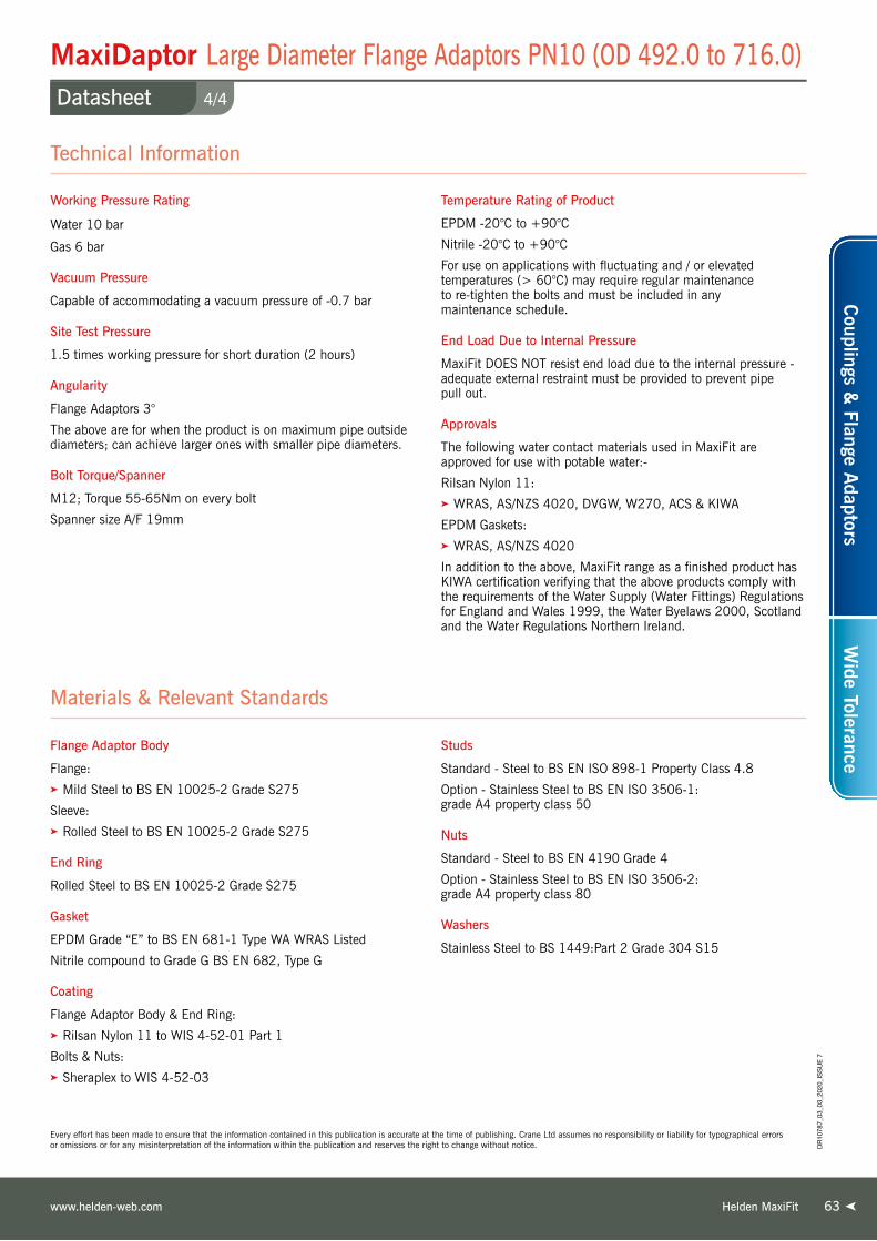
63
Every effort has been made to ensure that the information contained in this publication is accurate at the time of publishing. Crane Ltd assumes no responsibility or liability for typographical errors or omissions or for any misinterpretation of the information within the publication and reserves the right to change without notice.
Helden MaxiFitwww.helden-web.com
Working Pressure Rating
Water 10 bar
Gas 6 bar
Vacuum Pressure
Capable of accommodating a vacuum pressure of -0.7 bar
Site Test Pressure
1.5 times working pressure for short duration (2 hours)
Angularity
Flange Adaptors 3°
The above are for when the product is on maximum pipe outside diameters; can achieve larger ones with smaller pipe diameters.
Bolt Torque/Spanner
M12; Torque 55-65Nm on every bolt
Spanner size A/F 19mm
Temperature Rating of Product
EPDM -20°C to +90°C
Nitrile -20°C to +90°C
For use on applications with fluctuating and / or elevated temperatures (> 60°C) may require regular maintenance to re-tighten the bolts and must be included in any maintenance schedule.
End Load Due to Internal Pressure
MaxiFit DOES NOT resist end load due to the internal pressure - adequate external restraint must be provided to prevent pipe pull out.
Approvals
The following water contact materials used in MaxiFit are approved for use with potable water:-
Rilsan Nylon 11:➤ WRAS, AS/NZS 4020, DVGW, W270, ACS & KIWA
EPDM Gaskets:➤ WRAS, AS/NZS 4020
In addition to the above, MaxiFit range as a finished product has KIWA certification verifying that the above products comply with the requirements of the Water Supply (Water Fittings) Regulations for England and Wales 1999, the Water Byelaws 2000, Scotland and the Water Regulations Northern Ireland.
Flange Adaptor Body
Flange:➤ Mild Steel to BS EN 10025-2 Grade S275
Sleeve:➤ Rolled Steel to BS EN 10025-2 Grade S275
End Ring
Rolled Steel to BS EN 10025-2 Grade S275
Gasket
EPDM Grade “E” to BS EN 681-1 Type WA WRAS Listed
Nitrile compound to Grade G BS EN 682, Type G
Coating
Flange Adaptor Body & End Ring:➤ Rilsan Nylon 11 to WIS 4-52-01 Part 1
Bolts & Nuts:➤ Sheraplex to WIS 4-52-03
Studs
Standard - Steel to BS EN ISO 898-1 Property Class 4.8
Option - Stainless Steel to BS EN ISO 3506-1: grade A4 property class 50
Nuts
Standard - Steel to BS EN 4190 Grade 4
Option - Stainless Steel to BS EN ISO 3506-2: grade A4 property class 80
Washers
Stainless Steel to BS 1449:Part 2 Grade 304 S15
Materials & Relevant Standards
Technical Information
Couplings &
Flange Adaptors
Wide Tolerance
63
4/4
MaxiDaptor Large Diameter Flange Adaptors PN10 (OD 492.0 to 716.0)Datasheet
DR
1078
7_03
_03_
2020
_IS
SU
E 7

64
1/4
MaxiDaptor Large Diameter Flange Adaptors PN16 (OD 348.5 to 572.3)Datasheet
Every effort has been made to ensure that the information contained in this publication is accurate at the time of publishing. Crane Ltd assumes no responsibility or liability for typographical errors or omissions or for any misinterpretation of the information within the publication and reserves the right to change without notice.
OD Range Flange Details Gasket Mould
No.
Studs No.-Dia x Length
Setting GapWeight
(kg)Min (mm)
Max (mm) Nom. Drilling Flange Diameter
OD (mm)Flange Bore
S (mm)Flange Thickness
T (mm) Type Sleeve Length A (mm)
Overall Length L (mm)
Min (mm)
Max (mm)
348.5 365.5 350 PN16 520.0 367.5 18 2 120 218 6008 8-M12 x 205 45 68 28.5351.0 368.0 300 PN16 478.0 300.0 18 3 240 333 6002 6-M12 x 325 165 188 38.5351.0 368.0 300 PN16 478.0 329.0 18 3 240 333 6002 6-M12 x 325 165 188 36.5351.0 368.0 350 PN16 520.0 370.0 18 1 120 218 6002 8-M12 x 205 45 68 28.6374.5 391.5 300 PN16 502.0 300.0 18 3 240 333 1659 6-M12 x 325 160 183 43.1374.5 391.5 350 PN16 520.0 350.0 18 1 120 218 1659 8-M12 x 205 45 68 31.0374.5 391.5 350 PN16 520.0 393.5 18 1 120 218 1659 8-M12 x 205 45 68 27.5374.5 391.5 400 PN16 580.0 393.5 25 1 120 218 1659 8-M12 x 205 45 68 41.6394.3 411.3 350 PN16 522.0 350.0 18 2 205 298 1766 8-M12 x 290 130 153 37.1394.3 411.3 350 PN16 520.0 397.5 18 2 205 303 1766 8-M12 x 290 130 153 33.1394.3 411.3 400 PN16 580.0 413.5 25 1 120 220 1766 8-M12 x 205 45 68 39.8404.8 421.8 400 PN16 580.0 400.0 18 1 120 213 1767 8-M12 x 205 45 68 34.9404.8 421.8 400 PN16 580.0 424.0 18 1 120 218 1767 8-M12 x 205 45 68 32.8418.2 435.2 400 PN16 580.0 437.0 18 1 120 218 1784 8-M12 x 205 45 68 32.0425.0 442.0 400 PN16 580.0 400.0 18 1 120 218 1662 8-M12 x 205 45 68 35.7425.0 442.0 400 PN16 580.0 444.0 18 1 120 218 1662 8-M12 x 205 45 68 31.6434.4 451.4 400 PN16 580.0 448.0 18 2 205 303 1768 8-M12 x 290 130 153 37.4447.2 464.2 400 PN16 580.0 400.0 18 2 205 303 1769 8-M12 x 290 130 153 42.2447.2 464.2 400 PN16 580.0 448.0 18 2 205 303 1769 8-M12 x 290 130 153 37.7455.0 472.0 400 PN16 582.0 400.0 18 2 205 298 6003 8-M12 x 290 130 153 42.6455.0 472.0 450 PN16 640.0 450.0 23 1 120 218 6003 10-M12 x 205 45 68 46.0455.0 472.0 450 PN16 640.0 474.0 23 1 120 218 6003 10-M12 x 205 45 68 42.8462.5 479.5 400 PN16 590.0 440.0 25 2 205 303 10511/40 8-M12 x 290 130 153 45.7467.0 484.0 450 PN16 640.0 486.0 23 1 120 218 6073 10-M12 x 205 45 68 41.6476.0 493.0 400 PN16 603.0 400.0 23 3 255 338 1770 8-M12 x 325 180 203 60.8476.0 493.0 450 PN16 640.0 495.0 23 1 120 218 1770 10-M12 x 205 45 68 40.7487.3 504.3 450 PN16 640.0 506.5 23 1 120 218 1771 10-M12 x 205 45 68 39.4487.3 504.3 500 PN16 715.0 506.5 23 1 120 218 1771 10-M12 x 205 45 68 53.2501.9 518.9 450 PN16 640.0 485.5 23 2 205 303 1772 10-M12 x 290 130 153 48.7501.9 518.9 500 PN16 715.0 500.0 23 1 120 218 1772 10-M12 x 205 45 68 54.7501.9 518.9 500 PN16 715.0 521.0 23 1 120 218 1772 10-M12 x 205 45 68 51.7510.0 527.0 450 PN16 640.0 494.0 23 2 205 303 6004 10-M12 x 290 130 153 47.9510.0 527.0 500 PN16 715.0 500.0 23 1 120 218 6004 10-M12 x 205 45 68 54.9527.0 544.0 500 PN16 715.0 500.0 23 1 120 218 1773 10-M12 x 205 45 68 55.6527.0 544.0 500 PN16 715.0 546.0 23 1 120 218 1773 10-M12 x 205 45 68 48.8540.1 557.1 500 PN16 715.0 559.0 23 1 120 218 1774 10-M12 x 205 45 68 47.2555.3 572.3 500 PN16 715.0 550.0 23 2 205 303 1775 10-M12 x 290 130 153 56.0555.3 572.3 600 PN16 840.0 574.5 25 1 120 218 1775 10-M12 x 205 45 68 62.3
Flange Adaptor Type 1 Flange Adaptor Type 2 Flange Adaptor Type 3
4
2
31
1
4
2
31
4
2
3
MaxiDaptor Flange Adaptors PN16
DR
1078
7_03
_03_
2020
_IS
SU
E 7
Key
1 = Sleeve
2 = End Ring
3 = Gasket
4 = Stud, Nut & Washer
64 Helden MaxiFit Telephone: +44 (0)1462 4433226464

65
Every effort has been made to ensure that the information contained in this publication is accurate at the time of publishing. Crane Ltd assumes no responsibility or liability for typographical errors or omissions or for any misinterpretation of the information within the publication and reserves the right to change without notice.
Helden MaxiFitwww.helden-web.com
Working Pressure Rating
Water 16 bar
Gas 6 bar
Vacuum Pressure
Capable of accommodating a vacuum pressure of -0.7 bar
Site Test Pressure
1.5 times working pressure for short duration (2 hours)
Angularity
Flange Adaptors 3°
The above are for when the product is on maximum pipe outside diameters; can achieve larger ones with smaller pipe diameters.
Bolt Torque/Spanner
M12; Torque 55-65Nm on every bolt
Spanner size A/F 19mm
Temperature Rating of Product
EPDM -20°C to +90°C
Nitrile -20°C to +90°C
For use on applications with fluctuating and / or elevated temperatures (> 60°C) may require regular maintenance to re-tighten the bolts and must be included in any maintenance schedule.
End Load Due to Internal Pressure
MaxiFit DOES NOT resist end load due to the internal pressure - adequate external restraint must be provided to prevent pipe pull out.
Approvals
The following water contact materials used in MaxiFit are approved for use with potable water:-
Rilsan Nylon 11:➤ WRAS, AS/NZS 4020, DVGW, W270, ACS & KIWA
EPDM Gaskets:➤ WRAS, AS/NZS 4020
In addition to the above, MaxiFit range as a finished product has KIWA certification verifying that the above products comply with the requirements of the Water Supply (Water Fittings) Regulations for England and Wales 1999, the Water Byelaws 2000, Scotland and the Water Regulations Northern Ireland.
Technical Information
Flange Adaptor Body
Flange:➤ Mild Steel to BS EN 10025-2 Grade S275
Sleeve:➤ Rolled Steel to BS EN 10025-2 Grade S275
End Ring
Rolled Steel to BS EN 10025-2 Grade S275
Gasket
EPDM Grade “E” to BS EN 681-1 Type WA WRAS Listed
Nitrile compound to Grade G BS EN 682, Type G
Coating
Flange Adaptor Body & End Ring:➤ Rilsan Nylon 11 to WIS 4-52-01 Part 1
Bolts & Nuts:➤ Sheraplex to WIS 4-52-03
Studs
Standard - Steel to BS EN ISO 898-1 Property Class 4.8
Option - Stainless Steel to BS EN ISO 3506-1: grade A4 property class 50
Nuts
Standard - Steel to BS EN 4190 Grade 4
Option - Stainless Steel to BS EN ISO 3506-2: grade A4 property class 80
Washers
Stainless Steel to BS 1449:Part 2 Grade 304 S15
Materials & Relevant Standards
Couplings &
Flange Adaptors
Wide Tolerance
65
2/4
MaxiDaptor Large Diameter Flange Adaptors PN16 (OD 348.5 to 572.3)Datasheet
DR
1078
7_03
_03_
2020
_IS
SU
E 7

66
3/4
MaxiDaptor Large Diameter Flange Adaptors PN16 (OD 566.5 to 692.0)Datasheet
Every effort has been made to ensure that the information contained in this publication is accurate at the time of publishing. Crane Ltd assumes no responsibility or liability for typographical errors or omissions or for any misinterpretation of the information within the publication and reserves the right to change without notice.
Flange Adaptor Type 1 Flange Adaptor Type 2 Flange Adaptor Type 3
4
2
31
1
4
2
31
4
2
3
MaxiDaptor Flange Adaptors PN16OD Range Flange Details Gasket
Mould No.
Studs No.-Dia x Length
Setting GapWeight
(kg)Min (mm)
Max (mm) Nom. Drilling Flange Diameter
OD (mm)Flange Bore
S (mm)Flange Thickness
T (mm) Type Sleeve Length A (mm)
Overall Length L (mm)
Min (mm)
Max (mm)
566.5 583.5 500 PN16 715.0 500.0 23 2 205 303 1776 10-M12 x 290 130 153 63.6566.5 583.5 500 PN16 715.0 550.0 23 2 205 303 1776 10-M12 x 290 130 153 56.2582.2 599.2 500 PN16 715.0 560.0 23 3 205 303 1777 10-M12 x 290 130 153 60.4582.2 599.2 600 PN16 840.0 601.0 25 1 120 218 1777 10-M12 x 205 45 68 72.5601.0 618.0 600 PN16 840.0 600.0 25 1 120 218 6020 10-M12 x 205 45 68 73.4601.0 618.0 600 PN16 840.0 620.0 25 1 120 218 6020 10-M12 x 205 45 68 69.7613.0 630.0 600 PN16 840.0 632.0 23 1 120 218 6019 10-M12 x 205 45 68 64.4618.0 635.0 600 PN16 840.0 637.0 23 1 120 218 6025 10-M12 x 205 45 68 63.6630.5 647.5 600 PN16 840.0 600.0 23 1 120 218 1778 10-M12 x 205 45 68 70.6630.5 647.5 600 PN16 840.0 649.5 23 1 120 218 1778 10-M12 x 205 45 68 61.8645.2 662.2 600 PN16 840.0 664.0 23 1 120 218 1779 10-M12 x 205 45 68 59.7662.0 679.0 600 PN16 840.0 681.0 23 1 120 218 1780 10-M12 x 205 45 68 57.1675.0 692.0 600 PN16 840.0 653.0 23 2 205 303 6005 10-M12 x 290 130 153 70.6
DR
1078
7_03
_03_
2020
_IS
SU
E 7
Key
1 = Sleeve
2 = End Ring
3 = Gasket
4 = Stud, Nut & Washer
66 Helden MaxiFit Telephone: +44 (0)1462 4433226666

67
Every effort has been made to ensure that the information contained in this publication is accurate at the time of publishing. Crane Ltd assumes no responsibility or liability for typographical errors or omissions or for any misinterpretation of the information within the publication and reserves the right to change without notice.
Helden MaxiFitwww.helden-web.com
Working Pressure Rating
Water 16 bar
Gas 6 bar
Vacuum Pressure
Capable of accommodating a vacuum pressure of -0.7 bar
Site Test Pressure
1.5 times working pressure for short duration (2 hours)
Angularity
Flange Adaptors 3°
The above are for when the product is on maximum pipe outside diameters; can achieve larger ones with smaller pipe diameters.
Bolt Torque/Spanner
M12; Torque 55-65Nm on every bolt
Spanner size A/F 19mm
Temperature Rating of Product
EPDM -20°C to +90°C
Nitrile -20°C to +90°C
For use on applications with fluctuating and / or elevated temperatures (> 60°C) may require regular maintenance to re-tighten the bolts and must be included in any maintenance schedule.
End Load Due to Internal Pressure
MaxiFit DOES NOT resist end load due to the internal pressure - adequate external restraint must be provided to prevent pipe pull out.
Approvals
The following water contact materials used in MaxiFit are approved for use with potable water:-
Rilsan Nylon 11:➤ WRAS, AS/NZS 4020, DVGW, W270, ACS & KIWA
EPDM Gaskets:➤ WRAS, AS/NZS 4020
In addition to the above, MaxiFit range as a finished product has KIWA certification verifying that the above products comply with the requirements of the Water Supply (Water Fittings) Regulations for England and Wales 1999, the Water Byelaws 2000, Scotland and the Water Regulations Northern Ireland.
Technical Information
Flange Adaptor Body
Flange:➤ Mild Steel to BS EN 10025-2 Grade S275
Sleeve:➤ Rolled Steel to BS EN 10025-2 Grade S275
End Ring
Rolled Steel to BS EN 10025-2 Grade S275
Gasket
EPDM Grade “E” to BS EN 681-1 Type WA WRAS Listed
Nitrile compound to Grade G BS EN 682, Type G
Coating
Flange Adaptor Body & End Ring:➤ Rilsan Nylon 11 to WIS 4-52-01 Part 1
Bolts & Nuts:➤ Sheraplex to WIS 4-52-03
Studs
Standard - Steel to BS EN ISO 898-1 Property Class 4.8
Option - Stainless Steel to BS EN ISO 3506-1: grade A4 property class 50
Nuts
Standard - Steel to BS EN 4190 Grade 4
Option - Stainless Steel to BS EN ISO 3506-2: grade A4 property class 80
Washers
Stainless Steel to BS 1449:Part 2 Grade 304 S15
Materials & Relevant Standards
Couplings &
Flange Adaptors
Wide Tolerance
67
4/4
MaxiDaptor Large Diameter Flange Adaptors PN16 (OD 566.5 to 692.0)Datasheet
DR
1078
7_03
_03_
2020
_IS
SU
E 7

68
1/2
MaxiDaptor Large Diameter Flange Adaptors ANSI Flange DrillingDatasheet
Every effort has been made to ensure that the information contained in this publication is accurate at the time of publishing. Crane Ltd assumes no responsibility or liability for typographical errors or omissions or for any misinterpretation of the information within the publication and reserves the right to change without notice.
OD Range Flange Details Gasket Mould
No.
Studs No.-Dia x Length
Setting GapWeight
(kg)Min (mm)
Max (mm) Nom. Drilling Flange Diameter
OD (mm)Flange Bore
S (mm)Flange Thickness
T (mm) Type Sleeve Length A (mm)
Overall Length L (mm)
Min (mm)
Max (mm)
351.0 368.0 14” ANSI150 533.0 370.0 25 1 120 218 6002 6-M12 x 205 45 68 35.9374.5 391.5 14” ANSI150 533.0 393.5 25 1 120 218 1659 6-M12 x 205 45 68 34.0386.0 403.0 14” ANSI150 533.0 397.5 25 2 205 218 6035 6-M12 x 290 130 153 39.0394.3 411.3 14” ANSI150 533.0 397.5 25 2 205 218 1766 6-M12 x 290 130 153 39.2404.8 421.8 16” ANSI150 597.0 424.0 25 1 120 218 1767 8-M12 x 205 45 68 42.2425.0 442.0 16” ANSI150 597.0 444.0 25 1 120 218 1662 8-M12 x 205 45 68 40.3434.4 451.4 16” ANSI150 597.0 453.5 25 1 120 303 1768 8-M12 x 205 45 68 39.4439.0 456.0 16” ANSI150 597.0 458.0 25 1 120 303 6036 8-M12 x 205 45 68 39.0447.2 464.2 16” ANSI150 597.0 448.0 25 2 205 303 1769 8-M12 x 290 130 153 46.3455.0 472.0 16” ANSI150 597.0 448.0 25 2 205 303 6003 8-M12 x 290 130 153 46.4455.0 472.0 18” ANSI150 635.0 474.0 25 1 120 303 6003 8-M12 x 205 45 68 44.0487.3 504.3 18” ANSI150 635.0 499.0 25 2 205 303 1771 8-M12 x 290 130 153 47.8492.0 509.0 18” ANSI150 635.0 499.0 25 2 205 303 6037 8-M12 x 290 130 153 47.8501.9 518.9 18” ANSI150 635.0 499.0 25 2 205 303 1772 8-M12 x 290 130 153 48.0510.0 527.0 18” ANSI150 637.0 499.0 25 2 205 303 6004 8-M12 x 290 130 153 48.6527.0 544.0 20” ANSI150 698.0 546.0 25 1 120 303 1773 10-M12 x 205 45 68 47.9540.1 557.1 20” ANSI150 698.0 550.0 25 2 205 303 1774 10-M12 x 290 130 153 54.4546.0 563.0 20” ANSI150 698.0 550.0 25 2 205 303 6038 10-M12 x 290 130 153 54.8555.3 572.3 20” ANSI150 698.0 550.0 25 2 205 303 1775 10-M12 x 290 130 153 55.0565.0 582.0 20” ANSI150 698.0 550.0 25 2 205 303 1776 10-M12 x 290 130 153 55.1582.2 599.2 20” ANSI150 709.0 550.0 25 2 205 303 1777 10-M12 x 290 130 153 57.8601.0 618.0 24” ANSI150 813.0 620.0 25 1 120 218 6020 10-M12 x 205 45 68 63.3630.0 647.0 24” ANSI150 813.0 649.0 25 1 120 303 1778 10-M12 x 205 45 68 58.7645.2 662.2 24” ANSI150 813.0 653.0 25 2 205 303 1779 10-M12 x 290 130 153 66.7654.0 671.0 24” ANSI150 813.0 653.0 25 2 205 303 6039 10-M12 x 290 130 153 66.9662.0 679.0 24” ANSI150 813.0 653.0 25 2 205 303 1780 10-M12 x 290 130 153 67.0675.0 692.0 24” ANSI150 813.0 653.0 25 2 205 303 6005 10-M12 x 290 130 153 67.3
Flange Adaptor Type 1 Flange Adaptor Type 2 Flange Adaptor Type 3
4
2
31
1
4
2
31
4
2
3
MaxiDaptor Flange Adaptors ANSI
DR
1078
7_03
_03_
2020
_IS
SU
E 7
Key
1 = Sleeve
2 = End Ring
3 = Gasket
4 = Stud, Nut & Washer
68 Helden MaxiFit Telephone: +44 (0)1462 443322Helden MaxiFit Telephone: +44 (0)1462 4433226868

69
Every effort has been made to ensure that the information contained in this publication is accurate at the time of publishing. Crane Ltd assumes no responsibility or liability for typographical errors or omissions or for any misinterpretation of the information within the publication and reserves the right to change without notice.
Helden MaxiFitwww.helden-web.com
Working Pressure Rating
Water 16 bar
Gas 6 bar
Vacuum Pressure
Capable of accommodating a vacuum pressure of -0.7 bar
Site Test Pressure
1.5 times working pressure for short duration (2 hours)
Flange Drilling & Rated Pressure
While drilling patterns defined for the flange adaptors are compatible with the standards listed in the data sheet table, the rated working pressure of the product is as noted above
Angularity
Flange Adaptors 3°
The above are for when the product is on maximum pipe outside diameters; can achieve larger ones with smaller pipe diameters.
Bolt Torque/Spanner
M12; Torque 55-65Nm on every bolt
Spanner size A/F 19mm
Temperature Rating of Product
EPDM -20°C to +90°C
Nitrile -20°C to +90°C
For use on applications with fluctuating and / or elevated temperatures (> 60°C) may require regular maintenance to re-tighten the bolts and must be included in any maintenance schedule.
End Load Due to Internal Pressure
MaxiFit DOES NOT resist end load due to the internal pressure - adequate external restraint must be provided to prevent pipe pull out.
Approvals
The following water contact materials used in MaxiFit are approved for use with potable water:-
Rilsan Nylon 11:➤ WRAS, AS/NZS 4020, DVGW, W270, ACS & KIWA
EPDM Gaskets:➤ WRAS, AS/NZS 4020
In addition to the above, MaxiFit range as a finished product has KIWA certification verifying that the above products comply with the requirements of the Water Supply (Water Fittings) Regulations for England and Wales 1999, the Water Byelaws 2000, Scotland and the Water Regulations Northern Ireland.
Technical Information
Flange Adaptor Body
Flange:➤ Mild Steel to BS EN 10025-2 Grade S275
Sleeve:➤ Rolled Steel to BS EN 10025-2 Grade S275
End Ring
Rolled Steel to BS EN 10025-2 Grade S275
Gasket
EPDM Grade “E” to BS EN 681-1 Type WA WRAS Listed
Nitrile compound to Grade G BS EN 682, Type G
Coatings
Flange Adaptor Body & End Ring:➤ Rilsan Nylon 11 to WIS 4-52-01 Part 1
Bolts & Nuts:➤ Sheraplex to WIS 4-52-03
Studs
Standard - Steel to BS EN ISO 898-1 Property Class 4.8
Option - Stainless Steel to BS EN ISO 3506-1: grade A4 property class 50
Nuts
Standard - Steel to BS EN 4190 Grade 4
Option - Stainless Steel to BS EN ISO 3506-2: grade A4 property class 80
Washers
Stainless Steel to BS 1449:Part 2 Grade 304 S15
Materials & Relevant Standards
Couplings &
Flange Adaptors
Wide Tolerance
69
2/2
MaxiDaptor Large Diameter Flange Adaptors ANSI Flange DrillingDatasheet
DR
1078
7_03
_03_
2020
_IS
SU
E 7

Crane BS&U are solely the provider of products and have no direct influence on, or take any responsibility for any working practices employed or depicted in the images enclosed to install such products.
Leaking Pipework - Water Treatment WorksNext Generation UltraGrip
East Borneo - Samarinda
Project
Problem - A 400 mm PE100 SDR 17
was leaking because customer had
initially selected low grade compression
fittings which were not able to grip the
pipe. This pipe was taking raw water
and transporting it to a local water
treatment plant.
Solution - UltraGrip was installed to
ensure a trouble free solution
for a pipe that was leaking badly.
Client
PDAM Samarinda
Distributor
PT Duta Prima Utama - Jakarta
Helden MaxiFit Telephone: +44 (0)1462 443322Helden UltraGrip Telephone: +44 (0)1462 4433227070

71Helden MegaFit
Ro
bu
st
Couplings & Flange AdaptorsAdvanced Mechanical Jointing Technology
UltraRange

7272
MegaFitOverview
Helden MegaFit Telephone: +44 (0)1462 443322Telephone: +44 (0)1462 443322
Universal Pipe Fittings
The MegaFit range of universal pipe fittings represent the
very latest in mechanical pipe coupling technology, with
products designed to connect plain ended pipes of the same
nominal bore, with same or different outside diameters. One
coupling is able to connect steel, ductile iron, uPVC, cast iron
and asbestos cement pipes, thereby reducing stocks.
Simplifies Stock-holding & InstallationMegaFit products are designed for use in repair situations
where the exact outside diameter of the pipes are unknown.
An OD tolerance range of up to 34mm is offered, which has
the effect of reducing stockholding, down to one size per
nominal diameter, also simplifies installation.
Simple, Reliable SealThe MegaFit range design incorporates end rings which
are designed to enclose the gasket. The unique ‘slide easy’
gasket provides maximum sealing pressure, even on scored,
pitted and corroded pipe surfaces through its distinctive
circumferential ribs offering a simple installation and
guaranteed seal.
Approved QualityThe MegaFit product range includes couplings and
flange adaptors, which are available from DN50 (2”) to
DN300 (12”). All models are designed and manufactured
under quality management systems to BS EN ISO
9001 and have been tested by Helden’s comprehensive
in-house research facilities and also conform to the American
Water Works Association specification AWWA/ANSI C.219
for bolted couplings.
Pipe Materials
MegaFit CouplingMegaDaptor Flange Adaptor
MegaFit Coupling

73
MegaFit Couplings and Flange AdaptorsProduct Design Benefits
Helden MegaFitwww.helden-web.com
Guaranteed Sealing
Excellent Corrosion Protection
Simple to Fit
User Friendly
➤ The MegaFit range is suitable for water and gas applications.
Following extensive tests, the products can be guaranteed
for a working pressure of 16 bar for water applications (test
pressure 24 bar) and 6 bar for gas (test pressure 9 bar).
➤ With up to 34mm tolerance on the pipe OD, each product fits
a range of pipe diameters and materials. It reduces the need
for expensive and time consuming trial holes, reduces stock
holding and increases stock turn. In all MegaFit is adaptable
and economic solution to most pipe connections.
➤ For the discerning customer, the MegaFit range offers
an extended sealing face, greater than other wide tolerance
models. M16 bolts on DN100 models and above ensure
a complete robust solution.
➤ MegaFit couplings accommodate angular deflection between
pipes of up to 8° for couplings and 4° for flange adaptors,
allowing for ease of installation and
for pipeline movement such as
ground settlement. This angular
deflection can be utilised to lay
pipelines to long radius curves,
without the need for special
fittings, saving both time and cost.
Customer Benefits
The unique, ‘slide easy’ gasket provides maximum
sealing pressure, even on scored, pitted and
corroded pipe surfaces through its distinctive
circumferential ribs.
Metal components are coated with Rilsan Nylon 11
which is WRAS approved for use with potable
water. The nuts and bolts are Sheraplex coated
to WIS 4-52-03, offering long term protection
to corrosion, impact and abrasion for continued
reliable performance.
The MegaFit range is supplied with captive bolts,
meaning that the nuts need only to be tightened,
with a torque wrench, at one end, saving time
and simplifying installation.
MegaFit includes an extended centre sleeve as
standard to aid installation it allows for greater
cutting tolerances and greater pipe insertion depths
- sealing beyond corrosion damaged pipe ends.
Couplings &
Flange Adaptors
Wide Tolerance
DR
1078
7_03
_03_
2020
_IS
SU
E 7

* Materials of construction at the discretion of Helden. Helden reserves the right to modify the details in this publication as products and specifications are updated and improved.
Every effort has been made to ensure that the information contained in this publication is accurate at the time of publishing. Crane Ltd assumes no responsibility or liability for typographical errors or omissions or for any misinterpretation of the information within the publication and reserves the right to change without notice.
1/2
MegaFit CouplingsDatasheet
Helden MegaFit Telephone: +44 (0)1462 4433227474
MegaFit Couplings
DR
1078
7_03
_03_
2020
_IS
SU
E 7
DNOD Range Bolts
No.-Dia x LengthA
(mm)C
(mm)
Sleeve Length x Thickness
L x T (mm)
Setting Gap Gasket Mould No.
Weight (kg)
Min (mm) Max (mm) Min (mm) Max (mm)
50 43.5 63.5 4-M12 x 235 151 242 144 x 5 18 60 6010 4.5
65 63.0 83.7 4-M12 x 235 171 242 144 x 5 18 60 6011 5.2
80 85.7 107.0 4-M12 x 260 192 267 170 x 5 18 100 6012 6.3
100 107.2 133.2 4-M16 x 290 231 300 180 x 5 18 110 6013 9.0
125 132.2 160.2 4-M16 x 290 265 300 180 x 5.5 18 110 6014 11.3
150 158.2 192.2 4-M16 x 340 308 350 213 x 5.5 18 130 6015 15.4
175 192.2 226.9 4-M16 x 340 344 350 215 x 7 18 130 6030 21.7
200 218.1 252.1 4-M16 x 340 369 350 220 x 8 18 135 6016 24.3
250 266.2 300.2 6-M16 x 420 417 430 300 x 8 18 215 6017 34.7
300 315.0 349.0 6-M16 x 420 466 430 300 x 8 18 215 6018 39.4
CouplingKey
A = End Ring Diameter
C = Overall Length
L = Sleeve Length
T = Sleeve Thickness

75
* Materials of construction at the discretion of Helden. Helden reserves the right to modify the details in this publication as products and specifications are updated and improved.
Every effort has been made to ensure that the information contained in this publication is accurate at the time of publishing. Crane Ltd assumes no responsibility or liability for typographical errors or omissions or for any misinterpretation of the information within the publication and reserves the right to change without notice.
Working Pressure Rating
Water 16 bar
Gas 6 bar
Vacuum Pressure
Capable of accommodating a vacuum pressure of -0.7 bar
Site Test Pressure
1.5 times working pressure for short duration (2 hours)
Angularity
Couplings 8°
The above are for when the product is on maximum pipe outside diameters; can achieve larger ones with smaller pipe diameters.
Bolt Torque/Spanner
M12; Torque 55-65Nm on every bolt
M16; Torque 95-110Nm on every bolt
Temperature Rating of Product
EPDM -20°C to +90°C
Nitrile -20°C to +90°C
For use on applications with fluctuating and / or elevated temperatures (> 60°C) may require regular maintenance to re-tighten the bolts and must be included in any maintenance schedule.
End Load Due to Internal Pressure
MegaFit DOES NOT resist end load due to the internal pressure - adequate external restraint must be provided to prevent pipe pull out.
Approvals
The following water contact materials used in MegaFit are approved for use with potable water:-
Rilsan Nylon 11:➤ WRAS, AS/NZS 4020, DVGW, W270, ACS & KIWA
EPDM Gaskets:➤ WRAS
Sleeve*
SG ductile iron BS EN 1563, EN GJS-450-10
End Rings*
SG ductile iron BS EN 1563, EN GJS-450-10
Coatings
Centre Sleeve & End Rings:➤ Rilsan Nylon 11 to WIS 4-52-01 Part 1
Bolts & Nuts:➤ Sheraplex to WIS 4-52-03
Gasket
EPDM compound Grade ‘E’ to BS EN 681-1 WRAS approved
Nitrile compound to DIN 3535-3
Bolts
Steel to BS EN ISO 898 Property Class Grade 8.8 equivalent DIN 267 - Part 3:Class 8.8
Nuts
Steel to BS EN20898-2 Property Class 8.0
Washers
Stainless Steel to BS 1449:Pt2 grade 304 S15
Materials & Relevant Standards
Technical Information
2/2
MegaFit CouplingsDatasheet
Helden MegaFitwww.helden-web.com
Couplings &
Flange Adaptors
Wide Tolerance
DR
1078
7_03
_03_
2020
_IS
SU
E 7

7676
1/2
MegaDaptor Flange AdaptorsDatasheet
* Materials of construction at the discretion of Helden. Helden reserves the right to modify the details in this publication as products and specifications are updated and improved.
Every effort has been made to ensure that the information contained in this publication is accurate at the time of publishing. Crane Ltd assumes no responsibility or liability for typographical errors or omissions or for any misinterpretation of the information within the publication and reserves the right to change without notice.
Helden MegaFit Telephone: +44 (0)1462 443322
DR
1078
7_03
_03_
2020
_IS
SU
E 7
Flange adaptors designed to join pipes of various materials and outside diameters to flanges of the same nominal size*.
*DN175 MegaDaptor supplied with DN200 flange.
DNOD Range
(mm)
Flan
ge
Nom
inal
Flange Drilling
Flange Thickness
(mm)
Bolts No.-Dia x Length
A(mm)
B(mm)
C(mm)
Sleeve Length x Thickness
(L) x (T)
Setting Gap(mm)
Type
Gasket Mould No. W
eigh
t (k
g)
Min Max Min Max
50 43.5 63.5 50 PN10/PN16 17.0 4-M12 x 125 151 167 131 80 x 6 25 35 1 6010 4.4
65 63.0 83.7 65 PN10/PN16 17.0 4-M12 x 125 171 185 132 80 x 6 25 35 1 6011 5.1
80 85.7 107.0 80 PN10/PN16 17.0 4-M12 x 145 192 200 154 100 x 6 30 60 1 6012 5.8
100 107.2 133.2 100 PN10/PN16 18.0 4-M16 x 180 231 234 191 130 x 6 57 85 2 6013 8.6
125 132.2 160.2 125 PN10/PN16 18.0 4-M16 x 160 265 268 171 111 x 6 28 65 1 6014 9.8
150 158.2 192.2 150 PN10/PN16 18.0 4-M16 x 210 303 317 220 150 x 6 70 100 2 6015 14.17
175* 192.2 226.9 200 PN10/PN16 18.0 4-M16 x 190 344 344 201 132 x 7 25 80 1 6030 17.2
200 218.1 252.1 200 PN10/PN16 18.0 4-M16 x 230 369 374 241 180 x 7 75 130 2 6016 20.4
250 266.2 300.2 250 PN10/PN16 20.0 6-M16 x 270 417 424 281 212 x 7 80 160 2 6017 27.5
300 315.0 349.0 300 PN10/PN16 21.5 6-M16 x 270 466 472 281 211 x 8 80 160 2 6018 34.3
Flange Adaptor Type 1 Flange Adaptor Type 2
MegaDaptor Flange Adaptors
Key
A = End Ring Diameter
B = Flange Diameter
C = Overall Length
L = Sleeve Length
T = Sleeve Thickness
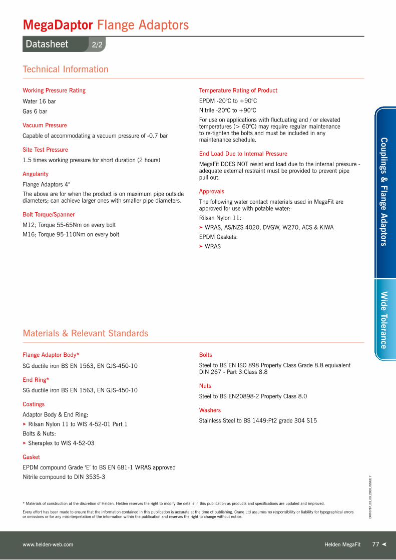
77
Working Pressure Rating
Water 16 bar
Gas 6 bar
Vacuum Pressure
Capable of accommodating a vacuum pressure of -0.7 bar
Site Test Pressure
1.5 times working pressure for short duration (2 hours)
Angularity
Flange Adaptors 4°
The above are for when the product is on maximum pipe outside diameters; can achieve larger ones with smaller pipe diameters.
Bolt Torque/Spanner
M12; Torque 55-65Nm on every bolt
M16; Torque 95-110Nm on every bolt
Temperature Rating of Product
EPDM -20°C to +90°C
Nitrile -20°C to +90°C
For use on applications with fluctuating and / or elevated temperatures (> 60°C) may require regular maintenance to re-tighten the bolts and must be included in any maintenance schedule.
End Load Due to Internal Pressure
MegaFit DOES NOT resist end load due to the internal pressure - adequate external restraint must be provided to prevent pipe pull out.
Approvals
The following water contact materials used in MegaFit are approved for use with potable water:-
Rilsan Nylon 11:➤ WRAS, AS/NZS 4020, DVGW, W270, ACS & KIWA
EPDM Gaskets:➤ WRAS
Technical Information
2/2
MegaDaptor Flange AdaptorsDatasheet
* Materials of construction at the discretion of Helden. Helden reserves the right to modify the details in this publication as products and specifications are updated and improved.
Every effort has been made to ensure that the information contained in this publication is accurate at the time of publishing. Crane Ltd assumes no responsibility or liability for typographical errors or omissions or for any misinterpretation of the information within the publication and reserves the right to change without notice.
Flange Adaptor Body*
SG ductile iron BS EN 1563, EN GJS-450-10
End Ring*
SG ductile iron BS EN 1563, EN GJS-450-10
Coatings
Adaptor Body & End Ring:➤ Rilsan Nylon 11 to WIS 4-52-01 Part 1
Bolts & Nuts:➤ Sheraplex to WIS 4-52-03
Gasket
EPDM compound Grade ‘E’ to BS EN 681-1 WRAS approved
Nitrile compound to DIN 3535-3
Bolts
Steel to BS EN ISO 898 Property Class Grade 8.8 equivalent DIN 267 - Part 3:Class 8.8
Nuts
Steel to BS EN20898-2 Property Class 8.0
Washers
Stainless Steel to BS 1449:Pt2 grade 304 S15
Materials & Relevant Standards
Helden MegaFitwww.helden-web.com
Couplings &
Flange Adaptors
Wide Tolerance
DR
1078
7_03
_03_
2020
_IS
SU
E 7
Helden MegaFit Telephone: +44 (0)1462 443322
Crane BS&U are solely the provider of products and have no direct influence on, or take any responsibility for any working practices employed or depicted in the images enclosed to install such products.
Replacement of Old Cast Iron Service PipeMegaFit Flange Adaptors - DN300
Germany - Bielefeld
Project
A DN300 gas main pipeline was cut and
a screwed ductile iron tee was installed
to build a new service line connected by
two MegaFit flange adaptors.
Client
Stadtwerke Bielefeld
Distributor
Friatec AG, Mannheim
7878

79Helden UltraGrip
Ne
xt
Optimum Wide Tolerance & Full End Restraint
UltraGripG e n e r a t i o n
NOW
AVAILA
BLE UP T
O DN600
VC 673979
*See back cover for full specification

Helden UltraGrip Telephone: +44 (0)1462 4433228080
Get to grips with UltraGrip
Key Benefits
➤ Grips and seals on the most corroded pipes
➤ Increased diameter range and wide tolerance delivers a reduction in stock holding costs
➤ Reversible bolts for quick and easy installation
➤ Easy on site handling delivered through world leading intelligent carrier design
➤ New design based on proven technology with enhancements to deliver longevity, reliability and total peace of mind
➤ High performance in both water (uti DN600) and gas applications (uti DN400)
➤ Innovative progressive gripping design ensures ultimate end load performance

Next Generation UltraGripOverview
8181Helden UltraGripwww.helden-web.com
PE Brochure for use with PVC & PE
An Advanced Design, Exceptional Performance
Next Generation UltraGrip is designed to offer a solution
to joining plain-ended pipes and contains an end load
resistant mechanism that grips and seals onto a variety
of pipe materials including Cast Iron, Ductile Iron, Steel,
PVC and PE.
Bigger Sizes DN450 – DN600Helden has extended the proven and successful
UltraGrip range in sizes up to DN600. This will give the
customer a single sealing and gripping product solution
to cover the majority of the pipes installed in their
underground water network. The larger sized UltraGrip
has been methodologically engineered to support
a progressive gripping mechanism through an enhanced
design, which has a larger footprint to increase the area
of actuation at the point of contact, resulting in an evenly
distributed gripping function. It has also been
designed to accommodate rough on-site handling
through an intelligent carrier that maintains
the gasket and grippers within the end ring,
ensuring the fitting can be easily slid on to the
pipe with no interference.
➤ Accelerated Ageing Tests
(AAT) to verify 50 year
design life expectancy.
➤ UltraGrip has been tested
on knurled and grooved pipe
work to match typical pipe
conditions found on many
sites around the world.
AVAILABLE UP TO DN600
Knurled and Grooved Pipe
Industry Testing
Helden products undergo intensive performance testing
to ensure the strength and integrity of all products meet
industry standards.
*Note: Due to the flexible nature of the plastic pipes, a close fit Stainless Steel internal support liner is required when PE Pipe or thin walled PVC is used to make a repair to prevent excessive pipe deformation which can occur when UltraGrip is installed.
Pipe Materials
Asbestos Cement & GRP pipe materials should not be used with the gripping version of UltraGrip.
Couplings &
Flange Adaptors
Wide Tolerance
DR10787_03_03_2020_ISSUE 7

Next Generation UltraGripOverview
8282 Helden UltraGrip Telephone: +44 (0)1462 443322
UltraGrip the Ultimate Gripping Technology
Progressive GrippingOne of the key components of UltraGrip is the progressive
gripping mechanism, which enhances its end-load restraint
capabilities as the internal pressure in the pipe increases.
A unique gripper system is suitable for all recommended
pipe materials and combined with an engineered intelligent
carrier which ensures maximum gripping strength around
the full pipe circumference. This is achieved through uniform
movement during installation and bolt-up.
In addition, the grippers are removable, allowing UltraGrip to
be converted to a flexible product to allow for axial movement.
The gripper and seal sub-assembly can accommodate
diameter pipe outside variation up to 54mm, depending on
nominal size.
Hygienic Protective CapsProtection caps have been introduced
to keep the fitting clean and free
from any contamination. The caps
are made of recyclable material to
minimise impact to the environment
and ensure fittings are clean and ready for use on potable
water (uti DN600) or gas (uti DN400) applications.
Corrosion ProtectionUltraGrip metal components are coated with Rilsan Nylon
11, which is WRAS approved for use with potable water.
Rilsan benefits include long term corrosion protection
and resistance to impact damage. Additionally, the bolts and
nuts are stainless steel coated with Delta Seal GZ, organic
dry film, which prevents galling and provides long term
corrosion protection.
Working Pressure & Temperature Ratings
Nominal SizeGripping Product Flex Product Operating
TemperatureGas Water Gas Water
DN40 to DN300 5 bar 16 bar 5 bar 16 bar
-20°C to +30°CDN350 to DN400 5 bar 10 bar 5 bar 10 bar
DN450 to DN600 N/A 10 bar N/A 10 bar
(Site Test Pressure – 1.5 times working pressure)Gripping product – to restrain axial loads
Flex product – remove grippers
UltraGrip Reducing Coupling
UltraGrip Coupling
UltraGrip End Cap
UltraGrip Flange Adaptor
UltraGrip Pecatadaptor

Next Generation UltraGripOverview
83Helden UltraGripwww.helden-web.com
Repair SolutionsUltraGrip offers the ideal solution for repairing severely
damaged, corroded or completely shattered pipes in
difficult trench conditions. In repair situations where
a pipe section needs to be cut out, the UltraGrip range
offers a versatile repair solution for a variety of different
pipe sizes and pipe material as a result of the wide
tolerance capability of UltraGrip products. Only a few
strategic sizes need to be kept in stock to cover many repair
or emergency situations.
Ease of InstallationUltraGrip is easy to install on site. The product is
pre-assembled to allow for quick positioning over the top
and bottom tolerance pipe with reversible captive bolts
requiring only a single spanner for tightening. An ideal
product to choose when dealing with tricky site conditions
such as confined spaces.
The Perfect Partner for Difficult Repairs
Suitable for Shattered Pipe
Couplings &
Flange Adaptors
Wide Tolerance
DR
1078
7_15
_08_
2021
_IS
SU
E 7

Ideal for PE & PVC Pipe Connections & Transitions
UltraGrip Support Liner For PE & PVC PipesOverview
Pipe Materials
8484 Helden UltraGrip Telephone: +44 (0)1462 443322
UltraGrip products are designed to offer a solution
for joining plain-ended pipes and contain an end load
resistant mechanism that grips and seals onto a variety
of pipe materials, including PVC and PE.
UltraGrip offers two alternative solutions for connecting
PE and rigid pipes across a wide range of sizes. You can
choose between the UltraGrip range of couplings and
adaptors or the UltraGrip Pecatadaptor.
UltraGrip Pecat adaptors are factory assembled with a PE
tail, ready for jointing into a pipe network by butt fusion
or using an electrofusion coupler. The PE connection
is 500mm in length which will accommodate two
electrofusion connections. The Pecat adaptor joint is
stronger than the pipe itself, both initially and after
years of service. Pecat fittings have been used in critical
pipeline applications throughout the world for more than
twenty years.
Please note that due to flexible nature of
plastic pipes, a close fit Stainless Steel
internal support liner is required
when mechanical joints are used
on PE pipes and thin walled PVC
in order to prevent excessive pipe
deformation which can occur.
UltraGrip Pecatadaptor

Next Generation UltraGrip Couplings & Flange AdaptorsProduct Design Benefits
85Helden UltraGripwww.helden-web.com
Simple to FitProgressive Gripping
• Captive, non-rotating bolts across whole range requiring a single spanner to install.
• Gasket/gripper are fully contained in the end ring housing, ensuring product slides easily over pipes.
• Bolt orientation in couplings/reducing couplings can be reversed to suit site conditions.
Enhanced Gasket Sealing
• Patented Gasket Technology incorporates a waffle profile design, providing localised high pressure points on the pipe surface.
• EPDM (water quality approved) and Nitrile gaskets variants.
Innovative Carrier Design
• Accommodates high tolerance on pipe outside diameter – up to 54mm.
• Interlocking “spring” and retention tab ensures gasket and grippers retract into and are retained in the housing of the end ring during transit.
• Progressive gripping technology, with increasing end load restraint capability as the internal pressure in the pipe increases.
• Uses grit and friction to mobilise end restraint forces, so will not damage the pipe surface.
• One gripper system suits all recommended pipe materials.
• Gripper has large footprint, reducing the load on the pipe surface.
Multiple Flange Drilling
• As standard the flange adaptors are multi drilled to accommodate BS EN 1092-1 PN10 & 16.
Customer Benefits
➤ High performance in both water (uti DN600) and gas (uti DN400) applications verified through proven Accelerated Aging Tests (AAT).
➤ All water contact materials approved for use with potable water (WRAS).
➤ Full end load resistance capability at full angular deflection.
➤ Eliminates the need for using expensive thrust blocks through proven progressive mechanism that accommodates end load forces from internal pressure in the pipeline.
➤ Wide Tolerance offering “one size per nominal bore” up to DN400.
➤ Fully pre-assembled product ensures simple and quick onsite installation with product easily sliding over pipe.
➤ Reversible bolts offer flexibility to operators to select best means of installing fittings in applications with restricted access.
➤ Rough on site handling is accommodated through Rilsan coating that withstands high levels of deformation / impact damage.
➤ Intelligent carrier design that ensures gasket and grippers are contained within the end ring, ensuring the product arrives on site ready for installation on top tolerance pipe.
DN40 - D
N400 Carrier
DN450 - D
N600 Carrier
Couplings &
Flange Adaptors
Wide Tolerance
DR
1078
7_03
_03_
2020
_IS
SU
E 7

Next Generation UltraGrip Pecatadaptors & End CapsProduct Design Benefits
8686 Helden UltraGrip Telephone: +44 (0)1462 443322
Customer Benefits Customer Benefits
➤ A reliable factory fitted and transition jointing solution for metal to PE pipes for customers who do not intend to make an on-site transition.
➤ An integral and full end load bearing solution from UltraGrip end to PE pipe which ensures longevity of the joint as the Pecatadaptor is stronger than the pipe itself.
➤ Fully pre-assembled product for simple on-site installation from metal to PE pipes.
➤ When making an electofusion connection to the network, the length of the PE pipe on the Pecatadaptor can accommodate two electrofusion connections, providing a second chance for correct installation.
➤ Reduced stock holding as the UltraGrip end can be fitted on a wide variety of pipe materials through the wide tolerance.
➤ The end caps are designed to either blank off a pipe end or use as a test end.
➤ Options for drilled and tapped bosses are available:
• Axial - to act as an inlet/drainage point (Min= 1/2”, Max=2”, All sizes)
• Radial - to act as air release/bleed hole (Min= 1/2”, Max=2”, depending on diameter)
➤ End caps supplied with Sheraplex coated steel bolts allow repeatable use without the need to lubricate threads.
➤ Option for stainless steel bolts available.
Long length of PE pipe for fusion jointing
Reliable type 1 transition joint Connect to a threaded pipe
Sheraplex Bolts
• 500mm long PE100 SDR11 PE pipe which is factory assembled and can accommodate two electrofusion connections.
• An integral Type 1 factory fitted connection between PE and UltraGrip end ready for fusion jointing into the network.
• The factory connection between PE and metal is stronger than the PE pipe.
• The UltraGrip End Cap is designed with the option of a radial and axis boss in sizes ranging from 1/2” - 2” BSP outlets to act as an air inlet or air release points.
• The End Caps are supplied with Sheraplex coated steel bolts to BS EN ISO 898-1, which offers long term corrosion protection and resistance to impact damage. This allows flexibility for reuse.
DR
1078
7_03
_03_
2020
_IS
SU
E 7

87Helden UltraGripwww.helden-web.com
City Mains - Connecting new PE by-pass pipeline to an existing asbestos cement pipe networkUltraGrip Coupling DN400
Holland Enschede
Project
An installation in Enschede of two
DN400 UltraGrips. Upgrade ensures
that ‘city water’ after heavy rains can
be transported away from key buildings
and infrastructure.
Client
Vitens
Contractor
A.Hak
Distributor
Imbema
Crane BS&U are solely the provider of products and have no direct influence on, or take any responsibility for any working practices employed or depicted in the images enclosed to install such products.

1/2
Next Generation UltraGrip CouplingsDatasheet
Every effort has been made to ensure that the information contained in this publication is accurate at the time of publishing. Crane Ltd assumes no responsibility or liability for typographical errors or omissions or for any misinterpretation of the information within the publication and reserves the right to change without notice.
8888 Helden UltraGrip Telephone: +44 (0)1462 443322
Notes: 1) Site Test Pressure – 1.5 times working pressure.
2) Factory Test Pressure – The minimum requirement in European Standards is 1.5 times working pressure plus 5 bar (e.g. 29 bar for 16 bar working pressure).
3) All water contact components are approved for use with Potable Water.
Nom SizeSize Range Insertion Depth
(D)Dimensions
Bolts Weight (kg)Overall Sleeve
Min Max Min Max A B L T No-size Type40 43.5 63.5 65 95 168 262 144 7.0 6-M12 x 70 HRH 5.7650 48.0 71.0 65 110 178 296 180 5.0 6-M12 x 70 CSX 6.1365 63.0 83.7 65 95 189 262 144 7.0 6-M12 x 70 HRH 6.8680 85.7 107.0 65 110 212 288 170 7.0 6-M12 x 70 HRH 8.54
100 107.0 133.2 90 125 280 342 180 7.0 6-M16 x 93 CSX 13.57125 132.2 160.2 90 125 305 342 180 6.0 6-M16 x 93 CSX 14.51150 158.2 192.2 90 135 339 386 213 6.5 8-M16 x 93 CSX 20.22175 192.2 226.9 125 165 403 400 220 6.5 10-M16 x 93 CSX 33.22200 218.1 256.0 125 165 432 400 220 6.5 10-M16 x 93 CSX 35.48250 266.0 310.0 125 165 476 524 300 8.0 12-M16 x 120 CSX 52.88300 315.0 356.0 125 200 522 524 300 8.0 16-M16 x 120 CSX 63.8350 352.2 396.0 125 200 577 525 300 7.5 18-M16 x 120 CSX 74.58400 398.2 442.0 125 200 623 525 300 7.5 20-M16 x 120 CSX 82.88450 448.0 492.0 135 215 713 545 300 7.5 24-M16 x 140 HRH 139.03500 498.0 552.0 155 215 803 565 300 7.5 18-M20 x 150 HRH 160.42500 558.0 608.0 155 215 860 565 300 7.5 20-M20 x 150 HRH 175.02600 604.0 648.0 195 255 900 565 300 7.5 24-M20 x 150 HRH 240.01
600 676.0 726.0 195 255 975 565 300 7.5 28-M20 x 150 HRH 267.38
Nominal SizeGripping Product Flex Product Operating
TemperatureGas Water Gas WaterDN40 to DN300 5 bar 16 bar 5 bar 16 bar
-20°C to +30°CDN350 to DN400 5 bar 10 bar 5 bar 10 bar
DN450 to DN600 N/A 10 bar N/A 10 bar
B
L
A
T
D
Bolt Torque
Nm
M12 55 - 70
M16 95 - 120
M20 210 - 230
Coupling
UltraGrip Couplings
Working Pressure & Temperature Ratings
DR
1078
7_15
_08_
2021
_IS
SU
E 7

Every effort has been made to ensure that the information contained in this publication is accurate at the time of publishing. Crane Ltd assumes no responsibility or liability for typographical errors or omissions or for any misinterpretation of the information within the publication and reserves the right to change without notice.
Helden UltraGripwww.helden-web.com
Gripping product suitable for
Steel / Ductile iron / Grey cast iron / PE / PVC
Flex product suitable for
Steel / Ductile iron / Grey cast iron / PVC / Asbestos cement
Angularity
Couplings 8°
Support liners – PE and PVC pipes
A close fit support liner is required when used on:➤ All PE pipes➤ Thin walled PVC pipes
When used on thick walled PVC pipes a support liner is not required. Please contact Helden for further details.
Use of restrained couplings on exposed pipework
Above ground exposed pipework is subject to both loads from the internal pressure and those from temperature changes / thermal expansion, which can be substantially higher than those from internal pressure and cannot always be safely determined. For this reason it is recommended that the use of UltraGrip be restricted to buried pipelines, valve chambers and above ground indoor applications and not exposed to direct sunlight or excessive temperature changes (e.g. pump houses).
Approvals
The following water contact materials used in UltraGrip are approved for use with potable water:-
Rilsan Nylon 11:➤ WRAS, KIWA, AS/NZS 4020
Gasket (EPDM):➤ WRAS, KTW, DVGW, W270, KIWA & AS/NZS 4020
In addition to the above, UltraGrip range as a finished product has KIWA certification verifying that the above products comply with the requirements of the Water Supply (Water Fittings) Regulations for England and Wales 1999, the Water Byelaws 2000, Scotland and the Water Regulations Northern Ireland.
Gasket (Nitrile):➤ DVGW Approved
DN40 to DN600 UltraGrip has been independently tested by BSI to confirm it meets the requirements of BS EN 14525 (VC 673979).
End Rings & Centre Sleeve
S.G. Iron to BS EN 1563 Symbol EN-GJS-450-10
Gasket
EPDM Compound Grade E to BS EN 681-1
Nitrile Compound to Grade G BS EN 682, Type G
Gripper & Carrier
Acetal Copolymer Grade M25 or equivalent
Coatings
Cast/Metal Components:➤ Rilsan Nylon 11 (Black)
Bolts:➤ Delta Seal GZ - Silver
Nuts:➤ Delta Seal GZ - Silver
Bolts
Standard - Stainless steel to BS EN 3506-1 Grade A2 Property Class 80 or 70
Option - Stainless steel to BS EN ISO 3506-1 Grade A4 Property Class 50
Nuts
Stainless Steel to BS EN 3506-2 Grade A4 Property Class 80
Washers
Stainless steel – BS1449:PT2 Grade 304 S15
Grit to Gripper
Corundum - aluminium oxide with a chemical composition of Al2O3 and a hexagonal crystal structure (rock-forming mineral that is found in igneous, metamorphic, and sedimentary rocks).
Materials & Relevant Standards
Technical Information
2/2
Next Generation UltraGrip CouplingsDatasheet
89
Couplings &
Flange Adaptors
Wide Tolerance
DR
1078
7_15
_08_
2021
_IS
SU
E 7

1/2
Next Generation UltraGrip Flange AdaptorsDatasheet
Every effort has been made to ensure that the information contained in this publication is accurate at the time of publishing. Crane Ltd assumes no responsibility or liability for typographical errors or omissions or for any misinterpretation of the information within the publication and reserves the right to change without notice.
9090 Helden UltraGrip Telephone: +44 (0)1462 443322
Nom SizeSize Range Flange
Nom SizeFlange Drilling Type
Insertion Depth (D) Dimensions Bolts Weight (kg)Min Max Min Max C A B T No-size Type
40 43.5 63.5 40 PN10,16 1 65 110 150 168 164 17.0 3-M12 x 70 HRH 4.440 43.5 63.5 50 PN10,16 1 65 110 165 168 164 17.0 3-M12 x 70 HRH 4.8350 48.0 71.0 50 PN10,16 1 65 110 165 178 163 17.0 3-M12 x 70 CSX 4.8365 63.0 83.7 60/65 PN10,16 1 65 110 185 189 162 17.0 3-M12 x 70 HRH 5.6865 63.0 83.7 65 PN10,16 1 65 110 185 189 164 17.0 3-M12 x 70 HRH 5.8780 85.7 107.0 80 PN10,16 1 65 110 200 212 164 17.0 3-M12 x 70 HRH 6.82
100 107.0 133.2 100 PN10,16 2 90 125 220 280 212 17.0 3-M16 x 90 HRH 10.17125 132.2 160.2 100 PN10,16 2 90 135 220 305 243 17.0 3-M16 x 90 HRH 11.5125 132.2 160.2 125 PN10,16 1 90 135 257 305 193 17.0 3-M16 x 90 HRH 11.19125 132.2 160.2 150 PM10,16 1 90 135 285 305 194 17.0 3-M16 x 90 HRH 12.6150 158.2 192.2 150 PN10,16 2 90 125 285 339 232 17.0 4-M16 x 90 HRH 14.72175 192.2 226.9 200 PN10,16 2 125 165 340 403 263 18.0 5-M16 x 93 CSX 24.32200 218.1 256.0 200 PN10,16 2 125 165 340 432 263 18.0 5-M16 x 93 CSX 25.75250 266.0 310.0 250 PN10,16 2 125 165 404 476 323 20.0 6-M16 x 120 HRH 36.23300 315.0 356.0 300 PN10,16 2 125 200 469 522 324 21.5 8-M16 x 120 HRH 44.5350 352.2 396.0 350 PN10,16 2 125 200 520 577 333 21.5 9-M16 x 120 CSX 51.75400 398.2 442.0 400 PN10,16 2 125 200 580 623 333 21.5 10-M16 x 120 CSX 58.46450 448.0 492.0 400 PN10,16 2 135 215 580 713 413 24.0 12-M16 x 140 HRH 97.42450 448.0 492.0 450 PN10,16 2 135 215 640 710 409 27.0 12-M16 x 140 HRH 101.0500 498.0 552.0 500 PN10,16 2 155 215 715 803 398 27.5 9-M20 x 150 HRH 115.78500 558.0 608.0 500 PN10,16 2 155 215 715 860 448 27.5 10-M20 x 150 HRH 130.09600 604.0 648.0 600 PN10,16 2 195 255 840 900 454 31.0 12-M20 x 150 HRH 170.97600 676.0 726.0 600 PN10,16 2 195 255 840 975 454 31.0 14-M20 x 150 HRH 195.36
Flange Drilling - All flanges are drilled to BS EN 1092 (formerly BS 4504) 7005* with the rating as per table* There are several parts to these standards to suit different flange materials: 1. BS EN 1092 PT1 2. BS EN 1092 PT2 3. BS EN 1092 PT3 4. BS EN 1092 PT4 5. ISO 7005-1 6. ISO 7005-2 7. ISO 7005-3
B
ACD
T
A
B
CD
T
Notes: 1) Site Test Pressure – 1.5 times working pressure.
2) Factory Test Pressure – The minimum requirement in European Standards is 1.5 times working pressure plus 5 bar (e.g. 29 bar for 16 bar working pressure).
3) All water contact components are approved for use with Potable Water.
Nominal SizeGripping Product Flex Product Operating
TemperatureGas Water Gas WaterDN40 to DN300 5 bar 16 bar 5 bar 16 bar
-20°C to +30°CDN350 to DN400 5 bar 10 bar 5 bar 10 bar
DN450 to DN600 N/A 10 bar N/A 10 bar
Bolt Torque
Nm
M12 55 - 70
M16 95 - 120
M20 210 - 230
Working Pressure & Temperature Ratings
UtraGrip Flange Adaptors
Flange Adaptor Type 1 Flange Adaptor Type 2
DR
1078
7_15
_08_
2021
_IS
SU
E 7

Every effort has been made to ensure that the information contained in this publication is accurate at the time of publishing. Crane Ltd assumes no responsibility or liability for typographical errors or omissions or for any misinterpretation of the information within the publication and reserves the right to change without notice.
Helden UltraGripwww.helden-web.com
Gripping product suitable for
Steel / Ductile iron / Grey cast iron / PE / PVC
Flex product suitable for
Steel / Ductile iron / Grey cast iron / PVC / Asbestos cement
Full flange sealing face suitable for
Water-type butterfly valves
Angularity
Flange Adaptors 4°
Support liners – PE and PVC pipes
A close fit support liner is required when used on:➤ All PE pipes➤ Thin walled PVC pipes
When used on thick walled PVC pipes a support liner is not required. Please contact Helden for further details.
Use of restrained couplings on exposed pipework
Above ground exposed pipework is subject to both loads from the internal pressure and those from temperature changes / thermal expansion, which can be substantially higher than those from internal pressure and cannot always be safely determined. For this reason it is recommended that the use of UltraGrip be restricted to buried pipelines, valve chambers and above ground indoor applications and not exposed to direct sunlight or excessive temperature changes (e.g. pump houses).
Approvals
The following water contact materials used in UltraGrip are approved for use with potable water:-
Rilsan Nylon 11:➤ WRAS, KIWA, AS/NZS 4020
Gasket (EPDM):➤ WRAS, KTW, DVGW, W270, KIWA & AS/NZS 4020
In addition to the above, UltraGrip range as a finished product has KIWA certification verifying that the above products comply with the requirements of the Water Supply (Water Fittings) Regulations for England and Wales 1999, the Water Byelaws 2000, Scotland and the Water Regulations Northern Ireland.
Gasket (Nitrile):➤ DVGW Approved
DN40 to DN600 UltraGrip has been independently tested by BSI to confirm it meets the requirements of BS EN 14525 (VC 673979).
End Ring & Adaptor Body/Centre Sleeve
S.G. Iron to BS EN 1563 Symbol EN-GJS-450-10
Gasket
EPDM Compound Grade E to BS EN 681-1
Nitrile Compound to Grade G BS EN 682, Type G
Gripper & Carrier
Acetal Copolymer Grade M25 or equivalent
Coatings
Cast/Metal Components:➤ Rilsan Nylon 11 (Black)
Bolts:➤ Delta Seal GZ - Silver
Nuts:➤ Delta Seal GZ - Silver
Bolts
Standard - Stainless steel to BS EN 3506-1 Grade A2 Property Class 80 or 70
Option - Stainless steel to BS EN ISO 3506-1 Grade A4 Property Class 50
Nuts
Stainless Steel to BS EN 3506-2 Grade A4 Property Class 80
Washers
Stainless steel – BS1449:PT2 Grade 304 S15
Grit to Gripper
Corundum - aluminium oxide with a chemical composition of Al2O3 and a hexagonal crystal structure (rock-forming mineral that is found in igneous, metamorphic, and sedimentary rocks).
Materials & Relevant Standards
Technical Information
2/2
Next Generation UltraGrip Flange AdaptorsDatasheet
91
Couplings &
Flange Adaptors
Wide Tolerance
DR
1078
7_15
_08_
2021
_IS
SU
E 7

1/2
Next Generation UltraGrip Reducing CouplingsDatasheet
Every effort has been made to ensure that the information contained in this publication is accurate at the time of publishing. Crane Ltd assumes no responsibility or liability for typographical errors or omissions or for any misinterpretation of the information within the publication and reserves the right to change without notice.
9292 Helden UltraGrip Telephone: +44 (0)1462 443322
Nom Size Size Range Insertion Depth Dimensions BoltsWeight
(kg)Small End
Large End
Small End Large End Small End (D1) Large End (D2) Overall Sleeve Small End Large EndMin Max Min Max Min Max Min Max A1 A2 B L T Size Type Size Type
32 40 36.0 46.0 43.5 63.5 65 95 65 95 153 168 266 150 5.0 3-M12 x 70 CSX 3-M12 x 70 CSX 5.1680 100 85.7 107.0 107.0 133.2 65 95 90 125 212 280 325 185 7.5 3-M12 x 70 HRH 3-M16 x 93 CSX 11.42100 125 107.0 133.2 132.2 160.2 90 125 90 115 280 305 352 190 7.5 3-M16 x 93 CSX 3-M16 x 93 CSX 14.97100 150 107.0 133.2 158.2 192.2 90 115 90 135 280 339 375 216 7.5 3-M16 x 93 CSX 4-M16 x 93 CSX 17.94125 150 132.2 160.2 158.2 192.2 90 115 90 135 305 339 366 207 7.5 3-M16 x 93 CSX 4-M16 x 93 CSX 18.37150 175 158.2 192.2 192.2 226.9 90 125 125 165 339 403 393 220 7.0 4-M16 x 93 CSX 5-M16 x 93 CSX 27.25175 200 192.2 226.9 218.1 256.0 125 155 125 165 403 432 393 220 7.0 5-M16 x 93 CSX 5-M16 x 93 CSX 34.78200 250 218.1 256.0 266.0 310.0 125 165 125 165 432 476 479 280 7.0 5-M16 x 93 CSX 6-M16 x 120 CSX 44.59250 300 266.0 310.0 315.0 356.0 125 165 125 200 476 522 524 300 9.0 6-M16 x 120 CSX 8-M16 x 120 CSX 58.43400 450 398.0 442.0 448.0 492.0 125 200 125 200 623 713 575 330 7.5 10-M16 x 120 CDX 12-M16 x 140 HRH 117.82500 500 498.0 552.0 558.0 608.0 140 215 140 215 803 860 595 330 7.5 9-M20 x 150 HRH 9-M20 x 150 HRH 167.21
600 600 604.0 648.0 676.0 726.0 195 255 195 255 900 975 595 330 7.5 10-M20 x 150 HRH 10-M20 x 150 HRH 259.03
B
L
A1
D2D1A2
T
Notes: 1) Site Test Pressure – 1.5 times working pressure.
2) Factory Test Pressure – The minimum requirement in European Standards is 1.5 times working pressure plus 5 bar (e.g. 29 bar for 16 bar working pressure).
3) All water contact components are approved for use with Potable Water.
Nominal SizeGripping Product Flex Product Operating
TemperatureGas Water Gas WaterDN40 to DN300 5 bar 16 bar 5 bar 16 bar
-20°C to +30°CDN350 to DN400 5 bar 10 bar 5 bar 10 bar
DN450 to DN600 N/A 10 bar N/A 10 bar
Bolt Torque
Nm
M12 55 - 70
M16 95 - 120
M20 210 - 230
Working Pressure & Temperature Ratings
Reducing Coupling
UtraGrip Reducing Couplings
DR
1078
7_15
_08_
2021
_IS
SU
E 7

Every effort has been made to ensure that the information contained in this publication is accurate at the time of publishing. Crane Ltd assumes no responsibility or liability for typographical errors or omissions or for any misinterpretation of the information within the publication and reserves the right to change without notice.
Helden UltraGripwww.helden-web.com
Gripping product suitable for
Steel / Ductile iron / Grey cast iron / PE / PVC
Flex product suitable for
Steel / Ductile iron / Grey cast iron / PVC / Asbestos cement
Angularity
Reducing Coupling 8°
Support liners – PE and PVC pipes
A close fit support liner is required when used on:➤ All PE pipes➤ Thin walled PVC pipes
When used on thick walled PVC pipes a support liner is not required. Please contact Helden for further details.
Use of restrained couplings on exposed pipework
Above ground exposed pipework is subject to both loads from the internal pressure and those from temperature changes / thermal expansion, which can be substantially higher than those from internal pressure and cannot always be safely determined. For this reason it is recommended that the use of UltraGrip be restricted to buried pipelines, valve chambers and above ground indoor applications and not exposed to direct sunlight or excessive temperature changes (e.g. pump houses).
Approvals
The following water contact materials used in UltraGrip are approved for use with potable water:-
Rilsan Nylon 11:➤ WRAS, KIWA, AS/NZS 4020
Gasket (EPDM):➤ WRAS, KTW, DVGW, W270, KIWA & AS/NZS 4020
In addition to the above, UltraGrip range as a finished product has KIWA certification verifying that the above products comply with the requirements of the Water Supply (Water Fittings) Regulations for England and Wales 1999, the Water Byelaws 2000, Scotland and the Water Regulations Northern Ireland.
Gasket (Nitrile):➤ DVGW Approved
DN40 to DN600 UltraGrip has been independently tested by BSI to confirm it meets the requirements of BS EN 14525 (VC 673979).
End Rings & Centre Sleeve
S.G. Iron to BS EN 1563 Symbol EN-GJS-450-10
Gasket
EPDM Compound Grade E to BS EN 681-1
Nitrile Compound to Grade G BS EN 682, Type G
Gripper & Carrier
Acetal Copolymer Grade M25 or equivalent
Coatings
Cast/Metal Components:➤ Rilsan Nylon 11 (Black)
Bolts:➤ Delta Seal GZ - Silver
Nuts:➤ Delta Seal GZ - Silver
Bolts
Standard - Stainless steel to BS EN 3506-1 Grade A2 Property Class 80 or 70
Option - Stainless steel to BS EN ISO 3506-1 Grade A4 Property Class 50
Nuts
Stainless Steel to BS EN 3506-2 Grade A4 Property Class 80
Washers
Stainless steel – BS1449:PT2 Grade 304 S15
Grit to Gripper
Corundum - aluminium oxide with a chemical composition of Al2O3 and a hexagonal crystal structure (rock-forming mineral that is found in igneous, metamorphic, and sedimentary rocks).
Materials & Relevant Standards
Technical Information
2/2
Next Generation UltraGrip Reducing CouplingsDatasheet
93
Couplings &
Flange Adaptors
Wide Tolerance
DR
1078
7_15
_08_
2021
_IS
SU
E 7

1/2
Next Generation UltraGrip Pecatadaptors & End CapsDatasheet
Every effort has been made to ensure that the information contained in this publication is accurate at the time of publishing. Crane Ltd assumes no responsibility or liability for typographical errors or omissions or for any misinterpretation of the information within the publication and reserves the right to change without notice.
Radial Boss
Axial Boss
B
AD
A
D
BL
Factory fitted connection between PE and UltraGrip end
9494 Helden UltraGrip Telephone: +44 (0)1462 443322
Notes: 1) Site Test Pressure – 1.5 times working pressure.
2) Factory Test Pressure – The minimum requirement in European Standards is 1.5 times working pressure plus 5 bar (e.g. 29 bar for 16 bar working pressure).
3) All water contact components are approved for use with Potable Water.
Nominal SizeGripping Product Flex Product Operating
TemperatureGas Water Gas WaterDN40 to DN300 5 bar 16 bar 5 bar 16 bar
-20°C to +30°CDN350 to DN400 5 bar 10 bar 5 bar 10 bar
DN450 to DN600 N/A 10 bar N/A 10 bar
Bolt Torque
Nm
M12 55 - 70
M16 95 - 120
M20 210 - 230
Working Pressure & Temperature Ratings
Nom Size
Size Range Insertion Depth (D)
BossDimensions Bolts Weight
(kg)Axial RadialMin Max Min Max Min BSP Max BSP Min BSP Max BSP A B No-size Type
40 43.5 63.5 65 95 1/2” 2” 1/2” 3/4” 168 150 3-M12 x 70 CSX 3.3465 63.0 83.7 65 95 1/2” 2” 1/2” 3/4” 189 150 3-M12 x 70 CSX 3.9780 85.7 107.0 65 110 1/2” 2” 1/2” 3/4” 212 166 3-M12 x 70 CSX 4.84100 107.0 133.2 90 125 1/2” 2” 1/2” 1” 280 197 3-M16 x 93 CSX 8.44125 132.2 160.2 90 135 1/2” 2” 1/2” 1” 305 215 3-M16 x 93 CSX 10.12150 158.2 192.2 90 135 1/2” 2” 1/2” 1” 339 219 4-M16 x 93 CSX 12.6175 192.2 226.9 125 165 1/2” 2” 1/2” 1” 403 235 5-M16 x 93 CSX 19.54200 218.1 256.0 125 165 1/2” 2” 1/2” 1 1/2” 432 237 5-M16 x 93 CSX 21.4250 266.0 310.0 125 165 1/2” 2” 1/2” 2” 476 309 6-M16 x 120 CSX 32.46
300 315.0 356.0 125 200 1/2” 2” 1/2” 2” 522 310 8-M16 x 120 CSX 39.21
Nom Size
Size Range PE Insertion Depth (D)
DimensionsBolts Weight
(kg)Overall PE Pipe EndMin Max Size Sdr Min Max A B L Size Type
80 85.7 107.0 90 11 65 95 212 682 496 3-M12 x 70 HRH 7.43100 107.0 133.2 110 11 90 115 280 708 496 3-M16 x 93 CSX 12.23100 107.0 133.2 125 11 90 115 280 701 496 3-M16 x 93 CSX 12.92125 132.2 160.2 110 11 90 115 305 727 496 3-M16 x 93 CSX 13.84125 132.2 160.2 125 11 90 115 305 721 496 3-M16 x 93 CSX 14.56150 158.2 192.2 160 11 90 125 339 730 496 4-M16 x 93 CSX 20.7150 158.2 192.2 180 11 90 125 339 727 496 4-M16 x 93 CSX 23.27
200 218.1 256.0 225 11 125 165 432 751 496 5-M16 x 93 CSX 36.22
UltraGrip End Caps
UltraGrip Pecatadaptors
Pecatadaptor End Cap
DR
1078
7_15
_08_
2021
_IS
SU
E 7

Every effort has been made to ensure that the information contained in this publication is accurate at the time of publishing. Crane Ltd assumes no responsibility or liability for typographical errors or omissions or for any misinterpretation of the information within the publication and reserves the right to change without notice.
Helden UltraGripwww.helden-web.com
Gripping product suitable for
Steel / Ductile iron / Grey cast iron / PE / PVC
Flex product suitable for
Steel / Ductile iron / Grey cast iron / PVC / Asbestos cement
Angularity
Pecatadaptor 4°
End Cap 4°
Support liners – PE and PVC pipes
A close fit support liner is required when used on:➤ All PE pipes➤ Thin walled PVC pipes
When used on thick walled PVC pipes a support liner is not required. Please contact Helden for further details.
Pecatadaptors length of PE accommodates:
➤ 2 Electrofusion connections
End Cap Optional - drilled & tapped bosses available:
➤ Axial – to act as inlet/drainage point (Min=1/2”, Max=2” - all sizes)➤ Radial – to act as air release/bleed hole (Min=1/2”, Max=2” - depending on diameter)
End Cap Bolts
Sheraplex coated steel bolts to allow repeated use without the need to lubricate threads. Stainless steel bolts are optional.
Use of restrained couplings on exposed pipework
Above ground exposed pipework is subject to both loads from the internal pressure and those from temperature changes / thermal expansion, which can be substantially higher than those from internal pressure and cannot always be safely determined. For this reason it is recommended that the use of UltraGrip be restricted to buried pipelines, valve chambers and above ground indoor applications and not exposed to direct sunlight or excessive temperature changes (e.g. pump houses).
Approvals
The following water contact materials used in UltraGrip are approved for use with potable water:-
Rilsan Nylon 11:➤ WRAS, KIWA, AS/NZS 4020
Gasket (EPDM):➤ WRAS, KTW, DVGW, W270, KIWA & AS/NZS 4020
In addition to the above, UltraGrip range as a finished product has KIWA certification verifying that the above products comply with the requirements of the Water Supply (Water Fittings) Regulations for England and Wales 1999, the Water Byelaws 2000, Scotland and the Water Regulations Northern Ireland.
Gasket (Nitrile):➤ DVGW Approved
DN40 to DN600 UltraGrip has been independently tested by BSI to confirm it meets the requirements of BS EN 14525 (VC 673979).
End Rings & Centre Sleeve
S.G. Iron to BS EN 1563 Symbol EN-GJS-450-10
Completion Sleeve to Pecatadaptor
Mild Steel Tube to DIN1629 Grade ST52 or ST37-2
Gasket
EPDM Compound Grade E to BS EN 681-1
Nitrile Compound to Grade G BS EN 682, Type G
Coatings
Cast/Metal Components:➤ Rilsan Nylon 11 (Black)
Bolts:➤ Pecatadaptors: Delta Seal GZ - Silver➤ End Caps: Sheraplex to WIS 4-52-03
Nuts:➤ Delta Seal GZ - Silver
Gripper & Carrier
Acetal Copolymer Grade M25 or equivalent
Bolts
Standard - Stainless steel to BS EN 3506-1 Grade A2 Property Class 80 or 70
Option - Stainless steel to BS EN ISO 3506-1 Grade A4 Property Class 50
Nuts
Stainless Steel to BS EN 3506-2 Grade A4 Property Class 80
Washers
Stainless steel – BS1449:PT2 Grade 304 S15
Grit to Gripper
Corundum - aluminium oxide with a chemical composition of Al2O3 and a hexagonal crystal structure (rock-forming mineral that is found in igneous, metamorphic, and sedimentary rocks).
Materials & Relevant Standards
Technical Information
2/2
Next Generation UltraGrip Pecatadaptors & End CapsDatasheet
95
Couplings &
Flange Adaptors
Wide Tolerance
DR
1078
7_15
_08_
2021
_IS
SU
E 7

Maintenance on Water Pipe NetworkNext Generation UltraGrip Reducing Coupling - DN80/DN110 HDPE
Crane BS&U are solely the provider of products and have no direct influence on, or take any responsibility for any working practices employed or depicted in the images enclosed to install such products.
Project
In Germany, many utility
companies use HDPE pipe material
for daily repair and renewal of
existing pipe network.
A project in Memmingen, FriaGrip
(UltraGrip) reducing coupling with
a stainless steel support liner
was installed to connect a cast
iron pipe sized at DN80 to a new
110mm HDPE pipe.
Client
Stadtwerke Memmingen
Distributor
Aliaxis Germany
Germany - Memmingen
9696 Helden UltraGrip Support Liners Telephone: +44 (0)1462 4433229696

Helden UltraGrip Support Linerswww.helden-web.com
UltraGrip Stainless Steel Support Liners
For PE Pipes For Metric PVC Pipes
Pipe OD PE pipes - Stainless steel support liners need and availability for different SDR ratings Stainless steel support liner details Pipe OD PVC pipes with wall thickness greater than that notes
do not need a support liner when use with UltraGrip
SDR9 SDR11 SDR13.6 SDR17 SDR21 T(mm)
L(mm)
W(mm) No Wedges
40 – ✓ – – – 1.5 110 – None
50 – ✓ – ✓ – 1.5 110 – None
63 A ✓ ✓ ✓ ✓ 1.0 135 220 1 63 3.4mm & Over
75 A ✓ A ✓ ✓ 1.0 135 220 1 75 3.6mm & Over
90 A ✓ ✓ ✓ ✓ 1.0 135 220 1 90 4.3mm & Over
110 A ✓ ✓ ✓ ✓ 1.0 150 220 1 110 5.3mm & Over
125 A ✓ A ✓ ✓ 1.0 150 220 1 125 6.0mm & Over
140 A ✓ A ✓ ✓ 1.0 150 220 1 140 6.7mm & Over
160 A ✓ ✓ ✓ ✓ 1.0 175 220 1 160 7.7mm & Over
180 A ✓ B ✓ ✓ 1.0 175 220 1 180 8.6mm & Over
200 A ✓ A ✓ ✓ 2.0 210 220 1 200 9.6mm & Over
225 A ✓ A ✓ ✓ 2.0 180 300 1 225 10.8mm & Over
250 ✓ ✓ A ✓ ✓ 2.0 180 300 1 250 11.9mm & Over
280 A ✓ ✓ ✓ ✓ 2.0 200 300 1 280 13.4mm & Over
315 ✓ ✓ A ✓ ✓ 2.0 200 300 1 315 15.0mm & Over
355 ✓ ✓ A ✓ ✓ 2.0 200 300 1 355 16.9mm & Over
400 ✓ ✓ ✓ ✓ ✓ 2.0 200 300 1 400 19.1mm & Over
450 A ✓ ✓ ✓ ✓ 3.0 240 300 2 450 21.5mm & Over
500 A ✓ A ✓ A 3.0 240 300 2 500 23.9mm & Over
560 A ✓ A ✓ A 3.0 240 300 2 560 26.7mm & Over
630 A ✓ A ✓ A 3.0 240 300 2 630 30.0mm & Over
710 A ✓ A ✓ A 3.0 240 300 2
Stainless steel
ASTM, AISI 304
Materials
L
LW
W
Couplings &
Flange Adaptors
Wide Tolerance
1/1
UltraGrip Support Liner For PE & PVC PipesDatasheet
Every effort has been made to ensure that the information contained in this publication is accurate at the time of publishing. Crane Ltd assumes no responsibility or liability for typographical errors or omissions or for any misinterpretation of the information within the publication and reserves the right to change without notice.
Note: If PVC pipe wall thickness is thinner than stated in table contact Helden to verify availability of liners.
If a stainless steel liner is required, the dimensions will be as per the equivalent sized one for PE pipe.
Table Key
✓= Requires a Support Liner and products available
A = Requires a support line, which is technically proven; contact Helden with regard to availability
– = Liners not available for this pipe size / SDR rating
97
One Part Liner Two Part Liner
DR
1078
7_03
_03_
2020
_IS
SU
E 7

Valve Replacement on DN500 Cast Iron mainsUltraGrip Flange Adaptors – DN500
Germany – Bremen
Project
A quick and efficient method
of replacement of valves using
DN500 UltraGrip Flange Adaptors
Client
Bremen – Germany
Distributor
Friatec AG, Manheim
Contractor
STEHNKE Bauunternehmung
GmbH & Co. Bremen
Helden UltraGrip Telephone: +44 (0)1462 443322
Crane BS&U are solely the provider of products and have no direct influence on, or take any responsibility for any working practices employed or depicted in the images enclosed to install such products.
9898

99Helden Dismantling Joint
Fle
xib
le
Fully Restrained Double Flanged Fitting
DismantlingJ o i n t R a n g e

100100
Dismantling JointOverview
Dismantling Joints
Developed for Complete Versatility
The Dismantling Joint range was developed to provide
greater versatility for the designer at the planning stage and
the engineer in the installation stage of flanged pipe work
systems and to allow for simple maintenance programmes.
Allows for AdjustmentThe Dismantling Joints are double flanged fittings that
accommodate up to 100mm (4”) longitudinal adjustment and
can be locked at the required length with the tie bars supplied.
Not only does this system allow for fast, easy maintenance
of valves, pumps or meters, it simplifies future pipe work
modifications and reduces downtime when changes need
to be made.
Easy to InstallThe installation is also straightforward using just a spanner
and torque wrench to tighten the high tensile steel
or stainless steel tie bars. With fewer tie bars than flange
holes that also act as flange jointing bolts, the installation
process is quick and easy while offering a secure, rigid, fully
end load resistant system with a pressure rating equal to that
of the flange.
The RangeA comprehensive range is available from DN40 (1½”)
to DN4000 (144") with virtually any flange drilling or pressure
rating supplied. Larger sizes and custom made Dismantling
Joints can be designed and built on request.
Flanged Pipe Materials
Helden Dismantling Joint Telephone: +44 (0)1462 443322

101
Dismantling JointProduct Design Benefits
Full Flange Sealing
Excellent Corrosion Protection
Compact Design
Independent Gasket Tightening
Longitudinal Adjustment
Reduced Weight
The flange of the spigot piece provides a full flange
sealing area, making it ideal for applications where a full-
face flange is required, e.g. wafer and butterfly valves.
The flange adaptor and flange spigot are coated with
WRAS approved Rilsan Nylon 11 providing excellent
protection from transport, storage, site and corrosion
damage. The tie bars are Zn3 Zinc Plated as standard
with other coatings, grades and finishes available
on request. The nuts and bolts are Sheraplex coated
to WIS-4-52-03, offering long term protection
against corrosion.
Studs independent of the tie rods compress the
gasket ensuring long term sealing performance
that is not effected due to any external loading.
Longitudinal adjustment facilitates
installation and removal of
flanged equipment.
The use of high tensile steel in the tie rods reduces
the number required to accommodate end load forces,
reducing the overall weight of the product.
Harnessing is provided within the bolt circle,
eliminating other complex anchoring systems
and reducing space requirements.
➤ Helden’s Dismantling Joints are particularly suitable for
simplifying the installation and removal of isolation valves,
control valves, check valves, non-return valves, flow metering
valves, pump sets, pressure reducing valves, flanged pipe
and fittings.
➤ The simplicity and versatility of the fittings make them suitable
for many applications including pumping stations, water
treatment works, sewage treatment works, plant rooms,
meter chambers, power generation equipment, gas
distribution stations.
➤ Studs independent of the tie rods compress the gasket
allowing the use of smaller diameters than those in the
flange connecting bolts so improving access for operatives
during installation.
➤ Use of high tensile steel in the tie rods reduces the number
required to accommodate the end load forces making it easier
and quicker for operatives to install, especially in tight spaces,
chambers and congested pump stations.
Customer Benefits
Couplings &
Flange Adaptors
Dedicated
Helden Dismantling Jointwww.helden-web.com
DR
1078
7_03
_03_
2020
_IS
SU
E 7

102102 Helden Dismantling Joint Telephone: +44 (0)1462 443322
Crane BS&U are solely the provider of products and have no direct influence on, or take any responsibility for any working practices employed or depicted in the images enclosed to install such products.
Dukhan Road Highway East ConstructionDismantling Joints – DN200 - DN1200 Large Diameter Couplings Large Diameter Flange Adapters
Qatar - Doha
Project
Dukhan Highway, Qatar
development consists of ten grade-
separated interchange, seven
camel underpasses and an 87km
two way collector road which
will create a strategic east-west
highway.
Client
ASHGAL
Consultant
Parsons
Contractor
UNICORP

103Helden Dismantling Jointwww.helden-web.com

104104 Helden Dismantling Joint Telephone: +44 (0)1462 443322
Every effort has been made to ensure that the information contained in this publication is accurate at the time of publishing. Crane Ltd assumes no responsibility or liability for typographical errors or omissions or for any misinterpretation of the information within the publication and reserves the right to change without notice.
Flange Details Flange to Flange Details Tie Rod Details
Nom Drilling
Flange Thickness Flange OD Nominal Length Minimum Length Maximum Length Steel Tie Rod Stainless Steel Tie Rod
Flange AdaptorE (mm)
SpigotE (mm)
A(mm)
B(mm)
C(mm)
D(mm)
Dia x Length (mm) No.
Total Weight
of DJ (kg)
Dia x Length (mm) No.
Total Weight
of DJ (kg)
50 PN10,16,25,40 17 17 165 194 174 214 M16 x 300 4 6.9 M16 x 300 4 6.9
65 PN10,16 17 17 185 194 174 214 M16 x 300 4 7.7 M16 x 300 4 7.7
80 PN10,16,25,40 17 17 200 194 174 214 M16 x 300 4 9.4 M16 x 300 4 9.4
100 PN10,16 17 17 220 194 174 214 M16 x 300 4 10.4 M16 x 300 4 10.4
125 PN10,16 17 17 250 194 174 214 M16 x 300 4 11.9 M16 x 300 4 11.9
150 PN10,16 17 17 285 194 174 214 M20 x 310 4 15.8 M20 x 310 4 15.8
200 PN10 20 20 340 194 174 214 M20 x 310 4 21.6 M20 x 310 4 21.6
200 PN16 20 20 340 194 174 214 M20 x 310 4 21.6 M20 x 310 4 21.6
250 PN10 19 20 395 194 174 214 M20 x 310 4 28.9 M20 x 310 4 28.9
250 PN16 19 20 405 194 174 214 M24 x 330 4 31.6 M24 x 330 4 31.6
300 PN10 19 19 445 194 174 214 M20 x 310 4 32.8 M20 x 310 4 32.8
300 PN16 19 20 460 194 174 214 M24 x 330 4 35.4 M24 x 330 4 35.4
MAXIMUM LENGTH (D)
(E) (E)
NOMINAL LENGTH (B)
MINIMUM LENGTH (C)
Ø F
LAN
GE D
IA. (A
)
Dismantling Joints (Standard Product)Table provides details of standard product – for products offering longer flange dimensions and / or increased longitudinal adjustment contact Helden.
Dismantling Joint (Cast)
DR
1078
7_21
_07_
2021
_IS
SU
E 7
Note: Maximum Longitudinal Adjustment = Maximum Length – Minimum Length
MATING FLANGE
MATING FLANGE
1/4Datasheet
Dismantling Joints Cast DN40 to DN300 (PN10,16,25,40)

105Helden Dismantling Jointwww.helden-web.com
Working Pressure Rating
Water - In accordance with the flange rating
Gas 6 bar
Vacuum Pressure
Capable of accommodating a vacuum pressure of -0.7 bar
Site Test Pressure
1.5 times working pressure for short duration (2 hours)
Angularity
Dismantling joints are in essence double flanged pipe where the flange to flange dimension can be adjusted, and therefore are not able to accommodate any angularity.
Bolt Torque/Spanner
M12; Torque 55-65Nm on every bolt
Tie rods
Torque is a function of the flange connecting gasket, not supplied by Helden; consult flange gasket supplier.
Temperature Rating of Product
EPDM -20°C to +90°C
Nitrile -20°C to +90°C
For use on applications with fluctuating and / or elevated temperatures (> 60°C) may require regular maintenance to re-tighten the bolts and must be included in any maintenance schedule.
Approvals
The following water contact materials used in Dismantling Joints are approved for use with potable water:-
Rilsan Nylon 11:➤ WRAS, AS/NZS 4020, DVGW, W270, ACS & KIWA
EPDM Gaskets:➤ WRAS, AS/NZS 4020
Technical Information Materials & Relevant Standards
Flange Drilling
BS EN1092-1 (formerly BS4504), ISO7005
Cast Flange Adaptor Body & End Rings
Ductile Iron to BS EN1563: Symbol EN-GJS-450-10
Cast Flange Spigot:
Ductile Iron to BS EN1563: Symbol EN-GJS-450-10
Steel Spigot Options:
➤ Steel tube to BS EN10255➤ Steel tube to BS EN10216-1: Grade P265TR1➤ Rolled steel to BS EN10025-2: Grade S275
Gaskets
Standard:➤ EPDM to BS EN681-1: Type WA
Other gasket grades are available contact Helden.
Coatings
Flange Adaptor, Spigot & End Ring:➤ Rilsan Nylon 11 to WIS 4-52-01 Part 1
Option 1 Flange Adaptor bolts & Nuts:➤ Sheraplex to WIS 4-52-03
Steel Tie Rods/Nuts:➤ Zn3 Zinc coated
Tie Rods, Studs, Nuts and Washers
The following two options are as standard variants:-
Option 1: Zinc Plated Steel
Tie Rods
ASTM A193 (Grade B7/MB7) equivalent to BS EN10269:+A1: Name 42CrMo4 (Yield 725N/mm²)
Tie Rod Nuts
ASTM A194 Grade 2H/M2H equivalent to BS EN20898-2: Property Class 8.00
Flange Adaptor Studs
Steel to BS EN ISO898-1: Property Class 4.8
Flange Adaptor Nuts
Steel to BS4190: Grade 4
Flange Adaptor Washers
Stainless Steel to BS1449:Part 2: Grade 304S15
Option 2: Stainless Steel
Tie Rods
Stainless Steel to BS EN3506-1: Grade A4 Property Class 70 (Yield 450N/mm²)
Tie Rod Nuts
Stainless Steel to BS EN3506-2: Grade A4 Property Class 80
Flange Adaptor Studs
Stainless Steel to BS EN ISO 3506-1: grade A4 property class 50
Flange Adaptor Nuts
Stainless Steel to BS EN ISO 3506-2: grade A4 property class 80
Flange Adaptor Washers
Stainless Steel to BS1449: Part 2: Grade 304S15
Every effort has been made to ensure that the information contained in this publication is accurate at the time of publishing. Crane Ltd assumes no responsibility or liability for typographical errors or omissions or for any misinterpretation of the information within the publication and reserves the right to change without notice. D
R10
787_
21_0
7_20
21_I
SS
UE
7
2/4Datasheet
Dismantling Joints Cast DN40 to DN300 (PN10,16,25,40)C
ouplings & Flange A
daptorsD
edicated

106106
Every effort has been made to ensure that the information contained in this publication is accurate at the time of publishing. Crane Ltd assumes no responsibility or liability for typographical errors or omissions or for any misinterpretation of the information within the publication and reserves the right to change without notice.
Note: Maximum Longitudinal Adjustment = Maximum Length – Minimum Length
Flange Details Flange to Flange Details Tie Rod Details
Nom Drilling
Flange Thickness Flange OD Nominal Length Minimum Length Maximum Length Steel Tie Rod Stainless Steel Tie Rod
Flange AdaptorE (mm)
SpigotE (mm)
A(mm)
B(mm)
C(mm)
D(mm)
Dia x Length (mm) No.
Total Weight
of DJ (kg)
Dia x Length (mm) No.
Total Weight
of DJ (kg)
40 PN10,16,25,40 18 18 150 187 167 207 M16 x 300 4 7.8 M16 x 300 4 7.8
100 PN25,40 25 25 235 194 174 214 M20 x 320 4 19.2 M20 x 320 4 19.2
125 PN25,40 25 25 270 194 174 214 M24 x 330 4 26.2 M24 x 330 4 26.2
150 PN25 25 25 300 194 174 214 M24 x 330 4 28.9 M24 x 330 4 28.9
150 PN40 25 25 300 194 174 214 M24 x 330 4 28.8 M24 x 330 4 28.8
200 PN25 25 25 360 194 174 214 M24 x 340 4 37.5 M24 x 340 4 37.5
200 PN40 25 25 375 194 174 214 M27 x 350 4 42.6 M27 x 350 4 42.6
250 PN25 25 25 425 194 174 214 M27 x 350 4 49.1 M27 x 350 4 49.1
250 PN40 25 25 450 194 174 214 M30 x 370 4 57.9 M30 x 370 4 57.9
300 PN25 25 25 485 194 174 214 M27 x 350 4 57.1 M27 x 350 4 57.1
300 PN40 25 25 515 194 174 214 M30 x 380 4 69.8 M30 x 380 4 69.8
(E) (E)
Dismantling Joints (Standard Product)Table provides details of standard product – for products offering longer flange dimensions and / or increased longitudinal adjustment contact Helden.
Dismantling Joint (Fabricated)
DR
1078
7_21
_07_
2021
_IS
SU
E 7
MAXIMUM LENGTH (D)
NOMINAL LENGTH (B)
MINIMUM LENGTH (C)
Ø F
LAN
GE D
IA. (A
)
MATING FLANGE
MATING FLANGE
3/4
Dismantling Joints Fabricated DN40 to DN300 (PN10,16,25,40)Datasheet
Helden Dismantling Joint Telephone: +44 (0)1462 443322

Helden Dismantling Jointwww.helden-web.com 107
Working Pressure Rating
Water - In accordance with the flange rating
Gas 6 bar
Vacuum Pressure
Capable of accommodating a vacuum pressure of -0.7 bar
Site Test Pressure
1.5 times working pressure for short duration (2 hours)
Angularity
Dismantling joints are in essence double flanged pipe where the flange to flange dimension can be adjusted, and therefore are not able to accommodate any angularity.
Bolt Torque/Spanner
M12; Torque 55-65Nm on every bolt
M16; Torque 95-110Nm on every bolt
Tie rods
Torque is a function of the flange connecting gasket, not supplied by Helden; consult flange gasket supplier.
Temperature Rating of Product
EPDM -20°C to +90°C
Nitrile -20°C to +90°C
For use on applications with fluctuating and / or elevated temperatures (> 60°C) may require regular maintenance to re-tighten the bolts and must be included in any maintenance schedule.
Approvals
The following water contact materials used in Dismantling Joints are approved for use with potable water:-
Rilsan Nylon 11:➤ WRAS, AS/NZS 4020, DVGW, W270, ACS & KIWA
EPDM Gaskets:➤ WRAS, AS/NZS 4020
Technical Information Materials & Relevant Standards
Flange Drilling
BS EN1092-1 (formerly BS4504), ISO7005
Fabricated Flange Adaptor Body
Rolled Steel to BS EN 10025-2: Grade S275
End Rings
Rolled Steel to BS EN 10025-2: Grade S275
Ductile Iron to BS EN1563: Symbol EN-GJS-450-10
Sleeve Options
➤ Steel Tube to BS EN10255➤ Steel Tube to BS EN10216-1: Grade P265TR1➤ Rolled Steel to BS EN 10025-2: Grade S275
Fabricated Flange Spigot:
Rolled steel to BS EN10025-2: Grade S275
Steel Spigot Options:
➤ Steel tube to BS EN10255➤ Steel tube to BS EN10216-1: Grade P265TR1➤ Rolled steel to BS EN10025-2: Grade S275
Gaskets
Standard:➤ EPDM to BS EN681-1: Type WA
Other gasket grades are available contact Helden.
Coatings
Flange Adaptor, Spigot & End Ring:➤ Rilsan Nylon 11 to WIS 4-52-01 Part 1
Option 1 Flange Adaptor bolts & Nuts:➤ Sheraplex to WIS 4-52-03
Steel Tie Rods/Nuts:➤ Zn3 Zinc coated
Tie Rods, Studs, Nuts and Washers
The following two options are as standard variants:-
Option 1: Zinc Plated Steel
Tie Rods
ASTM A193 (Grade B7/MB7) equivalent to BS EN10269:+A1: Name 42CrMo4 (Yield 725N/mm²)
Tie Rod Nuts
ASTM A194 Grade 2H/M2H equivalent to BS EN20898-2: Property Class 8.00
Flange Adaptor Studs
Steel to BS EN ISO898-1: Property Class 4.8
Flange Adaptor Nuts
Steel to BS4190: Grade 4
Flange Adaptor Washers
Stainless Steel to BS1449:Part 2: Grade 304S15
Option 2: Stainless Steel
Tie Rods
Stainless Steel to BS EN3506-1: Grade A4 Property Class 70 (Yield 450N/mm²)
Tie Rod Nuts
Stainless Steel to BS EN3506-2: Grade A4 Property Class 80
Flange Adaptor Studs
Stainless Steel to BS EN ISO 3506-1: grade A4 property class 50
Flange Adaptor Nuts
Stainless Steel to BS EN ISO 3506-2: grade A4 property class 80
Flange Adaptor Washers
Stainless Steel to BS1449: Part 2: Grade 304S15
Every effort has been made to ensure that the information contained in this publication is accurate at the time of publishing. Crane Ltd assumes no responsibility or liability for typographical errors or omissions or for any misinterpretation of the information within the publication and reserves the right to change without notice.
Couplings &
Flange Adaptors
Dedicated
DR
1078
7_21
_07_
2021
_IS
SU
E 7
4/4
Dismantling Joints Fabricated DN40 to DN300 (PN10,16,25,40)Datasheet

108108 Helden Dismantling Joint Telephone: +44 (0)1462 443322
1/2
Dismantling Joints DN350 to DN2400 (PN10)Datasheet
Every effort has been made to ensure that the information contained in this publication is accurate at the time of publishing. Crane Ltd assumes no responsibility or liability for typographical errors or omissions or for any misinterpretation of the information within the publication and reserves the right to change without notice.
Note: Maximum Longitudinal Adjustment = Maximum Length – Minimum Length
(D)
(E) (E)
(B)
(C)
(A)
Dismantling Joint(For diameters over DN2400 contact Helden)
Flange Details Flange To Flange Details Tie Rod Details
Nom Drilling
Flange Thickness Flange OD Nominal Length Minimum Length Maximum Length Steel Tie Rod Stainless Steel Tie Rod
E(mm)
A(mm)
B(mm)
C(mm)
D(mm)
Dia x Length (mm) No. Total Weight
of DJ (kg)Dia x Length
(mm) No. Total Weight of DJ (kg)
350 PN10 18 505 295 270 320 M20 x 430 4 57.7 M20 x 430 4 57.7
400 PN10 18 565 295 270 320 M24 x 440 4 68.9 M24 x 440 4 68.9
450 PN10 23 615 300 275 325 M24 x 450 5 87.2 M24 x 450 5 87.2
500 PN10 23 670 300 275 325 M24 x 460 5 97.1 M24 x 460 5 97.1
550 PN10 23 730 300 275 325 M27 x 470 5 112.0 M27 x 470 5 112.0
600 PN10 23 780 300 275 325 M27 x 470 5 120.0 M27 x 470 5 120.0
650 PN10 23 835 300 275 325 M27 x 480 6 132.0 M27 x 480 6 132.0
700 PN10 23 895 300 275 325 M27 x 480 6 146.0 M27 x 480 6 146.0
800 PN10 23 1015 300 275 325 M30 x 500 6 167.0 M30 x 500 8 169.0
900 PN10 25 1115 307 277 337 M30 x 520 7 211.0 M30 x 520 8 215.6
1000 PN10 25 1230 307 277 337 M33 x 530 7 246.0 M33 x 530 8 251.0
1100 PN10 25 1340 307 277 337 M33 x 540 8 276.0 M33 x 540 10 286.0
1200 PN10 38 1455 320 290 350 M36 x 570 8 414.0 M36 x 570 10 426.0
1300 PN10 38 1575 320 290 350 M39 x 590 8 475.0 M39 x 590 10 491.0
1400 PN10 38 1675 320 290 350 M39 x 600 9 509.0 M39 x 600 12 533.0
1500 PN10 38 1785 320 290 350 M39 x 610 9 606.0 M39 x 610 12 631.0
1600 PN10 38 1915 320 290 350 M45 x 630 10 731.0 M45 x 630 10 731.0
1800 PN10 38 2115 320 290 350 M45 x 650 11 829.0 M45 x 650 14 866.0
2000 PN10 60 2325 462 412 512 M45 x 830 12 1,412.0 M45 x 830 16 1,470.0
2200 PN10 60 2550 462 412 512 M52 x 860 13 1,699.0 M52 x 950 14 1,775.0
2400 PN10 60 2760 462 412 512 M52 x 880 14 1,878.0 M52 x 970 18 2,032.0
Dismantling Joints (Standard Product)Table provides details of standard product – for products offering longer flange dimensions and / or increased longitudinal adjustment contact Helden.
DR
1078
7_03
_03_
2020
_IS
SU
E 7

109
Every effort has been made to ensure that the information contained in this publication is accurate at the time of publishing. Crane Ltd assumes no responsibility or liability for typographical errors or omissions or for any misinterpretation of the information within the publication and reserves the right to change without notice.
Working Pressure Rating
Water - In accordance with the flange rating
Gas 6 bar
Vacuum Pressure
Capable of accommodating a vacuum pressure of -0.7 bar
Site Test Pressure
1.5 times working pressure for short duration (2 hours)
Angularity
Dismantling joints are in essence double flanged pipe where the flange to flange dimension can be adjusted, and therefore are not able to accommodate any angularity.
Bolt Torque/Spanner
M12; Torque 55-65Nm on every bolt
M16; Torque 95-110Nm on every bolt
Tie rods
Torque is a function of the flange connecting gasket, not supplied by Helden; consult flange gasket supplier.
Temperature Rating of Product
EPDM -20°C to +90°C
Nitrile -20°C to +90°C
For use on applications with fluctuating and / or elevated temperatures (> 60°C) may require regular maintenance to re-tighten the bolts and must be included in any maintenance schedule.
Approvals
The following water contact materials used in Dismantling Joints are approved for use with potable water:-
Rilsan Nylon 11:➤ WRAS, AS/NZS 4020, DVGW, W270, ACS & KIWA
EPDM Gaskets:➤ WRAS, AS/NZS 4020
In addition to the above, the flange adaptor component in the Dismantling Joint has as a finished product KIWA certification verifying that it complies with the requirements of the Water Supply (Water Fittings) Regulations for England and Wales 1999, the Water Byelaws 2000, Scotland and the Water Regulations Northern Ireland.
Technical Information Materials & Relevant Standards
Flange Drilling
BS EN1092-1 (formerly BS4504), ISO7005
Fabricated Flange Adaptor Body
Rolled Steel to BS EN 10025-2: Grade S275
End Rings & Sleeve Options
➤ Rolled Steel to BS EN 10025-2: Grade S275 ➤ Rolled Steel to BS EN 10025-2: Grade S355 (depending on section)
Flange
Rolled Steel to BS EN 10025-2: Grade S275
Spigot Options:
➤ Steel Tube to BS10216-1: Grade P265TR1➤ Rolled steel to BS EN10025-2: Grade S275
Gaskets
Standard:➤ EPDM to BS EN681-1: Type WA
Other gasket grades are available contact Helden.
Coatings
Flange Adaptor, Spigot & End Ring:➤ Rilsan Nylon 11 to WIS 4-52-01 Part 1
Option 1 Flange Adaptor bolts & Nuts:➤ Sheraplex to WIS 4-52-03
Steel Tie Rods/Nuts:➤ Zn3 Zinc coated
Tie Rods, Studs, Nuts and Washers
The following two options are as standard variants:-
Option 1: Zinc Plated Steel
Tie Rods
ASTM A193 (Grade B7/MB7) equivalent to BS EN10269:+A1: Name 42CrMo4 (Yield 725N/mm²)
Tie Rod Nuts
ASTM A194 Grade 2H/M2H equivalent to BS EN20898-2: Property Class 8.00
Flange Adaptor Studs
Steel to BS EN ISO898-1: Property Class 4.8
Flange Adaptor Nuts
Steel to BS4190: Grade 4
Flange Adaptor Washers
Stainless Steel to BS1449:Part 2: Grade 304S15
Option 2: Stainless Steel
Tie Rods
Stainless Steel to BS EN3506-1: Grade A4 Property Class 70 (Yield 450N/mm²)
Tie Rod Nuts
Stainless Steel to BS EN3506-2: Grade A4 Property Class 80
Flange Adaptor Studs
Stainless Steel to BS EN ISO 3506-1: grade A4 property class 50
Flange Adaptor Nuts
Stainless Steel to BS EN ISO 3506-2: grade A4 property class 80
Flange Adaptor Washers
Stainless Steel to BS1449: Part 2: Grade 304S15
Helden Dismantling Jointwww.helden-web.com
2/2
Dismantling Joints DN350 to DN2400 (PN10)Datasheet
Couplings &
Flange Adaptors
Dedicated
DR
1078
7_03
_03_
2020
_IS
SU
E 7

Helden Dismantling Joint Telephone: +44 (0)1462 443322
1/2
Dismantling Joints DN350 to DN2400 (PN16)Datasheet
Every effort has been made to ensure that the information contained in this publication is accurate at the time of publishing. Crane Ltd assumes no responsibility or liability for typographical errors or omissions or for any misinterpretation of the information within the publication and reserves the right to change without notice.Every effort has been made to ensure that the information contained in this publication is accurate at the time of publishing. Crane Ltd assumes no responsibility or liability for typographical errors or omissions or for any misinterpretation of the information within the publication and reserves the right to change without notice.
Note: Maximum Longitudinal Adjustment = Maximum Length – Minimum Length
(D)
(E) (E)
(B)
(C)
(A)
Flange Details Flange To Flange Details Tie Rod Details
Nom Drilling
Flange Thickness Flange OD Nominal Length Minimum Length Maximum Length Steel Tie Rod Stainless Steel Tie Rod
E(mm)
A(mm)
B(mm)
C(mm)
D(mm)
Dia x Length (mm) No. Total Weight
of DJ (kg)Dia x Length
(mm) No. Total Weight of DJ (kg)
350 PN16 18 520 295 270 320 M24 x 450 4 63.4 M24 x 450 4 63.4
400 PN16 18 580 295 270 320 M27 x 460 4 75.2 M27 x 460 4 75.2
450 PN16 23 640 300 275 325 M27 x 470 5 99.0 M27 x 470 5 99.0
500 PN16 23 715 300 275 325 M30 x 480 5 121.0 M30 x 480 5 121.0
550 PN16 23 775 300 275 325 M30 x 490 5 134.0 M30 x 490 5 134.0
600 PN16 23 840 300 275 325 M33 x 500 5 154.0 M33 x 500 5 154.0
650 PN16 23 860 300 275 325 M33 x 510 6 153.0 M33 x 510 6 153.0
700 PN16 23 910 300 275 325 M33 x 520 6 162.0 M33 x 520 6 162.0
750 PN16 23 970 300 275 325 M33 x 530 6 177.0 M33 x 530 8 182.0
800 PN16 23 1025 300 275 325 M36 x 540 6 184.0 M36 x 540 8 190.5
900 PN16 25 1125 307 277 337 M36 x 570 7 232.0 M36 x 570 10 251.5
1000 PN16 25 1255 307 277 337 M39 x 590 7 282.0 M39 x 590 10 306.5
1100 PN16 38 1355 320 290 350 M39 x 610 8 406.0 M39 x 610 12 438.0
1200 PN16 38 1485 320 290 350 M45 x 640 8 505.0 M45 x 640 10 529.0
1300 PN16 38 1585 320 290 350 M45 x 650 8 533.0 M45 x 650 12 582.0
1400 PN16 38 1685 320 290 350 M45 x 660 9 583.0 M45 x 660 14 644.0
1500 PN16 38 1820 320 290 350 M52 x 690 9 760.0 M52 x 770 12 829.0
1600 PN16 38 1930 320 290 350 M52 x 710 10 850.0 M52 x 800 12 903.0
1800 PN16 38 2130 320 290 350 M52 x 730 11 962.0 M52 x 810 16 1,075.0
2000 PN16 60 2345 462 412 512 M56 x 930 12 1,662.0 M56 x 1020 18 1,899.0
2200 PN16 60 2555 462 412 512 M56 x 950 13 1,871.0 M56 x 1040 20 2,145.0
2400 PN16 60 2765 462 412 512 M56 x 980 16 2,144.0 M56 x 1070 24 2,468.0
Dismantling Joint(For diameters over DN2400 contact Helden)
Dismantling Joints (Standard Product)Table provides details of standard product – for products offering longer flange dimensions and / or increased longitudinal adjustment contact Helden.
DR
1078
7_03
_03_
2020
_IS
SU
E 7
110110

111
Every effort has been made to ensure that the information contained in this publication is accurate at the time of publishing. Crane Ltd assumes no responsibility or liability for typographical errors or omissions or for any misinterpretation of the information within the publication and reserves the right to change without notice.
Working Pressure Rating
Water - In accordance with the flange rating
Gas 6 bar
Vacuum Pressure
Capable of accommodating a vacuum pressure of -0.7 bar
Site Test Pressure
1.5 times working pressure for short duration (2 hours)
Angularity
Dismantling joints are in essence double flanged pipe where the flange to flange dimension can be adjusted, and therefore are not able to accommodate any angularity.
Bolt Torque/Spanner
M12; Torque 55-65Nm on every bolt
M16; Torque 95-110Nm on every bolt
Tie rods
Torque is a function of the flange connecting gasket, not supplied by Helden; consult flange gasket supplier.
Temperature Rating of Product
EPDM -20°C to +90°C
Nitrile -20°C to +90°C
For use on applications with fluctuating and / or elevated temperatures (> 60°C) may require regular maintenance to re-tighten the bolts and must be included in any maintenance schedule.
Approvals
The following water contact materials used in Dismantling Joints are approved for use with potable water:-
Rilsan Nylon 11:➤ WRAS, AS/NZS 4020, DVGW, W270, ACS & KIWA
EPDM Gaskets:➤ WRAS, AS/NZS 4020
In addition to the above, the flange adaptor component in the Dismantling Joint has as a finished product KIWA certification verifying that it complies with the requirements of the Water Supply (Water Fittings) Regulations for England and Wales 1999, the Water Byelaws 2000, Scotland and the Water Regulations Northern Ireland.
Technical Information Materials & Relevant Standards
Flange Drilling
BS EN1092-1 (formerly BS4504), ISO7005
Fabricated Flange Adaptor Body
Rolled Steel to BS EN 10025-2: Grade S275
End Rings & Sleeve Options
➤ Rolled Steel to BS EN 10025-2: Grade S275 ➤ Rolled Steel to BS EN 10025-2: Grade S355 (depending on section)
Flange
Rolled Steel to BS EN 10025-2: Grade S275
Spigot Options:
➤ Steel Tube to BS10216-1: Grade P265TR1➤ Rolled steel to BS EN10025-2: Grade S275
Gaskets
Standard:➤ EPDM to BS EN681-1: Type WA
Other gasket grades are available contact Helden.
Coatings
Flange Adaptor, Spigot & End Ring:➤ Rilsan Nylon 11 to WIS 4-52-01 Part 1
Option 1 Flange Adaptor bolts & Nuts:➤ Sheraplex to WIS 4-52-03
Steel Tie Rods/Nuts:➤ Zn3 Zinc coated
Tie Rods, Studs, Nuts and Washers
The following two options are as standard variants:-
Option 1: Zinc Plated Steel
Tie Rods
ASTM A193 (Grade B7/MB7) equivalent to BS EN10269:+A1: Name 42CrMo4 (Yield 725N/mm²)
Tie Rod Nuts
ASTM A194 Grade 2H/M2H equivalent to BS EN20898-2: Property Class 8.00
Flange Adaptor Studs
Steel to BS EN ISO898-1: Property Class 4.8
Flange Adaptor Nuts
Steel to BS4190: Grade 4
Flange Adaptor Washers
Stainless Steel to BS1449:Part 2: Grade 304S15
Option 2: Stainless Steel
Tie Rods
Stainless Steel to BS EN3506-1: Grade A4 Property Class 70 (Yield 450N/mm²)
Tie Rod Nuts
Stainless Steel to BS EN3506-2: Grade A4 Property Class 80
Flange Adaptor Studs
Stainless Steel to BS EN ISO 3506-1: grade A4 property class 50
Flange Adaptor Nuts
Stainless Steel to BS EN ISO 3506-2: grade A4 property class 80
Flange Adaptor Washers
Stainless Steel to BS1449: Part 2: Grade 304S15
Helden Dismantling Jointwww.helden-web.com
2/2
Dismantling Joints DN350 to DN2400 (PN16)Datasheet
Every effort has been made to ensure that the information contained in this publication is accurate at the time of publishing. Crane Ltd assumes no responsibility or liability for typographical errors or omissions or for any misinterpretation of the information within the publication and reserves the right to change without notice.
Couplings &
Flange Adaptors
Dedicated
DR
1078
7_03
_03_
2020
_IS
SU
E 7

112112
1/2
Dismantling Joints DN350 to DN1800 (PN25)Datasheet
Every effort has been made to ensure that the information contained in this publication is accurate at the time of publishing. Crane Ltd assumes no responsibility or liability for typographical errors or omissions or for any misinterpretation of the information within the publication and reserves the right to change without notice.
Helden Dismantling Joint Telephone: +44 (0)1462 443322
Note: Maximum Longitudinal Adjustment = Maximum Length – Minimum Length
(D)
(E) (E)
(B)
(C)
(A)
Flange Details Flange To Flange Details Tie Rod Details
Nom Drilling
Flange Thickness Flange OD Nominal Length Minimum Length Maximum Length Steel Tie Rod Stainless Steel Tie Rod
E(mm)
A(mm)
B(mm)
C(mm)
D(mm)
Dia x Length (mm) No. Total Weight
of DJ (kg)Dia x Length
(mm) No. Total Weight of DJ (kg)
350 PN25 25 555 302 277 327 M30 x 480 4 91.1 M30 x 480 4 91.1
400 PN25 25 620 302 277 327 M33 x 490 4 109.0 M33 x 490 4 109.0
450 PN25 25 670 302 277 327 M33 x 500 5 122.0 M33 x 500 5 122.0
500 PN25 25 730 302 277 327 M33 x 510 5 137.0 M33 x 510 5 137.0
550 PN25 25 785 302 277 327 M36 x 530 5 155.0 M36 x 530 5 155.0
600 PN25 25 845 302 277 327 M36 x 540 5 170.0 M36 x 540 6 177.0
650 PN25 25 895 307 277 337 M36 x 550 6 199.0 M36 x 550 8 211.0
700 PN25 25 960 302 277 327 M39 x 570 6 212.0 M39 x 570 8 227.0
800 PN25 25 1085 307 277 337 M45 x 630 6 279.0 M45 x 630 8 302.0
900 PN25 25 1185 307 277 337 M45 x 630 7 317.0 M45 x 630 10 350.0
1000 PN25 38 1320 320 290 350 M52 x 660 7 520.0 M52 x 740 8 567.0
1200 PN25 38 1530 320 290 350 M52 x 690 8 637.0 M52 x 770 12 724.0
1400 PN25 60 1755 462 412 512 M56 x 890 9 1,181.0 M56 x 980 14 1,369.0
1600 PN25 60 1975 462 412 512 M56 x 920 10 1,514.0 M56 x 1010 16 1,740.0
1800 PN25 60 2185 462 412 512 M64 x 970 11 1,855.0 M64 x 1075 16 1,970.0
Dismantling Joint(For diameters over DN1800 contact Helden)
Dismantling Joints (Standard Product)Table provides details of standard product – for products offering longer flange dimensions and / or increased longitudinal adjustment contact Helden.
DR
1078
7_03
_03_
2020
_IS
SU
E 7

113
Every effort has been made to ensure that the information contained in this publication is accurate at the time of publishing. Crane Ltd assumes no responsibility or liability for typographical errors or omissions or for any misinterpretation of the information within the publication and reserves the right to change without notice.
Technical Information Materials & Relevant Standards
Working Pressure Rating
Water - In accordance with the flange rating
Gas 6 bar
Vacuum Pressure
Capable of accommodating a vacuum pressure of -0.7 bar
Site Test Pressure
1.5 times working pressure for short duration (2 hours)
Angularity
Dismantling joints are in essence double flanged pipe where the flange to flange dimension can be adjusted, and therefore are not able to accommodate any angularity.
Bolt Torque/Spanner
M12; Torque 55-65Nm on every bolt
M16; Torque 95-110Nm on every bolt
Tie rods
Torque is a function of the flange connecting gasket, not supplied by Helden; consult flange gasket supplier.
Temperature Rating of Product
EPDM -20°C to +90°C
Nitrile -20°C to +90°C
For use on applications with fluctuating and / or elevated temperatures (> 60°C) may require regular maintenance to re-tighten the bolts and must be included in any maintenance schedule.
Approvals
The following water contact materials used in Dismantling Joints are approved for use with potable water:-
Rilsan Nylon 11:➤ WRAS, AS/NZS 4020, DVGW, W270, ACS & KIWA
EPDM Gaskets:➤ WRAS, AS/NZS 4020
Flange Drilling
BS EN1092-1 (formerly BS4504), ISO7005
Fabricated Flange Adaptor Body
Rolled Steel to BS EN 10025-2: Grade S275
End Rings & Sleeve Options
➤ Rolled Steel to BS EN 10025-2: Grade S275 ➤ Rolled Steel to BS EN 10025-2: Grade S355 (depending on section)
Flange
Rolled Steel to BS EN 10025-2: Grade S275
Spigot Options:
➤ Steel Tube to BS10216-1: Grade P265TR1➤ Rolled steel to BS EN10025-2: Grade S275
Gaskets
Standard:➤ EPDM to BS EN681-1: Type WA
Other gasket grades are available contact Helden.
Coatings
Flange Adaptor, Spigot & End Ring:➤ Rilsan Nylon 11 to WIS 4-52-01 Part 1
Option 1 Flange Adaptor bolts & Nuts:➤ Sheraplex to WIS 4-52-03
Steel Tie Rods/Nuts:➤ Zn3 Zinc coated
Tie Rods, Studs, Nuts and Washers
The following two options are as standard variants:-
Option 1: Zinc Plated Steel
Tie Rods
ASTM A193 (Grade B7/MB7) equivalent to BS EN10269:+A1: Name 42CrMo4 (Yield 725N/mm²)
Tie Rod Nuts
ASTM A194 Grade 2H/M2H equivalent to BS EN20898-2: Property Class 8.00
Flange Adaptor Studs
Steel to BS EN ISO898-1: Property Class 4.8
Flange Adaptor Nuts
Steel to BS4190: Grade 4
Flange Adaptor Washers
Stainless Steel to BS1449:Part 2: Grade 304S15
Option 2: Stainless Steel
Tie Rods
Stainless Steel to BS EN3506-1: Grade A4 Property Class 70 (Yield 450N/mm²)
Tie Rod Nuts
Stainless Steel to BS EN3506-2: Grade A4 Property Class 80
Flange Adaptor Studs
Stainless Steel to BS EN ISO 3506-1: grade A4 property class 50
Flange Adaptor Nuts
Stainless Steel to BS EN ISO 3506-2: grade A4 property class 80
Flange Adaptor Washers
Stainless Steel to BS1449: Part 2: Grade 304S15
Helden Dismantling Jointwww.helden-web.com
2/2
Dismantling Joints DN350 to DN1800 (PN25)Datasheet
Couplings &
Flange Adaptors
Dedicated
DR
1078
7_03
_03_
2020
_IS
SU
E 7

114114 Helden Dismantling Joint Telephone: +44 (0)1462 443322
1/2
Dismantling Joints DN350 to DN1600 (PN40)Datasheet
Every effort has been made to ensure that the information contained in this publication is accurate at the time of publishing. Crane Ltd assumes no responsibility or liability for typographical errors or omissions or for any misinterpretation of the information within the publication and reserves the right to change without notice.Every effort has been made to ensure that the information contained in this publication is accurate at the time of publishing. Crane Ltd assumes no responsibility or liability for typographical errors or omissions or for any misinterpretation of the information within the publication and reserves the right to change without notice.
Flange Details Flange To Flange Details Tie Rod Details
Nom Drilling
Flange Thickness Flange OD Nominal Length Minimum Length Maximum Length Steel Tie Rod Stainless Steel Tie Rod
E(mm)
A(mm)
B(mm)
C(mm)
D(mm)
Dia x Length (mm) No. Total Weight
of DJ (kg)Dia x Length
(mm) No. Total Weight of DJ (kg)
350 PN40 25 580 307 277 337 M33 x 520 4 111.0 M33 x 520 4 111.0
400 PN40 25 660 307 277 337 M36 x 540 4 138.0 M36 x 540 4 138.0
450 PN40 25 685 307 277 337 M36 x 550 5 148.0 M36 x 550 5 148.0
500 PN40 25 755 307 277 337 M39 x 570 5 178.0 M39 x 570 6 186.0
550 PN40 38 835 320 290 350 M45 x 600 5 289.0 M45 x 600 5 289.0
600 PN40 38 890 320 290 350 M45 x 620 5 313.0 M45 x 620 6 325.0
650 PN40 38 945 320 290 350 M45 x 630 6 350.0 M45 x 630 8 374.0
700 PN40 38 995 320 290 350 M45 x 640 6 375.0 M45 x 640 8 399.0
800 PN40 38 1140 320 290 350 M52 x 680 6 479.0 M52 x 760 8 544.0
900 PN40 38 1250 320 290 350 M52 x 700 7 570.0 M52 x 780 10 661.0
1000 PN40 38 1360 320 290 350 M52 x 720 8 661.0 M52 x 810 14 826.0
1200 PN40 38 1575 320 290 350 M56 x 780 10 863.0 M56 x 870 16 1,073.0
1400 PN40 60 1795 462 412 512 M56 x 980 14 1,640.0 M56 x 1070 22 1,937.0
1600 PN40 60 2025 462 412 512 M64 x 1040 14 1,988.0 M64 x 1140 20 2,318.0
Note: Stainless steel tie rods cannot accommodate this working pressure so not available.
Note: Maximum Longitudinal Adjustment = Maximum Length – Minimum Length
(D)
(E) (E)
(B)
(C)
(A)
Dismantling Joint(For diameters over DN1600 contact Helden)
Dismantling Joints (Standard Product)Table provides details of standard product – for products offering longer flange dimensions and / or increased longitudinal adjustment contact Helden.
DR
1078
7_03
_03_
2020
_IS
SU
E 7

115
Every effort has been made to ensure that the information contained in this publication is accurate at the time of publishing. Crane Ltd assumes no responsibility or liability for typographical errors or omissions or for any misinterpretation of the information within the publication and reserves the right to change without notice.
Technical Information Materials & Relevant Standards
Working Pressure Rating
Water - In accordance with the flange rating
Gas 6 bar
Vacuum Pressure
Capable of accommodating a vacuum pressure of -0.7 bar
Site Test Pressure
1.5 times working pressure for short duration (2 hours)
Angularity
Dismantling joints are in essence double flanged pipe where the flange to flange dimension can be adjusted, and therefore are not able to accommodate any angularity.
Bolt Torque/Spanner
M12; Torque 55-65Nm on every bolt
M16; Torque 95-110Nm on every bolt
Tie rods
Torque is a function of the flange connecting gasket, not supplied by Helden; consult flange gasket supplier.
Temperature Rating of Product
EPDM -20°C to +90°C
Nitrile -20°C to +90°C
For use on applications with fluctuating and / or elevated temperatures (> 60°C) may require regular maintenance to re-tighten the bolts and must be included in any maintenance schedule.
Approvals
The following water contact materials used in Dismantling Joints are approved for use with potable water:-
Rilsan Nylon 11:➤ WRAS, AS/NZS 4020, DVGW, W270, ACS & KIWA
EPDM Gaskets:➤ WRAS, AS/NZS 4020
Flange Drilling
BS EN1092-1 (formerly BS4504), ISO7005
Fabricated Flange Adaptor Body
Rolled Steel to BS EN 10025-2: Grade S275
End Rings & Sleeve Options:
➤ Rolled Steel to BS EN 10025-2: Grade S275 ➤ Rolled Steel to BS EN 10025-2: Grade S355 (depending on section)
Flange
Rolled Steel to BS EN 10025-2: Grade S275
Spigot Options:
➤ Steel tube to BS10216-1: Grade P265TR1➤ Rolled steel to BS EN10025-2: Grade S275
Gaskets
Standard:➤ EPDM to BS EN681-1: Type WA
Other gasket grades are available contact Helden.
Coatings
Flange Adaptor, Spigot & End Ring:➤ Rilsan Nylon 11 to WIS 4-52-01 Part 1
Option 1 Flange Adaptor bolts & Nuts:➤ Sheraplex to WIS 4-52-03
Steel Tie Rods/Nuts:➤ Zn3 Zinc coated
Tie Rods, Studs, Nuts and Washers
The following two options are as standard variants:-
Option 1: Zinc Plated Steel
Tie Rods
ASTM A193 (Grade B7/MB7) equivalent to BS EN10269:+A1: Name 42CrMo4 (Yield 725N/mm²)
Tie Rod Nuts
ASTM A194 Grade 2H/M2H equivalent to BS EN20898-2: Property Class 8.00
Flange Adaptor Studs
Steel to BS EN ISO898-1: Property Class 4.8
Flange Adaptor Nuts
Steel to BS4190: Grade 4
Flange Adaptor Washers
Stainless Steel to BS1449:Part 2: Grade 304S15
Option 2: Stainless Steel
Tie Rods
Stainless Steel to BS EN3506-1: Grade A4 Property Class 70 (Yield 450N/mm²)
Tie Rod Nuts
Stainless Steel to BS EN3506-2: Grade A4 Property Class 80
Flange Adaptor Studs
Stainless Steel to BS EN ISO 3506-1: grade A4 property class 50
Flange Adaptor Nuts
Stainless Steel to BS EN ISO 3506-2: grade A4 property class 80
Flange Adaptor Washers
Stainless Steel to BS1449: Part 2: Grade 304S15
Helden Dismantling Jointwww.helden-web.com
2/2
Dismantling Joints DN350 to DN1600 (PN40)Datasheet
Every effort has been made to ensure that the information contained in this publication is accurate at the time of publishing. Crane Ltd assumes no responsibility or liability for typographical errors or omissions or for any misinterpretation of the information within the publication and reserves the right to change without notice.
Couplings &
Flange Adaptors
Dedicated
DR
1078
7_03
_03_
2020
_IS
SU
E 7

116116 Helden Dismantling Joint Telephone: +44 (0)1462 443322
1/2
Dismantling Joints 4” to 40” AWWA (Class D)Datasheet
Every effort has been made to ensure that the information contained in this publication is accurate at the time of publishing. Crane Ltd assumes no responsibility or liability for typographical errors or omissions or for any misinterpretation of the information within the publication and reserves the right to change without notice.
Note: Maximum Longitudinal Adjustment = Maximum Length – Minimum Length
(D)
(E) (E)
(B)
(C)
(A)
Flange Details Flange To Flange Details Tie Rod Details
Nom Drilling
Flange Thickness Flange OD Nominal
LengthMinimum
LengthMaximum
Length Tie Rod Dia x Length
H.T Zinc Plated Steel H.T Steel BS4882 Grade
MB7 Yield 725N/mm2
Stainless Steel Class 70 Yield 450N/mm2
E (mm) A (mm) B (mm) C (mm) D (mm) No. Total Weight of DJ (kg) No. Total Weight
of DJ (kg)
4” Class D 18 229 187 167 207 5/8” x 11 1/2” 4 14.2 4 14.2
6” Class D 18 279 187 167 207 3/4” x 12” 4 19.7 4 19.7
8” Class D 18 343 187 167 207 3/4” x 12” 4 27.5 4 27.5
10” Class D 18 406 187 167 207 7/8” x 12” 4 35.4 4 35.4
12” Class D 18 483 187 167 207 7/8” x 12 1/2” 4 48.3 4 48.3
14” Class D 18 533 295 270 320 1” x 17 1/2” 4 69.3 4 69.3
16” Class D 18 597 295 270 320 1” x 17 1/2” 4 79.7 4 79.7
18” Class D 23 635 300 275 325 1 1/8” x 18 1/2” 4 98.3 4 98.3
20” Class D 23 698 300 275 325 1 1/8” x 18 1/2” 5 115.0 5 115.0
24” Class D 23 813 300 275 325 1 1/4” x 19” 5 143.0 5 143.0
28” Class D 23 927 300 275 325 1 1/4” x 19” 7 176.0 7 176.0
30” Class D 23 984 300 275 325 1 1/4” x 19” 7 189.0 7 189.0
32” Class D 23 1060 300 275 325 1 1/2” x 20” 7 218.0 7 218.0
36” Class D 25 1168 307 277 337 1 1/2” x 20 1/2” 8 278.0 8 278.0
40” Class D 25 1289 307 277 337 1 1/2” x 20 1/2” 9 320.0 9 320.0
Dismantling Joint(For diameters over 40" contact Helden)
Dismantling Joints (Standard Product)Table provides details of standard product – for products offering longer flange dimensions and / or increased longitudinal adjustment contact Helden.
DR
1078
7_03
_03_
2020
_IS
SU
E 7

117
Every effort has been made to ensure that the information contained in this publication is accurate at the time of publishing. Crane Ltd assumes no responsibility or liability for typographical errors or omissions or for any misinterpretation of the information within the publication and reserves the right to change without notice.
Technical Information Materials & Relevant Standards
Working Pressure Rating
Water - In accordance with the flange rating
Gas 6 bar
Vacuum Pressure
Capable of accommodating a vacuum pressure of -0.7 bar
Site Test Pressure
1.5 times working pressure for short duration (2 hours)
Angularity
Dismantling joints are in essence double flanged pipe where the flange to flange dimension can be adjusted, and therefore are not able to accommodate any angularity.
Bolt Torque/Spanner
M12; Torque 55-65Nm on every bolt
M16; Torque 95-110Nm on every bolt
Tie rods
Torque is a function of the flange connecting gasket, not supplied by Helden; consult flange gasket supplier.
Temperature Rating of Product
EPDM -20°C to +90°C
Nitrile -20°C to +90°C
For use on applications with fluctuating and / or elevated temperatures (> 60°C) may require regular maintenance to re-tighten the bolts and must be included in any maintenance schedule.
Approvals
The following water contact materials used in Dismantling Joints are approved for use with potable water:-
Rilsan Nylon 11:➤ WRAS, AS/NZS 4020, DVGW, W270, ACS & KIWA
EPDM Gaskets:➤ WRAS, AS/NZS 4020
Flange Drilling
ANSI/AWWA C207-01
Fabricated Flange Adaptor Body
Rolled Steel to BS EN 10025-2: Grade S275
End Rings Options:
➤ Ductile Iron to BS EN1563: Symbol EN-GJS-450-10➤ Rolled Steel to BS EN 10025-2: Grade S275
Sleeve Options:
➤ Steel Tube to BS EN10255:➤ Steel Tube to BS EN10216-1: Grade P265TR1➤ Rolled Steel to BS EN 10025-2: Grade S275➤ Rolled Steel to BS EN 10025-2: Grade S355 (depending on section)
Flange
Rolled Steel to BS EN 10025-2: Grade S275
Spigot Options:
➤ Steel Tube to BS EN10255➤ Steel Tube to BS EN10216-1: Grade P265TR1➤ Rolled Steel to BS EN 10025-2: Grade S275
Gaskets
Standard:➤ EPDM to BS EN681-1: Type WA
Other gasket grades are available contact Helden.
Coatings
Flange Adaptor, Spigot & End Ring:➤ Rilsan Nylon 11 to WIS 4-52-01 Part 1
Option 1 Flange Adaptor bolts & Nuts:➤ Sheraplex to WIS 4-52-03
Steel Tie Rods/Nuts:➤ Zn3 Zinc coated
Tie Rods, Studs, Nuts and Washers
The following two options are as standard variants:-
Option 1: Zinc Plated Steel
Tie Rods
ASTM A193 (Grade B7/MB7) equivalent to BS EN10269:+A1: Name 42CrMo4 (Yield 725N/mm²)
Tie Rod Nuts
ASTM A194 Grade 2H/M2H equivalent to BS EN20898-2: Property Class 8.00
Flange Adaptor Studs
Steel to BS EN ISO898-1: Property Class 4.8
Flange Adaptor Nuts
Steel to BS4190: Grade 4
Flange Adaptor Washers
Stainless Steel to BS1449:Part 2: Grade 304S15
Option 2: Stainless Steel
Tie Rods
Stainless Steel to BS EN3506-1: Grade A4 Property Class 70 (Yield 450N/mm²)
Tie Rod Nuts
Stainless Steel to BS EN3506-2: Grade A4 Property Class 80
Flange Adaptor Studs
Stainless Steel to BS EN ISO 3506-1: grade A4 property class 50
Flange Adaptor Nuts
Stainless Steel to BS EN ISO 3506-2: grade A4 property class 80
Flange Adaptor Washers
Stainless Steel to BS1449: Part 2: Grade 304S15
Helden Dismantling Jointwww.helden-web.com
2/2
Dismantling Joints 4” to 40” AWWA (Class D)Datasheet
Couplings &
Flange Adaptors
Dedicated
DR
1078
7_03
_03_
2020
_IS
SU
E 7

118118 Helden Dismantling Joint Telephone: +44 (0)1462 443322
1/2
Dismantling Joints 3” to 40” (ANSI 150)Datasheet
Every effort has been made to ensure that the information contained in this publication is accurate at the time of publishing. Crane Ltd assumes no responsibility or liability for typographical errors or omissions or for any misinterpretation of the information within the publication and reserves the right to change without notice.Every effort has been made to ensure that the information contained in this publication is accurate at the time of publishing. Crane Ltd assumes no responsibility or liability for typographical errors or omissions or for any misinterpretation of the information within the publication and reserves the right to change without notice.
Flange Details Flange To Flange Details Tie Rod Details
Nom Drilling
Flange Thickness Flange OD Nominal
LengthMinimum
LengthMaximum
Length Tie Rod Dia x Length
H.T Zinc Plated Steel H.T Steel BS4882 Grade
MB7 Yield 725N/mm2
Stainless Steel Class 70 Yield 450N/mm2
E (mm) A (mm) B (mm) C (mm) D (mm) No. Total Weight of DJ (kg) No. Total Weight
of DJ (kg)
3” ANSI 150 25 190 194 174 214 5/8” x 12 1/2” 4 14.0 4 14.0
4” ANSI 150 25 229 194 174 214 5/8” x 12 1/2” 4 17.4 4 17.4
6” ANSI 150 25 279 194 174 214 3/4” x 13” 4 23.8 4 23.8
8” ANSI 150 25 343 194 174 214 3/4” x 13” 4 33.3 4 33.3
10” ANSI 150 25 406 194 174 214 7/8” x 13 1/2” 4 43.0 4 43.0
12” ANSI 150 25 483 194 174 214 7/8” x 13 1/2” 4 59.1 4 59.1
14” ANSI 150 25 533 302 277 327 1” x 19” 4 82.8 4 82.8
16” ANSI 150 25 597 302 277 327 1” x 19” 4 95.8 4 95.8
18” ANSI 150 25 635 302 277 327 1 1/8” x 19” 4 103.0 4 103.0
20” ANSI 150 25 698 302 277 327 1 1/8” x 19 1/2” 5 121.0 6 121.0
24” ANSI 150 25 813 302 277 327 1 1/4” x 20 1/2” 5 151.0 6 151.8
28” ANSI 150 25 927 302 277 327 1 1/4” x 22” 7 187.0 8 187.6
30” ANSI 150 25 984 302 277 327 1 1/4” x 22 1/2” 7 202.0 10 218.0
32” ANSI 150 25 1060 302 277 327 1 1/2” x 23” 7 225.0 8 233.0
36” ANSI 150 25 1168 307 277 337 1 1/2” x 24 1/2” 8 291.0 10 308.0
40” ANSI 150 38 1289 320 290 350 1 1/2” x 25” 9 441.0 12 467.0
Note: Maximum Longitudinal Adjustment = Maximum Length – Minimum Length
(D)
(E) (E)
(B)
(C)
(A)
Dismantling Joint(For diameters over 40" contact Helden)
Dismantling Joints (Standard Product)Table provides details of standard product – for products offering longer flange dimensions and / or increased longitudinal adjustment contact Helden.
DR
1078
7_03
_03_
2020
_IS
SU
E 7

119
Every effort has been made to ensure that the information contained in this publication is accurate at the time of publishing. Crane Ltd assumes no responsibility or liability for typographical errors or omissions or for any misinterpretation of the information within the publication and reserves the right to change without notice.
Working Pressure Rating
Water - In accordance with the flange rating
Gas 6 bar
Vacuum Pressure
Capable of accommodating a vacuum pressure of -0.7 bar
Site Test Pressure
1.5 times working pressure for short duration (2 hours)
Angularity
Dismantling joints are in essence double flanged pipe where the flange to flange dimension can be adjusted, and therefore are not able to accommodate any angularity.
Bolt Torque/Spanner
M12; Torque 55-65Nm on every bolt
M16; Torque 95-110Nm on every bolt
Tie rods
Torque is a function of the flange connecting gasket, not supplied by Helden; consult flange gasket supplier.
Temperature Rating of Product
EPDM -20°C to +90°C
Nitrile -20°C to +90°C
For use on applications with fluctuating and / or elevated temperatures (> 60°C) may require regular maintenance to re-tighten the bolts and must be included in any maintenance schedule.
Approvals
The following water contact materials used in Dismantling Joints are approved for use with potable water:-
Rilsan Nylon 11:➤ WRAS, AS/NZS 4020, DVGW, W270, ACS & KIWA
EPDM Gaskets:➤ WRAS, AS/NZS 4020
Technical Information Materials & Relevant Standards
Flange Drilling
ASME/ANSI B16.5/B16.47
Fabricated Flange Adaptor Body
Rolled Steel to BS EN 10025-2: Grade S275
End Rings Options:
➤ Ductile Iron to BS EN1563: Symbol EN-GJS-450-10➤ Rolled Steel to BS EN 10025-2: Grade S275
Sleeve Options:
➤ Steel Tube to BS EN10255:➤ Steel Tube to BS EN10216-1: Grade P265TR1➤ Rolled Steel to BS EN 10025-2: Grade S275➤ Rolled Steel to BS EN 10025-2: Grade S355 (depending on section)
Flange
Rolled Steel to BS EN 10025-2: Grade S275
Spigot Options:
➤ Steel Tube to BS EN10255:➤ Steel Tube to BS EN10216-1: Grade P265TR1
Gaskets
Standard:➤ EPDM to BS EN681-1: Type WA
Other gasket grades are available contact Helden.
Coatings
Flange Adaptor, Spigot & End Ring:➤ Rilsan Nylon 11 to WIS 4-52-01 Part 1
Option 1 Flange Adaptor bolts & Nuts:➤ Sheraplex to WIS 4-52-03
Steel Tie Rods/Nuts:➤ Zn3 Zinc coated
Tie Rods, Studs, Nuts and Washers
The following two options are as standard variants:-
Option 1: Zinc Plated Steel
Tie Rods
ASTM A193 (Grade B7/MB7) equivalent to BS EN10269:+A1: Name 42CrMo4 (Yield 725N/mm²)
Tie Rod Nuts
ASTM A194 Grade 2H/M2H equivalent to BS EN20898-2: Property Class 8.00
Flange Adaptor Studs
Steel to BS EN ISO898-1: Property Class 4.8
Flange Adaptor Nuts
Steel to BS4190: Grade 4
Flange Adaptor Washers
Stainless Steel to BS1449:Part 2: Grade 304S15
Option 2: Stainless Steel
Tie Rods
Stainless Steel to BS EN3506-1: Grade A4 Property Class 70 (Yield 450N/mm²)
Tie Rod Nuts
Stainless Steel to BS EN3506-2: Grade A4 Property Class 80
Flange Adaptor Studs
Stainless Steel to BS EN ISO 3506-1: grade A4 property class 50
Flange Adaptor Nuts
Stainless Steel to BS EN ISO 3506-2: grade A4 property class 80
Flange Adaptor Washers
Stainless Steel to BS1449: Part 2: Grade 304S15
Helden Dismantling Jointwww.helden-web.com
2/2
Dismantling Joints 3” to 40” (ANSI 150)Datasheet
Every effort has been made to ensure that the information contained in this publication is accurate at the time of publishing. Crane Ltd assumes no responsibility or liability for typographical errors or omissions or for any misinterpretation of the information within the publication and reserves the right to change without notice.
Couplings &
Flange Adaptors
Dedicated
DR
1078
7_03
_03_
2020
_IS
SU
E 7

120120 Helden Dismantling Joint Telephone: +44 (0)1462 443322
1/2
Dismantling Joints 3” to 40” (ANSI 300)Datasheet
Every effort has been made to ensure that the information contained in this publication is accurate at the time of publishing. Crane Ltd assumes no responsibility or liability for typographical errors or omissions or for any misinterpretation of the information within the publication and reserves the right to change without notice.
Note: Maximum Longitudinal Adjustment = Maximum Length – Minimum Length
(D)
(E) (E)
(B)
(C)
(A)
Flange Details Flange To Flange Details Tie Rod Details
Nom Drilling
Flange Thickness Flange OD Nominal
LengthMinimum
LengthMaximum
Length Tie Rod Dia x Length
H.T Zinc Plated Steel H.T Steel BS4882 Grade
MB7 Yield 725N/mm2
Stainless Steel Class 70 Yield 450N/mm2
E (mm) A (mm) B (mm) C (mm) D (mm) No. Total Weight of DJ (kg) No. Total Weight
of DJ (kg)
3” ANSI 300 25 210 194 174 214 3/4” x 13” 4 19.3 4 19.3
4” ANSI 300 25 254 194 174 214 3/4” x 13” 4 26.2 4 26.2
6” ANSI 300 25 318 194 174 214 3/4” x 13 1/2” 4 32.1 4 32.1
8” ANSI 300 25 381 194 174 214 7/8” x 14 1/2” 4 43.1 4 43.1
10” ANSI 300 25 444 194 174 214 1” x 15” 4 63.0 6 60.8
12” ANSI 300 25 521 194 174 214 1 1/8” x 16” 4 74.1 6 80.2
14” ANSI 300 25 584 307 277 337 1 1/8” x 20 1/2” 5 117.0 8 129.0
16” ANSI 300 25 648 307 277 337 1 1/4” x 21 1/2” 5 138.0 8 151.5
18” ANSI 300 38 711 320 290 350 1 1/4” x 22” 6 220.0 10 241.0
20” ANSI 300 38 775 320 290 350 1 1/4” x 22 1/2” 8 262.0 12 284.0
24” ANSI 300 38 914 320 290 350 1 1/2” x 23 1/2” 8 359.0 12 393.0
28” ANSI 300 38 1035 320 290 350 1 5/8” x 25” 7 427.0 12 489.0
30” ANSI 300 38 1092 320 290 350 1 3/4” x 26” 8 500.0 12 551.0
32” ANSI 300 38 1149 320 290 350 1 7/8” x 26 1/2” 8 546.0 14 646.0
36” ANSI 300 38 1270 320 290 350 2” x 28” 10 676.0 14 749.0
40” ANSI 300 60 1238 462 412 512 1 5/8” x 33 1/2” 16 844.0 26 958.0
Dismantling Joint(For diameters over 40" contact Helden)
Dismantling Joints (Standard Product)Table provides details of standard product – for products offering longer flange dimensions and / or increased longitudinal adjustment contact Helden.
DR
1078
7_03
_03_
2020
_IS
SU
E 7

121
Every effort has been made to ensure that the information contained in this publication is accurate at the time of publishing. Crane Ltd assumes no responsibility or liability for typographical errors or omissions or for any misinterpretation of the information within the publication and reserves the right to change without notice.
Technical Information Materials & Relevant Standards
Working Pressure Rating
Water - In accordance with the flange rating
Gas 6 bar
Vacuum Pressure
Capable of accommodating a vacuum pressure of -0.7 bar
Site Test Pressure
1.5 times working pressure for short duration (2 hours)
Angularity
Dismantling joints are in essence double flanged pipe where the flange to flange dimension can be adjusted, and therefore are not able to accommodate any angularity.
Bolt Torque/Spanner
M12; Torque 55-65Nm on every bolt
M16; Torque 95-110Nm on every bolt
Tie rods
Torque is a function of the flange connecting gasket, not supplied by Helden; consult flange gasket supplier.
Temperature Rating of Product
EPDM -20°C to +90°C
Nitrile -20°C to +90°C
For use on applications with fluctuating and / or elevated temperatures (> 60°C) may require regular maintenance to re-tighten the bolts and must be included in any maintenance schedule.
Approvals
The following water contact materials used in Dismantling Joints are approved for use with potable water:-
Rilsan Nylon 11:➤ WRAS, AS/NZS 4020, DVGW, W270, ACS & KIWA
EPDM Gaskets:➤ WRAS, AS/NZS 4020
Flange Drilling
ASME/ANSI B16.5/B16.47
Fabricated Flange Adaptor Body
Rolled Steel to BS EN 10025-2: Grade S275
End Rings Options:
➤ Ductile Iron to BS EN1563: Symbol EN-GJS-450-10➤ Rolled Steel to BS EN 10025-2: Grade S275
Sleeve Options:
➤ Steel Tube to BS EN10255:➤ Steel Tube to BS EN10216-1: Grade P265TR1➤ Rolled Steel to BS EN 10025-2: Grade S275➤ Rolled Steel to BS EN 10025-2: Grade S355 (depending on section)
Flange
Rolled Steel to BS EN 10025-2: Grade S275
Spigot Options:
➤ Steel Tube to BS EN10255:➤ Steel Tube to BS EN10216-1: Grade P265TR1
Gaskets
Standard:➤ EPDM to BS EN681-1: Type WA
Other gasket grades are available contact Helden.
Coatings
Flange Adaptor, Spigot & End Ring:➤ Rilsan Nylon 11 to WIS 4-52-01 Part 1
Option 1 Flange Adaptor bolts & Nuts:➤ Sheraplex to WIS 4-52-03
Steel Tie Rods/Nuts:➤ Zn3 Zinc coated
Tie Rods, Studs, Nuts and Washers
The following two options are as standard variants:-
Option 1: Zinc Plated Steel
Tie Rods
ASTM A193 (Grade B7/MB7) equivalent to BS EN10269:+A1: Name 42CrMo4 (Yield 725N/mm²)
Tie Rod Nuts
ASTM A194 Grade 2H/M2H equivalent to BS EN20898-2: Property Class 8.00
Flange Adaptor Studs
Steel to BS EN ISO898-1: Property Class 4.8
Flange Adaptor Nuts
Steel to BS4190: Grade 4
Flange Adaptor Washers
Stainless Steel to BS1449:Part 2: Grade 304S15
Option 2: Stainless Steel
Tie Rods
Stainless Steel to BS EN3506-1: Grade A4 Property Class 70 (Yield 450N/mm²)
Tie Rod Nuts
Stainless Steel to BS EN3506-2: Grade A4 Property Class 80
Flange Adaptor Studs
Stainless Steel to BS EN ISO 3506-1: grade A4 property class 50
Flange Adaptor Nuts
Stainless Steel to BS EN ISO 3506-2: grade A4 property class 80
Flange Adaptor Washers
Stainless Steel to BS1449: Part 2: Grade 304S15
Helden Dismantling Jointwww.helden-web.com
2/2
Dismantling Joints 3” to 40” (ANSI 300)Datasheet
Couplings &
Flange Adaptors
Dedicated
DR
1078
7_03
_03_
2020
_IS
SU
E 7

122122 Helden Dismantling Joint Telephone: +44 (0)1462 443322
EkaterinburgDismantling JointsLarge Diameter CouplingsStepped CouplingsFlange Adaptors
Russia - Ural
Project
Repair of existing pipeline to
prevent water losses which were
estimated at 30%.
Client
Water Utility Ekaterinburg.
Contractor
Renessance
Crane BS&U are solely the provider of products and have no direct influence on, or take any responsibility for any working practices employed or depicted in the images enclosed to install such products.
123Helden FlexLock
FlexLock
Unr
ival
led
Couplings & Flange AdaptorsFor Ductile Iron or Steel Pipes

124124
FlexLockOverview
Unique, Patented & Self Anchoring Joints for Ductile Iron or Steel Pipes
The FlexLock system provides a self-anchoring method of
joining ductile iron or steel pipes and offers a cost effective,
quick and simple alternative to traditional anchoring systems
such as site welding, harnessing or thrust blocks.
Above Ground or Buried ApplicationFlexLock is a unique pipe jointing system that is fully end
load bearing. Gaskets have embedded stainless steel teeth
that grip the outer surface of the pipe, yet still allow for
angular deflection of pipes in service. This prevents pipes
from separating under pressure loads making FlexLock
ideal for above ground and buried applications, soft ground
conditions or temporary pipe work.
End Load RestraintFlexLock works on the same compression joint principle as
standard Helden products but as the compression bolts are
tightened, the stainless steel teeth grip around the outside
diameter of the pipe, providing a fully end load restraint joint.
Internal pressure in the pipe causes the assembly to lock
firmly providing a leak proof joint.
The FlexLock range consists of couplings and flange adaptors
with nominal sizes from DN50 (2”) up to DN300 (12”) and
are suitable for use on both gas and cold potable water
pipelines with a maximum operating temperature of 40°C.
FlexLock Flange Adaptors
FlexLock Coupling
Helden FlexLock Telephone: +44 (0)1462 443322
Pipe Materials

125
FlexLock Couplings & Flange AdaptorsProduct Design Benefits
Suitable for Water & Gas
Excellent Corrosion Protection
Unique Load Bearing Teeth
A FlexLock is supplied as standard with EPDM gaskets
for water applications to EN 681. However it is also
available with Nitrile gaskets to EN 682 suitable for
natural gas, petroleum products, low aromatic fuels,
sewage and drainage.
Metal components are coated with Rilsan Nylon
11 which is WRAS approved for use with potable
water. The nuts and bolts are Sheraplex coated to
WIS 4-52-03, offering long term protection against
corrosion, impact and abrasion to ensure continued
reliable performance.
As the compression bolts are tightened, unique load
bearing stainless steel teeth, that are moulded into the
gasket grip around the outside diameter of the pipe,
providing a fully end load restraint joint.
Customer Benefits
Helden FlexLockwww.helden-web.com
➤ FlexLock permits angular deflection between pipes (couplings
±6º / flange adaptors ±3º), allowing for normal pipeline
movement such as ground settlement. Long radius curves can
also be accommodated, reducing the need for special fittings.
➤ Cost effective – FlexLock provides significant cost savings
compared to non-locking couplings with a harnessing system.
➤ Restrains pressure thrusts without thrust blocks at bends.
➤ Convert cut lengths of pipe into flanged pipes - allows use
of pipe offcuts.
➤ Working Pressure of 16 bar on water up to and including
DN200 and 10 bar for DN250 & DN300. For gas applications
a working pressure of 6 bar can be achieved.
➤ FlexLock provides angular deflection in ANY
plane unlike a harness assembly
that can only provide angular
deflection in one plane.
Couplings &
Flange Adaptors
Dedicated
DR
1078
7_03
_03_
2020
_IS
SU
E 7

126126
FlexLock Unique Sealing SystemHow FlexLock Works
FlexLock flange adaptors and couplings work on the same compression joint principle as standard Helden products.
As the compression bolts are tightened, unique load bearing stainless steel teeth (moulded into the gasket) grip around the
outside diameter of the pipe, providing a fully end load resistant joint. Internal pressure in the pipe causes the assembly to lock
even more firmly.
Tightening the bolts compresses the
gaskets between the end rings and the
centre sleeve, pressing the gasket on to
the pipe and driving the edges of the
steel teeth to grip on the pipe surface.
Progressive tightening of the bolts
drive the teeth into their correct
locked position.
When the bolts are tightened to their
correct torque, the FlexLock coupling
or flange adaptor is securely locked
in position providing a leak proof joint
whilst at the same time allowing the
joint to compensate for angular
movement within the pipeline.
Helden FlexLock Telephone: +44 (0)1462 443322
Step 3Step 1 Step 2
DR
1078
7_03
_03_
2020
_IS
SU
E 7

Yorkshire WaterFlexLock Flange Adaptors - DN250
United Kingdom - Chesterfield
Project
FlexLock installed on ductile iron pipe.
Client
Yorkshire Water
Contractor
Black & Veatch
Crane BS&U are solely the provider of products and have no direct influence on, or take any responsibility for any working practices employed or depicted in the images enclosed to install such products.
Helden FlexLockwww.helden-web.com 127
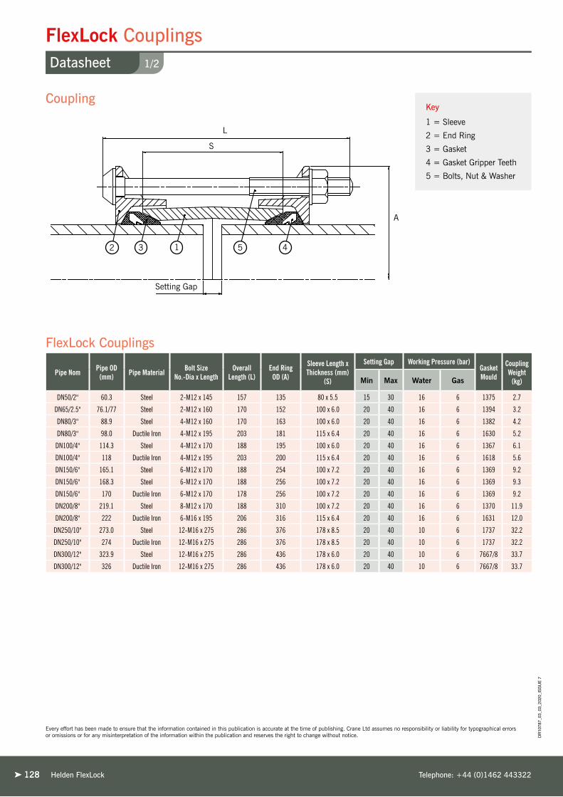
128128
Key
1 = Sleeve
2 = End Ring
3 = Gasket
4 = Gasket Gripper Teeth
5 = Bolts, Nut & Washer
Helden FlexLock Telephone: +44 (0)1462 443322
Every effort has been made to ensure that the information contained in this publication is accurate at the time of publishing. Crane Ltd assumes no responsibility or liability for typographical errors or omissions or for any misinterpretation of the information within the publication and reserves the right to change without notice.
1/2
FlexLock CouplingsDatasheet
Pipe Nom Pipe OD (mm) Pipe Material Bolt Size
No.-Dia x LengthOverall
Length (L)End Ring
OD (A)
Sleeve Length x Thickness (mm)
(S)
Setting Gap Working Pressure (bar)Gasket Mould
Coupling Weight
(kg)Min Max Water Gas
DN50/2" 60.3 Steel 2-M12 x 145 157 135 80 x 5.5 15 30 16 6 1375 2.7
DN65/2.5" 76.1/77 Steel 2-M12 x 160 170 152 100 x 6.0 20 40 16 6 1394 3.2
DN80/3" 88.9 Steel 4-M12 x 160 170 163 100 x 6.0 20 40 16 6 1382 4.2
DN80/3" 98.0 Ductile Iron 4-M12 x 195 203 181 115 x 6.4 20 40 16 6 1630 5.2
DN100/4" 114.3 Steel 4-M12 x 170 188 195 100 x 6.0 20 40 16 6 1367 6.1
DN100/4" 118 Ductile Iron 4-M12 x 195 203 200 115 x 6.4 20 40 16 6 1618 5.6
DN150/6" 165.1 Steel 6-M12 x 170 188 254 100 x 7.2 20 40 16 6 1369 9.2
DN150/6" 168.3 Steel 6-M12 x 170 188 256 100 x 7.2 20 40 16 6 1369 9.3
DN150/6" 170 Ductile Iron 6-M12 x 170 178 256 100 x 7.2 20 40 16 6 1369 9.2
DN200/8" 219.1 Steel 8-M12 x 170 188 310 100 x 7.2 20 40 16 6 1370 11.9
DN200/8" 222 Ductile Iron 6-M16 x 195 206 316 115 x 6.4 20 40 16 6 1631 12.0
DN250/10" 273.0 Steel 12-M16 x 275 286 376 178 x 8.5 20 40 10 6 1737 32.2
DN250/10" 274 Ductile Iron 12-M16 x 275 286 376 178 x 8.5 20 40 10 6 1737 32.2
DN300/12" 323.9 Steel 12-M16 x 275 286 436 178 x 6.0 20 40 10 6 7667/8 33.7
DN300/12" 326 Ductile Iron 12-M16 x 275 286 436 178 x 6.0 20 40 10 6 7667/8 33.7
Setting Gap
2 3 1 5 4
L
S
A
Coupling
FlexLock Couplings
DR
1078
7_03
_03_
2020
_IS
SU
E 7

129
Working Pressure Rating
Water:➤ DN50 to DN200 = 16 bar➤ DN250 to DN300 = 10 bar
Gas:➤ DN50 to DN300 = 6 bar
Vacuum Pressure
Capable of accommodating a vacuum pressure of -0.7 bar
Site Test Pressure
1.5 times working pressure for short duration (2 hours)
Angularity
Couplings 6°
Bolt Torque/Spanner
M12; Torque 55-65Nm on every bolt
M16; Torque 95-120Nm on every bolt
Temperature Rating of Product
EPDM -20°C to +40°C
Nitrile -20°C to +40°C
General Notes
➤ FlexLock is only suitable for use on Ductile Iron, Steel and Coated Steel Pipe➤ For coated steel pipe the maximum permitted coating thickness is 500μ DFT. This is to ensure the stainless steel teeth properly grip onto the pipe surface to mobilize the end load capability of the products. ➤ Due to the surface characteristics of stainless steel pipe, FlexLock grippers are unable to achieve a guaranteed grip on the pipe surface.➤ If the product has to be dismantled after installation then for reassembly a new gasket must be used, as there is a risk that the stainless steel teeth may become dislodged during this operation. These are available as spares from Helden by quoting gasket mould number from the table along with gasket compound.
Approvals
The following water contact materials used in FlexLock are approved for use with potable water:-
Rilsan Nylon 11:➤ WRAS, AS/NZS 4020, DVGW, W270, ACS & KIWA
EPDM Gaskets:➤ WRAS, AS/NZS 4020
In addition to the above, FlexLock range as a finished product has KIWA certification verifying that the above products comply with the requirements of the Water Supply (Water Fittings) Regulations for England and Wales 1999, the Water Byelaws 2000, Scotland and the Water Regulations Northern Ireland.
Centre Sleeve & End Ring Options:
➤ SG. Iron to BS 1563: Symbol EN-GJS-450-10➤ Rolled Steel to: BS EN 10025: Grade S275
Coupling Body Options:
➤ Ductile Iron to BS EN 1563 EN-GJS-450-10➤ Mild Steel to: BS EN 10025: Grade S275
Gasket
EPDM compound Grade E to BS EN 681-1
Nitrile compound Grade ‘G’ to BS EN 682-1
Gasket Gripper Teeth
Stainless Steel BS 3146: Part 2 Grade ANC2
Coatings
Body, Centre Sleeve, & End Rings: ➤ Rilsan Nylon 11 to WIS 4-52-01 Part 1
Bolts, Studs & Nuts:➤ Sheraplex coated to WIS 4-52-03
Bolts
Cold Forged Steel Fasteners to: BS EN ISO898-1: Property Class 8.8
Nuts
Steel BS EN 20898-2: Property Class 8
Washers
BS 4320 Form B Stainless Steel BS 1449:PT2: Grade 304 S15
Materials & Relevant Standards
Technical Information
Helden FlexLockwww.helden-web.com
Every effort has been made to ensure that the information contained in this publication is accurate at the time of publishing. Crane Ltd assumes no responsibility or liability for typographical errors or omissions or for any misinterpretation of the information within the publication and reserves the right to change without notice.
2/2
FlexLock CouplingsDatasheet
Couplings &
Flange Adaptors
Dedicated
DR
1078
7_03
_03_
2020
_IS
SU
E 7

130130
Key
1 = Flange Adaptor
2 = End Ring
3 = Gasket
4 = Gasket Gripper Teeth
5 = Stud
Helden FlexLock Telephone: +44 (0)1462 443322
1/2
FlexLock Flange AdaptorsDatasheet
Every effort has been made to ensure that the information contained in this publication is accurate at the time of publishing. Crane Ltd assumes no responsibility or liability for typographical errors or omissions or for any misinterpretation of the information within the publication and reserves the right to change without notice.
Pipe Nom
Pipe OD
(mm)
Pipe Material
Bolt Size No.-Dia x Length
Flange OD (A)
Overall Length
(L)
Flange Thickness (mm) (F)
Sleeve Length
(mm) (S)
Flange Nominal Drilling BS EN 1092-1
Working Pressure (bar) Setting GapGasket Mould
FA Weight
(kg)Water Gas Min Max
DN50/2" 60.3 Steel 2-M12 x 115 160 123 16 75 50 PN10/16 16 6 10 30 1375 2.3
DN65/2.5" 76.1 Steel 2-M12 x 115 180 123 16 75 60/65 PN10/16 16 6 10 30 1394 2.6
DN80/3" 88.9 Steel 4-M12 x 115 195 123 16 75 80 PN10/16 90 PN6 16 6 10 30 1382 3.4
DN80/3" 98 Ductile Iron 4-M12 x 115 195 123 16 75 80 PN10/16 90 PN6 16 6 10 30 1630 4.0
DN100/4" 114.3 Steel 4-M12 x 115 215 123 16 75 100 PN10/16 110 PN6 16 6 10 30 1367 4.5
DN100/4" 118 Ductile Iron 4-M12 x 115 215 123 16 75 100 PN10/16 16 6 10 30 1618 4.4
DN150/6" 165.1 Steel 8-M12 x 115 285 127 25 75 150 PN10/16 6”E 6”ANSI 150 16 6 10 30 1369 9.3
DN150/6" 168.3 Steel 8-M12 x 115 286 123 19 75 150 PN10/16 16 6 10 30 1369 8.0
DN150/6" 170 Ductile Iron 8-M12 x 115 286 123 19 75 150 PN10/16 16 6 10 30 1369 8.0
DN200/8" 219.1 Steel 8-M12 x 115 341 123 19 75 200 PN10 10 6 10 30 1370 9.7
DN200/8" 219.1 Steel 8-M12 x 115 340 127 25 73 200 PN16 16 6 10 30 1370 15.2
DN200/8" 222 Ductile Iron 6-M16 x 125 341 137 19 75 200 PN16 16 6 10 30 1631 10.6
DN200/8" 222 Ductile Iron 8-M16 x 125 340 137 25 75 200 PN10 8”E 10 6 10 30 1631 13.9
DN250/10" 273.0 Steel 12-M16 x 125 405 137 19 90 250 PN10/16* 10 6 10 30 1737 16.4
DN250/10" 274 Ductile Iron 12-M16 x 125 405 137 19 90 250 PN10/16* 10 6 10 30 1737 16.4
DN300/12" 323.9 Steel 12-M16 x 125 467 137 19 90 300 PN10/16* 10 6 10 30 7667/8 22.7
DN300/12" 326 Ductile Iron 12-M16 x 125 467 137 19 90 300 PN10/16* 10 6 10 30 7667/8 22.7
F
1532
4
Setting Gap
LS
A
Flange Adaptor
FlexLock Flange Adaptors
DR
1078
7_03
_03_
2020
_IS
SU
E 7

131
Working Pressure Rating
Water:➤ DN50 to DN200 = 16 bar➤ DN250 to DN300 = 10 bar
Gas:➤ DN50 to DN300 = 6 bar
Vacuum Pressure
Capable of accommodating a vacuum pressure of -0.7 bar
Site Test Pressure
1.5 times working pressure for short duration (2 hours
Flange Drilling
While DN250 to DN300 are supplied with PN1616 drilling the rated working pressure (water) is only 10 bar as stated in the table.
Angularity
Flange Adaptors 3°
Bolt Torque/Spanner
M12; Torque 55-65Nm on every bolt
M16; Torque 95-120Nm on every bolt
Temperature Rating of Product
EPDM -20°C to +40°C
Nitrile -20°C to +40°C
General Notes
➤ FlexLock is only suitable for use on Ductile Iron, Steel and Coated Steel Pipe➤ For coated steel pipe the maximum permitted coating thickness is 500μ DFT. This is to ensure the stainless steel teeth properly grip onto the pipe surface to mobilize the end load capability of the products. ➤ Due to the surface characteristics of stainless steel pipe, FlexLock grippers are unable to achieve a guaranteed grip on the pipe surface.➤ If the product has to be dismantled after installation then for reassembly a new gasket must be used, as there is a risk that the stainless steel teeth may become dislodged during this operation. These are available as spares from Helden by quoting gasket mould number from the table along with gasket compound.
Approvals
The following water contact materials used in FlexLock are approved for use with potable water:-
Rilsan Nylon 11:➤ WRAS, AS/NZS 4020, DVGW, W270, ACS & KIWA
EPDM Gaskets:➤ WRAS, AS/NZS 4020
In addition to the above, FlexLock range as a finished product has KIWA certification verifying that the above products comply with the requirements of the Water Supply (Water Fittings) Regulations for England and Wales 1999, the Water Byelaws 2000, Scotland and the Water Regulations Northern Ireland.
End Rings Options:
➤ SG. Iron to BS 1563: Symbol EN-GJS-450-10➤ Rolled Steel to: BS EN 10025: Grade S275
Flange Adaptor Body Options:
➤ Ductile Iron to BS EN 1563 EN-GJS-450-10➤ Mild Steel to: BS EN 10025: Grade S275
Gasket
EPDM compound Grade E to BS EN 681-1
Nitrile compound Grade ‘G’ to BS EN 682-1
Gasket Gripper Teeth
Stainless Steel BS 3146: Part 2 Grade ANC2
Coatings
Body, Centre Sleeve, & End Rings: ➤ Rilsan Nylon 11 to WIS 4-52-01 Part 1
Studs & Nuts:➤ Sheraplex coated to WIS 4-52-03
Studs
Cold Forged Steel Fasteners to: BS EN ISO898-1: Property Class 8.8
Nuts
Steel BS EN 20898-2: Property Class 8
Washers
BS 4320 Form B Stainless Steel BS 1449:PT2: Grade 304 S15
Materials & Relevant Standards
Technical Information
Helden FlexLockwww.helden-web.com
2/2
FlexLock Flange AdaptorsDatasheet
Every effort has been made to ensure that the information contained in this publication is accurate at the time of publishing. Crane Ltd assumes no responsibility or liability for typographical errors or omissions or for any misinterpretation of the information within the publication and reserves the right to change without notice.
Couplings &
Flange Adaptors
Dedicated
DR
1078
7_03
_03_
2020
_IS
SU
E 7

132132 Helden FlexLock Telephone: +44 (0)1462 443322
Crane BS&U are solely the provider of products and have no direct influence on, or take any responsibility for any working practices employed or depicted in the images enclosed to install such products.
West East Link MainFlexLock - DN150Large Diameter - DN800
United Kingdom - Liverpool
Project
West East link transmission main.
The 53km pipeline runs from Prescot
near Liverpool to Bury, near Manchester.
Client
United Utilities
Contractor
Murphys

Helden Large Diameter 133
Bes
po
ke Large DiameterFittings to Suit any Pipe Specification

Pipe Materials
134134
Large DiameterOverview
Helden Large Diameter Telephone: +44 (0)1462 443322
Customer SpecificationsThe dedicated range is designed for use with new-lay pipes
and other specified situations where the pipe material and
nominal sizes are known in advance. Customers can choose
from Helden’s standard range or have them custom made
to suit a range of diameters and working pressures. This
flexibility makes Helden the natural choice for most major
pipeline projects.
Design LiaisonHelden has worked with clients, consultants and contractors
all over the world, assisting in the selection of the product
most appropriate to each individual project. Such assistance
can include detailed design co-operation with specifying
engineers, site visits to aid successful installation, specially
designed products to suit project requirements, proof testing
in our comprehensive in-house test facility and handling of
the extensive documentation and inspection requirements
often associated with large projects.
Designed for FlexibilityFor pipeline design and installation engineers, the
Helden large diameter couplings are extremely versatile.
Each coupling sleeve is internally barrelled, allowing greater
angular deflection. Ideal when accommodating misaligned
pipes.
Product CapabilityLarge diameter couplings and flange adaptors are available
in a wide range of sizes to suit virtually any customer
requirement. Products can be supplied to suit all standard
and non standard pipe diameters from DN350 to DN4000.
Stepped couplings join pipes of different external diameters
and flange adaptors can be supplied with flanges drilled to
any national or international standard, or to customers’ own
specification with a pressure up to 80 bar.
ApprovalsAll products are designed and manufactured under quality
management systems certified to ISO 9001 and conform
to the American Water Works Association’s specification
AWWA/ANSI C219 for bolted couplings.
Re-movable Locating Plugs - Prevent Coupling CreepLD Dedicated couplings are available with removable locating
plugs, to prevent coupling creep on above ground pipelines
caused by repeated pipe movement from temperature
variation, continuous vibrations and movement. The
removable locating plug (optional) ensures the coupling can
slide fully over the pipe ends for quick and simple installation.
Once installed they engage between the pipe ends to prevent
the coupling moving beyond fixed limits.
Robust, Reliable, Proven Solution for New Lay Pipes

Helden Large Diameterwww.helden-web.com
Corrosion Protection
Various Gasket Grades
Internal Barrelling of Sleeve
Sleeve Length
Captive Bolts
Flash Butt Welding
Cold Expansion
Metal components are coated with Rilsan Nylon 11,
which is WRAS approved for use with potable water, and
offers long term corrosion protection and resistance to
impact damage.
The nuts & bolts are Sheraplex coated to WIS 4-52-03,
which does not gall when re-used and offers a consistent
“torque / load” ratio reducing the sensitivity during
installation while providing long term corrosion protection.
EPDM (water quality approved) and Nitrile gaskets as
standard. Alternative exotic grades available for specialist
applications (see Design Data for more details).
Internal barrelling of sleeve to accommodate
angular deflection of up to 6° (size dependant).
Standard and long sleeve lengths
available to accommodate site conditions.
Captive non-rotating bolt heads
require just a single spanner to install.
Flash butt welding used for end ring and centre
sleeve ensuring a full penetration weld with
totally homogeneous material and no impurities.
Conforming to AWWA C219 the end ring and centre
sleeve are cold expanded, which increases the strength
of the steel through work hardening, ensures roundness
of manufacture and verifies structural integrity of the
material with loads substantially greater than in service.
135
Large Diameter CouplingsProduct Design Benefits
➤ Couplings can absorb up to 10mm expansion and contraction,
which allows for movement on bridge crossings, in chambers
and pump stations. Often eliminates the need for special
expansion joints.
➤ Couplings can offer up to 6° of angular deflection; to allow for
the connection of misaligned pipes, take up ground settlement
at structures, lay pipes to large radius bends, etc.
➤ The standard finish for all Helden products is black Rilsan
Nylon 11, which is highly resistant to impact, corrosion,
abrasion and chemical attack. However, other coatings such
as shopcoat, hot dip galvanising, zinc spray and epoxy coating
can be supplied as required.
Customer Benefits
DR
1078
7_03
_03_
2020
_IS
SU
E 7
Couplings &
Flange Adaptors
Dedicated

End Load Forces
Flange Drilling
Clear and Full Bore FlangeNotching of end ring permits the use of tie rods to harness
the flange adaptor to accommodate end load forces.
Flange drilling to any standard
to accommodate site requirements.
As standard flange adaptors are supplied with clear
bore to slide over pipe for easy installation on site.
Full “S Bore” flange also available for use with
wafer style (butterfly) valves.
136136
Large Diameter Flange AdaptorsProduct Design Benefits
➤ Flange adaptors can absorb up to 5mm
expansion, which allows for movement
on bridge crossings, in chambers and
pump stations. Often eliminates the
need for special expansion joints.
➤ Flange adaptors can offer up to 3°
of angular deflection, to allow for
the connection of miss aligned pipe
to flange equipment and movement/
settlement in service.
➤ The standard finish for all Helden
products is black Rilsan Nylon 11, which
is highly resistant to impact, corrosion,
abrasion and chemical attack. However,
other coatings such as shopcoat, hot dip
galvanising, zinc spray and epoxy coating
can be supplied as required.
Customer Benefits
Corrosion Protection
Various Gasket Grades
Sleeve LengthFlash Butt Welding
Cold Expansion
Metal components are coated with Rilsan Nylon 11,
which is WRAS approved for use with potable water,
and offers long term corrosion protection and resistance
to impact damage.
The nuts & bolts are Sheraplex coated to WIS 4-52-03,
which does not gall when re-used and offers a consistent
“torque / load” ratio reducing the sensitivity during
installation while providing long term
corrosion protection.
EPDM (water quality approved) and Nitrile gaskets as
standard. Alternative exotic grades available for specialist
applications (see Design Data for more details).
Standard and long sleeve lengths
available to accommodate site conditions.Flash butt welding used for end ring and centre
sleeve ensuring a full penetration weld with
totally homogeneous material and no impurities.
Conforming to AWWA C219 the end ring and centre
sleeve are cold expanded, which increases the strength
of the steel through work hardening, ensures roundness
of manufacture and verifies structural integrity of the
material with loads substantially greater than in service.
Helden Large Diameter Telephone: +44 (0)1462 443322
DR
1078
7_03
_03_
2020
_IS
SU
E 7

Helden AquaGrip RangeHelden Large Diameterwww.helden-web.com
Desalination Plant Transfer PipelineLarge Diameter Flange Adaptor - DN1600
Australia - Adelaide
Project
The Desalination Plant has a capacity
of up to 100 gigalitres and will provide
Adelaide with up to half its annual water
requirement. The huge size of the plant
will be powered by sustainable energy
sources and will ensure that the majority
of the water supply is sourced from the
sea with lesser reliance placed on the
River Murray basin.
Client
South Australian Water
& South Australian Government
Contractor
McConnell Dowell
Distributor
Philmac
Crane BS&U are solely the provider of products and have no direct influence on, or take any responsibility for any working practices employed or depicted in the images enclosed to install such products.
137

138138 Helden Large Diameter Telephone: +44 (0)1462 443322
1/4
Large Diameter Couplings OD355.6 - 816Datasheet
Every effort has been made to ensure that the information contained in this publication is accurate at the time of publishing. Crane Ltd assumes no responsibility or liability for typographical errors or omissions or for any misinterpretation of the information within the publication and reserves the right to change without notice.
L= Distance back from end of pipe that must be rounded, meet tolerances, and free from any wrapping to ensure correct assembly.
Coupling Type Coupling Section Type
Sleeve LengthS (mm)
Dimensions (mm) Setting Gap X (mm) Bolt Details
Distance L Overall C Min. Max. Bolt Dia. Length (mm) Torque (Nm)
Standard Sleeve LO2 150 150 243 25 50 M12 235 55 - 65
Long Sleeve LO3 250 200 348 25 150 M12 340 55 - 65
Standard Sleeve YF2 178 150 276 38 76 M16 265 95 - 120
Long Sleeve YF3 250 200 351 38 150 M16 340 95 - 120
Standard Sleeve A2E 178 150 276 38 76 M16 265 95 - 120
Long Sleeve A2H 254 200 351 38 150 M16 340 95 - 120
Standard Sleeve XSXG 254 200 411 57 117 M16 400 95 - 120
A
C
L
S
X
Pipe OD(mm)
Pipe Material
Working Pressure
(bar)Gasket
Mould No.
Tolerance (mm) on Pipe OD for Distance L (mm) Coupling Section Type Bolts Weight (kg)
Diameter A (mm)
+ - Standard Sleeve
Long Sleeve No. x Dia Standard
SleeveLong
Sleeve
355.6 Steel & uPVC 23.2 J51LS 1.6 1.6 LO2 LO3 6 x M12 19.6 26.3 447
355.6 Steel 31.0 J51LS 1.6 1.6 LO2 LO3 8 x M12 20.0 26.9 447
358.6 Coated Steel 19.6 J51LS 1.6 1.6 LO2 LO3 6 x M12 19.7 26.5 450
358.6 Coated Steel 30.7 J51LS 1.6 1.6 LO2 LO3 8 x M12 20.2 27.1 450
378 Ductile Iron 29.2 J52LS 2.7 3.5 LO2 LO3 8 x M12 21.1 28.4 469
406.4 Steel & uPVC 27.2 J53LS 1.6 1.6 LO2 LO3 8 x M12 22.4 30.2 497
408.4 Coated Steel 27.0 J53LS 1.6 1.6 LO2 LO3 8 x M12 22.5 30.4 499
409.6 Coated Steel 27.0 J53LS 1.6 1.6 LO2 LO3 8 x M12 22.6 30.4 500
429 Ductile Iron 25.8 J54LS 2.8 4.0 LO2 LO3 8 x M12 23.6 31.7 520
457 Steel & uPVC 24.2 J55LS 1.6 1.6 LO2 LO3 8 x M12 24.9 33.5 548
460 Coated Steel 24.1 J55LS 1.6 1.6 LO2 LO3 8 x M12 25.0 33.7 551
480 Ductile Iron 23.1 J56LS 2.9 4.0 LO2 LO3 8 x M12 26.0 35.1 571
480 Ductile Iron 28.9 J56LS 2.9 4.0 LO2 LO3 10 x M12 26.5 35.7 571
508 Steel & uPVC 27.4 J57LS 1.6 1.6 LO2 LO3 10 x M12 27.8 37.4 598
511 Coated Steel 27.2 J57LS 1.6 1.6 LO2 LO3 10 x M12 27.9 37.6 602
532 Ductile Iron 26.1 J58LS 3.0 4.0 LO2 LO3 10 x M12 29.0 39.1 624
559 Steel & uPVC 24.9 J59LS 1.6 1.6 LO2 LO3 10 x M12 30.2 40.7 649
610 Steel & uPVC 22.9 J60LS 1.6 1.6 LO2 LO3 10 x M12 32.7 44.1 701
610 Steel 26.3 J60LS 1.6 1.6 LO2 LO3 12 x M12 33.1 44.6 701
613 Coated Steel 22.8 J60LS 1.6 1.6 LO2 LO3 10 x M12 32.8 44.3 704
613 Coated Steel 26.2 J60LS 1.6 1.6 LO2 LO3 12 x M12 33.2 44.8 704
635 Ductile Iron 22.0 J61LS 3.2 4.5 LO2 LO3 10 x M12 33.9 45.8 726
635 Ductile Iron 25.2 J61LS 3.2 4.5 LO2 LO3 12 x M12 34.3 46.3 726
660 Steel 24.3 J61LS 1.6 1.6 LO2 LO3 12 x M12 35.5 47.9 751
660 Steel 31.5 J61LS 1.6 1.6 YF2 YF3 10 x M16 62.6 74.5 770
663 Coated Steel 24.3 J61LS 1.6 1.6 LO2 LO3 12 x M12 35.7 48.1 754
663 Coated Steel 31.4 J61LS 1.6 1.6 YF2 YF3 10 x M16 62.9 74.8 773
711 Steel 22.6 J63LS 1.6 1.6 LO2 LO3 12 x M12 38.1 51.3 802
714 Coated Steel 22.4 J63LS 1.6 1.6 LO2 LO3 12 x M12 38.1 51.5 805
738 Ductile Iron 21.7 J63LS 3.4 4.5 LO2 LO3 12 x M12 39.3 53.1 830
738 Ductile Iron 28.2 J63LS 3.4 4.5 YF2 YF3 10 x M16 69.3 82.4 849
762 Steel 21.0 J64LS 1.6 1.6 LO2 LO3 12 x M12 40.4 54.6 852
762 Steel 27.3 J64LS 1.6 1.6 YF2 YF3 10 x M16 71.2 84.6 871
765 Coated Steel 21.0 J64LS 1.6 1.6 LO2 LO3 12 x M12 40.6 54.8 856
765 Coated Steel 27.2 J64LS 1.6 1.6 YF2 YF3 10 x M16 71.5 85.0 875
813 Steel 19.8 J65LS 1.6 1.6 LO2 LO3 14 x M12 43.3 58.5 903
816 Coated Steel 19.7 J65LS 1.6 1.6 LO2 LO3 14 x M12 43.3 58.7 906
Coupling
Large Diameter Couplings
DR
1078
7_03
_03_
2020
_IS
SU
E 7

139
Helden manufacture couplings to any pipe OD and pressure. If the product required is not shown in any of our tables please contact Helden who can provide the relevant information.
Working Pressure Rating
For Water / Wastewater applications as detailed in Large Diameter Coupling Technical Data Table.
Gas 6 bar
Vacuum Pressure
Capable of accommodating a vacuum pressure of -0.7 bar
Site Test Pressure
1.5 times working pressure for short duration (2 hours)
End Load Due to Internal Pressure
Dedicated Couplings DO NOT resist end load due to the internal pressure - adequate external restraint must be provided to prevent pipe pull out from the coupling.
Temperature Rating of Product
EPDM -20°C to +90°C
Nitrile -20°C to +90°C
Other Gasket Grades Contact Helden.
For use on applications with fluctuating and / or elevated temperatures (> 60°C) may require regular maintenance to re-tighten the bolts and must be included in any maintenance schedule.
Approvals
The following water contact materials used in Large Diameter Dedicated products are approved for use with potable water:-
Rilsan Nylon 11:➤ WRAS, AS/NZS 4020, DVGW, W270, ACS & KIWA.
EPDM Gaskets:➤ WRAS, AS/NZS 4020
In addition to the above, LD Dedicated range as a finished product has KIWA certification verifying that the above products comply with the requirements of the Water Supply (Water Fittings) Regulations for England and Wales 1999, the Water Byelaws 2000, Scotland and the Water Regulations Northern Ireland.
Technical Information
Centre Sleeve & End Rings
Steel to BS EN10025-2: Grade S275JR
Gaskets: LO2/LO3/YF2/YF3
Rubber 80 IRHD Moulded Compound to BS EN681-1: Type WA,WC,WG
BS EN682: Type G
(other materials available on request)
Gaskets: A2E/A2H/XSXG
Rubber 70 IRHD Moulded Compound to BS EN681-1: Type WA, WC, WG
BS EN682: Type G
(other materials available on request)
Coatings
Body, Flange & End Ring:➤ Rilsan Nylon 11 to WIS 4-52-01 Part 1
Nuts & Bolts:➤ Sheraplex coated to WIS 4-52-03
Bolts
Steel to BS EN ISO898-1: Property Class 4.8
Nuts
Steel to BS4190: Grade 4
Washers
Stainless Steel to BS1449:Part 2: Grade 304S15
Materials & Relevant Standards
Helden Large Diameterwww.helden-web.com
2/4
Large Diameter Couplings OD355.6 - 816Datasheet
Every effort has been made to ensure that the information contained in this publication is accurate at the time of publishing. Crane Ltd assumes no responsibility or liability for typographical errors or omissions or for any misinterpretation of the information within the publication and reserves the right to change without notice. D
R10
787_
03_0
3_20
20_I
SS
UE
7
Couplings &
Flange Adaptors
Dedicated

140140 Helden Large Diameter Telephone: +44 (0)1462 443322
3/4
Large Diameter Couplings OD842 - 2038Datasheet
Every effort has been made to ensure that the information contained in this publication is accurate at the time of publishing. Crane Ltd assumes no responsibility or liability for typographical errors or omissions or for any misinterpretation of the information within the publication and reserves the right to change without notice.
Coupling Type Coupling Section Type
Sleeve LengthS (mm)
Dimensions (mm) Setting Gap X (mm) Bolt Details
Distance L Overall C Min. Max. Bolt Dia. Length (mm) Torque (Nm)
Standard Sleeve LO2 150 150 243 25 50 M12 235 55 - 65
Long Sleeve LO3 250 200 348 25 150 M12 340 55 - 65
Standard Sleeve YF2 178 150 276 38 76 M16 265 95 - 120
Long Sleeve YF3 250 200 351 38 150 M16 340 95 - 120
Standard Sleeve A2E 178 150 276 38 76 M16 265 95 - 120
Long Sleeve A2H 254 200 351 38 150 M16 340 95 - 120
Standard Sleeve XSXG 254 200 411 57 117 M16 400 95 - 120
A
C
L
S
X
Coupling
Large Diameter Couplings
L= Distance back from end of pipe that must be rounded, meet tolerances, and free from any wrapping to ensure correct assembly.
DR
1078
7_03
_03_
2020
_IS
SU
E 7
Pipe OD(mm)
Pipe Material
Working Pressure
(bar)Gasket
Mould No.
Tolerance (mm) on Pipe OD for Distance L Coupling Section Type Bolts Weight (kg)
Diameter A (mm)
+ - Standard Sleeve
Long Sleeve No. x Dia Standard
SleeveLong
Sleeve
842 Ductile Iron 18.9 J65LS 1.0 4.5 LO2 LO3 14 x M12 44.6 60.3 931
842 Ductile Iron 25.0 J65LS 1.0 4.5 YF2 YF3 12 x M16 78.7 93.6 950
842 Ductile Iron 29.1 J116M 1.0 4.5 A2E A2H 14 x M16 103.4 122.7 965
864 Steel 17.9 J66LS 1.6 1.6 LO2 LO3 14 x M12 45.7 61.8 955
864 Steel 28.4 J116M 1.6 1.6 A2E A2H 14 x M16 105.9 125.8 988
867 Coated Steel 17.8 J66LS 1.6 1.6 LO2 LO3 14 x M12 45.9 62.0 958
867 Coated Steel 28.2 J117M 1.6 1.6 A2E A2H 14 x M16 106.3 126.2 992
914 Steel 16.0 J67LS 1.6 1.6 LO2 LO3 14 x M12 48.2 65.1 1005
914 Steel 26.8 J117M 1.6 1.6 A2E A2H 14 x M16 111.6 132.4 1039
916 Coated Steel 16.0 J67LS 1.6 1.6 LO2 LO3 14 x M12 48.3 65.2 1007
916 Coated Steel 26.8 J117M 1.6 1.6 A2E A2H 14 x M16 111.8 132.7 1041
945 Ductile Iron 22.0 J70LS 1.0 5.0 YF2 YF3 12 x M16 87.5 104.0 1054
945 Ductile Iron 25.9 J118M 1.0 5.0 A2E A2H 14 x M16 115.0 136.5 1069
1016 Steel 19.6 J71LS 1.6 1.6 YF2 YF3 14 x M16 94.3 112.2 1125
1019 Coated Steel 19.4 J71LS 1.6 1.6 YF2 YF3 14 x M16 94.6 112.5 1129
1048 Ductile Iron 18.4 J71LS 1.0 5.0 YF2 YF3 14 x M16 96.9 115.3 1156
1048 Ductile Iron 26.8 J119M 1.0 5.0 A2E A2H 16 x M16 127.1 151.0 1171
1067 Steel 17.7 J72LS 1.6 1.6 YF2 YF3 14 x M16 98.6 117.3 1177
1067 Steel 26.3 J119M 1.6 1.6 A2E A2H 16 x M16 129.4 153.7 1192
1070 Coated Steel 17.6 J72LS 1.6 1.6 YF2 YF3 14 x M16 98.9 117.6 1180
1070 Coated Steel 26.2 J120M 1.6 1.6 A2E A2H 16 x M16 129.7 154.1 1195
1118 Steel 16.2 J73LS 1.6 1.6 YF2 YF3 14 x M16 102.9 122.4 1227
1121 Coated Steel 16.0 J73LS 1.6 1.6 YF2 YF3 14 x M16 103.2 122.8 1231
1152 Ductile Iron 24.4 J121M 1.0 6.0 A2E A2H 16 x M16 138.7 164.7 1275
1219 Steel 23.0 J121M 1.6 1.6 A2E A2H 16 x M16 146.3 173.7 1343
1222 Coated Steel 23.0 J121M 1.6 1.6 A2E A2H 16 x M16 146.6 174.1 1347
1255 Ductile Iron 25.2 J122M 1.0 6.0 A2E A2H 18 x M16 151.0 179.4 1378
1422 Steel 24.5 J125M 1.6 3.0 A2E A2H 20 x M16 170.5 202.6 1546
1426 Coated Steel 24.4 J125M 1.6 3.0 A2E A2H 20 x M16 171.0 203.1 1551
1462 Ductile Iron 23.8 J125M 1.0 7.0 A2E A2H 20 x M16 174.8 207.7 1585
1620 Steel 20.3 J127M 3.0 3.0 A2E A2H 24 x M16 192.4 230.9 1745
1626 Coated Steel 20.2 J127M 3.0 3.0 A2E A2H 24 x M16 194.2 231.7 1751
1668 Ductile Iron 19.2 J128M 1.0 7.0 A2E A2H 24 x M16 199.4 237.0 1791
1829 Steel 16.0 J130M 3.0 3.0 A2E A2H 24 x M16 217.5 258.5 1954
1835 Coated Steel 24.0 J184H 3.0 3.0 XSXG - 32 x M16 378.4 - 1970
2032 Steel 22.1 J186H 3.0 3.0 XSXG - 36 x M16 418.6 - 2167
2038 Coated Steel 22.0 J186H 3.0 3.0 XSXG - 36 x M16 419.7 - 2173

141
Technical Information
Helden manufacture couplings to any pipe OD and pressure. If the product required is not shown in any of our tables please contact Helden who can provide the relevant information.
Working Pressure Rating
For Water / Wastewater applications as detailed in Large Diameter Coupling Technical Data Table.
Gas 6 bar
Vacuum Pressure
Capable of accommodating a vacuum pressure of -0.7 bar
Site Test Pressure
1.5 times working pressure for short duration (2 hours)
End Load Due to Internal Pressure
Dedicated Couplings DO NOT resist end load due to the internal pressure - adequate external restraint must be provided to prevent pipe pull out from the coupling.
Temperature Rating of Product
EPDM -20°C to +90°C
Nitrile -20°C to +90°C
Other Gasket Grades Contact Helden.
For use on applications with fluctuating and / or elevated temperatures (> 60°C) may require regular maintenance to re-tighten the bolts and must be included in any maintenance schedule.
Approvals
The following water contact materials used in Large Diameter Dedicated products are approved for use with potable water:-
Rilsan Nylon 11:➤ WRAS, AS/NZS 4020, DVGW, W270, ACS & KIWA.
EPDM Gaskets:➤ WRAS, AS/NZS 4020
In addition to the above, LD Dedicated range as a finished product has KIWA certification verifying that the above products comply with the requirements of the Water Supply (Water Fittings) Regulations for England and Wales 1999, the Water Byelaws 2000, Scotland and the Water Regulations Northern Ireland.
Technical Information
Centre Sleeve & End Rings
Steel to BS EN10025-2: Grade S275JR
Gaskets: LO2/LO3/YF2/YF3
Rubber 80 IRHD Moulded Compound to BS EN681-1: Type WA,WC,WG
BS EN682: Type G
(other materials available on request)
Gaskets: A2E/A2H/XSXG
Rubber 70 IRHD Moulded Compound to BS EN681-1: Type WA, WC, WG
BS EN682: Type G
(other materials available on request)
Coatings
Body, Flange & End Ring:➤ Rilsan Nylon 11 to WIS 4-52-01 Part 1
Nuts & Bolts:➤ Sheraplex coated to WIS 4-52-03
Bolts
Steel to BS EN ISO898-1: Property Class 4.8
Nuts
Steel to BS4190: Grade 4
Washers
Stainless Steel to BS1449:Part 2: Grade 304S15
Materials & Relevant Standards
Helden Large Diameterwww.helden-web.com
4/4
Large Diameter Couplings OD842 - 2038Datasheet
Every effort has been made to ensure that the information contained in this publication is accurate at the time of publishing. Crane Ltd assumes no responsibility or liability for typographical errors or omissions or for any misinterpretation of the information within the publication and reserves the right to change without notice. D
R10
787_
03_0
3_20
20_I
SS
UE
7
Couplings &
Flange Adaptors
Dedicated

142142 Helden Large Diameter Telephone: +44 (0)1462 443322
1/2
Large Diameter Stepped Couplings OD355.6 - 1222Datasheet
Every effort has been made to ensure that the information contained in this publication is accurate at the time of publishing. Crane Ltd assumes no responsibility or liability for typographical errors or omissions or for any misinterpretation of the information within the publication and reserves the right to change without notice.
Expanded Sleeve Stepped Coupling
Large Diameter Stepped Couplings
L= Distance back from end of pipe that must be rounded, meet tolerances, and free from any wrapping to ensure correct assembly.
DR
1078
7_03
_03_
2020
_IS
SU
E 7
A1
L X
A
CS
Pipe Details
Pipe OD (mm) Pipe
MaterialEnd 1
Tolerance on Pipe OD for Distance L Pipe
MaterialEnd 2
Tolerance on Pipe OD for Distance L
Wor
king
Pre
ssur
e (b
ar)
Gasket Mould No.
Coupling Section Type
Bolts No. x Dia
Weight (kg) Dimensions (mm)
Bolt Length
Dimensions Overall C
End
1
End
2 (mm) +
(mm) -
(mm) +
(mm) - En
d 1
End
2
Stan
dard
Sl
eeve
Long
Sl
eeve
Stan
dard
Sl
eeve
Long
Sl
eeve
Diam
eter
A
End
1
Diam
eter
A1
End
2
Stan
dard
Sl
eeve
Long
Sl
eeve
Stan
dard
Sl
eeve
Long
Sl
eeve
355.6 378 Steel & uPVC 1.6 1.6 Ductile Iron 2.7 3.5 29.2 J51LS J52LS LO2 LO3 8 x M12 20.7 27.8 446 469 235 340 243 348
358.6 378 Coated Steel 1.6 1.6 Ductile Iron 2.7 3.5 29.2 J51LS J52LS LO2 LO3 8 x M12 20.7 27.8 450 469 235 340 243 348
406.4 429 Steel & uPVC 1.6 1.6 Ductile Iron 2.8 4.0 25.7 J53LS J54LS LO2 LO3 8 x M12 23.1 31.1 497 520 235 340 243 348
409.6 429 Coated Steel 1.6 1.6 Ductile Iron 2.8 4.0 25.7 J53LS J54LS LO2 LO3 8 x M12 23.2 31.2 499 520 235 340 243 348
457 480 Steel & uPVC 1.6 1.6 Ductile Iron 2.9 4.0 23.1 J55LS J56LS LO2 LO3 8 x M12 25.6 34.5 548 571 235 340 243 348
460 480 Coated Steel 1.6 1.6 Ductile Iron 2.9 4.0 23.1 J55LS J56LS LO2 LO3 8 x M12 25.7 34.5 551 571 235 340 243 348
480 508 Ductile Iron 2.9 4.0 Steel & uPVC 1.6 1.6 27.3 J56LS J57LS LO2 LO3 10 x M12 27.3 36.7 571 598 235 340 243 348
480 511 Ductile Iron 2.9 4.0 Coated Steel 1.6 1.6 27.2 J56LS J57LS LO2 LO3 10 x M12 27.5 36.9 571 602 235 340 243 348
508 532 Steel & uPVC 1.6 1.6 Ductile Iron 3.0 4.0 26.1 J57LS J58LS LO2 LO3 10 x M12 28.6 38.4 598 624 235 340 243 348
511 532 Coated Steel 1.6 1.6 Ductile Iron 3.0 4.0 26.1 J57LS J58LS LO2 LO3 10 x M12 28.6 38.5 602 624 235 340 243 348
610 635 Steel & uPVC 1.6 1.6 Ductile Iron 3.2 4.5 22.0 J60LS J61LS LO2 LO3 10 x M12 33.6 45.2 700 726 235 340 243 348
613 635 Coated Steel 1.6 1.6 Ductile Iron 3.2 4.5 22.0 J60LS J61LS LO2 LO3 10 x M12 33.6 45.2 703 726 235 340 243 348
711 738 Steel 1.6 1.6 Ductile Iron 3.4 4.5 21.7 J63LS J63LS LO2 LO3 12 x M12 39.0 52.5 802 830 235 340 243 348
714 738 Coated Steel 1.6 1.6 Ductile Iron 3.4 4.5 21.7 J63LS J63LS LO2 LO3 12 x M12 39.0 52.5 805 830 235 340 243 348
738 747 Ductile Iron 3.4 4.5 Cast Iron CD 3.3 3.3 21.3 J63LS J63LS LO2 LO3 12 x M12 39.4 53.2 830 839 235 340 243 348
738 755 Ductile Iron 3.4 4.5 Cast Iron AB 3.3 3.3 21.2 J63LS J65LS LO2 LO3 12 x M12 39.9 53.7 830 847 235 340 243 348
813 842 Steel 1.6 1.6 Ductile Iron 1.0 4.5 18.8 J65LS J65LS LO2 LO3 14 x M12 44.4 59.7 903 931 235 340 243 348
816 842 Coated Steel 1.6 1.6 Ductile Iron 1.0 4.5 18.8 J65LS J65LS LO2 LO3 14 x M12 44.4 59.8 906 931 235 340 243 348
826 842 Cast Iron CD 3.3 3.3 Ductile Iron 1.0 4.5 18.8 J65LS J65LS LO2 LO3 14 x M12 44.3 59.8 918 931 235 340 243 348
842 886 Ductile Iron 1.0 4.5 Cast Iron AB 3.3 3.3 17.0 J65LS J65LS - LO3 14 x M12 - 62.7 931 978 - 340 - 348
906 945 Cast Iron CD 3.3 3.3 Ductile Iron 1.0 5.0 22.0 J67LS J70LS YF2 YF3 12 x M16 86.5 102.6 1017 1054 265 340 276 351
914 945 Steel 1.6 1.6 Ductile Iron 1.0 5.0 22.0 J67LS J70LS YF2 YF3 12 x M16 86.5 102.7 1005 1054 265 340 276 351
916 945 Coated Steel 1.6 1.6 Ductile Iron 1.0 5.0 22.0 J67LS J70LS YF2 YF3 12 x M16 86.5 102.7 1007 1054 265 340 276 351
945 964 Ductile Iron 1.0 5.0 Cast Iron AB 3.3 3.3 21.6 J70LS J70LS YF2 YF3 12 x M16 88.3 104.9 1054 1075 265 340 276 351
1016 1048 Steel 1.6 1.6 Ductile Iron 1.0 5.0 18.3 J71LS J71LS YF2 YF3 14 x M16 95.9 114.1 1125 1156 265 340 276 351
1019 1048 Coated Steel 1.6 1.6 Ductile Iron 1.0 5.0 18.3 J71LS J71LS YF2 YF3 14 x M16 95.9 114.2 1129 1156 265 340 276 351
1121 1152 Cast Iron AB 3.3 3.3 Ductile Iron 1.0 6.0 24.3 J120M J121M A2E A2H 16 x M16 137.6 164.9 1247 1275 265 340 276 351
1219 1255 Steel 1.6 1.6 Ductile Iron 1.0 6.0 25.2 J120M J132M A2E A2H 18 x M16 150.1 179.8 1344 1379 265 340 276 351
1222 1255 Coated Steel 1.6 1.6 Ductile Iron 1.0 6.0 25.2 J120M J132M A2E A2H 18 x M16 150.1 179.8 1347 1379 265 340 276 351
Coupling Type Coupling Section Type
Sleeve LengthS (mm)
Dimensions (mm) Setting Gap X (mm) Bolt Details
Distance L Overall C Min. Max. Bolt Dia. Length (mm) Torque (Nm)
Standard Sleeve LO2 150 150 243 25 50 M12 235 55 - 65
Long Sleeve LO3 250 200 348 25 150 M12 340 55 - 65
Standard Sleeve YF2 178 150 276 38 76 M16 265 95 - 120
Long Sleeve YF3 250 200 351 38 150 M16 340 95 - 120
Standard Sleeve A2E 178 150 276 38 76 M16 265 95 - 120
Long Sleeve A2H 254 200 351 38 150 M16 340 95 - 120
Standard Sleeve XSXG 254 200 411 57 117 M16 400 95 - 120

143
Helden manufacture stepped couplings to any pipe OD and pressure. If the product required is not shown in any of our tables please contact Helden who can provide the relevant information.
Working Pressure Rating
For Water / Wastewater applications as detailed in Large Diameter Stepped Coupling Technical Data Table.
Gas 6 bar
Vacuum Pressure
Capable of accommodating a vacuum pressure of -0.7 bar
Site Test Pressure
1.5 times working pressure for short duration (2 hours)
End Load Due to Internal Pressure
Dedicated Couplings and Stepped Couplings DO NOT resist end load due to the internal pressure - adequate external restraint must be provided to prevent pipe pull out from the coupling.
Temperature Rating of Product
EPDM -20°C to +90°C
Nitrile -20°C to +90°C
Other Gasket Grades Contact Helden.
For use on applications with fluctuating and / or elevated temperatures (> 60°C) may require regular maintenance to re-tighten the bolts and must be included in any maintenance schedule.
Approvals
The following water contact materials used in Large Diameter Dedicated products are approved for use with potable water:-
Rilsan Nylon 11:➤ WRAS, AS/NZS 4020, DVGW, W270, ACS & KIWA.
EPDM Gaskets:➤ WRAS, AS/NZS 4020
In addition to the above, Large Diameter Dedicated range as a finished product has KIWA certification verifying that the above products comply with the requirements of the Water Supply (Water Fittings) Regulations for England and Wales 1999, the Water Byelaws 2000, Scotland and the Water Regulations Northern Ireland.
Centre Sleeve & End Rings
Steel to BS EN10025-2: Grade S275JR
Gaskets: LO2/LO3/YF2/YF3
Rubber 80 IRHD Moulded Compound to BS EN681-1: Type WA,WC,WG
BS EN682: Type G
(other materials available on request)
Gaskets: A2E/A2H/XSXG
Rubber 70 IRHD Moulded Compound to BS EN681-1: Type WA, WC, WG
BS EN682: Type G
(other materials available on request)
Coatings
Body, Flange & End Ring:➤ Rilsan Nylon 11 to WIS 4-52-01 Part 1
Nuts & Bolts:➤ Sheraplex coated to WIS 4-52-03
Bolts
Steel to BS EN ISO898-1: Property Class 4.8
Nuts
Steel to BS4190: Grade 4
Washers
Stainless Steel to BS1449:Part 2: Grade 304S15
Materials & Relevant Standards
Technical Information
Helden Large Diameterwww.helden-web.com
2/2
Large Diameter Stepped Couplings OD355.6 - 1222Datasheet
Every effort has been made to ensure that the information contained in this publication is accurate at the time of publishing. Crane Ltd assumes no responsibility or liability for typographical errors or omissions or for any misinterpretation of the information within the publication and reserves the right to change without notice. D
R10
787_
03_0
3_20
20_I
SS
UE
7
Couplings &
Flange Adaptors
Dedicated

144144 Helden Large Diameter Telephone: +44 (0)1462 443322
1/4
Large Diameter Flange Adaptors OD355 - 1016mm to BS EN 1092-1 PN10 Drilling
Datasheet
Every effort has been made to ensure that the information contained in this publication is accurate at the time of publishing. Crane Ltd assumes no responsibility or liability for typographical errors or omissions or for any misinterpretation of the information within the publication and reserves the right to change without notice.
Flange Adaptor
Large Diameter Flange Adaptors (BS EN 1092-1 PN10 Drilling)
L= Distance back from end of pipe that must be rounded, meet tolerances, and free from any wrapping to ensure correct assembly.
DR
1078
7_03
_03_
2020
_IS
SU
E 7
A
X
C
L
A1
T
S Flange Adaptor Type
Flange Adaptor Section
Sleeve LengthS (mm)
Distance L (mm)
Setting Gap X (mm) Bolt Details
Min. Max. Bolt Dia. Length (mm) Torque (Nm)
Standard Sleeve LO2 73 150 25 50 M12 140 55 - 65
Long Sleeve LO3 123 200 25 100 M12 180 55 - 65
Standard Sleeve YF2 87 150 32 76 M16 160 95 - 120
Long Sleeve YF3 123 200 32 115 M16 190 95 - 120
Standard Sleeve A2E 87 150 32 76 M16 160 95 - 120
Long Sleeve A2H 125 200 32 115 M16 190 95 - 120
Standard Sleeve XSXG 254 200 57 117 M16 400 95 - 120
Pipe
OD
(mm
)
Pipe Material
Flange DrillingBS EN 1092-1
Tolerance on Pipe OD for Distance L
Gask
et M
ould
No.
No. N
otch
es In
En
d Ri
ng If
Req
uire
d Flange Adaptor Section Type
Flange Adaptor Studs
No. x Dia
Weight (kg) Dimensions Flange Adaptor Studs Length
Nom
inal
Drill
ing
(mm) +
(mm) -
Stan
dard
Sle
eve
Long
Sle
eve
Stan
dard
Sle
eve
Long
Sle
eve
Diam
eter
A (m
m)
Flan
ge O
D A1
(m
m)
Flan
ge T
hick
ness
T
(mm
)
Flan
ge B
olts
No. x
Dia
Over
all C
Sta
ndar
d Sl
eeve
(mm
)
Over
all C
Lon
g Sl
eeve
(mm
)
Stan
dard
Sle
eve
Long
Sle
eve
355.6 Steel & uPVC 350 PN10 1.6 1.6 J51LS 4 LO2 LO3 8 x M12 22.8 26.2 446 505 18 16 x M20 148 188 140 180
358.6 Coated Steel 350 PN10 1.6 1.6 J51LS 4 LO2 LO3 8 x M12 22.6 26.1 450 505 18 16 x M20 148 188 140 180
378 Ductile Iron 350 PN10 2.7 3.5 J52LS 8 LO2 LO3 8 x M12 21.3 24.9 469 505 18 16 x M20 148 188 140 180
406.4 Steel & uPVC 400 PN10 1.6 1.6 J53LS 4 LO2 LO3 8 x M12 26.3 30.2 497 565 18 16 x M24 148 188 140 180
409.4 Coated Steel 400 PN10 1.6 1.6 J53LS 4 LO2 LO3 8 x M12 26.1 30.0 500 565 18 16 x M24 148 188 140 180
429 Ductile Iron 400 PN10 2.8 4.0 J54LS 8 LO2 LO3 8 x M12 24.5 28.6 520 565 18 16 x M24 148 188 140 180
457 Steel & uPVC 450 PN10 1.6 1.6 J55LS 5 LO2 LO3 10 x M12 33.5 37.9 548 615 23 20 x M24 153 193 140 180
460 Coated Steel 450 PN10 1.6 1.6 J55LS 5 LO2 LO3 10 x M12 33.2 37.6 551 615 23 20 x M24 153 193 140 180
480 Ductile Iron 450 PN10 2.9 4.0 J56LS 10 LO2 LO3 10 x M12 30.7 35.2 571 615 23 20 x M24 153 193 140 180
508 Steel & uPVC 500 PN10 1.6 1.6 J57LS 5 LO2 LO3 10 x M12 37.7 42.5 598 670 23 20 x M24 153 193 140 180
511 Coated Steel 500 PN10 1.6 1.6 J57LS 5 LO2 LO3 10 x M12 37.3 42.1 602 670 23 20 x M24 153 193 140 180
532 Ductile Iron 500 PN10 3.0 4.0 J58LS 10 LO2 LO3 10 x M12 34.3 39.3 624 670 23 20 x M24 153 193 140 180
610 Steel & uPVC 600 PN10 1.6 1.6 J60LS 5 LO2 LO3 10 x M12 45.9 51.6 700 780 23 20 x M27 153 193 140 180
613 Coated Steel 600 PN10 1.6 1.6 J60LS 5 LO2 LO3 10 x M12 45.4 51.1 703 780 23 20 x M27 153 193 140 180
635 Ductile Iron 600 PN10 3.2 4.5 J61LS 10 LO2 LO3 10 x M12 41.6 47.5 726 780 23 20 x M27 153 193 140 180
711 Steel 700 PN10 1.6 1.6 J63LS Not Rqd. LO2 LO3 12 x M12 56.1 62.7 802 895 23 24 x M27 153 193 140 180
714 Coated Steel 700 PN10 1.6 1.6 J63LS 6 LO2 LO3 12 x M12 55.6 62.2 805 895 23 24 x M27 153 193 140 180
738 Ductile Iron 700 PN10 3.4 4.5 J63LS 12 LO2 LO3 12 x M12 50.8 57.6 830 895 23 24 x M27 153 193 140 180
813 Steel 800 PN10 1.6 1.6 J65LS Not Rqd. LO2 LO3 12 x M12 68.2 75.7 903 1015 23 24 x M30 153 193 140 180
816 Coated Steel 800 PN10 1.6 1.6 J65LS Not Rqd. LO2 LO3 12 x M12 67.6 75.1 906 1015 23 24 x M30 153 193 140 180
842 Ductile Iron 800 PN10 1.0 4.5 J65LS 12 LO2 LO3 12 x M12 62.2 69.9 931 1015 23 24 x M30 153 193 140 180
914 Steel 900 PN10 1.6 1.6 J67LS Not Rqd. LO2 LO3 14 x M12 79.8 88.2 1005 1115 25 28 x M30 155 195 140 180
916 Coated Steel 900 PN10 1.6 1.6 J67LS Not Rqd. LO2 LO3 14 x M12 79.3 87.7 1007 1115 25 28 x M30 155 195 140 180
945 Ductile Iron 900 PN10 1.0 5.0 J70LS 14 YF2 YF3 14 x M16 89.3 97.5 1054 1115 25 28 x M30 169 199 160 190
1016 Steel 1000 PN10 1.6 1.6 J71LS 7 YF2 YF3 14 x M16 112.4 121.2 1125 1230 25 28 x M33 169 199 160 190

145
Helden manufacture flange adaptors to any pipe OD and flange drilling. If the product required is not shown in any of our tables please contact Helden who can provide the relevant information.
Working Pressure Rating
For Water / Wastewater applications in accordance with flange rating.
Gas 6 bar
Vacuum Pressure
Capable of accommodating a vacuum pressure of -0.7 bar
Site Test Pressure
1.5 times working pressure for short duration (2 hours)
End Load Due to Internal Pressure
Dedicated Flange Adaptors DO NOT resist end load due to the internal pressure - adequate external restraint must be provided to prevent pipe pull out from the coupling.
Tie Rods
When using tie rods to provide restraint, depending on the pipe OD & flange drilling the flange adaptor end ring may need to be notched to allow the tie rod to pass over.
The Large Diameter Flange Adaptor Technical Data (BS EN 1092-1 PN10 Drilling) Table provides details on:➤ Those products that do not require notching (i.e. there is no interference between the tie rods and end ring) - indicated by “Not Rqd.”➤ Those products where there is interference between the tie rod and end ring and do require notching, with the number of notches provided as standard indicated.
Tie Rod Yield Strength
The number of notches indicated assumes the use of tie rods with a minimum yield strength of 725 N/mm2.
If tie rods with a lower yield strength are used, then depending on the working pressure an increased number than that specified in the table may be required; in this situation please advise Helden of the number of notches and we will accommodate your requirements.
Temperature Rating of Product
EPDM -20°C to +90°C
Nitrile -20°C to +90°C
Other Gasket Grades Contact Helden.
For use on applications with fluctuating and / or elevated temperatures (> 60°C) may require regular maintenance to re-tighten the bolts and must be included in any maintenance schedule.
Approvals
The following water contact materials used in Large Diameter Dedicated products are approved for use with potable water:-
Rilsan Nylon 11:➤ WRAS, AS/NZS 4020, DVGW, W270, ACS & KIWA.
EPDM Gaskets:➤ WRAS, AS/NZS 4020
In addition to the above, Large Diameter Dedicated range as a finished product has KIWA certification verifying that the above products comply with the requirements of the Water Supply (Water Fittings) Regulations for England and Wales 1999, the Water Byelaws 2000, Scotland and the Water Regulations Northern Ireland.
Flange Body & End Ring
Steel to BS EN10025-2: Grade S275JR
Gaskets: LO2/LO3/YF2/YF3
Rubber 80 IRHD Moulded Compound to BS EN681-1: Type WA,WC,WG
BS EN682: Type G
(other materials available on request)
Gaskets: A2E/A2H/XSXG
Rubber 70 IRHD Moulded Compound to BS EN681-1: Type WA, WC, WG
BS EN682: Type G
(other materials available on request)
Coatings
Body, Flange & End Ring:➤ Rilsan Nylon 11 to WIS 4-52-01 Part 1
Nuts & Studs:➤ Sheraplex coated to WIS 4-52-03
Studs
Steel to BS EN ISO898-1: Property Class 4.8
Nuts
Steel to BS4190: Grade 4
Washers
Stainless Steel to BS1449:Part 2: Grade 304S15
Materials & Relevant Standards
Technical Information
Helden Large Diameterwww.helden-web.com
2/4
Large Diameter Flange Adaptors OD355 - 1016mm to BS EN 1092-1 PN10 Drilling
Datasheet
Every effort has been made to ensure that the information contained in this publication is accurate at the time of publishing. Crane Ltd assumes no responsibility or liability for typographical errors or omissions or for any misinterpretation of the information within the publication and reserves the right to change without notice. D
R10
787_
03_0
3_20
20_I
SS
UE
7
Couplings &
Flange Adaptors
Dedicated

146146 Helden Large Diameter Telephone: +44 (0)1462 443322
3/4
Large Diameter Flange Adaptors OD1019 - 1668mm to BS EN 1092-1 PN10 Drilling
Datasheet
Every effort has been made to ensure that the information contained in this publication is accurate at the time of publishing. Crane Ltd assumes no responsibility or liability for typographical errors or omissions or for any misinterpretation of the information within the publication and reserves the right to change without notice.
Flange Adaptor
L= Distance back from end of pipe that must be rounded, meet tolerances, and free from any wrapping to ensure correct assembly.
A
X
C
L
A1
T
S Flange Adaptor Type
Flange Adaptor Section
Sleeve LengthS (mm)
Distance L (mm)
Setting Gap X (mm) Bolt Details
Min. Max. Bolt Dia. Length (mm) Torque (Nm)
Standard Sleeve LO2 73 150 25 50 M12 140 55 - 65
Long Sleeve LO3 123 200 25 100 M12 180 55 - 65
Standard Sleeve YF2 87 150 32 76 M16 160 95 - 120
Long Sleeve YF3 123 200 32 115 M16 190 95 - 120
Standard Sleeve A2E 87 150 32 76 M16 160 95 - 120
Long Sleeve A2H 125 200 32 115 M16 190 95 - 120
Standard Sleeve XSXG 254 200 57 117 M16 400 95 - 120
Large Diameter Flange Adaptors (BS EN 1092-1 PN10 Drilling)
DR
1078
7_03
_03_
2020
_IS
SU
E 7
Pipe
OD
(mm
)
Pipe Material
Flange DrillingBS EN 1092-1
Tolerance on Pipe OD for Distance L
Gask
et M
ould
No.
No. N
otch
es In
En
d Ri
ng If
Req
uire
d Flange Adaptor Section Type
Flange Adaptor Studs
No. x Dia
Weight (kg) Dimensions Flange Adaptor Studs Length
Nom
inal
Drill
ing
(mm) +
(mm) -
Stan
dard
Sle
eve
Long
Sle
eve
Stan
dard
Sle
eve
Long
Sle
eve
Diam
eter
A (m
m)
Flan
ge O
D A1
(m
m)
Flan
ge T
hick
ness
T
(mm
)
Flan
ge B
olts
No. x
Dia
Over
all C
Sta
ndar
d Sl
eeve
(mm
)
Over
all C
Lon
g Sl
eeve
(mm
)
Stan
dard
Sle
eve
Long
Sle
eve
1019 Coated Steel 1000 PN10 1.6 1.6 J71LS 7 YF2 YF3 14 x M16 111.4 120.3 1129 1230 25 28 x M33 169 199 160 190
1048 Ductile Iron 1000 PN10 1.0 5.0 J71LS 14 YF2 YF3 14 x M16 102.9 112.0 1156 1230 25 28 x M33 169 199 160 190
1118 Steel 1100 PN10 1.6 1.6 J73LS Not Rqd. YF2 YF3 16 x M16 126.0 135.7 1227 1340 25 32 x M33 169 199 160 190
1121 Coated Steel 1100 PN10 1.6 1.6 J73LS 8 YF2 YF3 16 x M16 124.9 134.6 1231 1340 25 32 x M33 169 199 160 190
1152 Ductile Iron 1100 PN10 1.0 6.0 J121M 16 A2E A2H 16 x M16 162.6 175.4 1275 1340 38 32 x M33 182 212 160 190
1219 Steel 1200 PN10 1.6 1.6 J74LS Not Rqd. YF2 YF3 16 x M16 141.8 152.3 1329 1455 25 32 x M36 169 199 160 190
1222 Coated Steel 1200 PN10 1.6 1.6 J74LS Not Rqd. YF2 YF3 16 x M16 201.1 214.7 1332 1455 25 32 x M36 169 212 160 190
1255 Ductile Iron 1200 PN10 1.0 6.0 J122M 16 A2E A2H 16 x M16 183.0 196.9 1378 1455 38 32 x M36 182 212 160 190
1422 Steel 1400 PN10 1.6 3.0 J125M 9 A2E A2H 18 x M16 245.5 261.2 1546 1675 38 36 x M39 182 212 160 190
1426 Coated Steel 1400 PN10 1.6 3.0 J125M 9 A2E A2H 18 x M16 243.1 258.8 1550 1675 38 36 x M39 182 212 160 190
1462 Ductile Iron 1400 PN10 1.0 7.0 J125M 18 A2E A2H 18 x M16 220.1 236.2 1585 1675 38 36 x M39 182 212 160 190
1620 Steel 1600 PN10 3.0 3.0 J127M Not Rqd. A2E A2H 20 x M16 309.3 327.2 1745 1915 38 40 x M45 182 212 160 190
1626 Coated Steel 1600 PN10 3.0 3.0 J127M Not Rqd. A2E A2H 20 x M16 304.7 322.6 1751 1915 38 40 x M45 182 212 160 190
1668 Ductile Iron 1600 PN10 1.0 7.0 J128M 20 A2E A2H 20 x M16 275.2 293.6 1791 1915 38 40 x M45 182 212 160 190

147
Helden manufacture flange adaptors to any pipe OD and flange drilling. If the product required is not shown in any of our tables please contact Helden who can provide the relevant information.
Working Pressure Rating
For Water / Wastewater applications in accordance with flange rating.
Gas 6 bar
Vacuum Pressure
Capable of accommodating a vacuum pressure of -0.7 bar
Site Test Pressure
1.5 times working pressure for short duration (2 hours)
End Load Due to Internal Pressure
Dedicated Flange Adaptors DO NOT resist end load due to the internal pressure - adequate external restraint must be provided to prevent pipe pull out from the coupling.
Tie Rods
When using tie rods to provide restraint, depending on the pipe OD & flange drilling the flange adaptor end ring may need to be notched to allow the tie rod to pass over.
The Large Diameter Flange Adaptor Technical Data (BS EN 1092-1 PN10 Drilling) Table provides details on:➤ Those products that do not require notching (i.e. there is no interference between the tie rods and end ring) - indicated by “Not Rqd.”➤ Those products where there is interference between the tie rod and end ring and do require notching, with the number of notches provided as standard indicated.
Tie Rod Yield Strength
The number of notches indicated assumes the use of tie rods with a minimum yield strength of 725 N/mm2.
If tie rods with a lower yield strength are used, then depending on the working pressure an increased number than that specified in the table may be required; in this situation please advise Helden of the number of notches and we will accommodate your requirements
Temperature Rating of Product
EPDM -20°C to +90°C
Nitrile -20°C to +90°C
Other Gasket Grades Contact Helden.
For use on applications with fluctuating and / or elevated temperatures (> 60°C) may require regular maintenance to re-tighten the bolts and must be included in any maintenance schedule.
Approvals
The following water contact materials used in Large Diameter Dedicated products are approved for use with potable water:-
Rilsan Nylon 11:➤ WRAS, AS/NZS 4020, DVGW, W270, ACS & KIWA.
EPDM Gaskets:➤ WRAS, AS/NZS 4020
In addition to the above, Large Diameter Dedicated range as a finished product has KIWA certification verifying that the above products comply with the requirements of the Water Supply (Water Fittings) Regulations for England and Wales 1999, the Water Byelaws 2000, Scotland and the Water Regulations Northern Ireland.
Technical Information
Flange Body & End Ring
Steel to BS EN10025-2: Grade S275JR
Gaskets: LO2/LO3/YF2/YF3
Rubber 80 IRHD Moulded Compound to BS EN681-1: Type WA,WC,WG
BS EN682: Type G
(other materials available on request)
Gaskets: A2E/A2H/XSXG
Rubber 70 IRHD Moulded Compound to BS EN681-1: Type WA, WC, WG
BS EN682: Type G
(other materials available on request)
Coatings
Body, Flange & End Ring:➤ Rilsan Nylon 11 to WIS 4-52-01 Part 1
Nuts & Studs:➤ Sheraplex coated to WIS 4-52-03
Studs
Steel to BS EN ISO898-1: Property Class 4.8
Nuts
Steel to BS4190: Grade 4
Washers
Stainless Steel to BS1449:Part 2: Grade 304S15
Materials & Relevant Standards
Helden Large Diameterwww.helden-web.com
4/4
Large Diameter Flange Adaptors OD1019 - 1668mm to BS EN 1092-1 PN10 Drilling
Datasheet
Every effort has been made to ensure that the information contained in this publication is accurate at the time of publishing. Crane Ltd assumes no responsibility or liability for typographical errors or omissions or for any misinterpretation of the information within the publication and reserves the right to change without notice.
Couplings &
Flange Adaptors
Dedicated
DR
1078
7_03
_03_
2020
_IS
SU
E 7

148148 Helden Large Diameter Telephone: +44 (0)1462 443322
1/4
Large Diameter Flange Adaptors OD355 - 813mm to BS EN 1092-1 PN16 Drilling
Datasheet
Every effort has been made to ensure that the information contained in this publication is accurate at the time of publishing. Crane Ltd assumes no responsibility or liability for typographical errors or omissions or for any misinterpretation of the information within the publication and reserves the right to change without notice.
Pipe
OD
(mm
)
Pipe Material
Flange DrillingBS EN 1092-1
Tolerance on Pipe OD for Distance L
Gask
et M
ould
No.
No. N
otch
es In
En
d Ri
ng If
Req
uire
d Flange Adaptor Section Type
Flange Adaptor Studs
No. x Dia
Weight (kg) Dimensions Flange Adaptor Studs Length
Nom
inal
Drill
ing
(mm) +
(mm) -
Stan
dard
Sle
eve
Long
Sle
eve
Stan
dard
Sle
eve
Long
Sle
eve
Diam
eter
A (m
m)
Flan
ge O
D A1
(m
m)
Flan
ge T
hick
ness
T
(mm
)
Flan
ge B
olts
No. x
Dia
Over
all C
Sta
ndar
d Sl
eeve
(mm
)
Over
all C
Lon
g Sl
eeve
(mm
)
Stan
dard
Sle
eve
Long
Sle
eve
355.6 Steel & uPVC 350 PN16 1.6 1.6 J51LS 4 LO2 LO3 8 x M12 24.1 27.5 446 520 18 16 x M24 148 188 140 180
358.6 Coated Steel 350 PN16 1.6 1.6 J51LS 4 LO2 LO3 8 x M12 23.9 27.3 450 520 18 16 x M24 148 188 140 180
378 Ductile Iron 350 PN16 2.7 3.5 J52LS 8 LO2 LO3 8 x M12 22.5 26.3 469 520 18 16 x M24 148 188 140 180
406.4 Steel & uPVC 400 PN16 1.6 1.6 J53LS 4 LO2 LO3 8 x M12 27.9 31.8 497 580 18 16 x M27 148 188 140 180
409.4 Coated Steel 400 PN16 1.6 1.6 J53LS 4 LO2 LO3 8 x M12 27.7 31.6 500 580 18 16 x M27 148 188 140 180
429 Ductile Iron 400 PN16 2.8 4.0 J54LS 8 LO2 LO3 8 x M12 26.2 30.2 520 580 18 16 x M27 148 188 140 180
451 PVC & Hep30 450 PN16 0.0 1.0 J55LS Not Rqd. LO2 LO3 10 x M12 45.2 42.4 541 640 25 20 x M27 155 193 140 180
457 Steel & uPVC 450 PN16 1.6 1.6 J55LS Not Rqd. LO2 LO3 10 x M12 37.5 41.9 548 640 23 20 x M27 153 193 140 180
460 Coated Steel 450 PN16 1.6 1.6 J55LS 5 LO2 LO3 10 x M12 37.2 41.5 551 640 23 20 x M27 153 193 140 180
480 Ductile Iron 450 PN16 2.9 4.0 J56LS 10 LO2 LO3 10 x M12 34.7 39.3 571 640 23 20 x M27 153 193 140 180
508 Steel & uPVC 500 PN16 1.6 1.6 J57LS Not Rqd. LO2 LO3 10 x M12 45.5 50.3 598 715 23 20 x M30 153 193 140 180
511 Coated Steel 500 PN16 1.6 1.6 J57LS Not Rqd. LO2 LO3 10 x M12 45.1 49.9 602 715 23 20 x M30 153 193 140 180
532 Ductile Iron 500 PN16 3.0 4.0 J58LS 10 LO2 LO3 10 x M12 42.2 47.2 624 715 23 20 x M30 153 193 140 180
610 Steel & uPVC 600 PN16 1.6 1.6 J60LS Not Rqd. LO2 LO3 10 x M12 58.5 64.2 700 840 23 20 x M33 153 193 140 180
613 Coated Steel 600 PN16 1.6 1.6 J60LS Not Rqd. LO2 LO3 10 x M12 58.0 63.7 703 840 23 20 x M33 153 193 140 180
635 Ductile Iron 600 PN16 3.2 4.5 J61LS Not Rqd. LO2 LO3 10 x M12 54.5 60.4 726 840 23 20 x M33 153 193 140 180
711 Steel 700 PN16 1.6 1.6 J63LS 6 LO2 LO3 12 x M12 58.5 65.2 802 910 23 24 x M33 153 193 140 180
714 Coated Steel 700 PN16 1.6 1.6 J63LS 6 LO2 LO3 12 x M12 58.0 64.6 805 910 23 24 x M33 153 193 140 180
738 Ductile Iron 700 PN16 3.4 4.5 J63LS 12 LO2 LO3 12 x M12 53.1 59.9 830 910 23 24 x M33 153 193 140 180
813 Steel 800 PN16 1.6 1.6 J65LS Not Rqd. LO2 LO3 12 x M12 69.6 77.1 903 1025 23 24 x M36 153 193 140 180
Flange Adaptor
L= Distance back from end of pipe that must be rounded, meet tolerances, and free from any wrapping to ensure correct assembly.
A
X
C
L
A1
T
S Flange Adaptor Type
Flange Adaptor Section
Sleeve LengthS (mm)
Distance L (mm)
Setting Gap X (mm) Bolt Details
Min. Max. Bolt Dia. Length (mm) Torque (Nm)
Standard Sleeve LO2 73 150 25 50 M12 140 55 - 65
Long Sleeve LO3 123 200 25 100 M12 180 55 - 65
Standard Sleeve YF2 87 150 32 76 M16 160 95 - 120
Long Sleeve YF3 123 200 32 115 M16 190 95 - 120
Standard Sleeve A2E 87 150 32 76 M16 160 95 - 120
Long Sleeve A2H 125 200 32 115 M16 190 95 - 120
Standard Sleeve XSXG 254 200 57 117 M16 400 95 - 120
Large Diameter Flange Adaptors (BS EN 1092-1 PN16 Drilling)
DR
1078
7_03
_03_
2020
_IS
SU
E 7
Every effort has been made to ensure that the information contained in this publication is accurate at the time of publishing. Crane Ltd assumes no responsibility or liability for typographical errors or omissions or for any misinterpretation of the information within the publication and reserves the right to change without notice.

149
Technical Information
Helden manufacture flange adaptors to any pipe OD and flange drilling. If the product required is not shown in any of our tables please contact Helden who can provide the relevant information.
Working Pressure Rating
For Water / Wastewater applications in accordance with flange rating.
Gas 6 bar
Vacuum Pressure
Capable of accommodating a vacuum pressure of -0.7 bar
Site Test Pressure
1.5 times working pressure for short duration (2 hours)
End Load Due to Internal Pressure
Dedicated Flange Adaptors DO NOT resist end load due to the internal pressure - adequate external restraint must be provided to prevent pipe pull out from the coupling.
Tie Rods
When using tie rods to provide restraint, depending on the pipe OD & flange drilling the flange adaptor end ring may need to be notched to allow the tie rod to pass over.
The Large Diameter Flange Adaptor Technical Data (BS EN 1092-1 PN16 Drilling) Table provides details on:➤ Those products that do not require notching (i.e. there is no interference between the tie rods and end ring) - indicated by “Not Rqd.”➤ Those products where there is interference between the tie rod and end ring and do require notching, with the number of notches provided as standard indicated.
Tie Rod Yield Strength
The number of notches indicated assumes the use of tie rods with a minimum yield strength of 725 N/mm2.
If tie rods with a lower yield strength are used, then depending on the working pressure an increased number than that specified in the table may be required; in this situation please advise Helden of the number of notches and we will accommodate your requirements.
Temperature Rating of Product
EPDM -20°C to +90°C
Nitrile -20°C to +90°C
Other Gasket Grades Contact Helden.
For use on applications with fluctuating and / or elevated temperatures (> 60°C) may require regular maintenance to re-tighten the bolts and must be included in any maintenance schedule.
Approvals
The following water contact materials used in Large Diameter Dedicated products are approved for use with potable water:-
Rilsan Nylon 11:➤ WRAS, AS/NZS 4020, DVGW, W270, ACS & KIWA.
EPDM Gaskets:➤ WRAS, AS/NZS 4020
In addition to the above, Large Diameter Dedicated range as a finished product has KIWA certification verifying that the above products comply with the requirements of the Water Supply (Water Fittings) Regulations for England and Wales 1999, the Water Byelaws 2000, Scotland and the Water Regulations Northern Ireland.
Flange Body & End Ring
Steel to BS EN10025-2: Grade S275JR
Gaskets: LO2/LO3/YF2/YF3
Rubber 80 IRHD Moulded Compound to BS EN681-1: Type WA,WC,WG
BS EN682: Type G
(other materials available on request)
Gaskets: A2E/A2H/XSXG
Rubber 70 IRHD Moulded Compound to BS EN681-1: Type WA, WC, WG
BS EN682: Type G
(other materials available on request)
Coatings
Body, Flange & End Ring:➤ Rilsan Nylon 11 to WIS 4-52-01 Part 1
Nuts & Studs:➤ Sheraplex coated to WIS 4-52-03
Studs
Steel to BS EN ISO898-1: Property Class 4.8
Nuts
Steel to BS4190: Grade 4
Washers
Stainless Steel to BS1449:Part 2: Grade 304S15
Materials & Relevant Standards
Helden Large Diameterwww.helden-web.com
2/4
Large Diameter Flange Adaptors OD355 - 813mm to BS EN 1092-1 PN16 Drilling
Datasheet
Every effort has been made to ensure that the information contained in this publication is accurate at the time of publishing. Crane Ltd assumes no responsibility or liability for typographical errors or omissions or for any misinterpretation of the information within the publication and reserves the right to change without notice. D
R10
787_
03_0
3_20
20_I
SS
UE
7
Every effort has been made to ensure that the information contained in this publication is accurate at the time of publishing. Crane Ltd assumes no responsibility or liability for typographical errors or omissions or for any misinterpretation of the information within the publication and reserves the right to change without notice.
Couplings &
Flange Adaptors
Dedicated

150150 Helden Large Diameter Telephone: +44 (0)1462 443322
3/4
Large Diameter Flange Adaptors OD816 - 1668mm to BS EN 1092-1 PN16 Drilling
Datasheet
Every effort has been made to ensure that the information contained in this publication is accurate at the time of publishing. Crane Ltd assumes no responsibility or liability for typographical errors or omissions or for any misinterpretation of the information within the publication and reserves the right to change without notice.
Flange Adaptor
A
X
C
L
A1
T
S Flange Adaptor Type
Flange Adaptor Section
Sleeve LengthS (mm)
Distance L (mm)
Setting Gap X (mm) Bolt Details
Min. Max. Bolt Dia. Length (mm) Torque (Nm)
Standard Sleeve LO2 73 150 25 50 M12 140 55 - 65
Long Sleeve LO3 123 200 25 100 M12 180 55 - 65
Standard Sleeve YF2 87 150 32 76 M16 160 95 - 120
Long Sleeve YF3 123 200 32 115 M16 190 95 - 120
Standard Sleeve A2E 87 150 32 76 M16 160 95 - 120
Long Sleeve A2H 125 200 32 115 M16 190 95 - 120
Standard Sleeve XSXG 254 200 57 117 M16 400 95 - 120
Large Diameter Flange Adaptors (BS EN 1092-1 PN16 Drilling)
L= Distance back from end of pipe that must be rounded, meet tolerances, and free from any wrapping to ensure correct assembly.
DR
1078
7_03
_03_
2020
_IS
SU
E 7
Pipe
OD
(mm
)
Pipe Material
Flange DrillingBS EN 1092-1
Tolerance on Pipe OD for Distance L
Gask
et M
ould
No.
No. N
otch
es In
En
d Ri
ng If
Req
uire
d Flange Adaptor Section Type
Flange Adaptor Studs
No. x Dia
Weight (kg) Dimensions Flange Adaptor Studs Length
Nom
inal
Drill
ing
(mm) +
(mm) -
Stan
dard
Sle
eve
Long
Sle
eve
Stan
dard
Sle
eve
Long
Sle
eve
Diam
eter
A (m
m)
Flan
ge O
D A1
(m
m)
Flan
ge T
hick
ness
T
(mm
)
Flan
ge B
olts
No. x
Dia
Over
all C
Sta
ndar
d Sl
eeve
(mm
)
Over
all C
Lon
g Sl
eeve
(mm
)
Stan
dard
Sle
eve
Long
Sle
eve
816 Coated Steel 800 PN16 1.6 1.6 J65LS 6 LO2 LO3 12 x M12 68.9 76.4 906 1025 23 24 x M36 153 193 140 180
842 Ductile Iron 800 PN16 1.0 4.5 J65LS 12 LO2 LO3 12 x M12 63.4 71.1 931 1025 23 24 x M36 153 193 140 180
914 Steel 900 PN16 1.6 1.6 J67LS 7 LO2 LO3 14 x M12 81.3 89.7 1005 1125 25 28 x M36 155 195 140 180
916 Coated Steel 900 PN16 1.6 1.6 J67LS 7 LO2 LO3 14 x M12 80.8 89.2 1007 1125 25 28 x M36 155 195 140 180
945 Ductile Iron 900 PN16 1.0 5.0 J70LS 14 YF2 YF3 14 x M16 90.8 99.1 1054 1125 25 28 x M36 169 199 160 190
1016 Steel 1000 PN16 1.6 1.6 J71LS 7 YF2 YF3 14 x M16 119.8 128.6 1125 1255 25 28 x M39 169 199 160 190
1019 Coated Steel 1000 PN16 1.6 1.6 J71LS 7 YF2 YF3 14 x M16 118.9 127.7 1129 1255 25 28 x M39 169 199 160 190
1048 Ductile Iron 1000 PN16 1.0 5.0 J71LS 14 YF2 YF3 14 x M16 110.4 119.4 1156 1255 25 28 x M39 169 199 160 190
1118 Steel 1100 PN16 1.6 1.6 J73LS 8 YF2 YF3 16 x M16 129.8 139.5 1227 1355 25 32 x M39 169 199 160 190
1121 Coated Steel 1100 PN16 1.6 1.6 J73LS 8 YF2 YF3 16 x M16 128.7 138.5 1231 1355 25 32 x M39 169 199 160 190
1152 Ductile Iron 1100 PN16 1.0 6.0 J121M 16 A2E A2H 16 x M16 168.0 180.9 1275 1355 38 32 x M39 182 212 160 190
1219 Steel 1200 PN16 1.6 1.6 J121M 8 A2E A2H 16 x M16 217.4 230.9 1343 1485 38 32 x M45 182 212 160 190
1222 Coated Steel 1200 PN16 1.6 1.6 J121M 8 A2E A2H 16 x M16 215.8 229.4 1347 1485 38 32 x M45 182 212 160 190
1255 Ductile Iron 1200 PN16 1.0 6.0 J122M 16 A2E A2H 16 x M16 197.6 211.5 1378 1485 38 32 x M45 182 212 160 190
1422 Steel 1400 PN16 1.6 3.0 J125M 9 A2E A2H 18 x M16 248.7 264.4 1546 1685 38 36 x M45 182 212 160 190
1426 Coated Steel 1400 PN16 1.6 3.0 J125M 9 A2E A2H 18 x M16 246.1 261.9 1550 1685 38 36 x M45 182 212 160 190
1462 Ductile Iron 1400 PN16 1.0 7.0 J125M 18 A2E A2H 18 x M16 223.3 239.4 1585 1685 38 36 x M45 182 212 160 190
1620 Steel 1600 PN16 3.0 3.0 J127M Not Rqd. A2E A2H 20 x M16 315.9 333.7 1745 1930 38 40 x M52 182 212 160 190
1626 Coated Steel 1600 PN16 3.0 3.0 J127M Not Rqd. A2E A2H 20 x M16 311.3 329.2 1751 1930 38 40 x M52 182 212 160 190
1668 Ductile Iron 1600 PN16 1.0 7.0 J128M 20 A2E A2H 20 x M16 281.3 299.7 1791 1930 38 40 x M52 182 212 160 190

151
Technical Information
Helden manufacture flange adaptors to any pipe OD and flange drilling. If the product required is not shown in any of our tables please contact Helden who can provide the relevant information.
Working Pressure Rating
For Water / Wastewater applications in accordance with flange rating.
Gas 6 bar
Vacuum Pressure
Capable of accommodating a vacuum pressure of -0.7 bar
Site Test Pressure
1.5 times working pressure for short duration (2 hours)
End Load Due to Internal Pressure
Dedicated Flange Adaptors DO NOT resist end load due to the internal pressure - adequate external restraint must be provided to prevent pipe pull out from the coupling.
Tie Rods
When using tie rods to provide restraint, depending on the pipe OD & flange drilling the flange adaptor end ring may need to be notched to allow the tie rod to pass over.
The Large Diameter Flange Adaptor Technical Data (BS EN 1092-1 PN16 Drilling) Table provides details on:➤ Those products that do not require notching (i.e. there is no interference between the tie rods and end ring) - indicated by “Not Rqd.”➤ Those products where there is interference between the tie rod and end ring and do require notching, with the number of notches provided as standard indicated.
Tie Rod Yield Strength
The number of notches indicated assumes the use of tie rods with a minimum yield strength of 725 N/mm2.
If tie rods with a lower yield strength are used, then depending on the working pressure an increased number than that specified in the table may be required; in this situation please advise Helden of the number of notches and we will accommodate your requirements.
Temperature Rating of Product
EPDM -20°C to +90°C
Nitrile -20°C to +90°C
Other Gasket Grades Contact Helden.
For use on applications with fluctuating and / or elevated temperatures (> 60°C) may require regular maintenance to re-tighten the bolts and must be included in any maintenance schedule.
Approvals
The following water contact materials used in Large Diameter Dedicated products are approved for use with potable water:-
Rilsan Nylon 11:➤ WRAS, AS/NZS 4020, DVGW, W270, ACS & KIWA.
EPDM Gaskets:➤ WRAS, AS/NZS 4020
In addition to the above, Large Diameter Dedicated range as a finished product has KIWA certification verifying that the above products comply with the requirements of the Water Supply (Water Fittings) Regulations for England and Wales 1999, the Water Byelaws 2000, Scotland and the Water Regulations Northern Ireland.
Flange Body & End Ring
Steel to BS EN10025-2: Grade S275JR
Gaskets: LO2/LO3/YF2/YF3
Rubber 80 IRHD Moulded Compound to BS EN681-1: Type WA,WC,WG
BS EN682: Type G
(other materials available on request)
Gaskets: A2E/A2H/XSXG
Rubber 70 IRHD Moulded Compound to BS EN681-1: Type WA, WC, WG
BS EN682: Type G
(other materials available on request)
Coatings
Body, Flange & End Ring:➤ Rilsan Nylon 11 to WIS 4-52-01 Part 1
Nuts & Studs:➤ Sheraplex coated to WIS 4-52-03
Studs
Steel to BS EN ISO898-1: Property Class 4.8
Nuts
Steel to BS4190: Grade 4
Washers
Stainless Steel to BS1449:Part 2: Grade 304S15
Materials & Relevant Standards
Helden Large Diameterwww.helden-web.com
4/4
Large Diameter Flange Adaptors OD816 - 1668mm to BS EN 1092-1 PN16 Drilling
Datasheet
Every effort has been made to ensure that the information contained in this publication is accurate at the time of publishing. Crane Ltd assumes no responsibility or liability for typographical errors or omissions or for any misinterpretation of the information within the publication and reserves the right to change without notice.
Couplings &
Flange Adaptors
Dedicated
DR
1078
7_03
_03_
2020
_IS
SU
E 7

152152 Helden Large Diameter Telephone: +44 (0)1462 443322
1/4
Large Diameter Flange Adaptors OD355 - 945mm to BS EN 1092-1 PN25 Drilling
Datasheet
Every effort has been made to ensure that the information contained in this publication is accurate at the time of publishing. Crane Ltd assumes no responsibility or liability for typographical errors or omissions or for any misinterpretation of the information within the publication and reserves the right to change without notice.
Flange Adaptor
A
X
C
L
A1
T
S Flange Adaptor Type
Flange Adaptor Section
Sleeve LengthS (mm)
Distance L (mm)
Setting Gap X (mm) Bolt Details
Min. Max. Bolt Dia. Length (mm) Torque (Nm)
Standard Sleeve LO2 73 150 25 50 M12 140 55 - 65
Long Sleeve LO3 123 200 25 100 M12 180 55 - 65
Standard Sleeve YF2 87 150 32 76 M16 160 95 - 120
Long Sleeve YF3 123 200 32 115 M16 190 95 - 120
Standard Sleeve A2E 87 150 32 76 M16 160 95 - 120
Long Sleeve A2H 125 200 32 115 M16 190 95 - 120
Standard Sleeve XSXG 254 200 57 117 M16 400 95 - 120
Large Diameter Flange Adaptors (BS EN 1092-1 PN25 Drilling)
L= Distance back from end of pipe that must be rounded, meet tolerances, and free from any wrapping to ensure correct assembly.
DR
1078
7_03
_03_
2020
_IS
SU
E 7
Pipe
OD
(mm
)
Pipe Material
Flange DrillingBS EN 1092-1
Tolerance on Pipe OD for Distance L
Gask
et M
ould
No.
No. N
otch
es In
En
d Ri
ng If
Req
uire
d Flange Adaptor Section Type
Flange Adaptor Studs
No. x Dia
Weight (kg) Dimensions Flange Adaptor Studs Length
Nom
inal
Drill
ing
(mm) +
(mm) -
Stan
dard
Sle
eve
Long
Sle
eve
Stan
dard
Sle
eve
Long
Sle
eve
Diam
eter
A (m
m)
Flan
ge O
D A1
(m
m)
Flan
ge T
hick
ness
T
(mm
)
Flan
ge B
olts
No. x
Dia
Over
all C
Sta
ndar
d Sl
eeve
(mm
)
Over
all C
Lon
g Sl
eeve
(mm
)
Stan
dard
Sle
eve
Long
Sle
eve
355.6 Steel 350 PN25 1.6 1.6 J51LS Not Rqd. LO2 LO3 8 x M12 34.4 37.8 446 555 25 16 x M30 155 195 140 180
358.6 Coated Steel 350 PN25 1.6 1.6 J51LS Not Rqd. LO2 LO3 8 x M12 34.1 37.5 450 555 25 16 x M30 155 195 140 180
378 Ductile Iron 350 PN25 2.7 3.5 J52LS 8 LO2 LO3 8 x M12 32.2 35.8 469 555 25 16 x M30 155 195 140 180
406.4 Steel 400 PN25 1.6 1.6 J53LS Not Rqd. LO2 LO3 8 x M12 40.7 44.6 497 620 25 16 x M33 155 195 140 180
409.4 Coated Steel 400 PN25 1.6 1.6 J53LS Not Rqd. LO2 LO3 8 x M12 40.4 44.3 500 620 25 16 x M33 155 195 140 180
429 Ductile Iron 400 PN25 2.8 4.0 J54LS 8 LO2 LO3 8 x M12 38.2 42.3 520 620 25 16 x M33 155 195 140 180
457 Steel 450 PN25 1.6 1.6 J55LS Not Rqd. LO2 LO3 10 x M12 44.4 48.8 548 670 25 20 x M33 155 195 140 180
460 Coated Steel 450 PN25 1.6 1.6 J55LS Not Rqd. LO2 LO3 10 x M12 44.1 48.4 551 670 25 20 x M33 155 195 140 180
480 Ductile Iron 450 PN25 2.9 4.0 J56LS 10 LO2 LO3 10 x M12 41.4 46.0 571 670 25 20 x M33 155 195 140 180
508 Steel 500 PN25 1.6 1.6 J57LS Not Rqd. LO2 LO3 10 x M12 50.9 55.7 598 730 25 20 x M33 155 195 140 180
511 Coated Steel 500 PN25 1.6 1.6 J57LS Not Rqd. LO2 LO3 10 x M12 50.4 55.3 602 730 25 20 x M33 155 195 140 180
532 Ductile Iron 500 PN25 3.0 4.0 J58LS 10 LO2 LO3 10 x M12 47.4 52.4 624 730 25 20 x M33 155 195 140 180
610 Steel 600 PN25 1.6 1.6 J60LS Not Rqd. LO2 LO3 10 x M12 62.7 68.4 700 845 25 20 x M36 155 195 140 180
613 Coated Steel 600 PN25 1.6 1.6 J60LS Not Rqd. LO2 LO3 10 x M12 62.2 67.9 703 845 25 20 x M36 155 195 140 180
635 Ductile Iron 600 PN25 3.2 4.5 J61LS 10 LO2 LO3 10 x M12 58.3 64.2 726 845 25 20 x M36 155 195 140 180
711 Steel 700 PN25 1.6 1.6 J63LS Not Rqd. LO2 LO3 12 x M12 74.2 81.0 802 960 25 24 x M39 155 195 140 180
714 Coated Steel 700 PN25 1.6 1.6 J63LS Not Rqd. LO2 LO3 12 x M12 69.4 76.1 805 960 25 24 x M39 155 195 140 180
738 Ductile Iron 700 PN25 3.4 4.5 J63LS 12 YF2 YF3 12 x M16 82.5 90.0 849 960 25 24 x M39 169 195 160 190
813 Steel 800 PN25 1.6 1.6 J65LS Not Rqd. YF2 YF3 12 x M16 106.5 113.6 922 1085 25 24 x M45 169 199 160 190
816 Coated Steel 800 PN25 1.6 1.6 J65LS Not Rqd. YF2 YF3 12 x M16 83.8 113.0 906 1085 25 24 x M45 169 199 160 190
842 Ductile Iron 800 PN25 1.0 4.5 J65LS 12 YF2 YF3 12 x M16 100.0 107.5 950 1085 25 24 x M45 169 199 160 190
914 Steel 900 PN25 1.6 1.6 J117M 7 A2E A2H 14 x M16 168.6 137.1 1038 1185 38 28 x M45 182 212 160 190
916 Coated Steel 900 PN25 1.6 1.6 J117M 7 A2E A2H 14 x M16 167.9 136.3 1041 1185 38 28 x M45 182 212 160 190
945 Ductile Iron 900 PN25 1.0 5.0 J118M 14 A2E A2H 14 x M16 156.1 124.0 1069 1185 38 28 x M45 182 212 160 190

153
Technical Information
Helden manufacture flange adaptors to any pipe OD and flange drilling. If the product required is not shown in any of our tables please contact Helden who can provide the relevant information.
Working Pressure Rating
For Water / Wastewater applications in accordance with flange rating.
Gas 6 bar
Vacuum Pressure
Capable of accommodating a vacuum pressure of -0.7 bar
Site Test Pressure
1.5 times working pressure for short duration (2 hours)
End Load Due to Internal Pressure
Dedicated Flange Adaptors DO NOT resist end load due to the internal pressure - adequate external restraint must be provided to prevent pipe pull out from the coupling.
Tie Rods
When using tie rods to provide restraint, depending on the pipe OD & flange drilling the flange adaptor end ring may need to be notched to allow the tie rod to pass over.
The Large Diameter Flange Adaptor Technical Data (BS EN 1092-1 PN25 Drilling) Table provides details on:➤ Those products that do not require notching (i.e. there is no interference between the tie rods and end ring) - indicated by “Not Rqd.”➤ Those products where there is interference between the tie rod and end ring and do require notching, with the number of notches provided as standard indicated.
Tie Rod Yield Strength
The number of notches indicated assumes the use of tie rods with a minimum yield strength of 725 N/mm2.
If tie rods with a lower yield strength are used, then depending on the working pressure an increased number than that specified in the table may be required; in this situation please advise Helden of the number of notches and we will accommodate your requirements.
Temperature Rating of Product
EPDM -20°C to +90°C
Nitrile -20°C to +90°C
Other Gasket Grades Contact Helden.
For use on applications with fluctuating and / or elevated temperatures (> 60°C) may require regular maintenance to re-tighten the bolts and must be included in any maintenance schedule.
Approvals
The following water contact materials used in Large Diameter Dedicated products are approved for use with potable water:-
Rilsan Nylon 11:➤ WRAS, AS/NZS 4020, DVGW, W270, ACS & KIWA.
EPDM Gaskets:➤ WRAS, AS/NZS 4020
In addition to the above, Large Diameter Dedicated range as a finished product has KIWA certification verifying that the above products comply with the requirements of the Water Supply (Water Fittings) Regulations for England and Wales 1999, the Water Byelaws 2000, Scotland and the Water Regulations Northern Ireland.
Flange Body & End Ring
Steel to BS EN10025-2: Grade S275JR
Gaskets: LO2/LO3/YF2/YF3
Rubber 80 IRHD Moulded Compound to BS EN681-1: Type WA,WC,WG
BS EN682: Type G
(other materials available on request)
Gaskets: A2E/A2H/XSXG
Rubber 70 IRHD Moulded Compound to BS EN681-1: Type WA, WC, WG
BS EN682: Type G
(other materials available on request)
Coatings
Body, Flange & End Ring:➤ Rilsan Nylon 11 to WIS 4-52-01 Part 1
Nuts & Studs:➤ Sheraplex coated to WIS 4-52-03
Studs
Steel to BS EN ISO898-1: Property Class 4.8
Nuts
Steel to BS4190: Grade 4
Washers
Stainless Steel to BS1449:Part 2: Grade 304S15
Materials & Relevant Standards
Helden Large Diameterwww.helden-web.com
2/4
Large Diameter Flange Adaptors OD355 - 945mm to BS EN 1092-1 PN25 Drilling
Datasheet
Every effort has been made to ensure that the information contained in this publication is accurate at the time of publishing. Crane Ltd assumes no responsibility or liability for typographical errors or omissions or for any misinterpretation of the information within the publication and reserves the right to change without notice. D
R10
787_
03_0
3_20
20_I
SS
UE
7
Couplings &
Flange Adaptors
Dedicated

154154 Helden Large Diameter Telephone: +44 (0)1462 443322
3/4
Large Diameter Flange Adaptors OD1016 - 1255mm to BS EN 1092-1 PN25 Drilling
Datasheet
Every effort has been made to ensure that the information contained in this publication is accurate at the time of publishing. Crane Ltd assumes no responsibility or liability for typographical errors or omissions or for any misinterpretation of the information within the publication and reserves the right to change without notice.
Flange Adaptor
A
X
C
L
A1
T
S Flange Adaptor Type
Flange Adaptor Section
Sleeve LengthS (mm)
Distance L (mm)
Setting Gap X (mm) Bolt Details
Min. Max. Bolt Dia. Length (mm) Torque (Nm)
Standard Sleeve LO2 73 150 25 50 M12 140 55 - 65
Long Sleeve LO3 123 200 25 100 M12 180 55 - 65
Standard Sleeve YF2 87 150 32 76 M16 160 95 - 120
Long Sleeve YF3 123 200 32 115 M16 190 95 - 120
Standard Sleeve A2E 87 150 32 76 M16 160 95 - 120
Long Sleeve A2H 125 200 32 115 M16 190 95 - 120
Standard Sleeve XSXG 254 200 57 117 M16 400 95 - 120
Large Diameter Flange Adaptors (BS EN 1092-1 PN25 Drilling)
L= Distance back from end of pipe that must be rounded, meet tolerances, and free from any wrapping to ensure correct assembly.
DR
1078
7_03
_03_
2020
_IS
SU
E 7
Pipe
OD
(mm
)
Pipe Material
Flange DrillingBS EN 1092-1
Tolerance on Pipe OD for Distance L
Gask
et M
ould
No.
No. N
otch
es In
En
d Ri
ng If
Req
uire
d Flange Adaptor Section Type
Flange Adaptor Studs
No. x Dia
Weight (kg) Dimensions Flange Adaptor Studs Length
Nom
inal
Drill
ing
(mm) +
(mm) -
Stan
dard
Sle
eve
Long
Sle
eve
Stan
dard
Sle
eve
Long
Sle
eve
Diam
eter
A (m
m)
Flan
ge O
D A1
(m
m)
Flan
ge T
hick
ness
T
(mm
)
Flan
ge B
olts
No. x
Dia
Over
all C
Sta
ndar
d Sl
eeve
(mm
)
Over
all C
Lon
g Sl
eeve
(mm
)
Stan
dard
Sle
eve
Long
Sle
eve
1016 Steel 1000 PN25 1.6 1.6 J119M Not Rqd. A2E A2H 14 x M16 202.2 213.5 1140 1320 38 28 x M52 182 212 160 190
1019 Coated Steel 1000 PN25 1.6 1.6 J119M Not Rqd. A2E A2H 14 x M16 200.7 212.1 1144 1320 38 28 x M52 182 212 160 190
1048 Ductile Iron 1000 PN25 1.0 5.0 J119M 14 A2E A2H 14 x M16 188.3 199.9 1171 1320 38 28 x M52 182 212 160 190
1118 Steel 1100 PN25 1.6 1.6 J120M Not Rqd. A2E A2H 16 x M16 218.1 230.6 1242 1420 38 32 x M52 182 212 160 190
1121 Coated Steel 1100 PN25 1.6 1.6 J120M Not Rqd. A2E A2H 16 x M16 216.4 228.9 1246 1420 38 32 x M52 182 212 160 190
1152 Ductile Iron 1100 PN25 1.0 6.0 J121M 16 A2E A2H 16 x M16 201.6 214.5 1275 1420 38 32 x M52 182 212 160 190
1219 Steel 1200 PN25 1.6 1.6 J121M Not Rqd. A2E A2H 16 x M16 243.5 257.1 1343 1530 38 32 x M52 182 212 160 190
1222 Coated Steel 1200 PN25 1.6 1.6 J121M Not Rqd. A2E A2H 16 x M16 242.0 255.6 1347 1530 38 32 x M52 182 212 160 190
1255 Ductile Iron 1200 PN25 1.0 6.0 J122M 16 A2E A2H 16 x M16 224.8 243.4 1378 1530 38 32 x M52 182 212 160 190

155
Technical Information
Helden manufacture flange adaptors to any pipe OD and flange drilling. If the product required is not shown in any of our tables please contact Helden who can provide the relevant information.
Working Pressure Rating
For Water / Wastewater applications in accordance with flange rating.
Gas 6 bar
Vacuum Pressure
Capable of accommodating a vacuum pressure of -0.7 bar
Site Test Pressure
1.5 times working pressure for short duration (2 hours)
End Load Due to Internal Pressure
Dedicated Flange Adaptors DO NOT resist end load due to the internal pressure - adequate external restraint must be provided to prevent pipe pull out from the coupling.
Tie Rods
When using tie rods to provide restraint, depending on the pipe OD & flange drilling the flange adaptor end ring may need to be notched to allow the tie rod to pass over.
The Large Diameter Flange Adaptor Technical Data (BS EN 1092-1 PN25 Drilling) Table provides details on:➤ Those products that do not require notching (i.e. there is no interference between the tie rods and end ring) - indicated by “Not Rqd.”➤ Those products where there is interference between the tie rod and end ring and do require notching, with the number of notches provided as standard indicated.
Tie Rod Yield Strength
The number of notches indicated assumes the use of tie rods with a minimum yield strength of 725 N/mm2.
If tie rods with a lower yield strength are used, then depending on the working pressure an increased number than that specified in the table may be required; in this situation please advise Helden of the number of notches and we will accommodate your requirements.
Temperature Rating of Product
EPDM -20°C to +90°C
Nitrile -20°C to +90°C
Other Gasket Grades Contact Helden.
For use on applications with fluctuating and / or elevated temperatures (> 60°C) may require regular maintenance to re-tighten the bolts and must be included in any maintenance schedule.
Approvals
The following water contact materials used in Large Diameter Dedicated products are approved for use with potable water:-
Rilsan Nylon 11:➤ WRAS, AS/NZS 4020, DVGW, W270, ACS & KIWA.
EPDM Gaskets:➤ WRAS, AS/NZS 4020
In addition to the above, Large Diameter Dedicated range as a finished product has KIWA certification verifying that the above products comply with the requirements of the Water Supply (Water Fittings) Regulations for England and Wales 1999, the Water Byelaws 2000, Scotland and the Water Regulations Northern Ireland.
Flange Body & End Ring
Steel to BS EN10025-2: Grade S275JR
Gaskets: LO2/LO3/YF2/YF3
Rubber 80 IRHD Moulded Compound to BS EN681-1: Type WA,WC,WG
BS EN682: Type G
(other materials available on request)
Gaskets: A2E/A2H/XSXG
Rubber 70 IRHD Moulded Compound to BS EN681-1: Type WA, WC, WG
BS EN682: Type G
(other materials available on request)
Coatings
Body, Flange & End Ring:➤ Rilsan Nylon 11 to WIS 4-52-01 Part 1
Nuts & Studs:➤ Sheraplex coated to WIS 4-52-03
Studs
Steel to BS EN ISO898-1: Property Class 4.8
Nuts
Steel to BS4190: Grade 4
Washers
Stainless Steel to BS1449:Part 2: Grade 304S15
Materials & Relevant Standards
Helden Large Diameterwww.helden-web.com
4/4
Large Diameter Flange Adaptors OD1016 - 1255mm to BS EN 1092-1 PN25 Drilling
Datasheet
Every effort has been made to ensure that the information contained in this publication is accurate at the time of publishing. Crane Ltd assumes no responsibility or liability for typographical errors or omissions or for any misinterpretation of the information within the publication and reserves the right to change without notice.
Couplings &
Flange Adaptors
Dedicated
DR
1078
7_03
_03_
2020
_IS
SU
E 7

156156
River Mersey (Sandon Docks)Large Diameter Couplings & Flange Adaptors – DN300 to DN2200
United Kingdom - Liverpool
Project
Sandon Docks, Liverpool – a substantial
refurbishment project under ‘Keeping the
Mersey Clean’ banner.
Large Diameter Dedicated couplings
and flange adaptors as well as QuickFit
flange adaptors of sizes varying from
300mm to 2200mm were supplied for
this project.
Client
United Utilities
Distributor
Frazer Manchester
Contractor
GCA Joint Venture
Helden Large Diameter Telephone: +44 (0)1462 443322
Crane BS&U are solely the provider of products and have no direct influence on, or take any responsibility for any working practices employed or depicted in the images enclosed to install such products.

Large Diameter Order / Enquiry Form
157157Helden Large Diameterwww.helden-web.com
DR
1078
7_03
_03_
2020
_IS
SU
E 7
Ductile Iron Cast Iron Steel Stainless Steel
PVC PE HEP30 GRP
ABS Clay Concrete Asbestos Cement
Copper Lead
Other (Please specify)
Date
Quantity
Fax
TelephoneCustomer Address
Company Name
EmailContact Name
Delivery Date
Pipe Details
Outside Diameter
Pipe Material
Outside Diameter Tolerances
Flange Rating
Packaging & Carriage Requirements
(Please tick)
Pipe Coating Thickness
Pipe Coating (Especially important on steel pipes)
Working/Test/Design Pressure
Coating Required
Gasket Grade Required or medium conveyed
Product Requirements
Drilling Pattern
Locating Plugs (If required)
Any Special Documents / Inspection Requirements
Any Other Special Requirements
Large Diameter is a bespoke product and Helden requires the following information to assist with the quotation process. This page can be copied from the brochure or a form fillable PDF is available on the website www.helden-web.com.
Please complete the form and send via email to: [email protected]
Couplings &
Flange Adaptors
Dedicated

158158 Helden Large Diameter Telephone: +44 (0)1462 443322
Crane BS&U are solely the provider of products and have no direct influence on, or take any responsibility for any working practices employed or depicted in the images enclosed to install such products.
Water Transmission LinesLarge Diameter Dedicated Flange Adaptors – DN500
South Moravia - Czech Republic
Project
Helden’s Large Diameter dedicated
flange adaptors and UltraGrip
large diameter couplings have
been installed in the historic city
of Znojmo, Czech Republic as part
of an ongoing project to improve
the sanitation of the city’s drinking
water.
Client
Vodarenska Akciova Spolecnost
(VAS, Water Utility)
Contractor
VHS Plus, spol. s r.o.
158158

159Helden QuickFit
QuickFit
Sim
ple
Couplings & Flange AdaptorsClose Tolerance Preassembled Fittings

Helden QuickFit Telephone: +44 (0)1462 443322
Standard Pipe Materials
160160
QuickFitOverview
Dedicated Couplings & Flange Adaptors
The QuickFit coupling range is designed to connect plain
ended pipes with similar outside diameters. The full range
includes couplings and flange adaptors in nominal sizes
between DN50 (2”) and DN300 (12”) and accommodates
PVC, coated and uncoated steel and ductile iron pipe.
New Lay & High Pressure ApplicationsThe QuickFit range is ideal for new lay schemes as the
fittings are preassembled with close tolerance to allow for
quick installation. They are also suitable for high pressure
applications – DN50 to DN125 are available up to 46 bar,
DN150 to DN300 to 29 bar as standard. Higher pressures
are available as fabricated specials.
Transferring the End LoadQuickFit flange adaptors are not end load-bearing products
and in the event that the application requires restraining, tie
rods can be used to transfer the end load forces to an anchor
flange on the pipe. The design of QuickFit flange adaptors
is such that there is sufficient clearance to allow the tie rods
to pass over the end ring without the need for notching. This
means that one product can be offered for both flexible and
tied configurations, thus reducing stock holding.
Removable Locating Plugs – Prevent Coupling CreepQuickFit couplings are available with removable locating plugs,
to prevent coupling creep on above ground pipelines caused
by repeated pipe movement from temperature variation,
continuous vibrations and movement. The removable
locating plug (optional) ensures the coupling can slide fully
over the pipe ends for quick and simple installation. Once
installed they engage between the pipe ends to prevent the
coupling moving beyond fixed limits.
QuickFit Flange Adaptor
QuickFit Coupling
Removable locating plug (optional).

161
QuickFit CouplingsProduct Design Benefits
Simple to Fit
Corrosion Protection
Various Gasket Grades
Removable Locating Plug
Customer Benefits
➤ QuickFit couplings allow 6° of angular deflection between
pipes, accommodating movement in service (e.g. ground
settlement) and making for easier installation (e.g. long radius
curves and misaligned pipes with two fittings and a short
length of pipe).
➤ QuickFit couplings allow 10mm of expansion & contraction,
accommodating movement in service to relieve stress in the
pipeline (e.g. temperature changes in pipelines).
➤ Stock reduction is accomplished through the tolerance on
OD means that both steel and coated steel are covered in the
same fitting.
➤ Rapid installation of new lay pipework through tolerances
designed round steel, coated steel and ductile iron pipes
and need to use simply 19mm A/F socket and torque wrench.
➤ Standard product supplied with Rilsan Nylon coating,
EPDM gaskets and Sheraplex coated bolts making it ideal
for water / waste water sector; other specialist coatings,
bolt materials and exotic gasket grades are available for
specialist applications are available (contact Helden
for further advice).
➤ Fully galvanised version is available
– see Marine Couplings section.
Helden QuickFitwww.helden-web.com
DR
1078
7_03
_03_
2020
_IS
SU
E 7
One size of captive, non-rotating bolt across whole
range requiring a single spanner to install along with
one bolt torque across range.
Metal components are coated with Rilsan Nylon 11,
which is WRAS approved for use with potable water,
and offers long term corrosion protection and resistance
to impact damage.
The nuts & bolts are Sheraplex coated to WIS 4-52-03,
which does not gall when re-used and offers a
consistent “torque / load” ratio reducing the sensitivity
during installation while providing long term
corrosion protection.
Optional feature is removal locating plug to prevent pipe
creep on above ground pipework.
EPDM (water quality
approved) and Nitrile gaskets
as standard. Alternative exotic
grades available for specialist
applications (see Design Data
for more details).
Couplings &
Flange Adaptors
Dedicated

162162
QuickFit Flange AdaptorsProduct Design Benefits
162 Helden QuickFit Telephone: +44 (0)1462 443322
Flexible Flange Drilling
Corrosion Protection
Various Gasket Grades
Full Bore Flange
End Load Forces Easily Accommodated
Customer Benefits
➤ QuickFit flange adaptors allow 3° angular deflection
between pipes and flange equipment, accommodating
movement in service (e.g. ground settlement) and making
for easier installation.
➤ QuickFit flange adaptors allow 5mm expansion & contraction,
accommodating movement in service to relieve stress in the
pipeline (e.g. temperature changes in pipelines).
➤ Stock reduction is accomplished from:-
● Use of low profile end rings that do not interfere with tie
rods means standard flange adaptor can be used as either
a flexible or harnessed version.
● Tolerance on OD means that both steel and coated steel are
covered in the same fitting.
➤ The full bore flange supplied as standard in QuickFit flange
adaptors with BS EN 1092-1 PN10 & 16 drillings make them
ideal for use with wafer style valves. All other flange adaptors
come with either clear bore or full face options.
➤ Rapid installation of new lay pipework through tolerances
designed round steel, coated steel and ductile iron pipes
and need to use simply 19mm A/F socket and torque wrench.
➤ Standard product supplied with Rilsan Nylon coating,
EPDM gaskets and Sheraplex coated bolts making it ideal
for water / waste water sector; other specialist coatings,
bolt materials and exotic gasket grades are available for
specialist applications are available (contact Helden
for further advice).
➤ Fully galvanised version is available
– see Marine Couplings section.
DR
1078
7_03
_03_
2020
_IS
SU
E 7
As standard the flange adaptors are multi drilled
to accommodate BS EN 1092-1 PN10 & 16. Flange
drilling to other standards available to accommodate
site requirements (see Datasheets)
Metal components are coated with Rilsan Nylon 11,
which is WRAS approved for use with potable water,
and offers long term corrosion protection and resistance
to impact damage.
The nuts & bolts are Sheraplex coated to
WIS 4-52-03, which does not gall when re-used and
offers a consistent “torque / load” ratio reducing the
sensitivity during installation while providing long term
corrosion protection.As standard flange adaptors are
supplied with full “S Bore” flange for
use with wafer style (butterfly) valves.
Low profile end ring means no interference with tie rods
used to harness the flange adaptor to accommodate
end load forces.
EPDM (water quality
approved) and Nitrile gaskets
as standard. Alternative exotic
grades available for specialist
applications (see Design Data
for more details).

163Helden QuickFitwww.helden-web.com
Hyndburn Wastewater Treatment PlantQuickFit - DN150
United Kingdom - Blackburn
Project
QuickFits are installed on the transfer
pipework to the pumping station and the
perforated basket screens, at Hyndburn
Wastewater Treatment Plant, which
serves a population of 114,000 in the
Great Harwood area of Blackburn.
A recent extension to the plant aims to
increase the capacity of effluent treated
each day.
Client
United Utilities
Contractor
Valves & Engineered Products
Crane BS&U are solely the provider of products and have no direct influence on, or take any responsibility for any working practices employed or depicted in the images enclosed to install such products.
163
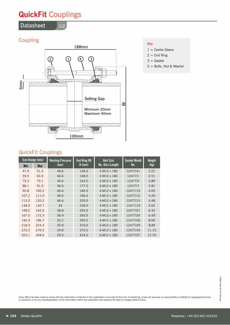
164164 Helden QuickFit Telephone: +44 (0)1462 443322
DR
1078
7_03
_03_
2020
_IS
SU
E 7
1/2
QuickFit CouplingsDatasheet
Every effort has been made to ensure that the information contained in this publication is accurate at the time of publishing. Crane Ltd assumes no responsibility or liability for typographical errors or omissions or for any misinterpretation of the information within the publication and reserves the right to change without notice.
Size Range (mm) Working Pressure (bar)
End Ring OD B (mm)
Bolt Size No.-Dia x Length
Gasket Mould No.
Weight (kg)Min Max
47.9 51.3 46.6 136.0 2-M12 x 180 12477/41 2.22
59.5 63.3 46.6 148.0 2-M12 x 180 12477/1 2.51
75.3 79.1 46.6 164.0 2-M12 x 180 12477/5 2.89
88.1 91.9 46.6 177.0 4-M12 x 180 12477/7 3.81
95.8 100.2 46.6 185.0 4-M12 x 180 12477/10 4.00
107.2 111.0 46.6 196.0 4-M12 x 180 12477/12 4.26
113.5 120.2 46.6 205.0 4-M12 x 180 12477/15 4.48
138.9 142.7 44 228.0 4-M12 x 180 12477/19 5.02
158.2 162.0 38.8 254.0 4-M12 x 180 12477/21 6.32
167.5 172.3 36.9 264.0 4-M12 x 180 12477/24 6.59
192.9 196.7 32.2 292.0 4-M12 x 180 12477/26 8.06
218.3 224.4 35.8 319.0 4-M12 x 180 12477/29 8.89
272.2 276.5 34.8 372.0 6-M12 x 180 12477/34 11.15
323.1 328.6 29.5 424.0 6-M12 x 180 12477/37 12.76
12 4 3
Coupling
QuickFit Couplings
Key
1 = Centre Sleeve
2 = End Ring
3 = Gasket
5 = Bolts, Nut & Washer
Minimum 20mmMaximum 40mm

165
Working Pressure Rating
For Water / Wastewater applications as detailed in QuickFit Coupling Technical Data Table.
Gas 6 bar
Vacuum Pressure
Capable of accommodating a vacuum pressure of -0.7 bar
Site Test Pressure
1.5 times working pressure for short duration (2 hours)
Angularity
Couplings 6°
Bolt Torque/Spanner
M12; Torque 55-65Nm on every bolt
Spanner size A/F 19mm
Temperature Rating of Product
EPDM -20°C to +90°C
Nitrile -20°C to +90°C
For use on applications with fluctuating and / or elevated temperatures (> 60°C) may require regular maintenance to re-tighten the bolts and must be included in any maintenance schedule.
End Load Due to Internal Pressure
QuickFit DOES NOT resist end load due to the internal pressure - adequate external restraint must be provided to prevent pipe pull out.
Approvals
The following water contact materials used in QuickFit are approved for use with potable water:-
Rilsan Nylon 11:➤ WRAS, AS/NZS 4020, DVGW, W270, ACS & KIWA
EPDM Gaskets:➤ WRAS, AS/NZS 4020
In addition to the above, QuickFit range as a finished product has KIWA certification verifying that the above products comply with the requirements of the Water Supply (Water Fittings) Regulations for England and Wales 1999, the Water Byelaws 2000, Scotland and the Water Regulations Northern Ireland.
Centre Sleeve & End Rings
Ductile Iron to BS EN1563: Symbol EN-GJS-450-10
Gaskets
EPDM to BS EN681-1, TYPE WA, WC
Nitrile to BS EN682:Type G
Other grades are available - contact Helden for details
Coatings
Centre Sleeve & End Rings:➤ Rilsan Nylon 11 to WIS 4-52-01 Part 1
Other coatings available: Scotchkote, Galvanised
Tee bolts, CDX Bolts & Nuts:➤ Sheraplex to WIS 4-52-03
Tee Bolts/Bolts
Standard - Steel to BS EN ISO 898-1: property class 4.8
Option - Stainless Steel to BS EN ISO 3506-1: grade A4 property class 50
Nuts
Standard - Steel to BS EN 20898-2: property class 8
Option - Stainless Steel to BS EN ISO 3506-2: grade A4 property class 80
Washers
Stainless Steel to BS1449:PART 2: GRADE 304S15
Materials & Relevant Standards
Technical Information
Helden QuickFitwww.helden-web.com
DR
1078
7_03
_03_
2020
_IS
SU
E 7
2/2
QuickFit CouplingsDatasheet
Every effort has been made to ensure that the information contained in this publication is accurate at the time of publishing. Crane Ltd assumes no responsibility or liability for typographical errors or omissions or for any misinterpretation of the information within the publication and reserves the right to change without notice.
Couplings &
Flange Adaptors
Dedicated

166166 Helden QuickFit Telephone: +44 (0)1462 443322
DR
1078
7_03
_03_
2020
_IS
SU
E 7
1/2
QuickFit Flange Adaptors - Standard CastDatasheet
Every effort has been made to ensure that the information contained in this publication is accurate at the time of publishing. Crane Ltd assumes no responsibility or liability for typographical errors or omissions or for any misinterpretation of the information within the publication and reserves the right to change without notice.
Key
1 = Centre Sleeve
2 = End Ring
3 = Gasket
5 = Bolts, Nut & Washer
Size Range (mm) Flange Detail (mm) Overall Length A (mm)
S Bore S (mm)
Flange Drilling
Bolt Size No.-Dia x Length
Gasket Mould No.
Weight (kg)Min Max Flange OD (B) Flange Thickness (T)
59.5 63.3 161.0 17.0 125.0 50.0 50 PN10,16,25,40 2-M12 x 115 12477/1 2.28
75.3 79.1 181.0 17.0 125.0 65.0 65 PN10,16 2-M12 x 115 12477/5 2.66
88.1 91.9 196.0 17.0 126.0 80.0 80 PN10,16,25,40 4-M12 x 115 12477/7 3.48
95.8 100.2 196.0 17.0 126.0 80.0 80 PN10,16,25,40 4-M12 x 115 12477/10 3.59
107.2 111.0 216.0 17.0 126.0 100.0 100 PN10,16 4-M12 x 115 12477/12 3.91
113.5 120.2 216.0 17.0 126.0 100.0 100 PN10,16 4-M12 x 115 12477/15 4.03
138.9 142.7 246.0 17.0 126.0 125.0 125 PN10,16 4-M12 x 115 12477/19 4.71
158.2 162.0 284.0 17.0 126.0 150.0 150 PN10,16 4-M12 x 115 12477/21 5.76
167.5 172.3 284.0 17.0 126.0 150.0 150 PN10,16 4-M12 x 115 12477/24 5.87
192.9 196.7 339.0 20.0 126.0 199.0 200 PN10,16 4-M12 x 115 12477/26 8.43
218.3 224.4 339.0 20.0 126.0 200.0 200 PN10,16 4-M12 x 115 12477/29 8.49
272.2 276.5 405.0 20.0 129.0 250.0 250 PN10,16 6-M12 x 115 12477/34 11.38
323.1 328.6 455.0 20.0 129.0 300.0 300 PN10,16 6-M12 x 115 12477/37 13.04
Flange Adaptor
QuickFit Flange Adaptors
Minimum 25mmMaximum 45mm
1 3 42

167
Working Pressure Rating
Water 16 bar
Gas 6 bar
Vacuum Pressure
Capable of accommodating a vacuum pressure of -0.7 bar
Site Test Pressure
1.5 times working pressure for short duration (2 hours)
Angularity
Flange Adaptor 3°
Bolt Torque/Spanner
M12; Torque 55-65Nm on every bolt
Spanner size A/F 19mm
Temperature Rating of Product
EPDM -20°C to +90°C
Nitrile -20°C to +90°C
For use on applications with fluctuating and / or elevated temperatures (> 60°C) may require regular maintenance to re-tighten the bolts and must be included in any maintenance schedule.
Tied Flange Adaptor
The design of the new QuickFit flange adaptor is such that there is sufficient clearance to allow tie rods (used to restrain them) to pass over without the need for notching
End Load Due to Internal Pressure
QuickFit DOES NOT resist end load due to the internal pressure - adequate external restraint must be provided to prevent pipe pull out.
Approvals
The following water contact materials used in QuickFit are approved for use with potable water:-
Rilsan Nylon 11:➤ WRAS, AS/NZS 4020, DVGW, W270, ACS & KIWA
EPDM Gaskets:➤ WRAS, AS/NZS 4020
In addition to the above, QuickFit range as a finished product has KIWA certification verifying that the above products comply with the requirements of the Water Supply (Water Fittings) Regulations for England and Wales 1999, the Water Byelaws 2000, Scotland and the Water Regulations Northern Ireland.
Centre Sleeve & End Rings
Ductile Iron to BS EN1563: Symbol EN-GJS-450-10
Gaskets
EPDM to BS EN681-1, TYPE WA, WC
Nitrile to BS EN682:Type G
Other grades are available - contact Helden for details
Coatings
Flange Adaptor Body & End Ring:➤ Rilsan Nylon 11 to WIS 4-52-01 Part 1
Other coatings available: Scotchkote, Galvanised
Tee bolts, CDX Bolts & Nuts:➤ Sheraplex to WIS 4-52-03
Tee Bolts/Bolts
Standard - Steel to BS EN ISO 898-1: property class 4.8
Option - Stainless Steel to BS EN ISO 3506-1: grade A4 property class 50
Nuts
Standard - Steel to BS EN 20898-2: property class 8
Option - Stainless Steel to BS EN ISO 3506-2: grade A4 property class 80
Washers
Stainless Steel to BS1449:PART 2: GRADE 304S15
Materials & Relevant Standards
Technical Information
Helden QuickFitwww.helden-web.com
DR
1078
7_03
_03_
2020
_IS
SU
E 7
2/2
QuickFit Flange Adaptors - Standard CastDatasheet
Every effort has been made to ensure that the information contained in this publication is accurate at the time of publishing. Crane Ltd assumes no responsibility or liability for typographical errors or omissions or for any misinterpretation of the information within the publication and reserves the right to change without notice.
Couplings &
Flange Adaptors
Dedicated

168168 Helden QuickFit Telephone: +44 (0)1462 443322
DR
1078
7_03
_03_
2020
_IS
SU
E 7
1/4
QuickFit Flange Adaptors - Fabricated (Standard Drillings)Datasheet
Every effort has been made to ensure that the information contained in this publication is accurate at the time of publishing. Crane Ltd assumes no responsibility or liability for typographical errors or omissions or for any misinterpretation of the information within the publication and reserves the right to change without notice.
Flange AdaptorKey
1 = Body
2 = End Ring
3 = Gasket
5 = Studs
Fabricated QuickFit Flange Adaptors -Standard Drillings Available
Every effort has been made to ensure that the information contained in this publication is accurate at the time of publishing. Crane Ltd assumes no responsibility or liability for typographical errors or omissions or for any misinterpretation of the information within the publication and reserves the right to change without notice.
Flange Details
BS EN 1092
ODNom (mm)
PN2.5 PN6 PN10 PN16 PN25 PN40
Y/N Tied? Y/N Tied? Y/N Tied? Y/N Tied? Y/N Tied? Y/N Tied?059.5 - 063.3 50 ✓ 7 ✓ 7
075.3 - 079.1 65 ✓ 7 ✓ 7 ✓ ✓ ✓ ✓
088.1 - 091.9 80 ✓ 7 ✓ 7
095.8 - 100.2 80 ✓ 7 ✓ 7
107.2 - 111.0 100 ✓ ✓ ✓ ✓ ✓ ✓ ✓ ✓
113.5 - 120.2 100 ✓ 7 ✓ 7 ✓ ✓ ✓ ✓
138.9 - 142.7 125 ✓ 7 ✓ 7 ✓ ✓ ✓ ✓
158.2 - 162.0 150 ✓ 7 ✓ 7 ✓ ✓ 7 7
167.5 - 172.3 150 ✓ 7 ✓ 7 ✓ ✓ 7 7
192.2 - 196.7 200 ✓ ✓ ✓ ✓ ✓ ✓ 7 7
218.3 - 224.4 200 ✓ 7 ✓ 7 ✓ ✓ 7 7
272.2 - 276.5 250 ✓ 7 ✓ 7 ✓ ✓ 7 7
323.1 - 328.6 300 ✓ 7 ✓ 7 7 7 7 7
Flange Details
BS 10:1962 Table
ODNom (”)
A D E F H J
Y/N Tied? Y/N Tied? Y/N Tied? Y/N Tied? Y/N Tied? Y/N Tied?059.5 - 063.3 2 ✓ 7 ✓ 7 ✓ 7 ✓ ✓ ✓ ✓ 7 7
075.3 - 079.1 2.5 ✓ 7 ✓ 7 ✓ 7 ✓ ✓ ✓ ✓ 7 7
088.1 - 091.9 3 ✓ 7 ✓ 7 ✓ 7 ✓ ✓ ✓ ✓ 7 7
095.8 - 100.2 3 ✓ 7 ✓ 7 ✓ 7 ✓ ✓ ✓ ✓ 7 7
107.2 - 111.0 4 ✓ ✓ ✓ ✓ ✓ ✓ ✓ ✓ ✓ ✓ 7 7
113.5 - 120.2 4 ✓ ✓ ✓ ✓ ✓ ✓ ✓ ✓ ✓ ✓ 7 7
138.9 - 142.7 5 ✓ ✓ ✓ ✓ ✓ ✓ ✓ ✓ ✓ ✓ 7 7
158.2 - 162.0 6 ✓ ✓ ✓ ✓ ✓ ✓ ✓ ✓ ✓ ✓ 7 7
167.5 - 172.3 6 ✓ 7 ✓ 7 ✓ 7 ✓ ✓ ✓ ✓ 7 7
192.2 - 196.7 8 ✓ ✓ ✓ ✓ ✓ ✓ ✓ ✓ 7 7 7 7
218.3 - 224.4 8 ✓ ✓ ✓ ✓ ✓ 7 ✓ ✓ ✓ ✓ 7 7
272.2 - 276.5 10 7 7 7 7 ✓ ✓ ✓ ✓ ✓ ✓ 7 7
323.1 - 328.6 12 7 7 ✓ ✓ ✓ ✓ 7 7 7 7 7 7
= Denotes standard cast product
Y/N = ✓= Can make QFFA with this drilling
7= Cannot make QFFA with this drilling
Tied? = ✓= Can offer as tied FA – notching not required
7= Cannot offer as tied FA – bolts clash with end ring – cannot notch
1 3 42

169
Working Pressure Rating
Water working pressure in accordance with the flange rating
Gas 6 bar
Vacuum Pressure
Capable of accommodating a vacuum pressure of -0.7 bar
Site Test Pressure
1.5 times working pressure for short duration (2 hours)
Angularity
Flange Adaptor 3°
Bolt Torque/Spanner
M12; Torque 55-65Nm on every bolt
Spanner size A/F 19mm
Temperature Rating of Product
EPDM -20°C to +90°C
Nitrile -20°C to +90°C
For use on applications with fluctuating and / or elevated temperatures (> 60°C) may require regular maintenance to re-tighten the bolts and must be included in any maintenance schedule.
Approvals
The following water contact materials used in QuickFit are approved for use with potable water:-
Rilsan Nylon 11:➤ WRAS, AS/NZS 4020, DVGW, W270, ACS & KIWA
EPDM Gaskets:➤ WRAS, AS/NZS 4020
Flange
Steel to BS EN 10025-2: Grade S275JR
Sleeve Options:
➤ Steel Tube to BS EN 10216-1: Grade P265TRI ➤ Steel Tube to BS EN 10217-1:➤ Steel BS EN10025-2: Grade S275JR
End Rings
Ductile Iron to BS EN1563: Symbol EN GJS-450-10
Gaskets
EPDM to BS EN681-1, TYPE WA, WC
Nitrile to BS EN682:Type G
Other grades are available - contact Helden for details
Tee Bolts/Bolts
Standard - Steel to BS EN ISO 898-1: property class 4.8
Option - Stainless Steel to BS EN ISO 3506-1: grade A4 property class 50
Nuts
Steel to BS EN 20898-2: property class 8
Option - Stainless Steel to BS EN ISO 3506-2: grade A4 property class 80
Washers
Stainless Steel to BS1449:PART 2: GRADE 304S15
Materials & Relevant Standards
Technical Information
Helden QuickFitwww.helden-web.com
DR
1078
7_03
_03_
2020
_IS
SU
E 7
2/4
QuickFit Flange Adaptors - Fabricated (Standard Drillings)Datasheet
Every effort has been made to ensure that the information contained in this publication is accurate at the time of publishing. Crane Ltd assumes no responsibility or liability for typographical errors or omissions or for any misinterpretation of the information within the publication and reserves the right to change without notice.
Couplings &
Flange Adaptors
Dedicated

170170 Helden QuickFit Telephone: +44 (0)1462 443322
DR
1078
7_03
_03_
2020
_IS
SU
E 7
3/4
QuickFit Flange Adaptors - Fabricated (Standard Drillings)Datasheet
Every effort has been made to ensure that the information contained in this publication is accurate at the time of publishing. Crane Ltd assumes no responsibility or liability for typographical errors or omissions or for any misinterpretation of the information within the publication and reserves the right to change without notice.
Key
1 = Body
2 = End Ring
3 = Gasket
5 = Studs
Flange Adaptor
Fabricated QuickFit Flange Adaptors -Standard Drillings Available
Flange Details ASME/ANSI B16.1/ASME B16.5 Class
OD Nom - (”)125 150 250 300
Y/N Tied? Y/N Tied? Y/N Tied? Y/N Tied?059.5 - 063.3 2 ✓ 7 ✓ 7 ✓ ✓ 7 7
075.3 - 079.1 2.5 ✓ ✓ ✓ ✓ ✓ ✓ 7 7
088.1 - 091.9 3 ✓ ✓ ✓ ✓ ✓ ✓ 7 7
095.8 - 100.2 3 ✓ 7 ✓ 7 ✓ ✓ 7 7
107.2 - 111.0 4 ✓ ✓ ✓ ✓ ✓ ✓ 7 7
113.5 - 120.2 4 ✓ ✓ ✓ ✓ ✓ ✓ 7 7
138.9 - 142.7 5 ✓ ✓ ✓ ✓ ✓ ✓ 7 7
158.2 - 162.0 6 ✓ ✓ ✓ ✓ ✓ ✓ 7 7
167.5 - 172.3 6 ✓ ✓ ✓ ✓ ✓ ✓ 7 7
192.2 - 196.7 8 ✓ ✓ ✓ ✓ 7 7 7 7
218.3 - 224.4 8 ✓ ✓ ✓ ✓ ✓ ✓ 7 7
272.2 - 276.5 10 ✓ ✓ ✓ ✓ 7 7 7 7
323.1 - 328.6 12 ✓ ✓ ✓ ✓ 7 7 7 7
Flange Details AWWA C207 Class
OD Nom - (”)B D E F
Y/N Tied? Y/N Tied? Y/N Tied? Y/N Tied?107.2 - 111.0 4 ✓ ✓ ✓ ✓ ✓ ✓ ✓ ✓
113.5 - 120.2 4 ✓ ✓ ✓ ✓ ✓ ✓ ✓ ✓
138.9 - 142.7 5 ✓ ✓ ✓ ✓ ✓ ✓ ✓ ✓
158.2 - 162.0 6 ✓ ✓ ✓ ✓ ✓ ✓ ✓ ✓
167.5 - 172.3 6 ✓ ✓ ✓ ✓ ✓ ✓ ✓ ✓
192.2 - 196.7 8 ✓ ✓ ✓ ✓ ✓ ✓ ✓ ✓
218.3 - 224.4 8 ✓ ✓ ✓ ✓ ✓ ✓ ✓ ✓
272.2 - 276.5 10 ✓ ✓ ✓ ✓ ✓ ✓ 7 7
323.1 - 328.6 12 ✓ ✓ ✓ ✓ ✓ ✓ 7 7
Flange Details AS2129 Table
OD Nom - (mm)A C D E
Y/N Tied? Y/N Tied? Y/N Tied? Y/N Tied?059.5 - 063.3 50 ✓ 7 ✓ 7 ✓ 7 ✓ 7
075.3 - 079.1 65 ✓ 7 ✓ 7 ✓ 7 ✓ 7
088.1 - 091.9 80 ✓ 7 ✓ 7 ✓ 7 ✓ 7
095.8 - 100.2 80 ✓ 7 ✓ 7 ✓ 7 ✓ 7
107.2 - 111.0 100 ✓ ✓ ✓ ✓ ✓ ✓ ✓ ✓
113.5 - 120.2 100 ✓ 7 ✓ 7 ✓ 7 ✓ 7
138.9 - 142.7 125 ✓ ✓ ✓ ✓ ✓ ✓ ✓ ✓
158.2 - 162.0 150 ✓ ✓ ✓ ✓ ✓ ✓ ✓ ✓
167.5 - 172.3 150 ✓ 7 ✓ 7 ✓ 7 ✓ 7
192.2 - 196.7 200 ✓ ✓ ✓ ✓ ✓ ✓ ✓ ✓
218.3 - 224.4 200 ✓ 7 ✓ 7 ✓ 7 ✓ 7
272.2 - 276.5 250 7 7 7 7 7 7 ✓ ✓
323.1 - 328.6 300 7 7 ✓ ✓ ✓ ✓ ✓ 7
Y/N = ✓= Can make QFFA with this drilling
7= Cannot make QFFA with this drilling
Tied? = ✓= Can offer as tied FA – notching not required
7= Cannot offer as tied FA – bolts clash with end ring – cannot notch
1 3 42

171
Working Pressure Rating
Water working pressure in accordance with the flange rating
Gas 6 bar
Vacuum Pressure
Capable of accommodating a vacuum pressure of -0.7 bar
Site Test Pressure
1.5 times working pressure for short duration (2 hours)
Angularity
Flange Adaptor 3°
Bolt Torque/Spanner
M12; Torque 55-65Nm on every bolt
Spanner size A/F 19mm
Temperature Rating of Product
EPDM -20°C to +90°C
Nitrile -20°C to +90°C
For use on applications with fluctuating and / or elevated temperatures (> 60°C) may require regular maintenance to re-tighten the bolts and must be included in any maintenance schedule.
Approvals
The following water contact materials used in QuickFit are approved for use with potable water:-
Rilsan Nylon 11:➤ WRAS, AS/NZS 4020, DVGW, W270, ACS & KIWA
EPDM Gaskets:➤ WRAS, AS/NZS 4020
Flange
Steel to BS EN 10025-2: Grade S275JR
Sleeve Options:
➤ Steel Tube to BS EN 10216-1: Grade P265TRI ➤ Steel Tube to BS EN 10217-1:➤ Steel BS EN10025-2: Grade S275JR
End Rings
Ductile Iron to BS EN1563: Symbol EN GJS-450-10
Gaskets
EPDM to BS EN681-1, TYPE WA, WC
Nitrile to BS EN682:Type G
Other grades are available - contact Helden for details
Tee Bolts/Bolts
Standard - Steel to BS EN ISO 898-1: property class 4.8
Option - Stainless Steel to BS EN ISO 3506-1: grade A4 property class 50
Nuts
Steel to BS EN 20898-2: property class 8
Option - Stainless Steel to BS EN ISO 3506-2: grade A4 property class 80
Washers
Stainless Steel to BS1449:PART 2: GRADE 304S15
Materials & Relevant Standards
Technical Information
Helden QuickFitwww.helden-web.com
DR
1078
7_03
_03_
2020
_IS
SU
E 7
4/4
QuickFit Flange Adaptors - Fabricated (Standard Drillings)Datasheet
Every effort has been made to ensure that the information contained in this publication is accurate at the time of publishing. Crane Ltd assumes no responsibility or liability for typographical errors or omissions or for any misinterpretation of the information within the publication and reserves the right to change without notice.
Couplings &
Flange Adaptors
Dedicated

Helden Large Diameter Telephone: +44 (0)1462 443322
United UtilitiesLarge Diameter Couplings
United Kingdom - Liverpool
Project
Catastrophic mains burst in Huyton,
Liverpool flooded many homes in
the area. Helden supplied a pair of
1048mm x 1084mm ductile to iron
cast stepped couplings to enable
emergency repairs to be made quickly
to the damaged section of pipe.
Client
United Utilities
Contractor
Enterprise
Crane BS&U are solely the provider of products and have no direct influence on, or take any responsibility for any working practices employed or depicted in the images enclosed to install such products.
172172
Helden Marinewww.helden-web.com 173
Marine
Sim
ple
Couplings & Flange AdaptorsApproved & Pre-assembled Fittings

174174
Marine Couplings & Flange AdaptorsOverview
Pipe Materials
Helden Marine Telephone: +44 (0)1462 443322
Pre-assembled & Approved Fittings for Marine Applications
The proven Marine range has been designed and
approved for use in marine environments. Alongside all
the features and benefits of Helden’s standard range,
the marine fittings have attained international seals
of approval from prominent marine authorities including
American Bureau of Shipping (ABS) and Bureau Veritas.
Allowing for MovementIn marine installations, pipework is often anchored to the
frame of the vessel so particular care must be taken to allow
for the movement of pipework as the ship travels. Marine
couplings and flange adaptors aim to relieve the strain and
stress that pipework may experience on board.
Enhanced Design FeaturesThe Marine range has enhanced design features including
a galvanized finish, nitrile gasket and a locating plug which
prevents coupling creep caused by repeated pipe movement.
The removable locating plug ensures the coupling can
slide fully over the pipe ends to ease installation and when
installed, they engage between the pipe ends preventing the
coupling moving beyond fixed limits.
Removable locating plug.
Typical Marine Applications
➤ Deck wash
➤ Sanitary supply
➤ Domestic fresh water
➤ Oil fuel transfer lines
➤ Scupper and
discharge lines
➤ Cargo oil lines in tankers
➤ Hold-sounding pipes
➤ Inert gas
➤ Bilge lines
➤ Ballast lines
➤ Fuel and lubricating oil
➤ Filling and vent pipes
➤ Fresh and salt
water systems
Note: Use on the above systems varies depending on the respective Marine Approval body; please consult with relevant one before using.

Helden Marinewww.helden-web.com 175
Marine Couplings & Flange AdaptorsProduct Design Benefits
DR
1078
7_03
_03_
2020
_IS
SU
E 7
Corrosion Protection
Fixed Fitting
Reduces Noise
Simple to Fit
Available as standard with galvanised body and
bolts for the most arduous conditions.
Removable locating plug prevents coupling creep
caused by continuous vibrations found onboard
along with movement from temperature variations.
Captive, non-rotating bolt head requires single
spanner/ torque wrench to make installation simple
with one bolt size (M12) across range and one bolt
torque (55-65Nm) for all pipe materials.
Resilient gasket helps absorb both noise
and vibration.
➤ The Marine design allows angular movement, which caters
for minor misalignment and pipe deflection with couplings
up to 6º and flange adaptors to 3º. Vessel movement can be
accommodated without using specialised fittings.
➤ Marine couplings are capable of accommodating 10mm
of expansion/contraction per fitting, flange adaptors 5mm
which reduces the need for supplementary expansion joints
or bellows.
➤ Marine products up to DN300 are pre-assembled allowing
quick and efficient installation, without the
need for dismantling, even in the
most difficult of conditions.
Customer Benefits
Couplings &
Flange Adaptors
Dedicated

176176
1/2
Marine CouplingsDatasheet
Every effort has been made to ensure that the information contained in this publication is accurate at the time of publishing. Crane Ltd assumes no responsibility or liability for typographical errors or omissions or for any misinterpretation of the information within the publication and reserves the right to change without notice.
Helden Marine Telephone: +44 (0)1462 443322
DR
1078
7_03
_03_
2020
_IS
SU
E 7
12 4 3
Pipe OD(mm)
W.P.(bar)
No.Plugs
End Ring ODB (mm) L (mm) Bolt Size
No.-Dia x Length
Setting gap Gasket Mould No.
Weight(kg)Min Max
047.9 - 051.3 46.6 1 Plug 136 188 2-M12 x 180 30 40 12477/41 2.22
059.5 - 063.3 46.6 1 Plug 148 188 2-M12 x 180 30 40 12477/1 2.51
075.3 - 079.1 46.6 1 Plug 164 188 2-M12 x 180 30 40 12477/5 2.89
088.1 - 091.9 46.6 1 Plug 177 188 4-M12 x 180 30 40 12477/7 3.81
107.2 - 111.0 46.6 1 Plug 196 188 4-M12 x 180 30 40 12477/12 4.26
113.5 - 120.2 46.6 1 Plug 205 188 4-M12 x 180 30 40 12477/15 4.48
138.9 - 142.7 44.0 1 Plug 228 188 4-M12 x 180 30 40 12477/19 5.02
158.2 - 162.0 38.8 1 Plug 254 188 4-M12 x 180 30 40 12477/21 6.32
167.5 - 172.3 36.9 1 Plug 264 188 4-M12 x 180 30 40 12477/24 6.59
192.2 - 196.7 32.2 2 Plug 292 188 4-M12 x 180 30 40 12477/26 8.06
218.3 - 224.4 35.8 2 Plug 319 188 4-M12 x 180 30 40 12477/29 8.89
272.2 - 276.5 34.8 2 Plug 372 188 6-M12 x 180 30 40 12477/34 11.15
323.1 - 328.6 29.5 2 Plug 424 188 6-M12 x 180 30 40 12477/37 12.76
355.6 23.2 2 Plug 446 243 6-M12 x 235 35 50 J51LS 19.60
406.4 27.2 2 Plug 497 243 8-M12 x 235 35 50 J53LS 22.40
457.0 24.2 3 Plug 548 243 8-M12 x 235 35 50 J55LS 24.90
508.0 27.4 3 Plug 598 243 10-M12 x 235 35 50 J57LS 27.80
560.0 24.9 3 Plug 649 243 10-M12 x 235 35 50 J59LS 30.20
610.0 22.9 3 Plug 700 243 10-M12 x 235 35 50 J60LS 32.70
660.0 24.3 3 Plug 751 243 12-M12 x 235 35 50 J61LS 35.50
711.0 22.6 3 Plug 802 243 12-M12 x 235 35 50 J63LS 38.00
Note: The above table is for steel pipe sizes - contact Helden for other pipe materials.
Every effort has been made to ensure that the information contained in this publication is accurate at the time of publishing. Crane Ltd assumes no responsibility or liability for typographical errors or omissions or for any misinterpretation of the information within the publication and reserves the right to change without notice.
Coupling
Marine Couplings
Key
1 = Centre Sleeve
2 = End Ring
3 = Gasket
5 = Bolts, Nut & Washer

177
Working Pressure Rating
For Water / Other Fluid applications as detailed in Marine Coupling Technical Data Table.
Gas 6 bar
Vacuum Pressure
Capable of accommodating a vacuum pressure of -0.7 bar.
Site Test Pressure
1.5 times working pressure for short duration (2 hours).
Angularity
Couplings 6°
Bolt Torque/Spanner
M12; Torque 55-65Nm on every bolt
Spanner size A/F 19mm
Temperature Rating of Product
EPDM -20°C to +90°C
Nitrile -20°C to +90°C
For use on applications with fluctuating and / or elevated temperatures (> 60°C) may require regular maintenance to re-tighten the bolts and must be included in any maintenance schedule.
End Load Due to Internal Pressure
Marine couplings / stepped couplings DO NOT resist end load due to the internal pressure - adequate external restraint must be provided to prevent pipe pull out.
Approvals
Helden marine couplings have the following shipping approvals:-➤ ABS; Certificate of Design Assessments➤ Bureau Veritas; Type Approval Certificate
Centre Sleeve & End Ring Options:
➤ Ductile Iron to BS EN1563 Symbol EN-GJS-450-10➤ Steel to BS EN10025-2 Grade S275JR
Gaskets
EPDM to BS EN681-1, TYPE WA, WC
Nitrile to BS EN682 Type G
Other grades are available - contact Helden for details
Coating
Centre sleeve, End Ring, Bolts & Nuts:➤ Galvanised
Locating Plug:➤ Zn10
Bolts
Steel to BS EN ISO 898-1 property class 4.8
Nuts
Steel to BS EN 20898-2 property class 8
Washer
Stainless Steel to BS1449:Part 2 Grade 304S15
Locating Plugs
Steel to BS970: Part 3: Grade 230M07
Materials & Relevant Standards
Technical Information
Helden Marinewww.helden-web.com
2/2
Marine CouplingsDatasheet
Every effort has been made to ensure that the information contained in this publication is accurate at the time of publishing. Crane Ltd assumes no responsibility or liability for typographical errors or omissions or for any misinterpretation of the information within the publication and reserves the right to change without notice. D
R10
787_
03_0
3_20
20_I
SS
UE
7
Options
NBR Gasket without removable plugs
EPDM Gasket with removable plugs
EPDM Gasket without removable plugs
Flange adaptors available on request
Couplings &
Flange Adaptors
Dedicated

Helden Marine Telephone: +44 (0)1462 443322
‘Dunfords’ Bulk CarrierMarine Couplings
United Kingdom
Project
‘Dunfords‘, a 30,000 tonne bulk carrier
is equipped with marine couplings in the
bilge & ballast sections of the vessel.
Crane BS&U are solely the provider of products and have no direct influence on, or take any responsibility for any working practices employed or depicted in the images enclosed to install such products.
178178

179Helden Wall Couplings
Sp
ecia
list
Wall CouplingsThe Perfect Through Wall Connection

180180
Wall CouplingsOverview
Helden Wall Couplings Telephone: +44 (0)1462 443322
Old PracticeThe normal procedure for passing pipes through walls
is to leave a substantial cut-out in the wall during the original
concrete pouring process. Later, the contractor will pass
a ‘puddle pipe’ through the cut-out, and build an intricate
‘letter-box’ shutter around it. New concrete is then poured
into the void to encapsulate the puddle pipe. Not only
is this a time consuming process, but very often the
puddle pipe moves with the pour and settles to a less than
suitable alignment.
Easier InstallationBy utilising a Helden wall coupling which is held rigidly
between the shutters, the ‘boxing out’ process is eliminated.
This means that pouring the wall is a simplified and is a
single step process. It also guarantees that leak paths, which
are inevitably set up when new concrete is poured onto old,
are completely eliminated.
Using a standard Type 1 Helden wall coupling gives a
versatile coupling either side of the wall where pipes can
either be passed through or inserted into each side. This
system allows for misalignment or angular deflection of up
to 3º on each side of the wall. In addition, the use of a
Helden wall coupling ensures that, on the outside of the
structure, the first ‘rocker’ or settlement coupling is built
into the shear face of the wall – exactly where it is required.
It also means that only one further versatile coupling is needed
to form the settlement ‘rocker’ instead of two. Consequently
the installed cost can be drastically reduced, particularly
where a large number of through the wall joints appear on a
building, for instance in a gravity treatment works.
Structural Strength of Concrete WallHelden strongly recommends the user ensures that the wall
is structurally capable of withstanding the resultant forces
induced by the system working pressure and any other
related influence.
The Perfect Solution for Passing Pipes Through Walls

Flexible FitCorrosion Protection
Using a standard Type 1 Helden wall coupling gives a
flexible coupling either side of the wall where pipes can
either be passed through or inserted into
each side. This allows for slight misalignment or
angular deflection on each side of the wall.
Metal components are coated with Rilsan Nylon 11
which is WRAS approved for use with potable water
and offers a long term protection to corrosion, impact
and abrasion to ensures continued reliable performance.
181
Wall Couplings - Type 1Product Design Benefits
Helden Wall Couplingswww.helden-web.com
DR
1078
7_03
_03_
2020
_IS
SU
E 7
➤ Straightforward for Civil Contractor to position the pipe.
➤ Easy to secure and prevent movement of the pipe work.
➤ Large formwork panels can be reused as there is no need to
make holes in the shuttering.
➤ No need for a contractor to come back and cast in pipes or
‘make good’ the wall surface after casting pipes.
➤ Ensures good bond between wall and pipe.
➤ Installed cost can be drastically reduced particularly where
a large number of through the wall joints appear on a structure
e.g. in a gravity treatment works.
Customer Benefits
Couplings &
Flange Adaptors
Dedicated

182182
Wall Couplings - Type 1Installation Benefits
Every effort has been made to ensure that the information contained in this publication is accurate at the time of publishing. Crane Ltd assumes no responsibility or liability for typographical errors or omissions or for any misinterpretation of the information within the publication and reserves the right to change without notice.
Helden Wall Couplings Telephone: +44 (0)1462 443322
DR
1078
7_03
_03_
2020
_IS
SU
E 7
Rocker Pipe
Flexible Couplings
Conventional Method with a Puddle Pipe
Helden Wall Coupling Method
In civil projects with reinforced concrete work & pipework it is inevitable that there will be a need to pass a pipe through a concrete wall.
Traditional methods to accommodate pipework are:-
➤ Box Out a section and come back later to cast in pipe.
➤ Cast In the Puddle Pipe, by cutting the formwork to include the pipe
when pouring main wall.
Designed to fit flush between formwork panels and coming with various end configurations to accommodate site conditions, Helden Wall Couplings provide an alternative means of passing a pipe through a wall or slab, that also offers the following advantages.
Rocker Pipe
Helden Wall Couplings
Traditional Methods Disadvantages:
Boxing Out
➤ Make up formwork for box out that will only
have one use.
➤ Never get a good surface finish between old
and new concrete.
➤ Potential weak joint between old and
new concrete.
Casting In ➤ Civil contractor has to position pipe at correct
level and location in wall.
➤ When pouring large walls there is always
a risk of movement of formwork and therefore
cannot always get pipework accurately positioned.
➤ Formwork can only be used for one
concrete pour.
In addition to the problems with casting in the puddle
pipe, two flexible couplings are required along with
a rocker pipe to accommodate ground movement.
Wall Coupling Advantages:
➤ Easier for civil contractor to position pipe at
correct level & location in wall.
➤ Easier to secure wall coupling to prevent risk
of movement during pouring of concrete.
➤ Large formwork panels can be re-used.
➤ No need to come back to wall to cast in pipes.
➤ No need to “make good” wall surface after
pouring secondary concrete around pipe.
In addition, the use of a Helden wall coupling ensures
that, on the outside of the structure, the first ‘rocker’
or settlement coupling is built into the shear face of
the wall – exactly where it is required. It also means
that only one further versatile coupling is needed to
form the settlement ‘rocker’ instead of two.

183183
Body, Centre Sleeve & End Rings:
DN80 to DN300:➤ Carbon steel to BS EN 10025: Grade S275JR➤ Ductile iron to BS EN 1563: Symbol EN-GJS-450-10
DN350 to DN1800:➤ Carbon steel to BS EN 10025: Grade S275JR
Gasket
EPDM to BS EN 681 Part 1 Type WA
Coatings
Wall Coupling Bodies & End Rings: ➤ Standard Rilsan Nylon 11.➤ Optional - Scotchkote 206N fusion bonded epoxy.
Studs:➤ Sheraplex coated to WIS 4-52-03.
Tee Bolts or Stud
Steel to BS EN ISO 898-1: Property Class 4.8
Washers
Stainless Steel to BS 1449: Part 2: Grade 304S15
Approvals
The following water contact materials used in Wall Couplings are approved for use with potable water:-
Rilsan Nylon 11:➤ WRAS, AS/NZS 4020, DVGW, W270, ACS & KIWA
EPDM Gaskets:➤ WRAS, AS/NZS 4020
Helden Wall Couplingswww.helden-web.com
1/1
Wall Coupling VariationsDatasheet
Every effort has been made to ensure that the information contained in this publication is accurate at the time of publishing. Crane Ltd assumes no responsibility or liability for typographical errors or omissions or for any misinterpretation of the information within the publication and reserves the right to change without notice. D
R10
787_
03_0
3_20
20_I
SS
UE
7
The Helden Wall Coupling is available in nine variations:
Type 4 Coupling/Bellmouth
Wall thickness
Type 6 Flange/Plain End
Wall thickness
Type 5 Flange/Flange
Wall thickness
Type 7 Flange/Bellmouth
Wall thickness
Type 9 Man EntryType 8 Harnessing
Wall thickness
Type 1 Coupling/Coupling
Wall thickness
Type 2 Coupling/Plain End
Wall thickness
Type 3 Coupling/Flange
Wall thickness
Helden Wall Couplings are patented products - UK Patent No. 2263323B, US Patent No.5505499.
Materials, Relevant Standards & Approvals
Couplings &
Flange Adaptors
Dedicated

184184
Wall Couplings Order / Enquiry Form
Helden Wall Couplings Telephone: +44 (0)1462 443322184184
DR
1078
7_03
_03_
2020
_IS
SU
E 7
1st End (Please Tick)
Quantity
Nominal Diameter
Wall Thickness
Man Entry Coupling Flanged Plain End Bellmouth Harness
2nd End (Please Tick) Man Entry Coupling Flanged Plain End Bellmouth Harness
Actual OD of Pipe
Pipe Material (Please Tick)Carbon
SteelStainless
Steel D.I. G.R.P Concrete PVC-U
Other please specify
Fluid Flowing
If Flanged, Flange Details
If Harnessed - Stud Details No. Diameter
Working Pressure Puddle Flange (Please Tick) Yes No
Any Other Details
Specifications
Date
Quantity
Fax
TelephoneCustomer Address
Company Name
EmailContact Name
Delivery Date
Customer Reference No. Fab No.
Wall Couplings are a bespoke product and Helden requires the following information to assist with the quotation process. This page can be copied from the brochure or a form fillable PDF is available on the website www.helden-web.com.
Please complete the form and send via email to: [email protected]
Helden strongly recommends the user ensures that the wall is structurally capable of withstanding the resultant forces induced by the system working pressure and any other related influences.
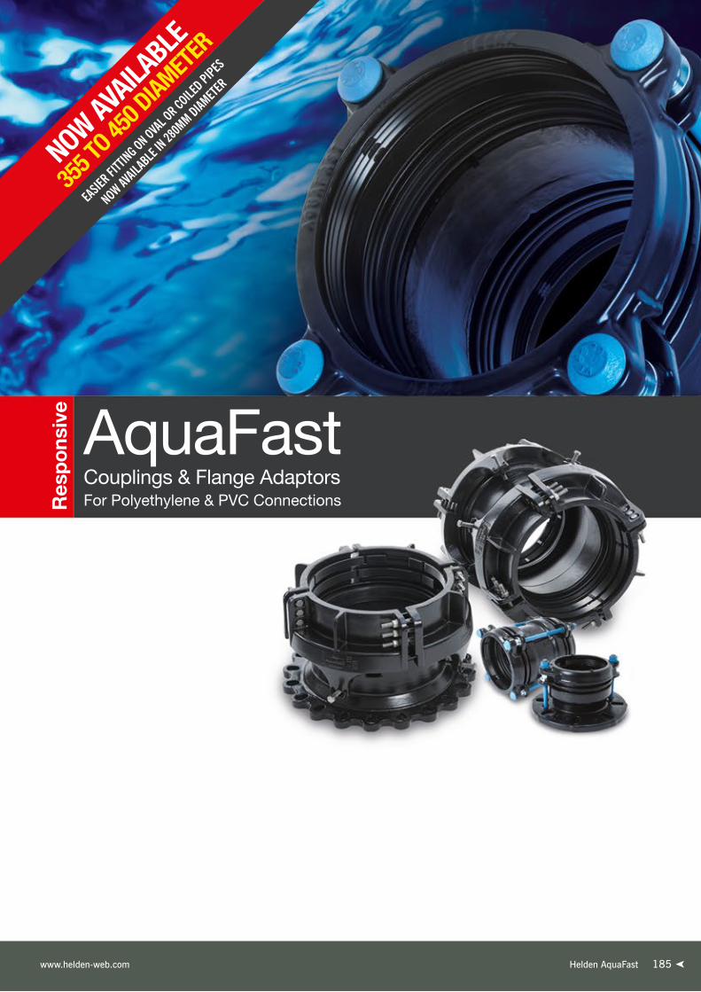
Helden AquaFast www.helden-web.com 185
Res
po
nsiv
e
EASIE
R FITTI
NG ON OVAL OR COILE
D PIPES
NOW AVAIL
ABLE
IN 28
0MM DIAM
ETER
NOW AVAILA
BLE
355 T
O 450 D
IAMETER
Couplings & Flange AdaptorsFor Polyethylene & PVC Connections
AquaFast

AquaFast Couplings & Flange Adaptors 63mm to 315mmOverview
Designed & Engineered to Simplify Polyethylene & PVC Pipe Connections
Effortless InstallationAquaFast’s unique pressure sealing system offers a simple
and reliable solution for connecting Polyethylene & PVC
pipe. With a visual indicator confirming correct fitment
and no special skills or tools required, installing AquaFast
is effortless and quicker than other systems. In addition,
an enhanced gripping mechanism ensures fittings slide
easily into position during installation and provide full end
load restraint in service negating the need for thrust blocks
to prevent pipe pull out.
On-the-spot RepairsFrom start to finish, AquaFast offers benefits
to the installer. Supplied fully assembled
and with an improved design that delays
gripper engagement, AquaFast slides effortlessly over coiled
and oval pipe making it easy for installers to correctly position
the product in narrow trench conditions. Needing no specialist
equipment, simply a “rag and a spanner”, AquaFast can
be installed in all-weather conditions and this, coupled with
a design that does not need a support liner, means the
product is ideal for on-the-spot connections in both new lay
and repair / maintenance work.
Simple JointingUsing only a standard spanner to tighten fewer bolts (only two
per fitting up to 125mm) until the visual indicator confirms
correct fitment AquaFast provides operatives with simple
means of joining PE pipes. The metal-to-metal positive stop
indicating mobilisation of the gripper and gasket sealing
mechanisms removes the need for a torque wrench and
prevents over tightening of the bolts while ensuring optimum
assembly to every time.
Transitional ConnectionsAquaFast couplings & flange adaptors are available
from 63mm to 315mm OD. Designed to work on both
Polyethylene pipe in both PE80 and PE100 material SDR
11, 17/17.6 without a support liner, they can also be used
to connect metric PVC pipe, so AquaFast is ideal for PE/PVC
transitional connections.
Pipe Materials
AquaFast Coupling
AquaFast Flange Adaptor
Triple contact pressure responsive sealing system
Water flow path
Pressure transfer path1
32
186186
Note: All water contact materials approved for use with potable water by WRAS.
Helden AquaFast Telephone: +44 (0)1462 443322

Helden AquaFast www.helden-web.com
AquaFast Couplings & Flange Adaptors 63mm to 315mmProduct Design Benefits
Positive Stop
Simple to Install
Efficient Gasket Sealing Technology
Flexible Flange Drilling
Corrosion Protection Unique Progressive Sealing and Gripping Mechanism
• Correct installation confirmed through visual indication with metal to metal contact between three components (end ring, intermediate ring and sleeve / flange adaptor body).
➤ Ideal for pumped sewage line as no
support liner is required meaning a clear
unrestricted bore. Additionally, Rilsan
abrasion resistance coating accommodates
any solids any solids in sewage.
➤ 50 years design life expectancy is assured
through “Accelerated Aging Testing” that
simulates lifecycle of the product and
Rilsan Nylon coating to metal works for
corrosion protections as well as Sheraplex
coated bolts to WIS 4-52-03.
➤ Rough on site handling accommodated
by Rilsan coating.
➤ Simple onsite installation as the product
comes pre-assembled hence easily slides
over the round pipe. The resistor ensures
gripper remains fully contained in housing
until bolt up is complete.
➤ Reduced number of bolts ensures the
product can be always orientated
to facilitate easy access for bolt up.
➤ Minimal damage to pipe as progressive
gripping system only penetrates sufficiently
to mobilise and load forces from internal
pressure and other loads in PE Pipe.
➤ All water contact materials approved
for use with potable water (WRAS).
➤ Fully restrained fitting, designed to meet
the performance requirements of
WIS4-24-01 Type 2 and ISO17885.
Customer Benefits
• Captive, non-rotating bolts across whole range requiring a single spanner to install.
• Increased bore dimensions and inclusion of resistors to prevent early engagement of gripper ensures AquaFast slides easily over pipe.
• Double ‘O’ ring gasket provides localised high pressure contact points generating efficient seal on pipe surface.
• EPDM (water quality approved) gaskets.
• As standard the flange adaptors are multi drilled to accommodate BS EN 1092-1 PN10 & 16.
• Metal components are coated with Rilsan Nylon 11, which is WRAS approved for use with potable water, and offers long term corrosion protection impact abrasion resistance.
• The nuts & bolts are Sheraplex coated to WIS 4-52-03, which does not gall when re-used and provides long term corrosion protection.
• Patented gasket and gripper design delivers low pressure / load to outside of pipe at initial bolt up eliminating the need for support liner.
• Water transfer path uses internal pressure to increase gasket compression at contact points.
• As system pressure increases the initial gripper engagement with the pipe is enhanced through progressive gripping.
Flange Adaptor
187
DR
1078
7_03
_03_
2020
_IS
SU
E 7
Couplings &
Flange Adaptors
PE Solutions

AquaFast Large Diameter Couplings & Flange Adaptors 355mm to 450mm
Overview
188188
Designed for simplified & dependable trench installation every time.
Simple to InstallAquaFast Large Diameter is quick and easy to install
providing an alternative solution to electrofusion and butt
fusion for all weather and trench conditions. It is a simple
fit and forget installation designed with the minimum
number of bolts and without the need for an internal liner
or expensive trench equipment.
QualityPatents are pending on this innovative product designed and
manufactured under quality systems to BS EN ISO 9001 and
the requirements of UK & European Water Regulations.
Reduced Stock HoldingAnd now just 10 sizes will cover a range of multiple SDR’s
offering a significant reduction in traditional stockholding and
allowing distributors and water utilities opportunity to have
stock to cover all eventualities with off-the-shelf availability.
Innovative Design ideal for Oval PipesHelden has built in a high tolerance for
AquaFast to fit with oval pipes and negating
the need to utilise expensive and time
consuming re-rounding tools.
Fully Corrosion ProtectedWRAS approved black Rilsan Nylon 11 coating provides
excellent corrosion and damage resistance to impact,
abrasion, weathering and chemicals.
Resists Pull-outImproved gripping mechanism offers end load restraint,
resisting pipe pull out, allowing the coupling and flange
adaptor to be suitable for use in climatic regions where
temperatures range from -20°C up to 60°C. AquaFast
has been designed to meet the performance requirements
of BS EN 12842, WIS 4-24-01 Type 2 and ISO 17855
(supersedes ISO 14236.2)
Pipe Material
Helden AquaFast Telephone: +44 (0)1462 443322

AquaFast Large Diameter Couplings & Flange Adaptors 355mm to 450mm
Product Design Benefits
189
Innovative Gripping Corrosion Protection
Centralisation Feature
Correct installation confirmed
through visual indication with
metal to metal contact between
the clamp bands.
Positive Stop
An enhanced gripping mechanism offers Type 2 end
load restraint, resisting pipe pull out.
All cast components are fully coated in Black Rilsan
Nylon 11 which has excellent resistance to impact,
abrasion, weathering and chemicals as well as good
thermal stability and flexibility
to accommodate for rough
site handling.
Centralisation bolts are available
around the product allowing
accurate fitment during installation.
➤ Coupling can be used for repair - no internal restriction
ideal for Sewage applications.
➤ Suitable for connecting pipes in wet/submerged conditions
and above ground applications.
➤ No requirement for a support liner, torque wrench
or any other specialist equipment on site.
➤ Easy to centralise on the pipe.
➤ Reduced stockholding - One product can connect one
nominal pipe size with common SDRs (11, 17/17.6 and 21).
➤ 5O years design life expectancy.
➤ Reusability - No spares required
for multiple installations.
➤ Saves time and effort as Contractor
only has to identify PE pipe nominal size
to select correct fitting.
➤ Fittings comes fully assembled.
➤ Minimal number of bolts to tighten.
Customer Benefits
Helden AquaFast www.helden-web.com
DR
1078
7_03
_03_
2020
_IS
SU
E 7
Couplings &
Flange Adaptors
PE Solutions

Helden AquaFast Telephone: +44 (0)1462 443322
Cambridge to Huntingdon A14AquaFast Couplings up to DN355
United Kingdom - A14
Project
£1.5 billion investment to
decommission a number of
existing potable water and foul
water pipelines which the new
carriageway will be built over and
put in place over 22km of new
pipelines to ensure Anglian Water
can continue to provide services to
its customers.
Client
Anglian Water
Crane BS&U are solely the provider of products and have no direct influence on, or take any responsibility for any working practices employed or depicted in the images enclosed to install such products.
190190

191Helden AquaFast www.helden-web.com 191

Helden AquaFast Telephone: +44 (0)1462 443322
1/2
AquaFast Couplings 63mm to 315mmDatasheet
Every effort has been made to ensure that the information contained in this publication is accurate at the time of publishing. Crane Ltd assumes no responsibility or liability for typographical errors or omissions or for any misinterpretation of the information within the publication and reserves the right to change without notice.
A
BSETTING GAP MAXIMUM GAP
Coupling
AquaFast Couplings
PipeOD
Bolt SizeNo.-Dia x Length
Dimensions (mm) SettingGap (mm)
MaxGap (mm)
Weight(kg)
A max B dia
63 2-M12 x 250 257 144 20 30 4.2
75 2-M12 x 250 257 156 20 30 4.7
90 2-M12 x 250 257 171 20 30 5.3
110 2-M12 x 250 257 192 20 30 6.4
125 2-M12 x 250 257 207 20 30 7.1
140 4-M12 x 250 257 221 20 30 8.4
160 4-M12 x 250 257 241 20 30 9.2
180 4-M12 x 375 382 272 30 50 18.0
200 4-M12 x 375 382 292 30 50 20.4
225 4-M16 x 385 395 328 30 50 24.8
250 6-M16 x 385 395 352 30 50 31.5
280 6-M16 x 385 395 382 30 50 33.6
315 6-M16 x 385 395 417 30 50 38.7
192192
DR
1078
7_03
_03_
2020
_IS
SU
E 7

Helden AquaFast www.helden-web.com
Working Pressure Rating
Water 16 bar
Gas not approved
Vacuum Pressure
Capable of accommodating a vacuum pressure of -0.7 bar
Site Test Pressure
1.5 times working pressure for short duration (2 hours)
Pipe Material / Support Liner
When used on the following pipe materials AquaFast does not need a support liner:-➤ MDPE (PE80) and HPPE (PE100) in SDR ratings 11 & 17➤ MOPVC (16 bar rated pipe)
Angularity
Couplings 1.5°
Bolt Torque/Spanner
Torque; None, simply tighten until correct installation confirmed through visual indication with metal to metal contact between three components (end ring, intermediate ring and sleeve).
Temperature Rating of Product
EPDM -20°C to +40°C
AquaFast is not suitable for use on heating systems with fluctuating temperatures.
End Load Due to Internal Pressure
AquaFast Fully restrained fitting, designed to meet the performance requirements of WIS4-24-01 Type 2 and ISO17885.
Approvals
The following water contact materials used in AquaFast are approved for use with potable water:-
Rilsan Nylon 11:➤ WRAS, AS/NZS 4020, DVGW, W270, ACS & KIWA
EPDM Gaskets:➤ WRAS, AS/NZS 4020
In addition to the above, AquaFast as a finished product has KIWA certification verifying that the above products comply with the requirements of the Water Supply (Water Fittings) Regulations for England and Wales 1999, the Water Byelaws 2000, Scotland and the Water Regulations Northern Ireland.
Centre Sleeve, End Ring & Flange Adaptor Body
Ductile iron to BS EN 1563 Symbol EN-GJS-450-10
Gripper Ring
Ductile iron to BS EN 1563 Symbol EN-GJS-450-10
Intermediate Ring
Ductile iron to BS EN 1563 Symbol EN-GJS-450-10
Gasket (EPDM)
BS EN 681-1 Type WA/BS 6920 hardness to 70 IRHD
Resisters
Free cutting Mild Steel (Grade Y15) Zn3 Zinc coated
Bolts
BS EN ISO 898-1 Property class 8.8
Option - Stainless Steel BS EN ISO3506-1 Grade A2 Property Class 70
(Stainless steel available as special order)
Nuts
Steel to BS EN20898-2 Property Class 8
Option - Stainless Steel BS EN ISO3506-2 Grade A4 Property Class 80
(Stainless steel available as special order)
Washers
BS 1449:Part 2 Grade 304S15
Coatings
Centre Sleeve, End Ring, Flange Adaptor body & intermediate ring:➤ Rilsan Nylon 11
Gripper:➤ Cataphoretic coating
Bolts & Nuts:➤ Sheraplex to WIS 4-52-03
Materials & Relevant Standards
Technical Information
2/2
AquaFast Couplings 63mm to 315mmDatasheet
Every effort has been made to ensure that the information contained in this publication is accurate at the time of publishing. Crane Ltd assumes no responsibility or liability for typographical errors or omissions or for any misinterpretation of the information within the publication and reserves the right to change without notice.
193
DR
1078
7_03
_03_
2020
_IS
SU
E 7
Couplings &
Flange Adaptors
PE Solutions

Helden AquaFast Telephone: +44 (0)1462 443322
1/2
AquaFast Large Diameter Couplings 355mm to 450mm
Datasheet
Every effort has been made to ensure that the information contained in this publication is accurate at the time of publishing. Crane Ltd assumes no responsibility or liability for typographical errors or omissions or for any misinterpretation of the information within the publication and reserves the right to change without notice.
Coupling
AquaFast Couplings
Nominal Size
WorkingPressure
(water) bar
Bolts size No dia x length
Insertion Depth (mm)
Setting gap (based on nominal
insertion depth)
Outer Dimensions (mm)Weight
(kg)Clamp band outer diameter (A) Length
(L)Nom Installed Uninstalled
355 16 24-M16 x 120 241 210 540 571 692 213.3
400 16 24-M16 x 120 247 210 585 618 704 231.3
450 16 24-M16 x 120 255 210 635 670 720 253.3
194194
DR
1078
7_03
_03_
2020
_IS
SU
E 7

Flange Adaptor Body, Centre Sleeve, Clamp Bands & Gripper Ring
Ductile iron to BS EN 1563 Symbol EN-GJS-450-10
Gasket
EPDM Grade ‘E’ to BS EN 681-1:1996 Type WA WRAS listed
Coatings
Body, Sleeve, Intermediate Ring & End Ring➤ Rilsan Nylon 11 to WIS 4-52-01 Part 1
Nuts and Bolts:➤ Sheraplex coated to WIS 4-52-03
Gripper:➤ Cataphoretic coating
Bolts
Standard - Stainless Steel BS EN ISO3506-1 Grade A2-70
Nuts
Standard - Stainless Steel BS EN ISO3506-2 Grade A4-80
Washers
Stainless Steel to BS1449: Part 2:1983 Grade 304S15
Materials & Relevant Standards
Technical Information
2/2
AquaFast Large Diameter Couplings 355mm to 450mm
Datasheet
Every effort has been made to ensure that the information contained in this publication is accurate at the time of publishing. Crane Ltd assumes no responsibility or liability for typographical errors or omissions or for any misinterpretation of the information within the publication and reserves the right to change without notice.
Working Pressure Rating
Water 16 bar
Gas not approved
Vacuum Pressure
Capable of accommodating a vacuum pressure of -0.7 bar
Site Test Pressure
1.5 times working pressure for short duration (2 hours)
Pipe Material / Support Liner
When used on the following pipe materials AquaFast does not need a support liner:-➤ MDPE (PE80) in SDR ratings 11 & 17/17.6➤ HPPE (PE100) in SDR ratings 11, 17/17.6 & 21
Angularity (in accordance with BS EN 12842)
Couplings 1.0°
Bolt Torque/Spanner
Torque; None, simply tighten until correct installation confirmed Correct installation confirmed through visual indication with metal to metal contact between the clamp bands.
Temperature Rating of Product
EPDM -20°C to +60°C
AquaFast is not suitable for use on heating systems with fluctuating temperatures.
End Load Due to Internal Pressure
AquaFast Fully restrained fitting, and has been designed to meet the performance requirements of BS EN 12842, WIS 4-24-01 Type 2 and ISO 17855 (supersedes ISO 14236.2).
Approvals
The following water contact materials used in AquaFast are approved for use with potable water:-
Rilsan Nylon 11:➤ WRAS, AS/NZS 4020, DVGW, W270, ACS & KIWA
EPDM Gaskets:➤ WRAS, AS/NZS 4020
In addition to the above, AquaFast as a finished product has KIWA certification verifying that the above products comply with the requirements of the Water Supply (Water Fittings) Regulations for England and Wales 1999, the Water Byelaws 2000, Scotland and the Water Regulations Northern Ireland.
195Helden AquaFast www.helden-web.com
DR
1078
7_03
_03_
2020
_IS
SU
E 7
Couplings &
Flange Adaptors
PE Solutions

Helden AquaFast Telephone: +44 (0)1462 443322
1/2
AquaFast Flange Adaptors 63mm to 315mmDatasheet
Every effort has been made to ensure that the information contained in this publication is accurate at the time of publishing. Crane Ltd assumes no responsibility or liability for typographical errors or omissions or for any misinterpretation of the information within the publication and reserves the right to change without notice.
All flanges drilled to BS EN 1092-1 (formerly BS 4504) /BS EN ISO 7005 PN10 and PN16
PipeOD
Flange Drillings
Tee Bolt Size No.-Dia x Length
Dimensions (mm) BoreC
(mm)
Flange Thickness
D (mm)
SettingGap(mm)
MaxGap(mm)
Weight (kg)
A max B dia
63 50/65 PN10,16 2-M12 x 135 144 185 50 17 20 25 4.4
75 65/80 PN10,16 2-M12 x 135 144 200 65 17 20 25 4.8
75 60 PN10,16 2-M12 x 135 144 200 65 17 20 25 4.9
90 65/80 PN10,16 2-M12 x 135 144 200 80 17 20 25 5.0
110 100 PN10,16 2-M12 x 135 144 229 100 17 20 25 6.1
125 100/125 PN10,16 2-M12 x 135 144 250 100 17 20 25 7.2
140 125 PN10,16 4-M12 x 135 144 250 125 17 20 25 7.4
160 150 PN10,16 4-M12 x 135 144 285 150 17 20 25 8.5
180 150 PN10,16 4-M12 x 190 199 285 150 17 25 35 12.4
200 200 PN10,16 4-M12 x 190 200 343 190 18 25 35 15.4
225 200 PN10,16 4-M16 x 195 205 343 190 18 25 35 16.9
250 250 PN10,16 6-M16 x 195 207 406 240 20 25 35 22.5
280 250 PN10,16 6-M16 x 195 207 406 270 20 25 35 22.1
315 300 PN10,16 6-M16 x 195 208 483 300 21.5 25 35 28.2
AD
B
SETTING GAP MAXIMUM GAPC
Flange Adaptor
AquaFast Flange Adaptors
196196
DR
1078
7_03
_03_
2020
_IS
SU
E 7

Helden AquaFast www.helden-web.com
Technical Information
2/2
AquaFast Flange Adaptors 63mm to 315mmDatasheet
Every effort has been made to ensure that the information contained in this publication is accurate at the time of publishing. Crane Ltd assumes no responsibility or liability for typographical errors or omissions or for any misinterpretation of the information within the publication and reserves the right to change without notice.
Working Pressure Rating
Water 16 bar
Gas not approved
Vacuum Pressure
Capable of accommodating a vacuum pressure of -0.7 bar
Site Test Pressure
1.5 times working pressure for short duration (2 hours)
Pipe Material / Support Liner
When used on the following pipe materials AquaFast does not need a support liner:-➤ MDPE (PE80) and HPPE (PE100) in SDR ratings 11 & 17➤ MOPVC (16 bar rated pipe)
Flange Drilling
All flange drilled to BS EN 1092-1 (formerly BS 4504) /BS EN ISO 7005 PN10 and PN16
Angularity (in accordance with BS EN 12842)
Flange Adaptors 1.5°
Bolt Torque/Spanner
Torque; None, simply tighten until correct installation confirmed through visual indication with metal to metal contact between three components (end ring, intermediate ring and adaptor body).
Temperature Rating of Product
EPDM -20°C to +40°C
AquaFast is not suitable for use on heating systems with fluctuating temperatures.
End Load Due to Internal Pressure
AquaFast Fully restrained fitting, designed to meet the performance requirements of WIS4-24-01 Type 2 and ISO17885.
Approvals
The following water contact materials used in AquaFast are approved for use with potable water:-
Rilsan Nylon 11:➤ WRAS, AS/NZS 4020, DVGW, W270, ACS & KIWA
EPDM Gaskets:➤ WRAS, AS/NZS 4020
In addition to the above, AquaFast as a finished product has KIWA certification verifying that the above products comply with the requirements of the Water Supply (Water Fittings) Regulations for England and Wales 1999, the Water Byelaws 2000, Scotland and the Water Regulations Northern Ireland.
Materials & Relevant Standards
Centre Sleeve, End Ring & Flange Adaptor Body
Ductile iron to BS EN 1563 Symbol EN-GJS-450-10
Gripper Ring
Ductile iron to BS EN 1563 Symbol EN-GJS-450-10
Intermediate Ring
Ductile iron to BS EN 1563 Symbol EN-GJS-450-10
Gasket (EPDM)
BS EN 681-1 Type WA/BS 6920 hardness to 70 IRHD
Resisters
Free cutting Mild Steel (Grade Y15) Zn3 Zinc coated
Bolts
BS EN ISO 898-1 Property class 8.8
Option - Stainless Steel BS EN ISO3506-1 Grade A2 Property Class 70
(Stainless steel available as special order)
Nuts
Steel to BS EN20898-2 Property Class 8
Option - Stainless Steel BS EN ISO3506-2 Grade A4 Property Class 80
(Stainless steel available as special order)
Washers
BS 1449:Part 2 Grade 304S15
Coatings
Centre Sleeve, End Ring, Flange Adaptor body & intermediate ring:➤ Rilsan Nylon 11
Gripper:➤ Cataphoretic coating
Bolts & Nuts:➤ Sheraplex to WIS 4-52-03
197
DR
1078
7_03
_03_
2020
_IS
SU
E 7
Couplings &
Flange Adaptors
PE Solutions

Helden AquaFast Telephone: +44 (0)1462 443322
1/2
AquaFast Large Diameter Flange Adaptors 355mm to 450mm
Datasheet
Every effort has been made to ensure that the information contained in this publication is accurate at the time of publishing. Crane Ltd assumes no responsibility or liability for typographical errors or omissions or for any misinterpretation of the information within the publication and reserves the right to change without notice.
Nominal Size
Flange Drilling
Working Pressure (water)
bar
Bolts size No dia x length
Insertion Depth (mm)Setting gap
(based on nominal insertion depth)
Outer Dimensions (mm)
Weight(kg)Min Nom Max
Clamp Band Outer Diameter (A)Length
(L)
Flange Outer Diameter
(B)
FlangeThickness
(T)Installed Uninstalled
355 300 PN10,16 16 12-M16 x 120 284 304 324 197 540 571 501 455 22.5 122.2
355 350 PN10,16 16 12-M16 x 120 284 304 324 117 540 571 421 520 23.5 120.0
400 350 PN10,16 16 12-M16 x 120 289 309 329 183 585 618 492 520 23.5 134.4
400 400 PN10,16 16 12-M16 x 120 290 310 330 117 585 618 427 580 25 132.0
450 400 PN10,16 16 12-M16 x 120 298 318 338 109 635 670 427 580 25 142.9
450 450 PN10,16 16 12-M16 x 120 298 318 338 117 635 670 435 640 27 147.2
450 500 PN10,16 16 12-M16 x 120 298 318 338 117 635 670 435 715 28.5 155.4
AquaFast Flange Adaptors
Flange Adaptor
198198
DR
1078
7_03
_03_
2020
_IS
SU
E 7

Helden AquaFast www.helden-web.com
Technical Information
2/2
AquaFast Large Diameter Flange Adaptors 355mm to 450mm
Datasheet
Every effort has been made to ensure that the information contained in this publication is accurate at the time of publishing. Crane Ltd assumes no responsibility or liability for typographical errors or omissions or for any misinterpretation of the information within the publication and reserves the right to change without notice.
Working Pressure Rating
Water 16 bar
Gas not approved
Vacuum Pressure
Capable of accommodating a vacuum pressure of -0.7 bar
Site Test Pressure
1.5 times working pressure for short duration (2 hours)
Pipe Material / Support Liner
When used on the following pipe materials AquaFast does not need a support liner:-➤ MDPE (PE80) in SDR ratings 11 & 17/17.6➤ HPPE (PE100) in SDR ratings 11, 17/17.6 & 21
Angularity (in accordance with BS EN 12842)
Flange Adaptors 1.0°
Bolt Torque/Spanner
Torque; None, simply tighten until correct installation confirmed Correct installation confirmed through visual indication with metal to metal contact between the clamp bands.
Temperature Rating of Product
EPDM -20°C to +60°C
AquaFast is not suitable for use on heating systems with fluctuating temperatures.
End Load Due to Internal Pressure
AquaFast Fully restrained fitting, and has been designed to meet the performance requirements of BS EN 12842, WIS 4-24-01 Type 2 and ISO 17855 (supersedes ISO 14236.2).
Approvals
The following water contact materials used in AquaFast are approved for use with potable water:-
Rilsan Nylon 11:➤ WRAS, AS/NZS 4020, DVGW, W270, ACS & KIWA
EPDM Gaskets:➤ WRAS, AS/NZS 4020
In addition to the above, AquaFast as a finished product has KIWA certification verifying that the above products comply with the requirements of the Water Supply (Water Fittings) Regulations for England and Wales 1999, the Water Byelaws 2000, Scotland and the Water Regulations Northern Ireland.
Flange Adaptor Body, Centre Sleeve, Clamp Bands & Gripper Ring
Ductile iron to BS EN 1563 Symbol EN-GJS-450-10
Gasket
EPDM Grade ‘E’ to BS EN 681-1:1996 Type WA WRAS listed
Coatings
Body, Sleeve, Intermediate Ring & End Ring➤ Rilsan Nylon 11 to WIS 4-52-01 Part 1
Nuts and Bolts:➤ Sheraplex coated to WIS 4-52-03
Gripper:➤ Cataphoretic coating
Bolts
Standard - Stainless Steel BS EN ISO3506-1 Grade A2-70
Nuts
Standard - Stainless Steel BS EN ISO3506-2 Grade A4-80
Washers
Stainless Steel to BS1449: Part 2:1983 Grade 304S15
Materials & Relevant Standards
Couplings &
Flange Adaptors
PE Solutions
199
DR
1078
7_03
_03_
2020
_IS
SU
E 7

Helden AquaFast Telephone: +44 (0)1462 443322
Making Drinking Water Systems More ReliableAquaFast Flange Adapters
France - Villiers Adam City
Project
Heldens AquaFast product has
been selected to provide
a bespoke solution for SETHA
bobingy. AquaFast products have
been selected due to their
progressive sealing system and
reusable benefits for pressure tests.
Client
SEDIF
Contractor
SETHA Bobingy (Sade)
Crane BS&U are solely the provider of products and have no direct influence on, or take any responsibility for any working practices employed or depicted in the images enclosed to install such products.
200200

201Helden AquaGrip
Un
iqu
e
Couplings & Flange AdaptorsFor Polyethylene Pipe Connections
AquaGrip

AquaGripOverview
202202 Helden AquaGrip Telephone: +44 (0)1462 443322
The AquaGrip range was developed in response to demand
for a simple, high performance end load restraint (Type 1)
mechanical method of joining polyethylene pipe. AquaGrip
products are designed to support and grip PE pipe to prevent
pipe collapse and pullout.
Easy & Safe to FitThe range requires no special skills or complicated tools to
fit, a suitably calibrated torque wrench is the only specialist
tool required. The ability to rotate the flange bolt holes and
the lightweight, compact design provide easier handling and
quicker installation.
A High Performance Polyethylene Pipe Jointing System
On-the-spot RepairsAnother key benefit of the AquaGrip range is ‘all-weather
installation’. It can be installed under wet conditions without
shelters, and even under water. It is ideal for on-the-spot
repairs - no need for fusion jointing equipment when
unexpected problems arise!
High PerformanceOnce fitted the product range offers axial restraint
and is designed and tested to meet the full Type 1
performance requirements of WIS 4-24-01 in all sizes
up to 450mm. Full Type 2 performance is achieved on
larger sizes. It is designed to equal or exceed the pressure
capabilities of MDPE (PE80) and HDPE (PE100) pipe and
has total corrosion protection with Rilsan Nylon coated body
and clamp bands.
Couplings OD 63mm to 180mm
Flange Adaptors OD up to 180mm
Flange Adaptors OD 225mm & Larger
Pipe Material

AquaGrip Couplings & Flange Adaptors up to 180mmProduct Design Benefits
Exceptional Grip
Unique Gasket Corrosion Resistance
Designed to Last
203Helden AquaGrip www.helden-web.com
DR
1078
7_03
_03_
2020
_IS
SU
E 7
Customer Benefits
The combination of the acetal grippers and separate
internal support liner gives AquaGrip an end load
gripping capability of Type 1 to WIS 4-24-01.
This means that the joint is
stronger than the PE pipe itself.
The sleeve or body are fully coated in black Rilsan
Nylon 11 which has excellent resistance to impact,
abrasion, weathering and chemicals as well as good
thermal stability and flexibility to accommodate
for rough site handling.
It is also WRAS listed.
The EPDM gasket (Compound 80 IRHD Grade E) is
suitable for water and sewage applications between
a temperature range of -10°C to +40°C.
Sheraplex coated nuts & bolts offer excellent
corrosion resistance and eliminates galling of coating
in threads allowing repeated dismantling and
installation of products if required.
Flange Adaptor
➤ Slip-on coupling without centre stop or obstruction making
it easier to make repairs to existing pipelines.
➤ No need to dismantle products to install.
➤ Same size bolt throughout range means just one torque wrench
for all pipe sizes.
➤ Substantial axial pipe adjustment up to 50mm - ideal for
making pipe and valve insertions into existing lines. No need
for precise cutting of the pipes or for machined pipe ends.
➤ Versatile range. Straight couplings for simple, convenient
repairs, or new lay connections. Flange adaptors
to introduce valves and flanged fittings or connect
to existing flanged pipework.
➤ Supplied complete with liners for PE pipes.
➤ AquaGrip has been tested and found to comply with the
requirements of the Water Supply (Water Fittings) Regulations
1999 for England and Wales, the Water Byelaws 2000
Scotland and the Water Regulations Northern Ireland.
➤ Flange adaptors and straight
couplings designed to the
full Type 1 performance
requirements of
WIS 4-24-01.
Couplings &
Flange Adaptors
PE Solutions

AquaGrip Flange Adaptors 225mm to 1600mmProduct Design Benefits
Polyethylenepipe
Exceptional End Restraint
Uniquely designed clamp locks onto the anchoring
shoulder, providing maximum
end load restraint.
Corrosion Resistance
Bolts, nuts and washers are plated in zinc, and
then Grey Flurene® 177, a low friction coating
which offers excellent corrosion resistance.
Reliable Seal
The flanged body incorporates an internal support
liner which carries the double ridged gasket(s) that
seals on the inside of the PE pipe. The inside of the
pipe is well protected from casual on-site damage,
so the seal remains secured.
External Coating
The body, clamp band and liner are fully coated
in Black Rilsan Nylon 11 which has excellent
resistance to impact, abrasion, weathering and
chemicals as well as good thermal stability and
flexibility to accommodate for rough site handling.
It is WRAS listed.
204204 Helden AquaGrip Telephone: +44 (0)1462 443322
DR
1078
7_03
_03_
2020
_IS
SU
E 7
➤ Large size flange adaptors seal on the inside of the
pipe ensuring a quick and reliable seal and greater
customer confidence.
➤ Available in sizes up to 1600mm.
➤ Connects to other types of pipe via a flange connection,
ideal for replacing damaged pipe lengths with new pipe
or introducing flanged fittings, such as metal valves, into
a polyethylene pipeline.
➤ AquaGrip is available with reduced bore flanges which can
reduce valve fitting costs e.g. 315mm pipe OD x 250mm
flange, 500mm pipe OD x 450mm flange.
➤ Ideal for structural lining in conjunction with mains
refurbishment techniques such as Swage-Line® RollDown®
and Die Draw®.
➤ Uniquely designed clamp bands lock onto the anchoring
shoulder, providing maximum end restraint.
➤ Tackles problem of misshapen polyethylene pipe ends.
➤ Generous cutting tolerance can compensate for cutting
inaccuracy (40mm minimum tolerance).
➤ UK Water Regulations Advisory Scheme (WRAS) approved
and designed to meet the performance requirements of WIS
4-24-01 (Type 1 performance to WIS 4-24-01 up to 450mm
SDR 11, other sizes / SDR's minimum Type 2).
Customer Benefits
Please note that these products may require the use of heating mats. Please contact the Marketing Department on +44 (0) 1462 443322 for details.

Helden AquaGrip www.helden-web.com
Laying Transmission MainAquaGrip Flange Adaptor - DN500
Sri Lanka - Wakwella
Project
The transmission main runs from
Wakwella Treatment Plant to Beak
Reservoir. The project has been funded
by the American Red Cross and will see
replacement of existing old asbestos
cement pipeline with a new PE network.
The new PE pipeline needs to connect to
ductile iron flanges at culverts and valve
chambers - large diameter AquaGrip is
ideally suited.
Client
National Water Supply & Drainage Board
Consultant
Integrated Development Consultants
Distributor
Lanka Development Network
Crane BS&U are solely the provider of products and have no direct influence on, or take any responsibility for any working practices employed or depicted in the images enclosed to install such products.
205

Helden AquaGrip Telephone: +44 (0)1462 443322
1/2
AquaGrip Couplings & Flange Adaptors up to 180mmDatasheet
Every effort has been made to ensure that the information contained in this publication is accurate at the time of publishing. Crane Ltd assumes no responsibility or liability for typographical errors or omissions or for any misinterpretation of the information within the publication and reserves the right to change without notice.
206206
DR
1078
7_03
_03_
2020
_IS
SU
E 7
AquaGrip Coupling Assembly (joins PE pipe to PE pipe)
AquaGrip Flange Adaptor Assembly (joins PE pipe to flanged equipment)
PipeOD
Dimensions (mm) No. of Bolts
Bolts size (mm)
Gasket Mould No.
Weight(kg)A C
63 144 208 2 M12 x 200 6001 2.490 167.5 208 4 M12 x 200 1785 3.8110 188 208 4 M12 x 200 1786 5.4125 203 208 4 M12 x 200 1787 5.8160 240 223 8 M12 x 215 1788 9.0180 257.5 223 8 M12 x 215 1789 9.8
PipeOD
Dimensions (mm) No. of T-Bolts
T-Bolt size (mm)
Flange specification nom (mm)
Gasket Mould No.
Weight(kg)A C
63 200 123 2 M12 x 115 50/80 PN10/16 6001 3.690 200 123 4 M12 x 115 80 PN10/16 1785 3.8110 220 123 4 M12 x 115 100 PN10 & 16 1786 4.2125 220 123 4 M12 x 115 100 PN10 & 16 1787 4.3160 285 129 8 M12 x 115 150 PN10 & 16 1788 8.1180 285 129 8 M12 x 115 150 PN10 & 16 1789 8.5
Coupling
Flange Adaptor

Helden AquaGrip www.helden-web.com
Working Pressure Rating
Water 16 bar
Gas not approved
Vacuum Pressure
Capable of accommodating a vacuum pressure of -0.7 bar
Site Test Pressure
1.5 times working pressure for short duration (2 hours)
Pipe Material / Support Liner
AquaGrip can be used on the following pipe materials with a Helden support liner:-➤ MDPE (PE80) and HPPE (PE100) in SDR ratings 11, 17, 17,6, & 21➤ MDPE (PE80) and HPPE (PE100) in SDR26 is also available for 125mm and 160mm
Angularity (in accordance with BS EN 12842)
Couplings 1.5° per end
Flange Adaptors 1.5°
Bolt Torque/Spanner
Torque 55-65Nm on every bolt
Spanner size A/F 19mm
Temperature Rating of Product
EPDM -20°C to +40°C
AquaGrip is not suitable for use on heating systems with fluctuating temperatures.
End Load Due to Internal Pressure
AquaFast Fully restrained fitting, and has been designed to meet the performance requirements of BS EN 12842, WIS 4-24-01 Type 1 and ISO 17855 (supersedes ISO 14236.2).
Approvals
The following water contact materials used in AquaGrip are approved for use with potable water:-
Rilsan Nylon 11:➤ WRAS, AS/NZS 4020, DVGW, W270, ACS & KIWA
EPDM Gaskets:➤ WRAS, AS/NZS 4020
In addition to the above, AquaGrip as a finished product has KIWA certification verifying that the above products comply with the requirements of the Water Supply (Water Fittings) Regulations for England and Wales 1999, the Water Byelaws 2000, Scotland and the Water Regulations Northern Ireland.
End Rings & Flange Adaptor Body
SG iron to BS EN 1563 Symbol EN-GJS-450-10.
Centre Sleeve/Liners
Mild steel to BS EN 10025 Grade S 275
Gasket
EPDM compound 80 IRHD Grade ‘E’ to BS EN 681-1 Type WA.
Coating
Flange Adaptor Body, Centre Sleeve & End Rings:➤ Rilsan Nylon 11 to WIS 4-52-01
Bolts:➤ Blue Sheraplex followed by dry film lubricant (Ilex).
Bolts
To BS EN ISO 898-1 Property Class 4.8.
Nuts
To BS 4190 Grade 4.
Washers
Stainless steel - BS 1449: PT2 Grade 304 S 15
Gripper
Acetal copolymer Grade M90 or equivalent.
Materials & Relevant Standards
Technical Information
2/2
AquaGrip Couplings & Flange Adaptor up to 180mmDatasheet
Every effort has been made to ensure that the information contained in this publication is accurate at the time of publishing. Crane Ltd assumes no responsibility or liability for typographical errors or omissions or for any misinterpretation of the information within the publication and reserves the right to change without notice.
207
DR
1078
7_03
_03_
2020
_IS
SU
E 7
Couplings &
Flange Adaptors
PE Solutions

Helden AquaGrip Telephone: +44 (0)1462 443322
1/2
AquaGrip Flange Adaptors 225mm to 1600mmDatasheet
Every effort has been made to ensure that the information contained in this publication is accurate at the time of publishing. Crane Ltd assumes no responsibility or liability for typographical errors or omissions or for any misinterpretation of the information within the publication and reserves the right to change without notice.
208208
DR
1078
7_03
_03_
2020
_IS
SU
E 7
For confirmation of other sizes please contact our Marketing Department.
Note:
*SDR = Standard Dimensional Ratio
= Pipe OD
Wall Thickness
** The chart introduces the popular flange drillings. Other drillings may be possible - contact Helden for further details
Pipe OD
SDR Rating * Flange Drilling **
Pressure Rating
Dimensions No. of
BoltsBolt Size
Weight (kg)(approx)
Gasket - 13022/
11 17/17.6 21 26/33 A (mm) C (mm) 11 17/17.6 21 26/33
225 ✓ ✓ ✓ ✓ 200 PN16 340 - 4 M16 x 130 15 1763 1685 1685 1685250 ✓ ✓ 7 ✓ 200 PN16 340 - 4 M16 x 130 24 1655 1686 1686 1686250 ✓ ✓ ✓ ✓ 250 PN16 405 - 4 M16 x 130 23 1685 1686 1686 1686280 ✓ ✓ ✓ ✓ 250 PN16 405 - 4 M16 x 130 32 1686 1713 1713 1687315 ✓ ✓ ✓ ✓ 250 PN16 405 170 4 M20 x 120 48 4 24 6 6355 ✓ ✓ ✓ ✓ 300 PN16 460 138 6 M20 x 120 65 6 32 34 8355 ✓ ✓ ✓ ✓ 350 PN16 520 138 6 M20 x 120 65 6 32 34 8400 ✓ ✓ ✓ ✓ 400 PN16 580 134 9 M20 x 120 95 34 9 25 25450 ✓ ✓ ✓ ✓ 400 PN16 580 134 9 M27 x 150 160 25 11 12 12450 ✓ ✓ ✓ ✓ 450 PN16 640 134 9 M27 x 150 186 25 11 12 12500 ✓ ✓ ✓ ✓ 400 PN16 580 175 9 M27 x 150 169 11 26 27 13500 ✓ ✓ ✓ ✓ 450 PN16 640 134 9 M27 x 150 169 11 26 27 13500 ✓ ✓ ✓ ✓ 500 PN16 715 134 9 M27 x 150 199 11 26 27 13560 ✓ ✓ ✓ ✓ 450 PN16 640 235 12 M27 x 150 200 27 28 14 14560 ✓ ✓ ✓ ✓ 500 PN16 715 180 12 M27 x 150 248 27 28 14 14630 ✓ ✓ ✓ ✓ 600 PN16 840 220 12 M27 x 150 311 14 15 15 29710 7 ✓ ✓ ✓ 700 PN16 910 310 12 M27 x 150 311 – 16 35 35/36800 7 ✓ ✓ ✓ 700 PN16 910 270 15 M27 x 150 470 – 31 18 19800 7 ✓ ✓ ✓ 800 PN16 1025 270 15 M27 x 150 497 – 31 18 19900 7 ✓ ✓ ✓ 900 PN16 1125
Contact Helden
15 M33 x 160 800 – 36 20 371000 7 ✓ ✓ ✓ 1000 PN16 1255 18 M33 x 160 1107 – 20 20 201200 7 7 7 ✓ 1200 PN16 1485 18 M33 x 180 1127 – – – 221400 7 7 7 ✓ 1400 PN16 1685 18 M33 x 180 1582 – – – 231600 7 7 7 ✓ 1600 PN16 1930 24 M33 x 180 1808 – – – –
✓ Product installation requires heating mats at all temperatures.
✓ Product installation requires heating mats if temperature of bore to the pipe falls below +5°C.
7 PE pipe wall too thick – do not have a product.
315mm - 800mm225mm - 280mm
Flange Adaptor
AquaGrip Flange Adaptors (joins PE pipe to flanged equipment)

Helden AquaGrip www.helden-web.com
Working Pressure Rating
Water 16 bar
Gas not approved
Vacuum Pressure
Capable of accommodating a vacuum pressure of -0.7 bar
Site Test Pressure
1.5 times working pressure for short duration (2 hours)
Pipe Material / Support Liner
AquaGrip can be used on both MDPE (PE80) and HPPE (PE100) with SDR ratings as defined in the table on the previous page.
Angularity (in accordance with BS EN 12842)
Flange Adaptors 1.5°
Bolt Torque/Spanner
Successful installation of LD AquaGrip flange adaptors requires the following bolt torque to be achieved on all clamp band bolts:-➤ M16 bolts 95 - 110Nm➤ M20 bolts 190 - 215Nm➤ M27 bolts 350 - 405Nm➤ M33 bolts 675 - 750Nm
Temperature Rating of Product
EPDM -20°C to +40°C
AquaGrip is not suitable for use on heating systems with fluctuating temperatures.
End Load Due to Internal Pressure
AquaFast Fully restrained fitting, and has been designed to meet the performance requirements of BS EN 12842, WIS 4-24-01 Type 1 and ISO 17855 (supersedes ISO 14236.2) for all sizes / SDR ratings up to 450mm and as a minimum Type 2 for large diameters.
Approvals
The following water contact materials used in AquaGrip are approved for use with potable water:-
Rilsan Nylon 11:➤ WRAS, AS/NZS 4020, DVGW, W270, ACS & KIWA
EPDM Gaskets:➤ WRAS, AS/NZS 4020
In addition to the above, AquaGrip as a finished product has KIWA certification verifying that the above products comply with the requirements of the Water Supply (Water Fittings) Regulations for England and Wales 1999, the Water Byelaws 2000, Scotland and the Water Regulations Northern Ireland.
Flange adaptor body
280mm and below: SG iron to BS EN 1563 Symbol EN-GJS-450-10.
315mm and above: mild steel to BS EN10025 Grade S275.
Clamp band
SG iron (225mm to 800mm) to BS EN 1563 Symbol EN-GJS-450-10.
Mild steel to BS EN10025 Grade S275 (900mm to 1600mm).
Liner
(225 -280mm sizes): aluminium to BS1490 Grade LM 27M.
Gaskets
70 IRHD EPDM to BS EN 681-1 Type WA. WRAS listed.
Coatings
Flange Adaptor Body, Clamp Bands & Liners:➤ Rilsan Nylon 11 (Black), WRAS listed.
Bolts, Nuts & Washers:➤ Zinc plated followed by Grey Flurene® 177.
Materials & Relevant Standards
Technical Information
2/2
AquaGrip Flange Adaptors 225mm to 1600mmDatasheet
Every effort has been made to ensure that the information contained in this publication is accurate at the time of publishing. Crane Ltd assumes no responsibility or liability for typographical errors or omissions or for any misinterpretation of the information within the publication and reserves the right to change without notice.
209
DR
1078
7_03
_03_
2020
_IS
SU
E 7
Couplings &
Flange Adaptors
PE Solutions

Helden AquaGrip Telephone: +44 (0)1462 443322
Martigues Thermal Power PlantAquaGrip Flange Adaptor - DN350
France - Marseille
Project
The Martigues power plant
is located on the shores of the
Mediterranean 30km from
Marseille. The existing power plant
comprises of 4 oil fired 250mw
units. Two of these are to be
transformed into state of the art
gas fired combined cycle units.
Client
EDF
Contractor
Cari TP Nice
Distributor
Aliaxis France
Crane BS&U are solely the provider of products and have no direct influence on, or take any responsibility for any working practices employed or depicted in the images enclosed to install such products.
210210

211Helden EasiRange
EasiRange
Vers
atile
EasiClamp, EasiTap, EasiTee & EasiCollarA Rapid Solution for Pipe Repair & Tapping
NOW
AVAILA
BLE UPT
O
DN700

212212 Helden EasiRange Telephone: +44 (0)1462 443322
EasiRangeOverview
Pipe Materials
The Simple, yet advanced repair and under pressure tapping solutionThe Helden EasiRange has been developed to provide a
comprehensive range of pipe repair and tapping products to
serve the needs of today’s water industry. The EasiRange of
products includes:-
Repair Clamps & Under Pressure Tapping (½” to 2” D&T Outlets)In the size range DN50 to DN700, as standard the
EasiClamp and EasiTap products come in two halves with
four self-retaining bolts that reduces the potential for them
being lost during installation. A key advantage of this variant
is once the product has been installed over the damaged pipe,
selective tightening of the four bolts allows an operatives
to re-align pipes with circumferential breaks that have
moved apart in service. In addition, with the four bolt variant
Helden has introduced a new Stainless Steel bolt option
on the established EasiClamp and EasiTap repair range. This
will give the customer an enhanced corrosion protection and
increase the longevity of the product.
Repair ClampsDN50 to DN700 EasiClamp
DN350 to DN600 MattSeal EasiTap
Under Pressure Tapping (½” to 2” D&T outlets)
DN50 to DN700 EasiTap
DN350 to DN600 MattSeal EasiTap
Under Pressure Tees (Flanged Outlets)
DN50 to DN300 Universal EasiTee
DN350 to DN600 MattSeal EasiTee
DN350 to DN1200 RingSeal EasiTee
Repairing Spigot & Socket Joints
DN350 to DN1200 EasiCollar
EasiClamp - 4 Bolt
Universal EasiTee
RingSeal EasiTee
EasiClamp Hinged - 2 Bolt
EasiClamp Hinged - 2 Bolt
EasiTap Hinged - 2 Bolt
EasiTap Hinged - 2 Bolt Drilled & Tapped BSP Boss
EasiTap - 4 Bolt
Optional Stainless Steel Bolts
1 Not suitable for EasiTee 2 Not suitable for EasiCollar 3 Only suitable for EasiCollar2 1 31, 2

213Helden EasiRangewww.helden-web.com
EasiRangeOverview
In the three high volumes sizes (DN80, DN100 and DN150)
a hinged two-bolt variant is available. This clamp consists
of two halves that are hinged and can be fully opened to
permit quicker and easier fitting on the pipe. Unlike the four-
bolt clamps, where the operative has to position the two
halves of the clamp on either side of the pipe, the hinged
two-bolt clamp is simply fully opened, positioned over the
top of pipe and then under it’s self-weight the hinged halves
drop, close and are locked into position by the two patented
self-retaining bolts. While this easier means of installation
reduces the length of time an operative is working adjacent
to the damaged pipe, with only two bolts there is limited
scope to re-align fractured pipe making this more suitable for
pinhole corrosion, impact damage and longitudinal fractures.
The two-bolt hinged repair clamp also incorporates lugs
that will facilitate connection to equipment that can install
the clamp from the trench side, negating the need for
an operator to enter the excavation. This, along with the
self-locating bolts that lock into position when the clamp
is on the pipe means the fittings are ready for the future
when keyhole vacuum excavation is used to access
pipelines to undertake repairs.
For the sizes DN350 to DN600, the Helden MattSeal
EasiTap is used for both repairing pipes and to tap an
outlet. Fabricated in steel with a 24mm tolerance on outside
diameter and always supplied with a D&T outlet that can
be left open while installing on a pressurised damaged pipe
to relieve the pressure, these products provide an ideal
means to repair larger diameter mains.
In all cases, the iron bodied EasiClamp and EasiTap products
provide a permanent repair / outlet that is as strong as the
original pipe.
Under Pressure Tees (Flanged Outlets)Universal EasiTee (DN50 to DN300) features a pipe outside
diameter tolerance of up to 26mm, meaning that one fitting
will suite the majority of pipe ODs for the same nominal
bore, and combining this with the ability to have a flanged
outlet the same size as the host pipe makes this an ideal
product to stock. The unique “swing over bolts” also makes
installing easy in the field as there is reduced chance
of losing components in the trench.
For the larger diameters (DN350 and over), Helden offers
two options:-
MattSeal EasiTee (DN350 to DN600)Fabricated in steel and incorporating the full waffle gasket
offering a 12mm tolerance, this range allows the installer
to take a branch outlet of the same diameter as the host pipe.
Ideal for use on cast iron pipes the waffle gasket prevents
leakage caused by potential stress fractures induced in cast
iron mains when installing the branch outlet.
RingSeal EasiTee (DN350 to DN1200)Fabricated in steel but using a gasket that seals around the
outlet cut into the host pipe, RingSeal offers a lighter weight
and more cost effective product that is ideal for steel and
ductile iron pipe, or where on cast iron pipe the flanged
outlet less than 70% of the host pipe diameter.
The datasheets for the two products provides more
information on when best to use MattSeal and RingSeal
EasiTee products.D
R10
450_
30_0
4_20
21_I
SS
UE
7
Pipe R
epairsC
lamps &
Taps
Circumferential breaks Corrosion holes Impact damage Longitudinal cracks
Repair Clamps are ideal for

214214 Helden EasiRange Telephone: +44 (0)1462 443322
EasiRangeOverview
Repairing Spigot & Socket JointsEasiCollar is an adaptable repair collar that provides
an effective, permanent repair to leaking spigot and socket
joints; once installed, the gasket reinforces the seal of the
spigot and socket joint. Installation can take place whilst the
mains pressure is on, avoiding costly shutdowns that disrupt
supply to customers and once installed EasiCollar provides
a permanent repair with no need for any future maintenance.
Permanent SealEasiClamp, EasiTap, and EasiTee (Universal and Matt Seal)
products guarantee a reliable, permanent seal even on
badly corroded pipes. A unique feature of these products
is Helden’s 100% circumferential ‘Waffle’ gasket, which
provides a leak tight seal and also caters for circumferential
or longitudinal cracks. The EPDM gasket, which is WRAS
approved for use with potable water, ensures a reliable
and permanent leak tight solution with working pressure
of 16 bar and site test pressure of 24 bar.
RingSeal EasiTee uses a twin seal gasket to provide
a permanent seal at the point of tapping.
Minimise StockholdingWide tolerance range – each fitting (EasiClamp, EasiTap
and Universal EasiTee) will suit a number of popular pipe
materials of the same nominal bore.
High StrengthThe range has been manufactured using the latest technology
minimising raw material usage. EasiRange products
(EasiClamp, EasiTap and Universal EasiTee) are constructed
from ductile and/or malleable iron or steel half housings.
The products will support and seal around the pipe for the
full length of the body, ensuring that sealing effectiveness
is maintained in all circumstances.
Ease of InstallationAll products can be installed under pressure, in all weather
conditions meaning there is no need for costly mains shut
down or disruption to customers. EasiClamp and EasiTap
products feature self-retaining bolts and Universal EasiTee
feature a unique ‘swing over’ bolt to aid installation, which
reduces the potential loss of bolts during installation.
No specialist installation equipment is required and can
be installed using simply a torque wrench to confirm correct
bolt torque.

215Helden EasiRangewww.helden-web.com
EasiClamp & EasiTap - 4 BoltProduct Design Benefits
➤ Accelerated Ageing Tests (AAT) to verify 50 year design
life expectancy.
➤ EasiRange has been tested on knurled and grooved pipe
work to match typical pipe conditions found on many
sites around the world.
Industry Testing
Helden products undergo intensive performance testing
to ensure the strength and integrity of all products meet
industry standards.
High Strength
Corrosion Protection
Enhanced Lifespan
The 100% ‘Waffle’ gasket provides a reliable
and permanent leak tight seal even on
circumferential or longitudinal cracks.
Permanent Seal
The strength of the ductile
iron housings will provide
permanent support and
seal around the pipe.
All cast components are fully coated in Black Rilsan
Nylon 11 which has excellent resistance to impact,
abrasion, weathering and chemicals as well as good
thermal stability and flexibility
to accommodate for rough
site handling.
Product comes as standard with grade 4.8 steel bolts
that are Sheraplex coated bolts to WIS 4-52-03
Option exists for grade A2 Stainless Steel bolts coated
with dry film lubricant.
Both provides excellent corrosion resistance against
degradation and maximizes long life
➤ Can be installed under pressure:
• No costly mains shutdown.
• No disruption to customers.
• No dirty water complaints.
➤ Enables easy repair in conditions where other pipes are
in close proximity.
➤ A reliable and permanent leak tight seal on circumferential
or longitudinal cracks.
➤ Available from DN50 to DN300.
Customer Benefits.
Pipe R
epairsC
lamps &
Taps
DR
1045
0_03
_03_
2020
_IS
SU
E 7

Helden EasiRange Telephone: +44 (0)1462 443322
1/2
EasiClamp & EasiTap - 4 Bolt (D&T / D&T Boss)Datasheet
Every effort has been made to ensure that the information contained in this publication is accurate at the time of publishing. Crane Ltd assumes no responsibility or liability for typographical errors or omissions or for any misinterpretation of the information within the publication and reserves the right to change without notice.
EasiClamp - 4 Bolt
216216
Nominal Diameter
OD Range DimensionsBolt Size
No.-Dia x LengthWeight
(kg)
Outlet BSP Threaded
SizeMin(mm)
Max(mm)
X(mm)
Y (Max)(mm)
Z(mm)
2” DN50 66.0 75.0 150 110 200 4-M12 x 65mm 4.1 3/4”
2 1/2” DN65 75.0 84.0 159 119 200 4-M12 x 65mm 4.4 3/4”
3” DN80 92.3 103.0 184 145 200 4-M16 x 95mm 4.9 3/4”
4” DN100 115.0 125.6 211 167 200 4-M16 x 95mm 6.0 1/2”, 3/4”or 1”
5” DN125 141.0 153.9 239 182 200 4-M16 x 95mm 7.5 3/4” or 1”
6” DN150 166.0 181.2 267 217 200 4-M16 x 95mm 8.3 3/4” or 1”
7” DN175 200.0 210.0 296 238 200 4-M16 x 95mm 9.0 3/4” or 1”
8” DN200 216.5 226.0 313 269 200 4-M16 x 95mm 9.5 1”
8” DN200 230.2 243.5 328 281 200 4-M16 x 95mm 10.8 3/4” or 1”
9” DN225 243.0 267.0 362 307 212 4-M16 x 120mm 13.6 3/4” or 1”
10” DN250 269.0 294.0 395 322 250 6-M16 x 120mm 18.5 1/2”, 3/4”or 1”
12” DN300 323.0 349.0 450 387 300 8-M16 x 120mm 25.2 1/2”, 3/4”or 1”
EasiClamp & EasiTap - 4 Bolt D&T Boss
Z
Y
X
DR
1045
0_03
_03_
2020
_IS
SU
E 7

Helden EasiRangewww.helden-web.com
Every effort has been made to ensure that the information contained in this publication is accurate at the time of publishing. Crane Ltd assumes no responsibility or liability for typographical errors or omissions or for any misinterpretation of the information within the publication and reserves the right to change without notice.
Housing
Plain Housing:➤ Ductile Iron to BS EN 1563 SYMBOL EN-GJS-450-10
Tapped Housing (Boss):➤ Ductile Iron to BS EN 1563 SYMBOL EN-GJS-450-10
Tapped Housing (Outlet) Options:➤ Ductile Iron to BS EN 1563 SYMBOL EN-GJS-450-10➤ Malleable Cast Iron to BS EN 1562 SYMBOL EN-GJMB-350-10
Bridging Plate
Stainless Steel to BS1449: Part 2 Grade 304S15 2B Finish
Gasket
BS EN681-1 60 IRHD
Coatings
Plain Housing:➤ Rilsan Nylon 11 to WIS 4-52-01 (Part1)
Tapped Housing:➤ Rilsan Nylon 11 to WIS 4-52-01 (Part1)
Bolts & Nuts:➤ Sheraplex to WIS 4-52-03
Bolts
Standard - Steel to BS EN ISO 898-1 Property Class 4.8
Option - Stainless Steel to BS EN ISO3506-1 Grade A2 Property Class 70
Nuts
Standard - Steel to BS 4190 Grade 4
Option - Stainless Steel to BS EN ISO3506-2 Grade A4 Property Class 80
Washers
Standard - Stainless Steel to BS 1449:Part 2 Grade 304 S15
Option - Stainless Steel to BS EN ISO3506-1 Grade A2 Property Class 50
Materials & Relevant Standards
Technical Information
2/2
EasiClamp & EasiTap - 4 Bolt (D&T / D&T Boss)Datasheet
Working Pressure Rating
Water 16 bar
Gas not approved
Vacuum Pressure
Capable of accommodating a vacuum pressure of -0.7 bar
Site Test Pressure
1.5 times working pressure for short duration (2 hours)
Angularity
Four Bolt EasiClamp fittings are not able to accommodate any angularity.
Bolt Torque/Spanner
M12; Torque 55-65Nm on every bolt
Spanner size A/F 19mm
M16; Torque 95-110Nm on every bolt
Spanner size A/F 24mm
Temperature Rating of Product
EPDM -20°C to +40°C
Four bolt EasiClamp is are not suitable for use on heating systems with fluctuating temperatures.
End Load Due to Internal Pressure
Four bolt EasiClamp and EasiTap DO NOT resist end load due to the internal pressure - adequate external restraint must be provided to prevent pipe pull out from the clamp.
Approvals
The following water contact materials used in four bolt EasiClamp and EasiTap are approved for use with potable water:-
Rilsan Nylon 11:➤ WRAS, AS/NZS 4020, DVGW, W270, ACS & KIWA
EPDM Gaskets:➤ WRAS, AS/NZS 4020
In addition to the above, four bolt EasiClamp and EasiTap as a finished product has KIWA certification verifying that the above products comply with the requirements of the Water Supply (Water Fittings) Regulations for England and Wales 1999, the Water Byelaws 2000, Scotland and the Water Regulations Northern Ireland.
217
DR
1045
0_03
_03_
2020
_IS
SU
E 7
Pipe R
epairsC
lamps &
Taps

Helden EasiRange Telephone: +44 (0)1462 443322
1/2
EasiClamp & EasiTap - 4 Bolt (D&T / D&T Outlet)Datasheet
Every effort has been made to ensure that the information contained in this publication is accurate at the time of publishing. Crane Ltd assumes no responsibility or liability for typographical errors or omissions or for any misinterpretation of the information within the publication and reserves the right to change without notice.
218218
Nominal Diameter
OD Range DimensionsBolt Size
No.-Dia x LengthWeight
(kg)
Outlet BSP Threaded
SizeMin(mm)
Max(mm)
X(mm)
Y (Max)(mm)
Z(mm)
A(mm)
3” 92.3 103.0 184 173 200 92 4-M16 x 95mm 5.0 1 1/2 or 2” BSP
4” 115.0 125.6 211 195 200 102 4-M16 x 95mm 6.0 2” BSP
5” 141.0 153.9 239 210 200 120 4-M16 x 95mm 7.5 2” BSP
6” 166.0 181.2 267 245 200 130 4-M16 x 95mm 8.3 2” BSP
7” 200.0 210.0 296 266 200 146 4-M16 x 95mm 9.0 2” BSP
200 216.5 226.0 313 292 200 153 4-M16 x 95mm 10.0 2” BSP
8” 230.2 243.5 332 309 200 161 4-M16 x 95mm 10.8 2” BSP
9” 243.0 267.0 362 330 212 180 4-M16 x 120mm 13.7 2” BSP
10” 269.0 294.0 395 347 250 194 6-M16 x 120mm 18.7 2” BSP
12” 323.0 349.0 450 412 300 221 8-M16 x 120mm 25.4 2” BSP
EasiTap - 4 Bolt D&T Outlet
Z
Y
X
A
EasiTap - 4 Bolt
DR
1045
0_03
_03_
2020
_IS
SU
E 7

Helden EasiRangewww.helden-web.com
Every effort has been made to ensure that the information contained in this publication is accurate at the time of publishing. Crane Ltd assumes no responsibility or liability for typographical errors or omissions or for any misinterpretation of the information within the publication and reserves the right to change without notice.
Technical Information
2/2
EasiClamp & EasiTap - 4 Bolt (D&T / D&T Outlet)Datasheet
Working Pressure Rating
Water 16 bar
Gas not approved
Vacuum Pressure
Capable of accommodating a vacuum pressure of -0.7 bar
Site Test Pressure
1.5 times working pressure for short duration (2 hours)
Angularity
Four Bolt EasiTap fittings are not able to accommodate any angularity.
Bolt Torque/Spanner
M12; Torque 55-65Nm on every bolt
Spanner size A/F 19mm
M16; Torque 95-110Nm on every bolt
Spanner size A/F 24mm
Temperature Rating of Product
EPDM -20°C to +40°C
Four bolt EasiClamp and EasiTap are not suitable for use on heating systems with fluctuating temperatures.
End Load Due to Internal Pressure
Four bolt EasiClamp and EasiTap DO NOT resist end load due to the internal pressure - adequate external restraint must be provided to prevent pipe pull out from the clamp.
Approvals
The following water contact materials used in four bolt EasiClamp and EasiTap are approved for use with potable water:-
Rilsan Nylon 11:➤ WRAS, AS/NZS 4020, DVGW, W270, ACS & KIWA
EPDM Gaskets:➤ WRAS, AS/NZS 4020
In addition to the above, four bolt EasiClamp and EasiTap as a finished product has KIWA certification verifying that the above products comply with the requirements of the Water Supply (Water Fittings) Regulations for England and Wales 1999, the Water Byelaws 2000, Scotland and the Water Regulations Northern Ireland.
Housing
Plain Housing:➤ Ductile Iron to BS EN 1563 SYMBOL EN-GJS-450-10
Tapped Housing (Boss):➤ Ductile Iron to BS EN 1563 SYMBOL EN-GJS-450-10
Tapped Housing (Outlet) Options:➤ Ductile Iron to BS EN 1563 SYMBOL EN-GJS-450-10➤ Malleable Cast Iron to BS EN 1562 SYMBOL EN-GJMB-350-10
Bridging Plate
Stainless Steel to BS1449: Part 2 Grade 304S15 2B Finish
Gasket
BS EN681-1 60 IRHD
Coatings
Plain Housing:➤ Rilsan Nylon 11 to WIS 4-52-01 (Part1)
Tapped Housing:➤ Rilsan Nylon 11 to WIS 4-52-01 (Part1)
Bolts & Nuts:➤ Sheraplex to WIS 4-52-03
Bolts
Standard - Steel to BS EN ISO 898-1 Property Class 4.8
Option - Stainless Steel to BS EN ISO3506-1 Grade A2 Property Class 70
Nuts
Standard - Steel to BS 4190 Grade 4
Option - Stainless Steel to BS EN ISO3506-2 Grade A4 Property Class 80
Washers
Standard - Stainless Steel to BS 1449:Part 2 Grade 304 S15
Option - Stainless Steel to BS EN ISO3506-1 Grade A2 Property Class 50
Materials & Relevant Standards
219
DR
1045
0_03
_03_
2020
_IS
SU
E 7
Pipe R
epairsC
lamps &
Taps

1/2
EasiClamp & EasiTap Large DiameterDatasheet
Every effort has been made to ensure that the information contained in this publication is accurate at the time of publishing. Crane Ltd assumes no responsibility or liability for typographical errors or omissions or for any misinterpretation of the information within the publication and reserves the right to change without notice.
EasiClamp Large Diameter
Nominal Diameter
OD Range DimensionsBolt Size
No.-Dia x LengthWeight
(kg)
Outlet BSP Threaded
Size
Working PressureMin
(mm)Max(mm)
X(mm)
Y (Max)(mm)
Z(mm)
14" DN350 372 396 586 542 340 6-M30 x 160mm 69 1'' BSP 16 bar
16" DN400 420 444 636 590 460 6-M30 x 160mm 111 1'' BSP 16 bar
18" DN450 468 492 687 639 460 6-M30 x 160mm 119 1'' BSP 16 bar
20" DN500 520 544 748 685 580 8-M30 x 160mm 176 1'' BSP 16 bar
24" DN600 621 645 913 794 580 8-M33 x 180mm 297 1'' BSP 16 bar
28" DN700 726 752 1022 900 580 8-M33 x 180mm 326 1'' BSP 10 bar
EasiClamp Large Diameter
DR
1045
0_30
_04_
2021
_IS
SU
E 7
Z
Y
X
Helden EasiRange Telephone: +44 (0)1462 443322220220

Every effort has been made to ensure that the information contained in this publication is accurate at the time of publishing. Crane Ltd assumes no responsibility or liability for typographical errors or omissions or for any misinterpretation of the information within the publication and reserves the right to change without notice.
Housing
Plain Housing:➤ Steel to BS EN10025-2:Grade S275JR
Tapped Housing (Boss):➤ Steel to BS EN10025
Bridging Plate
Stainless Steel to BS1449: Part 2 Grade 304S15 2B Finish
Plug
Leaded Gunmetal to BS1400: Designation LG2
Gasket
60 IRHD EPDM to BS2494:W WFBS listed
Coatings
Plain Housing:➤ Rilsan Nylon 11 to WIS 4-52-01 (Part1)
Tapped Housing:➤ Rilsan Nylon 11 to WIS 4-52-01 (Part1)
Bolts & Nuts:➤ Sheraplex to WIS 4-52-03
Bolts
Standard - Steel to BS EN ISO 898-1 Property Class 4.8
Nuts
Standard - Steel to BS EN20898-2 Propety Class 8.0
Washers
Steel to BS EN10083 Part 1 Grade C22E
Materials & Relevant Standards
Technical Information
2/2
EasiClamp & EasiTap Large DiameterDatasheet
Working Pressure Rating
Water, up to 24’’, 16 bar, from 28’’, 10 bar
Gas not approved
Vacuum Pressure
Capable of accommodating a vacuum pressure of -0.7 bar
Site Test Pressure
1.5 times working pressure for short duration (2 hours)
Angularity
EasiClamp and EasiTap fittings are not able to accommodate any angularity.
Bolt Torque/Spanner
M30; Torque 550-575Nm on every bolt
Spanner size A/F 46mm
M30; Torque 615-645Nm on every bolt
Spanner Size A/F 50mm
Temperature Rating of Product
EPDM -20°C to +40°C
EasiClamp and EasiTap fittings are not suitable for use on heating systems with fluctuating temperatures.
End Load Due to Internal Pressure
EasiClamp and EasiTap DO NOT resist end load due to the internal pressure - adequate external restraint must be provided to prevent pipe pull out from the clamp.
Approvals
The following water contact materials used in four bolt EasiClamp and EasiTap are approved for use with potable water:-
Rilsan Nylon 11:➤ WRAS, AS/NZS 4020, DVGW, W270, ACS & KIWA
EPDM Gaskets:➤ WRAS, AS/NZS 4020
DR
1045
0_30
_04_
2021
_IS
SU
E 7
Pipe R
epairsC
lamps &
Taps
Helden EasiRangewww.helden-web.com 221

222222 Helden EasiRange Telephone: +44 (0)1462 443322
EasiClamp & EasiTap Hinged - 2 BoltProduct Design Benefits
High Strength
Corrosion Protection
The two halves are hinged, fully
opening to permit quick and easy
fitting on the pipe. There are no
pins which removes any risk from
bimetallic corrosion.
The 100% ‘Waffle’ gasket provides
a reliable and permanent leak tight
seal even on circumferential
or longitudinal cracks.
Permanent Seal
Self Locating Bolts
Patented self retaining bolts not only prevent the loss of components in the trench
but also self locate allowing blind assembly. The double locking mechanism
automatically locks into position once the product is fully wrapped around the pipe
allowing the operator to use both hands to position over the leak.
Exceptional Grip
The strength of the ductile iron housings will provide
permanent support and seal around the pipe.
All cast components are fully coated in Black
Rilsan Nylon 11 which has excellent resistance
to impact, abrasion, weathering and
chemicals as well as good thermal stability
and flexibility to accommodate for rough
site handling.

223Helden EasiRangewww.helden-web.com
Universal EasiTeeProduct Design Benefits
DR
1045
0_03
_03_
2020
_IS
SU
E 7
Simple Installation
Universal EasiTee products feature a unique “swing
over” bolt to aid installation.
Greater Pressure
Flurene coated bolts offer higher load to torque
capabilities achieving a greater gasket pressure.
Excellent Corrosion Protection
The sleeve or body are fully coated in Black Rilsan
Nylon 11 which has excellent resistance to impact,
abrasion, weathering and chemicals as well as good
thermal stability and flexibility to accommodate for
rough site handling. It is also WRAS listed.
Reliable Sealing
Deflecting bridging plate ensures a positive seal
every time.
➤ Branch outlets available up to the same size as main.
➤ Can be installed under pressure:
• No costly mains shutdown.
• No disruption to customers.
• No dirty water complaints.
➤ Up to 24mm pipe size tolerance to suit a number
of popular pipe materials of the same nominal bore
and reduce stock holding.
➤ Constructed from ductile iron, the Universal EasiTee will
support and seal around the pipe for the full length of the
body, ensuring that sealing effectiveness is maintained
in all circumstances.
➤ Available from DN80 to DN300.
➤ Available with various flange connections.
Customer Benefits
Pipe R
epairsC
lamps &
Taps

Helden EasiRange Telephone: +44 (0)1462 443322
1/2
EasiClamp & EasiTap Hinged - 2 Bolt (D&T / D&T Boss)Datasheet
Every effort has been made to ensure that the information contained in this publication is accurate at the time of publishing. Crane Ltd assumes no responsibility or liability for typographical errors or omissions or for any misinterpretation of the information within the publication and reserves the right to change without notice.
224224
EasiClamp Hinged - 2 Bolt
DR
1045
0_03
_03_
2020
_IS
SU
E 7
EasiClamp Hinged - 2 Bolt
EasiTap Hinged - 2 Bolt D&T Boss
Nominal Diameter
OD Range Overall DimensionsBolt Size
No.-Dia x LengthGasket
Mould No.Weight
(kg)Min(mm)
Max(mm)
X(mm)
Y(mm)
Z(mm)
A(mm)
3” 92.3 103 182 175 212 347 2-M16 x 165 13094 4.8
4” 115 125.6 207 186 212 395 2-M16 x 165 13095 5.3
6” 166 181.2 264 233 212 512 2-M16 x 185 13096 6.9
Nominal Diameter
OD Range Overall DimensionsBolt Size
No.-Dia x LengthGasket
Mould No.Weight
(kg)
Standard BSP
Threaded Boss Size
Non Standard BSP Threaded
Boss SizeMin(mm)
Max(mm)
X(mm)
Y(mm)
Z(mm)
A(mm)
3” 92.3 103 182 175 212 347 2-M16 x 165 13094 4.8 0.75” BSP 0.5” BSP
4” 115 125.6 207 186 212 395 2-M16 x 165 13095 5.3 1” BSP 0.5” BSP 0.75” BSP
6” 166 181.2 264 233 212 512 2-M16 x 185 13096 6.9 1” BSP 0.5” BSP 0.75” BSP
Y
XZ
A

Helden EasiRangewww.helden-web.com
Every effort has been made to ensure that the information contained in this publication is accurate at the time of publishing. Crane Ltd assumes no responsibility or liability for typographical errors or omissions or for any misinterpretation of the information within the publication and reserves the right to change without notice.
Housing
Ductile Iron to BS EN1563 Symbol EN-GJS-450-10
Bridging Plate
Stainless Steel BS1449:PART 2 GRADE 304S15 2B Finish
Hinge Clip / Retaining Clip / Bolt Retainer Clip
Acetal M25-04 Natural (HOECHST)
Gasket
BS EN681-1 60 IRHD
Coatings
Body:➤ Rilsan Nylon 11 to WIS 4-52-01 (Part1)
Bolts and Anti-Rotation Nuts:➤ Sheraplex to WIS 4-52-03
Spherical Washer:➤ Galvanised
Bolts
Standard - Steel to BS EN ISO 898-1 Property Class 4.8
Anti-Rotation Nut
Cast or Machined Steel. Min Yield Strength = 275N/mm². Ultimate Tensile Strength = 430N/mm². Elongation = 23%
Spherical Washer
Ductile Iron to BS EN1563 Symbol EN-GJS-450-10
Materials & Relevant Standards
Technical Information
2/2
EasiClamp & EasiTap Hinged - 2 Bolt (D&T / D&T Boss)Datasheet
Working Pressure Rating
Water 16 bar
Gas not approved
Vacuum Pressure
Capable of accommodating a vacuum pressure of -0.7 bar
Site Test Pressure
1.5 times working pressure for short duration (2 hours)
Angularity
Two Bolt Remote EasiClamp and EasiTap fittings are not able to accommodate any angularity.
Bolt Torque/Spanner
M16; Torque 95-110Nm on every bolt
Spanner size A/F 24mm
Temperature Rating of Product
EPDM -20°C to +40°C
Two bolt Remote EasiClamp and EasiTap are not suitable for use on heating systems with fluctuating temperatures.
End Load Due to Internal Pressure
Two bolt Remote EasiClamp and EasiTap DO NOT resist end load due to the internal pressure - adequate external restraint must be provided to prevent pipe pull out from the clamp.
Approvals
The following water contact materials used in two bolt Remote EasiClamp and EasiTap are approved for use with potable water:-
Rilsan Nylon 11:➤ WRAS, AS/NZS 4020, DVGW, W270, ACS & KIWA
EPDM Gaskets:➤ WRAS, AS/NZS 4020
In addition to the above, two bolt Remote EasiClamp and EasiTap as a finished product has KIWA certification verifying that the above products comply with the requirements of the Water Supply (Water Fittings) Regulations for England and Wales 1999, the Water Byelaws 2000, Scotland and the Water Regulations Northern Ireland.
225
DR
1045
0_03
_03_
2020
_IS
SU
E 7
Pipe R
epairsC
lamps &
Taps

Helden EasiRange Telephone: +44 (0)1462 443322
1/2
EasiTap Hinged - 2 Bolt (D&T / D&T Outlet)Datasheet
Every effort has been made to ensure that the information contained in this publication is accurate at the time of publishing. Crane Ltd assumes no responsibility or liability for typographical errors or omissions or for any misinterpretation of the information within the publication and reserves the right to change without notice.
226226
EasiTap Hinged - 2 Bolt
DR
1045
0_03
_03_
2020
_IS
SU
E 7
EasiTap Hinged - 2 Bolt D&T Outlet
Nominal Diameter
OD Range Overall DimensionsBolt Size
No.-Dia x Length
Gasket Mould No.
Weight(kg)
Outlet - BSP Threaded SizeMin
(mm)Max(mm)
X(mm)
Y(mm)
Z(mm)
A(mm)
B(mm)
3” 92.3 103 182 185 212 347 86 2-M16 x 165 13094 5.0 2”BSP
4” 115 125.6 207 200 212 395 93 2-M16 x 165 13095 5.5 2”BSP
6” 166 181.2 264 247 212 512 122 2-M16 x 185 13096 7.1 2”BSP
Y
X Z
B
A

Helden EasiRangewww.helden-web.com
Every effort has been made to ensure that the information contained in this publication is accurate at the time of publishing. Crane Ltd assumes no responsibility or liability for typographical errors or omissions or for any misinterpretation of the information within the publication and reserves the right to change without notice.
Technical Information
2/2
EasiTap Hinged - 2 Bolt (D&T / D&T Outlet)Datasheet
Housing
Ductile Iron to BS EN1563 Symbol EN-GJS-450-10
Bridging Plate
Stainless Steel BS1449:PART 2 GRADE 304S15 2B Finish
Hinge Clip / Retaining Clip / Bolt Retainer Clip
Acetal M25-04 Natural (HOECHST)
Gasket
BS EN681-1 60 IRHD
Coatings
Body:➤ Rilsan Nylon 11 to WIS 4-52-01 (Part1)
Bolts and Anti-Rotation Nuts:➤ Sheraplex to WIS 4-52-03
Spherical Washer:➤ Galvanised
Bolts
Standard - Steel to BS EN ISO 898-1 Property Class 4.8
Anti-Rotation Nut
Cast or Machined Steel. Min Yield Strength = 275N/mm². Ultimate Tensile Strength = 430N/mm². Elongation = 23%
Spherical Washer
Ductile Iron to BS EN1563 Symbol EN-GJS-450-10
Working Pressure Rating
Water 16 bar
Gas not approved
Vacuum Pressure
Capable of accommodating a vacuum pressure of -0.7 bar
Site Test Pressure
1.5 times working pressure for short duration (2 hours)
Angularity
Two Bolt Remote EasiTap fittings are not able to accommodate any angularity.
Bolt Torque/Spanner
M16; Torque 95-110Nm on every bolt
Spanner size A/F 24mm
Temperature Rating of Product
EPDM -20°C to +40°C
Two bolt Remote EasiTap is not suitable for use on heating systems with fluctuating temperatures.
End Load Due to Internal Pressure
Two bolt Remote EasiTap DO NOT resist end load due to the internal pressure - adequate external restraint must be provided to prevent pipe pull out from the clamp.
Approvals
The following water contact materials used in two bolt Remote EasiTap are approved for use with potable water:-
Rilsan Nylon 11:➤ WRAS, AS/NZS 4020, DVGW, W270, ACS & KIWA
EPDM Gaskets:➤ WRAS, AS/NZS 4020
In addition to the above, two bolt Remote EasiTap as a finished product has KIWA certification verifying that the above products comply with the requirements of the Water Supply (Water Fittings) Regulations for England and Wales 1999, the Water Byelaws 2000, Scotland and the Water Regulations Northern Ireland.
Materials & Relevant Standards
227
DR
1045
0_03
_03_
2020
_IS
SU
E 7
Pipe R
epairsC
lamps &
Taps

Helden EasiRange Telephone: +44 (0)1462 443322
1/2
Universal EasiTeeDatasheet
Every effort has been made to ensure that the information contained in this publication is accurate at the time of publishing. Crane Ltd assumes no responsibility or liability for typographical errors or omissions or for any misinterpretation of the information within the publication and reserves the right to change without notice.
Pipe ODSize Range (mm)
BranchDrilling
Plain Mould No.
BranchMould No.
Dimensions (mm) MinimumBore Dia
(mm)
Bolt SizeNo.-Size x length
Weight(kg)
Min Max Nom Spec D W X Y Z
85.4 103.0 80 PN 10,16 1792 1791 200 205 213 193 128 76.0 4-M16 x 110 9.0
111.8 129.4 80/100 PN 10,16 1741 1740 200 228 227 252 146 103.0 4-M16 x 130 10.5
165.2 184.4 80/100 PN 10,16 1743 1742 200 275 269 305 165 103.0 4-M16 x 130 18.7
165.2 184.4 150 PN 10,16 1743 1742 285 275 269 305 165 153.0 4-M16 x 130 20.9
215.9 239.7 80/100 PN 10,16 1745 1744 200 365 319 385 228 103.0 6-M20 x 140 25.4
215.9 239.7 150 PN 10,16 1745 1744 285 365 319 385 228 154.0 6-M20 x 140 28.0
215.9 239.7 200 PN 16 1745 1744 340 365 319 385 228 205.0 6-M20 x 140 29.5
269.2 293.5 80/100 PN 10,16 1747 1746 200 424 368 462 260 103.0 6-M20 x 140 49.1
269.2 293.5 150 PN 10,16 1747 1746 285 424 368 462 260 154.0 6-M20 x 140 51.2
269.2 293.5 200 PN 16 1747 1746 340 424 368 462 260 206.0 6-M20 x 140 52.3
269.2 293.5 250 PN 16 1747 1746 405 424 368 462 260 256.0 6-M20 x 140 56.6
323.1 349.0 80/100 PN 10,16 1749 1748 200 478 439 534 290 103.0 6-M24 x 160 58.7
323.1 349.0 150 PN 10,16 1749 1748 285 478 439 534 290 154.0 6-M24 x 160 61.0
323.1 349.0 200 PN 16 1749 1748 340 478 439 534 290 205.0 6-M24 x 160 62.5
323.1 349.0 250 PN 16 1749 1748 405 478 439 534 290 255.0 6-M24 x 160 66.0
323.1 349.0 300 PN 16 1749 1748 460 478 439 534 290 304.0 6-M24 x 160 66.0
Universal EasiTee
D Bore Dia
Y
Z
W
X
228228
Universal EasiTee
DR
1045
0_03
_03_
2020
_IS
SU
E 7

Helden EasiRangewww.helden-web.com
Every effort has been made to ensure that the information contained in this publication is accurate at the time of publishing. Crane Ltd assumes no responsibility or liability for typographical errors or omissions or for any misinterpretation of the information within the publication and reserves the right to change without notice.
Working Pressure Rating
Water 16 bar
Gas not approved
Vacuum Pressure
Capable of accommodating a vacuum pressure of -0.7 bar
Site Test Pressure
1.5 times working pressure for short duration (2 hours)
Angularity
Universal EasiTee fittings are not able to accommodate any angularity.
Bolt Torque/Spanner:
M16; Torque 95-110Nm on every bolt
Spanner size A/F 24mm
M20; Torque 150-165Nm on every bolt
Spanner size A/F 30mm
M24; Torque 285-300Nm on every bolt
Spanner size A/F 36mm
Temperature Rating of Product
EPDM -20°C to +40°C
Universal EasiTee is not suitable for use on heating systems with fluctuating temperatures.
Loads from Drilling Equipment and Valve / Branch Pipework
Universal EasiTee is not designed to accommodate / resist the loads from the under pressure drilling equipment, which needs to be supported externally during the operation to drill into the main. In addition, the valve and branch pipework needs to be adequately supported to ensure none of the dead / live loads are imposed in the branch outlet in the Universal EasiTee.
Approvals
The following water contact materials used in Universal EasiTee are approved for use with potable water:-
Rilsan Nylon 11:➤ WRAS, AS/NZS 4020, DVGW, W270, ACS & KIWA
EPDM Gaskets:➤ WRAS, AS/NZS 4020
In addition to the above, Universal EasiTee as a finished product has KIWA certification verifying that the above products comply with the requirements of the Water Supply (Water Fittings) Regulations for England and Wales 1999, the Water Byelaws 2000, Scotland and the Water Regulations Northern Ireland.
Housing
Flanged Housing:➤ Ductile Iron to BS EN1563 SYMBOL EN-GJS-450-10
Plain Housing:➤ Ductile Iron to BS EN1563 SYMBOL EN-GJS-450-10
Bridging Plate
Ductile Iron to BS EN1563 SYMBOL EN-GJS-450-10
Gasket
BS EN681-1 60 IRHD
Coatings
Flanged, Plain Housing & Bridging Plate:➤ Rilsan Nylon 11 to WIS 4-52-01 (Part1)
Bolts & Nuts (standard Option):➤ Flurene coated
Bolts
Steel to BS EN ISO 898-1 Property Class 4.8 or Steel to BS EN 10083: Part 1 Grade 2.C.22
Nuts
Steel to BS 4190 Grade 4
Spherical Washers
Pearlite Malleablle Iron to BS EN 1562 Symbol EN-GJMW-400-5
Washers
Stainless Steel to BS 1449: Part 2 Grade 304 S15
Materials & Relevant Standards
Technical Information
2/2
Universal EasiTeeDatasheet
229
DR
1045
0_03
_03_
2020
_IS
SU
E 7
Pipe R
epairsC
lamps &
Taps

230230 Helden EasiRange Telephone: +44 (0)1462 443322
RingSeal EasiTeeProduct Design Benefits
Simple Construction
Fabricated from carbon steel, with a circular gasket
positioned at the base of the branch connection,
makes the RingSeal EasiTee both a lighter and
cost-effective alternative to the MattSeal EasiTee.
User Friendly
Sheraplex coated bolts offers a consistent torque/load
ratio improving the factor of safety and sensitivity to
installer error and eliminates galling of the coating in
the threads.
Excellent Corrosion Protection
The sleeve or body are fully coated in Black Rilsan
Nylon 11 which has excellent resistance to impact,
abrasion, weathering and chemicals as well
as good thermal stability and flexibility
to accommodate for rough site handling.
It is WRAS listed.
➤ Lightweight and quick to install.
➤ Up to DN600 branch (however, if the pipe is grey cast iron the
branch must be limited to 70% of the main line size).
➤ Can be installed under pressure:
• No costly mains shutdown.
• No disruption to customers.
• No dirty water complaints.
➤ Available from DN350 to DN1200.
➤ Ability to fabricate any flange drilling or outlet
(subject to pressure rating of the product).
Customer Benefits

231Helden EasiRangewww.helden-web.com
MattSeal EasiTeeProduct Design Benefits
DR
1045
0_03
_03_
2020
_IS
SU
E 7
Flexible
Ability to fabricate any flange drilling or outlet
(subject to pressure rating of the product).
The waffle gasket is designed to fully surround the
pipe within the housing offering optimal sealing.
The sleeve or body are fully coated in Black Rilsan
Nylon 11 which has excellent resistance to impact,
abrasion, weathering and chemicals as well as good
thermal stability and flexibility to accommodate for
rough site handling and is WRAS listed.
Reliable Sealing
Excellent Corrosion Protection
➤ Branch outlets from DN80 up to the same size as main, even
on old grey cast iron pipe.
➤ Can be installed under pressure:
• No costly mains shutdown.
• No disruption to customers.
• No dirty water complaints.
➤ Up to 12mm pipe size tolerance to suit a number
of popular pipe materials of the same nominal bore.
Reducing stock holding.
➤ Available from DN350 to DN600.
Customer Benefits
Pipe R
epairsC
lamps &
Taps

Helden EasiRange Telephone: +44 (0)1462 443322
1/2
RingSeal EasiTeeDatasheet
Every effort has been made to ensure that the information contained in this publication is accurate at the time of publishing. Crane Ltd assumes no responsibility or liability for typographical errors or omissions or for any misinterpretation of the information within the publication and reserves the right to change without notice.
4
5
3
2
1
RingSeal EasiTee products are manufactured to order. For detailed dimensional data please contact Helden.
RingSeal EasiTee – Branch Outlet Sizes Available for Suitable Pipe MaterialsThe Following table provides details on branch outlet that is possible on various pipe materials for RingSeal. If the outlet/nom size is not available, see MattSeal EasiTee as alternative.
Host / Main Flanged Outlet
Nom Dia DN80 DN100 DN150 DN200 DN250 DN300 DN350 DN400 DN450 DN500 DN600
Steel and Ductile Iron Pipe Material
DN350 14” ✓ ✓ ✓ ✓ ✓ ✓ ✓ - - - -
DN400 16” ✓ ✓ ✓ ✓ ✓ ✓ ✓ - - - -
DN450 18” ✓ ✓ ✓ ✓ ✓ ✓ ✓ ✓ ✓ - -
DN500 20” ✓ ✓ ✓ ✓ ✓ ✓ ✓ ✓ ✓ ✓ -
DN600 24” ✓ ✓ ✓ ✓ ✓ ✓ ✓ ✓ ✓ ✓ ✓
DN700 28” ✓ ✓ ✓ ✓ ✓ ✓ ✓ ✓ ✓ ✓ ✓
DN800 32” ✓ ✓ ✓ ✓ ✓ ✓ ✓ - - - -
DN900 36” ✓ ✓ ✓ ✓ ✓ ✓ - - - - -
DN1000 40” ✓ ✓ ✓ ✓ ✓ - - - - - -
DN1100 44” ✓ ✓ ✓ ✓ ✓ - - - - - -
DN1200 48” ✓ ✓ ✓ ✓ ✓ - - - - - -
Cast Iron Pipe Material
DN350 14” ✓ ✓ ✓ ✓ - - - - - - -
DN400 16” ✓ ✓ ✓ ✓ ✓ - - - - - -
DN450 18” ✓ ✓ ✓ ✓ ✓ ✓ - - - - -
DN500 20” ✓ ✓ ✓ ✓ ✓ ✓ ✓ - - - -
- 21” ✓ ✓ ✓ ✓ ✓ ✓ ✓ - - - -
- 22” ✓ ✓ ✓ ✓ ✓ ✓ ✓ - - - -
DN600 24” ✓ ✓ ✓ ✓ ✓ ✓ ✓ ✓ - - -
- 26” ✓ ✓ ✓ ✓ ✓ ✓ ✓ ✓ - - -
- 27” ✓ ✓ ✓ ✓ ✓ ✓ ✓ ✓ - - -
DN700 28” ✓ ✓ ✓ ✓ ✓ ✓ ✓ ✓ - - -
- 30” ✓ ✓ ✓ ✓ ✓ ✓ ✓ - - - -
DN800 32” ✓ ✓ ✓ ✓ ✓ ✓ ✓ - - - -
- 33” ✓ ✓ ✓ ✓ ✓ ✓ - - - - -
- 34” ✓ ✓ ✓ ✓ ✓ ✓ - - - - -
DN900 36” ✓ ✓ ✓ ✓ ✓ ✓ - - - - -
DN1000 40” ✓ ✓ ✓ ✓ ✓ - - - - - -
- 42” ✓ ✓ ✓ ✓ ✓ - - - - - -
DN1100 44” ✓ ✓ ✓ ✓ ✓ - - - - - -
DN1200 48” ✓ ✓ ✓ ✓ ✓ - - - - - -
Key
1 = Branch Housing
2 = Plain Housing
3 = Gasket
4 = Gasket retainer
5 = Bolt, Nut & Washer
232232
DR
1045
0_03
_03_
2020
_IS
SU
E 7

Helden EasiRangewww.helden-web.com
Every effort has been made to ensure that the information contained in this publication is accurate at the time of publishing. Crane Ltd assumes no responsibility or liability for typographical errors or omissions or for any misinterpretation of the information within the publication and reserves the right to change without notice.
Working Pressure Rating
Water 16 bar
Gas not approved
Vacuum Pressure
Capable of accommodating a vacuum pressure of -0.7 bar
Site Test Pressure
1.5 times working pressure for short duration (2 hours)
Angularity
RingSeal EasiTee fittings are not able to accommodate any angularity.
Bolt Torque/Spanner:
M16; Torque 95-110Nm on every bolt
Spanner size A/F 24mm
Temperature Rating of Product
EPDM -20°C to +40°C
RingSeal EasiTee is not suitable for use on heating systems with fluctuating temperatures.
Loads from Drilling Equipment and Valve / Branch Pipework
RingSeal EasiTee is not designed to accommodate / resist the loads from the under pressure drilling equipment, which needs to be supported externally during the operation to drill into the main. In addition, the valve and branch pipework needs to be adequately supported to ensure none of the dead / live loads are imposed in the branch outlet in the RingSeal EasiTee.
Approvals
The following water contact materials used in RingSeal EasiTee are approved for use with potable water:-
Rilsan Nylon 11:➤ WRAS, AS/NZS 4020, DVGW, W270, ACS & KIWA
EPDM Gaskets:➤ WRAS, AS/NZS 4020
In addition to the above, RingSeal EasiTee as a finished product has KIWA certification verifying that the above products comply with the requirements of the Water Supply (Water Fittings) Regulations for England and Wales 1999, the Water Byelaws 2000, Scotland and the Water Regulations Northern Ireland.
Branch Housing:
Steel BS EN10025-2 Grade S275JR Steel tube to BS EN 10216-1 Grade P265TRI or Steel tube to BS EN 10255
Plain Housing
Steel BS EN10025-2 Grade S275JR
Gasket
Rubber BS EN681-1 70 Hardness Grade EPDM
Gasket Retainer
Steel BS EN10025-2 Grade S275JR
Coatings
Branch Housing:➤ Rilsan Nylon 11 to WIS 4-52-01 (Part1)
Plain Housing:➤ Rilsan Nylon 11 to WIS 4-52-01 (Part1)
Gasket Retainer:➤ Zinc Plate to BS1706:1990 Fe/Zn8 c1 B
Bolt, Nut & Washer:➤ Sheraplex coated to WIS 4-52-03
Bolt
Steel BS EN ISO 898-1 Property Class 8.8
Nuts
Steel BS EN20898-2 Property Class 8.0
Washers
Stainless Steel BS EN ISO3506-1 Grade A2 Property Class 50 (304)
Materials & Relevant Standards
Technical Information
2/2
RingSeal EasiTeeDatasheet
233
DR
1045
0_03
_03_
2020
_IS
SU
E 7
Pipe R
epairsC
lamps &
Taps

Helden EasiRange Telephone: +44 (0)1462 443322
1/2
MattSeal EasiTeeDatasheet
Every effort has been made to ensure that the information contained in this publication is accurate at the time of publishing. Crane Ltd assumes no responsibility or liability for typographical errors or omissions or for any misinterpretation of the information within the publication and reserves the right to change without notice.
3
2
4
6
5
1
MattSeal EasiTee products are manufactured to order. For detailed dimensional data please contact Helden.
MattSeal EasiTee – Branch Outlet Sizes Available for Suitable Pipe MaterialsThe Following table provides details on branch outlet that is possible on various pipe materials for MattSeal. If the outlet/nom size is not available, see RingSeal EasiTee as alternative.
Host / Main Flanged Outlet
Nom Dia DN80 DN100 DN150 DN200 DN250 DN300 DN350 DN400 DN450 DN500 DN600
Steel and Ductile Iron Pipe Material
DN350 14” ✓ ✓ ✓ ✓ ✓ ✓ ✓ - - - -
DN400 16” ✓ ✓ ✓ ✓ ✓ ✓ ✓ - - - -
DN450 18” ✓ ✓ ✓ ✓ ✓ ✓ ✓ ✓ ✓ - -
DN500 20” ✓ ✓ ✓ ✓ ✓ ✓ ✓ ✓ ✓ ✓ -
DN600 24” ✓ ✓ ✓ ✓ ✓ ✓ ✓ ✓ ✓ ✓ ✓
Cast Iron Pipe Material
DN350 14” ✓ ✓ ✓ ✓ ✓ ✓ ✓ - - - -
DN400 16” ✓ ✓ ✓ ✓ ✓ ✓ ✓ - - - -
DN450 18” ✓ ✓ ✓ ✓ ✓ ✓ ✓ ✓ ✓ - -
DN500 20” ✓ ✓ ✓ ✓ ✓ ✓ ✓ ✓ ✓ ✓ -
- 21” ✓ ✓ ✓ ✓ ✓ ✓ ✓ ✓ ✓ ✓ -
- 22” ✓ ✓ ✓ ✓ ✓ ✓ ✓ ✓ ✓ ✓ -
DN600 24” ✓ ✓ ✓ ✓ ✓ ✓ ✓ ✓ ✓ ✓ ✓
Key
1 = Branch Housing
2 = Plain Housing
3 = Bridge Plate
4 = Saddle Gasket
5 = Housing Gasket
6 = Bolt, Nut & Washer
234234
DR
1045
0_03
_03_
2020
_IS
SU
E 7

Helden EasiRangewww.helden-web.com
Every effort has been made to ensure that the information contained in this publication is accurate at the time of publishing. Crane Ltd assumes no responsibility or liability for typographical errors or omissions or for any misinterpretation of the information within the publication and reserves the right to change without notice.
Working Pressure Rating
Water 16 bar
Gas not approved
Vacuum Pressure
Capable of accommodating a vacuum pressure of -0.7 bar
Site Test Pressure
1.5 times working pressure for short duration (2 hours)
Angularity
MattSeal EasiTee fittings are not able to accommodate any angularity.
Bolt Torque/Spanner:
M16; Torque 95-110Nm on every bolt
Spanner size A/F 24mm
M20; Torque 150-165Nm on every bolt
Spanner size A/F 30mm
M24; Torque 285-300Nm on every bolt
Spanner size A/F 36mm
M30; Torque 550-575Nm on every bolt
Spanner size A/F 46mm
M36; Torque 615-645Nm on every bolt
Spanner size A/F 50mm
Temperature Rating of Product
EPDM -20°C to +40°C
MattSeal EasiTee is not suitable for use on heating systems with fluctuating temperatures.
Loads from Drilling Equipment and Valve / Branch Pipework
MattSeal EasiTee is not designed to accommodate / resist the loads from the under pressure drilling equipment, which needs to be supported externally during the operation to drill into the main. In addition, the valve and branch pipework needs to be adequately supported to ensure none of the dead / live loads are imposed in the branch outlet in the MattSeal EasiTee.
Approvals
The following water contact materials used in MattSeal EasiTee are approved for use with potable water:-
Rilsan Nylon 11:➤ WRAS, AS/NZS 4020, DVGW, W270, ACS & KIWA
EPDM Gaskets:➤ WRAS, AS/NZS 4020
In addition to the above, MattSeal EasiTee as a finished product has KIWA certification verifying that the above products comply with the requirements of the Water Supply (Water Fittings) Regulations for England and Wales 1999, the Water Byelaws 2000, Scotland and the Water Regulations Northern Ireland.
Branch Housing
Steel BS EN10025-2 Grade S275JR
Steel Tube Options:➤ BS EN 10216-1 Grade P265TRI ➤ BS EN 10255
Plain Housing
Steel BS EN10025-2 Grade S275JR
Bridging Plate
Stainless Steel BS1449:Part 2 Grade 304S15
Saddle Gasket
60 IRHD EPDM to BS EN681-1
Housing Gasket
60 IRHD EPDM to BS EN681-1
Coatings
Branch Housing:➤ Rilsan Nylon 11 to WIS 4-52-01 (Part1)
Plain Housing:➤ Rilsan Nylon 11 to WIS 4-52-01 (Part1)
Bolts
Steel BS EN ISO898-1 Property Class 4.8
Nuts
Steel BS4190 Grade 4
Washers
Steel BS EN10083:Part 1 Grade C22E
Materials & Relevant Standards
Technical Information
2/2
MattSeal EasiTeeDatasheet
Pipe R
epairsC
lamps &
Taps
235
DR
1045
0_03
_03_
2020
_IS
SU
E 7

236236 Helden EasiRange Telephone: +44 (0)1462 443322
MattSeal EasiTapProduct Design Benefits
Advanced design with the option of with a 1/2”,
1” or 2” BSP outlet.
Options to meet your Tapping Needs
Flexible Lengths Offering
Ability to fabricate to any of these standard lengths
340mm, 460mm, 580mm, 770mm and 910mm
to suit your repair needs.
The waffle gasket is designed to fully surround
the pipe within the housing offering optimal sealing.
The sleeve or body are fully coated in Black Rilsan
Nylon 11 which has excellent resistance to impact,
abrasion, weathering and chemicals as well as good
thermal stability and flexibility to accommodate
for rough site handling and is WRAS listed.
Reliable Sealing
Excellent Gasket Protection
➤ Permanent repair for DN350 to DN1000 pipes.
Large sizes may be available.*
➤ Reduced stock holding offered with up to 24mm tolerance
on pipe size to suit a number of popular pipe materials
of the same nominal bore.
➤ The waffle gasket design is proven to give a very level
of sealing, even on old corroded pipe.
➤ Can be installed under pressure:
• No costly mains shutdown.
• No disruption to customers.
• No dirty water complaints.
➤ Product available in multiple lengths and can be tailored
to suit repair length of longitudinal cracks, corrosion holes
and impact damage.
Customer Benefits
*Contact Helden Technical Department for more information.

237Helden EasiRangewww.helden-web.com
EasiCollarProduct Design Benefits
Proven Sealing Capability
EasiCollar has a gasket that presses against the
old caulking and provides a new seal on the
face of the socket and pipe surface. It creates
a flexible joint that uses the same basic sealing
method as standard Helden couplings.
User Friendly
Sheraplex coated bolts offer an improved torque/load
ratio and eliminates galling of coating in threads.
Two rings are assembled in segments around the pipe,
one in front of the socket and around the gasket, the
other as an anchorage behind the socket. When the
connecting bolts are tightened, pressure is created in
the gasket to seal the leaking joint.
Simple Solution to Renew Old Joints
The sleeve or body are fully coated in Black Rilsan
Nylon 11 which has excellent resistance to impact,
abrasion, weathering and chemicals as well as good
thermal stability and flexibility to accommodate for
rough site handling. It is also WRAS listed.
Excellent Corrosion Protection
➤ Repair collar for spigot and sock joints
suitable for:
• Old spigot and socket iron pipes.
• Cast iron double collars.
• Asbestos cement collars.
• Concrete.
➤ Can be installed under pressure:
• No costly mains shutdown.
• No disruption to customers.
➤ Available from DN300 to DN1200.
➤ No additional lead caulking.
➤ EasiCollar is generally made to order,
taking into account the particular
dimensions of the pipe and socket.
Customer Benefits
DR
1045
0_03
_03_
2020
_IS
SU
E 7
Pipe R
epairsC
lamps &
Taps

Helden EasiRange Telephone: +44 (0)1462 443322
1/2
MattSeal EasiTapDatasheet
Every effort has been made to ensure that the information contained in this publication is accurate at the time of publishing. Crane Ltd assumes no responsibility or liability for typographical errors or omissions or for any misinterpretation of the information within the publication and reserves the right to change without notice.
MattSeal EasiTap products are manufactured to order. For detailed dimensional data please contact Helden.
Working Pressure Ratings
Nominal Size Working Pressure
Up to DN700 16 Bar
>DN700 Up to 16 Bar
Pipe Materials
238238
DR
1045
0_03
_03_
2020
_IS
SU
E 7

Helden EasiRangewww.helden-web.com
Every effort has been made to ensure that the information contained in this publication is accurate at the time of publishing. Crane Ltd assumes no responsibility or liability for typographical errors or omissions or for any misinterpretation of the information within the publication and reserves the right to change without notice.
1) Housing
Steel BS EN10025-2 Grade S275JR
Outlet Steel tube to BS EN 10255
2) Bridging Plate
Stainless Steel BS1449:Part 2 Grade 304S15
3) Saddle Gasket
60 IRHD EPDM to BS EN681-1
4) Housing Gasket
60 IRHD EPDM to BS EN681-1
5) Bolts, Nuts and Washers
Bolts - Steel BS EN ISO898-1 Property Class 4.8
Nuts - Steel BS4190 Grade 4
Washers - Steel BS EN10083:Part 1 Grade C22E
Finish Specification
1) Housing - Rilsan Nylon II
2) Bolt - Sheraplex coated to WIS 4-52-03
Materials & Relevant Standards
Technical Information
2/2
MattSeal EasiTapDatasheet
Working Pressure Rating (Up to DN700)
Water 16 bar
Gas not approved
For sizes over DN700 contact Helden.
Vacuum Pressure
Capable of accommodating a vacuum pressure of -0.7 bar
Site Test Pressure
1.5 times working pressure for short duration (2 hours)
Angularity
MattSeal EasiTee fittings are not able to accommodate any angularity.
Bolt Torque/Spanner:
M16; Torque 95-110Nm on every bolt
Spanner size A/F 24mm
M20; Torque 150-165Nm on every bolt
Spanner size A/F 30mm
M24; Torque 285-300Nm on every bolt
Spanner size A/F 36mm
M30; Torque 550-575Nm on every bolt
Spanner size A/F 46mm
M36; Torque 615-645Nm on every bolt
Spanner size A/F 50mm
Temperature Rating of Product
EPDM -20°C to +40°C
MattSeal EasiTee is not suitable for use on heating systems with fluctuating temperatures.
Loads from Drilling Equipment and Valve / Branch Pipework
MattSeal EasiTee is not designed to accommodate / resist the loads from the under pressure drilling equipment, which needs to be supported externally during the operation to drill into the main. In addition, the valve and branch pipework needs to be adequately supported to ensure none of the dead / live loads are imposed in the branch outlet in the MattSeal EasiTee.
Approvals
The following water contact materials used in MattSeal EasiTee are approved for use with potable water:-
Rilsan Nylon 11:➤ WRAS, AS/NZS 4020, DVGW, W270, ACS & KIWA
EPDM Gaskets:➤ WRAS, AS/NZS 4020
In addition to the above, MattSeal EasiTee as a finished product has KIWA certification verifying that the above products comply with the requirements of the Water Supply (Water Fittings) Regulations for England and Wales 1999, the Water Byelaws 2000, Scotland and the Water Regulations Northern Ireland.
239
DR
1045
0_03
_03_
2020
_IS
SU
E 7
Pipe R
epairsC
lamps &
Taps

Helden EasiRange Telephone: +44 (0)1462 443322
1/2
EasiCollar DN300 to DN1200Datasheet
Every effort has been made to ensure that the information contained in this publication is accurate at the time of publishing. Crane Ltd assumes no responsibility or liability for typographical errors or omissions or for any misinterpretation of the information within the publication and reserves the right to change without notice.
* Other pipe materials and spigot and socket dimensions may be catered for. Please see EasiCollar Features & Benefits for pipe materials.
** Larger sizes available on request.
NB: Sizes 80mm - 250mm will also suit Ductile Iron spigot & sockets with the same nominal bore.
X
L
Y
ØA
ØB
Spig
ot O
/D
ØD
5
6 1
4
2
3
Pipe nom **L (mm) ØD (mm)
mm inches
80 3 AB CD - -100 4 AB CD - -125 5 AB CD - -150 6 AB CD - -200 8 AB CD - -225 9 AB CD - -250 10 AB CD - -300 12 AB 261 527300 12 CD 261 550350 14 AB 261 585350 14 CD 261 611375 15 AB 261 614375 15 CD 261 641400 16 AB 261 642400 16 CD 261 671450 18 AB 261 703450 18 CD 261 734500 20 AB 261 751500 20 CD 261 783525 21 AB 261 781525 21 CD 261 813600 24 AB 286 867600 24 CD 286 902675 27 AB 286 954675 27 CD 286 990750 30 AB 286 1057750 30 CD 286 1076825 33 AB 286 1143825 33 CD 286 1164900 36 AB 286 1228900 36 CD 286 1249
1050 42 AB 286 14001050 42 CD 286 14231200 48 AB 286 15701200 48 CD 286 1595
EasiCollar to suit Cast Iron*
240240
DR
1045
0_03
_03_
2020
_IS
SU
E 7

Helden EasiRangewww.helden-web.com
Every effort has been made to ensure that the information contained in this publication is accurate at the time of publishing. Crane Ltd assumes no responsibility or liability for typographical errors or omissions or for any misinterpretation of the information within the publication and reserves the right to change without notice.
Working Pressure Rating
Water 16 bar
Gas not approved
For sizes over DN700 contact Helden.
Vacuum Pressure
Capable of accommodating a vacuum pressure of -0.7 bar
Site Test Pressure
1.5 times working pressure for short duration (2 hours)
Angularity
EasiCollar fittings are able to accommodate angularity in line with what the spigot and socket joint can accommodate.
Bolt Torque/Spanner:
M16; Torque 95-110Nm on every bolt
Spanner size A/F 24mm
M20; Torque 150-165Nm on every bolt
Spanner size A/F 30mm
Temperature Rating of Product
EPDM -20°C to +40°C
EasiCollar is not suitable for use on heating systems with fluctuating temperatures.
Approvals
The following water contact materials used in EasiCollar are approved for use with potable water:-
Rilsan Nylon 11:➤ WRAS, AS/NZS 4020, DVGW, W270, ACS & KIWA
EPDM Gaskets:➤ WRAS, AS/NZS 4020
Materials
1) Compression Flange - Steel BS EN10025-2 Grade S275JR
2) Anchor End Ring - Steel BS EN10025-2 Grade S275JR
3) Gasket - 61 IRHD EPDM Compound Ref. CVE61
4) Bolts - Steel BS EN ISO 898-1 Property Class 4.8
5) Nuts - Steel BS4190 Grade 4
6) Washers - Stainless Steel to BS1449:Part 2 Grade 304 S15
Finish Specification
Compression Flange (Part 1) Rilsan Nylon II - Black
Anchor End Ring (Part 2) Rilsan Nylon II - Black
Bolts and Nuts - Sheraplex coated to WIS 4-52-03
Materials & Relevant Standards
Technical Information
2/2
EasiCollar DN300 to DN1200Datasheet
EasiCollar products are manufactured to order. For detailed dimensional data please contact Helden.
Note: Due to the number of different types of spigot and socket joints, with varying tolerances, when enquiring about EasiCollar
a form is available with the dimensions required, please contact the Marketing Department for more information.
241
DR
1045
0_03
_03_
2020
_IS
SU
E 7
Pipe R
epairsC
lamps &
Taps

Routine RepairEasiCollar 15”
Crane BS&U are solely the provider of products and have no direct influence on, or take any responsibility for any working practices employed or depicted in the images enclosed to install such products.
Project
EasiCollar used to repair
a 15 inch cast iron pipe with
a leaking run lead joint.
Client
United Utilities
Contractor
Enterprise
United Kingdom - Preston
242242 Helden EasiRange Telephone: +44 (0)1462 443322242242

243Helden EasiRangewww.helden-web.com
Every effort has been made to ensure that the information contained in this publication is accurate at the time of publishing. Crane Ltd assumes no responsibility or liability for typographical errors or omissions or for any misinterpretation of the information within the publication and reserves the right to change without notice.
EasiCollar Order / Enquiry Form
Fax
Telephone
Customer Address
Company Name
Contact Name
Contact Details
Product Details Ductile Iron
Cast Iron
Delivery Time/Date*
Spigot OD (Max)
Dim A
Dim B
Dim X
Dim Y
Dim Z
Pipe Material
Pipe Markings / Class Rating
EasiCollar is a bespoke product and Helden requires the following information to assist with the quotation process. This page can be copied from the brochure or a form fillable PDF is available on the website www.helden-web.com.
Please complete the form and send via email to: [email protected]
* For fast turnaround deliveries, surcharges will be applied. Prices available on request.
Please note:
Due to the number of different types of spigot and socket joints, with varying tolerances, when ordering/enquiring about the product it would help if you could provide us with some basic information.
Please use cross sectional drawing and form to record dimensions, photocopy and send back to us with this information.
SPIG
OT
OD
SPIG
OT
OD
Z
ØB
ØB
X MIN/MAX ALLOWABLE
ØA
ØA
MA
X
Y
X
Pipe R
epairsC
lamps &
Taps

Helden EasiRange Telephone: +44 (0)1462 443322
Systems MaintenanceUniversal EasiTee - DN300
United Kingdom - Anglesey
Project
Upgrading network - making an
under pressure connection to an
existing cast iron water main.
Client
Welsh Water
Contractor
Daniel Contractor Limited
Crane BS&U are solely the provider of products and have no direct influence on, or take any responsibility for any working practices employed or depicted in the images enclosed to install such products.
244244244244

245Helden HandiRange
HandiRange
Pra
ctic
al
HandiClamp, HandiTap, HandiTee & HandiBand
Stainless Steel Repair & Tapping Solutions

Corrosion holes
Impact Damage
Longitudinal Cracks
Helden HandiRange Telephone: +44 (0)1462 443322
HandiRangeOverview
Note: HandiRange products will repair localised damage only. The maximum diameter of the hole in PE pipe that can be repaired by HandiClamp varies according to pipe diameter and clamp length.
246246
A Permanent Repair Solution for Small Bore PipesThe HandiRange is a comprehensive range of stainless
steel repair and tapping products, designed to serve the
needs of today’s water industry. The HandiRange comprises
HandiClamp, HandiTap, HandiTee and HandiBand.
Available in various clamp lengths and suitable for virtually
any pipe material, HandiRange products are available with
either EPDM or Nitrile gaskets, with a maximum operating
temperature of 40°C.
HandiClamp is constructed from 100% stainless steel and
offers permanent repair for many types of pipe damage from
DN50 (2”) to DN1000 (40”). The HandiTap range offers the
same design and construction features as the HandiClamp
but has various female BSP outlet options, offering a quick,
cost effective method of replacing service connections under
pressure. The HandiTee range is extremely useful to make
simple flanged connections on pipelines under pressure due
to its lightweight and easy installation. Finally, HandiBand is
a high quality repair clamp designed for localised damage on
small bore pipes DN15 to DN50 (1/2” – 2”).
Ideal For
HandiClamp Single Band HandiBand
HandiClamp Double Band
Pipe Materials
HandiTap
HandiTee

HandiRange Repair & Tapping SolutionsProduct Design Benefits
Corrosion Protection
Easy Installation
Rapid installation in poor site conditions, made easy
with simple, ‘flip-over’ action and self retaining bolts.Components constructed of fully-passivated stainless
steel (Grade 304) with no need for any further
protection on site (e.g. on-site
wrapping). Bolts are secured
with Dacromet coated nuts to
prevent galling.
➤ No specialist equipment required, standard under-pressure
equipment can be used with HandiTap and HandiTee.
➤ No costly mains shutdown with HandiTap and HandiTee,
allowing branch connections whilst under pressure.
➤ Reduced stock holding due to wide tolerance in the range.
Customer Benefits
First Time Seal
All encompassing waffle gasket offers a guaranteed
reliable seal even on badly corroded pipes.
1 part clamp
Up to 10mmtolerance
2 part clamp 3 part clamp
Up to 20mmtolerance
Up to 30mmtolerance
247Helden HandiRangewww.helden-web.com
DR
1078
7_03
_03_
2020
_IS
SU
E 7
Pipe R
epairsC
lamps &
Taps

1/2
HandiClamp & HandiTap Single BandDatasheet
Every effort has been made to ensure that the information contained in this publication is accurate at the time of publishing. Crane Ltd assumes no responsibility or liability for typographical errors or omissions or for any misinterpretation of the information within the publication and reserves the right to change without notice.
OD Range (mm)
A (mm)
B (mm)
Max Outlet Size*
Working** Pressure (bar)
Clamp Length***150 (mm) 200 (mm) 250 (mm) 300 (mm) 400 (mm) 500 (mm)
Bolt Details Bolt Details Bolt Details Bolt Details Bolt Details Bolt Details
BSP Water Gas No.-Dia x Length
Weight (kg)
No.-Dia x Length
Weight (kg)
No.-Dia x Length
Weight (kg)
No.-Dia x Length
Weight (kg)
No.-Dia x Length
Weight (kg)
No.-Dia x Length
Weight (kg)
44 - 48 141 77 1.25” BSP 24.0 4.0 2-M12 x 135 1.13 2-M12 x 135 1.35 3-M12 x 135 1.89 3-M12 x 135 2.10
48 - 52 143 82 1.25” BSP 24.0 4.0 2-M12 x 135 1.15 2-M12 x 135 1.37 3-M12 x 135 1.93 3-M12 x 135 2.14
54 - 58 146 88 1.5” BSP 24.0 4.0 2-M12 x 135 1.18 2-M12 x 135 1.41 3-M12 x 135 1.98 3-M12 x 135 2.20
58 - 64 148 92 1.5” BSP 24.0 4.0 2-M12 x 135 1.20 2-M12 x 135 1.44 3-M12 x 135 2.01 3-M12 x 135 2.24
60 - 67 149 94 1.5” BSP 24.0 4.0 2-M12 x 135 1.21 2-M12 x 135 1.45 3-M12 x 135 2.03 3-M12 x 135 2.26
63 - 70 151 97 1.5” BSP 24.0 4.0 2-M12 x 135 1.23 2-M12 x 135 1.47 3-M12 x 135 2.05 3-M12 x 135 2.29
68 - 76 153 102 1.5” BSP 24.0 4.0 2-M12 x 135 1.25 2-M12 x 135 1.51 3-M12 x 135 2.09 3-M12 x 135 2.34
75 - 83 157 109 1.5” BSP 24.0 4.0 2-M12 x 135 1.29 2-M12 x 135 1.55 3-M12 x 135 2.15 3-M12 x 135 2.41
82 - 89 160 116 1.5” BSP 20.0 4.0 2-M12 x 135 1.36 2-M12 x 135 1.60 3-M12 x 135 2.21 3-M12 x 135 2.48
87 - 96 163 121 1.5” BSP 20.0 4.0 2-M12 x 135 1.38 2-M12 x 135 1.63 3-M12 x 135 2.25 3-M12 x 135 2.53 4-M12 x 135 3.38
95 - 105 167 129 2.0” BSP 20.0 4.0 2-M12 x 135 1.49 2-M12 x 135 1.77 3-M12 x 135 2.42 3-M12 x 135 2.73 4-M12 x 135 3.65
102 - 112 170 136 2.0” BSP 20.0 4.0 2-M12 x 135 1.54 2-M12 x 135 1.83 3-M12 x 135 2.49 3-M12 x 135 2.83 4-M12 x 135 3.78
113 - 123 176 147 2.0” BSP 20.0 4.0 2-M14 x 135 1.67 2-M14 x 135 1.98 3-M14 x 135 2.70 3-M14 x 135 3.05 4-M14 x 135 4.07
120 - 131 179 154 2.0” BSP 12.0 3.0 2-M14 x 135 1.71 2-M14 x 135 2.09 3-M14 x 135 2.84 3-M14 x 135 3.21 4-M14 x 135 4.29
132 - 142 185 166 2.0” BSP 12.0 3.0 2-M14 x 135 2.17 3-M14 x 135 2.94 3-M14 x 135 3.34 4-M14 x 135 4.47
135 - 145 187 169 2.0” BSP 12.0 3.0 2-M14 x 135 2.19 3-M14 x 135 2.97 3-M14 x 135 3.37 4-M14 x 135 4.51
147 - 157 193 181 2.0” BSP 12.0 3.0 2-M14 x 135 2.28 3-M14 x 135 3.08 3-M14 x 135 3.50 4-M14 x 135 4.68
151 - 161 195 185 2.0” BSP 12.0 3.0 2-M14 x 135 2.31 3-M14 x 135 3.11 3-M14 x 135 3.54 4-M14 x 135 4.73
160 - 170 199 194 2.0” BSP 12.0 3.0 2-M14 x 135 2.39 3-M14 x 135 3.22 3-M14 x 135 3.67 4-M14 x 135 4.91
167 - 178 203 201 2.0” BSP 12.0 3.0 2-M14 x 135 2.44 3-M14 x 135 3.28 3-M14 x 135 3.75 4-M14 x 135 5.00
176 - 187 207 210 2.0” BSP 12.0 3.0 2-M14 x 135 2.50 3-M14 x 135 3.36 3-M14 x 135 3.84 4-M14 x 135 5.13
186 - 196 212 220 2.0” BSP 12.0 3.0 2-M14 x 135 2.58 3-M14 x 135 3.45 3-M14 x 135 3.95 4-M14 x 135 5.27
193 - 203 216 227 2.0” BSP 12.0 3.0 2-M14 x 135 2.63 3-M14 x 135 3.51 3-M14 x 135 4.02 4-M14 x 135 5.37
200 - 210 219 234 2.0” BSP 12.0 3.0 2-M14 x 135 2.88 3-M14 x 135 3.83 3-M14 x 135 4.40 4-M14 x 135 5.88
215 - 225 227 249 2.0” BSP 12.0 3.0 2-M14 x 135 3.00 3-M14 x 135 3.98 3-M14 x 135 4.59 4-M14 x 135 6.12 5-M14 x 135 7.71
219 - 229 229 253 2.0” BSP 12.0 3.0 2-M14 x 135 3.03 3-M14 x 135 4.02 3-M14 x 135 4.64 4-M14 x 135 6.19 5-M14 x 135 7.79
230 - 240 239 264 2.0” BSP 10.0 2.5 3-M14 x 135 4.13 3-M14 x 135 4.77 4-M14 x 135 6.37 5-M14 x 135 8.02
237 - 247 246 271 2.0” BSP 10.0 2.5 3-M14 x 135 4.21 3-M14 x 135 4.86 4-M14 x 135 6.48 5-M14 x 135 8.16
240 - 250 249 274 2.0” BSP 10.0 2.5 3-M14 x 135 4.23 3-M14 x 135 4.89 4-M14 x 135 6.53 5-M14 x 135 8.22
250 - 260 259 284 2.0” BSP 10.0 2.5 3-M14 x 135 4.33 3-M14 x 135 5.01 4-M14 x 135 6.69 5-M14 x 135 8.42
257 - 267 266 291 2.0” BSP 10.0 2.5 3-M14 x 135 4.41 3-M14 x 135 5.10 4-M14 x 135 6.80 5-M14 x 135 8.56
261 - 271 270 295 2.0” BSP 10.0 2.5 3-M14 x 135 4.45 3-M14 x 135 5.15 4-M14 x 135 6.87 5-M14 x 135 8.64
270 - 280 279 304 2.0” BSP 10.0 2.5 3-M14 x 135 4.54 3-M14 x 135 5.26 4-M14 x 135 7.02 5-M14 x 135 8.83
280 - 291 289 314 2.0” BSP 10.0 2.5 3-M14 x 135 4.64 3-M14 x 135 5.38 4-M14 x 135 7.18 5-M14 x 135 9.03
290 - 300 299 324 2.0” BSP 6.0 1.5 3-M14 x 135 4.74 3-M14 x 135 5.50 4-M14 x 135 7.34 5-M14 x 135 9.23
300 - 310 308 333 2.0” BSP 6.0 1.5 3-M14 x 135 4.84 3-M14 x 135 5.62 4-M14 x 135 7.50 5-M14 x 135 9.43
310 - 320 319 343 2.0” BSP 6.0 1.5 3-M14 x 135 4.94 3-M14 x 135 5.74 4-M14 x 135 7.67 5-M14 x 135 9.64
315 - 325 328 349 2.0” BSP 6.0 1.5 3-M14 x 135 5.00 3-M14 x 135 5.81 4-M14 x 135 7.75 5-M14 x 135 9.74
320 - 330 329 354 2.0” BSP 6.0 1.5 3-M14 x 135 5.04 3-M14 x 135 5.86 4-M14 x 135 7.83 5-M14 x 135 9.84
330 - 340 339 364 2.0” BSP 6.0 1.5 3-M14 x 135 5.15 3-M14 x 135 5.99 4-M14 x 135 7.99 5-M14 x 135 10.04
340 - 350 349 374 2.0” BSP 6.0 1.5 3-M14 x 135 5.25 3-M14 x 135 6.11 4-M14 x 135 8.15 5-M14 x 135 10.24
350 - 360 359 384 2.0” BSP 6.0 1.5 3-M14 x 135 5.35 3-M14 x 135 6.23 4-M14 x 135 8.32 5-M14 x 135 10.45
*This is the maximum size BSP outlet offered. Smaller outlets are available: 0.75”, 1.0”, 1.25”, 1.5”, 1.75”, 2.0”.**The rated working pressures quoted above for water applications are based
on worst case scenarios including circumferential cracks. When used to repair pipelines with less severe damage and dependant on the pipe surface, higher working pressures may be achieved.
***When using HandiRange products on PE pipe, consideration to clamp length must be given, please contact the Helden Marketing Department for more details.
A
B
A
B
A
B
A
B
HandiClamp & HandiTap Single Band
HandiClamp Single Band HandiTap Single Band
248248 Helden HandiRange Telephone: +44 (0)1462 443322
DR
1078
7_03
_03_
2020
_IS
SU
E 7

Working Pressure Rating
➤ Water = In accordance the rating as defined in the tables➤ Gas = In accordance the rating as defined in the tables
Vacuum Pressure
Capable of accommodating a vacuum pressure of -0.7 bar.
Site Test Pressure
1.5 times working pressure for short duration (2 hours)
Angularity
HandiClamp & HandiTap fittings are not able to accommodate any angularity.
Bolt Torque/Spanner
➤ M12; Torque = 55-65Nm on every bolt➤ M14; Torque = 70–80 Nm on every bolt➤ M16; Torque = 95-110Nm on every bolt
Temperature Rating of Product
➤ EPDM = -20°C to +40°C➤ Nitrile = 20°C to +40°C
Note: HandiClamp & HandiTap are not suitable for use on heating systems with fluctuating temperatures
End Load Due to Internal Pressure
HandiClamp & HandiTap fittings DO NOT resist end load due to the internal pressure - adequate external restraint must be provided to prevent pipe pull out from the clamp.
Approvals
The following water contact materials used in HandiClamp are approved for use with potable water:-
EPDM Gaskets:➤ WRAS, AS/NZS 4020
In addition to the above, HandiClamp & HandiTap range as a finished product has KIWA certification verifying that the above products comply with the requirements of the Water Supply (Water Fittings) Regulations for England and Wales 1999, the Water Byelaws 2000, Scotland and the Water Regulations Northern Ireland.
Body & Plates
Shell, channel plate, bridging plate, lug plate & nut plate
Stainless Steel to BS1449:Part 2 GRADE 304S15
Gasket
➤ EPDM to BS EN681-1, TYPE WA, WC 60 IRHD➤ Nitrile to BS EN682, Type G 60 IRHD
Studs
Stainless Steel to BS EN ISO3506-1 GRADE A2 Property Class 50
Nuts
Stainless Steel to BS EN ISO 3506-2 GRADE A4 Property Class 80
Washers
Stainless Steel BS1449:PART 2 GRADE 304S15
Materials & Relevant Standards
Technical Information
2/2
HandiClamp & HandiTap Single BandDatasheet
Every effort has been made to ensure that the information contained in this publication is accurate at the time of publishing. Crane Ltd assumes no responsibility or liability for typographical errors or omissions or for any misinterpretation of the information within the publication and reserves the right to change without notice.
249Helden HandiRangewww.helden-web.com
DR
1078
7_03
_03_
2020
_IS
SU
E 7
Pipe R
epairsC
lamps &
Taps

1/2
HandiClamp & HandiTap Double BandDatasheet
Every effort has been made to ensure that the information contained in this publication is accurate at the time of publishing. Crane Ltd assumes no responsibility or liability for typographical errors or omissions or for any misinterpretation of the information within the publication and reserves the right to change without notice.
*This is the maximum size BSP outlet offered. Smaller outlets are available: 0.75”, 1.0”, 1.25”, 1.5”, 1.75”, 2.0”.**The rated working pressures quoted above for water applications are based
on worst case scenarios including circumferential cracks. When used to repair pipelines with less severe damage and dependant on the pipe surface, higher working pressures may be achieved.
***When using HandiRange products on PE pipe, consideration to clamp length must be given, please contact the Helden Marketing Department for more details.
HandiClamp & HandiTap Double Band
HandiClamp Double Band HandiTap Double Band
250250 Helden HandiRange Telephone: +44 (0)1462 443322
DR
1078
7_03
_03_
2020
_IS
SU
E 7
OD Range (mm)
A (mm)
B (mm)
Max Outlet Size*
Working Pressure (bar)**
Clamp Length***200 (mm) 250 (mm) 300 (mm) 400 (mm)
Bolt Details Bolt Details Bolt Details Bolt Details
BSP Water Gas No.-Dia x Length
Weight (kg)
No.-Dia x Length
Weight (kg)
No.-Dia x Length
Weight (kg)
No.-Dia x Length
Weight (kg)
88 - 110 163 122 1.0” BSP 20.0 4.0 4-M12 x 135 2.50 6-M12 x 135 3.76 6-M12 x 135 4.14 8-M12 x 135 5.69
108 - 128 173 142 1.5” BSP 20.0 4.0 4-M12 x 135 2.67 6-M12 x 135 3.97 6-M12 x 135 4.40 8-M12 x 135 6.03
113 - 133 176 147 1.5” BSP 20.0 4.0 4-M14 x 135 2.77 6-M14 x 135 4.09 6-M14 x 135 4.54 8-M14 x 135 6.22
120 - 140 179 154 1.5” BSP 12.0 3.0 4-M14 x 135 2.81 6-M14 x 135 4.15 6-M14 x 135 4.61 8-M14 x 135 6.31
130 - 150 184 164 1.5” BSP 12.0 3.0 4-M14 x 135 2.88 6-M14 x 135 4.24 6-M14 x 135 4.72 8-M14 x 135 6.46
140 - 160 189 173 2.0” BSP 12.0 3.0 4-M14 x 135 2.95 6-M14 x 135 4.33 6-M14 x 135 4.82 8-M14 x 135 6.59
150 - 170 194 184 2.0” BSP 12.0 3.0 4-M14 x 135 3.07 6-M14 x 135 4.47 6-M14 x 135 4.99 8-M14 x 135 6.82
159 - 180 199 192 2.0” BSP 12.0 3.0 4-M14 x 135 3.13 6-M14 x 135 4.55 6-M14 x 135 5.09 8-M14 x 135 6.95
168 - 189 203 201 2.0” BSP 12.0 3.0 4-M14 x 135 3.19 6-M14 x 135 4.63 6-M14 x 135 5.18 8-M14 x 135 7.07
170 - 190 204 204 2.0” BSP 12.0 3.0 4-M14 x 135 3.21 6-M14 x 135 4.65 6-M14 x 135 5.21 8-M14 x 135 7.11
175 - 195 207 208 2.0” BSP 12.0 3.0 4-M14 x 135 3.24 6-M14 x 135 4.69 6-M14 x 135 5.26 8-M14 x 135 7.17
190 - 210 214 224 2.0” BSP 12.0 3.0 4-M14 x 135 3.35 6-M14 x 135 4.82 6-M14 x 135 5.42 8-M14 x 135 7.39
205 - 225 222 239 2.0” BSP 12.0 3.0 4-M14 x 135 3.67 6-M14 x 135 5.22 6-M14 x 135 5.90 8-M14 x 135 8.03
210 - 230 224 243 2.0” BSP 12.0 3.0 4-M14 x 135 3.71 6-M14 x 135 5.27 6-M14 x 135 5.95 8-M14 x 135 8.10
216 - 238 227 250 2.0” BSP 12.0 3.0 4-M14 x 135 3.76 6-M14 x 135 5.33 6-M14 x 135 6.03 8-M14 x 135 8.20
220 - 242 229 254 2.0” BSP 10.0 2.5 4-M14 x 135 3.79 6-M14 x 135 5.37 6-M14 x 135 6.08 8-M14 x 135 8.27
240 - 260 248 273 2.0” BSP 10.0 2.5 4-M14 x 135 3.95 6-M14 x 135 5.57 6-M14 x 135 6.32 8-M14 x 135 8.59
243 - 263 252 277 2.0” BSP 10.0 2.5 4-M14 x 135 3.98 6-M14 x 135 5.60 6-M14 x 135 6.36 8-M14 x 135 8.64
255 - 275 264 289 2.0” BSP 10.0 2.5 4-M14 x 135 4.07 6-M14 x 135 5.73 6-M14 x 135 6.65 8-M14 x 135 8.83
272 - 292 280 306 2.0” BSP 10.0 2.5 4-M14 x 135 4.21 6-M14 x 135 5.90 6-M14 x 135 6.71 8-M14 x 135 9.11
282 - 302 290 315 2.0” BSP 6.0 1.5 4-M14 x 135 4.29 6-M14 x 135 6.00 6-M14 x 135 6.83 8-M14 x 135 9.27
295 - 315 304 329 2.0” BSP 6.0 1.5 4-M14 x 135 4.40 6-M14 x 135 6.13 6-M14 x 135 6.99 8-M14 x 135 9.48
307 - 327 316 341 2.0” BSP 6.0 1.5 4-M14 x 135 4.50 6-M14 x 135 6.25 6-M14 x 135 7.14 8-M14 x 135 9.68
315 - 335 323 348 2.0” BSP 6.0 1.5 4-M14 x 135 4.56 6-M14 x 135 6.33 6-M14 x 135 7.23 8-M14 x 135 9.80
319 - 339 328 353 2.0” BSP 6.0 1.5 4-M14 x 135 4.59 6-M14 x 135 6.38 6-M14 x 135 7.28 8-M14 x 135 9.88
322 - 344 330 355 2.0” BSP 6.0 1.5 4-M14 x 135 4.62 6-M14 x 135 6.40 6-M14 x 135 7.32 8-M14 x 135 9.92
333 - 353 342 367 2.0” BSP 6.0 1.5 6-M14 x 135 6.52 6-M14 x 135 7.45 8-M14 x 135 10.10
341 - 361 350 375 2.0” BSP 6.0 1.5 6-M14 x 135 6.60 6-M14 x 135 7.55 8-M14 x 135 10.23
365 - 385 374 399 2.0” BSP 5.0 1.25 6-M14 x 135 6.84 6-M14 x 135 7.84 8-M14 x 135 10.62
396 - 416 405 430 2.0” BSP 5.0 1.25 6-M14 x 135 7.16 6-M14 x 135 8.22 8-M14 x 135 11.13
410 - 430 419 444 2.0” BSP 4.9 1.22 6-M14 x 135 7.30 6-M14 x 135 8.39 8-M14 x 135 11.35
A
B
A
B
A
B
A
B

Working Pressure Rating
➤ Water = In accordance the rating as defined in the tables➤ Gas = In accordance the rating as defined in the tables
Vacuum Pressure
Capable of accommodating a vacuum pressure of -0.7 bar.
Site Test Pressure
1.5 times working pressure for short duration (2 hours)
Angularity
HandiClamp & HandiTap fittings are not able to accommodate any angularity.
Bolt Torque/Spanner
➤ M12; Torque = 55-65Nm on every bolt➤ M14; Torque = 70–80 Nm on every bolt➤ M16; Torque = 95-110Nm on every bolt
Temperature Rating of Product
➤ EPDM = -20°C to +40°C➤ Nitrile = 20°C to +40°C
Note: HandiClamp & HandiTap are not suitable for use on heating systems with fluctuating temperatures
End Load Due to Internal Pressure
HandiClamp & HandiTap fittings DO NOT resist end load due to the internal pressure - adequate external restraint must be provided to prevent pipe pull out from the clamp.
Approvals
The following water contact materials used in HandiClamp are approved for use with potable water:-
EPDM Gaskets:➤ WRAS, AS/NZS 4020
In addition to the above, HandiClamp & HandiTap range as a finished product has KIWA certification verifying that the above products comply with the requirements of the Water Supply (Water Fittings) Regulations for England and Wales 1999, the Water Byelaws 2000, Scotland and the Water Regulations Northern Ireland.
Materials & Relevant Standards
Technical Information
2/2
HandiClamp & HandiTap Double BandDatasheet
Body & Plates
Shell, channel plate, bridging plate, lug plate & nut plate
Stainless Steel to BS1449:Part 2 GRADE 304S15
Gasket
➤ EPDM to BS EN681-1, TYPE WA, WC 60 IRHD➤ Nitrile to BS EN682, Type G 60 IRHD
Studs
Stainless Steel to BS EN ISO3506-1 GRADE A2 Property Class 50
Nuts
Stainless Steel to BS EN ISO 3506-2 GRADE A4 Property Class 80
Washers
Stainless Steel BS1449:PART 2 GRADE 304S15
Every effort has been made to ensure that the information contained in this publication is accurate at the time of publishing. Crane Ltd assumes no responsibility or liability for typographical errors or omissions or for any misinterpretation of the information within the publication and reserves the right to change without notice.
251Helden HandiRangewww.helden-web.com
DR
1078
7_03
_03_
2020
_IS
SU
E 7
Pipe R
epairsC
lamps &
Taps

1/2
HandiClamp & HandiTap Triple BandDatasheet
Every effort has been made to ensure that the information contained in this publication is accurate at the time of publishing. Crane Ltd assumes no responsibility or liability for typographical errors or omissions or for any misinterpretation of the information within the publication and reserves the right to change without notice.
HandiClamp Triple Band HandiTap Triple Band
252252 Helden HandiRange Telephone: +44 (0)1462 443322
DR
1078
7_03
_03_
2020
_IS
SU
E 7
*This is the maximum size BSP outlet offered. Smaller outlets are available: 0.75”, 1.0”, 1.25”, 1.5”, 1.75”, 2.0”.**The rated working pressures quoted above for water applications are based
on worst case scenarios including circumferential cracks. When used to repair pipelines with less severe damage and dependant on the pipe surface, higher working pressures may be achieved.
***When using HandiRange products on PE pipe, consideration to clamp length must be given, please contact the Helden Marketing Department for more details.
HandiClamp & HandiTap Triple Band
OD Range (mm)
A (mm)
B (mm)
Max Outlet Size*
Working** pressure
(bar)
Clamp Length***
300 (mm) 400 (mm) 500 (mm) 600 (mm)
Bolt Details Bolt Details Bolt Details Bolt Details
BSP Water Gas No.-Dia x Length Weight (kg) No.-Dia x Length Weight
(kg) No.-Dia x Length Weight (kg) No.-Dia x Length Weight
(kg)
270 - 300 279 303 2.0” BSP 7.4 1.9 9-M14 x 135 9.23 12-M14 x 135 12.34 15-M14 x 135 15.58 18 - M14 x 135 17.95
310 - 340 319 344 2.0” BSP 6.5 1.6 9-M14 x 135 9.72 12-M14 x 135 12.99 15-M14 x 135 16.40 18 - M14 x 135 18.93
335 - 365 344 369 2.0” BSP 6.0 1.5 9-M14 x 135 10.02 12-M14 x 135 13.39 15-M14 x 135 16.90 18 - M14 x 135 19.53
340 - 370 349 374 2.0” BSP 6.0 1.5 9-M14 x 135 10.08 12-M14 x 135 13.47 15-M14 x 135 17.00 18 - M14 x 135 19.65
360 - 390 369 394 2.0” BSP 5.6 1.4 9-M14 x 135 10.33 12-M14 x 135 13.79 15-M14 x 135 17.40 18 - M14 x 135 20.14
385 - 415 393 418 2.0” BSP 5.2 1.3 9-M14 x 135 10.63 12-M14 x 135 14.19 15-M14 x 135 17.91 18 - M14 x 135 20.74
395 - 425 404 429 2.0” BSP 5.1 1.3 9-M14 x 135 10.75 12-M14 x 135 14.36 15-M14 x 135 18.12 18 - M14 x 135 21.00
410 - 440 418 443 2.0” BSP 4.9 1.2 9-M14 x 135 10.93 12-M14 x 135 14.60 15-M14 x 135 18.41 18 - M14 x 135 21.35
420 - 450 429 454 2.0” BSP 4.8 1.2 9-M14 x 135 11.06 12-M14 x 135 14.77 15-M14 x 135 18.62 18 - M14 x 135 21.60
435 - 465 444 469 2.0” BSP 4.6 1.1 9-M14 x 135 11.24 12-M14 x 135 15.01 15-M14 x 135 18.93 18 - M14 x 135 21.97
440 - 470 449 474 2.0” BSP 4.5 1.1 9-M14 x 135 11.30 12-M14 x 135 15.09 15-M14 x 135 19.03 18 - M14 x 135 22.09
450 - 480 458 483 2.0” BSP 4.4 1.1 9-M14 x 135 11.42 12-M14 x 135 15.25 15-M14 x 135 19.22 18 - M14 x 135 22.32
475 - 505 483 508 2.0” BSP 4.2 1.1 9-M16 x 135 13.89 12-M16 x 135 18.55 15-M16 x 135 23.35 18 - M16 x 135 27.27
485 - 515 494 519 2.0” BSP 4.1 1.0 9-M16 x 135 14.06 12-M16 x 135 18.77 15-M16 x 135 23.62 18 - M16 x 135 27.60
505 - 535 514 539 2.0” BSP 4.0 1.0 9-M16 x 135 14.38 12-M16 x 135 19.19 15-M16 x 135 24.15 18 - M16 x 135 28.24
510 - 540 519 544 2.0” BSP 3.9 1.0 9-M16 x 135 14.45 12-M16 x 135 19.29 15-M16 x 135 24.28 18 - M16 x 135 28.39
520 - 550 529 554 2.0” BSP 3.8 1.0 9-M16 x 135 14.62 12-M16 x 135 19.51 15-M16 x 135 24.56 18 - M16 x 135 28.72
530 - 560 539 564 2.0” BSP 3.8 0.9 9-M16 x 135 14.77 12-M16 x 135 19.72 15-M16 x 135 24.81 18 - M16 x 135 29.02
535 - 565 543 568 2.0” BSP 3.7 0.9 9-M16 x 135 14.84 12-M16 x 135 19.82 15-M16 x 135 24.94 18 - M16 x 135 29.18
560 - 590 568 593 2.0” BSP 3.6 0.9 9-M16 x 135 15.24 12-M16 x 135 20.34 15-M16 x 135 25.59 18 - M16 x 135 29.96
570 - 600 579 604 2.0” BSP 3.5 0.9 9-M16 x 135 15.40 12-M16 x 135 20.56 15-M16 x 135 25.87 18 - M16 x 135 30.30
585 - 615 594 619 2.0” BSP 3.4 0.9 9-M16 x 135 15.65 12-M16 x 135 20.89 15-M16 x 135 26.27 18 - M16 x 135 30.78
610 - 640 619 644 2.0” BSP 3.3 0.8 9-M16 x 135 16.04 12-M16 x 135 21.41 15-M16 x 135 26.93 18 - M16 x 135 31.57
640 - 670 648 673 2.0” BSP 3.1 0.8 9-M16 x 135 16.51 12-M16 x 135 22.03 15-M16 x 135 27.71 18 - M16 x 135 32.50
670 - 700 679 704 2.0” BSP 3.0 0.7 9-M16 x 135 16.99 12-M16 x 135 22.68 15-M16 x 135 28.51 18 - M16 x 135 33.47
680 - 710 689 714 2.0” BSP 2.9 0.7 9-M16 x 135 17.14 12-M16 x 135 22.88 15-M16 x 135 28.77 18 - M16 x 135 33.77
A
B
A
B

Materials & Relevant Standards
Technical Information
2/2
HandiClamp & HandiTap Triple BandDatasheet
Working Pressure Rating
➤ Water = In accordance the rating as defined in the tables➤ Gas = In accordance the rating as defined in the tables
Vacuum Pressure
Capable of accommodating a vacuum pressure of -0.7 bar.
Site Test Pressure
1.5 times working pressure for short duration (2 hours)
Angularity
HandiClamp & HandiTap fittings are not able to accommodate any angularity.
Bolt Torque/Spanner
➤ M12; Torque = 55-65Nm on every bolt➤ M14; Torque = 70–80 Nm on every bolt➤ M16; Torque = 95-110Nm on every bolt
Temperature Rating of Product
➤ EPDM = -20°C to +40°C➤ Nitrile = 20°C to +40°C
Note: HandiClamp & HandiTap are not suitable for use on heating systems with fluctuating temperatures
End Load Due to Internal Pressure
HandiClamp & HandiTap fittings DO NOT resist end load due to the internal pressure - adequate external restraint must be provided to prevent pipe pull out from the clamp.
Approvals
The following water contact materials used in HandiClamp are approved for use with potable water:-
EPDM Gaskets:➤ WRAS, AS/NZS 4020
In addition to the above, HandiClamp & HandiTap range as a finished product has KIWA certification verifying that the above products comply with the requirements of the Water Supply (Water Fittings) Regulations for England and Wales 1999, the Water Byelaws 2000, Scotland and the Water Regulations Northern Ireland.
Body & Plates
Shell, channel plate, bridging plate, lug plate & nut plate
Stainless Steel to BS1449:Part 2 GRADE 304S15
Gasket
➤ EPDM to BS EN681-1, TYPE WA, WC 60 IRHD➤ Nitrile to BS EN682, Type G 60 IRHD
Studs
Stainless Steel to BS EN ISO3506-1 GRADE A2 Property Class 50
Nuts
Stainless Steel to BS EN ISO 3506-2 GRADE A4 Property Class 80
Washers
Stainless Steel BS1449:PART 2 GRADE 304S15
Pipe R
epairsC
lamps &
Taps
Every effort has been made to ensure that the information contained in this publication is accurate at the time of publishing. Crane Ltd assumes no responsibility or liability for typographical errors or omissions or for any misinterpretation of the information within the publication and reserves the right to change without notice.
253Helden HandiRangewww.helden-web.com
DR
1078
7_03
_03_
2020
_IS
SU
E 7

Pressure Rating
➤ Water = In accordance the rating as defined in the tables➤ Gas = In accordance the rating as defined in the tables
Vacuum Pressure
Capable of accommodating a vacuum pressure of -0.7 bar.
Site Test Pressure
1.5 times working pressure for short duration (2 hours).
Angularity
HandiBand fittings are not able to accommodate any angularity.
Temperature Rating of Product
➤ EPDM = -20°C to +40°C
➤ Nitrile = 20°C to +40°C
NOTE: HandiBand is not suitable for use on heating systems with fluctuating temperatures
End Load Due to Internal Pressure
HandiBand fittings DO NOT resist end load due to the internal pressure - adequate external restraint must be provided to prevent pipe pull out from the clamp.
Shell
Stainless Steel to BS1449:Part2 Grade 304 / Steel No. 1.4301
Lugs
Whitehart malleable cast iron equivalent to BS EN 1562 Grade ENGJMW-400-5
Studs/Nuts
Mild steel to BS EN ISO 898-1 Property class 4.6
Gasket
➤ EPDM to BS EN681-1, TYPE WA, WC 60 IRHD➤ Nitrile to BS EN682, Type G 60 IRHD
Materials & Relevant Standards
Technical Information
1/1
HandiBandDatasheet
Every effort has been made to ensure that the information contained in this publication is accurate at the time of publishing. Crane Ltd assumes no responsibility or liability for typographical errors or omissions or for any misinterpretation of the information within the publication and reserves the right to change without notice.
254254 Helden HandiRange Telephone: +44 (0)1462 443322
3” = 1 Bolt 6” = 2 Bolts
DR
1078
7_03
_03_
2020
_IS
SU
E 7
HandiBand
Nom Dia OD RangeWorking Pressure (bar)
Clamp LengthWater Gas
0.50” 15.0 - 22.0 7.0 1.8 3” (75mm)
0.50” 15.0 - 22.0 7.0 1.8 6” (150mm)
0.75” 26.0 - 30.0 7.0 1.8 3” (75mm)
0.75” 26.0 - 30.0 7.0 1.8 6” (150mm)
1.00” 33.0 - 37.0 7.0 1.8 3” (75mm)
1.00” 33.0 - 37.0 7.0 1.8 6” (150mm)
1.25” 42.0 - 45.0 7.0 1.8 3” (75mm)
1.25” 42.0 - 45.0 7.0 1.8 6” (150mm)
1.50” 48.0 - 54.0 7.0 1.8 3” (75mm)
1.50” 48.0 - 54.0 7.0 1.8 6” (150mm)
2.00” 60.0 - 64.0 7.0 1.8 3” (75mm)
2.00” 60.0 - 64.0 7.0 1.8 6” (150mm)

HandiRange - The pipe repair product that seals first time even on badly corroded pipes.
Helden HandiRangewww.helden-web.com 255

1/8
HandiTee DN80 to DN250 Clamp Length 300 to 500mmDatasheet
HandiTee
256256 Helden HandiRange Telephone: +44 (0)1462 443322
Every effort has been made to ensure that the information contained in this publication is accurate at the time of publishing. Crane Ltd assumes no responsibility or liability for typographical errors or omissions or for any misinterpretation of the information within the publication and reserves the right to change without notice.
When using HandiRange products on PE pipe, consideration to clamp length must be given, please contact the Helden Marketing Department for more details.
DN (mm)
OD Range (mm)
Working Pressure
Length of Clamp (mm)
300 400 500
Gas (bar)
Water (bar)
Max Flange Nom & Flange Drilling
A (mm)
B (mm)
C (mm)
Max Flange Nom & Flange Drilling
A (mm)
B (mm)
C (mm)
Max Flange Nom & Flange Drilling
A (mm)
B (mm)
C (mm)
80 88-110 4.0 16.0 DN65 PN10/16 140 300 260 DN65 PN10/16 140 400 260 DN65 PN10/16 140 500 260
80 100-120 4.0 16.0 DN65 PN10/16 140 300 260 DN80 PN10/16 140 400 260 DN80 PN10/16 140 500 260
100 108-128 3.0 12.0 DN65 PN10/16 160 300 280 DN80 PN10/16 160 400 280 DN80 PN10/16 160 500 280
100 114-134 3.0 12.0 DN65 PN10/16 160 300 280 DN80 PN10/16 160 400 280 DN80 PN10/16 160 500 280
100 120-140 3.0 12.0 DN65 PN10/16 160 300 280 DN80 PN10/16 160 400 280 DN80 PN10/16 160 500 280
100 130-150 3.0 12.0 DN65 PN10/16 160 300 280 DN80 PN10/16 160 400 280 DN100 PN10/16 160 500 280
125 133-155 3.0 12.0 DN65 PN10/16 185 300 305 DN100 PN10/16 185 400 305 DN100 PN10/16 185 500 305
125 135-155 3.0 12.0 DN65 PN10/16 185 300 305 DN125 PN10/16 185 400 305 DN125 PN10/16 185 500 305
125 140-160 3.0 12.0 DN65 PN10/16 185 300 305 DN125 PN10/16 185 400 305 DN125 PN10/16 185 500 305
150 158-180 3.0 12.0 DN65 PN10/16 210 300 330 DN125 PN10/16 210 400 330 DN125 PN10/16 210 500 330
150 165-185 3.0 12.0 DN65 PN10/16 210 300 330 DN125 PN10/16 210 400 330 DN125 PN10/16 210 500 330
150 168-189 3.0 12.0 DN65 PN10/16 210 300 330 DN125 PN10/16 210 400 330 DN125 PN10/16 210 500 330
150 170-190 3.0 12.0 DN65 PN10/16 210 300 330 DN150 PN10/16 210 400 330 DN150 PN10/16 210 500 330
150 176-196 3.0 12.0 DN65 PN10/16 210 300 330 DN150 PN10/16 210 400 330 DN150 PN10/16 210 500 330
150 180-200 3.0 12.0 DN65 PN10/16 210 300 330 DN150 PN10/16 210 400 330 DN150 PN10/16 210 500 330
150 190-210 3.0 12.0 DN65 PN10/16 210 300 330 DN150 PN10/16 210 400 330 DN150 PN10/16 210 500 330
150 195-217 3.0 12.0 DN65 PN10/16 210 300 330 DN150 PN10/16 210 400 330 DN150 PN10/16 210 500 330
150 205-225 3.0 12.0 DN65 PN10/16 210 300 330 DN150 PN10/16 210 400 330 DN150 PN10/16 210 500 330
200 210-230 3.0 12.0 DN65 PN10/16 260 300 380 DN150 PN10/16 260 400 380 DN150 PN10/16 260 500 380
200 216-238 3.0 10.0 DN65 PN10/16 260 300 380 DN150 PN10/16 260 400 380 DN150 PN10/16 260 500 380
200 225-246 3.0 10.0 DN65 PN10/16 260 300 380 DN150 PN10/16 260 400 380 DN150 PN10/16 260 500 380
200 230-250 3.0 10.0 DN65 PN10/16 260 300 380 DN150 PN10/16 260 400 380 DN150 PN10/16 260 500 380
225 240-260 3.0 10.0 DN65 PN10/16 285 300 405 DN150 PN10/16 285 400 405 DN200 PN10 285 500 405
225 250-270 3.0 10.0 DN65 PN10/16 285 300 405 DN150 PN10/16 285 400 405 DN200 PN10 285 500 405
250 260-280 3.0 10.0 DN65 PN10/16 310 300 430 DN150 PN10/16 310 400 430 DN200 PN10 310 500 430
250 269-289 3.0 10.0 DN65 PN10/16 310 300 430 DN150 PN10/16 310 400 430 DN200 PN10 310 500 430
250 273-293 3.0 10.0 DN65 PN10/16 310 300 430 DN150 PN10/16 310 400 430 DN200 PN10 310 500 430
250 282-302 3.0 10.0 DN65 PN10/16 310 300 430 DN150 PN10/16 310 400 430 DN200 PN10 310 500 430
A
B
C
HandiTee Under Pressure Tapping Tee
DR
1078
7_03
_03_
2020
_IS
SU
E 7

Pressure Rating
➤ Water = In accordance the rating as defined in the tables.➤ Gas = In accordance the rating as defined in the tables.
Vacuum Pressure
Capable of accommodating a vacuum pressure of -0.7 bar.
Site Test Pressure
1.5 times working pressure for short duration (2 hours).
Angularity
HandiTee fittings are not able to accommodate any angularity.
Bolt Torque/Spanner
M16; Torque = 95-120Nm on every bolt
Temperature Rating of Product
➤ EPDM = -20°C to +40°C
➤ Nitrile = 20°C to +40°C
Note: HandiTee is not suitable for use on heating systems with fluctuating temperatures
End Load Due to Internal Pressure
HandiTee fittings DO NOT resist end load due to the internal pressure - adequate external restraint must be provided to prevent pipe pull out from the clamp.
Loads from Drilling Equipment and Valve / Branch Pipework
HandiTee is not designed to accommodate / resist the loads from the under pressure drilling equipment, which needs to be supported externally during the operation to drill into the main. In addition, the valve and branch pipework needs to be adequately supported to ensure none of the dead / live loads are imposed in the branch outlet in the HandiTee.
Approvals
The following water contact materials used in HandiTee are approved for use with potable water:-➤ EPDM Gaskets; WRAS, AS/NZS 4020
Body & Plates
Shell, channel plate, bridging plate, lug plate & nut plate Stainless Steel AISI 304 (A2)
Gasket
EPDM as standard, Nitrile option
Flange Outlets
Stainless Steel AISI 304, flanges according to DIN2576 varying from DN50 up to DN300
Bolts
Stainless Steel AISI 304 (A2); M16 (metric thread according DIN267), thread is PTFE coated to prevent galling
Nuts
Stainless Steel AISI 304 (A2). M16 according DIN934
Washers
Stainless Steel BS1449:PART 2 GRADE 304S15
Materials & Relevant Standards
Technical Information
2/8
HandiTee DN80 to DN250 Clamp Length 300 to 500mmDatasheet
257Helden HandiRangewww.helden-web.com
Every effort has been made to ensure that the information contained in this publication is accurate at the time of publishing. Crane Ltd assumes no responsibility or liability for typographical errors or omissions or for any misinterpretation of the information within the publication and reserves the right to change without notice.
When using HandiRange products on PE pipe, consideration to clamp length must be given, please contact the Helden Marketing Department for more details.
DR
1078
7_03
_03_
2020
_IS
SU
E 7
Pipe R
epairsC
lamps &
Taps

3/8
HandiTee DN80 to DN250 Clamp Length 600 to 1000mmDatasheet
Every effort has been made to ensure that the information contained in this publication is accurate at the time of publishing. Crane Ltd assumes no responsibility or liability for typographical errors or omissions or for any misinterpretation of the information within the publication and reserves the right to change without notice.
When using HandiRange products on PE pipe, consideration to clamp length must be given, please contact the Helden Marketing Department for more details.
HandiTee Under Pressure Tapping Tee
HandiTee
A
B
C
258258 Telephone: +44 (0)1462 443322Helden HandiRange
DN (mm)
OD Range (mm)
Working Pressure
Length of Clamp (mm)
600 800 1000
Gas (bar)
Water (bar)
Max Flange Nom & Flange Drilling
A (mm)
B (mm)
C (mm)
Max Flange Nom & Flange Drilling
A (mm)
B (mm)
C (mm)
Max Flange Nom & Flange Drilling
A (mm)
B (mm)
C (mm)
80 88-110 4.0 16.0 DN65 PN10/16 140 600 260
80 100-120 4.0 16.0 DN80 PN10/16 140 600 260
100 108-128 3.0 12.0 DN80 PN10/16 160 600 280
100 114-134 3.0 12.0 DN80 PN10/16 160 600 280
100 120-140 3.0 12.0 DN80 PN10/16 160 600 280
100 130-150 3.0 12.0 DN100 PN10/16 160 600 280
125 133-155 3.0 12.0 DN100 PN10/16 185 600 305
125 135-155 3.0 12.0 DN125 PN10/16 185 600 305
125 140-160 3.0 12.0 DN125 PN10/16 185 600 305
150 158-180 3.0 12.0 DN125 PN10/16 210 600 330
150 165-185 3.0 12.0 DN125 PN10/16 210 600 330
150 168-189 3.0 12.0 DN125 PN10/16 210 600 330
150 170-190 3.0 12.0 DN150 PN10/16 210 600 330
150 176-196 3.0 12.0 DN150 PN10/16 210 600 330
150 180-200 3.0 12.0 DN150 PN10/16 210 600 330
150 190-210 3.0 12.0 DN150 PN10/16 210 600 330
150 195-217 3.0 12.0 DN150 PN10/16 210 600 330
150 205-225 3.0 12.0 DN150 PN10/16 210 600 330
200 210-230 3.0 12.0 DN150 PN10/16 260 600 380
200 216-238 3.0 10.0 DN150 PN10/16 260 600 380
200 225-246 3.0 10.0 DN150 PN10/16 260 600 380
200 230-250 3.0 10.0 DN150 PN10/16 260 600 380
225 240-260 3.0 10.0 DN200 PN10 285 600 405
225 250-270 3.0 10.0 DN200 PN10 285 600 405
250 260-280 3.0 10.0 DN200 PN10 310 600 430
250 269-289 3.0 10.0 DN200 PN10 310 600 430
250 273-293 3.0 10.0 DN200 PN10 310 600 430
250 282-302 3.0 10.0 DN200 PN10 310 600 430
Not Available Not AvailableD
R10
787_
03_0
3_20
20_I
SS
UE
7

Materials & Relevant Standards
Technical Information
4/8
HandiTee DN80 to DN250 Clamp Length 600 to 1000mmDatasheet
Pressure Rating
➤ Water = In accordance the rating as defined in the tables.➤ Gas = In accordance the rating as defined in the tables.
Vacuum Pressure
Capable of accommodating a vacuum pressure of -0.7 bar.
Site Test Pressure
1.5 times working pressure for short duration (2 hours).
Angularity
HandiTee fittings are not able to accommodate any angularity.
Bolt Torque/Spanner
M16; Torque = 95-120Nm on every bolt
Temperature Rating of Product
➤ EPDM = -20°C to +40°C
➤ Nitrile = 20°C to +40°C
Note: HandiTee is not suitable for use on heating systems with fluctuating temperatures
End Load Due to Internal Pressure
HandiTee fittings DO NOT resist end load due to the internal pressure - adequate external restraint must be provided to prevent pipe pull out from the clamp.
Loads from Drilling Equipment and Valve / Branch Pipework
HandiTee is not designed to accommodate / resist the loads from the under pressure drilling equipment, which needs to be supported externally during the operation to drill into the main. In addition, the valve and branch pipework needs to be adequately supported to ensure none of the dead / live loads are imposed in the branch outlet in the HandiTee.
Approvals
The following water contact materials used in HandiTee are approved for use with potable water:-➤ EPDM Gaskets; WRAS, AS/NZS 4020
Body & Plates
Shell, channel plate, bridging plate, lug plate & nut plate Stainless Steel AISI 304 (A2)
Gasket
EPDM as standard, Nitrile option
Flange Outlets
Stainless Steel AISI 304, flanges according to DIN2576 varying from DN50 up to DN300
Bolts
Stainless Steel AISI 304 (A2); M16 (metric thread according DIN267), thread is PTFE coated to prevent galling
Nuts
Stainless Steel AISI 304 (A2). M16 according DIN934
Washers
Stainless Steel BS1449:PART 2 GRADE 304S15
Every effort has been made to ensure that the information contained in this publication is accurate at the time of publishing. Crane Ltd assumes no responsibility or liability for typographical errors or omissions or for any misinterpretation of the information within the publication and reserves the right to change without notice.
When using HandiRange products on PE pipe, consideration to clamp length must be given, please contact the Helden Marketing Department for more details.
259www.helden-web.com Helden HandiRange
DR
1078
7_03
_03_
2020
_IS
SU
E 7
Pipe R
epairsC
lamps &
Taps

5/8
HandiTee DN300 to DN750 Clamp Length 300 to 500mmDatasheet
Every effort has been made to ensure that the information contained in this publication is accurate at the time of publishing. Crane Ltd assumes no responsibility or liability for typographical errors or omissions or for any misinterpretation of the information within the publication and reserves the right to change without notice.
When using HandiRange products on PE pipe, consideration to clamp length must be given, please contact the Helden Marketing Department for more details.
HandiTee Under Pressure Tapping Tee
HandiTee
A
B
C
260260 Helden HandiRange Telephone: +44 (0)1462 443322
DN (mm)
OD Range (mm)
Working Pressure
Length of Clamp (mm)
300 400 500
Gas (bar)
Water (bar)
Max Flange Nom & Flange Drilling
A (mm)
B (mm)
C (mm)
Max Flange Nom & Flange Drilling
A (mm)
B (mm)
C (mm)
Max Flange Nom & Flange Drilling
A (mm)
B (mm)
C (mm)
300 295-315 3.0 10.0 DN65 PN10/16 360 300 480 DN150 PN10/16 360 400 480 DN200 PN10 360 500 480
300 314-334 3.0 10.0 DN65 PN10/16 360 300 480 DN150 PN10/16 360 400 480 DN200 PN10 360 500 480
300 322-344 3.0 10.0 DN65 PN10/16 360 300 480 DN150 PN10/16 360 400 480 DN200 PN10 360 500 480
300 335-355 3.0 10.0 DN65 PN10/16 360 300 480 DN150 PN10/16 360 400 480 DN200 PN10 360 500 480
300 347-367 3.0 10.0 DN150 PN10/16 360 400 480 DN200 PN10 360 500 480
350 350-368 3.0 10.0 DN150 PN10/16 410 400 530 DN200 PN10 410 500 530
350 360-380 3.0 10.0 DN150 PN10/16 410 400 530 DN200 PN10 410 500 530
350 365-385 3.0 10.0 DN150 PN10/16 410 400 530 DN200 PN10 410 500 530
350 382-402 3.0 10.0 DN150 PN10/16 410 400 530 DN200 PN10 410 500 530
350 396-420 3.0 10.0 DN150 PN10/16 410 400 530 DN200 PN10 410 500 530
400 404-424 3.0 10.0 DN150 PN10/16 460 400 580 DN200 PN10 460 500 580
400 410-430 3.0 10.0 DN150 PN10/16 460 400 580 DN200 PN10 460 500 580
400 420-440 2.0 6.0 DN200 PN10 460 500 580
450 435-455 2.0 6.0 DN200 PN10 510 500 630
450 468-488 2.0 6.0 DN200 PN10 510 500 630
450 485-505 2.0 6.0 DN200 PN10 510 500 630
500 532-552 2.0 6.0 DN200 PN10 560 500 680
500 545-575 2.0 6.0 DN200 PN10 560 500 680
500 568-498 2.0 6.0 DN200 PN10 560 500 680
600 588-618 2.0 6.0 DN200 PN10 660 500 780
600 608-638 2.0 6.0
600 628-658 2.0 6.0
600 648-678 2.0 6.0
600 668-698 2.0 6.0
600 688-718 2.0 6.0
700 708-738 2.0 6.0
700 728-758 2.0 6.0
750 748-778 2.0 6.0
750 768-798 2.0 6.0
DR
1078
7_03
_03_
2020
_IS
SU
E 7

Materials & Relevant Standards
Technical Information
6/8
HandiTee DN300 to DN750 Clamp Length 300 to 500mmDatasheet
Pressure Rating
➤ Water = In accordance the rating as defined in the tables.➤ Gas = In accordance the rating as defined in the tables.
Vacuum Pressure
Capable of accommodating a vacuum pressure of -0.7 bar.
Site Test Pressure
1.5 times working pressure for short duration (2 hours).
Angularity
HandiTee fittings are not able to accommodate any angularity.
Bolt Torque/Spanner
M16; Torque = 95-120Nm on every bolt
Temperature Rating of Product
➤ EPDM = -20°C to +40°C
➤ Nitrile = 20°C to +40°C
Note: HandiTee is not suitable for use on heating systems with fluctuating temperatures
End Load Due to Internal Pressure
HandiTee fittings DO NOT resist end load due to the internal pressure - adequate external restraint must be provided to prevent pipe pull out from the clamp.
Loads from Drilling Equipment and Valve / Branch Pipework
HandiTee is not designed to accommodate / resist the loads from the under pressure drilling equipment, which needs to be supported externally during the operation to drill into the main. In addition, the valve and branch pipework needs to be adequately supported to ensure none of the dead / live loads are imposed in the branch outlet in the HandiTee.
Approvals
The following water contact materials used in HandiTee are approved for use with potable water:-➤ EPDM Gaskets; WRAS, AS/NZS 4020
Body & Plates
Shell, channel plate, bridging plate, lug plate & nut plate Stainless Steel AISI 304 (A2)
Gasket
EPDM as standard, Nitrile option
Flange Outlets
Stainless Steel AISI 304, flanges according to DIN2576 varying from DN50 up to DN300
Bolts
Stainless Steel AISI 304 (A2); M16 (metric thread according DIN267), thread is PTFE coated to prevent galling
Nuts
Stainless Steel AISI 304 (A2). M16 according DIN934
Washers
Stainless Steel BS1449:PART 2 GRADE 304S15
Pipe R
epairsC
lamps &
Taps
Every effort has been made to ensure that the information contained in this publication is accurate at the time of publishing. Crane Ltd assumes no responsibility or liability for typographical errors or omissions or for any misinterpretation of the information within the publication and reserves the right to change without notice.
When using HandiRange products on PE pipe, consideration to clamp length must be given, please contact the Helden Marketing Department for more details.
261Helden HandiRangewww.helden-web.com
DR
1078
7_03
_03_
2020
_IS
SU
E 7

7/8
HandiTee DN300 to DN750 Clamp Length 600 to 1000mmDatasheet
Every effort has been made to ensure that the information contained in this publication is accurate at the time of publishing. Crane Ltd assumes no responsibility or liability for typographical errors or omissions or for any misinterpretation of the information within the publication and reserves the right to change without notice.
When using HandiRange products on PE pipe, consideration to clamp length must be given, please contact the Helden Marketing Department for more details.
HandiTee Under Pressure Tapping Tee
HandiTee
A
B
C
262262 Telephone: +44 (0)1462 443322Helden HandiRange
DN (mm)
OD Range (mm)
Working Pressure
Length of Clamp (mm)
600 800 1000
Gas (bar)
Water (bar)
Max Flange Nom & Flange Drilling
A (mm)
B (mm)
C (mm)
Max Flange Nom & Flange Drilling
A (mm)
B (mm)
C (mm)
Max Flange Nom & Flange Drilling
A (mm)
B (mm)
C (mm)
300 295-315 3.0 10.0 DN200 PN10 360 600 480
300 314-334 3.0 10.0 DN250 PN10 360 600 480
300 322-344 3.0 10.0 DN250 PN10 360 600 480
300 335-355 3.0 10.0 DN250 PN10 360 600 480
300 347-367 3.0 10.0 DN250 PN10 360 600 480
350 350-368 3.0 10.0 DN250 PN10 410 600 530
350 360-380 3.0 10.0 DN250 PN10 410 600 530
350 365-385 3.0 10.0 DN250 PN10 410 600 530 DN300 PN10 410 800 530 DN300 PN10 410 1000 530
350 382-402 3.0 10.0 DN250 PN10 410 600 530 DN300 PN10 410 800 530 DN300 PN10 410 1000 530
350 396-420 3.0 10.0 DN250 PN10 410 600 530 DN300 PN10 410 800 530 DN300 PN10 410 1000 530
400 404-424 3.0 10.0 DN250 PN10 460 600 580 DN300 PN10 460 800 580 DN300 PN10 460 1000 580
400 410-430 3.0 10.0 DN250 PN10 460 600 580 DN300 PN10 460 800 580 DN300 PN10 460 1000 580
400 420-440 2.0 6.0 DN250 PN10 460 600 580 DN300 PN10 460 800 580 DN300 PN10 460 1000 580
450 435-455 2.0 6.0 DN250 PN10 510 600 630 DN300 PN10 510 800 630 DN300 PN10 510 1000 630
450 468-488 2.0 6.0 DN250 PN10 510 600 630 DN300 PN10 510 800 630 DN300 PN10 510 1000 630
450 485-505 2.0 6.0 DN250 PN10 510 600 630 DN300 PN10 510 800 630 DN300 PN10 510 1000 630
500 532-552 2.0 6.0 DN250 PN10 560 600 680 DN300 PN10 560 800 680 DN300 PN10 560 1000 680
500 545-575 2.0 6.0 DN250 PN10 560 600 680 DN300 PN10 560 800 680 DN300 PN10 560 1000 680
500 568-498 2.0 6.0 DN250 PN10 560 600 680 DN300 PN10 560 800 680 DN300 PN10 560 1000 680
600 588-618 2.0 6.0 DN250 PN10 660 600 780 DN300 PN10 660 800 780 DN300 PN10 660 1000 780
600 608-638 2.0 6.0 DN250 PN10 660 600 780 DN300 PN10 660 800 780 DN300 PN10 660 1000 780
600 628-658 2.0 6.0 DN250 PN10 660 600 780 DN300 PN10 660 800 780 DN300 PN10 660 1000 780
600 648-678 2.0 6.0 DN250 PN10 660 600 780 DN300 PN10 660 800 780 DN300 PN10 660 1000 780
600 668-698 2.0 6.0 DN250 PN10 660 600 780 DN300 PN10 660 800 780 DN300 PN10 660 1000 780
600 688-718 2.0 6.0 DN250 PN10 660 600 780 DN300 PN10 660 800 780 DN300 PN10 660 1000 780
700 708-738 2.0 6.0 DN250 PN10 760 600 880 DN300 PN10 760 800 880 DN300 PN10 760 1000 880
700 728-758 2.0 6.0 DN250 PN10 760 600 880 DN300 PN10 760 800 880 DN300 PN10 760 1000 880
750 748-778 2.0 6.0 DN250 PN10 810 600 930 DN300 PN10 810 800 930 DN300 PN10 810 1000 930
750 768-798 2.0 6.0 DN250 PN10 810 600 930 DN300 PN10 810 800 930 DN300 PN10 810 1000 930
DR
1078
7_03
_03_
2020
_IS
SU
E 7

Materials & Relevant Standards
Technical Information
8/8
HandiTee DN300 to DN750 Clamp Length 600 to 1000mmDatasheet
Pressure Rating
➤ Water = In accordance the rating as defined in the tables.➤ Gas = In accordance the rating as defined in the tables.
Vacuum Pressure
Capable of accommodating a vacuum pressure of -0.7 bar.
Site Test Pressure
1.5 times working pressure for short duration (2 hours).
Angularity
HandiTee fittings are not able to accommodate any angularity.
Bolt Torque/Spanner
M16; Torque = 95-120Nm on every bolt
Temperature Rating of Product
➤ EPDM = -20°C to +40°C
➤ Nitrile = 20°C to +40°C
Note: HandiTee is not suitable for use on heating systems with fluctuating temperatures
End Load Due to Internal Pressure
HandiTee fittings DO NOT resist end load due to the internal pressure - adequate external restraint must be provided to prevent pipe pull out from the clamp.
Loads from Drilling Equipment and Valve / Branch Pipework
HandiTee is not designed to accommodate / resist the loads from the under pressure drilling equipment, which needs to be supported externally during the operation to drill into the main. In addition, the valve and branch pipework needs to be adequately supported to ensure none of the dead / live loads are imposed in the branch outlet in the HandiTee.
Approvals
The following water contact materials used in HandiTee are approved for use with potable water:-➤ EPDM Gaskets; WRAS, AS/NZS 4020
Body & Plates
Shell, channel plate, bridging plate, lug plate & nut plate Stainless Steel AISI 304 (A2)
Gasket
EPDM as standard, Nitrile option
Flange Outlets
Stainless Steel AISI 304, flanges according to DIN2576 varying from DN50 up to DN300
Bolts
Stainless Steel AISI 304 (A2); M16 (metric thread according DIN267), thread is PTFE coated to prevent galling
Nuts
Stainless Steel AISI 304 (A2). M16 according DIN934
Washers
Stainless Steel BS1449:PART 2 GRADE 304S15
Every effort has been made to ensure that the information contained in this publication is accurate at the time of publishing. Crane Ltd assumes no responsibility or liability for typographical errors or omissions or for any misinterpretation of the information within the publication and reserves the right to change without notice.
When using HandiRange products on PE pipe, consideration to clamp length must be given, please contact the Helden Marketing Department for more details.
263www.helden-web.com Helden HandiRange
DR
1078
7_03
_03_
2020
_IS
SU
E 7
Pipe R
epairsC
lamps &
Taps

Helden MaxiFit Telephone: +44 (0)1462 443322264264
The Flexible Solution for PIPE REPAIRS
MAXIFIT
➤ A VERSATILE SOLUTION FOR PIPE JOINTING ➤ UP TO 34MM TOLERANCE ON THE PIPE OD ➤ THE EXPANSIVE RANGE IS AVAILABLE
IN SIZES DN40 UP TO DN700 ➤ QUICK & EFFICIENT INSTALLATION ➤ EXCELLENT CORROSION &
DAMAGE RESISTANCE

Through Bore Hydrant
Inno
vativ
e
For Network Assessment & Improved Asset Management
KM565051 0086-CPR-565052
265Helden Through Bore Hydrant

Through Bore HydrantOverview
266 Helden Through Bore Hydrant Telephone: +44 (0)1462 443322
A Major Step Forward for Pipework Repair & MaintenanceHelden is a world leader in pipe joint, repair and flow control
products for the water & waste water industry.
The new unique Through Bore Hydrant (TBH) provides
unobstructed vertical access through a standard type 2
fire hydrant allowing for a wide range of activities to be
undertaken whilst the main is still under full pressure.
Typical applications include, pipe work inspection and
replacement along with the renewal of fittings and monitoring
the pressure and quality of water. Internal inspection can
be made using a miniature camera, hydrophone or acoustic
imaging equipment. In addition, the ability to pinpoint the
exact location of a leak is a huge step forward in effective
leakage management. Industry targets set by Ofwat include
better management of the existing pipe work infrastructure.
Current practice is to isolate the fault and then depressurize
& drain pipework as required. Every time this procedure is
undertaken the Utility Company has to notify each household
affected, accept the loss of treated water and flush the system
through before resuming supply. Furthermore, substantial
costs can also be incurred in locating the leak and excavating
large sections of the road and footpath, and of course with
subsequent reinstatement. Other disadvantages include
traffic disruption and issues with ensuring Health and Safety
procedures are adhered too.
Installing the new TBH can make many current practices
redundant as well as enabling cost effective solutions for
improving efficiencies within the water supply network
or pipework system.
The Through Bore Hydrant, won the coveted SBWWI Water
Dragons Innovation Award in 2009. It meets BS750, BS EN
14339 standards and is Kitemark accredited and constructed
of WRAS approved materials, for use with potable water.
Technical Specification ➤ Ductile Iron Body, Plug and Gearcasing and Spindle Cap
➤ Size DN 80mm
➤ To BS750:2012, BS EN 1074-2:2000, BS EN 1074-6,
BS EN 14339
➤ 2½” Stainless Steel London Round Thread
Outlet to BS 750
➤ Universal Inlet Flange Drilling to BS EN 1092-2
PN10/16 also BS10 table D & E
➤ Stainless Steel Pinion / Non-Rising operating spindle
➤ Suitable for buried service
➤ Welded nickel machined seat for improved corrosion
and erosion resistance, specially profiled for low torque
and extended life
➤ Exceeds BS750 Flow requirements
• Minimum Kv 92 2000 litres / min
• Minimum Kv 350 5830 litres / min
(with London Thread Outlet removed)
➤ Fusion Bonded Epoxy Coating minimum 250μm DFT
• WRAS Approved Coatings & Elastomer
➤ BSI Kitemarked (KM565051)
& CPR certified (0086-CPR-565052)

Through Bore HydrantProduct Design Benefits
DR
1078
7_15
_08_
2021
_IS
SU
E 7
267Helden Through Bore Hydrantwww.helden-web.com
Customer Benefits
➤ Unlike current hydrants which have an ‘S’ shaped water
path, TBH has a straight vertical path which provides direct
full bore access (80mm*) to the main enabling a wide range
of inspection, repair and maintenance activities
➤ Enables network mapping / monitoring by the Utility,
improving supply efficiencies
➤ Offers industry leading flowrates at low operating pressures,
particularly beneficial to the Emergency Fire and Rescue
Services and ultimately public safety
➤ Enables major reductions in supply interruptions, excavation
and highway disruption, considerably decreasing the overall
carbon footprint
➤ Similar in appearance and operation
to existing type 2 hydrants, minimising
the need for operator training
➤ Lower operating torques that minimize
potential for operator injury
Operating Stem/Pinion Cap
• Ductile iron for added strength
• Securely attached to stem/pinion
• Colored red for ease of identification
Outlet Fasteners
• Stainless steel bolts and washers offer enhanced corrosion resistance
Hydrant Body
• Ductile iron for added strength
• Offers full unrestricted direct access to the main (80mm)
• Inlet flange drilled to suit PN10/16 & BS Table D/E
Gearbox
• Ductile iron for added strength
• Fully sealed for submerged duty
• Isolated from the water flow
Stem/Pinion
• Non-Rising stainless steel
• Anti-Clockwise to open
• 1.75 turns to commence flow
• 7.5 turns to fully open
Nickel Seat
• Welded nickel machined seat for improved corrosion and erosion resistance
• Profiled for low torque and extended valve life
• No potential damage to Epoxy seat experienced in conventional hydrants
* with outlet removed
Flow C
ontrol

268 Helden Through Bore Hydrant Telephone: +44 (0)1462 443322

Through Bore Hydrant
“Humberside Fire & Rescue Service is very pleased with the improved flow and
performance of the Through Bore Hydrant when compared to the traditional swan neck style. We are also benefitting from the reduced potential for product and
supply contamination as well as operating cap security. This is definitely a hydrant
for the future”
Neil Mizon – Water Officer & Crew Manager Humberside Fire & Rescue Service.
269www.helden-web.com Helden Through Bore Hydrant
S Sh
and-
Bro
wn
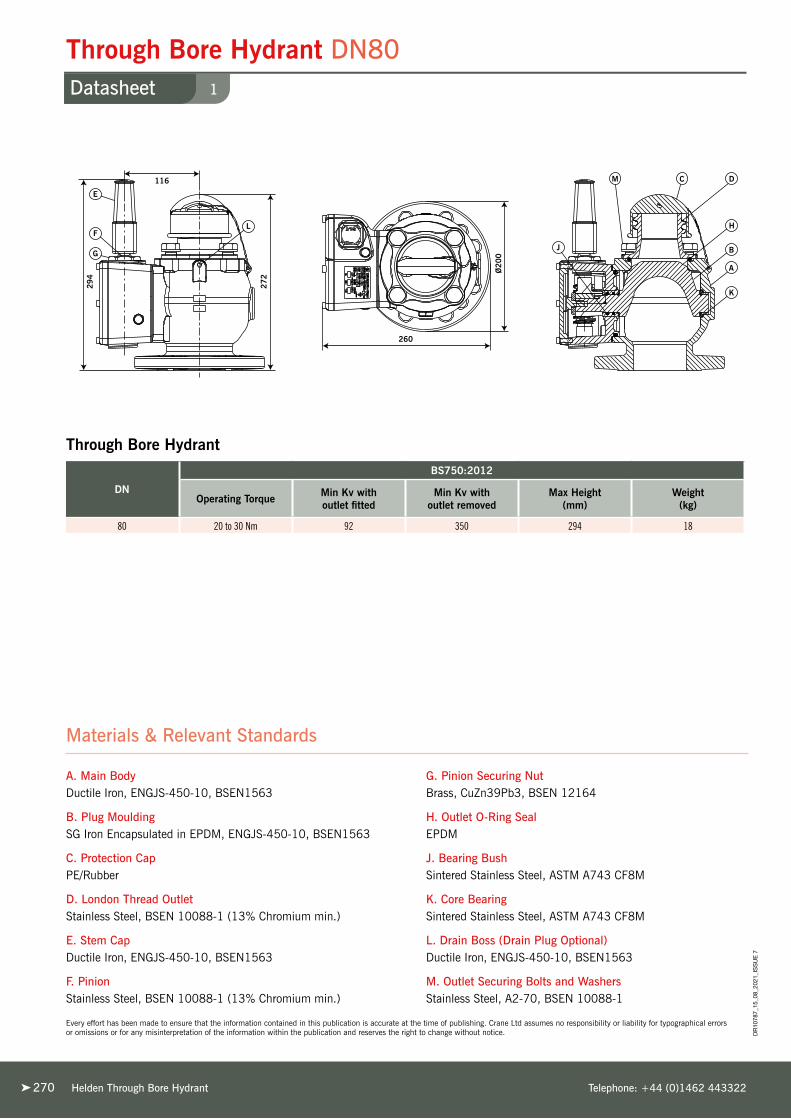
Through Bore Hydrant DN80 1Datasheet
DR
1078
7_15
_08_
2021
_IS
SU
E 7
270 Helden Through Bore Hydrant Telephone: +44 (0)1462 443322
Materials & Relevant Standards
A. Main BodyDuctile Iron, ENGJS-450-10, BSEN1563
B. Plug MouldingSG Iron Encapsulated in EPDM, ENGJS-450-10, BSEN1563
C. Protection CapPE/Rubber
D. London Thread OutletStainless Steel, BSEN 10088-1 (13% Chromium min.)
E. Stem CapDuctile Iron, ENGJS-450-10, BSEN1563
F. PinionStainless Steel, BSEN 10088-1 (13% Chromium min.)
G. Pinion Securing NutBrass, CuZn39Pb3, BSEN 12164
H. Outlet O-Ring SealEPDM
J. Bearing BushSintered Stainless Steel, ASTM A743 CF8M
K. Core BearingSintered Stainless Steel, ASTM A743 CF8M
L. Drain Boss (Drain Plug Optional)Ductile Iron, ENGJS-450-10, BSEN1563
M. Outlet Securing Bolts and WashersStainless Steel, A2-70, BSEN 10088-1
DN
BS750:2012
Operating Torque Min Kv with outlet fitted
Min Kv with outlet removed
Max Height (mm)
Weight(kg)
80 20 to 30 Nm 92 350 294 18
Through Bore Hydrant
Every effort has been made to ensure that the information contained in this publication is accurate at the time of publishing. Crane Ltd assumes no responsibility or liability for typographical errors or omissions or for any misinterpretation of the information within the publication and reserves the right to change without notice.

Helden Design Data 271
TechnicalAdvanced Solutions for Pipe Technology
D e s i g n D a t a

Important Notice
Helden Design Data Telephone: +44 (0)1462 443322272272
The technical, performance data, specifications, dimensions and all other information published in the Design Data section supersede all previously published information.
All data contained herein is subject to change without notice.
The information given in the following pages is intended as a general guide to the proper design and installation of practical piping systems using Helden products. It is not intended as a substitute for competent, professional advice, which should always be sought in the design of any piping system. Good piping practice should always prevail and recommended design pressures, temperatures, tolerances and loads should never be exceeded.
Special conditions often exist for which the information given here is not specifically suited and specialist engineering advice should be obtained. As with any other piping system, the specific advantages and limitations of Helden products should be considered when designing a system using Helden products. The suggestions made here do not set out to give specific solutions to actual installation problems but to give ideas on which to base your own unique solutions.
While every effort has been made to ensure its accuracy, Helden make no express or implied warranty of any kind in respect of the information contained in this brochure or the materials referred to herein. Any person making use of the information contained here does so entirely at their own risk and assumes any and all liability resulting from such use.
The information contained within this section applies specifically to Helden products only, and is not intended to apply to any other bolted sleeve type coupling product.
© 2020 by Helden. No part of this directory may be reproduced, stored or transmitted, in any form or by any means, electronic, mechanical, photocopying, recording or otherwise, without prior permission.
Glossary of Terms
The following abbreviations are used in this brochure:
OD - Pipe outside diameter
NB - Nominal bore
DN - Nominal diameter, in millimetres
PN - Nominal pressure, in bar
(1 bar = 0.1 MPa = 0.1 N/mm2 ≈ 14.5 lbf/in2)
CI - Grey cast iron
DI - Ductile iron
PE - Polyethylene
MDPE - Medium density polyethylene (PE80)
HDPE - High density polyethylene (PE100)
AC - Asbestos cement
GRP - Glass reinforced plastics
PVC-U - Unplasticised polyvinyl chloride
ABS - Acrylonitrile butadiene styrene
EPDM - Ethylene propylene diene monomer
NBR - Nitrile butadiene rubber
WRAS - Water Regulations Advisory Scheme
PCD - Pitch circle diameter
SDR - Standard diameter to wall thickness ratio
DR
1078
7_03
_03_
2020
_IS
SU
E 7

Glossary of Standards
Helden Design Datawww.helden-web.com 273
Design D
ata
Glossary of Standards
The following standards are used in this brochure:
ANSI B16.1 - Specification for cast iron pipe flanges and flange fittings
AWWA/ANSI C219 - Specification for bolted, sleeve type couplings for plain ended pipes
BS 10 - Specification for flanges and bolting for pipes, valves and fittings
BS 750 - Specification for underground fire hydrants and surface box frames and covers
BS 4504 - Specification for circular flanges for pipes, valves, fittings, PN designated
BS EN 681 - Specification for elastomeric seals. Material requirements for pipe joint seals used
in water and drainage applications. Part 1: Vulcanized rubber
BS EN 682 - Specification for elastomeric seals. Materials requirements for seals used in pipes
and fittings carrying gas and hydrocarbon fluids
BS EN 1074-2 - Specification for Isolation valves for water supply. Fitness for purpose requirements
and appropriate verification tests.
BS EN 1074-6 - Specification for Hydrants for water supply. Fitness for purpose requirements
and appropriate verification tests.
BS EN 1092-1 - Specification for flanges and their joints. Circular flanges for pipes, valves, fittings
and accessories, PN designated. Part 1: Steel flanges
BS EN 14339 - Specification for underground fire hydrants
BS EN 14525 - Specification for ductile iron wide tolerance couplings and flange adaptors for use
with pipes of different materials
BS EN ISO 9001 - Quality management system requirements
BS EN ISO 14001 - Environmental management systems requirements
ISO 7005 - Specification for metallic flanges Part 1: Steel flanges
ISO 17885:2015 - Specification for plastics piping systems – Mechanical fittings for pressure piping systems
WIS-4-24-01 - Specification for mechanical fittings and joints including flanges for PE pipes for
the conveyance of cold potable water for the size range 90-100 made of metal
or plastics or a combination of both
WIS-4-52-03 - Specification for anti-corrosion coatings on threaded fasteners
Every effort has been made to ensure that the information contained in this publication is accurate at the time of publishing. Crane Ltd assumes no responsibility or liability for typographical errors or omissions or for any misinterpretation of the information within the publication and reserves the right to change without notice. D
R10
787_
03_0
3_20
20_I
SS
UE
7

Design & Specifications of Piping Systems
Helden Design Data Telephone: +44 (0)1462 443322274274
The Helden system is suitable for an enormous range of
pipework applications and it is therefore impossible to give
a comprehensive list of potential uses. In general terms, the system
is suitable for virtually any pipeline, above or below ground level,
working within the following typical parameters:
Working Pressure Up to 80 bar (1450psi), according to size and type of product.
Up to full vacuum. Higher pressures are available on request.
Temperature Limited by gasket grade used, but within the range -60°C to +200°C
(-75°F to +390°F)
Note: At elevated temperatures, accelerated gasket relaxation will
occur, leading to reduced life of fitting
Suitable forWater, gas, oil, petrochemicals, sewage, powdered solids,
granular solids, air. Subject to gasket grade used and product/
pipe limitations.
LocationAbove or below ground (subject to certain limitations according
to product type and pipe material).
Backed by many years of design and manufacturing experience,
the Helden system is a complete and cost-effective answer
to almost all pipeline installation problems.
Compare the following benefits with those offered by alternative
pipe jointing systems:
➤ ISO 9001 certification is proof of our exacting
quality standards.
➤ ISO 14001 certification is proof of our
environmental credentials.
➤ Exclusive Helden gaskets, moulded to exacting specifications,
assure perfect lifetime sealing, meeting
all relevant Standards.
➤ Size range extends from DN15 (0.5") to more than
DN5000 (200").
➤ The Helden system is designed for plain-ended
pipes, eliminating threading, bevelling, welding or flanging.
➤ The system can joint most types of pipes, valves or meters.
➤ By specifying Helden, installation delays caused
by adverse weather conditions are overcome, particularly
relevant to PE installation.
➤ You can rely on Helden products. Their dependability has
been demonstrated for more than 85 years in all conditions of
service.
➤ On-site jointing equipment - with Helden products
all you need is a spanner and a torque wrench.
➤ The simplicity of our design assures you of couplings which
will assemble quickly, easily and accurately every time.
Company representatives are available to offer technical
advice to the installer.
➤ As a mechanical jointing system it can eliminate the need
for specialist labour or on-site fabrication.
➤ Helden couplings are protected against corrosion
with a range of specialised coatings. Please state coating
required when ordering.
➤ Helden has over 100 agents and distributors worldwide, in
addition to an exclusive distributor network throughout the UK.
Every effort has been made to ensure that the information contained in this publication is accurate at the time of publishing. Crane Ltd assumes no responsibility or liability for typographical errors or omissions or for any misinterpretation of the information within the publication and reserves the right to change without notice. D
R10
787_
03_0
3_20
20_I
SS
UE
7
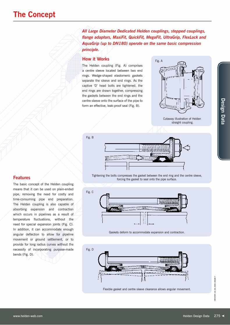
The Concept
Helden Design Datawww.helden-web.com 275
Design D
ata
Tightening the bolts compresses the gasket between the end ring and the centre sleeve, forcing the gasket to seal onto the pipe surface.
Fig. B
Fig. D
Flexible gasket and centre sleeve clearance allows angular movement.
Gaskets deform to accommodate expansion and contraction.
Fig. C
All Large Diameter Dedicated Helden couplings, stepped couplings, flange adaptors, MaxiFit, QuickFit, MegaFit, UltraGrip, FlexLock and AquaGrip (up to DN180) operate on the same basic compression principle.
Fig. A
Cutaway illustration of Helden straight coupling.
How it WorksThe Helden coupling (Fig. A) comprises
a centre sleeve located between two end
rings. Wedge-shaped elastomeric gaskets
separate the sleeve and end rings. As the
captive ‘D’ head bolts are tightened, the
end rings are drawn together, compressing
the gaskets between the end rings and the
centre sleeve onto the surface of the pipe to
form an effective, leak-proof seal (Fig. B).
FeaturesThe basic concept of the Helden coupling
means that it can be used on plain-ended
pipe, removing the need for costly and
time-consuming pipe end preparation.
The Helden coupling is also capable of
absorbing expansion and contraction
which occurs in pipelines as a result of
temperature fluctuations, without the
need for special expansion joints (Fig. C).
In addition, it can accommodate enough
angular deflection to allow for pipeline
movement or ground settlement, or to
provide for long radius curves without the
necessity of incorporating purpose-made
bends (Fig. D).
DR
1078
7_03
_03_
2020
_IS
SU
E 7

Helden Design Data Telephone: +44 (0)1462 443322
System Overview
276276
Pipe MaterialsMost rigid and semi-rigid pipe materials can be joined with Helden coupling products:- steel (including stainless steel), grey cast iron, ductile iron, asbestos cement, uPVC, GRP, concrete, polyethylene and ABS.
Of these, the rigid materials with high strength capabilities, such as steel, grey cast iron, ductile iron and concrete can be joined using standard Helden couplings without revision to our normal fitting instructions.
Certain lower strength materials, such as clayware and the lower classes of asbestos cement pipe, may need reduced bolt torques to avoid pipe damage. Glass reinforced plastic (GRP) pipe is relatively flexible and its structure may be damaged by high gasket pressures. Reduced bolt torques are also recommended for this pipe material (details available on request).
Polyethylene (PE) pipe is produced in various types and with various performance capabilities. All exhibit the tendency to creep i.e. change shape when loaded. The use of standard Helden couplings may result in leakage or pipe pull-out. Helden AquaGrip and AquaFast products are both specifically designed to join PE pipe either to another PE pipe or to flanged equipment or other pipe materials. Certain sizes of EasiClamp are also suitable for use on repairs to PE pipe. UltraGrip may be used on PE pipe if a supporting internal liner is also used.
See page 36 for a table that lists which Helden products will work on which standard pipe material.
Pipe Outside DiametersDedicated Helden couplings and flange adaptors may be specified for any pipe size between DN50 (2") and DN5000 (200"), even for outside diameters not covered by recognised pipe standards. Since Helden couplings fit over the outside of the pipe, it is essential that the OD is specified at time of enquiry/order.
Pipe TolerancesHelden couplings give their optimum performance when they are a close fit on the pipe. Seal effectiveness depends on the pressure which the gasket applies to the pipe surface. Undersized pipes may mean a loss in pressure rating.
Many pipe standards quote the main pipe barrel tolerance separately from the tolerance on the pipe ends.
Unless otherwise informed, Helden products are designed to accommodate the pipe end outside diameter and associated tolerance from the relevant industry specification for the pipe material concerned. In the event that the pipe outside diameter and tolerances are not in accordance with the standard then guidance should be sought from Helden on how these can be accommodated in our products.
Pipe OvalityModerate ovality, especially in large diameter steel or ductile iron pipes, can frequently be rectified by selective bolt tightening to give a uniform annular gap between pipe and coupling. More severe ovality, up to a limit of about ±1% of diameter, may be corrected by jacking, taking care not to damage the internal lining of the pipe.
Pipes having local stiffening near the ends may be impossible to correct or shape by these methods and good circularity is essential if couplings are to be fitted successfully.
N.B. The Helden MaxiFit, MegaFit and UltraGrip ranges of Universal Coupling products can accommodate larger pipe tolerances and ovality, see separate brochures for details.
Diameter MeasurementThe most reliable method of measuring OD is by circumference measurement. This eliminates the effects of ovality and, provided that ovality is moderate, it is almost always possible to correct during assembly. Circumference measurement may be carried out using either a purpose-made circumference tape which reads out directly as an effective diameter, or it is possible to use an ordinary tape wrapped around the pipe and the resulting circumference value converted to effective diameter by dividing the result by π(= 3.142).
If pipe calipers are available, these can give a useful further indication of pipe shape and the possible need for special sizing of the coupling. If in doubt, contact Helden for further advice.
Pipe CoatingsMany pipes are finished with a coating of some description, which can affect pipe O.D. Allowance must be made for these coatings in the manufacturing size of the coupling, or installation of the coupling may be difficult or impossible. Very thick pipe wrappings (typically several millimetres thick) must be removed at pipe ends so that the coupling will seat either on the bare pipe or on a high quality thinner paint film. It is important that details of the intended pipe corrosion protection are made known to us when ordering so that the correct size of coupling can be produced. Alternatively, we must be informed of the finished pipe diameter including all coatings, with appropriate tolerances.
Pipe Surface FinishThe Helden system relies on good uniform contact of the gaskets with the pipe surface.
It is important to ensure that the pipe ends, in the areas where the coupling gaskets will seat, are free from loose surface deposits, bumps, dents, score marks, weld beads, flat spots and the like, or the full pressure capability of the coupling may not be realised.
Working Pressure
The working pressure capability of a coupling varies with its size and construction. It is also dependent upon correct pipe tolerances and surface finish. Wider pipe OD tolerances than those specified will result in a reduction in pressure capability. For most pipe materials, the actual test pressure will be lower than that of the coupling and will be determined by the pipe capability or class. Similarly the pressure rating of a flange adaptor will be determined by the rating of the main flange (eg. PN16 = 16 bar working pressure, 24 bar test).
When assembled onto the pipe(s), the pressure rating of the completed assembly will be that of the lowest rated component. Under normal circumstances working pressures are up to 2/3 of the maximum test pressure shown in any Helden literature appropriate schedule.
Operating TemperatureThe operating temperature of Helden couplings is determined by the temperature rating of the gaskets and on coating type. Different grades of gaskets are available to suit various temperature ranges as well as different chemical resistance requirements. For details see the Gaskets section (pages 289-292). Most Helden Couplings are supplied with Rilsan Nylon 11 coating which has a maximum operating temperature of 90°C.
For higher temperatures, alternative coatings may be necessary.
Helden couplings operate at their maximum efficiency under conditions of relatively constant temperature. If temperature fluctuations occur or at elevated temperatures >60ºC, retightening of the bolts may be required. For this reason, where maintenance-free operation is required, Helden couplings are not recommended as a pipe jointing system for central heating or similar systems which do not operate at a relatively constant temperature.
Chemical ResistanceThe chemical resistance of a Helden coupling is determined by suitability of the gaskets and by the chemical resistance of the internal surfaces of the coupling sleeve. If the coupling is coated with Rilsan, epoxy, etc. it is necessary to ensure that this material is chemically suitable for contact with the pipe contents. Chemical resistance of the gaskets and coatings may be checked with the chart on page 292 or by contacting Helden.
DR
1078
7_03
_03_
2020
_IS
SU
E 7

Angular Deflection
277Helden Design Datawww.helden-web.com
Design D
ata
Each dedicated Helden coupling or flange
adaptor will allow for a setting angularity
(Ø) as shown in Table 1.1.
The ability of Helden couplings to
accommodate angular deflection, either on
installation or in service, can be used in a
number of valuable ways:
a) To take up minor misalignment or lateral
displacement in straight pipes, eg. at
closing lengths.
b) To accommodate ground settlement.
c) To lay pipes to long radius curves
without special bends.
a) Lateral DisplacementLateral displacement between two pipes
can be easily accommodated using two
couplings and an appropriate length of
closing pipe which can be allowed to
angulate (Fig 1.1 & 1.2).
A SINGLE COUPLING CANNOT
ACCOMMODATE LATERAL
DISPLACEMENT.
The length, L, of the closing pipe can
be calculated from the closing length
Table 1.2.
b) Ground SettlementGround settlement, for example where a
pipe leaves an underground structure, may
be accommodated using a pair of Helden
couplings. In this case, pipe trenches are
excavated below the pipe invert to allow
for pipe bedding. If this bedding is to be
flexible (eg. granular fill), some settlement
will inevitably occur when the trench is
backfilled. (Fig. 1.4)
To minimise stresses in pipe 1, coupling
A should be installed as close as possible
to the structure. The two couplings A and
B allow pipe 2 to angulate to take up
settlement Y. The minimum length of pipe
2 is determined using the Closing Length
Table in Table 1.2. The structural strength
of the pipe in bending may need to be
considered.
Alternatively, a Helden wall
coupling can be used instead of pipe 1 and
coupling A.
Lateral displacement (Y) can be accommodated using two couplings.
Fig. 1.1
Length of closing pipe (L) depends on maximum angularity (Ø).
Fig. 1.2
Table 1.1
Angular deflection (ø). Up to 6° in smaller pipes, reducing to 1° in larger diameters.
Fig. 1.3 SETTING ANGULARITY TABLE - DEDICATED RANGE
Coupling Size Angle Inclination
Up to DN450 (18") ± 6° 1 in 10
Over DN450 - DN600 (18" - 24") ± 5° 1 in 12
Over DN600 - DN750 (24" - 30") ± 4° 1 in 15
Over DN750 - DN1200 (30" - 48") ± 3° 1 in 20
Over DN1200 - DN1800 (48" - 72") ± 2° 1 in 30
Over DN1800 (72") ± 1° 1 in 60
Flange Adaptor Size
Up to DN450 (18") ± 3° 1 in 20
Over DN450 - DN600 (18" - 24") ± 2.5° 1 in 24
Over DN600 - DN750 (24" - 30") ± 2° 1 in 30
Over DN750 - DN1200 (30" - 48") ± 1.5° 1 in 40
Over DN1200 - DN1800 (48" - 72") ± 1° 1 in 60
Over DN1800 (72") ± 0.5° 1 in 120
The above schedules represent the maximum angular deflection for each size range and should only be used when the pipes will not move in service. For other conditions it is recommended to halve these figures to allow for in-service flexibility.
Every effort has been made to ensure that the information contained in this publication is accurate at the time of publishing. Crane Ltd assumes no responsibility or liability for typographical errors or omissions or for any misinterpretation of the information within the publication and reserves the right to change without notice. D
R10
787_
03_0
3_20
20_I
SS
UE
7

Angular Deflection
Helden Design Data Telephone: +44 (0)1462 443322278278
c) Long Radius CurvesUsing Helden couplings it is possible to lay
a pipeline to long radius curves, taking a
small angular deflection at each coupling,
without the need for special large-angle
bends with associated thrust blocks.
This method can be used to avoid major
obstacles on cross-country pipelines or
follow the line of roads or streams, etc.
using the equation given below.
Table 1.3
Long radius curves can be accommodated without special bends.
Fig. 1.5
NB: In an above ground pipeline, lateral pressure thrusts will need to be restrained by the support system. Buried pipes laid to a curve will
normally receive sufficient support from the trench backfill material.
Fig. 1.4
Ground Settlement. Displacement can be accommodated using two couplings and Y A B
See minimum radius Table 1.3
R= L 2 sin 1/2 ø
ø = 2 sin-1 L
2 R
Where L = pipe length ø = angular deflection r = radius of curve
Or ( )
CLOSING LENGTH TABLE (see Fig. 1.2 & 1.4)
Pipe Nominal Diameter L, Minimum Length (mm)
Up to DN450 (18") Displacement Y x 10
Over DN450 - DN600 (18" - 24") Displacement Y x 12
Over DN600 - DN750 (24" - 30") Displacement Y x 15
Over DN750 - DN1200 (30" - 48") Displacement Y x 20
Over DN1200 - DN1800 (48" - 72") Displacement Y x 30
Over DN1800 (72") Displacement Y x 60
EXAMPLE: Pipe OD = 711mm EXAMPLE: Pipe OD = 28" Lateral displacement to be accommodated = 90mm Lateral displacement to be accommodated = 4" Minimum closing length = 90 x 15 = 1350mm Minimum closing length = 4 x 15 = 60"
NOTE: For Helden flange adaptors these lengths must be doubled.
MINIMUM RADIUS TABLE
Pipe diameter <DN450 >DN450-600 >DN600-750 >DN750-1200 >DN1200-1800 >DN1800
18" 18" - 24" 24" - 30" 30" - 48" 48" - 72" 72"
Nominal Angle ø 6° 5° 4° 3° 2° 1°
Pipe Length (L) Minimum Radius (R)3m (10ft) 29m (95ft) 34m (110ft) 43m (140ft) 57m (185ft) 86m (280ft) 172m (565ft)
6m (20ft) 57m (187ft) 69m (225ft) 86m (280ft) 115m (375ft) 172m (565ft) 344m (1130ft)
9m (30ft) 86m (280ft) 103m (335ft) 129m (425ft) 172m (565ft) 258m (845ft) 516m (1690ft)
12m (40ft) 115m (375ft) 138m (450ft) 172m (565ft) 229m (750ft) 344m (1130ft) 688m (2260ft)
Other radii may be calculated using the formula given above. NOTE: These minimum radii do not allow any in-service movement.
Table 1.2
DR
1078
7_03
_03_
2020
_IS
SU
E 7

Setting Gap
Helden Design Datawww.helden-web.com 279
Design D
ata
Helden couplings are used to join pipes
flexibly, so that if there is pipe or ground
movement during the life of the pipeline,
the coupling will accommodate this without
leakage. However, such movement will
result in relative longitudinal and/or angular
displacement of the pipes within the
coupling.
Under normal conditions, adjacent pipe
ends should not make contact with each
other in service. If there is insufficient gap
so that pipes do touch, the pipeline will
tend to buckle as temperatures increase
and pipe end damage may occur. At the
other extreme, if the pipe end gap is too
large on installation, there is a risk that
pipes may pull out past the gasket(s) of the
coupling leading to leakage and failure of
the pipeline.
It is therefore necessary to ensure that pipe
end gaps are set within specified limits
during installation of the coupling to ensure
that neither situation occurs.
We give a Recommended Setting Gap for
all sizes of Helden coupling and flange
adaptor, which specifies the normal initial
gap between adjacent pipe ends such
that if the full recommended angularity or
expansion occurs in service, the pipe ends
should not touch together causing damage.
(see Table 1.4)
Similarly, we also give a Maximum
Recommended Gap which ensures that
even with full recommended angularity
there should not be any risk of pipe ends
pulling out past the coupling or flange
adaptor gasket, leading to leakage.
(see Fig. 1.6 and Table 1.4)
For pipes above ground, it is possible for
unanchored pipes to shunt together after
installation, opening up a large gap between
pipes at certain points. Such pipe movement
must be controlled to ensure that the
Maximum Permissible Gap is not exceeded,
or there may be a risk of the pipe pulling
out of the coupling. Soil friction acting on
pipes laid below ground normally prevents
any such pipe shunting movement.
The Maximum Permissible Gap, measured
on the centreline, should not be exceeded
in service. Consideration of actual thermal
movement or deflection conditions may
lead to different initial setting gaps.
When couplings are specified with a locating
plug, the Recommended Setting Gap
should be increased by the diameter of the
pin or plug (9.5mm or 12.7mm). However,
the Maximum Permissible Gap should not
be increased.
Where the standard Helden sleeve length
is found to be insufficient, longer sleeved
couplings and flange adaptors can be
supplied.
Table 1.4
Fig. 1.6
a) Pipes laid straight with equal setting gaps. b) Accumulated gap (X) on straight pipeline must not exceed maximum permissible value given in Setting Gap Table.
SETTING GAP TABLE
Coupling Sleeve Width Nominal Size (D)
Recommended Setting Gap Maximum Permissible Gap (x)Couplings Flange Adaptors
100mm DN50 (2") to DN300 (12") 20mm 20mm 40mm
150mm DN350 (14") to DN900 (36") 25mm 25mm 50mm
178mm DN1000 (40") to DN1800 (72") 40mm 30mm 75mm
254mm Over DN1800 (72") 55mm 55mm 115mm
General guide for dedicated couplings, see fitting instructions related to each product type for further details.
Every effort has been made to ensure that the information contained in this publication is accurate at the time of publishing. Crane Ltd assumes no responsibility or liability for typographical errors or omissions or for any misinterpretation of the information within the publication and reserves the right to change without notice. D
R10
787_
03_0
3_20
20_I
SS
UE
7

Pressure Forces
Helden Design Data Telephone: +44 (0)1462 443322280280
All pipelines under pressure are subject to
longitudinal forces which tend to separate
the component parts of the pipeline.
Consider the case of pressure acting on a
blank end (Fig 1.7). The force, F, necessary
to prevent pipe separation is given by:
It is important to appreciate the magnitude
of the end thrusts which can result
from internal pressure in a pipeline.
These longitudinal forces are particularly
important in flexibly jointed pipelines, such
as those jointed with Helden standard
couplings. The pipeline designer must
carefully consider not only the magnitude of
these forces but also the means of resisting
them to prevent failure of the pipeline.
Pressure thrusts will be produced at all
changes of direction, eg. bends, tees, etc.
and at cap ends, valves and reducers.
Unless these thrusts are restrained locally
at the point at which they are developed,
pipe components may move under the load,
leading to failure.
Even small diameter pipes may pull out
of couplings at modest pressures unless
proper external restraint is provided,
especially if the pipe system is subjected
to temperature or pressure fluctuations,
vibration or external loadings.
With surface or above-ground pipelines it is
generally necessary to take full account of
the thrusts produced by internal pressures
and to restrain them with thrust blocks,
anchorages or tie bars. At a bend, there is
a force, R, tending to push the bend
outwards (Fig. 1.8).
In this case there must be sufficient
anchorage to resist resultant force R. In a
buried system a thrust block (Fig. 1.8a)
may be used to resist R.
HELDEN FLEXIBLE COUPLINGS DO
NOT RESIST LONGITUDINAL THRUST
LOADINGS, AND PIPE PULL-OUT WILL
OCCUR UNLESS THE LOADS ARE
RESTRAINED BY OTHER MEANS.
Longitudinal pressure forces acting at a bend.
Concrete thrust block for retaining bend.
Fig. 1.8
Fig. 1.8a
Internal pressure will mainly cause pipe
movement if there is inadequate restraint.
However it can also cause coupling
movement. A Helden stepped coupling is in
effect a reducer, and internal pressure will
tend to push it towards the smaller diameter
pipe. Under normal circumstances, i.e.
modest diameter reduction, buried service,
standard water pressures etc., soil and pipe
friction are sufficient to prevent coupling
movement. However, for larger diameter and
for above ground service, and in particular
higher pressures, the pressure thrust acting
on the stepped coupling sleeve can be
sufficient to cause coupling movement and
consequent disengagement. Positive steps
must be taken to restrain the coupling to
prevent movement. This may take the form
of harness rods, stops on the pipe or within
the coupling or encasement in concrete.
For further advice, please contact Helden
Technical Support.
F =
p π d2
4 Where d = pipe OD p = internal pressure.Example: d = 508mm OD. p = 16 bar = 1.6 N/mm2
Then F = 1.6 x π x 5082 = 4 324293 N = 324.3 kN = 33.07 tonnes
Longitudinal pressure forces acting at a blank end.
Fig. 1.7
R= p π d2
sin ø
2 2
where d = pipe outside diameter
p = internal pressure
and ø = angle of the bend
NOTE: Any consistent set of units is suitable.
Coupling Movement Under Pressure
DR
1078
7_03
_03_
2020
_IS
SU
E 7

Accommodating End Load System
Helden Design Datawww.helden-web.com 281
Design D
ata
Below ground, pipe thrusts can normally
be restrained by means of concrete thrust
blocks at bends, valves, etc. However,
above ground this is more difficult. In
such circumstances it may be necessary to
provide a harness assembly, attached to the
pipes on both sides of the coupling. This
consists of one or more pairs of tie bolts
located in either harness lugs welded to
the pipe (Fig. 1.9 (a)) or attached by other
means, eg. flanges cast on. Accommodating
pipe thrusts in above ground applications
with Helden standard coupling products
requires either external brackets / pipe
supports or the use of harness assemblies
attached to the pipe some distance back
from each joint. Harness assemblies consist
of one or more pairs of tie rods located in
lugs / flanges welded to the pipe a short
distance away from the joint. The design of
the harness lug assembly has to include for
the transfer of end load forces via the tie
rods into the pipe wall, and it is essential to
verify that the interface between the lug and
pipe wall is sufficiently strong enough to
accommodate these loads. For this reason
Helden deem that the responsibility of the
design for the harness lugs lies with the
pipe manufacturer and therefore we are not
able to include these as part of our product
offering.
Use of a single pair of tie rods permits
angularity between pipes in one plane, eg.
to permit ground settlement.
Flange adaptors can also be prepared for
harness assembly. Here, a number of the
flange bolts are replaced with long tie bars
(Fig 1.9 (b))*.
Harnessed flange adaptors used with a
flanged spigot (Fig. 1.9 (c)) give a simple,
cost-effective method of providing a
demountable joint in an otherwise flanged
system. Helden provide the complete
package for Fig 1.9 (c).
When a flange adaptor is harnessed (or
a Dismantling Joint used), there will be
no resultant angular deflection, or in
service expansion capability within the
joint, unless special arrangements are
specified beforehand.
* NOTE: If a flange adaptor is to be used in a tied arrangement, it may be necessary to notch
the end ring to ensure sufficient clearance for the tie bars. If notified beforehand, Helden
can incorporate notching of the end rings during manufacture. (Please note that the Helden
MaxiDaptor cannot be notched).
For ductile iron flange systems, it is normally recommended that the end ring is notched to
accommodate a number of tie bars equal to half the quantity of main flange bolts. For steel
flange systems, this number may be reduced.
a) Harness assembly for straight or stepped coupling to prevent pipe separation under pressure.(It may be necessary to reinforce the pipe wall locally to the harness assembly to resist pipe distortion.)
b) Harness assembly with flange adaptor.
c) Flange adaptor with flanged spigot (supplied complete as the Helden Dismantling Joint).
Fig. 1.9
FlexLockDedicated flange adaptors
and couplings for steel and
ductile iron pipes.
UltraGripWide tolerance couplings,
flange adaptors, end caps
and reducers for most
pipe materials. (For below
ground installations)
Dismantling JointDouble flanged adjustable
spool piece in a variety
of flanges.
Helden has within its comprehensive range specialist products capable of accommodating end load forces these include:-
Alternative Helden Products
Every effort has been made to ensure that the information contained in this publication is accurate at the time of publishing. Crane Ltd assumes no responsibility or liability for typographical errors or omissions or for any misinterpretation of the information within the publication and reserves the right to change without notice. D
R10
787_
03_0
3_20
20_I
SS
UE
7

Pipe Support
Helden Design Data Telephone: +44 (0)1462 443322282282
Pipes laid above ground, usually with
supports at specified locations, must
transfer all the weight of pipe and contents,
plus any pressure-related forces, through
those supports.
Fig. 1.10 shows a standard method of
supporting a pipeline where subsidence
is expected and which allows freedom of
movement within the capabilities of the
Helden couplings while anchoring and
supporting the pipes. Alternate pipe lengths
are fully supported between two couplings,
provided that the clear pipe span does not
exceed 10 metres (30ft).
This pipe span distance does not apply
to MaxiFit, MegaFit or New QuickFit
as anchored couplings. Contact Helden
for details. Intermediate anchors
(B) are necessary to prevent any
cumulative pipe creep, with full thrust
anchors (A) at the ends of long runs or
at major changes in direction.
The Helden Anchored Coupling (Fig. 1.11)
provides an alternative method of supporting
pipes above ground. Brackets welded to the
centre sleeve of the coupling can be bolted
directly to the supporting structure without
the need for specially shaped saddles,
straps, etc., thus reducing installation costs
and greatly improving laying times. The
brackets are capable of withstanding the
thrust produced by maximum angularity
and will support a 10 metre (30ft) long
pipe filled with water.
Anchored couplings may be bolted to the
structure in any orientation (ie. bolted to
a ceiling, side wall, etc.), provided that
the pipeline is substantially horizontal.
Useful when installing a number of pipes
in a confined space i.e. a pipe duct. Anchor
brackets are not designed to withstand
longitudinal or lateral forces due to external
pressure thrusts.
Large diameter (>DN1600/54") or heavy
section couplings may require a reinforced
saddle around the anchor brackets.
The use of locating plugs with anchored
couplings is recommended to help control
pipe movement.
(Please note that MaxiFit, MegaFit and
New QuickFit couplings are not available,
as anchored couplings.)
Fig. 1.12
Important:1. Harness assemblies should not normally be used in conjunction with anchored couplings.
2. Ensure that sufficient clearance is allowed between the coupling and the plinth to permit full assembly of ALL bolts.Helden anchored coupling.
Fig. 1.11
If specified, Helden couplings can be included in a pipe system
that is to have cathodic protection. They can be supplied with a
threaded stud on the centre sleeve and end rings, such that electrical
connections can be made across and including the coupling. Contact
Helden for further details. See Fig. 1.12.
Method of supporting pipes where subsidence is expected.A. Anchor at end of each straight run. B. Intermediate anchor points. C. Guide supports or cradles.
Fig. 1.10
Anchored Couplings
Cathodic Protection
DR
1078
7_03
_03_
2020
_IS
SU
E 7

Locating Plugs
Helden Design Datawww.helden-web.com 283
Design D
ata
Where Helden couplings are to be
installed in pipelines laid on significant
slopes, it is important to consider the
restraint of the component of self-weight
acting parallel to the axis of the pipeline,
to stop the pipe sliding down the slope
(Fig. 1.15).
Below ground pipelines will receive
significant restraint from backfill loading
and therefore less extra axial restraint
will be necessary than for above ground
pipelines, but the gravity forces still need
to be considered in a proper engineering
assessment of the design.
On above ground pipelines the Helden
couplings should be fitted with locating
plugs to ensure the coupling’s location
relative to the pipe ends.
N.B. Locating plugs are not designed to
restrain pipe self-weight, axial forces or
other pipeline thrusts, only to restrain the
coupling itself, ie the pipes must be fixed.
Where the length L of pipe to be supported
by the Helden couplings does not exceed
10 metres (30ft), it is normally desirable
to anchor one end, A, of each pipe in
position relative to the ground, allowing the
other end, B, to be supported by coupling
C and to move axially with temperature
fluctuations as shown. Its limitations are
detailed in Expansion and Contraction (refer
to page 284).
Pipeline anchorage must be designed to
restrain all axial forces due to self-weight,
fluid friction and pressure. The pipe support
design will be determined by pipe diameter,
pressure, wall thickness, pipe inclination
to horizontal, etc and is beyond the
scope of this brochure. Certain diameter,
pipe length and inclination conditions
may necessitate the use of supports on
both sides of the coupling. In this instance
one support should be fixed, the other
sliding to permit thermal movement. It is
essential that accurate pipe alignment is
observed to prevent excessive shear stress
in the coupling.
In certain cases of limited diameter and
inclination to the horizontal it may be
possible to permit the use of Helden
anchored couplings to both support and
restrain the pipes. In this instance the
pipe self-weight axial loads are restrained
by the coupling locating plug and Helden
should be contacted for specific design
recommendations before proceeding.
Fig. 1.15
Typical support of inclined pipelines.
Couplings installed above ground may
tend to creep along the pipe with repeated
pipe movement, temperature variation or
vibration. This can be restrained by using
couplings fitted with removable locating
plugs, which prevent the coupling from
moving beyond fixed limits Fig. 1.14.
Removable locating plugs enable single
pipe removal. Once the locating plug is
removed, the end rings can be slackened
off and the gaskets and centre sleeve can be
slid along the pipe to expose the joint. The
pipe can then be removed.
Normally it is unnecessary to use locating
plugs in couplings below ground since soil
friction will ensure that the couplings remain
in their correct position relative to the pipes.
However, locating plugs can provide a useful
method of coupling centralisation over the
pipe ends.
Removable locating plugs are only available
on Dedicated couplings.
Removable locating plugs are available Zinc plated or stainless steel.
For Dedicated Helden couplings, locating plugs are produced
in the following standard sizes-
Fig. 1.14
a) Removable locating plug.
Pipe OD Thread Diameter Peg Diameter
up to 914mm (36") 0.25" BSP 9.5mm (0.375")
over 914mm* (36") 0.5" BSP 12.7mm (0.5")
*may be used on smaller diameter heavy section couplings.
Inclined Pipelines
Every effort has been made to ensure that the information contained in this publication is accurate at the time of publishing. Crane Ltd assumes no responsibility or liability for typographical errors or omissions or for any misinterpretation of the information within the publication and reserves the right to change without notice. D
R10
787_
03_0
3_20
20_I
SS
UE
7

Shear Strength
Helden Design Data Telephone: +44 (0)1462 443322284284
Helden couplings and flange adaptors can
accommodate significant regular expansion
and contraction movement in a pipe
system, usually enough to remove the need
for special expansion jointing products. This
is achieved by deformation of the gaskets
rather than by sliding on the pipe surface.
Most expansion movements due to normal
ambient temperature variations can be
accommodated using Helden couplings.
Under certain circumstances, e.g.
occasional or long-term movement, it may
be possible to allow for increased expansion
and contraction, but this should not
be attempted without first contacting
Helden.
Stepped couplings permit the same total
expansion movement as straight couplings.
However, pressure thrust may act on the
stepped coupling causing the stepped
coupling to move along the pipe with
repeated expansion movement. Restraint
for the coupling will be required.
Fig. 1.17
Expansion and contraction y - x = 10mm (0.375")
As stated earlier in System Overview
(Page 276 - Pipe Surface Finish and Pipe
Tolerances) it is important to remember:
a) Within the area of the seal, pipe surfaces
should be round, clean, smooth and free from
bumps, dents, score marks, flat spots etc.
b) Tolerances Should be in accordance
with industry standards / specifications, if
pressure ratings are to be maintained.
In the Pipe End Preparation Table (Table
1.6) dimension L is the distance back from
the end of the pipes which must be rounded
where necessary to meet the tolerances
required. It is also the distance back from
the end of the pipe from which any pipe
wrapping should be removed to permit
coupling assembly.
This applies equally to coupling sleeves
with or without locating plugs.
Where it is required to slide the coupling
completely on to one pipe end, any wrapping
must be cut back or obstructions removed,
for minimum distance M.
Fig. 1.18
Up to DN1500 (60"), Dedicated Helden
couplings are capabIe of withstanding a
shear force corresponding to the weight
of a 10 metre (30ft) length of water-filled
pipe of the diameter for which the couplings
were designed, when supported between
two couplings. This also applies to flange
adaptors. In the case of stepped couplings
the maximum shear resistance is that of the
smaller end of the coupling - Fig. 1.16.
External superimposed forces will reduce
the maximum clear span. MaxiFit and
MegaFit Wide Range couplings are not
generally suitable for this duty and the pipe
should be adequately supported to prevent
sagging and coupling rotation.
Maximum Relative Pipe Movement,
Y-X (all sizes)
Couplings 10mm
Flange Adaptors 5mm
Table 1.6
PIPE END PREPARATION TABLE
Sleeve Length Dimension L for normal coupling assembly
Dimension M for closing connections (wrapping cut back)
100mm 100mm 150mm
150mm 150mm 225mm
178mm 150mm 250mm
254mm 200mm 300mm
Expansion & Contraction
Pipe End Preparation
Fig. 1.16
Shear Strength
DR
1078
7_03
_03_
2020
_IS
SU
E 7

Couplings
Helden Design Datawww.helden-web.com 285
Design D
ata
Straight Couplings are used for joining pipes of the same material or pipes of different materials but having the same outside diameter.
Available in 3mm size increments from
DN350 (19") nom. up to DN5000 (200")
nom. in standard form.
Couplings can be supplied with removable
locating plug.
Heavy Duty Couplings, with strengthened
end rings and sleeves are available for
higher working pressures.
Long Sleeve Couplings, to take up larger
pipe end gaps or cutting inaccuracies can
also be supplied.
When using couplings, care must be taken
to ensure that pipes are within the accepted
tolerances, if pressure ratings are to
be maintained.
When used on coated pipe, thickness of
coating must be considered to be in addition
to the pipe outside diameter.
BoltsSheraplex coated bolts are supplied as
standard. Galvanised or stainless steel bolts
are also available. (Some products may
have a limited range of bolt coatings for
performance reasons.)
Locating PlugsLocating plugs are manufactured from
carbon steel as standard, zinc plated. They
are also available in stainless steel.
Marine CouplingsCouplings specified for marine use are
supplied complete with galvanised bolts,
zinc plated locating plugs and Grade G
nitrile gaskets.
Heavy Section CouplingsHeavy duty couplings with strengthened
end rings and sleeves are available in sizes
from DN250 (10") nom.
Coupling Sleeve DesignWithin the range of Dedicated couplings
there are variations of centre sleeve design,
depending on the size and application.
Standard Sleeve
There are three types of standard sleeve
for differing pipe sizes: (see Fig. 1.19)
a) Steel plate sleeve
b) Ductile iron sleeve
c) Hot rolled section sleeve
Coupling sleeve design is dependent
on diameter and at the discretion of
Helden.
These standard sleeves do not have an
integral centre register within the sleeve,
enabling couplings to be slipped back
along the pipe for pipe cleaning, repair and
maintenance.
Straight Coupling
(c) Hot rolled section sleeve
Steel plate sleeve
Fig. 1.19
(a)
(b)
Type 2 DN150 to DN300
Type 1 up to and including DN125
Ductile iron sleeve
NOTEHelden Flexible couplings do not resist longitudinal thrust loadings, and pipe pull-out will occur unless the loads are restrained by other means.
Every effort has been made to ensure that the information contained in this publication is accurate at the time of publishing. Crane Ltd assumes no responsibility or liability for typographical errors or omissions or for any misinterpretation of the information within the publication and reserves the right to change without notice. D
R10
787_
03_0
3_20
20_I
SS
UE
7

Stepped Couplings
286286 Helden Design Data Telephone: +44 (0)1462 443322
Fig. 1.25
Expanded sleeve
(a) (b)
Make-up ring sleeve
Expanded Sleeve Stepped Coupling
Make-Up Ring Stepped Coupling
Stepped Couplings are used to connect pipes of different outside diameters and/or pipes of different materials.
Pressure RatingPressure ratings for stepped couplings are
equivalent to either:
➤ the rating specified in the straight
coupling schedules for the larger of the
two pipe sizes involved, or
➤ the lower of the individual pressure
rating of the two.
Coupling MovementWhen stepped or wide range couplings
are used to join pipes of different outside
diameters, it is essential to ensure that the
stepped coupling cannot be forced along the
smaller diameter pipe by internal pressure
forces. This does not normally apply to the
standard range of stepped couplings using
expanded sleeves in a below ground service
at moderate pressures. This is particularly
important above ground and/or where a
stepped coupling is used as an expansion
joint. Regular inspection of the coupling
position against a previously applied mark
is strongly recommended, especially in
above ground installations. (See also
Pressure Forces, page 280.
Stepped Coupling Sleeve DesignTo accommodate the variety of sizes and
combinations required, the centre sleeve of
stepped couplings will be one of the three
basic designs:
A. Expanded Sleeve
For the standard stepped connections
(same nominal size, different materials),
an expanded one-part sleeve, made as
a casting or of rolled steel, is normally
supplied (see Fig. 1.25a).
B. Make-Up Ring Sleeve
Where large steps between pipe sizes are
required, a three-part welded sleeve is
fabricated with studs fitted to the centre
plate of the coupling instead of bolts.
(Fig. 1.25b).
NOTEFor non-standard couplings the customer is encouraged to ask for an overall dimension drawing of the stepped coupling offered.
NOTEHelden Flexible couplings do not resist longitudinal thrust loadings, and pipe pull-out will occur unless the loads are restrained by other means.
Every effort has been made to ensure that the information contained in this publication is accurate at the time of publishing. Crane Ltd assumes no responsibility or liability for typographical errors or omissions or for any misinterpretation of the information within the publication and reserves the right to change without notice. D
R10
787_
03_0
3_20
20_I
SS
UE
7

Flange Adaptors
287Helden Design Datawww.helden-web.com
Design D
ataFig. 1.20
Mating to a raised face flange
QuickFit Flange Adaptor
NOTE(i) Customer approval of the supply of this design is generally sought prior to purchase.
NOTEHelden Flexible couplings do not resist longitudinal thrust loadings, and pipe pull-out will occur unless the loads are restrained by other means.
Fig. 1.21
Straight sleeve
Flange adaptors are used to enable plain-ended pipe to be connected either to flanged pipe or to flanged valves and other fittings.
Raised Face FlangesHelden flange adaptors are provided with
flat mating faces. These are suitable for
bolting to both flat and raised faces. The
same gasket loading characteristics can be
obtained as with a raised face assembly. To
obtain a satisfactory seal, the radial contact
dimension or ledge (K on Fig. 1.20) should
be a minimum of 8mm.
Pressure RatingsHelden flange adaptors are supplied to suit
the pressure rating of the flange, unless
specifically ordered otherwise. The overall
pressure rating of the assembled adaptor
will be equal to that of the lower rated
component, either pipe or flange. e.g.
PN10 flange adaptors have a flange rated
at a working pressure of 10 bar (150 psi).
The coupling component of the flange
adaptor will invariably have a higher
pressure rating than the flange.
Dedicated Flange AdaptorsAre available in four basic forms with
different sleeve designs:
Straight Sleeve
The standard form of flange adaptor has a
straight sleeve and a flat face. (Fig. 1.21).
Expanded Sleeve (See note (i))
Specifically for use with very thick walled
pipe such as asbestos cement or concrete,
the expanded sleeve can also be used
when the nominal sizes of the flange and
the pipe are different (e.g. connecting
DN350 (14") pipe to a DN300 (12") valve).
See Fig. 1.22.
Typical Dimensions
Nom. flange size:
> DN300 (12")
B= 160mm H= 57mm
B= 235mm H= 82mm
Always confirm dimensional details
before ordering.
Tapped Flange (See note (i))
As an alternative to the expanded sleeve,
mismatched components may be joined
using a tapped flange (Fig. 1.23). Studs,
instead of flange bolts, are used to make
the connection to the mating flange.
Dimension B on Fig. 1.23 varies with the
flange thickness C, relative to the tapping
diameter. (This design is not suitable for
some flange arrangements.)
‘S’ Bore
Flange adaptor with full flange faces
suitable for use with wafer style (butterfly)
valves are available see Fig. 1.24.
Fig. 1.22
Expanded sleeve‘S’ bore flange
Fig. 1.24
Fig. 1.23
Tapped flange
DR
1078
7_03
_03_
2020
_IS
SU
E 7

Flange Comparison Chart
Helden Design Data Telephone: +44 (0)1462 443322288288
Nominal Size Table
Diameter P.C.D. Hole Dia. Bolt Dia. No. Boltsmm inch mm inch mm inch mm inch
DN80/3" PN10/16 200 7.9 160 6.3 18 0.7 16 0.625 8
BS10 ADE 184 7.25 146 5.75 17 0.688 16 0.625 4
ANSI 125/150 190 7.5 152 6 19 0.75 16 0.625 4
DN100/4" PN10/16 220 8.67 180 7.1 18 0.7 16 0.625 8
BS10 AD 216 8.5 178 7 17 0.688 16 0.625 4
BS10 E 216 8.5 178 7 17 0.688 16 0.625 8
ANSI 125/150 229 9 191 7.5 19 0.75 16 0.625 8
DN150/6" PN10/16 285 11.22 240 9.45 22 0.875 20 0.79 8
BS10 A 279 11 235 9.25 17 0.688 16 0.625 4
BS10 D 279 11 235 9.25 17 0.688 16 0.625 8
BS10 E 279 11 235 9.25 22 0.875 19 0.75 8
ANSI 125/150 279 11 241 9.5 22 0.875 19 0.75 8
DN200/8" PN10 340 13.4 295 11.6 22 0.875 20 0.79 8
PN16 340 13.4 295 11.6 22 0.875 20 0.79 12
BS10 AD 337 13.25 292 11.5 17 0.688 16 0.625 8
BS10 E 337 13.25 292 11.5 22 0.875 19 0.75 8
ANSI 125/150 343 13.5 298 11.75 22 0.875 19 0.75 8
DN250/10" PN10 395 15.55 350 13.78 22 0.875 20 0.79 12
PN16 405 15.55 355 14 26 1.03 24 0.95 12
BS10 AD 406 16 356 14 22 0.875 19 0.75 8
BS10 E 406 16 356 14 22 0.875 19 0.75 12
ANSI 125/150 406 16 362 14.25 25 1 22 0.875 12
DN300/12" PN10 445 17.5 400 15.75 22 0.875 20 0.79 12
PN16 460 18.2 410 16.15 26 1.03 24 0.95 12
BS10 A 457 18 406 16 22 0.875 19 0.75 8
BS10 D 457 18 406 16 22 0.875 19 0.75 12
BS10 E 457 18 406 16 25 1 22 0.875 12
ANSI 125/150 483 19 432 17 25 1 22 0.875 12
DN350/14" PN10 505 19.88 460 18.11 22 0.875 20 0.79 16
PN16 520 20.47 470 18.50 26 1.03 24 0.95 16
BS10 A 527 20.75 470 18.5 25 1 22 0.875 8
BS10 DE 527 20.75 470 18.5 25 1 22 0.875 12
ANSI 125/150 533 21 476 18.75 29 1.125 25 1 12
DN400/16" PN10 565 22.24 515 20.28 26 1.03 24 0.95 16
PN16 580 22.83 525 20.67 30 1.20 27 1.07 16
BS10 ADE 578 22.75 521 20.5 25 1 22 0.875 12
ANSI 125/150 597 23.5 540 21.25 29 1.125 25 1 16
DN450/18" PN10 615 24.21 565 22.24 26 1.03 24 0.95 20
PN16 640 25.20 585 23.03 30 1.20 27 1.07 20
BS10 AD 641 25.25 584 23 25 1 22 0.875 12
BS10 E 641 25.25 584 23 25 1 22 0.875 16
ANSI 125/150 635 25 578 22.75 32 1.25 29 1.125 16
DN500/20" PN10 670 26.38 620 24.41 26 1.03 24 0.95 20
PN16 715 28.15 650 25.59 33 1.30 30 1.20 20
BS10 A 705 27.75 642 25.25 25 1 22 0.875 12
BS10 DE 705 27.75 642 25.25 25 1 22 0.875 16
ANSI 125/150 698 27.5 635 25 32 1.25 29 1.125 20
DN600/24" PN10 780 30.71 725 28.54 30 1.20 27 1.07 20
PN16 840 33.07 770 30.31 36 1.42 33 1.30 20
BS10 A 826 32.5 756 29.75 29 1.125 25 1 12
BS10 D 826 32.5 756 29.75 29 1.125 25 1 16
BS10 E 826 32.5 756 29.75 32 1.25 29 1.125 16
ANSI 125/150 813 32 749 29.5 35 1.375 32 1.25 20
DR
1078
7_03
_03_
2020
_IS
SU
E 7

Gaskets
Helden Design Datawww.helden-web.com 289
Design D
ata
The quality and performance of the gaskets is a crucial factor in the efficiency of any compression-
fit pipe joint. It is the gasket which absorbs the forces applied by the expansion and contraction of
the pipes, the angular movements and even the weight of the pipe itself. To do this successfully,
the gasket must retain its flexibility and compressive stress throughout its operational life.
Helden gaskets are made in accordance with BS EN 681 for water and BS EN 682 for gas,
which specifies stringent requirements for physical and chemical properties, aimed at giving the
best possible long-term performance.
Fitted Gaskets
All straight couplings, stepped couplings and flange adaptors in the QuickFit, MegaFit, UltraGrip
and MaxiFit products, are normally supplied ready-assembled with the gaskets already
in position. Making assembly of the product quicker and easier.
Removal of the gaskets prior to or during assembly of the coupling is neither necessary,
nor recommended.
Unfitted Gaskets
Wedge-shaped gaskets are supplied as standard with Dedicated couplings, stepped couplings
and flange adaptors in sizes DN350 (14") and over. Unfitted gaskets are always stretched onto
the pipe during installation.
Bonded Gaskets
Certain Helden products, such as EasiClamp, EasiTee etc, are supplied with waffle type gaskets
that are bonded into position. These gaskets are not replaceable.
Gasket Grade Selection
Helden products offer a variety of gasket grades to suit the widest possible range of applications.
In order to ensure maximum gasket life in the intended application, proper selection is essential,
See table on page 292.
Many factors need to be considered in deciding on the best grade for a specific service.
Temperature is the primary consideration, with type and concentration of the product carried,
duration and continuity of service also to be considered. Temperatures higher than the maximum
quoted for each grade will lead to accelerated deterioration of the gaskets.
Fluctuating and / or Elevated Temperature
Whilst gasket compounds used in coupling type products may be capable of accommodating
fluctuating or elevated temperatures (>60ºC) the relaxation rate of the elastomeric seals will
increase, thus reducing the life expectancy of the joint. The failure mode is likely to be leakage
of the seal between the coupling and pipe outside diameter, which, on the basis that there is
sufficient travel on the bolts and the metal components are not touching, can be rectified by
tightening the bolts. In the event that the metal components are touching, replacement of the
gaskets in the coupling will be required.
Unless otherwise specified, Helden couplings are supplied with Grade E (EPDM) gaskets as
standard in all sizes. Grade E is suitable for potable water, drainage and sewage applications but
is NOT suitable for use with natural gas, hydrocarbon fuels and lubricants. For gas, oil and fuel
applications Grade G (nitrile) should normally be specified.
For QuickFit and Dedicated range only: where special usage conditions apply, eg. special
chemical requirements, low flammability (eg. in confined spaces such as tunnels) or higher
temperature resistance, a range of non-standard gasket materials is available, normally to special
order. For further information on gasket suitability, contact Helden.
Standard Gaskets
Introduction
Gasket Types
Every effort has been made to ensure that the information contained in this publication is accurate at the time of publishing. Crane Ltd assumes no responsibility or liability for typographical errors or omissions or for any misinterpretation of the information within the publication and reserves the right to change without notice. D
R10
787_
03_0
3_20
20_I
SS
UE
7

Summary of Gaskets
Helden Design Data Telephone: +44 (0)1462 443322290290 Telephone: +44 (0)1462 443322
Grade E - Ethylene Propylene (EPDM) BS EN 681-1 WRAS approved.Colour flash: GreenTemperature range: -40°C to +90°C (-40°F to 195°F) - (Note 1)Suitable for: potable water, sewage, many strong and oxidising chemicals, some food applications.NOT suitable for: Gas petroleum products, oily compressed air or hydrocarbon fuels and lubricants.
Grade G - Nitrile (NBR) BS EN 682 Type G.Colour flash: SilverTemperature range: -20°C to +100°C (-4°F to 212°F) - (Note 1)Suitable for: natural gas, petroleum products, low aromatic fuels (generally <30% aromatic content), oily compressed air and sewage applications.NOT suitable for: potable water.
SPECIALIST GASKETS - AVAILABLE ON REQUEST FOR DEDICATED AND QUICKFIT COUPLING RANGE ONLY
Grade V - PolychloropreneColour flash: YellowTemperature range: -30°C to +90°C (-22°F to 195°F) - (Note 1)Suitable for: Good resistance to ageing, weathering, ozone, oxidation, acids, most inorganic chemicals, vegetable and animal fats. Low flammability.NOT suitable for: chlorinated hydrocarbons, aromatic solvents.
Grade C - EpichlorhydrinColour flash: White with 'ECO' superimposed.Temperature range: -45°C to +110°C (-50°F to 230°F) - (Note 1)Suitable for: petroleum products, including low aromatic fuels (<30% aromatic content) and oily compressed air.NOT suitable for: Aqueous media.
Grade A - PolyacrylicColour flash: PurpleTemperature range: -10°C to +130°C (15°F to 265°F) - (Note 1)Suitable for: Hot transformer and lubricating oils, petroleum products and low aromatic fuels (<30% aromatic content).NOT suitable for: Water and steam.
Grade O - FluoroelastomerColour flash: BlueTemperature range: -5°C to +180°C (25°F to 350°F) - (Note 1) (+100°C (212°F) on water and steam) Suitable for: Petroleum products, aromatic fuels, hydraulic fluids, oxidising acids and organic liquids.NOT suitable for: Ketones.
Grade L - SiliconeColour flash: Red gasket materialTemperature range: -60°C to +200°C (-75°F to 395°F) (dry heat), - (Note 1) -60°C to +120°C (-75°F to 250°F) (wet heat) - (Note 1)Suitable for: Dry heat conditions, neutral aqueous and some chemical solutions.NOT suitable for: Petroleum based products or high mechanical abuse applications.Note 1: Use on applications with fluctuating and / or elevated temperatures may require regular maintenance to re-tighten the bolts and must be included in any maintenance schedule. Note 2: The above temperatures for each gasket type apply to the maximum rating of the gasket and not the finished product. See relevant technical datasheet for temperature rating of product.
StorageStored correctly, gaskets maintain full operational performance and maximum life expectancy. Please observe the following storage conditions.
➤ Store in a cool dark place and, where possible, in black polythene sacks which exclude light, especially ultra-violet.
➤ Store away from sunlight, electrical discharges and sparking electric motors.
➤ Storage temperature should be below 20°C (70°F) and preferably below 15°C (60°F).
➤ Always store gaskets in an unstressed condition - never hang on hooks, nails, handrails, etc., even for a short time.
Safety NoteRubber gaskets should never be disposed of by burning, as harmful by-products can be produced. Never handle incinerated or fire damaged gaskets
without proper protective clothing.
LubricationIMPORTANT: It is strongly recommended that unfitted gaskets are lubricated prior to fitting. Failure to apply lubricant can cause difficulty in fitting and may result in gasket creep under load. This may cause bolt torques to drop, thus necessitating re-tightening.
Renewal of GasketsIf, for any reason, it becomes necessary to renew a gasket in a Helden coupling or flange adaptor (where the product cannot be fully dismantled and removed from the pipe), a strip of the correct section gasket material should be cut square about 6mm longer than the pipe circumference and inserted into the tapered recess of the sleeve. Care should be taken that the cut ends of the gasket butt together before bolting up the end rings - glueing the cut ends together prior to bolt-up may assist in this. Gasket strip can be purchased as strip from Helden.
NOTE: Reference should be made to the grade of gasket material required and coupling type. Alternatively, use a gasket of the same cross-section but a larger diameter and cut this squarely to produce a strip sufficiently long to wrap around the pipe.
Chemical ResistanceThe various gasket grades mentioned in this section, in addition to having different operating temperatures, are resistant to different chemicals. When designing a piping system it is important to verify that the correct gasket grade is specified.
DR
1078
7_03
_03_
2020
_IS
SU
E 7

Corrosion Protection
291Helden Design Datawww.helden-web.com
Design D
ata
A number of factory applied coatings are available to ensure full protection against corrosion:
Rilsan Nylon 11
Rilsan Nylon 11 is a thermoplastic polyamide powder coating produced from a renewable raw
material of plant origin (Castor Oil). Applied by dipping in a fluidised bed, it forms a durable
protection with excellent resistance to impact, abrasion, weathering, many chemicals and with
good thermal stability and flexibility. Rilsan Nylon 11 provides all the corrosion protection
you need for the majority of buried and above ground service applications and eliminates the
need for any further protection, such as on-site wrapping. For specific chemical resistance
information, please check the chemical resistance chart at the end of the section, or ask for
specific recommendations.
Rilsan Nylon 11 is both WRAS and DWI approved, is suitable for use with potable water and has
a maximum operating temperature rating of 90°C (195°F) for water service.
Site repair of localised surface damage, e.g. through careless handling, is straightforward using
the special two-pack repair kit.
Most Helden products are supplied with this protection as standard. Rilsan Nylon 11 Black
meets the requirements of WIS 4-52-01 Part 1 and EN 10310 and is our standard Rilsan
coating colour, since this provides the optimum resistance to sunlight exposure during storage
and provides a responsible coating solution that also helps to protect our environment.
Fusion Bonded Epoxy (FBE)
Many Helden products may be specified with FBE coating, such as 3M’s Scotchkote 206N. FBE
coatings are thermosetting compounds and offer excellent corrosion protection and resistance
to a wide range of organic and inorganic chemicals. Many may be used in contact with potable
water. FBE coatings generally offer good resistance to soil compaction and cathodic disbondment.
Continuous maximum temperature capability of 90°C (195°F) on water service. Site repair is
possible using special repair packs.
Galvanising
A hot dip process giving a zinc coating in conformity with BS EN ISO 1461. Certain Helden
products may be specified with this coating. Other specialist coatings can be supplied according
to customer requirements.
Depending on product and market/application, bolts may be coated in the following corrosion-
protection systems:
Sheraplex - low friction compound coating based on sheradising and fluoropolymer
Galvanised - a metallic zinc coating
Flurene 177 - a low friction coating, mainly used for AquaGrip and EasiTee products
Stainless steel - bolts may be supplied in either grade 304 or 316 stainless steel
Delta Seal GZ - Silver - anti-galling organic coating for Stainless Steel nuts
Bolt Coatings
Product Coatings
Every effort has been made to ensure that the information contained in this publication is accurate at the time of publishing. Crane Ltd assumes no responsibility or liability for typographical errors or omissions or for any misinterpretation of the information within the publication and reserves the right to change without notice. D
R10
787_
03_0
3_20
20_I
SS
UE
7

Chemical Resistance Chart
Helden Design Data Telephone: +44 (0)1462 443322292292 Telephone: +44 (0)1462 443322
CHEMICAL COMPOSITION
GASKET / GRADE RILSAN SCOTCHKOTE CHEMICAL
COMPOSITIONGASKET / GRADE RILSAN SCOTCHKOTE
Acetic Acid, up to 10% E,G,V ✓ ✓ Hydrogen, Gas E, G, V ✓ ✓Acetone E ✓ ✓ Hydrogen Sulphide E, V ✓ ✓Acetylene E,G ? ? Kerosene G, A, O ✓ ✓Air, oil free E,G ✓ ✓ Ketones E ✓ ✓Air, oily G, A ✓ ✓ Lubricating Oil, Refined G, O ✓ ✓Alcohol - butyl, ethyl, methyl E, G ✓ ✓ Methane G, A, O ✓ ✓Aluminium Hydroxide E ✓ ? Methyl Ethyl Ketone E ✓ ✓Alums, all types E, G, V ✓ ✓ Mineral Oils G ✓ ✓Ammonia Gas, cold E, G, V ✓ ✓ Naphtha O ✓ ✓Ammonium Bicarbonate E, G ✓ ✓ Natural Gas G ✓ ✓Ammonium Nitrate E, G ✓ ✓ Nitric Acid, to 10% E ? ✓Animal Oils/Fats G ✓ ✓ Nitrogen E, G, V ✓ ✓Aviation Fuel G, C, O ✓ ✓ Oil, Crude Sour G, O ✓ ✓Benzene O ✓ ✓ Oxygen E ✓ ✓Blast Furnace Gas O ? ? Ozone E ✓ ✓Bleach Solutions E ✓ ✓ Petroleum Oils G, O ✓ ✓Brine E, G, V ✓ ✓ Phenol (Carbolic Acid) O ✓ ✓Butane Gas G, V ✓ ✓ Polyvinyl Acetate E ✓ ✓Calcium Chloride E, G, V ✓ ✓ Potassium Chloride E, G, V ✓ ✓Calcium Hydroxide E, G, V ✓ ✓ Potassium Hydroxide E, V ✓ ✓Calcium Hypochlorite (Bleach) E ✓ ✓ Potassium Permanganate G ? ?Carbon Tetrachloride O ? ✓ Propane Gas T ✓ ✓Caustic Soda E, V, G ✓ ✓ Sewage E, G, V ✓ ✓Chlorine (dry) E ? ? Sodium Bicarbonate E, G, V ✓ ✓Coke Oven Gas G, O ? ? Sodium Carbonate E ✓ ✓Copper Sulphate E, G, V ✓ ✓ Sodium Chloride E, G, V ✓ ✓De-ionised Water E, G, V ✓ ✓ Sodium Hydroxide, to 50% E, V ✓ ✓Detergents E, G, V ✓ ✓ Sodium Hypochlorite,
to 20% E, G ✓ ✓Developing Fluids G, V ? ? Styrene O ✓ ?Diesel Oil G, O ✓ ✓ Sulphuric Acid,
to 25%, 66°C (150°F) E ✓(10%) ✓Ethane G ✓ ✓ Toluene O ✓ ✓Ethylene G, O ✓ ✓ Turpentine G ✓ ✓Ethylene Glycol E, G, V ✓ ✓ Vegetable Oils E, G ✓ ✓Fuel Oil G, O ✓ ✓ Vinyl Acetate E ? ?Gasoline, Leaded & Unleaded (<30% aromatics) G, O ✓ ✓ Vinyl Chloride O ? ?Glycerine (Glycerol) E, G, V ✓ ✓ Water, to 90°C (195°F) E ✓ ✓Glycols E, G, V ✓ ✓ Water, Potable E ✓ ✓Hexane G, O ✓ ✓ Water - Waste, Seawater E, G, V ✓ ✓Hydrochloric Acid, Cold to 50% E, O ? ✓ White Spirit G ✓ ✓
For advice on any chemical not listed here, please contact Helden for further details✓Good Resistance ? Contact Helden for further advice D
R10
787_
03_0
3_20
20_I
SS
UE
7

Sewage Pumping StationDismantling Joints Various sizes up to DN1600
Dubai - United Arab Emirates
International ProjectsCase Study Index
Project
DS161 - Sewage Pumping Station.
Client
Dubai Municipality
Contractor
Hedley International Emirates
Contracting LLC
(Now called Bin Hafeez
Contracting)
Consultant
ACE International
www.helden-web.com Helden Large Diameter
Crane BS&U are solely the provider of products and have no direct influence on, or take any responsibility for any working practices employed or depicted in the images enclosed to install such products.
293

Helden Telephone: +44 (0)1462 443322
Case Study Index
Large DiameterHigh Pressure Coupling
AquaFastLarge Diameter
AquaFast
Dismantling Joints Large Diameter
AquaGrip
Large Diameter
Dismantling Joints MaxiFit
AquaGrip
EasiCollar Universal EasiTee
FlexLock FlexLock Large Diameter
Project
Extracting Sea Water Inland
Country
Chile
Page 34
Project
Cambridge to Huntingdon A14 Road
Country
United Kingdom
Page 188-189
Project
Making Drinking Water Systems more Reliable
Country
France - Villiers Adam City
Page 198
Project
Ekaterinburg
Country
Russia - Ural
Page 120
Project
Laying Transmission Main
Country
Sri Lanka - Wakwella
Page 203
Project
Desalination Plant Transfer Pipeline
Country
Australia - Adelaide
Page 135
Project
Sewage Pumping Station
Country
United Arab Emirates - Dubai
Page 281
Project
Martigues Thermal Power Plant
Country
France - Marseille
Page 208
Project
Routine Repair
Country
United Kingdom - Preston
Page 238
Project
Systems Maintenance
Country
United Kingdom - Anglesey
Page 240
Project
Yorkshire Water
Country
United Kingdom - Chesterfield
Page 125
Project
West East Link Main
Country
United Kingdom - Liverpool
Page 130
294294

www.helden-web.com Helden
Marine MegaFit
Large Diameter
UltraGripQuickFit UltraGrip
Large Diameter Large DiameterLarge Diameter
UltraGrip
MaxiStepMaxiFit
Project
‘Dunfords’ Bulk Carrier
Country
United Kingdom
Page 176
Project
Replacement of Old Cast Iron Service Pipe
Country
Germany - Bielefeld
Page 78
Project
Water Transmission Lines
Country
South Moravia - Czech Republic
Page 156
Project
Valve Replacement on DN500 Cast Iron mains
Country
Germany - Bremen
Page 98
Project
Hyndburn Wastewater Treatment Plant
Country
United Kingdom - Blackburn
Page 161
Project
City Mains
Country
Holland - Enschede
Page 87
Project
United Utilities
Country
United Kingdom - Liverpool
Page 170
Project
Irrigation Water Channel
Country
Serbia - Tesa River
Page 286
Project
River Mersey (Sandon Docks)
Country
United Kingdom - Liverpool
Page 154
Project
Maintenance on Water Pipe Network
Country
Germany - Memmingen
Page 96
Project
Hodder Aqueduct
Country
United Kingdom - Lancashire
Page 44
Project
South East Water
Country
United Kingdom - Canterbury
Page 40
295

Helden Large Diameter Telephone: +44 (0)1462 443322
Irrigation - 14km Water Channel from the Tisa RiverLarge Diameter Dedicated Couplings DN1200
Serbia - Vojvodina, North
Project
Irrigation - connection of 2 plain ends
of GRP pipe.
Using Helden Large Diameter
Dedicated Couplings to connect plain
ends of DN1200 GRP pipe, water is
transported to an accumulation reservoir
and from there the water is used to
irrigate agricultural areas of Serbia that
grow corn, apples and many other types
of fruit and vegetables.
The contractor DTD Severna Backa said
the installation was easy and fast, and
they appreciated the high quality of the
gasket as it was able to be installed at
close to °C with no problems.
Client
Vovodina Vode
Distributor
ALIAXIS Serbia
Contractor
DTD Severna Backa
Crane BS&U are solely the provider of products and have no direct influence on, or take any responsibility for any working practices employed or depicted in the images enclosed to install such products.
296296

DR
1078
7_03
_03_
2020
_IS
SU
E 7
Couplings & Flange AdaptorsContents
Product Portfolio 2 - 3
Helden’s Evolution 4 - 5
Our Heritage 6
Our Processes 7
Our Brands 8 - 9
Timeline 10 - 11
World Leaders - Quality 12 - 13
Manufacturing Excellence 14 - 15
Manufacturing Investment 16 - 21
International Locations 22 - 23
Corrosion Protection - Rilsan Coating
24 - 25
Gas & Industrial Applications
26 - 27
Good People Make Good Things Happen
28 - 29
We Operate Around the World
30 - 31
Applications Selector 32 - 33
Outside Diameter Chart 35
Pipe Materials Selector 36
Case Study Index 293 - 296
Datasheet Index 297
Industrial
Applications including:Oil based & petroleum productsChemicalsSewageGeneral industrial processing
Water Products
Gas Products
Applications
Wide Tolerance PE Solutions
INCLUDES MaxiFit
Plus
Pipe Materials
Note: The choice of gasket material must be appropriate for each service to ensure successful operation (see pages 289-292 for further information)
MaxiFit 37 - 70
MegaFit 71 - 78
AquaFast 185 - 200
UltraGrip 79 - 98
AquaGrip 201 - 210
AVAILABLE UP TO DN600
NOWAVAILABLE
355 TO 450 DIAMETER
Product Range & Sizing Page
AquaFast CouplingsOD Range 63 to 315 192AquaFast Flange AdaptorsOD Range 63 to 315 196AquaFast Large Diameter CouplingsOD Range 355 to 450 194AquaFast Large Diameter Flange AdaptorsOD Range 355 to 450 198AquaGrip CouplingOD Range 63 to 180 206AquaGrip Flange AdaptorOD Range 225 to 1600 208OD Range 63 to 180 206Dismantling Joint (Standard Product)3” to 40” (ANSI 150) 1183” to 40” (ANSI 300) 1204” to 40” AWWA (Class D) 116DN350 to DN1600 (PN40) 114DN350 to DN1800 (PN25) 112DN350 to DN2400 (PN10) 108DN350 to DN2400 (PN16) 110DN40 to DN300 (PN10,16,25,40) Cast 104DN40 to DN300 (PN10,16,25,40) Fabricated 106EasiClamp & EasiTap - 4 Bolt D&T BossDN50 to DN300 216EasiClamp & EasiTap - Large DiameterDN14" to DN28" 220EasiClamp Hinged - 2 BoltDN3" to DN6" 224EasiCollarDN300 to DN1200 240EasiTap - 4 Bolt D&T OutletDN3" to DN12" 218EasiTap Hinged - 2 Bolt D&T BossDN3" to DN6" 224EasiTap Hinged - 2 Bolt (D&T / D&T Outlet)DN3" to DN6" 226FlexLock CouplingsDN50/2" to DN300/12" 128FlexLock Flange AdaptorsDN50/2" to DN300/12" 130HandiBandOD Range 15.0 to 64.0 254HandiClamp & HandiTap Double BandOD Range 88 to 430 250HandiClamp & HandiTap Single BandOD Range 44 to 360 248HandiClamp & HandiTap Triple BandOD Range 270 to 710 252HandiTeeDN300 to DN750 Clamp Length 300 to 500mm 260DN300 to DN750 Clamp Length 600 to 1000mm 262DN80 to DN250 Clamp Length 300 to 500mm 256DN80 to DN250 Clamp Length 600 to 1000mm 258Large Diameter CouplingsOD Range 355.6 - 816 138OD Range 842 - 2038 140Large Diameter Flange AdaptorsOD Range 1016 - 1255 to BS EN 1092-1 PN25 154OD Range 1019 - 1668 to BS EN 1092-1 PN10 146OD Range 355.6 - 1016 to BS EN 1092-1 PN10 144OD Range 355.6 - 813 to BS EN 1092-1 PN16 148OD Range 355.6 - 945 to BS EN 1092-1 PN25 152OD Range 816 - 1668 to BS EN 1092-1 PN16 150Large Diameter Stepped CouplingsOD Range 355.6 - 1222 142
Product Range & Sizing Page
Marine CouplingOD Range 047.9 to 711.0 176MattSeal EasiTapUp to DN700 238MattSeal EasiTeeDN350/14" to DN600/24" 234MaxiDaptor Flange Adaptor ANSIOD Range 351 to 692.0 68MaxiDaptor Flange Adaptor PN10OD Range 351.0 to 504.3 60MaxiDaptor Flange Adaptor PN10OD Range 492.0 to 716.0 62MaxiDaptor Flange Adaptor PN16OD Range 348.5 to 572.3 64MaxiDaptor Flange Adaptor PN16OD Range 566.5 to 692.0 66MaxiDaptor Flange AdaptorsNom Size 50 to 300 52MaxiFit Couplings - Standard Sleeve & End CapsDN40 to DN300 48MaxiFit Large Diameter CouplingsOD Range 351.0 to 727.0 54MaxiFit Plus Couplings & End CapsDN50 to DN150 46MaxiFit Plus Flange AdaptorsDN65 to DN100 46MaxiFitXtra Couplings - Long Sleeve & End CapsDN50 to DN300 48MaxiStep Expanded Sleeve Stepped CouplingOD Range 374.5 to 758.0 56MaxiStep Make Up Ring Stepped CouplingsOD Range 315.0 to 727.0 58MaxiStep Reducing CouplingsNom Size 50/65 to 225/250 50MegaDaptor Flange AdaptorsDN50 to DN300 76MegaFit CouplingsDN50 to DN300 74QuickFit CouplingSize Range 47.9 to 328.6 164QuickFit Flange Adaptors - Fabricated (Standard Drillings)OD Range 059.5 to 328.6 168OD Range 059.5 to 328.6 170QuickFit Flange AdaptorsSize Range 59.5 to 328.6 166RingSeal EasiTeeDN350/14" to DN1200/48" 232Through Bore HydrantDN80 270UltraGrip CouplingsNom Size 40 to 600 88UltraGrip End CapsNom Size 40 to 300 94UltraGrip PecatadaptorsNom Size 80 to 200 94UltraGrip Stainless Steel Support LinersPipe OD 40 to 710 97Universal EasiTeeOD Range 85.4 to 349.0 228UltraGrip Flange AdaptorsNom Size 40 to 600 90UltraGrip Reducing CouplingsNom Size 32 to 600 92Wall Coupling VariationsDN80 to DN1800 183
Datasheet Index
2 Helden Telephone: +44 (0)1462 443322 297Heldenwww.helden-web.com

Wid
e Tole
ranc
eDe
dica
ted
PE S
olutio
nsCl
amps
& Ta
pswww.helden-web.com
Printed in the UK
■ Designed and manufactured under quality management systems
in accordance with BS EN ISO 9001.
■ Environmental Management System accredited to ISO 14001.
■ For full terms and conditions, please visit our website.
■ We hope our communications have an impact on you - but not
the environment - we have taken steps to ensure this brochure
is printed on Forestry Stewardship Council material and the
paper is made by a totally chlorine free process.
DR
1078
7_09
_202
1_IS
SU
E 7
46-48 WILBURY WAY HITCHIN, HERTFORDSHIRE SG4 0UD. UNITED KINGDOM
TELEPHONE: +44 (0)1462 443322 FAX: +44 (0)1462 443311 EMAIL: [email protected]
DUBAI SALES OFFICE CRANE BS&U BUILDING 4, OFFICE 901 THE GALLERIES PO BOX 17415 DOWNTOWN JEBEL ALI DUBAI. UAE
TELEPHONE: +971 4816 5800
*BS EN 14525 - Ductile Iron wide tolerance couplings and flange adaptors for use with pipes of different materials : ductile iron, steel, PVC-U, PE, fibre-cement.
Every effort has been made to ensure that the information contained in this publication is accurate at the time of publishing. Crane Ltd assumes no responsibility or liability for typographical errors or omissions or for any misinterpretation of the information within the publication and reserves the right to change without notice.
To visit our Video Library go to:www.youtube.com/user/CraneBSU
Distributor stamp
I S S U E 7
Product Portfolio› Couplings
› Flange Adaptors
› Pipe Repairs
› Flow Control
Product P
ortfolio
EMS 553775FM 00311
www.cranebsu.com
Keeping Our World ConnectedKeeping Our World Connected
ISS
UE
7
Copyright © 2022 FDOKUMEN


![Phosphorothioate-modified oligodeoxyribonucleotides. III. NMR and UV spectroscoptc studies of the R p - R p , S p - S p , and R p - S p duplexes, [d(GG s AATTCC)] 2 , derived from](https://static.fdokumen.com/doc/165x107/6344fcca38eecfb33a065871/phosphorothioate-modified-oligodeoxyribonucleotides-iii-nmr-and-uv-spectroscoptc.jpg)
![P-omission under sluicing, [P clitic] and the nature of P-stranding](https://static.fdokumen.com/doc/165x107/632111e6f2b35f3bd10fb543/p-omission-under-sluicing-p-clitic-and-the-nature-of-p-stranding.jpg)