
Overboard Expansion Board for actuation on Wireless Sensor ...
163
Overboard Expansion Board for actuation on Wireless Sensor Networks S´ ergio Miguel Rodrigues Teixeira Dissertation submitted to obtain the Master Degree in Electronics Engineering Jury Chairman: Professor Doutor Carlos Alberto Ferreira Fernandes Supervisor: Professor Doutor Rui Manuel Rodrigues Rocha Co-Supervisor: Professor Doutor Mois´ es Sim ˜ oes Piedade Member: Professor Doutor Francisco Andr´ e Corr ˆ ea Alegria June of 2012
-
Upload
khangminh22 -
Category
Documents
-
view
0 -
download
0
Transcript of Overboard Expansion Board for actuation on Wireless Sensor ...
OverboardExpansion Board for actuation on Wireless Sensor
Networks
Sergio Miguel Rodrigues Teixeira
Dissertation submitted to obtain the Master Degree in
Electronics Engineering
Jury
Chairman: Professor Doutor Carlos Alberto Ferreira FernandesSupervisor: Professor Doutor Rui Manuel Rodrigues RochaCo-Supervisor: Professor Doutor Moises Simoes PiedadeMember: Professor Doutor Francisco Andre Correa Alegria
June of 2012
Abstract
Wireless Sensor Networks(WSN) are widely employed nowadays in a variety of areas, like environ-
ment, agriculture, buildings monitoring, among others. These are constituted by several nodes, being
the amount of nodes dependent on the application. Each node is usually composed by a processing
unit, sensors, a communication device and a power source. These networks, however, are limited to
sensing tasks. In order to overcome this obstacle it is necessary to equip the nodes that constitute the
network with actuation abilities. This inclusion permits these networks to accomplish distributed sens-
ing and actuation tasks, Wireless Sensor and Actuator Networks (WSAN), using the sensors to gather
information from the physical world and using it to instruct the actuators in making specific tasks. The
use of actuators cannot be seen as a minor modification to the WSN. From the communication protocol
viewpoint, the inclusion of actuator’s demands bidirectional communication and it is usually necessary
to address several nodes simultaneously to allow more complex actions. The requirements of both net-
works can also vary, in WSN the main concerns usually are power consumption, latency and network
lifetime, while in WSAN, since these have the ability to interact with the physical world, other concerns
have to be taken into consideration usually, real-time actions and communication reliability.
The purpose of this work is the integration of actuation functionalities in WSN. In order to achieve
this goal, the nodes, which constitute the basic element of WSN, will be equipped with a daughter board
capable of actuation operations, named Overboard. The Overboard is compatible with the MoteIST,
MicaZ and Iris motes. The actuation functionalities available are the result of an analysis on the most
common types of actuators used in WSAN, being these electric motors, solenoids and relays. The
Overboard is also capable of interacting through automation protocols, with the purpose of control the
devices connected through them, the protocols compatible are the X10, KNX and CAN Bus protocols.
The Overboard is supplied by the node attached to it. In order to test the Overboard functionalities, a
test mode is available, which allows the control of the board through a console.
Keywords: Wireless Sensor Networks, Wireless Sensor and Actuator Networks, Actuator’s control,
Automation Protocol’s control, Overboard, MoteIST.
i

ii
Resumo
A utilizacao de redes de sensores sem fios (RSSF) em aplicacoes de monitorizacao e actualmente
uma area em crescimento. Estas sao utilizadas na monitorizacao ambiental, na agricultura, nas cidades,
nas fabricas, entre outras areas. As RSSF sao constituıdas por nos, sendo o numero de nos utilizado
determinado pela aplicacao. Cada no e normalmente constituıdo por uma unidade de processamento,
um ou varios sensores, um transceptor para comunicar e uma bateria.
Apesar da popularidade, as RSSF estao limitadas a actividades de monitorizacao. Contudo, atraves da
integracao de mecanismos de actuacao, e possıvel realizar operacoes de monitorizacao e actuacao,
este tipo de redes sao intituladas de Redes de Sensores e Actuadores Sem Fios(RSASF), utilizando
os sensores para obter informacoes e, atraves destas, utilizar os actuadores para realizar tarefas pre
determinadas. A inclusao de actuadores exige alteracoes na comunicacao entre nos, pois para controlar
os actuadores e recolher informacao dos sensores e necessario comunicacao bilateral, caracterıstica
que nao e comum nas RSSF, e, para operacoes mais complexas e necessario tambem a comunicacao
com varios nos simultaneamente, com o intuito de coordenar a actuacao entre os nos. Devido as
diferencas entre os dois tipos de redes, estas tem normalmente requisitos diferentes. Enquanto que as
RSSF tem como principais prioridades o consumo de energia a latencia e a autonomia, as RSASF tem
como prioridades a capacidade para actuar em tempo real e a fiabilidade das comunicacoes.
O objectivo deste trabalho e a integracao de funcionalidades de actuacao em RSSF. Para realizar
este objectivo, os nos da rede em questao serao equipados com uma PCB, denominada Overboard,
capaz de realizar operacoes de actuacao. A Overboard e compatıvel com os motes, MicaZ, MoteIST
e Iris. Atraves de varios estudos relacionados com as RSASF foram identificados os actuadores mais
uteis, e o controlo destes integrado na Overboard, estes sao os motores electricos, solenoides e reles.
A Overboard tambem e capaz de interagir com protocolos de automacao, permitingo o controlo dos
aparelhos ligados a estes, nomeadamente os protocolos X10, KNX e CAN Bus. A energia utilizada pela
Overboard e retirada do no em que esta esta fixada. Com o objectivo de testar todas as funcionalidades
desta, um modo de teste foi implementado, permitindo o controlo desta atraves de uma consola.
Palavras-chave: Redes de Sensores, Redes de sensores e actuadores, Controlo de actuadores,
Protocolos de automacao, Overboard, MoteIST.
iii

iv

Contents
Abstract i
Resumo iii
List of Tables vii
List of Figures x
Acronyms xii
1 Introduction 1
1.1 Goals . . . . . . . . . . . . . . . . . . . . . . . . . . . . . . . . . . . . . . . . . . . . . . . 2
1.2 Document Organization . . . . . . . . . . . . . . . . . . . . . . . . . . . . . . . . . . . . . 2
2 State of the Art 3
2.1 Characterization of the Actuators . . . . . . . . . . . . . . . . . . . . . . . . . . . . . . . . 4
2.2 Drivers and Controllers . . . . . . . . . . . . . . . . . . . . . . . . . . . . . . . . . . . . . 5
2.2.1 Electric Motors . . . . . . . . . . . . . . . . . . . . . . . . . . . . . . . . . . . . . . 6
2.2.2 Power Line Actuation . . . . . . . . . . . . . . . . . . . . . . . . . . . . . . . . . . 10
2.3 Indirect Actuation . . . . . . . . . . . . . . . . . . . . . . . . . . . . . . . . . . . . . . . . . 14
2.3.1 X10 Protocol . . . . . . . . . . . . . . . . . . . . . . . . . . . . . . . . . . . . . . . 15
2.3.2 CAN Bus . . . . . . . . . . . . . . . . . . . . . . . . . . . . . . . . . . . . . . . . . 16
2.3.3 KNX Protocol . . . . . . . . . . . . . . . . . . . . . . . . . . . . . . . . . . . . . . . 17
3 System Requirements and Architecture 21
3.1 Actuator’s Control . . . . . . . . . . . . . . . . . . . . . . . . . . . . . . . . . . . . . . . . 22
3.2 Automation Protocols Interface . . . . . . . . . . . . . . . . . . . . . . . . . . . . . . . . . 24
3.3 RF Communication . . . . . . . . . . . . . . . . . . . . . . . . . . . . . . . . . . . . . . . . 28
3.4 Main Hirose connector . . . . . . . . . . . . . . . . . . . . . . . . . . . . . . . . . . . . . . 29
3.5 RF connector . . . . . . . . . . . . . . . . . . . . . . . . . . . . . . . . . . . . . . . . . . . 31
3.6 MCU Interface . . . . . . . . . . . . . . . . . . . . . . . . . . . . . . . . . . . . . . . . . . 32
4 Overboard Design 35
4.1 Hardware Design . . . . . . . . . . . . . . . . . . . . . . . . . . . . . . . . . . . . . . . . . 35
4.1.1 RS-232 Interface . . . . . . . . . . . . . . . . . . . . . . . . . . . . . . . . . . . . . 35
4.1.2 CAN Interface . . . . . . . . . . . . . . . . . . . . . . . . . . . . . . . . . . . . . . 36
4.1.3 Direct Actuation Interface . . . . . . . . . . . . . . . . . . . . . . . . . . . . . . . . 37
4.1.4 Microcontroller . . . . . . . . . . . . . . . . . . . . . . . . . . . . . . . . . . . . . . 39
v

4.1.5 Overboard Functional Diagram . . . . . . . . . . . . . . . . . . . . . . . . . . . . . 41
4.1.6 Power Board Design . . . . . . . . . . . . . . . . . . . . . . . . . . . . . . . . . . . 42
4.2 Software Design . . . . . . . . . . . . . . . . . . . . . . . . . . . . . . . . . . . . . . . . . 44
4.2.1 Development Tools . . . . . . . . . . . . . . . . . . . . . . . . . . . . . . . . . . . . 44
4.2.2 Proprietary Protocol . . . . . . . . . . . . . . . . . . . . . . . . . . . . . . . . . . . 45
4.2.3 Overboard’s Application . . . . . . . . . . . . . . . . . . . . . . . . . . . . . . . . . 47
4.2.4 MoteIST-Overboard Application . . . . . . . . . . . . . . . . . . . . . . . . . . . . . 51
4.2.5 CANBus Board Test Application . . . . . . . . . . . . . . . . . . . . . . . . . . . . 53
5 Prototypes and Results 55
5.1 Development Tools . . . . . . . . . . . . . . . . . . . . . . . . . . . . . . . . . . . . . . . . 55
5.2 Prototypes . . . . . . . . . . . . . . . . . . . . . . . . . . . . . . . . . . . . . . . . . . . . 55
5.3 Results . . . . . . . . . . . . . . . . . . . . . . . . . . . . . . . . . . . . . . . . . . . . . . 58
6 Conclusions 63
7 Annexes 65
7.1 Bill of Materials . . . . . . . . . . . . . . . . . . . . . . . . . . . . . . . . . . . . . . . . . . 65
Appendix 66
A Overboard’s Bill of Materials 67
B Overboard’s Schematics 71
C PICKIT 3 Pinout 75
D Servomotors Interface 77
E Physical External Interface types 79
F Overboard User Manual 81
Bibliography 147
vi
List of Tables
2.1 Actuator’s characterization table . . . . . . . . . . . . . . . . . . . . . . . . . . . . . . . . 5
2.2 Common drive modes for brushless motors . . . . . . . . . . . . . . . . . . . . . . . . . . 9
3.1 AC power line, main switching devices features . . . . . . . . . . . . . . . . . . . . . . . . 23
3.2 KNX devices available in bus . . . . . . . . . . . . . . . . . . . . . . . . . . . . . . . . . . 27
3.3 CC1101 main features . . . . . . . . . . . . . . . . . . . . . . . . . . . . . . . . . . . . . . 28
3.4 Characteristics for different antenna solutions . . . . . . . . . . . . . . . . . . . . . . . . . 29
3.5 Communication protocols available in the hirose connector . . . . . . . . . . . . . . . . . 30
3.6 RF Board connector, pin functionalities . . . . . . . . . . . . . . . . . . . . . . . . . . . . . 31
4.1 Market analysis of Controller area network (CAN) transceivers . . . . . . . . . . . . . . . 36
4.2 Market analysis of Bipolar Drivers . . . . . . . . . . . . . . . . . . . . . . . . . . . . . . . 37
4.3 H-bridge logic . . . . . . . . . . . . . . . . . . . . . . . . . . . . . . . . . . . . . . . . . . . 38
4.4 H-bridge logic . . . . . . . . . . . . . . . . . . . . . . . . . . . . . . . . . . . . . . . . . . . 38
4.5 MCU families analysis . . . . . . . . . . . . . . . . . . . . . . . . . . . . . . . . . . . . . . 39
4.6 MCU families analysis . . . . . . . . . . . . . . . . . . . . . . . . . . . . . . . . . . . . . . 39
4.7 Overboard, communication characteristics . . . . . . . . . . . . . . . . . . . . . . . . . . . 41
4.8 Common Appliances . . . . . . . . . . . . . . . . . . . . . . . . . . . . . . . . . . . . . . . 42
4.9 Solid-State Relay (SSR) analysis . . . . . . . . . . . . . . . . . . . . . . . . . . . . . . . . 43
4.10 Optotriac analysis . . . . . . . . . . . . . . . . . . . . . . . . . . . . . . . . . . . . . . . . 43
4.11 Triac analysis . . . . . . . . . . . . . . . . . . . . . . . . . . . . . . . . . . . . . . . . . . . 44
4.12 Action command constitution . . . . . . . . . . . . . . . . . . . . . . . . . . . . . . . . . . 46
4.13 Designated module constitution . . . . . . . . . . . . . . . . . . . . . . . . . . . . . . . . . 46
4.14 Protocol’s information requirements . . . . . . . . . . . . . . . . . . . . . . . . . . . . . . 46
5.1 Overboard electromechanical Characteristics . . . . . . . . . . . . . . . . . . . . . . . . . 59
5.2 Tests Description . . . . . . . . . . . . . . . . . . . . . . . . . . . . . . . . . . . . . . . . . 60
5.3 Overboard power consumption tests . . . . . . . . . . . . . . . . . . . . . . . . . . . . . . 61
5.4 H-bridges, drive capacity . . . . . . . . . . . . . . . . . . . . . . . . . . . . . . . . . . . . 62
A.1 Overboard’s Bill of Materials . . . . . . . . . . . . . . . . . . . . . . . . . . . . . . . . . . . 67
E.1 PEI types and encoding . . . . . . . . . . . . . . . . . . . . . . . . . . . . . . . . . . . . . 79
vii

viii

List of Figures
2.1 H-bridges Control Methods . . . . . . . . . . . . . . . . . . . . . . . . . . . . . . . . . . . 6
2.2 Bipolar and Unipolar Drivers, respectively . . . . . . . . . . . . . . . . . . . . . . . . . . . 7
2.3 Stepper motors- (a) to be driven by a bipolar, (b) to be driven by a unipolar . . . . . . . . 8
2.4 Microstepping timming diagram . . . . . . . . . . . . . . . . . . . . . . . . . . . . . . . . . 8
2.5 Servo motor rotation angle control . . . . . . . . . . . . . . . . . . . . . . . . . . . . . . . 10
2.6 Triac characteristic curve and symbol . . . . . . . . . . . . . . . . . . . . . . . . . . . . . . 10
2.7 Triac, control diagram . . . . . . . . . . . . . . . . . . . . . . . . . . . . . . . . . . . . . . 11
2.8 Triac, phase control method . . . . . . . . . . . . . . . . . . . . . . . . . . . . . . . . . . . 11
2.9 Triac, integral control method . . . . . . . . . . . . . . . . . . . . . . . . . . . . . . . . . . 12
2.10 Electromechanical Relay . . . . . . . . . . . . . . . . . . . . . . . . . . . . . . . . . . . . . 12
2.11 Solid-State Relay using a relay to control triac . . . . . . . . . . . . . . . . . . . . . . . . . 13
2.12 Solid-State Relay using a LED to control a photo triac . . . . . . . . . . . . . . . . . . . . 13
2.13 Inductive loads, protecting measures . . . . . . . . . . . . . . . . . . . . . . . . . . . . . . 14
2.14 Inductive loads, protecting measures . . . . . . . . . . . . . . . . . . . . . . . . . . . . . . 14
2.15 X10 signal transmission . . . . . . . . . . . . . . . . . . . . . . . . . . . . . . . . . . . . . 15
2.16 X10 protocol, RF protocol . . . . . . . . . . . . . . . . . . . . . . . . . . . . . . . . . . . . 15
2.17 CAN Bus network . . . . . . . . . . . . . . . . . . . . . . . . . . . . . . . . . . . . . . . . 16
2.18 CAN Bus protocol, Data rate vs bus length . . . . . . . . . . . . . . . . . . . . . . . . . . . 17
2.19 KNX Bus and main networks . . . . . . . . . . . . . . . . . . . . . . . . . . . . . . . . . . 18
3.1 Overboard, block diagram . . . . . . . . . . . . . . . . . . . . . . . . . . . . . . . . . . . . 21
3.2 CM11, X10 device . . . . . . . . . . . . . . . . . . . . . . . . . . . . . . . . . . . . . . . . 24
3.3 RS-232 communication, block diagram . . . . . . . . . . . . . . . . . . . . . . . . . . . . . 24
3.4 TM13 RF transceiver from Marmitek . . . . . . . . . . . . . . . . . . . . . . . . . . . . . . 25
3.5 Wiring Diagram . . . . . . . . . . . . . . . . . . . . . . . . . . . . . . . . . . . . . . . . . . 26
3.6 KNX sample network with several devices . . . . . . . . . . . . . . . . . . . . . . . . . . . 26
3.7 CAN Bus Interface . . . . . . . . . . . . . . . . . . . . . . . . . . . . . . . . . . . . . . . . 27
3.8 51 pin, Hirose connector diagram . . . . . . . . . . . . . . . . . . . . . . . . . . . . . . . . 30
3.9 RF Board connector . . . . . . . . . . . . . . . . . . . . . . . . . . . . . . . . . . . . . . . 32
4.1 Overboard, functional diagram . . . . . . . . . . . . . . . . . . . . . . . . . . . . . . . . . 41
4.2 Power Board, functional diagram . . . . . . . . . . . . . . . . . . . . . . . . . . . . . . . . 42
4.3 MSP430 Programming Interface . . . . . . . . . . . . . . . . . . . . . . . . . . . . . . . . 45
4.4 Overboard protocol message constitution . . . . . . . . . . . . . . . . . . . . . . . . . . . 45
4.5 Overboard’s application, block diagram . . . . . . . . . . . . . . . . . . . . . . . . . . . . . 47
4.6 System Initialization function, code . . . . . . . . . . . . . . . . . . . . . . . . . . . . . . . 48
4.7 Main Clock configuration, code . . . . . . . . . . . . . . . . . . . . . . . . . . . . . . . . . 48
ix
4.8 I2C protocol configuration, code . . . . . . . . . . . . . . . . . . . . . . . . . . . . . . . . 49
4.9 RS-232 protocol configuration, code . . . . . . . . . . . . . . . . . . . . . . . . . . . . . . 50
4.10 Overboard test mode, Main Menu . . . . . . . . . . . . . . . . . . . . . . . . . . . . . . . . 50
4.11 Required hardware . . . . . . . . . . . . . . . . . . . . . . . . . . . . . . . . . . . . . . . . 51
4.12 MoteIST’s application, block diagram . . . . . . . . . . . . . . . . . . . . . . . . . . . . . . 52
4.13 RS-232 configuration, code . . . . . . . . . . . . . . . . . . . . . . . . . . . . . . . . . . . 52
4.14 I2C configuration, code . . . . . . . . . . . . . . . . . . . . . . . . . . . . . . . . . . . . . 53
4.15 CAN Board . . . . . . . . . . . . . . . . . . . . . . . . . . . . . . . . . . . . . . . . . . . . 53
4.16 CAN bus application, block diagram . . . . . . . . . . . . . . . . . . . . . . . . . . . . . . 54
5.1 Integrated Circuits test boards . . . . . . . . . . . . . . . . . . . . . . . . . . . . . . . . . 56
5.2 Overboard PCB prototype . . . . . . . . . . . . . . . . . . . . . . . . . . . . . . . . . . . . 56
5.3 Overboard operation modes . . . . . . . . . . . . . . . . . . . . . . . . . . . . . . . . . . . 57
5.4 Overboard test mode, Main Menu . . . . . . . . . . . . . . . . . . . . . . . . . . . . . . . . 58
5.5 Overboard prototype, size measurement . . . . . . . . . . . . . . . . . . . . . . . . . . . . 58
5.6 Modules of the Overboard . . . . . . . . . . . . . . . . . . . . . . . . . . . . . . . . . . . . 59
5.7 Overboard’s test connections . . . . . . . . . . . . . . . . . . . . . . . . . . . . . . . . . . 60
5.8 Current Consumption in the Overboard . . . . . . . . . . . . . . . . . . . . . . . . . . . . . 61
5.9 H-bridges, drive capacity . . . . . . . . . . . . . . . . . . . . . . . . . . . . . . . . . . . . 62
C.1 PIC24H Programming Interface . . . . . . . . . . . . . . . . . . . . . . . . . . . . . . . . . 75
D.1 Servomotor . . . . . . . . . . . . . . . . . . . . . . . . . . . . . . . . . . . . . . . . . . . . 77
D.2 Servo motors wire connectors, color code . . . . . . . . . . . . . . . . . . . . . . . . . . . 77
x

Acronyms
AC alternating current
ADC Analogue to Digital Converter
ASK Amplitude Shift Keying
BCU Bus Coupling Unit
CA Collision Avoidance
CAN Controller area network
CSMA Carrier Sense Multiple Access
DC Direct Current
DSP Digital Signal Processor
EIB European Installation Bus
EIS European Installation Bus Interworking Standard
EMF Electromotive Force
EMI Electro-Magnetic Interference
EMR Electro-Mechanical Relays
ESD ElectroStatic Discharge
FSK Frequency Shift Keying
GPIO General Purpose Input Output
GPS Global Positioning System
GTO Gate Turn Off thyristor
IC Integrated Circuit
ICSP In-Circuit Serial Programming
ICT Information and Communication Technologies
ID Identity Document
IDE Integrated Development Environment
IGBT Insulated Gate Bipolar Transistor
xi

JTAG Joint Test Action Group
KNX Konnex
LC Line Coupler
LED Light-Emitting Diode
MCU Microcontroller
MIPS Milions of Instructions Per Second
OCP Over Current Protection
OVP Over Voltage Protection
PCB Printed Circuit Board
PDIP Plastic Dual In-line Package
PEI Physical External Interface
PWM Pulse Width Modulation
RF Radio Frequency
RFI Radio Frequency Interference
SCR Silicon Controlled Rectifier
SOIC Small-Outline Integrated Circuit
SOT Small Outline Transistor
SPI Serial Peripheral Interface
SSR Solid-State Relay
TSD Temperature Shut Down
UART Universal Asynchronous Receiver Transmitter
USB Universal Serial Bus
UVLO Under Voltage Lockout
WDT Watchdog Timer
WSAN Wireless Sensor and Actuator Networks
WSN Wireless Sensor Networks
xii

Chapter 1– Introduction
Wireless Sensor Networks (WSN) are widely used nowadays in monitoring and tracking applications[1].
These can be employed in areas like environmental, agriculture, buildings monitoring, among others.
WSN are constituted by several nodes, also known as motes, being the amount of nodes dependent
on the application. Each node is usually composed by a processing unit, sensors, a communication
device and a power source. In it simplest form it can be defined as a network of intelligent devices
called nodes, that are able to sense a desired set of physical values and communicate the information
gathered, through wireless links, via multiple or single hops, to a sink node, also called controller or
monitor, that is able to use the information locally or is connected to other networks. The nodes can be
stationary or mobile and can be aware of their location or not. The nodes that constitute the network are
not required to be homogeneous [2].
Although their huge popularity, WSN are designed only for sensing applications. For applications
that required actuation operations, another type of networks is required, these networks are called
Wireless Sensor and Actuator Networks (WSAN).
The WSAN have been among the most addressed research fields in the area of Information and
Communication Technologies (ICT). According to the Institute of Electrical and Electronics Engineers(IEEE)
there has been a continuously grow in the research of these networks[2]. In these networks nodes col-
laborate to accomplish distributed sensing and actuation tasks, enabling the interaction between people
or computers and the surrounding environment. Sensors gather information from the physical world
and this information, after being treated or not, is used to instruct actuators in making all sorts of tasks.
Actuators may be simple static devices programmed to take immediate, one-shot, action in response to
a sensory input, or sophisticated entities such as mobile robots that can make complex decisions and
take appropriate actions all by themselves[3].
The integration of actuators in WSN increases the range of applications available for the imple-
mentation of this type of network, permitting the autonomous control of acting and sensing operations.
These can be employed in areas such as health care, mode-based services, entertainment, logistics,
transportation, environmental protection, among others. This inclusion cannot be seen only as a minor
change to the WSN. From the communication protocol viewpoint, the inclusion of actuators demands
bidirectional communication and it is usually necessary to address several nodes simultaneously to allow
more complex actions [2]. The requirements of both networks can also vary, in WSN the main concerns
usually are power consumption, latency and network lifetime. However in WSAN, since they have the
ability to interact with the physical world, other concerns have to be taken into consideration, usually,
real-time actions and communication reliability [3].
1

1.1 Goals
The goal of this thesis is to expand the functionalities of WSN providing them with actuation capa-
bilities. Since WSN are not equipped with the necessary hardware to perform any type of actuation, a
daughter board with the necessary hardware will be integrated in the network nodes that require the use
of actuation functionalities. This daughter board is called the Overboard. The Overboard should be able
to perform the widest actuation operations possible, in order to maximize its area of employment.
In order to further expand the actuation capabilities, the Overboard will be able to communicate
through automation protocols, permitting the control of the devices connected to them. This method
allows the control of a greater number, and if desired, with higher energy requirements, of actuators,
since these are not supplied, neither attached to the Overboard, being only required their connection to
the automation protocol bus.
The Overboard is to be integrated in the Tagus-SensorNet motes1, developed by the Groups of
Embedded networked Systems and Heterogeneous Networks(GEM), which is a part of Instituto das
Telecomunicacoes(IT).
1.2 Document Organization
This document is presented with the following structure:
• Chapter 1: The context in which the thesis is developed is described, along with the motivation
and goals.
• Chapter 2: The state of art of current automation protocols and actuators is discussed, and their
characteristics are compared.
• Chapter 3: The Overboard’s requirements and architecture are discussed and defined.
• Chapter 4: The design of the Overboard hardware and software is described and the Overboard
components discussed.
• Chapter 5: The developed prototypes are described and shown along with the results of the test
applied to them.
• Chapter 6: The thesis conclusions are shown along with the proposed future work.
• Chapter 7: Annexes of the thesis.
1http://leme.tagus.ist.utl.pt/gems/PmWiki/index.php/Projects/Tagus-SensorNet.
2

Chapter 2– State of the Art
The study of WSAN has the objective of comprehending the most desired actuation capabilities on
all sorts of areas. These actuation operations, after being identified, can be integrated, if possible, in the
Overboard maximizing its usefulness.
Much research is being made in WSAN related to the implementation of these in all sorts of envi-
ronments. There are already some commercial applications, but most of the research is for academic
purposes and is not commercially viable [3]. In the following paragraphs, several applications of WSAN
are described, being organized by area of employment.
The implementation of WSAN in agriculture allows the reduction of wasted water, early detection of
plagues and automation of the irrigation systems [4], [5]. This is done through the automatic identification
of the temperature, soil humidity, pests, droughts and luminosity in the crops, triggering when desired,
automatic responses [6]. The actuation responses usually are delivered in the form of sprinklers, foggers
and/or valve controlled irrigation systems [6], [7], [8], [4], [5], [9]. In the case of greenhouse agriculture,
the actuation is made mostly through fans, pumps and/or heaters [10].
Another area where the WSAN are also employed, is in cattle production. In this area, WSAN
usually have the objective of controlling the cattle’s position. This is done by monitoring the cattle’s
actual position and providing automatic responses when it is outside the pre-established boundaries,
these boundaries can be physical or virtual [11], [12], [13]. The monitorization of the position of the
cattle is usually done through Global Positioning System (GPS) and/or cameras [12] located in each
animal, while the control mechanisms normally used to contain or make the animals retrieve to the
inside of the desired boundaries are zappers, speaker systems and/or electric fences [12].
The automation of homes is also an area where WSAN are implemented. Usually these are used
to automate and solve everyday life problems in areas such as home entertainment allowing and/or
health care. These provide, among other features, the automation of lights, windows, doors, room
temperature and the switching of electrical devices in general. These networks usually monitor the
temperature, noise, luminosity, motion, may also make use of video-cameras. In the heath care case,
the monitorization of the glucose, blood pressure and heartbeat levels may also be employed [14]. In
the health care case, a normally used response is a telephone call to the family or the hospital or other
entities depending on the problem detected [14]. In the other cases of home automation, usually the
actuation responses are in the form of dimmers, switches and electric motors [14]. It is possible to find
already in the market some commercial solutions, the Home Control Assistant,[15] and the Savant, [16]
are two examples of these products.
In the field of medicine the implementation of WSAN can be used in the prevention of injuries [17]
or diseases [18], recovery of limb movement [18] among other implementations. For the prevention
of injuries and limb movement recovery, a possible solution is to use an accelerometer to identify the
type of movements the patient is doing, and use the data collected to predict if the movements are
3
dangerous to the patient, in the injuries prevention case [17] , or if the patient is trying to move a limb,
in the limb movement recovery case [18]. For the prevention of diseases normally sensors are used
to perform continuous measurements of specific indicators of diseases [18]. The actuation response in
the prevention of diseases case usually is the notification of the doctor responsible for the respective
patient [18]. In the injury prevention case, it is normally used a signal that alerts the patient to stop the
movement it is performing [17]. For the notification a possible solution that is currently being studied is
the sudden vibration of the area in question, this vibration can be originated through a electric motor
[17]. Finally, in order to return limb movement, electrodes can be used to stimulate the nerves causing
muscle movement [18].
Last but not least, WSAN can also be employed in urban environments. The use of WSAN in
sewers overflow control, in the traffic control systems, in the water delivery system, the parking system
are just a few examples of implementations in this area. For the control of the flow of sewer system,
the monitorization and flow control, allows the prevention of overflows in the sewer system. A possible
implementation is the monitorization of the sewer flow through pressure sensors in the pipes and control
it through valves or pneumatic bladders [19]. In the traffic control case, the implementation of WSAN
can optimize the flow of vehicle and pedestrian flows. The monitorization of both vehicle and pedestrian
traffic can be made through video cameras relying also on other sensors to characterize the weather,
existence of precipitation, ice among other risk factors, optimizing this way the safety of both. The control
of the traffic is made through the traffic lights [20].
The analysis of the WSAN presented previously, helped to summarized the most used actuators
and possible applications. However, a fully detailed characterisation of the actuator’s requirements is
necessary in order to determine if their use is possible. This study is shown in section 2.1.
2.1 Characterization of the Actuators
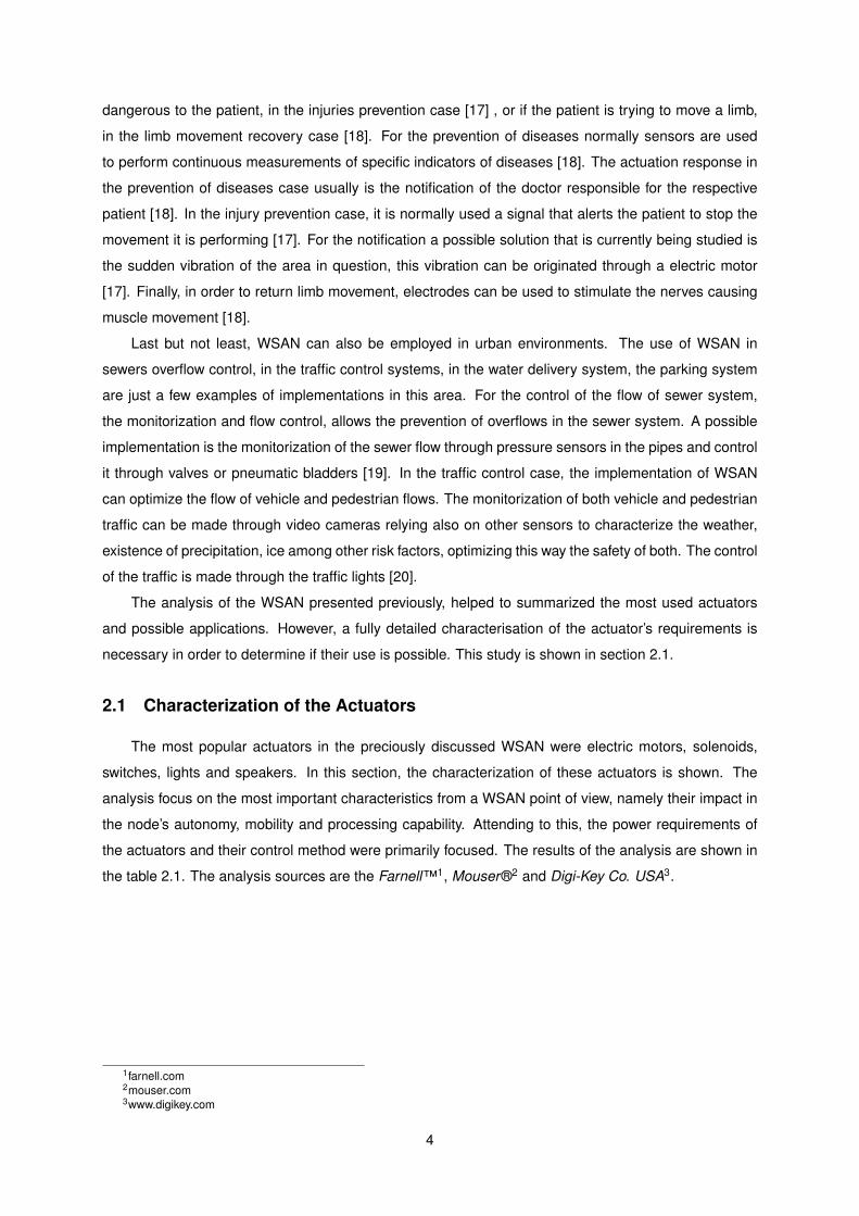
The most popular actuators in the preciously discussed WSAN were electric motors, solenoids,
switches, lights and speakers. In this section, the characterization of these actuators is shown. The
analysis focus on the most important characteristics from a WSAN point of view, namely their impact in
the node’s autonomy, mobility and processing capability. Attending to this, the power requirements of
the actuators and their control method were primarily focused. The results of the analysis are shown in
the table 2.1. The analysis sources are the Farnell™1, Mouser®2 and Digi-Key Co. USA3.
1farnell.com2mouser.com3www.digikey.com
4
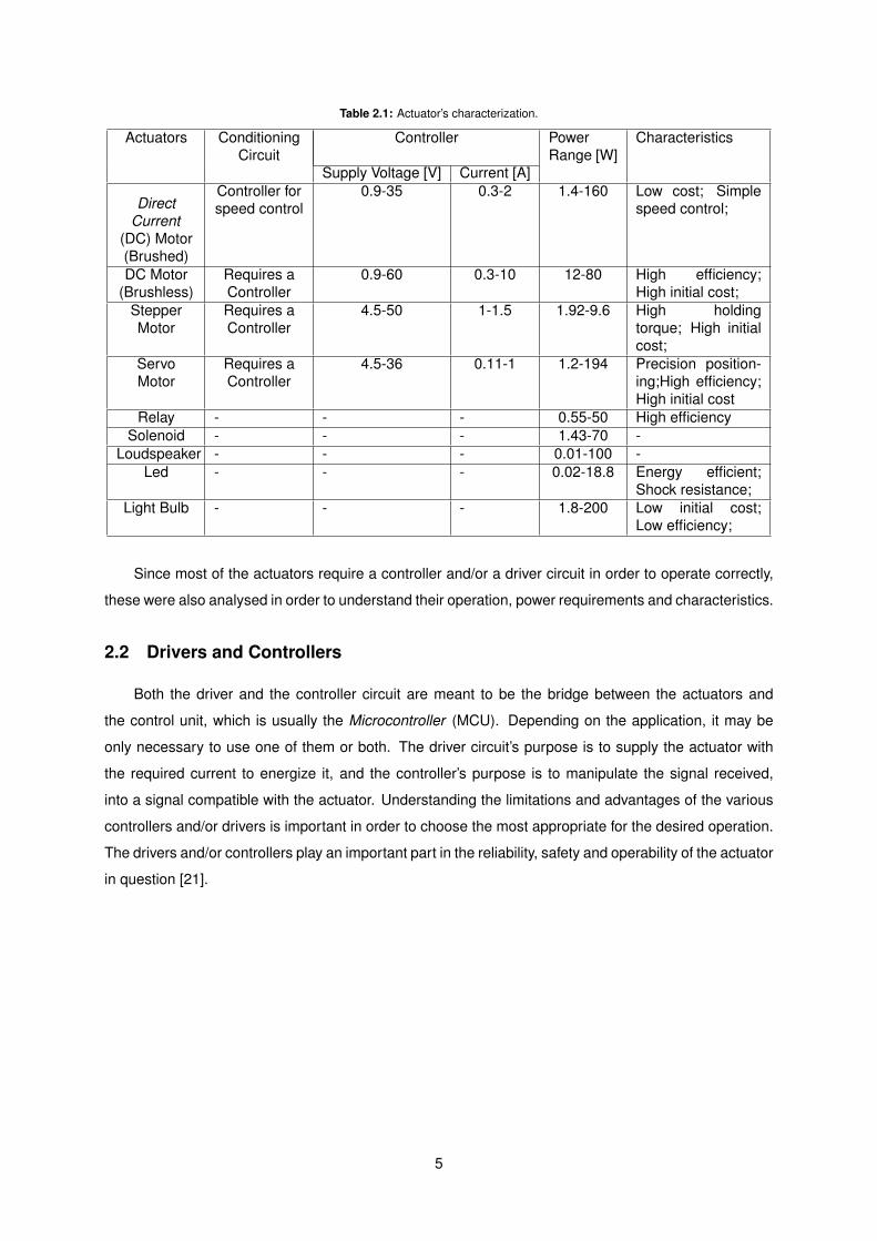
Table 2.1: Actuator’s characterization.
Actuators ConditioningCircuit
Controller PowerRange [W]
Characteristics
Supply Voltage [V] Current [A]
DirectCurrent
(DC) Motor(Brushed)
Controller forspeed control
0.9-35 0.3-2 1.4-160 Low cost; Simplespeed control;
DC Motor(Brushless)
Requires aController
0.9-60 0.3-10 12-80 High efficiency;High initial cost;
StepperMotor
Requires aController
4.5-50 1-1.5 1.92-9.6 High holdingtorque; High initialcost;
ServoMotor
Requires aController
4.5-36 0.11-1 1.2-194 Precision position-ing;High efficiency;High initial cost
Relay - - - 0.55-50 High efficiencySolenoid - - - 1.43-70 -
Loudspeaker - - - 0.01-100 -Led - - - 0.02-18.8 Energy efficient;
Shock resistance;Light Bulb - - - 1.8-200 Low initial cost;
Low efficiency;
Since most of the actuators require a controller and/or a driver circuit in order to operate correctly,
these were also analysed in order to understand their operation, power requirements and characteristics.
2.2 Drivers and Controllers
Both the driver and the controller circuit are meant to be the bridge between the actuators and
the control unit, which is usually the Microcontroller (MCU). Depending on the application, it may be
only necessary to use one of them or both. The driver circuit’s purpose is to supply the actuator with
the required current to energize it, and the controller’s purpose is to manipulate the signal received,
into a signal compatible with the actuator. Understanding the limitations and advantages of the various
controllers and/or drivers is important in order to choose the most appropriate for the desired operation.
The drivers and/or controllers play an important part in the reliability, safety and operability of the actuator
in question [21].
5

2.2.1 Electric Motors
The control of electric motors analysed in table 2.1, with the exception of the DC brushed motor, is
made through the use of a controller to function correctly. The controller is determined by the type of
electric motor and the task it is required to perform. The DC brushed motor, although it does not need a
controller to function, may use a controller to control the speed of the shaft rotation. In this type of motor,
the speed is directly proportional to the supply voltage. There are two methods to vary the amplitude of
the output voltage. The first is called linear output control and the second, which is predominant in small
and medium size motors, is called Pulse Width Modulation (PWM) [22]. In the first method the amplitude
of the voltage applied at the motor’s terminals is controlled through the use of a chopper circuit. This
method requires a controlled rectifier, thus having higher costs than the second method. In the second
method the amplitude of the voltage applied at the motor’s terminals is constant, allowing the use of
cheaper uncontrolled rectifiers to provide this voltage. The principle of the PWM method is shown in
Figure 2.1.
0
1
2
3
4
5
6
7
8
9
10
11
12
Ap
plie
d V
olt
age
H-bridge Control Methods
PWM Control
PWM Equivalent Output
Linear Control
Figure 2.1: H-bridges Control Methods.
The control is made varying the on and off times, called duty cycle, within each period of the signal.
The voltage applied at the motor’s terminals is the result of the mean of the voltage in each period [23],
and can be described by the equation (2.1). The frequency of the signal in this method is kept constant,
and its value is normally limited by the controller characteristics.
Vequivalent =(V +×
(Pulsewidth)) +
(V −×
(Period− Pulsewidth)) (2.1)
The direction of the rotation in the DC brushed motor is dependent only by the current direction,
therefore the control of the direction is simply a matter of reversing the current direction [22]. This is
usually made through the driver circuit.
The most common drivers are the unipolar, so called because it produces unidirectional currents,
and bipolar, so called because it produces bidirectional currents, also called H-bridge. These can be ap-
plied not only in electric motors but in a variety of applications [24]. Both drivers are shown in Figure 2.2.
Their use allows a simple control over the power and direction of the current applied to the load. The
unipolar circuit is suitable for permanent magnet devices and hybrid steppers. This solution is simpler
and cheaper, but when dealing with electric motors, it only works with unipolar and bifilar motors. The
bipolar circuit is more versatile, it is able to reverse the flow of the current applied to the load, this ability
6

allows the control of bipolar stepper motors, DC motors, brushed and brushless, push-pull solenoids
and many other similar actuators.
VSUPPLY
SW 1
SW 2
SW3
SW 4
VSUPPLY
SW 2
(A) (B)
SW 1
LOAD LOAD
Figure 2.2: Bipolar and Unipolar Drivers.
In both cases, the control of the circuit is made by opening or closing the switches. In the unipolar case,
the control of the switches dictates which phase is energized. In the bipolar case the control is more
complex, and some precautions have to be taken. With four switches the bipolar controller offers sixteen
possible operation modes, but seven will damage the circuit by short-circuiting the power supply, leaving
nine operation modes.
The implementation of this type of drivers in electric motors means that invariably the load is in-
ductive, being a winding of the electric motor. Due this fact the implementation of this circuits requires
additional circuitry in order to prevent the appearance of dangerously high voltages each time the induc-
tive load is switched off. The origin of this phenomenon lies in the fact that the voltage in an inductor is
proportional to the rate of change of the current, as it is shown in the equation 2.2 [22].
V = Ldi
dt(2.2)
Through equation 2.2 it is possible to conclude that switching off inductors in order to force the
current to zero quickly, produces a very large self-induced voltage. These voltages can be high enough
to damage the electronic components connected to it. In order to prevented this phenomenon, diodes
need to be used, sometimes called ’freewheel diodes’ as shown in Figure 2.2. The purpose of the diodes
is to offer a one-way valve for the current to flow until the energy stored in the inductor is depleted. The
existence of the diodes also limits the voltage present at the switch terminals, preventing the appearance
of high voltages when these are switched off [22].
In order to operate with a DC brushless motor or stepper motor, unlike the DC brushed motor, it
is required a controller. The task of the controller, for both motors, is to make sure that the current is
applied to the correct winding in the correct direction and at the correct time [23]. This process is called
commutation. Usually PWM methods are employed. Since it is necessary to provide, for both motors,
positive and negative currents pulses in the windings, in order to correctly function, it is normally used
the bipolar driver [23]. However, in the case of the stepper motor, unipolar drivers can be used in the
7
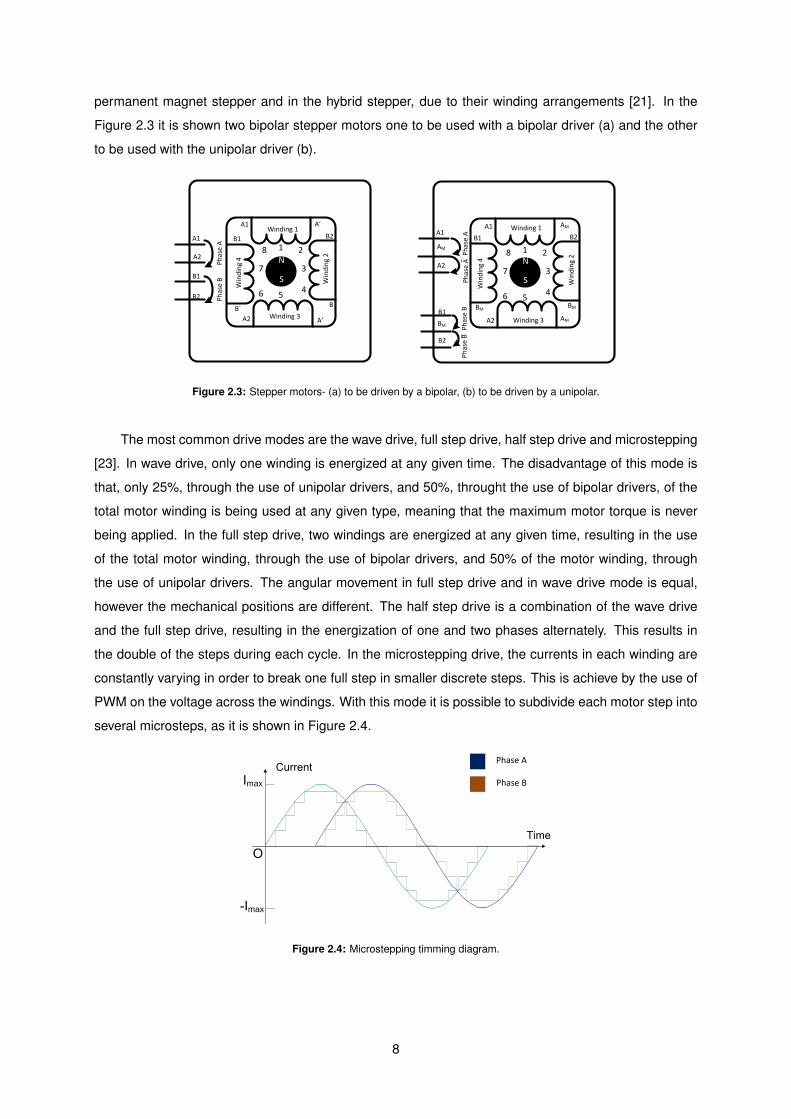
permanent magnet stepper and in the hybrid stepper, due to their winding arrangements [21]. In the
Figure 2.3 it is shown two bipolar stepper motors one to be used with a bipolar driver (a) and the other
to be used with the unipolar driver (b).
Ph
ase
B
A1
A2
B1
B2
A’
B´
A’
B´
A1
A2
B1 B2
N
S
A1
A2
B1
B2
A1
A2
B1 B2
N
S
AM
AM
BM
BMBM
AM
1
5
37
2
46
81
5
37
2
46
8
Win
din
g 2
Winding 1
Winding 3
Win
din
g 4
Ph
ase
A
Win
din
g 2
Winding 1
Winding 3
Win
din
g 4
Ph
ase
BP
has
e A
Ph
ase
AP
has
e B
Figure 2.3: Stepper motors- (a) to be driven by a bipolar, (b) to be driven by a unipolar.
The most common drive modes are the wave drive, full step drive, half step drive and microstepping
[23]. In wave drive, only one winding is energized at any given time. The disadvantage of this mode is
that, only 25%, through the use of unipolar drivers, and 50%, throught the use of bipolar drivers, of the
total motor winding is being used at any given type, meaning that the maximum motor torque is never
being applied. In the full step drive, two windings are energized at any given time, resulting in the use
of the total motor winding, through the use of bipolar drivers, and 50% of the motor winding, through
the use of unipolar drivers. The angular movement in full step drive and in wave drive mode is equal,
however the mechanical positions are different. The half step drive is a combination of the wave drive
and the full step drive, resulting in the energization of one and two phases alternately. This results in
the double of the steps during each cycle. In the microstepping drive, the currents in each winding are
constantly varying in order to break one full step in smaller discrete steps. This is achieve by the use of
PWM on the voltage across the windings. With this mode it is possible to subdivide each motor step into
several microsteps, as it is shown in Figure 2.4.
max
max
Phase A
Phase B
Figure 2.4: Microstepping timming diagram.
8
The characteristics of the discussed drive modes are summarized in table 2.2, with the exception of
the microstep.
Table 2.2: Common drive modes for brushless motors.
Drive Mode Phase Position Nº of positionsA B A B• 1
• 3Wave Mode
• 5 4
• 7• • 2
• • 4Full Step
• • 6 4
• • 8• 1• • 2
• 3• • 4
Half Step• 5 8
• • 6• 7
• • 8
The servo motor’s control is quite different from the previous discussed electric motors. The main
reason is that servo motors are used in closed-loop position control, meaning that the position of the
shaft is measured in order to increase precision. The control of the position is usually achieved through
the use of a potentiometer or through a toothed belt [22]. These components provide the feedback
necessary for the controller to rotate the shaft into the desired position with high precision. In regards to
the driver circuit, it must provide high gains in order to minimize position errors caused by static friction
[22]. Due to the complexity of the controller and driver circuit, and also due to the fact that most of the
servo motors available in the market already have both circuits integrated in the motor and their interface
is standardized [25]. The study of the servo motor control is composed by the analysis of the standard
interface.
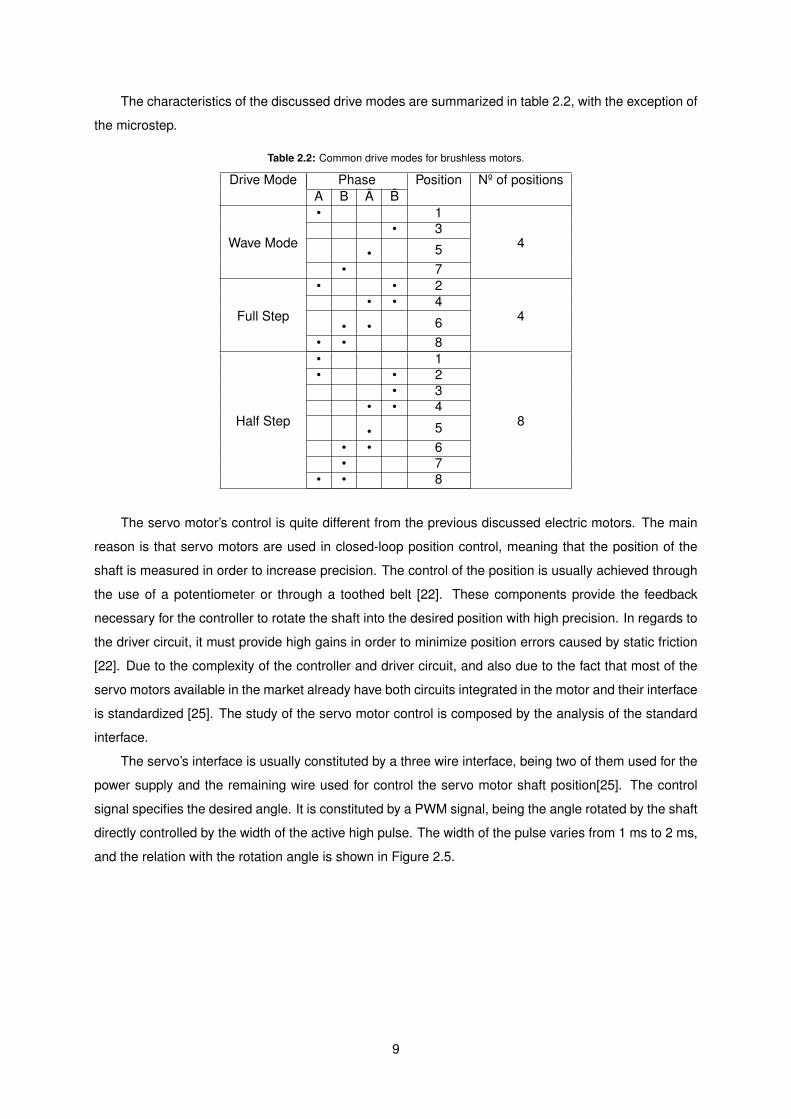
The servo’s interface is usually constituted by a three wire interface, being two of them used for the
power supply and the remaining wire used for control the servo motor shaft position[25]. The control
signal specifies the desired angle. It is constituted by a PWM signal, being the angle rotated by the shaft
directly controlled by the width of the active high pulse. The width of the pulse varies from 1 ms to 2 ms,
and the relation with the rotation angle is shown in Figure 2.5.
9
3
The servo is controlled by a Pulse Width Modulation [PWM]. The width of the pulse dictates the
amount of degrees the engine will spin. In figure 2, it’s shown the relationship between both.
The values shown in the figure 2 were retrieved from the futaba website, and the correct
functioning of the servo using these values is not guaranteed.
The control of a servo motor is made through a three wire connection, containing the power
supply, ground and the control signal. In order to control a servo motor with the Overboard an
external power source is required. The characteristics of that power source are described in the
table 7. The output connectors and respective pinout are shown in figure 6. The connections in
the servo motors connectors can change from brand to brand. The connection should be
carefully supervised.
Triac Control
The triac is an electronic device, whose electrical characteristics are very convenient for
controlling the Alternating Current (AC) from the power grid. It is used to switch and/or dim low
power devices connected to the power grid. Because the triacs are very sensitive to high values
of dv/dt, special care needs to be taken when dealing with inductive loads.
The control of the triggering in the triac is made through a zero voltage crossing circuit, whose
purpose is to detect the zero current points. When a zero point is detected, the user can
choose to fire, or not, the triac. It can only be fired in the beginning of each phase, due to the
method (zero voltage crossing circuit) used to control it.
The triac and its driver circuit are located in an accessory board, called Power Board (figure 3),
due to the elevated power that are present in their terminals, capable of destroying the
Overboard. The Power Board has an opto-isolation between the Overboard connection and the
electrical grid. The output connectors are shown in figure 6.
1 ms
1.5 ms
2 ms
Minimum Pulse
Neutral Position
Maximum Pulse
0º
90º
180º
Figure 2 - Angle vs Pulse width Figure 2.5: Servo motor rotation angle control.
2.2.2 Power Line Actuation
The control of devices connected to the alternating current (AC) power line is usually done with
relays or triacs[26]. The control is normally made through the regulation of the power applied to the
devices. These being mainly electric motors, transformers, resistance heating, lamps among others
[26]. Normally the regulation of the power applied to the devices is made through switching, which
enables primarily on and off operations, and through dimming, limiting the power delivered to the device.
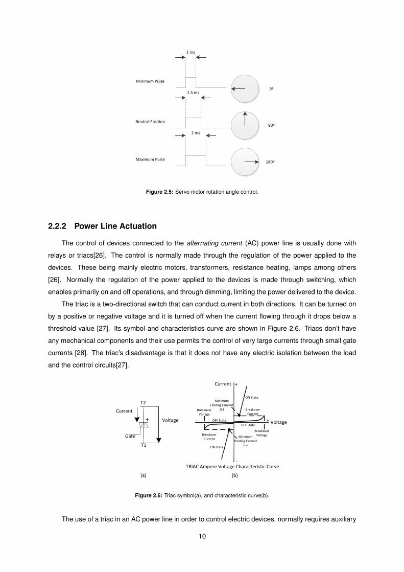
The triac is a two-directional switch that can conduct current in both directions. It can be turned on
by a positive or negative voltage and it is turned off when the current flowing through it drops below a
threshold value [27]. Its symbol and characteristics curve are shown in Figure 2.6. Triacs don’t have
any mechanical components and their use permits the control of very large currents through small gate
currents [28]. The triac’s disadvantage is that it does not have any electric isolation between the load
and the control circuits[27].
T2
T1
Gate
+
-
Current
(a)
Current +
-
Voltage Voltage+-
Breakover Current
Breakover Current
Breakover Voltage
Breakover Voltage
Minimum Holding Current
(IH)
Minimum Holding Current
(IH)
ON State
ON State
OFF State
OFF State
TRIAC Ampere Voltage Characteristic Curve
(b)
Figure 2.6: Triac symbol(a), and characteristic curve(b).
The use of a triac in an AC power line in order to control electric devices, normally requires auxiliary
10

hardware to operate correctly. The reason for this, is because the AC power line signal is composed
by a sinusoidal waveform with no DC component, causing the triac to enter the off state each time the
current, flowing through it, becomes inferior to the holding current. In order to overcome this problem,
a zero crossing detector can be used to detect the point where there is no current and re-trigger the
device, causing a continuous on state, when required. Due to the non-symmetrical nature of the triac,
the triggering of the positive and negative cycles is not at the same voltage level. In order to provide a
symmetrical triggering, a trigger device is used, normally a diac[29].
Load
AC Zero Crossing Detector
Triac Trigger
Time
CurrentOn the Load
Figure 2.7: Triac, control diagram.
The triac can also operate as a dimmer device. This can be done by two methods, the phase control
method and the integral cycle control method. In the first method the triggering of the triac is delayed,
reducing the amount of power delivered to the load, as it is shown in Figure 2.8.
Time
CurrentOn the Load
Figure 2.8: Triac, phase control method.
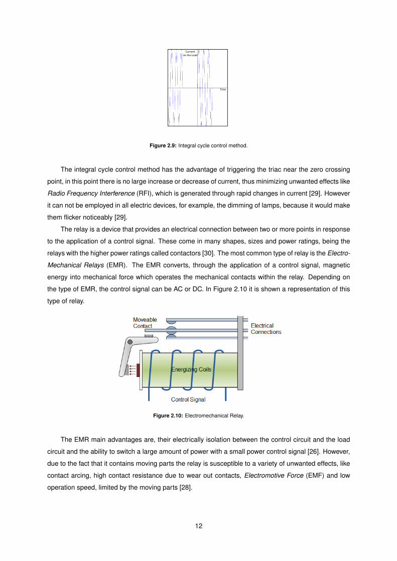
In the second method the number of cycles that the triac is triggered is controlled, allowing the
redution of the overall power applied in the triac, as it is shown in Figure 2.9.
11
Time
Currenton the Load
Figure 2.9: Integral cycle control method.
The integral cycle control method has the advantage of triggering the triac near the zero crossing
point, in this point there is no large increase or decrease of current, thus minimizing unwanted effects like
Radio Frequency Interference (RFI), which is generated through rapid changes in current [29]. However
it can not be employed in all electric devices, for example, the dimming of lamps, because it would make
them flicker noticeably [29].
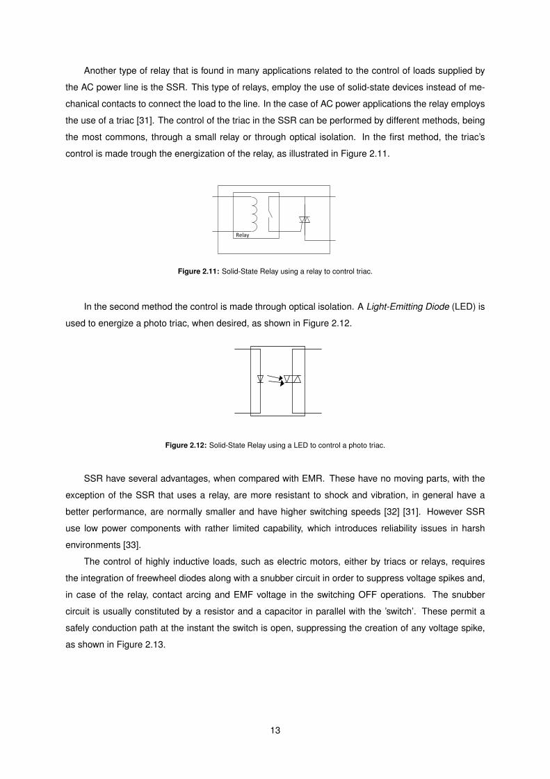
The relay is a device that provides an electrical connection between two or more points in response
to the application of a control signal. These come in many shapes, sizes and power ratings, being the
relays with the higher power ratings called contactors [30]. The most common type of relay is the Electro-
Mechanical Relays (EMR). The EMR converts, through the application of a control signal, magnetic
energy into mechanical force which operates the mechanical contacts within the relay. Depending on
the type of EMR, the control signal can be AC or DC. In Figure 2.10 it is shown a representation of this
type of relay.
Figure 2.10: Electromechanical Relay.
The EMR main advantages are, their electrically isolation between the control circuit and the load
circuit and the ability to switch a large amount of power with a small power control signal [26]. However,
due to the fact that it contains moving parts the relay is susceptible to a variety of unwanted effects, like
contact arcing, high contact resistance due to wear out contacts, Electromotive Force (EMF) and low
operation speed, limited by the moving parts [28].
12
Another type of relay that is found in many applications related to the control of loads supplied by
the AC power line is the SSR. This type of relays, employ the use of solid-state devices instead of me-
chanical contacts to connect the load to the line. In the case of AC power applications the relay employs
the use of a triac [31]. The control of the triac in the SSR can be performed by different methods, being
the most commons, through a small relay or through optical isolation. In the first method, the triac’s
control is made trough the energization of the relay, as illustrated in Figure 2.11.
Relay
Figure 2.11: Solid-State Relay using a relay to control triac.
In the second method the control is made through optical isolation. A Light-Emitting Diode (LED) is
used to energize a photo triac, when desired, as shown in Figure 2.12.
Figure 2.12: Solid-State Relay using a LED to control a photo triac.
SSR have several advantages, when compared with EMR. These have no moving parts, with the
exception of the SSR that uses a relay, are more resistant to shock and vibration, in general have a
better performance, are normally smaller and have higher switching speeds [32] [31]. However SSR
use low power components with rather limited capability, which introduces reliability issues in harsh
environments [33].
The control of highly inductive loads, such as electric motors, either by triacs or relays, requires
the integration of freewheel diodes along with a snubber circuit in order to suppress voltage spikes and,
in case of the relay, contact arcing and EMF voltage in the switching OFF operations. The snubber
circuit is usually constituted by a resistor and a capacitor in parallel with the ’switch’. These permit a
safely conduction path at the instant the switch is open, suppressing the creation of any voltage spike,
as shown in Figure 2.13.
13
AC ControlCircuit
Load
Snu
bb
er C
ircu
it
Switch
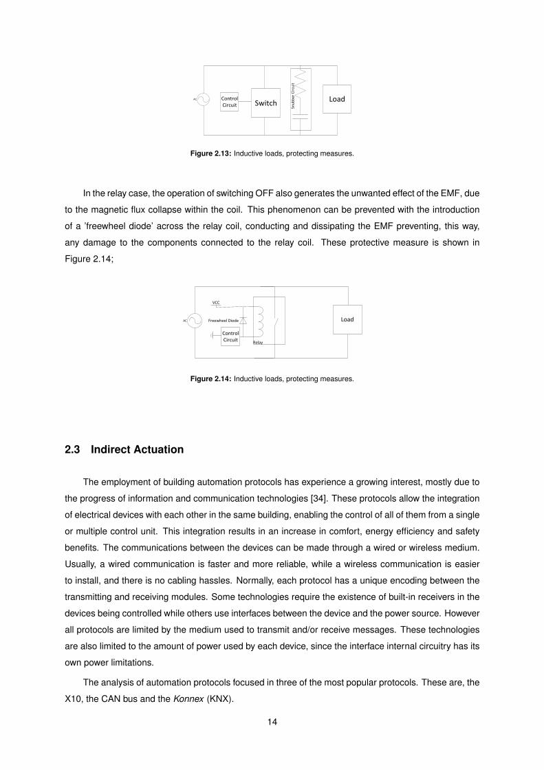
Figure 2.13: Inductive loads, protecting measures.
In the relay case, the operation of switching OFF also generates the unwanted effect of the EMF, due
to the magnetic flux collapse within the coil. This phenomenon can be prevented with the introduction
of a ’freewheel diode’ across the relay coil, conducting and dissipating the EMF preventing, this way,
any damage to the components connected to the relay coil. These protective measure is shown in
Figure 2.14;
AC Load
Relay
VCC
ControlCircuit
Freewheel Diode
Figure 2.14: Inductive loads, protecting measures.
2.3 Indirect Actuation
The employment of building automation protocols has experience a growing interest, mostly due to
the progress of information and communication technologies [34]. These protocols allow the integration
of electrical devices with each other in the same building, enabling the control of all of them from a single
or multiple control unit. This integration results in an increase in comfort, energy efficiency and safety
benefits. The communications between the devices can be made through a wired or wireless medium.
Usually, a wired communication is faster and more reliable, while a wireless communication is easier
to install, and there is no cabling hassles. Normally, each protocol has a unique encoding between the
transmitting and receiving modules. Some technologies require the existence of built-in receivers in the
devices being controlled while others use interfaces between the device and the power source. However
all protocols are limited by the medium used to transmit and/or receive messages. These technologies
are also limited to the amount of power used by each device, since the interface internal circuitry has its
own power limitations.
The analysis of automation protocols focused in three of the most popular protocols. These are, the
X10, the CAN bus and the Konnex (KNX).
14
2.3.1 X10 Protocol
The X10 protocol is a low bandwidth protocol, for signal communication and control of devices over the
power lines. Each device controlled by the X10 protocol is identified by two criteria, the house code and
the unit code, being available sixteen house and unit codes, permitting a total of 256 different codes.
The transmission is made through broadcast, being the device(s) with the matching identification the
only one(s) that process the message. Each communication is constituted by a house code, a unit code
and a command code. In the existence of separate power lines, it’s possible to use plug-in transceiver
devices that communicate through other means of transmission, such as, serial communication, Radio
Frequency (RF) or infra-red signals.
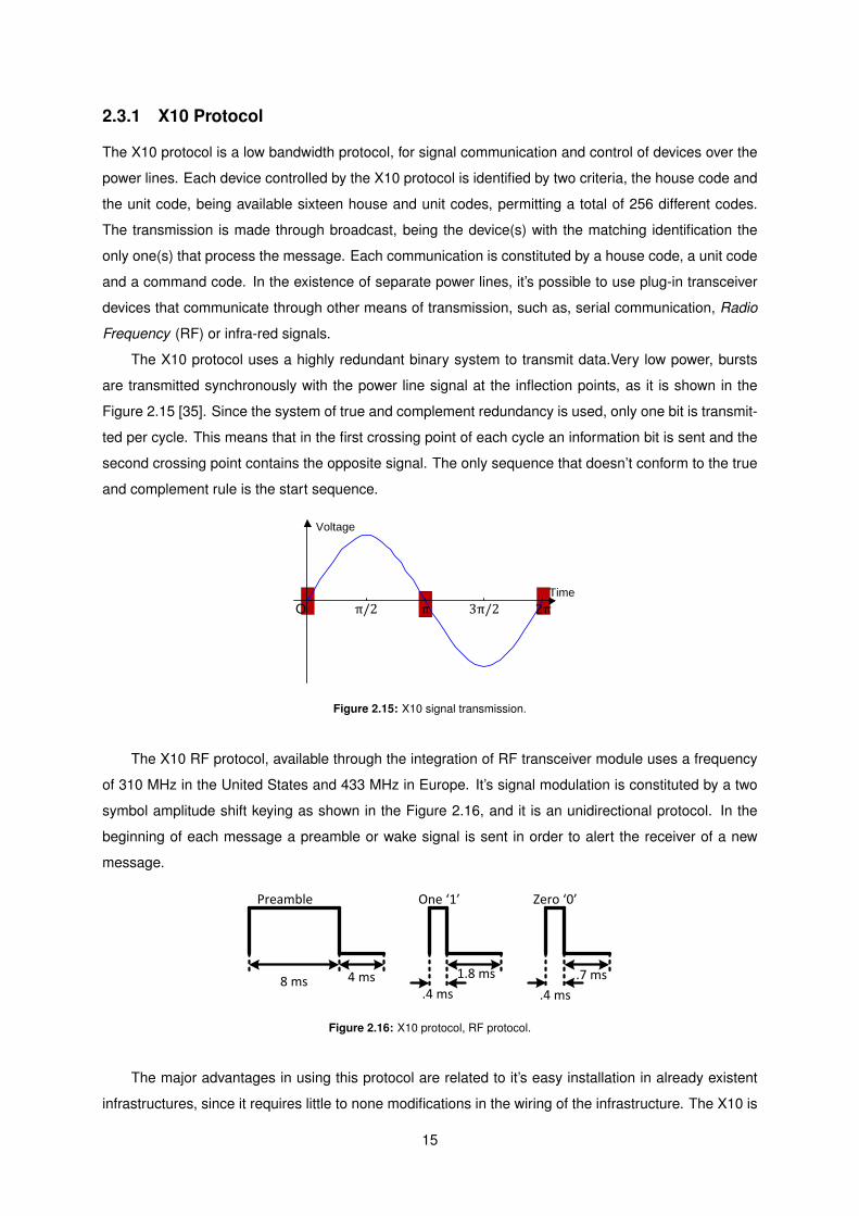
The X10 protocol uses a highly redundant binary system to transmit data.Very low power, bursts
are transmitted synchronously with the power line signal at the inflection points, as it is shown in the
Figure 2.15 [35]. Since the system of true and complement redundancy is used, only one bit is transmit-
ted per cycle. This means that in the first crossing point of each cycle an information bit is sent and the
second crossing point contains the opposite signal. The only sequence that doesn’t conform to the true
and complement rule is the start sequence.
y=-sinx, x∊[0,2π]
O π/2 π 2π3π/2
Voltage
Time
Figure 2.15: X10 signal transmission.
The X10 RF protocol, available through the integration of RF transceiver module uses a frequency
of 310 MHz in the United States and 433 MHz in Europe. It’s signal modulation is constituted by a two
symbol amplitude shift keying as shown in the Figure 2.16, and it is an unidirectional protocol. In the
beginning of each message a preamble or wake signal is sent in order to alert the receiver of a new
message.
Preamble One ‘1’ Zero ‘0’
8 ms 4 ms.4 ms
1.8 ms
.4 ms
.7 ms
Figure 2.16: X10 protocol, RF protocol.
The major advantages in using this protocol are related to it’s easy installation in already existent
infrastructures, since it requires little to none modifications in the wiring of the infrastructure. The X10 is
15
a plug-and-play technology, which means that the implementation of a system is done just by plugging
the modules in the power lines. Since this technology implementation doesn’t requires modifications
in the infrastructures, it is relatively inexpensive and require little expertise to implement it. Another
advantage his the wide variety of products available in the market that use this technology, providing a
plurality of solutions for most needs.
However this protocol has also some limitations. It is a fairly slow protocol, 50 bit/s, which can be
unsuitable for some applications. Another problem is the signal degradation. The use of power lines as
medium of transmission, makes the signal capable of being subverted to a phenomenon called Electro-
Magnetic Interference (EMI) filtration. The inductance combined with the capacitance present in the
power line due to the electrical devices connected to it, are the origin of this phenomenon. In extreme
cases the X10 signal can be eliminated. The implementation of this protocols in electrical systems that
contain more than one phase is also a problem, since each phase is isolated from the others, the X10
signal can not reach devices that are on other phases.In order to solve this problem between each phase
an X10 coupler needs to be installed, this device allows the X10 signal to pass between phases.
2.3.2 CAN Bus
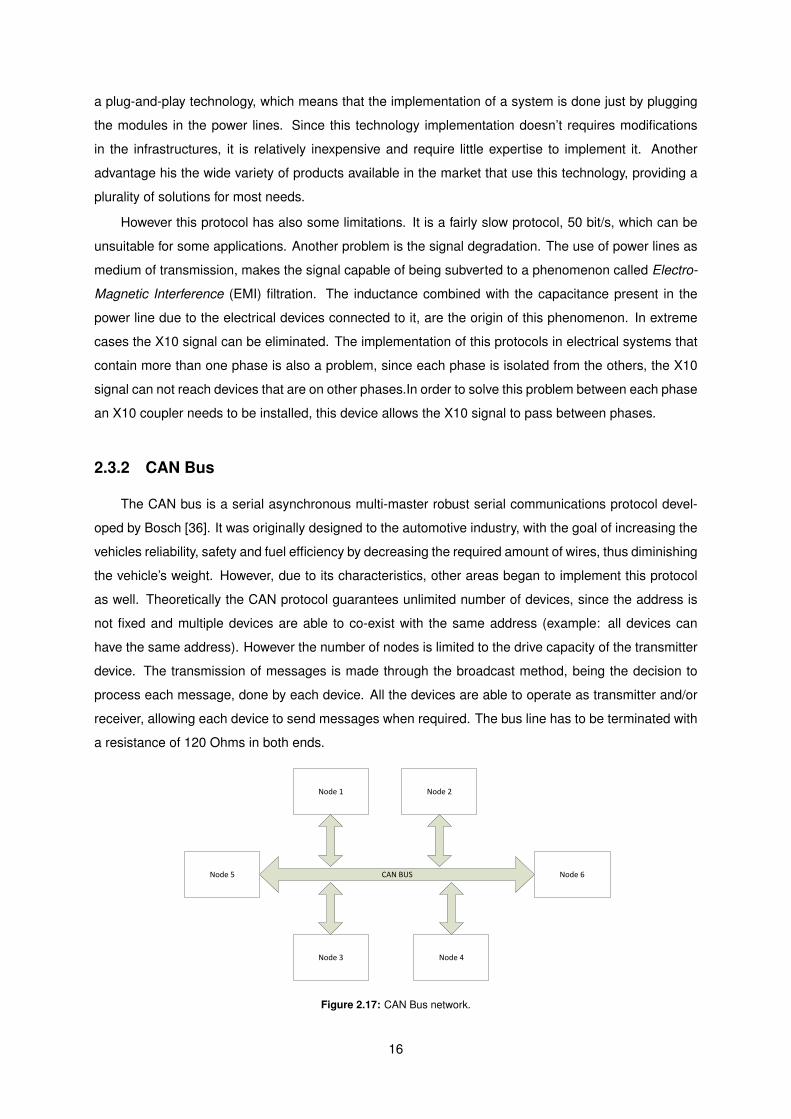
The CAN bus is a serial asynchronous multi-master robust serial communications protocol devel-
oped by Bosch [36]. It was originally designed to the automotive industry, with the goal of increasing the
vehicles reliability, safety and fuel efficiency by decreasing the required amount of wires, thus diminishing
the vehicle’s weight. However, due to its characteristics, other areas began to implement this protocol
as well. Theoretically the CAN protocol guarantees unlimited number of devices, since the address is
not fixed and multiple devices are able to co-exist with the same address (example: all devices can
have the same address). However the number of nodes is limited to the drive capacity of the transmitter
device. The transmission of messages is made through the broadcast method, being the decision to
process each message, done by each device. All the devices are able to operate as transmitter and/or
receiver, allowing each device to send messages when required. The bus line has to be terminated with
a resistance of 120 Ohms in both ends.
Node 1 Node 2
Node 3 Node 4
CAN BUSNode 5 Node 6
Figure 2.17: CAN Bus network.
16

The CAN protocol provides non-destructive bit-wise arbitration by ensuring that the highest priority
message is always transmitted, when multiple nodes transmit simultaneously. It is possible a total of
2032 priorities 1 and a maximum eight data bytes per message. The only exception is when the trans-
mitting nodes have the same priority, in this case both nodes suspend the transmission and try again
after a break off period.
This protocol also provides fault tolerance mechanisms by including a two bit acknowledge field.
The transmitting node waits for the acknowledgement of the receiving node, ensuring that the message
is being received. The CAN bus accepts has a dominant bit the differential voltage of 0.9 V or higher.
This method ensures some noise tolerance, since there is no ground reference, it also makes the com-
munication immune to electromagnetic interferences since, in the case of electromagnetic fields, both
lines are affected preserving the same differential voltage between them.
The communication data rates are dependent on the physical distance between nodes, as it is
shown in Figure 2.18.1000 0
1000 30
800 50
500 100
250 250
125 500
62,5 1000
20 2500
10 5000
0
100
200
300
400
500
600
700
800
900
1000
0 30 50 100 250 500 1000 2500 5000
Data Ra
te (K
Bit/s)
Data Rate vs Bus Length
Bus Length (m)
Figure 2.18: CAN Bus protocol, Data rate vs bus length.
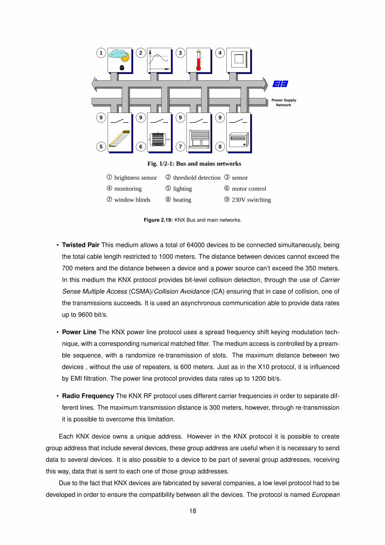
2.3.3 KNX Protocol
The KNX protocol is the only worldwide open standard for building and home control. It was created
by the KNX association. This protocol provides serial data transmission between devices connected
to the bus, and it is designed as a management system in the field of electrical installation for load
switching, environmental control and security of infrastructures, as it is shown in Figure 2.19.
The bus system is designed to be implemented as a decentralized system, but nevertheless it still
allows, when desired, centralized application implementations. The aim of this protocol is the interwork-
ing between sensors and actuators, not being used in “communication only“ applications.
The KNX protocol is supported by several types of media: twisted pair, power line, radio frequency
and ethernet. Also, being an infra-red protocol under development.
1Using standard frames.
17
Introduction to the System
EIBA Handbook Series Page 1/2-5 Version 1.1
1. EIB: User's View
1.1 Introduction to the EIB Technology
1.1.1 General Purpose of EIB
The European Installation Bus (hereafter referred to as "the Installation Bus" or in short as"the Bus") is designed as a management system in the field of electrical installation for loadswitching, environmental control and security, for different types of buildings. The InstallationBus can be installed in large buildings such as business premises, schools, hospitals, factoriesand administration premises as well as in domestic residences. Its purpose is to ensure themonitoring and control of functions and processes such as lighting, window blinds, heating,ventilation, air-conditioning, load management, signaling, monitoring and alarms.
The EIB system allows the bus devices to draw their power supply from the communicationmedium, like Twisted Pair or Powerline (230 V mains). Other devices may, additionally,require power supply from the mains or other sources, as in the Radio Frequency and Infra-redmedia. Fig. 1/2-1 draws some usage examples.
1 2 3 4
Power SupplyNetwork
5
9
8
9
7
9
6
9
Fig. 1/2-1: Bus and mains networks
brightness sensor threshold detection sensor
monitoring lighting motor control
window blinds heating 230V switching
Figure 2.19: KNX Bus and main networks.
• Twisted Pair This medium allows a total of 64000 devices to be connected simultaneously, being
the total cable length restricted to 1000 meters. The distance between devices cannot exceed the
700 meters and the distance between a device and a power source can’t exceed the 350 meters.
In this medium the KNX protocol provides bit-level collision detection, through the use of Carrier
Sense Multiple Access (CSMA)/Collision Avoidance (CA) ensuring that in case of collision, one of
the transmissions succeeds. It is used an asynchronous communication able to provide data rates
up to 9600 bit/s.
• Power Line The KNX power line protocol uses a spread frequency shift keying modulation tech-
nique, with a corresponding numerical matched filter. The medium access is controlled by a pream-
ble sequence, with a randomize re-transmission of slots. The maximum distance between two
devices , without the use of repeaters, is 600 meters. Just as in the X10 protocol, it is influenced
by EMI filtration. The power line protocol provides data rates up to 1200 bit/s.
• Radio Frequency The KNX RF protocol uses different carrier frequencies in order to separate dif-
ferent lines. The maximum transmission distance is 300 meters, however, through re-transmission
it is possible to overcome this limitation.
Each KNX device owns a unique address. However in the KNX protocol it is possible to create
group address that include several devices, these group address are useful when it is necessary to send
data to several devices. It is also possible to a device to be part of several group addresses, receiving
this way, data that is sent to each one of those group addresses.
Due to the fact that KNX devices are fabricated by several companies, a low level protocol had to be
developed in order to ensure the compatibility between all the devices. The protocol is named European
18

Installation Bus Interworking Standard (EIS), and defines all available functions used by the devices
[37].
Although its various benefits, that were discussed previously, the use of the KNX protocol also has
its disadvantages, such as, the high costs associated with the acquisition of KNX devices and the need
for specialized personal for the installation of this type of networks.
19

20

Chapter 3– System Requirements and Architecture
The objective of this chapter is to discuss the requirements of the Overboard and define its architec-
ture. The Overboard’s requirements are the result of the actuation functionalities analysed in Chapter 2
and the requirements established inside GEM. The requirements established are the following:
1. Compatibility with MoteIST, MicaZ and Iris.
2. Ability to control the actuators discussed in Section 2.1.
3. Ability to communicate with X10 protocol, CAN Bus protocol and KNX protocol.
4. Existence of a Test mode, in order to allow the testing of the Overboard for errors.
5. Existence of a MCU, for the automation of the actuation functionalities.
Through the analysis of these requirements it became possible to design a block diagram of the
Overboard, shown in Figure 3.1.
Actuator’sControl
Co
nn
ector
Co
nn
ector
RS-232 Line Converter
RS-232 Line Converter
Bipolar Driver
Signal Driver
Bipolar Driver
Gen
eral Actu
ators
Co
nn
ector
CAN bus transceiver
CA
NC
on
necto
r
Servo M
oto
r C
on
necto
rP
ow
er Bo
ard
Co
nn
ectorHIROSE
CONNECTOR 20 PINS
MCU program connector
HIROSE CONNECTOR 51 PINS
Overboard
PWM control signal
PWM control signal
PWMsignal
ICSP signals
KNX Communication
X10 Communication
I2C signal
Co
nn
ecto
r
TRIAC driver
Isolation
TRIA
C
Neutral
AC supply +
Load terminal +
Load terminal -
HIROSE CONNECTOR
20 PINS
RF Transceiver
MMCXConnector
RF Board
Power Board
UART
UART
Servo motor control signal
Power Supply (3 V)
SPI
Microcontroller
GPIO signals
UART
Altern
ative Po
wer
Co
nn
ector
Actuator’s Power Supply
Co
nso
le C
on
necto
r
Actuator’s Power Supply
Actuator’s Power Supply
Power Supply(3 V)RS-232 Line
Converter
RS-232 Communication
UART
Figure 3.1: Overboard, block diagram.
21

In Figure 3.1 it is shown the Overboard and two auxiliary boards, named Power board and RF board.
The Power board’s purpose is to control AC power devices while the RF board ’s purpose is to take
advantage of the X10 and KNX radio frequency protocols to communicate through them when desired.
The creation of these auxiliary boards has the disadvantages of increasing the building costs, the cost of
the Printed Circuit Board (PCB) and the cost of the extra components, and requiring more space for their
use, the space belonging to the Overboard and the space of each auxiliary board, however, these have
the advantage of being easily replaced, if damaged, not requiring the construction of another Overboard.
The reason for the creation of the Power board, is due to safety reasons since it will be subjected to
currents and voltages that could permanently damage the Overboard if a short-circuit occurred. In the
case of the RF board, the purpose of detaching it from the Overboard, is to permit the use of different
RF boards by the same main board.
The normal control of the Overboard is made through a mote, which can be a MoteIST, Iris or
MicaZ. In order for the Overboard to be interact with all the specified motes, it uses the 51 pins hirose
connector present in all of them. This connector provides communication, power supply and physical
support. The communication with the Overboard is made through a proprietary protocol, described in
detail in Appendix F. Through it, it is possible to interact with the board independently of the serial bus
used.
In order to allow the testing of the Overboard functionalities, a test mode was included. The activa-
tion of this mode allows the control of the board through a console, using a host PC. Through the console
it is possible to activate and deactivate the board’s modules, configure the actuation functionalities, re-
quest the transmission of data and test the sleep mode functionality. The communication protocol used
is the RS-232. The use of this standard is justified due to its simplicity and wide availability. Regarding
the control of actuators, due to the fact that their power requirements, shown in Table 2.1, can be higher
than the power available by the Overboard, an additional connector was integrated in the Overboard in
order to allow the use of another power supply.
3.1 Actuator’s Control
The ability to correctly operate different types of actuators is greatly associated with the amount of energy
available. In the Overboard’s case, the energy available is provided by the node connected to it. Since
the nodes compatible with the Overboard have a power supply composed only by two AA batteries (3 V),
the Overboard’s control over actuators is restricted to small power actuators only. In order to overcome
this limitation, the Overboard permits the integration of an external power supply, with the purpose of
expanding it’s control to more power demanding actuators, like electric motors, solenoids and similar
actuators.
With the purpose of controlling electric motors and solenoids, the Overboard is equipped with two
bipolar drivers (H-bridges), with the liberty to operate independently or together. These drivers were
chosen over the unipolar drivers, because these allows the control of more types of actuators as de-
scribed in section 2.2. The purpose of the existence of two bipolar drivers is to allow the Overboard to
22

control stepper motors.
The control of servomotors, as described in sub-section 2.2.1, requires the integration of a dedicated
connection output, because it is a digital control. After an analysis on the most common servomotors,
the Futaba1, and Hitec2 servomotors, the following specifications were retrieve.
• Typical operating voltages are comprehended between 4.8 V and 6 V.
• Control signal voltage ranges between 3 V and 5 V.
• Wait period of 20 ms between commands.
Due to the fact that most servomotors have a similar interface, described in Appendix E, the Over-
board’s interface is compatible with a wide range of servomotors. The interface is constituted by three
wires, two are related to the power supply and the other is the control signal. The control signal is es-
sentially a variable PWM signal, so in order for the Overboard to control servomotors, it must be able to
generate PWM signals.
Since the typical operating voltages of the servomotors range between 4.8 V and 6 V, these require
the existence of an external power supply in order to function properly.
Regarding the control of devices connected to the AC power line, the Overboard allows the control
of them through the switching of the power line. According to Subsection 2.2.2, the control of these
devices is usually made though relays or triacs. Their main features are described in table 3.1.
Table 3.1: AC power line, main switching devices features.
Device ElectricIsolation
Existenceof movingparts
Unwanted Effects
Triac No NoSwitches off, every time current is below holding cur-rent. Different triggering times in the positive andnegative cycle. Radio frequency interference.
EMR Yes Yes Contact arcing, Electromotive Force, low operatingspeed.
SSR (with smallrelay) Yes Yes Reliability issues due to the use of low power com-
ponents with limited capability.SSR (with opti-cal isolation) Yes No
Through the analysis of table 3.1, it is possible to conclude that the more appropriate switching
device for the Overboard is the SSR with optical isolation, although there may exist reliability issues, it
is the only that doesn’t have moving parts, while providing electrical isolation, allowing higher operating
speeds and protecting the Overboard from any accidental short-circuit with the power line.
The SSR are available as Integrated Circuit (IC) or can be constructed with discrete components,
namely a triac with an optoisolator with a triac output.
1http://www.futaba-rc.com/2http://www.hitecrcd.com/
23

3.2 Automation Protocols Interface
The use of automation protocols, permits the control of vast number of devices expanding the Over-
board’s control abilities greatly, however, in order for the Overboard to be able to operate the devices
connected to each protocol, it is required the integration of an interface for each protocol. These inter-
faces are normally constituted by a controller and a transceiver.
In order to control the devices integrated in a X10 network it is necessary an transceiver. The
communication with the X10 transceivers is made through the X10 serial protocol. Depending on the
chosen transceiver, this protocol can be implemented over the RS-232 standard or the Universal Serial
Bus (USB) standard. Unlike the radio frequency and infrared approaches, this approach uses bidirec-
tional communication in order to check if the messages are being correctly received. The transceiver
used to test the control of the Overboard over the X10 devices is the CM11 from Marmitek, shown in Fig-
ure 3.2, that already exists in-house. When transmitting over the RS-232 standard the communication
uses a data rate of 4800 bit/s, 8 data bits, 1 stop bit and has no parity (8-N-1).
Figure 3.2: CM11, X10 device.
In order for the Overboard to be compatible with the X10’s CM11 transceiver, it is necessary to
be able to communicate through the RS-232 standard. For this, it require the existence of a RS-232
transceiver and a Universal Asynchronous Receiver Transmitter (UART) controller. Since most of the
MCUs available in the market already integrate UART controllers, this becomes a requirement for the
MCU, being only required the integration of a RS-232 transceiver into the Overboard, as shown in
Figure 3.3.
RS-232 Transceiver
(IC)
X10 Transceiver
(CM11)
Microcontroller
UART ControllerCPU
Data Bus UART RS-232
X10 Network
Figure 3.3: RS-232 communication, block diagram.
The control of X10 devices through radio frequency requires the integration of a RF transceiver in
the X10 network. The communication, as described in the Subsection 2.3.1 is unidirectional, uses 433
24

MHz in Europe, and uses two symbol amplitude shift keying (On-Off Keying) as signal modulation. The
transceiver used to test the control of the Overboard over X10 devices based on RF is the TM13 from
Marmitek, shown in Figure 3.4, already existent in-house. It is responsible for receiving the RF signals
and send them through the power line.
Figure 3.4: TM13 RF transceiver from Marmitek.
In order to communicate with the TM13 transceiver it is necessary the integration in the Overboard
of a RF transmitter. The transmitter has to be able to generate the signal described above, and shown
in Figure 2.16.
To access the KNX bus externally, the European Installation Bus (EIB) developed a standard called
Physical External Interface (PEI) that allows the transmission and reception of messages over any KNX
device, however in order to do so a PEI interface is required. It consists of a mechanical/electrical part,
being optional the integration of additional software in the application module. There are 21 types of PEI
interfaces that can be grouped in 3 different categories.
• Parallel I/O communication.
• Serial I/O communication.
• Special purpose.
There PEI interface is composed by 10 pins, as shown in Figure 3.5.
25

PEIBUS Access
Unit
1, 10 : 0 V
6: Type
5: VCC
2, 3, 4, 7, 9: Digital I/O
8: VDD20 V/ 2 mA
(limited)
VCC
100 pF 1 K
1 K
1 K
229 uHRi = 20
47.5 K
100 pF
100 pF
Figure 3.5: PEI Wiring Diagram.
The type of PEI interface is chosen through the insertion of a resistor between the pin 6 and the pin
5. The value of that resistor determines the PEI type. The relation between the value of the resistor and
the type of PEI is shown in Appendix F.
The testing of the control of the Overboard over devices connected to a KNX network is made
through a sample network shown in Figure 3.6.
63
4. TESTES E RESULTADOS
4.1. Rede de Dispositivos EIB/KNX
Para estudo da tecnologia EIB/KNX e posterior desenvolvimento e teste da solução
apresentada nesta tese, foi utilizado um protótipo constituído por vários dispositivos EIB/KNX.
Este protótipo, demonstrado na figura seguinte foi montado por um grupo de alunos da cadeira
de Edifícios Inteligentes e Domótica.
Figura 29 – Protótipo de Dispositivos EIB/KNX
Este protótipo é constituído pelos seguintes dispositivos do fabricante hager:
1. Interruptor quádruplo acoplado ao modulo de 4 entradas TX304
2. Controlador de ambiente TX450
3. Interruptor horário electrónico de 2 canais TX022
4. Módulo de 4 estores TX223
5. Módulo de iluminação de intensidade variável TX210
Figure 3.6: KNX network with several KNX devices.
It is constituted by the KNX devices described in Table 3.2, all of them belonging to the Hager brand.
26

Table 3.2: KNX devices available in bus.
Device number Device name Description1 TX304 4 flush mounted inputs2 TX450 Environment controller3 TX022 Electronic schedule with 2 channels4 TX223 4 shutters or blinders controller
5 and 6 TX210 Universal dimmer7 TX350 RF transceiver8 TH002 Media coupler for bus system9 - disconnector
10 TX111 Power supply module
There are two transceivers available to communicate with the network the ’TH002’ and the ’TX350’.
The ’TH002’ communicates with the control unit through the RS-232 standard, and it uses the PEI
type 16 protocol to communicate with the control unit. This protocol provides a serial asynchronous
communication, with a data rate of 9600 bit/s, 8 data bits, 1 stop bit and with no parity. It makes use of
five signal wires of the RS-232 standard, namely the transmit, the receive, the request to send, the clear
to send and the ground wires.
The ’TX350’ is RF transceiver, it uses Frequency Shift Keying (FSK) modulation with a frequency of
868 MHz. In order to use this transceiver to send messages through the KNX bus, the Overboard must
have a RF transceiver.
The use of the CAN Bus protocol, requires the existence of a CAN controller and a CAN transceiver.
Since there are various MCUs with CAN controllers integrated, this becomes a requirements for the
choice of the MCU. As for the transceiver, it’s integration in the Overboard is essential, since it provides
the ’bridge’ between the CAN Bus and the controller, as it is shown in Figure 3.7.
Control Unit
CAN Bus Controller
CAN Transceiver
CAN High
CAN Low
Receive Data
Transmit Data
CAN Bus
Figure 3.7: CAN Bus Interface.
27
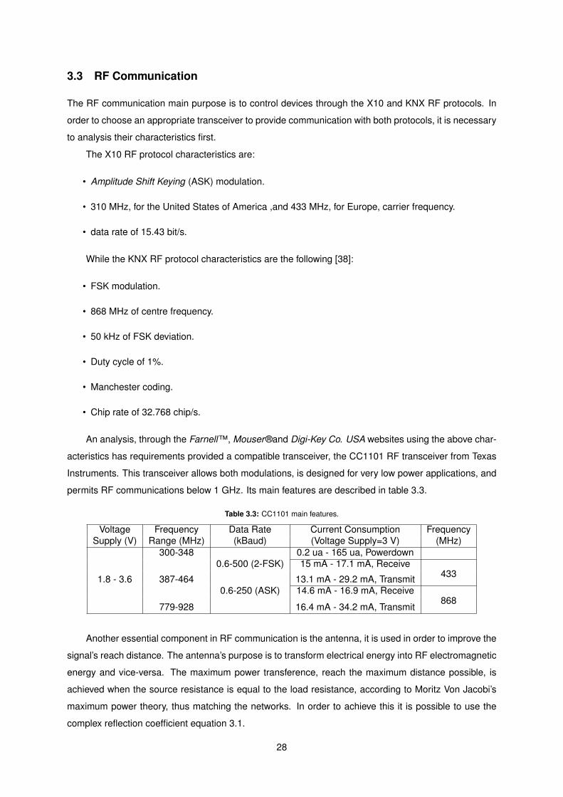
3.3 RF Communication
The RF communication main purpose is to control devices through the X10 and KNX RF protocols. In
order to choose an appropriate transceiver to provide communication with both protocols, it is necessary
to analysis their characteristics first.
The X10 RF protocol characteristics are:
• Amplitude Shift Keying (ASK) modulation.
• 310 MHz, for the United States of America ,and 433 MHz, for Europe, carrier frequency.
• data rate of 15.43 bit/s.
While the KNX RF protocol characteristics are the following [38]:
• FSK modulation.
• 868 MHz of centre frequency.
• 50 kHz of FSK deviation.
• Duty cycle of 1%.
• Manchester coding.
• Chip rate of 32.768 chip/s.
An analysis, through the Farnell™, Mouser®and Digi-Key Co. USA websites using the above char-
acteristics has requirements provided a compatible transceiver, the CC1101 RF transceiver from Texas
Instruments. This transceiver allows both modulations, is designed for very low power applications, and
permits RF communications below 1 GHz. Its main features are described in table 3.3.
Table 3.3: CC1101 main features.
Voltage Frequency Data Rate Current Consumption FrequencySupply (V) Range (MHz) (kBaud) (Voltage Supply=3 V) (MHz)
300-348 0.2 ua - 165 ua, Powerdown0.6-500 (2-FSK) 15 mA - 17.1 mA, Receive
1.8 - 3.6 387-464 13.1 mA - 29.2 mA, Transmit 433
0.6-250 (ASK) 14.6 mA - 16.9 mA, Receive
779-928 16.4 mA - 34.2 mA, Transmit868
Another essential component in RF communication is the antenna, it is used in order to improve the
signal’s reach distance. The antenna’s purpose is to transform electrical energy into RF electromagnetic
energy and vice-versa. The maximum power transference, reach the maximum distance possible, is
achieved when the source resistance is equal to the load resistance, according to Moritz Von Jacobi’s
maximum power theory, thus matching the networks. In order to achieve this it is possible to use the
complex reflection coefficient equation 3.1.
28

Γ =Za − Z0
Za + Z0(3.1)
This equation is equal to zero when the antenna is perfectly matched with the transmission line,
thus delivering all the applied power to the antenna. Other equations are also used in the matching of
antennas, such as the return loss and the voltage standing wave ratio. The antenna performance is also
affected by other factors, such as, the antenna placement, the ground planes, undesired magnetic field
of the PCB, obstacles in the line of sight, antenna gain characteristics, antenna bandwidth and antenna
radiation efficiency [39].
The design of the antenna is normally conditioned by the size, cost and performance. In table 3.4,
it is shown the most common types of antennas, along with their advantages and disadvantages.
Table 3.4: Characteristics for different antenna solutions.
Antenna types Advantages DisadvantagesPCB Antenna Very Low Cost. Potentially large sizes at lower frequencies.
Small sizes at high frequencies. Difficult to design small and efficientantennas for frequencies lower than 433 MHz.
Good performance for frequencieshigher than 868 MHz.
Standard design antennaswidely available
Chip Antenna Small size. Medium Performance.
Medium Cost.Whip Antenna Good Performance. High Cost.
Difficult to fit in many applications.Wire Antenna Very cheap. Mechanical manufacturing of antenna.
The antennas can be further divided into single ended and differential antennas. Single ended
antennas receive a signal which is referenced to ground and the characteristic input impedance is usually
50 Ω. These type of antennas normally requires a network that transforms the signal from balanced to
unbalanced, a balun, since most of the RF IC’s have differential, balanced, RF ports. The differential
antennas don’t require the use of a balun circuit resulting a lower number of components. In both
antennas it is still required to match the impedance of the RF port of the radio with the antenna, and if
desired, the integration of filters [39].
3.4 Main Hirose connector
The MoteIST, MicaZ and Iris, all share a common connector, the 51 pin hirose, with equal pinout.
This connector provides twelve lines of serial communication, with the ability of communication through
UART, Inter-Integrated Circuit(I2C) and Serial Peripheral Interface (SPI). It also has eight Analogue to
Digital Converter (ADC) inputs, four interrupt lines, eight power control lines, three PWM outputs, three
pins reserved for sensor boards communications, four power supply lines and nine General Purpose
29

Input Output (GPIO) pins. These connector’s pins are shown in Figure 3.8. By using this connector to
communicate with the mote, the compatibility with all these motes is ensured.
Hir
ose
Co
nn
ecto
r1
2
3
4
5
6
7
8
9
10
11
12
13
14
15
16
17
18
19
20
21
22
23
24
25
27
28
29
30
31
32
33
34
35
36
37
38
39
40
41
42
43
44
45
46
47
48
49
50
5126
Pin number Description Pin number Description1 Ground 27 UART 0 Receive
2 Sensor Supply 28 UART 0 Transmit
3 GPIO 29 Power Control 0
4 GPIO 30 Power Control 1
5 GPIO 31 Power Control 2
6 GPIO 32 Power Control 3
7 Battery Voltage monitor Enable 33 Power Control 4
8 LED3 34 Power Control 5
9 LED2 35 Power Control 6
1 LED1 36 ADC Input 7/Battery monitor/JTAG TDI
11 GPIO 37 ADC Input 6/JTAG TODO
12 GPIO 38 ADC Input 5/JTAG TMS
13 GPIO 39 ADC Input 4/JTAG TCK
14 Power Control 7 40 ADC Input 3
15 USART 1 Clock 41 ADC Input 2
16 Serial Program MOSI 42 ADC Input 1
17 Serial Program MISO 43 ADC Input 0/ RSSI monitor
18 SPI, Serial Clock 44 Temperature Sensor Enable
19 USART 1 Receive Data 45 THRU Connector 1
20 USART1 Transmit Power 46 THRU Connector 2
21 I2C Bus Clock 47 THRU Connector 3
22 I2C Bus Data 48 Reset
23 GPIO\PWM0 49 GPIO/PWM1B
24 GPIO/PWM1A 50 Digital Supply
25 GPIO/AC+ 51 Ground
26 GPIO/AC‐
Figure 3.8: 51 pin, Hirose connector diagram.
Due to it’s characteristics, the hirose connector also provides physical support to the Overboard.
However the size of the board should be as smaller as possible in order to not compromise the con-
nector’s physical support. Since there are several communication protocols available through the hirose
connector, an analysis was made in order to find out the most appropriate to be used for the communi-
cation between boards. The analysis is shown in Table 3.5.
Table 3.5: Communication protocols available in the hirose connector.
CommunicationProtocol
Maximum Bitrate (KBit/s) Existent lines
I2C 1000 Serial Data Line (SDA), Serial Clock Line (SCL).
SPI 20000 Serial Clock (SCLK), MOSI (Master Output Slave Input), MISO(Master Input Slave Output), SS (Slave Select).
UART 115,200UART Transmit (UTX), UART Receive (URX), UART Clock(BCLK) and the optional Clear to Send (UCTS) and Request toSend (URTS).
After an analysis on the available protocols, shown in Table 3.5, it was concluded that the most
appropriate is the I2C protocol, due to the fact that it requires only two signal wires, simplifying the design
of the board, and the fact that it allows multiple devices to start communications has masters, permitting
both boards to transmit messages between each other. In order for the Overboard to communicate
30

through this protocol it requires the existence of a I2C controller.
The Overboard is also powered through the hirose connector, since it is the only connection between
the both boards. All the three analysed motes, MoteIST [40], Iris [41] and MicaZ [42], provide a voltage
of 3 V. However the maximum current available for the Overboard is limited due to the hirose connector
electrical characteristics to 500 mA.
The design of modular systems is a preventive measure. By dividing the board’s system in modules,
and attributing some degree of autonomy to each, it is possible to design a more robust system. If a
module fails, it will not disrupt the correct operation of the other modules. It also provides an easier
system repair or upgrade, requiring only the replacement of the malfunctioning or outdated module.
3.5 RF connector
Taking advantage and, in order to maintain compatibility with the already built RF boards in-house, the
Overboard’s RF transceivers are built in individual modules connected to the board through a 20 pins
hirose connector. This strategy, provides compatibility with the RF boards existent for the MoteIST, while
maintain the modularity of the RF system. In order to maintain compatibility its necessary to integrate
in the Overboard the same connector and pin functionalities. The connector is shown in Figure 3.9, and
it’s pins are described in Table 3.6.
Table 3.6: RF Board connector, pin functionalities.
Pin number Pin Functionality1 GPIO2 GPIO3 GPIO4 GPIO5 GPIO6 GPIO7 GPIO8 GPIO9 GPIO10 GPIO11 UART, Transmit12 GPIO13 UART, Receive14 GPIO15 Voltage Supply16 SPI, SS17 Ground18 SPI, MOSI19 SPI, SCLK20 SPI, MISO
31

Figure 3.9: RF Board connector.
In order to integrate this connector and provide the same functionalities it is necessary for the
Overboard to have SPI and UART communication. Despite being the main objective of this connector
the interface with RF boards, it can be used for other purposes, the only restriction is the pre-defined pin
functionalities of the connector.
3.6 MCU Interface
The MCU is a fundamental component in the Overboard. It is responsible for the automation of the
board’s functionalities. In order to obtain a MCU able to control all the Overboard operations and com-
munications, several characteristics are required.
• Existence of an I2C controller, in order to correctly communicate with the mote.
• Ability to be supplied through the 50 pin hirose connector.
• Capability of generating a PWM signal in order to control the servo motors and take fully advantage
of the bipolar drivers.
• Existence of a UART controller, in order to communicate with 10 transceiver, CM11, the KNX
transceiver, TH002 and the 20 pin hirose connector.
• Existence of a SPI controller, in order to provide SPI communication through the 20 pin hirose
connector.
• Existence of a CAN controller, for CAN communication.
• Ability to enter low power modes, in order to lower the Overboard’s consumption.
After analysing the current available MCUs in the market, through the Farnell™, Mouser®and Digi-
Key Co. USA websites, the choice was narrowed to the following MCU families, which were considered
the most appropriate given the requirements previously mentioned.
• STM8S208xx family from STMicroelectronics - These 8-bit MCU have the ability to provide CAN
bus, UART, SPI and I2C communications interface. They have two 16 bit timers with PWM signal
generation capability. The maximum core frequency is 24 MHz providing a maximum of 20 Milions
of Instructions Per Second (MIPS). They have a flash memory up to 128 Kbytes, can be supplied
with a voltage from 2.95 to 5.5 V and consume a maximum current of 60 mA in active mode and
a minimum current of 9 uA in powerdown mode. They are able to generate an internal clock up to
32

16 MHz. These MCU are available in LQFP packages with a maximum size of 14 x 14 mm and a
minimum size of 7 x 7 mm.
• PIC24HJ family from Microchip - These are 16-bit MCU with the ability to process up to 40 MIPS
at 80 MHz. They’re voltage supply can vary from 3 to 3.6 V and consume a maximum of 90 mA
and a minimum of 13 uA in powerdown mode. They are able to communicate through SPI, I2C,
UART and CAN bus. These possess up to eight, 16-bit timers with PWM signal generation ability.
These MCU can have a maximum flash memory of 256 Kbytes. They’re internal clock is capable of
generating a frequency up to 80 MHz. TheseMCU are available in QFN, TQFP, SPDIP and SOIC,
with a maximum size of 14 x 14 mm and a minimum of 6 x 6 mm.
• CY8C38 family from Cypress Semiconductor - These are 8-bit MCU with the ability to operate
at a maximum frequency of 67 MHz and to process up to 33 MIPS. They are able to communicate
through CAN Bus, USB, SPI, I2C and UART protocols. It contains up to four timers able to generate
PWM signals. The flash memory can have up to 64 Kbytes. It supports a voltage supply between
1.71 V and 5.5 V and consumes a maximum of 15.8 mA and a minimum of 200 nA in hibernate
mode. These MCU can generate, from their internal clock, a frequency up to 62 MHz. The
packages available are the SSOP, TQFP and QFN with a maximum size of 14 x 14 mm and a
minimum of 7 x 7 mm.
33

34

Chapter 4– Overboard Design
In this chapter, the Overboard design specifications are discussed. In the first section, the com-
ponents integrated in the Overboard are analysed, their parameters, qualities and requirements. In the
second section, the software developed and implemented is explained in detail, along with the auxiliary
applications created for the control of the Overboard, through a mote or through the test mode.
4.1 Hardware Design
The components used in the Overboard are described and analysed in this section. The analysis
is divided by the main systems, RS-232 interface, CAN interface, Direct actuation interface and the
Microcontroller. During the analysis of the components available nowadays the main concerns were
its cost, consumption and size. The consumption is a very important aspect because the Overboard
is powered by batteries, the lower the consumption the longer the autonomy will be. The size of the
components is important because the Overboard is physically supported by a 51 pin hirose connector
and it’s size should be keep as small as possible in order to not compromise the support integrity.
4.1.1 RS-232 Interface
The Overboard’s RS-232 interface is constituted by a controller, integrated in the MCU and a transceiver.
The transceivers requirements are, the capability to support data rates used by the automation protocols,
in the KNX case, 9600 bit/s, and in the X10, 4800 bit/s. Due to its characteristics the MAX3222 from
Maxim Integrated Products was chosen.
It features:
• Operating voltage supply between 3 and 5.5 V.
• Normal current consumption, with no load of 1 mA.
• Features a shutdown mode that lowers current consumption to 1 uA.
• Provides data rates up to 120kbit/s.
35

4.1.2 CAN Interface
The CAN interface, in resemblance with the RS-232 interface, is composed by a controller, integrated
in the MCU, and a transceiver. In order to choose the most appropriate transceiver for the Overboard,
a market analysis was made, through the Farnell™, Mouser®and Digi-Key Co. USA websites. This
analysis is shown in Table 4.1.
Table 4.1: Market analysis of CAN transceivers.
Component Brand Voltage Available Existence Price (e)name Required (V) Packages of a sleep mode
SN65HVD1050 Texas Instruments 4.5 - 5.5 8 pin SOIC Yes 1.25SN65HVD232 Texas Instruments 3 - 3.6 8 pin SOIC Yes 2.35
MAX3058 Maxim IC 5 8 pin SOIC Yes 1.34MAX3051 Maxim IC 3.3 8 pin SOIC Yes 1.99
8 pin SOT 1.96MCP2551 Microchip 4.5 - 5.5 8 pin PDIP Yes 0.931
8 pin SOIC 0.931
From the analysis of the Table 4.1, the cheapest component is the MCP2551, however it requires a
voltage supply that is not available in the Overboard, meaning that to use this component, a boost regula-
tor would be necessary. The chosen transceiver was the MAX3051, due to the fact that it is the cheapest
component available that operates with the voltage available in the Overboard. This component is avail-
able in two distinct packages, being used the smallest, which is the Small Outline Transistor (SOT)
package.
The MAX3051 features:
• Data rates up to 1 Mbit/s.
• Capable of being connect to 112 nodes in simultaneously.
• Provides protection against short-circuit conditions, high voltage transients and high temperatures.
• Current consumption in normal operation mode is 35 mA, when it is dominant, and 2 mA, when it
is recessive.
• Current consumption in shutdown mode is 1 uA.
36

4.1.3 Direct Actuation Interface
The direct actuation interface is constituted by two bipolar drivers and a servomotor interface . The
bipolar drivers implementation could be done using a discrete component solution or an IC solution.
The IC solution was chosen, due to the fact that the discrete solution would require more space to
be implemented. A analysis on the current available bipolar drivers was made, through the Farnell™,
Mouser®and Digi-Key Co. USA websites in order to choose the most appropriate. This analysis is
shown in Table 4.2.
Table 4.2: Market analysis of Bipolar Drivers.
Voltage (V) Low Nº of Max. DC RDS1 Price
Component Brand Logic Load power Output Current (Ω) (e)Input Supply Mode Drivers (A)
MPC17510 Freescale 4-5.5 2-15 No 1 1.2 0.45 2.87Semiconductor
A3906 Allegro 2-5.5 2.5-9 Yes 2 1 0.52 1.90A3950 Microsystems 2-7 8-36 Yes 1 2.8(peak) 0.35 3.16A4952 2-6 8-40 No 1 2(peak) 0.8 3.44
BD6385 ROHM 2-5.5 10-28 Yes 2 1.2 1 3.18Semiconductor
LV8549 ON 1.8-5.5 4-16 Yes 2 1 1 1.49LV8011 Semiconductor 4.5-5.5 2-6.5 Yes 1 1 0.37 3.57LV8548 1.8-5.5 4-16 No 2 1 1 1.57
DRV8830 Texas - 2.75-6.8 No 1 1 0.45 3.05UC3770 Instruments 4.75-5.3 10-45 No 1 2(peak) - 3.23
DRV8833 2-5.75 2.7-10.8 Yes 2 1.5 0.36 2.38DRV8821 2-5.75 8-32 Yes 4 1.5 0.55 3.87
L298 ST 4.5-7 2.5-46 Yes 2 2 - 3.51Microelectronics
1 Output ON Resistance.
From the analysis of the table 4.2 it is possible to conclude that, it is cheaper to use a IC with more
that one bipolar driver than to implement several IC’s with only one bipolar driver. Given this conclusion,
only the IC with more than one bipolar driver were further analysed. Furthermore, the L298 IC from
ST Microelectronics, was found inappropriate because of the required logic voltage, that would require
the integration of a boost regulator, because the Overboard is powered with 3 V. From the resulting
candidates, it was concluded that the DRV8833 from Texas Instruments is the most appropriate, due to
the fact that it provides the highest output currents, has the lowest output on resistance, and it has the
best price for the characteristics it provides.
37

The DRV833 features:
• Capability of driving both bipolar drivers independently or simultaneously.
• Ability to obtain 2 A of peak current in each bipolar driver.
• Current regulation and limitation in each bipolar driver.
• Internal shutdown in the presence of over and under voltage, over current and over temperature.
• Features ElectroStatic Discharge (ESD) protection and shoot-through protection.
• Package size with only 4X4 mm2.
• In normal operation mode, current consumption is 3 mA.
• In sleep mode, the current consumption lowers to 2.5 uA.
As described in Subsection 3.1, the direct actuation hardware is supplied by an independent power
source. In order to take full advantage of the DRV8833 IC, the Overboard should allow the use of power
sources with voltage values up to 10.8 V, which is the maximum voltage accepted by the DRV8833
bipolar drivers. Another aspect, is the heat dissipation, if not properly deal with, it could become a
serious problem. Although the DRV8833 use of a PowerPAD TM package, which mean it uses an
exposed pad to increase heat dissipation, the heat dissipation pad must be connected to copper in the
in order to proper dissipate the generated heat.
The control of the bipolar drivers in the DRV8833 is made though two signals for each driver. It is
also possible to make use of the fast and decay methods discussed in Subsection 2.2.1.The signal logic
is described in table 4.3.
Table 4.3: H-bridge logic.
Input 1 Input 2 Output 1 Output 2 Function0 0 High impedance High impedance Fast decay0 1 Low High Reverse1 0 High Low Forward1 1 Low Low Brake/slow decay
If desired, PWM signals can be used to control the bipolar drivers output. In table 4.4 it is described
the output logic.
Table 4.4: H-bridge logic.
Input 1 Input 2 FunctionPWM 0 Foward PWM, fast decay
1 PWM Foward PWM, slow decay0 PWM Reverse PWM, fast decay
PWM 1 Reverse PWM, slow decay
38

4.1.4 Microcontroller
The MCU is the most important component in the Overboard, it is responsible for performing the
tasks communicated by the mote, and reporting their success or failure. In Subsection 3.6, several MCU
families were found appropriate, these are STM8S208 family from STMicroelectronics, PIC24HJ family
from Microchip and CY8C38 family from Cypress Semiconductor. In order to choose the most
appropriate MCU, the most relevant characteristics of the MCU, regarding the Overboard purposes,
were analysed. These are, the power consumption, processing capabilities, available memory, existing
functionalities, package size and price. These characteristics are shown in Table 4.5 and were re-
trieved from the website of each respective MCU family, as for the prices, these are from the Farnell™,
Mouser®and Digi-Key Co. USA websites.
Table 4.5: MCU families analysis.
Device family STM8S208 PIC24HJ CY8C38Architecture 8-bit 16-bit 8-bit
Digital Interfaces 2xUART;1xSPI; 2xSPI;2xI2C; 1xCAN;1xI2C;1xI2C;1xCAN 2xUART;2xCAN UART;SPI1;
Operating Voltage (V) 2.95-5.5 3-3.6 1.71-5.5Max. Nº of MIPS 20 40 33
Memory (KBytes) Flash 128 256 64RAM 6 16 8
Current Normal 60 90 15.8Operation (mA)
Consumption Lowest Power 9 13 0.2Mode (uA)
Packages Available LQFP TQFP, SSOP, TQFP,QFN QFN
Min. Price e 4.28 4.35 22.341 It has no dedicated digital communication. However, it can provide those functions, through
the use of Universal Digital Blocks.
Table 4.6: MCU families analysis.
Device family STM8S208 PIC24HJ CY8C38Architecture 8-bit 16-bit 8-bit
Digital Interfaces 2xUART;1xSPI; 2xSPI;2xI2C; 1xCAN;1xI2C;1xI2C;1xCAN 2xUART;2xCAN UART;SPI1;
Analysing the prices of each MCU family, shown in Table 4.5, it’s possible to conclude that the
CY8C38 family from Cypress Semiconductor is the least appropriate MCU, in comparison with the others
MCU shown in the Table due to its price. Although it processes similar characteristics in comparison
with the other MCU, it’s price is much higher.
Regarding the STM8S208 family from STMicroelectronics and the PIC24HJ family from Microchip,
it is possible to conclude, through the analysis of the Table 4.5 that, although the STM8S208 is cheaper
and has a lower power consumption, the PIC24HJ has more digital interfaces, more processing capa-
bilities, more memory and is available in a smaller package, for these reasons the PIC24HJ family from
Microchip was chosen.
39

From the analysis of the table 4.5, it is possible to conclude that, although the PIC24HJ family
presents the highest current consumptions, it provides more digital interfaces, is capable of operating at
higher frequencies, and offers the best price for the characteristics is has, in comparison with the others.
The differences between the MCUs within the PIC24HJ family are related to the Flash memory, it
can be 64 KB, 128 KB or 256 KB, RAM, can be 8 KB or 16 KB, number of ADCs, can be 18 or 32,
number of I2C modules, one or two, number of CAN modules,zero to two, available packages, QFN or
TQFP, and number of pins, 100 or 64.
40
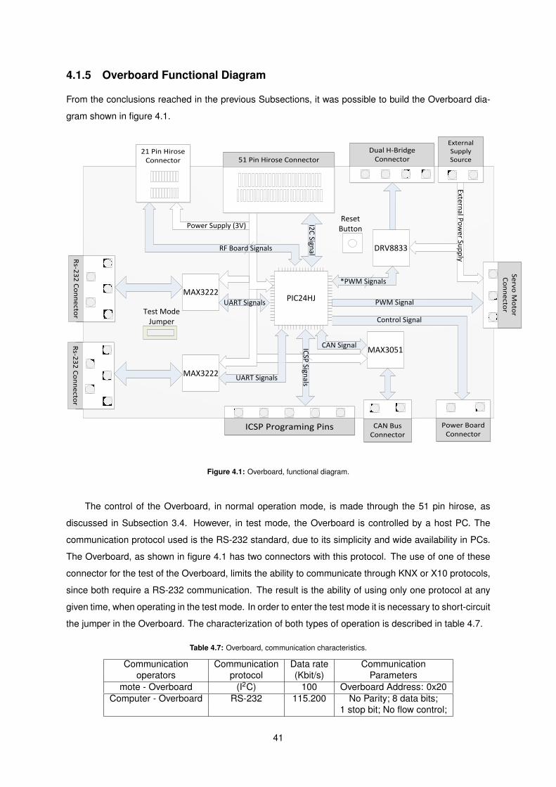
4.1.5 Overboard Functional Diagram
From the conclusions reached in the previous Subsections, it was possible to build the Overboard dia-
gram shown in figure 4.1.
Power Board Connector
Se
rvo M
oto
r C
on
ne
ctor
DRV8833
MAX3051
MAX3222
MAX3222
PIC24HJ
I2C
Signal
ICSP
Signals
PWM Signal
Control Signal
CAN Signal
UART Signals
UART Signals
RF Board Signals
Power Supply (3V)
External P
ow
er Sup
ply
32
*PWM Signals
32
32
CAN Bus Connector
ICSP Programing Pins
21 Pin Hirose Connector 51 Pin Hirose Connector
Rs-2
32
Co
nn
ecto
rR
s-23
2 C
on
ne
ctor
Dual H-Bridge Connector
External Supply Source
Reset Button
Test Mode Jumper
Figure 4.1: Overboard, functional diagram.
The control of the Overboard, in normal operation mode, is made through the 51 pin hirose, as
discussed in Subsection 3.4. However, in test mode, the Overboard is controlled by a host PC. The
communication protocol used is the RS-232 standard, due to its simplicity and wide availability in PCs.
The Overboard, as shown in figure 4.1 has two connectors with this protocol. The use of one of these
connector for the test of the Overboard, limits the ability to communicate through KNX or X10 protocols,
since both require a RS-232 communication. The result is the ability of using only one protocol at any
given time, when operating in the test mode. In order to enter the test mode it is necessary to short-circuit
the jumper in the Overboard. The characterization of both types of operation is described in table 4.7.
Table 4.7: Overboard, communication characteristics.
Communication Communication Data rate Communicationoperators protocol (Kbit/s) Parameters
mote - Overboard (I2C) 100 Overboard Address: 0x20Computer - Overboard RS-232 115.200 No Parity; 8 data bits;
1 stop bit; No flow control;
41

The Overboard has also a reset button for abnormal situations. The reset button permits the reboot
of the Overboard MCU, provoking the termination of any operation in course.
4.1.6 Power Board Design
In Subsection 3.1 it was concluded through the analysis of several solutions, that, the best method for
the control of AC powered devices by the Overboard is through the use of a SSR with optical isolation.
The functional diagram is show in figure 4.2.
Po
we
r B
oa
rd
Co
nn
ect
or
Zero
C
ross
ing
Det
ecto
r
AC Phase
Load Terminal
Load Terminal
Neutral
OptoTriac
Tria
c
Figure 4.2: Power Board, functional diagram.
In order to choose the most appropriate components for the Power board, a study of the most com-
mon AC power devices and their power characteristics was made. The results are shown in Table 4.8.
Table 4.8: Common Appliances.
Appliance Power Rating(W) Current(A)Compact Fluorescent Lamp CFL 8-35 0.03-0.15
Bulb 25-100 0.11-0.43Fluorescent Lamp 20-40 0.01-0.2
Fan 25-80 0.1-0.4TV 80-400 0.4-2
Fridge 200-300 1-1.4Vacuum Cleaner 150-400 0.7-2Washing Machine 800-1000 4-4.5
Microwave 600-1500 2.6-6.5Desktop Computer 80-150 1-1.3
Laser Printer 1000-1500 4.3-6.5Ink Jet Printer 25-50 0.11-0.22Electric Iron 450-1000 2-3Hair Dryer 1200-1500 5.2-6.5
Music System 20-40 0.09-0.17
42
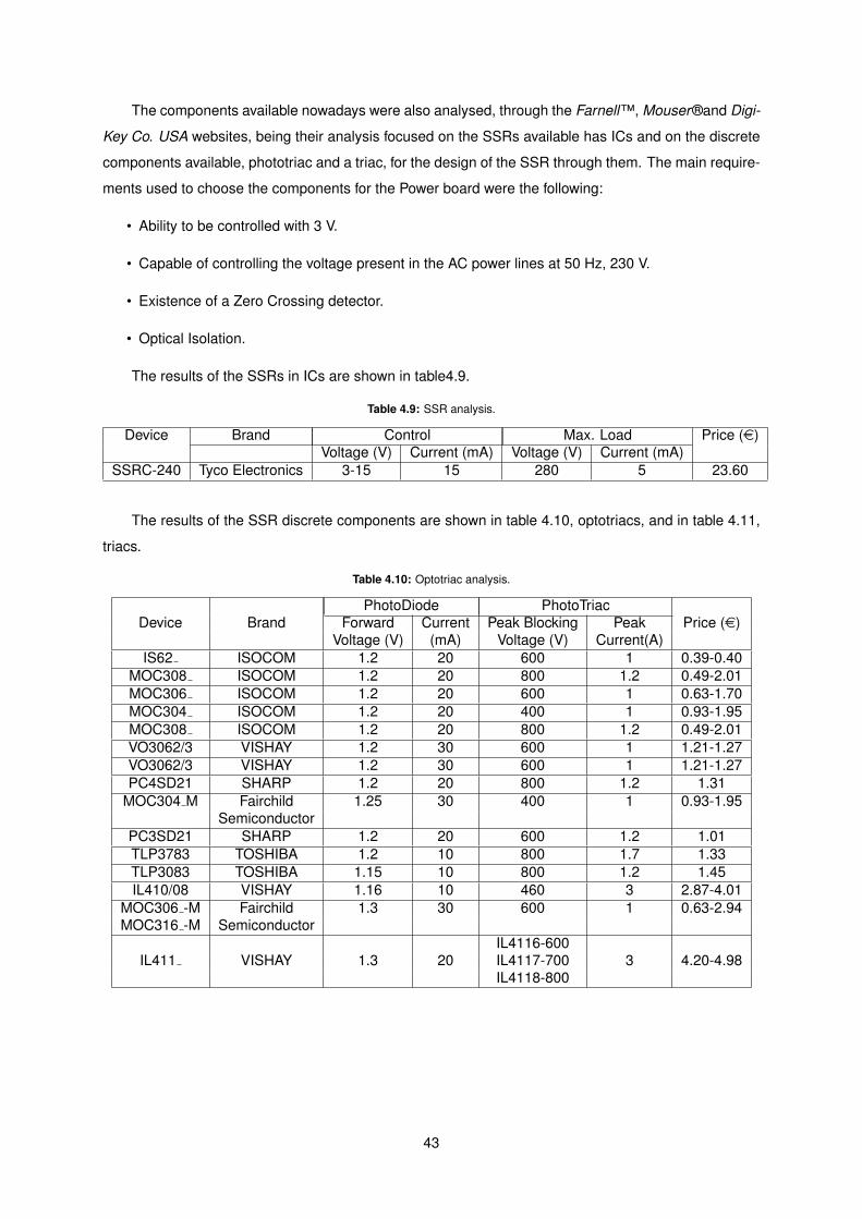
The components available nowadays were also analysed, through the Farnell™, Mouser®and Digi-
Key Co. USA websites, being their analysis focused on the SSRs available has ICs and on the discrete
components available, phototriac and a triac, for the design of the SSR through them. The main require-
ments used to choose the components for the Power board were the following:
• Ability to be controlled with 3 V.
• Capable of controlling the voltage present in the AC power lines at 50 Hz, 230 V.
• Existence of a Zero Crossing detector.
• Optical Isolation.
The results of the SSRs in ICs are shown in table4.9.
Table 4.9: SSR analysis.
Device Brand Control Max. Load Price (e)Voltage (V) Current (mA) Voltage (V) Current (mA)
SSRC-240 Tyco Electronics 3-15 15 280 5 23.60
The results of the SSR discrete components are shown in table 4.10, optotriacs, and in table 4.11,
triacs.
Table 4.10: Optotriac analysis.
PhotoDiode PhotoTriacDevice Brand Forward Current Peak Blocking Peak Price (e)
Voltage (V) (mA) Voltage (V) Current(A)IS62 ISOCOM 1.2 20 600 1 0.39-0.40
MOC308 ISOCOM 1.2 20 800 1.2 0.49-2.01MOC306 ISOCOM 1.2 20 600 1 0.63-1.70MOC304 ISOCOM 1.2 20 400 1 0.93-1.95MOC308 ISOCOM 1.2 20 800 1.2 0.49-2.01VO3062/3 VISHAY 1.2 30 600 1 1.21-1.27VO3062/3 VISHAY 1.2 30 600 1 1.21-1.27PC4SD21 SHARP 1.2 20 800 1.2 1.31
MOC304 M Fairchild 1.25 30 400 1 0.93-1.95Semiconductor
PC3SD21 SHARP 1.2 20 600 1.2 1.01TLP3783 TOSHIBA 1.2 10 800 1.7 1.33TLP3083 TOSHIBA 1.15 10 800 1.2 1.45IL410/08 VISHAY 1.16 10 460 3 2.87-4.01
MOC306 -M Fairchild 1.3 30 600 1 0.63-2.94MOC316 -M Semiconductor
IL4116-600IL411 VISHAY 1.3 20 IL4117-700 3 4.20-4.98
IL4118-800
43

Table 4.11: Triac analysis.
Peak Blocking ON-State Max. Trigger PriceDevice Brand Voltage (V) Current (A) Current (mA) (e)
RMS Peak1 Q1 Q2 Q3 Q4L0109 ERP N-800 10 10 10 10L0107 ERP Littelfuse M-600 10 5 5 5 7 0.206-0.45L0103 ERP D-400 3 3 3 5
Z0103Z0107 M-600 1 8 5 5 5 7
Z0109 N-800 10 10 10 10 0.12-0.928
Z0110 NXP 25 25 25 25BT131-600 12.5 3 3 3 7 0.122
BT134W-600 10 0.236
BT134/6-600 600 25 35 35 35 70 0.244-0.349Z0405 4 20 10 15 10 10 0.42
T405- 00 STMicro- 6-600 5 5 5T410- 00 electronics 7-700 30 10 10 10 - 0.30-1.12T435- 00 8-800 35 35 35
1 Using a 50 Hz signal.
Through the analysis of the Tables 4.9, 4.10 and 4.11, it’s possible to conclude it is more advanta-
geous the use of a SSR built from discrete components, since it is cheaper and has a higher range of
available products, allowing higher flexibility when defining the Power board characteristics.
Analysing the ON-State Current shown in Table 4.11 and comparing it with the current used by the
appliances shown in Table 4.8, concluded that the triacs with higher ON-State Current are the most
appropriate, since these are compatible with more appliances. From the triacs with higher ON-State
Current, the T410 series was found the most appropriate, because, in comparison with the other triacs
shown in Table 4.11, it has the highest blocking peak current and is cheaper than the other T4 series.
Regarding the choice of the optotriac, since all the optotriacs shown in Table 4.10 are compatible with
the chosen triac, the cheapest was chosen, which is the IS622 from the IS62 series.
4.2 Software Design
In this section it is described the developed applications for the Overboard. These include the Overboard
application, the CAN Bus board application and the MoteIST application for the control of the Overboard.
The development tools used in the development of the applications is also discussed.
4.2.1 Development Tools
The software tool used to develop the applications for the Overboard MCU is the MPLAB Integrated De-
velopment Environment (IDE) program. It is a free, integrated toolset for the development of applications
for the Microchip MCUs, made available by Microchip, further information is available at [43].
The programming or debugging of the MCU requires a programming interface, in order to provide
the communication between the MCU and the host PC. The programming interface used is the MPLAB
PICkit 3 from Microchip, available in LEME. It provides, protection against overvoltage and overcurrent,
44

and it is also able to provide power to the MCU, delivering a voltage between 2 V and 6 V and up to
30 mA, further information is available at [44]. The method used to program is the In-Circuit Serial
Programming (ICSP). This method requires five signals in order to successfully program the MCU. The
interface between the MCU and the Pickit 3 is shown in appendix C.
The programming and debugging of the MoteIST MCU is done with a different software tool since
the MPLAB IDE program used for the Overboard MCU is incompatible with the MoteIST MCU, which is a
MSP430 MCU from Texas Instruments. The software tool used is the Code Composer Studio developed
by Texas Instruments. It is an integrated development environment for the development of applications
for the Texas Instruments MCUs, further information can be found at [45]. The programming of the MCU
is done with a programming interface named MSP-FET430UIF, shown in Figure 4.3 also from Texas
Instruments, it is described in detail at [46]. Both tools are already existent in LEME. The protocol used
to program the MoteIST is the Spy-By-Wire, which is a serialized version of the JTAG protocol developed
by Texas Instruments. This protocols reduces the amount of signal wires required for the programming
to two, not including the power supply, instead of the standard four required by the Joint Test Action
Group (JTAG) protocol. Further information about the MoteIST interface can be found at [40].
Figure 4.3: MSP430 Programming Interface.
All the software applications were developed using C language, due to its simplicity, existence of
compilers for the MCUs used and because its ’low level’ nature allows direct hardware control, which is
important for the control of the actuators by the Overboard.
4.2.2 Proprietary Protocol
As discussed in Chapter 3, the communications between the Overboard and the mote or PC, are per-
formed using a proprietary protocol developed exclusively for the Overboard. The constitution of the
messages is show in figure 4.4.
Action(8 bit)
Module(8 bit)
*AditionalInformation
*Required in specific operations
Figure 4.4: Message composition in detail.
45

The actions available and existent modules in the Overboard have an hexadecimal number as-
signed. The numbers attributed to each action are shown in table 4.12, and to each module are shown
in table 4.13.
Table 4.12: Action command constitution.
Actions Code in HexadecimalEnable Module 1Disable Module 2
Configure Module 3Send Data 4
Reboot Overboard ff
Table 4.13: Designated module constitution.
Module name Code in HexadecimalCAN bus 1
X10 Wired 2KNX Wired 3
X10 RF 4KNX RF 5
H Bridge 1 6H Bridge 2 60
Power Board interface 7servomotor interface 8
TimeConfigure Time 9
Request Overboard Time e
With the exception of the enable, disable, reboot and request MCU current time actions, all the
existent operations require extra information in order to perform correctly. In the table 4.14 it is shown
the information required by each action.
Table 4.14: Protocol’s information requirements.
Operation Required Information DescriptionConfigure H-bridge Speed; Direction Configures current
direction and speed.Configure Triac On-Off Turns on or off.
Configure Servomotor Pulse Width Configures the pulsesent to servo.
Configure Time Seconds, Minutes, Hours, Configures the MCU’sConfigure Time Days, Day o the week Real Time Clock.
Automation protocols Address and Data Sends message to the assignedaddress with the desired data
The Overboard does not guarantee the accomplishment of the commands received. So, for every
command received, it returns a message communicating the accomplishment or failure in executing the
command. A fully detailed User Manual for the Overboard can be found in the Appendix D.
46
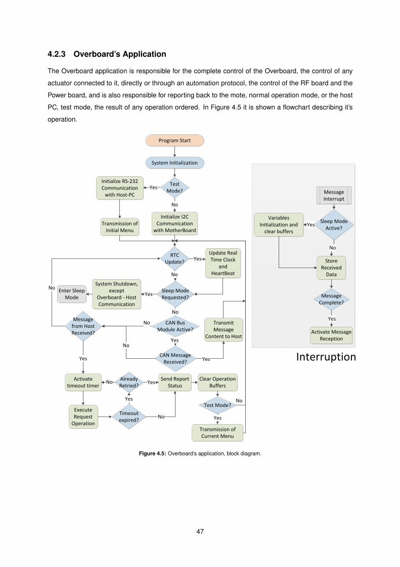
4.2.3 Overboard’s Application
The Overboard application is responsible for the complete control of the Overboard, the control of any
actuator connected to it, directly or through an automation protocol, the control of the RF board and the
Power board, and is also responsible for reporting back to the mote, normal operation mode, or the host
PC, test mode, the result of any operation ordered. In Figure 4.5 it is shown a flowchart describing it’s
operation.
Initialize RS-232 Communication
with Host-PC
Test Mode?
Yes
Initialize I2C Communication
with MotherBoard
No
Transmission of Initial Menu
System Initialization
RTC Update?
Update Real Time Clock
and HeartBeat
Yes
Sleep Mode Requested?
No
CAN Bus Module Active?
No
Message from Host Received?
Enter Sleep Mode
Transmit Message
Content to Host
Message Interrupt
Store Received
Data
Message Complete?
Activate Message Reception
Yes
Sleep Mode Active?
No
System Shutdown, except
Overboard - Host Communication
Yes
Variables Initialization and
clear buffersYes
Activate timeout timer
Execute Request
Operation
Yes
Timeout expired?
Already Retried?
Yes
No
No
Send Report Status
Yes
No
Transmission of Current Menu
Test Mode?
No
Clear Operation Buffers
Yes
No
CAN Message Received?
Yes
Yes
No
Program Start
Interruption
Figure 4.5: Overboard’s application, block diagram.
47

The Overboard application starts when the board is powered. Immediately after it begins the sys-
tem initialization. The system initialization is a function, shown in Figure 4.6, that disables the MCU
Watchdog, configures the main clock and the real time clock, configures the pins of the MCU, initializes
the global variables correctly, initializes the communication with the desired host, I2C in the normal op-
eration mode and RS-232 in the test mode, and disables all the MCU interruptions, with the exception
of the ones used in the communication with the host.
void system_initialization()
RCONbits.SWDTEN=0; //Disable Watch Dog Timer
Oscillator_Config(); //Primary oscillator initialization
RCONbits.VREGS=0; // Voltage Regulator is in standby mode during sleep
init_pins(); //Initialize all pins used
clearIntr(); //Disable all interrupts
clearIntrflags(); //Clear Interrupt flags
setup_variables(); //Initializes the variables correctly
Timer_32bit(); //Real Time Clock Initialization
all_peripherical_disable(); //Disable all peripherical modules
if(resident_on) //Test Mode
resident_init(); //RS-232 Communication Initialization
initial_screen(); //Transmission of the Main Menu through RS-232 to host
else
init_I2C1(I2C_Baud_Rate, (I2C_Overboard_address)); //I2C Communication Initialization
overboard_idle(); //Put the Overboard into an Idle State
/**************************Clear all global variables**********************/
void setup_variables()
//Variables
//I2c Buffer
i2c_txcounter=0;
clear_buffer(i2c_buffer, i2c_buffer_size);
//Time structure
RTC.seconds=0;
RTC.minutes=0;
RTC.hours=0;
RTC.year_day=0;
Figure 4.6: System Initialization function on the Overboard, code.
The main clock of the Overboard application is the PIC24HJ internal RC clock which provides a
nominal frequency of 7.37 MHz. Through the use of a PLL and a postscaler the nominal frequency is
increased to the value of approximately 80 MHz. In Figure 4.7, it is shown the function that configures
the main clock frequency.
#include "p24HJ128GP506a.h"#include "../h/Clock_lib.h"#include "../h/Pin_lib.h"#include "../h/Interrupt_lib.h"#include "../h/I2C_lib.h"/****************************Clock Configuration****************************
Configure Oscillator to operate the device at 40MhzFosc= Fin*M/(N1*N2), Fcy=Fosc/2Fosc= 7.37M*43/(2*2)=79.2275Mhz for 7.37M input clock
***************************************************************************/void Oscillator_Config()PLLFBD=41; // M=43(PLL divisor)CLKDIVbits.PLLPOST=0; // N1=2(PLL postscaler)CLKDIVbits.PLLPRE=0; // N2=2 (PLL prescaler)
// Initiate Clock Switch to Internal FRC with PLL (NOSC = 0b001)__builtin_write_OSCCONH(0x01);__builtin_write_OSCCONL(0x01);
while (OSCCONbits.COSC!= 0b001); // Wait for Clock switch to occur
while(OSCCONbits.LOCK!=1); // Wait for PLL to lock
OSCCONbits.LPOSCEN=0; //Disable Secondary Oscillator/**************************************************************************/
/*************************Timer 1 ******************************************Configure RTC clockFclock = FCY/(Prescaler*Period Value)FCY = 40 MHzPrescaler = 8Period Value = 49516
1
Figure 4.7: Main Clock configuration on the Overboard, code.
The I2C protocol communication, used between the Overboard and the mote, in the normal op-
eration mode, is configured to communicate as a master, which means that it can initiate message
48
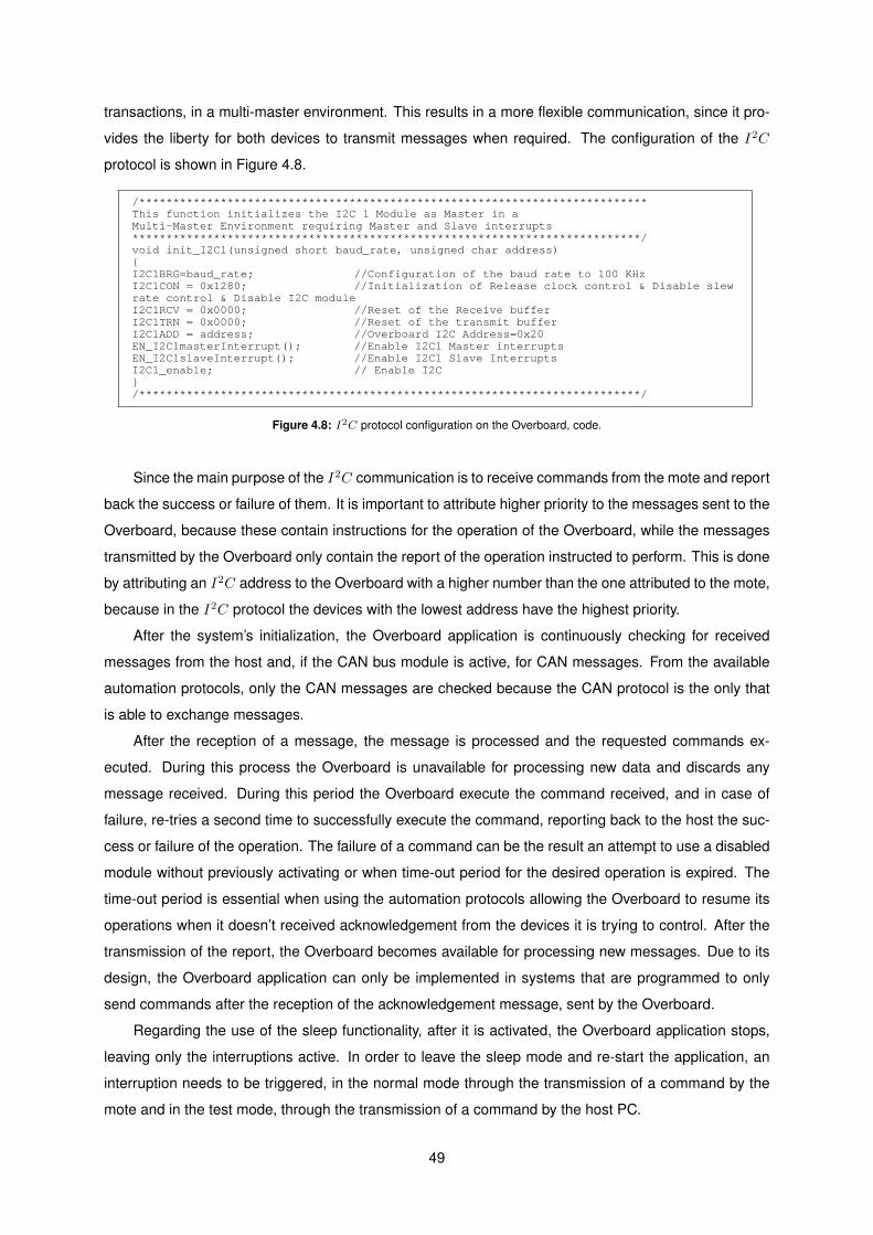
transactions, in a multi-master environment. This results in a more flexible communication, since it pro-
vides the liberty for both devices to transmit messages when required. The configuration of the I2C
protocol is shown in Figure 4.8.
#include "p24HJ128GP506a.h"#include "../h/I2C_lib.h"#include "../h/System_lib.h"#include "../h/Interrupt_lib.h"#include "../h/Error_lib.h"#include "../h/Clock_lib.h"#include "../h/Menu_lib.h"
// I2C related functions:/***************************************************************************This function initializes the I2C 1 Module as Master in a Multi-Master Environment requiring Master and Slave interrupts***************************************************************************/void init_I2C1(unsigned short baud_rate, unsigned char address)I2C1BRG=baud_rate; //Configuration of the baud rate to 100 KHzI2C1CON = 0x1280; //Initialization of Release clock control & Disable slew rate control & Disable I2C moduleI2C1RCV = 0x0000; //Reset of the Receive bufferI2C1TRN = 0x0000; //Reset of the transmit bufferI2C1ADD = address; //Overboard I2C Address=0x20EN_I2C1masterInterrupt(); //Enable I2C1 Master interruptsEN_I2C1slaveInterrupt(); //Enable I2C1 Slave InterruptsI2C1_enable; // Enable I2C/**************************************************************************/
/***************************************************************************Disable I2C1 module function***************************************************************************/void disable_I2C1()dis_I2C1_slave_interrupt;dis_I2C1_master_interrupt;I2C1_disable;
1
Figure 4.8: I2C protocol configuration on the Overboard, code.
Since the main purpose of the I2C communication is to receive commands from the mote and report
back the success or failure of them. It is important to attribute higher priority to the messages sent to the
Overboard, because these contain instructions for the operation of the Overboard, while the messages
transmitted by the Overboard only contain the report of the operation instructed to perform. This is done
by attributing an I2C address to the Overboard with a higher number than the one attributed to the mote,
because in the I2C protocol the devices with the lowest address have the highest priority.
After the system’s initialization, the Overboard application is continuously checking for received
messages from the host and, if the CAN bus module is active, for CAN messages. From the available
automation protocols, only the CAN messages are checked because the CAN protocol is the only that
is able to exchange messages.
After the reception of a message, the message is processed and the requested commands ex-
ecuted. During this process the Overboard is unavailable for processing new data and discards any
message received. During this period the Overboard execute the command received, and in case of
failure, re-tries a second time to successfully execute the command, reporting back to the host the suc-
cess or failure of the operation. The failure of a command can be the result an attempt to use a disabled
module without previously activating or when time-out period for the desired operation is expired. The
time-out period is essential when using the automation protocols allowing the Overboard to resume its
operations when it doesn’t received acknowledgement from the devices it is trying to control. After the
transmission of the report, the Overboard becomes available for processing new messages. Due to its
design, the Overboard application can only be implemented in systems that are programmed to only
send commands after the reception of the acknowledgement message, sent by the Overboard.
Regarding the use of the sleep functionality, after it is activated, the Overboard application stops,
leaving only the interruptions active. In order to leave the sleep mode and re-start the application, an
interruption needs to be triggered, in the normal mode through the transmission of a command by the
mote and in the test mode, through the transmission of a command by the host PC.
49
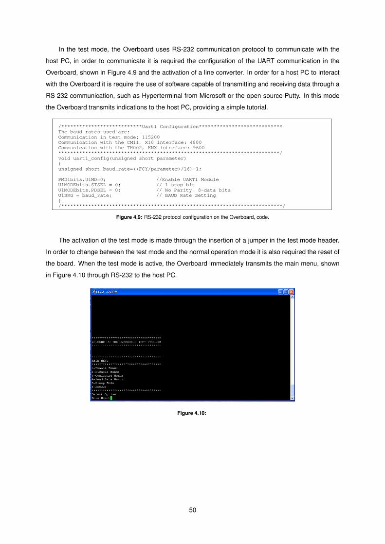
In the test mode, the Overboard uses RS-232 communication protocol to communicate with the
host PC, in order to communicate it is required the configuration of the UART communication in the
Overboard, shown in Figure 4.9 and the activation of a line converter. In order for a host PC to interact
with the Overboard it is require the use of software capable of transmitting and receiving data through a
RS-232 communication, such as Hyperterminal from Microsoft or the open source Putty. In this mode
the Overboard transmits indications to the host PC, providing a simple tutorial.
#include "p24HJ128GP506a.h"#include "../h/Uart_lib.h"#include "../h/Clock_lib.h"#include "../h/Interrupt_lib.h"#include "../h/Pin_lib.h"
/***************************Uart1 Configuration****************************The baud rates used are:Communication in test mode: 115200Communication with the CM11, X10 interface: 4800Communication with the TH002, KNX interface: 9600**************************************************************************/void uart1_config(unsigned short parameter)unsigned short baud_rate=((FCY/parameter)/16)-1;
PMD1bits.U1MD=0; //Enable UART1 ModuleU1MODEbits.STSEL = 0; // 1-stop bitU1MODEbits.PDSEL = 0; // No Parity, 8-data bitsU1BRG = baud_rate; // BAUD Rate Setting/**************************************************************************//***************************Uart2 Configuration****************************/void uart2_config(unsigned long parameter)unsigned long baud_rate=((FCY/parameter)/16)-1;
PMD1bits.U2MD=0;U2MODEbits.STSEL = 0; // 1-stop bitU2MODEbits.PDSEL = 0; // No Parity, 8-data bitsU2MODE=0x00; //Interrupt flag is set when character is receivedU2BRG = baud_rate; // BAUD Rate Setting/**************************************************************************//********************************uart1_enable******************************/void uart1_enable()
1
Figure 4.9: RS-232 protocol configuration on the Overboard, code.
The activation of the test mode is made through the insertion of a jumper in the test mode header.
In order to change between the test mode and the normal operation mode it is also required the reset of
the board. When the test mode is active, the Overboard immediately transmits the main menu, shown
in Figure 4.10 through RS-232 to the host PC.
Figure 4.10:
50
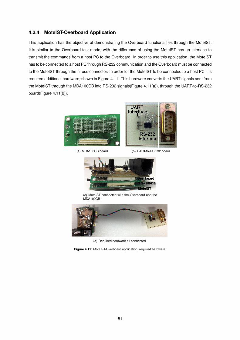
4.2.4 MoteIST-Overboard Application
This application has the objective of demonstrating the Overboard functionalities through the MoteIST.
It is similar to the Overboard test mode, with the difference of using the MoteIST has an interface to
transmit the commands from a host PC to the Overboard. In order to use this application, the MoteIST
has to be connected to a host PC through RS-232 communication and the Overboard must be connected
to the MoteIST through the hirose connector. In order for the MoteIST to be connected to a host PC it is
required additional hardware, shown in Figure 4.11. This hardware converts the UART signals sent from
the MoteIST through the MDA100CB into RS-232 signals(Figure 4.11(a)), through the UART-to-RS-232
board(Figure 4.11(b)).
MTS/MDA Sensor Board User’s Manual
Table 6-3. Connection Table for MDA100. Use the photo (top view) below the table to locate the pins.
A B C D E F 1 GND GND GND VCC VCC VCC
2 OPEN OPEN USART1_CK INT3 ADC2 PW0
3 OPEN OPEN UART0_RX INT2 ADC1 PW1
4 OPEN OPEN UART0_TX INT1 ADC0 PW2
5 OPEN OPEN SPI_SCK INT0 THERM_PWR PW3
6 OPEN OPEN USART1_RX BAT_MON THRU1 PW4
7 OPEN OPEN USART1_TX LED3 THRU2 PW5
8 OPEN OPEN I2C_CLK LED2 THRU3 PW6
9 OPEN OPEN I2C_DATA LED1 RSTN ADC7
10 OPEN OPEN PWM0 RD PWM1B ADC6
11 OPEN OPEN PWM1A WR OPEN ADC5
12 OPEN OPEN AC+ ALE OPEN ADC4
13 OPEN OPEN AC- PW7 OPEN ADC3
14 GND GND GND VCC VCC VCC
15 OPEN OPEN OPEN OPEN OPEN OPEN
16 OPEN OPEN OPEN OPEN OPEN OPEN
17 OPEN OPEN OPEN OPEN OPEN OPEN
Shared functionality
WARNING: Never connect signals that are greater than VCC (3V typical) or less than 0 V to any of the holes that connect to the Mote Processor Radio board. It is okay to connect different voltages to the non-connected holes. However, be careful. If a voltage out of the range of 0 to Vcc should reach the Mote Processor Radio Board damage will occur.
Page 24 Doc. # 7430-0020-04 Rev. B
(a) MDA100CB board (b) UART-to-RS-232 board
(c) MoteIST connected with the Overboard and theMDA100CB
(d) Required hardware all connected
Figure 4.11: MoteIST-Overboard application, required hardware.
51
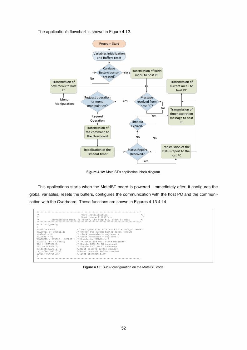
The application’s flowchart is shown in Figure 4.12.
Transmission of initial menu to host PC
Variables initialization and Buffers reset
Carriage Return button
pressed?No
Yes
Message received from
host PC?No
Request operation or menu
manipulation?
Yes
Transmission of new menu to host
PC
MenuManipulation
Transmission of the command to the Overboard
Status Report Received?
Initialization of the Timeout timer
Transmission of timer expiration message to host
PCTimeout Expired?
No No
Yes
Transmission of the status report to the
host PC
Yes
Transmission of current menu to
host PC
Program Start
Request Operation
Figure 4.12: MoteIST’s application, block diagram.
This applications starts when the MoteIST board is powered. Immediately after, it configures the
global variables, resets the buffers, configures the communication with the host PC and the communi-
cation with the Overboard. These functions are shown in Figures 4.13 4.14.
/**************************************************************************//* Library Includes *//**************************************************************************/#include "..\h\Uart_lib.h"#include "msp430f2619.h"#include "..\h\Menu_lib.h"
/**************************************************************************//* Uart Initialization *//* Baud rate = 115200 bps *//* Asynchronous mode, No Parity, One Stop bit, 8-bit of data *//**************************************************************************/void init_uart()P3SEL = 0x30; // Configure Pins P3.4 and P3.5 = USCI_A0 TXD/RXDUCA0CTL1 |= UCSSEL_2; // Choose Sub system master clock (SMCLK)UCA0BR0 = 8; // Clock Prescaler - register 0UCA0BR1 = 0; // Clock Prescaler - register 1 UCA0MCTL = UCBRS2 + UCBRS0; // Modulation UCBRSx = 5UCA0CTL1 &= ~UCSWRST; // **Initialize USCI state machine**IE2 |= UCA0RXIE; // Enable USCI_A0 RX interruptIE2 |= UCA0TXIE; // Enable USCI_A0 TX interruptrx_bufferUART[0]=0; //Reset receive buffer countertx_bufferUART[0]=0; //Reset transmit buffer counterIFG2&=~UCA0TXIFG; //Clear Transmit flag/**************************************************************************/
void clear_UARTbuffer(char *buffer)unsigned char counter;
for(counter=0; counter<Uart_BufferSize; counter++)buffer[counter]=0;
1
Figure 4.13: S-232 configuration on the MoteIST, code.
52
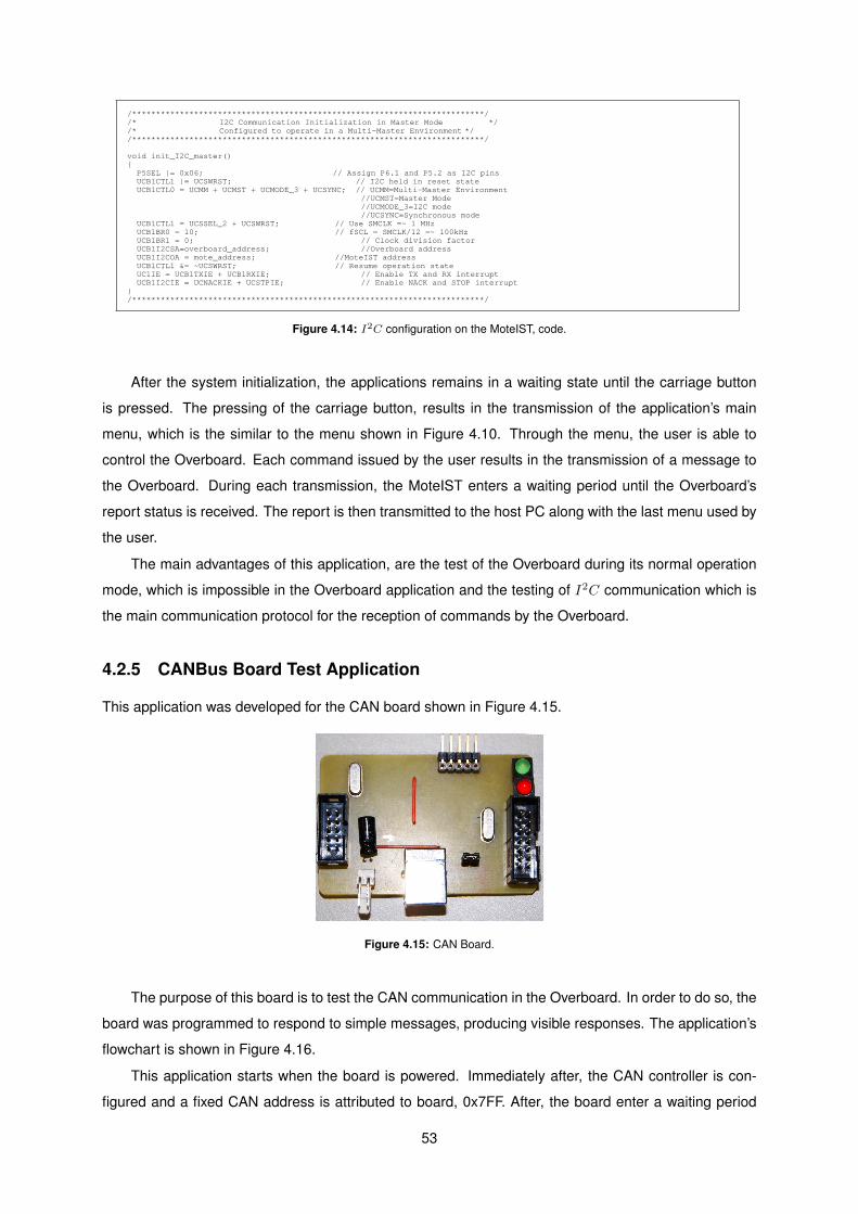
/**************************************************************************//* Library Includes *//**************************************************************************/#include "..\h\I2C_lib.h"#include "..\h\Menu_lib.h"#include "msp430f2619.h"
/**************************************************************************//* I2C Communication Initialization in Master Mode *//* Configured to operate in a Multi-Master Environment *//**************************************************************************/
void init_I2C_master() P5SEL |= 0x06; // Assign P6.1 and P5.2 as I2C pins UCB1CTL1 |= UCSWRST; // I2C held in reset state UCB1CTL0 = UCMM + UCMST + UCMODE_3 + UCSYNC; // UCMM=Multi-Master Environment
//UCMST=Master Mode//UCMODE_3=I2C mode//UCSYNC=Synchronous mode
UCB1CTL1 = UCSSEL_2 + UCSWRST; // Use SMCLK =~ 1 MHz UCB1BR0 = 10; // fSCL = SMCLK/12 =~ 100kHz UCB1BR1 = 0; // Clock division factor UCB1I2CSA=overboard_address; //Overboard address UCB1I2COA = mote_address; //MoteIST address UCB1CTL1 &= ~UCSWRST; // Resume operation state UC1IE = UCB1TXIE + UCB1RXIE; // Enable TX and RX interrupt UCB1I2CIE = UCNACKIE + UCSTPIE; // Enable NACK and STOP interrupt/**************************************************************************/
/**************************************************************************/void restore_I2c_master()
1
Figure 4.14: I2C configuration on the MoteIST, code.
After the system initialization, the applications remains in a waiting state until the carriage button
is pressed. The pressing of the carriage button, results in the transmission of the application’s main
menu, which is the similar to the menu shown in Figure 4.10. Through the menu, the user is able to
control the Overboard. Each command issued by the user results in the transmission of a message to
the Overboard. During each transmission, the MoteIST enters a waiting period until the Overboard’s
report status is received. The report is then transmitted to the host PC along with the last menu used by
the user.
The main advantages of this application, are the test of the Overboard during its normal operation
mode, which is impossible in the Overboard application and the testing of I2C communication which is
the main communication protocol for the reception of commands by the Overboard.
4.2.5 CANBus Board Test Application
This application was developed for the CAN board shown in Figure 4.15.
Figure 4.15: CAN Board.
The purpose of this board is to test the CAN communication in the Overboard. In order to do so, the
board was programmed to respond to simple messages, producing visible responses. The application’s
flowchart is shown in Figure 4.16.
This application starts when the board is powered. Immediately after, the CAN controller is con-
figured and a fixed CAN address is attributed to board, 0x7FF. After, the board enter a waiting period
53
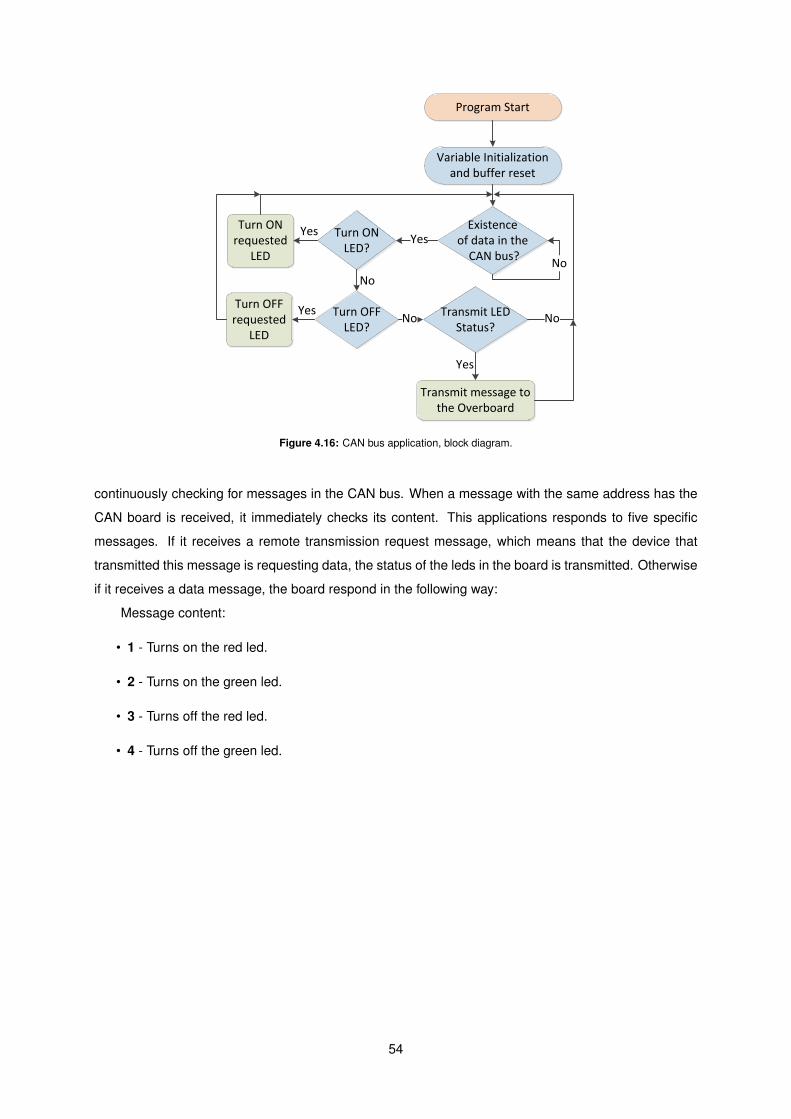
Variable Initialization and buffer reset
Existence of data in the
CAN bus?No
YesTurn ON LED?
Turn OFF LED?
No
Transmit LED Status?
No No
Turn ON requested
LED
Yes
Turn OFF requested
LED
Yes
Transmit message to the Overboard
Yes
Program Start
Figure 4.16: CAN bus application, block diagram.
continuously checking for messages in the CAN bus. When a message with the same address has the
CAN board is received, it immediately checks its content. This applications responds to five specific
messages. If it receives a remote transmission request message, which means that the device that
transmitted this message is requesting data, the status of the leds in the board is transmitted. Otherwise
if it receives a data message, the board respond in the following way:
Message content:
• 1 - Turns on the red led.
• 2 - Turns on the green led.
• 3 - Turns off the red led.
• 4 - Turns off the green led.
54

Chapter 5– Prototypes and Results
In order to validate the hardware and software, proposed in chapter 4, for the Overboard, several
prototypes were built, and the developed software implemented into the prototypes for testing purposes.
In this chapter, these prototypes are presented, evaluated and their results compared with the simula-
tions made.
5.1 Development Tools
In order to design the prototypes PCB, the Altium Designer was used. This software tool allows the
design of circuit schematics and PCB layouts for fabrication, also providing simulation of both and their
comparison for unwanted differences, among other features. Further information can be found at their
website 1. This software was chosen due to its existence in-house and also because of the extensive
experience in its use.
For the PCB creation, a photographic method was used, available in the Printed Circuit Boards
Laboratory of IST-TagusPark. This method is able to create PCBs with a maximum of two layers. In
this method, a copper board is covered with a thin layer of photo-resist. Afterwards, it is exposed to
intense light through a photo-mask detailing the tracks required. The result is a chemical change in the
exposed areas of the photo-resist. Then the board is immersed in a solution primarily constituted by
caustic soda, in order to remove the light exposed photo-resist. After, it is immersed in another solution
mainly composed by ferric chloride, where the areas that are not covered with the photo-resist layer are
removed, leaving only the image of the photo-mask used previously. After this process, the board is
ready to be used, however further processes can be applied for protection and durability purposes.
5.2 Prototypes
In order to test each functionality of the Overboard, previously to the creation of the PCB, each IC
proposed in Chapter 4 was tested individually. Whenever possible the testing was made recurring to
breadboards, however, when it has impossible, PCBs had to be built, as shown in figure 5.2, in order to
access the IC pins. The testing of the developed software applications was made through the connection
of each individual IC with the MCU by intermediate of breadboards.
1http://www.altium.com
55

(a) MAX3222 from Maxim IC, breadboard circuit (b) MAX3051 from Maxim IC,PCB circuit
(c) PIC24H from Microchp, PCB circuit
Figure 5.1: Integrated Circuits test boards.
After the successful testing of each individual IC, a PCB prototype was designed and built. The
schematics are shown in Appendix B.
The Overboard prototype is shown in Figure 5.2. In these figures, the ICs and the connectors are
identified.
(a) Overboard top layer
Mote Connector
MAX3222
MAX3222
PIC24HJ
MAX3051
DRV8833
Bipolar Transistor
(b) Overboard bottom layer
Figure 5.2: Overboard PCB prototype.
56

In the prototype a jumper is used to switch between the normal operation state and the test mode
state. It was also included a reset button, in order to reboot the Overboard’s application when desired.
In most of the cases, as it is possible to observe, the connectors chosen were the standard one row
headers. This choice was made due to the size restrictions of the board. However, two RJ25 connectors
are used for the communication with the X10 and KNX automation protocols. The reason for the use of
these connectors is to provide a more intuitive approach for the regular user, who is more familiarized
with these type of connectors, existent in a wide range of products. Due to the size restrictions, the
communication with a host PC in the test mode is also accomplished through one of these connectors,
in this mode it is impossible to communicate with X10 and KNX devices simultaneously. Only one of
these protocols can be active at any given time due to the fact that both automation protocols share the
same connector.
In Figure 5.2(b) it is also possible to observe that the servomotor’s control signal uses a bipolar
transistor. The transistor is used as a switch, and the goal is to amplify the signal’s voltage sent by the
MCU into values recognizable by the servomotor’s digital logic.
In the direct control of actuators, it is required the use of an external power supply with the single
purpose of supplying them. This power supply is connected to the ’External Power Connector’, identified
in Figure 5.2(b).
It is shown in Figure 5.3, the two possible operation modes. In the normal operation mode, the
Overboard is connected to a mote, in Figure 5.3(a) the MoteIST is used, being powered by it. In the test
mode, the Overboard is connected to a host PC, being supplied by an external power source.
(a) Overboard connected to MoteIST, normal opera-tion mode
(b) Overboard in test mode
Figure 5.3: Overboard operation modes.
In the normal operation mode, the Overboard communicates only with the mote, receiving com-
mands and replying the success or failure of their operation. In order to test the Overboard’s operation
during the normal operation mode, an application was developed for the MoteIST with the purpose of
interfacing with a host PC, receiving commands and re-transmitting them to the Overboard, very similar
to the Overboard’s test mode.
In the test mode, the Overboard is accessed through a terminal, using RS-232 communication. The
Overboard, after initialization, transmits a simple interface in order to simplify the testing of the Overboard
functionalities. In Figure 5.4 it is shown the main menu, which is the first menu to be displayed.
57
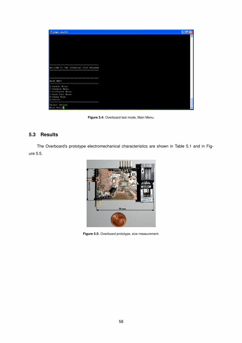
Figure 5.4: Overboard test mode, Main Menu.
5.3 Results
The Overboard’s prototype electromechanical characteristics are shown in Table 5.1 and in Fig-
ure 5.5.
Figure 5.5: Overboard prototype, size measurement.
58
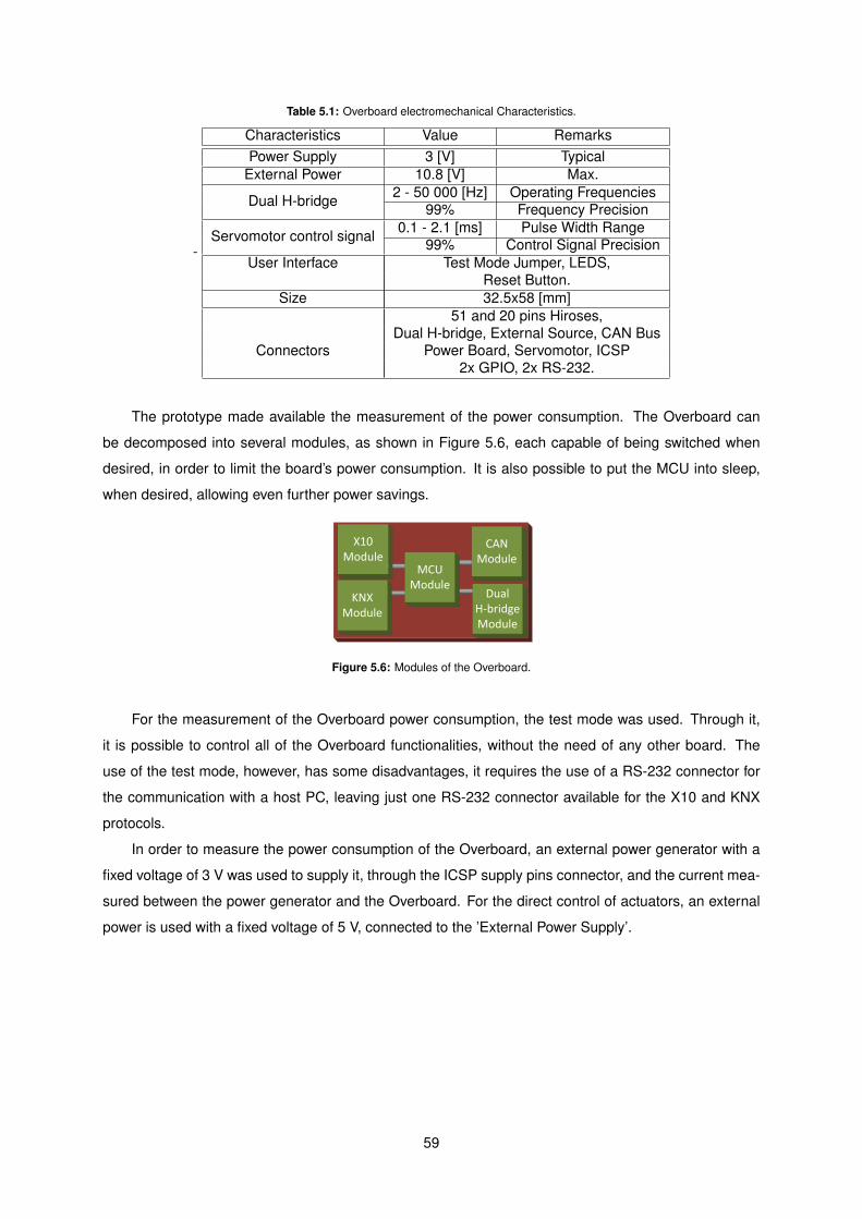
Table 5.1: Overboard electromechanical Characteristics.
-
Characteristics Value RemarksPower Supply 3 [V] Typical
External Power 10.8 [V] Max.
Dual H-bridge 2 - 50 000 [Hz] Operating Frequencies99% Frequency Precision
Servomotor control signal 0.1 - 2.1 [ms] Pulse Width Range99% Control Signal Precision
User Interface Test Mode Jumper, LEDS,Reset Button.
Size 32.5x58 [mm]51 and 20 pins Hiroses,
Dual H-bridge, External Source, CAN BusConnectors Power Board, Servomotor, ICSP
2x GPIO, 2x RS-232.
The prototype made available the measurement of the power consumption. The Overboard can
be decomposed into several modules, as shown in Figure 5.6, each capable of being switched when
desired, in order to limit the board’s power consumption. It is also possible to put the MCU into sleep,
when desired, allowing even further power savings.
X10 Module
KNX Module
MCU Module
CAN Module
Dual H-bridge Module
Figure 5.6: Modules of the Overboard.
For the measurement of the Overboard power consumption, the test mode was used. Through it,
it is possible to control all of the Overboard functionalities, without the need of any other board. The
use of the test mode, however, has some disadvantages, it requires the use of a RS-232 connector for
the communication with a host PC, leaving just one RS-232 connector available for the X10 and KNX
protocols.
In order to measure the power consumption of the Overboard, an external power generator with a
fixed voltage of 3 V was used to supply it, through the ICSP supply pins connector, and the current mea-
sured between the power generator and the Overboard. For the direct control of actuators, an external
power is used with a fixed voltage of 5 V, connected to the ’External Power Supply’.
59

Figure 5.7: Overboard’s test connections.
The ’Main Power Supply’ is responsible for powering the Overboard’s ICs and the ’External Power
Supply’ purpose is to power the actuators controlled by the Overboard’s through the direct interface
or the servo interface. Only the power consumption of the ’Main Power Supply’ is calculated since it
corresponds to the power delivered by the mote to the Overboard. The power delivered through the
’External Power Supply’ doesn’t affect the mote and it is dependent on the actuator controlled.
In order to measure the power consumption of each functionality, the tests shown in Table 5.2, were
created.
Table 5.2: Tests Description.
Test Description1 Microcontroller in sleep mode with the system clock disabled. All the ICs of the Overboard
disabled1
2 Microcontroller running the software application2. All the ICs of the Overboard disabled1
3 Microcontroller running the software application2. CAN Module is enable but there is nocommunication in course1.
4 Microcontroller running the software application2. CAN Module is enable and transmitting1.5 Microcontroller running the software application2. KNX Module is enable but there is no
communication in course1.6 Microcontroller running the software application2. KNX Module is enable and transmitting1.7 Microcontroller running the software application2. X10 Module is enable but there is no
communication in course1.8 Microcontroller running the software application2. X10 Module is enable and transmitting1.9 Microcontroller running the software application 2. Dual Bipolar Drivers Module is enable but
no control is being made1.10 Microcontroller running the software application 2. Dual Bipolar Drivers Module is enable
and both drivers are operating13.11 Microcontroller running the software application2. Servomotor interface is controlling a
servomotor413.1 The module that communicates with the host PC is enable.2 The system clock uses the internal oscillator with a frequency of 80 MHz.3 The width of the PWM used is irrelevant.4 Th3 servomotor used is the Futaba 3003.
60
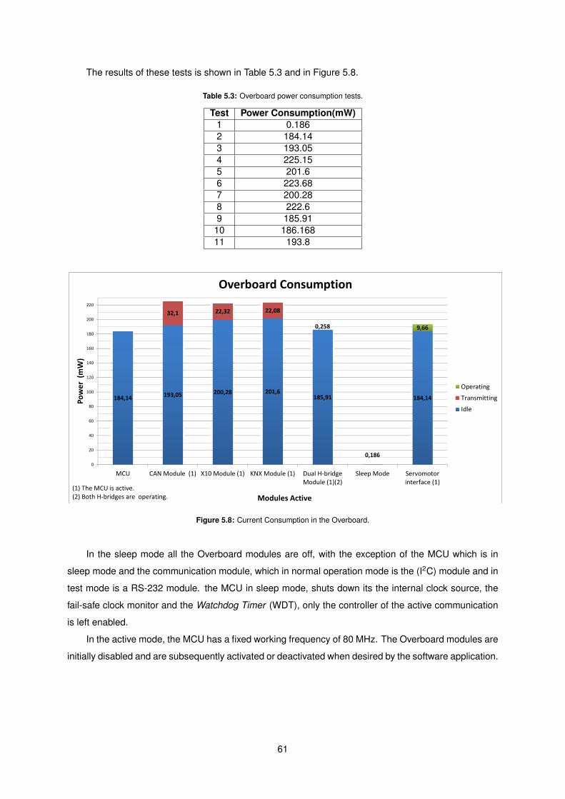
The results of these tests is shown in Table 5.3 and in Figure 5.8.
Table 5.3: Overboard power consumption tests.
Test Power Consumption(mW)1 0.1862 184.143 193.054 225.155 201.66 223.687 200.288 222.69 185.9110 186.16811 193.8
184,14 193,05 200,28 201,6185,91
0,186
184,14
32,1 22,32 22,08
0,258 9,66
0
20
40
60
80
100
120
140
160
180
200
220
MCU CAN Module (1) X10 Module (1) KNX Module (1) Dual H‐bridgeModule (1)(2)
Sleep Mode Servomotorinterface (1)
Power (mW)
Modules Active
Overboard Consumption
Operating
Transmitting
Idle
(1) The MCU is active.(2) Both H‐bridges are operating.
Figure 5.8: Current Consumption in the Overboard.
In the sleep mode all the Overboard modules are off, with the exception of the MCU which is in
sleep mode and the communication module, which in normal operation mode is the (I2C) module and in
test mode is a RS-232 module. the MCU in sleep mode, shuts down its the internal clock source, the
fail-safe clock monitor and the Watchdog Timer (WDT), only the controller of the active communication
is left enabled.
In the active mode, the MCU has a fixed working frequency of 80 MHz. The Overboard modules are
initially disabled and are subsequently activated or deactivated when desired by the software application.
61
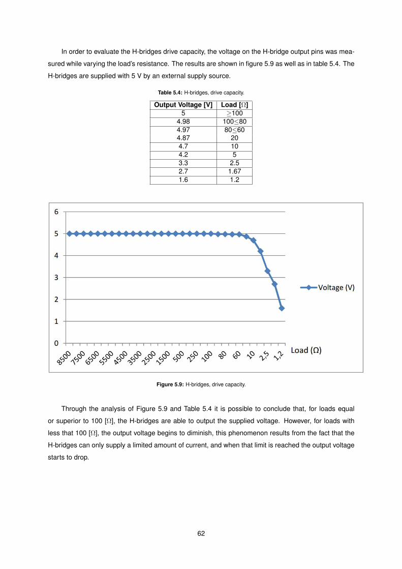
In order to evaluate the H-bridges drive capacity, the voltage on the H-bridge output pins was mea-
sured while varying the load’s resistance. The results are shown in figure 5.9 as well as in table 5.4. The
H-bridges are supplied with 5 V by an external supply source.
Table 5.4: H-bridges, drive capacity.
Output Voltage [V] Load [Ω]5 ≥100
4.98 100≤804.97 80≤604.87 204.7 104.2 53.3 2.52.7 1.671.6 1.2
Figure 5.9: H-bridges, drive capacity.
Through the analysis of Figure 5.9 and Table 5.4 it is possible to conclude that, for loads equal
or superior to 100 [Ω], the H-bridges are able to output the supplied voltage. However, for loads with
less that 100 [Ω], the output voltage begins to diminish, this phenomenon results from the fact that the
H-bridges can only supply a limited amount of current, and when that limit is reached the output voltage
starts to drop.
62
Chapter 6– Conclusions
The objective of this thesis was the expansion of WSN’s functionalities through the integration of
actuation capabilities in them. In order to reach this objective a daughter board, named Overboard,
capable of actuation functionalities was designed and built, with the purpose of being integrated in WSN
nodes. The actuation functionalities implemented were,the direct control of electric motors, solenoids
and devices connected to the AC powerline and the indirect control of devices connected to the X10,
KNX and CAN Bus automation protocols. The Overboard is controlled by the node it is attached.
Recalling the requirements defined in chapter 3.
1. Compatibility with MoteIST, MicaZ and Iris.
2. Ability to control the actuators discussed in Section 2.1.
3. Ability to communicate with X10 protocol, CAN Bus protocol and KNX protocol.
4. Existence of a Test mode, allowing the Overboard to be tested for errors.
5. Existence of a MCU, for the automation of the actuation functionalities.
In order to achieve compatibility with the specified motes, the 51 pins hirose connector present in
all of them, with equal pinout, is used for communication, power supply and physical support purposes.
Through this connector several communication protocols are available, UART, SPI and I2C, being the
last one chosen for the communications between boards. The reasons for choosing the I2C protocol
were, the flexibility provided by the protocol in allowing both boards to initiate communications and the
fact that it requires less signal wires than the rest, simplifying the board’s routing.
As for the second requirement, the disassociation of the RF and power modules, provide modularity
to the Overboard. The 20 pin hirose connector used for the integration of the RF board is also compatible
with the RF boards existent for the MoteIST. Furthermore, the existence of general-purpose pins allows
the future integration of more functionalities without the need to modify the Overboard.
Regarding the control of the maximum types of actuators, two independent bipolar drivers, an in-
terface for the servomotors and a daughter board for the control of AC power devices were integrated
in the Overboard. The bipolar drivers were chosen due to their versatility. Through them, it is possible
to control electric motors, solenoids and similar actuators. The servomotor interface was included in the
Overboard due to the huge popularity and utility of servomotors. Last but not least, the daughter board,
named Power Board, equips the Overboard with the functionality of control AC power devices and also
isolates the high voltages from the Overboard.
63
The communication through automation protocols, more specifically the, X10, KNX and CAN Bus
protocols was achieved. This ability is of great advantage, since it allows the control of elevated amounts
of actuators, without the restriction of their power needs. These protocols are very useful in the integra-
tion of the Overboard in infrastructures that use them.
The creation of a test mode, specified in the fifth requirement, made available the testing of each
module of the Overboard and further allows the testing of the communication protocols through the
transmission and reception of messages. In order to access the test mode, it is required the existence
of a host PC with a terminal able to communicate through RS-232 communication.
Regarding the last requirement, the integration of a MCU allowed the automation of the tasks avail-
able on the Overboard, these being requested by the motherboard, in normal operation mode, or by a
host PC, through the test mode. Furthermore, the Overboard’s capability of shutting down specific mod-
ules when these are not required, allows the batteries to increase their autonomy. This characteristic is
essential, since that power consumption in WSN is critical.
Last but not least, in order to verify the board’s functionalities and evaluate it’s performance, several
tests were made, these being shown in Chapter 5. The board’s direct actuation functionalities were
tested using electric motors and their characterization was made using variable loads. Regarding the
indirect actuation functionalities, these were tested with testbeds.
Having achieved the goals laid down for this work, there is still room for the improvement of the
software application, the board’s design and the further integration of actuation functionalities in the
board. The Power board can also be further improved into being able to dim the power delivered to
devices connected to it and not only switch, which is, its present functionality. The creation of RF boards,
in order to interact with the automation protocols through RF is also another functionality that should be
developed in the future.
64

Chapter 7– Annexes
In this chapter the annexes of the thesis are presented. Those include, the bill of materials, pre-
sented in Appendix A, the board’s schematics, presented in Appendix B, the pinout of the programmer
used to program the Overboard, presented in Appendix C, an explanation of servomotors interface, pre-
sented in Appendix D, the different types of KNX physical external interfaces, presented in Appendix E
and the User Manual of the Overboard, presented in Appendix F.
7.1 Bill of Materials
The Bill of Materials shown in Table A.1, contains the components used in the Overboard, stating their
name, Manufacturer, Manufacturer Part Number, Designator, Value, Package, Case Type and prices.
The designation each term is as follows.
• Name: The type of component is described.
• Manufacturer: The Manufacturer of the component.
• Manufacturer Part Number: The Manufacturer reference number.
• Designator: The name of the component in the schematics.
• Package: standard reference of the component’s capsule or it’s physical dimensions.
• Case Type: The component’s termination style.
• S1: Price for one unit applied by Farnell in euros.
• S2: Price for one unit applied by Digi-Key Co. USA in euros.
• S3: Price for one unit applied by Mouser in euros.
65

a
66
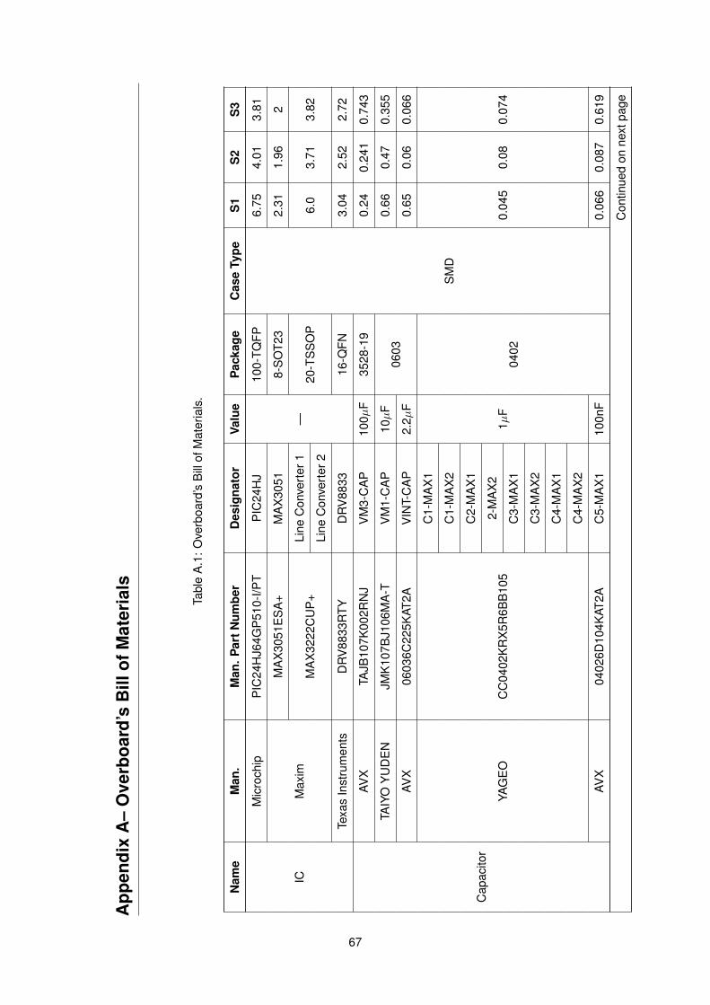
App
endi
xA
–O
verb
oard
’sB
illof
Mat
eria
ls
Tabl
eA
.1:
Ove
rboa
rd’s
Bill
ofM
ater
ials
.
Nam
eM
an.
Man
.Par
tNum
ber
Des
igna
tor
Valu
eP
acka
geC
ase
Type
S1
S2
S3
IC
Mic
roch
ipP
IC24
HJ6
4GP
510-
I/PT
PIC
24H
J
—
100-
TQFP
SM
D
6.75
4.01
3.81
Max
im
MA
X30
51E
SA
+M
AX
3051
8-S
OT2
32.
311.
962
MA
X32
22C
UP
+Li
neC
onve
rter
120
-TS
SO
P6.
03.
713.
82Li
neC
onve
rter
2
Texa
sIn
stru
men
tsD
RV
8833
RTY
DR
V88
3316
-QFN
3.04
2.52
2.72
Cap
acito
r
AVX
TAJB
107K
002R
NJ
VM
3-C
AP
100µ
F35
28-1
90.
240.
241
0.74
3
TAIY
OY
UD
EN
JMK
107B
J106
MA
-TV
M1-
CA
P10µ
F06
030.
660.
470.
355
AVX
0603
6C22
5KAT
2AV
INT-
CA
P2.
2µF
0.65
0.06
0.06
6
YAG
EO
CC
0402
KR
X5R
6BB
105
C1-
MA
X1
1µF
0402
0.04
50.
080.
074
C1-
MA
X2
C2-
MA
X1
2-M
AX
2
C3-
MA
X1
C3-
MA
X2
C4-
MA
X1
C4-
MA
X2
AVX
0402
6D10
4KAT
2AC
5-M
AX
110
0nF
0.06
60.
087
0.61
9
Con
tinue
don
next
page
67
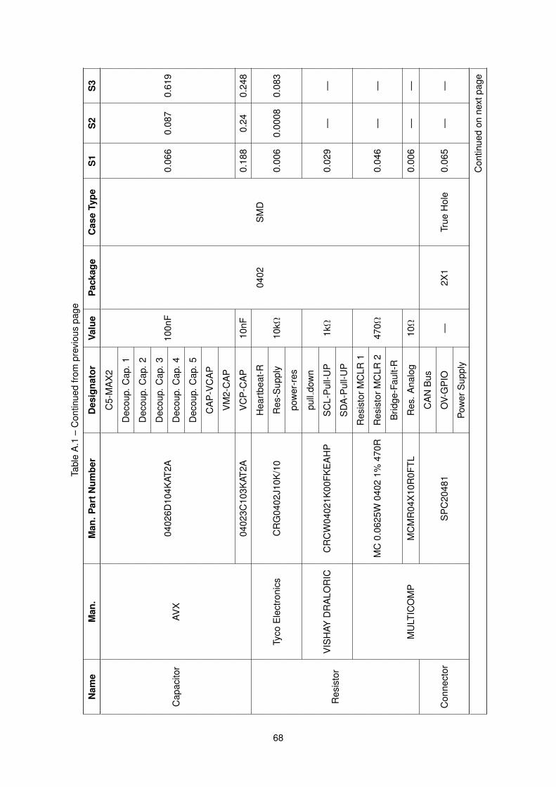
Tabl
eA
.1–
Con
tinue
dfro
mpr
evio
uspa
ge
Nam
eM
an.
Man
.Par
tNum
ber
Des
igna
tor
Valu
eP
acka
geC
ase
Type
S1
S2
S3
Cap
acito
rAV
X04
026D
104K
AT2A
C5-
MA
X2
100n
F
0402
SM
D
0.06
60.
087
0.61
9
Dec
oup.
Cap
.1
Dec
oup.
Cap
.2
Dec
oup.
Cap
.3
Dec
oup.
Cap
.4
Dec
oup.
Cap
.5
CA
P-V
CA
P
VM
2-C
AP
0402
3C10
3KAT
2AV
CP
-CA
P10
nF0.
188
0.24
0.24
8
Res
isto
r
Tyco
Ele
ctro
nics
CR
G04
02J1
0K/1
0
Hea
rtbe
at-R
10kΩ
0.00
60.
0008
0.08
3R
es-S
uppl
y
pow
er-r
es
VIS
HAY
DR
ALO
RIC
CR
CW
0402
1K00
FKE
AH
P
pull
dow
n
1kΩ
0.02
9—
—S
CL-
Pul
l-UP
SD
A-P
ull-U
P
MU
LTIC
OM
P
MC
0.06
25W
0402
1%47
0R
Res
isto
rMC
LR1
470Ω
0.04
6—
—R
esis
torM
CLR
2
Brid
ge-F
ault-
R
MC
MR
04X
10R
0FTL
Res
.A
nalo
g10
Ω0.
006
——
Con
nect
orS
PC
2048
1
CA
NB
us
—2X
1Tr
ueH
ole
0.06
5—
—O
V-G
PIO
Pow
erS
uppl
y
Con
tinue
don
next
page
68
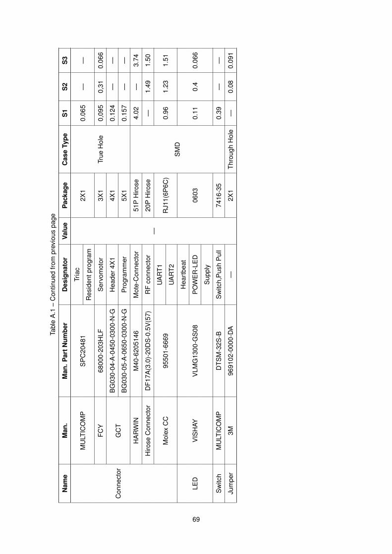
Tabl
eA
.1–
Con
tinue
dfro
mpr
evio
uspa
ge
Nam
eM
an.
Man
.Par
tNum
ber
Des
igna
tor
Valu
eP
acka
geC
ase
Type
S1
S2
S3
Con
nect
or
MU
LTIC
OM
PS
PC
2048
1Tr
iac
—
2X1
True
Hol
e
0.06
5—
—R
esid
entp
rogr
am
FCY
6800
0-20
3HLF
Ser
vom
otor
3X1
0,09
50,
310.
066
GC
TB
G03
0-04
-A-0
450-
0300
-N-G
Hea
der4
X1
4X1
0.12
4—
—
BG
030-
05-A
-065
0-03
00-N
-GP
rogr
amm
er5X
10.
157
——
HA
RW
INM
40-6
2051
46M
ote-
Con
nect
or51
PH
irose
SM
D
4.02
—3.
74
Hiro
seC
onne
ctor
DF1
7A(3
.0)-
20D
S-0
.5V
(57)
RF
conn
ecto
r20
PH
irose
—1.
491.
50
Mol
exC
C95
501-
6669
UA
RT1
RJ1
1(6P
6C)
0.96
1.23
1.51
UA
RT2
LED
VIS
HAY
VLM
G13
00-G
S08
Hea
rtbe
at
0603
0.11
0.4
0.06
6P
OW
ER
-LE
D
Sup
ply
Sw
itch
MU
LTIC
OM
PD
TSM
-32S
-BS
witc
h,P
ush
Pul
l74
16-3
50.
39—
—
Jum
per
3M96
9102
-000
0-D
A—
2X1
Thro
ugh
Hol
e—
0.08
0.09
1
69

a
70
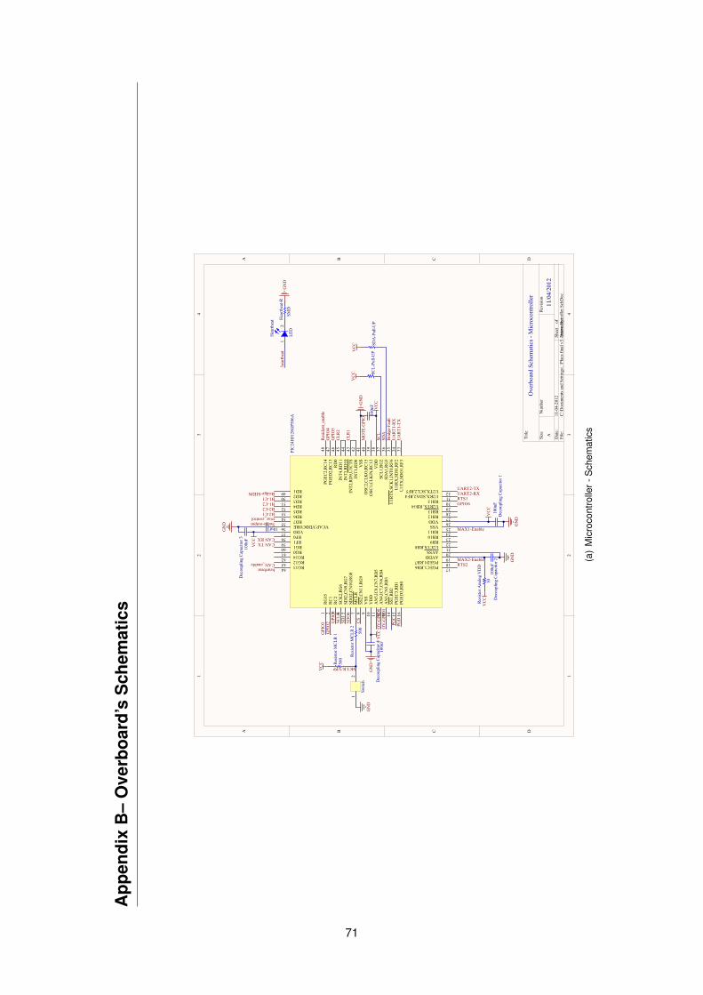
App
endi
xB
–O
verb
oard
’sS
chem
atic
s
11
22
33
44
DD
CC
BB
AA
Title
Num
ber
Rev
ision
Size A Dat
e:11
-04-
2012
Shee
t o
fFi
le:
C:\D
ocum
ents
and
Set
tings
\..\P
laca
fina
l v3
- mic
roco
ntro
ller.S
chD
ocD
raw
n By
:
12
Hea
rtbea
t
LED
Hea
rtbea
t-R
SMD
GN
Dhe
artb
eat
PGD
PGC
100n
FD
ecou
plin
g C
apac
itor 1
100n
F
100n
FD
ecou
plin
g C
apac
itor 2
100n
FD
ecou
plin
g C
apac
itor 4
100n
FD
ecou
plin
g C
apac
itor 3
10uf
GN
D
Res
istor
MC
LR 1
500
Res
istor
MC
LR 2
500
VC
C
GN
D
Res
istor
Ana
log
VD
D
10
SDA
SCL
UA
RT1
-RX
UA
RT1
-TX
UART2-RXUART2-TX
Brid
ge-F
ault
CAN RXCAN TX
CLR
2
CLR
1
RTS1
RTS2heartbeatCAN_enable
MAX1-Enable
MAX2-Enable
Res
iden
t_en
able
triac_controlB2-C1B2-C2
B1-C1B1-C2
CS
SDI
SDO
SCLK
GPI
O5
GPI
O1
GPIO6
GPI
O4
GPI
O3
VC
C
VC
C
GN
D
VC
CGN
D
VC
C
GN
D
GN
D
VC
C
SCL-
Pull-
UP
VC
C
SDA
-Pul
l-UP
VC
C
Bridge-SHDN
GPI
O2
MCLR/VPP
MO
TE-G
PIO
OV
-GPI
O0
OV
-GPI
O1
Ove
rboa
rd S
chem
atic
s - M
icro
cont
rolle
r
Servo-output
12
Switc
h
RG15
1
RC
12
RC
23
SCK
2,R
G6
4
SDI2
,CN
9,RG
75
SDO
2,C
N10
,RG
86
MCL
R7
SS2,
CN
11,R
G9
8
VSS
9
VD
D10
AN
5,IC
8,C
N7,
RB
511
AN
4,IC
7,C
N6,
RB
412
AN
3,C
N5,
RB
313
SS1,
RB
214
PGEC
3,R
B1
15
PGED
3,R
B0
16
PGEC1,RB6 17
PGED1,RB7 18
AVDD 19
AVSS 20
U2CTS,RB8 21
RB9 22
RB10 23
RB11 24
VSS 25
VDD 26
RB12 27
RB13 28
U2RTS, RB14 29
RB15 30
U2RX,SDA2,RF4 31
U2TX,SCL2,RF5 32U1T
X,S
DO
1,R
F333
U1R
X,S
DI1
,RF2
34U
1RTS
,SC
K1,
INT0
,RF6
35SD
A1,
RG3
36SC
L1,R
G2
37V
DD
38O
SC1,
CLK
IN,R
C12
39O
SC2,
CLK
O,R
C15
40V
SS41
INT1
,RD
842
INT2
,RD
9,U
1CTS
43IN
T3,R
D10
44IN
T4,R
D11
45R
D0
46PG
ED2,
RC
1347
PGEC
2,R
C14
48
RD149 RD250 RD351 RD452 RD553 RD654 RD755 VCAP,VDDCORE56 VDD57 RF058 RF159 RG160 RG061 RG1462 RG1263 RG1364
PIC
24H
J128
GP5
06A
11/0
4/20
12
PICAP0VCAP01PICAP0VCAP02COCA
P0VCAP
PIDecoupling0301PIDecoupling0302CO
Deco
upli
ng03
PIDecoupling Capacitor 101 PIDecoupling Capacitor 102CODecoupling Capacitor 1
PIDecoupling Capacitor 201 PIDecoupling Capacitor 202CODecoupling Capacitor 2
PIDecoupling Capacitor 301 PIDecoupling Capacitor 302
CODecoupling Capacitor 3
PIDecoupli
ng Capacit
or 401
PIDecoupling
Capacitor 4
02
CODecoupling Capacitor 4
PIHeartbeat01
PIHeartbeat02
COHe
artbeat
PIHear
tbeat0
R01PIH
eartbe
at0R02
COHeartbeat0R
PIPI
C24H
J128GP
506A
01
PIPI
C24H
J128GP
506A
02
PIPI
C24H
J128GP
506A
03
PIPI
C24H
J128GP
506A
04
PIPI
C24H
J128GP
506A
05
PIPI
C24H
J128GP
506A
06
PIPI
C24H
J128GP
506A
07
PIPI
C24H
J128GP
506A
08
PIPI
C24H
J128GP
506A
09
PIPI
C24H
J128
GP50
6A01
0
PIPI
C24H
J128
GP50
6A01
1
PIPIC2
4HJ128
GP506A
012
PIPIC2
4HJ128
GP506A
013
PIPIC2
4HJ128
GP506A
014
PIPIC2
4HJ128
GP506A
015
PIPI
C24H
J128
GP50
6A01
6
PIPIC24HJ128GP506A017PIPIC24HJ128GP506A018PIPIC24HJ128GP506A019PIPIC24HJ128GP506A020
PIPIC24HJ128GP506A021PIPIC24HJ128GP506A022PIPIC24HJ128GP506A023PIPIC24HJ128GP506A024
PIPIC24HJ128GP506A025PIPIC24HJ128GP506A026PIPIC24HJ128GP506A027PIPIC24HJ128GP506A028
PIPIC24HJ128GP506A029PIPIC24HJ128GP506A030PIPIC24HJ128GP506A031PIPIC24HJ128GP506A032
PIPI
C24H
J128
GP50
6A03
3
PIPIC2
4HJ128
GP506A
034
PIPIC2
4HJ128
GP506A
035
PIPIC2
4HJ128
GP506A
036
PIPIC2
4HJ128
GP506A
037
PIPI
C24H
J128
GP50
6A03
8
PIPI
C24H
J128
GP50
6A03
9
PIPIC2
4HJ128
GP506A
040
PIPIC2
4HJ128
GP506A
041
PIPIC2
4HJ128
GP506A
042
PIPI
C24H
J128
GP50
6A04
3
PIPI
C24H
J128
GP50
6A04
4
PIPIC2
4HJ128
GP506A
045
PIPIC2
4HJ128
GP506A
046
PIPIC2
4HJ128
GP506A
047
PIPIC2
4HJ128
GP506A
048
PIPIC24HJ128GP506A049PIPIC24HJ128GP506A050PIPIC24HJ128GP506A051PIPIC24HJ128GP506A052PIPIC24HJ128GP506A053PIPIC24HJ128GP506A054PIPIC24HJ128GP506A055PIPIC24HJ128GP506A056PIPIC24HJ128GP506A057PIPIC24HJ128GP506A058PIPIC24HJ128GP506A059PIPIC24HJ128GP506A060PIPIC24HJ128GP506A061PIPIC24HJ128GP506A062PIPIC24HJ128GP506A063PIPIC24HJ128GP506A064COPIC24HJ128GP506A
PIResistor A
nalog VDD01
PIResistor A
nalog VDD02
COResist
or Analog
VDD
PIResistor MCLR 101PIResistor MCLR 102 CORe
sist
or M
CLR
1
PIResistor
MCLR 201
PIResistor
MCLR 202
CORe
sist
or M
CLR
2
PISCL0Pull0UP01PISCL0Pull0UP02 COSC
L0Pu
ll0U
P
PISDA0Pull0UP01PISDA0Pull0UP02 COSDA0
Pull0U
P
PISwit
ch0 Pu
sh Pul
l01PIS
witch0
Push
Pull02
COSwitch0 Push Pull
(a)
Mic
roco
ntro
ller-
Sch
emat
ics
71
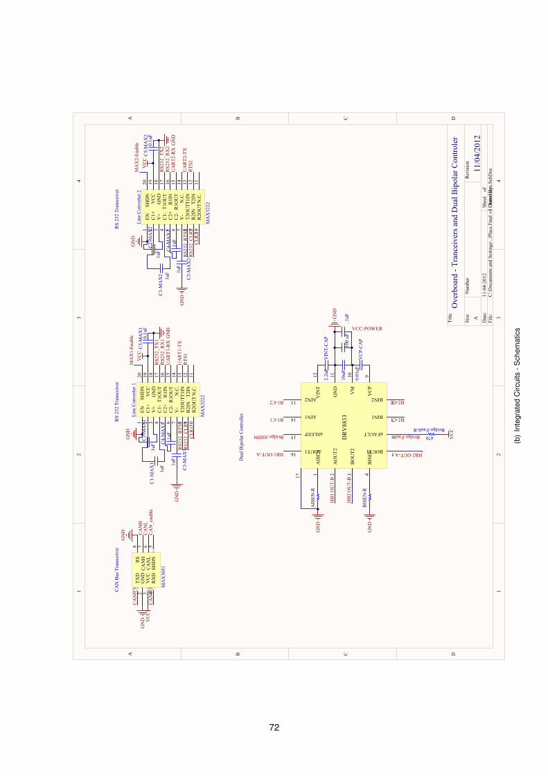
11
22
33
44
DD
CC
BB
AA
Title
Num
ber
Rev
ision
Size A Dat
e:11
-04-
2012
Shee
t o
fFi
le:
C:\D
ocum
ents
and
Set
tings
\..\P
laca
Fin
al v
4 - I
nter
face
s.Sch
Doc
Dra
wn
By:
GN
D
GN
D CAN
HCA
NL
CAN
RX
CAN
TX
Ove
rboa
rd -
Tran
ceiv
ers a
nd D
ual B
ipol
ar C
ontro
ler
TXD
1G
ND
2V
CC
3
RX
D4
SHD
N5
CAN
L6
CAN
H7
RS
8
MA
X30
51
VC
CCA
N_e
nabl
e
EN1
C1+
2
V+
3
C1-
4
C2+
5
C2-
6
V-
7
T2O
UT
8
R2I
N9
T2IN
12T1
IN13
N.C
.14
R1O
UT
15R
1IN
16T1
OU
T17
GN
D18
VC
C19
SHD
N20
R2O
UT
10N
.C.
11
Line
Con
verte
r 1
MA
X32
22
GN
D
1uF
C1-
MA
X1
1uF
C2-
MA
X1
1uF
C3-
MA
X1
1uF
C4-
MA
X1
GN
D
VC
C0.
1uF
C5-
MA
X1
RS2
32_T
X1
RS2
32_R
X1
UA
RT1
-RX
UA
RT1
-TX
RTS
1R
S232
_CLR
1CL
R1
RS2
32_R
TS1
EN1
C1+
2
V+
3
C1-
4
C2+
5
C2-
6
V-
7
T2O
UT
8
R2I
N9
T2IN
12T1
IN13
N.C
.14
R1O
UT
15R
1IN
16T1
OU
T17
GN
D18
VC
C19
SHD
N20
R2O
UT
10N
.C.
11
Line
Con
verte
r 2
MA
X32
22
GN
D
1uF
C1-
MA
X2
1uF
C2-
MA
X2
1uF
C3-
MA
X2
1uF
C4-
MA
X2
GN
D
VC
C0.
1uF
C5-
MA
X2
RS2
32_T
X2
RS2
32_R
X2
UA
RT2
-RX
UA
RT2
-TX
RTS
2R
S232
_CLR
2CL
R2
RS2
32_R
TS2
MA
X1-
Enab
leM
AX
2-En
able G
ND
GN
D
AIS
EN1
AO
UT2
2
BO
UT2
3
BIS
EN4
BOUT1 5
nFAULT 6
BIN1 7
BIN2 8V
CP
9
VM
10
GN
D11
VIN
T12
AIN213
AIN114
nSLEEP15
AOUT116
DR
V88
33
17
AIS
EN-R
BIS
EN-R
Bridge-FaultBridge-Fault-R
470 VC
C
Bridge-SHDN
B2-C1
B2-C2
B1-C1
B1-C2
10uF
VCC-POWERV
INT-
CAP
2.2u
F
VC
P-CA
P0.
01uF
HB1 OUT-A HB2 OUT-A
HB
1 O
UT-
B
HB
2 O
UT-
B.1
uF10
0 uF
GN
D
GN
D
GN
D
CAN
Bus
Tra
nsce
iver
RS
232
Tran
scei
ver
RS
232
Tran
scei
ver
Dua
l Bip
olar
Con
trolle
r
11/0
4/20
12
PIAISE
N0R01
PIAISE
N0R02
COAISEN0R
PIBISE
N0R01
PIBISE
N0R02
COBI
SEN0
R
PIBridge0Fault0R01PIBridge0Fault0R02 COBridge0Fault0R
PIC10MAX101 PIC10MAX102CO
C10M
AX1
PIC10MAX201 PIC10MAX202CO
C10M
AX2
PIC20MAX101PIC20MAX102 COC
20MA
X1
PIC20MAX201PIC20MAX202 COC
20MA
X2
PIC30M
AX101
PIC30M
AX102
COC3
0MAX
1
PIC30M
AX201
PIC30M
AX202
COC3
0MAX
2
PIC40M
AX101
PIC40M
AX102
COC4
0MAX
1
PIC40M
AX201
PIC40M
AX202
COC4
0MAX
2
PIC50M
AX101
PIC50M
AX102
COC5
0MAX
1
PIC50M
AX201
PIC50M
AX202
COC5
0MAX
2
PIDR
V883
501
PIDR
V883
502
PIDR
V883
503
PIDRV883504
PIDRV883505PIDRV883506
PIDRV883507PIDRV883508
PIDRV883509
PIDRV8
8350
10
PIDRV8
8350
11
PIDRV8
8350
12
PIDRV8835013PIDRV8835014
PIDRV8835015PIDRV8835016
PIDRV8
8350
17CODRV8835
PILine
Con
verter
101
PILine
Conve
rter 1
02
PILine
Conve
rter 1
03
PILine
Conve
rter 1
04
PILine
Conve
rter 1
05
PILine
Con
verter
106
PILine
Conve
rter 1
07
PILine
Conve
rter 1
08
PILine
Conve
rter 1
09
PILine
Conve
rter 1
010PIL
ine Co
nverte
r 1011
PILine
Conve
rter 1
012
PILine
Conve
rter 1
013
PILine
Conve
rter 1
014
PILi
ne C
onve
rter
101
5
PILine
Conve
rter 1
016
PILine
Conve
rter 1
017
PILine
Conve
rter 1
018
PILine
Conve
rter 1
019
PILi
ne C
onve
rter
102
0
COLine Converter 1
PILine Converter 201
PILine Converter 202
PILine Converter 203
PILine Converter 204
PILine Converter 205
PILine Converter 206
PILine Converter 207
PILine Converter 208
PILine Converter 209
PILine
Conve
rter 2
010PIL
ine Co
nverte
r 2011
PILine
Conve
rter 2
012
PILine
Conve
rter 2
013
PILine Converter 2014
PILine Converter 2015
PILine
Conve
rter 2
016
PILine
Conve
rter 2
017
PILine
Conve
rter 2
018
PILine Converter 2019
PILine Converter 2020
COLine Converter 2
PIMA
X305
101
PIMA
X305
102
PIMA
X305
103
PIMA
X305
104
PIMA
X305
105
PIMA
X305
106
PIMA
X305
107
PIMA
X305
108
COMA
X305
1
PIVCP0CAP01PIVCP0CAP02CO
VCP0
CAP
PIVINT0CAP01PIVINT0CAP02COVINT
0CAP
PIVM10CAP01PIVM10CAP02CO
VM10
CAP
PIVM20CAP01PIVM20CAP02CO
VM20
CAP
PIVM30CAP01PIVM30CAP02CO
VM30
CAP
PIDRV8835014NLB10C1PIDRV8835013NLB10C2
PIDRV883507 NLB20C1PIDRV883508 NLB20C2
PIBridge0Fault0R02PIDRV883506 NLBridge0FaultPIDRV8835015NLBridge0SHDN
PIMA
X305
105NL
CAN0
enab
lePI
MAX3
0510
7NLCA
NH
PIMA
X305
106NL
CANL
PIMA
X305
104
NLCAN
RX
PIMA
X305
101
NLCAN
TX
PILine
Conve
rter 1
010NL
CLR1
PILine
Conve
rter 2
010NLCL
R2
PIAISE
N0R01
PIBISE
N0R01
PIC20MAX102PIC20MAX202
PIC40M
AX102
PIC40M
AX202
PIC50M
AX102
PIC50M
AX202
PIDRV8
8350
11
PIDRV8
8350
17
PILine
Con
verter
101
PILine
Conve
rter 1
018
PILine Converter 201
PILine
Conve
rter 2
018
PIMA
X305
102
PIMA
X305
108
PIVINT0CAP01 PIVM10CAP02PIVM20CAP02
PIVM30CAP02
PIDRV8835016NLHB1 OUT0A
PIDR
V883
502
NLHB1 OUT0B
PIDRV883505 NLHB2 OUT0A
PIDR
V883
503
NLHB2 OUT0B
PILi
ne C
onve
rter
102
0NLMA
X10E
nabl
e
PILine Converter 2020NL
MAX2
0Ena
ble
PIAISE
N0R02PIDR
V883
501
PIBISE
N0R02PIDRV883504
PIC10MAX101PIL
ine Co
nverte
r 102
PIC10MAX102PIL
ine Co
nverte
r 104
PIC10MAX201PILine Converter 202
PIC10MAX202PILine Converter 204
PIC20MAX101PIL
ine Co
nverte
r 103
PIC20MAX201PILine Converter 203
PIC30M
AX101
PILine
Conve
rter 1
05
PIC30M
AX102PILine
Con
verter
106
PIC30M
AX201
PILine Converter 205
PIC30M
AX202PILine Converter 206
PIC40M
AX101
PILine
Conve
rter 1
07
PIC40M
AX201
PILine Converter 207
PIDRV883509PIVCP0CAP01
PIDRV8
8350
12 PIVINT0CAP02
PILine
Conve
rter 1
011
PILine
Conve
rter 1
014
PILine
Conve
rter 2
011
PILine Converter 2014
PILine
Conve
rter 1
09NL
RS23
20CL
R1PILine Converter 209
NLRS2320CLR2
PILine
Conve
rter 1
08NLRS
2320
RTS1
PILine Converter 208
NLRS
2320
RTS2
PILine
Conve
rter 1
016NLR
S232
0RX1
PILine
Conve
rter 2
016NL
RS23
20RX
2
PILine
Conve
rter 1
017NLR
S232
0TX1
PILine
Conve
rter 2
017NL
RS23
20TX
2
PILine
Conve
rter 1
012NLR
TS1
PILine
Conve
rter 2
012NLRTS2
PILi
ne C
onve
rter
101
5NLUART
10RX
PILine
Conve
rter 1
013NLUAR
T10TX
PILine Converter 2015NL
UART
20RX
PILine
Conve
rter 2
013NL
UART
20TX
PIBridge0Fault0R01
PIC50M
AX101
PIC50M
AX201
PILine
Conve
rter 1
019
PILine Converter 2019
PIMA
X305
103
PIDRV8
8350
10 PIVCP0CAP02PIVM10CAP01PIVM20CAP01
PIVM30CAP01
NLVCC0POWER
(b)
Inte
grat
edC
ircui
ts-S
chem
atic
s
72

11
22
33
44
DD
CC
BB
AA
Title
Num
ber
Rev
ision
Size A Dat
e:11
-04-
2012
Shee
t o
fFi
le:
C:\D
ocum
ents
and
Set
tings
\..\P
laca
fina
l-Con
nect
ors (
25-1
0-11
).Sch
Doc
Dra
wn
By:
2929
33
3030
3131
3232
3333
3434
3535
3636
3737
3838
3939
4040
4141
4242
4343
4444
4545
4646
4747
4848
4949
44
55
66
77
88
99
1010
1111
1212
1313
1414
1515
1616
1717
1818
1919
2020
2121
2222
2323
Hir
ose
22
11
2424
2525
2626
2828
2727
5050
5151
Mot
e-C
onne
ctor
Hiro
se 5
1 Pi
ns
1 2
CAN
Bus
Hea
der 2
X1
CAN
HCA
NL
1 2
Pow
er S
uppl
y
Hea
der 2
X1
1 2 3
Serv
omot
or
Hea
der 3
X1
1 2
Tria
c
Hea
der 2
X1
12
Supp
ly
LED
Res
-Sup
ply
SMD
GN
DV
CC
VC
C
VC
C
GN
D
GN
D
SDA
SCL
VC
C
pull_down
1k GN
D
CS
SDI
SDO
SCLK
66
88
1010
1212
1414
1616
55
77
99
1111
1313
1515
DF1
7 R
ecep
tacl
e
11
33
1717
1919
1818
2020
22
44
RF
conn
ecto
r
Hiro
se 2
0 Pi
ns
Serv
o-ou
tput
VC
C-P
OW
ER
GN
D
GN
D
Net
Labe
l135
Net
Labe
l136
Res
iden
t_en
able
1 2 3 4
Hea
der 4
X1
HB
1 O
UT-
A
HB
2 O
UT-
A
HB
1 O
UT-
BH
B2
OU
T-B
MCL
R/V
PP1 2 3 4 5
Prog
ram
mer
Hea
der 5
X1
VC
CG
ND
PGD
PGC
GN
DVC
C
UA
RT2
-TX
UA
RT2
-RX
GPI
O1
GPI
O6
GPI
O2
GPI
O4
GPI
O3
GPI
O5
RS2
32_T
X1
RS2
32_R
X1
RS2
32_C
LR1
RS2
32_R
TS1
RS2
32_T
X2
RS2
32_R
X2
RS2
32_C
LR2
RS2
32_R
TS2
MO
TE-G
PIO
1 2
OV
-GPI
O
Hea
der 2
X1
OV
-GPI
O0
OV
-GPI
O1
GN
D
GN
D
GN
D
Ove
rboa
rd -
Con
nnec
tors
triac
_con
trol
VC
C-P
OW
ER
12
POW
ER- L
ED
LED
pow
er-re
s
SMD
GN
DV
CC
-PO
WER
1 2
Res
iden
t pro
gram
Jum
per
11
22
33
44
55
66
RJ1
1 - 6
P6C
UA
RT1
RJ1
1 - 6
P6C
11
22
33
44
55
66
RJ1
1 - 6
P6C
UA
RT2
RJ1
1 - 6
P6C
11/0
4/20
12
PICAN Bus01
PICAN Bus02COCAN Bus
PIHead
er 4 X
101
PIHead
er 4 X
102
PIHead
er 4 X
103
PIHead
er 4 X
104 COHeader 4 X1
PIMo
te0Connect
or01
PIMo
te0Connect
or02
PIMo
te0Connect
or03
PIMo
te0Connect
or04
PIMo
te0Connect
or05
PIMo
te0Connect
or06
PIMo
te0Connect
or07
PIMo
te0Connect
or08
PIMo
te0Connect
or09
PIMote0Connector010
PIMote0Connector011
PIMote0Connector012
PIMote0Connector013
PIMote0Connector014
PIMote0Connector015
PIMote0Connector016
PIMote0Connector017
PIMote0Connector018
PIMote0Connector019
PIMote0Connector020
PIMote0Connector021
PIMote0Connector022
PIMote0Connector023
PIMote0Connector024
PIMote0Connector025
PIMote0Connector026
PIMote0Connector027
PIMote0Connector028
PIMote0Connector029
PIMote0Connector030
PIMote0Connector031
PIMote0Connector032
PIMote0Connector033
PIMote0Connector034
PIMote0Connector035
PIMote0Connector036
PIMote0Connector037
PIMote0Connector038
PIMote0Connector039
PIMote0Connector040
PIMote0Connector041
PIMote0Connector042
PIMote0Connector043
PIMote0Connector044
PIMote0Connector045
PIMote0Connector046
PIMote0Connector047
PIMote0Connector048
PIMote0Connector049
PIMote0Connector050
PIMote0Connector051
COMote0Conne
ctor
PIOV0GPIO01
PIOV0GPIO02COOV0GPIO
PIPOWE
R0 LED
01PI
POWE
R0 L
ED02
COPOWE
R0 L
ED
PIpower0
res01
PIpower0
res02
COpower0res
PIPowe
r Supp
ly01
PIPowe
r Supp
ly02COPo
wer
Supp
ly
PIProg
rammer
01
PIProg
rammer
02
PIPr
ogra
mmer
03
PIPr
ogra
mmer
04
PIProg
rammer
05COProgrammer
PIpull0down01PIpull0down02
COpull0down
PIRes0Su
pply01
PIRes0Su
pply02
CORes0Su
pply
PIResi
dent p
rogram
01
PIResi
dent p
rogram
02CORe
side
nt p
rogr
am
PIRF c
onnect
or01
PIRF
con
nector
02
PIRF c
onnect
or03
PIRF
con
nector
04
PIRF c
onnect
or05
PIRF
con
nector
06
PIRF c
onnect
or07
PIRF
con
nector
08
PIRF c
onnect
or09
PIRF
con
nect
or01
0
PIRF
con
nect
or01
1PI
RF c
onne
ctor
012
PIRF
con
nect
or01
3PI
RF c
onne
ctor
014
PIRF
con
nect
or01
5PI
RF c
onne
ctor
016
PIRF
con
nect
or01
7PI
RF c
onne
ctor
018
PIRF
con
nect
or01
9PI
RF c
onne
ctor
020
CORF connector
PISe
rvom
otor
01
PISe
rvom
otor
02
PISe
rvom
otor
03COSe
rvom
otor
PISupply01
PISu
pply
02
COSupp
ly
PITriac01
PITriac02CO
Triac
PIUART101
PIUART102
PIUART103
PIUART104
PIUART105
PIUART106
COUA
RT1
PIUART201
PIUART202
PIUART203
PIUART204
PIUART205
PIUART206
COUA
RT2
PICAN Bus01
NLCA
NH
PICAN Bus02
NLCANL
PIRF
con
nect
or01
6NLCS
PIMo
te0Connect
or01
PIMote0Connector051
PIpower0
res02
PIPowe
r Supp
ly02
PIPr
ogra
mmer
03
PIpull0down01
PIRes0Su
pply02
PIRF
con
nect
or01
7
PISe
rvom
otor
03
PITriac02
PIUART106
PIUART206
PIRF
con
nect
or01
2NLGP
IO1
PIRF
con
nect
or01
0NLGP
IO2
PIRF
con
nector
08NLG
PIO3
PIRF
con
nector
06NLG
PIO4
PIRF
con
nector
04NL
GPIO
5PIRF
con
nector
02NL
GPIO
6
PIHead
er 4 X
101NLHB1 OUT0A
PIHead
er 4 X
102NL
HB1
OUT0
B
PIHead
er 4 X
104NLHB2 OUT0A
PIHead
er 4 X
103NLHB2 OUT0B
PIProg
rammer
01NLMC
LR0VPP
PIMote0Connector039NLMOTE0GPIO
NLNetLabel135
NLNetLabel136
PIMo
te0Connect
or03
PIMo
te0Connect
or04
PIMo
te0Connect
or05
PIMo
te0Connect
or06
PIMo
te0Connect
or07
PIMo
te0Connect
or08
PIMo
te0Connect
or09
PIMote0Connector010
PIMote0Connector011
PIMote0Connector012
PIMote0Connector013
PIMote0Connector014
PIMote0Connector015
PIMote0Connector016
PIMote0Connector017
PIMote0Connector018
PIMote0Connector019
PIMote0Connector020
PIMote0Connector023
PIMote0Connector024
PIMote0Connector025
PIMote0Connector026
PIMote0Connector027
PIMote0Connector028
PIMote0Connector029
PIMote0Connector030
PIMote0Connector031
PIMote0Connector032
PIMote0Connector033
PIMote0Connector034
PIMote0Connector035
PIMote0Connector036
PIMote0Connector037
PIMote0Connector038
PIMote0Connector040
PIMote0Connector041
PIMote0Connector042
PIMote0Connector043
PIMote0Connector044
PIMote0Connector045
PIMote0Connector046
PIMote0Connector047
PIMote0Connector048
PIMote0Connector049
PIPO
WER0
LED
02PIpower0
res01
PIRes0Su
pply01
PISu
pply
02
PIRF c
onnect
or01
PIRF c
onnect
or03
PIRF c
onnect
or05
PIRF c
onnect
or07
PIRF c
onnect
or09
PIRF
con
nect
or01
4
PIUART102
PIUART202
PIOV0GPIO01
NLOV0G
PIO0
PIOV0GPIO02
NLOV0G
PIO1
PIProg
rammer
05NLPGC
PIPr
ogra
mmer
04NLPGD
PIpull0down02PIResi
dent p
rogram
02NLResident0enable
PIUART101NLR
S232
0CLR
1
PIUART201NLR
S232
0CLR
2
PIUART103NLR
S232
0RTS
1
PIUART203NLR
S232
0RTS
2
PIUART104NLRS2320RX1
PIUART204NLRS2320RX2
PIUART105NLR
S232
0TX1
PIUART205NLR
S232
0TX2
PIMote0Connector022
NLSC
LPI
RF c
onne
ctor
019
NLSC
LK
PIMote0Connector021
NLSDA
PIRF
con
nect
or01
8NLSD
I
PIRF
con
nect
or02
0NLSDO
PISe
rvom
otor
01NLServo0output
PITriac01
NLtr
iac0
cont
rol
PIRF
con
nect
or01
3NLUA
RT20
RXPI
RF c
onne
ctor
011
NLUA
RT20
TX
PIMo
te0Connect
or02
PIMote0Connector050
PIProg
rammer
02
PIResi
dent p
rogram
01
PIRF
con
nect
or01
5
PISupply01
PIPOWE
R0 LED
01
PIPowe
r Supp
ly01
PISe
rvom
otor
02
NLVCC0POWER
(c)
Con
nect
ors
-Sch
emat
ics
73

74

Appendix C– PICKIT 3 Pinout
Pickit 3USB Communication
PIC24HOverboard
Power Supply
ICSPDAT
ICSPCLCK
VPP
VDD
VPP/MCLR
PGD
VSS
PGC
VSS
4.7 – 10 (kΩ)
Figure C.1: PIC24H Programming Interface.
• ICSPCLCK - This is the clock line of the serial data interface, it is always driven by the debugger,
being the data transferred on the falling edge.
• ICSPDAT - This is the serial data line. It is bi-directional, being the direction of the data depended
of the operation desired.
• VPP - This signal is responsible for putting the MCU into programming mode. It is must be con-
nected to a special pin of the MCU called MCLR.
• Power Supply - Voltage Supply. Their value is depended on the MCU, and it isn’t required if the
MCU already being powered.
• VSS - Ground Signal.
75

76
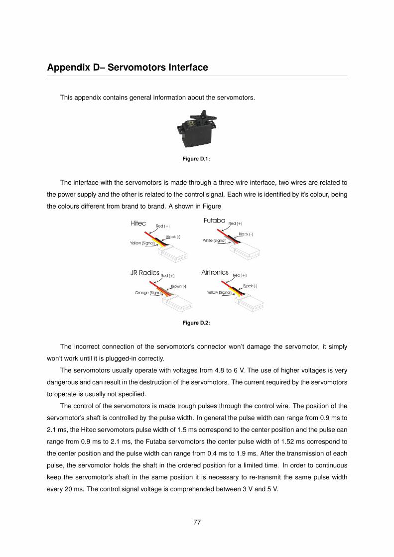
Appendix D– Servomotors Interface
This appendix contains general information about the servomotors.
Figure D.1:
The interface with the servomotors is made through a three wire interface, two wires are related to
the power supply and the other is related to the control signal. Each wire is identified by it’s colour, being
the colours different from brand to brand. A shown in Figure
Figure D.2:
The incorrect connection of the servomotor’s connector won’t damage the servomotor, it simply
won’t work until it is plugged-in correctly.
The servomotors usually operate with voltages from 4.8 to 6 V. The use of higher voltages is very
dangerous and can result in the destruction of the servomotors. The current required by the servomotors
to operate is usually not specified.
The control of the servomotors is made trough pulses through the control wire. The position of the
servomotor’s shaft is controlled by the pulse width. In general the pulse width can range from 0.9 ms to
2.1 ms, the Hitec servomotors pulse width of 1.5 ms correspond to the center position and the pulse can
range from 0.9 ms to 2.1 ms, the Futaba servomotors the center pulse width of 1.52 ms correspond to
the center position and the pulse width can range from 0.4 ms to 1.9 ms. After the transmission of each
pulse, the servomotor holds the shaft in the ordered position for a limited time. In order to continuous
keep the servomotor’s shaft in the same position it is necessary to re-transmit the same pulse width
every 20 ms. The control signal voltage is comprehended between 3 V and 5 V.
77

78
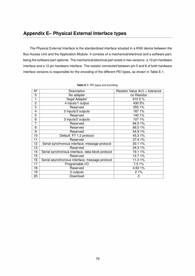
Appendix E– Physical External Interface types
The Physical External Interface is the standardized interface situated in a KNX device between the
Bus Access Unit and the Application Module. It consists of a mechanical/electrical and a software part,
being the software part optional. The mechanical/electrical part exists in two versions: a 10 pin hardware
interface and a 12 pin hardware interface. The resistor connected between pin 5 and 6 of both hardware
interface versions is responsible for the encoding of the different PEI types, as shown in Table E.1.
Table E.1: PEI types and encoding.
Nº Description Resistor Value (kΩ) + tolerance0 No adapter no Resistor1 ’Ilegal Adapter’ 910 5 %2 4 inputs/1 output 430 5%3 Reserved 255 1%4 2 inputs/3 outputs 187 1%5 Reserved 140 1%6 3 inputs/2 outputs 107 1%7 Reserved 84.5 1%8 Reserved 66.5 1%9 Reserved 54.9 1%10 Default: FT 1.2 protocol 45.3 1%11 Reserved 37.4 1%12 Serial synchronous interface, message protocol 30.1 1%13 Reserved 24.3 1%14 Serial synchronous interface. data block protocol 19.1 1%15 Reserved 14.7 1%16 Serial asynchronous interface, message protocol 11.0 1%17 Programable I/O 7.5 1%18 Reserved 4.53 1%19 5 outputs 2 1%20 Download 0
79

80

Appendix F– Overboard User Manual
81


[Version 1.8]
Sérgio Miguel Rodrigues Teixeira
[Overboard User Manual] The purpose of this document is to provide information about the Overboard’s functionalities
and operation modes, in order to permit its correct use.

User Manual Page i

User Manual Page ii
Revision History
Version Date Revision Description
1.0 25/11/2011 Template Creation.
1.1 23/04/2012 Full Document Revision.
1.2 29/04/2012 Orthography Revision.
1.3 2/05/2012 Modification of several Figures.
1.4 5/05/2012 Orthography Revision.
1.5 9/05/2012 Inclusion of the application code in the Appendix.
1.6 11/05/2012 Inclusion of the Overboard’s schematics in the Appendix.
1.7 13/05/2012 Inclusion of the Overboard’s pinout Figure.
1.8 20/05/2012 Separation of the User Guide into three files, User Guide,
Schematics and Software.

Overboard User Manual April 25, 2012
User Manual Page 1
Table of Contents
Revision History .................................................................................................................................... ii
Table of Contents .......................................................................................................................... 1
List of Figures ................................................................................................................................ 4
List of Tables ................................................................................................................................. 6
Acronyms ...................................................................................................................................... 8
1. Introduction ......................................................................................................................... 10
Purpose ................................................................................................................................... 10
Related Documents ................................................................................................................. 11
2. Overview ............................................................................................................................. 12
Functional Description ............................................................................................................. 14
Main Hirose Connector ....................................................................................................................... 16
RF Connector ...................................................................................................................................... 17
Control of actuators directly ................................................................................................................ 18
Power Board ....................................................................................................................................... 22
Automation protocols .......................................................................................................................... 24
Overboard Programming .................................................................................................................... 27
Operation Mode Interface ................................................................................................................... 28
Electromechanical Characteristics ...................................................................................................... 29
3. Software Applications .......................................................................................................... 31
Proprietary Protocol ................................................................................................................ 32
Enable/ Disable Module ...................................................................................................................... 33
Configure Module ................................................................................................................................ 34
Overboard User Manual April 25, 2012
User Manual Page 2
Send Data ........................................................................................................................................... 48
Reboot Overboard .............................................................................................................................. 50
Sleep ................................................................................................................................................... 50
Normal Mode ........................................................................................................................... 51
Test Mode ............................................................................................................................... 52
4. Glossary ............................................................................................................................. 58
5. Index ................................................................................................................................... 60

Overboard User Manual April 25, 2012
User Manual Page 3

Overboard User Manual April 25, 2012
User Manual Page 4
List of Figures
Figure 1 - Overboard connected to MoteIST ....................................................... 12
Figure 2 - Overboard modules ............................................................................ 13
Figure 3 - Overboard, Connectors Identification ................................................. 14
Figure 4 - 51P Hirose Connector, pinout ............................................................. 16
Figure 5 - 20P Hirose Connector ........................................................................ 17
Figure 6 - Actuator's Power Supply, pinout. ........................................................ 18
Figure 7 - Overboard, H-bridges identification .................................................... 19
Figure 8 - Control over electric motors, connections .......................................... 19
Figure 9 - Control over stepper motor, connections ............................................ 20
Figure 10 - Servomotor's angle control ............................................................... 21
Figure 11 - Servomotor Connector, pinout .......................................................... 21
Figure 12 – Servomotor, from Futaba, connected to Overboard ......................... 22
Figure 13 - Power Board, Block Diagram ............................................................ 22
Figure 14 - Power Board Connector, Pinout ....................................................... 23
Figure 15 - Power Board, pinout ......................................................................... 23
Figure 16 - Automation protocols connectors, identification ................................ 24
Figure 17 – X10 connector, plug and jack ........................................................... 25
Figure 18 – X10 connector, plug and jack ........................................................... 26
Figure 19 - CAN Bus Connector, pinout .............................................................. 27
Figure 20 - ICSP Connector, pinout .................................................................... 27
Figure 21 - Overboard LEDs identification .......................................................... 29
Figure 22 - Enable/ Disable Module, message ................................................... 33
Figure 23 - Standard H-bridge, configure message ............................................ 36
Figure 24 - Standard Stepper Motor, configure message ................................... 37
Figure 25 - Typical Power Board control, message ............................................ 37
Figure 26 - Servomotor, PWM control ................................................................. 38
Figure 27 - Test KNX connection ........................................................................ 39
Overboard User Manual April 25, 2012
User Manual Page 5
Figure 28 - Switch KNX light ............................................................................... 40
Figure 29 - Dimming/brightening of a KNX light .................................................. 41
Figure 30 - Set brightness level, KNX light ......................................................... 41
Figure 31 - Turn off/on all units/lights, X10 message .......................................... 43
Figure 32 - Switching device message, X10 protocol ......................................... 44
Figure 33 - Dim/Bright message, X10 protocol ................................................... 45
Figure 34 - Configure Time/Date message ......................................................... 46
Figure 35 - Request clock and date information .................................................. 47
Figure 36 - Time and data information message ................................................. 47
Figure 37 - Transmission of CAN message, standard ID .................................... 48
Figure 38 - Extended Address, CAN Message ................................................... 50
Figure 39 - Test Mode, Main Menu ..................................................................... 52
Figure 40 - Overboard application, manual ......................................................... 53
Figure 41 - Overboard application, Enable Menu ................................................ 54
Figure 42 - Overboard application, Configure Menu ........................................... 55
Figure 43 - Overboard application, Send Data Menu .......................................... 55
Figure 44 - Overboard application, sleep mode .................................................. 56
Figure 45 - Overboard application, success message ........................................ 56
Figure 46 - Overboard application, failure message ........................................... 56

Overboard User Manual April 25, 2012
User Manual Page 6
List of Tables
Table 1 - Connectors characteristics ................................................................... 15
Table 2 - X10 connector, pinout identification ..................................................... 25
Table 3 - X10 connector, pinout identification ..................................................... 26
Table 4 - Overboard, LEDs identification ............................................................ 30
Table 5 - Proprietary protocol, actions ................................................................ 32
Table 6 - Enable/Disable actions, modules available .......................................... 33
Table 7 - Configure Module, available options .................................................... 34
Table 8 - H-bridge, available modes ................................................................... 35
Table 9 - Available commands for the KNX module ............................................ 38
Table 10 - Available commands for the X10 module ........................................... 42
Table 11 - House code, codification .................................................................... 43
Table 12 - Unit code, codification ........................................................................ 44
Table 13 - Day of the Week, codification ............................................................ 46
Table 14 – Message configuration, description ................................................... 49
Table 15 - Reports codification ........................................................................... 51

Overboard User Manual April 25, 2012
User Manual Page 7

Overboard User Manual April 25, 2012
User Manual Page 8
Acronyms
AC: Alternating Current
CAN: Controller Area Network
DC: Direct Current
IC: Integrated Circuit
KNX: Konnex
PWM: Pulse Width Modulation
RF: Radio Frequency
WSN: Wireless Sensor Networks

Overboard User Manual April 25, 2012
User Manual Page 9
Overboard User Manual April 25, 2012
User Manual Page 10
1. Introduction
The Overboard is a daughter board designed with the purpose of expanding
the functionalities of Wireless Sensor Networks (WSN) by providing them with
actuation capabilities. Its integration in WSN is done by physically connecting it to
a node (mote) in the network. This board is compatible with the MicaZ, Iris and
MoteIST motes. The Overboard is an autonomous system fully equipped with the
necessary hardware for the operation of several actuation functionalities. It is
also capable of interacting with automation protocols, allowing the control of the
actuators connected to these protocols.
Purpose
The goal of this document is to provide information about the Overboard
functionalities, limitations, operating modes and correct handling procedures, in
order to prevent its incorrect handling, which can result in permanent damages
for the Overboard, for the actuators and mote connected to it.

Overboard User Manual April 25, 2012
User Manual Page 11
Related Documents
The complete information about the Overboard design, construction and results
can be found in the ‘Overboard - Expansion Board for actuation on Wireless
Sensor Networks’ thesis document written by Sérgio Miguel Rodrigues Teixeira.
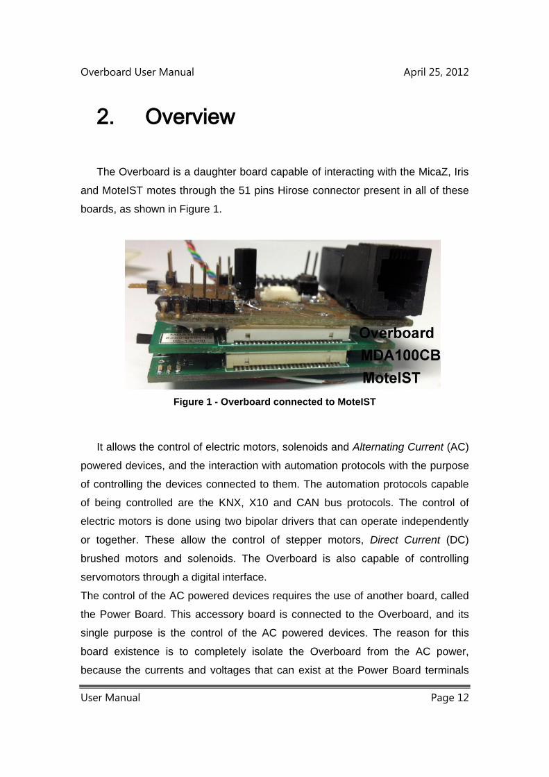
Overboard User Manual April 25, 2012
User Manual Page 12
2. Overview
The Overboard is a daughter board capable of interacting with the MicaZ, Iris
and MoteIST motes through the 51 pins Hirose connector present in all of these
boards, as shown in Figure 1.
Figure 1 - Overboard connected to MoteIST
It allows the control of electric motors, solenoids and Alternating Current (AC)
powered devices, and the interaction with automation protocols with the purpose
of controlling the devices connected to them. The automation protocols capable
of being controlled are the KNX, X10 and CAN bus protocols. The control of
electric motors is done using two bipolar drivers that can operate independently
or together. These allow the control of stepper motors, Direct Current (DC)
brushed motors and solenoids. The Overboard is also capable of controlling
servomotors through a digital interface.
The control of the AC powered devices requires the use of another board, called
the Power Board. This accessory board is connected to the Overboard, and its
single purpose is the control of the AC powered devices. The reason for this
board existence is to completely isolate the Overboard from the AC power,
because the currents and voltages that can exist at the Power Board terminals
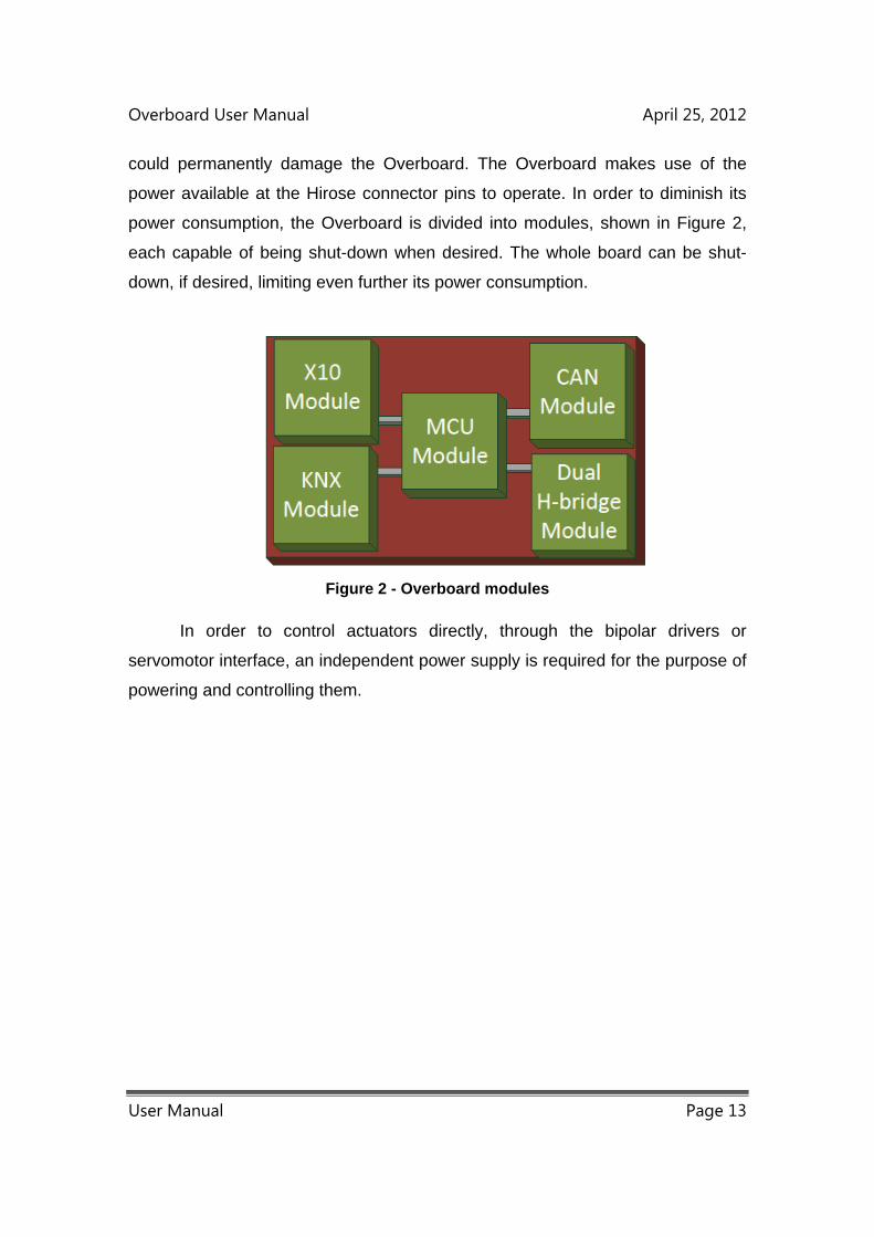
Overboard User Manual April 25, 2012
User Manual Page 13
could permanently damage the Overboard. The Overboard makes use of the
power available at the Hirose connector pins to operate. In order to diminish its
power consumption, the Overboard is divided into modules, shown in Figure 2,
each capable of being shut-down when desired. The whole board can be shut-
down, if desired, limiting even further its power consumption.
Figure 2 - Overboard modules
In order to control actuators directly, through the bipolar drivers or
servomotor interface, an independent power supply is required for the purpose of
powering and controlling them.

Overboard User Manual April 25, 2012
User Manual Page 14
Functional Description
All the Overboard connectors along with the Reset button and the Test
mode Jumper are identified in Figure 3. The connector’s characteristics are
described briefly in Table 1, and thoroughly described in the rest of this chapter.
Hirose Connector
Figure 3 - Overboard, Connectors Identification

Overboard User Manual April 25, 2012
User Manual Page 15
Table 1 - Connectors characteristics
Name I/O Maximum
Voltage (V)
Description
Servomotor
Connector
Output 45 Used for the control of
Servomotors.
2x Bipolar
Controller
Connector
Output 10.8 Used for the control of DC
electric motors.
PB Connector Output 3 Controls the Power Board.
Actuator’s Power
Supply
Input 45 Power supply for the
actuators connected to the
Overboard.
RF Connector Input/Output 3 Used for the control of RF
boards.
X10 Connector Input/Output 25 Used for the interaction
with X10 transceivers.
KNX Connector Input/Output 25 Used for the interaction
with KNX transceivers.
ICSP Connector Input/Output 3 For the programming
and/or power supply.
CAN Bus
Connector
Input/Output 12 Used for interacting with
the CAN bus.
Hirose Connector Input/Output 3 Used for the
communication with motes
and/or power supply.
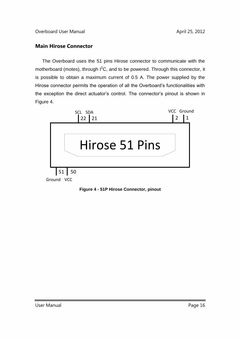
Overboard User Manual April 25, 2012
User Manual Page 16
Main Hirose Connector
The Overboard uses the 51 pins Hirose connector to communicate with the
motherboard (motes), through I2C, and to be powered. Through this connector, it
is possible to obtain a maximum current of 0.5 A. The power supplied by the
Hirose connector permits the operation of all the Overboard’s functionalities with
the exception the direct actuator’s control. The connector’s pinout is shown in
Figure 4.
12
5051
2122
GroundVCC
VCCGround
SDASCL
Hirose 51 Pins
Figure 4 - 51P Hirose Connector, pinout
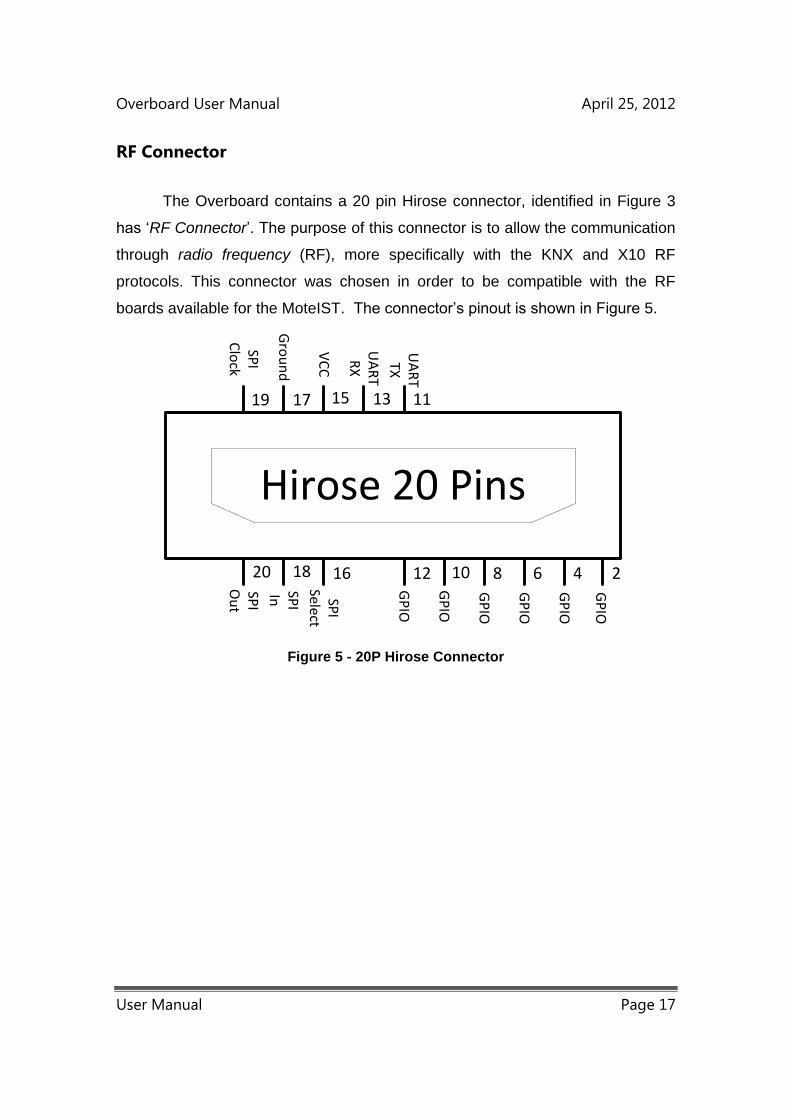
Overboard User Manual April 25, 2012
User Manual Page 17
RF Connector
The Overboard contains a 20 pin Hirose connector, identified in Figure 3
has ‘RF Connector’. The purpose of this connector is to allow the communication
through radio frequency (RF), more specifically with the KNX and X10 RF
protocols. This connector was chosen in order to be compatible with the RF
boards available for the MoteIST. The connector’s pinout is shown in Figure 5.
Hirose 20 PinsG
rou
nd
VC
C
UA
RT
RX
UA
RT
TX
SPI
Clo
ckSP
I O
ut
SPI
In SPI
Sele
ct
GP
IO
GP
IO
GP
IO
GP
IO
GP
IO
GP
IO
24681012161820
19 17 15 13 11
Figure 5 - 20P Hirose Connector

Overboard User Manual April 25, 2012
User Manual Page 18
Control of actuators directly
In order to control the actuators directly connected to the Overboard, it is
necessary the existence of a power supply, identified in Figure 3 by ‘Actuator’s
Power Supply’. Its pinout is shown in Figure 6.
VCCGround
Figure 6 - Actuator's Power Supply, pinout.
The purpose of this integration is to allow the control of actuators with higher
power requirements. The direct control of actuators is done through the
DRV8833 IC and through the servomotor’s interface. The DRV8833 is a dual
bipolar driver that allows the control of two DC motors, one stepper motor,
solenoids and other inductive loads. It permits a maximum voltage of 10.8 V, and
each bipolar driver is capable of handling a current up to 1 A. The connectors of
the bipolar drivers are identified in Figure 4 as ‘2x Bipolar Controller Connector’
and the identification of each individual bipolar driver (H-bridge) is shown in
Figure 7.
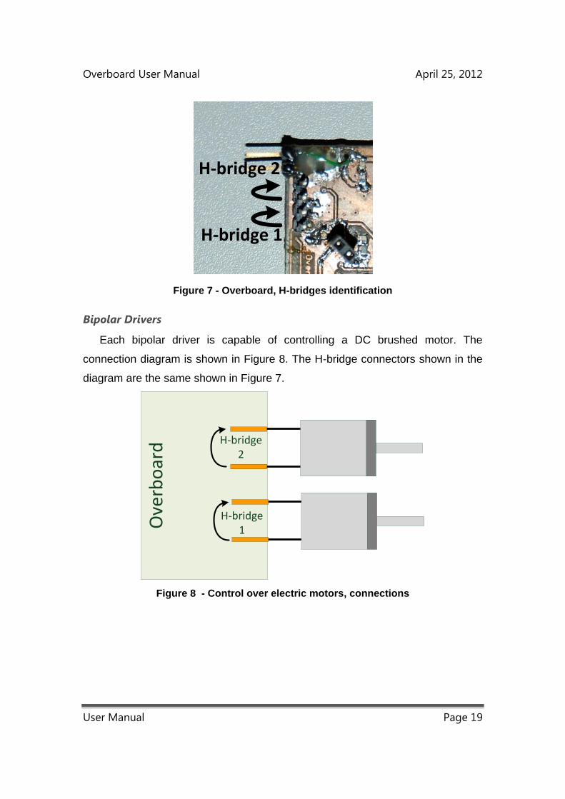
Overboard User Manual April 25, 2012
User Manual Page 19
H-bridge 2
H-bridge 1
Figure 7 - Overboard, H-bridges identification
Bipolar Drivers
Each bipolar driver is capable of controlling a DC brushed motor. The
connection diagram is shown in Figure 8. The H-bridge connectors shown in the
diagram are the same shown in Figure 7.
Ove
rbo
ard
H-bridge1
H-bridge2
Figure 8 - Control over electric motors, connections

Overboard User Manual April 25, 2012
User Manual Page 20
Stepper Motors
The control of stepper motors requires the use of an H-bridge for each phase.
Since the Overboard has two H-bridges, it is able to control one, two phase
bipolar stepper motor. The connection diagram is shown in Figure 9.
Ove
rbo
ard
H-bridge1
H-bridge2
Ph
ase
1P
has
e2
Figure 9 - Control over stepper motor, connections
Servo Driver
The servomotor’s interface allows the control of servomotors. It uses a digital
interface in order to control the servomotors. The control is made by PWM. Each
pulse width corresponds to a specific angle of the servomotor’s shaft. Although
the relation between the pulse width and the angle may slightly vary between
servomotor’s brands, it is usually very similar ranging between 1 ms to 2 ms, as
shown in Figure 9.
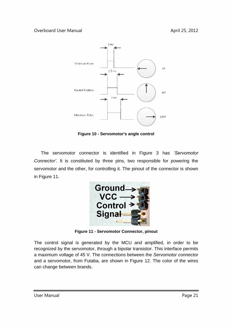
Overboard User Manual April 25, 2012
User Manual Page 21
Figure 10 - Servomotor's angle control
The servomotor connector is identified in Figure 3 has ‘Servomotor
Connector’. It is constituted by three pins, two responsible for powering the
servomotor and the other, for controlling it. The pinout of the connector is shown
in Figure 11.
Figure 11 - Servomotor Connector, pinout
The control signal is generated by the MCU and amplified, in order to be
recognized by the servomotor, through a bipolar transistor. This interface permits
a maximum voltage of 45 V. The connections between the Servomotor connector
and a servomotor, from Futaba, are shown in Figure 12. The color of the wires
can change between brands.
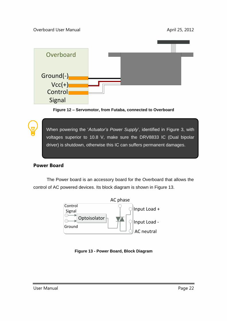
Overboard User Manual April 25, 2012
User Manual Page 22
Ground(-)
Vcc(+)ControlSignal
Overboard
Figure 12 – Servomotor, from Futaba, connected to Overboard
Power Board
The Power board is an accessory board for the Overboard that allows the
control of AC powered devices. Its block diagram is shown in Figure 13.
AC neutral
AC phase
Input Load -
Input Load +
Optoisolator
Control Signal
Ground
Figure 13 - Power Board, Block Diagram
When powering the ‘Actuator’s Power Supply’, identified in Figure 3, with
voltages superior to 10.8 V, make sure the DRV8833 IC (Dual bipolar
driver) is shutdown, otherwise this IC can suffers permanent damages.
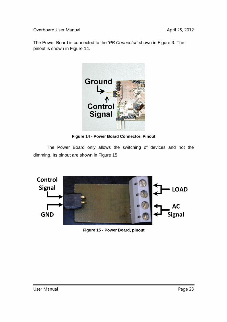
Overboard User Manual April 25, 2012
User Manual Page 23
The Power Board is connected to the ‘PB Connector’ shown in Figure 3. The
pinout is shown in Figure 14.
Figure 14 - Power Board Connector, Pinout
The Power Board only allows the switching of devices and not the
dimming. Its pinout are shown in Figure 15.
GND
ControlSignal LOAD
ACSignal
Figure 15 - Power Board, pinout
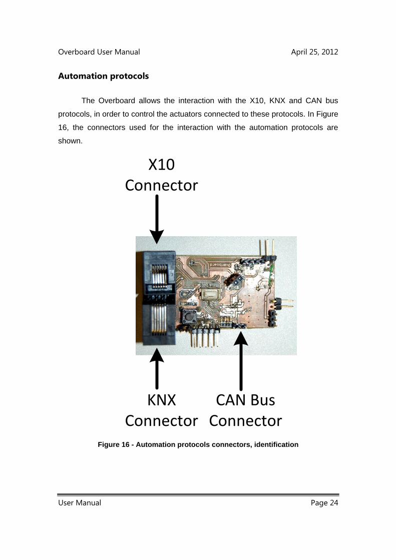
Overboard User Manual April 25, 2012
User Manual Page 24
Automation protocols
The Overboard allows the interaction with the X10, KNX and CAN bus
protocols, in order to control the actuators connected to these protocols. In Figure
16, the connectors used for the interaction with the automation protocols are
shown.
X10 Connector
KNX Connector
CAN Bus Connector
Figure 16 - Automation protocols connectors, identification
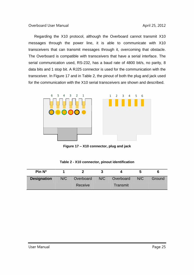
Overboard User Manual April 25, 2012
User Manual Page 25
Regarding the X10 protocol, although the Overboard cannot transmit X10
messages through the power line, it is able to communicate with X10
transceivers that can transmit messages through it, overcoming that obstacle.
The Overboard is compatible with transceivers that have a serial interface. The
serial communication used, RS-232, has a baud rate of 4800 bit/s, no parity, 8
data bits and 1 stop bit. A RJ25 connector is used for the communication with the
transceiver. In Figure 17 and in Table 2, the pinout of both the plug and jack used
for the communication with the X10 serial transceivers are shown and described.
123456 1 2 3 4 5 6
Figure 17 – X10 connector, plug and jack
Table 2 - X10 connector, pinout identification
Pin Nº 1 2 3 4 5 6
Designation N/C Overboard
Receive
N/C Overboard
Transmit
N/C Ground
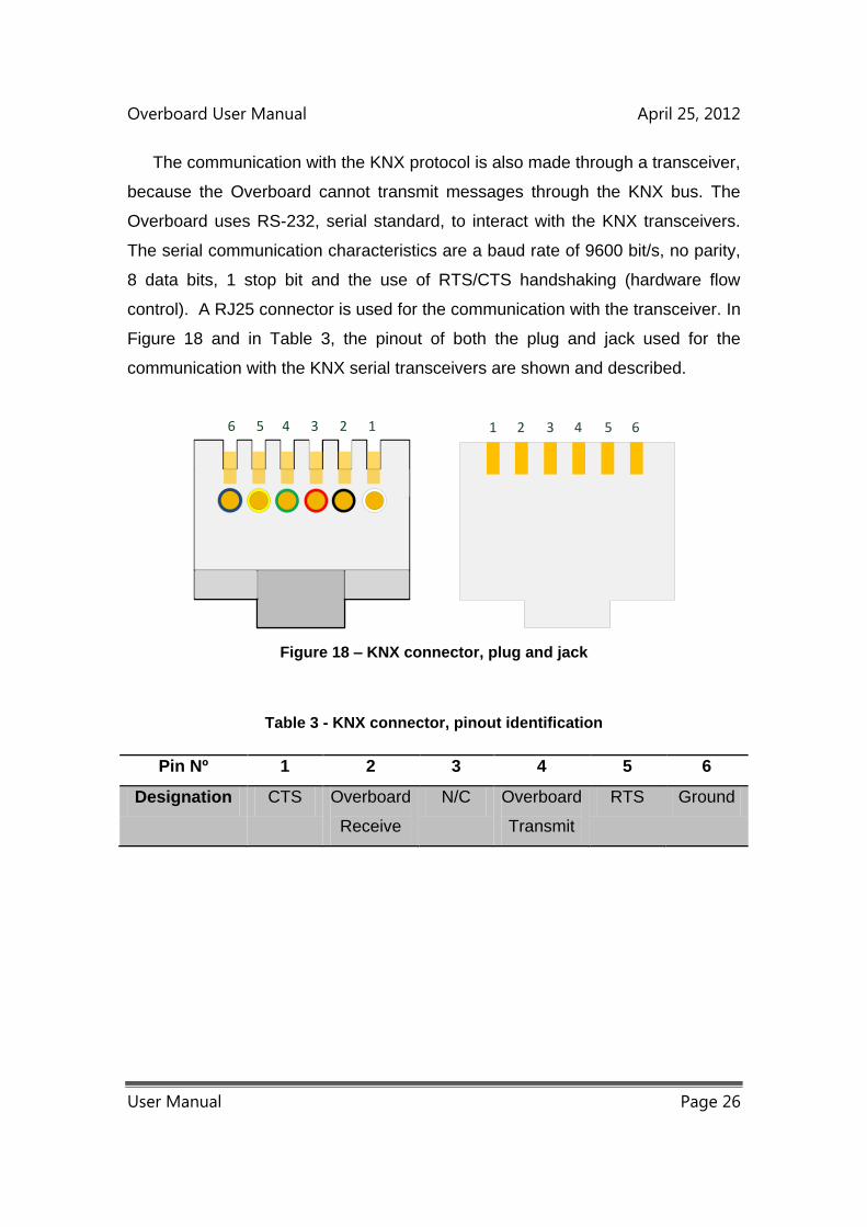
Overboard User Manual April 25, 2012
User Manual Page 26
The communication with the KNX protocol is also made through a transceiver,
because the Overboard cannot transmit messages through the KNX bus. The
Overboard uses RS-232, serial standard, to interact with the KNX transceivers.
The serial communication characteristics are a baud rate of 9600 bit/s, no parity,
8 data bits, 1 stop bit and the use of RTS/CTS handshaking (hardware flow
control). A RJ25 connector is used for the communication with the transceiver. In
Figure 18 and in Table 3, the pinout of both the plug and jack used for the
communication with the KNX serial transceivers are shown and described.
123456 1 2 3 4 5 6
Figure 18 – KNX connector, plug and jack
Table 3 - KNX connector, pinout identification
Pin Nº 1 2 3 4 5 6
Designation CTS Overboard
Receive
N/C Overboard
Transmit
RTS Ground

Overboard User Manual April 25, 2012
User Manual Page 27
Regarding the CAN bus protocol, the Overboard is able to transmit
messages directly into the bus. This is only possible due to the existence of a
CAN transceiver. The pinout of the CAN connector is shown in Figure 19.
Figure 19 - CAN Bus Connector, pinout
Overboard Programming
The Overboard’s MCU is a PIC24HJ from Microchip™. The programming
is made through In-Circuit Serial Programming, using the ICSP Connector,
shown in Figure 3. The pinout of this connector is shown in Figure 20.
Figure 20 - ICSP Connector, pinout
Overboard User Manual April 25, 2012
User Manual Page 28
Operation Mode Interface
The Overboard has two operating modes, the normal mode and the test
mode. These modes are chosen through the Test mode jumper shown in Figure
3. The test mode is selected with the insertion of the jumper, otherwise the
normal mode is selected. If the operation mode is changed, and the board is
powered, a system reset is required otherwise the Overboard won’t function
correctly. The reset is made through the Reset Button shown in Figure 3.
In the normal mode, the Overboard makes use of the 51 pins Hirose
connector to communicate with the motherboard, while in the test mode, the
Overboard relies in the RJ 25 connector normal associated with the KNX protocol
for communicating with a host PC. In this mode, the KNX and X10 protocols use
the same RJ 25 connector, making impossible the use of both simultaneously.
The communication protocol between the Overboard and the host PC is RS-232
and has a baud rate of 115200 bit/s, no parity, 8 data bits and 1 stop bit. The
connector used has the same pinout as the one shown in Figure 17.
The Overboard can be powered through two connectors, the 51 pins
Hirose connector and the ICSP connector.
Only one connector should be powering the Overboard at any given
moment, otherwise the board can suffer permanent damages.
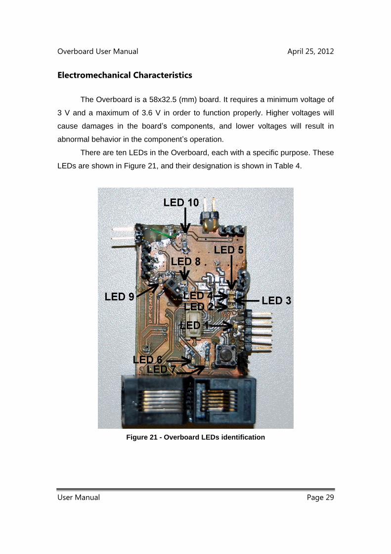
Overboard User Manual April 25, 2012
User Manual Page 29
Electromechanical Characteristics
The Overboard is a 58x32.5 (mm) board. It requires a minimum voltage of
3 V and a maximum of 3.6 V in order to function properly. Higher voltages will
cause damages in the board’s components, and lower voltages will result in
abnormal behavior in the component’s operation.
There are ten LEDs in the Overboard, each with a specific purpose. These
LEDs are shown in Figure 21, and their designation is shown in Table 4.
Figure 21 - Overboard LEDs identification
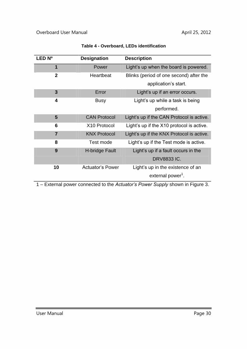
Overboard User Manual April 25, 2012
User Manual Page 30
Table 4 - Overboard, LEDs identification
LED Nº Designation Description
1 Power Light’s up when the board is powered.
2 Heartbeat Blinks (period of one second) after the
application’s start.
3 Error Light’s up if an error occurs.
4 Busy Light’s up while a task is being
performed.
5 CAN Protocol Light’s up if the CAN Protocol is active.
6 X10 Protocol Light’s up if the X10 protocol is active.
7 KNX Protocol Light’s up if the KNX Protocol is active.
8 Test mode Light’s up if the Test mode is active.
9 H-bridge Fault Light’s up if a fault occurs in the
DRV8833 IC.
10 Actuator’s Power Light’s up in the existence of an
external power1.
1 – External power connected to the Actuator’s Power Supply shown in Figure 3.
Overboard User Manual April 25, 2012
User Manual Page 31
3. Software Applications
The Overboard’s software application starts immediately after applying
power to the board. At each initialization, the Test mode jumper, shown in
Figure 3, is checked in order to determine which mode is select.
Independently of the mode selected, the protocol used by the Overboard to
communicate is the same. This protocol was developed specifically for the
Overboard.
The Overboard is always checking for received messages. After a
message reception, the state of the Overboard is checked, if it is busy
completing a task, the message is discarded, otherwise, it tries to successfully
complete the task at hands, reporting back the success or failure, of the task
received. If a task is not successful, the Overboard tries to successfully
complete it a second time, only reporting back the failure, if it fails to complete
it both times.

Overboard User Manual April 25, 2012
User Manual Page 32
Proprietary Protocol
In the protocol used by the Overboard, each message sent to the
Overboard contains all the information required to perform a given task. Each
message is composed by an unsigned char (8 bit) vector with variable length. It
can be decomposed into three parts. The first part contains the desired action,
the second specifies the module and the information in the third depends on the
desired action, in some cases not being necessary. The first and the second
module have a size of eight bit each and the third has a variable size.
The actions and modules available in the Overboard are shown in Table 5
and 6, respectively.
Table 5 - Proprietary protocol, actions
Actions Available Hexadecimal Code
Enable Module 1
Disable Module 2
Configure Module 3
Send Data 4
Sleep 5
Reboot Overboard FF
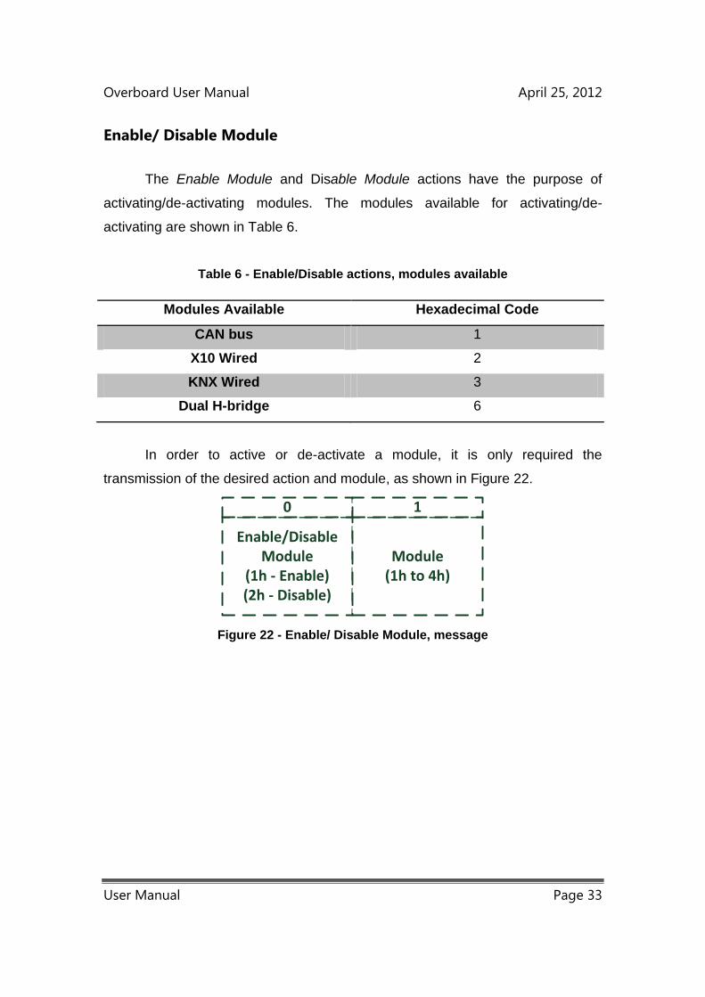
Overboard User Manual April 25, 2012
User Manual Page 33
Enable/ Disable Module
The Enable Module and Disable Module actions have the purpose of
activating/de-activating modules. The modules available for activating/de-
activating are shown in Table 6.
Table 6 - Enable/Disable actions, modules available
Modules Available Hexadecimal Code
CAN bus 1
X10 Wired 2
KNX Wired 3
Dual H-bridge 6
In order to active or de-activate a module, it is only required the
transmission of the desired action and module, as shown in Figure 22.
Enable/Disable Module
(1h - Enable)(2h - Disable)
Module(1h to 4h)
0 1
Figure 22 - Enable/ Disable Module, message

Overboard User Manual April 25, 2012
User Manual Page 34
Configure Module
The Configure Module command allows the configuration and the
operation of the Overboard modules, with the exception of the CAN bus protocol.
After activating the desired module, its configuration is made through this option.
The available options for this action are shown in Table 7.
Table 7 - Configure Module, available options
Modules Available Hexadecimal Code
H-bridge 1 4
H-bridge 2 5
Stepper motor (both H-bridges are
used)
A
Power Board, Control signal 7
Servomotor, Control signal 8
KNX Wired, Control 3
X10 Wired, Control 2
Real Time Clock, Configure 9
Request Overboard Clock and Date E
The H-bridge 1 and 2 options allow the configuration of each H-bridge
individually. In order to use these options, it is required the previous activation of
the Dual H-bridge Module. In order to configure an H-bridge correctly it is also
necessary the transmission of the desired H-bridge mode and PWM. The
available H-bridge modes are shown in Table 8. The PWM argument is sent in
percentage and determines the speed of the motor’s rotation. The minimum
PWM value is 1%, minimum speed, and the maximum 100%, which corresponds
to the maximum speed. When selecting the standby and brake modes, the PWM
is not transmitted.
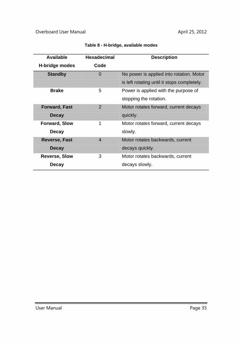
Overboard User Manual April 25, 2012
User Manual Page 35
Table 8 - H-bridge, available modes
Available
H-bridge modes
Hexadecimal
Code
Description
Standby 0 No power is applied into rotation. Motor
is left rotating until it stops completely.
Brake 5 Power is applied with the purpose of
stopping the rotation.
Forward, Fast
Decay
2 Motor rotates forward, current decays
quickly.
Forward, Slow
Decay
1 Motor rotates forward, current decays
slowly.
Reverse, Fast
Decay
4 Motor rotates backwards, current
decays quickly.
Reverse, Slow
Decay
3 Motor rotates backwards, current
decays slowly.
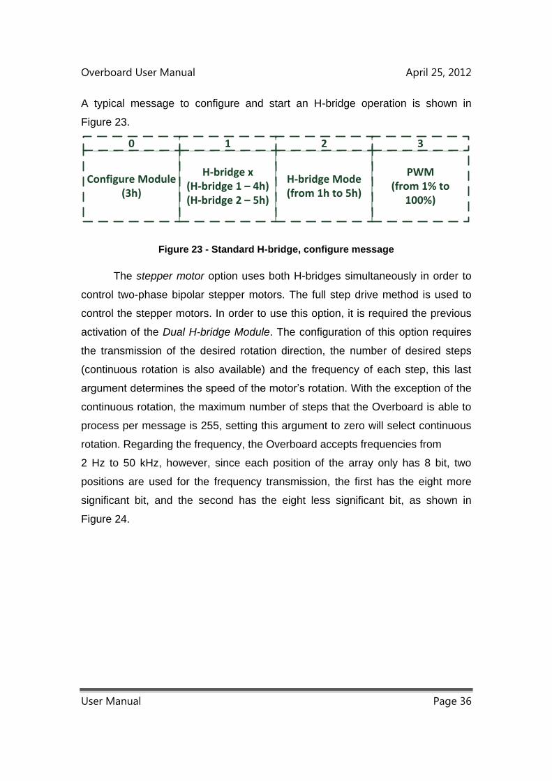
Overboard User Manual April 25, 2012
User Manual Page 36
A typical message to configure and start an H-bridge operation is shown in
Figure 23.
Configure Module(3h)
H-bridge x(H-bridge 1 – 4h)(H-bridge 2 – 5h)
H-bridge Mode(from 1h to 5h)
PWM(from 1% to
100%)
0 1 2 3
Figure 23 - Standard H-bridge, configure message
The stepper motor option uses both H-bridges simultaneously in order to
control two-phase bipolar stepper motors. The full step drive method is used to
control the stepper motors. In order to use this option, it is required the previous
activation of the Dual H-bridge Module. The configuration of this option requires
the transmission of the desired rotation direction, the number of desired steps
(continuous rotation is also available) and the frequency of each step, this last
argument determines the speed of the motor’s rotation. With the exception of the
continuous rotation, the maximum number of steps that the Overboard is able to
process per message is 255, setting this argument to zero will select continuous
rotation. Regarding the frequency, the Overboard accepts frequencies from
2 Hz to 50 kHz, however, since each position of the array only has 8 bit, two
positions are used for the frequency transmission, the first has the eight more
significant bit, and the second has the eight less significant bit, as shown in
Figure 24.
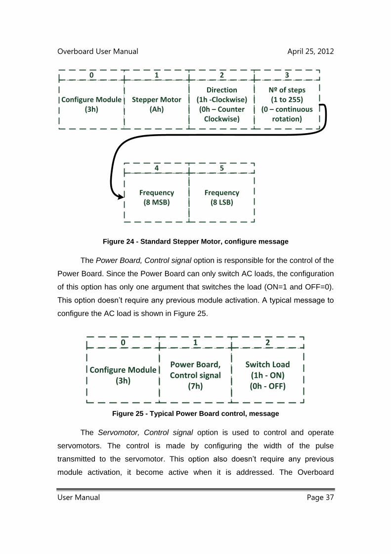
Overboard User Manual April 25, 2012
User Manual Page 37
Configure Module(3h)
Stepper Motor(Ah)
Direction(1h -Clockwise)(0h – Counter
Clockwise)
Nº of steps(1 to 255)
(0 – continuous rotation)
Frequency(8 MSB)
Frequency(8 LSB)
0 1 2 3
4 5
Figure 24 - Standard Stepper Motor, configure message
The Power Board, Control signal option is responsible for the control of the
Power Board. Since the Power Board can only switch AC loads, the configuration
of this option has only one argument that switches the load (ON=1 and OFF=0).
This option doesn’t require any previous module activation. A typical message to
configure the AC load is shown in Figure 25.
Configure Module(3h)
Power Board, Control signal
(7h)
Switch Load(1h - ON)(0h - OFF)
0 1 2
Figure 25 - Typical Power Board control, message
The Servomotor, Control signal option is used to control and operate
servomotors. The control is made by configuring the width of the pulse
transmitted to the servomotor. This option also doesn’t require any previous
module activation, it become active when it is addressed. The Overboard
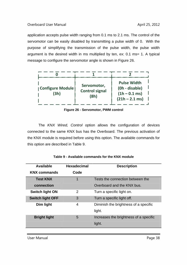
Overboard User Manual April 25, 2012
User Manual Page 38
application accepts pulse width ranging from 0.1 ms to 2.1 ms. The control of the
servomotor can be easily disabled by transmitting a pulse width of 0. With the
purpose of simplifying the transmission of the pulse width, the pulse width
argument is the desired width in ms multiplied by ten, ex: 0.1 ms= 1. A typical
message to configure the servomotor angle is shown in Figure 26.
Configure Module(3h)
Servomotor, Control signal
(8h)
Pulse Width(0h - disable)(1h – 0.1 ms)
(21h – 2.1 ms)
0 1 2
Figure 26 - Servomotor, PWM control
The KNX Wired, Control option allows the configuration of devices
connected to the same KNX bus has the Overboard. The previous activation of
the KNX module is required before using this option. The available commands for
this option are described in Table 9.
Table 9 - Available commands for the KNX module
Available
KNX commands
Hexadecimal
Code
Description
Test KNX
connection
1 Tests the connection between the
Overboard and the KNX bus.
Switch light ON 2 Turn a specific light on.
Switch light OFF 3 Turn a specific light off.
Dim light 4 Diminish the brightness of a specific
light.
Bright light 5 Increases the brightness of a specific
light.
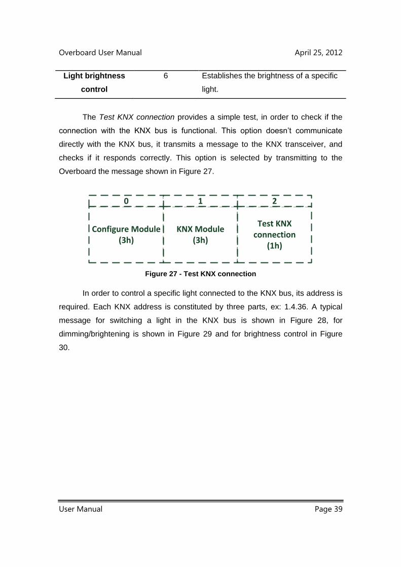
Overboard User Manual April 25, 2012
User Manual Page 39
Light brightness
control
6 Establishes the brightness of a specific
light.
The Test KNX connection provides a simple test, in order to check if the
connection with the KNX bus is functional. This option doesn’t communicate
directly with the KNX bus, it transmits a message to the KNX transceiver, and
checks if it responds correctly. This option is selected by transmitting to the
Overboard the message shown in Figure 27.
Configure Module(3h)
KNX Module(3h)
Test KNX connection
(1h)
0 1 2
Figure 27 - Test KNX connection
In order to control a specific light connected to the KNX bus, its address is
required. Each KNX address is constituted by three parts, ex: 1.4.36. A typical
message for switching a light in the KNX bus is shown in Figure 28, for
dimming/brightening is shown in Figure 29 and for brightness control in Figure
30.

Overboard User Manual April 25, 2012
User Manual Page 40
Configure Module(3h)
KNX Module(3h)
Switch Light(2h - ON)(3h - OFF)
Address(1º part)
Address(2º part)
Address(3º part)
0 1 2 3
4 5
Figure 28 - Switch KNX light
Regarding the dimming/brightening of a light through the KNX protocol,
there are seven available levels. Each level has a specific speed of
increasing/decreasing the brightness of the light. After the reception of a
message for dimming/brightening, the light will diminish/increase its brightness,
at a constant speed (chosen level), until it turns off/reaches maximum brightness
level, or until it receives an equal message which results in the immediately stop
of the variation in the light brightness.
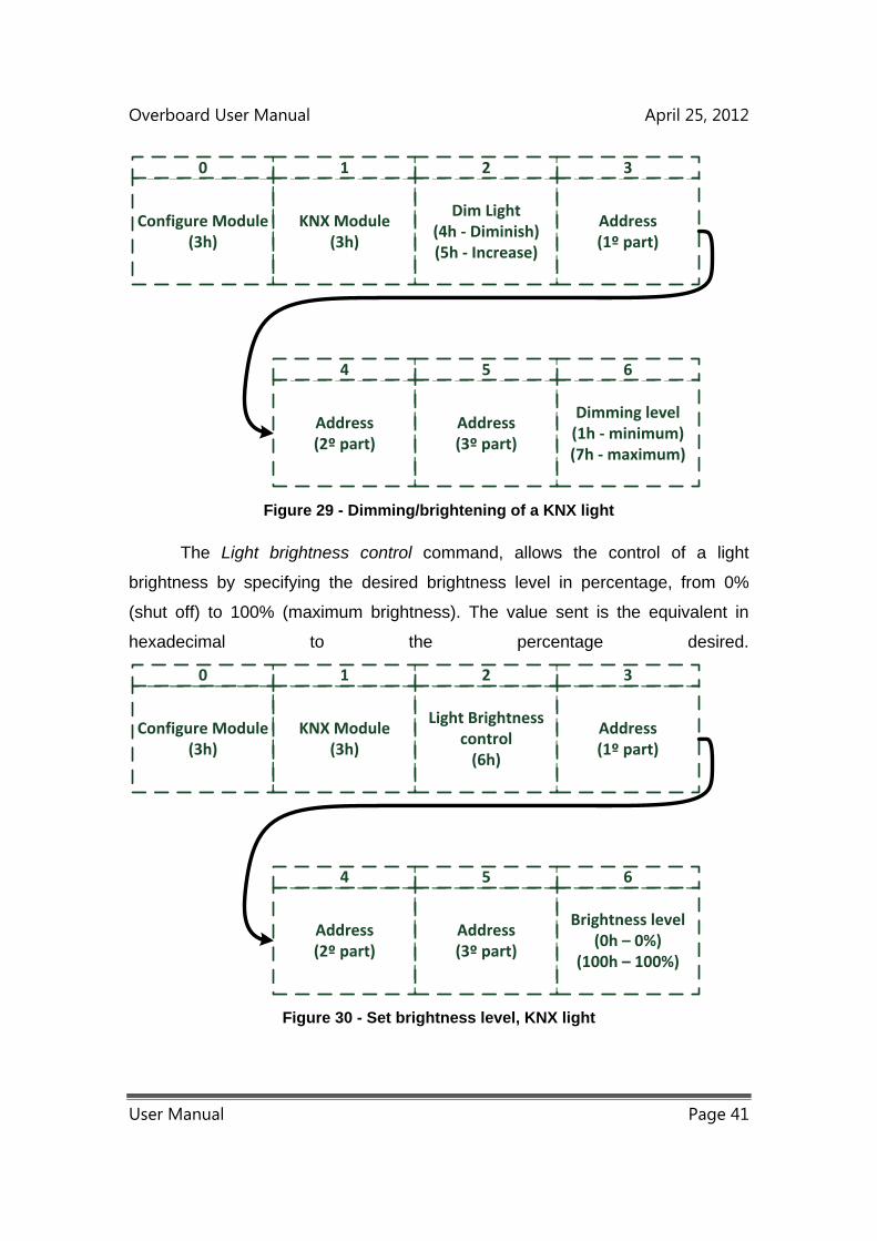
Overboard User Manual April 25, 2012
User Manual Page 41
Configure Module(3h)
KNX Module(3h)
Dim Light(4h - Diminish)(5h - Increase)
Address(1º part)
Address(2º part)
Address(3º part)
0 1 2 3
4 5
Dimming level(1h - minimum)(7h - maximum)
6
Figure 29 - Dimming/brightening of a KNX light
The Light brightness control command, allows the control of a light
brightness by specifying the desired brightness level in percentage, from 0%
(shut off) to 100% (maximum brightness). The value sent is the equivalent in
hexadecimal to the percentage desired.
Configure Module(3h)
KNX Module(3h)
Light Brightness control
(6h)
Address(1º part)
Address(2º part)
Address(3º part)
0 1 2 3
4 5
Brightness level(0h – 0%)
(100h – 100%)
6
Figure 30 - Set brightness level, KNX light
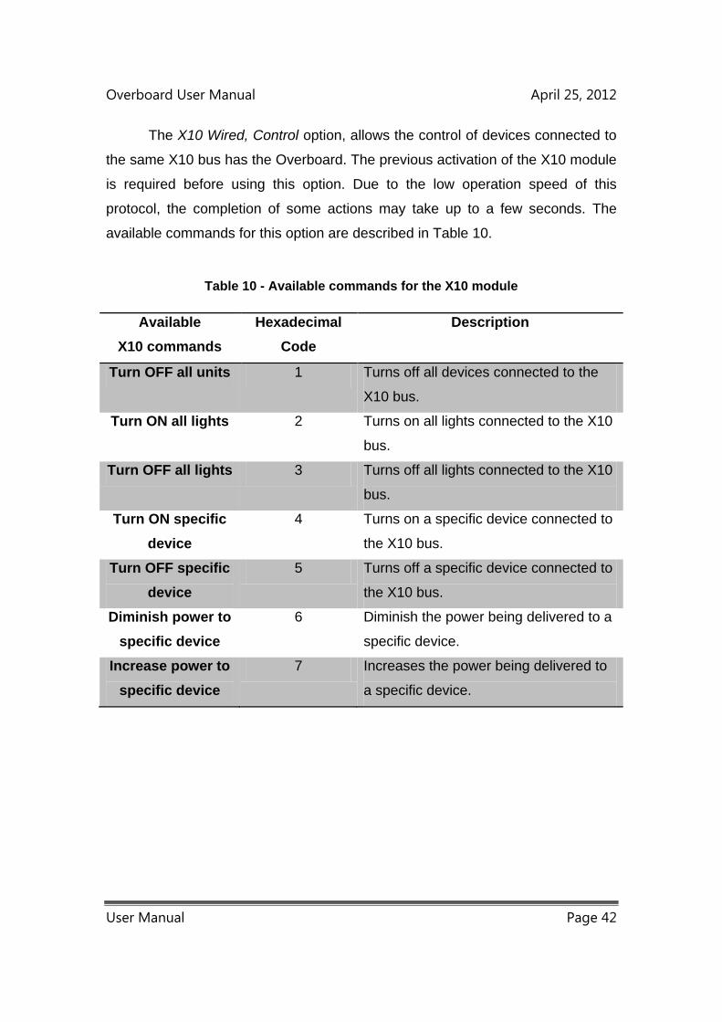
Overboard User Manual April 25, 2012
User Manual Page 42
The X10 Wired, Control option, allows the control of devices connected to
the same X10 bus has the Overboard. The previous activation of the X10 module
is required before using this option. Due to the low operation speed of this
protocol, the completion of some actions may take up to a few seconds. The
available commands for this option are described in Table 10.
Table 10 - Available commands for the X10 module
Available
X10 commands
Hexadecimal
Code
Description
Turn OFF all units 1 Turns off all devices connected to the
X10 bus.
Turn ON all lights 2 Turns on all lights connected to the X10
bus.
Turn OFF all lights 3 Turns off all lights connected to the X10
bus.
Turn ON specific
device
4 Turns on a specific device connected to
the X10 bus.
Turn OFF specific
device
5 Turns off a specific device connected to
the X10 bus.
Diminish power to
specific device
6 Diminish the power being delivered to a
specific device.
Increase power to
specific device
7 Increases the power being delivered to
a specific device.
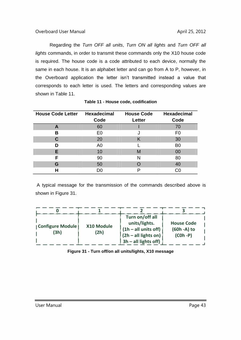
Overboard User Manual April 25, 2012
User Manual Page 43
Regarding the Turn OFF all units, Turn ON all lights and Turn OFF all
lights commands, in order to transmit these commands only the X10 house code
is required. The house code is a code attributed to each device, normally the
same in each house. It is an alphabet letter and can go from A to P, however, in
the Overboard application the letter isn’t transmitted instead a value that
corresponds to each letter is used. The letters and corresponding values are
shown in Table 11.
Table 11 - House code, codification
House Code Letter Hexadecimal
Code
House Code
Letter
Hexadecimal
Code
A 60 I 70
B E0 J F0
C 20 K 30
D A0 L B0
E 10 M 00
F 90 N 80
G 50 O 40
H D0 P C0
A typical message for the transmission of the commands described above is
shown in Figure 31.
House Code(60h -A) to
(C0h -P)
3
Configure Module(3h)
X10 Module(2h)
Turn on/off all units/lights.
(1h – all units off)(2h – all lights on)3h – all lights off)
0 1 2
Figure 31 - Turn off/on all units/lights, X10 message
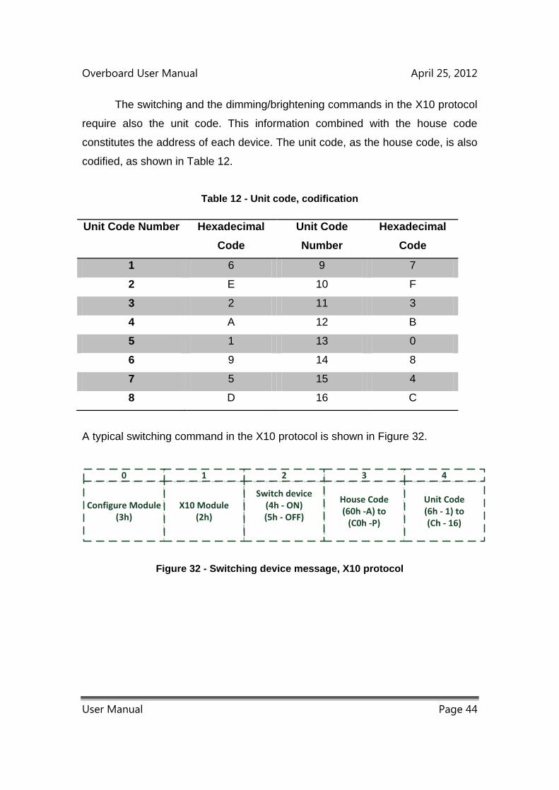
Overboard User Manual April 25, 2012
User Manual Page 44
The switching and the dimming/brightening commands in the X10 protocol
require also the unit code. This information combined with the house code
constitutes the address of each device. The unit code, as the house code, is also
codified, as shown in Table 12.
Table 12 - Unit code, codification
Unit Code Number Hexadecimal
Code
Unit Code
Number
Hexadecimal
Code
1 6 9 7
2 E 10 F
3 2 11 3
4 A 12 B
5 1 13 0
6 9 14 8
7 5 15 4
8 D 16 C
A typical switching command in the X10 protocol is shown in Figure 32.
House Code(60h -A) to
(C0h -P)
3
Configure Module(3h)
X10 Module(2h)
Switch device(4h - ON)(5h - OFF)
0 1 2
Unit Code(6h - 1) to(Ch - 16)
4
Figure 32 - Switching device message, X10 protocol

Overboard User Manual April 25, 2012
User Manual Page 45
The dimming and brightening commands require also the intensity level
argument. There are 22 available levels. The level argument transmitted is the
amount of levels that will be summed or subtracted to the present intensity level
in the device. A typical dimming/brightening command in the X10 protocol is
shown in Figure 33.
Configure Module(3h)
X10 Module(2h)
Dimm/Bright power intensity(6h - Dimming)
(7h - Brightening)
House Code(60h -A) to
(C0h -P)
Unit Code(6h - 1) to(Ch - 16)
Intensity level(1h - Minimum)
(22h - Maximum)
0 1 2 3
4 5
Figure 33 - Dim/Bright message, X10 protocol
Regarding the Real Time Clock, Configure option in the Configure Module,
this option configures the Overboard real time clock and date. This option doesn’t
require any previous module activation. This data is only used in the X10
protocol, in order to set the X10 transceiver clock and date, when requested.
After setting them, the Overboard’s internal clock updates them automatically.
The number of the day related to the beginning of the year is transmitted in two
positions, the first transmits the less significant two decimal numbers and the
second, the most significant decimal number. Regarding the day of the week,
each day has a number attributed, shown in Table 13.
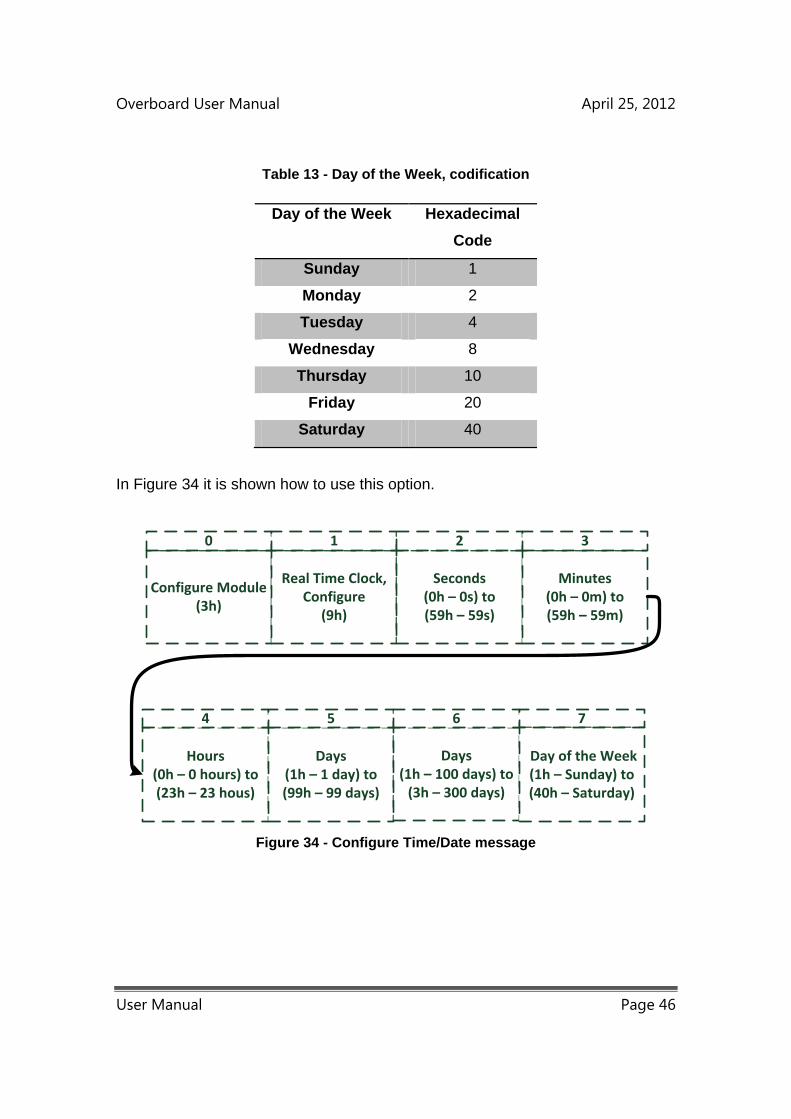
Overboard User Manual April 25, 2012
User Manual Page 46
Table 13 - Day of the Week, codification
Day of the Week Hexadecimal
Code
Sunday 1
Monday 2
Tuesday 4
Wednesday 8
Thursday 10
Friday 20
Saturday 40
In Figure 34 it is shown how to use this option.
Configure Module(3h)
Real Time Clock,Configure
(9h)
Seconds(0h – 0s) to(59h – 59s)
Minutes(0h – 0m) to(59h – 59m)
Hours(0h – 0 hours) to(23h – 23 hous)
Days(1h – 1 day) to(99h – 99 days)
0 1 2 3
4 5
Days(1h – 100 days) to
(3h – 300 days)
6 7
Day of the Week(1h – Sunday) to(40h – Saturday)
Figure 34 - Configure Time/Date message
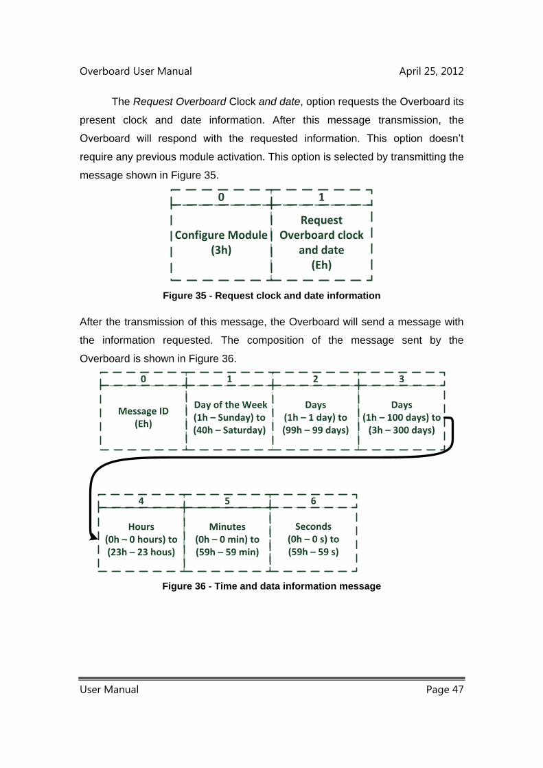
Overboard User Manual April 25, 2012
User Manual Page 47
The Request Overboard Clock and date, option requests the Overboard its
present clock and date information. After this message transmission, the
Overboard will respond with the requested information. This option doesn’t
require any previous module activation. This option is selected by transmitting the
message shown in Figure 35.
Configure Module(3h)
Request Overboard clock
and date(Eh)
0 1
Figure 35 - Request clock and date information
After the transmission of this message, the Overboard will send a message with
the information requested. The composition of the message sent by the
Overboard is shown in Figure 36.
Message ID(Eh)
Day of the Week(1h – Sunday) to(40h – Saturday)
Days(1h – 1 day) to(99h – 99 days)
Days(1h – 100 days) to
(3h – 300 days)
Hours(0h – 0 hours) to(23h – 23 hous)
Minutes(0h – 0 min) to(59h – 59 min)
0 1 2 3
4 5
Seconds(0h – 0 s) to(59h – 59 s)
6
Figure 36 - Time and data information message
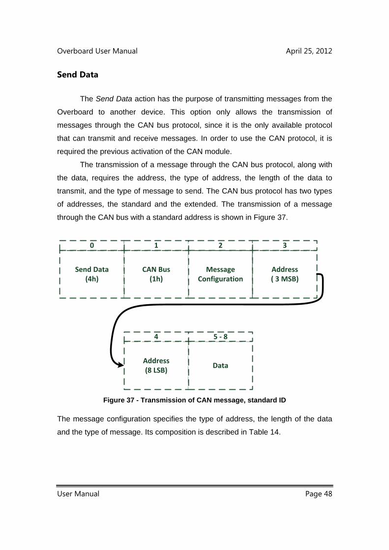
Overboard User Manual April 25, 2012
User Manual Page 48
Send Data
The Send Data action has the purpose of transmitting messages from the
Overboard to another device. This option only allows the transmission of
messages through the CAN bus protocol, since it is the only available protocol
that can transmit and receive messages. In order to use the CAN protocol, it is
required the previous activation of the CAN module.
The transmission of a message through the CAN bus protocol, along with
the data, requires the address, the type of address, the length of the data to
transmit, and the type of message to send. The CAN bus protocol has two types
of addresses, the standard and the extended. The transmission of a message
through the CAN bus with a standard address is shown in Figure 37.
Send Data(4h)
CAN Bus(1h)
Message Configuration
Address( 3 MSB)
Address(8 LSB)
Data
0 1 2 3
4 5 - 8
Figure 37 - Transmission of CAN message, standard ID
The message configuration specifies the type of address, the length of the data
and the type of message. Its composition is described in Table 14.
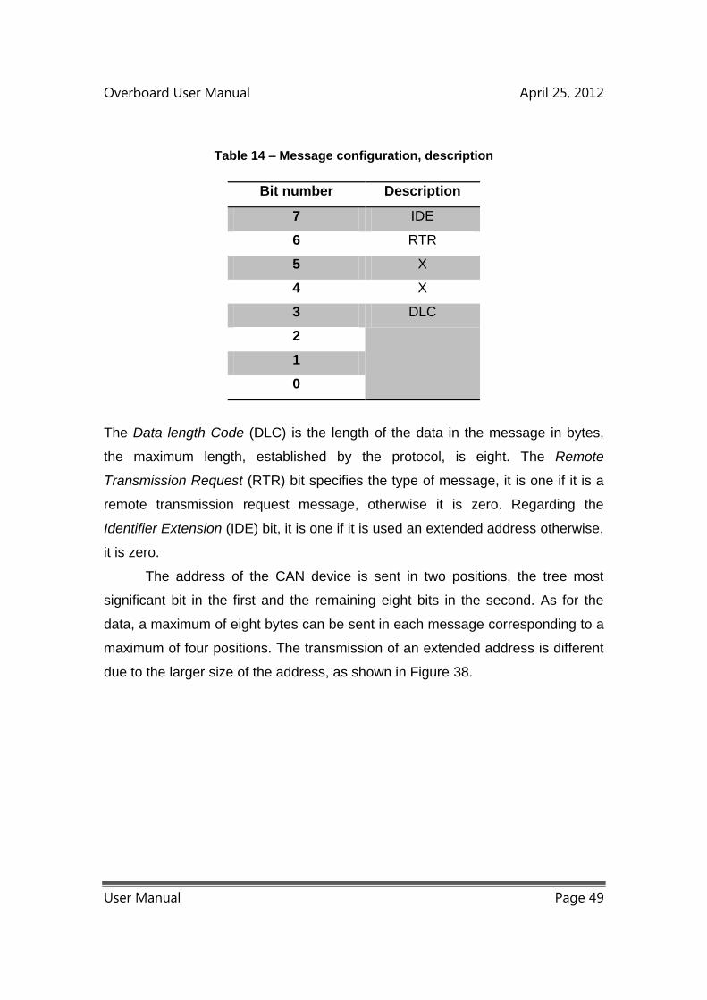
Overboard User Manual April 25, 2012
User Manual Page 49
Table 14 – Message configuration, description
Bit number Description
7 IDE
6 RTR
5 X
4 X
3 DLC
2
1
0
The Data length Code (DLC) is the length of the data in the message in bytes,
the maximum length, established by the protocol, is eight. The Remote
Transmission Request (RTR) bit specifies the type of message, it is one if it is a
remote transmission request message, otherwise it is zero. Regarding the
Identifier Extension (IDE) bit, it is one if it is used an extended address otherwise,
it is zero.
The address of the CAN device is sent in two positions, the tree most
significant bit in the first and the remaining eight bits in the second. As for the
data, a maximum of eight bytes can be sent in each message corresponding to a
maximum of four positions. The transmission of an extended address is different
due to the larger size of the address, as shown in Figure 38.
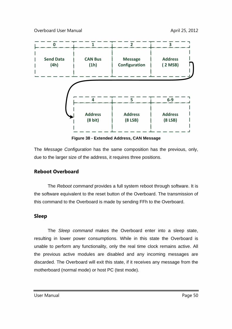
Overboard User Manual April 25, 2012
User Manual Page 50
Send Data(4h)
CAN Bus(1h)
Message Configuration
Address( 2 MSB)
Address(8 bit)
Address(8 LSB)
0 1 2 3
4 5
Address(8 LSB)
6-9
Figure 38 - Extended Address, CAN Message
The Message Configuration has the same composition has the previous, only,
due to the larger size of the address, it requires three positions.
Reboot Overboard
The Reboot command provides a full system reboot through software. It is
the software equivalent to the reset button of the Overboard. The transmission of
this command to the Overboard is made by sending FFh to the Overboard.
Sleep
The Sleep command makes the Overboard enter into a sleep state,
resulting in lower power consumptions. While in this state the Overboard is
unable to perform any functionality, only the real time clock remains active. All
the previous active modules are disabled and any incoming messages are
discarded. The Overboard will exit this state, if it receives any message from the
motherboard (normal mode) or host PC (test mode).
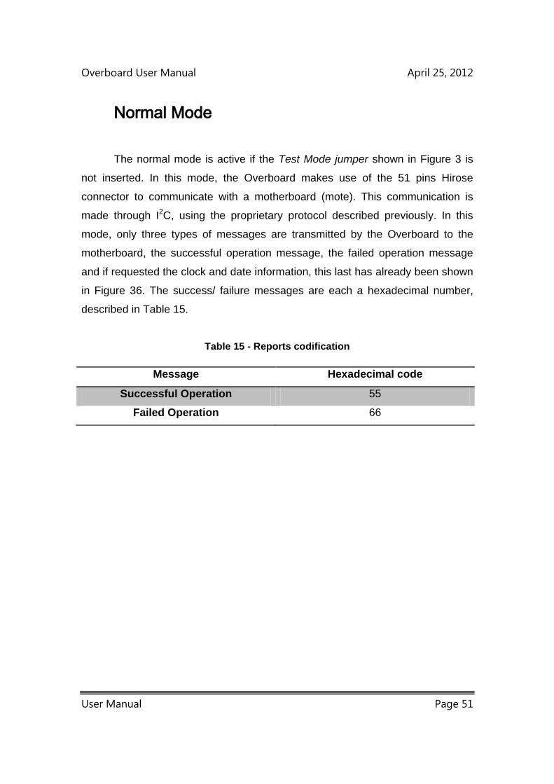
Overboard User Manual April 25, 2012
User Manual Page 51
Normal Mode
The normal mode is active if the Test Mode jumper shown in Figure 3 is
not inserted. In this mode, the Overboard makes use of the 51 pins Hirose
connector to communicate with a motherboard (mote). This communication is
made through I2C, using the proprietary protocol described previously. In this
mode, only three types of messages are transmitted by the Overboard to the
motherboard, the successful operation message, the failed operation message
and if requested the clock and date information, this last has already been shown
in Figure 36. The success/ failure messages are each a hexadecimal number,
described in Table 15.
Table 15 - Reports codification
Message Hexadecimal code
Successful Operation 55
Failed Operation 66

Overboard User Manual April 25, 2012
User Manual Page 52
Test Mode
The test mode is active if the Test Mode jumper shown in Figure 3 is
inserted. The main purpose of test mode is to test the Overboard functionalities.
In this mode, the Overboard makes use of the RJ 25 connector identified in
Figure 16 has KNX Connector to communicate with a host PC through RS-232.
The Overboard transmits instructions to the host PC, primitive interface, with the
purpose of facilitating the interaction between both. When active, the Overboard
automatically activates the RS-232 module related to the host PC
communications, and it remains active until the operation mode is switched.
After the mode activation, the Overboard automatically transmits the main
menu to the host PC, show in Figure 39. A console is required for viewing the
menus transmitted.
Figure 39 - Test Mode, Main Menu
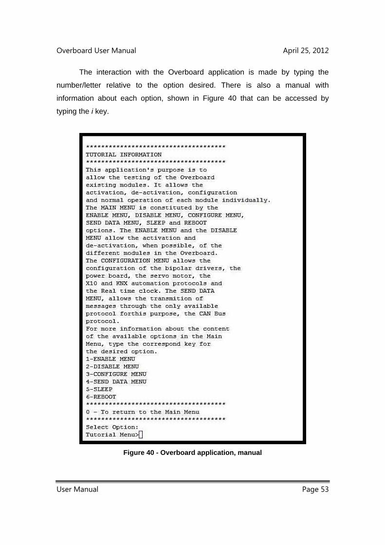
Overboard User Manual April 25, 2012
User Manual Page 53
The interaction with the Overboard application is made by typing the
number/letter relative to the option desired. There is also a manual with
information about each option, shown in Figure 40 that can be accessed by
typing the i key.
Figure 40 - Overboard application, manual
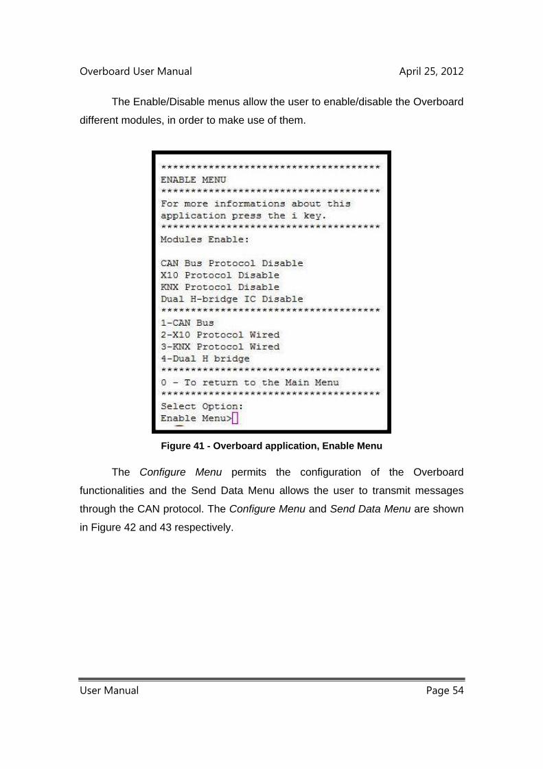
Overboard User Manual April 25, 2012
User Manual Page 54
The Enable/Disable menus allow the user to enable/disable the Overboard
different modules, in order to make use of them.
Figure 41 - Overboard application, Enable Menu
The Configure Menu permits the configuration of the Overboard
functionalities and the Send Data Menu allows the user to transmit messages
through the CAN protocol. The Configure Menu and Send Data Menu are shown
in Figure 42 and 43 respectively.

Overboard User Manual April 25, 2012
User Manual Page 55
Figure 43 - Overboard application, Send Data Menu
Figure 42 - Overboard application, Configure Menu
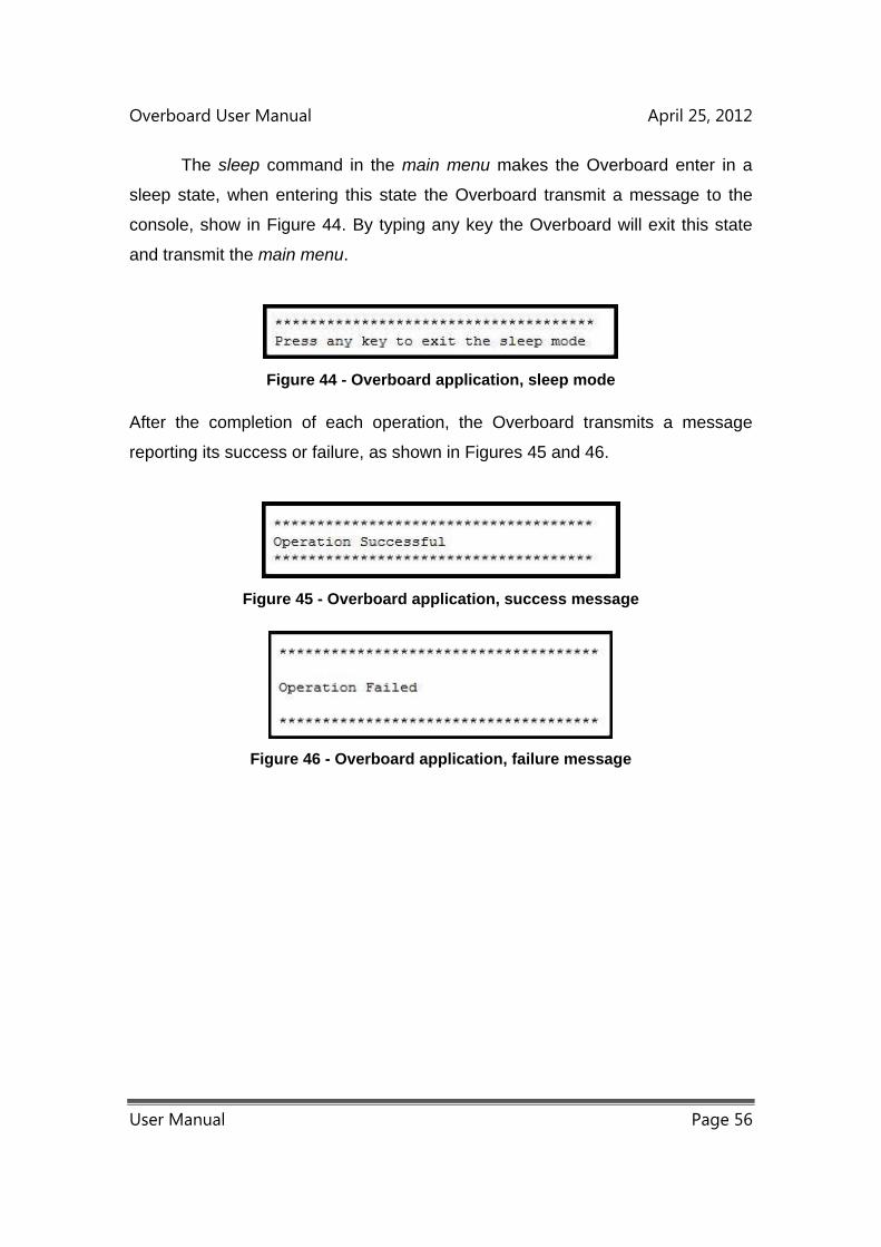
Overboard User Manual April 25, 2012
User Manual Page 56
The sleep command in the main menu makes the Overboard enter in a
sleep state, when entering this state the Overboard transmit a message to the
console, show in Figure 44. By typing any key the Overboard will exit this state
and transmit the main menu.
Figure 44 - Overboard application, sleep mode
After the completion of each operation, the Overboard transmits a message
reporting its success or failure, as shown in Figures 45 and 46.
Figure 45 - Overboard application, success message
Figure 46 - Overboard application, failure message

Overboard User Manual April 25, 2012
User Manual Page 57

Overboard User Manual April 25, 2012
User Manual Page 58
4. Glossary
Wireless sensor networks - Group of spatially dispersed and dedicated sensors
for monitoring and recording the physical conditions of the environment, and
organizing the collected data.
Mote - Also known as node, it is the basic element of WSN. It is usually
composed by radio transceiver, a MCU and sensors.
Actuator - Mechanical device that converts energy into motion.
Daughter Board - Circuit board meant to be an extension of another board.
Automation Protocol - Network protocol used for process, industrial, building,
vehicle and substation automation.
Servomotor - A motor that controls the action of a mechanical device in a
servomechanism.
Stepper motor - Brushless DC motor that divides a full rotation into a number of
steps, allowing the motors position to be commanded to move and hold at one of
these steps without any feedback sensors.

Overboard User Manual April 25, 2012
User Manual Page 59
Overboard User Manual April 25, 2012
User Manual Page 60
5. Index
Wireless sensor networks – 9, 10.
Mote – 9, 11, 14, 15, 16, 44, 52.
Actuator – 9, 12, 14, 15, 17, 23, 30.
Daughter Board – 9, 11.
Automation Protocol – 9, 11, 23.
X10 Protocol – 23, 24, 27, 30, 44, 45.
KNX Protocol – 23, 25, 27, 30, 40.
CAN bus Protocol – 11, 23, 26, 34, 48,
Servomotor – 11, 12, 14, 17, 19, 20, 21, 34, 38.
Stepper motor – 11, 17, 19, 34, 36, 37.
Electric Motor – 11, 14, 18.
Bibliography
[1] J. Yick, B. Mukherjee, and D. Ghosal, “Wireless sensor network survey,” Computer Networks,
vol. 52, no. 12, pp. 2292–2330, 2008.
[2] R. Verdone, D. Dardari, G. Mazzini, and A. Conti, Wireless Sensor and Actuator Networks: Tech-
nologies, Analysis and Design, 1st ed. Academic Press, 2007.
[3] I. F. Akyildiz and I. Kasimoglu, “Wireless sensor and actor networks: research challenges,” Ad Hoc
Networks, vol. 2, no. 4, pp. 351–367, 2004.
[4] N. Zhang, M. Wang, and N. Wang, “Precision agriculture - a worldwide overview,” Computers and
Electronics in Agriculture, vol. 36, no. 2-3, pp. 113–132, 2002.
[5] R. Evans, G. Buchleiter, E. Sadler, B. King, G. Harting, and A. USDA, “Controls for precision irriga-
tion with self-propelled systems,” United States Department of Agriculture, Tech. Rep., 2000.
[6] D. Anurag, S. Roy, and S. Bandyopadhyay, “Agro-sense: Precision agriculture using sensor-based
wireless mesh networks,” 2008 First ITUT Kaleidoscope Academic Conference Innovations in NGN
Future Network and Services, 2008.
[7] N. Wang, N. Zhang, and M. Wang, “Wireless sensors in agriculture and food industry—Recent
development and future perspective,” Computers and Electronics in Agriculture, vol. 50, no. 1, pp.
1–14, 2006.
[8] M. Damas, A. M. Prados, F. Gomez, and G. Olivares, “HidroBus® system: fieldbus for integrated
management of extensive areas of irrigated land,” Microprocessors and Microsystems, vol. 25,
no. 3, pp. 177–184, 2001.
[9] J. Hu, L. Shen, Y. Yang, and R. Lv, “Design and implementation of wireless sensor and actor network
for precision agriculture,” in Wireless Communications Networking and Information Security WCNIS
2010 IEEE International Conference on, 2010, pp. 571–575.
[10] Z. Qian, X.-L. Yang, Y.-M. Zhou, L.-R. Wang, and G. U. O. Xi-Shan, “A wireless solution for green-
house monitoring and control system based on ZigBee technology,” Journal of Zhejiang University
SCIENCE A, vol. 8, no. 10, pp. 1584–1587, 2007.
[11] T. Wark, C. Crossman, W. Hu, Y. Guo, P. Valencia, P. Sikka, P. Corke, C. Lee, J. Henshall,
K. Prayaga, J. O’Grady, M. Reed, and A. Fisher, “The design and evaluation of a mobile sensor/ac-
tuator network for autonomous animal control,” Proceedings of the 6th international conference on
Information processing in sensor networks IPSN 07, pp. 206–215, 2007.
147

[12] T. Wark, D. Swain, C. Crossman, P. Valencia, G. Bishop-Hurley, and R. Handcock, “Sensor and
Actuator Networks: Protecting Environmentally Sensitive Areas,” Ieee Pervasive Computing, vol. 8,
no. 1, pp. 30–36, 2009.
[13] P. Sikka, P. Corke, P. Valencia, C. Crossman, D. Swain, and G. Bishop-Hurley, “Wireless adhoc sen-
sor and actuator networks on the farm,” in IPSN 06 Proceedings of the 5th international conference
on Information processing in sensor networks, ser. IPSN ’06. ACM, 2006, pp. 492–499.
[14] S. Dengler, A. Awad, and F. Dressler, “Sensor/Actuator Networks in Smart Homes for Supporting
Elderly and Handicapped People,” 21st International Conference on Advanced Information Net-
working and Applications Workshops AINAW07, vol. 2, pp. 863–868, 2007.
[15] A. Q. Technologies, “Home Control Assistant :: Home Control Assistant,” 2009.
[16] S. S. LLC, “Savant,” 2005. [Online]. Available: http://www.savantav.com/
[17] R. W. Lindeman, Y. Yanagida, K. Hosaka, and S. Abe, “The TactaPack: A Wireless Sensor/Actuator
Package for Physical Therapy Applications,” 2006 14th Symposium on Haptic Interfaces for Virtual
Environment and Teleoperator Systems, no. c, pp. 337–341, 2006.
[18] D. Hodgins, “Intelligent medical systems,” Medical Device Developments ,1st March, pp. 11–12,
2006.
[19] L. Montestruque and L. Michael, “Csonet: a metropolitan scale wireless sensor-actuator network,”
in International Workshop on Mobile Device and Urban Sensing MODUS, 2008.
[20] D. Curiac and C. Volosencu, “Urban Traffic Control System Architecture Based on Wireless Sensor-
Actuator Networks,” wseas.us, pp. 259–263, 2010.
[21] J. a. Rosario, “Automation of a SMD Component Placement Machine,” Master’s thesis, Universi-
dade Tecnica de Lisboa, 2009.
[22] A. Hughes, Electric Motors and Drives: Fundamentals, Types and Applications, 3rd ed. Elsevier
Ltd., 2006.
[23] W. Yeadon and A. Yeadon, Handbook of Small Electric Motors, 1st ed., W. Yeadon and A. Yeadon,
Eds. McGraw-Hill Professional, 2001.
[24] P. Acarnley, Stepping Motors a guide to theory and practice, 4th ed. London: Institution of Engi-
neering and Technology, 2007.
[25] J. Hamblen, T. Hall, and M. Furman, Rapid Prototyping of Digital Systems. Springer, 2007.
[26] A. Jain, Power Electronics and Its Applications. Penram International Publishing (India) Pvt. Ltd.,
2004.
[27] R. Dorf, The Electrical Engineering Handbook (Electronics, Power Electronics, Optoelectronics,
Microwaves, Electromagnetics, and Radar), 3rd ed. CRC Press, 2006.
148
[28] D. Patrick and S. Fardo, Industrial electronics: devices and systems, 2nd ed. The Fairmont Press,
Inc., 2000.
[29] O. Bishop, Electronics: circuits and systems, 4th ed. Newnes, 2011.
[30] D. Lionetti, “Understanding a relay’s operation can prevent trouble down the line,” Electronics, De-
sign, Strategy, News - Volume 40, Edition 9-12, 1995.
[31] S. Herman, Industrial Motor Control, 6th ed. Delmar Cengage Learning, 2009.
[32] ——, Electrical Motor Control, 9th ed. Delmar Cengage Learning, 2009.
[33] S. Horowitz and A. Phadke, Power System Relaying, 3rd ed. Wiley, 2008.
[34] M. Osipov, “Home automation with ZigBee,” Next Generation Teletraffic and WiredWireless Ad-
vanced Networking, vol. 5174, pp. 263–270, 2008.
[35] B. Sosinsky, Networking Bible, 1st ed. John Wiley & Sons, 2009.
[36] R. B. Gmbh, “CAN Specification,” Stuttgart, Tech. Rep., 1991.
[37] J. a. P. S. Silva, “Aplicacao de Interface Com Sistema Domotico EIB,” Master’s thesis, Universidade
Tecnica de Lisboa, 2007.
[38] T. Weinzierl, “KNX-RF Implementation based on MSP430 and CC1101,” Weinzierl Engineering
GmbH, Tyrlaching, Tech. Rep., 2007.
[39] R. Wallace, “Antenna Selection Guide,” Texas Instruments, Dallas, Tech. Rep., 2010.
[40] J. Teixeira, “MoteIST++ - A Hardware platform for Wireless Sensor Networks,” Master’s thesis,
Universidade Tecnica de Lisboa, 2009.
[41] “IRIS wireless measurement system datasheet,” p. 2, 2011.
[42] “MICAz wireless measurement system datasheet,” p. 2, 2009.
[43] Microchip, “MPLAB ® IDE User’s Guide with MPLAB Editor and MPLAB SIM Simulator,” p. 352,
2009.
[44] ——, “PICkit™ 3 Programmer/Debugger User’s Guide,” p. 94, 2009.
[45] T. Instruments, “Code Composer Studio v4 User’s Guide for MSP430,” p. 44, 2009.
[46] ——, “MSP-FET430 Flash Emulation Tool (FET),” p. 95, 2009.
149

150