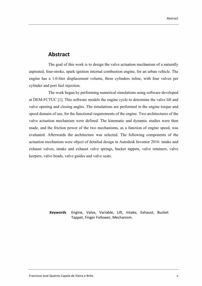
Design of the Valve Actuation Mechanism of a Four-Stroke ...
115
DEPARTAMENTO DE ENGENHARIA MECÂNICA Design of the Valve Actuation Mechanism of a Four-Stroke Spark Ignition Internal Combustion Engine Submitted in Partial Fulfillment of the Requirements for the Degree of Master in Mechanical Engineering in the specialty of Energy and Environment Selecção e Dimensionamento de um Mecanismo de Accionamento de Válvulas de um Motor de Combustão Interna de Ciclo de 4 Tempos de Ignição por Faísca Author Francisco José Queirós Capela de Vieira e Brito Advisor Professor Doutor Pedro de Figueiredo Vieira Carvalheira Jury President Professor Doutor José Manuel Baranda Moreira da Silva Ribeiro Professor Auxiliar da Universidade de Coimbra Vowels Professor Doutor Fernando Jorge Ventura Antunes Professor Auxiliar da Universidade de Coimbra Professor Doutor Pedro de Figueiredo Vieira Carvalheira Professor Auxiliar da Universidade de Coimbra Advisor Professor Doutor Pedro de Figueiredo Vieira Carvalheira Professor Auxiliar da Universidade de Coimbra Coimbra, July, 2016
-
Upload
khangminh22 -
Category
Documents
-
view
0 -
download
0
Transcript of Design of the Valve Actuation Mechanism of a Four-Stroke ...
DEPARTAMENTO DE ENGENHARIA MECÂNICA
DesignoftheValveActuationMechanismofaFour-StrokeSparkIgnitionInternalCombustionEngineSubmittedinPartialFulfillmentoftheRequirementsfortheDegreeofMasterinMechanicalEngineeringinthespecialtyofEnergyandEnvironment
SelecçãoeDimensionamentodeumMecanismodeAccionamentodeVálvulasdeumMotordeCombustãoInternadeCiclode4TemposdeIgniçãoporFaísca
AuthorFranciscoJoséQueirósCapeladeVieiraeBritoAdvisorProfessorDoutorPedrodeFigueiredoVieiraCarvalheira
Jury
PresidentProfessorDoutorJoséManuelBarandaMoreiradaSilvaRibeiroProfessorAuxiliardaUniversidadedeCoimbra
Vowels
ProfessorDoutorFernandoJorgeVenturaAntunesProfessorAuxiliardaUniversidadedeCoimbraProfessorDoutorPedrodeFigueiredoVieiraCarvalheiraProfessorAuxiliardaUniversidadedeCoimbra
Advisor ProfessorDoutorPedrodeFigueiredoVieiraCarvalheiraProfessorAuxiliardaUniversidadedeCoimbra
Coimbra,July,2016


With your mind power, your determination, your instinct, and the experience as
well, you can fly very high. Ayrton Senna, in “Racing is in My Blood”, 1991.
To my Parents and Joana.


Acknowledgements
FranciscoJoséQueirósCapeladeVieiraeBrito iii
ACKNOWLEDGEMENTSThis dissertation would not be possible without all the support I received. I
would like to take this opportunity and repay some of that gratitude.
To my Advisor, Professor Doutor Pedro Carvalheira. For the incredible support,
availability and concern from the first moment, but also for teaching me so much in such a
short span of time. I could not have hoped for a better advisor. Thank you very much
Professor.
To my Parents. Not only for supporting me all of the time and allowing me to
pursue my dreams, but also for being a daily inspiration and a true example that belief and
hard work can accomplish anything. Thank you so much.
To Joana. For being everything I could ask for and more. For the incredible
support in every second I need it and for encouraging me to be better every single day. Thank
you so much.

Design of the Valve Actuation Mechanism of a Four-Stroke Spark Ignition Internal CombustionEngine
iv 2016
Abstract
FranciscoJoséQueirósCapeladeVieiraeBrito v
AbstractThe goal of this work is to design the valve actuation mechanism of a naturally
aspirated, four-stroke, spark ignition internal combustion engine, for an urban vehicle. The
engine has a 1.0-liter displacement volume, three cylinders inline, with four valves per
cylinder and port fuel injection.
The work began by performing numerical simulations using software developed
at DEM-FCTUC [1]. This software models the engine cycle to determine the valve lift and
valve opening and closing angles. The simulations are performed in the engine torque and
speed domain of use, for the functional requirements of the engine. Two architectures of the
valve actuation mechanism were defined. The kinematic and dynamic studies were then
made, and the friction power of the two mechanisms, as a function of engine speed, was
evaluated. Afterwards the architecture was selected. The following components of the
actuation mechanism were object of detailed design in Autodesk Inventor 2016: intake and
exhaust valves, intake and exhaust valve springs, bucket tappets, valve retainers, valve
keepers, valve beads, valve guides and valve seats.
Keywords Engine, Valve, Variable, Lift, Intake, Exhaust, BucketTappet,FingerFollower,Mechanism.

Design of the Valve Actuation Mechanism of a Four-Stroke Spark Ignition Internal CombustionEngine
vi 2016

Resumo
FranciscoJoséQueirósCapeladeVieiraeBrito vii
ResumoA motivação para este trabalho consiste em efetuar a seleção e o projeto
detalhado de um mecanismo de acionamento de válvulas de um motor de combustão interna,
de ciclo de quatro tempos e ignição por faísca, para um veículo automóvel utilitário. O motor
tem 1.0 litro de cilindrada, três cilindros em linha, quatro válvulas por cilindro e injeção na
porta de admissão.
O trabalhou começou pela realização de simulações de modelação do ciclo de
funcionamento do motor, usando o programa “Ciclo de Funcionamento do Motor”
desenvolvido no DEM-FCTUC [1], para determinar o levantamento máximo e os ângulos
de abertura e fecho das válvulas de admissão e escape em função da velocidade de rotação
do motor. Foram definidas duas arquiteturas para o trem de válvulas, efetuados estudos
cinemáticos e dinâmicos e avaliado o atrito de ambos os mecanismos em função da
velocidade de rotação do motor. De seguida foi efetuada a seleção da arquitetura mais
adequada, em função dos requisitos funcionais do mesmo. Os componentes seguintes do
mecanismo de acionamento das válvulas do motor foram objeto de desenho pormenorizado
em software de desenho CAD-3D (Autodesk Inventor 2016): válvulas de admissão e de
escape, molas das válvulas de admissão e escape, touches, retentores das válvulas, pratos
das válvulas, meias-luas, guias das válvulas e sedes das válvulas.
Palavras-chave: Motor, Válvula, Variável, Levantamento, Admissão,Escape,Touche,Balanceiro,Mecanismo.

Design of the Valve Actuation Mechanism of a Four-Stroke Spark Ignition Internal CombustionEngine
viii 2016

Contents
FranciscoJoséQueirósCapeladeVieiraeBrito ix
ContentsLIST OF FIGURES .............................................................................................................. xiLIST OF TABLES ............................................................................................................... xvSIMBOLOGY AND ACRONYMS .................................................................................. xvii
Simbology ...................................................................................................................... xviiAcronyms ......................................................................................................................... xx
1. INTRODUCTION ......................................................................................................... 11.1. Motivation .............................................................................................................. 11.2. Goals ...................................................................................................................... 31.3. Starting Point ......................................................................................................... 31.4. Methodology .......................................................................................................... 31.5. Definition of Engine Characteristics ...................................................................... 4
2. ENGINE CYCLE ........................................................................................................... 92.1. Overview ................................................................................................................ 92.2. Combustion Chamber .......................................................................................... 11
2.2.1. Overview ...................................................................................................... 112.2.2. Volume ......................................................................................................... 122.2.3. Design .......................................................................................................... 132.2.4. Flame Behavior Throughout the Combustion Chamber .............................. 17
2.3. Engine Cycle Simulations .................................................................................... 202.3.1. Overview ...................................................................................................... 202.3.2. Intake and Exhaust Valves Optimal Opening and Closing Angles ............. 222.3.3. Intake Valves Optimal Lift .......................................................................... 262.3.4. Exhaust Valves Optimal Lift ....................................................................... 29
3. VALVE TRAIN DESIGN ........................................................................................... 333.1. Overview .............................................................................................................. 333.2. Bucket Tappet Valve Train .................................................................................. 35
3.2.1. System Considerations ................................................................................. 353.2.2. Length and Displacement Relations ............................................................ 393.2.3. Spring Rate and Damping Coefficient ......................................................... 393.2.4. Forces ........................................................................................................... 443.2.5. Friction Work ............................................................................................... 503.2.6. Type of Spring Ends .................................................................................... 533.2.7. Stability ........................................................................................................ 533.2.8. Critical Frequency of Helical Springs .......................................................... 553.2.9. Fatigue Loading of Helical Compression Springs ....................................... 57
3.3. Finger Follower Valve Train ............................................................................... 594. CONCLUSIONS ......................................................................................................... 61BIBLIOGRAPHY ................................................................................................................ 63
Design of the Valve Actuation Mechanism of a Four-Stroke Spark Ignition Internal CombustionEngine
x 2016
ANNEX A ............................................................................................................................ 67ANNEX B ............................................................................................................................ 71ANNEX C ............................................................................................................................ 73
LISTOFFIGURES
FranciscoJoséQueirósCapeladeVieiraeBrito xi
LISTOFFIGURESFigure 1.1. Alba, a Portuguese manufactured car between 1952 and 1954, racing at the
Caramulo hill climb in 2007 [2]. ............................................................................. 1Figure 1.2. EU’s CO2 emissions goal for 2020 [4]. .............................................................. 2Figure 1.3. Work methodology. ............................................................................................. 3Figure 1.4. An example of a double overhead camshaft (DOHC) engine [6]. ...................... 6Figure 2.1. Four-stroke engine - Otto Cycle [6]. ................................................................. 10Figure 2.2. Schematic example of an ICE (internal combustion engine) combustion
chamber (represented as the blue triangle) [7]. ..................................................... 11Figure 2.3. Venn diagram explaining how the chamber’s shape affects its efficiency. ...... 12Figure 2.4. 1KR-FE Engine’s cylinder head [8]. ................................................................. 13Figure 2.5. 1KR-FE Engine’s combustion chamber (designed in Autodesk Inventor 2016).
............................................................................................................................... 13Figure 2.6. 1KR-FE Engine’s combustion chamber (designed in Autodesk Inventor 2016).
............................................................................................................................... 14Figure 2.7. Iterative process for the combustion chamber’s optimization. .......................... 15Figure 2.8. 1KR-FE Engine’s combustion chamber – lateral view (designed in Autodesk
Inventor 2016). ...................................................................................................... 15Figure 2.9. 1KR-FE Engine’s combustion chamber – cutaway view (designed in Autodesk
Inventor 2016). ...................................................................................................... 16Figure 2.10. Optimized final solution of the combustion chamber (designed in Autodesk
Inventor 2016). ...................................................................................................... 16Figure 2.11. Optimized final solution of the combustion chamber – lateral view (designed
in Autodesk Inventor 2016). .................................................................................. 17Figure 2.12. Optimized final solution of the combustion chamber – cutaway view
(designed in Autodesk Inventor 2016). ................................................................. 17Figure 2.13. Intersection between the sphere and the combustion chamber. This
intersection represents the flame front’s surface area (designed in Autodesk Inventor 2016). ...................................................................................................... 18
Figure 2.14. Schematic example of a combustion chamber with the piston at TDC [10]. .. 19Figure 2.15. Combustion chamber with (left) and without (right) “skirt” (designed in
Autodesk Inventor 2016). ...................................................................................... 19Figure 2.16. Flame behavior throughout the combustion chamber. .................................... 19Figure 2.17. Overview of the engine’s cycle simulation program [1]. ................................ 20
Design of the Valve Actuation Mechanism of a Four-Stroke Spark Ignition Internal CombustionEngine
xii 2016
Figure 2.18. The four angles to be determined through engine cycle simulation. ............... 20Figure 2.19. 1KR-FE’s “Certificate of Performance” showing the maximum power and
torque for the engine’s operating range [11]. ........................................................ 22Figure 2.20. Evolution of engine brake power and brake specific fuel consumption
throughout the engine’s operating range for a valve lift of 0.0076 m on both intake and exhaust valves at WOT. .................................................................................. 24
Figure 2.21. Intake and exhaust valves opening and closing angles throughout the engine’s operating range for a valve lift of 0.0076 m on both intake and exhaust valves at WOT. ..................................................................................................................... 25
Figure 2.22. Evolution of engine brake power and brake specific fuel consumption throughout the engine’s operating range for a valve lift of 0.0076 m on both intake and exhaust valves at WOT. .................................................................................. 25
Figure 2.23. Intake and exhaust valves opening and closing angles throughout the engine’s operating range for a valve lift of 0.0076 m on both intake and exhaust valves at WOT. ..................................................................................................................... 26
Figure 2.24. Effect of the butterfly throttle valve. Position from left to right: Idle; Partial Load; Full Load [12]. ............................................................................................. 27
Figure 2.25. Evolution of bmep as function of (IVL) for n = 3500 rpm. ............................ 29Figure 2.26. Evolution of bsfc with EVL and a constant IVL = 0.00366 m. ...................... 30Figure 2.27. Evolution of bsfc with EVL and a constant IVL = 0.00271 m. ...................... 31Figure 2.28. Evolution of bsfc with EVL and a constant IVL = 0.00195 m. ...................... 31Figure 2.29. Evolution of bsfc with EVL and a constant IVL = 0.00143 m. ...................... 32Figure 3.1. Cam lobe [6]. ..................................................................................................... 33Figure 3.2. Variable valve train with discrete (left) and continuous (right) systems [13]. .. 34Figure 3.3. Variable valve train effect on engine behavior [13]. ......................................... 34Figure 3.4. Schematic example of a bucket tappet valve actuation mechanism (left) and a
finger follower valve actuation mechanism (right) [6]. ......................................... 34Figure 3.5. Schematic representation of the considered mass-spring-damper system. ....... 35Figure 3.6. Schematic representation of all the system’s components. The captioned masses
are analyzed as being one mass only. .................................................................... 35Figure 3.7. Schematic representation of forces and displacements on the valve and its
components. The system is actuated directly by the cam on the tappet’s top end. 38Figure 3.8. Schematic representation of a bucket tappet mechanism mounted on the engine
[14]. ........................................................................................................................ 41Figure 3.9. Force of the intake (left) and the exhaust (right) valve spring as function of
crank angle. ............................................................................................................ 44Figure 3.10. Schematic representation of the pressure inside the cylinder and on the
inlet/outlet port [16]. .............................................................................................. 45
LISTOFFIGURES
FranciscoJoséQueirósCapeladeVieiraeBrito xiii
Figure 3.11. Schematic figure showing the width of the valve seat and the external seat diameter of the valve [16]. ..................................................................................... 46
Figure 3.12. Force of the intake (left) and exhaust (right) valve seat as function of crank angle. ...................................................................................................................... 47
Figure 3.13. Force applied by the intake (left) and exhaust (right) cam on the tappet’s top end as function of crank angle. .............................................................................. 48
Figure 3.14. Schematic representation of the valve guide’s inner diameter. ....................... 49Figure 3.15. Schematic representation of the valve stem, the valve guide, and the engine oil
between them. ........................................................................................................ 49Figure 3.16. Intake bucket tappet friction work as function of crank angle. ....................... 50Figure 3.17. Intake cam friction work on bucket tappet as function of crank angle. .......... 51Figure 3.18. Intake valve guide friction work as function of crank angle. .......................... 51Figure 3.19. Exhaust bucket tappet friction work as function of crank angle. .................... 52Figure 3.20. Exhaust cam friction work on bucket tappet as function of crank angle. ........ 52Figure 3.21. Exhaust valve guide friction work as function of crank angle. ....................... 53Figure 3.22. Fatigue diagram containing various criteria of failure [17]. ............................ 57Figure 3.23. Schematic example of a finger follower valve train [18]. ............................... 59Figure 3.24. Force of the intake cam on the bucket tappet as function of crank angle. ...... 60Figure 0.1. 1KR-FE Engine’s schematic illustration [19]. .................................................. 67Figure 0.1. Bucket tappet valve train designed in Autodesk Inventor 2016. ....................... 71Figure 0.2. Bucket tappet valve train – exploded view - designed in Autodesk Inventor
2016. ...................................................................................................................... 71Figure 0.3. Bucket tappet valve train designed in Autodesk Inventor 2016. ....................... 72Figure 0.1. Honda’s VTEC mechanism [20]. ...................................................................... 73Figure 0.2. BMW’s Valvetronic mechanism at minimum (left) and maximum lift (right)
positions [21]. ........................................................................................................ 74Figure 0.3. BMW’s Valvetronic 1st generation [22]. ........................................................... 75Figure 0.4. BMW’s Valvetronic 2nd generation [23]. .......................................................... 76Figure 0.5. Nissan’s VVEL mechanism [24]. ...................................................................... 78Figure 0.6. Nissan’s VVEL mechanism at maximum (up) and minimum lift (down) [25]. 79Figure 0.7. Valvematic’s intermediate shaft [26]. ............................................................... 81Figure 0.8. Toyota Valvematic [27]. .................................................................................... 82Figure 0.9. Internal gear threads [21]. .................................................................................. 82Figure 0.10. Valvematic’s low (left) and high (right) lift positions [21]. ............................ 83Figure 0.11. Valvematic’s mechanism that converts rotary motion into linear motion [28].
............................................................................................................................... 84

Design of the Valve Actuation Mechanism of a Four-Stroke Spark Ignition Internal CombustionEngine
xiv 2016
Figure 0.12. FIAT’s MultiAir mechanism [29]. .................................................................. 85Figure 0.13. A SOHC engine with FIAT’s MultiAir technology [30]. ............................... 85Figure 0.14. MultiAir’s actuation modes [31]. .................................................................... 86Figure 0.15. Valvematic system designed in Autodesk Inventor 2016. .............................. 89Figure 0.16. Valvematic system designed in Autodesk Inventor 2016. .............................. 89Figure 0.17. Valvematic system designed in Autodesk Inventor 2016. .............................. 90Figure 0.18. Valvematic’s finger follower mechanism designed in Autodesk Inventor 2016.
............................................................................................................................... 90
LISTOFTABLES
FranciscoJoséQueirósCapeladeVieiraeBrito xv
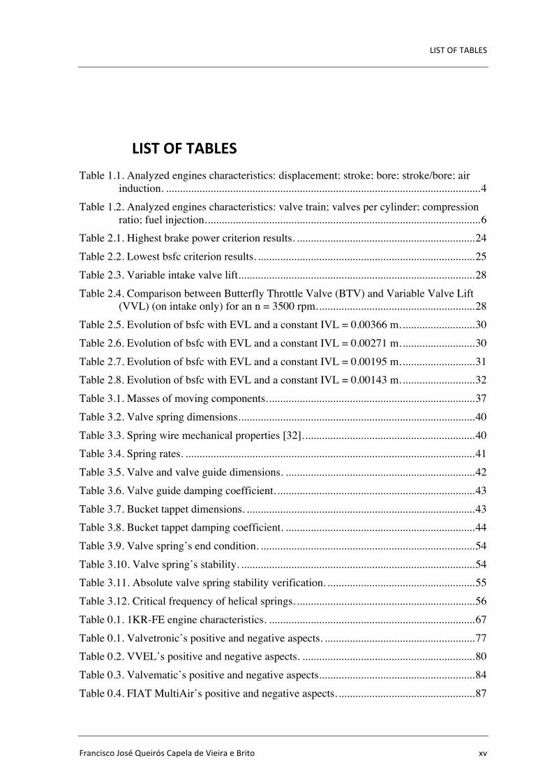
LISTOFTABLESTable 1.1. Analyzed engines characteristics: displacement; stroke; bore; stroke/bore; air
induction. ................................................................................................................. 4Table 1.2. Analyzed engines characteristics: valve train; valves per cylinder; compression
ratio; fuel injection. .................................................................................................. 6Table 2.1. Highest brake power criterion results. ................................................................ 24Table 2.2. Lowest bsfc criterion results. .............................................................................. 25Table 2.3. Variable intake valve lift. .................................................................................... 28Table 2.4. Comparison between Butterfly Throttle Valve (BTV) and Variable Valve Lift
(VVL) (on intake only) for an n = 3500 rpm. ........................................................ 28Table 2.5. Evolution of bsfc with EVL and a constant IVL = 0.00366 m. .......................... 30Table 2.6. Evolution of bsfc with EVL and a constant IVL = 0.00271 m. .......................... 30Table 2.7. Evolution of bsfc with EVL and a constant IVL = 0.00195 m. .......................... 31Table 2.8. Evolution of bsfc with EVL and a constant IVL = 0.00143 m. .......................... 32Table 3.1. Masses of moving components. .......................................................................... 37Table 3.2. Valve spring dimensions. .................................................................................... 40Table 3.3. Spring wire mechanical properties [32]. ............................................................. 40Table 3.4. Spring rates. ........................................................................................................ 41Table 3.5. Valve and valve guide dimensions. .................................................................... 42Table 3.6. Valve guide damping coefficient. ....................................................................... 43Table 3.7. Bucket tappet dimensions. .................................................................................. 43Table 3.8. Bucket tappet damping coefficient. .................................................................... 44Table 3.9. Valve spring’s end condition. ............................................................................. 54Table 3.10. Valve spring’s stability. .................................................................................... 54Table 3.11. Absolute valve spring stability verification. ..................................................... 55Table 3.12. Critical frequency of helical springs. ................................................................ 56Table 0.1. 1KR-FE engine characteristics. .......................................................................... 67Table 0.1. Valvetronic’s positive and negative aspects. ...................................................... 77Table 0.2. VVEL’s positive and negative aspects. .............................................................. 80Table 0.3. Valvematic’s positive and negative aspects. ....................................................... 84Table 0.4. FIAT MultiAir’s positive and negative aspects. ................................................. 87
Design of the Valve Actuation Mechanism of a Four-Stroke Spark Ignition Internal CombustionEngine
xvi 2016
Table 0.5. Comparison between the analyzed variable valve lift mechanisms. .................. 88
SIMBOLOGYANDACRONYMS
FranciscoJoséQueirósCapeladeVieiraeBrito xvii
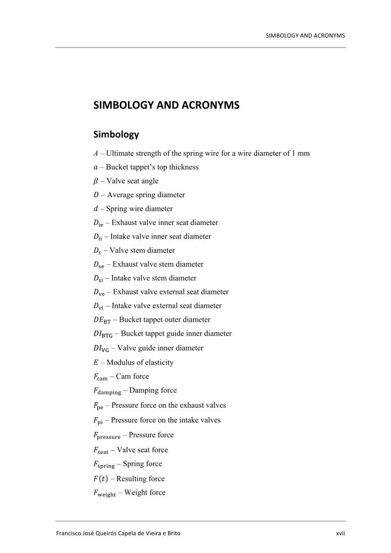
SIMBOLOGYANDACRONYMS
Simbology
A – Ultimate strength of the spring wire for a wire diameter of 1 mm
𝑎 – Bucket tappet’s top thickness
𝛽 – Valve seat angle
𝐷 – Average spring diameter
𝑑 – Spring wire diameter
𝐷%& – Exhaust valve inner seat diameter
𝐷%% – Intake valve inner seat diameter
𝐷' – Valve stem diameter
𝐷(& – Exhaust valve stem diameter
𝐷(% – Intake valve stem diameter
𝐷)& – Exhaust valve external seat diameter
𝐷)% – Intake valve external seat diameter
𝐷𝐸+, – Bucket tappet outer diameter
𝐷𝐼+,. – Bucket tappet guide inner diameter
𝐷𝐼/. – Valve guide inner diameter
𝐸 – Modulus of elasticity
𝐹123 – Cam force
𝐹4235%67 – Damping force
𝐹5& – Pressure force on the exhaust valves
𝐹5% – Pressure force on the intake valves
𝐹58&((98& – Pressure force
𝐹(&2: – Valve seat force
𝐹(58%67 – Spring force
𝐹(𝑡) – Resulting force
𝐹>&%7?: – Weight force
Design of the Valve Actuation Mechanism of a Four-Stroke Spark Ignition Internal CombustionEngine
xviii 2016
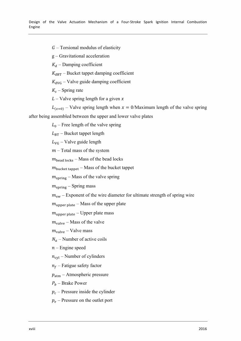
𝐺 – Torsional modulus of elasticity
g – Gravitational acceleration
𝐾B – Damping coefficient
𝐾4+, – Bucket tappet damping coefficient
𝐾4/. – Valve guide damping coefficient
𝐾' – Spring rate
𝐿 – Valve spring length for a given 𝑥
𝐿 EFG – Valve spring length when 𝑥 = 0/Maximum length of the valve spring
after being assembled between the upper and lower valve plates
𝐿G – Free length of the valve spring
𝐿+, – Bucket tappet length
𝐿/. – Valve guide length
𝑚 – Total mass of the system
𝑚K&24MN1O( – Mass of the bead locks
𝑚K91O&::255&: – Mass of the bucket tappet
𝑚(58%67 – Mass of the valve spring
𝑚(58%67 – Spring mass
𝑚(> – Exponent of the wire diameter for ultimate strength of spring wire
𝑚955&85M2:& – Mass of the upper plate
𝑚955&85M2:& – Upper plate mass
𝑚)2M)& – Mass of the valve
𝑚)2M)& – Valve mass
𝑁Q – Number of active coils
𝑛 – Engine speed
𝑛1SM – Number of cylinders
𝑛T – Fatigue safety factor
𝑝2:3 – Atmospheric pressure
𝑃W – Brake Power
𝑝X – Pressure inside the cylinder
𝑝Y – Pressure on the outlet port
SIMBOLOGYANDACRONYMS
FranciscoJoséQueirósCapeladeVieiraeBrito xix
𝑝Z – Pressure on the inlet port
𝑟X – Compression ratio
𝑆Q – Alternate strength
𝑆Y – Endurance strength
𝑆] – Average strength
𝑆(2 – Alternate shear strength
𝑆(& – Endurance shear strength
𝑆(3 – Average shear strength
𝑆(9 – Ultimate shear strength
𝑆9: – Ultimate strength
𝑇 – Temperature
𝑇W – Brake torque
𝑉11 – Volume of the combustion chamber
𝑉B – Engine displacement volume
𝑉41 – Cylinder displacement volume
𝑥 – Valve lift/displacement
𝑥G – Difference in length between 𝐿Gand 𝐿 EFG
𝑤 – Valve seat width
𝜎Q – Alternate stress
𝜎] – Average stress
𝜏Q – Alternate shear stress
𝜏] – Average shear stress
𝜏c32d – Maximum value of shear stress amplitude
𝜏c3%6 – Minimum value of shear stress amplitude
𝜏c – Shear stress amplitude
𝜈 – Poisson’s ratio
𝜇 𝑇 – Dynamic viscosity of oil

Design of the Valve Actuation Mechanism of a Four-Stroke Spark Ignition Internal CombustionEngine
xx 2016
Acronyms
ABDC – After Bottom Dead Center
ATDC – After Top Dead Center
BBDC – Before Bottom Dead Center
BDC – Bottom Dead Center
bsfc – Brake Specific Fuel Consumption
BTDC – Before Top Dead Center
BTV – Butterfly Throttle Valve
CAD – Computer Aided Design
DEM – Departamento de Engenharia Mecânica
DOHC – Dual/Double Overhead Camshaft
ECU – Engine Control Unit
EVC – Exhaust Valves Close
EVL – Exhaust Valve Lift
EVO – Exhaust Valves Open
FCTUC – Faculdade de Ciências e Tecnologia da Universidade de Coimbra
ICE – Internal Combustion Engine
IVC – Inlet Valves Close
IVL – Intake Valve Lift
IVO – Inlet Valves Open
RPM – Revolutions Per Minute
SI – Spark Ignition
SOHC – Single Overhead Camshaft
TDC – Top Dead Center
TI – Ignition Timing
UMM – União Metalo-Mecânica
VTEC – Variable Valve Timing and Lift Electronic Control
VVEL – Variable Valve Event and Lift
VVL – Variable Valve Lift
VVT-i – Variable Valve Timing with Intelligence
WOT – Wide Open Throttle

SIMBOLOGYANDACRONYMS
FranciscoJoséQueirósCapeladeVieiraeBrito xxi

Design of the Valve Actuation Mechanism of a Four-Stroke Spark Ignition Internal CombustionEngine
xxii 2016

INTRODUCTION
FranciscoJoséQueirósCapeladeVieiraeBrito 1
1. INTRODUCTION
1.1. MotivationNowadays, there is a total absence of internal combustion engine projects in
Portugal. The desire to build genuine Portuguese engines and motor vehicles has always
been on the minds of several engineers and automotive enthusiasts. Portuguese engine and
car manufacturing - despite some interesting and notable examples – Alba (Figure 1.1),
Casal, UMM, etc. - has always fallen short of its true potential. An incomprehensible reality
when the large number of countries that target this type of industry are analyzed.
The automotive industry is one of the most important in the world and it offers
a wide range of solutions for almost every costumer need. Urban vehicles are one of the most
popular ones. Not only do they influence the daily lives of innumerous families, but they
also play an important role on the impact that motor vehicles have in the environment.
Figure1.1.Alba,aPortuguesemanufacturedcarbetween1952and1954,racingattheCaramulohillclimb
in2007[2].

Design of the Valve Actuation Mechanism of a Four-Stroke Spark Ignition Internal CombustionEngine
2 2016
Environmental problems such as global warming, are a worrying reality and a
worldwide concern. Among many other aspects in a car, the engine is one of critical
relevance to the environmental issue. It is therefore utmost important to design an internal
combustion engine with the lowest possible fuel consumption and emission levels. The rules
regulating vehicle emissions are tight and tend to become even more in the future. For 2020,
the European Union’s CO2 emissions target is 95 grams per kilometer (for passenger cars)
[3]. To comply with these regulations (Figure 1.1), engine manufacturers are investing on a
number of solutions which allow them to boost the efficiency of their engines. One of those
solutions is engine downsizing, which is a growing worldwide trend in urban vehicles. More
and more manufacturers are including small engines in their powertrain catalogue, showing
this is the way to go. Their goal is simple: build a small and highly efficient power unit.
Although these are very important issues, it is also necessary for the car to be as
attractive as possible for the driver. For that to happen, the engine must produce a decent
amount of brake power. One of the most popular technologies to achieve the desired brake
power throughout the engine’s operating range is cam phasing. To further increase brake
power, but also to lower both fuel consumption and emission levels, variable valve lift is
applied to the valve train. Variable valve lift allows the engine to lower its brake specific
fuel consumption in partial load.
Figure1.2.EU’sCO2emissionsgoalfor2020[4].
2
ICCT BRIEFING
1. BACKGROUNDThe EEA has recently released the provisional data for the CO2 emissions of passenger cars registered in the European Union in 2014.2
Average CO2 emissions from European cars decreased by 3% compared to 2013, while the average mass fell by approximately 1% (to 1383 kg for all manufacturers). This development implies that all manufacturers have met their 2015 targets (130 g/km on average) and are already making progress towards their 2020 targets (95 g/km on average). According to the data, all major manufacturers have achieved the 2015 target at least one year early, with average EU fleet emissions amounting to 123.3 g/km.3
As Figure 1 illustrates, since 2005 CO2 emission levels of new cars in the EU decreased by 24%, from a starting point of 162 g/km. As CO2 emissions are directly related to fuel consumption, this reduction is equivalent to a decrease in fuel consumption from approximately 6.7 liters per 100 kilometers (l/100 km) to 5.1 l/100 km.
80
100
120
140
160
180
2005 2010 2015 2020
CO2 (g/km)
2020: 95 g/km (one year phase-in)
-23% (2014-2021)
2015: 130 g/km
until 2007:-1%/year
from 2008:-4%/year
2014
Figure 1: Historical development and future targets for CO2 emission levels of new passenger cars in the EU. Effects of phase-in, super-credits and eco-innovations not shown here.
The purpose of this briefing paper is to build upon EEA’s observations by providing a summary of individual passenger car manufacturers’ performance in terms of CO2 emission reduction, fuel/technology trends, and market share. The performance is investigated by country and manufacturer. Furthermore, the briefing paper discusses the use of super-credits as a medium of achieving emission targets.
2 European Environmental Agency, “New cars meet CO2 target two years ahead of the deadline”, http://www.eea.europa.eu/highlights/new-cars-meet-co2-target, European Environmental Agency, “Monitoring of CO2 emissions from passenger cars: Summary data for 2014”, http://www.eea.europa.eu/data-and-maps/data/co2-cars-emission-8.
3 Based on the New European Drive Cycle (NEDC) type-approval data
INTRODUCTION
FranciscoJoséQueirósCapeladeVieiraeBrito 3
1.2. GoalsThe present dissertation aims to suppress the absence of national projects in the
automotive industry, by providing the first insight on what will be a complete and detailed
project of an internal combustion engine for an urban vehicle. This work focuses on the
analysis, selection and design of the engine’s valve train.
1.3. StartingPointWhen it comes to urban vehicles, there are many different types of motoring
options adopted by manufacturers. A preliminary study carried out in [5] focused on
comparing the different types of solutions available, and was able to determine which SI
(spark ignition) engine best fits an urban vehicle. It concluded that the best engine would be
an inline three-cylinder with a displacement volume around 1.0-liter. As a future work
proposal it was suggested that the engine’s detailed project and CAD (computer aided
design) were made. These conclusions and future work proposals are the starting point of
this dissertation.
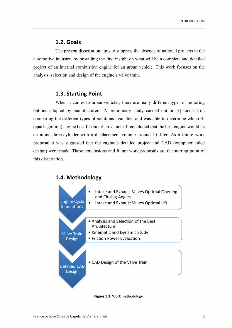
1.4. Methodology
Figure1.3.Workmethodology.
EngineCycleSimulations
• Intake andExhaustValvesOptimalOpeningandClosingAngles
• IntakeandExhaustValvesOptimalLift
ValveTrainDesign
• AnalysisandSelectionoftheBestArquitecture
• KinematicandDynamicStudy• FrictionPowerEvaluation
DetailedCADDesign
• CADDesignoftheValveTrain

Design of the Valve Actuation Mechanism of a Four-Stroke Spark Ignition Internal CombustionEngine
4 2016
The first step of the work methodology (Figure 1.3) is to model the engine cycle
in order to obtain the optimal opening and closing angles (for the intake and exhaust valves)
and the optimal values of valve lift in the engine torque and speed domain of use, for the
engine’s functional requirements. The work is followed by the analysis of two different types
of architectures for the valve actuation mechanism. A kinematic and dynamic study is
performed for both valve train architectures, as well as a friction power evaluation of both
mechanisms as a function of engine speed (n). After the best architecture is selected, the
work is concluded with the design of the valve train mechanism.
1.5. DefinitionofEngineCharacteristicsSome of the engine’s characteristics have already been defined in [5]. To this
point, those characteristics are:
• Four-Stroke;
• Spark Ignition;
• Inline three-cylinder;
• A displacement around 1.0-liter;
However, before the valve train can be addressed, there are several other
characteristics that need to be addressed and justified. To do this, the specifications of several
engines (that meet the above list of characteristics) are analyzed. The analyzed engines are: Table1.1.Analyzedenginescharacteristics:displacement;stroke;bore;stroke/bore;airinduction.
Displacement [cm3]
Stroke [mm]
Bore [mm]
Stroke/Bore Air Induction
Ford EcoBoost 999 82.0 71.9 1.140 Turbocharged Opel Ecotec Turbo 999 77.4 74.0 1.046 Turbocharged
Volkswagen TSI 999 76.4 74.5 1.025 Turbocharged
Nissan DIG-S 1198 83.6 78.0 1.072 Supercharged
PSA (group) PureTech 1199 90.5 75.0 1.206 Turbocharged
Renault Energy TCe 90 898 73.1 72.2 1.012 Turbocharged Honda ECA Series 3-
cyl. 995 81.5 72.0 1.132 Atmospheric
Toyota 1KR-FE 998 84.0 71.0 1.183 Atmospheric Smart Fortwo 999 81.8 72.0 1.136 Atmospheric
INTRODUCTION
FranciscoJoséQueirósCapeladeVieiraeBrito 5
Air Induction
It is concluded from (Table 1.1), that the majority of inline three-cylinder SI
engines have forced induction air intake (whether its turbocharged or supercharged) making
it a rational solution due to its popularity among car manufacturers. However, this is not the
only important factor when deciding what type of air intake the engine will have. As
previously stated in this work’s goals, this project aims to suppress a lack of nationally
designed engines. Nowadays, Portuguese industry has no tradition whatsoever in building
internal combustion engines and it is important to offer a simpler solution before trying to
build a more complex one. Like many car manufacturers, before a
turbocharged/supercharged engine is designed, a naturally aspirated/atmospheric engine
must be build. Therefore, an atmospheric engine is chosen.
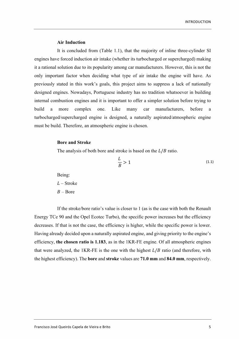
Bore and Stroke
The analysis of both bore and stroke is based on the 𝐿/𝐵 ratio.
𝐿𝐵 > 1 (1.1)
Being:
𝐿 – Stroke
𝐵 – Bore
If the stroke/bore ratio’s value is closer to 1 (as is the case with both the Renault
Energy TCe 90 and the Opel Ecotec Turbo), the specific power increases but the efficiency
decreases. If that is not the case, the efficiency is higher, while the specific power is lower.
Having already decided upon a naturally aspirated engine, and giving priority to the engine’s
efficiency, the chosen ratio is 1.183, as in the 1KR-FE engine. Of all atmospheric engines
that were analyzed, the 1KR-FE is the one with the highest 𝐿/𝐵 ratio (and therefore, with
the highest efficiency). The bore and stroke values are 71.0 mm and 84.0 mm, respectively.
Design of the Valve Actuation Mechanism of a Four-Stroke Spark Ignition Internal CombustionEngine
6 2016
Table1.2.Analyzedenginescharacteristics:valvetrain;valvespercylinder;compressionratio;fuelinjection.
Valve Train
Valves per Cylinder
Compression Ratio
Fuel Injection
Ford EcoBoost DOHC 4 10.0:1 Direct Fuel Injection Opel Ecotec
Turbo DOHC 4 10.5:1
Direct Fuel Injection
Volkswagen TSI DOHC 4 10.5:1 Direct Fuel Injection
Nissan DIG-S DOHC 4 13.0:1 Direct Fuel Injection
PSA (group) PureTech
DOHC 4 10.5:1 Direct Fuel Injection
Renault Energy TCe 90
DOHC 4 9.5:1 Port Fuel Injection
Honda ECA Series 3-cyl.
SOHC 4 10.8:1 Port Fuel Injection
Toyota 1KR-FE DOHC 4 10.5:1 Port Fuel Injection
Smart Fortwo DOHC 4 11.4:1 Port Fuel Injection
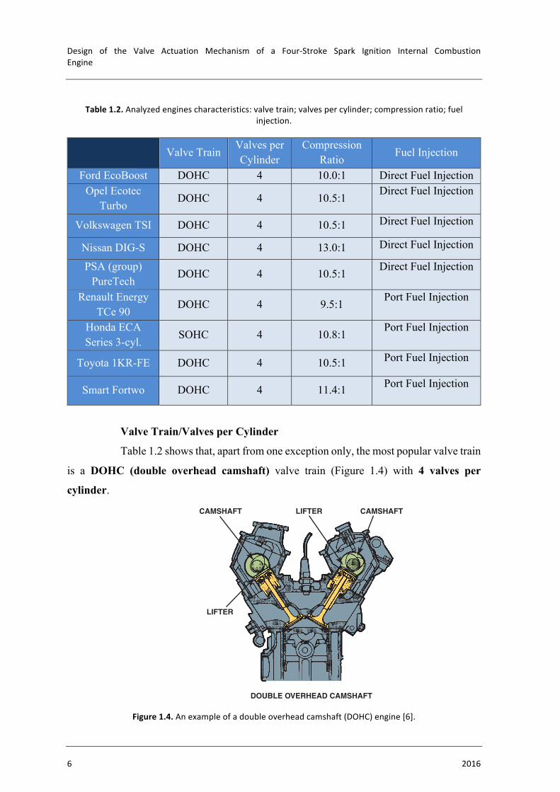
Valve Train/Valves per Cylinder
Table 1.2 shows that, apart from one exception only, the most popular valve train
is a DOHC (double overhead camshaft) valve train (Figure 1.4) with 4 valves per
cylinder.
Figure1.4.Anexampleofadoubleoverheadcamshaft(DOHC)engine[6].
152 CHAPTER 18
ENGINE ROTATION DIRECTION The SAE standard for auto-motive engine rotation is counterclockwise (CCW) as viewed from the flywheel end (clockwise as viewed from the front of the engine). The flywheel end of the engine is the end to which the power is applied to drive the vehicle. This is called the principal end of the engine. The nonprincipal end of the engine is opposite the principal end and is generally referred to as the front of the engine, where the accessory belts are used. ! SEE FIGURE 18–15 .
Therefore, in most rear-wheel-drive vehicles, the engine is mounted longitudinally with the principal end at the rear of the en-gine. Most transversely mounted engines also adhere to the same standard for direction of rotation. Many Honda engines, and some marine applications, may differ from this standard .
CAMSHAFT CAMSHAFTLIFTER
CAMFOLLOWER
CAMFOLLOWER
CAMSHAFT
LIFTER
DOUBLE OVERHEAD CAMSHAFT
SINGLE OVERHEAD CAMSHAFT
FIGURE 18–12 SOHC engines usually require additional com-ponents, such as a rocker arm, to operate all of the valves. DOHC engines often operate the valves directly.
FIGURE 18–13 A DOHC engine uses a camshaft for the intake valves and a separate camshaft for the exhaust valves in each cylinder head.
What Is a Rotary Engine?
A successful alternative engine design is the rotary engine, also called the Wankel engine after its inventor, Felix Heinrich Wankel (1902–1988), a German inventor. The Mazda RX-7 and RX-8 represent the only long-term use of the rotary engine. The rotating combustion cham-ber engine runs very smoothly, and it produces high power for its size and weight.
The basic rotating combustion chamber engine has a triangular-shaped rotor turning in a housing. The housing is in the shape of a geometric figure called a two-lobed epitrochoid. A seal on each corner, or apex, of the rotor is in constant contact with the housing, so the rotor must turn with an eccentric motion. This means that the center of the rotor moves around the center of the engine. The eccentric motion can be seen in ! FIGURE 18–14 .
? FREQUENTLY ASKED QUESTION
Where Does an Engine Stop?
When the ignition system is turned off, the firing of the spark plugs stops and the engine will rotate until it stops due to the inertia of the rotating parts. The greatest resistance that oc-curs in the engine happens during the compression stroke. It has been determined that an engine usually stops when one of the cylinders is about 70 degrees before top dead center (BTDC) on the compression stroke with a variation of plus or minus 10 degrees.
This explains why technicians discover that the starter ring gear is worn at two locations on a 4-cylinder engine. The engine stops at one of the two possible places depend-ing on which cylinder is on the compression stroke.
? FREQUENTLY ASKED QUESTION
ENGINE MEASUREMENT
BORE The diameter of a cylinder is called the bore. The larger the bore, the greater the area on which the gases have to work. Pressure is measured in units, such as pounds per square inch (PSI). The greater the area (in square inches), the higher the force exerted by the pistons to rotate the crankshaft. ! SEE FIGURE 18–16 .
INTRODUCTION
FranciscoJoséQueirósCapeladeVieiraeBrito 7
Compression Ratio
By analyzing the data from Table 1.2, the chosen compression ratio is 11.0:1.
This is an average value of all atmospheric engines that were analyzed.
Fuel Injection
Fuel injection presents a similar problem to air induction. Although the engine
would benefit from having direct fuel injection, it would present the same problem as with
choosing a turbocharger instead of natural aspiration. Being this an initial project, it must
present a simple and inexpensive solution (as possible). Therefore, and since it is also a
common choice for naturally aspirated engines, port fuel injection is chosen.
Summarizing, the engine’s characteristics are:
• Four-Stroke
• Spark Ignition
• Inline three cylinder
• Four valves per cylinder
• Naturally Aspirated
• Port Fuel Injection
• DOHC – Double Overhead Camshaft
• 11.0:1 Compression Ratio
Apart from the compression ratio, the engine’s characteristics are the same as
Toyota’s 1KR-FE engine. Therefore, this engine is used as a base/model whenever
necessary.
Design of the Valve Actuation Mechanism of a Four-Stroke Spark Ignition Internal CombustionEngine
8 2016
ENGINECYCLE
FranciscoJoséQueirósCapeladeVieiraeBrito 9
2. ENGINECYCLE
2.1. OverviewIn any internal combustion engine, there is charge exchange in each engine
cycle. On a 4-stroke SI engine, each cycle has, as the name indicates, four different
strokes/phases (Figure 2.1).
“Engine cycles are identified by the number of piston strokes required to
complete the cycle. A piston stroke is a one-way piston movement either from top to bottom
or bottom to top of the cylinder. During one stroke, the crankshaft rotates 180° (1/2
revolution). A cycle is a complete series of events that continually repeats. Most automobile
engines use a four-stroke cycle.
Intake stroke - The intake valve is open and the piston inside the cylinder travels downward,
drawing a mixture of air and fuel into the cylinder. The crankshaft rotates 180° from top
dead center (TDC) to bottom dead center (BDC) and the camshaft rotates 90° (top left of
Figure 2.1).
Compression stroke - As the engine continues to rotate, the intake valve closes and the
piston moves upward in the cylinder, compressing the air-fuel mixture. The crankshaft
rotates 180° from bottom dead center (BDC) to top dead center (TDC) and the camshaft
rotates 90° (top right of Figure 2.1).
Power stroke - When the piston gets near the top of the cylinder, the spark at the spark plug
ignites the air-fuel mixture, which forces the piston downward. The crankshaft rotates 180°
from top dead center (TDC) to bottom dead center (BDC) and the camshaft rotates 90°
(bottom left of Figure 2.1).
Exhaust stroke - The engine continues to rotate, and the piston again moves upward in the
cylinder. The exhaust valve opens, and the piston forces the residual burned gases out of the
exhaust valve and into the exhaust manifold and exhaust system. The crankshaft rotates 180°
from bottom dead center (BDC) to top dead center (TDC) and the camshaft rotates 90°
(bottom right of Figure 2.1).
Design of the Valve Actuation Mechanism of a Four-Stroke Spark Ignition Internal CombustionEngine
10 2016
150 CHAPTER 18
INTAKEVALVE
INTAKEPORT
AIR−FUELMIXTURE
CRANKSHAFTROTATION
CONNECTINGROD
THE INTAKE STROKE THE COMPRESSION STROKE
BOTHVALVESCLOSED
PISTON RISES,COMPRESSING THEINTAKE CHARGE
THE EXHAUST STROKETHE POWER STROKE
PISTON DESCENDS,DRAWING FUEL AND AIRINTO THE CYLINDER
PISTON RISES,FORCING EXHAUSTGASES FROM THECYLINDER
PISTON FORCED DOWNIN THE CYLINDERBY EXPANDING GASES
SPARK PLUG FIRES
AIR AND FUELIGNITE
EXHAUSTPORT
INTAKEVALVECLOSED
EXHAUSTVALVEOPEN
FIGURE 18–5 The downward movement of the piston draws the air-fuel mixture into the cylinder through the intake valve on the intake stroke. On the compression stroke, the mixture is compressed by the upward movement of the piston with both valves closed. Ignition occurs at the beginning of the power stroke, and combustion drives the piston downward to produce power. On the exhaust stroke, the upward-moving piston forces the burned gases out the open exhaust valve.
are major factors in engine operation. A typical older-model engine uses one intake valve and one exhaust valve per cyl-inder. Many newer engines use two intake and two exhaust valves per cylinder. The valves are opened by a camshaft. Some engines use one camshaft for the intake valves and a separate camshaft for the exhaust valves. When the camshaft is located in the block, the valves are operated by lifters, pushrods, and rocker arms.
This type of engine is called:
! A pushrod engine
! Cam-in-block design
! Overhead valve (OHV), because an overhead valve engine has the valves located in the cylinder head ( " SEE FIGURE 18–11 . )
When one overhead camshaft is used, the design is called a single overhead camshaft (SOHC) design. When two overhead
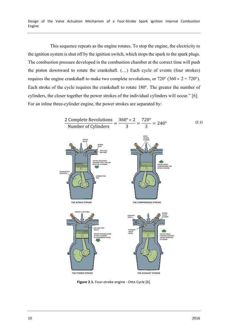
This sequence repeats as the engine rotates. To stop the engine, the electricity to
the ignition system is shut off by the ignition switch, which stops the spark to the spark plugs.
The combustion pressure developed in the combustion chamber at the correct time will push
the piston downward to rotate the crankshaft. (…) Each cycle of events (four strokes)
requires the engine crankshaft to make two complete revolutions, or 720° (360 ´ 2 = 720°).
Each stroke of the cycle requires the crankshaft to rotate 180°. The greater the number of
cylinders, the closer together the power strokes of the individual cylinders will occur.” [6].
For an inline three-cylinder engine, the power strokes are separated by:
2CompleteRevolutionsNumberofCylinders =
360°´23 =
720°3 = 240° (2.1)
Figure2.1.Four-strokeengine-OttoCycle[6].
ENGINECYCLE
FranciscoJoséQueirósCapeladeVieiraeBrito 11
Having already defined the engine’s characteristics (in Chapter 1) as well as the
operating cycle’s main aspects, the next step is to focus on the engine’s operating cycle
simulations. However, to begin them, the software has to undergo several modifications (the
simpler modifications are explained on Annex A). Having been created around the PSA
engine TU3JP-KFW with a 1.4-liter displacement and 2 valves per cylinder, many aspects
that have direct influence on the program have to be modified, in order to create a version of
the software that can accurately simulate the engine cycle of a 3-cylinder power unit with a
1.0-liter displacement.
One of the main aspects that needs to be addressed is the flame’s behavior inside
the combustion chamber. The combustion chamber of each engine is distinctively different.
This aspect has a direct influence in the flame’s behavior inside the chamber. Because the
program relies on the flame’s behavior to work, it is necessary to adapt the software to this
particular situation. Therefore, a new combustion chamber must be designed and the flame
behavior inside it analyzed.
2.2. CombustionChamber
2.2.1. Overview
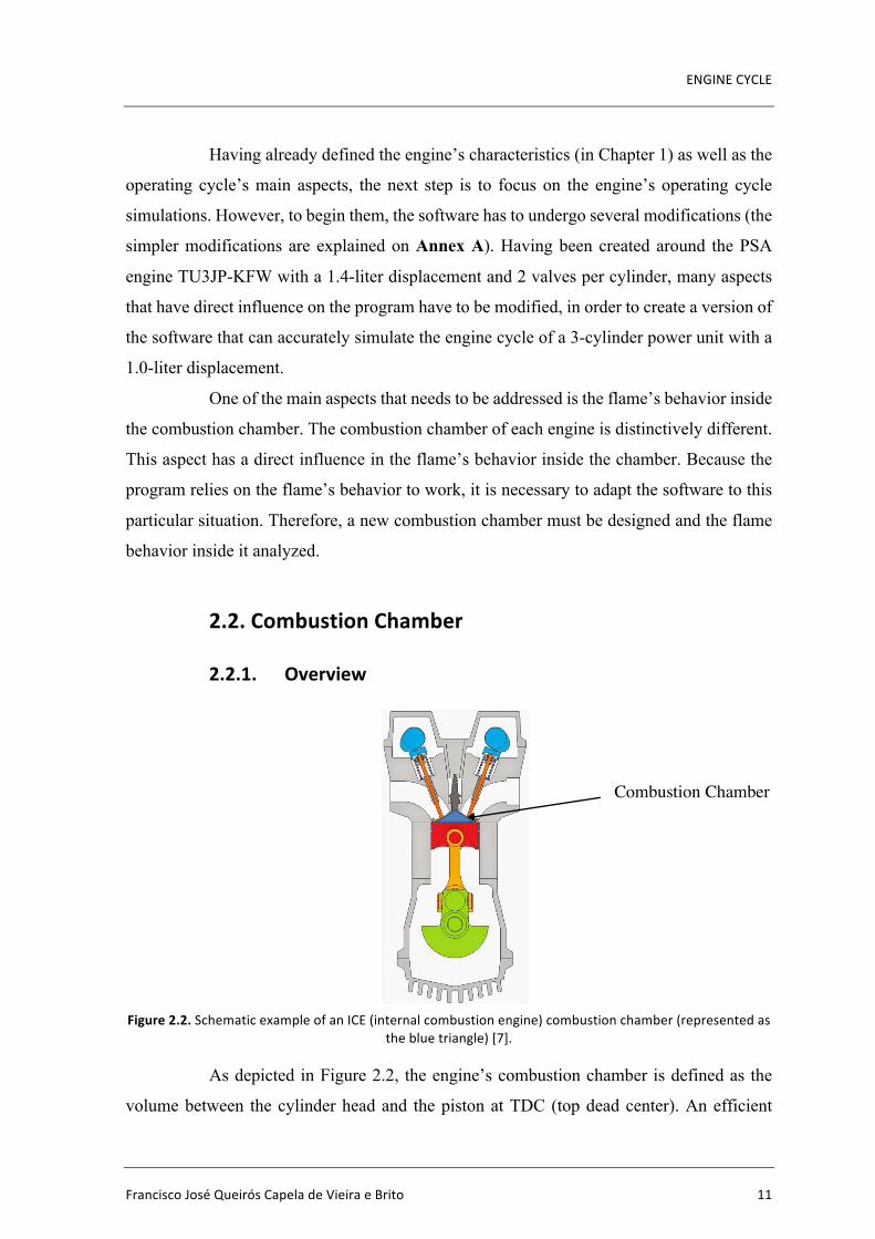
Figure2.2.SchematicexampleofanICE(internalcombustionengine)combustionchamber(representedasthebluetriangle)[7].
As depicted in Figure 2.2, the engine’s combustion chamber is defined as the
volume between the cylinder head and the piston at TDC (top dead center). An efficient
Combustion Chamber
Design of the Valve Actuation Mechanism of a Four-Stroke Spark Ignition Internal CombustionEngine
12 2016
combustion chamber is absolutely central for obtaining the highest possible brake power
(𝑃W) with the lowest possible brake specific fuel consumption (bsfc).
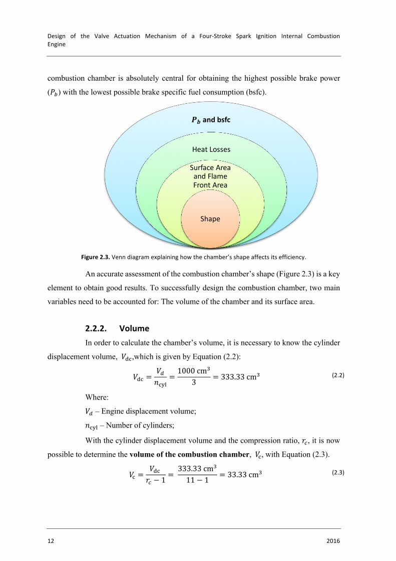
Figure2.3.Venndiagramexplaininghowthechamber’sshapeaffectsitsefficiency.
An accurate assessment of the combustion chamber’s shape (Figure 2.3) is a key
element to obtain good results. To successfully design the combustion chamber, two main
variables need to be accounted for: The volume of the chamber and its surface area.
2.2.2. VolumeIn order to calculate the chamber’s volume, it is necessary to know the cylinder
displacement volume, 𝑉41,which is given by Equation (2.2):
𝑉41 =𝑉B𝑛1SM
=1000cm�
3 = 333.33cm� (2.2)
Where:
𝑉B – Engine displacement volume;
𝑛1SM – Number of cylinders;
With the cylinder displacement volume and the compression ratio, 𝑟X, it is now
possible to determine the volume of the combustion chamber, 𝑉1, with Equation (2.3).
𝑉1 =𝑉41𝑟X − 1
= 333.33cm�
11 − 1 = 33.33cm� (2.3)
𝑷𝒃 and bsfc
HeatLosses
SurfaceAreaandFlameFrontArea
Shape
ENGINECYCLE
FranciscoJoséQueirósCapeladeVieiraeBrito 13
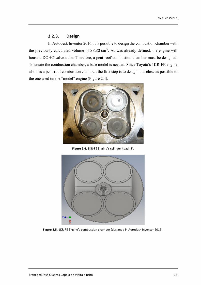
2.2.3. DesignIn Autodesk Inventor 2016, it is possible to design the combustion chamber with
the previously calculated volume of 33.33cm�. As was already defined, the engine will
house a DOHC valve train. Therefore, a pent-roof combustion chamber must be designed.
To create the combustion chamber, a base model is needed. Since Toyota’s 1KR-FE engine
also has a pent-roof combustion chamber, the first step is to design it as close as possible to
the one used on the “model” engine (Figure 2.4).
Figure2.4.1KR-FEEngine’scylinderhead[8].
Figure2.5.1KR-FEEngine’scombustionchamber(designedinAutodeskInventor2016).

Design of the Valve Actuation Mechanism of a Four-Stroke Spark Ignition Internal CombustionEngine
14 2016
Figure2.6.1KR-FEEngine’scombustionchamber(designedinAutodeskInventor2016).
As shown in Figure 2.5, the combustion chamber is designed as a solid volume,
much like a “negative” from a photograph. After the first chamber design is completed
(Figure 2.5 and Figure 2.6), it is possible to begin the optimization process, as there is clearly
room for improvement.
The engine cycle simulation software is used to evaluate the optimization
process and determine which combustion chamber shape is better. The combustion
chamber’s area plays an essential role in the software’s calculation of heat losses. The
program measures the heat losses through two coefficients - 𝐾1? and 𝐾5:
𝐾1? =SurfaceAreaoftheCylinderHead
CylinderCrossSectionArea (2.4)
𝐾5 =SurfaceAreaofthePistonCrownCylinderCrossSectionArea (2.5)
Before and after each optimization, both cylinder head and piston crown surface
areas are measured (the cylinder’s cross-section area is constant since the bore is also
constant). Those measurements are inserted on 𝐾1? and 𝐾5 coefficients which immediately
changes the engine’s 𝑃W and bsfc values. The ultimate purpose of the optimization is to obtain
ENGINECYCLE
FranciscoJoséQueirósCapeladeVieiraeBrito 15
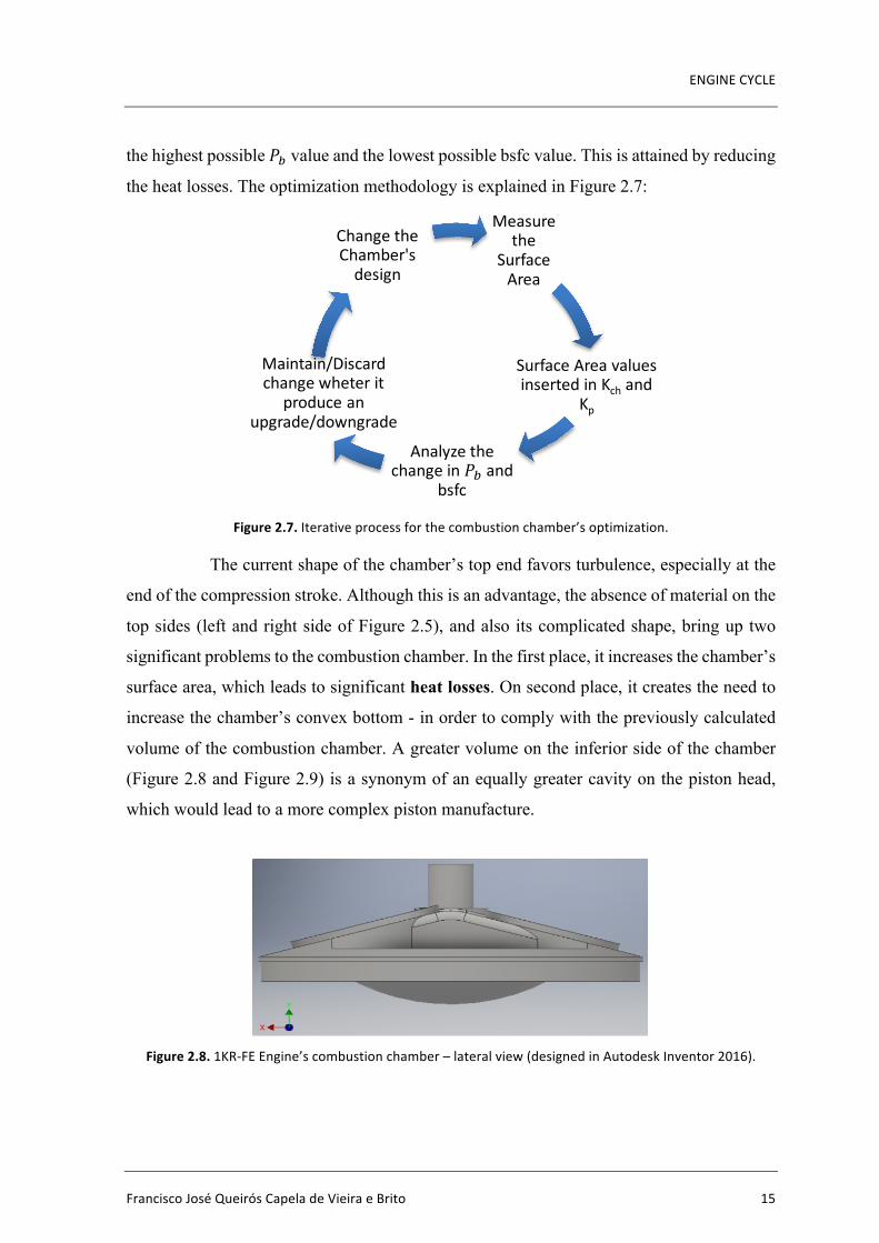
the highest possible 𝑃W value and the lowest possible bsfc value. This is attained by reducing
the heat losses. The optimization methodology is explained in Figure 2.7:
Figure2.7.Iterativeprocessforthecombustionchamber’soptimization.
The current shape of the chamber’s top end favors turbulence, especially at the
end of the compression stroke. Although this is an advantage, the absence of material on the
top sides (left and right side of Figure 2.5), and also its complicated shape, bring up two
significant problems to the combustion chamber. In the first place, it increases the chamber’s
surface area, which leads to significant heat losses. On second place, it creates the need to
increase the chamber’s convex bottom - in order to comply with the previously calculated
volume of the combustion chamber. A greater volume on the inferior side of the chamber
(Figure 2.8 and Figure 2.9) is a synonym of an equally greater cavity on the piston head,
which would lead to a more complex piston manufacture.
Figure2.8.1KR-FEEngine’scombustionchamber–lateralview(designedinAutodeskInventor2016).
Measurethe
SurfaceArea
SurfaceAreavaluesinsertedinKch and
Kp
Analyzethechangein𝑃W and
bsfc
Maintain/Discardchangewheterit
produce anupgrade/downgrade
ChangetheChamber'sdesign
Design of the Valve Actuation Mechanism of a Four-Stroke Spark Ignition Internal CombustionEngine
16 2016
Figure2.9.1KR-FEEngine’scombustionchamber–cutawayview(designedinAutodeskInventor2016).
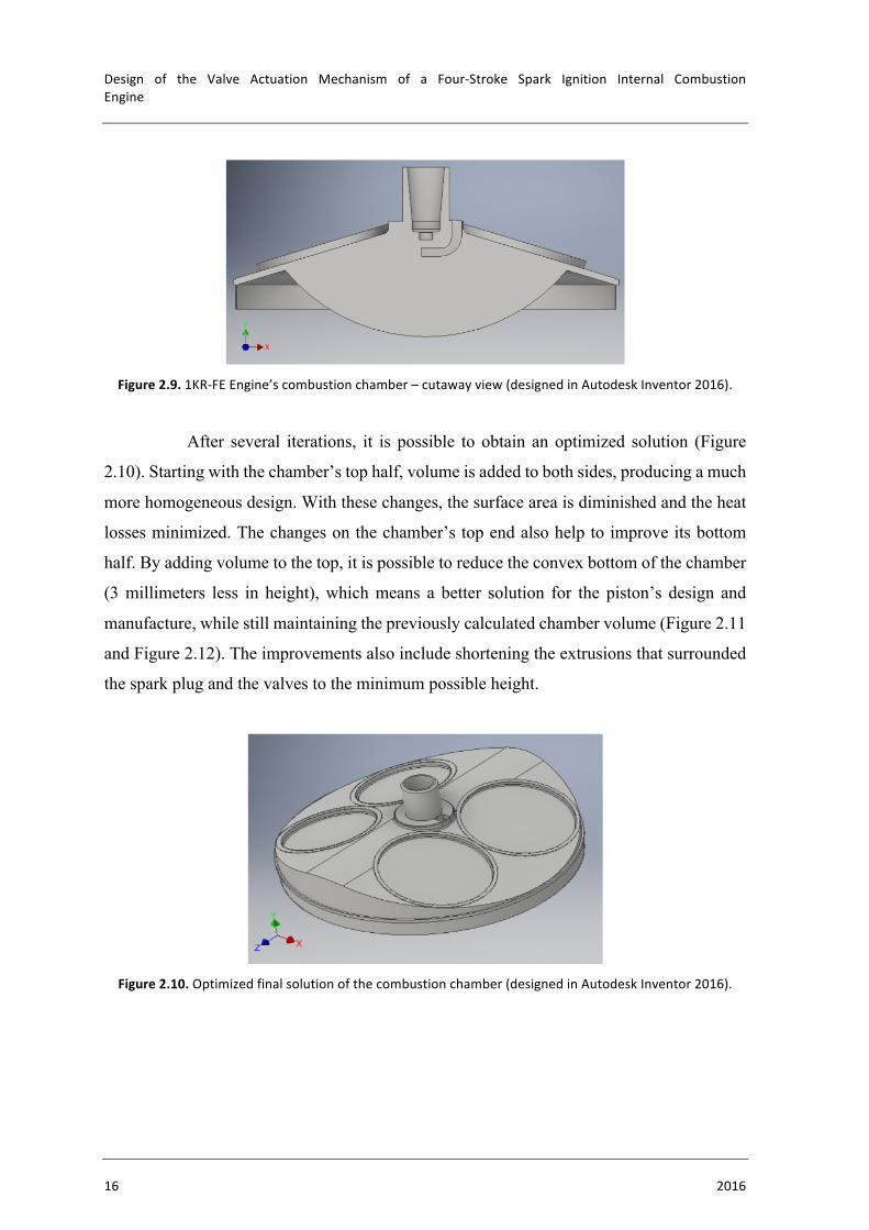
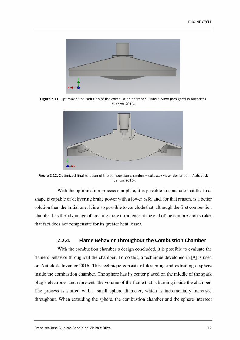
After several iterations, it is possible to obtain an optimized solution (Figure
2.10). Starting with the chamber’s top half, volume is added to both sides, producing a much
more homogeneous design. With these changes, the surface area is diminished and the heat
losses minimized. The changes on the chamber’s top end also help to improve its bottom
half. By adding volume to the top, it is possible to reduce the convex bottom of the chamber
(3 millimeters less in height), which means a better solution for the piston’s design and
manufacture, while still maintaining the previously calculated chamber volume (Figure 2.11
and Figure 2.12). The improvements also include shortening the extrusions that surrounded
the spark plug and the valves to the minimum possible height.
Figure2.10.Optimizedfinalsolutionofthecombustionchamber(designedinAutodeskInventor2016).
ENGINECYCLE
FranciscoJoséQueirósCapeladeVieiraeBrito 17
Figure2.11.Optimizedfinalsolutionofthecombustionchamber–lateralview(designedinAutodesk
Inventor2016).
Figure2.12.Optimizedfinalsolutionofthecombustionchamber–cutawayview(designedinAutodesk
Inventor2016).
With the optimization process complete, it is possible to conclude that the final
shape is capable of delivering brake power with a lower bsfc, and, for that reason, is a better
solution than the initial one. It is also possible to conclude that, although the first combustion
chamber has the advantage of creating more turbulence at the end of the compression stroke,
that fact does not compensate for its greater heat losses.
2.2.4. FlameBehaviorThroughouttheCombustionChamberWith the combustion chamber’s design concluded, it is possible to evaluate the
flame’s behavior throughout the chamber. To do this, a technique developed in [9] is used
on Autodesk Inventor 2016. This technique consists of designing and extruding a sphere
inside the combustion chamber. The sphere has its center placed on the middle of the spark
plug’s electrodes and represents the volume of the flame that is burning inside the chamber.
The process is started with a small sphere diameter, which is incrementally increased
throughout. When extruding the sphere, the combustion chamber and the sphere intersect

Design of the Valve Actuation Mechanism of a Four-Stroke Spark Ignition Internal CombustionEngine
18 2016
each other, forming a surface (Figure 2.13). This surface is the flame front. Following the
same procedure as [9], there are two ways of measuring the flame front’s surface. The first
one is used as long as the flame front’s surface isn’t touching the combustion chamber’s
walls. It consists of only extruding the volume that is contained inside the flame front’s
surface and measuring its outside area (left of Figure 2.13). The second one is used from the
point where the flame front touches the chamber’s wall onwards. In this situation, the
measurement procedure is adapted. The volume contained inside the flame front’s surface is
eliminated and the remaining volume of the chamber is maintained. The blue surface on the
right hand side of Figure 2.13 represents the flame front’s surface area that is measured.
Figure2.13.Intersectionbetweenthesphereandthecombustionchamber.Thisintersectionrepresents
theflamefront’ssurfacearea(designedinAutodeskInventor2016).
𝐴W, which is the flame front’s surface area, is determined by measuring the
intersection’s surface. By incrementally increasing the diameter of the sphere, it is possible
to evaluate the growth of the flame front’s surface area throughout the combustion process.
However, to perform this evaluation, an assumption has to be made. It is assumed that the
combustion chamber has a constant geometry. The considered geometry is the one it has
when the piston is at TDC (Figure 2.14). It is also necessary to suppress the “skirt” around
the combustion chamber to obtain accurate results (Figure 2.15). This “skirt” represents the
clearance volume between the piston and the cylinder above the first compression ring. In
reality, the mass contained by the “skirt” is very small and therefore has no significant
contribution to the heat losses. However, if it was to be considered, it would significantly
increase the surface area and cause the calculated heat losses to be much higher than what
they actually are.

ENGINECYCLE
FranciscoJoséQueirósCapeladeVieiraeBrito 19
Figure2.14.SchematicexampleofacombustionchamberwiththepistonatTDC[10].
Figure2.15.Combustionchamberwith(left)andwithout(right)“skirt”(designedinAutodeskInventor
2016).
With all of the measurements completed, it is possible to perform a polynomial
fit and obtain the results depicted in Figure 2.16. The presented equation on Figure 2.16
expresses the relation between 𝑉K 𝑉1 and 𝑟K 𝐵.
Figure2.16.Flamebehaviorthroughoutthecombustionchamber.
y=-8.4260E+02x6 +1.3893E+03x5 - 8.4401E+02x4 +2.1442E+02x3 -1.3546E+01x2 +9.6784E-02x+8.7391E-03
-0.2
0.0
0.2
0.4
0.6
0.8
1.0
1.2
-0.05
0.00
0.05
0.10
0.15
0.20
0.25
0.30
0.35
-0.1 0 0.1 0.2 0.3 0.4 0.5 0.6
V b/V
c
A b/A
c
rb/B
Flame Behavior throughout the Combustion Chamber
Ab/Ac
Vb/Vc
Poly. (Vb/Vc)
Design of the Valve Actuation Mechanism of a Four-Stroke Spark Ignition Internal CombustionEngine
20 2016
Being:
• 𝐴K 𝐴1 – Flame front surface area/Cylinder cross section area;
• 𝑉K 𝑉1 – Volume burned/Combustion chamber volume;
• 𝑟K 𝐵 – Burned gas radius/Cylinder bore
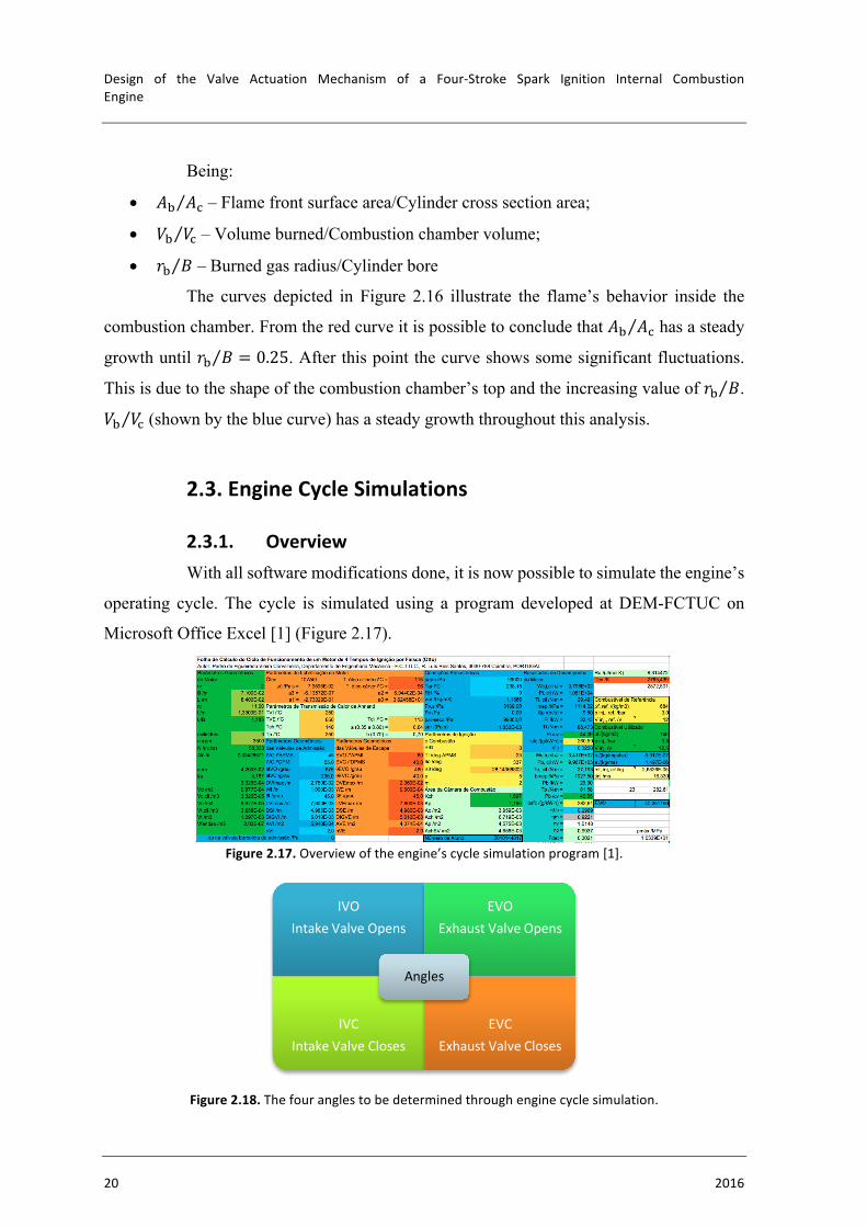
The curves depicted in Figure 2.16 illustrate the flame’s behavior inside the
combustion chamber. From the red curve it is possible to conclude that 𝐴K 𝐴1 has a steady
growth until 𝑟K 𝐵 = 0.25. After this point the curve shows some significant fluctuations.
This is due to the shape of the combustion chamber’s top and the increasing value of 𝑟K 𝐵.
𝑉K 𝑉1 (shown by the blue curve) has a steady growth throughout this analysis.
2.3. EngineCycleSimulations
2.3.1. OverviewWith all software modifications done, it is now possible to simulate the engine’s
operating cycle. The cycle is simulated using a program developed at DEM-FCTUC on
Microsoft Office Excel [1] (Figure 2.17).
Figure2.17.Overviewoftheengine’scyclesimulationprogram[1].
Figure2.18.Thefouranglestobedeterminedthroughenginecyclesimulation.
IVOIntakeValveOpens
EVOExhaustValveOpens
IVCIntakeValveCloses
EVCExhaustValveCloses
Angles
ENGINECYCLE
FranciscoJoséQueirósCapeladeVieiraeBrito 21
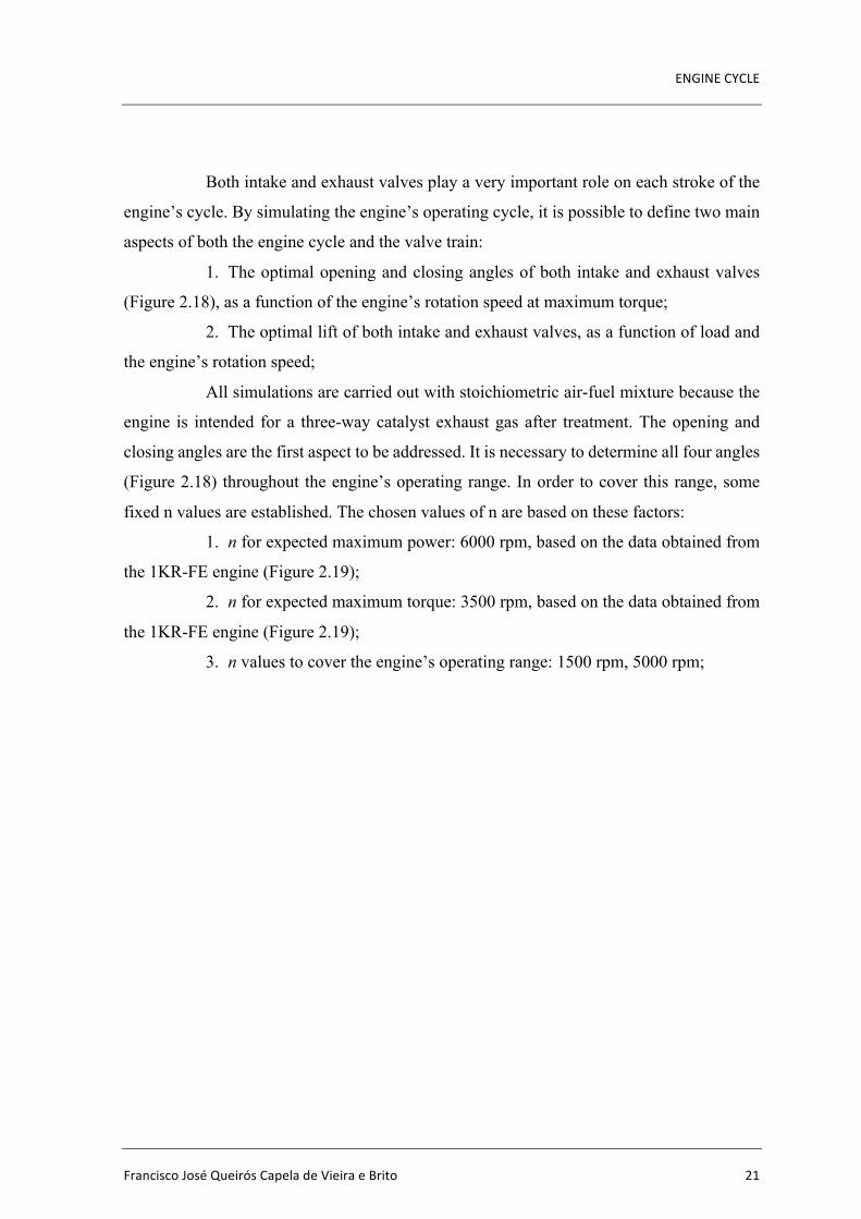
Both intake and exhaust valves play a very important role on each stroke of the
engine’s cycle. By simulating the engine’s operating cycle, it is possible to define two main
aspects of both the engine cycle and the valve train:
1. The optimal opening and closing angles of both intake and exhaust valves
(Figure 2.18), as a function of the engine’s rotation speed at maximum torque;
2. The optimal lift of both intake and exhaust valves, as a function of load and
the engine’s rotation speed;
All simulations are carried out with stoichiometric air-fuel mixture because the
engine is intended for a three-way catalyst exhaust gas after treatment. The opening and
closing angles are the first aspect to be addressed. It is necessary to determine all four angles
(Figure 2.18) throughout the engine’s operating range. In order to cover this range, some
fixed n values are established. The chosen values of n are based on these factors:
1. n for expected maximum power: 6000 rpm, based on the data obtained from
the 1KR-FE engine (Figure 2.19);
2. n for expected maximum torque: 3500 rpm, based on the data obtained from
the 1KR-FE engine (Figure 2.19);
3. n values to cover the engine’s operating range: 1500 rpm, 5000 rpm;
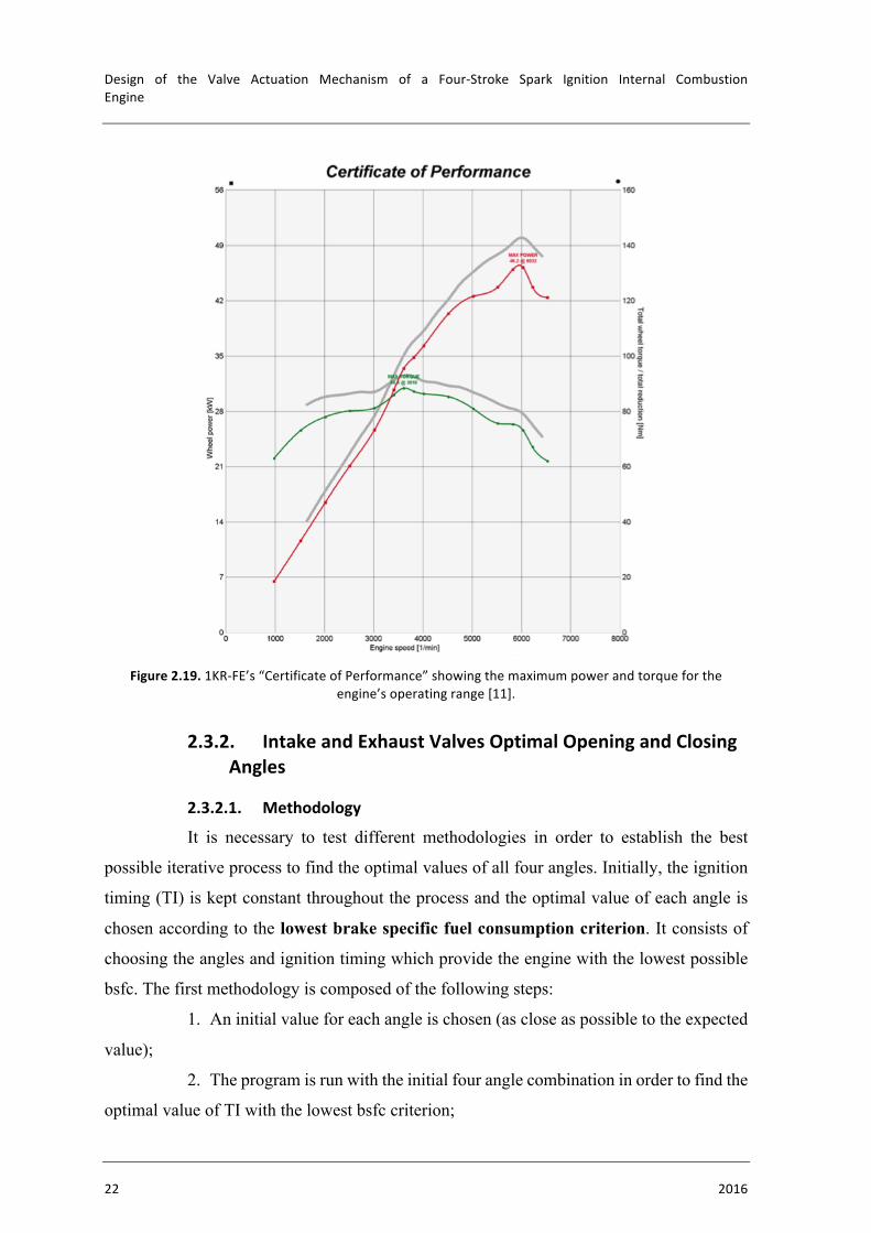
Design of the Valve Actuation Mechanism of a Four-Stroke Spark Ignition Internal CombustionEngine
22 2016
Figure2.19.1KR-FE’s“CertificateofPerformance”showingthemaximumpowerandtorqueforthe
engine’soperatingrange[11].
2.3.2. IntakeandExhaustValvesOptimalOpeningandClosingAngles
2.3.2.1. Methodology
It is necessary to test different methodologies in order to establish the best
possible iterative process to find the optimal values of all four angles. Initially, the ignition
timing (TI) is kept constant throughout the process and the optimal value of each angle is
chosen according to the lowest brake specific fuel consumption criterion. It consists of
choosing the angles and ignition timing which provide the engine with the lowest possible
bsfc. The first methodology is composed of the following steps:
1. An initial value for each angle is chosen (as close as possible to the expected
value);
2. The program is run with the initial four angle combination in order to find the
optimal value of TI with the lowest bsfc criterion;

ENGINECYCLE
FranciscoJoséQueirósCapeladeVieiraeBrito 23
3. Once the optimal value of TI is established, the program is run with different
values of the IVO angle (positive and negative increments of five degrees). The optimal IVO
angle is established while the other three angles remain constant;
4. After obtaining the optimal angle for the IVO, the same process is applied for
the IVC angle, however, now the program is run with the new IVO angle on the four angle
combination;
5. The process is repeated for the EVO and EVC angles;
This methodology has three important flaws. The first one is that it establishes
the optimal value of TI at the start and keeps it constant throughout the process. Due to this
procedure, the optimal value of TI is only correctly applied for the first combination of
angles. As soon as the IVO angle changes, the ignition timing is already outdated. It is
therefore necessary to update the TI value throughout the process. The second flaw is that
this methodology only relies on one criterion to determine the optimal angles – the lowest
brake specific fuel consumption. It is also necessary to analyze whether other criterion could
produce a better result. The highest brake power criterion must be tested. It consists of
selecting the angles and timing ignition which provide the engine with the highest possible
brake power. The last important flaw of this process is that it depends heavily on the initial
four angle combination. Therefore, it is mandatory to perform a second round of iteration to
minimize the angle combination’s influence.
By correcting the previous flaws, the desired methodology is achieved:
1. An initial value for each angle is chosen (as close as possible to the expected
value);
2. The program is run with the initial four angle combination in order to find the
(initially) optimal angle of TI with the lowest bsfc criterion;
3. Once the optimal angle of TI is established, the program is run with different
variations of the IVO angle (positive and negative increments of five degrees). For each
variation of the IVO angle, the optimal value of TI is determined. The optimal angles of IVO
and TI are established while the other three angles remain constant;
4. After obtaining the optimal IVO and TI angles, the same process is applied
for the IVC angle, however, now the program is run with the new value of IVO on the four
angle combination;
5. The process is repeated for the EVO and EVC angles;

Design of the Valve Actuation Mechanism of a Four-Stroke Spark Ignition Internal CombustionEngine
24 2016
6. The process is repeated for the highest brake power criterion;
7. A second iteration of the process with each criteria is performed;
All engine cycle simulations that are carried out to determine the optimal
opening and closing angles of both intake and exhaust valves are performed at wide open
throttle (WOT) and have a constant valve lift of 0.0076 m on both intake and exhaust valves.
This value is taken from the “model” engine.
2.3.2.2.
Highest Brake Power Criterion Table2.1.Highestbrakepowercriterionresults.
n [rpm] Pb
[kW] bsfc
[g/kW×h] IVO [°]
IVC [°]
EVO [°]
EVC [°]
1500 13.60 266.88 20 15 40 15 3500 33.35 259.49 30 30 60 25 5000 45.86 265.74 30 45 70 30 6000 52.32 272.76 35 55 75 35
Figure2.20.Evolutionofenginebrakepowerandbrakespecificfuelconsumptionthroughouttheengine’s
operatingrangeforavalveliftof0.0076monbothintakeandexhaustvalvesatWOT.
0
10
20
30
40
50
60
258
260
262
264
266
268
270
272
274
0 1000 2000 3000 4000 5000 6000 7000
P b[kW]
bsfc[g/kW·h]
n [rpm]
BrakePower(Pb)andBrakeSpecificFuelConsumption(bsfc)asfunctionofEngineSpeed(n)
bsfc
Pb

ENGINECYCLE
FranciscoJoséQueirósCapeladeVieiraeBrito 25
Figure2.21.Intakeandexhaustvalvesopeningandclosinganglesthroughouttheengine’soperatingrange
foravalveliftof0.0076monbothintakeandexhaustvalvesatWOT.
Lowest bsfc criterion Table2.2.Lowestbsfccriterionresults.
n [rpm] Pb
[kW] bsfc
[g/kW´h] IVO [°]
IVC [°]
EVO [°]
EVC [°]
1500 - - - - - - 3500 33.13 259.46 40 35 60 30 5000 45.46 265.42 45 45 75 35 6000 52.02 272.36 45 55 80 40
Figure2.22.Evolutionofenginebrakepowerandbrakespecificfuelconsumptionthroughouttheengine’s
operatingrangeforavalveliftof0.0076monbothintakeandexhaustvalvesatWOT.
0
10
20
30
40
50
60
70
80
0 1000 2000 3000 4000 5000 6000 7000
IVO,IVC
,EVO
,EVC
[°]
n [rpm]
IntakeValveOpens(IVO),IntakeValveCloses(IVC),ExhaustValveCloses(EVO),ExhaustValveCloses(EVC)asfunctionofEngine
Speed(n)
IVO(°BTDC)
IVC(°ABDC)
EVO(°BBDC)
EVC(°ATDC)
0
10
20
30
40
50
60
258
260
262
264
266
268
270
272
274
0 1000 2000 3000 4000 5000 6000 7000
Pb[kW]
bsfc[g/kW·h]
n [rpm]
BrakePower(Pb)andBrakeSpecificFuelConsumption(bsfc)asfunctionofEngineSpeed(n)
bsfcPb
Design of the Valve Actuation Mechanism of a Four-Stroke Spark Ignition Internal CombustionEngine
26 2016
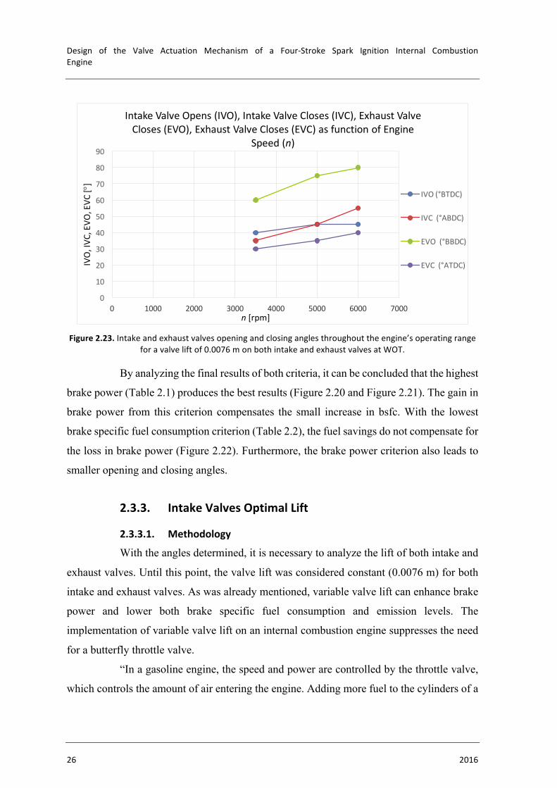
Figure2.23.Intakeandexhaustvalvesopeningandclosinganglesthroughouttheengine’soperatingrange
foravalveliftof0.0076monbothintakeandexhaustvalvesatWOT.
By analyzing the final results of both criteria, it can be concluded that the highest
brake power (Table 2.1) produces the best results (Figure 2.20 and Figure 2.21). The gain in
brake power from this criterion compensates the small increase in bsfc. With the lowest
brake specific fuel consumption criterion (Table 2.2), the fuel savings do not compensate for
the loss in brake power (Figure 2.22). Furthermore, the brake power criterion also leads to
smaller opening and closing angles.
2.3.3. IntakeValvesOptimalLift
2.3.3.1. Methodology
With the angles determined, it is necessary to analyze the lift of both intake and
exhaust valves. Until this point, the valve lift was considered constant (0.0076 m) for both
intake and exhaust valves. As was already mentioned, variable valve lift can enhance brake
power and lower both brake specific fuel consumption and emission levels. The
implementation of variable valve lift on an internal combustion engine suppresses the need
for a butterfly throttle valve.
“In a gasoline engine, the speed and power are controlled by the throttle valve,
which controls the amount of air entering the engine. Adding more fuel to the cylinders of a
0
10
20
30
40
50
60
70
80
90
0 1000 2000 3000 4000 5000 6000 7000
IVO,IVC
,EVO
,EVC
[°]
n [rpm]
IntakeValveOpens(IVO),IntakeValveCloses(IVC),ExhaustValveCloses(EVO),ExhaustValveCloses(EVC)asfunctionofEngine
Speed(n)
IVO(°BTDC)
IVC(°ABDC)
EVO(°BBDC)
EVC(°ATDC)
ENGINECYCLE
FranciscoJoséQueirósCapeladeVieiraeBrito 27
gasoline engine without adding more air (oxygen) will not increase the speed or power of
the engine.” [6].
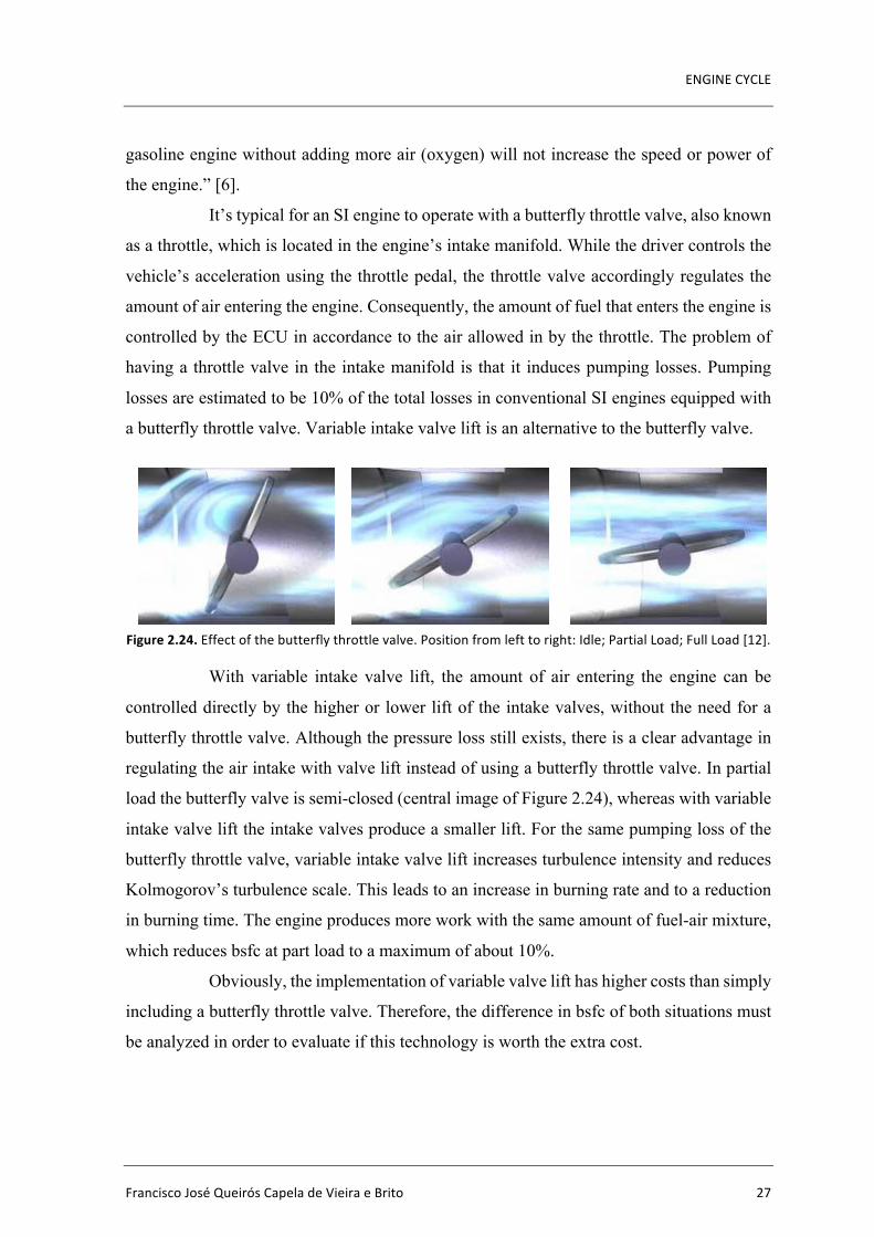
It’s typical for an SI engine to operate with a butterfly throttle valve, also known
as a throttle, which is located in the engine’s intake manifold. While the driver controls the
vehicle’s acceleration using the throttle pedal, the throttle valve accordingly regulates the
amount of air entering the engine. Consequently, the amount of fuel that enters the engine is
controlled by the ECU in accordance to the air allowed in by the throttle. The problem of
having a throttle valve in the intake manifold is that it induces pumping losses. Pumping
losses are estimated to be 10% of the total losses in conventional SI engines equipped with
a butterfly throttle valve. Variable intake valve lift is an alternative to the butterfly valve.
Figure2.24.Effectofthebutterflythrottlevalve.Positionfromlefttoright:Idle;PartialLoad;FullLoad[12].
With variable intake valve lift, the amount of air entering the engine can be
controlled directly by the higher or lower lift of the intake valves, without the need for a
butterfly throttle valve. Although the pressure loss still exists, there is a clear advantage in
regulating the air intake with valve lift instead of using a butterfly throttle valve. In partial
load the butterfly valve is semi-closed (central image of Figure 2.24), whereas with variable
intake valve lift the intake valves produce a smaller lift. For the same pumping loss of the
butterfly throttle valve, variable intake valve lift increases turbulence intensity and reduces
Kolmogorov’s turbulence scale. This leads to an increase in burning rate and to a reduction
in burning time. The engine produces more work with the same amount of fuel-air mixture,
which reduces bsfc at part load to a maximum of about 10%.
Obviously, the implementation of variable valve lift has higher costs than simply
including a butterfly throttle valve. Therefore, the difference in bsfc of both situations must
be analyzed in order to evaluate if this technology is worth the extra cost.
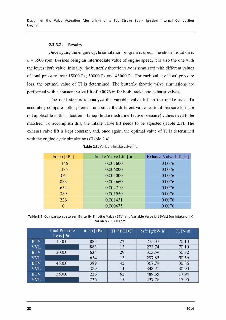
Design of the Valve Actuation Mechanism of a Four-Stroke Spark Ignition Internal CombustionEngine
28 2016
2.3.3.2. Results
Once again, the engine cycle simulation program is used. The chosen rotation is
n = 3500 rpm. Besides being an intermediate value of engine speed, it is also the one with
the lowest bsfc value. Initially, the butterfly throttle valve is simulated with different values
of total pressure loss: 15000 Pa, 30000 Pa and 45000 Pa. For each value of total pressure
loss, the optimal value of TI is determined. The butterfly throttle valve simulations are
performed with a constant valve lift of 0.0076 m for both intake and exhaust valves.
The next step is to analyze the variable valve lift on the intake side. To
accurately compare both systems – and since the different values of total pressure loss are
not applicable in this situation – bmep (brake medium effective pressure) values need to be
matched. To accomplish this, the intake valve lift needs to be adjusted (Table 2.3). The
exhaust valve lift is kept constant, and, once again, the optimal value of TI is determined
with the engine cycle simulations (Table 2.4). Table2.3.Variableintakevalvelift.
bmep [kPa] Intake Valve Lift [m] Exhaust Valve Lift [m] 1146 0.007600 0.0076 1135 0.006800 0.0076 1061 0.005000 0.0076 883 0.003660 0.0076 634 0.002710 0.0076 389 0.001950 0.0076 226 0.001431 0.0076 0 0.000675 0.0076
Table2.4.ComparisonbetweenButterflyThrottleValve(BTV)andVariableValveLift(VVL)(onintakeonly)
forann=3500rpm.
Total Pressure Loss [Pa]
bmep [kPa] TI [°BTDC] bsfc [g/kW×h] Tb [N×m]
BTV 15000 883 22 275.37 70.13 VVL 883 13 273.74 70.10 BTV 30000 634 29 303.59 50.32 VVL 634 13 297.85 50.36 BTV 45000 389 42 367.79 30.86 VVL 389 14 348.21 30.90 BTV 55000 226 62 489.35 17.94 VVL 226 15 437.76 17.95
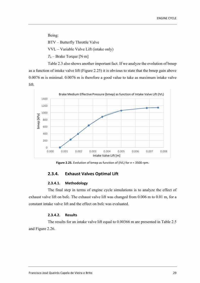
ENGINECYCLE
FranciscoJoséQueirósCapeladeVieiraeBrito 29
Being:
BTV – Butterfly Throttle Valve
VVL – Variable Valve Lift (intake only)
Tb – Brake Torque [N×m]
Table 2.3 also shows another important fact. If we analyze the evolution of bmep
as a function of intake valve lift (Figure 2.25) it is obvious to state that the bmep gain above
0.0076 m is minimal. 0.0076 m is therefore a good value to take as maximum intake valve
lift.
Figure2.25.Evolutionofbmepasfunctionof(IVL)forn=3500rpm.
2.3.4. ExhaustValvesOptimalLift
2.3.4.1. Methodology
The final step in terms of engine cycle simulations is to analyze the effect of
exhaust valve lift on bsfc. The exhaust valve lift was changed from 0.006 m to 0.01 m, for a
constant intake valve lift and the effect on bsfc was evaluated.
2.3.4.2. Results
The results for an intake valve lift equal to 0.00366 m are presented in Table 2.5
and Figure 2.26.
0
200
400
600
800
1000
1200
1400
0.000 0.001 0.002 0.003 0.004 0.005 0.006 0.007 0.008
bmep
[kPa]
IntakeValveLift[m]
BrakeMediumEffectivePressure(bmep)asfunctionofIntakeValveLift(IVL)
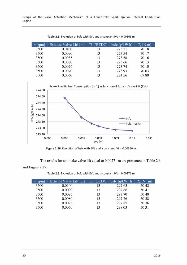
Design of the Valve Actuation Mechanism of a Four-Stroke Spark Ignition Internal CombustionEngine
30 2016
Table2.5.EvolutionofbsfcwithEVLandaconstantIVL=0.00366m.
n [rpm] Exhaust Valve Lift [m] TI [°BTDC] bsfc [g/kW×h] Tb [N×m] 3500 0.0100 13 273.51 70.18 3500 0.0090 13 273.54 70.17 3500 0.0085 13 273.58 70.16 3500 0.0080 13 273.66 70.13 3500 0.0076 13 273.74 70.10 3500 0.0070 13 273.93 70.03 3500 0.0060 13 274.56 69.80
Figure2.26.EvolutionofbsfcwithEVLandaconstantIVL=0.00366m.
The results for an intake valve lift equal to 0.00271 m are presented in Table 2.6
and Figure 2.27. Table2.6.EvolutionofbsfcwithEVLandaconstantIVL=0.00271m.
n [rpm] Exhaust Valve Lift [m] TI [°BTDC] bsfc [g/kW· h] Tb [N· m] 3500 0.0100 13 297.63 50.42 3500 0.0090 13 297.66 50.41 3500 0.0085 13 297.70 50.40 3500 0.0080 13 297.76 50.38 3500 0.0076 13 297.85 50.36 3500 0.0070 13 298.03 50.31
273.40
273.60
273.80
274.00
274.20
274.40
274.60
274.80
0.005 0.006 0.007 0.008 0.009 0.01 0.011
bsfc[g/kW·h]
EVL[m]
BrakeSpecificFuelConsumption(bsfc)asfunctionofExhaustValveLift(EVL)
bsfc
Poly.(bsfc)

ENGINECYCLE
FranciscoJoséQueirósCapeladeVieiraeBrito 31
Figure2.27.EvolutionofbsfcwithEVLandaconstantIVL=0.00271m.
The results for an intake valve lift equal to 0.00195 m are presented in Table 2.7
and Figure 2.28. Table2.7.EvolutionofbsfcwithEVLandaconstantIVL=0.00195m.
n [rpm] Exhaust Valve Lift [m] TI [°BTDC] bsfc [g/kW· h] Tb [N· m] 3500 0.0100 14 347.78 30.96 3500 0.0090 14 347.87 30.95 3500 0.0085 14 347.95 30.94 3500 0.0080 14 348.07 30.92 3500 0.0076 14 348.21 30.90
Figure2.28.EvolutionofbsfcwithEVLandaconstantIVL=0.00195m.
The results for an intake valve lift equal to 0.00143 m are presented in Table 2.8
and Figure 2.29.
297.40
297.60
297.80
298.00
298.20
298.40
298.60
298.80
0.005 0.006 0.007 0.008 0.009 0.01 0.011
bsfc[g/kW·h]
EVL[m]
BrakeSpecificFuelConsumption(bsfc)asfunctionofExhaustValveLift(EVL)
bsfcPoly.(bsfc)
347.50
348.00
348.50
349.00
349.50
350.00
0.006 0.007 0.008 0.009 0.01 0.011
bsfc[g/kW·h]
EVL[m]
BrakeSpecificFuelConsumption(bsfc)asfunctionofExhaustValveLift(EVL)
bsfcPoly.(bsfc)
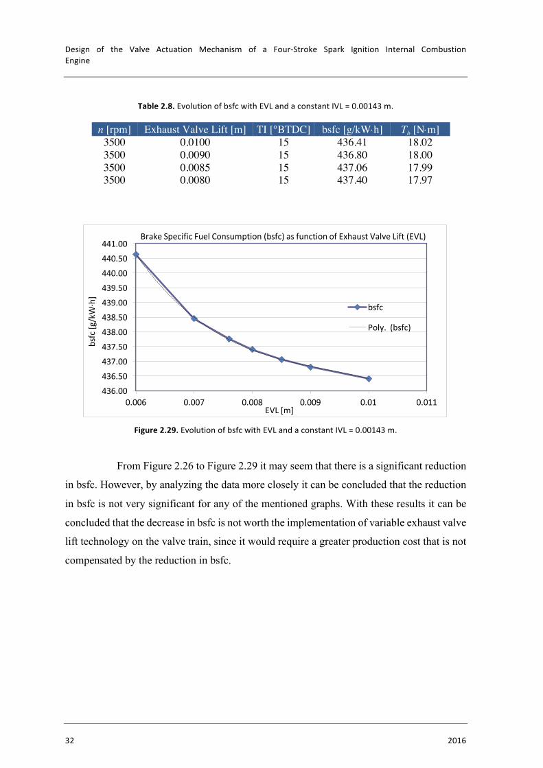
Design of the Valve Actuation Mechanism of a Four-Stroke Spark Ignition Internal CombustionEngine
32 2016
Table2.8.EvolutionofbsfcwithEVLandaconstantIVL=0.00143m.
n [rpm] Exhaust Valve Lift [m] TI [°BTDC] bsfc [g/kW×h] Tb [N×m] 3500 0.0100 15 436.41 18.02 3500 0.0090 15 436.80 18.00 3500 0.0085 15 437.06 17.99 3500 0.0080 15 437.40 17.97
Figure2.29.EvolutionofbsfcwithEVLandaconstantIVL=0.00143m.
From Figure 2.26 to Figure 2.29 it may seem that there is a significant reduction
in bsfc. However, by analyzing the data more closely it can be concluded that the reduction
in bsfc is not very significant for any of the mentioned graphs. With these results it can be
concluded that the decrease in bsfc is not worth the implementation of variable exhaust valve
lift technology on the valve train, since it would require a greater production cost that is not
compensated by the reduction in bsfc.
436.00436.50437.00437.50438.00438.50439.00439.50440.00440.50441.00
0.006 0.007 0.008 0.009 0.01 0.011
bsfc[g/kW·h]
EVL[m]
BrakeSpecificFuelConsumption(bsfc)asfunctionofExhaustValveLift(EVL)
bsfc
Poly.(bsfc)

VALVETRAINDESIGN
FranciscoJoséQueirósCapeladeVieiraeBrito 33
320 CHAPTER 32
The amount of lift of a camshaft is often different for the intake and exhaust valves.
! If the specifications vary, the camshaft is called asymmetrical.
! If the lift is the same, the cam is called symmetrical.
However, when the amount of lift increases, so do the forces on the camshaft and the rest of the valve train. Generally, a camshaft with a lift of over 0.5 in. (1.3 cm) is unsuitable for street operation except for use in engines that are over 400 in. 3 (6 liters).
The lift specifications at the valve face assume the use of the stock rocker arm ratio. If nonstock rocker arms with a higher ratio are installed (for example, 1.6:1 rockers replacing the stock 1.5:1 rocker arms), the lift at the valve is increased. Also, because the rocker arm rotation covers a greater distance at the pivot of the rocker arm, the rocker arm can hit the edge of the valve retainer.
LASHRAMP
CLOSINGRAMP
OPENINGRAMP
NOSE
HEEL FIGURE 32–20 The ramps on the cam lobe allow the valves to be opened and closed quickly yet under control to avoid damaging valve train components, especially at high engine speeds.
Best to Warn the Customer
A technician replaced a timing chain and gears on a high mileage Chevrolet V-8. The repair was accomplished correctly, yet after starting, the engine burned an excessive amount of oil. Before the timing chain replacement, oil consumption was minimal. The replacement timing chain restored proper operation of the engine by restoring the proper cam and valve timing which increased engine vacuum. Increased vacuum can draw oil from the crankcase past worn piston rings and through worn valve guides during the intake stroke. Similar increased oil consumption problems occur if a valve job is performed on a high-mileage engine with worn piston rings and/or cylinders.
To satisfy the owner of the vehicle, the technicians had to disassemble and refinish the cylinders and replace the piston rings. Therefore, all technicians should warn customers that increased oil usage might result from almost any engine repair to a high-mileage engine.
TECH TIP
ROCKER ARMS
PURPOSE AND FUNCTION A rocker arm reverses the upward movement of the pushrod to produce a downward movement on the tip of the valve. Engine designers make good use of the rocker arm. It is designed to reduce the travel of the cam follower or lifter and pushrod while maintaining the required valve lift. This is done by using a rocker arm ratio usually of 1.5:1.
For a given amount of lift on the pushrod, the valve will open to 1.5 times the cam lobe lift. This ratio allows the camshaft to be smaller, so the engine can be smaller. " SEE FIGURE 32–21 .
CAUTION: Using rocker arms with a higher ratio than stock can also cause the valve spring to compress too much and ac-tually bind. Valve spring bind (coil bind) occurs when the valve spring is compressed to the point where there is no clearance in the spring. (It is completely compressed.) When coil bind oc-curs in a running engine, bent pushrods, broken rocker arms, or other valve train damage can result. " SEE FIGURE 32–22 .
AB
FIGURE 32–21 A 1.5:1 ratio rocker arm means that dimension A is 1.5 times the length of dimension B. Therefore, if the pushrod is moved up 0.4 in. by the camshaft lobe, the valve will be pushed down (opened) 0.4 in. ! 1.5, or 0.6 in.
FIGURE 32–22 A high-performance aluminum roller rocker arm. Both the pivot and the tip that contacts the stem of the valve are equipped with rollers to help reduce friction for more power and better fuel economy.
3. VALVETRAINDESIGN
3.1. OverviewThe fresh mixture of air and fuel is conducted to the cylinder (port fuel injection)
at the beginning of a new cycle, and the products of combustion are removed at the cycle’s
end. To do so, engines need to be equipped with devices that are capable of opening and
closing the intake and exhaust ports of the cylinder head. The devices that carry out this task
are the intake and exhaust valves. Both types of valves are controlled by the camshaft(s).
“The major function of a camshaft is to open the valves. Camshafts have
eccentric shapes called lobes (Figure 3.1) that open the valve against the force of the valve
springs. The valve spring closes the valve when the camshaft rotates off of the lobe. The
camshaft lobe changes rotary motion (camshaft) to linear motion (valves). Cam shape or
contour is the major factor in determining the operating characteristics of the engine. (…)
Cam lobe shape has more control over engine performance characteristics than any other
single engine part” [13].
Figure3.1.Camlobe[6].
During regular driving, an internal combustion engine is subject to innumerous
different situations. It is therefore mandatory for a power unit to have a strong adaptability
without losing its reliability. For an engine to be as flexible as possible, it needs to be
equipped with variable valve train systems, in order to control both valve timing and valve
lift.
CAMSHAFTS AND VALVE TRAINS 319
INTERFERENCEENGINE DESIGN
FREEWHEELINGENGINE DESIGN
NO VALVE/PISTONINTERFERENCE
VALVE/PISTONCOLLISION
FIGURE 32–16 Many engines are of the interference design. If the timing belt (or chain) breaks, the piston still moves up and down in the cylinder while the valves remain stationary. With a freewheeling design, nothing is damaged, but in an interference engine, the valves are often bent.
BENT VALVES
FIGURE 32–17 A head from a Mercedes showing bent valves when the timing chain stretched and skipped over the crankshaft sprocket. When this happened, the piston kept moving and bent the valves.
CAMSHAFT MOVEMENT
REASONS CAMSHAFTS MOVE On engines equipped with flat bottom lifters, as the camshaft lobe pushes the lifter upward against the valve spring force, a backward twisting force is devel-oped on the camshaft. After the lobe goes past its high point, the lifter moves down the backside of the lobe. This makes a forward twisting force. This action produces an alternating torsion force for-ward, then backward, at each cam lobe. The number of cam lobes on the shaft multiplies this alternating torsion force.
Cam chucking is the movement of the camshaft lengthwise in the engine during operation. Each camshaft must have some means to control the shaft end thrust. One method is to use a thrust plate between the camshaft drive gear or sprocket and a flange on the camshaft.
A thrust plate is attached to the engine block with cap screws. In a few camshafts, a button, spring, or retainer that contacts the timing cover limits forward motion of the camshaft.
WHY FLAT-BOTTOM LIFTERS ROTATE Valve trains that use flat bottom lifters use a spherical (curved) lifter face that slides against the cam lobe. This produces a surface on the lifter face that is slightly convex, by about 0.002 in. The lifter also contacts the lobe at a point that is slightly off center. This produces a small turn-ing force on the lifter to cause some lifter rotation for even wear. In operation, there is a wide line of contact between the lifter and the high point of the cam lobe. ! SEE FIGURE 32–18 .
These are the highest loads that are produced in an engine. This surface is the most critical lubrication point in an engine.
CAMSHAFT LOBE LIFT The lobe lift of the cam is usually expressed in decimal inches and represents the distance that the valve lifter or follower is moved. The amount that the valve is lifted is determined by the lobe lift times the ratio of the rocker arm. ! SEE FIGURES 32–19 AND 32–20 .
The higher the lift of the camshaft lobe, the greater the amount of air and fuel that can enter the engine. The more air and fuel burned in an engine, the greater the power potential of the engine.
CLEARANCE
NOTE THAT THE LIFTER BORESARE OFFSET TO ALLOW ROTATION.
c
NOTE: THE TAPERIS USUALLY BETWEEN0.0007" TO 0.002".
ABOUT 0.002"
RIGHT
FIGURE 32–18 The slight angle and the curve on the bottom of a flat bottom lifter cause the lifter and the pushrod to rotate during normal operation.
LOBE LIFT
FIGURE 32–19 The lobe lift is the amount the cam lobe lifts the lifter. The blue circle is called the base circle. Because the rocker arm adds to this amount, the entire valve train has to be con-sidered when selecting a camshaft that has the desired lift and duration.
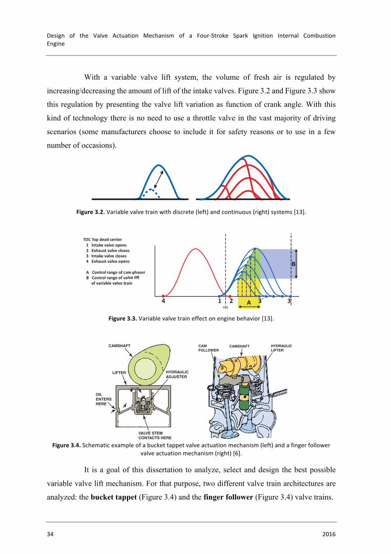
Design of the Valve Actuation Mechanism of a Four-Stroke Spark Ignition Internal CombustionEngine
34 2016
With a variable valve lift system, the volume of fresh air is regulated by
increasing/decreasing the amount of lift of the intake valves. Figure 3.2 and Figure 3.3 show
this regulation by presenting the valve lift variation as function of crank angle. With this
kind of technology there is no need to use a throttle valve in the vast majority of driving
scenarios (some manufacturers choose to include it for safety reasons or to use in a few
number of occasions).
Figure3.2.Variablevalvetrainwithdiscrete(left)andcontinuous(right)systems[13].
Figure3.3.Variablevalvetraineffectonenginebehavior[13].
Figure3.4.Schematicexampleofabuckettappetvalveactuationmechanism(left)andafingerfollower
valveactuationmechanism(right)[6].
It is a goal of this dissertation to analyze, select and design the best possible
variable valve lift mechanism. For that purpose, two different valve train architectures are
analyzed: the bucket tappet (Figure 3.4) and the finger follower (Figure 3.4) valve trains.
Schaeffl er SYMPOSIUM 2010
18 UniAir
252 Schaeffl er SYMPOSIUM 2010 253
18UniAir
18
Despite the increasing trend towards the hybrid-ization and electrification of automotive power-trains the internal combustion engine will con-tinue to play a decisive role in the next few decades. The increasingly strict limits for CO
2
emissions and thus fuel consumption define the optimization of the internal combustion engine as the automotive industry’s main task. Along with electrification, hybridization and the development of low cost vehicles, the opti-mization of fuel con-sumption has become a megatrend (Fig-ure 1). One possible method of meeting ambitious fuel con-sumption and emis-sions targets is the use of variable valve trains.
The Schaeffler Group has been working on the different types of variable valve trains for a long time. A dis-tinction is made be-
tween valve train systems with variable phases and valve trains systems with variable lift. Vari-able camshaft phasing units that adjust the phases can influence exhaust gas recirculation and the effective compression ratio. Systems with variable lift can have a discrete two- or three-step lift actuation or be fully-variable. This article focuses on fully-variable valve train sys-
tems (Figure 2). The Schaeffler Group soon rec-ognized that fully-variable mechanical valve trains such as Valvetronic cannot optimally meet all challenges in terms of flexibility. The Schaef-fler Group therefore secured the license rights to “UniAir”, potentially today’s most flexible valve train system, as early as in 2001.
Introducti onThe variable valve train is one of the key tech-nologies for implementing strategies for low CO
2
emissions. In conventional gasoline engines with throttle valve control, up to 10 % of the provided fuel is consumed as energy for pulling air into the cylinder against the throttling resistance when the suitable air volume is metered. If a variable valve train is used, the throttle valve can remain completely open (or even be omitted),
and air can be drawn in by the piston without resistance. The correct air volume for each oper-ating point is then controlled directly in the in-take ports of the relevant cylinders by means of a timing and geometric control of the valve opening operation.
Figure 3 shows that variable valve trains con-tinuously adjust the valve lift (see B). If variable camshaft phasing units are used in addition, the valve lift curves can be moved towards ear-lier closing of the intake valve during phasing. This reduces the pumping work and increases the effective work of the engine. The engine then operates in the so-called Miller cycle in partial load ranges (Figure 4). The Miller pro-cess describes the movement towards early closing of the intake valve. A comparison of the PV diagrams of the standard engine and the variable engine shows that the area indicating the pumping work is significantly smaller due to reduced throttling losses. In addition, less air is
MEGATRENDS IN THE AUTOMOTIVE INDUSTRYReduced CO2 emissions/fuel consump!onEmission regula!ons> Op!miza!on of the internal combus!on engine
Low cost vehicles Electrifica!on/hybridiza!on
Figure 1 Megatrends in the automoti ve industry
Discrete
• Two-step• Switchable tappet• Pivot element• Finger follower• Shi"ing cam lobe• Roller tappet
• Three-step• Finger follower• Shi"ing cam lobe
Valve train
Valve li"Phase adjustment
Con!nuous
• Electric
• Mechanical• Valvetronic
• Electrohydraulic • UniAir
Con!nuous• Hydraulic• Electromechanical
Figure 2 Variability of the valve train
TDC
1
2 3
4
5
1 2 3´4
1
2 3´3
3
4
5
A
B
PRes
sure
p i
n ba
r
Pres
sure
p in
bar
TDC Top dead center 1 Intake valve opens 2 Exhaust valve closes 3 Intake valve closes 4 Exhaust valve opens
t A Control range of cam phaser B Control range of va of variable valve train p Pressure
Figure 3 Process of conti nuous, variable, mechanical valve trains
CAMSHAFTS AND VALVE TRAINS 323
LIFTER
VALVE STEMCONTACTS HERE
OILENTERSHERE
CAMSHAFT
HYDRAULICADJUSTER
FIGURE 32–30 Hydraulic lifters may be built into bucket-type lifters on some overhead camshaft engines.
CAMSHAFT HYDRAULICLIFTER
CAMFOLLOWER
FIGURE 32–31 The use of cam followers allows the use of hydraulic lifters with an overhead camshaft design.
OVERHEAD CAMSHAFT VALVE TRAINS
TERMINOLOGY Overhead camshaft engines use several differ-ent types of valve opening designs.
1. One type opens the valves directly with a bucket. ! SEE FIGURE 32–30 .
2. The second type uses a cam follower, also called a finger follower, that provides an opening ratio similar to that of a rocker arm. Finger followers open the valves by approximately 1 1/2 times the cam lift. The pivot point of the finger follower may have a mechanical adjustment or it may have an auto-matic hydraulic adjustment. ! SEE FIGURE 32–31 .
" Camshaft base circle size reduced
" Valve length increased
" Lifter design changed
3. A third type moves the rocker arm directly through a hydraulic lifter.
4. In the fourth design, some newer engines have the hydraulic adjustment in the rocker arm and are commonly called hydrau-lic lash adjusters (HLA). ! SEE FIGURE 32–32 .
HYDRAULIC LIFTER
ROCKER ARM
CAMSHAFT
FIGURE 32–32 Hydraulic lash adjusters (HLA) are built into the rocker arm on some OHC engines. Sometimes hydraulic lash adjusters may not bleed down properly if the wrong viscosity (SAE rating) oil is used.
CAMSHAFT SPECIFICATIONS
DURATION Camshaft duration is the number of degrees of crankshaft (not camshaft) rotation for which a valve is lifted off the seat.
The specification for duration can be expressed by several dif-ferent methods, which must be considered when comparing one cam with another. The three most commonly used methods include:
1. Duration of valve opening at zero lash (clearance). If a hy-draulic lifter is used, the lash is zero. If a solid lifter is used, this method of expression refers to the duration of the opening of the valve after the specified clearance (lash) between the rocker arm and the valve stem tip has been closed.
2. Duration at 0.05 in. lifter (tappet) lift. Because this specification method eliminates all valve lash clearances and compensates for lifter (tappet) styles, it is the preferred method to use when

VALVETRAINDESIGN
FranciscoJoséQueirósCapeladeVieiraeBrito 35
3.2. BucketTappetValveTrain
3.2.1. SystemConsiderations
Figure3.5.Schematicrepresentationoftheconsideredmass-spring-dampersystem.
For the valve train analysis, a mass-spring-damper system is used. The system
is analyzed for the highest engine speed considered: n = 6000 rpm. As depicted in Figure
3.5, this type of system consists of a mass m that is connected with a spring and a damper.
The spring’s characteristic feature is the spring rate, 𝐾', whereas the damper is characterized
by the damping coefficient, 𝐾B. Mass m is actuated by a variety of different forces, with 𝐹(𝑡)
being the resulting one. It actuates on mass m causing a displacement – x. The goal of this
analysis is to study the behavior of the valve train’s moving components. Those
components are the masses set in motion by the cam’s actuation on the bucket tappet.
Figure3.6.Schematicrepresentationofallthesystem’scomponents.Thecaptionedmassesareanalyzedas
beingonemassonly.
𝐾B 𝐾'
𝑚
𝐹(𝑡)
𝑥
Valve
Valve Spring
Bead Locks
Bucket Tappet Upper Plate

Design of the Valve Actuation Mechanism of a Four-Stroke Spark Ignition Internal CombustionEngine
36 2016
In this case, mass m represents the sum of every moving component that is being
analyzed. In order to simplify this analysis, some assumptions are made:
• All of the moving components that are being analyzed are addressed as
being one mass only (m);
• The previous assumption is valid as long as the spring’s force is positive,
which in this case means the bucket tappet does not lose contact with the
cam;
As depicted in Figure 3.6, the moving components are:
• Valve
• Valve Spring
• Upper Plate
• Valve Spring
• Bead Locks
• Bucket Tappet
Each moving component was designed in Autodesk Inventor 2016 and their
mass value is presented on Table 3.1. By summing up the mass of every moving component,
the total mass m is obtained by Equation (3.1). When the masses of the moving components
(valve, valve spring, bead locks, upper plate and bucket tappet) have a given displacement,
the spring’s center of mass has only one half of that displacement. Because of this, only half
of the valve spring’s mass is considered.
𝑚 = 𝑚)2M)& + 𝑚K&24MN1O( + 𝑚955&85M2:& + 𝑚K91O&::255&: +12 ∙ 𝑚(58%67
(3.1)
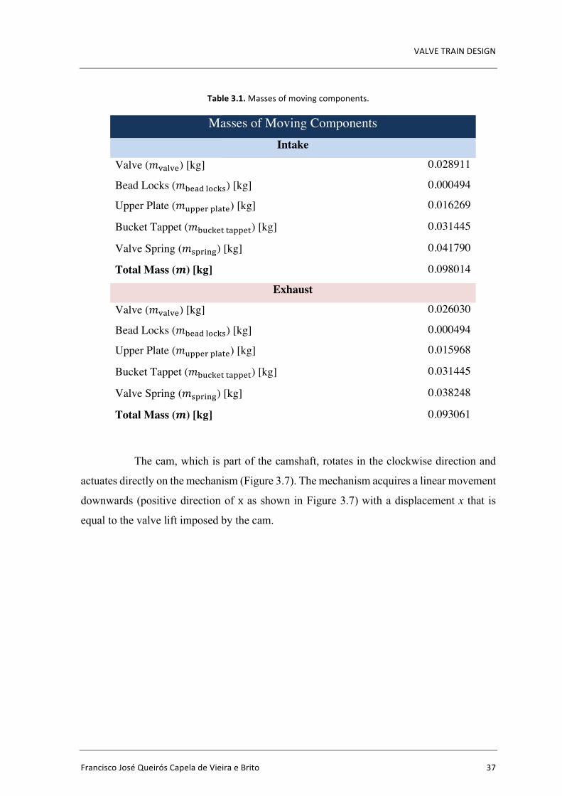
VALVETRAINDESIGN
FranciscoJoséQueirósCapeladeVieiraeBrito 37
Table3.1.Massesofmovingcomponents.
Masses of Moving Components Intake
Valve (𝑚)2M)&) [kg] 0.028911
Bead Locks (𝑚K&24MN1O() [kg] 0.000494
Upper Plate (𝑚955&85M2:&) [kg] 0.016269
Bucket Tappet (𝑚K91O&::255&:) [kg] 0.031445
Valve Spring (𝑚(58%67) [kg] 0.041790
Total Mass (𝒎) [kg] 0.098014
Exhaust
Valve (𝑚)2M)&) [kg] 0.026030
Bead Locks (𝑚K&24MN1O() [kg] 0.000494
Upper Plate (𝑚955&85M2:&) [kg] 0.015968
Bucket Tappet (𝑚K91O&::255&:) [kg] 0.031445
Valve Spring (𝑚(58%67) [kg] 0.038248
Total Mass (𝒎) [kg] 0.093061
The cam, which is part of the camshaft, rotates in the clockwise direction and
actuates directly on the mechanism (Figure 3.7). The mechanism acquires a linear movement
downwards (positive direction of x as shown in Figure 3.7) with a displacement x that is
equal to the valve lift imposed by the cam.
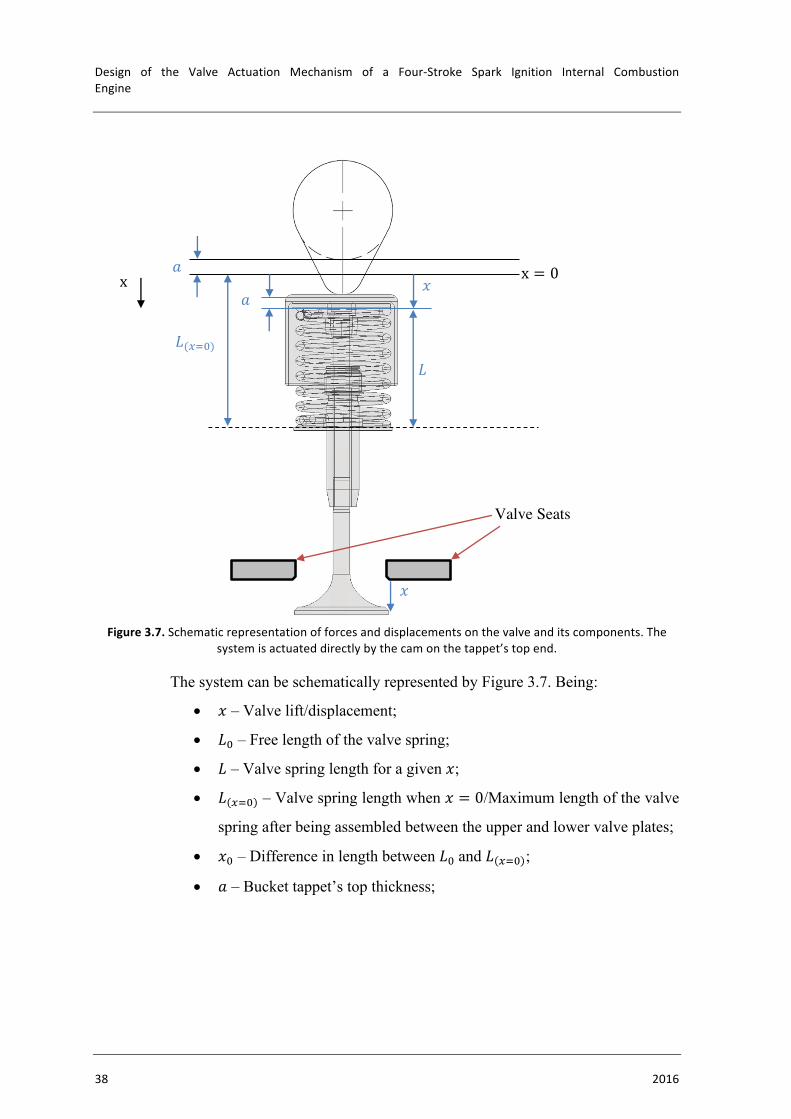
Design of the Valve Actuation Mechanism of a Four-Stroke Spark Ignition Internal CombustionEngine
38 2016
Figure3.7.Schematicrepresentationofforcesanddisplacementsonthevalveanditscomponents.Thesystemisactuateddirectlybythecamonthetappet’stopend.
The system can be schematically represented by Figure 3.7. Being:
• 𝑥 – Valve lift/displacement;
• 𝐿G – Free length of the valve spring;
• 𝐿 – Valve spring length for a given 𝑥;
• 𝐿 EFG – Valve spring length when 𝑥 = 0/Maximum length of the valve
spring after being assembled between the upper and lower valve plates;
• 𝑥G – Difference in length between 𝐿Gand 𝐿 EFG ;
• 𝑎 – Bucket tappet’s top thickness;
𝑥
𝐿
𝐿(EFG)
Valve Seats
𝑥
x = 0 x 𝑎
𝑎
VALVETRAINDESIGN
FranciscoJoséQueirósCapeladeVieiraeBrito 39
3.2.2. LengthandDisplacementRelationsWith valve lift and Figure 3.7 it is possible to obtain the valve spring’s length at
any value of x:
𝑥 = 𝐿 EFG − 𝐿 ⇔ 𝐿 = 𝐿 EFG − 𝑥 (3.2)
Also, if 𝑥 = 0 (valve closed):
𝐿 = 𝐿 EFG (3.3)
which is the maximum length that can be obtained by the valve spring.
Finally 𝑥G can be defined as:
−𝑥G = 𝐿G − 𝐿 dFG ⇔ 𝑥G = 𝐿 dFG − 𝐿G < 0 (3.4)
In this case 𝑥G is inferior to zero because of the convention made to the positive
direction of x.
3.2.3. SpringRateandDampingCoefficientAs previously stated, both spring and damper have characteristic features - 𝐾'
and 𝐾B - respectively. To determine the spring and damping forces it is necessary to define
both spring rate and damping constant first. The spring rate is defined once (for the valve
spring) [17].
• Spring Rate, 𝐾'
𝐾' =𝑑� ∙ 𝐺
8 ∙ 𝐷� ∙ 𝑁Q ∙ 1 +1
2 ∙ 𝐶� (3.5)
Being:
𝑑 – Spring wire diameter [m];
𝐷 – Average spring diameter [m];
𝑁Q – Number of active coils;
𝐺 – Torsional modulus of elasticity [Pa]:
𝐺 =𝐸
2 ∙ (1 + 𝜈) (3.6)
𝐸 – Modulus of elasticity [Pa];
𝜈 – Poisson’s ratio;
𝐶 – Spring index:
𝐶 =𝐷𝑑 (3.7)
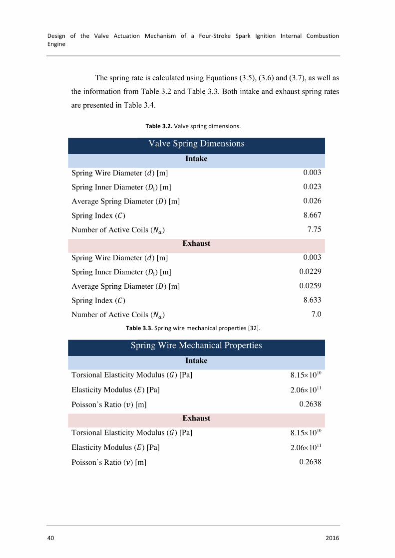
Design of the Valve Actuation Mechanism of a Four-Stroke Spark Ignition Internal CombustionEngine
40 2016
The spring rate is calculated using Equations (3.5), (3.6) and (3.7), as well as
the information from Table 3.2 and Table 3.3. Both intake and exhaust spring rates
are presented in Table 3.4.
Table3.2.Valvespringdimensions.
Valve Spring Dimensions Intake
Spring Wire Diameter (𝑑) [m] 0.003
Spring Inner Diameter (𝐷%) [m] 0.023
Average Spring Diameter (𝐷) [m] 0.026
Spring Index (𝐶) 8.667
Number of Active Coils (𝑁Q) 7.75
Exhaust
Spring Wire Diameter (𝑑) [m] 0.003
Spring Inner Diameter (𝐷%) [m] 0.0229
Average Spring Diameter (𝐷) [m] 0.0259
Spring Index (𝐶) 8.633
Number of Active Coils (𝑁Q) 7.0
Table3.3.Springwiremechanicalproperties[32].
Spring Wire Mechanical Properties Intake
Torsional Elasticity Modulus (𝐺) [Pa] 8.15´1010
Elasticity Modulus (𝐸) [Pa] 2.06´1011
Poisson’s Ratio (𝑣) [m] 0.2638
Exhaust
Torsional Elasticity Modulus (𝐺) [Pa] 8.15´1010
Elasticity Modulus (𝐸) [Pa] 2.06´1011
Poisson’s Ratio (𝜈) [m] 0.2638
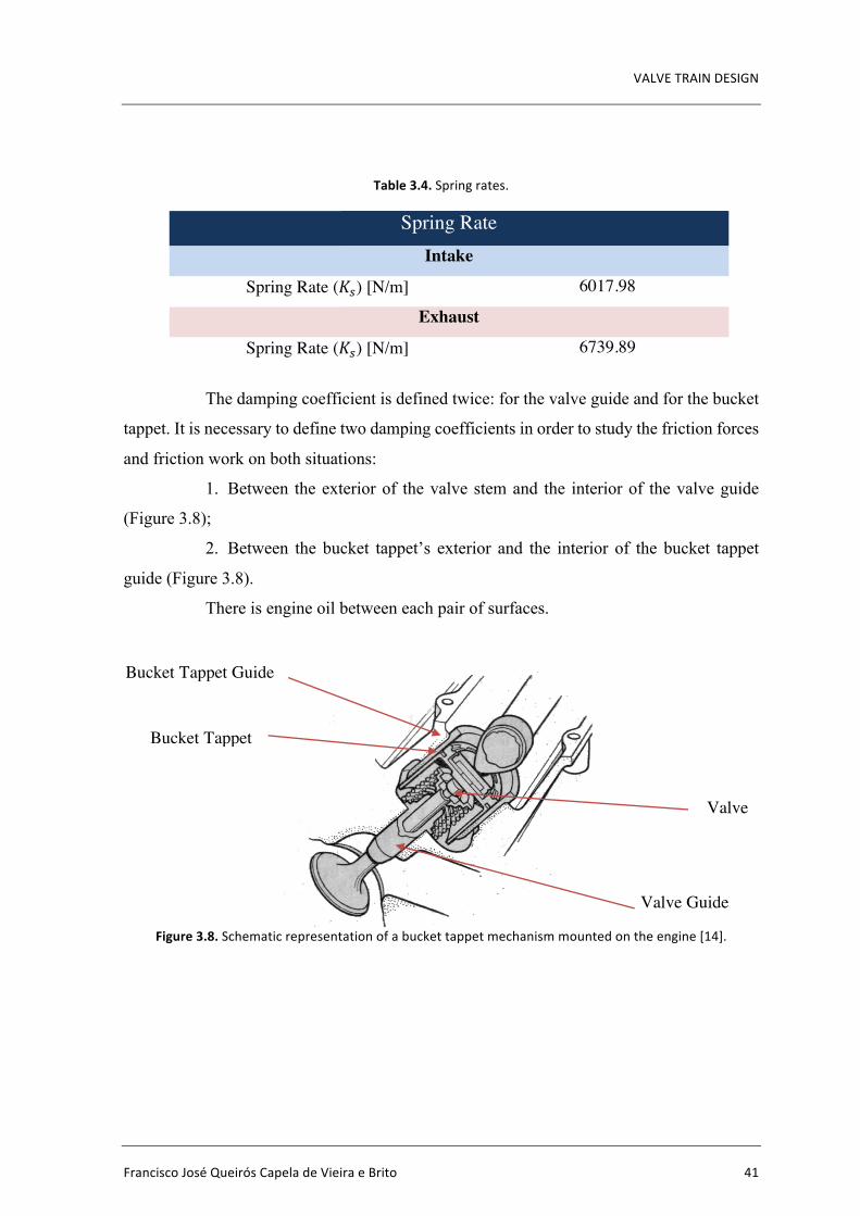
VALVETRAINDESIGN
FranciscoJoséQueirósCapeladeVieiraeBrito 41
Table3.4.Springrates.
Spring Rate Intake
Spring Rate (𝐾') [N/m] 6017.98
Exhaust
Spring Rate (𝐾') [N/m] 6739.89
The damping coefficient is defined twice: for the valve guide and for the bucket
tappet. It is necessary to define two damping coefficients in order to study the friction forces
and friction work on both situations:
1. Between the exterior of the valve stem and the interior of the valve guide
(Figure 3.8);
2. Between the bucket tappet’s exterior and the interior of the bucket tappet
guide (Figure 3.8).
There is engine oil between each pair of surfaces.
Figure3.8.Schematicrepresentationofabuckettappetmechanismmountedontheengine[14].
Valve
Valve Guide
Bucket Tappet
Bucket Tappet Guide
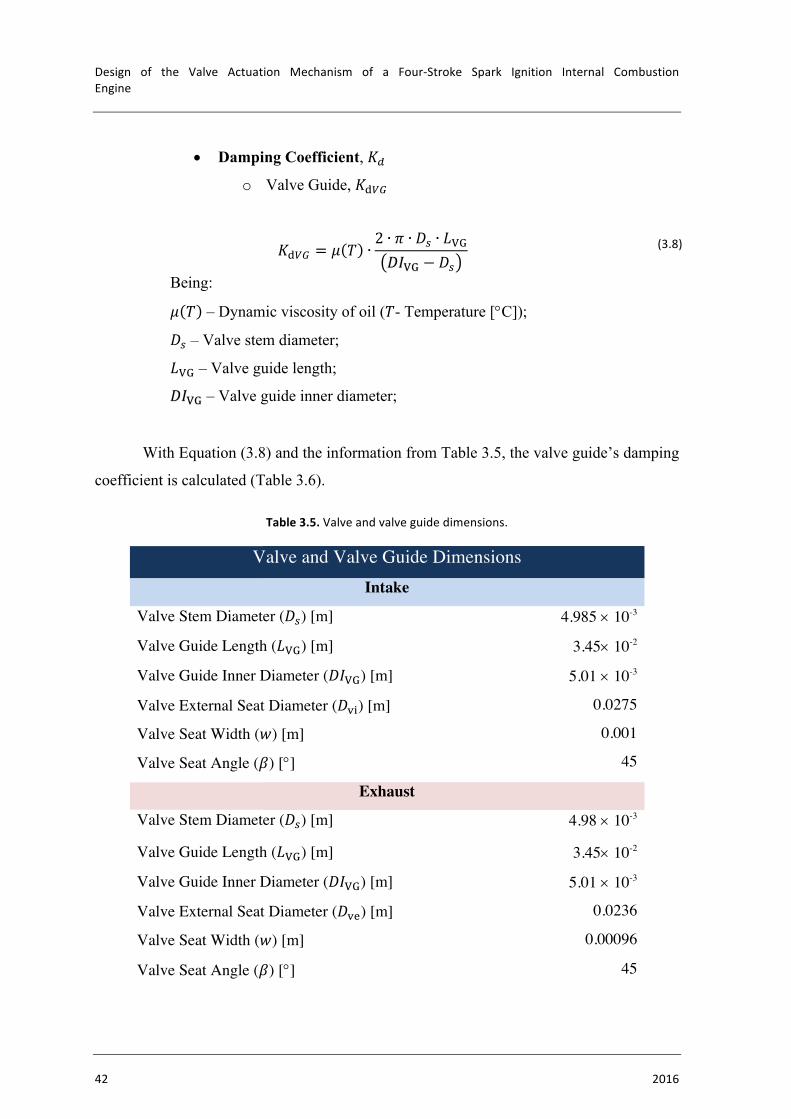
Design of the Valve Actuation Mechanism of a Four-Stroke Spark Ignition Internal CombustionEngine
42 2016
• Damping Coefficient, 𝐾B
o Valve Guide, 𝐾4��
𝐾4�� = 𝜇 𝑇 ∙2 ∙ 𝜋 ∙ 𝐷' ∙ 𝐿/.𝐷𝐼/. − 𝐷'
(3.8)
Being:
𝜇 𝑇 – Dynamic viscosity of oil (𝑇- Temperature [°C]);
𝐷' – Valve stem diameter;
𝐿/. – Valve guide length;
𝐷𝐼/. – Valve guide inner diameter;
With Equation (3.8) and the information from Table 3.5, the valve guide’s damping
coefficient is calculated (Table 3.6).
Table3.5.Valveandvalveguidedimensions.
Valve and Valve Guide Dimensions Intake
Valve Stem Diameter (𝐷') [m] 4.985 ´ 10-3
Valve Guide Length (𝐿/.) [m] 3.45´ 10-2
Valve Guide Inner Diameter (𝐷𝐼/.) [m] 5.01 ´ 10-3
Valve External Seat Diameter (𝐷)%) [m] 0.0275
Valve Seat Width (𝑤) [m] 0.001
Valve Seat Angle (𝛽) [°] 45
Exhaust
Valve Stem Diameter (𝐷') [m] 4.98 ´ 10-3
Valve Guide Length (𝐿/.) [m] 3.45´ 10-2
Valve Guide Inner Diameter (𝐷𝐼/.) [m] 5.01 ´ 10-3
Valve External Seat Diameter (𝐷)&) [m] 0.0236
Valve Seat Width (𝑤) [m] 0.00096
Valve Seat Angle (𝛽) [°] 45
VALVETRAINDESIGN
FranciscoJoséQueirósCapeladeVieiraeBrito 43
Table3.6.Valveguidedampingcoefficient.
Damping Coefficient – Valve Guide Intake
Damping Coefficient (𝐾4/.) [N×s/m] 0.35
Exhaust
Damping Coefficient (𝐾4/.) [N×s/m] 0.29
o Bucket Tappet, 𝐾4+,
𝐾4+, = 𝜇 𝑇 ∙2 ∙ 𝜋 ∙ 𝐷𝐸+, ∙ 𝐿+,𝐷𝐼+,. − 𝐷𝐸+,
(3.9)
Being:
𝜇 𝑇 = 8.098´10¢�Pa ∙ s – Dynamic viscosity of oil;
𝐷𝐸+, – Bucket tappet outer diameter;
𝐿+, – Bucket tappet length;
𝐷𝐼+,. – Bucket tappet guide inner diameter;
With Equation (3.9) and the information from Table 3.7, the bucket tappet’s damping
coefficient is calculated (Table 3.8).
Table3.7.Buckettappetdimensions.
Bucket Tappet Dimensions Intake
Bucket Tappet Outer Diameter (𝐷𝐸+,) [m] 0.032
Bucket Tappet Length (𝐿+,) [m] 0.0239
Bucket Tappet Guide Inner Diameter
(𝐷𝐼+,.) [m]
0.032025
Exhaust
Bucket Tappet Outer Diameter (𝐷𝐸+,) [m] 0.032
Bucket Tappet Length (𝐿+,) [m] 0.0239
Bucket Tappet Guide Inner Diameter
(𝐷𝐼+,.) [m]
0.032025

Design of the Valve Actuation Mechanism of a Four-Stroke Spark Ignition Internal CombustionEngine
44 2016
-200
-150
-100
-50
00 180 360 540 720
Forceofth
eExhaustV
alveSp
ring[N
]
CrankAngle[∘]
ForceoftheExhaustValveSpringasfunctionofCrankAngle
Table3.8.Buckettappetdampingcoefficient.
Damping Coefficient – Bucket Tappet Intake
Damping Coefficient (𝐾4+,) [N×s/m] 1.56
Exhaust
Damping Coefficient (𝐾4+,) [N×s/m] 1.56
3.2.4. Forces• Spring Force, 𝐹(58%67
Spring force is the force exerted by the spring on the moving masses of the
system. For a system with a linear behavior, the spring force (𝐹(58%67) is given by Equation
(3.10) [15].
𝐹 = 𝐾 ∙ 𝑥 (3.10)
With 𝐹 being 𝐹(58%67, 𝐾 the spring rate (𝐾'), and 𝑥 the displacement as
previously defined. With Equation (3.10) and the previously defined length and
displacement relations comes Equation (3.11).
𝐹(58%67 = 𝐾' ∙ 𝐿 − 𝐿G = −𝐾' ∙ 𝐿G − 𝐿 = −𝐾' ∙ 𝐿G − 𝐿 EFG + 𝑥= −𝐾' ∙ (𝑥 − 𝑥G)
(3.11)
Figure3.9.Forceoftheintake(left)andtheexhaust(right)valvespringasfunctionofcrankangle.
-250
-200
-150
-100
-50
00 180 360 540 720
Forceofth
eIntakeValveSp
ring[N]
CrankAngle[∘]
ForceoftheIntakeValveSpringasfunctionofCrankAngle

VALVETRAINDESIGN
FranciscoJoséQueirósCapeladeVieiraeBrito 45
The force of the intake and the exhaust valve spring throughout the engine cycle
is depicted on Figure 3.9 (left and right respectively). On the intake valve spring, the
minimum and maximum forces (in module) are, respectively, 154 N and 200 N. The exhaust
valve spring’s minimum and maximum forces (in module) are, respectively, 135 N and 186
N. The minimum forces in the valve springs are registered when the valves are closed. When
the force of the valve springs starts to increase, it means that the valves are opening.
• Damping Force, 𝐹4235%67
Damping force (𝐹4235%67) is given by Equation (3.12).
𝐹 = −𝐾 ∙𝑑𝑥𝑑𝑡 (3.12)
With 𝐹 being 𝐹4235%67, 𝐾 the sum of both damping coefficients (𝐾B), and 𝑥 the
displacement as previously defined.
𝐹4235%67 = −(𝐾4�� + 𝐾4+,)×𝑑𝑥𝑑𝑡
(3.13)
• Weight Force, 𝐹>&%7?:
Weight force (𝐹>&%7?:) is given by Equation (3.14).
𝐹 = 𝑚 ∙ 𝑔 (3.14)
Being:
𝑔 = 9.81m/s� – Gravitational acceleration;
• Pressure Force, 𝐹58&((98&
Figure3.10.Schematicrepresentationofthepressureinsidethecylinderandontheinlet/outletport[16].
𝑝Z 𝑝Y
𝑝X
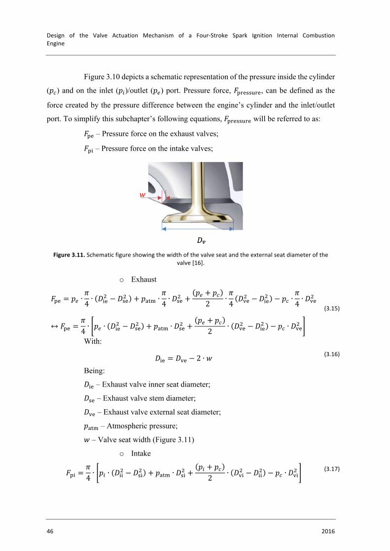
Design of the Valve Actuation Mechanism of a Four-Stroke Spark Ignition Internal CombustionEngine
46 2016
Figure 3.10 depicts a schematic representation of the pressure inside the cylinder
(𝑝X) and on the inlet (𝑝Z)/outlet (𝑝Y) port. Pressure force, 𝐹58&((98&, can be defined as the
force created by the pressure difference between the engine’s cylinder and the inlet/outlet
port. To simplify this subchapter’s following equations, 𝐹58&((98& will be referred to as:
𝐹5& – Pressure force on the exhaust valves;
𝐹5% – Pressure force on the intake valves;
Figure3.11.Schematicfigureshowingthewidthofthevalveseatandtheexternalseatdiameterofthe
valve[16].
o Exhaust
𝐹5& = 𝑝Y ∙𝜋4 ∙ 𝐷%&
� − 𝐷(&� + 𝑝2:3 ∙𝜋4 ∙ 𝐷(&
� +𝑝Y + 𝑝X2 ∙
𝜋4 𝐷)&� − 𝐷%&� − 𝑝X ∙
𝜋4 ∙ 𝐷)&
�
↔ 𝐹5& =𝜋4 ∙ 𝑝Y ∙ 𝐷%&
� − 𝐷(&� + 𝑝2:3 ∙ 𝐷(&� +𝑝Y + 𝑝X2 ∙ 𝐷)&� − 𝐷%&� − 𝑝X ∙ 𝐷)&�
(3.15)
With:
𝐷%& = 𝐷)& − 2 ∙ 𝑤 (3.16)
Being:
𝐷%& – Exhaust valve inner seat diameter;
𝐷(& – Exhaust valve stem diameter;
𝐷)& – Exhaust valve external seat diameter;
𝑝2:3 – Atmospheric pressure;
𝑤 – Valve seat width (Figure 3.11)
o Intake
𝐹5% =𝜋4 ∙ 𝑝Z ∙ 𝐷%%
� − 𝐷(%� + 𝑝2:3 ∙ 𝐷(%� +𝑝Z + 𝑝X2 ∙ 𝐷)%� − 𝐷%%� − 𝑝X ∙ 𝐷)%� (3.17)

VALVETRAINDESIGN
FranciscoJoséQueirósCapeladeVieiraeBrito 47
0
1000
2000
3000
4000
0 180 360 540 720
Forceofth
eVa
lveSeat[N
]
CrankAngle[∘]
ForceoftheExhaustValveSeatasfunctionofCrankAngle
Being:
𝐷%% – Intake valve inner seat diameter;
𝐷(% – Intake valve stem diameter;
𝐷)% – Intake valve external seat diameter;
• Valve Seat Force, 𝐹(&2:
The valve seat force is the force exerted by the valve seat when in contact with
the valve. To define the valve seat force, it is necessary to apply Newton’s second law of
motion to the system:
Σ𝐹 = 𝑚 ∙ 𝑎
⇔ 𝐹58&((98& + 𝐹(58%67 + 𝐹4235%67 + 𝐹>&%7?: + 𝐹(&2: + 𝐹123 = 𝑚 ∙𝑑�𝑥𝑑𝑡�
(3.18)
On one hand, if 𝑥 = 0, then:
⇒𝑑�𝑥𝑑𝑡� = 0;
𝑑𝑥𝑑𝑡 = 0;𝐹123 = 0
On 𝑥 = 0 there is no force being applied by the cam on the tappet and both
acceleration and velocity are null because the system has no motion. The valve seat force
balances all the other forces. Equation (3.18) becomes:
𝐹(&2: = −𝑚 ∙ 𝑔 + 𝐾' 0 − 𝑥G − 𝐹58&((98& (3.19)
which is the equation for the force applied by the valve seat on mass 𝑚. Figure
3.12 shows the force of the intake and exhaust valve seats (left and right, respectively) during
an engine cycle.
Figure3.12.Forceoftheintake(left)andexhaust(right)valveseatasfunctionofcrankangle.
0
1000
2000
3000
4000
5000
6000
0 180 360 540 720
Forceofth
eIntakeValveSe
at[N
]
CrankAngle[∘]
ForceoftheIntakeValveSeatasfunctionofCrankAngle
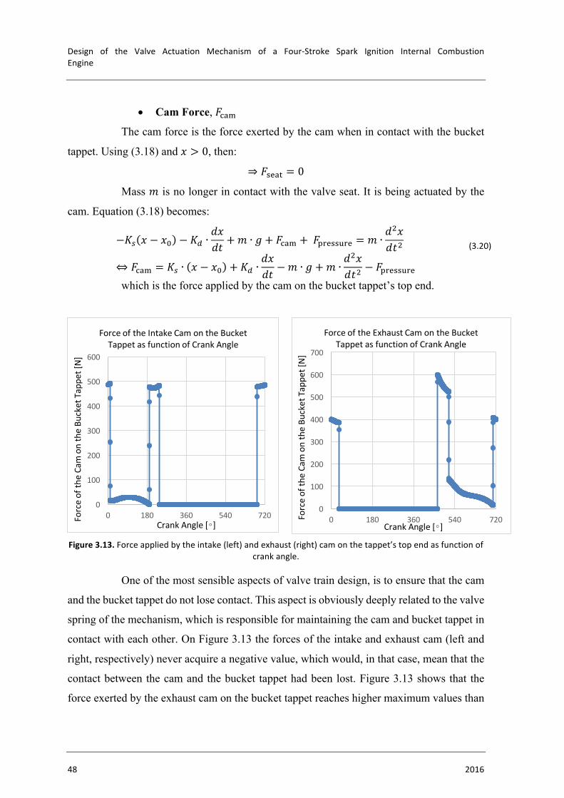
Design of the Valve Actuation Mechanism of a Four-Stroke Spark Ignition Internal CombustionEngine
48 2016
0
100
200
300
400
500
600
700
0 180 360 540 720Forceofth
eCamontheBu
cketTappe
t[N]
CrankAngle[∘]
ForceoftheExhaustCamontheBucketTappetasfunctionofCrankAngle
• Cam Force, 𝐹123
The cam force is the force exerted by the cam when in contact with the bucket
tappet. Using (3.18) and 𝑥 > 0, then:
⇒ 𝐹(&2: = 0
Mass 𝑚 is no longer in contact with the valve seat. It is being actuated by the
cam. Equation (3.18) becomes:
−𝐾' 𝑥 − 𝑥G − 𝐾B ∙𝑑𝑥𝑑𝑡 + 𝑚 ∙ 𝑔 + 𝐹123 +𝐹58&((98& = 𝑚 ∙
𝑑�𝑥𝑑𝑡�
⇔ 𝐹123 = 𝐾' ∙ 𝑥 − 𝑥G + 𝐾B ∙𝑑𝑥𝑑𝑡 − 𝑚 ∙ 𝑔 +𝑚 ∙
𝑑�𝑥𝑑𝑡� − 𝐹58&((98&
(3.20)
which is the force applied by the cam on the bucket tappet’s top end.
Figure3.13.Forceappliedbytheintake(left)andexhaust(right)camonthetappet’stopendasfunctionof
crankangle.
One of the most sensible aspects of valve train design, is to ensure that the cam
and the bucket tappet do not lose contact. This aspect is obviously deeply related to the valve
spring of the mechanism, which is responsible for maintaining the cam and bucket tappet in
contact with each other. On Figure 3.13 the forces of the intake and exhaust cam (left and
right, respectively) never acquire a negative value, which would, in that case, mean that the
contact between the cam and the bucket tappet had been lost. Figure 3.13 shows that the
force exerted by the exhaust cam on the bucket tappet reaches higher maximum values than
0
100
200
300
400
500
600
0 180 360 540 720Forceofth
eCamontheBu
cketTappe
t[N]
CrankAngle[∘]
ForceoftheIntakeCamontheBucketTappetasfunctionofCrankAngle
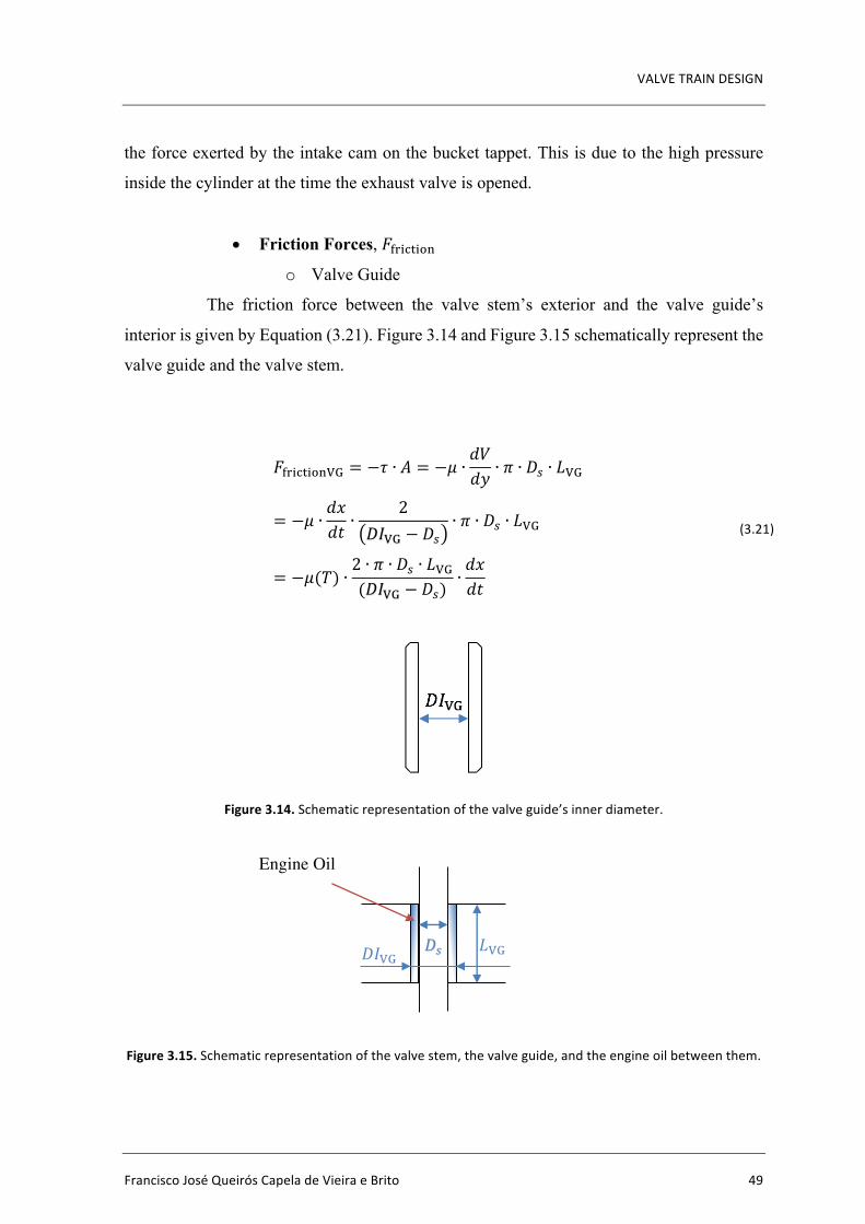
VALVETRAINDESIGN
FranciscoJoséQueirósCapeladeVieiraeBrito 49
the force exerted by the intake cam on the bucket tappet. This is due to the high pressure
inside the cylinder at the time the exhaust valve is opened.
• Friction Forces, 𝐹8%1:%N6
o Valve Guide
The friction force between the valve stem’s exterior and the valve guide’s
interior is given by Equation (3.21). Figure 3.14 and Figure 3.15 schematically represent the
valve guide and the valve stem.
𝐹8%1:%N6/. = −𝜏 ∙ 𝐴 = −𝜇 ∙𝑑𝑉𝑑𝑦 ∙ 𝜋 ∙ 𝐷' ∙ 𝐿/.
= −𝜇 ∙𝑑𝑥𝑑𝑡 ∙
2𝐷𝐼/. − 𝐷'
∙ 𝜋 ∙ 𝐷' ∙ 𝐿/.
= −𝜇(𝑇) ∙2 ∙ 𝜋 ∙ 𝐷' ∙ 𝐿/.(𝐷𝐼/. − 𝐷')
∙𝑑𝑥𝑑𝑡
(3.21)
Figure3.14.Schematicrepresentationofthevalveguide’sinnerdiameter.
Figure3.15.Schematicrepresentationofthevalvestem,thevalveguide,andtheengineoilbetweenthem.
𝐷' 𝐿/. 𝐷𝐼/.
Engine Oil
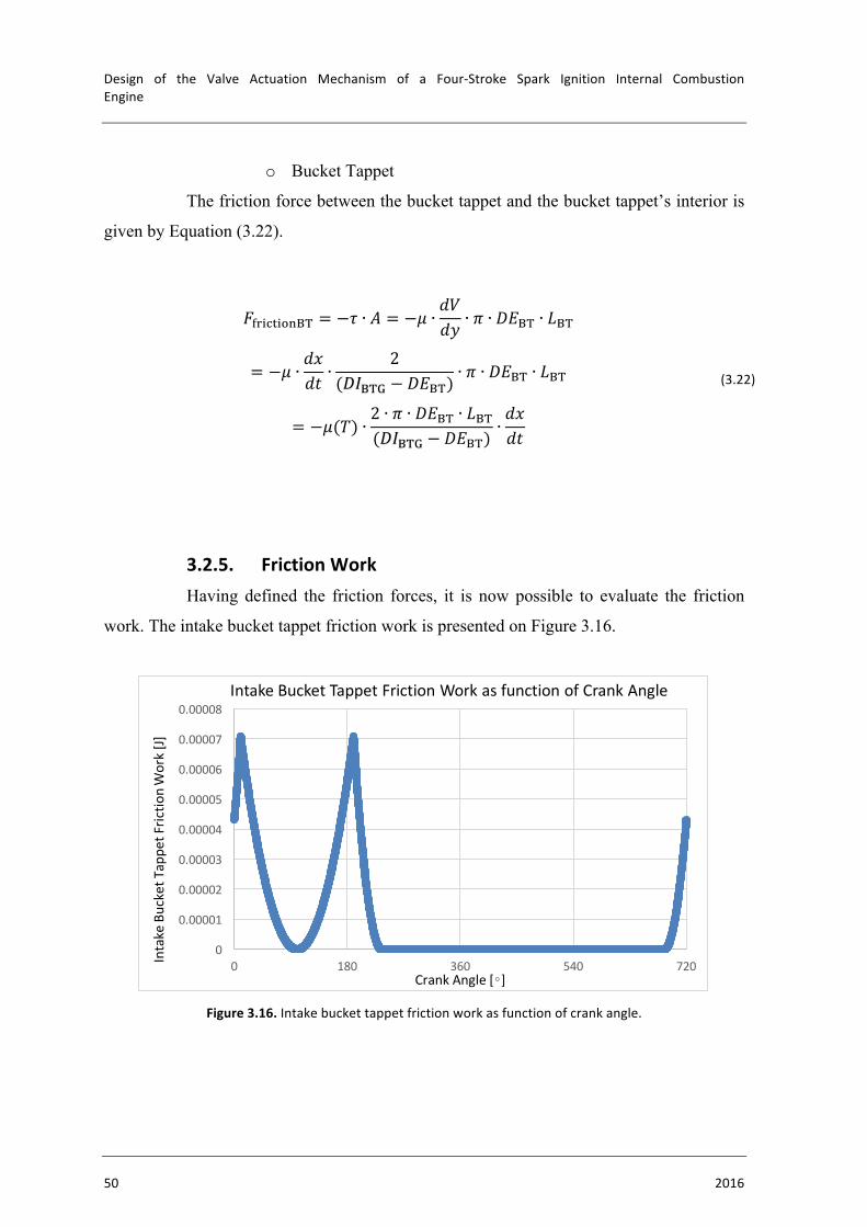
Design of the Valve Actuation Mechanism of a Four-Stroke Spark Ignition Internal CombustionEngine
50 2016
o Bucket Tappet
The friction force between the bucket tappet and the bucket tappet’s interior is
given by Equation (3.22).
𝐹8%1:%N6+, = −𝜏 ∙ 𝐴 = −𝜇 ∙𝑑𝑉𝑑𝑦 ∙ 𝜋 ∙ 𝐷𝐸+, ∙ 𝐿+,
= −𝜇 ∙𝑑𝑥𝑑𝑡 ∙
2(𝐷𝐼+,. − 𝐷𝐸+,)
∙ 𝜋 ∙ 𝐷𝐸+, ∙ 𝐿+,
= −𝜇(𝑇) ∙2 ∙ 𝜋 ∙ 𝐷𝐸+, ∙ 𝐿+,(𝐷𝐼+,. − 𝐷𝐸+,)
∙𝑑𝑥𝑑𝑡
(3.22)
3.2.5. FrictionWorkHaving defined the friction forces, it is now possible to evaluate the friction
work. The intake bucket tappet friction work is presented on Figure 3.16.
Figure3.16.Intakebuckettappetfrictionworkasfunctionofcrankangle.
0
0.00001
0.00002
0.00003
0.00004
0.00005
0.00006
0.00007
0.00008
0 180 360 540 720IntakeBucketT
appe
tFric
tionWork[J]
CrankAngle[∘]
IntakeBucketTappetFrictionWorkasfunctionofCrankAngle
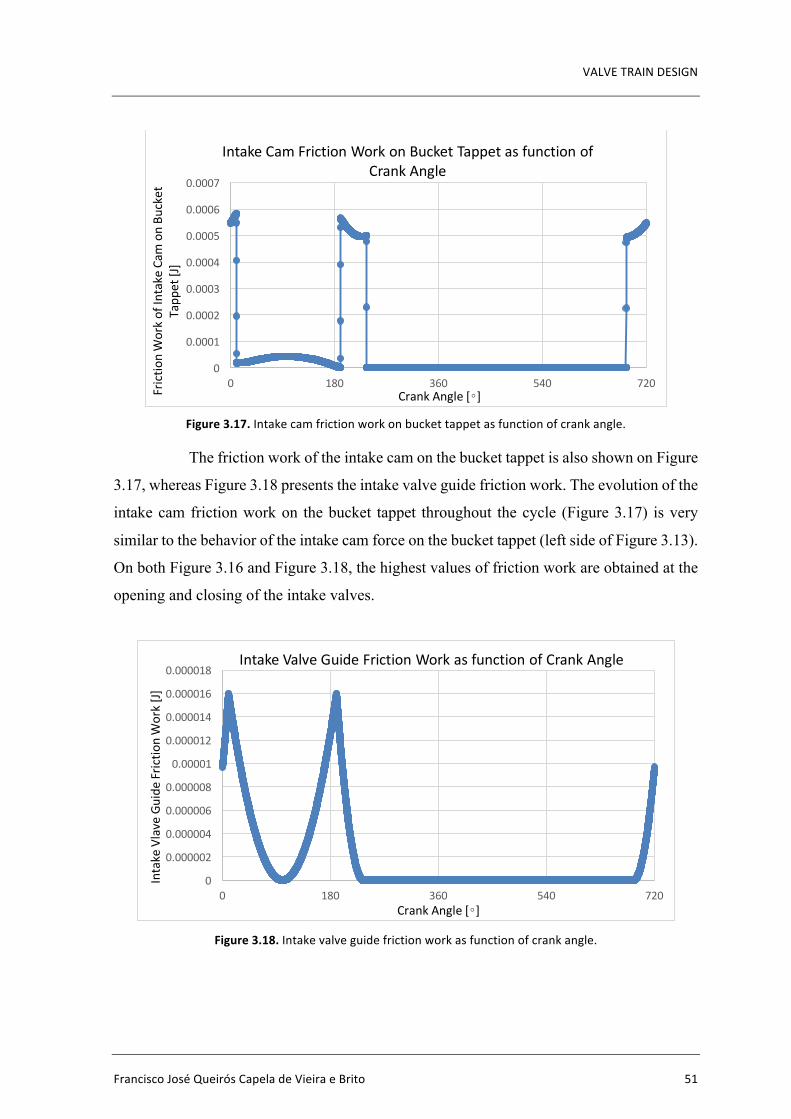
VALVETRAINDESIGN
FranciscoJoséQueirósCapeladeVieiraeBrito 51
Figure3.17.Intakecamfrictionworkonbuckettappetasfunctionofcrankangle.
The friction work of the intake cam on the bucket tappet is also shown on Figure
3.17, whereas Figure 3.18 presents the intake valve guide friction work. The evolution of the
intake cam friction work on the bucket tappet throughout the cycle (Figure 3.17) is very
similar to the behavior of the intake cam force on the bucket tappet (left side of Figure 3.13).
On both Figure 3.16 and Figure 3.18, the highest values of friction work are obtained at the
opening and closing of the intake valves.
Figure3.18.Intakevalveguidefrictionworkasfunctionofcrankangle.
0
0.0001
0.0002
0.0003
0.0004
0.0005
0.0006
0.0007
0 180 360 540 720Frictio
nWorkofIntakeCam
onBu
cket
Tapp
et[J]
CrankAngle[∘]
IntakeCamFrictionWorkonBucketTappetasfunctionofCrankAngle
0
0.000002
0.000004
0.000006
0.000008
0.00001
0.000012
0.000014
0.000016
0.000018
0 180 360 540 720
IntakeVlaveGuide
Frictio
nWork[J]
CrankAngle[∘]
IntakeValveGuideFrictionWorkasfunctionofCrankAngle

Design of the Valve Actuation Mechanism of a Four-Stroke Spark Ignition Internal CombustionEngine
52 2016
The exhaust bucket tappet friction work is presented on Figure 3.19.
Figure3.19.Exhaustbuckettappetfrictionworkasfunctionofcrankangle.
The friction work of the exhaust cam on the bucket tappet is also shown on
Figure 3.20, whereas Figure 3.21 presents the exhaust valve guide friction work. The
evolution of the exhaust cam friction work on the bucket tappet throughout the cycle (Figure
3.20) is very similar to the behavior of the exhaust cam force on the bucket tappet (right side
of Figure 3.13). On both Figure 3.19 and Figure 3.21, the highest values of friction work are
obtained at the opening and closing of the exhaust valves.
Figure3.20.Exhaustcamfrictionworkonbuckettappetasfunctionofcrankangle.
0
0.00001
0.00002
0.00003
0.00004
0.00005
0.00006
0.00007
0 180 360 540 720
ExhausBUc
ketTappe
tFric
tionWork[J]
CrankAngle[∘]
ExhaustBucketTappetFrictionWorkasfunctionofCrankAngle
0
0.0001
0.0002
0.0003
0.0004
0.0005
0.0006
0.0007
0 180 360 540 720
ExhaustC
amFric
tionon
BucketTappe
t[J]
CrankAngle[∘]
ExhaustCamFrictionWorkonBucketTappetasfunctionofCrankAngle
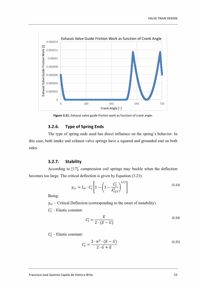
VALVETRAINDESIGN
FranciscoJoséQueirósCapeladeVieiraeBrito 53
Figure3.21.Exhaustvalveguidefrictionworkasfunctionofcrankangle.
3.2.6. TypeofSpringEndsThe type of spring ends used has direct influence on the spring’s behavior. In
this case, both intake and exhaust valve springs have a squared and grounded end on both
sides.
3.2.7. StabilityAccording to [17], compression coil springs may buckle when the deflection
becomes too large. The critical deflection is given by Equation (3.23):
𝑦Xª = 𝐿G ∙ 𝐶c« 1 − 1 −𝐶�«
𝜆YTT�
c �
(3.23)
Being:
𝑦Xª – Critical Deflection (corresponding to the onset of instability)
𝐶c« – Elastic constant:
𝐶c« =𝐸
2 ∙ (𝐸 − 𝐺) (3.24)
𝐶�« – Elastic constant:
𝐶�« =2 ∙ 𝜋� ∙ (𝐸 − 𝐺)2 ∙ 𝐺 + 𝐸
(3.25)
0
0.000002
0.000004
0.000006
0.000008
0.00001
0.000012
0.000014
0 180 360 540 720
ExhaustV
alveGuide
Fric
tionWork[J]
CrankAngle[∘]
ExhaustValveGuideFrictionWorkasfunctionofCrankAngle

Design of the Valve Actuation Mechanism of a Four-Stroke Spark Ignition Internal CombustionEngine
54 2016
𝜆YTT – Effective slenderness ratio:
𝜆YTT =𝛼 ∙ 𝐿G𝐷 (3.26)
Being:
𝜶 – End-condition constant (as shown in Table 3.9, 𝜶 = 𝟎. 𝟓)
Table3.9.Valvespring’sendcondition.
End Condition for helical compression springs
End-Condition Constant 𝛼 for both Intake and Exhaust Valve Springs
Spring supported between flat parallel surfaces (fixed ends) 0.5
Table3.10.Valvespring’sstability.
Stability Intake
Critical Deflection (𝑦Xª) [m] 0.111
Elastic Constant (𝐶c«) 0.827
Elastic Constant (𝐶�«) 6.66
Effective Slenderness Ratio (𝜆YTT) 1.285
Exhaust
Critical Deflection (𝑦Xª) [m] 0.111
Elastic Constant (𝐶c«) 0.827
Elastic Constant (𝐶�«) 6.66
Effective Slenderness Ratio (𝜆YTT) 1.178
There is absolute stability when:
𝐶�«
𝜆YTT� > 1 (3.27)
This means that:
𝐿G <𝜋 ∙ 𝐷𝛼
2 ∙ (𝐸 − 𝐺)2 ∙ 𝐺 + 𝐸
c �
(3.28)
For steel springs, Equation (3.28) becomes Equation (3.29).
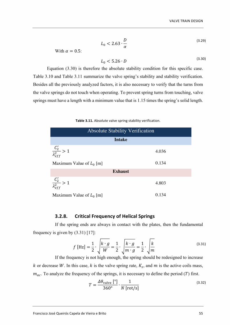
VALVETRAINDESIGN
FranciscoJoséQueirósCapeladeVieiraeBrito 55
𝐿G < 2.63 ∙𝐷𝛼
(3.29)
With 𝛼 = 0.5:
𝐿G < 5.26 ∙ 𝐷 (3.30)
Equation (3.30) is therefore the absolute stability condition for this specific case.
Table 3.10 and Table 3.11 summarize the valve spring’s stability and stability verification.
Besides all the previously analyzed factors, it is also necessary to verify that the turns from
the valve springs do not touch when operating. To prevent spring turns from touching, valve
springs must have a length with a minimum value that is 1.15 times the spring’s solid length.
Table3.11.Absolutevalvespringstabilityverification.
Absolute Stability Verification Intake
𝐶�«
𝜆YTT� > 1 4.036
Maximum Value of 𝐿G [m] 0.134
Exhaust 𝐶�«
𝜆YTT� > 1 4.803
Maximum Value of 𝐿G [m] 0.134
3.2.8. CriticalFrequencyofHelicalSpringsIf the spring ends are always in contact with the plates, then the fundamental
frequency is given by (3.31) [17]:
𝑓 Hz =12 ∙
𝑘 ∙ 𝑔𝑊 =
12 ∙
𝑘 ∙ 𝑔𝑚 ∙ 𝑔 =
12 ∙
𝑘𝑚
(3.31)
If the frequency is not high enough, the spring should be redesigned to increase
𝑘 or decrease 𝑊. In this case, 𝑘 is the valve spring rate, 𝐾', and 𝑚 is the active coils mass,
𝑚QX. To analyze the frequency of the springs, it is necessary to define the period (𝑇) first.
𝑇 =𝛥𝜃)2M)&[°]360° ∙
1𝑁[rot/s]
(3.32)

Design of the Valve Actuation Mechanism of a Four-Stroke Spark Ignition Internal CombustionEngine
56 2016
𝑓 =1𝑇
(3.33)
Table3.12.Criticalfrequencyofhelicalsprings.
Critical Frequency of Helical Springs Intake
Active Coils Mass (𝑚QX) [kg] 0.035
Fundamental Frequency (𝑓T¹ºB) [Hz] 2.07´102
Period (𝑇) [s] 7.50´10-3
Frequency (𝑓) [Hz] 1.33´102
(𝑓T¹ºB) [Hz] / (𝑓) [Hz] 1.55
Exhaust
Active Coils Mass [kg] 0.032
Fundamental Frequency (𝑓T¹ºB) [Hz] 2.31´102
Period (𝑇) [s] 8.06´10-3
Frequency (𝑓) [Hz] 1.24´102
(𝑓ºQ») [Hz] / (𝑓) [Hz] 1.86
Table 3.12 shows that the fundamental frequency is 1.55 and 1.86 times higher
than the spring’s frequency, for both intake and exhaust valves, respectively. With this
design, the springs don’t resonate.

VALVETRAINDESIGN
FranciscoJoséQueirósCapeladeVieiraeBrito 57
3.2.9. FatigueLoadingofHelicalCompressionSprings
Figure3.22.Fatiguediagramcontainingvariouscriteriaoffailure[17].
Using the Modified Goodman Criterion [17]: 𝑆Q𝑆Y+𝑆]𝑆9:
= 1 ↔𝑆Q𝑆Y= 1 −
𝑆]𝑆9:
↔ 𝑆Y =𝑆Q
1 − 𝑆]𝑆9:
(3.34)
𝑆(2𝑆'&
+𝑆(3𝑆(9
= 1 ↔𝑆(2𝑆(&
= 1 −𝑆(3𝑆(9
↔ 𝑆(& =𝑆(2
1 − 𝑆(3𝑆(9
(3.35)
Being:
𝑆Q – Alternate strength;
𝑆Y – Endurance strength;
𝑆] – Average strength;
𝑆9: - Ultimate strength;
𝑆(& – Endurance shear strength;
𝑆(2 – Alternate shear strength;
𝑆(9 – Ultimate shear strength;
𝑆(3 – Average shear strength
For unpeened steel spring wire:
𝑆(2 = 241MPa (3.36)
Fatigue Failure Resulting from Variable Loading 305
When the midrange stress is compression, failure occurs whenever σa = Se orwhenever σmax = Syc , as indicated by the left-hand side of Fig. 6–25. Neither a fatiguediagram nor any other failure criteria need be developed.
In Fig. 6–27, the tensile side of Fig. 6–25 has been redrawn in terms of strengths,instead of strength ratios, with the same modified Goodman criterion together with fouradditional criteria of failure. Such diagrams are often constructed for analysis anddesign purposes; they are easy to use and the results can be scaled off directly.
The early viewpoint expressed on a σm , σa diagram was that there existed a locuswhich divided safe from unsafe combinations of σm and σa . Ensuing proposals includedthe parabola of Gerber (1874), the Goodman (1890)22 (straight) line, and the Soderberg(1930) (straight) line. As more data were generated it became clear that a fatigue criterion,rather than being a “fence,” was more like a zone or band wherein the probability of fail-ure could be estimated. We include the failure criterion of Goodman because
• It is a straight line and the algebra is linear and easy.
• It is easily graphed, every time for every problem.
• It reveals subtleties of insight into fatigue problems.
• Answers can be scaled from the diagrams as a check on the algebra.
We also caution that it is deterministic and the phenomenon is not. It is biased and wecannot quantify the bias. It is not conservative. It is a stepping-stone to understanding; itis history; and to read the work of other engineers and to have meaningful oral exchangeswith them, it is necessary that you understand the Goodman approach should it arise.
Either the fatigue limit Se or the finite-life strength Sf is plotted on the ordinate ofFig. 6–27. These values will have already been corrected using the Marin factors ofEq. (6–18). Note that the yield strength Sy is plotted on the ordinate too. This serves asa reminder that first-cycle yielding rather than fatigue might be the criterion of failure.
The midrange-stress axis of Fig. 6–27 has the yield strength Sy and the tensilestrength Sut plotted along it.
Figure 6–27Fatigue diagram showingvarious criteria of failure. Foreach criterion, points on or“above” the respective lineindicate failure. Some point Aon the Goodman line, forexample, gives the strength Sm
as the limiting value of σm
corresponding to the strengthSa , which, paired with σm , isthe limiting value of σa .
Alte
rnat
ing
stre
ss !
a
Midrange stress !m
0 Sm
A
SutSy
0
Sa
Se
Sy
Soderberg line
Modified Goodman line
ASME-elliptic line
Load line, slope r = Sa/Sm
Gerber line
Yield (Langer) line
22It is difficult to date Goodman’s work because it went through several modifications and was neverpublished.
bud29281_ch06_265-357.qxd 11/30/2009 4:23 pm Page 305 pinnacle s-171:Desktop Folder:Temp Work:Don't Delete (Jobs):MHDQ196/Budynas:
Design of the Valve Actuation Mechanism of a Four-Stroke Spark Ignition Internal CombustionEngine
58 2016
𝑆(3 = 379MPa (3.37)
𝐴 = 2211MPa (3.38)
𝑚.NN4326 = 0.145 (3.39)
𝑆9: =22113.0G.c�½ = 1885MPa (3.40)
𝑆(9 = 0.577 ∙ 𝑆9: = 0.577 ∙ 1885 = 1088MPa (3.41)
For unpeened steel spring wire:
𝑆(& =241
1 − 3791088
= 370MPa (3.42)
Using the Modified Goodman Criterion, the safety fatigue factor is given by
Equation (3.43).
𝑛T =1
𝜎Q𝑆Y+ 𝜎]𝑆9:
(3.43)
o Intake
𝑛T =1
𝜏Q𝑆(&
+ 𝜏]𝑆(9
=1
65.5370 +
507.11088
= 1.555 (3.44)
o Exhaust
𝑛T =1
𝜏Q𝑆(&
+ 𝜏]𝑆(9
=1
73.2370 +
458.21088
= 1.615 (3.45)
Being:
𝐴 – Ultimate strength of the spring wire for a wire diameter of 1 mm;
𝑚(> – Exponent of the wire diameter for ultimate strength of spring wire;
𝑆9: – Ultimate strength;
𝑛T – Fatigue safety factor;
𝜎Q – Alternate stress;
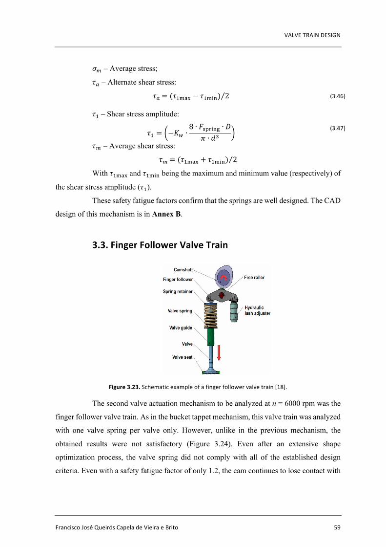
VALVETRAINDESIGN
FranciscoJoséQueirósCapeladeVieiraeBrito 59
𝜎] – Average stress;
𝜏Q – Alternate shear stress:
𝜏Q = (𝜏c32d − 𝜏c3%6) 2
(3.46)
𝜏c – Shear stress amplitude:
𝜏c = −𝐾¾ ∙8 ∙ 𝐹(58%67 ∙ 𝐷
𝜋 ∙ 𝑑� (3.47)
𝜏] – Average shear stress:
𝜏] = (𝜏c32d + 𝜏c3%6) 2
With 𝜏c32d and 𝜏c3%6 being the maximum and minimum value (respectively) of
the shear stress amplitude (𝜏c).
These safety fatigue factors confirm that the springs are well designed. The CAD
design of this mechanism is in Annex B.
3.3. FingerFollowerValveTrain
Figure3.23.Schematicexampleofafingerfollowervalvetrain[18].
The second valve actuation mechanism to be analyzed at n = 6000 rpm was the
finger follower valve train. As in the bucket tappet mechanism, this valve train was analyzed
with one valve spring per valve only. However, unlike in the previous mechanism, the
obtained results were not satisfactory (Figure 3.24). Even after an extensive shape
optimization process, the valve spring did not comply with all of the established design
criteria. Even with a safety fatigue factor of only 1.2, the cam continues to lose contact with
Bulletin of the Transilvania University of Braşov • Series I • Vol. 5 (54) No. 1 - 2012
20
The valve spring is mounted between the cylinder head and the retainer. It has the role to overcome the inertial forces of the valve and the other parts of the mechanism and to maintain the valve on its seat, when the cam does not act upon the valve.
Fig. 1. Description of the analysed valve train
In order to simplify the virtual model, a single valve actuation system was submitted to analysis. 3. Design of the Cam Profile
When designed using the kinematic inversion principle, the cam profile is obtained by determining the successive positions of the roller, around the cam's base circle center.
The successive positions of the roller are determined by rotating the entire mechanism around the cam center, in opposite direction of cam rotation.
The coordinates of the rollers center were calculated starting from the valve lift curve (Figure 2).
First step was to determine the angle made by the oscillating finger follower due to the valve movement.
Fig. 2. The input data valve curve lift
Fig. 3. The method for determining the angular displacement of the finger
follower
As shown in Figure 3, the angular displacement of the finger follower was calculated using the following formula:
=A
H sinArcα , (1)
where: H - sum between the initial displacement of the finger follower along y axis, and the valve lift value, corresponding to the camshaft angular position [mm]; A - length of the arm between two centers, respectively the center of rotation of the finger follower and the one of the contact
circle, from the valve side [mm]; α - angular displacement of the finger follower [deg].
The second step in the design of the cam profile was the calculation of the coordinates of the successive positions of the roller.
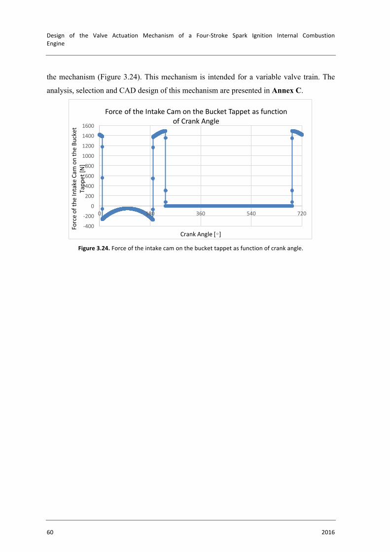
Design of the Valve Actuation Mechanism of a Four-Stroke Spark Ignition Internal CombustionEngine
60 2016
the mechanism (Figure 3.24). This mechanism is intended for a variable valve train. The
analysis, selection and CAD design of this mechanism are presented in Annex C.
Figure3.24.Forceoftheintakecamonthebuckettappetasfunctionofcrankangle.
-400
-200
0
200
400
600
800
1000
1200
1400
1600
0 180 360 540 720
Forceofth
eIntakeCam
ontheBu
cket
Tapp
et[N
]
CrankAngle[∘]
ForceoftheIntakeCamontheBucketTappetasfunctionofCrankAngle

CONCLUSIONS
FranciscoJoséQueirósCapeladeVieiraeBrito 61
4. CONCLUSIONSFrom the introductory chapter there are several conclusions regarding the
engine’s characteristics. Those characteristics are:
• Type: Four-Stroke;
• Ignition: Spark Ignition;
• Cylinders: Inline Three Cylinder;
• Displacement: 998 cm3;
• Air Induction: Atmospheric;
• Fuel Injection: Port Fuel Injection;
• Bore: 71.0 mm;
• Stroke: 84.0 mm;
• Stroke/Bore: 1.183;
• Compression Ratio: 11.0:1;
• Valves: 12 Valves – 4 Valves Per Cylinder;
• Valve Train: DOHC – Double Overhead Camshaft;
In chapter 2, two different strategies were used in order to obtain the highest
possible brake power and the lowest possible brake specific fuel consumption. It was
concluded that the highest brake power criterion provides the best results. It was also
concluded that the use of a valve train equipped with variable intake valve lift, instead of a
butterfly throttle valve, leads to a 10% reduction in bsfc. However, for a valve train
equipped with variable exhaust valve lift, the bsfc reduction was not significant. Therefore,
variable valve lift should be applied to the intake valves but not to the exhaust valves.
From chapter 3, two mechanisms were analyzed: the bucket tappet valve train
and the finger follower valve train. Regarding the bucket tappet valve train, the mechanism
was successfully designed with one spring (per valve) only. The same result was not obtained
for the finger follower valve train system (with the same engine speed – n = 6000 rpm).
With one spring (per valve) only, the cam did not maintain contact with the mechanism. It
may be possible to design this system with two valve springs per valve. This designed is
proposed for future work.
Design of the Valve Actuation Mechanism of a Four-Stroke Spark Ignition Internal CombustionEngine
62 2016
Finally, in chapter 4 it is concluded that, out of all of the analyzed systems,
Toyota’s Valvematic is the more advantageous continuous variable valve lift system for
this engine.
Future Work Proposals
• Following the conclusions from chapter 3, the finger follower valve train
design with two springs per valve is suggested as future work proposal;
• As a continuation to this specific work it is suggested that the camshafts
are designed and that the Valvematic valve train’s detailed project is
continued;
• It is suggested that the engine’s detailed project is continued;

BIBLIOGRAPHY
FranciscoJoséQueirósCapeladeVieiraeBrito 63
BIBLIOGRAPHY[1] Carvalheira, Pedro. A Thermodynamic Cycle Model of Four-Stroke Spark
Ignition Internal Combustion Engine. Symposium for Combustion Control, Aachen, 2016.
[2] https://autoandrive.com/2010/05/12/alba-1952-1954/
(Accessed 17/06/2016)
[3] http://ec.europa.eu/clima/policies/transport/vehicles/cars/index_en.html
(Accessed 28/06/2016)
[4] The international council on clean transportation. CO2 emissions from new
passenger cars in the EU: Car manufacturers’ performance in 2014.July 2015
[5] Pita, Hernâni. Projecto de Um Motor de Combustão Interna para Um Veículo
Automóvel Utilitário. MSc Diss., University of Coimbra, 2011.
[6] Halderman, James D. Automotive Technology. 4th ed. New Jersey: Prentice
Hall, 2012.
[7] http://enginedesignfunctioncylinder.blogspot.pt/2015_05_01_archive.html
(Accessed 18/06/2016)
[8] http://www.motorteiledirekt.de/media/catalog/product/p/1/p1470371.jpg
(Accessed 30/06/2016)
[9] Silva Alves, Eric. Optimisation numérique et expérimentale du rendement
énergétique du moteur M3165. Rapport de Stage, Universidade de Coimbra, 2015.
[10] http://www.briskusa.com/sites/default/files/Bbacistheoryofspark.jpg
(Accessed 21/06/2016)
[11] Rototest. Certificate of Performance. Sweden: Rototest Research Institute,
2006.
[12] http://www.dacarsa.net/basic/divulgacion/Valvetronic.php
(Accessed 18/06/2016)
[13] Haas, Michael. UniAir – The first fully-variable, electro-hydraulic valve
control system. Schaeffler Symposium, 2010.
Design of the Valve Actuation Mechanism of a Four-Stroke Spark Ignition Internal CombustionEngine
64 2016
[14]https://upload.wikimedia.org/wikipedia/commons/f/f4/Overhead_valve_wi
th_bucket_tappet_(Autocar_Handbook,_13th_ed,_1935).jpg
(Accessed 02/07/2016)
[15] Antunes, Fernando J. V. Sebenta de Vibrações e Ruído. DEM-FCTUC.
2015.
[16] http://www.grumpysperformance.com/vgd5.jpg
(Accessed 02/07/2016)
[17] Budynas, Richard G. and Nisbett, J. Keith. Shigley’s Mechanical
Engineering Design. 9th ed. New York: McGraw-Hill, 2011.
[18] Sandu G., Cofaru C. and Jelerenschi L., Design of the Cam Profile for a
Roller Finger Follower Valve Train. Transilvania University of Brasov, 2012.
[19]http://toyota-engine.ru/engines/dvigatel-1kr-fe/podrobnoe-opisanie-i-
tekhnicheskie-kharakteristiki-dvigatelya-1kr-fe
(Accessed 26/03/2016)
[20] http://world.honda.com/automobile-technology/VTEC/
(Accessed 02/07/2016)
[21] Wan, Mark. Autozine Techinical School,
http://www.autozine.org/technical_school/engine/vvt_5.html
(Accessed 03/06/2016)
[22] http://www.kfztech.de/kfztechnik/motor/steuerung/valvetronic.htm
(Accessed 02/07/2016)
[23] http://www.not2fast.com/bmw/bmw_valvetronic.jpg
(Accessed 02/07/2016)
[24] http://www.superstreetonline.com/how-to/engine/1405-nissan-variable-
valve-timing/
(Accessed 02/07/2016)
[25] http://dbnst.nii.ac.jp/english/detail/1809
(Accessed 02/07/2016)
[26] http://toyota-club.net/files/faq/12-11-03_faq_valvematic_eng.htm
(Accessed 02/07/2016)
[27] http://paultan.org/2007/06/13/toyota-reveals-valvematic-technology/
(Accessed 02/07/2016)
BIBLIOGRAPHY
FranciscoJoséQueirósCapeladeVieiraeBrito 65
[28] Forno, António. Alternative organ for controlling the load of four- stroke
internal combustion engines and its activation. MSc Diss., University of Coimbra, 2012.
[29]http://www.germancarforum.com/threads/fiat-multiair-in-detail-incl-bmw-
valvetronic-comparison.30583/
(Accessed 02/07/2016)
[30]http://www.carmagazine.co.uk/car-news/industry-news/fiat/tomorrows-
world-fiats-multiair-engine-tech/
(Accessed 02/07/2016)
[31]http://www.gizmag.com/fiat-releases-multiair-engine-technology--is-this-
a-fundamental-breakthrough-in-internal-combustion-engine-design/11184/pictures
(Accessed 02/07/2016)
[32] Ace Wire Spring & Form Company. Properties of Common Spring
Materials. United States of America: 1105 Thompson Avenue – Mckees Rocks, PA, 2016.
Design of the Valve Actuation Mechanism of a Four-Stroke Spark Ignition Internal CombustionEngine
66 2016
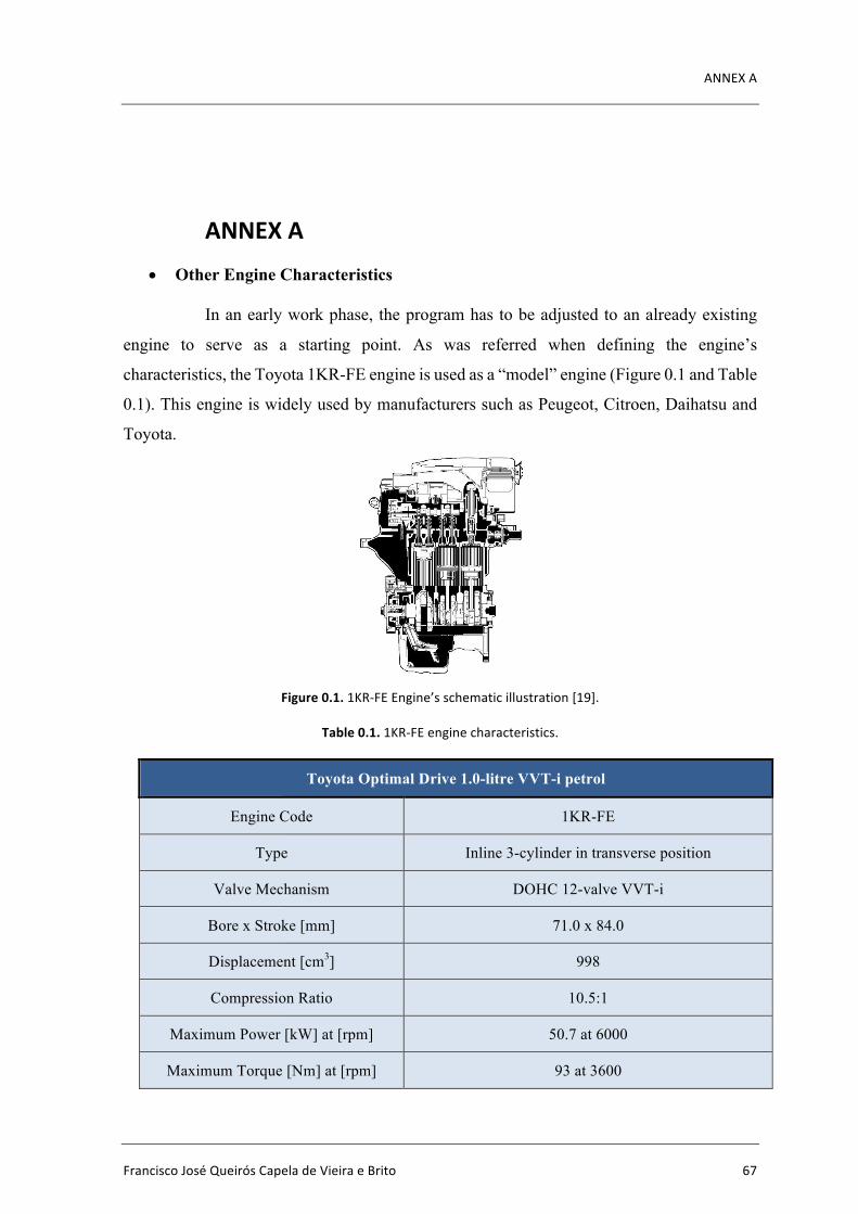
ANNEXA
FranciscoJoséQueirósCapeladeVieiraeBrito 67
ANNEXA• Other Engine Characteristics
In an early work phase, the program has to be adjusted to an already existing
engine to serve as a starting point. As was referred when defining the engine’s
characteristics, the Toyota 1KR-FE engine is used as a “model” engine (Figure 0.1 and Table
0.1). This engine is widely used by manufacturers such as Peugeot, Citroen, Daihatsu and
Toyota.
Figure0.1.1KR-FEEngine’sschematicillustration[19].
Table0.1.1KR-FEenginecharacteristics.
Toyota Optimal Drive 1.0-litre VVT-i petrol
Engine Code 1KR-FE
Type Inline 3-cylinder in transverse position
Valve Mechanism DOHC 12-valve VVT-i
Bore x Stroke [mm] 71.0 x 84.0
Displacement [cm3] 998
Compression Ratio 10.5:1
Maximum Power [kW] at [rpm] 50.7 at 6000
Maximum Torque [Nm] at [rpm] 93 at 3600

Design of the Valve Actuation Mechanism of a Four-Stroke Spark Ignition Internal CombustionEngine
68 2016
The software’s modified parameters are presented below.
1. Engine’s geometric parameters
• Number of cylinders
• Bore
• Stroke
• Compression ratio
• Connecting rod length
2. Engine’s lubrication parameters
• Oil type
• Oil crankcase temperature
• Dynamic viscosity of the oil
3. Intake valves geometric parameters
• Inlet valve opening
• Inlet valve closing
4. Exhaust valves geometric parameters
• Exhaust valve opening
• Exhaust valve closing
5. Geometric characteristics for the calculation of the engine’s friction
value
6. Piston ring geometric and lubrication characteristics
• Height and oil film thickness:
i. above the first (compression) piston ring
ii. between the first and second (compression) piston rings
iii. between the second piston ring and the oil scraper ring
iv. of the piston skirt below the oil scraper ring
• Height and oil thickness:
i. of the first piston ring
ii. of the second piston ring
iii. of the oil scraper ring
iv. of the piston skirt below the oil scraper ring
7. Geometric and lubrication characteristics of connecting rod’s and
camshaft’s bearings
ANNEXA
FranciscoJoséQueirósCapeladeVieiraeBrito 69
• Diameter, width and thickness of oil film:
i. of the connecting rod’s main bearings
ii. of the connecting rod’s head bearings
iii. of the camshaft’s main bearings
• Number of:
i. connecting rod’s main bearings
ii. connecting rod’s head bearings
iii. camshafts
• Medium diameter, width, oil film thickness and width:
i. camshaft’s rebounds
8. Camshaft and connecting rod shaft seal dimensions
• Inner connecting rod shaft seal diameter on the flywheel side
• Inner connecting rod shaft seal diameter on the supply side
• Inner camshaft shaft seal diameter on the supply side
9. Water pump specifications
• Entrance Angle
• Exit Angle
• Transmission Ratio
10. Oil pump specifications

Design of the Valve Actuation Mechanism of a Four-Stroke Spark Ignition Internal CombustionEngine
70 2016
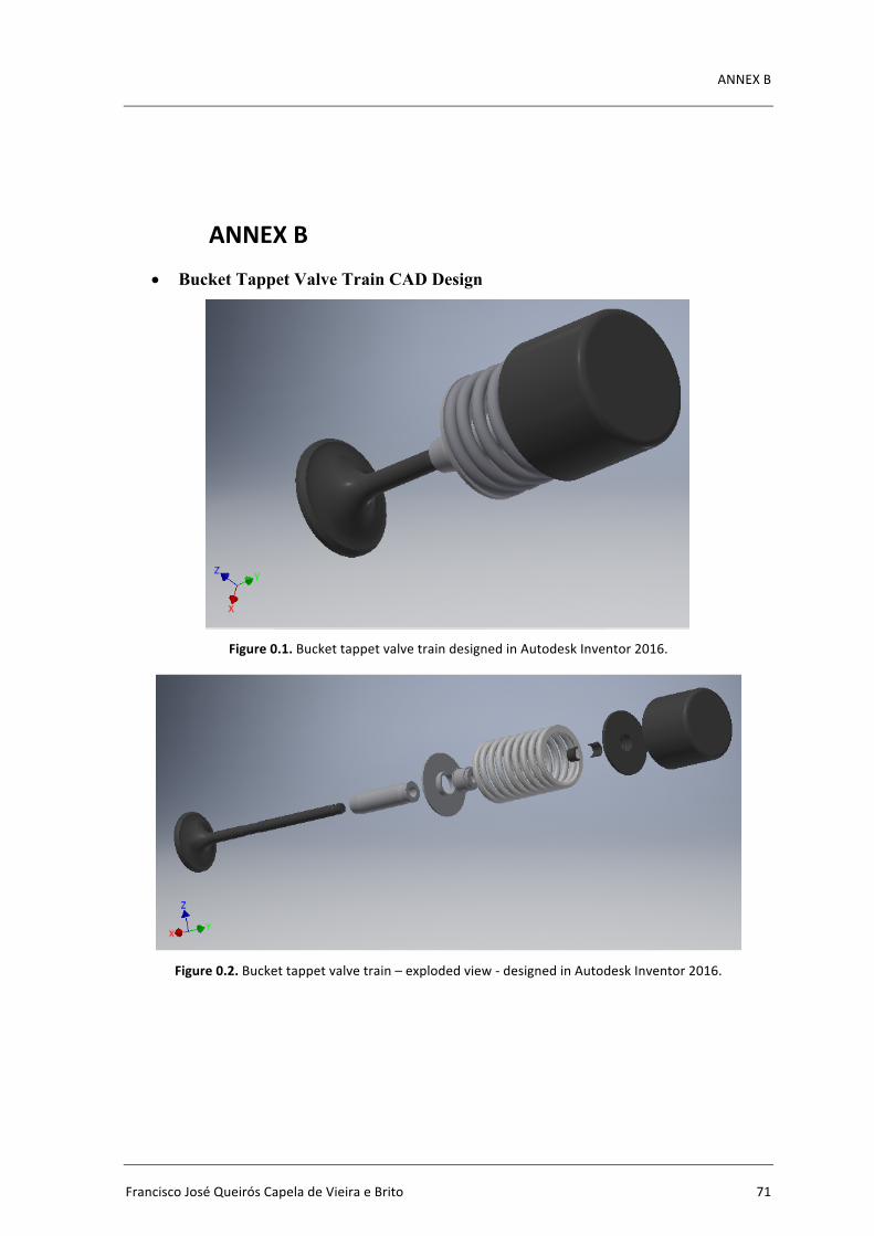
ANNEXB
FranciscoJoséQueirósCapeladeVieiraeBrito 71
ANNEXB• Bucket Tappet Valve Train CAD Design
Figure0.1.BuckettappetvalvetraindesignedinAutodeskInventor2016.
Figure0.2.Buckettappetvalvetrain–explodedview-designedinAutodeskInventor2016.
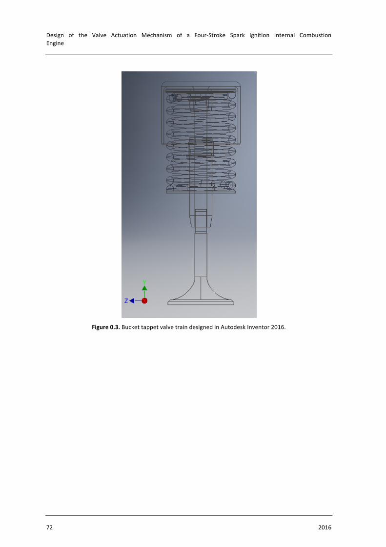
Design of the Valve Actuation Mechanism of a Four-Stroke Spark Ignition Internal CombustionEngine
72 2016
Figure0.3.BuckettappetvalvetraindesignedinAutodeskInventor2016.
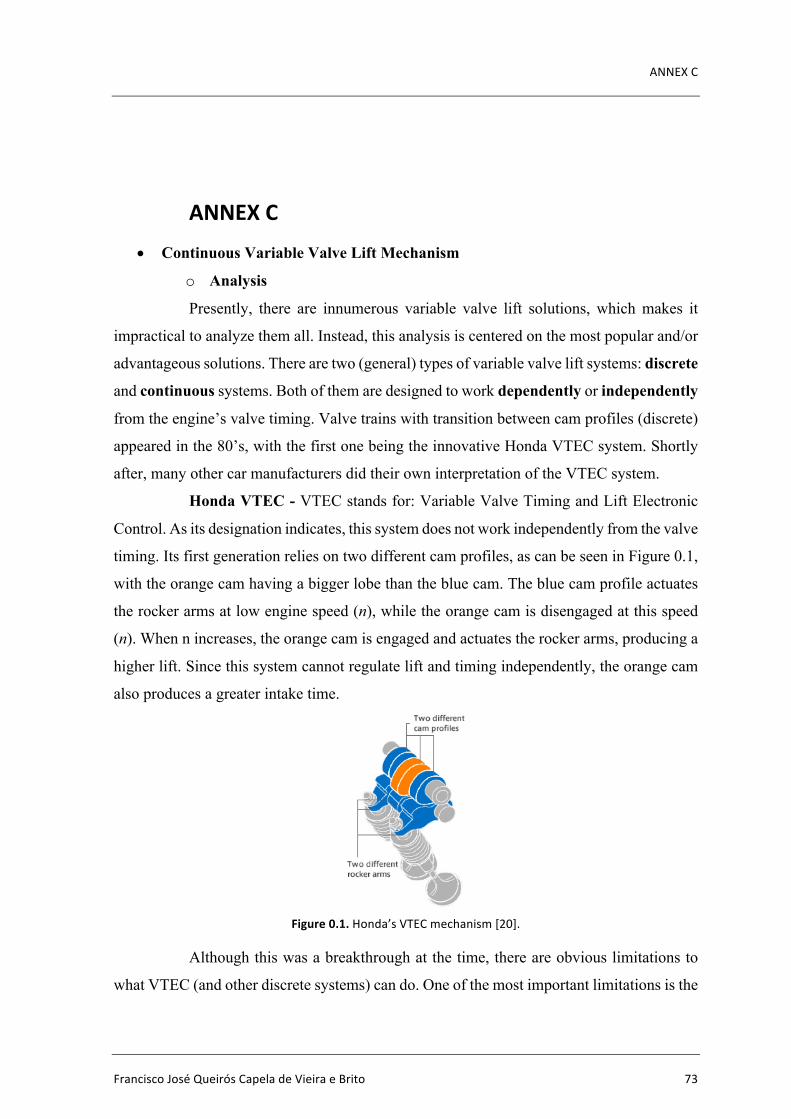
ANNEXC
FranciscoJoséQueirósCapeladeVieiraeBrito 73
ANNEXC• Continuous Variable Valve Lift Mechanism
o Analysis
Presently, there are innumerous variable valve lift solutions, which makes it
impractical to analyze them all. Instead, this analysis is centered on the most popular and/or
advantageous solutions. There are two (general) types of variable valve lift systems: discrete
and continuous systems. Both of them are designed to work dependently or independently
from the engine’s valve timing. Valve trains with transition between cam profiles (discrete)
appeared in the 80’s, with the first one being the innovative Honda VTEC system. Shortly
after, many other car manufacturers did their own interpretation of the VTEC system.
Honda VTEC - VTEC stands for: Variable Valve Timing and Lift Electronic
Control. As its designation indicates, this system does not work independently from the valve
timing. Its first generation relies on two different cam profiles, as can be seen in Figure 0.1,
with the orange cam having a bigger lobe than the blue cam. The blue cam profile actuates
the rocker arms at low engine speed (n), while the orange cam is disengaged at this speed
(n). When n increases, the orange cam is engaged and actuates the rocker arms, producing a
higher lift. Since this system cannot regulate lift and timing independently, the orange cam
also produces a greater intake time.
Figure0.1.Honda’sVTECmechanism[20].
Although this was a breakthrough at the time, there are obvious limitations to
what VTEC (and other discrete systems) can do. One of the most important limitations is the

Design of the Valve Actuation Mechanism of a Four-Stroke Spark Ignition Internal CombustionEngine
74 2016
fact that valve lift can’t be controlled independently from the valve timing. This is caused
by the fact that when a bigger cam lobe comes into effect, not only is the valve lift greater,
but also the duration of the intake (a limitation that is also present in some continuous
systems). The second limitation is the fact that there isn’t a continuous adjustment to the
vehicle’s needs. Instead, the discrete system works very similarly (in that aspect) to a
turbocharger, only coming into effect at a certain n value (which originates the so called
“turbocharger lag”). With the arrival of the XXI century came the fully continuous variable
valve lift systems. In 2001, BMW released the first system to reach production – the
Valvetronic.
BMW Valvetronic - The goal of this system is not to deliver an extra amount
of brake power, but instead, to focus on reducing the engine’s bsfc alone (BMW reports a
10% reduction in bsfc [19]). Unlike the previously existing discrete valve lift systems,
BMW’s Valvetronic ensures that valve lift is changed continuously, in order to match the
position of the throttle pedal – controlled by the driver. It is a combination between BMW’s
variable valve timing technology – the Double VANOS – and a variable valve lift
mechanism. Together they work as a fully controllable valve train. Although this innovation
allows for the throttle butterfly valve to be removed, BMW has chosen to keep it. It is only
used on cold starts and as a backup mechanism in case Valvetronic fails. In any other case,
the butterfly valve is kept fully open (like if it wasn’t there) and only Valvetronic is used.
Figure0.2.BMW’sValvetronicmechanismatminimum(left)andmaximumlift(right)positions[21].
Electric Motor
Rocker Arm Bearing Torsion Spring
Eccentric Shaft’s Gear
Rocker Arm
Intermediate Rocker Arm Eccentric Shaft
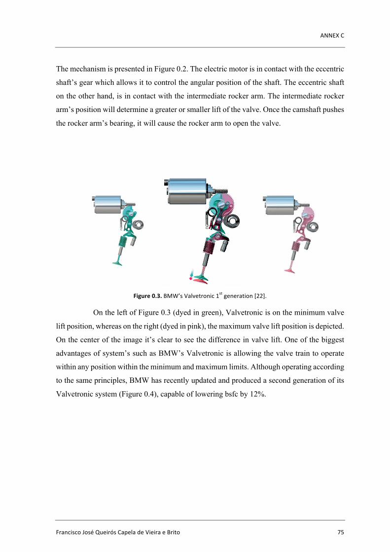
ANNEXC
FranciscoJoséQueirósCapeladeVieiraeBrito 75
The mechanism is presented in Figure 0.2. The electric motor is in contact with the eccentric
shaft’s gear which allows it to control the angular position of the shaft. The eccentric shaft
on the other hand, is in contact with the intermediate rocker arm. The intermediate rocker
arm’s position will determine a greater or smaller lift of the valve. Once the camshaft pushes
the rocker arm’s bearing, it will cause the rocker arm to open the valve.
Figure0.3.BMW’sValvetronic1stgeneration[22].
On the left of Figure 0.3 (dyed in green), Valvetronic is on the minimum valve
lift position, whereas on the right (dyed in pink), the maximum valve lift position is depicted.
On the center of the image it’s clear to see the difference in valve lift. One of the biggest
advantages of system’s such as BMW’s Valvetronic is allowing the valve train to operate
within any position within the minimum and maximum limits. Although operating according
to the same principles, BMW has recently updated and produced a second generation of its
Valvetronic system (Figure 0.4), capable of lowering bsfc by 12%.

Design of the Valve Actuation Mechanism of a Four-Stroke Spark Ignition Internal CombustionEngine
76 2016
Figure0.4.BMW’sValvetronic2ndgeneration[23].
Even though it was the first system to allow a new range of valve train
possibilities, Valvetronic has some important disadvantages. In first place it only influences
a reduction in bsfc, having no positive impact on brake power. Secondly, being a
complicated system, the high number of components mean that it has high inertia and friction
losses (limiting the maximum possible engine speed (n)). This means that, although there is
a reduction in bsfc on part load, there is no increase in brake power on full load (due to this
fact, Valvetronic will stop being a solution for BMW’s M-Power range new vehicles).
Finally, the Valvetronic system also takes up a large space above the cylinder head, which
limits its applicability to smaller vehicles.
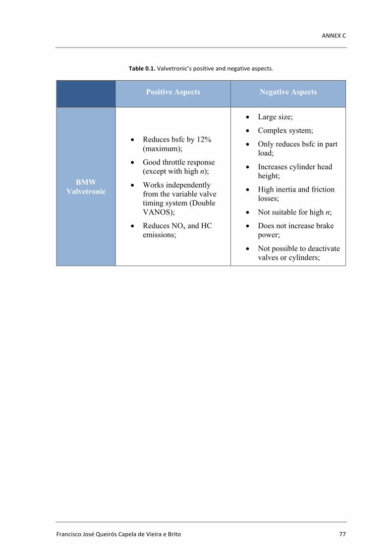
ANNEXC
FranciscoJoséQueirósCapeladeVieiraeBrito 77
Table0.1.Valvetronic’spositiveandnegativeaspects.
Positive Aspects Negative Aspects
BMW Valvetronic
• Reduces bsfc by 12% (maximum);
• Good throttle response (except with high n);
• Works independently from the variable valve timing system (Double VANOS);
• Reduces NOx and HC emissions;
• Large size;
• Complex system;
• Only reduces bsfc in part load;
• Increases cylinder head height;
• High inertia and friction losses;
• Not suitable for high n;
• Does not increase brake power;
• Not possible to deactivate valves or cylinders;
Design of the Valve Actuation Mechanism of a Four-Stroke Spark Ignition Internal CombustionEngine
78 2016
Nissan VVEL
Figure0.5.Nissan’sVVELmechanism[24].
Six years after BMW’s breakthrough, Nissan introduced its VVEL system (Variable
Valve Event and Lift). Contrary to the Valvetronic system, this technology cannot work
independently from the valve timing. The lift and timing variation are done simultaneously
by VVEL, and are mutually dependent. VVEL can achieve a variation in valve lift from 0.7
mm to 12.5 mm. Although still a complicated and bulky system, VVEL benefits from having
a shorter design and less components than Valvetronic. This allows it to have a smaller
friction energy loss compared to the Valvetronic system, and also to achieve higher n. “The
structure consists of two subsystems (Figure 0.5), the mechanical valve train system, to
operate the opening and closing of the intake valves, and the actuator system, to vary the
valve lift and event angle by controlling the multi-link mechanism of the valve train based
on control commands. The VVEL opens and closes the intake valves by transforming the
rotating motion of the drive shaft into an oscillating motion of the output cam through the
multi-link mechanism (Figure 0.5). The drive shaft, to which input cams (eccentric drive
cams) are fixed, corresponds to a conventional camshaft, being synchronized at half
crankshaft speed. Above the drive shaft, the system deploys the control shaft integrated with
Rocker Arm
Control Shaft
Drive Shaft/Camshaft
Eccentric Cam
Link A
Link B
Output cam
ANNEXC
FranciscoJoséQueirósCapeladeVieiraeBrito 79
control cams (eccentric control cams) and the rocker arm actuating (rocking) at the fulcrum
at the center of the control cam. The input cam and one end of the rocker arm are connected
to each other by link A, which transforms the rotating motion into a rocking motion. The
other end of the rocker arm is connected with the output cam by link B, actuating (oscillating)
the output cam. As a result, the output cams oscillate at the center of the driveshaft and push
down the respective valve lifters. The actuator system consists of a link mechanism, a
reduction mechanism, a DC motor and a position sensor (rotating angle sensor). The DC
motor rotates the eccentric control cam through the reduction mechanism, varying valve lift
and event angle.
Figure 0.6 shows how the system varies the valve lift by changing the attitude of
the link mechanism. The fulcrum of the rocker arm has moved its farthest travel towards the
driveshaft by shifting the eccentric control cam off-center in the direction of the driveshaft.
As a result, the whole attitude of the link mechanism has been changed, allowing the output
cam to oscillate with a large angle and hence producing a large valve lift. In counter state of
minimum valve lift, the fulcrum of the rocker arm is moved away from the drive shaft and
lowering the oscillation angle of the output cam. As a result, the contact length with the valve
lift shortens producing a small valve lift.” [28].
Figure0.6.Nissan’sVVELmechanismatmaximum(up)andminimumlift(down)[25].

Design of the Valve Actuation Mechanism of a Four-Stroke Spark Ignition Internal CombustionEngine
80 2016
The butterfly throttle valve is not completely eliminated but has its role reduced.
With this system, Nissan states that there is a reduction in 10% of bsfc at partial load.
Another advantage of VVEL is the fact that it can withstand higher n than Valvetronic, not
compromising top end performance. However, the gain in brake power given by this system
(comparing to the same engine without this technology) is largely lost due to the additional
friction of the extra components [21]. Table0.2.VVEL’spositiveandnegativeaspects.
Nissan VVEL
• Reduces bsfc by 10% (maximum);
• Good throttle response;
• Enhanced brake power at high n;
• Valves or cylinder deactivation possible;
• Reduces HC emissions;
• Large size;
• Complex system;
• Increases cylinder head height (although not as much as Valvetronic);
• Expensive;
• Doesn’t work independently from the variable timing system;
• High electrical consumption (electro-mechanical system);
ANNEXC
FranciscoJoséQueirósCapeladeVieiraeBrito 81
Toyota Valvematic
Figure0.7.Valvematic’sintermediateshaft[26].
In 2008 Toyota introduced Valvematic. Having already developed and
implemented Dual VVT-i (Variable Valve Timing with Intelligence) technology in their
vehicles, Toyota went a step further by adding a mechanism that allows for continuously
variable valve lift. Toyota’s CVVL solution (Continuous Variable Valve Lift) is notoriously
different and simpler from BMW’s and even Nissan’s complex approach. Valvematic is a
compact and simple solution that, unlike the previous two, does not increase the height of
the cylinder head. Instead, an intermediate shaft is added to the intake side of the cylinder
head (Figure 0.7). The increase in inertia and friction due to the added components is lower
(compared to the previously presented technologies), which prevents it from compromising
top end power (like Valvetronic). Toyota claims that Valvematic improves brake power by
10% and reduces by 5 to 10% bsfc in regular driving. Valvematic is able to produce a
variable lift between 0.97mm and 11mm. This technology saves the need for a throttle
butterfly valve, which helps save fuel in part load (it can be maintained for safety reasons).
Control Shaft
Roller Member
Finger
Followers

Design of the Valve Actuation Mechanism of a Four-Stroke Spark Ignition Internal CombustionEngine
82 2016
Figure0.8.ToyotaValvematic[27].
An explanation on how Valvematic operates follows: “Valvematic employs an intermediate
shaft (Figure 0.7) to achieve continuous variable valve lift. The intermediate shaft has an
actuating member for each cylinder. Each actuating member is made of two finger followers
laminating a roller bearing member (Figure 0.7). The finger followers can rotate in relation
to the roller member by means of internal gear threads (Figure 0.9) and an electric motor
attached to the end of the intermediate shaft (Figure 0.8) Note that the gear threads of roller
member and finger followers are in opposite direction (Figure 0.9). This means that when
the shaft swivels, the roller member and finger followers will move in opposite direction,
moving either apart or closer together. In this way, the axle angle between them can be varied
infinitely by the electric motor.
Figure0.9.Internalgearthreads[21].
The intake valve is actuated by the camshaft via intermediate shaft. More
precisely speaking, the camshaft acts on the roller member of the intermediate shaft,
Dual VVT-i Electromotor
Actuator
ANNEXC
FranciscoJoséQueirósCapeladeVieiraeBrito 83
transferring the movement to both finger followers, then towards the roller rocker arms and
eventually to the intake valves (Figure 0.10). When the finger follower is set at a narrow
angle in relation to the roller member, it results in a low valve lift. When the angle of the
finger follower is increased, the valve lift is also increased (Figure 0.10). In this way,
Valvematic can vary valve lift by adjusting the angle of the finger followers.” [21].
Figure0.10.Valvematic’slow(left)andhigh(right)liftpositions[21].
“The system can be classified into three mechanisms according to their function: the
actuator which drives the control shaft which changes valve lift, the variable valve lift
mechanism, and the cam phaser which controls intake and exhaust valve timing (Dual VVT-
i in Figure 0.8). The actuator (Figure 0.8) consists of a DC brushless motor, a control unit
and a mechanism to convert rotary motion into linear motion. It is connected to the control
shaft (Figure 0.7), and is positioned in the cylinder head rear end. The DC motor with a rated
output torque of about 1 N×m is arranged in a concentric circle around the conversion
mechanism for miniaturization of the actuator. When the motor turns the ring gear, the
planetary gear revolves around the sun shaft while rotating (Figure 0.11). Because the angle
of rotation of the variable arm and cam is always uniform, the range in which the roller
rocker arm comes in contact with the oscillation cam changes. The cam surface of the
oscillation cam consists of a no lift part and a lift part. This profile affects valve lift height
and valve opening duration change. When combined with variable valve timing, this
mechanism allows the valve opening and closing event to be controlled independently.” [28].
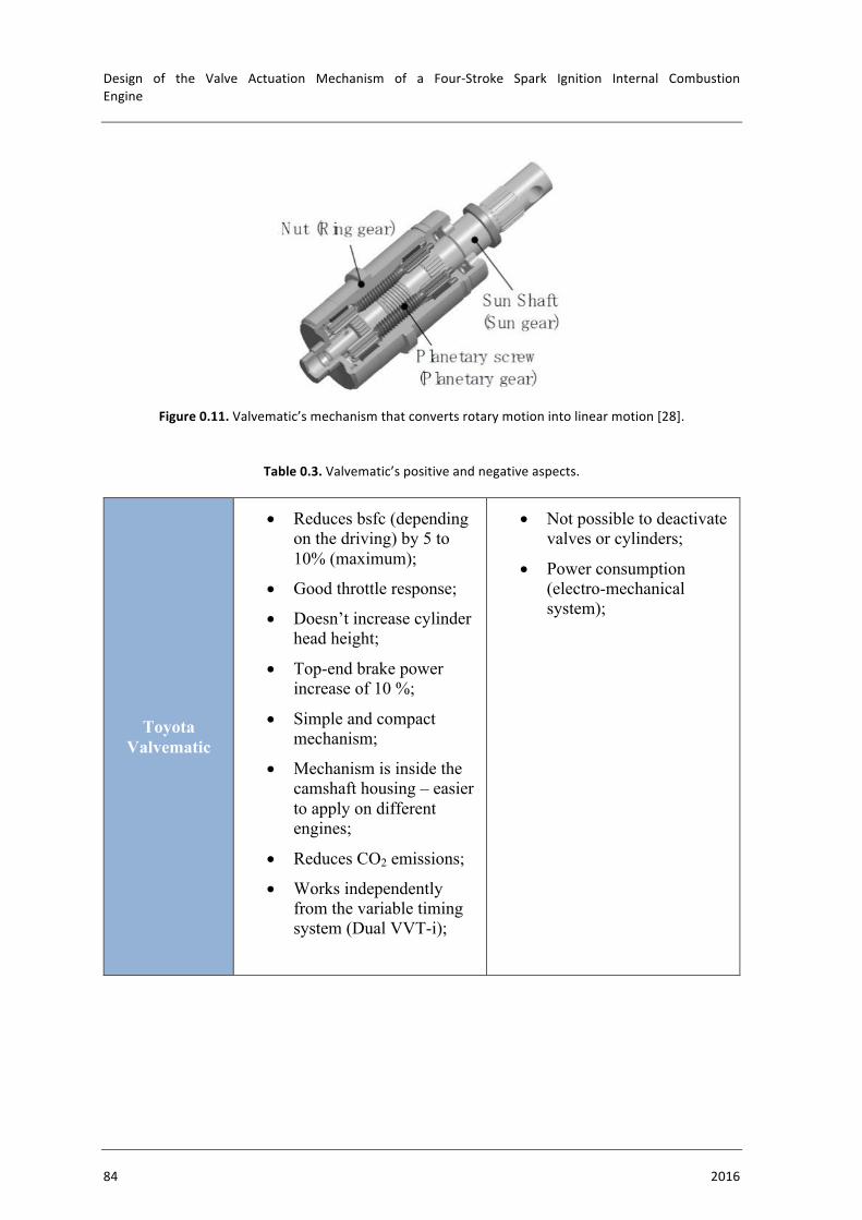
Design of the Valve Actuation Mechanism of a Four-Stroke Spark Ignition Internal CombustionEngine
84 2016
Figure0.11.Valvematic’smechanismthatconvertsrotarymotionintolinearmotion[28].
Table0.3.Valvematic’spositiveandnegativeaspects.
Toyota Valvematic
• Reduces bsfc (depending on the driving) by 5 to 10% (maximum);
• Good throttle response;
• Doesn’t increase cylinder head height;
• Top-end brake power increase of 10 %;
• Simple and compact mechanism;
• Mechanism is inside the camshaft housing – easier to apply on different engines;
• Reduces CO2 emissions;
• Works independently from the variable timing system (Dual VVT-i);
• Not possible to deactivate valves or cylinders;
• Power consumption (electro-mechanical system);

ANNEXC
FranciscoJoséQueirósCapeladeVieiraeBrito 85
FIAT MultiAir
Figure0.12.FIAT’sMultiAirmechanism[29].
MultiAir is an electro-hydraulic system created by FIAT. To understand MultiAir’s
concept, first it is necessary to consider a DOHC engine – with both intake and exhaust
camshafts. MultiAir replaces the intake camshaft of a DOHC engine - as depicted in Figure
0.12. As a result, the formerly designated “exhaust camshaft” is now the engine’s only
camshaft. Having withdrawn one of the camshafts, the system relies on the remaining one
to operate. The camshaft conventionally actuates the exhaust valves while actuating the
intake valves through a series of components (Figure 0.13). For this to be possible, an
additional cam (per cylinder) is installed on the camshaft (Figure 0.13).
(
Figure0.13.ASOHCenginewithFIAT’sMultiAirtechnology[30].
Extra Cam
Conventional Cam
Camshaft Finger Follower Pressure Accumulator
Solenoid Valve
High-pressure Chamber
Pump
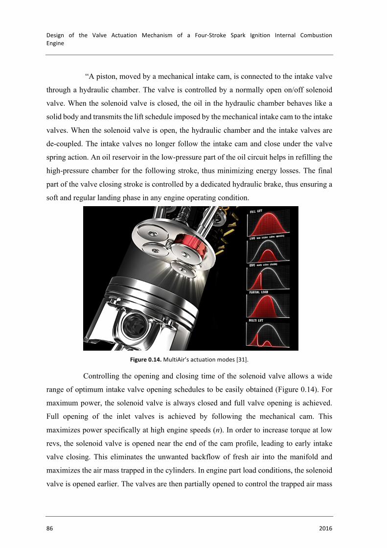
Design of the Valve Actuation Mechanism of a Four-Stroke Spark Ignition Internal CombustionEngine
86 2016
“A piston, moved by a mechanical intake cam, is connected to the intake valve
through a hydraulic chamber. The valve is controlled by a normally open on/off solenoid
valve. When the solenoid valve is closed, the oil in the hydraulic chamber behaves like a
solid body and transmits the lift schedule imposed by the mechanical intake cam to the intake
valves. When the solenoid valve is open, the hydraulic chamber and the intake valves are
de-coupled. The intake valves no longer follow the intake cam and close under the valve
spring action. An oil reservoir in the low-pressure part of the oil circuit helps in refilling the
high-pressure chamber for the following stroke, thus minimizing energy losses. The final
part of the valve closing stroke is controlled by a dedicated hydraulic brake, thus ensuring a
soft and regular landing phase in any engine operating condition.
Figure0.14.MultiAir’sactuationmodes[31].
Controlling the opening and closing time of the solenoid valve allows a wide
range of optimum intake valve opening schedules to be easily obtained (Figure 0.14). For
maximum power, the solenoid valve is always closed and full valve opening is achieved.
Full opening of the inlet valves is achieved by following the mechanical cam. This
maximizes power specifically at high engine speeds (n). In order to increase torque at low
revs, the solenoid valve is opened near the end of the cam profile, leading to early intake
valve closing. This eliminates the unwanted backflow of fresh air into the manifold and
maximizes the air mass trapped in the cylinders. In engine part load conditions, the solenoid
valve is opened earlier. The valves are then partially opened to control the trapped air mass

ANNEXC
FranciscoJoséQueirósCapeladeVieiraeBrito 87
depending on the required torque. Alternatively, the intake valves can be partially opened
by closing the solenoid valve once the mechanical cam action has already started. In this
case, the air flow into the cylinder is faster and results in higher air turbulence in the
combustion chamber. The last two actuation modes can be combined in the same intake
stroke, thus generating a so-called “MultiLift” mode that enhances turbulence and the
combustion rate at very low loads.” [28].
Table0.4.FIATMultiAir’spositiveandnegativeaspects.
Fiat
MultiAir
• Reduces bsfc by 10%;
• Good throttle response;
• Brake power increase of 10 %;
• Ability to change the cam profile;
• Flexibility of use: Allows for 5 different actuation modes;
• Independent adjustment of each cylinder (with possible deactivation of valves or cylinders)
• Low-end torque increased by 15%;
• Reduces CO2 emissions;
• Large size;
• Cannot be implemented in both intake and exhaust;
• Doesn’t include variable valve timing for the exhaust valves;

Design of the Valve Actuation Mechanism of a Four-Stroke Spark Ignition Internal CombustionEngine
88 2016
o Selection Table0.5.Comparisonbetweentheanalyzedvariablevalveliftmechanisms.
BMW
Valvetronic
Nissan
VVEL
Toyota
Valvematic
FIAT
MultiAir
Size
Flexibility
Easy to Implement
Reliability
Fuel Saving
Power boost
Having already presented the pros and cons of each system, the overall
performance of each mechanism is summarized on Table 0.5. From all four analyzed
systems, two obviously stand out: Toyota’s Valvematic and FIAT’s MultiAir. MultiAir
technology is by far the most flexible and innovative thanks to its vast array of possibilities.
It truly offers an almost infinite adjustment to the engine’s needs. However, it doesn’t offer
any type of variable valve timing to the exhaust valves, whereas Toyota’s Valvematic varies
the exhaust valves timing (through its Dual VVT-i technology). Although not as flexible and
as innovative as MultiAir, Valvematic is a surprisingly compact and yet powerful solution.
It offers more benefits and less limitations than both Valvetronic and VVEL with a much
smaller mechanism while still incorporating independent variable valve timing and lift
systems.
Throughout the years it is possible to identify some key factors that led to the
internal combustion engine’s success. Those key factors include the engine’s robustness,
simplicity and a high power/weight (or even power/size) factor. For all of the previous
pointed out reasons, and with these key factors in mind, the chosen mechanism is Toyota’s
Valvematic.
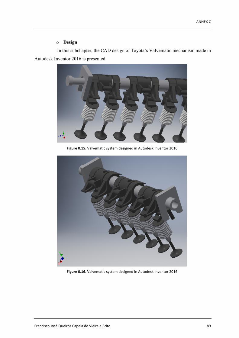
ANNEXC
FranciscoJoséQueirósCapeladeVieiraeBrito 89
o Design
In this subchapter, the CAD design of Toyota’s Valvematic mechanism made in
Autodesk Inventor 2016 is presented.
Figure0.15.ValvematicsystemdesignedinAutodeskInventor2016.
Figure0.16.ValvematicsystemdesignedinAutodeskInventor2016.

Design of the Valve Actuation Mechanism of a Four-Stroke Spark Ignition Internal CombustionEngine
90 2016
Figure0.17.ValvematicsystemdesignedinAutodeskInventor2016.
Figure0.18.Valvematic’sfingerfollowermechanismdesignedinAutodeskInventor2016.

FranciscoJoséQueirósCapeladeVieiraeBrito 91