Other Heat Exchange Equipment
30
Chapter 18 Other Heat Exchange Equipment INTRODUCTION The purpose of this chapter is to extend the material presented in the three previous chapters to the design, operation, and predicative calculations of several other types of heat exchangers. The presentation will focus on: evaporators, waste heat boilers, condensers, and quenchers. As described earlier, heat exchangers are devices used to transfer heat from a hot fluid to a cold fluid. They can be classified by their functions. Faraq and Reynolds (1) provide an abbreviated summary of these units and their functions (see Table 14.1). To this list can be added a host of other exchangers, including parallel corrugated plates, plate units, etc. (2) Also to be included in the list are direct-contact coolers and speciality condensers. (3) The four general classifications of direct-contact gas–liquid heat transfer oper- ations are: 1. simple gas cooling, 2. gas cooling with vaporization of coolant, 3. gas cooling with partial condensation, and 4. gas cooling with total condensation. Most of the direct-exchange applications listed above are accomplished with the following devices: 1. Baffle-tray columns. 2. Spray chambers. 3. Packed columns. 4. Crossflow-tray columns. 5. Pipeline contactors. Heat Transfer Applications for the Practicing Engineer. Louis Theodore # 2011 John Wiley & Sons, Inc. Published 2011 by John Wiley & Sons, Inc. 381
-
Upload
khangminh22 -
Category
Documents
-
view
0 -
download
0
Transcript of Other Heat Exchange Equipment

Chapter 18
Other Heat ExchangeEquipment
INTRODUCTION
The purpose of this chapter is to extend the material presented in the three previouschapters to the design, operation, and predicative calculations of several other typesof heat exchangers. The presentation will focus on: evaporators, waste heat boilers,condensers, and quenchers.
As described earlier, heat exchangers are devices used to transfer heat from a hotfluid to a cold fluid. They can be classified by their functions. Faraq and Reynolds(1)
provide an abbreviated summary of these units and their functions (see Table 14.1).To this list can be added a host of other exchangers, including parallel corrugatedplates, plate units, etc.(2) Also to be included in the list are direct-contact coolersand speciality condensers.(3)
The four general classifications of direct-contact gas–liquid heat transfer oper-ations are:
1. simple gas cooling,
2. gas cooling with vaporization of coolant,
3. gas cooling with partial condensation, and
4. gas cooling with total condensation.
Most of the direct-exchange applications listed above are accomplished with thefollowing devices:
1. Baffle-tray columns.
2. Spray chambers.
3. Packed columns.
4. Crossflow-tray columns.
5. Pipeline contactors.
Heat Transfer Applications for the Practicing Engineer. Louis Theodore# 2011 John Wiley & Sons, Inc. Published 2011 by John Wiley & Sons, Inc.
381

ILLUSTRATIVE EXAMPLE 18.1
Which of the following is NOT a heat exchanger?
(a) Reboiler
(b) Condenser
(c) Absorber
(d) Superheater
SOLUTION: A reboiler is connected to the bottom of a fractionating tower and providesthe reboil heat necessary for distillation. The heating medium, which may be steam or a hotprocess fluid, transfers heat to the bottoms product of the column. Therefore, a reboiler is classi-fied as a heat exchanger.
A condenser (see later section) condenses a vapor or mixture of vapors either alone or inthe presence of a non-condensable gas. The cooling medium, which may be cooling water orair, absorbs heat from the hot process vapor. Therefore, a condenser is classified as a heatexchanger.
An absorber(4) is a mass transfer device, used for separating components from either a liquidor gaseous stream. Therefore, an absorber is NOT a heat exchanger.
A superheater heats a vapor above its saturation temperature. Therefore a superheater isclassified as a heat exchanger.
Therefore, (c) is the correct answer. B
The following topics are treated in this chapter:
Evaporators
Waste heat boilers
Condensers
Quenchers
Cooling towers do not receive treatment; however, material is available in theliterature.(4)
EVAPORATORS
The vaporization of a liquid for the purpose of concentrating a solution is a commonoperation in the chemical process industry. The simplest device is an open pan or kettlethat receives heat from a coil or jacket or by direct firing underneath the pan. Perhapsthe traditional unit is the horizontal-tube evaporator in which a liquid (to be concen-trated) in the shell side of a closed, vertical cylindrical vessel is evaporated by passingsteam or another hot gas through a bundle of horizontal tubes contained in the lowerpart of the vessel. The liquid level in the evaporator is usually less than half the heightof the vessel; the empty space permits disengagement of entrained liquid from thevapor passing overhead.(5)
382 Chapter 18 Other Heat Exchange Equipment

The describing equation of an evaporator, like that of any heat exchanger, isgiven by
_Q ¼ UADTlm (18:1)
The term (UA)21 is equal to the sum of the individual resistances of the steam, thewalls of the tubes, the boiling liquid, and any fouling that may be present.
Consider Figure 18.1.(5) Assume F lb of feed to the evaporator per hour, whosesolid content is xF. (The symbol x is employed for weight fraction.) Also, assumethe enthalpy of the feed per lb to be hF. L lb of thick liquor, whose compositionin weight fraction of solute is xL and whose enthalpy is hL leaves from the bottomof the evaporator. V lb of vapor, having a solute concentration of yV and an enthalpyof hV Btu/lb, leaves the unit. In most evaporators, the vapor is pure water, and there-fore yV is zero.
The material balance equations for this evaporator are relatively simple. A totalmaterial balance gives
F ¼ Lþ V (18:2)
A componential balance leads to
FxF ¼ LxL þ VyV (18:3)
Vapor
Steam
CondensateThick liquor
VyV
ShS
ShC
hV
LxLhL
FeedFxFhF
Figure 18.1 Material and enthalpy balance for a single-effect evaporator.
Evaporators 383

In order to furnish the heat necessary for evaporation, S lb of stream is supplied tothe heating surface with an enthalpy of hS Btu/lb; S lb of condensate with an enthalpyof hC Btu/lb is leaving as condensate. One simplifying assumption usually made isthat, in an evaporator, there is very little cooling of the condensate. This is usuallyless than a few degrees in practice; the sensible heat recovered from cooling the con-densate is so small compared to the latent heat of the steam supplied to the heating sur-face that the condensate will leave at the condensing temperature of the steam. Theenthalpy balance equation is therefore,
FhF þ ShS ¼ VhV þ LhL þ ShC (18:4)
Both Equations (18.1) and (18.4) are applied in tandem when designing and/orpredicting the performance of an evaporator.
Mixing Effects
The calculations for an evaporator can be complicated because of an adiabatic solutiontemperature change. When two or more pure substances are mixed to form a solution, aheat effect usually results. Many have experienced this effect on mixing concentratedsulfuric acid with water. This heat of mixing is defined as the enthalpy change thatoccurs when two or more pure substances are mixed at constant temperature andpressure to form a solution.
Enthalpy concentration diagrams offer a convenient way to calculate enthalpy ofmixing effects and temperature changes associated with this type of process. Thesediagrams, for a two-component mixture, are graphs of the enthalpy of a binary solutionplotted as a function of composition (mole fraction or weight fraction of one com-ponent), with the temperature as a parameter. For an ideal solution, isotherms or anenthalpy-concentration diagram would be straight lines. For a real solution, theactual isotherm is displaced vertically from the ideal solution isotherm at a givenpoint by the value of Dh at that point, where Dh is the enthalpy of mixing. Withreference to the enthalpy concentration diagram in Figure 18.2, Dh is negativeover the entire composition range. This means that heat must be evolved wheneverthe pure components at the given temperature are mixed to form a solution at thesame temperature. Such a system is said to be exothermic. An endothermic systemis one for which the heats of solution are positive, i.e., solution at constanttemperature is accompanied by the absorption of heat. Organic mixtures often fitthis description.(5)
ILLUSTRATIVE EXAMPLE 18.2
Calculate the temperature when 50 lb of pure H2SO4 at 258C is mixed adiabatically with 200 lbof a 50% by weight aqueous H2SO4 solution at 258C. Also calculate the heat effect if the finalmixture is at 258C.
384 Chapter 18 Other Heat Exchange Equipment

SOLUTION: Calculate the weight (or mass) percent H2SO4 in the final H2SO4–H2O mixture:
H2SO4: 50þ 100 ¼ 150 lb
H2O: 100 lb
%H2SO4 ¼ ð150=250Þ100 ¼ 60%
Construct a straight line between the 50% solution and pure H2SO4 at 258C (778F) onFigure 18.2 in order to estimate the final temperature in 8F at 60% H2O:
T ¼ 1408F
200°F180
16014012010080
77
60
4032
wt. % H2SO4
h (B
tu/lb
) so
lutio
n
–140
–120
–100
–80
–60
–40
–20
140
120
100
80
60
40
20
0
0 10 20 30 40 50 60 70 80
Free
zing
line
90 100
Figure 18.2 Enthalpy-concentration diagram for H2SO4–H2O. (Adapted from the data of W. D. ROSS,Chem. Eng. Progr., 43, 314, 1952.)
Evaporators 385

Calculate the heat, Q, that needs to be transferred to return the mixture to 258C. FromFigure 18.2,
h at 1408F ¼ �86 Btu=lb
h at 778F ¼ �121:5 Btu=lb
so that
Q ¼ mDh ¼ m(h2 � h1)(250)(�121:5þ 86) ¼ �8875 Btu
This represents the amount of heat that must be removed since Q is negative.There is also a heat effect when gases or solids are dissolved in liquids. This effect is nor-
mally small but can be significant in some applications, particularly acidic gases in water.This type of calculation should be included in not only evaporator calculations but also forsome absorber systems when temperature changes through the unit can be significant. B
ILLUSTRATIVE EXAMPLE 18.3
A single-effect evaporator is to concentrate 10,000 lb/h of a 10% NaOH solution to 75%. Thefeed enters at 1208F and the evaporator is to operate at an absolute pressure of 14.7 psi. The 75%NaOH solution leaves at the evaporator equilibrium temperature. For what heat transfer rate(Btu/h) should the evaporator be designed? Also calculate the area requirement in the evapor-ator if the overall heat transfer coefficient is 500 Btu/h . ft2 . 8F and 103 psig (3408F) saturatedsteam is employed in the steam chest. The NaOH–H2O enthalpy-concentration diagram is pro-vided in Figure 18.3. The enthalpy of saturated steam at 14.7 psia is approximately 1150 Btu/lb.
SOLUTION: Assume a basis of one hour of operation. Calculate the flow rate of steam, V, andthe 75% NaOH–H2O solution, L, leaving the evaporator. From a NaOH balance,
(10,000)(0:1) ¼ (0:75)(L)
L ¼ 1333:3 lb=h
From an overall material balance,
F ¼ Lþ V
V ¼ 10,000� 1333 ¼ 8667 lb/h
Estimate the enthalpy of solution entering the unit, hF, in Btu/lb, see Figure 18.3,
hF ¼ 81 Btu/lb solution
Estimate the enthalpy of the 75% NaOH solution, hL, leaving the unit:
hL ¼ 395 Btu/lb solution
The evaporator heat required, _Q, in Btu/h is then
_Q ¼ S _mihi ¼ (8667)(1150)þ (1333)(395)� (10,000)(81) ¼ 9,683,600 Btu=h
386 Chapter 18 Other Heat Exchange Equipment
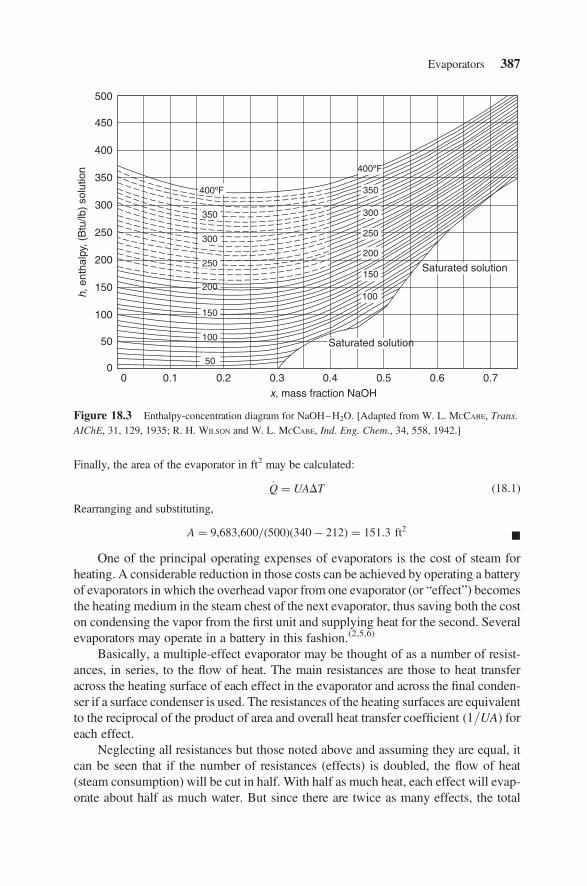
Finally, the area of the evaporator in ft2 may be calculated:
_Q ¼ UADT (18:1)
Rearranging and substituting,
A ¼ 9,683,600=(500)(340� 212) ¼ 151:3 ft2 B
One of the principal operating expenses of evaporators is the cost of steam forheating. A considerable reduction in those costs can be achieved by operating a batteryof evaporators in which the overhead vapor from one evaporator (or “effect”) becomesthe heating medium in the steam chest of the next evaporator, thus saving both the coston condensing the vapor from the first unit and supplying heat for the second. Severalevaporators may operate in a battery in this fashion.(2,5,6)
Basically, a multiple-effect evaporator may be thought of as a number of resist-ances, in series, to the flow of heat. The main resistances are those to heat transferacross the heating surface of each effect in the evaporator and across the final conden-ser if a surface condenser is used. The resistances of the heating surfaces are equivalentto the reciprocal of the product of area and overall heat transfer coefficient (1/UA) foreach effect.
Neglecting all resistances but those noted above and assuming they are equal, itcan be seen that if the number of resistances (effects) is doubled, the flow of heat(steam consumption) will be cut in half. With half as much heat, each effect will evap-orate about half as much water. But since there are twice as many effects, the total
100h, e
ntha
lpy,
(B
tu/lb
) so
lutio
n
500
450
400
350
300
250
200
150
100
50
0
x, mass fraction NaOH
Saturated solution
Saturated solution
0 0.1 0.2 0.3 0.4 0.5 0.6 0.7
400ºF
400ºF
300
300350
350
250
250
200
200
50
100
150
150
Figure 18.3 Enthalpy-concentration diagram for NaOH–H2O. [Adapted from W. L. MCCABE, Trans.
AIChE, 31, 129, 1935; R. H. WILSON and W. L. MCCABE, Ind. Eng. Chem., 34, 558, 1942.]
Evaporators 387

evaporation will be the same. Thus, under these simplifying assumptions, the sameoutput would be obtained regardless of the number of effects (each of equal resist-ances), and the steam consumption would be inversely proportional to the numberof effects or the total heating surface installed.
This resistance concept is also useful in understanding the design and operation ofsuch units. The designer places as many resistances (effects) in series as can be affordedin order to reduce the steam consumption. One can also show that the lowest total arearequired arises when the ratio of temperature drop to area is the same for each effect.
ILLUSTRATIVE EXAMPLE 18.4
Given the triple-effect evaporator information below, calculate the temperature drop across theheating surface in the first effect:
Effect U, Btu/h . ft2 . 8F A, ft3
1 240 1252 200 1503 125 160
The condensing stream temperature in the first effect and the vapor leaving the third effect are4008F and 1208F, respectively.
SOLUTION: Assuming the resistances across each effect are the same,
R1 ¼1
U1A1¼
1(240)(125)
¼ 3:333� 10�5
R2 ¼1
U2A2¼
1(200)(150)
¼ 3:333� 10�5
R3 ¼1
U3A3¼
1(125)(160)
¼ 5:0� 10�5
XR ¼ 11:666� 10�5
One may therefore write,
DT1
DTTOTAL¼
R1PR
Substituting
DT1 ¼(400� 120)(3:333� 10�5)
(11:666� 10�5)
¼ 808F B
ILLUSTRATIVE EXAMPLE 18.5
Qualitatively describe what an evaporator does.
388 Chapter 18 Other Heat Exchange Equipment

SOLUTION: This is an open-ended question that could just have easily been placed inChapter 23. Standiford(7) provides an answer to this example.
The requirements for the correct functioning of any evaporator are:
1. It must transfer a great deal of heat—on the order of 1000 Btu/lb of water evaporated.This, more than anything else, determines the type, size, and cost of each effect of theevaporator.
2. It must efficiently separate the vapor from the residual liquid. What is efficient inone evaporator may be many orders of magnitude different from what is efficient inanother (e.g., from loss of salt value at only a few dollars a ton, to lithium chemicalsvalued at a dollar a pound, to radioactive waste). Separation may be important solelybecause of the value of product lost, pollution problems, or because of fouling or cor-rosion in the equipment in which the vapor is condensed or in which the condensate issubsequently used.
3. It must make as efficient use of the available heat or mechanical energy as iseconomically feasible. This means using the vapor evaporated in one part (effect) ofthe evaporator as the heating steam in another effect that is operating at a lowertemperature (as in a multiple-effect evaporator), or compressing the vapor evolvedso that it can be used as the heating medium in the same evaporator, or by employ-ing a combination of these. As in most other cases, efficiency is usually gained onlyas capital cost is increased and, for evaporators, the designer has a wide range tochoose from.
4. It must meet conditions dictated by the characteristics of either the liquid beingevaporated or the product. In a crystallizing evaporator,(4) crystal size, shape, andpurity may be of the utmost importance. If a salting or scaling liquid is to be handled,the evaporator type selected must be capable of dealing with it. Product quality charac-teristics that may also be important are corrosiveness and degradation at high tempera-ture, long holdup time, or contact with certain metals.
Other considerations are the size of the operation, the foaming characteristics of the liquor,the need for special types of materials of construction such as polished stainless steel (requiredfor many food products), and easy access for cleaning. B
ILLUSTRATIVE EXAMPLE 18.6 (adapted from Badger and Banchero(8))
An evaporator is to be fed with 5000 lb of solution containing 2% solids by weight. The feed,F, is at a temperature of 1008F. It is to be concentrated to a solution of 5% solute by weight inan evaporator operating at a pressure of 1 atm in the vapor space. In order to carry out theevaporation, the heating surface is supplied with steam at 5 psig (2278F) and the overall heattransfer coefficient of the evaporator, U, is 280 Btu/h . ft2 . 8F. What is the mass of vaporproduced, the total mass of steam required, and the surface area required? Neglect enthalpyof solution effects.
SOLUTION: In order to simplify the solution, it will be assumed that the solution isso dilute that its boiling point is the same as the boiling point of water and that its heatcapacity and latent enthalpy are the same as that of water. Under these circumstances, the ther-mal properties of the solution (both feed and product) and of the steam can be taken from thesteam tables. This results in the following values for pertinent quantities on a per hour
Evaporators 389

basis (see Figure 18.1):
F ¼ 5000 lb
xF ¼ 0:02
Total solids in feed ¼ (5000)(0:02) ¼ 100 lb (componential balance)
Total water in feed ¼ 5000� 100 ¼ 4900 lb (componential balance)
TF ¼ 1008F
hF ¼ 68 Btu=lb (estimated from steam tables at 1008F)
xL ¼ 0:05
Total solids in liquor ¼ (5000)(0:02) ¼ 100 lb
L ¼ 100=(0:05) ¼ 2000 lb
TL ¼ 2128F (at 1 atm)
hL ¼ 180 Btu=lb (estimated from steam tables)
V ¼ 5000� 2000 ¼ 3000 (overall balance)
TV ¼ 2128F
hV ¼ 1156 Btu=lb (estimated from steam tables at 1.0 atm)
TS ¼ 2278F
hS ¼ 1156 Btu=lb (estimated from steam tables at 2278F
and 5 psig)
TC ¼ 2278F (condensate)
hC ¼ 195 Btu=lb (estimated from steam tables)
The following enthalpy (energy) balance results (S representing steam):
F(hF)þ S(hS) ¼ V(hV )þ L(hC)þ S(hC)
Substituting and solving yields
(5000)(68)þ 1156(S) ¼ (3000)(1150)þ (2000)(180)þ 195(S)
S ¼ 3611 lb
The total heat requirement is
Q ¼ (3611)(1156� 195) ¼ 3,470,000 Btu
The required area is (assuming all of the above is based on one hour)
A ¼ Q=UDT ¼ 3,470,000=(280)(227� 212) ¼ 826 ft2 B
ILLUSTRATIVE EXAMPLE 18.7 (adapted from Badger and Banchero(8))
An evaporator is fed with 5000 lb/h of a 20% solution of sodium hydroxide at 1008F. This is tobe concentrated to a 40% solution. The evaporator is supplied with saturated steam at 5 psig.Although the unit operates with the vapor space at a pressure of 4 in Hg absolute, the boiling
390 Chapter 18 Other Heat Exchange Equipment

temperature of the solution in the evaporator is 1988F (due to the superheat created by theexposed heating element). The overall heat transfer coefficient is 400 Btu/h . ft2 . 8F.Calculate the steam rate and the required heat transfer area.
SOLUTION: Assume a basis of one hour. The following data is known:
F ¼ 5000 lb; xF ¼ 0:20
TF ¼ 1008F; xL ¼ 0:40
xV ¼ yV ¼ 0:00
From the steam tables (see Appendix) at 2288F and 5 psig,
hS ¼ 1156 Btu=lb
hC ¼ 196 Btu=lb
hvap ¼ 1156� 196 ¼ 960 Btu=lb
In addition,
Boiling point of water at 4 in Hg absolute ¼ 125:48FEnthalpy of saturated steam at 1258F ¼ 1116 Btu=lb (estimated from steam tables)
hF(1008F) ≃ 55 Btu=lb (from Figure 18:3)
hL(1988F) ≃ 177 Btu=lb (from Figure 18.3)
A componential material balance yields
FxF ¼ LxL þ VyV ; yV ¼ 0:0
(5000)(0:20) ¼ (0:40)(L)
L ¼ 2500 lb
V ¼ 2500 lb
An enthalpy balance yields
FhF þ S(hS � hC) ¼ VhV þ LhL
In calculating hV, the enthalpy of vapor leaving the solution, it should be rememberedthat this vapor is in equilibrium with the boiling solution at a pressure of 4 in Hg absoluteand therefore, is superheated in comparison with vapor in equilibrium with water at the samepressure. Since the heat capacity of superheated steam in this range may be assumed to be0.46 Btu/lb . 8F, then
hV ¼ 1116þ (0:46)(198:0� 125) ¼ 1150 Btu=lb
Substituting into the enthalpy balance gives
5000(55:0)þ S(1156� 196) ¼ (2500)(1150)þ (2500)(177)
Solving for S, the steam rate, yields
S ¼ 3170 lb=h
Evaporators 391

The area may now be calculated using the standard heat exchanger equation.
_Q ¼ UADT
(3170)(1156� 196) ¼ 400(A)(228� 198)
A ¼ 254 ft2 B
WASTE HEAT BOILERS
Energy has become too valuable to discard. As a result, waste heat and/or heat-recovery boilers are now common in many process plants. As the chemical processingindustries become more competitive, no company can afford to waste or dump thermalenergy. This increased awareness of economic considerations has made waste-heatboilers one of the more important products of the boiler industry. The term “wasteheat boiler” includes units in which steam is generated primarily from the sensibleheat of an available hot flue or hot gas stream rather than by solely firing fuel.
An obvious by-product of incineration processes is thermal energy—in manycases, a large amount of thermal energy. The total heat load generated by a typicalhazardous waste incinerator, for example, is in the range of 10 to 150 millionBtu/h. While waste heat boilers are capable of recovering 60–70% of this energy,the effort may or may not be justified economically. In assessing the feasibility ofrecovery, a number of factors must be taken into account; among these are theamount of heat wasted, the fraction of that heat that is realistically recoverable, theirregularity in availability of heat, the cost of equipment to recover the heat, andthe cost of energy. The last factor is particularly critical and may be the mostimportant consideration in a decision involving whether or not to harness theenergy generated by a particular incinerator. Other important considerations are theincinerator capacity and nature of the waste/fuel being handled. Generally, heat recov-ery on incinerators of less than 5 million Btu/h may not be economical because ofcapital cost considerations. Larger capacity incinerators may also be poor candidatesfor heat recovery if steam is not needed at the plant site or if the combustion gases arehighly corrosive; in the latter case, the maintenance cost of the heat recovery equip-ment may be prohibitive.
The main purpose of a boiler is to convert a liquid, usually water, into a vapor. Inmost industrial boilers, the energy required to vaporize the liquid is provided by thedirect firing of a fuel in the combustion chamber. The energy is transferred from theburning fuel in the combustion chamber by convection and radiation to the metalwall separating the liquid from the combustion chamber. Conduction then takesplace through the metal wall and conduction/convection into the body of the vapor-izing liquid. In a waste heat boiler, no combustion occurs in the boiler itself; the energyfor vaporizing the liquids is provided by the sensible heat of hot gases which areusually product (flue) gases generated by a combustion process occurring elsewherein the system. The waste heat boilers found at many facilities make use of the fluegases for this purpose.
392 Chapter 18 Other Heat Exchange Equipment

In a typical waste heat boiler installation, the water enters the unit after it haspassed through a water treatment plant or the equivalent. This boiler feed water issent to heaters/economizers and then into a steam drum. Steam is generated in theboiler by indirectly contacting the water with hot combustion (flue) gases. Thesehot gases may be around 20008F. The steam, which is separated from the water inthe steam drum, may pass through a superheater, and is then available for internaluse or export. The required steam rate for the process or facility plus the steam temp-erature and pressure are the key design and operating variables on the water side. Theinlet and outlet flue gas temperatures also play a role, but it is the chemical properties ofthe flue gas that can significantly impact boiler performance. For example, acid gasescan arise due to the presence of any chlorine or sulfur in the fuel or waste. The prin-cipal combustion product of chlorine is hydrogen chloride, which is extremely corros-ive to most metal heat transfer surfaces. This problem is particularly aggravated if thetemperature of the flue gas is below the dewpoint temperature of HCl (i.e., the temp-erature at which the HCl condenses). This usually occurs at temperatures of about3008F. In addition to acid gases, problems may also arise from the ash of incinerationprocesses; some can contain a fairly high concentration of alkali metal salts that havemelting points below 15008F. The lower melting point salts can slag and ultimatelyfoul (and, in some cases, corrode) boiler tubes and/or heat transfer surfaces.
Boilers may be either fire tube or water tube (water-wall). Both are commonlyused in practice; the fire-tube variety is generally employed for smaller applications(,15 � 106 Btu/h). In the fire-tube waste heat boiler, the hot gases from the processare passed through the boiler tubes. The bundle of tubes is immersed in the water to bevaporized; the vaporizing water and tube bundles are encased in a large insulated con-tainer called a shell. The steam generated is stored in a surge drum, usually locatedabove the shell and connected to the shell through vertical tubes called risers.Because of construction constraints, steam pressure in fire-tube boilers is usually lim-ited to around 1000 psia.
Fire-tube boilers are compact, low in initial cost, and easy to modularize based onplant requirements. However, they are also slow to respond to changes in demand forsteam (load) compared to water-tube boilers, and the circulation is slower. Also, stres-ses are greater in fire-tube boilers because of their rigid design and subsequent inabilityto expand and contract easily. Fire-tube boilers usually range in size from less than 2 to50 million Btu/h. Most industrial fire-tube boilers are either horizontal return tube(HRT), scotch marine, or firebox. Fire-tube boilers are usually directly fired withfuels, either liquid or gaseous. They also serve to recover heat from incineratorsfired on waste fuels.
In the water-tube waste heat boiler, the water is contained inside the tubes and thehot flue gases flow through the tube bundle, usually in a direction perpendicular to thetubes (cross-flow). Because of the increased turbulence that accompanies cross-flow,the overall heat transfer coefficient for water-tube boilers is higher than that for fire-tube boilers. This advantage is somewhat offset, however, because it is more difficultto clean the outside surfaces of the tubes than the inside surfaces. As a result, heattransfer losses and maintenance problems due to flue gas fouling tend to be greaterin water-tube boilers.
Waste Heat Boilers 393

Water-tube boilers can be physically divided into two sections, the furnace andthe convection pass. Furnaces (fireboxes, combustion chambers, etc.) will vary in con-figuration and size, but their function is to contain the flaming combustion gases andtransfer the heat energy to the water-cooled walls. The convection pass contains thesuperheaters, reheater, economizer, and air preheater heat exchangers, where theheat of the combustion flue gases is used to increase the temperature of the steam,water, and combustion air. The superheaters and reheaters are designed to increasethe temperature of the steam generated within the tubes of the furnace walls. Steamflows inside the tubes and flue gas passes along the outside surface of the tubes.The economizer is normally a counterflow heat exchanger designed to recoverenergy from the flue gas after the superheater and the reheater. The boiler economizeris a tube bank type, hot-gas-to-water heat exchanger. It increases the temperature of thewater entering the steam drum. The air heater is not a portion of the steam–water cir-cuit, but serves a key role in the steam generator system to provide additional heattransfer and efficiency. In many cases, especially in a high pressure boiler, the temp-erature of the flue gas leaving the economizer is still quite high. The air heater recoversmuch of this energy and adds it to the combustion air. Heating the combustion air priorto its entrance to the furnace reduces fuel usage.
Water-tube boilers respond quickly to changes in demand for steam due toimproved water circulation. They can withstand much higher operating pressuresand temperatures than fire-tube boilers. In addition, the water-tube boiler design issafer. They can also burn a wide variety of fuels as well as wastes and have the abilityto expand and contract more easily than fire-tube boilers. The major drawback is thatwater-tube boilers are more expensive to install. They also require more complicatedfurnaces and repair techniques.
Describing Equations
The design of waste heat boilers involve calculations that are based on energy balancesand estimates of the rates of heat transfer. Although some units operate in an unsteady-state or cyclical mode, the calculation procedures are invariably based on steady-stateconditions.
In heat transfer equipment, there is no shaft work, and potential and kinetic energyeffects are small in comparison with the other terms in an energy balance equation.Heat flow to or from the surroundings is not usually desired in practice and is usuallyreduced to a small magnitude by suitable insulation. It is therefore customary to con-sider this heat loss or gain negligible in comparison to the heat transfer through thewalls of the tubes from the hot combustion gases to the water in the boilers. Thus,all the sensible heat lost by the hot gases may be assumed transferred to the steam.
The heart of the heat transfer calculation is the heat flux, which is based on the areaof the heating surface and is a function of the temperature difference driving force andthe overall heat transfer coefficient, as discussed earlier. This relatively simple equationcan be used to estimate heat transfer rates, area requirements, and temperature changesin a number of heat transfer devices. However, problems develop if more exact
394 Chapter 18 Other Heat Exchange Equipment

calculations are required. The properties of the fluid (viscosity, thermal conductivity,heat capacity, and density) are important parameters in these calculations. Each ofthese properties, especially viscosity, is temperature dependent. Since a temperatureprofile, in which the temperature varies from point to point, exists in a flowingstream undergoing heat transfer, a problem arises in the choice of temperature atwhich the properties should be evaluated. When temperature changes within thestream become large, the difficulty of calculating heat transfer quantities is increased.Because of these effects, the entire subject of heat transfer to fluids with phase change(as in a waste heat boiler) is complex and, in practice, is treated empirically rather thantheoretically.(3)
The rigorous design and/or performance evaluation of a waste heat boiler isan involved procedure. Fortunately, several less rigorous methods are available inthe literature. One approach that is fairly simple and yet reasonably accurate hasbeen devised by Ganapathy.(9) This method provides a technique for sizing wasteheat boilers of the fire-tube type and involves the use of a performance evaluationchart (see Figure 18.4) that is based on fundamental heat transfer equations plussome simplifying assumptions.
Details regarding Ganapathy’s methods are now discussed, employing thisauthor’s notation. Earlier equations may be combined and applied to the boilerwhere the temperature outside the tubes (Tc) can be assumed constant due to the
0.5 6
6
8
10
12
15
20
30
40
4
400
600
800
1000
1200
1400
8
10
12
16
20
25
30
1.0
1.5
2.0
Tube
insi
de d
iam
eter
, Di,
in
Cut
line
No.
1
Cut
line
No.
2
Tem
pera
ture
diff
eren
ce r
atio
, f
Ave
rage
flue
gas
tem
pera
ture
, Th,
av, °
F
Tube
leng
th, L
, ft
2.5
3.0
4.0
250
300
220
200180160150140
120
100
80
60
40
Gas
mas
s flo
w r
ate
per
tube
(m· /N
), lb
/h
Figure 18.4 Waste heat boiler performance evaluation chart.(9)
Waste Heat Boilers 395

water-to-steam phase change. The result is once again,
_Q ¼ _mhc ph(Th1 � Th2) ¼ UiAi(Th1 � Tc)� (Th2 � Tc)
ln[(Th1 � Tc)=(Th2 � Tc)](18:5)
where (employing Ganapathy’s notation) Tc is the boiling temperature of the water.Note that UiAi was used in Equation (18.5) instead of UoAo. The two expressionsare equal. In this procedure, it is slightly more convenient to use the inside heat transferarea rather than the outside as the basis for U. Since the outside film coefficient, ho,associated with a boiling liquid is much greater than the inside coefficient for theflue gas, the inside resistance predominates and is responsible for about 95% of thetotal resistance. The inside overall heat transfer coefficient may therefore be simplifiedby the approximate relationship
Ui ¼ 0:95hi (18:6)
The total inside heat transfer area for the boiler is given by
Ai ¼ pDiNL (18:7)
where N is the number of tubes. The Dittus–Boelter equation may be used to solveexplicitly for hi (the inside film coefficient):
hi ¼ 0:023k0:6G0:8c0:4
p
D0:2i m0:4
(18:8)
and the gas mass flux, G, may be represented in terms of _mh
G ¼4 _mh
D2i N
(18:9)
Equations (18.5) through (18.9) may be combined to give
lnTh1 � Tc
Th2 � Tc
� �¼
UiAi
_mhc ph¼
(C)(L)[F(T)]
D0:8i ( _mh=N)0:2 (18:10)
where F(T) ¼ k0:6=c0:6phm
0:4 and C is a constant equal to 0.0833 when Di is in feet, or0.608 when Di is in inches.
Keeping in mind that this procedure is used for engineering design purposesand is not intended for rigorous analytical calculations, the value of F(T ) does not,in practice, vary over a very large range for most hot gas streams. The performanceevaluation chart shown in Figure 18.4 is based on Equation (18.10) for typicalvalues of F(T ).
The following describes a procedure for the use of the chart as a design tool. It isassumed in this procedure that the inside tube diameter and the number of tubes have
396 Chapter 18 Other Heat Exchange Equipment

been chosen and the tube length is to be determined. Two later Illustrative Examplesfurther demonstrate the use of Figure 18.4.
1. From the inlet and desired outlet gas temperature, and the water saturation(boiling) temperature, calculate the arithmetic average gas temperature,Th,av, and the value of the temperature difference ratio, f, where
f ¼Th1 � Tc
Th2 � Tc(18:11)
Mark those points on the appropriate axes.
2. Draw a straight line connecting these points and extend the line to the left to cutline No. 2. Mark this point B.
3. Mark the value of the flue gas mass flow rate per tube and the value of theinside diameter on the appropriate axes. (For design purposes, a good startingvalue of _mh=N is 80–150 lb/h.)
4. Draw a straight line connecting these points and extend the line to the right tocut line No. 1. Mark this point A.
5. Connect points A and B by a straight line. The intersection of this line with theL axis yields the appropriate tube length.
The chart could be used in similar fashion as a performance evaluation tool. Inthis case, the outlet gas temperature would be unknown and hence would have to beestimated in order to determine the average gas temperature. In order to avoid atime consuming trial-and-error procedure involving the gas outlet temperature andthe average gas temperature, Equation (18.12) may be used to estimate Th,av withouttoo much loss of accuracy:
Th,av ¼ 0:5(Th1 þ Tc) (18:12)
ILLUSTRATIVE EXAMPLE 18.8
What factors should be considered when assessing whether it is feasible to implement energyrecovery using a waste heat boiler?
SOLUTION: As discussed above, important factors include:
1. the amount of heat wasted,
2. the fraction of heat that could realistically be recovered,
3. irregularity in availability of heat (scheduling),
4. cost of equipment,
5. cost of energy,
6. incinerator capacity, and
7. nature of waste handled. B
Waste Heat Boilers 397

ILLUSTRATIVE EXAMPLE 18.9
Discuss the following with respect to waste heat boilers:
1. The effect of fouling on the water/steam side.
2. The effect of fouling on the gas side.
3. Monitoring procedures to follow to account for fouling and/or scaling.
SOLUTION:
1. The exit gas temperature will increase, thus resulting in loss of energy recovery andreduced steam production. Tube wall temperatures can increase significantly, leadingto tube failures due to scale formation.
2. This leads to loss of steam output and can increase the gas side pressure drop. However,it does not significantly increase the tube wall temperatures.
3. In monitoring the boiler performance, one should be aware of increases in exit gastemperatures, tube wall temperatures or loss of steam production for the same gasinlet conditions. B
ILLUSTRATIVE EXAMPLE 18.10
Using Ganapathy’s method, determine the required “length” of a waste heat boiler to be used tocool hot gases (average heat capacity ¼ 0.279 Btu/lb . 8F) from 2000 to 5508F and generate30,000 lb/h of steam at 3308F from water at 1408F. The boiler contains 800 1.5-inch ID tubes.
SOLUTION: Calculate the temperature difference ratio, f:
f ¼2000� 330550� 330
¼ 7:59
The average gas temperature is
Th,av ¼ 0:5(Th1 þ Th2) ¼ (0:5)(2000þ 550) ¼ 12758F
From the steam tables, see Appendix:
hsteam ¼ 1187:7 Btu=lb
hwater ¼ 107:89 Btu=lb
Therefore,
_Q ¼ _m(hsteam � hwater) ¼ 30,000(1187:7� 107:89) ¼ 32:39� 106 Btu=h
_mh ¼ _Q=c p(Th1 � Th2) ¼ 32:39� 106=(0:279)(2000� 550) ¼ 80,070 lb=h
_mh=N ¼ 80,700=800 ¼ 100 lb=h per tube
From Figure 18.5, the tube length is L = 15 ft. B
398 Chapter 18 Other Heat Exchange Equipment

ILLUSTRATIVE EXAMPLE 18.11
Refer to Illustrative Example 18.10. Provide the details of the calculations and results onGanapathy’s performance chart (Figure 18.4).
SOLUTION: Refer to Figure 18.5 for details. B
ILLUSTRATIVE EXAMPLE 18.12
120,000 lb/h of flue gas from an incinerator is to be cooled from 1800 to 5008F in a waste heatboiler. If 2-inch ID tubes and a flow rate of 150 lb/h through each tube is to be used, estimate therequired heat transfer area, tube length, heat duty, and water mass flow rate. Water at 2008F isavailable for the steam generator; saturated steam at 80 psia is needed. The average heat capacityof the flue gas is 0.26 Btu/lb . 8F. Use Ganapathy’s method to solve the problem.
SOLUTION: From the steam tables (see Appendix), the boiling point of water at 80 psia is3128F. The temperature difference ratio, f, is
f ¼Th1 � Tc
Th2 � Tc¼
1800� 312500� 312
¼ 7:9
0.5 6
6
8
10
12
15
20
30
40
4
400
600
800
1000
1200
1400
8
10
12
16
20
25
30
1.0
1.5
2.0
Tube
insi
de d
iam
eter
, Di,
in
Cut
line
No.
1
Cut
line
No.
2
Tem
pera
ture
diff
eren
ce r
atio
, f
Ave
rage
flue
gas
tem
pera
ture
, Tha
, °F
Tube
leng
th, L
, ft
2.5
3.0
4.0
250
300
220
200180160150140
120
100
80
60
40
Gas
mas
s flo
w r
ate
per
tube
(m· /N
), lb
/hr
Figure 18.5 Chart for Illustrative Example 18.10.
Waste Heat Boilers 399

The average gas temperature is
Th,av ¼ (Th1 þ Th2)=2 ¼ (1800þ 500)=2 ¼ 11508F
On the nomograph (see Figure 18.4), connect ( _m=N) ¼ 150 with Di ¼ 2 and extend the line tointersect cut line No. 1 at point A. Connectf ¼ 7.9 with Th,av = 1150 and extend the line to inter-sect cut line No. 2 at point B. The line connecting points A and B intersects the L line close to21.5 ft. The number of tubes, N, is
N ¼_m
_m=N¼ 120,000=150 ¼ 800
The total heat transfer area (inside) is given by
Ai ¼ NLDi ¼ (800)(21:5)(2=12) ¼ 2866 ft2
Note: This is only one design; several alternatives are possible by changing _m=N or L. If Lhas to be limited because of space constraints, the nomograph may be used in reverse tocalculate _m=N.
The heat duty is
_Q ¼ _mc p(Th1 � Th2) ¼ (120,000)(0:26)(1800� 500) ¼ 4:06� 107 Btu=h
The required water flow rate is obtained from an enthalpy balance. The enthalpy of water at2008F is 168.1 Btu/lb. The value for the water’s enthalpy was obtained from the saturatedsteam tables. Note that, since pressure has very little effect on the enthalpy of liquids, theenthalpy may be assumed the same as the enthalpy of liquid water at 2008F and its saturationpressure. The enthalpy of steam at 80 psia is 1183.1 Btu/lb. The required water flow is,therefore,
_m ¼_Q
h2 � h1¼
4:06� 107
1183:1� 168:1¼ 40,000 lb=h
B
ILLUSTRATIVE EXAMPLE 18.13
The sulfuric acid dew point for a flue gas discharge from a boiler is 2858F. Is the downstreameconomizer safer from corrosion if the feed water temperature is 2308F and flue gas is above6008F or when the feed water is at 2758F and flue gas temperature is 3508F? Provide a qualitativeanswer.
SOLUTION: In a typical economizer, the water-side film heat transfer coefficient is50–150 times higher than the gas side film coefficient. Therefore, the tube wall temperaturewill be close to the water temperature. Therefore, the gas temperature (6008F or 3508F)will not be a factor. Condensation is more likely to occur when the feed water temperatureis at 2758F; a slight temperature excursion can lead to problems, e.g., tube failure due tocorrosion. B
400 Chapter 18 Other Heat Exchange Equipment

CONDENSERS(10,11)
Condensation can be accomplished by increasing pressure or decreasing temperature(removing heat), or both. In practice, condensers operate through extraction of heat.Condensers differ in the means of removing heat and the type of device used. Thetwo different means of condensing are direct contact (or contact), where the coolingmedium with vapors and condensate are intimately mixed and combined, and indirect(or surface), where the cooling medium and vapors/condensate are separated by a sur-face area of some type. The reader is referred to Chapter 12 for additional details.
Contact condensers are simpler, less expensive to install, and require less auxili-ary equipment and maintenance. The condensate/coolant from a contact condenserhas a volume flow 10 to 20 times that of a surface condenser. This condensatecannot be reused and may pose a waste disposal problem unless the dilution of anypollutant is sufficient to meet regulatory requirements. Some typical contact conden-sers are shown in Figure 18.6.
Surface condensers form the bulk of the condensers used in industry. Some of theapplicable types of surface condensers are: shell and tube, double pipe, spiral plate, flatplate, air-cooled, and various extended surface tubular units. This section focuseson shell and tube condensers (see also Chapter 16) because they are so widely usedin industry and have been standardized by the Tubular Exchanger ManufacturersAssociation (TEMA).
Condensing can be accomplished in either the shell or tubes. The economics,maintenance, and operational ramifications of the allocation of fluids are extremelyimportant, especially if extended surface tubing is being considered. The designershould be given as much latitude as possible in specifying the condenser.
Vent(a) (b) (c)Vent
Vapor
Vapor
Drip plateswith weir
VaporCoolant
Discharge Discharge Discharge
Coolant
Coolant
Figure 18.6 Contact condensers: (a) spray; (b) jet; (c) barometric.
Condensers 401

Air-cooled condensers consist of a rectangular bank of high finned tubes, a fan, aplenum for even distribution of air to the rectangular face of the tube bank, a header forvapor inlet and condensate outlet, and a steel supporting structure. Fins are usuallyaluminum, 0.5 to 0.625 inch high, applied to a bare tube by tension winding, or sol-dering, or cold-extruded from the tube itself. Bimetallic tubes can be used to provideprocess corrosion resistance on the inside and aluminum extruded fins on the outside.Headers for the tube side frequently contain removable gasketed plugs correspondingto each tube end and are used for access to the individual tube-to-tube sheet joint formaintenance.
Nearly all tubular exchangers employ roller expanding of the tube ends into tubeholds drilled into tube sheets as a means of providing a leak-proof seal. TEMArequires that tube holes be of close tolerance and contain two concentric grooves.These grooves give the tube joint greater strength but do not increase sealing abilityand may actually decrease it. Research is currently being done to clarify what is thebest procedure to follow for a given set of materials, pressures, temperatures, and load-ings. Welding or soldering of tubes to tube sheets may be performed for additionalleak-tightness or in lieu of roller expanding.
The design of contact condensers involves calculating the quantity of coolantrequired to condense and subcool the vapor, and proper sizing of the dischargepiping and hotwell. The calculation of coolant flow rate is available in the literature.(11)
Use of a contact condenser requires consideration of coolant availability, any liquidwaste disposal, or treatment facilities. Contact condensers are relatively efficientscrubbers as well as condensers and have the lowest equipment cost. Reputablemanufacturers of the various types of contact condensers should be consulted forsizing and layout recommendations.
The heat transfer for a surface condenser is governed by the standard relationship:
_Q ¼ Uo ADTlm (18:13)
where _Q ¼ total heat load, Btu/h
Uo ¼ overall heat-transfer coefficient, Btu/h . ft2 . 8F
DTlm ¼ log mean temperature difference, 8F
A ¼ surface area, ft2
The first determination is the heat load. In the simplest case, it is the latent heat to con-dense plus the subcooling load. If a condensing range exceeding 10–208F exists, gascooling or desuperheating and intermediate liquid subcooling must be accounted for.The next step is specifying the coolant flow rate and temperatures to balance the vaporheat load. Temperature crosses where the outlet coolant temperature is higher than thevent and condensate outlet temperature should be avoided. Fluids are usually in coun-terflow, but in some cases, as with a fluid near its freezing point, parallel flow is used toafford a greater degree of safety from freezing the condenser. Frequently, there is acombination of parallel and counterflow as in a two-pass tube side, single-pass shelltubular condenser. The procedure is to apply a correction (described in Chapter 16)
402 Chapter 18 Other Heat Exchange Equipment

to the LMTD. Strictly, the correction factor applies only to the subcooling or desuper-heating zones, but it is sometimes applied to condensers.
ILLUSTRATIVE EXAMPLE 18.14
Discuss the effect of a non-condensable gas in a vapor mixture.
SOLUTION: If there is non-condensable gas present or a vapor mixture of miscible andimmiscible components with a large condensing range, diffusion of the condensing vaporthrough another vapor or a gas must be considered. The presence of a noncondensable gas ina vapor stream reduces the film coefficient; the amount of reduction is related to the size ofthe gas cooling load relative to the total load. The greater the ratio of sensible heat to thetotal heat, the closer the heat-transfer coefficient approaches that of cooling the gas only. Thecalculation procedure is essentially that established by Colburn and Hougen.(12) It is a trial-and-error method performed for at least five points along the condensing curve. B
ILLUSTRATIVE EXAMPLE 18.15
Provide some typical condensation heat transfer coefficients.
SOLUTION: Some typical condensing coefficients are presented in Table 18.1.(10) B
ILLUSTRATIVE EXAMPLE 18.16
Discuss coolant selection.
Table 18.1 Condensation Heat Transfer Coefficient
Fluid h, Btu/ft2 . h . 8F
Steam 1500Steam/10% gas 600Steam/20% gas 400Steam/40% gas 220Pure light hydrocarbons 250Mixed light hydrocarbons 175Medium hydrocarbons 100Medium hydrocarbons with steam 125Pure organic solvents 250
Condensers 403

SOLUTION: The choice of a coolant will depend upon the particular plant and the efficiencyrequired of the condenser. The most common coolant is the primary plant coolant, usually cool-ing tower or river water. It has been shown(13) that the vapor outlet temperature is critical tothe efficiency of a condenser. In some instances, use of chilled brine or a boiling refrigerantcan achieve a collection efficiency that will be sufficient without additional devices. It is notunusual to specify multiple-stage condensing, where condensers, usually two, connected inseries use cooling mediums with successively lower temperatures. For example, a condenserusing cooling-tower water can be used prior to a unit using chilled water or brine—therebyachieving maximum efficiency while minimizing use of chilled water. B
QUENCHERS
Hot gases must often be cooled before being discharged to the atmosphere or enteringanother device(s) which normally is not designed for very high temperature operation(.5008F). These gases are usually cooled either by recovering the energy in a wasteheat boiler, as discussed in an earlier section of this chapter, or by quenching. Bothmethods may be used in tandem. For example, a waste heat boiler can reduce anexit gas temperature down to about 5008F; a water quench can then be used to furtherreduce the gas temperature to around 2008F, as well as saturate the gas with water. Thissecondary cooling and saturation can later eliminate the problem of water evaporationand can also alleviate other potential problems.(3)
Although quenching and the use of a waste heat boiler are the most commonlyused methods for gas cooling applications, there are several other techniques for cool-ing hot gases. All methods may be divided into two categories: direct-contact andindirect-contact cooling. The direct-contact cooling methods include (a) dilutionwith ambient air, (b) quenching with water, and (c) contact with high heat capacitysolids. Among the indirect contact methods are (d) natural convection and radiationfrom ductwork, (e) forced-draft heat exchangers, and (f) the aforementioned wasteheat boilers.
With the dilution method, the hot gaseous effluent is cooled by addingsufficient ambient air that results in a mixture of gases at the desired temperature.The water quench method uses the heat of vaporization of water to cool the gases.When water is sprayed into the hot gases under conditions conducive to evaporation,the energy contained in the gases evaporates the water, and this results in a cooling ofthe gases. The hot exhaust gases may also be quenched using submerged exhaustquenching. This is another technique employed in some applications. In the solidscontact method, the hot gases are cooled by giving up heat to a bed of ceramicelements. The bed in turn is cooled by incoming air to be used elsewhere in theprocess. Natural convection and radiation occur whenever there is a temperaturedifference between the gases inside a duct and the atmosphere surrounding it.Cooling hot gases by this method requires only the provision of enough heat transferarea to obtain the desired amount of cooling. In forced-draft heat exchangers, thehot gases are cooled by forcing cooling fluid past the barrier separating the fluidfrom the hot gases. These methods are further discussed below.
404 Chapter 18 Other Heat Exchange Equipment

Dilution with Ambient Air
The cooling of gases by dilution with ambient air is the simplest method that can beemployed. Essentially, it involves the mixing of ambient air with a gas of knownvolume and temperature to produce a low-temperature mixture that can be admittedto another device. In designing such a system, the amount of ambient air requiredto provide a gaseous mixture of the desired temperature is first determined.
The quantity of air required for cooling may be calculated directly from anenthalpy balance, i.e., the heat “lost” by the gas is equal to that “gained” by the dilutionair. The design of the vessel or duct to accomplish this mixing process is based on aresidence time of approximately 0.8–1.5 s (based on the combined flow rate) at theaverage temperature.
Quenching with Liquids
When a large volume of hot gas is to be cooled, a method other than dilution withambient air should be used. This is usually the case and the cooling method mostoften used is liquid quenching.
Cooling by liquid quenching is essentially accomplished by introducing the hotgases into a liquid (usually water) contacting device. When the water evaporates,the energy necessary to vaporize the water is obtained at the expense of the hot gas,resulting in a reduction in the gas temperature. The temperature of the gases dischargedfrom the quencher is at the adiabatic saturation temperature of the gas if the operation isadiabatic and the gas leaves the quencher saturated with water vapor.(3) (A saturatedgas contains the maximum water vapor possible at that temperature; any increase inwater content will result in condensation.) Simple calculational and graphical pro-cedures are available for estimating the adiabatic saturation temperature of a gas.(3)
There are four types of liquid quenchers that may be employed: spray towers, ven-turi scrubbers, submerged exhaust tanks, and packed towers (generally a poor choice).The venturi scrubber is actually an air pollution control device but can also be usedsimultaneously for both particulate removal from, and quenching of, the hot gases.(11)
Contact with High Heat Capacity Solids
Inert ceramics with high heat capacities have, in a few cases, been used to cool hoteffluent gases from one unit to temperatures suitable for another process unit.Besides cooling the gases by absorbing heat, this method also allows a certainamount of energy recovery by using the heat absorbed by the solids to subsequentlypreheat an airstream being introduced to another process unit. In one such system,the solid elements are packed into beds called regenerative thermal oxidizers(RTOs).(13) These chambers operate on a regenerative principle—alternately absorb-ing, storing, and recycling heat energy. The chambers are thus used in a cyclic fashion.In the first half-cycle, the process air is passed through the previously heated ceramic
Quenchers 405

elements in a particular chamber, simultaneously cooling the bed and transferring heatinto the gas that is then moved on to another unit. At any point during the cycle, thetemperature at the bed varies over 10008F from the cold side (i.e., the inlet side forthe ambient air) to the hot side. In the second half-cycle, hot gases are introducedto the hot side of the bed, flow through the bed in the opposite direction of the coldflow in the first half-cycle, the heat lost by the gases is absorbed by the bed that isbrought to its maximum average temperature for the start of the next cycle. Typicalcycle times range from 2–10 min. Manufacturers claim over 90% thermal energyrecovery with this device.
Natural Convection and Radiation
When a hot gas flows through a duct, the duct becomes hot and heats the surroundingair. As the air becomes heated, natural drafts are formed, carrying the heat away fromthe duct. This phenomenon is natural convection. Heat is also discharged from the hotduct to its surroundings by radiant energy. Both of these modes of heat transfer havealready been discussed in Chapters 12 and 13, respectively.
The rate of heat transfer, Q̇, is determined by the amount of heat to be removedfrom the hot gaseous effluent entering the system. For any particular basic process,the mass flow rate of gaseous effluent and its maximum temperature are fixed. Thecooling system must therefore be designed to recover sufficient heat to lower the efflu-ent temperature to the operating temperature of the device to be used. The rate of heattransfer can be calculated by the enthalpy difference of the gas at the inlet and outlet ofthe cooling system.
Forced-Draft Cooling
As discussed in Chapters 9 and 10, heat transfer by convection is due to fluid motion.Cold fluid adjacent to a hot surface receives heat, which is imparted to the bulk of thefluid by mixing. With natural convection, the heated fluid adjacent to the hot surfacerises and is replaced by colder fluid. By agitating the fluid, mixing occurs at a muchhigher rate than with natural currents, and heat is taken away from the hot surface ata much higher rate. In most process applications, this agitation is induced by circulat-ing the fluid at a rapid rate past the hot surface. This method of heat transfer is calledforced convection. Since forced convection transfers heat much faster than natural con-vection, most process applications use forced-convection heat exchangers. Wheneverpossible, heat is exchanged between the hot and cold streams to reduce the heat inputto the process. There are, however, many industrial applications where it is not feasibleto exchange heat in this fashion, and a cooling fluid such as water or air is used, and theheat removed from the stream by the coolant is transferred to the environment. Whenwater is used, the heat is taken from the process stream in a shell-and-tube cooler, andthe heat picked up by the water is transferred to the atmosphere in a cooling tower.When air is used as the cooling medium in either shell-and-tube or fin-tube coolers,the heated air is discharged to the atmosphere and is not recirculated through the
406 Chapter 18 Other Heat Exchange Equipment

cooler. Because there are so many different types of forced-convection heat exchan-gers, it is impossible to present a specific design procedure unless a specific type ischosen for discussion.
ILLUSTRATIVE EXAMPLE 18.17
Discuss the equipment employed for most convection–radiation cooling systems.
SOLUTION: For most convection–radiation systems, the only equipment used is sufficientductwork to provide the required heat transfer area. Unless the temperature of the gases dis-charged is exceptionally high, or if there are corrosive gases or fumes present, black iron duct-work is generally satisfactory. The temperature of the duct wall, Tw, can be determined for anyportion of the ductwork. If Tw proves to be greater than black iron can withstand, either a moreheat-resistant material should be used for that portion of the system or a portion of the cooled gasshould be recirculated to lower the gas temperature at the cooling system inlet. B
ILLUSTRATIVE EXAMPLE 18.18
It is proposed to cool 144,206 lb/h of a hot flue combustion gas by using ambient air at 708F.Calculate the quantity (mass, mole, and volume basis) of air required to cool the gases from20508F to an acceptable temperature of 5608F. Assume an average flue gas heat capacity of0.3 Btu/lb.8F.
SOLUTION: Under adiabatic conditions,
_Qflue ¼_Qair
_Q flue ¼ _m flue �cp DT ¼ (144,206)(0:3)(2050� 560)
¼ 64:5� 106 Btu=h
Since _Q flue ¼_Qair ,
64:5� 106 ¼ _mair(0:243)(560� 70)
or
_mair ¼ 541,700 lb=h; MW ¼ 29
¼ 18,680 lb mol=h
¼ 7,215,000 ft3=h (708F)
Note: The combined mass (and volume) flow of the gas is now significantly higher. This canadversely impact on the economics for the downstream equipment. B
ILLUSTRATIVE EXAMPLE 18.19
Design the air quench tank in the previous example if a 1.5-s residence time is required.
Quenchers 407

SOLUTION: The total mass flow rate of the gas is now
_m ¼ 144,200þ 541,700
¼ 685,900 lb=h
The volumetric flow at 5608F (assuming air) is
q ¼ _mtRT=P(MW) ¼ (685,900)(0:73)(1020)=(1:0)(29)
¼ 1:76� 107 ft3=h
¼ 4890 f3=s
The volume of the tank is, therefore,
Vt ¼ (4890)(1:5)
¼ 7335 ft3 B
ILLUSTRATIVE EXAMPLE 18.20
Calculate the physical dimensions of the tank in the previous example.
SOLUTION: The physical dimensions of the tank are usually set by minimizing surface(materials) cost. The total surface is given by
S ¼ 2(pD2=4)þ pDH; H ¼ tank height
To minimize the total surface, the derivative of S with respect to D is set equal to zero:
dS
dD¼ pDþ pH ¼ 0
or
D ¼ H
The dimensions of the tank may now be calculated:
Vt ¼ (pD2=4)(H) ¼ (pD3=4)
D ¼ 21:06 ft
H ¼ 21:06 ft
Note: The size of the tank is excessive. This is another reason why air quenching is rarelyused. B
ILLUSTRATIVE EXAMPLE 18.21
It is proposed to reduce the temperature of 10% of the 144,206 lb/h of flue gas describedin Illustrative Example 18.18 to 5508F using a solids contact method that operates on a 1-h
408 Chapter 18 Other Heat Exchange Equipment

cooling cycle. Assume the average heat capacities of the flue gas and solid to be 0.3 and0.88 Btu/lb . 8F, respectively, over the temperature range in question. The initial temperatureof the solids is 708F. Assuming an approach temperature of 408F, what mass of solid must beprovided in order to cool the flue gas to the required temperature during each hour of operation.
SOLUTION: Set up an enthalpy balance for both the flue gas and solid:
Dhflue ¼ Dhsolid
For the flue gas, the enthalpy change for one hour of operation is
Dhf ¼ mcp(T2 � T1) ¼ (0:1)(144,206)(0:3)(2050� 550)
¼ 6,489,000 Btu
For the solids,
Dhs ¼ ms(0:88)(510� 70)
Since Dhs ¼ Dhf,
ms ¼ 6,489,000=(0:88)(440) ¼ 16,759 lb solids B
ILLUSTRATIVE EXAMPLE 18.22
With reference to the previous example, design a radiative heat exchanger to cool the entirecombustion gases (MW ¼ 28.27) from 2050 to 1808F. The ambient air temperature is 608Fand an overall heat transfer coefficient for the cooler of 1.5 Btu/h . ft2 . 8F may be assumed toapply.
SOLUTION: Based on the data provided in the previous examples,
_Q ¼ (144,206)(0:3)(2050� 180)
¼ 80:9� 106 Btu=h
The long-mean temperature difference is given by
DTlm ¼ [(2050� 60)� (180� 60)]=ln[(2050� 60)=(180� 60)]
¼ 6668F
The radiative surface area required is
A ¼ _Q=UDTlm ¼ 80:9� 106=(1:5)(666)
¼ 80,980 ft2
Quenchers 409

The volumetric flow, qa, at inlet conditions is given by
qa ¼ (144,206=28:27)(379)(2050þ 460)=(60þ 460)
¼ 9,332,000 ft3=h
Duct or pipe velocities of 60 ft/s for this type of application are typical. Assume this value toapply at inlet (20508F) conditions. The duct area and diameter may now be calculated:
Aduct ¼ (9,332,000)=(3600)(60)
¼ 43:2 ft2
D ¼ 7:42 ft
The length of required heat exchange ducting is then
L ¼ A=pD ¼ 80,980=(p)(7:42)
¼ 3476 ft
The practicality of this method of cooling is questionable. B
REFERENCES
1. I. FARAQ and J. REYNOLDS, Heat Transfer, A Theodore Tutorial, East Williston, NY, 1996.2. D. GREEN and R. PERRY (editors), Perry’s Chemical Engineers’ Handbook, 8th edition, McGraw-Hill,
New York City, NY, 2008.3. J. SANTOLERI, J. REYNOLDS, and L. THEODORE, Introduction to Hazardous Waste Incineration, 2nd edi-
tion, John Wiley & Sons, Hoboken, NJ, 2000.4. L. THEODORE and F. RICCI, Mass Transfer Operations for the Practicing Engineer, John Wiley & Sons,
Hoboken, NJ, 2010.5. L. THEODORE, F. RICCI, and T. VAN VLIET, Thermodynamics for the Practicing Engineer, John Wiley &
Sons, Hoboken, NJ, 2009.6. D. KERN, Process Heat Transfer, McGraw-Hill, New York City, NY, 1950.7. F. STANDIFORD, Evaporation, Chem. Eng., New York City, NY, December 9, 1963.8. W. BADGER and J. BANCHERO, Introduction to Chemical Engineering, McGraw-Hill, New York
City, NY, 1955.9. V. GANAPATHY, Size or Check Waste Heat Boilers Quickly, Hydrocarbon Processing, 169–170,
September, 1984.10. W. CONNERY, Condensers (Chapter 6)—Air Pollution Control Equipment, L. THEODORE and
A. J. BUONICORE (editors), Prentice-Hall, Upper Saddle River, NJ, 1982.11. L. THEODORE, Air Pollution Control Equipment Calculations, John Wiley & Sons, Hoboken, NJ, 2008.12. A. COLBURN and O. HOUGEN, Ind. Eng. Chem., 26(11), 1178–1182, New York City, NY, 1934.13. W. MONTAZ, T. TRAPPI, and J. SEUVERT, Sizing up RTO and RCO Heat Transfer Media, Pollution
Engineering, 34–38, December, 1997.
410 Chapter 18 Other Heat Exchange Equipment