User interface reverse engineering in support of interface migration to the web
Upload
khangminh22Category
view
3download
0
1 | P a g e O r c a V 4 3 1 1 . 0 1 J a n u a r y 2 0 1 5
MULTIPLE PUMP
VFD CONTROL SYSTEM
Version 4311.01 January 2015
C o r p o r a t io n

2 | P a g e O r c a V 4 3 1 1 . 0 1 J a n u a r y 2 0 1 5
INTRODUCTION
ORCA Pump Controller
The ORCA pump control system is a fully integrated pump controller for one to six pumps to maintain a constant pressure. The ORCA system requires only connection to power, wiring of pump motors, and attachment of a pressure tube to the discharge manifold for the system to be ready to run. The ORCA controller starts and stops pumps according to information collected from a pressure transducer and compares this to a reference set point entered in the ORCA menu setting. The controller maintains the system pressure at the set point by varying the speed of the VFD pump and switching other pumps ON and OFF. When the system detects NO FLOW it will shut down until the pressure drops below a restart point. The ORCA control logic reduces running costs by ensuring pumps runs as efficiently as possible and are shut down when not required. Options can be requested to meet any application, including specific site requirements such as remote communication, environmental considerations and fault monitoring and reporting. The ORCA offers full telemetry outputs for simple integration into central control applications. The ORCA has easily accessible menus that allows anyone to make adjustments to any pump application thus saving on potentially costly service calls when setting changes are required. The ORCA Pump Control system is a member of the Techsys Pump Control range that has a range of options to suit specific applications and user requirements. Options can be discussed your agent or Techsys staff prior to ordering to ensure your site application needs are fully met prior to commissioning.
Version History This manual covers the software applications for Version No. 4311.00 or later. Please contact your agent or Techsys Corporation to obtain verification of the currency of this manual for your application. Your application’s software version is displayed briefly when the ORCA is switched on. NOTE. Previous version notations have been included in this manual to enable the use of this manual with earlier version of firmware. These can be located by using the index (Previous Version Additions) to locate the new features. The most recent version prior to this was 2407.01 Contact details for Support: Techsys Engineering
Ph: 07 5534 1879 Email: [email protected] Website support: www.techsys.net.au

3 | P a g e O r c a V 4 3 1 1 . 0 1 J a n u a r y 2 0 1 5
INTRODUCTION 2
PUMP CONTROL PANEL 7
MOVING AROUND & EDITING THE MENU ITEMS 8
MENUS 9 SYSTEM DISPLAY MENUS 21 FAULT HISTORY 23 PUMP DATA LOG 24 ACCESS CODE 26 TUNING 31 TIMING 33 PUMP DEFINITIONS 43 JOCKEY PUMP 44 OUTPUTS 47 INPUTS 51 ANALOGUE INPUTS 57 PIPE FILL MODE 58 RESTORE OPTIONS 59 TIME OF DAY SET POINTS 59
PID CONTROL 63
PRESSURE TANK REQUIREMENTS 65
VFD SETTINGS 65
SPECIFICATIONS 716
SPARE PARTS 767
TROUBLESHOOTING 79
INSTALLATION NOTES 80
INDEX 88
CONTENTS

4 | P a g e O r c a V 4 3 1 1 . 0 1 J a n u a r y 2 0 1 5
QUICKSTART
The following procedures are the minimum required to start and operate the ORCA. Please read the entire manual before commissioning your Techsys controller and call your Techsys agent if you require further assistance. Your agent’s contact details can be found in the supporting documentation. Please quote the 4 digit serial number of your application when making enquiries. . The following ROTATION CHECK MUST be completed before any other commissioning steps begin. The ROTATION CHECK confirms the operational directions of pumps and must be checked in both Manual and Automatic Modes.
WARNING! Only Electrically Qualified Personnel are to alter wiring connections;
There is HIGH VOLTAGE WIRING within the switchboard.
*****IMPORTANT*****
Failure to follow this procedure will VOID WARRANTY and cause failure of the
pump station.
1. Select OFF Mode for all pumps. (If Access Code is displayed, enter the number 21)
2. Switch ON all circuit breakers in the cabinet.
3. Press “P1” key. The MODE & RUNNING LEDs should illuminate and pump 1 should start. Check Rotation against the pump manufacturer’s directional arrow. After checking, turn Pump 1 to OFF by pressing “P1” again.
4. If the direction is correct go to Step 6. If the direction is not correct, contact your electrician, who can swap any two of the U, V, W wires from the VFD.
5. Re-check direction
6. Check direction of the ALL pumps as in step 3 by sequentially pressing the other “P” buttons and observing the rotation of each pump. If any of the pumps turn in the wrong direction, your electrician should change two of the wires connected to the motor in question.
7. Check Pump 1 MANUAL Mode. Press and hold “P1” for 3 seconds and the pump will start and run at full speed. The MODE LED will be flashing and the RUNNING LED will be on. Check Rotation against the pump manufacturer’s directional arrow. After checking, turn Pump 1 OFF by pressing “P1” again. (When in manual mode, beware of possible damage to equipment through exceeding design pressure. Manual Mode may bypass “pump protection” and if so pump damage may result if pumps are permitted to run unmonitored.)
8. If the direction in “Manual” is OK go to Step 9. If the direction is not correct, contact your electrician to swap any two of the incoming main supply wires into the Main Isolator.
9. Check all pumps for direction in MANUAL mode as per Step 6 by sequentially pressing and holding each of the “P” buttons.
10. Rotation check complete.
Every ORCA control panel has push buttons for 6 pumps. It is not necessary to press/select buttons for pumps in excess of the actual number of pumps present. Selecting these pumps (those not present) will have no effect on the overall operation of the ORCA controller.

5 | P a g e O r c a V 4 3 1 1 . 0 1 J a n u a r y 2 0 1 5
ADJUST SET POINT (OPERATING PRESSURE of your System).
1. Press the DOWN key until the Message “Access Code” is displayed.
2. Press the ENTER (*) key. The top line of the display will start flashing. Then press the UP key until the number 21 appears in the lower part of the screen. Press the ENTER (*) key again and the top line of the display will stop flashing. The access code is now entered.
3. Press the DOWN key once more. A menu named SETTINGS will appear.
4. Press the ENTER (*) key to access the SETTINGS Sub Menu.
5. Press the DOWN key until SET POINT screen is reached.
6. To adjust the SET POINT press the ENTER (*) key, then press the UP key to increase the setting and the DOWN key to decrease the setpoint. When the desired setting has been reached press the ENTER (*) key again.
7. * NOTE* If the desired Set Point is not able to be selected (pressing the DOWN key does not change the value) the “Low Pressure Shutdown” may need to be decreased. The set point value can not be set below the Low Pressure Shutdown value . After the adjustments have been made, press the DOWN key until the sub menu is exited and the SETTINGS main screen appears again.
8. To return to the main System Pressure display, press the Down OR Up key.
CALIBRATE PRESSURE TRANSDUCER
Calibration is only required if the pressure transducer was fitted on site. For a full explanation go to the section marked CALIBRATION OF ANALOGUE SENSORS.
1. Press the DOWN key until you reach the Main Menu marked CONFIGURE.
2. Enter the CONFIGURATION sub menu by pressing the ENTER (*) key.
3. Go to the ZERO PRESSURE screen. To complete this step the pressure in the system must be zero. Remove the transducer tube to be sure.
4. “ZERO” the sensor using either AUTOMATIC or MANUAL options.
Automatic Zero. (Not included on previous versions)
Press ENTER (*) to begin editing the ZERO PRESSURE; then press and hold both UP and DOWN buttons together for 1 second or until “Finding Zero” is displayed on the screen.
In 5-20 seconds zero will be displayed; press ENTER (*) to finish the operation.
Manual Zero
Press ENTER (*) and then the DOWN key to decrease the dispalyed value to ZERO. If “Value Too Low” appears, increase the value slowly by pressing the UP key until a zero value is obtained. *NOTE* The value does not change with each press of the UP/DOWN key. Press and hold the UP/DOWN key for rapid change and single press for small change.
When ZERO is displayed press ENTER (*) to finish the operation.
5. Press the DOWN key until you reach “ADJUST PRESSURE”. (At this point the sytem must have a stable pressure and preferably close to the desired set pressure.
6. Adjust the value in the ADJUST PRESSURE screen until the pressure on the system gauge is the same as the screen pressure. Press the ENTER (*) key and then the UP key to increase the dislay pressure or the DOWN key to decrease the display pressure. *NOTE* The value does not change with each press of the UP/DOWN key. Press and hold the UP/DOWN key for rapid change and single press for small change. When the displayed value is the same as the actual system pressure press ENTER (*) to finish the operation.
7. Press the DOWN key until the menu returns to the main CONFIGURE screen again.
The Pressure Transducer is now calibrated.
8. To return to the main System Pressure display, press the Down OR Up key.

6 | P a g e O r c a V 4 3 1 1 . 0 1 J a n u a r y 2 0 1 5
System Operation
The operating constraints for the system are detailed below.
When the system pressure drops below the SYSTEM CUT IN pressure setting, the ORCA will start the VFD to run the first pump and increases in speed until the SET POINT PRESSURE is reached. If one pump cannot satisfy the pressure requirement another pump will start. The VFD pump will continue to run until the SET POINT PRESSURE is achieved. This procedure is repeated until the set point is reached or all pumps are running. The controller will modulate the speed of the VFD pump to maintain the set point pressure.
Cancelling audible beeper.
If during commissioning you wish to cancel the BEEP heard on key strokes go to the “Flow-Rate Vfd-Sp” menu and press *
(Not included on previous versions)
System Start Stable Flow demand No Flow Flow resumes
HIGH PRESSURE SHUTDOWN
HIGH PRESSURE LIMIT
SET POINT PRESSURE
LOW PRESSURE SHUT DOWN
SYSTEM CUT IN PRESSURE

7 | P a g e O r c a V 4 3 1 1 . 0 1 J a n u a r y 2 0 1 5
Pump Control Panel The ORCA Control Panel allows the operator to edit settings and values in each menu.
To edit values and settings within menus Press the ENTER (*) key when the desired menu is displayed. The top line will flash if the menu can be edited (some menus may be locked and unavailable). Use the UP and DOWN buttons to change the selection, then press ENTER (*) again to confirm the change.
Each pump is controlled by an individual “P” button. By default a valid Access Code is required to enable, or manually run a pump. Pumps can however be stopped and disabled without an Access Code. (Default is 21).
To enable a pump for operation Press the “P” button and the associated mode indicator will light up. The selected pump is now available for operation in Automatic mode.
To disable a pump in Automatic Mode Press the “P” button until the Pump ON/OFF indicator light turns off.
To operate a pump on Manual Press and hold the “P” switch for 3 seconds to start a pump in “Manual”. The Pump MODE light will be flashing and the RUN indicator will be on. To turn a manual pump off, press and release the “P” switch. The RUN light turns off when the pump is disabled. To return it to Automatic press the “P” button again until the Mode indicator turns on.
MANUAL MODE PROTECTION
Pump protection settings apply to all pumps including those in manual mode. Unless specifically requested otherwise the ORCA controller will maintain pump protection and if active, will not allow pumps to run in manual when manual is selected.
Pump Enable Indicators
Pump RUN Indicators
Input Indicators
Two line LCD Display
Pump Enable buttons

8 | P a g e O r c a V 4 3 1 1 . 0 1 J a n u a r y 2 0 1 5
Moving Around & Editing the Menu Items To move between the Main Menu screens press the UP or DOWN key.
Once the required Menu is selected press the ENTER (*) Key to enter the specific menu
To edit a value, a valid Access Code needs to be entered. If the Access Code is not inserted correctly the system will inhibit menu selection and pump select keys. To edit a value press the ENTER (*) key and then the UP or DOWN key until the desired value is displayed. Press the ENTER (*) Key again to save the value selected. TO EXIT SUBMENUS To move out of a submenu scroll to the top or bottom of the sub menu and the display will return to the main menu area.

9 | P a g e O r c a V 4 3 1 1 . 0 1 J a n u a r y 2 0 1 5
MENUS
• Navigating the through the menus is very simple. o Press UP or Down button to navigate the Main menu set to find the appropriate sub menu. o Press the * to enter any Sub menu. o Then press down to find the required menu item. o When the required menu is displayed, press the * button, the display will flash.
The UP or DOWN button can then be used to change the value. o Press * again to lock in the data. o Pressing either the UP or DOWN button continuously will eventually return to the main menu.

10 | P a g e O r c a V 4 3 1 1 . 0 1 J a n u a r y 2 0 1 5

11 | P a g e O r c a V 4 3 1 1 . 0 1 J a n u a r y 2 0 1 5
This is the full list of menu items. Some menus only appear when a particular option is set.

12 | P a g e O r c a V 4 3 1 1 . 0 1 J a n u a r y 2 0 1 5
The ORCA controller has menus to allow the system to be tuned for different applications. These menus are listed below and explained in detail later in this manual. If an option is not needed and disabled in its Menu, screens associated with that option will not appear. For example if 3 pumps are selected the menu options for pumps 4 to 6 will be hidden.
Main Menu Sub Menu Units Range Defaults
Set Point &
Actual Pressure number
0 - 9999 0 - 9999
Display only
Flow Rate/ min &
VFD Speed number
0 - 9999 0 - 100
Display only
FAULT HISTORY
F1 message Type/Time/Date AND Low Press Shutdown, High Press Shutdown, No Flow Shutdown, VFD Fault, Pump 1[JP] to 6 Fault, Pump 1[JP] to 6 Protection, High Temperature, Auto Reboot, Power Failure, Power glitch, Analog1 Error, Analog2 Error, AnComms Fault
Display only
F2 message
F3 message
F4 message
F5 message
If “RTC ERROR” is displayed at any time, it indicates that the real time clock had not been set when the fault occurred. To set the clock, go to the “Configure” menu and sub menu “Set Time/Date”

13 | P a g e O r c a V 4 3 1 1 . 0 1 J a n u a r y 2 0 1 5
Sub Menu Units Range Defaults
PUMP DATA LOG
Flow Total Unitless 0 - 9999999 display
Average Flow Rate /Sec 0 - 9999 display
Average Pressure Unitless 0 - 9999 display
X Highest Pressure Unitless 0 – 9999 display
Hours Run 1 hours 0 - 65535 display
! Hours Run 2 hours 0 - 65535 display
! Hours Run 3 hours 0 - 65535 display
! Hours Run 4 hours 0 - 65535 display
! Hours Run 5 hours 0 - 65535 display
! Hours Run 6 hours 0 - 65535 display
Pump Starts 1 number 0 - 65535 display
!* Pump Starts 2 number 0 - 65535 display
!* Pump Starts 3 number 0 - 65535 display
!* Pump Starts 4 number 0 - 65535 display
!* Pump Starts 5 number 0 - 65535 display
!* Pump Starts 6 number 0 - 65535 display
Pump Starts Last Hr number 0 - 65535 display
Analogue Input 1 % Disabled, 0.00 - 100.00 display
* Analogue Input 2 % Disabled, 0.00 - 100.00 display
* Analogue Output 1 % 0.00 - 100.00 display
* Analogue Output 2 % 0.00 - 100.00 display
* Digital Input State M 1 - 12 X for Active display
*1 Digital Input State E 13 - 20 X for Active display
* Digital Output State 1 - 8 X for Active display
* PID Error % 0.00 - 100.00 display
Current & maximum retry number 0 – 50 0 – 50 display
* Temperature degrees C 0 - 999 display
X Modbus monitor Rx, Tx, Err 0-9999 0-9999 0-9999 display
* These menus are related to other settings. They are not visible unless relevant settings are enabled *1 This menu is shown if the expansion board is present (4 to 6 pumps or more than 3 outputs are utilised). ! These menus may be hidden depending on the number of configured pumps.
X (Not included on previous versions)
Access Code
Access Code number 0 - 250 0

14 | P a g e O r c a V 4 3 1 1 . 0 1 J a n u a r y 2 0 1 5
Sub Menu Units Range Defaults
SETTINGS
*1 Low Press Shutdown % or Units From 0 to Cut In Pressure 50.0%
*2 Cut In Pressure % From Low Pressure Shutdown to
99.9% of Set Point 75.0%
Set Point Unitless 0 - 9999 300
*2 High Pressure Limit % 100.1% of Set Point to High Press
Shutdown 150.0%
*2 High Press Shutdown % High Pressure Limit to 300% 200.0%
Pump Flow Rate /Sec 0 - 9999, Flow Meter 99
* Friction Loss Unitless 0 - 999 0
* Set Point 2 Unitless 0 - 9999 400
* Set Point 3 Unitless 0 - 9999 400
* Set Point 4 Unitless 0 - 9999 400
* Set Point 5 Unitless 0 - 9999 400
* Set Point 6 Unitless 0 - 9999 400
* Set Point 7 Unitless 0 - 9999 400
* Set Point 8 Unitless 0 - 9999 400
* Pressure Trip 1 Low Unitless 0 - 9999 100
* Pressure Trip 1 High Unitless 0 - 9999 200
* Pressure Trip 2 Low Unitless 0 - 9999 500
* Pressure Trip 2 High Unitless 0 - 9999 600
* Flow Trip Low /Sec 0 - 9999 100
* Flow Trip High /Sec 0 - 9999 200
* DOL Cut In Unitless 0 - 9999 200
* DOL Cut Out Unitless 0 - 9999 400
* These menus are related to other settings. They are not visible unless related settings are enabled *1 Low pres shutdown can either be a fixed pressure value or a proportion of the set point. Pressing Up and Down together will toggle between fixed and proportional mode. Default is proportional mode. *2 These menus are proportions of set point; They show a computed pressure in brackets to the right of the second line of the display. This computation is always based on Set Point 1. However if an alternate setpoint is selected (2-8) the value will be calculated from the new setpoint.
*1 & *2 (Proportional Settings Not included on previous versions)

15 | P a g e O r c a V 4 3 1 1 . 0 1 J a n u a r y 2 0 1 5
Sub Menu Units Range Defaults
TUNING
*1 Minimum Frequency % 0.0 - 100.0 45.0
*1 Shutoff Head Unitless 0 - 9999 1924
*2 Response Rate (P % 0.1 - 100.0 2.0
Acceleration %/second 1 - 100 20
Auto Rotation selection Full, 1 - 6, At Specific
Time, Low Hours Full
*3 Rotation Time time (24hr) 0:00-> 23:59 0:00
Hi Press Restarts number Off, 1 - 250 Off
X Standby Boost % of Setpoint 10 - 250 20
*6 Standby Flow Min /Sec 0 - 9999 200
*5 Fallback FlowMin Unitless /Sec 1 - 9999 200
*2 Error Correction (I seconds Off,
0.1 - 100.0 3.0
*2 Overshoot Elimination (D % Off,
0.1 - 50.00 15.0
*4 RR(P) EC(I) OE(D) Numbers x 3 -1000, 1000 Display only
*These menus are related to other settings. They are not visible unless related settings are enabled *1 Either Minimum Frequency or Shutoff Head will be displayed depending on what the required method for obtaining the point at which the pump will not contribute flow. This will either be “Calculated” via the “Shutoff Head” or “Fixed” via a “Minimum frequency” and is set in the Configure Menu. (Shutoff Head Not included on previous versions) *2 The effect of changing values in these menus are instantaneous. The system will respond as these values are changed. These menus also show the current pressure to the right in brackets to assist tuning. *3 The Rotation Time menu will only be displayed if Auto Rotation is set to be “At a Specific Time”.
(Not available on previous versions) *4 These three menu items are displayed on single screen. *5 Fallback FlowMin is only displayed if “JP Fallback” is set to “On” in the CONFIGURE Menu. *6 Standby FlowMin is only displayed if “JP Fallback” is set to “Off” and the “Standby Test” is set to “Flow Rate” in the CONFIGURE Menu. X (Standby Boost is a fixed value and not a % on previous versions)

16 | P a g e O r c a V 4 3 1 1 . 0 1 J a n u a r y 2 0 1 5
Sub Menu Units Range Defaults
TIMING
Lo Press Delay seconds Off,
0 - 250 120
Hi Press Delay seconds Off,
0 - 250 4
In Delay Timer seconds 0 - 999 4
Out Delay Timer seconds 0 - 999 1
Restart Delay seconds 0 - 999 0
*1 Standby Test Time seconds 0 - 999 10
*5 X Fallback Delay seconds 0 - 999 10
*2 Boost Hold Time seconds Off,
1 - 250 15
Pump Fault Timer seconds 0 - 250 10
No Flow Delay seconds 0-250 10
I/P Delay Timer seconds 0 - 999 120
* Press Trip Low Delay seconds 0 - 999 0
* Press Trip High Delay seconds 0 - 999 0
* Flow Trip Low Delay seconds 0 - 999 0
* Flow Trip High Delay seconds 0 - 999 0
*3 Change Over Delay seconds 0.00 - 10.00 0.30
*6 X UV Warm Up seconds 0-99999 120
*6 X UV Hot to Cold seconds 0-9999 900
*7 X Backup Spin Intv DD:HH 01 Hour - 45 Days 4 Days
*7 X Backup Spin Time Seconds 1 – 60 5
*4 X Stop Time (24hr) HH:MM Disabled, 0:00 -> 23:59 Disabled
*4 X Start Time (24hr) HH:MM 0:01 -> 00:00 0
*These menus are related to other settings. They are not visible unless related settings are enabled *1 “Standby Test Time” is shown depending on the setting of “Standby Test” in the CONFIGURE Menu. *2 “Boost Hold Time” is shown in pressure mode when “Standby Test” (in CONFIGURE Menu) is set to Boost. *3 “Change Over Delay” is not shown when operating in all VFD mode (Operating System in CONFIGURE
menu). *4 If “Stop Time” is before “Start Time” then the Backup will run through midnight. Start Time is hidden if Stop
Time is disabled. (Not included on previous versions) *5 “Fallback Delay” is shown if “JP Fallback” setting is “On” in the CONFIGURE Menu. *6 Visible when an output is set to be UV Bypass. *7 Visible when a pump is defined as a Backup pump. X (Not included on previous versions)

17 | P a g e O r c a V 4 3 1 1 . 0 1 J a n u a r y 2 0 1 5
Sub Menu Units Range Defaults
CONFIGURE
Operating Mode selection Pressure, Level, Pressure
*1 Level Mode selection Std An:Tank Fill, Std An:TankEmpty, Rev
An:Tank Fill, Rev An:TankEmpty Std An:TankEmpty
Number of pumps number 1 – 6 3
Min Freq Mode selection Fixed, Calculated Fixed
Press Decimal number 0 – 3 0
Flow Decimal number 0 – 3 0
*2 *3 Transducer Zero Unitless 0 - 9999 *3
*2 *3 Adjust Pressure Unitless 0 - 10000 *3
Averaging number Disabled, 1 - 50 5
*4 Flow Meter Zero /Sec 0 - 9999 0
*4 Adjust Flow /Sec 0 - 10000 1000
X*9 Backup Pres Zero Unitless 0 - 9999 0
X*9 Adjust Backup Pr Unitless 0 - 9999 0
*5 Scale An output 2 number 100 – 10000 1000
JP Fallback selection On. Off Off
*6 Standby Test selection Boost, Flow Switch, Flow Rate, Off Boost
X*8 Fallback Test selection Flow Switch, Flow Rate Flow Rate
Set Time/Date selection 00:00 2000 Jan 1 -23:59 2099 Dec 31. 00:00 2000 Jan 1
Operating System selection Cascading, Lead VFD Lag, All VFD Lead VFD Lag
DOL Backup Mode selection On, Off Off
*6 Friction Loss Calc selection Linear, Exponential Linear
*7 Access Code number Off, 0 - 250 21
Serial Comms selection Output Cont Data 2400, 4800, 9600, 1920, Modbus Protocol 2400, 4800, 9600, 1920
Modbus Protocol 9600
X Modbus Address number 1 - 31 1
X No Of Duty Pumps number 1 – 6 3
X Flow Sensing selection Calculated, Scaled AnInp2, Digital Pulse Calculated
X Manual Run selection Input or Button, Input Only Input or Button
* These menus are related to other settings. They are not visible unless related settings are enabled *1 Only shown if Operating Mode is set to Level. *2 These menus show a value that is decoupled from the value that you are changing. Thus one press up and one
press down may not corresponded to +1 or -1 change in value. *3 These settings are by default setup for a 4-20ma sensor with the range of 0-25bar (2500 kpa). However it is still
highly recommended that you calibrate the Orca for your sensor. *4 These menus are only visible when one of the Analogue inputs is configured as a flow meter. *5 Menu hidden when Analogue output 2 is configured as VFD speed. *6 Menu hidden when in level mode. *7 The Access Code allows you to change the access code and also determine which features require you to enter
an access code. *8 Menu hidden unless “JP Fallback” is set to “On” in the CONFIGURE Menu. *9 Menu hidden unless “Analogue Input 2” is set to “Backup Pressure” in the CONFIGURE Menu. X (Not included on previous versions)

18 | P a g e O r c a V 4 3 1 1 . 0 1 J a n u a r y 2 0 1 5
Sub Menu Units Range Defaults
PUMP DEFINITION
Pump 1 selection Duty/Standby, Backup, Jockey Duty/Standby
* Pump 2 selection Duty/Standby, Backup Duty/Standby
* Pump 3 selection Duty/Standby, Backup Duty/Standby
* Pump 4 selection Duty/Standby, Backup Duty/Standby
* Pump 5 selection Duty/Standby, Backup Duty/Standby
* Pump 6 selection Duty/Standby, Backup Duty/Standby
* Whether or not these options are shown depend on how many pumps are configured in the Configuration Menu.
(Not included on previous versions- Originally Duty or Backup, no standby feature)
Sub Menu Units Range Defaults
JOCKEY PUMP
* Jockey Pump Mode selection Main VFD, Separate
VFD, DOL Main VFD
* JP Cut In Pressure % of JP Setpoint 0 – 9999 83.3
2 JP Cut Out Pres Unitless 0 – 9999 300
* 3, 5 JP Set Point Unitless 0 – 9999 300
* 5 JP Flow Rate /Sec 0 – 9999 50
* 3 JP Response Rate % 0.1 – 100.0 3.0
* JP Acceleration %/second 1 – 100 20
* 3, 5 JP Standby Test selection Off, Boost, Flow Switch,
Flow Rate Boost
* 1, 3 JP Standby Boost % of JP Setpoint 5 – 250 6.6
* 1, 3, 5 JP Stdby FlowMin /Sec 0 – 250 5
* JP Run On Time seconds 0 – 999 1
* JP Restart Delay seconds 0 – 999 0
* 3, 5 JP Use Main SP selection Yes, No No
* 3 JP Min Frequency % 0.0 – 100.0 10
* 3 JP ErrorCorr’t (I seconds Off, 0.1- 100.0 15
* 3 JP OverShtElim (D % Off, 0.01 – 50.00 4
* All of these menus are not visible unless Pump 1 is configured to be a Jockey Pump 1 Menu only visible if the JP Standby Test mode is set to the matching function. 2 Appears when Jockey Pump Mode is set to DOL 3 When Jockey Pump Mode is set to DOL this optional has no function and will not be visible 4 Not visible when JP Use Main SP) Set Point) is set to YES 5 (Not included on previous version)

19 | P a g e O r c a V 4 3 1 1 . 0 1 J a n u a r y 2 0 1 5
Sub Menu Units Range Defaults
OUTPUTS
Digital Output 1 selection Any of the following can be selected on any output and used multiple times
Shutdown Fault, Lo Press Fault, Hi Press Fault,
Any Alarm, Pump 1 – 6 Run, Pump 1 – 6 Fault, System Paused,
Any Pump Shutdown, Any Pump Running, No Flow Shutdown,
VFD Fault, Pressure Trip 1 – 2,
Alternate Trip, Flow Trip,
All Pumps On, Aux Output 1 – 3,
Set Point Output 1-8 Any Fault
Pump 1 Run
Digital Output 2 selection Any Pump Shutdown
Digital Output 3 selection VFD Fault
Digital Output 4 selection System Paused
* Digital Output 5 selection Any Pump Run
* Digital Output 6 selection Shutdown Fault
* Digital Output 7 selection
* Digital Output 8 selection
^
^ ^ UV Bypass
Analogue Output 1
selection VFD Speed. VFD Speed
Analogue Output 2
selection VFD Speed, Flow Rate, System
Pressure System
Pressure
*These menus are related to other settings. They are not visible unless related settings are enabled. ^ (Not included on previous versions)

20 | P a g e O r c a V 4 3 1 1 . 0 1 J a n u a r y 2 0 1 5
Sub Menu Units Range Defaults
INPUTS
Program Input 1 selection Any of the following can be selected on any input and used multiple times Not selected,
Set Point 2 - 8, Soft Pause,
Soft Pause JP Run, Emergency Stop,
Pump 1[JP]- 6 Prot(Pause)
Pump 1[JP] - 6 Stop Pump 1[JP] - 6 Manual
Run, Fire Mode, Cycle
Pumps, Shutdown Verify, VFD Fault, Reset,
No Flow, Aux Input 1 - 3, Pump 1[JP] - 6
Fault(Stop), Flow Pulse,
Low Level Pause
VFD Fault
Program Input 2 selection No Flow
Program Input 3 selection Pump 1 Manual Run
Program Input 4 selection Pump 1 Stop
Program Input 5 selection Not selected
Program Input 6 selection Not selected
Program Input 7 selection Reset
Program Input 8 selection Soft Pause
Program Input 9 selection Emergency Stop
Program Input 10 selection Pump 1 Protection
Program Input 11 selection Cycle Pumps
Program Input 12 selection Soft Pause JP Run
# Program Input 13 selection Not selected
# Program Input 14 selection Not selected
# Program Input 15 selection Not selected
# Program Input 16 selection Not selected
# Program Input 17 selection Not selected
# Program Input 18 selection Not selected
# Program Input 19 selection Not selected
# Program Input 20 selection Not selected
(Flow Pulse, Low Level Pause & Scdule Override Not included on previous
versions
Schedule override
Analogue Input 1 selection Disabled, Control
Pressure, Flow Mtr, Set Point Input
Pressure
Analogue Input 2 selection
Disabled, Control Pressure, Flow Mtr,
Set Point Input, Backup Pressure
Disabled,
^ Validate AnInput selection NO NO, YES
# For 1-3 pumps there are 12 standard programmable inputs. An add-on PCB (Techsys Expansion Board) is supplied with 4-6 pump options which will allow inputs 13 to 20 to be used. ^ (Not included on previous versions)
Sub Menu Units Range Defaults
PIPE FILL
Pipe Fill Mode selection On, Off Off
^ * Jump Ramp Time seconds Off, 1 - 999 Off
^ * Jump Final Speed % 1-100% Off
* Pipe Fill Time seconds 5 - 999 100
* Pipe Empty Pressure Unitless 0 - 9999 200
* Pipe Empty Time seconds 0 - 999 200
* These menus are related to other settings. They are not visible unless related settings are enabled. (Jump Speed feature not included on previous versions) ^ (Not included on previous versions)

21 | P a g e O r c a V 4 3 1 1 . 0 1 J a n u a r y 2 0 1 5
Sub Menu Units Range Defaults
RESTORE OPTIONS
CREATE BACKUP
*1 RESTORE BACKUP
*1 The Restore Backup menu item is only shown when there is a valid backup present. (This function was not included on previous version)
Sub Menu Units Range Defaults
TIME OF DAY SP
^ Set Point 2 Time time Disabled, 00:00 – 23:59 Disabled
^ Set Point 3 Time time Disabled, 00:00 – 23:59 Disabled
^ Set Point 4 Time time Disabled, 00:00 – 23:59 Disabled
^ Set Point 5 Time time Disabled, 00:00 – 23:59 Disabled
^ Set Point 6 Time time Disabled, 00:00 – 23:59 Disabled
^ Set Point 7 Time time Disabled, 00:00 – 23:59 Disabled
^ Set Point 8 Time time Disabled, 00:00 – 23:59 Disabled
^ (Not included on previous versions)

22 | P a g e O r c a V 4 3 1 1 . 0 1 J a n u a r y 2 0 1 5
SYSTEM DISPLAY MENUS
Set-Pr Actual –Pr number 0 – 9999 0 – 9999 display
Flow-Rate VFD-Sp number 0 – 9999 0 – 100 display
Set Point and Actual Pressure The Actual Pressure is measured in the discharge pipeline of the system by the pressure transducer and is displayed on the ORCA Pressure status screen (Actual-Pr), next to the Pressure Set Point (Set-Pr). If the jockey pump is running on the main VFD, then the jockey pump set point will appear. This will be denoted by “JP” alongside the value. The Pressure Status screen is the ORCA default display. Other messages are displayed when activated; these include in order of priority: Emergency Stop, Hi Press Shutdown, Lo Press Shutdown, No Flow Shutdown, VFD Shutdown, DOL Backup Mode, New Fault, Lo Flow Detected, Pipe Fill Mode, Pause On JP Run, Pause Activated, Paused Low Level and High Press Limit. After 25 minutes from the last key press the ORCA will revert to Pressure Status screen automatically.
Flow Rate and VFD Speed The ORCA can operate on a calculated flow rate or via a 4-20mA input from a flow meter or a flow meter with a digital output. The Flowrate is displayed in this screen and will show “*” adjacent to the Flowrate number if the Flowrate is a calculated flow. If the flow input is determined from a flow meter the flow is displayed without the asterisk. The estimated flow rate is calculated from information entered into the Pump Flowrate menu. This calculation automatically compensates for the number of pumps operating and the speed of the VFD pump – it is useful in determining the system capacity. The estimated flow for the VFD pump is calculated using the pump speed and mathematical Affinity Laws. This is a calculated flow and must be treated as such. The time base for this flow is in flow per MINUTES and is not adjustable. The VFD Speed is displayed as a percentage of maximum speed and is for informational purposes only.
Flow-Rate VFD-Sp
XXXXX* XXX%
Set-Pr Actual-Pr
XXXX XXXX

23 | P a g e O r c a V 4 3 1 1 . 0 1 J a n u a r y 2 0 1 5
FAULT HISTORY
Sub Menu Units Message Type
F1 message Type/Time/Date AND display
F2 message Hi Press Shutdown, No Flow Shutdown, display
F3 message VFD Fault, Pump 1 – 6 Shutdown, display
F4 message Lo Press Shutdown, High Temperature, display
F5 message Auto Reboot, Power Failure. Display
When a system fault is registered a “NEW FAULT” message will appear on the main screen. It will also be logged in the FAULT HISTORY menu. There is space for 5 faults. F1 is the most recent fault. In the event of a new fault which has been automatically reset, the default screen will display the message “New Fault”. Go to the FAULT HISTORY to view this fault. Faults that are active will remain live on the screen until the ENTER Key is pressed to clear the fault.
NOTE: When the power has been turned off for any reason, “POWER FAILURE” will be recorded and
displayed. This does not mean the controller is faulty or the system not operating correctly.
The message is intended to alert the operator of an event/issue he otherwise may not be aware of. Faults will appear in the sub menu in the following format with the time and date included on the screen. NOTE: The FAULT HISTORY menu is cleared when the system is first powered up. If there is a problem with the clock or the clock hasn’t been initialised correctly then “RTC ERROR” will appear along with the fault. See “Set Time and Date” in the CONFIGURE menu for more details. “Pump 1 – 6 Shutdown” signifies that the corresponding “Pump protect 1-6” input has been activated for the period of the input delay time. A HIGH TEMPERATURE fault is recorded when the temperature rises above 60 degrees C. This fault will continue to be updated if the temperature continues to rise along with the time and date that the highest temperature was recorded. This fault stops being updated when the temperature drops below 55 degrees C. After this a new fault will appear if the temperature rises above 60 degrees C. “Auto Reboot” denotes that the ORCA has automatically restarted due to an internal reset, whereas “Power Failure” records that the ORCA has recovered from a power supply problem. The FAULT HISTORY menu is always accessible (no access code is required)
F1 Hi PressShut
16/08/08 20:04
F1 Hi Temp 69C
01/04/08 11:51
** NEW FAULT **
24 | P a g e O r c a V 4 3 1 1 . 0 1 J a n u a r y 2 0 1 5
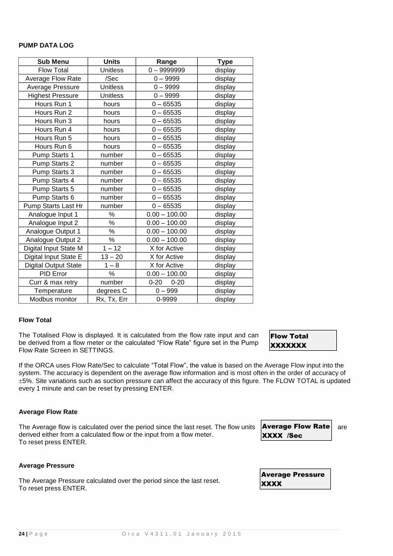
PUMP DATA LOG
Sub Menu Units Range Type
Flow Total Unitless 0 – 9999999 display
Average Flow Rate /Sec 0 – 9999 display
Average Pressure Unitless 0 – 9999 display
Highest Pressure Unitless 0 – 9999 display
Hours Run 1 hours 0 – 65535 display
Hours Run 2 hours 0 – 65535 display
Hours Run 3 hours 0 – 65535 display
Hours Run 4 hours 0 – 65535 display
Hours Run 5 hours 0 – 65535 display
Hours Run 6 hours 0 – 65535 display
Pump Starts 1 number 0 – 65535 display
Pump Starts 2 number 0 – 65535 display
Pump Starts 3 number 0 – 65535 display
Pump Starts 4 number 0 – 65535 display
Pump Starts 5 number 0 – 65535 display
Pump Starts 6 number 0 – 65535 display
Pump Starts Last Hr number 0 – 65535 display
Analogue Input 1 % 0.00 – 100.00 display
Analogue Input 2 % 0.00 – 100.00 display
Analogue Output 1 % 0.00 – 100.00 display
Analogue Output 2 % 0.00 – 100.00 display
Digital Input State M 1 – 12 X for Active display
Digital Input State E 13 – 20 X for Active display
Digital Output State 1 – 8 X for Active display
PID Error % 0.00 – 100.00 display
Curr & max retry number 0-20 0-20 display
Temperature degrees C 0 – 999 display
Modbus monitor Rx, Tx, Err 0-9999 display
Flow Total The Totalised Flow is displayed. It is calculated from the flow rate input and can be derived from a flow meter or the calculated “Flow Rate” figure set in the Pump Flow Rate Screen in SETTINGS. If the ORCA uses Flow Rate/Sec to calculate “Total Flow”, the value is based on the Average Flow input into the system. The accuracy is dependent on the average flow information and is most often in the order of accuracy of
5%. Site variations such as suction pressure can affect the accuracy of this figure. The FLOW TOTAL is updated every 1 minute and can be reset by pressing ENTER.
Average Flow Rate The Average flow is calculated over the period since the last reset. The flow units are derived either from a calculated flow or the input from a flow meter. To reset press ENTER.
Average Pressure The Average Pressure calculated over the period since the last reset. To reset press ENTER.
Average Flow Rate
XXXX /Sec
Flow Total
XXXXXXX
Average Pressure
XXXX

25 | P a g e O r c a V 4 3 1 1 . 0 1 J a n u a r y 2 0 1 5
Highest Pressure The Highest Pressure is the highest pressure point reached since the last reset of this log. (Not included on previous versions) To reset press ENTER.
Hours Run Pump 1-6 Each pump has an hour run meter. The hour log displays the operation time for each pump in both AUTOMATIC and MANUAL modes. To reset the time press ENTER.
Pump 1-6 Starts The ORCA displays the number of starts for each pump. This can assist in the selection of run time settings. The starts do not increment when pumps are in MANUAL. To reset press ENTER.
Starts Last Hour This is a totalisation of starts for all pumps over the past hour. This history can assist with tuning and trouble shooting. The value displayed is updated at ten minute intervals. The value will not be accurate or valid until 1 hour has elapsed since the last reset. To reset press ENTER.
Analogue Input 1 Displayed is the Analogue Input reading as percentage. E.g. If the analogue input was 12mA on a 4-20mA selection then the reading in this screen would be 50.00 % - 12-4 =8….8/ (20-4)16=50%
Analogue Input 2 As per Analogue Input 1. See INPUTS for configuration options
Analogue Output 1 Displayed is the Analogue Output as percentage. This output is reserved for VFD speed and cannot be changed.
Analogue Output 2 Displayed is the Analogue Output value as percentage. This output can be configured. See OUTPUTS for configurable options for this item.
Digital Input State M (Main Inputs) Displayed is the state of the Digital inputs X = energised
- = de-energised See INPUTS for configurable options for this item.
Hours Run Pump1
XXXXX
Pump Starts 1
XXXXX
Analogue Output 1
XXX.XX%
Analogue Output 2
XXX.XX%
Digital Input M
X- - X- - - - X - - X
Starts Last Hour
XXXXX
Analogue Input 2
XXX.XX%
Analogue Input 1
XXX.XX%
Highest Pressure
XXXX

26 | P a g e O r c a V 4 3 1 1 . 0 1 J a n u a r y 2 0 1 5
Digital Input State E (Expansion Board Inputs) State of the Digital inputs on expansion board X = energised
- = de-energised See INPUTS for configurable options for this item. Visible only when a Techsys Expansion Board is present.
Digital Output State Displayed is the state of the Digital outputs X = energized
- = de-energized See OUTPUTS for configurable options for this item.
PID Error Displayed is the calculated error between the Set Point and actual pressure.
Curr & Max Retry
The number under “Curr” is the current number of times the main processor has not been able to communicate with the analogue system. If it is not at Zero it indicates that the analogue system has been subject to noise and may have had to restart itself. If this display continuously cycles from incrementing to 20 and resetting to 0, it indicates a malfunction with the analogue system (contact your dealer for advice). The number under “Max Retry” is the maximum number of times the main processor has not been able to communicate with the analogue circuitry. If it is at 20 there may have been a disruption in the analogue system and it was unable to restart itself. The main processor has forced it to restart.
Temperature
Displayed is the current temperature in degrees C, read from the temperature sensor on the circuit board.
Modbus monitor Used to monitor serial communication data transmit & receive transaction and errors. (Not included on previous versions)
ACCESS CODE
Access Code number 0 – 250 0
Press ENTER to edit the Access Code The Access Code enables access to the pump buttons and all menus. The access code will have to be re-entered after 25 minutes of no operator activity. The system will then automatically lock the use of the keys which control the ON/OFF and AUTOMATIC and MANUAL functions. This is designed to protect the system from tampering.
Access Code
XXX
Digital Output
X - - X - - - -
PID Error
XXX.XX %
Digital Input E
XX - X - - - X
Temperature
XXX degrees C
Curr & Max Retry
XXX XXX

27 | P a g e O r c a V 4 3 1 1 . 0 1 J a n u a r y 2 0 1 5
SETTINGS
Sub Menu Units Range Default
Low Pressure Shutdown Units or % 0.0% Cut In Pressure 50.0%
Cut In Pressure % of Setpoint Low Pressure Shutdown to 99.9% 75.0%
Set Point Unitless 0 – 9999 300
High Pressure Limit % of Setpoint 100.1% to High Pressure Shutdown 150.0%
High Pressure Shutdown % of Setpoint High Pressure Limit- 300.0% 200.0%
Pump Flow Rate /Sec 0 – 9999, Flow Meter 99
Friction Loss Unitless 0 – 999 0
Set Point 2 Unitless 0 – 9999 400
Set Point 3 Unitless 0 – 9999 400
Set Point 4 Unitless 0 – 9999 400
Set Point 5 Unitless 0 – 9999 400
Set Point 6 Unitless 0 – 9999 400
Set Point 7 Unitless 0 – 9999 400
Set Point 8 Unitless 0 – 9999 400
Pressure Trip 1 Low Unitless 0 – 9999 100
Pressure Trip 1 High Unitless 0 – 9999 200
Pressure Trip 2 Low Unitless 0 – 9999 500
Pressure Trip 2 High Unitless 0 – 9999 600
Flow Trip Low /Sec 0 – 9999 100
Flow Trip High /Sec 0 – 9999 200
DOL Cut In Unitless 0 – 9999 200
DOL Cut Out Unitless 0 – 9999 400
Low Pressure Shutdown Low pressure Alarm. If any pump is running and the system falls below this pressure and remains there for the period of the “Lo Pressure Delay” time (Set in the TIMING Menu), then the system will then shut down. Lo Press Shutdown can be ether a fixed pressure or relative pressure calculated from the current Set Point. To toggle between fixed and relative, press both up and down. When Lo Press Shutdown is relative, the value is a percentage of the current set point. In relative mode a calculated pressure value (based off set point 1) is displayed in brackets on the right of the display). (Relative pressure setting is not included on previous versions) A fault message will show on the main screen showing that there is a low pressure shutdown fault. The fault is also recorded in the FAULT HISTORY. To clear the fault and restart the system press the ENTER key. NOTE: All pumps will be shut down including manual pumps.
Cut In Pressure When the system pressure falls below the “Cut In Pressure” the system will restart. This pressure must be higher than the Low Pressure Shutdown and lower than 99.9%. On the right of the display a value in brackets indicates the calculated pressure based on set point 1. (This setting is an adjustable value and not a % on previous versions)
Set Point The Set Point is the pressure that the system will maintain. This set point is unit-less and is determined by the operator and the setting of the pressure transducer.
LoPress Shutdown
XXXX
Set Point
XXXX
Cut In Pressure
XXX.X % (XXXX)
% (XXXX)
(XXXX)
LO PRESS SHUTDWN

28 | P a g e O r c a V 4 3 1 1 . 0 1 J a n u a r y 2 0 1 5
High Pressure Limit The High Pressure Limit is the pressure point that stops pumps if the pressure rises above this limit. Once the pressure rises above this figure the fixed speed pumps will shut down and the VFD rapidly decelerates. If the system pressure falls to below the High Pressure Limit the ORCA will restart and function normally. This setting is limited to a value that is lower than the High Pressure Shutdown and higher than the highest Set Point. (This includes all other Set Points 2 to 8). On the right of the display a value in brackets indicates the calculated pressure based on set point 1. When a full speed pump is turned off, the following message will be displayed on the main screen for 5 seconds. If the pressure is above the High Pressure Limit, turning pumps to MANUAL is also disabled. (This setting is an adjustable value and not a % on previous versions)
High Pressure Shutdown The High Pressure Shutdown shuts down the system if any pump is running, and the pressure rises above this pressure for longer than the “High Pressure Delay” time. The High Pressure Shutdown value is limited to a value higher than the High Pressure Limit. High Pressure Shutdown can be set for auto reset. Set for Auto reset in the “Fault Re-start Screen” or set to OFF. On the right of the display a value in brackets indicates the calculated pressure based on set point 1. NOTE: On reaching the High Pressure Shut Down all pumps will be shut down including manual pumps. (This setting is an adjustable value and not a % on previous versions)
Pump Flow Rate There are two options for the Flow rate figure: Actual Flow rate Calculated Flow rate
ACTUAL FLOW RATE The analogue input programmed for Flow rate Input can read the input from a Flow Meter to register the flow. This input is a 4-20mA analogue or pulsed signal. (Pulsed Signal is not included on previous versions) See Flow Meter Calibration (CONFIGURE) for additional information.
CALCULATED FLOW RATE This figure is the flow rate of the pump at the nominated set point at full motor speed. It is read from a manufacturer’s pump curve and input as a flow rate / minute. Any units can be used for this figure however the time units are fixed at MINUTES. Each time the Set Point is changed this figure must be modified to maintain accuracy. The calculation is done on the number of pumps running at any time with an adjustment for pump speed on the VFD pump based on “Affinity Law” calculations.
HiPress Limit
XXX.X % (XXX)
(XXXX)
Pump Flow Rate
XXXX /Min
HIGH PRESS LIMIT
HiPress Shutdown
XXX.X % (XXX)
(XXXX)

29 | P a g e O r c a V 4 3 1 1 . 0 1 J a n u a r y 2 0 1 5
Friction Loss Friction loss is the figure that is added to the Set Point to compensate for Friction in a pipeline. The setting increases the Set Point Pressure based on the calculated flow rate. The increase in Set Point is proportional to the calculated flow rate. The input figure is the total additional pressure required when all of the nominated pumps are operating.
Linear Friction Loss Exponential Friction Loss NB. Make sure that the friction loss figure is less than the difference between the highest Set Point and High Pressure Limit.
Set Point 2-8 The ORCA has the option to set 8 Set Points that can be triggered by a Digital Input or via a time of day event. This allows a variation to the main Set Point to be made remotely. It changes the main Set Point to the value nominated in alternate Set Points 2 through 8. To select this option, an input is programmed to function as Set Point 2 to 8 and is activated by closing the contact between the nominated input and the Input Common OR by using the timed Set Point feature. Screens Set Point 2 – 8 are hidden unless an input is nominated as the corresponding set point within the INPUTS menu or a timed set point option is set.
Pressure Trip 1 Low The ORCA has the ability to energise an output relay based on a nominated system pressure. This can be useful to signal other elements of a system not under control of the ORCA. See Output Relays for information on how to set this feature. Pressure Trip 1 – the designated relay will energize on reaching Pressure Trip 1 entered value (either Pressure Trip Low and/or Pressure Trip 1 High).
Friction Loss
XXX
Set Point 2
XXXX
PR
ES
SU
RE
TIME
Pressure trip 1 High
Pressure trip 1 Low
Relay EnergizedRelay Energized Relay Off
Relay State
Press Trip 1 Low
XXXX
FRICTION LOSS
0
10
20
30
40
50
60
0% 20% 40% 60% 80% 100%
% FLOW
AD
D T
O S
ET
PO
INT
FRICTION LOSS
0
0.2
0.4
0.6
0.8
1
1.2
0% 20% 40% 60% 80% 100%
% FLOW
AD
D T
O S
ET
PO
INT
30 | P a g e O r c a V 4 3 1 1 . 0 1 J a n u a r y 2 0 1 5
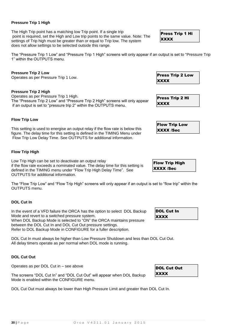
Pressure Trip 1 High The High Trip point has a matching low Trip point. If a single trip point is required, set the High and Low trip points to the same value. Note: The settings of Trip high must be greater than or equal to Trip low. The system does not allow settings to be selected outside this range. The “Pressure Trip 1 Low” and “Pressure Trip 1 High” screens will only appear if an output is set to “Pressure Trip 1” within the OUTPUTS menu.
Pressure Trip 2 Low Operates as per Pressure Trip 1 Low.
Pressure Trip 2 High Operates as per Pressure Trip 1 High. The “Pressure Trip 2 Low” and “Pressure Trip 2 High” screens will only appear if an output is set to “pressure trip 2” within the OUTPUTS menu.
Flow Trip Low This setting is used to energise an output relay if the flow rate is below this figure. The delay time for this setting is defined in the TIMING Menu under Flow Trip Low Delay Time. See OUTPUTS for additional information.
Flow Trip High Low Trip High can be set to deactivate an output relay if the flow rate exceeds a nominated value. The delay time for this setting is defined in the TIMING menu under “Flow Trip High Delay Time”. See OUTPUTS for additional information. The “Flow Trip Low” and “Flow Trip High” screens will only appear if an output is set to “flow trip” within the OUTPUTS menu.
DOL Cut In In the event of a VFD failure the ORCA has the option to select DOL Backup Mode and revert to a switched pressure system. When DOL Backup Mode is selected to “ON” the ORCA maintains pressure between the DOL Cut In and DOL Cut Out pressure settings. Refer to DOL Backup Mode in CONFIGURE for a fuller description. DOL Cut In must always be higher than Low Pressure Shutdown and less than DOL Cut Out. All delay timers operate as per normal when DOL mode is running.
DOL Cut Out
Operates as per DOL Cut in – see above The screens “DOL Cut In” and “DOL Cut Out” will appear when DOL Backup Mode is enabled within the CONFIGURE menu. DOL Cut Out must always be lower than High Pressure Limit and greater than DOL Cut In.
Press Trip 1 Hi
XXXX
Press Trip 2 Low
XXXX
Press Trip 2 Hi
XXXX
Flow Trip Low
XXXX /Sec
Flow Trip High
XXXX /Sec
DOL Cut In
XXXX
DOL Cut Out
XXXX

31 | P a g e O r c a V 4 3 1 1 . 0 1 J a n u a r y 2 0 1 5
TUNING
Sub Menu Units Range Default
Minimum Frequency % 0.0 – 100.0 45.0
Shutoff Head Unitless 0 – 9999 1924
Response Rate % 0.1 – 100.0 2.0
Acceleration %/second 1 – 100 20
Auto Rotation selection Full, 1 – 6, At Specific Time, Low
Hours Full
Rotation Time time (24hr) 0:00-> 23:59 0:00
High Press Restarts number Off, 1 – 250 Off
Standby Boost % of Setpoint 10 – 250 20
Standby Flow Min /Sec 0 – 9999 200
Error Correction (I seconds Off, 0.1 – 100.0 3.0
Overshoot Elimination (D % Off, 0.1 – 50.00 15.0
RP(P) EC(I) OE(D number -1000, 1000 display
Minimum Frequency or Shutoff Head The minimum frequency is the lowest setting at which a pump will begin to contribute to the system pressure. This value is expressed as a percentage. This is the minimum frequency at which the ORCA determines that a pump is to be stopped as at this speed it is not contributing flow.
There are two ways to setup the Minimum Frequency,
“Fixed” or “Calculated”; this is selected by editing the “Min Freq Mode” option In the Configuration Menu.
Fixed – A fixed valve is selected for all set points. The pump minimum frequency (Hz) can be found in your pump’s data sheet. Divide this minimum value by the maximum speed of the pump (Hz) and multiply the result 100 to get minimum frequency (%). Enter this value
Calculated – The Shutoff Head of the pump is entered and the Min Frequency is then calculated based on the Shutoff Head value and the current set point. The actual calculated minimum pump speed is shown on the right hand side of the display. (This feature is not available on previous versions)
Response Rate (Proportional) The response rate is a figure used to set the speed of reaction of the system. It is expressed as a percentage ranging from 0.1 – 100.0. is the slowest response and 100.0 the fastest. The current pressure reading is also displayed to assist while tuning – Shown above as “nn”
Acceleration The acceleration of the VFD can be limited by this figure. It is designed to brake the PID control. It is used in cases where the Acceleration needs to be dampened. The figure is input in %/second.
Auto-Rotation
The ORCA can start-up on a different pump (Lead Pump) at each re-start or time interval. Note- Auto rotation can only occur on LLA & All VFD systems. The lead pump is the first auto pump to start (if available). The options are Full, 1, 2, 3, 4, 5, 6, Time of Day or Low Hours.
Pump “1-6” – The selected pump (1-6) will nominate a particular pump to always be the lead pump.
Auto Rotation
FULL
Acceleration
XXX %/second
Min Frequency
XX.X %
Response Rate
XXX.X % (nn)
Shutoff Head
XXXX (XX.X%)

32 | P a g e O r c a V 4 3 1 1 . 0 1 J a n u a r y 2 0 1 5
Full – the lead pump will cycle after each system standby, shutdown or PAUSE.
Time – once every 24 hours at a specified time the system will shutdown (including the jockey pump, if present) and the lead pump will rotate on restart. (The specific timed feature is not available on previous versions)
Low Hours – will start the pump with the lowest hours according to the pump run Hour Run meters (see PUMP DATA LOG).
Forced rotation - set one of the programmable inputs to “Cycle Pumps” and activating this input will cycle the pumps – see Programmable Inputs. If a jockey pump is fitted, the jockey pump will be designated Pump 1 and will not auto-rotate. See JOCKEY PUMP and PUMP DEFINITION for more information.
Rotation Time When Auto rotation is set to a specific time; this is the time at which the rotation occurs at. Be sure to set the clock in the configuration menu. (The specific timed feature is not available on previous versions)
High Pressure Restarts This setting allows the operator to set the number of times that the system can shutdown and automatically restart after a High Pressure Shutdown. The range is from Off to 1-250.
”Off”- the system shuts down after the High Pressure delay timer trips (default).
“Automatic restart” – (per hr) The ORCA will allow “X” restarts in an hour commencing from the first High
Pressure Fault. A message “New Fault” appears on the main screen on each restart and is logged in the fault log.
Standby Boost / Standby Flow Min The ORCA uses one of three methods to determine if there is “no flow”. The
options detailed below are selected via the “Standby Test” screen, which is in the
CONFIGURE menu. Each test is only carried out if there is 1 pump running, not
at maximum speed and the system pressure is at or above the Set Point.
Boost: The ORCA tests for “No Flow” by boosting the system pressure to a new pressure, typically 5%
(adjustable) higher than the set pressure (“Standby Boost”) for a period of time (“Boost Hold Time”) and then
tracks the system pressure to see if it falls back to normal within a prescribed period of time (“Standby Test
Time”). The “Standby Boost” pressure sets the amount the Set Point pressure is boosted by. The Boost Hold time ensure the system will be totally pressurised. The time that it takes to drop back to the Set Point pressure is
referenced against the Standby Test time. If the time to return to “Set Point” is less than the “Standby Test” the system continues to operate. If the system pressure does not drop to the set point within the test time setting, the ORCA assumes there is “NO FLOW” and will place the system in standby mode until the system pressure falls below cut in pressure point, which wakes the ORCA to restart pressure control again.
+boost +boost No Flow Standby
-Turn off all pumps
-3% -3% -3%
15 15 15 TIME (seconds)
2 2 2
boost up time
ACTUAL PRESSURE expired at 10 boost hold time
SET POINT standby test time
PR
ES
SU
RE
In this mode the “Standby Boost” screen will be visible and “Standby Flow/Sec” will be hidden.
Standby Boost
XXX
HiPress Restarts
XXX
Auto Rotation
XX:XX (hh:mm)

33 | P a g e O r c a V 4 3 1 1 . 0 1 J a n u a r y 2 0 1 5
Flow Switch: If an ORCA input is programmed to “No Flow”. The flow switch is connected to the selected ORCA input and when activated the ORCA will turn off the pump after a period nominated by the standby test time. In this mode both the “Standby Boost” and “Standby Flow/Sec” screens will be hidden.
Flow Rate: If a flow meter is connected to an analogue or a pulsed input and set up properly and the flow rate is below the nominated amount in this menu for the period of the standby test time the system will placed in standby mode. In this mode the “Standby Flow Min” screen will be visible and “Standby Boost” will be hidden.
Error Correction (Integral Time) The error correction time is the time taken to convert a constant error of 1% to a 1% change on the output. The error correction component is proportional to the tracking error and increases linearly with time. It is useful when trying to close the gap on small errors that cannot be eliminated through the use of the response rate alone. It is expressed as a percentage ranging from Off, 0.1 – 100.0. Off will disable this part of the PID equation. The current pressure reading is also displayed to assist while tuning – Shown above as “nn”
Overshoot Elimination (Derivative Gain) The overshoot elimination gain provides a damping effect to eliminate system oscillation and to minimize overshoot. It is expressed as a percentage ranging from Off, 0.01 – 50.00. Off will disable this part of the PID equation. The current pressure reading is also displayed to assist while tuning – Shown above as “nn”
RR(P) Proportional Output Displays the proportional component within the PID equation. Proportional is
another name for “Response Rate”.
EC(I) Error Correction Displays the error correction component within the PID equation.
OE(D) Overshoot Elimination Displays the overshoot elimination component within the PID equation. These three “Output” display values help in the tuning of the Orca. Each has a range of -1000 to 1000. See PID Control for more information.
TIMING
Sub Menu Units Range Default
Low Pressure Delay Seconds Off, 0 – 250 120
High Pressure Delay seconds Off, 0 – 250 4
In Delay Timer seconds 0 – 999 4
Out Delay Timer seconds 0 – 999 1
Restart Delay seconds 0 – 999 0
Standby Test Time seconds 0 – 999 10
Boost Hold Time seconds Off, 1 – 250 15
Pump Fault Timer seconds 0 – 250 10
Now Flow Delay seconds 0 – 250 10
Input Delay Timer seconds 0 – 999 120
Pressure Trip Low Delay seconds 0 – 999 0
Pressure Trip High Delay seconds 0 – 999 0
Flow Trip Low Delay seconds 0 – 999 0
Flow Trip High Delay seconds 0 – 999 0
Change Over Delay seconds 0.00 – 10.00 0.30
Backup Spin Intv DD:HH 01 Hour – 45 Days 4 Days
Backup Spin Time seconds 1 – 60 5
Stop Time (24hr) HH:MM Disabled, 0:00 – 23:59 Disabled
Start Time (24hr) HH:MM 0:01 -> 00:00 Disabled
Error Correct (I
XXX.X secs (nn)
OvershootElim (D
XX.XX % (nn)
RR(P) EC(I) OE(D
XXX XXX XXX
Standby Flow Min
XXXX /min

34 | P a g e O r c a V 4 3 1 1 . 0 1 J a n u a r y 2 0 1 5
Low Pressure Shutdown Delay
Time delay for the “Low Pressure Shutdown”. The range for this is “OFF, 0-250 sec”.
OFF – The system will ignore any low-pressure shutdown commands.
** CAUTION** low pressure faults can be caused by systems failures. Forcing pumps to run in the presence of faults can cause damage to pumps and equipment. The Low & High Pressure delay timers are independent of each other and can be set to suit individual needs.
High Pressure Shutdown Delay
Delays the response “High Pressure Shutdown”. The range for this is “OFF, 0-250 sec”.
OFF – The system will ignore any high-pressure shutdown commands. **
CAUTION** High pressure faults can be caused by systems failures. Forcing pumps to run in the presence of faults can cause damage to pumps and equipment. The Low & High Pressure delay timers are independent of each other and can be set to suit individual needs.
In Delay Timer
The “IN DELAY TIMER” is used to delay the starting of additional pumps. When the system pressure drops below the “Cut In Pressure” the system starts the first pump according to the “restart timer”.
Additional pumps start when called upon after the “In Delay Timer” has elapsed. This timer is designed to assist in the reduction of Short Cycling by allowing the system to stabilise before additional pumps are started.
Out Delay Timer
When the pumps are called to shut down, a delay can be set using the “OUT
DELAY TIMER”.
**CAUTION** Take care in setting this timer as the increase in pressure due to this delay can cause pressure spikes.
Restart Delay
When the system pressure drops below the Cut In Pressure the ORCA restart will be delayed by the RESTART DELAY.
Standby Test Time
The “Standby Test Time” selects how long the pressure should take to drop back down to the setpoint after a Standby Boost to determine if there is little or no flow.
• If the Boost Pressure” drops back to the “Set Point” within the “Standby Test Time” then the ORCA determines that there must be flow and continues to operate.
• If the “Boost Pressure” does not drop down to the “Set Point Pressure” within the “Standby test Time” the ORCA detects “NO FLOW” and the system will placed in Standby mode..
Boost Hold Time This timer will hold the Boost Set pressure at the boosted value for the time nominated to ensure that all mainlines, pressure tanks etc are fully pressurised. This screen is visible when “Boost” is selected in the Standby Test screen within the CONFIGURE menu.
HiPressure Delay
XXX seconds
Out Delay Timer
XXX seconds
LoPressure Delay
XXX seconds
Restart Delay
XXX seconds
Standby Test Tm
XXX seconds
Boost Hold Time
XXX seconds
In Delay Timer
XXX seconds

35 | P a g e O r c a V 4 3 1 1 . 0 1 J a n u a r y 2 0 1 5
Pump Fault Timer
If an input is programmed to become “P1 to 6 Fault(Stop)”, this timer will delay the actiavtion of the fault. It is typically used with flow switches for pump loss of prime detection.
No Flow Timer
This timer delays a “No Flow” shutdown by the given entered value in seconds .
Input Delay Timer This timer sets the delay for reaction to inputs: NO FLOW and PUMP 1-6 PROTECTION.
Pressure Trip Low Delay Delays the activation of the ORCA Output Relay when programmed for Pressure Trip (both Pressure Trip 1 & 2)
Pressure Trip High Delay Delays the deactivation of the relevant Output relay if programmed for Pressure Trip (both Pressure Trip 1 & 2) The screens “Pressure Trip Low Delay” and “Pressure Trip High Delay” are only visible if at least one output is set to “pressure trip 1” or “pressure trip 2” in the OUTPUTS menu.
Flow Trip Low Delay Delays the activation of the relevant ORCA Output if programmed for Flow Trip. This delay timer is relevant for the Low Flow Trip setting.
Flow Trip High Delay Delays the deactivation of the relevant ORCA Output relay if programmed for Flow Trip. This delay timer is relevant for the High Flow Trip setting. The screens “Flow Trip Low Delay” and “Flow Trip High Delay” are only visible if an output is set as “flow trip” in the OUTPUTS menu.
Change Over Delay This delay is used to allow sufficient time for the VFD to reset when the Jockey pump is enabled to run from the main VFD. (On previous versions it has not been used for the Jockey Pump change over)
Backup Spin Interval
The “backup spin” feature of the Orca, allows pumps set to Backup to be spun up every “Backup Spin Interval (Intv)”. Eg. 1 day will give the backup pumps to spin once a day. Backup pumps will only be started if there is another pump running to eliminate the possibility over pressurising the system.
• This option will be displayed when one or more pumps have been selected as a backup pump. (This feature is not available on previous versions)
I/P Delay Timer
XXX seconds
Pres Trip Lo Dly
XXX seconds
Pres Trip Hi Dly
XXX seconds
Flow Trip Hi Dly
XXX seconds
Change Over Dly
XX.XX seconds
Pump Fault Timer
XXX seconds
Flow Trip Lo Dly
XXX seconds
Backup Spin Intv
XX:XX (dd:hh)
No Flow Timer
XXX seconds

36 | P a g e O r c a V 4 3 1 1 . 0 1 J a n u a r y 2 0 1 5
Backup Spin Time
Backup Spin Time is the time a pump is run when the backup spin is instigated. • This option will be displayed when one or more pumps have been selected
as a backup pump. (This feature is not available on previous versions)
Stop Time (24hr) and Start Time (24hr)
The “Stop Time” and “Start Time” option allows a period of time to be set where the system will be paused. For Example:
1. Stop Time: 15:00 – Start Time: 16:00 The system pauses at 3:00 pm each day for 1 hour.
2. Stop Time: 23:00 – Start Time: 6:00 The system pauses at 11:00 pm each day and starts again at 6:00 am the next day.
The “Stop Time” and “Start Time” requires the current time and date be set correctly in the configure menu. (This feature is not available on previous versions)
CONFIGURE
Sub Menu Units Range Default
Operating Mode selection Pressure, Level, Flowrate, Temperature Pressure
Level Mode selection Std An:Tank Fill, Std An:TankEmpty, Rev
An:Tank Fill, Rev An:TankEmpty Std An:Tank
Number of pumps number 1 – 6 3
Min Freq Mode selection Fixed, Calculated Fixed
Press Decimal number 0 – 3 0
Flow Decimal number 0 – 3 0
Transducer Zero Unitless 0 – 9999
Adjust Pressure Unitless 0 – 10000
Averaging number 0 – 50 5
Flow Meter Zero /Sec 0 – 9999
Adjust Flow /Sec 0 – 10000
Backup Pres Zero Unitless 0 – 9999 0
Adjust Backup Pr Unitless 0 – 9999 0
Scale An output 2 Number 100 – 10000 1000
JP Fallback selection On. Off Off
Standby Test selection Boost, Flow Switch, Flow Rate Boost
Set Time/Date selection 00:00 2000 Jan 1 -23:59 2099 Dec 31. 00:00 2000 Jan 1
Operating System selection Cascading, Lead VFD Lag, All VFD Cascading
DOL Backup Mode selection On, Off Off
Friction Loss Calc selection Linear, Exponential Linear
Access Code number Off, 0 – 250 21
Serial Comms selection Output Cont Data, Modbus Protocol Modbus Protocol
Modbus Address number 1 – 31 1
No Of Duty Pumps number 1 – 6 3
Flow Sensing selection Calculated, Scaled AnInp2, Digital Pulse Calculated
Manual Run selection Input or P_But’n, Input Only Input or P_But’n
Backup Spin Time
XX seconds
Stop Time (24hr)
XX:XX (hh:mm)
Start Time (24hr)
XX:XX (hh:mm)
37 | P a g e O r c a V 4 3 1 1 . 0 1 J a n u a r y 2 0 1 5
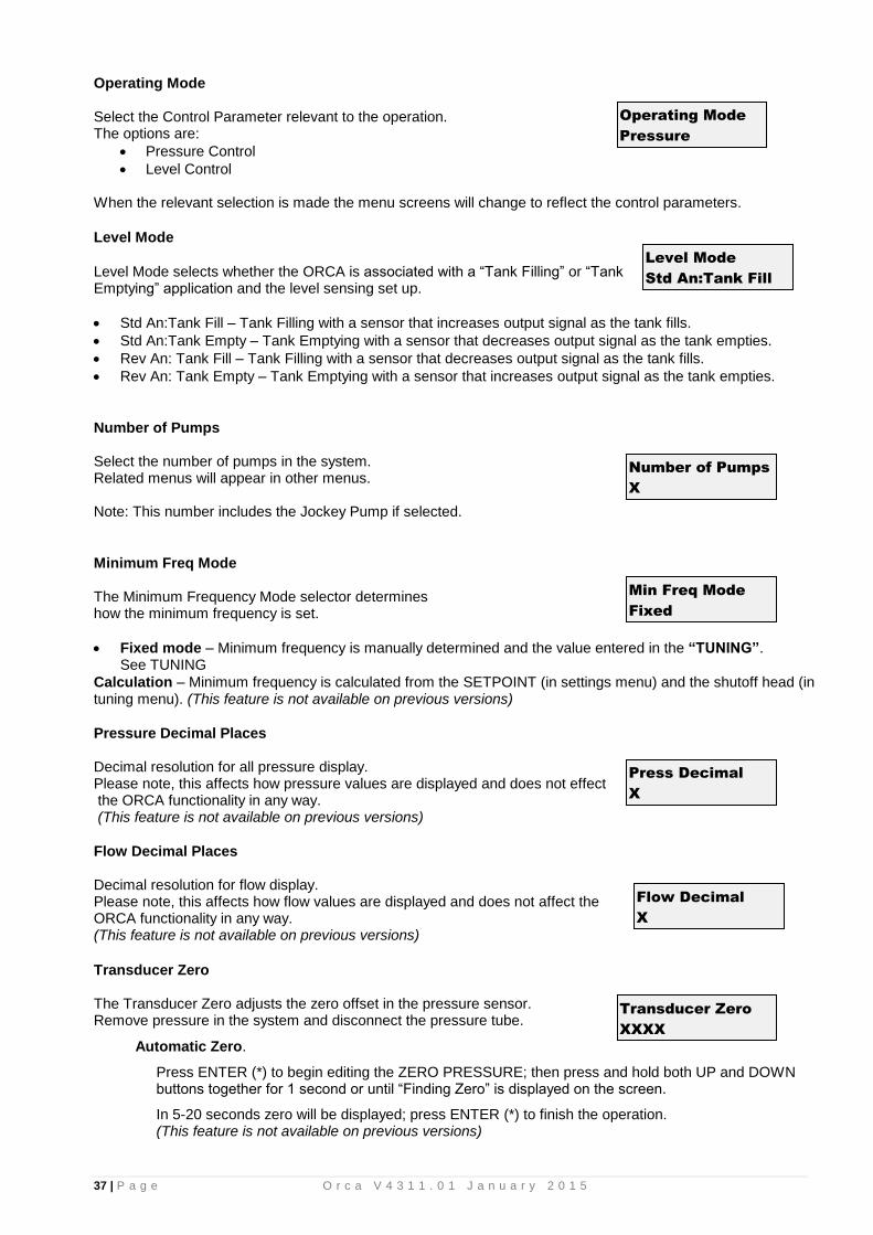
Operating Mode Select the Control Parameter relevant to the operation. The options are:
• Pressure Control
• Level Control
When the relevant selection is made the menu screens will change to reflect the control parameters.
Level Mode
Level Mode selects whether the ORCA is associated with a “Tank Filling” or “Tank Emptying” application and the level sensing set up.
• Std An:Tank Fill – Tank Filling with a sensor that increases output signal as the tank fills.
• Std An:Tank Empty – Tank Emptying with a sensor that decreases output signal as the tank empties.
• Rev An: Tank Fill – Tank Filling with a sensor that decreases output signal as the tank fills.
• Rev An: Tank Empty – Tank Emptying with a sensor that increases output signal as the tank empties.
Number of Pumps Select the number of pumps in the system. Related menus will appear in other menus. Note: This number includes the Jockey Pump if selected.
Minimum Freq Mode The Minimum Frequency Mode selector determines how the minimum frequency is set.
• Fixed mode – Minimum frequency is manually determined and the value entered in the “TUNING”. See TUNING
Calculation – Minimum frequency is calculated from the SETPOINT (in settings menu) and the shutoff head (in tuning menu). (This feature is not available on previous versions)
Pressure Decimal Places Decimal resolution for all pressure display. Please note, this affects how pressure values are displayed and does not effect the ORCA functionality in any way. (This feature is not available on previous versions)
Flow Decimal Places Decimal resolution for flow display. Please note, this affects how flow values are displayed and does not affect the ORCA functionality in any way. (This feature is not available on previous versions)
Transducer Zero The Transducer Zero adjusts the zero offset in the pressure sensor. Remove pressure in the system and disconnect the pressure tube.
Automatic Zero.
Press ENTER (*) to begin editing the ZERO PRESSURE; then press and hold both UP and DOWN buttons together for 1 second or until “Finding Zero” is displayed on the screen.
In 5-20 seconds zero will be displayed; press ENTER (*) to finish the operation. (This feature is not available on previous versions)
Transducer Zero
XXXX
Operating Mode
Pressure
Number of Pumps
X
Level Mode
Std An:Tank Fill
Min Freq Mode
Fixed
Press Decimal
X
Flow Decimal
X

38 | P a g e O r c a V 4 3 1 1 . 0 1 J a n u a r y 2 0 1 5
Manual Zero (Primary Transducer)
Press ENTER (*) and then the DOWN key to decrease the dispalyed value to ZERO. If “Value Too Low” appears, increase the value slowly by pressing the UP key until a zero value is obtained. *NOTE* The value does not change with each press of the UP/DOWN key. Press and hold the UP/DOWN key for rapid change and single press for small change.
When ZERO is displayed press ENTER (*) to finish the operation.
Reconnect pressure tube before re-enabling pumps.
Adjust Pressure (Primary Transducer) The calibration of the analogue sensors is achieved by adjusting the pressure reading on this screen to match a reading from a pressure gauge. This will only need to be done if a new or non-standard Techsys transducer is fitted. Once the system pressure has stabilised, press the ENTER key and then either UP or DOWN keys to match the reading on this screen to suit a pressure gauge reading. Once the readings are matched the system pressure is calibrated. Press ENTER again and then exit the menu to store the data. Transition to the new reading may take some time to settle, wait for 5 seconds before accepting the adjustment.
Averaging
The displayed pressure responsiveness is dampened to reduce fluctuations in the readout. Decrease Responsiveness with a higher ”AVERAGING” value and increase responsiveness with a lower number.
Flow Meter Zero OR Backup Pres Zero (Backup Transducer) Flow The Flow Meter Zero adjusts the zero in the Flow Meter input. With no flow press ENTER and then the UP or DOWN keys to set the reading to “0”. Be sure that the flow meter is connected to the relevant input. If the value input is too low then the message “VALUE TOO LOW” will appear. If this has occurred press the UP key until a zero value appears. Press ENTER again and then exit out of the menu to initiate a store of the “zero” value.
Backup If Analogue input is configured to be a backup pressure transducer then this display will be displayed instead of Flow. When the backup transducer is selected it will automatically swap between transducers should one transducer become out of range. Out of range is defined as a reading greater than 95% or less than 18%. For it to work effectively it has to be zeroed exactly the same as the primary transducer.
Adjust Pressure
XXXX
Pre
ssure
% of full Scale
Error
Pre
ssu
re
% of full Scale
Error
Flow Meter Zero
XXXXX /Sec
Averaging
XX
Backup Pres Zero
XXXX

39 | P a g e O r c a V 4 3 1 1 . 0 1 J a n u a r y 2 0 1 5
Adjust Flow OR Adjust Backup Pr ( Backup Transducer) Flow The calibration of the analogue sensors is achieved by adjusting the ORCA Flow Meter reading to match the reading from the system Flow Meter.
Backup If the Analogue input is configured to be a backup pressure transducer then this display will be displayed instead of Flow. When the backup transducer is selected it will automatically swap between transducers should one transducer become out of range. Out of range is defined as a reading greater than 95% or less than 18%. For it to work effectively it has to be adjusted exactly the same as the primary transducer.
Scale An Output
This allows the analogue input to be re-scaled and sent to other devices. 1000 =1:1, 2000 = 2:1 (Output twice the input value). Refer to Outputs to select either Flow, Pressure or VFD Speed references
Standby Test
The ORCA uses one of three methods to detect “NO FLOW”
• Boost – Add extra pressure to the system and time how long it takes to fall back to the set point.
• Flow switch – If a flow switch closes the contact an ORCA input programmed to “No Flow” then the system shuts down. This shut down reason is NOT registered as a fault.
• Flow Rate – If the flow rate in the system is below the nominated amount in this menu the system will shut down. A flow meter is required for this selection.
For more information see “Standby Boost” in the TUNING section.
JP Fallback
If ORCA pump 1 is configured as a Jockey Pump and the “Standby Test” option method is set to “Flow Switch” or “Flow Rate” then the system can be configured to automatically fall back to operate on the Jockey Pump when a flow switch input is sensed OR the flow rate is the flow is below the “Fallback FlowMin” setting in the TUNING menu. When fallback is enabled there is a delay timer associated with this action, it is the “Fallback Delay” and is in the TIMING menu.
Set Time / Date Select a field and press the ENTER key. Set the time or date field and press the ENTER KEY again. This will highlight the next set of numbers. A flashing cursor will signal which field is being edited.
If the screen reads “00:00 2000 Jan 01” (the default), then the time and date need to be initialised. Set the relevant fields as above.
Adjust Flow
XXXXX /min
Standby Test
Boost
Set Time/Date
12:00 2010 Jul 01
Scale An Output
XXXXX
JP Fallback
On
Adjust Backup Pr
XXXX

40 | P a g e O r c a V 4 3 1 1 . 0 1 J a n u a r y 2 0 1 5
Operating System Select the type of operation that is required for the system. Options:
• Cascading
• Lead VFD Lag
• All VFD
CASCADING
DO NOT USE CASCADING UNLESS UPGRADING AN EXISTING CASCADING SYSTEM
EG TECHSYS MARLIN. The ORCA starts the first pump via the VFD and continues to accelerate until the pump reaches full speed. If the system is not at the set point the controller then VFD cycles to the next pump and switches the initial pump to full speed. This operation continues until the Set Point is reached or all pumps are running. The reverse occurs as the demand reduces. One VFD and bypass contactors for each pump are supplied for this option.
LEAD VFD LAG
The ORCA starts the first pump via the VFD and continues to accelerate until the pump reaches full speed. If the system is not at the Set Point the controller starts a LAG pump to make up for the flow demand. This is typically via a soft starter. This operation continues until the set point is reached or all pumps are running. The reverse occurs as the demand reduces. One VFD and backup soft starters are supplied for this option.
Select this option for Lead Lag Autorotate also.
ALL VFD The ORCA starts the first pump via the VFD1 and continues to accelerate until the pump reaches full speed. If the system is not at the Set Point the ORCA then starts the next pump (Pump 2) via VFD2. This operation continues until the Set Point is reached or all pumps are running. The reverse occurs as the demand reduces. One VFD per pump is supplied for this option.
DOL Backup Mode
In the event of a VFD failure the ORCA has the option to select DOL Backup Mode which allows the system to function as a switched pressure system. To enable DOL Backup Mode set this screen as ON, before a VFD failure has occurred.
If the system experiences a VFD failure the ORCA will control between the CUT IN and CUT OUT pressure whilst in VFD Fail mode. To reset this mode, turn off the power and restart.
Operating System
Lead VFD Lag
DOL Backup Mode
-------------OFF-----------

41 | P a g e O r c a V 4 3 1 1 . 0 1 J a n u a r y 2 0 1 5
Out Delay
Pump1 off
Pump2 on
Pump1 on Pump3 on
Restart Delay
Restart Delay In Delay
TIME
PR
ES
SU
RE
DOL CUT IN
DOL CUT OUT
Low Pressure Shutdown
High Pressure Limit
High Pressure Shutdown
Low Pressure Shutdown, High Pressure Limit and High Pressure Shutdown are active within this mode.
Friction Loss Calculation
There are two methods of calculating the pressure loss.
• Linear progression.
• Exponential extrapolation. Friction loss is the figure that is added to the Set Point to compensate for Friction in a pipeline. The result of this setting is to increase the Set Point Pressure based on the flow rate calculated. The input figure is the total additional pressure required when all of the nominated pumps are operating.
FRICTION LOSS
0
0.2
0.4
0.6
0.8
1
1.2
0% 20% 40% 60% 80% 100%
% FLOW
AD
D T
O S
ET
PO
INT
Linear Friction Loss Exponential Friction Loss
Exponential extrapolation Select this option to vary the set point based on the basis of the flow to the power of 1.52.
Set Point = %Flow1.52
Friction Loss
Linear
FRICTION LOSS
0
10
20
30
40
50
60
0% 20% 40% 60% 80% 100%
% FLOW
AD
D T
O S
ET
PO
INT

42 | P a g e O r c a V 4 3 1 1 . 0 1 J a n u a r y 2 0 1 5
User Access Code The access code is used to limit access to the settings menus. The user access code has the range “off, 0 – 250”. Off will disable the access code and allow unlimited access. Once a number is selected then access to the settings screens or any other editable screen will require the inputting of this number before progressing further. To edit press enter and then up or down keys to edit the new number. Press enter again and exit the menu to store the changes. WARNING. If the Access Code is changed from the default of 21 and then forgotten it may restrict access to other authorised users. Ensure that the new Access Code is recorded in the Site Record section of this manual AND if necessary another safe place.
Serial Comms
Serial Comms selects how the onboard RS-485 serial port is used.
• Output Cont Data options is a data logging option that allows the pump station to be remotely or locally logged.
• Modbus Protocol allows modbus compatible interfaces to monitor and adjust values during operation. ** Please make inquired to Techsys to obtain the relevant manuals and datasheets for the Orca’s modbus interface. (This feature is not available on previous versions)
Modbus Address
The Modbus Address setting allows changes to the ORCA’s address when installed on network of modbus devices. This allows more than one device to be used on a network to avoid conflicts with other modbus devices. (This feature is not available on previous versions)
Number of Duty Pumps
The Number of Duty Pumps determines how many of the “Duty / Standby” pumps that are in auto mode can be running at the same time. For example: A 3 pump system, with the “Number of Duty Pumps” set to 2 will only allow 2 pumps to run at the same time. Which two pumps is defined by the Auto Rotation setting (in tuning menu).
Warning: If “No of Duty Pumps” doesn’t equal Number of Pumps and “Auto Rotation” setting isn’t either “Full”, “Low Hours” or “At Specific Time” then one or more pumps will never run and remain redundant.
(This feature is not available on previous versions)
Flow Sensing
The “Flow Sensing” setting allows the user to select how the flow rate is determined. Options are Calculated, Scaled AnInp2 or Digital Pulse.
• “Calculated” uses the flow rate setting “Pump Flow Rate” in the settings menus to calculate the current Flow Rate.
• “Scaled AnInp2” uses an analogue sensor (ether current-loop or variable voltage ) to determine the current Flow Rate.
• Digital Pulse uses a compatible digital output flow meter to determine the current Flow Rate. (This feature is not available on previous versions)
Access Code
XXX
Serial Comms
Modbus 9600
Modbus AddressXX
No of Duty PumpsX
Flow Sensing
Calculated

43 | P a g e O r c a V 4 3 1 1 . 0 1 J a n u a r y 2 0 1 5
Manual Run
On particular applications it is necessary to prevent an operator from running a pump manually which would normally be done by pressing and holding the “P” button. When “Input or Button” is selected both manual pump run actions are available. When “Input Only” is selected to run a pump manually an input programmed to be pump manual run is required and activated via an external switch. A typical application would be a pump Auto/Off/Manual switch. (This feature is not available on previous versions)
PUMP DEFINITIONS
Sub Menu Units Range Default
Pump 1 selection Duty/Standby, Backup, Jockey Duty/Standby
Pump 2 selection Duty/Standby, Backup Duty/Standby
Pump 3 selection Duty/Standby, Backup Duty/Standby
Pump 4 selection Duty/Standby, Backup Duty/Standby
Pump 5 selection Duty/Standby, Backup Duty/Standby
Pump 6 selection Duty/Standby, Backup Duty/Standby
Each pump can be defined as:
• Duty/Standby
• Backup Pump 1 can also be configured as a jockey pump.
Duty/Standby
If a pump is defined as Duty/Standby, then the relevant pump will be
available for operation, however if the number of Duty/Standby pumps is more than the “No of Duty Pumps” (in Configuration Menu) then the system will only simultaneously operate up to the number of pumps as detrmined by the “No of Duty Pumps”. The remaining pump/s will be rotated depending on the setting of the “Auto Rotation” menu (in TUNING Menu). (This feature is not available on previous versions – Only Duty and Backup were available)
Backup
If a pump is defined as a Backup pump it will remain dormant unless one of
the Duty/Standby pumps faults (via pump protect input). It will then automatically become a Duty/Standby pump until the fault has been removed. When a pump is setup as backup the pump mode light will flash every five seconds..
The number of pumps visible in these screens is determined by the “number of pumps” screen within the
CONFIGURE menu.
(Not included on previous versions - Originally Duty or Backup, no standby feature)
Pump 1
Duty/Standby
Pump 1
Backup
Manual Run
Input or Button

44 | P a g e O r c a V 4 3 1 1 . 0 1 J a n u a r y 2 0 1 5
JOCKEY PUMP
If pump 1 is defined as Jockey the “JOCKEY PUMP” menu will become visible.
Sub Menu Units Range Default
Jockey Pump Mode selection DOL, Main VFD, Separate VFD Main VFD
JP Cut In Pressure % of JP Setpoint
0 – 9999 250
JP Cut Out Press Unitless 0 – 9999 300
JP Set Point Unitless 0 – 9999 300
JP Flow Rate /Sec 0 – 9999 50
JP Response Rate % 0.1 – 100.0 3.0
JP Acceleration %/second 1 – 100 20
JP Standby Test selection Off, Boost, Flow Switch, Flow Rate Boost
JP Standby Boost % of JP Setpoint
5 – 250 5
JP Stdby FlowMin /Sec 0 – 250 5
JP Run On Time seconds 0 – 999 1
JP Restart Delay seconds 0 – 999 0
JP Use Main SP selection Yes, No No
The Jockey pump is typically a smaller auxiliary pump that is outside the flow range of the main pumps. The jockey pump will turn on when there are no main pumps running and the pressure is below Jockey “Cut-In” Pressure. The Jockey pump can be set up to “run-on” after the main pumps start but it will eventually be turned off. Once the main pump/s are running, they will then meet the increased demand. Should the demand then drop to a point where the main pump become inefficient then the system can be configured to fall back to the Jockey pump. To do this, set the “Standby Test” in CONFIGURE to “Flow Rate”. The “JP Fallback” option screen can then be changed from Off to On, this screen is also in CONFIGURE. The correct main pump flow rate has to be entered or alternatively a flow meter attached, then a minimum flow rate is set in the “Fallback FlowMin” screen which is in the TUNING menu.
Jockey Pump Mode The jockey pump can function on any of the settings below:
Main VFD The Jockey pump will be run from the main VFD. It will try to maintain SET POINT via the response rate, error correction time and overshoot elimination gain. In this mode the jockey pump will turn off whenever any main pumps start.
Separate VFD The Jockey pump will run on its own dedicated VFD. It will try to maintain SET POINT via the response rate, error correction time and overshoot elimination gain. In this mode when a main pump starts the jockey pump CAN continue to run at maximum speed until the Jockey Pump “Run on timer” expires.
DOL The Jockey pump will be run from a DOL contactor. It will run as a switched type pressure control system with JP Cut In and Cut Out determining when the jockey pump turns on and off . In this mode when a main pump starts the jockey pump CAN continue to run while the run on timer is active.
JP Cut In Pressure The “JP Cut In Press” is the Pressure which the pump defined as Jockey pump will restart. This value cannot be set above the JP Set point and typically it is set at around 90% of the JP Set point and also above the main pump Cut In Pressure by at least 10%. If set below the main pump cut in setting the Jockey pump will never operate. The number in bracket on the RHS of the bottom line is the actual pressure setting based on the percentage setting. (This percentage feature is not on previous versions)
JP Cut In Press
XX % (123)
Jockey Pump Mode
Main VFD
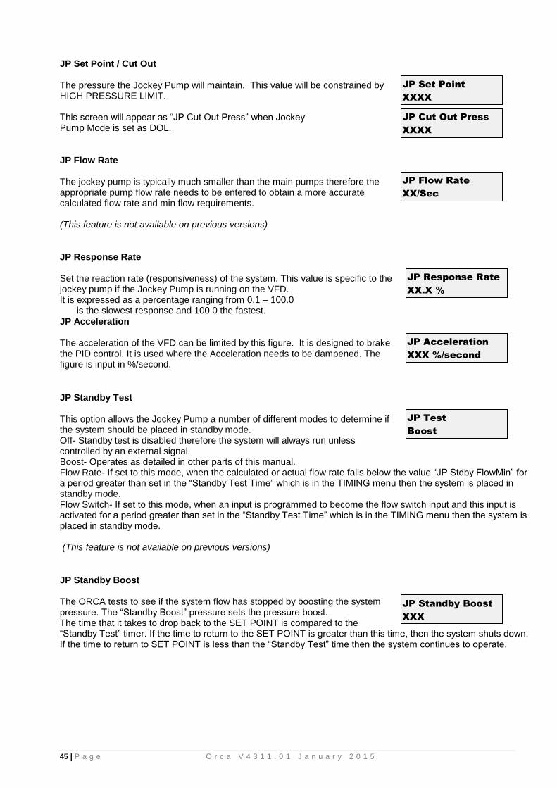
45 | P a g e O r c a V 4 3 1 1 . 0 1 J a n u a r y 2 0 1 5
JP Set Point / Cut Out The pressure the Jockey Pump will maintain. This value will be constrained by HIGH PRESSURE LIMIT. This screen will appear as “JP Cut Out Press” when Jockey Pump Mode is set as DOL.
JP Flow Rate The jockey pump is typically much smaller than the main pumps therefore the appropriate pump flow rate needs to be entered to obtain a more accurate calculated flow rate and min flow requirements. (This feature is not available on previous versions)
JP Response Rate Set the reaction rate (responsiveness) of the system. This value is specific to the jockey pump if the Jockey Pump is running on the VFD. It is expressed as a percentage ranging from 0.1 – 100.0 is the slowest response and 100.0 the fastest.
JP Acceleration The acceleration of the VFD can be limited by this figure. It is designed to brake the PID control. It is used where the Acceleration needs to be dampened. The figure is input in %/second.
JP Standby Test This option allows the Jockey Pump a number of different modes to determine if the system should be placed in standby mode. Off- Standby test is disabled therefore the system will always run unless controlled by an external signal. Boost- Operates as detailed in other parts of this manual. Flow Rate- If set to this mode, when the calculated or actual flow rate falls below the value “JP Stdby FlowMin” for a period greater than set in the “Standby Test Time” which is in the TIMING menu then the system is placed in standby mode. Flow Switch- If set to this mode, when an input is programmed to become the flow switch input and this input is activated for a period greater than set in the “Standby Test Time” which is in the TIMING menu then the system is placed in standby mode. (This feature is not available on previous versions)
JP Standby Boost The ORCA tests to see if the system flow has stopped by boosting the system pressure. The “Standby Boost” pressure sets the pressure boost. The time that it takes to drop back to the SET POINT is compared to the “Standby Test” timer. If the time to return to the SET POINT is greater than this time, then the system shuts down. If the time to return to SET POINT is less than the “Standby Test” time then the system continues to operate.
JP Set Point
XXXX
JP Response Rate
XX.X %
JP Standby Boost
XXX
JP Acceleration
XXX %/second
JP Cut Out Press
XXXX
JP Flow Rate
XX/Sec
JP Test
Boost

46 | P a g e O r c a V 4 3 1 1 . 0 1 J a n u a r y 2 0 1 5
JP Stdby FlowMin Should the calculated or actual Jockey Pump flow rate fall below the “JP Stdby FlowMin” value for a period greater than set in the “Standby Test Time” which is in the TIMING menu, then the system is placed in standby mode. (This feature is not available on previous versions)
JP Run On Time
The Jockey pump can be forced to keep running for a set period of time after the main system has started. NB. The jockey pump will not “run on” when selected as MAIN VFD in the JOCKEY PUMP MODE menu. Instead it will instantly turn off when an auto pump starts. A VFD can only run one pump at any time.
JP Restart Delay When the pressure drops below the JP Cut In Pressure and remains there the Jockey pump will start after this period. Given no auto pumps have started.
JP Min Frequency This is the minimum frequency specific to the Jockey pump. See MINIMUM FREQUENCY in TUNING menu for more information.
JP Error Correction (Integral Time)
The error correction is the time it will take to convert a constant error of 1% to a 1% change on the output. This is useful when trying to close the gap on small errors that can not be eliminated through the use of the response rate alone. This value is specific to when the jockey pump is running on the VFD. It is expressed as a percentage ranging from OFF, 0.1 – 100.0. OFF will disable this part of the PID equation.
JP Overshoot Elimination (Derivative Gain) The overshoot elimination gain is used to provide a damping effect to eliminate system oscillation and to minimise overshoot. This value is specific to when the jockey pump is running on the VFD. It is expressed as a percentage ranging from OFF, 0.01 – 50.00. OFF will disable this part of the PID equation.
JP Run On Time
XXX seconds
JP Restart Delay
XXX seconds
JP Min Frequency
XX.X %
JP ErrorCorr’t (I
XX.X seconds
JP OvershtElim (D
XX.XX %
JP Stdby FlowMin
XXX

47 | P a g e O r c a V 4 3 1 1 . 0 1 J a n u a r y 2 0 1 5
OUTPUTS
Sub Menu Units Range Default
Digital Output 1 selection Any output can be programmed to one of the following.
Shutdown Fault, Lo Press Fault, Hi Press Fault,
Any Alarm, Pump 1[JP]– 6 Run, Pump 1[JP]– 6 Fault,
System Paused, Any Pump Shutdown, Any Pump Running, No Flow Shutdown,
VFD Fault, Pressure Trip 1 – 2,
Alternate Trip, Flow Trip,
Aux Output 1 – 3
Pump 1
Digital Output 2 selection Any Pump Shutdown
Digital Output 3 selection VFD Fault
Digital Output 4 selection System Paused
Digital Output 5 selection Any Pump Run
Digital Output 6 selection Any Alarm
Digital Output 7 selection
Digital Output 8 selection
Any fault
UV Bypass
Analogue Output 1
selection VFD Speed.
VFD Speed, Flow Rate, System
Pressure
VFD Speed
Analogue Output 2
selection System Pressure
The ORCA has four main programmable outputs that can be used to communicate with external sources such as Telemetry or Building Management Systems (BMS). As each system requires different combinations of information all output relays are configurable in software. All outputs are Voltage Free – Change Over contact outputs and capable of 5 amps 240 VAC. If the expansion board is fitted four more programmable outputs are available. To view which outputs are currently activated view the PUMP DATA LOG menu, under Digital Output State. The status of the analogue outputs is also available within this menu.

48 | P a g e O r c a V 4 3 1 1 . 0 1 J a n u a r y 2 0 1 5
Digital Output Options
No Option Delay
1 Shutdown Fault As per delay timers
2 Low Pressure Fault As per delay timers
3 High Pressure Fault As per delay timers
4 Any Alarm Instantaneous
5 Pump 1 Run Instantaneous
6 Pump 2 Run Instantaneous
7 Pump 3 Run Instantaneous
8 Pump 4 Run Instantaneous
9 Pump 5 Run Instantaneous
10 Pump 6 Run Instantaneous
11 Pump 1 Fault As per Input Delay Timer
12 Pump 2 Fault As per Input Delay Timer
13 Pump 3 Fault As per Input Delay Timer
14 Pump 4 Fault As per Input Delay Timer
15 Pump 5 Fault As per Input Delay Timer
16 Pump 6 Fault As per Input Delay Timer
17 System Paused Instantaneous
18 Any Pump Shutdown As per Input Delay Timer
19 Any Pump Running Instantaneous
20 No Flow Shutdown As per Input Delay Timer
21 VFD Fault Instantaneous
22 Pressure Trip 1 As per Press Trip delay timers
23 Pressure Trip 2 As per Press Trip delay timer
24 Alternate Trip Instantaneous
25 Flow trip As per Flow trip delay timers
26 Jockey Pump Run Instantaneous
27 Aux Output 1 Instantaneous
28 Aux Output 2 Instantaneous
29 Aux Output 3 Instantaneous
30 SP 1 Output Instantaneous
31 SP 2 Output Instantaneous
32 SP 3 Output Instantaneous
33 SP 4 Output Instantaneous
34 SP 5 Output Instantaneous
35 SP 6 Output Instantaneous
36 SP 7 Output Instantaneous
37 SP 8 Output Instantaneous
38 Any Fault Instantaneous
38 UV Bypass As per UV Hot to Cold Timer
• Shutdown Fault This output is used to indicate that there has been an event that has shut down the system. This can be a High or Low-Pressure Shutdown, No Flow Shutdown or VFD Shutdown.
• Low Pressure Fault A shutdown based on a Low Pressure Shutdown.
• High Pressure Fault A shutdown based on a High Pressure Shutdown.
• Any Alarm If there are any conditions that MAY cause a shut down (Eg. Low or High Pressure) or Fault Re-starts active this output will activate.
• Pump 1-6 Run Activates when the relevant pump is running.

49 | P a g e O r c a V 4 3 1 1 . 0 1 J a n u a r y 2 0 1 5
• Pump 1-6 Shutdown Pump 1-6 shutdown on individual pump protection activation.
• System Paused Either “system pause” or “system pause JP run” inputs have been activated
• Any Pump Shutdown Any pump shutdown will activate the relay.
• Any Pump Running Any pump running will activate the relay.
• No Flow Shutdown The No Flow Shutdown action is active.
• VFD Fault Output is on when the VFD is being tested or the VFD has shutdown.
• Pressure Trip 1 When the system pressure reaches the nominated Pressure Trip 1 Low and High, this relay will energise or de-energise. See Pressure Trip in SETTINGS.
• Pressure Trip 2 When the system pressure reaches the nominated Pressure Trip 2 Low and High, this relay will energise or de-energise. See Pressure Trip in SETTINGS.
• Alternate Trip Each time the system shuts down the energized state of the relay will change. E.g. If the relay on one cycle is closed during operation then the next cycle this relay will be open. The relay will change on the following: - Low Pressure Shutdown, High Pressure Shutdown, No Flow Shutdown and VFD Shutdown.
• Flow Trip When the system flow reaches the nominated Flow Trip points Low or High, this relay will energise or de-energise. See Flow Trip in SETTINGS.
• Aux Outputs 1 – 3 Any output can be set to be an auxiliary output. Setting an output to become an auxiliary output allows the ORCA to use an input to turn on a Digital Output. To do this the input has to be set up to be an Auxiliary input. There are three auxiliary functions available. Aux Input 1 operates Aux Output 1 Aux Input 2 operates Aux Output 2 Aux Input 3 operates Aux Output 3
• Set Point Output 1-8 (SP 1-8 Output) Outputs are activated depending on which set point is the current set point. The current Set Point can be set by ether configuring an input or setting a time of day event. (Not included on previous versions)
• Any Fault Outputs are activated for any fault condition
• UV Bypass Used to control a the warm up cycle of a UV lamp if utilized in conjunction with the pump controller. If the system is placed on standby for longer than the period set for the “UV Hot to Cold” timer then the next time the system restarts the output will activate, it will stay activated for the period set in “UV WarmUp” which facilitates the use of valves etc to bypass the flow until the UV lamp is up to temperature. (Not included on previous versions)

50 | P a g e O r c a V 4 3 1 1 . 0 1 J a n u a r y 2 0 1 5
* RELAY RATINGS The relays are rated at 5 amp 250VAC. Consideration of inrush current, inductive loads and cycling must be taken into account when applying current to these relays.
Shutdown Fault
Low Pressure Fault
High Pressure Fault
No Flow Shutdown
Any Alarm
Pump 1[JP] Run
Pump 2 Run
Pump 3 Run
Pump 4 Run
Pump 5 Run
Pump 6 Run
Pump 1[JP] Fault
Pump 2 Fault
Pump 3 Fault
Pump 4 Fault
Pump 5 Fault
Pump 6 Fault
System Paused
Any Pump Shutdown
Any Pump Running
No Flow Shutdown
VFD Fault
Pressure Trip 1
Pressure Trip 2
Alternate Trip
Flow Trip
All Pumps Running
Aux Output 1
Aux Output 2
Aux Output 3
Setpoint Output 1
Setpoint Output 2
Setpoint Output 3
Setpoint Output 4
Setpoint Output 5
Setpoint Output 6
Setpoint Output 7
Setpoint Output 8
Any Fault
UV Bypass
Mains Bypass
High P
ressure Shutdow
n
Low P
ressure Shutdow
n
No F
low S
hutdown from
flow sw
itch
VF
D F
ault Shutdow
n (DO
L mode operating)
Pum
p 1 Running
Pum
p 2 Running
Pum
p 3 Running
Pum
p 4 Running
Pum
p 5 Running
Pum
p 6 Running
Jockey P
ump R
unning
Pum
p 1 Prot(P
ause)
Pum
p 2 Prot(P
ause)
Pum
p 3 Prot(P
ause)
Pum
p 4 Prot(P
ause)
Pum
p 5 Prot(P
ause)
Pum
p 6 Prot(P
ause)
Pum
p 1[JP] F
ault(Stop)
Pum
p 2 Fault(S
top)
Pum
p 3 Fault(S
top)
Pum
p 4 Fault(S
top)
Pum
p 5 Fault(S
top)
Pum
p 6 Fault(S
top)
Pum
p 1[JP] S
top
Pum
p 2 Stop
Pum
p 3 Stop
Pum
p 4 Stop
Pum
p 5 Stop
Pum
p 6 Stop
Soft P
ause activated
Soft P
ause JP R
un activated
VF
D F
ault active
Pressure below
"Pressure T
rip 1 Low"
Pressure abov
e "Pressure T
rip 1 High"
Pressure below
"Pressure T
rip 2 Low"
Pressure abov
e "Pressure T
rip 2 High"
Flow
below "F
low T
rip 1"
Flow
above "F
low T
rip 1"
High P
ressure Fault restart
Pressure is abov
e High P
ressure setting
Pressure is below
Low P
ressure setting
All pum
ps currently av
ailable are on
Aux
Input 1
Aux
Input 2
Aux
Input 3
Sy
stem operating on m
ain setpoint
Sy
stem operating on setpoint 2
Sy
stem operating on setpoint 3
Sy
stem operating on setpoint 4
Sy
stem operating on setpoint 5
Sy
stem operating on setpoint 6
Sy
stem operating on setpoint 7
Sy
stem operating on setpoint 8
Sy
stem restarting w
ith cold UV
Output to toggle on each sy
stem restart
No pum
ps available or sy
stem shutdow
n
Pum
ps available &
system
operational
Transducer range ex
ceeded - Validate A
nInput
Syste
m C
ond
ition
Outp
ut C
ond
ition

51 | P a g e O r c a V 4 3 1 1 . 0 1 J a n u a r y 2 0 1 5
INPUTS
Sub Menu Units Range Default
Program Input 1 selection Not selected, Set Point 2 - 8,
Soft Pause, Sft Pause JP Run, Emergency Stop, Pump 1[JP] - 6
Prot(Pause) Pump 1[JP] - 6 Stop,
Pump 1[JP] - 6 Manual Run,
Fire Mode, Cycle Pumps,
VFD Fault, Reset, No Flow, Aux Input 1 -
3, Pump 1[JP] - 6
Fault(Stop), Low Level pause, Schedule override
VFD Fault
Program Input 2 selection No Flow
Program Input 3 selection Pump 1 Manual Run
Program Input 4 selection Pump 1 Stop
Program Input 5 selection Not selected
Program Input 6 selection Not selected
Program Input 7 selection Reset
Program Input 8 selection Soft Pause
Program Input 9 selection Emergency Stop
Program Input 10 selection Pump 1 Protection
Program Input 11 selection Cycle Pumps
Program Input 12 selection Soft Pause JP Run
Program Input 13 selection Not selected
Program Input 14 selection Not selected
Program Input 15 selection Not selected
Program Input 16 selection Not selected
Program Input 17 selection Not selected
Program Input 18 selection Not selected
Program Input 19 selection Not selected
Program Input 20 selection Not selected
Analogue Input 1
selection
Disable, Control Pressure,
Control Level, Control Flow,
Flow Mtr, Set Point, Backup Pressure
Control Pressure,
Analogue Input 2
selection
Disable, Control Pressure,
Control Level, Control Flow,
Flow Mtr, Set Point, Backup Pressure
Disable,
Validate AnInput selection NO, YES NO
There are 12 main inputs with the ORCA that control external sensing functions. If an expansion board is fitted there are 8 more inputs are available. All inputs are programmable to suit various applications. They all require VOLTAGE FREE contacts and as such should NOT HAVE ANY VOLTAGE APPLIED.
• All inputs operate on a CLOSED CONTACT for activation. This contact needs to be made between the input common and the relevant input. There are three terminals for the input Common to allow for multiple connections.
You can view which inputs are activated by the Indicators on the front of the unit and also within the PUMP DATA LOG menu under the “Digital Input State” screens. See PUMP DATA LOG for more information. Each Input can now have inverted logic. Normally if an input is connected via a switch or sensor between the input common and a programmable input it is deemed to be ON and the input LED will be illuminated. With inverted logic when an input is activated the controller will read this as OFF but the input LED will be illuminated to indicate the actual state of the input. Inverted inputs have a number of uses and the main use would be to provide fail safe activation of an input. Eg. If an programmable input is set to pause the system on low level, then a normal input would provide an ON signal to pause the system, should that input be disconnected or broken the system would not shut down resulting in damage to the pumps. If the input is inverted the float can be wired to close the input connection for system run & open for system pause. (Fail Safe)

52 | P a g e O r c a V 4 3 1 1 . 0 1 J a n u a r y 2 0 1 5
To invert an input, firstly have the required input on the display, press the Enter button and then press the Up & Down buttons simultaneously, the Input should now show (INV) on the top line. The change it back complete the same procedure. Analogue inputs cannot be inverted. (Note- This option is not included on previous versions)
PROGRAMMABLE INPUT OPTIONS
Option Delay time Duration
1 Not selected Instantaneous Continuous
1 Set Point 2 1 second Continuous
2 Set Point 3 1 second Continuous
3 Set Point 4 1 second Continuous
4 Set Point 5 1 second Continuous
5 Set Point 6 1 second Continuous
6 Set Point 7 1 second Continuous
7 Set Point 8 1 second Continuous
8 Soft Pause 1 second Continuous
9 Soft Pause JP Run 1 second Continuous
10 Emergency Stop Instantaneous Continuous
11 P1[JP] Prot(Pause) Input delay Continuous
12 P2 Prot(Pause) Input delay Continuous
13 P3 Prot(Pause) Input delay Continuous
14 P4 Prot(Pause) Input delay Continuous
15 P5 Prot(Pause) Input delay Continuous
16 6 Prot(Pause) Input delay Continuous
17 Pump 1[JP] Stop Instantaneous Continuous
18 Pump 2 Stop Instantaneous Continuous
19 Pump 3 Stop Instantaneous Continuous
20 Pump 4 Stop Instantaneous Continuous
21 Pump 5 Stop Instantaneous Continuous
22 Pump 6 Stop Instantaneous Continuous
23 Pump 1[JP] Manual Run Instantaneous Continuous
24 Pump 2 Manual Run Instantaneous Continuous
25 Pump 3 Manual Run Instantaneous Continuous
26 Pump 4 Manual Run Instantaneous Continuous
27 Pump 5 Manual Run Instantaneous Continuous
28 Pump 6 Manual Run Instantaneous Continuous
29 Fire Mode 1 second Continuous
30 Cycle pumps 1 second Rising edge
31 VFD Fault 1 second Continuous
32 Reset 1 second Rising edge
33 No Flow Input delay Continuous
34 Aux Input 1 Instantaneous Continuous
35 Aux Input 2 Instantaneous Continuous
36 Aux Input 3 Instantaneous Continuous
37 Pump1[JP] Fault(Stop) Pump Fault Delay Continuous
38 Pump2 Fault(Stop) Pump Fault Delay Continuous
39 Pump3 Fault(Stop) Pump Fault Delay Continuous
40 Pump4 Fault(Stop) Pump Fault Delay Continuous
41 Pump5 Fault(Stop) Pump Fault Delay Continuous
42 Pump6 Fault(Stop) Pump Fault Delay Continuous
43 Flow Pulse Instantaneous Rising edge
44 Low Level Pause 1 second Continuous
45 Schedule Override Instantaneous Continuous

53 | P a g e O r c a V 4 3 1 1 . 0 1 J a n u a r y 2 0 1 5
Not Selected When this is selected the input will not respond to activation.
Set Point 2-8
Closing of the contact to either of these inputs will activate the alternate set points 2 to 8. If two inputs are activated at the same time, then the Set Point with the highest number will be the selected option. Eg If Set Points 2 and 6 are activated Set Point 6 pressure setting will be used. The Set-Pr will also change on the main display.
Soft Pause
An external sensor can be used to PAUSE the system. When the system receives a PAUSE command the system will shut down in a controlled manner based on the rates set in the response rates menu. The system will slowly drop the pressure causing all pumps running to turn off one at a time and a message will be shown on the main screen. After the PAUSE input has been deactivated the system will restart under normal operations. If the Auto-rotation is selected to FULL the lead pump will rotate.
Soft Pause JP Run
This is the same as Soft Pause except the jockey pump will continue to operate if fitted.
Emergency Stop An external sensor can be used to STOP the system. This is particularly useful for sites with suction tanks to halt the pumping operation until the tank is allowed to reach a suitable level for pumping. There are numerous other applications for the system pause function. When the system receives a STOP command the system will immediately shut down all pumps and indicate a message. After the STOP input has been deactivated the system will restart under normal operations and return pumps to the modes they were before the “stop”. Pumps in MANUAL mode will automatically restart after deactivation of the input. If the Auto-rotation is selected to FULL the lead pump will rotate.
Pump 1, 2, 3, 4, 5 and 6 Prot(Pause) The ORCA has inputs for each pump to allow for individual pump protection. In the event of a pump going into a fault condition the input for that pump should close. This will shut down the pump after the time set by the Input Delay Timer. The pump will become available again when the Input contact is opened. This protection is ideal for the following pump protection sensors:
• Temperature probes
• Thermal Overloads
• Any individual pump protection device that will auto reset with causing damage to the pump or motor is restarted.
PAUSE ON. JP RUN
*EMERGENCY STOP*
PAUSE ACTIVATED

54 | P a g e O r c a V 4 3 1 1 . 0 1 J a n u a r y 2 0 1 5
Pump 1, 2, 3, 4, 5 and 6 Stop
Activation of this input will instantly stop the operation of the relevant pump. This can be used as an “Off override” switch in the system or if remote control of a pump is required. This input will override the relevant “Pump 1-6 Manual Run” input when both are active.
Pump 1, 2, 3, 4, 5 and 6 Manual Run
Activation of this input will instantly start the relevant pump. All automatic control of the pump is ceased at this stage. This action can cause an alarm or shutdown condition. (See Manual operation)
Fire Mode
FIRE MODE directs the ORCA to ignore all shutdown alarms/faults and the pumps will continue under all conditions. The following protection features are disabled:
• High Pressure Shutdown
• Low Pressure Shutdown
• System Pause
• No Flow
• Individual Pump Protection
• Pump 1-6 Stop **Be sure to understand the possible repercussions of activating this Input. Forcing pumps to run in the presence of system faults can damage pumps and equipment. FIRE MODE should be used only if the risk of the pump stopping is greater than letting it run to destruction. Some VFD's have a similar function and will override the protections within the VFD if an input is toggled. Contact your local dealer for further information regarding this feature. Hardware items such as circuit breakers, Thermal Overloads and any other switchgear protection is not affected by this mode.
Cycle pumps
Activation of this input will shutdown and then cycle the pumps to the next available pump as the lead pump. If pump 1 started first on the last start-up, the toggling of this input will switch the lead pump to pump 2 instantly on receipt of this signal.
VFD Fault
In the event of a VFD fault this input will initiate a “retry cycle” to attempt to reset the VFD. On receipt of this signal
the system will attempt to clear the fault by sending a reset message to the VFD after a 15 second delay. This will be repeated until the VFD is restored to an operational level. During this cycle the Low-Pressure Shutdown protection is disabled to allow the system to recover automatically. De-powering and then re-energising the switchboard will generally clear VFD faults. See VFD Fail for more configuration information
Reset
The reset input allows remote resetting of ORCA after a shutdown fault. If ORCA has shutdown due to a fault (for any reason) closing the reset contact will reset all current faults and restart the system. (VFD Fault excluded)

55 | P a g e O r c a V 4 3 1 1 . 0 1 J a n u a r y 2 0 1 5
No Flow
If the system detects that there should be flow but there is a No Flow signal from an external flow switch, the ORCA will display the message "Low Flow Detected". Once system detects a closed contact on this input the ORCA will time out and shut down. This is optional and requires a flow switch to feedback into the No Flow Input and will only operate if there is at least 1 pump selected to AUTO. The system will only shut down if the system pressure is lower that the set point. ORCA assumes that if pressure is at set point then the system is in standard operation mode. Once the No Flow Delay Timer has expired then the screen message changes to: The system pressure at the time of shutdown is displayed on this screen also. The system will not restart until ENTER is pressed to clear the fault.
Aux Inputs 1, 2 and 3
Any input can be set to be an auxiliary input. Setting an input to become an auxiliary input allows the ORCA to use this input to turn on a Digital Output. To do this the output has to be set up to be an Auxiliary output. There are three auxiliary functions available. Aux Input 1 operates Aux Output 1 Aux Input 2 operates Aux Output 2 Aux Input 3 operates Aux Output 3
Pump 1, 2, 3, 4, 5 and 6 Fault(Stop)
The ORCA has the capability to assign an input for each pump to allow for individual pump fault protection. In the event of a pump going into a fault condition the input for that pump should close. This will shut down the pump after the time set by the Pump Fault Input Delay Timer (In Timing Menu). The pump will not be available until the fault has been reset by the operator on the status screen.
Flow Pulse
When the input is programmed to this mode a digital output flow meter can be connected. Volume per pulse information need to be entered and then the actual flow can be displayed and logged on the ORCA. (Not included on previous versions)
Low Level Pause
An external sensor can be used to Low Level Pause the system. When the system receives a Low Level Pause command the system will shut down in a controlled manner based on the rates set in the response rates menu. The system will slowly drop the pressure causing all pumps running to turn off one at a time and a message will be shown on the main screen. After the Low Level Pause input has been deactivated the system will restart under normal operations. If the Auto-rotation is selected to FULL the lead pump will rotate.
(Not included on previous versions)
Low Flow Detected
XXXXX
No Flow Shutdown
XXXXX
PAUSED LOW LEVEL
XXX
Program Input X
PX Fault(Stop)

56 | P a g e O r c a V 4 3 1 1 . 0 1 J a n u a r y 2 0 1 5
Schedule Override
When an input is programmed to this mode, activation of the input will then override any scheduled time event that has caused the system to pause allowing the system to then run until the input is released. (Not included on previous versions) External contacts must be VOLTAGE FREE - any applied voltage can cause damage to the system. The ORCA will supply a control voltage to the external contact.

57 | P a g e O r c a V 4 3 1 1 . 0 1 J a n u a r y 2 0 1 5
GND
F FLOW TRANSDUCER INPUTP PRESSURE TRANSDUCER INPUT24V 24VDC TRANSDUCER SUPPLY
INTERNAL TRANSDUCER
P VOLTS mA
F VOLTS mA
ANALOGUE INPUTS
GND
F FLOW TRANSDUCER INPUTP PRESSURE TRANSDUCER INPUT24V 24VDC TRANSDUCER SUPPLY
INTERNAL TRANSDUCER
P VOLTS mA
F VOLTS mA
ANALOGUE INPUTS
ANALOGUE INPUTS
The standard transducer fitted to the ORCA is rated to 25Bar.
External Analogue Input The analogue terminals are located on the left hand side of the PCB near the top. The use of 4 – 20mA and 0-10V transducers require the slide switches to be placed to match the input. This allows the system to read the correct input from the transducers.
Volts = 0-500mVDC,0-5VDC,0-10VDC etc mA= 0-20mA,4-20mA etc 4-20 mA is a standard analogue signal from a pressure transducer. To use this input note the wiring requirements on the PCB. A 24VDC power supply is available on board for 2-wire configuration Typical 4-20mA application shown. Note switch settings. Three wire transducers are typically 0-10 V or 0-5V output. Note switch settings.
FLOW METER INPUTS ORCA can accept a 0-10VDC or 4-20mA signal from flow meters.
Validate AnInput
If set to YES then any analogue input used to control or monitor a signal will be monitored for a signal that is deemed to be outside of the normal operating range – This is less than 15% (3mA) and greater than 95% (19mA). This function is only usable for 4-20mA transducers. (Not included on previous versions)
P VOLTS mA
F VOLTS mA
GND
F FLOW TRANSDUCER INPUTP PRESSURE TRANSDUCER INPUT24V 24VDC TRANSDUCER SUPPLY
INTERNAL TRANSDUCER
P VOLTS mA
F VOLTS mA
V VOLTS mA
COM ANALOG OUTPUT GND
A AUX ANALOG OUTPUTV VFD SPEED
A VOLTS mA
ANALOGUE INPUTS
ANALOGUE OUTPUTS

58 | P a g e O r c a V 4 3 1 1 . 0 1 J a n u a r y 2 0 1 5
PIPE FILL MODE
Pipe Fill Mode selection On, Off Off
Jump Ramp Time seconds Off, 1 - 999 Off
Jump Final Speed % 0-100% Off
Pipe Fill Time seconds 5 - 999 100
Pipe Empty Pressure unitless 0 - 9999 200
Pipe Empty Time seconds 0 - 999 200
When a system has been idle for a period of time there may be loss of water in the system and a need to start the pumps slowly to reduce the possibility of Water Hammer. The Pipe Fill Control will override the SET POINT control in these circumstances. Pipe Fill will accelerate all pumps one at a time to full speed governed by the “Pipe Fill Time” parameter or until the “Cut In” pressure is reached.
Pipe Fill Mode This screen will enable or disable the mode. If Pipe Fill Mode is set to “OFF” then the next three screens (“Pipe Fill Time, Pipe Empty Pressure and Pipe Empty Time”), will be hidden.
Jump Ramp Time In certain situations it is necessary to accelerate the first pump faster up to a certain speed to facilitate cooling or lubrication of bush type bearings. In this situation the “Jump Ramp Time” defines how long the first pump takes to accelerate to the Jump Final Speed, after the first pump has reached this speed normal pipe fill will commence. (Not included on previous versions)
Jump Final Speed In certain situations it is necessary to accelerate the first pump faster up to a certain speed to facilitate cooling or lubrication of plain bearings. In this situation the “Jump Final Speed” set the final speed this pump will reach before normal pipe fill commences. (Not included on previous versions)
Pipe Fill Time Nominates the maximum time to fill the reticulation pipe work. The OCRA will increase the VFD from zero to maximum frequency based on the time nominated. The Pipe Fill Time is the time taken to accelerate all pumps to maximum frequency.
Pipe Empty Pressure In order for this mode to be initiated the system must have been below the Pipe Empty Pressure for at least the Pipe Empty Time.
Pipe Empty Time Once the “System Cut In Pressure” is reached or all available pumps are on and running at 100% the Pipe Fill Mode will automatically cease and normal pressure control functions will operate. Whilst in Pipe Fill Mode the main screen will flash the message “Pipe Fill Mode” to inform the operator that there is a control over-ride functioning. To disengage Pipe Fill Mode select “OFF” in the first screen of this section. Whilst in Pipe Fill Mode the Low Pressure Shutdown is disabled.
Pipe Empty Press
XXXX
Pipe Empty Time
XXX seconds
Pipe Fill Time
XXX seconds
Pipe Fill Mode
=======On======
Jump Ramp Time
XXX seconds
Jump Final Speed
XX %

59 | P a g e O r c a V 4 3 1 1 . 0 1 J a n u a r y 2 0 1 5
TIME OF DAY SET POINTS
TIME OF DAY SP
Set Point 2 Time time (hh:mm) (24) Disabled 00:00 – 23-59 Disabled
Set Point 3 Time time (hh:mm) (24) Disabled 00:00 – 23-59 Disabled
Set Point 4 Time time (hh:mm) (24) Disabled 00:00 – 23-59 Disabled
Set Point 5 Time time (hh:mm) (24) Disabled 00:00 – 23-59 Disabled
Set Point 6 Time time (hh:mm) (24) Disabled 00:00 – 23-59 Disabled
Set Point 7 Time time (hh:mm) (24) Disabled 00:00 – 23-59 Disabled
Set Point 8 Time time (hh:mm) (24) Disabled 00:00 – 23-59 Disabled
Set Point 2, 3, 4, 5, 6, 7 and 8 Time
Time of day set points allow different set points to be active at a particular time of day. For example if you enable “Set Point 2 Time” to be “9:00 -> 10:00”, at 9:00 am Set Point 2 will come into effect, and after 10:00 am the default set point (Set Point 1) will be used again. Note: Set Point inputs will override time of day set point selection. If two or more timed setpoints overlap, then the setpoint that has highest number has priority (2-8 Eight has the highest priority then 7, then 6 etc). (Not included on previous versions)
RESTORE OPTIONS
Create Backup *operation*
Restore Backup *operation*
The Orca can backup settings.
A backup can be created at any time via the “Create Backup” option in the “Restore Options” menu.
Create Backup A backup is created and stored on the system. This will over write any previously stored backup. Only 1 backup set of data is possible.
Restore Backup The backup is restored on the system. This item will be present only if a valid backup is available. When restoring the backup, the system will overwrite the current settings with the backup and restart. **CAUTION** The backup will restore system status to the time of the back up. If a pump was running when the backup was made it will be running when the backup is restored. (Not included on previous versions)
Set Point 2 Time
XX:XX -> XX:XX
Create Backup
Press * to Backup
Restore Backup
Press * to Restore

60 | P a g e O r c a V 4 3 1 1 . 0 1 J a n u a r y 2 0 1 5
PUMP PROTECTION
The ORCA has numerous safety features built into the system to protect the pumps from damage. Some of these shut down all operations and some are designed to halt operations until the system can stabilise. The user determines the selection of each of these.
Description Screen Message Action
High Pressure Shutdown
HiPress Shutdown Shutdown - Restart Automatically or Manually
Low Pressure Shutdown
LoPress Shutdown Shutdown - Manual restart
No Flow Shutdown
Low Flow Detected No Flow Shutdown
On first detecting a “No Flow Input” Shutdown- Manual Restart
Emergency Stop Emergency Stop Halts the system until contacts opened again.
Individual Pump Protection(Pause)
P X Protection Pump 1-6 Halted until fault is removed
Individual Pump Fault (Stop)
P X Fault Pump 1-6 Shutdown, requires operator reset
High Pressure Shutdown
If the system pressure exceeds the High Pressure Shutdown setting for a period of time set by the High Pressure Delay, the ORCA will shutdown the system until manually reset. The pressure reached will stay on the display until the fault is reset. There is the option to allow a number of automatic restarts after this shutdown. There are 0-250 restarts possible and are set in the “High Pressure Restarts” screen within the TUNING menu.
Low Pressure Shutdown If the system drops under the specified Low Pressure Shutdown setting for a period of time set by the Low Pressure Delay the ORCA will shutdown the system until manually reset. Retries are not available for this Fault.
Individual Pump Protection - P 1[JP]-6 Prot(Pause) The ORCA has inputs for each pump to allow for individual pump protection. In the event of a pump going into a fault condition the input for that pump should close. This will shut down the pump after the time set by the Input Delay Timer. The pump will automatically restart when the Input contact is opened. This protection is ideal for the following pump protection sensors:
• Temperature probes
• Thermal Overload
• Thermistor The individual pump Mode LED’s will flash when a pump
Individual No flow Pump Protection P 1[JP]-6 Fault(Stop) ORCA has inputs for each pump to allow for individual No Flow pump protection. In the event of a pump going into a fault condition the input for that pump should close. This will shut down the pump after the time set by the No Flow Delay Timer. The pump will NOT automatically restart when this event occurs. This protection is ideal for the following pump protection sensors:
• Temperature probes
• Loss of prime flow switches
• Thermal Overload
• Thermistor ALL FAULTS CAN BE REMOTELY RESET FROM THE “RESET INPUT”

61 | P a g e O r c a V 4 3 1 1 . 0 1 J a n u a r y 2 0 1 5
CALIBRATION OF ANALOGUE SENSORS
The ORCA can accept most analogue signals from sensors and requires that a calibration routine be run to set both SCALING and ZERO OFFSET of these sensors. Go to the CONFIGURE Menu and press the Enter Key.
ZERO ERROR
The Zero Error routine should be done BEFORE using the “Adjust Pressure” screen. The zero error offset is trimmed out on the “Transducer Zero” screen. Make sure there is no pressure in the system or in the tube leading to the transducer. Zeroing the transducer can be done two ways. Either via automatic method or manual method.
Automatic Method On the “Transducer Zero” screen press ENTER to edit the data. Then press and hold both up and down for 2 seconds then release. On the screen should read “Finding Zero – Please Wait”, this will take about 5-20 seconds depending on the value you have set for averaging. After it finishes it should show the value 0, if it shows 1 or VALUE TOO LOW, then a minor amount of fine tuning will be required. The fine tuning is accomplished using the Manual Method Below, In short press the down button to decrease the value, and if the screen shows “VALUE TOO LOW” press the UP button until zero appears. (Not included on previous versions)
Manual Method On the “Transducer Zero” screen press ENTER to edit the data and then DOWN to make the reading go to “0”. Wait for 5 seconds for the reading to stabilise. Take care when running this procedure to reduce to the “zero” value slowly as the possibility of running past is high.
The pressure readings are averaged so the readings can lag behind the key presses. Always allow the system to stabilise prior to completing this procedure. If the value input is lower than Zero a message stating, “VALUE TOO LOW” will appear on the screen. Press the UP key until a “zero” value appears. Once completed, press ENTER again and back out of the menu to initiate a store of the “zero” value.
PRESSURE ADJUSTMENT
For this routine it is necessary to have a reference pressure that can be used to compare the system pressure to the pressure that the ORCA senses. To calibrate the scaling for the analogue sensor apply a pressure to the system and allow it to stabilise. This can be done by manually starting one pump and then closing the main isolation vale and shutting down the pump. This should hold system pressure and remove any fluctuations that are prevalent when pumps are running. The system pressure should be set at least two times higher than the standard operating pressure, as the calibration routine works best with an end of scale reading.

62 | P a g e O r c a V 4 3 1 1 . 0 1 J a n u a r y 2 0 1 5
Go to the “Adjust Pressure” screen. The pressure on this screen should match the pressure on a pressure gauge in the system. If it does not, press ENTER and then either UP or DOWN to move the displayed pressure to match the gauge pressure. There is a buffer that takes approximately 5 seconds to stabilise so wait for this period to make sure that the reading is stable before accepting or editing the settings. Once the readings match and are steady then the scaling is calibrated. Press ENTER again and back out of the menu to initiate a store of the “Adjust Pressure” value.
FLOW METER ADJUSTMENT
Flow Meter Zero The “Flow Meter Zero” adjusts the zero offset in the Flow Meter input. Make sure there is zero flow in the system before attempting to zero the flow meter. Be sure that the flow meter is connected to the relevant input.
Zeroing the flow meter can be done two ways. Either via automatic method or manual method.
Automatic Method On the “Flow Meter Zero” screen press ENTER to edit the data. Then press and hold both up and down for 2 seconds then release. On the screen should read “Finding Zero – Please Wait”, this will take about 5-20 seconds depending on the value you have set for averaging. After it finishes it should show the value 0, if it shows 1 or VALUE TOO LOW, then a minor amount of fine tuning will be required. The fine tuning is accomplished using the Manual Method Below, In short press the down button to decrease the value, and if the screen shows “VALUE TOO LOW” press the UP button until zero appears. (Not included on previous versions)
Manual Method With no flow rate in the system trim the display by pressing ENTER and then the UP or DOWN keys to set the reading to “0”. Once calibrated press ENTER again and exit the CONFIGURE sub menu to store the value.
Adjust Flow The calibration of the analogue sensors is achieved by adjusting the Flow meter reading on this screen to match a reading from the Flow Meter output screen.
GENERAL The basis for calibration is that the sensors have linear response. If the instrument being used has non-linear response the system readings will be inaccurate. The standard transducer used with the ORCA has linear characteristics and has temperature compensation to
eliminate transducer error over a wide temperature span. Standard transducers have an accuracy of 0.5% under normal conditions. It is recommended that in cases where the normal system pressure in excess of 80% of the maximum pressure to consider a different range transducer. Pressure shock can damage a transducer and render it unserviceable.
Flow Meter Zero
XXXXX /min
Adjust Flow
XXXXX /min

63 | P a g e O r c a V 4 3 1 1 . 0 1 J a n u a r y 2 0 1 5
PID Control
SYSTEM TUNING
Response Rate The ORCA has an on board PID controller that calculates the required VFD speed to maintain pressure at Set Point. This calculation is based on the actual system pressure being read and the speed of any one pump. Adjustment of the response of the system to varied flows can be made by using the “Response Rate” (Proportional gain) menu item located in the TUNING menus. FASTER 100% The scale for Response Rate is 0.1 – 100%. SLOWER 0.1
Additional to this control there is the ability to dampen the response of the system by limiting the “Acceleration” (located in the TUNING menu). This will limit the acceleration rate of the system. It is a BRAKING method only. Error Correction (Integral Time) and Overshoot Elimination (Derivative Gain) are both found in the TUNING menu and can be used to further fine tune your system.
Error Correction
The Error Correction is the time it will take to convert a constant error of 1% to a 1% change on the output. The error correction component is proportional to the tracking error and increases linearly with time. This is useful when trying to close the gap on small errors near the setpoint that cannot be eliminated through the use of the response rate alone. FASTER 0.1 sec The scale for Error Correction is OFF, 0.1 – 100 seconds. SLOWER 100
Overshoot Elimination The Overshoot Elimination is used to provide a damping effect to eliminate system oscillation and to minimize overshoot. MORE 50% The scale for Overshoot Elimination is OFF, 0.1 – 50%. LESS 0.1 On start-up the ORCA will accelerate the pump at 100% to minimum frequency. From this point on the PID will control the actual speed of reaction of the controller to the system.
In an attempt to give pump control users better understand PID control Techsys has
labelled the relevant items accordingly.
Proportional Gain = Response Rate
Integral Time = Error Correction
Derivative Gain = Overshoot Elimination

64 | P a g e O r c a V 4 3 1 1 . 0 1 J a n u a r y 2 0 1 5
STANDBY (Sleep) METHODS
The ORCA tests for flow rate continuously and will determine if the pump system is contributing to the system flow. The ORCA uses one of three methods to determine if there is no flow in the reticulation. The options detailed below are selected via the “Standby Test” screen, which is in the CONFIGURE menu. Each test is only carried out if there is only 1 pump running, it’s not at maximum speed and the system pressure is at or above 3% of the Set Point.
Boost: The ORCA tests to see if the system flow has stopped by boosting the system pressure. The “Standby Boost” pressure sets the amount the Set Point pressure is boosted by. The time that it takes to drop back to the Set Point is compared to the Standby Test time. If the time to return to Set Point is less than the “Standby Test” time then the system continues to operate.
+boost +boost No Flow Standby
-Turn off all pumps
-3% -3% -3%
15 15 15 TIME (seconds)
2 2 2
boost up time
ACTUAL PRESSURE expired at 10 boost hold time
SET POINT standby test time
PR
ES
SU
RE
In this mode the “Standby Boost” screen will be visible and “Standby Flow/Sec” will be hidden.
Flow Switch: If a flow switch closes the contact between the No Flow input then the system assumes that there is no flow and shuts down after the period nominated by the standby test time. In this mode both the “Standby Boost” and “Standby Flow/Sec” screens will be hidden.
Flow Rate: If the flow rate in the system is below the nominated amount in this menu for the period of the standby test time the system will shut down. In this mode the “Standby Flow Min” screen will be visible and “Standby Boost” will be hidden.
Standby Flow Min
XXXX /min

65 | P a g e O r c a V 4 3 1 1 . 0 1 J a n u a r y 2 0 1 5
PRESSURE TANK REQUIREMENTS
As with all pressure systems a pressure tank is recommended for use in systems with VFD pumps. The pressure tank is used to:
• Reduce the effects of Water Hammer
• Provide supplemental pressure in the system to reduce the cycle time of the pump starts.
The size of the pressure tank is based on the number of starts required at very low
flows. As the VFD Pump will take up the lower flows the only requirement for the pressure tank is to supplement the pressure when the VFD is at rest awaiting the system restart. Be sure to have a full diameter pipe between the reticulation and the pressure tank. Do not install any restrictors in this line. PRE-CHARGE PRESSURE Set the air pressure in the pressure tank at 10% below the System Cut-In Pressure. This must be done when there is no pressure in the reticulation.
VFD SETTINGS
The ORCA can be used with most brands of VFD as all of the intelligence for operating the system is held within the controller itself. Nonetheless the VFD needs to be set so that it will receive the correct control signals from the ORCA. There are some important settings VFD Rates
• VFD Inputs/Outputs
• Acceleration
• Deceleration
• Maximum Speed VFD Inputs
• Digital input
• Digital Output
VFD Inputs/Outputs 1. Analogue Input - Set to VFD Speed reference - 0-10VDC 2. Digital input - Set to Start/Stop/Reset - Close contact for run - Open Stop/Reset 3. Digital Output - Set to VFD fault - Close contact for fault There are configuration sheets for most brands of VFD's. Contact your local agent for detailed information about your specific VFD.

66 | P a g e O r c a V 4 3 1 1 . 0 1 J a n u a r y 2 0 1 5
ABB ACS400
ORCA parameters for use with ABB ACS400 VFD. Listed below are the standard settings for this VFD.
PARAMETER DESCRIPTION ABB DEFAULT ORCA Setup
Group 99 START-UP DATA
9901 language 0 (English) 0 ENGLISH
9902 applic macro 6 (PID CTRL) STANDARD
9905 motor nom volt 230/400 V *) 415
9906 motor nom curr IN **) Motor Nameplate
9907 motor nom freq 50 Hz 50 Hz
9908 motor nom speed 1440 rpm Motor Nameplate
9909 motor nom power 2-110 Kw ***) Motor Nameplate
9910 motor cos phi 0.83 Motor Nameplate
Group 14 RELAY OUTPUTS
1401 Relay Output 1 [1] Ready Fault -1
Group 16 SYSTEM CONTROLS
1601 run enable 4 (DI4) NOT SELECTED
1604 fault reset sel 0 (KEYPAD) START / STOP
1605 local lock 0 (open) 1 (LOCK)
Group 20 LIMITS
2003 max current 1.5*IN **) Set To suit
Group 22 ACCEL/DECEL
2201 acc/dec 1/2 sel 0 (NOT SEL) 0 (NOT SEL)
2202 acceler time 1 5 s 1
2203 deceler time 1 5 s 5
2206 ramp shape 0 (linear)
Group 26 MOTOR CONTROL
2603 Ir compensation 10 V 10 V
2606 U/f ratio 1 (linear) SQUARED (2)
2607 slip comp ratio 0% 100%
To adjust the VFD control parameters the screen on the front of the VFD must be accessed. To scroll between adjustments press the MENU key to gain access to the Menu Headings. To obtain access to the menus press ENTER and scroll to the relevant menu To edit the items press ENTER. To modify settings hold down the UP or DOWN keys.
VFD Control Panel
The ABB must be in Remote Mode to operate with the ORCA. To reset defaults change Par 99.02 to any other setting – save it and then change it back to Standard

67 | P a g e O r c a V 4 3 1 1 . 0 1 J a n u a r y 2 0 1 5
ABB ACS550
ORCA parameters for use with ABB ACS550VFD. Listed below are the standard settings for this VFD.
Parameter
s DESCRIPTION ABB DEFAULT ORCA Set-up
Group 99 START-UP DATA
9902 Applic Macro STANDARD (1) STANDARD (1)
9904 Motor Ctrl Mode Vector Speed (1) Scalar Frequency (3 )
9905 Motor Nom Volt 230/400 V *) 415
9906 Motor Nom Curr IN **) Motor Nameplate
9907 Motor Nom Freq 50 Hz 50 Hz
9908 Motor Nom Speed 1440 rpm Motor Nameplate
9909 Motor Nom Power 0.75…90 kW Motor Nameplate
9910 Motor ID Run OFF (0) OFF (0)
Group 10 Start/Stop/Dir
1001 Ext1 Commands DI1,2 (2) DI 1 (1)
1003 Direction Request (3) FORWARD (1)
Group 12 CONSTANT SPEEDS
1201 Const Speed Sel DI3,4 (9) DI3(3)
1202 Const Speed 1 5 Hz 50 Hz
Group 14 RELAY OUTPUTS
1401 Relay Output 1 Ready (1) FAULT -1 (3)
Group 16 SYSTEM CONTROLS
1601 Run Enable Not Selected (0) NOT SELECTED (0)
1604 Fault Reset Sel Keypad (0) START / STOP (7)
1606 Local lock Not Selected (0) On (7)
Group 20 LIMITS
2003 Max Current 0…1.8 * I2hd Motor Name +10%
Group 21 START/STOP
2108 Start Inhibit Off (0) OFF (0)
Group 22 Accel/Decel
2201 ACC/DEC ½ Sel DI5 (5) NOT SELECTED (0)
2202 Acceler Time 1 5 s 1 s
2203 Deceler Time 1 5 s 1 s
Group 26 MOTOR CONTROL
2603 IR Compensation 50 V 0 V
2605 U/F ratio Linear (1) SQUARED (2)
2608 Slip Comp Ratio 0 % 100 %
To reset defaults change Par 99.02 to any other setting – save it and then change it back to Standard. To adjust the VFD control parameters the screen on the front of the VFD must be accessed. To scroll between adjustments press the MENU key to gain access to the Menu Headings. To obtain access to the menus press ENTER and scroll to the relevant menu. To edit the items press ENTER. To modify settings hold down the “UP” or “DOWN” keys. VFD Control Panel

68 | P a g e O r c a V 4 3 1 1 . 0 1 J a n u a r y 2 0 1 5
Danfoss VLT6000
ORCA parameters for use with Danfoss VLT6000VFD. Listed below are the standard settings for this VFD.
No. Description Default ORCA Setup
001 Language English
100 Configuration Open loop Open loop
101 Torque characteristics Auto Energy Optimization Multiple Motors
102 Motor power Depends on the unit
103 Motor Voltage Depends on the unit
104 Motor Frequency 50Hz
105 Motor Current Depends on the unit Name plate + 10%
106 Rated motor speed Depends on the unit
206 Ramp up time Depends on the unit 1
207 Ramp down time Depends on the unit 1
209 Jog frequency 10Hz 50
308 Terminal 53 input voltage Reference Reference
309 Terminal 53 min scaling 0.0V 0.0V
310 Terminal 53 Max scaling 10.0V 10.0V
326 Relay 2 Function Running Alarm
To reset the VLT6000 to factory settings:- 1. Power down system. 2. On power up depress “Display Mode”, ”Change data” & “OK”
Control unit LCP (Local Control Panel) The front of the frequency converter features a control panel - LCP(Local Control Panel). This is a complete interface for operation and programming of the frequency converter. The control panel is detachable and can - as an alternative – be installed up to 3 metres away from the frequency converter, e.g. on the front panel, by means of a mounting kit option. The functions of the control panel can be divided into five groups: 1. Display 2. Keys for changing display mode 3. Keys for changing program parameters 4. Indicator lamps 5. Keys for local operation All data are indicated by means of a 4-line alphanumeric display, which, in normal operation, is able to show 4 operating data values and 3 operating condition values continuously. During programming, all the information required for quick, effective parameter Setup of the frequency converter will be displayed. As a supplement to the display, there are three indicator lamps for voltage (ON), warning (WARNING) and alarm (ALARM), respectively. All frequency converter parameter Setups can be changed immediately via the control panel, unless this function has been programmed to be Locked [1] via parameter 016 Lock for data change or via a digital input, parameters 300-307 Data change lock.
■Control keys for parameter setup
The control keys are divided into functions. This means that the keys between display and indicator lamps are used for parameter Setup, including selecting the display indication during normal operation.
[DISPLAY MODE] is used for selecting the indication mode of the display or when returning to the Display mode from either the Quick menu or the Extend menu mode.

69 | P a g e O r c a V 4 3 1 1 . 0 1 J a n u a r y 2 0 1 5
Altivar 28
ORCA parameters for use with Schneider Altivar 28 VFD. Listed below are the standard settings for this VFD
Code Default ORCA Setting Site Setting
Menu I/O
tCC 2C
L12 rrS
L13 PS2 PS2
L14 PS4
AIC SAI
CrL 4
CrH 20
AO rFr
Aot 0
r2 SrA
Add 1
bdr 19.2
Menu Drive DrC
UnS 240
FrS 50
tUn no
tFr 60 50
Uft n P
brA YES
Frt 0
SFr 4.0
nrd YES
Atr no Yes
OPL YES
IPL YES
StP no
FLr no
drn no
SdS 30
FCS no
MENU Settings SET
LFr
rP1 0
ACC 3 1.5
dEC 3 1.5
AC2 5
dE2 5
LSP 0
HSP
ItH
UFr 20
SLP
FLG 33
IdC
tdC 0.5
JPf 0
JOG 10
rPG 1
rIG 1
FbS 1
PIC no
SP2 10 50
SP3 15
SP4 20
SP5 25
SP6 30
SP7 35
Ftd
Ctd
ttd 100

70 | P a g e O r c a V 4 3 1 1 . 0 1 J a n u a r y 2 0 1 5
Danfoss FC51 ORCA parameters for use with Danfoss FC51 VFD
# NOTE Parameter 5-40 is set to No Alarm only when the “VFD Fault” Input on the ORCA is Inverted (INV). The (INV) feature was not available on previous versions therefore the “ALARM” setting needs to be used on older versions of the software.
Recommended initialisation (via par.14-22 Operation Mode) 1. Select par.14-22 Operation Mode 2. Press [OK] 3. Select “Initialisation” 4. Press [OK] 5. Cut off the mains supply and wait until the display turns off. 6. Reconnect the mains supply - the frequency converter is now reset. 7. Change par.14-22 Operation Mode back to Normal Operation.
Param-
eters Description DEFAULT
ORCA
Set-up
Commissioning
Date & Data
1-00 CONFIGURATION MODE Open Loop Open Loop
1-01 MOTOR CONTROL PRINCIPLE VVC+ VVC+
1-03 TORQUE CHARACTERISTICS Constant Torque Constant Torque
1-20 MOTOR POWER Motor Name Plate
1-22 MOTOR VOLTAGE Motor Name Plate
1-23 MOTOR FREQUENCY 50Hz 50Hz
1-24 MOTOR CURRENT Motor Name Plate
1-25 RATED MOTOR SPEED Motor Name Plate
1-90 MOTOR THERMAL
PROTECTION NO PROTECTION None
3-03 MAXIMUM REFERENCE 50Hz 50Hz
3-11 JOG SPEED Hz 5.0Hz 50Hz
3-15 REFERENCE 1 SOURCE Analogue Input 53 Analogue Input 53
3-16 REFERENCE 2 SOURCE Analogue Input 60 Analogue Input 60
3-17 REFERENCE 3 SOURCE Local Bus Reference Local Bus Reference
3-41 RAMP UP TIME 1 Sec
3-42 RAMP DOWN TIME 3 Sec
3-80* JOG RAMP TIME 3 Sec 5 Sec
4-14 MOTOR HIGH FREQUENCY 65 50
5-12 TERMINAL 27 INPUT RESET [3] COAST & RESET INV
# 5-40 RELAY 2 FUNCTION [0] No operation Alarm
# 5-40 RELAY 2 FUNCTION [0] No operation No Alarm
6-10 TERMINAL 53 MIN SCALING 0.7V 0.0V
6-11 TERMINAL 53 MAX SCALING 10V 10V
6-14 TERMINAL 53 LOW
REFERENCE 0 0
6-15 TERMINAL 53 HIGH
REFERENCE 50 50
8-01 CONTROL SITE Digital and Word
Control Digital and Word
Control

71 | P a g e O r c a V 4 3 1 1 . 0 1 J a n u a r y 2 0 1 5
Danfoss FC102 & FC202 ORCA parameters for use with Danfoss FC102 & FC202 VFD
# NOTE Parameter 5-40 is set to No Alarm only when the “VFD Fault” Input on the ORCA is Inverted (INV). The (INV) feature was not available on previous versions therefore the “ALARM” setting needs to be used on older versions of the software.
Recommended initialisation (via par.14-22 Operation Mode) 1. Select par.14-22 Operation Mode 2. Press [OK] 3. Select “Initialisation” 4. Press [OK] 5. Cut off the mains supply and wait until the display turns off. 6. Reconnect the mains supply - the frequency converter is now reset. 7. Change par.14-22 Operation Mode back to Normal Operation.
Param-
eters Description DEFAULT
ORCA Set-up Commission
ing Date &
Data
0-02 REGIONAL SETTINGS International International
1-00 CONFIGURATION OPEN LOOP OPEN LOOP
1-03 TORQUE CHARACTERISTICS AUTO ENERGY OPTIMISATION
VARIABLE TORQUE
1-20 MOTOR POWER Motor Name Plate
1-22 MOTOR VOLTAGE Motor Name Plate
1-23 MOTOR FREQUENCY Motor Name Plate
1-24 MOTOR CURRENT Motor Name Plate
1-25 RATED MOTOR SPEED Motor Name Plate
3-03 MAXIMUM REFERENCE 50HZ 50HZ
3-11 JOG FREQUENCY 5Hz 50Hz
3-15 REFERENCE 1 SOURCE Analogue Input 53 Analogue Input 53
3-16 REFERENCE 2 SOURCE Digital
Potentiometer Digital
Potentiometer
3-41 RAMP UP TIME 1 Sec
3-42 RAMP DOWN TIME 5 Sec
3-80 JOG RAMP TIME 3 Sec 5 Sec
4-14 MOTOR SPEED HIGH LIMIT 25Hz 50Hz
5-12 TERMINAL 27 INPUT RESET [3] COAST &RESET
INVERSE
# 5-40 [0] RELAY 1 FUNCTION Alarm No Alarm
5-40 [1] RELAY 2 FUNCTION Running Alarm
6-10 TERMINAL 53 MIN SCALING 0.7V 0.0V
6-11 TERMINAL 53 MAX SCALING 10V 10V
6-14 TERMINAL 53 LOW REFERENCE 0 0
6-15 TERMINAL 53 HIGH REFERENCE 50 50
8-01 CONTROL SITE Digital and Word
Control Digital and Word
Control

72 | P a g e O r c a V 4 3 1 1 . 0 1 J a n u a r y 2 0 1 5
Danfoss FC101 ORCA parameters for use with Danfoss FC101 VFD
# NOTE Parameter 5-40 is set to No Alarm only when the “VFD Fault” Input on the ORCA is Inverted (INV). The (INV) feature was not available on previous versions therefore the “ALARM” setting needs to be used on older versions of the software.
Param-
eters Description DEFAULT
ORCA Set-up Commissio
ning Date &
Data
0-02 MOTOR SPEED UNIT RPM Hz
1-00 CONFIGURATION OPEN LOOP OPEN LOOP
1-03 TORQUE CHARACTERISTICS AUTO ENERGY OPTIMISATION
VARIABLE TORQUE
1-20 MOTOR POWER DEPENDS ON MOTOR SIZE
1-22 MOTOR VOLTAGE DEPENDS ON
MOTOR
1-23 MOTOR FREQUENCY DEPENDS ON
MOTOR
1-24 MOTOR CURRENT DEPENDS ON MOTOR SIZE
1-25 RATED MOTOR SPEED DEPENDS ON
MOTOR
1-90 MOTOR THERMAL PROTECTION NO PROTECTION
3-03 MAXIMUM REFERENCE 50Hz
3-11 JOG FREQUENCY 5Hz 50Hz
3-15 REFERENCE 1 SOURCE Analogue Input 53 Analogue Input 53
3-41 RAMP UP TIME 1 Sec
3-42 RAMP DOWN TIME 3 Sec
3-80 JOG RAMP TIME 5 Sec
4-14 MOTOR SPEED HIGH LIMIT 25Hz 50Hz
5-12 TERMINAL 27 INPUT RESET [3] COAST
&RESET INVERSE
5-13 TERMINAL 29 DIGITAL INPUT [14] JOG [14] JPG
# 5-40 [0] ITEM [0] - RELAY 1 FUNCTION [9] ALARM [160] NO ALARM
5-40 [1] ITEM [1] - RELAY 2 FUNCTION [0] NO
OPERATION [9] ALARM
6-10 TERMINAL 53 MIN SCALING 0.7V 0.0V
6-11 TERMINAL 53 MAX SCALING 10V 10V
6-15 TERMINAL 53 HIGH REFEENCE 50.00hZ
8-01 CONTROL SITE [0] DIGITAL AND
CONTROL WORD

73 | P a g e O r c a V 4 3 1 1 . 0 1 J a n u a r y 2 0 1 5
Vacon Drive Settings
Vacon 20 ORCA parameters for use with Vacon 20 VFD
Vacon 20 VFD Settings for Orca
Parameters Description Vacon 20 Default VFD Setting for Orca P17.1 Application Type [0] Basic [1] Pump P17.2 Parameter Conceal [1] Only Quick
Setup [0] All Parameters
Visible P1.1 Motor Nominal Voltage
[Volts] Depends on Pump
Size Motor Name Plate
P1.2 Motor Nominal Frequency [Hz]
Depends on Pump Size
Motor Name Plate
P1.3 Motor Nominal Speed [RPM]
Depends on Pump Size
Motor Name Plate
P1.4 Motor Nominal Current [Amps]
Depends on Pump Size
Motor Name Plate
P1.7 Current Limit [Amps] 0 Amps Maximum Motor Current
P2.4 I/O Start / Stop Logic [2] FWD Edge / BWD Edge
[0] Forward / Reverse
P3.2 Max. Frequency [Hz] 50.00 Hz 50.00 Hz P3.5 Preset Speed 1 [Hz] 10.00 Hz 50.00 Hz P4.2 Acceleration Time 1 3.00 sec 1.00 sec P4.3 Deceleration Time 1 3.00 sec 5.00 sec P5.1 I/O Control Signal 1 [1] DI1 Terminal 8 [1] DI1 Terminal 8 P5.6 Fault Reset [3] DI3 Terminal 10 [3] DI3 Terminal 10 P5.8 Preset Speed B0 [4] DI3 Terminal 14 [4] DI4 Terminal 14 P8.1 RO1 Relay 1 Function [2] Run [4] Fault Inverted
P14.1 Automatic Reset [0] Disabled [1] Enable P14.2 Wait Time 0.50 0.30
To Reset the Vacon 20 to Factory Default Settings 1. Run Wizard First. Parameter Sys = S-P4.2 [1] Restores Factory Defaults for all
Parameters. Note: Running the Start-Up Wizard will always return all parameter
settings to factory defaults

74 | P a g e O r c a V 4 3 1 1 . 0 1 J a n u a r y 2 0 1 5
Vacon Drive Settings
Vacon 100 Flow
ORCA parameters for use with Vacon 100 Flow VFD
Vacon 100 Flow VFD Settings for Orca
Parameters Description Vacon 100 Flow
Default
VFD Setting for
Orca
103 Acceleration Time 5 second 1 second
104 Deceleration Time 5 second 1 second
105 Preset Frequency 10 Hz 50 Hz
107 Current Limit IL Motor Name Plate +10%
110 Nominal Motor Voltage
230-400V Motor Name Plate
111 Nominal Frequency 50.00 Hz Motor Name Plate
112 Nominal Motor Speed 1440 Motor Name Plate
113 Nominal Motor Current IL Motor Name Plate
379 AI1 Signal Range 0V-10V/0-20mA 0V-10V/0-20mA
1101 Relay Output 1 Function
Ready Fault Invert
To Reset the Vacon 100 Flow to Factory Default Settings 1. Press Function Button
2. Select Quick Edit
3. Type in 831
4. Default Should be [0], Change to [1] to Reset to Default

75 | P a g e O r c a V 4 3 1 1 . 0 1 J a n u a r y 2 0 1 5
SIEMENS MICROMASTER 440
Parameters
Description
Danfoss Default
Orca Set-up
COMMISIONING
DATA
/ /
P0003 User Access Level [1] Standard [3] Expert
P0004 Parameter Filter [0] All Parameters [0] All Parameters
P0100 Europe / North America [0] Europe KW 50Hz [0] Europe KW
50Hz
P0300 Inverter Application [0] Constant Torque [1] Variable Torque
P0304 Rated Motor Voltage[Volts]
Motor Name Plate
P0305 Rated Motor Current [Amps]
Motor Name Plate
P0307 Rated Motor Power [KW]
Motor Name Plate
P0310 Rated Motor Frequency [Hz]
50.00Hz Motor Name Plate
P0311 Rated Motor Speed [RPM]
Motor Name Plate
P0640 Motor Overload Factor 150% 110%
P0701 Function Digital Input 1 [1] On/Off 1 [1] On/Off 1
P0702 Function Digital Input 2 [12] Reverse [9] Fault
Acknowledge
P0703 Function Digital Input 3 [9] Fault Acknowledge [10] Jog Right
P0731 BI :Function Of Digital Output 1
[52:3] Drive Fault Active [52:3] Drive Fault
Active
P0732 BI: Function Of Digital Output 2
[52:7] Drive Warning Active
[52:2] Drive Running
P0761 Width Of ADC Dead band [Volts]
0.0V 0.5V
P1120 Ramp Up Time 10.00 Seconds 1.00 Seconds
P1121 Ramp Down time 10.00 seconds 5.00 seconds
P1058 Jog Frequency Right [Hz] 5.00Hz 50.00Hz
P1060 Jog Ramp Up Time 10.00 Seconds 5.00 seconds
TO RESET THE MICROMASTER 440 TO FACTORY SETTINGS Parameter P0970 [1]

76 | P a g e O r c a V 4 3 1 1 . 0 1 J a n u a r y 2 0 1 5
SPECIFICATIONS
Item Description
Power supply - control 1. Control 240VAC 50-60Hz single phase 2 amp Single pole circuit breaker protected
2. 24VDC – 250mA 3. 18VAC
External transducer power supply 24 VDC 100mA max. Auto reset fuse protected
EMC/ EMI filtering Designed to minimize conducted and radiated emissions.
Transducer-on board 0-25 Bar 0.5% accuracy temperature compensated. Temp max 80 degC 50 Bar burst pressure
Time based functions .05% of real time
Output Relays 5 amp 250VAC changeover software configurable. Common input for all pump control relays.
Switched inputs Voltage free - internal supply 24VDC - activation threshold - 2mA
Operating temperature 0 to 45 degC
Over voltage protection Varistor protection. Clamp voltage 275V - 4500 amps 1 amp - IEC127-2/3
Enclosure IP54 not certified
Contactor Rated voltage - 690Vac Coil - as per control Voltage cycles mech. - 10x 106 elec. - 2 x 10⁶
cycles/hr - 3600 Auxiliary contacts - 1 x NO Standard - IEC947
Motor circuit breakers Standard - IEC947
Wiring Standard - AS3000
Input supply Voltage - 3 phase 230 OR 440V
Input supply tolerance - 3 phase -20% + 10%
Input frequency range 48 to 62 Hz
Typical system Weights 1.1– 4kW 2 pump 30kg 5.5 – 11kw 2 pump 35kg 15kW 2 pump 48kg

77 | P a g e O r c a V 4 3 1 1 . 0 1 J a n u a r y 2 0 1 5
SPARE PARTS
The typical spare parts required for ORCA are detailed in the table below. Please refer to Techsys Corporation for confirmation of parts type and suitability for use with specific projects. *For use when retrofitting the ORCA to an existing system for fitting to new switchboard. Includes:
• ORCA Base PCB mounted to panel
• SS Retrofit panel
• ORCA Lexan
ORCA PCB BOARD ORCA EXPANSION BOARD ORCA RETROFIT KIT
PCB HARDWARE & SPECIFICATIONS
Part Code
0-25 Bar Standard pressure transducer PS25B
PCB Board 3PC
PCB Expansion board 3PEX
Retrofit panel OR-RF
Manual ORCA Manual
Lexan Orca Lexan
ORCA 3 Pump panel mount retrofit kit* ORCA_Retrofit
ORCA 6 Pump panel mount retrofit kit* ORCA_E_Retrofit

78 | P a g e O r c a V 4 3 1 1 . 0 1 J a n u a r y 2 0 1 5
CONNECTIONS
OUTPUT 1NO
C
NC
NOC
NC
NOC
NC
NOC
NC
OUTPUT 2
OUTPUT 3
OUTPUT 4
NE
GP
OS
3P
EX
3P
EX
INP
UT
CO
MM
ON
INP
UT
CO
MM
ON
INP
UT
CO
MM
ON
INP
UT
12
INP
UT
11
INP
UT
10
INP
UT
9
INP
UT
8
INP
UT
7IN
PU
T 6
INP
UT
5IN
PU
T 4
INP
UT
3
INP
UT
2
INP
UT
1
V1V2
V3
D3
D2D1
ACTIVE IN A
NEUTRAL IN NEARTH IN E
ACTIVE OUT A
NEUTRAL OUT NEARTH OUT E
FAN OUTPUT F
LV1
LV2
COM ANALOGUE OUTPUT GND
A AUX ANALOGUE OUTPUTV VFD SPEED
GND
F FLOW TRANSDUCER INPUTP PRESSURE TRANSDUCER INPUT24V 24VDC TRANSDUCER SUPPLY
VFD RUN 1
VFD RUN 1
N COMN-N+
INTERNAL TRANSDUCER
LOW VOLTAGE INPUT24VAC OR 24VDC
ORCA PUMPCONTROLLER
3PC
10 WAY RIBBON CABLE
PROTRUDES THROUGH SIDEOF ENCLOSURE
250 psi MAX
MODEL 24PC ON BOARDPRESSURE TRANSDUCER
1/4" BSP M.I. THREAD
1
2P
4-20mA
GND
F FLOW TRANSDUCER INPUTP PRESSURE TRANSDUCER INPUT24V 24VDC TRANSDUCER SUPPLY
2
1P
0-10VDC
SERIAL COMMS TERMINALS
OUTPUT TERMINALS 1-45 amp max 250VAC changeover
software configurable
VFD RUN TERMINALS1 amp max 250VAC changeover
mAVolts
mAVolts
mAVolts
mAVolts
SELECTOR DIP SWITCHES
3U
CONTACTOR OUTPUT
TERMINALSVOLTAGE OUTPUT IS DEPENDANT ON
SUPPLY CONNECTED TO THE 3PEX
TERMINALS.
Max 5 amp
CONTACTOR OUTPUT
TERMINALSVOLTAGE OUTPUT IS DEPENDANT ON
SUPPLY CONNECTED TO THE 3PEX
TERMINALS.
Max 5 amp
LOW VOLTAGE POWER SUPPLY18-25VAC
20-30VDC
POWER SUPPLY 240VAC ± 10%
COOLING FAN CONTROLPOWER SUPPLY OUTPUT VOLTAGE
CUT IN TEMP 30degC
CUT OUT TEMP 25degC
INPUT TERMINALS 1-12VOLT FREE
INPUT COMMON IS NEGATIVE 24VDC
DO NOT CONNECT ANY EXTERNAL
VOLTAGE
24VDC POWER SUPPLY100mA MAX DRAW
POLYFUSE PROTECTED
COMMON POWER SUPPLY
FOR D1-3 AND V1-3
OUTPUTS
CONNECTED INTERNALLY
POWER SUPPLY 240VAC max 1 amp
ANALOGUE OUTPUT
TERMINALS
Detailed above are the locations for the components for the ORCA Printed Circuit Board (PCB)
EXPANSION BOARD
For applications where there are more than 3 pumps the ORCA uses an add on Expansion board. This board carries additional components to allow the system to run up to 6 pumps including a Jockey Pump. The expansion board adds an additional
• 3 pump capacity
• 4 Programmable outputs
• 8 extra programmable inputs
NC
CNO
OUTPUT 5
OUTPUT 6NO
C
NC
OUTPUT 7NO
C
NC
OUTPUT 8NO
C
NC INP
UT
13
IN
PU
T 1
4
INP
UT
15
INP
UT
16
INP
UT
17
INP
UT
18
INP
UT
19
INP
UT
20
INP
UT
CO
MM
ON
INP
UT
CO
MM
ON
INP
UT
CO
MM
ON
3P
EX
3P
EX
V6
V5V4
D4D5
D6
NEUTRAL IN
NEUTRAL IN
3PEXPCONTROLLERORCA PUMP
CONNECTED INTERNALLY
OUTPUT TERMINALS 5-85 amp max 250VAC changeover
software configurable
INPUT TERMINALS 13-20VOLT FREE
INPUT COMMON IS NEGATIVE 24VDC
DO NOT CONNECT ANY EXTERNAL
VOLTAGE
EXPANSION BOARD POWER
SUPPLY TERMINALS
AS PER MAIN PCB POWER
SUPPLY
CONTACTOR OUTPUT TERMINALSVOLTAGE OUTPUT IS DEPENDANT ON SUPPLY
CONNECTED TO THE 3PEX TERMINALS.
Max 5 amp
NEUTRAL OR -ve TERMINALPOWER SUPPLY DEPENDANT
CONTACTOR OUTPUT TERMINALSVOLTAGE OUTPUT IS DEPENDANT ON SUPPLY
CONNECTED TO THE 3PEX TERMINALS.
Max 5 amp
CONNECTED INTERNALLY

79 | P a g e O r c a V 4 3 1 1 . 0 1 J a n u a r y 2 0 1 5
TROUBLESHOOTING
PROBLEM CAUSE SOLUTION
Can’t Stop or Start pumps • Screen Stated – “Access Code:”
• One of the Inputs is set to operate the Pump causing override.
• Input Access Code- factory setting is 21
• Check Input LED’s for activation.
Pump won’t start • Pump “P” button not selected
• Motor circuit breaker tripped or off
• Control circuit breaker tripped or off
• VFD faulted
• Pressure above Cut In pressure
• System Pause Active
• Select ON for at least 1 pump
• Reset circuit breaker
• Reset Circuit breaker
• De-power and re-power the system.
• Allow the system pressure to drop
• Reset Input
Pump won’t turn off • Manual selected for that pump
• Pump Manual Run input active
• Shutdown Timer too long
• Select OFF or AUTO for that pump.
• Remove input
• Adjust shutdown timer
No display screen • Control circuit breaker tripped
• High voltage has tripped the surge protection fuse
• Temperature within the enclosure in excess of 50degC
• Reset Circuit breaker
• Replace fuse on the PCB
• Lower internal temperature
No pressure or wrong pressure displayed
• Incorrect Sensing Input selected
• Calibration incorrect for sensor
• Change Sensing Input to suit sensor used
• Calibrate sensor
Pumps cycling excessively • Minimum frequency set too high
• IN delay too low
• High Pressure limit being hit
• Pause Input tripping
• Voltage being applied to the Inputs.
• Response rate too high
• Adjust Minimum frequency to a lower number
• Adjust IN Delay timer
• Check system pressures - Adjust HP Limit if necessary
• Check Pause input
• Make sure the Inputs are Voltage Free
• Lower Response Rate

80 | P a g e O r c a V 4 3 1 1 . 0 1 J a n u a r y 2 0 1 5
PROBLEM CAUSE SOLUTION
Pump shutting down on Pump Protection
• Fault in protection sensor • Replace or adjust sensor
Controller powers on and off continuously
• Voltage being applied to the Inputs.
• Excessive current being drawn from the external pressure sensor
• Make sure that the Inputs are Voltage Free
• Check external sensor current 100mA max.
Can’t tune the set point above/Below a number
• The set point must be between the Cut In pressure and the High Pressure limit
• Adjust HP limit or Cut In pressure to allow the Set point to move
• Check Set Point 2 & 3 to make sure that they are not above HP Limit or below Cut In pressures
System Displays wont initialise Loading Data message cycles continuously
• System needs to be initialised.
• Press the “Commissioning Button” on the PCB whilst powering up the system to initialise the program
• System Pressure not displaying
• Analogue circuits not functional
• There are 2 LED’s located on the front top right of the PCB. One is for Power which should be flashing – the other is for indication that the analogue circuit is operational which also should be flashing. Solid light or no light means inoperative.
INSTALLATION NOTES General Installation information can be obtained from Techsys Corporation regarding the site-specific requirements however, there are some “GOLDEN RULES” in site installation that should be followed.
Site Installation
• The ORCA requires a NEUTRAL
• Select the site most shaded and out of direct sunlight. Heat is a VFD killer.
• Allow the airflow from the fans to be unimpeded.
• The earth needs to be nearby and not laid parallel with High Voltage cables.
• Always connect the motor earth directly to the earth within the VFD.
• Inputs
• Connect the shield to EARTH and one end only.
• Never apply voltage to the Inputs.
• Take care in running inputs for long distances.
• The inputs use a 24VDC signal as the carrier voltage - use compliant sensors.
• Outputs
• 5 amp maximum switching load.
• Check the programming on each output before trying to troubleshoot.
• Start-up
• CHECK ROTATION - CHECK ROTATION - CHECK ROTATION - CHECK ROTATION - CHECK ROTATION All these items are site related.

81 | P a g e O r c a V 4 3 1 1 . 0 1 J a n u a r y 2 0 1 5
Fault Messages Explained
• Low Press Shutdown o If the pressure is lower than the “LoPress Shutdown” Setting for a period greater than the valued
entered in “LoPressure Delay” timer, then the system will be shutdown and LOW PRESSURE SHUTDOWN message will be displayed and a fault log entry will also be stored indicating the time that the fault occurred. This fault can be cleared by pressing the * button or activating the reset input.
• High Press Shutdown o If the pressure is Higher than the “HiPress Shutdown” Setting for a period greater than the valued
entered in “HiPressure Delay” timer, then the system will be shutdown and HIGH PRESSURE SHUTDOWN message will be displayed and a fault log entry will also be stored indicating the time that the fault occurred. This fault can be cleared by pressing the * button or activating the reset input.
• Lo Flow Detected o If a system flow switch is installed and connected to an input which in turn is programmed to be
“No Flow” then whilst any pump is running and the pressure is lower than the set point then the controller expects to see the flow switch input to be off, however If the input is on the “Lo Flow Detected will be displayed and the No Flow Timer will be started. If the No Flow input stays on the No Flow Timer will eventually expire and a No Flow Shutdown will occur – See also No Flow Shutdown.
• No Flow Shutdown o If a system flow switch is installed and connected to an input which in turn is programmed to be
“No Flow” then whilst any pump is running and the pressure is lower than the set point then the controller expects to see the flow switch input to be off. If the switch is on as per the condition described above, for a time greater than the duration of the “No Flow Timer”, then the system will be shutdown and NO FLOW SHUTDOWN message will be displayed and a fault log entry will also be stored indicating the time that the fault occurred. This fault can be cleared by pressing the * button or activating the reset input.
• VFD Shutdown/ VFD Fault o If a VFD fault is received the controller will stop the VFD, reset the VFD and attempt to restart the
VFD again, this will occur three times and if the VFD fails to restart after the third time then the system will be shutdown and VFD SHUTDOWN message will be displayed and a fault log entry will also be stored indicating the time that the fault occurred. This fault can only be cleared by turning off the power, waiting 20 seconds and then turning the power back on.
• Pump 1[JP] to 6 Fault o If an individual pump flow or temperature switch is installed and connected to an input which in
turn is programmed to be “Px Fault(Stop)”, then whilst the associated pump is running the controller expects to see the flow switch input to be off. If the switch is on as per the condition described above for a time greater than the duration of the “Pump Fault Timer”, then the pump will be disabled and the NEW FAULT message will be displayed, also a fault log entry will also be stored indicating the time that the fault occurred. This fault can be cleared by pressing the * button or activating the reset input but unless the input/fault is not rectified it will occur again.
• Pump 1[JP] to 6 Protection o If an individual pump protection or isolation device is connected to an input which in turn is
programmed to be “Px Prot(Pause)”. If the input is on for a time greater than the duration of the “Input Delay Timer”, then the pump will be disabled and the NEW FAULT message will be displayed, also a fault log entry will also be stored indicating the time that the fault occurred. This fault will automatically be cleared when the input/fault is rectified.
• High Temperature o Every time the controller detects that the temperature is above 50C it is recorded in the Fault Log,
no further action is taken. If the VFD gets too hot it will shutdown and thus a VFD fault will then also be registered.
• Auto Reboot o If an exceptionally hi DV/DT power disturbance event occurs it can cause corruption, this event is
detected and the system will automatically reboot. No action needs to be taken unless it is occurring very frequently or it is causing supply issues.
• Power Failure o Each time the power is turned off, the event is recorded, when the power is turned back on the
POWER FAILURE message will be displayed, this is to purely indicate there has been a event that may be of interest, the message can be cleared by pressing the * key but this is not essential for the system to operate.

82 | P a g e O r c a V 4 3 1 1 . 0 1 J a n u a r y 2 0 1 5
• Power glitch o If the power is off for only 100mS (One tens of a second) then this will be logged in the fault
register. It is very unlikely that this will ever happen on a system but from experience when it does it shows an underlying power supply issue that may need to be addressed.
• Transducer Shutdown o See Analog1&2 Error
• Analog1 Error o If the “Validate AnInput” option in the Input menu is set to YES and Analogue 1 is used to control
or monitor a signal, it will continually be monitored for a signal that is deemed to be outside of the normal operating range – This is less than 15% (3mA) and greater than 95% (19mA). This function is only usable for 4-20mA transducers. If Analogue 1 does fall outside these values then the TRANSDUCER SHUTDOWN message will be displayed, the system will be shutdown (Shutdown will not occur if the other Analogue input is used as a backup control sensor) and the fault will be logged along with the time it occurred.
• Analog2 Error o If the “Validate AnInput” option in the Input menu is set to YES and Analogue 2 is used to control
or monitor a signal, it will continually be monitored for a signal that is deemed to be outside of the normal operating range – This is less than 15% (3mA) and greater than 95% (19mA). This function is only usable for 4-20mA transducers. If Analogue 1 does fall outside these values then the TRANSDUCER SHUTDOWN message will be displayed, the system will be shutdown (Shutdown will not occur if the other Analogue input is used as a backup control sensor) and the fault will be logged along with the time it occurred.
• Analogue Shutdown o See AnComms Fault
• AnComms Fault o There are two independent micro processors operating on this board, should the main processor
not be able to communicate with the Analogue processor it attempts to restart it, if this fails after 20 attempts the system is shutdown, an ANALOGUE SHUTDOWN message is displayed and the fault is recorded along with the time it occurred.
• RTC ERROR o An RTC ERROR is displayed in the fault log when the clock (Real Time Clock) has not been set
or has reset due to the battery being flat.
• Pipe Fill Mode o If Pipe Fill mode is enabled this message is displayed when the pipe fill sequence is in operation.
• DOL Backup Mode o If DOL Backup Mode is enabled and the VFD has failed to restart, then this message will be
displayed when the system is operating in DOL mode.
• Pause Activated. o If an input is programmed to be Soft Pause and the input is activated, then all pumps will ramp
down and stoped and Pause Activated will be displayed.
• Pause Low Level o If an input is programmed to be Low Level Pause and the input is activated, then all pumps will
ramp down and stoped and Low Level Pause will be displayed.
• Time OFF o If the system has been programmed to operate on scheduled time events then during the OFF
time the TIME OFF message will be displayed.

83 | P a g e O r c a V 4 3 1 1 . 0 1 J a n u a r y 2 0 1 5
Site Record
Main Menu Sub Menu Date
/ / / / / /
Set Point & Actual Pressure
Flow Rate/ min & VFD Spd
FAULT HISTORY Fault 1
Fault 2
Fault 3
Fault 4
Fault 5
PUMP DATA LOG Flow Total
Average Flow Rate
Average Pressure
Highest Press
Hours Run 1
Hours Run 2
Hours Run 3
Hours Run 4
Hours Run 5
Hours Run 6
Pump Starts 1
Pump Starts 2
Pump Starts 3
Pump Starts 4
Pump Starts 5
Pump Starts 6
Pump Starts Last Hr
Analogue Input 1
Analogue Input 2
Analogue Output 1
Analogue Output 2
Digital Input State M
Digital Input State E
Digital Output State
PID Error
Curr & max retry
Temperature
Modbus Monitor
Access Code 21
SETTINGS LoPress Shutdown
Cut In Pressure
Set Point
HiPress Limit
HiPress Shutdown
Pump Flow Rate
Friction Loss
Set Point 2
Set Point 3
Set Point 4
Set Point 5
Set Point 6
Set Point 7
Set Point 8
Pressure Trip 1 Low
Pressure Trip 1 High
Pressure Trip 2 Low
Pressure Trip 2 High

84 | P a g e O r c a V 4 3 1 1 . 0 1 J a n u a r y 2 0 1 5
Main Menu Sub Menu Date
Flow Trip Low
Flow Trip High
DOL Cut In
DOL Cut Out
TUNING Minimum Frequency
Shutoff Head
Response Rate (P
Acceleration
Auto Rotation
Rotation Time
HiPress Restarts
Standby Boost
Standby Flow Min
Error Correct (I
OvershootElim (D
RR(P) EC(I) OE(D) N/A N/A N/A
TIMING LoPressure Delay
HiPressure Delay
IN Delay Timer
Out Delay Timer
Restart Delay
Standby Test Time
Fallback Delay
Boost Hold Time
Pump Fault Timer
Input Delay Timer
Press Trip Low Delay
Press Trip High Delay
Flow Trip Low Delay
Flow Trip High Delay
Change Over Delay
UV Warm Up
UV Hot to Cold
Backup Spin Intv
Backup Spin Time
Stop Time
Start Time
CONFIGURATION Operating Mode
Level Mode
Number of pumps
Min Freq Mode
Press Decimal
Flow Decimal
Transducer Zero
Adjust Pressure
Averaging
Flow Meter Zero
Adjust Flow
Backup Pres Zero
Adjust Backup Pr
Scale An output2
Standby Test
Fallback Test
Set Time/Date

85 | P a g e O r c a V 4 3 1 1 . 0 1 J a n u a r y 2 0 1 5
Main Menu Sub Menu Date
Operating System
DOL Backup Mode
Friction Loss Calc
Access Code
Serial Comms
Modbus Address
No Of Duty Pumps
Flow Sensing
Manual Run
PUMP DEFINITION Pump 1
Pump 2
Pump 3
Pump 4
Pump 5
Pump 6
JOCKEY PUMP Jockey Pump Mode
JP Cut In Pres
JP Set Point
JP Cut Out Pres
JP Flow Rate
JP Response Rate
JP Acceleration
JP Standby Test
JP Standby Boost
JP Standby Flow
JP Run On Time
JP Restart Delay
JP Use Main SP
JP Min Frequency
JP ErrorCorr’t (I
JP OverShtElim (D
OUTPUTS Digital Output 1
Digital Output 2
Digital Output 3
Digital Output 4
Digital Output 5
Digital Output 6
Digital Output 7
Digital Output 8
Analogue Output 1
Analogue Output 2
INPUTS Program Input 1
Program Input 2
Program Input 3
Program Input 4
Program Input 5
Program Input 6
Program Input 7
Program Input 8
Program Input 9
Program Input 10
Program Input 11

86 | P a g e O r c a V 4 3 1 1 . 0 1 J a n u a r y 2 0 1 5
Main Menu Sub Menu Date
Program Input 12
Program Input 13
Program Input 14
Program Input 15
Program Input 16
Program Input 17
Program Input 18
Program Input 19
Program Input 20
Analogue Input 1
Analogue Input 2
Validate AnInput
PIPE FILL Pipe Fill Mode
Jump Ramp Time
Jump Final Speed
Pipe Fill Time
Pipe Empty Pressure
Pipe Empty Time
TIME OF DAY SET POINTS Set Point 2 Time
Set Point 3 Time
Set Point 4 Time
Set Point 5Time
Set Point 6 Time
Set Point 7 Time
RESTORE OPTIONS CREATE BACKUP
RESTORE BACKUP
CREATE BACKUP
RESTORE BACKUP

87 | P a g e O r c a V 4 3 1 1 . 0 1 J a n u a r y 2 0 1 5
NOTES

88 | P a g e O r c a V 4 3 1 1 . 0 1 J a n u a r y 2 0 1 5
INDEX
ABB 400, 66 ABB 550, 67 ACCELERATION, 31, 45 ACCESS CODE, 26, 42 ACCESS CODE, 13, 42 ACTUAL PRESSURE, 22 ADJUST PRESSURE, 38 ADJUST PRESSURE, 61 ALL VFD, 40 ANALOG1 ERROR, 80 ANALOG2 ERROR, 80 ANALOGUE INPUT, 13, 20, 24, 25, 57,
65, 81 ANALOGUE OUTPUT, 13, 24, 25, 81 ANALOGUE SHUTDOWN, 80 ANCOMMS FAULT, 80 AUTO REBOOT, 79 AUTOMATIC ZERO, 5, 37 AUTO-ROTATION, 32 AUTO-ROTATION, 31 AUX INPUTS, 55 AVERAGING, 38 BACKUP, 43 BOOST HOLD TIME, 34 CALIBRATE, 5, 61 CALIBRATION, 38, 39, 61 CALIBRATION, 61 CALIBRATION, 5 CASCADING, 40 CONFIGURE, 17, 36 CONNECTIONS, 76 CONSTRAINTS, 6 CONTACTOR, 74 CONTROL PARAMETERS, 36 CUT IN, 34 CYCLE, 54 CYCLING, 50 DANFOSS FC101 VFD, 72 DANFOSS FC102 VFD, 71 DANFOSS FC51 VFD, 70 DANFOSS VLT6000, 68 DECIMAL PLACES, 37 DECIMAL RESOLUTION, 37 DIGITAL INPUTS, 25, 26 DIGITAL OUTPUT OPTIONS, 48 DIGITAL OUTPUTS, 26 DISABLE A PUMP, 7 DOL BACKUP MODE, 30, 40, 80 DUTY PUMPS, 42 DUTY/STANDBY, 43 EMC FILTERING, 74 ENABLE A PUMP, 7 ERROR, 62 ERROR CORRECTION, 63 EXPANSION BOARD, 76 FAULT, 23 FAULT HISTORY, 23 FAULT HISTORY, 12 FAULT MESSAGES, 79 FAULT RESTARTS, 32, 35, 45, 46, 60 FAULTS, 23 FIRE MODE, 54 FLOW, 22 FLOW METER, 14, 17, 27, 28, 36, 38,
39, 62, 82 FLOW METER CALIBRATION, 62 FLOW PULSE INPUT, 55 FLOW RATE, 22, 24, 28, 29, 33, 38,
39, 41, 62, 64
FLOW –TOTALIZED, 24 FLOW TRIP, 30 FLOW TYPE, 42, 43 FLOW-AVERAGE, 24 FRICTION LOSS, 29, 41 HIGH PRESS SHUTDOWN, 79 HIGH TEMPERATURE, 79 HOUR RUN, 25 HOUR RUN, 25 INDUCTIVE LOADS, 50 INPUT DELAY TIMER, 35, 53, 55, 60 INPUTS, 20, 51 INRUSH CURRENT, 50 INSTALLATION NOTES, 78 INTRODUCTION, 2 JOCKEY PUMP, 18, 44 JOCKEY PUMP MODE, 44 JP CUT IN, 44 JP RESTART DELAY, 46 JP RUN ON TIME, 46 JP SET POINT, 45 JUMP FINAL SPEED, 58 LEAD PUMP, 31 LEAD VFD LAG, 40 LEVEL MODE, 37 LO FLOW DETECTED, 79 LOSS OF PRIME, 60 LOW LEVEL PAUSE, 55 LOW PRESS SHUTDOWN, 79 MANUAL, 7, 25 MANUAL MODE, 7 MANUAL ZERO, 5, 38 MENUS, 12 MENUS, 12 MENUS, 9 MINIMUM FREQ MODE, 37 MINIMUM FREQUENCY, 31 MINIMUM FREQUENCY, 15 MODBUS ADDRESS, 42 MODBUS MONITOR, 26 NEW FAULT, 79 NEW FUNCTION, 55, 56, 57, 58, 59,
61, 62 NEW FUNCTION, 5, 6, 13, 14, 15, 16,
17, 18, 19, 20, 21, 25, 26, 27, 28, 31, 32, 35, 36, 37, 42, 43, 49, 52
NO FLOW, 32, 33, 35, 38, 39, 62, 64 NO FLOW, 55 NO FLOW SHUTDOWN, 79 NUMBER OF PUMPS, 37 OUT DELAY, 34 OUTPUTS, 19, 47 OVERSHOOT ELIMINATION, 63 PAUSE, 53, 60 PAUSE ACTIVATED, 80 PAUSE LOW LEVEL, 80 PID CONTROL, 63 PID ERROR, 23, 26, 33, 46 PIPE EMPTY PRESSURE, 58 PIPE EMPTY TIME, 58 PIPE FILL, 20 PIPE FILL MODE, 58, 80 PIPE FILL TIME, 58 POWER FAILURE, 79 POWER GLITCH, 80 POWER SUPPLY, 74 PRESSURE TANK, 65 PRESSURE TRANSDUCER, 22, 57 PRESSURE TRIP, 29
PROGRAMMABLE INPUT OPTIONS, 52
PROGRAMMABLE OUTPUTS, 47 PROPORTIONAL, 33 PROTECTION, 53, 55, 60 PUMP DATA LOG, 13 PUMP DEFINITION, 18 PUMP DEFINITIONS, 43 PUMP PROTECTION, 60 PUMP X FAULT(STOP), 55, 60 PUMP X PROT(PAUSE), 60 QUICKSTART, 4 RELAYS, 50 RESET, 54 RESPONSE RATE, 31, 45 RESPONSE RATE, 63 RESTART, 32, 53, 55, 60 RESTART DELAY, 34 RESTORE OPTIONS, 21, 59 ROTATION CHECK, 4 RTC ERROR, 80 SCHEDULED OVERRIDE, 56 SCHNEIDER ALTIVAR 28, 69 SERIAL COMMS, 42 SET POINT, 5, 6, 22, 27 SET POINT 2-8, 29 SET TIME / DATE, 39 SETTINGS, 14 SHUTDOWN, 27, 28, 32, 34, 60 SHUTOFF HEAD, 15 SIEMENS MICROMASTER 440 VFD,
73 SITE RECORD, 81 SLEEP, 64 SPARE PARTS, 75 SPARE PARTS, 75 SPECIFIACTIONS, 74 STANDBY, 64 STANDBY TEST, 39 STARTS, 25, 32, 34, 35, 45, 46, 60 SYSTEM CUT IN, 6 SYSTEM TUNING, 63 TANK EMPTYING, 37 TANK FILLING, 37 TEMPERATURE, 26, 74 TEMPERATURE, 53, 60 TIME OF DAY SET POINTS, 59 TIME OF DAY SP, 21 TIME OFF, 80 TIMING, 16 TRANSDUCER DRIFT, 62 TRANSDUCER SHUTDOWN, 80 TRANSDUCER ZERO, 37, 38, 62 TRANSDUCER ZERO, 61 TROUBLESHOOTING, 77 TUNING, 15 USER ACCESS CODE, 42 VALIDATE ANALOGUE INPUTS, 57 VERSION, 2 VFD, 66, 67 VFD FAILURE, 30, 40 VFD FAULT, 54 VFD PUMP, 22 VFD SETTINGS, 65 VFD SHUTDOWN, 79 ZERO PRESSURE, 5
Copyright © 2022 FDOKUMEN