
Oracle® Exalogic Elastic Cloud Machine Owner's Guide Release EL X2-2, X3-2, X4-2, and X5-2
302
[1]Oracle® Exalogic Elastic Cloud Machine Owner's Guide Release EL X2-2, X3-2, X4-2, and X5-2 E18478-20 April 2015 This document describes how to manage and configure an Exalogic machine.
-
Upload
niituniversity -
Category
Documents
-
view
3 -
download
0
Transcript of Oracle® Exalogic Elastic Cloud Machine Owner's Guide Release EL X2-2, X3-2, X4-2, and X5-2

[1]Oracle® Exalogic Elastic CloudMachine Owner's Guide
Release EL X2-2, X3-2, X4-2, and X5-2
E18478-20
April 2015
This document describes how to manage and configure anExalogic machine.

Oracle Exalogic Elastic Cloud Machine Owner's Guide, Release EL X2-2, X3-2, X4-2, and X5-2
E18478-20
Copyright © 2010, 2015, Oracle and/or its affiliates. All rights reserved.
Primary Author: Salvador Esparza, Ashish Thomas
This software and related documentation are provided under a license agreement containing restrictions onuse and disclosure and are protected by intellectual property laws. Except as expressly permitted in yourlicense agreement or allowed by law, you may not use, copy, reproduce, translate, broadcast, modify, license,transmit, distribute, exhibit, perform, publish, or display any part, in any form, or by any means. Reverseengineering, disassembly, or decompilation of this software, unless required by law for interoperability, isprohibited.
The information contained herein is subject to change without notice and is not warranted to be error-free. Ifyou find any errors, please report them to us in writing.
If this is software or related documentation that is delivered to the U.S. Government or anyone licensing iton behalf of the U.S. Government, then the following notice is applicable:
U.S. GOVERNMENT END USERS: Oracle programs, including any operating system, integrated software,any programs installed on the hardware, and/or documentation, delivered to U.S. Government end usersare "commercial computer software" pursuant to the applicable Federal Acquisition Regulation andagency-specific supplemental regulations. As such, use, duplication, disclosure, modification, andadaptation of the programs, including any operating system, integrated software, any programs installed onthe hardware, and/or documentation, shall be subject to license terms and license restrictions applicable tothe programs. No other rights are granted to the U.S. Government.
This software or hardware is developed for general use in a variety of information managementapplications. It is not developed or intended for use in any inherently dangerous applications, includingapplications that may create a risk of personal injury. If you use this software or hardware in dangerousapplications, then you shall be responsible to take all appropriate fail-safe, backup, redundancy, and othermeasures to ensure its safe use. Oracle Corporation and its affiliates disclaim any liability for any damagescaused by use of this software or hardware in dangerous applications.
Oracle and Java are registered trademarks of Oracle and/or its affiliates. Other names may be trademarks oftheir respective owners.
Intel and Intel Xeon are trademarks or registered trademarks of Intel Corporation. All SPARC trademarksare used under license and are trademarks or registered trademarks of SPARC International, Inc. AMD,Opteron, the AMD logo, and the AMD Opteron logo are trademarks or registered trademarks of AdvancedMicro Devices. UNIX is a registered trademark of The Open Group.
This software or hardware and documentation may provide access to or information about content,products, and services from third parties. Oracle Corporation and its affiliates are not responsible for andexpressly disclaim all warranties of any kind with respect to third-party content, products, and servicesunless otherwise set forth in an applicable agreement between you and Oracle. Oracle Corporation and itsaffiliates will not be responsible for any loss, costs, or damages incurred due to your access to or use ofthird-party content, products, or services, except as set forth in an applicable agreement between you andOracle.

iii
Contents
Audience..................................................................................................................................................... xiiiRevision History ........................................................................................................................................ xiiiDocumentation Accessibility .................................................................................................................. xviRelated Documents .................................................................................................................................. xviConventions .............................................................................................................................................. xvi
1 Introduction to Exalogic Machine
1.1 About Oracle Exalogic................................................................................................................ 1-11.2 Exalogic Hardware Configurations.......................................................................................... 1-21.3 Features of Exalogic .................................................................................................................... 1-21.4 Hardware Components of Exalogic ......................................................................................... 1-21.4.1 Power Distribution Units in Exalogic ............................................................................... 1-31.4.2 Spares Kit for Exalogic ........................................................................................................ 1-31.4.3 Pre-cabling for Exalogic X4-2 and X5-2 Machines .......................................................... 1-41.5 Exalogic Machine Rack Layout ................................................................................................. 1-41.6 Operational Procedures for Exalogic Machine ....................................................................... 1-51.6.1 Non-emergency Power Procedure .................................................................................... 1-51.6.1.1 Power On Sequence...................................................................................................... 1-51.6.1.2 Power Off Sequence ..................................................................................................... 1-61.6.2 Emergency Power-off Considerations.............................................................................. 1-61.6.2.1 Emergency Power-off Procedure ............................................................................... 1-61.6.2.2 Emergency Power-off Switch...................................................................................... 1-61.6.3 Cautions and Warnings ...................................................................................................... 1-6
2 Site Requirements for Exalogic Machine
2.1 Environmental Requirements ................................................................................................... 2-12.2 Space Requirements.................................................................................................................... 2-12.2.1 Receiving and Unpacking Requirements......................................................................... 2-22.2.2 Maintenance Access Requirements................................................................................... 2-22.3 Flooring Requirements............................................................................................................... 2-32.4 Electrical Power Requirements ................................................................................................. 2-32.4.1 Facility Power Requirements ............................................................................................. 2-42.4.2 Circuit Breaker Requirements............................................................................................ 2-52.4.3 Grounding Guidelines ........................................................................................................ 2-52.5 Temperature and Humidity Requirements ............................................................................ 2-5

iv
2.6 Ventilation and Cooling Requirements ................................................................................... 2-6
3 Installation Planning and Procedure
3.1 Installation Overview................................................................................................................. 3-13.2 Preparing to Install an Exalogic Machine................................................................................ 3-23.2.1 Before You Begin.................................................................................................................. 3-33.2.2 Reviewing Safety Guidelines ............................................................................................. 3-33.2.3 Unpacking Exalogic Machine Rack................................................................................... 3-43.2.4 Tools for Installation............................................................................................................ 3-53.2.5 Preparing the Installation Site............................................................................................ 3-53.2.6 Placing Exalogic Machine in Its Allocated Space............................................................ 3-63.2.6.1 Moving an Exalogic Machine...................................................................................... 3-63.2.6.2 Stabilizing the Exalogic Machine ............................................................................... 3-73.2.6.3 Attaching a Ground Cable (Optional) .................................................................... 3-113.3 Powering on the System the First Time................................................................................ 3-123.3.1 Inspecting the Machine After It Is in Place ................................................................... 3-123.3.2 Connecting Power Cords................................................................................................. 3-123.3.3 Powering On the Exalogic Machine............................................................................... 3-133.4 Connecting a Laptop to Exalogic Machine........................................................................... 3-173.5 What Next? ............................................................................................................................... 3-18
4 Default IP Addresses and Ports Used in Exalogic Machine
4.1 Exalogic Machine Full Rack....................................................................................................... 4-14.2 Exalogic Machine Half Rack...................................................................................................... 4-34.3 Exalogic Machine Quarter Rack................................................................................................ 4-54.4 Exalogic Machine Eighth Rack.................................................................................................. 4-64.5 Default Port Assignments.......................................................................................................... 4-8
5 Adding Exalogic Machine to Your Network
5.1 Default State of the Exalogic Machine Network Configuration .......................................... 5-15.2 Verifying Factory Configuration .............................................................................................. 5-15.3 Prerequisites for Connecting Exalogic Machine to External Ethernet Network ............... 5-55.4 Initial Network Configuration of Exalogic Machine ............................................................. 5-55.4.1 Configuring the Cisco Ethernet Switch ............................................................................ 5-5
6 Understanding Network Requirements and Configuration
6.1 Overview of Network Requirements....................................................................................... 6-16.2 Naming Conventions ................................................................................................................. 6-46.3 Important Notes for Oracle Solaris Users................................................................................ 6-56.4 Network Connection and IP Address Requirements ............................................................ 6-56.4.1 Network Connection Requirements ................................................................................. 6-56.4.2 IP Address Requirements ................................................................................................... 6-66.5 Default InfiniBand Bonded IP Addresses ............................................................................ 6-106.6 Introduction to Oracle Exalogic Network Configuration .................................................. 6-106.6.1 InfiniBand Fabric .............................................................................................................. 6-106.6.2 InfiniBand Switches.......................................................................................................... 6-11

v
6.6.3 Default Bonded Interfaces ............................................................................................... 6-116.6.4 IPMP Overview for Oracle Solaris Users ...................................................................... 6-126.6.4.1 IPMP Components .................................................................................................... 6-126.6.4.2 IPMP Groups.............................................................................................................. 6-126.6.5 Connectivity Between Exalogic Compute Nodes ........................................................ 6-136.6.6 Connectivity Between Exalogic Machine and External LAN Through Sun Network
QDR InfiniBand Gateway Switch 6-136.6.6.1 Ethernet Device Requirements ................................................................................ 6-136.6.6.2 Network Interface Configuration for Compute Nodes ....................................... 6-146.6.6.3 Transceiver and Cable Requirements..................................................................... 6-146.6.7 Additional InfiniBand Network Requirements and Specifications .......................... 6-156.7 Preparing to Reconfigure the Networking of Exalogic Machine...................................... 6-156.8 Subnet Manager Requirements for Connecting Exalogic to Exadata .............................. 6-166.9 Network Configuration Worksheets..................................................................................... 6-166.9.1 General Network Configuration Worksheet (Required) ............................................ 6-166.9.2 Management Network Configuration Worksheet (Required)................................... 6-176.9.3 Client Access Network Configuration Worksheet (Required)................................... 6-186.9.4 Private InfiniBand Network Configuration Worksheet (Required).......................... 6-18
7 Setting Up Oracle Integrated Lights Out Manager (ILOM)
7.1 ILOM Overview .......................................................................................................................... 7-17.1.1 ILOM Interfaces ................................................................................................................... 7-27.2 Important Notes Before You Begin .......................................................................................... 7-27.3 Management Network Diagram for Exalogic Machine ........................................................ 7-27.4 ILOM IP Addresses for Exalogic Machine Components ...................................................... 7-37.5 Connecting to ILOM via the Network ..................................................................................... 7-37.5.1 Connecting to the CLI ......................................................................................................... 7-47.5.2 Connecting to the Web GUI ............................................................................................... 7-47.5.3 Launching a Remote KVM Session ................................................................................... 7-47.6 Connecting to ILOM via a Serial Connection ......................................................................... 7-47.7 Reconfiguring Network Access ................................................................................................ 7-67.7.1 Configuring ILOM IP Addresses Manually .................................................................... 7-77.8 What Next? .................................................................................................................................. 7-8
8 Configuring the Storage Appliance
8.1 Prerequisites................................................................................................................................. 8-18.2 Getting Started............................................................................................................................. 8-18.3 Storage Appliance Overview .................................................................................................... 8-28.3.1 Introduction to Projects ...................................................................................................... 8-38.3.2 Introduction to Shares......................................................................................................... 8-38.4 Configuration Overview............................................................................................................ 8-38.4.1 Initial Configuration............................................................................................................ 8-38.4.2 Connecting Storage Heads to the Management Network and Accessing the Web
Interface 8-48.4.3 Cluster Network Configuration ........................................................................................ 8-68.4.4 Network Configuration Options ....................................................................................... 8-7

vi
8.4.4.1 Option 1: ASR Support and Separate Paths for Management and DisasterRecovery 8-7
8.4.4.2 Option 2: ASR Support and Shared Path for Management and Disaster Recovery,with Single Management URL 8-9
8.4.4.3 Option 3: ASR Support and No Disaster Recovery, But with Single ManagementURL 8-11
8.4.5 Default Storage Configuration........................................................................................ 8-118.4.6 Custom Configuration ..................................................................................................... 8-128.5 Creating Custom Projects ....................................................................................................... 8-138.6 Creating Custom Shares.......................................................................................................... 8-158.7 Using the Phone Home Service to Manage the Storage Appliance.................................. 8-188.7.1 Registering Your Storage Appliance.............................................................................. 8-18
9 Configuring NFS Version 4 (NFSv4) on Exalogic
9.1 Overview...................................................................................................................................... 9-19.2 Verifying NIS Setting on Exalogic ............................................................................................ 9-29.3 Configuring the Storage Appliance.......................................................................................... 9-29.3.1 NFS Service ........................................................................................................................... 9-29.3.2 NIS Service............................................................................................................................ 9-39.4 Configuring an Exalogic Linux Compute Node to Use NFSv4 ........................................... 9-49.5 Creating NFSv4 Mount Points on Oracle Linux..................................................................... 9-5
10 Configuring Ethernet Over InfiniBand
10.1 Introduction to Virtual NICs (VNICs) .................................................................................. 10-110.2 Setting Up Ethernet Over InfiniBand (EoIB) on Oracle Linux .......................................... 10-210.3 Setting Up Ethernet Over InfiniBand (EoIB) on Oracle Solaris......................................... 10-610.3.1 Setting Up Ethernet Over InfiniBand on Oracle Solaris 11.1...................................... 10-610.3.2 Setting Up Ethernet Over InfiniBand on Oracle Solaris 11.2.................................... 10-11
11 Virtual LANs (VLANs)
11.1 Introduction to VLAN............................................................................................................. 11-111.2 Example Scenario..................................................................................................................... 11-111.3 Tagging Ethernet Connectors With a VLAN Identifier...................................................... 11-211.4 Oracle Linux: Creating VNICs and Associating Them with VLANs............................... 11-311.5 Oracle Solaris: Creating VNICs and Associating Them with VLANs ............................. 11-4
12 Using the InfiniBand Gateway Switches and Managing the InfiniBandNetwork Using Subnet Manager
12.1 Using Sun Network QDR InfiniBand Gateway Switches .................................................. 12-112.1.1 Physical Specifications ..................................................................................................... 12-112.1.2 Accessing the Command-Line Interface (CLI) of a Gateway Switch........................ 12-212.1.3 Verifying the Status of a Gateway Switch..................................................................... 12-312.1.4 Starting the Subnet Manager Manually......................................................................... 12-412.1.5 Checking Link Status........................................................................................................ 12-512.1.6 Verifying the InfiniBand Fabric ...................................................................................... 12-512.1.6.1 Discovering the InfiniBand Network Topology ................................................... 12-6

vii
12.1.6.2 Performing Diagnostics on the InfiniBand Fabric ................................................ 12-612.1.6.3 Validating and Checking Errors in the InfiniBand Fabric ................................... 12-712.1.7 Monitoring a Gateway Switch Using Web Interface ................................................... 12-712.2 Understanding Administrative Commands ........................................................................ 12-812.2.1 Hardware Command Overview..................................................................................... 12-812.2.2 InfiniBand Command Overview.................................................................................... 12-812.3 Managing InfiniBand Network Using Subnet Manager .................................................... 12-812.3.1 Overview of Subnet Manager ......................................................................................... 12-812.3.2 Running the Subnet Manager in Different Rack Configurations .............................. 12-912.3.3 Monitoring the Subnet Manager .................................................................................. 12-1012.3.3.1 Displaying the Subnet Manager Status ................................................................ 12-1012.3.3.2 Displaying Recent Subnet Manager Activity ...................................................... 12-1012.3.4 Controlling the Subnet Manager .................................................................................. 12-1112.3.4.1 Identifying the Location of Master Subnet Manager ......................................... 12-1112.3.4.2 Relocating Master Subnet Manager ...................................................................... 12-1112.3.4.3 Enabling Subnet Manager on a Switch................................................................. 12-1112.3.4.4 Disabling Subnet Manager on a Switch ............................................................... 12-1212.4 Working with the Default Rack-Level InfiniBand Partition............................................ 12-1212.4.1 Partition in Exalogic Machine ....................................................................................... 12-1212.4.2 Verifying the Default Partition ..................................................................................... 12-1212.5 What Next? ............................................................................................................................. 12-12
13 Using Sun Datacenter InfiniBand Switch 36 in Multirack Configurations
13.1 Physical Specifications ............................................................................................................ 13-113.2 Accessing the CLI of a Sun Datacenter InfiniBand Switch 36 ........................................... 13-213.3 Verifying the Switch Status .................................................................................................... 13-213.4 Starting the Subnet Manager in Multirack Configuration Scenarios ............................... 13-413.5 Checking Link Status............................................................................................................... 13-413.6 Verifying the InfiniBand Fabric in a Multirack Configuration ......................................... 13-513.6.1 Discovering the InfiniBand Network Topology in a Multirack Configuration....... 13-613.6.2 Performing Diagnostics on the InfiniBand Fabric in a Multirack Configuration.... 13-613.6.3 Checking for Errors in the InfiniBand Fabric in a Multirack Configuration............ 13-713.7 Monitoring the Spine Switch Using Web Interface............................................................. 13-713.8 What Next? ............................................................................................................................... 13-8
14 Monitoring and Controlling the InfiniBand Fabric
14.1 Monitoring the InfiniBand Fabric.......................................................................................... 14-114.1.1 Identifying All Switches in the Fabric ........................................................................... 14-114.1.2 Identifying All HCAs in the Fabric ................................................................................ 14-214.1.3 Displaying the InfiniBand Fabric Topology ................................................................. 14-214.1.4 Displaying a Route Through the Fabric ........................................................................ 14-314.1.5 Displaying the Link Status of a Node............................................................................ 14-314.1.6 Displaying Counters for a Node..................................................................................... 14-414.1.7 Displaying Data Counters for a Node ........................................................................... 14-514.1.8 Displaying Low-Level Detailed Information for a Node............................................ 14-514.1.9 Displaying Low-Level Detailed Information for a Port .............................................. 14-6

viii
14.1.10 Mapping LIDs to GUIDs.................................................................................................. 14-614.1.11 Performing Comprehensive Diagnostics for the Entire Fabric .................................. 14-714.1.12 Performing Comprehensive Diagnostics for a Route.................................................. 14-714.1.13 Determining Changes to the InfiniBand Topology ..................................................... 14-814.1.14 Determining Which Links Are Experiencing Significant Errors ............................... 14-914.1.15 Checking All Ports.......................................................................................................... 14-1014.2 Controlling the InfiniBand Fabric........................................................................................ 14-1014.2.1 Clearing Error Counters ................................................................................................ 14-1014.2.2 Clearing Data Counters ................................................................................................. 14-1114.2.3 Resetting a Port ............................................................................................................... 14-1114.2.4 Setting Port Speed........................................................................................................... 14-1114.2.5 Disabling a Port............................................................................................................... 14-1214.2.6 Enabling a Port ................................................................................................................ 14-1314.3 For More Information............................................................................................................ 14-13
15 Using InfiniBand Partitions in Exalogic Physical Environments
15.1 Overview of Partitioning ........................................................................................................ 15-115.2 Understanding Partition Keys ............................................................................................... 15-215.3 Before You Begin...................................................................................................................... 15-315.3.1 Verifying InfiniBand Switch Firmware ......................................................................... 15-315.3.2 Gathering Port GUIDs of Compute Nodes and BridgeX Ports of Gateway Switches.......
15-315.3.3 Identifying All InfiniBand Switches in the Fabric........................................................ 15-515.3.4 Determining the SM Priority on an InfiniBand Switch ............................................... 15-515.3.5 Logging In to the InfiniBand Switch That Runs Master SM....................................... 15-515.4 Moving from a Default Partition to a Custom Partition .................................................... 15-515.5 Creating an IPoIB Partition and Adding Ports .................................................................... 15-615.6 Deleting a Partition.................................................................................................................. 15-815.7 Creating a Partition for EoIB and Associating the pkey with a VNIC and VLAN ........ 15-815.8 Post-Configuration Steps ...................................................................................................... 15-1415.9 Important Notes for Combined Exalogic-Exadata Fabric Users..................................... 15-1515.10 Partitioning Limitations ........................................................................................................ 15-15
16 Monitoring the Exalogic Machine Using Oracle Enterprise Manager OpsCenter
16.1 Overview................................................................................................................................... 16-216.2 Key Features ............................................................................................................................. 16-216.3 Prerequisites.............................................................................................................................. 16-216.4 Accessing Oracle Enterprise Manager Ops Center Documentation ................................ 16-316.5 Launching Oracle Enterprise Manager Ops Center............................................................ 16-316.6 Understanding the Workflow ................................................................................................ 16-416.7 Managing Users and Roles ..................................................................................................... 16-416.8 Discovering and Managing Exalogic Machine Hardware................................................. 16-516.9 Grouping Exalogic Machine Hardware Assets ................................................................... 16-716.9.1 Prerequisites ...................................................................................................................... 16-716.9.2 Creating the Exalogic Top-Level Group........................................................................ 16-716.9.3 Creating a Sub-Group for Exalogic Compute Nodes .................................................. 16-9

ix
16.9.4 Creating a Sub-Group for the Storage Appliance ........................................................ 16-916.9.5 Creating a Sub-Group for InfiniBand Switches.......................................................... 16-1016.9.6 Adding Assets to a Group ............................................................................................. 16-1116.10 Viewing Exalogic Compute Nodes ..................................................................................... 16-1116.11 Viewing InfiniBand Switches ............................................................................................... 16-1316.12 Viewing the Storage Appliance ........................................................................................... 16-1516.13 Viewing the InfiniBand Fabric and Its Nodes ................................................................... 16-1616.14 About Problem Management ............................................................................................... 16-1916.15 Using Monitoring Profiles and Rules.................................................................................. 16-2016.15.1 Creating a Monitoring Profile ....................................................................................... 16-2016.15.2 Adding a Monitoring Rule from the Asset View....................................................... 16-2116.16 Using Reports in Oracle Enterprise Manager Ops Center............................................... 16-2116.17 Using Oracle Services in Oracle Enterprise Manager Ops Center.................................. 16-2216.17.1 Prerequisites for Using Oracle Services in Oracle Enterprise Manager Ops Center .........
16-2316.17.2 Viewing Service Requests.............................................................................................. 16-2316.17.3 Filing a Service Request ................................................................................................. 16-24
17 Installing Auto Service Request (ASR) Software
17.1 About Oracle Auto Service Request (ASR) .......................................................................... 17-117.2 Recommended Configuration................................................................................................ 17-217.3 Before You Begin...................................................................................................................... 17-217.4 Prerequisites for Installing ASR Manager ............................................................................ 17-217.5 Installing ASR Manager on a Standalone System ............................................................... 17-217.5.1 Installing Service Tags for Oracle Linux ....................................................................... 17-217.5.2 Installing SASM Package................................................................................................. 17-317.5.3 Installing ASR Package .................................................................................................... 17-317.6 Registering the ASR Manager ................................................................................................ 17-317.7 Activating ILOM for Exalogic Compute Nodes.................................................................. 17-317.8 Activating the Storage Appliance.......................................................................................... 17-417.9 Approving and Verifying ASR Activation for Exalogic Machine Assets ........................ 17-617.9.1 Approving Exalogic Machine Assets in My Oracle Support ..................................... 17-617.9.2 Viewing and Verifying ASR Assets ............................................................................... 17-6
A Configuring Exalogic Machine Using ECU
A.1 Overview..................................................................................................................................... A-1A.2 Important Notes Before You Begin ......................................................................................... A-1A.3 Configuration Tasks .................................................................................................................. A-2
B Site Checklists
B.1 System Components Checklist................................................................................................. B-1B.2 Data Center Room Checklist .................................................................................................... B-2B.3 Data Center Environment Checklist ....................................................................................... B-3B.4 Access Route Checklist.............................................................................................................. B-3B.5 Facility Power Checklist............................................................................................................ B-4B.6 Power Checklist.......................................................................................................................... B-5

x
B.7 Safety Checklist .......................................................................................................................... B-6B.8 Logistics Checklist ..................................................................................................................... B-6B.9 Network Specification Checklist.............................................................................................. B-7B.10 Reracking Checklists.................................................................................................................. B-8B.10.1 Recycling the Racks .......................................................................................................... B-11
C Cabling Diagrams
C.1 Exalogic Eighth Rack ................................................................................................................. C-1C.2 Exalogic Quarter Rack............................................................................................................... C-2C.3 Exalogic Half Rack ..................................................................................................................... C-2C.4 Exalogic Full Rack...................................................................................................................... C-2
D Replacement Units
D.1 Rack-Level FRUs for Exalogic X5-2 ......................................................................................... D-2D.2 Rack-Level FRUs for Exalogic X4-2 ......................................................................................... D-2D.3 Rack-Level FRUs for Exalogic X2-2 and X3-2 ........................................................................ D-3D.4 Parts for ZS3-ES Storage Appliance for Exalogic X5-2 ......................................................... D-4D.5 Parts for ZS3-ES Storage Appliance for Exalogic X4-2 ......................................................... D-4D.6 Parts for Sun ZFS Storage 7320 Appliance ............................................................................. D-5D.7 Parts for Oracle Server X5-2 Compute Nodes ....................................................................... D-6D.8 Parts for Sun Server X4-2 Compute Nodes ............................................................................ D-7D.9 Parts for Sun Server X3-2 Compute Nodes ............................................................................ D-7D.10 Parts for X4170 M2 Compute Nodes....................................................................................... D-8D.11 Parts for Sun Network QDR InfiniBand Gateway Switch for Exalogic X5-2 .................... D-9D.12 Parts for Sun Network QDR InfiniBand Gateway Switch for Exalogic X4-2 .................. D-10D.13 Parts for Sun Network QDR InfiniBand Gateway Switch for Exalogic X2-2 and X3-2 . D-10D.14 Parts for Sun Datacenter InfiniBand Switch 36 for Exalogic X5-2 .................................... D-11D.15 Parts for Sun Datacenter InfiniBand Switch 36 for Exalogic X4-2 .................................... D-11D.16 Parts for Sun Datacenter InfiniBand Switch 36 for Exalogic X2-2 and X3-2.................... D-12D.17 Parts for the Cisco Catalyst 4948E-F-S Switch ..................................................................... D-12D.18 Parts for the Cisco Catalyst 4948 Switch............................................................................... D-12D.19 Parts for the Gari DE2-24C Disk Enclosure for Exalogic X5-2........................................... D-13D.20 Parts for the Gari DE2-24C Disk Enclosure.......................................................................... D-13
E Cabling Tables for Exalogic
E.1 Administrative Gigabit Ethernet Network-Cabling Tables................................................. E-1E.2 InfiniBand Network Cabling Tables ....................................................................................... E-6E.2.1 Exalogic Machine Full Rack .............................................................................................. E-6E.2.2 Exalogic Machine Half Rack ........................................................................................... E-12E.2.3 Exalogic Machine Quarter Rack ..................................................................................... E-15E.2.4 Exalogic Machine Eighth Rack........................................................................................ E-17E.3 Power Distribution Unit Cabling Tables .............................................................................. E-19E.3.1 PDU Cabling for Exalogic Elastic Cloud X5-2 .............................................................. E-19E.3.2 PDU Cabling for Exalogic Elastic Cloud X4-2 .............................................................. E-21

xi
F Managing Solaris Zones on Exalogic
F.1 Requirements.............................................................................................................................. F-1F.2 Terminology................................................................................................................................ F-1F.3 Creating a Solaris Zone ............................................................................................................. F-2F.3.1 Prerequisites ....................................................................................................................... F-2F.3.1.1 Creating an iSCSI Target ............................................................................................ F-2F.3.1.2 Creating an iSCSI Initiator ......................................................................................... F-3F.3.1.3 Creating the Project and LUN ................................................................................... F-4F.3.1.4 Disabling the Write Cache.......................................................................................... F-5F.3.1.5 Formatting the LUN.................................................................................................... F-5F.3.1.6 Setting Up the Exclusive 10 GbE Network for the Zone ....................................... F-7F.3.2 Setting Up a Solaris Zone .................................................................................................. F-8F.3.2.1 Creating a Zone............................................................................................................ F-8F.3.2.2 Installing and Booting Up the Zone.......................................................................... F-9F.4 Migrating a Zone to a New Host ........................................................................................... F-11
G Customizing the Linux Operating System on Exalogic Compute Nodes
G.1 RPMs That Must Not Be Modified or Removed ................................................................... G-1G.2 Installing, Updating, and Removing RPMs by Using Yum................................................. G-2

xii

xiii
Preface
This guide describes the Oracle Exalogic machine, which is an integrated cloudmachine comprising hardware and software. It includes information about hardwareoperations and site planning, as well as physical, electrical, and environmentalspecifications.
This preface contains the following sections:
■ Audience
■ Revision History
■ Documentation Accessibility
■ Related Documents
■ Conventions
AudienceThis guide is intended for Oracle Exalogic machine customers and those responsiblefor data center site planning.
It is assumed that the readers of this manual have knowledge of the following:
■ System administration concepts
■ Hardware and networking concepts
Revision History
E18478-18: April 2014■
Note: All hardware-related specifications in this guide are based oninformation for a typical deployment provided by Oracle at the timethis guide was written. Oracle is not responsible for hardwareproblems that may result from following the average specifications inthis document. For detailed information about preparing your site forOracle Exalogic machine deployment, consult your hardwarespecification.

xiv
E18478-17: February 2014■ Section 1.4, "Hardware Components of Exalogic": Added generic link that points
to data sheets.
■ Section 2.1, "Environmental Requirements": Added generic link that points to datasheets.
■ Section 3.5, "What Next?": Added note with a link to MOS document for changingpasswords.
■ Appendix C, "Cabling Diagrams": Removed sections about multirack cabling andadded a reference to the Exalogic Elastic Cloud Multirack Cabling Guide.
E18478-16: December 2013■ Section 1.4, "Hardware Components of Exalogic": Added generic link that points
to X4-2 data sheet.
■ Section 1.4, "Hardware Components of Exalogic": Added precabling informationfor X4-2.
■ Section 2.1, "Environmental Requirements": Added generic link that points to X4-2data sheet.
■ Appendix E, "Cabling Tables for Exalogic": Added precabling information forX4-2.
■ Rebranded the document to cater to X4-2 in addition to X3-2 and X2-2.
E18478-15: September 2013Added Guidelines for Managing pkey Allocation in a Hybrid Rack.
E18478-14: August 2013■ Section 4.5, "Default Port Assignments": Added default ports assignments of the
Exalogic rack.
■ Section 8.4.1, "Initial Configuration": Updated note about the initial configurationof the storage appliance.
■ Section 10.3.1, "Setting Up Ethernet Over InfiniBand on Oracle Solaris 11.1":Added Oracle Solaris 11.1 procedure for setting up Ethernet over InfiniBand.
■ Section 11.5, "Oracle Solaris: Creating VNICs and Associating Them with VLANs":Added Oracle Solaris 11.1 procedure for creating VLAN-tagged VNICs.
■ Section 17.8, "Activating the Storage Appliance": Updated the procedure andscreenshot in this section.
■ Appendix F, "Managing Solaris Zones on Exalogic": Created appendix describingthe use of Solaris zones on Exalogic.
■ Appendix G, "Customizing the Linux Operating System on Exalogic ComputeNodes": Created appendix describing how to install, upgrade, and remove RPMson Linux compute nodes.
E18478-13: March 2013■ Section 1.4, "Hardware Components of Exalogic": Added direct links to the data
sheets for X2-2 and X3-2.
■ Section 1.4, "Hardware Components of Exalogic": Added information about thespares kit for Exalogic

xv
■ Appendix C, "Cabling Diagrams": Added additional Exalogic wiringconfigurations
■ Appendix D, "Replacement Units": Added note about the spares kit for Exalogic
■ Appendix E, "Cabling Tables for Exalogic": Corrected errors in the networkingtables
E18478-12: February 2013■ Section D.9, "Parts for Sun Server X3-2 Compute Nodes": Added the replacement
part numbers of the new BBU
■ Section 15.5, "Creating an IPoIB Partition and Adding Ports": Corrected thesmpartition command syntax in step 3.
E18478-11: December 2012■ Section 1.4, "Hardware Components of Exalogic": Added generic link that points
to both X2-2 and X3-2 data sheets
■ Section 2.1, "Environmental Requirements": Added generic link that points to bothX2-2 and X3-2 data sheets
E18478-10: October 2012■ Section 2.1, "Environmental Requirements": Added environmental requirements
for X3-2
■ Section 15.5, "Creating an IPoIB Partition and Adding Ports": Added steps forconfiguring the storage appliance when creating IB partitions
■ Chapter 16, "Monitoring the Exalogic Machine Using Oracle Enterprise ManagerOps Center": Added information, up front, to clarify the scope of the content inthis chapter
■ Appendix D, "Replacement Units": Added replacement parts list for the newhardware components in X3-2
■ Rebranded the document cater to both X3-2 and X2-2
E18478-09: September 2012■ Chapter 10, "Configuring Ethernet Over InfiniBand":
■ Updated the procedure to set up EoIB on Oracle Linux and Oracle Solaris, tocorrect certain errors and inconsistencies
■ Added information about the recommended naming convention for VNICs onOracle Linux
■ Section 12.3.2, "Running the Subnet Manager in Different Rack Configurations":
■ Updated Table 12–2, " Running the Subnet Manager in Different RackConfigurations" to make the information clearer
■ Added information for running the SM in rack configurations with varyingswitch-firmware versions
■ Section 15.7, "Creating a Partition for EoIB and Associating the pkey with a VNICand VLAN": Added information about the recommended naming convention forVNICs on Oracle Linux
■ Section A.3, "Configuration Tasks": Updated with information about contactingOracle Advanced Customer Support

xvi
Documentation AccessibilityFor information about Oracle's commitment to accessibility, visit the OracleAccessibility Program website athttp://www.oracle.com/pls/topic/lookup?ctx=acc&id=docacc.
Access to Oracle SupportOracle customers that have purchased support have access to electronic supportthrough My Oracle Support. For information, visithttp://www.oracle.com/pls/topic/lookup?ctx=acc&id=info or visithttp://www.oracle.com/pls/topic/lookup?ctx=acc&id=trs if you are hearingimpaired.
Related DocumentsFor more information, see the following documents:
■ Oracle Exalogic Release Notes
■ Oracle Exalogic Machine Multirack Cabling Guide
ConventionsThe following text conventions are used in this document:
Convention Meaning
boldface Boldface type indicates graphical user interface elements associatedwith an action, or terms defined in text or the glossary.
italic Italic type indicates book titles, emphasis, or placeholder variables forwhich you supply particular values.
monospace Monospace type indicates commands within a paragraph, URLs, codein examples, text that appears on the screen, or text that you enter.

1
Introduction to Exalogic Machine 1-1
1Introduction to Exalogic Machine
[2]This chapter describes the features and hardware components of an Exalogic machine.It also includes usage information related to the Exalogic machine.
This chapter contains these topics:
■ About Oracle Exalogic
■ Exalogic Hardware Configurations
■ Features of Exalogic
■ Hardware Components of Exalogic
■ Exalogic Machine Rack Layout
■ Operational Procedures for Exalogic Machine
1.1 About Oracle ExalogicOracle Exalogic is an integrated hardware and software system designed to provide acomplete platform for a wide range of application types and widely varied workloads.Exalogic is intended for large-scale, performance-sensitive, mission-critical applicationdeployments. It combines Oracle Fusion Middleware software and industry-standardSun hardware to enable a high degree of isolation between concurrently deployedapplications, which have varied security, reliability, and performance requirements.Exalogic enables customers to develop a single environment that can supportend-to-end consolidation of their entire applications portfolio.
Exalogic is designed to fully leverage an internal InfiniBand fabric that connects all ofthe processing, storage, memory and external network interfaces within an Exalogicmachine to form a single, large computing device. Each Exalogic machine is connectedto the customer's data center networks via 10 GbE (traffic) and GbE (management)interfaces.
Customers can integrate Exalogic machines with an Exadata machine or additionalExalogic machines by using the available InfiniBand expansion ports and optionaldata center switches. The InfiniBand technology used by Exalogic offers significantlyhigh bandwidth, low latency, hardware-level reliability, and security. If you are usingapplications that follow Oracle's best practices for highly scalable, fault-tolerantsystems, you do not need to make any application architecture or design changes tobenefit from Exalogic. You can connect many Exalogic machines or a combination ofExalogic machines and Oracle Exadata Database Machines to develop a single,large-scale environment.

Exalogic Hardware Configurations
1-2 Oracle Exalogic Elastic Cloud Machine Owner's Guide
1.2 Exalogic Hardware ConfigurationsThe following hardware configurations of Exalogic are available:
■ Exalogic machine full rack
■ Exalogic machine half rack
■ Exalogic machine quarter rack
■ Exalogic machine eighth rack
1.3 Features of ExalogicExalogic includes the following features:
■ Complete, pre-assembled, and certified system for maximum performance
■ Best platform for end-to-end consolidation of large-scale application deployments
■ Ready to deploy
■ Linearly scalable
■ Enterprise-ready
■ Enterprise-level software and hardware support
1.4 Hardware Components of ExalogicExalogic machines consist of compute nodes, a storage appliance as well as requiredInfiniBand and Ethernet networking components. The number of these components ineach machine varies based on the hardware configuration.
Note: In addition to purchasing one or more Exalogic racks, you canpurchase an appropriate number of licenses for a software pack thatcontains new features in Oracle WebLogic Server depending on thenumber of compute nodes to be used. This software pack includes anumber of Exalogic-specific enhancements and features. Theadditional software licenses are a prerequisite for using the softwarepack.
Software licenses are optional. You only need to purchase licenses forthose CPUs on which the licensed software will be used.
Note: The hardware components listed in this chapter are forExalogic machines shipped from the factory.
Table 1–1 Hardware Components of Exalogic
ComponentFullRack
HalfRack
QuarterRack
EighthRack
Sun Rack II 1242 1 1 1 1

Hardware Components of Exalogic
Introduction to Exalogic Machine 1-3
You can connect up to eight Exalogic machines, or a combination of Exalogic andExadata on the same InfiniBand fabric, without the need for any external switches.
1.4.1 Power Distribution Units in ExalogicEach Exalogic rack contains two redundant PDUs that are available in both high andlow voltage options. The available PDU options can be found in the data sheetsavailable at the following location:
http://www.oracle.com/technetwork/server-storage/engineered-systems/exalogic/index.html.
1.4.2 Spares Kit for ExalogicThe Exalogic machine is accompanied by a spares kit containing additional parts andaccessories (cables, for example) that Oracle Services personnel will use to replace
Compute nodes:
■ X2-2: Sun Fire X4170 M2
■ X3-2: Sun Server X3-2
■ X4-2: Sun Server X4-2
■ X5-2: Oracle Server X5-2
30 16 8 4
Storage Appliance:
■ X2-2 and X3-2: Dual controller Sun ZFS Storage7320 appliance (60 TB)
■ X4-2 and X5-2: Oracle ZS3-ES storage appliance
1 1 1 1
Sun Network QDR InfiniBand Gateway Switches(NM2-GW)
4 2 2 2
Sun Datacenter InfiniBand Switch 36 (NM2-36P) 1 1 0 0
Cisco Ethernet management switch
■ X2-2: 48-port Cisco Catalyst 4948 switch (partnumber: 371-4784-N)
■ X3-2, X4-2, and X5-2: 48-port Cisco Catalyst4948E-F-S switch (part number: 7023685)
1 1 1 1
Redundant power distribution units (for the availablePDU options, see Power Distribution Units in Exalogic)
2 2 2 2
Note: If more than eight racks of Exalogic or Exadata are required tobe connected on the same InfiniBand fabric, Oracle offers a choice ofseveral high-capacity datacenter switches, which allow the creation ofExalogic clouds consisting of hundreds of racks and tens of thousandsof processors.
Note: When you upgrade from an Exalogic eighth-, quarter-, orhalf-rack to a full rack, if the original rack was ordered with 15 kVAPDU, you must upgrade to a 24 kVA PDU.
Table 1–1 (Cont.) Hardware Components of Exalogic
ComponentFullRack
HalfRack
QuarterRack
EighthRack

Exalogic Machine Rack Layout
1-4 Oracle Exalogic Elastic Cloud Machine Owner's Guide
non-working and broken parts quickly. When Oracle Services personnel visit your sitefor repairing and replacing hardware, you should make the spares kit available tothem. Note that any parts used by Oracle Service personnel from the spares kit will bereplenished by Oracle.
1.4.3 Pre-cabling for Exalogic X4-2 and X5-2 MachinesThe eighth, quarter, and half rack X4-2 and X5-2 machines are pre-cabled with acomplete set (equivalent in number to a full rack) of InfiniBand (92), Ethernet (42), andpower cables.
All the cables are connected to the appropriate switches and routed to the correct rackunit location. The unconnected ends of the cables are tied off to lacer bars. At a latertime, if the machine is upgraded to a larger rack, the filler panels and lacer bars areremoved, the X4-2 and X5-2 servers are installed with rack rails andcable-management arms, and the cables for power, InfiniBand, and Ethernet areconnected to the newly installed compute nodes.
1.5 Exalogic Machine Rack LayoutThe following table displays the location of the hardware components on the 42 rackunits of an Exalogic machine. The table includes the information for all the availablerack configurations: full, half, quarter, and eighth racks. The dashes within the rackconfiguration columns of the table, represent empty rack units that are covered withsolid one-unit fillers. The rack unit 42 is at the top of the Exalogic machine and therack unit 1 is at the bottom.
See a summary of the hardware components for the different Exalogic machineconfigurations in Hardware Components of Exalogic.
Note: Do not alter the rack layout. Do not use the free space in therack for anything other than a rack upgrade kit.
Table 1–2 Layout for all Exalogic machine configurations
Rack UnitFullRack
HalfRack
QuarterRack
EighthRack Front View Rear View
U29 to U42 X - - - Compute Node Compute Node
U27, U28 X X - - Compute Node Compute Node
U26 X - - - Vented one-unitfiller
NM2-GW InfiniBandSwitch / Gateway
U25 X X X X Vented one-unitfiller
Cisco EthernetManagement Switch
U24 X - - - Vented one-unitfiller
NM2-GW InfiniBandSwitch / Gateway
U23 X X X X Vented one-unitfiller
NM2-GW InfiniBandSwitch / Gateway
U21, U22 X X X X Storage ApplianceServer Head
Storage ApplianceServer Head
U17 to U20 X X X X Storage ApplianceDisk Shelf
Storage ApplianceDisk Shelf

Operational Procedures for Exalogic Machine
Introduction to Exalogic Machine 1-5
1.6 Operational Procedures for Exalogic MachineThis section includes the following topics:
■ Non-emergency Power Procedure
■ Emergency Power-off Considerations
■ Cautions and Warnings
1.6.1 Non-emergency Power ProcedureCompute nodes and controllers in the storage device are powered on by eitherpressing the power button on the front of the machine, or by logging in to the ILOMinterface and applying power to the system.
Compute nodes and controllers can also be powered off by using operating systemcommands.
For example, you can use the following command on the Oracle Linux operatingsystem:
shutdown -h -y now
On the Oracle Solaris operating system, you can use the following command:
shutdown -i 5 now
1.6.1.1 Power On SequenceThe power on sequence is as follows:
1. Rack, including switches.
Ensure that the switches have had power applied for a few minutes to completepower-on configuration before starting the storage controllers and compute nodes.
2. Storage server heads attached to the chassis of the storage device.
U16 X X X X Vented one-unitfiller
NM2-GW InfiniBandSwitch / Gateway
U10 to U15 X X - - Compute Node Compute Node
U06 to U09 X X X - Compute Node Compute Node
U02 to U05 X X X X Compute Node Compute Node
U01 X X - - Vented one-unitfiller
NM2-36P InfiniBandSwitch
Note: You can use this command after logging in to the computenodes.
The network switches do not have power switches. They power offwhen power is removed, by way of the PDU or at the breaker in thedata center.
Table 1–2 (Cont.) Layout for all Exalogic machine configurations
Rack UnitFullRack
HalfRack
QuarterRack
EighthRack Front View Rear View

Operational Procedures for Exalogic Machine
1-6 Oracle Exalogic Elastic Cloud Machine Owner's Guide
Wait for a few minutes for the storage appliance to boot and start NFS services anddaemons.
3. Compute nodes.
1.6.1.2 Power Off SequenceThe power off sequence is as follows:
1. Compute nodes
2. Storage server heads attached to the chassis of the storage device
3. Rack, including switches
1.6.2 Emergency Power-off ConsiderationsIf there is an emergency, then power to the Exalogic machine should be haltedimmediately. The following emergencies may require powering off the Exalogicmachine:
■ Natural disasters such as earthquake, flood, hurricane, tornado or cyclone.
■ Abnormal noise, smell or smoke coming from the machine.
■ Threat to human safety.
1.6.2.1 Emergency Power-off ProcedureTo perform an emergency power-off procedure for the Exalogic machine, turn offpower at the circuit breaker or pull the emergency power-off switch in the computerroom. After the emergency, contact Oracle Support Services to restore power to themachine.
1.6.2.2 Emergency Power-off SwitchEmergency power-off (EPO) switches are required when computer equipmentcontains batteries capable of supplying more than 750 volt-amperes for more than fiveminutes. Systems that have these batteries include internal EPO hardware forconnection to a site EPO switch or relay. Use of the EPO switch will remove powerfrom the Exalogic machine.
1.6.3 Cautions and WarningsThe following cautions and warnings apply to Exalogic machines:
■ Do not touch the parts of this product that use high-voltage power. Touching themmight result in serious injury.
Note: After power is applied, the LEDs on all compute nodes andstorage server heads will start blinking after a few minutes. From therear of the rack, you can see the green LEDs on the PSUs turn oninstantly after power is applied. In addition, from the rear of the rack,you can see the display on the PDUs that lights up once power isavailable.
Note: Once the compute nodes are down, you can proceed to shutdown the storage appliance.

Operational Procedures for Exalogic Machine
Introduction to Exalogic Machine 1-7
■ Do not power off Exalogic machines unless there is an emergency. In that case,follow the Emergency Power-off Procedure.
■ Keep the front and rear cabinet doors closed. Failure to do so might cause systemfailure or result in damage to hardware components.
■ Keep the top, front, and back of the cabinets clear to allow proper airflow andprevent overheating of components.
■ Use only the supplied hardware.

Operational Procedures for Exalogic Machine
1-8 Oracle Exalogic Elastic Cloud Machine Owner's Guide

2
Site Requirements for Exalogic Machine 2-1
2Site Requirements for Exalogic Machine
[3]This chapter describes the site requirements for the Exalogic machine.
This chapter contains the following topics:
■ Environmental Requirements
■ Space Requirements
■ Flooring Requirements
■ Electrical Power Requirements
■ Temperature and Humidity Requirements
■ Ventilation and Cooling Requirements
2.1 Environmental RequirementsThe environmental requirements for an Exalogic machine depend on the purchasedhardware configuration. The environmental requirements for an Exalogic rack can befound in the data sheets at the following location:
http://www.oracle.com/technetwork/server-storage/engineered-systems/exalogic/index.html
2.2 Space RequirementsAll Exalogic machines use the same rack, and have the same space requirements. Thespace requirements are as follows:
■ Height: 1998 mm (78.66 inches)
■ Width: 600 mm with side panels (23.62 inches)
■ Depth (front door handle to rear door handle): 1200 mm (47.24 inches)
■ Depth (doors removed): 1112 mm (43.78 inches)
The minimum ceiling height for the cabinet is 2300 mm (90 inches), measured from thetrue floor or raised floor, whichever is higher. An additional 914 mm (36 inches) is fortop clearance. The space above the cabinet and its surroundings must not restrict themovement of cool air between the air conditioner and the cabinet, or the movement ofhot air coming out of the top of the cabinet.
See Also: Appendix B, "Site Checklists"

Space Requirements
2-2 Oracle Exalogic Elastic Cloud Machine Owner's Guide
2.2.1 Receiving and Unpacking RequirementsBefore your Exalogic machine arrives, ensure that the receiving area is large enoughfor the package. The following are the package dimensions for the Exalogic machine:
■ Shipping height: 2159 mm (85 inches)
■ Shipping width: 1219 mm (48 inches)
■ Shipping depth: 1575 mm (62 inches)
■ For the shipping weight, see the data sheets at the following location:
http://www.oracle.com/technetwork/server-storage/engineered-systems/exalogic/index.html
If your loading dock meets the height and ramp requirements for a standard freightcarrier truck, then you can use a pallet jack to unload the rack. If the loading dock doesnot meet the requirements, then you must provide a standard forklift or other meansto unload the rack. You can also request that the rack be shipped in a truck with a liftgate.
When the Exalogic machine arrives, leave the rack in its shipping packaging until itarrives in its installation site. Use a conditioned space to remove the packagingmaterial to reduce particles before entering the data center. The entire access route tothe installation site should be free of raised-pattern flooring that can cause vibration.
Allow enough space for unpacking it from its shipping cartons. Ensure that there isenough clearance and clear pathways for moving the Exalogic machine from theunpacking location to the installation location. Table 2–1 lists the access routerequirements for the Exalogic machine.
2.2.2 Maintenance Access RequirementsThe maintenance area must be large enough for the Exalogic machine, and have therequired access space. For example, the required space to remove the side panels is675. 64 mm (26.6 inches). Table 2–2 lists the maintenance access requirements for theExalogic machine.
Table 2–1 Access Route Requirements
Access Route Item With Shipping Pallet Without Shipping Pallet
Minimum door height 2184 mm (86 inches) 2040 mm (80.32 inches)
Minimum door width 1220 (48 inches) 600 mm (23.62 inches)
Minimum elevator depth 1575 mm (62 inches) 1200 mm (47.24 inches)
Maximum incline 6 degrees 6 degrees
Minimum elevator, pallet jack,and floor loading capacity
1134 kg (2500 lbs) 1134 kg (2500 lbs)
Table 2–2 Maintenance Access Requirements for Exalogic Machine
Location Maintenance Access Requirement
Rear maintenance 914 mm (36 inches)
Front maintenance 914 mm (36 inches)
Top maintenance 914 mm (36 inches)

Electrical Power Requirements
Site Requirements for Exalogic Machine 2-3
2.3 Flooring RequirementsOracle recommends that the Exalogic machine be installed on raised flooring. The sitefloor and the raised flooring must be able to support the total weight of the Exalogicmachine as specified in Section 2.1.
Table 2–3 lists the floor load requirements.
2.4 Electrical Power RequirementsExalogic Machine can operate effectively over a wide range of voltages andfrequencies. However, it must have a reliable power source. Damage may occur if theranges are exceeded. Electrical disturbances such as the following may damageExalogic Machine:
■ Fluctuations caused by brownouts
■ Wide and rapid variations in input voltage levels or in input power frequency
■ Electrical storms
■ Faults in the distribution system, such as defective wiring
To protect your Exalogic machine from such disturbances, you should have adedicated power distribution system, power-conditioning equipment, as well aslightning arresters or power cables to protect from electrical storms.
Each rack has two pre-installed power distribution units (PDUs). The PDUs acceptdifferent power sources. You must specify the type of PDU that is correct for your datacenter.
Table 2–4 lists the PDU low voltage requirements.
Table 2–3 Floor Load Requirements for Exalogic Machine
Description Requirement
Maximum allowable weight of installed rack equipment 952.54 kg (2100 lbs)
Maximum allowable weight of installed power distribution units 52.16 kg (115 lbs)
Maximum dynamic load (maximum allowable weight of installedequipment including PDUs)
1004.71 kg (2215 lbs)
Note: Open tiles are required for electrical access.
Table 2–4 PDU Requirements for Low Voltage
Specification 15 kVA, 1 ph 15 kVA, 3 ph 22 kVA, 1 ph 24 kVA, 3 ph
Phase 1 ph 3 ph 1 ph 3 ph
Market PartNumber
6442A 6440A 7100873 XSR-24K-IEC309-4P
ManufacturingPart Number
597-0566-01 597-0564-01 7018123 594-5596-01
Voltage 200-240 VAC 1ph 200-240 VAC 3ph 200-240 VAC 1ph 200-240 VAC 3ph
Amps Per PDU 72A (3 × 24A) 69A (3 × 23A) 110.4 (3x36.8A) 120A (6 × 20A)
Outlets 42 C13, 6 C19 42 C13, 6 C19 42 C13, 6 C19 42 C13, 6 C19

Electrical Power Requirements
2-4 Oracle Exalogic Elastic Cloud Machine Owner's Guide
Table 2–5 lists the PDU high voltage requirements.
2.4.1 Facility Power RequirementsElectrical work and installations must comply with applicable local, state, or nationalelectrical codes. Contact your facilities manager or qualified electrician to determinewhat type of power is supplied to the building.
Number ofInputs
3x30A, 1 ph 1x60A, 3 ph 3 x50A 1 ph 2x60A, 3 ph
Current 24A max. perinput
40A max. per phase 36.8A per input 34.6A max. per phase
Data CenterReceptacle
NEMA L6-30R IEC309-3P4W-IP67
(60A, 250V, AC, 3 ph)
IEC309 60A 3ph 4 Wire
Hubbell HBL460R/C9Wor equivalent.
Hubbell CS8265C IEC309-3P4W-IP67
(60A, 250V, AC, 3 ph)
IEC309 60A 3ph 4Wire
HubbellHBL460R/C9W orequivalent.
Number ofOutlets Per Rack
6 2 6 4
Table 2–5 PDU Requirements for High Voltage
Specification 15 kVA, 1 ph 15 kVA, 3 ph 22 kVA, 1 ph 24 kVA, 3 ph
Phase 1 ph 3 ph 1 ph 3 ph
Market PartNumber
6443A 6441A 7100874 XSR-24K-IEC309-5P
ManufacturingPart Number
597-0567-01 597-0565-01 7018124 594-5600-01
Voltage 200-240 VAC 1ph 220/380-240/415 VAC3ph
200-240 VAC 1ph 220/380-240/415VAC 3ph
Amps Per PDU 72A (3 × 24A) 62.7 A (3 × 20.9A) 96A (3x32A) 109A (6 × 18.1A)
Outlets 42 C13, 6 C19 42 C13, 6 C19 42 C13, 6 C19 42 C13, 6 C19
Number of Inputs 3x25A, 1 ph 1x25A, 3 ph 3 x 32A 1 ph 2x25A, 3 ph
Current 24A max. perinput
24A max. per input 32 A per input 18 A max. per input
Data CenterReceptacle
IEC309-2P3W-IP44
(32A, 250V, AC,3ph)
IEC309 32A 1ph3 Wire HubbellHBL332R/C9Wor equivalent
IEC 309-4P5W-IP44
(32A, 400V, AC, 3ph)
IEC309 32A 3ph 5 WireHubbellHBL532R/C9W orequivalent.
Hubbell CS8265C IEC 309-4P5W-IP44
(32A, 400V, AC, 3ph)
IEC309 32A 3ph 5Wire HubbellHBL532R/C9W orequivalent.
Number ofOutlets Per Rack
6 2 6 4
Table 2–4 (Cont.) PDU Requirements for Low Voltage
Specification 15 kVA, 1 ph 15 kVA, 3 ph 22 kVA, 1 ph 24 kVA, 3 ph

Temperature and Humidity Requirements
Site Requirements for Exalogic Machine 2-5
To prevent catastrophic failures, design the input power sources to ensure adequatepower is provided to the PDUs. Use dedicated AC breaker panels for all power circuitsthat supply power to the PDU. When planning for power distribution requirements,balance the power load between available AC supply branch circuits. In the UnitedStates and Canada, ensure that the overall system AC input current load does notexceed 80 percent of the branch circuit AC current rating.
PDU power cords are 4 m (13.12 feet) long, and 1 to 1.5 m (3.3 to 4.9 feet) of the cordwill be routed within the rack cabinet. The installation site AC power receptacle mustbe within 2 m (6.6 feet) of the rack.
2.4.2 Circuit Breaker RequirementsTo prevent catastrophic failures, the design of your power system must ensure thatadequate power is provided to all of the compute nodes. Use dedicated AC breakerpanels for all power circuits that supply power to the compute nodes. Electrical workand installations must comply with applicable local, state, or national electrical codes.Compute nodes require electrical circuits to be grounded to the Earth.
In addition to circuit breakers, provide a stable power source, such as anuninterruptible power supply (UPS) to reduce the possibility of component failures. Ifcomputer equipment is subjected to repeated power interruptions and fluctuations,then it is susceptible to a higher rate of component failure.
2.4.3 Grounding GuidelinesThe cabinets for the Exalogic machine are shipped with grounding-type power cords(three-wire). Always connect the cords to grounded power outlets. Because differentgrounding methods are used, depending on location, check the grounding type, andrefer to documentation, such as IEC documents, for the correct grounding method.Ensure that the facility administrator or qualified electrical engineer verifies thegrounding method for the building, and performs the grounding work.
2.5 Temperature and Humidity RequirementsAirflow through Exalogic machines is from front to back. For cooling and airflowrequirements, see Section 2.1, "Environmental Requirements".
Table 2–6 lists the temperature, humidity and altitude requirements for operating andnonoperating machines.
Note: Circuit breakers are supplied by the customer. One circuitbreaker is required for each power cord.
Note: Studies have shown that temperature increases of 10 degreesCelsius (15 degrees Fahrenheit) above 20 degrees Celsius (70 degreesFahrenheit) reduce long-term electronics reliability by 50 percent.
Excessive internal temperatures may result in full or partial shutdownof Exalogic machines.

Ventilation and Cooling Requirements
2-6 Oracle Exalogic Elastic Cloud Machine Owner's Guide
Set conditions to the optimal temperature and humidity ranges to minimize the chanceof downtime due to component failure. Operating an Exalogic machine for extendedperiods at or near the operating range limits, or installing it in an environment whereit remains at or near non-operating range limits could significantly increase hardwarecomponent failure.
The ambient temperature range of 21 to 23 degrees Celsius (70 to 74 degreesFahrenheit) is optimal for server reliability and operator comfort. Most computerequipment can operate in a wide temperature range, but near 22 degrees Celsius (72degrees Fahrenheit) is desirable because it is easier to maintain safe humidity levels.Operating in this temperature range provides a safety buffer in the event that the airconditioning system goes down for a period of time.
The ambient relative humidity range of 45 to 50 percent is suitable for safe dataprocessing operations. Most computer equipment can operate in a wide range (20 to 80percent), but the range of 45 to 50 percent is recommended for the following reasons:
■ Optimal range helps protect computer systems from corrosion problemsassociated with high humidity levels.
■ Optimal range provides the greatest operating time buffer in the event of airconditioner control failure.
■ This range helps avoid failures or temporary malfunctions caused by intermittentinterference from static discharges that may occur when relative humidity is toolow.
2.6 Ventilation and Cooling RequirementsAlways provide adequate space in front of and behind the rack to allow for properventilation. Do not obstruct the front or rear of the rack with equipment or objects thatmight prevent air from flowing through the rack. Rack-mountable servers andequipment typically draw cool air in through the front of the rack and let warm air out
Table 2–6 Temperature, Humidity, and Altitude Requirements
Condition Operating RequirementNonoperatingRequirement Optimum
Temperature 5 to 32 degrees Celsius (59to 89.6 degrees Fahrenheit)
-40 to 70 degrees Celsius(-40 to 158 degreesFahrenheit).
For optimal rack cooling, datacenter temperatures from 21to 23 degrees Celsius (70 to 47degrees Fahrenheit)
Relative humidity 10 to 90 percent relativehumidity, non-condensing
Up to 93 percent relativehumidity.
For optimal data center rackcooling, 45 to 50 percent,non-condensing
Altitude 3048 meters (10000 feet)maximum
12000 meters (40000 feet). Ambient temperature isreduced by 1 degree Celsiusper 300 m above 900 maltitude above sea level
Note: Electrostatic discharge (ESD) is easily generated, and hard todissipate in areas of low relative humidity, such as below 35 percent.ESD becomes critical when humidity drops below 30 percent. It is notdifficult to maintain humidity in a data center because of thehigh-efficiency vapor barrier and low rate of air changes normallypresent.

Ventilation and Cooling Requirements
Site Requirements for Exalogic Machine 2-7
the rear of the rack. There is no air flow requirement for the left and right sides due tofront-to-back cooling.
If the rack is not completely filled with components, then cover the empty sectionswith filler panels. Gaps between components can adversely affect air flow and coolingwithin the rack.
Relative humidity is the percentage of the total water vapor that can exist in the airwithout condensing, and is inversely proportional to air temperature. Humidity goesdown when the temperature rises, and goes up when the temperature drops. Forexample, air with a relative humidity of 45 percent at a temperature of 24 degreesCelsius (75 degrees Fahrenheit) has a relative humidity of 65 percent at a temperatureof 18 degrees Celsius (64 degrees Fahrenheit). As the temperature drops, the relativehumidity rises to more than 65 percent, and water droplets are formed.
Air conditioning facilities usually do not precisely monitor or control temperature andhumidity throughout an entire computer room. Generally, monitoring is done atindividual points corresponding to multiple exhaust vents in the main unit, and otherunits in the room. Special consideration should be paid to humidity when usingunderfloor ventilation. When underfloor ventilation is used, monitoring is done ateach point close to an exhaust vent. Distribution of the temperature and humidityacross the entire room is uneven.
Exalogic machines have been designed to function while mounted in a naturalconvection air flow. The following requirements must be followed to meet theenvironmental specification:
■ Ensure there is adequate air flow through the server.
■ Ensure the server has front-to-back cooling. The air inlet is at the front of theserver, and the air is let out the rear.
■ Allow a minimum clearance of 914 mm (36 inches) at the front of the server, and914 mm (36 inches) at the rear of the server for ventilation.
Use perforated tiles, approximately 400 CFM/tile, in front of the rack for cold airintake. The tiles can be arranged in any order in front of the rack, as long as cold airfrom the tiles can flow into the rack. Inadequate cold air flow could result in a higherinlet temperature in the servers due to exhaust air recirculation. The following is therecommended number of floor tiles:
■ Four floor tiles for Exalogic machine full rack.
■ Three floor tiles for Exalogic machine half rack.
■ One floor tile for Exalogic machine quarter rack and for Exalogic machine eighthrack.
Figure 2–1 shows a typical installation of the floor tiles for an Exalogic machine fullrack in a typical data center.

Ventilation and Cooling Requirements
2-8 Oracle Exalogic Elastic Cloud Machine Owner's Guide
Figure 2–1 Typical Data Center Configuration for Perforated Floor Tiles

3
Installation Planning and Procedure 3-1
3Installation Planning and Procedure
[4]This chapter explains how to prepare for the installation of Exalogic machines, toinstall an Exalogic machine at the site, and to power on the rack and its components.
It contains the following topics:
■ Installation Overview
■ Preparing to Install an Exalogic Machine
■ Powering on the System the First Time
■ Connecting a Laptop to Exalogic Machine
■ What Next?
3.1 Installation OverviewThis following figure illustrates the process of installing an Exalogic machine at thesite. Note that you must commission the Exalogic machine after installing it at the site.

Preparing to Install an Exalogic Machine
3-2 Oracle Exalogic Elastic Cloud Machine Owner's Guide
Figure 3–1 Installation Workflow
3.2 Preparing to Install an Exalogic MachineThis section contains the following topics:
■ Before You Begin
■ Reviewing Safety Guidelines
■ Unpacking Exalogic Machine Rack

Preparing to Install an Exalogic Machine
Installation Planning and Procedure 3-3
■ Tools for Installation
■ Preparing the Installation Site
3.2.1 Before You BeginBefore installing the Exalogic machine, or installing any server or equipment into therack, read the Important Safety Information for Sun Hardware Systems (816-7190)document included with the rack.
Observe all safety notices printed on the packaging and listed in the Sun Rack II Safetyand Compliance Guide (820-4762) and the Sun Rack II Power Distribution Units UsersGuide (820-4760). Go tohttp://download.oracle.com/docs/cd/E19657-01/index.html to download theseguides.
Exalogic machine cabinets can enclose a variety of rack-mountable Sun servers,storage products, and other third-party equipment.
3.2.2 Reviewing Safety GuidelinesBefore the Exalogic machine arrives, the following safety precautions should bereviewed to ensure the site is safe, as well as ready for delivery. Failing to observethese precautions can result in injury, equipment damage, or malfunction.
■ Do not block ventilation openings.
■ Do not install the Exalogic machine in a location that is exposed to direct sunlightor near a device that may become hot.
■ Do not install the Exalogic machine in a location that is exposed to excessive dust,corrosive gases, or air with high salt concentrations.
■ Do not install the Exalogic machine in a location that is exposed to frequentvibrations. Install the Exalogic machine on a flat, level surface.
■ Use a power outlet that uses proper grounding. When using shared grounding,the grounding resistance must not be greater than 10 ohms. Ensure that yourfacility administrator or a qualified electrical engineer verifies the groundingmethod for the building, and performs the grounding work.
■ Be sure that each grounding wire used for the Exalogic machine is usedexclusively for the Exalogic machine. Also be sure to observe the precautions,warnings, and notes about handling that appear on labels on the equipment.
■ Do not place cables under the equipment or stretch the cables too tightly.
■ Do not disconnect power cords from the equipment while its power is on.
■ If you cannot reach the connector lock when disconnecting LAN cables, then pressthe connector lock with a flathead screwdriver to disconnect the cable. You coulddamage the system board if you force your fingers into the gap rather than using aflathead screwdriver.
■ Do not place anything on top of the Exalogic machine or perform any workdirectly above it.
■ Do not let the room temperature rise sharply, especially in winter. Suddentemperature changes can cause condensation to form inside the Exalogic machine.Allow for a sufficient warm-up period prior to server operation.
■ Do not install the Exalogic machine near a photocopy machine, air conditioner,welding machine, or any other equipment that generates loud, electronic noises.

Preparing to Install an Exalogic Machine
3-4 Oracle Exalogic Elastic Cloud Machine Owner's Guide
■ Avoid static electricity at the installation location. Static electricity transferred tothe Exalogic machine can cause malfunctions. Static electricity is often generatedon carpets.
■ Confirm that the supply voltage and frequency match the electrical ratingsindicated on the Exalogic machine.
■ Do not insert anything into any Exalogic machine opening, unless doing so is partof a documented procedure. The Exalogic machine contains high-voltage parts. Ifa metal object or other electrically-conductive object enters an opening in theExalogic machine, then it could cause a short circuit. This could result in personalinjury, fire, electric shock, and equipment damage.
3.2.3 Unpacking Exalogic Machine RackRefer to the unpacking instructions included with the packaging when unpacking therack from the shipping carton. After unpacking the rack, follow local laws andguidelines to recycle the packaging properly.
See Also:
■ Important Safety Information for Sun Hardware Systems (816-7190)document that is included with the rack
■ All safety notices printed on the packaging and listed in Sun RackII Safety and Compliance Guide (820-4762), and Sun Rack II PowerDistribution Units Users Guide (820-4760)
Caution: Carefully unpack the rack from the packaging andshipping pallet. Rocking or tilting the rack can cause it to fall over andcause serious injury or death. You should always use professionalmovers when unpacking and installing this rack.
Note: After unpacking the rack from the packaging, save themounting brackets used to secure the rack to the shipping pallet. Youcan use these mounting brackets to secure the rack permanently to theinstallation site floor. Do not dispose of these brackets, as you will notbe able to order replacement brackets.

Preparing to Install an Exalogic Machine
Installation Planning and Procedure 3-5
Figure 3–2 Unpacking Exalogic Machine Rack
3.2.4 Tools for InstallationThe following tools are required for installation:
■ Screwdriver handle (magnetic)
■ T-30 Torx wrench key
■ T-25 Torx wrench key
■ 6-mm hexagon Allen wrench key
■ SW 12-mm single-headed wrench
■ Side panel removal tool
■ Keys to the front door, rear door, and side panel locks
■ Cage nut mounting tool
■ 32 M6 cage nuts
■ 32 M6 screws
■ Straight tip
3.2.5 Preparing the Installation SiteThe following procedure describes how to prepare the site prior to unpacking andsituating the Exalogic machine:
1. Thoroughly clean and vacuum the area in preparation for the installation.
2. Note problems or peculiarities at the site that require special equipment.
3. Verify that the installation site flooring has a strength rating to withstand thecombined weight of the Exalogic machine and any other installed equipment.
Note: For more information, see Section 2.1, "EnvironmentalRequirements".

Preparing to Install an Exalogic Machine
3-6 Oracle Exalogic Elastic Cloud Machine Owner's Guide
4. Install all necessary electrical equipment and ensure that sufficient power isprovided.
5. Ensure that the installation site provides adequate air conditioning.
6. Operate the air conditioning system for 48 hours to bring the room temperature tothe appropriate level.
3.2.6 Placing Exalogic Machine in Its Allocated SpaceThis section contains the following topics:
■ Moving an Exalogic Machine
■ Stabilizing the Exalogic Machine
■ Attaching a Ground Cable (Optional)
3.2.6.1 Moving an Exalogic MachineThe following procedure describes how to move an Exalogic machine:
1. Ensure the doors are closed and secured.
2. Ensure the leveling and stabilizing feet on the rack are raised and out of the way.
3. Push the Exalogic machine from behind to the installation site.
When moving the Exalogic machine to the installation site, the front casters do notroll; you must steer the unit by moving the rear casters. You can safely maneuverthe Exalogic machine by carefully pushing it.
It is preferred to use two people to move the rack: one person in front and oneperson in back to help guide the rack. When transporting configured racks fromone location to another, take care to move them slowly, 0.65 meters per second(2.13 feet per second) or slower.
Carefully examine the transportation path. Avoid obstacles such as doorways orelevator thresholds that can cause abrupt stops or shocks. Go around obstacles byusing ramps or lifts to enable smooth transport.
See Also: The Sun Rack II Power Distribution Units User's Guide forthe Sun Rack II Power Distribution Unit (PDU) power requirements
WARNINGS:
■ Never attempt to move the Exalogic machine by pushing on theside panels. Pushing on the side panels can tip the rack over.This action can cause serious personal injury or death as well asdamage to the equipment.
■ Never tip or rock the Exalogic machine because the rack can fallover.

Preparing to Install an Exalogic Machine
Installation Planning and Procedure 3-7
Figure 3–3 Carefully Push Exalogic Machine from Behind
3.2.6.2 Stabilizing the Exalogic MachineAfter moving the Exalogic machine to the installation site, stabilize the rack to ensurethat it does not move or tip over. You can stabilize the rack permanently by extendingthe rack leveling feet, using mounting brackets, or both. After installation, use feet andthe brackets to stabilize the Exalogic machine.
3.2.6.2.1 Stabilize Exalogic Machine with Leveling Feet The rack contains four leveling feetthat can be lowered to stabilize the rack. The leveling feet can be used even when therack is permanently secured to the floor. To adjust the leveling feet, do the following:
1. Locate the four leveling feet located at the bottom corners of the Exalogic machine.Figure 3–4 shows the location of the leveling feet on the bottom of the Exalogicmachine.
Figure 3–4 Location of Leveling Feet on Exalogic Machine
■ 1: Distance from the edge of the mounting feet to the side of the rack is 33.75mm (1.33 inches)
■ 2: Width from the outside edges of the leveling feet is 532.5 mm (20.96 inches)
■ 3: Width from the inside edges of the leveling feet is 429 mm (16.89 inches)
■ 4: Distance from the edge of the feet to the front rack surface is 73.75 m (2.90inches)

Preparing to Install an Exalogic Machine
3-8 Oracle Exalogic Elastic Cloud Machine Owner's Guide
■ 5: Depth of the outside edges of the leveling feet is 1058.5 mm (41.67 inches)
■ 6: Distance from the edge of the leveling feet to the rear rack surface is 32.5mm (1.28 inches)
■ 7: Distance from the center of front casters to the side of the rack is 86.7 mm(3.41 inches)
■ 8: Width between the center of the front casters is 426.6 mm (16.80 inches)
■ 9: Distance from the center of the rear casters to the rear of the rack is 173.7mm (6.83 inches)
■ 10: Depth between the front and rear casters is 828.6 mm (32.62 inches)
■ 11: Distance between the rear casters and the rear of the rack is 162.4 mm (6.39inches)
■ 12: Distance from the center of rear casters to the side of the rack is 96.4 mm(3.80 inches)
■ 13: Width between the center of the rear casters is 407.2 mm (16.03 inches)
2. Lower the leveling feet to the floor as shown in Figure 3–5 using the SW 12 mmwrench. When lowered correctly, the four leveling feet should support the fullweight of the Exalogic machine.
Figure 3–5 Securing Exalogic Machine Using the Leveling Feet
3.2.6.2.2 Stabilize Exalogic Machine with Mounting Brackets The rack can be permanentlymounted to the installation site floor using the same mounting brackets that securedthe rack to the shipping pallet. The rack is secured to the pallet with four mountingbrackets. Use the front and rear brackets to stabilize the rack to the installation floor.Prepare the installation site by drilling four holes into the floor. Before permanentlystabilizing the Exalogic machine with the mounting brackets, pre-drill the mountingholes. Figure 3–6 shows the location and dimensions of the mounting brackets.

Preparing to Install an Exalogic Machine
Installation Planning and Procedure 3-9
Figure 3–6 Location of Mounting Brackets on Rack
1. Obtain four bolts and washers to mount the Exalogic machine to the floor. The boltholes in the mounting brackets have a 10.0 mm diameter. Oracle does not providemounting bolts because different floors require different bolt types and strengths.
2. Position the Exalogic machine over the pre-drilled holes. Figure 3–7 shows thebottom view of the Exalogic machine, and the location for the mounting hole andfloor cut dimensions.
Figure 3–7 Bottom View of Exalogic Machine Showing Mounting Hole and Floor CutoutDimensions
■ 1: Distance from mounting bracket to the edge of the rack is 113 mm (4.45inches)
■ 2: Width between the centers of the mounting hole slots is 374 mm (14.72inches)

Preparing to Install an Exalogic Machine
3-10 Oracle Exalogic Elastic Cloud Machine Owner's Guide
■ 3: Distance between mounting bracket to the edge of the rack is 113 mm (4.45inches)
■ 4: Distance between the centers of the front and rear mounting hole slots is1120 mm (44.1 inches)
■ 5: Depth of cable-routing floor cutout is 330 mm (13 inches)
■ 6: Distance between the floor cutout and the edge of the rack is 160 mm (6.3inches)
■ 7: Width of cable-routing floor cutout is 280 mm (11 inches)
If you plan to route data or PDU power cords down through the bottom of therack, then you need to cut a hole in the installation floor site. Cut a rectangularhole below the rear portion of the rack, between the two rear casters and behindthe rear RETMA (Radio Electronics Television Manufacturers Association) rails.Figure 3–8 shows the base positions of the rack from the bottom.
Figure 3–8 Base Position to Measure
3. Open the front and rear Exalogic machine doors.
4. Install the mounting brackets to the rack as shown in Figure 3–9 using a 6 mmhexagon Allen wrench key.
Caution: Do not create a hole where the rack casters or leveling feetbrackets will be placed.

Preparing to Install an Exalogic Machine
Installation Planning and Procedure 3-11
Figure 3–9 Securing Exalogic Machine Using Mounting Brackets
5. Using bolts and washers that are appropriate for your installation site,permanently mount your system to the floor using the four mounting brackets asshown in Figure 3–9.
6. Firmly tighten all of the bolts that secure the mounting brackets to the Exalogicmachine and to the floor.
3.2.6.3 Attaching a Ground Cable (Optional)The Exalogic machine power distribution units (PDUs) achieve earth ground throughtheir power cords. Final chassis ground is achieved by way of the ground prong whenyou connect the power cord to a socket. For additional grounding, attach a chassisearth ground cable to the Exalogic machine. The additional ground point enableselectrical current leakage to dissipate more efficiently.
1. Ensure the installation site has properly grounded the power source in the datacenter. The facility PDU must have earth ground.
2. Ensure all grounding points, such as raised floors and power receptacles, referencethe facility ground.
3. During manufacturing, the ground cable attachment area might be a painted orcoated surface. Ensure that direct, metal-to-metal contact is made for thisinstallation.
Note: The bolts required for securing the Exalogic machine to thefloor vary depending on the installation location. Select bolts that areappropriate for your location.
WARNING: The PDU power input lead cords and the ground cablemust reference a common earth ground. If they do not, then adifference in ground potential can be introduced. If you are unsureof your facility's PDU receptacle grounding, then do not install aground cable until you confirm that there is a proper PDUreceptacle grounding. If a difference in ground potential isapparent, then you must take corrective action.
Note: A grounding cable is not shipped with the system.

Powering on the System the First Time
3-12 Oracle Exalogic Elastic Cloud Machine Owner's Guide
4. Attach the ground cable to one of the attachment points located at the bottom rearof the system frame as shown in Figure 3–10. The attachment point is anadjustable bolt that is inside the rear of the Exalogic machine cabinet on the rightside.
Figure 3–10 Earth Ground Attachment Bolt Location
3.3 Powering on the System the First TimeBefore powering on the system for the first time, it is necessary to inspect the machine,and connect the power cords. This section contains the following topics:
■ Inspecting the Machine After It Is in Place
■ Connecting Power Cords
■ Powering On the Exalogic Machine
3.3.1 Inspecting the Machine After It Is in PlaceThe following procedure describes how to visually examine the Exalogic machinephysical system after it is in place, but before power is supplied:
1. Check the rack for damage.
2. Check the rack for loose or missing screws.
3. Check your Exalogic machine for the ordered configuration. Refer to the CustomerInformation Sheet (CIS) on the side of the packaging.
4. Check that all cable connections are secure and firmly in place as follows:
a. Check the power cables. Ensure that the correct connectors have been suppliedfor the data center facility power source.
b. Check the network data cables.
5. Check the site location tile arrangement for cable access and airflow.
6. Check the data center airflow that leads in to the front of the Exalogic machine.
3.3.2 Connecting Power CordsThe following procedure describes how to connect power cords to the Exalogicmachine:
See Also: Section 2.6, "Ventilation and Cooling Requirements"formore information

Powering on the System the First Time
Installation Planning and Procedure 3-13
1. Open the rear cabinet door.
2. Ensure that the correct power connectors have been supplied.
3. Unfasten the power cord cable ties. The ties are for shipping only and are nolonger needed.
4. Route the power cords to the facility receptacles either above the rack or below theflooring, as shown in Figure 3–11 and Figure 3–12.
5. Secure the power cords in bundles, as shown in Figure 3–11.
6. Plug the PDU power cord connectors into the facility receptacles.
Figure 3–11 Power Cord Routing from the Bottom of the Rack
Figure 3–12 Power Cord Routing Example from the Top of the Rack
3.3.3 Powering On the Exalogic MachineThe following procedure describes how to power on the Exalogic machine:
1. Ensure that each of the three main power cords is connected.

Powering on the System the First Time
3-14 Oracle Exalogic Elastic Cloud Machine Owner's Guide
2. Switch on the six power distribution unit (PDU) circuit breakers located on therear of the main PDU (PDU A) inside the Exalogic machine. The circuit breakersare on the rear of the Exalogic machine cabinet as shown in Figure 3–13. Press theON (|) side of the toggle switch.
Figure 3–13 PDU Switch Locations
3. Wait 3 to 5 minutes for all Oracle Integrated Lights Out Manager (ILOM) serviceprocessors to boot.
4. Open the front cabinet door.
5. Verify that server standby power is on for compute nodes, InfiniBand gatewayswitches, and storage appliance in the Exalogic machine.
When power is delivered to the receptacles at the rear of the server chassis,standby power is made available by the power supplies. When standby power isdistributed to the chassis, the service processor (SP) powers on and starts up tomanage the system. The main power is supplied for the remainder of the chassisand fans when the power button on the front of the server chassis is pressed. Thepower button is disabled while the SP is starting. The start-up state is indicated bya steady one second on, one second off blinking pattern of the Power/OK LED onthe front of the system. After the SP has started, the power button is enabled andthe system is placed in standby power mode.
In standby power mode, the Power/OK LED on the front panel blinks green in a0.1 second on, 2.9 seconds off pattern, as shown in Figure 3–14.
Note: The 24 kVA PDU has 4 plugs, and the 15 kVA PDU has 2plugs. In either case, you can use the instructions described in thissection to power on your Exalogic machine.

Powering on the System the First Time
Installation Planning and Procedure 3-15
Figure 3–14 Exalogic Compute Node LED Lights
6. Verify that the main power is on for each compute node.
In main power mode, the Power/OK LED on the front panel blinks in a onesecond on, one second off pattern while the system BIOS starts. After BIOSinitialization completes and the operating system begins to start, the Power/OKLED illuminates and remains a steady green.
7. Press the soft switches located on the front of the two storage heads in the storageappliance, as shown in Figure 3–15. In addition, see Figure 3–16.
Figure 3–15 Soft Switches on the Server Heads in the Sun ZFS Storage 7320 appliance
Figure 3–16 shows the soft switch and LED lights on each of the server heads inthe storage appliance.
Figure 3–16 Soft Switch and LED Lights on Server Heads

Powering on the System the First Time
3-16 Oracle Exalogic Elastic Cloud Machine Owner's Guide
8. Wait 3-5 minutes for the storage appliance to initiate NFS services, daemons, andbasic services.
9. After making sure that the storage appliance is up and running, press the softswitches located on the front of the compute nodes in your Exalogic machine, asshown in Figure 3–15. After power-on, the LED indicators turn green, as shown inFigure 3–16.
10. Verify that power is applied to the Cisco Ethernet switch.
11. Verify that power is applied to the Sun Network QDR InfiniBand GatewaySwitches.
12. Optional: Verify that power is supplied to the Sun Datacenter InfiniBand Switch36.
Tip: You can ping the IP address assigned to the storage appliance toverify whether the system is up and running. For the default NET0 IPaddresses, see Chapter 4, "Default IP Addresses and Ports Used inExalogic Machine."
Alternatively, you can try to launch the administration console for thestorage appliance. Before you can ping the IP address or launch theadministration console, you must connect a laptop to the rack, asdescribed in Connecting a Laptop to Exalogic Machine.
Note: If you are using an Exalogic machine full rack, you mustswitch on thirty compute nodes. If you are using an Exalogic machinehalf rack, you must switch on sixteen compute nodes. If you are usingan Exalogic machine quarter rack, you must switch on eight computenodes.
Note: The Ethernet switch is inside a vented filler panel in Unit 25 ofthe rack.
Note: The gateway switches are inside vented filler panels. If you areusing an Exalogic machine full rack, verify that power is supplied tothe four gateway switches included in the Exalogic machine. If youare using an Exalogic machine half rack, verify that power is suppliedto the two gateway switches included in the Exalogic machine. If youare using an Exalogic machine quarter rack, verify that power issupplied to the two gateway switches included in the Exalogicmachine.
Note: The Sun Datacenter InfiniBand Switch 36 is inside a ventedfiller panel in Exalogic machine full rack and Exalogic machine halfrack. This switch is not included in Exalogic machine quarter rack.This spine switch is used in multirack configuration scenarios (anExalogic machine to another Exalogic machine, and an Exalogicmachine to an Oracle Exadata Database Machine) only.

Connecting a Laptop to Exalogic Machine
Installation Planning and Procedure 3-17
3.4 Connecting a Laptop to Exalogic MachineYou can connect a laptop to the Exalogic machine as follows:
1. Ensure that you have a laptop with functional USB and network ports.
2. Ensure that you have a Category 5E patch cable of maximum length 25 feet and aserial cable of maximum length 15 feet.
3. Open the rear cabinet door of the rack.
4. Connect the network port of your laptop into an unused input port in the CiscoEthernet switch. This switch is inside a vented filler panel in Unit 25 of yourExalogic machine rack. Note that you should not connect to any of themanagement or console ports on the switch. The ports are labeled on the switch.
5. If you have not booted the operating system on your laptop, start the operatingsystem now.
■ If you are using the Windows operating system on your laptop, do thefollowing:
a. Go to Control Panel > Network Connections. Select your wired networkadapter in the list of network connections, right-click and selectProperties. The network properties screen is displayed.
b. Click the General tab, and select Internet Protocol (TCP/IP). ClickProperties. The Internet Protocol (TCP/IP) Properties screen is displayed.
c. Select the Use the following IP address: option, and enter a static IPaddress for your laptop. Although a default gateway is not necessary,enter the same IP address in the Default Gateway field. Click OK to exitthe network connections screen.
■ If you are using a Linux operating system on your laptop, do the following:
a. Log in as a root user.
b. At the command prompt, enter the following command to display thenetwork devices, such as ETH0, attached to the Exalogic machine:
Note: If you require serial connectivity, you can use a USB-to-Serialadapter to connect from the USB port of your laptop to the Ciscoswitch.
A USB-to-Serial adapter is installed in the rack on all of the gatewayswitches (Sun Network QDR InfiniBand Gateway Switches).
An extra adapter is included in the shipping kit in the Exalogicmachine full rack and half rack configurations.
Note: This static IP should be on the same subnet and address rangeas the network on which the Cisco Ethernet switch resides. You canuse the default NET0 IP addresses of compute nodes assigned at thetime of manufacturing or the custom IP address that you reconfiguredusing the Oracle Exalogic Configuration Utility. For the list ofdefault NET0 IP addresses, see Chapter 4, "Default IP Addresses andPorts Used in Exalogic Machine."

What Next?
3-18 Oracle Exalogic Elastic Cloud Machine Owner's Guide
# ifconfig -a
The list of network devices or adapters attached to the Exalogic machine isdisplayed.
c. To set up the desired network interface, run the ifconfig command at thecommand prompt, as in the following example:
# ifconfig eth0 192.168.1.150 netmask 255.255.255.0 up
In this example, the ifconfig command assigns the IPv4 address192.168.1.150, with a network mask of 255.255.255.0, to the eth0 inter-face.
6. For laptop connectivity, open any telnet or ssh client program, such as PuTTY.Connect to one of the service processor IP addresses or to the IP address of acompute node, which is up and running.
3.5 What Next?After powering on the Exalogic machine, including compute nodes and storageappliance, proceed to configure the Exalogic machine.
Note: After you cable your laptop to the Cisco Ethernet switch, youcan use the NET0 IP addresses of Exalogic machine components tocommunicate with them. For a list of default IP addresses assigned atthe time of manufacturing, see Chapter 4, "Default IP Addresses andPorts Used in Exalogic Machine".
If you have not run the Oracle Exalogic Configuration Utility setof tools and scripts to reconfigure IP addresses for the Exalogicmachine, you can use a set of default IP addresses. If you have alreadyrun the Oracle Exalogic Configuration Utility set of tools andscripts, you can use the network IP address that you provided asinput to the Exalogic Configurator spreadsheet. For more informationabout Oracle Exalogic Configuration Utility, see Appendix A,"Configuring Exalogic Machine Using ECU".
Note: For information about changing passwords of Exalogicmachine components, see MOS document 1594316.1 at:
https://support.oracle.com/epmos/faces/DocumentDisplay?id=1594316.1

4
Default IP Addresses and Ports Used in Exalogic Machine 4-1
4Default IP Addresses and Ports Used inExalogic Machine
[5]This chapter lists the default ILOM, NET0, InfiniBand Bonded IP addresses, and portsassigned to Exalogic machine components during manufacturing.
This chapter contains the following sections:
■ Exalogic Machine Full Rack
■ Exalogic Machine Half Rack
■ Exalogic Machine Quarter Rack
■ Exalogic Machine Eighth Rack
■ Default Port Assignments
4.1 Exalogic Machine Full RackTable 4–1 lists the default ILOM, NET0, and InfiniBand Bonded IP addresses assignedduring manufacturing to Exalogic compute nodes and other hardware components inan Exalogic machine Full Rack.
Tip: For more information about how these interfaces are used, seeFigure 6–1, "Network Diagram for Exalogic Machine".
Table 4–1 Default ILOM, NET0, and IB Bonded IP for Exalogic Full Rack
Unit Component (Front View)ILOM IPAddress
NET0 IPAddress
IB Bonded IPAddress
42 Compute Node 192.168.1.132 192.168.1.32 192.168.10.32
41 Compute Node 192.168.1.131 192.168.1.31 192.168.10.31
40 Compute Node 192.168.1.130 192.168.1.30 192.168.10.30
39 Compute Node 192.168.1.129 192.168.1.29 192.168.10.29
38 Compute Node 192.168.1.128 192.168.1.28 192.168.10.28
37 Compute Node 192.168.1.127 192.168.1.27 192.168.10.27
36 Compute Node 192.168.1.126 192.168.1.26 192.168.10.26
35 Compute Node 192.168.1.125 192.168.1.25 192.168.10.25
34 Compute Node 192.168.1.124 192.168.1.24 192.168.10.24
33 Compute Node 192.168.1.123 192.168.1.23 192.168.10.23
32 Compute Node 192.168.1.122 192.168.1.22 192.168.10.22

Exalogic Machine Full Rack
4-2 Oracle Exalogic Elastic Cloud Machine Owner's Guide
31 Compute Node 192.168.1.121 192.168.1.21 192.168.10.21
30 Compute Node 192.168.1.120 192.168.1.20 192.168.10.20
29 Compute Node 192.168.1.119 192.168.1.19 192.168.10.19
28 Compute Node 192.168.1.118 192.168.1.18 192.168.10.18
27 Compute Node 192.168.1.117 192.168.1.17 192.168.10.17
26 Sun Network QDR InfiniBandGateway Switch
192.168.1.204 Not applicable Not applicable
25 Cisco Management Switch Not applicable 192.168.1.200 Not applicable
24 Sun Network QDR InfiniBandGateway Switch
192.168.1.203 Not applicable Not applicable
23 Sun Network QDR InfiniBandGateway Switch
192.168.1.202 Not applicable Not applicable
22 Server head for the storage appliance 192.168.1.116 192.168.1.16 192.168.10.16
21 Server head for the storage appliance 192.168.1.115 192.168.1.15 192.168.10.15
20 Disk storage tray for the storageappliance
Not applicable Not applicable Not applicable
19
18
17
16 Sun Network QDR InfiniBandGateway Switch
192.168.1.201 Not applicable Not applicable
15 Compute Node 192.168.1.114 192.168.1.14 192.168.10.14
14 Compute Node 192.168.1.113 192.168.1.13 192.168.10.13
13 Compute Node 192.168.1.112 192.168.1.12 192.168.10.12
12 Compute Node 192.168.1.111 192.168.1.11 192.168.10.11
11 Compute Node 192.168.1.110 192.168.1.10 192.168.10.10
10 Compute Node 192.168.1.109 192.168.1.9 192.168.10.9
9 Compute Node 192.168.1.108 192.168.1.8 192.168.10.8
8 Compute Node 192.168.1.107 192.168.1.7 192.168.10.7
7 Compute Node 192.168.1.106 192.168.1.6 192.168.10.6
6 Compute Node 192.168.1.105 192.168.1.5 192.168.10.5
5 Compute Node 192.168.1.104 192.168.1.4 192.168.10.4
4 Compute Node 192.168.1.103 192.168.1.3 192.168.10.3
3 Compute Node 192.168.1.102 192.168.1.2 192.168.10.2
2 Compute Node 192.168.1.101 192.168.1.1 192.168.10.1
1 Sun Datacenter InfiniBand Switch 36 192.168.1.205 Not applicable Not applicable
-
-
PDU-A (left from rear view) 192.168.1.210 Not applicable Not applicable
PDU-B (right from rear view) 192.168.1.211 Not applicable Not applicable
Table 4–1 (Cont.) Default ILOM, NET0, and IB Bonded IP for Exalogic Full Rack
Unit Component (Front View)ILOM IPAddress
NET0 IPAddress
IB Bonded IPAddress

Exalogic Machine Half Rack
Default IP Addresses and Ports Used in Exalogic Machine 4-3
4.2 Exalogic Machine Half RackTable 4–2 lists the default ILOM, NET0, and InfiniBand Bonded IP addresses assignedduring manufacturing to Exalogic compute nodes and other hardware components inan Exalogic machine half rack.
Note: For X2-2: Compute Node refers to Sun Fire X4170 M2, CiscoManagement Switch refers to Cisco 4948 Management Switch, andstorage appliance refers to Sun ZFS 7320 storage appliance.
For X3-2: Compute Node refers to Sun Server X3-2, CiscoManagement Switch refers to Cisco 4948E-F-S Management Switch,and storage appliance refers to Sun ZFS 7320 storage appliance.
For X4-2: Compute Node refers to Sun Server X4-2, CiscoManagement Switch refers to Cisco 4948E-F-S Management Switch,and storage appliance refers to Oracle ZS3-ES storage appliance.
For X5-2: Compute Node refers to Sun Server X5-2, CiscoManagement Switch refers to Cisco 4948E Management Switch, andstorage appliance refers to Oracle ZS3-ES storage appliance.
Table 4–2 Default ILOM, NET0, and IB Bonded IP for Exalogic Half Rack
Unit Rack Component (Front View)ILOM IPAddress
NET0 IPAddress
IB Bonded IPAddress
42 4U Solid Filler Not applicable Not applicable Not applicable
41 Not applicable Not applicable Not applicable
40 Not applicable Not applicable Not applicable
39 Not applicable Not applicable Not applicable
38 4U Solid Filler Not applicable Not applicable Not applicable
37 Not applicable Not applicable Not applicable
36 Not applicable Not applicable Not applicable
35 Not applicable Not applicable Not applicable
34 4U Solid Filler Not applicable Not applicable Not applicable
33 Not applicable Not applicable Not applicable
32 Not applicable Not applicable Not applicable
31 Not applicable Not applicable Not applicable
30 2U Solid Filler Not applicable Not applicable Not applicable
29 Not applicable Not applicable Not applicable
28 Compute Node 192.168.1.118 192.168.1.18 192.168.10.18
27 Compute Node 192.168.1.117 192.168.1.17 192.168.10.17
26 1U Solid Filler Not applicable Not applicable Not applicable
25 Cisco Management Switch Not applicable 192.168.1.200 Not applicable
24 1U Solid Filler Not applicable Not applicable Not applicable
23 Sun Network QDR InfiniBandGateway Switch
192.168.1.202 Not applicable Not applicable

Exalogic Machine Half Rack
4-4 Oracle Exalogic Elastic Cloud Machine Owner's Guide
22 Server head for the storage appliance 192.168.1.116 192.168.1.16 192.168.10.16
21 Server head for the storage appliance 192.168.1.115 192.168.1.15 192.168.10.15
20 Disk storage tray for the storageappliance
Not applicable Not applicable Not applicable
19
18
17
16 Sun Network QDR InfiniBandGateway Switch
192.168.1.201 Not applicable Not applicable
15 Compute Node 192.168.1.114 192.168.1.14 192.168.10.14
14 Compute Node 192.168.1.113 192.168.1.13 192.168.10.13
13 Compute Node 192.168.1.112 192.168.1.12 192.168.10.12
12 Compute Node 192.168.1.111 192.168.1.11 192.168.10.11
11 Compute Node 192.168.1.110 192.168.1.10 192.168.10.10
10 Compute Node 192.168.1.109 192.168.1.9 192.168.10.9
9 Compute Node 192.168.1.108 192.168.1.8 192.168.10.8
8 Compute Node 192.168.1.107 192.168.1.7 192.168.10.7
7 Compute Node 192.168.1.106 192.168.1.6 192.168.10.6
6 Compute Node 192.168.1.105 192.168.1.5 192.168.10.5
5 Compute Node 192.168.1.104 192.168.1.4 192.168.10.4
4 Compute Node 192.168.1.103 192.168.1.3 192.168.10.3
3 Compute Node 192.168.1.102 192.168.1.2 192.168.10.2
2 Compute Node 192.168.1.101 192.168.1.1 192.168.10.1
1 Sun Datacenter InfiniBand Switch 36 192.168.1.205 Not applicable Not applicable
-
-
PDU-A (left from rear view) 192.168.1.210 Not applicable Not applicable
PDU-B (right from rear view) 192.168.1.211 Not applicable Not applicable
Note: For X2-2: Compute Node refers to Sun Fire X4170 M2, CiscoManagement Switch refers to Cisco 4948 Management Switch, andstorage appliance refers to Sun ZFS 7320 storage appliance.
For X3-2: Compute Node refers to Sun Server X3-2, CiscoManagement Switch refers to Cisco 4948E-F-S Management Switch,and storage appliance refers to Sun ZFS 7320 storage appliance.
For X4-2: Compute Node refers to Sun Server X4-2, CiscoManagement Switch refers to Cisco 4948E-F-S Management Switch,and storage appliance refers to Oracle ZS3-ES storage appliance.
For X5-2: Compute Node refers to Sun Server X5-2, CiscoManagement Switch refers to Cisco 4948E Management Switch, andstorage appliance refers to Oracle ZS3-ES storage appliance.
Table 4–2 (Cont.) Default ILOM, NET0, and IB Bonded IP for Exalogic Half Rack
Unit Rack Component (Front View)ILOM IPAddress
NET0 IPAddress
IB Bonded IPAddress

Exalogic Machine Quarter Rack
Default IP Addresses and Ports Used in Exalogic Machine 4-5
4.3 Exalogic Machine Quarter RackTable 4–3 lists the default ILOM, NET0, and InfiniBand Bonded IP addresses assignedduring manufacturing to Exalogic compute nodes and other hardware components inan Exalogic machine quarter rack.
Table 4–3 Default ILOM, NET0, and IB Bonded IP for Exalogic Quarter Rack
Unit Rack Component (Front View)ILOM IPAddress
NET0 IPAddress
InfiniBandBonded IPAddress
42 4U Solid Filler Not applicable Not applicable Not applicable
41 Not applicable Not applicable Not applicable
40 Not applicable Not applicable Not applicable
39 Not applicable Not applicable Not applicable
38 4U Solid Filler Not applicable Not applicable Not applicable
37 Not applicable Not applicable Not applicable
36 Not applicable Not applicable Not applicable
35 Not applicable Not applicable Not applicable
34 4U Solid Filler Not applicable Not applicable Not applicable
33 Not applicable Not applicable Not applicable
32 Not applicable Not applicable Not applicable
31 Not applicable Not applicable Not applicable
30 2U Solid Filler Not applicable Not applicable Not applicable
29 Not applicable Not applicable Not applicable
28 2U Solid Filler Not applicable Not applicable Not applicable
27 Not applicable Not applicable Not applicable
26 1U Solid Filler Not applicable Not applicable Not applicable
25 Cisco Management Switch Not applicable 192.168.1.200 Not applicable
24 1U Solid Filler Not applicable Not applicable Not applicable
23 Sun Network QDR InfiniBandGateway Switch
192.168.1.202 Not applicable Not applicable
22 Server head for the storage appliance 192.168.1.116 192.168.1.16 192.168.10.16
21 Server head for the storage appliance 192.168.1.115 192.168.1.15 192.168.10.15
20 Disk storage tray for the storageappliance
Not applicable Not applicable Not applicable
19
18
17
16 Sun Network QDR InfiniBandGateway Switch
192.168.1.201 Not applicable Not applicable
15 2U Solid Filler Not applicable Not applicable Not applicable
14 Not applicable Not applicable Not applicable

Exalogic Machine Eighth Rack
4-6 Oracle Exalogic Elastic Cloud Machine Owner's Guide
4.4 Exalogic Machine Eighth RackTable 4–4 lists the default ILOM, NET0, and InfiniBand Bonded IP addresses assignedduring manufacturing to Exalogic compute nodes and other hardware components inan Exalogic machine eighth rack.
13 4U Solid Filler Not applicable Not applicable Not applicable
12 Not applicable Not applicable Not applicable
11 Not applicable Not applicable Not applicable
10 Not applicable Not applicable Not applicable
9 Compute Node 192.168.1.108 192.168.1.8 192.168.10.8
8 Compute Node 192.168.1.107 192.168.1.7 192.168.10.7
7 Compute Node 192.168.1.106 192.168.1.6 192.168.10.6
6 Compute Node 192.168.1.105 192.168.1.5 192.168.10.5
5 Compute Node 192.168.1.104 192.168.1.4 192.168.10.4
4 Compute Node 192.168.1.103 192.168.1.3 192.168.10.3
3 Compute Node 192.168.1.102 192.168.1.2 192.168.10.2
2 Compute Node 192.168.1.101 192.168.1.1 192.168.10.1
1 1U Solid Filler Not applicable Not applicable Not applicable
-
-
PDU-A (left from rear view) 192.168.1.210 Not applicable Not applicable
PDU-B (right from rear view) 192.168.1.211 Not applicable Not applicable
Note: For X2-2: Compute Node refers to Sun Fire X4170 M2, CiscoManagement Switch refers to Cisco 4948 Management Switch, andstorage appliance refers to Sun ZFS 7320 storage appliance.
For X3-2: Compute Node refers to Sun Server X3-2, CiscoManagement Switch refers to Cisco 4948E-F-S Management Switch,and storage appliance refers to Sun ZFS 7320 storage appliance.
For X4-2: Compute Node refers to Sun Server X4-2, CiscoManagement Switch refers to Cisco 4948E-F-S Management Switch,and storage appliance refers to Oracle ZS3-ES storage appliance.
For X5-2: Compute Node refers to Sun Server X5-2, CiscoManagement Switch refers to Cisco 4948E Management Switch, andstorage appliance refers to Oracle ZS3-ES storage appliance.
Table 4–3 (Cont.) Default ILOM, NET0, and IB Bonded IP for Exalogic Quarter Rack
Unit Rack Component (Front View)ILOM IPAddress
NET0 IPAddress
InfiniBandBonded IPAddress

Exalogic Machine Eighth Rack
Default IP Addresses and Ports Used in Exalogic Machine 4-7
Table 4–4 Default ILOM, NET0, and IB Bonded IP for Exalogic Eighth Rack
Unit Rack Component (Front View)ILOM IPAddress
NET0 IPAddress
InfiniBandBonded IPAddress
42 4U Solid Filler Not applicable Not applicable Not applicable
41 Not applicable Not applicable Not applicable
40 Not applicable Not applicable Not applicable
39 Not applicable Not applicable Not applicable
38 4U Solid Filler Not applicable Not applicable Not applicable
37 Not applicable Not applicable Not applicable
36 Not applicable Not applicable Not applicable
35 Not applicable Not applicable Not applicable
34 4U Solid Filler Not applicable Not applicable Not applicable
33 Not applicable Not applicable Not applicable
32 Not applicable Not applicable Not applicable
31 Not applicable Not applicable Not applicable
30 2U Solid Filler Not applicable Not applicable Not applicable
29 Not applicable Not applicable Not applicable
28 2U Solid Filler Not applicable Not applicable Not applicable
27 Not applicable Not applicable Not applicable
26 1U Solid Filler Not applicable Not applicable Not applicable
25 Cisco Management Switch Not applicable 192.168.1.200 Not applicable
24 1U Solid Filler Not applicable Not applicable Not applicable
23 Sun Network QDR InfiniBandGateway Switch
192.168.1.202 Not applicable Not applicable
22 Server head for the storage appliance 192.168.1.116 192.168.1.16 192.168.10.16
21 Server head for the storage appliance 192.168.1.115 192.168.1.15 192.168.10.15
20 Disk storage tray for storageappliance
Not applicable Not applicable Not applicable
19
18
17
16 Sun Network QDR InfiniBandGateway Switch
192.168.1.201 Not applicable Not applicable
15 2U Solid Filler Not applicable Not applicable Not applicable
14 Not applicable Not applicable Not applicable
13 4U Solid Filler Not applicable Not applicable Not applicable
12 Not applicable Not applicable Not applicable
11 Not applicable Not applicable Not applicable
10 Not applicable Not applicable Not applicable

Default Port Assignments
4-8 Oracle Exalogic Elastic Cloud Machine Owner's Guide
4.5 Default Port AssignmentsTable 4–5 lists the default ports assigned to Exalogic compute nodes and otherhardware components in an Exalogic machine.
9 4U Solid Filler Not applicable Not applicable Not applicable
8 Not applicable Not applicable Not applicable
7 Not applicable Not applicable Not applicable
6 Not applicable Not applicable Not applicable
5 Compute Node 192.168.1.104 192.168.1.4 192.168.10.4
4 Compute Node 192.168.1.103 192.168.1.3 192.168.10.3
3 Compute Node 192.168.1.102 192.168.1.2 192.168.10.2
2 Compute Node 192.168.1.101 192.168.1.1 192.168.10.1
1 1U Solid Filler Not applicable Not applicable Not applicable
-
-
PDU-A (left from rear view) 192.168.1.210 Not applicable Not applicable
PDU-B (right from rear view) 192.168.1.211 Not applicable Not applicable
Note: For X2-2: Compute Node refers to Sun Fire X4170 M2, CiscoManagement Switch refers to Cisco 4948 Management Switch, andstorage appliance refers to Sun ZFS 7320 storage appliance.
For X3-2: Compute Node refers to Sun Server X3-2, CiscoManagement Switch refers to Cisco 4948E-F-S Management Switch,and storage appliance refers to Sun ZFS 7320 storage appliance.
For X4-2: Compute Node refers to Sun Server X4-2, CiscoManagement Switch refers to Cisco 4948E-F-S Management Switch,and storage appliance refers to Oracle ZS3-ES storage appliance.
For X5-2: Compute Node refers to Sun Server X5-2, CiscoManagement Switch refers to Cisco 4948E Management Switch, andstorage appliance refers to Oracle ZS3-ES storage appliance.
Table 4–4 (Cont.) Default ILOM, NET0, and IB Bonded IP for Exalogic Eighth Rack
Unit Rack Component (Front View)ILOM IPAddress
NET0 IPAddress
InfiniBandBonded IPAddress

Default Port Assignments
Default IP Addresses and Ports Used in Exalogic Machine 4-9
Table 4–5 Default Ports
Source Target Protocol Port Application
Any Compute nodes,storage applianceheads, andInfiniBand ILOMs
SSH over TCP 22 SSH
Any Compute nodes,storage applianceheads, andInfiniBand ILOMs
HTTP over TCP 80 Web (userconfigurable)
Any Compute nodes,storage applianceheads, andInfiniBand ILOMs
SNMP over UDP 161 SNMP (SimpleNetworkManagementProtocol) (userconfigurable)
Any Compute nodes,storage applianceheads, andInfiniBand ILOMs
LDAP overUDP/TCP
389 Outgoing LDAP(LightweightDirectory AccessProtocol) (userconfigurable)
Any Compute nodes,storage applianceheads, andInfiniBand ILOMs
HTTPS over TCP 443 Web (userconfigurable)
Any Compute nodes,storage applianceheads, andInfiniBand ILOMs
IPMI over UDP 623 IPMI (IntelligentPlatformManagementInterface)
Any Compute nodes, andstorage applianceheads ILOMs
TCP 5120 ILOM remoteconsole: CD
Any Compute nodes, andstorage applianceheads ILOMs
TCP 5121 ILOM remoteconsole: keyboardand mouse
Any Compute nodes, andstorage applianceheads ILOMs
TCP 5123 ILOM remoteconsole: diskette
Any Compute nodes, andstorage applianceheads ILOMs
TCP 5555 ILOM remoteconsole: encryption
Any Compute nodes, andstorage applianceheads ILOMs
TCP 6481 ILOM remoteconsole: Servicetagdaemon
Any Compute nodes, andstorage applianceheads ILOMs
TCP 5556 ILOM remoteconsole:authentication
Any Compute nodes, andstorage applianceheads ILOMs
TCP 7578 ILOM remoteconsole: video
Any Compute nodes, andstorage applianceheads ILOMs
TCP 7579 ILOM remoteconsole: serial

Default Port Assignments
4-10 Oracle Exalogic Elastic Cloud Machine Owner's Guide
ASR Manager Compute nodes, andstorage applianceheads ILOMs
HTTP 6481 Service tags listenerfor asset activation
Compute nodes,storage applianceheads, andInfiniBand ILOMs
Any TFTP over UDP 69 Outgoing TFTP(Trivial FileTransfer Protocol)
Compute nodes,storage applianceheads, andInfiniBand ILOMs
Any NTP over UDP 123 Outgoing NTP
Compute nodes,storage applianceheads, andInfiniBand ILOMs
Any IPMI over UDP 162 Outgoing IPMI(IntelligentPlatformManagementInterface) PlatformEvent Trap (PET)
Compute nodes,storage applianceheads, andInfiniBand ILOMs
Any Syslog over UDP 514 Outgoing Syslog
Compute nodes,storage applianceheads, andInfiniBand ILOMs
Any DHCP over UDP 546 Client DHCP(Dynamic HostConfigurationProtocol)
Compute nodes,storage applianceheads, andInfiniBand ILOMs
Any RADIUS over UDP 1812 Outgoing RADIUS(RemoteAuthentication DialIn User Service)(user configurable)
Compute nodes, andstorage applianceheads ILOMs
ASR Manager SNMP 162 Telemetry messagessent to ASRManager
Any Storage appliance HTTP over TCP 215 Browser interface
Storage management Any NTP over UDP 123 Outgoing NTP
Any PDU HTTP over TCP 80 Browser interface
Any PDU SNMP over UDP 161 SNMP (userconfigurable)
Any PDU HTTPS over TCP 443 Browser interface
PDU Any SNMP over UDP 162 Outgoing SNMPv2traps
PDU Any Syslog over UDP 514 Outgoing Syslog
PDU Any DHCP over UDP 546 DHCP (DynamicHost ConfigurationProtocol) client
Table 4–5 (Cont.) Default Ports
Source Target Protocol Port Application

5
Adding Exalogic Machine to Your Network 5-1
5Adding Exalogic Machine toYour Network
[6]This chapter discusses the factory configuration and initial network configuration forthe Exalogic machine.
This chapter contains the following topics:
■ Default State of the Exalogic Machine Network Configuration
■ Verifying Factory Configuration
■ Prerequisites for Connecting Exalogic Machine to External Ethernet Network
■ Initial Network Configuration of Exalogic Machine
5.1 Default State of the Exalogic Machine Network ConfigurationAt the time of manufacturing in the factory, an Exalogic machine has the followingnetwork topology:
■ Compute nodes configured with NET0, ILOM, and BOND0 interfaces
■ Storage heads configured with NET0, ILOM, and BOND0 interfaces
■ Sun Network QDR InfiniBand Gateway Switches, referred to as leaf switches,configured with the ILOM interface
■ Sun Datacenter InfiniBand Switch 36, referred to as the spine switch, notconfigured
■ Cisco Ethernet Management Switch, which is not configured
5.2 Verifying Factory ConfigurationYou can verify the factory configuration of your Exalogic machine by viewing the/etc/exalogic.conf file on the compute nodes.
The file provides default configuration information, such as the following:
Note: Exalogic compute nodes are not pre-configured with the BOND1interface for the Ethernet over InfiniBand (EoIB) connectivity. You canconfigure BOND1 for compute notes during the initial configuration ofthe Exalogic machine.
Note: This switch is used in multirack configuration scenarios only.

Verifying Factory Configuration
5-2 Oracle Exalogic Elastic Cloud Machine Owner's Guide
RACK_TYPE=3NODE_INDEX=19RACK_NAME=el01CNODE_PREFIX=cnSNODE_PREFIX=snDNS_SERVER_LIST=DOMAIN_SEARCH_ORDER=DOMAIN_NAME=abc.example.cometh0_BOOTPROTO=staticeth0_NETMASK=255.255.252.0eth0_GATEWAY=10.11.12.13bond0_NETMASK=255.255.255.0has_bond1=0SPNET0_NETMASK=SPNET0_GATEWAY=cnode1_host_name=el01cn01cnode1_private_host_name=el01cn01-privcnode1_eth0_IPADDR=192.168.1.1cnode1_bond0_IPADDR=192.168.10.1cnode1_SPNET0_IPADDR=192.168.1.101cnode2_host_name=el01cn02cnode2_private_host_name=el01cn02-privcnode2_eth0_IPADDR=192.168.1.2cnode2_bond0_IPADDR=192.168.10.2cnode2_SPNET0_IPADDR=192.168.1.102cnode3_host_name=el01cn03cnode3_private_host_name=el01cn03-privcnode3_eth0_IPADDR=192.168.1.3cnode3_bond0_IPADDR=192.168.10.3cnode3_SPNET0_IPADDR=192.168.1.103cnode4_host_name=el01cn04cnode4_private_host_name=el01cn04-privcnode4_eth0_IPADDR=192.168.1.4cnode4_bond0_IPADDR=192.168.10.4cnode4_SPNET0_IPADDR=192.168.1.104cnode5_host_name=el01cn05cnode5_private_host_name=el01cn05-privcnode5_eth0_IPADDR=192.168.1.5cnode5_bond0_IPADDR=192.168.10.5cnode5_SPNET0_IPADDR=192.168.1.105cnode6_host_name=el01cn06cnode6_private_host_name=el01cn06-privcnode6_eth0_IPADDR=192.168.1.6cnode6_bond0_IPADDR=192.168.10.6cnode6_SPNET0_IPADDR=192.168.1.106cnode7_host_name=el01cn07cnode7_private_host_name=el01cn07-privcnode7_eth0_IPADDR=192.168.1.7cnode7_bond0_IPADDR=192.168.10.7cnode7_SPNET0_IPADDR=192.168.1.107cnode8_host_name=el01cn08cnode8_private_host_name=el01cn08-privcnode8_eth0_IPADDR=192.168.1.8cnode8_bond0_IPADDR=192.168.10.8cnode8_SPNET0_IPADDR=192.168.1.108cnode9_host_name=el01cn09cnode9_private_host_name=el01cn09-privcnode9_eth0_IPADDR=192.168.1.9cnode9_bond0_IPADDR=192.168.10.9cnode9_SPNET0_IPADDR=192.168.1.109

Verifying Factory Configuration
Adding Exalogic Machine to Your Network 5-3
cnode10_host_name=el01cn10cnode10_private_host_name=el01cn10-privcnode10_eth0_IPADDR=192.168.1.10cnode10_bond0_IPADDR=192.168.10.10cnode10_SPNET0_IPADDR=192.168.1.110cnode11_host_name=el01cn11cnode11_private_host_name=el01cn11-privcnode11_eth0_IPADDR=192.168.1.11cnode11_bond0_IPADDR=192.168.10.11cnode11_SPNET0_IPADDR=192.168.1.111cnode12_host_name=el01cn12cnode12_private_host_name=el01cn12-privcnode12_eth0_IPADDR=192.168.1.12cnode12_bond0_IPADDR=192.168.10.12cnode12_SPNET0_IPADDR=192.168.1.112cnode13_host_name=el01cn13cnode13_private_host_name=el01cn13-privcnode13_eth0_IPADDR=192.168.1.13cnode13_bond0_IPADDR=192.168.10.13cnode13_SPNET0_IPADDR=192.168.1.113cnode14_host_name=el01cn14cnode14_private_host_name=el01cn14-privcnode14_eth0_IPADDR=192.168.1.14cnode14_bond0_IPADDR=192.168.10.14cnode14_SPNET0_IPADDR=192.168.1.114cnode15_host_name=el01cn15cnode15_private_host_name=el01cn15-privcnode15_eth0_IPADDR=192.168.1.17cnode15_bond0_IPADDR=192.168.10.17cnode15_SPNET0_IPADDR=192.168.1.117cnode16_host_name=el01cn16cnode16_private_host_name=el01cn16-privcnode16_eth0_IPADDR=192.168.1.18cnode16_bond0_IPADDR=192.168.10.18cnode16_SPNET0_IPADDR=192.168.1.118cnode17_host_name=el01cn17cnode17_private_host_name=el01cn17-privcnode17_eth0_IPADDR=192.168.1.19cnode17_bond0_IPADDR=192.168.10.19cnode17_SPNET0_IPADDR=192.168.1.119cnode18_host_name=el01cn18cnode18_private_host_name=el01cn18-privcnode18_eth0_IPADDR=192.168.1.20cnode18_bond0_IPADDR=192.168.10.20cnode18_SPNET0_IPADDR=192.168.1.120cnode19_host_name=el01cn19cnode19_private_host_name=el01cn19-privcnode19_eth0_IPADDR=192.168.1.21cnode19_bond0_IPADDR=192.168.10.21cnode19_SPNET0_IPADDR=192.168.1.121cnode20_host_name=el01cn20cnode20_private_host_name=el01cn20-privcnode20_eth0_IPADDR=192.168.1.22cnode20_bond0_IPADDR=192.168.10.22cnode20_SPNET0_IPADDR=192.168.1.122cnode21_host_name=el01cn21cnode21_private_host_name=el01cn21-privcnode21_eth0_IPADDR=192.168.1.23cnode21_bond0_IPADDR=192.168.10.23cnode21_SPNET0_IPADDR=192.168.1.123

Verifying Factory Configuration
5-4 Oracle Exalogic Elastic Cloud Machine Owner's Guide
cnode22_host_name=el01cn22cnode22_private_host_name=el01cn22-privcnode22_eth0_IPADDR=192.168.1.24cnode22_bond0_IPADDR=192.168.10.24cnode22_SPNET0_IPADDR=192.168.1.124cnode23_host_name=el01cn23cnode23_private_host_name=el01cn23-privcnode23_eth0_IPADDR=192.168.1.25cnode23_bond0_IPADDR=192.168.10.25cnode23_SPNET0_IPADDR=192.168.1.125cnode24_host_name=el01cn24cnode24_private_host_name=el01cn24-privcnode24_eth0_IPADDR=192.168.1.26cnode24_bond0_IPADDR=192.168.10.26cnode24_SPNET0_IPADDR=192.168.1.126cnode25_host_name=el01cn25cnode25_private_host_name=el01cn25-privcnode25_eth0_IPADDR=192.168.1.27cnode25_bond0_IPADDR=192.168.10.27cnode25_SPNET0_IPADDR=192.168.1.127cnode26_host_name=el01cn26cnode26_private_host_name=el01cn26-privcnode26_eth0_IPADDR=192.168.1.28cnode26_bond0_IPADDR=192.168.10.28cnode26_SPNET0_IPADDR=192.168.1.128cnode27_host_name=el01cn27cnode27_private_host_name=el01cn27-privcnode27_eth0_IPADDR=192.168.1.29cnode27_bond0_IPADDR=192.168.10.29cnode27_SPNET0_IPADDR=192.168.1.129cnode28_host_name=el01cn28cnode28_private_host_name=el01cn28-privcnode28_eth0_IPADDR=192.168.1.30cnode28_bond0_IPADDR=192.168.10.30cnode28_SPNET0_IPADDR=192.168.1.130cnode29_host_name=el01cn29cnode29_private_host_name=el01cn29-privcnode29_eth0_IPADDR=192.168.1.31cnode29_bond0_IPADDR=192.168.10.31cnode29_SPNET0_IPADDR=192.168.1.131cnode30_host_name=el01cn30cnode30_private_host_name=el01cn30-privcnode30_eth0_IPADDR=192.168.1.32cnode30_bond0_IPADDR=192.168.10.32cnode30_SPNET0_IPADDR=192.168.1.132snode1_host_name=el01sn01snode1_private_host_name=el01sn01-privsnode1_eth0_IPADDR=192.168.1.15snode1_bond0_IPADDR=192.168.10.15snode1_SPNET0_IPADDR=192.168.1.115snode2_host_name=el01sn02snode2_private_host_name=el01sn02-privsnode2_eth0_IPADDR=192.168.1.16snode2_bond0_IPADDR=192.168.10.16snode2_SPNET0_IPADDR=192.168.1.116

Initial Network Configuration of Exalogic Machine
Adding Exalogic Machine to Your Network 5-5
5.3 Prerequisites for Connecting Exalogic Machine to External EthernetNetwork
Depending on the type of your Ethernet device, you should use cables andtransceivers to connect an Exalogic machine to your existing network. For moreinformation, see Section 6.6.6, "Connectivity Between Exalogic Machine and ExternalLAN Through Sun Network QDR InfiniBand Gateway Switch".
5.4 Initial Network Configuration of Exalogic MachineAfter you connect your Exalogic machine to the external Ethernet network usingcables and transceivers, you must configure the following Exalogic components to addthem to the network:
1. Mandatory: Cisco Ethernet Switch
2. Optional: vNICs on Sun Network QDR InfiniBand Gateway Switches for Ethernetover InfiniBand (EoIB) connectivity, if necessary
3. Mandatory: Compute nodes
4. Mandatory: Storage heads
5. Mandatory: Sun Network QDR InfiniBand Gateway Switches
6. Optional: Sun Datacenter InfiniBand Switch 36, if you are connecting yourExalogic machine to another Exalogic machine rack or to an Oracle ExadataDatabase Machine rack
5.4.1 Configuring the Cisco Ethernet SwitchThe host name, IP address, DNS and NTP configurations must be configured for theCisco Ethernet switch. Before configuring the switch, note the following:
■ The Cisco Ethernet switch should not be connected until the runningconfiguration has been verified, and any necessary changes have been made bythe network administrator.
■ The Cisco Ethernet switch should not be connected to the network until the IPaddresses on all components have been configured in the Exalogic machine. Thisis to prevent any duplicate IP address conflicts which are possible due to thedefault addresses set in the components when shipped.
The following procedure describes how to configure the Cisco Ethernet switch:
Note: You can use the Oracle Exalogic Configuration Utility set oftools and scripts to configure the compute nodes, storage heads, andSun Network QDR InfiniBand Gateway Switches. For moreinformation about Exalogic Configuration Utility, see Appendix A,"Configuring Exalogic Machine Using ECU".
You must configure the Cisco Ethernet Switch manually. For moreinformation, see Configuring the Cisco Ethernet Switch.
For information about configuring VNICs for Ethernet connectivity,see Chapter 10, "Configuring Ethernet Over InfiniBand".
For information about configuring the Sun Datacenter InfiniBandSwitch 36 manually in multirack scenarios, see Chapter 13, "Using SunDatacenter InfiniBand Switch 36 in Multirack Configurations".

Initial Network Configuration of Exalogic Machine
5-6 Oracle Exalogic Elastic Cloud Machine Owner's Guide
1. Connect a serial cable from the Cisco switch console to a laptop or similar device.An RJ45 to DB9 serial cable is included in the Cisco documentation package.
2. Ensure that the terminal session is logged on the laptop by scripting the output.The data can be used as a reference that the switch has been configured correctly.The default serial port speed is 9600 baud, 8 bits, no parity, 1 stop bit, and nohandshake.
Switch con0 is now availablePress RETURN to get started.
3. Change to enable mode using the following command. The Cisco switch promptsfor the default password. For the default password, contact Oracle Support.
Switch> enable
4. Configure the network for a single VLAN. The following is an example of theconfiguration:
Switch# configure terminalEnter configuration commands,one per line.End with CNTL/Z.Switch(config)# interface vlan 1Switch(config-if)# ip address 10.7.7.34 255.255.255.0Switch(config-if)# endSwitch# *Sep 15 14:12:06.309:%SYS-5-CONFIG_I:Configured from console byconsoleSwitch# write memoryBuilding configuration...Compressed configuration from 2474 bytes to 1066 bytes [OK ]
5. (Optional) Disable the default IP routing setting, and configure the defaultgateway as follows. This step is required if IP routing will not be used on theswitch.
Switch# configure terminalEnter configuration commands,one per line.End with CNTL/Z.Switch(config)# no ip routingSwitch(config)# ip default-gateway 10.7.7.1Switch(config)# end*Sep 15 14:12:46.309:%SYS-5-CONFIG_I:Configured from console by consoleSwitch# write memoryBuilding configuration...Compressed configuration from 2492 bytes to 1070 bytes [OK ]
6. Set the host name of the switch as follows:
Note: If IP routing is required on the switch, then leave the IProuting setting as the default, and configure the default gateway asfollows:
Switch# configure terminalEnter configuration commands,one per line.End with CNTL/Z.Switch(config)# ip route 0.0.0.0 0.0.0.0 10.7.7.1Switch(config)# end*Sep 15 14:13:26.013:%SYS-5-CONFIG_I:Configured from console byconsoleSwitch# write memoryBuilding configuration...Compressed configuration from 2502 bytes to 1085 bytes [OK ]

Initial Network Configuration of Exalogic Machine
Adding Exalogic Machine to Your Network 5-7
Switch# configure terminalEnter configuration commands,one per line.End with CNTL/Z.Switch(config)# hostname corxsw-ipburxsw-ip(config)# endburxsw-ip# write memoryBuilding configuration...Compressed configuration from 3789 bytes to 1469 bytes [OK ]
The system host name will be used as the prompt name.
7. Set the password as follows:
Switch# configure terminalEnter configuration commands,one per line.End with CNTL/Z.Switch(config)# enable password Your_PasswordSwitch(config)# enable secret Your_PasswordThe enable secret you have chosen is thesame as your enable password.This is not recommended.Re-enter the enable secret.Switch(config)# endSwitch#write memory*Sep 15 14:25:05.893:%SYS-5-CONFIG_I:Configured from console by consoleBuilding configuration...Compressed configuration from 2502 bytes to 1085 bytes [OK ]
8. Set the password for telnet network access. The following is an example:
Switch# configure terminalEnter configuration commands,one per line.End with CNTL/Z.Switch(config)# line vty 0 15Switch(config-line)# login%Login disabled on line 1,until 'password'is set%Login disabled on line 2,until 'password'is set%Login disabled on line 3,until 'password'is set...%Login disabled on line 15,until 'password'is set%Login disabled on line 16,until 'password'is setSwitch(config-line)# password Your_PasswordSwitch(config-line)# loginSwitch(config-line)# endSwitch#write memoryBuilding configuration...Compressed configuration from 3786 bytes to 1468 bytes [OK ]Switch#
In the preceding example, the first login output shows the password has not beenset, and telnet access is disabled. If the login command returns nothing, then thepassword is set and telnet access is available.
9. Configure up to three DNS servers. The following is an example:
Switch# configure terminalEnter configuration commands,one per line.End with CNTL/Z.Switch(config)# ip domain-name exdm.comSwitch(config)# ip name-server 10.7.7.3Switch(config)# ip name-server 129.148.5.5Switch(config)# ip name-server 10.8.160.1Switch(config)# end*Sep 15 14:26:37.045:%SYS-5-CONFIG_I:Configured from console by consoleSwitch#write memoryBuilding configuration...Compressed configuration from 2603 bytes to 1158 bytes [OK ]

Initial Network Configuration of Exalogic Machine
5-8 Oracle Exalogic Elastic Cloud Machine Owner's Guide
10. Set the clock and time zone as follows. The switch keeps internal time inCoordinated Universal Time (UTC) format.
– To use UTC use the following command:
no clock timezone global configuration
– To use a time zone, use the following command:
clock timezone zone hours-offset [minutes-offset]
In the preceding command, zone is the time zone to display when standardtime in effect, hours-offset is the hours offset from UTC, and minutes-offset is theminutes offset from UTC.
– To set summer time hours, use the following command:
clock summer-time zone recurring [week day month hh:mm week day month \hh:mm [offset]]
In the preceding command, zone is the time zone to be displayed whensummer time is in effect, week is the week of the month (1 to 5 or last), day isthe day of the week, month is the month, hh:mm is the time in 24-hour format,and offset is the number of minutes to add during summer time. The defaultoffset is 60 minutes.
– To manually set the clock to any time, use the following command:
clock set hh:mm:ss month day year
In the preceding command, hh:mm:ss is the time in 24-hour format, day is theday of the month, month is the month, and year is the year. The time specifiedis relative to the configured time zone.
To set the local time and time zone, ordering is important. The following is anexample of setting local time to US Eastern time:
Switch# configure terminalEnter configuration commands,one per line.End with CNTL/Z.Switch(config)# clock timezone EST -5Switch(config)# clock summer-time EDT recurringSwitch(config)# endSwitch# clock set 21:00:00 December 09 2009Switch#write memoryBuilding configuration...Compressed configuration from 3784 bytes to 1465 bytes [OK ]Switch# show clock21:00:06.643 EST Wed Dec 9 2009
11. Configure up to two NTP servers. The following is an example:
Switch# configure terminalEnter configuration commands,one per line.End with CNTL/Z.Switch(config)# ntp server 10.7.7.32 preferSwitch(config)# ntp server 129.148.9.19Switch(config)# end*Sep 15 14:51:08.665:%SYS-5-CONFIG_I:Configured from console byconsoleSwitch# write memoryBuilding configuration...Compressed configuration from 2654 bytes to 1163 bytes [OK ]Switch# show ntp status<output will vary per network>

Initial Network Configuration of Exalogic Machine
Adding Exalogic Machine to Your Network 5-9
Switch# show clock20:59:06.643 EST Wed Dec 9 2009
The preceding should show the NTP server synchronized to local time if the Ciscoswitch is connected to the network and has access to NTP.
12. Verify the configuration using the following command:
Switch# show running-config
The following is an example of the output:
Building configuration...Current configuration :2654 bytes!version 12.2no service padservice timestamps debug datetime msecservice timestamps log datetime msecno service password-encryptionservice compress-config!hostname Switch!boot-start-markerboot-end-marker!enable secret 5 $1$mS8h$EaJrIECUxavfGH6vLZg1T.enable password Your_Password!no aaa new-modelip subnet-zeroip domain-name sodm.comip name-server 10.7.7.3ip name-server 172.16.5.5ip name-server 10.8.160.1!ip vrf mgmtVrf!vtp mode transparent!power redundancy-mode redundant!!spanning-tree mode pvstspanning-tree extend system-idno spanning-tree vlan 1!vlan internal allocation policy ascending!!interface FastEthernet1ip vrf forwarding mgmtVrfno ip addressspeed autoduplex auto!interface GigabitEthernet1/1!interface GigabitEthernet1/2!

Initial Network Configuration of Exalogic Machine
5-10 Oracle Exalogic Elastic Cloud Machine Owner's Guide
...!interface GigabitEthernet1/44!interface GigabitEthernet1/45media-type rj45!interface GigabitEthernet1/46media-type rj45!interface GigabitEthernet1/47media-type rj45!interface GigabitEthernet1/48media-type rj45!interface Vlan1ip address 10.7.7.34 255.255.255.0!interface Vlan48no ip addressshutdown!ip default-gateway 10.7.7.1ip http server!!control-plane!!line con 0stopbits 1line vty 0 4password Your_Passwordloginline vty 5 15password Your_Passwordlogin!ntp server 10.7.7.32 preferntp server 172.16.9.1end
If any setting is incorrect, then repeat the appropriate step. To erase a setting, enterno in front of the same command. For example, to erase the default gateway, thefollowing commands would be entered:
no ip default-gateway 10.7.7.1endwrite memory
13. Save the current configuration using the following command:
Switch# copy running-config startup-config
14. Exit from the session using the following command:
Switch# exit
15. Disconnect the cable from the Cisco console.

Initial Network Configuration of Exalogic Machine
Adding Exalogic Machine to Your Network 5-11
Note: To check the configuration, attach a laptop computer to port48, and ping the IP address of the internal management network.

Initial Network Configuration of Exalogic Machine
5-12 Oracle Exalogic Elastic Cloud Machine Owner's Guide

6
Understanding Network Requirements and Configuration 6-1
6Understanding Network Requirements andConfiguration
[7]This chapter describes the network requirements for the Exalogic machine.
It contains the following topics:
■ Overview of Network Requirements
■ Naming Conventions
■ Important Notes for Oracle Solaris Users
■ Network Connection and IP Address Requirements
■ Default InfiniBand Bonded IP Addresses
■ Introduction to Oracle Exalogic Network Configuration
■ Preparing to Reconfigure the Networking of Exalogic Machine
■ Subnet Manager Requirements for Connecting Exalogic to Exadata
■ Network Configuration Worksheets
6.1 Overview of Network RequirementsAn Exalogic machine includes compute nodes, storage appliance, as well asequipment to connect the compute nodes to your network. The network connectionsallow the servers to be administered remotely, enable clients to connect to the computenodes, and enable client access to the storage appliance.
Each compute node consists of the following network components and interfaces:
■ 4 embedded Gigabit Ethernet ports (On Oracle Linux: NET0, NET1, NET2, and NET3,on Oracle Solaris: igb0, igb1, igb2, igb3)
■ 1 dual-port QDR InfiniBand Host Channel Adapter (ib0 and ib1 for Oracle Linux,and ibp0 and ibp1 for Oracle Solaris)
■ 1 Ethernet port for Sun Integrated Lights Out Manager remote management(ILOM)
Note: Only NET0 or igb0 is connected and used.
Note: This port is not connected or used.

Overview of Network Requirements
6-2 Oracle Exalogic Elastic Cloud Machine Owner's Guide
The storage appliance consists of the following network components and interfaces:
■ 4 embedded Gigabit Ethernet ports (On Oracle Linux: NET0, NET1, NET2, and NET3,on Oracle Solaris: igb0, igb1, igb2, igb3) per server head - a total of 8 embeddedGigabit Ethernet ports
■ 1 dual-port QDR InfiniBand Host Channel Adapters (ib0 and ib1 for OracleLinux, and ibp0 and ibp1 for Oracle Solaris) per server head - a total of 2 adapters
■ 4 Ethernet ports on each server head for Sun Integrated Lights Out Managerremote management (ILOM). However, sideband management is used. The ETH0and ETH1 interfaces are used for active/passive clustering support. The dedicatedILOM port is not used due to sideband.
The Cisco Ethernet switch supplied with the Exalogic machine is minimallyconfigured during installation. The minimal configuration disables IP routing, and setsthe following:
■ Host name
■ IP address
■ Subnet mask
■ Default gateway
■ Domain name
■ Domain Name Server
■ NTP server
■ Time
■ Time zone
Additional configuration, such as defining multiple virtual local area networks(VLANs) or enabling routing, may be required for the switch to operate properly inyour environment and is beyond the scope of the installation service.
To deploy the Exalogic machine, ensure that you meet the minimum networkrequirements. There are up to five networks for an Exalogic machine. Each networkmust be on a distinct and separate subnet from the others. The network descriptionsare as follows:
■ Management network: This required network connects to your existingmanagement network, and is used for administrative work for all components ofthe Exalogic machine. It connects ILOM, compute nodes, server heads in thestorage appliance, switches connected to the Ethernet switch in the Exalogicmachine rack. This management network is in a single subnet. ILOM connectivityuses the NET0 (on Oracle Solaris, igb0) sideband interface.
For multirack configurations, you may have any of the following:
– A single subnet per configuration
– A single subnet per rack in the multirack configuration
– Multiple subnets per configuration
Oracle recommends that you configure a single subnet per configuration.
Note: These ports are pre-wired in the Exalogic machine at the timeof manufacturing. Do not touch or modify the ports.

Overview of Network Requirements
Understanding Network Requirements and Configuration 6-3
With sideband management, only the NET0 (on Oracle Solaris, igb0) interface ofeach compute node is physically connected to the Ethernet switch on the rack. Forthe server heads in the storage appliance, NET0 and NET1 interfaces (on OracleSolaris, igb0 and igb1) are physically connected to support active-passiveclustering.
■ InfiniBand private network: This required network connects the compute nodesand the storage appliance through the BOND0 interface to the InfiniBandswitches/gateways on the Exalogic rack. It is the default IP over InfiniBand(IPoIB) subnet created automatically during the initial configuration of theExalogic machine.
■ Client access network: This required network connects the compute nodes to yourexisting client network through the BOND1 interface and is used for client access tothe compute nodes. Each Exalogic compute node has a single default client access(edge network) to an external 10 Gb Ethernet network through a Sun NetworkQDR InfiniBand Gateway Switch.
The logical network interface of each compute node for client access networkconnectivity is bonded. Bond1 consists of 2 vNICs (Ethernet over IB vNICs). EachvNIC is mapped to a separate Sun Network QDR InfiniBand Gateway Switch forhigh availability (HA) and each host EoIB vNIC is associated with a different HCAIB port (On Oracle Linux, vNIC0 -> ib0, vNIC1 -> ib1; on Oracle Solaris, vNIC0 ->ibp0, vNIC1 -> ibp1).
■ Additional networks (optional): Each Sun Network QDR InfiniBand GatewaySwitch has eight 10 Gb Ethernet ports. The number of ports used in Exalogicdeployment depends on your specific bandwidth requirements (how many 10 Gbports can be shared per compute node) and on your specific LAN/VLANconnection requirements. A group of 16 compute nodes connects 2 Sun NetworkQDR InfiniBand Gateway Switches in an active-passive bond. Each compute nodeis connected to two separate Sun Network QDR InfiniBand Gateway Switches forHA.
Note that each compute node requires a bond for each external network (physicalnetwork or VLAN).
Figure 6–1 shows the network diagram for the Exalogic machine with Oracle Linuxoperating system.
Note: Do not use the management network interface (NET0 on OracleLinux, and igb0 on Oracle Solaris) on compute nodes for client orapplication network traffic. Cabling or configuration changes to theseinterfaces on Exalogic compute nodes is not permitted.
Note: This network is either based on the default InfiniBandpartition or based on a partition allocated for the Exalogic machine. Asingle default partition is defined at the rack level. For moreinformation, see Section 12.4, "Working with the Default Rack-LevelInfiniBand Partition".

Naming Conventions
6-4 Oracle Exalogic Elastic Cloud Machine Owner's Guide
Figure 6–1 Network Diagram for Exalogic Machine
6.2 Naming ConventionsThe Exalogic machine name is used to generate host names for network interfaces forall systems. For example, an Exalogic machine name of el01 will result in computenode host names of el01cn01, el01cn02, el01cn03, and so on.
In a multirack configuration, each Exalogic rack name should be unique and identifythe rack. Oracle recommends using el01 for the first Exalogic rack, el02 for thesecond, el03 for the third, and so on.
Note: If you are using Oracle Solaris, you can assign the logicalnames of IPMP groups to be ipmp0 or BOND0, and ipmp1 or BOND1 andhave the name of the datalink corresponding to the NET0 Ethernet portto be displayed as igp0 or net0 in the Solaris administrationcommands. For more information, see IPMP Overview for OracleSolaris Users.
Note: You can connect up to eight Exalogic machine full racks, or acombination of 4 Exalogic machine full racks and 4 Oracle ExadataDatabase Machine full racks together on the same Infiniband fabric,without purchasing additional hardware. To connect more machines,Oracle offers a choice of several high-capacity datacenter switcheswhich allow the creation of Exalogic clouds comprising hundreds ofracks and tens of thousands of processors

Network Connection and IP Address Requirements
Understanding Network Requirements and Configuration 6-5
6.3 Important Notes for Oracle Solaris UsersIf you are using the Oracle Solaris operating system on Exalogic compute nodes, keepthe following points in mind:
■ BOND0 and BOND1, two important terms used in this guide, refer to the defaultinterfaces for IP over InfiniBand (IPoIB) and Ethernet over InfiniBand (EoIB),respectively, on the Oracle Linux operating system.
■ Oracle Solaris uses the IP Multipathing (IPMP) technology to support IPMPGroups that consist of one or more physical interfaces on the same system that areconfigured with the same IPMP group name. This technology provides the samefunctionality as Bonded Interfaces on Oracle Linux. You can name the IPMP groupsanything. In this guide, BOND0 and BOND1 are used as example names to keep theterminology consistent with Oracle Linux.
6.4 Network Connection and IP Address RequirementsThis section describes the network connections required for multiple networks ofExalogic machine. The network cables must be run from your network equipment tothe location of the Exalogic machine.
The requirements to connect the Exalogic machine to your existing Ethernet networkinfrastructure are described in the following sections:
■ Network Connection Requirements
■ IP Address Requirements
6.4.1 Network Connection RequirementsBefore installation, network cables must be run from your existing networkinfrastructure to the installation site. The requirements to connect the Exalogicmachine to your existing network infrastructure are as follows:
■ Management network connection requirements
– At least one Ethernet connection for the Ethernet switch in the rack to theexisting management network. The total number of connections depends onyour HA requirements for the data center.
■ Client access network connection requirements
– At least one Ethernet over InfiniBand (EoIB) bond per Exalogic compute nodeto the client access network is required. Additional client access networkinterface bonds are added for each physical LAN or each virtual LAN (VLAN)in which the compute node is connected. The minimum configuration requires(single Bond to single LAN per compute node) the number of networkconnections per Exalogic compute node, as outlined in the subsequent tablefor Full Rack, Half Rack, and Quarter Rack configurations.
The following table describes the number of required connections:
Note: For an overview of IPMP, see Section 6.6.4, "IPMP Overviewfor Oracle Solaris Users".
Type of Exalogic MachineBonded NetworkConfiguration
Exalogic machine full rack 30

Network Connection and IP Address Requirements
6-6 Oracle Exalogic Elastic Cloud Machine Owner's Guide
Up to eight external physical networks can be connected through EoIB using theSun Network QDR InfiniBand Gateway Switch. You can create multiple bondedvNICs on the compute nodes.
■ Additional network connection requirements
You must determine the following:
– How many LANs to connect to (typically, 1 or 2. Maximum 8)
– How many 10 Gb ports per LAN are required (your network throughputrequirements for client access network)
At least two 10 Gb Ethernet ports per compute node - one active and anotherpassive.
The following are the connection choices based on the number of Ethernet ports:
– 1 active 10 Gb Ethernet port shared by up to 8 compute nodes
– 2 active 10 Gb Ethernet ports shared by up to 8 compute nodes
* 1 port shared by 4 compute nodes for 1 LAN
* 1 port shared by 8 compute nodes for 2 LANs (1 port per LAN percompute node)
– 4 active 10 Gb Ethernet ports shared by up to 8 compute nodes
* 1 port shared by 2 compute nodes for 1 LAN (1 port per LAN percompute node)
* 1 port shared by 4 compute nodes for 2 LANs (1 port per LAN percompute node)
* 1 port shared by 8 compute nodes for 4 LANs (1 port per LAN percompute node)
– 8 active 10 Gb Ethernet ports shared by up to 8 compute nodes
* 1 port per 1 compute node for 1 LAN
* 1 port shared by 2 compute nodes for 2 LANs (1 port per LAN percompute node)
* 1 port shared by 4 compute nodes for 4 LANs (1 port per LAN percompute node)
* 1 port shared by 8 compute nodes for 8 LANs (1 port per LAN percompute node)
6.4.2 IP Address RequirementsAn Exalogic machine requires a large number of host names and IP addresses duringinitial configuration. The number of IP addresses required for a particular network,such as the management network, depends on the type of system. The networkconfiguration, such as host names and IP addresses, used during installation is
Exalogic machine half rack 16
Exalogic machine quarter rack 8
Exalogic machine eighth rack 4
Type of Exalogic MachineBonded NetworkConfiguration

Network Connection and IP Address Requirements
Understanding Network Requirements and Configuration 6-7
generated from information you supply to your Oracle technical representative in thecompleted configuration worksheet. See Section 6.9, "Network ConfigurationWorksheets".
Configure the new IP addresses in your existing networks only after you havecompleted the configuration worksheets, and received the Installation Template fromyour Oracle representative. All IP addresses in the Installation Template must beunassigned at the time of initial configuration. In addition, all IP addresses must bestatically assigned IP addresses, not dynamically assigned (DHCP) addresses.
All InfiniBand physical IP addresses in BOND0 must be in the same subnet, with aminimum subnet mask of 255.255.240.0 (or /20). The subnet mask chosen should bewide enough to accommodate possible future expansion of the Exalogic machine andInfiniBand network. Each device (compute nodes, switches, and storage appliance) inthe Exalogic rack is assigned a separate Local Identifier (LID) by the IB SubnetManager. Oracle Exalogic supports a single IP over IB (IPoIB) link over a logicalExalogic deployment over the IB subnet. Multiple IP subnets can be layered on top ofthe default IPoIB link.
Table 6–1 lists the IP address requirements for the Exalogic machine:

Network Connection and IP Address Requirements
6-8 Oracle Exalogic Elastic Cloud Machine Owner's Guide
Table 6–1 IP Address Requirements for Exalogic Machine
Type ofExalogicMachine
ManagementNetworkRequirements
Client Access NetworkRequirements
InfiniBandPrivate Network(IPoIB)Requirements
Exalogicmachine fullrack
Minimum of 68 IPaddresses
■ At least 2 IPaddresses permanagementnetwork forcompute nodes:
1 IP address forILOM
1 IP address forETH0
■ 2 IP addresses percontroller/serverheads in thestorage appliance
■ 1 IP address perSun NetworkQDR InfiniBandGateway Switch
Minimum of one IP address per Bond.Additional IP addresses per Bondadded as per Service or Protocolrequirements.
For example, HTTP may only expose afloating IP address to an external LoadBalancer and not to the HTTP Client(only observes VIP of Load Balancer),while JMS may expose the virtual IPdirectly to the JMS Client.
Typically, an application serversupporting both HTTP and JMS willhave a floating IP address for JMS(public) and a floating IP address forHTTP (private to the Load Balancer).
In addition, T3 typically uses aminimum of two IP addresses. One ofthese IP addresses is private to theLoad Balancer, and the other floatingIP address is exposed to applicationserver clients. An application serverclient initially accesses the applicationserver through a well-known virtual IPaddress, such as T3://floating_IP:Port. This request is received by anexternal Load Balancer, whichforwards the packet to a private IPaddress of the application server. Theapplication server responds with ahandle that consists of another floatingIP address, such as W_floatingIP:Port. This request isforwarded through the Client. For anynew requests, Client accesses theapplication Server through T3:W_floatingIP:Port.
Minimum of oneIP address perbond per computenode.
Exalogic machinefull rack contains30 compute nodes.
One computenode can be amember of onlyone privatenetwork of anapplicationdomain.

Network Connection and IP Address Requirements
Understanding Network Requirements and Configuration 6-9
Exalogicmachine halfrack
Minimum of 38 IPaddresses
■ At least 2 IPaddresses permanagementnetwork forcompute nodes:
1 IP address forILOM
1 IP address forETH0
■ 2 IP addresses percontroller/serverheads in thestorage appliance
■ 1 IP address perSun NetworkQDR InfiniBandGateway Switch
Same as above. Minimum of oneIP address perbond per computenode.
Exalogic machinehalf rack contains16 compute nodes.
One computenode can be amember of onlyone privatenetwork of anapplicationdomain.
Exalogicmachinequarter rack
Minimum of 22 IPaddresses
■ At least 2 IPaddresses permanagementnetwork forcompute nodes:
1 IP address forILOM
1 IP address forETH0
■ 2 IP addresses forcontrollers/serverheads in thestorage appliance
■ 1 IP address perSun NetworkQDR InfiniBandGateway Switch
Same as above. Minimum of oneIP address perbond per computenode.
Exalogic machinequarter rackcontains 8compute nodes.
One computenode can be amember of onlyone privatenetwork of anapplicationdomain.
Table 6–1 (Cont.) IP Address Requirements for Exalogic Machine
Type ofExalogicMachine
ManagementNetworkRequirements
Client Access NetworkRequirements
InfiniBandPrivate Network(IPoIB)Requirements

Default InfiniBand Bonded IP Addresses
6-10 Oracle Exalogic Elastic Cloud Machine Owner's Guide
6.5 Default InfiniBand Bonded IP AddressesDefault InfiniBand bonded IP addresses are assigned to Exalogic compute nodes at thetime of manufacturing. However, you can reconfigure the IP addresses by using theOracle Exalogic Configuration Utility. The Oracle Exalogic ConfigurationUtility and its associated scripts reconfigure InfiniBand Bonded IP addresses basedon the input you provide to the Exalogic Configurator spreadsheet.
For a list of default InfiniBand Bonded IP addresses, see Chapter 4, "Default IPAddresses and Ports Used in Exalogic Machine."
6.6 Introduction to Oracle Exalogic Network ConfigurationThis section introduces the following topics:
■ InfiniBand Fabric
■ InfiniBand Switches
■ Default Bonded Interfaces
■ IPMP Overview for Oracle Solaris Users
■ Connectivity Between Exalogic Compute Nodes
■ Connectivity Between Exalogic Machine and External LAN Through Sun NetworkQDR InfiniBand Gateway Switch
■ Additional InfiniBand Network Requirements and Specifications
6.6.1 InfiniBand FabricExalogic machines use a unified 32 Gb per second InfiniBand quad data rate (QDR)fabric for internal communication.
Exalogicmachine eighthrack
Minimum of 20 IPaddresses
■ At least 2 IPaddresses permanagementnetwork forcompute nodes:
1 IP address forILOM
1 IP address forETH0
■ 2 IP addresses forcontrollers/serverheads in thestorage appliance
■ 1 IP address perSun NetworkQDR InfiniBandGateway Switch
Same as above. Minimum of oneIP address perbond per computenode.
Exalogic machineeighth rackcontains 4compute nodes.
One computenode can be amember of onlyone privatenetwork of anapplicationdomain.
Table 6–1 (Cont.) IP Address Requirements for Exalogic Machine
Type ofExalogicMachine
ManagementNetworkRequirements
Client Access NetworkRequirements
InfiniBandPrivate Network(IPoIB)Requirements

Introduction to Oracle Exalogic Network Configuration
Understanding Network Requirements and Configuration 6-11
Applications running on compute nodes communicate with applications on othercompute nodes using this InfiniBand network. Exalogic machines communicate withOracle Exadata Database Machines for database connectivity via IPoIB. Exalogicmachines can be connected to an external network, including a standard databasehosted on a machine outside of the Exalogic machine, via the InfiniBand-to-10 GbEthernet gateways using Ethernet over InfiniBand (EoIB). Each Exalogic machineconfiguration includes at least 2 such gateways, which also act as InfiniBand switchesconnecting all compute nodes and the storage appliance within the Exalogic machine.
6.6.2 InfiniBand SwitchesSun Network QDR InfiniBand Gateway Switches (part number NM2-GW) are used asthe leaf switches in the Exalogic machine. They connect to the Host Channel Adapters(HCAs) of Exalogic compute nodes.
These switches (NM2-GW) also act as Ethernet gateways to connect your Exalogicmachine to the external LAN over Ethernet. For more information, see ConnectivityBetween Exalogic Machine and External LAN Through Sun Network QDR InfiniBandGateway Switch.
Sun Datacenter InfiniBand Switch 36 (part number NM2-36P) is used in multirackconfiguration scenarios (an Exalogic machine to another Exalogic machine, and anExalogic machine to an Oracle Exadata Database Machine) only. This switch is notconnected or used in an Exalogic machine single rack.
6.6.3 Default Bonded InterfacesAfter the Sun Network QDR InfiniBand Gateway Switches are connected to Exalogiccompute nodes, the following bonded interfaces are configured:
■ IP over InfiniBand (IPoIB) - bond0 link (ib0/ib1 for Oracle Linux, and ibp0/ibp1for Oracle Solaris)
ib0 or ibp0 represents the HCA port 0 of compute nodes, and ib1 or ibp1represents the HCA port 1 of compute nodes.
■ Ethernet over InfiniBand (EoIB) - bond1 link, which uses two vNICs, such asvNIC0 and vNIC1 for ib0 and ib1 (vNIC0 and vNIC1 for ibp0 and ibp1 on OracleSolaris), respectively.
Note: In the Exalogic machine, InfiniBand switches (both leaf andspine switches) are automatically configured to separate the IP overInfiniBand (IPoIB) traffic and the Ethernet over InfiniBand (EoIB)traffic.
Note: Depending on your application deployment and isolationrequirements, you can create additional bonded IP subnet interfacesover this default IPoIB link.
For more information, see the "Application Isolation by Subnettingover IPoIB" topic in the Oracle Exalogic Enterprise Deployment Guide.

Introduction to Oracle Exalogic Network Configuration
6-12 Oracle Exalogic Elastic Cloud Machine Owner's Guide
6.6.4 IPMP Overview for Oracle Solaris UsersOn the Oracle Solaris operating system, IP network multipathing (IPMP) providesphysical interface failure detection and transparent network access failover for asystem with multiple interfaces on the same IP link. IPMP also provides loadspreading of packets for systems with multiple interfaces.
This section discusses the following topics:
■ IPMP Components
■ IPMP Groups
6.6.4.1 IPMP ComponentsIPMP comprises the following components:
■ The in.mpathd daemon
■ The /etc/default/mpathd configuration file
■ ifconfig options for IPMP configuration
6.6.4.2 IPMP GroupsAn IP multipathing group, or IPMP group, consists of one or more physical interfaceson the same system that are configured with the same IPMP group name. Allinterfaces in the IPMP group must be connected to the same IP link. The same(non-null) character string IPMP group name identifies all interfaces in the group. Youcan place interfaces from NICs of different speeds within the same IPMP group, aslong as the NICs are of the same type. IPMP groups on Oracle Solaris provide thesame functionality as Bonded Interfaces on Oracle Linux in the Exalogic environment.For example, the default IPMP group ipmp0 comprises two physical interfaces that areconnected to the default IPoIB link for internal communication in your Exalogicmachine. The other default IPMP group ipmp1 comprises two virtual interfaces thatare connected to the default EoIB link for external data center connectivity.
Note: Oracle Solaris uses the IP Multipathing (IPMP) technology tosupport IPMP Groups that provide the same functionality as bondedinterfaces on Oracle Linux. If you are using Oracle Solaris on Exalogiccompute nodes, you can name the IPMP groups anything. In thisguide, BOND0 and BOND1 are used as example names to keep theterminology consistent with Oracle Linux.
Note: For information about the in.mpathd daemon and the mpathdconfiguration file, see the in.mpathd (1M) man page on the OracleSolaris operating system installed on Exalogic compute nodes. Forinformation about ifconfig, see the ifconfig (1M) man page.
Note: For information about administering and configuring IPMPgroups on the Oracle Solaris operating system installed on Exalogiccompute nodes, see Oracle Solaris 11.1 documentation.

Introduction to Oracle Exalogic Network Configuration
Understanding Network Requirements and Configuration 6-13
6.6.5 Connectivity Between Exalogic Compute NodesCompute nodes in the Exalogic machine are connected to one another throughdual-ported InfiniBand quad data rate (QDR) host channel adapters (HCAs). EachHCA has an IP address, and active-passive bonding is configured. The active port ofthe HCA connects to an Sun Network QDR InfiniBand Gateway Switch, and thepassive port of the HCA connects to another Sun Network QDR InfiniBand GatewaySwitch in the Exalogic machine.
6.6.6 Connectivity Between Exalogic Machine and External LAN Through Sun NetworkQDR InfiniBand Gateway Switch
The Sun Network QDR InfiniBand Gateway Switches also act as gateways to connectto Ethernet networks, and they support eight 10 GB Ethernet ports. These ports can beaccessed by Exalogic compute nodes through the InfiniBand network through EoIB.You can create multiple VLANs per each of these Ethernet ports.
Each Exalogic compute node can access one or more Ethernet ports on two SunNetwork QDR InfiniBand Gateway Switches (NM2-GW), for HA purposes. AnExalogic machine full rack includes 4 gateway switches. Therefore, a group of 8compute nodes in the Exalogic machine full rack can access one Ethernet port on boththe primary gateway switch and the secondary gateway switch that the group ofcompute nodes is connected to. Each port is represented as an EoIB vNIC at thecompute nodes. Each compute node has two bonded vNICs (active/passive).
This section discusses the following topics:
■ Ethernet Device Requirements
■ Network Interface Configuration for Compute Nodes
■ Transceiver and Cable Requirements
6.6.6.1 Ethernet Device RequirementsBefore you begin, ensure that you have a 10 Gb Ethernet Switch, Router, or NIC devicethat supports any of the following:
■ SFP+ 10G-Base-SR Module
■ XFP 10G-Base-SR Module
■ QSFP Optical Module
For example, here is how a QSFP module on the Exalogic's Sun Network QDRInfiniBand Gateway Switch (NM2-GW) is connected to the SFP+/XFP modules on thedata center's 10 GbE switch.
Note: For more information about network connectivity in differentExalogic machine configurations, see Appendix C, "CablingDiagrams".
Note: You can configure up to eight compute nodes to use a single 10GB Ethernet port.
For information about creating a VNIC for Ethernet connectivity, seeChapter 10, "Configuring Ethernet Over InfiniBand".

Introduction to Oracle Exalogic Network Configuration
6-14 Oracle Exalogic Elastic Cloud Machine Owner's Guide
Figure 6–2 Connectivity Between NM2-GW and External 10 GB Ethernet Switch
6.6.6.2 Network Interface Configuration for Compute NodesBy default, each Exalogic compute node is configured with one bonded EoIB interface(ethX) for one external LAN. It is BOND1 (vnic0/vnic1), which connects to one externalLAN, such as LAN1.
If a vNIC is created at one of the Sun Network QDR InfiniBand Gateway Switches, theethX interface is associated with the vNIC automatically.
6.6.6.3 Transceiver and Cable RequirementsTable 6–2 lists the transceiver and cable requirements that you must complete toconnect your Exalogic machine to your data center's 10 Gb Ethernet switch.
Note: You can configure additional EoIB network interfaces forconnecting to additional LANs, as required.
Table 6–2 Transceivers and Cables
Optical Module onExalogic's Sun NetworkQDR InfiniBand GatewaySwitch Cable Needed
Ethernet SwitchVendor Transceiver Needed
QSFP module QSFP MTP to 4 LC
A minimum of one opticalcable per NM2-GW isneeded, but two cables perNM2-GW arerecommended.
A Sun Oracle switch ora 10 GbE standardswitch from athird-party vendor
For Sun Oracle switch:x2129/3 SFP+/XFP SRmodule
For third-party switches:SFP+/XFP moduleprovided by the switchvendor

Preparing to Reconfigure the Networking of Exalogic Machine
Understanding Network Requirements and Configuration 6-15
6.6.7 Additional InfiniBand Network Requirements and SpecificationsTable 6–3 lists additional InfiniBand specifications and cable requirements.
6.7 Preparing to Reconfigure the Networking of Exalogic MachineYou should prepare to reconfigure the networking of your Exalogic machine asfollows:
1. Identify your current management network.
2. Identify your current client access network.
3. Determine if you will connect multiple Exalogic machines or a combination ofExalogic machines and Oracle Exadata Database Machines. If you plan do to eitherof these, then contact your Oracle representative.
4. Provide input to the Exalogic Configurator spreadsheet, which will be used togenerate configuration scripts required for the initial network configuration.
5. Review the values you entered in the spreadsheet.
6. Execute Oracle Exalogic Configuration Utility scripts, as described in Appendix A,"Configuring Exalogic Machine Using ECU".
7. Run the network connections to the planned Exalogic machine location.
QSFP module QSFP – QSFP
A minimum of one opticalcable per NM2-GW isneeded, but two cables perNM2-GW arerecommended.
A Sun Oracle switch ora 10 GbE standardswitch from athird-party vendor
For Sun Oracle switch:x2124A QSFP module
For third-party switches:QSFP module provided bythe switch vendor
Note: Exalogic ships withQSFP transceivers, bydefault. Customers mayuse them on the datacenter switch side if theyuse a Sun Oracle 10GbEswitch, such as the SunNetwork 10 GbE Switch72p.
Table 6–3 HCA, Port Specifications and Cable Requirements
Component/Item
ExalogicMachineFull Rack
ExalogicMachineHalf Rack
ExalogicMachineQuarter Rack
Two ExalogicMachines
InfiniBand quad data rate (QDR) host channeladapters (HCAs)
30 16 8 60
Unused ports in (Sun Network QDR InfiniBandGateway Switches (NM2-GW leaf switches)
0 6 16 6
Unused ports in Sun Datacenter InfiniBand Switch(NM2-36P) spine switch
Note: This switch is used in multirack configurationsonly.
36 0 Not applicable 4
Table 6–2 (Cont.) Transceivers and Cables
Optical Module onExalogic's Sun NetworkQDR InfiniBand GatewaySwitch Cable Needed
Ethernet SwitchVendor Transceiver Needed

Subnet Manager Requirements for Connecting Exalogic to Exadata
6-16 Oracle Exalogic Elastic Cloud Machine Owner's Guide
8. Inform your Oracle representative when you have completed these steps.
6.8 Subnet Manager Requirements for Connecting Exalogic to ExadataSee Section 12.3.2, "Running the Subnet Manager in Different Rack Configurations."
6.9 Network Configuration WorksheetsThe following networks are used with the Exalogic machine:
■ Management network
■ Client access network
■ InfiniBand private network (IPoIB)
The InfiniBand private network is a non-routable network fully contained in theExalogic machine, and it does not connect to your existing network. This network isautomatically configured during installation.
This section contains the following worksheets:
■ General Network Configuration Worksheet (Required)
■ Management Network Configuration Worksheet (Required)
■ Client Access Network Configuration Worksheet (Required)
■ Private InfiniBand Network Configuration Worksheet (Required)
6.9.1 General Network Configuration Worksheet (Required)Table 6–4 is the general network configuration worksheet. Fill out this worksheet andprovide it to the Oracle representative, or use as a reference to complete the initialconfiguration of your Exalogic machine. Information entered in this worksheet is usedas input to Oracle Exalogic Configuration Utility. This worksheet includes fieldsin the Exalogic Configurator spreadsheet that typically require data.
Note: All networks must be on distinct and separate subnets fromeach other.
All IP addresses must be statically assigned IP addresses, notdynamically assigned (DHCP) addresses.
Table 6–4 General Network Configuration Worksheet
Item Entry Description and Example
Domain name Company network domainname.
Example: abc.example.com
Region Name of the country in whichthe Exalogic machine resides.
Time Zone Valid time zone.

Network Configuration Worksheets
Understanding Network Requirements and Configuration 6-17
6.9.2 Management Network Configuration Worksheet (Required)The management network is used for administrative work for all components of theExalogic machine. It connects the NET0 (igb0 on Oracle Solaris) network interface onall compute nodes, Integrated Lights Out Manager (ILOM), server heads of the storageappliance, and InfiniBand gateways/switches to the Cisco Ethernet switch in the rack.
The Cisco Ethernet switch supplied with the Exalogic machine is minimallyconfigured during installation. The minimal configuration disables IP routing, and setsthe following:
■ First management IP address, subnet mask, and gateway for NET0 (igb0 for OracleSolaris)
■ First IP address, subnet mask, and gateway for ILOM
Additional configuration, such as defining multiple virtual local area networks(VLANs) or enabling routing, may be required for the switch to operate properly inyour environment and is beyond the scope of the installation service. If additionalconfiguration is needed, then your network administrator must perform the necessaryconfiguration steps during installation of the Exalogic machine.
Table 6–5 is the management network configuration worksheet. Fill out this worksheetand provide it to the Oracle representative, or use as a reference to complete the initialconfiguration of your Exalogic machine. Information entered in this worksheet is usedas input to Oracle Exalogic Configuration Utility. This worksheet includes fieldsin the Exalogic Configurator spreadsheet that typically require data.
IP address of the DomainName Server
IP address of one or morenetwork name servers (up tofour servers).
Example: 10.25.45.123,10.25.45.125
NTP Server IP address of one or moreNetwork Time Protocolservers (up to four servers).
Example: 10.12.13.14,10.12.13.15
Search Domains A list of search domains forname lookup (up to fourdomains).
Example: example.com,example.org
Default Gateway IP address of the defaultgateway in your organization.
Example: 10.203.72.2
Table 6–4 (Cont.) General Network Configuration Worksheet
Item Entry Description and Example

Network Configuration Worksheets
6-18 Oracle Exalogic Elastic Cloud Machine Owner's Guide
6.9.3 Client Access Network Configuration Worksheet (Required)The client access network is used for client access to the Exalogic compute nodes.Table 6–6 is the client access network configuration worksheet. Fill out this worksheetand provide it to the Oracle representative, or use as a reference to complete the initialconfiguration of your Exalogic machine. Information entered in this worksheet is usedas input to Oracle Exalogic Configuration Utility. This worksheet includes fieldsin the Exalogic Configurator spreadsheet that typically require data.
6.9.4 Private InfiniBand Network Configuration Worksheet (Required)The private InfiniBand network is used for fabric consolidation of inter-processorcommunication, network and storage. It is optimized for cluster and storage traffic.Table 6–7 is the client access network configuration worksheet. Fill out this worksheetand provide it to the Oracle representative, or use as a reference to complete the initialconfiguration of your Exalogic machine. Information entered in this worksheet is usedas input to Oracle Exalogic Configuration Utility. This worksheet includes fieldsin the Exalogic Configurator spreadsheet that typically require data.
Table 6–5 Management Network Configuration Worksheet
Item Entry Description and Example
First Management IP address
or
First ILOM IP address
First IP address in thesequential range used formanagement/networkinterfaces. This network mustbe distinct from all othernetworks on the Exalogicmachine.
Example: 10.204.74.100
Subnet mask Subnet mask for themanagement network.
Example: 255.255.248.0
Gateway IP address Gateway IP address for themanagement network.
Example: 10.204.72.1
Table 6–6 Client Access Network Configuration Worksheet
Item Entry Description and Example
First Client Access IP Address(BOND1)
First IP address in thesequential range used forclient access networkinterfaces. This network mustbe distinct from all othernetworks on the Exalogicmachine.
For information, see IPAddress Requirements.
Subnet mask Subnet mask for client accessnetwork.
Example: 255.255.252.0
Gateway IP address Gateway IP address for theclient access network.
Example: 172.16.8.1

Network Configuration Worksheets
Understanding Network Requirements and Configuration 6-19
Table 6–7 Private InfiniBand Network Configuration Worksheet
Item Entry Description and Example
First Private InfiniBand IPAddress (BOND0)
First IP address in thesequential range used forprivate InfiniBand networkinterfaces. This network mustbe distinct from all othernetworks on the Exalogicmachine.
For information, see IPAddress Requirements.
Subnet mask Subnet mask for the privateInfiniBand network.
Example: 255.255.192.0
Gateway IP address Gateway IP address forprivate InfiniBand network.
Example: 172.16.8.2

Network Configuration Worksheets
6-20 Oracle Exalogic Elastic Cloud Machine Owner's Guide

7
Setting Up Oracle Integrated Lights Out Manager (ILOM) 7-1
7Setting Up Oracle Integrated Lights OutManager (ILOM)
[8]This chapter describes how to set up and access Oracle Integrated Lights Out Manager(ILOM) for Exalogic compute nodes. It contains the following topics:
■ ILOM Overview
■ Important Notes Before You Begin
■ Management Network Diagram for Exalogic Machine
■ ILOM IP Addresses for Exalogic Machine Components
■ Connecting to ILOM via the Network
■ Connecting to ILOM via a Serial Connection
■ Reconfiguring Network Access
■ What Next?
7.1 ILOM OverviewOracle Integrated Lights Out Manager (ILOM) provides advanced service processor(SP) hardware and software that you can use to manage and monitor your Exalogicmachine components, such as compute nodes, gateway switches, storage appliance,and the InfiniBand switch. ILOM's dedicated hardware and software is preinstalled onthese components.
ILOM enables you to actively manage and monitor compute nodes in the Exalogicmachine independently of the operating system state, providing you with a reliableLights Out Management (LOM) system.
With ILOM, you can proactively:
■ Learn about hardware errors and faults as they occur
■ Remotely control the power state of your compute node
■ View the graphical and non-graphical consoles for the host
■ View the current status of sensors and indicators on the system
■ Determine the hardware configuration of your system
■ Receive generated alerts about system events in advance via IPMI PETs, SNMPTraps, or E-mail Alerts.
The ILOM service processor (SP) runs its own embedded operating system and has adedicated Ethernet port, which together provide out-of-band management capability.

Important Notes Before You Begin
7-2 Oracle Exalogic Elastic Cloud Machine Owner's Guide
In addition, you can access ILOM from the compute node's operating system. UsingILOM, you can remotely manage your compute node as if you were using a locallyattached keyboard, monitor, and mouse.
ILOM automatically initializes as soon as power is applied to your compute node. Itprovides a full-featured, browser-based web interface and has an equivalentcommand-line interface (CLI).
The ILOM management interface is also integrated with Oracle Enterprise ManagerOps Center. Oracle Enterprise Manager Ops Center can discover new and existingsystems on your network, update firmware and BIOS configurations, provision theoperating environment with off-the-shelf distributions, manage updates andconfiguration changes, and remotely control key aspects of the service processor suchas boot control, power status, and indicator lights.
Exalogic compute nodes are configured at the time of manufacturing to use SidebandManagement. This configuration eliminates separate cables for the Service Processor(SP) NET MGT port and the NET0 Port.
7.1.1 ILOM InterfacesILOM supports multiple interfaces for accessing its features and functions. You canchoose to use a browser-based web interface or a command-line interface.
Web InterfaceThe web interface provides an easy-to-use browser interface that enables you to log into the SP, then to perform system management and monitoring.
Command-Line InterfaceThe command-line interface enables you to operate ILOM using keyboard commandsand adheres to industry-standard DMTF-style CLI and scripting protocols. ILOMsupports SSH v2.0 and v3.0 for secure access to the CLI. Using the CLI, you can reuseexisting scripts with Sun systems, and automate tasks using familiar interfaces.
7.2 Important Notes Before You BeginYou require at least one static IP address for Service Processor (ILOM access). For thelist of default ILOM IP addresses assigned to Exalogic machine hardware componentsat the time of manufacturing, see Chapter 4, "Default IP Addresses and Ports Used inExalogic Machine."
If you reconfigure these IP addresses during the initial configuration of the Exalogicmachine using Oracle Exalogic Configuration Utility and its associated tools, youmust use those IP addresses to access ILOM.
Note that as a general convention, root is used as the default user name.
7.3 Management Network Diagram for Exalogic MachineFigure 7–1 illustrates the management/ILOM network in the Exalogic machine.

Connecting to ILOM via the Network
Setting Up Oracle Integrated Lights Out Manager (ILOM) 7-3
Figure 7–1 Management Network in Exalogic Machine
Figure 7–1 shows two compute nodes and two Sun Network QDR InfiniBand GatewaySwitches as an example only. The number of compute nodes and gateway switchesdepends on your purchased Exalogic machine rack configuration. The Cisco Ethernetmanagement switch is connected to the NET0 port of compute nodes, and it isconnected to the InfiniBand gateway switches.
7.4 ILOM IP Addresses for Exalogic Machine ComponentsILOM IP addresses are assigned to Exalogic machine components at the time ofmanufacturing. For a list of default ILOM IP addresses, see Chapter 4, "Default IPAddresses and Ports Used in Exalogic Machine."
However, you can reconfigure the IP addresses by using the Oracle ExalogicConfiguration Utility. The Oracle Exalogic Configuration Utility and itsassociated scripts reconfigure ILOM IP addresses based on the input you provide tothe Exalogic Configurator spreadsheet.
If the Exalogic Configuration Utility fails to reconfigure IP addresses ormisconfigures IP addresses, you can configure IP addresses manually, as described inSection 7.7.1, "Configuring ILOM IP Addresses Manually".
7.5 Connecting to ILOM via the NetworkUnder normal circumstances, you can access ILOM via the network. You can use theEthernet connection method to connect to the ILOM. You must know the ILOM'sEthernet address. For the default IP addresses assigned at the time of manufacturing,see Chapter 4, "Default IP Addresses and Ports Used in Exalogic Machine." You canuse either the CLI or the web interface to access ILOM. Alternatively, you can launch aremote KVM session to access ILOM.
Note: You can use this connection method only if ILOM IP addressesare configured and can be accessed over the network. The networkmust be connected to the NET0 port (with sideband) of each of theExalogic compute nodes or hardware components.
Oracle recommends that you use this connection method to accessILOM for Exalogic compute nodes.

Connecting to ILOM via a Serial Connection
7-4 Oracle Exalogic Elastic Cloud Machine Owner's Guide
This section discusses the following topics:
■ Connecting to the CLI
■ Connecting to the Web GUI
■ Launching a Remote KVM Session
7.5.1 Connecting to the CLI1. Start your SSH client, such as PuTTY.
2. In the Host Name (or IP address) field, enter the ILOM IP address of the Exalogiccompute node or hardware component you want to connect to.
3. Ensure that SSH is chosen as the Connection Type.
4. Type the user name and the password, when prompted. The default user name isroot.
The CLI command prompt is displayed.
7.5.2 Connecting to the Web GUI1. In the address bar of a web browser, type the ILOM IP address of an Exalogic
compute node or hardware component, and press Enter.
The login screen is displayed.
2. Enter the user name and the password. The default user name is root.
3. Click Log In.
The web GUI is displayed.
7.5.3 Launching a Remote KVM SessionTo access the ILOM consoles for Exalogic machine components that are connected toILOM, do the following:
1. Ensure that pop-up blockers are disabled in your browser before you launch theremote console.
2. Type the ILOM IP address, which you noted down in the procedure ILOM IPAddresses for Exalogic Machine Components, in the address bar of a web browser.
3. Log in to ILOM using the default user name root. After login, the ILOM homepage is displayed.
4. Click the Remote Control tab, and click Launch Remote Console.
The remote console is displayed.
7.6 Connecting to ILOM via a Serial ConnectionYou can connect to ILOM via a serial connection if you are unable to access ILOM viathe network due to any of the following problems:
■ Misconfiguration of the network
■ Misconfiguration of ILOM IP addresses
■ Misconfiguration of Cisco Ethernet switch ports
■ Sideband configuration issues

Connecting to ILOM via a Serial Connection
Setting Up Oracle Integrated Lights Out Manager (ILOM) 7-5
Connecting to ILOM of a computeTo connect to ILOM of a compute node in the Exalogic machine using a serialconnection, complete the following steps:
1. Attach a serial cable from a terminal or a PC running terminal emulation softwareto the SER MGT port of an Exalogic compute node. The cable should be of length15 feet or less.
2. Verify that your terminal or laptop is operational.
3. Configure the terminal device or the terminal emulation software to use thefollowing settings:
■ 8N1: eight data bits, no parity, one stop bit
■ 9600 baud (default, but can be set to any standard rate up to 115200)
■ Disable software flow control (XON/XOFF)
■ Disable hardware control
4. Verify that power is supplied to either PSU.
If there is power applied to either PSU, then ILOM will be functional regardless ofthe power state of compute nodes.
5. Press Enter on the terminal device. A connection between the terminal device andthe ILOM is established.
The ILOM login prompt is displayed.
6. Log in to the CLI using the default user name root.
The ILOM default command prompt is displayed.
Connecting to ILOM of Sun Network QDR InfiniBand Gateway SwitchTo connect to ILOM of a Sun Network QDR InfiniBand Gateway Switch in theExalogic machine using a serial connection, complete the following steps:
1. Attach a USB-to-Serial connector to the USB port of the gateway switch.
2. Verify that your terminal or laptop is operational.
3. Configure the terminal device or the terminal emulation software to use thefollowing settings:
■ 8N1: eight data bits, no parity, one stop bit
■ 115200 baud
■ Disable software flow control (XON/XOFF)
■ Disable hardware control
4. Press the Return or Enter key on the serial device several times to synchronize theconnection.
You may see text similar to the following:
where nm2name is the host name of the management controller. The namemight be the word hostname.
Note: You can reconfigure network access after connecting to ILOMvia a serial connection. For more information, see ReconfiguringNetwork Access.

Reconfiguring Network Access
7-6 Oracle Exalogic Elastic Cloud Machine Owner's Guide
Even if you do not see the text, go to Step 5.
5. Log in as the root user. The # prompt is displayed.
7.7 Reconfiguring Network AccessThis step is required only if your network access must be reconfigured. You canreconfigure network access after connecting to the ILOM using a serial connection oran Ethernet connection.
This section contains the following topics:
■ Using a Serial Connection
■ Using the Ethernet Connection
Using a Serial Connection1. Connect to the ILOM using a serial connection, as described in Connecting to
ILOM via a Serial Connection.
2. Run the following commands at the ILOM command prompt:
set pendingipdiscovery=static
set pendingipaddress=<ip_address>
set pendingipnetmask=<ip_netmask>
set pendingipgateway=<ip_gateway>
set pendingmanagementport=/SYS/MB/NET0
set commitpending=true
Using the Ethernet Connection1. Connect to the ILOM using the Ethernet connection, as described in Connecting to
ILOM via the Network.
2. Run the following commands at the ILOM command prompt:
set pendingipdiscovery=static
set pendingipaddress=<ip_address>
set pendingipnetmask=<ip_netmask>
set pendingipgateway=<ip_gateway>
set pendingmanagementport=/SYS/MB/NET0
Note: If you do not see this output or prompt, there is a problemwith the serial configuration, the USB-to-Serial connector, or the CLI.
Note: Oracle recommends that you use an Ethernet connection ifreconfiguration of network access becomes necessary.
Note: An Ethernet cable is pre-wired in the Exalogic machine for thispurpose.

Reconfiguring Network Access
Setting Up Oracle Integrated Lights Out Manager (ILOM) 7-7
set commitpending=true
Using ipmitool Commands When SP Network Information Is LostIf the service processor (SP) network information gets lost, you can use an SSH shell toconnect to the ETH0 interface of the operating system on the compute node and runappropriate ipmitool commands to reconfigure network settings, as in the followingexample:
/opt/ipmitool/bin/ipmitool sunoem cli 'set/SP/users/rootpassword=somepasswd' somepasswd
This example resets the ILOM root password.
7.7.1 Configuring ILOM IP Addresses ManuallyIf ILOM IP addresses get misconfigured due to Oracle Exalogic ConfigurationUtility failures, you can configure ILOM IP addresses manually. Under normalcircumstances, you do not need to configure ILOM IP addresses manually.
To configure IP addresses manually, complete the following steps:
1. Obtain a free static IP address from the network to which the Cisco 4948 switch isconnected.
2. Configure the IP address and sideband management by using a serial portconnection as follows:
a. Establish a serial connection to the SP of a compute node by inserting a serialcable into the SER MGT port on the rear of the compute node.
b. In the terminal window, configure the following settings:
8N1: Eight data bit, no parity, one stop bit
9600 Baud
Disable hardware control
Disable software control
c. At the login prompt, log in as the root user.
d. From your present working directory, use the cd command to move to the/SP/network directory, as shown in Figure 7–2.
Note: For more information about ipmitool commands andoptions, navigate to the /opt/ipmitool/bin/ directory and run manipmitool.

What Next?
7-8 Oracle Exalogic Elastic Cloud Machine Owner's Guide
Figure 7–2 Configuring ILOM IP Using Serial Port Connection
e. Run the following commands at the command prompt:
set pendingipdiscovery=static
set pendingipaddress=<ip_address>
set pendingipnetmask=<ip_netmask>
set pendingipgateway=<ip_gateway>
set pendingmanagementport=/SYS/MB/NET0
set commitpending=true
7.8 What Next?After configuring ILOM for your Exalogic machine, verify the various configurationsand proceed to complete the initial configuration of the storage appliance, which isincluded in the Exalogic machine.

8
Configuring the Storage Appliance 8-1
8Configuring the Storage Appliance
[9]This chapter describes how to configure the storage appliance, which is included inthe Exalogic machine.
This chapter contains the following topics:
■ Prerequisites
■ Getting Started
■ Storage Appliance Overview
■ Configuration Overview
■ Creating Custom Projects
■ Creating Custom Shares
■ Using the Phone Home Service to Manage the Storage Appliance
8.1 PrerequisitesThe following are the prerequisites for configuring the storage appliance:
■ Powering on the storage appliance by pressing the switches on the storagecontrollers, as described in Section 3.3.3, "Powering On the Exalogic Machine"
■ Gathering information, such as IP address, IP net mask, Host name, DomainName Server (DNS) domain name, DNS server IP address, Default router IPaddress, and Password for configuring an Ethernet interface on the storagecontrollers
■ Running the Oracle Exalogic Configuration Utility to reconfigure IP addressesand other network parameters for the storage appliance
8.2 Getting StartedYou can access the storage appliance over Ethernet via the Cisco EthernetManagement Switch.
The storage controllers are configured in an active-passive cluster, by default. Thesoftware propagates the configuration to the peer controller during clusterinitialization. After the cluster is initialized, you can administer the system from eitherstorage controller.

Storage Appliance Overview
8-2 Oracle Exalogic Elastic Cloud Machine Owner's Guide
Complete the following steps:
1. Verify that the storage appliance is powered up and on the network.
2. Connect an Ethernet cable from your network to the NET0 port on the back panel ofthe controller (storage server head).
3. Open a terminal window and use an SSH client to connect to the administrativeconsole of the storage appliance (ssh [email protected]). When prompted,enter the administrative password for the storage appliance that you set whenrunning Oracle Exalogic Configuration Utility to configure the Exalogicmachine.
a. After login, at the command prompt, type start /SP/console.
b. Type y to confirm that you want to start the console.
c. Press any key to begin configuring the appliance. The shell interfaceconfiguration screen appears. NET-0 at the top of the screen should beunderlined.
d. Verify the information on the screen, or enter values that do not appear.
e. Apply the values by pressing ESC-1 or the F1 key or by pressing Enter afterconfirming the password. The final shell configuration screen appears,confirming that your appliance is ready for further configuration using thebrowser user interface (BUI).
4. Configure the remaining system parameters through a browser running on anyclient on the same network as the initial interface. The management software isdesigned to be fully featured and functional on the following supported webbrowsers: Firefox 2.x and 3.x, Internet Explorer 7, Internet Explorer 8, Safari 3.1 orlater, and WebKit 525.13 or later.
5. Direct your browser to the storage system using either the IP address or host nameyou assigned to the NET0 port as follows:
https://ipaddress:215
or
https://hostname:215
The login screen appears.
6. Type root into the Username field and the administrative password that youentered into the appliance shell kit interface and press the Enter key. The Welcomescreen appears.
7. To begin configuring the system, click Start on the Welcome screen.You are guidedthrough the Initial Configuration of the remaining network interfaces, DNS, timesettings, directory service, and storage.
8.3 Storage Appliance OverviewThis section introduces projects and shares.
Tip: Refer to the Cluster documentation in the Oracle ZFS StorageAppliance Administration Guide located onhttp://docs.oracle.com/cd/E27998_01/html/E48433/index.htmlfor more information.

Configuration Overview
Configuring the Storage Appliance 8-3
8.3.1 Introduction to ProjectsAll file systems and LUNs are grouped into projects. A project defines a commonadministrative control point for managing shares. All shares within a project can sharecommon settings, and quotas can be enforced at the project level in addition to theshare level. Projects can also be used solely for grouping logically related sharestogether, so their common attributes (such as accumulated space) can be accessed froma single point.
By default, the appliance creates node-level projects based on the number of computenodes in your Exalogic machine when a storage pool is first configured. For example,for a compute node with the host name abc, the default project abc_1 is created. Youcan create all shares within this default project. However, Oracle recommends that youcreate additional projects for organizational purposes.
8.3.2 Introduction to SharesShares are file systems and LUNs that are exported over supported data protocols toclients of the appliance. File systems export a file-based hierarchy and can be accessedover NFS over IPoIB in the case of Exalogic machines. The project/share tuple is aunique identifier for a share within a pool. Multiple projects can contain shares withthe same name, but a single project cannot contain shares with the same name. Asingle project can contain both file systems and LUNs, and they share the samenamespace.
For a list of default shares created in the Exalogic machine, see Default StorageConfiguration.
8.4 Configuration OverviewThe storage appliance in the Exalogic machine is configured at different stages of theExalogic machine setup and enterprise deployment.
The following are the configuration stages:
■ Initial Configuration
■ Connecting Storage Heads to the Management Network and Accessing the WebInterface
■ Cluster Network Configuration
■ Network Configuration Options
■ Default Storage Configuration
■ Custom Configuration
8.4.1 Initial ConfigurationThe initial configuration involves networking configuration for the NET0 interface,configuration of ILOM IP addresses, launch of service processor console, launch ofseveral client network services, and the layout of the storage pool for standaloneoperation. When completed, the appliance in the Exalogic machine is ready for use,and it will have default shares configured for Exalogic compute nodes to access.
Note: When you run the Oracle Exalogic Configuration Utility set oftools and scripts, the initial configuration for the storage appliance iscompleted.

Configuration Overview
8-4 Oracle Exalogic Elastic Cloud Machine Owner's Guide
For more information, see the Shares and Configuration sections of the Oracle ZFSStorage Appliance Administration Guide (http://docs.oracle.com/cd/E27998_01/html/E48433/toc.html). Alternatively, see the Oracle Fusion Middleware ExalogicEnterprise Deployment Guide for the recommended storage configuration in the OracleExalogic environment.
8.4.2 Connecting Storage Heads to the Management Network and Accessing the WebInterface
Figure 8–1 shows the physical network connections for the storage appliance.
Figure 8–1 Network Ports on the Storage Appliance
By default, the NET0 (igb0), NET1 (igb1), and NET2 (igb2) ports on the storage heads areconnected to the Cisco management switch, which is included in the Exalogicmachine. The igb0 and igb1 interfaces are reserved for administrative access, such asaccess via a web browser or via command line. This configuration ensures that thestorage heads are always reachable, independent of the load on the network datainterfaces, and independent of which head is active. One end of a free hanging cable isconnected to NET3 (igb3). You can use the other end of this cable to connect to yourdata center network directly. Typically, for high availability purposes, this cable isconnected to a data center switch other than the one that Exalogic's Cisco ManagementSwitch is connected to.
To view the default network configuration of the storage appliance included in yourExalogic machine, do the following:
1. In a web browser, enter the IP address or host name you assigned to the NET0 portof either storage head as follows:
https://ipaddress:215
or
https://hostname:215
The login screen appears.
2. Type root into the Username field and the administrative password that youentered into the appliance shell kit interface and press the Enter key. The Welcomescreen is displayed.
3. Click the Configuration tab, and click NETWORK. The default networkingconfiguration is displayed, as shown in Figure 8–2.

Configuration Overview
Configuring the Storage Appliance 8-5
Figure 8–2 Network Configuration Screen
The Interfaces section shows the configured network interfaces. The green iconindicates that an interface is active on the storage head whose IP address or hostname is used to access the administration console. The blue icon indicates that aninterface is not active on the storage head. To view or edit the network settings foran interface, click the pencil icon. The interface settings are displayed in a screen,as in Figure 8–3.
Note: The interface names and IP addresses shown on the screens inthis chapter are examples only. You must verify the interface names inyour environment and use them accordingly.

Configuration Overview
8-6 Oracle Exalogic Elastic Cloud Machine Owner's Guide
Figure 8–3 Network Interface Settings
8.4.3 Cluster Network ConfigurationThe cluster is set up in an active-passive configuration. All resources, data interfacelinks, and storage pool are owned by the active storage head. When the active nodefails, all resources (except the one that is locked to the active node) will be taken overby the passive storage head.
In the example configuration for an active head, igb0 is used as the administrativenetwork interface for the active storage head, such as storagenode1. The lock symbolindicates that igb0 is locked to this storage head. To access this active storage head in abrowser, you can use the following URL using either the host name or the IP address:
https://storagenode1:215
or
https://<IP_storagenode1>:215
In the example configuration for a passive head, igb1 is used as the administrativenetwork interface for the passive storage head, such as storagenode2. The lock symbolindicates that igb1 is locked to this storage head. To access this passive storage head ina browser, you can use the following URL using either the host name or the IP address:
https://storagenode2:215
or
Note: The interface names and IP addresses shown on the screens inthis chapter are examples only. You must verify the interface names inyour environment and use them accordingly.

Configuration Overview
Configuring the Storage Appliance 8-7
https://<IP_storagenode2>:215
8.4.4 Network Configuration OptionsYou can choose any of the following network configuration options for the storageappliance, based on your specific requirements:
■ Option 1: ASR Support and Separate Paths for Management and DisasterRecovery
■ Option 2: ASR Support and Shared Path for Management and Disaster Recovery,with Single Management URL
■ Option 3: ASR Support and No Disaster Recovery, But with Single ManagementURL
8.4.4.1 Option 1: ASR Support and Separate Paths for Management and DisasterRecoveryIn this default configuration, the igb0 port on your active storage head (head 1) isused, and the management option is enabled. The igb0 port on your stand-by storagehead (head 2) is not used. The igb1 port on your stand-by storage head (head 2) isused, and the management option is disabled. The igb2 and igb3 ports are bondedwith IP Multipathing (IPMP), and the management option is disabled on both igb2and igb3.
This default configuration option offers the following benefits:
■ Supports Automated Service Request (ASR) for the storage appliance included inthe Exalogic machine, using ports igb0 and igb1
■ Supports disaster recovery for the Exalogic machine, using ports igb2 and igb3
■ Provides Exalogic Configuration Utility, which is used to reconfigure the Exalogicmachine based on your specific requirements, with ports igb0 and igb1
■ Separates the disaster recovery path from the management path
The bonded interface is a new interface, such as dr-repl-interface, with igb2 andigb3 configured as an IPMP group. For example, the network settings of thedr-repl-interface is shown in Figure 8–4.
Note: For more information about network configuration for thestorage appliance, see the Network topic in the Oracle ZFS StorageAppliance Administration Guide.
Tip: Administrators should remember to use two differentmanagement URLs for the storage heads.
Note: Ensure that the free hanging cable from the igb3 port isconnected to your data center network switch. Typically, for highavailability purposes, this cable is connected to a data center switchother than the one that Exalogic's Cisco Management Switch isconnected to.

Configuration Overview
8-8 Oracle Exalogic Elastic Cloud Machine Owner's Guide
Figure 8–4 igb2 and igb3 in an IPMP Group
In the Properties section, if you select the Allow Administration option, managementis enabled on the interface. To create an IPMP Group with two interfaces, such as igb2and igb3, you must click the + icon (next to Interfaces) on the Network ConfigurationScreen. The Network Interface screen is displayed, as shown in Figure 8–5.
Note: The interface names and IP addresses shown on the screens inthis chapter are examples only. You must verify the interface names inyour environment and use them accordingly.

Configuration Overview
Configuring the Storage Appliance 8-9
Figure 8–5 Creating a New IPMP Group Interface
Enter a name for the new interface. In the Properties section, select the EnableInterface option. Select the IP MultiPathing Group option to configure two interfaces,such as igb2 and igb3, in an IPMP group.
8.4.4.2 Option 2: ASR Support and Shared Path for Management and DisasterRecovery, with Single Management URLIn this custom configuration, the igb0 port on your active storage head (head 1) isused, and the management option is enabled. The igb0 port on your stand-by storagehead (head 2) is not used. The igb1 port on your stand-by storage head (head 2) isused, and the management option is disabled. The igb2 and igb3 ports are bondedwith IP Multipathing (IPMP), and the management option is enabled on both igb2 andigb3.
This configuration option offers the following benefits:
■ Supports Automated Service Request (ASR) for the storage appliance included inthe Exalogic machine, using ports igb0 and igb1
■ Supports disaster recovery for the Exalogic machine, using ports igb2 and igb3
■ Provides Exalogic Configuration Utility, which is used to reconfigure the Exalogicmachine based on your specific requirements, with ports igb0 and igb1
■ Provides single management URL for both storage heads, using ports igb2 andigb3
To configure this option, complete the following steps:
1. Ensure that the physical connections are correct, as shown in Figure 8–1. Ensurethat the free hanging cable from the igb3 port is connected to your data centernetwork switch.
Note: This option does not separate the management path from thedisaster recovery path.

Configuration Overview
8-10 Oracle Exalogic Elastic Cloud Machine Owner's Guide
2. In a web browser, enter the IP address or host name you assigned to the NET0 portof either storage head as follows:
https://ipaddress:215
or
https://hostname:215
The login screen appears.
3. Type root into the Username field and the administrative password that youentered into the appliance shell kit interface and press the Enter key. The Welcomescreen is displayed.
4. Click the Configuration tab, and click NETWORK. The default networkingconfiguration is displayed.
5. On the network configuration screen (Figure 8–2), click the pencil symbol next tothe IPMP interface, such as dr-repl-interface (the bonded interface of igb2 andigb3). The Network Interface screen for dr-repl-interface is displayed, as inFigure 8–6.
Figure 8–6 IPMP Network Interface Settings
6. Select the Allow Administration option to enable management traffic on bothigb2 and igb3 interfaces.
Note: The interface names and IP addresses shown on the screens inthis chapter are examples only. You must verify the interface names inyour environment and use them accordingly.

Configuration Overview
Configuring the Storage Appliance 8-11
7. Click APPLY.
8.4.4.3 Option 3: ASR Support and No Disaster Recovery, But with SingleManagement URLIn this custom configuration, the igb0 port on your active storage head (head 1) isused, and the management option is enabled. The igb0 port on your stand-by storagehead (head 2) is not used. The igb1 port on your stand-by storage head (head 2) isused, and the management option is disabled. The igb2 port uses a virtual IP, and themanagement option is enabled. The igb3 port is not used.
This configuration option offers the following benefits:
■ Supports Automated Service Request (ASR) for the storage appliance included inthe Exalogic machine, using ports igb0 and igb1
■ Provides Exalogic Configuration Utility, which is used to reconfigure the Exalogicmachine based on your specific requirements, with ports igb0 and igb1
■ Provides single management URL for both storage heads, using the port igb2
To configure this option, complete the following steps:
1. Ensure that the physical connections are correct, as shown in Figure 8–1.
2. In a web browser, enter the IP address or host name you assigned to the NET0 portof either storage head as follows:
https://ipaddress:215
or
https://hostname:215
The login screen appears.
3. Type root into the Username field and the administrative password that youentered into the appliance shell kit interface and press the Enter key. The Welcomescreen is displayed.
4. Click the Configuration tab, and click NETWORK. The default networkingconfiguration is displayed.
5. On the network configuration screen (Figure 8–2), click the delete symbol next tothe IPMP interface, such as dr-repl-interface (the bonded interface of igb2 andigb3). Delete this IPMP interface.
6. On the network configuration screen (Figure 8–2), click the pencil symbol next tothe igb3 interface. The Network Interface screen for igb3 is displayed. Click theEnable Interface option to disable the interface, which is enabled, by default.
7. Click APPLY.
8.4.5 Default Storage ConfigurationBy default, a single storage pool is configured. Active-passive clustering for the serverheads is configured. Data is mirrored, which yields a highly reliable andhigh-performing system.
Note: This option does not offer disaster recovery support. Whenyou use this configuration option, you may connect the free hangingcable from igb3 to the Cisco Management switch.

Configuration Overview
8-12 Oracle Exalogic Elastic Cloud Machine Owner's Guide
The default storage configuration is done at the time of manufacturing, and it includesthe following shares:
■ Two exclusive NFS shares for each of the Exalogic compute nodes - one for crashdumps, and another for general purposes
In this scenario, you can implement access control for these shares, based on yourrequirements.
■ Two common NFS shares to be accessed by all compute nodes - one for patches,and another for general purposes
8.4.6 Custom ConfigurationYou can create and configure a number of projects and shares on the storage applianceto meet your specific storage requirements in the enterprise.
You can implement custom configuration, such as the following:
■ Custom projects, such as Dept_1, Dept_2.
■ Custom shares, such as jmslogs, jtalogs.
■ Creation and administration of users.
■ Access control for custom shares.
Table 8–1 Default Configuration of the storage appliance
Default Configuration Name
Storage pool exalogic
Projects ■ Projects at the compute node level
NODE_1 to NODE_N
where N represents the number of compute nodes inyour Exalogic machine rack configuration.
■ Common project
common
Shares ■ NODE_SHARES
dumps, and general
These shares are at the compute node level.
■ COMMON_SHARES
common/patches, common/general, and common/images
Note: This table represents the default configuration of the storageappliance before the Exalogic machine rack configuration is modifiedat the customer's site. Oracle Exalogic Configuration Utility does notalter this configuration.
Note: For information about the recommended directory structureand shares, see the Oracle Fusion Middleware Exalogic EnterpriseDeployment Guide.

Creating Custom Projects
Configuring the Storage Appliance 8-13
8.5 Creating Custom ProjectsShares are grouped together as Projects. For example, you can create a project forDept_1. Dept_1 will contain department-level shares.
To create the Dept_1 project, do the following:
1. In the Browser User Interface (BUI), click the Shares tab.
The shares page is displayed.
2. Click the Projects panel.
3. Click the + button above the list of projects in the project panel.
4. Enter a name for the project, such as Dept_1. The new project Dept_1 is listed onthe Project Panel, which is on the left navigation pane.
5. Click the General tab on the Dept_1 project page to set project properties. Thissection of the BUI controls overall settings for the project that are independent ofany particular protocol and are not related to access control or snapshots. Whilethe CLI groups all properties in a single list, this section describes the behavior ofthe properties in both contexts.
The project settings page contains three sections: Space Usage (Users and Groups),Inherited Properties, and Default Settings (File systems and LUNs). Table 8–2describes the project settings.
Table 8–2 Project Settings
Section andSetting Description
Space Usage Space within a storage pool is shared between all shares. File systems cangrow or shrink dynamically as needed, though it is also possible to enforcespace restrictions on a per-share basis.
■ Quota - Sets a maximum limit on the total amount of space consumedby all file systems and LUNs within the project.
■ Reservation - Guarantees a minimum amount of space for use across allfile systems and LUNs within the project.

Creating Custom Projects
8-14 Oracle Exalogic Elastic Cloud Machine Owner's Guide
InheritedProperties
Standard properties that can either be inherited by shares within the project.The behavior of these properties is identical to that at the shares level.
■ Mountpoint - The location where the file system is mounted. Thisproperty is only valid for file systems.
Oracle recommends that you use specify /export/<project_name> asthe default mountpoint. By using this consistently, you can group allshares and mount under the relevant project. It also prevents multipleshares from using the same mount points. Note that the same storageappliance is used by a multiple departments (15 in the case of Exalogicmachine full rack configuration). The departments will have a similarshare structure, such as /export/dept_1/<share1>, /export/dept_2/share1, and so on.
■ Read only - Controls whether the file system contents are read only. Thisproperty is only valid for file systems.
■ Update access time on read - Controls whether the access time for filesis updated on read. This property is only valid for file systems.
■ Non-blocking mandatory locking - Controls whether CIFS lockingsemantics are enforced over POSIX semantics. This property is onlyvalid for file systems.
■ Data deduplication - Controls whether duplicate copies of data areeliminated.
■ Data compression - Controls whether data is compressed before beingwritten to disk.
■ Checksum - Controls the checksum used for data blocks.
■ Cache device usage - Controls whether cache devices are used for theshare.
■ Synchronous write bias - Controls the behavior when servicingsynchronous writes. By default, the system optimizes synchronouswrites for latency, which leverages the log devices to provide fastresponse times.
■ Database record size - Controls the block size used by the file system.This property is only valid for file systems.
By default, file systems will use a block size just large enough to hold thefile, or 128K for large files. This means that any file over 128K in size willbe using 128K blocks. If an application then writes to the file in smallchunks, it will necessitate reading and writing out an entire 128K block,even if the amount of data being written is comparatively small. Theproperty can be set to any power of 2 from 512 to 128K.
■ Additional replication - Controls number of copies stored of each block,above and beyond any redundancy of the storage pool.
■ Virus scan - Controls whether this file system is scanned for viruses.This property is only valid for file systems.
■ Prevent destruction - When set, the share or project cannot bedestroyed. This includes destroying a share through dependent clones,destroying a share within a project, or destroying a replication package.
■ Restrict ownership change - By default, this check box is selected andthe ownership of files can only be changed by a root user. This propertycan be removed on a per-filesystem or per-project basis by deselectingthis check box. When deselected, file ownership can be changed by theowner of the file or directory.
Table 8–2 (Cont.) Project Settings
Section andSetting Description

Creating Custom Shares
Configuring the Storage Appliance 8-15
6. After entering your choices, click Apply.
8.6 Creating Custom SharesShares are file systems and LUNs that are exported over supported data protocols tocompute nodes. File systems export a file-based hierarchy and can be accessed overNFS over IPoIB in Exalogic machines.
To create a custom share, such as domain_home under the Dept_1 project, do thefollowing:
1. In the Browser User Interface (BUI), click the Shares tab.
The shares page is displayed.
2. Click the + button next to Filesystems to add a file system. The Create Filesystemscreen is displayed.
DefaultSettings
Custom settings for file systems, to be used as default, include the following:
■ User - The current owner of the directory.
■ Group - The group that is the current owner of the directory.
■ Permissions - Permissions include Read (R), Write (W), or Execute (X).
Custom settings for LUNs, to be used as default, include the following:
■ Volume Size - Controls the size of the LUN. By default, LUNs reserveenough space to completely fill the volume
■ Thin provisioned - Controls whether space is reserved for the volume.This property is only valid for LUNs.
By default, a LUN reserves exactly enough space to completely fill thevolume. This ensures that clients will not get out-of-space errors atinopportune times. This property allows the volume size to exceed theamount of available space. When set, the LUN will consume only thespace that has been written to the LUN. While this allows for thinprovisioning of LUNs, most file systems do not expect to get "out ofspace" from underlying devices, and if the share runs out of space, itmay cause instability or a corruption on clients, or both.
■ Volume block size - The native block size for LUNs. This can be anypower of 2 from 512 bytes to 128K, and the default is 8K.
Table 8–2 (Cont.) Project Settings
Section andSetting Description

Creating Custom Shares
8-16 Oracle Exalogic Elastic Cloud Machine Owner's Guide
Figure 8–7 Create Filesystem
3. In the Create Filesystems screen, choose the target project from the Projectpull-down menu. For example, choose Dept_1.
4. In the Name field, enter a name for the share. For example, enter domain_home.
5. From the Data migration source pull-down menu, choose None.
6. Select the Permissions option. Table 8–3 lists the access types and permissions.
You can use this feature to control access to the file system, based on the accesstypes (users and groups) in Dept_1.
7. You can either inherit a mountpoint by selecting the Inherit mountpoint option orset a mountpoint.
Table 8–3 File System Access Types and Permissions
Access Type Description Permissions to Grant
User User that is the current ownerof the directory.
The following permissions can be granted:
■ R - Read - Permission to list the contentsof the directory.
■ W - Write - Permission to create files inthe directory.
■ X - Execute - Permission to look upentries in the directory. If users haveexecute permissions but not readpermissions, they can access filesexplicitly by name but not list thecontents of the directory.
Group Group that is the currentgroup of the directory.
Other All other accesses.

Creating Custom Shares
Configuring the Storage Appliance 8-17
8. To enforce UTF-8 encoding for all files and directories in the file system, select theReject non UTF-8 option. When set, any attempts to create a file or directory withan invalid UTF-8 encoding will fail.
9. From the Case sensitivity pull-down menu, select Mixed, Insensitive, orSensitive to control whether directory lookups are case-sensitive orcase-insensitive.
10. From the Normalization pull-down menu, select None, Form C, Form D, FormKC, or Form KD to control what unicode normalization, if any, is performed onfilesystems and directories. Unicode supports the ability to have the same logicalname represented by different encodings. Without normalization, the on-diskname stored will be different, and lookups using one of the alternative forms willfail depending on how the file was created and how it is accessed. If this propertyis set to anything other than None (the default), the Reject non UTF-8 propertymust also be selected.
Note: The mount point must be under /export. The mount point forone share cannot conflict with another share. In addition, it cannotconflict with another share on cluster peer to allow for proper failover.
When inheriting the mountpoint property, the current dataset name isappended to the project's mountpoint setting, joined with a slash ('/').For example, if the domain_home project has the mountpoint setting/export/domain_home, then domain_home/config inherits themountpoint /export/domain_home/config.
Note: This option is selected only when you are creating the filesystem.
Table 8–4 Case Sensitivity Values
BUI Value Description
Mixed Case sensitivity depends on the protocol being used. For NFS, FTP, andHTTP, lookups are case-sensitive. This is default, and prioritizes conformanceof the various protocols over cross-protocol consistency.
Insensitive All lookups are case-insensitive, even over protocols (such as NFS) that aretraditionally case-sensitive. This setting should only be used where CIFS isthe primary protocol and alternative protocols are considered second-class,where conformance to expected standards is not an issue.
Sensitive All lookups are case-sensitive. In general, do not use this setting.
Note: This option is selected only when you are creating the filesystem.
Table 8–5 Normalization Settings
BUI Value Description
None No normalization is done.
Form C Normalization Form Canonical Composition (NFC) - Characters aredecomposed and then recomposed by canonical equivalence.

Using the Phone Home Service to Manage the Storage Appliance
8-18 Oracle Exalogic Elastic Cloud Machine Owner's Guide
11. After entering the values, click Apply.
8.7 Using the Phone Home Service to Manage the Storage ApplianceYou can use the PhoneHome service screen in the BUI to manage the applianceregistration as well as the PhoneHome remote support service. Registering the storageappliance connects your appliance with the inventory portal of Oracle, through whichyou can manage your Sun gear. Registration is also a prerequisite for using thePhoneHome service.
The PhoneHome service communicates with Oracle support to provide:
■ Fault reporting - the system reports active problems to Oracle for automatedservice response. Depending on the nature of the fault, a support case may beopened. Details of these events can be viewed in Problems.
■ Heartbeats - daily heartbeat messages are sent to Oracle to indicate that the systemis up and running. Oracle support may notify the technical contact for an accountwhen one of the activated systems fails to send a heartbeat for too long.
■ System configuration - periodic messages are sent to Oracle describing currentsoftware and hardware versions and configuration as well as storageconfiguration. No user data or metadata is transmitted in these messages.
8.7.1 Registering Your Storage ApplianceTo register the appliance for the first time, you must provide a Oracle Single Sign-Onaccount and specify one of that account's inventory teams into which to register theappliance.
Using the BUI:
1. Enter your Oracle Single Sign-On user name and password. A privacy statementwill be displayed for your review. It can be viewed at any time later in both theBUI and CLI.
Form D Normalization Form Canonical Decomposition (NFD) - Characters aredecomposed by canonical equivalence.
Form KC Normalization Form Compatibility Composition (NFKC) - Characters aredecomposed by compatibility equivalence, then recomposed by canonicalequivalence.
Form KD Normalization Form Compatibility Decomposition (NFKD) - Characters aredecomposed by compatibility equivalence.
Note: This option is selected only when you are creating the filesystem.
Note: You need a valid Oracle Single Sign-On account user nameand password to use the fault reporting and heartbeat features of thePhone Home service. Go to http://support.oracle.com and clickRegister to create your account
Table 8–5 (Cont.) Normalization Settings
BUI Value Description

Using the Phone Home Service to Manage the Storage Appliance
Configuring the Storage Appliance 8-19
2. The appliance will validate the credentials and allow you to choose which of yourinventory teams to register with. The default team for each account is the same asthe account user name, prefixed with a '$'.
3. Commit your changes.
Note: You can see a log of PhoneHome events inMaintenance->Logs->PhoneHome.
If the phone home service is enabled before a valid Oracle SingleSign-On account has been entered, it will appear in the maintenancestate. You must enter a valid Oracle Single Sign-On account to use thephone home service.

Using the Phone Home Service to Manage the Storage Appliance
8-20 Oracle Exalogic Elastic Cloud Machine Owner's Guide

9
Configuring NFS Version 4 (NFSv4) on Exalogic 9-1
9Configuring NFS Version 4 (NFSv4) on Exalogic
[10]This chapter describes how to set up and configure Network File System (NFS)Version 4 (NFSv4) on Oracle Exalogic.
It contains the following topics:
■ Overview
■ Verifying NIS Setting on Exalogic
■ Configuring the Storage Appliance
■ Configuring an Exalogic Linux Compute Node to Use NFSv4
■ Creating NFSv4 Mount Points on Oracle Linux
9.1 OverviewOracle Exalogic is a multihomed system where multiple IP addresses are configuredon the InfiniBand network interface. NFSv4 addresses file locking problems onmultihomed systems, such as Exalogic. The file locking problem occurs when NFSv3 isused.
NFSv3NFSv3 is a stateless protocol. NFS clients do not maintain the state between requests;the clients rely on the Network Lock Manager (NLM) protocol to support file locking.There are known limitations on the NLM based locking, and NFSv3 it can cause lockownership issues under certain multihomed system configurations, where the sourceIP addresses are not deterministic between lock and unlock requests.
NFSv4Unlike NFSv3, NFSv4 is a stateful protocol. An NFS client obtains a client ID assignedduring the initial negotiation phase and uses it for all subsequent requests. With theuse of Client ID, the client IP address is not used in the file locking process. Therefore,the file locking problem on Exalogic does not occur when NFSv4 is used. In addition,with locking built into the protocol, NFSv4 provides better lock performance thanNFSv3.
Naming ServiceNFSv4 requires a naming service, such as Network Information Service (NIS) orLDAP, for ID mapping. You can continue to use the naming service on your existingnetwork. The naming service is not related to the file locking problem.

Verifying NIS Setting on Exalogic
9-2 Oracle Exalogic Elastic Cloud Machine Owner's Guide
9.2 Verifying NIS Setting on ExalogicTo verify the NIS setting in your storage appliance, complete the following steps:
1. Log in to the Browser User Interface (BUI) of the storage appliance in yourExalogic machine.
2. Click Configuration > SERVICES > NIS. NIS Server configuration information isdisplayed, as shown in Figure 9–1.
3. Note down the domain name and the server IP address listed on the page. Yourequire this information when setting up NIS clients on Exalogic compute nodes. Ifyou do not see configuration information on this page, it means that you shouldinstall an NIS Server. Figure 9–1 uses an example NIS domainnisdomain.example.com.
Figure 9–1 NIS Service
9.3 Configuring the Storage ApplianceYou must configure two services in the storage appliance for using NFSv4 on Exalogic:
■ NFS Service
■ NIS Service
9.3.1 NFS ServiceLog in to the browser user interface (BUI) of the storage appliance, and configure theNFS service as follows:
1. Click Configuration on the home page.
2. Expand Services on the left navigation menu.
3. Click NFS. The NFS service configuration page is displayed, as shown inFigure 9–2.
Note: It is assumed that you have a working NIS or LDAP service onyour network. This chapter does not describe how to set up the NIS orLDAP service.

Configuring the Storage Appliance
Configuring NFS Version 4 (NFSv4) on Exalogic 9-3
Figure 9–2 NFS Service
Enter information in the fields as follows:
■ Minimum supported version: NFSv3
■ Maximum supported version: NFSv4
■ Use DNS domain as NFSv4 identity domain: Ensure that the option is notselected.
■ Use custom NFSv4 identity domain: Enter the domain name of the NIS serviceyou are using.
■ Enable NFSv4 delegation: Select this option.
■ Click APPLY.
9.3.2 NIS ServiceLog in to the browser user interface (BUI) of the storage appliance, and configure theNIS service. For example, in Figure 9–3 the domain nisdomain.example.com isentered.
Figure 9–3 NIS Service

Configuring an Exalogic Linux Compute Node to Use NFSv4
9-4 Oracle Exalogic Elastic Cloud Machine Owner's Guide
The NIS service must be up and running. For Server, select the Use listed serversoption, and enter the host name or IP address of the NIS server.
9.4 Configuring an Exalogic Linux Compute Node to Use NFSv4Configure an Exalogic Linux compute node as follows:
1. Log in to the compute node as root.
2. Edit the /etc/idmapd.conf configuration file:
vi /etc/idmapd.conf
Set the domain value, as in the following example:
Domain = us.myexample.com
3. Restart the rpcidmapd service:
service rpcidmapd restart
4. Update the /etc/yp.conf configuration file, and set the correct domain value, asin the following example:
vi /etc/yp.conf
Add the following line:
domain us.myexample.com server <NIS_Server_hostname_or_IP>
Where us.myexample.com is the example domain and <NIS_Server_hostname_or_IP> is the host name or IP address of the NIS server. You must replace thesesample values with values appropriate for your environment.
5. Set NIS domain name on the command line:
# domainname <NIS_DOMAIN_NAME>
For example:
# domainname nisdomain.example.com
6. Edit the /etc/nsswitch.conf configuration file:
vi /etc/nsswitch.conf
Change the following entries:
#passwd: filespasswd: files nis
#shadow: filesshadow: files nis
#group: filesgroup: files nisautomount: files nis nisplusaliases: files nis nisplus
7. Restart the rpcidmapd service:
# service rpcidmapd restart
8. Restart the ypbind service by running the following command:
# service ypbind restart
9. Check the yp service by running this command:
# ypwhich

Creating NFSv4 Mount Points on Oracle Linux
Configuring NFS Version 4 (NFSv4) on Exalogic 9-5
10. Verify if you can access Oracle user accounts:
# ypcat passwd
11. Add ypbind to your boot sequence, so that it starts automatically after rebooting.
# chkconfig ypbind on
9.5 Creating NFSv4 Mount Points on Oracle LinuxCreate NFSv4 mount points on Oracle Linux as follows:
1. Create a new share on the storage appliance. In this example, it is assumed that thenew share is accessible as el01sn01:/export/common/patches. This mount pointis mounted on the compute node as /u01/common/patches.
2. On the compute node, create a new directory as follows:
# mkdir -p /u01/common/patches
3. Edit the /etc/fstab configuration file:
vi /etc/fstab
Add the following line, and enter the correct values for nfs4 and proto=tcp
el01sn01:/export/common/patches /u01/common/patches nfs4rw,bg,hard,nointr,rsize=131072,wsize=131072,proto=tcp
4. Mount all shared volumes by running the following command:
# mount -a

Creating NFSv4 Mount Points on Oracle Linux
9-6 Oracle Exalogic Elastic Cloud Machine Owner's Guide

10
Configuring Ethernet Over InfiniBand 10-1
10Configuring Ethernet Over InfiniBand
[11]This chapter describes how to set up Ethernet over InfiniBand (EoIB) networkconfiguration for your Exalogic machine.
For more information about cabling a gateway switch to an external data center 10 GbEthernet switch, see Section 6.6.6, "Connectivity Between Exalogic Machine andExternal LAN Through Sun Network QDR InfiniBand Gateway Switch". Forinformation about cable and transceiver requirements, see Section 6.6.6.3, "Transceiverand Cable Requirements".
This chapter contains the following topics:
■ Introduction to Virtual NICs (VNICs)
■ Setting Up Ethernet Over InfiniBand (EoIB) on Oracle Linux
■ Setting Up Ethernet Over InfiniBand (EoIB) on Oracle Solaris
10.1 Introduction to Virtual NICs (VNICs)A virtual NIC or VNIC maps an Ethernet connector on the Sun Network QDRInfiniBand Gateway Switch to a network interface within the compute node. Aconnector (0A-ETH-1 to 0A-ETH-4, and1A-ETH-1 to 1A-ETH-4) hosts a 10 GbE port. Inthe Exalogic machine, on each Sun Network QDR InfiniBand gateway switch, you canhave a maximum of eight 10 GbE uplinks. In most scenarios, the number of 10 GbEuplinks is less than 8.
One or more VNICs can be assigned to a compute node. If more than one VNIC isassigned, they can be different connectors on the same Sun Network QDR InfiniBandGateway Switch or on different Sun Network QDR InfiniBand Gateway Switches. Thedefault configuration is to map one connector on each of the two switches and to bondor balance the pair for increased availability.
VNIC Resource LimitOn each Sun Network QDR InfiniBand Gateway Switch there can be a maximum of1K VNICs per logical gateway. Logical gateway denotes either a single externalEthernet port or a defined group of external Ethernet ports. The 1K limit is shared byall VLANs on the logical gateway and each defined VLAN ID also consumes one ofthe 1K VNICs. For more information on VLANs see Chapter 11, "Virtual LANs(VLANs)".
Note: In Exalogic, you create VNICs in Sun Network QDRInfiniBand Gateway Switch manual mode.

Setting Up Ethernet Over InfiniBand (EoIB) on Oracle Linux
10-2 Oracle Exalogic Elastic Cloud Machine Owner's Guide
To find out how many VNICs are currently defined, use the showvnics command andfor VLANs, use showvlan.
10.2 Setting Up Ethernet Over InfiniBand (EoIB) on Oracle LinuxTo set up Ethernet over InfiniBand connectivity for an Exalogic compute node runningOracle Linux, complete the following steps:
1. Use an SSH client, such as PuTTY, to log in to a Sun Network QDR InfiniBandGateway Switch. Oracle recommends that you log in as the root user. Forexample, log in to el01gw04 as root.
2. At the command prompt, run the following command:
el01gw04# listlinkup | grep Bridge
The following is an example of the output of the listlinkup command:
Connector 0A-ETH PresentBridge-0 Port 0A-ETH-1 (Bridge-0-2) up (Enabled)Bridge-0 Port 0A-ETH-2 (Bridge-0-2) up (Enabled)Bridge-0 Port 0A-ETH-3 (Bridge-0-1) up (Enabled)Bridge-0 Port 0A-ETH-4 (Bridge-0-1) up (Enabled)Bridge-0 Port 1A-ETH-1 (Bridge-1-2) down (Enabled)Bridge-0 Port 1A-ETH-2 (Bridge-1-2) down (Enabled)Bridge-0 Port 1A-ETH-3 (Bridge-1-1) up (Enabled)Bridge-0 Port 1A-ETH-4 (Bridge-1-1) up (Enabled)
From this output, identify the uplinks. You can determine that you can use any ofthe following Ethernet connectors for creating a VNIC:
■ 0A-ETH-1
■ 0A-ETH-2
■ 0A-ETH-3
■ 0A-ETH-4
■ 1A-ETH-3
■ 1A-ETH-4
3. Determine GUIDs of the Exalogic compute node that requires the VNIC, asfollows:
a. On the compute node that requires the VNIC, log in as root, and run theibstat command on the command line. For example, log in to el01cn01 asroot.
Example:
el01cn01# ibstatCA 'mlx4_0'
CA type: MT26428Number of ports: 2Firmware version: 2.7.8100Hardware version: b0Node GUID: 0x0021280001a0a364System image GUID: 0x0021280001a0a367
Note: This procedure uses 1A-ETH-3 as an example.

Setting Up Ethernet Over InfiniBand (EoIB) on Oracle Linux
Configuring Ethernet Over InfiniBand 10-3
Port 1:State: ActivePhysical state: LinkUpRate: 40Base lid: 120LMC: 0SM lid: 6Capability mask: 0x02510868Port GUID: 0x0021280001a0a365Link layer: IB
Port 2:State: ActivePhysical state: LinkUpRate: 40Base lid: 121LMC: 0SM lid: 6Capability mask: 0x02510868Port GUID: 0x0021280001a0a366Link layer: IB
In the output, information about two ports is displayed. Identify the GUID andBase lid of the port that you want to use for creating the VNIC.
For the example illustrated in this procedure, we will use the port with GUID0x0021280001a0a366 and Base lid 121.
b. On the same compute node, run the following command to view informationabout all the active links in the InfiniBand fabric:
hostname# iblinkinfo.pl -R | grep hostname
hostname is the name of the compute node. You can also specify the bondedIPoIB address of the compute node.
Example:
el01cn01# iblinkinfo.pl -R | grep el01cn0165 15[ ] ==( 4X 10.0 Gbps Active/ LinkUp)==> 121 2[ ] "el01cn01EL-C 192.168.10.29 HCA-1" (Could be 5.0 Gbps)64 15[ ] ==( 4X 10.0 Gbps Active/ LinkUp)==> 120 1[ ] "el01cn01EL-C 192.168.10.29 HCA-1" (Could be 5.0 Gbps)
From the output of the iblinkinfo command, note the switch lid value (65,in first column) associated with the Base lid of the compute node port thatyou noted earlier (121, in the first line):
4. Determine the gateway switch that corresponds to the switch LID 65 by runningthe ibswitches command, as in the following example:
Example:
el01cn01# ibswitchesSwitch : 0x002128548042c0a0 ports 36 "SUN IB QDR GW switch el01gw03" enhancedport 0 lid 63 lmc 0Switch : 0x002128547f22c0a0 ports 36 "SUN IB QDR GW switch el01gw02" enhancedport 0 lid 6 lmc 0Switch : 0x00212856d0a2c0a0 ports 36 "SUN IB QDR GW switch el01gw04" enhancedport 0 lid 65 lmc 0Switch : 0x00212856d162c0a0 ports 36 "SUN IB QDR GW switch el01gw05" enhancedport 0 lid 64 lmc 0

Setting Up Ethernet Over InfiniBand (EoIB) on Oracle Linux
10-4 Oracle Exalogic Elastic Cloud Machine Owner's Guide
lid 65 corresponds to gateway switch el01gw04 with GUID 0x00212856d0a2c0a0.
5. Define a dummy MAC address in the following format:
last3_octets_of_switchGUID : last3_octets_of_computenode_adminIP_in_hex_format
Example:
GUID of switch: 00:21:28:56:d0:a2:c0:a0
Last three octets: a2:c0:a0
Administrative IP of the compute node that requires the VNIC: 192.168.1.1
Last three octets: 168.1.1 (in hexadecimal notation: a8:01:01)
MAC address: a2:c0:a0:a8:01:01
6. As ilom-admin, log in to the gateway switch (el01gw04) that you identified in Step4.
7. Run the following command to create a VLAN:
hostname# createvlan connector -vlan vlan_ID -pkey default
Example:
e101gw04# createvlan 1A-ETH-3 -vlan 0 -pkey default
8. Run the following command to create a VNIC:
hostname# createvnic connector -guid compute_node_port_GUID -mac unique_mac_address -pkey default
Example:
el01gw04# createvnic 1A-ETH-3 -guid 0021280001a0a366 -mac a2:c0:a0:a8:01:01-pkey default
The VNIC is created.
9. To verify the VNIC, on the switch CLI, run the showvnics command. Thefollowing example output is displayed:
10. On the compute node, run the following command to display the list of VNICsavailable on the compute node:
el01cn01# mlx4_vnic_info -l
Note: The dummy MAC address should be unique to the Exalogicnetwork. Only even numbers are supported for the most significantbyte of the MAC address (unicast). The above address is an exampleonly.
Note: This new resource is not tagged with any VLAN. At this time,Exalogic uses a single partition (the default partition).

Setting Up Ethernet Over InfiniBand (EoIB) on Oracle Linux
Configuring Ethernet Over InfiniBand 10-5
This command displays the name of the new interface, as seen on the computenode, such as eth4. Note this ID.
11. Create another VNIC for the same compute node, but using a connector on adifferent gateway switch. Note the ethX ID of this VNIC too.
It is recommended that you configure the two EoIB interfaces as a bondedinterface, such as bond1.
12. Create interface files for the VNICs on the compute node.
To ensure correct failover behavior, the name of the VNIC interface file and thevalue of the DEVICE directive in the interface file must not be based on thekernel-assigned ethX interface name (eth4, eth5, and so on). Instead, Oraclerecommends that the interface file name and value of the DEVICE directive in theinterface file be derived from the EPORT_ID and IOA_PORT values, as follows:
a. Run the following command to find the EPORT_ID:
#mlx4_vnic_info -i ethX | grep EPORT_ID
Example:
e101cn01#mlx4_vnic_info -i eth4 | grep EPORT_IDEPORT_ID 331
Note the EPORT_ID that is displayed, 331 in this example.
b. Run the following command to find the IOA_PORT:
#mlx4_vnic_info -i ethX | grep IOA_PORT
Example:
e101cn01#mlx4_vnic_info -i eth4 | grep IOA_PORTIOA_PORT mlx4_0:1
Note the number after the colon (:) in the IOA_PORT value that is displayed, inthis case 1.
c. Build the interface file name and device name by using the followingconvention:
Interface file name: ifcfg-ethA_B
Device name: ethA_B
A is the EPORT_ID, and B is the number after the colon (:) in the IOA_PORT value.
Example:
Interface file name: ifcfg-eth331_1
Device name: eth331_1
In this example, 331 is the EPORT_ID, and 1 is the value derived from the IOA_PORT.
13. Create the interface file for the first VNIC, eth4 in the example, by using a texteditor such as vi.
Save the file in the /etc/sysconfig/network-scripts directory.
Note: Any other unique naming scheme is also acceptable.

Setting Up Ethernet Over InfiniBand (EoIB) on Oracle Solaris
10-6 Oracle Exalogic Elastic Cloud Machine Owner's Guide
Example:
# more /etc/sysconfig/network-scripts/ifcfg-eth331_1DEVICE=eth331_1BOOTPROTO=noneONBOOT=yesHWADDR=a2:c0:a0:a8:01:01MASTER=bond1SLAVE=yes
■ Make sure that the name of the interface file (ifcfg-eth331_1 in the example)is the name derived in step 12.
■ For the DEVICE directive, specify the device name (eth331_1 in the example)derived in step 12.
■ For the HWADDR directive, specify the dummy MAC address created in step 5.
14. Create an interface file for the second VNIC, say eth5. Be sure to name theinterface file and specify the DEVICE directive by using a derived interface nameand not the kernel-assigned name, as described earlier. In addition, be sure tospecify the relevant dummy MAC address for the HWADDR directive.
15. After creating the interface files, create the ifcfg-bond1 file. If the file alreadyexists, verify its contents.
Example:
# more /etc/sysconfig/network-scripts/ifcfg-bond1DEVICE=bond1IPADDR=192.168.48.128NETMASK=255.255.255.0BOOTPROTO=noneUSERCTL=noTYPE=EthernetONBOOT=yesIPV6INIT=noBONDING_OPTS="mode=active-backup miimon=100 downdelay=5000 updelay=5000"GATEWAY=192.168.48.1
16. Bring up the new bond1 interface using the ifup command.
You must also reboot the compute node for the changes to take effect.
10.3 Setting Up Ethernet Over InfiniBand (EoIB) on Oracle SolarisThis section includes the following procedures to set up EoIB on Oracle Solaris:
■ Setting Up Ethernet Over InfiniBand on Oracle Solaris 11.1
■ Setting Up Ethernet Over InfiniBand on Oracle Solaris 11.2
10.3.1 Setting Up Ethernet Over InfiniBand on Oracle Solaris 11.1You can set up Ethernet over InfiniBand connectivity for Exalogic compute nodesrunning Oracle Solaris 11.1 by doing the following:
1. Use an SSH client, such as PuTTY, to log in to a Sun Network QDR InfiniBandGateway Switch as a root. For example, log in to el01gw04 as root.
2. At the command prompt, run the following command:
el01gw04# listlinkup | grep Bridge

Setting Up Ethernet Over InfiniBand (EoIB) on Oracle Solaris
Configuring Ethernet Over InfiniBand 10-7
A section of the output of this command is as follows:
Connector 0A-ETH PresentBridge-0 Port 0A-ETH-1 (Bridge-0-2) up (Enabled)Bridge-0 Port 0A-ETH-2 (Bridge-0-2) up (Enabled)Bridge-0 Port 0A-ETH-3 (Bridge-0-1) up (Enabled)Bridge-0 Port 0A-ETH-4 (Bridge-0-1) up (Enabled)Bridge-0 Port 1A-ETH-1 (Bridge-1-2) down (Enabled)Bridge-0 Port 1A-ETH-2 (Bridge-1-2) down (Enabled)Bridge-0 Port 1A-ETH-3 (Bridge-1-1) up (Enabled)Bridge-0 Port 1A-ETH-4 (Bridge-1-1) up (Enabled)
From this example, identify the uplinks. In this example, you can use any of thefollowing Ethernet connectors for creating a VNIC:
■ 0A-ETH-1
■ 0A-ETH-2
■ 0A-ETH-3
■ 0A-ETH-4
■ 1A-ETH-3
■ 1A-ETH-4
3. Determine GUIDs of an Exalogic compute node as follows:
a. On the compute node that requires the VNIC, log in as root, and run thedladm show-ib command on the command line. For example, log in toel01cn02 as root. This command displays port information, as in thefollowing example output:
el01cn02# dladm show-ibLINK HCAGUID PORTGUID PORT STATE PKEYSibp0 21280001A0A694 21280001A0A695 1 up FFFFibp1 21280001A0A694 21280001A0A696 2 up FFFF
In the output, information about two ports is displayed. From this output, youmust determine which port GUID to use. This example procedure uses theport GUID 21280001A0A695 (port 1).
b. On the same compute node, run the following command on the command lineto report information about all active links in the InfiniBand fabric:
el01cn02# iblinkinfo.pl -R | grep hostname
Where hostname is the name of the compute node. For example, el01cn02.
The following is the example output of this command:
el01cn02# iblinkinfo.pl -R | grep el01cn0265 15[ ] ==( 4X 10.0 Gbps Active/ LinkUp)==> 121 2[ ] "el01cn02EL-C 192.168.10.29 HCA-1" (Could be 5.0 Gbps)64 15[ ] ==( 4X 10.0 Gbps Active/ LinkUp)==> 120 1[ ] "el01cn02EL-C 192.168.10.29 HCA-1" (Could be 5.0 Gbps)
Note: This example procedure uses 1A-ETH-3.

Setting Up Ethernet Over InfiniBand (EoIB) on Oracle Solaris
10-8 Oracle Exalogic Elastic Cloud Machine Owner's Guide
From this example output, note down the switch lid values. The switch lid ofport 1 is 64 (the first column in the output). The switch lid of port 2 is 65.
4. Determine which gateway switch is associated with the switch lids by comparingthe first column of the iblinkinfo output to the lid value of the ibswitchescommand as follows:
a. On the compute node, run the ibswitches command on the command line.The example output of this command is as follows:
el01cn02# ibswitchesSwitch : 0x002128548042c0a0 ports 36 "SUN IB QDR GW switch el01gw03"enhanced port 0 lid 63 lmc 0Switch : 0x002128547f22c0a0 ports 36 "SUN IB QDR GW switch el01gw02"enhanced port 0 lid 6 lmc 0Switch : 0x00212856d0a2c0a0 ports 36 "SUN IB QDR GW switch el01gw04"enhanced port 0 lid 65 lmc 0Switch : 0x00212856d162c0a0 ports 36 "SUN IB QDR GW switch el01gw05"enhanced port 0 lid 64 lmc 0
b. In this example output, identify the switches that lid values 64 and 65 areassociated with. In this example, the switch lid 64 of the gateway switchel01gw05 with GUID 0x00212856d162c0a0 is associated with port 1 of theHCA in the compute node el01cn02.
5. Define a dummy MAC address in the following format:
<last three octets from el01gw05 switch ib GUID> : <last three octetsof the administrative IP of the compute node in hexadecimal format>
Example:
GUID of switch el01gw05: 00:21:28:56:d1:62:c0:a0
Last three octets of the switch GUID: 62:c0:a0
Administrative IP address of compute node: 192.168.1.5
Last three octets of the compute node's IP address: 168.1.5
Last three octets in hexadecimal notation: a8:01:05.
MAC address of the VNIC: 62:c0:a0:a8:01:05
6. As root, log in to el01gw05 that you identified in Step 4. Use its IP address or hostname to log in.
7. Upon login, to permit the configuration of VNICs, run the following command:
el01gw05# allowhostconfig
8. To create a VLAN, run the following command:
e101gw05# createvlan 1A-ETH-3 -vlan 1706 -pkey default
Note: This example procedure uses LID 64 of this gateway switch.
Note: Each MAC address should be unique. Only even numbers aresupported for the most significant byte of the MAC address (unicast).The above address is an example only.

Setting Up Ethernet Over InfiniBand (EoIB) on Oracle Solaris
Configuring Ethernet Over InfiniBand 10-9
9. Note the ID of the VLAN you created by running the showvlan command asfollows:
# showvlanConnector/LAG VLN PKEY------------- --- ----1A-ETH-3 0 ffff1A-ETH-3 1706 ffff
In this example, the VLAN ID is 1706.
10. Run the following command to create a VNIC on the switch:
el01gw05# createvnic 1A-ETH-3 -guid 00:21:28:00:01:A0:A6:95 -mac62:c0:a0:a8:01:05 -pkey default
A VNIC is created.
11. To verify that the VNIC was created, run the showvnics command. The followingexample output is displayed:
12. On the compute node, run the following command to display the list of VNICsavailable on the compute node:
el01cn02# dladm show-phys | grep eoib
This command displays the name of the new interface, as seen on the computenode, such as eoib0. Note the corresponding link, such as net7. It also displays thestate of the interface.
13. Create another VNIC for the same compute node, using a connector on a differentgateway switch, by following steps 1 to 12. Note the name of this interface and itscorresponding link. For example, eoib1 interface with the link net8.
14. Delete the following files:
■ /etc/hostname.bond1
■ /etc/hostname.eoib0
■ /etc/hostname.eoib0
Note: This new resource is not tagged with any VLAN.
Note: You may repeat the above steps to create more network-administered tagless VNICs on the same compute node as long as aunique {ETH connector, port GUID} tuple is chosen each time. Whenthis second VNIC is configured in the same manner, the VNIC is seenon the compute node (for example, as the eoib1 interface with the linknet8). It is recommended that you configure these two Ethernet overInfiniBand (EoIB) interfaces in an IPMP group, such as bond1.
To create a host-administered VNIC on a {ETH connector, port GUID}tuple with a network-administered tagless VNIC already created on it,complete the steps described in Section 11.5, "Oracle Solaris: CreatingVNICs and Associating Them with VLANs".

Setting Up Ethernet Over InfiniBand (EoIB) on Oracle Solaris
10-10 Oracle Exalogic Elastic Cloud Machine Owner's Guide
15. Restart the compute node by running the reboot command.
16. Create the VNIC you created in step 8 again on the compute node by running thefollowing command:
hostname# dladm create-vnic -l link_name [-v vlan_id] interface_name
Example:
el01cn02# dladm create-vnic -l net7 eoib0el01cn02# dladm create-vnic -l net8 eoib1
If you are creating a VLAN tagged VNIC, use the -v option to add the VLAN IDas follows:
el01cn02# dladm create-vnic -l net7 -v 1706 eoib0el01cn02# dladm create-vnic -l net8 -v 1706 eoib1
17. You can verify if the VNICs were created by using the dladm show-vnic commandas follows:
hostname# dladm show-vnic
18. To configure eoib0 and eoib1 in an IPMP group for high availability purposes, dothe following:
a. Identify the data links associated with the VNICs you created on theInfiniBand switch by running the following command:
el01cn02# dladm show-phys -m
Identify the link names associated with the VNICs you created, such as net7and net8.
b. Create the IPMP group by running the following command:
hostname# ipadm create-ipmp bond_name
Example:
el01cn02# ipadm create-ipmp bond1
c. Create the IP interfaces for the two links you noted in step a by running theipadm create-ip command as follows:
hostname# ipadm create-ip link_name
Example:
el01cn02# ipadm create-ip net7el01cn02# ipadm create-ip net8
d. Create interfaces for the VNICs you created in step 16 by running thefollowing commands:
hostname# ipadm create-ip interface_name
Example:
el01cn02# ipadm create-ip eoib0el01cn02# ipadm create-ip eoib1
e. Set one of the interfaces as a standby for the bonded interface, by running thefollowing command:

Setting Up Ethernet Over InfiniBand (EoIB) on Oracle Solaris
Configuring Ethernet Over InfiniBand 10-11
hostname# ipadm set-ifprop -p standby=on -m ip interface_name
Example:
e101cn02# ipadm set-ifprop -p standby=on -m ip eoib1
f. Add the two interfaces to the ipmp bond you created in step b, by running thefollowing command:
hostname# ipadm add-ipmp -i interface_name1 -i interface_name2 bond_name
Example:
e101cn02# ipadm add-ipmp -i eoib0 -i eoib1 bond1
g. Set an IP address for the bonded interface you created, by running thefollowing command:
hostname# ipadm create-addr –T static –a local=ipv4_address/CIDR_netmaskbond_name/v4
Example:
e101cn02# ipadm create-addr –T static –a local=10.100.44.68/22 bond1/v4
h. Verify that your bonded interface is up, by running the following command:
hostname# ipadm show-ifIFNAME CLASS STATE ACTIVE OVERlo0 loopback ok yes --net0 ip ok yes --net4 ip ok yes --net8 ip down no --net9 ip down no --bond0_0 ip ok yes --bond0_1 ip ok no --bond1 ipmp ok yes eoib1 eoib0eoib1 ip ok no --eoib0 ip ok yes --
i. Verify that your bonded interface was given an IP address by running thefollowing command:
# ipadm show-addrADDROBJ TYPE STATE ADDRlo0/v4 static ok 127.0.0.1/8net0/v4 static ok 138.3.2.87/21net4/v4 static ok 169.254.182.77/24bond0/v4 static ok 192.168.14.101/24bond1/v4 static ok 138.3.48.35/22bond1/v4a static ok 138.3.51.1/22lo0/v6 static ok ::1/128net0/v6 addrconf ok fe80::221:28ff:fed7:e944/10
10.3.2 Setting Up Ethernet Over InfiniBand on Oracle Solaris 11.2To set up Ethernet over InfiniBand connectivity for Exalogic compute nodes runningOracle Solaris 11.2 Base Image of EECS 2.0.6.2.0 perform the following procedure:
1. Use an SSH client, such as PuTTY, to log in to a compute node as root. For thisexample log in to el01cn16 as root.

Setting Up Ethernet Over InfiniBand (EoIB) on Oracle Solaris
10-12 Oracle Exalogic Elastic Cloud Machine Owner's Guide
2. Run the following command to verify that the image version is EECS 2.0.6.2.0 orgreater, and the kernel version is SunOS 11.2.
root@el01cn16:~# imageinfo
A section of the output of this command is as follows:
Exalogic 2.0.6.2.0 (build:r240216)Image version : 2.0.6.2.0. . .Kernel version : SunOS 11.2. . .
3. Get the names of the InfiniBand (IB) datalink by running the following command:
root@el01cn16:~# dladm show-phys
The following is a section of the output of the command that displays net4 andnet5 as the names for the IB datalink:
LINK MEDIA STATE SPEED DUPLEX DEVICE. . .net4 Infiniband up 32000 unknown ibp0net5 Infiniband up 32000 unknown ibp1
4. Open a second terminal and log in as root to the switch net5 is connected to(el01sw-ib02 for this example).
Run the showvlan command to verify that the VLAN 0 is associated with thedefault partition and that the VLAN ID is created on the correct IB partition. Thefollowing example displays the output from this command showing that theVLAN ID is 3066 and it’s associated to the correct IB partition:
[root@el01sw-ib02 ~]# showvlanConnector/LAG VLN PKEY------------- --- ------0A-ETH-1 0 0xffff0A-ETH-1 3066 0x8206
5. Repeat the previous step on the switch net4 is connected to (el01sw-ib03 for thisexample).
6. From the compute node session, use the dladm command to verify that thecompute node GUIDs are included in the IB partition that the VLAN 3066 is using.
See the following extract of the command output for net4 and net5:
root@el01cn16:~# dladm show-ib net4LINK HCAGUID PORTGUID PORT STATE GWNAME GWPORT PKEYSnet4 2128000... 21280001EFF369 1 up el01sw-ib02 0a-eth-17FFF,8206,FFFF
el01sw-ib02 0a-eth-2el01sw-ib02 0a-eth-3. . .
root@el01cn16:~# dladm show-ib net5LINK HCAGUID PORTGUID PORT STATE GWNAME GWPORT PKEYSnet5 2128000... 21280001EFF36A 2 up el01sw-ib02 0a-eth-17FFF,8206,FFFF
el01sw-ib02 0a-eth-2el01sw-ib02 0a-eth-3. . .

Setting Up Ethernet Over InfiniBand (EoIB) on Oracle Solaris
Configuring Ethernet Over InfiniBand 10-13
Make a note of the data that the command displays in the PORTGUID column forboth IB datalinks.
7. Run the commands iblinkinfo, ibswitches, and ibstat to determine themapping among the IB HCA ports, IB datalinks and IB switches. See the followingsection of the first command output:
root@el01cn16:~# iblinkinfo|grep cn16. . .
14 33[ ] ==(...)==> 72 2[ ] "el01cn16 EL-C 192.168.10.16 HCA-1" ()
15 33[ ] ==(...)==> 71 1[ ] "el01cn16 EL-C 192.168.10.16 HCA-1" ()
The output of the command displays a pair of value sets:
■ switch lid 14, base lid 72, port 2
■ switch lid 15, base lid 71, port 1
The following is an extract of the second command:
root@el01cn16:~# ibswitches. . .Switch : 0x0010e00b4520c0a0 ports 36 "SUN IB QDR GW switch el01sw-ib0210.128.21.186 leaf:1" enhanced port 0 lid 14 lmc 0. . .Switch : 0x0010e00b6d80c0a0 ports 36 "SUN IB QDR GW switch el01sw-ib0310.128.21.187 leaf:2" enhanced port 0 lid 15 lmc 0
The lid and port data from the previous command output matches the followingswitches:
■ switch lid 14, base lid 72 matches el01sw-ib02
■ switch lid 15, base lid 71 matches el01sw-ib03
The following is an extract of the third and last command:
root@el01cn16:~# ibstat. . .
Port 1:. . .Base lid: 71. . .Port GUID: 0x0021280001eff369Link layer: IB
Port 2:. . .Base lid: 72. . .Port GUID: 0x0021280001eff36aLink layer: IB
With this information you can see that 0x0021280001eff369 is the port GUID fornet4 and 0x0021280001eff36a is the port GUID for net5 (see Step 6). Now youcan determine the following mappings:
■ port1 -> net4 -> el01sw-ib03
■ port2 -> net5 -> el01sw-ib02
8. Run the following commands to create the EoIB datalink over net4 and displaythe results of the procedure:

Setting Up Ethernet Over InfiniBand (EoIB) on Oracle Solaris
10-14 Oracle Exalogic Elastic Cloud Machine Owner's Guide
root@el01cn16:~# dladm create-eoib -l net4 -g el01sw-ib03 -c 0A-ETH-1 eoib0
root@el01cn16:~# dladm show-eoibLINK GWNAME GWPORT GWID FLAGS SPEED MACADDRESS OVEReoib0 el01sw-ib03 0a-eth-1 506 aH---- 10000 0:0:0:0:0:0 net4
9. Open another terminal and log in as root to the switch net4 is connected to(el01sw-ib03 for this example).
Run the following commands to create a VNIC with no VLAN tag and display theresults of the procedure. The following is an example of the commands’ output:
[root@el01sw-ib03 ~]# createvnic 0A-ETH-1 -guid 0021280001EFF369 -mac80:C0:A0:09:16:01vNIC created
[root@el01sw-ib03 ~]# showvnics |grep cn16
105 WAIT-IOA N 0021280001EFF369 el01cn16 EL-C 192.168.10.16 000080:C0:A0:09:16:01 NO 0xffff 0A-ETH-1
10. From the compute node session create a host-based VNIC with a VLAN tag. Runthe following commands:
root@el01cn16:~# dladm create-vnic -l eoib0 -v 3066 vnic3066_0
root@el01cn16:~# dladm show-vnic
The following is an example of the show-vnic command output:
LINK OVER SPEED MACADDRESS MACADDRTYPEVIDSvnic3066_0 eoib0 10000 2:8:20:42:a1:f1 random3066
11. Run the following commands to create the EoIB datalink over net5:
root@el01cn16:~# dladm create-eoib -l net5 -g el01sw-ib02 -c 0A-ETH-1 eoib1
root@el01cn16:~# dladm show-eoib
The following is an example of the show-eoib command output:
LINK GWNAME GWPORT GWID FLAGS SPEED MACADDRESS OVEReoib0 el01sw-ib03 0a-eth-1 506 aHnU-- 10000 80:c0:a0:9:16:1 net4eoib1 el01sw-ib02 0a-eth-1 286 aH---- 10000 0:0:0:0:0:0 net5
12. Log into the switch that net5 is connected to and run the following command tocreate a VNIC with no VLAN tag:
[root@el01sw-ib02 ~]# createvnic 0A-ETH-1 -guid 0021280001eff36a -mac00:14:4F:09:16:02vNIC created
Run the following command to display the result of the creation of the VNIC:
[root@el01sw-ib02 ~]# showvnics|grep cn16108 WAIT-IOA N 0021280001EFF36A el01cn16 EL-C 192.168.10.16 000000:14:4F:09:16:02 NO 0xffff 0A-ETH-1
13. From the compute node session run the following command to create a VNIC witha VLAN tag:

Setting Up Ethernet Over InfiniBand (EoIB) on Oracle Solaris
Configuring Ethernet Over InfiniBand 10-15
root@el01cn16:~# dladm create-vnic -l eoib1 -v 3066 vnic3066_100:14:4F:09:16:02vNIC created
Run the following command to display the result of the creation of the VNIC:
root@el01cn16:~# dladm show-vnicLINK OVER SPEED MACADDRESS MACADDRTYPEVIDSvnic3066_0 eoib0 10000 2:8:20:42:a1:f1 random3066vnic3066_1 eoib1 10000 2:8:20:10:7f:d3 random3066
14. Run the following commands to create the IPMP bond1 group:
root@el01cn16:~# ipadm create-ip vnic3066_0
root@el01cn16:~# ipadm create-ip vnic3066_1
root@el01cn16:~# ipadm delete-ipmp bond1
root@el01cn16:~# ipadm create-ipmp -i vnic3066_0 -i vnic3066_1 bond1
root@el01cn16:~# ipadm create-addr -T static -a 192.168.100.16/24 bond1/v4
root@el01cn16:~# ipadm set-ifprop -p standby=on -m ip vnic3066_1
root@el01cn16:~# ipmpstat -iINTERFACE ACTIVE GROUP FLAGS LINK PROBE STATEvnic3066_1 no bond1 is----- up disabled okvnic3066_0 yes bond1 --mbM-- up disabled okbond0_1 no bond0 is----- up disabled okbond0_0 yes bond0 --mbM-- up disabled ok
15. From the session to switch el01sw-ib03 run the following command to verify thatthe active VNIC is up on the switch el01sw-ib03:
[root@el01sw-ib03 ~]# showvnics |grep cn16105 UP N 0021280001EFF369 el01cn16 EL-C 192.168.10.16 3174480:C0:A0:09:16:01 NO 0xffff 0A-ETH-1106 UP H 0021280001EFF369 el01cn16 EL-C 192.168.10.16 6451302:08:20:42:A1:F1 3066 0x8206 0A-ETH-1
16. On the switch el01sw-ib02, the passive VNIC is not expected to appear until theIPMP group failover process runs. From the session to the switch el01sw-ib02 runthe following command to verify the state of the VNIC:
[root@el01sw-ib02 ~]# showvnics|grep cn16108 UP N 0021280001EFF36A el01cn16 EL-C 192.168.10.16 3174400:14:4F:09:16:02 NO 0xffff 0A-ETH-1

Setting Up Ethernet Over InfiniBand (EoIB) on Oracle Solaris
10-16 Oracle Exalogic Elastic Cloud Machine Owner's Guide

11
Virtual LANs (VLANs) 11-1
11Virtual LANs (VLANs)
[12]This chapter describes how to set up a VLAN on the Ethernet connector of a SunNetwork QDR InfiniBand Gateway Switch, and it describes how to assign a virtualNIC (VNIC) on a compute node to use that VLAN.
The tasks described in this chapter are optional.
It contains the following topics:
■ Introduction to VLAN
■ Example Scenario
■ Tagging Ethernet Connectors With a VLAN Identifier
■ Oracle Linux: Creating VNICs and Associating Them with VLANs
■ Oracle Solaris: Creating VNICs and Associating Them with VLANs
11.1 Introduction to VLANThe Ethernet standard has a provision to combine multiple broadcast domains, andthus IP subnets, onto a single Ethernet cable using a Virtual LAN (IEEE 802.1Q VLAN)configuration. To use VLANs, both ends of the Ethernet link must be configured tosupport the defined VLANs. The benefits include a logical division of workload,enforcing security isolation, and splitting traffic across several manageable broadcastdomains. VLANs allow traffic separation from the 10 GbE switch to compute nodes.By design, Ethernet traffic on one VLAN cannot be seen by any host on a differentVLAN. To enable communication between two VLANs, you should use an externalrouter.
11.2 Example ScenarioTo understand the use of VLANs in an Exalogic environment, consider the followingexample scenario.
You want to combine Production, Test, and Development environments in the sameExalogic machine. However, you do not want these systems to communicate with eachother directly. The production systems require dedicated Ethernet interfaces. You wishto share resources, such as Ethernet connectors, between Test and Developmentsystems.
Note: You can create more than one VLAN per Ethernet connection.
For a general introduction to VNICs, see Section 10.1, "Introduction toVirtual NICs (VNICs)".

Tagging Ethernet Connectors With a VLAN Identifier
11-2 Oracle Exalogic Elastic Cloud Machine Owner's Guide
For the Production systems, you may dedicate a few of the external 10 GbE connectorson the gateway switch (for example, 0A-ETH-1 to 0A-ETH-4). Production systems willbe on one VLAN using these four dedicated 10 GbE external uplinks.
For the Development systems, you may use one Ethernet connector on the gatewayswitch and a VLAN of their own. For example, 1A-ETH-3 associated with VLAN ID 10.In this VLAN, the resources using 1A-ETH-3 are dedicated to Development systems.
The Test systems require two Ethernet interfaces, and they can use Development'sEthernet connector 1A-ETH-3, but on a different VLAN. For example, you can createtwo Ethernet interfaces using 1A-ETH-3 associated with a VLAN ID 11 for use by theTest systems. In this manner, Development systems on their VLAN get their resourceswhile sharing the Ethernet connector or uplink with Test systems. Since the twoVLANs exist on the same 10 GbE Ethernet link on the gateway switch, any trafficbetween the two VLANs should travel through an external router if they are requiredto be seen by each other.
11.3 Tagging Ethernet Connectors With a VLAN IdentifierTo tag an Ethernet connector on the gateway switch with a VLAN identifier, you mustrun the createvlan command on the gateway switch that the VLAN will be associatedwith.
In this process, you are mapping the following:
■ Ethernet connector on the Sun Network QDR InfiniBand Gateway Switch(0A-ETH-1 to 0A-ETH-4, and 1A-ETH-1 to 1A-ETH-4)
■ VLAN ID (2 to 4094)
■ InfiniBand partition key (0xFFFF)
For example, you can associate VLAN identifiers 10 and 11 to the same Ethernetconnector 1A-ETH-3.
To do so, run the createvlan command, as in the following example:
1. Log in to the gateway switch interface as root, and run the following commands:
# createvlan 1A-ETH-3 -VLAN 10 -PKEY default
Where 1A-ETH-3 is the Ethernet connector on the gateway switch, 10 is the VLANidentifier, and default is the partition key used in Exalogic.
# createvlan 1A-ETH-3 -VLAN 11 -PKEY default
Where 1A-ETH-3 is the Ethernet connector, 11 is the VLAN identifier, and defaultis the partition key used in Exalogic.
If you are using Oracle Solaris compute nodes, you should also enable theconnector for untagged traffic, by running the following command on the gatewayswitch:
Note: On a single Ethernet connection using the connector on thegateway switch, you can create up to 4094 VLANs.
Note: Exalogic uses the default partition, and the partition key is0xFFFF. You can associate multiple VLANs to a single Ethernetconnector.

Oracle Linux: Creating VNICs and Associating Them with VLANs
Virtual LANs (VLANs) 11-3
# createvlan 1A-ETH-3 -VLAN -1 -PKEY default
2. To verify, run the following command:
# showvlan
The following information is displayed:
Connector/LAG VLN PKEY-------------- --- -----1A-ETH-3 0 ffff1A-ETH-3 10 ffff1A-ETH-3 11 ffff
11.4 Oracle Linux: Creating VNICs and Associating Them with VLANsIf you plan to associate a VNIC with a VLAN, you should provide a VLAN identifierwhen mapping the MAC address, partition key, GUID, and Ethernet connector. InExalogic, the default partition key (0xFFFF) is used.
To create a VNIC and associate with a VLAN, use the following example procedure:
1. On the gateway switch CLI, as root, complete the steps 1 through 6, as describedin Section 10.2, "Setting Up Ethernet Over InfiniBand (EoIB) on Oracle Linux".
2. Run the following command to create a VNIC and associate it with a VLAN (forexample, with VLAN 10, as shown in Tagging Ethernet Connectors With a VLANIdentifier):
# createvnic 1A-ETH-3 -GUID 00:21:28:56:d0:a2:c0:a0 -maca2:c0:a0:a8:1:1 -vlan 10 -pkey default
Where 1A-ETH-3 is the Ethernet connector, 00:21:28:56:d0:a2:c0:a0 is the GUID,a2:c0:a0:a8:1:1 is the dummy MAC address, 10 is the VLAN identifier, anddefault is the partition key used in Exalogic.
This example creates a VNIC, such as eth4.
3. To create a second VNIC using the same Ethernet connector and GUID, run thefollowing command to tag the VNIC with a different VLAN identifier (11):
# createvnic 1A-ETH-3 -GUID 00:21:28:56:d0:a2:c0:a0 -maca2:c0:a0:a8:1:a -vlan 11 -pkey default
Where 1A-ETH-3 is the Ethernet connector, 00:21:28:56:d0:a2:c0:a0 is the GUID,a2:c0:a0:a8:1:a is the dummy MAC address defined for this second interface, 11is the VLAN identifier, and default is the partition key used in Exalogic.
This example creates a VNIC, such as eth5.
4. Run the following command to verify the VNICs:
# showvnics
The following message is displayed:
ID STATE FLG IOA_GUID NODE IID MAC VLN PKEY GW--- -------- --- ----------------------- ---------- ---- -------------
8 UP N 00:21:28:00:01:A0:A3:65 computenode1 EL-C 192.168.10.29 0000a2:c0:a0:a8:1:1 10 ffff 1A-ETH-3
9 UP N 00:21:28:00:01:A0:A3:65 computenode1 EL-C 192.168.10.29 0001a2:c0:a0:a8:1:a 11 ffff 1A-ETH-3
Tip: See the Example Scenario for more information.

Oracle Solaris: Creating VNICs and Associating Them with VLANs
11-4 Oracle Exalogic Elastic Cloud Machine Owner's Guide
5. If you want your VNIC configuration to persist across reboots, you should saveVNIC configuration to a file. For information about doing this on Oracle Linux,see step step 13 in Section 10.2, "Setting Up Ethernet Over InfiniBand (EoIB) onOracle Linux". Be sure to create a bonded interface comprising two VNICs onOracle Linux, for high availability purposes.
11.5 Oracle Solaris: Creating VNICs and Associating Them with VLANsIf you wish to associate a VNIC with a VLAN, you should provide a VLAN identifierwhen mapping the MAC address.
To create a VNIC and associate with a VLAN, use the following example procedure:
1. On the gateway switch CLI, as root, complete one of the following proceduresdepending on the OS version:
■ steps 1 to 15 as described in Section 10.3.1, "Setting Up Ethernet OverInfiniBand on Oracle Solaris 11.1"
■ steps 1 to 13 as described in Section 10.3.2, "Setting Up Ethernet OverInfiniBand on Oracle Solaris 11.2"
This procedure creates a VNIC, such as eoib0.
2. On Oracle Solaris, VLAN-tagged VNICs may only be created from the OracleSolaris compute node. Run one of the following procedures depending on the OSversion:
■ step 16 in Section 10.3.1, "Setting Up Ethernet Over InfiniBand on OracleSolaris 11.1"
■ steps 10 and 13 in Section 10.3.2, "Setting Up Ethernet Over InfiniBand onOracle Solaris 11.2"
3. You can verify that the VNICs were created by running one of the followingprocedures depending on the OS version:
■ step 17 in Section 10.3.1, "Setting Up Ethernet Over InfiniBand on OracleSolaris 11.1."
■ second command in step 10 in Section 10.3.2, "Setting Up Ethernet OverInfiniBand on Oracle Solaris 11.2"
4. Run the following command on the gateway switch CLI, as root, to verify theVNICs:
# showvnics
The following message is displayed:
Tip: After creating the interfaces, you can run the ifconfigcommand with the -a option to verify the MAC address on thecompute node. For example, to verify the new interface and its MACaddress, run the following command on the Oracle Linux computenode for which the VNIC was created:
# ifconfig -a eth4
The output of this command shows the HWADDR, which is the MACaddress you defined for the VNIC in Section 10.2, "Setting UpEthernet Over InfiniBand (EoIB) on Oracle Linux".

Oracle Solaris: Creating VNICs and Associating Them with VLANs
Virtual LANs (VLANs) 11-5
ID STATE FLG IOA_GUID NODE IID MAC VLN PKEY GW--- -------- --- ----------------------- ---------- ---- -------------0 UP N 00:21:28:00:01:A0:A6:95 computenode1 EL-C 192.168.10.290000 62:C0:A0:A8:01:05 NO ffff 1A-ETH-31 UP H 00:21:28:00:01:A0:A6:95 computenode1 EL-C 192.168.10.298001 62:C0:A0:A8:01:02 10 ffff 1A-ETH-32 UP H 00:21:28:00:01:A0:A6:95 computenode1 EL-C 192.168.10.298002 62:C0:A0:A8:01:03 11 ffff 1A-ETH-3
Note that the VNIC with ID 0 corresponds to an already creatednetwork-administered VNIC (created using the steps described in Section 10.3,"Setting Up Ethernet Over InfiniBand (EoIB) on Oracle Solaris"). The two newhost-administered interfaces are the ones with IDs 1 and 2 (with VLANs 10 and11, respectively).
5. If you want to configure the VNIC interfaces in an IPMP group on Oracle Solaris,for high availability purposes, perform on of the following procedures dependingon the OS version:
■ step 18 in Section 10.3.1, "Setting Up Ethernet Over InfiniBand on OracleSolaris 11.1."
■ step 14 in Section 10.3.2, "Setting Up Ethernet Over InfiniBand on OracleSolaris 11.2"
Tip: After creating the interfaces, you can run the dladm command toverify the MAC address on the compute node. For example, to verifythe new interface and its MAC address, run one of the followingcommands on the Oracle Solaris compute node for which the VNICwas created:
# dladm show-vnic eoib0_v10
The output of this command shows the MAC address, which is theMAC address you defined for the VNIC.

Oracle Solaris: Creating VNICs and Associating Them with VLANs
11-6 Oracle Exalogic Elastic Cloud Machine Owner's Guide

12
Using the InfiniBand Gateway Switches and Managing the InfiniBand Network Using Subnet Manager 12-1
12Using the InfiniBand Gateway Switches andManaging the InfiniBand Network Using
Subnet Manager
[13]This chapter describes how to use the Sun Network QDR InfiniBand Gatewayswitches in your Exalogic machine. The number of gateway switches depends on yourpurchased Exalogic machine rack configuration.
It also describes how to manage the InfiniBand network using Subnet Manager.
This chapter contains the following sections:
■ Using Sun Network QDR InfiniBand Gateway Switches
■ Understanding Administrative Commands
■ Managing InfiniBand Network Using Subnet Manager
■ Working with the Default Rack-Level InfiniBand Partition
■ What Next?
12.1 Using Sun Network QDR InfiniBand Gateway SwitchesThis section contains the following topics:
■ Physical Specifications
■ Accessing the Command-Line Interface (CLI) of a Gateway Switch
■ Verifying the Status of a Gateway Switch
■ Starting the Subnet Manager Manually
■ Checking Link Status
■ Verifying the InfiniBand Fabric
■ Monitoring a Gateway Switch Using Web Interface
12.1.1 Physical SpecificationsThis section introduces Sun Network QDR InfiniBand Gateway Switches, which arealso referred to as leaf switches in this guide.
Table 12–1 provides the physical specifications of the Sun Network QDR InfiniBandGateway Switch.

Using Sun Network QDR InfiniBand Gateway Switches
12-2 Oracle Exalogic Elastic Cloud Machine Owner's Guide
12.1.2 Accessing the Command-Line Interface (CLI) of a Gateway SwitchWith power applied, you can access the CLI of a gateway switch in your Exalogicmachine.
The number of gateway switches in your Exalogic machine depends on yourpurchased Exalogic machine rack configuration. You must access the command-lineinterfaces of these gateway switches individually.
For example, to access the CLI of a gateway switch, complete the following steps:
1. If you are using a network management port, begin network communication withthe CLI using the ssh command and the host name configured for the gatewayswitch:
% ssh -l root gateway-nameroot@gateway-name's password: password#
where gateway-name is the host name configured for the gateway switch.
If you do not see this output or prompt, there is a problem with the networkcommunication, host name, or CLI.
2. If you are using a USB management port, begin serial communication with the CLIas follows:
a. Connect a serial terminal, terminal server, or workstation with a TIPconnection to the USB-to-serial adapter. Configure the terminal or terminalemulator with these settings:
115200 baud, 8 bits, No parity, 1 Stop bit, and No handshaking
b. Press the Return or Enter key on the serial device several times to synchronizethe connection. You might see text similar to the following:
…CentOS release 5.2 (Final)Kernel 2.6.27.13-nm2 on an i686
gateway-name login: rootPassword: password#
where gateway-name is the host name assigned to the gateway switch.
If you do not see this output or prompt, there is a problem with the networkcommunication, host name, or command-line interface (CLI).
Table 12–1 NM2-GW Specifications
Dimension Measurements
Width 17.52 in. (445.0 mm)
Depth 24 in. (609.6 mm)
Height 1.75 in. (44.5 mm)
Weight 23.0 lbs (11.4 kg)
Note: Repeat these steps to access the CLI for the other gatewayswitches in your Exalogic machine.

Using Sun Network QDR InfiniBand Gateway Switches
Using the InfiniBand Gateway Switches and Managing the InfiniBand Network Using Subnet Manager 12-3
12.1.3 Verifying the Status of a Gateway SwitchFor each gateway switch, you can check the status of the CLI, power supplies, fans,and switch chip. Verify that the voltage and temperature values of the gateway switchare within specification:
# showunhealthy# env_test
An unfavorable output from these commands indicates a hardware fault with thatparticular component. A voltage or temperature deviating more than 10% from theprovided specification means a problem with the respective component.
For example, on the CLI of one of the gateway switches, enter the following commandto check its status:
# env_test
This command performs a set of checks and displays the overall status of the gatewayswitch, as in the following example:
Environment test started:Starting Voltage test:Voltage ECB OKMeasured 3.3V Main = 3.28 VMeasured 3.3V Standby = 3.37 VMeasured 12V = 12.06 VMeasured 5V = 5.03 VMeasured VBAT = 3.25 VMeasured 1.0V = 1.01 VMeasured I4 1.2V = 1.22 VMeasured 2.5V = 2.52 VMeasured V1P2 DIG = 1.17 VMeasured V1P2 AND = 1.16 VMeasured 1.2V BridgeX = 1.21 VMeasured 1.8V = 1.80 VMeasured 1.2V Standby = 1.20 VVoltage test returned OKStarting PSU test:PSU 0 presentPSU 1 presentPSU test returned OKStarting Temperature test:Back temperature 23.00Front temperature 32.62SP temperature 26.12Switch temperature 45, maxtemperature 45Bridge-0 temperature 41, maxtemperature 42Bridge-1 temperature 43, maxtemperature 44Temperature test returned OKStarting FAN test:Fan 0 not presentFan 1 running at rpm 11212Fan 2 running at rpm 11313Fan 3 running at rpm 11521Fan 4 not presentFAN test returned OKStarting Connector test:Connector test returned OKStarting onboard ibdevice test:Switch OKBridge-0 OK

Using Sun Network QDR InfiniBand Gateway Switches
12-4 Oracle Exalogic Elastic Cloud Machine Owner's Guide
Bridge-1 OKAll Internal ibdevices OKOnboard ibdevice test returned OKEnvironment test PASSED
When the status is operational, you can start the Subnet Manager (SM).
12.1.4 Starting the Subnet Manager ManuallyThe Subnet Manager (SM) is enabled on the gateway switches in a single Exalogic rackconfiguration, by default.
However, if the SM is not running on the InfiniBand switches, you can start andactivate the SM as follows:
1. On the CLI of a switch, start the SM by running the following command:
# enablesm
2. Set the SM priority within the command-line interface (CLI) as follows:
# setsmpriority priority
For example, to set the SM on a gateway switch to priority 5, run the followingcommand:
# setsmpriority 5
The following output is displayed:
-------------------------------------------------OpenSM 3.2.6_20090717
Reading Cached Option File: /etc/opensm/opensm.confLoading Cached Option:routing_engine = ftreeLoading Cached Option:sminfo_polling_timeout = 1000Loading Cached Option:polling_retry_number = 3
Command Line Arguments:Priority = 5Creating config file template '/tmp/osm.conf'.Log File: /var/log/opensm.log
-------------------------------------------------
For the changes to take effect, restart the SM as follows:
# disablesm
# enablesm
Note: Repeat these steps to verify the status of the other gatewayswitches in your Exalogic machine.
Note: For information about the switches on which the SM shouldrun in various rack configurations and the SM priorities for theswitches, see Section 12.3.2, "Running the Subnet Manager in DifferentRack Configurations."

Using Sun Network QDR InfiniBand Gateway Switches
Using the InfiniBand Gateway Switches and Managing the InfiniBand Network Using Subnet Manager 12-5
12.1.5 Checking Link StatusAfter starting the SM, you can verify that the Link LEDs for cabled links are green. Ifthe Link LED is dark, the link is down. If the Link LED flashes, there are symbolerrors.
To check the link status of the cables:
# listlinkup
If the link for a connector is reported as not present, the link at either end of the cableis down. If a port is down, use the enableswitchport 0 portnumber command tobring the port up. Alternatively, use the ibdevreset command to reset the switch chip.
See the Sun Network QDR InfiniBand Gateway Switch Administration Guide, "Enable aSwitch Chip Port" and "Reset the Switch Chip".
After making sure that the link is up, you can verify the InfiniBand fabric.
The following is example output of the listlinkup command:
# listlinkupConnector 0A Present <-> Switch Port 20 up (Enabled)Connector 1A Present <-> Switch Port 22 up (Enabled)Connector 2A Present <-> Switch Port 24 up (Enabled)...Connector 15A Not presentConnector 0A-ETH PresentBridge-0-1 Port 0A-ETH-1 up (Enabled)Bridge-0-1 Port 0A-ETH-2 up (Enabled)Bridge-0-0 Port 0A-ETH-3 up (Enabled)Bridge-0-0 Port 0A-ETH-4 up (Enabled)Connector 1A-ETH PresentBridge-1-1 Port 1A-ETH-1 up (Enabled)Bridge-1-1 Port 1A-ETH-2 up (Enabled)Bridge-1-0 Port 1A-ETH-3 up (Enabled)Bridge-1-0 Port 1A-ETH-4 up (Enabled)Connector 0B Present <-> Switch Port 19 up (Enabled)Connector 1B Present <-> Switch Port 21 up (Enabled)...Connector 15B Not present#
12.1.6 Verifying the InfiniBand FabricUse the following commands on the command-line interface (CLI) to verify that theInfiniBand fabric is operational:
1. ibnetdiscover
Discovers and displays the InfiniBand fabric topology and connections. SeeDiscovering the InfiniBand Network Topology.
2. ibdiagnet
Performs diagnostics upon the InfiniBand fabric and reports status. SeePerforming Diagnostics on the InfiniBand Fabric.
3. ibcheckerrors

Using Sun Network QDR InfiniBand Gateway Switches
12-6 Oracle Exalogic Elastic Cloud Machine Owner's Guide
Checks the entire InfiniBand fabric for errors. See Validating and Checking Errorsin the InfiniBand Fabric.
12.1.6.1 Discovering the InfiniBand Network TopologyTo discover the InfiniBand network topology and build a topology file which is usedby the OpenSM Subnet Manager, run the following command on the command-lineinterface (CLI) of a gateway switch:
# ibnetdiscover
The output is displayed, as in the following example:
The topology file is used by InfiniBand commands to scan the InfiniBand fabric andvalidate the connectivity as described in the topology file, and to report errors asindicated by the port counters.
# Topology file: generated on Sat Apr 13 22:28:55 2002## Max of 1 hops discovered# Initiated from node 0021283a8389a0a0 port 0021283a8389a0a0vendid=0x2c9devid=0xbd36sysimgguid=0x21283a8389a0a3switchguid=0x21283a8389a0a0(21283a8389a0a0)Switch 36 "S-0021283a8389a0a0" # "Sun DCS 36 QDR switch localhost" enhanced port0 lid 15 lmc 0[23] "H-0003ba000100e388"[2](3ba000100e38a) # "nsn33-43 HCA-1" lid 14 4xQDRvendid=0x2c9devid=0x673csysimgguid=0x3ba000100e38bcaguid=0x3ba000100e388Ca 2 "H-0003ba000100e388" # "nsn33-43 HCA-1"[2](3ba000100e38a) "S-0021283a8389a0a0"[23] # lid 14 lmc 0 "Sun DCS 36 QDRswitch localhost" lid 15 4xQDR
12.1.6.2 Performing Diagnostics on the InfiniBand FabricTo perform a collection of tests on the InfiniBand fabric and generate several files thatcontain parameters and aspects of the InfiniBand fabric, run the following commandon the command-line interface (CLI) on a gateway switch:
# ibdiagnet
In the following example, the ibdiagnet command is minimized to determine whichlinks are utilized:
# ibdiagnet -lw 4x -ls 10 -skip all
Loading IBDIAGNET from: /usr/lib/ibdiagnet1.2-W- Topology file is not specified.Reports regarding cluster links will use direct routes.
Loading IBDM from: /usr/lib/ibdm1.2-I- Using port 0 as the local port.-I- Discovering ... 2 nodes (1 Switches & 1 CA-s) discovered....
Note: The actual output for your InfiniBand fabric will differ fromthat in the example.

Using Sun Network QDR InfiniBand Gateway Switches
Using the InfiniBand Gateway Switches and Managing the InfiniBand Network Using Subnet Manager 12-7
-I- Links With links width != 4x (as set by -lw option)-I----------------------------------------------------I- No unmatched Links (with width != 4x) were found-I----------------------------------------------------I- Links With links speed != 10 (as set by -ls option)-I----------------------------------------------------I- No unmatched Links (with speed != 10) were found...-I- Stages Status Report:STAGE Errors WarningsBad GUIDs/LIDs Check 0 0Link State Active Check 0 0Performance Counters Report 0 0Specific Link Width Check 0 0Specific Link Speed Check 0 0Partitions Check 0 0IPoIB Subnets Check 0 0
Please see /tmp/ibdiagnet.log for complete log-----------------------------------------------------------------I- Done. Run time was 1 seconds.
12.1.6.3 Validating and Checking Errors in the InfiniBand FabricUse the ibcheckerrors command that uses the topology file to scan the InfiniBandfabric and validate the connectivity as described in the topology file, and to reporterrors as indicated by the port counters.
On the command-line interface (CLI), enter the following command:
# ibcheckerrors
## Summary: 4 nodes checked, 0 bad nodes found## 34 ports checked, 0 ports have errors beyond threshold
12.1.7 Monitoring a Gateway Switch Using Web Interface1. Open a web browser and go to the following URL:
http://gateway-IP
where gateway-IP is the IP address of a gateway switch.
2. Log in to the interface as the root user.
3. Click the Switch/Fabric Monitoring Tools tab.
4. Click Launch Sun DCS GW Monitor.
The Fabric Monitor is displayed.
Note: The actual output for your InfiniBand fabric will differ fromthat in the example.
Note: The actual output for your InfiniBand fabric will differ fromthat in the example.

Understanding Administrative Commands
12-8 Oracle Exalogic Elastic Cloud Machine Owner's Guide
12.2 Understanding Administrative CommandsThe following topics provide an overview of administrative tasks and the commandsets to perform those tasks. Administering the gateway requires accessing thecommand-line interface (CLI), which is also referred to as the management controller.
This section contains the following topics:
■ Hardware Command Overview
■ InfiniBand Command Overview
12.2.1 Hardware Command OverviewThe CLI (management controller) uses a simplified Linux operating system and filesystem. From the # prompt on the CLI, you can type hardware commands to performsome administrative and management tasks. Hardware commands are user-friendlyand can perform some testing upon the switch chip, enabling greater control of agateway switch and its operation.
After you log in to the root account, the shell prompt (#) appears, and you can entershell commands. Enter the hardware commands in the following format:
# command [arguments][arguments]...
12.2.2 InfiniBand Command OverviewThe InfiniBand commands are a means of monitoring and controlling aspects of theInfiniBand fabric. These commands are also installed on and run from the CLI, whichis also the host of the Subnet Manager. Use of these commands requires thoroughknowledge of InfiniBand architecture and technology.
After you log in to the root account, the shell prompt (#) appears, and you can entershell commands. Enter the InfiniBand commands in the following format:
# command [option][option] ...
12.3 Managing InfiniBand Network Using Subnet ManagerThis section contains the following topics:
■ Overview of Subnet Manager
■ Running the Subnet Manager in Different Rack Configurations
■ Monitoring the Subnet Manager
■ Controlling the Subnet Manager
12.3.1 Overview of Subnet ManagerThe subnet manager (SM) manages all operational characteristics of the InfiniBandnetwork, such as the following:
■ Discovering the network topology
■ Assigning a local identifier (LID) to all ports connected to the network
■ Calculating and programming switch forwarding tables
■ Programming Partition Key (PKEY) tables at HCAs and switches

Managing InfiniBand Network Using Subnet Manager
Using the InfiniBand Gateway Switches and Managing the InfiniBand Network Using Subnet Manager 12-9
■ Programming QoS tables (Service Level to Virtual Lane mapping tables, andVirtual Lane arbitration tables)
■ Monitoring changes in the fabric
The InfiniBand network typically has more than one SM, but only one SM is active at atime. The active SM is Master SM, others are Standby SMs. If the master SM shutsdown or fails, a standby SM will automatically become the master SM.
12.3.2 Running the Subnet Manager in Different Rack ConfigurationsTable 12–2 provides information about the switches on which the subnet managershould run in different rack configurations.
Running the SM in Configurations with Varying Switch Firmware VersionsIn a multirack configuration consisting of both Exalogic and Exadata machines, iffirmware upgrades result in switches with varying firmware versions across theconfiguration, the SM should run on only the switches with the latest firmwareversion. This is necessary to benefit from the features of the latest firmware.
Note that the SM should run on at least two switches in the fabric.
Consider a configuration that consists of three or more spine switches—for example,two Exalogic machines connected to two Exadata machines—but with varyingfirmware versions.
Note: In the Exalogic machine, the InfiniBand switches (both leafand spine) are automatically configured to separate the IP overInfiniBand (IPoIB) traffic and the Ethernet over InfiniBand (EoIB)traffic.
Table 12–2 Running the Subnet Manager in Different Rack Configurations
Rack ConfigurationSM Should RunOn... SM Priority
Single Exalogic machine All leaf switches All leaf switches: 5
Two half- or full-rack Exalogic machines Spine switches Spine switch: 8
Two quarter-rack Exalogic machines All leaf switches All leaf switches: 5
Three or more Exalogic machines Spine switches Spine switch: 8
Half- or full-rack Exalogic machine connected to ahalf- or full-rack Exadata machine
See also: "Running the SM in Configurations withVarying Switch Firmware Versions"
Spine switches Spine switch: 8
Quarter-rack Exalogic machine connected to aquarter-rack Exadata machine
See also: "Running the SM in Configurations withVarying Switch Firmware Versions"
All leaf switches All leaf switches: 5
Two or more Exalogic machines connected to two ormore Exadata machines
See also: "Running the SM in Configurations withVarying Switch Firmware Versions"
Spine switches Spine switch: 8

Managing InfiniBand Network Using Subnet Manager
12-10 Oracle Exalogic Elastic Cloud Machine Owner's Guide
■ If two or more of the available spine switches, across the configuration, have thehighest firmware version, the SM should run on those spine switches, with thepriority set to 8.
■ If only one of the spine switches in the entire configuration has the highestfirmware version:
– The SM should run on that spine switch. The SM priority should be set to 8.
– In addition, the SM should run on one or more leaf switches having the latestfirmware version. The SM priority of the leaf switches should be set to 5.
In this case, running the SM on one or more leaf switches, besides running it onthe spine switch, is necessary to fulfill the requirement that at least two SMsshould be running in the fabric.
For more information about running the subnet manager, see the following topics:
■ Section 12.1.4, "Starting the Subnet Manager Manually"
■ Section 12.3.4.1, "Identifying the Location of Master Subnet Manager"
■ Section 12.3.4.2, "Relocating Master Subnet Manager"
■ Section 12.3.4.3, "Enabling Subnet Manager on a Switch"
■ Section 12.3.4.4, "Disabling Subnet Manager on a Switch"
12.3.3 Monitoring the Subnet ManagerThis section contains the following topics:
■ Displaying the Subnet Manager Status
■ Displaying Recent Subnet Manager Activity
12.3.3.1 Displaying the Subnet Manager StatusIf you want to quickly determine your Subnet Manager's priority and state, you canuse the sminfo command.
On the command-line interface (CLI), run the following command:
# sminfo
The output is displayed, as in the following example:
sminfo: sm lid 15 sm guid 0x21283a8389a0a0, activity count 32046 priority 8 state3 SMINFO_MASTER
In the example output, the Subnet Manager's hosting HCA has LID 15 and GUID0x21283a8620b0f0. The Subnet Manager has a priority of 8 (high) and its state is 3(master).
12.3.3.2 Displaying Recent Subnet Manager ActivityOn the command-line interface (CLI), run the following command:
# getmaster -l
The output is displayed, as in the following example:
# getmaster -lLast ring buffer history listed:whereismaster-daemon is running20091204 15:00:53 whereismaster started

Managing InfiniBand Network Using Subnet Manager
Using the InfiniBand Gateway Switches and Managing the InfiniBand Network Using Subnet Manager 12-11
20091204 15:00:55 No OpenSM Master seen in the system20091204 15:06:19 OpenSM Master on Switch : 0x0002c9000100d050 ports 36 Sun DCS36 QDR switch o4nm2-36p-2.norway.test.com enhanced port 0 lid 7 lmc 0
12.3.4 Controlling the Subnet ManagerThis section contains the following topics:
■ Identifying the Location of Master Subnet Manager
■ Relocating Master Subnet Manager
■ Enabling Subnet Manager on a Switch
■ Disabling Subnet Manager on a Switch
12.3.4.1 Identifying the Location of Master Subnet ManagerFrom any InfiniBand switch in the network (leaf switch or spine switch), log in as rootand run the getmaster command to obtain the location of the master SM as follows:
# getmaster
This command displays the host name or IP address and the IP address of the switchwhere the master SM is running.
12.3.4.2 Relocating Master Subnet ManagerYou are required to relocate the master SM from a leaf switch (Sun Network QDRInfiniBand Gateway Switch) to the spine switch (Sun Datacenter InfiniBand Switch 36)when you are connecting more than one Exalogic machine. This step is also necessarywhen you are connecting an Exalogic machine to an Oracle Exadata DatabaseMachine.
Relocating the master SM does not affect the availability of the InfiniBand network.You can perform this task while normal workload is running.
To relocate the master SM from a leaf switch (Sun Network QDR InfiniBand GatewaySwitch) to the spine switch (Sun Datacenter InfiniBand Switch 36):
1. Identify the location of the master SM, as described in Identifying the Location ofMaster Subnet Manager.
2. If the master SM is not running on a spine switch, log in as a root user to the leafswitch where the master SM is located.
3. Disable SM on the switch, as described in Disabling Subnet Manager on a Switch.This step relocates the master SM to another switch in the network.
4. Perform the above steps until the master SM relocates to the spine switch (SunDatacenter InfiniBand Switch 36).
5. Enable SM on the leaf switches where SM was disabled during this procedure. Forinformation about enabling SM on a switch, see Enabling Subnet Manager on aSwitch.
12.3.4.3 Enabling Subnet Manager on a SwitchTo enable SM on a switch:
1. Log in as a root user.
2. At the command prompt, run the following command:
# enablesm

Working with the Default Rack-Level InfiniBand Partition
12-12 Oracle Exalogic Elastic Cloud Machine Owner's Guide
12.3.4.4 Disabling Subnet Manager on a SwitchTo disable SM on a switch:
1. Log in as a root user.
2. At the command prompt, run the following command:
# disablesm
12.4 Working with the Default Rack-Level InfiniBand PartitionThis section contains the following topics:
■ Partition in Exalogic Machine
■ Verifying the Default Partition
12.4.1 Partition in Exalogic MachineBy default, the Exalogic machine includes a single partition at the rack level. AllExalogic compute nodes and the storage appliance are full members of this defaultpartition.
12.4.2 Verifying the Default PartitionYou can verify the default partition and the partition key by running the smpartitionlist command on the command-line interface (CLI) for one of the gateway switches.
12.5 What Next?The Sun Network QDR InfiniBand Gateway Switch is installed with the default vNICs(vnic0 and vnic1) configured on separate Sun Network QDR InfiniBand GatewaySwitches for the Ethernet over InfiniBand (EoIB) BOND1 interface.
Optionally, you can create VLANs and vNICs using the InfiniBand gateway switches.
Note: Oracle recommends that you create IP subnets over the defaultIP over InfiniBand (IPoIB) link to implement isolate applicationdeployments in the Exalogic environments. Each IP subnet will have asingle multicast domain. When you create IP subnets, ensure that eachof the interfaces per Exalogic compute node for these additional IPsubnets above the default IPoIB subnet is bonded, for high availability(HA) purposes.
For more information, see the "Application Isolation by Subnettingover IPoIB" topic in the Oracle Exalogic Enterprise Deployment Guide.

13
Using Sun Datacenter InfiniBand Switch 36 in Multirack Configurations 13-1
13Using Sun Datacenter InfiniBand Switch 36 inMultirack Configurations
[14]This chapter describes how to set up and configure Sun Datacenter InfiniBand Switch36, which is used as the spine switch in multirack configurations (an Exalogic machineto another Exalogic machine, or an Exalogic machine to an Oracle Exadata DatabaseMachine) only. This spine switch is not included in Exalogic machine quarter-rackconfiguration.
By using this spine switch, you can connect multiple Exalogic machines or acombination of Exalogic machines and Oracle Exadata Database Machines together onthe same InfiniBand fabric.
This chapter contains the following topics:
■ Physical Specifications
■ Accessing the CLI of a Sun Datacenter InfiniBand Switch 36
■ Verifying the Switch Status
■ Starting the Subnet Manager in Multirack Configuration Scenarios
■ Checking Link Status
■ Verifying the InfiniBand Fabric in a Multirack Configuration
■ Monitoring the Spine Switch Using Web Interface
■ What Next?
13.1 Physical SpecificationsTable 13–1 provides the physical specifications of the Sun Datacenter InfiniBandSwitch 36.
Table 13–1 Sun Datacenter InfiniBand Switch 36 Specifications
Dimension Measurements
Width 17.52 in. (445.0 mm)
Depth 24 in. (609.6 mm)
Height 1.75 in. (44.5 mm)
Weight 23.0 lbs (11.4 kg)

Accessing the CLI of a Sun Datacenter InfiniBand Switch 36
13-2 Oracle Exalogic Elastic Cloud Machine Owner's Guide
13.2 Accessing the CLI of a Sun Datacenter InfiniBand Switch 36The Sun Datacenter InfiniBand Switch 36 is connected and used in the Exalogicmachine in multirack configuration scenarios only. Therefore, you can access the CLIof this switch after connecting the switch in a multirack configuration scenario.
After connecting this switch and applying power, you can access its command-lineinterface (CLI).
To access the command-line interface (CLI):
1. If you are using a network management port, begin network communication withthe command-line interface (CLI) using the ssh command and the host nameconfigured with the DHCP server.:
% ssh -l root switch-nameroot@switch-name's password: password#
where switch-name is the host name assigned to the Sun Datacenter InfiniBandSwitch 36.
If you do not see this output or prompt, there is a problem with the networkcommunication or cabling of the switch.
2. If you are using a USB management port, begin serial communication with thecommand-line interface (CLI) as follows:
a. Connect a serial terminal, terminal server, or workstation with a TIPconnection to the USB-to-serial adapter. Configure the terminal or terminalemulator with these settings:
115200 baud, 8 bits, No parity, 1 Stop bit, and No handshaking
b. Press the Return or Enter key on the serial device several times to synchronizethe connection. You might see text similar to the following:
…CentOS release 5.2 (Final)Kernel 2.6.27.13-nm2 on an i686
switch-name login: rootPassword: password#
where switch-name is the host name assigned to the Sun DatacenterInfiniBand Switch 36.
If you do not see this output or prompt, there is a problem with the networkcommunication or the cabling of the switch.
13.3 Verifying the Switch StatusFor the Sun Datacenter InfiniBand Switch 36, you can check the status of thecommand-line interface (CLI), power supplies, fans, and switch chip. Verify that thevoltage and temperature values of the switch are within specification:
# showunhealthy# env_test

Verifying the Switch Status
Using Sun Datacenter InfiniBand Switch 36 in Multirack Configurations 13-3
An unfavorable output from these commands indicates a hardware fault with thatparticular component. A voltage or temperature deviating more than 10% from theprovided specification means a problem with the respective component.
For example, on the CLI of the switch, enter the following command to check itsstatus:
# env_test
This command performs a set of checks and displays the overall status of switch, as inthe following example:
Environment test started:Starting Voltage test:Voltage ECB OKMeasured 3.3V Main = 3.28 VMeasured 3.3V Standby = 3.37 VMeasured 12V = 12.06 VMeasured 5V = 5.03 VMeasured VBAT = 3.25 VMeasured 1.0V = 1.01 VMeasured I4 1.2V = 1.22 VMeasured 2.5V = 2.52 VMeasured V1P2 DIG = 1.17 VMeasured V1P2 AND = 1.16 VMeasured 1.2V BridgeX = 1.21 VMeasured 1.8V = 1.80 VMeasured 1.2V Standby = 1.20 VVoltage test returned OKStarting PSU test:PSU 0 presentPSU 1 presentPSU test returned OKStarting Temperature test:Back temperature 23.00Front temperature 32.62SP temperature 26.12Switch temperature 45, maxtemperature 45Bridge-0 temperature 41, maxtemperature 42Bridge-1 temperature 43, maxtemperature 44Temperature test returned OKStarting FAN test:Fan 0 not presentFan 1 running at rpm 11212Fan 2 running at rpm 11313Fan 3 running at rpm 11521Fan 4 not presentFAN test returned OKStarting Connector test:Connector test returned OKStarting onboard ibdevice test:Switch OKBridge-0 OKBridge-1 OKAll Internal ibdevices OKOnboard ibdevice test returned OKEnvironment test PASSED
When the switch status is operational, you can start the Subnet Manager (SM).

Starting the Subnet Manager in Multirack Configuration Scenarios
13-4 Oracle Exalogic Elastic Cloud Machine Owner's Guide
13.4 Starting the Subnet Manager in Multirack Configuration ScenariosThe Sun Datacenter InfiniBand Switch 36, which is referred to as the spine switch, isnot connected, by default. Therefore, when you connect this switch in multirackconfiguration scenarios, you must start the Subnet Manager manually on the switch asfollows:
1. On the CLI of the spine switch, run the following command:
# enablesm
2. On the CLI of the spine switch, set the Subnet Manager priority within thecommand-line interface (CLI) as follows:
# setsmpriority priority
For example, to set the Subnet Manager on the spine switch to priority 8, run thefollowing command on the CLI of the spine switch:
# setsmpriority 8
The following output is displayed:
-------------------------------------------------OpenSM 3.2.6_20090717
Reading Cached Option File: /etc/opensm/opensm.confLoading Cached Option:routing_engine = ftreeLoading Cached Option:sminfo_polling_timeout = 1000Loading Cached Option:polling_retry_number = 3
Command Line Arguments:Priority = 8Creating config file template '/tmp/osm.conf'.Log File: /var/log/opensm.log
-------------------------------------------------
For the changes to take effect, restart the Subnet Manager as follows:
# disablesm
# enablesm
3. After assigning the SM priority on the spine switch correctly, on the CLI of thegateway switches (Sun Network QDR InfiniBand Gateway Switches referred to asleaf switches in this guide), run the following command to disable SubnetManager individually on the gateway switches:
# disablesm
13.5 Checking Link StatusAfter starting the Subnet Manager, you can verify that the Link LEDs for cabled linksare green. If the Link LED is dark, the link is down. If the Link LED flashes, there aresymbol errors.
To check the link status of the cables:
Note: For information about the switches on which the SM shouldrun in various rack configurations and the SM priorities for theswitches, see Section 12.3.2, "Running the Subnet Manager in DifferentRack Configurations."

Verifying the InfiniBand Fabric in a Multirack Configuration
Using Sun Datacenter InfiniBand Switch 36 in Multirack Configurations 13-5
# listlinkup
If the link for a connector is reported as not present, the link at either end of the cableis down. If a port is down, use the enableswitchport 0 portnumber command tobring the port up. Alternatively, use the ibdevreset command to reset the switch chip.
See the Sun Datacenter InfiniBand Switch 36 User's Guide, "Enable a Switch Chip Port"and "Reset the Switch Chip".
After making sure that the link is up, you can verify the InfiniBand fabric.
The following is example output of the listlinkup command:
# listlinkupConnector 0A Present <-> Switch Port 20 up (Enabled)Connector 1A Present <-> Switch Port 22 up (Enabled)Connector 2A Present <-> Switch Port 24 up (Enabled)...Connector 15A Not presentConnector 0A-ETH PresentBridge-0-1 Port 0A-ETH-1 up (Enabled)Bridge-0-1 Port 0A-ETH-2 up (Enabled)Bridge-0-0 Port 0A-ETH-3 up (Enabled)Bridge-0-0 Port 0A-ETH-4 up (Enabled)Connector 1A-ETH PresentBridge-1-1 Port 1A-ETH-1 up (Enabled)Bridge-1-1 Port 1A-ETH-2 up (Enabled)Bridge-1-0 Port 1A-ETH-3 up (Enabled)Bridge-1-0 Port 1A-ETH-4 up (Enabled)Connector 0B Present <-> Switch Port 19 up (Enabled)Connector 1B Present <-> Switch Port 21 up (Enabled)...Connector 15B Not present#
13.6 Verifying the InfiniBand Fabric in a Multirack ConfigurationUse the following commands on the command-line interface (CLI) of the spine switchto verify that the InfiniBand fabric in your multirack configuration is operational:
1. ibnetdiscover
Discovers and displays the InfiniBand fabric topology and connections. SeeDiscovering the InfiniBand Network Topology in a Multirack Configuration.
2. ibdiagnet
Performs diagnostics upon the InfiniBand fabric and reports status. SeePerforming Diagnostics on the InfiniBand Fabric in a Multirack Configuration.
3. ibcheckerrors
Checks the entire InfiniBand fabric for errors. See Checking for Errors in theInfiniBand Fabric in a Multirack Configuration.

Verifying the InfiniBand Fabric in a Multirack Configuration
13-6 Oracle Exalogic Elastic Cloud Machine Owner's Guide
13.6.1 Discovering the InfiniBand Network Topology in a Multirack ConfigurationTo discover the InfiniBand network topology and build a topology file which is usedby the OpenSM Subnet Manager, run the following command on the command-lineinterface (CLI) of the spine switch:
# ibnetdiscover
The output is displayed, as in the following example:
The topology file is used by InfiniBand commands to scan the InfiniBand fabric andvalidate the connectivity as described in the topology file, and to report errors asindicated by the port counters.
# Topology file: generated on Sat Apr 13 22:28:55 2002## Max of 1 hops discovered# Initiated from node 0021283a8389a0a0 port 0021283a8389a0a0vendid=0x2c9devid=0xbd36sysimgguid=0x21283a8389a0a3switchguid=0x21283a8389a0a0(21283a8389a0a0)Switch 36 "S-0021283a8389a0a0" # "Sun DCS 36 QDR switch localhost" enhanced port0 lid 15 lmc 0[23] "H-0003ba000100e388"[2](3ba000100e38a) # "nsn33-43 HCA-1" lid 14 4xQDRvendid=0x2c9devid=0x673csysimgguid=0x3ba000100e38bcaguid=0x3ba000100e388Ca 2 "H-0003ba000100e388" # "nsn33-43 HCA-1"[2](3ba000100e38a) "S-0021283a8389a0a0"[23] # lid 14 lmc 0 "Sun DCS 36 QDRswitch localhost" lid 15 4xQDR
13.6.2 Performing Diagnostics on the InfiniBand Fabric in a Multirack ConfigurationTo perform a collection of tests on the InfiniBand fabric and generate several files thatcontain parameters and aspects of the InfiniBand fabric, run the following commandon the command-line interface (CLI) of the spine switch:
# ibdiagnet
In the following example, the ibdiagnet command is minimized to determine whichlinks are underperforming:
# ibdiagnet -lw 4x -ls 10 -skip all
Loading IBDIAGNET from: /usr/lib/ibdiagnet1.2-W- Topology file is not specified.Reports regarding cluster links will use direct routes.
Loading IBDM from: /usr/lib/ibdm1.2-I- Using port 0 as the local port.-I- Discovering ... 2 nodes (1 Switches & 1 CA-s) discovered....-I- Links With links width != 4x (as set by -lw option)-I---------------------------------------------------
Note: The actual output for your InfiniBand fabric will differ fromthat in the example.

Monitoring the Spine Switch Using Web Interface
Using Sun Datacenter InfiniBand Switch 36 in Multirack Configurations 13-7
-I- No unmatched Links (with width != 4x) were found-I----------------------------------------------------I- Links With links speed != 10 (as set by -ls option)-I----------------------------------------------------I- No unmatched Links (with speed != 10) were found...-I- Stages Status Report:STAGE Errors WarningsBad GUIDs/LIDs Check 0 0Link State Active Check 0 0Performance Counters Report 0 0Specific Link Width Check 0 0Specific Link Speed Check 0 0Partitions Check 0 0IPoIB Subnets Check 0 0
Please see /tmp/ibdiagnet.log for complete log-----------------------------------------------------------------I- Done. Run time was 1 seconds.
13.6.3 Checking for Errors in the InfiniBand Fabric in a Multirack ConfigurationUse the ibcheckerrors command that uses the topology file to scan the InfiniBandfabric and validate the connectivity as described in the topology file, and to reporterrors as indicated by the port counters.
On the command-line interface (CLI) of the spine switch, enter the followingcommand:
# ibcheckerrors
## Summary: 4 nodes checked, 0 bad nodes found## 34 ports checked, 0 ports have errors beyond threshold
13.7 Monitoring the Spine Switch Using Web Interface1. Open a web browser and go to the following URL:
http://switch-IP
where switch-IP is the IP address of the spine switch.
2. Log in to the interface as the root user.
3. Click the Switch/Fabric Monitoring Tools tab.
4. Click Launch Sun DCS GW Monitor.
The Fabric Monitor is displayed.
Note: The actual output for your InfiniBand fabric will differ fromthat in the example.
Note: The actual output for your InfiniBand fabric will differ fromthat in the example.

What Next?
13-8 Oracle Exalogic Elastic Cloud Machine Owner's Guide
13.8 What Next?After setting up the Sun Datacenter InfiniBand Switch 36 in a multirack configurationscenario, you can proceed to monitor and control the InfiniBand fabric.

14
Monitoring and Controlling the InfiniBand Fabric 14-1
14Monitoring and Controlling the InfiniBandFabric
[15]This chapter describes how to monitor and control the InfiniBand fabric.
It contains the following topics:
■ Monitoring the InfiniBand Fabric
■ Controlling the InfiniBand Fabric
■ For More Information
14.1 Monitoring the InfiniBand FabricThis section contains the following topics:
■ Identifying All Switches in the Fabric
■ Identifying All HCAs in the Fabric
■ Displaying the InfiniBand Fabric Topology
■ Displaying a Route Through the Fabric
■ Displaying the Link Status of a Node
■ Displaying Counters for a Node
■ Displaying Data Counters for a Node
■ Displaying Low-Level Detailed Information for a Node
■ Displaying Low-Level Detailed Information for a Port
■ Mapping LIDs to GUIDs
■ Performing Comprehensive Diagnostics for the Entire Fabric
■ Performing Comprehensive Diagnostics for a Route
■ Determining Changes to the InfiniBand Topology
■ Determining Which Links Are Experiencing Significant Errors
■ Checking All Ports
14.1.1 Identifying All Switches in the FabricYou can use the ibswitches command to identify the Sun Network QDR InfiniBandGateway Switches in the InfiniBand fabric in your Exalogic machine. This commanddisplays the Global Unique Identifier (GUID), name, Local Identifier (LID), and LID

Monitoring the InfiniBand Fabric
14-2 Oracle Exalogic Elastic Cloud Machine Owner's Guide
mask control (LMC) for each switch. The output of the command is a mapping ofGUID to LID for switches in the fabric.
On any command-line interface (CLI), run the following command:
# ibswitches
The output is displayed, as in the following example:
Switch : 0x0021283a8389a0a0 ports 36 "Sun DCS 36 QDR switch localhost" enhancedport 0 lid 15 lmc 0
14.1.2 Identifying All HCAs in the FabricYou can use the ibhosts command to display identity information about the hostchannel adapters (HCAs) in the InfiniBand fabric in a subnet. This command displaysthe GUID and name for each HCA.
On the command-line interface (CLI), run the following command:
# ibhosts
The output is displayed, as in the following example:
Ca : 0x0003ba000100e388 ports 2 "nsn33-43 HCA-1"Ca : 0x5080020000911310 ports 1 "nsn32-20 HCA-1"Ca : 0x50800200008e532c ports 1 "ib-71 HCA-1"Ca : 0x50800200008e5328 ports 1 "ib-70 HCA-1"Ca : 0x50800200008296a4 ports 2 "ib-90 HCA-1"...#
14.1.3 Displaying the InfiniBand Fabric TopologyTo understand the routing that happens within your InfiniBand fabric, theibnetdiscover command displays the node-to-node connectivity. The output of thecommand is dependent upon the size of your fabric. You can also use this command todisplay the LIDs of HCAs.
On the command-line interface (CLI), enter the following command:
# ibnetdiscover
The output is displayed, as in the following example:
# Topology file: generated on Sat Apr 13 22:28:55 2002## Max of 1 hops discovered# Initiated from node 0021283a8389a0a0 port 0021283a8389a0a0vendid=0x2c9devid=0xbd36
Note: The actual output for your InfiniBand fabric will differ fromthat in the example.
Note: The output in the example is just a portion of the full outputand varies for each InfiniBand topology.

Monitoring the InfiniBand Fabric
Monitoring and Controlling the InfiniBand Fabric 14-3
sysimgguid=0x21283a8389a0a3switchguid=0x21283a8389a0a0(21283a8389a0a0)Switch 36 "S-0021283a8389a0a0" # "Sun DCS 36 QDR switch localhost" enhanced port0 lid 15 lmc 0[23] "H-0003ba000100e388"[2](3ba000100e38a) # "nsn33-43 HCA-1" lid 14 4xQDRvendid=0x2c9devid=0x673csysimgguid=0x3ba000100e38bcaguid=0x3ba000100e388Ca 2 "H-0003ba000100e388" # "nsn33-43 HCA-1"[2](3ba000100e38a) "S-0021283a8389a0a0"[23] # lid 14 lmc 0 "Sun DCS 36 QDRswitch localhost" lid 15 4xQDR
14.1.4 Displaying a Route Through the FabricYou sometimes need to know the route between two nodes in the InfiniBand fabric.The ibtracert command can provide that information by displaying the GUIDs,ports, and LIDs of the nodes.
On the command-line interface (CLI), run the following command:
# ibtracert slid dlid
where slid is the LID of the source node and dlid is the LID of the destination node inthe fabric.
The output is displayed, as in the following example:
# ibtracert 15 14#From switch {0x0021283a8389a0a0} portnum 0 lid 15-15 "Sun DCS 36 QDR switch localhost"[23] -> ca port {0x0003ba000100e38a}[2] lid 14-14 "nsn33-43 HCA-1"To ca {0x0003ba000100e388} portnum 2 lid 14-14 "nsn33-43 HCA-1"#
For this example:
The route starts at switch with GUID 0x0021283a8389a0a0 and is using port 0. Theswitch is LID 15 and in the description, the switch host's name is Sun DCS 36 QDRswitch localhost. The route enters at port 23 of the HCA with GUID0x0003ba000100e38a and exits at port 2. The HCA is LID 14.
14.1.5 Displaying the Link Status of a NodeIf you want to know the link status of a node in the InfiniBand fabric, run theibportstate command to display the state, width, and speed of that node:
On the command-line interface (CLI), run the following command:
# ibportstate lid port
where lid is the LID of the node in the fabric, port is the port of the node.
Note: The actual output for your InfiniBand fabric will differ fromthat in the example.
Note: The actual output for your InfiniBand fabric will differ fromthat in the example.

Monitoring the InfiniBand Fabric
14-4 Oracle Exalogic Elastic Cloud Machine Owner's Guide
The output is displayed, as in the following example:
# ibportstate 15 23
PortInfo:# Port info: Lid 15 port 23LinkState:.......................ActivePhysLinkState:...................LinkUpLinkWidthSupported:..............1X or 4XLinkWidthEnabled:................1X or 4XLinkWidthActive:.................4XLinkSpeedSupported:..............2.5 Gbps or 5.0 Gbps or 10.0 GbpsLinkSpeedEnabled:................2.5 Gbps or 5.0 Gbps or 10.0 GbpsLinkSpeedActive:.................10.0 GbpsPeer PortInfo:# Port info: Lid 15 DR path slid 15; dlid 65535; 0,23LinkState:.......................ActivePhysLinkState:...................LinkUpLinkWidthSupported:..............1X or 4XLinkWidthEnabled:................1X or 4XLinkWidthActive:.................4XLinkSpeedSupported:..............2.5 Gbps or 5.0 Gbps or 10.0 GbpsLinkSpeedEnabled:................2.5 Gbps or 5.0 Gbps or 10.0 GbpsLinkSpeedActive:.................10.0 Gbps#
14.1.6 Displaying Counters for a NodeTo help ascertain the health of a node in the fabric, use the perfquery command todisplay the performance, error, and data counters for that node:
On the command-line interface (CLI), enter the following command:
# perfquery lid port
where lid is the LID of the node in the fabric, and port is the port of the node.
For example:
# perfquery 15 23## Port counters: Lid 15 port 23PortSelect:......................23CounterSelect:...................0x1b01SymbolErrors:....................0...VL15Dropped:.....................0XmtData:.........................20232RcvData:.........................20232XmtPkts:.........................281
Note: The actual output for your InfiniBand fabric will differ fromthat in the example.
Note: If a port value of 255 is specified for a switch node, thecounters are the total for all switch ports.

Monitoring the InfiniBand Fabric
Monitoring and Controlling the InfiniBand Fabric 14-5
RcvPkts:.........................281
14.1.7 Displaying Data Counters for a NodeTo list the data counters for a node in the fabric, use the ibdatacounts command.
On the command-line interface (CLI), enter the following command:
# ibdatacounts lid port
where lid is the LID of the node in the fabric, and port is the port of the node.
For example:
# ibdatacounts 15 23#XmtData:.........................6048RcvData:.........................6048XmtPkts:.........................84RcvPkts:.........................84
14.1.8 Displaying Low-Level Detailed Information for a NodeIf intensive troubleshooting is necessary to resolve a problem, you can use thesmpquery command to display very detailed information about a node in the fabric.
On the command-line interface (CLI), enter the following command:
# smpquery switchinfo lid
where lid is the LID of the node in the fabric.
For example:
# smpquery switchinfo 15## Switch info: Lid 15LinearFdbCap:....................49152RandomFdbCap:....................0McastFdbCap:.....................4096LinearFdbTop:....................16DefPort:.........................0DefMcastPrimPort:................255DefMcastNotPrimPort:.............255LifeTime:........................18StateChange:.....................0LidsPerPort:.....................0PartEnforceCap:..................32InboundPartEnf:..................1OutboundPartEnf:.................1FilterRawInbound:................1FilterRawOutbound:...............1EnhancedPort0:...................1#
Note: The output in the example is just a portion of the full output.
Note: The actual output for your InfiniBand fabric will differ fromthat in the example.

Monitoring the InfiniBand Fabric
14-6 Oracle Exalogic Elastic Cloud Machine Owner's Guide
# smpquery portinfo lid port
14.1.9 Displaying Low-Level Detailed Information for a PortIf intensive troubleshooting is necessary to resolve a problem, you can use thesmpquery command to display very detailed information about a port.
On the command-line interface (CLI), enter the following command:
# smpquery portinfo lid port
where lid is the LID of the node in the fabric.
For example:
# smpquery portinfo 15 23#Mkey:............................0x0000000000000000GidPrefix:.......................0x0000000000000000Lid:.............................0x0000SMLid:...........................0x0000CapMask:.........................0x0DiagCode:........................0x0000MkeyLeasePeriod:.................0LocalPort:.......................0LinkWidthEnabled:................1X or 4XLinkWidthSupported:..............1X or 4XLinkWidthActive:.................4XLinkSpeedSupported:..............2.5 Gbps or 5.0 Gbps or 10.0 GbpsLinkState:.......................ActivePhysLinkState:...................LinkUpLinkDownDefState:................PollingProtectBits:.....................0LMC:.............................0...SubnetTimeout:...................0RespTimeVal:.....................0LocalPhysErr:....................8OverrunErr:......................8MaxCreditHint:...................85RoundTrip:.......................16777215#
14.1.10 Mapping LIDs to GUIDsIn the InfiniBand fabric in Exalogic machines, as a Subnet Manager and Subnetadministrator, you may want to assign subnet-specific LIDs to nodes in the fabric.Often in the use of the InfiniBand commands, you must provide an LID to issue acommand to a particular InfiniBand device.
Note: The actual output for your InfiniBand fabric will differ fromthat in the example.
Note: The actual output for your InfiniBand fabric will differ fromthat in the example, and it is just a portion of the full output.

Monitoring the InfiniBand Fabric
Monitoring and Controlling the InfiniBand Fabric 14-7
Alternatively, the output of a command might identify InfiniBand devices by theirLID. You can create a file that is a mapping of node LIDs to node GUIDs, which canhelp with administrating your InfiniBand fabric.
The following procedure creates a file that lists the LID in hexadecimal, the GUID inhexadecimal, and the node description:
1. Create an inventory file:
# osmtest -f c -i inventory.txt
The inventory.txt file can be used for other purposes too, besides this procedure.
2. Create a mapping file:
# cat inventory.txt |grep -e '^lid' -e 'port_guid' -e 'desc' |sed's/^lid/\nlid/'> mapping.txt
3. Edit the latter half of the mapping.txt file to remove the nonessential information.The content of the mapping.txt file looks similar to the following:
lid 0x14port_guid 0x0021283a8620b0a0# node_desc Sun DCS 72 QDR switch 1.2(LC)lid 0x15port_guid 0x0021283a8620b0b0# node_desc Sun DCS 72 QDR switch 1.2(LC)lid 0x16port_guid 0x0021283a8620b0c0# node_desc Sun DCS 72 QDR switch 1.2(LC)
14.1.11 Performing Comprehensive Diagnostics for the Entire FabricIf you require a full testing of your InfiniBand fabric, you can use the ibdiagnetcommand to perform many tests with verbose results. The command is a useful tool todetermine the general overall health of the InfiniBand fabric.
On the command-line interface (CLI), run the following command:
# ibdiagnet -v -r
The ibdiagnet.log file contains the log of the testing.
14.1.12 Performing Comprehensive Diagnostics for a RouteYou can use the ibdiagpath command to perform some of the same comprehensivetests for a particular route.
On the command-line interface (CLI), run the following command:
# ibdiagpath -v -l slid dlid
where slid is the LID of the source node in the fabric, and dlid is the LID of thedestination node.
Note: Creation of the mapping file is not a requirement forInfiniBand administration.
Note: The output in the example is just a portion of the entire file.

Monitoring the InfiniBand Fabric
14-8 Oracle Exalogic Elastic Cloud Machine Owner's Guide
The ibdiagpath.log file contains the log of the testing.
14.1.13 Determining Changes to the InfiniBand TopologyIf your fabric has a number of nodes that are suspect, the osmtest command enablesyou to take a snapshot (inventory file) of your fabric and at a later time compare thatfile to the present conditions.
Complete the following steps:
1. Ensure that Subnet Manager is initiated.
2. On the command-line interface (CLI), run the following command to take asnapshot of the topology:
# osmtest -f c
For example:
# osmtest -f cCommand Line ArgumentsDone with argsFlow = Create InventoryAug 13 19:44:53 601222 [B7D466C0] 0x7f -> Setting log level to: 0x03Aug 13 19:44:53 601969 [B7D466C0] 0x02 -> osm_vendor_init: 1000 pending umadsspecifiedusing default guid 0x21283a8620b0f0Aug 13 19:44:53 612312 [B7D466C0] 0x02 -> osm_vendor_bind: Binding to port0x21283a8620b0f0Aug 13 19:44:53 636876 [B7D466C0] 0x02 -> osmtest_validate_sa_class_port_info:-----------------------------SA Class Port Info:base_ver:1class_ver:2cap_mask:0x2602cap_mask2:0x0resp_time_val:0x10-----------------------------OSMTEST: TEST "Create Inventory" PASS#
3. After an event, compare the present topology to that saved in the inventory file, asin the following example:
# osmtest -f vCommand Line ArgumentsDone with argsFlow = Validate InventoryAug 13 19:45:02 342143 [B7EF96C0] 0x7f -> Setting log level to: 0x03Aug 13 19:45:02 342857 [B7EF96C0] 0x02 -> osm_vendor_init: 1000 pending umadsspecifiedusing default guid 0x21283a8620b0f0Aug 13 19:45:02 351555 [B7EF96C0] 0x02 -> osm_vendor_bind: Binding to port0x21283a8620b0f0Aug 13 19:45:02 375997 [B7EF96C0] 0x02 -> osmtest_validate_sa_class_port_info:-----------------------------SA Class Port Info:
Note: Although this procedure is most useful after initializing theSubnet Manager, it can be performed at any time.

Monitoring the InfiniBand Fabric
Monitoring and Controlling the InfiniBand Fabric 14-9
base_ver:1class_ver:2cap_mask:0x2602cap_mask2:0x0resp_time_val:0x10-----------------------------Aug 13 19:45:02 378991 [B7EF96C0] 0x01 -> osmtest_validate_node_data: Checkingnode 0x0021283a8620b0a0, LID 0x14Aug 13 19:45:02 379172 [B7EF96C0] 0x01 -> osmtest_validate_node_data: Checkingnode 0x0021283a8620b0b0, LID 0x15...Aug 13 19:45:02 480201 [B7EF96C0] 0x01 ->osmtest_validate_single_path_rec_guid_pair:Checking src 0x0021283a8620b0f0 to dest 0x0021283a8620b0f0Aug 13 19:45:02 480588 [B7EF96C0] 0x01 -> osmtest_validate_path_data: Checkingpath SLID 0x19 to DLID 0x19Aug 13 19:45:02 480989 [B7EF96C0] 0x02 -> osmtest_run:***************** ALL TESTS PASS *****************OSMTEST: TEST "Validate Inventory" PASS#
14.1.14 Determining Which Links Are Experiencing Significant ErrorsYou can use the ibdiagnet command to determine which links are experiencingsymbol errors and recovery errors by injecting packets.
On the command-line interface (CLI), run the following command:
# ibdiagnet -c 100 -P all=1
In this instance of the ibdiagnet command, 100 test packets are injected into each linkand the -P all=1 option returns all counters that increment during the test.
In the output of the ibdiagnet command, search for the symbol_error_counter string.That line contains the symbol error count in hexadecimal. The preceding lines identifythe node and port with the errors. Symbol errors are minor errors, and if there arerelatively few during the diagnostic, they can be monitored.
In addition, in the output of the ibdiagnet command, search for the link_error_recovery_counter string.
That line contains the recovery error count in hexadecimal. The preceding linesidentify the node and port with the errors. Recovery errors are major errors and therespective links must be investigated for the cause of the rapid symbol errorpropagation.
Additionally, the ibdiagnet.log file contains the log of the testing.
Note: Depending on the size of your InfiniBand fabric, the outputfrom the osmtest command could be tens of thousands of lines long.
Note: According to the InfiniBand specification 10E-12 BER, themaximum allowable symbol error rate is 120 errors per hour.

Controlling the InfiniBand Fabric
14-10 Oracle Exalogic Elastic Cloud Machine Owner's Guide
14.1.15 Checking All PortsTo perform a quick check of all ports of all nodes in your InfiniBand fabric, you canuse the ibcheckstate command.
On the command-line interface (CLI), run the following command:
# ibcheckstate -v
The output is displayed, as in the following example:
# Checking Switch: nodeguid 0x0021283a8389a0a0Node check lid 15: OKPort check lid 15 port 23: OKPort check lid 15 port 19: OK...# Checking Ca: nodeguid 0x0003ba000100e388Node check lid 14: OKPort check lid 14 port 2: OK## Summary: 5 nodes checked, 0 bad nodes found## 10 ports checked, 0 ports with bad state found#
14.2 Controlling the InfiniBand FabricThis section contains the following topics:
■ Clearing Error Counters
■ Clearing Data Counters
■ Resetting a Port
■ Setting Port Speed
■ Disabling a Port
■ Enabling a Port
14.2.1 Clearing Error CountersIf you are troubleshooting a port, the perfquery command provides counters of errorsoccurring at that port. To determine if the problem has been resolved, you can reset allof the error counters to 0 with the ibclearerrors command.
On the command-line interface (CLI), run the following command:
# ibclearerrors
The output is displayed, as in the following example:
## Summary: 5 nodes cleared 0 errors#
Note: The ibcheckstate command requires time to complete,depending upon the size of your InfiniBand fabric. Without the -voption, the output contains only failed ports. The output in theexample is only a small portion of the actual output.

Controlling the InfiniBand Fabric
Monitoring and Controlling the InfiniBand Fabric 14-11
14.2.2 Clearing Data CountersWhen you are optimizing the InfiniBand fabric for performance, you might want toknow how the throughput increases or decreases according to changes you are makingto the fabric and Subnet Manager. The ibclearcounters command enables you toreset the data counters for all ports to 0.
On the command-line interface (CLI), run the following command:
# ibclearcounters
The output is displayed, as in the following example:
## Summary: 5 nodes cleared 0 errors#
14.2.3 Resetting a PortYou might need to reset a port to determine its functionality.
On the command-line interface (CLI), run the following command:
# ibportstate lid port reset
where lid is the LID of the node in the fabric, and port is the port of the node.
For example:
# ibportstate 15 23 resetInitial PortInfo:# Port info: Lid 15 port 23LinkState:.......................DownPhysLinkState:...................DisabledLinkWidthSupported:..............1X or 4XLinkWidthEnabled:................1X or 4XLinkWidthActive:.................4XLinkSpeedSupported:..............2.5 Gbps or 5.0 Gbps or 10.0 GbpsLinkSpeedEnabled:................2.5 Gbps or 5.0 Gbps or 10.0 GbpsLinkSpeedActive:.................2.5 GbpsAfter PortInfo set:# Port info: Lid 15 port 23LinkState:.......................DownPhysLinkState:...................DisabledAfter PortInfo set:# Port info: Lid 15 port 23
LinkState:.......................DownPhysLinkState:...................PortConfigurationTraining#
14.2.4 Setting Port SpeedYou can manually set the speed of a single port to help determine symbol errorgeneration. The ibportstate command can set the speed to 2.5, 5.0, or 10.0 GB/sec.
On the command-line interface (CLI), run the following command:
# ibportstate lid port speed <value>
where lid is the LID of the node in the fabric, port is the port of the node, and<value> is the speed you want to set.

Controlling the InfiniBand Fabric
14-12 Oracle Exalogic Elastic Cloud Machine Owner's Guide
For example:
# ibportstate 15 23 speed 1Initial PortInfo:# Port info: Lid 15 port 23LinkSpeedEnabled:................2.5 Gbps or 5.0 Gbps or 10.0 GbpsAfter PortInfo set:# Port info: Lid 15 port 23LinkSpeedEnabled:................2.5 Gbps# ibportstate 15 23 speed 7Initial PortInfo:# Port info: Lid 15 port 23LinkSpeedEnabled:................2.5 GbpsAfter PortInfo set:# Port info: Lid 15 port 23LinkSpeedEnabled:................2.5 Gbps or 5.0 Gbps or 10.0 Gbps#
14.2.5 Disabling a PortIf a port is found to be problematic due to a bad cable connection or a physical damageto the connectors, you can disable the port.
On the command-line interface (CLI), run the following command:
# disableswitchport [--reason=reason] connector|ibdev port
where reason is the reason for disabling the port, Blacklist or Partition. connectoris the number of the QSFP connector (0A–15B). ibdev is the InfiniBand device name(Switch, Bridge-0-0, Bridge-0-1, Bridge-1-0, Bridge-1-1). port is the number of the port(1–36).
This hardware command disables a QSFP connector and port on the switch chip or aport on the BridgeX chips. The command addresses either the connector or the port onthe switch chip or the BridgeX port.
The --reason option enables you to use a passphrase to lock the state of the port:
■ Blacklist – A connector and port pair are identified as being inaccessible becauseof unreliable operation.
■ Partition – A connector and port pair are identified as being isolated from theInfiniBand fabric.
Both the Blacklist and Partition passphrases survive reboot. You unlock thesepassphrases using the enableswitchport command with the --reason option.
The following example shows how to disable and blacklist connector 14A with thedisableswitchport command.:
# disableswitchport --reason=Blacklist 14A
Note: Adding speed values enables either speed. For example, speed7 is 2.5, 5.0, and 10.0 GB/sec.
Note: State changes made with the ibportstate command are notrecognized by the disableswitchport, enableswitchport, orlistlinkup commands.

For More Information
Monitoring and Controlling the InfiniBand Fabric 14-13
Disable Switch port 7 reason: BlacklistInitial PortInfo:# Port info: DR path slid 65535; dlid 65535; 0 port 7LinkState:.......................DownPhysLinkState:...................PollingLinkWidthSupported:..............1X or 4XLinkWidthEnabled:................1X or 4XLinkWidthActive:.................4XLinkSpeedSupported:..............2.5 Gbps or 5.0 Gbps or 10.0 GbpsLinkSpeedEnabled:................2.5 Gbps or 5.0 Gbps or 10.0 GbpsLinkSpeedActive:.................2.5 GbpsAfter PortInfo set:# Port info: DR path slid 65535; dlid 65535; 0 port 7LinkState:.......................DownPhysLinkState:...................Disabled#
14.2.6 Enabling a PortAfter fixing any connection- or connector-related problem related to a port, you shouldenable the port with the enableswitchport command.
On the command-line interface (CLI), run the following command:
enableswitchport [--reason=reason] connector|ibdev port
where reason is the reason for disabling the port, connector is the number of theQSFP connector (0A–15B), ibdev is the InfiniBand device name (Switch, Bridge-0-0,Bridge-0-1, Bridge-1-0, Bridge-1-1), and port is the number of the port (1–36).
For example:
# enableswitchport --reason=Blacklist 14AEnable Switch port 7Initial PortInfo:# Port info: DR path slid 65535; dlid 65535; 0 port 7LinkState:.......................DownPhysLinkState:...................DisabledLinkWidthSupported:..............1X or 4XLinkWidthEnabled:................1X or 4XLinkWidthActive:.................4XLinkSpeedSupported:..............2.5 Gbps or 5.0 Gbps or 10.0 GbpsLinkSpeedEnabled:................2.5 Gbps or 5.0 Gbps or 10.0 GbpsLinkSpeedActive:.................2.5 GbpsAfter PortInfo set:# Port info: DR path slid 65535; dlid 65535; 0 port 7LinkState:.......................DownPhysLinkState:...................Polling#
14.3 For More InformationFor more information about Sun Network QDR InfiniBand Gateway Switches, see theproduct documentation at the following URL:
http://download.oracle.com/docs/cd/E19671-01/index.html
Note: After fixing the cable connection or any connector problems,you should enable the port.

For More Information
14-14 Oracle Exalogic Elastic Cloud Machine Owner's Guide

15
Using InfiniBand Partitions in Exalogic Physical Environments 15-1
15Using InfiniBand Partitions in ExalogicPhysical Environments
[16]This chapter describes how to use InfiniBand partitions for network isolation onExalogic's InfiniBand fabric in the Exalogic physical environment.
This chapter contains the following sections:
■ Overview of Partitioning
■ Understanding Partition Keys
■ Before You Begin
■ Moving from a Default Partition to a Custom Partition
■ Creating an IPoIB Partition and Adding Ports
■ Deleting a Partition
■ Creating a Partition for EoIB and Associating the pkey with a VNIC and VLAN
■ Post-Configuration Steps
■ Important Notes for Combined Exalogic-Exadata Fabric Users
■ Partitioning Limitations
15.1 Overview of PartitioningAn InfiniBand partition defines a group of InfiniBand nodes that are allowed tocommunicate with one another. You can use InfiniBand partitions to increase securityby implementing network isolation on Exalogic machine's InfiniBand fabric. Inaddition, you can associate InfiniBand nodes with specific VLANs.
Note: If you are connecting your Exalogic machine to Oracle ExadataDatabase Machine on the same InfiniBand fabric, you must use thedefault partition for data traffic between Exalogic machine and OracleExadata Database Machine. In this scenario, if you wish to implementnetwork isolation, you can configure IP subnets on the default IPoIBnetwork interface.
In addition, see Section 15.9, "Important Notes for CombinedExalogic-Exadata Fabric Users" for more information about usingpartitions in this scenario.

Understanding Partition Keys
15-2 Oracle Exalogic Elastic Cloud Machine Owner's Guide
An InfiniBand node can be a member of multiple partitions. When a packet arrives at acompute node, the partition key (pkey) of the packet is matched with the SubnetManager configuration. This validation prevents a compute node from communicatingwith another compute node outside its partition.
Based on your requirements, you can create additional partitions as follows:
■ Create a unique partition for Exalogic's private InfiniBand fabric by settingnondefault partition keys.
This scenario applies to both single rack and multiple Exalogic racks.
■ Create Virtual LANs (VLANs) on the client access network for EoIB configurationby specifying nondefault partition keys.
VLAN tagging for a virtual network interface (VNIC) on the EoIB network isoptional.
15.2 Understanding Partition KeysA partition key (pkey) is a unique ID assigned to an InfiniBand partition. The pkey ofthe default partition is 0x7fff. When a pkey is created, it is a 15-bit number. After themembership type is set, the pkey value becomes a 16-bit number. The Most SignificantBit (MSB) of the 16-bit pkey value denotes the membership type. A limited memberhas a value of 0, and a full member has a value of 1.
A full member can communicate with both full and limited members of the partition.However, a limited member can only communicate with a full member.
When assigning a pkey value for a unique, nondefault partition, you should select a15-bit value. For example, 0x1234 with values from 0x0001 to 0x7fff. A total of 32767pkeys are available. Do not assign pkeys that differ only in the MSB of their 16-bitnumbers (for example, 0x8005 and 0x0005).
Guidelines for Managing pkey Allocation in a Hybrid RackThe term hybrid rack denotes an Exalogic machine on which half the compute nodesare in a physical configuration and the other half constitutes a virtualized data center.For more information about hybrid racks, see the Exalogic Elastic Cloud Release Notes.
On a hybrid Exalogic rack, Exalogic Control ensures that a unique pkey is assigned toeach partition in the virtual environment. However, in the physical half of the rack,pkeys continue to be assigned manually, typically by the network administrator. Thefollowing guidelines will help ensure that the pkeys assigned manually to thepartitions created in the physical half of a hybrid rack are different from those thatExalogic Control assigns automatically to partitions created in the virtual half of therack.
1. Make a list (say, L1) of all the pkeys assigned to partitions that were created beforethe rack was converted to a hybrid configuration.
This set includes the pkey for the IPoIB-default partition (0x7fff) and pkeys for anynondefault partitions that were created in the physical configuration. Note thatthese pkeys are not guaranteed to be sequential, because they are assignedmanually by administrators, who may be using different conventions for assigningpkeys to partitions. For example, for EoIB partitions, some administrators mayfollow the convention of assigning pkey values that match the VLAN IDs used forthe EoIB networks.
2. Identify a list (say, L2) of pkeys to be assigned to partitions created in the physicalhalf of the hybrid rack.

Before You Begin
Using InfiniBand Partitions in Exalogic Physical Environments 15-3
Select a list that is preferably near the upper end of the 0x0001–0x7ffe range. Forexample, if you identify 0x7000 to 0x7ffe as you range, you can create up to 4096partitions. We recommend the upper end, because Exalogic Control assigns pkeysstarting from lower end—that is, 0x0001.
3. In this list (L2), mark or remove the pkeys that were assigned before the rack wasconverted to a hybrid configuration—that is, the L1 list you created earlier.
4. As you create partitions, select pkeys from only the predetermined list (L2) andkeep track of the pkeys that you are assigning.
Such an approach provides a reasonable guarantee that pkeys assigned in thephysical environment are different from the pkeys that Exalogic Control assigns inthe virtual half of the rack.
After the Exalogic machine is converted to a hybrid rack, for every network (eitherIPoIB or EoIB) that you create in the virtual half of the hybrid rack, Exalogic Controlautomatically assigns a unique pkey, starting from 0x0001. While selecting an unusedpkey for a new partition, Exalogic Control will skip any pkeys (both L1 and L2) thatare used for partitions in the physical half of the configuration. This way, everypartition on the hybrid rack—regardless of whether it is on the physical or virtualpart—will have a unique pkey.
15.3 Before You BeginBefore you can start creating unique InfiniBand partitions, you must complete thefollowing tasks:
1. Verify the switch firmware version
2. Gather the port GUIDs of compute nodes and BridgeX ports of gateway switches
3. Identify the InfiniBand switches in your Exalogic machine's InfiniBand fabric andnote down their IP addresses
4. Determine which InfiniBand switch is running the master Subnet Manager (SM)
5. Log in to the InfiniBand switch that is running the master Subnet Manager (SM)
15.3.1 Verifying InfiniBand Switch FirmwareEnsure that the InfiniBand switches in your Exalogic machine are installed withfirmware versions 2.0.4 or above. This requirement is mandatory.
15.3.2 Gathering Port GUIDs of Compute Nodes and BridgeX Ports of GatewaySwitches
Before creating an InfiniBand partition, you must identify the port GUIDs of Exalogiccompute nodes that will be added to the partition. In addition, you must identify theBridgeX ports of the gateway switches that are connected to those Exalogic computenodes.
Identifying Port GUIDs on Compute NodesTo identify the port GUIDs on an Exalogic compute node, run the following commandon the command line:
# ibstat
This command displays output, as in the following example:

Before You Begin
15-4 Oracle Exalogic Elastic Cloud Machine Owner's Guide
In the above example, Port GUID values are highlighted in a rectangle for illustrationpurposes only. The actual command does not highlight Port GUID. You must see thecommand output and note down the values for both InfiniBand ports on eachcompute node.
Alternatively, you can run the following command to display only GUIDs:
# ibstat | grep 'Port GUID:'
Identifying BridgeX Ports on Gateway SwitchesTo identify the BridgeX ports on the gateway switches that are connected to yourcompute nodes, run the following command at the command prompt on each gatewayswitch that your compute node is connected to:
# showgwports
This command displays the BridgeX ports. Note down the values in the INTERNALPORTS section of the output, as in the following example:
INTERNAL PORTS:---------------Device Port Portname PeerPort PortGUID LID IBState GWState--------------------------------------------------------------------Bridge-0 1 Bridge-0-1 4 0x002128548062c001 0x0015 Active UpBridge-0 2 Bridge-0-2 3 0x002128548062c002 0x000d Active UpBridge-1 1 Bridge-1-1 2 0x002128548062c041 0x000f Active UpBridge-1 2 Bridge-1-2 1 0x002128548062c042 0x0010 Active Up
Tip: In an Exalogic machine full rack, compute nodes 1 to 15 (startfrom the bottom of the rack) connect their InfiniBand port 1 togateway switch1 and their InfiniBand port2 to gateway switch 2.Similarly, compute nodes 16 to 30 are connected to gateway switches 3and 4.

Moving from a Default Partition to a Custom Partition
Using InfiniBand Partitions in Exalogic Physical Environments 15-5
15.3.3 Identifying All InfiniBand Switches in the FabricTo identify all InfiniBand switches (Sun Network InfiniBand Gateway Switch or SunDatacenter InfiniBand Switch 36) running master or standby instances of SubnetManager (SM) on the fabric, run the following command on any of the InfiniBandswitches:
# ibswitches
This command displays the GUID, name, LID, and LMC for each switch. The outputof the command is a mapping of GUID to LID for switches in the fabric.
15.3.4 Determining the SM Priority on an InfiniBand SwitchAfter identifying the InfiniBand switches and their IP addresses, you must log in toeach of the switches and run the following command to identify the InfiniBand switchwhere the master Subnet Manager (SM) is running:
# getmaster
This command displays output, as shown in the following example:
Local SM enabled and running20111122 08:45:02 Master SubnetManager on sm lid 11 sm guid 0x21283bad45c0a0 : SUNIB QDR GW switch el01gw04 10.10.10.10
15.3.5 Logging In to the InfiniBand Switch That Runs Master SMAfter identifying the InfiniBand switch where master SM is running, log in to theILOM shell for the InfiniBand switch as the ILOM administrator (ilom-admin). Afterlogging in, run the show /SYS/Fabric_Mgmt command to log in to the restricted Linuxshell. To view a list of available commands, you can run the help all command.
15.4 Moving from a Default Partition to a Custom PartitionMoving from a configuration that does not use InfiniBand partitions (that is, uses thedefault partition only) to a configuration with partitions involves the following steps:
■ Making all Exalogic compute nodes limited members of the default partition
■ Disabling IPoIB on the default partition
See the following example:
1. Run the following command to start the process:
# smpartition start
2. Run the following command:
# smpartition list modified
Note: By default, all Exalogic compute nodes are full members of thedefault partition.
Note: Do not complete this step if your Exalogic machine isconnected to Oracle Exadata Database Machine on the sameInfiniBand fabric.

Creating an IPoIB Partition and Adding Ports
15-6 Oracle Exalogic Elastic Cloud Machine Owner's Guide
3. Run the following command to make Exalogic compute nodes limited members ofthe default partition and to disable IPoIB on the default partition:
# smpartition modify -n Default -port ALL_CAS -m limited -flag
15.5 Creating an IPoIB Partition and Adding PortsIn this example procedure, you are creating a unique, non-default partition namedmyIPoIB for network isolation on Exalogic's private InfiniBand fabric by configuring anon-default partition key (pkey) value 0x005.
To do so, complete the following steps:
1. Log in to the InfiniBand switch where master SM is running. For moreinformation, see Section 15.3, "Before You Begin".
2. To start the configuration process, run the following command:
# smpartition start
3. Create the myIPoIB partition with the pkey 0x005 with full membership byrunning the following command:
# smpartition create -n myIPoIB -pkey 0x8005 -m full -flag ipoib
4. Run the following command to add the compute node port GUIDs, which younoted down in Section 15.3.2, "Gathering Port GUIDs of Compute Nodes andBridgeX Ports of Gateway Switches", to the myIPoIB partition.
# smpartition add -n myIPoIB -port portGUID1 portGUID2
In this example, portGUID1 and portGUID2 are the ports that you want to add tothe partition. This command example shows a few port entries only. You can addas many ports as necessary. An example port value is 0021280001cef8e3.
5. If you intend to use the partition for creating vNICs, run the following commandto add the gateway switch's BridgeX ports to the myIPoIB partition; otherwise,proceed to the next step. The gateway switch's BridgeX ports were noted down inSection 15.3.2, "Gathering Port GUIDs of Compute Nodes and BridgeX Ports ofGateway Switches".
# smpartition add -n myIPoIB -port BridgeXPort1 BridgeXPort2 BridgeXPort3BridgeXPort4
In this example, BridgeXPort1, BridgeXPort2, BridgeXPort3, and BridgeXPort4are the BridgeX ports that you want to add to the partition.
6. Follow these steps to add the ibp0 and the ibp1 network device port GUIDs to thepartition:
a. SSH to the storage appliance and run the following commands to determinethe port GUID of the ibp0 network device:
:> configuration:configuration> net:configuration net> devices:configuration net devices> select ibp0:configuration net devices ibp0> showProperties:
speed = 32000 Mbit/sup = true
active = false

Creating an IPoIB Partition and Adding Ports
Using InfiniBand Partitions in Exalogic Physical Environments 15-7
media = Infinibandfactory_mac = not available
port = 1guid = 0x212800013e8fbf
configuration net devices ibp0> done
b. Repeat the previous step with select ibp1 to determine the port GUID of theibp1 device.
c. Run the following command to add storage appliance GUIDs to the myIPoIBpartition:
# smpartition add -n myIPoIB -port ibp0GUID ibp1GUID
7. Run the following command to view the changed partition configuration:
# smpartiiton list modified
This command displays the new partition with its pkey, ports added to thepartition, and membership type.
8. Run the following command to confirm the partition configuration:
# smpartition commit
9. Create interfaces for the ibp0 and the ibp1 network devices and bond them byrunning these steps:
a. Log in to the Browser User Interface (BUI) of the storage appliance in yourExalogic machine.
b. Under the Configuration tab, select Network.
c. Create a new datalink with the following properties by dragging ibp0 underDevices to the Datalinks column to:
i. In the Name field, enter ibp0.8005, where 8005 is the partition key.
ii. In the Partition Key field, enter the partition key specified for the partition.
iii. Set the Link Mode as Connected Mode.
d. Create a datalink for ibp1 called ibp1.8005 by performing Step c.
e. Create an interface for the ibp0 network device with the following propertiesby dragging the ibp0.8005 datalink to the interfaces column:
i. In the Name field, enter ib0.8005, where 8005 is the partition key.
ii. In the Configure with field, select Static Address List.
iii. Enter the IPv4 Address/Mask as 0.0.0.0/8.
f. Create an interface for ibp1 called ib1.8005 by performing Step e.
g. Bond the interfaces by adding another interface. Click the plus button next tothe Interfaces column and enter the following information:
i. In the Name field, enter a name that denotes the IB partition, such as IB_IF_8005.
ii. In the Configure with field, select Static Address List.
iii. Enter the IPv4 Address/Mask to configure as the Infiniband device. Youcan use any unused IP address. In this example, we will use 192.168.33.15/24.
iv. Check the IP MultiPathing Group box.

Deleting a Partition
15-8 Oracle Exalogic Elastic Cloud Machine Owner's Guide
10. The network must be configured on the compute node and the share mounted byfollowing these steps:
a. SSH to a compute node that is a member of the partition as the root user.
b. Determine the active infiniband device by running the following commandson the compute node:
# ifconfig ib0# ifconfig ib1
The active device will have non-zero Rx/Tx bytes.
c. Configure the network for the active device by running the followingcommands:
# echo 0x8005 > /sys/class/net/ib0/create_child# ifconfig -a | grep -A6 8005ib0.8005 Link encap:InfiniBand HWaddr80:50:05:4C:FE:80:00:00:00:00:00:00:00:00:00:00:00:00:00:00
BROADCAST MULTICAST MTU:2044 Metric:1RX packets:0 errors:0 dropped:0 overruns:0 frame:0TX packets:0 errors:0 dropped:0 overruns:0 carrier:0collisions:0 txqueuelen:256RX bytes:0 (0.0 b) TX bytes:0 (0.0 b)
# ifconfig ib0.8005 192.168.33.15
d. Unmount any mounted shares using the umount command.
e. Mount the share from the remote device. Use the IP specified in theconfiguration step. In our example we used 192.168.33.15.
# mount 192.168.33.15:/export/share_name /mnt/share_name
f. Repeat the previous steps for all compute nodes that are members of thepartition.
15.6 Deleting a PartitionYou can delete a non-default partition by running the following command:
# smpartition delete -n myIPoIB
This command deletes the myIPoIB partition.
15.7 Creating a Partition for EoIB and Associating the pkey with a VNICand VLAN
You can create a partition for EoIB (both inbound and outbound) and associate thepartition's pkey with a VLAN and VNIC on the edge network.
Note: Do not attempt to delete the default partition.
Note: The port GUID values, MAC addresses, VLAN IDs, computenode names, gateway switch names, and Ethernet connector namesused in this procedure are examples only.

Creating a Partition for EoIB and Associating the pkey with a VNIC and VLAN
Using InfiniBand Partitions in Exalogic Physical Environments 15-9
1. At the command prompt on one of the gateway switches, run the followingcommand:
el01gw04# listlinkup | grep Bridge
The following is an example of the output of the lislinkup command:
Connector 0A-ETH PresentBridge-0 Port 0A-ETH-1 (Bridge-0-2) up (Enabled)Bridge-0 Port 0A-ETH-2 (Bridge-0-2) up (Enabled)Bridge-0 Port 0A-ETH-3 (Bridge-0-1) up (Enabled)Bridge-0 Port 0A-ETH-4 (Bridge-0-1) up (Enabled)Bridge-0 Port 1A-ETH-1 (Bridge-1-2) down (Enabled)Bridge-0 Port 1A-ETH-2 (Bridge-1-2) down (Enabled)Bridge-0 Port 1A-ETH-3 (Bridge-1-1) up (Enabled)Bridge-0 Port 1A-ETH-4 (Bridge-1-1) up (Enabled)
From this example, identify the uplinks. You can determine that you can use anyof the following Ethernet connectors for creating a VNIC:
■ 0A-ETH-1
■ 0A-ETH-2
■ 0A-ETH-3
■ 0A-ETH-4
■ 1A-ETH-3
■ 1A-ETH-4
2. Determine GUIDs of the Exalogic compute node the requires the VNIC as follows:
a. On the compute node that requires the VNIC, log in as root, and run theibstat command on the command line. For example, log in to el01cn01 asroot.
Example:
el01cn01# ibstatCA 'mlx4_0'
CA type: MT26428Number of ports: 2Firmware version: 2.7.8100Hardware version: b0Node GUID: 0x0021280001a0a364System image GUID: 0x0021280001a0a367Port 1:
State: ActivePhysical state: LinkUpRate: 40Base lid: 120LMC: 0SM lid: 6Capability mask: 0x02510868Port GUID: 0x0021280001a0a365Link layer: IB
Port 2:State: Active
Note: This procedure uses 1A-ETH-3 as an example.

Creating a Partition for EoIB and Associating the pkey with a VNIC and VLAN
15-10 Oracle Exalogic Elastic Cloud Machine Owner's Guide
Physical state: LinkUpRate: 40Base lid: 121LMC: 0SM lid: 6Capability mask: 0x02510868Port GUID: 0x0021280001a0a366Link layer: IB
In the output, information about two ports is displayed. Identify the GUID andBase lid of the port that you want to use for creating the VNIC.
For the example illustrated in this procedure, we will use the port with GUID0x0021280001a0a366 and Base lid 121.
b. On the same compute node, run the following command to view informationabout all the active links in the InfiniBand fabric:
hostname# iblinkinfo.pl -R | grep hostname
hostname is the name of the compute node. You can also specify the bondedIPoIB address of the compute node.
Example:
el01cn01# iblinkinfo.pl -R | grep el01cn0165 15[ ] ==( 4X 10.0 Gbps Active/ LinkUp)==> 121 2[ ] "el01cn01EL-C 192.168.10.29 HCA-1" (Could be 5.0 Gbps)64 15[ ] ==( 4X 10.0 Gbps Active/ LinkUp)==> 120 1[ ] "el01cn01EL-C 192.168.10.29 HCA-1" (Could be 5.0 Gbps)
From the output of the iblinkinfo command, note the switch lid value (65,in first column) associated with the Base lid of the compute node port thatyou noted earlier (121, in the first line):
3. Determine the gateway switch that corresponds to the switch lid 65 by runningthe ibswitches command, as in the following example:
Example:
el01cn01# ibswitchesSwitch : 0x002128548042c0a0 ports 36 "SUN IB QDR GW switch el01gw03" enhancedport 0 lid 63 lmc 0Switch : 0x002128547f22c0a0 ports 36 "SUN IB QDR GW switch el01gw02" enhancedport 0 lid 6 lmc 0Switch : 0x00212856d0a2c0a0 ports 36 "SUN IB QDR GW switch el01gw04" enhancedport 0 lid 65 lmc 0Switch : 0x00212856d162c0a0 ports 36 "SUN IB QDR GW switch el01gw05" enhancedport 0 lid 64 lmc 0
lid 65 corresponds to gateway switch el01gw04 with GUID 0x00212856d0a2c0a0.
4. Define a dummy MAC address in the following format:
last3_octets_of_switchGUID : last3_octets_of_computenode_adminIP_in_hex_format
Example:
GUID of switch: 00:21:28:56:d0:a2:c0:a0
Last three octets: a2:c0:a0
Administrative IP of the compute node that requires the VNIC: 192.168.1.1
Last three octets: 168.1.1 (in hexadecimal notation: a8:01:01)

Creating a Partition for EoIB and Associating the pkey with a VNIC and VLAN
Using InfiniBand Partitions in Exalogic Physical Environments 15-11
MAC address: a2:c0:a0:a8:01:01
5. Ensure that you have noted down all port GUIDs and BridgeX ports.
6. Log in to the InfiniBand switch where master SM is running. For moreinformation, see Section 15.3, "Before You Begin".
7. Run the following command to start the configuration process:
# smpartition start
8. Run the following command to create a myEoIB partition with the pkey 0x005 witha full membership:
# smpartition create -n myEoIB -pkey 0x005 -m full
9. Run the following command to add port GUIDs and BridgeX ports, which younoted down in Section 15.3.2, "Gathering Port GUIDs of Compute Nodes andBridgeX Ports of Gateway Switches", to the myEoIB partition:
# smpartition add -n myEoIB -port port_guid1 port_guid2 bridgex_port1 bridgex_port2
Where port_guid1, port_guid2, bridgex_port1, and bridgex_port2 are the portsthat you want to add to the partition. This command example shows a few portentries only. You can add as many ports as necessary. An example port value is0021280001cef8e3.
10. Run the following command to view the changed partition configuration:
# smpartition list modified
This command displays the new partition with its pkey, ports added to thepartition, and membership type.
11. Run the following command to confirm the partition configuration:
# smpartition commit
The myEoIB partition with 0x005 pkey is created.
12. Log in to the gateway switch interface as root, and run the following commands:
# createvlan 1A-ETH-3 -vlan 10 -pkey 0x005
Where 1A-ETH-3 is the Ethernet connector on the gateway switch, 10 is the VLANidentifier, and 0x005 is the partition key that you created earlier.
13. To verify, run the following command:
# showvlan
The following information is displayed:
Connector/LAG VLN PKEY-------------- --- -----1A-ETH-3 10 0x0050A-ETH-1 11 ffff
Note: The dummy MAC address should be unique to the Exalogicnetwork. Only even numbers are supported for the most significantbyte of the MAC address (unicast). The above address is an exampleonly.

Creating a Partition for EoIB and Associating the pkey with a VNIC and VLAN
15-12 Oracle Exalogic Elastic Cloud Machine Owner's Guide
14. As root, log in to el01gw04 that you identified in Step 4. Use its IP address or hostname to log in.
15. Upon login, run the following command to create a VNIC:
# createvnic 1A-ETH-3 -GUID 00212856d0a2c0a0 -mac a2:c0:a0:a8:01:01 -vlan 10-pkey 0x005
Where 1A-ETH-3 is the Ethernet connector, 00:21:28:56:d0:a2:c0:a0 is the GUID,a2:c0:a0:a8:01:01 is the dummy MAC address defined in Step 4, 10 is the VLANidentifier, and 0x005 is the partition key that you created earlier.
This example creates a VNIC, such as eth4 (on Oracle Linux) or eoib0 (on OracleSolaris) associated with VLAN 10 associated with a partition with 0x005 as thepkey.
16. Run the following command to verify the VNICs:
# showvnics
The following message is displayed:
17. On the compute node, run the following command to display the list of VNICsavailable on the compute node:
el01cn01# mlx4_vnic_info -l
This command displays the name of the new interface, as seen on the computenode, such as eth4. Note this ID.
18. Create another VNIC for the same compute node, but using a connector on adifferent gateway switch. Note the ethX ID of this VNIC too.
It is recommended that you configure the two EoIB interfaces as a bondedinterface, such as bond1.
19. Create interface files for the VNICs on the compute node.
To ensure correct failover behavior, the name of the VNIC interface file and thevalue of the DEVICE directive in the interface file must not be based on thekernel-assigned ethX interface name (eth4, eth5, and so on). Instead, Oraclerecommends that the interface file name and value of the DEVICE directive in theinterface file be derived from the EPORT_ID and IOA_PORT values, as follows:
Tip: After creating the interfaces, you can run the ifconfigcommand with the -a option to verify the MAC address on thecompute node. For example, to verify the new interface and its MACaddress, run the following command on the Oracle Linux computenode for which the VNIC was created:
# ifconfig -a eth4
The output of this command shows the HWADDR, which is the MACaddress you defined for the VNIC in Step 5.
Note: Any other unique naming scheme is also acceptable.

Creating a Partition for EoIB and Associating the pkey with a VNIC and VLAN
Using InfiniBand Partitions in Exalogic Physical Environments 15-13
a. Run the following command to find the EPORT_ID:
#mlx4_vnic_info -i ethX | grep EPORT_ID
Example:
e101cn01#mlx4_vnic_info -i eth4 | grep EPORT_IDEPORT_ID 331
Note the EPORT_ID that is displayed, 331 in this example.
b. Run the following command to find the IOA_PORT:
#mlx4_vnic_info -i ethX | grep IOA_PORT
Example:
e101cn01#mlx4_vnic_info -i eth4 | grep IOA_PORTIOA_PORT mlx4_0:1
Note the number after the colon (:) in the IOA_PORT value that is displayed, inthis case 1.
c. Build the interface file name and device name by using the followingconvention:
Interface file name: ifcfg-ethA_B
Device name: ethA_B
A is the EPORT_ID, and B is the number after the colon (:) in the IOA_PORT value.
Example:
Interface file name: ifcfg-eth331_1
Device name: eth331_1
In this example, 331 is the EPORT_ID, and 1 is the value derived from the IOA_PORT.
20. Create the interface file for the first VNIC, eth4 in the example, by using a texteditor such as vi.
Save the file in the /etc/sysconfig/network-scripts directory.
Example:
# more /etc/sysconfig/network-scripts/ifcfg-eth331_1DEVICE=eth331_1BOOTPROTO=noneONBOOT=yesHWADDR=a2:c0:a0:a8:01:01MASTER=bond1SLAVE=yes
■ Make sure that the name of the interface file (ifcfg-eth331_1 in the example)is the name derived in step 19.
■ For the DEVICE directive, specify the device name (eth331_1 in the example)derived in step 19.
■ For the HWADDR directive, specify the dummy MAC address created in step 4.
21. Create an interface file for the second VNIC, say eth5. Be sure to name theinterface file and specify the DEVICE directive by using a derived interface name

Post-Configuration Steps
15-14 Oracle Exalogic Elastic Cloud Machine Owner's Guide
and not the kernel-assigned name, as described earlier. In addition, be sure tospecify the relevant dummy MAC address for the HWADDR directive.
22. After creating the interface files, create the ifcfg-bond1 file. If the file alreadyexists, verify its contents.
Example:
# more /etc/sysconfig/network-scripts/ifcfg-bond1DEVICE=bond1IPADDR=192.168.48.128NETMASK=255.255.255.0BOOTPROTO=noneUSERCTL=noTYPE=EthernetONBOOT=yesIPV6INIT=noBONDING_OPTS="mode=active-backup miimon=100 downdelay=5000 updelay=5000"GATEWAY=192.168.48.1
23. Restart the network services by running the following command:
# service network restart
24. Bring up the new bond1 interface using the ifup command.
You must also reboot the compute node for the changes to take effect.
15.8 Post-Configuration StepsAfter creating a partition on the InfiniBand switch, you must create a child interfacefor the IPoIB interface on your Exalogic compute node.
For example, on the InfiniBand switch, if you defined a partition with pkey 0x33, withIPoIB enabled, you must complete the following steps on a compute node with port 1that is either full or limited member of that partition:
1. Log in as a root user.
2. Run the following commands on the command line:
# cd /sys/class/net/ib0
echo 0x8033 > create_child
3. Run the following command to verify that the child interface was created:
# ifconfig ib0.8033
4. Specify your setup for the child interface in an ibcfg-ib0.8033 file in the/etc/sysconfig/networks-scripts directory. Note that it is .8033 even if it mightbe limited member.
Note: Even though the example uses port 1, you can create childinterfaces for both ib0 and ib1 and bond them together on thepartitioned network.

Partitioning Limitations
Using InfiniBand Partitions in Exalogic Physical Environments 15-15
15.9 Important Notes for Combined Exalogic-Exadata Fabric UsersRead the following notes if you are using partitions in a scenario where your Exalogicmachine is connected to an Oracle Exadata Database Machine on the same InfiniBandfabric:
■ Oracle Exadata Database Machine currently uses the default InfiniBand partitiononly. Therefore, Oracle Exadata Database Machine nodes are full members of thedefault partition.
■ If your Exalogic machine is connected to the Oracle Exadata Database Machine onthe same InfiniBand fabric, ensure that all Exalogic compute nodes are limitedmembers of the default partition. By default, all Exalogic compute nodes are fullmembers of the default partition. To make an Exalogic compute node a limitedmember of the default partition, add the port GUIDs of the compute node aslimited members of the default partition. In addition, ensure that IPoIB is enabledon the default partition.
■ Exalogic nodes as limited members of the default partition will not be able tocommunicate with any other Exalogic node in the default partition. However,client access to Oracle Exadata Database Machine is provided via IPoIB in thedefault partition.
■ You must disable Subnet Manager (SM) on all InfiniBand switches that are notusing firmware 2.0.4 or above. Exalogic's InfiniBand switches use firmwareversions 2.0.4 or above for partitioning support, and SM should run on one ofExalogic's InfiniBand switches.
15.10 Partitioning LimitationsConsider the following limitations when creating non-default partitions:
■ Once a new partition configuration is successfully committed using thesmpartition command on the current master SM, the configuration is kept highlyavailable among the defined set of SM instances. However, all Sun Network QDRInfiniBand Gateway Switches defined to have SM enabled (that is, defined by thesmnodes command on each gateway switch) must be operational and able tocommunicate with the other smnodes gateway switches in order for any change inthe partition configuration to take place.
■ The limitation for number of partitions per end-port is a constraint defined by thevarious end-port implementations. For ConnectX2 and BridgeX, this limit is 128,which includes the default partition. Hence the maximum number of otherpartitions is 127. The CLI interface of the gateway switch does not verify thisexplicitly. However, if you specify partitions more than the maximum limit for anyport (GUID), the SM only handles the maximum number of partitions and thenlogs a message.

Partitioning Limitations
15-16 Oracle Exalogic Elastic Cloud Machine Owner's Guide

16
Monitoring the Exalogic Machine Using Oracle Enterprise Manager Ops Center 16-1
16Monitoring the Exalogic Machine Using OracleEnterprise Manager Ops Center
[17]This chapter describes how to manage assets of an Exalogic machine in a physicalconfiguration using a standalone Oracle Enterprise Manager 11g Ops Centerinstallation that is external to Exalogic.
The information in this chapter is intended to be a reference model, to help youunderstand how an external, standalone installation of an Oracle product likeEnterprise Manger Ops Center 11g or Enterprise Manager Cloud Control can be usedto manage the assets in an Exalogic machine in a physical configuration.
■ For more information about Enterprise Manager Ops Center 12c, the preferredproduct for hardware-level management, see the Enterprise Manager Ops Center 12cdocumentation at http://docs.oracle.com/cd/E27363_01/index.htm.
■ For more information about Enterprise Manager Cloud Control, see the EnterpriseManager Cloud Control 12c documentation at http://docs.oracle.com/cd/E24628_01/index.htm.
This chapter contains the following sections:
■ Overview
■ Key Features
■ Prerequisites
■ Accessing Oracle Enterprise Manager Ops Center Documentation
■ Launching Oracle Enterprise Manager Ops Center
■ Understanding the Workflow
■ Managing Users and Roles
■ Discovering and Managing Exalogic Machine Hardware
■ Grouping Exalogic Machine Hardware Assets
■ Viewing Exalogic Compute Nodes
■ Viewing InfiniBand Switches
Note: Exalogic virtual configurations include Exalogic Control,which provides the management and monitoring interface forExalogic. The information in this chapter is relevant only for Exalogicphysical configurations.

Overview
16-2 Oracle Exalogic Elastic Cloud Machine Owner's Guide
■ Viewing the Storage Appliance
■ Viewing the InfiniBand Fabric and Its Nodes
■ About Problem Management
■ Using Monitoring Profiles and Rules
■ Using Reports in Oracle Enterprise Manager Ops Center
■ Using Oracle Services in Oracle Enterprise Manager Ops Center
16.1 OverviewOracle Enterprise Manager 11g Ops Center can optionally be used to monitor thefollowing components in the Exalogic machine infrastructure:
■ Exalogic compute nodes
■ Storage appliance
■ Sun Network QDR InfiniBand Gateway Switches
■ Sun Datacenter InfiniBand Switch 36
Although Oracle Enterprise Manager is optional in the Exalogic machine environment,Oracle recommends that you use Oracle Enterprise Manager Ops Center to monitorthe hardware components of the Exalogic machine.
16.2 Key FeaturesOracle Enterprise Manager 11g Ops Center supports the following key features in theExalogic machine environment:
■ Hardware lifecycle management
■ InfiniBand fabric views and Ethernet network view
■ Console access to launch the browser user interface for managing the storageappliance and the InfiniBand switches
■ Serial console access to the service processors of compute nodes, switches, andstorage appliance
■ Integration with Oracle Services
■ Problem management for the storage appliance
In addition, Oracle Enterprise Manager Ops Center supports bare metal provisioning,discovery of hardware assets, patch automation, import of firmware images, creationpolicies, and firmware upgrade for the hardware components of an Exalogic machine.
16.3 PrerequisitesThe following are the prerequisites for using Oracle Enterprise Manager Ops Center:
Note: The storage appliance has the ability to create service requestswhen it detects a problem condition. When the appliance is running inthe Oracle Enterprise Manager Ops Center environment, Ops Centeralso detects the problem condition and creates an alert. You can usethis feature of Ops Center to report all problems.

Launching Oracle Enterprise Manager Ops Center
Monitoring the Exalogic Machine Using Oracle Enterprise Manager Ops Center 16-3
■ Installing and configuring Oracle Enterprise Manager Ops Center outside of theExalogic machine
You must connect the system that you installed Oracle Enterprise Manager OpsCenter on to the Exalogic machine's Ethernet network either directly to the switchin the rack or to a datacenter switch carrying that network.
For information about installing Oracle Enterprise Manager Ops Center, see thefollowing URL:
http://download.oracle.com/docs/cd/E11857_01/nav/management.htm
■ Verifying the IP addresses assigned to each of the management and data interfaceson the hardware components of the Exalogic machine
16.4 Accessing Oracle Enterprise Manager Ops Center DocumentationYou can access Oracle Enterprise Manager Ops Center documentation at the followingURL:
http://docs.oracle.com/cd/E11857_01/nav/management.htm
16.5 Launching Oracle Enterprise Manager Ops CenterWhen you launch Oracle Enterprise Manager Ops Center in a web browser, the loginpage is displayed.
After successful login, the home page is displayed, as in Figure 16–1.
Figure 16–1 Oracle Enterprise Manager Home Page
Note: After installing Oracle Enterprise Manager Ops Center, youcan deploy the enterprise controller and proxy controllers on the samemachine.
For more information about site preparation and installation, see the"Site Preparation" and "Installation" sections in the Oracle EnterpriseManager Ops Center documentation.

Understanding the Workflow
16-4 Oracle Exalogic Elastic Cloud Machine Owner's Guide
16.6 Understanding the WorkflowFigure 16–2 illustrates the workflow for the management of Exalogic machinehardware components using Oracle Enterprise Manager Ops Center.
Figure 16–2 Management of Exalogic Machine Hardware Using Oracle EnterpriseManager Ops Center
16.7 Managing Users and RolesYou can add users to Oracle Enterprise Manager Ops Center from the localauthentication subsystem of the Enterprise Controller's operating system. Each usercan be given a different role which grants or denies access to the different functions ofOracle Enterprise Manager Ops Center. You can view the existing Users from theUsers tab of the Administration section.

Discovering and Managing Exalogic Machine Hardware
Monitoring the Exalogic Machine Using Oracle Enterprise Manager Ops Center 16-5
You can view the Roles of existing users from the Roles tab of the Administrationsection.
16.8 Discovering and Managing Exalogic Machine HardwareThis section describes how to discover and manage the hardware components of theExalogic machine. For a list of the hardware components managed by OracleEnterprise Manager Ops Center, see Section 16.1, "Overview".
To discover and manage Exalogic hardware:
1. On the Oracle Enterprise Manager Ops Center home page, click CustomDiscovery on the Actions panel.
The following screen is displayed.
Figure 16–3 Custom Asset Discovery Screen
Note: For more information about User and Role management inEnterprise Manager Ops Center, see the "User and Role Management"topic in the Administration section in the Oracle Enterprise ManagerOps Center 11g documentation. This topic describes the followingtasks:
■ Adding a user
■ Deleting a user
■ Roles and authorizations
■ Assigning a role
■ Configuring a notification profile
■ Deleting a notification profile

Discovering and Managing Exalogic Machine Hardware
16-6 Oracle Exalogic Elastic Cloud Machine Owner's Guide
2. In the Custom Asset Criteria Table section, click the New Criteria icon to definenew discovery criteria. The Specify Asset Discovery Criteria section in Figure 16–3is enabled. You must define discovery criteria for the following assets in yourExalogic machine individually:
■ Compute Nodes
■ Storage appliance
■ Sun Network QDR InfiniBand Gateway Switches
■ Sun Datacenter InfiniBand Switch 36
3. For each of the above asset categories, in the Specify Asset Discovery Criteriasection, enter the following:
■ A name for the criteria
■ IP addresses, ranges, or subnets
■ Host names
4. After setting the discovery criteria for each of the Exalogic machine assetcategories, name and save the criteria. You can check Save Criteria for Future Useto save the criteria for future use.
5. Click Discover Assets.
When the assets are discovered, they are listed under the Available to beManaged Assets tab on the home page.
6. To add assets to the Assets panel, click the Available to be Managed Assets tab,select the assets, and click the Managed Assets icon. The selected asset is nowlisted under the Managed Assets tab on the home page.
Note: This switch is used in multirack configuration scenarios only.It is not connected in a Exalogic machine single rack configuration.
Note: For example, you can enter ComputeNode for the computenodes' discovery criteria, Storage for the storage appliance's discovercriteria, Gateway for the gateway switches' discovery criteria.
Note: In this field, enter the IP addresses or ranges assigned to yourExalogic machine components.
Note: In this field, enter the host names, if any, assigned to yourExalogic machine components.
Note: You can launch the discoveries all at once by multiple selectionof the saved criteria.

Grouping Exalogic Machine Hardware Assets
Monitoring the Exalogic Machine Using Oracle Enterprise Manager Ops Center 16-7
16.9 Grouping Exalogic Machine Hardware AssetsThis section describes how to group the Exalogic-specific managed assets to reflecttheir physical containment hierarchy.
It contains the following topics:
■ Prerequisites
■ Creating the Exalogic Top-Level Group
■ Creating a Sub-Group for Exalogic Compute Nodes
■ Creating a Sub-Group for the Storage Appliance
■ Creating a Sub-Group for InfiniBand Switches
■ Adding Assets to a Group
16.9.1 PrerequisitesBefore grouping Exalogic-specific managed assets, ensure that all Exalogic-specifichardware assets, such as compute nodes, storage appliance, and network switches arediscovered and managed. However, you can extend or modify the groups at any time.For more information, see Section 16.8, "Discovering and Managing Exalogic MachineHardware".
In addition, verify that all Exalogic-specific assets are listed under Managed Assets, asshown in the example (Figure 16–9).
16.9.2 Creating the Exalogic Top-Level GroupTo create a top-level group for Exalogic machine assets, complete the following steps:
1. On the right navigation pane named Actions, click Create Group under Organize.The Configure/Modify Group screen is displayed.
2. In the Configure Group screen, in the Group Name field, enter a name for the newExalogic group. For example, enter Exalogic. Enter a description in theDescription field. Select the Top Level (Root) option as Location. See Figure 16–4.
Note: In addition to discovering hardware assets, you may discoveroperating systems running on the host compute nodes.

Grouping Exalogic Machine Hardware Assets
16-8 Oracle Exalogic Elastic Cloud Machine Owner's Guide
Figure 16–4 Configure Group
3. After entering the group information and selecting the location, click Next. TheSummary screen is displayed, as in Figure 16–5.
Figure 16–5 Group Summary Screen
Note: When you are naming your group, you can also specify thehost name of an Exalogic rack. For example, you can enter Exalogicel01 as a group name.

Grouping Exalogic Machine Hardware Assets
Monitoring the Exalogic Machine Using Oracle Enterprise Manager Ops Center 16-9
4. On the Summary screen, click Finish. The Exalogic group is created at thetop-level (root).
16.9.3 Creating a Sub-Group for Exalogic Compute NodesAfter creating a top-level group for the Exalogic machine, you can create a sub-groupfor Exalogic compute nodes as follows:
1. On the right navigation pane named Actions, click Create Group under Organize.The Configure/Modify Group screen is displayed.
2. In the Configure Group screen, in the Group Name field, enter a name for the newExalogic group. For example, enter ComputeNodes. Enter a description in theDescription field. Select the Inside a user-defined Group/Subgroup option asLocation. In the Group Selection Panel, select the Exalogic top-level group thatyou created in Section 16.9.2. The Configure Group screen should be similar toFigure 16–6.
Figure 16–6 Configure Sub-Group for Compute Nodes
3. After entering the sub-group information and selecting the group location, clickNext. The Summary screen is displayed.
4. On the Summary screen, click Finish. The ComputeNodes sub-group is createdunder the Exalogic group.
16.9.4 Creating a Sub-Group for the Storage ApplianceAfter creating a top-level group for the Exalogic machine, you can create a sub-groupfor the storage appliance, which is included in the Exalogic machine.
You can create a sub-group for this storage appliance as follows:
1. On the right navigation pane named Actions, click Create Group under Organize.The Configure/Modify Group screen is displayed.

Grouping Exalogic Machine Hardware Assets
16-10 Oracle Exalogic Elastic Cloud Machine Owner's Guide
2. In the Configure Group screen, in the Group Name field, enter a name for the newExalogic group. For example, enter Storage. Enter a description in the Descriptionfield. Select the Inside a user-defined Group/Subgroup option as Location. In theGroup Selection Panel, select the Exalogic top-level group that you created inSection 16.9.2. The Configure Group screen should be similar to Figure 16–7.
Figure 16–7 Configure Sub-Group for Storage Appliance
3. After entering the sub-group information and selecting the group location, clickNext. The Summary screen is displayed.
4. On the Summary screen, click Finish. The Storage sub-group is created under theExalogic group.
16.9.5 Creating a Sub-Group for InfiniBand SwitchesAfter creating a top-level group for the Exalogic machine, you can create a sub-groupfor the InfiniBand switches and gateways (leaf switches and spine switches), which areincluded in the Exalogic machine.
You can create a sub-group for these InfiniBand switches as follows:
1. On the right navigation pane named Actions, click Create Group under Organize.The Configure/Modify Group screen is displayed.
2. In the Configure Group screen, in the Group Name field, enter a name for the newExalogic group. For example, enter IBswitches. Enter a description in theDescription field. Select the Inside a user-defined Group/Subgroup option asLocation. In the Group Selection Panel, select the Exalogic top-level group thatyou created in Section 16.9.2. The Configure Group screen should be similar toFigure 16–8.
Note: Ensure that you do not select the Configure group rulesoption.

Viewing Exalogic Compute Nodes
Monitoring the Exalogic Machine Using Oracle Enterprise Manager Ops Center 16-11
Figure 16–8 Configure Sub-Group for InfiniBand Switches
3. After entering the sub-group information and selecting the group location, clickNext. The Summary screen is displayed.
4. On the Summary screen, click Finish. The IBswitches sub-group is created underthe Exalogic group.
16.9.6 Adding Assets to a GroupAfter creating the top-level Exalogic group and its sub-groups, you must addExalogic-specific managed assets to a group.
To add an Exalogic-specific managed asset to a group, do the following:
1. On the All Assets page, click the Managed Assets tab. Exalogic-specific managedassets are listed under All Managed Assets.
2. Select a managed asset, and click the Add Asset to Group icon.
Note that you can add more than one asset to a group or subgroup simultaneouslyby selecting the assets. Hold the Ctrl key on your keyboard while selecting theassets.
The Add Assets to Group/SubGroup screen is displayed.
3. Select the relevant sub-group (ComputeNodes, Storage, or IBswitches) under theExalogic group. Click the Add Assets to Group button. The selected asset isadded to the selected group/sub-group.
4. Repeat these steps for each of the Exalogic compute nodes, the storage appliance,and the InfiniBand switches listed under Managed Assets.
16.10 Viewing Exalogic Compute NodesTo view Exalogic compute nodes, do the following:

Viewing Exalogic Compute Nodes
16-12 Oracle Exalogic Elastic Cloud Machine Owner's Guide
1. On the left navigation pane, under Assets, from the drop-down list, select the AllUser Defined Groups option.
2. Select the Exalogic top-level group. The Exalogic group page is displayed, as inFigure 16–9.
Figure 16–9 Exalogic Group View
3. On the left navigation pane, select a particular compute node under theComputeNodes sub-group to view information about that compute node.
4. Click the Hardware tab to view detailed information about that compute node.This information includes CPU, memory, network adapter, disk, power supply,and fan tray (fan). For example, see Figure 16–10.
Figure 16–10 Compute Node Hardware Information
5. Review this information to verify that the configuration corresponds to thecompute node configuration in your Exalogic machine.
6. If you wish to launch the Service Processor (SP) console from within this screen,click the Console tab. If your console connection is not enabled, enable it byclicking the Enable the Console Connection icon.

Viewing InfiniBand Switches
Monitoring the Exalogic Machine Using Oracle Enterprise Manager Ops Center 16-13
7. Click the Connect to the Console icon. The SP console for the selected computenode is launched, as shown in Figure 16–11.
Figure 16–11 Launching Service Processor Console
8. On the right navigation pane named Actions, click the Launch LOM Controlleroption to verify that the Sun Integrated Lights Out Manager (ILOM) web interfacefor the compute node can be launched.
16.11 Viewing InfiniBand SwitchesTo view Exalogic-specific InfiniBand switches, do the following:
1. On the left navigation pane, under Assets, from the drop-down list, select the AllUser Defined Groups option.
2. Select the Exalogic top-level group. The Exalogic group page is displayed, as inFigure 16–9.
3. On the left navigation pane, select a particular switch under the IBswitchessub-group to view information about that switch. You should see a page similar tothe compute node page shown in Figure 16–12.

Viewing InfiniBand Switches
16-14 Oracle Exalogic Elastic Cloud Machine Owner's Guide
Figure 16–12 Switch View
4. Click the Hardware tab to view detailed information about that switch. Thisinformation includes ports, network adapters connected to the switch, and so on.The hardware information about the switch is displayed, as in Figure 16–13.
Figure 16–13 Switch Hardware Information
5. Review this information to verify that the configuration corresponds to thecorresponding switch specifications in your Exalogic machine.
In addition, verify that the information matches with the configuration of thenetwork managed by Oracle Enterprise Manager Ops Center. To view informationabout managed networks, on the left navigation page, click Managed Networks toview network information.
6. If you wish to view connectivity information about service processor and serverport, click the Connectivity tab.
7. If you wish to view information about switch ports, click the Port Monitoring tab.
8. If you wish to launch the Service Processor (SP) console from within this interface,click the Console tab. If your console connection is not enabled, enable it byclicking the Enable the Console Connection icon.

Viewing the Storage Appliance
Monitoring the Exalogic Machine Using Oracle Enterprise Manager Ops Center 16-15
9. Click the Connect to the Console icon. The SP console for the selected switch islaunched, as shown in Figure 16–11.
10. On the right navigation pane named Actions, click the Launch LOM Controlleroption to verify that the Sun Integrated Lights Out Manager (ILOM) web interfacefor the switch can be launched.
16.12 Viewing the Storage ApplianceTo view the storage appliance included in the Exalogic machine, do the following:
1. On the left navigation pane, under Assets, from the drop-down list, select the AllUser Defined Groups option.
2. Select the Exalogic top-level group. The Exalogic group page is displayed, as inFigure 16–9.
3. On the left navigation pane, select the storage appliance under the Storagesub-group to view information about the storage appliance, as shown inFigure 16–14.
Figure 16–14 Storage Appliance View
4. Click the Hardware tab to view detailed information about the storage appliance.This information includes CPU, memory, network adapters, disks, and so on.

Viewing the InfiniBand Fabric and Its Nodes
16-16 Oracle Exalogic Elastic Cloud Machine Owner's Guide
Figure 16–15 Storage appliance Hardware View
5. Review this information to verify that the configuration corresponds to thecorresponding storage appliance specifications in your Exalogic machine.
6. Click the Storage Shares tab to view the shares (exported file systems) configuredon the storage appliance, as shown in Figure 16–16.
Figure 16–16 Viewing Shares Configured on the Storage Appliance
7. If you wish to launch the administration console for the storage appliance fromwithin the Oracle Enterprise Manager Ops Center interface, click the Terminal tab.
16.13 Viewing the InfiniBand Fabric and Its NodesYou can view the InfiniBand fabric and its nodes in Enterprise Manager Ops Center.
Note: You can also launch the storage appliance UI, detaileddashboard, analytics, and manage shares and services by selecting anappropriate action from the Operate actions pane, as shown inFigure 16–15.

Viewing the InfiniBand Fabric and Its Nodes
Monitoring the Exalogic Machine Using Oracle Enterprise Manager Ops Center 16-17
To view the InfiniBand fabric, do the following:
1. On the left navigation pane, under Managed Assets, from the drop-down list,select the option that starts with the Fabric: string. This string is of the format:Fabric: fabric@<IP address>
Figure 16–17 Fabric View
When you collapse this fabric string, you will see compute nodes, gatewayswitches, and the storage appliance. You can select each of them to viewinformation about a particular fabric node.
2. In the navigation pane, click a compute node under the ComputeNodes sub-groupunder the fabric. Information about that particular fabric node.
3. From this view, you can view detailed information about the fabric node, such asSummary, Hardware, Capabilities, Connectivity, Problems, Monitoring, PortMonitoring, Console, Jobs, Configuration, Charts, and Service Requests.
4. Similarly, on the left navigation pane, under the fabric drop-down list, click agateway switch. Information about the switch as a fabric node is shown, as shownin Figure 16–18.

Viewing the InfiniBand Fabric and Its Nodes
16-18 Oracle Exalogic Elastic Cloud Machine Owner's Guide
Figure 16–18 Viewing a Switch in the Fabric
5. To monitor switch ports, click the Port Monitoring tab. Monitoring informationabout the switch ports is displayed, as shown in Figure 16–19.
Figure 16–19 Switch Port Monitoring
6. From this view, you can view detailed information about the fabric node, such asSummary, Hardware, Capabilities, Connectivity, Problems, Monitoring, PortMonitoring, Console, Jobs, Configuration, Charts, and Service Requests.
7. Similarly, on the left navigation pane, under the fabric drop-down list, click thestorage appliance. Information about the storage appliance as a fabric node isshown, as shown in Figure 16–20.

About Problem Management
Monitoring the Exalogic Machine Using Oracle Enterprise Manager Ops Center 16-19
Figure 16–20 Viewing the Storage Appliance in the Fabric
8. If you wish to launch the administration console for any of the fabric nodes(compute nodes, storage appliance, or gateway switches) from within the OracleEnterprise Manager Ops Center interface, click the Terminal tab in the respectivefabric dashboard pages.
16.14 About Problem ManagementProblem management in Enterprise Manager Ops Center comprises severalcomponents that are designed to work together to simplify managing problems for thehardware assets in your Exalogic machine. The components include monitoring rules,suggested actions, and tools to automate problem identification and resolution.
When monitoring is enabled, it is connected with a problem management andnotification system. Monitoring includes a standard set of monitoring rules andattributes, many of which are editable. In addition, you can add custom monitoringattributes and alert conditions.
A new alert is generated every time an attribute does not meet a monitoring rule.When an attribute for a managed asset or sub-asset type does not meet a monitoringrule, an alert is generated and is displayed as a problem in the Message Center. If anattribute exceeds a monitoring rule and then later meets the rule, the alert isautomatically cleared. If the attribute does not meet the rule again, a new alert isgenerated.

Using Monitoring Profiles and Rules
16-20 Oracle Exalogic Elastic Cloud Machine Owner's Guide
16.15 Using Monitoring Profiles and RulesMonitoring rules, profiles, and plans detect components or attributes of a managedasset or resource that are not operating within specified parameters. A resource is ageneric term for any resource managed through Enterprise Manager Ops Center, it canbe an asset, a group, a network, or a library. An Enterprise Manager Ops Centeradministrator has permissions to edit and add monitoring rules and profiles.
The following are the main components of a complete monitoring configuration:
■ Monitoring Rules - Express alerting conditions. You can apply one or more rulesto an asset in order to monitor the asset and raise an alert when the monitoringrule condition is met.
■ Monitoring Profiles - A set of monitoring rules targeted to a specific asset type.Default monitoring profiles contain a set of rules that are automatically applied.You can copy a profile and manually configure the rules in the profile.
16.15.1 Creating a Monitoring ProfileYou can create a new monitoring profile and edit the profile to add rules.
To create a monitoring profile, do the following:
1. Expand Plan Management in the navigation pane.
2. Click Monitoring Profiles.
3. Click Create Profile in the Action pane.
4. Provide a name and description for the monitoring profile, then select the resourcetype for the profile from the Subtype list.
Note: For more information about problem management inEnterprise Manager Ops Center, see the "Problem Management" topicin the User section in the Oracle Enterprise Manager Ops Center 11gdocumentation. This topic describes the following tasks:
■ Viewing unresolved problems
■ Viewing problem details
■ Assigning a problem
■ Acknowledging problems
■ Adding an annotation
■ Displaying an annotation
■ Using maintenance mode
■ Taking action on a problem
■ Marking a problem repaired
■ Closing a problem
Note: For more information about monitoring profiles and rules, seethe "Monitoring Profiles and Rules" topic in the Advanced Usersection in the Oracle Enterprise Manager Ops Center 11gdocumentation.

Using Reports in Oracle Enterprise Manager Ops Center
Monitoring the Exalogic Machine Using Oracle Enterprise Manager Ops Center 16-21
5. Click Finish to save the profile. The new profile will appear in the center contentpane.
6. (Optional) To add or remove rules or change monitoring parameters, double-clickthe profile in the center content pane.
7. (Optional) To make this profile the default monitoring profile, click the Set asDefault Profile icon.
16.15.2 Adding a Monitoring Rule from the Asset ViewTo add a monitoring rule from the asset view, do the following:
1. Click Assets in the Navigation pane, expand the tree and click the asset to whichyou want to add the rule.
2. Click the Monitoring tab to see a list of all the monitoring rules.
3. Click the Add Alert Monitoring Rule icon in the center pane. The Add AlertMonitoring Rule Parameters window is displayed.
4. Select a Rule Type from the drop-down menu: Threshold, Boolean Control,Enumerated Control or Expression
5. Select an Asset Type from the drop-down menu.
6. Complete the Monitored Attribute. If you selected Expression, the MonitoredAttribute option is not available.
7. Provide a name and description for the rule that will appear in the Profile Detailspage.
8. Define the monitoring schedule, either continuously or for a specific time period.The start and end times are based on the monitored asset's time zone.
9. Define how long the alerting condition must last to be considered an alert. Thedefault setting is 5 minutes. You can change the amount of time and the unit ofmeasurement to be either minutes, hours, or days.
10. Complete the Alert parameters for the different severity levels.
11. Use the Immediate Action field to define what action should take place when aproblem is detected.
12. Click Apply to save the rule. The new rule will appear in the profile.
16.16 Using Reports in Oracle Enterprise Manager Ops CenterReports in provide you with insight into all phases of the asset lifecycle. You cangather more detailed information about job history, firmware, OS updates, and thenexport that information to CSV or PDF output. Problem reports export to HTML.
You can create the following reports in Enterprise Manager Ops Center:
■ Problem reports
Problem reports summarize problem details for a specific managed asset ordetailed information about specific problems. You can export these reports into anHTML output. The Summary Reports provide you with an historical account ofthe detected problems. You can create a report for a specific time period, for aspecific severity level, status, type of problem, or the asset groups affected by theproblem. These reports are invaluable in trend analysis and identifying patternsthat you can then take steps to mitigate.

Using Oracle Services in Oracle Enterprise Manager Ops Center
16-22 Oracle Exalogic Elastic Cloud Machine Owner's Guide
■ Firmware compliance reports
Firmware Compliance Reports enable you to maintain consistent firmwareversions across your data center. You can associate one of your firmware profileswith the report, then run the Firmware Compliance Report to determine if thefirmware on the asset complies with your firmware profile's specifications. Ifassets do not contain the firmware version identified in the profile, you can updatethe firmware from the report.
■ Server provisioning reports
Obtain a report of historical server provisioning actions. Run this simple ad-hocreport to obtain details about the Deployment Plan provisioning activities thatoccurred over a specified time period. Get specific information about the activity,including who ran the provisioning job, which profiles were selected, and the finaloutcome.
■ System information reports
Run a system information report to obtain the information about different resourcetypes such as compute nodes, chassis, logical domains, global zone, andnon-global zone. The system information report displays information about thecurrent configuration of the targets.
16.17 Using Oracle Services in Oracle Enterprise Manager Ops CenterOracle Services enable you to view contract or warranty information and servicerequests for a specific asset. You can also view service requests that were filed as theresult of an alert or problem in Enterprise Manager Ops Center, view service requestdetails, and file a service request. By using Ops Center, you can display currentcontract and warranty information for a specific asset, or you can view theentitlements associated with your Oracle online account. An alert appears in the UIwhen a contract or warranty is about to expire.
You can quickly and easily create new service requests in the Oracle EnterpriseManager Ops Center UI. When you create a service request in the UI, you can viewyour requests and the requests of others in the UI.
This section discusses the following topics:
■ Prerequisites for Using Oracle Services in Oracle Enterprise Manager Ops Center
Note: For information about using reports, see the "Reports" topic inthe User section in Oracle Enterprise Manager Ops Center 11gdocumentation. This topic describes the following tasks:
■ Creating charts
■ Creating a system information report
■ Updating reports
■ Creating problem reports
Note: You cannot display service requests filed outside of OracleEnterprise Manager Ops Center. If you enter a service request outsideof the UI, you must go to the Service Requests Home page on MyOracle Support to view the request and status.

Using Oracle Services in Oracle Enterprise Manager Ops Center
Monitoring the Exalogic Machine Using Oracle Enterprise Manager Ops Center 16-23
■ Viewing Service Requests
■ Filing a Service Request
16.17.1 Prerequisites for Using Oracle Services in Oracle Enterprise Manager OpsCenter
The following are the prerequisites for using Oracle Services in Oracle EnterpriseManager Ops Center:
■ Register your assets with My Oracle Support
■ Register your user as a My Oracle Support user in order to have access to the MyOracle Support database
■ Run Enterprise Manager Ops Center in Connected Mode
To access the database, your user must be registered as a My Oracle Support user. Thisis the same account that is used to access My Oracle Support athttp://support.oracle.com.
To register an Oracle.com account, go tohttps://myprofile.oracle.com/EndUser/faces/profile/createUser.jspx?tid=minimal&nextURL=https://support.oracle.com:443/CSP/ui/flash.html?login.
To determine if you are running in Connected Mode and have access to My OracleSupport, view the following connection icons in the upper right corner of the UI:
■ World icon indicates Internet connection
■ Shield icon indicates connectivity to the Oracle Knowledge Base
■ Phone icon indicates the connection status to My Oracle Support Services
If the icons do not contain color, you are not connected. The following graphicshows how the icons appear when you are connected.
16.17.2 Viewing Service RequestsTo view the service requests, complete the following steps:
1. In the left navigation pane, click Message Center.
2. Click Open Service Requests, My Service Requests, or Service Requests Openedby Others to display a list of requests.
3. To view details of a particular service request, highlight a row, then click the ViewService Request icon. The following graphic shows an example service request.

Using Oracle Services in Oracle Enterprise Manager Ops Center
16-24 Oracle Exalogic Elastic Cloud Machine Owner's Guide
16.17.3 Filing a Service RequestWhen your assets are associated with a contract and registered in the Oracle database,you can create and file a service request in Ops Center from a problem or from anasset. See Section 16.17.1, "Prerequisites for Using Oracle Services in Oracle EnterpriseManager Ops Center" for requirements that must be met before successfully filing aservice request ticket.
If the asset is not registered in My Oracle Support, the service request job will fail.
To file a service request from a problem, do the following:
1. Click Message Center in the Navigation pane.
2. Click My Problems or Unassigned Problems.
3. Highlight the problem, then click the phone icon in the center pane.
To file a service request from an asset, do the following:
1. Click the server or hardware in the Assets section of the Navigation pane.
2. Click Open Service Request in the Actions pane. The action is disabled if theconnection cannot be established.
Note: You can also view all open service requests associated with aparticular asset. To do so, select an asset under Assets in thenavigation pane, click the Service Requests tab in the content pane.

17
Installing Auto Service Request (ASR) Software 17-1
17Installing Auto Service Request (ASR)Software
[18]This chapter describes how to install Auto Service Request (ASR) for Exalogicmachines.
It contains the following topics:
■ About Oracle Auto Service Request (ASR)
■ Recommended Configuration
■ Before You Begin
■ Prerequisites for Installing ASR Manager
■ Installing ASR Manager on a Standalone System
■ Registering the ASR Manager
■ Activating ILOM for Exalogic Compute Nodes
■ Activating the Storage Appliance
■ Approving and Verifying ASR Activation for Exalogic Machine Assets
17.1 About Oracle Auto Service Request (ASR)Auto Service Request (ASR) is a secure, scalable, customer-installable software featureof warranty and Oracle Support Services that provides auto-case generation whencommon hardware component faults occur. ASR is designed to enable faster problemresolution by eliminating the need to initiate contact with Oracle Support Services forcommon hardware component failures, reducing both the number of phone callsneeded and overall phone time required.
ASR also simplifies support operations by using electronic diagnostic data. Easilyinstalled and deployed, ASR is completely controlled by you, the customer, to ensuresecurity. ASR is applicable only for component faults. Not all component failures arecovered, though the most common components (such as disk, fan, and powersupplies) are covered.
Note: ASR is not a replacement for other monitoring mechanisms,such as SMTP and SNMP alerts, within your data center. It is acomplementary mechanism that expedites and simplifies the deliveryof replacement hardware. ASR should not be used for downtimeevents in high-priority systems. For high-priority events, contactOracle Support Services directly.

Recommended Configuration
17-2 Oracle Exalogic Elastic Cloud Machine Owner's Guide
17.2 Recommended ConfigurationThe recommended configuration is to install the ASR Manager, which receives faulttelemetry information from Exalogic compute nodes, on a system outside of Exalogic.This machine can also be a virtual machine that runs Oracle Solaris or Oracle Linux.
Although it is possible to install ASR Manager on one of the Exalogic compute nodes,it is recommended that you install it outside of Exalogic.
17.3 Before You BeginBefore installing ASR, ensure that the following conditions are met:
■ Ensure that you have access to My Oracle Support (http://support.oracle.com)and your contact information is correct and current.
■ Make sure that all of your Exalogic machine assets have a Contact assigned andthat the contact is correct and current.
■ Identify and designate a system, outside of Exalogic, to serve as ASR Manager.
■ Identify and verify ASR assets.
■ Ensure connectivity to the Internet using HTTPS.
17.4 Prerequisites for Installing ASR ManagerThe following are the prerequisites for installing ASR Manager on a system outside ofExalogic:
■ Root access to the system on which ASR Manager will be installed
■ Operating system: Oracle Linux 5.3 and later, or Oracle Solaris 10, Update 6 (10u6)and later
■ Java version: at least JRE/JDK 1.6.0_04
17.5 Installing ASR Manager on a Standalone SystemInstalling ASR Manager on a standalone system (a machine outside of Exalogicrunning Oracle Linux or Oracle Solaris) involves the following steps:
1. Installing Service Tags for Oracle Linux
2. Installing SASM Package
3. Installing ASR Package
17.5.1 Installing Service Tags for Oracle LinuxTo install service tags for Oracle Linux, complete the following steps:
1. If necessary, download Sun Service Tags 1.1.5 from the following URL, and unzip:
https://support.oracle.com/CSP/main/article?cmd=show&type=NOT&doctype=SYSTEMDOC&id=1185493.1
2. Run the following commands to install the service tags:
Note: For Exalogic compute nodes, ASR only covers what the ILOMmonitors.

Activating ILOM for Exalogic Compute Nodes
Installing Auto Service Request (ASR) Software 17-3
rpm -i sun-servicetag-1.1.5-1.i386.rpm
rpm -i sun-hardware-reg-1.0.0-1.i386.rpm
17.5.2 Installing SASM PackageTo install the SASM package, complete the following steps:
1. Run the following command, as a root user, to verify you have version 1.2.1 orlater:
■ On Oracle Linux:
# rpm -q SUNWsasm
■ On Oracle Solaris:
# pkginfo -l SUNWsasm
If required, download SASM 1.2.1 from the following URL:
https://support.oracle.com/CSP/main/article?cmd=show&type=NOT&doctype=SYSTEMDOC&id=1185493.1
2. As root, run the following command to install the SASM package:
■ On Oracle Linux:
# rpm -i SUNWsasm.version_num.rpm
■ On Oracle Solaris:
# pkgadd -d SUNWsasm.version_num.pkg
17.5.3 Installing ASR PackageTo install the ASR package, complete the following steps:
1. Download the ASR package from the following URL, and unzip:
https://support.oracle.com/CSP/main/article?cmd=show&type=NOT&doctype=SYSTEMDOC&id=1185493.1
2. As root, run the following commands to install the ASR package:
■ On Oracle Linux:
# rpm -i SUNWswasr.version_num.rpm
■ On Oracle Solaris:
# pkgadd -d SUNWswasr.version_num.pkg
3. Add the asr command to the PATH (update to the root's .profile, .cshrc, .kshrc.or .bashrc as needed):
PATH=$PATH:/opt/SUNWswasr/bin/asr export PATH
17.6 Registering the ASR ManagerTo register the ASR Manager, see the topic Register the ASR Manager in Oracle® AutoService Request Installation and Operations Guide.
17.7 Activating ILOM for Exalogic Compute NodesTo activate the ILOM for Exalogic compute nodes, complete the following steps:

Activating the Storage Appliance
17-4 Oracle Exalogic Elastic Cloud Machine Owner's Guide
1. Activate the ASR Manager host machine by running the following command:
asr activate_asset -i IP_address_of_ASM_Manager_host_machine
2. Activate ILOM for Exalogic compute nodes individually by running the followingcommand:
asr activate_asset -i ILOM_IP_address_of_compute_node
17.8 Activating the Storage ApplianceTo activate the storage appliance included in your Exalogic machine, complete thefollowing steps:
1. Ensure that you have a valid My Oracle Support Account.
2. Ensure that you can connect to the Internet from your storage appliance usingeither a direct connection or a web proxy.
3. In a web browser, enter the IP address or host name you assigned to the NET0 portof either storage head as follows:
https://ipaddress:215
or
https://hostname:215
The login screen appears.
4. Type root into the Username field and the administrative password that youentered into the appliance shell kit interface and press the Enter key. The Welcomescreen is displayed.
5. Click the Configuration tab, and click SERVICES. On the left navigation pane,click Services to display the list of services.
6. Click Phone Home, as shown in Figure 17–1.
Note: For a list of default ILOM IP addresses assigned to Exalogiccompute nodes, see Chapter 4, "Default IP Addresses and Ports Usedin Exalogic Machine."

Activating the Storage Appliance
Installing Auto Service Request (ASR) Software 17-5
Figure 17–1 Phone Home Tab on the List of Services
When you click Phone Home, the Phone Home page is displayed, as shown inFigure 17–2.
Figure 17–2 Phone Home Settings Page
7. In the My Oracle Support Username field, enter your username.
8. In the Password field, enter the password for your My Oracle Support account.
9. If you are using a web proxy to connect to the Internet from the storage appliance,select the Use web proxy option, and enter the following information:
■ In the Host: port field, enter the complete host name of your web proxy serverand the port.
■ In the Username field, enter your user name for the accessing the web proxyserver.
■ In the Password field, enter your password.
10. Click the Apply button.
11. When the Service Enable / Disable popup is presented, select the Enable option.

Approving and Verifying ASR Activation for Exalogic Machine Assets
17-6 Oracle Exalogic Elastic Cloud Machine Owner's Guide
17.9 Approving and Verifying ASR Activation for Exalogic MachineAssets
This section contains the following topics:
■ Approving Exalogic Machine Assets in My Oracle Support
■ Viewing and Verifying ASR Assets
17.9.1 Approving Exalogic Machine Assets in My Oracle SupportTo approve Exalogic machine assets in My Oracle Support, complete the followingsteps:
1. Log in to My Oracle Support.
2. On the home page, click the More... tab, and click Settings.
3. In the Settings left-hand section, click Pending ASR Activations.
4. Select the Exalogic machine hardware component you want to activate and reviewthe information on the ASR Activation – Asset screen, as shown in Figure 17–3.You may need to update information about your Exalogic machine, as required.
Figure 17–3 ASR Activation - Asset Screen in My Oracle Support
5. Click Approve to complete activation.
17.9.2 Viewing and Verifying ASR AssetsTo view and verify ASR assets (Exalogic machine components whose ASR is active),complete the following steps:
Note: For information about network configuration for the storageappliance, see Section 8.4.4, "Network Configuration Options."
ASR activation for the storage appliance covers ILOM on the storageserver heads.
Note: An Exalogic machine asset must be in an active ASR state inMy Oracle Support in order for Service Request autocreate to work.

Approving and Verifying ASR Activation for Exalogic Machine Assets
Installing Auto Service Request (ASR) Software 17-7
1. On the standalone system where ASM Manager is running, run the followingcommand to verify the status of your Exalogic machine assets:
list_asset
This command should list ASR assets in your Exalogic machine, includingcompute nodes and storage server heads.
2. Log in to My Oracle Support. You must see the same set of ASR assets with theircorrect serial numbers.

Approving and Verifying ASR Activation for Exalogic Machine Assets
17-8 Oracle Exalogic Elastic Cloud Machine Owner's Guide

A
Configuring Exalogic Machine Using ECU A-1
AConfiguring Exalogic Machine Using ECU
[19]This appendix provides an overview of the Exalogic Configuration Utility (ECU).
It contains the following topics:
■ Overview
■ Important Notes Before You Begin
■ Configuration Tasks
A.1 OverviewThe ECU enables you to perform the initial configuration of an Exalogic machine andto connect the machine to your existing network. The ECU does not perform all of theinitial configuration steps. For more information, see Section 5.4, "Initial NetworkConfiguration of Exalogic Machine."
The ECU verifies the current state of your Exalogic machine before performing anyinitial configuration.
During manufacturing, an Exalogic machine is configured with the following defaultnetwork topology:
■ Compute nodes and storage heads with NET0, ILOM, and BOND0 (IPoIB) interfaces
■ Sun Network QDR InfiniBand Gateway Switches with the ILOM interface
A.2 Important Notes Before You BeginBefore using the ECU to configure the Exalogic machine, keep the following points inmind:
■ Ensure that you have connected a laptop to the Exalogic machine
Note: Sun Datacenter InfiniBand Switch 36, which is included inExalogic full- and half-rack machines, is not connected or configured,by default. This switch is used in multirack configuration scenariosonly. For more information, see Chapter 13, "Using Sun DatacenterInfiniBand Switch 36 in Multirack Configurations".
In addition, the Cisco Ethernet management switch is not configured,by default.
For information about configuring VNICs for Ethernet connectivity,see Chapter 10, "Configuring Ethernet Over InfiniBand".

Configuration Tasks
A-2 Oracle Exalogic Elastic Cloud Machine Owner's Guide
For information about connecting a laptop to your Exalogic machine, seeSection 3.4, "Connecting a Laptop to Exalogic Machine".
■ Validate the desired network configuration
Review Section 5.1, "Default State of the Exalogic Machine NetworkConfiguration" and Chapter 6, "Understanding Network Requirements andConfiguration" to identify the desired network topology of your Exalogic machine.In addition, review the network topology with your network administrator.
■ Ensure that all required network parameters are available
After determining the desired network configuration, you should determine a fullset of network parameters, such as gateway addresses, netmask, IP addresses forNET0, BOND0, BOND1 (if needed), ILOMs, and so on. You are required to enter themin the configurator spreadsheet, which is used as input by Exalogic ConfigurationUtility.
■ Ensure that all the required cabling is completed
You must have connected your Exalogic machine to the data center's Ethernetdevice, such as a switch. For more information, see Section 6.6.6, "ConnectivityBetween Exalogic Machine and External LAN Through Sun Network QDRInfiniBand Gateway Switch".
■ Set up VNICs, as necessary, for Ethernet over InfiniBand (EoIB) connectivity. Formore information, see Chapter 10, "Configuring Ethernet Over InfiniBand".
A.3 Configuration TasksOracle recommends strongly that the configuration tasks using ECU be performed byfully trained, qualified Oracle personnel or by formally accredited Oracle partners. Formore information, contact Oracle Advanced Customer Support (ACS):
Email: [email protected]
Website: http://www.oracle.com/acs

B
Site Checklists B-1
BSite Checklists
[20]Complete the checklists in this appendix to ensure that the site is prepared forinstalling and deploying Exalogic machines.
This appendix contains the following topics:
■ System Components Checklist
■ Data Center Room Checklist
■ Data Center Environment Checklist
■ Access Route Checklist
■ Facility Power Checklist
■ Power Checklist
■ Safety Checklist
■ Logistics Checklist
■ Network Specification Checklist
■ Reracking Checklists
B.1 System Components ChecklistComplete the following checklist to ensure that the systems component considerationshave been addressed.
System Components Checklist Items Yes No N/A Comment
Is it an Exalogic machine full rack,Exalogic machine half rack, Exalogicmachine quarter rack, or Exalogicmachine eighth rack?
How many racks will be installed?
If more than one rack will be installed,then was the cable upgrade kit ordered?
Is the rack installation a new system oran addition to an existing system?
Is the system going to connect toanother Exalogic machine?
Was the multirack cabling servicepurchased?

Data Center Room Checklist
B-2 Oracle Exalogic Elastic Cloud Machine Owner's Guide
B.2 Data Center Room ChecklistComplete the following checklist to ensure that the data center room requirements aremet. For information about the data center requirements, see "Flooring Requirements"on page 2-3.
Are all Exalogic machine racks adjacentto each other?
If the connecting racks are not withinthe specified proximity, then have thefollowing been done:
■ Purchased approved longerInfiniBand cables from an approvedthird-party provider?
■ Asked Oracle Support Services toprovide and schedule the custommultirack cabling service with theinstallation?
Will the Ethernet switch be replaced? Ifyes, then have you arranged for thereplacement switch installation?
Data Center Room Checklist Items Yes No N/A Comment
Has the Exalogic machine location beenallocated?
Is there a vacant location for the newequipment?
Does the floor layout meet theequipment maintenance accessrequirements?
Is there adequate space available formaintenance?
Will the equipment be positioned sothat the exhaust air of one rack does notenter the air inlet of another rack?
Have cabinet stabilization measuresbeen considered?
Does the raised floor satisfy the weightrequirements for the new hardware?
Can floor tiles be removed withoutpermission to accommodate service?
Are there cable routing channels orcutouts?
Are you providing any additionalhardware?
Is the hardware you are providing fullycompatible with the Exalogic machine?
Will the new hardware location requireany non-standard cable lengths?
System Components Checklist Items Yes No N/A Comment

Access Route Checklist
Site Checklists B-3
B.3 Data Center Environment ChecklistComplete the following checklist to ensure that the data center environmentrequirements are met. For information about environment requirements, see"Temperature and Humidity Requirements" on page 2-5.
B.4 Access Route ChecklistComplete the following checklist to ensure that the access route requirements are met.
Is the floor to ceiling height a minimumof 2914 mm or 2.9 m (9.6 feet)?
Is the depth of the raised floor aminimum of 46 cm (18 inches)?
Data Center EnvironmentConsiderations Yes No N/A comment
Does the computer room air handlingmeet temperature and humidityrequirements?
Does the installation floor layout satisfythe ventilation requirements?
Will the equipment be positioned so theexhaust air of one rack does not enterthe air intake of another rack?
Are the perforated floor tiles each ratedat 400 CFM or greater?
Do the data center air conditionersprovide sufficient front to back airflow?
Is airflow adequate to prevent hotspots?
Can the data center continuously satisfyenvironmental requirements?
Can more vented floor tiles be obtainedif required?
Access Route Considerations Yes No N/A Comment
Has the access route been checked forclearances of the packaged equipment?
Do all the doors and entry waysconform to the width and heightrequirements for transportation,including the width of the unpackedunit?
Do all the doors meet the heightrequirement of minimum 86 inches forpackaged delivery?
Does the access route provide sufficientspace for transport of the packeddevices?
Data Center Room Checklist Items Yes No N/A Comment

Facility Power Checklist
B-4 Oracle Exalogic Elastic Cloud Machine Owner's Guide
B.5 Facility Power ChecklistComplete the following checklist to ensure that the facility power requirements aremet. For information about power requirements, see "Electrical Power Requirements"on page 2-3.
Are there any ramps or thresholds thatare of concern? If yes, then providedetails.
Are there any stairs or ramps in themoving patch for the new hardware?
Have you confirmed that all routeincline angles are within the permittedrange?
Have you confirmed that the accessroute is free of any obstacles that wouldexpose the device to shock?
Are all the surfaces acceptable forrolling the new unpacked and packedequipment?
If a pallet jack is to be use, then haveyou confirmed the following:
■ The pallet jack supports the deviceweight?
■ The pallet jack tines are compatiblewith the shipping pallet?
If there are stairs, then is a loadingelevator accessible for the equipment?
If an elevator is to be used, then haveyou confirmed the following:
■ The elevator car is wide enough forthe device to be carried into it?
■ The elevator car is high enough forthe device to be carried into it?
■ The load limit of the elevator isgreater than the device weight?
■ Are elevators available to handleup to 1049.09 kg (2308 lbs)fully-loaded rack capacity?
■ The elevator door meets theminimum height requirement of 86inches for packaged rack delivery?
Does the path from the receivinglocation to the designated data centerarea support the weight of theunpacked equipment?
Is the path onto the raised floor ratedfor dynamic loading of the server? Referto Section 2.3, "Flooring Requirements"for requirements.
Access Route Considerations Yes No N/A Comment

Power Checklist
Site Checklists B-5
B.6 Power ChecklistComplete the following checklist to ensure that the power requirements are met forSun Oracle Database Machine. For information about power requirements, see"Electrical Power Requirements" on page 2-3.
Facility Power Considerations Yes No N/A Comment
Do you know the required operatingvoltage and electric current level of thedevice and peripherals?
Will you be using single-phase(low-voltage or high-voltage) or 3-phase(low-voltage or high-voltage) power?
Are enough power outlets providedwithin 2 meters for each rack?
Do the power outlets have appropriatesocket receptacles for the PDU optionordered? Options are low voltage orhigh voltage, single-phase or 3-phase.
Will optional ground cables be attachedto the rack?
Are the circuit breakers for theequipment suitable in terms of voltageand current-carrying capacities?
Does the power frequency meet theequipment specifications?
Are power outlets available for the newequipment at the designated location?
Will system power be delivered fromtwo separate grids?
Is there a UPS to power the equipment?
Do you have the minimum requiredpower sources to support the powerload for the new hardware? Usekilowatt (kW) /kilovolt (kVA) toexpress power load.
Power Checklist Considerations Yes No N/A Comment
Do you have the minimum requiredpower sources?
Are power outlets available for the newequipment at the designated location?
Does the power frequency meet theequipment specifications?
Is there a UPS to power the equipment?
Is the capacity of the UPS sufficient forthe Exalogic machine?
Does the power source support thepower load for the new hardware? Usekilowatt (kW)/kilovolt (kVA) to expresspower load.

Safety Checklist
B-6 Oracle Exalogic Elastic Cloud Machine Owner's Guide
B.7 Safety ChecklistComplete the following checklist to ensure that the safety requirements are met. Forinformation about safety, see "Operational Procedures for Exalogic Machine" onpage 1-5, and "Temperature and Humidity Requirements" on page 2-5.
B.8 Logistics ChecklistComplete the following checklist to ensure that the logistics requirements are met. Forinformation about unpacking and space requirements, see Section 2.2, "SpaceRequirements".
Safety Checklist Considerations Yes No N/A Comment
Is there an emergency power shut off?
Is there a fire protection system in thedata center room?
Is the computer room adequatelyequipped to extinguish a fire?
Is antistatic flooring installed?
Is the floor below the raised floor freeof obstacles and blockages?
Logistics Checklist Considerations Yes No N/A Comment
Do you have contact information forthe data center personnel?
Is there security or access control forthe data center?
Are there any security backgroundchecks or security clearances requiredfor vendor personnel to access thedata center? If yes, then do you have arecommended agency?
How many days in advance mustbackground checks be completed?
Are there any additional securityaccess issues?
Is computer room access available forinstallation personnel?
Are laptops, cell phones, and camerasallowed in the data center?
Does the building have a deliverydock?
Is there a delivery/unpacking/stagingarea?
Is the delivery inside?
If the delivery is not inside, then is thesite prepared for uncrating?
Is the unpacking/staging areaprotected from the elements?

Network Specification Checklist
Site Checklists B-7
B.9 Network Specification ChecklistComplete the following checklist to ensure that the network specification requirementsare met. For information about IP addresses, see Chapter 6, "Understanding NetworkRequirements and Configuration".
Does the building have adequatereceiving space?
Is the unpacking area air-conditionedto avoid thermal shock for varioushardware components?
Will sufficient moving personnel beavailable to install the hardware?
Is union labor required for any part ofthe delivery or installation?
Are you prepared for uncrating andtrash removal?
Is uncrating of cabinet and cabinettrash removal required?
Are there any restrictions on deliverytruck length, width or height?
Does the customer allow cardboardboxes and other packing material inthe computer room? If no, then doground level deliveries require a truckwith a side rail lift?
Is there a time constraint on dockaccess? If yes, then provide timeconstraints.
Is tail lift required on delivery carrierto unload the equipment at thedelivery dock?
Will any of the following be requiredto place equipment in computerroom?
■ Stair walkers
■ Lifters
■ Ramps
■ Steel plates
■ Floor covers
Does the delivery carrier require anyspecial equipment, such as non-floordamaging rollers, transport dollies,pallet jacks or fork lifts?
Logistics Checklist Considerations Yes No N/A Comment

Reracking Checklists
B-8 Oracle Exalogic Elastic Cloud Machine Owner's Guide
B.10 Reracking ChecklistsReracking of Exalogic half racks, Exalogic quarter racks, or Exalogic eighth racks isallowed when the customer site requires a specialized infrastructure. Exalogic fullracks cannot be reracked due to potential air flow and cooling issues.
Notes:
■ If you are deploying multiple Exalogic machines that will beconnected to form a single system, then contact your Oraclerepresentative for instructions.
■ By default, there is one default InfiniBand partition at the Exalogicmachine level. All compute nodes in the Exalogic machine aremembers of the default InfiniBand partition. The most commonmodel for application isolation involves multiple IP subnetting, inwhich the most mission-critical applications are assigned theirown IP subnets layered above the default IPoIB link. In thismodel, some subnets may also contain applications that have lessstringent or otherwise different resource requirements.
Network SpecificationConsiderations Yes No N/A Comment
Did you complete all the networkingworksheets, which is included inSection 6.9, "Network ConfigurationWorksheets", and provide it to yourOracle technical representative?
Have you received the site-specificinstallation template from your Oracletechnical representative?
Did you review the installationtemplate and consult with your Oracletechnical representative regardingsite-specific changes, if any?
Did you verify the IP addresses in theinstallation template are currently notin use?
Have you performed the requiredconfiguration within your networkinfrastructure to allow the Exalogicmachine to use the IP addressesspecified in the template?
Have you registered IP addresses inthe installation template with DNS?
Did you run the required networkcables from your network equipmentto the location where the Exalogicmachine will be installed?
Did you label the network cables thatwill connect to the Exalogic machine?

Reracking Checklists
Site Checklists B-9
Complete the following checklist prior to reracking an Exalogic machine:
Notes:
■ Customer must purchase both the Oracle Reracking Service andOracle Installation Service.
■ Oracle does not provide support for customer-suppliedequipment.
Reracking Considerations Yes No N/A Comment
Has the customer purchased OracleReracking Service?
Has the customer purchased theOracle Installation Service?
Is there a cart capable of carrying theweight of the servers to move thecomponents and associated cablingfrom the supplied rack to thecustomer supplied rack?
Do the target rack dimensions meetthe following requirements?
■ Height: 42RU (shorter racks canbe supported with customerprovided PDUs)
■ Width: 600mm
■ Depth: 1112mm without front andrear doors
Is the target rack at least 30 RU talland does it include the customerprovided PDUs?
If the rack is less than 42 RU, then therack must be at least 30 RU tall andthe customer must providecompatible PDUs to install in thetarget rack.
Is the distance between the front andrear mounting planes between theminimum of 610 mm and themaximum 915 mm (24 inches to 36inches)?
Is the clearance depth in the front ofthe front mounting plane (distance tothe front cabinet door) at least 25.4mm (1 inch)?
Does the target rack meet thefollowing minimum load capacity?
■ 19kg/RU
■ 785 kg total
Is the rack a four-post rack (mountingat both front and rear).
Note: Two-post racks are notcompatible.

Reracking Checklists
B-10 Oracle Exalogic Elastic Cloud Machine Owner's Guide
The following checklist is specific to the power distribution units (PDUs) when usingthe reracking service.
Does the target rack's horizontalopening and unit vertical pitchconform to ANSI/EIA 310-D-1992 orIEC 60927 standards?
Does the target rack have RETMA railsupport?
Note: Exalogic racks require 19 inchesfor RETMA rail spacing width. Theminimum rack width of 600 mm isrecommended to accommodate thePDU and cable harnesses on the side.If the rack is less than 600 mm wide,then it must have additional depth toaccommodate mounting behind theserver CMAs.
Does the target rack support Oraclecable management arms (CMAs)?
Does the target rack supportinstallation of Oracle vented and solidfiller panels?
Can the target rack provide tie-downsalong the left rear side of the rack tosupport the InfiniBand cables? Theside is left rear side when viewedfrom the front of the rack.
Can the target rack provide tie-downsfor the Ethernet wiring harness?
Is there sufficient space for the cableharnesses and the PDUs in the targetrack?
Can a label with the Exalogic rackserial number be printed and attachedto the target rack?
PDU Reracking Considerations Yes No N/A Comment
Does the target rack supportinstallation of standard Oracle PDUs?
If not, then complete this checklist.
Can the customer provide anequivalent pair of PDUs?
Can the customer provide two PDUswith capacity of 10kVA per PDU?
Can the customer provide at least thefollowing number of 10A C13 plugsper PDU:
■ Half rack: 46 cables
■ Quarter rack: 28 cables
■ Eighth rack: 20 cables
Reracking Considerations Yes No N/A Comment

Reracking Checklists
Site Checklists B-11
B.10.1 Recycling the RacksThe following checklist is specific to recycling the rack:
Can the customer provide a singlePDU and its circuits to support theOracle Exadata Rack powerrequirements in case one PDU fails?
Can the customer ensure power loadsare evenly distributed across allcircuits of a single PDU?
Can the customer provide appropriatepower drops for the PDUs?
Recycling Considerations Yes No N/A Comment
Does the customer want Oracle to takeback and recycle the empty rack?
If yes, then the shipping company canpack the empty rack for recycling.
If Oracle is recycling the rack, then hasthe customer completed theappropriate application at the OracleElectronic Waste and Product Returnwebsite?
The website is at
http://www.oracle.com/us/products/applications/green/waste-and-product-returns-185031.html
PDU Reracking Considerations Yes No N/A Comment

Reracking Checklists
B-12 Oracle Exalogic Elastic Cloud Machine Owner's Guide

C
Cabling Diagrams C-1
CCabling Diagrams
[21]This appendix contains cabling diagrams for each of the Exalogic machineconfigurations. This appendix has the following sections:
■ Exalogic Eighth Rack
■ Exalogic Quarter Rack
■ Exalogic Half Rack
■ Exalogic Full Rack
C.1 Exalogic Eighth RackFigure C–1 illustrates the cabling for a single Exalogic eighth rack.
Figure C–1 Exalogic Eighth Rack Network Connectivity
In Figure C–1, NM2-GW represents a Sun Network QDR InfiniBand Gateway Switch(leaf switches). Servers refers to compute nodes in the Exalogic machine. Half of thecompute nodes are connected with their active ports to the first gateway switch andtheir passive ports to the second gateway switch. The remaining half of the computenodes are connected with their active ports to the second gateway switch and theirpassive ports to the first gateway switch. This connection is for high availability andload distribution purposes.
Note: For information about connecting an Exalogic machine withone or more Exalogic or Exadata machines, see the Exalogic ElasticCloud Multirack Cabling Guide.

Exalogic Quarter Rack
C-2 Oracle Exalogic Elastic Cloud Machine Owner's Guide
Exalogic machine eighth racks do not contain the Sun Datacenter InfiniBand Switch36.
C.2 Exalogic Quarter RackFigure C–2 illustrates the cabling for a single Exalogic quarter rack.
Figure C–2 Exalogic Quarter Rack Network Connectivity
In Figure C–2, NM2-GW represents a Sun Network QDR InfiniBand Gateway Switch(leaf switches). Servers refers to compute nodes in the Exalogic machine. Half of thecompute nodes are connected with their active ports to the first gateway switch andtheir passive ports to the second gateway switch. The remaining half of the computenodes are connected with their active ports to the second gateway switch and theirpassive ports to the first gateway switch. This connection is for high availability andload distribution purposes.
Exalogic machine quarter racks do not contain the Sun Datacenter InfiniBand Switch36.
C.3 Exalogic Half RackFigure C–3 illustrates the cabling for a single Exalogic half rack.
Figure C–3 Exalogic Half Rack Network Connectivity
In Figure C–3, NM2-GW represents a Sun Network QDR InfiniBand Gateway Switch(leaf switches). Servers refers to compute nodes in the Exalogic machine. The SunDatacenter InfiniBand Switch 36, referred to as spine switch, is not connected.
C.4 Exalogic Full RackFigure C–4 illustrates the cabling for a single Exalogic full rack.

Exalogic Full Rack
Cabling Diagrams C-3
Figure C–4 Exalogic Full Rack Network Connectivity
In Figure C–4, NM2-GW represents a Sun Network QDR InfiniBand Gateway Switch(leaf switches). Servers refers to compute nodes in the Exalogic machine. The SunDatacenter InfiniBand Switch 36, referred to as spine switch, is not connected.

Exalogic Full Rack
C-4 Oracle Exalogic Elastic Cloud Machine Owner's Guide

D
Replacement Units D-1
DReplacement Units
[22]This appendix lists the replacement units for the Exalogic machine.
There are two types of replacement units, FRUs (field replaceable units), and CRUs(customer replaceable units). FRUs are installed by trained Oracle field technicians.CRUs are installed by the customer.
This appendix contains the following topics:
■ Rack-Level FRUs for Exalogic X5-2
■ Rack-Level FRUs for Exalogic X4-2
■ Rack-Level FRUs for Exalogic X2-2 and X3-2
■ Parts for ZS3-ES Storage Appliance for Exalogic X5-2
■ Parts for ZS3-ES Storage Appliance for Exalogic X4-2
■ Parts for Sun ZFS Storage 7320 Appliance
■ Parts for Oracle Server X5-2 Compute Nodes
■ Parts for Sun Server X4-2 Compute Nodes
■ Parts for Sun Server X3-2 Compute Nodes
■ Parts for X4170 M2 Compute Nodes
■ Parts for Sun Network QDR InfiniBand Gateway Switch for Exalogic X5-2
■ Parts for Sun Network QDR InfiniBand Gateway Switch for Exalogic X4-2
■ Parts for Sun Network QDR InfiniBand Gateway Switch for Exalogic X2-2 andX3-2
■ Parts for Sun Datacenter InfiniBand Switch 36 for Exalogic X5-2
■ Parts for Sun Datacenter InfiniBand Switch 36 for Exalogic X4-2
■ Parts for Sun Datacenter InfiniBand Switch 36 for Exalogic X2-2 and X3-2
Note: The Exalogic machine is accompanied by a spares kitcontaining additional parts and accessories (cables, for example) thatOracle Services personnel will use to replace non-working and brokenparts quickly. When Oracle Services personnel visit your site forrepairing and replacing hardware, you should make the spares kitavailable to them. Note that any parts used by Oracle Servicepersonnel from the spares kit will be replenished by Oracle.

Rack-Level FRUs for Exalogic X5-2
D-2 Oracle Exalogic Elastic Cloud Machine Owner's Guide
■ Parts for the Cisco Catalyst 4948E-F-S Switch
■ Parts for the Cisco Catalyst 4948 Switch
■ Parts for the Gari DE2-24C Disk Enclosure for Exalogic X5-2
■ Parts for the Gari DE2-24C Disk Enclosure
D.1 Rack-Level FRUs for Exalogic X5-2Table D–1 lists the rack-level replaceable parts for Exalogic X5-2 machines.
D.2 Rack-Level FRUs for Exalogic X4-2Table D–2 lists the rack-level replaceable parts for Exalogic X4-2 machines.
Note: All replacement parts shown in the following table areconsidered FRU when covered under Premier Support of Systemswarranty.
Table D–1 Rack-Level Replacement Parts for EL X5-2
Part Number Description
Coverageunder BasicWarranty
7015399 Pwrcord, Jmpr, SR2, 1m, C14RA, 10A, C13 FRU
7015400 Pwrcord, Jmpr, SR2, 2m, C14RA, 10A, C13 FRU
530-4436-01 CBL, 7' ETHRNT(CAT5/CAT5E) BLACK FRU
530-4502-01 CBL, 10' ETHRNT(CAT5/CAT5E) BLUE FRU
530-4446-01 5M, 10GE QSFP Passive Copper, CAB FRU
350-1546-01 ASSY, 1U CMA KIT, EXADATA, X4170 FRU
371-4919-01 ASY, SLIDE-RAIL, LONG, 1U-2U, STAN FRU
135-1204-01 XCVR, 40GBps, SR, QSFP-MTO FRU
Note: All replacement parts shown in the following table areconsidered FRU when covered under Premier Support of Systemswarranty.
Table D–2 Rack-Level Replacement Parts for EL X4-2
Part Number Description
Coverageunder BasicWarranty
7079238 Base Rack FRU
7015400 JUMPER CABLE, 2 M, C13-C14 FRU
530-4445-01 3M, 10GE QSFP Passive Copp, CBL FRU
530-4502-01 CBL, SHIELD RJ45 CAT5E, 1M FRU
530-4436-01 CBL, 7FT ETHERNET(CAT5/CAT5E) BLACK FRU
530-4526-01 CBL, 7FT ETHERNET(CAT5/CAT5E) GREEN FRU

Rack-Level FRUs for Exalogic X2-2 and X3-2
Replacement Units D-3
D.3 Rack-Level FRUs for Exalogic X2-2 and X3-2Table D–3 lists the rack-level replaceable parts for Exalogic X2-2 and X3-2 machines.
530-4527-01 CBL, 7FT ETHERNET(CAT5/CAT5E) YELLOW FRU
7069031 CBL, BLACK, 10 FT, 10G, CAT6A FRU
7069032 CBL, BLUE, 10 FT, 10G, CAT6A FRU
371-4919-01 ASY, SLIDE-RAIL, LONG, 1U-2U, STAN FRU
7042273 CBL, MGT, ARM, SLIM-RAIL, 1U, 2U, SNAP-IN FRU
135-1203 XCVR, 1000BASE-T, COPPER SFP FRU
530-4444 1M, QSFP Passive Copper, CBL FRU
Note: All replacement parts shown in the following table areconsidered FRU when covered under Premier Support of Systemswarranty.
Table D–3 Rack-Level Replacement Parts for EL X2-2 and X3-2
Part Number Description
Coverageunder BasicWarranty
F530-4502 CBL,10FT ETHERNET (CAT5/CAT5e),BLUE FRU
F530-4526 CBL,7FT ETHERNET (CAT5/CAT5e),GREEN FRU
F530-4527 CBL,7FT ETHERNET (CAT5/CAT5e),YELLOW FRU
F530-4432 CBL,7FT ETHERNET (CAT5/CAT5e),BLUE FRU
F530-4433 CBL,10FT ETHERNET (CAT5/CAT5e),RED FRU
F530-4434 CBL,7FT ETHERNET (CAT5/CAT5e),RED FRU
F530-4435 CBL,10FT ETHERNET (CAT5/CAT5e),BLACK FRU
F530-4436 CBL,7FT ETHERNET (CAT5/CAT5e),BLACK FRU
F530-4437 CBL,10FT ETHERNET (CAT5/CAT5e),ORANGE FRU
F530-4438 CBL,7FT ETHERNET (CAT5/CAT5e),ORANGE FRU
F350-1519 ASSY,SERIAL CABLE SET(3) NM (2 Serial Cables + 1 Null Modem) FRU
F310-0307 ASSY,COOLING FAN FOR CISCO SWITCH FRU
F371-4784 SNET,WS-C4948-S,CISCO CATALYST (Cisco Switch) FRU
F371-4785 SPWR,PWR-C49-300AC,CISCO C4948 (Second Power Supply for CiscoSwitch)
FRU
F350-1521 BOLT-ON vented FILLER PNL,SUN RACKII,1U,VENT FRU
F350-1546 1U CMA FOR QUICKSILVER,X4170 FRU
Table D–2 (Cont.) Rack-Level Replacement Parts for EL X4-2
Part Number Description
Coverageunder BasicWarranty

Parts for ZS3-ES Storage Appliance for Exalogic X5-2
D-4 Oracle Exalogic Elastic Cloud Machine Owner's Guide
D.4 Parts for ZS3-ES Storage Appliance for Exalogic X5-2Table D–4 lists the replaceable parts for the ZS3-ES storage appliance, which isincluded in the Exalogic X5-2 machine:
For more information, see the ZS3-ES Storage Appliance Customer Service Manual.
D.5 Parts for ZS3-ES Storage Appliance for Exalogic X4-2Table D–5 lists the replaceable parts for the ZS3-ES storage appliance, which isincluded in the Exalogic X4-2 machine:
Note: All replacement parts shown in the following table areconsidered FRU when covered under Premier Support of Systemswarranty.
Table D–4 Replacement Parts for Oracle ZS3-ES Appliance
Part Number DescriptionCoverageunderBasic Warranty
7015351 CPU, INTEL, E5-2658, 2.1G, 95W, 8-core FRU
7020774 ASSY, HEATSINK, CPU 1U Nashua, 60 MM Fin FRU
7018701 LV DIMM, 16GB,DDR3,1 600, 1.3V FRU
7097377 ASSY, SSD, 1.6TB, 2.5, SAS2,Readzilla FRU
7066874 FRU, DR, 900GB, SAS2, 10K Marlin FRU
541-2732-03 ASSY, DVD FILLER W/USB, BZL, TRAY FRU
7046442 DUAL PORT CX3 4XQDR PCI-E, LP FRU
7048710 ASSY, RISER, X8, 1U, PCI-E FRU
7048707 ASSY, RISER, X16, 1U, PCI-E FRU
7027478 ASSY, 2.5 DISK BP FRU
7013526 ASSY, FAN MODULE, CR, 40X56 FRU
7048712 ASSY, MOTHERBOARD, LYNX2 FRU
150-3993-01 BATTERY, 3V, 390MAH, LITH, COIN FRU
7079385 PS, AC, A247A, F, 12V, 760W FRU
7056175 ASSY, GEN-2 CLUSTER CRD, BKT, R13 FRU
7056272 PCA, THEBE-EXT, SAS PCIE 6GBS 8 PORT FRU
530-3510-01 CBL, ASSY, SWITCH, INTRLCK, A77 FRU
530-3883-01 CABLE, MINI-SAS, 36POS, LONG, LYNX FRU
Note: All replacement parts shown in the following table areconsidered FRU when covered under Premier Support of Systemswarranty.

Parts for Sun ZFS Storage 7320 Appliance
Replacement Units D-5
For more information, see the ZS3-ES Storage Appliance Customer Service Manual.
D.6 Parts for Sun ZFS Storage 7320 ApplianceTable D–6 lists the replaceable parts for the Sun ZFS Storage 7320 appliance, which isincluded in the Exalogic machine.
Table D–5 Replacement Parts for Oracle ZS3-ES Appliance
Part Number DescriptionCoverageunderBasic Warranty
7015351 CPU, INTEL, E5-2658, 2.1G, 95W, 8-core FRU
7020774 ASSY, HEATSINK, CPU 1U Nashua, 60 MM Fin FRU
7018701 LV DIMM, 16GB,DDR3,1 600, 1.3V FRU
7046052 SSD, 1.6TB, 2.5" SAS Readzilla, Marlin FRU
7066874 FRU, DR, 900GB, SAS2, 10K Marlin FRU
541-2732-03 ASSY, DVD FILLER W/USB, BZL, TRAY FRU
375-3696-01 DUAL PORT CX2 4XQDR PCI-E, LP FRU
7038488 Spare: 4GB USB Flash Memory FRU
7048710 ASSY, RISER, X8, 1U, PCI-E FRU
7048707 ASSY, RISER, X16, 1U, PCI-E FRU
7027478 ASSY, 2.5 DISK BP FRU
7020903 Assy, 2M, 4X Mini SAS Cbl, Shld FRU
7013526 ASSY, FAN MODULE, CR, 40X56 FRU
7048712 ASSY, MOTHERBOARD, LYNX2 FRU
150-3993-01 BATTERY, 3V, 390MAH, LITH, COIN FRU
7060951 FRU, PS, AC, A256, F,12V, 600W FRU
7056175 ASSY, GEN-2 CLUSTER CRD, BKT, R13 FRU
7056272 PCA, THEBE-EXT, SAS PCIE 6GBS 8 PORT FRU
7043562 FRU, ASSY, Indctr, 3.5" 1U, Nashua FRU
7039841 FRU, ASM,SIS_PCB_2.5in. Bonnie FRU
Note: All replacement parts shown in the following table areconsidered FRU when covered under Premier Support of Systemswarranty.
Table D–6 Replacement Parts for Sun ZFS Storage 7320 appliance
Part Number DescriptionCoverageunderBasic Warranty
F371-4885 1 x Intel Westmere E5620 FRU
F541-2545 Heatsink, CPU, X4170, ATO FRU
F371-4898 4GB DDR3-1333 Registered ECC Memory (1x4GB) FRU
F371-4743 4GB,SLC,USB-2,SBC (USB Thumb Drive) FRU

Parts for Oracle Server X5-2 Compute Nodes
D-6 Oracle Exalogic Elastic Cloud Machine Owner's Guide
For more information, see the Sun ZFS Storage 7x20 Appliance Customer Service Manual.
D.7 Parts for Oracle Server X5-2 Compute NodesTable D–7 lists the replaceable parts for the Oracle Server X5-2 compute nodes used inthe Exalogic machine.
F542-0371 500GB 7.2K 2.5 inch SATA HDD (Silver Marlin Bracket, OS drive) FRU
7042768 500GB 10K 2.5 inch SATA HDD (Silver Marlin Bracket, OS drive) FRU
F542-0330 512GB SSD, 2.5" SATA Marlin bracket (ReadZilla) (FW-AGXA0201) FRU
F375-3609 8 Port LSI SAS-2 6G HBA FRU
F375-3606 Dual port 4X QDR InfiniBand PCI-E HCA (CX1) FRU
F511-1496 Generation 2 Cluster Heatbeat PCI-E Card FRU
F300-2233 PS,AC,A247,F,12V,760W FRU
F541-2732 DVD Drive Bay Panel FRU
Note: All replacement parts shown in the following table areconsidered FRU when covered under Premier Support of Systemswarranty.
Table D–7 Replacement Parts for Oracle Server X5-2 Compute Nodes
Part Number DescriptionCoverage withBasic Warranty
7089073 FAN MODULE FRU
7094132 SSD, 400GB ME, 2.5" SAS3, Marlin FRU
7078072 DIMM, 32GB, DDR3, 1600, 4Rx4, 1.35V FRU
7067728 HEAT SINK CPU 1U FRU
7095106 CPU, E5-2699, 2.3G, 145W, 18C FRU
7097205 ASSY, 2.5 DISK BP FRU
7085209 ASY, 12G SAS RAID HBA, INT, 8P FRU
7083433 ASSY, RISER, DOUBLE_STACK FRU
7083430 ASSY, RISER FRU
7098505 MOTHER BOARD ASSEMBLY FRU
7050794 ASSY, BBU08 BATTERY MODULE, 55 C FRU
7057184 ASSY, MOUNT-BATTERY, REMOTE FRU
7079395 PS, AC, A256, F, 12V, 600W FRU
7086632 ASM, SIS_PCB_2.5IN, BONNIE FRU
Table D–6 (Cont.) Replacement Parts for Sun ZFS Storage 7320 appliance
Part Number DescriptionCoverageunderBasic Warranty

Parts for Sun Server X3-2 Compute Nodes
Replacement Units D-7
For more information, see the Oracle Server X5-2 Service Manual.
D.8 Parts for Sun Server X4-2 Compute NodesTable D–8 lists the replaceable parts for the Sun Server X4-2 compute nodes used in theExalogic machine.
For more information, see the Sun Server X4-2 Service Manual.
D.9 Parts for Sun Server X3-2 Compute NodesTable D–9 lists the replaceable parts for the Sun Server X3-2 compute nodes used in theExalogic machine.
530-4445-01 3M, 10GE QSFP Passive Copper, CBL FRU
7094264 Cable Kit FRU
7300399 ASM, FIM, Disk, 1U FRU
Note: All replacement parts shown in the following table areconsidered FRU when covered under Premier Support of Systemswarranty.
Table D–8 Replacement Parts for Sun Server X4-2 Compute Nodes
Part Number DescriptionCoverage withBasic Warranty
7058153 Motherboard Assembly FRU
7069240 FRU, CPU, Intel E5-2697, 12Core, 2.7 GHz FRU
7060951 FRU, PS,AC, A256, F, 12V, 600W FRU
7013526 FRU, ASM, FAN_MOD, NASHUA FRU
7048710 FRU ASSY, RISER, NASHUA FRU
7048707 FRU ASSY, RISER, DOUBLE_STACK, NASHUA FRU
7020774 FRU ASSY, HEAT SINK CPU 1U NASHUA, 60 MM FIN FRU
7027478 ASM, SIS_PCB_2.5IN, BONNIE Rear 2 disk bkpln FRU
7019614 FRU, Cable Kit, Nashua FRU
7046442 CX3 FRU
7027478 ASSY, 2.5 DISK BP FRU
7018701 DIMM, 16GB, DDR3, 1600, 2Rx4, 1.35V FRU
7038488 FLASH DRIVE, TLC, OSA ID, USB, 4GB FRU
7047503 ASY, 6G SAS RAID HBA, INT, B4, 8P FRU
7057184 ASSY, MOUNT-BATTERY, REMOTE FRU
7077233 400 GB SSD in Marlin Brkt FRU
Table D–7 (Cont.) Replacement Parts for Oracle Server X5-2 Compute Nodes
Part Number DescriptionCoverage withBasic Warranty

Parts for X4170 M2 Compute Nodes
D-8 Oracle Exalogic Elastic Cloud Machine Owner's Guide
For more information, see the Sun Server X3-2 Service Manual.
D.10 Parts for X4170 M2 Compute NodesTable D–10 lists the replaceable parts for the X4170 M2 compute nodes used in theExalogic machine.
Note: All replacement parts shown in the following table areconsidered FRU when covered under Premier Support of Systemswarranty.
Table D–9 Replacement Parts for Sun Server X3-2 Compute Nodes
Part Number DescriptionCoverage withBasic Warranty
7026878 1X 2.9 Ghz Intel 8-Core Xeon E5-2690, 135 W FRU
7020774 Heatsink, CPU, X4170 M3 FRU
7018701 16 GB DIMMs FRU
F375-3696 Dual port 4X QDR InfiniBand PCI-E HCA (CX2) FRU
F375-3701 6 GB/s SAS RAID HBA,Internal FRU
7105627 ASSY Battery Carrier Remote FRU
7106158 Universal Upgrade Remote Battery Kit FRU
542-0388 300 GB Disk FRU
7047410 A256 600 W AC Input Power Supply FRU
7048712 System Board Assembly FRU
7027478 4-Slot 2.5" Disk Backplane Assembly FRU
7048710 1 Slot PCI Express Riser Assembly FRU
7048707 2 Slot PCI Express Riser Assembly FRU
7013526 Dual Counter Rotating Fan Module FRU
F150-3993 CR2032 Battery (for M/B) FRU
350-1287 Cable Management Arm FRU
350-1719 Snap-In Slide Rail Rackmount Kit FRU
7039841 2.5" Disk Cage Front Indicator Module FRU
7019614 Cable Kit (includes the following) FRU
530-4537 Disk Drive Flex Cable FRU
7014918 Dual Backplane Power Cable FRU
7014919 Single Backplane Power Cable FRU
7019726 Interlock Switch Cable FRU
7020903 Disk Data Cable, SFF-8087 to SFF-8643, 620 mm FRU
7027302 Front Indicator Module Cable FRU
7041996 Disk Data Cable, SFF-8087 to SFF 8643, 650mm FRU

Parts for Sun Network QDR InfiniBand Gateway Switch for Exalogic X5-2
Replacement Units D-9
For more information, see the Sun Fire X4170 M2 Server Service Manual.
D.11 Parts for Sun Network QDR InfiniBand Gateway Switch for ExalogicX5-2
Table D–11 lists the replaceable parts for the Sun Network QDR InfiniBand GatewaySwitches used in Exalogic X5-2 machines.
Note: All replacement parts shown in the following table areconsidered FRU when covered under Premier Support of Systemswarranty.
Table D–10 Replacement Parts for X4170 M2 Compute Nodes
Part Number DescriptionCoverage withBasic Warranty
F371-4889 1 x Intel Westmere X5670 FRU
F541-2545 Heatsink, CPU, X4170, ATO FRU
F371-4966 8 GB DDR3-1333 Low Voltage Registered ECC Memory (1 x 8GB) FRU
F375-3696 Dual port 4X QDR InfiniBand PCI-E HCA (CX2) FRU
F375-3701 6 GB/s SAS RAID HBA,Internal FRU
F371-4982 Battery for 6 GB/s SAS RAID HBA,Internal (BBU08) FRU
F540-7841 32 GB SATA SSD FRU
F300-2233 PS,AC,A247,F,12V,760W FRU
F541-4081 Motherboard (FRU'd in removable tray assembly.) FRU
F511-1489 PDB FRU
F511-1548 8 Disk BP FRU
F541-2739 PCI_BAR_1U FRU
F541-2883 PCI-E Riser, X8, 1U FRU
F541-2885 PCI-E Riser, X16, 1U FRU
F541-4275 Paddle Card, CR_FANs FRU
F530-4228 CBL,MINI-SAS,36POS,LONG,LY FRU
F530-4431 CABLE,FAN_DATA,1U FRU
F530-3927 CBL,PDB,MB,1U+2U,RIBBON FRU
F530-4417 CABLE,FAN-PADDLE BD,P FRU
F541-4276 FAN MODULE,CR,40X56 FRU
F541-4274 FAN_DECK,1U,CR_FANS FRU
F541-2075 BUSS_BAR,PWR,1U+2U FRU
F150-3993 CR2032 Battery (for M/B) FRU

Parts for Sun Network QDR InfiniBand Gateway Switch for Exalogic X4-2
D-10 Oracle Exalogic Elastic Cloud Machine Owner's Guide
For more information, see the Sun Network QDR InfiniBand Gateway Switch ServiceManual.
D.12 Parts for Sun Network QDR InfiniBand Gateway Switch for ExalogicX4-2
Table D–12 lists the replaceable parts for the Sun Network QDR InfiniBand GatewaySwitches used in Exalogic X4-2 machines.
For more information, see the Sun Network QDR InfiniBand Gateway Switch ServiceManual.
D.13 Parts for Sun Network QDR InfiniBand Gateway Switch for ExalogicX2-2 and X3-2
Table D–13 lists the replaceable parts for the Sun Network QDR InfiniBand GatewaySwitches used in Exalogic X2-2 and X3-2 machines.
Note: All replacement parts shown in the following table areconsidered FRU when covered under Premier Support of Systemswarranty.
Table D–11 Replacement Parts for Sun Network QDR InfiniBand Gateway Switch forExalogic X5-2 Machines
Part Number DescriptionCoverage withBasic Warranty
7054724 ASSY, SYSTEM, NM2-GW, LF FRU
7061031 FAN MODULE, 1RU, REVERSE-FLOW FRU
371-2210-01 ASSY, CR2032 BATTERY, A84/85/88/93 FRU
7065505 PS, AC, A247B FRU
Note: All replacement parts shown in the following table areconsidered FRU when covered under Premier Support of Systemswarranty.
Table D–12 Replacement Parts for Sun Network QDR InfiniBand Gateway Switch forExalogic X4-2 Machines
Part Number DescriptionCoverage withBasic Warranty
7054724 NM2-GW system FRU FRU
300-2299-01 PS, AC, A247A, F, 12V, 760W FRU
7061031 ASSY, FAN MOD, 1RU, SANACE, REVERSE-FLOW FRU

Parts for Sun Datacenter InfiniBand Switch 36 for Exalogic X4-2
Replacement Units D-11
For more information, see the Sun Network QDR InfiniBand Gateway Switch ServiceManual.
D.14 Parts for Sun Datacenter InfiniBand Switch 36 for Exalogic X5-2Table D–14 lists the replaceable parts for the Sun Datacenter InfiniBand Switch 36 usedin the Exalogic X5-2 machine full rack and half rack configurations.
For more information, see the Sun Datacenter InfiniBand Switch 36 User's Guide.
D.15 Parts for Sun Datacenter InfiniBand Switch 36 for Exalogic X4-2Table D–15 lists the replaceable parts for the Sun Datacenter InfiniBand Switch 36 usedin Exalogic X4-2 machine full rack and half rack configurations.
Note: All replacement parts shown in the following table areconsidered FRU when covered under Premier Support of Systemswarranty.
Table D–13 Replacement Parts for Sun Network QDR InfiniBand Gateway Switch forExalogic X2-2 and X3-2 Machines
Part Number DescriptionCoverage withBasic Warranty
F350-1566-01 FRU, ASSY, FAN MOD, 1RU, SANACE, REVERSE FRU
F300-2233-02 FRU, PS, AC, A247, F, 12V, 760W FRU
F371-2210-01 FRU, CR2032, BATTERY, A84/85/88 FRU
F541-4188-01 FRU, ASSY, SYSTEM, NM2-GATEWAY FRU
Note: All replacement parts shown in the following table areconsidered FRU when covered under Premier Support of Systemswarranty.
Table D–14 Replacement Parts for Sun Datacenter InfiniBand Switch 36
Part Number DescriptionCoverage withBasic Warranty
7052970 Assy, System, NM2-36P Managed FRU
7065505 PS, AC, A247B, F, 12V, 760W FRU
7061031 Fan Module, 1RU, Reverse-Flow FRU
371-2210 ASSY, CR2032 Battery FRU
Note: All replacement parts shown in the following table areconsidered FRU when covered under Premier Support of Systemswarranty.

Parts for Sun Datacenter InfiniBand Switch 36 for Exalogic X2-2 and X3-2
D-12 Oracle Exalogic Elastic Cloud Machine Owner's Guide
For more information, see the Sun Datacenter InfiniBand Switch 36 User's Guide.
D.16 Parts for Sun Datacenter InfiniBand Switch 36 for Exalogic X2-2 andX3-2
Table D–16 lists the replaceable parts for the Sun Datacenter InfiniBand Switch 36 usedin Exalogic X2-2 and X3-2 machines full rack and half rack configurations.
For more information, see the Sun Datacenter InfiniBand Switch 36 User's Guide.
D.17 Parts for the Cisco Catalyst 4948E-F-S SwitchTable D–17 lists the replacement parts for the Cisco Catalyst 4948E-F-S switch.
For repair information, see the Cisco Catalyst 4948E Switch Installation Guide.
D.18 Parts for the Cisco Catalyst 4948 SwitchTable D–18 lists the replacement parts for the Cisco Catalyst 4948 switch.
Table D–15 Replacement Parts for Sun Datacenter InfiniBand Switch 36
Part Number DescriptionCoverage withBasic Warranty
7052970 ASSY, SYSTEM, NM2-36P MANAGED FRU
300-2299-01 PS, AC, A247A, F, 12V, 760W FRU
7061031 ASSY, FAN MOD, 1RU, SANACE, REVERSE-FLOW FRU
Note: All replacement parts shown in the following table areconsidered FRU when covered under Premier Support of Systemswarranty.
Table D–16 Replacement Parts for Sun Datacenter InfiniBand Switch 36
Part Number DescriptionCoverage withBasic Warranty
F541-3495-03 FRU, ASSY, SYSTEM, NM2-36P MANAGE FRU
F350-1312-04 FRU, FAN MODULE, 1RU, REVERSE-FLO FRU
F300-2233-02 FRU, PS, AC, A247, F, 12V, 760W FRU
Table D–17 Replacement Parts for the Cisco Catalyst 4948E-F-S Switch
Part Number DescriptionRepairCategory
Coverage withBasic Warranty
7023685 Cisco C4948E-F-S switch without the power supply and fan IR FRU
7024423 Power supply for Cisco 4948E-F-S switch HS FRU
7024424 Cooling fan for Cisco 4948E-F-S switch HS FRU

Parts for the Gari DE2-24C Disk Enclosure
Replacement Units D-13
For repair information, see the Cisco Catalyst 4948E Switch Installation Guide.
D.19 Parts for the Gari DE2-24C Disk Enclosure for Exalogic X5-2Table D–19 lists the replacement parts for the Gari DE2-24C disk enclosure for ExalogicX5-2.
D.20 Parts for the Gari DE2-24C Disk EnclosureTable D–20 lists the replacement parts for the Gari DE2-24C disk enclosure.
Table D–18 Replacement Parts for Cisco Catalyst 4948 Switch
Part Number DescriptionRepairCategory
Coverage withBasic Warranty
F371-4784 Cisco Catalyst 4948 switch IR FRU
F371-4785 Power supply for Cisco Catalyst 4948 switch HS FRU
F310-0307 Cooling fan for Cisco Catalyst 4948 switch HS FRU
Table D–19 Replacement Parts for Gari DE2-24C Disk Enclosure
Part Number DescriptionCoverage withBasic Warranty
7094120 ASSY,SSD,200GB WI, SAS3 Logz FRU
7043627 ASSY, DE2-24P&C 580W AC PCM FRU
7043628 ASSY, DE2-24P&C I/O Module (IOM) FRU
7044319 ASSY, 4U Chassis with Midplane FRU
7063682 ASSY, DE2-24C rail kit for rack shipments FRU
7066831 ASSY, Drive, 4TB. 3.5" SAS FRU
530-3883-01 ASSY, 2M, 4X MINI SAS CBL, SHLD FRU
Table D–20 Replacement Parts for Gari DE2-24C Disk Enclosure
Part Number DescriptionCoverage withBasic Warranty
7043627 ASSY, DE2-24P&C 580W AC Power Cooling Module FRU
7043628 ASSY, DE2-24P&C I/O Module (IOM) FRU
7043630 ASSY, 2U Chassis with Midplane FRU
530-3883 ASSY, 2M, 4X MINI SAS CBL, SHLD FRU
530-3886 ASSY, 0.5M, 4X MINI SAS CBL, SHLD FRU
7044619 ASSY, DE2-24P UNIVERSAL RAIL KIT FRU
7044396 ASSY DE2-24P SAS 73GB SSD, LogZ FRU
7066831 Assy, DRIVE, 4T 3.5", SAS/7200 rpm, DE2-24C FRU

Parts for the Gari DE2-24C Disk Enclosure
D-14 Oracle Exalogic Elastic Cloud Machine Owner's Guide

E
Cabling Tables for Exalogic E-1
ECabling Tables for Exalogic
[23]The tables in this appendix show the cable layouts for Exalogic machines.
This appendix contains the following topics:
■ Administrative Gigabit Ethernet Network-Cabling Tables
■ InfiniBand Network Cabling Tables
■ Power Distribution Unit Cabling Tables
The following abbreviations are used in the tables:
E.1 Administrative Gigabit Ethernet Network-Cabling TablesThis section contains the tables for the administrative Gigabit Ethernet networkcabling. The Gigabit Ethernet switch is located in rack unit 25.
Table E–1 shows the cable connections from the compute nodes to the Gigabit Ethernetswitch (Cisco switch) in an Exalogic machine full rack:
Note: The eighth-, quarter-, and half-rack X4-2 and X5-2 machinesare pre-cabled with a complete set (equivalent in number to a fullrack) of InfiniBand (92), Ethernet (42), and power cables. All the cablesare connected to the appropriate switches and routed to the correctrack-unit location. The unconnected ends of the cables are tied off tolacer bars. At a later time, when the machine is upgraded to a largerrack, the filler panels and lacer bars are removed, the X4-2 and X5-2servers are installed with rack rails and cable-management arms, andthe cables (power, InfiniBand, and Ethernet) are connected to thenewly installed compute nodes.
Abbreviation Description
Rn Rack n, where n is the number of the rack, such as R1.
Un Unit height in rack, where n is the number, such as U20.
Pn InfiniBand port n, where n is port number, such as P8A.
Note: For Exalogic machine rack layouts, see Section 1.5, "ExalogicMachine Rack Layout."

Administrative Gigabit Ethernet Network-Cabling Tables
E-2 Oracle Exalogic Elastic Cloud Machine Owner's Guide
Table E–1 Gigabit Ethernet Cabling for Exalogic Machine Full Rack
FromRackSlot Type of Equipment
FromEquipmentPort
To
CiscoSwitch Port Description
Notapplicable
External LAN NET 1 10' Blue Cat 5
Notapplicable
PDU-A NET 2 1M Grey Cat 5
Notapplicable
PDU-B NET 3 1M Grey Cat 5
U42 Compute node NET0 4 10' Blue Cat 5
U41 Compute node NET0 5 10' Blue Cat 5
U40 Compute node NET0 6 10' Blue Cat 5
U39 Compute node NET0 7 10' Blue Cat 5
U38 Compute node NET0 8 10' Blue Cat 5
U37 Compute node NET0 9 10' Blue Cat 5
U36 Compute node NET0 10 7' Blue Cat 5
U35 Compute node NET0 11 7' Blue Cat 5
U34 Compute node NET0 12 7' Blue Cat 5
U33 Compute node NET0 13 7' Blue Cat 5
U32 Compute node NET0 14 7' Blue Cat 5
U31 Compute node NET0 15 7' Blue Cat 5
U30 Compute node NET0 16 7' Blue Cat 5
U29 Compute node NET0 17 7' Blue Cat 5
U28 Compute node NET0 18 7' Blue Cat 5
U27 Compute node NET0 19 7' Blue Cat 5
U26 Sun Network QDR InfiniBandGateway Switch
NET0 38 7' Black Cat 5
U24 Sun Network QDR InfiniBandGateway Switch
NET0 39 7' Black Cat 5
U23 Sun Network QDR InfiniBandGateway Switch
NET0 40 7' Black Cat 5
U22 Storage appliance server head NET0 20 7' Blue Cat 5
U22 Storage appliance server head NET1 21 7' Blue Cat 5
U22 Storage appliance server head NET2 43 7' Blue Cat 5
U21 Storage appliance server head NET0 22 7' Blue Cat 5
U21 Storage appliance server head NET1 23 7' Blue Cat 5
U21 Storage appliance server head NET2 44 7' Blue Cat 5
U16 Sun Network QDR InfiniBandGateway Switch
NET0 41 7' Black Cat 5
U15 Compute node NET0 24 7' Blue Cat 5
U14 Compute node NET0 25 7' Blue Cat 5

Administrative Gigabit Ethernet Network-Cabling Tables
Cabling Tables for Exalogic E-3
Table E–2 shows the cable connections from the compute nodes to the Gigabit Ethernetswitch (Cisco switch) in an Exalogic machine half rack:
U13 Compute node NET0 26 7' Blue Cat 5
U12 Compute node NET0 27 10' Blue Cat 5
U11 Compute node NET0 28 10' Blue Cat 5
U10 Compute node NET0 29 10' Blue Cat 5
U9 Compute node NET0 30 10' Blue Cat 5
U8 Compute node NET0 31 10' Blue Cat 5
U7 Compute node NET0 32 10' Blue Cat 5
U6 Compute node NET0 33 10' Blue Cat 5
U5 Compute node NET0 34 10' Blue Cat 5
U4 Compute node NET0 35 10' Blue Cat 5
U3 Compute node NET0 36 10' Blue Cat 5
U2 Compute node NET0 37 10' Blue Cat 5
U1 Sun Datacenter InfiniBandSwitch 36
NET0 42 7' Black Cat 5
Table E–2 Gigabit Ethernet Cabling for Exalogic Machine Half Rack
FromRackSlot Type of Equipment
FromEquipmentPort
To
CiscoSwitch Port Description
Notapplicable
External LAN NET 1 10' Blue Cat 5
Notapplicable
PDU-A NET 2 1M Grey Cat 5
Notapplicable
PDU-B NET 3 1M Grey Cat 5
U28 Compute node NET0 18 7' Blue Cat 5
U27 Compute node NET0 19 7' Blue Cat 5
U23 Sun Network QDR InfiniBandGateway Switch
NET0 40 7' Black Cat 5
U22 Storage appliance server head NET0 20 7' Blue Cat 5
U22 Storage appliance server head NET1 21 7' Blue Cat 5
U22 Storage appliance server head NET2 43 7' Blue Cat 5
U21 Storage appliance server head NET0 22 7' Blue Cat 5
U21 Storage appliance server head NET1 23 7' Blue Cat 5
U21 Storage appliance server head NET2 44 7' Blue Cat 5
U16 Sun Network QDR InfiniBandGateway Switch
NET0 41 7' Black Cat 5
Table E–1 (Cont.) Gigabit Ethernet Cabling for Exalogic Machine Full Rack
FromRackSlot Type of Equipment
FromEquipmentPort
To
CiscoSwitch Port Description

Administrative Gigabit Ethernet Network-Cabling Tables
E-4 Oracle Exalogic Elastic Cloud Machine Owner's Guide
Table E–3 shows the cable connections from the compute nodes to the Gigabit Ethernetswitch (Cisco switch) in an Exalogic machine quarter rack:
U15 Compute node NET0 24 7' Blue Cat 5
U14 Compute node NET0 25 7' Blue Cat 5
U13 Compute node NET0 26 7' Blue Cat 5
U12 Compute node NET0 27 10' Blue Cat 5
U11 Compute node NET0 28 10' Blue Cat 5
U10 Compute node NET0 29 10' Blue Cat 5
U9 Compute node NET0 30 10' Blue Cat 5
U8 Compute node NET0 31 10' Blue Cat 5
U7 Compute node NET0 32 10' Blue Cat 5
U6 Compute node NET0 33 10' Blue Cat 5
U5 Compute node NET0 34 10' Blue Cat 5
U4 Compute node NET0 35 10' Blue Cat 5
U3 Compute node NET0 36 10' Blue Cat 5
U2 Compute node NET0 37 10' Blue Cat 5
U1 Sun Datacenter InfiniBandSwitch 36
NET0 42 7' Black Cat 5
Table E–3 Gigabit Ethernet Cabling for Exalogic Machine Quarter Rack
FromRackSlot Type of Equipment
FromEquipmentPort
To
CiscoSwitch Port Description
Notapplicable
External LAN NET 1 10' Blue Cat 5
Notapplicable
PDU-A NET 2 1M Grey Cat 5
Notapplicable
PDU-B NET 3 1M Grey Cat 5
U23 Sun Network QDR InfiniBandGateway Switch
NET0 40 7' Black Cat 5
U22 Storage appliance server head NET0 20 7' Blue Cat 5
U22 Storage appliance server head NET1 21 7' Blue Cat 5
U22 Storage appliance server head NET2 43 7' Blue Cat 5
U21 Storage appliance server head NET0 22 7' Blue Cat 5
U21 Storage appliance server head NET1 23 7' Blue Cat 5
U21 Storage appliance server head NET2 44 7' Blue Cat 5
U16 Sun Network QDR InfiniBandGateway Switch
NET0 41 7' Black Cat 5
Table E–2 (Cont.) Gigabit Ethernet Cabling for Exalogic Machine Half Rack
FromRackSlot Type of Equipment
FromEquipmentPort
To
CiscoSwitch Port Description

Administrative Gigabit Ethernet Network-Cabling Tables
Cabling Tables for Exalogic E-5
Table E–4 shows the cable connections from the compute nodes to the Gigabit Ethernetswitch (Cisco switch) in an Exalogic machine eighth rack:
U9 Compute node NET0 30 10' Blue Cat 5
U8 Compute node NET0 31 10' Blue Cat 5
U7 Compute node NET0 32 10' Blue Cat 5
U6 Compute node NET0 33 10' Blue Cat 5
U5 Compute node NET0 34 10' Blue Cat 5
U4 Compute node NET0 35 10' Blue Cat 5
U3 Compute node NET0 36 10' Blue Cat 5
U2 Compute node NET0 37 10' Blue Cat 5
Table E–4 Gigabit Ethernet Cabling for Exalogic Machine Eighth Rack
FromRackSlot Type of Equipment
FromEquipmentPort
To
CiscoSwitch Port Description
Notapplicable
External LAN NET 1 10' Blue Cat 5
Notapplicable
PDU-A NET 2 1M Grey Cat 5
Notapplicable
PDU-B NET 3 1M Grey Cat 5
U23 Sun Network QDR InfiniBandGateway Switch
NET0 40 7' Black Cat 5
U22 Storage appliance server head NET0 20 7' Blue Cat 5
U22 Storage appliance server head NET1 21 7' Blue Cat 5
U22 Storage appliance server head NET2 43 7' Blue Cat 5
U21 Storage appliance server head NET0 22 7' Blue Cat 5
U21 Storage appliance server head NET1 23 7' Blue Cat 5
U21 Storage appliance server head NET2 44 7' Blue Cat 5
U16 Sun Network QDR InfiniBandGateway Switch
NET0 41 7' Black Cat 5
U5 Compute node NET0 34 10' Blue Cat 5
U4 Compute node NET0 35 10' Blue Cat 5
U3 Compute node NET0 36 10' Blue Cat 5
U2 Compute node NET0 37 10' Blue Cat 5
Table E–3 (Cont.) Gigabit Ethernet Cabling for Exalogic Machine Quarter Rack
FromRackSlot Type of Equipment
FromEquipmentPort
To
CiscoSwitch Port Description

InfiniBand Network Cabling Tables
E-6 Oracle Exalogic Elastic Cloud Machine Owner's Guide
E.2 InfiniBand Network Cabling TablesThis section contains the tables for the InfiniBand network cabling. The Sun NetworkQDR InfiniBand Gateway Switch is located in located in rack units 26, 24, 23, or 16(depending on the rack configuration).
This section contains the following topics:
■ Exalogic Machine Full Rack
■ Exalogic Machine Half Rack
■ Exalogic Machine Quarter Rack
■ Exalogic Machine Eighth Rack
E.2.1 Exalogic Machine Full RackThis section contains the following tables:
■ Table E–5, " InfiniBand Network Cabling for Exalogic Machine Full Rack"
■ Table E–6, " InfiniBand Gateway Switch Inter-Connections for Exalogic MachineFull Rack"
■ Table E–7, " InfiniBand Gateway Switch Cross-Connections for Exalogic MachineFull Rack"
Table E–5 lists the location, ports and cables for the InfiniBand connections for anExalogic machine full rack.
Table E–5 InfiniBand Network Cabling for Exalogic Machine Full Rack
FromRack Unit(SunNetworkQDRInfiniBandGatewaySwitch) Port
To RackUnit
Type ofEquipment Port Description
U26 9A U42 Compute node PCIe 2, P1 3 meter QDRInfiniBand cable
U26 9B U41 Compute node PCIe 2, P1 3 meter QDRInfiniBand cable
U26 10A U40 Compute node PCIe 2, P1 3 meter QDRInfiniBand cable
U26 10B U39 Compute node PCIe 2, P1 3 meter QDRInfiniBand cable
U26 11A U38 Compute node PCIe 2, P1 3 meter QDRInfiniBand cable
U26 11B U37 Compute node PCIe 2, P1 2 meter QDRInfiniBand cable
U26 12A U36 Compute node PCIe 2, P1 2 meter QDRInfiniBand cable
U26 12B U35 Compute node PCIe 2, P2 2 meter QDRInfiniBand cable
U26 13A U34 Compute node PCIe 2, P2 2 meter QDRInfiniBand cable

InfiniBand Network Cabling Tables
Cabling Tables for Exalogic E-7
U26 13B U33 Compute node PCIe 2, P2 2 meter QDRInfiniBand cable
U26 14A U32 Compute node PCIe 2, P2 2 meter QDRInfiniBand cable
U26 14B U31 Compute node PCIe 2, P2 2 meter QDRInfiniBand cable
U26 15A U30 Compute node PCIe 2, P2 2 meter QDRInfiniBand cable
U26 15B U29 Compute node PCIe 2, P2 2 meter QDRInfiniBand cable
U24 9A U42 Compute node PCIe 2, P2 3 meter QDRInfiniBand cable
U24 9B U41 Compute node PCIe 2, P2 3 meter QDRInfiniBand cable
U24 10A U40 Compute node PCIe 2, P2 3 meter QDRInfiniBand cable
U24 10B U39 Compute node PCIe 2, P2 3 meter QDRInfiniBand cable
U24 11A U38 Compute node PCIe 2, P2 3 meter QDRInfiniBand cable
U24 11B U37 Compute node PCIe 2, P2 2 meter QDRInfiniBand cable
U24 12A U36 Compute node PCIe 2, P2 2 meter QDRInfiniBand cable
U24 12B U35 Compute node PCIe 2, P1 2 meter QDRInfiniBand cable
U24 13A U34 Compute node PCIe 2, P1 2 meter QDRInfiniBand cable
U24 13B U33 Compute node PCIe 2, P1 2 meter QDRInfiniBand cable
U24 14A U32 Compute node PCIe 2, P1 2 meter QDRInfiniBand cable
U24 14B U31 Compute node PCIe 2, P1 2 meter QDRInfiniBand cable
U24 15A U30 Compute node PCIe 2, P1 2 meter QDRInfiniBand cable
U24 15B U29 Compute node PCIe 2, P1 2 meter QDRInfiniBand cable
Table E–5 (Cont.) InfiniBand Network Cabling for Exalogic Machine Full Rack
FromRack Unit(SunNetworkQDRInfiniBandGatewaySwitch) Port
To RackUnit
Type ofEquipment Port Description

InfiniBand Network Cabling Tables
E-8 Oracle Exalogic Elastic Cloud Machine Owner's Guide
U23 7A U28 Compute node PCIe 2, P1 2 meter QDRInfiniBand cable
U23 7B U27 Compute node PCIe 2, P1 2 meter QDRInfiniBand cable
U23 8A U22 Storage applianceserver head
PCIe 0, P2 2 meter QDRInfiniBand cable
U23 8B U21 Storage applianceserver head
PCIe 0, P2 2 meter QDRInfiniBand cable
U23 9A U15 Compute node PCIe 2, P1 2 meter QDRInfiniBand cable
U23 9B U14 Compute node PCIe 2, P1 2 meter QDRInfiniBand cable
U23 10A U13 Compute node PCIe 2, P1 2 meter QDRInfiniBand cable
U23 10B U12 Compute node PCIe 2, P1 2 meter QDRInfiniBand cable
U23 11A U11 Compute node PCIe 2, P1 3 meter QDRInfiniBand cable
U23 11B U10 Compute node PCIe 2, P1 3 meter QDRInfiniBand cable
U23 12A U9 Compute node PCIe 2, P2 3 meter QDRInfiniBand cable
U23 12B U8 Compute node PCIe 2, P2 3 meter QDRInfiniBand cable
U23 13A U7 Compute node PCIe 2, P2 3 meter QDRInfiniBand cable
U23 13B U6 Compute node PCIe 2, P2 3 meter QDRInfiniBand cable
U23 14A U5 Compute node PCIe 2, P2 3 meter QDRInfiniBand cable
U23 14B U4 Compute node PCIe 2, P2 3 meter QDRInfiniBand cable
U23 15A U3 Compute node PCIe 2, P2 3 meter QDRInfiniBand cable
U23 15B U2 Compute node PCIe 2, P2 3 meter QDRInfiniBand cable
U16 7A U28 Compute node PCIe 2, P2 3 meter QDRInfiniBand cable
Table E–5 (Cont.) InfiniBand Network Cabling for Exalogic Machine Full Rack
FromRack Unit(SunNetworkQDRInfiniBandGatewaySwitch) Port
To RackUnit
Type ofEquipment Port Description

InfiniBand Network Cabling Tables
Cabling Tables for Exalogic E-9
Table E–6 lists the InfiniBand gateway switch inter-connections for an Exalogicmachine full rack.
U16 7B U27 Compute node PCIe 2, P2 3 meter QDRInfiniBand cable
U16 8A U22 Storage applianceserver head
PCIe 0, P1 3 meter QDRInfiniBand cable
U16 8B U21 Storage applianceserver head
PCIe 0, P1 3 meter QDRInfiniBand cable
U16 9A U15 Compute node PCIe 2, P2 2 meter QDRInfiniBand cable
U16 9B U14 Compute node PCIe 2, P2 2 meter QDRInfiniBand cable
U16 10A U13 Compute node PCIe 2, P2 2 meter QDRInfiniBand cable
U16 10B U12 Compute node PCIe 2, P2 2 meter QDRInfiniBand cable
U16 11A U11 Compute node PCIe 2, P2 2 meter QDRInfiniBand cable
U16 11B U10 Compute node PCIe 2, P2 2 meter QDRInfiniBand cable
U16 12A U9 Compute node PCIe 2, P1 2 meter QDRInfiniBand cable
U16 12B U8 Compute node PCIe 2, P1 2 meter QDRInfiniBand cable
U16 13A U7 Compute node PCIe 2, P1 3 meter QDRInfiniBand cable
U16 13B U6 Compute node PCIe 2, P1 3 meter QDRInfiniBand cable
U16 14A U5 Compute node PCIe 2, P1 3 meter QDRInfiniBand cable
U16 14B U4 Compute node PCIe 2, P1 3 meter QDRInfiniBand cable
U16 15A U3 Compute node PCIe 2, P1 3 meter QDRInfiniBand cable
U16 15B U2 Compute node PCIe 2, P1 3 meter QDRInfiniBand cable
Table E–5 (Cont.) InfiniBand Network Cabling for Exalogic Machine Full Rack
FromRack Unit(SunNetworkQDRInfiniBandGatewaySwitch) Port
To RackUnit
Type ofEquipment Port Description

InfiniBand Network Cabling Tables
E-10 Oracle Exalogic Elastic Cloud Machine Owner's Guide
Table E–7 lists the InfiniBand gateway switch cross-connections for an Exalogicmachine full rack.
Table E–6 InfiniBand Gateway Switch Inter-Connections for Exalogic Machine Full Rack
FromRack Unit(SunNetworkQDRInfiniBandGatewaySwitch) Port
To RackUnit
Type ofEquipment Port Description
U16 4A U23 Sun NetworkQDR InfiniBandGateway Switch
4A 2 meter QDRInfiniBand cable
U16 4B U23 Sun NetworkQDR InfiniBandGateway Switch
4B 2 meter QDRInfiniBand cable
U16 5A U23 Sun NetworkQDR InfiniBandGateway Switch
5A 2 meter QDRInfiniBand cable
U16 5B U23 Sun NetworkQDR InfiniBandGateway Switch
5B 2 meter QDRInfiniBand cable
U16 6A U23 Sun NetworkQDR InfiniBandGateway Switch
6A 2 meter QDRInfiniBand cable
U16 6B U23 Sun NetworkQDR InfiniBandGateway Switch
6B 2 meter QDRInfiniBand cable
U24 4A U26 Sun NetworkQDR InfiniBandGateway Switch
4A 1 meter QDRInfiniBand cable
U24 4B U26 Sun NetworkQDR InfiniBandGateway Switch
4B 1 meter QDRInfiniBand cable
U24 5A U26 Sun NetworkQDR InfiniBandGateway Switch
5A 1 meter QDRInfiniBand cable
U24 5B U26 Sun NetworkQDR InfiniBandGateway Switch
5B 1 meter QDRInfiniBand cable
U24 6A U26 Sun NetworkQDR InfiniBandGateway Switch
6A 1 meter QDRInfiniBand cable
U24 6B U26 Sun NetworkQDR InfiniBandGateway Switch
6B 1 meter QDRInfiniBand cable

InfiniBand Network Cabling Tables
Cabling Tables for Exalogic E-11
Table E–7 InfiniBand Gateway Switch Cross-Connections for Exalogic Machine FullRack
FromRack Unit(SunNetworkQDRInfiniBandGatewaySwitch) Port
To RackUnit
Type ofEquipment Port Description
U16 0A U26 Sun NetworkQDR InfiniBandGateway Switch
0A 2 meter QDRInfiniBand cable
U16 0B U26 Sun NetworkQDR InfiniBandGateway Switch
0B 2 meter QDRInfiniBand cable
U16 1A U26 Sun NetworkQDR InfiniBandGateway Switch
1A 2 meter QDRInfiniBand cable
U16 1B U26 Sun NetworkQDR InfiniBandGateway Switch
1B 2 meter QDRInfiniBand cable
U16 2A U24 Sun NetworkQDR InfiniBandGateway Switch
2A 2 meter QDRInfiniBand cable
U16 2B U24 Sun NetworkQDR InfiniBandGateway Switch
2B 2 meter QDRInfiniBand cable
U16 3A U24 Sun NetworkQDR InfiniBandGateway Switch
3A 2 meter QDRInfiniBand cable
U16 3B U24 Sun NetworkQDR InfiniBandGateway Switch
3B 2 meter QDRInfiniBand cable
U23 0A U24 Sun NetworkQDR InfiniBandGateway Switch
0A 1 meter QDRInfiniBand cable
U23 0B U24 Sun NetworkQDR InfiniBandGateway Switch
0B 1 meter QDRInfiniBand cable
U23 1A U24 Sun NetworkQDR InfiniBandGateway Switch
1A 1 meter QDRInfiniBand cable
U23 1B U24 Sun NetworkQDR InfiniBandGateway Switch
1B 1 meter QDRInfiniBand cable
U23 2A U26 Sun NetworkQDR InfiniBandGateway Switch
2A 1 meter QDRInfiniBand cable

InfiniBand Network Cabling Tables
E-12 Oracle Exalogic Elastic Cloud Machine Owner's Guide
E.2.2 Exalogic Machine Half RackThis section contains the following tables:
■ Table E–8, " InfiniBand Network Cabling for Exalogic Machine Half Rack"
■ Table E–9, " InfiniBand Gateway Switch Inter-Connections for Exalogic MachineHalf Rack"
Table E–8 lists the location, ports and cables for the InfiniBand connections for anExalogic machine half rack.
U23 2B U26 Sun NetworkQDR InfiniBandGateway Switch
2B 1 meter QDRInfiniBand cable
U23 3A U26 Sun NetworkQDR InfiniBandGateway Switch
3A 1 meter QDRInfiniBand cable
U23 3B U26 Sun NetworkQDR InfiniBandGateway Switch
3B 1 meter QDRInfiniBand cable
Table E–8 InfiniBand Network Cabling for Exalogic Machine Half Rack
FromRack Unit(SunNetworkQDRInfiniBandGatewaySwitch) Port
To RackUnit
Type ofEquipment Port Description
U23 7A U28 Compute node PCIe 2, P1 2 meter QDRInfiniBand cable
U23 7B U27 Compute node PCIe 2, P1 2 meter QDRInfiniBand cable
U23 8A U22 Storage applianceserver head
PCIe 0, P2 2 meter QDRInfiniBand cable
U23 8B U21 Storage applianceserver head
PCIe 0, P2 2 meter QDRInfiniBand cable
U23 9A U15 Compute node PCIe 2, P1 2 meter QDRInfiniBand cable
U23 9B U14 Compute node PCIe 2, P1 2 meter QDRInfiniBand cable
Table E–7 (Cont.) InfiniBand Gateway Switch Cross-Connections for Exalogic MachineFull Rack
FromRack Unit(SunNetworkQDRInfiniBandGatewaySwitch) Port
To RackUnit
Type ofEquipment Port Description

InfiniBand Network Cabling Tables
Cabling Tables for Exalogic E-13
U23 10A U13 Compute node PCIe 2, P1 2 meter QDRInfiniBand cable
U23 10B U12 Compute node PCIe 2, P1 2 meter QDRInfiniBand cable
U23 11A U11 Compute node PCIe 2, P1 3 meter QDRInfiniBand cable
U23 11B U10 Compute node PCIe 2, P1 3 meter QDRInfiniBand cable
U23 12A U9 Compute node PCIe 2, P2 3 meter QDRInfiniBand cable
U23 12B U8 Compute node PCIe 2, P2 3 meter QDRInfiniBand cable
U23 13A U7 Compute node PCIe 2, P2 3 meter QDRInfiniBand cable
U23 13B U6 Compute node PCIe 2, P2 3 meter QDRInfiniBand cable
U23 14A U5 Compute node PCIe 2, P2 3 meter QDRInfiniBand cable
U23 14B U4 Compute node PCIe 2, P2 3 meter QDRInfiniBand cable
U23 15A U3 Compute node PCIe 2, P2 3 meter QDRInfiniBand cable
U23 15B U2 Compute node PCIe 2, P2 3 meter QDRInfiniBand cable
U16 7A U28 Compute node PCIe 2, P2 3 meter QDRInfiniBand cable
U16 7B U27 Compute node PCIe 2, P2 3 meter QDRInfiniBand cable
U16 8A U22 Storage applianceserver head
PCIe 0, P1 3 meter QDRInfiniBand cable
U16 8B U21 Storage applianceserver head
PCIe 0, P1 3 meter QDRInfiniBand cable
U16 9A U15 Compute node PCIe 2, P2 2 meter QDRInfiniBand cable
U16 9B U14 Compute node PCIe 2, P2 2 meter QDRInfiniBand cable
U16 10A U13 Compute node PCIe 2, P2 2 meter QDRInfiniBand cable
Table E–8 (Cont.) InfiniBand Network Cabling for Exalogic Machine Half Rack
FromRack Unit(SunNetworkQDRInfiniBandGatewaySwitch) Port
To RackUnit
Type ofEquipment Port Description

InfiniBand Network Cabling Tables
E-14 Oracle Exalogic Elastic Cloud Machine Owner's Guide
Table E–9 lists the InfiniBand gateway switch inter-connections for an Exalogicmachine half rack.
U16 10B U12 Compute node PCIe 2, P2 2 meter QDRInfiniBand cable
U16 11A U11 Compute node PCIe 2, P2 2 meter QDRInfiniBand cable
U16 11B U10 Compute node PCIe 2, P2 2 meter QDRInfiniBand cable
U16 12A U9 Compute node PCIe 2, P1 2 meter QDRInfiniBand cable
U16 12B U8 Compute node PCIe 2, P1 2 meter QDRInfiniBand cable
U16 13A U7 Compute node PCIe 2, P1 2 meter QDRInfiniBand cable
U16 13B U6 Compute node PCIe 2, P1 3 meter QDRInfiniBand cable
U16 14A U5 Compute node PCIe 2, P1 3 meter QDRInfiniBand cable
U16 14B U4 Compute node PCIe 2, P1 3 meter QDRInfiniBand cable
U16 15A U3 Compute node PCIe 2, P1 3 meter QDRInfiniBand cable
U16 15B U2 Compute node PCIe 2, P1 3 meter QDRInfiniBand cable
Table E–9 InfiniBand Gateway Switch Inter-Connections for Exalogic Machine Half Rack
FromRack Unit(SunNetworkQDRInfiniBandGatewaySwitch) Port
To RackUnit
Type ofEquipment Port Description
U16 4A U23 Sun NetworkQDR InfiniBandGateway Switch
4A 2 meter QDRInfiniBand cable
U16 4B U23 Sun NetworkQDR InfiniBandGateway Switch
4B 2 meter QDRInfiniBand cable
U16 5A U23 Sun NetworkQDR InfiniBandGateway Switch
5A 2 meter QDRInfiniBand cable
Table E–8 (Cont.) InfiniBand Network Cabling for Exalogic Machine Half Rack
FromRack Unit(SunNetworkQDRInfiniBandGatewaySwitch) Port
To RackUnit
Type ofEquipment Port Description

InfiniBand Network Cabling Tables
Cabling Tables for Exalogic E-15
E.2.3 Exalogic Machine Quarter RackThis section contains the following tables:
■ Table E–10, " InfiniBand Network Cabling for Exalogic Machine Quarter Rack"
■ Table E–11, " InfiniBand Gateway Switch Inter-Connections for Exalogic MachineQuarter Rack"
Table E–10 lists the location, ports and cables for the InfiniBand connections for anExalogic machine quarter rack.
U16 5B U23 Sun NetworkQDR InfiniBandGateway Switch
5B 2 meter QDRInfiniBand cable
U16 6A U23 Sun NetworkQDR InfiniBandGateway Switch
6A 2 meter QDRInfiniBand cable
U16 6B U23 Sun NetworkQDR InfiniBandGateway Switch
6B 2 meter QDRInfiniBand cable
Table E–10 InfiniBand Network Cabling for Exalogic Machine Quarter Rack
FromRack Unit(SunNetworkQDRInfiniBandGatewaySwitch) Port
To RackUnit
Type ofEquipment Port Description
U23 8A U22 Storage applianceserver head
PCIe 0, P2 2 meter QDRInfiniBand cable
U23 8B U21 Storage applianceserver head
PCIe 0, P2 2 meter QDRInfiniBand cable
U23 12A U9 Compute node PCIe 2, P2 3 meter QDRInfiniBand cable
U23 12B U8 Compute node PCIe 2, P2 3 meter QDRInfiniBand cable
U23 13A U7 Compute node PCIe 2, P2 3 meter QDRInfiniBand cable
U23 13B U6 Compute node PCIe 2, P2 3 meter QDRInfiniBand cable
U23 14A U5 Compute node PCIe 2, P2 3 meter QDRInfiniBand cable
Table E–9 (Cont.) InfiniBand Gateway Switch Inter-Connections for Exalogic Machine
FromRack Unit(SunNetworkQDRInfiniBandGatewaySwitch) Port
To RackUnit
Type ofEquipment Port Description

InfiniBand Network Cabling Tables
E-16 Oracle Exalogic Elastic Cloud Machine Owner's Guide
Table E–11 lists the InfiniBand gateway switch inter-connections for an Exalogicmachine quarter rack.
U23 14B U4 Compute node PCIe 2, P2 3 meter QDRInfiniBand cable
U23 15A U3 Compute node PCIe 2, P2 3 meter QDRInfiniBand cable
U23 15B U2 Compute node PCIe 2, P2 3 meter QDRInfiniBand cable
U16 8A U22 Storage applianceserver head
PCIe 0, P1 3 meter QDRInfiniBand cable
U16 8B U21 Storage applianceserver head
PCIe 0, P1 3 meter QDRInfiniBand cable
U16 12A U9 Compute node PCIe 2, P1 2 meter QDRInfiniBand cable
U16 12B U8 Compute node PCIe 2, P1 2 meter QDRInfiniBand cable
U16 13A U7 Compute node PCIe 2, P1 2 meter QDRInfiniBand cable
U16 13B U6 Compute node PCIe 2, P1 3 meter QDRInfiniBand cable
U16 14A U5 Compute node PCIe 2, P1 3 meter QDRInfiniBand cable
U16 14B U4 Compute node PCIe 2, P1 3 meter QDRInfiniBand cable
U16 15A U3 Compute node PCIe 2, P1 3 meter QDRInfiniBand cable
U16 15B U2 Compute node PCIe 2, P1 3 meter QDRInfiniBand cable
Table E–10 (Cont.) InfiniBand Network Cabling for Exalogic Machine Quarter Rack
FromRack Unit(SunNetworkQDRInfiniBandGatewaySwitch) Port
To RackUnit
Type ofEquipment Port Description

InfiniBand Network Cabling Tables
Cabling Tables for Exalogic E-17
E.2.4 Exalogic Machine Eighth RackThis section contains the following tables:
■ Table E–12, " InfiniBand Network Cabling for Exalogic Machine Eighth Rack"
■ Table E–13, " InfiniBand Gateway Switch Inter-Connections for Exalogic MachineEighth Rack"
Table E–12 lists the location, ports and cables for the InfiniBand connections for anExalogic machine eighth rack.
Table E–11 InfiniBand Gateway Switch Inter-Connections for Exalogic Machine QuarterRack
FromRack Unit(SunNetworkQDRInfiniBandGatewaySwitch) Port
To RackUnit
Type ofEquipment Port Description
U16 4A U23 Sun NetworkQDR InfiniBandGateway Switch
4A 2 meter QDRInfiniBand cable
U16 4B U23 Sun NetworkQDR InfiniBandGateway Switch
4B 2 meter QDRInfiniBand cable
U16 5A U23 Sun NetworkQDR InfiniBandGateway Switch
5A 2 meter QDRInfiniBand cable
U16 5B U23 Sun NetworkQDR InfiniBandGateway Switch
5B 2 meter QDRInfiniBand cable
U16 6A U23 Sun NetworkQDR InfiniBandGateway Switch
6A 2 meter QDRInfiniBand cable
U16 6B U23 Sun NetworkQDR InfiniBandGateway Switch
6B 2 meter QDRInfiniBand cable
Table E–12 InfiniBand Network Cabling for Exalogic Machine Eighth Rack
FromRack Unit(SunNetworkQDRInfiniBandGatewaySwitch) Port
To RackUnit
Type ofEquipment Port Description
U23 8A U22 Storage applianceserver head
PCIe 0, P2 2 meter QDRInfiniBand cable
U23 8B U21 Storage applianceserver head
PCIe 0, P2 2 meter QDRInfiniBand cable

InfiniBand Network Cabling Tables
E-18 Oracle Exalogic Elastic Cloud Machine Owner's Guide
Table E–13 lists the InfiniBand gateway switch inter-connections for an Exalogicmachine eighth rack.
U23 14A U5 Compute node PCIe 2, P2 3 meter QDRInfiniBand cable
U23 14B U4 Compute node PCIe 2, P2 3 meter QDRInfiniBand cable
U23 15A U3 Compute node PCIe 2, P2 3 meter QDRInfiniBand cable
U23 15B U2 Compute node PCIe 2, P2 3 meter QDRInfiniBand cable
U16 8A U22 Storage applianceserver head
PCIe 0, P1 3 meter QDRInfiniBand cable
U16 8B U21 Storage applianceserver head
PCIe 0, P1 3 meter QDRInfiniBand cable
U16 14A U5 Compute node PCIe 2, P1 3 meter QDRInfiniBand cable
U16 14B U4 Compute node PCIe 2, P1 3 meter QDRInfiniBand cable
U16 15A U3 Compute node PCIe 2, P1 3 meter QDRInfiniBand cable
U16 15B U2 Compute node PCIe 2, P1 3 meter QDRInfiniBand cable
Table E–13 InfiniBand Gateway Switch Inter-Connections for Exalogic Machine EighthRack
FromRack Unit(SunNetworkQDRInfiniBandGatewaySwitch) Port
To RackUnit
Type ofEquipment Port Description
U16 4A U23 Sun NetworkQDR InfiniBandGateway Switch
4A 2 meter QDRInfiniBand cable
U16 4B U23 Sun NetworkQDR InfiniBandGateway Switch
4B 2 meter QDRInfiniBand cable
Table E–12 (Cont.) InfiniBand Network Cabling for Exalogic Machine Eighth Rack
FromRack Unit(SunNetworkQDRInfiniBandGatewaySwitch) Port
To RackUnit
Type ofEquipment Port Description

Power Distribution Unit Cabling Tables
Cabling Tables for Exalogic E-19
E.3 Power Distribution Unit Cabling TablesThis section contains the following tables for the Power Distribution Units (PDU)cabling for Exalogic machines:
■ PDU Cabling for Exalogic Elastic Cloud X5-2
■ PDU Cabling for Exalogic Elastic Cloud X4-2
E.3.1 PDU Cabling for Exalogic Elastic Cloud X5-2Table E–14 lists the location, ports, and cables of the PDU connections for all rackconfigurations of an X5-2 Exalogic machine. All jumper cables are 2 meters long unlessspecified differently. Exalogic full rack machines require three phase 24kVA PDUs.
U16 5A U23 Sun NetworkQDR InfiniBandGateway Switch
5A 2 meter QDRInfiniBand cable
U16 5B U23 Sun NetworkQDR InfiniBandGateway Switch
5B 2 meter QDRInfiniBand cable
U16 6A U23 Sun NetworkQDR InfiniBandGateway Switch
6A 2 meter QDRInfiniBand cable
U16 6B U23 Sun NetworkQDR InfiniBandGateway Switch
6B 2 meter QDRInfiniBand cable
U16 USB Serial Notapplicable
Open ended Notapplicable
USB Adapter
U16 USB Serial Notapplicable
Open ended Notapplicable
USB Adapter
Table E–14 PDU Power Cabling for an Exalogic Elastic Cloud X5-2
FromRack Unit Rack Configuration
Single Phase15 kVAPDU A, PDU B
Three Phase24 kVA for fullracksPDU A, PDU B Type of Equipment
U42 full rack - G5-6, G2-0 Compute node
U41 full rack - G5-5, G2-1 Compute node
U40 full rack - G5-4, G2-2 Compute node
U39 full rack - G5-3, G2-3 Compute node
U38 full rack - G5-2, G2-4 Compute node
Table E–13 (Cont.) InfiniBand Gateway Switch Inter-Connections for Exalogic MachineEighth Rack
FromRack Unit(SunNetworkQDRInfiniBandGatewaySwitch) Port
To RackUnit
Type ofEquipment Port Description

Power Distribution Unit Cabling Tables
E-20 Oracle Exalogic Elastic Cloud Machine Owner's Guide
U37 full rack - G4-6, G1-0 Compute node
U36 full rack - G4-5, G1-1 Compute node
U35 full rack - G4-4, G1-2 Compute node
U34 full rack - G4-3, G1-3 Compute node
U33 full rack - G4-2, G1-4 Compute node
U32 full rack - G3-5, G0-1 Compute node
U31 full rack - G3-4, G0-2 Compute node
U30 full rack - G3-3, G0-3 Compute node
U29 full rack - G3-2, G0-4 Compute node
U28 full and half racks G5-2, G0-4 G3-1, G0-5 Compute node
U27 full and half racks G5-1, G0-5 G3-0, G0-6 Compute node
U26 full rack G5-0, G0-6 G5-1, G2-5 NM2-GW IB Switch
U25 full, half, quarter,and eighth racks
G4-5, G1-1 G5-0, G2-6 Cisco EthernetManagement Switch
U24 full rack G4-4, G1-2 G4-1, G1-5 NM2-GW IB Switch
U23 full, half, quarter,and eighth racks
G4-3, G1-3 G4-0, G1-6 NM2-GW IB Switch
U22 full, half, quarter,and eighth racks
G3-1, G2-5 G2-6, G5-0 ZS3-ES StorageAppliance ServerHead
U21 full, half, quarter,and eighth racks
G3-0, G2-6 G2-5, G5-1 ZS3-ES StorageAppliance ServerHead
U20, U19,U18, andU17
full, half, quarter,and eighth racks
G4-2, G1-4 G2-4, G5-2 DE2-24C StorageAppliance Disk Shelf(jumper length: 1meter)
U16 full, half, quarter,and eighth racks
G4-1, G1-6 G2-3, G5-3 NM2-GW IB Switch
U15 full and half racks G4-0, G2-0 G2-2, G5-4 Compute node
U14 full and half racks G2-5, G3-1 G2-1, G5-5 Compute node
U13 full and half racks G2-4, G3-2 G1-5, G4-1 Compute node
U12 full and half racks G2-3, G3-3 G1-4, G4-2 Compute node
U11 full and half racks G2-2, G3-4 G1-3, G4-3 Compute node
U10 full and half racks G2-1, G3-5 G1-2, G4-4 Compute node
U09 full, half, and quarterracks
G2-0, G3-6 G1-1, G4-5 Compute node
U08 full, half, and quarterracks
G1-1, G4-5 G1-0, G4-6 Compute node
U07 full, half, and quarterracks
G1-0, G4-6 G0-5, G3-1 Compute node
Table E–14 (Cont.) PDU Power Cabling for an Exalogic Elastic Cloud X5-2
FromRack Unit Rack Configuration
Single Phase15 kVAPDU A, PDU B
Three Phase24 kVA for fullracksPDU A, PDU B Type of Equipment
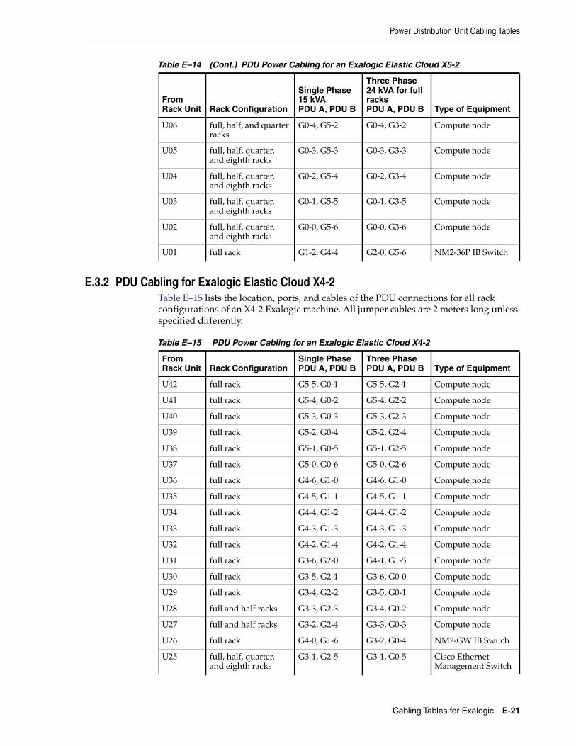
Power Distribution Unit Cabling Tables
Cabling Tables for Exalogic E-21
E.3.2 PDU Cabling for Exalogic Elastic Cloud X4-2Table E–15 lists the location, ports, and cables of the PDU connections for all rackconfigurations of an X4-2 Exalogic machine. All jumper cables are 2 meters long unlessspecified differently.
U06 full, half, and quarterracks
G0-4, G5-2 G0-4, G3-2 Compute node
U05 full, half, quarter,and eighth racks
G0-3, G5-3 G0-3, G3-3 Compute node
U04 full, half, quarter,and eighth racks
G0-2, G5-4 G0-2, G3-4 Compute node
U03 full, half, quarter,and eighth racks
G0-1, G5-5 G0-1, G3-5 Compute node
U02 full, half, quarter,and eighth racks
G0-0, G5-6 G0-0, G3-6 Compute node
U01 full rack G1-2, G4-4 G2-0, G5-6 NM2-36P IB Switch
Table E–15 PDU Power Cabling for an Exalogic Elastic Cloud X4-2
FromRack Unit Rack Configuration
Single PhasePDU A, PDU B
Three PhasePDU A, PDU B Type of Equipment
U42 full rack G5-5, G0-1 G5-5, G2-1 Compute node
U41 full rack G5-4, G0-2 G5-4, G2-2 Compute node
U40 full rack G5-3, G0-3 G5-3, G2-3 Compute node
U39 full rack G5-2, G0-4 G5-2, G2-4 Compute node
U38 full rack G5-1, G0-5 G5-1, G2-5 Compute node
U37 full rack G5-0, G0-6 G5-0, G2-6 Compute node
U36 full rack G4-6, G1-0 G4-6, G1-0 Compute node
U35 full rack G4-5, G1-1 G4-5, G1-1 Compute node
U34 full rack G4-4, G1-2 G4-4, G1-2 Compute node
U33 full rack G4-3, G1-3 G4-3, G1-3 Compute node
U32 full rack G4-2, G1-4 G4-2, G1-4 Compute node
U31 full rack G3-6, G2-0 G4-1, G1-5 Compute node
U30 full rack G3-5, G2-1 G3-6, G0-0 Compute node
U29 full rack G3-4, G2-2 G3-5, G0-1 Compute node
U28 full and half racks G3-3, G2-3 G3-4, G0-2 Compute node
U27 full and half racks G3-2, G2-4 G3-3, G0-3 Compute node
U26 full rack G4-0, G1-6 G3-2, G0-4 NM2-GW IB Switch
U25 full, half, quarter,and eighth racks
G3-1, G2-5 G3-1, G0-5 Cisco EthernetManagement Switch
Table E–14 (Cont.) PDU Power Cabling for an Exalogic Elastic Cloud X5-2
FromRack Unit Rack Configuration
Single Phase15 kVAPDU A, PDU B
Three Phase24 kVA for fullracksPDU A, PDU B Type of Equipment

Power Distribution Unit Cabling Tables
E-22 Oracle Exalogic Elastic Cloud Machine Owner's Guide
U24 full rack G3-0, G2-6 G2-6, G5-0 NM2-GW IB Switch
U23 full, half, quarter,and eighth racks
G2-6, G3-0 G2-5, G5-1 NM2-GW IB Switch
U22 full, half, quarter,and eighth racks
G2-5, G3-1 G3-0, G0-6 ZS3-ES StorageAppliance ServerHead
U21 full, half, quarter,and eighth racks
G2-4, G3-2 G2-4, G5-2 ZS3-ES StorageAppliance ServerHead
U20, U19,U18, andU17
full, half, quarter,and eighth racks
G2-3, G3-3 G2-3, G5-3 DE2-24C StorageAppliance Disk Shelf(jumper length: 1meter)
U16 full, half, quarter,and eighth racks
G1-6, G4-0 G1-6, G4-0 NM2-GW IB Switch
U15 full and half racks G2-2, G3-4 G2-2, G5-4 Compute node
U14 full and half racks G2-1, G3-5 G2-1, G5-5 Compute node
U13 full and half racks G2-0, G3-6 G2-0, G5-6 Compute node
U12 full and half racks G1-4, G4-2 G1-4, G4-2 Compute node
U11 full and half racks G1-3, G4-3 G1-3, G4-3 Compute node
U10 full and half racks G1-2, G4-4 G1-2, G4-4 Compute node
U09 full, half, and quarterracks
G1-1, G4-5 G1-1, G4-5 Compute node
U08 full, half, and quarterracks
G1-0, G4-6 G1-0, G4-6 Compute node
U07 full, half, and quarterracks
G0-6, G5-0 G0-6, G3-0 Compute node
U06 full, half, and quarterracks
G0-5, G5-1 G0-5, G3-1 Compute node
U05 full, half, quarter,and eighth racks
G0-4, G5-2 G0-4, G3-2 Compute node
U04 full, half, quarter,and eighth racks
G0-3, G5-3 G0-3, G3-3 Compute node
U03 full, half, quarter,and eighth racks
G0-2, G5-4 G0-2, G3-4 Compute node
U02 full, half, quarter,and eighth racks
G0-1, G5-5 G0-1, G3-5 Compute node
U01 full rack G0-0, G5-6 G0-0, G3-6 NM2-36P IB Switch
Table E–15 (Cont.) PDU Power Cabling for an Exalogic Elastic Cloud X4-2
FromRack Unit Rack Configuration
Single PhasePDU A, PDU B
Three PhasePDU A, PDU B Type of Equipment

F
Managing Solaris Zones on Exalogic F-1
FManaging Solaris Zones on Exalogic
[24]Oracle Solaris zones are an integral part of the Oracle Solaris operating system. Zonesisolate software applications and services using flexible software-defined boundaries.This appendix describes how to manage Solaris zones on Exalogic.
This appendix contains the following sections:
■ Requirements
■ Terminology
■ Creating a Solaris Zone
■ Migrating a Zone to a New Host
F.1 RequirementsCreating zones on an Exalogic machine has the following requirements:
■ An Exalogic machine imaged to release 2.0.4.0 running Oracle Solaris.
■ An Exalogic machine patched to the April 2013 Patch Set Update available in theMy Oracle Support document ID 1545364.1.
■ An Exalogic machine patched with the Solaris patch for Zones on Shared Storage(ZOSS) over iSCSI available in the My Oracle Support document ID 16514816.
F.2 TerminologyTable F–1 describes the terms used in this appendix.
Table F–1 Terminology
Term Description
Logical Unit A logical unit is a component of a storage system. A logical unitis uniquely numbered creating a Logical Unit Number (LUN).The storage appliance can contain many LUNs. LUNs whenassociated with one or more SCSI targets, form a unique SCSIdevice. This SCSI device can be accessed by one or more SCSIinitiators.
Initiator An initiator is an application or production system end-pointthat is capable of initiating a SCSI session, sending SCSIcommands, and I/O requests. Initiators are also identified byunique addressing methods.
Initiator Group A set of initiators. When an initiator group is associated with aLUN, only initiators from that group may access the LUN.

Creating a Solaris Zone
F-2 Oracle Exalogic Elastic Cloud Machine Owner's Guide
F.3 Creating a Solaris ZoneThis section describes how to create a Solaris zone. This section contains the followingtopics:
■ Prerequisites
■ Setting Up a Solaris Zone
F.3.1 PrerequisitesBefore creating a Solaris zone, you should perform the following tasks:
■ Creating an iSCSI Target
■ Creating an iSCSI Initiator
■ Creating the Project and LUN
■ Disabling the Write Cache
■ Formatting the LUN
■ Setting Up the Exclusive 10 GbE Network for the Zone
F.3.1.1 Creating an iSCSI TargetYou can create an iSCSI target by doing the following:
1. Log in to the storage appliance BUI as the root user.
2. Click the Configuration tab.
3. Click SAN.
4. Click iSCSI Targets.
5. To create a new iSCSI target, click the plus button next to iSCSI Targets.
The New iSCSI Target dialog box appears.
6. For the Target IQN, select the Auto-assign option.
7. In the Alias field, enter a name for your iSCSI target.
8. For the Initiator authentication mode, select the authentication mode you areusing for communication between the compute node and storage appliance. Bydefault, no authentication is used.
Target A target is an end-point that provides a service of processingSCSI commands and I/O requests from an initiator. A target,once configured, consists of zero or more logical units.
Target Group A set of targets. LUNs are exported over all the targets in onespecific target group.
Table F–1 (Cont.) Terminology
Term Description

Creating a Solaris Zone
Managing Solaris Zones on Exalogic F-3
9. From the Network interfaces list, select the interface that corresponds to yourInfiniBand partition. You can identify the interface by logging in to the storageappliance and running configuration net interfaces show. If there are nopartitions defined, identify the interface for the label IB_Interface.
10. Click OK.
11. You can add the iSCSI target to an iSCSI target group by dragging and droppingthe target to a iSCSI target group in the iSCSI Target Groups panel on the right. Ifrequired, you can create a new iSCSI target group by dragging and dropping thetarget to the top of iSCSI Target Groups panel on the right.
F.3.1.2 Creating an iSCSI InitiatorYou can create an iSCSI initiator by doing the following:
1. Before you can create an iSCSI initiator, you must identify an initiator IQN. Theinitiator IQN is a unique reference number associated with a specific computenode. To find the initiator IQN for a compute node, do the following:
a. Log in to an Exalogic compute node.
b. Run the iscsiadm list initiator-node command as follows:
# iscsiadm list initiator-nodeInitiator node name: iqn.1986-03.com.sun:01:e00000000000.51891a8bInitiator node alias: el01cn01
Login Parameters (Default/Configured):Header Digest: NONE/-Data Digest: NONE/-Max Connections: 65535/-
Authentication Type: NONERADIUS Server: NONERADIUS Access: disabledTunable Parameters (Default/Configured):
Session Login Response Time: 60/-Maximum Connection Retry Time: 180/-Login Retry Time Interval: 60/-
Configured Sessions: 1
In this example, the initiator IQN is:
iqn.1986-03.com.sun:01:e00000000000.51891a8b
2. Log in to the storage appliance BUI as the root user.
3. Click the Configuration tab.
4. Click SAN.
5. Click Initiators.
6. Click iSCSI Initiators.
7. Click the plus button next to iSCSI Initiators to create a new iSCSI initiator.
Note: For more information on setting up CHAP authenticationbetween the compute node and storage, see the "Setting Up CHAPAuthentication" topic in the following document:http://www.oracle.com/technetwork/server-storage/sun-unified-storage/documentation/iscsi-quickstart-v1-2-051512-1641594.pdf

Creating a Solaris Zone
F-4 Oracle Exalogic Elastic Cloud Machine Owner's Guide
8. In the Initiator IQN field, enter the initiator IQN you identified in step 1.
9. In the Alias field, enter a name for the iSCSI initiator you are creating.
10. If you are using CHAP authentication, select the Use CHAP check box and fill inthe Initiator CHAP name and Initiator CHAP secret fields as you did inSection F.3.1.1, "Creating an iSCSI Target."
11. Click OK.
12. Add the iSCSI initiator to an iSCSI initiator group by dragging and dropping theinitiator.
If required, you can create a new iSCSI initiator group.
F.3.1.3 Creating the Project and LUNYou can create the project and LUN by doing the following:
1. Create a project as described in Section 8.5, "Creating Custom Projects."
2. You can create the LUN by doing the following:
a. Next to the Project, click Shares.
b. Click LUNs.
The list of LUNs appears.
c. Click the plus button next to LUNs.
d. In the Project field, select the project you created in step 1.
e. In the Name field, enter a name for the LUN.
f. Enter the size of the volume in GB.
g. Select Thin provisioned.
h. Set the Volume block size as 32k.
i. In the Target Group field, select the target group you used in Section F.3.1.1,"Creating an iSCSI Target."
j. In the Initiator Group field, select the initiator group you used inSection F.3.1.2, "Creating an iSCSI Initiator."
k. Click Apply.
l. Note the GUID of the LUN you created in the list of LUNs. For example,g600144f09c96cca900005190bfc4000a.
Note: For more information on setting up CHAP authenticationbetween the compute node and storage appliance, see the "Setting UpCHAP Authentication" topic in the following document:http://www.oracle.com/technetwork/server-storage/sun-unified-storage/documentation/iscsi-quickstart-v1-2-051512-1641594.pdf
Note: After creating the LUN, ensure that the Write cache enabledcheck box is deselected. You can find this check box in the Protocolstab of the LUN.

Creating a Solaris Zone
Managing Solaris Zones on Exalogic F-5
F.3.1.4 Disabling the Write CacheYou must disable the write cache on the LUN permanently by doing the following:
1. Log in to the compute node for which you identified the initiator node name asdescribed in Section F.3.1.2, "Creating an iSCSI Initiator."
2. Edit the /kernel/drv/sd.conf file.
3. Add the following to the sd.conf file:
sd-config-list="SUN ZFS Storage 7120","write-cache-disable","SUN ZFS Storage 7320","write-cache-disable","SUN ZFS Storage 7420","write-cache-disable","SUN ZFS Storage 7335","write-cache-disable";
write-cache-disable=1,0x00008,0,0,0,1,0,0,0,0,0,0,0,0,0,0,0,0,0,0;
4. Restart the compute node by running the reboot command.
F.3.1.5 Formatting the LUNBefore the compute node can use the LUN, you must format the LUN. You can formatthe LUN by doing the following:
1. Log in to a compute node as the root user.
2. Run the iscsiadm commands to discover the iSCSI targets from the compute node:
# iscsiadm add discovery-address IPoIB_address_of_the_storage_appliance# iscsiadm modify discovery -t enable
In this example, IPoIB_address_of_the_storage_appliance is the IP address ofthe storage appliance on the IPoIB network.
3. Run the following command to load drivers, attach device instances, create logicallinks to device nodes, and load the device policy for iSCSI:
# devfsadm -c iscsi
4. Identify the disk you should format and label by running echo | format asfollows:
# echo | formatSearching for disks...done
AVAILABLE DISK SELECTIONS:0. c0t600144F09C96CCA90000518CDEB10005d0 <SUN-ZFS Storage
7320-1.0-64.00GB>/scsi_vhci/disk@g600144f09c96cca90000518cdeb10005
1. c0t600144F09C96CCA90000518CDF100006d0 <SUN-ZFS Storage7320-1.0-64.00GB>
/scsi_vhci/disk@g600144f09c96cca90000518cdf1000062. c0t600144F09C96CCA90000518CDFB60007d0 <SUN-ZFS Storage
7320-1.0-64.00GB>/scsi_vhci/disk@g600144f09c96cca90000518cdfb60007
3. c0t600144F09C96CCA900005190BFC4000Ad0 <SUN-ZFS Storage 7320-1.0 cyl8352 alt 2 hd 255 sec 63>
/scsi_vhci/disk@g600144f09c96cca900005190bfc4000a4. c7t0d0 <LSI-MR9261-8i-2.12-28.87GB>
/pci@0,0/pci8086,340a@3/pci1000,9263@0/sd@0,0Specify disk (enter its number): Specify disk (enter its number):

Creating a Solaris Zone
F-6 Oracle Exalogic Elastic Cloud Machine Owner's Guide
The value after /scsi_vhci/disk@g is the GUID of the LUN you created inSection F.3.1.3, "Creating the Project and LUN." In this example, the diskc0t600144F09C96CCA900005190BFC4000Ad0 with the GUIDg600144f09c96cca900005190bfc4000a should be formatted and labelled.
5. Format the disk by doing the following:
a. Run the format command to start formatting the disk as follows:
# format -e c0t600144F09C96CCA900005190BFC4000Ad0selecting c0t600144F09C96CCA900005190BFC4000Ad0[disk formatted]
The format prompt appears.
b. Enter fdisk to manipulate the partition tables as follows:
format> fdiskNo fdisk table exists. The default partition for the disk is:
a 100% "SOLARIS System" partitionc. When prompted, enter n to edit the partition table.
Type "y" to accept the default partition, otherwise type "n" to edit thepartition table. n
d. Enter 1 to set the partition type.
e. Enter f to set the partition type as EFI (Protective) as follows:
Select the partition type to create:1=SOLARIS2 2=UNIX 3=PCIXOS 4=Other 5=DOS126=DOS16 7=DOSEXT 8=DOSBIG 9=DOS16LBA A=x86 BootB=Diagnostic C=FAT32 D=FAT32LBA E=DOSEXTLBA F=EFI (Protective)G=EFI_SYS 0=Exit? f
6. Label the LUN by doing the following:
a. Enter 6 to label the LUN.
The format prompt appears.
b. Enter label to label the disk as follows:
format> label
The list of label types appears.
c. Enter 1 to specify the label type as an EFI label as follows:
[0] SMI Label[1] EFI LabelSpecify Label type[1]: 1
A confirmation message appears.
d. Enter y to continue.
e. Enter quit to exit the format prompt.
f. You can use the format command to ensure the disk is available and the samesize you specified in the storage appliance BUI as follows:
# formatSearching for disks...done

Creating a Solaris Zone
Managing Solaris Zones on Exalogic F-7
AVAILABLE DISK SELECTIONS:0. c0t600144F09C96CCA90000518CDEB10005d0 <SUN-ZFS Storage
7320-1.0-64.00GB>/scsi_vhci/disk@g600144f09c96cca90000518cdeb10005
1. c0t600144F09C96CCA90000518CDF100006d0 <SUN-ZFS Storage7320-1.0-64.00GB>
/scsi_vhci/disk@g600144f09c96cca90000518cdf1000062. c0t600144F09C96CCA90000518CDFB60007d0 <SUN-ZFS Storage
7320-1.0-64.00GB>/scsi_vhci/disk@g600144f09c96cca90000518cdfb60007
3. c0t600144F09C96CCA900005190BFC4000Ad0 <SUN-ZFS Storage7320-1.0-64.00GB>
/scsi_vhci/disk@g600144f09c96cca900005190bfc4000a4. c7t0d0 <LSI-MR9261-8i-2.12-28.87GB>
/pci@0,0/pci8086,340a@3/pci1000,9263@0/sd@0,0Specify disk (enter its number):
F.3.1.6 Setting Up the Exclusive 10 GbE Network for the ZoneThe zone you want to create should be given access to an exclusive network. Youshould create the necessary VNICs for the zone by doing the following:
1. Create a VLAN and VNIC. Follow the procedure in Section 11.5, "Oracle Solaris:Creating VNICs and Associating Them with VLANs.".
2. Log in to the compute node as the root user.
3. Run the dladm show-phys command to identify the physical links of the EoIBdevices as in the following example:
# dladm show-physLINK MEDIA STATE SPEED DUPLEX DEVICEnet6 Infiniband up 32000 unknown ibp1net0 Ethernet up 1000 full igb0net1 Ethernet unknown 0 unknown igb1net3 Ethernet unknown 0 unknown igb3net4 Ethernet up 10 full usbecm0net8 Ethernet up 10000 full eoib1net2 Ethernet unknown 0 unknown igb2net5 Infiniband up 32000 unknown ibp0net9 Ethernet up 10000 full eoib0
In this example, net8 and net9 are the physical links of the EoIB devices.
4. Create a VNIC on the compute node for the first physical link using the dladmcreate-vnic command as follows:
# dladm create-vnic -l link_of_eoib0 -v VLAN_ID vnic1_name
Example:
# dladm create-vnic -l net9 -v 1706 vnic3_1706
5. Create a VNIC for the second physical link using the dladm create-vniccommand as follows:
# dladm create-vnic -l link_of_eoib1 -v VLAN_ID vnic2_name
Example:
# dladm create-vnic -l net8 -v 1706 vnic2_1706

Creating a Solaris Zone
F-8 Oracle Exalogic Elastic Cloud Machine Owner's Guide
F.3.2 Setting Up a Solaris ZoneWith the storage appliance prepared, you can store the zone on the storage applianceand set up additional bonded network on the 10 GbE Exalogic client networkexclusively for the zone.
You can set up the solaris zone by doing the following:
1. Creating a Zone
2. Installing and Booting Up the Zone
F.3.2.1 Creating a ZoneYou can create a zone by doing the following:
1. Log in to the compute node as the root user.
2. Run the zonecfg command to configure the zone as follows:
# zonecfg -z zone_name
Example:
# zonecfg -z zone04Use 'create' to begin configuring a new zone.
In this example, the name of the zone you are creating is zone04.
3. Enter create to begin configuring the zone:
zonecfg:zone04 createcreate: Using system default template 'SYSdefault'
4. Create the zone by running the following commands:
zonecfg:zone04> set zonepath=/zones/zone04zonecfg:zone04> add rootzpoolzonecfg:zone04:rootzpool> add storage iscsi://IPoIB_Address_of_the_storage_Appliance/luname.naa.LUNGUIDzonecfg:zone04:rootzpool> endzonecfg:zone04> remove anetzonecfg:zone04> add netzonecfg:zone04:net> set physical=vnic1_namezonecfg:zone04:net> endzonecfg:zone04> add netzonecfg:zone04:net> set physical=vnic2_namezonecfg:zone04:net> endzonecfg:zone04> verifyzonecfg:zone04> commit
In this example:
■ IPoIB_address_of_the_storage_appliance is the IP address of the storageappliance on the IPoIB network.
■ LUNGUID is the GUID of the LUN you created in Section F.3.1.3, "Creating theProject and LUN."
■ vnic1_name and vnic2_name are the VNICs you created in Section F.3.1.6,"Setting Up the Exclusive 10 GbE Network for the Zone."
Example:

Creating a Solaris Zone
Managing Solaris Zones on Exalogic F-9
zonecfg:zone04> set zonepath=/zones/zone04zonecfg:zone04> add rootzpoolzonecfg:zone04:rootzpool> add storageiscsi://192.168.14.133/luname.naa.600144f09c96cca900005190bfc4000azonecfg:zone04:rootzpool> endzonecfg:zone04> remove anetzonecfg:zone04> add netzonecfg:zone04:net> set physical=vnic2_1706zonecfg:zone04:net> endzonecfg:zone04> add netzonecfg:zone04:net> set physical=vnic3_1706zonecfg:zone04:net> endzonecfg:zone04> verifyzonecfg:zone04> commit
5. You can verify the details of the zone by running the info command as follows:
zonecfg:zone04> infozonename: zone04zonepath: /zones/zone04brand: solarisautoboot: falsebootargs:file-mac-profile:pool:limitpriv:scheduling-class:ip-type: exclusivehostid:fs-allowed:net:
address not specifiedallowed-address not specifiedconfigure-allowed-address: truephysical: vnic1_namedefrouter not specified
net:address not specifiedallowed-address not specifiedconfigure-allowed-address: truephysical: vnic2_namedefrouter not specified
rootzpool:storage: iscsi://IPoIB_Address_of_the_Storage_Appliance/luname.naa.LUNGUID
zonecfg:zone04>
F.3.2.2 Installing and Booting Up the ZoneBefore installing the zone, ensure that you have a repository for the Solaris installationset up stored on the storage appliance. The zone creation uses this repository to storethe operating system files for the zone.
1. Install the zone by running the command as follows:
# zoneadm -z zone04 install
Configured zone storage resource(s) from:iscsi://192.168.14.133/luname.naa.600144f09c96cca900005190bfc4000a
Created zone zpool: zone04_rpoolProgress being logged to/var/log/zones/zoneadm.20130513T104657Z.zone04.install

Creating a Solaris Zone
F-10 Oracle Exalogic Elastic Cloud Machine Owner's Guide
Image: Preparing at /zones/zone04/root.
AI Manifest: /tmp/manifest.xml.lPaGVoSC Profile: /usr/share/auto_install/sc_profiles/enable_sci.xml
Zonename: zone04Installation: Starting ...
Creating IPS imageStartup linked: 1/1 done
Installing packages from:exa-family
origin:http://localhost:1008/exa-family/acbd22da328c302a86fb9f23d43f5d10f13cf5a6/
solarisorigin: http://install1/release/solaris/
DOWNLOAD PKGS FILES XFER (MB)SPEEDCompleted 185/185 34345/34345 229.7/229.710.6M/s
PHASE ITEMSInstalling new actions 48269/48269Updating package state database DoneUpdating image state DoneCreating fast lookup database DoneInstallation: Succeeded
Note: Man pages can be obtained by installing pkg:/system/manual
done.
Done: Installation completed in 81.509 seconds.
Next Steps: Boot the zone, then log into the zone console (zlogin -C)
to complete the configuration process.
Log saved in non-global zone as/zones/zone04/root/var/log/zones/zoneadm.20130513T104657Z.zone04.install
2. Boot up the zone by running the following command:
# zoneadm -z zone04 boot
3. Once the zone has booted up, log in to the zone using the zlogin command asfollows:
# zlogin zone04[Connected to zone 'zone04' pts/7]
4. Bond the VNICs you created as described in step 5 of Section 11.5, "Oracle Solaris:Creating VNICs and Associating Them with VLANs.".
5. Run the following command to display the bond you created in the previous step:
root@zone04:~# ipadm show-addrADDROBJ TYPE STATE ADDRlo0/v4 static ok 127.0.0.1/8bond1/v4 static ok 138.3.51.2/22lo0/v6 static ok ::1/128
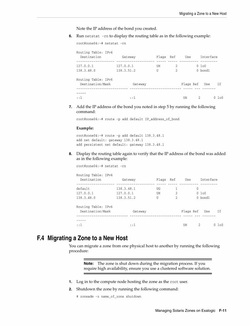
Migrating a Zone to a New Host
Managing Solaris Zones on Exalogic F-11
Note the IP address of the bond you created.
6. Run netstat -rn to display the routing table as in the following example:
root@zone04:~# netstat -rn
Routing Table: IPv4Destination Gateway Flags Ref Use Interface
-------------------- -------------------- ----- ----- ---------- ---------127.0.0.1 127.0.0.1 UH 2 0 lo0138.3.48.0 138.3.51.2 U 2 0 bond1
Routing Table: IPv6Destination/Mask Gateway Flags Ref Use If
--------------------------- --------------------------- ----- --- ------------::1 ::1 UH 2 0 lo0
7. Add the IP address of the bond you noted in step 5 by running the followingcommand:
root@zone04:~# route -p add default IP_address_of_bond
Example:
root@zone04:~# route -p add default 138.3.48.1add net default: gateway 138.3.48.1add persistent net default: gateway 138.3.48.1
8. Display the routing table again to verify that the IP address of the bond was addedas in the following example:
root@zone04:~# netstat -rn
Routing Table: IPv4Destination Gateway Flags Ref Use Interface
-------------------- -------------------- ----- ----- ---------- ---------default 138.3.48.1 UG 1 0127.0.0.1 127.0.0.1 UH 2 0 lo0138.3.48.0 138.3.51.2 U 2 0 bond1
Routing Table: IPv6Destination/Mask Gateway Flags Ref Use If
--------------------------- --------------------------- ----- --- ------------::1 ::1 UH 2 0 lo0
F.4 Migrating a Zone to a New HostYou can migrate a zone from one physical host to another by running the followingprocedure:
1. Log in to the compute node hosting the zone as the root user.
2. Shutdown the zone by running the following command:
# zoneadm -z name_of_zone shutdown
Note: The zone is shut down during the migration process. If yourequire high availability, ensure you use a clustered software solution.

Migrating a Zone to a New Host
F-12 Oracle Exalogic Elastic Cloud Machine Owner's Guide
Example:
# zoneadm -z zone04 shutdown
3. Detach the zone by running the following command:
# zoneadm -z name_of_zone detach
Example:
# zoneadm -z zone04 detachzoneadm: zone 'zone04': warning(s) occured during processing URI:'iscsi://192.168.14.133/luname.naa.600144f09c96cca900005190bfc4000a'Could not remove one or more iSCSI discovery addresses because logical unit isin useExported zone zpool: zone04_rpoolUnconfigured zone storage resource(s) from:
iscsi://192.168.14.133/luname.naa.600144f09c96cca900005190bfc4000a#
4. Create a directory on the storage appliance to which you can export theconfiguration of the zone:
# mkdir -p directory
Example:
# mkdir -p /u01/common/general/zone04
5. Export the configuration of the zone by running the following command:
# zonecfg -z name_of_zone export > directory/name_of_zone.cfg
Example:
# zonecfg -z zone04 export > /common/general/zone04/zone04.cfg
6. Log in to the compute node you want to migrate the zone to as the root user.
7. Import the zone from the configuration file you created in the previous step byrunning the following command:
# zonecfg -z name_of_zone -f directory/name_of_zone.cfg
Example:
# zonecfg -z zone04 -f /common/general/zone04/zone04.cfg
8. Attach the zone by running the following command:
# zoneadm -z name_of_zone attach
Example:
# zoneadm -z zone04 attachConfigured zone storage resource(s) from:
iscsi://192.168.14.133/luname.naa.600144f09c96cca900005190bfc4000aImported zone zpool: zone04_rpoolProgress being logged to /var/log/zones/zoneadm.20130513T135704Z.zone04.attach
Installing: Using existing zone boot environmentZone BE root dataset: zone04_rpool/rpool/ROOT/solaris
Cache: Using /var/pkg/publisher.Updating non-global zone: Linking to image /.
Processing linked: 1/1 done

Migrating a Zone to a New Host
Managing Solaris Zones on Exalogic F-13
Updating non-global zone: Auditing packages.No updates necessary for this image.
Updating non-global zone: Zone updated.Result: Attach Succeeded.
Log saved in non-global zone as/zones/zone04/root/var/log/zones/zoneadm.20130513T135704Z.zone04.attach
9. Boot up the zone by running the following command:
# zoneadm -z name_of_zone boot
Example:
# zoneadm -z zone04 boot
Note: In some situations, the process of detaching and attaching cancause the server to boot up with the system configuration wizardrunning.
You can resolve this issue, by logging in to the console and completingthe wizard. You can use the following command to log in to the zone:
# zlogin -C name_of_zone

Migrating a Zone to a New Host
F-14 Oracle Exalogic Elastic Cloud Machine Owner's Guide

G
Customizing the Linux Operating System on Exalogic Compute Nodes G-1
GCustomizing the Linux Operating System onExalogic Compute Nodes
[25]This appendix describes how to customize the Linux operating system on computenodes in an Exalogic machine, to suit your business needs, by installing additionalRPMs, and updating or removing RPMs that are installed by default. It applies toExalogic in a physical configuration, with the Linux operating system installed on baremetal. The tasks described in this appendix are optional.
This appendix contains the following sections:
■ RPMs That Must Not Be Modified or Removed
■ Installing, Updating, and Removing RPMs by Using Yum
G.1 RPMs That Must Not Be Modified or RemovedDo not modify or delete the following RPMs outside of an Exalogic upgrade, patch setupdate (PSU), or patch.
kernel*compat-dapl*dapl*ib-bonding*ibacm*ibutils*ibsim*infiniband-diags*libibcm*libibmad*libibumad*libibverbs*libmlx4*librdmacm*libsdp*mpi-selector*mpitests_openmpi_gcc*mstflint*mvapich*ofa*ofed*openmpi_gcc*opensm*perftest*qperf*rds-tools*sdpnetstat*

Installing, Updating, and Removing RPMs by Using Yum
G-2 Oracle Exalogic Elastic Cloud Machine Owner's Guide
srptools*exalogic*infinibus*
G.2 Installing, Updating, and Removing RPMs by Using Yum
Preparing the Compute Nodes for Yum Updates1. On a host outside the Exalogic machine, set up a local yum repository as described
in the "Server Setup" section of the following document:
http://www.oracle.com/technetwork/articles/servers-storage-admin/yum-repo-setup-1659167.html
While doing this, select only the ol5_x86_64_latest channel.
2. On each compute node on the Exalogic machine, do the following:
a. Log in as the root user.
b. Set up the compute node as a yum client of the repository you set up in step 1,by performing the steps in the "Client Setup" section of the followingdocument:
http://www.oracle.com/technetwork/articles/servers-storage-admin/yum-repo-setup-1659167.html
c. To ensure that essential RPMs are not modified during yum updates, appendthe following exclude directive, to the /etc/yum.conf file.
exclude=kernel* compat-dapl* dapl* ib-bonding* ibacm* ibutils* ibsim*infiniband-diags* libibcm* libibmad* libibumad* libibverbs* libmlx4*librdmacm* libsdp* mpi-selector* mpitests_openmpi_gcc* mstflint* mvapich*ofa* ofed* openmpi_gcc* opensm* perftest* qperf* rds-tools* sdpnetstat*srptools* exalogic* infinibus*
This exclusion list includes all of the RPMs listed in Appendix G.1, "RPMsThat Must Not Be Modified or Removed."
Installing, Updating, and Removing RPMs by Using Yum1. Ensure that the compute node on which you want to perform yum updates has
been prepared, as described in "Preparing the Compute Nodes for Yum Updates."
2. Install, update, or remove RPMs as follows:
■ To install an RPM from the yum repository, run the following command:
# yum install rpm_name
■ To update a specific RPM, run the following command:
# yum update rpm_name
■ To update all the RPMs, run the following command:
# yum update
■ To remove an RPM, run the following command:
Note: The entire directive must be on one line.

Installing, Updating, and Removing RPMs by Using Yum
Customizing the Linux Operating System on Exalogic Compute Nodes G-3
# yum remove rpm_name
For the yum update or yum remove command, if you specify an RPM that is in theexclusion list defined earlier, the command will fail.

Installing, Updating, and Removing RPMs by Using Yum
G-4 Oracle Exalogic Elastic Cloud Machine Owner's Guide


![2-[5-Methyl-2-(propan-2-yl)phenoxy]- N ′-{2-[5-methyl-2-(propan-2-yl)phenoxy]acetyl}acetohydrazide](https://static.fdokumen.com/doc/165x107/6344862303a48733920aed56/2-5-methyl-2-propan-2-ylphenoxy-n-2-5-methyl-2-propan-2-ylphenoxyacetylacetohydrazide.jpg)