Optimized design of local shielding for the IFMIF/EVEDA beam dump
10
1 Optimized design of local shielding for the IFMIF/EVEDA beam dump M. García 1,2 , F. Ogando 1,2 , P. Ortego 3 , J.M. Arroyo 4 , B. Brañas 4 , C. Töre 3 , D. López 1,2 , P. Sauvan 1,2 , A. Mayoral 1,2 , J. Sanz 1,2 1 Dpto. de Ingeniería Energética, Escuela Técnica Superior de Ingenieros Industriales UNED, C/ Juan del Rosal 12, 28040 Madrid, Spain 2 Instituto de Fusión Nuclear, UPM, C/ José Gutiérrez Abascal 2, 28006 Madrid, Spain 3 SEA, Madrid, Spain 4 CIEMAT, Avda Complutense, Madrid, Spain Abstract This paper describes the local shielding design process of the IFMIF/EVEDA Beam Dump and the most relevant results obtained from the simulations. Different geometries and materials have been considered, and the design has been optimized taking into account the origin of the doses, the effect of the walls of the accelerator vault and the space restrictions. The initial idea was to shield the beam stopper with a large water tank of easy transport and dismantling but it was shown to be insufficient to satisfy the dose limit requirements, basically due to photon dose, and hence a denser shield combining hydrogenous and heavy materials was preferred. It will be shown that, with this new shielding, dose rate outside the accelerator vault during operation comply with the legal limits and unrestricted maintenance operations inside most of the vault are possible after a reasonable cooling time after shutdown. Introduction The International Fusion Materials and Irradiation Facility (IFMIF) will be an accelerator-based neutron source to test candidate materials for nuclear fusion reactors. During the Engineering Validation and Design Activities (EVEDA) phase, a prototype accelerator (125 mA, CW, 9 MeV deuterons) will be tested in Rokkasho (Japan). As no target is foreseen for the accelerated beam during this phase, a beam dump is required to stop it during commissioning and accelerator tests. The piece that stops the beam is a copper conical sheet with a 250 cm length, 30 cm aperture diameter and 0.5 cm thickness. Beam dump radioprotection concerns arise from the fact that deuterons hit the intercepting copper beam stop as well as previous deuterons implanted in it, which will result in secondary neutrons and photons as well as in deuteron induced activation products. The generation of neutrons will induce: i) high neutron and prompt gamma dose rates during accelerator operation and ii) gamma dose rates on beam-off due to activation of all materials. The impact of the deuterons on its surface gives rise to neutron production at a rate up to 4,6 10 14 neutrons per second and the activation by this neutron source of the surrounding materials.
-
Upload
independent -
Category
Documents
-
view
0 -
download
0
Transcript of Optimized design of local shielding for the IFMIF/EVEDA beam dump

1
Optimized design of local shielding for the IFMIF/EVEDA beam dump
M. García 1,2
, F. Ogando 1,2
, P. Ortego 3, J.M. Arroyo
4, B. Brañas
4, C. Töre
3, D. López
1,2,
P. Sauvan 1,2
, A. Mayoral 1,2
, J. Sanz 1,2
1
Dpto. de Ingeniería Energética, Escuela Técnica Superior de Ingenieros Industriales UNED, C/ Juan del Rosal 12, 28040 Madrid, Spain
2Instituto de Fusión Nuclear, UPM, C/ José Gutiérrez Abascal 2, 28006 Madrid, Spain 3SEA, Madrid, Spain 4CIEMAT, Avda Complutense, Madrid, Spain
Abstract
This paper describes the local shielding design process of the IFMIF/EVEDA Beam Dump and the most relevant results obtained from the simulations. Different geometries and materials have been considered, and the design has been optimized taking into account the origin of the doses, the effect of the walls of the accelerator vault and the space restrictions. The initial idea was to shield the beam stopper with a large water tank of easy transport and dismantling but it was shown to be insufficient to satisfy the dose limit requirements, basically due to photon dose, and hence a denser shield combining hydrogenous and heavy materials was preferred. It will be shown that, with this new shielding, dose rate outside the accelerator vault during operation comply with the legal limits and unrestricted maintenance operations inside most of the vault are possible after a reasonable cooling time after shutdown.
Introduction
The International Fusion Materials and Irradiation Facility (IFMIF) will be an accelerator-based neutron source to test candidate materials for nuclear fusion reactors. During the Engineering Validation and Design Activities (EVEDA) phase, a prototype accelerator (125 mA, CW, 9 MeV deuterons) will be tested in Rokkasho (Japan). As no target is foreseen for the accelerated beam during this phase, a beam dump is required to stop it during commissioning and accelerator tests. The piece that stops the beam is a copper conical sheet with a 250 cm length, 30 cm aperture diameter and 0.5 cm thickness.
Beam dump radioprotection concerns arise from the fact that deuterons hit the intercepting copper beam stop as well as previous deuterons implanted in it, which will result in secondary neutrons and photons as well as in deuteron induced activation products. The generation of neutrons will induce: i) high neutron and prompt gamma dose rates during accelerator operation and ii) gamma dose rates on beam-off due to activation of all materials. The impact of the deuterons on its surface gives rise to neutron production at a rate up to 4,6 1014 neutrons per second and the activation by this neutron source of the surrounding materials.
2
In the design of the Beam Dump (BD) the radioprotection requirements to be fulfilled are: i) dose rate outside the accelerator vault during accelerator operation must be below the acceptable levels for workers and/or public; and ii) inside the accelerator vault man-access for maintenance must be allowed during beam-off phases. The dose rate limits to be fulfilled are 12.5 µSv/h for workers and 0.5 µSv/h for public.
Methodology
The starting point for the radioprotection analysis is the deuteron particle position and energy at the copper cone entrance provided by the TraceWin [1] code. The first step is to determine an equivalent deuteron source which could be introduced into transport codes, while retaining as close as possible the particle distribution from TraceWin.
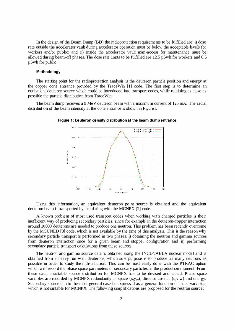
The beam dump receives a 9 MeV deuteron beam with a maximum current of 125 mA. The radial distribution of the beam intensity at the cone entrance is shown in Figure1.
Figure 1: Deuteron density distribution at the beam dump entrance
Using this information, an equivalent deuteron point source is obtained and the equivalent deuteron beam is transported by simulating with the MCNPX [2] code.
A known problem of most used transport codes when working with charged particles is their inefficient way of producing secondary particles, since for example in the deuteron-copper interaction around 10000 deuterons are needed to produce one neutron. This problem has been recently overcome by the MCUNED [3] code, which is not available by the time of this analysis. This is the reason why secondary particle transport is performed in two phases: i) obtaining the neutron and gamma sources from deuteron interaction once for a given beam and stopper configuration and ii) performing secondary particle transport calculations from these sources.
The neutron and gamma source data is obtained using the INCL4/ABLA nuclear model and is obtained from a heavy run with deuterons, which sole purpose is to produce as many neutrons as possible in order to study their distribution. This can be most easily done with the PTRAC option which will record the phase space parameters of secondary particles in the production moment. From these data, a suitable source distribution for MCNPX has to be devised and tested. Phase space variables are recorded by MCNPX redundantly as space (x,y,z), director cosines (u,v,w) and energy. Secondary source can in the most general case be expressed as a general function of these variables, which is not suitable for MCNPX. The following simplifications are proposed for the neutron source:

3
Since 9 MeV deuteron track length inside copper is in the hundred of microns, neutrons are supposed to be produced in the internal surface of the conical beam stopper. Since the beam is supposed azimuthally symmetric, this leaves only one spatial independent variable.
Particle source in every point has azimuthal symmetry around the beam axis. This is not trivially true, due to the small deuteron impact angle into the stopper material.
Neutron spectrum in a certain direction is spatially homogeneous. That is, the spectrum, which still depends on the emission angle with respect to the beam direction, can be separated from the spatial distribution.
Under these assumptions and considering a beam following x direction, a simplified neutron source is proposed with the form:
),()(),,,,,( EuSxSEvuzyxS vx
which can be easily introduced into the MCNPX input. The same procedure applies not only to neutrons but to gamma prompt radiation as well.
It is worth noting that the original neutron source from the INCL4 model contains unphysical energies that violate the energy conservation principle. These particles have been taken out from the spectra for the radioprotection studies, while keeping the total neutron production.
The resulting neutron source has been scaled with a 2.5 increasing factor [4] to match the cross section at 9 MeV with experimental data giving a total neutron source of 4.57 1014 n/s. The average number of neutrons produced per deuteron is 5.87 10-4 and its mean energy 2.7 MeV.
Dose rates on beam-on phase are obtained using the conversion factors from ICRP74 [6] corresponding to ambient dose equivalent to convert the neutron and gammas fluxes to dose rates. In the following step, with the deuteron and neutron fluxes computed previously, the radioactive inventory and the corresponding decay photon source are calculated using the ACAB [7] code with the EAF-2007 [8] nuclear data libraries. The MCNPX is used to transport the emitted gamma rays and to compute residual dose rates using the ICRP74 conversion factors corresponding to ambient dose equivalent.
Beam Stop shielding optimization
In Figure 2 the layout of the accelerator and the position of the BD are showed. The accelerator vault inner dimensions are the following: 41.5 m length, 8 m width, and 7 m height. The walls and ceiling of the vault are made of ordinary concrete 1.5 m thick. The floor has a similar thickness and it is highly reinforced in order to support the heavy loads present in the area, including the shielding components of the beam dump.
4
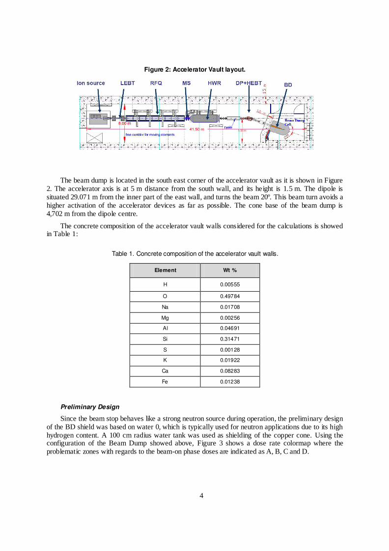
Figure 2: Accelerator Vault layout.
The beam dump is located in the south east corner of the accelerator vault as it is shown in Figure 2. The accelerator axis is at 5 m distance from the south wall, and its height is 1.5 m. The dipole is situated 29.071 m from the inner part of the east wall, and turns the beam 20º. This beam turn avoids a higher activation of the accelerator devices as far as possible. The cone base of the beam dump is 4,702 m from the dipole centre.
The concrete composition of the accelerator vault walls considered for the calculations is showed in Table 1:
Table 1. Concrete composition of the accelerator vault walls.
Element Wt %
H 0.00555
O 0.49784
Na 0.01708
Mg 0.00256
Al 0.04691
Si 0.31471
S 0.00128
K 0.01922
Ca 0.08283
Fe 0.01238
Preliminary Design
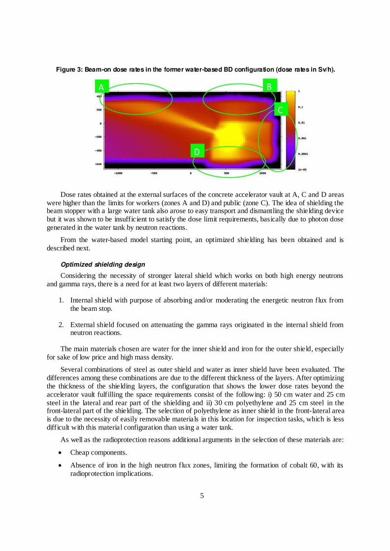
Since the beam stop behaves like a strong neutron source during operation, the preliminary design of the BD shield was based on water 0, which is typically used for neutron applications due to its high hydrogen content. A 100 cm radius water tank was used as shielding of the copper cone. Using the configuration of the Beam Dump showed above, Figure 3 shows a dose rate colormap where the problematic zones with regards to the beam-on phase doses are indicated as A, B, C and D.
5
Figure 3: Beam-on dose rates in the former water-based BD configuration (dose rates in Sv/h).
Dose rates obtained at the external surfaces of the concrete accelerator vault at A, C and D areas were higher than the limits for workers (zones A and D) and public (zone C). The idea of shielding the beam stopper with a large water tank also arose to easy transport and dismantling the shielding device but it was shown to be insufficient to satisfy the dose limit requirements, basically due to photon dose generated in the water tank by neutron reactions.
From the water-based model starting point, an optimized shielding has been obtained and is described next.
Optimized shielding design
Considering the necessity of stronger lateral shield which works on both high energy neutrons and gamma rays, there is a need for at least two layers of different materials:
1. Internal shield with purpose of absorbing and/or moderating the energetic neutron flux from the beam stop.
2. External shield focused on attenuating the gamma rays originated in the internal shield from neutron reactions.
The main materials chosen are water for the inner shield and iron for the outer shield, especially for sake of low price and high mass density.
Several combinations of steel as outer shield and water as inner shield have been evaluated. The differences among these combinations are due to the different thickness of the layers. After optimizing the thickness of the shielding layers, the configuration that shows the lower dose rates beyond the accelerator vault fulfilling the space requirements consist of the following: i) 50 cm water and 25 cm steel in the lateral and rear part of the shielding and ii) 30 cm polyethylene and 25 cm steel in the front-lateral part of the shielding. The selection of polyethylene as inner shield in the front-lateral area is due to the necessity of easily removable materials in this location for inspection tasks, which is less difficult with this material configuration than using a water tank.
As well as the radioprotection reasons additional arguments in the selection of these materials are:
Cheap components.
Absence of iron in the high neutron flux zones, limiting the formation of cobalt 60, with its radioprotection implications.

6
Acceptable weight.
Beam dump diameter as originally designed fulfilling the space requirements.
The general layout of the shielding is showed in the Figure 4.
Figure 4: Beam Dump Layout.
During operation of the accelerator, since the entrance of the beam dump is open to the accelerator vacuum tube, a wide area of the vault would be submitted to high fluxes of neutrons, therefore producing in short time such activation that hands-on maintenance would not be possible during beam-off. Because this same reason, the wide extension of uncollided neutrons reaching into the north wall still produce unacceptable dose rates outside the wall. Even with the consideration of a lead shutter, located at copper cone entrance to allow manual maintenance in the accelerator area on beam-off phase, the dose rates are still too high. This is mainly due to the unavoidable gaps between the shutter and the concrete structure, which is a way of escape of gammas, leading to too high dose rates for hands-on maintenance.
In order to solve these problems a new design element was introduced: a dedicated room with concrete walls for the space just behind the lead shutter. This small room, which has to fit between the shielding frontal wall and the last quadrupole of the HEBT, has two main purposes:
Its two walls perpendicular to the beam line have the main purpose of collimating the neutron current escaping the beam dump during operation
The lateral walls will contain the radiation scattered in the frontal walls, with clear benefits for both beam-on and beam-off phases since: i) the region suffering high neutron fluxes during operation will be reduced (this will also reduce the activation of present materials) and ii) gamma flux will be strongly reduced and restricted to the room, allowing the hands-on maintenance outside it.
The dedicated room consists of 20 cm thick and 3 m tall concrete walls. They surround the space beyond frontal wall until the last HEBT quadrupole, which remains outside the room. The perpendicular room size has been preliminarily set to 200 cm, but may be changed when considering an unshielded entrance maze. Due to the smaller radius of the beam line at that position, it enters the
7
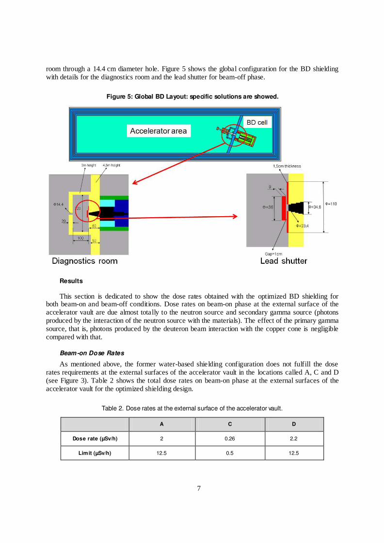
room through a 14.4 cm diameter hole. Figure 5 shows the global configuration for the BD shielding with details for the diagnostics room and the lead shutter for beam-off phase.
Figure 5: Global BD Layout: specific solutions are showed.
Results
This section is dedicated to show the dose rates obtained with the optimized BD shielding for both beam-on and beam-off conditions. Dose rates on beam-on phase at the external surface of the accelerator vault are due almost totally to the neutron source and secondary gamma source (photons produced by the interaction of the neutron source with the materials). The effect of the primary gamma source, that is, photons produced by the deuteron beam interaction with the copper cone is negligible compared with that.
Beam-on Dose Rates
As mentioned above, the former water-based shielding configuration does not fulfill the dose rates requirements at the external surfaces of the accelerator vault in the locations called A, C and D (see Figure 3). Table 2 shows the total dose rates on beam-on phase at the external surfaces of the accelerator vault for the optimized shielding design.
Table 2. Dose rates at the external surface of the accelerator vault.
A C D
Dose rate (µSv/h) 2 0.26 2.2
Limit (µSv/h) 12.5 0.5 12.5
8
Zones A and D (external surfaces of the accelerator vault) are adjoining to other worker rooms. In these areas, the dose rate limit is that for workers, that is 12.5 µSv/h. The external surface of the accelerator vault called C is outside the building, and the dose rate limit to be fulfilled is that corresponding to the public, that is 0.5 µSv/h. As showed, dose rates requirements are fulfilled along the perimeter of the external surface of the accelerator vault.
Beam-off Dose Rates
In the evaluation of the residual dose rates around the Beam Dump configuration, the base case analyzed is the corresponding to 6 months full power (125 mA) irradiation time. A reasonable cooling time of one day has been chosen.
The configuration of the beam-off phase solution to avoid high dose rates in the diagnostic cell and so allow manual maintenance in this area is showed in Figure 5 (lead shutter detail). The removable lead plug is cylindrical (36 cm diameter, 9 cm thickness) and the fixed lead sheet is also cylindrical (1.5 cm thickness, 23 cm inner diameter, 110 cm outer diameter). The gap between removable and fixed devices is 1 cm.
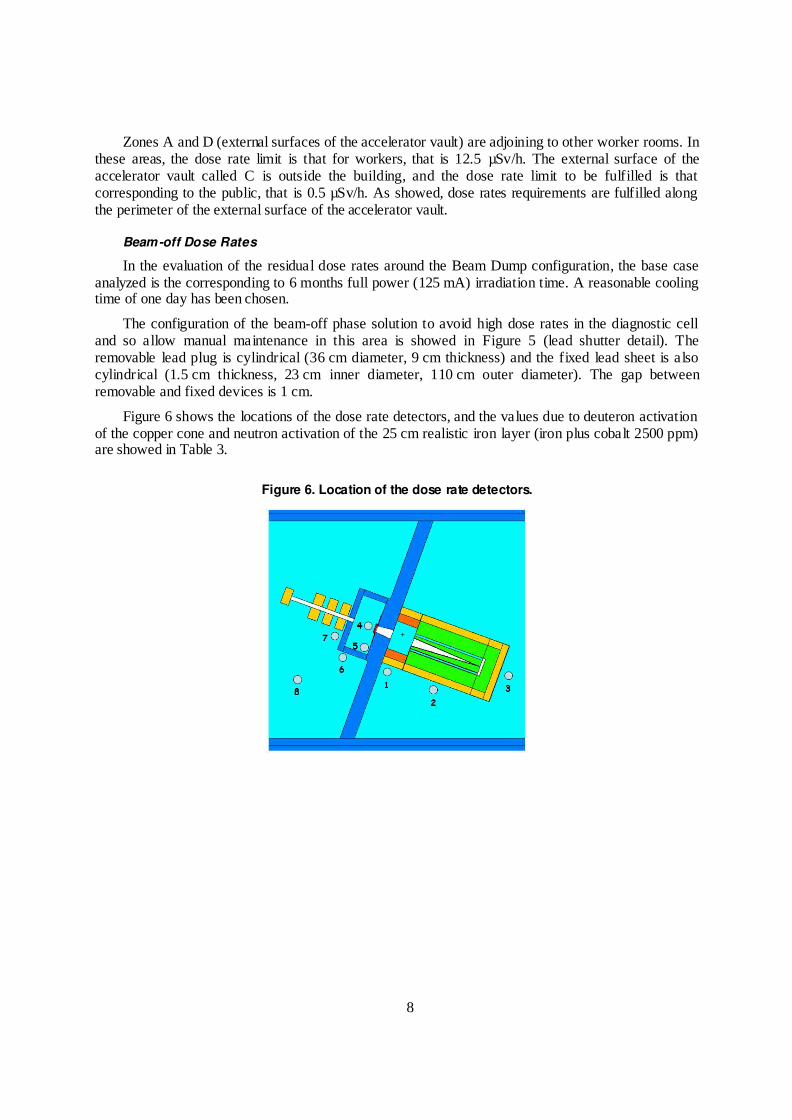
Figure 6 shows the locations of the dose rate detectors, and the values due to deuteron activation of the copper cone and neutron activation of the 25 cm realistic iron layer (iron plus cobalt 2500 ppm) are showed in Table 3.
Figure 6. Location of the dose rate detectors.
9
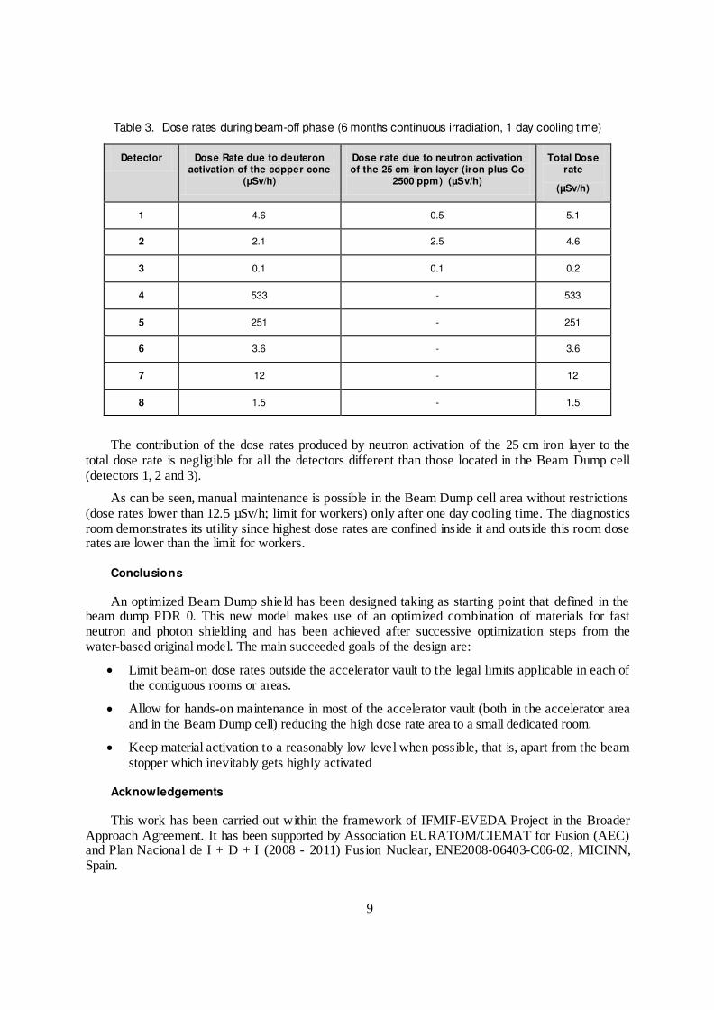
Table 3. Dose rates during beam-off phase (6 months continuous irradiation, 1 day cooling time)
Detector Dose Rate due to deuteron activation of the copper cone
(µSv/h)
Dose rate due to neutron activation of the 25 cm iron layer (iron plus Co
2500 ppm) (µSv/h)
Total Dose rate
(µSv/h)
1 4.6 0.5 5.1
2 2.1 2.5 4.6
3 0.1 0.1 0.2
4 533 - 533
5 251 - 251
6 3.6 - 3.6
7 12 - 12
8 1.5 - 1.5
The contribution of the dose rates produced by neutron activation of the 25 cm iron layer to the total dose rate is negligible for all the detectors different than those located in the Beam Dump cell (detectors 1, 2 and 3).
As can be seen, manual maintenance is possible in the Beam Dump cell area without restrictions (dose rates lower than 12.5 µSv/h; limit for workers) only after one day cooling time. The diagnostics room demonstrates its utility since highest dose rates are confined inside it and outside this room dose rates are lower than the limit for workers.
Conclusions
An optimized Beam Dump shield has been designed taking as starting point that defined in the beam dump PDR 0. This new model makes use of an optimized combination of materials for fast neutron and photon shielding and has been achieved after successive optimization steps from the water-based original model. The main succeeded goals of the design are:
Limit beam-on dose rates outside the accelerator vault to the legal limits applicable in each of the contiguous rooms or areas.
Allow for hands-on maintenance in most of the accelerator vault (both in the accelerator area and in the Beam Dump cell) reducing the high dose rate area to a small dedicated room.
Keep material activation to a reasonably low level when possible, that is, apart from the beam stopper which inevitably gets highly activated
Acknowledgements
This work has been carried out within the framework of IFMIF-EVEDA Project in the Broader Approach Agreement. It has been supported by Association EURATOM/CIEMAT for Fusion (AEC) and Plan Nacional de I + D + I (2008 - 2011) Fusion Nuclear, ENE2008-06403-C06-02, MICINN, Spain.
10
References
[1] R. Duperrier, N. Pichoff, D. Uriot, CEA Saclay codes review, ICCS conference, Amsterdam, 2002
[2] D. B. Pelowitz, ed.:, MCNPX User‟s manual, Version 2.5.0, LA-CP-05-0369 (2005). User's Manual, Version 2.6.0,' LA-CP-07-1473 (April 2008), J. S. Hendricks et al.: 'MCNPX 2.6.0 Extensions,' LA-UR-08-2216 http://mcnpx.lanl.gov. (2008)
[3] P. Sauvan, J. Sanz, F. Ogando, “New capabilities for Monte Carlo simulation of deuteron transport and secondary products generation”, Nucl Instr and Meth in Phys Research A 614 323-330 (2010)
[4] J. Sanz, P. Sauvan, F. Ogando, D. López, M. García, A. Mayoral, F. Ortiz, V. Blideanu, P. Joyer. “Methodology to address radioprotection and safety issues in the IFMIF/EVEDA accelerator prototype”. Proceedings of this conference
[5] J. Sanz, M. García, F. Ogando, A. Mayoral, D. López, P. Sauvan, B. Brañas. “First IFMIF-EVEDA radioprotection studies for the preliminary design of the accelerator beam dump”. Fusion Science and Technology. Volume: 56 Issue: 1. Pages: 273-280. Published: 2009
[6] ICRP. “Conversion Coefficients for Use in Radiological Protection against External Radiation”. International Commission on Radiological Protection, ICRP Publication 74. Tarrytown, NY (1996)
[7] J. Sanz, O. Cabellos, N. García-Herranz, “ACAB -2008: Activation Code V2008”, Nuclear Energy Agency NEA Data Bank. NEA-1839, (2008)
[8] R.A. Forrest, J. Kopecky, J.-CH. Sublet „The European Activation File: EAF-2007 deuteron and proton-induced cross section libraries”, UKAEA FUS 536, March 2007. Also „The European Activation File: EAF-2007 neutron-induced cross section libraries‟, UKAEA FUS 535, March 2007, and R.A. Forrest, “EAF-2007 decay data library” UKAEA FUS 537, March (2007)
[9] CIEMAT and UNED teams, “Preliminary design of IFMIF/EVEDA Beam Dump” (2009)