Design Optimization of Dump Diffusers with NACA 66-021 ...
20
Design Optimization of Dump Diffusers with NACA 66-021 Shaped Flame Tube Aravind S, 1 Sabarinathan G, 2 Dhinakaran S, 3 Sanjay Kumar S, 4 and Sundararaj K 5 Kumaraguru College of Technology, Coimbatore – 641 049, Tamil Nadu, India V.R. Sanal Kumar 6 Indian Space Research Organization, Trivandrum - 695022, Kerala, India Although the design and optimization of an aircraft engine have been advanced significantly over the last few decades, an aerodynamic shape optimization of dump diffuser is still an active research topic in the modern aircraft industry aiming for achieving more efficient combustion and the less total pressure losses. In our previous connected paper (AIAA 2019-4258) we reported that the dump diffuser facilitated by multiple-steps pre-diffuser cones, along with the aerodynamically-shaped adjustable flame tube that could improve the performance characteristics of aero gas turbine engines under a wide range of operating conditions. Herein, we attempted the aerodynamic design optimization of dump diffusers with NACA 66-021 shaped flame tube for improving the static pressure recovery. Numerical studies have been carried out using a validated 2D density-based steady viscous flow solver with the standard k-ε turbulence model. The code is verified and validated using the exact value of the boundary layer displacement thickness predicted at the Sanal flow choking condition. Parametric studies reveal that a dump diffuser with the NACA 66-021 airfoil-shaped flame tube has an improved static pressure recovery than the previously proposed NACA 0012 shaped flame tube. We observed that, in addition to the fluid dynamics and the geometric variables of a dump-diffuser, the thickness-to-chord ratio of the NACA airfoil-shaped flame tube is also having a bearing on the static pressure recovery. We concluded that the aerodynamics design optimization of dump diffusers with the NACA series airfoil-shaped flame tube is a meaningful objective for negating the large total pressure losses lucratively for an efficient combustion. I. Nomenclature A = area of cross-section A2/A1 = area ratio B = blockage factor Cp = pressure coefficient c = chord d = distance between the pre-diffuser exit and the flame dome L = total length of the dump diffuser P = static pressure Po = total pressure Tu = turbulence intensity 1 Undergraduate Student, Dept. of Aeronautical Engineering; [email protected] 2 Undergraduate Student, Dept. of Aeronautical Engineering; [email protected] 3 Undergraduate Student, Dept. of Aeronautical Engineering; [email protected] 4 Undergraduate Student, Dept. of Aeronautical Engineering; [email protected] 5 Professor and Head, Dept. of Aeronautical Engineering, [email protected] 6 Professor of Aeronautics (KCT) and Aerospace Scientist (ISRO – SC No.6301/2013), and Project Coordinator, Indo-Russian Joint Research Project at the Indian Institute of Science, Bangalore-12, Senior AIAA Member; [email protected] Downloaded by INDIAN INSTITUTE OF SCIENCE on December 1, 2020 | http://arc.aiaa.org | DOI: 10.2514/6.2020-3705 AIAA Propulsion and Energy 2020 Forum August 24-28, 2020, VIRTUAL EVENT 10.2514/6.2020-3705 Copyright © 2020 by the American Institute of Aeronautics and Astronautics, Inc. All rights reserved. AIAA Propulsion and Energy Forum
-
Upload
khangminh22 -
Category
Documents
-
view
2 -
download
0
Transcript of Design Optimization of Dump Diffusers with NACA 66-021 ...
Design Optimization of Dump Diffusers
with NACA 66-021 Shaped Flame Tube
Aravind S,1 Sabarinathan G,2 Dhinakaran S,3
Sanjay Kumar S,4 and Sundararaj K5
Kumaraguru College of Technology, Coimbatore – 641 049, Tamil Nadu, India
V.R. Sanal Kumar6
Indian Space Research Organization, Trivandrum - 695022, Kerala, India
Although the design and optimization of an aircraft engine have been advanced
significantly over the last few decades, an aerodynamic shape optimization of dump
diffuser is still an active research topic in the modern aircraft industry aiming for achieving
more efficient combustion and the less total pressure losses. In our previous connected
paper (AIAA 2019-4258) we reported that the dump diffuser facilitated by multiple-steps
pre-diffuser cones, along with the aerodynamically-shaped adjustable flame tube that
could improve the performance characteristics of aero gas turbine engines under a wide
range of operating conditions. Herein, we attempted the aerodynamic design optimization
of dump diffusers with NACA 66-021 shaped flame tube for improving the static pressure
recovery. Numerical studies have been carried out using a validated 2D density-based
steady viscous flow solver with the standard k-ε turbulence model. The code is verified and
validated using the exact value of the boundary layer displacement thickness predicted at
the Sanal flow choking condition. Parametric studies reveal that a dump diffuser with the
NACA 66-021 airfoil-shaped flame tube has an improved static pressure recovery than the
previously proposed NACA 0012 shaped flame tube. We observed that, in addition to the
fluid dynamics and the geometric variables of a dump-diffuser, the thickness-to-chord ratio
of the NACA airfoil-shaped flame tube is also having a bearing on the static pressure
recovery. We concluded that the aerodynamics design optimization of dump diffusers with
the NACA series airfoil-shaped flame tube is a meaningful objective for negating the large
total pressure losses lucratively for an efficient combustion.
I. Nomenclature
A = area of cross-section
A2/A1 = area ratio
B = blockage factor
Cp = pressure coefficient
c = chord
d = distance between the pre-diffuser exit and the flame dome
L = total length of the dump diffuser
P = static pressure
Po = total pressure
Tu = turbulence intensity
1 Undergraduate Student, Dept. of Aeronautical Engineering; [email protected] 2 Undergraduate Student, Dept. of Aeronautical Engineering; [email protected] 3 Undergraduate Student, Dept. of Aeronautical Engineering; [email protected] 4 Undergraduate Student, Dept. of Aeronautical Engineering; [email protected] 5 Professor and Head, Dept. of Aeronautical Engineering, [email protected] 6 Professor of Aeronautics (KCT) and Aerospace Scientist (ISRO – SC No.6301/2013), and Project Coordinator,
Indo-Russian Joint Research Project at the Indian Institute of Science, Bangalore-12, Senior AIAA Member;
Dow
nloa
ded
by I
ND
IAN
IN
STIT
UT
E O
F SC
IEN
CE
on
Dec
embe
r 1,
202
0 | h
ttp://
arc.
aiaa
.org
| D
OI:
10.
2514
/6.2
020-
3705
AIAA Propulsion and Energy 2020 Forum
August 24-28, 2020, VIRTUAL EVENT
10.2514/6.2020-3705
Copyright © 2020 by the American Institute of Aeronautics and Astronautics, Inc. All rights reserved.
AIAA Propulsion and Energy Forum

t/c = thickness to chord ratio of the flame tube (airfoil)
V = local axial velocity
Vo = velocity at the inlet
Xi = length of the pre-diffuser inlet.
Xi/A1 = pre-diffuser ratio
X, Y = axial and perpendicular distance
Y/H = exit height ratio
Y/R = radial distance
2Y/A1 = pre-diffuser exit ratio
2Y/A2 = second divergent angle exit ratio
= first divergent angle after the pre diffuser
= second divergent angle
= first angle ratio
= third divergent angle
/ = second angle ratio
δ = boundary-layer displacement thickness
density
II. Introduction
A dump diffuser is a type of combustor diffuser. The diffuser is one of the key components of the gas turbine
combustor. Its primary function is to slow down the airflow delivered by the compressor to promote an efficient
combustion and avoid the large total pressure losses. Of late many experimental and numerical studies have been
reported on diffuser flows with remarkable physical insight on critical flow features. Nonetheless, the design
optimization of dump diffuser is still an emerging field in the modern aircraft industry [1-27]. For advanced
aircraft engines, the faired diffuser concept is unattractive due to the performance deterioration under a wide
range of operating conditions. The flow pattern becomes more sensitive to changes in operating conditions.
Therefore, the modern aircraft engines incorporate a different type of combustor inlet with dump diffuser (see
Fig.1). It consists of a pre-diffuser followed by a dump region around the flame tube. Such systems are favored
because of their inherent flow stability under a wide range of operating conditions and insensitivity to
manufacturing resilience and thermal expansions. However, they have relatively high losses, low-pressure
recovery, and long axial distances in comparison to the faired diffusers. Owing to the complexity of flow
conditions and a large number of requirements, the design optimization of the combustor inlet is still an elusive
problem. Note that reducing the pre-diffuser length and simultaneously increasing the opening angle to maintain
the area ratio is critical because the flow tends to separate.
The flow field in the entry region of a gas turbine combustion chamber is mainly determined by the
performance of the combustor diffuser. In modern times, the diffusing system customarily used by aircraft
engines is the dump diffuser. The dump diffuser produces a stable flow pattern under a wide range of operating
conditions. Fishenden and Stevens [9] studied the influence of the dump diffuser system. A fully annular model
of dump diffuser was tested. Results showed that the presence of the flame tube (see Fig.1) has a beneficial effect
on the performance and stability of flow in the pre-diffuser but no mention about the shape of the flame tube,
which we are planning to optimize through this project.
Fig. 1 Conventional shape of a flame tube in a dump diffuser [1].
Dow
nloa
ded
by I
ND
IAN
IN
STIT
UT
E O
F SC
IEN
CE
on
Dec
embe
r 1,
202
0 | h
ttp://
arc.
aiaa
.org
| D
OI:
10.
2514
/6.2
020-
3705
Modern aircraft gas turbine design requires that the compressor produces a high-pressure ratio with a
minimum number of stages. As a consequence, the air leaves the compressor with a high axial velocity. Effective
combustion with small pressure losses can only be achieved with the low air velocities. Moreover, the air which
is to be discharged into the flame tube must approach the combustor-liner admission ports rather slowly to ensure
favorable conditions for the flow through them, in particular large discharge coefficients, steep jet angles, and
deep penetration. A diffuser is used to reduce the average velocity of fluid flow in a duct. In subsonic flow, this
reduction in velocity is achieved by gradually increasing the cross-sectional area of the duct. For an efficient
diffuser, there should be an increase in static pressure and reduction in flow velocity. Note that the shape of the
dump zone varies widely among engines. It is known that in addition to the geometric and fluid dynamic features
that generally affect the annual diffuser performance, the characteristics of dump-diffuser combustor inlets
depend on a variety of parameters, notably the dump gap. The dump gap is the distance between the flame tube
head (or the dome cowling) and the pre-diffuser exit plane, referred to as pre-diffuser exit height (see Fig.1). The
short dump diffusers give an advantage in gaining the thrust-to-weight (T/W) ratio of the engine. Note that the
design requirements for gas turbines tend to be demand the flow fields and stress fields are very complex and
must be well understood to achieve the required design efficiencies. The primary technology drivers are to reduce
design cycle time and manufacturing costs.
The literature review reveals that many experimental and numerical studies have been focused on the design
optimization of modern aero-gas turbine engines during the last few decades [1-27]. Those studies demonstrated
that the performance of dump diffusers depends largely on the profile of the pre-diffuser, the flow field of diffuser
inlet, and the distance between the head of the flame tube and the outlet of the pre-diffuser. V.R. Sanal Kumar et
al. [3-6] in a series of papers demonstrated the importance of aerodynamics design optimization of dump diffusers
and correlated geometric variables with various intrinsic flow features of dump diffusers for efficient combustion.
Selvakarthick et al. [7] concluded that a dump diffuser with an adjustable flame tube for getting different dump
gap and orientation may be a future viable option for warranting high-performance aero-gas turbine engines with
maximum static pressure recovery under a wide range of operating conditions. Walker et al. [14] was investigated
experimentally a diffuser with a high dome flow rate and high dome depth. The authors revealed the interaction
between the diffuser and downstream geometry and explained how this interaction varied with changes in diffuser
geometry. Ainley [16], Johnston [17], and Howard [18] reported the characteristics of annular diffusers, but
without taking into account flame tube effects. Sovran, Klomp, and E.D. [19] shown the correlation between the
performance parameters of the plane, conical, and annular diffusers. However, the effect of flame tubes is not
considered. Biaglow, J.A. [20] demonstrated the advantage of dump type diffuser configurations compared to
faired diffusers. Wagner, W.B, Tanrikut, S, and Sokolowski, [21] investigated the effects of flow splits on the
performance of a curved wall dump diffuser with a canted pre-diffuser. Klein, [8] reported that the main fluid
dynamics parameter which affects the diffuser performance is the area fraction blocked by the boundary layer
displacement thickness (δ). Srinivasan and Freeman et al. [23] attempted to optimize the dump gap ratio. Japikse
[22] highlighted that the static pressure recovery is insensitive to a Mach number below 0.25 and has almost
negligible influence up to a Mach number of 0.60. Note that, a Mach number of around 0.2-0.3 is more typical at
the inlet of a modern combustion chamber. Prakash Ghose et al. [24] studied numerically the effect of dome shape
on the static pressure recovery in a dump diffuser at different inlet swirl. V.R. Sanal Kumar et al. [6] observed that
at a sufficiently small dump gap and with high turbulence intensity the flame tube head proximity creates back
pressure on the pre-diffuser discharge flow and displaces it towards the walls and thus inhibits separation and
thereby the pressure recovery on the pre-diffuser significantly increases. Figure 2(a-d) shows the evolution of the
dump diffuser design advancement for modern aircraft engines with various types of flame tubes.
In our connected work, Aravind et al. [1, 2] reported that the dump diffuser with geometrically optimized pre-
diffuser upstream port and its divergent cone along with the aerodynamically-shaped adjustable flame tube for
attaining a variable dump gap effect is a profitable and viable option for improving the performance characteristics
of aero gas turbine engines under a wide range of operating conditions. Towards meeting further design objectives,
in this connected project, using a two-dimensional (2D) standard k-ε turbulence model, parametric analytical
studies have been carried out to examine the flow features through a dump diffuser facilitated with NACA airfoil-
shaped flame tubes. The reason for choosing the NACA series airfoil is due to the fact that it produces high profile
drag and form drag in the flow field even with an aerodynamically shaped geometry. It will obviously contribute
towards increasing the static pressure recovery for meeting the lucrative design objectives of the dump diffusers
for improving the performance characteristics of aero gas turbine engines under a wide range of operating
conditions, which is examined herein using a validate viscous flow solver. Due to the Covid-19 pandemic the
planned experimental validation will be carried out in the next phase.
Dow
nloa
ded
by I
ND
IAN
IN
STIT
UT
E O
F SC
IEN
CE
on
Dec
embe
r 1,
202
0 | h
ttp://
arc.
aiaa
.org
| D
OI:
10.
2514
/6.2
020-
3705

(c) V. R. Sanal Kumar et.al., [6] (AIAA - 2007)
(b) Hestermann et.al. [27] (ASME -1994)
(a) Honami and Morioka [25] (ASME-1990)
Dow
nloa
ded
by I
ND
IAN
IN
STIT
UT
E O
F SC
IEN
CE
on
Dec
embe
r 1,
202
0 | h
ttp://
arc.
aiaa
.org
| D
OI:
10.
2514
/6.2
020-
3705

Fig. 2(a-e) Evolution of the Dump Diffuser Designs
III. Numerical Methodology
Numerical simulations have been carried out using a 2D standard k-ε turbulence model. The model invoked
the control volume technique. The viscosity is estimated from the Sutherland formula. As a part of the model
validation, our results are compared with the benchmark data [25]. Figure 3 shows the comparison of the
coefficient of pressure distribution at the flame dome (radially) with the experimental data of Honami and
Morioka [25]. It is crystal clear from Fig.3 that our model and its code of solution are validated qualitatively for
conducting numerical exercises with the NACA series-shaped flame tubes. The diffuser geometric variables and
material properties were known a priori. An initial wall temperature and inlet gas temperature were specified. On
the solid walls, the no-slip boundary condition was imposed. The CFL number was taken as 1 for all
computations. Ideal gas was selected as the working fluid. The axial velocity at the pre-diffuser inlet was
prescribed. The inlet turbulence intensity was taken as 8 % and the inlet dissipation rate was calculated from the
inlet turbulence intensity. Constant static pressure was specified at the outlet of the domain. It is evident from
Fig.3 that the standard k-ε turbulence model is better than the RNG k-ε turbulence model for this study. Note that
Launder and Spalding [28] have successfully used the standard k-ε turbulence model by minimizing unknowns
and presenting a set of equations that can be applied to numerous turbulent applications. The model is verified
using a closed-form analytical model satisfying the Sanal flow choking condition [29,30].
(d) Selvakarthick et.al., [7] (AIAA - 2016)
(e) Aravind and Sabarinathan et al. [1] (AIAA - 2019)
Dow
nloa
ded
by I
ND
IAN
IN
STIT
UT
E O
F SC
IEN
CE
on
Dec
embe
r 1,
202
0 | h
ttp://
arc.
aiaa
.org
| D
OI:
10.
2514
/6.2
020-
3705

Fig. 3 Comparison of the coefficient of pressure distribution at the flame dome (radially) [1].
Fig. 4 Grid refinement study for 2D model validation [1].
-0.9
-0.7
-0.5
-0.3
-0.1
0.1
0.3
0.5
0.7
0.9
1.1
-1.2 -1 -0.8 -0.6 -0.4 -0.2 0 0.2 0.4 0.6 0.8 1 1.2
Co
effi
cien
t o
f P
ress
ure
Radial Distance
EXPERIMENT(Shinji
Honami et.al.,)
standard k epsilon
RNG k epsilon
0.989
0.99
0.991
0.992
0.993
0.994
0.995
0.996
0.997
0.998
0.999
0 0.2 0.4 0.6 0.8 1 1.2
Sta
tic
Pre
ssure
/ T
ota
l P
ress
ure
Axial Disance / Radial Distance
Node 1.75e5
Node 2.5e5
Node 3e5
Dow
nloa
ded
by I
ND
IAN
IN
STIT
UT
E O
F SC
IEN
CE
on
Dec
embe
r 1,
202
0 | h
ttp://
arc.
aiaa
.org
| D
OI:
10.
2514
/6.2
020-
3705
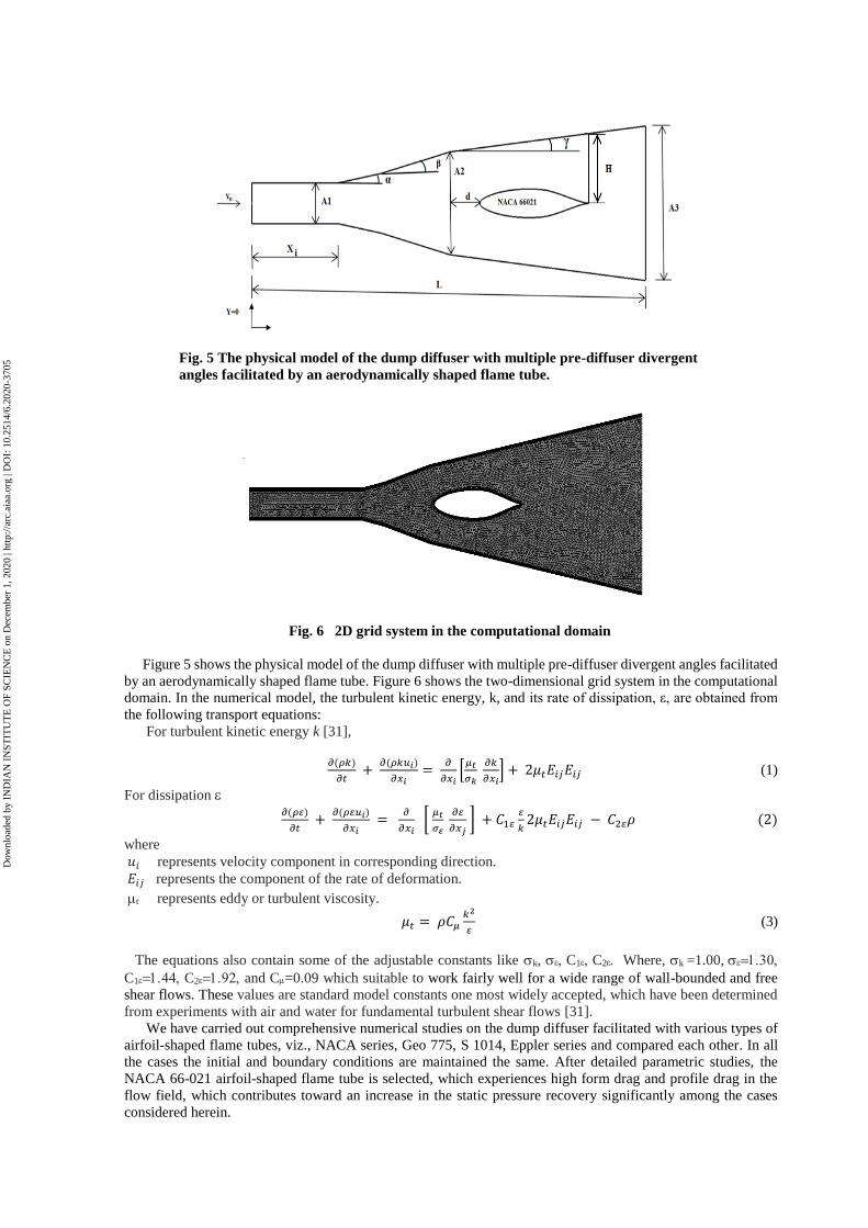
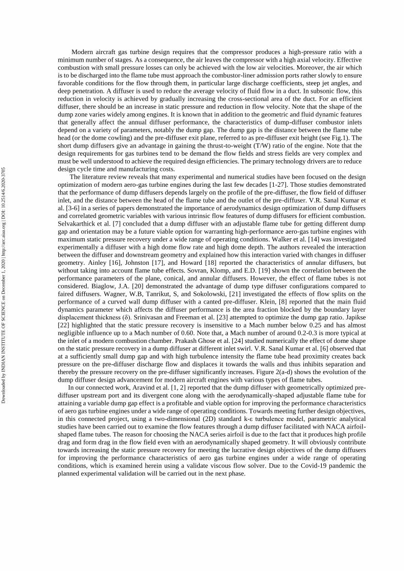
Fig. 5 The physical model of the dump diffuser with multiple pre-diffuser divergent
angles facilitated by an aerodynamically shaped flame tube.
Fig. 6 2D grid system in the computational domain
Figure 5 shows the physical model of the dump diffuser with multiple pre-diffuser divergent angles facilitated
by an aerodynamically shaped flame tube. Figure 6 shows the two-dimensional grid system in the computational
domain. In the numerical model, the turbulent kinetic energy, k, and its rate of dissipation, ε, are obtained from
the following transport equations:
For turbulent kinetic energy k [31],
𝜕(𝜌𝑘)
𝜕𝑡 +
𝜕(𝜌𝑘𝑢𝑖)
𝜕𝑥𝑖=
𝜕
𝜕𝑥𝑖[
𝜇𝑡
𝜎𝑘
𝜕𝑘
𝜕𝑥𝑖] + 2𝜇𝑡𝐸𝑖𝑗𝐸𝑖𝑗 (1)
For dissipation
𝜕(𝜌𝜀)
𝜕𝑡 +
𝜕(𝜌𝜀𝑢𝑖)
𝜕𝑥𝑖 =
𝜕
𝜕𝑥𝑖 [
𝜇𝑡
𝜎𝜀
𝜕𝜀
𝜕𝑥𝑗 ] + 𝐶1𝜀
𝜀
𝑘2𝜇𝑡𝐸𝑖𝑗𝐸𝑖𝑗 − 𝐶2𝜀𝜌 (2)
where
𝑢𝑖 represents velocity component in corresponding direction.
𝐸𝑖𝑗 represents the component of the rate of deformation.
t represents eddy or turbulent viscosity.
𝜇𝑡 = 𝜌𝐶𝜇𝑘2
𝜀 (3)
The equations also contain some of the adjustable constants like k, C1C2 Where, k =1.00,
C1 C2 and C=0.09 which suitable to work fairly well for a wide range of wall-bounded and free
shear flows. These values are standard model constants one most widely accepted, which have been determined
from experiments with air and water for fundamental turbulent shear flows [31].
We have carried out comprehensive numerical studies on the dump diffuser facilitated with various types of
airfoil-shaped flame tubes, viz., NACA series, Geo 775, S 1014, Eppler series and compared each other. In all
the cases the initial and boundary conditions are maintained the same. After detailed parametric studies, the
NACA 66-021 airfoil-shaped flame tube is selected, which experiences high form drag and profile drag in the
flow field, which contributes toward an increase in the static pressure recovery significantly among the cases
considered herein.
Dow
nloa
ded
by I
ND
IAN
IN
STIT
UT
E O
F SC
IEN
CE
on
Dec
embe
r 1,
202
0 | h
ttp://
arc.
aiaa
.org
| D
OI:
10.
2514
/6.2
020-
3705
IV. Results and Discussion
It is well known that in an aircraft industry, weight of each design plays a major role which directly affects
the efficiency of an aircraft. So instead of using many axial stages in a compressor to get a required amount of
pressure in the flow to get efficient combustion in the combustion chamber, we can reduce the number of axial
stages by using the optimized dump diffuser model which gives required pressure with the shortest possible
length at a wide range of operating conditions. Towards meeting this objective, we have carried out
comprehensive in silico studies. Numerical simulations are carried with low inlet velocity in the range of 30-90
m/s, which ensures effective combustion [1]. During the parametric studies, we found that the thickness-to-chord
ratio (t/c) of the flame tube is having bearing on the static pressure recovery. If the angle of divergent is getting
increased continuously after the second divergent angle then there will be a chance of flow gets separated, so
there should be a requirement for a slight decrease in the third divergent angle () to make the flow to be attached
even at the downstream when compared with the second divergent angle see Fig.5) We conducted a
computational study on the dump diffuser with various NACA series airfoils to know the effect of the flame tube
geometry in pressure recovery. From Fig. 2(a), It shows that authors used the flame tube where the aerodynamic
shape was not much concentrated for an output. Because of an increase in flame tube depth, the flow tends to get
accelerated due to its boundary layer interaction between the non-aerodynamic shaped flame tube and the
straight-walled construction as per flow characteristics based on the Sanal flow chocking condition [30]. This
behavior occurs on both the upper and lower side of the non-aerodynamic shaped flame tube inside a dump
diffuser which causes major static pressure loss on the flow passing to the combustion section. Hence from Fig.
2(b) Hestermann et.al. [27] decreased the flame tube depth slightly compared to Honami et.al. [25] design which
increased the static pressure recovery on the output due to its low boundary layer blockage between the walls.
This initiative makes the dump diffuser designers to concentrate over the flame tube depth and its design inside
the dump diffuser. Thereby flame tube added as an important and interesting parameter which should be
optimized inside the dump diffuser to achieve the desired output. From here, the evolution of flame tube design
on the dump diffuser started. In Fig. 2(c), V. R. Sanal Kumar et.al., [6] approached this problem differently by
designing the cone-shaped flame tube which increased the static pressure recovery on output when compared to
previous designs. But, in a cone-shaped flame tube before the starting of the divergent wall section, there is a
contraction due to the curve radius (R) on the cone-shaped flame tube inlet and the straight-walled diffuser. Due
to the high curve radius (R) on the cone-shaped flame tube, the flow tends to lose its energy which directly affects
the output. In Fig. 2(d), Selvakarthick et.al., [7] increased the divergent wall angle () after the straight-walled
pre-diffuser to reduce the contraction characteristics on the flow by placing the flame tube in the dump diffuser.
Selvakarthick et.al., [7], also introduced the aerodynamically shaped flame tube design with NACA 0012 airfoil,
which provided maximum static pressure recovery compared to the old designs. At the same time due to its low
thickness to chord ratio (t/c) of NACA 0012 airfoil, the profit of keeping an aerodynamic-shaped flame tube was
considered to be less. Aravind and Sabarinathan et.al. [2], replaced the NACA 0012 with the NACA 66-021
shaped flame tube (see Fig. 2e) in the dump diffuser for getting better performance based on the physical insight
gained throw the in silico simulations while characterizing airfoil flow features in a wall-bounded flow system
at subsonic inflow conditions. Authors reported that NACA 66021 has high profile drag and form drag on the
flow [2], which could increase the static pressure recovery and compliment with the coupled effect on multiple
divergent walls on dump diffuser. Authors further reported that the thickness to chord (t/c) ratio of an airfoil is
an important parameter for the flame tube to achieve the maximum possible static pressure recovery on the dump
diffuser [2]. Experienced gained from the comprehensive in silico simulation prompted the authors to examine
the flow features of various dump diffusers with various symmetrical airfoils having different (t/c) ratios to
optimize the t/c ratio of a flame tube for meeting the design objectives of modern aircraft engines lucratively.
It is evident from the numerical results presented in Figs. 8-26 that the NACA 66-021 airfoil-shaped flame
tube has a maximum static pressure recovery than the other cases considered herein (see Table-1). It can be seen
from Fig. 21 that variations of the turbulent intensity in given inflow conditions will not affect the increasing
static pressure recovery on the dump diffuser with the standard k- turbulence model. In a few cases due to low
thickness to chord ratio (t/c), a significant flow separation was developed leading to a decrease in the static
pressure recovery on the dump diffuser. We observed that instead of having a straight wall, multiple opening
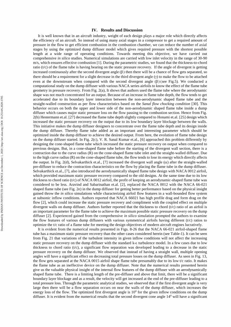
angles will have a significant effect on decreasing total pressure losses on the dump diffuser. As seen in Fig. 13,
the flow gets separated at the NACA 0015 airfoil shape flame tube presumably due to its low t/c ratio. It makes
the flame tube as an ineffective device on the dump diffuser. Note that the numerical results presented herein
give us the valuable physical insight of the internal flow features of the dump diffuser with an aerodynamically
shaped flame tube. There is a limiting length of the pre-diffuser and above that limit, there will be a significant
boundary layer blockage and as a result, the velocity will get increased at the end of the pre-diffuser leading to a
total pressure loss. Through the parametric analytical studies, we observed that if the first divergent angle is very
large then there will be a flow separation occurs on near the walls of the dump diffuser, which increases the
energy loss of the flow. The optimized first divergent angle is 100 for the given inflow conditions on the dump
diffuser. It is evident from the numerical results that the second divergent cone angle 140 will have a significant
Dow
nloa
ded
by I
ND
IAN
IN
STIT
UT
E O
F SC
IEN
CE
on
Dec
embe
r 1,
202
0 | h
ttp://
arc.
aiaa
.org
| D
OI:
10.
2514
/6.2
020-
3705

effect on increasing the static pressure recovery. The optimum second divergent angle is required because, if the
second divergent angle is too large then there will be an increase in total pressure loss due to flow separation.
The area ratio also decides the amount of diffusion of the flow throughout the aerodynamically shaped flame
tube from the pre-diffuser exit. So, the area ratio should be optimized to avoid flow separation and flow re-
circulation ahead of the dump gap. Table-1 shows the comparison of the maximum static-to-total pressure ratio
(P/Po) of the investigated flame tube configurations on the dump diffuser. It can be clearly discerned from the
Table-1 that the optimized dump diffuser with NACA 66021 airfoil achieved the high static pressure recovery
than the other airfoil-shaped flame tubes considered herein under identical inflow conditions.
Fig. 7 Non-dimensional pressure contour variations in the computational domain of the dump diffuser
with multiple pre-diffuser divergent angles along with NACA 66021 airfoil.
Fig. 8 Comparison of the static pressure recovery on the dump diffuser with airfoils NACA 0012 and
NACA 66-021.
0.994
0.9942
0.9944
0.9946
0.9948
0.995
0.9952
0.9954
-1.2 -1 -0.8 -0.6 -0.4 -0.2 0 0.2 0.4 0.6 0.8 1 1.2
Sta
tic
Pre
ssure
/ T
ota
l P
ress
ure
Exit Height Ratio
NACA 0012
airfoil
NACA 66-021
airfoil
Dow
nloa
ded
by I
ND
IAN
IN
STIT
UT
E O
F SC
IEN
CE
on
Dec
embe
r 1,
202
0 | h
ttp://
arc.
aiaa
.org
| D
OI:
10.
2514
/6.2
020-
3705

Fig. 9 Comparison of the static pressure recovery on the dump diffuser with airfoils NACA 4412
and NACA 66-021.
Fig. 10 Comparison of the static pressure recovery on the dump diffuser with airfoils NACA 63-
415 and NACA 66-021.
0.994
0.9942
0.9944
0.9946
0.9948
0.995
0.9952
0.9954
-1.2 -1 -0.8 -0.6 -0.4 -0.2 0 0.2 0.4 0.6 0.8 1 1.2
Sta
tic
Pre
ssure
/To
tal
Pre
ssure
Exit Height Ratio
NACA 66-021 airfoil
NACA 4412
0.9936
0.9938
0.994
0.9942
0.9944
0.9946
0.9948
0.995
0.9952
0.9954
-1.2 -1 -0.8 -0.6 -0.4 -0.2 0 0.2 0.4 0.6 0.8 1 1.2
Sta
tic
Pre
ssure
/To
tal
Pre
ssure
Exit Height Ratio
NACA 66-021
airfoil
NACA 63415
Dow
nloa
ded
by I
ND
IAN
IN
STIT
UT
E O
F SC
IEN
CE
on
Dec
embe
r 1,
202
0 | h
ttp://
arc.
aiaa
.org
| D
OI:
10.
2514
/6.2
020-
3705

Fig. 11 Comparison of the static pressure recovery on the dump diffuser with airfoils NACA65-
421 and NACA 66-021.
Fig. 12 Comparison of the static pressure recovery on the dump diffuser with airfoils NACA
0015 and NACA 66-021.
0.9936
0.9938
0.994
0.9942
0.9944
0.9946
0.9948
0.995
0.9952
0.9954
-1.2 -1 -0.8 -0.6 -0.4 -0.2 0 0.2 0.4 0.6 0.8 1 1.2
Sta
tic
Pre
ssure
/To
tal
Pre
ssure
Exit Height Ratio
NACA 66-021
airfoil
NACA 65421
0.993
0.9935
0.994
0.9945
0.995
0.9955
-1.2 -1 -0.8 -0.6 -0.4 -0.2 0 0.2 0.4 0.6 0.8 1 1.2
Sta
tic
Pre
ssure
/To
tal
Pre
ssure
Exit Height Ratio
NACA 66-021
airfoil
NACA 0015
Dow
nloa
ded
by I
ND
IAN
IN
STIT
UT
E O
F SC
IEN
CE
on
Dec
embe
r 1,
202
0 | h
ttp://
arc.
aiaa
.org
| D
OI:
10.
2514
/6.2
020-
3705
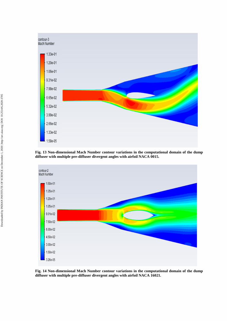
Fig. 13 Non-dimensional Mach Number contour variations in the computational domain of the dump
diffuser with multiple pre-diffuser divergent angles with airfoil NACA 0015.
Fig. 14 Non-dimensional Mach Number contour variations in the computational domain of the dump
diffuser with multiple pre-diffuser divergent angles with airfoil NACA 16021.
Dow
nloa
ded
by I
ND
IAN
IN
STIT
UT
E O
F SC
IEN
CE
on
Dec
embe
r 1,
202
0 | h
ttp://
arc.
aiaa
.org
| D
OI:
10.
2514
/6.2
020-
3705

Fig. 15 Comparison of the static pressure recovery on the dump diffuser with NACA
0018 and NACA 66-021.
Fig. 16 Comparison of the static pressure recovery on the dump diffuser with NACA 0021 and
NACA 66-021.
0.9932
0.9934
0.9936
0.9938
0.994
0.9942
0.9944
0.9946
0.9948
0.995
0.9952
0.9954
-1.2 -1 -0.8 -0.6 -0.4 -0.2 0 0.2 0.4 0.6 0.8 1 1.2
Sta
tic
Pre
ssure
/To
tal
Pre
ssure
Exit Height Ratio
NACA 66-021
airfoil
NACA 0018
0.994
0.9942
0.9944
0.9946
0.9948
0.995
0.9952
0.9954
-1.2 -1 -0.8 -0.6 -0.4 -0.2 0 0.2 0.4 0.6 0.8 1 1.2
Sta
tic
Pre
ssure
/To
tal
Pre
ssure
Exit Height Ratio
NACA 66-021
airfoil
NACA 0021
Dow
nloa
ded
by I
ND
IAN
IN
STIT
UT
E O
F SC
IEN
CE
on
Dec
embe
r 1,
202
0 | h
ttp://
arc.
aiaa
.org
| D
OI:
10.
2514
/6.2
020-
3705

Fig. 17 Comparison of the static pressure recovery on the dump diffuser with airfoils NACA
0024 and NACA 66-021.
Fig. 18 Comparison of the static pressure recovery on the dump diffuser with airfoils NACA 16-
018 and NACA 66-021.
0.9938
0.994
0.9942
0.9944
0.9946
0.9948
0.995
0.9952
0.9954
-1.2 -1 -0.8 -0.6 -0.4 -0.2 0 0.2 0.4 0.6 0.8 1 1.2
Sta
tic
Pre
ssure
/To
tal
Pre
ssure
Exit Height Ratio
NACA 66-021 airfoil
NACA 0024
0.994
0.9942
0.9944
0.9946
0.9948
0.995
0.9952
0.9954
-1.2 -1 -0.8 -0.6 -0.4 -0.2 0 0.2 0.4 0.6 0.8 1 1.2
Sta
tic
Pre
ssure
/To
tal
Pre
ssure
Exit Height Ratio
NACA 66-021
airfoil
NACA 16018
Dow
nloa
ded
by I
ND
IAN
IN
STIT
UT
E O
F SC
IEN
CE
on
Dec
embe
r 1,
202
0 | h
ttp://
arc.
aiaa
.org
| D
OI:
10.
2514
/6.2
020-
3705
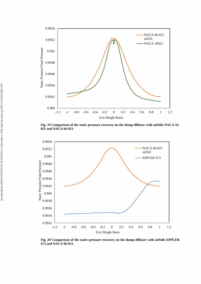
Fig. 19 Comparison of the static pressure recovery on the dump diffuser with airfoils NACA 16-
021 and NACA 66-021.
Fig. 20 Comparison of the static pressure recovery on the dump diffuser with airfoils EPPLER
473 and NACA 66-021.
0.994
0.9942
0.9944
0.9946
0.9948
0.995
0.9952
0.9954
-1.2 -1 -0.8 -0.6 -0.4 -0.2 0 0.2 0.4 0.6 0.8 1 1.2
Sta
tic
Pre
ssure
/To
tal
Pre
ssure
Exit Height Ratio
NACA 66-021
airfoil
NACA 16021
0.9932
0.9934
0.9936
0.9938
0.994
0.9942
0.9944
0.9946
0.9948
0.995
0.9952
0.9954
-1.2 -1 -0.8 -0.6 -0.4 -0.2 0 0.2 0.4 0.6 0.8 1 1.2
Sta
tic
Pre
ssure
/To
tal
Pre
ssure
Exit Height Ratio
NACA 66-021
airfoil
EPPLER 473
Dow
nloa
ded
by I
ND
IAN
IN
STIT
UT
E O
F SC
IEN
CE
on
Dec
embe
r 1,
202
0 | h
ttp://
arc.
aiaa
.org
| D
OI:
10.
2514
/6.2
020-
3705

Fig. 21 Comparison of the pressure recovery on the dump diffuser with different inlet turbulence
intensity.
Fig. 22 Comparison of the static pressure recovery on the dump diffuser with airfoils Geo 776 and
NACA 66-021.
0.994
0.9942
0.9944
0.9946
0.9948
0.995
0.9952
0.9954
-1.2 -1 -0.8 -0.6 -0.4 -0.2 0 0.2 0.4 0.6 0.8 1 1.2
Sta
tic
Pre
ssure
/ T
ota
l P
ress
ure
Exit Height Ratio
Vo= 35 m/s
Tu= 5%
Tu= 10%
Tu= 15%
Tu= 20%
0.9938
0.994
0.9942
0.9944
0.9946
0.9948
0.995
0.9952
0.9954
-1.2 -1 -0.8 -0.6 -0.4 -0.2 0 0.2 0.4 0.6 0.8 1 1.2
Sta
tic
Pre
ssure
/To
tal
Pre
ssure
Exit height ratio
NACA 66-021
airfoil
geo 776
Dow
nloa
ded
by I
ND
IAN
IN
STIT
UT
E O
F SC
IEN
CE
on
Dec
embe
r 1,
202
0 | h
ttp://
arc.
aiaa
.org
| D
OI:
10.
2514
/6.2
020-
3705

Fig. 23 Comparison of the static pressure recovery on the dump diffuser with airfoils NACA 66021
and S 1014.
Fig. 24 Comparison of the static pressure recovery on the dump diffuser with airfoils NACA 66021
and Geo 775.
0.994
0.9942
0.9944
0.9946
0.9948
0.995
0.9952
0.9954
-1.2 -1 -0.8 -0.6 -0.4 -0.2 0 0.2 0.4 0.6 0.8 1 1.2
Sta
tic
Pre
ssure
/To
tal
Pre
ssure
Exit height ratio
NACA 66-021
airfoil
s1014
0.994
0.9942
0.9944
0.9946
0.9948
0.995
0.9952
0.9954
-1.2 -1 -0.8 -0.6 -0.4 -0.2 0 0.2 0.4 0.6 0.8 1 1.2
Sta
tic
Pre
ssure
/To
tal
Pre
ssure
Exit height ratio
NACA 66-021
airfoil
geo 775
Dow
nloa
ded
by I
ND
IAN
IN
STIT
UT
E O
F SC
IEN
CE
on
Dec
embe
r 1,
202
0 | h
ttp://
arc.
aiaa
.org
| D
OI:
10.
2514
/6.2
020-
3705

Fig. 25 Comparison of the static pressure recovery on the dump diffuser with airfoils NACA 66021 and
Eppler 862.
Fig. 26 Comparison of the static pressure recovery on the dump diffuser with airfoils NACA 66021
and Eppler 863.
0.9938
0.994
0.9942
0.9944
0.9946
0.9948
0.995
0.9952
0.9954
-1.2 -1 -0.8 -0.6 -0.4 -0.2 0 0.2 0.4 0.6 0.8 1 1.2
Sta
tic
Pre
ssure
/To
tal
Pre
ssure
Exit height ratio
NACA 66-021
airfoileppler 862
0.9938
0.994
0.9942
0.9944
0.9946
0.9948
0.995
0.9952
0.9954
-1.2 -1 -0.8 -0.6 -0.4 -0.2 0 0.2 0.4 0.6 0.8 1 1.2
Sta
tic
Pre
ssure
/To
tal
Pre
ssure
Exit height ratio
NACA 66-021
airfoil
Eppler 863
Dow
nloa
ded
by I
ND
IAN
IN
STIT
UT
E O
F SC
IEN
CE
on
Dec
embe
r 1,
202
0 | h
ttp://
arc.
aiaa
.org
| D
OI:
10.
2514
/6.2
020-
3705

Table. 1 Investigated flame tube configurations on the dump diffuser.
Case No. Flame Tube Shape Inlet Velocity(m/s) (P/P0)max
Case 1 NACA 66-021 30 0.9953 Case 2 NACA 16021 30 0.9952 Case 3 NACA 0012 30 0.9950 Case 4 NACA 4412 30 0.9946 Case 5 NACA 65421 30 0.9947 Case 6 NACA 0015 30 0.9944 Case 7 NACA 0018 30 0.9945 Case 8 NACA 0021 30 0.9946 Case 9 NACA 0024 30 0.9948 Case 10 NACA 16018 30 0.9947 Case 11 NACA 63415 30 0.9946 Case 12 EPPLER 473 30 0.9943 Case 13 EPPLER 862 30 0.9948 Case 14 EPPLER 863 30 0.9948 Case 15 GEO 775 30 0.9949 Case 16 GEO 776 30 0.9950 Case 17 S 1014 30 0.9950
V. Concluding Remarks
The main expected outcome for any dump diffuser design is to achieve complete combustion. From the
detailed parametric studies carried out herein, we concluded that the thickness-to-chord (t/c) ratio of the flame
tube is an important parameter, which needs to be optimized for achieving the highest pressure recovery. In
addition to that, the angle ratio between the continuous divergent sections of the pre-diffuser region decides the
flow path and its separation, which have a significant impact on achieving high static pressure recovery in the
dump diffuser. We concluded that the static pressure recovery could be improved significantly by keeping an
aerodynamically shaped flame tube. The fact is that such a flame tube is having an inherent high form drag and
profile drag. Here we analyzed with symmetrical airfoils because the camber of an airfoil creates a flow distortion
inside the dump diffuser section. Also, all the simulations conducted at a zero-degree angle of attack to avoid
flow recirculation causing total pressure losses. From the analysis, we noticed that NACA 66-021 aerofoil
provides maximum static pressure recovery at given operating conditions when compared with the other
symmetrical aerofoils. Note that NACA 66-021 has a max thickness of 21 % at 45 % chord, which makes the
flow to pass over the flame tube without losing its energy. We observed that NACA 16021 airfoil achieved
pressure recovery closer to the NACA 66-021 airfoil with its max thickness of 21 % at 50 % chord. All these
deliberations lead to conclude that the thickness to chord ratio (t/c) of an aerodynamically shaped flame tube has
a significant effect on producing the high static pressure recovery for meeting the design objectives of a dump
diffuser. We concluded that dump diffuser with multiple pre-diffuser cones and the adjustable aerodynamically-
shaped flame tube with its optimized thickness-to-chord ratio can provide the maximum pressure recovery to
improve the combustion in a combustion chamber with the less number of compressor stages at different
operating conditions.
Acknowledgments
The authors would like to thank the management of Kumaraguru College of Technology, Coimbatore - 641 049,
Tamil Nadu, India for their extensive support of this research work.
References
[1] Aravind S, Sabarinathan G, Ajith Sukumaran, Amrith Mariappan, Sundararaj K, and V. R. Sanal Kumar. “Design of
Pre-diffuser Cone for Dump Diffusers for Aero Gas Turbine Engines,” The 2019 AIAA Propulsion and Energy Forum
and Exposition, Indianapolis, Indiana, 19-21 August 2019, AIAA 2019-4258, https://doi.org/10.2514/6.2019-4258
[2] Aravind S, Sabarinathan G, Dhinakaran S, and Sanjay Kumar S, “Aerodynamics Design Optimization of Dump
Diffusers with NACA 66-021 Shaped Flame Tube,” Undergraduate Project Report, Dept. of Aeronautical Engineering,
KCT, Coimbatore, India, June 2020.
[3] V.R. Sanal Kumar et al., Influence of dump gap on the performance characteristics of dump-diffusers, 16th international
symposium on transport phenomena, ISTP-16, PRAGUE, 2005.
Dow
nloa
ded
by I
ND
IAN
IN
STIT
UT
E O
F SC
IEN
CE
on
Dec
embe
r 1,
202
0 | h
ttp://
arc.
aiaa
.org
| D
OI:
10.
2514
/6.2
020-
3705

[4] V.R. Sanal Kumar, Santhosh Kumar Sahoo, and S. Raghunathan., “Internal Flow Simulation of Dump Diffusers for
Modern Aircraft Engines,” 45th AIAA/ASME/SAE/ASEE Joint Propulsion Conference & Exhibit, Colorado
Convention Centre, Denver, CO, USA, 2-5 Aug 2009. doi: 10.2514/6.2009-4832.
[5] V. R. Sanal Kumar, Vigneshwaran Sankar, Nichith Chandrasekaran, and Sulthan Ariff Rahman M. "Modeling of Sanal
Flow Choking Condition and Design Optimization of High-Performance Dual-thrust SRMs”, AIAA Propulsion and
Energy Forum, July 9-11, 2018, Cincinnati, Ohio, 2018 Joint Propulsion Conference, doi:10.2514/6.2018-4693.
[6] V R Sanalkumar, Abhijit Muraleedharan, Yasir Khan, A Arokkia Swamy and RMO Gemson, Studies on Dump
Diffusers for Modern Aircraft Engines, 43rd AIAA/ASME/SAE/ASEE Joint Propulsion Conference & Exhibit, 08 July
2007 - 11 July 2007 Cincinnati, OH, U.S.A, https://doi.org/10.2514/6.2007-5161
[7] Selvakarthick G, Ajith S, Hemasai N.D and V.R Sanal Kumar, "Parametrical Optimization of a three-dimensional
Dump Diffuser with Aerodynamically-shaped Flame Tube for Modern Aircraft Engines" 52nd AIAA/SAE/ASEE Joint
Propulsion Conference, AIAA 2016-5009. doi:10.2514/6.2016-5009.
[8] Klein, A., Characteristics of combustor diffuser, Progress in Aerospace Science, Vol. 31, pp. 171-271, 1995.
[9] Fishenden, C.R., and Stevens, S.J., "Performance of Annular Combustor-Dump diffuser," Journal of Aircraft, Vol. 14,
pp.60-67, 1977.
[10] S. J. Stevens, U. S. L. Nayak, J. F. Preston. "Influence of Compressor Exit Conditions on Diffuser Performance". VOL.
15, NO. 8.
[11] S.J. Stevens, A.P. Wray. "The Aerodynamic Performance of a Modern Vaporising Combustor Dump Diffuser". AIAA
-88-3273.
[12] Ananda Reddy G, Ganesan V. "A numerical study of pre-diffuser optimization of an aero gas turbine combustion
chamber", Indian Journal of Engineering & Materials Sciences, 2005, 12(4): 281-291.
[13] Mongia H, Hsiao G, Burrus D, et al. Combustor Diffuser Modeling Part I: Inlet Profiles and 2-D Calculations. AIAA
Paper, AIAA 2004-4168.
[14] Walker A D, Carrotte J F, Denman P A. Annular Diffusers with Large Downstream Blockage Effects for Gas Turbine
Combustion Applications[J]. Journal of Propulsion and Power, 2011, 27(6): 1218-1231.
[15] A. H. Lefebvre, “The role of fuel preparation in low-emission combustion,” Journal of Engineering for Gas Turbines
and Power, vol. 117, no. 4, pp. 617–654, 1995. doi: 10.2514/3.23077.
[16] Ainley, D.G. (1945): "Investigations of Air Flow Through Some Annular Diffusers", Power Jet Report 1151.
[17] Johnston, I.H. (1953): "The Effect of Inlet Conditions on the Flow in Annular Diffusers", British Aeronautical Research
Council, C.P. No. 178.
[18] Howard, J.H.G.; Thornton-Trump, A.B.; Henseler, H.J. (1967): "Performance and Flow Regimes for Annular
Diffusers", ASME Paper 67-WA/FE-21.
[19] G. Sovran, and E.D. Klomp, “Experimentally determined optimum geometries for rectilinear diffusers with rectangular,
conical or annular cross-section" Fluid Mechanics of Internal Flow, Sovran, G., (Editor), Elsevier, New York, 1967, pp
462-474.
[20] Biaglow, J.A. (1971): "Effect of Various Diffuser Designs on the Performance of an Experimental Turbojet Combustor
Insensitive to Radial Distortion of Inlet Air Flow", NASA TMX-2216
[21] Wagner, W.B.; Tanrikut, S.; Sokolowski, D.E. (1980): "Performance of Annular Predifuser-Combuster Systems",
ASME Paper 80-GT-15. doi:10.1.1.826.9683.
[22] Japikse, D., 1984, “Turbo Machinery Diffuser Technology”, Concepts ETI.
[23] R. Srinivasan, W.G. Freeman, J. Grahmann, and Coleman, E., “Parametric evaluation of the Aerodynamic Performance
of an Annular Combustor-Diffuser System,” AIAA Paper 90-2163, 1990, doi:10.2514/6.1990-2163.
[24] Prakash Ghose, Amitava Datta, Achintya Mukhopadhyay, “Effect of Dome Shape on Static Pressure Recovery in the
Dump Diffuser at Different Inlet Swirl, International Journal of Emerging Technology and Advanced Engineering,
ICERTSD 2013, Feb 2013.ISSN 2250-2459.
[25] Shinji Honami, and T. Morioka, “Flow Behavior in a Dump Diffuser with Distorted Flow at the inlet,” ASME Paper
90-GT-90, 1990.
[26] Leilei Xu, Yue Huang, Can Ruan, Peiyong Wangand Fei Xin, Study of the Dump Diffuser Optimization for Gas Turbine
Combustors, APISAT2014”, 2014 Asia-Pacific International Symposium on Aerospace Technology, APISAT2014,
Procedia Engineering 99 (2015) 828 – 834
doi: 10.1016/j.proeng.2014.12.608
[27] R. Hestermann, S. Kim, A. Ben Khaled, and S. Wittig, Flow field and performance characteristics of combustor
diffusers: A basic study, The American Society of Mechanical Engineers 345 E. 47th St., New York, N.Y. 10017, 94-
GT-212, Copyright © 1994 by ASME.
[28] Launder, B.E.; Spalding, D.B. (March 1974). "The numerical computation of turbulent flows". Computer Methods in
Applied Mechanics and Engineering. 3 (2): 269–289. doi:10.1016/0045-7825(74)90029-2.
[29] V.R. Sanal Kumar et al., A closed-form analytical model for predicting 3D boundary layer displacement thickness for
the validation of viscous flow solver, American Institute of Physics (AIP) Advances 8, 025315 (2018); doi:
10.1063/1.502033, View online: https://doi.org/10.1063/1.5020333.
[30] V.R. Sanal Kumar et al., “Sanal Flow Choking: A Paradigm Shift in Computational Fluid Dynamics Code Verification
and Diagnosing Detonation and Hemorrhage in Real‐World Fluid‐Flow Systems,” Advanced Science News, Global
Challenges, May 2020, https://doi.org/10.1002/gch2.202000012
[31] Versteeg, Henk Kaarle, Malalasekera, Weeratunge (2007), “An introduction to Computational Fluid Dynamics”, The
Finite Volume Method. Pearson Education.
Dow
nloa
ded
by I
ND
IAN
IN
STIT
UT
E O
F SC
IEN
CE
on
Dec
embe
r 1,
202
0 | h
ttp://
arc.
aiaa
.org
| D
OI:
10.
2514
/6.2
020-
3705