
Tissue Gene Expression Analysis Using Arrayed Normalized cDNA Libraries
IEEE TRANSACTIONS ON POWER DELIVERY, VOL. 26, NO. 3, JULY 2011 1489
Optimization Scheme in Combinatorial UPQC andSFCL Using Normalized Simulated Annealing
Hossein Heydari, Member, IEEE, and Amir Hassan Moghadasi
Abstract—This paper presents a positive approach in an opti-mized design of a combinatory unified power-quality conditioner(UPQC) and superconducting fault current limiters (SFCLs). Thisis based on a normalized simulated annealing algorithm comparedwith analytic hierarchy process objective optimization. The opti-mization algorithm for simultaneous optimization computes andproduces three-dimensional alignments in Pareto front at the endof the optimization run. The results show that the SFCL can re-duce the volt-ampere rating of the UPQC by limiting the fault cur-rent, thereby reducing the cost of UPQC installation. The afore-mentioned algorithm requires advanced numerical techniques forsimulation studies by PSCAD/EMTDC on a sample distributionsystem for determining a global optimal combination of UPQC andSFCL by considering individual parameters and accounting forthe constraints, which is the main motivation of this paper. Thiswill result in a more thorough knowledge of “scaling factors” andthe system quality mechanism which will enable the most efficientsystems from the viewpoints of cost cutting, energy savings, anddownsizing.
Index Terms—Analytic hierarchy process, multiobjectivedecision making, power quality (PQ), simulated annealing, super-conducting fault current limiter, unified power-quality conditioner(UPQC).
I. INTRODUCTION
S INCE MORE sensitive loads have come into wide use,power quality (PQ) has become a more serious issue for
customers and utilities. Active filter systems could be a goodsolution for the PQ problems. Many configurations, such asshunt, series, and hybrid (a combination of shunt and seriesactive filters) have been introduced and improved. The unifiedpower-quality conditioner (UPQC) has been widely studied bymany researchers as an ultimate device to improve power quality[1]–[5]. A UPQC, which has two inverters that share one dc-linkcapacitor, can compensate the voltage sag and swell as well asthe harmonic current and voltage.
The development of the power system and modern industriesas well as interconnection of large electric networks increasesthe short-circuit capacity of the power system than before. Faultcurrent limiters (FCLs) are devices that can limit or eliminatefault current in an electric power system. An ideal FCL would
Manuscript received January 30, 2010; revised August 25, 2010; acceptedJanuary 26, 2011. Date of publication March 10, 2011; date of current versionJune 24, 2011. Paper no. TPWRD-00075-2010.
The authors are with the Electrical Engineering Department, Center of Ex-cellence for Power System Automation and Operation and High Voltage andMagnetic Material Research Center, Iran University of Science and Technology(IUST), Tehran 1684613114, Iran (e-mail: [email protected]).
Color versions of one or more of the figures in this paper are available onlineat http://ieeexplore.ieee.org.
Digital Object Identifier 10.1109/TPWRD.2011.2111390
be able to instantly react to a fault, limiting the fault currentto a fraction of its unrestrained value. This current reductionshould take place in less than one cycle. The fault current limitershould also be able to intercept and handle a series of faults andthey should automatically recover from each fault so that humanintervention is not necessary [6], [7].
A superconducting fault current limiter (SFCL) has manyadvantageous functions, such as automatic excessive currentdetecting, automatic recovering, and faster excessive currentlimiting operations. Furthermore, due to the low-loss nature inthe superconducting state during normal operation, they couldbe installed in the system to control excessive current levelswithout causing any nuisance.
With the recent breakthrough of economical second-genera-tion high-temperature superconductor (HTS) wires, the SFCLhas become more feasible. These excessive current controllersare very effective in limiting fault current without addingany additional impedance to the system during normal oper-ation. However, during excessive current, the SFCLs switchinto a high-impedance state. Paired with sensing and controlelectronics, an HTS assembly can rapidly respond to a fault[8]–[10].
One of the prominent features of the multiobjective optimiza-tion algorithms is the production of the Pareto front for simul-taneously optimizing 3-D alignments which rarely reported thepower system literatures. The Pareto front eliminates the needfor trying, for example, different numbers of break points in themultiple criteria decision making (MCDM) comparing results.The multiobjective optimization algorithm computes and pro-duces Pareto front at the end of the optimization run. Since thePareto front shows the front of all nondominated solutions, theengineer can select any of the solutions lying on the Pareto frontwithout jeopardizing optimality. More important, the designercan tell exactly how much greater cost is incurred on a certainobjective if another objective was favored by a certain amount.
Prior research using the genetic-algorithm (GA) and simu-lated-annealing (SA) techniques has provided effective optimaldesigns for various apparatuses and systems [11]–[13]. Theirmain drawbacks are a lack of implementing advanced numericalmodeling/simulations and three objective functions of the de-vices. This paper attempts to fill this void by providing a simul-taneous optimization of 3-D alignment for optimal operation ofa combinatory UPQC and a resistive SFCL in order to reducethe volt-ampere rating of the UPQC, thereby reducing the costof its installation. This is accomplished by an algorithm basedon the prioritized multiobjective simulated annealing (PMOSA)as being improved by normalization, a feasible method for theoptimized design of the proposed configuration [14], [15].
0885-8977/$26.00 © 2011 IEEE
1490 IEEE TRANSACTIONS ON POWER DELIVERY, VOL. 26, NO. 3, JULY 2011
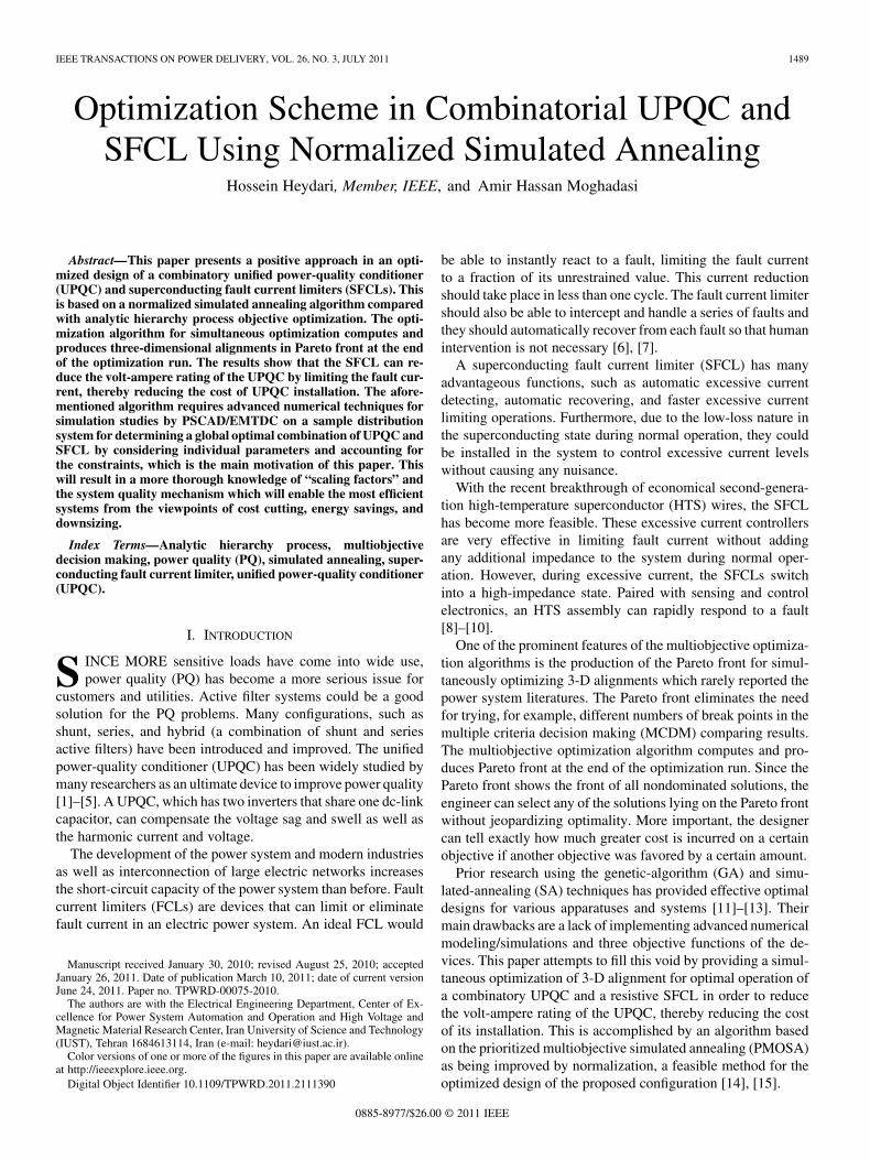
Fig. 1. Proposed combinatorial UPQC and SFCL.
However, for comparative purposes, the optimization processis verified by the analytic hierarchy process (AHP), that is, oneof the most prevalent MCDM techniques. AHP is a decisionanalysis method based on quantitative and qualitative anal-ysis, together with handling numerically human judgment indecision-making processes [16], [17]. The optimization algo-rithm for simultaneously optimizing computes and producesthe 3-D alignments in Pareto front at the end of the optimizationrun.
Hence comes the need for advanced numerical techniques forPSCAD/EMTDC simulation studies on a sample distributionsystem for determining a global optimal combination of UPQCand SFCL, by considering individual parameters and accountingfor the constraints, which is the main motivation of this paper.
II. PROPOSED UPQC SYSTEM
The integration of series-active and shunt-active power fil-ters (APFs) forming UPQC is to mitigate voltage imbalance,reactive power, negative-sequence current, and harmonics. Themain purpose of the series-APF is harmonic isolation between asubtransmission system and a distribution system. It is also ca-pable of compensating voltage flicker/imbalance, voltage reg-ulation, and harmonic at the utility-consumer PCC. While theshunt APF absorbs current harmonics, it compensates for reac-tive power and negative-sequence current injected by the load.Furthermore, it controls the voltage of the dc-link capacitor to adesired value.
In this study, the UPQC is composed of a three phase dc–acconverter for compensation of harmonic current and three phasedc–ac converters for voltage sag mitigation. The passive filtersare also used for neutralization of the switching frequency ef-fects of the APFS and high frequencies.
Fig. 1 shows the configuration of the proposed scheme withthe UPQC located in feeder II.
A. Control Scheme of the Proposed System
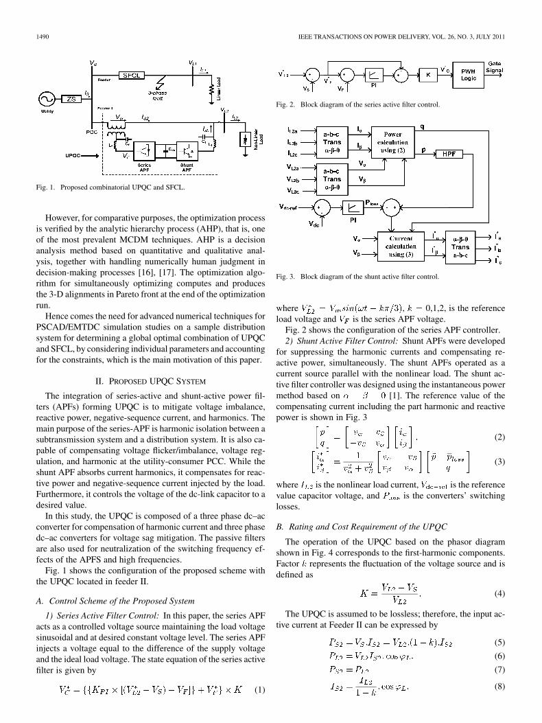
1) Series Active Filter Control: In this paper, the series APFacts as a controlled voltage source maintaining the load voltagesinusoidal and at desired constant voltage level. The series APFinjects a voltage equal to the difference of the supply voltageand the ideal load voltage. The state equation of the series activefilter is given by
(1)
Fig. 2. Block diagram of the series active filter control.
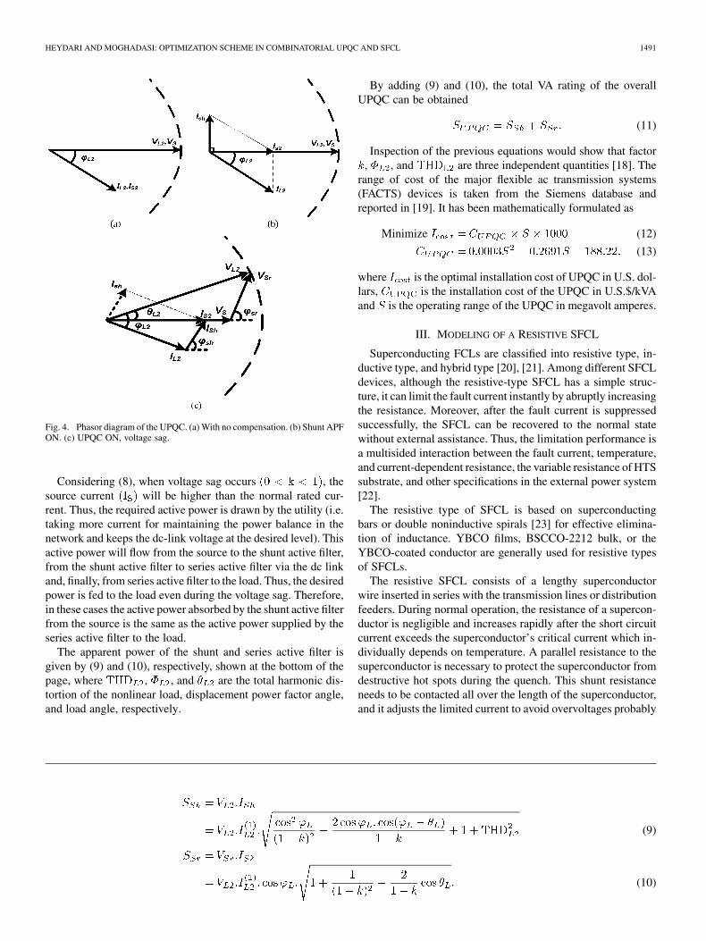
Fig. 3. Block diagram of the shunt active filter control.
where , 0,1,2, is the referenceload voltage and is the series APF voltage.
Fig. 2 shows the configuration of the series APF controller.2) Shunt Active Filter Control: Shunt APFs were developed
for suppressing the harmonic currents and compensating re-active power, simultaneously. The shunt APFs operated as acurrent source parallel with the nonlinear load. The shunt ac-tive filter controller was designed using the instantaneous powermethod based on [1]. The reference value of thecompensating current including the part harmonic and reactivepower is shown in Fig. 3
(2)
(3)
where is the nonlinear load current, is the referencevalue capacitor voltage, and is the converters’ switchinglosses.
B. Rating and Cost Requirement of the UPQC
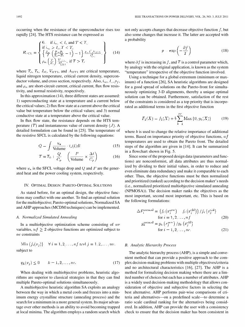
The operation of the UPQC based on the phasor diagramshown in Fig. 4 corresponds to the first-harmonic components.Factor represents the fluctuation of the voltage source and isdefined as
(4)
The UPQC is assumed to be lossless; therefore, the input ac-tive current at Feeder II can be expressed by
(5)
(6)
(7)
(8)
HEYDARI AND MOGHADASI: OPTIMIZATION SCHEME IN COMBINATORIAL UPQC AND SFCL 1491
Fig. 4. Phasor diagram of the UPQC. (a) With no compensation. (b) Shunt APFON. (c) UPQC ON, voltage sag.
Considering (8), when voltage sag occurs , thesource current will be higher than the normal rated cur-rent. Thus, the required active power is drawn by the utility (i.e.taking more current for maintaining the power balance in thenetwork and keeps the dc-link voltage at the desired level). Thisactive power will flow from the source to the shunt active filter,from the shunt active filter to series active filter via the dc linkand, finally, from series active filter to the load. Thus, the desiredpower is fed to the load even during the voltage sag. Therefore,in these cases the active power absorbed by the shunt active filterfrom the source is the same as the active power supplied by theseries active filter to the load.
The apparent power of the shunt and series active filter isgiven by (9) and (10), respectively, shown at the bottom of thepage, where , , and are the total harmonic dis-tortion of the nonlinear load, displacement power factor angle,and load angle, respectively.
By adding (9) and (10), the total VA rating of the overallUPQC can be obtained
(11)
Inspection of the previous equations would show that factor, , and are three independent quantities [18]. The
range of cost of the major flexible ac transmission systems(FACTS) devices is taken from the Siemens database andreported in [19]. It has been mathematically formulated as
Minimize (12)
(13)
where is the optimal installation cost of UPQC in U.S. dol-lars, is the installation cost of the UPQC in U.S.$/kVAand is the operating range of the UPQC in megavolt amperes.
III. MODELING OF A RESISTIVE SFCL
Superconducting FCLs are classified into resistive type, in-ductive type, and hybrid type [20], [21]. Among different SFCLdevices, although the resistive-type SFCL has a simple struc-ture, it can limit the fault current instantly by abruptly increasingthe resistance. Moreover, after the fault current is suppressedsuccessfully, the SFCL can be recovered to the normal statewithout external assistance. Thus, the limitation performance isa multisided interaction between the fault current, temperature,and current-dependent resistance, the variable resistance of HTSsubstrate, and other specifications in the external power system[22].
The resistive type of SFCL is based on superconductingbars or double noninductive spirals [23] for effective elimina-tion of inductance. YBCO films, BSCCO-2212 bulk, or theYBCO-coated conductor are generally used for resistive typesof SFCLs.
The resistive SFCL consists of a lengthy superconductorwire inserted in series with the transmission lines or distributionfeeders. During normal operation, the resistance of a supercon-ductor is negligible and increases rapidly after the short circuitcurrent exceeds the superconductor’s critical current which in-dividually depends on temperature. A parallel resistance to thesuperconductor is necessary to protect the superconductor fromdestructive hot spots during the quench. This shunt resistanceneeds to be contacted all over the length of the superconductor,and it adjusts the limited current to avoid overvoltages probably
(9)
(10)
1492 IEEE TRANSACTIONS ON POWER DELIVERY, VOL. 26, NO. 3, JULY 2011
occurring when the resistance of the superconductor rises toorapidly [24]. The HTS resistance can be expressed as
if andif
if
(14)
where , , , , and are critical temperature,liquid nitrogen temperature, critical current density, supercon-ductor volume, and cross section, respectively. Also, , , ,and are short-circuit current, critical current, flux flow resis-tivity, and normal resistivity, respectively.
In this approximation (14), three different states are assumed:1) superconducting state at a temperature and a current belowthe critical values; 2) flux flow state at a current above the criticalvalue but temperature below the critical values; and 3) normalconductive state at a temperature above the critical value.
In flux flow state, the resistance depends on the HTS tem-perature and instantaneous value of current density . Adetailed formulation can be found in [25]. The temperature ofthe resistive SFCL is calculated by the following equations:
Volume(15)
Volume(16)
where is the SFCL voltage drop and and are the gener-ated heat and the power cooling system, respectively.
IV. OPTIMAL DESIGN: PARETO-OPTIMAL SOLUTIONS
As stated before, for an optimal design, the objective func-tions may conflict with one another. To find an optimal solutionfor the multiobjective; Pareto-optimal solutions, Normalized SAand AHP approaches (MCDM techniques) can be implemented.
A. Normalized Simulated Annealing
In a multiobjective optimization scheme consisting ofvariables, objective functions are optimized subject to
constraints
subject to
(17)
When dealing with multiobjective problems, heuristic algo-rithms are superior to classical strategies in that they can findmultiple Pareto-optimal solutions simultaneously.
A multiobjective heuristic algorithm SA exploits an analogybetween the way in which a metal cools and freezes into a min-imum energy crystalline structure (annealing process) and thesearch for a minimum in a more general system. Its major advan-tage over other methods is an ability to avoid becoming trappedat local minima. The algorithm employs a random search which
not only accepts changes that decrease objective function , butalso some changes that increase it. The latter are accepted witha probability
(18)
where is increasing in , and is a control parameter which,by analogy with the original application, is known as the system“temperature” irrespective of the objective function involved.
Using a technique for a global extremum (minimum or max-imum) of a function [26], SA heuristic algorithms are designedfor a good spread of solutions on the Pareto-front for simulta-neously optimizing 3-D alignments, thereby a unique optimalsolution can be obtained. Furthermore, satisfaction of the restof the constraints is considered as a top priority that is incorpo-rated as additional terms in the first objective function
(19)
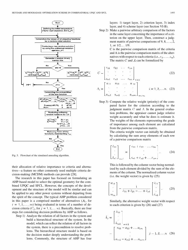
where is used to change the relative importance of additionalterms. Based on importance priority of objective functions,temperatures are used to obtain the Pareto front. The detailedsteps of the algorithm are given in [14]. It can be summarizedin a flowchart shown in Fig. 5.
Since some of the proposed design data (parameters and func-tions) are nonconformist, all data attributes are thus normal-ized by dividing to their initial values, in order to reduce andeven eliminate data redundancy and make it comparable to eachother. Thus, the objective functions must be then normalizedand prioritized (ranked) according to the decision maker’s needs(i.e., normalized prioritized multiobjective simulated annealing(NPMOSA)). The decision maker ranks the objectives as themost important, second most important, etc. This is based onthe following formulations:
for (20)
for (21)
B. Analytic Hierarchy Process
The analytic hierarchy process (AHP), is a simple and conve-nient method that can provide a positive approach to the com-plex decision-making problems with multiple objectives/criteriaand no architectural characteristics [16], [27]. The AHP is amethod for formalizing decision making where there are a lim-ited number of choices but each has a number of attributes. AHPis a widely used decision-making methodology that allows con-sideration of objective and subjective factors in selecting thebest alternative. AHP performs pair-wise comparisons of cri-teria and alternatives—on a predefined scale—to determine aratio scale cardinal ranking for the alternatives being consid-ered. In addition, AHP can provide the user with a consistencycheck to ensure that the decision maker has been consistent in
HEYDARI AND MOGHADASI: OPTIMIZATION SCHEME IN COMBINATORIAL UPQC AND SFCL 1493
Fig. 5. Flowchart of the simulated annealing algorithm.
their allocation of relative importance to criteria and alterna-tives—a feature no other commonly used multiple criteria de-cision-making (MCDM) methods can provide [28].
The research in this paper has focused on formulating anAHP-based model to select the optimal geometry for the com-bined UPQC and SFCL. However, the concepts of the devel-opment and the structure of the model will be similar and canbe applied to any other power systems without departing fromthe spirit of the concept. The typical AHP problem consideredin this paper is a comprised number of alternatives ( , for
) being evaluated in terms of a number of de-cision criteria ( , for ). Basically, there are foursteps for considering decision problems by AHP as follows.
Step 1) Analyze the relation of all factors in the system andbuild a hierarchical structure of the system. In themodel, which can reflect the relation of all factors inthe system, there is a precondition to resolve prob-lems. The hierarchical structure model is based onthe decision maker deeply understanding the prob-lems. Commonly, the structure of AHP has four
layers: 1) target layer, 2) criterion layer, 3) indexlayer, and 4) scheme layer (see Section VI-B).
Step 2) Make a pairwise arbitrary comparison of the factorsin the same layer concerning the importance of a cri-terion on the upper layer. Then, construct a judg-ment matrix of pairwise comparisons of 9, 8, , 2,1, or 1/2 1/9.C is the pairwise comparison matrix of the criteriaand A is the pairwise comparison matrix of the alter-natives with respect to each criteria (i.e., ).The matrix and can be formulized by
(22)
(23)
Step 3) Compute the relative weight (priority) of the com-pared factor for the criterion according to thejudgment matrix and . In the general evalua-tion problems, the appraiser cannot judge relativeweight accurately and what he does is estimate it.The weights of the elements representing the gradeof importance among each element are calculatedfrom the pairwise comparison matrix.The criteria weight vector can initially be obtainedby calculating the sum array elements of each rowof a pairwise comparison matrix
(24)
This is followed by the column vector being normal-ized by each element divided by the sum of the ele-ments of the column. The normalized column vector(i.e. the weight vector) is given by (25):
(25)
Similarly, the alternative weight vector with respectto each criterion is given by (26) and (27)
(26)
1494 IEEE TRANSACTIONS ON POWER DELIVERY, VOL. 26, NO. 3, JULY 2011
(27)
The sum of all the weight vectors forms a decisionmatrix as
where and are the relative priority valuesof the alternatives with respect to the criteria and theweight of importance of each criterion, respectively.
Step 4) Compute the total sequencing weights of the layersin the system, then proceed to sequencing. At last,we will receive the final sequencing of ultimatetarget in the projects.Considering the research in this paper, selection cri-teria for the aforementioned optimal combinatorialUPQC and SFCL (in the minimization case) is theone that satisfies the following expression need to beevaluated.:
(28)where is the preference value of the best al-ternative.
V. NUMERICAL SIMULATION ANALYSIS
The proposed system was modeled and simulated by PSCAD/EMTDC simulations. The modeled three-phase system consistsof a resistive linear load (Feeder I), a nonlinear and sensitiveload of a three-phase diode bridge with the R-L load in the dcside (Feeder II). The SFCL combination of the electrical andthermal model defined as a component in PSCAD/EMTDC isshown in Tables I and II.
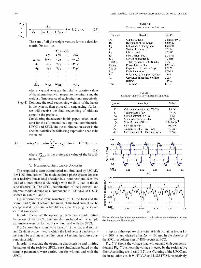
Fig. 6 shows the current waveform of: 1) the load and thesource and 2) shunt active filter, in which the load current can becompensated by a shunt active filter current, keeping the sourcecurrent sinusoidal.
In order to evaluate the operating characteristic and limitingbehaviors of the SFCL, case simulations based on the sampleparameters were performed for without and with the SFCL.
Fig. 6 shows the current waveform of: 1) the load and source,and 2) shunt active filter, in which the load current can be com-pensated by a shunt active filter current keeping the source cur-rent sinusoidal.
In order to evaluate the operating characteristic and limitingbehaviors of the resistive SFCL, case simulations based on thesample parameters were carried out for without and with theSFCL.
TABLE ICHARACTERISTICS OF THE SYSTEM
TABLE IICHARACTERISTICS OF THE RESISTIVE SFCL
Fig. 6. Current harmonics compensation. (a) Load current and source current.(b) Shunt active filter current.
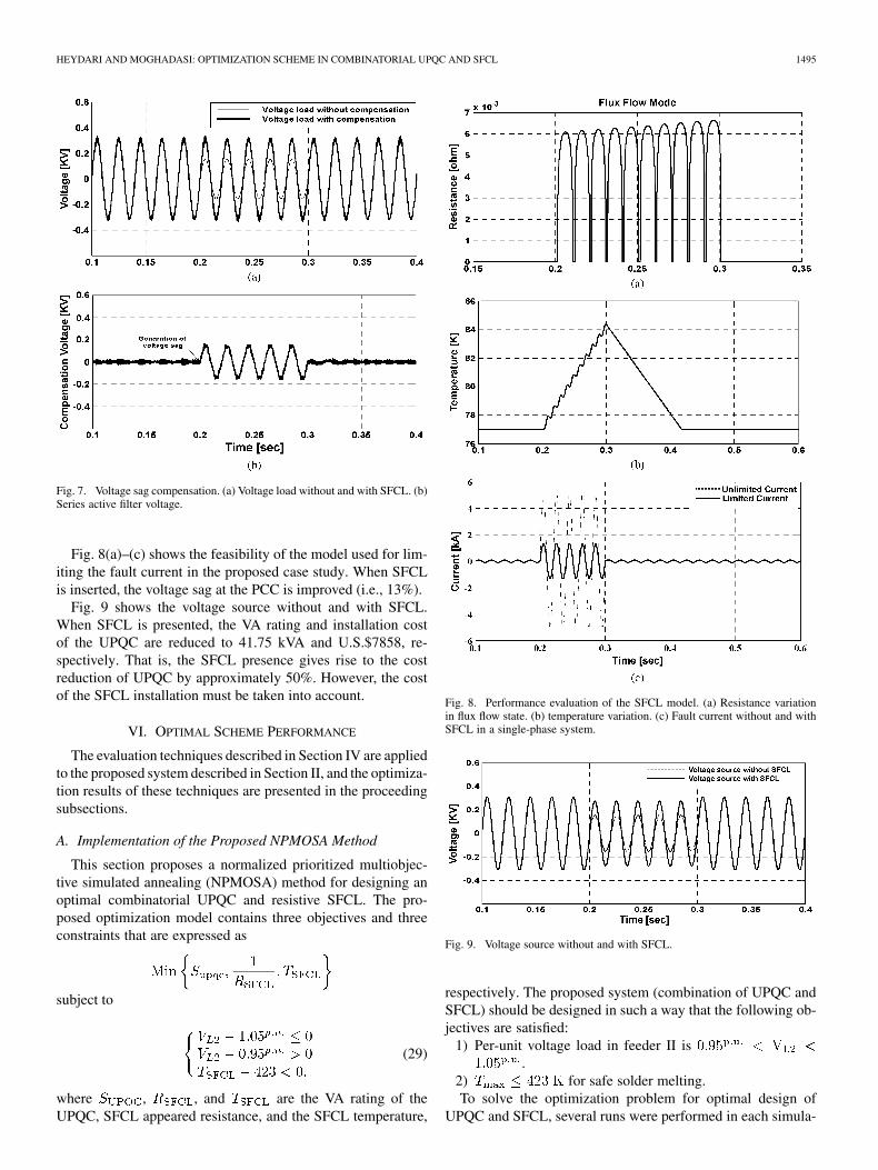
Suppose a three-phase short-circuit fault occurs in feeder I at200 ms and cleared after 100 ms. In the absence of
the SFCL, a voltage sag of 48% occurs at PCC.Fig. 7(a) shows the voltage load without and with compensa-
tion and Fig. 7(b) shows the voltage injected by the series activefilter. According to (11) and (12), the VA rating of the UPQC andthe installation cost is 94.47 kVA and U.S.$17784, respectively.
HEYDARI AND MOGHADASI: OPTIMIZATION SCHEME IN COMBINATORIAL UPQC AND SFCL 1495
Fig. 7. Voltage sag compensation. (a) Voltage load without and with SFCL. (b)Series active filter voltage.
Fig. 8(a)–(c) shows the feasibility of the model used for lim-iting the fault current in the proposed case study. When SFCLis inserted, the voltage sag at the PCC is improved (i.e., 13%).
Fig. 9 shows the voltage source without and with SFCL.When SFCL is presented, the VA rating and installation costof the UPQC are reduced to 41.75 kVA and U.S.$7858, re-spectively. That is, the SFCL presence gives rise to the costreduction of UPQC by approximately 50%. However, the costof the SFCL installation must be taken into account.
VI. OPTIMAL SCHEME PERFORMANCE
The evaluation techniques described in Section IV are appliedto the proposed system described in Section II, and the optimiza-tion results of these techniques are presented in the proceedingsubsections.
A. Implementation of the Proposed NPMOSA Method
This section proposes a normalized prioritized multiobjec-tive simulated annealing (NPMOSA) method for designing anoptimal combinatorial UPQC and resistive SFCL. The pro-posed optimization model contains three objectives and threeconstraints that are expressed as
subject to
(29)
where , , and are the VA rating of theUPQC, SFCL appeared resistance, and the SFCL temperature,
Fig. 8. Performance evaluation of the SFCL model. (a) Resistance variationin flux flow state. (b) temperature variation. (c) Fault current without and withSFCL in a single-phase system.
Fig. 9. Voltage source without and with SFCL.
respectively. The proposed system (combination of UPQC andSFCL) should be designed in such a way that the following ob-jectives are satisfied:
1) Per-unit voltage load in feeder II is.
2) for safe solder melting.To solve the optimization problem for optimal design of
UPQC and SFCL, several runs were performed in each simula-
1496 IEEE TRANSACTIONS ON POWER DELIVERY, VOL. 26, NO. 3, JULY 2011
TABLE IIILIMITS OF VARIABLES FOR THE OPTIMIZATION PROBLEM
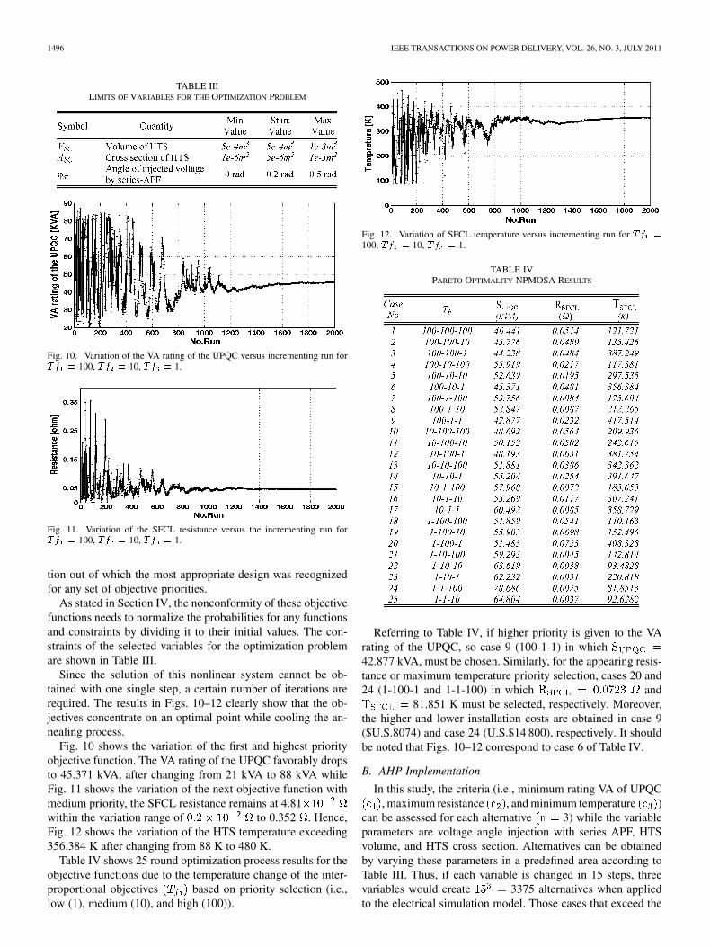
Fig. 10. Variation of the VA rating of the UPQC versus incrementing run for�� � 100, �� � 10, �� � 1.
Fig. 11. Variation of the SFCL resistance versus the incrementing run for�� � 100, �� � 10, �� � 1.
tion out of which the most appropriate design was recognizedfor any set of objective priorities.
As stated in Section IV, the nonconformity of these objectivefunctions needs to normalize the probabilities for any functionsand constraints by dividing it to their initial values. The con-straints of the selected variables for the optimization problemare shown in Table III.
Since the solution of this nonlinear system cannot be ob-tained with one single step, a certain number of iterations arerequired. The results in Figs. 10–12 clearly show that the ob-jectives concentrate on an optimal point while cooling the an-nealing process.
Fig. 10 shows the variation of the first and highest priorityobjective function. The VA rating of the UPQC favorably dropsto 45.371 kVA, after changing from 21 kVA to 88 kVA whileFig. 11 shows the variation of the next objective function withmedium priority, the SFCL resistance remains at 4.81within the variation range of to 0.352 . Hence,Fig. 12 shows the variation of the HTS temperature exceeding356.384 K after changing from 88 K to 480 K.
Table IV shows 25 round optimization process results for theobjective functions due to the temperature change of the inter-proportional objectives based on priority selection (i.e.,low (1), medium (10), and high (100)).
Fig. 12. Variation of SFCL temperature versus incrementing run for �� �
100, �� � 10, �� � 1.
TABLE IVPARETO OPTIMALITY NPMOSA RESULTS
Referring to Table IV, if higher priority is given to the VArating of the UPQC, so case 9 (100-1-1) in which42.877 kVA, must be chosen. Similarly, for the appearing resis-tance or maximum temperature priority selection, cases 20 and24 (1-100-1 and 1-1-100) in which and
81.851 K must be selected, respectively. Moreover,the higher and lower installation costs are obtained in case 9($U.S.8074) and case 24 (U.S.$14 800), respectively. It shouldbe noted that Figs. 10–12 correspond to case 6 of Table IV.
B. AHP Implementation
In this study, the criteria (i.e., minimum rating VA of UPQC, maximum resistance , and minimum temperature )
can be assessed for each alternative 3) while the variableparameters are voltage angle injection with series APF, HTSvolume, and HTS cross section. Alternatives can be obtainedby varying these parameters in a predefined area according toTable III. Thus, if each variable is changed in 15 steps, threevariables would create 3375 alternatives when appliedto the electrical simulation model. Those cases that exceed the
HEYDARI AND MOGHADASI: OPTIMIZATION SCHEME IN COMBINATORIAL UPQC AND SFCL 1497
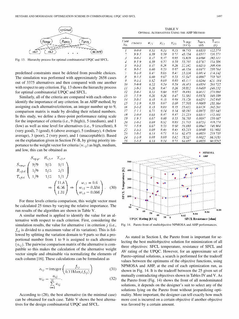
Fig. 13. Hierarchy process for optimal combinatorial UPQC and SFCL.
predefined constraints must be deleted from possible choices.The simulation was performed with approximately 2658 casesout of 3375 alternatives and then compared with one anotherwith respect to any criterion. Fig. 13 shows the hierarchy processfor optimal combinatorial UPQC and SFCL.
Similarly, all of the criteria are compared with each others toidentify the importance of any criterion. In an AHP method, byassigning each alternative/criterion, an integer number up to 9,comparison matrix is made by dividing their related numbers.In this study, we define a three-point performance rating scalefor the importance of criteria (i.e., 9 (high)), 5 (medium), and 1(low) as well as nine level for alternatives (i.e., 9 (excellent), 8(very good), 7 (good), 6 (above average), 5 (ordinary), 4 (belowaverage), 3 (poor), 2 (very poor), and 1 (unacceptable)). Basedon the explanation given in Section IV-B, by giving priority im-portance to the weight vector for criteria as high, medium,and low, this can be obtained as
(30)
For three levels criteria comparison, this weight vector mustbe calculated 25 times by varying the relative importance. Therun results of the algorithm are shown in Table V.
A similar method is applied to identify the value for an al-ternative with respect to each criterion. First, considering thesimulation results, the value for alternative in criterion (i.e.,
is divided to a maximum value of its variation). This is fol-lowed by splitting the variation domain to 9 parts so that a pro-portional number from 1 to 9 is assigned to each alternative
. The pairwise comparison matrix of the alternative is com-patible so this makes the calculation of the alternative weightvector simple and obtainable via normalizing the elements ofeach column [16]. These calculations can be formulated as
(31)
(32)
According to (28), the best alternative (in the minimal case)can be obtained for each case. Table V shows the best alterna-tives for the design combinatorial UPQC and SFCL.
TABLE VOPTIMAL ALTERNATIVES USING THE AHP METHOD
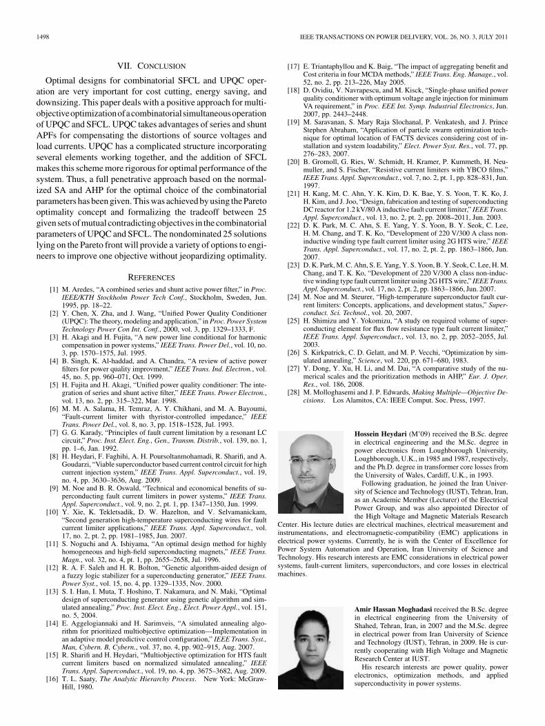
Fig. 14. Pareto front of multiobjective NPMOSA and AHP performances.
As stated in Section I, the Pareto front is important for se-lecting the best multiobjective solution for minimization of allthree objectives: SFCL temperature, resistance of SFCL andAV rating of the UPQC. However, for an approximate set ofPareto-optimal solutions, a search is performed for the tradeoffvalues between the optimums of the objective functions, usingNPMOSA and AHP, at the end of each optimization run, asshown in Fig. 14. It is the tradeoff between the 25 given set ofmutually contradicting objectives shown in Tables IV and V. Asthe Pareto front (Fig. 14) shows the front of all nondominatedsolutions, it depends on the designer’s suit to select any of thesolutions lying on the Pareto front without jeopardizing opti-mality. More important, the designer can tell exactly how muchmore cost is incurred on a certain objective if another objectivewas favored by a certain amount.
1498 IEEE TRANSACTIONS ON POWER DELIVERY, VOL. 26, NO. 3, JULY 2011
VII. CONCLUSION
Optimal designs for combinatorial SFCL and UPQC oper-ation are very important for cost cutting, energy saving, anddownsizing. This paper deals with a positive approach for multi-objectiveoptimizationofacombinatorialsimultaneousoperationof UPQC and SFCL. UPQC takes advantages of series and shuntAPFs for compensating the distortions of source voltages andload currents. UPQC has a complicated structure incorporatingseveral elements working together, and the addition of SFCLmakes this scheme more rigorous for optimal performance of thesystem. Thus, a full penetrative approach based on the normal-ized SA and AHP for the optimal choice of the combinatorialparameters has been given. This was achieved by using the Paretooptimality concept and formalizing the tradeoff between 25given sets of mutual contradicting objectives in the combinatorialparameters of UPQC and SFCL. The nondominated 25 solutionslying on the Pareto front will provide a variety of options to engi-neers to improve one objective without jeopardizing optimality.
REFERENCES
[1] M. Aredes, “A combined series and shunt active power filter,” in Proc.IEEE/KTH Stockholm Power Tech Conf., Stockholm, Sweden, Jun.1995, pp. 18–22.
[2] Y. Chen, X. Zha, and J. Wang, “Unified Power Quality Conditioner(UPQC): The theory, modeling and application,” in Proc. Power SystemTechnology Power Con Int. Conf., 2000, vol. 3, pp. 1329–1333, F.
[3] H. Akagi and H. Fujita, “A new power line conditional for harmoniccompensation in power systems,” IEEE Trans. Power Del., vol. 10, no.3, pp. 1570–1575, Jul. 1995.
[4] B. Singh, K. Al-haddad, and A. Chandra, “A review of active powerfilters for power quality improvment,” IEEE Trans. Ind. Electron., vol.45, no. 5, pp. 960–071, Oct. 1999.
[5] H. Fujita and H. Akagi, “Unified power quality conditioner: The inte-gration of series and shunt active filter,” IEEE Trans. Power Electron.,vol. 13, no. 2, pp. 315–322, Mar. 1998.
[6] M. M. A. Salama, H. Temraz, A. Y. Chikhani, and M. A. Bayoumi,“Fault-current limiter with thyristor-controlled impedance,” IEEETrans. Power Del., vol. 8, no. 3, pp. 1518–1528, Jul. 1993.
[7] G. G. Karady, “Principles of fault current limitation by a resonant LCcircuit,” Proc. Inst. Elect. Eng., Gen., Transm. Distrib., vol. 139, no. 1,pp. 1–6, Jan. 1992.
[8] H. Heydari, F. Faghihi, A. H. Poursoltanmohamadi, R. Sharifi, and A.Goudarzi, “Viable superconductor based current control circuit for highcurrent injection system,” IEEE Trans. Appl. Superconduct., vol. 19,no. 4, pp. 3630–3636, Aug. 2009.
[9] M. Noe and B. R. Oswald, “Technical and economical benefits of su-perconducting fault current limiters in power systems,” IEEE Trans.Appl. Superconduct., vol. 9, no. 2, pt. 1, pp. 1347–1350, Jun. 1999.
[10] Y. Xie, K. Tekletsadik, D. W. Hazelton, and V. Selvamanickam,“Second generation high-temperature superconducting wires for faultcurrent limiter applications,” IEEE Trans. Appl. Superconduct., vol.17, no. 2, pt. 2, pp. 1981–1985, Jun. 2007.
[11] S. Noguchi and A. Ishiyama, “An optimal design method for highlyhomogeneous and high-field superconducting magnets,” IEEE Trans.Magn., vol. 32, no. 4, pt. 1, pp. 2655–2658, Jul. 1996.
[12] R. A. F. Saleh and H. R. Bolton, “Genetic algorithm-aided design ofa fuzzy logic stabilizer for a superconducting generator,” IEEE Trans.Power Syst., vol. 15, no. 4, pp. 1329–1335, Nov. 2000.
[13] S. I. Han, I. Muta, T. Hoshino, T. Nakamura, and N. Maki, “Optimaldesign of superconducting generator using genetic algorithm and sim-ulated annealing,” Proc. Inst. Elect. Eng., Elect. Power Appl., vol. 151,no. 5, 2004.
[14] E. Aggelogiannaki and H. Sarimveis, “A simulated annealing algo-rithm for prioritized multiobjective optimization—Implementation inan adaptive model predictive control configuration,” IEEE Trans. Syst.,Man, Cybern. B, Cybern., vol. 37, no. 4, pp. 902–915, Aug. 2007.
[15] R. Sharifi and H. Heydari, “Multiobjective optimization for HTS faultcurrent limiters based on normalized simulated annealing,” IEEETrans. Appl. Superconduct., vol. 19, no. 4, pp. 3675–3682, Aug. 2009.
[16] T. L. Saaty, The Analytic Hierarchy Process. New York: McGraw-Hill, 1980.
[17] E. Triantaphyllou and K. Baig, “The impact of aggregating benefit andCost criteria in four MCDA methods,” IEEE Trans. Eng. Manage., vol.52, no. 2, pp. 213–226, May 2005.
[18] D. Ovidiu, V. Navrapescu, and M. Kisck, “Single-phase unified powerquality conditioner with optimum voltage angle injection for minimumVA requirement,” in Proc. EEE Int. Symp. Industrial Electronics, Jun.2007, pp. 2443–2448.
[19] M. Saravanan, S. Mary Raja Slochanal, P. Venkatesh, and J. PrinceStephen Abraham, “Application of particle swarm optimization tech-nique for optimal location of FACTS devices considering cost of in-stallation and system loadability,” Elect. Power Syst. Res., vol. 77, pp.276–283, 2007.
[20] B. Gromoll, G. Ries, W. Schmidt, H. Kramer, P. Kummeth, H. Neu-muller, and S. Fischer, “Resistive current limiters with YBCO films,”IEEE Trans. Appl. Superconduct., vol. 7, no. 2, pt. 1, pp. 828–831, Jun.1997.
[21] H. Kang, M. C. Ahn, Y. K. Kim, D. K. Bae, Y. S. Yoon, T. K. Ko, J.H. Kim, and J. Joo, “Design, fabrication and testing of superconductingDC reactor for 1.2 kV/80 A inductive fault current limiter,” IEEE Trans.Appl. Superconduct., vol. 13, no. 2, pt. 2, pp. 2008–2011, Jun. 2003.
[22] D. K. Park, M. C. Ahn, S. E. Yang, Y. S. Yoon, B. Y. Seok, C. Lee,H. M. Chang, and T. K. Ko, “Development of 220 V/300 A class non-inductive winding type fault current limiter using 2G HTS wire,” IEEETrans. Appl. Superconduct., vol. 17, no. 2, pt. 2, pp. 1863–1866, Jun.2007.
[23] D. K. Park, M. C. Ahn, S. E. Yang, Y. S. Yoon, B. Y. Seok, C. Lee, H. M.Chang, and T. K. Ko, “Development of 220 V/300 A class non-induc-tive winding type fault current limiter using 2G HTS wire,” IEEE Trans.Appl. Superconduct., vol. 17, no. 2, pt. 2, pp. 1863–1866, Jun. 2007.
[24] M. Noe and M. Steurer, “High-temperature superconductor fault cur-rent limiters: Concepts, applications, and development status,” Super-conduct. Sci. Technol., vol. 20, 2007.
[25] H. Shimizu and Y. Yokomizu, “A study on required volume of super-conducting element for flux flow resistance type fault current limiter,”IEEE Trans. Appl. Superconduct., vol. 13, no. 2, pp. 2052–2055, Jul.2003.
[26] S. Kirkpatrick, C. D. Gelatt, and M. P. Vecchi, “Optimization by sim-ulated annealing,” Science, vol. 220, pp. 671–680, 1983.
[27] Y. Dong, Y. Xu, H. Li, and M. Dai, “A comparative study of the nu-merical scales and the prioritization methods in AHP,” Eur. J. Oper.Res., vol. 186, 2008.
[28] M. Molloghasemi and J. P. Edwards, Making Multiple—Objective De-cisions. Los Alamitos, CA: IEEE Comput. Soc. Press, 1997.
Hossein Heydari (M’09) received the B.Sc. degreein electrical engineering and the M.Sc. degree inpower electronics from Loughborough University,Loughborough, U.K., in 1985 and 1987, respectively,and the Ph.D. degree in transformer core losses fromthe University of Wales, Cardiff, U.K., in 1993.
Following graduation, he joined the Iran Univer-sity of Science and Technology (IUST), Tehran, Iran,as an Academic Member (Lecturer) of the ElectricalPower Group, and was also appointed Director ofthe High Voltage and Magnetic Materials Research
Center. His lecture duties are electrical machines, electrical measurement andinstrumentations, and electromagnetic-compatibility (EMC) applications inelectrical power systems. Currently, he is with the Center of Excellence forPower System Automation and Operation, Iran University of Science andTechnology. His research interests are EMC considerations in electrical powersystems, fault-current limiters, superconductors, and core losses in electricalmachines.
Amir Hassan Moghadasi received the B.Sc. degreein electrical engineering from the University ofShahed, Tehran, Iran, in 2007 and the M.Sc. degreein electrical power from Iran University of Scienceand Technology (IUST), Tehran, in 2009. He is cur-rently cooperating with High Voltage and MagneticResearch Center at IUST.
His research interests are power quality, powerelectronics, optimization methods, and appliedsuperconductivity in power systems.
Copyright © 2022 FDOKUMEN