
Optimization of Two Soil–Structure Interaction Parameters ...
Upload
khangminh22Category
view
5download
0
Retrospective Theses and Dissertations Iowa State University Capstones, Theses andDissertations
1974
Optimization of phase converter parameters andeffects of voltage variation on their performanceRoshan Lal ChhabraIowa State University
Follow this and additional works at: https://lib.dr.iastate.edu/rtd
Part of the Agriculture Commons, and the Bioresource and Agricultural Engineering Commons
This Dissertation is brought to you for free and open access by the Iowa State University Capstones, Theses and Dissertations at Iowa State UniversityDigital Repository. It has been accepted for inclusion in Retrospective Theses and Dissertations by an authorized administrator of Iowa State UniversityDigital Repository. For more information, please contact [email protected].
Recommended CitationChhabra, Roshan Lal, "Optimization of phase converter parameters and effects of voltage variation on their performance " (1974).Retrospective Theses and Dissertations. 5978.https://lib.dr.iastate.edu/rtd/5978

INFORMATION TO USERS
This material was produced from a microfilm copy of the original document. While the most advanced technological means to photograph and reproduce this document have been used, the quality is heavily dependent upon the quality of the original submitted.
The following explanation of techniques is provided to help you understand markings or patterns which may appear on this reproduction.
1. The sign or "target" for pages apparently lacking from the document photographed is "Missing Page(s)". If it was possible to obtain the missing page(s) or section, they are spliced into the film along with adjacent pages. This may have necessitated cutting thru an image and duplicating adjacent pages to insure you complete continuity.
2. When an image on the film is obliterated with a large round black mark, it is an indication that the photographer suspected that the copy may have moved during exposure and thus cause a blurred image. You will find a good image of the page in the adjacent frame.
3. When a map, drawing or chart, etc., was part of the material being photographed the photographer followed a definite method in "sectioning" the material. It is customary to begin photoing at the upper left hand corner of a large sheet and to continue photoing from left to right in equal sections with a small overlap. If necessary, sectioning is continued again — beginning below the first row and continuing on until complete.
4. The majority of users indicate that the textual content is of greatest value, however, a somewhat higher quality reproduction could be made from "photographs" if essential to the understanding of the dissertation. Silver prints of "photographs" may be ordered at additional charge by writing the Order Department, giving the catalog number, title, author and specific pages you wish reproduced.
5. PLEASE NOTE: Some pages may have indistinct print. Filmed as received.
Xerox University IMicrofilms 300 North Zeeb Road Ann Arbor, Michigan 48106
CHHABRA, Roshan Lai, 1941-OPTIMIZATION OF PHASE CONVERTER PARAMETERS AND EFFECTS OF VOLTAGE VARIATION ON THEIR PERFORMANCE.
Iowa State University, Ph.D., 1974 Engineering, agricultural
University Microfilms, A XEROX Company, Ann Arbor, Michigan
THIS DISSERTATION HAS BEEN MICROFILMED EXACTLY AS RECEIVED.
Optimization of phase converter parameters
and effects of voltage variation on their performance
by
Roshan Lai Chhabra
A Dissertation Submitted to the
Graduate Faculty in Partial Fulfillment of
The Requirements for the Degree of
DOCTOR OF PHILOSOPHY
Major; Agricultural Engineering
Approved :
For the Gra
Iowa State University Of Science and Technology
Ames, Iowa
1974
Signature was redacted for privacy.
Signature was redacted for privacy.
Signature was redacted for privacy.
ii
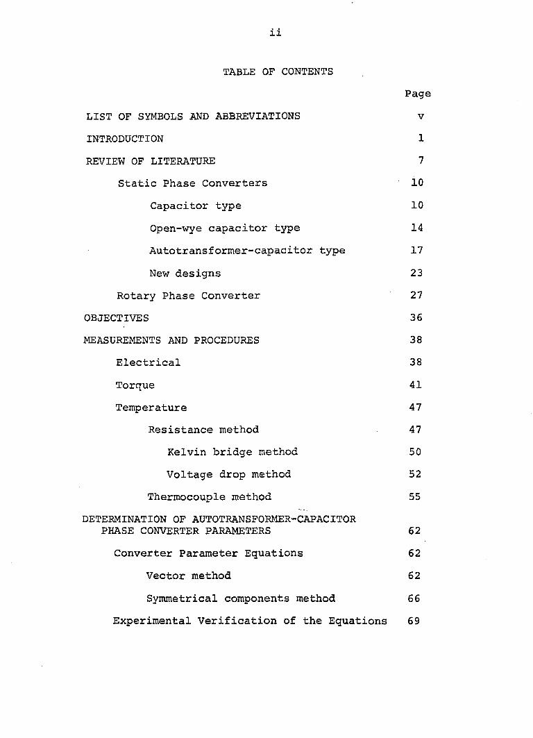
TABLE OF CONTENTS
Page
LIST OF SYMBOLS AND ABBREVIATIONS V
INTRODUCTION 1
REVIEW OF LITERATURE 7
Static Phase Converters 10
Capacitor type 10
Open-wye capacitor type 14
Autotransforiner-capacitor type 17
New designs 23
Rotary Phase Converter 27
OBJECTIVES 36
MEASUREMENTS AND PROCEDURES 38
Electrical 38
Torque 41
Temperature 47
Resistance method 47
Kelvin bridge method 50
Voltage drop method 52
Thermocouple method 55
DETERMINATION OF AUTOTRANSFORMER-CAPACITOR PHASE CONVERTER PARAMETERS 62
Converter Parameter Equations 62
Vector method 62
Symmetrical components method 66
Experimental Verification of the Equations 69
iii
OPTIMIZATION OF PARAMETERS FOR THE PRACTICAL APPLICATIONS 75
Performance Characteristics 77
Voltages and currents 80
Power input and efficiency 86
Power factor 89
Slip 89
Temperature rise 89
VOLTAGE EFFECTS ON PHASE CONVERTER OPERATED THREE-PHASE MOTORS 95
Test Outline 96
Three-Phase Power 97
Autotransformer-Capacitor Converter 97
Rotary Phase Converter 99
Performance Characteristics 100
Voltages and currents 100
Winding temperature 105
Power input and efficiency 107
Power factor 109
Slip 109
Torque 111
EFFECTS OF UNBALANCED VOLTAGE ON MOTOR PERFORMANCE 117
Unbalance with Three-Phase Power 118
Current unbalance 119
Winding temperature 121
Unbalance with Phase Converter 123
iv
Current unbalance and temperature rise 123
PERFORMANCE CHARACTERISTICS OF MOTORS OPERATING FROM OPEN-WYE TYPE PHASE CONVERTER 129
EFFECTS OF STARTING CAPACITANCE ON LOCKED-ROTOR TORQUE 135
POWER SERVICE DESIGN FOR PHASE CONVERTER AND ASSOCIATED THREE-PHASE MOTOR(S) 143
Transformer Size 144
Conductor Size 146
Overload Protection 155
Grounding 158
Installation 158
DISCUSSION 163
SUMMARY 167
RESULTS AND CONCLUSIONS 169
SUGGESTIONS FOR FUTURE STUDY 172
REFERENCES 175
SUPPLEMENTARY REFERENCES 185
ACKNOWLEDGEMENTS 194
APPENDIX A: EQUIPMENT SPECIFICATIONS 196
Electric Motor Specifications 197
Phase Converter Specifications 198
Dynamometer Specifications 199
Transducer and Recording Instruments Specifications 200
Metering Instruments Specifications 201

APPENDIX B: TYPES OF PHASE CONVERTERS
APPENDIX C: EXPERIMENTAL DATA
vi
LIST OF SYMBOLS AND ABBREVIATIONS
a operator (characteristic angle)
a.c. alternating current
AWG American Wire Gauge
c,C capacitance
CM circular mils
CT current transformer
D/A digital to analog
D.C. direct current
f Frequency
Hg hertz (cycles per second)
hp horsepower
I current
2 , 3 current in line 1 , 2, or 3
IEEE Institute of Electrical and Electronic Engineers
j imaginary components of complex quantities, sj -1
K constant
KV kilovolt
KVA kilovolt ampere
KVAR reactive kilovolt ampere (reactive power)
KW kilowatt
KWhr kilowatt hour
L length
L^^2 3 line 1, 2, or 3
vii
LB-FT pound - feet
LB-IN pound - inch
LRT locked-rotor torque
n,N turns ratio
N.C. normally closed
NEC National Electrical Code
N.O. normally opened
NEMA National Electrical Manufacturers Association
O.L. over load
PF power factor
R.P.M. revolution per minute
SPOT single pole double throw
SPST single pole single throw
T, „ _ terminal 1, 2 , or 3 -L f 6 y J
TPDT triple pole double throw
V voltage
voltage between phase A and phase B
voltage between phase A and neutral phase
zero sequence component of
positive sequence component of
negative sequence component of
w,W watts
capacitive reactance
Z impedance per phase of the motor

viii
3.142
microfarads
efficiency
efficiency of single-phase, three-phase, converter
positive sequence power factor angle
phase angle
single-phase
three-phase
degrees centigrade
degrees Fahrenheit
per cent
INTRODUCTION
Most rural electric power lines are single-phase. For
many years, single-phase lines have served admirably as a
means of utilizing incandescent lighting and single-phase
appliances. But farms in the United States have been growing
steadily larger. A report, prepared by the Iowa Crop and
Livestock Reporting Service shows 135,264 farms in Iowa in
1970, 1340 fewer than in 1969 and 5,583 less than in 1965.
Larger farms broaden the scope of farm operations and make
necessary more use of electric power.
The population census showed a 16,000 drop in farm pop
ulation in the State of Iowa in 1969, and a drop of 6,641 in
1970. According to the U. S. Statistical Abstract, it is
estimated that by 1980 we can expect about 2 million farms in
this country, 800,000 fewer than the latest census figure,
2.8 million in 1972. The reduction in manual labor available
on farms makes it necessary that machines be available to do
the farm operations faster and at a lower cost. A higher
profit with less effort being a part of modernization, it is
not unreasonable to predict that the trend towards mechaniza
tion of farms as well as need for larger motors on the farm
stead will continue.
To meet the need for larger motors, three-phase motors
are the ideal type. There are several reasons for the choice
of three-phase motors. Three-phase motors generally are

2
readily available and provide a wide choice of performance
characteristics. They are smaller, lighter, and simpler in
construction than single-phase motors. Single-phase motors
are higher in initial cost than three-phase motors in
integral horsepower sizes, particularly for motors larger
than 3 hp. Single-phase motors, because of starting windings
and switching devices, also require more maintenance. Most
manufacturers do not offer single-phase motors above 10 hp.
Perhaps of more importance, single-phase motors require
a starting inrush current 2 to 3 times higher than the same
size three-phase motors, and thus limits the size of motors
permissible on many single-phase lines. For example, most
7.5 hp single-phase, 230 volt, 60 motors have a name
plate rating of about 40 amperes at full load and require an
inrush current over 200 amperes. A three-phase motor of
similar hp and voltage rating requires about 20 amperes at
full load and 100 amperes at starting (33, 72).
Three-phase service, a preferable power source to op
erate three-phase motors, is readily available to only a
small percentage of farms, except for some areas of the west
coast where irrigation is necessary for farming. Most rural
lines are single-phase because three-phase service normally
requires a greater investment in transformers and lines,
which is not always profitable because most of the farms
have low annual energy consumption and poor load factor.
Feedlot equipment is operated only for an hour or two per day;
3
drying systems may be operated for only a few weeks per year;
and irrigation systems may be used for a few days to several
weeks per season (23).
As a result of an increase in the number of large crop-
drying, large feeding and irrigation systems on farms, motors
have become larger, with 10 to 20 hp becoming common. For
example, crop drying systems matched to picker-sheller harvest
rates may require 15, 20 hp and even larger motors. To meet
this demand for larger electric motors, without requiring
the installation of three-phase service, phase converters
have offered a solution for some farmers and power suppliers.
A phase converter is a device that permits the use of
three-phase motors from a single-phase power source. The
application of a phase converter operated three-phase motor
is recommended in the following situations (22, 86, 87, 88).
1) When the cost of extending three-phase power is
relatively high and the annual energy consumption is rela
tively low.
2) When the customer has to pay the cost for the exten
sion of three-phase service. For example, Baebler reported
(5) that
"one power company serves its customers under a residential ra,te which provides a single-phase service as standard. The company will extend the three-phase service irrespective of the amount of connected load provided the customer pays for the non standard facilities".
4
3) When the rate structure is higher for three-phase
service than for single-phase service.
4) When the hp of motor needed exceeds the largest size
allowed by the power supplier because of the limitation on
inrush currents with across-the-line starting. Some power
suppliers have set inrush current limitations on the basis of
the ASAE rural motor starting application guide (90, 95):
"Single-phase motors shall be permitted on a distribution system if the designed locked-rotor current at 230 volts is no more than 260 amperes and if no more than 260 amperes at any time during the starting cycle".
and also "Phase converters supplying three phase motors shall be permitted anywhere on a system if the design inrush current to the phase converter does not exceed 260 amperes at 230 volts".
These guidelines limit the single-phase motor's size to
about 7.5 hp, however, a phase converter operated, three-
phase, 20 hp motor with an inrush current of approximately
200 amperes may be used without violating the recommendations.
5) When a three-phase power supply is expected to re
place the existing single-phase lines in the near future, the
customer can plan for the future and purchase three-phase
motors and, with the help of phase converters, can operate
them from a single-phase supply until the three-phase service
is installed.
6) When equipment has a three-phase motor as an integ
ral part of the unit, and replacement of the three-phase motor
5
by a single-phase motor is not feasible. Examples are some
irrigation pumps and floating lagoon pumps.
Phase converter three-phase motor combinations are
being used to operate many types of fam loads. In a study
conducted by the Edison Electric Institute it was found that
50 of the 88 power companies surveyed are serving some kind
of phase conversion equipment on their lines (79). The num
ber of units connected to a single company's lines ranged
from 1 to 200. The largest three-phase motor operating in
conjunction with a phase converter was a 75 hp motor. The
most common ratings reported, however, were 15, 20, and 25 hp.
Some of the typical applications of phase converter operated
motors reported in the study are listed below:
1. Grain dryers (15 and 20 hp motors)
2. Irrigation pumps (10, 25, and 50 hp motors)
3. Feed mills. Hammer mills (25 and 40 hp motors)
4. Fertilizer mixers
5. Silo unloaders
6. Cattle-feeding systems (15 hp and larger motors)
7. Deep well pumps
8. Air compressors (5, 10, and 15 hp motors)
9. Air conditioners
10. Power tools - power saws, turret lathe.
Phase converters, when properly selected, installed, and
maintained, have satisfactorily operated three-phase motors
6
from single-phase lines. In many cases, however, because
of the wide variations in the design of phase converters
available and a lack of knowledge for their application,
some power suppliers have discouraged the use of phase con
verters on their lines. The author believes that much
improvement and greater knowledge of the design and applica
tions are needed to eliminate the difficulties in the use of
phase converters for farm loads.
REVIEW OF LITERATURE
Phase converters have been in use for several decades.
According to Robert Cotanch (4) the first phase converter
was invented more than 60 years ago. Much of the improve
ment and development was accomplished in the 1960's. Im
proved performance of phase converters has resulted in
steadily increasing applications. Also, strong efforts by
the power supplier to serve the farmer's need for larger
motors in the most economical way possible, has accelerated
the demand and subsequently improved reliability of phase
conversion systems.
In a wider sense, any device permitting the conversion
of a m-phase system into a n-phase system may be properly
called a phase converter. This would include, for example,
a Scott transformer used for converting two-phase into three
phase currents or vice versa. A rotary converter for conver
sion of three-phase current into 6, 9, or 12-phase current
is also an example of phase converters. Even the choking
coil and condensers which for starting purposes split the
phase for feeding the auxiliary winding of a single-phase
motor could be called a phase converter.
According to the definition in text books, a phase con
verter is a machine that converts power from an a.c. system
of one or more phases to an a.c. system of a different num
ber of phases, both systems of the same frequency. Most
8
common applications of phase converters are limited to the
conversion of single-phase power to three-phase power. In
this study, phase converters in a narrow sense will be con
sidered a device that permits the use of a three-phase
induction motor on a single-phase power source.
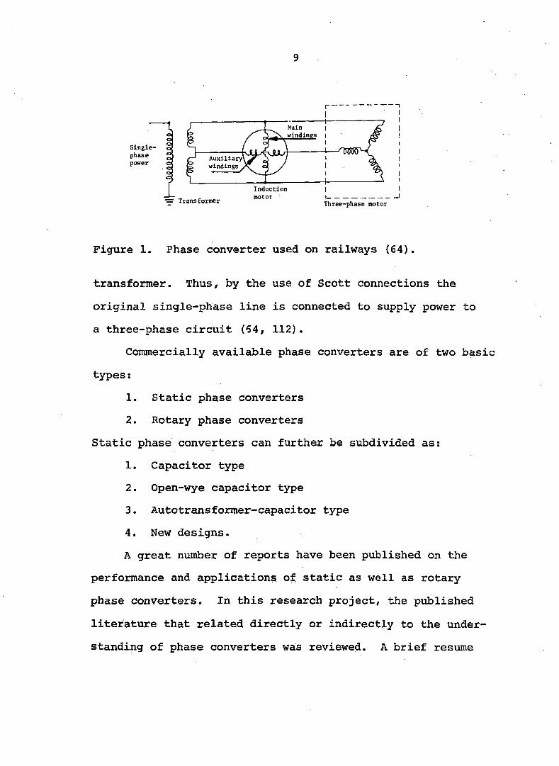
Originally phase converters (rotary type) were used to
electrify railways where locomotives equipped with three-
phase motors received power from a single-phase source. An
early phase converter used on railways, shown in Figure 1,
was designed and operated upon the principle that a single-
phase induction motor develops a rotating magnetic field
(64). If the motor were to run at synchronous speed, the
magnetic field would not only rotate uniformly at synchronous
speed, but its magnitude would also remain constant. There
fore, if the stator of a single-phase induction motor is
designed with an auxiliary winding placed in slots, symmet
rically spaced midway between the slots of the main winding,
the auxiliary winding will become the source of an induced
voltage. This voltage is in time quadrature with the
supply voltage.
As illustrated in Figur- 1, the main stator of the
induction motor was supplied from a step-down transformer
which reduced the voltage to a value suitable for the motor.
The auxiliary winding was designed to develop a voltage
equal to 86.6 per cent of the secondary voltage of the
9
I
Single- 2
phase g
power o
I o o G
o o t
Auxiliary'
windings .
Transformer
Induction
motor Three-phase motor
Figure 1. Phase converter used on railways (64)
transformer. Thus, by the use of Scott connections the
original single-phase line is connected to supply power to
a three-phase circuit (64, 112).
Commercially available phase converters are of two basic
types :
1. Static phase converters
2. Rotary phase converters
Static phase converters can further be subdivided as;
1. Capacitor type
2. Open-wye capacitor type
3. Autotransformer-capacitor type
4. New designs.
A great number of reports have been published on the
performance and applications of static as well as rotary
phase converters. In this research project, the published
literature that related directly or indirectly to the under
standing of phase converters was reviewed. A brief resume
10
is presented of a few pertinent articles on the various types
of phase converters.
Static Phase Converters
Static phase converters, as the name implies, have no
moving parts other than switching relays which operate during
the starting of the three-phase motor.
Capacitor type
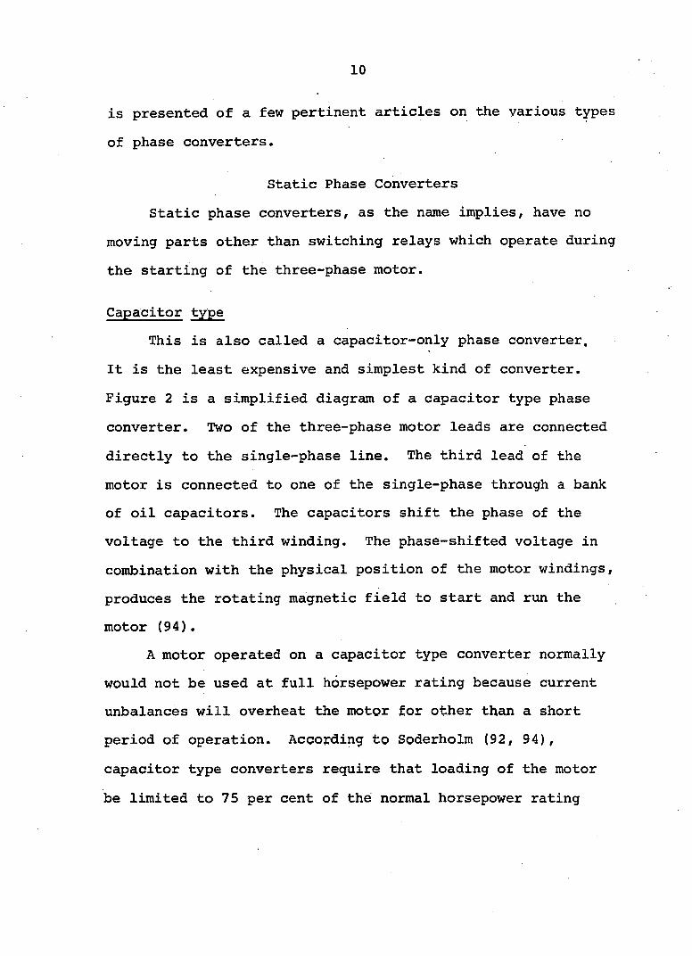
This is also called a capacitor-only phase converter.
It is the least expensive and simplest kind of converter.
Figure 2 is a simplified diagram of a capacitor type phase
converter. Two of the three-phase motor leads are connected
directly to the single-phase line. The third lead of the
motor is connected to one of the single-phase through a bank
of oil capacitors. The capacitors shift the phase of the
voltage to the third winding. The phase-shifted voltage in
combination with the physical position of the motor windings,
produces the rotating magnetic field to start and run the
motor (94).
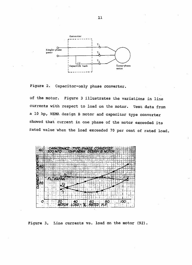
A motor operated on a capacitor type converter normally
would not be used at full horsepower rating because current
unbalances will overheat the motor for other than a short
period of operation. According to Soderholm (92, 94),
capacitor type converters require that loading of the motor
be limited to 75 per cent of the normal horsepower rating
11
Converter
Single-phase
power
Three-phase
motor
bank Capaci
I
J I 1_
Figure 2. Capacitor-only phase converter.
of the motor. Figure 3 illustrates the variations in line
currents with respect to load on the motor. Test data from
a 10 hp, NEMA design B motor and capacitor type converter
showed that current in one phase of the motor exceeded its
rated value when the load exceeded 70 per cent of rated load.
m
Figure 3. Line currents vs. load on the motor (92).
12
Satisfactory operation of a capacitor-only converter is
limited to low starting torque and constant loads. Ager (1),
in studying the use of auxiliary impedances in the single-
phase operation of polyphase induction machines, concluded
that no appropriate value of impedance can be found that will
give polyphase performance for more than a single load. He
stated several benefits of using capacitors, but, according
to him, these capacitors do not make single-phase performance
of the motor equivalent to the polyphase through out the
range of normal operation.
Bakes (6) found that a capacitor type phase converter
operated motor could not be loaded beyond the motor rating
without causing severe motor unbalance, excessive vibration,
noise and overheating. He also found that the starting
torque of a converter operated motor is 70% less than that
of a single-phase repulsion induction motor of the same
horsepower rating. Like many research reports, Bake's study
suggests that capacitor-only phase converter operated three-
phase motors are not suitable for loads that require high
starting torque, such as a high pressure compressor. These
converters, however, are being used satisfactorily to power
small ventilating fans, blowers, and power saws.
In 1953, Haberman (38) studied a capacitor type phase
converter operating a 5 hp, three-phase induction motor.
He concluded that the proper rating of a three-phase motor

13
with such a phase converter is not more than:
1. Sixty per cent of the three-phase rating if the
standard per cent locked rotor torque and break
down torque are required.
2. Sixty to seventy per cent of the three-phase
rating if no more than a ten per cent higher
temperature rise is to be tolerated.
He suggested that for the highest obtainable locked rotor
and running torques, the capacitors should be sized at 200
pF for starting and 26.5 yF for running per motor horsepower.
Hogan (44) from his theoretical analysis of capacitor
type converters found that a three-phase motor operated from
this type of converter can be balanced only if the power
factor of the motor is held at 50 per cent.
According to Brown et al. (14, 15, 17), a perfect
balance of a three-phase induction motor operating from a
capacitor type converter can be realized only when the
negative sequence component of the motor voltage is zero.
This is possible only when the phase angle of the machine is
less than 30^. Thus the power factor should not exceed
0.866 for an exactly balanced condition. When, as usually
happens, power factor is better than 0.866, the negative
sequence voltage is minimum but different than zero.
In comparison with straight single-phase steady state
operation of a three-phase motor, the addition of appropriate
14
balancing capacitors at the normal running speed results in
significant reduction in copper losses and a modest improve
ment in the torque.
Open-wye capacitor type
In 1957/ Henry Steelman was the first to obtain patent
rights on open-wye type capacitor converters (41). This
converter, like capacitor-only converters, does not convert
single-phase electrical service to three-phase, however, it
does make it possible to operate a three-phase induction
motor on single-phase service.
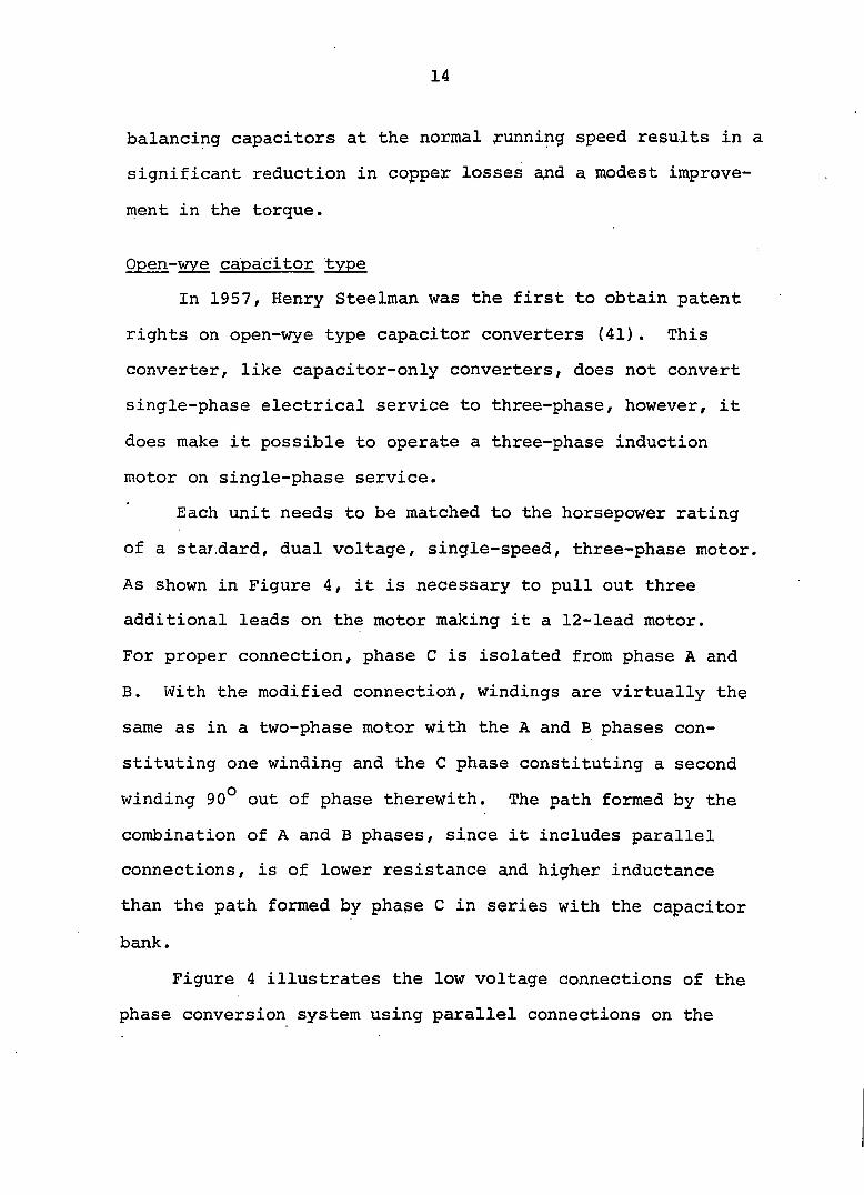
Each unit needs to be matched to the horsepower rating
of a standard, dual voltage, single-speed, three-phase motor
As shown in Figure 4, it is necessary to pull out three
additional leads on the motor making it a 12-lead motor.
For proper connection, phase C is isolated from phase A and
B. With the modified connection, windings are virtually the
same as in a two-phase motor with the A and B phases con
stituting one winding and the C phase constituting a second
winding 90° out of phase therewith. The path formed by the
combination of A and B phases, since it includes parallel
connections, is of lower resistance and higher inductance
than the path formed by phage C in series with the capacitor
bank.
Figure 4 illustrates the low voltage connections of the
phase conversion system using parallel connections on the
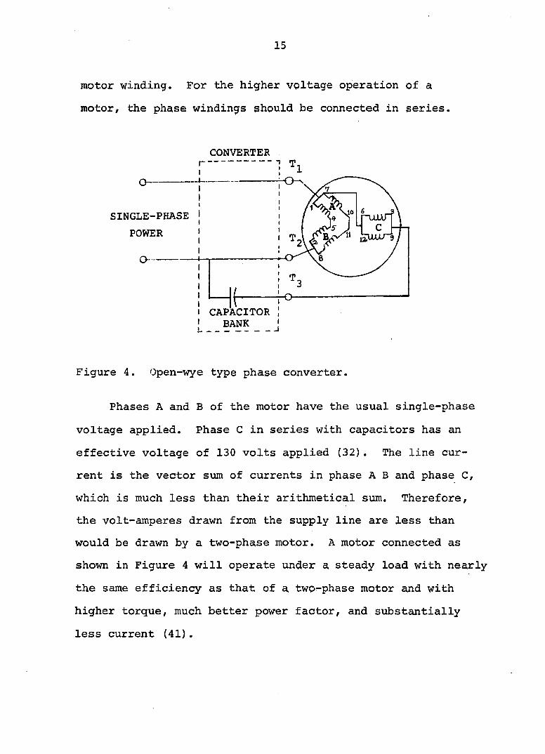
15
motor winding. For the higher voltage operation of a
motor, the phase windings should be connected in series.
CONVERTER .
SINGLE-PHASE
POWER
CAPACITOR BANK
_ J
Figure 4. Open-wye type phase converter.
Phases A and B of the motor have the usual single-phase
voltage applied. Phase C in series with capacitors has an
effective voltage of 130 volts applied (32). The line cur
rent is the vector sum of currents in phase A B and phase C,
which is much less than their arithmetical sum. Therefore,
the volt-amperes drawn from the supply line are less than
would be drawn by a two-phase motor. A motor connected as
shown in Figure 4 will operate under a steady load with nearly
the same efficiency as that of a two-phase motor and with
higher torque, much better power factor, and substantially
less current (41).
16
The KVAR of a capacitor on 60 power supply can be
expressed by the following relationship ;
KVAR = 0.377 (KV)2 C (1)
where KV is voltage drop across the capacitor and C is
capacitance in microfarads. From Equation 1, the effective
KVAR of a fixed capacitor is increased when the voltage drop
across its terminal increases. According to Elliot and
Elliot (31), the compensation effect of the capacitors in the
circuit allows a fixed quantity of capacitance to be used
and eliminates the "phase balancing" common to other types
of static phase converters.
To gain more starting torque from the motor, electro
lytic capacitors should be connected across the oil capacitor
bank. These additional capacitors must be removed from the
circuit when the motor reaches its rated speed. This can be
accomplished by a N.C. time delay relay or a voltage sensing
relay.
A few examples of the successful applications of open-
wye type capacitor converters given in (32) are irrigation
pumps, oil wells, centrifugal pumps, compressors, hydraulic
pumps, hammer mills, feed mixers, grain dryers, punch
presses and a 100 hp rock crushing mill.
This type of phase converter is not recommended for over
loaded motors and for rapidly and widely fluctuating load
applications.
17
Autotransformer-capacitor type
The autotransformer-capacitor phase converter is an
improvement over the capacitor-only type converter. This
type of converter is of the same basic design as the capac
itor type converter. The major difference is the addition
of an autotransformer that allows the operation of a motor
at full horsepower output (94).
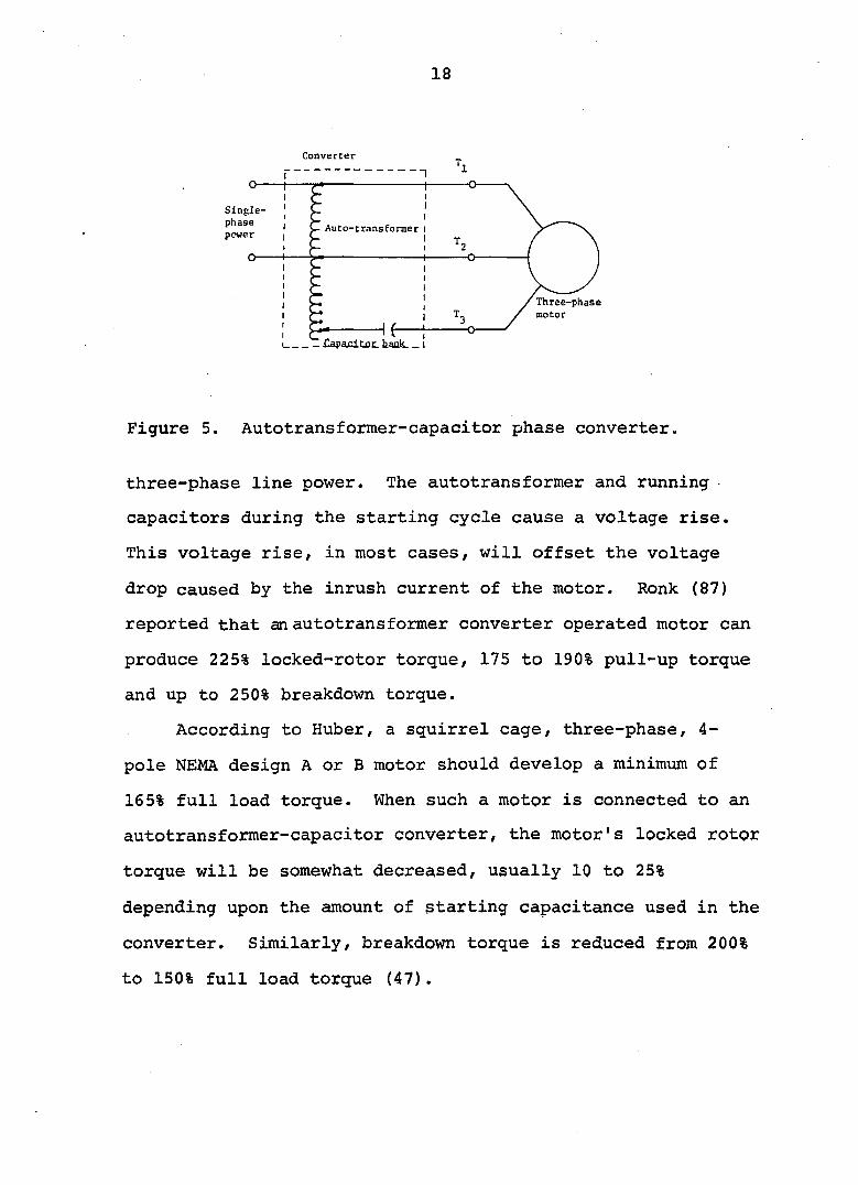
A simplified diagram of an autotransformer-capacitor
converter is shown in Figure 5. Hogan (44) referred to the
autotransformer converter as an "add-a-phase" converter.
According to him, this type of converter adds a phase to the
already present single-phase. Through the combination of
transformer, capacitor and impedance of the motor, a third
phase is introduced whose relation to the other two phases
comprises symmetrical three-phase power (86) .
Autotransformer-capacitor converters have been used to
operate 1 to 100 horsepower three-phase motors. In any
case it is not recommended that an autotransformer-capacitor
type converter be used to operate a motor larger than the
rating of the converter (86).
According to Ronk (87), the autotransformer-capacitor
converter has overcome all of the shortcomings of the capac
itor-only and open-wye type converters. A three-phase motor
with this converter can be made to produce about the same
locked-rotor and pull-up torque as the three-phase motor on
18
Converter T.
Auto-transformer
Three-phase
motor
1 O-
Single-
phase
power
O
Figure 5. Autotransformer-capacitor phase converter.
three-phase line power. The autotransformer and running
capacitors during the starting cycle cause a voltage rise.
This voltage rise, in most cases, will offset the voltage
drop caused by the inrush current of the motor. Ronk (87)
reported that an autotransformer converter operated motor can
produce 225% locked-rotor torque, 175 to 190% pull-up torque
and up to 250% breakdown torque.
According to Ruber, a squirrel cage, three-phase, 4-
pole NEMA design A or B motor should develop a minimum of
165% full load torque. When such a motor is connected to an
autotransformer-capacitor converter, the motor's locked rotor
torque will be somewhat decreased, usually 10 to 25%
depending upon the amount of starting capacitance used in the
converter. Similarly, breakdown torque is reduced from 200%
to 150% full load torque (47).
19
Huber also reported that for a three-phase motor
requiring a starting current of six times the running cur
rent, the use of a phase converter will reduce the starting
current to approximately three times the running current (47).
The starting current of a motor on an autotransformer-capac
itor phase converter ranges from 2.5 to 3 times the rated
full load current (86). The single-phase starting amperes
on the 230-volt line are found to be approximately 12 ampere
per horsepower. Hogan (45) found that starting KVA of an
autotransformer converter is much less than that of a single-
phase motor on a single-phase line or a three-phase motor on
a balanced three-phase power source.
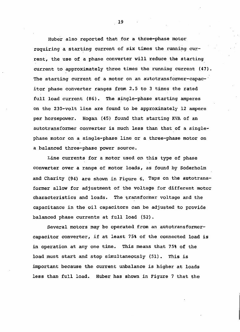
Line currents for a motor used on this type of phase
converter over a range of motor loads, as found by Soderholm
and Charity (94) are shown in Figure 6. Taps on the autotrans-
former allow for adjustment of the voltage for different motor
characteristics and loads. The transformer voltage and the
capacitance in the oil capacitors can be adjusted to provide
balanced phase currents at full load (52).
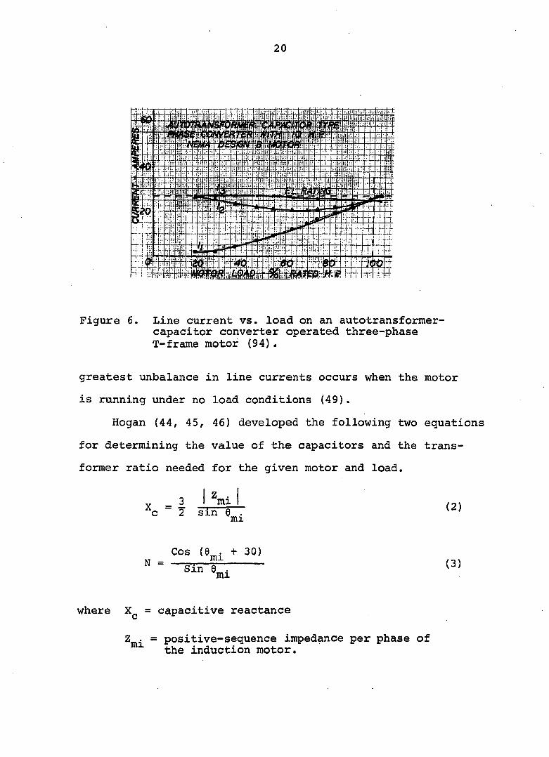
Several motors may be operated from an autotransformer-
capacitor converter, if at least 75% of the connected load is
in operation at any one time. This means that 75% of the
load must start and stop simultaneously (51). This is
important because the current unbalance is higher at loads
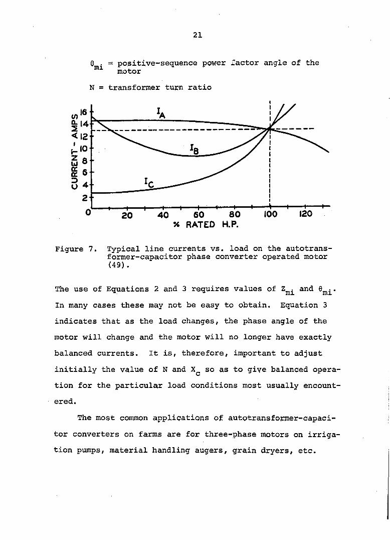
less than full load. Huber has shown in Figure 7 that the
20
Figure 6. Line current vs. load on an autotransformer-capacitor converter operated three-phase T-frame motor (94) .
greatest unbalance in line currents occurs when the motor
is running under no load conditions (49).
Hogan (44, 45, 46) developed the following two equations
for determining the value of the capacitors and the trans
former ratio needed for the given motor and load.
^c = l ÏÏ11
Cos (0„. + 30)
where = capacitive reactance
Z . = positive-sequence impedance per phase of the induction motor.
21
0 . = positive-sequence power factor angle of the motor
N - transformer tu^n ratio
G 8 • g 6-D . O 4 -
2 "
120 100 60 80 % RATED H.P.
40 20
Figure 7. Typical line currents vs. load on the autotrans-former-capacitor phase converter operated motor (49).
The use of Equations 2 and 3 requires values of and 9^^ .
In many cases these may not be easy to obtain. Equation 3
indicates that as the load changes, the phase angle of the
motor will change and the motor will no longer have exactly
balanced currents. It is, therefore, important to adjust
initially the value of N and so as to give balanced opera
tion for the particular load conditions most usually encount
ered.
The most common applications of autotransformer-capaci-
tor converters on farms are for three-phase motors on irriga
tion pumps, material handling augers, grain dryers, etc.
22
This type of converter is also being used for air condi
tioners and oil well pumps. Power consumption of a 25 hp
motor and autotransformer-capacitor phase converter in
filling a 20* x 60* silo with corn silage was found to be
approximately 1.5 KWhr per ton (13). Harisha (39) reported
a successful application of a 75 hp, 480-volt motor and an
autotransformer-capacitor converter on an irrigation pump.
Single-phase inrush current was 340 amperes and full load
current was 150 amperes. Running currents for the 75 hp
three-phase motor were 88/ 88, and 95 ampere.
Parvis (77) and Price (81) , in a survey of farm loads,
found numerous installations where autotransformer-capacitor
type phase converters have been in regular use. The majority
of the operators were reported to be fairly satisfied by the
performance of the units. They found that in many applica
tions, the size of the heater coil in the magnetic motor
starter had to be increased.
Brooks (11) reported a multi-motor application of
an autotransformer-capacitor converter. The converter rated
at 30 hp was being used for a 20 hp blower motor and a 10 hp
elevator motor at a city incinerator. The equipment had been
in service for five years and was used 50 hours per week.
Manufacturer's literature and the findings of several
studies do not recommend the use of autotransformer-capacitor
converters for multispeed and variable speed motor applica
tions (11, 28, 39, 86).
23
New designs
There have been continuous efforts by manufacturers and
researchers to improve the design of static phase converters
so that they can provide a balanced output voltage for a
wider range of loads. A variety of proposals have been made
for phase converter systems that are different in basic
design from conventional systems. A few of these are
described briefly in this section.
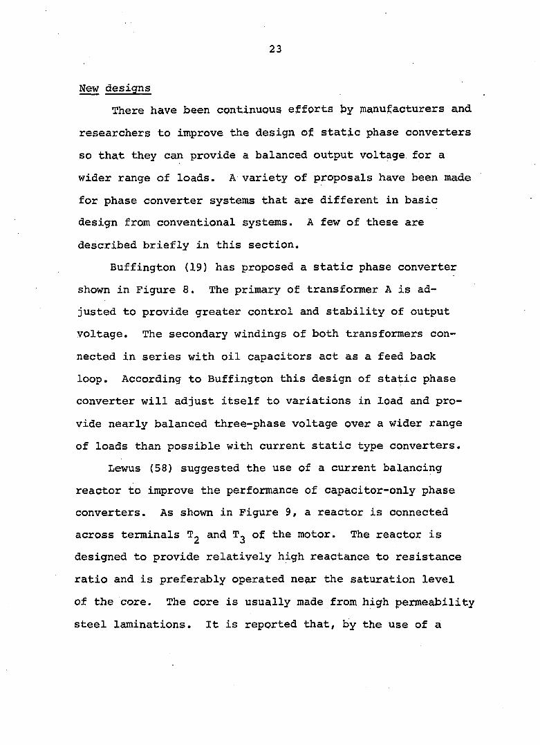
Buffington (19) has proposed a static phase converter
shown in Figure 8. The primary of transformer A is ad
justed to provide greater control and stability of output
voltage. The secondary windings of both transformers con
nected in series with oil capacitors act as a feed back
loop. According to Buffington this design of static phase
converter will adjust itself to variations in load and pro
vide nearly balanced three-phase voltage over a wider range
of loads than possible with current static type converters.
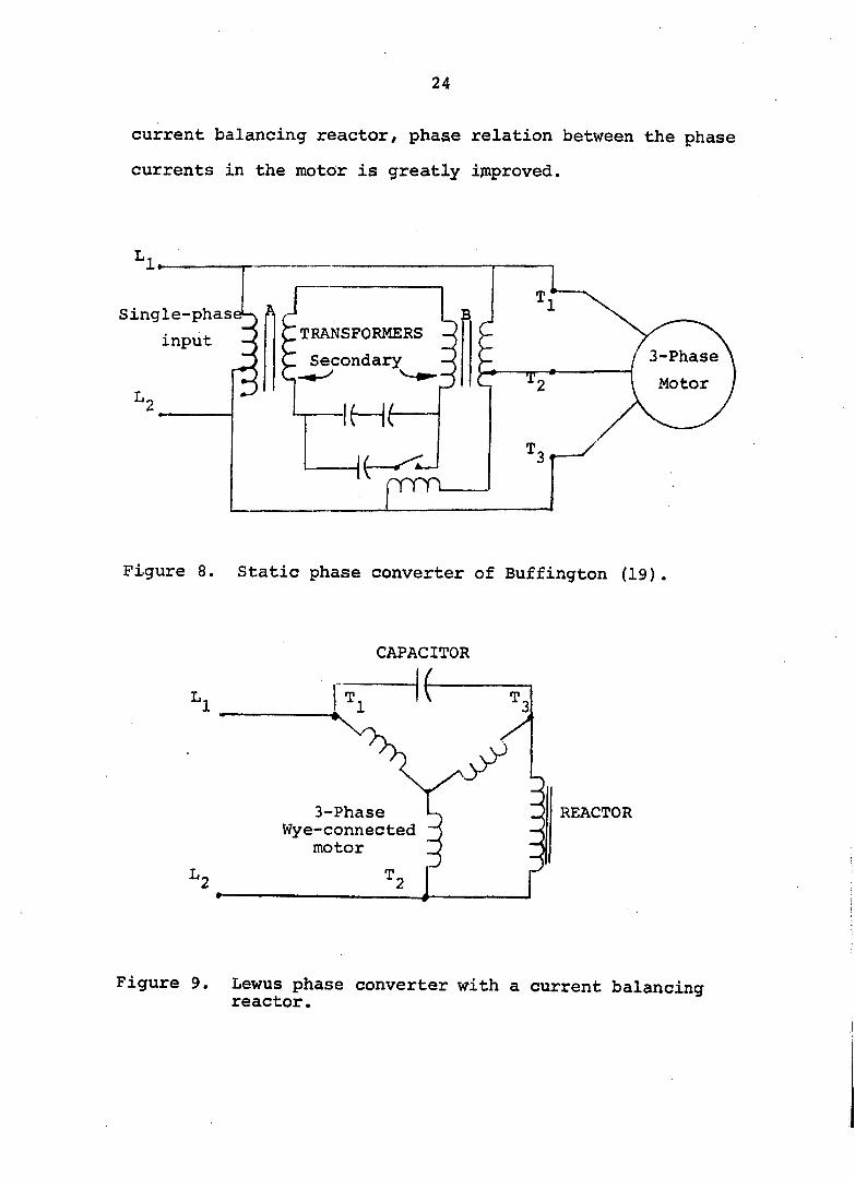
Lewus (58) suggested the use of a current balancing
reactor to improve the performance of capacitor-only phase
converters. As shown in Figure 9, a reactor is connected
across terminals T^ and T^ of the motor. The reactor is
designed to provide relatively high reactance to resistance
ratio and is preferably operated near the saturation level
of the core. The core is usually made from high permeability
steel laminations. It is reported that, by the use of a
24
current balancing reactor, phase relation between the phase
currents in the motor is greatly improved.
Single-phas
input TRANSFORMERS
Secondary 3-Phase
Motor
prm
Figure 8. Static phase converter of Buffington (19).
CAPACITOR
L 1
3-Phase Wye-connected
motor
REACTOR
L 2
Figure 9. Lewus phase converter with a current balancing reactor.
25
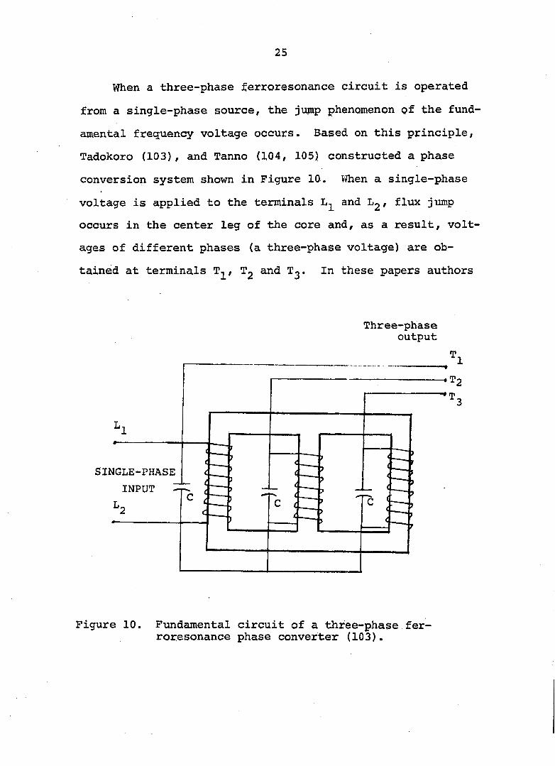
When a three-phase ferroresonance circuit is operated
from a single-phase source, the jump phenomenon of the fund
amental frequency voltage occurs. Based on this principle,
Tadokoro (103), and Tanno (104, 105) constructed a phase
conversion system shown in Figure 10. VThen a single-phase
voltage is applied to the terminals and Lg f flux jump
occurs in the center leg of the core and, as a result, volt
ages of different phases (a three-phase voltage) are ob
tained at terminals Tg and T^. In these papers authors
Three-phase output
SINGLE-PHASE
INPUT
Figure 10. Fundamental circuit of a three-phase ferroresonance phase converter (103).
26
have described in great detail the theoretical analysis of
the circuit used in the device. No experimental data was
reported and the device has not been tested to supply power
to three-phase motors (103, 104, 105).
Bessho (9, 10) constructed a 5 KVA static phase con
verter using a ferroresonance silicon iron core. The core
consisted of a leakage-flux path between the input and out
put windings. The device was made of two parallel fer
roresonance circuits connected in series. He found that
this type of phase converter performed effectively as a
voltage regulator, however, its application to supply three-
phase power to motor loads was not satisfactory.
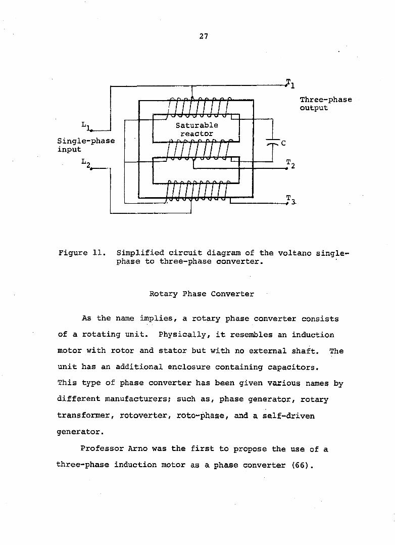
Hisano et al. (43) modified the circuit proposed by
Bessho and called it a voltano converter. A simplified
wiring diagram is shown in Figure 11. The voltano converter
consists of a three-phase saturable reactor with windings
wound on a 3-legged core. A capacitor C acts as a fer-
roresonant capacitance.
Hisano et al. (43) studied the effects of variation in
load, source voltage, power factor, and various core material
on the three-phase output voltage. A graph of output voltage
at various loads was presented in the report. Hisano con
cluded that a voltano converter W9,s approximately 90% effi
cient and can supply fairly well-balanced three-phase output.
27
Single-phase input
mm
mm
Three-phase output
Figure 11. Simplified circuit diagram of the voltano single-phase to three-phase converter.
Rotary Phase Converter
As the name implies, a rotary phase converter consists
of a rotating unit. Physically, it resembles an induction
motor with rotor and stator but with no external shaft. The
unit has an additional enclosure containing capacitors.
This type of phase converter has been given various names by
different manufacturers; such as, phase generator, rotary
transformer, rotoverter, roto-phase, and a self-driven
generator.
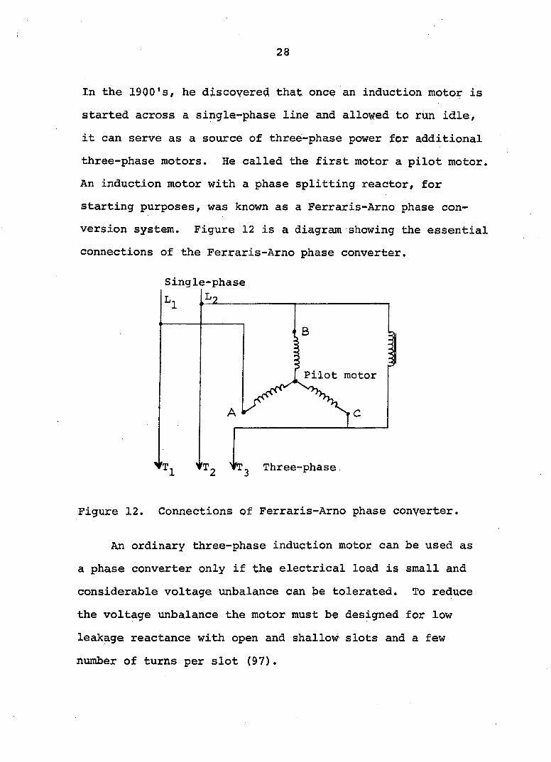
Professor Arno was the first to propose the use of a
three-phase induction motor as a phase converter (66).
28
In the 1900's, he discovered that once an induction motor is
started across a single-phase line and allowed to run idle,
it can serve as a source of three-phase power for additional
three-phase motors. He called the first motor a pilot motor.
An induction motor with a phase splitting reactor, for
starting purposes, was known as a Ferraris-Arno phase con
version system. Figure 12 is a diagram showing the essential
connections of the Ferraris-Arno phase converter.
Single-phase
Pilot motor
•T^ vT. Three-phase
Figure 12. Connections of Ferraris-Arno phase converter.
An ordinary three-phase induction motor can be used as
a phase converter only if the electrical load is small and
considerable voltage unbalance can be tolerated. To reduce
the voltage unbalance the motor must be designed for low
leakage reactance with open and shallow slots and a few
number of turns per slot (97).

29
Figure 13 shows a simplified diagram of the rotary con
verter. Two of the three rotary converter terminals are
connected directly to the single-phase power lines. The
third terminal of the rotary converter is connected to one of
the single-phase lines through capacitors. The capacitors
provide the rotating magnetic field to start the converter.
The generating action of the rotary converter, in combination
with the phase shift of the capacitor, produces the third
phase voltage to operate a three-phase motor (22).
Converter
Single-
phase
power
Three-phase
motor
I Capacitor bank ,
Figure 13. Rotary phase converter.
According to Cotanch (4) a "rotary converter" is not a
converter at all. More accurately it is a "phase generator".
One phase is generated by the rotary unit and oil capacitors
and the other two phases are supplied from the single-phase
source. The rotary converter also receives energy from the
same source. With the rotary unit energized, three distinct
30
phases and voltages are produced at the terminals. Hence,
any three-phase load within the rating of the stator winding
of the motor can be handled whether it is inductive or
resistive or any combination (4).
For the operation of several motors from one converter,
the rotary converter is usually the best choice. One motor,
or any combination of motors may be operated, provided the
total horsepower load, or amperage drawn is no larger than
the continuous load rating of the converter. Also, one motor
or any combination of motors may be started at the same time
as long as the sum of the total horsepower of the motors
starting does not exceed the rated starting horsepower of
the rotary converter (4).
To place a rotary converter in operation all three-phase
motors must be disconnected. When the rotary converter is
started and full speed has been obtained the various three-
phase motors are then connected as required. Each of the
motors operated on the rotary converter has a separate
capacitor panel. On starting a motor, its capacitor panel
should be connected across the same phases as the main capac
itor bank in the basic unit (47).
In many cases, the largest motor to be operated is the
main factor in determining the size of the rotary converter
and main capacitor bank. If the largest motor is driving a
high starting torque load a rotary converter larger than
normal size should be selected (4).
31
The starting current of a rotary converter may be as
large or larger than the current drawn when the largest
permitted size three-phase motor is started on the converter
(22). Inrush current of a converter is, however, usually
less than that of a three-phase motor of the same size
starting on three-phase line power or a single-phase motor
starting on a single-phase source. Single-phase inrush cur
rent of a 20 hp converter is about the same as that of a 7.5
hp single-phase motor (4).
Even with a carefully matched motor and rotary con
verter, currents are always somewhat unbalanced, because of
the variations in their internal parameters, resistance,
reactance, and core losses. The unbalance of currents is
rapidly magnified when the motor is overloaded. Soderholm
(92), from a study of various brands of phase converters,
found that performance characteristics of rotary phase con
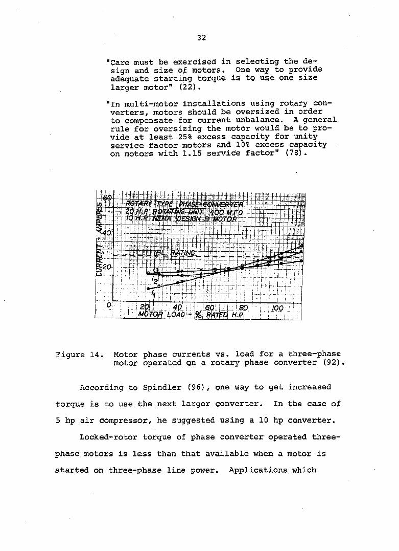
verters vary widely depending upon the design. Figure 14
shows the phase current variations in a motor operated on a
rotary phase converter over a range of motor loads (94).
To avoid the possibilities of excessive unbalance in
motor currents, several technical reports have recommended
that motors should be oversized. Following are a few
examples :
"Motors must have horsepower ratings greater than or equal to their actual loads, over-sizing of motors is desirable" (24).
32
"Care must be exercised in selecting the design and size of motors. One way to provide adequate starting torque is to use one size larger motor" (22).
"In multi-motor installations using rotary converters, motors should be oversized in order to compensate for current unbalance. A general rule for oversizing the motor would be to provide at least 25% excess capacity for unity service factor motors and 10% excess capacity on motors with 1.15 service factor" (78).
Figure 14. Motor phase currents vs. load for a three-phase motor operated on a rotary phase converter (92).
According to Spindler (96), one way to get increased
torque is to use the next larger converter. In the case of
5 hp air compressor, he suggested using a 10 hp converter.
Locked-rotor torque of phase converter operated three-
phase motors is less than that available when a motor is
started on three-phase line power. Applications which

33
require a high starting torque are not recommended for use
with a rotary phase converter. The maximum motor starting
torque required should be limited to approximately 100 to
150% of full load torque (24).
Charity and Soderholm (23) found that when one motor is
fully loaded and running, the starting torque of a second
motor is improved slightly. Locked rotor torque limitations
can be increased somewhat for a specific motor by having
other motors started but idling on the line before the higher
locked rotor torque motor is started (24), According to
Huber (47), as subsequent motors are started the starting
torque will be increased since each motor in effect serves
as a generator once the motor has acquired its full speed.
Maggs et al. (67) have made similar observations. They have
reported that the pilot motor (phase converter) as well as
all additional motors running at any instant in combination
act as phase converters. Voltage stability, as distinct from
voltage balance, of the three-phase output increases with the
number of motors running.
Rotary phase converters under idle conditions will run
considerably hotter than under load conditions. This is due
to the greater "no load" unbalance in voltage and, therefore,
large circulating currents. Under load, the voltages become
more balanced and circulating currents and heating are
reduced. Charity and Soderholm (23) have reported that the
temperature rise in a wye wound motor operating from a
34
converter with a horsepower rating equal to that of the
motor is about the same as would be experienced for the
motor operating on three-phase line power.
The power loss in rotary converters is higher than that
in static converters. Patterson and Carroll (78) found that
a 10 hp rotary converter had losses of 1.5 KW while the con
verter was running whether loaded or not. A 15 hp rotary
converter is reported to have a constant demand of 2.7 KW
regardless of motor load (24) . According to Charity et al.
(22), losses in an idling converter are higher than a
loaded converter. They found that a.20 hp continuous rating
converter required 1.72 KW input power to operate unloaded
and 1.0 KW when loaded. Huber (51) found that leaving the
rotary converter energized is not practical since the power
loss in the converter is greatest when the load is not in
operation.
Applications of rotary phase converters include motors
driving augers, bucket elevators, silo unloaders, hoists,
fans, blowers, grain dryers, center pivot irrigation systems
compressors, machine tools, corn shellers, and saw mills (12
26, 29f 37, 78, 81). Reports show that rotary phase con
verters have been successfully used on applications like
computers, radio stations, rectifiers, SCR drives, electro
magnets, grape presses, and resistance welders (4, 24) .
These loads are not adaptable to any type of static phase
converter.
35
Rotary phase converters are also suitable for multi-
speed motors. Either wye or delta connected motors can be
operated from rotary phase converters (4, 88).
Photographs of some of the commercially available phase
converters are shown in Appendix B. Figures 77 through 80
are for capacitor-only phase converters. Figures 81 throgh
85 illustrate autotransformer-capacitor and rotary phase con
verters.
36
OBJECTIVES
A review of research literature revealed that phase
converters have been in use for several decades. The re
search papers published dealt with theoretical approaches
made to develop analytical equations to predict the perfor
mance of phase converter operated three-phase motors. In
most cases, these equations are in terms of the motor's
internal parameters and are of little practical use in
adjusting a converter for balanced currents in a motor to
run a given load. These equations are also very complicated
and require a lengthy computational procedure.
Most of the single-phase rural loads today experience
a wide variation of voltage because of the power line char
acteristics. There is a limited amount of information
available on the effects of line voltage variation on phase
converter performance.
To develop design equations for phase converters that
are simple and practicable and to provide needed information
on phase converter applications, the objectives of the
study are;
1. To develop analytical equations to determine the
value of capacitance bank and the transformer turns-
ratio of autotransformer-capacitor type phase con
verter for balanced currents of a three-phase motor
for a given load. The accuracy of the analytical
37
equations will be verified with experimental
data.
To optimize the size of capacitors and autotrans-
former turns-ratio for the best results with
varying motor loads.
To determine the effects of variations in single-
phase line voltage on the performance of three-
phase motors operating on an autotransformer-
capacitor and rotary phase converters.
To determine the current values and winding
temperature rise in three-phase U-frame and T-
frame motors with unbalanced three-phase voltages
at the terminals of the motors.
To study the performance characteristics of three-
phase motors operating from an open-wye type phase
converter.
To determine the optimum value of starting capaci
tance for the maximum locked rotor torque of motors
operated from an autotransformer capacitor type
phase converter.
To develop a design procedure for power service
for phase converters and associated three-phase
motors and to verify the theoretical equation for
determining phase converter ampere load by experi
mental data.
38
MEASUREMENTS AND PROCEDURES
• The research lab was equipped with single-phase and
three-phase power supplies. The wiring circuits needed for
the testing of motors were added to the load side of the
main disconnects.
Instruments were required for the following three types
of measurements:
1. Electrical measurements for voltage, current, power,
and power factor.
2. Torque measurements for locked rotor torque and
the dynamic torque-speed curves of the test motor.
3. Temperature measurements for estimates of the hot-
spot temperature in the windings of the motors.
Electrical
The voltage regulation circuits for single-phase and
three-phase power are shown in Figure 15. A variac was con
nected across the line to line voltage. The voltage at the
adjustable tap of the variac fed the primary of a low turns-
ratio transformer. The secondary winding of the transformer,
a source of voltage, was connected in series with the line
voltage. By reversing the polapity on the primary winding,
transformers were used to buck or boost the line voltage.
The magnitude of the secondary voltage was varied by adjust
ing the tap on the variac.

39
p 1-0 IN VAfHAC^ UUUUL Î 1-0 OUT
i - 0 I N
"UUUULT TRA\SFORMER
jnnnn p
VAfUAC : p
uuuuu TRANSFORMER
jrgn. 5-0 OUT
Figure 15. Regulation of line voltage with variacs and transformers.
For the tests conducted in this study both source volt
ages, single-phase and three-phase,were not required to be
regulated simultaneously. Two variacs and two transformers
were used for the regulation of three-phase line voltage.
When three-phase power was not needed, one of the two variacs
and transformers were disconnected from the three-phase line
and were used to supply regulated single-phase voltage for
the phase converter. To eliminate rewiring of the variac and
transformer from three-phase to single-phase and vice versa,
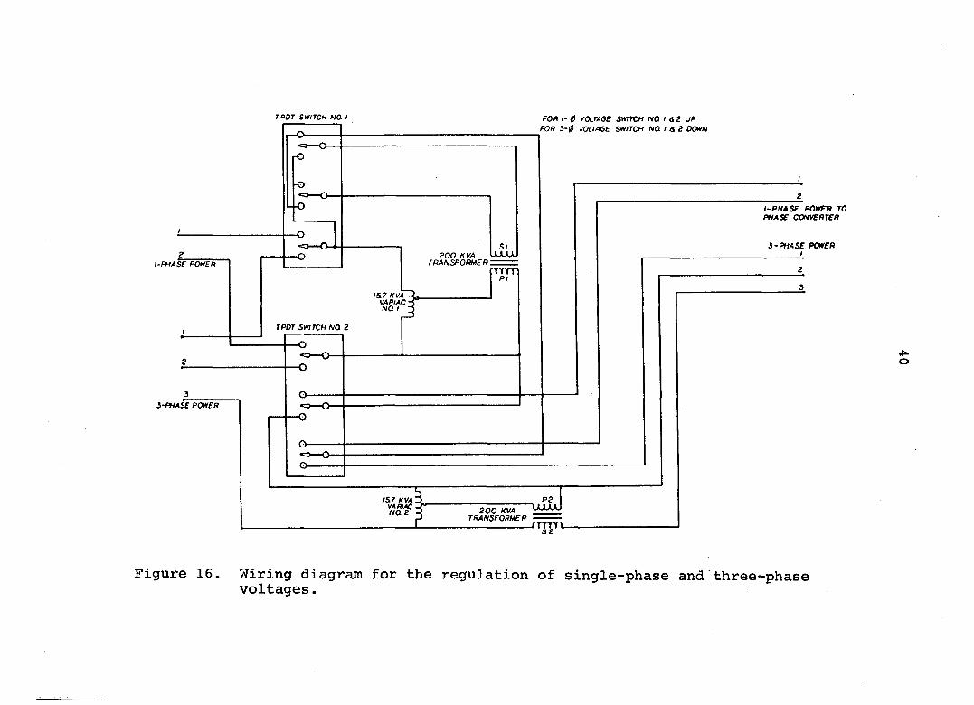
two TPDT switches were used. The circuit arrangement used
for three-phase and single-phase power is shown in Figure 16.
TOOT SUITCH NOl I
I5l7 KVA VAHIAC NQ
TPDT SWITCH /va 2
i-PHAse PonEn
5-PHASE PWFfl
FOR /- 0 VOLTAGE SWITCH NQ I <i 2 UP FOR 3-ff JQLTAGE SWITCH NO I A S Down
S I zoo KVA Luxl
TRANSFORMER :
o-
I-PHASE POWER TO PHASE CONVERTER
3-PHASE POWER
IS.7 KVA . VARIAC . WQ2 • P2
200 KVA TRANSFORMER
•u o
Figure 16. Wiring diagram for the regulation of single-phase and three-phase voltages.
41
Regulated single-phase voltage was provided when switches 1
and 2 were in the "UP" position. VVhen switches 1 and 2
were in the "DOWN" position, the single-phase line was dis
connected and the circuit was changed to regulated three-
phase voltages for three-phase testing of the motors.
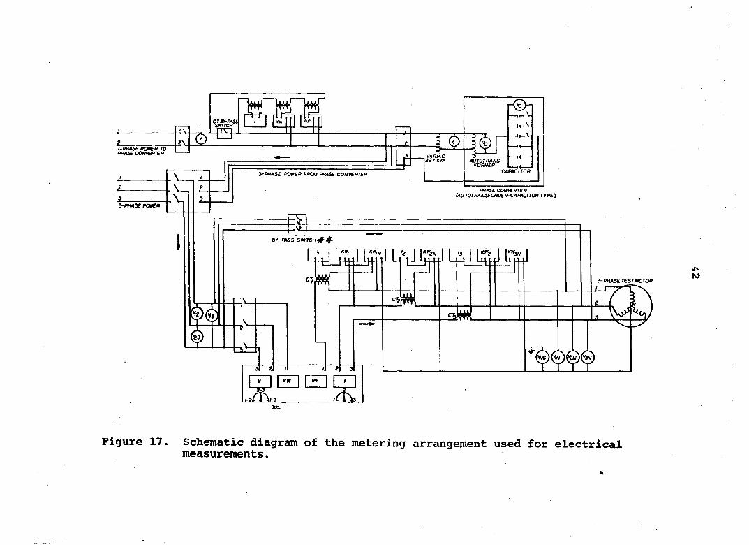
A schematic diagram of the metering arrangement is
shown in Figure 17. The instruments are voltmeters, ammeters,
wattmeters, and power factor meters. Description of meters,
motors, and phase converters is given in Appendix A. Current
transformers were used to measure the line currents of the
motor. A bypass switch, 4, protected the ammeters and watt
meters from being damaged by the high inrush currents at
motor starting. A TPDT switch allowed the use of the same
meters, without any rewiring, for measurements in tests on
three-phase line power and on three-phase power supply from
the phase converters. Pictorial views of the dynamometer
and metering arrangement are shown in Figures 18 and 19.
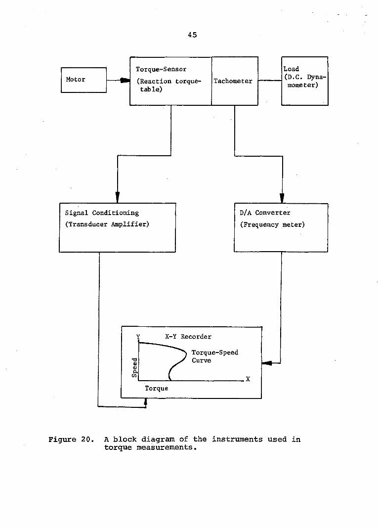
Torque
A block diagram of the instruments used in measuring
locked rotor torque and for plotting dynamic torque-speed
curves of motors is shown in Figure 20. The major components
are a strain guage reaction torque table, a signal condi
tioning unit (transducer amplifier), a digital to analog con^
verter (frequency meter), an X-Y recorder, and a D.C.
dynamometer.
i-oHAse PCtfCff TO OHAX COMERTER AUTOTRANS-rOPVfff
3'OHASE PO0ER PROU PHASE CONVERTER
PHASE CONVERTER Ç^UTOTRANSEORUER-CAFiACtTOR TfPE)
3-PHASe POMTA
Br-*HSS SWITCH# 4'
CT. i-PHASe TESrtéOTOR
Tut
Figure 17. Schematic diagram of the metering arrangement used for electrical measurements.
43
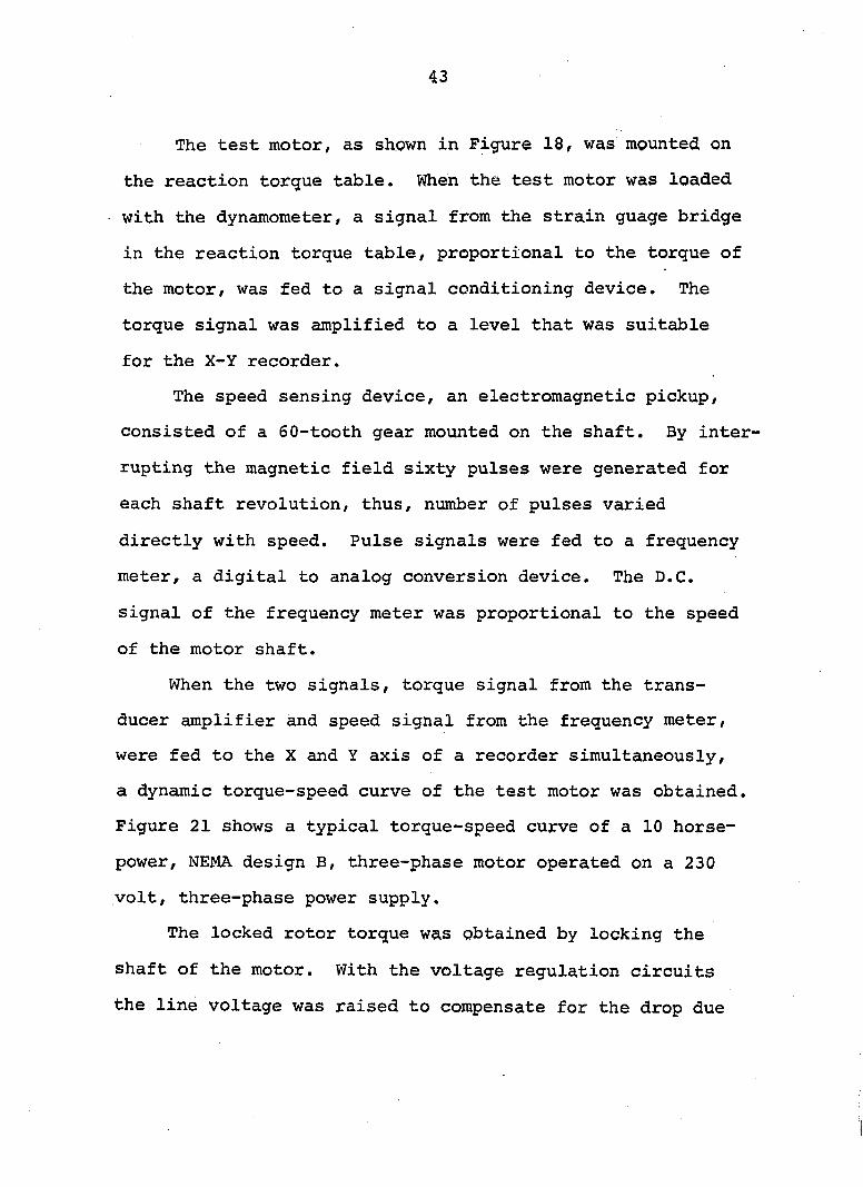
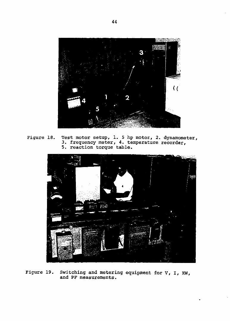
The test motor, as shown in Figure 18, was mounted on
the reaction torque table. When the test motor was loaded
with the dynamometer, a signal from the strain guage bridge
in the reaction torque table, proportional to the torque of
the motor, was fed to a signal conditioning device. The
torque signal was amplified to a level that was suitable
for the X-Y recorder.
The speed sensing device, an electromagnetic pickup,
consisted of a 60-tooth gear mounted on the shaft. By inter
rupting the magnetic field sixty pulses were generated for
each shaft revolution, thus, number of pulses varied
directly with speed. Pulse signals were fed to a frequency
meter, a digital to analog conversion device. The D.C.
signal of the frequency meter was proportional to the speed
of the motor shaft.
When the two signals, torque signal from the trans
ducer amplifier and speed signal from the frequency meter,
were fed to the X and Y axis of a recorder simultaneously,
a dynamic torque-speed curve of the test motor was obtained.
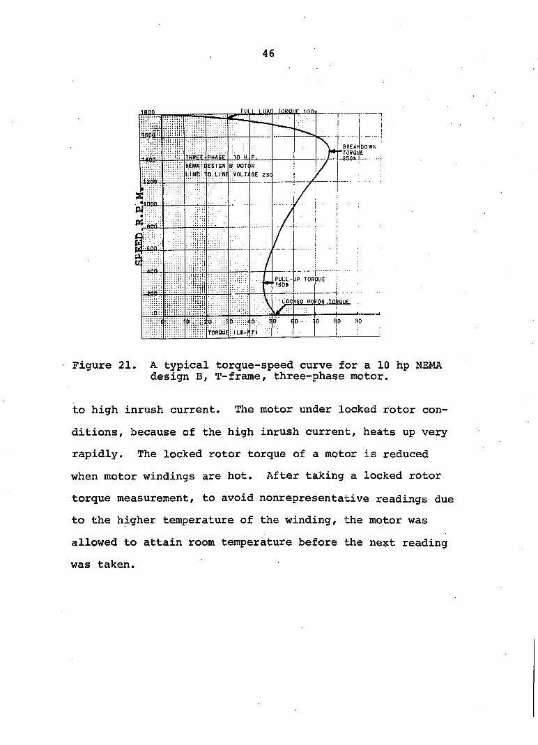
Figure 21 shows a typical torque-speed curve of a 10 horse
power, NEMA design B, three-phase motor operated on a 230
volt, three-phase power supply.
The locked rotor torque was obtained by locking the
shaft of the motor. With the voltage regulation circuits
the line voltage was raised to compensate for the drop due
44
Figure 18. Test motor setup, 1. 5 hp motor, 2. dynamometer, 3. frequency meter, 4. temperature recorder, 5. reaction torque table.
Figure 19. Switching and metering equipment for V, I, KW, and PF measurements.
45
Motor
Torque-Sensor Load
(Reaction torque-table)
Tachometer (D.C. Dyna
(Reaction torque-table)
Tachometer mometer)
y Signal Conditioning
(Transducer Amplifier)
V D/A Converter
(Frequency meter)
Torque-Speed Curve
Torque
Figure 20. A block diagram of the instruments used in torque measurements.
46
Fin i nun r.iBQiiF inn.
DOWN
THREE
U.
PULL - IP TOR HIE I 'ISO* ;
:• !iiOe(EO RQ-OR TokouF :
400.
;o
Figure 21. A typical torque-speed curve for a 10 hp NEMA design B, T-frame, three-phase motor.
to high inrush current. The motor under locked rotor con
ditions, because of the high inrush current, heats up very
rapidly. The locked rotor torque of a motor is reduced
when motor windings are hot. After taking a locked rotor
torque measurement, to avoid nonrepresentative readings due
to the higher temperature of the winding, the motor was
allowed to attain room temperature before the ne%t reading
was taken.
47
Temperature
A thermo-conductive body, developing heat at a con
stant rate, will have a maximum temperature rise directly
proportional to the heat developed in unit time and inversely
proportional to the dissipation per degree rise per second.
In an induction motor, from a cold start to the final steady
state, the temperature rises exponentially with time.
An electric motor comprises several parts, each with a
characteristic surface area, mass, heat capacity, and thermal
conductivity. The temperature rise of different parts, or
even of various points within the same part, may be very
uneven. Therefore, it is necessary to make estimates of
hot-spot temperatures of motor windings.
Several methods have been suggested to measure the
temperature rise of electric motors (3, 33, 72, 106). Resis
tance and embedded thermocouple methods were applied to
estimate the hot-spot temperature of the motors tested for
this study. These two methods give different bases for
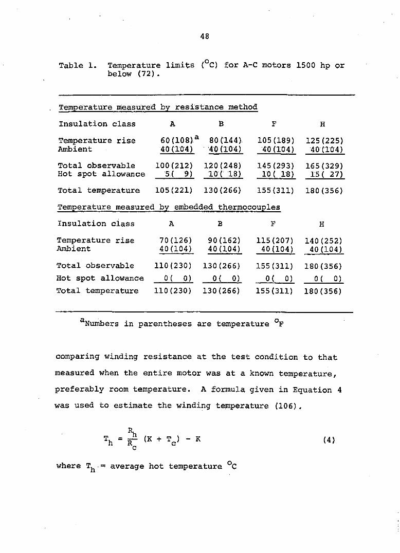
estimating hot-spot temperature. Table 1 shows the maximum
allowable temperature and temperature-rise of various
classes of insulations determined by resistance and embedded
thermocouple methods (72).
Resistance method
The resistance method gives the average temperature of
the stator winding. The temperature is determined by
48
Table 1. Temperature limits (°C) for A-C motors 1500 hp or below (72).
Temperature measured by resistance method
Insulation class
Temperature rise Ambient
Total observable Hot spot allowance
A B
60(108)^ 80C144). 40(104) 40(104)
100(212) 120(248) 5( 9) 10( 18)
105(189) 40(104)
145(293) 10 ( 18)
Insulation class
Temperature rise Ambient
Total observable
Hot spot allowance
Total temperature
70(126) 40(104)
110(230)
0 ( 0 )
B
90(162) 40(104)
130 (266)
0 ( 0 )
H
125 (225) 40(104)
165(329) 15 ( 27)
Total temperature 105(221) 130(266) 155(311) 180(356)
Temperature measured by embedded thermocouples
115(207) 40(104)
155(311)
0 ( 0 )
H
140(252) 40(104)
180(356)
0 ( 0 )
110(230) 130(266) 155(311) 180(356)
^Numbers in parentheses are temperature °F
comparing winding resistance at the test condition to that
measured when the entire motor was at a known temperature,
preferably room temperature. A formula given in Equation 4
was used to estimate the winding temperature (106).
Th = R- (K + ?=) - K c
(4)
where T, - average hot temperature C
49
= average cold temperature °C
= hot resistance, ohms
= cold resistance, ohms
K = constant; for copper, K = 234.5 and for aluminum, K = 225
Resistance R^ was measured at ambient temperature. The test
motor was loaded to the desired horsepower and run for a
specified time until a constant temperature had been reached.
Measurement of the hot resistance requires quick stopping
of the motor at the end of the heat run. Resistance after
shutdown is measured as frequently as possible until resis
tance readings have begun a slow decline from the maximum
value. Knowing the hot resistance values, temperature is
computed from Equation 4.
If a motor of 50 horsepower or smaller is stopped
within one minute after the shutdown, no extrapolation of
observed resistance and corresponding is necessary. How
ever, if a motor cannot be stopped within the specified
time, resistance readings are taken at intervals of approxi
mately one minute. A curve o€ these readings is plotted as
a function of time and extrapolated to the time of shutdown.
The value of temperature thus obtained is considered as the
maximum temperature of the test motor. If successive measure-,
ments show increasing temperature after shutdown, the highest
value is considered (106).
50
The following two methods were used to obtain the resis
tance of windings.
a. Kelvin bridge method
b. Voltage drop method
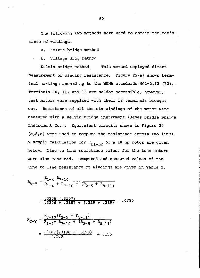
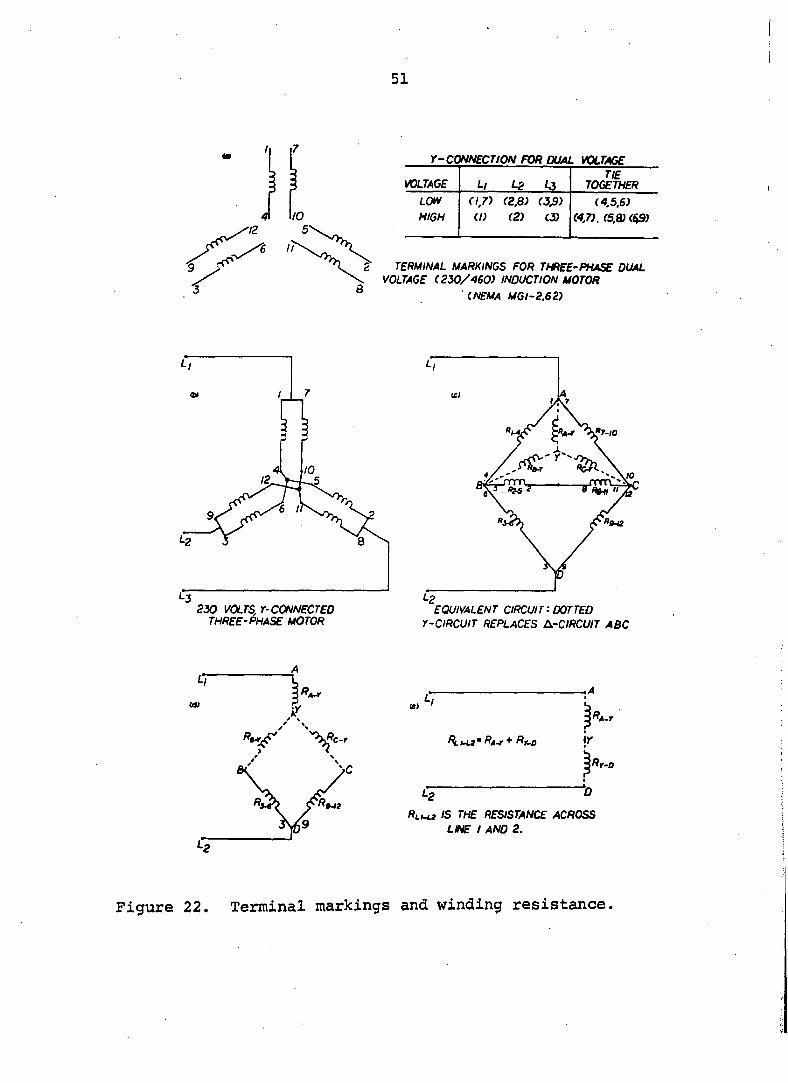
Kelvin bridge method This method employed direct
measurement of winding resistance. Figure 22(a) shows term
inal markings according to the NEMA standards MGl-2.62 (72).
Terminals 10, 11, and 12 are seldom accessible, however,
test motors were supplied with their 12 terminals brought
out. Resistance of all the six windings of the motor were
measured with a Kelvin bridge instrument (James Bridle Bridge
Instrument Co.). Equivalent circuits shown in Figure 20
(c,d,e) were used to compute the resistance across two lines.
A sample calculation for ^ 10 hp motor are given
below. Line to line resistance values for the test motors
were also measured. Computed and measured values of the
line to line resistance of windings are given in Table 2.
^ _ *1-4 *7-10
A-Y ^1-4 + *7-10 (*2-5 *8-11)
— .3206 (.3107) = 0785 .3206 + .3107 + (.319 + .319)
^ *7-10^*2-5 *8-11^
*1-4+ *7-10 •*" (*2-5 *8-11^
51
r-CONNECTION FOR DUAL VOLTAGE
voltage Ll L2 43 TIE
together
LOW (1,7) (2,8) (3,9) (4,5.6)
HIGH ( ! ) (2) 13) (4,7). (5,8) (^)
TERMINAL MARKINGS FOR THREE-PHASE DUAL VOLTAGE (250/460) INDUCTION MOTOR
CNEMA MGl-2.62)
230 VOLTS, Y-CONNECTED THREE-PHASE MOTOR
EQUIVALENT CIRCUIT-. DOTTED
r-CIRCUIT REPLACES A-CIRCUIT ABC
IS THE RESISTANCE /iCflCSS
LINE I AND 2.
Figure 22. Terminal markings and winding resistance.
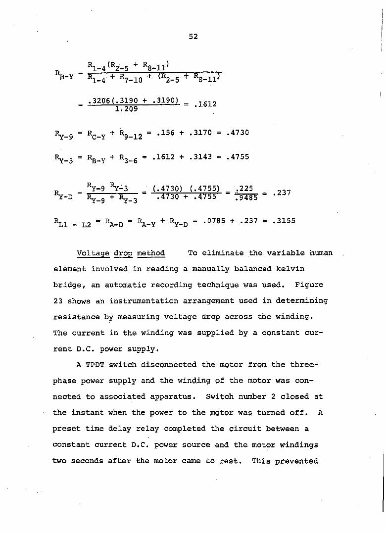
52
^1-4^^2-5 *8-ll)
" *1-4 + VlO + (*2_5 + Rg-iiJ
.3206 (.3190 + .3190) _ nr-.o = 009 '1G12
V9 = Vy + Vl2 = '156 + .3170 = .4730
Ry_3 = Rg_y + R3_g = .1612 + .3143 = .4755
_ By-g &-3 _ (.4730) (.4755) _ .225 VD - Ry.g + Ry_3 ~ '4730 + .4755 " TgTgF "
Rj l _ L2 ~ A-D ~ \-Y Y-D ~ •0785 + .237 = .3155
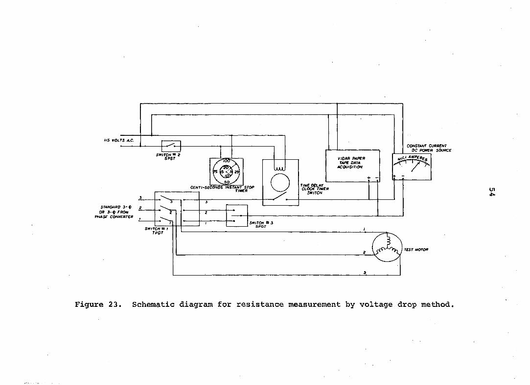
Voltage drop method To eliminate the variable human
element involved in reading a manually balanced kelvin
bridge, an automatic recording technique was used. Figure
23 shows an instrumentation arrangement used in determining
resistance by measuring voltage drop across the winding.
The current in the winding was supplied by a constant cur
rent D.C. power supply.
A TPDT switch disconnected the motor from the three-
phase power supply and the winding of the motor was con
nected to associated apparatus. Switch number 2 closed at
the instant when the power to the motor was turned off. A
preset time delay relay completed the circuit between a
constant current D.C. power source and the motor windings
two seconds after the motor came to rest. This prevented
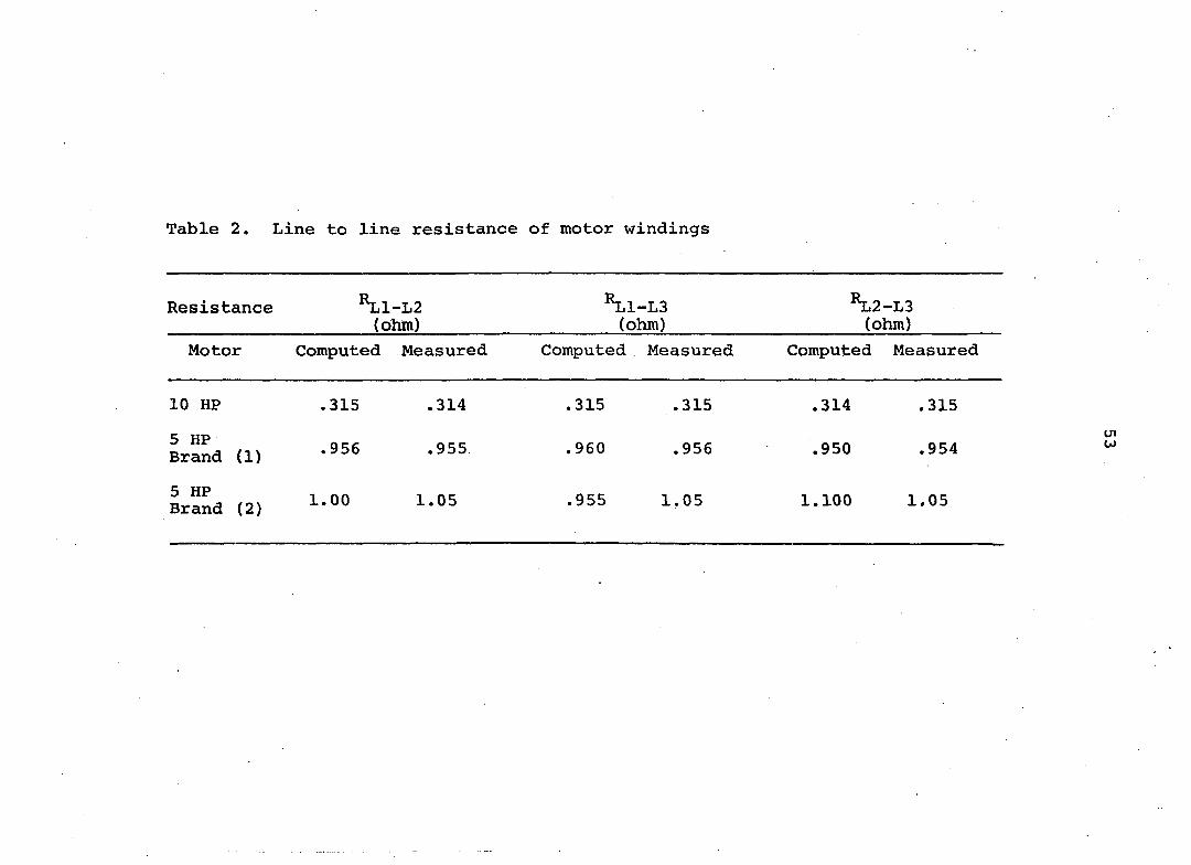
Table 2. Line to line resistance of motor windings
Resistance *L1-L2 (ohm)
^Ll-LS (ohm)
^2-L3 (ohm)
Motor Computed Measured Computed Measured Computed Measured
10 HP .315 .314 .315 .315 .314 .315
5 HP Brand (1) .956 .955 .960 .956 .950 .954
5 HP Brand (2)
1.00 1.05 .955 1.05 1.100 1.05
US VOLTS A,C.
CONSTANT CURRENT DC POWFA SOURCE
SWITCH *» 2 SPSr ViOAfi AtPEA TAPE DATA
ACQUISITION uuuU
CENTt'SeCONDS^TANT STOP , TitéER
TitdE DELAY CLOCK TthtER
SWITCH
STANDARD S-P OR 3-p FROM
PHASE CONVERTER
SWITCH tt 3 SPOT
SWITCH # / TPDT
TEST aOTOR
Figure 23. Schematic diagram for resistance measurement by voltage drop method.
55
the D.C. power supply and data acquisition system from being
damaged by any induced voltage present at the motor termi
nal due to its generator action. The voltage drop, due to
D.C. current, across the winding of the motor was recorded
on a paper tape data acquisition system. Twenty successive
data points were recorded during the cooling period. Knowing
the magnitude of D.C. current and the voltage drop, the
resistance of the winding was computed.
Thermocouple method
The thermocouple method for determining hot-spot
temperature is recommended by IEEE and is used widely in the
electrical industry (106). In this method, the temperature
of the winding is recorded under steady state operation of
a loaded motor. Unlike the resistance method, the test
motor need not be stopped. Thermocouple detectors are
placed in intimate contact with the insulation of coils. A
bonding epoxy is used to hold the thermocouple in place.
Impregnation of the stator winding provides a random
buildup of varnish on the windings, thus resulting in varia
tion of thermal resistance between the thermocouple and the
winding and the variation in temperature at different pointt
of the winding (106). To increase the probability of finding
the hottest accessible area 15 thermocouples were embedded
around the circumference of the stator winding.
56
The thermocouples were copper-constantan# American
National Standard Institute (ANSI) type-T, made of .01 inch
diameter wire. Distribution of thermocouples in the winding
is given in Table 3.
Table 3. Location and distribution of thermocouples in test motors
Thermocouple Location Number
1 Ambient 2 Phase 1 winding/ at 12.0 o'clock 3 Phase 1 winding, at 12.05 o'clock 4 Phase 1 winding, at 12.10 o'clock 5 Random, below a coil at 1.30 o'clock 6 Phase 2 winding at 4.00 o'clock 7 Phase 2 winding at 4.05 o'clock 8 Phase 2 winding at 4.10 o'clock 9 Random, above a coil at 5.30 o'clock
10 Random at 5.50 o'clock 11 Phase 3 winding at 7.0 o'clock 12 Phase 3 winding at 7.05 o'clock 13 Phase 3 winding at 7.10 o'clock 14 Random at 9.30 o'clock 15 Random at 10.00 o'clock 16 In iron core at 11.30 o'clock
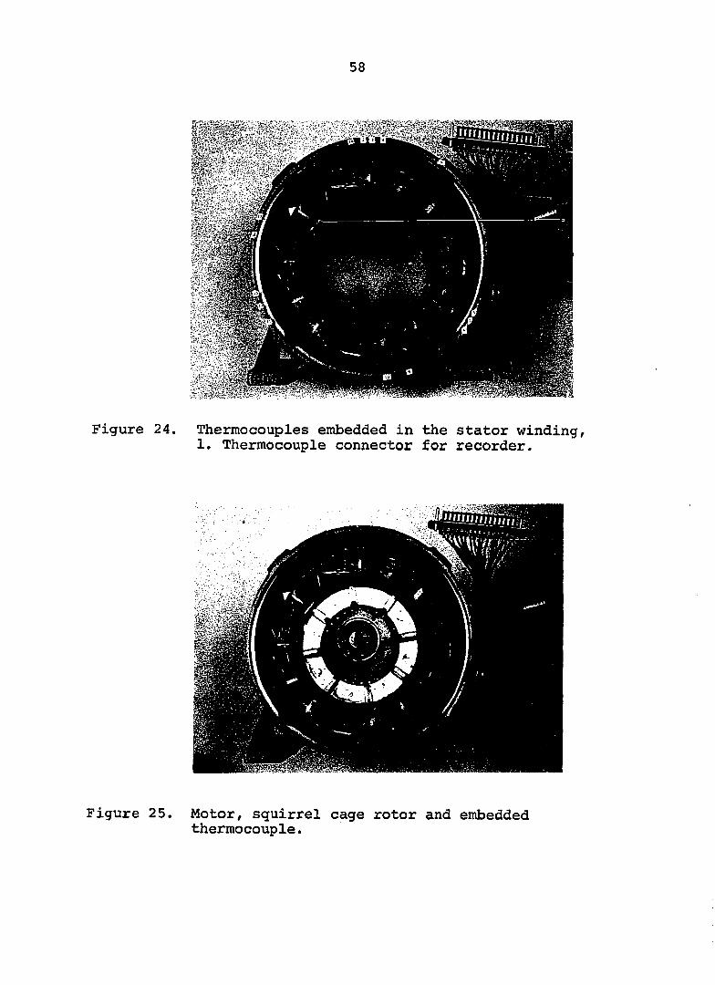
Locations of the 15 thermocouples in the stator winding
are shown in Figure 24. Each thermocouple was installed and
its lead brought out in such, a manner that the thermocouple
detector is effectively protected from contact with cooling
air. After inserting the thermocouple between the coils,
the epoxy was placed in the vicinity of the thermocouple.
57
The epoxy used had the characteristics of being thermally
conductive and electrically insulative.
Thermocouple lead wires were tied against the motor
winding several inches before being brought out. This min
imized the transfer of heat from the junction to the lead
and also, as shown in Figure 25, kept the leads from rubbing
against the rotor and the shaft.
A 16 point 8 minutes per cycle honeywell recorder was
used to monitor the temperature of the motor winding. To
check the recorder for accuracy and calibration all thermo
couples were placed in boiling water and test points rer
corded. Then, a voltage signal from a potentiometer,
equivalent to the voltage output of a type-T thermocouple
at 212°F, was fed to the recorder. For proper calibration,
data from the two sources should be closely matched. The
calibration apparatus is shown in Figure 26. A sample cali
bration chart is illustrated in Figure 27.
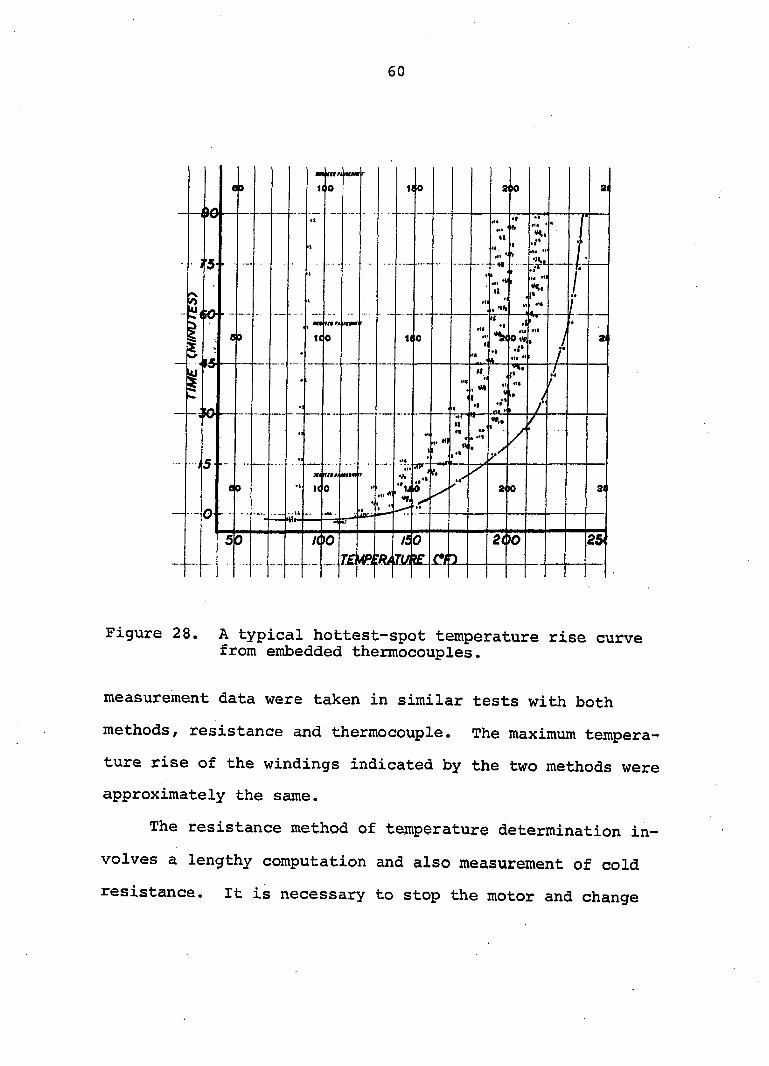
A steady state condition for testing motors was con
sidered to be reached when the increase in the hottest-spot
reading declined to 1 degree rise for the three consecutive
cycles. The temperature rise of the motor is the maximum
temperature reading recorded prior to or after the shutdown
less the ambient temperature of the immediate surrounding
air. A typical recorder temperature curve for the 16
thermocouples is shown in Figure 28. Several temperature
58
mUmm
Figure 24. Thermocouples embedded in the stator winding, 1. Thermocouple connector for recorder.
Figure 25. Motor, squirrel cage rotor and embedded thermocouple.
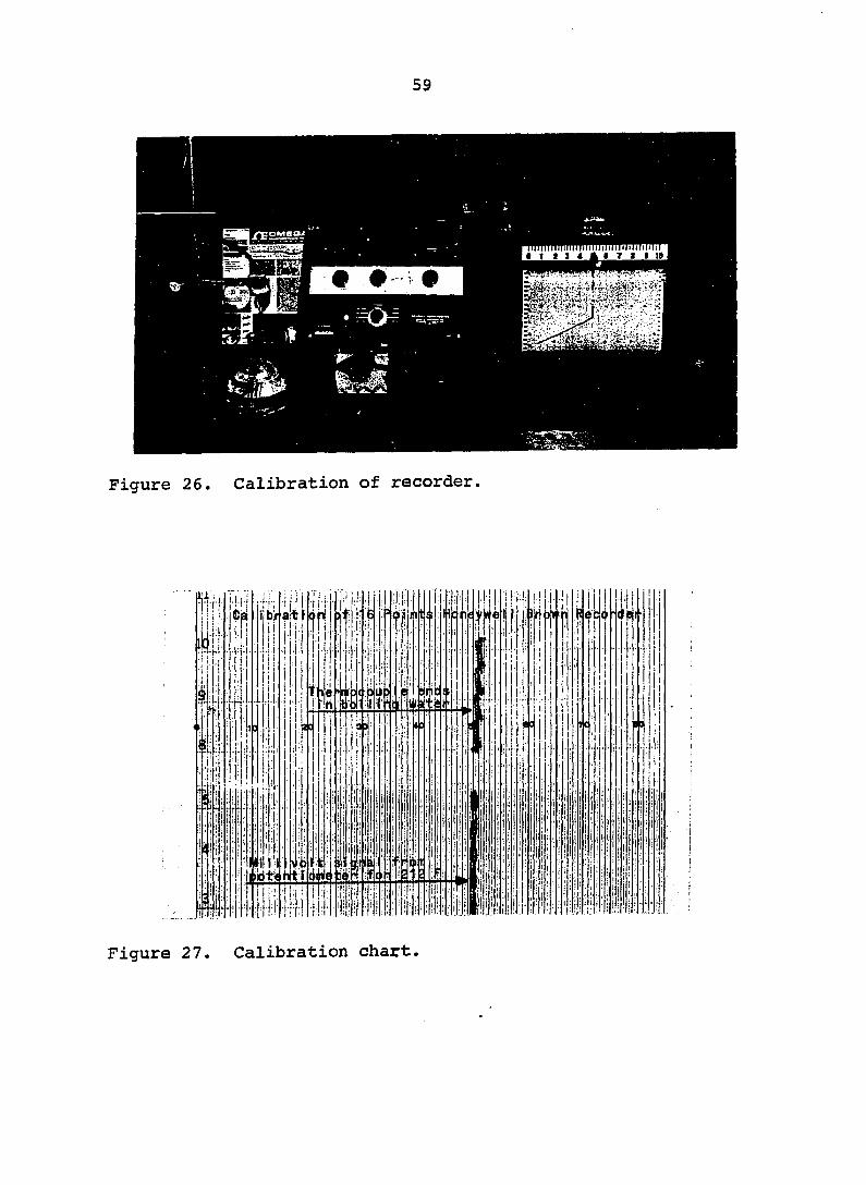
Figure 26. Calibration of recorder
Çei
Hi:
. ! • (•
I i!
ct!
the g
lit
:l! '
b)
III nc!
3111)1
;:iL WW S H E I
1:^1
t,,:
Ml tj iË'l
Figure 27. Calibration chart.
60
21 ei Il 0 KO 210
Î5
•>h
69 KO 21 110
j t
e o 2K> 31 l ( I
200 50
Figure 28. A typical hottest-spot temperature rise curve from embedded thermocouples.
measurement data were taken in similar tests with both
methods, resistance and thermocouple. The maximum tempera
ture rise of the windings indicated by the two methods were
approximately the same.
The resistance method of temperature determination in
volves a lengthy computation and also measurement of cold
resistance. It is necessary to stop the motor and change
61
the wiring connections of associated apparatuses to measure
the hot resistance of the windings. After confirming that
there was no significant difference in the results obtained
from the two methods, temperature was measured by the therm
ocouple method in subsequent tests.
Complete specifications of the instruments used in this
study are given in Appendix A.

62
DETERMINATION OF AUTOTRANSFORMER-CAPACITOR PHASE CONVERTER PARAMETERS
Reports have been made on the optimtmi size capacitor
and transformer turns-ratio that will produce balanced motor
voltages and currents (40, 45). These values generally have
been determined by empirical methods. Analytical equations
were developed, in this study, to determine the capacitor
size and the transformer turns-ratio for balanced currents
in the motor by using basic principles of circuit analysis.
The equations are in terms of readily available motor
parameters; nameplate current, voltage and power factor angle.
Two methods were used in developing the equations, vector
diagrams and symmetrical components.
Converter Parameter Equations
A simplified diagram of an autotransformer-capacitor
phase converter is shown in Figure 29. Single-phase lines
are connected to the primary of the transformer and also to
two of the terminals of the three-phase motor. Capacitors
are connected between the step-up secondary terminal of the
transformer and the third terminal of the motor.
Vector method
Figure 30 shows a vector diagram for a phase-converter,
three-phase motor combination for the motor operating under
balanced conditions. Single-phase voltage V is equal to
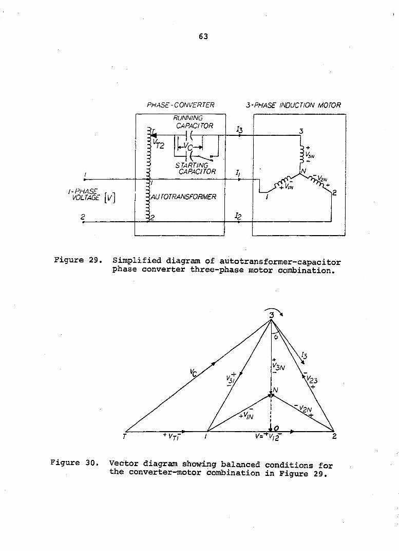
63
PHASE-CONVERTER 3-PHASE INDUCTION MOTOR
RUNNING CAPACITOR
STARTING CAPACITOR
I-PHASE 'AUTOTRANSFORMER
Figure 29. Simplified diagram of autotransformer-capacitor phase converter three-phase motor combination.
Figure 30. Vector diagram showing balanced conditions for the converter-motor combination in Figure 29.
64
^12' rated voltage of the motor. The autotransformer
voltage in phase with V and therefore lies along the
vector V^2' Currents and in the three windings
of the motor lag behind the corresponding voltages by an
angle (j), the phase angle. In Figure 30, only is shown.
Voltage at terminal 3 of the motor is determined by the
voltage across the capacitor and output voltage of the
autotransformer
The capacitor voltage, V^f is at a right angle to the
current I^. Vector V^, when extended, intersects the trans
former output voltage vector V^g point T. To operate a
three-phase motor with balanced voltages and currents, the
output voltage of the transformer should be equal to Vq,2'
and voltage drop across the capacitor should be V^. The
capacitor size and the transformer turns-ratio are derived
as follows:
From Figure 30
^NO = ^IN 30 =
V = Vj2 = n/T
^IN ^2N ^3N
V30 = IN + = (3/2) IN = ' y5?2)V (5)
also VgQ = Vg sin (J) (6)
65
Therefore/ from Equations 5 and 6
'c='VV2) (7)
and the voltage drop across the capacitor is
= I3 = :3 '5ïîe'
I3 1 and C = (^) (^) (8)
c
Under balanced conditions, the currents in the three windings
of the motor are equal.
Il = I2 = I3 = I
where I is nameplate current. Substituting the value of
from Equation 7 in Equation 8
c = (i) (9)
For f = 60 Hg and C in microfarads (uF), solving Equation 9
gives the following relation for the capacitance
C = 3063 (J) sin (10)
where V and I are the nameplate voltage and current of the
motor, and (j) is the power factor angle.
The transformer output voltage can be written in
terms of primary voltage

66
Vpa = nV
where n is turns-ratio of the transformer. From Figure 30,
V^2 can also be expressed as:
\2 = <1 V) + ('i'jn ) cos 4,
nV = i V + cot (J) (11)
Equation 11 gives the output voltage from the transformer
required for balanced operation of the motor. The trans
former turns-ratio, n, from Equation 10 is
1 \/T n = J + -J cot <t) (12)
where (j) is the power factor angle previously defined.
Symmetrical components method
The method of symmetrical components permits analysis
of motor performance under unbalanced conditions. An un
balanced system of three related phasors can be resolved
into three systems of balanced phasors, called symmetrical
components of the original phasors (20, 21). The three
systems of balanced phasors are; 1) positive-sequence com
ponents, 2) negative-sequence components and 3) zero-
sequence components. The first two systems consist of three
phasors, equal in magnitude and displaced from each other
by 120 degrees. Negative-sequence components have a
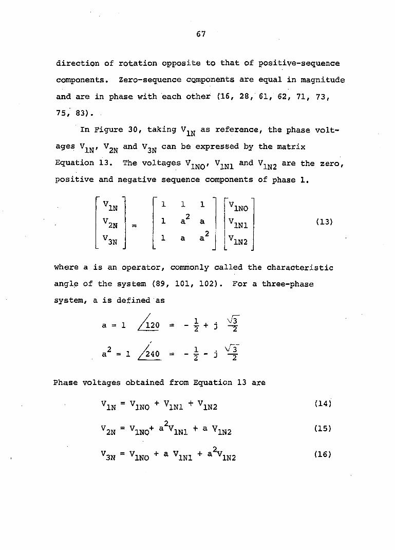
67
direction of rotation opposite to that of positive-sequence
components. Zero-sequence components are equal in magnitude
and are in phase with each other (16, 28, 61, 62, 71, 73,
75, 83).
In Figure 30, taking as reference, the phase volt
ages and can be expressed by the matrix
Equation 13. The voltages and are the zero,
positive and negative sequence components of phase 1,
^2N 11
^3N J
1 1
1 a: a
\NO'
^INl (13)
^1N2
where a is an operator, commonly called the characteristic
angle of the system (89, 101, 102). For a three-phase
system, a is defined as
a = 1 /l20 = — ^ 4- i —^
a^ = 1 /240 = - J - j
Phase voltages obtained from Equation 13 are
^IN ^INO ^INl ^1N2
^2N ^ INl ^ ^1N2
^3N ^INO ^ INl ^ 1N2
(14)
(15)
(16)
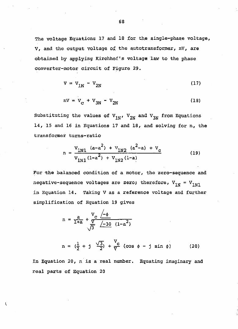
68
The voltage Equations 17 and 18 for the single-phase voltage,
V, and the output voltage at the ^utotransformer, nV, are
obtained by applying Kirchhof's voltage law to the phase
converter-motor circuit of Figure 29.
V = IN - V
"V = Vc + 3N - ' 2N (18)
Substituting the values of Vjjj and from Equations
14, 15 and 16 in Equations 17 and 18, and solving for n, the
transformer turns-ratio
n = % (19)
^INl ^ ^1N2
For the balanced condition of a motor, the zero-sequence and
negative-sequence voltages are zero; therefore,
in Equation 14. Taking V as a reference voltage and further
simplification of Equation 19 gives
Z /-30 (1-a^) #
n — + j — (.COS <|) - j sin (j)) (20)
In Equation 20, n is a real number. Equating imaginary and
real parts of Equation 20
V
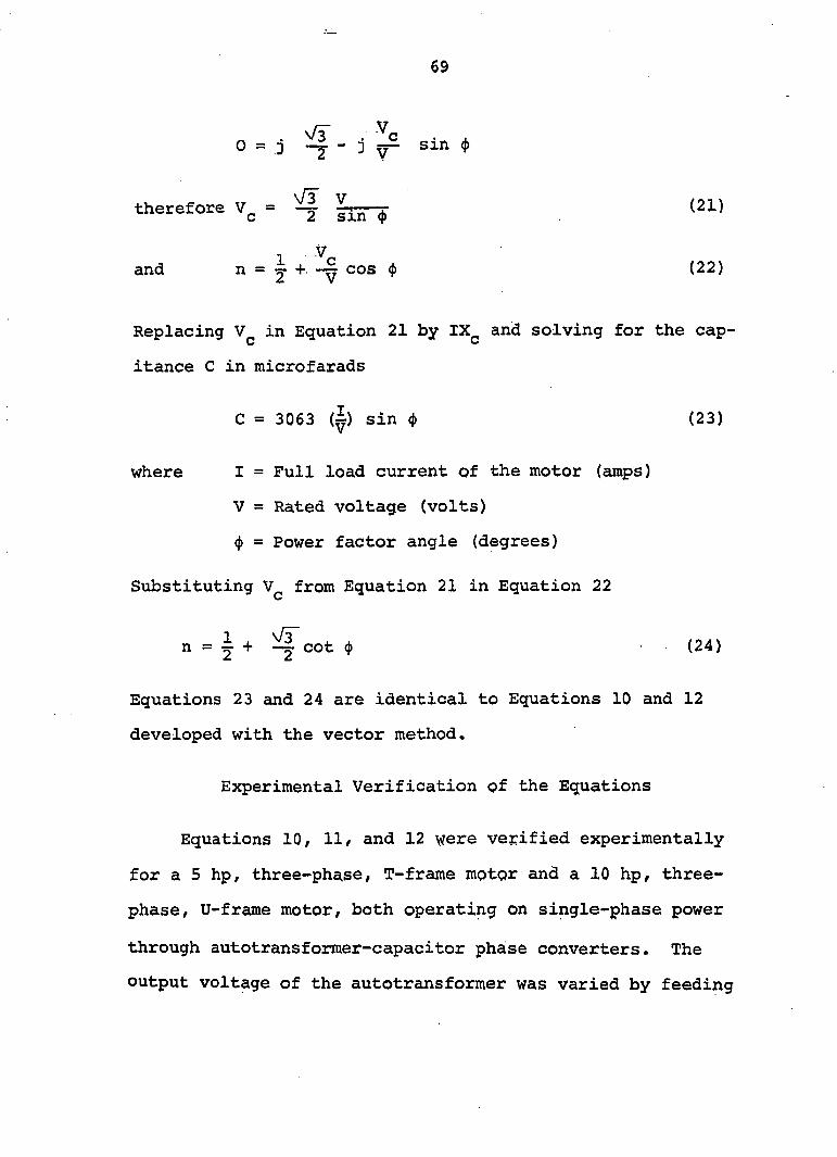
69
0 = j ^ - j sin (j>
therefore ^ (21)
T V_
and n = J + cos <j) (22)
Replacing in Equation 21 by IX^ and solving for the cap-
itance C in microfarads
C = 3063 (^) sin <t> (23)
where I = Full load current of the motor (amps)
V = Rated voltage (volts)
(j) = Power factor angle (degrees)
Substituting from Equation 21 in Equation 22
n = Y + cot (j) (24)
Equations 23 and 24 are identical to Equations 10 and 12
developed with the vector method.
Experimental Verification of the Equations
Equations 10, 11, and 12 were verified experimentally
for a 5 hp, three-phase, T-frame motor and a 10 hp, three-
phase, U-frame motor, both operating on single-phase power
through autotransformer-capacitor phase converters. The
output voltage of the autotransformer was varied by feeding
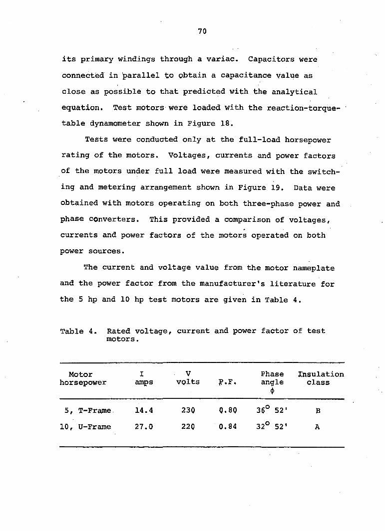
70
its primary windings through a variac. Capacitors were
connected in parallel to obtain a capacitance value as
close as possible to that predicted with the analytical
equation. Test motors were loaded with the reaction-torque-
table dynamometer shown in Figure 18.
Tests were conducted only at the full-load horsepower
rating of the motors. Voltages, currents and power factors
of the motors under full load were measured with the switch
ing and metering arrangement shown in Figure 19. Data were
obtained with motors operating on both three-phase power and
phase converters. This provided a comparison of voltages,
currents and power factors of the motors operated on both
power sources.
The current and voltage value from the motor nameplate
and the power factor from the manufacturer's literature for
the 5 hp and 10 hp test motors are given in Table 4.
Table 4. Rated voltage, current and power factor of test motors
Motor horsepower
I amps
V volts p.F
Phase Insulation angle class
*
5, T-Frame 14.4 230 0.80 36° 52' B
10, U-Frame 27.0 220 0.84 32° 52' A
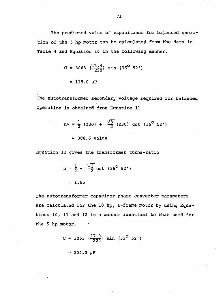
71
The predicted value of capacitance for balanced opera
tion of the 5 hp motor can be calculated from the data in
Table 4 and Equation 10 in the following manner.
C = 3063 sin (36° 52')
= 115.0 n?
The autotransformer secondary voltage required for balanced
operation is obtained from Equation 11
nV = J (230) + ^ (230) cot (36° 52')
= 380.6 volts
Equation 12 gives the transformer turns-ratio
n = I + cot (36° 52')
= 1.65
The autotransformer-capacitor phase converter parameters
are calculated for the 10 hp, U-frame motor by using Equa
tions 10/ 11 and 12 in a manner identical to that used for
the 5 hp motor.
C = 3063 (^1^) sin (32° 52")
= 204.0 yP
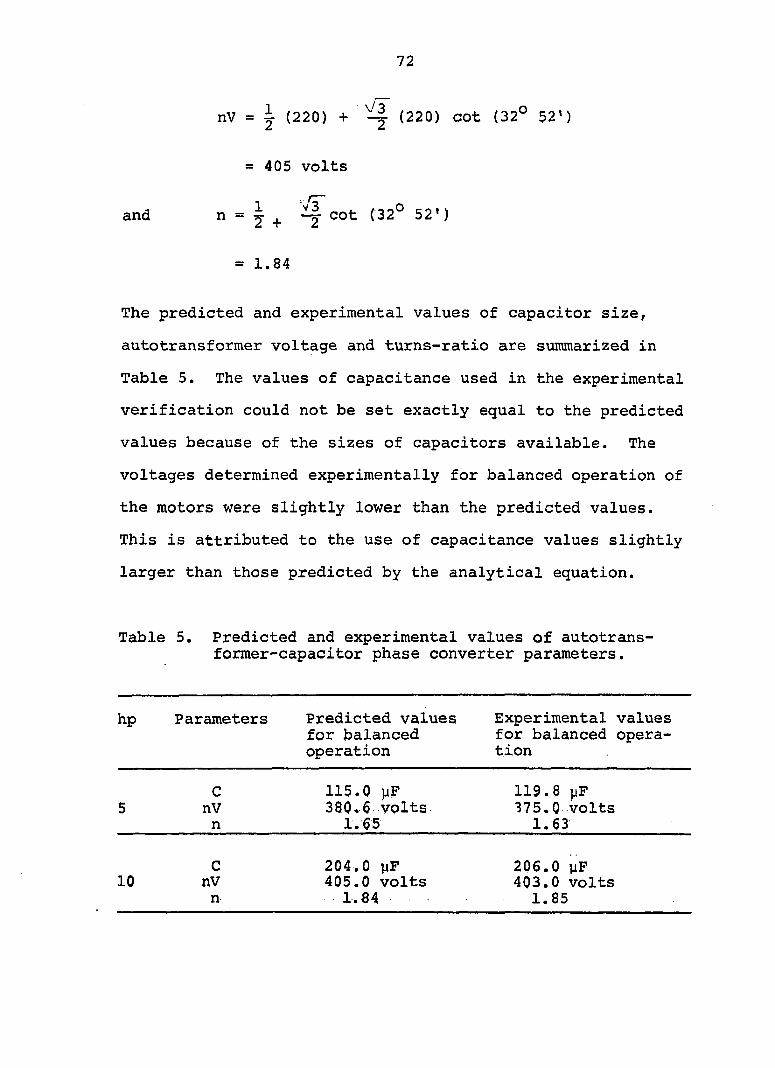
72
nV = J (220) + ^ (220) cot (32° 52')
= 405 volts
and n = Y + ^ cot (32° 52')
= 1.84
The predicted and experimental values of capacitor size,
autotransformer voltage and turns-ratio are summarized in
Table 5. The values of capacitance used in the experimental
verification could not be set exactly equal to the predicted
values because of the sizes of capacitors available. The
voltages determined experimentally for balanced operation of
the motors were slightly lower than the predicted values.
This is attributed to the use of capacitance values slightly
larger than those predicted by the analytical equation.
Table 5. Predicted and experimental values of autotrans-former-capacitor phase converter parameters.
hp Parameters Predicted values Experimental values hp for balanced for balanced operaoperation tion
C 115.0 yF 119.8 jjF 5 nV 380.6 volts 375.0 volts
n 1.65 1.63
C 204.0 uF 206.0 yF 10 nV 405.0 volts 403.0 volts
n 1.84 1.85
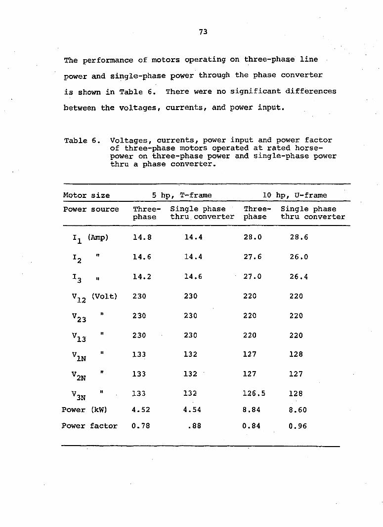
73
The performance of motors operating on three-phase line
power and single-phase power through the phase converter
is shown in Table 6. There were no significant differences
between the voltages, currents, and power input.
Table 6. Voltages, currents, power input and power factor of three-phase motors operated at rated horsepower on three-phase power and single-phase power thru a phase converter.
Motor size 5 hp, T—frame 10 hp, U-frame
Power source Three-phase
- Single phase thru converter
Three-phase
Single phase thru converter
"l (Amp) 14.8 14.4 28.0 28.6
:2 II 14.6 14.4 27.6 26.0
:3 II 14.2 14.6 27.0 26.4
^12 (Volt) 230 230 220 220
^23 It 230 230 220 220
^13 II 230 230 220 220
^IN II 133 132 127 128
^2N II 133 132 127 127
^3N n 133 132 126.5 128
Power (kW) 4.52 4.54 8.84 8.60
Power factor 0.78 .88 0.84 0.96

74
The close agreement of the operating conditions of the
motors on three-phase power and on the phase converter veri
fies that the equations developed in this study can be
applied to determine analytically the capacitor size and
autotransformer setting for balanced voltages and currents
in a three-phase motor with an autotransformer-capacitor
phase converter.
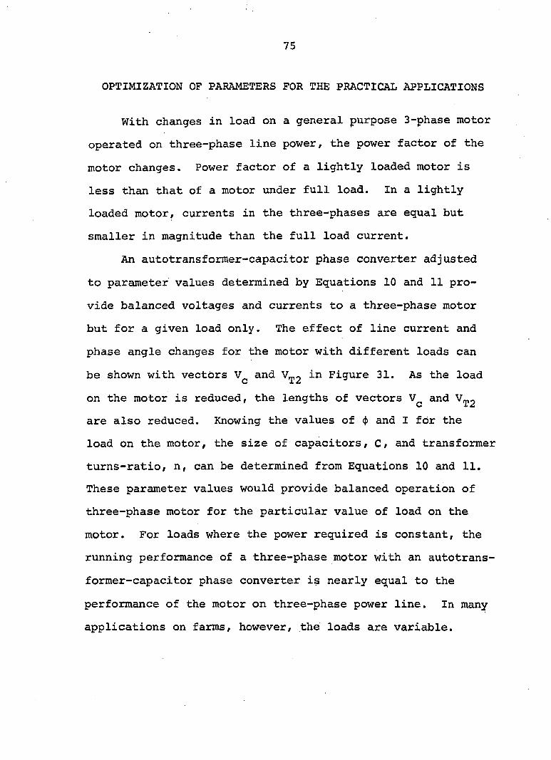
75
OPTIMIZATION OF PARAMETERS FOR THE PRACTICAL APPLICATIONS
With changes in load on a general purpose 3-phase motor
operated on three-phase line power, the power factor of the
motor changes. Power factor of a lightly loaded motor is
less than that of a motor under full load. In a lightly
loaded motor, currents in the three-phases are equal but
smaller in magnitude than the full load current.
An autotransformer-capacitor phase converter adjusted
to parameter values determined by Equations 10 and 11 pro
vide balanced voltages and currents to a three-phase motor
but for a given load only. The effect of line current and
phase angle changes for the motor with different loads can
be shown with vectors and V^2 Figure 31. As the load
on the motor is reduced, the lengths of vectors and
are also reduced. Knowing the values of (p and I for the
load on the motor, the size of capacitors, C, and transformer
turns-ratio, n, can be determined from Equations 10 and 11.
These parameter values would provide balanced operation of
three-phase motor for the particular value of load on the
motor. For loads where the power required is constant, the
running performance of a three-phase motor with an autotrans
former-capacitor phase converter is nearly equal to the
performance of the motor on three-phase power line. In many
applications on farms, however, the loads are variable.
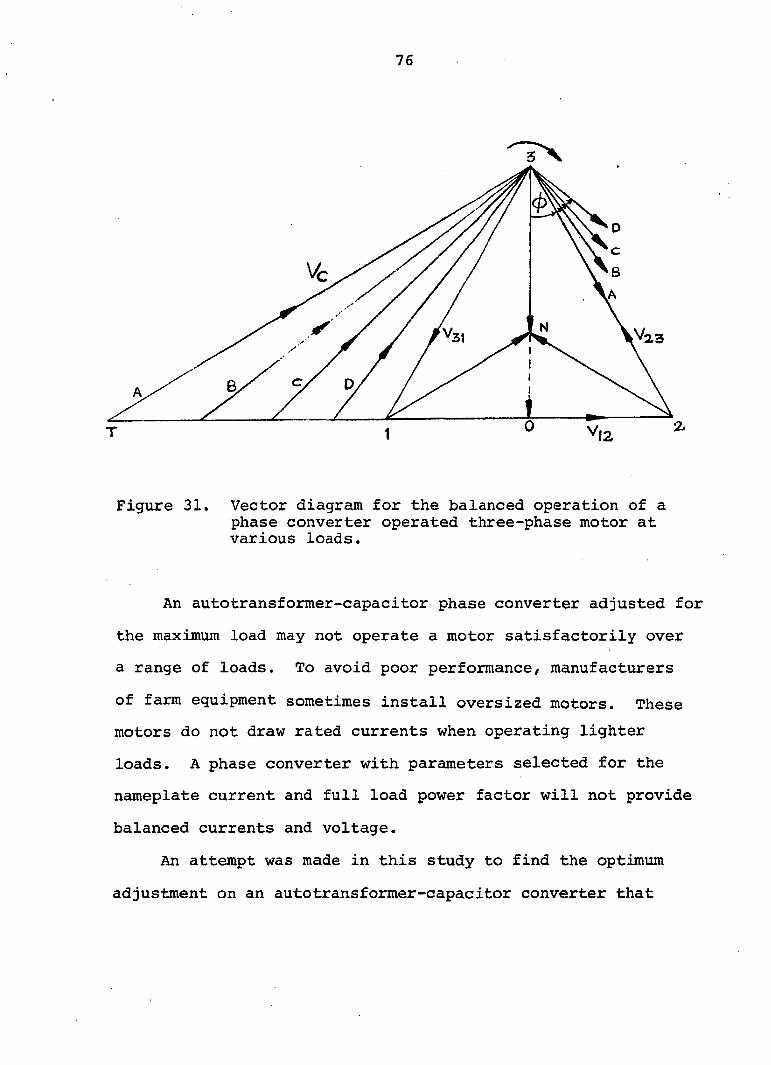
76
Figure 31. Vector diagram for the balanced operation of a phase converter operated three-phase motor at various loads.
An autotransformer-capacitor phase converter adjusted for
the maximum load may not operate a motor satisfactorily over
a range of loads. To avoid poor performance, manufacturers
of farm equipment sometimes install oversized motors. These
motors do not draw rated currents when operating lighter
loads. A phase converter with parameters selected for the
nameplate current and full load power factor will not provide
balanced currents and voltage.
An attempt was made in this study to find the optimum
adjustment on an autotransformer-capacitor converter that
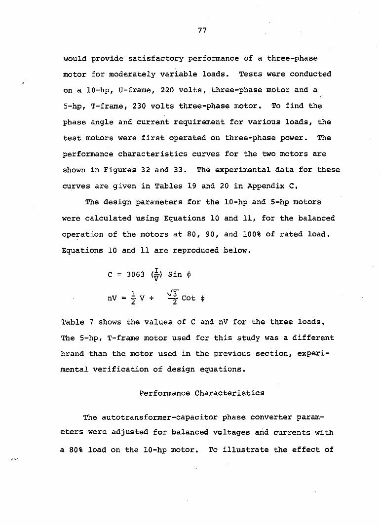
77
would provide satisfactory performance of a three-phase
motor for moderately variable loads. Tests were conducted
on a 10-hp, U-frame, 220 volts, three-phase motor and a
5-hp, T-frame, 230 volts three-phase motor. To find the
phase angle and current requirement for various loads, the
test motors were first operated on three-phase power. The
performance characteristics curves for the two motors are
shown in Figures 32 and 33. The experimental data for these
curves are given in Tables 19 and 20 in Appendix C,
The design parameters for the 10-hp and 5-hp motors
were calculated using Equations 10 and 11, for the balanced
operation of the motors at 80, 90, and 100% of rated load.
Equations 10 and 11 are reproduced below.
C = 3063 (^) Sin (p
nV = J V + ^ Cot <p
Table 7 shows the values of C and nV for the three loads.
The 5-hp, T-frame motor used for this study was a different
brand than the motor used in the previous section, experi
mental verification of design equations.
Performance Characteristics
The autotransformer-capacitor phase converter param
eters were adjusted for balanced voltages and currents with
a 80% load on the 10-hp motor. To illustrate the effect of

78
EFFICIENCY
0 POWER FACTOR
* VOL M6e ÈICURRENT
•GROWER
BSLIP
10 SO 30 40 50 60 70 80 90 lOO IIO 120 130 140 150 LOAD C% OF RATED HORSEPOiVER)
Figure 32. Performance curves of a 10-hp, U^frame, 220 volts, three-phase motor operated on three-phase line power.
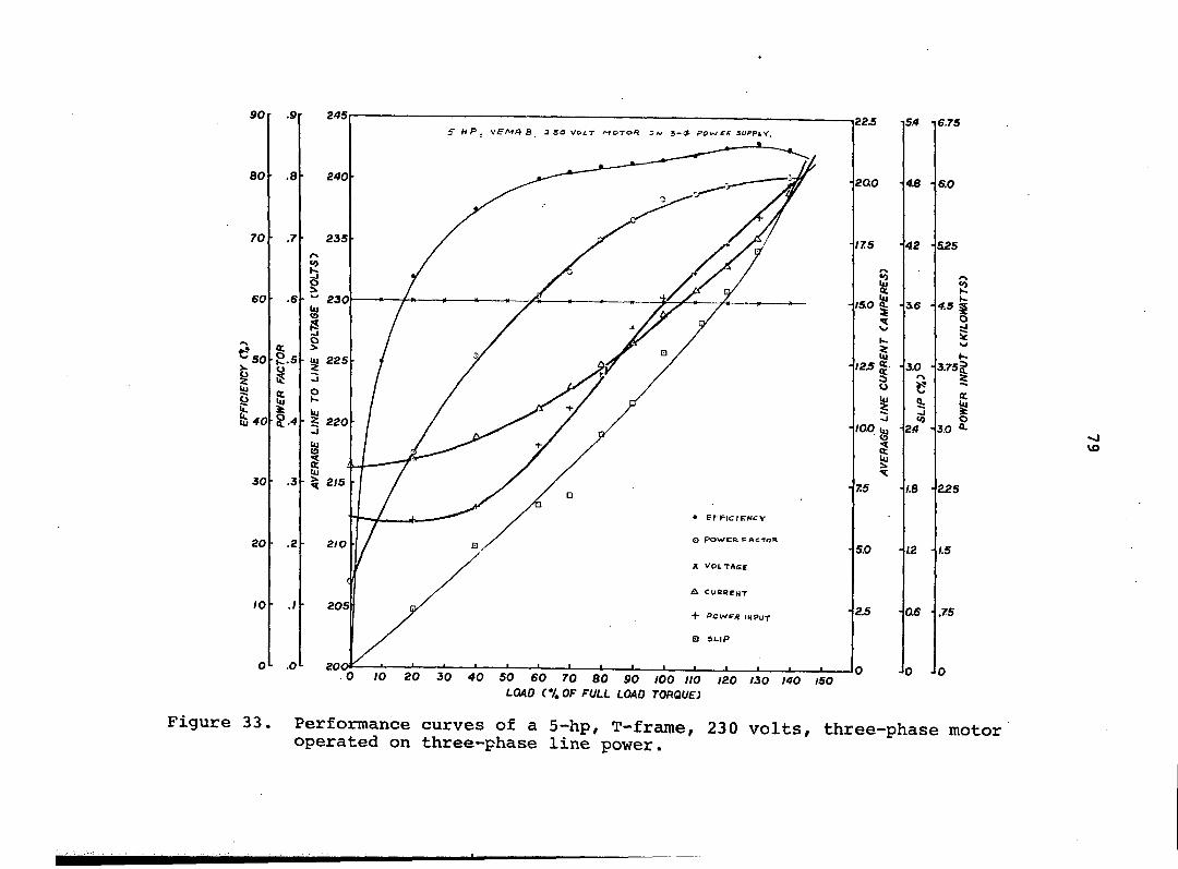
90
BO
70
60
.9
.7
.6
SO e
I & 40
1=
I.
.3
.2
30
SO
10
O"- .0
245 f H P . b 3 S o VCiT motor 3-^ fow supply.
UI 225
• 5 220
X VOLTAGE
a CuegENT
+ Pcwr* INPUT
B SLIP
0 /O 20 30 40 50 60 70 80 90 100 HO 120 130 140 ISO LOAD C%OF FULL LOAD TORQUE)
-22£ SA •
200 48 -
•17.5 42 •
1 , - ISO ^ • i6 -
3
t-
1 - /2 .5 | 1
o
30 • <->
e
% 9:
• /oo^ •
i
«0 24 •
- 7.5 1.6 •
• 5.0 12 •
IS 1 0£ •
• 0 0
6.7S
60
525
Î2 K
4.5 5 o
3.75|
J 225
1.5
.75
vo
Figure 33. Performance curves of a 5-hp, T-frame, 230 volts, three-phase motor operated on three-phase line power.
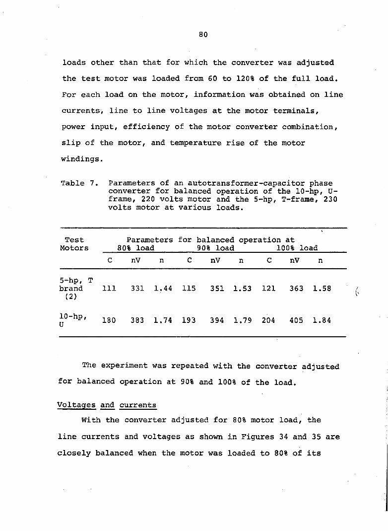
80
loads other than that for which the converter was adjusted
the test motor was loaded from 60 to 120% of the full load.
For each load on the motor, information was obtained on line
currents, line to line voltages at the motor terminals,
power input, efficiency of the motor converter combination,
slip of the motor, and temperature rise of the motor
windings.
Table 7. Parameters of an autotransformer-capacitor phase converter for balanced operation of the 10-hp, U-frame, 220 volts motor and the 5-hp, T-frame, 230 volts motor at various loads.
Test Parameters for balanced operation at Motors 80% load 90% load 100% load
C nV n C nV n C nV n
5-hp, T brand 111 331 1.44 115 351 1.53 121 363 1.58
( 2 )
10-hp, ]_go 383 1.74 193 3 9 4 1 . 7 9 204 405 1.84
The experiment was repeated with the converter adjusted
for balanced operation at 90% and 100% of the load.
Voltages and currents
With the converter adjusted for 80% motor load, the
line currents and voltages as shown in Figures 34 and 35 are
closely balanced when the motor was loaded to 80% of its
81
rated horsepower. Motor terminal voltages and line currents
became unbalanced, however, with the load on the motor
other than 80%. For example the percentage unbalance in
line currents was 12% at 70% and 90% loads. The unbalance
at ± 20% load increased to 24%. The percentage of unbal
ance was computed from the maximum difference in current or
voltage from the average of the three line currents or the
three line to line voltages.
The maximum unbalance in terminal voltages was 2% at
t 10% load and 4% at ± 20% load. As the load on the motor
deviated further from 80%, the unbalance in both current
and voltage increased rapidly.
The average line current of the motor operated at var
ious loads from the three-phase power line is also graphed
in Figure 34 for comparison. This illustrates the spread
of three unbalanced line currents of the motor operated
from an autotransformer-capacitor converter in relation to
the average line current with three-phase power.
Figures 36 and 37 are line currents and voltages of
the 10-hp U-frame motor with the converter adjusted for
balanced operation at 90% of the load. The maximum unbal
ance in line current was 8% at -10% load and 16% at +10%
load. At -20% load the current unbalance increased to 22%
and at +20% load the unbalance was 27%. The maximum volt
age unbalance was 3.2% at -20% load, 1.9% at -10% load.
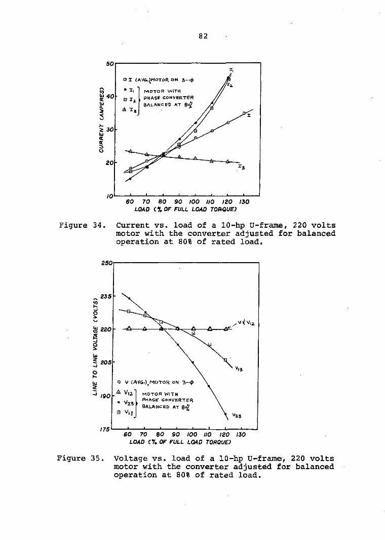
82
G I (AV6i.>MOTO« ON
MOTOR WITH
PHASE converter
balanced a t 8^
60 70 80 90 100 110 120 iso
load c% of full load tobque)
Figure 34. Current vs. load of a 10-hp U-frame/ 220 volts motor with the converter adjusted for balanced operation at 80% of rated load.
250
235
k 220
205
O V (AV6.)^MOTOK ON 3-<#>
. V|2 MOTOR WITH
, y ^ PHASE converter
balanced a t 8<>j[
190
175
load f % of full load torque)
Figure 35. Voltage vs. load of a 10-hp U-frame', 220 volts motor with the converter adjusted for balanced operation at 80% of rated load.

83
y>
I 3
§ o
25-
IS^
G I (AiVsO, MOTOR ON 3-4»
• I, Q Xj.
A X,
MOTOR WITH PHASE CONV B R T B R
balanced AT 90%
70 80 90 100 no 120 130 140 load (% of full load torque")
Figure 36. Current vs. load of 10-hp U-frame 220 volts motor with the converter adjusted for balanced operation at 90% of rated load.
250
^235
i 220
2
W 3205
e w
190
175
0 V (AVGO^MOTOR OKI i-(> v,z • V23
a v,3
MOTOR WITH P H A S E c o n v e r t e r
BALANCED AT 30%
Figure 37.
70 BO 90 100 no 120 130 140 LOAD CV. OF FULL LOAD TORQUE)
Voltage vs. load of a 10-hp U-frame 220 volts motor with the converter adjusted for balanced operation at 90% of rated load.
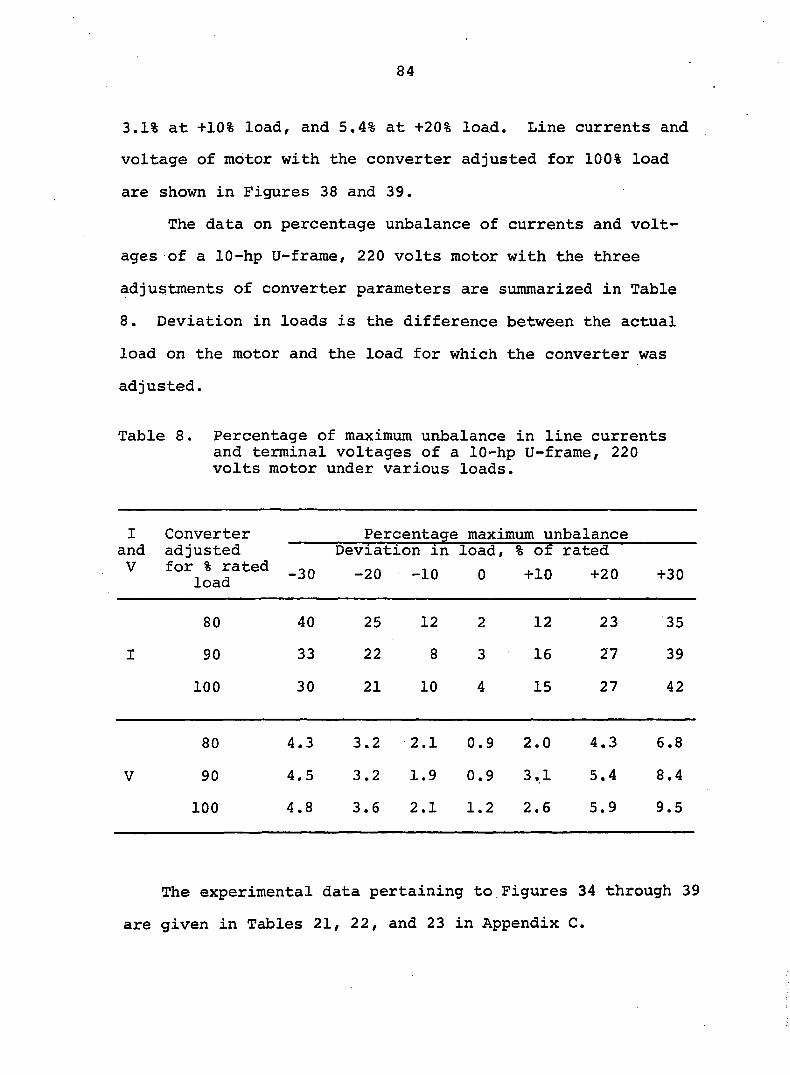
84
3.1% at +10% load, and 5.4% at +20% load. Line currents and
voltage of motor with the converter adjusted for 100% load
are shown in Figures 38 and 39.
The data on percentage unbalance of currents and volt
ages of a 10-hp U-frarae, 220 volts motor with the three
adjustments of converter parameters are summarized in Table
8. Deviation in loads is the difference between the actual
load on the motor and the load for which the converter was
adjusted.
Table 8. Percentage of maximum unbalance in line currents and terminal voltages of a 10-hp U-frame, 220 volts motor under various loads.
I and V
80 40 25 12 2 12 23 35
I 90 33 22 8 3 16 27 39
100 30 21 10 4 15 27 42
80 4.3 3.2 2.1 0.9 2.0 4.3 6.8
V 90 4.5 3.2 1.9 0.9 3.1 5.4 8.4
100 4.8 3.6 2.1 1.2 2.6 5.9 9.5
Converter Percentage maximum unbalance adjusted Deviation in load, % of rated
for % rated _20 -10 0 +10 +20 +30
The experimental data pertaining to Figures 34 through 39
are given in Tables 21, 22, and 23 in Appendix C.
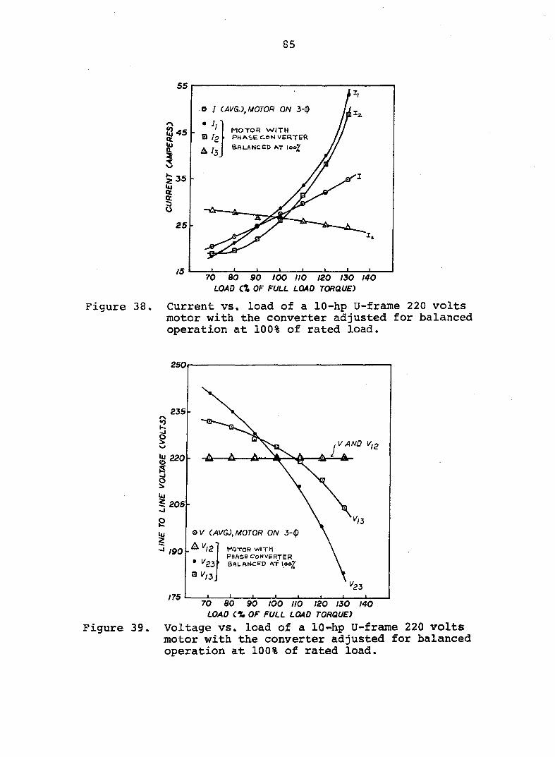
85
CAVG.), MOTOR ON 3-(])
MOTOR WITH PHASE CON VERTER Balanced a t ioo7
Figure 38.
70 bo 90 too no 120 130 140
load CX of full load torque)
Current vs. load of a 10-hp U-frame 220 volts motor with the converter adjusted for balanced operation at 100% of rated load.
250
V AND v.
205
V CAVGÙ, MOTOR ON 3-<p
A I// motor WITH PHASE converter
' BALANCED AT \AAY
190
23 175
load c% of full load torque)
Figure 39. Voltage vs. load of a 10-hp U-frame 220 volts motor with the converter adjusted for balanced operation at 100% of rated load.

86
Power input and efficiency
Power input and efficiency curves for the motor oper
ating on a three-phase power line and on an autotransformer-
capacitor converter with parameters adjusted for the balanced
operation at 80, 90/ and 100% load are shown in Figures 40
and 41. Power input to the motor, over the range of loads,
was minimum with the three-phase power line. Power drawn
by the motor-converter combination, for the three settings
of parameters, was about the same. A slightly higher power
was drawn by the motor operating with the converter adjusted
for balanced currents at 80%, 90%, and 100% of the rated
load than that with three-phase operation.
Efficiency of the motor operated on a three-phase power
line was greater than with the phase converter. This was
2 due to the additional power lost, I R and eddy current losses
in the transformer winding of the phase converter. The
motor phase converter combination had about the same maximum
efficiency for the three adjustments of capacitors and trans
formers. For all the three settings, the maximum efficiency
resulted at a load 10% above that for which the parameters
were adjusted. For example, with the parameters adjusted
for 80% load, the maximum efficiency occurred at 90% of the
rated load.
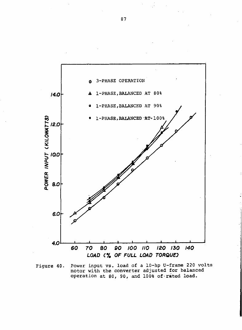
87
0 3-PHASE OPERATION
A 1-PHASE,BALANCED AT 80% 14.0
a 1-PHASE,BALANCED AT 90%
• 1-PHASE,BALANCED AT-i 100%
12.0
10.0
6.0-
60 70 80 90 too 110 120 150 140 LOAD C% OF FULL LOAD TORQUES
Figure 40. Power input vs. load of a 10-hp U-frame 220 volts motor with the converter adjusted for balanced operation at 80, 90, and 100% of rated load.
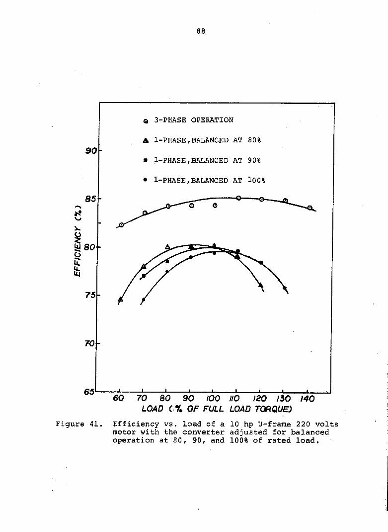
88
Q 3-PHASE OPERATION
• 1-PHASE,BALANCED AT 80%
• 1-PHASE,BALANCED AT 90%
• 1-PHASE,BALANCED AT l00%
8 5 -
75
70-
Figure 41
60 70 80 90 100 110 120 130 LOAD ( % OF FULL LOAD TORQUE)
140
Efficiency vs. load of a 10 hp U-frame 220 volts motor with the converter adjusted for balanced operation at 80, 90, and 100% of rated load.
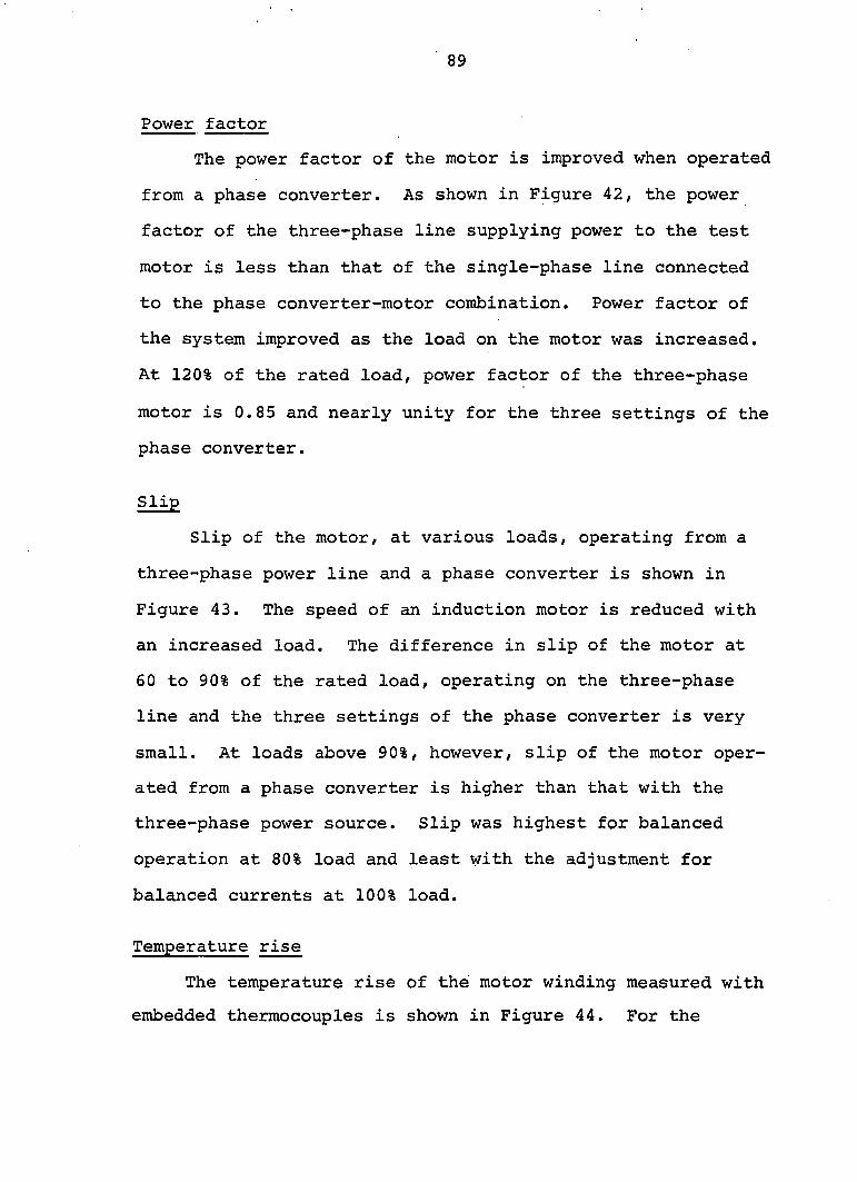
89
Power factor
The power factor of the motor is improved when operated
from a phase converter. As shown in Figure 42, the power
factor of the three-phase line supplying power to the test
motor is less than that of the single-phase line connected
to the phase converter-motor combination. Power factor of
the system improved as the load on the motor was increased.
At 120% of the rated load, power factor of the three-phase
motor is 0.85 and nearly unity for the three settings of the
phase converter.
Slip
Slip of the motor, at various loads, operating from a
three-phase power line and a phase converter is shown in
Figure 43. The speed of an induction motor is reduced with
an increased load. The difference in slip of the motor at
60 to 90% of the rated load, operating on the three-phase
line and the three settings of the phase converter is very
small. At loads above 90%, however, slip of the motor oper
ated from a phase converter is higher than that with the
three-phase power source. Slip was highest for balanced
operation at 80% load and least with the adjustment for
balanced currents at 100% load.
Temperature rise
The temperature rise of the motor winding measured with
embedded thermocouples is shown in Figure 44. For the
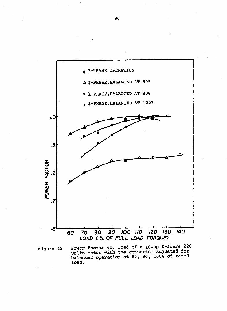
90
Q 3-PHASE OPERATION
A 1-PHASE,BALANCED AT 80%
• 1-PHASE,BALANCED AT 90%
, i-PRASE,BALANCED AT 100%
AO-
.9
I et
w g .7
.6 JL
60 70 eo 90 100 no 120 130 140 LOAD C r. OF FULL LOAD TORQUE)
Figure 42. Power factor vs. load of a lO-hp U-frame 220 volts motor with the converter adjusted for balanced operation at 80/ 90, 100% of rated load.
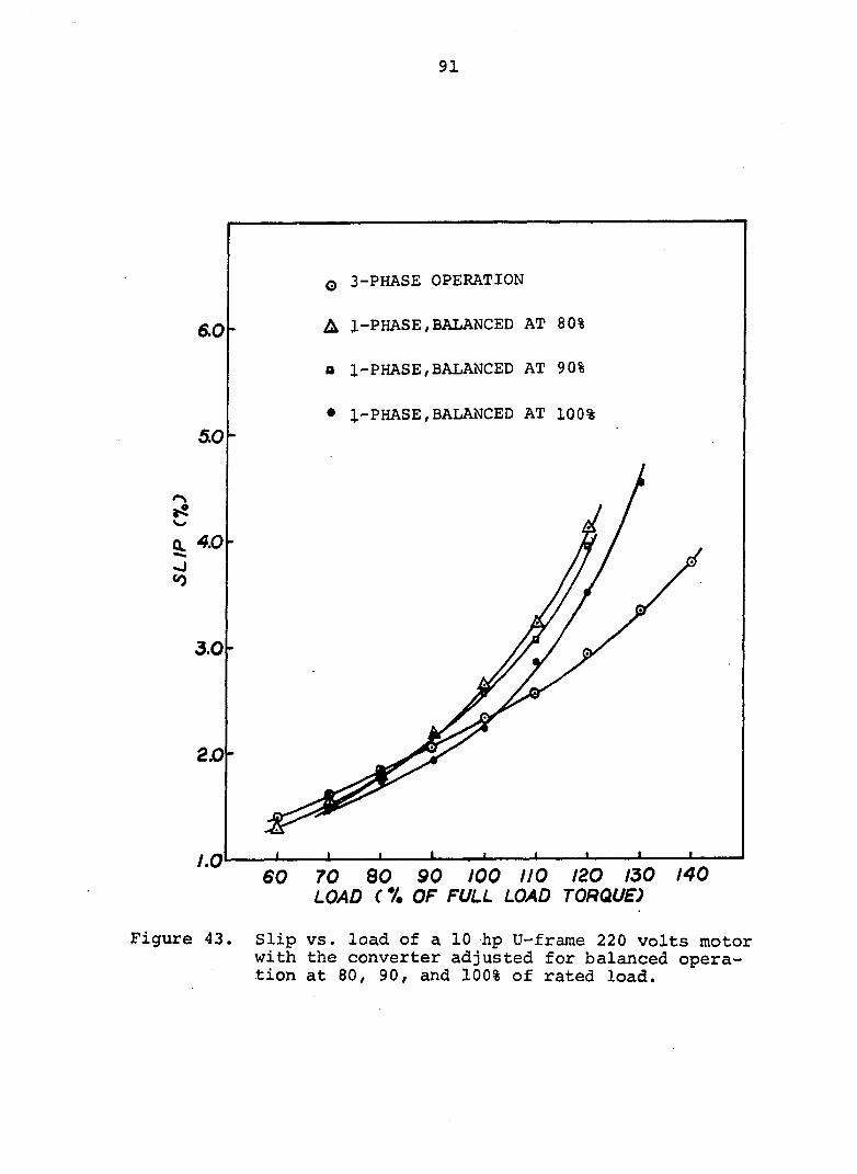
91
3-PHASE OPERATION
A 1-PHASE,BALANCED AT 80% 6.0
a 1-PHASE,BALANCED AT 90%
• 1-PHASE,BALANCED AT 100%
4.0
3.0-
20
LO
LOAD ( % OF FULL LOAD TORQUE)
Figure 43. Slip vs. load of a 10 hp U-frame 220 volts motor with the converter adjusted for balanced operation at 80, 90/ and 100% of rated load.
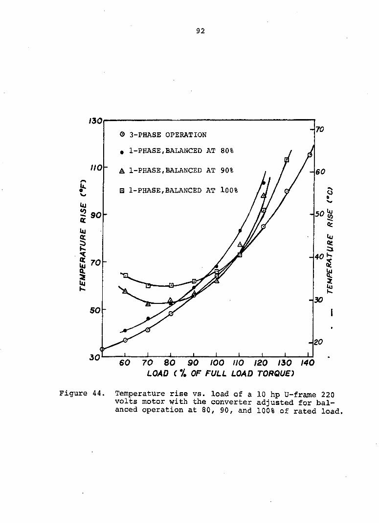
92
150
O 3-PHASE OPERATION
# 1-PHASE,BALANCED AT 80%
A 1-PHASE,BALANCED AT 90%
• 1-PHASE,BALANCED AT l00%
70 80 90 100 110 120 150 140 LOAD ( % OF FULL LOAD TORQUE)
Figure 44. Temperature rise vs. load of a 10 hp U-frajne 220 volts motor with the converter adjusted for balanced operation at 80, 90, and 100% of rated load.
93
same load on the motor, the motor ran cooler, in general,
on the three-phase supply than on single-phase line through a
phase converter. Temperature of the winding is related to
motor current, thus temperature rise is greater at higher
loads. Temperature rise in the motor windings under all
test conditions did not exceed the design limits of the
insulation.
The experiment conducted on thé 10-hp U-frame motor was
repeated for a 5-hp T-frame, design B, 230 volts motor. The
values of parameters for balanced operation at 80, 90 and
100% of rated load are given in Table 7. The difference in
capacitor sizes for balanced operation at 80 and 90%, was
very small. The capacitors available for this study did not
permit fine adjustment. Therefore, tests for the 5-hp motor
were conducted for two settings only, i.e., balanced opera
tion adjustments at 80 and 100% of the rated motor load.
The performance characteristics curves of currents,
voltages, power input, efficiency, power factor, slip, and
temperature rise, for a 5-hp, design B, 230 volts, three-
phase test motor are shown in Figures 92 through 100 in
Appendix C. The experimental data related to these figures
are given in Tables 24 and 25, also in Appendix C.
The effects of loads other than the load, for which the
converter was adjusted, on the performance of a 5-hp T-frame
230 volts test motor are very similar to those explained for
the 10-hp, U-frame, 220 volts test motor.
94
The experimental results in this section of the study
show that in the applications where the motor supplied with
the machine is oversized, for better performance of the motor,
parameters in the autotransformer-capacitor phase converter
should be adjusted for the actual load on the motor and not
for its nameplate horsepower. This will require measurement
of the current drawn by the motor and determination of the
corresponding power factor from the performance character
istics curves obtained with the motor operating on three-
phase power. Figures 32 and 33 are two examples of such
curves.
In applications where load fluctuates often over a
moderate range, the autotransformer-capacitor converter
should be adjusted for the average value of the load. For
example, with the motor load varying between 80 to 100% of
the rated, parameters adjusted for 90% of the rated load may
give the best results. On applications where only infrequent
variations in load are expected, the converter should be
adjusted for the most frequently encountered load.
95
VOLTAGE EFFECTS ON PHASE CONVERTER OPERATED THREE-PHASE MOTORS
The increased use of phase converter operated three-
phase motors has made desirable the study of the effects of
input line voltage variation on motor performance. Present
phase converter designs do not provide identical terminal
voltages at each phase of the motor when the single-phase
input voltage to the phase converter varies. When the phase
voltages are not equal, unbalanced currents flow in the motor
stator windings. The magnitude of current unbalance is
dependent on the voltage unbalance. Even a small amount of
voltage unbalance may increase currents and excessive motor
heating, because phase current unbalance is several times the
voltage unbalance.
Most general purpose poly-phase induction motors are
designed to operate within a voltage range of 10 per cent
above or below a nominal voltage (3, 69). This allowable
operating range is based on the assumption that the voltages
applied to the motor are equal. Performance of a three-
phase motor operating on unbalanced voltage can be unde
sirably different from that given by motor manufacturers
(33, 34). For this reason, some manufacturers often have
refused to guarantee three-phase motors operated on single-
phase power through a phase converter.

96
Test Outline
In this study, the effects were investigated of input
line voltage variation on the performance of a 5-hp, three-
phase, T-frame, 230-volts, NEMA design B motor. The motor
was operated on a three-phase power supply and on autotrans-
former-capacitor and rotary converters. Input voltage was
varied over the range of 85 to 115 per cent of the rated
voltage of the motor.
The block diagram shown in Figure 45 outlines the tests
performed and parameters studied. Motor terminal voltage,
line currents, winding temperature, power input, and slip
were recorded with load on the motor held constant at rated
full-load torque (15 lb.-ft.).
5-hp,230V T-Prmme Design B 3-$ Motor
Tested 2. Auto-Cap 1. 3-* Power
Input voltage with . variation 85% to
Performance
Motor terminal voltag* Line current Winding temperatur# Power input
o n ' c o n v e r t e r 3. Rotary
converter
^ variabxun OJA
115% of rated studied
Efficiency Power factor Slip Locked Rotor torque Pull-up torque Breakdown torque
Figure 45. Outline of motor tests and parameters studied.
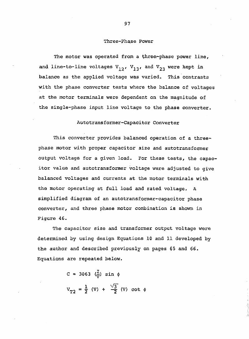
97
Three-phase Power
The motor was operated from a three-phase power line,
and line-to-line voltages ^13' Vgg were kept in
balance as the applied voltage was varied. This contrasts
with the phase converter tests where the balance of voltages
at the motor terminals were dependent on the magnitude of
the single-phase input line voltage to the phase converter.
Autotransformer-Capacitor Converter
This converter provides balanced operation of a three-
phase motor with proper capacitor size and autotransformer
output voltage for a given load. For these tests, the capac
itor value and autotransformer voltage were adjusted to give
balanced voltages and currents at the motor terminals with
the motor operating at full load and rated voltage. A
simplified diagram of an autotransformer-capacitor phase
converter, and three phase motor combination is shown in
Figure 46.
The capacitor size and transformer output voltage were
determined by using design Equations 10 and 11 developed by
the author and described previously on pages 65 and 66.
Equations are repeated below.
C = 3063 (|) sin (|)
^T2 = i (V) + ^ (V) cot 4)
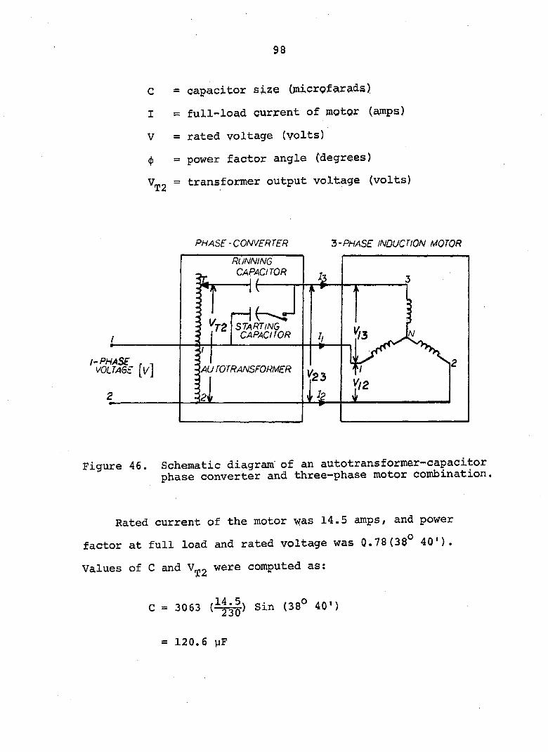
98
c = capacitor size (microfarads)
I = full-loa,d current of motor (ajnps)
V = rated voltage (volts)
<j) = power factor angle (degrees)
V^2 = transformer output voltage (volts)
PHASE-CONVERTER 3-PHASE INDUCTION MOTOR
RUNNING CAPACITOR
/-PHASE - 'AU TOTRANSFORMER
Figure 46. Schematic diagram of an autotransformer-capacitor phase converter and three—phase motor combination.
Rated current of the motor was 14.5 amps/ and power
factor at full load and rated voltage was 0.78(38° 40').
Values of C and were computed as:
C = 3063 Sin (38° 40')
= 120.6 yF
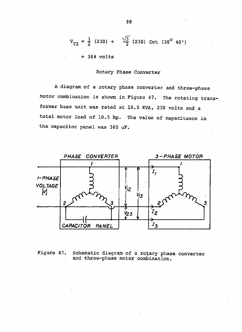
99
V^2 = J (230) + ^ (230) Cot (38° 40')
= 364 volts
Rotary Phase Converter
A diagram of a rotary phase converter and three-phase
motor combination is shown in Figure 47. The rotating trans
former base unit was rated at 10.5 KVA, 230 volts and a
total motor load of 10.5 hp. The value of capacitance in
the capacitor panel was 365 yF.
PHASE CONVERTER 3-PHASE MOTOR
/'PHASE
VOLTAGE
CAPACITOR PANEL
Figure 47. Schematic diagram of a rotary phase converter and three-phase motor combination.
100
Performance Characteristics
Electrical and mechanical characteristics of the test
motor are illustrated in Figures 48 through 59. Comparisons
are shown for the motor operating on three-phase power and
on single-phase power through phase converters. Phase volt
ages and currents, motor temperature rise, power input,
efficiency, power factor, slip, and locked-rotor, pull-up,
and breakdown torques are given for a variation of input
line voltage of ± 15 per cent of nominal motor voltage.
Experimental data pertaining to these tests is given in Tables
26 through 32 in Appendix C.
Voltages and currents
Motor terminal voltages for the motor operating on an
autotransformer-capacitor phase converter are shown in
Figure 48. With the calculated values of capacitance,
autotransformer output voltage and an input voltage of 230
volts, the line-to-line voltages and Vgg at the
motor terminals were equal. Motor terminal voltages became
unbalanced, however, with the variation of input voltage
above and below rated motor voltage. The percentage un
balance as computed from the maximum deviation in voltage
from the average of the three voltages was 4.5 and 2.5 per
cent at an input voltage 10 per cent below and above rated
voltage, respectively.

101
265
^ 250k
2 •J
§
S 225
s 5 zoo
e §
ITS
AUTO" CAR CONVERTER ^
* /jÙ A 1/23
' /3
' ' 1 1 1 L. 1
85 90 95 100 105 110 115 VOLTAGE C '/, OF RATED)
Figure 48. Voltage at terminals of a 5-hp, T-frame, 230 volts, design B test motor vs. single-phase input line voltage to autotransformer-capacitor phase converter.
Figure 49 shows the effect of voltage variation on cur
rents in the motor operated on three-phase power and on the
autotransformer-capacitor converter. With the motor on
three-phase power, line currents increased with input voltage
above or below nominal, but remained approximately balanced.
The average of the three line currents shown in Figure 49
was 8 and 10 per cent higher than rated at 85 and 115
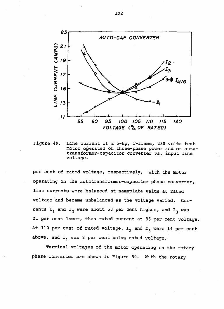
102
AUTO-CAR CONVERTER
K-
W 17 q:
q:
o is
3-(p Ta]/Q
100 105 110 115 120 VOLTAGE C7o OF RATED)
Figure 49. Line current of a 5-hp, T-frarae, 230 volts test motor operated on three-phase power and on autotransformer-capacitor converter vs. input line voltage.
per cent of rated voltage, respectively. With the motor
operating on the autotransformer-capacitor phase converter,
line currents were balanced at nameplate value at rated
voltage and became unbalanced as the voltage varied. Cur
rents and I2 were about 50 per cent higher, and was
21 per cent lower, than rated current at 85 per cent voltage.
At 110 per cent of rated voltage, and were 14 per cent
above, and was 8 per cent below rated voltage.
Terminal voltages of the motor operating on the rotary
phase converter are shown in Figure 50. With the rotary
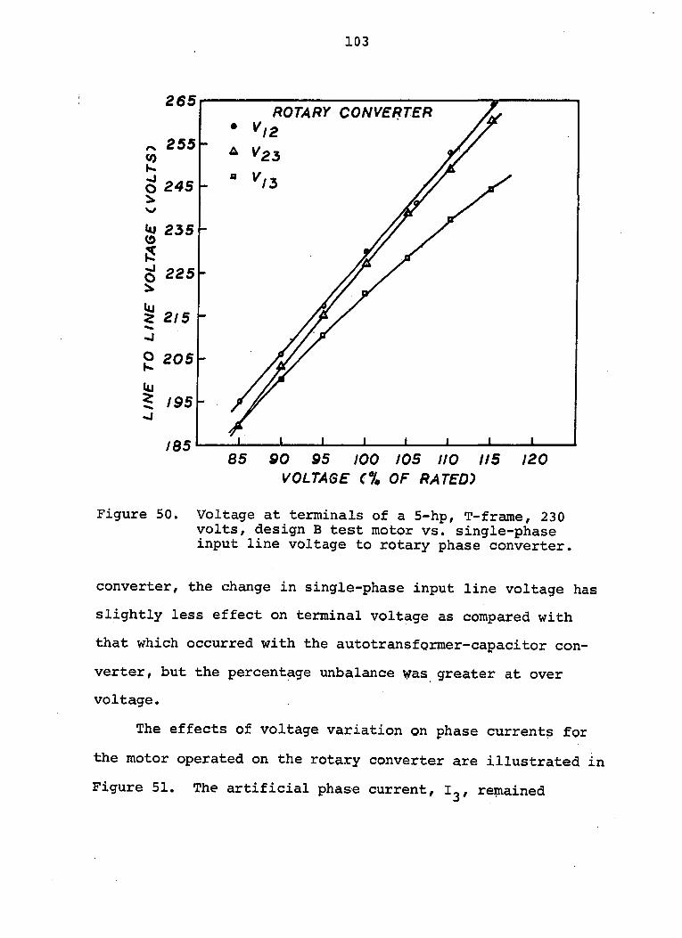
103
265 ROTARY CONVERTER
O 245
W 235
Z 215
9 205
90 95 100 /OS no 115 VOLTAGE C% OF RATED)
120
Figure 50. Voltage at terminals of a 5-hp, T-frame, 230 volts, design B test motor vs. single-phase input line voltage to rotary phase converter.
converter, the change in single-phase input line voltage has
slightly less effect on terminal voltage as compared with
that which occurred with the autotransformer-capacitor con
verter, but the percentage unbalance was greater at over
voltage.
The effects of voltage variation on phase currents for
the motor operated on the rotary converter are illustrated in
Figure 51. The artificial phase current, remained
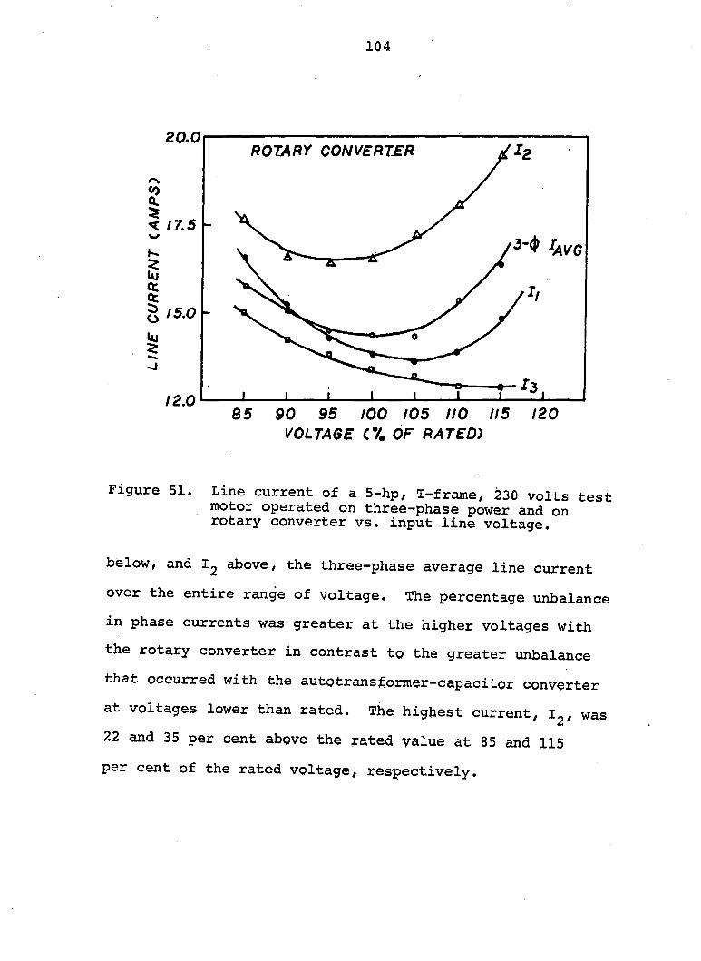
104
20.0
I < /7.5 w
K
Uj
ct
o
g
12.0
ROTARY CONVERTER
/h
o- "o
1 1 i 1 1 1 -1
85 90 95 100 105 110 115 120
VOLTAGE (% OF RATED)
Figure 51. Line current of a 5-hp, T-frame, 230 volts test motor operated on three-phase power and on rotary converter vs. input line voltage.
below, and above, the three-phase average line current
over the entire range of voltage. The percentage unbalance
in phase currents was greater at the higher voltages with
the rotary converter in contrast to the greater unbalance
that occurred with the autotransformer-capacitor converter
at voltages lower than rated. The highest current, was
22 and 35 per cent above the rated value at 85 and 115
per cent of the rated voltage, respectively.
105
Winding temperature
Because one or more of the motor phase currents increase
at under and over voltage, temperature of the motor windings
will be higher than at rated voltage. High winding tempera
ture may cause insulation deterioration and reduction of
motor life.
Figure 52 shows the highest temperature rise of the
motor windings as measured with embedded thermocouples,
with the motor operating on three-phase power and on the two
types of phase converters. Temperature rise was lowest at
rated voltage and increased at under and over voltages. A
i 15 per cent variation of the rated three-phase voltage
increased the temperature rise by 15° C (27° P) above the
temperature rise of 66° C (119° F) at rated voltage. The
highest temperature rise recorded for the motor operating
on the autotransformer-capacitor converter was 97° C (175° F)
at 90 per cent voltage. With the rotary converter, the
highest winding temperatures recorded were 83° C (149° F) and
98° C (176° F) at an input line voltage of 110 and 115 per
cent, respectively. '
Class B insulation used in NEMA T-frame motors is rated
for a total allowable temperature pf 130° C (266° F). The
allowable temperature rise is 90° C (162° F) on the basis of
a 40° C (104° F) ambient temperature. As illustrated in
Figure 61, input voltage to the autotransformer-capacitor
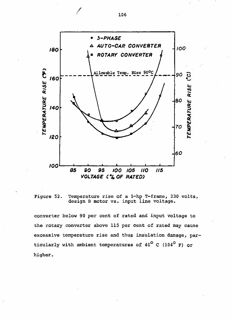
/ 106
• 5-PHASE
A AUTO-CAR CONVERTER
« ROTARY CONVERTER i 100
\ Allowable Temp. Rise 90°C / ^
t60
80
C 140
70
120
60
too as 90 95 100 105 no 115
VOLTAGE CXOF RATED)
Figure 52. Temperature rise of a 5-hp T-frame, 230 volts, design B motor vs. input line voltage.
converter below 90 per cent of rated and input voltage to
the rotary converter above 115 per cent of rated may cause
excessive temperature rise and thu§ insulation damage, par
ticularly with ambient temperatures of 40° C (104° F) or
higher.
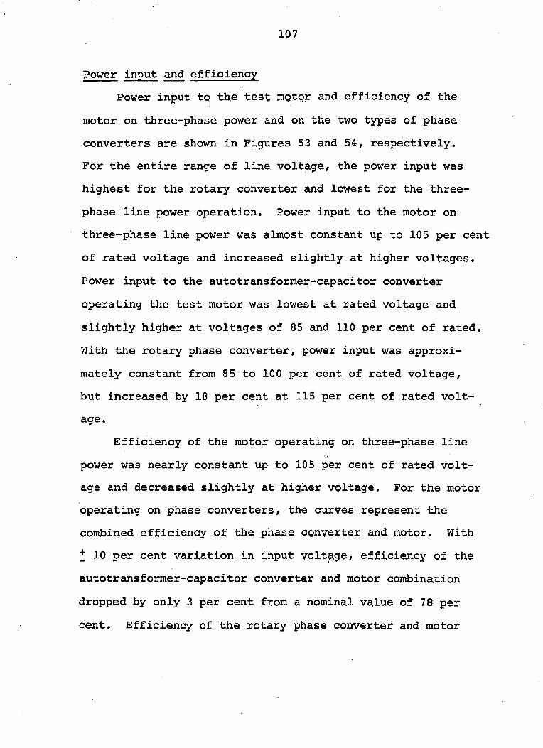
107
Power input and efficiency
Power input to the test motor and efficiency of the
motor on three-phase power and on the two types of phase
converters are shown in Figures 53 and 54, respectively.
For the entire range of line voltage, the power input was
highest for the rotary converter and lowest for the three-
phase line power operation. Power input to the motor on
three-phase line power was almost constant up to 105 per cent
of rated voltage and increased slightly at higher voltages.
Power input to the autotransformer-capacitor converter
operating the test motor was lowest at rated voltage and
slightly higher at voltages of 85 and 110 per cent of rated.
With the rotary phase converter, power input was approxi
mately constant from 85 to 100 per cent of rated voltage,
but increased by 18 per cent at 115 per cent of rated volt
age.
Efficiency of the motor operating on three-phase line
power was nearly constant up to 105 per cent of rated volt
age and decreased slightly at higher voltage. For the motor
operating on phase converters, the curves represent the
combined efficiency of the phase converter and motor. With
+ 10 per cent variation in input voltage, efficiency of the
autotransformer-capacitor converter and motor combination
dropped by only 3 per cent from a nominal value of 78 per
cent. Efficiency of the rotary phase converter and motor
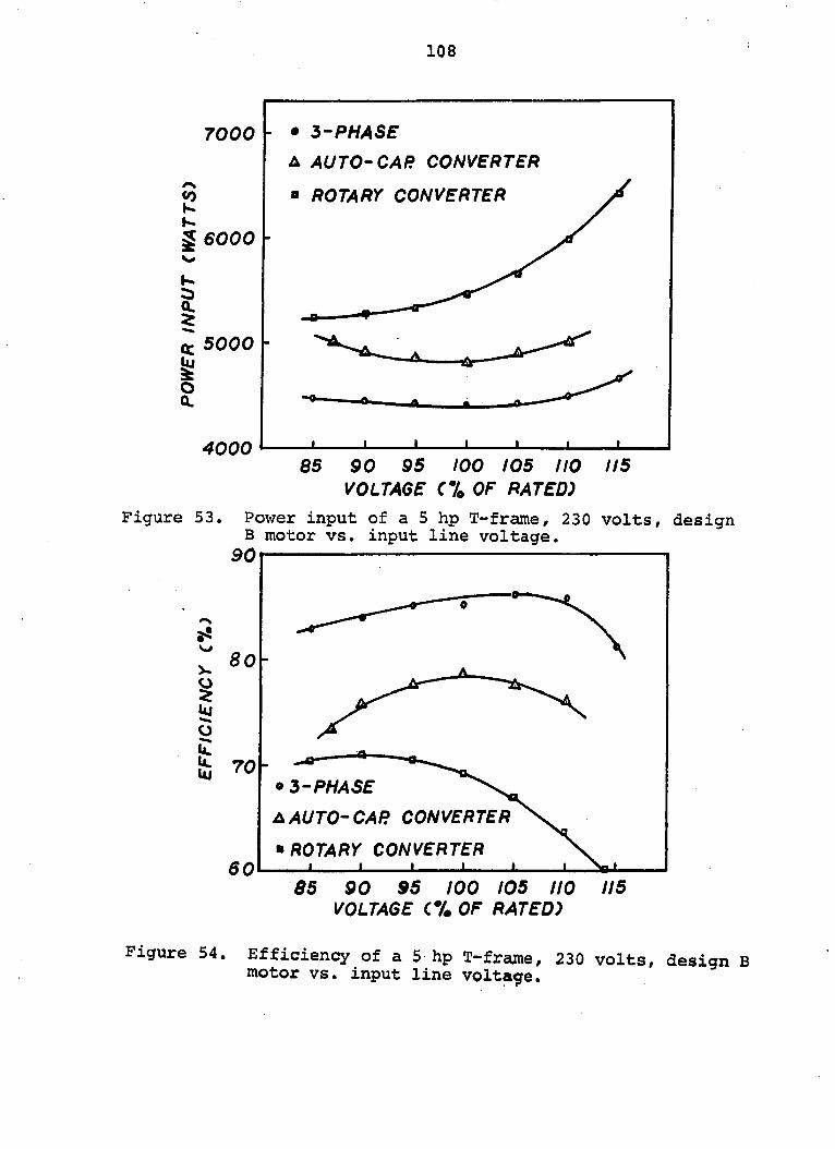
108
7000
E K S 6000
I % 5000
o Q.
4000
• 5'PHASE
A AUTO-CAR CONVERTER
= ROTARY CONVERTER
85 90 95 100 105 HO VOLTAGE C7o OF RATED)
115
Figure 53. Power input of a 5 hp T-frame, 230 volts, design B motor vs. input line voltage.
90
V
w kj
0
1
8 0 -
70-
6 0
• 3-PHASE
AUTO'CAR CONVERTER
•ROTARY CONVERTER ' I I I
85 90 95 too 105 HO VOLTAGE C7# OF RATED)
Figure 54. Efficiency of a 5 hp T-frajne, 230 volts, design B motor vs. input line vpltage.
109
combination was approximately 70 per cent from 85 to 95 per
cent of rated voltage, but dropped sharply to a value of 59
per cent at 115 per cent of rated voltage.
Power factor
Power factor of the test motor operating on three-
phase line power and phase converters is shown in Figure 55.
On three-phase line power, power factor increased slightly
with decreasing voltage (0,8 at 100% and 0.82 at 90%) and
decreased rapidly with voltage above rated (0.69 at 110%).
With the autotransformer-capacitor converter, power factor
of the system was 0.9 at rated voltage and increased to
approximately 1.0 at 90 and 110 per cent of rated voltage.
Power factor of the system with the motor operating on the
rotary converter was lower than that with three-phase and
decreased linearly as input line voltage was increased (0.70
at 90 per cent and 0.48 at 100 per cent).
Sli£
Figure 56 shows slip of the test motor in relation to
input line voltage. At rated voltage, slip was approxi
mately 3 per cent for operation on three-phase power and on
both phase converters. At 90 per cent of rated voltage,
slip increased to approximatley 4 pep cent and vas greater
with both phase converters than with three-phase power. At
110 per cent of rated voltage, slip decreased to approxi
mately 2.5 per cent. At the higher voltage, slip was
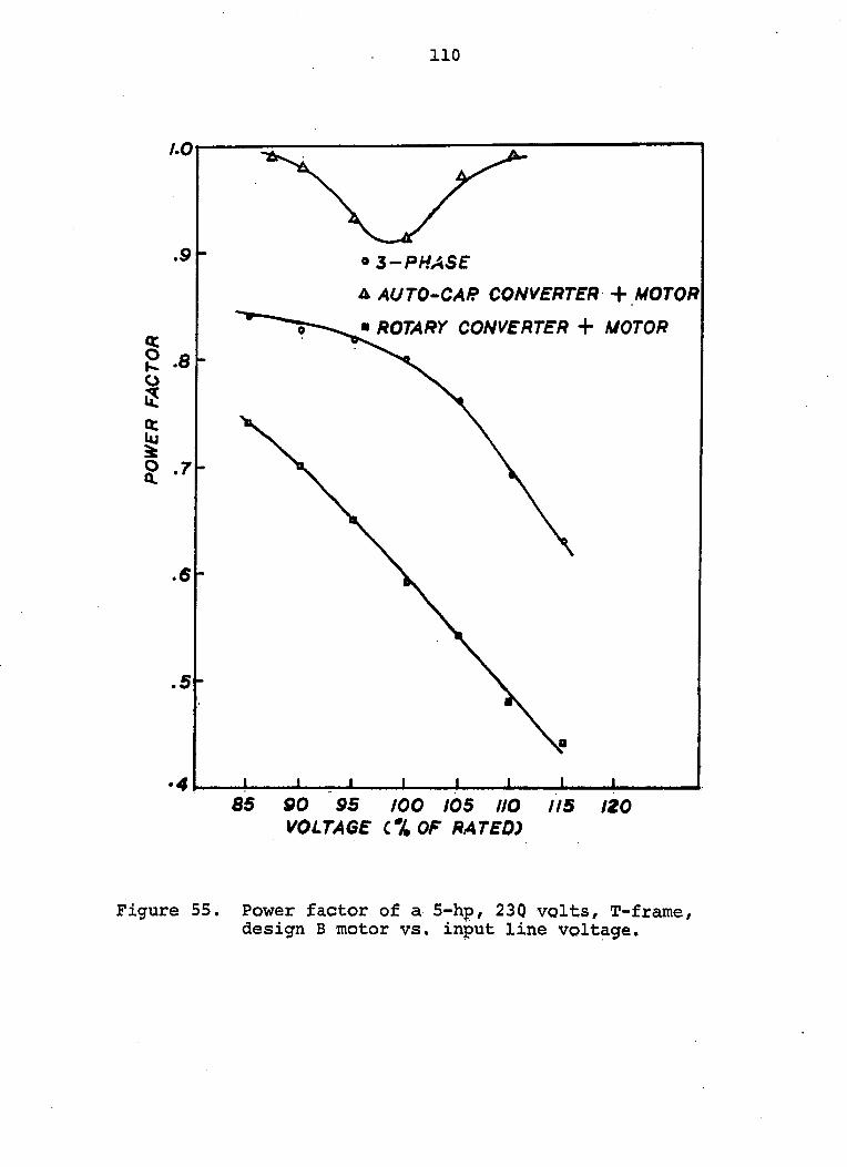
110
/.Oi
.9
g .e
g tt
?
.5
5-
® 3-PHASE
A AUTO-CAP CONVERTER MOTOR
• ROTARY CONVERTER + A/OTO/Î
_L ± ± ± ± 85 SO 95 100 105 HO
VOLTAGE C% OF RATED) l is 120
Figure 55. Power factor of a 5-hp, 23Q volts, T-frame, design B motor vs. input line voltage.
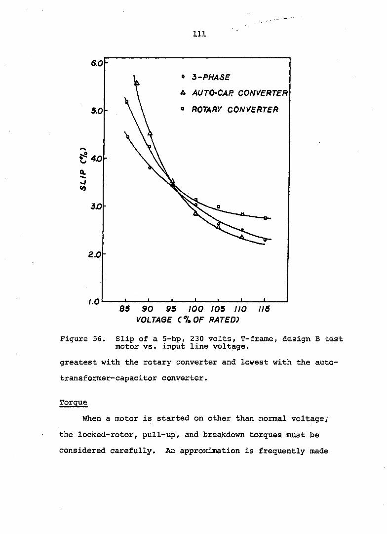
Ill
6.0 • 3'PHASE
A AUTO-CAR CONVERTER
" ROTARY CONVERTER 5.0
Q.
<0
2.0
1.0 85 90 95 100 105 HO 115
VOLTAGE C%OF RATED)
Figure 56. Slip of a 5-hp, 230 volts, T-frame, design B test motor vs. input line voltage.
greatest with the rotary converter and lowest with the auto-
transformer-capacitor converter.
Torque
When a motor is started on other than normal voltage;
the locked-rotor, pull-up, and breakdown torques must be
considered carefully. An approximation is frequently made
112
that torque varies as the square of the applied voltage (7) .
According to standards on motors (33, 72), this assumption
does not apply when the motor terminal voltages are other
than balanced.
Data on locked-rotor, pull-up, and breakdown torques
of the test motor operating on three-phase line power and
phase converters are graphed in Figures 57, 58, and 59.
With three-phase line power, torques were consistently higher
than those with phase converters. Locked-rotor and pull-up
torques of the motor operated on the autotransformer-capaci-
tor converter were higher than on the rotary converter. How
ever, breakdown torque was higher with the motor operating
on the rotary converter than on the autotransformer-capaci-
tor converter.
Locked-rotor, pull-up, and breakdown torques of the
motor operating on three-phase line power and on phase con
verters, over the input voltage range of 85 to 115 per cent
of rated are summarized in Table 9. Torque values are given
as a percentage of rated full-load torque of the test motor.
Breakdown torque of the motor operating on the autotrans-
former-capacitor phase converter is the maximum torque on
that portion of the torque-speed curve with the starting
capacitor switched out of the circuit.
Although locked-rotor and pull-up torques of the motor
with phase converters are lower than those obtained on
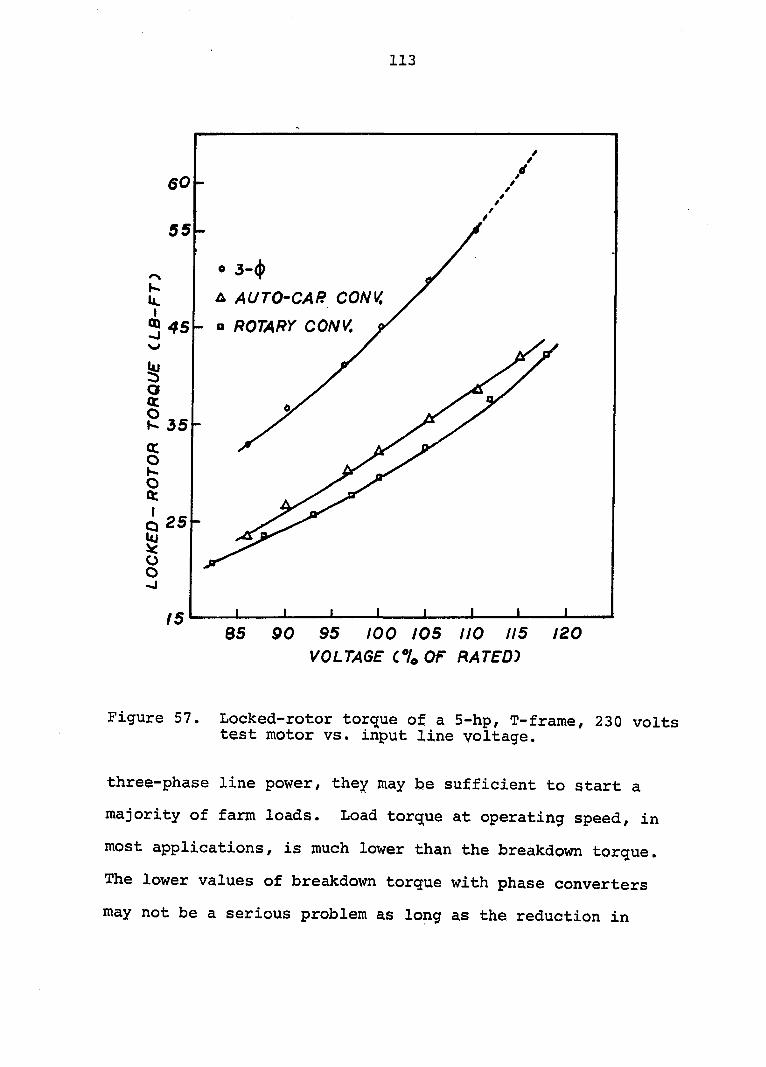
113
60
55
3-(|)
AUTO-CAR CONV,
ROTARY CONV, » 45
25
85 90 95 too 105 HO 115 120 VOLTAGE C7O OF RATED")
Figure 57. Locked-rotor torque of a 5-hp, T-frame, 230 volts test motor vs. input line voltage.
three-phase line power/ they may be sufficient to start a
majority of farm loads. Load torque at operating speed, in
most applications, is much lower than the breakdown torque.
The lower values of breakdown torque with phase converters
may not be a serious problem as long as the reduction in
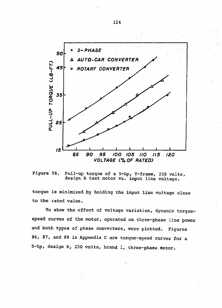
114
o 3-PHASE SO
A AUTO-CAR CONVERTER
45 o ROTARY CONVERTER
35
25
85 90 95 too 105 I/O 1/5 /20 VOLTAGE CU OF RATED)
Figure 58. Pull-up torque of a 5-hp, T-frame, 230 volts, design B test motor vs. input line voltage.
torque is minimized by holding the input line voltage close
to the rated value.
To show the effect of voltage variation, dynamic torque-
speed curves of the motor, operated on three-phase line power
and both types of phase converters, were plotted. Figures
86, 87, and 88 in Appendix C are torque-speed curves for a
5~hp/ design B, 230 volts, brand 1, three-phase motor.
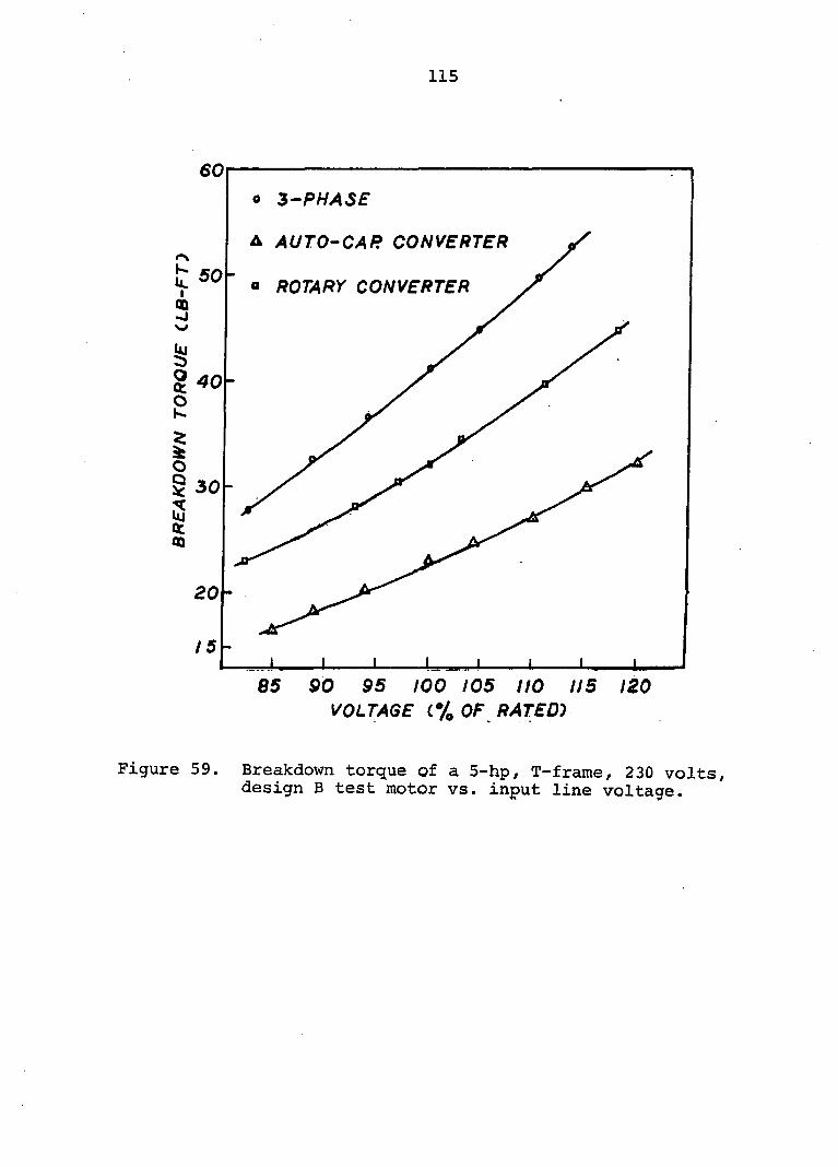
115
60
o 3^PHA3E
A AUTO'CAR CONVERTER
50 = ROTARY CONVERTER
40
5 30
20
85 90 95 too 105 NO 115 120 VOLTAGE (.% OF RATED-)
Figure 59. Breakdown torque of a 5-hp, T-frame, 230 volts, design B test motor vs. input line voltage.
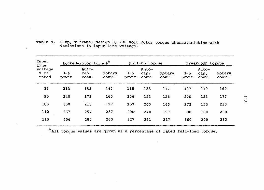
Table 9. 5-hp, T-frame, design B, 230 volt motor torque characteristics with Variations in input line voltage.
Input line voltage % of rated
Locked--rotor torque^ Pull--up torque Breakdown torque Input line voltage % of rated
3—(j) power
Auto-cap. conv.
Rotary conv.
3-4 power
Auto-cap, conv.
Rotary conv.
3—<j) power
Auto-cap. conv.
Rotary conv.
85 213 153 147 185 133 117 197 110 160
90 240 173 160 206 153 128 220 123 177
100 300 213 197 253 200 160 273 153 213
110 367 257 237 300 240 197 330 180 260
115 406 280 263 327 261 217 360 200 283
^•All torque values are given as a percentage of rated full-load torque.

117
EFFECTS OF UNBALANCED VOLTAGE ON MOTOR PERFORMANCE
When three-phase motors are opej-ated from a single-
phase power line through phase converters, the voltage at
the motor terminals are not always balanced. The effects
of unbalanced voltage on the performance of three-phase
induction motors have been disucssed in various technical
reports (8, 54, 63, 65, 84, 110). Most of these reports
deal with the unbalance conditions of voltage on three-phase
line power. They do not include the voltage unbalance that
is typical of the three-phase voltage output of phase con
verters. Because of this difference a study was made of the
effects of unbalanced voltage on the performance of a three-
phase motor operating on a phase converter.
Unbalance in the voltage output of a phase converter is
caused mainly by two conditions, the load on the motor-con
verter combination is above or below the motor rating and the
single-phase voltage input to the phase converter is dif
ferent than the rated voltage. In both conditions the nature
of unbalance, usually, is such that the two voltages and
V23 are either higher than Y^2 both are lower than
This is shown in Figures 35, 37, 39, 48, and 50 and also
verified by Knight et al. (57).
118
Unbalance with Three-Phase Power
To study the effects of unbalanced voltage on the
three line currents and winding temperature, the test motors
were operated at various percentages of unbalance in motor
terminal voltages. The voltage unbalance similar to that
which occurred with the motors operating from phase con- .
verters, was simulated from the three-phase line power
supply. The voltage held constant and the magnitude
of the two voltages and V23 were maintained at various
values above and below The circuit used to obtain the
various values of and V22 is shown in Figure 15.
A 10 hp U-frame and a 10 hp T-frame motor were tested
at 80 and 100 per cent of the rated load, with voltage
unbalance up to a maximum of 6 per cent. The unbalances in
voltage and current were computed according to the following
definition given in the application data section MGl-14.33 of
NEMA Standards (72).
For example, if three line to line voltages are 220, 241, and
232, the average voltage is 231, the maximum deviation from
the average is (231-220) = 11 volts, and the percentage
unbalance is (11/231) x 100 = 4.76.
Per cent voltage = 100 x unbalance
Maximum deviation from avg. voltage avg. voltage
(25)
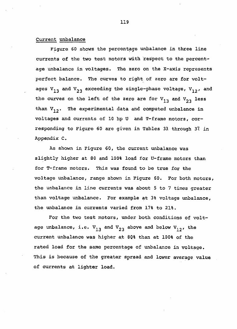
119
Current unbalance
Figure 60 shows the percentage unbalance in three line
currents of the two test motors with respect to the percent
age unbalance in voltages. The zero on the X-axis represents
perfect balance. The curves to right of zero are for volt
ages and Vgg exceeding the single-phase voltage, and
the curves on the left of the zero are for and Vgg less
than V^2• The experimental data and computed unbalance in
voltages and currents of 10 hp U and T-frame motors, cor
responding to Figure 60 are given in Tables 33. through 37 in
Appendix C.
As shown in Figure 60, the current unbalance was
slightly higher at 80 and 100% load for U-frame motors than
for T-frame motors. This was found to be true for the
voltage unbalance, range shown in Figure 60. For both motors,
the unbalance in line currents was about 5 to 7 times greater
than voltage unbalance. For example at 3% voltage unbalance,
the unbalance in currents varied from 17% to 21%.
For the two test motors, under both conditions of volt
age unbalance, i.e. and Vgg above and below the
current unbalance was higher a,t 80% than at 100% of the
rated load for the same percentage of unbalance in voltage.
This is because of the greater spread and lower average value
of currents at lighter load.
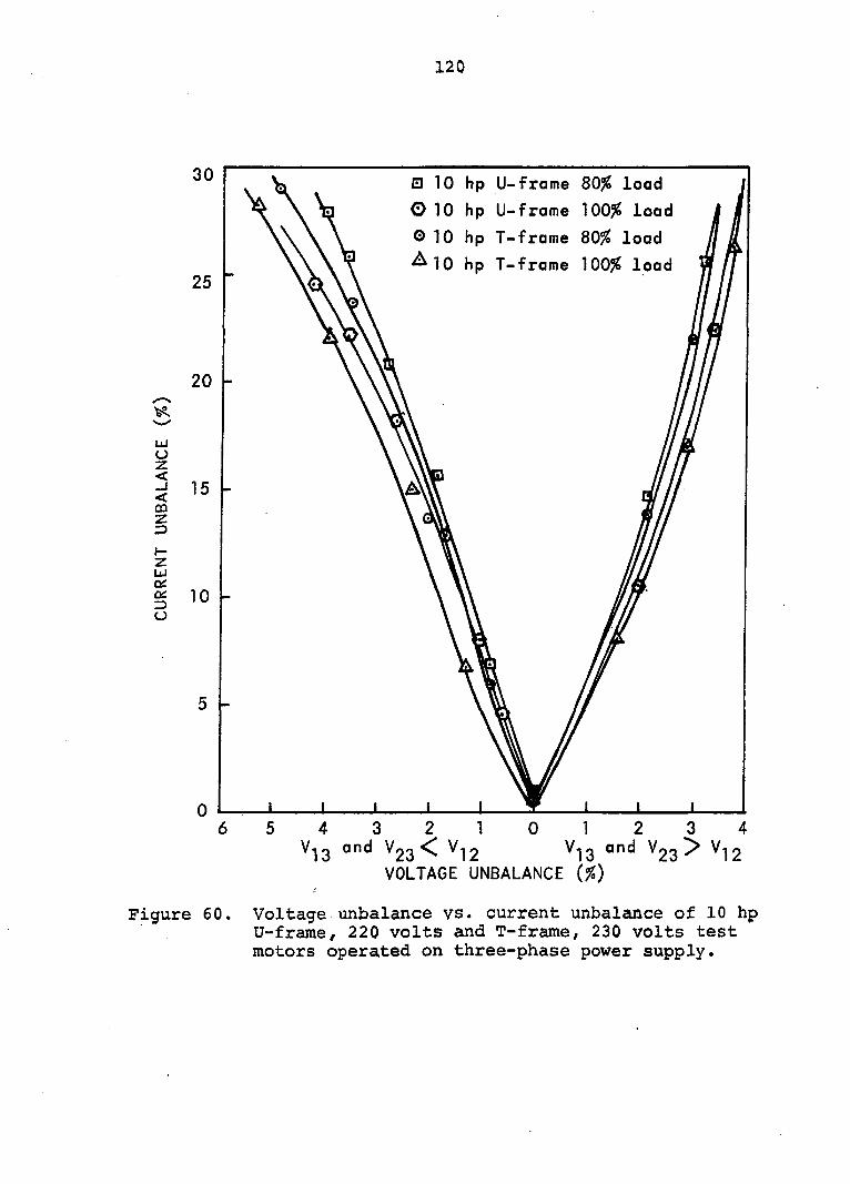
120
30
25
20
LU o z < _J < m z 3
o:
O
15
10
• 10 hp U-frame 80% load
010 hp U-frame 100# load
O 10 hp T-frame 80% load
^10 hp T-frame 100# load
_L ± 1
Vi3 and Vgg 2 1 0
^ 12 VOLTAGE UNBALANCE (%)
Vi3 and V23 3 4
> V12
Figure 60. Voltage unbalance vs. current unbalance of 10 hp U-frame/ 220 volts and T-frame, 230 volts test motors operated on three-phase power supply.
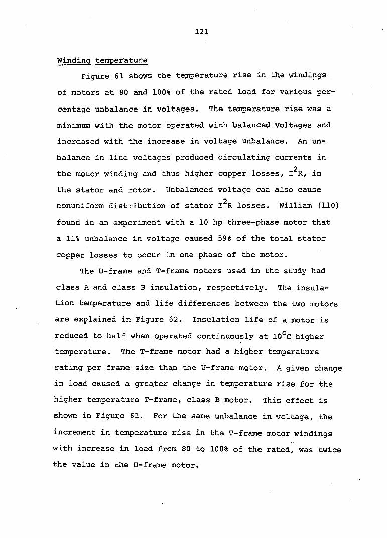
121
Winding temperature
Figure 61 shows the temperature rise in the windings
of motors at 80 and 100% of the rated load for various per
centage unbalance in voltages. The temperature rise was a
minimum with the motor operated with balanced voltages and
increased with the increase in voltage unbalance. An un
balance in line voltages produced circulating currents in
2 the motor winding and thus higher copper losses, I R, in
the stator and rotor. Unbalanced voltage can also cause
2 nonuniform distribution of stator I R losses. William (110)
found in an experiment with a 10 hp three-phase motor that
a 11% unbalance in voltage caused 59% of the total stator
copper losses to occur in one phase of the motor.
The U-frame and T-frame motors used in the study had
class A and class B insulation, respectively. The insula
tion temperature and life differences between the two motors
are explained in Figure 62. Insulation life of a motor is
reduced to half when operated continuously at 10°C higher
temperature. The T-frame motor had a higher temperature
rating per frame size than the U-frame motor. A given change
in load caused a greater change in temperature rise for the
higher temperature T-frame, class B motor. This effect is
shown in Figure 61. For the same unbalance in voltage, the
increment in temperature rise in the T-frame motor windings
with increase in load from 80 to 100% of the rated, was twice
the value in the U-frame motor.
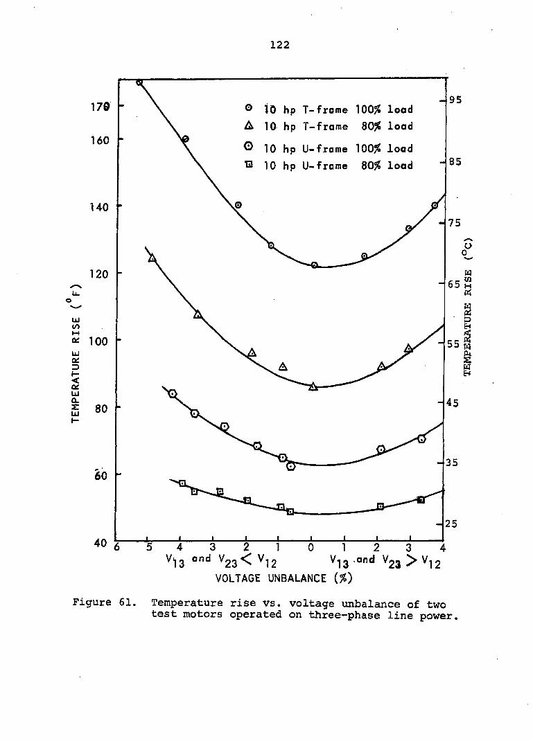
122
- 95 170 ® 10 hp T-frome 100# load
A 10 hp T-frame 80# load
^ 10 hp U-frame 100# load
13 10 hp U-frame 80# load
160
85
140
75
120
uj {fi 2 100 uj
55 s
80
- 35
60
25
40
VOLTAGE UNBALANCE (#)
Figure 61. Temperature rise vs. voltage unbalance of two test motors operated on three-phase line power.

123
20,000
lOiOOO
6,000
4,000
X % 2,000 5 S, S 1,000
600
400
200
\ \ \ \ \ floss
\ ^
\ ^loss \ B
floss
\ ^
\ ^loss \ B
\ A \ A \\ I \\ \
\
Insulation Temperature (C)
Figure 62. Typical motor winding life vs. temperature for commonly used classes of insulation.
Unbalance with Phase Converter
Current unbalance and temperature rise
Figures 63 and 64 show the effects of voltage unbalance
on the unbalance in line currents and temperature rise of a
three-phase motor operated from an autotransformer-capacitor
phase converter and rotary phase converter, respectively.
The experimental data corresponding to these figures are
given in Tables 10 and 11.
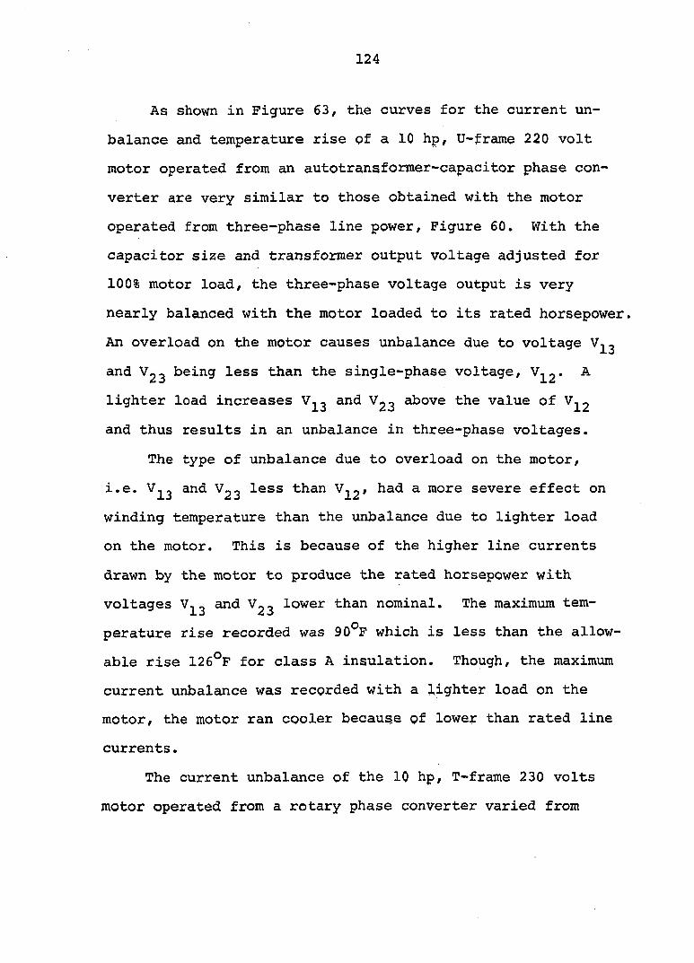
124
As shown in Figure 63, the curves for the current un
balance and temperature rise of a 10 hp, U-frame 220 volt
motor operated from an autotransformer-capacitor phase con
verter are very similar to those obtained with the motor
operated from three-phase line power, Figure 60. With the
capacitor size and transformer output voltage adjusted for
100% motor load, the three-phase voltage output is very
nearly balanced with the motor loaded to its rated horsepower.
An overload on the motor causes unbalance due to voltage
and Vgg being less than the single-phase voltage, A
lighter load increases and above the value of
and thus results in an unbalance in three-phase voltages.
The type of unbalance due to overload on the motor,
i.e. and less than had a more severe effect on
winding temperature than the unbalance due to lighter load
on the motor. This is because of the higher line currents
drawn by the motor to produce the rated horsepower with
voltages and lower than nominal. The maximum tem
perature rise recorded was 90®P which is less than the allow
able rise 126°F for class A insulation. Though, the maximum
current unbalance was recorded with a lighter load on the
motor, the motor ran cooler because of lower than rated line
currents.
The current unbalance of the 10 hp, T-frame 230 volts
motor operated from a rotary phase converter varied from
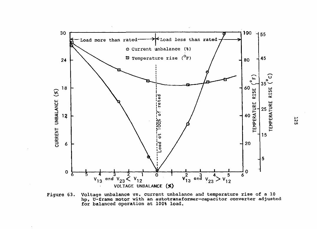
IGO -
h Load less than rated Load more than rated
Figure 63,
1 0 23^ *12
VOLTAGE UNBALANCE (%)
4. 5
^23 12
H" ro in
Voltage unbalance vs. current unbalance and temperature rise of a 10 hp, U-frame motor with an autotransformer-capacitor converter adjusted for balanced operation at 100% load.
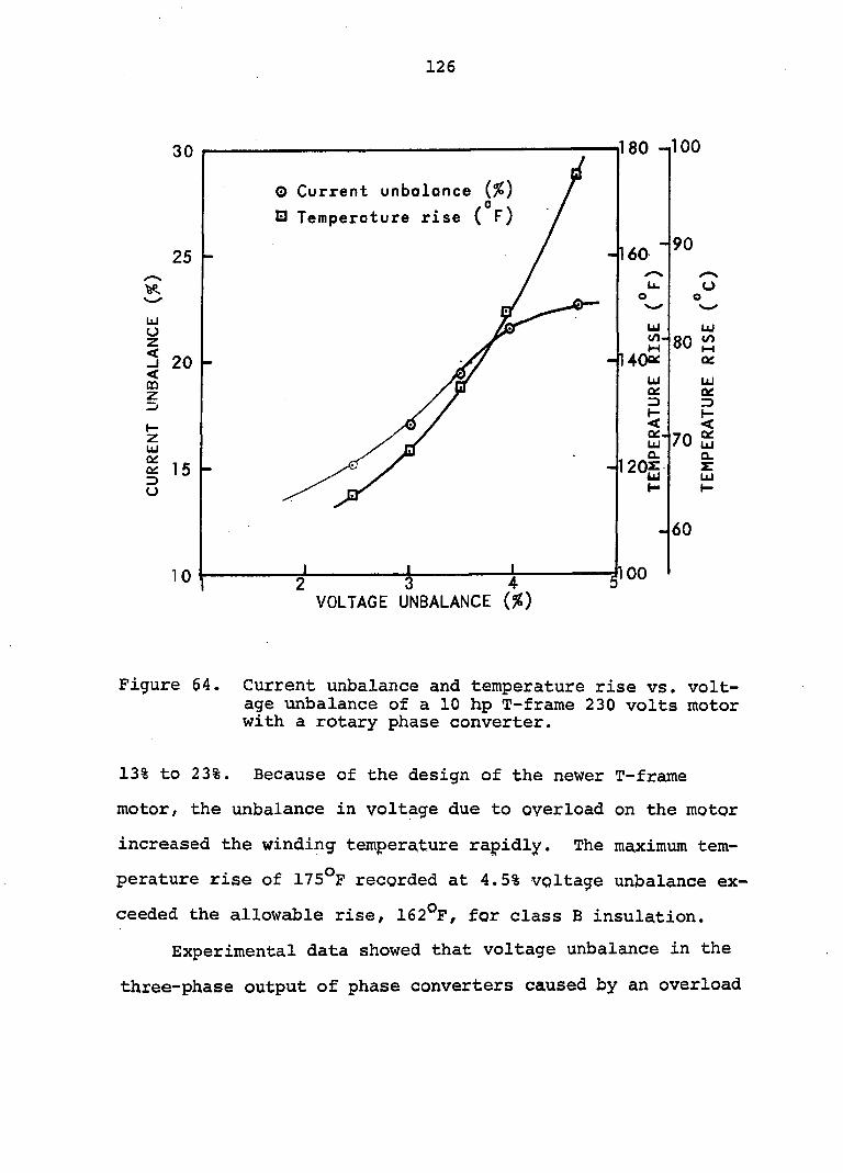
126
30
25 -
LU
u z < _J < QÛ z
20 -
z LU
^ 15 z> o
1 0
O Current unbalance {%) . 0 .
Q Temperature rise ( F)
_L _L 2 3 4 VOLTAGE UNBALANCE {%)
-160
180 -ilOO
-90
w (/)
1400È u Qg =>
< (K. LU
20| H
100
80 Q£
LU ÛC =)
70 £ Q.
60
Figure 64. Current unbalance and temperature rise vs. voltage unbalance of a 10 hp T-frame 230 volts motor with a rotary phase converter.
13% to 23%. Because of the design of the newer T-frame
motor, the unbalance in voltage due to overload on the motor
increased the winding temperature rapidly. The maximum tem
perature rise of 175°F recorded at 4.5% voltage unbalance ex
ceeded the allowable rise, 162®F, for class B insulation.
Experimental data showed that voltage unbalance in the
three-phase output of phase converters caused by an overload
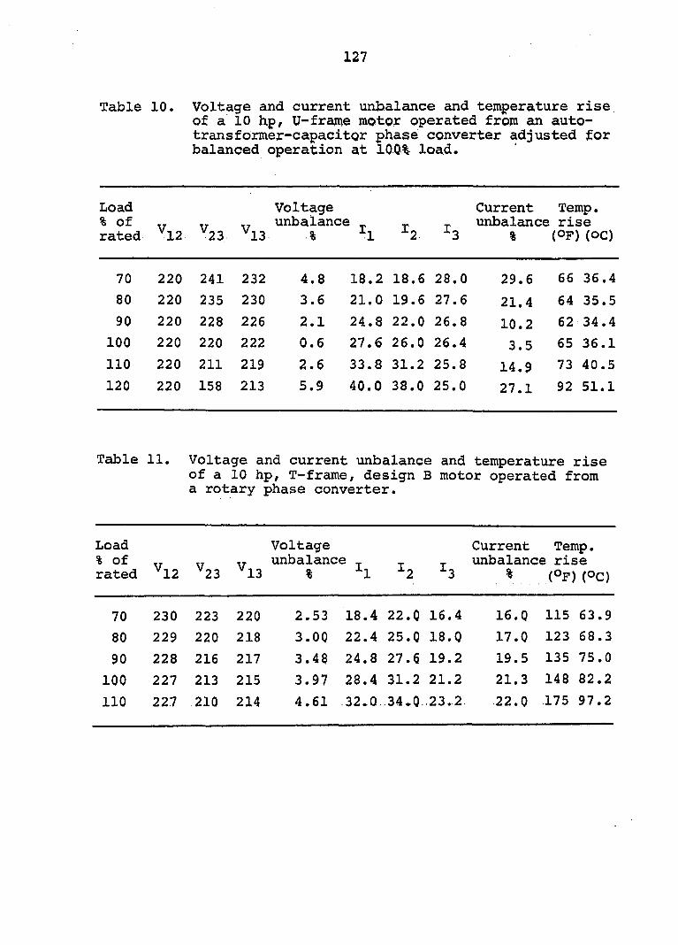
127
Table 10. Voltage and current unbalance and temperature rise of a 10 hp/ U-frame motor operated from an auto-trans former-capacitor phase converter adjusted for balanced operation at 100% load.
Load % of rated Vl2 ^23
(D
Voltage unbalance
% -^1 l2 I3
Current unbalance
%
Temp, rise
(OF) (OC)
70 220 241 232 4.8 18.2 18.6 28.0 29.6 66 36.4
80 220 235 230 3.6 21.0 19.6 27.6 21.4 64 35.5
90 220 228 226 2.1 24.8 22.0 26.8 10.2 62 34.4
100 220 220 222 0.6 27.6 26.0 26.4 3.5 65 36.1
110 220 211 219 2.6 33.8 31.2 25.8 14.9 73 40.5
120 220 158 213 5.9 40.0 38.0 25.0 27.1 92 51.1
Table 11. Voltage and current unbalance and temperature rise of a 10 hp, T-frame, design B motor operated from a rotary phase converter.
Load Voltage Current Temp. % of „ unbalance _ unbalance rise rated ^12 ^23 ^13 % "^1 ^2 ^3 % (Op) (Oc)
70 230 223 220 2.53 18.4 22.0 16.4 16.0 115 63 .9
80 229 220 218 3.00 22.4 25.0 18.Q 17.0 123 68 .3
90 228 216 217 3.48 24.8 27.6 19.2 19.5 135 75 .0
100 227 213 215 3.97 28.4 31.2 21.2 21.3 148 82 .2
110 227 210 214 4.61 32.0. 34.0 23.2 22.0 175 97 .2

128
on the motor or because of lower single-phase input voltage
may be detrimental to the motor life. The voltage unbalance
caused by a load less than the full load and single-phase
voltage higher than rated has less serious temperature rise
and in many cases may be acceptable.
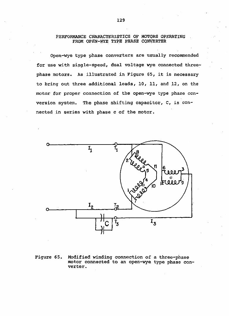
129
PERFORMANCE CHARACTERISTICS OF MOTORS OPERATING . FROM OPEN-WYE TYPE PHASE CONVERTER
Open-wye type phase converters are usually recommended
for use with single-speed, dual voltage wye connected three-
phase motors. As illustrated in Figure 65, it is necessary
to bring out three additional leads, 10, 11, and 12, on the
motor for proper connection of the open-wye type phase con
version system. The phase shifting capacitor, C, is con
nected in series with phase c of the motor.
Figure 65. Modified winding connection of a three-phase motor connected to an open-wye type phase converter.
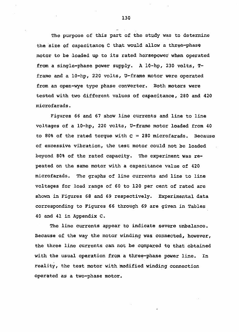
130
The purpose of this part of. the study was to determine
the size of capacitance C that would allow a three-phase
motor to be loaded up to its rated horsepower when operated
from a single-phase power supply. A 10-hp, 230 volts, T-
frame and a 10-hp, 220 volts, U-frajtie motor were operated
from an open-wye type phase converter. Both motors were
tested with two different values of capacitance, 280 and 420
microfarads.
Figures 66 and 67 show line currents and line to line
voltages of a 10-hp, 220 volts, U-frame motor loaded from 40
to 80% of the rated torque with c = 280 microfarads. Because
of excessive vibration, the test motor could not be loaded
beyond 80% of the rated capacity. The experiment was re
peated on the same motor with a capacitance value of 420
microfarads. The graphs of line currents and line to line
voltages for load range of 60 to 120 per cent of rated are
shown in Figures 68 and 69 respectively. Experimental data
corresponding to Figures 66 through 69 are given in Tables
40 and 41 in Appendix C.
The line currents appear to indicate severe unbalance.
Because of the way the motor winding wag connected, however,
the three line currents can not be compared to that obtained
with the usual operation from a three-phase power line. In
reality, the test motor with, modified winding connection
operated as a two-phase motor.

131
U) 04
01 +) C <D
k 3 U 0) e 'H
Figure 66.
275
Load (% of rated)
Line currents vs. load on a 10-hp, 220 volts, U-frame motor, C = 280 yF.
Figure 67.
50 Load (% of rated)
Line to line voltage vs. load qn a 10 hp, 220 volts, U-frame motor, C = 280 yF.
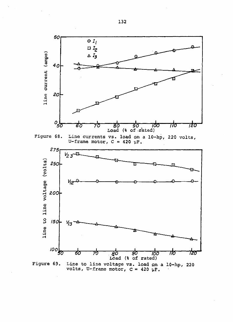
132
(0 eu
+> G <D U W 3 O a> c
•m
TÔo—th—rh 90. Load (% of -rated)
Figure 68. Line currents vs. load on a lO-hp, 220 volts, U-frame motor, C - 420 yP.
150' W
Figure 69.
^ W> too Load (% of rated)
Line to line voltage vs. load pn a IQ-hp, 220 volts, U-frame motor, c = 420 jiF,
133
The single-phase line current, I^/ in Figure 65 is
vector sum of currents in phage ab ajid phase c. At no load,
the current through the capacitor phase, I^, was very high
and produced severe vibrations in the motor. As the load on
the motor was increased, showed slight variation. Current
is considerably higher than because is vector sum
of currents and Ig. Curves for and Ig are nearly
parallel for the range of load on the test motor. Both cur
rents, however, increased with the load.
Voltage Vgg, the voltage across capacitors C, was the
highest. This voltage was the vector sum of voltage across
winding c, and single-phase voltage across phase
ab of the motor.
By using the correct value of oil capacitor the current
Ig in phase ab as related to in phase c can be displaced
by nearly 90°. The test motor will operate practically as
though it was fed from a two-phase power line. Voltage
across phase c is nearly in quadrature with the line voltage
across phase ab.
Perfect two-phase operating conditions occur at only
one value of load for a given value of capacitance. As the
load changes, the magnitudes of current and phase angle
deviates from a true two-phase operation. Tests showed
that for a 10-hp, general purpose, V-frame, induction motor,
capacitors sized at 40 microfarads per motor horsepower would
134
provide nearly two-phase operating conditions of a three-
phase motor loaded tQ its r^ted capacity.
The experimental data on a lO-hp, 230 volts, T-frame,
NEMA design B motor operating from an open-wye type phase
converter with C = 280 and 420 microfarads are given in
Tables 42 and 43 in Appendix C. The efficiency of both
motors was slightly lower than on three-phase line power
through out the range of loads. Slip of the motors increased
rapidly with overload.
To avoid stalling and overheating of a motor operated
from an open-wye type phase converter, caution should be
exercised not to exceed 100% of the nameplate horsepower.
The open-wye phase conversion system is less expensive
than rotary and autotransformer-capacitor converters and, in
applications where low starting torque is required and the
load on the motor does not fluctuate, this system will
operate three-phase motors from single-phase power.
135
EFFECTS OF STARTING CAPACITANCE ON LOCKED-ROTOR TORQUE
A typical torque-speed curve of a three-phase, squirrel
cage, design B motor operated from three-phase power is
shown in Figure 21, The locked-rotor, pull-up, and break
down torques are identified on the curve. According to the
ASA (3) and NEMA (72) specifications, a 5-hp, squirrel cage,
230 volts, three-phase, design B motor with rated voltage
and frequency applied should produce locked-rotor, pull-up,
and breakdown torques of 185, 225, and 130 per cent of the
full-load torque respectively.
The torque characteristics of a three-phase motor
operated from a phase converter usually are different in
values than those obtained with three-phase line power.
Starting torque is reduced considerably (22, 23) and break
down torque is also lower (49).
Design Equations 10 and 11 for the autotransformer-
capacitor phase converter give the optimum values of param
eters i.e., size of the capacitors and transformer output
voltage for the balanced steady state operation of a three-
phase motor. These equations do not determine the capacitor
size needed for starting conditions. If started with only
the running capacitance in the circuit, the motor would have
very little starting torque. For example, the torque-speed
curve closest to the Y-axis in Figure 70, was obtained for
a 5-hp, 230 volts, T-frame, NEMA design B, three-phase motor

136
RacsiiasBca
m «a**» -an aeziqeT»** asax i(U¥ fm««3iwK*ea sïs'.ïr. îgâssîïsg K» S*C£SSWBO«®S| R? us( t»fl «MiCaVUlBV' V fitf as.'dKecaa)ft«»xc»x V fitf as.'dKetaa««i>xaB««
'j*'aaa«-t""SisS»«S a» JieKaaKMgwaA*#** T'.r-vsansiJ&aisss:»»» j»' Hne.'flee%c«aavK.<«: rt Ci^&£2(ID9inxrs:«a»i» ' 4;pL!BMaNaiRMae*»p» 'WNCAO###Y**RE«G« K:«MGa:aaa a^uoii
llilill il "gii.ni§
mai;:
ii jzt*-B mt itrÉ ;
Figure 70. Dynamic torque-speed characteristics of a 5-hp, T-frame, design B, three-phase motor operated from an autotransformer-capacitor-phase converter .
137
operated from an autotransformer-capacitor phase converter
with running capacitance of 150 microfarads. A similar curve
for the same motor and converter but, with 180 microfarads
of running capacitance shows a slight improvement in the
locked rotor, pull-up and breakdown torque of the motor.
For a motor to perform properly, the locked-rotor and
pull-up torques must exceed the load torque requirements by
a margin great enough to accelerate the load to the operating
point in a short period of time, generally no more than 10
seconds. The torques available from the test motor with
capacitance of 150 or 180 uF would be insufficient to start
a load that requires a 5-hp motor for steady state operation.
Locked-rotor and pull-up torques can be improved by
placing more capacitance in the circuit for the duration of
the starting cycle. Common practice has been to use electro
lytic capacitors because of their lower cost, high capaci
tance, and smaller size. Electrolytic capacitors, however,
have short duty cycles and should be disconnected at about
90% of the full load speed of the motor. Several switching
arrangements to switch the electrolyte capacitors out of the
circuit have been applied successfully (32, 86),
The effects of starting capacitance on the torque-speed
curve of the test motor are shown in Figure 70. The locked-
rotor torque of the 5-hp motor was improved to 36,6 pound-ft
by adding 1250 microfarads of electrolytic capacitance to the
138
starting circuit. This is about 240 per cent of the full
load torque of the motor, The torque-speed curve beyond
the point where electrolytic capacitors are removed from
the circuit,, overlaps the torque curve of motor obtained with
180 microfarads of running capacitance alone. The torque
available with the running capacitance alone in most applica
tions is sufficient to accelerate the load to the operating
point.
To find the optimum size of electrolytic capacitors
that would give a maximum possible locked-rotor and pull-up
torque, tests were conducted on a 5-hp, 3-phase, 230 volts,
T-frame, design B motor. The experimental data in graphical
form are shown in Figures 71 and 72.
To improve the starting torque of the motor by using
electrolytic capacitors, it is important for the single-
phase line voltage to be at its rated value. Lower single-
phase voltage would reduce the effect of starting capacitors
on the locked-rotor torque. For example, at 100% of rated
input single-phase voltage the locked rotor torque was 35
pound-feet with 700 microfarads and decreased to 31 pound-
feet at 95% of rated voltage. When low voltage at starting
of the motor is expected, the value of electrolytic capaci
tance should be increased to offset the reduction in locked
rotor torque. At 95% of the rated voltage, it was possible
to obtain 35 pound-feet of locked rotor torque by increasing
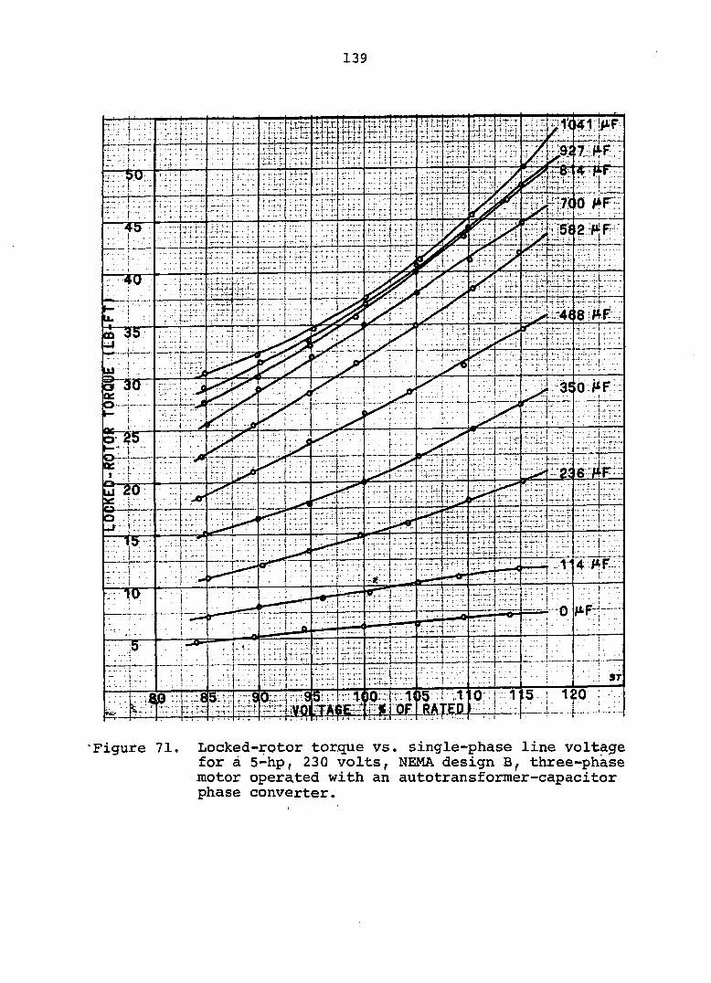
139
l - f .
CD
....
ST
"Figure 71. Locked-rotor torque vs. single-phase line voltage for à 5-hp, 230 volts, NEMA design B, three-phase motor operated with an autotransformer-capacitor phase converter.

1 y O L T A G E
VOLTAGE
DO : BOO 00 1
Figure 72 Locked-rotor torque vs. starting capacitance (yF) for a 5-hp, 230 volts NEMA design B, three-phase motor operated with an autotransformer-capacitor phase converter.
141
the starting capacitance from 700 to 1040 microfarads.
Graphs in Figure 72 show that holding single-phase
input voltage constant, an increase in starting capacitance
improved the motor locked-rotor torque. This is because of
phase shift in the artificial phase voltage to about 120
electrical degrees apart from the other two phases, giving
approximately three-phase conditions during the starting
cycle. Beyond a certain value of capacitance, however, the
effect of additional capacitors is relatively very small.
For example, for rated line voltage, locked-rotor torque
was 23 Ib-ft with 400 yF, 32 Ib-ft with 600 yF, and 36 Ib-ft
with 800 yF. An additional 200 yF in the circuit improved
the locked-rotor torque to 37 Ib-ft, an increase of 1 Ib-ft
over that obtained with 800 yF.
The test data on an autotransformer capacitor phase
converter operated 5-hp three-phase motor with single-phase
voltage at rated value showed that electrolytic capacitors
sized at 180 yF per motor horsepower would give locked-
rotor and pull-up torques slightly higher than NEMA specifi
cations for the motor. The nearly maximum locked-rotor
torque was obtained with 200 JiF per horsepower. Starting
capacitance larger than 200 jiF per horsepower had a very
little increase in the starting torque of the motor,
Starting capacitors have similar improvement in the
locked-rotor and pull-up torques of a three-phase motor

142
operated from various types of phase converters. The
effects of starting capacitors on the dynamic torque-speed
characteristics of motors operated from capacitor-only,
open-wye type, and rotary phase converters are shown in
Figures 89, 90, and 91 respectively in Appendix C.
143
POWER SERVICE DESIGN FOR PHASE CONVERTER AND ASSOCIATED THREE-PHASE MOTOR(S)
A majority of the problems encountered with phase con
verter applications have been due to improper installation
and undersized wiring. In general, undersized wiring on any
electric motor application will cause excessive voltage drop.
This will reduce starting torque, and motors may not start
or may start but take too long to accelerate the load,
causing overheating of the motor in either case.
Problems arising from undersized wiring and excessive
voltage drop are more severe when three-phase motors are
supplied power from a single-phase source through a phase
converter. In many cases, phase converters are adjusted to
give balanced three-phase output at the rated input voltage
and rated load on the motor. Any drop in the single-phase
voltage at the input of the phase converter, therefore, will
usually result in unbalanced three-phase voltage output (40).
Unbalanced voltage causes excessively high current in
one or more phases of the fully loaded motor, and the aver
age current often is higher than the nameplate rating. The
consequences of higher than normal currents are excessive
heating and premature deterioration of the motor. Low
single-phase input voltage accompanied by an unbalanced
three-phase output has a compound effect on the reduction
of motor torque which impairs the performance of the phase
converter, three-phase motor system.
144
Well designed services to phase converters can be
achieved by selecting the proper transformer, conductor
size, and overload protection.
Transformer Size
In the past, some of the commercially available rotary
phase converters were rated by their motor starting capa
bility. Commonly, rotary phase converters with a nameplate
rating of 30 horsepower could be used to start and operate
a maximum of a 30-hp single motor or several three-phase
motors with a combined rating of 60 hp. However, there is
a wide variation in recommendations on the maximum motor
load that can be operated from a rotary phase converter.
Following are a few examples :
"The combined horsepower of all the motors to be operated simultaneously should not exceed 1.5 times horsepower rating of the converter." (51)
"Loading on a rotary converter can not be more than twice its rated horsepower before recommended temperature rise is exceeded." (23)
"The total horsepower load that can be connected to a rotary converter is two to four times the horsepower of the largest motor that may be started." (94)
"Total horsepower of motors may be well in excess of the converter single motor rating. Generally a load four times the rating is acceptable, sometimes even more if voltage is maintained," (4)
"Total motor load should not be greater than four times the size of converter," (12, 96)
145
With static phase converters, the rating problem did not
usually arise because static converters were recommended
for use with only one three-phase motor.
Power suppliers select and install stepdown trans
formers to serve farm loads. In many instances, trans
formers are sized on the basis of converter horsepower
rating and not for their total motor horsepower capability.
In sizing a transformer for phase converter operated
three-phase motors, the total horsepower of all the motors
to be operated from the phase converter should be considered.
Some manufacturers of phase converters recently have added
the combined maximum horsepower capacity to the phase con
verter nameplate.
When selecting a transformer for three-phase motors
operated on three-phase power or for a phase converter op
erated, three-phase motor on single-phase power, economics
usually dictates the sizing of the transformer bank to pro
vide loads beyond the transformer rating. Because trans
formers can withstand heating for short periods of time,
seldom will obvious damage occur from overloading. If too
small a transformer is used, the excessive voltage drop in
the impedance of the transformer may give an unbalanced
voltage output from the phase converter and thus reduce per
formance of the three-phase motor.
Often three-phase transformers sized by allowing 3/4
KVA for each horsepower motor load have performed
146
satisfactorily. However, to provide for the losses in the
phase converter as well as to avoid excessive voltage drop
in the transformer winding, some of the electric power sup
ply companies size a single-phase transformer for a phase-
converter three-phase motor system at 1 KVA per horsepower
motor load.
For applications where one transformer will supply a
phase converter load as well as other loads, both loads
should be considered. A transformer should be selected so
that it provides one KVA per motor horsepower as well as
the KVA requirements of the additional loads being served
from it (11, 12, 40).
Conductor Size
Two different sizes of wires are required for the phase
converter three-phase motor system: 1) those used to supply
single-phase power from the meter pole to the phase con
verter and 2) those used to supply three-phase power from
the phase converter to the three-phase motor(s).
To properly design an electrical wiring system, the
following factors must be considered;
1. Load current amperes
2. Length of wires (distance between power source and
load)
3. Permissible voltage drop on lines
147
4, Conductor insulation and material
5. Any national or local code requirements.
The ampere load on the wires supplying three-phase power
from the phase converter to the motor is determined by the
size and type of motorCs) being used. The motor nameplate
is the best source for determining current requirements at
full motor load. Full load current of three-phase motors
can also be obtained from table 430-150 of the 1971 National
Electric Code (NEC).
To determine the size of conductors required to serve
single-phase power to a phase converter, knowledge of the
current drawn by the phase converter at rated motor horse
power load is essential. Unlike motors, phase converters
are not standardized, and such information is not readily
available. Even the manufacturers of phase converters may
not be able to furnish this information because the amperes
drawn by a phase converter will depend upon the size, type,
and voltage rating of the three-phase motor(s) to be used.
The efficiency of a phase converter will also affect the
single-phase ampere load.
The ampere load of phase converters supplying power to
three-phase motors can be found by the following analytical
method. Power requirements of a three-phase motor on three-
phase service can be written
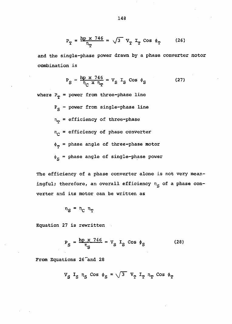
148
Pj = = Vr Vj cos 4.^ (26)
and the single-phase power drawn by a phase converter motor
combination is
»s
where = power from three-phase line
Pg = power from single-phase line
= efficiency of three-phase
= efficiency of phase converter
<|)^ = phase angle of three-phase motor
(J)g = phase angle of single-phase power
The efficiency of a phase converter alone is not very mean
ingful; therefore, an overall efficiency Tig of a phase con
verter and its motor can be written as
rig = n?
Equation 27 is rewritten
Pg = = Vg I3 COS (28)
From Equations 26"and 28
Vg Ig Is = \f^ "t
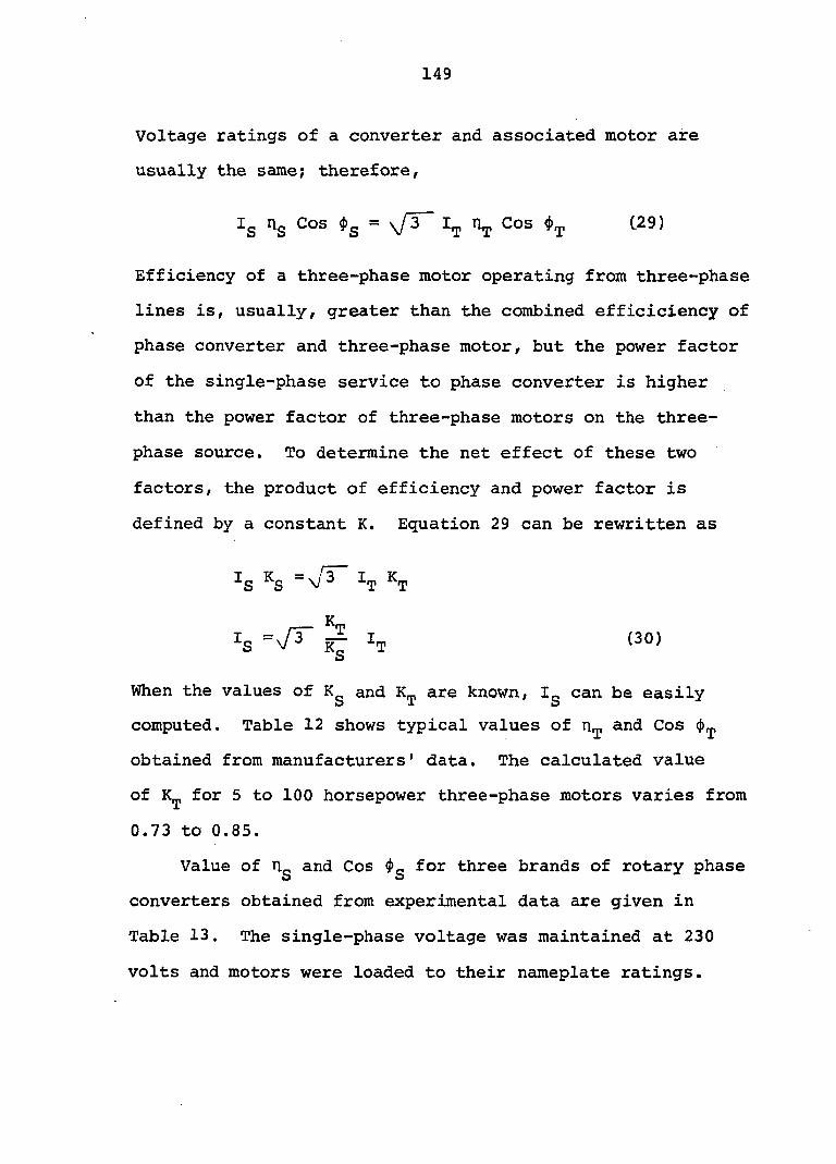
149
Voltage ratings of a converter and associated motor are
usually the same; therefore,
Ig rig Cos $g = \fT~ Cos (29)
Efficiency of a three-phase motor operating from three-phase
lines is, usually, greater than the combined efficiciency of
phase converter and three-phase motor, but the power factor
of the single-phase service to phase converter is higher
than the power factor of three-phase motors on the three-
phase source. To determine the net effect of these two
factors, the product of efficiency and power factor is
defined by a constant K. Equation 29 can be rewritten as
:s 4
_ K
:s =\/3^ iÇ 4 (30)
When the values of Kg and are known, Ig can be easily
computed. Table 12 shows typical values of and Cos cj)
obtained from manufacturers' data. The calculated value
of for 5 to 100 horsepower three-phase motors varies from
0.73 to 0.85.
Value of Ug and Cos $g for three brands of rotary phase
converters obtained from experimental data are given in
Table 13. The single-phase voltage was maintained at 230
volts and motors were loaded to their nameplate ratings.
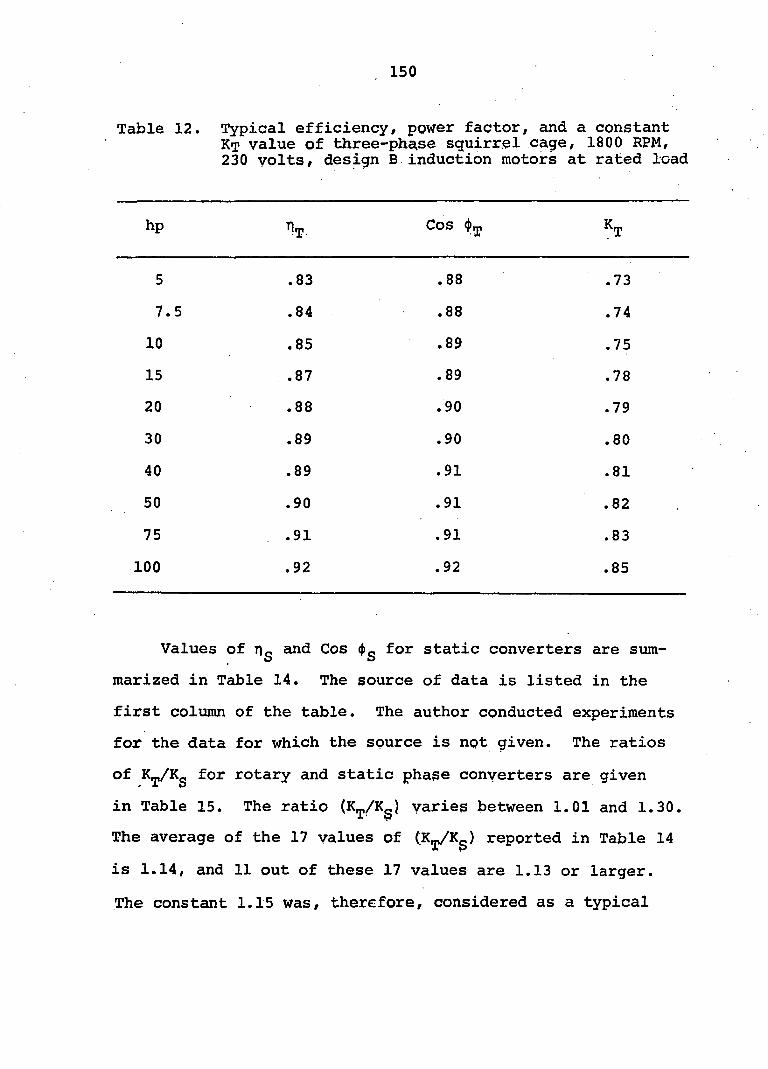
150
Table 12. Typical efficiency, power factor, and a constant KT value of three-phase squirrel cage, 1800 RPM, 230 volts, design B induction motors at rated load
hp ^T
Cos S
5 .83 .88 .73
7.5 .84 .88 .74
10 .85 .89 .75
15 .87 .89 .78
20 .88 .90 .79
30 .89 .90 .80
40 .89 .91 .81
50 .90 .91
CM 00
75 .91 .91 .83
100 .92 .92 .85
Values of rig and Cos ())g for static converters are sum
marized in Table 14. The source of data is listed in the
first column of the table. The author conducted experiments
for the data for which the source is not given. The ratios
of for rotary and static phase converters are given
in Table 15. The ratio (K^/Kg) varies between 1.01 and 1.30.
The average of the 17 values of (K^/Kg) reported in Table 14
is 1.14, and 11 out of these 17 values are 1.13 or larger.
The constant 1.15 was, therefore, considered as a typical

151
value for the ratio (K^/Kg). From Equation 30
I = 1.732 X 1.15 X I S ^
= 1.99 = 2 (approx.) (31)
Table 13. Experimental data on efficiency and power factor of rotary phase converter three-phase, 230 volts, design B induction motor combinations
Converter. A Converter B Converter C
Motor hp
Cos (j)g Cos (j>g Cos (j)g
15 .75 .93 .69 .75 .80 .60 .75 .93 .69
20 .76 .82 .70 .79 .82 .65 .79 .91 .72
30 .79 .91 .72 .79 .87 .68 .77 .91 .70
2-15 .76 .95 .72 .78 .89 .69 .73 .92 .68
2-20 .80 .99 .80 .83 .90 .74 .76 .88 .67
The conductor size serving phase converters can be de
signed by the relationship in Equation 31; i.e., ampere load
of the single-phase line should be considered twice the full
load ampere rating of the three-phase motor(s) being operated
from it.
To verify Equation 31, a study was conducted of the
current drawn by various brands of rotary and static phase
converters. Test data on ampere load of phase converters
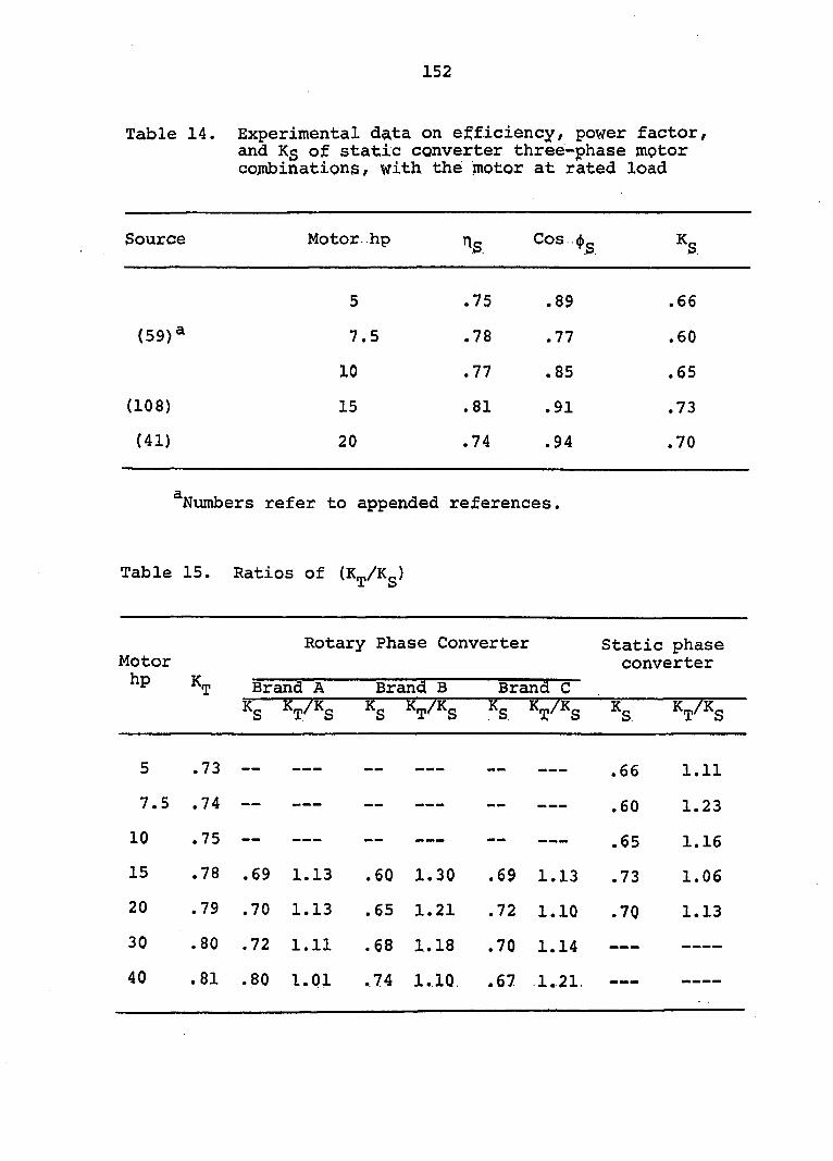
152
Table 14. Experimental data on efficiency, power factor, and Kg of static converter three-phase motor cojnbinationg, with the motor at rated load
Source Motor hp 'i.s. Cos..<j)g ^S
5 .75
ov C
O
. 66
(59)* 7.5 00
.77 .60
10 .77
m
CO
.65
(108) 15 .81 .91 .73
(41) 20 .74 .94 .70
Numbers refer to appended references.
Table 15. Ratios of (K^/Kg)
Motor hp Kn
Rotary Phase Converter
Brand A
Kg K Brand B
T S
Brand C
Static phase converter
K,
5 .73 — — — — — — — — — — — — — .66 1.11
7.5 .74 — — — — — — — — — — — — — — — .60 1.23
10 .75 — — — — — — — — — — .65 1.16
15 .78 .69 1.13 .60 1.30 .69 1.13 .73 1.06
20 .79 .70 1.13 .65 1.21 .72 1.10 .70 1.13
30 .80 .72 1.11 .68 1.18 .70 1.14 — — — — — —
40 .81 .80 1.01 .74 1.10, .67 1.21. ••Ml» ^

153
and current of associated three-phase motor(s) are given in
Table 16. Data on rotary phase converters are in close
agreement with Equation 31. Current drawn by static con
verters is slightly lower than twice the current of three-
phase motors. This is because of the relatively lower losses
in static phase converters.
Table 16. Test data on ampere load of phase converters serving three-phase fully loaded motor(s)
Rotary Converter Static Converter
Motor 3-(j) ; hp Current Brand A Brand B Brand C Brand D Brand E
5 14 24.0 29.8 21.4 23.0
7.5 20 — --— ——— 35.4 42.0
10 28 46.0 58.0 48.0 47.6 44.5
15 41 70.0 81.0 70.0 69.0 67.0
20 52 92.0 100*0 90.0 ———— ———
30 77 134*0 142.0 138.0
4 0 100 163*0 161.0 194.0
The size of the conductor can be computed with the fol
lowing equations:
For single-phase wiring
Copper conductor CM = x Xg x L (32)
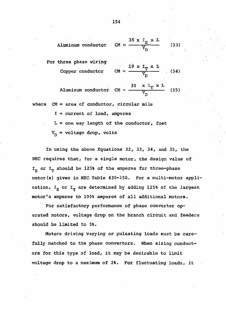
154
35 X Ig X L Aluminum conductor CM p »
*D (33)
For three phase wiring
Copper conductor (34)
30 X X L Aluminum conductor CM = ^ (35)
where CM = area of conductor, circular mils
I = current of load, amperes
L = one way length of the conductor, feet
Vg = voltage drop, volts
In using the above Equations 32, 33, 34, and 35, the
NEC requires that, for a single motor, the design value of
Ig or should be 125% of the amperes for three-phase
motor(s) given in NEC-Table 430-150. For a multi-motor appli
cation, Ig or I^ are determined by adding 125% of the largest
motor's amperes to 100% amperes of all additional motors.
For satisfactory performance of phase converter op
erated motors, voltage drop on the branch circuit and feeders
should be limited to 5%.
Motors driving varying or pulsating loads must be care
fully matched to the phase converters. When sizing conduct
ors for this type of load, it may be desirable to limit
voltage drop to a maximum of 2%. For fluctuating loads, it
155
is recommended that feeders and branch circuit should be
designed to carry the intermittent Incugh current of the
phase converter rather than rated current. After the con
ductor area in CM is computed, its size in American wire
gauge (AWG) can be found from a CM-AWG conversion table.
Such conversion tables are given in the Handbook (33).
The wire size selected should be checked for its allow
able ampacity from Tables 310-12 through 310-15 of the 1971
NEC. If the allowable ampacity is less than the value, Ig
or used in computing CM from Equations 32, 33, 34, or
35, then the larger size conductors capable of carrying the
current Ig or I^ should be used.
Overload Protection
Large horsepower motors, phase converters and their
wiring represent a sizable investment. NEC requires that
the system be protected against excessive currents because
of the possibility of an overload on the motors or mal
functioning of either the motor or the phase converter.
As shown in Figure 73, a single-phase fused disconnect
should be installed ahead of the phase converter. This dis
connect is desirable even if the phase converter has its
own circuit breaker. The size of single-phase disconnect is
determined by the ampere load of the phase converter, I^, M
used in sizing the single-phase conductors between the meter
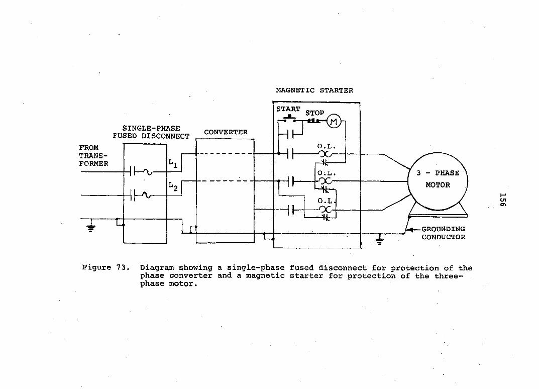
MAGNETIC STARTER
START STOP
SINGLE-PHASE FUSED DISCONNECT
CONVERTER
FROM TRANSFORMER
- PHASE
MOTOR
O . L .
-OG-
O.L. -00
GROUNDING CONDUCTOR
Figure 73. Diagram showing a single-phase fused disconnect for protection of the phase converter and a magnetic starter for protection of the three-phase motor.
157
pole and the phase converter. Fuses preferably should be
of time-delay type to allow inrush current for starting the
motors.
To protect the windings of the three-phase motor(s)
from continuous excessive currents, a magnetic starter
should be installed between the phase converter and the
motor. If more than one motor is used, each motor should
be provided with a magnetic starter.
The magnetic starter used with each three-phase motor
is the same size and type regardless of whether the power
source is a power line or a phase converter. Overload
heaters in the magnetic starter should be sized according
to the NEC recommendations. Overload current protection
sensors require careful installation. A correct ambient
compensated heater should be installed on each of the three
lines from the phase converter to the motor. Very heavy
current is drawn in the manufactured phase when a motor is
running with an overload. This is particularly true on
fluctuating loads like haylage filling applications. For
example, a motor used on materials-handling blower may
experience a wide variation of overload. Varying loads may
cause instantaneous heavy current, which can result in
unwanted tripping of the magnetic starter. Sometimes this
is eliminated by bypassing the heater in the manufactured
phase. This, however, may shorten the motor life. Also,
158
bypassing of the overload heater is a violation of Code
recommendations.
Because the voltage between the manufactured phase and
one of the single-phase power line phase is not constant
during starting or during any period of load variation this
phase should not be used for the holding coil of the mag
netic starter.
Grounding
For the safety of the operator it is important that a
grounding conductor should be installed on all electrical
equipment. For phase converter applications, the grounding
conductors should be connected to the motor base, the phase
converter enclosure, and the grounding provision on the
meter pole. This will insure a continuous ground return to
carry any fault current back to the transformer and minimize
electrical shock hazard (109).
Installation
Figure 74 is a wiring diagram for a three-phase motor
operated from an autotransformer-capacitor phase converter.
The setting on a current limiting resistor in series with the
coil of a relay number 2, a voltage sensitive relay, deter
mines the time for which a bank of electrolytic capacitors is
connected in the circuit for motor starting.
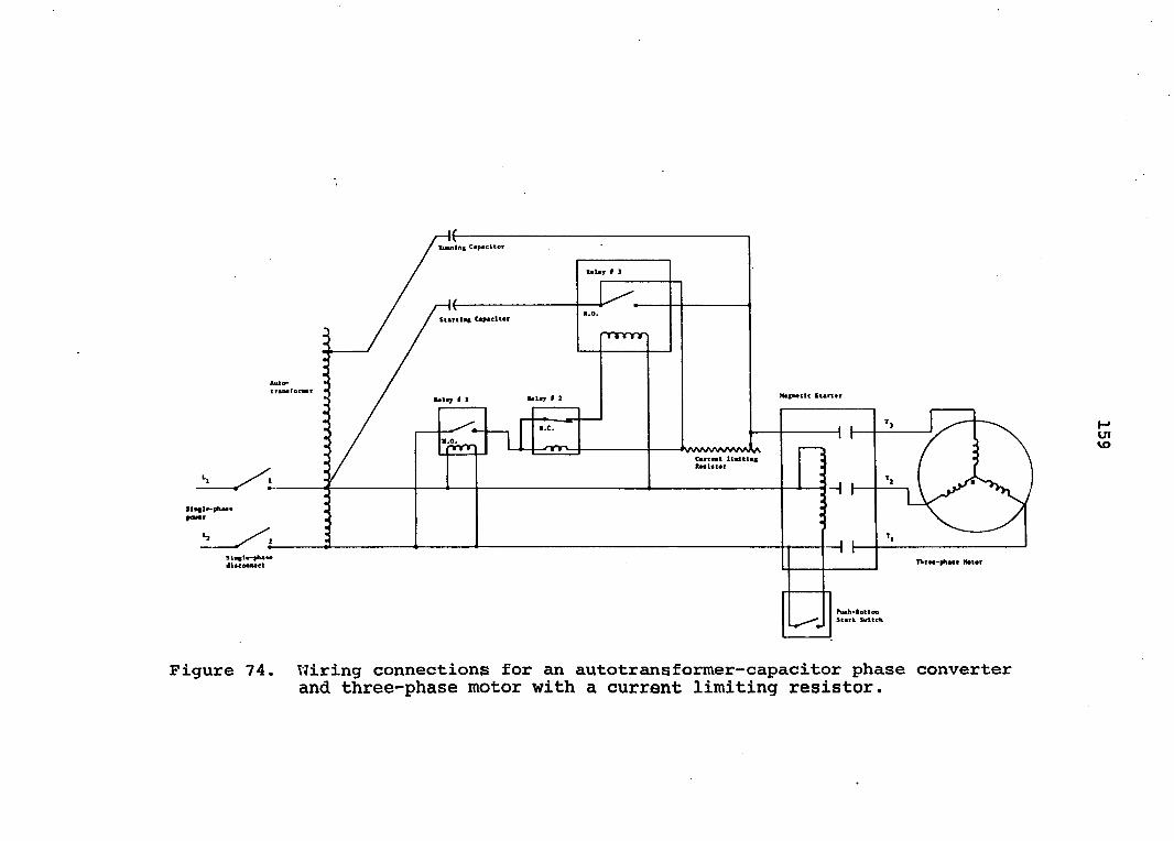
tmiblng
m#lay # 1
StartUc CaMclter
NsfMClc Scartar
TlitM-phMt Meter
Figure 74. Wiring connections for an autotransformer-capacitor phase converter and three-phase motor with a current limiting resistor.
160
Figure 75 shows a wiring diagram for multimotor appli
cation from a single rotary phase converter. Each motor is
protected by a magnetic starter. The capacitor bank assoc
iated with an individual motor is connected in parallel
with the main capacitor bank of the rotary unit when the
motor is started.
Figure 76 shows wiring connections of an open-wye type
phase converter and a three-phase motor. Modified con
nections of the motor winding are illustrated. A current
limiting resistor, similar to that used in an autotrans-
former capacitor converter, is connected in series with the
voltage sensitive control relay to drop the electrolytic
capacitors out of circuit at the proper speed of the motor.
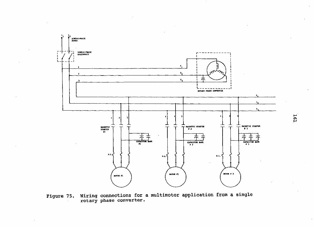
SmCLC-PHASC
SINGLE-PHASE oiscomcT
I J
ItOTAtY PHASB CONVEKTEll
MACKETIC STAHTEIl HAC1ICTIC STAKTEt MACKETIC STARTEK
T T T CAPACITOR BANK CAPACITOR tAXK CAPACITOR BANK
O.L 0. O.L
MOTOR #2 MOTOR 11
Figure 75. Wiring connections for a multimotor application from a single rotary phase converter.
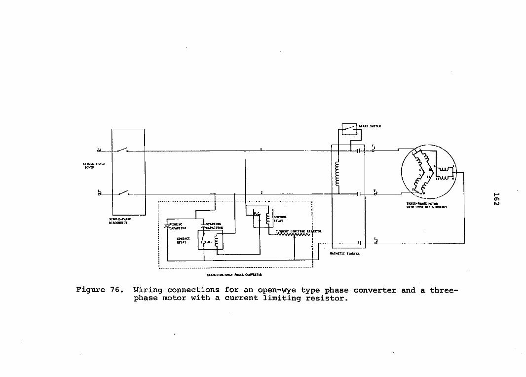
ST ATT SWITCH
•PKASC
WITH orn WYE WINDINGS
ion LDftTIHC USISTM
»
MAGNETIC STAJtTtt
CAPACITOR-Om.T PHASE CONVUtTEft
Figure 76. Wiring connections for an open-wye type phase converter and a three-phase motor with a current limiting resistor.
163
DISCUSSION
Static and rotary phase converter g have piade possible
the satisfactory operation of many three-phase motors from
single-phase power lines on farms. Usually, the cost for a
phase converter system is lower than the cost of extending
three-phase power to the farm. By no means, however, should
phase converters be considered a replacement for commercial
three-phase power.
Design Equations 10 and 12 eliminate the tedious empir
ical methods for determining capacitor size and transformer
turns ratio of an autotransformer-capacitor phase converter
to give the balanced voltages and currents in a three-phase
motor. It must be admitted that the simplification of
design does not make an autotransformer-capacitor phase con
verter the universal answer to all the applications of
three-phase motors on farms with only single-phase power.
Torque characteristics of a three-phase motor are changed
when used with a phase converter.
Perhaps the greatest limitation of an autotransformer-
capacitor phase converter is the need for electrolytic
capacitors to obtain the desired starting torque. This is
the only component used in autotransformer-capacitor con
verters that has low reliability. A majority of the prob
lems encountered in the use of autotransformer-capacitor
phase converter can be attributed to the failure of one or
164
more electrolytic capacitors. The short duty cycle of
electrolytic capacitors jnake the phase converter unsuitable
for cyclical start-stop loads.
The taps on the secondary of the transformer winding
and capacitor size can be adjusted in the field to obtain
close balance in the voltages and currents of a three-phase
motor. Taking all the facts into account, however, this
may not be always an acceptable procedure to the user of
autotransformer-capacitor phase converter.
A rotary phase converter has the advantage that it can
be used for more than one three-phase motor. It also seems
to be possible to obtain NEMA specified torques from a
design B, general purpose induction motor operated from a
rotary phase converter without the use of electrolytic
capacitors (4).
The oil type capacitors, usually, have long duty cycle.
Any possibility of failure of running capacitors because of
over voltage can be eliminated by designing the rotary con
verter winding so that with the rotary converter idling,
the voltage across the capacitor does not exceed the voltage
ratings. The voltage output across terminals 2 and 3 in
Figure 47 drops when the rotary converter is supplying power
to a three-phase motor.
The author from his experiences of working with several
rotary phase converters has found that oil type capacitors
165
sized at 40 to 45 yF per motor horsepower give optimum
balance in voltages and currents and fairly good dynamic
torque-speed characteristics from the motor. More experi
mental study should be made, however, before this is accepted
as a design criteria.
As a general rule, temperature rise of the three-phase
motor windings has been found to be higher with phase con
verters than those with three-phase line power. In most
cases the rise does not exceed the allowable rise for the
class of insulation used in the motor.
Locked-rotor, pull-up, and breakdown torques of motors
operated from phase converters are lower than that obtained
with three-phase line power, although they may be sufficient
to start and accelerate a majority of farm loads without
affecting motor life.
The author believes that measurement techniques used
in this study can be improved. For example, external cur
rent transformers were used to read the currents on 5 and
10 ampere full scale ammeters. Better accuracy of measurement
can be obtained by using ammeters calibrated with built in
internal current transformers.
The thermocouple method for measuring temperature was
found to be quite reliable. The resistance method requires
elaborate instrumentation. It is also time consuming and
the machine has to be stopped after each test. Thermocouples

166
were installed in the lab and could AOt be embedded deep
inside the motor windings. Thermocouples installed at the
factory at the time of winding the stator would give better
estimates of the hot-spot.
167
SUMMARY
The need for three-phase motors on farms is discussed
and the potential for phase converters is considered in
meeting the demand to operate large motors from the existing
single-phase power line. Technical literature on various
types of phase converters is reviewed in some detail.
Comparative limitations on the use of various types of
phase converters are presented.
Design equations are developed for the capacitor size
and transformer turns-ratio to give balanced operation of a
three-phase motor operating from an autotransformer-capacitor
phase converter. Recommendations are made on adjusting
parameters for fluctuating and variable loads. The effects
of variation in the single-phase line voltage are given on
the performance of three-phase motors operating from rotary
and autotransformer-capacitor phase converters.
Performance of three-phase motors are presented under
various percentages of unbalance in their terminal voltage.
This voltage unbalance was similar to the voltage unbalance
that may occur with phase converters. Performance charac
teristics are discussed for a 10 hp U-fr^e motor and a 10
hp T-frame motor operated from an open-wye type phase con
verter. Effects of the size of starting capacitance are
determined on the locked rotor torque of a three-phase motor
operating from em autotransformer-capacitor phase converter

168
that has been adjusted for balanced condition at rated motor
horsepower.
A method is developed for designing power distribution
conductors for a phase converter and associated three-phase
motor (s). The analytical equation developed for determining
conductor size was verified experimentally.
169
RESULTS AND CONCLUSIONS
The author believes that the results from the various
phases of this study have met the objectives of the research
project. The following conclusions are drawn from these
studies ;
(1) Equations 10 and 12 {C = 3063 (I/V) sin (j)},
{n = (1/2) + cot <j)} / are accurate and
practical for determing capacitance value and
transformer turns ratio in an autotransformer-
capacitor phase converter to give balanced cur
rents and voltages to a three-phase motor for a
given load. These equations are in terms of
nameplate data and phase angle of the three-
phase motor and are of greater practical value
than equations that require internal parameters
like resistance and reactance of the motor.
(2) Capacitance value and transformer output voltage
in an autotransformer-capacitor phase converter,
in application where the three-phase motor is
oversized, should be adjusted for the load on the
motor and not for the nameplate horsepower. If the
load varies moderately, the two parameters should
be adjusted for the average load and not for the
maximum or minimum load on the motor.
170
Variations in single-phase voltage input to the
phase converter results in unbalanced three-phase
output voltages.
Lower than nominal voltage will cause higher tem
perature rise of a motor on an autotransformer-
capacitor phase converter. Higher temperature of
the test motor operated from a rotary converter
will be experienced with single-phase voltage
higher than nominal.
Locked rotor torque and pull-up torque of the
general purpose, three-phase induction motor
operating from the autotransformer-capacitor
phase converter are higher than those obtained
with the rotary phase converter. The breakdown
torque, however, is higher with the motor ope
rating on the rotary phase converter.
The unbalance in currents due to overload on the
motor at rated single-phase voltage or due to
lower single-phase voltage accompanied with a
rated load on the motor increases the winding
temperature rapidly. An overload on motors
operated from phage converter should be avoided
and motor capacity must be derated when the single-
phase voltage is lower than rated.

171
(7) The open-wye type phase conversion system is the
least expensive for applications where low start
ing torque is required. The phase shifting capaci
tance sized at 40 pf per horsepower gives optimum
steady state performance.
(8) To obtain maximum locked-rotor torque with a
general purpose three-phase, induction motor
operating from an autotransformer-cipacitor phase
converter, starting capacitance should be sized
at 200 yf per horsepower of steady state load on
the motor.
(9) Due to additional losses in the phase converter,
the combined efficiency of motor-phase converter
system is lower than the efficiency of the motor
operating on three-phase line power. At no load
or very light load on the motor, the motor losses
and heating are greater with a phase converter
than with balanced three-phase power.
(10) A single-phase transformer to supply the power to
a phase converter and its associated motor(s)
should be rated at 1 KVA per horsepo-wer of motor
load. Single-phase conductors serving phase con
verters should be designed according to Equation
31 {Ig = 2 ly} , considering ampere load, on the
single-phase line to be twice that of full load
amperes drawn by the three-phase mot or (s).
172
SUGGESTIONS FOR FURTHER STUDY
Equations 10 and 12 for calculating the size of
capacitors and transformer turns-ratio of an autotransformer-
capacitor phase converter were found to be of a greater
practical value than design equations requiring motor
internal parameters. To further the usefulness of this
study an attempt should be made to develop a similar equa
tion to give the size of capacitors and rotating unit of the
rotary phase converter for balanced operation of a given
motor. This equation should be in terms of nameplate data
of the converter and motor. The investigation probably
should be extended to developing a general equation that may
be applicable to one or multimotor applications.
Investigations should be made of a practical method of
incorporating a feedback circuit in the design of autotrans-
former-capacitor phase converters. This would permit the
control of output voltages and V23 by the three-phase
line currents which are representative of the load on the •
three-phase motor. It is believed that addition of the feed
back loop to the autotransformer-capacitor phase converter
circuit would allow use of a single motor, or a combination
of motors, of various sizes within the rating of the phase
converter.
The optimum size of starting capacitors used in the
rotary phase converter should be determined to give the
173
rated locked rotor torque of the three-phase motor. Further
investigations should be made to determine the size of the
starting capacitors needed for each of the additional motors
to be used on a multimotor application of a rotary phase
converter, preferably each motor should be capable of pro
viding rated starting torque.
The possibility should be investigated of using a sat
urable core reactor in place of the capacitors in the rotary
phase conversion system. Increasing the current through a
reactor made of core metal with a very sharp limit of magnet
ization would cause no substantial rise of voltage, once
the saturation point is reached. This arrangement, perhaps,
may give better voltage balance than that obtained from a
rotary phase converter with capacitive reactance.
The author studied the effects of voltage variations on
the performance of phase converter operated three-phase
motors, with the motor loaded to rated horsepower. It is
suggested that investigations should be conducted to study
the combined effects of voltage variations and motor
operated at above and below the rated horsepower.
An investigation should be made on the performance of
three-phase synchronous motors operated from a single-phase
power source through the rotary as well as autotransformer-
capacitor phase converters.

174
It would be useful to explore, by studying the voltage
and current balance and temperature rise of three-phase
motors, the application of the Voltano phase conversion
system for farm loads.
175
REFERENCES
1. Ager, R. W. The use of auxiliary impedances in the single-phase operation of polyphase induction motors. AIEE Trans. 60: 494-499. 1941.
2. Alger, P. L., H. C. Ward and F. H. Wright. Split-winding starting of 3-Phase motors. AIEE Trans. 70/ Part 1: 867-873. 1951.
3. American Standard Association. Alternating current induction motors, induction machines in general and universal motors. Standard C-50. 2-1955. American Standard Association, New York, N.Y. 1955.
4. Arco Electric Product Corp. Roto-phase, rotary phase converters. Arco Electric Product Corp. (Shelbyville, Indiana) Bulletin 180. Jan. 1967.
5. Baebler, A. W. Application of phase converters. Paper presented at large motors and phase converter conference. Ag. Eng. Dept. University of Wisconsin. 1967.
6. Bakes, R. Capacitor serves three-phase motors from single phase line. Electrical World 139, No. 18: 74-75. May 1953.
7. Bartheld, R. G. The rerate question. Allis-Chalmers Engineering Review 31, No. 2: 26-28. 1964.
8. Berndt, M. M. and N. L. Schmitz. Derating of polyphase induction motors operated with unbalanced line voltage. AIEE Trans. 81, Part 3; 680-683. Feb. 1963.
9. Bessho, K. Improvement of single-phase to three-phase converters. Electrical Engineering in Japan 87, No. 7: 29-39. 1967.
10. Bessho, K. Theory and performance of single to three phase converter. Electrical Engineering in Japan 86, No. 8: 29-39. 1966.
11. Brooks, L. A. Application of phase converters on rural lines. AIEE paper No. 68-CP-455-IGA presented at the IEEE Rural Electrification Conference, Atlanta, Ga., April 29-30, 1968. IEEE, New York, N.Y. 1968.
176
12. Brooks, L. A., M. F. Finner and 0. I. Berge. All dairy farmers now can use large electric motors. Hoard's Dairyman 113, No. 13: 780-781. July 1968.
13. Brooks, L. A., M. F. Finner and 0. 1. Berge. Using large electric motors. Agricultural Engineering, Journal of the ASAE 48, No. 2: 84-85. Feb, 1967.
14. Brown, J. E. and O. I. Butler. A general method of analysis of three-phase induction motors with symmetrical primary connections. Institution of Electrical Engineers Proceedings 100, No. 2: 25-34. Feb. 1953.
15. Brown, J. E. and C. S. Jha. The starting of a 3-phase induction motor connected to a single-phase supply system. Institution of Electrical Engineers Proceedings 106, No. 26, Part A: 183-190. April 1959.
16. Brown, J. E. and R. L. Russell. Bridge method for determining symmetrical components of current, voltage, and power with special reference to electrical machinery. Institution of Electrical Engineers Proceedings 105, No. 3, Part A; 529-537. Oct. 1958.
17. Brown, J. E. and R. L. Russell. Symmetrical component analysis applied to phase converters of Ferraris-Arno type. Institution of Electrical Engineers Proceedings 105, No. 3, Part A: 538-544. Oct. 1958.
18. Buffington, J. F. Phase converter. Canadian Patent. No. 786,933, class 321-15. Issued June 4, 1968.
19. Buffington, J. F. Static phase converter system. United States Patent No. 3,349,316. Issued Oct. 24, 1967.
20. Butler, F. Symmetrical components. The Ronald Press Company, New York, N.Y. 1959.
21. Calabrese, G. 0. Symmetrical components. The Ronald Press Company, New York, N.Y. 1959.
22. Charity, L. F., L. B. Altman and C. C. Carney. Characteristics of rotary-type phase converters. ASAE Trans. 10, No. 4: 505-507, 511. 1967.
23. Charity, L. F. and L. H. Soderholm. Performance characteristics of motors operating from rotary-phase converters. IEEE paper No. 34-CP-67-208 presented at the IEEE Rural Electrification Conference, Cedar Rapids, Iowa, May 1-2, 1967. IEEE, New York, N.Y. 1967.

177
24. Common Wealth Edison Report. Rotating phase converter. Common Wealth Edison Company (Chicago, Illinois) Distribution Engineering Guide No. DEG 385. Oct. 1968.
25. Court Chard, F. Pela. A Note on the diagramatic estimation of phase-sequence components. Institution of Electrical Engineers Proceedings 106, No. 26, Part A: 191-192. April 1959.
26. Dalemont, J. Three phase motors operated from single-phase mains. Electrical World and Engineer 46, No. 22; 914-915. Nov. 1905.
27. Daniels, A. E. and B. R. Relly. A locus diagram to determine the complete starting performance of a 3-phase induction motor connected to a single-phase supply. Institution of Electrical Engineers Proceedings 109, Part C: 244-249. Dec. 1962.
28. Denton, F. M. Symmetrical components, and their application to the phase converter. Journal of the Institution of Electrical Engineers 71: 663-673. June-Dec. 1932.
29. The Durham Company. Operate three phase.motors from single phase power. The Durham Company (Lebanon, Missouri) Bulletin No. 2ÛB-168. 1968.
30. Eglin, W. C. L. The power company's problems in the electric supply for large single phase load. AIEE Trans. 35, Part 2; 1289-1292. 1916.
31. Elliot, K. C., Jr. and W. M. Elliot. Open-wye-type phase conversion systems. IEEE Trans. IGA-6, No. 2: 146-148. March-April 1970.
32. Elliot Phase Conversion Systems. Ken Elliot Motors Inc. (Bossier City, Louisiana) Bulletin. 1970.
33. Fink, D. G. and J. M. Carroll (editors). Standard Handbook for Electrical Engineers. Tenth Edition. McGraw-Hill Book Company, New York, N.Y. 1969.
34. Fitzgerald, A. E. and C. Kingsley, Jr. Electric Machinery. Second Edition. McGraw-Hill Book Company, New York, N.Y. 1961.
35. Gelder, C. H. Farm power supply-essentially a job for single phase. Electrical World 130, Part 2: 100-101. Dec. 1948.
178
36. Gleason, L. L. and W. A. Elmore. Protection of 3-phase motors against single-phase operation. AIEE Trans. 77, Part 3; 1112-1120. 1958.
37. Griffith, L. E. Farm loads change to three phase. IEEE paper No. 34-CP-67-263 presented at the IEEE Rural Electrification Conference, Cedar Rapids, Iowa, May 1-2, 1967. IEEE, New York, N.Y. 1967.
38. Haberman, R., Jr. Single-phase operation of a 3-phase motor with a simple static phase converter. AIEE Trans. 73, Part 3B: 833-837. August 1954.
39. Harisha, Fred. Innovating with phase converter in Wisconsin. Paper No. 10-13, presented at the 13th National Electric Farm Power Conference, Chicago, Illinois, Sep. 1966. IEEE, New York, N.Y. 1966.
40. Harkness, K. A. and J. W. Hooper. An evaluation of the phase converter-three-phase motor. Kansas State College, Engineering Experiment Station Bulletin 38, No. 11. July 1954.
41. H-A-S Phase Conversion System. Steelman Electric Co., Inc. (Kilgore, Texas) Catalog 1-70. August 1966.
42. Henry Electric Company. Henry phase converter. Henry Electric Company (Saginaw, Michigan) Pamphlet. 1967.
43. Hisano, K., H. Hobayashi and T. Kabayashi. A new type single-phase converter. IEEE Trans. Mag-2, No. 3: 643-647. Sep. 1966.
44. Hogan, J. C. Analysis of single-phase-to-3-phase static converters. AIEE Trans. 74, Part 2; 403-4-406. Jan. 1956.
45. Hogan, J. C. Autotransformer betters motor phase conversion. Electrical World 144, No. 16: 121-122. Oct. 1955.
46. Hogan, J. C. Phase converters and their application. ASAE paper 1954 presented at the Winter meeting of ASAE, Chicago, Illinois, December, 1954. ASAE, St. Joseph, Michigan. 1954.
47. Huber, G. H. Application and effects of 15 HP and larger three phase motors on single phase lines. IEEE paper No. 34-CP-66-225 presented at the IEEE Rural Electrification Conference, Dallas, Texas, May 12-13, 1966. IEEE, New York, N.Y. 1966.
179
48. Huber, G. H. Are phase converters necessary? IEEE paper No. 69-CP-407-IGA presented at the IEEE Rural Electrification Conference, New Orleans, Louisiana, April 28-29, 1969. IEEE, New York, N.Y. 1969.
49. Huber, G. H. Operation and application of static and rotary phase converters. ASAE Paper No. 68-838 presented at the Winter meeting of ASAE, Chicago, Illinois, Dec. 10-13, 1968. ASAE, St. Joseph, Michigan. 1968.
50. Huber, G. H. Phase converters, their application and current demand. IEEE Trans. IGA-1, No. 4: 280-284. July-August, 1964.
51. Huber, G. H. The practical aspects of phase converters. Paper presented at the Electric Power and Motor Conference, University of Illinois, Urbana, Illinois, Sep. 4, 1969. 1969.
52. Huber, G. H. Using static and rotary phase converters. Agricultural Engineering Journal of ASAE 50, No. 9: 519-521. Sep. 1969.
53. Ishizaki, A. and K. Hirayama. Determination of equivalent circuit parameters for performance calculation of polyphase induction machines. Electrical Engineering in Japan 87, No. 1: 71-79. 1967.
54. Jain, S. K. Rerating of induction motor under unbalanced supply voltage. Journal of Institution of Engineers (India) 51, No. 20, Part ELI: 1-5. Dec, 1970.
55. James, C. W. Overcurrent protection of motors served by phase converters. IEEE paper No. 34-CP-67-262 presented at the IEEE Rural Electrification Conference, Cedar Rapids, Iowa, May 1-2, 1967. IEEE, New York, N.Y. 1967.
56. Kemper, M. J. Operating experiences with three-phase motors on single phase lines. IEEE Trans. IGA-2, No. 6; 443-445. Nov.-Dec. 1966.
57. Knight, W. H., P. R. Bakes and H. E. Hattrup. Performance of the Henry phase converter. Agricultural Engineering Journal of ASAE 35, No. 2: 98, lOl. Feb. 1954.
58. Lewus Electric Company. New Lewus-PC-Static type phase converter. Lewus Electric Co. (chicago, Illinois) Circular No. 12-13. 1963.
59
60
61
62
63
64
65
6 6 ,
67.
6 8 .
69.
70.
71.
180
Lindley, K. E. Analysis of some methods of supplying a three phase induction motor from a single phase line. South Dakota State College Engineering Experiment Station Bulletin No. 1. May 1959.
Liwschitz, M. M. and W. H. Formhals. Some phase of calculation of leakage reactance of induction motors. AIEE Trans. 66: 1409-1413. 1947.
Lunn, E. 0. Induction motors under unbalanced conditions. AIEE Trans. 55: 387-393. April 1936.
Lyon, W. V. Application of the method of symmetrical components. McGraw-Hill Book Co. Inc., New York, N.Y. 1937.
Lyon, W. V. Unbalanced three-phase circuits. Electrical World 75, No. 23: 1304-1308. June 1920.
Lyon, W. V. and C. Kingsley. Analysis of unsymmetrical machines. AIEE Trans. 55, No. 1: 471-476. May 1936.
Macmillan, C. and G. K. Carter. Over voltage in polyphase induction motor during single-phase operation. AIEE Trans. 60: 819-822. August 1941.
Maggs, A. H. Single-phase to three-phase conversion by the Ferraris-Arno system. The Journal of Institution of Electrical Engineers 93, No. 32: 133-136. April 1946.
Maggs, A. H. and S. A. Choudhary. An improved single-phase to three-phase conversion system. BTH Activities 13: 221-226. Nov.-Dec. 1937.
Miracle, B. P. Large single phase motors for low starting torque application. IEEE Trans. IGA-6, No. 1: 48-51. Jan. 1970.
Moore, R. C. Correcting induction motor P.P. with capacitors. Allis-Chalmers Engineering Review 29, No. 1: 12-15. 1964.
Mumgaard, Milo. Power supply problems and applications of large electric motors. ASAE Paper No. MC-67106 presented at the Mid Central Meeting of ASAE, St. Joseph, Michigan. 1967.
Myatt, L. F. Symmetrical Components. Pergamon Press, Oxford, London. 1968.
181
72. National Electric Manufacturers Association, NEMA Standards. Motors and Generators (New York, N.Y.) Publication No. MG 1-1967. 1967.
73. Neuman, R. Symmetrical component analysis of unsym-metrical polyphase systems. Sir Isaac Pitman, and Sons, Ltd., London, 1939.
74. Nishiyama, H. Graphical solution of performance of a 3-phase induction motor supplied by a single-phase source. Electrical Engineering in Japan 84, No, 1; 1-11. Jan. 1964,
75. Norman, H. M, Mathematical solution of an unbalanced 3-phase voltage system. Journal of AIEE 47: 449-451. June 1928.
76. Parham, J. W. Operating problems with large single phase motors on single phase lines. IEEE Paper No. 34-CP-66-224 presented at the IEEE Rural Electrification Conference, Dallas, Texas, May 12-13, 1966. IEEE, New York, N.Y. 1966.
77. Parvis, W. J. Our experiences with rotating type of phase converters on grain dryers. ASAE Paper No. 65-318, presented at the Summer Meeting of ASAE, University of Georgia, Athens, Georgia, June 20-23, 1965. ASAE, St. Joseph, Michigan. 1965.
78. Patterson, F. J. and B. W. Carroll. Service to rural water supply systems by use of static or rotary converters. SWIEECO records. IEEE paper No. 70-C5-SWIEECO. 1970.
79. Phase Converter Study. A report prepared by the phase converter subcommittee. Edison Electric Institute, EEI Publication No. 66-427. 1966.
80. Porteous, D, T. and R. L. Russell. Passive low-power single phase 3 phase converter. Institution of Electrical Engineers Proceedings 117, No, 9: 1841-1846. Sep. 1970.
81. Price, D. R. Performance of commercial phase-converters. Department of Agricultural Engineering, Cornell University, Ithaca, New York. 1967.
82. Rao, P. V. Switching transient in three-phase induction motors run on single phase supply. Journal of the Indian Institute of Science 39, No. 4: 101-109. Oct. 1959,

182
83. Rao, P. V. and C. S. Ghosh. Single phase operation of three-phase motors. Indian Journal of Physics 25, No. 69; 565-574. 1951.
84. Reddy, I. G. Torque angle analysis of induction motor under balanced and unbalanced conditions. Journal of Institution of Engineers (India) 17, No, 8, Part EL4: 328-339. April 1967.
85. Reed, H. R. and R. J. W. Koopman. Induction motors on unbalanced voltages. AIEE Trans. 55: 1206-1213. Nov. 1936.
86. Ronk Electrical Industries, System Analyzer Division. Add-A-phase Converter, general and technical questions and answers. Ronk Electrical Industries Inc. (Nokomis, Illinois) Bulletin 208. 1969.
87. Ronk, L. B. Experience records of phase converters. AIEE paper No. CP-60-5010 presented at the AIEE Rural Electrification Conference, Omaha, Nebraska, May 10-12, 1960. IEEE, New York, N.Y. 1960.
88. Ronk Electrical Industries. System Analyzer Division. General and technical questions and answers. Ronk Electrical Industries Inc. (Nokomis, Illinois) Rotoverter Bulletin 205. 1969.
89. Roy, N. N. Allowable output from a 3-phase induction motor operating under single phase conditions. Journal of Institution of Engineers (India) 48, No. 4, Part EL2: 332-343. Dec. 1967.
90. Single phase rural distribution service for motors and phase converters. ASAE Recommendation-ASAE R329: 422. 1971.
91. Slepian, J. Induction motors on unbalanced voltages. Electrical World 75, No. 6: 313-315. Feb, 1920.
92. Soderholm, L. H. Phase converters for rural application. IEEE Trans. IGA-7, No. 4; 553-557. July-August 1971.
93. Soderholm, L. H. and L. f. Charity. Dynamic torque characteristics of phase converter operated motors. ASAE paper No. 69-301 presented at Annual Meeting of ASAE, Purdue University, W. Lafayette, Indiana, June 22-25, 1969. 1969.
183
94. Soderholm, L. H. and L. F. Charity. Performance characteristics of phase converters. Paper presented at the Electric Power and Motor Conference, University of Illinois, Urbana, Illinois, Sept. 3-4, 1969. 1969.
95. Soderholm, L. H. and L. F. Charity. Progress on development of lEEE-ASAE rural motor starting application guide. IEEE Trans. IGA-6, No. 69-70. Jan.-Feb. 1970.
96. Spindler, R. B. Why and how of rotary phase converters. IEEE paper No. 34-CP-67-253 presented at the IEEE Rural Electrification Conference, Cedar Rapids, Iowa, May 1-2, 1967. IEEE, New York, N.Y. 1967.
97. Sreenivasan, T. V. Application of a capacitor with the Arno 1:3 phase converter. Journal of Institution of Engineers (India) 46, No. 12, Part EL6j 518-527. Aug. 1966.
98. Sreenivasan, T. V. Single phasing of three phase induction motors. Journal of Institution of Engineers (India) 46, No. 4, Part EL2: 121-129. Dec. 1965.
99. Sreenivasan, T. V. and R. N. Basu. Single phase rural electrification. Journal of Institution of Engineers (India) 86, No. 9, Part 2: 1767-1775. May 1956.
100. Sreenivasan, T. V. and M. R. Krishnamurthi. Performance of three-phase motors with a capacitor on single-phase circuits. Journal of Institution of Engineers (India) 37, No. 1, Part EL2: 715-729. March-August 1957.
101. Stokvis, L. G. Analysis of unbalanced three-phase systems. Electrical World 65, No. 18; 1111-1115. May 1915.
102. Stubbings, G. W. Elements of symmetrical components theory. Sir Isaac Pitman and Sons, Ltd., London. 1937.
103. Tadokoro, M. Single-phase to three-phase conversion mechanism of three-phase ferra-regonance circuit. Electrical Engineering in Japan 86, No. 8: 10-20. 1966.
104. Tanno, Y. Rectifier utilizing single phase to polyphase converter. Electrical Engineering in Japan 87, No. 6: 43-50. June 1967.
105. Tanno, Y. Single phase to polyphase conversion by means of parametric oscillation. Electrical Engineering in Japan 83, No. 1: 35-44. Jan. 1963.
184
106. Test procedure for polypha.se induction motor and generators. IEEE Report No. 112A. Sep. 1964.
107. Tracy, G. F. and E. W. Walther. Split phase starting of 3-phase motors. AIEE Trans. 54: 1068-1972, Oct. 1935,
108. U. S. Department of Agriculture. Technical Standard Division. Report on fields tests of Henry phase converter. United States Department of Agriculture, REA, Washington, D.C. 1951.
109. Vantuyl, L. J. Farm wiring-present and future. ASAE paper presented at the Tri-State meeting of ASAE, Toledo, Ohio. April 21-22, 1967. ASAE, St. Joseph, Michigan. 1967.
110. William, J. E. Operation of 3-phase induction motors on unbalanced voltages. AIEE Trans. 73, Part 3: 125-133. April 1954.
111. Williams, J. H. Electrical plant and machinery. Journal of Institution of Electrical Engineers 78: 165-166. 1936.
112. Windred, G. The operation of polyphase motors from a single-phase supply. The Electrical Review 93, No. 2,394: 527-528. Oct. 1923.
185
SUPPLEMENTARY REFERENCES
Agarwalf P. D. and P. L. Alger. Saturation factors for leakage reactance of induction motors. AIEE Trans, 79, Part 3. 1037-1042. February 1961.
Alger, P. L. Induced high-frequency currents in squirrel cage windings. AIEE Trans, 75: 724-729, October 1957.
Alger, P. L. Induction motor performance calculations, AIEE Trans. 49: 1055-1067. 1930.
Alger, P. L. and H. A. Jones. Rating of high temperature induction motors. AIEE Trans. 64: 300-302. 1945.
Alger, P. L. and H. R, West, The air gap reactance of polyphase machines. AIEE Trans. 66: 1331-1343, 1947,
Arnold, R. E. Nema suggested standards for future design of A.C. integral horse power motors. IEEE Trans. IGA-6, No. 2: 110-114. March-April 1970,
Ballou, J. A. Electric motors versus gas engines as prime movers in producing operations. IEEE Trans, IGA-6, No. 6: 540-544. 1970.
Barnes, E. C. Performance and characteristics of induction motors for solid-state variable frequency drives. IEEE Trans. IGA-7, No. 2: 212-217. March-April 1971.
Barton, T. H., and V. Ahmad. The measurement of induction motor stray loss and its effect on performance. Institution of Electrical Engineers Proceedings 105, No, 7: 64-75, March 1958,
Berberich, L. J. and K, N. Mathes. Internal activities in the temperature classification of electrical insulating materials. AIEE Trans. 77, Part 2: 69-33. April 1958,
Bicknell, H. C., Jr. and P, G, Cummings. Measuring motor windings temperature rise resistance method vs. embedded detector. Power 115, No. 7: 84-85, July 1971,
Blanchard, C. B. and C, T. Anderson, A laboratory investigation of temperature rise as a function of atmospheric conditions. AIEE Trans. 32, Part 1: 289-299. 1913.
/
186
Brice, M. R. Overload protection for electric motors. Paper presented at the conference on Electrical Application for the Textile Industry. Atlanta, Georgia, April 23-24, 1953. AIEE, New York, N. Y. 1953.
Cable, J. A. How to specify non-overloading drives, Allis-Chalmers Engineering Review 29, No. 1: 8-9. 1964.
Capp, J. A. and L, T. Robinson. Thermocouples and resistance coils for the determination of local temperatures in electrical machines. AIEE Trans. 32, Part 1; 185-190. 1913.
Campbell, J. How to cope with electric motor noise. Machine Design 35, No. 2: 140-158. 1963.
Chann, L. E. Phase converters on the farm. Contractors' Electrical Equipment PL2: 1-5. April 1971.
Chubb, L. W., E. I. Chute and 0. W. A. Getting. Measurement of temperature in rotating electric machines. AIEE Trans. 32, Part 1: 163-175. 1913.
Cotanch, R. N. Rotary phase converters solve farm power problems. Contractors' Electrical Equipment PCI: 1-2. April 1971.
Day, M. W. and R. A. Beekman. Effect of room temperature on temperature rise of motors and generators. AIEE Trans. 32, Part 1: 254-278. 1913.
Deshpande, M. U. Some research problems in electrical apparatus. Journal of Institution of Engineers (India) 42, No. 10, Part EL5: 236-248. June 1962.
Dudley, A. M. Induction motors on unbalanced circuits. The Electrical Journal 21, No. 7: 339-343. December 1924.
Erlicki, M. S. and J. Appelbaum. Optimized parameters analysis of an induction machine. IEEE Trans. PAS-84, No. 11: 1017-1021. Nov. 1965.
Evans, R. D. Measurement of power factor on unbalanced polyphase circuits. AIEE Trans. 39, Part 2: 1485-1487. 1920.
Fechheimer, C. J. Power factor and unbalance on a polyphase system. AIEE Trans. 39, Part 2: 1469-1473. 1920.
187
Flikke, A. M. and W. A. Junnila. Capacitor motors for high-torque farm jobs. Agricultural Engineering Journal of ASAE 46, No. 8: 438-441. 1965.
Fortescue, C. L. Method of symmetrical co-ordinates applied to the solution of polyphase networks. AIEE Trans. 37, Part 2: 1027-1131. 1918.
Fortescue, C. L, Polyphase power representation by means of symmetrical components. AIEE Trans. 39, Part 2: 1481-1484. 1920.
Fortescue, C. L. The measurement of power in polyphase circuits. AIEE Trans. 42, Part 2: 358-375. 1923.
Frank, J. J. and W. 0. Dwyer. The temperature rise of stationary induction apparatus as influenced by the effects of temperature, barometric pressure and humidity of the cooling medium. AIEE Trans. 32, Part 1; 235-258. 1913.
Fujita, H. A simple circle diagram method for determining the characteristics of the special squirrel-cage induction motor. Electrical Engineering in Japan 86, No. 8; 21-28. 1966.
Garg, R. K. Operation of three-phase induction motors from single-phase supply. Journal of Institution of Engineers (India) 44, No. 6, Part EL3: 155-176. Feb. 1964.
Gazda, A. A. Performance of polyphase induction motors, under unbalanced secondary conditions, AIEE Trans. 36: 339-359. February 1917.
Gopal Reddy, I. Torque angle analysis of induction motor under balanced and unbalanced conditions. Journal of Institution of Engineers (India) 47, No. 8, Part EL4, 328-339. April 1967.
Govinda Rao, C. V. A note on torque problem in rotating machines. Journal of Institution of Engineers (India) 43, No. 4, Part EL2: 65-69. December 1962.
Govinda Rao, C. V. and R. M. Mathur. Generalized circuit theory of electrical machines. Journal of Institution of Engineers (India) 43, No. 8, Part EL4: 183-206. April 1963.
Habibullah, B. and Jagatheesan. Connection matrix technique applied to modified Alpha, Beta, Zero Components. Journal of Institution of Engineers (India) 50, No. 6, Part EL3: 116-119. February 1970.
188
Hansseen, I. E. Calculation of the starting torque of single phase induction motors with phase splitting starting devices. AIEE Trans. 21, Part I: 373-375. April 1908,
HeidGreder, J. F., R. C. Robinson and E. F. Merrill. Relationship between high temperature operation and the performance guarantees of induction motors. AIEE Trans. PAS-82: 597-600. 1963.
Henry, G. R. and T. S. Eden. Method of determining temperature of alternating generators and motors and room temperature. AIEE Trans. 32, Part 1: 177-184. 1913.
Hilderban, L. E. Duty cycles and motor rating. AIEE Trans. 58: 478-480. 1939.
Hilderban, L. E. and B. M. Lain. Investigation of hot-spot temperatures in integral-horse power motors. AIEE Trans. 64: 124-127. 1945.
Honda, M. Symmetrical coordinates analysis of three-phase unbalanced electric furnace circuits. Electrical Engineering in Japan 86, No. 2: 1-9. 1966.
Jha, C. S. and A. R. Daniels. The starting of single-phase induction motor having a symmetrical stator windings in quadrature. Institution of Electrical Engineers Proceedings 106, Part A; 326-335. 1959.
Johannesen, S. E. and C. W. Wade. Methods of determining temperature of transformers and cooling medium. AIEE Trans. 32, Part 1: 191-211. 1913.
Junndla, W. A., R. E. Larson, and U. J. Johnson. Motor torque consideration when using solid state controls for ventilation of animal shelters. ASAE Paper No. 70-319 presented at the annual meeting of ASAE, Minneapolis, Minnesota, June 3-6, 1970. ASAE, St. Joseph, Michigan. 1970.
Junnila, W. A. and A. M. Plikke. Selecting electric motors for vertical silo unloaders. ASAE Paper No. 61-812 presented at the winter meeting of ASAE, Chicago, Illinois, Dec. 4-8, 1961. ASAE, St. Joseph, Michigan. 1961.
Kesavamurthy, N. and R. E. Bedford. The circuit theory calculation of polyphase induction machines. Institution of Electrical Engineers Proceedings 105, Part C: 499-508. 1958.
189
Khanijo, M. K. Analysis of starting characteristics of three phase induction motor. Journal of Institution of Engineers (India) 48, No. 12, Part EL6: 795-808. August 1968.
Khanijo, M. K. Frequency response of a three phase induction motor. Journal of Institution of Engineers (India) 48, No. 6, Part EL3; 421-430. February 1968.
Khanijo, M. K. Starting transients of a three phase induction motor. Journal of Institution of Engineers (India) 48, No. 2, Part ELI; 31-43. October 1967.
Kundu, P. Generalized approach to electrical machines and development of their equivalent circuits. Journal of Institution of Engineers (India) 46, No. 2, Part ELI: 1-25. October 1965.
Langmuir, I. Laws of heat transmission in electrical machinery. AIEE Trans. 32, Part 1; 301-23. 1913.
Lamkey, F. R. Integral horsepower induction motors. Machine Design - Electric motors reference issue 42, No. 9; 23-31. April 1970.
Lincoln, P. M. Polyphase power factor. AIEE Trans. 39, Part 2: 1477-1479. 1920.
Liwschitz, M. M. Leakage reactance of the squirrel cage rotor with respect to the stator harmonics and the equivalent circuits of the induction motor. AIEE Trans. 66, Part 2: 1407-1408. 1947.
Lomb, P. and G. Ellesworth. A generalized locus diagram for induction motors. Institution of Electrical Engineering Proceedings 105, Part A: 517-521. 1958.
Merrill, E. F. Temperature rise conditions for large induction motors. IEEE Trans, on IGA-5, No. 4: 446-54. July/August 1969.
Meyers, J. F. and T. F. Armbruster. Semi-synchronous starting. Allis-Chalmers Engineering Review 33, No. 2: 4-7. 1968.
Moon, C. G. Interpreting motor nameplates. Machine Design 35, No. 9: 168-177. September 1963.
Moore, R. C. and J. E. Peterman. Reducing siren effect in large motors. Allis-Chalmers Engineering Review 33, No. 3; 8-10. 1968.
190
Murphy, F. J. Measure generator stator temperature. Power 115, No. 9: 96-97. September 1971.
Nailen, R. L. Large motor starting problems in the petroleum industry. IEEE Trans. IGA-5, No. 4: 422-427. July/August 1969.
Natraseuschi, A. T. Installation and method of recording electric motors torque-speed curve under steady-state and dynamic regimes. IEEE Trans. IGA-7, No. 4; 500-5-3. July/ August 1971.
Norman, H. M. Starting characteristics and control of polyphase squirrel-cage induction motors. AIEE Trans. 45: 369-382. 1926.
Parham, J. W. Serving single phase motors. Agricultural Engineering Journal of ASAE 48, No. 9: 508-511. September 1967.
Picozzi, V. J. Economics evaluation and trends of high temperature motors. AIEE Trans. PAS-82: 191-196. 1963.
Potter, C. P. Measurement of temperature in general purpose squirrel-cage induction motors. AIEE Trans. 58: 468-477. 1939.
Pradhan, M. C. and P. K. Dash. Performance calculations of induction motors with part-windings. Journal of Institution of Engineers (India) 50, No, 8, Part EL4; 179-186. April 1970.
Pratt, W. H. Power factor in polyphase circuits. AIEE Trans. 39, Part 2: 1491-1495. 1920.
Puchstein, A. F. and L. Loyd. Alternating current machines. John Wiley and Sons Inc. New York, N. Y. 1964.
Puckett, H. B. and L. H. Soderholm. Protecting induction motors and their controls during power failures. ASAE paper no. 70-815 presented at the winter meeting of ASAE, Chicago, Illinois, Dec. 4-7, 1970. ASAE St. Joseph, Michigan. 1970.
Raj, S. H. Design of electrical power machines. Journal of Institution of Engineers (India) 42, No. 6, Part EL3; 130-150. February 1962.
Rama Rao, N. Fault analysis by R, S and T components. Journal of Institution of Engineers (India) 49, No. 6, Part EL3: 179-188. February 1969.
191
Rama Rao, N. and P. A. D. Jyothi Rao. Discussion on steady-state heating of induction motors under unbalanced conditions. Journal of Institution of Engineers (India) 47, No. 8, Part EL4; 379-382. April 1967.
Reddy, I. G. Single phase motor performance - A new approach. IEEE Trans. PAS-83, No. 6: 611-614. 1964.
Reiland, P. A. Relating motor safe stall and accelerating times. Allis-Chalmers Engineering Review 36, No. 6: 28-31. 1971.
Robertson, S. D. T. and K. M. Hebbar. A digital model for three phase induction machines. IEEE Trans. PAS-88, No. 11; 1624-1634. November 1969.
Robertson, S. D. T. and K. M. Hebbar. Torque pulsations in induction motors with inverter drives. IEEE Trans. IGA-7, No. 2: 318-323. March/April 1971.
Roy, N. N. Allowable output from a three-phase induction motor connected to unsymmetrical supply. Journal of Institution of Engineers (India) 47, No. 6, Part EL3: 181-195. February 1967.
Roy, N. N. Discussion on allowable output from a three-phase induction motor connected to unsymmetrical supply. Journal of Institution of Engineers (India) 48, No. 6, Part EL3: 472-475. February 1968.
Roy, N. N. Temperature rise in stator winding of a three phase induction motor connected to unsymmetrical supply. Journal of Institution of Engineers (India) 46, No. 8, Part EL4: 312-328. April 1966.
Russell, R. J. Single phase motors vs. multiphase motors. Western Electrician 42, No. 10; 216-217. March 1908.
Schatz, M. W. Overload protection of motors-four common questions. IEEE Trans. IGA-7, No. 2: 196-207. March/April 1971.
Seelbach, R. W. Motor group installations, where have we been and where are we going. IEEE Trans. IGA-7, No. 2: 189-195. March/April 1971.
Sekiguchi, T. Transient torque behavior of induction motors. Electrical Engineering in Japan 90, No. 2: 75-81. 1970.
192
Sheets, W. J. Maintenance and repair of squirrel cage induction motors. Midwest Electrical News 35, No, 8: 4-6-10. August 1971.
Singh, A. Discussion on transient currents in three phase induction motors on reconnection with supply line. Journal of Institution of Engineers (India) 46, No. 8, Part EL4: 336. April 1966.
Skinner, C. E., L. W. Chubb and T. Phillips. Effect of air temperature, barometric pressure and humidity on the temperature rise of electric apparatus. AIEE Trans. 32, Part 1: 279-288. 1913.
Srinivasan, A. and S. Srinivasan. Induction motor as a load balancer. Journal of Institution of Engineers (India) 34, No. 3: 433-450. March 1954.
Srinivasan, S. Steady state heating of induction motors under balanced conditions. Journal of Institution of Engineers (India) 46, No. 10, Part EL5: 421-429. June 1966.
Srinivasan, S. and S. Rao. Voltage balance effect of polyphase induction motors on three phase lines subject to single-phase line to line loading. Journal of Institution of Engineers (India) 39, No. 7, Part 2: 803-816. March 1959.
Sreenivasan, T. V. Controlled acceleration and braking of three phase induction motors. Journal of Institution of Engineers (India) 48, No. 12, Part EL6: 960-969. August 1968.
Srinivasan, T. V. Negative sequence component of current due to unsymmetrical loading of a three-phase power systems. Journal of Institution of Engineers (India) 41, No. 12, Part EL2: 755-764. August 1961.
Stanley, H. C. An analysis of the induction machine. AIEE Trans. 57; 751-757. 1938.
Subba Rao, U. S. Generalization of scott and open-delta connections. Journal of Institution of Engineers (India) 44, No. 10, Part EL5; 403-412. 1964.
Suhr, F. W. Symmetrical components as applied to the single-phase induction motor. AIEE Trans. 64: 651-656. 1920.
Sukumaran, K. and T. Phillip. Leakage reactance separation in a squirrel cage machine. Journal of Institution of Engineers (India) 39, No. 11, Part 2: 1141-46. July 1959.
193
Summers/ E. R. Determination of temperature rise of induction motors. AIEE Trans. 58: 459-467. 1939.
Thacker, M. S. and H. V. Gopalakrishna. Three phase motors on single phase supply. Electrotechnics 20: 82-89. 1948.
Torchio, P. Polyphase power factor and unbalanced loads. AIEE Trans. 39, Part 2: 1489-1490. 1920.
Trickey, P. H. Test analysis for equivalent circuit parameters of precision induction motors. IEEE Trans. 84, No. 11: 1094-1103, November 1965.
Tsiuitse, P. J. and E. A. Klingshirn. Optimum voltage and frequency for polyphase induction motors operating with variable frequency power supplies. IEEE Trans. IGA-7, No. 4: 480-487. July/August 1971.
Tsiuitse, P. J. and P. R. Weihsmann. Polyphase induction motor noise. IEEE Trans. IGA-7, No. 3: 339-358. May/June 1971.
Veinott, C. G. Performance calculations on induction motors. AIEE Trans. 51: 743-755. 1932.
Venkata Rao, P. Switching transients in single phase induction motors. AIEE Trans. 75: 1023-1029. 1956.
Wahl, A. M. and L. A. Kilgure. Transient starting torque in induction motors. AIEE Trans. 59: 603-607. 1940.
Wallau, H. L. Polyphase power factor. AIEE Trans. 39, Part 2: 1475-1476. 1920.
Wang, H. H. Unbalanced operation of AC machines. IEEE Trans. 84, No. 11: 1054-66. 1965.
Webking, H. E. A simplified method for predicting induction motor performance. AIEE Trans. 70, Part I: 667-671. 1951.
Williamson, R. B. Notes on internal heating of stator coils. AIEE Trans. 32, Part 1: 153-162. 1913.
Woll, R. F. Influence of NEMA T rerate program on integral horsepower motors for the petroleum industry. IEEE Trans. IGA-5, No. 4: 428-446. July/August 1969.
194
ACKNOWLEDGEMENTS
The author expresses his sincere gratitude to his
advisor. Dr. Leon F. Charity, for his untiring interest
and guidance in conducting, organizing, and reporting this
study.
The author feels indebted to Dr. Leo H. Soderholm for
his invaluable encouragement and cooperation throughout the
study.
Profound feelings of gratitude are extended to Dr.
David D. Robb for his congenial nature and pleasing attitude
with which he discussed the various aspects of this research
with the author.
Thanks are extended to Dr. Clarence W. Bockhop for
providing financial support and physical facilities.
The author also wishes to thank the members of his
graduate committee, Drs. Leon P. Charity, Clarence W. Bockhop,
Paul N. Hinz, Stephen J. Marley and David D. Robb,
Appreciation is expressed to the Investor-owned Electric
Utility Companies of Iowa for their financial support of
the study.
Gratitude is particularly expressed to the Winpower
Manufacturing Company of Newton, Iowa for the granting of
permission to complete the final phase of this research
project while the author was an employee of the company.

195
Above all the author wants to extend his appreciation
to the Agricultural Engineering staff, his friends and
fellow graduate students who helped make the author's long
period of stay at Iowa State a pleasant one.
Special thanks are expressed to Mrs. Barbara Kalsem for
her excellent editing and typing of this thesis.
Lastly the author wishes to thank his wife, Suman, for
her patience, endurance, and understanding through many
tiring hours.

196
APPENDIX A: EQUIPMENT SPECIFICATIONS
!
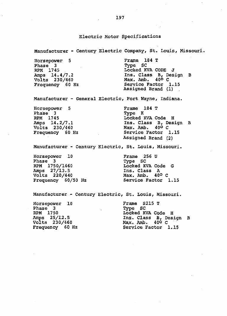
197
Electric Motor Specifications
Manufacturer - Century Electric Company, St. Louis, Missouri.
Horsepower 5 Phase 3 RPM 1745 Amps 14.4/7.2 Volts 230/460 Frequency 60 Hz
Frame 184 T Type se Locked KVA CODE J Ins. Class B, Design Max. Amb. 40° C Service Factor 1.15 Assigned Brand (1)
B
Manufacturer - General Electric, Fort Wayne, Indiana.
Horsepower 5 Phase 3 RPM 1745 Amps 14.2/7.1 Volts 230/460 Frequency 60 Hz
Frame 184 T Type K Locked KVA Code H Ins. Class B, Design Max. Amb. 40° C Service Factor 1.15 Assigned Brand (2)
Manufacturer - Century Electric, St. Louis, Missouri.
Horsepower 10 Phase 3 RPM 1750/1460 Amps 27/13.5 Volts 220/440 Frequency 50/50 Hz
Frame 256 U Type se Locked KVA Code G Ins. Class A Max. Amb. 40° C Service Factor 1.15
B
Manufacturer - Century Electric, St. Louis, Missouri.
Horsepower 10 Frame S215 T Phase 3 Type SC RPM 1750 Locked KVA Code H Amps 25/12.5 Ins. Class B, Design B Volts 230/460 M^. Amb. 40O C Frequency 60 Hz Service Factor 1.15
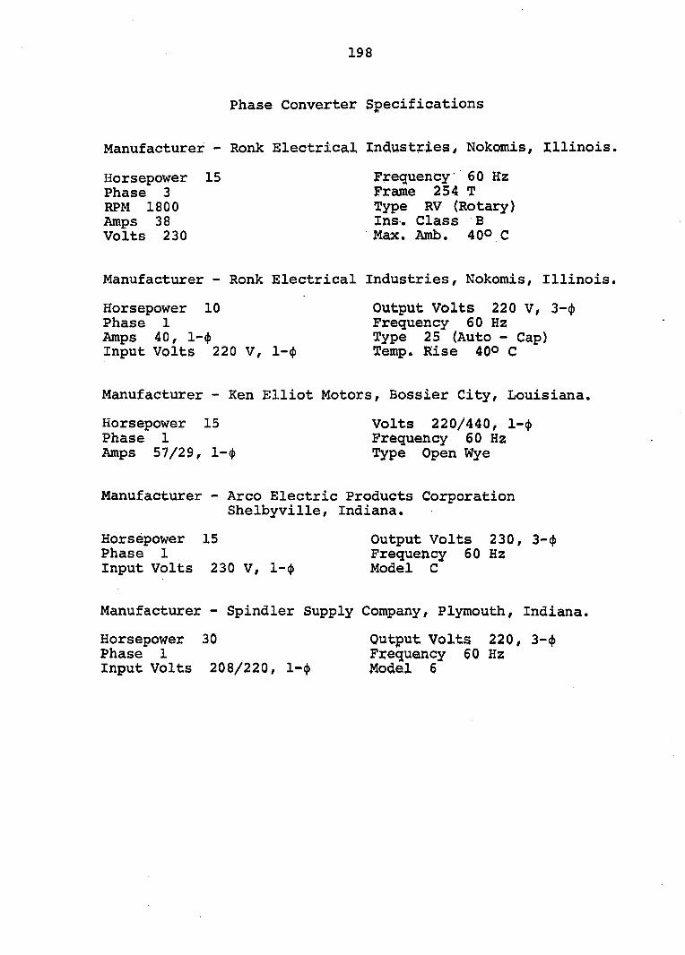
198
Phase Converter Specifications
Manufacturer - Ronk Electrical Industries, Nokomis, Illinois,
Horsepower 15 Frequency 60 Hz Phase 3 Frame 254 T RPM 1800 Type RV (Rotary) Amps 38 Ins. Class B Volts 230 Max. Amb. 40° C
Manufacturer - Ronk Electrical Industries, Nokomis, Illinois.
Horsepower 10 Output Volts 220 V, 3-<|) Phase 1 Frequency 60 Hz Amps 40, l-(j) Type 25 (Auto - Cap) Input Volts 220 V, l-(f) Temp, Rise 40° C
Manufacturer - Ken Elliot Motors, Bossier City, Louisiana.
Horsepower 15 Volts 220/440, l-(j) Phase 1 Frequency 60 Hz Amps 57/29, 1-<|) Type Open Wye
Manufacturer - Arco Electric Products Corporation Shelbyville, Indiana.
Horsepower 15 Output Volts 230, 3-4) Phase 1 Frequency 60 Hz Input Volts 230 V, 1-4» Model C
Manufacturer - Spindler Supply Company, Plymouth, Indiana.
Horsepower 30 Output Volts 220, 3-<j> Phase 1 Frequency 60 Hz Input Volts 208/220, l-<j> Model 6

199
Dynamometer Specifications
Manufacturer - Reliance Electric Cppipany, Cleveland, Ohio.
V-S Drive, Rotating Power Conversion
Horsepower 20 L.R. Amps 432 - 456/228 Phase 3 Frame D 20 VS RPM 3530 DC Amps 72 Amps 69.4 - 68/34 DC Volts 240 Volts 208 - 220/440 Excitation 120V, 2.24 Amps Frequency 60 Hz
Power Matched RPM - DC Motor
Horsepower 20 RPM 1750/4000 Amp 72 Volt 240 Field Volts 240 Field Max. Amps 2.27
Field Amps 1.6/.325 Windings Stab-Shunt Frame 287AT Type TR Insulation Class F Max. Amb. 40° C
Ventilation Motor - Forced Ventilation
Horsepower 0.5 Frequency 60 Hz Phase 3 Type P RPM 3450 Locked KVA Code Amps 2.2 Ins. Class A Volts 200 Max. Amb. 40° C
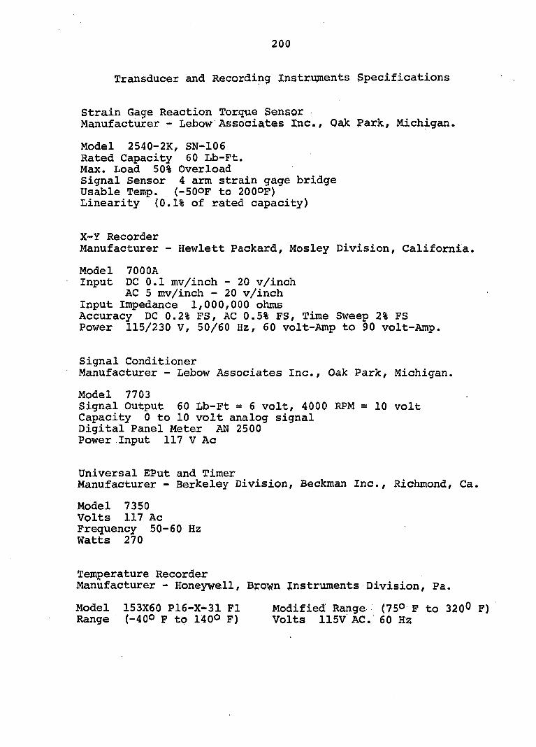
200
Transducer and Recording Instruments Specifications
Strain Gage Reaction Torque Sensor Manufacturer - Lebow Associates Inc./ Oak Park, Michigan.
Model 2540-2K, SN-106 Rated Capacity 60 Lb-Pt. Max. Load 50% Overload Signal Sensor 4 arm strain gage bridge Usable Temp. (-50OF to 2000P) Linearity (0.1% of rated capacity)
X-Y Recorder Manufacturer - Hewlett Packard, Mosley Division, California.
Model 7000A Input DC 0.1 mv/inch - 20 v/inch
AC 5 mv/inch - 20 v/inch Input Impedance 1,000,000 ohms Accuracy DC 0.2% FS, AC 0.5% FS, Time Sweep 2% FS Power 115/230 V, 50/60 Hz, 60 volt-Amp to 90 volt-Amp.
Signal Conditioner Manufacturer - Lebow Associates Inc., Oak Park, Michigan.
Model 7703 Signal Output 60 Lb-Ft = 6 volt, 4000 RPM = 10 volt Capacity 0 to 10 volt analog signal Digital Panel Meter AN 2500 Power Input 117 V Ac
Universal EPut and Timer Manufacturer - Berkeley Division, Beckman inc., Richmond, Ca.
Model 7350 Volts 117 Ac Frequency 50-60 Hz Watts 270
Temperature Recorder Manufacturer - Honeywell, Bpown Instruments Division, Pa.
Model 153X60 P16-X^31 F1 Modified Range (75° F to 320° F) Range (-40° F to 140° F) Volts 115V AC. 60 Hz
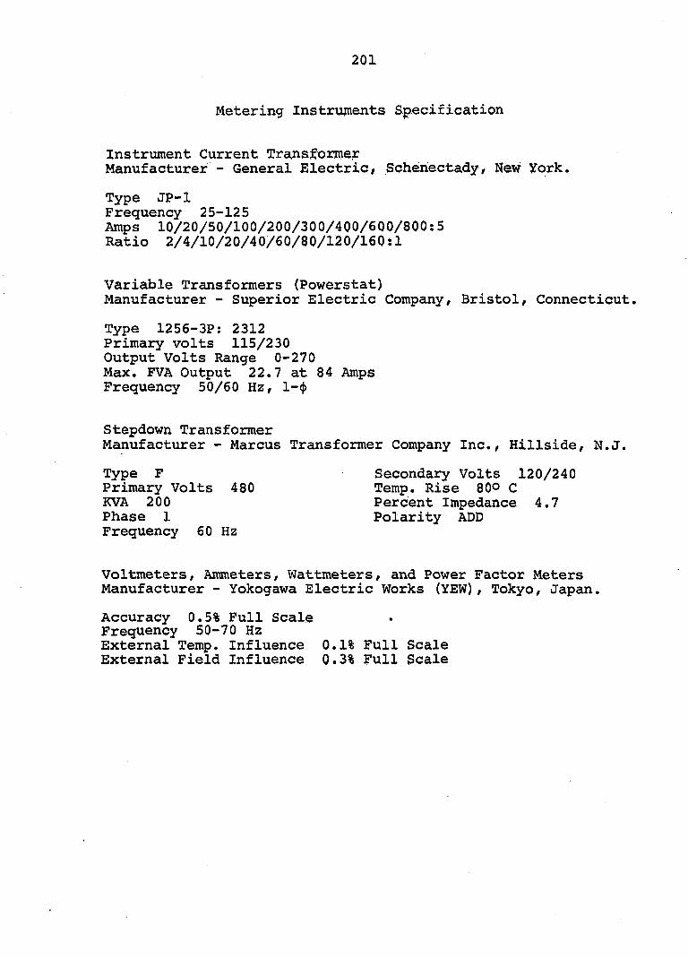
201
Metering Instruments Specification
Instrument Current Transformer Manufacturer - General Electric, Schenectady, New York.
Type JP-1 Frequency 25-125 Amps 10/20/50/100/200/300/400/600/800:5 Ratio 2/4/10/20/40/60/80/120/160:1
Variable Transformers (Powerstat) Manufacturer - Superior Electric Company, Bristol, Connecticut.
Type 1256-3P; 2312 Primary volts 115/230 Output Volts Range 0-270 Max. PVA Output 22.7 at 84 Amps Frequency 50/60 Hz, l-if)
Stepdown Transformer Manufacturer - Marcus Transformer Company Inc., Hillside, N.J.
Type F Secondary Volts 120/240 Primary Volts 480 Temp. Rise 80° C KVA 200 Percent Impedance 4.7 Phase 1 Polarity ADD Frequency 60 Hz
Voltmeters, Ammeters, Wattmeters, and Power Factor Meters Manufacturer - Yokogawa Electric Works (YEW), Tokyo, Japan.
Accuracy 0.5% Full Scale Frequency 50-70 Hz External Temp. Influence 0.1% Full Scale External Field Influence 0.3% Full Scale
202
APPENDIX B; TYPES OF PHASE CONVERTERS
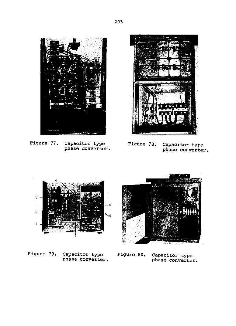
203
Figure 77. Capacitor type phase converter.
3,3 2 Tla.
Figure 78. Capacitor type phase converter,
Figure 79. Capacitor type Figure 80. Capacitor type phase converter. phase converter.
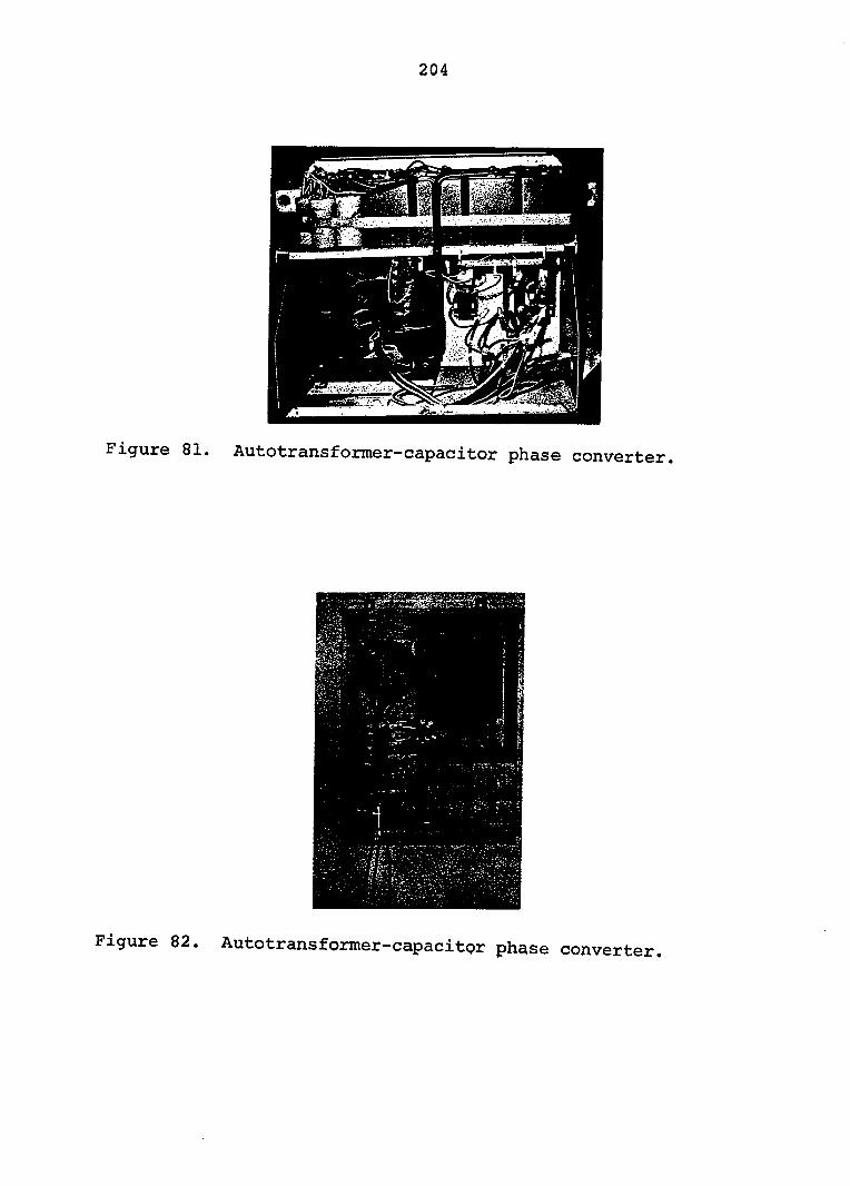
204
Figure 81. Autotransformer-capacitor phase converter.
Figure 82. Autotransformer-capacitor phase converter.
Figure 83 (upper right). Rotary phase converter.
Figure 84 (center). Open-wye type phase converter.
Figure 85 (lower right). Rotary phase converter.
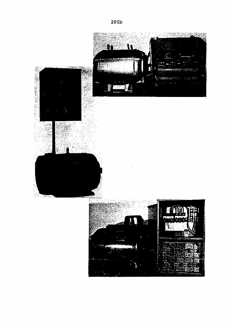
205b
206
APPENDIX C: EXPERIMENTAL DATA
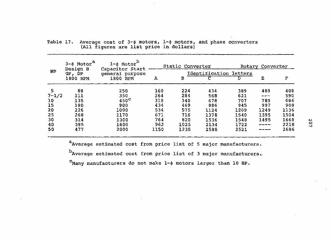
Table 17. Average cost of 3-(f) mptors, l-(j) motors, and phase converters (All figures are list price in dollars)
oëîignT Capacitor^Start Static Converter Rotary Converter
GP, DP general purpose Identitication letters 1800 RPM 1800 RPM A B C ~ D E F
5 88 250 160 224 434 389 489 408 7-1/2 111 350 264 284 568 621 — 590 10 135 450^ 319 340 678 707 789 684 15 180 900 434 469 886 945 997 908 20 226 1000 534 575 1124 1209 1249 1136 25 268 1170 671 716 1378 1540 1395 1504 30 314 1300 764 820 1536 1548 1495 1668 40 395 1600 962 1025 2134 1722 — — — — 2218 50 477 2000 1150 1230 2588 2521 — 2686
^Average estimated cost from price list of 5 major manufacturers.
^Average estimated cost from price list of 3 major manufacturers..
^Many manufacturers do not make 1-^ motors larger than 10 HP.
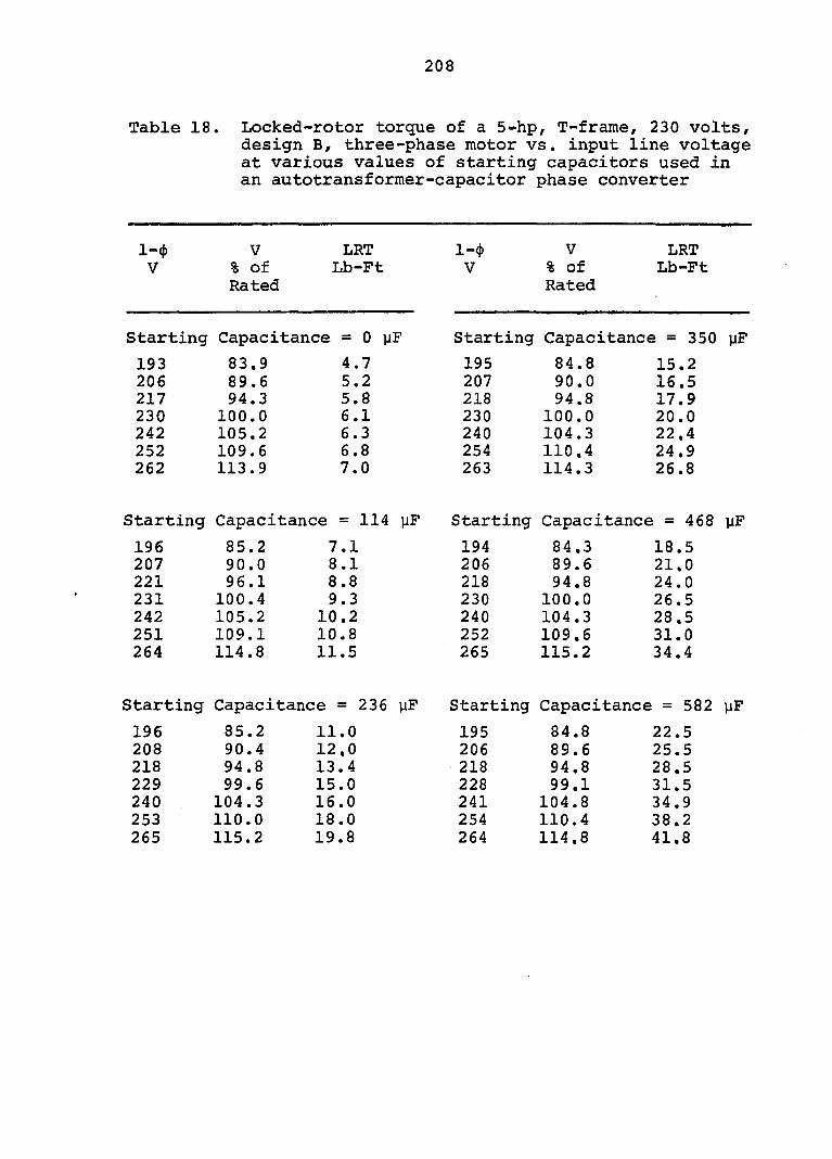
208
Table 18. Locked-rotor torque of a 5-hp, T-frame, 230 volts, design B, three-phase motor vs. input line voltage at various values of starting capacitors used in an autotransformer-capacitor phase converter
I-* V LRT l-(t) V LRT V % of Lb-Ft V % of Lb-Ft
Rated Rated
Starting Capacitance = 0 yF Starting Capacitance = 350 yF
193 83.9 4.7 195 84.8 15.2 206 89.6 5.2 207 90.0 16.5 217 94.3 5.8 218 94.8 17.9 230 100.0 6.1 230 100.0 20.0 242 105.2 6.3 240 104.3 22,4 252 109.6 6.8 254 110.4 24.9 262 113.9 7.0 263 114.3 26.8
Starting Capacitance = 114 yF Starting Capacitance = 468 yF
196 85.2 7.1 194 84.3 18.5 207 90.0 8.1 206 89.6 21.0 221 96.1 8.8 218 94.8 24.0 231 100.4 9.3 230 100.0 26.5 242 105.2 10.2 240 104.3 28.5 251 109.1 10.8 252 109.6 31.0 264 114.8 11.5 265 115.2 34.4
Starting Capacitance = 236 yF Starting Capacitance = 582 yF
196 85.2 11.0 195 84.8 22.5 208 90.4 12.0 206 89.6 25.5 218 94.8 13.4 218 94.8 28.5 229 99.6 15.0 228 99.1 31.5 240 104.3 16.0 241 104.8 34.9 253 110.0 18.0 254 110.4 38.2 265 115.2 19.8 264 114.8 41.8
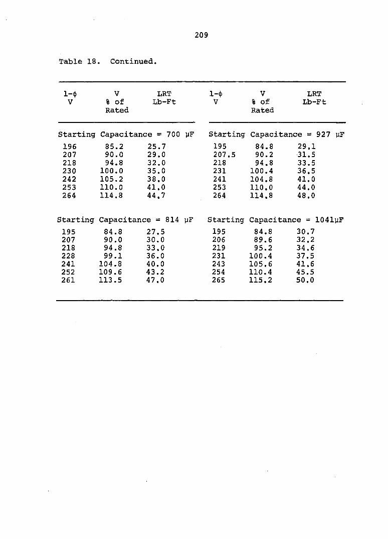
Table 18. Continued.
209
l-({) V IJRT l-* V LRT V % of Lb-Ft V % of Lb-Ft
Rated Rated
Starting Capacitance = 700 yF Starting Capacitance = 927 yF
196 85.2 25.7 195 84.8 29.1 207 90.0 29.0 207.5 90.2 31.5 218 94.8 32.0 218 94.8 33.5 230 100.0 35.0 231 100.4 36.5 242 105.2 38.0 241 104.8 41.0 253 110.0 41.0 253 110.0 44.0 264 114.8 44.7 264 114.8 48.0
Starting Capacitance = 814 yF Starting Capacitance = 1041yF
195 84.8 27.5 195 84.8 30.7 207 90.0 30.0 206 89.6 32.2 218 94.8 33.0 219 95.2 34.6 228 99.1 36.0 231 100.4 37.5 241 104.8 40.0 243 105.6 41.6 252 109.6 43.2 254 110.4 45.5 261 113.5 47.0 265 115.2 50.0
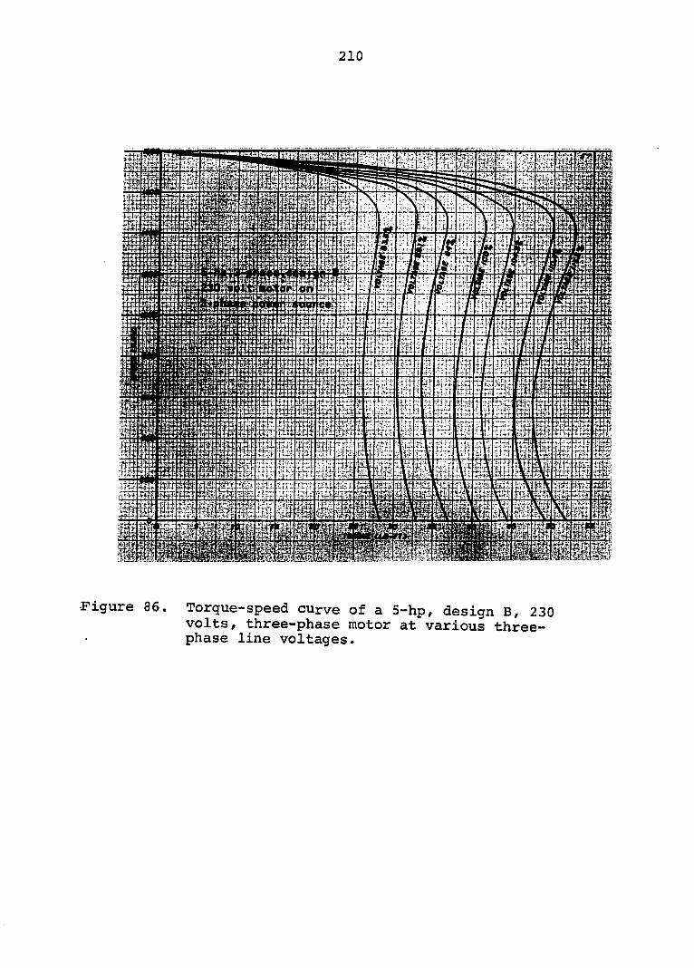
210
% m
s i .fis
•Figure 86. Torque-speed curve of a 5-hp, design B, 230 volts, three-phase motor at various three-phase line voltages.
211
"Figure 87. Torque-speed curves of an autotransformer phase converter operated 5-hp, design B, 230 volts/ three-phase motor at various single-phase line voltages.

212
Figure 88. Torque-speed curves of a rotary phase converter operated 5-hp, design B, 230 volts, three-phase motor at various single-phase line voltages.
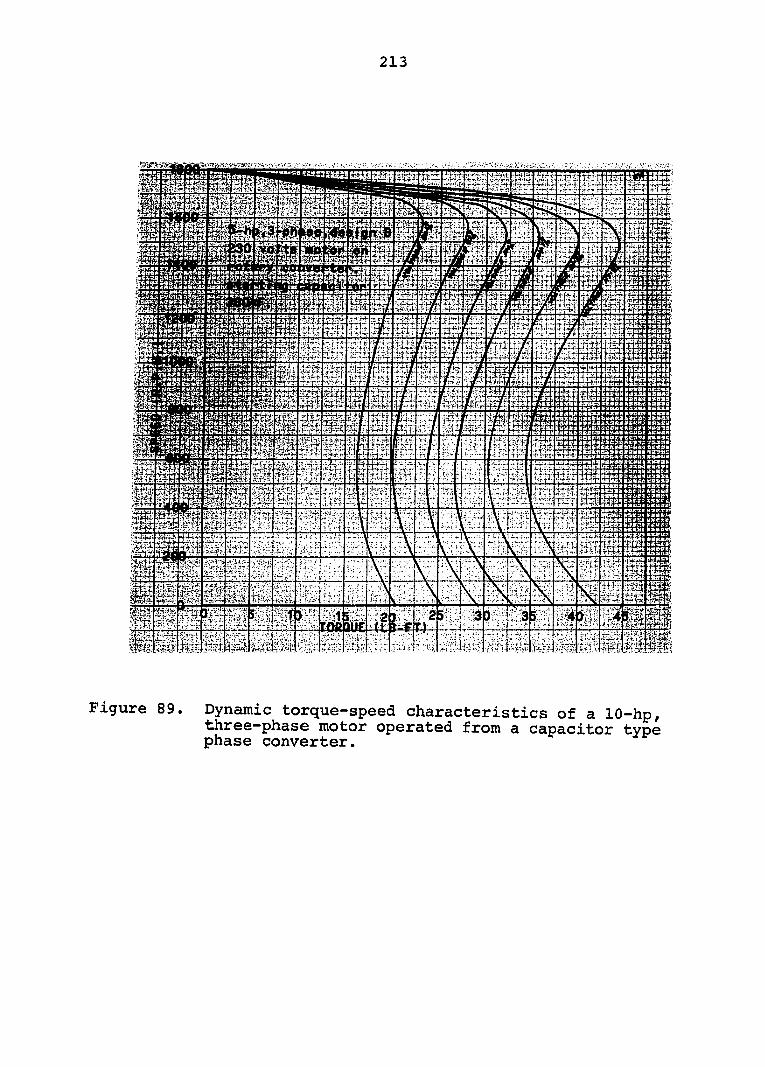
213
" y '
EÎÎS agi
Figure 89. Dynamic torque-speed characteristics of a 10-hp, three-phase motor operated from a capacitor type phase converter.
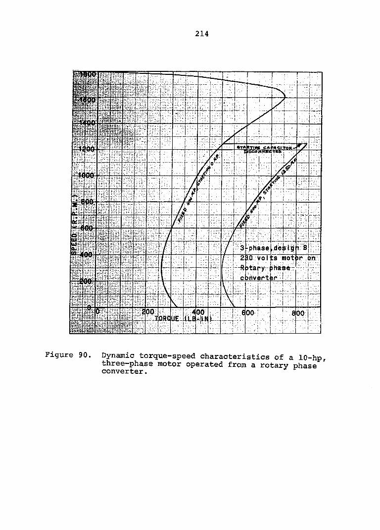
214
31-phase .des I g
2 ÎO Vo l ts mot
>tary- i^hàôér • ' 1 : ! VI .;, ç.>nvept iP .
Figure 90. Dynamic torgue-speed characteristics of a 10-hp, three-phase motor operated from a rotary phase converter.
215
Figure 91. Dynamic torque-speed characteristics of à 10-hp, three-phase motor operated from an open wye type phase converter.
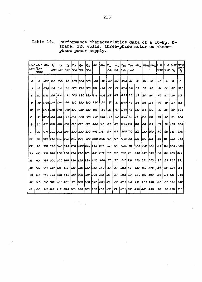
216
Table 19. Performance characteristics data of a 10-hp, U-frame, 220 volts, three-phase motor on three-phase power supply.
LOAD L&FT
LOAD %0F RATEC
RPU H AMP
H AMP
H AMP
''/2 VOLT
^23 VOLT
^3 VOLT
^IN VOLT
^2N VOLT
^3N VOLT
^N6 VOLT
KW,^ KW3F^ 3-(P
PFCn 3-^
ppai SLIP
%
EFFIO lENCr %
0 0 laoo 11.0 10.8 9.6 220 220 220 /J6 -.80 127 127 I2&5 7.1 J2 .28 J6 .14 .15 0 0
3 10 1796 11.4 11.4 10.2 220 220 220 /.7S -.48 127 127 I26J5 7.0 .35 52 40 .31 .31 .22 58-S
6 20 1792 12.4 12.4 11.2 220 220 220 2.16 -JOB 127 127 1265 7.3 £8 30 B4 A5 A7 A4 71.7
9 30 1768 13.4 13.6 12.6 220 220 220 264 -32 127 127 126.5 7.2 .96 IÛ2 .96 59 .59 .67 75.6
12 40 I7B4 14.8 14.8 14.0 220 220 220 308 .64 127 127 126.5 7.2 L20 136 120 .67 .66 39 8Q2
15 50 I7B0 16.6 16.6 15.6 220 220 220 3S2 LOO 127 127 126.5 7.2 /.48 USO 148 .73 .72 I.II 82.5
/a 60 1775 IBS IB3 17.6 220 220 220 4.04 lAO 127 127 1265 7.3 176 m 104 .77 .76 1.39 823
21 70 1771 203 203 19.6 220 220 220 4.4B 1.76 127 127 1265 7.0 200 320 200 30 30 1.61 83.6
24 80 1767 23J0 22.8 220 220 220 220 5.00 2.08 127 127 126.5 7.2 232 248 232 32 31 133 84.3
27 90 1763 252 25.2 24.4 220 220 220 5.52 2.44 127 127 126.5 7.6 2£4 2.72 2£4 34 33 2JOS 84.3
30 100 1758 2BO 27.6 27.0 220 220 220 6.12 2.72 127 127 126.5 7.5 2S6 236 236 34 34 2J3 84A
33 no 1754 30.0 300 283 220 220 220 6.56 3.08 127 127 I26£ 7.8 320 3.36 320 35 35 2.55 85.1
36 120 1747 32A 324 31.2 220 220 220 7.12 3A0 127 127 1265 7.8 352 360 3.48 36 35 2.94 85.1
39 130 1740 35.4 35J0 34.0 220 220 220 7.72 3.72 127 127 I26.S 8.2 330 3S2 330 .86 35 3J3 84.8
42 140 1732 382 38.0 3SA 220 220 220 ejs 4.04 127 127 1265 8.4 4.12 4.24 4X38 .87 36 3.78 84.2
45 150 1723 41.6 4L2 38.6 220 220 220 9.08 4.36 127 127 1265 8.2 4.48 4.60 4.40 37 36 4L28 813
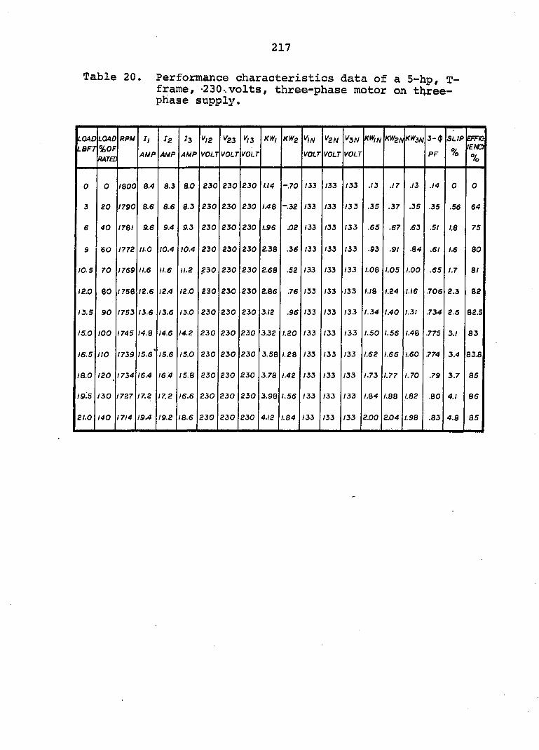
217
Table 20. Performance characteristics data of a 5-hp, T-frame, -230..volts, three-phase motor on t^ree-phase supply.
LOAD IBF7
LOAD %0F MTEC
RPM h AMP
l2 AMP
l3 AMP
^12 VOLT
^23 VOLT
^13 VOLT
KW/ KWz V,N VOLT
^2N VOLT
^3N VOLT
KW,N KW2N K^3N 3-(j)
PF SLIP %
EFFIO lENO %
0 0 IBOO 8.4 8.3 8.0 230 230 230 /./4 -.70 133 133 133 .13 .17 .13 .14 0 0
3 20 1790 8.6 8.6 8.3 230 230 230 1.48 -.32 133 133 133 .35 .37 .35 .35 .56 64
6 40 I7QI 9.6 9.4 9.3 230 230 230 1.96 .02 133 133 133 .65 .67 .63 .51 1.8 75
â 60 1772 II.O 10.4 10.4 230 230 230 2.38 .36 133 133 133 .93 .91 .84 .61 1.6 80
10.5 70 1769 11.6 11.6 11.2 230 230 230 2.68 .52 133 133 133 1.08 1.05 1.00 .65 1.7 81
(2.0 BO /758 12.6 12.4 12.0 230 230 230 2.86 .76 133 133 133 1.18 1.24 1.16 .706 2.3 82
13.5 90 1753 13.6 13.6 13.0 230 230 230 3.12 .96 133 133 133 1.34 1.40 1.31 .734 2.6 82.S
15.0 100 1745 I4.e 14.6 14.2 230 230 230 3.32 L20 133 133 133 1.50 1.56 1.48 .775 3.1 83
16.5 110 1739 15.6' 15.6 15.0 230 230 230 3.58 1.28 133 133 133 1.62 1.66 1.60 .774 3.4 83.8
IB.O 120 1734 16.4 16.4 I5.B 230 230 230 3.78 1.42 133 133 133 1.73 1.77 1.70 .79 3.7 85
19.5 130 1727 17.2 17.2 16.6 230 230 230 3.98 1.56 133 133 133 1.84 1.88 1.82 .80 4.1 86
21.0 140 1714 19.4 19.2 18.6 230 230 230 4.12 1.84 133 133 133 2.00 2.04 1.98 .83 4.8 85
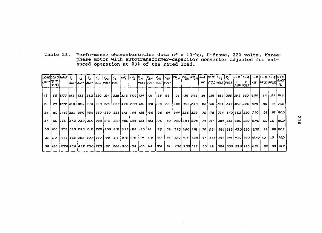
Table 21. Performance characteristics data of a 10-hp, U-frame/ 220 volts, three-phase motor with autotransformer-capacitor converter adjusted for balanced operation at 80% of the rated load.
LOAD LB^FT
LOAD %of RATED
RPU h AMP
h AMP
b AMP
*^2
VOLT ^23 VOLT
^3
VOLT kiv, klvg ""IN
VOLT ^2N VOLT
^SN VOLT
^NG VOLT
X^IN 3-0 PF
SLIP (%)
^7-2
VOLT VOLT / - $
I AMP
l-<P V
VOLT
l-(p KW
1 - 0 PFcn
1 - (p PF(2)
EFFIO lENCr %
IB 60 1777 15.2 172 23.2 220 234 220 3.48 2.04 134 131 125 66 .96 1.36 2.46 .91 I.2B 384 355 29.5 220 6.00 .94 .93 74.6
21 70 1772 /8.8 /8.a 224 220 228 226 4.24 2.00 130 <28 126 66 2.08 /.80 2.40 .85 1.56 384 347 32.0 220 6.70 .96 .95 780
24 eo I76B 223 22.0 22.4 220 220 223 5/2 1.96 12 B 126 126 64 2.44 2.36 2.32 .79 1.78 384 340 35.2 220 7.50 .98 .97 80.0
27 90 1761 27.2 25.2 21.6 220 2/3 220 6.00 I.BB 123 123 126 62 2.80 2.84 2.26 .74 2.17 384 332 38,0 220 &.40 39 I.O 80.0
30 100 1753 32.0 29.6 21.2 220 205 2)0 696 I.B4 120 121 126 59 3.20 3.60 2.1 Q .70 2.61 384 325 430 220 9.30 .99 .98 80.2
33 110 1742 3ao 36.4 20.4 220 195 2/3 B.I6 1.76 114 IIB 127 56 3.70 4.16 2.08 .67 322 384 3/6 47.0 220 10.40 I.O 1.0 79.0
36 120 1726 45.6 45.2 20.0 220 IB2 206 9.60 1.64 105 114 126 51 4.30 5.00 1.92 .63 4.11 384 305 53.5 220 11.74 .99 .99 76.2
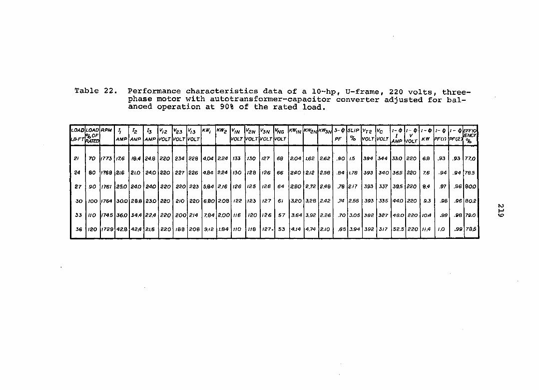
Table 22. Performance characteristics data of a 10-hp, U-frame, 220 volts, three-phase motor with autotransformer-capacitor converter adjusted for balanced operation at 90% of the rated load.
LOAD LB-FT
LOAD %0F RATED
F>PM AMP AMP
h AMP
^/2 VOLT
^23 I'Oi.r
^13 VOLT
/fW, KWg 1/Oi.r
^2N VOLT
Ksw VOLT
^NG VOLT
K»2N 3-4»
PF SLIP %
Vtz VOLT
Vc VOLT
1- (t> I
AMP /•• $ /
VOLT /- (J>
KW
/- <J)
PF(/)
1- $
flF(2J
E^RF/O rftCK %
21 70 1773 17.6 /8.4 24.8 220 234 228 4.04 2.24 /33 ISO 127 68 2.04 1.62 2.62 .90 1.5 394 344 33.0 220 6.8 .93 .93 77.0
24 80 1768 21.6 21.0 24.0 220 227 226 4.84 2.24 130 128 126 66 240 2.12 2.58 .84 1.78 393 340 36£ 220 7.6 .94 .94 78.5
27 90 1761 25.0 24.0 24.0 220 220 223 5.84 2./6 126 125 126 64 2.80 2.72 2.48 .78 2.17 393 337 39.5 220 8.4 .97 .96 80.0
30 lOO 1754 30.0 28.8 23.0 220 2/0 220 6.80 2.08 122 123 127 61 3.20 3.28 2.42 .74 2.55 393 335 44.0 220 9.3 .98 .96 80.2
33 no 1745 36.0 34.4 22.4 220 200 2/4 7.84 2.00 116 120 126 57 3.64 3.92 2.26 .70 3.05 392 327 48.0 220 /OX) S9 .98 70.0
36 120 1729 42.8 42.4 2/.6 220 <88 208 9.12 /.84 no 118 127. S3 4.14 4.74 2./0 .65 3.94 392 317 52.5 220 //.4 1.0 .99 78J5
to M ko
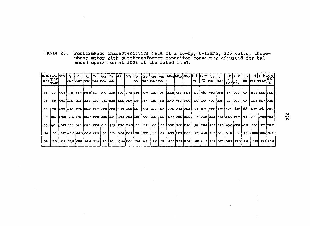
Table 23, Performance characteristics data of a 10-hp, U-frame, 220 volts, three-phase motor with autotransformer-capacitor converter adjusted for balanced operation at 100% of the rated load.
UOAD LB-FT
Q U.
Q
^ O
b
PPM h AMP
h AMP
h AMP VOLT
*^23 VOLT VOLT
KWj KW^ *^//V VOi.7-
^2N VOLT
K3A/ VOLT VOLT
K*//V K^2N l 3N 3-0
PF SLIP
% ^T2
VOLT VOLT / - $
1 AMP
/ - $
V VOLT
/ - $
KW / - $
PFCO / - $
PF(2) EFFIC lENCf %
21 70 1773 IB.2 IB.6 26.0 220 241 232 3.76 2.72 /38 134 126 71 2.08 1.32 3.04 .96 1.50 403 358 37 220 7.0 A 66 £60 74.6
24 80 1769 21.0 19.6 27.6 220 235 230 4.56 2.64 135 131 126 68 2.40 1.80 3.00 .90 1.72 403 355 39 220 7.7 .906 B97 77.S
27 SO 1765 24.8 22.0 268 220 228 226 5.36 2.56 131 I2B 126 67 S.70 2.32 2S2 .86 1.94 400 355 41.5 220 8.5 S34 S3I 79.0
JO 100 1760 28.6 26.0 26.4 220 220 224 6.08 2.52 /28 127 /28 68 3.00 230 2JB0 .81 2.22 403 353 44.5 220 9.4 361 S60 79A
33 no 1749 33.8 il.2 25.8 220 211 2/9 7.36 2.40 /22 127 126 62 3.52 3.52 2.72 .75 2B3 402 340 48.0 220 10.3 SBS S75 79.7
36 120 1737 40.0 3B.O 2S.O 220 i9a 2/3 8.64 2.24 lie 122 123 57 4X30 4.24 2£0 .70 3.50 403 332 520 220 11.4 .996 S96 78.5
39 130 17 IB 53.0 48.8 24.4 220 IQ3 204 IO.OQ 2.04 104 113 126 52 4.56 5.32 2.32 .66 4.56 402 317 58.2 220 12.8 .998 .999 75.8
to to o

Table 24, Performance characteristics data of a 5-hp, T-frame, 230 volts, three-phase motor with autotransformer-capacitor converter adjusted for balanced operation at 80% of the rated load.
load
LBTT LOAD %0F r47ec
RPU j,
AMP ^2
AMP h
AMP VOLT ^23
VOLT ^,3 VOLT
KWi KW^ VOLT
''2N VOLT
^3N VOLT
^N6 VOLT
'<^2N 3-4»
PF SLIP (%)
^T2 VOLT VOLT
/- 4»
J AMP
1- $ V
VOLT
/-(J)
KW /- (J)
PFCn PF(2) EFFIG lENCY %
9 60 I77i 9.4 11.2 13.0 230 242 237 2.08 .68 139 136 132 71.5 .86 .73 1.22 .75 1.5 316 302 14.0 230 3.12 .975 .97 72.7
IO.S 70 1767 11.2 11.2 12.6 230 235 235 2.52 .68 135 134 132 69 i.oa .95 1.20 .71 ;.83 315 295 I5.B 230 3.56 .980 .980 74.0
12.0 80 1762 13.2 12.2 12.4 230 230 232 2.96 .66 132 131 132 67 1.30 1.20 1.16 .67 2.11 350 286 tr.e 230 3.96 .980 .97 76.0
13.5 90 I7S4 I4.B 13.0 12.2 230 224 230 3.34 .66 129 129 132 64.5 1.47 1.39 1.14 .65 2.56 350 282 20.2 230 4.36 .980 .95 77.2
ISO lOO 1744 I7.Z /4.e li.e 230 215 226' 3.84 .62 124 126 132 62 1.72 1.67 1.09 .63 3.11 315 275 23.2 230 4.60 .975 .90 78jO
I&5 110 1733 19.4 17.0 11.4 230 207 221 4.32 .60 120 124 132 59 1.94 1.94 1.04 .61 3.72 315 265 25.0 230 5.28 .965 .973 77.0

Table 25. Performance characteristics data of a 5-hp, T-frame# 230 volts, three-phase motor with autotransformer-capacitor converter adjusted for balanced operation at 100% of the rated load.
LOAD LBFT
LOAD %0F Mjm
BPU h AUP AUP
^3 AfJP VOLT
ta VOLT
^13 VOLT
KWf KWg ^,N VOLT
^2N VOLT
^3N VOLT
^NG VOLT
KW,^ Kt/V 3-t) PF
SLIP '^r2 VOLT VOLT
1-0 r
AMP
1-0 V
VOLT
1-0 KW
1-0 PFdJ
1-0 PF121
EFFIO lENCr %
10.5 70 1766 9.2 I2.Q 15.4 230 24 B 239 2 / 2 1.22 142.0 136.0 130.0 73.5 .94 .82 .162 9062 1.89 365 345 164 230 3.72 .990 .99 70.8
12.0 80 1761 lO.B I2.e 15.0 230 243 236 2.50 I.20 139 136 131 71.5 •112 .101 .159 8543 2.17 365 340 17.92 230 4.08 .992 .99 73.7
13.5 90 1759 II.B 13.2 14.84 230 240 235 2.70 1.20 I3B 135 132 70.0 .120 .113 .157 .8322 2£8 365 335 IB.70 230 4.42 .995 t.O 763
15.0 too 1752 MA 14.4 14.6 230 230 230 3.38 LIS 132 132 132 67 .152 .152 .151 .7631 2.67 365 325 21.4 230 4.80 .999 .98 76.0
(6.5 no 1741 15.6 15.2 14.4 230 227 229 3.60 1.14 130 130 132 65.5 .163 .162 .I4B .7438 3.28 365 324 2224 230 5.12 1.00 1.0 79.7
18.0 120 1731 17.6 I6.B 14.0 230 220 225 4.04 L05 126 128 132 630 .182 J88 .143 .7014 3.83 365 316 24.0 230 5.52 .999 1.0 80.3
I9.S 130 1715 2086 19.7 13.6 230 20B 217 4.6B 1.04 119 125 130 590 .211 .227 J35 •6720 4.72 365 307 26.8 230 6.14 .995 .997 77.3
to to to
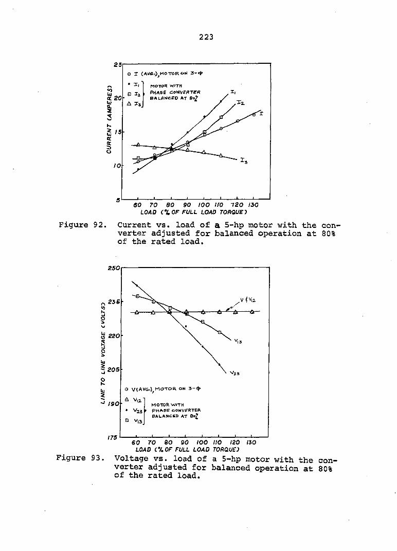
223
Ï20
I S / 5 ac.
% o
10
O I (AV&.)^MOTOR ON 3-4»
A I3
motor with
PHASE COtiVEflTER balanced at
Figure 92.
60 70 80 90 too IfO 120 130 load cx of full load torque j
Current vs. load of a 5-hp motor with the converter adjusted for balanced operation at 80% of the rated load.
250
^2se
I i ~ 205h
220
V
^23
o \/(av&.)^motor on 3-e}>
. A V,2 " /SOp MOTOR WITH
• YlS ' PHASE CONVERTER BALANCBB AT 90?
Q V,3
175 ' 60 70 80 90 100 110 120 izo
load cv, of full load torque)
Figure 93. Voltage vs. load of a 5-hp motor with the converter adjusted for balanced operation at 80% of the rated load.
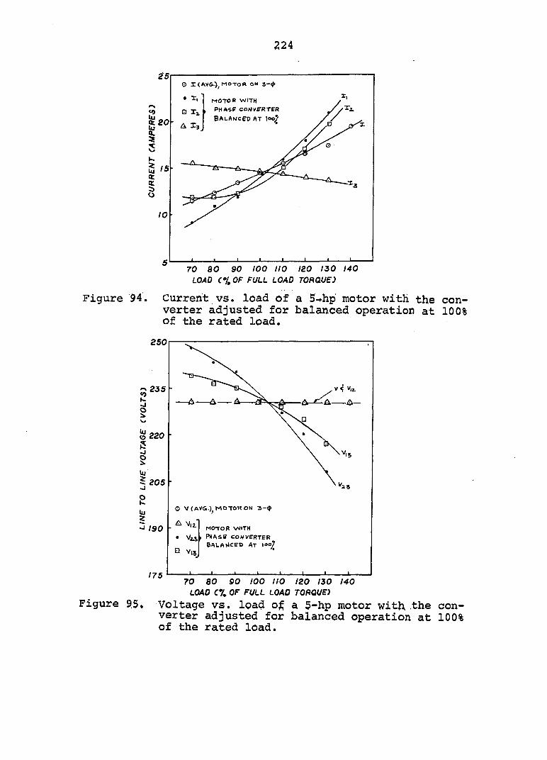
224
o i motor ow 3-4»
MOTOR WITH phase" COHVE-RTER
BALANCED AT LOO % 20
Figure 94.
70 so 90 100 no 120 130 140 LOAD (% OF FULL LOAD TORQUE)
Current VS. load of a 5-»hp motor with the converter adjusted for balanced operation at 100% of the rated load.
250
i W o G
235 •
220
205
S
190
175
Q V(AV&.) MOTOR ON 3-*
• Vts Q V,,
MOTOR WITH
PHASff CONVERTER bbla(4cet> at 100/
Figure 9.5.
70 80 so 100 no 120 130 140 LOAD C7. OF FULL LOAD TORQUE)
Voltage vs. load o^ a 5-hp motor with the converter adjusted for balanced operation at 100% of the rated load.
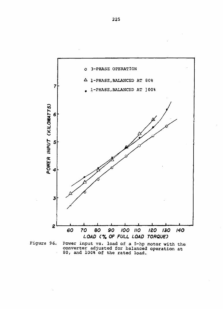
225
O 3-PHASE OPERATION
A 1-PHASE,BALANCED AT 80%
. 1-PHASE,BALANCED AT ]00%
9 4
120 130 140 LOAD C7. OF FULL LOAD TORQUE)
Figure 9 6. Power input vs. load of a 5-hp motor with the converter adjusted for balanced operation at 80, and 100% of the rated load.
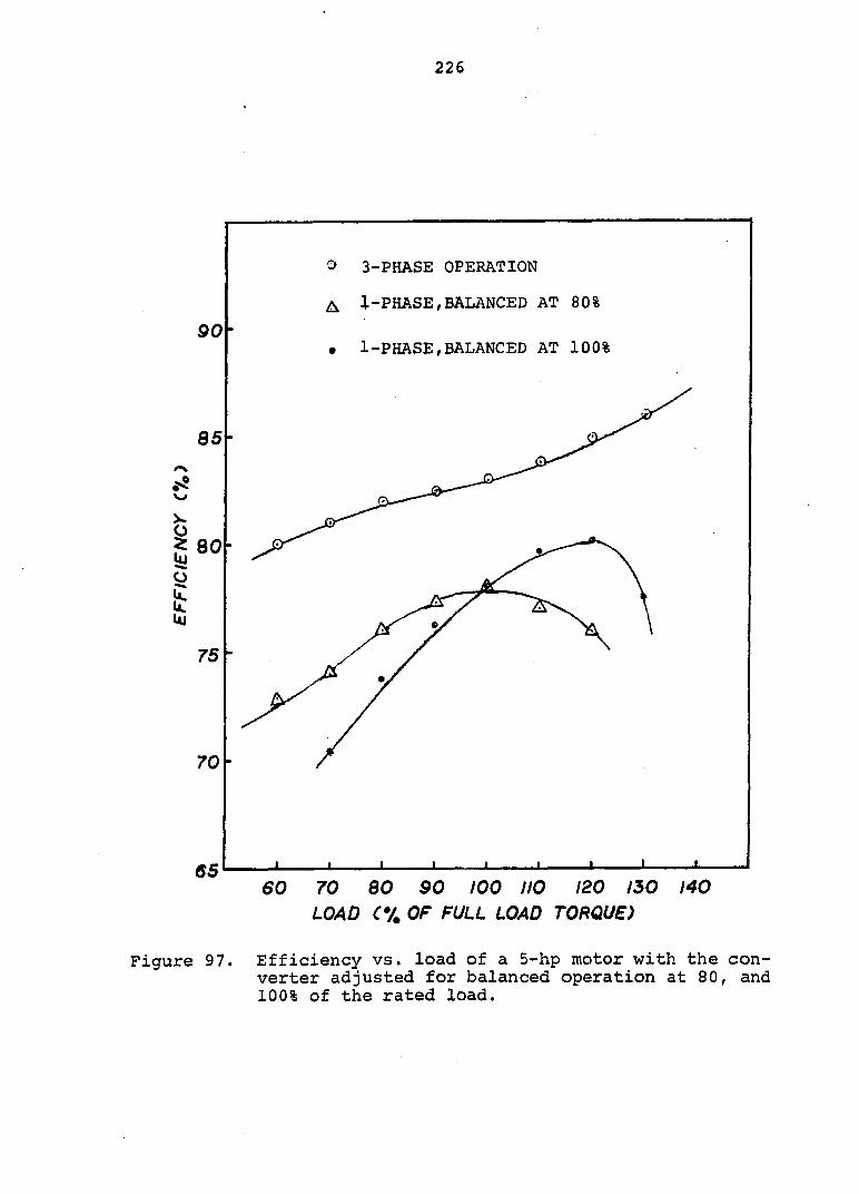
226
90
85
X 0 ? 80
1 75
70
65
O 3-PHASE OPERATION
A I-PHASE,BALANCED AT 80%
• 1-PHASE,BALANCED AT 100%
60 70 80 90 100 IIO 120 130 LOAD OF FULL LOAD TORQUE)
140
Figure 97. Efficiency vs. load of a 5-hp motor with the converter adjusted for balanced operation at 80, and 100% of the rated load.
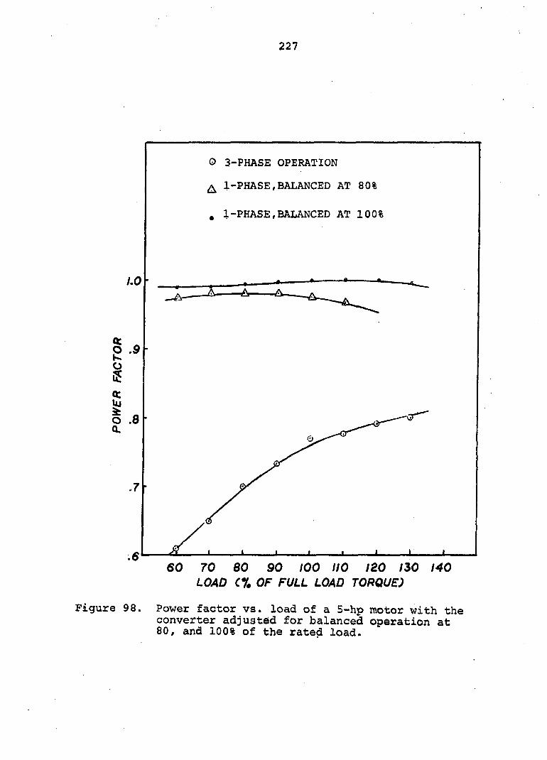
227
O 3-PHASE OPERATION
^ 1-PHASE,BALANCED AT 80%
. 1-PHASE,BALANCED AT 100%
• » •
-A-
I ® M
o Q.
.8
.6 60 70 60 90 100 110 120 130 140
LOAD C% OF FULL LOAD TORQUE)
Figure 98. Power factor vs. load of a 5-hp motor with the converter adjustôd for balanced operation at 80, and 100% of the rated load.
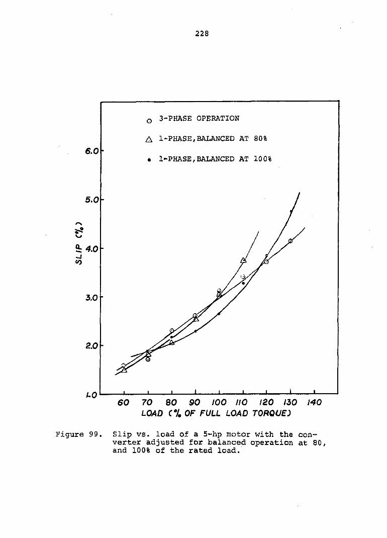
228
3-PHASE OPERATION
A 1-PHASE,BALANCED AT 80%
6.0 • l-PHASE,BALANCED AT 100%
5.0
4.0
3.0
2.0
AO 60 70 80 SO 100 no 120 150 140
LOAD C7. OF FULL LOAD TORQUE)
Figure 99. Slip vs. load of a 5-hp motor with the converter adjusted for balanced operation at 80, and 100% of the rated load.
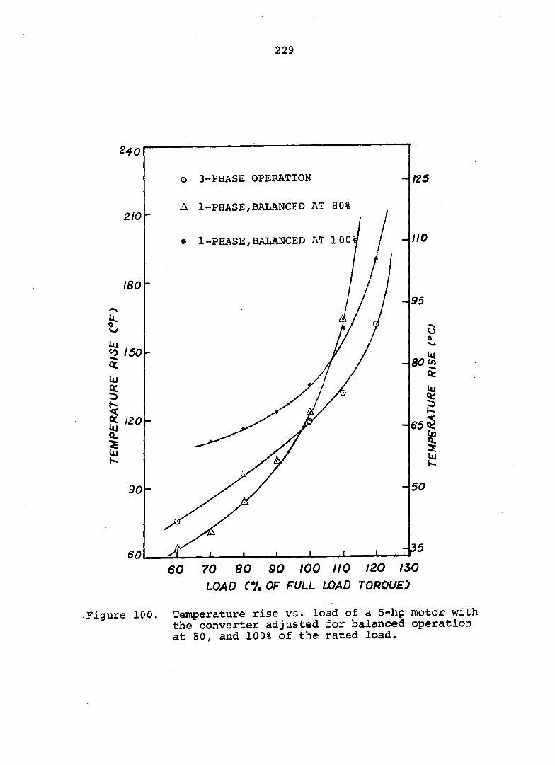
229
Q 3-PHASE OPERATION 125
A 1-PHASE/BALANCED AT 80% 210
- no • 1-PHASE,BALANCED AT 100
180 -
95
<0 150
120
50 90
60 70 80 90 100 no 120 130 LOAD CV. OF FULL LOAD TORQUE)
-Figure 100. Temperature rise vs. load of a 5-hp motor with the converter adjusted for balanced operation at 80, and 100% of the rated load.
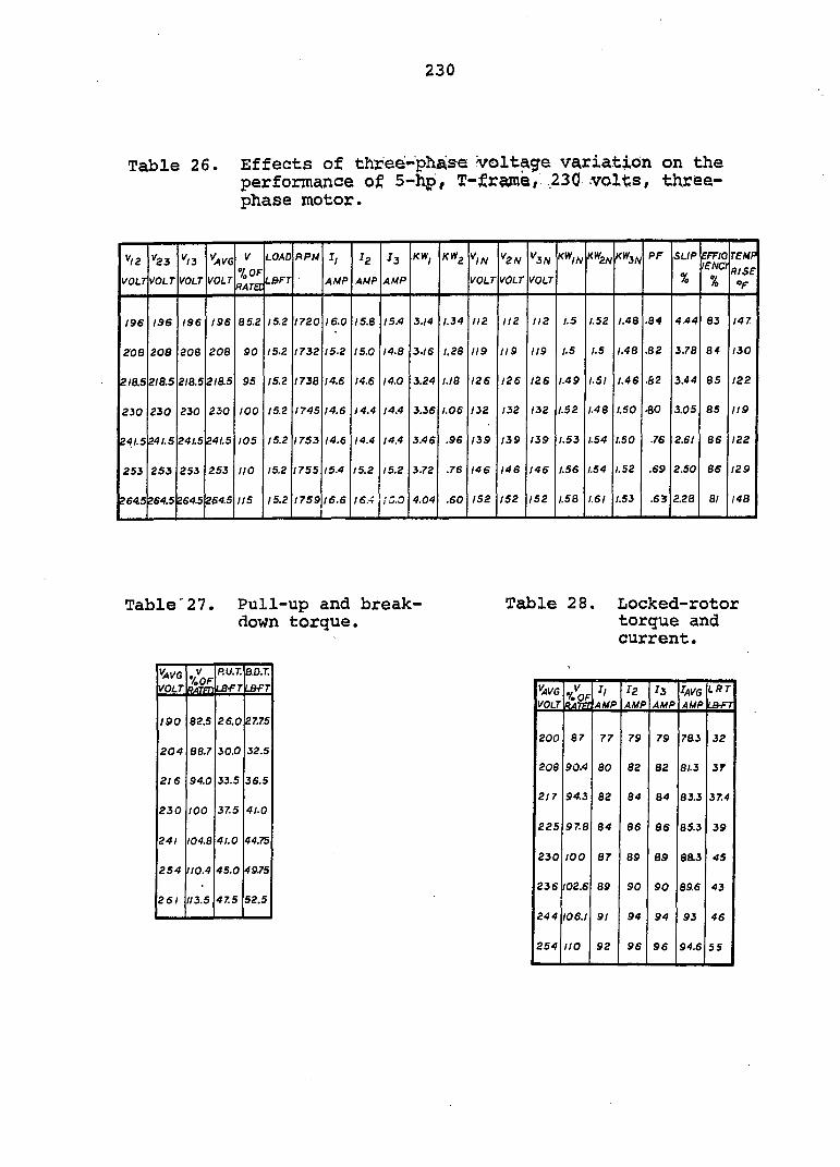
230
Table 26. Effects of threé-'phAse voltage variation on the performance of 5-hp, T-fraraë/ ,230 volts, three-phase motor.
v/2
VOLT
*23
volt
^/3
VOLT
K^VG
VOLT
V
%0F
RATED
LOAD
LBFT
RPU :/
AMP
h
AMP
:3
AMP
kw, kwg ^IN
VOLT
^2N
VOLT
^3N
VOLT
X^IN X»3N PF SLIP
%
EFFIO lENCr
%
TEMP
RISE °F
196 136 196 196 a 5.2 15.2 1720 16.0 15.8 15.4 3.14 1.34 112 112 112 1.5 1.52 1.48 .84 4yf4 83 147
208 208 208 208 90 15.2 1732 15.2 15.0 14.8 3.16 1,28 119 119 119 1.5 1.5 1.48 .82 3.78 84 130
2IB.S 2I8.S 2/8.5 3IB.S 95 IS.2 I73B 14.6 14.6 14.0 3.24 1.18 126 126 126 1.49 I.SI 1.46 •82 3.44 85 122
230 230 230 230 100 15.2 1745 14.6 14.4 14.4 3.36 1.06 132 132 132 1.52 1.48 1.50 SO 3.05 85 119
24/. 5 24/. 5 241.5 241.5 105 15.2 1753 14.6 14.4 14.4 3.46 .96 139 139 139 1.53 1.54 1.50 .76 2.61 86 122
253 253 253 253 110 15.2 1755 IS.4 15.2 15.2 3.72 .76 146 146 146 1.56 1.54 1.52 .69 2.50 86 129
2645 264.5 264.5 264.5 115 15.2 1759 16.6 /s.-f !Q.O 4.04 .60 152 152 152 1.58 1.61 1.53 .63 2.28 81 148
Table'27. Pull-up and breakdown torque.
Y^VG
VOLT %0F f?i17]7î
P.U.T.
LBFT
B.D.T.
LBFT
190 82.5 26.0 27.75
204 88.7 30.0 32.5
216 94.0 33.5 36.5
230 100 37.5 41.0
241 104.8 41.0 44.75
254 110.4 45.0 49.75
261 113.5 47.5 52.5
Table 28. Locked-rotor torque and current.
Vg
VOLT mSf h
AMP
I2
AMP
l3
AMP
II
LRT
LBFT
200 87 77 79 79 78.3 32
208 90.4 80 82 82 81.3 37
217 94.3 82 84 84 83.3 37.4
225 97.8 84 86 86 85.3 39
230 100 87 89 89 88.3 45
236 102.6 89 90 90 89.6 43
244 106.1 91 94 94 93 46 Jj
no 92 96 96 94.6 55
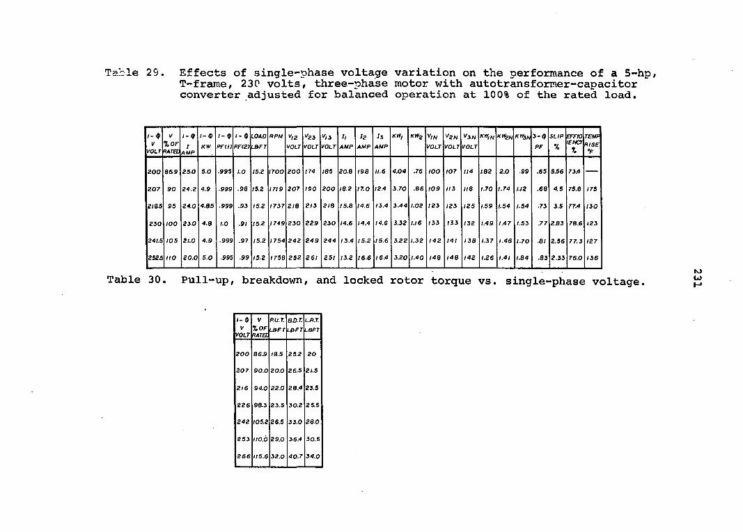
Table 29. Effects of single-phase voltage variation on the performance of a 5-hp, T-frame, 230 volts, three-phase motor with autotransformer-capacitor converter adjusted for balanced operation at 100% of the rated load.
/- $ V
VOLT
y
%0F RATED
/- (p
I AMP
r- ®
KW
1- $ PFD)
1- $ PF(2)
LOAD
L&FT
RPU V/Z
VOLT
"23 VOLT
y,3
VOLT
It
AMP
L2
AMP
L3
AMP
K»I KWS ^IN
VOLT
^2N
VOLT
V3N
VOLT
KWFN KM&N 3-$
PF
SLIP
%
EFFIO LENCY
r.
TEMF
RISE °F
ZOO B6.9 25.0 5.0 .995 1.0 15.2 1700 200 174 185 20.8 19.8 11.6 4.04 .76 100 107 114 1.82 2.0 .99 .65 5.56 73.4
207 90 24.2 4.9 .999 .98 15.2 1719 207 190 200 ia.2 17.0 12.4 3.70 .86 109 113 IIB 1.70 1.74 U2 .68 4.5 75.8 175
218.5 95 24.0 4.es .999 .93 15.2 I7I7 2IE 213 2/8 I5.B 14.6 13.4 3.44 1.02 123 123 125 1.59 1.54 1.54 .73 3.5 77.4 130
230 100 23.0 4.3 1.0 .91 15.2 1749 230 229 230 14.6 14.4 14.6 3.32 1.16 133 (33 132 1.49 1.47 T.53 .77 2.83 78.6 123
241.5 105 21.0 4.9 .999 .97 15.2 1754 242 249 244 13.4 15.2 15.6 3.22 1.32 142 141 I3B 1.37 1.46 1.70 .81 2.56 77.3 127
252J no 20.0 5.0 .995 .99 15.2 I75B 252 26/ 251 13.2 16.6 16.4 3.20 1.40 148 148 142 1.26 1.41 I.B4 .83 2.33 76.0 136
K> Table 30. Pull-up, breakdown, and locked rotor torque vs. single-phase voltage.
V VOLT
V %0F RATEL
P.U.T.
LBFT
BD.T
LBfT
L.R.T.
LBFT
200 86.9 IS.5 25.2 20
207 90.0 20.0 26.5 2/.5
216 94.0 22.0 28.4 23.5
226 98.3 23.5 30.2 25.5
242 105.2 26.5 33.0 28.0
253 IIO.O 29.0 36.4 30.5
266 115.6 32.0 40.7 34.0
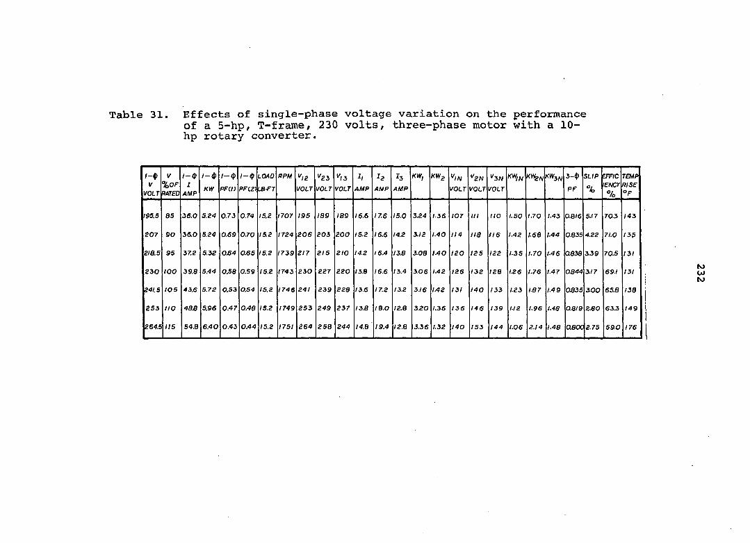
Table 31. Effects of single-phase voltage variation on the performance of a 5-hp, T-frame, 230 volts, three-phase motor with a 10-hp rotary converter.
/—4) V
VOLT
V %0F RATED
/ - $
1 AMP
/-(J) KW
/ - $
PFd)
1— ({î PF12)
LOAD
œ-FT
RPM ",2 VOLT
'23 VOLT
',3 VOLT
4 AMP
h
AMP
h
AMP
KW, KW^
VOLT
'^2N
VOLT
V3N
VOLT
KWIFJ K*3A, 3-$ PF
SLIP
%
EFFIC
lENCr
7o
TEMP RISE "F
195.5 es 36.0 5.24 0.73 0.74 15.2 1707 195 199 IB9 16.6 17.6 15.0 3.24 1.36 107 I I I no 1.50 1.70 1.43 0.8/6 5.17 70.3 143
207 so 36.0 5.24 0.69 0.70 15.2 1724 206 203 200 15.2 16.6 14.2 3.12 1.40 114 lia 116 1.42 1.68 1.44 0835 4.22 71.0 135
2/8.5 95 37.2 5.32 0£4 0.65 15.2 1739 217 215 210 14.2 16.4 13.8 3.08 1.40 120 125 122 1.35 1.70 1.46 0338 3.39 70.5 131
230 100 39.8 5.44 0.58 0.59 15.2 1743 230 227 220 13.8 16.6 13.4 3.06 1.42 126 132 128 1.26 1.76 1.47 0.844 317 69.1 131
241.5 LOS 43.6 5.72 O.S3 0.54 15.2 1746 241 239 228 13.6 17.2 13.2 3.16 1.42 131 140 133 1.23 1.87 1.49 0335 3.00 65.8 138
253 no 48.8 5.96 0.47 0.40 15.2 1749 253 249 237 13.8 I8.0 12.8 3.20 1.36 136 146 139 1.12 1.96 1.43 0.8/8 2.80 63.3 149
264.5 I I S 548 6.40 0.43 0.44 15.2 1751 264 258 244 I4.B 19.4 I2.B 3.36 1.32 I40 153 144 1.06 2.14 1.48 Q80C 2.75 59.0 176
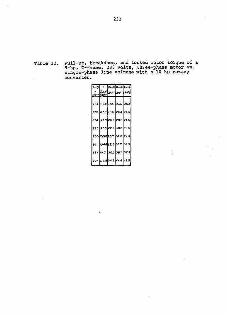
233
Table 32. Pull-up, breakdown, and locked rotor torque of a 5-hp, T-frame, 230 volts, three-phase motor vs. single-phase line voltage with a 10 hp rotary converter.
/—$ {/ P.U.T BO.T. LJi.T
VOLT %0F RATED
<^FT lbfr lbfr
IBS 82.2 l&S 23.0 20.5
202 87.0 18.5 2sj 23.5
2/4 93.0 20.2 28.0 25.5
223 97.0 22.2 30.2 275
230 100.0 23.7 32.0 29.3
24/ I04S 27.2 35.7 32.5
257 II 1.7 30.5 3s.7 37.5
2 7/, 117.8 34.S 44.4 42x3
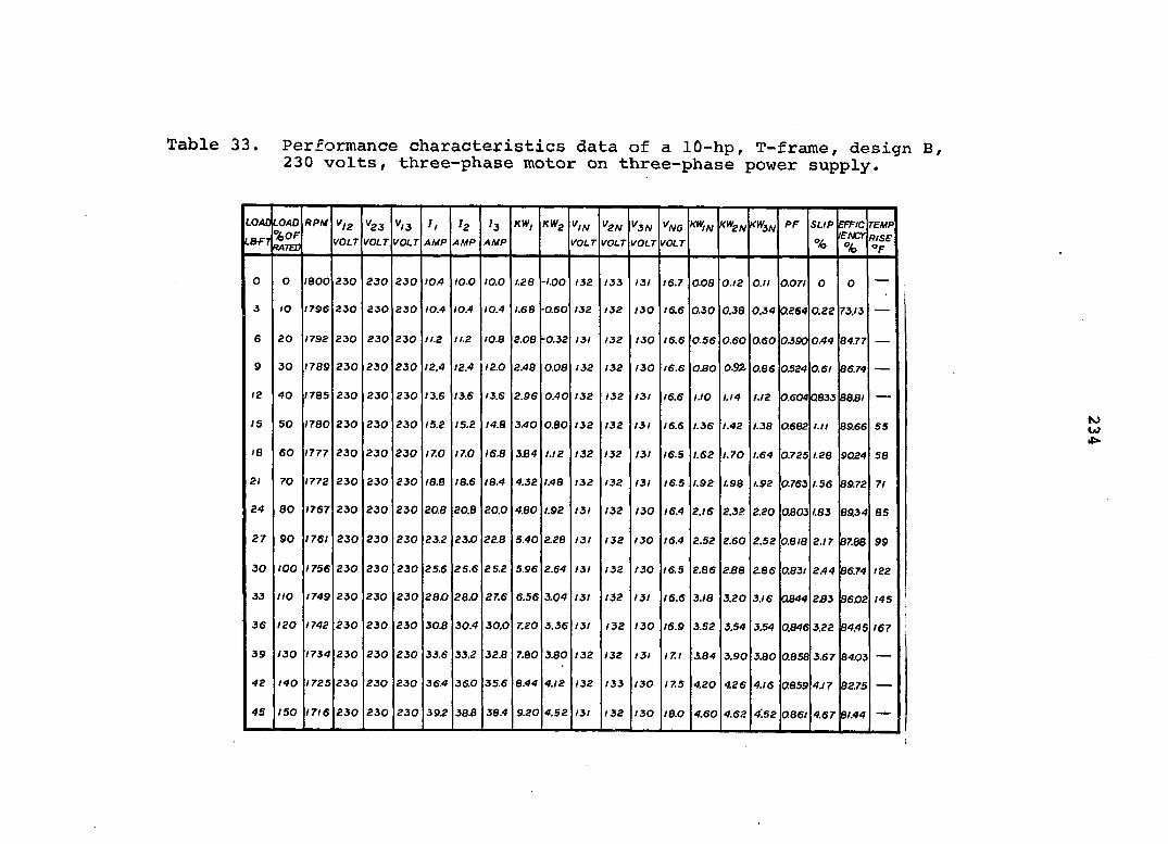
Table 33. Performance characteristics data of a lû-hp, T-frame, design B, 230 volts, three-phase motor on three-phase power supply.
LOAO
LBfT
LOAO %0F RATED
RPU "12
VOLT
^23 VOLT
"13
VOLT
h
AMP
^2 4MP
h
AMP
KW, "/W I'oz.r
"2N
VOLT
"3N
VOLT
"ng
VOLT
K^IN KW2^ X^3N PF SUP
%
EFFIC lENCr
%
TEMP
RISE "F
O O IBOO 230 230 230 lOA 10.0 10.0 1.28 -'.00 132 133 131 16.7 ooa 0.12 O.ll 0.07I 0 0
3 to 1796 230 230 230 I0.4 I0.4 I0.4 1.68 -0.60 132 /32 I30 16.6 0.30 0.38 0.34 0.264 0.22 73.13
6 20 1792 230 230 230 11.2 11.2 lO.B 2.08 -0.32 131 132 130 16.6 0.56 0.60 0.60 OJ90 0.44 84.77
9 30 1789 230 230 230 12.4 12.4 12.0 2.48 0.08 132 132 I30 16.6 0£0 0.92. 0.86 OJ524 0.6/ 86.74
12 40 1783 230 230 230 13.6 13.6 13.6 2.96 0.40 132 132 I3l 16.6 I.IO 1.14 1.12 0.604 Q833 8831
IS 50 1780 230 230 230 15.2 15.2 14.8 3.40 0.80 132 132 I3l 16.6 1.36 1.42 I.3B 0.682 / . / / B9.66 55
18 60 1777 230 230 230 17.0 17.0 16.8 3.84 1.12 132 132 131 I6.S 1.62 I.70 1.64 0.725 1.28 9024 58
21 70 1772 230 230 230 IB.8 18.6 18.4 4.32 1.48 132 132 131 16.5 1.92 1.98 1.92 0-763 1.56 89.72 7/
24 80 1767 230 230 230 20.8 20.B 20.0 4.80 1.92 131 132 130 16.4 2.16 2.32 2.20 0.803 1.83 89.34 85
27 90 1761 230 230 230 23.2 23.0 22.8 5.40 2.28 131 132 I30 16.4 2.52 2.60 2.52 0.8/8 2.17 87.68 99
30 too 1756 230 230 230 25.6 25.6 25.2 5.96 2.64 131 132 /30 16.5 2.86 2.88 2.86 0.83/ 2.44 96.74 122
33 no 1749 230 230 230 20.0 28.0 27.6 6.56 3.04 131 132 131 16.6 3/8 3.20 3.16 0844 233 9602 145
36 ISO 1742 230 230 230 304 30.4 30.0 7.20 3.36 131 132 130 16.9 3.52 3.54 3.54 0.846 3.22 84.4 S 167
39 130 1734 230 230 230 33.6 33.2 32.8 7.80 3.80 132 132 131 17.1 3L84 3.90 3.80 0.858 3.67 84.03 —
42 140 1725 230 230 230 36.4 36.0 35.6 8.44 4./2 132 133 130 17.5 4.20 4.26 4.16 0859 4.17 82.75
45 ISO 1716 230 230 230 39.2 383 38.4 9.20 4.52 131 132 I30 I&.0 4.60 4.62 4:52 0.86/ 4.67 8/.44 —
KJ W

235
Table 34. Effects of unbalanced voltage on the performance of a 10-hp, T-frame, 230 volts, three-phase motor loaded at 80% of the rated horsepower on three-phase line.
I//2
VOLT
^23
VOLT
^/3
VOLT
UNBAL
ANCE
%
RPM h
AMP
^2
AMP
^3
AMP
KW, KW2 ^IN
VOLT
^2N
VOLT
^3N
VOLT
^/V6
VOLT
KW2N '<^3N SLIP
% BFFIC
IBNCY
%
TEMP
RISE °F
230 218 210 4863 1759 20.0 28.4 17.6 4.36 2.52 126 131 117 9.5 1.64 3.20 204 2.277 86.74 124
230 22/ 216 3.448 1760 20.0 26.4 17.6 4.48 2.28 128 132 121 II.O 1.78 3.00 2.04 2222 87.50 107
230 224 222 2.07! 1761 20.4 23.6 18.4 4.68 2.04 129 132 125 12.1 1.98 2.68 2.08 2.166 98.54 96
230 227 227 0.8771 1763 20.8 21.2 19.2 4.84 1.88 130 132 128 13.5 2.14 2.44 2.12 2.055 B9.07 92
230 233 239 2.136 1765 22J0 17.6 21.6 5.16 1.60 134 132 137 17.6 2.48 1.92 224 1.944 89.87 92
230 237 244 2.953 1769 22.4 16.0 23.2 5.24 1.48 135 133 138 19.0 2GQ 1.70 2.34 1.722 885/ 97
Table 35. Effects of unbalanced voltage on the performance of a 10-hp, T-frame, 230 volts, three-phase motor loaded at 100% of the rated horsepower on three-phase line.
^12
VOLT
^23
VOLT
^13
VOLT
UNBAL
ANCE
%
RPM II
AMP
•f2
AMP
I3
AMP
KW, KW2 ^IN
VOLT
^2N
VOLT
^3N
VOLT
^NG
VOLT
KWi^ KV^N SLIP
%
EFFIC
lENCY
%
TEMpi
RISE °F
230 218 207 5.344 1750 24.4 35.6 232 5.44 3.48 125 132 116 8.2 2.18 4.12 2.68 2.777 83.07 178
230 221 213 3.916 I7S0 24.8 33.2 23.6 5.60 3.24 127 132 120 9.0 2.34 3.84 2.70 2.777 34.0> 160
230 224 220 2.374 1751 252 30.4 23.6 5.80 3.00 128 132 123 10.3 2.54 3.58 2.74 2.722 84.19 140
230 226 225 1.321 1751 25.6 27.6 24.4 5.96 2.76 130 132 127 11.3 2.74 3.20 2.76 2.722 85.74 128
230 233 237 1.571 1754 26.4 23.2 26.0 6.20 2.48 133 132 134 13.9 3.08 2.68 2.92 2.555 85.94 125
230 236 243 2B2I 1754 27.2 20.8 27.2 6.36 2.36 134 132 138 17.0 3.28 2.40 3.00 2.555 85.94 133
230 238 247 3.636 1756 27.6 IB.4 28.8 6.40 2.20 135 132 140 19.3 3.44 2.08 3.04 2444 87.14 140

Table 36. Effects of unbalanced voltage on the performance of a 10-hp, U-frame 220 volts/ three-phase motor loaded at 80% of the rated horsepower on three-phase line.
y/2
VOLT
K23
VOLT
y/3
VOLT
UNBAl ANCE %
RPM h
AMP
I2
AMP
J3
AMP
KW, KW2 *///v
VOLT
^2N
VOLT
^3N
VOLT
^NG
VOLT
XW,N KW2N f<W3N SLIP
%
EFFIC lENCY 7o
TEMP RISE °F
220 2n 204 3.969 1763 20.0 283 183 4.20 2.68 120 126 115 5.0 1.62 3.12 2.12 2055 87/2 57
220 211 206 3.611 1763 20.0 28.0 18.8 4.28 2.56 121 126 116 5.2 1.70 3.04 2.12 2055 86.99 55
220 213 209 2304 1764 20.4 26.4 18.6 4.40 2.48 122 126 ne 5.3 }.78 2.90 2.14 2400 87.50 55
220 215 215 1.652 1765 20.4 24.8 19.2 4.48 2.28 123 126 120 6.1 1.92 2.72 2.16 1944 97.76 51
220 217 217 0.917 1765 21.2 223 20.0 4.68 2.08 124 126 123 7.2 2.08 2.48 2.20 1.944 6628 50
220 22! 223 0.753 /766 22.0 20.4 20.8 4.88 L88 126 126 126 8.5 2.28 2.24 2.20 1.886 8830 49
220 224 229 2.080 1767 22.8 18.0 22.4 5.16 1.66 128 126 130 10.5 2.52 L96 2.28 L833 8828 50
220 228 235 3.367 1766 24.0 16.0 24.4 5.32 1.48 130 126 134 12.0 2.78 1.70 2.36 L777 87.25 52
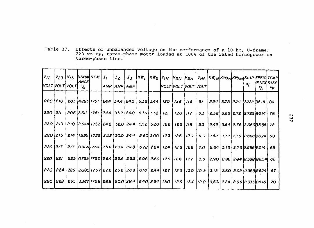
Table 37. Effects of unbalanced voltage on the performance of a 10-hp, U-frame, 220 volts, three-phase motor loaded at 100% of the rated horsepower on three-phase line.
"/g
VOLT
^23
VOLT
y/3
VOLT
UNBAL ANCE %
RPM
AMP
l2
AMP
^3
AMP
KW, KW2 ^IN
VOLT
^2N
VOLT
^3N
VOLT
^NG
VOLT
mN KWb/V KWSN SL/P
Vo
EFF/C lENCy 7o
TEMP RISE
220 210 203 4.265 1751 24.4 34.4 24.0 5.36 3.44 /20 /26 1 /6 5./ 2.24 3.78 2.74 2.722 85./5 84
220 211 206 3.611 175 / 24.4 33.2 24.0 5.36 3.38 12 / 126 1 /7 5.3 2.36 3.66 2.72 2.722 B6./4 78
220 213 210 2.644 1752 24.8 32.0 24.4 5.52 3.20 122 126 1 /8 5.3 2.42 3.54 2.76 2.666 85.55 72
220 215 2/4 L695 /752 25.2 30.0 24.4 5.60 3.00 / 23 /26 /20 6.0 2.52 3.32 2.76 2.666 36.74 68
220 2 /7 2/7 0.9/7% / 754 25.6 28.4 24.8 5.72 2.84 124 126 /22 7.0 2.64 3./6 2.76 2.555 Q7./4 65
220 221 223 0.753 /757 26.4 25.6 25.2 S.96 2.60 / 26 /26 /27 8.6 2.90 2.88 2S4 2.388 86.54 62
220 224 229 2.080 1757 27.6 23.2 26.8 6.16 2.44 127 /26 /30 /0.3 3./2 2.60 2.92 2.380 86.74 67
220 229 235 3.367 /758 28.8 20.0 28.4 6.40 2.24 130 /26 / 34 /2.0 3.52 2.24 2.96 2.333 85.16 70
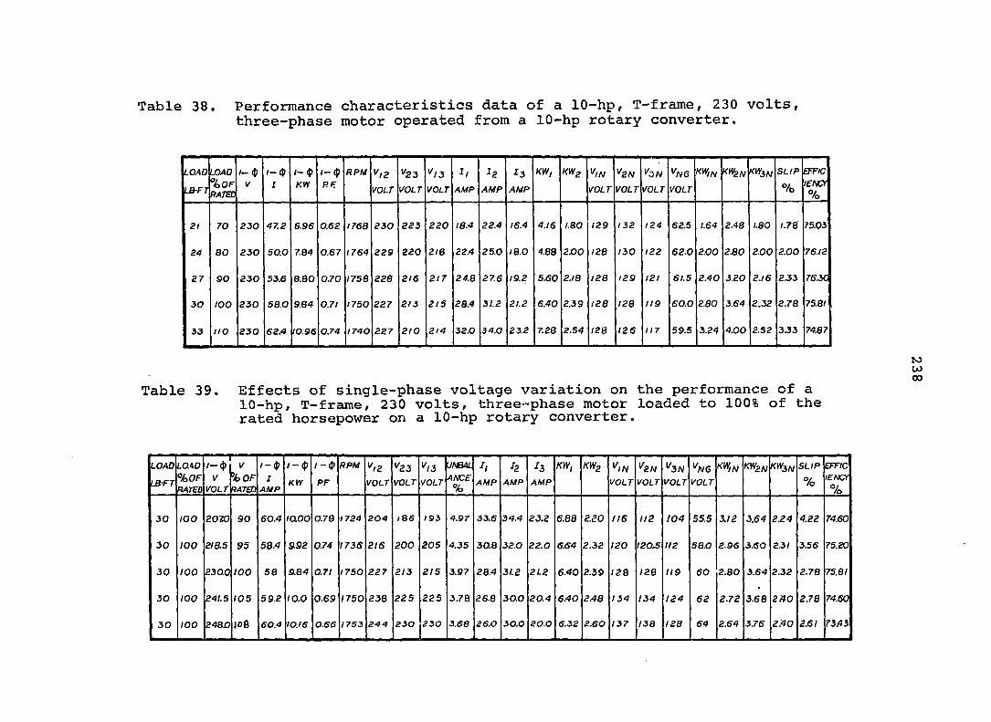
Table 38. Performance characteristics data of a 10-hp, T-frame, 230 volts, three-phase motor operated from a 10-hp rotary converter.
LOAD
LB-FT
LOAD
%0F RATED
/— $ V
/— (J) :
1— (p
KW
1-
RF
RPM ^12
VOLT
*^23
VOLT VOLT
: /
AMP
:2
AMP
:3
AMP
KM, KWg
VOLT
^2N
VOLT VOLT
^NG
VOLT
KVfm KWl/V SLIP
% EFFIC
lENCt
%
2/ 70 230 47.2 6.96 0.62 1768 230 223 220 IB.4 22.4 16.4 4.16 1.80 129 132 124 62.5 1.64 2.48 1.80 1.78 75.03
24 80 230 50.0 7.64 0.67 1764 229 220 216 22.4 25.0 18.0 4.88 200 128 130 122 62.0 2.00 230 2.00 2.00 76.12
27 90 230 53.6 8.80 0.70 1758 228 2/6 2 /7 24.8 27.6 19.2 5.60 2.18 128 129 I2l 61.5 2.40 3.20 2.16 233 76JC
30 100 230 58.0 9.84 0.7I 1750 227 2 /3 2 /5 28.4 31.2 21.2 6.40 2.39 128 128 119 60.0 2.80 3.64 2.32 2.78 75.8/
33 no 230 62.4 I0.96 0.74 1740 227 2 /0 214 32.0 34.0 23.2 7.28 2.54 I2B 126 117 59.5 3.24 4.00 2.52 3J3 74.87
M w 00
Table 39. Effects of single-phase voltage variation on the performance of a 10-hp, T-frame, 230 volts, three-phase motor loaded to 100% of the rated horsepower on a 10-hp rotary converter.
LOAD
LBf r
LO.W
%0F
RATED
/—(J) V
VOLT
V
%0F
PATED
l-<p
I AMP
/ — (j?
K tV
/ -(j>
PF
RPM ^12
VOLT
^23
VOLT VOLT
UNBAL
ANCE
%
-r,
AMP
h
AMP
fa
AMP
m, KWs ^IN
VOLT
' 2W VOLT VOLT
^N6
VOLT
KW,^ K^2N KW3N SLIP
% EFFIC
lENCr
%
30 100 2020 90 60.4 laoo 0.78 1724 204 lB6 193 4.97 33.6 34.4 23.2 6.88 2.S0 116 112 104 55.5 3.12 3.64 2.24 4.22 74.60
30 100 218.5 95 58.4 9.92 0.74 I73S 2/6 200 205 4.35 30.8 32.0 22.0 6.64 2.32 120 I20.S 112 S8.0 2.96 3.60 2.3/ 3.56 75.20
30 100 2300 too 58 9.84 0.7I 1750 227 213 215 3.97 28.4 3 /2 21.2 6.40 2.39 126 128 119 60 2.80 3.64 2.32 2.78 75.81
30 100 241.5 105 59.2 10.0 0.69 1750 238 225 225 3.78 26.8 30.0 20.4 6.40 2.48 134 134 124 62 2.72 3.68 2.40 2.78 74.60
30 100 2480 |08 60.4 IO.I6 O.SS 1753 244 230 230 3.68 26.0 30.0 20.0 6.32 S.SO 137 138 128 64 2.64 3.76 2.40 2.6/ 73.43
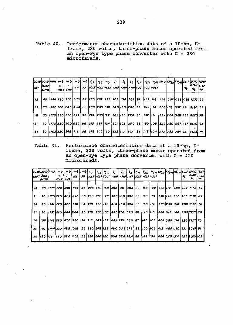
239
Table 40. Performance characteristics data of a 10-hp, U-frame, 220 volts, three-phase motor operated from an open-wye type phase converter with C = 280 microfarads.
LOAD
LBfr
LOAD
%0F
RATED
RPU 1- (p
V
VOLT
/—(p
1
AUP
; — ())
KW
/-(J)
PF
^^12
VOLT
"23
VOLT
"13
VOLT
II
AMP
h
AUP
h
AUP
"IN
VOLT
"2N
VOUT
"3N
VOLT
K'^IN KW2N ftà/v SLIP
%
EFFK lENCr
%
TEMP
RISE
"F
12 40 1784 220 21.2 i.76 .82 220 267 133 203 10.4 26A 82 155 118 1.76 092 092 038 7&36 33
15 SO 1780 220 24.0 4.56 .88 220 260 130 24.0 12.8 26.0 82 153 114 2.00 1.58 0.92 l.ll 81.80 33
18 60 1775 220 27.0 5.44 .95 219 256 127 26.8 17.0 27.0 83 152 III 2.24 2.24 0.88 1.39 8223 38
21 70 1770 220 30.0 6.24 .96 2IS 251 124 29/4 19.6 25.0 83 ISO 108 2A4 2.80 0J)7 1.67 8370 43
24 80 1762 220 34.8 7.12 .98 218 245 120 33.2 24.4 24.4 83 148 104 2.72 3.52 034 2.11 8332 74
Table 41. Performance characteristics data of a 10-hp, U-frame, 220 volts, three-phase motor operated from an open-wye type phase converter with C = 420 microfarads.
LOAD LBFT
LOAD %0F K4TEÛ
RPM 1-9 V
VOLT
/ - < >
I AMP
f — $
KW 1— ^ PF
"l2 VOLT
"23 VOLT
"L3 VOLT
h. AUP
h AUP
4 AMP
"IN VOLT
"2N VOLT
^3N VOLT
KWIN X^2N SLIP
%
EFFIC £NCr
7o
TEMP RISE "F
IB 60 1775 220 3a8 624 .73 220 268 150 38.0 83 40A 88 154 122 3.32 1.12 1.60 1.39 71.73 69
21 70 1770 220 40.4 6J96 .80 220 262 146 40.0 12.0 39.6 88 152 119 3.48 1.76 1.56 1.67 75X)3 69
24 80 1764 220 42.0 7.76 .84 219 256 141 41.6 16.0 38.6 87 ISO 114 3.68 2.36 1.50 2.00 76.91 70
27 90 1755 220 44.4 8.64 .90 219 250 155 44.0 21.6 37.6 88 148 110 3.88 3.16 1.44 2.50 77.71 70
30 100 1749 220 47.0 9.60 S4 218 249 129 46.4 27.4 36.6 87 147 ICS 4.04 3.96 1.36 233 77.71 73
33 no 1744 220 4B3 10.18 .95 220 248 125 48.0 30.8 37.2 86 ISO 106 4.12 4£0 1.30 3.11 80.61 81
36 120 1731 220 52.0 11.02 SB 220 240 120 50.4 3SjO 36.4 86 149 104 4£4 5.20 1.24 333 81.23 102
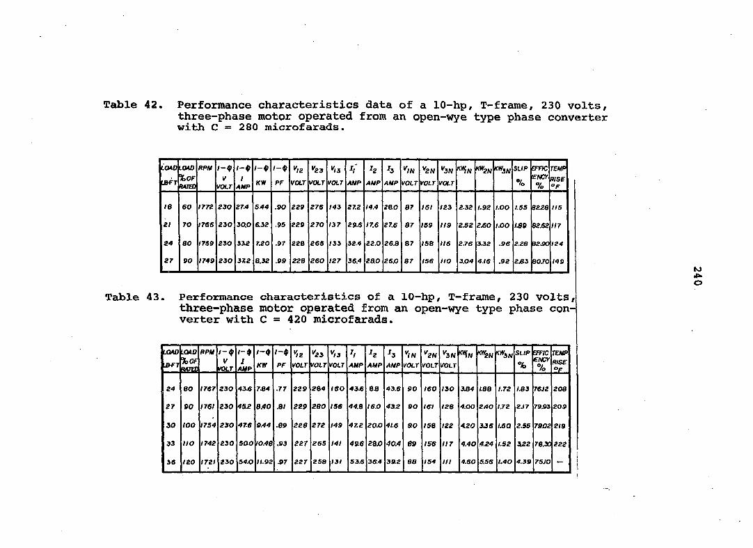
Table 42. Performance characteristics data of a 10-hp, T-frame^ 230 volts, three-phase motor operated from an open-wye type phase converter with C = 280 microfarads.
LCMO
IBTT
UM %0F HATED
RPM / - • y
VOLT
/ —
/ AUP
/ - •
KW PF ^12
VOLT "23
I'OLT
1^3
yOLT
I,'
AUP '2
AMP H
AUP
«ON
VOLT rai.r fotr
X^IN ' 2W SL/P
%
erne
lENCr
%
rewp
mse "F
le eo nn 230 27.4 5.44 .90 229 276 M3 27.2 14.4 28.0 87 /6 / 123 2.32 1.92 LOO 1.55 8228 115
2/ TO 1706 230 30.0 6.92 .95 229 270 137 29.6 17.6 27.6 87 159 119 2.52 2JB0 1.00 139 82.62 117
24 80 J 759 230 33l2 7.20 .97 228 265 133 32.4 22.0 26.8 87 ISB 116 2J'6 332 .96 2£8 92.90 124
27 90 1749 230 3Z2 8.32 .09 228 260 127 36.4 28.0 26.0 87 156 no 3.04 4.16 .92 2JB3 B0.70 149
Table 43. Performance characteristics of a 10-hp, T-frame, 230 volts, three-phase motor operated from an open-wye type phase converter with C = 420 microfarads.
LOAD
'.BFJ
LCMO %0F
RPU f — $ V
A)LT ; AUP
/-•
KIR
/-4> *)2
ratr
"23 votr
"/J VOLT
H AUP
H AUP
'3 AUP
''/N /Oi-r
^2N VOLT VOLT
"ÏN SLIP
% BT7C CMCf %
TEUP RISE °F
24 80 1767 230 43.6 7.84 .77 229 284 160 43J6 6B 43.6 90 160 I30 184 1.88 /.72 /.83 76V2 208
27 90 1761 230 452 8.40 .8/ 229 280 156 44.8 I6.0 412 90 ISI (28 4.00 2AO /.72 2J7 79.93 209
30 too I7S4 230 47.6 9.44 .89 228 272 149 47.2 20.0 4 /6 90 158 122 4.20 336 /.60 2.55 7942 2 /9
33 no 1742 230 sao ro.48 .93 227 265 141 456 ZBJO 40.4 69 156 117 4.40 4.24 /.52 422 78.* 222
38 I20 1721 230 S4X} /1.92 .97 227 258 131 53J6 3S.4 39.2 88 154 ni 4.60 5.56 I.40 4.39 7SJO -
to ii o
Copyright © 2022 FDOKUMEN