Numerical Process Simulation for Tool and Process Design in Bulk Metal Forming
Upload
khangminh22Category
view
0download
0
Jian Cao1Department of Mechanical Engineering,
Northwestern University,Evanston, IL 60208
e-mail: [email protected]
Mihaela BanuDepartment of Mechanical Engineering,
University of Michigan,Ann Arbor, MI 48109
e-mail: [email protected]
Opportunities and Challenges inMetal Forming forLightweighting: Review andFuture WorkThe purposes of this review are to summarize the historical progress in the last 60 years oflightweight metal forming, to analyze the state-of-the-art, and to identify future directions inthe context of Cyber-physically enabled circular economy. In honoring the 100th anniver-sary of the establishment of the Manufacturing Engineering Division of ASME, this reviewpaper first provides the impact of the metal forming sector on the economy and historicalperspectives of metal forming research work published by the ASME Journal of Manufac-turing Science and Engineering, followed by the motivations and trends in lightweighting.To achieve lightweighting, one needs to systematically consider: (1) materials and materialcharacterization; (2) innovative forming processes; and (3) simulation tools for integratedpart design and process design. A new approach for process innovation, i.e., the Perfor-mance-Constraints-Mechanism-Innovation (PCMI) framework, is proposed to systemati-cally seek new processes. Finally, trends and challenges for the further development incircular economy are presented for future exploration. [DOI: 10.1115/1.4047732]
Keywords: metal forming, lightweight materials, Performance-Constraints-Mechanism-Innovation (PCMI)
1 IntroductionMetal working has long been an intriguing part of our human
development, evident from examples, such as those in Fig. 1, i.e.,the world’s oldest preserved Neolithic copper axe (5300 yearsold) discovered with the Iceman in 1991 [1], the oldest non-rustsword once owned by Emperor Goujian more than 2500 yearsago [2], ancient coins (more than 2500 years old) used in Turkey,India, China and Greece [3], and countless carefully carvedpieces of jewelry. More examples can be found in a short metalforming film created for the general public that brilliantly combinesart and science.2 In modern industrialized nations, the metalforming related industry takes up about 15–20% of GDP (e.g.,7% of US GDP and 28% of German GDP) [4]. The Journal of Man-ufacturing Science and Engineering (JMSE) has a long history ofhosting forming papers. Beginning in 1959 as the Journal of Engi-neering for Industry, and then becoming in 1995 the Journal ofManufacturing Science and Engineering, it has published morethan 750 papers on material forming, illustrating the evolution ofthe technology and material development over the past severaldecades. A summary of the processes, and the associated periodof time of their development, is presented in Fig. 2.Analytical studies, including the upper bound of metal forming
processes, were developed for axisymmetric or planar bulk (e.g.,extrusion and rolling) and sheet (e.g., sheet bending) forming ofsteel and aluminum alloys in the years prior to 1970. As Fig. 2 illus-trates, advancing the nonlinear finite element simulations in the1970s allowed numerical simulation of axisymmetric drawing pro-cesses, and was part of the initial attempts to simulate the complexproduction process, including nonlinear material and frictionalbehaviors. Further advancement in computation resources in the1980s enabled more complex simulations, consequently extending
the simulation work on extrusion and drawing to sheet metalforming.Beginning in the 1990s, numerical simulation benchmarks orga-
nized through NUMISHEET exercises, greatly challenged the tech-nology transfer from academic research to industrial applications,which included the simulations of complex physical phenomenasuch as springback, wrinkling, and fracture in realistic industrialparts. The insightful knowledge obtained from the combined exper-imental and numerical simulations led to further understanding oftool-material interaction and material behavior, and inspired newprocess developments, such as laser forming, as well as controlmodel developments, which is evident from papers published inthe 2000s. From 2000 to 2009, “Aluminum” first appearedamong the top 10 most used words in the titles of forming papersand was among the top five from papers published recently from2010 to 2019; a result of lightweighting research. Furthermore, flex-ible manufacturing processes for low-volume production, such asincremental forming and laser forming, have also attracted signifi-cant numbers of publications in the last decade.The JMSE publishes a broad perspective of papers that address
key scientific questions and technological innovations related tometal forming processes, which is reflected in the ten most citedpapers published in the JMSE as listed in Fig. 3. The topicsinclude: fracture prediction, related to solid mechanics; grain sizeeffect, related to materials science; integration of electrical currentor lasers, on forming, related to physics; and forming path genera-tion, related to metrology and computer science. The top ten listdelivered another important message, that the manufacturingprocess is an integration platform merging knowledge fromvarious disciplines. Research work published in the JMSE alsoreceived notices and citations from other journals and conferencesas shown in Fig. 3.The significant economic impacts of metal forming calls for inno-
vations in metal forming that support developments in infrastruc-ture, energy efficiency and sustainability, and space exploration.This centennial review paper addresses the advancement of metalforming from the perspective of lightweighting due to the impactthat lightweighting has on all of the above key challenge areas. In
1Corresponding author.2https://www.youtube.com/watch?v=vUEVVFBiW1w&feature=youtu.beManuscript received February 15, 2020; final manuscript received July 2, 2020;
published online September 28, 2020. Assoc. Editor: Albert Shih.
Journal of Manufacturing Science and Engineering NOVEMBER 2020, Vol. 142 / 110813-1Copyright © 2020 by ASME
Dow
nloaded from http://asm
edigitalcollection.asme.org/m
anufacturingscience/article-pdf/142/11/110813/6595174/manu_142_11_110813.pdf by guest on 09 July 2022
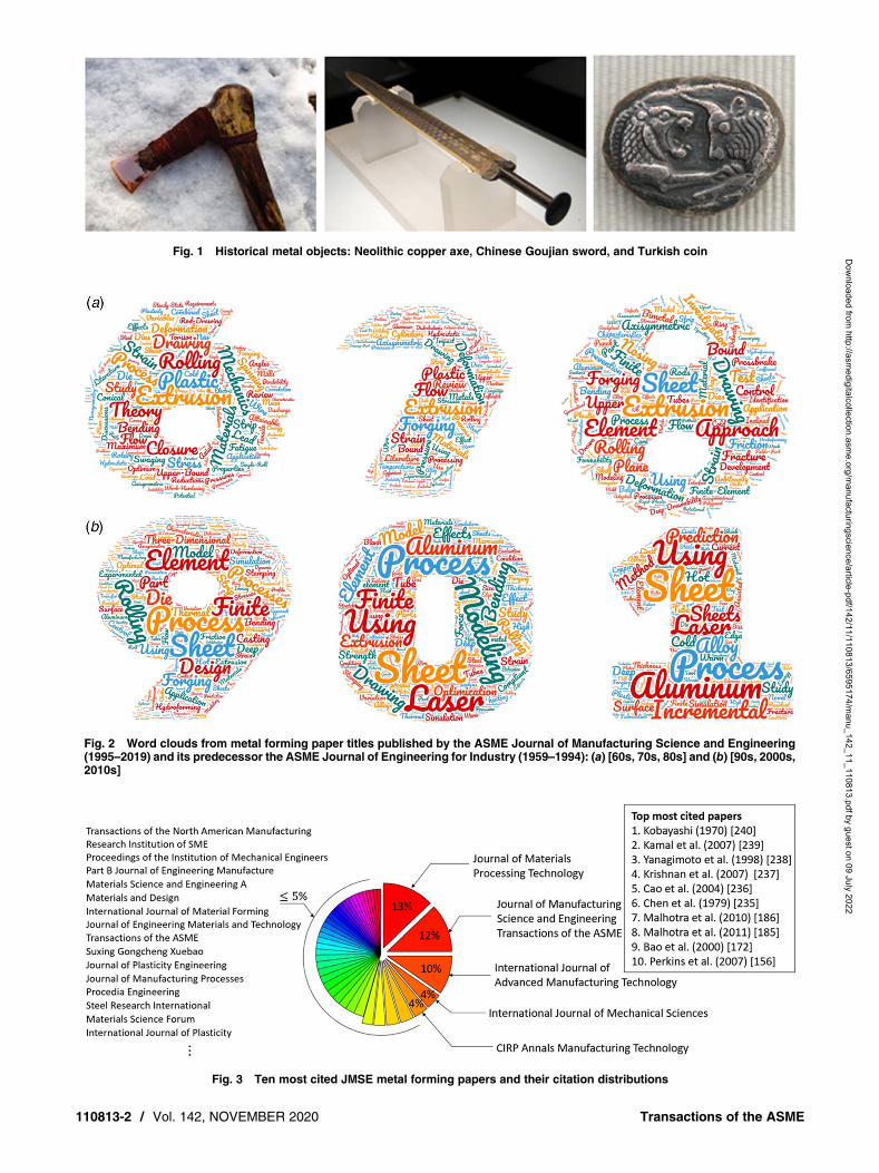
Fig. 1 Historical metal objects: Neolithic copper axe, Chinese Goujian sword, and Turkish coin
Fig. 2 Word clouds from metal forming paper titles published by the ASME Journal of Manufacturing Science and Engineering(1995–2019) and its predecessor the ASME Journal of Engineering for Industry (1959–1994): (a) [60s, 70s, 80s] and (b) [90s, 2000s,2010s]
Fig. 3 Ten most cited JMSE metal forming papers and their citation distributions
110813-2 / Vol. 142, NOVEMBER 2020 Transactions of the ASME
Dow
nloaded from http://asm
edigitalcollection.asme.org/m
anufacturingscience/article-pdf/142/11/110813/6595174/manu_142_11_110813.pdf by guest on 09 July 2022

the following sections, we will start with the motivations for light-weighting in Sec. 2, followed by the methods for lightweight designin Sec. 3, material characterization in Sec. 4, innovative formingprocesses in Sec. 5, and simulation tools for integrated partdesign and process design in Sec. 6. Finally, the summary section(Sec. 7) will address trends and challenges in the further use oflightweight metals, and the connections with other manufacturingprocesses and systems.
2 Motivations for LightweightingThe essential motivations for lightweighting lie in two aspects:
functional performance, and energy efficiency and sustainability,which ultimately link to market competitiveness and socialresponsibility.Functional performance: Mass is critically linked to product
function in many applications, based on fundamental physics. Forexample, lightweight components can achieve faster acceleration,lighter crankshafts can allow higher revolutions, and reduction ofunsprung masses in a car chassis can increase driving comfortand safety. Needless to say, lower mass for the same functionalityis attractive to consumers, civilians, and soldiers, due to therelated increase in ease of use and transportation. Figure 4 showsthe historical weight of a 12-oz beverage can, from over 100 gbefore 1958 to just about 13 g at present. Considering a volumeof 200 billion cans every year [8], the material saved could wrapthe Earth’s equator more than 1660 times if the cross section ofthe aluminum bar was 1 cm2. Such an achievement is the resultof multiple technical innovations and scientific understanding ofmaterial deformation mechanics, including the invention of two-piece can manufacturing using draw, re-draw, and wall-ironing,the accurate prediction of material anisotropic behavior and form-ability, and the advancement of die coating material.Energy efficiency and sustainability: The link of lightweighting
with energy efficiency and sustainability is quite direct. Taking theabove beverage can as an example and assuming the aluminumwere produced from 100% recycled aluminum, it would result ina savings of 2.7E11 MJ every year. In modern transportation engi-neering, the application of lightweight components is a centralgoal, particularly in the aerospace industry, since the energy con-sumed in the usage phase outplaces that in production. A 10%reduction in ground vehicle weight can result in a 6−8% fueleconomy improvement [9]. Using lightweight components andhigh-efficiency engines enabled by advanced materials in just onequarter of the U.S. fleet could save more than 5 billion gallons offuel annually by 2030 [9]. In a more specific example, every 1 kg
of weight saving in a commercial aircraft can yield a savings of555 liters of fuel per year, the equivalent of 20,000 MJ or half ofthe CO2 emissions per year from an average mid-size passengercar [9].
3 Lightweight DesignLightweight design needs to comply with specific functional
requirements, such as thrust, safety, and regulations, and satisfyeconomic constraints, i.e., cost. Below, we will summarize threemain approaches in lightweight design, which address these needs.One traditional method of lightweight design is to analyze where
the primary material can be replaced by another material with betterweight specific characteristics to reduce the weight of one part. Onecommon practice is to consider replacing mild steels with aluminumalloys. Although the density of aluminum is a third that of steel, alu-minum alloys typically have only a third of the tensile strength andtensile modulus of steel alloys. As the use of light metals must notdecrease product properties, specific material properties should betaken into account. Relating the strength of a material to itsdensity, high-strength steels (HSS) become lightweight materialscomparable with some aluminum alloys. Depending on the actualalloy and grade, steel and aluminum are likewise “light metals”as well as magnesium and titanium. Replacing cast iron and tradi-tional steel components with lightweight materials such as high-strength steel, magnesium alloys, aluminum alloys, carbon fiber,and polymer composites can directly reduce the weight of a vehi-cle’s body and chassis by up to 50% [9]. As for applications inshell structures with lightweight construction criteria and perfor-mance criteria such as dent resistance, aluminum and especiallymagnesium show much better properties than steel, as shells withthe same area weight have a higher wall thickness due to lowerdensity. In the case of the BMWM3, the front hood made of alumi-num is 42% lighter than the standard steel front hood [10].An improved method for lightweight design is to separate one
component into zones, where a higher load bearing area will bereinforced with a thicker or stronger material, while other areascan use a nominal thickness, i.e., multi-material design. A goodexample shown in Fig. 5 is tailor welded blanks (TWB) usedwith body panels. Nowadays, the focus has moved fromsingle-material-intensive body structures (body-in-white) todesigns using multi-materials (steel, aluminum, magnesium, andpolymer composites) as shown in Fig. 6. Also shown in Fig. 6, isthe evolution of material usage in the aviation industry, which dem-onstrates the same trend. Selection and combination of materials fora lightweight design can follow multiple strategies.
Fig. 4 Historical weight of a beverage can. Sources: 1935–1958 from Stolle Machinery [5]; 1992-present fromAustralian Aluminum Council [6]. Illustration of cans from Hosford and Duncan [7].
Journal of Manufacturing Science and Engineering NOVEMBER 2020, Vol. 142 / 110813-3
Dow
nloaded from http://asm
edigitalcollection.asme.org/m
anufacturingscience/article-pdf/142/11/110813/6595174/manu_142_11_110813.pdf by guest on 09 July 2022

Tekkaya et al. [14] proposed some strategies which considereither partial replacement of the material while maintaining thesame design, or full material replacement and the re-designing ofthe part so as to achieve the same functionality. Mixed-materiallightweight design, however, does have side effects, such as recy-clability at the end of the part’s life or corrosion. These areadverse effects that need to be considered from the design stage.The above two part-level lightweighting approaches are com-
monly practiced in industry. However, this bottom-up approachmay often lead to additional complications, such as increased diffi-culties in forming or in joining with other parts, or the need of addi-tional auxiliary system support. For example, alloys with highertensile strength typically result in lower formability [15]. Thus,Ashby’s plots [16] showed us that for steel alloys, an increase ofstrength from 250 MPa to 1000 MPa leads to a decrease of tensile
ductility from 45% down to 12%; for aluminum alloys, a strengthincrease from 150 MPa to 530 MPa corresponds to a failure strainreduction from 30% to 10%; for magnesium, a similar trendholds, e.g., strength increasing from 200 MPa to 380 MPa corre-sponds to failure strain reduction from 20% to 7%. Another compli-cation with high-strength alloys is the need for higher formingforce, hence, more rigid presses and wear resistant tools, as indi-cated in a recent review article on smart forming tools by Caoet al. [17].Among these alloys, advanced steels are the fastest growing
system for lighweighting vehicles due to their reduced cost,improved properties, and improved weldability over conventionalsteels, aluminum, magnesium, and titanium alloys. According tothe WorldAutoSteel classification [18], the advanced steelsfamily, known as advanced high-strength steels (AHSS, strength
Fig. 5 Example of the use of tailor welded blanks in a car body (www.arcelormittal.com [11])
Fig. 6 Evolution of material usage in automotive and aviation sectors: (a) material usage for a body-in-white. Data obtained from aplot in Ref. [12]. (b) Material usage for a plane shell. Data obtained from Heuss et al. [13].
110813-4 / Vol. 142, NOVEMBER 2020 Transactions of the ASME
Dow
nloaded from http://asm
edigitalcollection.asme.org/m
anufacturingscience/article-pdf/142/11/110813/6595174/manu_142_11_110813.pdf by guest on 09 July 2022

>500 MPa) includes (i) Gen-1 grades, which are dual phase,complex-phase, Ferritic-Bainitic, Martensitic (MS or MART),transformation-induced plasticity (TRIP), and hot-formed steelsand (ii) Gen-2 grade, i.e., twinning-induced plasticity (TWIP).Some examples illustrating the phases of these steels are presentedin Figs. 7(a)–7(c).Recently, Gen-3 grade steels have been developed based on
Gen-2 steels but with improved strength-ductility, weldability,and reduced cost. A Gen-3 steel generally is recognized as havinga minimum (tensile strength and elongation) product of 20 GPa*%. The use of Gen-3 steel leads to a significant weight reductionof an autobody by enabling improved geometry and decreasingmaterial thickness [21]. The position of Gen-3 steels in the Ashbyplot (elongation versus yield strength) shows their unique qualifica-tions for the lightweight design of complex shapes, which is neededto provide vehicle stiffness, high bearing loading, and crashworthi-ness (Fig. 8). These developments demonstrate that steels remain astrong candidate for lightweight design along with other, moreexpensive, material systems: aluminum, magnesium, and titaniumalloys. Under these conditions, lightweight design becomes an artof optimizing the material combinations for both cost-efficiencyand functional purposes.In addition to replacing the primary material or using multi-
material design, geometry redesign is seen nowadays as an alterna-tive solution for lightweighting complex shape components manu-factured mostly by bulk forming, such as power transmission andchassis components. Geometry redesign starts from analyzing theload distribution in components and removing material in theleast loaded zones. The redesigned geometry can be achievedusing innovative bulk forming processes, such as swaged forging,hydroforming, and metamorphic processes also known as incre-mental forming. Merklein et al. [22,23] presented an extensivereview of sheet bulk forming processes. Table 1 presents examples
of potential weight reduction achievable by geometry redesign ofseveral transmission components proposed in 2015 by the Light-weight Forging Initiative, Germany [27]. The target weigh reduc-tion of this ongoing initiative is 273 lb of the power transmissionof a hybrid truck [24–26].Over the last few years, bi-metal forging has started to gain atten-
tion as a very efficient process of combining geometry redesign withmulti-material design for high performance transmission compo-nents. This approach has the potential of 30–50% weight reductionby using tailored materials such as steel and aluminum, magnesium,or titanium. Behrens and Kosch [28] and Chavdar et al. [29] dem-onstrated that analyzing the loads and the mechanical response ofeach zone of a component, tough and stiff materials can beformed into a single component. For example, the core of a gearcan be made of different materials since the core requires hightoughness but only low strength, which is in the typical range ofan aluminum alloy, while the teeth material requires high strengthand wear resistance, which can be made of a high-grade steelalloy, as shown in Fig. 9. While the technology has benefits forlightweighting, there are remaining challenges in optimizing thesequence of the operations and in designing the thermomechanicalparameters. For example, forging of steel shells should not result inmelting of the aluminum core.To solve this challenge in creating and realizing lightweight
design, the scientific approach using integrated computationalmaterials engineering (ICME) techniques has been increasinglyresearched and adopted in industry. ICME is the approach to verti-cally integrate material development and material processing tech-nology with system performance analysis and optimization, usingadvanced simulation tools. The US National Academy of Engineer-ing published a report in 2008 [30] defining ICME as an emergingdiscipline that can accelerate material development and unifydesign and manufacturing, leading to significant economic benefits.
Fig. 7 Optical and SEMmicrographs of the (a) high strength low alloy steel (HSLA) [19], (b) DP780, and (c) CP800 with martensite(M ), bainite (B), and ferrite (F ) microstructures indicated [20] (Creative Commons license CC BY 4.0)
Fig. 8 Ashby-type diagram for different steel system lightweight material designs:tensile strength versus tensile elongation [18]
Journal of Manufacturing Science and Engineering NOVEMBER 2020, Vol. 142 / 110813-5
Dow
nloaded from http://asm
edigitalcollection.asme.org/m
anufacturingscience/article-pdf/142/11/110813/6595174/manu_142_11_110813.pdf by guest on 09 July 2022
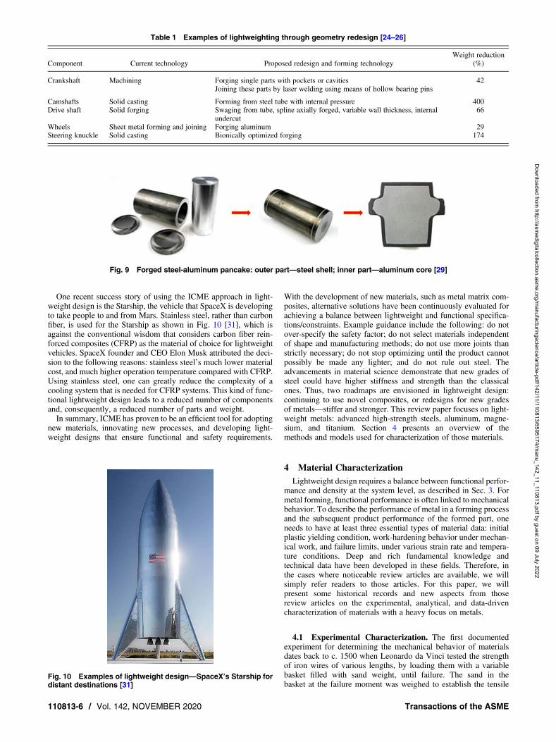
One recent success story of using the ICME approach in light-weight design is the Starship, the vehicle that SpaceX is developingto take people to and from Mars. Stainless steel, rather than carbonfiber, is used for the Starship as shown in Fig. 10 [31], which isagainst the conventional wisdom that considers carbon fiber rein-forced composites (CFRP) as the material of choice for lightweightvehicles. SpaceX founder and CEO Elon Musk attributed the deci-sion to the following reasons: stainless steel’s much lower materialcost, and much higher operation temperature compared with CFRP.Using stainless steel, one can greatly reduce the complexity of acooling system that is needed for CFRP systems. This kind of func-tional lightweight design leads to a reduced number of componentsand, consequently, a reduced number of parts and weight.In summary, ICME has proven to be an efficient tool for adopting
new materials, innovating new processes, and developing light-weight designs that ensure functional and safety requirements.
With the development of new materials, such as metal matrix com-posites, alternative solutions have been continuously evaluated forachieving a balance between lightweight and functional specifica-tions/constraints. Example guidance include the following: do notover-specify the safety factor; do not select materials independentof shape and manufacturing methods; do not use more joints thanstrictly necessary; do not stop optimizing until the product cannotpossibly be made any lighter; and do not rule out steel. Theadvancements in material science demonstrate that new grades ofsteel could have higher stiffness and strength than the classicalones. Thus, two roadmaps are envisioned in lightweight design:continuing to use novel composites, or redesigns for new gradesof metals—stiffer and stronger. This review paper focuses on light-weight metals: advanced high-strength steels, aluminum, magne-sium, and titanium. Section 4 presents an overview of themethods and models used for characterization of those materials.
4 Material CharacterizationLightweight design requires a balance between functional perfor-
mance and density at the system level, as described in Sec. 3. Formetal forming, functional performance is often linked to mechanicalbehavior. To describe the performance of metal in a forming processand the subsequent product performance of the formed part, oneneeds to have at least three essential types of material data: initialplastic yielding condition, work-hardening behavior under mechan-ical work, and failure limits, under various strain rate and tempera-ture conditions. Deep and rich fundamental knowledge andtechnical data have been developed in these fields. Therefore, inthe cases where noticeable review articles are available, we willsimply refer readers to those articles. For this paper, we willpresent some historical records and new aspects from thosereview articles on the experimental, analytical, and data-drivencharacterization of materials with a heavy focus on metals.
4.1 Experimental Characterization. The first documentedexperiment for determining the mechanical behavior of materialsdates back to c. 1500 when Leonardo da Vinci tested the strengthof iron wires of various lengths, by loading them with a variablebasket filled with sand weight, until failure. The sand in thebasket at the failure moment was weighed to establish the tensile
Table 1 Examples of lightweighting through geometry redesign [24–26]
Component Current technology Proposed redesign and forming technologyWeight reduction
(%)
Crankshaft Machining Forging single parts with pockets or cavities 42Joining these parts by laser welding using means of hollow bearing pins
Camshafts Solid casting Forming from steel tube with internal pressure 400Drive shaft Solid forging Swaging from tube, spline axially forged, variable wall thickness, internal
undercut66
Wheels Sheet metal forming and joining Forging aluminum 29Steering knuckle Solid casting Bionically optimized forging 174
Fig. 9 Forged steel-aluminum pancake: outer part—steel shell; inner part—aluminum core [29]
Fig. 10 Examples of lightweight design—SpaceX’s Starship fordistant destinations [31]
110813-6 / Vol. 142, NOVEMBER 2020 Transactions of the ASME
Dow
nloaded from http://asm
edigitalcollection.asme.org/m
anufacturingscience/article-pdf/142/11/110813/6595174/manu_142_11_110813.pdf by guest on 09 July 2022
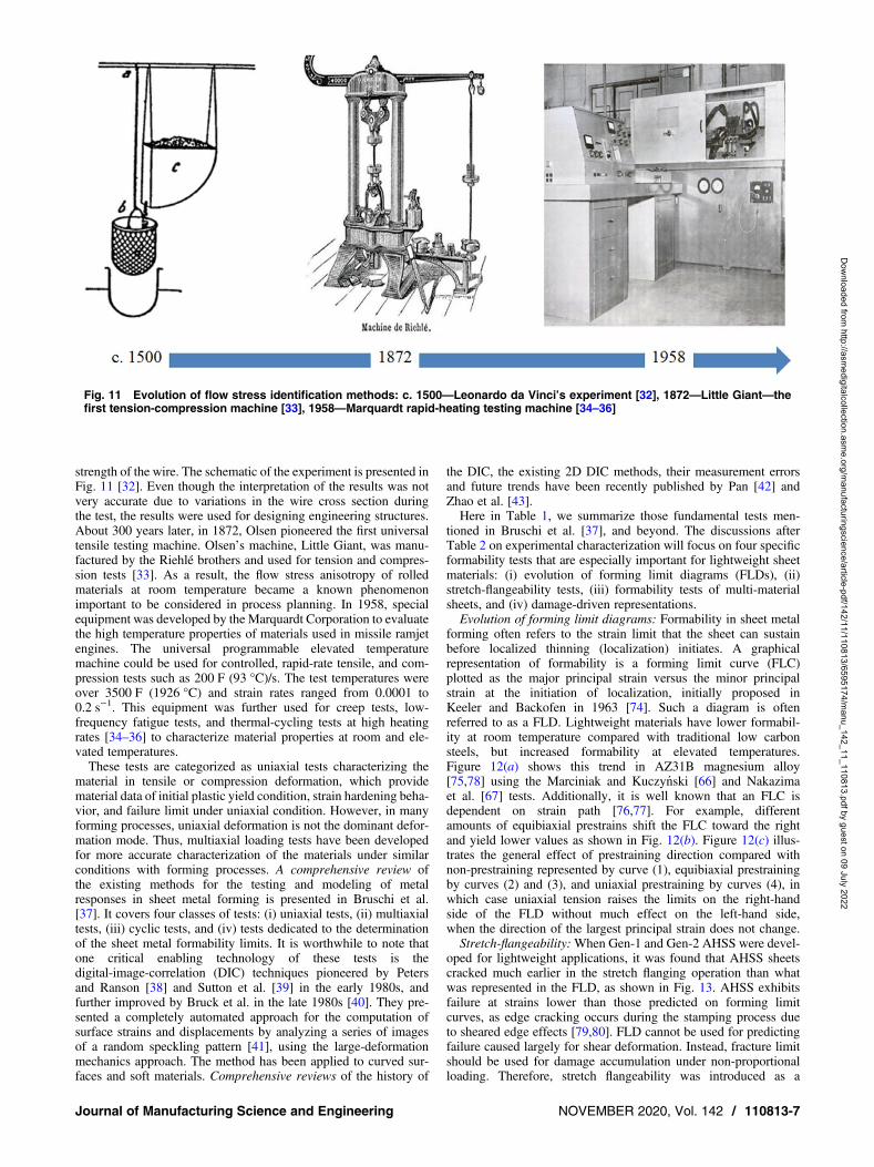
strength of the wire. The schematic of the experiment is presented inFig. 11 [32]. Even though the interpretation of the results was notvery accurate due to variations in the wire cross section duringthe test, the results were used for designing engineering structures.About 300 years later, in 1872, Olsen pioneered the first universaltensile testing machine. Olsen’s machine, Little Giant, was manu-factured by the Riehlé brothers and used for tension and compres-sion tests [33]. As a result, the flow stress anisotropy of rolledmaterials at room temperature became a known phenomenonimportant to be considered in process planning. In 1958, specialequipment was developed by the Marquardt Corporation to evaluatethe high temperature properties of materials used in missile ramjetengines. The universal programmable elevated temperaturemachine could be used for controlled, rapid-rate tensile, and com-pression tests such as 200 F (93 °C)/s. The test temperatures wereover 3500 F (1926 °C) and strain rates ranged from 0.0001 to0.2 s−1. This equipment was further used for creep tests, low-frequency fatigue tests, and thermal-cycling tests at high heatingrates [34–36] to characterize material properties at room and ele-vated temperatures.These tests are categorized as uniaxial tests characterizing the
material in tensile or compression deformation, which providematerial data of initial plastic yield condition, strain hardening beha-vior, and failure limit under uniaxial condition. However, in manyforming processes, uniaxial deformation is not the dominant defor-mation mode. Thus, multiaxial loading tests have been developedfor more accurate characterization of the materials under similarconditions with forming processes. A comprehensive review ofthe existing methods for the testing and modeling of metalresponses in sheet metal forming is presented in Bruschi et al.[37]. It covers four classes of tests: (i) uniaxial tests, (ii) multiaxialtests, (iii) cyclic tests, and (iv) tests dedicated to the determinationof the sheet metal formability limits. It is worthwhile to note thatone critical enabling technology of these tests is thedigital-image-correlation (DIC) techniques pioneered by Petersand Ranson [38] and Sutton et al. [39] in the early 1980s, andfurther improved by Bruck et al. in the late 1980s [40]. They pre-sented a completely automated approach for the computation ofsurface strains and displacements by analyzing a series of imagesof a random speckling pattern [41], using the large-deformationmechanics approach. The method has been applied to curved sur-faces and soft materials. Comprehensive reviews of the history of
the DIC, the existing 2D DIC methods, their measurement errorsand future trends have been recently published by Pan [42] andZhao et al. [43].Here in Table 1, we summarize those fundamental tests men-
tioned in Bruschi et al. [37], and beyond. The discussions afterTable 2 on experimental characterization will focus on four specificformability tests that are especially important for lightweight sheetmaterials: (i) evolution of forming limit diagrams (FLDs), (ii)stretch-flangeability tests, (iii) formability tests of multi-materialsheets, and (iv) damage-driven representations.Evolution of forming limit diagrams: Formability in sheet metal
forming often refers to the strain limit that the sheet can sustainbefore localized thinning (localization) initiates. A graphicalrepresentation of formability is a forming limit curve (FLC)plotted as the major principal strain versus the minor principalstrain at the initiation of localization, initially proposed inKeeler and Backofen in 1963 [74]. Such a diagram is oftenreferred to as a FLD. Lightweight materials have lower formabil-ity at room temperature compared with traditional low carbonsteels, but increased formability at elevated temperatures.Figure 12(a) shows this trend in AZ31B magnesium alloy[75,78] using the Marciniak and Kuczynski [66] and Nakazimaet al. [67] tests. Additionally, it is well known that an FLC isdependent on strain path [76,77]. For example, differentamounts of equibiaxial prestrains shift the FLC toward the rightand yield lower values as shown in Fig. 12(b). Figure 12(c) illus-trates the general effect of prestraining direction compared withnon-prestraining represented by curve (1), equibiaxial prestrainingby curves (2) and (3), and uniaxial prestraining by curves (4), inwhich case uniaxial tension raises the limits on the right-handside of the FLD without much effect on the left-hand side,when the direction of the largest principal strain does not change.Stretch-flangeability:When Gen-1 and Gen-2 AHSS were devel-
oped for lightweight applications, it was found that AHSS sheetscracked much earlier in the stretch flanging operation than whatwas represented in the FLD, as shown in Fig. 13. AHSS exhibitsfailure at strains lower than those predicted on forming limitcurves, as edge cracking occurs during the stamping process dueto sheared edge effects [79,80]. FLD cannot be used for predictingfailure caused largely for shear deformation. Instead, fracture limitshould be used for damage accumulation under non-proportionalloading. Therefore, stretch flangeability was introduced as a
Fig. 11 Evolution of flow stress identification methods: c. 1500—Leonardo da Vinci’s experiment [32], 1872—Little Giant—thefirst tension-compression machine [33], 1958—Marquardt rapid-heating testing machine [34–36]
Journal of Manufacturing Science and Engineering NOVEMBER 2020, Vol. 142 / 110813-7
Dow
nloaded from http://asm
edigitalcollection.asme.org/m
anufacturingscience/article-pdf/142/11/110813/6595174/manu_142_11_110813.pdf by guest on 09 July 2022

formability parameter or criterion for estimating the integrity of theparts after shearing processes. Stretch flangeability was first mea-sured by hole expansion testing (HET) and recently by a moresophisticated Smiley tool test (STT).
• Hole expansion test (HET)—The origin of the HET is not pre-cisely known. The concept of punching a ductile material withholes for storing information in various data-handling equip-ment first appeared in c. 1800. In 1954, IBM adopted this tech-nology for creating computer memory cards. Then in 1966,three metallurgists and engineers from the IBM Corporation,Queener et al. [81], published in JMSE the first theory for pre-dicting the effect of various design and operating parameters,on the mechanics of punching circular holes in relatively
ductile non-metallic materials used in data-handling equip-ment. It is supposed that this concept was used later fortesting metal sheets. In 2003, the HET became a standardizedmethod for determining stretch-flangeability (ISO/TS 16630)and began to be used in the automotive industry. With thedevelopment of Gen-1 and Gen-2 steels, these tests werefurther improved. A summary of different geometries of thehole expansion tests is presented in a comprehensive reviewpaper presented at two consecutive IDDRG Conferences in2014 [82] and 2016 [83]. Using DIC measurements, theimpact of the punch geometry can be visualized and itseffect on crack propagation can be determined. Moreover, itwas found that the pre-existing conditions of the sheets influ-ences crack propagation. For example, Chiriac and Shi [84]
Table 2 A summary of the experimental characterization tests
Type of tests Experimental apparatus
Uniaxial ASTM E8 standard [44]Split-Hopkinson pressure bar [45,46] Hopkinson, 1914 and Kosky, 1949Layer compression test [47] Pawelski, 1967
Cyclic G’Sell-Rauch shear test [48–50] G’Sell et al., 1983, Hu, 1992, Rauch, 1998Miyauchi shear test [51] Miyauchi, 1984Arcan apparatus [52,53] Arcan et al., 1978, Doyoyo and Wierzbicki, 2003In-plane tension-compression test [54] Kuwabara, 2009Double-wedge in-plane uniaxial tension-compression [55] Cao, 2009
Multiaxial Bulge test (ISO 16808) [56] Hill, 1950Bulge test using concentrically grooved disks [57] Kawai and Kurosaki, 1980Bi-axial tensile testing device [58] Kuwabara et al., 1998Self-driven bi-axial testing apparatus [59] Kuwabara et al., 1998, 2009Twente bi-axial test [60] Pijlman, 2001Biaxial tensile machine [61] Merklein and Biasutti, 2013Cruciform multiaxial mechanical testing [62] NIST, US 2013
Formability Erichsen (ISO 20482) and Olsen (ASTM E643-84) [63,64] Erichsen and Olsen, 1913Fukui conical test [65] Fukui, 1939M-K test [66] Marciniak and Kuczynski, 1967Nakazima test [67] Nakazima et al., 1968Swift test [68] Swift, 1970Limiting dome height test [69] Ghosh, 1975OSU formability test, 1994 [70] Wagoner et al, 1994Hole expansion test (ISO/TS 16630) [71] 1966, redeveloped 2003In situ X-ray stress measurement in Marciniak test [72] Foecke et al., 2007Pulse current for assessment of enhanced formability [73] Salandro et al., 2010
Fig. 12 Influence of forming temperature, prestraining of the sheet, and the path change on the FLD (experimental): (a) at 300 °C,AZ31B Mg alloy exhibits a six or seven times higher formability than at room temperature [75], (b) FLDs for as-received and equi-biaxially prestrained sheets—prestraining increases the strain limits in biaxial tension [76], and (c) experimental forming limitstrains for (1) proportional straining, (2) equibiaxial stretching followed by uniaxial tension, (3) equibiaxial stretching followedby plane strain stretching, and (4) uniaxial tension followed by equibiaxial stretching [77]
110813-8 / Vol. 142, NOVEMBER 2020 Transactions of the ASME
Dow
nloaded from http://asm
edigitalcollection.asme.org/m
anufacturingscience/article-pdf/142/11/110813/6595174/manu_142_11_110813.pdf by guest on 09 July 2022

investigated the edge propagation in multistage forming ofDP980 steel with two initial conditions: prestrain 0% and5%, and two-hole expansion tests: flat punch and conicalpunch (Fig. 14). The results indicated that for a conicalpunch, the hole expansion ratio (HER) was not influencedby the prestraining conditions and did not have any significantvariation. However, when a flat punch (in-plane edge stretch-ing) was used, the strain concentrator around the hole was highand the HER decreased with an increase in the prestrain level.Thus, in-plane curvature is important in improving the beha-vior of the sheet for multistage forming.
• STT—To address the effects of planar curvature and processsequence on stretch-flangeability, Larour et al. [83] proposedthe so-called “smiley” validation tool as shown in Fig. 14,for determining the stretch-flangeability for a complex partformed first by deep drawing (Fig. 15(a)), then trimmed(Fig. 15(b)), and finally flanged (Fig. 15(c)). Experimentaltests and finite element modeling of DP600, DP800, CP800,and CP1000HD were performed and they demonstrated thatno edge crack was obtained for DP600 and CP800, andreduced edge cracks occurred only in regions A and B1 forDP800 and CP1000HD (Fig. 15).
Formability of multi-metal sheets: Tailor welded blanks offeradvantages for lightweighting components, by welding two ormore materials with different densities. However, in TWBs thereexists decreased formability caused by changes in the material
properties in the heat-affected zone of the weld, which limitstheir utilization [86]. Saunders and Wagoner analyzed theforming performance of tailor welded steel blanks using fourtesting methods, among which were an optimized OSU formabil-ity test, full dome test, and a scaled down fender part. It was foundthat the brittle nature of the weld explained the lower formability[87]. Moreover, during the forming process, weld line movementsled to the potential for local wrinkling in areas where effectiveclamping by the tooling was lost. Due to these challenges, FLDin TWBs is normally at the level of that of the weakest material.Recent developments in joining processes, such as laser welding,have resulted in better mechanical properties of the weld and con-sequently, TWBs have regained attention as a lightweight design[88–90]. Figure 16(a) shows the FLD of laser welded TWBs indual-phase and interstitial free (IF) steels, showing that theoverall formability of the TWB is about 2% lower than that ofthe IF steel [91]. Arcelor Mittal’s hot stamped laser weldedblanks of two ultrahigh-strength steels (Ductibor 500 and Usibor1500 released in 2017) proved to have a higher formability com-pared with those with conventional welds. Thus, a multi-materialdoor ring was manufactured with significantly reduced weightand optimized crash performance (Fig. 16(b)) [92]. Improvedformability, together with different proposed methods for control-ling the weld movement during forming in a programmable way,e.g., controlling the blank holder [93], represents promisingachievements in the utilization of the TWB concept for lightweightdesign of components.
Fig. 13 Crack propagation: (a) in experiment, (b) in simulation with initial edge damage, and (c) FLD showing that the stretchflanging limit for the edge cracked part is lower than FLD (major strain between 0.4–0.6 obtained in the area joining the walland the flange indicated full damage) [79] (Reprinted with permission from Elsevier © 2010)
Fig. 14 Surface strain distribution along the hole edge: (i) conical punch; (ii) flat punch; (a) conical punch and zero prestrain,(b) flat punch and zero prestrain, (c) conical punch and 5% prestrain, (d ) flat punch and 5% prestrain, and (e) FLC of theDP980IBF grade and edge fracture strain measurements of the conical and flat punch for the zero prestrain condition [83–85]
Journal of Manufacturing Science and Engineering NOVEMBER 2020, Vol. 142 / 110813-9
Dow
nloaded from http://asm
edigitalcollection.asme.org/m
anufacturingscience/article-pdf/142/11/110813/6595174/manu_142_11_110813.pdf by guest on 09 July 2022

Damage-driven representations: From the above discussions, itcan be seen that FLD or stretch flanging tests are useful, howeverinsufficient, to predict the evolution of defects through the metalforming process chain. Fundamentally, one can think of those fail-ures as damage evolution, which leads to crack initiation and crackpropagation, that can be characterized and modeled using the stress-based approach. For example, (i) Stoughton and Zhu [94] convertedstrain-based FLCs to stress-based FLCs and demonstrated pathindependency, and (ii) studies on AHSSs show that the tougherthe material is, the greater the stretch-flangeability results. Hence,fracture toughness can be used to estimate edge cracking andrank the stretch-flangeability of AHSSs. Supported by this conclu-sion, a new test, the essential work of fracture [95,96], was proposedbased on measuring the toughness of the material for the estimationof edge cracking. In summary, damage-driven representations havegained attention in recent years to address formability in sheetmetals, for example, in Hirt et al. [97] which addresses the usabilityof a component based on the maximum accumulated damagethrough the process chain. We refer readers to the comprehensivereview article by Tekkaya et al. [98] for the history and develop-ment of damage evolution.
4.2 Analytical Characterization. The ICME approachdepends on accurate modeling of a metal’s plastic behaviorsunder complex loading conditions, in the forming process chain.Below, we will briefly summarize the developments in modelingthe initial yield representation, hardening, and failure. At the end
of the section, there are presented the most advanced microstruc-tural characterization methods which enables application of thesedevelopments in modeling and simulation of forming processes.Note that there is vast literature in solid mechanics, material charac-terization on each of these areas, hence, we will refer readers to therepresentative review articles in each of those areas.Initial yield representation: Advanced non-ferrous alloys such as
Al, Mg, or Ti alloys present anomalies of the yield shape, comparedwith the initial formulations of Tresca in 1864 and von Mises in1913 [99]. These anomalous behaviors originate from dislocationmovements and microstructure evolution, such as twinning, cross-slip, etc., leading to anisotropy symmetry, tension-compressionasymmetry, pressure sensitivity, and distorted deformation. Theseeffects are known as strength differential effects (SDE) and are cor-related with the atomic structure of the materials. For example,body-centered cubic materials, such as austenitic steels, and face-centered cubic materials, such as AA 2090-T3, have weak SDE,while the hexagonal close-packed metals, such as AZ31 andTi64, have strong SDE. Prediction of the SDE leads to subsequentdevelopments of the classical yield criteria toward having moreflexible functions with more function coefficients. Comprehensivereviews present the yield criteria developed between 1864 andpresent and provide details of each criterion and the recommenda-tions for their applications in forming different materials [100–130]. This includes the papers by McDowell [114] in IJSS and byBanabic [124] in the JMSE. The selection of a criterion for a light-weight design depends on a balance between the accuracy of predic-tion, the amount of experimental work required for identifying the
Fig. 15 Smiley tool test for determining edge flangeability in three steps: (a) deep drawing, (b) cutting, and (c) flanging operations[83]
Fig. 16 TWB (a) comparison of the experimental as-received ɛ-FLD for the TWB and IF base material [90] and (b) Arcelor Mittal’ssimplified door ring cuts the number of parts by a third and reduces the weight of the hang-on part by 20% [91]
110813-10 / Vol. 142, NOVEMBER 2020 Transactions of the ASME
Dow
nloaded from http://asm
edigitalcollection.asme.org/m
anufacturingscience/article-pdf/142/11/110813/6595174/manu_142_11_110813.pdf by guest on 09 July 2022

Fig. 17 An overview of the yield criteria recommended for prediction of lightweight materials [126–129]
Journal of Manufacturing Science and Engineering NOVEMBER 2020, Vol. 142 / 110813-11
Dow
nloaded from http://asm
edigitalcollection.asme.org/m
anufacturingscience/article-pdf/142/11/110813/6595174/manu_142_11_110813.pdf by guest on 09 July 2022

Fig. 18 ICME chain for incremental forming (based on Refs. [140–143])]
Fig. 19 Data-driven material characterization using recurrent neural network [144]
110813-12 / Vol. 142, NOVEMBER 2020 Transactions of the ASME
Dow
nloaded from http://asm
edigitalcollection.asme.org/m
anufacturingscience/article-pdf/142/11/110813/6595174/manu_142_11_110813.pdf by guest on 09 July 2022

coefficients needed for the specific criterion, and computationalresources.Hou et al. [130] published comprehensive reviews on predicting
SDE behavior, by analyzing the evolution of the yield loci againstthe experimental values. Seen in Fig. 17 are selective representa-tions of the initial yield surfaces for some typical lightweight mate-rials (e.g., steel, aluminum, magnesium, and titanium alloys), toshow their qualitative anomalous behavior. For example, aluminumhas a weak SDE anisotropy symmetry comparing with Druker, vonMises and Tresca yield surface, while magnesium and titaniumalloys have tension-compression asymmetry, as well as distorteddeformation. Particularly for titanium alloys, strong pressure sensi-tivity exists. Their summary indicates that using magnesium andtitanium alloys in forming components, requires further investiga-tions of their behavior under complex forming conditions, to miti-gate strong SDE.Hardening—yield surface evolution: The evolution of the yield
surface during forming is controlled by the hardening law whichdescribes the proportionalities between stress and strain. There aredifferent types of hardening behavior that can be determined,based on experimental observations of the microstructure evolutionand dislocation movement. Chaboche [131] and Haddadi et al.[132] reviewed classification (isotropic, kinematic, or a mixed hard-ening) and the associated phenomenological hardening laws. Adislocation-based microstructural model was proposed by Huet al. [133] to describe the sheet metal anisotropic hardening beha-vior induced by microstructural evolution at large strain. An exten-sion of the hardening laws to elevated temperatures and cyclicloading, was presented in McDowell [134], showing that tomodel thermoplasticity it is important to use the temperaturehistory independently, as the flow rule cannot exhibit the necessarydegree of temperature dependence.Failure: The Marciniak-Kuczynski (M-K) analysis is a classic
approach in predicting FLC at both room temperature and elevatedtemperatures [66,135]. It has been widely used by researchers topredict FLCs with various yield criteria or hardening laws, includ-ing in the work by Yao and Cao [136], and articles in the 2020special issue of the Journal of Materials Processing Technologyto celebrate the 100th birthday of Marciniak. Recently, Banabicet al. presented an extensive review of the developments of theM-Kmodel for sheet metal formability tests [137]. The fundamentalapproach is to assume a pre-existing thickness non-homogeneity,represented as a thinner groove in sheets. Therefore, during defor-mation, when the ratio of the rate of deformation accumulatedinside the groove, relative to that of the normal thickness, exceedsa critical value, the limit can be identified. As mentioned before,more recent advances in using damage theory for predictingfailure can be found in a review article by Tekkaya et al. [98].Microstructure characterization: Significant advancements of
scanning electron microscopy (SEM), transmission electron micros-copy (TEM), and high resolution transmission electron microscopytoward 3D measurements at the micro-scale and meso-scale havebeen made in the 1980s. They allowed a better understanding ofthe deformation mechanisms due to forming leading to better repre-sentations of the constitutive material models. Thus, starting frommodels describing isotropic work-hardening behavior (Swift-typeor power law), monotonic law with saturation (Voce-type models)to nonlinear law with saturation (Lemaitre–Chaboche), new setsof internal variables were introduced to characterize work-hardening stagnation that occurs after an orthogonal or inversestrain path change for complex loads (e.g., the microstructuralmodel of Hu et al. [133]). Consequently, the accuracy of predictingthe behavior of advanced lightweight materials was significantlyincreased.Another significant advancement on material characterization
was the development of the electron backscattered diffraction(EBSD) method. EBSD makes the connection of the microstructureand the crystallographic texture in pre-forming and during formingand post-forming. Thus, EBSD provides quantitative informationinfluencing selection of material models [138,139]. This
information is the basis for 3D reconstruction of grain structuresand is combined with crystal plasticity models to allow the studyof the evolution of the microstructure and the post-forming mechan-ical properties. These crystal plasticity models combined with finiteelement models are able to enhance the fidelity of numericalmodels. Figure 18 shows a schematic of a comprehensive ICMEapplication to accurately predict the geometric shape, formingforce, and thickness variation in incremental forming processes ofan aerospace advanced aluminum alloy (AA7075-O). EBSD ofthe AA7075-O microstructure pre- and post-forming was used for3D reconstruction of a representative volume of this material andfurther used for identification of the four out-of-plane parametersof the 18 parameters used in the Yld2004 yield criterion. Thus, com-bining these four parameters with the 14 parameters determinedexperimentally, the accuracy of the prediction of forming force ofan incrementally formed cone shape increased to 95% comparedwith experimental values. It is noted that the Yld2004 model com-pared with the conventional Hill1948 model is able to predict thesmall SED features present in the behavior of AA7075-O.While recognizing the benefit of using ICME chain in virtual
manufacturing, computation cost of these models remain a chal-lenge in their large-scale adoption in designing processes. Moti-vated by this challenge, nowadays there are efforts in usingmachine learning as a knowledge transfer method of the findingsfrom the physical-based models to data-driven models.
4.3 Data-Driven Models. Phenomenological mathematicalmodels as described in the above analytical characterization discus-sion have historically been used to calculate plasticity, but suchmodels are often based on restricting certain theoretical assump-tions, and are therefore not sophisticated enough to model today’scomplex, designed materials. It is a well-realized fact that spring-back prediction of AHSS and aluminum alloys still remains amajor challenge even with the advancements in modeling of mate-rial yield surface and its hardening evolution. While more sophisti-cated models exist (such as the crystal plasticity model ormulti-scale models), they are much slower, and need hours ordays of computational time on super-computers to solve a widerange of engineering problems.To develop a more systematic way to model plasticity, Mozaffar
et al. [144] used deep learning methods to create a neural network, aset of algorithms that can extract hidden relationships in data. Thenewly developed neural network architecture learns any materialbehavior under different force patterns and understands the plastic-ity of the material, based on the material’s properties and its historyof force. The model, as shown in Fig. 19, is directly extracted frommaterial behavior data, and effectively combines microstructurepattern effects on materials without the need to solve the equationsiteratively. Such approach can be extended to include damage pre-diction, for example, to capture the stretch flangeability, or toinclude the modeling of material behavior of the thin welds inTWBs that are mostly ignored in current simulations due to theexcessive computational cost, and therefore, allows engineers todesign materials and manufacturing processes at the same time, totruly enable an integrated systematic approach to optimization.
5 Process InnovationProcess innovation is an imperative part of the lightweighting
effort. The weight evolution of the beverage can as shown inFig. 4, is one clear example. Before 1958, cans were made ofthree pieces: a rolled and seamed cylinder, and two end pieces.The two-piece can-making process was first realized as animpact-extrusion process, and then further innovated into a com-bined deep drawing and ironing process, which successfullyreduced the weight by more than 70%, from 80 g in 1958 to22.65 g in 1963. This is largely due to the fact that the deep-drawingprocess is able to form a can bottom of 0.279 mm instead of the0.762 mm in the impact-extrusion process [7]. The further
Journal of Manufacturing Science and Engineering NOVEMBER 2020, Vol. 142 / 110813-13
Dow
nloaded from http://asm
edigitalcollection.asme.org/m
anufacturingscience/article-pdf/142/11/110813/6595174/manu_142_11_110813.pdf by guest on 09 July 2022

lightweighting from 22.65 g in 1963 to 13.08 g at present, is anotheramazing 42% reduction, and can be attributed to the development oflubricant and the basic understanding of material deformationbehavior.Metal forming processes can be characterized in many different
ways, as shown in classic metal forming textbooks, such as thoseby Avitzur [145], Lange [146], Altan and Tekkaya [147], andHosford and Caddell [148], and in more general manufacturing pro-cesses textbooks, such as those by Kalpakjian and Schmid [149]and Groover [150]. In this review paper, inspired by the ICMEframework, as well as the thought process demonstrated in materialdesign, found in Olson [151], the following strategy map is pro-posed and aims to stimulate the thought-process for forming inno-vation, based on fundamental science, rather than a simplecategorization exercise. Figure 20 presents our proposedPerformance-Constraints-Mechanism-Innovation (PCMI) frame-work. In Sec. 5.1, detailed examples following the formability asa constraint to generate innovative forming processes will begiven. Followed by more abstract examples in Sec. 5.2, in whichpress load or materials is taken as a constraint for this PCMIchain. Note that Fig. 20 aims to inspire new process innovation fol-lowing a logic brainstorming method. Hence, the boxes in thisfigure can be greatly expanded based on the objectives.
5.1 Examples of Using the PCMI Approach for ProcessInnovation—Formability as a Constraint. As discussed in themotivation section and in the material characterization section,formability is one of the main constraints for successfullyforming a lightweight part, because lightweight materials tend tohave low formability. Meanwhile, through fundamental research,we have a better understanding of the mechanisms attributed toformability. We know that formability can be enhanced at an ele-vated temperature, in the presence of hydrostatic pressure or shear-ing, i.e., a function of stress state, at a different strain rate, orfollowing a different strain path. Below, we illustrate process inno-vations that address these mechanisms related to formability.Temperature—Given the knowledge that formability increases as
temperature increases, various new forming processes have beendeveloped:
• Based on induction heating, warm forming of aluminumalloys [152] and magnesium alloys [153], and hot stampingof ultrahigh-strength steel parts [154] with a tensile strengthof 1.5 GPa, have been developed. Common research topicsin this category include the following: what is the microstruc-ture evolution at a given thermal history, and how to heat/coolthe part following the desired temperature history in thedesired area. The ability to address these topics will allow usto use the forming process as an effective process to set thematerial properties [155,156], rather than just successfullyforming to the right geometry. For example, as shown inFig. 21, one can tailor the properties and hence sheet thicknessin a B-pillar part on an automobile, to minimize the weightbased on the required loading condition. Induction heatinghas advantages, such as rapid heating time, high efficiencyand being highly scalable, while its drawbacks include align-ment difficulties and localized surface currents.
• Based on resistance heating, electrically assisted forming hasreceived considerable attention since the publication fromRoth’s group [158], which is among the top ten most citedpapers published by the JMSE, and which also rejuvenatedthe debate on electroplasticity that was initially proposed byTroitskii in 1969 [159] and by Okazaki et al. in 1980 [160].In fact, the use of electric current to assist metal forming pro-cesses can be tracked back to 1890, in two U.S. patents thatwere issued to Dewey [161] and Lemp [162]. A review ofthis part of history can be found in Magargee et al. [163],along with a novel experimental setup to decouple the effectof electrical current from that of heat, which demonstratedthat the thermal-mechanical models can effectively modelthe noted softening behavior, as noticed in electroplasticitywork. This view was further debated and adopted by manyother researchers, including nearly 20 papers published bythe JMSE on this topic since 2007. Readers can find recentreview papers on this topic in Nguyen-Tran et al. [164] andRuszkiewicz et al. [165]. The effects of electric current onformability enhancement and springback reduction havebeen demonstrated in multiple electrically assisted metalforming processes, as shown in Fig. 22, for example, simple
Fig. 20 The Performance-Constraint-Mechanism-Innovation (PCMI) relationship
110813-14 / Vol. 142, NOVEMBER 2020 Transactions of the ASME
Dow
nloaded from http://asm
edigitalcollection.asme.org/m
anufacturingscience/article-pdf/142/11/110813/6595174/manu_142_11_110813.pdf by guest on 09 July 2022

compression of Ti-6Al-4V [166], gear forming of ultra highstrength steel (UHSS) [167], roll bonding of aluminum andcopper sheets [168], incremental forming of Ti-6Al-4V[169], and wire drawing of 308L stainless steel [170].
• Based on laser radiation, lasers can achieve local heatingeffectively due to a non-contact method that complies withversatility and controllability considerations [171]. One ofthe common applications is laser bending (Fig. 23) as illus-trated in Bao and Yao [172] (one of the top ten most citedJMSE papers) and Shi et al. [173]. Duflou et al. [171] uses a500 W Nd:YAG laser with a fiber beam delivery system, inan incremental forming system, to form a 1.25 mm aluminumAA5182 sheet. Laser forming is a complex process which mayencounter thermal distortion and buckling. The final deformedgeometry is the accumulation of deformation from each indi-vidual laser action along the laser path.
Stress-state—Hydrostatic pressure can delay fracture and henceincrease formability. The emergence of hydroforming (Fig. 22)
takes advantage of this property [174]. Koc and Altan [175] pro-vided a comprehensive overview on tube hydroforming, which isa process that is widely used for lightweighting. One criticalelement in hydroforming to control the stress state is lubricity. Tri-bological behavior [176–179] and lubricant study [180,181] arecritical to the success of hydroforming. In addition to tube hydro-forming, sheet hydroforming [182] shown in Fig. 24(c) is anotherprocess that is used for lightweighting. Recently, stress superposi-tion is merged as an innovation of the stress-state mechanismwhich allows larger deformation. For example, stress superpositionin combined bending–linear flow splitting enhances formability ofmetals in high-throughput forming of components with a constantcross section in a continuous manner without any expensive toolchange costs [183].Strain rate—Material sensitivity to strain rate has led to some
interesting processes, for example, electromagnetic forming orimpact forming that utilizes an extremely high strain rate range(∼102–104 1/s), and superplastic forming that utilizes an extremelylow strain rate (∼10−4 1/s) [37].
Fig. 21 Stress–strain curves and CCT diagram for a B-pillar with tailored properties[157] (Reprinted with permission from Elsevier © 2012)
Fig. 22 Enhanced formability in electrically assisted metal forming processes, from left to right, and from top to down: (a) simplecompression of Ti-6Al-4V [166], (b) gear forming of UHSS [167] (Reprinted with permission from Elsevier © 2011), (c) roll bondingof aluminum and copper sheets [168], (d ) incremental forming of Ti-6Al-4V [169], and (e) wire drawing of 308L stainless steel [170]
Journal of Manufacturing Science and Engineering NOVEMBER 2020, Vol. 142 / 110813-15
Dow
nloaded from http://asm
edigitalcollection.asme.org/m
anufacturingscience/article-pdf/142/11/110813/6595174/manu_142_11_110813.pdf by guest on 09 July 2022
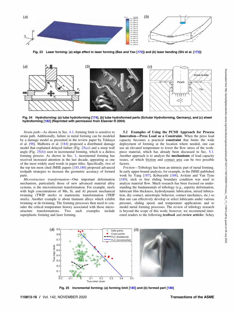
Strain path—As shown in Sec. 4.1, forming limit is sensitive tostrain path. Additionally, failure in metal forming can be modeledby a damage model as presented in the review paper by Tekkayaet al. [98]. Malhotra et al. [184] proposed a distributed damagemodel that explained delayed failure (Fig. 25(a)) and a steep wallangle (Fig. 25(b)) seen in incremental forming, which is a dielessforming process. As shown in Sec. 1, incremental forming hasreceived increased attention in the last decade, appearing as oneof the most widely used words in paper titles. Specifically, two ofthe top ten most cited JMSE papers [185,186] proposed advancedtoolpath strategies to increase the geometric accuracy of formedparts.Microstructure transformation—One important deformation
mechanism, particularly those of new advanced material alloysystems, is the microstructure transformation. For example, steelswith high concentrations of Mn, Si, and Al present mechanicaltwinning (TWIP steels) or martensitic transformation (TRIPsteels). Another example is about titanium alloys which exhibittwinning or de-twinning. The forming processes then need to con-sider the critical temperature history associated with those micro-structure transformations. Two such examples includesuperplastic forming and laser forming.
5.2 Examples of Using the PCMI Approach for ProcessInnovation—Press Load as a Constraint. When the press loadcapacity becomes a practical constraint that limits the widedeployment of forming at the location where needed, one canuse an elevated temperature to lower the flow stress of the work-piece material, which has already been discussed in Sec. 5.1.Another approach is to analyze the mechanisms of load capacityissues, of which friction and contact area can be two possiblefactors.Friction—Tribology has been an intrinsic part of metal forming.
In early upper-bound analysis, for example, in the JMSE publishedwork by Yang [187], Kobayashi [188], Avitzur and Van Tyne[189], stick or free sliding boundary condition was used toanalyze material flow. Much research has been focused on under-standing the fundamentals of tribology (e.g., asperity deformation,lubricant film thickness, hydrodynamic lubrication, mixed lubrica-tion, dry contact, anisotropic behavior, contact mechanics, etc.) sothat one can effectively develop or select lubricants under variouspressure, sliding speed, and temperature applications and tomodel metal forming processes. The review of tribology researchis beyond the scope of this work; however, we recommend inter-ested readers to the following textbook and review articles: Schey
Fig. 23 Laser forming: (a) edge effect in laser forming (Bao and Yao [172]) and (b) laser bending (Shi et al. [173])
Fig. 24 Hydroforming: (a) tube hydroforming [174], (b) tube hydroformed parts (Schuler Hydroforming, Germany), and (c) sheethydroforming [182] (Reprinted with permission from Elsevier © 2004)
Fig. 25 Incremental forming: (a) forming limit [185] and (b) formed part [186]
110813-16 / Vol. 142, NOVEMBER 2020 Transactions of the ASME
Dow
nloaded from http://asm
edigitalcollection.asme.org/m
anufacturingscience/article-pdf/142/11/110813/6595174/manu_142_11_110813.pdf by guest on 09 July 2022

[190], Kalpakjian [191], Geiger [192], Wilson [193], Lenard [194],Bay et al. [195], Dohda et al. [196], etc.One way to reduce the friction factor in metal forming is to use
ultrasonic vibration, which has shown advantages for microforminghard-to-form materials, or materials that have galling tendency. Thisidea was explored by multiple researchers at around the same timeframe, Presz and Andersen [197] and Ngaile and Bunget [198]. Asshown in Fig. 26 [199], an ultrasonic generator was able to reducethe load by up to 15%, and consequently reduce the buckling risk ofthe extruded pins. Note that although ultrasonic vibration is effec-tive for microforming, it faces challenges in scaling up to macro-scale forming, simply due to the basic physics involved. An alterna-tive method to reduce friction is to use textured surfaces, asexplored by Hector and Sheu [200] and demonstrated in Menget al. [201], where up to a 40% reduction in the friction coefficientwas achieved due to the addition of hydrodynamic lift duringsliding.Contact area—One effective way to reduce load is to reduce the
contact area. Instead of deforming the entire workpiece at the sametime, one can incrementally form the workpiece, such as in stripforging, which was analyzed in the 1978 JMSE work by Avitzurand Kohser [202]. Incremental forming processes are also reviewedin Jeswiet et al. [203], which details incremental sheet forming,Groche et al. [204] detailed incremental bulk forming, and also inYang et al. [205], which reviews flexible forming processes.Recently, the 3D servo-press built by Groche et al. [206] havingthree degrees of freedom allows variable motion patterns fornear-net shape orbital forming in forging and incrementalforming. This topic has received increased attention in the past 15years, due to the great potential of its applications under theumbrella of distributed manufacturing, as well as the existence ofgreat scientific and technological challenges in controlling thegeometry, surface quality, residual stress, and forming time. Infact, two of the top ten cited papers in the JMSE (Fig. 3), Malhotraet al. [186] and 2011 [185], are in this area.
6 Numerical Simulation of Metal Forming ProcessesNumerical simulation of metal forming started with two-
dimensional simulations in the 1960s and 1970s, to model bulkforming operations, such as forging, extrusion and wire drawing,as reflected in Fig. 2. With the development of shell elements andcomputational power, numerical simulations of sheet metalforming started to take place in the late 1970s and 1980s. In thissection, we will present the origin of simulations for bulk andsheet metal forming as published in the JMSE, followed by the inte-gration of CAD-FEM-CAE tools as a result of recent developmentsin data-driven manufacturing.
6.1 Brief Origin of Metal Forming Simulations. The expan-sion of industrialization to different sectors encouraged the develop-ment of large and powerful machines, of which key components aremade by bulk forming, such as shafts. Enabled by this need, researchfor finding analytical and numerical models for forging andextrusion, was the main priority of researchers from 1959 to 1969.Theoretical solutions for predicting the forging forces [207,208],and analytical models for extrusion, cold rolling, and wire drawing,were reviewed in the JMSE in 1967 [209,210]. Advancedapproaches, such as the upper-boundmethod for obtaining an admis-sible velocity field applied to plane-strain extrusion, tube extrusion,and axisymmetric piercing, were published by Lambert et al. [211]in 1969.These analytical considerationswere the base for developingthe first in-house finite element software.2D simulations of metal forming processes began in the 1970s
[212] and extended to industrial applications in the 1980s. Oneexample is the 2D FEM ALPID, presented at the NAMRC IX con-ference in 1981 [213], which in 1990, became a two-dimensionalgeneral purpose FEM tool for simulation of a wide class offorming processes, namely, DEFORM [214]. Computer modelinghas become an integral part of the design and developmentprocess, not only at leading organizations, but in most forging com-panies. The 1990s brought advanced numerical algorithms imple-mented into FEM, for the prediction of temperature evolutionduring multipass forging, and the relationship between the stressstate and crack opening or closure in shape rolling [215]. Nowa-days, the trend of finite element simulation packages, such asDEFORM, is to provide fundamental modules in simulatingphase transformation, ductile fracture, microstructural evolution,etc., such that simulations of an integrated manufacturing processchain, from ingot conversion through bulk forming to sheet bulkforming, to machining, heat treatment, and final product installa-tion, can be simulated using one platform.Sheet metal forming involves large strains which only in the
1970s started to be numerically calculated, due to the merging ofadvanced shell elements. Early work was done by Wang andBudiansky [216] on calculating the strain distributions in the stamp-ing of sheet metal, by arbitrarily shaped punches and dies. A furtherstep was realized by Gosh and Kikuchi [217] by considering aLagrangian–Eulerian 3D finite element mesh, together with a ther-momechanical model, which proved to be able to accurately predicthot stamping processes. Developments of computational power andadvancement of the FORTRAN language in the late 1970s allowed theextensive use of finite element methods by the introduction ofnumerical algorithms, such as the direct sparse matrix solver, fordecreasing the computation time, and allowing the considerationof anisotropy and the work-hardening characteristics of the mate-rial. Based on improved knowledge of the material flow and bound-ary conditions, the automotive industry started to consider finite
Fig. 26 Setup of ultrasonic vibration-assisted micro-extrusion [199] (Reprinted with permissionfrom Elsevier © 2011)
Journal of Manufacturing Science and Engineering NOVEMBER 2020, Vol. 142 / 110813-17
Dow
nloaded from http://asm
edigitalcollection.asme.org/m
anufacturingscience/article-pdf/142/11/110813/6595174/manu_142_11_110813.pdf by guest on 09 July 2022

element simulation as a necessary design tool, for decreasing thelead-time from a design to a part. Thus, in the late 1970s, Tang atFord developed an in-house finite element simulation code,MTLFRM, for panel forming simulation [218]. Similarly, in the1980s, Norman Wang at General Motors, developed GMFORM,which was later improved and renamed PANELFORM [219].Simulation of metal forming processes has had positive impacts
on increasing industrial performance, additionally, it created a newsector—software development. An argument to support this state-ment can be extracted from the history of ABAQUS software.Between 1968 and 1991, David Hibbitt, Pedro Marcal, Bengt Karls-son, and Paul Sorenson founded the principles of programming afinite element software. Their initial developments took two path-ways: Marc Analysis and ABAQUS. The necessity to have onesolver with a CAD preprocessor, was soon solved by thecompany HKS Inc., known later as SIMULIA. Starting withthe Engineous software’s iSIGHT in 2008 (the first CAD-CAE inte-gration), SIMULIA has added capabilities in optimization, templatecreation and process automation, computational fluid dynamics,injection molding, fatigue and durability, topology optimization,electromagnetics, vibroacoustics, and more. More currently, the3DEXPERIENCE platform offered by Dassault Systems,managed by SIMULIA, integrates design, simulation of processes,marketplace, production plan, and global production systems.LS-DYNA originated from the 3D FEA program DYNA3D, devel-oped by John O. Hallquist at Lawrence Livermore National Labo-ratory (LLNL) in 1976, and experienced extensive growth sincethe founding of Livermore Software Technology Corporation(LSTC) by Hallquist in 1987 as one of the most widely adoptedmultiphysics solvers by the automotive industry. In 2019, it wasacquired by ANSYS.
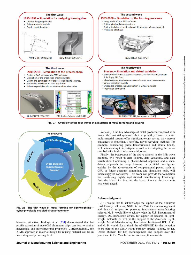
6.2 Toward Integration of CAD-FEM-CAE Tools. A com-prehensive review of the most used finite element software forsheet metal forming simulation for industrial applications—fromtheir initial development up to 1998—in the USA, Japan, andEurope, was published in CIRP Annals [220]. Development ofthe new in-house finite element modeling for die design purposes,continued between 1990 and1998, achieving performance inspringback and wrinkling predictions.The first wave of FEM software development is summarized in
the 1993 NUMISHEET Conference Proceedings [221]. The chal-lenge in transferring data and converting their data format four tofive times (e.g., AutoCAD->I-DEAS->STAMP3D->I-DEAS->NXT Defect Evaluator [203]), called for integration withuser-friendly computation systems [222]. Also, the continuouslydeveloped constitutive material models, yield, and damage criteria,suitable for lightweight materials, were integrated into these simu-lation systems to allow their usage from the design phase. Thisdetermined the second wave of integration of CAD and FEM soft-ware. Real impact opportunities arose in 2010 after the auto indus-try’s recovery, when the existing design paradigms limited to thepart-level, were asked to include the entire process chain, allowingflexibility in adoption of multi-material systems. The paradigmchange was reinforced by international initiatives for reducingCO2 emissions (e.g., CAFÉ standard). Soon after, a third wave ofintegration has started from the need to design lightweight multi-material components, and optimization of manufacturing processchains toward a reduced time-to-market [223,224]. For example,by integrating CAD-FEM-CAE with crystal plasticity models,new design criteria can be used, such as multi-scale design foroptimum strength, increased volumetric yield, decreased propertyvariation, and prolonged fatigue life [225,226].CAD-FEM-CAE systems were merged into platforms connected
to validation modules, which were able to evaluate the appropriate-ness of a certain process design. Thus, platforms such as AutodeskFusion 360, Dassault Systems, Siemens NX, and PTC Creo becamesystem modeling software solutions. They represent completephysics-based design platforms for modeling, simulation,
validation, and verification, of early design models and require-ments. The outcome of a system modeling software solution isdesigning and analyzing the effect of failures without physicallybuilding the systems. By analyzing the effects of specific designdecisions during the design phase, compared with building anactual prototype, the overall cost of building the system diminishessignificantly. This transformational change in designing formingprocesses is considered the fourth wave in this paper, whichstarted recently and will continue to be developed by incorporatingvirtual reality testing, inspection, and validation. The above-described four waves are illustrated in Fig. 27.
7 Future Trends“The future cannot be predicted, but futures can be invented,”
said Nobel Laureate in Physics, Dennis Gabor in 1963. While wetake the opportunity of the MED 100th birthday to review andappreciate more than 5000 years’ worth of metal forming arts andscience history, we are also inspired by the countless possibilitiesof new, future inventions in metal forming for lightweighting.One concept that we hope readers will take away from reading
this paper is the proposed PCMI framework for process innovation,which is established on the solid foundation of our scientific under-standing about constraints. Combined with Integrated Computa-tional Materials Engineering and Material Reuse [227,228], thefuture of metal forming is hypothetically imagined by the authorsas the fifth wave era, a cyber-physically enabled circular economy.The most renowned definition of this was framed in 2013 by the
Ellen MacArthur Foundation, who introduced the CircularEconomy as, “an industrial economy that is restorative or regener-ative by intention and design” [229,230]. In our case, we interpretthis as changing the economy from a linear path (mining-making-using-discarding), to a circular one (design/manufacturing-distrib-uting-using-reusing-recycling), as shown in Fig. 28 (based on theconcept presented in Ref. [231]). The realization of this vision formetal forming requires enormous contributions and integrationsfrom various disciplines, as further illustrated below.Design/manufacturing: The PCMI framework fits right into this
phase—designing a process in conjunction with designing aproduct. The fourth wave of simulation tools as described in Sec. 6and the data-driven model described in Sec. 4.3 are the necessarytools, which can be further enhanced by having an augmentedreality system. Virtual reality and new data-driven models will beimplemented in the system modeling software solutions, for predic-tion of the material behavior and process control, as digital manufac-turing demands. Furthermore, in this phase, physical realization of aprocess occurs with necessary in situ sensor integration, into metalforming processes and equipment, to realize Industry 4.0.Distributing: The pathway from manufacturer to user, can be as
close as the garage and the corner mall, or as far as crossing theocean. DeVor et al. [232] presented the concept of transformingthe landscape of manufacturing from centralized manufacturingmodes, to distributed manufacturing, and further analyzed the tech-nological and societal impacts. This concept has been increasinglyadopted in both civilian and military forms for reasons ranging fromtiming to resilience. Since the contents of constraints in PCMI vary,it can lead to new forming processes and new ways of handling tra-ceability, one critical element in the distribution network.Using: Data in the usage phase is often hard to monitor and collect,
particularly when humans are in the loop. Nevertheless, these data areultimately necessary and important for human-centric design, and forthe success of a product. Interesting future work can include formingsensors into a product, or using the nature of microstructure andsurface properties as a traceable item. Customization or personaliza-tion of a product will be of interest as well, which will demand flex-ible forming processes, digitalization and cyber-physicalmanufacturing systems. One example is presented in Tan et al. [233].Reusing: Since metal mining and metal production is an energy
intensive process, smart reusing of metal products or their scrap,
110813-18 / Vol. 142, NOVEMBER 2020 Transactions of the ASME
Dow
nloaded from http://asm
edigitalcollection.asme.org/m
anufacturingscience/article-pdf/142/11/110813/6595174/manu_142_11_110813.pdf by guest on 09 July 2022
becomes attractive. Tekkaya et al. [234] demonstrated that hotprofile extrusion of AA-6060 aluminum chips can lead to similarmechanical and microstructural properties. Correspondingly, theICME approach in material design for reusing material will be aninteresting and promising field.
Recycling: One key advantage of metal products compared withmany other material systems is their recyclability. However, whilemulti-material systems offer significant weight saving, they presentchallenges in recycling. Therefore, novel recycling methods, forexample, considering phase transformation and atomic bonds,will be interesting to investigate, as well as investigating the corro-sion behavior in dissimilar material joints.Finally, the integration of the above aspects in the fifth wave
economy will result in data volume, data versatility, and datavariabilities. Combining a physics-based approach and a data-driven approach in deep learning or artificial intelligenceenabled by the advancement of computational power, such asGPU or future quantum computing, and simulation tools, willincreasingly be considered. This work will provide the foundationfor transferring highly sophisticated manufacturing knowledgefrom the hands of a few, into the hands of many, for the count-less years ahead.
AcknowledgmentJ. C. would like to acknowledge the support of the Vannevar
Bush Faculty Fellowship N00014-19-1-2642 for its encouragementand financial support for pursuing fundamental manufacturingscience. M. B. would like to acknowledge the U.S. Department ofEnergy, DE-EE0008456 award, for support of research on light-weight materials, as well as the support of the American Light-weight Metal Manufacturing Innovation Institute—LIFT. J. C.and M. B. would like to thank the ASME/MED for the invitationto be part of the MED 100th birthday special volume, to Dr.Delcie Durham for her encouragement and support over theyears, and to Dr. Yuanli Bai for his in-depth comments.
Fig. 27 Overview of the four waves in simulation of metal forming and beyond
Fig. 28 The fifth wave of metal forming for lightweighting—cyber-physically enabled circular economy
Journal of Manufacturing Science and Engineering NOVEMBER 2020, Vol. 142 / 110813-19
Dow
nloaded from http://asm
edigitalcollection.asme.org/m
anufacturingscience/article-pdf/142/11/110813/6595174/manu_142_11_110813.pdf by guest on 09 July 2022

Conflict of InterestThere are no conflicts of interest.
Data Availability StatementThe datasets generated and supporting the findings of this article
are obtainable from the corresponding author upon reasonablerequest. The authors attest that all data for this study are includedin the paper.
References[1] Artioli, G., Angelini, I., Kaufmann, G., Canovaro, C., Dal Sasso, G., and Villa,
I. M., 2017, “Correction: Long-Distance Connections in the Copper Age: NewEvidence from the Alpine Iceman’s Copper Axe,” Plos One, 12(12),p. e0189561.
[2] Andrews, S., 2017, “A Weapon Like no Other: The Ancient Chinese Sword ofGoujian, Found in a Tomb, is Perfectly Sharp After More Than 2,500 Years,”Last Modified Nov. 22, 2017, https://www.thevintagenews.com/2017/11/22/ancient-chinese-sword-goujian-retrieved-tomb-perfectly-sharp-even-2500-years/,Accessed Jan. 20, 2020.
[3] “7 Oldest Coins that Ever Existed,” 2008, http://www.oldest.org/culture/coins/,Accessed Jan. 20, 2020.
[4] “The Top 20 Economies in the World,” 2019, Last Modification Nov. 19, 2019,https://www.investopedia.com/insights/worlds-top-economies/, Accessed Dec.15, 2019.
[5] Australian Aluminum Council, 2014, “How Many Aluminum Cans Equal 1Pound?,” https://recycleusainc.com/how-many-aluminum-cans-equal-1-pound/,Accessed Jan. 25, 2020.
[6] “A Brief History of the Beverage Can Body,” 2006, Last Modified November2006, https://stollemachinery.com/, Accessed Jan. 30, 2020.
[7] Hosford, W. F., and Duncan, J. L., 1994, The Aluminum Beverage Can,Scientific American, Scientific American, a Division of Springer NatureAmerica, Inc, pp. 48–53.
[8] Recycle USA Inc., 2020, “Aluminium Cans Consumed,” https://www.theworldcounts.com/challenges/consumption/foods-and-beverages/aluminium-cans-facts, Accessed Jan. 30, 2020.
[9] Office of Energy Efficiency and Renewable Energy, 2019, “LightweightMaterials for Cars and Trucks,” https://www.energy.gov/eere/vehicles/lightweight-materials-cars-and-trucks, Accessed Jan. 30, 2020.
[10] Kleiner, M., Geiger, M., and Klaus, A., 2003, “Manufacturing of LightweightComponents byMetal Forming,”CIRPAnn.Manuf. Technol., 52(2), pp. 521–542.
[11] Kashani, H. T., Kah, P., and Martikainen, J., 2015, “Laser Overlap Welding ofZinc-Coated Steel on Aluminum Alloy,” Phys. Procedia, 78, pp. 265–271.
[12] Taub, A., De Moor, E., Luo, A., Matlock, D. K., Speer, J. G., and Vaidya, U.,2019, “Materials for Automotive Lightweighting,” Ann. Rev. Mater. Res.,49(1), pp. 327–359.
[13] Heuss, R., Müller, N., van Sintern, W., Starke, A., and Tschiesner, A., 2012,“Lightweight, Heavy Impact”, Report McKinsey & Company.
[14] Tekkaya, E. A., Khalifa, N. B., Grzancic, G., and Hölker, R., 2014, “Forming ofLightweight Metal Components: Need for New Technologies,” Procedia Eng.,81, pp. 28–37.
[15] Mass Reduction for Light-Duty Vehicles for Model Years 2017–2025, USDepartment of Transportation, National Highway Traffic Safety, DOT HS 811666, November 2018, downloaded Jan. 30, 2020.
[16] Springer, H., Baron, C., Szczepaniak, A., Uhlenwinkel, V., and Raabe, D., 2017,“Stiff, Light, Strong and Ductile: Nano-Structured High Modulus Steel,” Sci.Rep., 7(1), p. 2757.
[17] Cao, J., Brinksmeier, E., Fu, M., Gao, R. X., Liang, B., Merklein, M., Schmidt,M., and Yanagimoto, J., 2019, “Manufacturing of Advanced Smart Tooling forMetal Forming,” CIRP Ann., 68(2), pp. 605–628.
[18] Savic, V., Hector Jr., L, Singh, H., Paramasuwom, M., Basu, U., Basudhar, A.,and Stander, N, 2018, “Development of a Lightweight Third-GenerationAdvanced High-Strength Steel (3GAHSS) Vehicle Body Structure,” SAE Int.J. Mater. Manuf. 11(4), pp. 303–313.
[19] Prahl, U., Ramazani, A., and Berme, B., 2013, “Advanced Steels for TransportApplications,” Structural Materials and Processes in Transportation, D.Lehmhus, M. Busse, A. S. Herrmann, and K. Kayvantash, eds., Wiley-VCHVerlag GmbH & Co., Germany, pp. 11.
[20] Pathak, N., Butcher, C., Worswick, M. J., Bellhouse, E., and Gao, J., 2017,“Damage Evolution in Complex-Phase and Dual-Phase Steels During GEStretching,” Materials, 10(4), p. 346.
[21] Davenport, M., 2017, “Third-Generation Advanced High-Strength SteelEmerges”, Stamping Journal, Last Modified Oct. 15, 2017, https://www.thefabricator.com/stampingjournal/article/stamping/third-generation-advanced-high-strength-steel-emerges, Accessed Jan. 30, 2020.
[22] Merklein, M., Allwood, J. M., Behrens, B.-A., Brosius, A., Hagenah, H.,Kuzman, K., Mori, K., Tekkaya, A. E., and Weckenmann, A., 2012, “BulkForming of Sheet Metal,” CIRP Ann., 61(2), pp. 725–745.
[23] The Minerals, Metals & Materials Society (TMS), 2019, MetamorphicManufacturing: Shaping the Future of On-Demand Components (Pittsburgh,PA: TMS, 2019). www.tms.org/metamorphicmanufacturing
[24] Raedt, H. W., Wilke, F., and Ernst, C.-S., 2016, Germany’s Lightweight ForgingInitiative, Last Modified June 6, 2016, https://www.forgemag.com/articles/84493-germanys-lightweight-forging-initiative, Accessed June 2, 2020.
[25] Raedt, H.-W., Wilke, F., and Ernst, C.-S., 2015, “Lightweight Potential for aLight Commercial Vehicle,” Stahl Eisen, 135(11), pp. 161–169.
[26] Lightweight Forging, 2019, Presentation of Stahl Institute, Germany,http://www.massiverleichtbau.de/fileadmin/info/ergebnisse_der_initiative_3/Presentation_of_results_English_4-2019.pdf, Accessed June 2, 2020.
[27] Raedt, H.-W., Wilke, F., and Ernst, C.-S., 2014, “The Lightweight ForgingInitiative—Automotive Lightweight Design Potential with Forging,” ATZ,116(3), pp. 40–45.
[28] Behrens, B.-A., and Kosch, K.-G., 2011, “Production of Strong Steel-AluminumComposites by Formation of Intermetallic Phases in Compound Forging,” SteelRes. Int., 82(11), pp. 1261–1265.
[29] Chavdar, B., Goldstein, R., and Ferguson, L., 2016, “Hot Hydroforging ofLightweight Bimaterial Gears and Hollow Products,” Conference: 23rdIFHTSE World Congress, April.
[30] National Research Council of the National Academies, 2008, IntegratedComputational Materials Engineering: A Transformational Discipline forImproved Competitiveness and National Security, The National AcademiesPress, Washington, DC.
[31] Wall, M., 2019, “Why Elon Musk Turned to Stainless Steel for SpaceX’sStarship Mars Rocket,” Last Modified Jan. 13, 2019, https://www.space.com/43101-elon-musk-explains-stainless-steel-starship.html, Accessed Jan.30, 2020.
[32] Lund, J. R., and Byrne, J. P., 2000, “Leonardo Da Vinci’s Tensile StrengthTests: Implications for the Discovery of Engineering Mechanics,” Civil Eng.Environ Syst., p. 118.
[33] Olsen, T., 2020, “Tinius Olsen, Born in Norway,” https://www.tiniusolsen.com/our-company/history, Accessed Jan. 15, 2020.
[34] Bramer, S. E., Kahmann, K. G., Jr., and Titus, R., 1958, A ProgrammingUniversal Elevated-Temperature Testing Machine -Short-Time High-Temperature Testing, ASM, Cleveland, OH, pp. 114–134.
[35] Moon, D. P., and Simmons, W. F., 1959, “Methods for Conducting Short-timeTensile, Creep, and Creep-rupture Tests,” Defense Metals Information CenterReport, Battelle Memorial Institute, Columbus, OH.
[36] Bernett, E. C., 1960, “Tensile and Short-Time Creep Properties of N-155 AlloySheet,” ASME J. Eng. Ind., 82(4), pp. 283–300.
[37] Bruschi, S., Altan, T., Banabic, D., Bariani, P. F., Brosius, A., Cao, J., Ghiotti,A., Khraisheh, M., Merklein, M., and Tekkaya, A. E., 2014, “Testing andModelling of Material Behaviour and Formability in Sheet Metal Forming,”CIRP Ann. Manuf. Technol., 63(2), pp. 727–749.
[38] Peters, W. H., and Ranson, W. F., 1982, “Digital Imaging Techniques inExperimental Stress Analysis,” Opt. Eng. 21(3), p. 213427.
[39] Sutton, M. A., Wolters, W. J., Peters, W. H., Ranson, W. R., and McNeill, S. R.,1983, “Determination of Displacements Using an Improved Digital CorrelationMethod,” Image Vision Compu., 1(3), pp. 133–139.
[40] Bruck, H. A., McNeill, S. R., Sutton, M. A., and Peters, W. H., III, 1989,“Digital Image Correlation Using Newton-Raphson Method of PartialDifferential Correction,” Exp. Mech., 29(3), pp. 261–267.
[41] Chu, T. C., Ranson, W. F., and Sutton, M. A., 1985, “Applications ofDigital-Image-Correlation Techniques to Experimental Mechanics,” Exp.Mech., 25(3), pp. 232–244.
[42] Pan, B., 2018, “Digital Image Correlation for Surface DeformationMeasurement: Historical Developments, Recent Advances and Future Goals,”Meas. Sci. Technol., 29(8), p. 082001.
[43] Zhao, J., Sang, Y., Duan, F., and Duan, F., 2019, “The State of the Art ofTwo-Dimensional Digital Image Correlation Computational Method,” Eng.Rep., 1(2), p. 12038.
[44] Standard Test Methods for Tension Testing of Metallic Materials, ASTM E8/E8M—13.
[45] Hopkinson, B., 1914, “A Method of Measuring the Pressure Produced in theDetonation of High Explosives or by the Impact of Bullets,” Philos.Trans. R. Soc. London A, 213(497–508), pp. 437–456.
[46] Kolsky, H., 1949, “An Investigation of the Mechanical Properties of Materials atVery High Rates of Loading,” Proc. Phys. Soc. B., 62(11), pp. 676–700.
[47] Pawelski, O., 1967, “Über das Stauchen von Hohlzylindern und Seine Eignungzur Bestimmung der Formänderungsfestigkeit Dünner Bleche,” Arch. fur dasEisenhuttenwesen, 38(6), pp. 437–442.
[48] G’Sell, C., Boni, S., and Shrivastave, S., 1983, “Application of the Plane SimpleShear Test for Determination of the Plastic Behavior of Solid Polymers at LargeStrains,” J. Mater. Sci., 18(3), pp. 903–918.
[49] Hu, Z., 1992, “Lois de Comportement des Métaux en Grandes TransformationsTenant Compte de L’Evolution de la Microstructure,” Ph.D. Dissertation, InstitutNational Polytechnique de Grenoble.
[50] Rauch, E. F., 1998, “Plastic Anisotropy of Sheet Metals Determined by SimpleShear Tests,” Mater. Sci. Eng. A, 241(1–2), pp. 179–183.
[51] Miyauchi, K., 1984, “A Proposal of a Planar Simple Shear Test Sheet Metals,”Sci. Pap. Inst. Phys. Chem. Res., 78(3), pp. 27–40.
[52] Arcan, M., Hashin, Z., and Voloshin, A., 1978, “A Method to Produce UniformPlane–Stress States With Applications to Fiber-Reinforced Materials,” Exp.Mech., 18(4), pp. 141–146.
[53] Doyoyo, M., and Wierzbicki, T., 2003, “Experimental Studies on the YieldBehaviour of Ductile and Brittle Aluminum Foams,” Int. J. Plast., 19(8),pp. 1195–1214.
[54] Kuwabara, T., Saito, R., Hirano, T., and Oohashi, N., 2009, “Difference inTensile and Compressive Flow Stresses in Austenitic Stainless Steel Alloys
110813-20 / Vol. 142, NOVEMBER 2020 Transactions of the ASME
Dow
nloaded from http://asm
edigitalcollection.asme.org/m
anufacturingscience/article-pdf/142/11/110813/6595174/manu_142_11_110813.pdf by guest on 09 July 2022

and Its Effect on Springback Behavior,” Int. J. Mater. Form., 2(Suppl. 1),pp. 499–502.
[55] Cao, J., Lee, W., Cheng, H. C., Seniw, M., Wang, H.-P., and Chung, K., 2009,“Experimental and Numerical Investigation of Combined Isotropic-Kinematic Hardening Behavior of Sheet Metals,” Int. J. Plast., 25(5), pp. 942–972.
[56] Hill, R., 1950, “ATheory of the Plastic Bulging of a Metal Diaphragm by LateralPressure,” Philos. Mag., 4(322), pp. 1133–1142.
[57] Kawai, N., and Kurosaki, Y., 1980, “Formability Assessment by Bulge TestEmploying Grooved Disks (Investigation Into the Optimum Geometry of theGroove),” ASME J. Eng. Ind., 102(3), pp. 201–208.
[58] Kuwabara, T., Ikeda, S., and Kuroda, K., 1998, “Measurement and Analysis ofDifferential Work Hardening in Cold-Rolled Steel Sheet Under BiaxialTension,” J. Mater. Process. Technol., 80–81, pp. 517–523.
[59] Kuwabara, T., Kumano, Y., Ziegelheim, J., and Kurosaki, I., 2009,“Tension-compression Asymmetry of Phosphor Bronze for Electronic Partsand Its Effect on Bending Behavior,” Int. J. Plast., 25(9), pp. 1759–1776.
[60] Pijlman, H., 2001, “Sheet Material Characterization by Multi-AxialExperiments,” Ph.D. Dissertation, University of Twente, The Netherlands.
[61] Merklein, M., and Biasutti, M., 2013, “Development of a Biaxial TensileMachine for Characterization of Sheet Metals,” J. Mater. Process. Technol.,213(6), pp. 939–946.
[62] The National Institute of Standards and Technology, 2013, “Cruciform MultiaxialMechanical Testing—Center for Automotive Lightweighting,” https://www.nist.gov/programs-projects/cruciform-multiaxial-mechanical-testing, Accessed Jan. 17,2020.
[63] Erichsen, A. M., 1913, “Process and Apparatus for Testing Metal Sheets andPlates,” GB Patent No. 91228571 (A) (applied 1912-12-11).
[64] Miles, M., 2006, “Formability Testing of Sheet Metals,” Vol 14B MetalworkingSheet Forming, S. L. Semiatin, ed., ASM International, Springer.
[65] Fukui, S., 1939, Researches on the Deep-Drawing Process, Scientific Papers ofthe Institute of Physical, and Chemical Research- RIKEN, RIKEN, Saitama,Japan, pp. 1422–1527.
[66] Marciniak, Z., and Kuczynski, K., 1967, “Limit Strains in the Processes ofStretch-Forming Sheet Metal,” Int. J. Mech. Sci., 9(9), pp. 609–620.
[67] Nakazima, K., Kikuma, T., and Hasuka, K., 1968, “Study on the Formability ofSteel Sheets,” Yawata Tech. Rep., 284, pp. 140–141.
[68] Swift, H. W., 1952, “Plastic Instability Under Plane Stress,” J. Mech. Phys.Solids, 1(1), pp. 1–18.
[69] Ghosh, A. K., 1975, “The Effect of Lateral Draw-In on Stretch Formability,”Met. Eng. Q., 15(3), pp. 53–61.
[70] Wagoner, R. W., Wang, W., and Sriram, S., 1994, “Development of OSUFormability Test and OSU Friction Test,” J. Mater. Process. Technol., 45(1–4), pp. 13–18.
[71] Hole Expansion Test, ISO/TS 16630, Published in July 2009, Updated in 2017.[72] Foecke, T., Iadicola, M. A., Lin, A., and Banovic, S. W., 2007, “A Method for
Direct Measurement of Multiaxial Stress-Strain Curves in Sheet Metal,” Metall.Mater. Trans. A, 38A(2), pp. 306–313.
[73] Salandro, W. A., Jones, J. J., McNeal, T. A., Roth, J. T., Hong, S.-T., andSmith, M. T., 2010, “Formability of Al 5xxx Sheet Metals Using PulsedCurrent for Various Heat Treatments,” ASME J. Manuf. Sci. Eng., 132(5),p. 051016.
[74] Keeler, S. P., and Backofen, W. A., 1963, “Plastic Instability and Fracture inSheets Stretched Over Rigid Punches,” Trans. ASM, 56, pp. 25–48.
[75] Kim, H. J., Choi, S. C., Lee, K. T., and Kim, H. Y., 2008, “ExperimentalDetermination of Forming Limit Diagram and Springback Characteristics ofAZ31B Mg Alloy Sheets at Elevated Temperatures,” Mater. Trans., 49(5),pp. 1112–1119.
[76] Graf, A., and Hosford, W., 1994, “The Influence of Strain-Path Changes onForming Limit Diagrams of A1 6111 T4,” Int. J. Mech. Sci., 36(10), pp. 897–910.
[77] Hiwatashi, S., Van Bael, A., Van Houtte, P., and Teodosiu, C., 1998, “Predictionof Forming Limit Strains Under Strain-Path Changes: Application of anAnisotropic Model Based on Texture and Dislocation Structure,” Int. J. Plast.,14(7), pp. 647–569.
[78] Turetta, A., Ghiotti, A., and Bruschi, S., 2007, “Optimization of Nakazima Testat Elevated Temperatures,” Proceedings of the 10th ESAFORM Conference onMaterial Forming, E. Cueto and F. Chinesta, eds., AIP Conference Proceedings,Vol. 907, pp. 223–228.
[79] Li, Y., Luo, M., Gerlach, J., and Wierzbicki, T., 2010, “Prediction ofShear-Induced Fracture in Sheet Metal Forming,” J. Mater. Process. Technol.,210(14), pp. 1858–1869.
[80] Kwansoo, C., Kim, H., and Lee, C., 2014, “Forming Limit Criterion for DuctileAnisotropic Sheets as a Material Property and its Deformation Path Insensitivity.Part I: Deformation Path Insensitive Formula Based on Theoretical Models,”Int. J. Plast., 58, pp. 3–34.
[81] Queener, C. A., Smith, T. C., and Gilkey, H. E., 1966, “Mechanics of PunchingCircular Holes in Materials for Data Handling,” ASME J. Eng. Ind., 88(4),pp. 377–386.
[82] Krempaszky, C., Larour, P., Freudenthaler, J., and Werner, E., 2014, “TowardsMore Efficient Hole Expansion Testing,” Proceedings of IDDRG 2014Conference—Innovations for the Sheet Metal Industry, Paris, France, June1–4, pp. 188–193.
[83] Larour, P., Schauer, H., Lackner, J., and Till, E. T., 2016, “Edge CrackSimulation With the Modular “Smiley” Forming Tool,” Annual Conference ofthe International Deep Drawing Research Group (IDDRG 2016): Challengesin Forming High-Strength Sheets, IOP Conference Series: Materials Scienceand Engineering, Linz, Austria, June 12–15, Vol. 159, p. 294.
[84] Chiriac, C., and Shi, M. F., 2015, “Experimental Study of Edge StretchingLimits of DP980IBF Steel in Multistage Forming Process,” SAE Int. J. Mater.Manuf., 8(2), pp. 415–418.
[85] Shi, M., and Chen, X., 2007, “Prediction of Stretch Flangeability Limits ofAdvanced High Strength Steels Using the Hole Expansion Test,” SAETechnical Paper 2007-01-1693.
[86] Kinsey, B. L., and Cao, J., 2003, “An Analytical Model for Tailor Welded BlankForming,” ASME J. Manuf. Sci. Eng., 125(2), pp. 344–351.
[87] Saunders, F. I., and Wagoner, R. H., 1996, “Forming of Tailor-Welded Blanks,”Metall. Mater. Trans. A, 27(9), pp. 2605–2616.
[88] Kinsey, B., Liu, Z., and Cao, J., 1999, “New Apparatus and Method forForming Tailor-Welded Blanks,” Society of Automotive Engineers,1999-01-0681.
[89] Kinsey, B., Liu, Z. H., and Cao, J., 2000, “A Novel Forming Technology ForTailor Welded Blanks,” J. Mater. Process. Technol., 99(1–3), pp. 145–153.
[90] Kinsey, B., and Cao, J., 2001, “Enhancement of Sheet Metal Formability viaLocal Adaptive Controllers,” Trans. North Am. Manuf. Res. Inst. SME,XXIX, pp. 81–88.
[91] Basak, S., Katiyar, S. B., Orozco-Gonzalez, P., Baltazar-Hernandez, V. H.,Arora, K. S., and Panda, S. P., 2019, “Microstructure, Forming LimitDiagram, and Strain Distribution of Pre-Strained DP-IF Steel Tailor-WeldedBlank for Auto Body Application,” Int. J. Adv. Manuf. Technol., 104(5–8),pp. 1749–1767.
[92] “Global Automotive & Mobility Solutions, Single-piece Door Ring EnhancesSafety,” Arcelor Mittal’s Simplified Door Ring Cuts the Number of Parts by aThird and Reduces the Weight of the Hang-on Part by 20 Percent, https://automotive.arcelormittal.com/tailored_blanks_home/LWB_innovation/LWB_ablation, Accessed Jan. 28, 2020.
[93] He, S., Wu, X., and Hu, S. J., 2003, “Formability Enhancement forTailor-Welded Blanks Using Blank Holding Force Control,” ASME J. Manuf.Sci. Eng., 125(3), pp. 461–467.
[94] Stoughton, T. B., and Zhu, X., 2004, “Review of Theoretical Models of theStrain-Based FLD and Their Relevance to the Stress-Based FLD,”Int. J. Plast., 20(8–9), pp. 1463–1486.
[95] Gutiérrez, D., Pérez, L. I., Lara, A., Casellas, D., and Prado, J. M., 2013,“Evaluation of Essential Work of Fracture in a Dual Phase High StrengthSteel Sheet,” Rev. Metal., 49(1), pp. 45–54.
[96] Casellas,D., Lara,A., Frómeta, D., Guttiéres,D.,Molas, S., Pérez, L., Rehrl, J., andSuppan, C., 2017, “Fracture Toughness to Understand Stretch-Flangeability andEdge Cracking Resistance in AHSS,”Metall. Mater. Trans. A, 48(1), pp. 86–94.
[97] Hirt, G., Tekkaya, E. A., Clausmeyer, T., and Lohmar, J., 2020, “Potential andStatus of Damage Controlled Forming Processes,” Prod. Eng., 14(1), pp. 1–4.
[98] Tekkaya, E. A., Bouchard, P. O., Bruschi, S., and Tasan, C., 2020, “Damage inMetal Forming,” CIRP Annals, 2020(Article in press.).
[99] von Mises, R., 1913, “Mechanik der Festen Körper im Plastisch- DeformablenZustand, Nachrichten von der Gesellschaft der Wissenschaften zu Göttingen,”Math.-Phys. Kl., 4, pp. 582–592.
[100] Mohammed, B., Park, T., Kim, H., Pourboghrat, F., and Esmaeilpour, R., 2018,“The Forming Limit Curve for Multiphase Advanced High Strength SteelsBased on Crystal Plasticity Finite Element Modeling,” Mat. Sci. Eng. A, 725,pp. 250–266.
[101] Hill, R., 1948, “A Theory of the Yielding and Plastic Flow of AnisotropicMetals,” Proc. R. Soc. A, 193, pp. 281–297.
[102] Drucker, D. C., 1949, “Relation of Experiments to Mathematical Theories ofPlasticity,” ASME J. Appl. Mech., 16, pp. 349–357.
[103] Drucker, D. C., and Prager, W., 1952, “Soil Mechanics and Plastic Analysis forLimit Design,” Q. Appl. Math., 10(2), pp. 157–165.
[104] Hershey, A. V., 1954, “The Plasticity of an Isotropic Aggregate of AnisotropicFace-Centered Cubic Crystals,” ASME J. Appl. Mech., 21(3), pp. 241–249.
[105] Hosford, W. F., 1966, “Texture Strengthening,” Metals Eng. Quart., 6,pp. 13–19.
[106] Paul, P., 1972, “Discussion: “AGeneralized Isotropic Yield Criterion” (Hosford,W. F., 1972, ASME J. Appl. Mech., 39, pp. 607–609),” J. Appl. Mech., 39(4), p.1172.
[107] Hosford, W. F., 1972, “AGeneralized Isotropic Yield Criterion,”ASME J. Appl.Mech., 39(2), pp. 607–609.
[108] Hosford, W. F., and Allen, T. J., 1973, “Twining and Directional Slip as a Causefor Strength Differential Effect,” Metall. Trans., 4(5), pp. 1424–1425.
[109] Hill, R., 1979, “Theoretical Plasticity of Textured Aggregates,” Math. Proc.Cambridge Philos. Soc., 85(1), pp. 179–191.
[110] Hosford, W. F., 1979, “On Yield Loci of Anisotropic Cubic Metals,”Proceedings of the 7th North American Metalworking Conference SME,Dearborn, MI, pp. 191–197.
[111] Logan, R. W., and Hosford, F., 1980, “Upper-bound Anisotropic Yield LocusCalculations Assuming <111> Pencil Glide,” Int. J. Mech. Sci., 22(7),pp. 419–430.
[112] Barlat, F., and Lian, J., 1989, “Plastic Behavior and Stretchability of SheetMetals—Part1: A Yield Function for Orthotropic Sheets Under Plane StressConditions,” Int. J. Plast., 5(1), pp. 51–66.
[113] Karafillis, A. P., and Boyce, M. C., 1993, “A General Anisotropic YieldCriterion Using Bounds and a Transformation Weighting Tensor,” J. Mech.Phys. Solids, 41(12), pp. 1859–1886.
[114] McDowell, D. L., 2000, “Modeling and Experiments in Plasticity,” Int. J. SolidsStruct., 37(1–2), pp. 293–309.
[115] Stoughton, T. B., and Yoon, J. W., 2004, “A Pressure-Sensitive Yield CriterionUnder a Non-Associated Flow Rule for Sheet Metal Forming,” Int. J. Plast.,20(4), pp. 705–731.
Journal of Manufacturing Science and Engineering NOVEMBER 2020, Vol. 142 / 110813-21
Dow
nloaded from http://asm
edigitalcollection.asme.org/m
anufacturingscience/article-pdf/142/11/110813/6595174/manu_142_11_110813.pdf by guest on 09 July 2022

[116] Barlat, F., Aretz, H., Yoon, J. W., Karabin, M. E., Brem, J. C., and Dick, R. E.,2005, “Linear Transformation-Based Anisotropic Yield Functions,” Int. J. Plast.,21(5), pp. 1009–1039.
[117] Lee, E.-H., Stoughton, T. B., and Yoon, J. W., 2018, “Constitutive Modelingand FE Implementation for Anisotropic Hardening Under ProportionalLoading Conditions,” J. Phys.: Conf. Ser., 1063(1), p. 012025.
[118] Soare, S., Yoon, J. W., and Cazacu, O., 2008, “On the Use of HomogeneousPolynomials to Develop Anisotropic Yield Functions With Applications toSheet Forming,” Int. J. Plast., 24(6), pp. 915–944.
[119] Choi, S. H., Kim, D. H., Lee, H. W., Seong, B. S., Piao, K., and Wagoner, R. R.,2009, “Evolution of the Deformation Texture and Yield Locus Shape in anAZ31 Mg Alloy Sheet Under Uniaxial Loading,” Mater. Sci. Eng. A, 526(1–2), pp. 38–49.
[120] Khan, A. S., Kazmi, R., Pandey, A., and Stoughton, T., 2009, “Evolution ofSubsequent Yield Surfaces and Elastic Constants With Finite PlasticDeformation. Part-I: A Very Low Work Hardening Aluminum Alloy(Al6061-T6511),” Int. J. Plast., 25(9), pp. 1611–1625.
[121] Nixon, M. E., Cazacu, O., and Lebensohn, R. A., 2010, “Anisotropic Responseof High-Purity a-Titanium: Experimental Characterization and ConstitutiveModeling,” Int. J. Plast., 26(4), pp. 516–532.
[122] Horstemeyer, M. F., and Bammann, D. J., “Historical Review of Internal StateVariable Theory for Inelasticity,” Int. J. Plast., 26(9), pp. 1310–1334.
[123] Khan, A. S., and Yu, S. J., 2012, “Deformation Induced Anisotropic Responsesof Ti-6Al-4V Alloy Part I: Experiments,” Int. J. Plast., 38, pp. 1–13.
[124] Banabic, D., 2016, “Advances in Plastic Anisotropy and Forming Limits inSheet Metal Forming,” ASME J. Manuf. Sci. Eng., 138(9), p. 090801.
[125] Li, H., Hu, X., Yang, H., and Li, L., 2016, “Anisotropic and AsymmetricalYielding and Its Distorted Evolution: Modeling and Applications,”Int. J. Plast., 82, pp. 127–158.
[126] Cazacu, O., and Barlat, F., 2004, “A Criterion for Description of Anisotropy andYield Differential Effects in Pressure-Insensitive Metals,” Int. J. Plast., 20(11),pp. 2027–2045.
[127] Cazacu, O., Plunkett, B., and Barlat, F., 2006, “Orthotropic Yield Criterion forHexagonal Closed Packed Metals,” Int. J. Plast., 22(7), pp. 1171–1194.
[128] Plunkett, B., Cazacu, O., and Barlat, F., 2008, “Orthotropic Yield Criteria forDescription of the Anisotropy in Tension and Compression of Sheet Metals,”Int. J. Plast., 24(5), pp. 847–866.
[129] Khan, A. S., Yu, S. J., and Liu, H., 2012, “Deformation Induced AnisotropicResponses of Ti-6Al-4V Alloy Part II: A Strain Rate and TemperatureDependent Anisotropic Yield Criterion,” Int. J. Plast., 38, pp. 14–26.
[130] Hou, Y., Min, J., Guo, N., Lin, J., Carsley, J. E., Clausmeyer, T. B., andTekkaya, E. A., 2019, “Investigation of Evolving Yield Surfaces ofDual-Phase Steels,” J. Mater. Process. Technol., p. 116314.
[131] Chaboche, J. L., 1991, “On Some Modifications of Kinematic Hardeningto Improve the Description of Ratcheting Effects,” Int. J. Plast., 7(7), pp. 661–678.
[132] Haddadi, H., Bouvier, S., Banu, M., Maier, C., and Teodosiu, C., 2006,“Towards an Accurate Description of the Anisotropic Behaviour of SheetMetals Under Large Plastic Deformations: Modelling, Numerical Analysis andIdentification,” Int. J. Plast., 22(12), pp. 2226–2271.
[133] Hu, Z., Rauch, E. E., and Teodosiu, C., 1992, “Work-hardening Behavior ofMild Steel Under Stress Reversal at Large Strains,” Int. J. Plast., 8(7),pp. 839–856.
[134] McDowell, D. L., 1992, “Nonlinear Kinematic Hardening Theory for CyclicThermoplasticity and Thermoviscoplasticity,” Int. J. Plast., 8(6), pp. 695–728.
[135] Marciniak, Z., 1965, “Stability of Plastic Shells Under Tension With KinematicBoundary Condition,” Arch. Mech. Stosow., 17, pp. 577–592.
[136] Yao, H., and Cao, J., 2002, “Prediction of Forming Limit Curves Using anAnisotropic Yield Function With Prestrain Induced Backstress,” Int. J. Plast.,18(8), pp. 1013–1038.
[137] Banabic, D., Kami, A., Comsa, D.-S., and Eyckens, P., 2019, “Developments ofthe Marciniak-Kuczynski Model for Sheet Metal Formability: A Review,”J. Mater. Process. Technol., p. 116446.
[138] Dingley, D. J., Meaden, G., Dingley, D. J., and Day, A. P., 2018, “A Review ofEBSD: From Rudimentary on Line Orientation Measurements to HighResolution Elastic Strain Measurements Over the Past 30 Years,” IOP Conf.Ser.: Mater. Sci. Eng., 375, p. 012003.
[139] Wilkinson, A. J., and Britto, T. B., 2012, “Strains, Planes, and EBSD inMaterials Science,” Mater. Today, 15(9), pp. 366–367.
[140] Nath, M., Shin, J., Bansal, A., Banu, M., and Taub, A., 2018, “Comparison ofTexture and Surface Finish Evolution During Single Point IncrementalForming and Formability Testing of AA 7075,” TMS Annual Meeting &Exhibition, Springer, 3(11), pp. 225–232.
[141] Esmaeil, R., Kim, H., Park, T., Pourboghrat, F., and Mohammed, B., 2017,“Comparison of 3D Yield Functions for Finite Element Simulation of SinglePoint Incremental Forming (SPIF) of Aluminum 7075,” Int. J. Mech. Sci.,133, pp. 544–554.
[142] Leem, D., Moser, N., Ren, H., Mozaffar, M., Ehmann, K. F., and Cao, J., 2019,“Improving the Accuracy of Double-Sided Incremental Forming Simulations byConsidering Kinematic Hardening and Machine Compliance,” Procedia Manuf.,29, pp. 88–95.
[143] Shin, J., Bansal, A., Chang, R., Taub, A., and Banu, M., 2019, “Process Planningfor Precision Incremental Forming of Complex Parts,” AIP Conf. Proc., 2113,p. 170022.
[144] Mozaffar, M., Bostanabad, R., Chen, W., Ehmann, K., Cao, J., and Bessa, A.,2019, “Deep Learning Predicts Path-Dependent Plasticity,” PNAS, 116(52),pp. 26414–26420.
[145] Avitzur, B., 1980, Metal Forming: The Application of LimitAnalysis (Manufacturing Engineering and Materials Processing), MarcelDekker Inc.
[146] Lange, K., 1985, Handbook of Metal Forming, Society of ManufacturingEngineers; New edition (Sept. 1, 1994) (originally published in 1985).
[147] Altan, T., and Tekkaya, E. A., 2012, Sheet Metal Forming: Fundamentals,Materials Park, Ohio : ASM International, Cleveland, OH.
[148] Hosford, W. F., and Caddell, R. M., 2007, Metal Forming Mechanics andMetallurgy.
[149] Kalpakjian, S., and Schmid, S., 2014, Manufacturing Engineering &Technology, 7th ed., Pearson.
[150] Groover, M., 2011, Introduction to Manufacturing Processes.[151] Olson, G. B., 2000, “Designing a New Material World,” Science, 288(5468),
pp. 993–998.[152] Kim, H. S., Koç, M., Ni, J., and Ghosh, A., 2006, “Finite Element Modeling and
Analysis of Warm Forming of Aluminum Alloys-Validation ThroughComparisons With Experiments and Determination of a Failure Criterion,”ASME J. Manuf. Sci. Eng., 128(3), pp. 613–621.
[153] Kaya, S., Spampinato, G., and Altan, T., 2008, “An Experimental Study onNonisothermal Deep Drawing Process Using Aluminum and MagnesiumAlloys,” ASME J. Manuf. Sci. Eng., 130(6), p. 061001.
[154] Mori, K., Bariani, P. F., Behrens, B.-A., Brosius, A., Bruschi, S., Maeno, T.,Merklein, M., and Yanagimoto, J., 2017, “Hot Stamping of Ultra-HighStrength Steel Parts,” CIRP Ann., 66(2), pp. 755–777.
[155] Tekkaya, A. E., Allwood, J. M., Bariani, P. F., Bruschi, S., Cao, J., Gramlich, S.,Groche, P., Hirt, G., Ishikawa, T. C., Löbbe, C., Lueg-Althoff, J., Merklein, M.,Misiolek, W. Z., Pietrzyk, M., Shivpuri, R., and Yanagimoto, J., 2015, “MetalForming Beyond Shaping: Predicting and Setting Product Properties,” CIRPAnn. Manuf. Technol., 64(2), pp. 629–653.
[156] Perkins, A., Kronenberger, T. A., and Roth, J., 2007, “Metallic Forging UsingElectrical Flow as an Alternative to Warm/Hot Working,” ASME J. Manuf.Sci. Eng., 129(1), pp. 84–94.
[157] Bardelcik, A., Worswick, M. J., Winkler, S., and Wells, M. A., 2012, “A StrainRate Sensitive Constitutive Model for Quenched Boron Steel With TailoredProperties,” Int. J. Impact Eng., 50, pp. 49–62.
[158] Perkins, T. A., Kronenberger, T. J., and Roth, J. T., 2007, “Metallic ForgingUsing Electrical Flow as an Alternative to Warm/Hot Working,” ASMEJ. Manuf. Sci. Eng., 129(1), pp. 84–94.
[159] Troitskii, O. A., 1969, “Electromechanical Effect in Metals,” ZhETF PismaRedaktsiiu, 10, p. 18.
[160] Okazaki, K., Kagawa, M., and Conrad, H., 1980, “An Evaluation of theContributions of Skin, Pinch and Heating Effects to the Electroplastic Effectin Titanium,” Mater. Sci. Eng., 45(2), pp. 109–116.
[161] Dewey, M., 1890, “Method of Utilizing Electricity in the Formation of MetallicCartridge Cases,” US Patent No. 438,409.
[162] Lemp, H., 1891, “Forming or Shaping Metals by Electricity,” US Patent No.432,629.
[163] Magargee, J., Morestin, F., and Cao, J., 2013, “Characterization of Flow Stressfor Commercially Pure Titanium Subjected to Electrically AssistedDeformation,” ASME J. Eng. Mater. Technol., 135(4), p. 041003.
[164] Nguyen-Tran, H.-D., Hyun-Seok Oh, H.-S., Hong, S.-T., Nam Han, H. N., Cao,J., Ahn, S.-H., and Doo-Man Chun, D.-M., 2015, “A Review ofElectrically-Assisted Manufacturing,” Int. J. Precis. Eng. Manuf.-GreenTechnol., 2(4), pp. 365–376.
[165] Ruszkiewicz, B. J., Grimm, T., Ragai, I., Mears, L., and Roth, J. T., 2017, “AReview of Electrically-Assisted Manufacturing With Emphasis on Modelingand Understanding of the Electroplastic Effect,” ASME J. Manuf. Sci. Eng.,139(11), p. 110801.
[166] Ross, C. D., Kronenberger, T. J., and Roth, J. T., 2009, “Effect of DC onthe Formability of Ti–6Al–4V,” ASME J. Eng. Mater. Technol., 131(3),p. 031004.
[167] Mori, K., Maeno, T., and Fukui, Y., 2011, “Spline Forming of Ultra-HighStrength Gear Drum Using Resistance Heating of Side Wall of Cup,” CIRPAnn., 60(1), pp. 299–302.
[168] Ng, M. K., Li, L., Fan, Z., Gao, R. X., Smith, E. F., Ehmann, K. F., and Cao, J.,2015, “Joining Sheet Metals by Electrically-Assisted Roll Bonding,” CIRP Ann.Manuf. Technol., 64(1), pp. 273–276.
[169] Valoppi, B., Sánchez Egea, A. J., Zhang, Z., González Rojas, H. A., Ghiotti, A.,Bruschi, S., and Cao, J., 2016, “A Hybrid Mixed Double-Sided IncrementalForming Method for Forming Ti6Al4V Alloy,” CIRP Ann. Manuf. Technol.,65(1), pp. 309–312.
[170] Sánchez Egea, A. J., González Rojas, H. A., Celentano, D. J., Perió, J. J., andCao, J., 2017, “Thermomechanical Analysis of an Electrically Assisted WireDrawing Process,” ASME J. Manuf. Sci. Eng., 139(11), p. 111017.
[171] Duflou, J. R., Callebaut, B., Verbert, J., and De Baerdemaeker, H., 2008,“Improved SPIF Performance Through Dynamic Local Heating,” Int. J. Mach.Tools Manuf., 48(5), pp. 543–549.
[172] Bao, J., and Yao, L. Y., 2000, “Analysis and Prediction of Edge Effects in LaserBending,” ASME J. Manuf. Sci. Eng., 123(1), pp. 53–61.
[173] Shi, Y., Yao, Z., Shen, H., and Hu, J., 2008, “Research on the Mechanisms ofLaser Forming for the Metal Plate,” Int. J. Mach. Tools Manuf., 46(12–13),pp. 1689–1697.
[174] Dohmann, F., and Hartl, C., 1996, “Hydroforming—A Method toManufacture Light-Weight Parts,” J. Mater. Process. Technol., 60(1–4),pp. 669–676.
[175] Koc, M., and Altan, T., 2001, “An Overall Review of the Tube Hydroforming(THF) Technology,” J. Mater. Process. Technol., 108(3), pp. 384–393.
110813-22 / Vol. 142, NOVEMBER 2020 Transactions of the ASME
Dow
nloaded from http://asm
edigitalcollection.asme.org/m
anufacturingscience/article-pdf/142/11/110813/6595174/manu_142_11_110813.pdf by guest on 09 July 2022
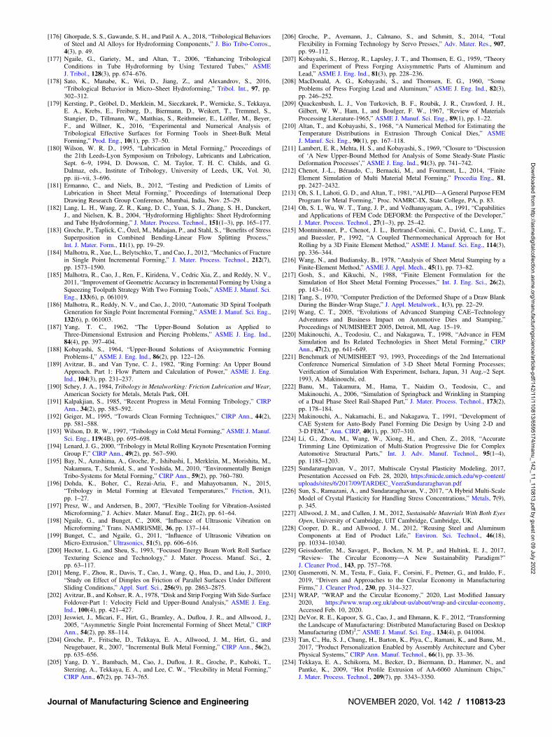
[176] Ghorpade, S. S., Gawande, S. H., and Patil A. A., 2018, “Tribological Behaviorsof Steel and Al Alloys for Hydroforming Components,” J. Bio Tribo-Corros.,4(3), p. 49.
[177] Ngaile, G., Gariety, M., and Altan, T., 2006, “Enhancing TribologicalConditions in Tube Hydroforming by Using Textured Tubes,” ASMEJ. Tribol., 128(3), pp. 674–676.
[178] Sato, K., Manabe, K., Wei, D., Jiang, Z., and Alexandrov, S., 2016,“Tribological Behavior in Micro–Sheet Hydroforming,” Tribol. Int., 97, pp.302–312.
[179] Kersting, P., Gröbel, D., Merklein, M., Sieczkarek, P., Wernicke, S., Tekkaya,E. A., Krebs, E., Freiburg, D., Biermann, D., Weikert, T., Tremmel, S.,Stangier, D., Tillmann, W., Matthias, S., Reithmeier, E., Löffler, M., Beyer,F., and Willner, K., 2016, “Experimental and Numerical Analysis ofTribological Effective Surfaces for Forming Tools in Sheet-Bulk MetalForming,” Prod. Eng., 10(1), pp. 37–50.
[180] Wilson, W. R. D., 1995, “Lubrication in Metal Forming,” Proceedings ofthe 21th Leeds-Lyon Symposium on Tribology, Lubricants and Lubrication,Sept. 6–9, 1994, D. Dowson, C. M. Taylor, T. H. C. Childs, and G.Dalmaz, eds., Institute of Tribology, University of Leeds, UK, Vol. 30,pp. iii–vii, 3–696.
[181] Ermanno, C., and Niels, B., 2012, “Testing and Prediction of Limits ofLubrication in Sheet Metal Forming,” Proceedings of International DeepDrawing Research Group Conference, Mumbai, India, Nov. 25–29.
[182] Lang, L. H., Wang, Z. R., Kang, D. C., Yuan, S. J., Zhang, S. H., Danckert,J., and Nielsen, K. B., 2004, “Hydroforming Highlights: Sheet Hydroformingand Tube Hydroforming,” J. Mater. Process. Technol., 151(1–3), pp. 165–177.
[183] Groche, P., Taplick, C., Özel, M., Mahajan, P., and Stahl, S., “Benefits of StressSuperposition in Combined Bending-Linear Flow Splitting Process,”Int. J. Mater. Form., 11(1), pp. 19–29.
[184] Malhotra, R., Xue, L., Belytschko, T., and Cao, J., 2012, “Mechanics of Fracturein Single Point Incremental Forming,” J. Mater. Process. Technol., 212(7),pp. 1573–1590.
[185] Malhotra, R., Cao, J., Ren, F., Kiridena, V., Cedric Xia, Z., and Reddy, N. V.,2011, “Improvement of Geometric Accuracy in Incremental Forming by Using aSqueezing Toolpath Strategy With Two Forming Tools,” ASME J. Manuf. Sci.Eng., 133(6), p. 061019.
[186] Malhotra, R., Reddy, N. V., and Cao, J., 2010, “Automatic 3D Spiral ToolpathGeneration for Single Point Incremental Forming,” ASME J. Manuf. Sci. Eng.,132(6), p. 061003.
[187] Yang, T. C., 1962, “The Upper-Bound Solution as Applied toThree-Dimensional Extrusion and Piercing Problems,” ASME J. Eng. Ind.,84(4), pp. 397–404.
[188] Kobayashi, S., 1964, “Upper-Bound Solutions of Axisymmetric FormingProblems-I,” ASME J. Eng. Ind., 86(2), pp. 122–126.
[189] Avitzur, B., and Van Tyne, C. J., 1982, “Ring Forming: An Upper BoundApproach. Part 1: Flow Pattern and Calculation of Power,” ASME J. Eng.Ind., 104(3), pp. 231–237.
[190] Schey, J. A., 1984, Tribology in Metalworking: Friction Lubrication and Wear,American Society for Metals, Metals Park, OH.
[191] Kalpakjian, S., 1985, “Recent Progress in Metal Forming Tribology,” CIRPAnn., 34(2), pp. 585–592.
[192] Geiger, M., 1995, “Towards Clean Forming Techniques,” CIRP Ann., 44(2),pp. 581–588.
[193] Wilson, D. R. W., 1997, “Tribology in Cold Metal Forming,” ASME J. Manuf.Sci. Eng., 119(4B), pp. 695–698.
[194] Lenard, J. G., 2000, “Tribology in Metal Rolling Keynote Presentation FormingGroup F,” CIRP Ann., 49(2), pp. 567–590.
[195] Bay, N., Azushima, A., Groche, P., Ishibashi, I., Merklein, M., Morishita, M.,Nakamura, T., Schmid, S., and Yoshida, M., 2010, “Environmentally BenignTribo-Systems for Metal Forming,” CIRP Ann., 59(2), pp. 760–780.
[196] Dohda, K., Boher, C., Rezai-Aria, F., and Mahayotsanun, N., 2015,“Tribology in Metal Forming at Elevated Temperatures,” Friction, 3(1),pp. 1–27.
[197] Presz, W., and Andersen, B., 2007, “Flexible Tooling for Vibration-AssistedMicroforming,” J. Achiev. Mater. Manuf. Eng., 21(2), pp. 61–64.
[198] Ngaile, G., and Bunget, C., 2008, “Influence of Ultrasonic Vibration onMicroforming,” Trans. NAMRI/SME, 36, pp. 137–144.
[199] Bunget, C., and Ngaile, G., 2011, “Influence of Ultrasonic Vibration onMicro-Extrusion,” Ultrasonics, 51(5), pp. 606–616.
[200] Hector, L. G., and Sheu, S., 1993, “Focused Energy Beam Work Roll SurfaceTexturing Science and Technology,” J. Mater. Process. Manuf. Sci., 2,pp. 63–117.
[201] Meng, F., Zhou, R., Davis, T., Cao, J., Wang, Q., Hua, D., and Liu, J., 2010,“Study on Effect of Dimples on Friction of Parallel Surfaces Under DifferentSliding Conditions,” Appl. Surf. Sci., 256(9), pp. 2863–2875.
[202] Avitzur, B., and Kohser, R. A., 1978, “Disk and Strip ForgingWith Side-SurfaceFoldover-Part 1: Velocity Field and Upper-Bound Analysis,” ASME J. Eng.Ind., 100(4), pp. 421–427.
[203] Jeswiet, J., Micari, F., Hirt, G., Bramley, A., Duflou, J. R., and Allwood, J.,2005, “Asymmetric Single Point Incremental Forming of Sheet Metal,” CIRPAnn., 54(2), pp. 88–114.
[204] Groche, P., Fritsche, D., Tekkaya, E. A., Allwood, J. M., Hirt, G., andNeugebauer, R., 2007, “Incremental Bulk Metal Forming,” CIRP Ann., 56(2),pp. 635–656.
[205] Yang, D. Y., Bambach, M., Cao, J., Duflou, J. R., Groche, P., Kuboki, T.,Sterzing, A., Tekkaya, E. A., and Lee, C. W., “Flexibility in Metal Forming,”CIRP Ann., 67(2), pp. 743–765.
[206] Groche, P., Avemann, J., Calmano, S., and Schmitt, S., 2014, “TotalFlexibility in Forming Technology by Servo Presses,” Adv. Mater. Res., 907,pp. 99–112.
[207] Kobayashi, S., Herzog, R., Lapsley, J. T., and Thomsen, E. G., 1959, “Theoryand Experiment of Press Forging Axisymmetric Parts of Aluminum andLead,” ASME J. Eng. Ind., 81(3), pp. 228–236.
[208] MacDonald, A. G., Kobayashi, S., and Thomsen, E. G., 1960, “SomeProblems of Press Forging Lead and Aluminum,” ASME J. Eng. Ind., 82(3),pp. 246–252.
[209] Quackenbush, L. J., Von Turkovich, B. F., Roubik, J. R., Crawford, J. H.,Gilbert, W. W., Ham, I., and Boulger, F. W., 1967, “Review of MaterialsProcessing Literature-1965,” ASME J. Manuf. Sci. Eng., 89(1), pp. 1–22.
[210] Altan, T., and Kobayashi, S., 1968, “A Numerical Method for Estimating theTemperature Distributions in Extrusion Through Conical Dies,” ASMEJ. Manuf. Sci. Eng., 90(1), pp. 167–118.
[211] Lambert, E. R., Mehta, H. S., and Kobayashi, S., 1969, “Closure to “Discussionof ‘A New Upper-Bound Method for Analysis of Some Steady-State PlasticDeformation Processes’,” ASME J. Eng. Ind., 91(3), pp. 741–742.
[212] Chenot, J.-L., Béraudo, C., Bernacki, M., and Fourment, L., 2014, “FiniteElement Simulation of Multi Material Metal Forming,” Procedia Eng., 81,pp. 2427–2432.
[213] Oh, S. I., Lahoti, G. D., and Altan, T., 1981, “ALPID—A General Purpose FEMProgram for Metal Forming,” Proc. NAMRC-IX, State College, PA, p. 83.
[214] Oh, S. I., Wu, W. T., Tang, J. P., and Vedhanayagam, A., 1991, “Capabilitiesand Applications of FEM Code DEFORM: the Perspective of the Developer,”J. Mater. Process. Technol., 27(1–3), pp. 25–42.
[215] Montmitonnet, P., Chenot, J. L., Bertrand-Corsini, C., David, C., Lung, T.,and Buessler, P., 1992, “A Coupled Thermomechanical Approach for HotRolling by a 3D Finite Element Method,” ASME J. Manuf. Sci. Eng., 114(3),pp. 336–344.
[216] Wang, N., and Budiansky, B., 1978, “Analysis of Sheet Metal Stamping by aFinite-Element Method,” ASME J. Appl. Mech., 45(1), pp. 73–82.
[217] Gosh, S., and Kikuchi, N., 1988, “Finite Element Formulation for theSimulation of Hot Sheet Metal Forming Processes,” Int. J. Eng. Sci., 26(2),pp. 143–161.
[218] Tang, S., 1970, “Computer Prediction of the Deformed Shape of a Draw BlankDuring the Binder-Wrap Stage,” J. Appl. Metalwork., 1(3), pp. 22–29.
[219] Wang, C. T., 2005, “Evolutions of Advanced Stamping CAE–TechnologyAdventures and Business Impact on Automotive Dies and Stamping,”Proceedings of NUMISHEET 2005, Detroit, MI, Aug. 15–19.
[220] Makinouchi, A., Teodosiu, C., and Nakagawa, T., 1998, “Advance in FEMSimulation and Its Related Technologies in Sheet Metal Forming,” CIRPAnn., 47(2), pp. 641–649.
[221] Benchmark of NUMISHEET ‘93, 1993, Proceedings of the 2nd InternationalConference Numerical Simulation of 3-D Sheet Metal Forming Processes;Verification of Simulation With Experiment, Isehara, Japan, 31 Aug.–2 Sept.1993, A. Makinouchi, ed.
[222] Banu, M., Takamura, M., Hama, T., Naidim O., Teodosiu, C., andMakinouchi, A., 2006, “Simulation of Springback and Wrinkling in Stampingof a Dual Phase Steel Rail-Shaped Part,” J. Mater. Process. Technol., 173(2),pp. 178–184.
[223] Makinouchi, A., Nakamachi, E., and Nakagawa, T., 1991, “Development ofCAE System for Auto-Body Panel Forming Die Design by Using 2-D and3-D FEM,” Ann. CIRP, 40(1), pp. 307–310.
[224] Li, G., Zhou, M., Wang, W., Xiong, H., and Chen, Z., 2018, “AccurateTrimming Line Optimization of Multi-Station Progressive Die for ComplexAutomotive Structural Parts,” Int. J. Adv. Manuf. Technol., 95(1–4),pp. 1185–1203.
[225] Sundararaghavan, V., 2017, Multiscale Crystal Plasticity Modeling, 2017,Presentation Accessed on Feb. 28, 2020, https://micde.umich.edu/wp-content/uploads/sites/6/2017/09/TARDEC_VeeraSundararaghavan.pdf
[226] Sun, S., Ramazani, A., and Sundararaghavan, V., 2017, “A Hybrid Multi-ScaleModel of Crystal Plasticity for Handling Stress Concentrations,” Metals, 7(9),p. 345.
[227] Allwood, J. M., and Cullen, J. M., 2012, Sustainable Materials With Both EyesOpen, University of Cambridge, UIT Cambridge, Cambridge, UK.
[228] Cooper, D. R., and Allwood, J. M., 2012, “Reusing Steel and AluminumComponents at End of Product Life,” Environ. Sci. Technol., 46(18),pp. 10334–10340.
[229] Geissdoerfer, M., Savaget, P., Bocken, N. M. P., and Hultink, E. J., 2017,“Review- The Circular Economy—A New Sustainability Paradigm?”J. Cleaner Prod., 143, pp. 757–768.
[230] Gusmerotti, N. M., Testa, F., Gaia, F., Corsini, F., Pretner, G., and Iraldo, F.,2019, “Drivers and Approaches to the Circular Economy in ManufacturingFirms,” J. Cleaner Prod., 230, pp. 314–327.
[231] WRAP, “WRAP and the Circular Economy,” 2020, Last Modified January2020, https://www.wrap.org.uk/about-us/about/wrap-and-circular-economy,Accessed Feb. 10, 2020.
[232] DeVor, R. E., Kapoor, S. G., Cao, J., and Ehmann, K. F., 2012, “Transformingthe Landscape of Manufacturing: Distributed Manufacturing Based on DesktopManufacturing (DM)2,” ASME J. Manuf. Sci. Eng., 134(4), p. 041004.
[233] Tan, C., Hu, S. J., Chung, H., Barton, K., Piya, C., Ramani, K., and Banu, M.,2017, “Product Personalization Enabled by Assembly Architecture and CyberPhysical Systems,” CIRP Ann. Manuf. Technol., 66(1), pp. 33–36.
[234] Tekkaya, E. A., Schikorra, M., Becker, D., Biermann, D., Hammer, N., andPantke, K., 2009, “Hot Profile Extrusion of AA-6060 Aluminum Chips,”J. Mater. Process. Technol., 209(7), pp. 3343–3350.
Journal of Manufacturing Science and Engineering NOVEMBER 2020, Vol. 142 / 110813-23
Dow
nloaded from http://asm
edigitalcollection.asme.org/m
anufacturingscience/article-pdf/142/11/110813/6595174/manu_142_11_110813.pdf by guest on 09 July 2022

[235] Chen, C. C., Oh, S. I., and Kobayashi, S., 1979, “Ductile Fracture inAxisymmetric Extrusion and Drawing-Part 1: Deformation Mechanics ofExtrusion and Drawing,” ASME J. Eng. Ind., 101(1), pp. 23–35.
[236] Cao, J., Krishnan, N., Wang, Z., Lu, H., Liu, W. K., and Swanson, A., 2004,“Microforming: Experimental Investigation of the Extrusion Process forMicropins and Its Numerical Simulation Using RKEM,” ASME J. Manuf.Sci. Eng., 126(4), pp. 642–652.
[237] Krishnan, N., Cao, J., and Dohda, K., 2007, “Study of the Size Effect on FrictionConditions in Microextrusion-Part I: Microextrusion Experiments andAnalysis,” ASME J. Manuf. Sci. Eng., 129(4), pp. 669–676.
[238] Yanagimoto, J., Karhausen, K., Brand, A. J., and Kopp, R., 1998, “IncrementalFormulation for the Prediction of Flow Stress and Microstructural Change in HotForming,” ASME J. Manuf. Sci. Eng., 120(2), pp. 316–322.
[239] Kamal, M., and Daehn, G. S., 2007, “A Uniform Pressure ElectromagneticActuator forFormingFlat Sheets,”ASMEJ.Manuf. Sci.Eng.,129(2), pp.369–379.
[240] Kobayashi, S., 1970, “Deformation Characteristics and Ductile Fracture of 1040Steel in Simple Upsetting of Solid Cylinders and Rings,” ASME J. Eng. Ind.,92(2), pp. 391–398.
[241] Benchmark of NUMISHEET’96, 1996, Proceedings of the 3rd InternationalConference on Numerical Simulation of 3D Sheet Forming Processes:Verification of Simulation With Experiments, Dearborn, Michigan, Sept. 29–Oct. 3, 1996, J. K. Lee, G. L. Kinzel, and R. H. Wagoner, eds.
[242] Benchmark of NUMISHEET’05, 2005, Proceedings of the 6th InternationalConference and Workshop on Numerical Simulation of 3D Sheet MetalForming Process, M. Lorenzo, ed.
[243] Benchmark of NUMISHEET 2016, 2006, Proceedings of the 10th InternationalConference and Workshop on Numerical Simulation of 3D Sheet Metal FormingProcesses, Journal of Physics: Conference Series, Vol. 734.
[244] Schmid, K., and Jason Coryell, J., 2017, “Stamping Assessment of Various 980and 1180 MPa Steel Grades,” Paper and Presentation at the InternationalAutomotive Body Congress, Frankfurt, Germany, Am Buesing Palais, June13–14.
[245] Lechner, M., Schulte, R., and Merklein, M., 2019, “Augmented Reality forForming Technology—Visualisation of Simulation,” Proceedings ofNUMISHEET 2018, IOP Conf. Series: Materials Science and Engineering,Tokyo, Japan, July 30–Aug. 3, 2018, Vol. 651, p. 012045.
110813-24 / Vol. 142, NOVEMBER 2020 Transactions of the ASME
Dow
nloaded from http://asm
edigitalcollection.asme.org/m
anufacturingscience/article-pdf/142/11/110813/6595174/manu_142_11_110813.pdf by guest on 09 July 2022
Copyright © 2022 FDOKUMEN