
Virtual processing – application of rapid prototyping for visualization of metal forming processes
9
Virtual processing – application of rapid prototyping for visualization of metal forming processes Suwat Jirathearanat * , Victor Vazquez, Ciro A. Rodrı ´guez, Taylan Altan ERC for Net Shape Manufacturing, The Ohio State University, Columbus, OH 43210, USA Abstract The objective of the study was to build physical models (prototypes) of a product based on finite element (FE) process simulations to aid product engineering in the evaluation of the manufacturing ability of the product. A methodology and two computer programs were developed to translate the FE geometrical information into a geometric representation acceptable by most rapid prototyping (RP) systems. In the case of the ERC/NSM, the prototypes are built with a fused deposition modeling (FDM) machine. This report has been focused in the production of physical models based on the FE simulation results for sheet and billet forming processes. However, the programs can be used with other process simulations as well. # 2000 Published by Elsevier Science S.A. All rights reserved. Keywords: Virtual processing; Prototyping; Sheet metal forming processes; Forging process 1. Introduction During the last decade, process modeling has been accepted as a powerful tool in the metal forming processes. FE simulations are used to verify parameters of the forming process, such as stress and strain distributions in a formed part. This could be done for various steps of the deformation sequence. This method may help the engineers to ensure a successful forming process before expensive tooling is manufactured. Different steps of the forming sequence can be observed as a result of FE process simulation. However, visualization of the intermediate forming steps is difficult due to the complexity of most industrial products. As an alternative, physical models of formed metal parts from FE process simulations can assist in visualizing the formability of the parts. Being able to physically handle the formed parts is more desirable and eases the understanding of the simulation results [1]. Recently, the methods to generate physical models by RP technology have been drastically improved. Models can be prototyped accurately and directly from 3D solid models in a highly automated fashion. Integrating RP technology and the process simulations performed in the die design process could reduce lead time in die design and manufacturing process. To achieve this objective it is necessary to manu- facture solid models of the finite element meshes that are the results of process simulations. 1.1. Previous work on virtual processing Virtual processing is a process of generating physical models of intermediate steps of metal forming process FE simulations. Literature review on the virtual processing showed only one study that applied RP technology in virtual processing of metal forming process FE simulation [1]. First, the authors obtained the geometric information of sheet metal FE mesh from FE simulation results. Second, they converted it into a geometric representation acceptable by RP systems. Finally, the data was fed into a laser stereolithography system for prototyping the formed parts. 1.2. Objective The objective of the present work was to apply RP technology to reduce lead time in the development of manufacturing processes, focusing mainly on forging and sheet metal forming. Two conversion programs were designed and developed at the ERC/NSM the Ohio State University: FEMSTL [2] and PAMSTL [3]. FEMSTL works with geometric data created either in I-DEAS or DEFORM. I-DEAS is a commercial CAD program that has capabilities to simulate structural process and DEFORM is a commercial program used mainly for the simulation of bulk forming * Corresponding author. Journal of Materials Processing Technology 98 (2000) 116–124 0924-0136/00/$ – see front matter # 2000 Published by Elsevier Science S.A. All rights reserved. PII:S0924-0136(99)00312-X
-
Upload
independent -
Category
Documents
-
view
1 -
download
0
Transcript of Virtual processing – application of rapid prototyping for visualization of metal forming processes
Virtual processing ± application of rapid prototyping forvisualization of metal forming processes
Suwat Jirathearanat*, Victor Vazquez, Ciro A. RodrõÂguez, Taylan Altan
ERC for Net Shape Manufacturing, The Ohio State University, Columbus, OH 43210, USA
Abstract
The objective of the study was to build physical models (prototypes) of a product based on ®nite element (FE) process simulations to aid
product engineering in the evaluation of the manufacturing ability of the product. A methodology and two computer programs were
developed to translate the FE geometrical information into a geometric representation acceptable by most rapid prototyping (RP) systems.
In the case of the ERC/NSM, the prototypes are built with a fused deposition modeling (FDM) machine. This report has been focused in the
production of physical models based on the FE simulation results for sheet and billet forming processes. However, the programs can be used
with other process simulations as well. # 2000 Published by Elsevier Science S.A. All rights reserved.
Keywords: Virtual processing; Prototyping; Sheet metal forming processes; Forging process
1. Introduction
During the last decade, process modeling has been
accepted as a powerful tool in the metal forming processes.
FE simulations are used to verify parameters of the forming
process, such as stress and strain distributions in a formed
part. This could be done for various steps of the deformation
sequence. This method may help the engineers to ensure a
successful forming process before expensive tooling is
manufactured. Different steps of the forming sequence
can be observed as a result of FE process simulation.
However, visualization of the intermediate forming steps
is dif®cult due to the complexity of most industrial products.
As an alternative, physical models of formed metal parts
from FE process simulations can assist in visualizing the
formability of the parts. Being able to physically handle the
formed parts is more desirable and eases the understanding
of the simulation results [1].
Recently, the methods to generate physical models by RP
technology have been drastically improved. Models can be
prototyped accurately and directly from 3D solid models in a
highly automated fashion. Integrating RP technology and
the process simulations performed in the die design process
could reduce lead time in die design and manufacturing
process. To achieve this objective it is necessary to manu-
facture solid models of the ®nite element meshes that are the
results of process simulations.
1.1. Previous work on virtual processing
Virtual processing is a process of generating physical
models of intermediate steps of metal forming process FE
simulations. Literature review on the virtual processing
showed only one study that applied RP technology in virtual
processing of metal forming process FE simulation [1].
First, the authors obtained the geometric information of
sheet metal FE mesh from FE simulation results. Second,
they converted it into a geometric representation acceptable
by RP systems. Finally, the data was fed into a laser
stereolithography system for prototyping the formed parts.
1.2. Objective
The objective of the present work was to apply RP
technology to reduce lead time in the development of
manufacturing processes, focusing mainly on forging and
sheet metal forming. Two conversion programs were
designed and developed at the ERC/NSM the Ohio State
University: FEMSTL [2] and PAMSTL [3]. FEMSTL works
with geometric data created either in I-DEAS or DEFORM.
I-DEAS is a commercial CAD program that has capabilities
to simulate structural process and DEFORM is a commercial
program used mainly for the simulation of bulk forming* Corresponding author.
Journal of Materials Processing Technology 98 (2000) 116±124
0924-0136/00/$ ± see front matter # 2000 Published by Elsevier Science S.A. All rights reserved.
PII: S 0 9 2 4 - 0 1 3 6 ( 9 9 ) 0 0 3 1 2 - X
processes. PAMSTL works with geometric data of a shell FE
mesh from PAMSTAMP. This is commercial FE simulation
software for the simulations of the sheet metal forming
processes. Both FEMSTL and PAMSTL convert the FE
mesh data into STL representation, which is the standard
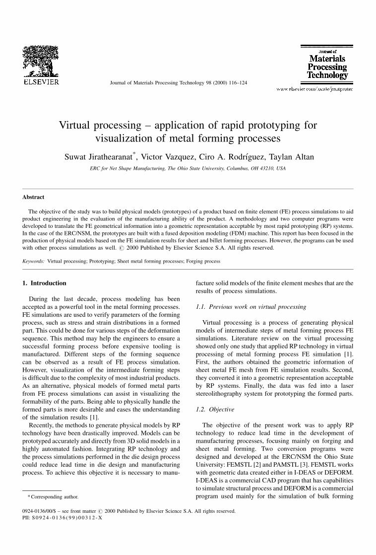
input format for RP systems. Fused deposition modeling
(FDM) system (see Fig. 1) is used to fabricate the virtually
processed parts.
1.3. Fused deposition modeling system
The FDM system builds parts from plastics such as ABS,
nylon and investment casting wax. The material ®lament is
fed into the head (extruder) where the material is lique®ed
with a temperature just above its melting point. The semi-
liquid plastic is then deposited onto the base to make the ®rst
layer of the part. Then, the platform moves down a distance
of one layer thickness for the construction of the next layer.
The temperature of the previous layer has to be maintained
just below the melting point of the material for good
adhesion with the next layer. The successive layers are built
in the same way until the entire part is completed.
2. Process simulations for sheet metal forming andforging operations
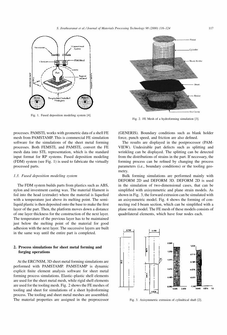
At the ERC/NSM, 3D sheet metal forming simulations are
performed with PAMSTAMP. PAMSTAMP is dynamic
explicit ®nite element analysis software for sheet metal
forming process simulations. Elastic±plastic shell elements
are used for the sheet metal mesh, while rigid shell elements
are used for the tooling mesh. Fig. 2 shows the FE meshes of
tooling and sheet for simulations of a sheet hydroforming
process. The tooling and sheet metal meshes are assembled.
The material properties are assigned in the preprocessor
(GENERIS). Boundary conditions such as blank holder
force, punch speed, and friction are also de®ned.
The results are displayed in the postprocessor (PAM-
VIEW). Undesirable part defects such as splitting and
wrinkling can be displayed. The splitting can be detected
from the distributions of strains in the part. If necessary, the
forming process can be re®ned by changing the process
parameters (i.e., boundary conditions) or the tooling geo-
metry.
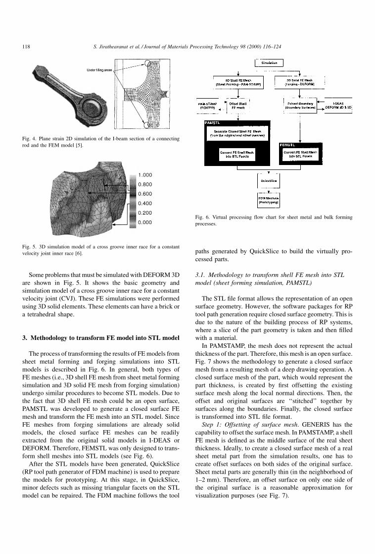
Bulk forming simulations are performed mainly with
DEFORM 2D and DEFORM 3D. DEFORM 2D is used
in the simulation of two-dimensional cases, that can be
simpli®ed with axisymmetric and plane strain models. As
shown in Fig. 3, the forward extrusion can be simulated with
an axisymmetric model. Fig. 4 shows the forming of con-
necting rod I-beam section, which can be simpli®ed with a
plane strain model. The FE mesh of these models consists of
quadrilateral elements, which have four nodes each.
Fig. 1. Fused deposition modeling system [4].Fig. 2. FE Mesh of a hydroforming simulation [3].
Fig. 3. Axisymmetric extrusion of cylindrical shaft [2].
S. Jirathearanat et al. / Journal of Materials Processing Technology 98 (2000) 116±124 117
Some problems that must be simulated with DEFORM 3D
are shown in Fig. 5. It shows the basic geometry and
simulation model of a cross groove inner race for a constant
velocity joint (CVJ). These FE simulations were performed
using 3D solid elements. These elements can have a brick or
a tetrahedral shape.
3. Methodology to transform FE model into STL model
The process of transforming the results of FE models from
sheet metal forming and forging simulations into STL
models is described in Fig. 6. In general, both types of
FE meshes (i.e., 3D shell FE mesh from sheet metal forming
simulation and 3D solid FE mesh from forging simulation)
undergo similar procedures to become STL models. Due to
the fact that 3D shell FE mesh could be an open surface,
PAMSTL was developed to generate a closed surface FE
mesh and transform the FE mesh into an STL model. Since
FE meshes from forging simulations are already solid
models, the closed surface FE meshes can be readily
extracted from the original solid models in I-DEAS or
DEFORM. Therefore, FEMSTL was only designed to trans-
form shell meshes into STL models (see Fig. 6).
After the STL models have been generated, QuickSlice
(RP tool path generator of FDM machine) is used to prepare
the models for prototyping. At this stage, in QuickSlice,
minor defects such as missing triangular facets on the STL
model can be repaired. The FDM machine follows the tool
paths generated by QuickSlice to build the virtually pro-
cessed parts.
3.1. Methodology to transform shell FE mesh into STL
model (sheet forming simulation, PAMSTL)
The STL ®le format allows the representation of an open
surface geometry. However, the software packages for RP
tool path generation require closed surface geometry. This is
due to the nature of the building process of RP systems,
where a slice of the part geometry is taken and then ®lled
with a material.
In PAMSTAMP, the mesh does not represent the actual
thickness of the part. Therefore, this mesh is an open surface.
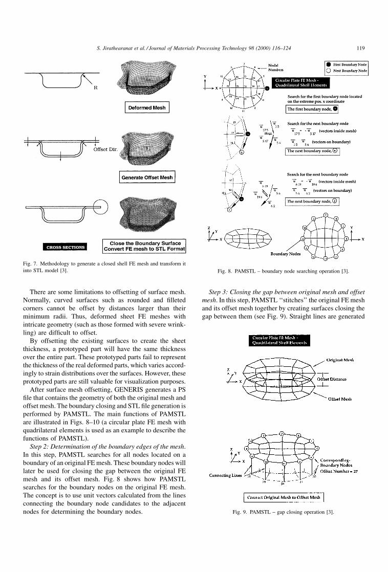
Fig. 7 shows the methodology to generate a closed surface
mesh from a resulting mesh of a deep drawing operation. A
closed surface mesh of the part, which would represent the
part thickness, is created by ®rst offsetting the existing
surface mesh along the local normal directions. Then, the
offset and original surfaces are `̀ stitched'' together by
surfaces along the boundaries. Finally, the closed surface
is transformed into STL ®le format.
Step 1: Offsetting of surface mesh. GENERIS has the
capability to offset the surface mesh. In PAMSTAMP, a shell
FE mesh is de®ned as the middle surface of the real sheet
thickness. Ideally, to create a closed surface mesh of a real
sheet metal part from the simulation results, one has to
create offset surfaces on both sides of the original surface.
Sheet metal parts are generally thin (in the neighborhood of
1±2 mm). Therefore, an offset surface on only one side of
the original surface is a reasonable approximation for
visualization purposes (see Fig. 7).
Fig. 4. Plane strain 2D simulation of the I-beam section of a connecting
rod and the FEM model [5].
Fig. 5. 3D simulation model of a cross groove inner race for a constant
velocity joint inner race [6].
Fig. 6. Virtual processing flow chart for sheet metal and bulk forming
processes.
118 S. Jirathearanat et al. / Journal of Materials Processing Technology 98 (2000) 116±124
There are some limitations to offsetting of surface mesh.
Normally, curved surfaces such as rounded and ®lleted
corners cannot be offset by distances larger than their
minimum radii. Thus, deformed sheet FE meshes with
intricate geometry (such as those formed with severe wrink-
ling) are dif®cult to offset.
By offsetting the existing surfaces to create the sheet
thickness, a prototyped part will have the same thickness
over the entire part. These prototyped parts fail to represent
the thickness of the real deformed parts, which varies accord-
ingly to strain distributions over the surfaces. However, these
prototyped parts are still valuable for visualization purposes.
After surface mesh offsetting, GENERIS generates a PS
®le that contains the geometry of both the original mesh and
offset mesh. The boundary closing and STL ®le generation is
performed by PAMSTL. The main functions of PAMSTL
are illustrated in Figs. 8±10 (a circular plate FE mesh with
quadrilateral elements is used as an example to describe the
functions of PAMSTL).
Step 2: Determination of the boundary edges of the mesh.
In this step, PAMSTL searches for all nodes located on a
boundary of an original FE mesh. These boundary nodes will
later be used for closing the gap between the original FE
mesh and its offset mesh. Fig. 8 shows how PAMSTL
searches for the boundary nodes on the original FE mesh.
The concept is to use unit vectors calculated from the lines
connecting the boundary node candidates to the adjacent
nodes for determining the boundary nodes.
Step 3: Closing the gap between original mesh and offset
mesh. In this step, PAMSTL `̀ stitches'' the original FE mesh
and its offset mesh together by creating surfaces closing the
gap between them (see Fig. 9). Straight lines are generated
Fig. 7. Methodology to generate a closed shell FE mesh and transform it
into STL model [3]. Fig. 8. PAMSTL ± boundary node searching operation [3].
Fig. 9. PAMSTL ± gap closing operation [3].
S. Jirathearanat et al. / Journal of Materials Processing Technology 98 (2000) 116±124 119

to connect corresponding boundary nodes between the
original mesh and the offset mesh. The nodal numbers of
the offset mesh are always offset by a certain number, such
as the total number of the nodes on the original mesh.
Step 4: Converting FE mesh into STL representation. In
this step, PAMSTL converts the original mesh, the offset
mesh and the closing surfaces into STL format. In the
meshes, every element (quadrilateral shell element) is bro-
ken into two triangular facets and written into the equivalent
STL facets. Fig. 10 shows the conversion of FE mesh into
STL representation.
Accuracy issues. STL ®les converted from FE mesh have
some accuracy related drawbacks in de®ning their solid
models. The ®rst reduction of accuracy is caused by the
nature of meshing process (discretization) itself. Discretiza-
tion process is a process of breaking a solid model into a
number of very small elements. Therefore, it is always an
approximation, where the accuracy of the model depends on
the sizes of the elements used.
Transformation of the deformed FE mesh into STL format
using PAMSTL further reduces the accuracy. This is because
a quadrilateral shell element would not remain planar once
deformed. Consequently, splitting the quadrilateral element
might generate two triangular facets on different planes.
This results in faceted appearance. One way to improve the
accuracy and the faceted surface effect is using very small
elements in the discretization process of the FE simulation.
This could also be accomplished by remeshing the part at the
®nal forming step, thus avoiding the penalty in calculation
time caused by using a large number of elements.
3.2. Methodology to transform solid FE model into STL
model (forging simulation, FEMSTL)
In general, the outer surface of a 3D FE mesh could have
either quadrilateral or triangular facets. These facets can be
considered as the units that form the surfaces of a solid
model in the STL format. The surface boundary is extracted
from a model consisting of either tetrahedral or brick
elements, the result is a closed shell FE mesh. This is formed
by triangular or quadrilateral facets, respectively. If the
triangular facets are obtained, the normals can be calculated
for each facet and the STL ®le can be written using this
information. If the quadrilateral facets were extracted from
the solid, each of the rectangular facets have to be divided
into two triangular facets and also the normal of each facet
should be calculated to write the STL ®le. FEMSTL was
developed to transform the FE meshes with both triangular
elements and quadrilateral elements into STL models.
4. Applications of virtual processing
PAMSTL was designed to transform a shell FE mesh into
four different shapes in STL representation mainly based on
the quality of the sheet FE mesh, see Fig. 11. The sheet
surface option is suitable for FE meshes with relatively
simple geometry so that successful offset for the meshes
can be generated. The die surface option is suitable when the
successful offset mesh cannot be created, especially in the
case of intricate FE meshes. The open surface option should
be used to transform troublesome sheet FE meshes (i.e.,
sheet FE meshes with missing elements) into STL format.
Then, it can be repaired and processed for prototyping with
QuickSlice, FDM front-end software. The following exam-
ples are the applications of some of the different outputs
from PAMSTL in sheet metal forming. Some application
examples of FEMSTL in forging operations are presented as
well.
Fig. 10. PAMSTL ± operation to convert FE mesh to STL representation
[3].
Fig. 11. PAMSTL ± inputs and outputs [3].
120 S. Jirathearanat et al. / Journal of Materials Processing Technology 98 (2000) 116±124
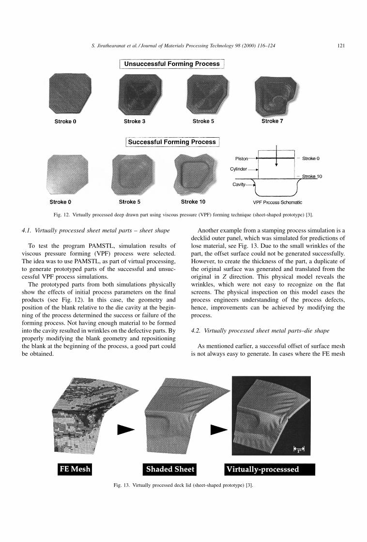
4.1. Virtually processed sheet metal parts ± sheet shape
To test the program PAMSTL, simulation results of
viscous pressure forming (VPF) process were selected.
The idea was to use PAMSTL, as part of virtual processing,
to generate prototyped parts of the successful and unsuc-
cessful VPF process simulations.
The prototyped parts from both simulations physically
show the effects of initial process parameters on the ®nal
products (see Fig. 12). In this case, the geometry and
position of the blank relative to the die cavity at the begin-
ning of the process determined the success or failure of the
forming process. Not having enough material to be formed
into the cavity resulted in wrinkles on the defective parts. By
properly modifying the blank geometry and repositioning
the blank at the beginning of the process, a good part could
be obtained.
Another example from a stamping process simulation is a
decklid outer panel, which was simulated for predictions of
lose material, see Fig. 13. Due to the small wrinkles of the
part, the offset surface could not be generated successfully.
However, to create the thickness of the part, a duplicate of
the original surface was generated and translated from the
original in Z direction. This physical model reveals the
wrinkles, which were not easy to recognize on the ¯at
screens. The physical inspection on this model eases the
process engineers understanding of the process defects,
hence, improvements can be achieved by modifying the
process.
4.2. Virtually processed sheet metal parts±die shape
As mentioned earlier, a successful offset of surface mesh
is not always easy to generate. In cases where the FE mesh
Fig. 12. Virtually processed deep drawn part using viscous pressure (VPF) forming technique (sheet-shaped prototype) [3].
Fig. 13. Virtually processed deck lid (sheet-shaped prototype) [3].
S. Jirathearanat et al. / Journal of Materials Processing Technology 98 (2000) 116±124 121
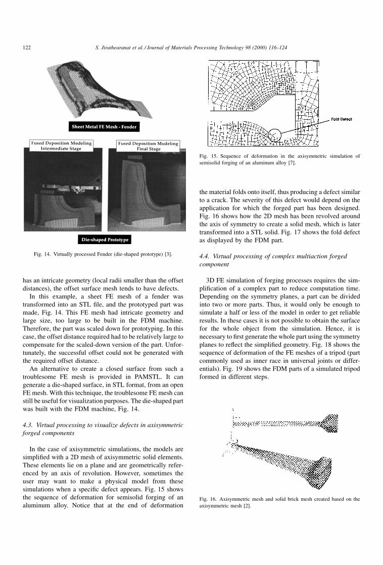
has an intricate geometry (local radii smaller than the offset
distances), the offset surface mesh tends to have defects.
In this example, a sheet FE mesh of a fender was
transformed into an STL ®le, and the prototyped part was
made, Fig. 14. This FE mesh had intricate geometry and
large size, too large to be built in the FDM machine.
Therefore, the part was scaled down for prototyping. In this
case, the offset distance required had to be relatively large to
compensate for the scaled-down version of the part. Unfor-
tunately, the successful offset could not be generated with
the required offset distance.
An alternative to create a closed surface from such a
troublesome FE mesh is provided in PAMSTL. It can
generate a die-shaped surface, in STL format, from an open
FE mesh. With this technique, the troublesome FE mesh can
still be useful for visualization purposes. The die-shaped part
was built with the FDM machine, Fig. 14.
4.3. Virtual processing to visualize defects in axisymmetric
forged components
In the case of axisymmetric simulations, the models are
simpli®ed with a 2D mesh of axisymmetric solid elements.
These elements lie on a plane and are geometrically refer-
enced by an axis of revolution. However, sometimes the
user may want to make a physical model from these
simulations when a speci®c defect appears. Fig. 15 shows
the sequence of deformation for semisolid forging of an
aluminum alloy. Notice that at the end of deformation
the material folds onto itself, thus producing a defect similar
to a crack. The severity of this defect would depend on the
application for which the forged part has been designed.
Fig. 16 shows how the 2D mesh has been revolved around
the axis of symmetry to create a solid mesh, which is later
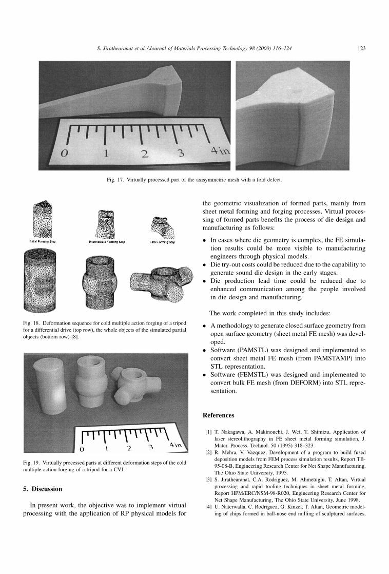
transformed into a STL solid. Fig. 17 shows the fold defect
as displayed by the FDM part.
4.4. Virtual processing of complex multiaction forged
component
3D FE simulation of forging processes requires the sim-
pli®cation of a complex part to reduce computation time.
Depending on the symmetry planes, a part can be divided
into two or more parts. Thus, it would only be enough to
simulate a half or less of the model in order to get reliable
results. In these cases it is not possible to obtain the surface
for the whole object from the simulation. Hence, it is
necessary to ®rst generate the whole part using the symmetry
planes to re¯ect the simpli®ed geometry. Fig. 18 shows the
sequence of deformation of the FE meshes of a tripod (part
commonly used as inner race in universal joints or differ-
entials). Fig. 19 shows the FDM parts of a simulated tripod
formed in different steps.
Fig. 14. Virtually processed Fender (die-shaped prototype) [3].
Fig. 15. Sequence of deformation in the axisymmetric simulation of
semisolid forging of an aluminum alloy [7].
Fig. 16. Axisymmetric mesh and solid brick mesh created based on the
axisymmetric mesh [2].
122 S. Jirathearanat et al. / Journal of Materials Processing Technology 98 (2000) 116±124
5. Discussion
In present work, the objective was to implement virtual
processing with the application of RP physical models for
the geometric visualization of formed parts, mainly from
sheet metal forming and forging processes. Virtual proces-
sing of formed parts bene®ts the process of die design and
manufacturing as follows:
� In cases where die geometry is complex, the FE simula-
tion results could be more visible to manufacturing
engineers through physical models.
� Die try-out costs could be reduced due to the capability to
generate sound die design in the early stages.
� Die production lead time could be reduced due to
enhanced communication among the people involved
in die design and manufacturing.
The work completed in this study includes:
� A methodology to generate closed surface geometry from
open surface geometry (sheet metal FE mesh) was devel-
oped.
� Software (PAMSTL) was designed and implemented to
convert sheet metal FE mesh (from PAMSTAMP) into
STL representation.
� Software (FEMSTL) was designed and implemented to
convert bulk FE mesh (from DEFORM) into STL repre-
sentation.
References
[1] T. Nakagawa, A. Makinouchi, J. Wei, T. Shimizu, Application of
laser stereolithography in FE sheet metal forming simulation, J.
Mater. Process. Technol. 50 (1995) 318±323.
[2] R. Mehra, V. Vazquez, Development of a program to build fused
deposition models from FEM process simulation results, Report TB-
95-08-B, Engineering Research Center for Net Shape Manufacturing,
The Ohio State University, 1995.
[3] S. Jirathearanat, C.A. Rodriguez, M. Ahmetuglu, T. Altan, Virtual
processing and rapid tooling techniques in sheet metal forming,
Report HPM/ERC/NSM-98-R020, Engineering Research Center for
Net Shape Manufacturing, The Ohio State University, June 1998.
[4] U. Naterwalla, C. Rodriguez, G. Kinzel, T. Altan, Geometric model-
ing of chips formed in ball-nose end milling of sculptured surfaces,
Fig. 17. Virtually processed part of the axisymmetric mesh with a fold defect.
Fig. 18. Deformation sequence for cold multiple action forging of a tripod
for a differential drive (top row), the whole objects of the simulated partial
objects (bottom row) [8].
Fig. 19. Virtually processed parts at different deformation steps of the cold
multiple action forging of a tripod for a CVJ.
S. Jirathearanat et al. / Journal of Materials Processing Technology 98 (2000) 116±124 123

Report ERC/NSM-D-96-08, Engineering Research Center for Net
Shape Manufacturing, The Ohio State University, March 1996.
[5] V. Vazquez, T. Altan, Die design for flashless forging of complex
parts, J. Mater. Process. Technol. 98 (2000) 81±89.
[6] V. Vazquez, K. Sweeney, D. Wallace, C. Wolff, M. Ober, T. Altan,
Tooling and process design to cold forge a cross groove inner race for
a constant velocity joint-physical modeling and FEM process
simulation, J. Mater. Process. Technol. 59 (1996) 144±157.
[7] M. Koc, V. Vazquez, T. Witulski, T. Altan, Application of the finite
element method to predict material flow and defects in the semi-solid
forging of A356 aluminium alloys, J. Mater. Process. Technol. 59
(1996) 106±112.
[8] J.A. Pale, R. Shivpuri, T. Altan, Recent developments in tooling,
machines and research in cold forming of complex parts, J. Mater.
Process. Technol. 33 (1992) 1±29.
124 S. Jirathearanat et al. / Journal of Materials Processing Technology 98 (2000) 116±124