Extrusion Based Rapid Prototyping Technique An Advanced Platform
11
M. Enamul Hoque, Y. Leng Chuan, Ian Pashby Department of Mechanical, Materials and Manufacturing Engineering, University of Nottingham Malaysia Campus, Jalan Broga, 43500 Semenyih, Selangor Darul Ehsan, Malaysia Received 14 January 2011; revised 27 May 2011; accepted 23 June 2011 Published online 9 August 2011 in Wiley Online Library (wileyonlinelibrary.com). DOI 10.1002/bip.21701 This article was originally published online as an accepted preprint. The ‘‘Published Online’’ date corresponds to the preprint version. You can request a copy of the preprint by emailing the Biopolymers editorial office at biopolymers@wiley. com INTRODUCTION Tissue Engineering T issue Engineering (TE) is an interdisciplinary field that brings together the principles of life sciences, medicine, and engineering. 1–6 TE is concerned with the technology that develops artificial tissue/organ for the improvement or replacement of lost or dam- aged human tissue/organ. 7 This technology makes physiolog- ical replacement of impaired tissues or organs to patients, which restores, maintains, or improves the functions of dam- aged tissues. 1 The implantation of engineered biological sub- stitute should be functional at the time of implantation or integrate and form functional tissues at a later stage. 6 For scaffold-based therapy, TE treatment approach have been investigated for the reconstruction of large bone defects: cells are taken from the patient or a donor, cultured in vitro and seeded in a scaffold. The cell-construct is then implanted in the defect with the aim to stimulate new bone formation, Review Extrusion Based Rapid Prototyping Technique: An Advanced Platform for Tissue Engineering Scaffold Fabrication Correspondence to: M. Enamul Hoque; e-mail: Enamul.Hoque@nottingham. edu.my ABSTRACT: Advances in scaffold design and fabrication technology have brought the tissue engineering field stepping into a new era. Conventional techniques used to develop scaffolds inherit limitations, such as lack of control over the pore morphology and architecture as well as reproducibility. Rapid prototyping (RP) technology, a layer-by-layer additive approach offers a unique opportunity to build complex 3D architectures overcoming those limitations that could ultimately be tailored to cater for patient-specific applications. Using RP methods, researchers have been able to customize scaffolds to mimic the biomechanical properties (in terms of structural integrity, strength, and microenvironment) of the organ or tissue to be repaired/replaced quite closely. This article provides intensive description on various extrusion based scaffold fabrication techniques and review their potential utility for TE applications. The extrusion-based technique extrudes the molten polymer as a thin filament through a nozzle onto a platform layer- by-layer and thus building 3D scaffold. The technique allows full control over pore architecture and dimension in the x- and y- planes. However, the pore height in z- direction is predetermined by the extruding nozzle diameter rather than the technique itself. This review attempts to assess the current state and future prospects of this technology. # 2011 Wiley Periodicals, Inc. Biopolymers 97: 83–93, 2012. Keywords: polymer; rapid prototyping; layer-by-layer; scaffolds; tissue engineering V V C 2011 Wiley Periodicals, Inc. Biopolymers Volume 97 / Number 2 83
-
Upload
nottingham-my -
Category
Documents
-
view
3 -
download
0
Transcript of Extrusion Based Rapid Prototyping Technique An Advanced Platform

Extrusion Based Rapid Prototyping Technique: An Advanced Platform forTissue Engineering Scaffold Fabrication
M. Enamul Hoque, Y. Leng Chuan, Ian PashbyDepartment of Mechanical, Materials and Manufacturing Engineering, University of Nottingham Malaysia Campus,
Jalan Broga, 43500 Semenyih, Selangor Darul Ehsan, Malaysia
Received 14 January 2011; revised 27 May 2011; accepted 23 June 2011
Published online 9 August 2011 in Wiley Online Library (wileyonlinelibrary.com). DOI 10.1002/bip.21701
This article was originally published online as an accepted
preprint. The ‘‘Published Online’’ date corresponds to the
preprint version. You can request a copy of the preprint by
emailing the Biopolymers editorial office at biopolymers@wiley.
com
INTRODUCTION
Tissue Engineering
Tissue Engineering (TE) is an interdisciplinary field
that brings together the principles of life sciences,
medicine, and engineering.1–6 TE is concerned with
the technology that develops artificial tissue/organ
for the improvement or replacement of lost or dam-
aged human tissue/organ.7 This technology makes physiolog-
ical replacement of impaired tissues or organs to patients,
which restores, maintains, or improves the functions of dam-
aged tissues.1 The implantation of engineered biological sub-
stitute should be functional at the time of implantation or
integrate and form functional tissues at a later stage.6
For scaffold-based therapy, TE treatment approach have
been investigated for the reconstruction of large bone defects:
cells are taken from the patient or a donor, cultured in vitro
and seeded in a scaffold. The cell-construct is then implanted
in the defect with the aim to stimulate new bone formation,
ReviewExtrusion Based Rapid Prototyping Technique: An Advanced Platformfor Tissue Engineering Scaffold Fabrication
Correspondence to: M. Enamul Hoque; e-mail: Enamul.Hoque@nottingham.
edu.my
ABSTRACT:
Advances in scaffold design and fabrication technology
have brought the tissue engineering field stepping into a
new era. Conventional techniques used to develop
scaffolds inherit limitations, such as lack of control over
the pore morphology and architecture as well as
reproducibility. Rapid prototyping (RP) technology, a
layer-by-layer additive approach offers a unique
opportunity to build complex 3D architectures
overcoming those limitations that could ultimately be
tailored to cater for patient-specific applications. Using
RP methods, researchers have been able to customize
scaffolds to mimic the biomechanical properties (in terms
of structural integrity, strength, and microenvironment)
of the organ or tissue to be repaired/replaced quite closely.
This article provides intensive description on various
extrusion based scaffold fabrication techniques and
review their potential utility for TE applications. The
extrusion-based technique extrudes the molten polymer
as a thin filament through a nozzle onto a platform layer-
by-layer and thus building 3D scaffold. The technique
allows full control over pore architecture and dimension
in the x- and y- planes. However, the pore height in z-
direction is predetermined by the extruding nozzle
diameter rather than the technique itself. This review
attempts to assess the current state and future prospects of
this technology. # 2011 Wiley Periodicals, Inc.
Biopolymers 97: 83–93, 2012.
Keywords: polymer; rapid prototyping; layer-by-layer;
scaffolds; tissue engineering
VVC 2011 Wiley Periodicals, Inc.
Biopolymers Volume 97 / Number 2 83
thereby repairing the defect. This approach holds promises not
only for bone tissue but also for other organs and tissues.8
The latest TE technology combines cells, scaffolds, and
signaling substances to both physically and biologically
regenerate tissue.8,9 Further research, development, and inte-
gration of tools allow precise and reproducible fabrication of
scaffolds, and also quantitative characterization of the bio-
logical integration of the tissue engineered constructs.10
Results are in substantial progress in the development of
increasingly complex tissue engineered constructs.
TE SCAFFOLDScaffold is a porous structure that assumes the role of a syn-
thetic extracellular matrix (ECM), which permits cell adhe-
sion, proliferation, and differentiation for surgical implanta-
tions.9,11 Fabricated scaffold should mimic the biomechani-
cal properties of the organ or tissue to be replaced.
Therefore, the scaffold should essentially be three-dimen-
sional (3D) to facilitate cell attachment, growth, and neotis-
sue formation.12 Besides, the scaffold being is a suitable car-
rier structure needs to be combined with the cell to hasten
the healing process of damaged tissues.13
Due to all these requirements, there is always a great chal-
lenge associated with the modeling, design, and fabrication of
TE scaffolds to meet various biological and biophysical condi-
tions, for example, designing load bearing scaffolds for bone
and cartilage tissue applications.12,14 Bone and cartilage tissue
scaffolds usually require complex architecture in terms of pore
shape, size, and interconnectivity to provide the needed struc-
tural integrity, strength, transport, and an ideal microenviron-
ment for the growth of cells and tissues in growth.15
So far, limited or even no systematic study has been con-
ducted to assess whether the exact match of mechanical prop-
erties is indeed crucial for optimal tissue regeneration.16 For
instance, since mechanical properties are directly related to the
porosity of porous structures, a stiffer and less porous scaffold
will provide a better integration with the surrounding natural
tissue, or a more deformable and porous one will allow cells to
attach and proliferate in a more efficient way.17 Different TE
applications pose different challenges in the development of
suitable scaffold, for example skin, bone, and cartilage tissues.
Conventionally fabricated scaffolds may not be ideal for skin
TE, because they do not provide the optimal environment for
cell adherence, proliferation, and multiplication.18 Nevertheless,
bone tissue has the capability of self healing/reconstruction
upon injury to some extent. However, when the defect is crit-
ically large it usually remains unhealed, and requires an ideal fil-
ler, such as cadaver bone, coral, hydroxyapatite, or similar min-
eral compound, which consists of tailored structural and me-
chanical properties.19 Likewise, cartilage has poor cell density
and lacks in vascularization therefore, it becomes difficult to de-
velop suitable scaffolds meeting the requirements for cartilage
TE. Scaffolds should also provide mechanical support besides
introducing stimuli to the cells, allowing them to behave as if
they are in their natural in vivo native environment.
SCAFFOLD MATERIALSThere is a broad list of materials that have been currently
used in the fabrication of TE scaffolds. The selection of mate-
rial used in the manufacturing of a TE scaffold depends on
numerous factors including intended application and, scaf-
fold processing technique to be employed.20,21 Materials for
TE scaffolds must be naturally biocompatible, biodegradable,
and essentially be processable into required 3D porous struc-
tures. Among all type of materials, polymers offer great
potential in design and processing of TE scaffolds.22,23 For
example, polymer can be chemically modified to match a
wide range of properties for biomedical applications, such as
mechanical properties, diffusivity, density, hydrophilicity,
etc. Besides, there can be optimal control over specific cellu-
lar interactions with polymeric material, because cells feel
comfort in interacting with proteins that are attached to
some material surfaces, particularly natural polymers.24
Natural polymers offer high degree of biocompatibility
whereby the cells act naturally and thus supports the process
of proliferation and differentiation most.25 Alginate and colla-
gen are among the most popular natural polymers so far used
in scaffold design to construct artificial tissue.26 Other than
natural polymers, poly(ethylene glycol) (PEG), poly(ethylene
oxide) (PEO), polycaprolactone (PCL) and poly-L-lactide acid
(PLLA) are the widely used synthetic polymers in biomedical
field. PEG and PEO are used in the production of hydrogel
scaffolds due to their hydrophilic nature, and their controllable
and reproducible chemistry, which allows modification of par-
ticular properties, such as molecular weight, structure, degra-
dation rate, cross-linking density, mechanical strength, and
stiffness. However, PEG’s major drawback in regard to cell
seeding is that it does not present specific receptors for cell
attachment.26 PCL is another common biocompatible and
biodegradable aliphatic polyester with low melting point and
good solubility in most solvents. This material has been used
in various biomedical devices, such as urethral catheters, drug
delivery systems, resorbable sutures, and has been proposed as
a material for engineering of bone and cartilage.27
The general approaches applied in the TE include cell-
seeded polymeric scaffolds, cell-seeded gels, and cell self-as-
sembly into a cellular matrices.28,29 Among these, cell-seeded
polymeric scaffold approach is the most commonly used
84 Hoque, Chuan, and Pashby
Biopolymers

method for artificial tissue generation, and many consider
this technique as the classic TE approach. It involves 3D po-
rous structure (i.e., scaffold) into or onto which cells are
placed. Then the adhered cells organize themselves into a 3D
assembly having similar characteristics as natural ECM
arrangements and interactions.28,30
However, not all polymeric materials are applicable/suita-
ble for all scaffold fabrication methods. For example, mold-
ing methods are inappropriate for developing hydrogel scaf-
folds. Because, the biomaterial cannot be removed without
damaging both internal and external architecture, which will
most likely cause scaffold breakage.31 Porous hydrogel scaf-
folds are difficult to develop especially, when integration of
tight interconnecting pores is required. There are limited
reports presenting any rapid prototyping (RP) technology
producing scaffolds with consistent pore definition in the
range of 200–400 lm, while retaining a high accuracy of out-
side architecture.7,26
Hydrogel with low viscosity tends to be difficult to use in
constructing scaffolds because of its long gelation time that
results in the collapse of scaffolds due to the mechanical
instability.32 However, recent advances in RP came out with
a new technology called bioplotting, which aims to circum-
vent these inherent problems. This technology allows plot-
ting of various biomaterials into a media bath containing
material of similar flowability, which supports the structure
as it is dispensed, and to initiate cross-linking of the hydro-
gel. By controlling material’s concentration, viscosity, and the
temperature of both the plotting material and the plotting
media, the speed of the hydrogel gelation and cross-linking
in the media bath can be enhanced.7,26,33
Combination of more than one biomaterial provides bet-
ter characteristics than any single type of biomaterial. For
example, the composite consisted of PLLA and b-tricalciumphosphate (TCP) has better combination of properties as a
scaffold material. The biodegradation rate of PLLA is too low
to match the tissue regeneration process after implantation.34
Besides, the acidic degradation products of PLLA, such as
lactic acid tends to cause aseptic inflammation in tissue.35
Unlikely, TCP has a higher biodegradation rate due to its
hydrophilic surface, and its degradation products are also of-
ten alkaline. However, TCP has poor mechanical properties
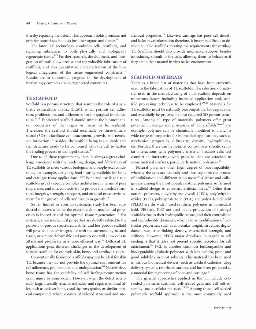
(e.g., brittle in nature). According to the histological analysis
of the in vivo experiment of PLLA/TCP composite scaffold
manufactured by low temperature deposition manufacturing
(LDM) process (see Figure 1), the scaffold was degraded in
24 weeks after implantation with no trace of aseptic inflam-
mation found. As a scaffold material for bone TE, PLLA/TCP
composite could be a better choice compared to the PLLA or
TCP alone.36
EXTRACELLULAR MATRIXDuring the process of tissue regeneration and repair, cells play
the most important roles due to their extensive proliferation,
cell-to-cell signaling, biomolecular production, formation of
ECM.5,6 Various studies demonstrated that the ECM promotes
key cell signaling pathways, and enables cell proliferation, dif-
ferentiation, and proper cell-to-cell and cell-matrix interac-
tions. The ECM is a vital component of cellular microenviron-
ment, supplying cell and tissue with the appropriate 3D archi-
tecture for normal growth and development. Reproduction of
these condition and structures in vitro would create an oppor-
tunity for rapid and accurate studies of molecular and biologi-
cal events that happen in vivo. Moreover, ECM and a tuned
3D microenvironment are important for any successful clinical
correspondent research of TE, cell based therapy, or stem cell
biology. In vitro cells require sufficient movement of nutrients
with the elimination of metabolites. For this process to be suc-
cessful, high diffusion rates of culture media are required to
enclose the 3D scaffold. High diffusion rates are induced by
smaller distances in the range of 150–400 lm. That is why the
biodegradable scaffolds must incorporate an internal porous
architecture for successful and maximum cell growth. The cells
cultured on a 3D matrix behave almost the same as they
behave in vivo. Three dimensional cell cultures on a biode-
gradable cell scaffold are the basis of TE where the specific cell
can grow and regenerate into a structure similar to tissues or
organs in the living body.37 The proliferation and multiplica-
tion of the transplanted cells are greatly influenced by the
composition and biocompatibility of the biomaterial, and
architecture and the surrounding of the scaffolds. Various 3D
matrices are currently employed for the proliferation and mul-
tiplication of various progenitor cells including adult mesen-
chymal stem cells. However, most of these matrices do not
provide the inherent and unique biological environment where
cells can proliferate and multiply in the same fashion as in
vivo systems.5
Certain criteria were considered necessary for an ideal ma-
trix for cell transplantation. Engineers design biomaterials
with a cellular structure to replace or regenerate tissues in the
body. Natural tubular structures often have a honeycomb-
like or foam-like core supporting a denser outer cylindrical
shell, increasing the resistance of the shell to kinking or local
buckling failure. For example, titanium foam is being consid-
ered as substitute material for trabecular bone.38 Many mate-
rials have a cellular structure, with either a two-dimensional
(2D) array of prismatic cells as in a honeycomb or a 3D array
of polyhedral cells as in foam. Engineering honeycombs and
foams can now be made from nearly all types of materials,
such as polymers, metals, ceramics, glasses, and composites
with pore sizes ranging from nanometers to millimeters.38,39
Extrusion Based Rapid Prototyping Technique 85
Biopolymers
Preferably, honeycomb foam not only provides open cell
porous network, it also has remarkably high specific strength
and stiffness, resulting in a structure with extremely favorable
properties. Honeycomb cellular structure gives rise to a
unique combination of properties, which is exploited in en-
gineering design. Their low weights make them attractive for
structural sandwich panels, their abilities to undergo large
deformations at relatively low stresses make them ideal for
absorbing the energy of impacts, their low thermal conduc-
tivities make them excellent insulators, and their high specific
surface areas make them attractive as substrates for catalysts
in chemical reactions. Honeycombs with their prismatic cells
are referred to as 2D cellular solids, while foams with their
polyhedral cells are 3D cellular solids. The relative density is
the density of the cellular solid divided by that of the solid it
is made from, and is equivalent to the volume fraction of
solid. Foams may be either open (with solid only at the edges
of the polyhedral) or closed (with solid membranes over the
faces of the polyhedral). The properties of the foam depend
on those of the solid making up the cellular material; in
materials such as wood, the cell wall is itself a multilayered
composite material.38,39
It has been reported that the scaffold structures designed
and fabricated with the extrusion based RP techniques were
highly similar to the honeycomb of the bee with its regular
array of identical pores when viewed in the Z-direction of the
fabrication process. Honeycomb-structured scaffold is a suit-
able scaffold for 3D cell cultures, which has enormous poten-
tial in the field of various TE applications. The biodegradable
honeycomb collagen sheet can be cut into suitable thickness
and various sizes depending on the application.5 The
mechanics of honeycombs lends great understanding of how
the 3D scaffolds behave under loading forces.38,40 The main
difference lies in the morphology of the pores; the bee’s hon-
eycomb comprises hexagonal pores surrounded by solid
faces/walls that nest together to fill a plane, whereas the 3D
scaffold structure is built from intercrossing filaments
stacked in horizontal planes and comprises pores surrounded
by solid edges/struts. Even though the pores of the bee’s hon-
eycomb are usually hexagonal in section they can also be in
other polygonal shapes in manmade honeycombs, for exam-
ple triangles and squares.41
SCAFFOLD FABRICATION TECHNIQUES
Limitations of Conventional Techniques
To date, conventional techniques have shown great promise in
scaffold fabrication, and a wide range of techniques and scaf-
fold characteristics have been reported.42,43 Conventional TE
scaffold production techniques include fiber bonding, solvent
casting/particulate leaching, membrane lamination, melt mold-
ing, and gas foaming.44 Generally, the main disadvantage of
these conventional techniques is that they are not able to de-
velop a homogeneous structure. They are also associated with
poor reproducibility, irregularity of pore shape, and insufficient
pore interconnectivity.45 Therefore, these techniques remain
FIGURE 1 Low temperature deposition manufacturing system.36
86 Hoque, Chuan, and Pashby
Biopolymers

impractical to manufacture useful scaffolds as required because
of the following number of limitations20:
Manual Intervention. All conventional techniques involve
multistage manual processes that are labor-intensive and
time consuming. The heavy reliance on user skills and expe-
riences often results in nonuniformity and poor repeatability
of the scaffold architectures and properties.
Reproducibility of Processing Procedures. Conventional
techniques are unable to precisely control the pore size, pore
geometry, and spatial distribution of pores, which results in
inconsistent macrostructure and microstructure of the scaf-
folds. For example, scaffolds produced by solvent casting
and/or particulate leaching cannot guarantee interconnectiv-
ity of pores, because this depends on whether the adjacent
salt particles are in contact.
Use of Toxic Solvents. Most conventional techniques require
extensive use of toxic organic solvents to dissolve the raw
stocks (granules, pellets, or powders) and convert into the
final scaffold. Thereupon, it becomes difficult to remove the
toxic solvents completely from the fabricated scaffolds espe-
cially, in thicker constructs. The residual toxic solvents cause
adverse effects on adherent cells, incorporated biological
active agents, or nearby tissues.46
Use of Porogens. Some techniques (e.g., particulate leaching,
hydrocarbon templating, etc.) use salts or waxes as porogens
to create porosities in the scaffolds. The use of porogens lim-
its the scaffold thickness to �2 mm47 because of the prob-
lems in complete removal of porogens. In addition, it
becomes difficult to prevent the agglomeration of porogen
particles and thus to achieve uniform porogen dispersion.
This phenomenon results in uneven pore size and densities,
and morphologies of the scaffolds, which give rise to anisot-
ropy in scaffold properties.43
Shape Limitation. Some of the techniques use moulds or
containers to manufacture scaffolds as thin membranes or
3D constructs. These techniques are confined to create cer-
tain simple shapes and cannot produce scaffolds with com-
plex and/or desired structural architectures.
Limited Cell Growth. Conventional techniques produce
scaffolds mostly in the form of foams. Cells are then seeded
and expected to grow into scaffold. However, this approach
has resulted in the in vitro growth of tissues with cross-sec-
tions of\500 lm from the external surface.48,49 This is prob-
ably due to the diffusion constrait of the foam, which causes
scarcity in nutrients and oxygen supply, and sufficient re-
moval of waste products.
RAPID PROTOTYPING TECHNOLOGYThe inherent limitations of the conventional methods have led
to use the RP techniques to customize design and fabricate 3D
porous scaffolds with fully interconnected pore networks. RP
technology was first launched in the market in late 1980s with
the introduction of the stereolithography (STL) system by 3D
Systems,50 which is now used almost in all engineering areas.
Presently, RP technique is a powerful tool to fabricate TE scaf-
folds, and this technique is becoming increasingly popular in
TE field. RP technique develops scaffold directly from the
scanned image and the computer model of the defect site to
supply a structurally and mechanically perfect fit scaffolds.51 It
is the process of creating 3D objects through repetitive deposi-
tion of material layers, using computer controlled equipment,
based on the cross-sectional data obtained from slicing a com-
puter aided design (CAD) model of the object.52
As opposed to conventional techniques that involve subtrac-
tion or removal of materials from stock, all RP techniques are
material attachment processes, which employ the same fabrica-
tion mechanism of layer-by-layer additive manufacturing to
produce 3D physical parts from wood, plastics, metals, and
ceramics.53 RP fabrication begins with the development of a
3D volumetric computer model of the desired part that can be
derived from output data generated by surface digitizers or
medical imaging systems, for example, computed tomography
or magnetic resonance imaging. The digital model is then
mathematically sliced into thin layers having a constant thick-
ness that is user-defined. Using RP fabrication, layers of mate-
rial representing the cross-sectional profiles of the desired part
as obtained from the computer-generated slices are formed by
processing solid sheet, liquid, or powder material feedstocks.
The material layers are automatically and precisely stacked and
fused on top of one another to create the desired physical
part.21,54 Furthermore, advances in in vivo imaging, such as
positron emission tomography, make it possible to provide a
confined monitoring of the development and incorporation of
the engineered tissues.55,56
RP techniques having full control over porosity, pore size,
pore shape, and permeability, are able to produce scaffolds
with fully interconnected pore structure. Besides, RP techni-
ques also allow the investigation of the effect of scaffold geom-
etry on cell behavior for further optimization of the scaffold
design.57 This method is particularly useful for TE, since it
allows a very good reproducibility and the production of
almost any kind of structure within the limitations of each
technique used. It is possible to design a structure that mimics
the natural tissue to be replaced.58 It is here where RP offers
Extrusion Based Rapid Prototyping Technique 87
Biopolymers

possibilities to compromise such different requirements into
one scaffold, because it adds freedom of varying structural pa-
rameters to the nonvariable bulk mechanical properties of the
material used.16,35 Currently, a number of RP techniques have
been exploited for TE scaffold fabrication that include STL,
selective laser sintering, fused deposition modeling (FDM),
electron beam melting and 3D printing. These RP systems
cover a range of processing technologies such as laser, print, as-
sembly, extrusion, etc.59–61 However, this article focuses on the
systems based on extrusion technology.
Systems Based on Extrusion Technology
Among the available RP techniques, extrusion based techni-
ques are the most advanced scaffold fabrication technique
due to their ability of using different biomaterials, their pos-
sibility of manufacturing scaffolds in a cell-friendly environ-
ment, and their feasibility of controlled drop-on demand
high precision deposition.62 In the material science literature,
another term for extrusion-based systems is ‘‘direct-write’’
technique.51 Lewis and coworkers63 define direct writing
techniques as those that rely on the formulation of colloidal
inks for a given deposition scheme. The techniques employed
in direct writing can perform extrusion of strands/filaments
and/or plotting of dots in 3D.64 The basic principle of extru-
sion-based fabrication technologies involves the extrusion of
a melt to build a 3D scaffold through a jet or nozzle in a lay-
ered fashion guided by the computer model (see Figure 2).16
A computer model (volume model) is sliced into a number
of layers by CAD software and each layer of the original
model is produced in succession (see Figure 3).65 These tech-
niques include multiphase jet solidification (MJS), 3D plot-
ting, precise extrusion manufacturing (PEM), FDM, etc. A
variety of biomaterials can be used to fabricate scaffolds
based on the type of machine used.
Multiphase Jet Solidification (MJS). MJS process was devel-
oped by a Germany’s leading organization of applied research
‘‘The Fraunhofer-Gessellschaft.’’ The MJS process is able to
produce metallic or ceramic parts. It uses low-melting point
alloys or a powder-binder mixture, which is squeezed out
through a computer-controlled nozzle to build the part
layer-by-layer. The main components of the apparatus used
for the MJS process comprise of a personal computer, a com-
puter-controlled positioning system, a heated chamber with
a jet and a hauling system. The material is supplied as pow-
der, pellet, or bar. The extrusion temperature of the molten
FIGURE 2 Overview of rapid prototyping (RP) technology that uses layer-by-layer build-up process.16
88 Hoque, Chuan, and Pashby
Biopolymers

material can reach up to 2008C. Extrusion orifices vary from
0.5 to 2.0 mm.
The MJS process is usually used to produce high density
metallic and ceramic parts. A feedstock consists of powder-
binder-mixture is heated in a process chamber above the
melting point of the binder, and thus only the binder is
liquefied during the process. A piston squeezes out the low
viscous mixture through an x-y-z controlled jet. The feed
rate of the piston controls the material flow. The material is
deposited layer-by-layer by moving the jet and solidifies
when touches the base platform or the previous layer due to
temperature decrease. Following the aim to build up metallic
and ceramic parts, most investigations were performed using
powder-binder-mixtures of stainless steel. However, for med-
ical applications the constraints and aims of using MJS are
quite different. In this case, the modeling material used is a
polymeric material instead of powder-binder-mixture and
supplied as powders, pellets, or bars.
Koch et al.66 studied the use of MJS process to build 3D
hollow scaffolds made of poly(D, L-lactide) for bone and car-
tilage TE. The scaffold pore size was found to be in the range
of 300–400 lm and the structure supported ingrowth of
human bone tissues. However, there was no report on the
detailed scaffold morphology using microscope analyses or
on any mechanical study of the scaffold properties. Calvert
and Crockett 67 developed an in-house extrusion-based RP
technique to manufacture scaffolds. They built scaffolds with
typical layer heights of 0.2–1.0 mm and a resolution of �0.5
mm. Xiong et al.36 built an RP technique called PEM to fab-
ricate 3D scaffolds. They manufactured and tested porous
scaffolds with PLLA and TCP for bone TE (see Figure 4).
Three-Dimensional Plotting. This system was developed by
the researchers at the University of Freiburg68 and was
termed as ‘‘bioplotter.’’ This technique involves a moving ex-
truder head (x-y-z control) and uses compressed air to force
out a liquid or paste-like plotting medium. The process gen-
erates an object by building micro strands or dots in a layered
fashion. Unlike 3D bioplotter, 3D printing (3DP) build scaf-
folds layer-by-layer by bonding starch particles together fol-
lowed by infiltration and partial cross linking of starch with
lysine ethyl ester diisocyanate. The 3D bioplotting allows 3D
dispensing and reactive processing of oligoether urethanes
derived from isophorone diisocyanate, oligoethylene oxide,
and glycerol.
Landers et al.69 compared 3DP and 3D bioplotting in
manufacturing biodegradable polyurethane scaffolds using
aliphatic polyurethanes based on lysine ethyl ester diisocya-
nate and isophorone diisocyanate. Depending on the type of
dispenser head, a variety of materials can be used to build
scaffolds. Landers and Mulhaupt Rolf68 have made use of a
wide variety of polymer hot melts as well as pastes, solutions
and dispersions of polymers and reactive oligomers. The bio-
plotter built in house at the Freiburg Materials Research Cen-
ter, Albert Ludwigs University, Freiburg, Germany was
employed to fabricate scaffolds for TE applications, which
investigated the versatility of this technique.70,71
Geng et al.51 present a technique based on 3DP, referred
to as dual dispensing for the design and fabrication of scaf-
folds (see Figure 5). The dual dispensing method excrete the
high sensitivity to material concentration compared with the
method of dispensing plotting materials into a fluid medium,
as the precipitation occurs when the dispensing material and
the coagulant medium merge on the base or on the previous
layer. There is then no precipitated lump forming at the noz-
zle and no movement of the fluid medium to affect the shape
of the precipitated strands of the scaffold. The chitosan scaf-
folds built by this dual dispensing method exhibits excellent
FIGURE 3 CAD images of generated scaffold assemblies (top) and their fabricated counterparts (bottom).65
Extrusion Based Rapid Prototyping Technique 89
Biopolymers

uniformity, sufficient strength, good reproducibility, and cal-
ibration. The qualities of the surface, the edges of scaffolds,
and uniformity of the top layer are still well maintained.
Moreover, greater flexibility can be achieved with different
dispensers to suit the nature of the fluid to be dispensed.
Ang et al.69,72 fabricated chitosan scaffolds layer-by-layer
with a pre-programmed lay-down pattern (see Figure 6).
Scaffolds fabricated show good attachment between
layers allowed the chitosan matrix to form fully intercon-
nected channel architecture. The results of this preliminary
study using the RP robotic dispensing (RPBOD) system
demonstrated its potential in fabricating 3D scaffolds with
regular and reproducible macropore architecture. Besides,
results of in vitro cell culture studies revealed the scaffolds’
biocompatibility.
Xiong et al.36 developed another wise RP technique, called
low temperature deposition manufacturing (LDM) system
that processes slurry material into frozen scaffold under low
temperature (e.g., 08C). The research team fabricated the
PLLA/TCP composite scaffolds for bone TE. First, the mate-
rial slurry was fed into the material hopper with a soft pipe
connected to a screw pump nozzle. Then the computer con-
trolled the nozzle to move in the X-Y plane to extrude the
material slurry out and deposited it onto the platform in the
area defined by the digital models. The layer of deposited
materials was frozen on the platform that built the scaffold.
In comparison to other depostion methods, the LDM process
can better preserve bioactivities of scaffold materials because
of its nonheating liquefying processing of materials.
Fused Deposition Modeling. FDM is another prominent
extrusion-based RP process. The FDM technique was first
invented by Crump SS of Stratasys Inc73, to develop 3D
objects, and further improved by Comb et al.74 FDM system
is capable of using multiple build materials in a build/sup-
port relationship. The FDM technique requires preformed
filaments with specific size and material properties to build
scaffold. The filament is heated in a liquifier to a semi-liquid
state and pump through a nozzle directly onto the build plat-
form following a programmed model. The incoming fila-
ment acts as a piston to extrude the semi-molten material
along a thin orifice and deposit it through a nozzle tip onto
the platform below. FDM has extended its applications to
medical modeling due to its low cost process and the use of
cheap materials. The feasibility of manufacturing bioresorb-
able and ceramic implants make FDM a suitable process for
producing implants at low cost. To date, FDM technique has
FIGURE 4 Precision extrusion deposition (PED) system that pro-
vides better mixing of polymers and thus avoids possible air bubble
formation.36
FIGURE 5 Dual dispensing system (left) and top views of chitosan scaffolds fabricated by this system (right).51
90 Hoque, Chuan, and Pashby
Biopolymers

shown promising success in the fabrication of 3D scaffolds in
terms of pore reproducibility and interconnectivity.
An interdisciplinary group75 has studied and patented the
parameters to process PCL and several composites (PCL/HA,
PCL/TCP ets.) by FDM technique. For more than 3 years,
this first generation of scaffolds (PCL) has been studied with,
and without cells in a clinical setting. Employing FDM tech-
nique, the second generation of scaffolds for bone TE was
fabricated from polymer and CaP composites. These scaf-
folds, as certained, favorable mechanical and biochemical
properties (degradation and resorption kinetics). The
strength is conferred via ceramic phase whereas; toughness
and plasticity are attained via polymer phase. In addition,
these scaffolds offer improved cell seeding, and enhanced
incorporation and immobilization of growth factors. How-
ever, the commercially available FDM system imposes some
constraints on TE scaffold fabrication. The nature and oper-
ating limits of the FDM system reduce the choice of scaffold-
ing materials to thermoplastics and to preform filament.
The major contribution of the further developed FDM sys-
tems is that the techniques apply the same modeling principle as
FDM but employ different driving forces like, the external gas
pressure or the pressure created by turning screw to extrude the
polymer melt. Therefore, the scaffolding material can be directly
melted and extruded without filament preparation, which
greatly widens the material processing windows. However, dif-
ferent FDM systems have inherent advantages and limitations.
For example, the system that extrudes the polymer melt by
external gas pressure is easy to operate and maintain cleanliness.
However, there is a possibility that the air bubbles may remain
entrapped in the polymer melt (if any) because of lack of appro-
priate mixing, which may cause imperfect filament deposition.
In the case, maintaining a bit higher super heat in the polymer
melts and holding for a while may facilitate easy escape of the
air bubbles. However, the system that extrudes the polymer melt
using the pressure created by turning screw is tedious to main-
tain the cleanliness, and without appropriate cleaning of the sys-
tem, the scaffold might be contaminated. However, the advant-
age is that the polymer melt is mixed thoroughly and thus avoid
the possibility of air bubbles entrapment.
Woodfield et al.,76 developed 3D fiber deposition (3DF)-
bioplotter and tested for TE scaffold fabrication, considering
a system for the extrusion of highly viscous polymer. They
investigated the poly(ethylene glycol)-terephthalate-poly(bu-
tylene terephthalate) (PEGT/PBT) block-copolymers and
polyethyleneoxide-terephtalate/polybutylene-terephtelate
(PEOT/PBT) to process into 3D scaffolds that can modulate
their viscoelastic properties to accomplish mechanical
requirements for tailored tissue engineered applications. The
3DF-bioplotter device was able to fabricate structures with
high reproducibility and flexibility, and it offered a wide vari-
ety of solutions in terms of different architectural and geo-
metrical configurations. The 3DP method generally involves
low cost with minimal specialized equipment. However, reso-
lution is the primary limiting factor, which is determined by
the size of dispensing tip.
Wang et al.77 developed a variation of FDM process called
precision extruding deposition (PED) system to fabricate
FIGURE 6 Rapid prototyping robotic dispensing (RPBOD) system and SEM images showing the top view of the chitosan-40% HA scaffold.69
Extrusion Based Rapid Prototyping Technique 91
Biopolymers

interconnected 3D scaffolds at Drexel University. The major
difference between PED and conventional FDM is that in the
PED system the scaffolding material can be directly extruded
without filament preparation. PED system fused pellet-
formed PCL by two electrical band heaters connected with
two respective thermo-couples. Then the PCL melt was
extruded by the pressure created by a tuning precision screw
to build the scaffolds layer-by-layer. The scaffold morphol-
ogy, internal microarchitecture, mechanical properties, and
biocompatibility of the as-fabricated scaffolds were eval-
uated. The test results reported the structural integrity, con-
trolled pore size (250 lm), pore interconnectivity, a favorable
mechanical property and basic biocompatibility of the PED-
fabricated PCL scaffolds.
Shor78 proposed a new system called mini-extruder
mounted on a high-precision positioning system deliveries the
PCL or PCL-HA in a fused form through the deposition noz-
zle. Similar to mini-extruder, Hoque et al.79 developed a desk-
top robot based rapid prototyping (DRBRP) system, which is
able to fabricate 3D scaffolds with virtually any thermoplastic
synthetic polymers of any form (e.g., pellet, lump, powder,
etc.). The mini-extruder and DRBRP systems can be used with
bulk material in any form (e.g., granule, pellet, powder etc),
which can be avoided in most of the material preparation
steps in a filament-based system. This configuration opens up
the opportunity for the use of a wider range of materials, mak-
ing the system more versatile and realizable alternative manu-
facturing process for composite scaffold materials. The as fab-
ricated scaffolds with DRBRP system were tested for their bio-
compatibility using rabbit smooth muscle cells that showed
excellent cell adhesion and tissue formation.79
CONCLUSIONSScaffolds built by polymeric deposition and/or extrusion
based RP techniques, always showed good attachment with
regular and reproducible scaffold architecture. The dispens-
ing process has certain advantages, such as flexibility in sup-
port for the scaffold as it forms. However, the main disad-
vantage of this method is the high sensitivity of materials
concentration/viscosity on the nozzle tip. Furthermore, due
to frequent filament distortion during the extrusion of mate-
rial causes failure of the process, therefore limiting choices of
material used. Consequently, this problem prevents an auto-
matic and continuous process reducing the main advantage
of a filament based scaffolding system.
The existing CAD-based scaffolds are based on cubic latti-
ces with straight edges and sharp turns or those derived from
Boolean intersections of geometric primitives, such as
spheres and cylinders. Neither of these partitions provides a
biomorphic environment suitable for cell attachment, migra-
tion and proliferation. The aggregates of cells, foam/ECM,
typically have cells separated by curved partitions. The bio-
morphic geometry that best mimics this structural configura-
tion would be surfaces that are continuous through space
and divided into two (pore and nonpore) not necessarily
equal by a nonintersecting two-sided surface.
The biocompatibilities of various polymers have not been
conclusively proved till now. In spite of today’s availability of
numerous of biodegradable materials, usually no single ma-
terial is able to provide the scaffold with all the required
properties for TE applications. Hence, the major challenge in
developing a scaffold lies primarily in the choice of a suitable
single or blend of biomaterials with the correct combination
of properties. The field is still widely open to design the most
appropriate polymer scaffold with all the vital considerations
and properties for effective in vivo applications.
REFERENCES1. Olivares, A. L.; Marsal, E.; Planell, J. A.; Lacroix, D. Biomaterials
2009, 30, 6142–6149.
2. Lacroix, D.; Chateau, A.; Ginebra, M.; Planell, J. Biomaterials
2006, 27, 5326–5334.
3. Lacroix, D.; Prendergast, P. J. J Biomech 2002, 35, 1163–1171.
4. Sandino, C.; Planell, J. A.; Lacroix, D. J Biomech 2008, 41,
1005–1014.
5. Joseph, J.-G. Polym Adv Technol 2006, 17, 395–418.
6. Joseph, P. V.; Robert, L. Lancet 1999, 354, 32–35.
7. Maher, P. S.; Keatch, R. P.; Donnelly, K.; Mackay, R. E. Rapid
Prototyping J 2009, 15, 204–210.
8. Van Cleynenbreugel, T.; Schrooten, J.; Van Oosterwyck, H.; Van-
der Sloten, J. Med Biol Eng Comput 2006, 44, 517–525.
9. Lebourg, M.; Serra, R. S.; Estelles, J. M.; Sanchez, F. H.; Ribelles,
J. L. G.; Anton, J. S. J Mater Sci 2008, 19, 2047–2053.
10. Su, R.; Campbell, G. M.; Boyd, S. K. Med Eng Phys 2007, 29,
480–490.
11. Wang, P.; Hu, J.; Ma, P. X. Biomaterials 2009, 30, 2735–2740.
12. Badylak, S. F. Biomaterials 2007, 28, 3587–3593.
13. Chuenjitkuntaworn, B.; Inrung, W.; Damrongsri, D.; Mekaa-
piruk, K.; Supaphol, P.; Pavasant, P. J Biomed Mater Res A
2010, 94A, 241–251.
14. Drury, J. L.; Mooney, D. J. Biomaterials 2003, 24, 4337–4351.
15. Sun, W.; Starly, B.; Nam, J.; Darling, A. Comput-Aided Des
2005, 37, 1097–1114.
16. Moroni, L.; de Wijn, J. R.; van Blitterswijk, C. A. Biomaterials
2006, 27, 974–985.
17. Zhensheng, L.; Jonathan, G.; Ming-Hong, C.; Ashleigh, C.;
Miqin, Z. J Biomed Mater Res 2008, 86A, 552–559.
18. Dodson, M. V.; Mathison, B. A.; Mathison, B. D. Cell Differ Dev
1990, 29, 59–66.
19. Tjong, S. C. Mater Sci Eng R: Reports 2006, 53, 73–197.
20. Thomson, R.; Wake, M.; Yaszemski, M.; Mikos, A. Adv Polymer
Sci 1995, 122, 245–274.
21. Leong, K. F.; Cheah, C. M.; Chua, C. K. Biomaterials 2003, 24,
2363–2378.
92 Hoque, Chuan, and Pashby
Biopolymers

22. Melchels, F. P. W.; Feijen, J.; Grijpma, D. W. Biomaterials 2010,
31, 6121–6130.
23. Harley, B. A. C.; Kim, H.-D.; Zaman, M. H.; Yannas, I. V.; Lauf-fenburger, D. A.; Gibson, L. J. Biophys J 2008, 95, 4013–4024.
24. Tanaka, M.; Sackmann, E. Nature 2005, 437, 656–663.
25. Mano, J. F.; Silva, G. A.; Azevedo, H. S.; Malafaya, P. B.; Sousa,
R. A.; Silva, S. S.; Boesel, L. F.; Oliveira, J. M.; Santos, T. C.;
Marques, A. P.; Neves, N. M.; Reis, R. L. J R Soc Interface 2007,
4, 999–1030.
26. Maher, P. S.; Keatch, R. P.; Donnelly, K.; Paxton, J. Z. In 4th Euro-
pean Conference of the International Federation for Medical and
Biological Engineering, Antwerp, Belgium, 2009, p 2200–2204.
27. Barrows, T. Clin Mater 1986, 1, 233–257.
28. Puppi, D.; Chiellini, F.; Piras, A. M.; Chiellini, E. Prog Polym
Sci 2010, 35, 403–440.
29. Ke, C.; William, S. K. Biotechnol Prog 2010, 26, 838–846.
30. Frisman, I.; Seliktar, D.; Bianco-Peled, H. Acta Biomater 2010,
6, 2518–2524.
31. Mastrogiacomo, M.; Muraglia, A.; Komlev, V.; Peyrin, F.; Rustichelli,
F.; Crovace, A.; Cancedda, R. OrthodCraniofac Res 2005, 8, 277–284.
32. Cunha, P. L. R.; Castro, R. R.; Rocha, F. A. C.; de Paula, R. C.
M.; Feitosa, J. P. A. Int J Biol Macromol 2005, 37, 99–104.
33. Chatterjee, S.; Bohidar, H. B. Int J Biol Macromol 2005, 35, 81–88.
34. Chuenjitkuntaworn, B.; Inrung, W.; Damrongsri, D.; Mekaa-
piruk, K.; Supaphol, P.; Pavasant, P. J Biomed Mater Res A
2010, 94A, 241–251.
35. Moroni, L.; Schotel, R.; Sohier, J.; de Wijn, J. R.; van Blitters-
wijk, C. A. Biomaterials 2006, 27, 5918–5926.
36. Xiong, Z.; Yan, Y.; Wang, S.; Zhang, R.; Zhang, C. Scr Mater
2002, 46, 771–776.
37. Lalan, B. A. S.; Pomerantseva, M. D. I.; Joseph, P.; Vacanti, M.
D. World J Surg 2001, 25, 1458–1466.
38. Gibson, L. J. J Biomech 2005, 38, 377–399.
39. Gibson, L. J.; Anthony, K.; Carl, Z. Comprehensive Composite
Materials; Pergamon: Oxford, 2000; pp 821–842.
40. Schaffner, G.; Guo, X.-D. E.; Silva, M. J.; Gibson, L. J. Int J
Mech Sci 2000, 42, 645–656.
41. Silva, M. J.; Hayes, W. C.; Gibson, L. J. Int J Mech Sci 1995, 37,
1161–1177.
42. Widmer, M. S.; Gupta, P. K.; Lu, L.; Meszlenyi, R. K.; Evans, G.
R.; Brandt, K.; Savel, T.; Gurlek, A.; Patrick, C. W.; Mikos, A. G.
Biomaterials 1945, 1998, 19.
43. Hutmacher, D. W.; Goh, J. C.; Teoh, S. H. Ann Acad Med Singa-
pore 2001, 30, 183–191.
44. Morsi, Y. S.; Wong, C. S.; Patel, S. S.Virtual Prototyping and Bio
Manufacturing in Medical Applications, Springer Sciencet Busi-
ness Media, LLC: New York, 2008, p 129–148.
45. Seunarine, K.; Gadegaard, N.; Tormen, M.; Meredith, D. O.; Riehle,
M. O.; Wilkinson, C. D. W. Nanomedicine 2006, 1, 281–296.
46. Healy, K.; Whang, K.; Thomas, C. US Patent 5723508, 1998, 508.
47. Lu, L.; Mikos, A. G. MRS Bulletin 1996, 21, 28.
48. Ishaug-Riley, S.; Crane, G.; Gurlek, A.; Miller, M.; Yasko, A.;
Yaszemski, M.; Mikos, A. J Biomed Mater Res 1997, 36, 1–8.
49. Freed, L. E.; Vunjak-Novakovic, G.; Biron, R. J.; Eagles, D. B.;Lesnoy, D. C.; Barlow, S. K.; Langer, R. Biotechnology 1994, 12,689–693.
50. Legault, M. Rapid Manufacturing, Part I: The Technologies.
Available at: http://www.compositesworld.com/articles/rapid-
manufacturing-part-i-the-technologies, 2008.
51. Geng, L.; Feng, W.; Hutmacher, D. W.; Wong, Y. S.; Loh, H. T.;
Fuh, J. Y. H. Rapid Prototyping J 2005, 11, 90–97.
52. Starly, B. In Biomaterials; Narayan, R.; Lee, Y. S., Eds.; Springer
Verlag: New York, 2010; pp 39–55.
53. Cheah, C. M.; Chua, C. K.; Lee, C. W.; Feng, C.; Totong, K. Int J
Adv Manufacturing Technol 2005, 25, 308–320.
54. Chua, C. K.; Leong, K. F. Rapid Prototyping: Principles and
Applications in Manufacturing; Wiley: New York, 1997.
55. Chua, C. K.; Leong, K. F.; Tan, K. H. Biomed Mater 2009, 493–523.
56. Chua, C. K.; Chou, S. M.; Wong, T. S. Int J Adv Manufacturing
Technol 1998, 14, 146.
57. Starly, B.; Lau, W.; Bradbury, T.; Sun, W. Comput-Aided Des
2006, 38, 115–124.
58. Daily, S. Science News; Science Daily: University of Washington,
2010.
59. Hutmacher, D.; Sittinger, M.; Risbud, M. Trends Biotechnol
2004, 22, 354–362.
60. Leong, K. F. Biomaterials 2003, 24, 2363–2378.
61. Sachlos, E.; Czernuszka, J. T. Eur Cells Mater 2003, 5, 29–40.
62. Mironov, V.; Kasyanov, V.; Drake, C.; Markwald, R. R. Regen
Med 2008, 3, 93–103.
63. Gratson, G. M.; Xu, M.; Lewis, J. A. Nature 2004, 428, 386–386.
64. Hutmacher, D. W.; Schantz, T.; Zein, I.; Ng, K. W.; Teoh, S. H.;
Tan, K. C. J Biomed Mater 2001, 55, 203.
65. Narayan, R. Biomedical Materials; Springer Science+Business
Media: New York, 2009.
66. Koch, K. U.; Biesinger, B.; Arnholz, C.; Jansson, V. In Time-
Compression Technologies ’98 Conferences; Rapid News Publi-
cations: London, 1998, p 209–214.
67. Calvert, P.; Crockett, R. Chem Mater 1997, 9, 650–663.
68. Landers, R.; Mulhaupt, R. Macromol Mater Eng 2000, 282, 17–
21.
69. Ang, T. H.; Sultana, F. S. A.; Hutmacher, D. W.; Wong, Y. S.;
Fuh, J. Y. H.; Mo, X. M.; Loh, H. T.; Burdet, E.; Teoh, S. H.
Mater Sci Eng 2002, 20, 35–42.
70. Huang, A. H.; Farrell, M. J.; Mauck, R. L. J Biomech 2010, 43,
128–136.
71. Landers, R.; Pfister, A.; Hubner, U.; John, H.; Schmelzeisen, R.;
Mulhaupt, R. J Mater Sci 2002, 37, 3107–3116.
72. Ang, T. H.; Sultana, F. S. A.; Hutmacher, D. W.; Wong, Y. S.;
Fuh, J. Y. H.; Mo, X. M.; Loh, H. T.; Burdet, E.; Teoh, S. H.
Department of Mechanical Engineering; National University of
Singapore, 2002.
73. Crump, S. US Patent 5121329, 1992.
74. Comb, W. J.; Priedeman, W. R.; Turley, P. W. Manufacturing Sci
Eng 1994, 68, 547–556.
75. Hutmacher, D. W. Biomaterials 2000, 21, 2529–2543.
76. Woodfield, T.; Malda, J.; Wijn, J. D.; Peters, F.; Riesle, J.; Blitters-
wijk, C. V. Biomaterials 2004, 25, 4149–4161.
77. Wang, F.; Shor, L.; Darling, A. L.; Khalil, S. E. D.; Sun, W.; Lau,
A. C. W. Rapid Prototyping J 2004, 10, 42–49.
78. Shor, L. Biomaterials 2007, 28, 5291–5297.
79. Hoque, M. E.; San, W. Y.; Wei, F.; Li, S.; Huang, M.-H.; Vert,
M.; Hutmacher, D. W. Tissue Eng A 2008, 15, 3013–3024.
Reviewing Editor: Eric J. Toone
Extrusion Based Rapid Prototyping Technique 93
Biopolymers