
Extrusion in Ceramics
468
-
Upload
khangminh22 -
Category
Documents
-
view
0 -
download
0
Transcript of Extrusion in Ceramics


engineering materials and processes

Frank Händle (Ed.)
Extrusion in Ceramics
With 284 Figures, 8 in Color and 24 Tables
123

Frank HändleECT GmbHKisslingweg 1075417 MühlackerGermanye-mail: [email protected]
Series Editor:
Professor Brian Derby, Professor of Materials SciencsManchester Science Centre, Grosvenor Street, Manchester,M1 7HS, UK
Library of Congress Control Number: 2007927055
ISSN 1619-0181
ISBN 978-3-540-27100-0 Springer Berlin Heidelberg New York
This work is subject to copyright. All rights are reserved, whether the whole or part of the material is con-cerned, specifically the rights of translation, reprinting, reuse of illustrations, recitation, broadcasting,reproduction on microfilm or in any other way, and storage in data banks. Duplication of this publicationor parts thereof is permitted only under the provisions of the German Copyright Law of September 9,1965, in its current version, and permission for use must always be obtained from Springer. Violationsare liable for prosecution under the German Copyright Law.
Springer is a part of Springer Science+Business Media
springer.com
© Springer-Verlag Berlin Heidelberg 2007
The use of general descriptive names, registered names, trademarks, etc. in this publication does notimply, even in the absence of a specific statement, that such names are exempt from the relevant protectivelaws and regulations and therefore free for general use.
Typesetting: Data supplied by the authorProduction: LE-TEX Jelonek, Schmidt & Vöckler GbR, Leipzig, GermanyCover design: eStudioCalamar S.L., F. Steinen-Broo, Pau/Girona, Spain
Printed on acid-free paper SPIN 11515852 7/3100/YL – 5 4 3 2 1 0

This Book is Dedicated to all Those who haveHelped me Learn Things About Ceramic Extrusion

Contents
1 Introduction by Frank Händle . . . . . . . . . . . . . . . . . . . . . . . . . . . . . . . . . . . . . . . . . . . . . . . . . . . . . . . . . . 1
2 Shaping in Ceramic Technology – an Overview by Andrea Bresciani. . . . . . . . . . . . . . . . . . . . . . . . . . . . . . . . . . . . . . . . . . . . . . . . . . . . . . 13
3 Current Classification of Ceramic Materials by Hubertus Reh . . . . . . . . . . . . . . . . . . . . . . . . . . . . . . . . . . . . . . . . . . . . . . . . . . . . . . . . . . 39
4 Types of Extrusion Units by Willi Bender . . . . . . . . . . . . . . . . . . . . . . . . . . . . . . . . . . . . . . . . . . . . . . . . . . . . . . . . . . . 63
5 A Short History of the Extruder in Ceramics by Willi Bender, Hans H. Böger . . . . . . . . . . . . . . . . . . . . . . . . . . . . . . . . . . . . . . . . 91
6 The Principle of the Auger Extruder by John Bridgwater. . . . . . . . . . . . . . . . . . . . . . . . . . . . . . . . . . . . . . . . . . . . . . . . . . . . . . . 137
7 Rheology of Ceramic Bodies by Fritz Laenger . . . . . . . . . . . . . . . . . . . . . . . . . . . . . . . . . . . . . . . . . . . . . . . . . . . . . . . . . . 153
8 Rheology and Extrudability of Ceramic Compounds by Wolfgang Gleißle. . . . . . . . . . . . . . . . . . . . . . . . . . . . . . . . . . . . . . . . . . . . . . . . . . . . . . 175
9 Scenarios of Extrusion by Dietmar Lutz . . . . . . . . . . . . . . . . . . . . . . . . . . . . . . . . . . . . . . . . . . . . . . . . . . . . . . . . . . . 189
10 Laminations in Extrusion by Rainer Bartusch, Frank Händle . . . . . . . . . . . . . . . . . . . . . . . . . . . . . . . . . . . . . 205
11 Additives for Extrusion by Michael Hölzgen, Peter Quirmbach . . . . . . . . . . . . . . . . . . . . . . . . . . . . . . . . 233
12 About Dies, Pressure Heads, Strainer Plates and more by Harald Berger . . . . . . . . . . . . . . . . . . . . . . . . . . . . . . . . . . . . . . . . . . . . . . . . . . . . . . . . . 245
13 Twin-srew Extruders in Ceramic Extrusion by Werner Wiedmann, Maria Hölzel . . . . . . . . . . . . . . . . . . . . . . . . . . . . . . . . . . . 265
14 Piston Extruders by Günther Doll, Frank Händle, Fritz Spießberger . . . . . . . . . . . . . . . . . 287

VIII Contents
15 Evacuation in Ceramic Extrusion – Dependences and Local Situations by Fritz Laenger . . . . . . . . . . . . . . . . . . . . . . . . . . . . . . . . . . . . . . . . . . . . . . . . . . . . . . . . . 303
16 Evacuation Technology for Ceramic Extrusion by Mark Redmann . . . . . . . . . . . . . . . . . . . . . . . . . . . . . . . . . . . . . . . . . . . . . . . . . . . . . . . 309
17 Thermoplastic Extrusion for Ceramic Bodies by Frank Clemens. . . . . . . . . . . . . . . . . . . . . . . . . . . . . . . . . . . . . . . . . . . . . . . . . . . . . . . . 323
18 Tribological Principles by Günter Mennig. . . . . . . . . . . . . . . . . . . . . . . . . . . . . . . . . . . . . . . . . . . . . . . . . . . . . . . . 345
19 Wear Protection for Augers in Ceramic Extrusion-state-of-the-art by Walter Reisinger. . . . . . . . . . . . . . . . . . . . . . . . . . . . . . . . . . . . . . . . . . . . . . . . . . . . . . 355
20 Perspectives for Wear Reduction with Ceramic Extruder Components by Holger Wampers . . . . . . . . . . . . . . . . . . . . . . . . . . . . . . . . . . . . . . . . . . . . . . . . . . . . . 363
21 Test Methods for Plasticity and Extrusion Behaviour by Katrin Göhlert, Maren Übel . . . . . . . . . . . . . . . . . . . . . . . . . . . . . . . . . . . . . . . . 381
22 Simulation in Ceramic Extrusion by Boris Buchtala, Sigrid Lang . . . . . . . . . . . . . . . . . . . . . . . . . . . . . . . . . . . . . . . . 399
23 Selected Literature by Frank Händle, Kerstin Hohlfeld . . . . . . . . . . . . . . . . . . . . . . . . . . . . . . . . . . . . 419
The Authors of the Book. . . . . . . . . . . . . . . . . . . . . . . . . . . . . . . . . . . . . . . . . . . . . . . . 451
Index . . . . . . . . . . . . . . . . . . . . . . . . . . . . . . . . . . . . . . . . . . . . . . . . . . . . . . . . . . . . . . . . . . . . . . . . . . 465
1 Introduction
Frank Händle
1.1 What to Expect
For some time now, I have been toying around with the idea of writing a book about “Ceramic Extrusion”, because to my amazement I have been unable to locate a single existing, comprehensive rundown on the subject – much in contrast to, say, plastic extrusion and despite the fact that there are some outstanding contributions to be found about certain, individual top-ics, such as those in textbooks by Reed [1], Krause [2], Bender/Händle [3] at all.
By way of analogy to Woody Allen's wonderfully ironic movie entitled “Everything You Always Wanted to Know about Sex.” I originally in-tended to call this book “Everything You Always Wanted to Know about Ceramic Extrusion”, but after giving it some extra thought, I eventually decided on a somewhat soberer title. Nevertheless, my companion writersand I have done our best – considering our target group and their motives – not to revert to the kind of jargon that people use when they think the less understandable it sounds, the more scientific it appears.
This book addresses all those who are looking for a lot or a little general or selective information about ceramic extrusion and its sundry aspects. We realize that most of our readers will not be perusing this book just for fun or out of intellectual curiosity, but because they hope to get some use out of it for their own endeavors. In other words, and to borrow a metaphor from Economist Joseph Schumpeter, this book is intended to serve as a “box of tools”. It will be up to you, the reader, to decide which of the prof-fered “tools” you might find useful.
The following chapters deal with various aspects of ceramic extrusion. Each contribution can stand alone, i.e., does not necessarily depend on the readers' having read the other contributions, too. This does lead to some redundancy, of course, but it was simply unavoidable. The first time I ever saw an extruder, I was a little boy hanging on to my father's hand at a nearby brickmaking plant. I remember wondering how such a thing could

2 Frank Händle
actually spit out bricks. Now, 60 years later, I'm still wondering, or, like one of Einstein's students once remarked “I am still confused, but on a much higher level.”
1.2 History of an Obsession
In 1971 I got my first chance to dabble with extruders in a professional connection. Since then, I hope to have contributed to their further devel-opment with a few ideas and impulses based on inculcated theory, personal experience, various achievements and assorted flops – along with inputs from customers, some inquisitive contemplation of competitors' ideas, and loads of useful-to-superfluous information and intentional or unintentional disinformation, all of which had to be either analyzed and evaluated, or chalked off and forgotten. I maintained intensive contact with numerous comrades-in-arms. In fact, with some of them, it was more a case of “up in arms”; my thanks to all of them, though, including those whose views and approaches may be contrary to mine.
Now I would like to tell you a little story about a mild obsession called “Ceramic Extrusion” for ex- one, a story which might illustrate the devel-opment of the extrusion technology over the past 35 years and to introduce the main protagonists.
The most important of my partners in discussion included, in chrono-logical order, Carl O. Pels Leusden, who was with the Brick and Tile Re-search Institute in Essen for a long time before he became a professor at the Nuremberg University of Applied Sciences. His 1965 dissertation on the mode of operation of auger extruders raised Germany's discourse on ceramic extruders to a new level; indeed, we all owe him gratitude for the German language area's premiere papers on ceramic-extrusion topics for many years on end [4].
Professor Ernst Hallmann of the University of Applied Sciences in Es-sen was the first to attempt to construct an “extruder theory” for ceramic bodies. As we now know, that theory constitutes a remarkable “integrator” without recourse to rheological/empirical fundamentals; works by Schlegel must also be mentioned in this context [5].
I once unsuccessfully attempted to convince Professor Gerhardt Schen-kel at Stuttgart University's Institute of Plastic Technology that the then existing models for plastic extruders were only conditionally applicable to extruders for ceramic bodies [6]. Later, we had a cultivated meeting of the minds with his successors at the institute, Prof. H.G. Fritz and K. Geiger [7].

1 Introduction 3
We also had some good talks with L.A. Gömze, a Hungarian scientist – now a professor at Miscolc University – who developed an empirically un-derpinned, and therefore quite interesting, approach to the design of ex-truders [8].
With regard to the “scale-up problem”, i.e., the difficulty of transferring measured data from laboratory extruders to large, production-scale extrud-ers, we had occasion to investigate the laws of similarity/affinity [9], the literature on forming technology in general [10] and plethoric literature on the technology of extrusion for plastics, food and fodder, coal, graphite, cement-bonded bodies, etc.
“We” in the above sense basically refers to my colleagues at Händle GmbH: W. Bender, K. Eisele, F. Laenger, D. Lutz and the three chiefs of our application-oriented laboratory, R. Feldmeier, M. Probst and K. Göh-lert.
Ultimately, we were looking for answers to three crucial questions:
• What do we know for sure about the flow processes that take place in the various zones of extruders/vacuum units used for extruding ceramic bodies?
• Is there any chance of our developing a “theory” of extrusion for the various ceramic bodies that would allow sufficiently accurate prognoses in terms of anticipated production parameters like extrusion pressure, torque, axial pressure, heat evolution, etc.?
• What level of quality must empirical data have to qualify for use in the algorithms of an extruder theory for ceramic bodies?
Early on in my dealings with ceramic extruders, I found the mathemati-cal formulae fascinating – the more mathematical the better. Later on, though, I realized that most of them had been “built on sand”, since either the empirical-rheological framework data was missing, or the empirically determined material data or “body law”, were inadequate, hence leaving broad room for conjectural interpretation of the findings. Not even the range of instruments required for measuring the material data / properties of relevance to extrusion existed at the time.
While some ceramists swore by measured data obtained with the aid of the “Pfefferkorn” method, others preferred the capillary rheometric ap-proach, and still others, including H.W. Hennicke at the University of Clausthal-Zellerfeld and researchers at the Brick and Tile Institute in Es-sen, devised their own techniques. In pertinent U.S. literature, studies based on the Brabender measuring kneader [11] were encountered most frequently.

4 Frank Händle
All these various methods had their own very specific merits, but the re-sults obtained defy direct comparison, because different sets of physical quantities are measured in each case.
The cause of this dilemma lies embedded in the fundamental ceramic term “plasticity” or better “apparent plasticity”, also referred to as worka-bility; and that same term will keep popping up in the following contribu-tions, too.
To this very day, as J.G. Heinrich notes in his “Introduction”, there is still no binding definition to be found for plasticity in the ceramic sense, though that term is long-since clear and unambiguous in other fields:
“Despite numerous attempts to define and mathematically distinguish the term plasticity, a single uniform metrological test method is yet to be developed for that property. Plasticity is primarily a function of a mate-rial's yield point, as expressed in terms of a force measured under a defined set of geometrical conditions at the onset of deformation and which re-mains in effect up to the maximum achievable deformation prior to crack formation.” [12]
The first part of this definition we can understand well enough in rheological terms, and we can use appropriate instruments for measuring with sufficient accuracy. The last part of the definition, however, namely the part about “maximum achievable deformation prior to crack forma-tion” may be useful in actual practice, but must remain unsatisfactory in theory, because “crack formation” does not count among the accurately de-tectable physical phenomena. [13]
Most of the best pickings in recent years could be found in English-language literature, e.g., in works on plasticity by N.F. Astbury or H.H. Macey , in the empirical works of F.J. Goodson [14] and, above all, in the educational film that H.R. Hodgkinson made for the British Ceramic Soci-ety in 1963 – a genuine classic [15]. I also consider “Plasticity of Clay Wa-ter Systems” [16] very useful as written by W.G. Lawrence for New York's Alfred University.
All during that fact-gathering period, I drew much benefit from my regular easy-going discussions with Prof. H.W. Hennicke , who helped me organize a seminar devoted to “plasticity measuring methods”. Of course, I also kept in touch with various other German and foreign universities at the same time.
With all that information to build on, it was easy for me to assume the frequent role of initiator-cum-pusher for the cultivation of developments geared to making extruders perform better while moving toward a progno-sis-capable theory that would enable realistic simulation of ceramic extru-sion processes.

1 Introduction 5
The groundwork for all this was laid by F. Laenger at HÄNDLE GmbH and made public in a number of articles dealing with an “extruder-simulation model” [17].
All the while, our close cooperation with the “Karlsruhe Rheology” group headed by Prof. H.W. Buggisch [18] was particularly productive.
In the early 1990s, after coming to the conclusion that we now under-stood the processes taking place in the pressure-generating element of the extruder, we took things one step further by asking ourselves which flow processes take place in connection with the shaping of ceramic body in the pressure-consuming element, the pressure head/die unit.
Ultimately and for various reasons, however, the relevant experiments were not overly successful [19].
By then, to be sure, we had obtained the rheological tools of the trade we needed for finding our constitutive models, but our simulation methods were still immature; the contribution by Bechtel and Lang outlines the much-improved methods that have since become available.
A work of landmark importance for the theory of extrusion, “Paste Flow and Extrusion” by J.J. Benbow and J. Bridgwater appeared in 1993; fi-nally, a new approach had yielded reproducible data and was amenable to practical implementation [20]. We immediately contacted Prof. John Bridgewater at the University of Cambridge and were able to discuss F. Laenger's models and methods with him.
We were also able to consult with K. Hornung and O. Kulikov at Ger-many's Armed Forces University in Munich and with A.N. Alexandrou from the University of Cyprus [21].
This admittedly very personal story naturally lays no claim to having adequately or representatively described either the history of extruder the-ory or the evolution of extruders for diverse ceramic bodies and products. It does, however, offer some insight into what has been going on in recent years. It identifies the main protagonists and looks ahead to the perspec-tives and projects of the year to come; I'll get back to all that later.
1.3 About the Various Contributions
1.3.1 As already mentioned, I would like to make sure that the Introduc-tion to this book properly explains its structure, its target readers, and what you can expect from it.
1.3.2 Extrusion is only one of a good dozen or so methods that can be used for shaping ceramics – from the hand-molding of soft-mud bricks in wooden molds, to various casting techniques, isostatic pressing and dry pressing, all the way to the exotic explosive shaping method. All these

6 Frank Händle
various techniques are described in more or less detail in diverse works by Brownell, Heinrich, Herrmann, Hülsenberg, Reed, Kollenberg, Richerson [22], as well as in pertinent lexica and compilations .
Each of these alternatives has its own merits and drawbacks and, as such, is predestined for use in the manufacture of certain ceramic products [23].
In his contribution entitled “Shaping in ceramic technology – an over-view”, Andrea Bresciani, who is with the world's largest ceramic plant & equipment contractor SACMI, describes and compares the three most im-portant ceramic shaping methods.
As long as we are unfamiliar with the specifics of the various shaping methods, we can not understand the specifics of extrusion either, i.e., when and where extrusion would be superior to some other technology or, con-versely, when and where some other method would be superior to extru-sion.
1.3.3 The fact that people have been baking ceramics for thousands of years is really nothing new.
However, considering today's rapid developments in the field of ceramic materials, the question of what “ceramics” actually are calls for a very well-founded, fine-brush definition. I know of no one who would be better able to provide an answer to that complex question than Hubertus Reh,who, as editor-in-chief of major ceramic trade journals, author of numer-ous articles, and credentialed cognoscente of the industry, was able to draw on many years of relevant experience for his contribution entitled “Cur-rent classification of ceramic materials”.
1.3.4 In his “Types of extrusion units”, Willy Bender investigates all the various kinds of extruders and combined de-airing extrusion machines.
Nearly every type he lists is still to be found somewhere out there in the ceramic industry, be it for traditional, product-specific, material-particular or process-related reasons.
1.3.5 “A short history of the extruder in ceramics” is Willy Bender's and Hans H. Böger's historical rundown of extruders in the field of ce-ramics. With upwards of 30 pages, it is this book's by far longest contribu-tion. Numerous illustrations help bring us closer to the history of this tech-nology, and we note with surprise that many of today's supposedly new and revolutionary ideas actually have been around for a long, long time.
Newton was right when he mused that we are all “standing on the shoulders of giants” [24].
1.3.6 Unlike German authors, Anglo-Saxon scientists have a reputation for being able to explain complex things in an understandable manner. I asked John Bridgwater, who counts among the premier authors on ex-

1 Introduction 7
truder theory, to explain in his contribution entitled “The principle of the auger extruder” just what an extruder actually is.
So, for all of you out there who have never had much to do with extru-sion, this will make a good starting point.
1.3.7 While the above papers serve to introduce our topical theme from various angles, this book's first theoretical contribution stems from the pen of Fritz Laenger and delves into a key theme called “Rheology of ce-ramic bodies”. The fact has already been mentioned (but cannot be driven home often enough) that, without a working knowledge of the relevant ma-terial laws, trying to properly extrude a host of extremely disparate ce-ramic compositions would be like stumbling around in a dark cave looking for light switches.
1.3.8 Considering the relevance of rheology for extrusion, Fritz Laenger's contribution just had to be supplemented by Wolfgang Gleißle's “Rheol-ogy and extrudability of ceramic compounds”. As a member of the “Karlsruhe Rheology Group” at Karlsruhe University, Gleissle was most intensively concerned with the rheology of ceramic compounds. Here, he establishes the decisive criteria for the extrudability of ceramic com-pounds.
1.3.9 It would be hard to overlook the fact that workaday cooperation be-tween practicians and theoreticians frequently takes a counterproductive turn, since practicians tend to view theoretical formulations as unrealistic, while their own practice-oriented tinkerings tend to be difficult to pigeon-hole and often actually do constitute little more than doctoring around on symptoms. In his “Scenarios of extrusion”, Dietmar Lutz applies some rudimentary geometry to the most frequently encountered scenarios (read: problems) to show what happens and why, when, say, throughput dimin-ishes due to altered material data or to the introduction of other shaping factors.
These “didactical” instruments enable sufficiently accurate “diagnosti-cation” and subsequent pinpoint “therapeutic treatment” of practically any extrusion problem.
1.3.10 “Laminations” are a constant source of debate when it comes to the advantages and disadvantages of extrusion in comparison with other shap-ing methods. Whole libraries could be filled with the literature on this phe-nomenon and all the fabulous inventions and sure-fire formulae for their prevention. In “Laminations in extrusion” Rainer Bartusch and I have attempted to objectivize the discussion.
1.3.11 The contribution “Additives for Extrusion” by Michael Hölzgen and Peter Quirmbach is an introduction to the complex world of extru-

8 Frank Händle
sion additives – often enough in the form of a veritable “cocktail” – with-out which certain ceramic compounds would be practically unextrudable, and with the help of which the quality of extrudates can be substantially improved.
1.3.12 Extrusion always enjoys advantages over other shaping methods when it comes to profiling anything from simple three-hole bricks to big, heavy slugs for electroceramics or even filigreed honeycombs. Not just the extruder itself – the pressure generator –, but also the pressure head, die and strainer plate – the pressure consumers –, are of decisive importance for the quality of extrusion.
Frequently, they decide over the possibility or impossibility of produc-ing certain cross sections.
The contribution “Dies, pressure heads, strainer plates and more” by Harald Berger illuminates the immense variety of options and alterna-tives.
1.3.13 Most twin-screw extruders used in ceramic production were chosen either to produce the high requisite extrusion pressures or to introduce the high requisite or desirable shear forces for kneading and homogenizing ce-ramic compounds. For decades now, Werner & Pfleiderer – now COPERI-ON – have been supplying such extruders to well-known producers. Werner Wiedmann's and Maria Hölzel's contribution describes the op-eration and technical makeup of “Twin-screw extruders in ceramic ex-trusion”.
1.3.14 Not all ceramic compounds are put through single-screw and twin-screw extruders. If the idea is to achieve very high extrusion pressures, minimal contamination, short series, etc., an intermittent piston extruder can be the machine of choice.
In “Piston extruders”, Fritz Spiessberger and I try to explain their function, design, benefits and drawbacks.
1.3.15 As Aristotle once observed, nature abhors a vacuum. Consequently, nature is always intent on filling up empty spaces. By contrast, most ex-truder operators appear to have less of a problem with such things, particu-larly about perhaps not having been thorough enough in their efforts to achieve a good level of vacuum for their ceramic extrusion processes. In the contribution entitled “Evacuation in ceramic extrusion”, FritzLaenger portrays the basic essentials of evacuation.
1.3.16 The next paper, “Evacuation technology for ceramic extrusion”, by Mark Redmann, explores the various types of vacuum pumps that are suitable for use in extruding ceramic compounds.

1 Introduction 9
1.3.17 With the notable exception of a few hot-shaped products, most ce-ramic bodies – unlike plastic bodies – are extruded in the cold state. In-deed, it is often necessary to cool the compound in the extruder, because the heat generated by shearing and friction could cause the plasticity to de-teriorate and/or the extrusion additives to gel. In recent years, however, thermal plastic extrusion involving mixtures of ceramics and plastics has begun to take shape, so to speak.
In his contribution entitled “Thermoplastic extrusion for ceramic bodies”, Frank Clemens describes the present state of this relatively young art.
1.3.18 The potential macroeconomic consequences of wear & abrasion are a frequently explored topic. In view of the phenomenon's relevance to the extrusion of ceramic compounds and how it appears in the form of abra-sion, corrosion and/or adhesion, the next three contributions all deal with that problem complex.
Günter Mennig's, for example, offers a succinct depiction of “Tri-bological principles”.
1.3.19 In his field-oriented contribution entitled “Wear protection for augers in ceramic extruders – state of the art”, Walter Reisinger de-scribes the most important kinds of protective layers that are presently in industrial-scale use.
The reader need not look for the exotic kind of hardfacings that either can only be applied in ultra-thin layers or are constantly being referred to in the literature as “promising” meaning that they are still at the develop-ment stage.
1.3.20 We did, however, include a review of the latest results in the de-velopment and practical use of ceramic augers. Along with hard metal, monolithic ceramics have enormous qualitative and economic advantages to offer in applications involving highly abrasive ceramic compounds.
The relevant developmental situation is investigated in Holger Wam-pers' contribution “Perspectives for wear reduction with ceramic ex-truder components”.
1.3.21 In their article on “Test methods for plasticity and extrusion be-haviour”, Katrin Göhlert and Maren Übel focus attention on methods of particular importance for the characterization and registration of rheologi-cal data. The paper concentrates mainly on the various instruments used for determining plasticity / rheological indicators.
1.3.22 One age-old dream of all those concerned with the extrusion of ce-ramic compounds now appears to be within reach: the simulation of ce-ramic extrusion processes.

10 Frank Händle
Now, the highly complex tools and huge computing capacities required by modern CFD programs, at least, are available. The main remaining challenge is to establish and provide suitable material data for such simula-tions. Boris Buchtala und Sigrid Lang delineate the fundamental princi-ples and potentials of modern simulation technology in their contribution called “Simulation in ceramic extrusion”.
1.3.23 In this last section, which we have called “Selected literature”,Kerstin Hohlfeld and I have compiled all the various bibliographical ref-erences from the individual contributions and expanded the list to include some important literature of relevance that was not mentioned in the arti-cles. This bibliography naturally does not purport to completeness, and we fully realize that our selection may fail to mention important contributions from French, Italian, Japanese, Russian, Chinese and other publications. Indeed, a bibliography on “ceramic extrusion” stands way at the top of my personal wish list.
1.4 Famous last Words
1.4.1 Once word got out that SPRINGER Verlag had agreed to publish this book, a number of people said they thought I should give the subject of “ceramic extrusion” even broader treatment. However, considering the already wide diversity of applications and types of ceramic extrusion that were being dealt with in this book, I did not want to weigh it down even more.
While the kind of vacuum extruders used for making monoliths do look a lot like the kind used for extruding backing bricks, they are in reality about as closely related as a rally-tuned sports car and a robust family van.
A gigantic combined de-airing extrusion machine with a barrel diameter as wide as 850 mm and the capacity for putting out 12 columns of brick at once has little in common with a tiny, 20 mm-diameter micro-extruder. Or, compare a vertical extruder for clay pipes with diameters up to 1.50 m with an intermittent-action piston extruder that can work vertically as well as horizontally. Or how about a twin-screw extruder or piston extruder sporting extrusion pressures up to 400 bar in contrast with a huge vacuum extruder for forming electrical porcelain slugs at relatively low pressure?
1.4.2 Given this wide profusion and the resultant plethora of characteristic features and criteria, would it even be possible to stake out a set of similari-ties for extruders per se – the little one at the pottery as well as the high-techextruder down the road? Philosopher Ludwig Wittgenstein, who took a very keen interest in language problems and linguistic incongruities, coined the term “family resemblance”. I think that fits the situation quite well.

1 Introduction 11
Of course, we could also draw up a checklist of relevant extruder char-acteristics, e.g., L/D ratio, nominal transmission torque, vacuum-pump fi-nal pressure, etc.
It naturally would also make sense to use such a checklist to compare various extruders intended for a given application. Trying to assess the worth of different extruders for different applications, though, would make no sense at all, instead amounting to “paralysis by analysis”.
1.4.3 Extrusion, we must remember, is not merely a very diversified, variegated shaping technique. It is also the most important of all ceramic shaping techniques in the economic sense; just consider the world's hun-dred thousands of brickyards, from rudimentary clamp brickworks in the African jungle or Chinese highlands with extruders powered by diesel generator sets or water buffalo, all the way to high-tech production facili-ties for ceramic honeycombs. All the more reason for us to embark on the writing of this book.
1.4.4 Have recent years seen any real progress in the further development of ceramic extruders? Undoubtedly.
What further progress beyond the present state of the art is still neces-sary and will perhaps even be achievable within the next few years?
Well, in my opinion, there are six main potentials that I would like to mention:
Drives:The high-torque drives that are just now emerging hold lots of technically and economically promising options for extruder applications in the years to come; the first few high-speed extruders with high-torque drives are al-ready on the market – for plastics.
Sensorics:While presently available control technology on a PC, PLC or some other basis already meets most requirements, suitable sensors for online moni-toring of essential parameters were still lacking until recently. Now, though, we have the non-contacting means to very accurately measure the column speed and the profile geometries and can analogously monitor the material levels, even in an evacuated de-airing chamber.
What we are still lacking is an accurate online means of measuring the plasticity of extruded body directly on the extruder.
Anti-wear materials: Despite astounding progress in this area, we are still waiting for a break-through with regard to highly abrasive compounds. This appears to be a permanent case of “two steps forward, one step back”.

12 Frank Händle
Dies:The manufacture of large, filigreed honeycombs requires dies that are strong enough to withstand high flow pressures, resist being worn down by abrasive compounds, and are extensively fricton-low. All this also applies to other profiles that only lend themselves to extrusion if adequate die technology is available.
System competence: As long as the process of extrusion is understood and treated as a subpro-cess within the overall process, and as long as its interdependences with the upstream and downstream subprocesses are kept in mind, substantial optimization is achievable [25].
Extruder theory: Here, too, considerable progress has been made. I, personally, however, am still waiting for someone to assemble the vari-ous theoretical concepts into an integral model with allowance for the ma-terial data that can be gathered by means of modern instruments.
1.4.5 Finally, it is time for me to say thanks to all those who have helped this book on “Ceramic extrusion” come about. In addition to all its con-tributing authors, this includes our copy editor Mrs. Hestermann-Beyerle and her assistant, Mrs. Lempe; Mrs. Schillinger-Dietrich, who in laborious, painstaking detail gave shape to the contributions; and my secretary, Mrs. W. Piechatzek as well as our translators H. Gössele, J. Lorenz and P. Wil-ton. My thanks also to Professor Reed for helping me to find the right con-tacts at Alfred University – whose “Principles of Ceramic Processing” I urgently recommend for perusal – and to Pat LaCourse at the Alfred Uni-versity library in New York.
One of the basic lessons to be learned by any publishing editor is that he would, if given the chance, do the just-finished project much differently the next time. Well, there is always “room for hope” regarding a possible 2nd edition.
Naturally, each author is responsible for the content of his or her own contribution(s), while I myself, as the book's compiler, carry the overarch-ing responsibility.
Authors and publisher alike are open and grateful for critical comments, addenda, corrections and sundry feedback.
Mühlacker/Germany, Spring 2007 Frank Händle

2 Shaping in Ceramic Technology – an Overview
Andrea Bresciani
Shaping is, without doubt, the key stage in the manufacturing of any ce-ramic article, not only because it determines final geometry and thus func-tion, but also – and above all – because it has to combine the properties of the raw materials in way that allows the subsequent stages of the produc-tion process to be completed successfully.
Shaping is very closely correlated to the very concept of ceramic, its history and its technological development, as the following citation clearly indicates:
It’s one of those things that we all think we know about. Ceramic has been a constant of everyday life for hundreds of years. Hygienic and hard-wearing, heat-proof and tough, it is the ideal material for vases, tableware, candlesticks, pots, cups or, as one might say today, furnishing accessories.
From time immemorial, ceramic has been the art of shaping – on the turntable or in moulds – a clay body (keramos, in Greek) and water in or-der to obtain a varied range of objects for practical, decorative or religious uses. Once formed, the object is dried, decorated or painted, then fired (sometimes several times). This process has gone on without substantial change for thousand years, all over the globe, from Mesopotamia to China, from Faenza to the Mojave desert.
Thanks to the plasticity of the clay-water system, a key characteristic of ceramic is that it can be cold-formed. This simple concept allows us to classify the different shaping techniques. There are three main forming processes, which are largely defined by the quantity of water in the ce-ramic bodies. These are:
1. dry shaping 2. plastic shaping3. semi-liquid shaping.
Several different methods and techniques may be associated with each of these processes: they are used in the industrial production of traditional

14 Andrea Bresciani
ceramic materials (tiles, bricks, sanitaryware etc.) and more technical ones (substrates and mechanical/electronic components, insulators, rollers, grinding media, crucibles, bio-ceramics…).
Nevertheless, the most widespread and emblematic production methods used by industry are undoubtedly the following:
1. dry pressing 2. extruding 3. slip casting.
To aid the reader’s understanding of how a ceramic body can be worked and how such methods have become common industrial practice, there fol-lows a description and comparison of such methods, especially as regards the development of the most modern, automated production technologies.
2.1 Dry Pressing
This is the process used to make almost all ceramic tiles. Seeing this sys-tem as being specific to this application is thus more than justified. The reasons behind this preference mainly lie in the technical characteristics at-tainable on the product, the speed and simplicity of the shaping process and the inexpensiveness of the overall technological cycle.
Pressing essentially involves three operations:
1. forming of the tile: to give the semi-finished product the required ge-ometry;
2. compaction of the powder: to give the piece the mechanical qualities re-quired in the subsequent stages of the production process;
3. densification of the powder: to limit the empty spaces within the pressed item.
In describing dry pressing technology it is important to bear in mind two inseparable factors: the raw material to be shaped and the machine used in the industrial forming process.
In traditional ceramics the material to be pressed is a mix of various minerals (clays, feldspars, sands..) that have been pre-moistened homoge-neously to give the clayey parts plasticity and aid inter-particle cohesion.
In a dry or semi-dry state the powders have a moisture content of be-tween 3 and 7%. Loose powders of varying morphology and grain size are normally used, yet it is essential that they have good flow properties. This “flowability” largely depends on the shape of the “grain” and how the powder was prepared, that is:

2 Shaping in Ceramic Technology – an Overview 15
– dry grinding, followed by granulation; – spray-drying of the ceramic suspension (slip).
Compaction and densification of the powders is influenced not only by maximum press power but also by the intrinsic plasticity of the body, moisture content and particle size distribution.
The pressing operation requires utilisation of a press, that is, a com-pletely automated machine capable of applying the force needed to com-pact the powders contained in a die.
There are two main types of press, mechanical and hydraulic, each fea-turing different energy application systems. The hydraulic presses can be divided into single-axis (where pressure is exerted in one direction only) and isostatic presses (in which pressure is applied evenly over the entire surface of the piece being shaped).
Presses with exclusively mechanical operation, such as the toggle press and the friction press, are now largely obsolete and thus merit only a brief description.
The toggle press features a cross-beam control system consisting of two interconnected rods that reproduce a knee-like joint. During pressing the speed of fall of the punch decreases steadily as pressure increases (Fig. 1).
Fig. 1 Toggle press
Friction-type mechanical presses are characterised by a violent pressing action with a highly dynamic instantaneous impact. The fall and rise of the

16 Andrea Bresciani
shaft that transfers motion to the mobile cross-beam is controlled by two rotating vertical discs located to the side of the screw-coupled flywheel.
Contact with the flywheel tales place first with one disc then the other, one disc driving the punch down, the other raising it. The friction press is a high-output machine (up to 30 cycles/min) and, given the installed electri-cal power, features an excellent energy-productivity ratio.
Of simple design, it is also easy to maintain. Its limitations lie in the dif-ficulties of maintaining constant, uniform pressing. Hence it has now largely been abandoned in favour of more reliable, better-controlled hy-draulic pressing systems
The hydraulic press functions by way of a fluid that exerts a pressure in-side a cylinder-piston set. In keeping with the laws of hydrostatics, the pressure applied at one point is transmitted to the entire volume of the fluid. It is thus possible to generate considerable force by applying rela-tively high pressures (around 300 bar) to the fluid, which acts on cylinders with a large surface area (up to 2 m2 on presses with a compression force of over 6000 tons or 60 MN).
The fluid used to transmit this energy is a mineral or synthetic oil with special chemical-physical properties capable of performing under the par-ticularly heavy-duty operating conditions.
A hydraulic control unit, equipped with pumps that are driven by elec-tric motors, pressurises the oil and feeds it to the press in the quantities (flow rate) needed for proper operation. Through electronically controlled interception systems, the oil is introduced into the main cylinder chamber, thus creating the force needed for compaction of the ceramic material. The hydraulic circuit is normally sub-divided into two independent systems, a high pressure one which feeds the actual pressing mechanisms, and a low-pressure one which serves auxiliary units.
The main cylinder is housed in the upper structure of the press, this shifts the cross-beam (and therefore, the upper die punches) and exerts the compaction force at just the right moment.
Summing up, the pressing action is effected by transforming hydraulic pressure into a deformation force as per the following formula:
F = P · S
Where
F = Compaction force (daN) P = Oil pressure (bar) S = Surface area (cm2)

2 Shaping in Ceramic Technology – an Overview 17
The essential characteristics of the hydraulic press are:
– evenly distributed pressing force; – absolute repeatability of pressing cycle over time.
The above characteristics make hydraulic presses especially suitable for use in highly automated production plants and – as regards final product technical requirements – in the pressing of products with high levels of fir-ing shrinkage.
A modern ceramic press must:
– be reliable – provide high output – be automated – be flexible – be extremely precise at every stage of the cycle – maximise energy savings – be versatile.
This last characteristic refers to the possibility of choosing between a work cycle with maximum energy savings and a cycle with maximum speed
It should also be born in mind that a dry-pressing machine essentially consists of the press itself and equally important complementary devices such as:
– filler box feed devices – die cavity loading devices – dies – powder removal devices.
It should, in fact, be pointed out that improvement and optimisation of these devices has played a key role in evolution of presses in recent years and will continue to do so. Note that loading the powders with a filler box that uses a traditional grating is already seen as obsolete; the latter is now replaced by floating gratings directly supported by die box anti-friction in-serts. In this way filler box and load hopper are always the same, thus making it necessary to replace the grating only during size changeovers.
There are several types of tile forming die:
– entering punch die – mirror die – upper forming die – isostatic dies.

18 Andrea Bresciani
Fig. 2 Traditional filler box loading system
Fig. 3 Filling system with floating grating
Fig. 4 Filling system with floating grating

2 Shaping in Ceramic Technology – an Overview 19
Entering punch dies are the most widespread technological solution: during pressing the upper punches, fixed to the mobile cross-beam, pene-trate the corresponding cavities of the die, which is fixed to the lower part of the press. The pressed tile is then removed from the cavity by raising the lower punches.
Figure 5 shows the various parts of an entering punch die (liners, punches etc.).
Fig. 5 Cut-away diagram of an entering punch:
1. upper punch 2. lower punch 3. die box
With mirror dies, instead, the upper punch contacts the top of the die box, which is, in turn, mobile with respect to the die as it is connected to the lower part by elastic systems.
The key characteristic of a mirror die, (Fig. 6), is that the die box is shifted by the force exerted by the upper punches on the die box itself.
Fig. 6 Cut-away diagram of a mirror die
1. upper punch 2. lower punch 3. die box 4. base plate 5. pusher
In the wake of increased demand for solutions that allow the tile to exit the press face-up (e.g. because decoration at the press is becoming increas-ingly popular), other types of upper forming die with special mechanical control systems for punches and die walls have become commonplace:

20 Andrea Bresciani
these highly technological systems allow the tile to be produced face-up with a side spacer (Fig. 7).
Fig. 7 Cut-away diagram of an upper forming die
1. upper punch 2. lower punch 3. upper die box 4. lower die box 5. pusher
For some time now special isostatic (or, more properly, isostatic-effect)die sets have been used to optimise filling homogeneity right across the surface of the die cavity; isostatic dies have reduced finished die defects considerably. Compression is exerted by way of a punch with a rigid back and a hard, yet deformable polymer front that comes into contact with the powders to be pressed; a chamber between the punch and the polymer membrane contains an incompressible fluid. Fig. 8 illustrates the operating principle behind these punches.
Fig. 8 Isostatic punch operating principle
A general description of the filling, pressing and ejection sequence for the various kinds of die follows.
The pressing cycle begins with ejection of the tile formed during the previous pressing; this ejection consists of the tile being raised by the lower punches from the bottom of cavity until it is above and level with the surface of the die.
Figures 9 A, B, C, illustrate the different stages of the pressing cycle (filling – pressing – ejection) for entering punch, mirror and upper forming dies respectively.

2 Shaping in Ceramic Technology – an Overview 21
Fig. 9 A – Tile forming sequence: entering punch die
Fig. 9 B – Tile forming sequence: mirror die
Fig. 9 C – Tile forming sequence: upper forming die
Powder pressing is the most commonly used ceramic tile production technology in that, compared to other forming systems, it offers consider-able advantages:
– high productivity; – outstanding repeatability of dimensional parameters; – easy piece drying; – contained drying and firing shrinkage.
2.2 Extruding
This shaping technique is mainly used to manufacture ceramic items with a constant cross-sectional area: the length of the items is established by cut-ting the extruded material at right angles to the direction of outflow.

22 Andrea Bresciani
The body used in this process is completely different from that used in pressing: extrusion-ready bodies have, in fact, a moisture content higher than 14–15% and, depending on the raw materials, that figure can be as high as 20–22%.
The extrusion process generally consists of passing a column of body through a shaped (or profiled) opening, known as the extrusion mouth (sometimes referred to a the “last mouth of the machine”). From here, then, a shaped material of constant cross-section flows out: this is then cut to obtain the pieces that will be put through the subsequent stages of the ceramic production process.
The extrusion machines (Fig. 10) consist of three main parts:
1. The “propulsion” system, which compresses the ceramic mass at high pressure and forces it out through the extrusion mouth.
2. The extrusion mouth, which constitutes the shaped aperture that forms the extruded material.
3. The cutting device: this receives the formed material and sizes it as per requirements by making a cross-cut (and sometimes a longitudinal one).
Upstream from the actual extruder a mixer is normally installed; this is generally schematised as a horizontal-axis rotary propeller, which pushes the body through a holed grating in a de-gassing chamber.
Fig. 10 Extruder

2 Shaping in Ceramic Technology – an Overview 23
De-gassing, essential to attainment of proper body density, is normally effected in a chamber upstream from the propulsion unit by applying low pressure (low enough to be considered a “vacuum”).
From this grating, then, which is the end part of the vacuum chamber, the material is fed into the propulsion system feed zone.
Here, the propeller exerts a dragging, compaction and compression ac-tion on the de-gassed plastic mass. Between the end of the propeller and the extrusion mouth there is a zone without any mechanical parts; here, the plastic body being fed by the rotary propeller accumulates. Because there are no mechanical parts the body is able to absorb the rotation imparted by the propeller, re-densify and fill the gaps produced by the propeller and its shaft.
At this point the body must be given the shape of the manufactured ce-ramic product, and this is done by passing it through the extrusion mouth. This stage, a brief description of which is given below, is one of the most delicate stages of the entire process.
If we analyse the cross-section of an extrusion mouth at the aperture, the clayey body is subject to a pressure “q” exerted by that portion of the body contained inside the extrusion chamber and the attrition “t” exerted on the walls of the die itself: bear in mind that the attrition is uniform over all points of the edge between die and body. Under stationary conditions the mass is in equilibrium as are, therefore, the forces in play. It thus follows that:
q · A = t · P
where: q = on-body pressure in the extruder at the extrusion mouth t = attrition force per unit of length (N/m) A = surface area of extrusion mouth opening (m2) P = opening perimeter (m)
Therefore:
q/t = P/A
Given that the hydraulic diameter (Di) corresponds to 4A/P and that, for circular openings, the hydraulic diameter coincides with the diameter of the extrusion mouth opening, while, for very rectangular openings, the hy-draulic diameter is double the thickness b (Di = 2b), we obtain, in the force equilibrium expression:
t/q = Di/4, that is: t/q = b/2

24 Andrea Bresciani
This means that as the thickness of the extruded body varies it will be necessary to vary the ratio between the attrition force and the pressure to which the extruded mass is subject.
Normally, where one is careful to design the profile of the ceramic piece so that thickness is constant throughout the cross-section, then building a constant-thickness die generally ensures good equilibrium of the forces in play during the extrusion process.
The lower the body moisture content the higher the plastic body attrition forces; it is thus easily understandable that, whatever the other parameters of the extrusion process described above, that the water contained in the ceramic mass must provide the body with enough cohesion to equilibrate the attrition forces with the extrusion walls and the extrusion mouth. Should this not be so, the result will be fissures crossways to the direction of extrusion that are concentrated at the edges of the formed body (herring bone pattern).
During extrusion-shaping density is a direct function of the water con-tent of the ceramic mass: more specifically, the density of the extruded product increases as the water content in the mass decreases. If the goal is to obtain semi-finished products with as high an apparent density as possi-ble, then it will be necessary to reduce the water content that goes into the mix being extruded, bearing in mind, of course, the observations stated above.
The attrition forces in play vary from machine to machine, so laboratory analysis does not always provide results valid at industrial level:
The relationship between the extrusion pressure “p” needed to extrude a certain material with a certain extrusion mouth as a function of the extru-sion rate “v” is as follows:
p = po + C · v
where: po = minimum pressure (characteristic of the body) C = constant characteristic of the extrusion mouth used
Generally speaking, variations in pressure caused by changes in the ex-trusion rate are somewhat limited, and depend on the plasticity of the body.
If the water content in the body is increased the minimum pressure po drops and it is thus possible to obtain higher extrusion rates at lower ex-truder pressures; however, if pressure is too low it becomes difficult to pre-vent the piece from deforming under its own weight after extrusion.
This therefore constitutes a maximum limit to water content in the body. If, instead, we use bodies with a below-standard water content piece con-

2 Shaping in Ceramic Technology – an Overview 25
sistency will be greater yet it will be necessary to operate at higher extru-sion pressures.
2.3 Slip Casting
Slip casting is a well known ceramic-making technique and although parts of the industrial process have been mechanised the basic principles and methods of manufacture have changed little over the years.
Slip casting involves introducing liquid clay, or ‘slip’, into a mould and then removing it again. That may seem simple, but making properly shaped articles requires in-depth technical knowledge.
First, a solid model of the object has to be made. This would originally have been done in solid clay or with a pre-existing form. Nowadays it would generally be made of plastercine or Acrylic. These models are al-ways oversized as the finished article shrinks both in the mould and in the kiln. Earthenware, bone china and porcelain may shrink by as much as 15 to 20 percent; Parian is considerably more prone to shrinkage and may lose as much as 25 per cent.
From this original model a plaster mould is made. The generally con-sists of a cube of solidified Plaster of Paris that has been formed around the model and then cut in half to leave a hollow section of the required shape. These two halves are then held together with rubber bands or ten-sioned string etc. Some factories preferred to make their moulds out of clay rather than plaster of Paris as they lasted longer. A plaster mould will only reproduce sharp detail for about fifty casting cycles or so.
The ‘slip’, a mixture of finely ground stone and clay with water added to give it a creamy consistency, is poured into the mould from the rim. A per-centage of the water is absorbed by the plaster or clay mould itself, thus depositing a layer of clay on the inside. How long this takes depends on how thick the body of the vessel is required to be. The shorter the time, the thinner and more delicate the body. The thin translucent china vases we all love may only need three or four minutes. Heavier bodies may take up to ten minutes or so. It is important to ensure that the mould is kept topped up during this time or there will be uneven thickness from top to bottom. Most moulds can have a reservoir built onto the filling hole to automati-cally feed more slip as the level drops.
After this the surplus slip is tipped out and the moulds are allowed to drain while the clay body dries. This could take anything from an hour or so to a couple of days depending on the size and thickness of the object be-ing cast.

26 Andrea Bresciani
Hopefully the natural shrinkage that occurs during drying will detach the body from the mould so that when the parts are separated the vase can be extracted without difficulty.
Simple shapes such as traditional vases may be made in one piece, a skilled but fairly simple operation. For complicated shapes like figures, or even just the handles for our vase, the original model will have had to be cut up and the finished object made in a number of parts. It is at this stage, when the clay is basically dry but still in what we call a green or leather state, that the parts are reassembled. In the case of a simple vase it may just be a simple case of dabbing a little of the original slip onto the ends of the handles and sticking them carefully in place.
The fact that the mould was in two parts inevitably means that the slip will seep a little into the join. This leaves a small ridge around the finished object much like the seam linking the two halves of a chocolate Easter egg: this seam needs to be scraped down and cleaned up, a delicate and skilled job.
Slip casting is a shaping method for powder-based ceramic components that has been used for a long time in the traditional ceramic industry for the manufacture of tableware and sanitaryware. Slip casting is also occa-sionally used in the manufacture of advanced (technical) ceramics.
Fig. 11 Sketch of the slip casting process
It is a filtration process (Fig. 11), in which a powder suspension – usu-ally a water-based suspension – is poured into a plaster mould, which by its porosity creates capillary forces and removes liquid from the suspen-sion (slip).
When the liquid (filtrate) is drawn into the plaster mould, the powder particles are forced towards the mould walls and a consolidated layer (fil-ter cake) is gradually built up.
When a layer of desirable thickness has been obtained, the casting proc-ess is stopped either by having the excess slip removed, or by letting the

2 Shaping in Ceramic Technology – an Overview 27
casting fronts approach each other in the centre of the piece to form a solid body. After a certain drying period the shaped piece can be released from the mould for further drying and firing (sintering).
The main advantages of slip casting as a shaping method are that it al-lows complex geometries to be formed and good material homogeneity is generally achieved. Furthermore, the mould material is cheap.
The disadvantages are that large-scale production (Fig. 12) requires many moulds and plenty of room, coupled with the fact that plaster moulds have limited durability, as plaster of Paris erodes/corrodes in water proc-essing.
To get around these problems a method called pressure slip casting (or, more simply, pressure casting) has been developed. Instead of plaster, the moulds are made of polymeric materials: while porous, these have larger pores that do not generate the same capillary forces but require an exter-nally applied pressure to drive the filtration process.
However, the application of much higher pressure (<40 bar or 4.0 MPa) makes casting cycles much faster than in slip casting processes where the capillary forces correspond to a pressure of just 1–2 bar (0.1–0.2 MPa).
Fig. 12 Large-scale casting
Furthermore, the high pressure makes the cast pieces very dry and so demoulding can be done immediately and a new casting cycle started

28 Andrea Bresciani
again. Polymeric materials also last much longer than plaster and it is therefore possible to obtain shaped products with better dimensional toler-ances.
Today’s sanitaryware producers use four basic casting techniques:
1. Capillary casting in plaster moulds
1.A. bench (conveyor) plaster mould casting 1.B. battery (gang) casting in plaster moulds
2. Pressure casting in polymer moulds.
2.3.1 Capillary Casting in Plaster Moulds
With capillary casting, the same mould can be turned several times per day, so reducing capital investment with respect to bench and battery cast-ing. The moulds are still made from inexpensive materials, and the skill level required is again lower than with bench casting. Excellent recovery can be achieved with this method.
However, capillary casting is not without its disadvantages. Mould life is limited, and a variety of mould-making skills are required on account of mould complexity. While the skill levels needed are not as high as with bench casting, the process still requires significant training. Additionally, the number of turnovers per shift is still limited to only four to six casts per 24-hour day, and the potentially excellent recovery is not always easily achieved.
With capillary casting, the demands placed on ball clay and kaolin pro-ducers are the same as with traditional bench casting. Additionally, faster casting and firmer casts are also required. The methods used to address these needs can be defined as similar to those of battery casting. Custom slurry products seem to offer the potential to improve performance in this area.
Bench (Conveyor) Plaster Mould Casting: Bench plaster mould casting is still used for a number of reasons. For some companies, bench casting is simply the way casting has always been done and changing their processes is not something they have taken into consideration. Plaster is inexpensive, and the employees all understand the mould making technology. For other companies, this method simply works best for them. Modifications to moulds can be made with relative ease, a small numbers of pieces can be cast efficiently and the slip making technology is well established.
However, this method poses several drawbacks. The process is labour-intensive, the wage rate for a skilled caster is fairly high, and a long train-ing period is required before a caster becomes fully qualified. Addition-

2 Shaping in Ceramic Technology – an Overview 29
ally, significant space is required to produce the ware, making the process capital-intensive. Other restrictions include a short mould life and a limita-tion on the number of pieces cast per day.
Companies that use bench plaster mould casting have two main re-quirements as regards the slurries: cost control and consistency (of particle size, surface area, casting rate, viscosity and gel structure formation). Slurry producers have tried to address these needs in several ways. Im-proved statistical methods of analysis have been designed to respond to consistency concerns and increased-solid slurries have been developed to address both consistency and total cost requirements. In some cases, the slurry producer may recommend a traditional approach to slip adjustment (see sidebar: Improving Casting Performance). New chemical systems have also been proposed to improve slurry consistency.
Battery (Gang) Casting in Plaster Moulds: Battery casting (Fig. 13) provides greater productivity and relatively low mould cost. Additionally, more pieces can be produced within the space available, which reduces capital requirements compared to bench casting methods. Moreover, com-pared to bench casting, fewer skills are required to produce ware by this method are also lower than bench casting.
Fig. 13 Battery casting
However, this method also has its downsides. Mould life is short, and larger runs of the same items are usually required because the speed with which the moulds are turned over naturally produces more wear. Addition-

30 Andrea Bresciani
ally, while moulds are made of plaster, the mould-making methods are not traditional and require the interconnection of several mould parts to forma a single, larger assembly (with bench casting the moulds are not intercon-nected). Lavatories tend to be the most favoured piece for gang casting be-cause they are more easily gang-cast as a group.
Slurry requirements for manufacturers using gang casting methods are generally the same as with traditional bench casting, and many of the same solutions have been implemented. Manufacturers using this technique also wish to increase their casting rate. Coarser, custom-blended slurries have been developed to let sanitaryware manufacturers increase the perform-ance of their ball clay and kaolin slurries and so to meet the requirements of their specific casting method.
2.3.2 Pressure Casting in Polymer Moulds
Sanitaryware manufacturers are increasingly turning to pressure casting in polymer moulds (Fig. 14).
Fig. 14 High pressure casting machine
High productivity is one benefit of this method as more pieces can be cast per day. Some plants producing water tanks have established operat-ing parameters that allow them to turn the casts over about five times per hour.

2 Shaping in Ceramic Technology – an Overview 31
The number of pieces produced per square foot of manufacturing floor space is also greater, leading to potential savings in overall capital spend-ing. Excellent mould life and excellent recovery are two additional benefits – 40,000 casts per mould is not unusual – and A-grade recovery over 95% from cast to boxed has been accomplished in several instances.
Yet another advantage of this casting method is that a lower caster skill level is required. For many manufacturers, the competition for quality workers is heavy. With this method of casting, newly hired workers can quickly become proficient in performing the work.
2.3.3 Comparative Tables
Finally, to illustrate the characteristics of the various ceramic shaping methods more clearly, comparative tables have been added to briefly ex-plain the “pros” and “cons” of the various forming systems, as well as their main applications.
Table 1 Shaping parameters of the three basic techniques
dry pressing extruding slip casting Avg. moisture before shap-ing
5 wt. % 17 wt. % 28 wt. %
Avg. moisture after shaping 5 wt. % 17 wt. % 18 wt. % Duration of shaping process Low medium high Shaping energy consumption High medium low Green density High medium-high low Green deformability Low medium high Mould/die material rigid or elastic rigid rigid Mould/die porosity No no yesShrinkage after firing Low medium high Drying ability High low lowDrying energy consumption Low high high Surface permeability High low lowGlazing ability High low lowFiring ability High medium low Geometry of shaped article simple quite complex complex Article size small medium large Article thickness constant variable highly variable Productivity very high high low Automation level High high low Plant complexity medium low high Specific production costs medium low high

32 Andrea Bresciani
Table 2 Main applications of the three basic techniques
dry pressing extruding slip casting Floor tiles X XWall tiles XTrims X X X Roof tiles X XBricks X Sanitary wares XTable wares (hollow) ( * ) XTable wares (flat) X ( * ) XRefractories X X Kiln rollers XInsulators X X Technical ceramics X X XArt wares ( * ) X
(*) plastic shaping techniques starting from extruded materials.
Literature
[1] Cooper CF (1969) Ceramic fabrication science. Some problems. JProc Br Ceram Soc vol 12 No 3
[2] Van der Zwan J, Siskens CAM (1980) The compaction and me-chanical properties of some spray dried ceramic materials. In: Sci-ence of Ceramics vol 10, Bad Honnef , West-Germany
[3] Mostetzky H (1978/1979) Formgebung in der Keramik, Schlicker-giessen. In: Handbuch der Keramik J Keramische Zeitschrift vol 30 No 5, vol 31 No 5
[4] Kingery WD (1960) Pressure Forming of Ceramics. In: Ceramic Fabrication Processes, John Wiley & Sons, Inc New York, pp 55-61
[5] Clews FH (1969) Heavy Clay Technology. In: Academic Press[6] Singer F, Singer SS (1963) Industrial Ceramics. Chapman and Hall,
London[7] Emiliani T (1971) La Tecnologia della Ceramica. Ed. Fratelli Lega,
Faenza[8] Goodson FJ, Hodgekinson HR (1959) Extrusion Research. In: The
A. T. Green Book, Br Ceram R A pp 269-274 [9] Bodin V (1956) Technologie des Produits de Terre Cuite. Gauthier-
Villars, Paris[10] Hauth WE (1982) Joining of Technical Ceramics J cfi/Berichte der
DKG (German Ceramic Society Report) vol 59 pp 12-16.

2 Shaping in Ceramic Technology – an Overview 33
[11] anonym (1980) Keramik, Glas + Metall. DVS Berichte Band 66, Düsseldorf
[12] Cooper AR, Eaton LE (1962) Compaction Behavior of Several Ce-ramic Powders. J Am Ceram Soc vol 45 No 3 pp 97
[13] Mahanty J, Ninkam BN (1975) Theory of Dispersion Interactions between Macroscopic Bodies. J. Chem. Soc. Faraday 71(2):119
[14] Pietsch W (1967) Das Agglomerationsverhalten feiner Teilchen. JStaub 27:20
[15] Böhme G et al (1962) Adhesion Measurements Involving Small Par-ticles. J Trans Inst Chem Con vol 40 p 252
[16] Deeds CT, van Ohphen H, Bradley, WF (1966) Intersalation and In-ter-layer Hydration of Minerals of the Kaolinite Group. In: Proceed-ings of the Int Clay Conf Pergamon Press Part 2 p 183
[17] Pohl KD, Schwiete HE (1969) Untersuchungen zum Problem der Bindung organischer Bestandteile an Tonminerale. J Berichte der DKG vol 46 No 11 p 587
[18] Williams JC, Allen T (1980) Handbook of Powder Technology 1. [19] Bowden FB, Tabor D (1949) The Friction and Lubrication of Solids.
The University Press, Oxford,[20] Turba E (1965) The Behaviour of Powders Compacted in a Die. J
Proc Br Ceram Soc 3:101 [21] Amelina EA et al (1972) Der Einfluss von Adsorptionsschichten
grenzflächenaktiver Stoffe auf die Kohäsion fester Teilchen. In: Be-richte von 6ten Internationalen Kongress für gfa. Stoffe Zürich, vol 3 p 507
[22] Fedors RF, Landl RF (1979) Effect of Surface Adsorption and Ag-glomeration on the Packing of Particles. J Powder Tech 23:219
[23] Schubert H (1982) Kapillarität in porösen Feststoffsystemen. Sprin-ger Verlag Berlin
[24] Rumpf H. (1962) In: Kneper WA (ed) Agglomeration. Interscience New York pp 379-414
[25] Krupp H (1967) J: Adv Colloid Interface Sci 1:111-239 [26] Kingery WD (1983) Powder Preparation in Ceramic Powders In:
Vincenzini P (ed) Ceramic Powders. Elsevier Science Ltd[27] Capes CE (1980) Particle Size Enlargement. Elsevier Scient Publ
Co, Amsterdam[28] Schubert H (1984) Capillary Forces-Modeling and Application in
Particulate Technology. J Powder Tech 37:105 [29] Komarek KR (1967) Selecting Binders and Lubricants for Agglom-
eration Processes. J Chem Eng J 25:154.

34 Andrea Bresciani
[30] Reed JS, Runk RB (1976) Dry Pressing In: Wang FF (ed) Treatise on Materials Science and Technology. vol. 9 Ceramic Fabrication Processes, Academic Press New York pp 71-93
[31] Waters PL (1971) Briquet Binders, a Reappraisal. In: Inst Briquet Agglom Bien Conf 12:145-149.
[32] Levine S (1960) Organic (temporary) Binders for Ceramic Systems. J Ceram Age p 39
[33] Sarkar N, Greminger GK (1983) Methylcellulose Polymers as Multi functional Pressing Aids in Ceramics. J Am Ceram Soc Bull vol 62 No11 p1280
[34] Atlas J (1968) Les poudres atomisés dans le pressage isostatique. JIndustrie Ceramique, L' 604:124
[35] Gippini E (1970) Contribution à l'étude du pressage et de l'humidité optimale de moulage. J Industrie Ceramique, L' 633:731
[36] Nentwig H (1964) Das Pressen als Formgebungsverfahren. JSilikattechnik Vol 15 No 2 p 61
[37] Eckedahl C (1961) J The British Clayworker vol 70 pp 244-248 [38] Noble W, Williams AN, Clews FH (1958) Influence of Moisture
Contents and Forming Pressure on the Properties of Heavy Clay Products. J Trans J Br Ceram Soc vol 57 No 7 p 414
[39] Walkers FW Jr, Kerr EG (1917) Effect of Variation in Pressure and Moisture upon the Forming of Dust Pressed Tile. J Trans Am Ce-ram Soc vol 19 p 409
[40] Webb HW (1933) Die Filling, Hardness and Wedging of Dust Pressed Tiles. J Trans Br Ceram Soc vol 32 No 5 p 218
[41] Ortelli G (1973) La choix des matières premières pour le pressage isostatique. J Bulletin de la Société Française de la Céramique vol 11
[42] Franke G (1964) Der Einfluss von Pressdruck und Gleitmitteln bei der Herstellung von Schamottesteinen aus unplastischen Gemengen. J Silikattechnik vol 15 No 5 p 159
[43] Wagner W (1969/1970) Untersuchungen über den Einfluss von or-ganischen Flüssigkeiten auf den Abrieb und die Druckfestigkeit von gepressten Pulvern. In: Aachener Blätter für Aufbereitung, Verko-ken, Brikettieren vol 19/20 p 77
[44] Haase T (1960) Vorgänge beim Trockenpressen. J Berichte der DKG vol 37 No 3 p 97
[45] Blin C (1977) Adjuvants améliorants la résistance des pâtes crues. JIndustrie Ceramique, L' vol 703 No 2 p 87
[46] Waye BE (1964) Dry Pressing. J Br Ceram Soc 1:378
2 Shaping in Ceramic Technology – an Overview 35
[47] Krycer J et al (1983) An Evaluation of Tablet Binding Agents. JPowder Tech vol 34 No 39 p 53
[48] Bouchner B (1975) Der Einfluss von fester, flüssiger und Gasphase beim Pressen keramischer Massen”. J Sprechsaal vol 108 p 506
[49] Hoffmann ER (1972) Importance of Binders in Spray Dried Press-bodies. J Ceram Bull 51:240
[50] Fadeeva VS (1960) Extrusion of ceramic products from plastic clays. J Glass Ceram 14, 3, 5/1/ pp 86-94, doi: 10.1007/BF00714723
[51] Packard RQ (1967) Moisture Stress in Unfired Ceramic Clay Bod-ies. J Am Ceram Soc vol 50 No 5 pp 223-229 doi: 10.1111/j.1151-2916.1967.tb15092.x
[52] Henry EC (1943) Measurement of Workability of Ceramic Bodies for Plastic Molding Processes.J Am Ceram Soc vol 26 No 1 pp 37-39 doi: 10.1111/j.1151-2916.1943.tb15179.x
[53] Capriz G.(1963) A theoretical analysis of extrusion processes. JTrans Br Ceram Soc
[54] Norton F (1960) Prospects for the development of fine-ceramic manufacturing techniques. J Glass Ceram 16, 5, 11/1 pp 294-296 doi: 10.1007/BF00695638
[55] Budnikov PP, Shishkov NV (1964) The criterion of homogeneity in ceramic green products. J Glass Ceram 21, 11, 11/1 pp 653-655 doi: 10.1007/BF00688363
[56] Ovenston A, Benbow JJ (1968) Effects of die geometry on the ex-trusion of clay-like material. J Trans Br Ceram Soc
[57] Efremov GL (1960) Effect of the shape and distribution of clay par-ticles on shrinkage of products. J Glass Ceram 14, 6, 5/1 pp 201-205 doi: 10.1007/BF00668286
[58] Koshlyak LL (1960) A method of evaluating the effectiveness of clay-working equipment. J Glass Ceram 17, 1, 12/1 pp 29-32 doi: 10.1007/BF00838663,
[59] Phelps GW (1976) Particle Size Distribution and Slip Rheology. JProc Porc Enam Inst 38:1-15.
[60] Herdan G (1961) Small Particle Statistics. 2nd edition, Butter-worths, London
[61] Phelps GW, McLaren MG (1978) Particle Size Distribution and Slip Properties. In: Onoda GY, Hench LL (eds) Ceramic Processing be-fore Firing. John Wiley & Sons, New York
[62] Hauser EA (1939) Colloidal Phenomena. McGraw-Hill, New York

36 Andrea Bresciani
[63] Van Olphen H (1963) An Introduction to Clay Colloid Chemistry. John Wiley, New York
[64] Verwey EJW, Overbeck JTG (1949) Theory of the Stability of Lyo-phobic Colloids. Elsevier Publ, Amsterdam.
[65] Dean RB (1948) Modern Colloids. Van Nostrand, New York [66] Mysels KJ (1959) Introduction to Colloid Chemistry. Interscience,
New York [67] Sennett P, Olivier JP (1965) Colloidal Dispersions. Electrokinetic
Effects and the Concept of Zeta Potential. In: Gushee DE (ed) Chemistry and Physics of Interfaces. Amer Chem Soc, Washington, D. C.
[68] Rumpf H, Schubert H (1978) Adhesion Forces in Agglomeration Processes. In: Onoda GY, Hench LL (eds) Ceramic Processing be-fore Firing. John Wiley & Sons, New York
[69] Ryan W (1968) Properties of Ceramic Raw Materials. Pergamon Press Oxford
[70] Schofield RK, Samson HR (1954) Flocculation of Kaolinite Due to Attraction of Oppositely Charged Crystal Faces. J Discuss Faraday Soc No IB pp 134-45
[71] Grim RE (1968) Clay Mineralogy. 2nd edition, McGraw-Hill, New York
[72] Kingery WD (1960) Introduction to Ceramics. John Wiley, New York
[73] White WA, Pichler E (1959) Water Sorption Properties of Clay Minerals. In: 111. State Geol Surv Circ No. 266 ,Champaign, 111
[74] Johnson AL, Norton FH (1941) Fundamental Study of Clay: II, Mechanism of Deflocculation in the Clay-Water System. J Amer Ceram Soc 24:189-203
[75] Shaw DJ (1970) Introduction to Colloid and Surface Chemistry. 2nd edition, Butterworths, London
[76] Hemstock GW, Swanson JW (1956) Clay Deflocculation and its Ef-fect on the Flow Properties of Clay Slips. TAPPI:Technical Associa-tion of the Pulp & Paper Industry Journal 39:35-39
[77] Iler RK (1955) The Colloid Chemistry of Silica and Sili-cates.Cornell Univ Press, Ithaca. New York
[78] Anderson PJ, Murray P (1959) Zeta Potentials in Relation to Rheological Properties of Oxide Slips. J Am Ceram Soc 42:70-74
[79] Worrall WE (1956) The Organic Matter of Clays. J Trans Br Ceram Soc 55:689-705
[80] Phelps GW (1963) The Role of Naturally Occurring Organic Matter in Clay Slip Casting. Univ Microfilms Ann Arbor

2 Shaping in Ceramic Technology – an Overview 37
[81] Puri AN (1949) Soils: Their Physics and Chemistry. Reinhold Publ, New York
[82] Phelps GW (1959) The Role of Organic Matter in Slip Casting. JAm Ceram Soc Bull 38:246-50
[83] Lambe CM (1941) Control of Clays Containing Varying Quantities of Adsorbed Salts. J Am Ceram Soc Bull 20:155-58
[84] Shell HR, Cortelyou WP (1943) Soluble Salts Content of Pottery Bodies During Preparation. J Am Ceram Soc 26:17-85
[85] McCauley RA, Phelps GW, McLaren MG (1980) Water as a Ce-ramic Raw Material in Slip Casting. J Interceram 29:476-78
[86] Phelps GW, Maguire SG (1956) Water as a Ceramic Raw Material. J Am Ceram Soc Bull 35:422-426
[87] Coffin LB (1966) A Permeable Ceramic Mold Material. J Am Ce-ram Soc Bull 45:1014-1016
[88] Lambe CM (1958) Preparation and Use of Plaster Molds. In:Kingery WD (ed) Ceramic Fabrication Processes. John Wiley & Son, New York
[89] Nies BW, Lambe CM (1956) Movement of Water in Plaster Molds. J Am Ceram Soc Bull 35:319-324
[90] Walker EG (1965) The Role of the Mould in Casting. J Trans Br Ceram Soc 64:233-248
[91] Roy SK (1968) Slip Casting in Plaster Molds. In: Proc WW/ME Divs, Am Ceram Soc, Bedford Springs, Pa. Sept.
[92] Lehman L (1958) Plaster Molds and the Influence of their Properties on the Formation of a Slip Casting. Berichte der DKG 35:273-277
[93] Cunningham LE, Duffy EW (1944) Effect of Deflocculants on Physical Properties of Pottery Plaster Molds. J Am Ceram Soc 23:249-254
[94] Phelps GW (1978) Particle Size and Permeability in Slip Casting. In: Palmour H (ed) Processing of Crystalline Ceramics. Plenum Press, New York, pp 57-65
[95] Shearer WL (1932) Control of Plasticities of Ceramic Slips. J Am Ceram Soc 15:622-629.
[96] Bleininger AV, Hornung RM (1915) Notes on Casting. J Trans Am Ceram Soc XVII: 330-335
[97] van Wazcr JR, Lyons JW, Kim KY, Colwell RE (1963) Viscosity and Flow Measurement. Interscience Pubi, John Wiley, New York
[98] van Wunnik J, Dennis JS, Phelps GW (1961) The Effect of Tem-perature on Slips and Molds. J J Can Ceram Soc 30:1-7
[99] Herrmon ER, Cutler IB (1962) The Kinetics of Slip Casting”. JTrans Br Ceram Soc 61:207-211

38 Andrea Bresciani
[100] Roy SK (1970) Private communication to author [101] Ryan W, Worrall WE (1961) Casting Experiments with Fireclays. J
Trans Br Ceram Soc 60:540-555 [102] Adcock DS, McDowall IC (1957) The Mechanism of Filterpressing
and Slip Casting. J Am Ceram Soc 40:355-362 [103] Phelps GW, Silwanowicz A (1970) The Role of Nonclay Particle
Size in Whiteware Slip Casting. J Can Ceram Soc 39:17-19 [104] Phelps GW, Silwanowicz A, Romig W (1971) Role of Particle Size
Distribution in Nonclay Slip Rheology. J Am Ceram Soc Bull 50:720-722.
[105] Casale FA, Phelps GW (1979) Efeito da Granulometria dos Materiais nao Plasticos nas de Propriedades das Barbotinas de Louça Sanitaria. J Ceramica 25:42-47
[106] Brociner RE, Bailey RT (1966) Mechanical Treatment of Ceramic Bodies. In: 10th Int Ceram Congress, Stockholm

3 Current Classification of Ceramic Materials
Hubertus Reh
3.1 Classification by Application or Chemical-mineralogical Structure
3.1.1 The Fascinating World of Materials
Materials are grouped into three large families (Fig. 2) [1]. Ceramic materials are part of the group of non-metallic and inorganic materials, which also in-cludes glass, natural stone and inorganic binders (cement, lime, gypsum). But what defines ceramic materials? In the Continental Europe the following defi-nition has been agreed: ceramics are
non-metallic-inorganic materials, with an at least 30-% crystalline struc-ture, that are insoluble in water and have obtained their microstructure as a result of the action of temperature [1].
Until a few decades ago, the rule was that ceramic materials are formed by means of the typical process sequence powder⇒shaping⇒sintering. In the meantime, however, they can also be produced based on the melt state, by the decomposition of gaseous/vapour chemical compounds, or based on the col-loidal state of the starting materials.
If you added up all the groups of ceramic materials covered by the chemi-cal-mineralogical system (see Table 7), the total would still not reach a three-figure number even today1 (Fig. 1). They therefore constitute an infinitely small percentage of the theoretically feasible chemical compounds that can now be composed from the 114 reported, and of these 86 realistically usable, elements (excluding inert gases and radioactive elements). The incredible total of 6,6 · 1024 [2] would result if these 86 elements were put together in all con-ceivable combinations (i.e. in the extreme case, one compound composed of all 86 elements). The restriction is that only compounds that exhibit the typical ceramic properties – heat resistance at least during production, corrosion resis-
1 This term was chosen to facilitate the inclusion of material variants that, for example, contain sinter-ing aids or stabilization additives (ZrO2, etc.), i.e. actually contain additional phases.

40 Hubertus Reh
tance, largely insoluble, qualify as ceramic materials. But as 22 elements have a melting point above 1600°C, there are plenty possible combinations to be going on with.
Chronology of the evolution of ceramic material groups
1 1 1 2
68 9 9
14
24
41
74
0
10
20
30
40
50
60
70
80
2200
0
1500
0
1000
0
5000 0
500
1000
1500
1800
1900
1950
2000
Mat
eria
l gro
up
s
BC � Turn of the era � AD
Fig. 1 Graphic representation of the development of ceramic material groups

3 Current Classification of Ceramic Materials 41
Materials
Organic materials Metals Non-metallic inorganic materials
Composite materials
Fig. 2 Classification of materials in the main groups 2
Just around 10 000 element compounds are currently investigated – and these mostly with a concentration of up to a maximum of four elements per material. Considering that these combinations of elements can be multiplied by varying the percentages in the compositions or that more variants can be added based on composite or cellular materials, the number of possibilities can justifiably be described as 'infinite'. For plastics alone, over 20 000 variants are already known today.
Although the ceramic raw materials have to be transformed into ceramics at relatively high temperatures, particularly silicate ceramic materials require a very low energy consumption for their production (Table 1). Part of the reason for this is that natural raw materials are used, which save energy. On the other hand, the example of carbon-fibre composites shows that high-performance materials can be extremely expensive.
Table 1 The energy required for the production of one tonne of material [3]
Material Energy[GJ/t] Oil equivalent [t]
Wood 1 0,03
Brick 6 0,16
Concrete 8 0,20
Stoneware tile 9 0,23
Glass 24 0,60
Structural steel 58 1,50
PVC 80 2,10
Aluminium 290 7,50
C-fibre composite 4 000 103
2 Jebsen-Marwedel objected to the term "non-metallic" (Silikat Journal (1976) [12]); cor-rectly it should be "inorganic-non-metal".

42 Hubertus Reh
3.1.2 Historical Development of Ceramic Materials
Over many thousands of years, the development of mankind and the growth of civilization have been closely tied to man's ability to make use of materials. The series that began with wood in the dim and distant past continued with stone and, around 24 000 years ago, with ceramics (fired perhaps 'by accident' in a hearth). A figure of a woman (Fig. 3) dated back to this time and found in Moravia near Brno bears testimony to the first material actually made by man. Until then, man had only used the materials Nature had provided. The natural raw materials that had been used in an unchanged state until then were trans-formed in fire – this provided mankind with the first insights into chemical re-actions in solid materials.
Fig. 3 Ceramic figure, dated to around 22 000 BC (found in Moravia near Brno)
Many materials, such as metals, glasses or polymers, were developed much later. This may be because the raw materials needed for tradition silicate ce-

3 Current Classification of Ceramic Materials 43
ramics literally laid at man's feet and were plastic enough to allow easy shap-ing: the earth's crust contains around 49 % oxygen, 26 % silicon and 7,5 % aluminium. Together they make up 82,5 % of all elements disposable on earth, an enormous store of resources, which ceramists can use to produce traditional products.
And ceramists have been doing just that for a very long time. The oldest fired bricks, which were found in Knossos (Crete), have been dated back to around 4300 BC. These contain the elements in almost the same concentra-tions as the earth's crust – in chemical terms they contain around 50 % oxy-gen, 30 % silicon and 11 % aluminium. The other elements discovered as time went by were not initially needed for traditional ceramics, then at first only for their decoration – and finally, only relatively recently, specifically added to ceramic batches to produce certain materials.
How have ceramic materials become so successfully established against their numerous 'rivals', such as iron/steel, enamel, plastics, etc.? The reason is their unique combination of properties that no other material is able to deliver (Table 2).
Table 2 Specific material properties required for certain high-performance ceramic products
Silicate ceramics Technical ceramics (etc.)
♦ abrasion-/scratch-resistant ♦ abrasion-resistant
♦ flame-proof/non-combustible ♦ bioinert/biocompatible
♦ corrosion-resistant ♦ high hardness
♦ light-fast ♦ high-temp. resistance
♦ “natural” ♦ corrosion-resistant
♦ water-resistant ♦ mechanically strong
♦ weather-resistant ♦ low density
3.1.3 Ceramics Began Almost 25 000 Years ago
In historical terms, the 24 000-year-old ceramic figure mentioned above re-mained on its own for a long time. Not until the later Palaeolithic Age, that is around 10 000 BC and therefore around 8 000 years before the Bronze and Iron Age, were pots made from loam or clay and fired. The reason was proba-bly that the nomadic tribes of hunters began to settle at this time and were able to use stable ceramic products for the preparation and storage of food, instead of the vessels made of plants or animal skins commonly used until then. The further development of ceramic materials took place in three phases:
• Man spent many thousands of years looking for suitable raw materials. For traditional ceramics, these consisted of loams and clays. Improve-

44 Hubertus Reh
ments could be achieved by cleverly blending the materials. Very early on, it was discovered that the addition of e.g. sand could be used to com-bat the cracking of fat clays or that the addition of urea (urine) and subse-quent souring can drastically increase plasticity (China).
• In the second phase, the refinement of technologies brought progress even before the turn of the era: worth mentioning are preparation (comminu-tion, slurrying), shaping (use of plaster moulds, pressing of lean powders), but also firing systems.
• The late Middle Ages, with the emerging knowledge of chemistry and mineralogy, marked the start of the specific development of ceramic mate-rials and, parallel to this, a more systematic selection of raw materials and development of technologies.
Until well into the last millennium BC, more or less well prepared natural raw materials were used as the basis for the production of ceramic products. The products generally exhibited the properties with which their raw materials en-dowed them. In this context, the Chinese enjoyed very early success as they found optimal raw materials. Examples of this are their 'white stoneware' (100 AD), 'white porcelain' (420 AD) and 'Celadon porcelain' (700 AD).
The Europeans caught up much later when selective development began. First they tried to improve properties by selectively combining batch compo-nents. Near Passau in Germany, for example, graphitic schist was mixed with clay already around 1220 AD. From this, melting pots were formed and a mo-nopoly established all over Europe. In around the year 1600, the selective combination of highly refractory clays from Grossalmerode (Germany) with graphite powder produced melting crucibles that brought a considerable im-provement in temperature resistance and were wetted far less by the melt.
Symbolic for the introduction of research into ceramics was the develop-ment of porcelain. Since the end of the 15th century, more and more attempts had been made to copy the (expensive) Chinese porcelain. Glass frits were mainly used as the starting materials. This was how the Réaumur porcelain in France was developed, which is based on an intended recrystallization of glass vessels. However, the breakthrough was made by the alchemist Johann Frie-drich Böttger in the year 1709 in Saxonia, who for a long time was guided by his mentor, the scientist Ehrenfried von Tschirnhaus (who died in 1708). He found appropriate blends of raw materials and more importantly developed suitable kilns. Looking back, this marked the birth of ceramic research be-cause not only the body but a completely new decoration was evolved. The time was ripe: the R&D work carried out in a wide range of fields quickly set up milestones in material development. A few examples:
• Around 1735, in England blast furnaces could be fired with coke after it became possible to produce heat-resistant fireclay bricks
• In 1743 John Astbury in England fired white, porous earthenware [4]

3 Current Classification of Ceramic Materials 45
• Around 1750, porcelain was produced with bone ash in England and given the name 'bone china'
• In 1780 in Germany, a special vitrified stoneware was launched on to the market for applications in chemistry and pharmacy
• In 1820 dinas (silica) bricks were produced for the first time in England [4]
• In 1840 the first electric porcelain insulator was produced at KPM in Ber-lin
• In 1857 the ceramic grinding wheel was patented (Germany).
Development intensified parallel with the ongoing industrialization, which in turn resulted in an increase in research within the ceramics companies. Al-ready in the 19th century, 'exotic' raw materials came on to the scene as start-ing resources: coking breeze for carbon bricks (1857), talcum/steatite for elec-trical isolating ceramics (1859), SiC for heating rods (1900, becoming the first ceramic products to be made from a synthetic raw material), graphite com-pounds for electrodes (1902), etc.
3.1.4 The Road to High-performance (Advanced) Ceramics
There followed a seamless transition to the development of high-performance materials, which are used almost exclusively for technical ceramic products. Until well into the second millennium AD, the available raw materials dictated the product, the properties of which could perhaps be improved by preparation and control of the firing process. Ceramic products were used in technical ap-plications long before the turn of the era and these made a major contribution to the progress of civilization (Table 3).
Table 3 Clay ceramic products used in technical applications in the early years
Product Place Year
Loom spindles Turkey 6250 BC
Fired clay bricks Crete; Sumer/Iraq 4300 BC
Sewage pipes Habuba/Syria 3300 BC
Refractory moulds Greece 1500 BC
Roof tiles Greece 800 BC
Glass melting pots Germany 1290 AD
Back in the late Middle Ages, efforts were made to obtain special proper-ties. The material requirements were derived from five sources:

46 Hubertus Reh
• First, these were based mainly on economic considerations (for example, August the Strong and his 'white gold', i.e. porcelain)
• By the 20th century at the latest, completely different interests helped in promoting the development of materials. Less official, but certainly in the background, military aspects were often the driving factor behind materi-als development (communications, aerospace, etc.)
• Since the 1970s, environmental protection has also thrown up specific demands (catalytic converters, membranes, etc.)
• Finally, materials are developed for the common good or to further pros-perity (bioceramics, automotive engineering).
The focus is often on one outstanding aspect of material performance: e.g. re-fractoriness, electrical or thermal insulation, chemical resistance or wear resis-tance – the other properties are, at best, supplementary (Table 4). Such materi-als are generally only achieved with synthetic raw materials in combination with appropriate process engineering, for which utmost cleanness is essential.
Table 4 Selectively targeted top property values for ceramic materials
Product
Property
Kiln
fur
nitu
re
Thr
ead
guid
es
Fer
rite
mag
nets
Hea
t sh
ield
s
Art
ific
ial h
ip j
oint
s
Cat
alyt
ic c
onve
rter
s
Lon
g-ro
d in
sula
tors
Met
al m
elt
filt
ers
Cut
ting
tip
s
Supe
rcon
duct
or w
ire
Rol
ler
bear
ings
Spar
k pl
ugs
Abrasion-resistant � � � �
Biocompatible �
Chemically active �
Chemically resistant � �
Electrically insulating � �
Electrically conductive �
Magnetic �
Mechanically strong � � � � � �
Temperature-resistant � � � � � � �
Thermal shock-resistant � � �
Thermally conductive � �
Thermally insulating � �
70 % of the products shown in Table 5 consist of materials that were un-known 60 years ago. This clearly indicates the huge importance ceramics has gained thanks to the development of high-performance materials.

3 Current Classification of Ceramic Materials 47
Table 5 Typical products from high-performance materials and their introduction into the various markets
Application Typical products SinceArmouring Protective vests, armour plating 1990
Bio-implants Bones, artificial joints, etc. 1969
Computer industry Substrates, etc. 1943
Electricity industry Ceramic superconductors 1986
Electronics industry Transistors, substrates, magnets 1943
Power generation Ceramic fuel cells 1993
Nuclear energy Absorbers, fuel rods 1940
Communications industry Capacitors, piezoceramics 1932
Mechanical engineering Bearings, seals, screws 1990
Medical systems Tomographs, surgical instruments 1985
Aerospace Burner nozzles, heat shields 1961
Environmental protection Catalytic converters, membrane filters 1975
Transport Brake discs, valves, etc. 1999
Around 1920, the first ceramic departments became established at universi-ties and other institutes across Germany. These were not only set up for the specialist education of ceramists, they pushed ahead with further research ac-tivities. Above all, the vehicle and communications industries ensured a grow-ing demand for products for which special materials had to be developed. Launched onto the market, for example, were ceramic spark plugs made of sintered alumina (1929), cemented carbide cutting tools (WC, 1930), and ca-pacitors (barium-steatite, 1932).
The Second World War brought even greater intensification of R&D work, which still has an effect to this day. Around 1940, graphite products were used for atomic reactors (USA), in 1943 printed circuits on steatite substrates came onto the market. Highly modernized process engineering and faster analysis that penetrated into ever smaller dimensions were decisive factors on the road to materials of ever higher quality. Everyone started talking about ferrite com-pounds (permanent magnets, 1950), ceramic fibres (1952), synthetic diamonds (1955), translucent Al2O3 (1959), highly refractory insulating materials (space capsules, 1961), Si3N4 (engine components, 1986), ZrO2 (λ probes, 1976), synthetic hydroxyapatite (bone replacement) and much more. An absolutely astonishing success up to now was the discovery of non-metallic superconduc-tivity (YBa2Cu3Ox, 1986).
In the same year, 1986, the 'ormocers' were presented to the public. These coatings are sprayed in a thickness of nm onto window glass and darken this when the sun shines on it. In the 1990s, these nanoscale powders were also used in silicate ceramics: applied to tiles, sanitaryware and tableware articles or roofing tiles, they make sure that dirt particles cannot attache themselves to the surface. Special compositions even have an anti-bacterial effect.

48 Hubertus Reh
Another milestone was set up in 1973 with the development of precursor ceramics. Their starting materials are no longer inorganic, but organic, some-thing that had been completely unthinkable until then. This category also in-cludes biomorphous ceramics, in which organic templates such as wood or grasses are impregnated with inorganic (ceramic) materials and then pyro-lysed. Their organic structure is replaced with inorganic material: resistant fil-ters, lightweight components, etc. are formed. Cellular and also foam materi-als (with open or closed pores) are variants that open up new directions in technology. The applications range from filters/membranes to carriers for catalytic converters to heat shields on spacecraft, which consist of loosely packed, extremely fine SiC-coated graphite fibres – the plates formed from these exhibit up to 95 % porosity.
The development of ceramic materials has since long been an interdiscipli-nary matter. For one thing, structural characteristics are copied from biology. Secondly, the properties of the materials and products have to be tested in spe-cial institutes and facilities, e.g. proving grounds for ceramic armouring. Mod-ern material development, which is very often conducted to meet specific cus-tomer requirements, is driven forward in close cooperation with electronic engineers, medical specialists, technical designers, process engineers, material scientists, chemists, physicists, etc. Specialists from geology and mineralogy may also be called in, to help in the search for suitable starting materials. The leading role in the research work may be played by industry, institutes or even the users of ceramic products.
3.1.5 Extrusion Paved the Way
Ceramic materials can be shaped in a plastic, liquid or pulverized state. For a long time the plastic forming was the only way, in an early stage supported by plaster moulds. In 1753 crucibles were produced in a screw press, and in 1745 casting in plaster moulds started in England – at first without electrolytes; these were patented in France in 1788.
Litzow [4] distinguishes in his book between engines, which convert avail-able energy to mechanical energy, and working engines, which execute a cer-tain work. Extruders belong to the latter category. They improve bodies in terms of homogeneity and de-airing. Unfortunately no report is available about the working mechanism of the brick shaping machine patented in England in 1619. Thus the Dutch claymill from 1643 is the first known step in the direc-tion of the extruder. The first hydraulic press working with plastic material has been built in England in 1795. A pug mill has been tested in France in 1800 and as early as 1813 extruded perforated bricks have been produced in Eng-land. Across the channel in 1833 the first screw extruder has been invented, and in 1852 it was England again by working with the first piston press. In

3 Current Classification of Ceramic Materials 49
1855 the German Schlickeysen invented the vertical and in 1865 the horizon-tal working extruder. The deciding breakthrough to the working under vacuum was reached in the United States with a patent (1902) and the first vacuum ex-truder (1922).
The present global production of ceramic products is estimated at approx. 550 mill tpa, 365 mill t of these are contributed by bricks, roofing tiles and sewer pipes, which are nearly entirely extruded. Refractories, technical ceram-ics and tableware use extruders partly to form products or at least to prepare bats. So 70 % of the shaping of ceramics is executed to day in extruders, 28 % of the products are shaped from powders, and just 2 % are produced by slip casting. That shows how important extrusion is for the ceramics industry.
3.1.6 The Ceramic Piece as the Measure of all Things
The first classification of ceramic materials was dated by Litzow [4] to around 1800. It was very rudimentary, simply dividing ceramic materials into col-oured/white and porous/dense variants (Fig. 2, page 41). It covered the materi-als coarse pottery, earthenware, stoneware and porcelain – refractories were not included.
In the 20th century, an attempt was made to order the known materials so as to define material groups with the same or similar properties. F. Singer and H.Hecht, for example, described three main groups: coarse earthenware, sintered ware and steatite [5]. This system was extended by Salmang, who classified “all electrotechnical and highly refractory specialities” in the third group (be-sides steatite, zircon porcelain, Al2O3, MgO, BeO, titanates, cordierite, spinel ceramics, ferrites, etc.).
In 1967, H. W. Hennicke ordered the material developments derived from the broad fundamental research in a system that comprised “clay ceramic” alongside “special ceramic” materials [6]. He divided both into “coarse” and “fine” variants, drawing the dividing line at 0,1...0,2 mm – as above this limit inhomogeneities can be identified with the naked eye, as well as in “porous” and “dense” variants for which he defined the limit values at a water absorp-tion of 6 resp. 2 % depending on body fineness. The materials classified under these terms included 'real' materials (e.g. lime earthenware, fireclay, dental porcelain) or materials defined by their fineness and porosity but not specified in any greater detail (e.g. materials for masonry bricks, materials for filters). Under clay ceramics, he ordered materials that contain > 20 mass % clay min-erals in the starting body.
In the middle of the 1980s, the topic of classification was taken up again both in West and East Germany. The group of GDR authors Krause/Berger/Nehlert/Wiegmann [7] classified materials in an unstructured overview (bricks, porcelain, sintered oxides, etc.) and, for the first time, the products

50 Hubertus Reh
produced from these materials by their applications (construction, domestic use, medical systems, chemical engineering, etc.).
In 1985, K.H. Schüller and H.W. Hennicke published a classification that combined the craft-oriented material names derived from traditional ceramics with those of modern ceramics on the basis of synthetic raw materials, with ra-tional chemical and mineralogical names [8]. This was necessary because global economic development called for clear terms to resolve translation and definition problems, but also for correct standard descriptions. They estab-lished the main groups:
• silicate materials (with glassy phase content), • oxide materials (with a dominance of crystalline phases, low in glassy
phase or purely crystalline) and • non-oxide materials (non-oxide compounds or elements).
Silicate ceramics were still classified according to their microstructure, density (water absorption) and colour. Under “Other silicate ceramics”, refractories and cordierite were also found.
3.1.7 Material Properties as the Crucial Criterion
On this basis, another intensive discussion followed within the German Ce-ramic Society (DKG). Pursuing an approach proposed by Prof. Gugel, a sup-plementary overview structured according to ceramic product applications was prepared, providing an appropriate platform for discussions with the buyers and users of ceramic products. In this overview, the main property of the re-spective materials succeeded their chemical and mineralogical composition as the criterion for their classification into the different groups. The rapid tri-umph of the new materials was manifested in the fact that nine of twelve ap-plications could be listed under the new heading “Technical Ceramics” [9].
The advantage of this system of classification is that materials can be en-tered in more than one category, based on the products made from them: SiC as kiln furniture in refractories, but also as a component in mechanical ceram-ics; porcelain in utility ceramics, but also in electrical or chemical ceramics. In addition, further subdivisions were made with the description “active” or “pas-sive” as, for example, in chemical ceramics. Vessels or filters are classed as “passive”, catalytic converters as “active” products.
In this context, it is possible to refer to the categories compiled back in the 1930s, initially for electrical ceramic materials, by the Association of German Electrical Engineering Porcelain Factories in the form of property tables. These categories have been revised several times since then and further appli-cations added. Under the title “Advanced technical ceramics – unified method for classification” the material variants known up to 1995 and listed in DIN

3 Current Classification of Ceramic Materials 51
60-672 (earlier also DIN 40685) were finally standardized with four-figure codes so that, besides their technical use, economic statistics, market surveys, labelling, codes and databases can benefit from this.
These classification systems for technical ceramic products correspond largely to those described further above, but go into far more detail: high-Al2O3 ceramics for insulation, with an Al2O3 content between 80 and >99 % are, for example, subdivided into another four groups that differ with regard to their important properties, SiC is split into six groups (pressureless sintered, Si-infiltrated, hot-pressed, HIP, recrystallized, N-bonded), etc. In several pub-lications addressed particularly to the buyers and users of technical ceramic products [10,11], the German Ceramic Industry Association (VKI) in Selb has explained these classification systems.
3.1.8 Making two from one
The past two decades have brought advances in many sectors and led to a much larger number of ceramic products as well as completely new applica-tions, particularly in the technical field. On an initiative within the German Ceramic Society (DKG), professors and other experts reviewed the classifica-tion of ceramic materials at the end of 2004. They decided that the structure had been too detailed in some cases whereas it would be sensible make addi-tions in other fields. This applies particularly to electrical ceramics, where the differences between products with “active” and “passive functions” are now so great that these are now divided into two main groups.
The procedure taken in the reclassification of the materials again spanned two levels. First the ceramic products were classified according to the now commonly used generic terms (Table 6: Classification of the ceramic products by application), the typical properties of the products included in the main groups being the determinant criteria for their application. Traditional silicate ceramics, which used to dominate, now only account for two main groups: utility ceramics and building ceramics.
Following lengthy discussion, no distinction has been made between “engi-neering” or “structural” and “functional ceramics” in this system, as these products can often be classed in both categories. All materials of this genre were therefore covered by the uniform heading “Technical Ceramics” (which expressly included both “conventional” as well as “modern” refractory materi-als).

52 Hubertus Reh

3 Current Classification of Ceramic Materials 53

54 Hubertus Reh

3 Current Classification of Ceramic Materials 55
(Con
tinu
ed)
Tab
le 7

56 Hubertus Reh
(Con
tinu
ed)
Tab
le 7
AIO
N, B
N

3 Current Classification of Ceramic Materials 57
(Con
tinu
ed)
Tab
le 7

58 Hubertus Reh
Tab
le 8
Mat
rix
mat
eria
l gro
ups/
chem
ical
-min
eral
ogic
al c
lass
ific
atio
n

3 Current Classification of Ceramic Materials 59
*

60 Hubertus Reh
Fig. 4 Classification of ceramic materials around 1800 [4]
On the other hand, the materials were classified according to their chemi-cal-mineralogical structure in a total of 50 material groups and two fringe groups (on the dividing lines between ceramics, metals and glasses) (Table 7: Chemical-mineralogical classification of ceramic material groups). Rarely used and particularly exotic materials (e.g. some other oxides) were excluded. As mentioned in the introduction, the listed materials may exhibit variations in their structure: e.g. ZrO2 with high purity or stabilized with different percent-ages of Y2O3, etc.
Table 7 lists some fringe groups that do not fulfil all the conditions speci-fied above. Glass ceramics, for example, are produced by a different techno-logical route, the sequence being powder ⇒ melt ⇒ shaping. But the subse-quent heat treatment causes a crystallization of the melt phase, as a result of which much less glassy phase is retained than, for example, in stoneware. In material science terms, this group therefore constitutes a class of ceramic ma-terials.
Similarly, between metals and ceramics, there are materials containing me-tallic binders: borides, nitrides, carbides, silicides. These “hard metal ceram-ics” or “cemented carbides” are also termed cermets. These are produced based on a powder metallurgical route, the technological steps of the ceramic process (powder ⇒ shaping ⇒ sintering) being followed. Germany was inten-sively involved in the fundamental research (which was forced ahead in the in-

3 Current Classification of Ceramic Materials 61
terest of military objectives during the Second World War). Ceramics were in-strumental in their development. In what was then the Hescho Group in Hermsdorf/Thuringia, dry presses employed in the production of technical ce-ramic components were used as part of the first tests. Consequently, both ce-ramists and metallurgists are represented on the German Joint Committee on Powder Metallurgy.
Composites with ceramic matrix were first introduced into the classification system by Kriegesmann [12]. In Table 7 composites with ceramic matrix have been added, so that now five subgroups are included.
To conclude, it is worth pointing out the major advantage of this two-part system: both aspects, i.e. applications and chemical-mineralogical structure, can be combined in one table (Table 8). Such a combined table was compiled for the first time in 1987, following on from the classification system [13] de-scribed in [9)]. The result was “a clearly charted 'map' to aid orientation in the ever complex ceramic 'landscape'”.
Acknowledgement
Several experts kindly provided assistance with the compilation of Tables 6 and 7. Useful tips and ideas were supplied by Prof. J. Heinrich, Professors A. Roosen and P. Greil, Dr. W. Schiller and Prof. R. Telle. The entire work proc-ess from design to final editing was accompanied by valuable discussion con-tributions from Prof. J. Kriegesmann and Prof. H. Rasch. The author ex-presses his sincere thanks to all those named.
Literature
(1) Dietzel, A (1964) Keramische Werkstoffe bei hohen Temperaturen und Drü-cken (Vorwort). J Berichte der DKG vol 41 No 2 pp 23–41
(2) Petzow G (1987) Der Mensch, seine Werkstoffe und Technik im Dreiklang des Fortschritts. J Keramische Zeitschrift vol 39 No 9 pp 610–614
(3) Easterling K, Zschech E (1996) Werkstoffe im Trend. Verlag Technik, Ber-lin, p 34
(4) Litzow K (1984) Keramische Technik. Callwey-Verlag, München, p 69 (5) Singer F, Hecht H (1923) Keramik. Vieweg & Sohn, Braunschweig (6) Hennicke HW (1967) Zum Begriff Keramik und zur Einteilung keramischer
Werkstoffe. J Berichte der DKG vol 44 No 5 pp 209–211 (7) Krause E, Berger E, Nehlert J, Wiegmann J (1985) Technologie der Kera-
mik. Band 1, 2. Auflage, VEB Verlag für Bauwesen, Berlin, pp 184 ff (8) Schüller KH, Hennicke HW (1985) Zur Systematik der keramischen Werk-
stoffe. J Berichte der DKG vol 62 No 7 pp 259–263

62 Hubertus Reh
(9) Reh H (1986) Zur Klassifizierung der Keramik. J Keramische Zeitschrift vol 38 No 3 pp 128–129
(10) Informationszentrum Technische Keramik – IZTK (eds) (2001) Keramik in der Praxis. Seminarreihe 2001, Verband der Keramischen Industrie (VKI), Selb
(11) Informationszentrum Technische Keramik – IZTK (eds) (1999) Brevier Technische Keramik. Fahner Verlag, Lauf
(12) Kriegesmann J Einteilung keramischer Werkstoffe. In: Kriegesmann J (ed) Technische keramische Werkstoffe. Kapitel 2.1.0.0, Deutscher Wirtschafts-dienst, Köln
(13) Bender, W, Händle F, Reh H (1987) Das ist Keramik. Poster, Händle GmbH & Co. KG, 75417 Mühlacker

4 Types of Extrusion Units
Willi Bender
There exist basically three main groups of screw extruders employed for column extrusion:
− extruders without de-airing; − de-airing extruders with vacuum device incorporated in the extruder
barrel, and − combined de-airing extrusion units consisting of extruder, vacuum
chamber and mixer.
These extrusion units are available in a great variety of models and de-sign versions, which can be categorized and distinguished according to, amongst other aspects, the following different process-technological and design-relevant features:
1. by the range of application of the extruder; 2. by the product to be extruded within the application range; 3. by the arrangement of the auger shaft and direction of column exit; 4. by the diameter of the extruder barrel; 5. by the number of auger shafts; 6. by the consistency of the body to be processed; 7. by the design of the extruder barrel; 8. by the design and mounting of the augers; 9. by special extrusion methods;
10. by the type of de-airing device employed; 11. by the design of the extruder; 12. by the design of the de-airing mixer; 13. by the design of the combined de-airing extrusion unit.
All of these 13 points will be dealt with in detail in the following, whereby certain individual points may not be relevant for every extruder.

64 Willi Bender
4.1 Classification by the Range of Application
Extrusion of ceramics can simply be divided in 3 categories in respect of its field of application for:
− the heavy clay industry; − the fine ceramic industry; − the advanced ceramic industry.
The categories can be differentiated by shaping-specific aspects, these being amongst others the type of products, the kind of body composition, the degree of fineness of the material batch, the throughput rate and the ex-trusion pressure. The extruders selected for shaping must be designed ac-cordingly.
Heavy clay industry. The heavy clay industry is divided into the struc-tural ceramic industry, the stoneware industry and the refractory industry.
Extrusion is the most commonly adopted shaping process used in the structural ceramic industry. The majority of products receive their final shape directly by means of the extrusion process. This does also apply to extruded roofing tiles, but these may, however, be subjected to further forming, that is re-pressed, for example in the manufacture cambered tiles and to obtain an embossed surface. Slabs are extruded for the production of pressed roofing tiles, the final shape of which is achieved by a re-pressing process.
Stoneware pipes produced in the stoneware industry are almost exclu-sively shaped by way of extrusion, preferably using vertical extruders, but specially for the shaping of pipe bends also horizontal extruders
Extrusion is rarely employed in the refractory industry, but can be found sporadically for smaller and medium size standard shapes.
Fine ceramic industry. Only seldom are extruders used in fine ceram-ics for the direct shaping process; this is, for instance, in the case of ex-truded wall and floor tiles. Extruders are more frequently employed for the purposes of homogenizing, de-airing, or for the extrusion of slugs for sub-sequent shaping, such as in the pressing of flower pots, or the roller shap-ing method employed in the tableware industry.
Advanced ceramic industry. Within the field of technical ceramics, extrusion is used for direct shaping of high-quality solid and profiled col-umns as well as for extruding slugs, which will undergo a final shaping process, for example in the production of insulators in the field of electri-cal ceramics by machining on copying lathes.

4 Types of Extrusion Units 65
Table 1 Specific features classified by branches for the use of extruders
Definingfeature
Branch of ceramics
Body Degree of fineness of batch.Max. grain size
approx.µm
Extrusionpressure
up toapprox.bar
Range of throughputcapacity
approx.t/h
Typical pro-duct examples
Heavyclay in-dustry
silicate ce-ramic (clay ceramic)coarse ce-ramic bodies
1000 80 5 - 150 bricks, roofing tiles, ceiling bricks, wall and floor tiles
Fine ce-ramicindustry
silicate ce-ramic (clay ceramic)fine ceramic bodies, e.g. porcelainbodies
100 20 2 - 40 slugs for ta-bleware ce-ramics, wall and floor tiles
Advancedceramicindustry
non-plastic,oxide and non-oxideceramicbodies
10 200 0.001 - 20 thin-walled pipes, filter pipes, elec-trodes, honey-combs, slugs, fuel cells
It must be borne in mind that this represents only a rough classification, as further subdivisions exist within the individual fields of ceramics in re-spect of the types and designs of extruders, as can be seen in the additional criteria detailed under item 2.
4.2 Classification by the Product to be Extruded
This categorization is a refinement of the rough classification as shown in item 1 and division is according to the type of product to be extruded, so-me of which are shown below:
− extruders for bricks − extruders for extruded roofing tiles − extruders for slugs (slubs) − extruders for split tiles and flat punched tiles − extruders for stoneware pipes

66 Willi Bender
− extruders for pellets (e.g. lightweight aggregates) − extruders for slugs used in fine ceramics and advanced ceramic industry − extruders for honeycombs
This list is by no means complete and others could be added. The most crucial parameters for the design of an extruder are the prod-
uct and the type and characteristics of the body to be extruded, moreover the throughput capacity and the required extrusion pressure.
Ongoing development of the individual features of an extruder has pro-duced the boundary parameters for extruders employed in the structural ce-ramic industry as listed in table 2. Proof of continuous further development can be seen by comparing the level of technology in1960 with that of 2005. This is characterized by reduced power ratings. For instance, whilst in the 1990s extruders were still designed for using up to 750 kW, the power used nowadays for the same throughput rate is around 400 kW, whereby the motto “Do not extrude as stiff as possible, but rather as stiff as is necessary.” is well-founded.
Table 2 Boundary parameters of extruders and combined de-airing extrusionunits used in structural clay industry comparing the levels in 1960 and 2005
Item Identification Dimen-sion/value
State of art around 1960
State of art around 2005
1 Throughput capacity m³/h 35 75
2 Feed ratio Qeff : Qth 0.25 0.5
3 Web thickness with hollow ware prod-ucts
mm 5 - 8 1.6 – 3 (0.16*)
4 Column width with single column
mm 800 2000
5 Number of columns with multiple outlet
approx. num-ber
6 20
6 Extrusion pressure bar 30 80(300*)
7 Pressure build-up capability
bar/cm 0.25 0.5 (0.8*)
8 Extrusion moisture content
% on dry ba-sis
20 - 28 12 – 28
9 Extrusion stiffness/ penetrometer read-ing
N/mm2 0.18 0.35 – 0.60
10 Auger diameter mm 80 - 600 80 - 800

4 Types of Extrusion Units 67
11 Auger shaft speeds in general
– Constant up to max. 3 different with pole-chang-ing motors or with switchgear
Infinitely variable by motors with speed control
12 Column speed m/min 15 35
13 Vacuum residual pressure in vacuum chamber
%
mbar
90
100
96 – 98
40 – 20
14 Max. permissible power consumption of extruder de-airing mixer
kWkW
16080
500260
15 Effective torque at auger shaft Nm 55 000 200 000
* Comparative values with extrusion of honeycombs
4.3 Classification by the Arrangement of the Auger Shaft and Direction of Column Exit
Other distinguishing features are those with regard to the arrangement of the auger shaft and direction of extrusion:
− upright extruders: auger shaft vertical, column horizontal; − horizontal extruders: auger shaft horizontal, column horizontal; − vertical extruders (suspended extruders): auger shaft vertical, column
vertical− hinged-type extruders: direction of auger shaft and column exit can be
chosen arbitrarily
Upright extruders. The upright extruder was the very first type of extruder in operation (see also chapter 4), but this was soon replaced by the horizontal version initially to simplify material feed.
Horizontal extruders. The horizontal extruder is the type most com-monly used as it offers the best options in respect of process technology (Fig. 1).
Vertical extruders (suspended extruders). The vertical extruder was very quickly adopted early on for the extrusion of certain products, in par-ticular for stoneware pipes and large size slugs, also for certain shapes of roofing tiles and small items in the advanced ceramic industry. Favoured by the vertical outlet, the column can easily be removed without the risk of being deformed. As the products were extruded in an upright manner the machine was also often incorrectly referred to as an upright extruder.

68 Willi Bender
Fig. 1 Horizontal extruder
Hinged-type extruders. This type of special de-airing extruder devel-oped for use in the advanced ceramic industry is fitted with an extrusion barrel which can be adjusted from a vertical to horizontal position (90–0º), and is employed for the extrusion of non-plastic special bodies and oxide ceramics (Fig. 2).
Fig. 2 Special design de-airing extruder with hinged extruder barrel

4 Types of Extrusion Units 69
4.4 Classification by the Diameter of the Extruder Barrel
One of the most important extruder parameters is that of the extruder bar-rel diameter. Although there has never been any standardization, certain standard sizes have evolved in the course of time, identical to almost all machine manufacturers. Essentially these standard dimensions are the fol-lowing: 50, 80, 100, 110, 120, 150, 200, 250, 300, 400, 450, 500, 560, 600, 650, 700, 750, 800 and >800 mm Ø (up to approx. 1600mm Ø with verti-cal extruders for special applications).
Instead of the extrusion barrel diameter, the same dimensions are fre-quently quoted when referring to the auger diameters, which are almost identical but are, in fact, approx. 1–10 mm smaller than the extruder barrel diameter. Table 3 gives a rough guideline as to how the extrusion barrel diameters can be allocated to the application range and type of products.
Table 3 Range of application of extruders determined by the extrusion barrel di-ameter
Diameter of extruder barrel Range of application/type of products 50 – 110 mm laboratory, pilot plant installation, small items
150 – 200 mm profiled columns of all kinds, special products of fine ceramics and advanced ceramics
250 – 350 mm applied in all branches of ceramics for small to medium throughput rates, e.g. smaller solid and hollow slugs for tableware and advanced ceramics. Smaller shapes (solid columns) for structural ceramics industry
350 – 550 mm predominantly applied in the heavy clay industry for medium to high throughput capacity and medium to large size structural ceramic products (hollow columns) and refractory industry. Stoneware (sewer) pipes
560 – 800 mm for high throughput capacity, large products or multi-ple-column hollow ware used in structural ceramics.Individual units for extrusion of special products such as slugs, pipes, vessels for the glass industry
> 800 mm (up to approx. 1600)
solid and hollow slugs for electrical ceramics
4.5 Classification by the Number of Auger Shafts
Extruders are classified by the number of auger shafts as follows:
− single auger extruders, − combined single auger de-airing extrusion units,

70 Willi Bender
− twin shaft extruders,− multiple shaft extruders.
Single auger extruders. The single auger extruder with one auger shaft represents the standard design extruder.
Combined single auger de-airing extrusion units. With this type of extrusion unit the mixing blades, the compression augers for the vacuum chamber and the extrusion auger itself are fitted on a single shaft, in suc-cessive order. Typical examples for this extruder type are the suspended version of stoneware pipe extruders and the horizontal design of special extruders for slugs as shown in Fig. 3.
Fig. 3 Single-shaft de-airing extrusion unit used for the production of slugs
Twin shaft extruders. In the heavy clay industry the twin shaft extruder was specially developed for the extrusion of wide flat ribbons (approx. 400–1200 mm width) which are of a very low height in relation to their width, as can be found with large size wall and floor tiles (see also chapter 13 (Wiedmann/Hölzel). The extruder barrel outlet, which is wide in hori-zontal direction and narrow in vertical direction, ensures a uniform mate-rial feed right to the edges of the wide flat dies, whereby no unnecessarily high degree of deformation occurs in the vertical direction. Whereas warp-ing tends to be a problem when extruding flat clay ribbons with single au-ger extruders, the twin shaft extruder with its augers rotating either in the same or opposite direction, partly with a combing action, operates twist-free, thus preventing any up-turned or down-turned corners. With no twist-ing of the column, there is basically no need for counter knives, which also eliminates the risk of the formation of cutting laminations in this area. The material intake into the twin shaft extruder is such that auxiliary infeed aids can be dispensed with, thus also minimizing the problem of small dry clay crumbs (Fig. 4).

4 Types of Extrusion Units 71
Fig. 4 A Counter rotating twin shaft extruder
Multiple shaft extruders. Some publications quote a classification for multiple shaft extruders referring to combined de-airing extrusion units de-fined by the sum of their auger shafts, infeed shafts and mixer shafts. This method of categorization is, however, disputed.
With reference to the extruder itself, one distinguishes between the sin-gle shaft, twin shaft and multiple shaft extruder, which features three or more auger shafts. Extruders fitted with up to seven auger shafts are in use in plastics manufacturing technology. Multiple shaft extruders are in the course of development in the ceramics industry. An extruder with four shafts, designed with two adjoining double augers separated by a gusset, for the extrusion of slugs has been known.
4.6 Classification by the Consistency of the Body to be Processed
With reference to material stiffness and hence the extrusion pressure to be generated, a distinction is made in column extrusion between:
low pressure extrusion (in structural ceramics = soft extrusion) medium pressure extrusion (in structural ceramics = semi stiff extrusion) high pressure extrusion (in structural ceramics up to 80 bar = stiff extru-sion)

72 Willi Bender
Extruders must be accordinly designed to suit the respective pressure re-quirements.
Three different parameters have to be considered in defining the type of extrusion by the consistency of the body to be processed: extrusion mois-ture content, extrusion pressure and extrusion stiffness (penetrometer read-ing). Yet there is only a conditional interdependence of these three parame-ters. Merely quoting the extrusion pressure reading and the extrusion moisture content do not give any indication regarding the extrusion behav-iour, as different raw materials may have a totally different plasticity or stiffness even with the same moisture content, or vice versa have a differ-ent moisture content with the same degree of stiffness. The stiffness of the body, however, does represent a comparable value. Resistance created by the die, on the contrary, largely determines the extrusion pressure. These three factors influence the extrusion behaviour of a body and hence the de-sign of an extruder.
Therefore extruders are always designed for a maximum permissible ex-trusion pressure, e.g. up to 20 bar, up to 45 bar or up to 300 bar, and it is obvious that this fact has a considerable significance on the design of cer-tain machine components. Moreover the rheological behaviour of the body, which varies subject to the material stiffness, must be taken into ac-count for instance in the design of the auger geometry and the configura-tion of the shaping tools such as pressure head and die.
Table 4 summarizes the three parameters that define the type of extru-sion.
Table 4 Types of extrusion and approximate values of the most important pa-rameters
Type of extrusion Low pressure extrusion
Medium pressure extrusion
High pressureextrusion
Designation used instructural ceramicindustry
Soft extrusion Semi-stiff extrusion
Stiffextrusion
Parameter Dimension 1 2 3 4 Extrusionmoisture
% on dry 10 - 27 15 - 22 12 – 18 10 – 15
Extrusionpressure
bar 4 - 12 15 – 22 25 – 45 Up to 300
Penetrome-ter
N/mm2 < 0,20 0,20 – 0,30 0,25 –0,45 > 0,30

4 Types of Extrusion Units 73
4.7 Classification by the Design of the Extruder Barrel
There are seven types of extruders determined by the design of the ex-truder barrel (Fig. 5):
− extruders with cylindrical extrusion barrel − extruders with conical extrusion barrel − extruders with a combination of conical and cylindrical extrusion barrel − extruders with enlarged extrusion barrel − extruders with expanded extrusion barrel − extruders with stepped barrel − extruders with “noodle” barrel
Fig. 5 Schematic diagram of different types of construction of extruder barrels
Cylindrical barrel
Conical barrel
Combined (cylindrical/conical) barrel
Barrel with enlarged cylinder
Stepped barrel
Barrel with expansion cylinder

74 Willi Bender
Cylindrical extrusion barrel. The extruders commonly in use nowa-days are usually provided with a cylindrical extrusion barrel and accor-dingly also a cylindrical extrusion auger. The pressure build-up is achieved by extrusion augers with a degressive pitch, i.e. the pitch decreases in di-rection of material feed.
Conical extrusion barrel. When using a conical extrusion barrel, the diameter of the auger is gradually reduced in the direction of feed, whereby the augers have a linear pitch. The pressure build-up is in this case generated by the conicity of the extruder barrel. An extrusion auger of pure conical design is however rarely employed nowadays.
Conical/cylindrical extrusion barrel. With the modular assembly sys-tem now generally adopted for economic reasons in the manufacture of ex-truders, this combination of cylindrical and conical auger is found quite frequently. The design of this kind of extruder is such that a tapered sec-tion forms the transition between the larger auger diameter in the feed hopper of the extruder and the smaller auger diameter in the extrusion bar-rel. The reason for choosing this type of design is that, with this basic modular assembly system comprising the extruder machine body with in-feed devices and gearbox, the extruder can be used at any time for from two to four diverse extruder barrel diameters. For instance a basic unit is designed with a diameter of 250 mm of the feed hopper to suit a diameter of 160, 200 and 250 mm of the extrusion barrel, or say a basic unit with a 560 mm feed hopper diameter for 400, 450, 500 and 560 mm Ø of the ex-trusion barrel. This means that the design with the largest respective di-ameter of extrusion barrel can have a cylindrical extrusion auger, whilst the respective smaller diameters require a conical transition.
From a process-technological point of view this conical section is not entirely unproblematic, as an increase in pressure will ensue resulting from the transition from the larger to the smaller auger diameter, which may generate more heat, higher wear and an increased power consumption, though these effects can be compensated by proper design.
Enlarged extrusion barrel. With this design the auger diameter in-creases towards the front end; this version is pre-eminent in the extrusion of slugs. The purpose of using a conical extrusion barrel is to facilitate backward release of air still entrapped in the material.
Expanded extrusion barrel. This version represents an option to the enlarged extrusion barrel, for connection to a cylindrical auger. The aim is to obtain a perfect uniformly-condensed column. If this is a necessity, es-pecially when extruding different column sections, the expanded barrel proves to be of benefit.
Stepped barrel. A backflow, in opposite direction to the material feed, the so-called “leakage flow”, that reduces the theoretically possible

4 Types of Extrusion Units 75
throughput capacity of the extruder is produced in the gap between auger and extruder barrel. As a result of the wear of the augers this gap and thus the material backflow increases. This gap must not exceed a certain di-mension (e.g. 5–10 mm) as otherwise the amount of backflow material would be too high. This increase in the gap resulting from wear of the au-gers has to be compensated by readjustment of the auger tips or hard fac-ing the augers at regular intervals. In an attempt to reduce this backflow, an extrusion barrel with several narrowed sections and widened sections in the forward direction was used. With this stepped barrel the backflow could only extend over one step and not the entire length of the barrel.
“Noodle” barrel. This is used in the fine ceramic industry for opening up the cakes supplied from the filter presses and for shortening the drying time. The filter cakes are reduced to slender, round clay columns (noo-dles), which are extruded at a continuous rate and which are deposited on the drying belt in a spiral arrangement, adjacent to and on top of each other, allowing air to circulate between. Once the noodles are dried they are ground to powder suitable for the downstream dry shaping process (Fig. 6).
Fig. 6 Extruder fitted with noodle barrel
4.8 Classification by the Design and Mounting of the Augers
An extrusion auger is characterised by the so-called auger geometry, the parameters of which are summarized in table 5 (Fig. 7).

76 Willi Bender
The extrusion augers are differentiated by their pitch, i.e. the pitch of a full spiral of 360º, as follows:
− progressive pitch (increasing pitch) − progressive pitch of the hub (the progression is achieved by change of
the hub diameter, whereas the auger pitch as such remains constant) − degressive pitch (decreasing pitch) − linear pitch (pitch remains constant) – always looking in direction of
feed− combined pitch (combination of two of the aforementioned versions).
Table 5 Parameters for auger geometry
Parameter Symbol Dimension
Barrel diameter D mm
Auger diameter Ds mm
Hub diameter d mm
Ratio of diameter of hub/auger d/Ds –
Auger pitch: (pitch of a full spiral of 360º)* S mm
Middle angle of auger pitch ** ßm º
Thickness of flanks (wings) f mm
Number of auger flights n number
Barrel length L mm
Parameter for pressure build up:
Barrel length: barrel diameter
L/D –
Gap between auger and barrel wall a mm
Internal passage between hub and barrel wall h mm
Feed flow Qs m3/h
Backflow within the auger channel QD m3/h
Backflow in gap between auger and barrel wall QL m3/h
* The auger pitch can be either progressive, linear or degressive ** As the angle of pitch varies with the distance from the hub, differentiaton has
to be made between the inner, the middle and the outer pitch angle.

4 Types of Extrusion Units 77
Fig. 7 Diagrammatic view of augers with designation of the auger geometry
4.9 Classification by Specific Extrusion Method
In the course of time several special methods have developed in extrusion, some of which are listed hereunder:
− Twin-layer extrusion − multiple column extrusion − extrusion using pressure head with two outlets feeding onto two cutting
devices− extrusion with subsequent calendering − hot extrusion − vacuum extrusion
Twin-layer extrusion (Co-extrusion) Facing bricks are produced by the double- or twin-layer extrusion (co-extrusion) method with high-quality clay being used for the face of the bricks and less valuable clay for the basic body. The high-quality portion, representing about 6–8% of the total body, could possibly be brought in from further afield, whilst locally available, cheaper clay can used for the basic material. This enables very economical production of high-quality facing bricks. The characteristic feature of this method is the layered bind-
S ≈ π · D · tan β a
Q s
Q D
f
d
h
D
aQ L
β I
β m
β a
direction of extrusion
D S

78 Willi Bender
ing of two plastic bodies during the shaping process. Therefore these two materials must be chosen and modified in such a manner that their drying and firing shrinkage is as similar as possible. A special extrusion unit is employed for the shaping process utilising two extruders which are ar-ranged at right angles (the smaller machine for the material producing the face of the bricks and a standard size extruder for the basic material), the two extruders being connected by a special transition component (Fig. 8). This method is also known as co-extrusion, the name being derived from the essential co-action and co-operation of the two extruders.
Fig. 8 Diagrammatic view of a twin pressure head (Patent Officine Morando) for a two layer extrusion method
Multiple column extrusion Multiple column extrusion is predominantly applied in the structural ce-ramic industry where up to 20 columns are extruded side by side and cut by an appropriate cutting device (Fig. 9). The benefits of such type of ex-trusion are:
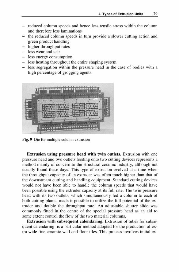
4 Types of Extrusion Units 79
− reduced column speeds and hence less tensile stress within the column and therefore less laminations
− the reduced column speeds in turn provide a slower cutting action and green product handling
− higher throughput rates − less wear and tear − less energy consumption − less heating throughout the entire shaping system − less segregation within the pressure head in the case of bodies with a
high percentage of grogging agents.
Fig. 9 Die for multiple column extrusion
Extrusion using pressure head with twin outlets. Extrusion with one pressure head and two outlets feeding onto two cutting devices represents a method mainly of concern to the structural ceramic industry, although not usually found these days. This type of extrusion evolved at a time when the throughput capacity of an extruder was often much higher than that of the downstream cutting and handling equipment. Standard cutting devices would not have been able to handle the column speeds that would have been possible using the extruder capacity at its full rate. The twin pressure head with its two outlets, which simultaneously fed a column to each of both cutting plants, made it possible to utilize the full potential of the ex-truder and double the throughput rate. An adjustable shutter slide was commonly fitted in the centre of the special pressure head as an aid to some extent control the flow of the two material columns.
Extrusion with subsequent calendaring. Extrusion of tubes for subse-quent calendaring is a particular method adopted for the production of ex-tra wide fine ceramic wall and floor tiles. This process involves initial ex-

80 Willi Bender
trusion in the form of a tube, which is then cut open and smoothened and flattened by means of calendaring rolls.
Hot extrusion. Hot extrusion, which involves heating of the clay by the introduction of steam into the combined de-airing extrusion unit, is primar-ily aimed at reducing the drying time. Most of the factories in the struc-tural clay industry use the benefits of hot extrusion. The steam is usually added at the mixer via a bottom plate in the mixing trough. As a rule the aim is to reach a column temperature of 50–60ºC.
Vacuum extrusion. All ceramic materials contain a certain percentage of gas, for the most part in the form of the finest air bubbles embedded be-tween the individual body components. The aim of de-airing, degasifica-tion, or evacuation of the body, is to remove the embedded air, which has a grogging effect and creates bubbles, in order to achieve an increase in plas-ticity and reduce the risk of laminations.
The subject of de-airing is dealt with in greater detail in chapter 15 and 16, and the equipment needed for de-airing purposes is listed in table 7 of same chapter.
4.10 Classification by the Type of De-airing Device Employed
De-airing removes the air embedded in the body. In order to optimise the de-airing process, the body must first be compacted, i.e. subjected to a higher pressure and then broken down in such a manner to achieve a ma-ximum surface area. Since plastic clay is basically impervious to gas, the only way the embedded air can be released is by the effect of the differen-tial pressure between the residual pressure in the vacuum chamber and the pressure of the air embedded in the body causing it to “burst” out. The greater the pressure difference and the thinner the material layer, the easier the body particles can be broken up. Various de-airing systems were deve-loped for this purpose, which can be differentiated as follows:
− extruder with de-airing device in the extrusion barrel (de-airing extru-der)
− extruder with combined auger/mixer shaft and intermediate vacuum chamber (single shaft de-airing extrusion unit)
− combined de-airing extrusion unit with separate vacuum chamber with shredder device, available in different versions (see table 7, item 6), the most commonly used being those with a screen plate and those with shredder blades (Fig. 10).

4 Types of Extrusion Units 81
Fig. 10 Vacuum chamber with shredder device
4.11 Classification by the Extruder Design Features
The following table shows the main components of a simple auger ex-truder and their most significant design versions:
Table 6 Components and design options of the extruder
Item Main components Design options and details 1 Extruder housing Version: extruder machine body and gearbox separate, or
as unit Design: open ribbed-type construction, enclosed double-walled box section, self-contained design, fitted on base frameMaterial: welded construction, cast iron, spheroidal graphite cast iron, cast steel
2 Infeed device Version: feed roller, feed paddle, feed auger, infeed roller paddles fitted on mixer shaft, meshing with auger, with or without rims Number: none, one or two Material: welded construction, casting, hard facing, stainless steel design Shaft: design, diameter Bearing: two-fold or overhung-mounted, type of bearing, dimensions, rated load, sealing Drive: by main drive, separate individual drive, constant or variable speeds

82 Willi Bender
Table 6 (Continued)
3 Extruder barrel Version: one part, enclosed, with or without intermediate barrel, swivel-type with hinges, with or without counter blades, number, coolable or heatable Material: welded construction, cast iron, spheroidal graphite cast iron, cast steel, stainless steel design
4 Barrel liners Version: one part or multiple part, smooth, perforated, with longitudinal strips, with spirals, with keel rails,Fixing: with screws, screwless, secured against twisting by strips, secured with bolts,Material: rolled sheet metal, welded on strips, cast barrel liners: cast steel, wear-resistant chilled casting, hard-faced, stainless steel design, special concrete
5 Augers Version: one part augers, individual augers, augers with replaceable rims, larger diameter at extruder infeed, thickness of wings, option of combination of pitches (de-gressive, progressive, linear), coolable or heatable, end auger (point auger): two or three flights, fixed or adjust-able in several steps or infinitely variable (regulated pres-sure head) Connection to shaft: self-contained element without con-tinuous shaft, machined boreholes with feather key con-nection, tangential keys, profiled shaft Material: welded construction, cast steel, cast steel with wear-resistant rims, Ni-hard, highly wear-resistant special casting, hard-faced augers, special steel, stainless steel design, plastic, ceramic
6 Auger shaft Version: material, diameter inside bearings Bearings: anti-friction bearings or sliding bearings, di-mensions, rated loads, sealing
7 Gearbox Version: integrated gearbox, separate gearbox Design: helical gearing, spur toothing, machined or ground wheels, immersion lubrication, circulation lubri-cation, type of bearings Material (for gearbox housing): welded construction, cast iron, spheroidal graphite cast iron, cast steel
8 Drive Version A: by belt drive, overhung mounted bearing of belt pulley, with intermediate gear and outboard bearing,Belt pulleys: diameter x width, spider pulley or solid pul-ley, number of grooves No-load facility: with anti-friction bearings, with sliding bearingsClutches: multiple disc clutch, compressed-air operated multiple disc clutch, compressed-air clutch, hydrauli-cally-operated clutch Version B: by directly coupled gearbox and variable speed motor

4 Types of Extrusion Units 83
Table 6 (Continued)
9 Accessories (examples)
Monitoring devices: pressure gauge, backflow monitoring device, standstill and synchronizing device, overload safety device, pressure control device, temperature sen-sor, counters, speed monitoring devices, service hour counterPressure heads: with/without regulating device, with oil-lubrication, fluidic-optimised, different geometric shapes Dies: construction, material Change-over mechanism for pressure head: shifting de-vice, swivelling device, multiple turret Column speed control Lifting and lowering device, travelling gear Automatic lubrication device: central lubrication system Electrical section: drive motors, electrical control, soft-ware for preventative maintenance
4.12 Classification by the Design of the De-airing Mixer
The following table shows the main components of the de-airing mixer and the most important options regarding the design of these parts:
Table 7 Components and design options of the de-airing mixer
Item Components Design options and details 1 Mixing trough Construction: one part, two or multiple part, length x
width, replaceable wearing liners, connection toSteam heating attachment: through bottom plate, through counter blades, through trough cover, combinations, moistening device
2 Mixer shaft Bearing: overhung mounted bearing, fitted in vacuum chamber, dimensions, rated loads, Connection to gearbox: continuous into gearbox, in hol-low shafts, with split coupling, with shrink-fit pulleys
3 Mixer blades (in open section mixing trough)
Construction: adjustable feed angle, one part design, forged mixer blades, mixer blades made by re-casting process,Connection to shaft: mixer blades with shaft inserted through shaft, two parts with feather keyway Material: welded construction, cast steel, cast steel with replaceable rims, highly wear-resistant casting, Nihard, hard-faced version, stainless steel version

84 Willi Bender
Table 7 (Continued)
4 Augers (in closed section of mixer)
Construction: one part augers, several individual augers, augers with replaceable rims, larger diameter at transition from mixer blades to augers Connection to shaft: machined boreholes with feather key, by bolts through the shaft Material: welded construction, cast steel, cast steel with wear-resistant rims, Nihard, highly wear-resistant special casting, hard-faced augers, stainless steel design
5 Vacuum chamber Construction: vacuum chamber and mixer-auger barrel designed as one unit, separate vacuum chamber: one part or split, with second vacuum chamber Design: size of vacuum chamber, size and number of openings, size and number of inspection glasses,Material: welded construction, cast iron, spheroidal graphite cast iron, cast steel Filter system: single or double filter Vacuum pump: type of construction, air capacity, resid-ual pressure which can be achieved
6 Shredder device Screen plates: one part, multiple part, round hole perfora-tion, slotted hole perforation, size of holes, movable to outside mechanically or hydraulically, swing-out inside the vacuum chamber Position of the screen plates: horizontal, vertical Shredder blades: rotating with mixer shafts, shredder blades driven separately, option for subsequent installa-tionCombination of perforated plate with rotating stripping knife in front Combination of perforated plate with high speed rotating shredder blades in front, high speed blade with collecting dish, number of cutting knife blades, material Outlet into vacuum chamber: round cross section, by means of retarding slides, replaceable dies, material
7 Gearbox and drive Analogous to extruder – see table 6, compare item 8
8 Special accessories (examples)
Monitoring devices: bin level monitoring device, partly also as listed in table 6, item 9 Moisture control device, Steam heating attachment: steam generator De-airing: vacuum generating system, vacuum pump, vacuum-meter, air filter, leak indicator device

4 Types of Extrusion Units 85
4.13 Classification by the Design Version of the Combined De-airing Extrusion Unit
The type of combined de-airing extrusion machine can be defined by, amongst other aspects, the configuration of the auger and mixer shafts, by the method of connection between the extruder and de-airing mixer, as well as by the construction of the de-airing mixer. One differentiates the features accordingly, as shown below:
A. By the configuration of the auger and mixer shaft(s): (Fig. 11)
Fig. 11 Diagrammatic view of possible position of auger shaft and mixer shaft
1A 1B
2
3
4
6
5
7
8B8A
1. Auger shaft and mixer shaft arrangedon top of each other, feeding in the same direction Option A: (commonly used version): mixer shaft above the auger shaft, option B: mixer shaft be-low the auger shaft. 2. Auger shaft and mixer shaft arrangedon top of each other, feeding in oppo-site direction 3. Auger shaft and mixer shaft arrangedon top of each other, mixer shaft feed-ing at right angles to auger shaft, either r.h. or l.h. 4 Auger shaft and mixer shaft arranged on same level, mixer shaft feeding at right angles to auger shaft, either r.h. or l.h.5. Auger shaft horizontal, mixer shaft vertical.6. Auger shaft vertical, mixer shaft horizontal.7. Auger shaft adjustable from horizon-tal to vertical, i.e. at any angle from0- 90º, mixer shaft horizontal and verti-cal to auger shaft. 8. Auger shaft and mixer shaft com-binedOption A: horizontal version, option B:vertical version

86 Willi Bender
B. By the method of connection between the extruder and mixer: Basically there are two options for connection of the machines that form the combined de-airing extrusion unit:
− detachable connection: as a combined or universal de-airing extrusion unit,
− non-detachable connection: as a monobloc- or compact combined de-airing extrusion unit.
Universal de-airing extrusion unit. Extruder and mixer are stand-alone (independent) machines which form the universal type combined de-airing extrusion unit, each equipped with its own drives. Therefore the ratio be-tween auger shaft speed and mixer shaft speed can be chosen freely and be adapted to any specific operating conditions. Due to the fact that the con-nection between both machines can be detached, it is possible to arrange the mixer either in longitudinal direction or at right angles (r.h. or l.h.) to the extruder (Fig. 12).
Fig. 12 Universal type combined de-airing extrusion unit
Compact version combined de-airing extrusion unit. With this ver-sion, the extruder and mixer form a conjoined single unit with one only common drive, the latter representing a cost benefit and probably the main motivation for the development of this type of construction (Fig. 13).

4 Types of Extrusion Units 87
Fig. 13 Compact version de-airing extrusion unit
The fixed ratio of the auger and mixer shaft speeds resulting from this type of construction is of a disadvantage, especially as this cannot subse-quently be altered. There are however gearboxes with two-stage switch-gear, which allow the speeds to be changed.
The compact de-airing extrusion unit is only available in a longitudinal arrangement; it has lost much of its importance in relation to the combined de-airing extrusion machine.
C. By the construction of the de-airing mixer: Any combined de-airing extrusion machine consists of an extruder and a primary pug sealer, of which several versions do exist, and therefore the following combinations are possible:
− combination of extruder and de-airing double shaft mixer − combination of extruder and de-airing single shaft mixer − combination of extruder and vertical or horizontal de-airing pug sealer
The combined de-airing extrusion unit does, in fact, consist of two ma-chines, which are the extruder as such and the preliminary pug sealer, which can be designed as a double-shaft mixer, a single-shaft mixer or as a vertical or horizontal de-airing pug sealer. The vacuum chamber is the connecting component between the two machines to form a single unit, whereby the de-airing chamber provides an air-tight connection between the outlet exit of the primary pug mill and the infeed hopper of the extru-der, a reason for the combined de-airing extrusion machine also being cal-led a composite extruder.
Extruder and de-airing double shaft mixer. Thanks to the high throughput capacity, the good mixing properties and the option of steam
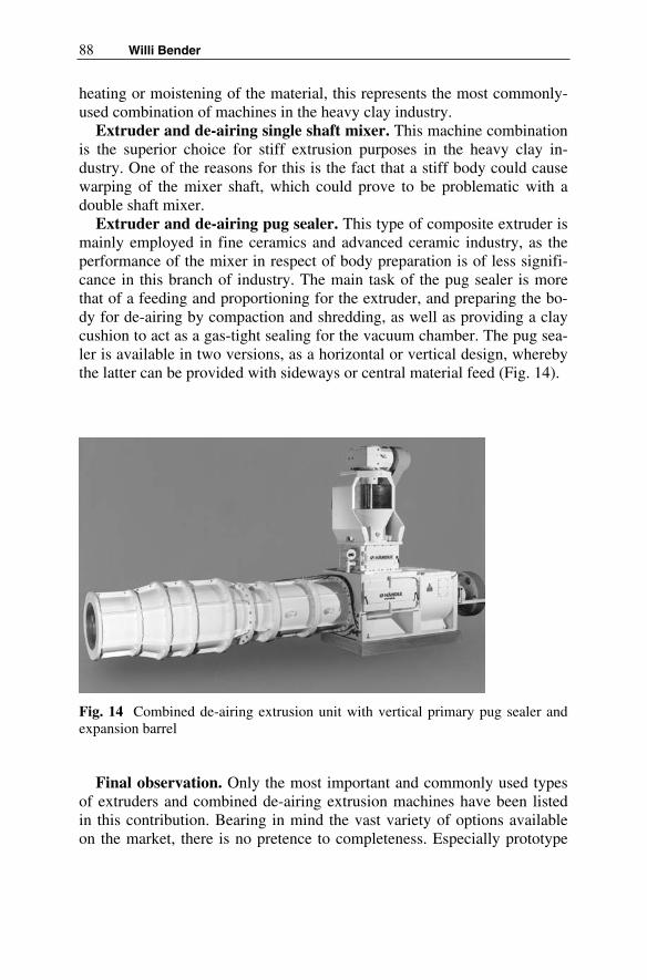
88 Willi Bender
heating or moistening of the material, this represents the most commonly-used combination of machines in the heavy clay industry.
Extruder and de-airing single shaft mixer. This machine combination is the superior choice for stiff extrusion purposes in the heavy clay in-dustry. One of the reasons for this is the fact that a stiff body could causewarping of the mixer shaft, which could prove to be problematic with a double shaft mixer.
Extruder and de-airing pug sealer. This type of composite extruder is mainly employed in fine ceramics and advanced ceramic industry, as the performance of the mixer in respect of body preparation is of less signifi-cance in this branch of industry. The main task of the pug sealer is more that of a feeding and proportioning for the extruder, and preparing the bo-dy for de-airing by compaction and shredding, as well as providing a clay cushion to act as a gas-tight sealing for the vacuum chamber. The pug sea-ler is available in two versions, as a horizontal or vertical design, whereby the latter can be provided with sideways or central material feed (Fig. 14).
Fig. 14 Combined de-airing extrusion unit with vertical primary pug sealer and expansion barrel
Final observation. Only the most important and commonly used types of extruders and combined de-airing extrusion machines have been listed in this contribution. Bearing in mind the vast variety of options available on the market, there is no pretence to completeness. Especially prototype

4 Types of Extrusion Units 89
machines or those special designs that are only suitable for specific appli-cations have not been taken into consideration.
Literature
[1] Herrmann H (1972) Schneckenmaschinen in der Verfahrenstechnik. Springer-Verlag Berlin Heidelberg ISBN 3-540 05632-7
[2] Häusser A (1966) Rohstoffe, Strangpressen, Texturen. J Die Ziegel-industrie vol 19 pp 834-838, 869-874, 904-907
[3] Häusser A (1967) Rohstoffe, Strangpressen, Texturen. J Die Ziegel-industrie vol 20 No 1:9-11, No 2:26-30, No 3:96-102
[4] Plaul, T (1973) Technologie der Grobkeramik. Band 1, Kapitel Formgebung, VEB Verlag für Bauwesen, Berlin
[5] Bender W (1975) Das Strangformverfahren in der Grobkeramik. JSilikat-Journal No 3
[6] Händle F (1975) Perspectives in the Ceramic Shaping Technology. JInterceram vol 24 No 4 pp 262-265
[7] Händle F (1977) Comparative study of vacuum unit systems in the heavy clay industry. J Interceram vol 26 No 3 pp 192-195
[8] Hülsenberg D (1980) Maschinelle Formgebung in der Keramik. VEB Verlag für Grundstoffindustrie, Leipzig, 1. Auflage
[9] Krause E, Berger I, Plaul T, Schulle W (1982) Technologie der Ke-ramik. Band 2, Mechanische Prozesse, VEB Verlag für Bauwesen, Berlin
[10] Pels Leusden CO (1982) Extrusion. In: Bender W, Händle, F (eds) Brick and Tile Making. Bauverlag GmbH, Wiesbaden und Berlin
[11] Händle F (1982) Shaping. J Brick & Tile Industrie International No 1
[12] Bender W, Lutz D (1985) Die Steifverpressung – eine interessante grobkeramische Formgebungstechnologie. J Sprechsaal vol 118 No 10 pp 979-983
[13] Bender W (1998) Extrusion technology in the structural ceramic in-dustry. J Brick and tile Industry International No 4
[14] Bender W (2000) Extrusion technology for the 3rd millenium. J Brick and Tile Industry International No 10

5 A Short History of the Extruder in Ceramics
Willi Bender, Hans H. Böger
There are only a few technologies that in the process of their development have found such an extensive range of application as that of extrusion technology. Its origin was in structural ceramics, yet nowadays the ex-truder is employed in such diverse industries as the plastics industry, the chemical and its related industries, foodstuffs industry, fodder concentrate industry, etc., both for extrusion as well as for preparation and other proc-ess technologies.
The concept of shaping a product by forming an endless column of the desired cross section, from which a brick is then cut to the required length, is in fact a very old one and known since at least the beginning of the 17th
century. To realise this idea, essentially three different modes of operation lent themselves to the processing of plastic and semi-plastic bodies, these being the piston press, the roll extruder and the auger extruder. Of these, the auger extruder is the most common. Therefore when reference is made to extrusion within the field of ceramics, it normally relates to the auger extruder. However the piston press and roll extruder were able to maintain a certain foothold and have undergone further development.
In 1985 the radial dry powder column extruder was developed for batch-continuous extrusion of dry powders [1]. Technically it cannot be classi-fied as an extruder, yet it combines the benefits of conventional column extrusion with the qualitative merits of isostatic pressing and mention of it should therefore not be omitted here.
Extruders are predominantly employed in ceramics for direct shaping, but they are also used for the pre-shaping of clots and slabs ready for a fur-ther shaping process and, lastly, particularly in the field of fine ceramics, as pure preparation machines for homogenising, de-airing and for im-provement of the plasticity and density of bodies.
Just as interesting as the versatile range of application of extruders and their design and process engineering features is their historical develop-ment, as depicted below. If the extrusion of structural ceramic products features prominently in the following, this is due to the fact that it is in this

92 Willi Bender, Hans H. Böger
branch of the ceramics industry that the process has been used for the longest period and where it is also the one most widely employed.
5.1 The Development of the Extruderand Column Shaping
Each of the three systems of column shaping, which are based on different methods of operation: piston extruder (intermittent), expression rolls and auger extruder (continuous) has its own development history. In the course of their development there have also been several combinations of these three column shaping systems, e.g. auger extruder/piston extruder, auger extruder/expression rolls, expression rolls/auger extruder, auger ex-truder/auger extruder, whereby in each of these cases the former is always the feed unit and the latter the actual shaping machine.
5.1.1 The Piston Extruder
The history of extrusion can be traced back to 1619 when the Englishman John Etherington built a hand-operated piston extruder, with which bricks were produced. After the introduction in England in 1623 of the “Statute of Monopolies”, which governed the protection of inventions, a patent was granted to him for his brick machine. Hence the piston extruder can be considered the earliest extrusion machine. Initially, however, this did not gain acceptance.
The next known inventor was Hostenberg of St. Petersburg, who from 1807 onwards built a hand-operated piston extruder for the shaping of drainage pipes, known therefore as a drainpipe extruder (Fig. 1). This de-sign of machine was rapidly and widely accepted all over Europe. It was built as a single or double-acting piston extruder, (the so-called “running-out machine” or “stupids”), for instance in England by Messrs. John Whitehead & Co. Ltd., Preston. This type of extruder was still used in iso-lated cases until the 1970s, for instance in Germany in a place called Zieko near to Coswig, Saxony-Anhalt, for extruding drainpipes, special-purpose bricks and horizontal-core bricks.
The filling or charging boxes that receive the material, one in the case of the single-acting extruder and two in the case of the double-acting version, were closed with heavy lids during the actual shaping operation. The pis-ton was actuated by hand with the use of a hand-wheel and backgear or with the aid of steam power. With the aim of avoiding the laborious open-ing and closing of these lids, a piston extruder was developed around 1870 which was fitted with a hinged extrusion barrel to replace the charging

5 A Short History of the Extruder in Ceramics 93
Fig. 1 Single-acting piston extruder, the so-called “running-out machine” or “stupids”, from 1810).
boxes. This was lifted into a vertical position for filling and into a horizon-tal position for the shaping operation (Fig. 2). The moulding machine built by Henry Clayton was displayed at the London World Exhibition in 1862. This was a double-acting piston extruder which pushed out a clay column to the right and to the left in alternating mode. Material feed was accom-plished by a horizontal pug mill (Fig. 3).
Fig. 2 Piston extruder with hinged extrusion barrel, circa 1870
Fig. 3 Double-acting piston extruder with preceding pug mill and roller mill, Clayton, 1862
Vertically-operating piston extruders for the shaping of larger pipes were introduced around 1870. The first versions of these extruders were of such design that the piston moved inside the material-filled barrel from bottom to top with the aid of a spindle. However, this method was soon

94 Willi Bender, Hans H. Böger
abandoned in favour of extruding from top to bottom. The inconvenience of piston extruders lay primarily in problems relating to the pressed-in air resulting in the formation of bubbles on the brick, moreover the standstill time for refilling the extrusion barrel after the pressing out of each piston charge. In an effort to avoid both factors, a vertical piston extruder with two rotating barrels was developed in 1880. While one barrel was pressed out, the second barrel was charged with material and rammed down to pre-vent air bubbles 2 (Fig. 4).
Fig. 4 Vertical piston extruder with two rotating barrels, around 1880
In the 1960s Messrs. Uniceram SA of Marseille, France, built a hydrau-lically-driven piston extruder for the stiff extrusion of structural clay prod-ucts, combined with a de-airing double-shaft mixer, was operated as a combined de-airing extrusion unit (Fig. 5). On the whole however the pis-ton extruder has been of relatively little importance in comparison to the auger extruder within the field of structural ceramics.
When advanced ceramics gained more significance from the 1950s on-wards processing oxide-ceramic and non-oxide ceramic bodies that fre-quently required a high degree of compression, necessitating high pressure rates not normally obtainable with auger extruders, interest in piston ex-truders was reawakened. Nevertheless the essential disadvantage of the piston extruder as opposed to the auger extruder will always be its inter-mittent mode of operation and the limited possibilities of evacuation.

5 A Short History of the Extruder in Ceramics 95
Fig. 5 Combined de-airing extrusion unit with de-airing double-shaft mixer and piston extruder, built by Messrs. Uniceram, Marseille, about 1960
5.1.2 The Expression Rolls
The Englishman Ainslie was one of the first to build an expression rolls machine, around 1830; two rolls pushed the clay into a pressure head to be shaped to a column through a die (Fig. 6). From England this machine reached other countries, including Germany, where its design served as a basis for several follow-up models, in particular those made by Messrs. Gebrüder Sachsenberg of Rosslau/Elbe, who built expression rolls from about 1865. Expression rolls featured either two vertical, superimposed rolls or, in order to facilitate material intake, two vertical rolls in an in-clined arrangement, set at a roller gap of approx. 5 – 6 mm. Expression rolls with an additional feed roll, operating as so-called triple expression rolls machines, were also on the market
Fig. 6 Expression rolls built by Ainslie, circa 1830
Frequently expression rolls were combined with an upright or horizontal pug mill or with an inclined-fitted auger extruder, so as to utilize the mix-ing and homogenising effect of these machines, which of course could not be achieved by the expression rolls (Fig. 7). The first vertical expression

96 Willi Bender, Hans H. Böger
rolls featuring a horizontal adjacent rolls arrangement were built by Sach-senberg in 1874 for the production of pipe.. Sachsenberg continued to manufacture expression rolls until about 1940, mainly for flat-type prod-ucts such as extruded roofing tiles. For instance Messrs. Karl Händle & Söhne of Mühlacker,Germany, produced an eccentric extruder in the 1930s. The pressure roll, which had to accomplish the forward feed of the material, was provided with longitudinal slots in which movable slides car-ried by eccentric rings were fitted as an infeed aid (Fig. 8).
Fig. 7 Expression rolls with feed auger, around 1875
Fig. 8 Eccentric extruder, Messrs. Händle, about 1930
Two patents in the United States dated 1961 and 1962 and a French pat-ent of 1961 describe a method for roll extrusion of thin tiles and carrier plates for catalyst converters to act as ceramic protective plates, made from

5 A Short History of the Extruder in Ceramics 97
plastic ceramic bodies with a clay portion and moisture content ranging be-tween 8 and 15% fed into the roller gap without pressure.
In 1970 Messrs. Rieterwerke of Constance, Germany, introduced an “augerless extruder” onto the market as their version of expression rolls, also known as “Europresse” or rotor-type extrusion machine, for which a patent had already been applied in 1963 as an “extruder for ceramic bod-ies”. The characteristic feature of this machine is a rotor with annular grooves into which a smooth feed roll squeezes the material, so that this can be carried around the circumference. Once the material is taken around about two thirds of the circumference it is pushed against tangentially-arranged scrapers which mesh into the annular grooves and which intro-duce the material into the pressure head (Fig. 9). Used in combination with a de-airing mixer, the “Europresse” can be operated as a combined de-airing extrusion machine. As there is no slide contact within the trans-ported clay mass thanks to the grooves of the rotor, one would anticipate the highest stress-free and lamination-free properties. In the end however, in spite of good results achieved in particular cases, these expectations could not be fulfilled and therefore the “Europresse” was unable to jeop-ardise the supremacy of the auger extruder.
Fig. 9 Diagram of the extruder “Europresse”, 1970 1. compaction roller, 2. feed roller,3. discharger, 4. pressure head
Later, in the 1990s, the German Institute for the Refractory and Ceramic Industry took up the technology of expression rolls again, for continuous shaping with simultaneous compaction of ceramic bodies, in particular for the production of multi-layer products 3 4. Such components made up of individual material layers can be produced relatively easily on expression rolls. In laboratory tests Al2O3specimens containing up to 32 layers were rolled together. It is possible to roll fibres, fabrics or metal foils between the individual layers of such a ceramic composite material.
The operating principle of an improved and patented expression rolls machine should enable the production of endless ceramic ribbons with

98 Willi Bender, Hans H. Böger
thicknesses from 0.5 to approx. 10 mm, of different cross sections and with internal channels, to be used for instance as kiln furniture, heat exchangers and fluid components (Fig. 10). This process is feasible with the most di-verse of material compounds, such as plastic or non-plastic, oxide, nitride or carbide materials. In the extrusion of non-plastic ceramic powders the percentage of plasticizing agents can be kept to a minimum as a result of the energy introduced during the rolling process (roll pressure 0.01-3.27 t/cm).
Fig. 10 Diagram of an expression rolls machine for perforated ceramic endless ribbons, 1990 1. feed section, 2. feed auger, 3 and 4. rollers, 5. roller gap, 6. core,7. perforation, 8. brick
Electrophoretic Extrusion
In 1977 another expression rolls machine known as the “Elephant” emerged. This adopted a new ceramic extrusion method utilizing electro-phoresis following the “Elephant” principle. It cannot be formally classi-fied as an extruder, rather being a machine for “shaping by means of pre-cipitating slurry in an electric field (electrophoresis)”, yet the unusual features of this special process do in fact fulfil the requirements of column extrusion. The process could also be termed the “extrusion of slurry”5,6,7,8.
The physical phenomenon of electrophoresis has been known since the 19th century, when Reuss discovered that particles suspended in water

5 A Short History of the Extruder in Ceramics 99
move in a certain direction once they find themselves in an electric field. Decades later it was realised that, according to the type of particles and also the liquid, they can be charged positive or negative and hence travel either to the cathode or anode.
It was in 1939 in the USSR that the first tests for electrophoretic extru-sion of ceramic materials were carried out. Then in 1977 M. S. Chronberg introduced a process for continuous production of flat ceramic products ranging from mosaic to large-size tiles (Fig. 11). Messrs. Händle of Müh-lacker, Germany, adopted this principle. After extensive basic studies by the Fraunhofer Institute for Silicate Research to back up the theory of elec-trophoresis, the second generation of electrophoretic expression rolls ma-chine “Elephant” was built, supplied to Messrs. Ceralit, Evreux, France, and commissioned in spring 1980. Using a voltage of 30V and an amper-age of 150A, the machine produced a throughput rate of 550 kg/h with a column thickness of 5.5 mm and a moisture content of 17% on a dry basis in the plastic state. The two counter-rotating and zinc-plated rolls form the anode. The cathode is arranged in their top gusset. The slurry is pumped into the uniform gap between the anodes and the cathode and the rolls are pressed together with appropriate power corresponding to the hydrostatic pressure of the slurry column. During the rotating motion of the rolls the layers of solid particles, precipitated on the roll surfaces, are firmly pressed down at their contact point, forming a continuous ceramic ribbon contain-ing a moisture content between 16 and 18% on dry basis. Employing a downstream roll and punching equipment enables the production of a wide range of ceramic tiles with a variety of embossment and sizes. But the principle of electrophoretic extrusion was not successful in the Structural Ceramic.
Fig. 11 Diagram of the electrophoretic expression rolls extruder “Elephant”, 1979 1. outlet of excess slip to be recycled, 2. deposit being formed by electrophoresis, 3. counter electrode (cathode), 4. inlet of the slip, 5. zinc anode, 6. double-layer band of ceramic body, 7. band

100 Willi Bender, Hans H. Böger
5.1.3 The Auger Extruder
It is doubtful whether anyone would imagine a connection in the history of extrusion between auger extruders and the smoking of tobacco. The role however of the clay tobacco pipe is important. During the 1570s, English sailors and soldiers returning from North America took tobacco and a smoking instrument similar to clay pipes back England. As smoking very soon became popular, it was in this period that the first clay pipe produc-tion facilities were set up there. Smoking spread from England across to Holland, where evidence of pipe smoking is to be found even prior to 1600. There is proof of the manufacture of clay pipes in Amsterdam from 1607 and, amongst other areas, in Gouda since 1617. It was in Gouda in 1643 that the Dutch “pipe baker” J.J. Speckstruyff designed a clay mill – the embryo of column extrusion with the use of augers – for the prepara-tion of his pipe clay. This device consisted of a wooden trough with fixed counter blades and a knife shaft with straight knives (Fig. 12). The pug mill developed from this Dutch clay mill was in turn the origin of two lines of development, one of them leading to the soft-mud moulding machine and the other to auger extruders.
In 1767 the Swedish captain Carl Wijnblad described one of the first soft-mud moulding machines, which was based on a horizontal pug mill. The knife shaft fitted in an open-topped trough was driven directly from a water wheel. Several rows of knives, arranged in a helix, were fitted into the knife shaft and the shaft end carried an eccentric thrust member. An opening was provided below the trough, into which the wooden moulds were manually inserted via a guide channel. The clay was fed by hand into the rear end of the trough, transported towards the front by means of the knife shafts and pushed into the wooden mould below with the aid of the thrust member at the front end of the trough; one mould could be filled with every rotation (Fig.13). Soft-mud moulding machines invented later often featured one or two upright pug mills. This first line of pug mill de-velopment, which led to the soft-mud moulding machine, is not pursued here further.
Early efforts to utilize the principle of Archimedes' screw for the pur-pose of extruding a column to produce bricks – without direct reference to the pug mill – started around 1830, and were made amongst others by Tweedale & Hunt in 1840 and in 1852 by Randal & Saunder. The latter used a counter-rotating horizontal twin auger and an interesting cutting de-vice for their machine (Fig. 14). It is also worth mentioning that Lord Ber-riedale invented a machine, a horizontal extruder with integrated and slid-ing clay screen in the extruder barrel, which became known in 1852 9. At the same time a mechanical cutter was introduced. Lord Berriedale's ma-

5 A Short History of the Extruder in Ceramics 101
Fig. 12 Prototype of the Dutch clay mill, Speckstruyff, 1643
chine already had the external shape of modern horizontal auger extruders, but in the end none of these machines could gain acceptance. It was finally Carl Schlickeysen who managed the breakthrough in 1855 with his “Uni-versal Patent Brickmaking Machine”.
The Berlin machinery manufacturer Carl Schlickeysen managed to ac-complish this with his “auger for movement of plastic materials”, which he installed into a pug mill and for which he applied for patents using the name “Universal Brickmaking Machine” in Europe and the United States of America. He was granted an English patent on 24th August 1854 for a

102 Willi Bender, Hans H. Böger
Fig. 13 Soft-mud moulding machine with horizontal pug mill by C. Wijnblad, 1767
Fig. 14 Twin-auger extruder of Randal & Saunder, 1852

5 A Short History of the Extruder in Ceramics 103
“machine for the production of pipes and bricks”. The Schlickeysen ex-truder was shown to the public for the first time during the Agricultural Fairs in Cleve and Cologne, Germany, in 1855 when the extrusion of roof-ing tiles was demonstrated. The Newton’s London Journal of June/July 1856 and the Official Business Report of the United States Patent Office, Washington, of 1856 described the invention for the first time under the ti-tle, “Patent Brickmaking Machine of C. Schlickeysen”.
This was an upright extrusion machine consisting of a feed hopper enlarged at the top and fitted with a special discharge auger blade, fol-lowed by a series of inclined compression blades screwed to a shaft with gaps in between in a slightly overlapping configuration in order to achieve the required extrusion pressure. The last auger blade was already a type of end auger and can be regarded as the driving screw. An interrupted helix was obtained, which represented a breakthrough. The most important ele-ment however was the second bottom component with its raised border, fitted to the shaft immediately beneath the discharge opening and rotating with the shaft. This bottom plate received the material pushed down from the rear closed section of the barrel and moved it around to the outlet open-ing where it was forced to exit, thus avoiding further trailing action due to continuous pressure of the material load from above. This made it possible to exert a uniform pressure over the entire outlet opening (Fig. 15). The first brickmaking machine was tested by Schlickeysen in his own brick-yard at Kremmen near Oranienburg, Germany, employing a traction beam and draught animals.
The leaseholder of the Ducal Brickyard in Rosslau/Elbe (Germany) Mr. Carl Schneider engaged Carl Schlickeysen in 1857 to design a “Universal Patent Brickmaking Machine” to be driven by a steam engine, which pro-duced the first bricks in February 1858 (Fig. 16).
Carl Schlickeysen did not have his own foundry and was therefore in need of a competent partner in order to implement his ideas, and he found this partner in Nienburg, Germany, in Messrs. Hertel & Co., later known as Nienburger Maschinenfabrik AG. Not only the extrusion barrel and the auger blades were cast in Nienburg, but the complete brick machine was manufactured there. The two engineers Hertel and his associate Schmelzer recognised the merits of the brick machine invented by Schlickeysen and developed their own horizontal auger extruder in 1859/60, which was suc-cessfully tested in 1860 in the Ducal brick plant in Nienburg-Grimschleben, Germany (Fig. 17). This machine was equipped with a ta-pered extrusion barrel and an infeed machine body of 75 cm diameter. The barrel length was 1.25 m and the output was quoted to be 1200–1300 bricks per hour. A speed of 6 – 8 rpm was specified for the auger shaft. There is proof that this extruder was still in operation until 1909. The hori-

104 Willi Bender, Hans H. Böger
Fig. 15 Patent Brick Machine of C. Schlickeysen, 1856
Fig. 16 First upright auger extruder powered by steam, 1858

5 A Short History of the Extruder in Ceramics 105
Fig. 17 First horizontal extruder, Hertel, 1860
zontal extruder managed its breakthrough at the International Agricultural Exhibition in Hamburg in 1863, where it was shown along with the Eng-lish piston extruder, the German expression rolls machine and the upright pug mill, offering the experts an opportunity for comparison.
There were essentially two reasons for the transition from an upright to a horizontal auger extruder: feeding of an upright extruder, which at that time was still effected manually, was extremely strenuous, and the ar-rangement of the drive – whether at top or bottom – was not without prob-lems.
On the other hand the upright extruder with its vertical outlet was bene-ficial inasmuch as the bricks produced on this machine hardly showed any noticeable laminations created by the auger and the flow movement of the clay. The clay pushed to the bottom was taken along towards the die by the rotating base and was forced to exit laterally. As a result of the change in direction, the previous longitudinal orientation of the clay material was converted to a crosswise orientation. As the “clay strings” were still turned inside the extruder, any laminations which may have been caused by the flow motion of the material were hardly visible in the extruded column and hence the vertical extruder produced virtually lamination-free bricks.
This changed abruptly when the horizontal auger extruder was intro-duced. The rotational movement of the single-flight auger creates two in-tertwined spiral-shaped columns with smoothened surface areas, where there is pronounced parallel orientation of the clay minerals. At that time it was still not appreciated that these two surfaces must be re-united by a suitable configuration of the end auger and of the pressure head; hence these deficiencies were visible on the bricks in the form of S-cracks and ring-type laminations. As a consequence the transition from the upright to the horizontal auger extruder divided the opinion of the experts. Whereas some considered it as progress that made the mass production of bricks really possible, for others it was the root of all evil.

106 Willi Bender, Hans H. Böger
Since the introduction of auger extruders from 1855 onwards, that is to say for the last 150 years, the problem of textures/laminations in the extru-ded bricks has been the main issue in extrusion, even today still not entire-ly resolved; a sometimes controversial subject permanently under discus-sion and the topic of numerous publications.
The triumphal march of the auger extruder however was not to be stopped. For all that, a great deal of design work and detail development had to be undertaken to reach today's state-of-the-art technology, which will be dealt with separately in Chapter 2 in much more detail. Around 1870 vertical auger extruders, the so-called “suspended extrusion ma-chines”, were brought onto the market, to become forerunners of the later sewer pipe presses (Fig. 18).
Fig. 18 Suspended auger extruder for the extrusion of pipes, 1870
The practice of de-airing extrusion began in the United States about 1920 and in Europe from 1932 onwards.
The rudiments of stiff extrusion were already known in the United States by the end of the 19th century but were only employed in Europe for

5 A Short History of the Extruder in Ceramics 107
the first time in England in 1960, and in Germany in 1967 in the form of a combined de-airing stiff-extrusion unit supplied by Händle. The characteristic feature of the stiff-extrusion method is the high compressive strength of the bricks enabling a direct setting onto the kiln cars straight af-ter the extruder. In the early stages of stiff extrusion efforts were made to extrude as stiff as possible, sometimes reaching extrusion pressure rates up to 80 bar. The motto nowadays is to extrude just as stiff as necessary, and it is found that the requirements of stiff-extrusion can already be met with extrusion pressure rates from approx. 25 bar onwards, depending on the raw material characteristics. In view of the purpose to be served if would however be more appropriate to call this process “direct setting” rather than stiff extrusion.
Reports of the time indicate that the first tests of hot shaping were car-ried out as early as 1868. The idea was taken up again around 1935, but it was not until 1970 that this process was generally adopted in the structural ceramics industry.
For extrusion of very wide, flat clay ribbons the twin-shaft auger ex-truder was reintroduced in 1994 in the field of structural clay products, whereas co-rotating screw-extruders are used since the late 1970s in ad-vanced ceramic for the production of honeycombs.
5.1.4 Classification
If the column extrusion technologies are classified according to the consis-tency of the material body and its moisture content – powder/plastic/slurry – and to the method of operation – continuous/intermittent – the following overview is obtained:
pulverised plastic slurry < 5% on dry basis 8 – 25% on dry basis > 30%
Continuous --- auger extruder electrophoretic 1854 extrusion
expression rolls machine 1977 1830
Intermittent (radial dry powder piston extruder Extruder) 1619 ---
1983

108 Willi Bender, Hans H. Böger
5.2 The Development of Individual Extruder Components
This chapter essentially refers to the auger extruder without de-airing de-vice, consisting of the following main components: die, pressure head, ex-trusion barrel, auger and auger shaft, infeed machine body with feed de-vice, and drive. The sheer number and diversity of the various structural components of the auger extruder is astonishing; only the highlights of their historical development can therefore be covered in this work.
5.2.1 Die
The first experience with dies for column shaping was gained with piston extruders using relatively low column speeds. The dies used were already provided with cores, as pipes and hollow core bricks were the first items to be extruded, these being difficult or impossible to produce by hand. When solid bricks were initially extruded in1855, there was no expertise in this area. The problem was encountered that the surface area of the brick col-umn advanced at a slower rate than the faster-moving core, the result of the braking effect of friction against the wall. It took a very long time be-fore suitable dies were made available enabling the production of the de-sired cross section with a smooth surface free of cracks. This complication unnerved quite a few brickmakers in the early years, and there were those who even decommissioned their newly-purchased auger extruder and re-turned to the hand-moulding process, which they found less problematic. At first it was found completely impossible to extrude a column without dog-ears. As a remedial measure wires were stretched in front of the die to simply cut off the torn up sides of the bricks (Fig. 19). Obviously the outlet
Fig. 19 Die with wires

5 A Short History of the Extruder in Ceramics 109
cross section had to be enlarged accordingly for this purpose. Not until 1865 was a solution found when Schlickeysen invented a die with watering device, the “scale lubrication die”, the inside of which was lined with scale-like metal strips of tin, zinc or brass plate, In the beginning the dies were also lined with a cloth, the so-called English leather, which was a firm and dense cotton fabric. The water introduced through the metal scales acted as a lubricant and smoothed down the clay. Multiple-part dies existed for cleaning and easy replacement of the scales (Fig. 20).
Fig. 20 Multi-part die
Similar difficulties were encountered in the United States, when the col-umn extrusion method was introduced there in 1870, which continued until the patented “Niedergesaess Patent Lubrication Brick Die” was brought onto the market.11 This made it possible to lubricate the column either by water, oil or steam. It was discovered that dry steam was more effective than water or oil for certain clays (Fig. 21). Development of oil-lubricated and steam-heated dies also marked the beginning of stiff extrusion in the United States with material moisture contents as low as approx. 12%.
With the arrival of perforated bricks, dies had to be provided with suit-able cores, core holders and core holder bows. Tests were made with so-called bow-less dies with the cores fixed to wires, but these proved to be unsuccessful. With the design of dies becoming more and more compli-cated, die-making developed into a special field within ceramic machinery engineering, and even today there are still a few companies in various countries who manufacture exclusively dies.
In order to achieve a uniform column advance over the entire cross sec-tion, brakes were a fairly early development fitted at those points where the column had a tendency to advance at a slightly higher speed (Fig. 22) or, as an alternative, the infeed conditions were improved at those points where the column stayed back .
Step-by-step the adjustable die was developed. In the 1980s dies were introduced which could be externally adjusted. This was also necessary in view of larger and more complex products, and to accommodate the re-quirements of multiple column-extrusion, for instance with horizontal core bricks being extruded up to 16 columns side by side.

110 Willi Bender, Hans H. Böger
Fig. 21 Niedergesaess Patent Lubrication Die, 1888
Fig. 22 Dies with external braking adjustment to regulate central material advance

5 A Short History of the Extruder in Ceramics 111
The die for extrusion of honeycombs can be considered a speciality. Messrs. Schneider & Co., Frechen, Germany, applied for one of the first patents on 1.3.1965. Messrs. Corning Glass Works, NY, United States, who applied for their patent on 8.11.1972, with Dr. Rodney Delano Bagley named as the inventor, actually invented the die. Further patents followed, amongst others in Japan and Great Britain.
5.2.2 Pressure Head
Returning again to the first extrusion machines; the pressure head repre-sented nothing more than a fixing plate to fit the die to the extrusion barrel. But the important function of the pressure head, that of serving as the adapter piece between the round extrusion barrel and the commonly rec-tangular inlet of the die, the actual moulding element, was of course soon recognised. The combination of pressure head and die is also called the shaping tool. In the structural ceramics industry the die is fitted into a so-called adapter plate, which is bolted to the pressure head. A further design was available for the production of solid bricks, whereby the pressure head and die formed one unit.
The main purpose of the pressure head, as a connection element be-tween extrusion barrel and die, is to create uniform inflow conditions over the entire die area. To start with, a universal pressure head was employed for all types of clays and products, but it was quickly discovered that plas-tic materials required a longer pressure head than lean bodies. Also perfo-rated bricks needed longer pressure heads than solid bricks to allow for ample space between core bow and end auger. Therefore a tripartite pres-sure head was designed, which made it possible to adjust the correct length of the pressure head, for instance in the event of alternating production of solid bricks and perforated bricks. Also there were lubricated pressure heads and those with a lateral cleaning door.
Again in the years around 1910 there existed the so-called conoid pres-sure head, the internal contours of which formed a fluid transition from the diameter of the round extrusion barrel into the die. In order to avoid dead corners, the specific die was also suitably contoured internally, by the in-sertion of appropriately-shaped wooden wedges or brass-lined hollow in-serts. This idea was looked at again around 1970, when the pressure head with the so-called IZF core was developed, IZF being The (German) Insti-tute for Brickmaking Research. This aimed to achieve almost identical re-sistance inside the pressure head by adapting its conical shape to the shape of the column near the die (Fig. 23).

112 Willi Bender, Hans H. Böger
Fig. 23 Correlation of various pressure head outlets and die cross sections
The pressure gauge, a so-called flow pressure meter, came into exis-tence in the 1950s, and was installed in the pressure head. This instrument continuously measures the extrusion, or flow, pressure, which is dependent on the moisture content of the body, and so initiated automatic moisture and plasticity control.
The arrival of stiff extrusion in the Europe in the 1960s – in the USA since 1920 or earlier – also brought the pressure head/die combination with oiling ring. With this system, oil is injected with a pump to improve the sliding behaviour of the clay (Fig. 24). Circa 1970 regulating pressure heads came into use, featuring slides or brakes, which could be externally adjusted and which had an effect on the material flow (Fig. 25).
Fig. 24 Pressure head/die combi-nation with lubrication device for use in stiff extrusion

5 A Short History of the Extruder in Ceramics 113
Fig. 25 Regulating pressure head
To accommodate the large variety of product sizes to be produced, it was also common practice to use several suitably-adapted pressure heads. Pressure head swivelling and shifting devices were designed from 1980 onwards to enable fast pressure head changes (Fig. 26). Hinged pressure heads that could be opened laterally were already being made around 1900. The double or triple turret pressure head is commonly used in the fine ceramics industry (Fig. 27).
Fig. 26 Pressure head shifting device
Since about 1998 pressure heads have been optimised by trying to use special simulating methods which is based as closely as possible on the shape of the product to be manufactured, in order to achieve an optimum flow profile with a uniform distribution of pressure and constant speed across the entire outlet cross section.

114 Willi Bender, Hans H. Böger
Fig. 27 Triple turret pressure head
The “remote-controlled” pressure head/die combination represents a new development, designed for continuous adjustment of the die during the extrusion process, using several geared motors, to suit the varying ma-terial parameters, such as body composition, temperature, plasticity, extru-sion pressure, etc. No brakes are used for this adjustment; it is achieved purely by modifying the infeed contour to the die. Messrs. Braun, Frie-drichshafen, Germany, realised such a unit for the first time in January 2005 for the extrusion of sewer pipes.
5.2.3 Extruder Barrel
The auger channel is formed by the extruder barrel in which the auger shaft rotates, and consists of an external shell with replaceable insert, fitted to the extruder body. The barrel diameter is the major parameter of an ex-truder and as such is virtually always designated in the name of the ma-chine. In order to satisfy the demands of machine design and process tech-nology, a great variety of shapes and versions have been created in the course of the development of the extruder barrel: cylindrical, conical (ta-pered in direction of the die but also enlarged), combined conical/cylin-drical, stepped and angular types.
The first horizontal extrusion machines built from 1861 were still pro-vided with one-part extruder barrels. It was however soon observed that the auger rims were subject to a relatively high wear and tear, and that fast access had to be created to facilitate their replacement. As a consequence the horizontally-split barrel was designed, the bottom half being the fixed component, whereas the top half was provided with eyelets so that it could be lifted off by means of block and tackle. Extruder barrels were also used which were fitted with several lateral cleaning flaps with toggle lock.

5 A Short History of the Extruder in Ceramics 115
Around 1870 extruder barrels, split in the vertical plane to be hinged side-ways, were introduced and are still in common use today (Fig. 28).
Fig. 28 Hinged extruder barrel
The Schlickeysen patent of 1854 already detailed counter knives pro-truding through the extruder barrel into the auger flights, aimed to prevent a twisting of the material.
Another type of extruder barrel was designed by Schmelzer, this one equipped with counter spiral strips serving the same purpose of preventing the body from rotating with the auger, for which he was granted an impe-rial patent.
At the same time it became apparent that the extruder barrel needed to be protected against wear. Some manufacturers began to install steel plate liners into the barrel; others used replaceable chill casting liners. Since 1860 the clearly defined purpose of barrel inserts has been to act as a wear protection for the extruder barrel and to increase wall friction to avoid twisting of the material, and ever since effort has been put into the im-provement of their design, resulting in the following developments: barrel liners with perforated plates or with ribs, raised parts or recesses, barrel liners with longitudinal and spiral strips, barrel inserts consisting of quarter or half shells made of chill casting and provided with longitudinal and saw tooth strips. Barrel liners, coated with special concrete, the so-called Op-tima concrete (a mix of one part of Portland blast furnace cement and two parts of grog with a grain size of 2-3 mm), are based on an Italian patent dating back to the 1960s.
Steam-heated pressure heads and extruder barrels had been known in the United States since the 1890s in context with stiff extrusion. After 1950, with the increasing importance of advanced ceramics and the use of non-plastic materials or bodies which were difficult to extrude and which had to be plastified with the aid of suitable bonding agents, there was also a

116 Willi Bender, Hans H. Böger
need to design barrel liners, pressure heads and augers for heating or cool-ing. Such bodies with binding agents that become plastic only at an in-creased temperature require a heatable extruder barrel, with water or oil serving for heat transmission. On the other hand there are binding agents which are particularly heat sensitive and for which the frictional heat de-veloping during extrusion must be eliminated, usually through a water-cooled barrel.
With the intention of avoiding a material back pressure, the stepped bar-rel was invented by Griesemann, a brick factory owner and later machine manufacturer. It was a design adopted by many ceramic machinery makers and was built up until the 1940s (Fig. 29). This was expedient at the time, but is now made superfluous by proper-designed extrusion tools. Theodor Groke, who founded a ceramic equipment-manufacturing firm in 1882 in Merseburg, Germany, built an extruder barrel with “back pressure preven-tion rings” (Fig. 30).
Fig. 29 Diagram of stepped barrel of Griesemann
Fig. 30 Back pressure prevention rings, Groke, 1882
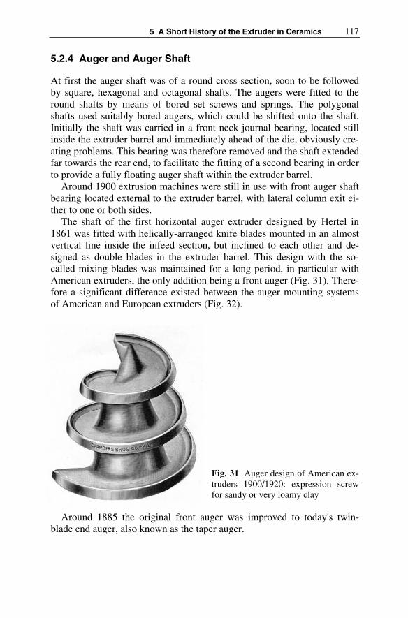
5 A Short History of the Extruder in Ceramics 117
5.2.4 Auger and Auger Shaft
At first the auger shaft was of a round cross section, soon to be followed by square, hexagonal and octagonal shafts. The augers were fitted to the round shafts by means of bored set screws and springs. The polygonal shafts used suitably bored augers, which could be shifted onto the shaft. Initially the shaft was carried in a front neck journal bearing, located still inside the extruder barrel and immediately ahead of the die, obviously cre-ating problems. This bearing was therefore removed and the shaft extended far towards the rear end, to facilitate the fitting of a second bearing in order to provide a fully floating auger shaft within the extruder barrel.
Around 1900 extrusion machines were still in use with front auger shaft bearing located external to the extruder barrel, with lateral column exit ei-ther to one or both sides.
The shaft of the first horizontal auger extruder designed by Hertel in 1861 was fitted with helically-arranged knife blades mounted in an almost vertical line inside the infeed section, but inclined to each other and de-signed as double blades in the extruder barrel. This design with the so-called mixing blades was maintained for a long period, in particular with American extruders, the only addition being a front auger (Fig. 31). There-fore a significant difference existed between the auger mounting systems of American and European extruders (Fig. 32).
Fig. 31 Auger design of American ex-truders 1900/1920: expression screw for sandy or very loamy clay
Around 1885 the original front auger was improved to today's twin-blade end auger, also known as the taper auger.

118 Willi Bender, Hans H. Böger
Fig. 32 Auger set-up of an American extruder, circa 1920
Wear of the auger was soon found to present a big problem. It was again Schlickeysen who, in 1881, introduced replaceable auger tips, which were fitted to the augers by screws or rivets. Re-adjustable auger tips were also in use. This method of wear protection was maintained until the 1970s, when it was replaced by auger hard facing. In the meantime, selection of the right material and correct method of applying the hard facing has be-come a science.
It was soon noticed that the shape, surface and pitch of the augers had a significant influence on the power consumption and the performance of the extruder in respect of quality and quantity. As the extruder was the focal product of the ceramic equipment manufacturing industry, which had en-joyed a rapid development from1860 onwards, a great deal of experiments were made in respect of those parameters thought to have an influence on the auger geometry. The result was that each machinery manufacturer of-fered his own special auger designs and components.
In the present structural clay industry the single-lead auger with a two, or three-lead front auger is usually employed. The task of the latter is to divide the material fed from the single-lead auger, which arrives in a non-symmetrical manner, into two almost identical halves. This process is by no means automatic and is dependent on the raw material properties, the type and size of products to be made. Therefore the correct position of the end auger in relation to the single-lead auger must be established by em-pirical methods. The regulating end auger introduced onto the market in 1992 features a special tooth system, which enables an almost infinitely-variable adjustment in relation to the single-lead auger, to facilitate opti-mum setting of the position (Fig. 33).

5 A Short History of the Extruder in Ceramics 119
Fig. 33 Regulating end auger
By the end of the 1950s the welded one-piece all-steel auger appeared in the structural clay industry. This was slipped onto a short square journal on the auger shaft and, in the absence of individual auger hubs, bolted-on au-ger tips, butt joints from hub to hub or any fixing screws, demonstrated a good fluidic behaviour. The augers were hard faced against wear. In order to ensure that re-facing could be effected without disturbing the production process, a replacement auger had to be kept on stock.
Monolithique extrusion augers are commonly used in the field of ad-vanced ceramics. These are of either cylindrical or conical design, in two parts with a cylindrical and conical section, single-led or double-led throughout, also with a reduced depth of the auger flight, and made of dif-ferent materials (Fig. 34). In addition to monolithic augers, there are also modular-type augers in use. Even ceramic augers for the processing of special bodies have been available since 2004, with diameters up to 120 mm, to prevent metallic contamination of the body.
Fig. 34 Auger segments in various materials for extruders in technical ceramics
5.2.5 Extruder Machine Body and Feed Device
Going back to the first auger extruders, the extruder machine body was separate from the open-type gearbox and drive section until, from 1865

120 Willi Bender, Hans H. Böger
onwards, these components were jointly mounted, normally onto a com-mon base plate (Fig. 35).
Fig. 35 Auger extruder: separate machine body and drive section
However the spasmodic manual feeding resulted in frequent jamming. This prompted Schlickeysen in 1873 to invent the pressure and feed roller to squeeze the material into the auger flights. In 1878 he added a second feed roller. Until around 1930 the standard version of an auger extruder in-corporated one or two feed rollers. These were either smooth, grooved or corrugated. The corrugated versions had different shapes: recessed, raised, horizontal, inclined horizontal and V-shaped. To improve the material in-feed, the two feed rollers were often made in different diameters and, al-ready around 1910, operated in some factories at different speeds. Again about 1910, feed augers with flights of varying depths began to be avail-able.
Feed paddles came into usage around 1930 (Fig. 36). Spiral-shaped in-feed rolls were invented for extrusion machines in the fine and advanced ceramics fields. (Fig. 37).
Fig. 36 Feed paddles

5 A Short History of the Extruder in Ceramics 121
Fig. 37 Infeed rolls
Since about 1990 the paddle or infeed rolls can also be driven sepa-rately, each from a slip-on type geared motor. Frequency control gives in-finite variability of the paddle shaft speeds, so that these can be optimally adapted to the auger shaft speed (Fig. 38).
Fig. 38 Feed paddles with separate drive
5.2.6 Drive Elements
Animals provided driving power for the first upright auger extruders. Ini-tially this was in the form of direct drive using a tie beam that was fastened in a beam shoe at the top end of the auger shaft. This system of drive was

122 Willi Bender, Hans H. Böger
rapidly supplemented by a capstan with a gear transmission system in or-der to better utilise the tractive power of the animals. This also made it possible to use a bottom drive (Fig. 39). With the animal-driven version an auger shaft speed of approx. 3 rpm could be achieved. The steam engine, which had already been applied for rotational movement since 1782, first provided drive power for an extruder in the year 1858, using transmission and belts (Fig. 40). Around 1880 Messrs. Raupach in Görlitz, Germany, also built a combination consisting of extruder and steam engine for direct drive. As it was usually necessary to drive several machines, the line-shaft drive with flat belts was still in use well into the 1960s, for the most part driven by a steam engine or loco-mobile and, from the 1920s onwards of-ten by a large electric motor. The use of electric motor drives had begun around 1885, but these were not readily accepted within the ceramic indus-try. Individual drive of the auger extruder using electric motors started in the 1920s, but only became common practice from 1960 onwards. At first three-phase induction motors with collector ring starters were employed, to be later replaced by squirrel-cage motors with speeds of 750, 1000 or 1500 rpm, dependent on the transmission ratio of the extruder gear box and the required auger shaft speed. For production of different sizes of bricks with varying throughput rates, two, or three-step belt pulleys were used from 1920 (Fig. 41), or two, or three-stage pole-changing electric motors since 1970, which made it possible to operate with two or three different auger shaft speeds. In the 1970s there were also extrusion machines with inte-grated change-speed gear for two speeds.
Fig. 39 Upright extruder with drive via capstan gear

5 A Short History of the Extruder in Ceramics 123
Fig. 40 Upright auger extruder with bottom drive using transmission and steam engine
Fig. 41 Auger extruder with 3-step belt pulley
Occasionally d.c. motors were used in the 1980s in order to provide an infinitely-variable control of the auger shaft speeds, but since then fre-quency-controlled squirrel-cage motors have become the standard.
Power transmission is as a rule effected by belt drive, at first this was with flat belts and later with V-belts. A drive version using a direct-coupled electric motor with intermediate reduction gear was offered as an option as far back as the 1920s. (Fig. 42). Mobile extrusion units with an independent power supply from a diesel generating set were developed from1950 for use in the Third World.

124 Willi Bender, Hans H. Böger
Fig. 42 Extruder drive via gearbox with direct-coupled electric motor, 1935
About 1890 American extruders were equipped with a single belt pulley with a simple friction clutch for engaging or disengaging the machine, whereas fast and loose pulleys were still commonly used in Europe well into the 1920s, though Schlickeysen had already invented a safety belt pul-ley in 1893 which transmitted only a previously-adjusted power and which continued to run idle once this value was exceeded. This method protected the machine against overload. Circa 1930 the constant-speed drive with spring band coupling came into use, followed in about 1950 by the multip-le-disc clutch, which originally had a manually-operated disconnecting le-ver, this being actuated since 1960 by electric motor. Finally, about 1980, the more robust compressed air clutch was introduced. As far as the gear-box is concerned, the first auger extruders were still equipped with an open back-gear. This was superseded in the first instance by gearboxes made by the extruder manufacturers themselves and integrated in the extruder ma-chine body; after 1970 separate gearboxes purchased from specialist gear-box manufacturers became common practice. Since around 1990 the planetary gearbox is the state-of-the-art technology. Also from 1990 to the present day, the use of several motors is commonly applied with the paddle shafts each driven by a separate geared motor.
5.3 The Development of the Vacuum Extruder and Combined De-airing Extrusion Unit
Introduction of de-airing extrusion represented a breakthrough in extrusion technology. It was a well-known fact that the auger draws in a consider-able amount of air together with the material, which is squeezed into the column and has a negative effect on its quality, and which in turn often causes substantial interruptions in production. In its early stages, this pre-vented the application of column extrusion in the whiteware industry, for instance to produce slugs or small pipes. The producers of porcelain con-tinued to prefer their roller kneading machines for the purpose of de-airing

5 A Short History of the Extruder in Ceramics 125
of the bodies, even accepting the additional effort involved in respect of shaping. The idea of withdrawing the air embedded in the raw material, which tends to shorten the clay and leads to blistering, so as to achieve an increase in plasticity and reduce laminations, originated in America. Sys-tematic work in this field originally began in the USA around 1900. The first patent for a “de-airing machine for shaped clay materials”, bearing the No. 701 957, was granted to R. H. Stanley, a ceramic engineer of Chicago, in 1902.
The schematic illustration already shows the principle of later de-airing extrusion machines, i.e. a primary pug mill A1 and a main extruder B3, which are connected by a low-pressure chamber B, the actual vacuum chamber. In this system, the clay cushions formed inside the auger flights of the primary pug mill and main extruder serve as a sealing for the vac-uum chamber, in which a negative pressure is produced by the vacuum pump E. This patent was acquired by Messrs. Chamber Brothers in Phila-delphia, and was used to build de-airing extruders (Fig. 43).
In 1913 R. B. Price also manufactured an outgassing auger for de-airing operation with self-sealing effect of the ceramic body against normal pres-sure. The USA patent No. 1 296 472 was granted to Messrs. Fate-Root-
Fig. 43 De-airing extruder designed by the American R. H. Stanley, American patent no. 701 957 from 1902
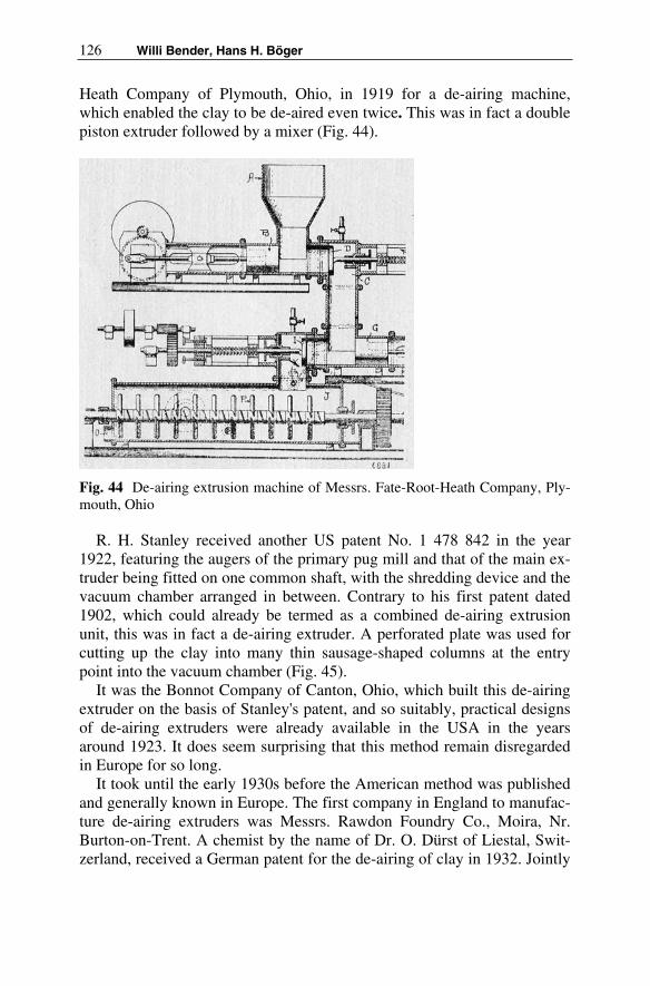
126 Willi Bender, Hans H. Böger
Heath Company of Plymouth, Ohio, in 1919 for a de-airing machine, which enabled the clay to be de-aired even twice. This was in fact a double piston extruder followed by a mixer (Fig. 44).
Fig. 44 De-airing extrusion machine of Messrs. Fate-Root-Heath Company, Ply-mouth, Ohio
R. H. Stanley received another US patent No. 1 478 842 in the year 1922, featuring the augers of the primary pug mill and that of the main ex-truder being fitted on one common shaft, with the shredding device and the vacuum chamber arranged in between. Contrary to his first patent dated 1902, which could already be termed as a combined de-airing extrusion unit, this was in fact a de-airing extruder. A perforated plate was used for cutting up the clay into many thin sausage-shaped columns at the entry point into the vacuum chamber (Fig. 45).
It was the Bonnot Company of Canton, Ohio, which built this de-airing extruder on the basis of Stanley's patent, and so suitably, practical designs of de-airing extruders were already available in the USA in the years around 1923. It does seem surprising that this method remain disregarded in Europe for so long.
It took until the early 1930s before the American method was published and generally known in Europe. The first company in England to manufac-ture de-airing extruders was Messrs. Rawdon Foundry Co., Moira, Nr. Burton-on-Trent. A chemist by the name of Dr. O. Dürst of Liestal, Swit-zerland, received a German patent for the de-airing of clay in 1932. Jointly

5 A Short History of the Extruder in Ceramics 127
Fig. 45 R. H. Stanley's de-airing extruder, patent no. 1 478842, from 1922
with Karl Leimer, who had acquired the company Maschinenfabrik Grie-semann & Co., Magdeburg, Germany, in 1930, he developed the de-airing extruder for use in the structural clay and fine ceramics industries. Almost at the same time in 1933 several equipment manufacturers offered the first extruders in Germany, amongst others Karl Händle & Söhne, Mühlacker and Richard Raupach GmbH, Görlitz, whereby the latter company also de-veloped special de-airing extrusion machines for the fine ceramics indus-try. Most of the ceramic machinery makers in Germany and adjacent coun-tries initially used the patents of Dr. Dürst, adding their own patents in the course of time (Fig. 46). Most of these new inventions were related to the improvement of the shredding device, as a fine chipping of the clay played a decisive role for achieving an effective de-airing effect. Another partia-laspect was the problem of keeping the air-suction device in the de-airing
Fig. 46 De-airing extruder from Händle, 1933

128 Willi Bender, Hans H. Böger
chamber free of clay. But this particular problem of the de-airing extruder was never entirely solved. As it was impossible with de-airing extruders to avoid blockage, back pressure and non-uniform de-airing, the manufactur-ers reverted to the original Stanley principle and from 1935 onwards de-veloped the so-called combined de-airing extrusion machine, a combina-tion of double-shaft mixer with shredding device and vacuum chamber, with the auger extruder fitted below (Fig. 47). In the meantime, the com-bined de-airing extrusion machine has almost entirely superseded the de-airing extruder. In connection with stiff extrusion the Americans prefer to apply the de-airing single-shaft mixer, the Europeans the de-airing double-shaft mixer.
Fig. 47 Combined de-airing extrusion machine comprising of vacuum double-shaft mixer and auger extruder, 1937
In the first instance reciprocating piston vacuum pumps and liquid ring vacuum pumps were employed to generate the required negative pressure in the vacuum chamber. The most commonly-applied were the liquid ring gas pumps manufactured from 1923. Liquid ring pumps are normally op-erated on the principle of continuous fresh water consumption; since 1960 oil in a closed loop is also partly used as operating liquid. Round about 1970 oil-lubricated rotary vane pumps came into use with a residual pres-sure of up to 8 mbar possible, and finally, circa 1998 brought oil-free water ring pumps with a closed water cycle. These can reach a residual pressure of up to 50 mbar. The first de-airing extruders operated with approx. 60-70% vacuum. Nowadays de-airing extrusion is normally accomplished with a residual pressure of 152-51 mbar, equivalent to a vacuum of 85-95%.

5 A Short History of the Extruder in Ceramics 129
5.4 The Extruder in the Different Fields of Ceramics
Extruders were and are used in all sections of the ceramics industry, if you disregard sanitaryware.
In household ceramics for the production of pugs, e.g. roller machines, in structural ceramics for the production of bricks of all types, for the pro-duction of lumps for pressing roofing tiles, for the extrusion of tiles and split tiles, for the production of stone-ware pipes with horizontal but usu-ally vertical extruders (Fig. 48) for pelletising expanded clay, in refractory ceramics and in the further field of technical ceramics, for the production of pugs in the manufacture of isolators (Fig. 49) just as for the extrusion of filigree honeycombs for various applications.
Fig. 48 Vertical extruder for stone-ware pipes
It would go beyond the bounds of this contribution, which is compre-hensive enough as it is, to describe the most various forms of construction adapted to the sector concerned, and the, partly, highly original detail solu-tions.
In some sectors, the extruder has now been replaced more or less by other forming technologies. This applies to the field of tableware in which, today, plates and cups are mostly isostatically pressed; extruders are only for special applications and in manufactories. The situation is similar in the refractory industry where hydraulic pressing has almost completely ousted extrusion.

130 Willi Bender, Hans H. Böger
Fig. 49 Extrusion of slugs in the production of insulators
The extruder is still dominant in structural ceramics and for the produc-tion of complex extruded profiles in technical ceramics. There have been appreciable developments in both fields in recent years. Depending on the application, you can find piston presses and single-screw and double-screw extruders in two or three-stage versions.
The market has been shown to be the primary “driver” for new devel-opments. Where this has not been the case, the most innovative inventions and developments have come to nothing.
Markets have also been more strongly generated by the legislator, for example, in the form of regulations within the framework of environment protection, if you think of catalyst support for power stations and the motor car or of the development of particle filters for diesel engines (Fig. 50).
Fig. 50 ECT combined de-airing extrusion machine, 2006
It can be assumed that extrusion, as one of the most important processes within ceramic forming, will maintain its position if we are successful in offering adequate solutions for the new challenges.

5 A Short History of the Extruder in Ceramics 131
A glance to the past of extruder development makes two things clear: that we, on the one hand, as Isaac Newton is supposed to have said: “all stand on the shoulders of giants“, i.e. are able to build on the experience of generations. On the other: that solution approaches have only failed in the past because either the market was not yet mature or the technical material and/or technical control prerequisites were not yet available.
5.5 Chronology of Extrusion in Ceramics
Year Event
250 BC Archimedes explores the Egyptian screw, later to be known as the Archimedes screw, as described in his work “Elements of mechanics”
1610 In England John Etherington builds the first hand-operated piston brickmaking machine, for which he was later granted a patent
1643 J. S. Spreckstruyff of Gouda, Holland, designs a clay mill for the preparation of pipe clay considered the embryo of the auger ex-truder
1654 Otto von Guericke demonstrates the Magdeburg hemispheres in Regensburg, Germany, thus proving the vacuum
1767 Soft-mud moulding machine with horizontal pug mill invented by the Swedish captain, Carl Wijnblad
1807 Hostenberg invents and builds a piston extruder in St. Petersburg for the production of drainpipes
1827 The lock keeper Bär of Bernburg an der Saale, Germany, builds a horizontal double piston extruder for clay pipes with sockets
1830 The Englishman Ainslie constructs the first known expression rolls machine
1852 Horizontal twin-auger extruder with cutter by Randal & Sander. Borie builds an extrusion machine in Paris
1853 Lord Berriedale's horizontal brickmaking machine with horizon-tal auger H. Clayton applies for a patent for a brick forming ma-chine with auger and shaping rolls in England
1855 The Universal Patent Brickmaking Machine, a suspended auger extruder designed by Carl Schlickeysen (auger for plastic bodies)
1858 Invention of the water-lubricated die by C. Schlickeysen The first steam-driven suspended auger extruder of C. Schlickeysen goes into operation in Rosslau/Elbe (Germany) Hand-operated cutter of Gebr. Sachsenberg Rosslau, Germany, with mobile carri-
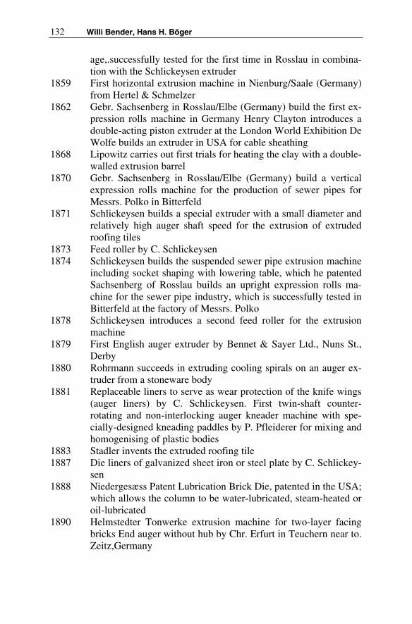
132 Willi Bender, Hans H. Böger
age,.successfully tested for the first time in Rosslau in combina-tion with the Schlickeysen extruder
1859 First horizontal extrusion machine in Nienburg/Saale (Germany) from Hertel & Schmelzer
1862 Gebr. Sachsenberg in Rosslau/Elbe (Germany) build the first ex-pression rolls machine in Germany Henry Clayton introduces a double-acting piston extruder at the London World Exhibition De Wolfe builds an extruder in USA for cable sheathing
1868 Lipowitz carries out first trials for heating the clay with a double-walled extrusion barrel
1870 Gebr. Sachsenberg in Rosslau/Elbe (Germany) build a vertical expression rolls machine for the production of sewer pipes for Messrs. Polko in Bitterfeld
1871 Schlickeysen builds a special extruder with a small diameter and relatively high auger shaft speed for the extrusion of extruded roofing tiles
1873 Feed roller by C. Schlickeysen 1874 Schlickeysen builds the suspended sewer pipe extrusion machine
including socket shaping with lowering table, which he patented Sachsenberg of Rosslau builds an upright expression rolls ma-chine for the sewer pipe industry, which is successfully tested in Bitterfeld at the factory of Messrs. Polko
1878 Schlickeysen introduces a second feed roller for the extrusion machine
1879 First English auger extruder by Bennet & Sayer Ltd., Nuns St., Derby
1880 Rohrmann succeeds in extruding cooling spirals on an auger ex-truder from a stoneware body
1881 Replaceable liners to serve as wear protection of the knife wings (auger liners) by C. Schlickeysen. First twin-shaft counter-rotating and non-interlocking auger kneader machine with spe-cially-designed kneading paddles by P. Pfleiderer for mixing and homogenising of plastic bodies
1883 Stadler invents the extruded roofing tile 1887 Die liners of galvanized sheet iron or steel plate by C. Schlickey-
sen1888 Niedergesæss Patent Lubrication Brick Die, patented in the USA;
which allows the column to be water-lubricated, steam-heated or oil-lubricated
1890 Helmstedter Tonwerke extrusion machine for two-layer facing bricks End auger without hub by Chr. Erfurt in Teuchern near to. Zeitz,Germany

5 A Short History of the Extruder in Ceramics 133
1893 L. Schmelzer jr. develops an extrusion barrel with spiral-shaped inside contour to prevent the material from twisting and proposes replaceable barrel inserts made of hard casting Schmelzer devel-ops the so-called replaceable compensation augers in connection with a tapered extruder barrel for a better utilisation of the wear volume of the augers
1894 Hertel builds a brickmaking machine in Nienburg into which steam is blown at the end of the extruder barrel
1898 Readjustable die for bricks 1900 First systematic work in America in respect of de-airing extru-
sion1902 The ceramic engineer R. H. Stanley is granted a patent in Amer-
ica for a “de-airing machine for pre-shaped clay bodies. The first de-airing extruders are built by Messrs. Chambers Brothers of Philadelphia Stepped-barrel extruder by Griesemann in Magde-burg, Germany
1906 Patented ring against back-pressure by C. Schlickeysen 1907 Cutter by Messrs. Keller, Laggenbeck, Germany, with curved
disc1913 Outgassing auger for de-airing operation with self-sealing against
normal pressure by the material by R. B. Price, for outgassing of water and volatile matter from ceramic bodies
1915 Outgassing auger featuring several successive de-airing zones, with several retarding discs and tempering of the machine hous-ing by J. W. Steinle, for vacuum outgassing of caoutchouc-type materials
1920 Stiff extrusion in the USA 1922 R. H. Stanley is granted the US patent 1 478 842 for a de-airing
auger extruder, which is built by Messrs. Bonnot Company in Canton/Ohio E. C. Bingham develops the Bingham-model to rep-resent the rheological behaviour of ceramic bodies
1924 Plasticity testing (by upsetting method) according to K. Pfeffer-korn
1930 W. Meskat of IG-Farben in Wolfen near to Bitterfeld, Germany, recognises the correlation between the auger flights and the flow characteristics (rheology) of bodies during extrusion and is the first to devise parameters for the design of extruder augers First successful tests for hot-shaping in Germany Introduction of the feed paddle
1931 Dr. Dürst of Switzerland receives a DRP (German Imperial Pat-ent) for de-airing of clay, which serves as a basis for the con-struction of de-airing extrusion machines made by Messrs. Rau-

134 Willi Bender, Hans H. Böger
pach, Görlitz (Germany) and Messrs. Griesemann, Magdeburg (Germany) Karl Leimer of Magdeburg and Dr. Dürst develop and patent a new de-airing extrusion machine
1933 Messrs. Händle of Mühlacker/Germany build their first de-airing extrusion machine
1933 Messrs. Raupach, Görlitz are the first to develop and build a de-airing extruder for the porcelain industry
1934 Roscher of Görlitz introduce a de-airing extruder onto the mar-ket, which is their own patent
1935 Händle are the first on the market in Europe with a combined de-airing extrusion machine with a double-shaft mixer, shredder de-vice, vacuum chamber and auger extruder
1936 The de-airing extruder is widely accepted in the porcelain indus-try
1938 Raupach of Görlitz have already supplied in excess of 400 de-airing extruders for the Ceramic industry, of which 100 have been delivered to the porcelain industry
1949 “Theory for design fundamentals for auger extrusion machines” by Rieterwerke, Constance, Germany
1957 M. Grimal introduces the hot shaping process in Realmont, France
1958 Presssure head with adjustable regulating slides by Braun 1960 E. Hallmann introduces a method for design fundamentals of ex-
trusion machines1960 First tests to produce honeycomb catalyst converters from ce-
ramic bodies in Germany 1960 Hydraulically-operated de-airing piston extruder for stiff extru-
sion by Uniceram, Marseille, France 1961 Stiff extrusion in England by Bradley & Craven 1966 O.C. Pels Leusden establishes seven rules for the construction of
dies; initial stages for solving the calculation of dies 1967 Stiff extrusion in Germany on a Händle extruder 1970 Development of the “Europresse” by Messrs. Rieter, Constance,
Germany, designed as a rotor-type extrusion machine, introduced in 1974
1970 Successful tests in Japan extruding honeycombs. First production plants around 1975
1971 Dr. Rodney Delano Bagley of Messrs. Corning Glass Works ap-plies for a patent to extrude honeycombs (carriers for catalyst converters) Patents are granted in Japan for the extrusion of ce-ramic catalyst converters
1975 Optimising of pressure heads by adopting the IZF pressure head

5 A Short History of the Extruder in Ceramics 135
1975 Extrusion of catalyst converter carriers produced from cordierite 1977 Electrophoretic expression-rolls extruder, system “Elephant” of
M. S. Chronberg 1980 Expression rolls extruder “Elephant”, made by Händle, Germany
is commissioned at Messrs. Ceralit, Evreux, France1983 Radial dry-powder extrusion machine RTS, designed by Anton
Stigler, Berchtesgaden, Germany, which is displayed by Händle/ Mühlacker at the Ceramitec exhibition in Munich in 1988
1985 Computer simulation model of F. Laenger for extruder design 1990 Technology of expression-rolls extrusion for multi-layer materi-
als is taken up again by the German Institute of Refractory and Ceramic Industry
1999 Messrs. Braun introduce a prototype for a simulation model of extrusion tools
Literature
[1] Ittner H (1986) C.I.P. with the R.T.S. system. J cfi/Berichte der DKG (German Ceramic Society Report) vol 63 No 3 pp 126 ff
[2] Kerl B (1907) Handbuch der gesamten Thonwarenindustrie. Überar-beitet von Cramer und Hecht, Braunschweig, 3. Auflage
[3] Rymon-Lipinski T, Gebhardt F (1994) Roll-Pressing of Ceramic Bbodies. J cfi/Berichte der DKG (German Ceramic Society Report) vol 71 No 8 pp 467-469
[4] Baulig A (1995) Roller Pressing for the Production of Ceramic Com-ponents with Internal Hollow Structures (in German). J Keramische Zeitschrift 11:898-900
[5] Chronberg MS, Händle F (1978) Processes and Equipment for the Production of materials by Electrophoresis Elephant. J Interceram vol 27 No 1 p 33
[6] Schmidt EW (1978) Elephant – Experimentation ou avenier? J Brick and tile Industry International No 4 pp 217 ff
[7] Händle F (1980) Elektrophoretische Verformung von keramischen Materialien. J Keramische Zeitschrift vol 32 No 4 pp 185-188
[8] Hennicke J, Hennicke HW (1981) Formgebung in der Keramik. In:Handbuch der Keramik. Verlag Schmidt GmbH (eds) Freiburg i. Brg., Gruppe I D1
[9] anonym (1853/1854) Lord Berriedales Verbesserung an Ziegelma-schinen. J Dingler´s Polytechnisches Journal vol 130 pp 330-331

136 Willi Bender, Hans H. Böger
[10] Böger HH (2005) Von der ägyptischen Schraube zur Ziegelstrang-presse. In: 22. Bericht der Stiftung Ziegelei-Museum-Cham, CH-6330 Cham, ISBN 3-9523037-0-4
[11] Davis CT (1895) A Practical Treatise on the manufacture of Brick, Tiles and Terra-Cotta. Henry Carey Baird & Co, Philadelphia
[12] Searle AB (1956) Modern Brickmaking. Revised and Enlarged, Ernst Benn Limited, London, Fourth Edition
[13] Dobson E (1921) A Rudimentary Treatise on the manufacture of Bricks and Tiles. Crosby Lockwood and Son, London
[14] Bender W, Händle F (1982) Brick and Tile making – Procedures and Operating Practice in the Heavy Clay Industry. Bauverlag GmbH, Wiesbaden und Berlin
[15] Bender W (1998) Extrusion technology in the structural ceramic in-dustry. J Brick and Tile Industry International No 4
[16] Bender W (2004) Vom Ziegelgott zum Industrieelektroniker – Ge-schichte der Ziegelherstellung von den Anfängen bis heute. Bundes-verband der Deutschen Ziegelindustrie e.V., Bonn
[17] Neumann F (1874) Die Ziegelfabrikation. Bernhard Friedrich Vogt, Weimar, 7. Auflage
[18] Händle F (1975) Perspectives in the Ceramic Shaping Technology. JInterceram vol 24 No 4 pp 262-265
[19] Händle F (1977) Comparative study of vacuum unit systems in the heavy clay industry J Interceram vol 26 No 3 pp 192-195
Origin of the Figures
Archives Händle GmbH, D-Mühlacker: Fig. 5, 8,24, 26, 27, 28, 31, 33, 36, 37, 38, 39, 41, 42, 46, 47, 48, 49 Archives of the autor: Fig. 12, 13, 30, 35, 43, 44 EC T, D-Mühlacker: Fig. 34, 50 Lit. 2: Fig. 1, 2, 4, 19, 20 Lit. 4: Fig. 10 Lit. 7: Fig. 11 Lit. 11: Fig. 21 Lit.. 12: Fig. 22, 32 Lit. 14: Fig. 23 Lit. 16: 3, 9, 25, 29, 45Lit. 17: 6, 7, 14, 15, 16, 17, 18, 40

6 The Principle of the Auger Extruder
John Bridgwater
6.1 Introduction
Why is the extrusion of ceramics using an auger such a widespread and successful technology? Why is it that the auger extruder is of such interest to industry? What do we know about it? When will it work? How does it happen that the auger, a type of well established equipment that certainly still lacks a complete scientific basis for its design, finds itself as the tech-nology of choice in business for so many established and new products? Questions such as these underlie the discussion here.
6.2 Liquid Phase and Additives
So why is the extrusion of ceramics widespread and successful? At first sight, the technical challenges seem considerable. For example, the parti-cles used to form many well-shaped objects are frequently hard and abra-sive. Sometimes the objects that are made need to be of very precise size or needing good mechanical or electrical properties specific to an applica-tion. The key to turning an abrasive material into a mouldable one that can be readily shaped by an auger extruder lies in the presence of, or addition of, a compound such as a clay. For some applications this compound is present naturally. Most other materials, including most synthetic ones, need to have added a clay or other additive to turn the material into one that can be moulded.
If the compound in the mixture includes a clay, there also needs to be present water since its presence renders the material more readily mould-able. The presence of clay and water in appropriate amounts has profound and helpful consequences for the formation of ceramic materials into ob-jects of desired shape. In the absence of clay and water, particles usually require very high pressures to be formed into objects since the frictional forces within the assembly of particles have to be overcome. The applica-

138 John Bridgwater
tion and release of the forces on the particles are then often difficult both for the design of the forming equipment and for the control of the product properties.
A first way of improving processing might be thought to rely on the ad-dition of water, or some other liquid, on its own with no clay being used. However, this generally offers no benefit. With the application of pressure, liquid starts to drain out of the packing rapidly. This occurs because ini-tially the whole of an applied stress is taken up by the liquid and this causes liquid motion through the particles under the induced pressure gra-dient through the pores. The stress transfers to the solid matrix and then frictional forces reappear and there is no benefit for the formation process. Indeed, liquid is likely to rapidly appear at the surface. The application of stress causes an instant increase in local voidage due to expansion of the packing to allow motion in regions of high shear. The volume increase in these regions sucks water out of the surrounding packing hence giving an immediate frictional behaviour. This is the effect seen when stepping onto wet sand; the region around the foot becomes dry but when the foot is re-moved, a wet patch is seen where the foot had been placed.
However, when a suitable clay is present, the behaviour changes radi-cally. Clay, with a much smaller particle size and with chemical affinity for water severely reduces the movement of water through the particle ma-trix. If we now do the footprint test, no dry region arises around where the foot has been placed and the material sticks to the sole of the shoe. Liquid is now retained in the particle matrix because there is a very much greater resistance to liquid flow and the stress applied remains borne by the liquid. This, in turn, ensures that the particles remain lubricated around the points of contact and this has the consequence that the material is mouldable and amenable to extrusion using an auger.
Thus the key to successful processing lies in the formulation of the ma-terial by having additives, commonly a clay and water, present in amounts that render the mass mouldable at a low applied stress. On its own, this ar-gues for high liquid content. However, a greater liquid content causes an increase in the rate of movement of the liquid. The benefits are then re-versed; unacceptable levels of liquid phase migration have to be avoided.
However the extrudate product must have sufficient strength to with-stand the processing steps subsequent to extrusion and this then argues for a low liquid content. This raises the pressure that needs to be applied by the auger. Perversely the raising of pressure also serves to raise the rate of liquid migration. Clearly a balance has to be achieved.
It is evident that selection of the liquid phase, its components and its amount are most important design steps. It is the frequent and much prac-tised experience of success in making these decisions is an important rea-

6 The Principle of the Auger Extruder 139
son for the prevalence of the auger technology for the formation of ceram-ics.
6.3 Physics of Process Steps
Suppose we wish to make a technical ceramic product; for instance it might be a material to be used as a catalyst for the chemical industry. Let us examine the physical steps that are needed and these are given in Fig. 1. In this scheme, the feed materials are held in storage and are then con-veyed dry to a mixer. This is followed by wet mixing, a step in which there is high shear that is known sometimes by the term pugging. Degassing then takes place before the material is passed to an auger where it is ex-truded into the product of whatever shape is needed. The extrudate, then in a quite delicate form, needs to be removed from the extruder with care and is then cut to the required length. It then undergoes drying and firing to give the ultimate product.
Considering this sequence in more detail, there are initially a number of solid components commonly held in a number of storage vessels or bags. The first step is to add these components one by one into a further vessel. Although the matter is well beyond the scope of the present discussion, the design of solids storage vessels so as to ensure reliable discharge is often no simple matter. The discharge can block itself or the internal flow pat-tern within the storage equipment change. In addition, the conveying equipment or pipework needs careful design. Problems such as erosion, caking or dust formation can occur all too easily.
However, in this vessel there is a gentle mixing action. Once all the components have been added, mixing continues for a few minutes, the purpose being to ensure that a good general homogeneity is achieved. However, the mode of action is one that aims to eliminate long range con-centration differences and it does not seek to promote homogeneity at the particulate level. Thus there are localised groupings of like particles re-maining.
Liquid is then added to the mixer and the mixing continued. The con-tents become first damp and then often either appear as a crumble or as a wet and coherent mass, forming quite sharp ridges in the surface. The pur-pose is to distribute both the liquid and solid phases in order to promote an intimate mixture of all components throughout the mixing system.
The intermediate material so created may appear suitable for extrusion but this is generally not the case and two conditioning stages need to be considered and are often essential.
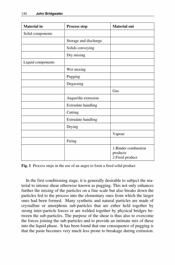
140 John Bridgwater
Material in Process step Material out
Solid components
Storage and discharge
Solids conveying
Dry mixing
Liquid components
Wet mixing
Pugging
Degassing
Gas
Augur/die extrusion
Extrudate handling
Cutting
Extrudate handling
Drying
Vapour
Firing
1.Binder combustionproducts2.Fired product
Fig. 1 Process steps in the use of an auger to form a fired solid product
In the first conditioning stage, it is generally desirable to subject the ma-terial to intense shear otherwise known as pugging. This not only enhances further the mixing of the particles on a fine scale but also breaks down the particles fed to the process into the elementary ones from which the larger ones had been formed. Many synthetic and natural particles are made of crystalline or amorphous sub-particles that are either held together by strong inter-particle forces or are welded together by physical bridges be-tween the sub-particles. The purpose of the shear is thus also to overcome the forces joining the sub-particles and to provide an intimate mix of these into the liquid phase. It has been found that one consequence of pugging is that the paste becomes very much less prone to breakage during extrusion.

6 The Principle of the Auger Extruder 141
This is linked to a material lacking consistency, having regions of low liq-uid content that are likely to fracture more readily. There may also be dif-ferent, possibly enhanced, product properties. Certainly it is a most impor-tant step for obtaining a product of consistent and reliable properties that can be processed satisfactorily.
The second conditioning step prior to extrusion is the removal of gas that has become entrained into the mix during feeding and processing. This is usually carried out by the application of a vacuum to the material. If this is not done, extrudate breakage, say at the outlet of the die plate, becomes more frequent.
Neither pugging nor degassing is amenable to a design methodology based upon quantitative science. However, the significance of the two ef-fects is well known and practical means for performing these available.
The extrusion step is then reached. The paste is dropped into the feed hopper of the extruder. From the base of this hopper, it is first carried and then compressed by the auger or screw. It then passes into the forming sec-tion which may be a duct having the shape of the final object or a die plate to make the object or objects of desired shape. It can alternatively pass into a mould. Figure 2 illustrates some basic types of system; there are designs with single screws and two screws, the latter either rotating in the same or opposite angular directions. There are many geometric decisions needed from the equipment designer – screw diameter, channel diameter, depth of channel between flights, helical angle of the screw to name but a few.
The product directly formed by extrusion is not strong and needs to be handled with considerable care. A system for the proper handling of ex-trudate is essential. For a product needed in the exact shape of the die or the holes in a die plate, a sophisticated system such as a belt or sequence of rollers having the same speed as the extrudate is needed. For some prod-ucts, it is sufficient to simply allow the material to fall off the die plate un-der the action of gravity. This would be satisfactory if the product is to be of a granular form where very close size and shape control are not neces-sary.
However, the more demanding duties commonly require not only a specified cross-section but also a specified length of product and so cutting is needed say by using either a rotating blade or fine wire. During continu-ous operation, this demands the careful integration and control of the ex-trusion rate, the extrudate handing systems and the cutter to give proper control of extrudate length. The cutter may be at the exit of the die plate or, especially for longer extrudates, well downstream of the die plate. The cut-ting must not cause damage by either the closing up of pores in a process of smearing or by the development of surface fractures leading to a rough-ened end face.

142 John Bridgwater
Fig. 2 Schematic diagram of screw extruders (longitudinal cross-section): (a) single-screw augur; (b) counter-rotating twin-screw extruder; (c) co-rotating twin-screw extruder
The cut extrudate is then generally dried, the purpose being to remove the liquid phase. The drying needs to be done at a rate that avoids the oc-currence of vaporisation of liquid within the pores of the product which could be very damaging. If the final product is to be fired, as is commonly the case, it then has to be heated. It is usually the stage at which the prod-
(a)
(b)
(c)
Extrudate
Extrudate
Extrudate
DieBarrel Screw(a)
(b)
(c)
ExtrudateExtrudateExtrudate
ExtrudateExtrudateExtrudate
ExtrudateExtrudate
DieBarrel Screw
6 The Principle of the Auger Extruder 143
uct is at its most fragile since the individual fine particles are held together only by very weak forces. It is here that the presence of further binder components in the initial mix such as a polymer or starch can be of value as these can impart some strength during the initial stages of firing. How-ever, as the firing continues the polymer or starch is lost while the product gains strength due to the development of bridges between particles. These may be bonds between the solids or it there may be bonds caused by the presence of a clay in which the clay provides the bridge between the prin-cipal solids. A proper temperature history is important to ensure that the strength is controlled, the required porosity maintained, and the final length and diameter of the extrudate achieved. The firing causes shrinkage to occur, the extent of which being controlled by both the material formu-lation and the relationship between temperature and time during the firing cycle.
For moulded products there is a related sequence of operations; mould release and the moving of the newly moulded product require attention, similar to that described above.
6.4 Engineering Implementation
In general, one way to approach the design of a process for a product is in-deed to separate all the physical steps needed to form that product, to carry out each of these in sequence in separate pieces of equipment and then simply interlink these pieces. This is the approach that has been used his-torically in the chemical industry, particularly in processes for the manu-facture and handling of liquids and gases. However, when dealing with solid materials we rarely will know the physics and the chemistry of our product well enough for such an approach to work. Even if we were to know these, most of the unit processes shown in figure 1 are not amenable to a scientific design protocol.
The list of physical processes may thus, at first sight, appear daunting and cause one to reflect upon the wisdom of using the technology. “Is there no simpler, perhaps more scientific way, to achieve our goal?” one may ask. However, there are influences at work that quickly lead one to the conclusion that auger technology should be the technology of choice. Some factors bearing on this point are:
• All processes for forming solid products are subject to the same physical laws.
• For instance the issues to be faced in the storage of powders or in the conveying of these materials are common to all forming routes. The in-

144 John Bridgwater
ability to achieve a good mixture of dry materials or to secure a break-down of particles into component crystallites is common to all forming routes. The point can be repeated many times.
• The physical processes that occur in an auger are well known. • The technology is well developed over many industries of which the
ceramics industry is just one. • The auger system enables many of the physical steps to be carried out in
one piece of equipment. It is interesting to note that chemical processes for gases and liquids are now moving in this direction, looking at what has been termed multifunctionality, the performance of more than one step within one piece of equipment, as a means of reducing both capital and operating costs.
• The performance of a number of physical steps within an auger system can not proceed by the use of mathematics as equations have not been found for most of the steps. However, this is offset by a great wealth of practical experience from both equipment manufacturers and equipment users.
• The important matter of die plate design is amenable to a scientifically based approach.
• Internal design of an auger can be arranged so as to meet the require-ments of a specific product. Three basic designs are illustrated in Fig. 2.
• Especially for smaller scale applications, pilot plant trials can be done at the industrial scale.
• The feed materials and the product may be ones not requiring certain steps. For example the feed material may be received already containing liquid mixed within it or the product may be one not needing to be dried and fired, eliminating all steps after the extruder.
• Soft materials can be extruded directly.• The presence of a liquid phase with appropriate additives enables hard
and abrasive materials to be formed into products.
There are quite a number of ancillary operations associated with the ex-truder in its simplest form. Failure to pay careful attention to these can lead to a product of variable properties, normally a quite unacceptable state of affairs. It can also cause there to be fluctuations in operating conditions which can the extruder to cease to operate. The extruder can even be me-chanically damaged by the generation of severe internal pressures. The ex-trusion thus has to be viewed as an integrated system at both the design and operational stages.
As indicated above, the industry has evolved practical means of adjust-ing the design and operation of equipment to enable the product to be
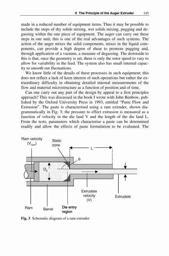
6 The Principle of the Auger Extruder 145
made in a reduced number of equipment items. Thus it may be possible to include the steps of dry solids mixing, wet solids mixing, pugging and de-gassing within the one piece of equipment. The auger can carry out these steps in one unit; this is one of the real advantages of such systems. The action of the auger mixes the solid components, mixes in the liquid com-ponents, can provide a high degree of shear to promote pugging and, through application of a vacuum, a measure of degassing. The downside to this is that, once the geometry is set, there is only the rotor speed to vary to allow for variability in the feed. The system also has small internal capac-ity to smooth out fluctuations.
We know little of the details of these processes in such equipment; this does not reflect a lack of keen interest of such operations but rather the ex-traordinary difficulty in obtaining detailed internal measurements of the flow and material microstructure as a function of position and of time.
Can one carry out any part of the design by appeal to a first principles approach? This was discussed in the book I wrote with John Benbow, pub-lished by the Oxford University Press in 1993, entitled “Paste Flow and Extrusion”. The paste is characterised using a ram extruder, shown dia-grammatically in Fig. 3; the pressure to effect extrusion is measured as a function of velocity in the die land V and the length of the die land L. From the tests, parameters which characterise a paste can be determined readily and allow the effects of paste formulation to be evaluated. The
Fig. 3 Schematic diagram of a ram extruder
D0
L
Ram Barrel Die entryregion
Extrudatevelocity
(V)
Staticzone
Extrudate
θ
Ram velocity(Vram)
D0
L
Ram Barrel Die entryregion
Extrudatevelocity
(V)
Staticzone
Extrudate
θ
Ram velocity(Vram)

146 John Bridgwater
problems that can arise during paste extrusion such as liquid phase migra-tion, external surface roughness, and the internal defect of lamination, spa-tial inhomogeneity due to the joining of paste flows, can be assessed in the same equipment. Die-plates can be designed by using the paste parameters coupled with simple equations.
However extensive and complete such testing may be, the implementa-tion in practice rests upon the knowledge and skill of the organisation of-fering the design of the single auger, twin-screw, whatever it may be. Test-ing in a pilot plant facility will be of key importance.
Sometimes a product arises of character similar to one that has been dealt with before. The range and style of products is ever-expanding; ex-perience is vital.
6.5 Other Types of Product
The diagram of the physical steps [Fig. 1] shows the manufacture of a fired product. The general scheme can, of course, be used for other quite differ-ent types of product. For example
• The product might not be in a fired form and may simply be the material available after the drying step.
• The material could be undried but cut into the form of long continuous strands or blocks which are of an appropriate length.
• The material leaving the die plate at the extruder itself might be the product. The extrudate then drops off the die in under its own weight when this sufficient to overcome the yield strength of the material. With careful selection of paste components and good processing, the range of lengths can be sufficiently narrow to provide the feed to equipment such as a spheroniser. This equipment employs a rolling action, causing ini-tially being in an approximately cylindrical form to be turned into spheres. In practice these can be of narrow diameter distribution, this narrowness being a manifestation of good design of the extrusion step.
More or less any material that can be formed into a coherent dough-like substance is a candidate for the use of this technology. As a practical sim-ple rule if the material, when squeezed, can be moulded in the hand, does not show liquid squeezed onto its surface, does not develop a gritty feel, and holds its moulded shape, then it is a candidate material for use of a system based upon the principle of the auger. Of course, this is a very crude assessment technique but it can often be of help at the very first stage of an evaluation.

6 The Principle of the Auger Extruder 147
Ceramic products are well suited to forming by a route based upon use of the auger. Amongst many others, one can list
• Bricks,• Ceramic pipes, • Tiles,• Honeycomb catalysts for car exhausts or power stations, • Catalyst particles, • Components for engines, • Electrical components.
Gels, such as soft alumina-based gels, can also be processed to form ce-ramics using the technology.
However, there are many other businesses that are making using this technology. Examples of products include
• Food for humans e.g. pasta, • Animal foodstuffs, • Pharmaceutical products, • Fertilisers.
There is thus a wide range of products for the mass market formed using auger technology which is far from stagnant. The technique is not only ex-panding in volume in the more traditional areas but also it is also proving invaluable for a host of new high-value products.
6.6 Range of Product Size and Shape
The diameter of objects that can be made can be up to a metre or even mo-re but can also be as small as pipes of a millimetre, with webs within that can be much finer. If a stress is applied to this material, to a first approxi-mation it is does not deform until a critical stress is attained. This stress determines the maximum size of object that can be made; if the forces due to its weight cause this stress to be exceeded, the object just collapses.
A wide variety of shapes is possible. A simple circular die gives a circu-lar product; use of a die plate with many holes operating in parallel enables production rates to be enhanced. A circular die with a cylindrical torpedo mounted along the axis of the pipe will give a tube. The shape of the duct determines the external shape of the object being formed. Interchangeable

148 John Bridgwater
die plates enable product shape to be altered between batches, with theory able to give guidance on design to avoid a process of mere guesswork.
More complex dies can be used to make honeycomb catalysts for use in car exhausts. The paste is forced from a large pipe into the array of small holes drilled just half way through the die plate, these holes being set out in a regular pattern, say rectangular. Cut in from the other side of the plate is an array of slots, these slots terminating in the same plane as the holes drilled previously from the first side. The slots are of the thickness of the web of material needed in the product. The paste is thus fed from the array of small holes; it passes down these small pipes into the bottom of the slots. In the array of slots, it spreads sideways to fill the whole of the avail-able slot area. The material leaves from the other side of the plate and has the external appearance of a large rectangular bar but there is in fact an in-ternal web structure due to the slots. This provides the high surface area needed to do the chemistry of exhaust gas cleaning.
Ingenious designers have devised other systems to produce reliably other geometries including, for example, a hollow tube with a coil of mate-rial forming a spiral attached to the inner surface.
6.7 Other Technologies
There are competing technologies for the manufacture of this type of solid product. One common method that of compaction, will be considered in a little detail. Brief comments on others then follow.
Compaction can be carried out in a range of equipment from presses for single pellets to high throughput roller systems of a range of designs. Here there is no liquid phase added to the flow though solid lubricants are com-mon. There is thus no need to dry the product after processing, certainly an advantage over the extrusion route. However, this seemingly straight for-ward technology is not without its difficulties. Many of these stem from the very process of compression that causes the particles to generate very high local forces. These can be detrimental to the amount of pore space in the product, with there being considerable variation in the local porosity. Damage to the die may well develop especially if the material is angular and abrasive. The presence of air can cause damage on rapid pressure re-lease. Internal cracking, or even bodily decomposition due to stress reduc-tion on exit from the press, can arise.
There is a significant problem in obtaining a material sufficiently well mixed to give a product quality. The achievement of good mixing on a small scale is a surprisingly difficult process; this not the result of inade-

6 The Principle of the Auger Extruder 149
quate design but rather stems from the fact that the physical laws govern-ing mixing behaviour are ones that not lead to a well mixed state. For in-stance with free flowing materials, the stable state is that of segregated layers of unmixed material. Hence obtaining a mixture that is sufficiently consistent from tablet to tablet to meet the demands of the market for a uniform product is not easy. Competition requires that there be a product of consistent quality. In related fields, such as the pharmaceutical indus-tries, the demands of regulators come to the fore. To overcome this prob-lem, the fine particles need to mixed and bound to one another by a whole new process of granulation. This also improves the flow behaviour of the material coming into the machine as well as improving the homogeneity from to the compaction step.
High shear or paddle granulation is a means of making granules by spraying the binding liquid onto a bed of agitated powder. It can be very effective in the detergent and pharmaceutical businesses. It is a competing technology to auger extrusion followed by spheronisation. Pan granulationuses an inclined rotating dish which imparts a gentle rolling action to the particles. It is suited to the production of granules when there is a lower volumetric throughput. Fluid bed granulation is a granule manufacturing method relying upon the injection of gas into a bed of particles sufficient to support the weight of the particles. It forms hardish granules but is prone to dust formation. Spray drying is another technology for such mate-rials but demands large specialised equipment and has high energy costs.
Slip casting takes a slurry, pours it into a mould and the liquid is then extracted through porous walls. The moulded form then enters the drying and firing steps discussed in Fig. 1. It is well suited to products such as sanitary ware. Tape casting is related to the methods based on the augur. Here a paste or other well-formed material may well be first made by the process steps given in Fig. 1 possibly using the steps up to and including extrusion using an auger. In tape extrusion itself, a material flows under a doctor blade to form a thin sheet. It is well suited for making the substrate of electronic components or for coating.
A general point to make from this discussion is that it is essential to eva-luate any process as a whole, having regard to the product and the proper-ties it needs for the market.
6.8 Final View
To conclude, systems based upon the use of an auger offer a most impor-tant method of forming solid products of a wide range of sizes and shapes.

150 John Bridgwater
For example, those manufacturing ceramic converters to treat car exhaust gases have demonstrated how it is possible to reliably manufacture prod-ucts of great complexity from difficult angular materials in a reliable fash-ion. The manufacturing rate is enormous, every car on the highway need-ing one.
Problems in auger technology may arise. For example, longitudinal shape can be hard to control. The final structure depends on powder opera-tions. Strength is not imparted during the extrusion itself. The structure and strength are not in general adjustable by changing how the extrusion equipment operates. Binders and rheology modifiers can adversely affect product properties
Advantages are:
• Very complicated cross-sections are possible, • Relatively small amounts of liquid are added to the solid, • Binders and rheology modifiers can positively affect product properties, • The technology is capable of shaping very hard and abrasive powders, • A uniform density of distribution is achieved, • The capital costs are low, • The running costs are low.
6.9 Acknowledgements
Thanks are due to Dr Eloise Barnes for making available figures 2 and 3 and to Dr Sarah Rough and Dr Ian Wilson for providing advice.
Literature
[1] Basterfield RA, Lawrence CJ, Adams MJ (2005) On the interpreta-tion of orifice extrusion data for viscoplatic materials. J Chem Eng Sci 60:2599-2607
[2] Bates AJD, Bridgewater J (2000) The radial flow pf pastes and gels. J Chem Eng Sci 55:3003-3012
[3] Benbow JJ, Bridgewater J (1993) Paste Flow and Extrusion. Claren-don Press, Oxford
[4] Chandler HW, George SD, Liddle J (2002) Deformation and flow of stiff pastes: review of rheology of some soft solids. J Br Ceram Trans vol 101 No 2 pp 47-57

6 The Principle of the Auger Extruder 151
[5] Blackburn S, Burbidge AS, Mills H (2000) A critical assessment to describing the extrusion of highly concentrated suspensions and pastes. In: Proceedings ot XIIIth International Congress on Rheol-ogy, Cambridge, Paper 4 pp 139-141
[6] Domanti ATJ, Bridgewater J (2004) On the origin of paste fracture. J Industrial and Engineering Chemistry Research 43:3750-3757
[7] Götz J, Zick K, Kreibich W (2003) Possible optimisation of pastes and the according apparatus in process engineering by MRI flow experiments. J Chem Process Eng 42:517-534
[8] Kulikov OL, Hornung K (2002) Wall detachment and high rate sur-face defects during extrusion of clay. J Journal of Non-Newtonian Fluid Mechanics 107:133-144
[9] Mantle MD, Bardesley MH, Gladden LF, Bridgewater J (2004) Laminations in ceramic forming – mechanism revealed by MRI. JActa Materialia 52:899-909
[10] Li YY, Perera SP, Crittenden BD, Bridgewater J (2001) The effect of binder on the manufacture of a 5A zeolite monolithe. J Powder Technology 116:85-96
[11] Onada GY, Hench LL (1978) Ceramic Processing before Firing. John Wiley and Sons, New York
[12] Rough SL, Bridgewater J, Wilson DI (2002) In situ measurements of porosities and permeabilities of alumina pastes. J Powder Tech-nology 123:262-274
[13] Wells LJ, Nightingale SA (2002) The effect of mixing and aging on taphole clays. In: Proceedings of the Iron and Steel Society/AIME, 61st Ironmaking Conference, USA, pp 205-212

7 Rheology of Ceramic Bodies
Fritz Laenger
7.1 Introduction
Designing ceramic machinery, especial ceramic extruders, requires knowl-edge of certain process parameters such as throughput, pressure, force and power requirement. Everyday practice shows that such quantities are highly dependent on the rheological properties and, hence, the material pa-rameters of the compounds.
Even modern ceramic- and technical ceramic products quality makes necessary the knowledge of material parameters to optimize molding and shaping processes. In the following the determination of the rheological behavior of ceramic compounds will be discussed.
In principle there are two possibilities to get the informations over the material parameters. First we have a theoretic model modified from the model over high filled polymere melts. This model allows to meassure and evaluate the rheological parameters. On the other hand we have a rheologi-cal computer model called ESM (extruder simulation model), developed by the author, which brings us in the position to simulate the material pa-rameters.
7.2 The Material Law
In contrast to the extrusion of plastics, we do not postulate wall adhesion and pure shear flow. As known from practice [1], the extrusion of ceramic bodies involves pronounced wall slippage, even in sharply conical dies. That being so, our main problem is friction.
Many approaches [2], [3] therefore rely on material parameters like the coefficient of friction between the extrusion compound and steel (µ) and within the extrusion compound itself (µi, inner friction) disregarding cohe-sion. Coulombian friction is assumed, as represented by:
µ = F(R) / F(N) = τ / σ (1)

154 Fritz Laenger
with F(R), i.e. τ, as the wall force or wall shear stress, and F(N), i.e. σ, as the normal force or direct stress. For flow along walls (wall slippage), the direct stress. a, is identical to the pressure, p, at right angles (normal) to the wall. The Coulombian approach presupposes that the coefficient of friction is independent of the direct stress. Plotting the wall shear stress, τ, versus the pressure along the wall, p, we therefore anticipate the linear relation-ship shown in Fig. 1, where the coefficient of friction, µ constitutes the ra-tio between the two factors.
Fig. 1 Coulomb friction diagram
To plot such a diagram, the wall shear stress must first be calculated. In a simple case involving one-dimensional, nonsloping, stationary cylindri-cal-tube flow, the balance of forces on a volume element yields the famil-iar shear stress (τ) vs. radius (r) diagram.
τ (r) = dp/dx · r/2 (2)
The graph of the curve is independent of the material law. In dealing with wall slippage, what interests us most is the wall shear stress, which can be expressed as follows:
τ (R) = dp/dx · R/2 (3)
Thus, it suffices to measure the pressure gradient along the wall of a cy-lindrical tube in order to arrive at the wall shear stress, referred to hereinaf-ter as τ.

7 Rheology of Ceramic Bodies 155
In the balance of torces it is not actually the radial pressure (prad), butthe axial pressure (pax) that counts, because pressure anisotropy is to be expected (like in bulk mechanics). The ζ value needs to be defined in order to quantify the pressure anisotropy:
ζ = p(rad) / p(ax) (4)
Tests conducted on good extrusion compounds showed a ζ value of about 1. ζ, values as low as 0.5–0.8 have been registered for materials that tend to block the flow. Thus, supplementary ascertainment of the axial pressure allows an initial rough classification of extrusion compounds. lf the ζ value is not close to 1, that fact must be allowed for in equation (3), i.e.:
τ (R)= 1/ ζ · dp/dx · R/2 (5)
because experiments have shown ζ to be independent of pressure and, hence, of the length ot the cylinder.
With regard to pressure gradients, extrusion compounds tested to date all proved to answer one of two type descriptions. Figure 2 depicts the pressure as a function of cylinder length. Type-1 compounds have a linear pressure gradient resulting in constant shear stress. Type-2 compounds fol-
Fig. 2 Pressure trop of a cylindrical tube flow

156 Fritz Laenger
low a sagging parabolic pressure-gradient curve with a resultant linear de-crease in shear stress along the cylinders axis (x). Figure 3 shows the wall shear stress calculated on the basis of the pressure gradients as a function of the x-coordinate (axial direction). While τ is constant for type 1, the type-2 τ drops off linearly to increasing x.
Fig. 3 Shear stress over cylinder length
Figure 4 shows how the shear stress depends on pressure for the two dif-ferent types of body. We see that none of the extrusion compounds de-velop Coulombian friction.
For type 1, the shear stress is completely pressure-independent, while for type 2 it begins to level off at a relatively low pressure in the direct-stress-independent range.
By applying the Coulombian function (equation 1), anyway, one obtains a situation similar to that shown in Fig. 5, where the coefficient of friction, µ , as a function of pressure, is hyperbolic for both types of body. Here, too, the constant coefficient of friction anticipated according to the Coulombian approach is shown for purposes of comparison.
The thusly determined type-1 and -2 coefficient-of-friction curves are undescriptive, because they were derived from a function (equation 1) with a premise – namely that the coefficient of friction is not a function of pres-sure – that the given system does not satisfy. Consequently, the more reli-able material parameter in this case is not the coefficient of friction but the shear stress.

7 Rheology of Ceramic Bodies 157
Fig. 4 Coulomb diagram for ceramic compounds type 1 and type 2
Fig. 5 Apparent friction numbers for ceramic compounds type 1 and type 2

158 Fritz Laenger
Actually, the wall shear stresses found in a cylindrical tube are not really material parameters at all, because their dependence on geometry limits their applicability to cylindrical-tube flow. For cylindrical tubes of similar geometry and a constant length/diameter ratio, the wall shear stresses determined according to equation 2 are identical. Other shapes, however, such as cones (die) or auger channels demand a different, more suitable approach, with equation 2 modified to accommodate the corre-sponding geometric boundary conditions. Nonetheless, the wall shear stress remains superior to the coefficient of friction as a useful material pa-rameter, because it yields a correct, practical, near-system definition of a compound‘s material properties, as explained above.
The independence of shear stress from the pressure is shown now, but what`s about the dependence of shear stress from the velocity of the flow-ing ceramic compound?
The velocity dependence, or better the shear rate dependence, of shear stress is represented with the aid of a flow curve (shear stress τ vs. shearrate Γ). According to Newton‘s definition [4], the shear rate is the velocity gradient dv/dr over the cross section of flow. The graph of the curve is de-scribed by the so called material (or flow) law or, respectively, by its coef-ficients.
The literature [5] lists numerous different, material laws. It therefore should be noted at this point that the more coefficients a material Iaw has, the more complicated it is to measure them, and the more difficult it is to incorporate them into equations of momentum and motion, For the calcula-tion of an extruder, such equations yield differential-equation systems with elaborate flow laws that defy analytical resolution. Consequently, the measured flow curve should be approximated with the aid of a relatively uncomplicated material law that still adequately describes the extrusion compound. Several of the approaches used in plastics/rubber/pharma-ceutical technology include [6]: power approach after Ostwald/de Waele and formulations according to Carreau, Münstedt, Casson, Herschel/ Bulk-ley, Bingham and Reiner/Philippoff.
As a point of departure for finding the law of flow with which to ap-proximate ceramic extrusion compounds in the subject range of shear rates, the apparent flow curve can be plotted to obtain a purely qualitative assertion.
The throughput, Q of an extruder and the pressure gradient, p/L are measured on a mathematically uncomplicated pressure consumer. The throughput and, hence, the shear rate can be altered by varying the auger speed n. A cylindrical tube with a constant radius (R = const.) is choosen. The shear stress along the wall is calculated according to the familiar equa-

7 Rheology of Ceramic Bodies 159
00 r
r)r( ⋅τ=τ
tion 5. The apparent shear stress Γs, also referred to as the volumetric shear stress or specific throughput, is calculated as follows:
(6)
Fig. 6 Apparent flow curves for typical clay-base ceramic compounds
Figure 6 shows the apparent flow curves of some typical clay-base ce-ramic bodies, all of them are linear. By extrapolating the apparent flow curves to Γs 0 [1/s] – and in this case extrapolation is certainly reliable, be-cause the measured values for Γs extend down to 0.01 1/s. The curves have an axis intercept, meaning that the compounds have a yield value, τ0. That, in turn, means that plug flow or block flow can be expected, if the yield point is fallen below; see Fig. 8. This type of flow begins at the center of flow, because that is where the shear stresses are smaller than τ0, as can be seen by transforming equation 2 [7], for r <r0 to obtain:
(7)
Consequently, that flow component is also referred to as core flow. In the outer part, where the shear stresses may exceed the yield limit, shear flow occurs; this is the only area in which the shear rate differs from 0.
3.meas
SR
Q
⋅π=Γ

160 Fritz Laenger
Thus, of the above mentioned approximation equations, Bingham‘s proves to be the least complicated, because it allows for core and shear flow [4]:
⎥⎦
⎤
⎢⎣
⎡−=Γη
τ−τ=
⎥⎦
⎤
⎢⎣
⎡−dr
dv;
)(
dr
dvw
pl
0 (8)
It includes the two coefficients yield limit, τ0 and Bingham‘s viscosity, ηpl = const, also referred to in the literature as stiffness. In this particular case, τ becomes the measured wall shear stress, τR, and Γw is the true shear rate in the shear fraction of flow.
If, however, the radius of the cylindrical tube is altered for one and the same length-to-diameter ratio, thus maintaining the same pressure drop, the apparent flow curves are seen to diverge (Fig. 7). The throughput dif-fers despite a constant pressure drop. This is an indication of wall slippage. The resultant slipfraction of the total flow also forms an unsheared block, since wall stippage requires only minimal pressure gradients and/or shear stresses [8], [9].
Fig. 7 Apparent flow curves for different tube diameters
As indicated in Fig. 7, the apparent flow curve allows no geometry in-dependent representation of the coefficients of the flow law. The yield limit, as well as the viscosity, which is determined from the slope of the curve, show different values for all three different barrel diameters. Only a geometry-independent manner of material-law representation can serve as a material-descriptive basis for calculating complicated geometries such as

7 Rheology of Ceramic Bodies 161
that of a die or an auger. In other words, the apparent flow curve, respec-tively the apparent shear rate must be corrected to true values.
7.3 Dynamic Consideration of Cylindrical-tube Pressure Flow of Bingham Media with Wall Slippage
Thus, within the shear rate range in question, the following material behav-ior can be derived from the apparent flow curve, as confirmed for all clay-ceramic extrusion compounds investigated to date: Bingham body with shear flow (Qs) and core flow (Qk), plus an additional slippage fraction (Qg) in the flow profile.
The total throughput of such a medium (Fig. 12) exhibiting pure pres-sure-induced flow reads:
Qtot = Qs + Qk + Qg (9)
with the Bingham throughput consisting of two fractions:
QBi = Qs + Qk (10)
it follows from equation 9 that:
Qtot = QBi + Qg (11)
For a linear material law, the superposition principle applies to the flow components and the shear stresses, but not to the shear rates. Hence, by analogy to equation 10, the composition of the dynamic quantity shear stress can be represented as
τR = τf + τ0 (12)
where τR is the shear stress serving as the “motor” in the shear fraction, and τ0 is the maximum shear stress occuring in the core flow. This formulation is identical to that of the equation-8 flow law following transformation into equation 13:
τR = ηpl ⋅ Γw + τ0 (13)
Calculation of the two Bingham-flow fractions (Fig. 8) is based on Bingham‘s material law (equation 8) and the law of momentum (equation 2). Substituting equation 2 into equation 8 and transforming yields:

162 Fritz Laenger
Fig. 8 Velocity- shear stress- and shear rate distribution for a cylindrical tube flow
dr2
r
L
p1dv 0
pl
⋅⎥⎦
⎤
⎢⎣
⎡ ⋅−τ⋅η
= (14)
integration by the radius r consists of two steps (Fig. 12). 0 ≤ τ ≤ τ0 appliesto the range 0 ≤ r ≤ r0, and τ0 < τ ≤ τR applies for r0 < r ≤ R. Assuming wall adhesion (with the wall slippage fraction being determined in the next step), where v(R) = 0, the velocity distribution will, respect to r in the di-rection x (Fig. 8) calculates to:
for 0 ≤ r ≤ r0, 0 ≤ τ ≤ r0
20
pl
2
R
r1
L4
Rpv
⎥
⎦
⎤
⎢
⎣
⎡ −⋅⋅η⋅
⋅= (15)
for r0 < r ≤ R, τ0 < τ ≤ τR
⎥⎦
⎤
⎢⎣
⎡ −⋅η
⋅τ−
⎥
⎥
⎦
⎤
⎢
⎢
⎣
⎡
−⋅⋅η⋅
⋅=
R
r1
R
R
r1
L4
Rp)r(v
pl
02
2
pl
2
(16)
Integration (equation 17):
∫∫ Θ⋅=Π⋅ R
0
2
0
ddrr)r(vQ (17)

7 Rheology of Ceramic Bodies 163
with respect to both radial ranges and for 0 ≤ Θ ≤ 2Π (Fig. 12) and substi-tution of equation 5 yields:
for 0 ≤ r ≤ r0, 0 ≤ τ ≤ r0
22
R
0
R
03
pl
Rk R
2Q
⎥
⎥
⎦
⎤
⎢
⎢
⎣
⎡
⎥
⎦
⎤
⎢
⎣
⎡
ττ
−ττ
⋅⋅ητ
⋅π= (18)
for r0 < r ≤ R, τ0 < τ ≤ τR
⎥
⎥
⎦
⎤
⎢
⎢
⎣
⎡
⎥
⎦
⎤
⎢
⎣
⎡
ττ
⋅−⎥
⎦
⎤
⎢
⎣
⎡
ττ
⋅+⎥
⎦
⎤
⎢
⎣
⎡
ττ
⋅−ττ
⋅−⋅⋅ητ
⋅π=4
R
03
R
02
R
0
R
03
pl
Rs 3
542
3
41R
2Q (19)
Equating equation 12 and equation 13 and substitution in equation 19 leads to the true shear rate,
4
R
03
R
02
R
0
R
0
R
0
3s
w
3
542
3
41
1
R
Q4
⎥
⎦
⎤
⎢
⎣
⎡
ττ
⋅−⎥
⎦
⎤
⎢
⎣
⎡
ττ
⋅+⎥
⎦
⎤
⎢
⎣
⎡
ττ
⋅−ττ
⋅−
ττ
−⋅⋅
π=Γ (20)
7.4 True Flow Curve
Up to this point, τR can be obtained via equation (5), but Qk, Qs, and, re-spectively, Γw cannot yet be calculated, because Bingham‘s viscosity, the yield point and the slippage fraction are still unknown. Consequently, the desired true flow curve cannot yet be plotted.
Since the theory provides no further equations for separating the slip-page fraction from the total throughput, that will have to be done experi-mentally.
In capillary rheometry, the wall slippage velocity, vg, is determined according to Mooney‘s procedure [10]. Plotting the apparent shear rate for τR = const. as a function of the reciprocal of the radius to obtain a so-called Mooney diagram (Fig. 9), and linearly approximating the three cylinder-radius values according to Mooney, one obtains positive gradients, a(τ),i.e. positive vg values, but on negative axis intercepts, i.e., with negative shear fractions, A(τ) [8]. This would result in a reverse convex velocity profile resembling that shown in Fig. 8 – something never before observed. In [8], it is proposed that the exponential function:

164 Fritz Laenger
R
)(a
s e)(Aτ
⋅τ=Γ (21)
be used for purposes of approximation. Figure 10 shows the results.
Fig. 9 Mooney plot
Fig. 10 Modified Mooney plot
The measured data points are closely approximated, and the shear frac-tions are positive. The total throughput can be described by analogy to equation (11) via the familiar Mooney equation as:
Qtot = A(τ) ⋅ π ⋅ R3 + vg ⋅ π ⋅ R2 (22)

7 Rheology of Ceramic Bodies 165
Substitution of equation (6), with Qmeas = Qtot into equation (21), and equation (22) yields:
)(A1eR v R
)(a
g τ⋅⎥
⎥
⎦
⎤
⎢
⎢
⎣
⎡
−⋅=τ
(23)
The slippage velocity and, hence, the slippage fraction can be calculated using the coefficients a(t) and A(t):
Qg = vg ⋅ π ⋅ R2 (24)
The Bingham throughput deriving from equation (22) is:
QBi = A(τ) ⋅ π ⋅ R3 (25)
adding equation (18) and equation (19) also yields QBi:
⎥
⎥
⎦
⎤
⎢
⎢
⎣
⎡
⎥
⎦
⎤
⎢
⎣
⎡
ττ
⋅+ττ
⋅−⋅ητ
⋅π=4
R
0
R
0
pl
R3Bi 3
1
3
41R
4 Q (26)
Equating equations (12) and (13) and their substitution into equation (26) yields the true shear rate, Γw:
4
R
0
R
0
R
0
3Bi
w
3
1
3
41
1
R
Q4
⎥
⎦
⎤
⎢
⎣
⎡
ττ
⋅+ττ
⋅−
ττ
−⋅⋅
π=Γ (27)
thus only τ0 is still unknown. However, the initial value of the apparent flow curve is available for iteration. In the first step of iteration, the true flow curve obtained via equations (5) and (27) is plotted and extrapolated for Γw = 0. The thusly obtained τ0-value is again substituted into equation (27). etc. The iteration converges rapidly and therefore requires only three or four steps. The Bingham viscosity deduced from the slope of the curve remains constant for iteration. By definition (according to Bingham‘s ma-terial law), that’s correct, because τ0 and ηpl are two linearly independent material parameters.
Due to production tolerances, the pressures and, hence, the wall shear stresses differ slightly for the three different barrel diameters. Since, how-ever, the modified Mooney method only applies to τR = const., additional calculated values are needed for plotting the true flow curve. They are ob-tained via a grid of shear stresses covering the measured range and super-
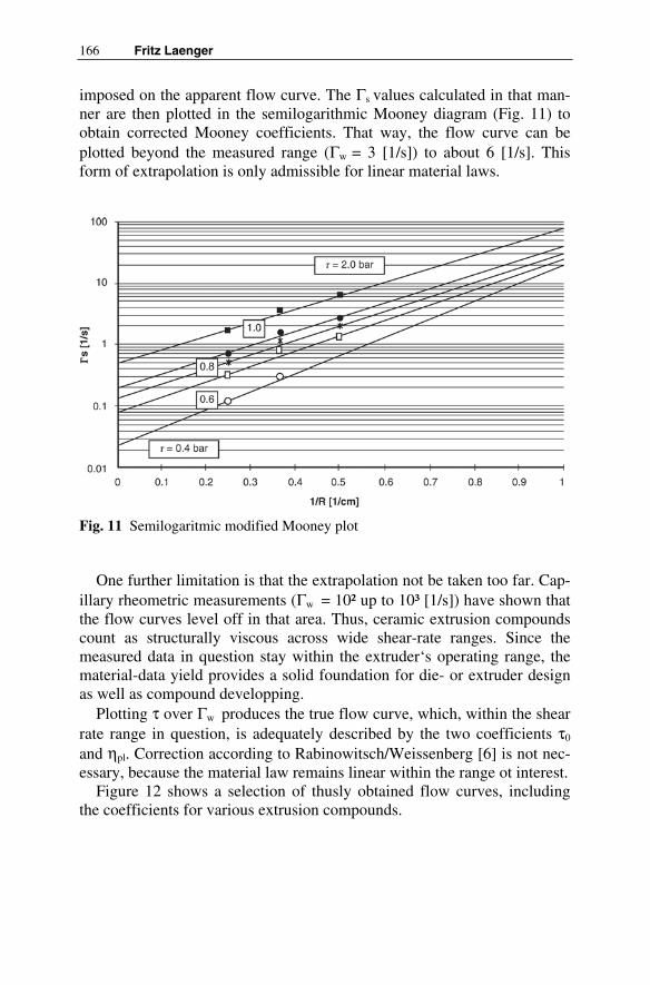
166 Fritz Laenger
imposed on the apparent flow curve. The Γs values calculated in that man-ner are then plotted in the semilogarithmic Mooney diagram (Fig. 11) to obtain corrected Mooney coefficients. That way, the flow curve can be plotted beyond the measured range (Γw = 3 [1/s]) to about 6 [1/s]. This form of extrapolation is only admissible for linear material laws.
Fig. 11 Semilogaritmic modified Mooney plot
One further limitation is that the extrapolation not be taken too far. Cap-illary rheometric measurements (Γw = 10² up to 10³ [1/s]) have shown that the flow curves level off in that area. Thus, ceramic extrusion compounds count as structurally viscous across wide shear-rate ranges. Since the measured data in question stay within the extruder‘s operating range, the material-data yield provides a solid foundation for die- or extruder design as well as compound developping.
Plotting τ over Γw produces the true flow curve, which, within the shear rate range in question, is adequately described by the two coefficients τ0
and ηpl. Correction according to Rabinowitsch/Weissenberg [6] is not nec-essary, because the material law remains linear within the range ot interest.
Figure 12 shows a selection of thusly obtained flow curves, including the coefficients for various extrusion compounds.

7 Rheology of Ceramic Bodies 167
Fig. 12 Time flow curves of typical clay base ceramic compounds – Bingham type
All of these measurements not only exhibit a large effort, but depend on uncertainty of measuring. In practice, the behaviour of an extrusion com-pound in an auger, pressure head or in a die is from interest. Therefore the rheological parameters have to be available cheep an quickly. For this per-pos a simulation model was developed by the author. Usually existing ex-trusion batches have to be adapted on a certain extrusion process or the ex-trusion machinery have to be adapted on the compound. In both cases extrusion parameters of laboratory extruders or production extruders still exist. The following chapture describes a very economical method how to develope the rheological parameters.
7.5 The Rheological Simulation Model
The coordinate system is based on cylinder coordinates (Fig. 13), because the auger is rotationally symmetrical and has a distinct axial direction. With respect to solving the system of differential equations (eq. 37), a fixed system of coordinates is of advantage. Consequently, reverse motion is assumed, i.e., the auger stands still, while the barrel rotates at auger speed.

168 Fritz Laenger
Fig. 13 Specification of auger-channel coordinates
The differential equation system (DES) for viscous, incompressible me-dia under conditions of steady, creeping flow with no allowance for grav-ity reads [4], [11]:
τ⋅−∇=∇p (28)
That equation represents equilibrium between the pressure gradient and the divergence of the shear-stress tensor and hence, a balance of momen-tum. Substituting Bingham‘s material law, as derived from rheological measurements including wall slippage in the tensor equation downgraded to a vector equation; 28, yields:
)R,(fv,1 g0 τ=Γ⋅η+⋅τ=τrr
rr
r
(29)
and resolving the DES leads up to the auger-channel velocity field:
( ))r(w),r(v),r(u)r(v =r
(30)
with the three components u(r), v(r), and w(r). Returning to Fig. 13, we see the velocity components qualitatively represented by the three direc-tions in space. There is no movement in direction r, because the direction r impulses are negligible compared with the material parameters and, hence to the effective resistance. Thus u(r) = 0. The v(r) velocity profile de-scribes the rotational velocity of the extrusion compound, while w(r) de-scribes the velocity component in the direction of z. The vectorial addition of the two velocity components leeds to the velocity field of material flow. In the following v(r) and w(r) have the additional specification NFG, which is standing for the superposition of Newtonian flow, yield point in-fluence and slipp velocity (Fig. 15, 18).

7 Rheology of Ceramic Bodies 169
Integration of the velocity field yields the throughput of the auger, dif-ferentiation of the velocity field to the shear-rate function in the auger channel. In the here discussed physical problem it can be shown, that in the strain velocity tensor only the second invariant is different from zero. Mul-tiplication of the absolut value of the second invariant with the Bingham viscosity yields the dissipation function of the auger channel. Combining the shear-rate function with the material law leeds on the shear stress func-tion in the auger channel. These dynamic and kinematic functions allow to describe the motion and the momentum of the extrusion compound and, hence the extruder process parameters.
The model works by iteration, so the equations can be solved to each pa-rameter. For example to the rheological parameters yield point τ0 and Bingham viscosity ηBi. All we need are the process data of an existing pro-duction scale or laboratory scale extrusion process: Troughput, auger speed, power requirement, pressure build – up, and the geometric data of the auger together with the rheological unknown extrusion compound.
Figure 14 shows the auger characteristic throughput over pressure gra-dient for an extruder with auger diameter 500 mm and a ceramic brick
Fig. 14 Auger characteristic
0 0.2 0.4 0.6 0.8 10
2000
4000
6000
8000
Q dpdL( )
Qisti
dpdL dpLi,[bar/cm]
[cm3/s]

170 Fritz Laenger
compound (throughput 20 m³/h, pressure 11 bar). The calculated line cor-responds to the measured process data. The yield point τ0 = 0.15 [bar] and the Bingham viscosity ηBi = 0.81 [bar s] were found by iteration. In Fig. 15 the velocity distribution in the auger channel is shown (compare with Fig. 13). The dynamic and kinematic functions τ (r), Φ (r) and Γ (r) are listed in Fig. 16. In this state it is even possible to simulate the behaviour of similar compounds, which are not rheologicaly too fare away from the testet one.
5 10 15 20 250
2
4
wNFG r( )
r
[cm]
5 10 15 20 25
0
20
vNFG r( )
r
Fig. 15 Velocity distribution of ceramic compound flow in auger channel, output direction and rotational direction
As an example for technical ceramic compounds the figures 17, 18, 19 offer the same grafics for a honeycomb compound to produce catalysts with 300 cells per square inch on a extruder with auger diameter 180 mm (throughput 280 l/h, pressure 150 bar). Hence of the 150 bar at the pressure head the compound is very stiff. The yield point calculates to 0.3 [bar], which is double to the brick compound and the Bingham viscocity with 2.2 [bar s] is more then triple than the brick compound.
[cm]
[cm]
[cm/s]
[cm/s]

7 Rheology of Ceramic Bodies 171
5 10 15 20 250
1
2
3
4
τ r( )
Φ r( )
Γ r( )
r
[bar]
[W/cm³]
[1/s]
Fig. 16 Shear rate-, shear stress- and dissipation function in the auger channel
0 1 2 3 4 50
50
100
150
200
Q dpdL( )
Qisti
dpdL dpLi,
Fig. 17 Auger characteristic
[cm]
[cm]
[cm3/s]

172 Fritz Laenger
6 6.5 7 7.5 8 8.5 90
1
2
wNFG r( )
r
[cm]
6 6.5 7 7.5 8 8.5 95
0
5
10
vNFG r( )
r
Fig. 18 (see Fig. 15) Velocity distribution of ceramic compound flow in auger channel, output direction and rotational direction
6 6.5 7 7.5 8 8.5 90
2
4
6
8
10
τ r( )
Φ r( )
Γ r( )
r
[bar]
[W/cm³]
[1/s]
Fig. 19 (see Fig. 16) Shear rate-, shear stress- and dissipation function in the au-ger channel
[cm]
[cm]
[cm]
[cm/s]
[cm/s]
7 Rheology of Ceramic Bodies 173
The slope of the auger characteristic is very small, hence the high stiff-ness (viscosity > 2 bar s). Therefore the shear stress and the dissipation function yield much higher values (please mention the different axis distri-bution for the two compounds).
7.6 Summary and Prospects
The rheology of ceramic extrusion compounds shows a Bingham charac-teristic with wall slippage. The material low can be determined by the de-scribed theory. The measuring equipment is available for example at Händle’s laboratory in Mühlacker, Germany. This characterisation leeds in a big effort.
An other methode is discussed, to minimize the measuring- and evalua-tion effort. A rheological computer simulation model (ESM), developed by the author [12], [13], [14], [15], makes it economical to find the material parameters. Some process data from production – or laboratory scale ex-trusion process together with the rheological model, are sufficient for evaluation. Even the behavior of the compound for example for different dies or different auger geometrie can be investigated and opimized, with-out further tests.
Literature
[1] Hodgkinson HR (1963) A Film: The Plane-Flow Extrusion of Plas-tic Clay. Special Publication No 41, The British Ceramic Research Association
[2] Gömze AL (1986) Chois of technical parameters for screw presses. J Interbrick 2:30-34
[3] Hallmann E (1983) Schneckenpressenberechnungen für keramische Stoffe, Teil I bis III J Sprechsaal vol 116 No 1:25-27, No 8:653-662, No 10:895-898
[4] Bird RB, Steward WE, Lightfood EN (1960) Transport Phenomena, Wiley International Edition
[5] Reiner M (1990) Rheologie in elementarer Darstellung. Carl Hanser Verlag, München
[6] Rheologie – Atlas Bd 1, VDMA, Frankfurt a. Main [7] Laenger F (1990) Designing an extruder with allowance for the
properties of ceramic extrusion compounds – part 1. J cfi/Berichte der DKG (German Ceramic Society Report) vol 67 No 4 pp 162-164

174 Fritz Laenger
[8] Geiger K (1989) Rheologische Charakterisierung von EPDM-Kautschukmischungen mittels Kapillarrheometer-Systemen. J KGK Kautschuk Gummi Kunststoffe vol 42 No 4
[9] Windhab E (1985) Untersuchungen zum rheologischen Verhalten konzentrierter Suspensionen. In: Forschungsberichte VDI Reihe 3, No 118
[10] Mooney M (1931) Explicit Formulas for slip and fluidity. J Rheolvol 2 pp 210-222
[11] Sommerfeld A (1978) Mechanik der deformierbaren Medien – Vor-lesung über theoretische Physik. Verlag Harri Deutsch Thun, Frank-furt a. Main
[12] Laenger F (1992) Designing an extruder with allowance for the properties of ceramic extrusion compounds – part 4a. J cfi/Berichte der DKG (German Ceramic Society Report) vol 69 No 7/8 pp 266-272
[13] Laenger F (1992) Designing an extruder with allowance for the properties of ceramic extrusion compounds – part 4b. J cfi/Berichte der DKG (German Ceramic Society Report) vol 69 No 9 pp 347-352
[14] Laenger F (1992) Designing an extruder with allowance for the properties of ceramic extrusion compounds – part 5a. J cfi/Berichte der DKG (German Ceramic Society Report) vol 69 No 10 pp 397-401
[15] Laenger F (1993) Designing an extruder with allowance for the properties of ceramic extrusion compounds – part 5b. J cfi/Berichte der DKG (German Ceramic Society Report) vol 70 No 3 pp 95 ff

8 Rheology and Extrudability of Ceramic Compounds
Wolfgang Gleißle, Jan Graczyk
Many ceramic products are made by extruding materials which are not ex-trudable in their original state and must be made so by appropriate treat-ment and by incorporating various additives which adjust their rheology or flow properties. The properties that are of importance for extrusion can, in fact, be characterized and quantified by means of rheological measure-ments. Capillary rheometry especially enables many different extrudability tests to be carried out, ranging from simple suitability tests to complex de-terminations of properties in order to achieve optimum processes and pro-ducts.
8.1 lntroduction
Extrusion is a much used process in many branches of the ceramics indus-try. Coarse earthenware as well as fine ceramic and industrial ceramic pro-ducts, ranging from bricks to high performance catalysts are made in this way. Figure 1 shows an example of an extruded industrial ceramic pro-duct.
Ceramic masses have been successfully extruded for more than 150 years. The first extruders for making bricks from stiff clay were made in 1835 [1]. The only condition which the extrusion compounds had to fulfill was that they should have sufficient plasticity. This, however, is not al-ways easy to achieve and is not easy to define accurately. Scott Blair wrote in 1940 [2]:
“Plasticity is like honesty – something indefinable which, however, is linked with specific characteristics”.
Several definitions have been formulated which summarize different material properties, some of which are difficult to determine, e.g. yield point, permanent deformation and the cohesion of the material during and after deformation.

176 Wolfgang Gleißle, Jan Graczyk
Explanation of symbols used in text
D die diameter DK channel diameter KA ageing factor KS increase factor L die Iength p pressure pB Bagley pressure R die radius V& volume rate vD extrusion rate vG sliding speed γ& shear rate
apγ& apparent shear rate τ hear stress
Fig. 1 Example of an extruder catalyst carrier
The classic definition, formulated by Haase [3] is as follows: “Plasticity is the ability of a solid substance to react to externally applied forces with permanent changes in shape without loss of cohesion of the particles which form that substance”.
More recent definitions, such as that proposed by Schulle [4] refer to the rheological behaviour of the material. In the ceramics industry, attempts to measure plasticity have been made for nearly a hundred years. Several methods have been developed to determine certain figures, Indexes and factors, e.g. by Pfefferkorn [5], Atterberg [6] and Ricke [7]. Bloor [8] and Moore [9] have produced a good bibliography on this subject. The results of most methods are of practical importance within a production process for a specific material, e.g. to ensure product quality, These figures are, however, of very little use in predicting the processing characteristics of other ceramic materials or to describe these rheologically. Strictly speak-ing, they cannot be applied to such materials at all. The use of rheometric tests has facilitated definite progress in characterizing plasticity. Their ad-vantages have also been recognized by various authors in the field of tradi-

8 Rheology and Extrudability of Ceramic Compounds 177
tional ceramics, e.g. by Schulle [4], Schober [10] and Laenger [11] for the optimization of compounds and of extruder design.
Interesting attempts to characterize the flow and extrusion characteris-tics of ceramic compounds, pastes and damp bulk solids have been made by Felder [12] and Raschka [13], using a torsional shear cell and an annu-lar shear Instrument specially developed for this purpose.
Benbow and co-workers have done work using a press resembling a simplified capillary rheometer [14-16]. Here, the connection between the extrusion pressure and the extrudate delivery rate was determined for dif-ferent paste-like materials. The results were used to formulate a mathema-tical description in which up to six parameters must be experimentally de-termined. The mathematical approximation enables one to calculate special extrusion parameters such as the extrusion pressure.
For industrial high-performance ceramics the transferable characteriza-tion of flow properties is indispensable both for developing suitable basic compounds for making complex moulded parts, as well as for designing suitable moulds.
We shell now discuss the methods (and informative value) of rheometri-cally characterizing the extrusion process, using as example ceramic com-pounds for making honeycomb catalyst supports.
8.2 Rheological Test Methods for Describing Extrudability
8.2.1 Capillary Rheometry
The flow processes that occur during extrusion are very complex. Many effects are apparent, some of which are difficult to separate, e.g. shear flow with yield point, wall slippage with slippage limit, elastic and time effects such as thixotropy. These effects should be identifiable in measuring proc-esses. The capillary rheometer can be used to determine such effects. The flow taking place in a capillary rheometer can be readily adapted to the ty-pe of flow encountered in an extrusion die. Even though the determina-tions do not allow a complete analytical and rheological description of the material (material law formulation) they will usually provide a good quali-tative description of extrusion behaviour and can be used as tests to characterize ceramic compounds (17,18].
Figure 2 shows the function of a high pressure capillary rheometer and curves typical for determinations on ceramic compounds such as volumet-ric flow V& and pressure p as a function of time t as well as the relation be-tween shear stress and shear rate ( )τ γ& .

178 Wolfgang Gleißle, Jan Graczyk
Fig. 2 Diagram showing the experimental set-up of a capillary rheometer with typical diagrams V(t), P(t) and τ( γ)
The separate determination of two specific extrusion pressure compo-nents is particularly informative – the pressure loss caused by powerful forming processes of the ceramic compound at the feed end of the extruder die (so-called “Bagley pressure”) and the pressure loss (“flow resistance”) inside the die.
The objectives of capillary-rheometric determinations to characterize the extrusion characteristics of ceramic compounds are many, ranging from simple tests to complex determinations of material properties in order to perfect the extrusion process and extrusion dies. Figure 3 shows the possible uses of these determinations and the equipment used. The possi-bilities of capillary-rheometric tests are explained with the help of some examples.

8 Rheology and Extrudability of Ceramic Compounds 179
Fig. 3 Characteristics – an overview

180 Wolfgang Gleißle, Jan Graczyk
8.2.2 Accelerated Test of Extrusion Properties
A quick check of extrusion properties of ceramic compounds can be made using a simplified capillary-rheometric method. A one-point or two-point determination can, for example, make it possible to quickly select promi-sing compound compositions. The accelerated test method was used in the development of a compound from aluminium oxide for making catalyst supports. Two criteria were here taken into account:
– good deformability, recognizable from the slight slope of the apparent flow curve,
– sufficient stability of flow properties after the compound has been made.
The pressure is determined at two extrusion speeds, using a capillary rheometer fitted with an extrusion die and a pipe with fixed dimensions. The determinations are carried out one hour after the ceramic mass has been prepared, and again 24 hours later. The figures obtained, and the fac-tors HA (ageing factor) and KS (increase factor), provide useful information on the characteristics of the ceramic compounds. The principle of the method is illustrated in Fig. 4.
Fig. 4 Essentail details of an accelorated test method

8 Rheology and Extrudability of Ceramic Compounds 181
8.2.3 Apparent Flow Curve
Several phenomena which make the extrusion of ceramic compounds easy or difficult result in characteristic pressure-time curves p(t) and the resul-tant apparent flow curves ‘c(t). Some examples of these phenomena are shown in Fig. 5.
Fig. 5 Characteristic phenomens during extrusion. Pressure time diagrams and the relevant flow curves
Case 1 in Fig. 5 shows effects caused by material inhomogeneities re-sulting from fluctuations in concentration, local differences in particle size distribution and the presence of entrapped air. The fluctuations of the mea-sured pressure-time curves do not produce an unequivocal apparent flow curve. Only a more or less broad flow range can be determined.
Case II shows the change in the material during extrusion under the in-fluence of pressure and deformation. In the given example the progressive separation of the liquid and solid phases can lead to an increase in solids concentration and the loss of extrudability of the material. The apparent flow function only shows the lower limit and is open towards the top.
Case III shows another aspect of the change of the material during ex-trusion. If certain volume throughputs, governed by the size and shape of the die, are exceeded, the extrusion pressure will gradually increase, then suddenly decrease and then increase again. The extruded strand becomes

182 Wolfgang Gleißle, Jan Graczyk
thinner than the die diameter and then suddenly becomes as thick, or alm-ost as thick. This process is repeated, in correlation with pressure variati-ons.
Case IV shows another variant of the change in the properties of a ceramic compound during extrusion. The phenomenon shown in this example, namely the appearance of a pressure loss that is almost indepen-dent of the extrusion rate, which increases or decreases for only a short time, depending on the previous extrusion rate, is due to thixotropy, This property is characteristic for ceramic compounds made of plastic clay, for example, and generally means very good extrusion characteristics.
8.2.4 Complete Determination – Flow Function, Sliding Function
A complete determination with the capillary rheometer includes the plot-ting of apparent flow curves with several dies having different lengths and diameters. This enables several corrections to be carried out, e.g. the Bag-ley correction, to separate the input pressure loss from the flow resistance inside the die; the Weißenberg-Rabinowitsch correction to determine the true shear rate, and the Mooney correction to determine wall slippage speed [19, 20], and therefore the differentiated determination of the mate-rial‘s flow properties and the formulation of the material law.
The results of the characterization of extrusion behaviour are explained using ceramic catalyst carrier compounds based on γ-aluminium oxide. The solid phase of all compounds was the same, consisting of γ-aluminiumoxide and pseudobohmite in a ratio of 2:1.
The fluid, aqueous phase contains flow control agents as detailed below:
Compound A 10 % by weight hydroxyethyl cellulose,
Compound B 20 % by weight polyvinyl pyrrolidone,
Compound C 10 % by weight ammonium alginate.
Figure 6 shows some typical graphs and the appropriate flow curves, as well as the extrudates produced in each case.
The uncorrected flow curves for two die lengths L1 and L2 in the dia-grams of the first line in Fig. 6 indicate definite, non-Newtonian flow for all three compounds. At high extrusion speeds the apparent shear stress and extrusion pressure show an increase and sudden fluctuations in the case of compound B. The different behaviour of the various compounds is evident from the flow curves corrected according to Bagley [19] (BK in the diagrams, line 1) and the Bagley diagram (line 2).

8 Rheology and Extrudability of Ceramic Compounds 183
Fig. 6 The results of capillary-rheometric determinations on aluminium oxide compounds
Comparison of the Bagley pressure and the extrusion pressure, i.e. the pressure losses resulting from the two basically different deformation and flow processes, produces curves which are characteristic for the extrusion behaviour of the compounds. The increase in extrusion pressure for com-pound A is due almost exclusively to the increase in the Bagley pressure. The corresponding shear stress function BK in diagram 1 A is almost in-dependent of apγ& . For compound B, the two pressures p and pB are very different, depending on the total pressure and the deformation rate, where-as both pressures p and pB for compound C increase proportionally to each other with increasing volume throughput.

184 Wolfgang Gleißle, Jan Graczyk
Ceramic compounds can be dyed in different colours in layers, to enable flow processes to be detected immediately. Internal flow processes will then become visible through deformation of the coloured specimens. The flow diagrams of the dyed material in line 4 confirm the different flow be-haviour of the ceramic compounds. Compound A is not deformed by in-ternal “flow”. There is pure plug flow and the material slides completely along the wall. The flow diagram for compound B indicates very marked shear deformation near the wall, whilst compound C is only slightly de-formed. With this compound, the volumetric flow results from internal flow and wall slippage.
For this compound C, Fig. 7 shows flow curves determined by meas-urements with dies of different diameters ( 1 and 2 mm). Despite the Bag-ley correction there is no uniform flow function ( )apτ γ& . Checking the slid-
ing properties by the method developed by Mooney [20] gives a material transport which is caused almost exclusively by sliding processes. Plotting sliding speed and extrusion rate ( 2
Dv 4V / D= π& ) against shear stress (Fig.
8) gives a single curve. If the suitability of rheometric methods to check extrusion performance
is to be checked, it is necessary to extrude these compounds through dies as used in actual practice. The results of rheometric tests an compounds A, B and C were therefore compared with the extrusion of honeycomb struc-tures (line 5 in Fig. 6). The specific rheometric characteristics of com-pounds A and C are in accordance with specially good extrusion character-
Fig. 7 Apparent flow curves and Bagley-corrected flow curves for ceramic com-pound C (aluminium oxide with ammonium alginate)

8 Rheology and Extrudability of Ceramic Compounds 185
Fig. 8 Shear stress vs. extrusion rate and sliding speed for ceramic compound C, determined by the Mooney method
istics. Compound B, on the other hand, is unsuitable for making complex extrusions, although the solid phase is identical with that of compounds A and C. The results prove that ceramic compounds will give the best extru-sion results if there is little or no shear deformation in the capillary – a case which, strictly speaking, lies outside the normal objectives of rheological determinations. This characteristic is, however, most effectively deter-mined by rheological tests.
8.3 Summary
Ceramic parts are often made by extrusion. The material properties neces-sary for extrusion can be checked by rheological tests. Here, capillary rhe-ometry, which enables many different extrudability tests to be carried out, is specially suitable.
In this article, we have described methods of determination ranging from simple tests to the complete rheological analysis of extrusion charac-teristics, ceramic compounds used to make catalyst supports serving es ex-ample. We have also discussed characteristic phenomena which influence the extrudability of ceramic compounds. Finally, we have compared the results of capillary-rheometric determinations and the extrusion of com-plex parts.

186 Wolfgang Gleißle, Jan Graczyk
Literature
[1] Green AT, Stewart CH (1953) Ceramics, a symposium arranged and edited by Green and Steward. British Ceramic Society, Stoke-on-Trent, p 755
[2] Blair GWS (1940) Einführung in die technische Fließkunde. Theo-dor Steinkopf Verlag, Dresden
[3] Haase T (1954) Untersuchungen zur Bildsamkeit keramischer Mas-sen. J Silikattechnik vol 5 No 10 pp 428-432
[4] Schulle W, Bartusch R (1984) Beitrag zur rheologischen Charakteri-sierung bildsamer keramischer Massen. J Keramische Zeitschrift vol 36 No 10 pp 524-528
[5] Pfefferkorn K (1924) Ein Beitrag zur Bestimmung der Plastizität in Tonen und Kaolinen. J Sprechsaal vol 57 No 25 pp 297-299
[6] Rieke R (1923) J Berichte der DKG 4:176-187[7] Atterberg A (1911) J Int Mill Bodenkunde No 1 p 10 [8] Bloor EC (1957) J Trans Brit Ceram Soc vol 56 pp 423-481 [9] Moore F (1967) Rheologie in der Keramik. Hermann Hübener Ver-
lag, Goslar [10] Schober G, Mörtel H (1988) Plastische keramische Massen im
Scherversuch und im Vergleich mit einem rheologischen Modell. Teil 1 und 2 J cfi/Berichte der DKG (German Ceramic Society Re-port) vol 65 3/4:67-69, 5:134-136
[11] Länger F (1990/1991) Designing an extruder with allowance for the properties of ceramic extrusion compounds – part 1, 2a and 2b Jcfi/Berichte der DKG (German Ceramic Society Report) vol 67 No 3 pp 92-94, vol 68 No 9 pp 409-413, vol 68 No 10/11 pp 531-533
[12] Felder R (1990) Charakterisierung von Pasten mit einem Schergerät im Hinblick auf ihre Ausformbarkeit. Dissertation, Universität Karlsruhe
[13] Raschka K (1990) Bestimmung der Fließeigenschaften feuchter Schüttgüter mit Anwendung bei der Schneckenextrusion. Disserta-tion, Universität Karlsruhe
[14] Benbow JJ, Oxley EW, Bridgwater J (1987) The Extrusion Mechan-ics of Pastes – the Influence of Paste Formulation on Extrusion Pa-rameters. J Chem Eng Sci vol. 42 No 9 pp 2151-2162
[15] Benbow JJ, Lawson TA, Oxley EW (1989) Prediction of Paste Ex-trusion Pressure. J Ceramic Bulletin vol. 68 No 10 pp 1821-1824
[16] Benbow JJ, Jazayeri SH, Bridgewater J (1988) J Ceram Trans ACS 2 pp 624-634

8 Rheology and Extrudability of Ceramic Compounds 187
[17] Graczyk J, Gleißle W, Roth A, Koffer M (1990) J Erdöl Kohle Erd-gas Petrochemie 43:27-30
[18] Graczyk J, Gleißle W (1992) The rheometric characterization of ce-ramic pastes for catalysts. In: Theoretical an Applied Rheology, Proc Xith Int Congress on Rheology, Bruessels, pp 601-603
[19] Bagley EB (1957) J 3. Appl. Phys 28:624-627 [20] Mooney M (1931) Explicit formulas for slip and fluidity. J Rheolo-
gy 2:210-222

9 Scenarios of Extrusion
Dietmar Lutz
9.1 Introduction
The goal of this contribution about the operating behaviour of single-screw extruders in the extrusion of ceramic masses is, on the basis of an easily comprehensible presentation, to explain the scenarios emerging in practice so as to be in a position, in the case of any problems arising, to initiate purposefully the necessary steps.
In practice, the most frequent problems in extrusion arise through
• modification to the rheological properties of the mass, for example, through variations in the moisture or in the homogeneity,
• any change to the profiles which can lead to increased flow resis-tance in the nozzle,
• wear on the screw or on the cylinder inserts or modification to the screw or cylinder surfaces which leads to an increased proportion in the flow-back or to a reduced capacity for the forming pressure of the screw,
• increase in the flow rate combined with increased strand speeds, • vacuum errors through leakage, • vacuum errors in spite of a faultlessly sealed vacuum aggregate, • mouthpiece errors.
In operating a screw extruder, it is important to understand the basics; no higher mathematics is necessary for this (1).

190 Dietmar Lutz
9.2 Functioning of Screw Extruders
Fig. 1 Functioning of screw extruders
It is meaningful to differentiate screw extruders into the two sub-systems
• pressure generators: system screw and cylinder
and
• pressure consumers: all resistances which the material has to surmount after leaving the screw
Only when there is a balance on both sides of point X can the ceramic mass escape from the nozzle.

9 Operating Behaviour of Srew Extruders in the Extrusion Ceramic Masses 191
In the example depicted in Fig. 1, the screw will compactly fill itself up to the backlog point (RSP 1). Only then is it in a position to build up the pressure P1 necessary for the pressure consumer.
Each extruder has a specific pressure formation capacity which is de-fined in bar / cm.
That means that an extruder with a pressure formation capacity of dpdl=0.3 bar/cm is, at a length of cylinder of L=1m, in a position to build up a pressure of 30 bar.
The value ‘dpdl’ is not a constant value. It depends on a variety of vol-umes of influence which we shall look into later.
The following important changes can occur which influence the func-tioning of the screw extruder whereby wear on the screw and cylinder in-serts should, to a large extent, not be taken into consideration within this framework.
• Increase in the flow rate • Modification to the compacting pressure
o nozzle cross-section o nozzle length o modification to the plasticity � moisture� shear stress � fluxes� material homogeneities
• Modification to the screw geometry o gradiento ratio of the outer screw diameter to the hub diameter o modification to the surface � “corrosion”� build-up of material deposit� increased friction through incorrect armoured material
The five most important cases are to be explained on the basis of the “didactic” presentations selected above.

192 Dietmar Lutz
9.2.1 Modification to Flow Rate
Fig. 2 Modification to flow rate
In the case of the screw extruder, an increase in the flow rate requires an increase in the screw speed and a corresponding increase in the dosing of the extruder.
Through this, the pressure rises from P1 to P2 as the increased strand speeds lead with the same nozzle to increased friction in the nozzle.
The curve, RPSP1 /P1, is thus shifted nearly parallel until it achieves the necessary pressure P2 which in turn results in an increase in the length of the backlog to X /REP2.
As the REP2 lies outside the closed cylinder in which a build-up in pressure is possible, the extruder shown in Fig. 2 will not be in a position to generate the required pressure or output.

9 Operating Behaviour of Srew Extruders in the Extrusion Ceramic Masses 193
Which remedies are available? � Extend the cylinder and screw so that the backlog point RSP2 lies
within the extended pressure cylinder L � Reduce the flow resistance of the nozzle or the nozzle consumer to
the extent that the RSP lies within the cylinder again. � Increase the pressure-forming capacity of the screw so that, at the
existing cylinder length, pressure P2 can be generated � Modification to the pressure increase angle through modification to
the mass to achieve pressure P2 with the existing cylinder length.
9.2.2 Modification to Nozzle
Fig. 3 Modification to the nozzle
It is rare just for one product or one profile to be extruded on screw ex-truders. More frequently it is dozens of different “profiles” which have to be extruded and which each require a specific nozzle or, as we often say in the ceramics sector, a pressure head/mouthpiece combination.

194 Dietmar Lutz
As already stated, the required compacting pressure P is determined mainly by the rheological features of the mass and execution of the pres-sure consumer, in detail, through the angle in the pressure head and mouthpiece, the friction conditions, the degree of transformation etc.
If the nozzle cannot be modified for technical flow or economic reasons, the remedial measures will be identical to the measures listed under 2.1 The degree to which possible modifications to the nozzle have to move to compensate the increased pressure level P2 is shown by the straight line A1P1. A/A 1 corresponds to the necessary “shortening” of the nozzle which has to be carried out to achieve the pressure level P1 without ex-tending the screw.
9.2.3 Modification to Plasticity – “Stiffer” Masses
Fig. 4 Modification to the plasticity – “stiffer” mass
If the moisture is reduced or the mass modified by additives, an increase in pressure can be expected with the nozzle remaining constant as a result of the increased friction in the pressure consumer, i.e. P1 is increased to P2.

9 Operating Behaviour of Srew Extruders in the Extrusion Ceramic Masses 195
Two cases have to be differentiated here: If the pressure increase angle α , defined by the friction between the
mass and the screw/ cylinder combination, remains the same, the remedies are identical to those shown in case 2.1. This is not to be expected, how-ever, if a stiffer mass leads to modification to the pressure increase angle, i.e. higher pressures are generated per cm screw length.
The two alternatives derived from this are presented in Fig. 4: The steeper pressure increase angle β leads in the pressure generator, at
the same backlog length, starting from the backlog point RSP1, to an in-creased pressure level P1*.
P2* is the maximum pressure achievable with the existing screw/cyl-inder combination for this stiffer mass. If this increased pressure level is not sufficient, it is necessary to revert to the remedies listed under 2.1 such as extension to the screw and cylinder which, particularly for stiffer masses, is connected with appreciable increases in the torque.
9.2.4 Modification to the Plasticity – “Softer” Mass
Fig. 5 Modification to the plasticity – “softer” mass

196 Dietmar Lutz
In the case of softer, usually damper masses, it can be assumed, in con-trast to case 2.3., that, by reducing the friction in the pressure consumer, the level of pressure is reduced from P1 to P2.
If the pressure increase angle α remains constant, the backlog length would be reduced, i.e. the screw /cylinder length could be reduced which can mean appreciable savings in energy.
As, however, in the case of softer masses, it has to be assumed that the pressure increase angle becomes flatter or the specific pressure formation capacity less, i.e. α becomes β , this is not the case.
The maximum pressure level which can be achieved, starting from the backlog point REP1 at a pressure increase angle β , lies in figure 5 at P1*. The maximum pressure level of the extruder shown above thus lies, at pressure increase angle β , only at P2* If this level is not sufficient, the steps described above have to be taken.
Screw /cylinder extensions can lead, in particular for soft masses, which have to be extruded at a high compacting pressure – e.g. for the manufac-ture of filigree honeycomb, to appreciable consequences.
In a concrete case, the screw and the cylinder were extended by 23% for a single-screw extruder with a screw diameter of 150 mm.
At the same speed, identical nozzle and identical mass, the extrusion speed was increased by factor 2.7 and the torque reduced by 25%.
The effects on wear, which mainly depends on the relative speeds be-tween the mass, screw and cylinder were appreciable and compensate within a brief period the costs for extension to the screw and cylinder.
Attention is drawn at this point to the fact that, for the design of an ex-truder, it is of decisive significance as to whether a “higher” compacting pressure is generated as the result of a higher flow resistance or a stiffer mass.
An extruder for compacting stiffer masses will only be in a position in the rarest of cases to extrude its ceramic masses at a high flow resistance.
On the other hand, an extruder which has been developed for the extru-sion of honeycombs for compacting pressures of over 100 bar will be in a position to process a stiff mass at relatively low flow resistances but, how-ever, will wander as a result of the steeper pressure increase angle of the backlog point in the direction of the nozzle; the function of the extruder is sub-optimum as the L/D ratio is too high for this case.

9 Operating Behaviour of Srew Extruders in the Extrusion Ceramic Masses 197
9.2.5 Fluctuating Plasticity
Fig. 6 Fluctuating plasticity
In the extrusion of ceramic architectural products, it is part of the regu-lar experience of any operator of extrusion plant include those by which the operating behaviour of the extruder varies with the weather conditions, i.e. depends on the dampness of the masses to be extruded.
These phenomena are known even in modern brick works, which have adequate buffers to compensate these fluctuations in raw material.
Less well-known is which marginal fluctuations in dampness are neces-sary to generate dramatic changes in plasticity with some masses (2).
If the plasticity in an extruder fluctuates between stiff and soft, this makes, for the operator and also the manufacturer of the extruder, for al-most insoluble problems as uncontrolled alterations to the pressure in-crease angle at the given pressure level allow no continuous pressure in-

198 Dietmar Lutz
crease through the cylinder length which leads to constant alteration to the backlog length as presented in Fig. 6
If such operating behaviour occurs periodically, for example in the wet season, works can adjust to this more or less easily.
It is different in a special case which we should like to describe as “non-completed ‘plasticisation’”.
As the introduction of shearing energy occurs specifically or non-specifically in the extruder per se, i.e. kneading of the mass und thus modi-fication to the plasticity takes place, this fluctuating operating behaviour can become a permanent condition in the case of non-completed or chang-ing plasticity of the mass in front of the extruder.
A frequent cause of this phenomenon, which makes itself noticeable through pulsating of the extrusion speed, altering consistency and the ge-ometry of the extrudate etc., is, in most cases, insufficient dosing and/or insufficient softening or homogenisation of the mass applied, often con-nected with deficient dosing.
The most important remedies to prevent fluctuating plasticity consist therefore of a guarantee of constant dosing and homogeneity conditions in front of the extruder.
9.3 Measures
The main measures which we have at our disposal in the case of changes in the operating behaviour have already been mentioned in key words.
A promising estimation of the effectiveness of individual measures requires an exact knowledge of the material law of the mass concerned, i.e. its rheological properties. Where does the yield limit lie, does the viscosity show dilitant or structual viscous/pseudoplastic behaviour in dependance on the shearing rate, does the viscosity alter at the same shearing rate in the course of time, i.e. are we dealing with rheopectic or thixotropic behaviour, do glide planes form, how sensitive does the mass react to changes in the plasticity and the temperature etc.
The success of technical measures or even simulations based experience, as they are set out in the contribution by Buchtala and Lang, are only likely to succeed if the material law of the mass to be extruded is sufficiently well known.
Unfortunately, the attempt is still made in practice, to “finagle” past these necessities, without precise or at least sufficient knowledge of the material laws in according to the “trial and error method” or with the aid of supercifical or apparently impressive methods such as, for example, thermography.

9 Operating Behaviour of Srew Extruders in the Extrusion Ceramic Masses 199
We restrict ourselves here to a brief presentation of the most important measures.
9.3.1 Modification to the Nozzle
It has already been indicated several times that the level of pressure necessary for the extrusion of a certain mass is determined by the pressure consumer, i.e. the nozzle.
If the pressure generated in the nozzle is or has to be reduced or increased, we mainly have the following individual measures at our disposal:
• variation in the ratio nozzle length to nozzle cross-section (shaping degree)
• variation of the inlet angle into the mouthpiece • modification to the friction relationships in the mouthpiece, for ex-
ample, through external lubrication of the mouthpiece or the addi-tion of an internal slide agent to the mass
• cooling or heating of the nozzle for mass sensitive to temperature • modification to the distance between the end of the screw and the
inlet of the nozzle • installation and structure of so-called slide funnels or strainer
plates in the back part of the nozzle • modification to shaping degree through alteration to the screw di-
ameter and/or nozzle cross-section
Indications to the effectiveness of the individual measures can be found in Reed, Pels Leusden, Hodgkinson etc. (3)
9.3.2 Modification to the Screw Geometry
If the level of pressure determined to a large extent by the mass and the pressure consumer prescribed or not alterable, the measures have to be concentrated on the pressure-generating system screw /cylinder.
Each extruder can be defined by two main parameters, the throughput and the pressure build-up.
Any modification to the screw geometry always leads thereby to modi-fication of the two parameters. Depending on the mass, product and the necessary pressure level, single-screw extruders work in the ceramics in-dustry with screws which show an L/D ratio (screw length/screw diameter in the closed cylinder) of 2-20. Similarly extreme differences can be estab-
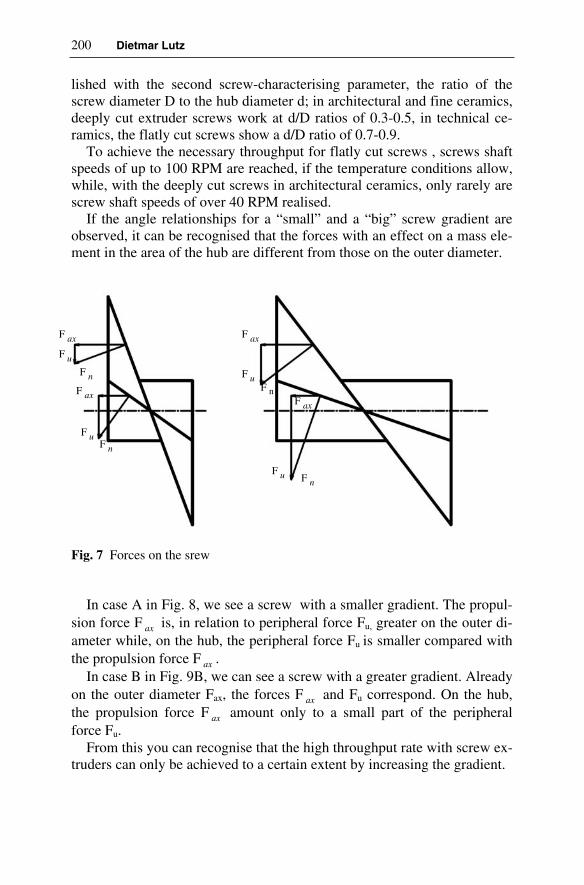
200 Dietmar Lutz
lished with the second screw-characterising parameter, the ratio of the screw diameter D to the hub diameter d; in architectural and fine ceramics, deeply cut extruder screws work at d/D ratios of 0.3-0.5, in technical ce-ramics, the flatly cut screws show a d/D ratio of 0.7-0.9.
To achieve the necessary throughput for flatly cut screws , screws shaft speeds of up to 100 RPM are reached, if the temperature conditions allow, while, with the deeply cut screws in architectural ceramics, only rarely are screw shaft speeds of over 40 RPM realised.
If the angle relationships for a “small” and a “big” screw gradient are observed, it can be recognised that the forces with an effect on a mass ele-ment in the area of the hub are different from those on the outer diameter.
Fig. 7 Forces on the srew
In case A in Fig. 8, we see a screw with a smaller gradient. The propul-sion force F ax is, in relation to peripheral force Fu, greater on the outer di-ameter while, on the hub, the peripheral force Fu is smaller compared with the propulsion force F ax .
In case B in Fig. 9B, we can see a screw with a greater gradient. Already on the outer diameter Fax, the forces F ax and Fu correspond. On the hub, the propulsion force F ax amount only to a small part of the peripheral force Fu.
From this you can recognise that the high throughput rate with screw ex-truders can only be achieved to a certain extent by increasing the gradient.
F ax
F ax
F ax
F ax
F u
F u
F u
F u
F n
F n
F nF n

9 Operating Behaviour of Srew Extruders in the Extrusion Ceramic Masses 201
While the screw in case A can be charactirised as a pressure screw , the screw in Fig. 9 B shows the typical conveyance screw which cannot generate high pressure.
Any modification to the d/D ratio, for example, the enlargement of the hub, leads to a modification to the ratio of Fax to Fu. As any modification to Fax/Fu implies a modification of the useful conveyance volumes and an increase in the screw shaft speed does not mean an alternative for many masses on the basis of the associated increase in the shearing load, very careful consideration is necessary in determining the optimum screw geometry.
Sumarising, the following individual measures are available to us:
• checking the L/D ratio of screw /cylinder with regard to the necessary pressure level
• checking the d/D ration of the screw with regard to the required flow rate
• checking the screw gradient with regard to the required flow rate and the achievable pressure forces on the hub or on the outer diamter.
9.3.3 Modification to the Friction Conditions for Screw and Cylinder
In our observations up to now, we have assumed ideal friction conditions in the screw/cylinder system.
For the screw extruder in ceramics, ideal means minimum friction between mass and screw at maximum friction btween mass and cylinder to prevent the mass stopper from turning as well. In the literature, this approach has become known as the “cork screw model”.
Without these different friction conditions between the mass and screw on the one hand and the mass and cylinder on the other, an extruder could not build up any pressure.
If the coarseness of the screw surface is taken as the basis for, by the way, insufficient indicator for estimating the friction coefficients to be expected between the mass and the screw, Ra values of 2-4 ų can be achieved today for application of tungsten carbide according to the high-speed plasma method; for hard chrome-plating, these values lie at about 0.3.
In a concrete case, comprehensive attempts were carried out on an extruder for the production of honeycombs from SiC mass. At identical conditions, the screw shaft speed was able at ideal coarseness of the screw compared with screws with customary coarseness values to be reduced to a third.

202 Dietmar Lutz
Unfortunately, at present, we have no surface coating available in practice which guarantees in continuous operation the high wear-resistance necessary for the extrusion of abrasive ceramic masses at low friction coefficients. Otherwise the value of the friction coefficients between screw and mass does not depend only on the coarseness of the screw surface but also on the adhesion between mass and screw, on the pressure, the wear conditions etc.
We do not have any tenable empirical examinations in which the influence of the various factors has been examined although it concerned an extremely relevant topic.
The complete context is summed up on the basis of a concrete example: In the case in hand, the maximum granulation of the tungsten carbide
material applied was 15 ų. For the fine mass to be extruded, the granulation share was <1 ų approx 50%. There would be ideal conditions if the maximum elevations or “valleys” on the surface of the screw were smaller than the granulations of the mass to be extruded as otherwise the mass would be deposited on the screw, i.e. in the depressions, and friction between mass / mass would occur which is significantly greater than the friction between the mass and the screw surface.
Fig. 8 Friction between mass, screw and barrel
As can be seen from Fig. 8, the screw attempts to turn the mass as well due to the friction between mass and steel. The cylinder casing has the job of preventing such turning as far as possible. Apart from this, the backflow
Mt
pitch
Barrel liner Basic liner
Grooved strip
µ M
µ Zµ A

9 Operating Behaviour of Srew Extruders in the Extrusion Ceramic Masses 203
area arising between the cylinder and the screw should be as low as possi-ble. That means, not only the edge gap between the screw and the cylinder is to be reduced as far as possible, also the backflow area resulting from the form of grooves is to be minimised.
The further you move from the cylinder in the direction of the screw hub, the more these “holding forces” can only be passed on through the in-ternal structure of the mass up to the hub.
This means that, at increased fine granulation share in connection with an increased plasticity, it becomes increasingly difficult to transport the mass to be extruded evenly over the whole free cross-section of the screw. This is exacerbated by the fact that at certain masses on the hub, a layer of the finest material fraction and liquid phase is formed which makes trans-port on the hub increasingly difficult.
Summarising, we have the following individual measures at our dis-posal:
• screws which are as smooth as possible for the achievement of low friction coefficients between mass and screw,
• optimised use of cylinders for the prevention of the mass turning in the cylinder at low backflow area,
• correct selection of the screw geometry,• sufficient plastification of the mass before extrusion.
9.3.4 Modification to the Mass
As already suggested in point 3.3, in the case of very fine masses, the situation can arise whereby the internal friction of the mass is no longer sufficient to convey the greater peripheral forces on the hub diameter of the screw outwards to the cylinder casing. It has to be examined here whether modifications to the mass are possible or whether a different ex-trusion principle, e.g. double-screw extruder has to be selected with respect to the potential for modification.
9.4 Facet
In practice, the problem scenarios often overlap. New products, connected with new nozzle cross-sections, can lead to rheologically altered masses with altered plasticity etc.
Target conflicts cannot be avoided per se, however, they can usually be solved with an understanding of how the extruder works if none of the possible adjusting screws is excluded from observation as is often the case.

204 Dietmar Lutz
Literature
[1] Pels Leusden CO (1982) Extrusion. In: Bender W, Händle, F (eds) Brick and Tile Making. Bauverlag GmbH, Wiesbaden und Berlin, pp 215-235
[2] Händle F (1978) Beitrag zur sogenannten Plastizität von Ton-Wasser-Systemen. J ZI Ziegelindustrie International vol 31 No 9 pp 472-476
[3] Lawrence WG (1961) Clay-Water Systems. The Ceramic Associa-tion of New York, Alfred University, New York
[4] Reed JS (1995) Principles of Ceramics Processing. John Wiley & Sons, New York, pp 450 ff
[5] Hodgkinson HR (1962) The mechanics of extrusion. J Claycraft 11:42-48
[6] Pels Leusden CO (1975) Die Formgebung von Strangpressen. In: Ziegeleitechnisches Jahrbuch 1975, Bauverlag GmbH, Wiesbaden und Berlin, pp 237-380

10 Laminations in Extrusion
Rainer Bartusch, Frank Händle
10.1 Definition
Within the field of ceramics, the term “laminations” is commonly used in reference to the textures which characterise the material structure of the body, the word “texture” stemming from the Latin “textura” meaning “tis-sue”. The term “laminations” according to Haage (1) encompasses:
– the orientation of the structural components (isotropic and anisotropic textures),
– the distribution of the structural components (homogeneous and inho-mogeneous textures),
– the degree of volume ratio (compact and porous textures).
Ceramic materials – as opposed to amorphous glasses – largely consist of crystalline structural components and almost all of them lend themsel-ves to laminations. In practical operation it must be aimed at optimising the recipe of the body and the preparation and shaping processes in a sui-table manner to ensure that laminations have no negative effect such as de-formations or cracks in the quality of the finished product. The state of la-mination of any ceramic product will be largely created during the shaping process, although it often only shows after drying or sintering.
It would be wrong to identify laminations as unwanted phenomena per se, all the more so as there are ceramic products in which laminations can have a useful effect in achieving certain material characteristics. An e-xample is substrates for car catalyst converters with the shape of thin-walled honeycombs, the structure of which receives a distinctive directio-nal texture as a result of the high degree of transformation during extrusi-on. As a consequence the sintered products feature an extremely low ther-mal linear expansion coefficient in their axial direction and therefore a high thermal shock resistance. This enables the ceramic honeycombs to withstand innumerable vehicle engine starts without incurring damage.

206 Rainer Bartusch, Frank Händle
Laminations can develop during all ceramic preparation and shaping processes; moreover in dry pressing as well as in casting; furthermore dur-ing repressing of roofing tile blanks or in the rolling of plates. Laminations can even be found in isostatic pressing.
In extrusion however laminations are frequently the focus of expert dis-cussion, as this system of shaping can in certain cases lead to high waste rates during production or defects encountered in the end use of the cera-mic product, often attributed to laminations whether this is the case or not. Therefore countless efforts have been and are still being made to find a so-lution to the negative effects of laminations in extrusion by introducing de-sign modifications, in particular in the area of the augers, the pressure head and the die. Many recommendations contained in published works have generally been found to be less than successful, although they may have solved the problem in individual cases.
There has nevertheless been some progress in previous decades in mi-nimising the laminations of extruded products. A universal nostrum cannot however be expected in view of the incipient complexity of the problem due to the extremely diverse conditions and requirements in respect of raw materials, the technologies applied and product specification in ceramic production plants.
The first part of the following text describes the development of lamina-tions during the extrusion process and under which aspects these can be classified. This is followed by a description of qualitative as well as quantitative methods to proof and evaluate laminations. The last section of this chapter details some possible methods for the minimisation of extrusion laminations and how their negative effects may be avoided. The bibliography is restricted to the essentials; information regarding further literature can be taken from the bibliography.
10.2 Causes of the Development of Laminations and Different Types of Laminations
During extrusion laminations basically develop as a result of the combined effect of raw material respectively body-specific characteristics and physi-cal processes caused by transport, homogenisation and shaping operations within the extruder, which may cause shearing, gliding, separation and re-joining effects within the ceramic body.
A meaningful classification for practical use pertaining to the causes for development of laminations can be found with Probst (2), who suggests three groups for the actuating variables: ceramic variables, process engi-

10 Laminations in Extrusion 207
neering variables and mechanical processing variables. Within these three groups there can be up to a dozen individual variables.
Fig. 1 Causes for development of laminations during extrusion according to Probst
Within the framework of this chapter only the most important actuating variables relevant in practical operation will be dealt with. For a purpose-ful battle against laminations it is, however, recommended to keep the a-bove classifications in mind. Attempts are frequently made in practice to combat laminations by manipulation of the auger geometry or the die, only producing marginal success as the real origin of the problem lies in earlier process stages.
It also has to be taken into consideration that the ceramic body already exhibits laminations to a greater or smaller degree even before being fed into the extruder or de-airing extrusion unit, although these change in cha-racter becoming more or less pronounced as a result of the preparation processes employed, e.g. in filter presses, in mixers, in kneaders, in proportioning units, etc. (3).
The large variety of laminations typical for extrusion, as described in the literature, can be reduced to the following types:
� Flow laminations, � Inner gliding surfaces, � Cutting laminations,

208 Rainer Bartusch, Frank Händle
� Specific laminations of the auger extrusion unit, � De-airing laminations, � Laminations caused by inhomogeneous body.
Numerous forms of laminations in clay-based ceramic products as – op-posed to oxide and non-oxide ceramics – are influenced by the specific properties of the clay minerals. Such clay minerals as kaolinite, halloysite, montmorillonite or illite are finely dispersed, from approx. 5 to 1000 nm, and consequently have a large specific surface of approx. 5 to 100 m²/g, and are furthermore of an anisometric morphology, having the geometric shape of lamella, little rods, strips, etc.
Fig. 2 REM exposure of kaolinite layers, edge length of plates approx. 1µm
It is not possible to deal with these ceramic actuating variables within this article; reference should be made to the relevant literature.
10.2.1 Flow Laminations
The characteristic feature of flow laminations is the directional orientation of the anisometric particles in the shearing speed gradient of the auger channel, the pressure head and the die. Figure 3 pictures the fracture sur-faces of extruded clay-body columns after drying showing various flow laminations caused by different clay mineral content.

10 Laminations in Extrusion 209
Fig. 3 Flow laminations in cross-section of clay-body columns Left: very plastic clay; Centre: kaolinitic kaoline; Right: clay with grog addition
As certain properties of the crystalline components depend on the crystallographic axes, directional differences in the property values caused by the flow lamination can be determined at the extruded items. This holds true for example for the drying and firing shrinkage, the linear thermal coefficient of expansion, the thermal conductivity and the mechanical strength.
The drying shrinkage differs in respect of location and direction, which may cause tensions inside the product in turn resulting in deformations or, if the strength is exceeded, in cracks.
Figure 4 demonstrates the drying shrinkage readings of extruded slugs of high-strength china. The specimens used were hollow slugs with an ou-ter diameter of 480 mm, from which insulators for power plants are made by the turning process after semi-hard drying.
Taking the axial direction of the slug or of the insulator there are rela-tively large differences in respect of the drying shrinkage over the radius. Therefore, compressive stresses and tensile stresses are to be expected in drying. Those areas of cross section that show the highest degree of shrinkage have a particularly high crack hazard, as tensile stresses are be-ing built up and the tensile strength of a ceramic structure is much lower than the compressive strength.
Flow laminations do, of course, also occur when using piston extrusion presses as the ceramic body is subjected to shearing stress in the pressure head and die. It follows that flow laminations are primarily linked to the nature of the material particles. There would be no flow laminations with

210 Rainer Bartusch, Frank Händle
raw materials consisting entirely of almost isometric particles such as tho-se of a ball shape (4).
Fig. 4 Directional drying shrinkage rates of high-strength china billets
10.2.2 Laminations as a Result of Inner Gliding Surfaces
Another type of lamination is that caused by inner gliding surfaces due to the relative movement of the ceramic body and auger respectively extruder barrel. Segregation occurs in the boundary layer between metal and cera-mic body. The coarser material particles in particular are pressed inside the body whilst the liquid phase and the very fine particles concentrate in the boundary layer (Fig. 5).
If the fine particles are of an anisometric shape as with clay minerals, orientation will be parallel to the surface of the boundary layer. Although, after having exited the auger, these boundary layers join to form a compact body, there is no intimate bonding respectively “cogging” between the bo-dy and the boundary layers. The follow-on reshaping in the pressure head and die merely deforms these layers; their structural characteristics are changed only very marginally. These gliding surfaces have a lower me-

10 Laminations in Extrusion 211
chanical strength after drying and sintering and are, therefore, more prone to cracks, which may also occur in use of the finished ceramic product.
Fig. 5 Development of surface slippers (schematic view according to PelsLeusden)
Such defects could for instance manifest themselves as frost damage on engineering bricks or in insulator slugs appearing in the form of cracks, sometimes of a spiral shape. It is possible to make these gliding surfaces visible by adding a small amount of a very intensive pigment into the extruder together with the body. By cutting open the extruded product and by studying the number and shape of the coloured patterns, certain conclu-sions can be drawn in respect of the formation of the gliding surfaces.
10.2.3 Cutting Laminations
Cutting laminations are mainly caused by fixtures in the die. Such fixtures are always unavoidable if a die with cores is employed in order to produce a perforated column, as with pipes, hollow profiles, common bricks, hon-eycombs, etc. The core bows, which are fitted crosswise to the flow direc-tion, separate the body. If the distance between the core bow and column exit is too narrow or if the flow pressure is too low, the parting planes can-not sufficiently “weld” together. (5)
Similar to the inner gliding surfaces certain areas of the column will have a reduced strength. Sometimes the resulting laminations are already apparent at the extruded product in the form of cracks, and if this is the case such columns and/or products can easily be pulled apart, even by hand.

212 Rainer Bartusch, Frank Händle
Fig. 6 Colouring test to show the laminations in a slug
Fig. 7 Part of a roofing tile after pressing with “open” cutting lamination

10 Laminations in Extrusion 213
Contrary to inner gliding surfaces, cutting laminations are usually a-ligned in the direction of extrusion. As they are created exclusively in the die or pressure head, these cutting laminations can be found with all types of extruders, i.e. with piston extrusion presses as well as auger extrusion units.
10.2.4 Laminations Specific to Extruders
Flow laminations, laminations caused by inner gliding surfaces, and cut-ting laminations, all can be distinguished to varying degrees in the extru-sion of plastic bodies, independent of the extrusion method employed, e.g. piston extrusion presses, single-shaft extruders, twin-shaft extrusion ma-chines or rotory-type extruders.
The work commissioned by the British Ceramic Research Association, carried out and published in 1962 and 1963 by Hodgkinson (6) was both scientifically and didactically pioneering, as can be seen by the accompa-nying instructional film, contributing then as now to a better understanding of flow laminations.
Hodgkinson’s work made and still makes many debates obsolete; cer-tain assumptions such as focusing on the extruder as the notorious “creator of laminations” had to be reconsidered and many patent cures documented in the literature revealed themselves on the basis of this work to be of no general use, only offering a suitable solution in individual cases. Hodgkin-son was able to prove with the use of a highly sophisticated test device, which was ahead of its time, that the formation of flow laminations within
Fig. 8 Slip-lines formed in clay

214 Rainer Bartusch, Frank Händle
solid columns in the form of thin bands is essentially determined by the degree of deformation, i.e. the ratio between the outlet cross section and inlet cross section, as well as the entry angles of the die.
The extent of lamination can, of course, vary considerably depending on the characteristics of the body, the ratio between internal and external fric-tion, the surface quality of the dies, etc.
Nevertheless this does not change the fundamental validity of this re-search and its results: “Inevitably, however, the application of results from this work to production problems must result in compromise” (6) as Hodg-kinson put it, well aware of the fact that in practice certain conditions may exist which could lead to severe deviations.
The auger in particular has a very specific influence on laminations, as examined below.
10.2.4.1 Influence of the Hub
Once the body to be extruded has passed the double or multi-wing end au-ger, also known as point auger, it can clearly be seen that an auger ex-truder, as opposed to a piston extrusion press, does in fact extrude a “pipe” and not a round solid column, whereby the diameter of the auger hub cor-responds to the inside diameter of the pipe.
Only when the body is rejoined in the pressure head, is the pipe formed to a compact column.
Fig. 9 Mass flow at the top auger

10 Laminations in Extrusion 215
However, in accordance with the characteristics of the body and de-pendent on the strain caused by deformation, the hub is still visible in the shape of a “core”, i.e. lamination, in the dried or fired product, whereby this lamination may develop into an S-crack typical for a screw extruder with a double-wing end auger.
By reducing the hub in the area of the last auger flights and of the point auger, the rejoining of the body inside the pressure head can be aided, but even then the shape of the hub may still in many cases be visible as a “co-re”, especially in solid extruded columns, as surface slippers will have formed between the ceramic body and the hub, which often results in a concentration of the liquid phase when in contact with the hub and which becomes evident in a concentrated manner in the form of the “core”.
10.2.4.2 Influence of the Auger Blades
“It can thus be said that the gross laminations in an extruded column are located around that
part of the clay which has been in contact with the auger blade during its consolidation in the machine. Why is this so? It has long been held that the clay is polished by the auger blade,
and that two surfaces of polished clay will not satisfactorily rejoin – even under pressure” (6).
This phenomenon as described by Hodgkinson is to be considered a special feature of gliding laminations and again is mainly dependent on the properties of the body, i.e. plasticity, grain size distribution, percentage of inert components and grog respectively binding agents, etc., which are de-cisive factors in the development of laminations.
But that is not the whole story! Especially the influence of the point au-ger at the end of the auger flights, which – contrary to customary opinion – contributes less to the pressure build-up but rather whose main function is that of dividing the column from the auger into two or more identical col-umn sections, is apparent in the form of laminations in the column as can be clearly seen in Fig. 6 showing an example of a coloured insulator slug.
Laminations caused by the auger blades can be influenced or largely eliminated by varying the geometry of the point auger, in particular by changing the pitch of the auger blades and variation of the speed, the num-ber of auger blades, by installing “lamination-eradicating attachments” to rotate with the auger and by reducing the hub.

216 Rainer Bartusch, Frank Händle
10.2.4.3 Influence of the Auger Rotation
Laminations typical for screw extruders – as opposed to piston extrusion presses – are also those which are induced by the rotation of the auger in-side the body-filled barrel, whereby the friction between the body and the auger surface causes the more or less compact “body clog” being distorted in direction of the rotation.
One tries to counteract this phenomenon, which is also undesirable from an energy point of view, by reducing the coefficient of friction between auger and body, by for instance using polished or hard chrome plated au-gers, by optimum-designed and machined barrels, by installing so-called counter knives alongside the barrel, by modifying the distance between auger and barrel, by controlled tempering of auger and barrel and by instal-ling so-called rectifiers or strainer plates at the end of the auger, etc.
Whilst such rotation of the body column has only a marginal effect on ceramic profiles with a high percentage of voids such as honeycombs or hollow blocks for ceramic ceilings, as the complex-designed dies function as a “rectifier”, or as the case may be other types of laminations such as cutting laminations or flow laminations superimpose those caused by rota-tion, the twisting of the column in the extrusion of solid columns for pa-vers or insulator slugs may lead to considerable problems in respect of product quality. (7)
10.2.4.4 S-crack
The so-called S-crack or Y-crack is typical for a screw extruder with a double-blade or triple-blade point auger. This type of lamination is a com-bined consequence of overlapping of flow laminations, the rotational mo-vements of the body, as well as the hollow space created by the auger hub in the centre of the emerging “body clog”, which will not entirely rejoin as a result of body characteristics or the geometry of the pressure head and die, all as described above.
Twisting of the column transforms the initial round cavity, which has been tapered at the pressure head and influenced by the double-blade or triple-blade point auger, into an S-shaped or Y-shaped crack-line, and this may lead to substantial quality problems above all with solid columns.
10.2.4.5 Development of Laminations Within the Extruder
In addition to those of Hodgkinson, there exist numerous noteworthy pub-lications by Pels Leusden, of which those relating to the process of forma-tion of laminations inside the extruder are of particular significance (8).

10 Laminations in Extrusion 217
Fig. 10 Slug showing a Y-shaped drying crack resulting from a triple-blade point auger
Fig. 11 Green brick showing a S-shaped crack resulting from a twin-blade point auger
The formation of laminations in different areas of the auger extruder was tested using 14 different auger flights of the most diverse geometry and under the most varied operating conditions.
For the purpose of these tests specimens were removed over the length of the auger from infeed point to the die, in different direction to the mate-rial flow.

218 Rainer Bartusch, Frank Händle
A so-called lamination number was fixed in relation to the tensile strength readings obtained from the specimens; more information on this relatively elaborate method can be found with Grätz (9).
Fig. 12 Variation in laminations in the auger extruder
The fundamental result, subject to the influence of the auger geometry, is unequivocal: laminations already inherent in the body change only in-significantly from the material infeed position to the intake point of the pressure head. An “inversion effect” of the laminations takes place in the pressure head, which means the relative highest lamination readings within the auger are transposed into the relative lowest lamination readings within the pressure head; unfortunately Pels Leusden did not follow up this phe-nomenon in his later works. It is clear that the most crucial laminations are formed in the area of the die, where the increase in lamination is manifold compared to that at the auger (10).
Bearing in mind the generally accepted opinion that the laminations with auger extruders are mainly caused by the auger, the foregoing conclu-sions are of obvious significance for several reasons, all the more so as in our opinion they also correlate the findings of Hodgkinson and others.
They imply that:
a) laminations, primarily in the form of flow laminations, wanted or un-wanted, are created in the area of the highest strain caused by deforma-tion, mainly as a result of the orientation of the anisomorphic particles.
diepressurehead cylinder
1,0
2,0
3,0
m
ediu
m la
min
atio
n va
lue
TZ
10 Laminations in Extrusion 219
b) other laminations such as those caused by rotation, surface slippers, laminations as a result of the hub design, etc. are partly destroyed in this area of highest deformation or they represent only a marginal per-centage if compared to flow laminations; a fact which is exploited by installing rectifiers or strainer plates which deliberately increases the compression loss of the ceramic body at the rectifier – the so-called “Bagley pressure” – above the compression loss in the die itself caused by the flow resistance (11).
c) we can still develop a problem-solving strategy to eliminate laminati-ons, sometimes a very painstaking exercise, whereby the sequence and weighting of the individual steps may vary according to the body cha-racteristics and the product. As Pels Leusden, Probst and others havecarried out extensive work on this subject, available in part in the form of checklists for analysing and solving the problems, we shall restrict ourselves here to a broad outline chiefly highlighting that the problem of eliminating laminations can only be solved in its entirety by consi-dering all influencing factors, especially those of preparation and pro-perties of the body, whereby the pressure head/die system is of decisi-ve importance within these influencing factors. (12)
10.3 De-airing Laminations
10.3.1 Influence of De-airing on the Formation of Laminations
The introduction of the combined de-airing extrusion machine in the 1930s represented a decisive step forward in the extrusion of ceramic bodies. Nowadays it is an accepted fact in extrusion technology that most of the air enclosed in the body and compressed with it needs to be evacuated, although the related background physics is not always readily known in practice. So-called “dragon teeth” which show at the die exit are one of the most obvious consequences of insufficient de-airing. The bound air contri-butes towards the porosity of the body whereby one must differentiate between the size of pores, the shape of pores, the distribution of pores, etc; in short there are “good” and “harmful” pores, and since these aspects are relevant to frost resistance, this is a subject with which a number of authors have dealt; an extensive research on literature can be found with Bender/Händle. (13)
Reference is also made in particular to the work on the influence of de-airing by Pels Leusden (12), who quantitatively determined with various clays in a plastic, dried and fired state the so-called lamination number re-lated to the tensile strengths in both main directional pulls, as well as the

220 Rainer Bartusch, Frank Händle
so-called lamination strength as the absolute tensile strength in the lamina-tion level.
To summarise, it can be established that both values improve positively with a high de-airing of all bodies, whereas with a partial de-airing the la-mination figures deteriorate with all kinds of bodies and in certain cases result in even worse lamination figures than with non-de-aired extrusion.
To the knowledge of the authors further research work exists only in the form of in-house investigations, which cannot be taken as a general gui-dance to cover the wide range of ceramic bodies and ceramic products, since the type of pore formation created by the de-airing process can lead to very varied results with different bodies and products.
This means in practical terms that the optimum vacuum must be deter-mined individually for each product when processing bodies that are sensi-tive to de-airing.
So-called “sniffle valves” inserted in the vacuum chamber, in combina-tion with suitable vacuum pumps, can control the degree of vacuum.
It is a wrong approach, often applied in practical operation, to use over-dimensioned vacuum pumps with a high rated throughput instead of amply-dimensioned vacuum pumps with a higher ultimate pressure, except for such cases where the vacuum collapses frequently as a result of insuffi-cient material feed into the combined de-airing extrusion unit or inadequa-te sealing of the vacuum chamber.
Use of over-dimensioned vacuum pumps often leads to an undesirable desiccation of the body.
10.3.2 Laminations Resulting from Sealed Air
Tests carried out in a desiccator reveal the existence of air residues in extruded specimens, even in the case of optimum de-aired and extruded samples, especially in the case of very fine-grained and simultaneously plastic materials, despite careful de-airing of < 30 mbar. This applies all the more if the cross section of the “sausages” or shavings exiting the de-airing mixer or the primary pug sealer is too large, if the dwell time of the body inside the vacuum chamber is too short and if the condensation of these “sausages” or shavings has caused an entirely sealed and dense sur-face.
These pieces of body are conveyed by the auger from the infeed zone into the pressure zone, where not only the body itself but also any existing residues of air are compacted, in turn creating laminations as the compac-ted air residue in the body forms pores, which enlarge under atmospheric pressure.

10 Laminations in Extrusion 221
Besides optimum de-airing a finest possible cutting up of the body at the entry into the vacuum chamber is a remedial step, combined with an ade-quate dwell time and a specially- designed auger in the area of pressure build-up. (14)
10.4 Laminations as a Result of Inhomogeneous Body
It is quite often found that lack of homogeneity of the body is the cause of laminations. Such inhomogeneity can be the result of inadequate mixing, uneven shearing stress during the preceding kneading action, variations in the plasticity within the grain size distribution and in the dispersion of the body components, in the form of non-plastic ingredients, and within the binding agents, etc.
Whilst “good-natured” bodies or less demanding ceramic products may tolerate the laminations created by these factors, unacceptable deficiencies in quality will be obtained with lamination-sensitive bodies and high-quality products, which cannot be cured permanently or at all by taking appropriate measures at the piston extrusion press or at the combined de-airing extrusion unit.
Another typical feature associated with ceramics is the cyclical occur-rence – often associated with the season of the year – of laminations due to variations in the consistency of the material to be processed. Frequently the origin can also be traced back to wear problems in the preceding grin-ding and mixing operations.
The sometimes large quantities of additives as commonly used in the brick industry for the production of highly-perforated heat-insulating bricks, together with the varied origin, grain shape and moisture content of these additives, demand optimum body preparation and proportioning a-head of the extruder.
The same holds true in relation to the high percentage of fibres as used in advanced ceramics products which, partly as a result of their structure, intensify the alignment by forming flow laminations and creating gliding laminations.
10.5 Methods for Detection and Evaluation of Laminations
One must basically differentiate between qualitative and quantitative methods of determination. If laminations do exist in a ceramic body, quali-

222 Rainer Bartusch, Frank Händle
tative methods will produce a “lamination picture”, which in turn will pro-vide information on the locality and the characteristic features of the lami-nation. In contrast to this, if quantitative methods are employed, these will deliver defined readings, which will permit an objective evaluation of the laminations.
Frequently qualitative methods are used during the production process as these will provide practice-orientated information, from which the state of lamination of a column respectively of a product can be deduced in a relatively fast manner without spending too much effort on measuring technique.
10.5.1 Qualitative Methods
Summarised below are a few qualitative methods often employed in prac-tical operation without any claims to completeness. Comprehensive litera-ture is available from which further details can be obtained on each of the individual methods (2).
10.5.1.1 Bending Test and “Slap Down” Test
Column segments are repeatedly subjected to deflection using both hands until cracks appear. The density, the thickness and the pattern of the cracks offer a qualitative assessment of the state of lamination. With larger extru-ded or pressed items deformation can also be achieved by slapping them hard onto a base, similarly producing a crack pattern.
10.5.1.2 “Ice Lenses” (“Eislinsen”) Test
Employing the so-called “Eislinsen” method entails the storing of the ex-truded products below freezing point of the dispersion liquid. A characte-ristic picture of the crack will show if any laminations are within the body.
10.5.1.3 Fast Drying
Extruded green blanks are deposited in a hot drying chamber or dryer. Fast drying will cause very high stresses, which again will create a certain pat-tern of laminations present.

10 Laminations in Extrusion 223
10.5.1.4 “Impact” Test
Another method is to strike two dried blanks against each other until cracks appear or fragments chip off. It may be possible to determine the state of lamination from the pattern of the surface of the fracture.
10.5.1.5 Desiccator Test
An extrusion test is carried out without de-airing, i.e. with the vacuum pump switched off. The dried or fired blank is stored in water within a desiccator at room temperature. When the atmospheric pressure in the desiccator is lowered down to approx. < 100 mbar, an air bubble formation can be observed rising from the blank revealing the pattern of the lamina-tion.
10.5.1.6 Colour Test
A shaped body, not densely sintered, is immersed in a solution of perman-ganate of potash over a certain period of time. Should there be laminations, the suction speed and the capillary degree of absorption of the structure are inconsistent. When such an impregnated sintered body is cut open, diffe-rences in the depth of colour and in the flow path of the coloured liquid are apparent.
10.5.2 Quantitative Methods
There are also quantitative methods which, however, necessitate more ela-borate equipment and which are therefore predominantly employed in con-text with research and development work. The most prominent methods are described in brief below:
10.5.2.1 Radiographic Method (XRD):
This method is commonly used in metallography to describe the laminati-on structure of metallic materials. Such laminations can, for instance, develop in forming processes such as the rolling of plates, drawing of wires or crystallization of a cast structure. X-ray texture goniometers function according to either the radiographic or reflection method. In contrast to the radiographic analyses of phases, the angle between the monochromatic X-ray hitting the specimen and the counter tube is kept constant for testing the laminations, preferably choosing a characteristic peak, i.e. a crystal level, which can easily be detected and which is part of

224 Rainer Bartusch, Frank Händle
vel, which can easily be detected and which is part of an essential structure component.
In the case of high-strength china slugs this could be the (001)-level of the clay mineral kaolinite, but certain crystalline phases of the sintered structure may also be used, such as mullite. The support carrying the ce-ramic test specimen is turned and tilted in a defined manner. Depending on the position of the specimen the intensity of the X-radiation is recorded and shown as pole figure, whereby the direction of extrusion and the trans-verse direction are marked. Thus very detailed and quantitative informati-on is achieved relating to the orientation of the crystals within a specific section of the product volume. Obviously many samples must be taken and tested in the case of larger-size ceramic items in order to obtain informati-on on the state of lamination in the whole product. Within the field of ce-ramics the application of the radiographic method for determination of la-minations is limited to research and development of high-performance ceramics.
10.5.2.2 Determination of Tensile Strength
This method was primarily developed for extruded structural clay products (9). Small dumbbell-shaped specimens (of approx. 30 mm length) are cut out of a plastic clay column in different directions and at different spots. After drying or firing the tensile strength of these specimens is determined. One can calculate a quotient of strength in two directions, for instance pa-rallel and vertical to the direction of extrusion. This quotient is called the lamination number. This lamination Fig. 1 indicates that there are no lami-nations. The more the lamination figure deviates from number 1, the more pronounced will be the lamination within the structure. Very extensive tests have been conducted with the aid of this method, which is however unsuitable for regular production checks because of the work and time in-volved.
10.5.2.3 Penetrometer Method
Simple hand-operated penetrometers suitable for measuring the plasticity of bodies to be extruded and for extruded columns are on the market. By using the penetrometer, designed to determine the plasticity, the resistance caused by penetration over the cross section of the extruded sample is established. It is advisable to use a template in order to ensure that the pe-netration depth is always measured at the same spot. This is a well-proven method for application on large surface cross sections, on slugs or imme-diately after extruder pressure heads, as used in brick factories, but is unsu-

10 Laminations in Extrusion 225
itable for thin-walled profiles. Although this method is a relatively fast and easy one, it is also prone to errors, as subjective influences brought about by different ways of handling cannot be excluded. In an effort to reduce any such unreliability, improved penetrometer units have been developed in the recent past, including a laboratory-use version, which can eliminate these subjective factors.
10.5.2.4 Shrinkage Measurement
Immediately after extrusion shrinkage marks are indented at different points and in different directions on the extruded products or, as the case may be, column segments. After drying or firing the directional and positi-on-dependent shrinkage is determined. Figure 4 demonstrates the result of such measurement of large-size high-strength china slugs. Using the rea-dings obtained in different directions, lamination figures can be calculated by quotient or subtraction. This represents a fairly simple and fast method and is therefore employed in several plants for production control purpo-ses.
10.5.2.5 Dilatometer Method
Dilatometer rods are cut from a dried or sintered column both in direction of extrusion as well as in transverse direction. Usually the length of rods is between 10 and 50 mm, depending on the type of dilatometer being used. As a result of the measurements temperature-dependent readings for the thermal coefficient of expansion in the relevant directions are calculated. The higher the difference in readings between the coefficient of expansion in different directions, the more distinctive are the laminations. A differen-tial dilatometer is the most suitable instrument for this method /10/. Rods taken from the two different directions are clamped into the device side by side, heated, and the difference in expansion respectively in shrinkage simply measured. The difference in expansion or shrinkage established on the dried specimens gives an indication regarding the mechanical strains which occur in a ceramic body during the sintering process. With the aid of modern methods of simulation, such as the finite element method, and with knowledge of other material parameters and temperature distribution, one can even calculate the distribution of stresses as a result of laminati-ons. With certain products the thermal coefficient of expansion within a defined temperature range is an important quality parameter and is deter-mined at regular intervals. This is the case for instance in the production of cordierite honeycombs for catalytic converters for automobiles.

226 Rainer Bartusch, Frank Händle
10.6 Opportunities for Minimising Detrimental Effects Caused by Laminations
The formation of laminations caused by extrusion and their implications depend to a very large extent on the raw material properties, the prepara-tion technology employed, the design and operating mode of the extruder. Consequently the following discourse can only represent some hints and a rough orientation. Purposeful tests carried out directly at the extruder or within the upstream technological processes are unavoidable in individual cases.
10.6.1 Optimisation of the Body
It is appropriate to first of all look into optimisation of the plastic body in regard to minimising laminations. Certain materials are particularly unfa-vourable and tend to the formation of extrusion laminations. These are tho-se body compositions which contain a high percentage of extremely fine and anisomorphic particles, mainly clays and kaolines with a proportion of clay minerals, whereby the lamination problems have a tendency to increa-se as the specific surface is enlarged. But also other materials like talcum or micaceous natural raw materials with lamellar particles are prone to the formation of extrusion laminations.
On the other hand the clay minerals contained in clays and kaolines car-ry the properties for plasticity, which is of vital importance for extrusion and thus for the entire plastic shaping process including extrusion of bricks and tiles, porcelain, stoneware and earthenware products. A suitable compromise must often be found between the essential plasticity and the formation of laminations. For structural clay products an optimum grain size distribution is of great significance. The percentage of the fraction be-low 2 µm must not be too high and should not represent more than 50% of the body. The actual limiting value depends on the method for determina-tion of the grain size. The so-called “Winkler” triangle is a handy aid for the purpose of developing or optimising material compounds for structural clay products. It produces empirically determined limiting values for the granulometric composition of brick-making bodies (2).
In the fields of fine ceramics, refractory ceramics, and in the stone and earthenware industries the tendency to laminations can sometimes be redu-ced by the use of a proportion of the raw material in the form of grog made from clay or kaoline, which is added to the body. In earlier years factories pre-fired some raw material themselves for this purpose; today special suppliers offer numerous types of grog with precise chemical and granu-

10 Laminations in Extrusion 227
lometric compositions. The use of such raw materials with grog addition not only reduces the tendency to laminations but also the drying and firing shrinkage and hence the risk of crack formation during drying and sinte-ring. Substituting clays by the addition of grog will also reduce plasticity. Should this cause problems in extrusion the addition of a small amount of cellulose can be helpful.
The water content of plastic bodies also influences the formation of la-minations, whereby its constancy and homogeneity are of particular impor-tance. Variations in the moisture content within the body may lead to significant lamination and its consequences. For this reason, filter cakes, prior to being extruded to form slugs for porcelain insulators, must be mi-xed in very efficient machines (e.g. circular screen feeders or kneaders), or alternatively so-called “pre-slugs” are formed by a de-airing extrusion ma-chine and subsequently stored covered for several days to avoid drying out, thereby achieving a uniform moisture content.
With a few exceptions (e.g. cordierite honeycombs, porcelain insula-tors), plastic bodies intended for the production of high-efficiency cera-mics contain no clays or kaolines; specially prepared synthetic raw materi-als of a relatively high purity are instead used (oxides, nitrides, carbides, etc.). The plasticity required by these bodies for shaping can only be attai-ned by using organic additives. Hence the risk of defects caused by lami-nation when extruding oxide and non-oxide ceramic components is signifi-cantly lower than would be the case with silicate ceramic products, as above all the flow laminations are of little consequence. Nevertheless gli-ding and cutting laminations do also occur in the extrusion of oxide and non-oxide ceramics.
10.6.2 Design-related and Process Engineering Methods for Optimisation
Besides body-orientated and process engineering methods it is possible to minimise laminations, and therefore avoid defects caused by these, by op-timising the design and operation of the extruder. In practice it is, however, proven time and again that bodies with a minimum tendency towards la-minations are a prerequisite in the avoidance of laminations and the asso-ciated defects. Or expressed another way: even the best extruder design cannot fully compensate the effects of an unfavourable body composition highly susceptible to laminations.
The following describes several design requirements essential to the mi-nimisation of laminations.

228 Rainer Bartusch, Frank Händle
It is of utmost importance to design all areas of the extruder, from body infeed right through to the column exit, in the best possible way in respect of fluidics. All components must be shaped in such manner that the complete body mass flows through freely. The properties of any plastic body which sticks or stops (at “dead corners”) will alter in the course of time, whereby the flow behaviour is the first thing to be affected. Such bits of material, possibly dried out especially within the vacuum chamber, may eventually move again and be extruded with the column. This leads to in-homogeneity of the column and can possibly cause laminations or other defects.
The auger must be able to create a high enough pressure build-up to cor-respond with the expected strain caused by deformation and the consis-tency of the body. This pressure build-up is greatly determined by the au-ger length and the ratio auger diameter/hub diameter. It is desirable that the greatest possible volume of material should be extruded with every rotati-on of the auger, which means that the flow rate should be as high as pos-sible in relation to the backward-directed pressure flow and leakage flow. Any extrusion auger rotating at high speed and producing a low volumetric output will generate many laminations in the body.
In addition to that the body becomes heated as a result of friction, which is absolutely undesirable. Useful physical models and practice-orientated methods have been established to calculate the optimum auger geometry with the aim of producing a high enough flow pressure.
The double or triple-blade point auger must be fitted in a precisely de-fined position in relation to the single flight auger to ensure that each of the individual columns entering the pressure head have the same material volume. This is absolutely vital to keep the flow pressure and column speed at a constant rate, as otherwise there will be intermittent variations in the pressure, which has an unfavourable effect on the product quality.
The “Hirth” tooth system is a well-proven design solution for an excel-lent power transmission between auger and point auger, as this enables an optimum positioning of the point auger.
Basically the body must create a certain minimum pressure (flow pres-sure) inside the pressure head respectively die, derived from the strain cau-sed by deformation, the external friction and the plasticity of the body. This pressure must be high enough to achieve a homogeneous “bonding” of the inner gliding surfaces of the individual columns once they leave the auger. If this pressure is too low the inner gliding surfaces may “open” du-ring drying or firing and cause lamination cracks.
Cores are frequently installed in the die to produce voids, for instance in the case of extruded pipes, hollow profiles, hollow bricks, etc. These cores are fixed to core bars, which in turn are fitted onto core bows. There must

10 Laminations in Extrusion 229
be sufficient distance between core bows and column exit. Moreover the extrusion pressure in the die must be high enough as otherwise there will not be a good bonding of the cutting surfaces and cracks will appear in these areas after drying or sintering. Designing dies for products with a complex geometry demands a lot of know-how, which only a few special suppliers have at their disposal. Basic approaches for calculation of the die geometry, taking into consideration the deformation, the properties of the body and the friction aspects, are under research.
10.7 Conclusion
Lamination in ceramic extrusion is one of those themes most frequently debated in print. On the one hand it is obviously a practice-relevant sub-ject, whereas on the other it offers a lot of freedom for imaginative inven-tors keen to design lamination-eradicating appliances of all kinds, as well as to theorizing apologists who believe in “lamination-free extrusion”.
The fact is that the subject of lamination does represent a highly complex issue in view of the countless possible ceramic bodies, the diver-sity of products to be extruded from these and the different, often in-constant, production conditions, all of which interact in a great many com-binations to cause laminations.
A proven method for eliminating laminations is to reduce the complexi-ty by systematically isolating any existing variables and identifying any constants in exactly the sequence as they arise.
In other words, as recommended in the following steps:
1. What kind of laminations are we faced with? Flow laminations, gliding laminations, etc.
2. Where could the actuating variables respectively the causes for the de-velopment of laminations lie: in the area of ceramics, process engineering or mechanical engineering?
3. At which stage in the production process do the laminations appear for the first time and in which form and of what significance are they?
4. Which actuating variables causing laminations can be considered as invariable constants and which actuating variables may be changed?
5. Are there any taboos associated with the production process – “this is so and must remain so!” – which may not be questioned, but which may have an influence on the formation of laminations?

230 Rainer Bartusch, Frank Händle
6. Can the laminations be classified regarding their negative effects in a sequence of priority?
7. Can certain laminations be quickly remedied in an economical way and with minimum effort?
8. Are the operating conditions constant or are there variations within the production process, for instance in the plasticity, the moisture content, the vacuum, the temperature, the wear condition, etc., which could be relevant regarding the formation of laminations?
Such a systematic procedure, for which Pels Leusden has also published checklists (12), is still no guarantee for a successful reduction of lamina-tions but it is an undeniably better approach than trying to cure individual symptoms as is still wide common practice.
Literature
[1] Haage R (1975) Zur Klärung der Begriffe Struktur und Textur für den Bereich der Keramik. J Silikattechnik vol 26 No 6 pp 200-201
[2] Probst M (1999) Laminations in Ceramic Production. J ZI Ziegelin-dustrie International vol 52 No 4:17-31,No 5:51-63
[3] Häusser A (1966) Rohstoffe, Strangpressen, Texturen. J Die Ziegel-industrie vol 19 pp 834-838, 869-874, 904-907
[4] Hodgkinson HR (1962) The mechanics of extrusion. J Claycraft 11:42-48
[5] Pels Leusden CO (1975) Die Formgebung von Strangpressen. In:Ziegeleitechnisches Jahrbuch 1975, Bauverlag GmbH Wiesbaden und Berlin, pp 239-380
[6] Hodgkinson HR (1963) A Film: The Plane-Flow Extrusion of Plas-tic Clay. Special Publication No 41, The British Ceramic Research Association
[7] Bartusch R (1984) Bildsame Strangformgebung feinkeramischer Massen. Freiberger Forschungsheft A 695, Grundstoff-Verfahrenstechnik, Silikattechnik, VEB Deutscher Verlag für Grundstoffindustrie, Leipzig
[8] Pels Leusden CO (1973) Ursachen der Texturbildung und Maßnah-men zu deren Einschränkung. J ZI Ziegelindustrie International 12:438-448
[9] Pels Leusden CO (1985) Formation and Influencing of Laminations during the Shaping Process. J ZI Ziegelindustrie International pp 390-405

10 Laminations in Extrusion 231
[10] Pels Leusden CO (1975) Die Formgebung auf Strangpressen. In:Ziegeleitechnisches Jahrbuch 1975, Bauverlag GmbH Wiesbaden und Berlin, pp 239-380
[11] Pels Leusden CO (1982) The basics of shaping. In: Bender W, Händle F (eds) Brick and Tile Making. Bauverlag GmbH, Wiesba-den und Berlin
[12] Pels Leusden CO (1967) Über Zusammenhänge zwischen rheologi-schen Eigenschaften plastischer, keramischer Stoffe und technische Daten bei ihrer Verformung. J Berichte der DKG vol 44 No 10 pp 506-512
[13] Grätz R (1974) Veränderung des Ziegelscherbens durch Zuschlag-stoffe, Zerkleinerung und Evakuierung. In: Ziegeleitechnisches Jahrbuch, Bauverlag GmbH Wiesbaden und Berlin, pp 227-311
[14] Pels Leusden CO Ablauf der Texturbildung bei der Formgebung in Schneckenpressen. Mitteilungen des Instituts für Ziegelforschung, 3 (20), Essen
[15] Gleißle W, Graczyk J (1993) Formbarkeit keramischer Massen durch Extrusion. J Chem Ing Tech vol 65 No 10 pp 1206-1213
[16] Pels Leusden CO Ursachen für die Entstehung der Texturen und Möglichkeiten ihre Ausprägung zu mindern. Mitteilungen des Insti-tuts für Ziegelforschung, 3 (19), Essen
[17] Pels Leusden CO Einflussgrößen bei der plastischen Formgebung auf Ziegeleigenschaften. Mitteilungen des Instituts für Ziegelfor-schung, 3 (15), Essen
[18] Bender W, Händle F (1992) Frost Resistance of ceramic building materials. In: ZI Jahrbuch, Bauverlag GmbH Wiesbaden und Berlin, pp 86-100
[19] Händle F, Lutz D (2005) New Insights on the extrusion of ceramic bodies. J ZI Ziegelindustrie International 5:8-17

11 Additives for Extrusion
Michael Hölzgen, Peter Quirmbach
11.1 Introduction
“Plasticity is like honesty: it is hard to define, but it is associated with certain properties.”
Scott Blair very accurately described the complexity of the situation with this thesis. Now however an attempt will be made to describe the phe-nomenon of plasticity and even to influence it, so is nevertheless necessary to find more precise definitions and use them in order to be able to opti-mize the plasticity of bodies for the purpose of plastic shaping. The gener-ally accepted definition of plasticity as a property of solids to exhibit flow properties under the influence of external forces, which lead to permanent deformation when the force is removed, is initially applicable to all plasti-cally deformable bodies. However from the point of view of influencing plasticity a clear distinction must be made between the body to be de-formed on the one hand and the moulding process employed on the other hand.
The moulding processes employed differ from each other here with re-spect to the
• rate of moulding, • the moulding forces as a function of the water content and the propor-
tion of clay minerals, • the geometry of the component, • the necessary complexity of the machine and• the application of additives.
The bodies to be processed can be plastic (ductile) or non-plastic bodies. A further distinguishing characteristic is the moisture when processed.
If the factors influencing the substance characteristic plasticity together with the differences with respect to different raw materials and differing

234 Michael Hölzgen, Peter Quirmbach
moulding processes are known, then basically it is possible to optimize the processing properties of natural plastic bodies or to endow initially non-plastic bodies with the ability to undergo plastic moulding.
A clear distinction between the bodies to be shaped and the moulding process employed thus forms the starting point for consideration. The re-quirements that can be derived from these make decisions possible con-cerning the application of additives and the choice of the optimum addi-tives when the chemical and physical mechanisms of action of these are known.
The bodies under consideration (silicate, oxide or non-oxide ceramic) all take the form of a heterogeneous substance mixture with water as fluid phase. As such they are subject to the following influencing factors during plastic deformation:
• type and proportion of the solids phases, • proportion of fluid phase, • grain size and grain size distribution, • grain shape, • ionic occupation of the solid surfaces, • deformation and compaction and its rate.
The influence of the individual factors described on the technological step of moulding is to be evaluated differently depending on the material involved and the water content necessary for the particular moulding proc-ess. The proportion of the fluid phase for the field of moulding under con-sideration with plastic moulding lies between ca. 2 and 35% by mass de-pending on the process. A distinction is made between:
• dry � 2-6% water content, • semi-wet � 5-9% water content, • wet � 8-22% water content.
In order to consider the surfaces of grains of silicate ceramic, oxide ce-ramic and non-oxide ceramic bodies as interfaces between solids and water as the surrounding fluid it is assumed that the ions in the outer layer of the solid must be deformable for charge compensation on account of their un-saturated bonding state. Since the possibilities for rearrangement processes to achieve electrical neutrality are very limited in a solid, this compensa-tion is achieved in aqueous systems by the addition of H2O molecules. This outer layer is made up of O2- ions in the raw materials under consid-eration, since these are more deformable than the cations on account of their greater polarizibility. These ions originate either in the structure of

11 Additives for Extrusion 235
the crystal itself are as a result of the addition of oxygen, which takes place by adsorption for the intial saturation.
Fig. 1 Hydrolysis of an oxide crystal surface
In addition to the charges present on the surface of a solid as a result of the interface new surfaces are also created by mechanical attrition of the solid, where some bonds are broken as a result of the effect of external forces (e.g. after grinding). These free bonds (“broken bonds”) also have a great tendency to saturation and the same reactions described in Fig. 1 take place.
Fig. 2 Hydrolysis of a “damaged” oxide crystal surface
The overall charge of the hydrolysed surface can be influenced by changing its pH.
2 H2O� H3O+ + OH- (1)
The ionic product of water:
Kw = c(H3O+) ⋅ c(OH-) (2)
pH = -lg c(H3O+) (3)
The pH dependant behaviour of the interactions between ceramic parti-cle surfaces, water and chemical additives is also derived from this.
Me
O O O O
Me Me MeMe
O O O O
Me Me Me Me
O O O O
Me Me Me
HO
HH
OH
Me
O O O O
Me Me MeMe
O O O O
Me Me Me
HO
HHO
HH
OHH
OH
Me
O
Me Me Me
H
O
H
O
H
O
H
Me
O
Me Me Me
H
O
H
O
H
O
H
Me Me Me Me
O O
Me Me Me Me
O O
Me Me Me Me
O O
Me Me Me Me
O O
HO
HHO
HH
OHH
OH
Me
O
Me Me Me
H
O
H
O
H
O
H
Me
O
Me Me Me
H
O
H
O
H
O
H

236 Michael Hölzgen, Peter Quirmbach
Fig. 3 Interactions in acidic environment with resulting positive particle surface charge
Fig. 4 Interactions in basic environment with resulting negative particle surface charge
Depending on the combination of material, processing moisture and the moulding process, differing demands are made on the mode of action of the additives to be employed.
Plasticizing effects can be brought about by the addition of thickening agents, lubricants, moulding aids, wetting agents, temporary binders and release agents. The influence of these on the body can be:
• thickening (thickeners, temporary binders) • lubricating� within the body (moulding aids) � between the body and the die (lubricants, release agents)
• wetting (wetting agents).
In many cases the positive influence of an additive is the result of the simultaneous occurrence of several effects.
Me
O
Me Me Me
H
O
H
O
H
O
H
H H
HO
+
HO-
Me
O
Me
H
O
H
HO-
HO-
O
Me Me
- O-
HO
HH
OH
H HO
Me
+ H HO
Me
+
HO
HH
OH
Me
O
Me
H
O
H
H H
HO
+
H H
HO
+
Me
O
Me Me Me
H
O
H
O
H
O
H
H H
HO
+
HO-

11 Additives for Extrusion 237
11.2 Additive Types
11.2.1 Thickeners
This group of additives includes raw materials with polyether and poly-meric alcohol functional groups together with raw materials containing the functions of both groups. The latter group includes polysaccharides and cellulose derivatives.
The mechanism of action of carboxymethylcellulose (CMC) will be dis-cussed here as an example. Here carboxylic acid group — COOH has a surface active effect with respect to the ceramic particle surface by react-ing to form hydrogen bonds with the surface groups of the ceramic parti-cle. The free OH groups of the cellulose molecule act like those of poly-meric alcohols with respect to the addition of water molecules.
11.2.2 Lubricants
The basic raw materials for this type of additive are polyether and fatty acid preparations.
The purpose of employing the additive group lubricants is in particular the creation of a lubricating layer between the walls of the mould and the ceramic body. The extrusion moulding technique is a specific field of ap-plication, whereby a parting effect should occur between the body and the die ring.
11.2.3 Moulding Aids
Fatty acids and polyethers are used as raw materials for these additives. The fatty acids are rendered emulsifiable by reaction, e.g. with ethylene oxide.
The products of this additive group act comparably to the lubricants. When moulding agents are used in contrast to lubricants, it is particularly desired to produce lubricating layers between the ceramic raw material particles; that is within the body.
11.2.4 Wetting Agents
Wetting agents reduce the surface tension of water and thus lead, via an increase in the surface area of the liquid, to better wetting of the ceramic

238 Michael Hölzgen, Peter Quirmbach
particles. The result is an optimized break up of the body with less make up water as a result of the better attachment of the water.
Wetting agents are primarily surfactants, i.e. either anionic, cationic or non-ionic surface active substances. These substances are made up of a hydrophobic main molecule R´ (e.g. an alkyl or aryl residue) and a hydro-philic functional group. These are subdivided into cationic (e.g. quaternary amino groups), anionic (e.g. sulfo, sulfate, carboxylate groups) and non-ionic (e.g. polyalcohol residues, polyol, polyether) groups. The selection of the functional group depends on the surface charge of the ceramic particle. The selection of the residual part of the molecule depends on the strength of the repulsive properties desired for the modified particle, which is brought about by the degree of hydrophobicity.
In addition wetting agents can be conditioned in such a manner that on the one hand they possess ion exchange properties and on the other they act as complexing agents that immobilize multivalent cations that are dis-solved in the aqueous phase.
11.2.5 Temporary Binders
Additives of this group are based on polymeric alcohols and polysaccha-rides adapted for the particular application. In addition to their effects as adhesives they can also, depending on their structure and molecular weight also exhibit thickening and hence plasticizing and lubricating properties. The contact mediation with the particular raw material to the ceramic par-ticle surface and their effect as initiator of a lubricating film between the particles have already been described in the previous discussions.
Lignin sulfonates also find application. Here the lignin acts as the hy-drophobic residue and the sulfonate group as hydrophilic surface active group.
11.2.6 Parting Agents
The raw material basis for this group of additives consists of fatty acid preparations.
The purpose of application of the parting agent group of additives is the formation of a lubricating layer between the die wall and the ceramic body, whereby adhesion is prevented. In contrast to lubricants the main field of application is in uniaxial presses.

11 Additives for Extrusion 239
11.3 The Chemical Structure and Mechanism of Action of Plasticizing Additive Types
The additives employed in field of plastic moulding achieve effects which meet the complex demands of this moulding technology by the mode of their contact with the particle surface and their constitutionally determined effects. Plasticizing effects are achieved by the functional groups of poly-ether, polymeric alcohol and fatty acid preparations.
11.3.1 Polyethers
Polyethers (e.g. polyethylene glycol = PEG) possess the ability of non-ionic substances to attach water molecules by secondary valencies. This is based on the ether groups ⎯ C ⎯ O ⎯ C ⎯ that regularly recur in their structures. The secondary valancies are produced by etherification of the monomers and can be saturated by the attachment of water. In the example given an association occurs between the O atom of the ether group of the PEG with the H+ ion of the Me ⎯ OH surface group of the raw material particle (Fig. 1/3). The consequence is particles of like charge, which repel each other and which can thus slip readily by each other.
Fig. 5/1 Particle surface additive interactions of polyethers
AcidicNeural
R´ R´´
pH
Particle-surface
Basic
Carbon
Metal ion
Single bond
C A M D
Hydrogen
Oxygen
H+ association
hydratedether bonds
(δ +)
(δ -)
(δ +)
(δ -)
(δ +)
(δ +)
(δ -)
(δ -)
(δ -)(δ -)
(δ +)
(δ +)

240 Michael Hölzgen, Peter Quirmbach
Fig. 5/2 Macroscopic interaction effects for polyethers
The property of these additives of forming a coating on the particle sur-face which has the effect of masking the morphology further supports the effect. This means that deviations in the surface structure of the particle from that of an ideal crystal, such as cavities or projections for example cannot bring about interlocking or mechanical bonding between particles. In this manner the surface-modified particles can move past each other without interference when an external force is applied.
In addition, depending on the mean molar mass water is absorbed into the polymer, which causes it to swell. The higher the molecular mass the greater is this swelling effect.
11.3.2 Polymeric Alcohols
Polymeric alcohols (e.g. polyvinyl alcohol = PVA) have their OH groups (hydroxyl groups) available which react with the H+ ion of the surface Me – OH group of the ceramic particle. The consequence is once again particles with like charges that repel each other and so can slide easily past each other. Morphology is also masked just as with the polyethers and the functional groups of the higher molecular weight polymeric alcohols also take up water so that swelling effects occur in the polymer.
Carbon
C A M D
Hydrogen
Oxygen
Single bond

11 Additives for Extrusion 241
Fig. 6 Idealized structure of PVA
11.3.3 Fatty Acid Preparations
The functional group of fatty acid preparations are employed as emulsified (water miscible) preparations and in non-emulsified form (water insolu-ble). In the case of the emulsified fatty acid preparations the H+ ions of the ceramic particle associate both with the ether groups ⎯ C ⎯ O ⎯ C ⎯,which are present in the emulsifier and with the carboxyl groups ⎯ COOH of the additive. Association of the H+ ions only takes place with the car-boxyl groups with the non-emulsified preparations.
Fig. 7/1 Particle surface; additive interactions with fatty acids
R´
Carbon
C A M D
Hydrogen
Oxygen
Single bond
AcidicNeural
pH
Particle-surface
Basic
Carbon
Metal ion
Single bond
C A M D
Hydrogen
Oxygen
H+ association
R´ R´R´

242 Michael Hölzgen, Peter Quirmbach
Fig. 7/2 Macroscopic interaction effects with fatty acids
The optimized functioning of the emulsified fatty acid preparations de-pends on the hydrophilic character of the emulsifier can permit an addi-tional possibility for contact with the ceramic particle surface. The hydro-phobic fatty residue creates a separating effect with respect to the similarly modified neighbouring particle. The particles can therefore push past each other with a reduced application of force. On account of the hydrophobic character the R´ residues also have a lubricating effect at the coating sur-face.
As with the other functional groups there is also the effect of surface smoothing in the sense of morphology masking.
11.4 Summary
The statement by Blair about plasticity quoted at the start demands a more precise definition of the “certain properties” mentioned. A general answer is already given by the valid definition of plasticity of solid bodies to ex-hibit flow properties under the effect of force. This flow effects is nothing more than the displacement of the ceramic particles with respect to each other. In the surface of the particle is influenced in the sense of lubricating layer formation that make for more ready displacement. These lubricating
Carbon
C A M D
Hydrogen
Oxygen
Single bond

11 Additives for Extrusion 243
layers are produced by bringing about charge compensation at the surface of the ceramic particle. The charge compensation is the result of the reac-tion of a charged particle surface with the functional groups of the addi-tive. This is dependant on the pH of the ceramic body.
A cationic particle surface is represented in an aqueous system by the die H+ ions of the Me – OH surface group. The functional groups of the additive differ depending on their raw material base:
Polyethers: O — Atom of the ether group ⎯ C ⎯ O ⎯ C ⎯
Polymeric alcohols: Hydroxyl groups OH Fatty acid preparations not emulsified: Carboxyl groups COOH Fatty acid preparations emulsified: Carboxyl groups COOH
and ether groups — C — O — C —
In addition depending on the molecular weight the functional groups of polyethers and polymeric alcohols can swell by the additional absorption of water into the polymer.
The criterion for the selection of the correct additive is the composition of the ceramic body with in addition for moulding procedures the objective of the plasticizing too. In this respect the influence on the plasticity and hence on the mouldability in conjunction with improved moulding and product properties can basically be broken down into the following possi-bilities:
• Creation of plastic moulding properties (e.g. for the extrusion of Al2O3),primarily with the aid of thickening and lubricating effects,
• Moulding with the expenditure of little force (e.g. in uniaxial pressing), primarily with the aid of lubricating effects or
• Achieving good moulding properties with less water (e.g. reducing the mixing water in roofing tile bodies), primarily with the aid of wetting effects.
The necessary “certain” properties of optimal plasticization with repro-ducibly good properties for the finished product, can be achieved for the parameters discussed, moulding process and raw material, together with the objective of plasticization by means of correctly selected additives and additive combinations.

244 Michael Hölzgen, Peter Quirmbach
Literature
[1] Shanefield DJ (1995) Extrusion. In: Organic Additives and Ceramic Processing. Kluwer Academic Publishers, Boston, pp 284-285
[2] Richerson DW (1992) Extrusion. In: Modern Ceramic Engineering. Marcel Dekker Inc, New York, pp 478-488
[3] Robinson GC (1978) Extrusion defects. In: Onoda GY, Hench LL (eds) Ceramic Processing before Firing. John Wiley & Sons, New York, Chis-ters, Brisbane, Toronto, pp 391-407
[4] Bohlmann C, Hölzgen M, Geis W, Quirmbach P (1998) Setting the Plasticity using various Additive Systems. J cfi/Berichte der DKG (German Ceramic Society Report) vol 75 No 1-2, pp 40-44

12 Dies, Pressure Heads, Strainer Plates and more
Harald Berger
Outline/Introduction
In any ceramic production plant, shaping plays a central role: it forms the basis for high-quality products.
Flawless surfaces and crack-free, filigree structures are expected to emerge from modern ceramic production processes, and that depends a lot on the quality of shaping. In this respect, stress-relieved extrusion is the main precondition for column-drawn products. During the entire shaping process the extrusion body must be kept uniformly shaped, guided and ul-timately moulded into the geometry of the end product while avoiding ex-cessive shear stress. All this takes place mainly in the pressure head and die, which are attached to the end of the extruder. Even “invisible” differ-ences in the speed of the body at various depths of the extruded column in the pressure head and die can cause defects with quality-impairing impacts on the final product. For successful production, the pressure head and die must be designed in such a way that the body maintains an optimal speed-and-stress profile as it flows through the extrusion tool; uniform, constant speed over the cross-section of the column must be assured.
The following article deals mainly with pressure heads and dies in the shaping of ceramic body by means of extrusion. The state-of-the-art re-garding the accomplishment of extrusion with maximum-achievable stress relief is described for the various fields: heavy clay ceramics, fine ceram-ics, and technical ceramics. In addition to pressure head and die, the ex-truder itself also has a major influence on shaping. Extruder, pressure head and die must not be viewed individually; they should be regarded as a “full & complete shaping assembly”. However, for the purposes of the follow-ing article, the extruder itself is not dealt with in detail.

246 Harald Berger
12.1 Specific Characteristics of Ceramic Extrusion Body with Regard to Shaping
The extrusion body used in the production of continuous-column ceramic products is, by nature, highly kneadable and workable. Permanent defor-mation takes place due to the effects of external forces that induce states of stress within the material as soon as a certain boundary stress is exceeded. This kind of behaviour is summarized under the heading “plasticity”. The body's intrinsic dimensional stability, i.e. its resistance to creep induced by its own weight, stems from the presence of the aforementioned boundary (or minimum) stress, which in the case of pure shear flow is termed “yield point” or “flow limit”. The flow limit indicates at which applied pressure the body begins to flow.
Consequently due to the flow limit of the ceramic body – the stresses re-sulting from the shaping process cannot be completely relieved. The same applies to subsequent relaxation of the body: some amount of residual pressure will always remain behind. This phenomenon is also called the “ceramic memory” of the extrusion body. Nevertheless, it is very likely that the induced stresses will ease later on during drying and firing.
Wall slip is another characteristic of ceramic body for extrusion. Wall slip depends both on the nature of the extrusion body and on the character-istics of the surface over which it has to slide.
Irrespective thereof, each and every extrusion compound has its own set of material properties, all of which have to be considered in detail.
12.2 Factors of Influence to be Considered for the Design of Extrusion Tools
• Rheological properties of extrusion body: The aforementioned rheological properties of ceramic body must be kept in mind for designing and building extrusion tools. These proper-ties constitute the sum total of numerous determining parameters – fac-tors to which the raw material is exposed from preparation through ex-trusion.
• Influence of the extruder: Size and design of the auger and extruder barrel, vacuum Position and geometry of the end auger, clearance between auger and barrel.
• Subsequent treatment of the extruded green bodies: Drying, firing, transport & handling systems.

12 Dies, Pressure Heads, Strainer Plates and more 247
• End-product requirements and characteristics: Ultimate shape, requirements regarding precision, surface quality, stan-dards, approvals.
• Efficiency:Structural materials and tribomaterials in relation to production quanti-ties.
12.3 Combination Pressure Head and Die Assemblies for Technical Ceramics
For designing and building an extrusion tool, the sum of the aforemen-tioned determining parameters must be duly accounted for. By tradition, auger extruders are used for continuous extrusion, and piston (or ram) ex-truders are employed for intermittent extrusion. Of course, the characteris-tics of the extruder in question must be incorporated into the design of the tool. In the case of an auger extruder, this also includes the nature of the extruder barrel, the auger and the end auger.
It takes well-prepared body of constant, uniform consistency to produce peak-quality wet-shaped products (extrudates). Two additional prerequi-sites are optimized vacuum conditions and a non-pulsating column.
In the field of technical ceramics, these requirements are usually satis-fied. Extrusion is practiced with well-prepared, homogeneous compounds conducive to constant, uniform production. On the other hand, extrusion involves very high pressures, often in excess of 200 bar, and, frequently, body that is difficult to extrude. This calls for extrusion tools – incl. every-thing from the extruder itself to the die exit – of hydraulically optimized design. Moreover, the extrudates and honeycomb elements for technical applications must display high levels of exactitude. For example, the engi-neering of a honeycomb die for thin-walled honeycombs, i.e., ceramic monoliths, with web thicknesses of 0.15 mm and less demands a degree of precision that can only be achieved with state-of-the-art machine tools.
Fig. 1 Symmetrical honeycomb cross sections

248 Harald Berger
Hexagons
Fig. 2 Combination pressure head and die assemblies for ceramic monoliths
Fig. 3 Laboratory production with a combination pressure head and die assembly for oval ceramic monoliths at 400 c.p.s.i.

12 Dies, Pressure Heads, Strainer Plates and more 249
Fig. 4 Combination pressure head and die assembly for experimental catalytic-converter monoliths used in diesel particulate control systems
12.3.1 Example: Combination Pressure Head and Die Assembly for Ceramic Monoliths
Fig. 5 Schematic diagram of an extrusion tool for ceramic monoliths
Figure 5 shows a combination pressure head and die assembly for use in the production of ceramic monoliths, specifically in this case of segments for particulate-emission filters. The hydraulically optimized extruder feeds

250 Harald Berger
the ceramic body to the die such that the nascent column undergoes gentle, low-stress shaping between the strainer plate and the die. The geometry of flow within the pressure head is designed to produce a uniform column-advance velocity at the pressure-head exit/die inlet.
Fig. 6 Combination pressure head and die assembly for monolithic segments
This is necessary to achieve uniform cross-sectional flow resistance across the die while maintaining advantageously low shear rates.
Inside the extruder, along the auger flights, the material glides over the smooth faces for a relatively long time, hence producing an uninterrupted, somewhat compacted surface.
Such surfaces do not join well later on. To prevent lamination-induced cracking while restraining the angular momentum imparted by the auger, a strainer plate is added. The strainer plate eliminates irregularities in the column resulting from upstream machinery and/or inadequate body prepa-ration. Then, the individual columns are reunited and compacted. The ge-ometry of flow within the pressure head is designed to ensure that the ma-terial is gently shaped into its intended cross section and takes on a uniform velocity profile before it reaches the die inlet. Various dies can be mounted on the pressure head, and different pressure-head liners can be used to accommodate the flow profile to the respective die. The die for monolithic segments comprises a core plate and an exit frame, and is, in this case, built into the front mounting plate.

12 Dies, Pressure Heads, Strainer Plates and more 251
12.3.2 Example: Combination Pressure Head and Die Assembly for Profiles and Multi-channel Filters
Fig. 7 Profiles and multi-channel extrudates for molecular filters
Fig. 8 A typical “standard” combination pressure head and die assembly for pro-files and multi-channel extrudates
Of course, the same criteria also apply to combination pressure head and die assemblies destined for use in the extrusion of profiles, tubes and multi-channel tubes: optimal body feed from extruder to die. Any neces-sary internals, e.g., die-core plates and braces, must be designed and lo-cated such that they are sure not to initiate any shear textures in the col-umn.

252 Harald Berger
Fig. 9 A selection of combination pressure head and die assemblies for profiles and multi-channel tubes
12.4 Combination Pressure Head and Die Assemblies in Heavy Clay Ceramics
In the field of heavy clay ceramics, the penetrometric data of an extruded column can serve as a basis of differentiation regarding the use of shaping tools. Up to a penetrometric value of approx. 2.2, the shaping process is re-ferred to as soft extrusion, whereas stiff extrusion is spoken of for pene-trometric values of roughly 3 and higher, and semi-stiff extrusion is situ-ated between the two of them. Soft extrusion rarely involves oiling or watering, that is, the body flows along the tool surface without need of lu-bricant. Dies used for producing solid bricks with bodies exhibiting certain properties constitute an exception to the rule. In semi-stiff extrusion, the dies are sometimes oiled or watered, and stiff extrusion requires that the pressure-head inlet be oiled, watered, or a combination of both (emulsion). In fact, production frequently would be impossible if the tool faces were not lubricated, because the clay bodies in use tend to “plug things up” un-der the high pressures employed. Lubrication also minimizes wear & tear on the tool, which otherwise would increase disproportionately for increas-ing extrusion pressures.

12 Dies, Pressure Heads, Strainer Plates and more 253
12.4.1 Soft Extrusion
12.4.1.1 Conventional Combination Pressure Head and Die Assembly for Soft Extrusion of Common Bricks
Fig. 10 Standard combination pressure head and die assembly for soft extrusion
Figure 10 is an exploded view of a standard combination pressure head and die assembly of the kind presently in widespread use for the manufac-ture of common building bricks. It comprises a slide-regulated pressure head and die. The die normally comprises a mounting (or front) plate, a die frame with a wear liner, a slide plate for regulating the column advance, and cores in a corebar.
Fig. 11 Some typical “standard bricks”

254 Harald Berger
With regard to optimal body feed from the extruder to the die exit, this requires several compromises:
• The body, i.e., the extrusion compound, is not fed uniformly to the die, and the pressure-head outlet is larger than the die inlet: this leaves so-called dead corners between the pressure head and the die, and the flow of body is more or less random, with clay sliding on clay.
• Braking slides are still used for externally regulating the column's ad-vance velocity. This, in turn, can induce stresses via regional retardation and, hence, different velocities within the flow of material.
• The energy consumption is somewhat higher because of the “brakes” used for regulating the column.
Why are such compromises made, and what are their impacts? Certainly the main reason is simple economics, since several different
formats can be produced with a single pressure head, i.e., several different dies can be run on one and the same pressure head. Changes in body com-position and minor alterations of dimensions are accommodated by replac-ing individual parts – often expendables –, by adding regulating elements, and by retarding the flow of material. Normally, experienced personnel can do all that on the spot with no problem. An optimally streamlined combination pressure head and die assembly, however, must be precisely attuned to the body. This, in turn, means that any alteration of the body will entail re-attunement and all the consequential work involved. For ex-ample, the entire flow geometry may have to be revised. Within certain limits, ceramic bodies tend to form more or less random, hard wedges of material in the dead corners. A separating layer appears between the “stiff-ened body” and that still being extruded.
Hence, most commonly employed prepared clays can be used to pro-duce adequately good to very good standard bricks in the described man-ner. Another advantage is that several common brick formats can be ex-truded on a single pressure head. In Germany, small bricks measuring, say, 24 x 11.5 cm are run on one pressure head, while formats up to 30 x 24 cm are run on a different one, and large formats between 36.5 x 24 cm and 50 x 30 cm are produced on a third pressure head. The boundaries are rather fluid, of course, depending on the nature of the body. Customized pressure heads are used for producing upright (soldier) bricks and other special formats.

12 Dies, Pressure Heads, Strainer Plates and more 255
12.4.1.1.2 Example: Combination Pressure Head and Die Assembly for the Manufacture of Multiple-column Horizontal-coringClay Bricks
The combination pressure head and die assembly shown in figure 12 is in service at a number of plants. It produces as many as 12 columns at once, all well expressed and exhibiting minimal differences in column advance at penetrometric levels up to approximately 2.5. Of course, this presumes that the body is well-prepared and consistent.
The pressure head's external-slide control setup serves to coordinate the extrusion velocities of the individual columns, so uniform velocities can be achieved for all formats. Dies of this size are not easy to handle. Conse-quently, a hydraulic quick-change unit is very helpful. It enables a change of dies in just a few minutes.
Fig. 12 Combination pressure head and die assembly for the manufacture of multiple-column horizontal-coring clay bricks
Conclusions
Common soft-extruded heavy clay bricks of adequate to very good quality for normal requirements are still being produced with combination pres-

256 Harald Berger
sure head and die assemblies in combination with convenient means of regulation that certainly are not. The main merits of such tools are their high flexibility and economic efficiency.
12.4.1.2 Example: Combination Pressure Head and Die Assembly for use in the Manufacture of Thermal Insulating Bricks and Other Filigree Products
Fig. 13 Cross section of a pressure head with plastic cartridge (corebar)
Fig. 14 A selection of “filigree” bricks

12 Dies, Pressure Heads, Strainer Plates and more 257
Thermal insulating bricks and other thin-walled, filigree products im-pose rigid requirements on shaping. Depending on the characteristics of the body, it may have to be systematically conducted from the extruder to the die exit in order to obtain a column with minimal internal stress and no lamination. A uniform, constant, undisturbed flow of material is the main precondition. If, for example, there are any shoulders between the pressure head and the die, clay can accumulate there and gradually harden. From time to time, small pieces would break off and plug up some of the slots in the die, hence interrupting the proper formation of webs.
A hydraulically optimized pressure head interior essentially involves a plastic cartridge that fits into the steel pressure head. For one thing, plastic is less expensive than steel, and it also provides for more favorable coeffi-cients of friction.
The pressure head and die are designed to give the product its final shape without generating any excessive shear rates in the body. This ne-cessitates the presence of large free cross sections in which the body is “gently” pressed into its ultimate shape. At the same time, however, the extrusion pressure generates strong forces that must be duly considered. Sturdy, hydraulically engineered corebars in combination with the use of high-strength steel take all that into account. Hydraulically optimized, arbi-trarily shaped cores, as the last shaping elements for both the interior and the exterior of the die frame and for any wear liners, are produced with the aid of state-of-the-art manufacturing technology.
12.4.2 Characteristics and Special Features of some Combination Pressure Head and Die Assemblies –with Differentiation According to Product Type
12.4.2.1 Solid Bricks
Moistened dies are frequently employed for extruding solid bricks, particu-larly facing bricks. Bricks are referred to as “solid”, if they have 15 % or less perforations (core holes). To achieve good densification despite the relatively large cross section of the column, a fairly long compaction zone is needed in the die in order to provide long friction surfaces of metal for the clay body. This enhances the friction around the outside of the column inside the die, as compared to the friction level inside and toward the cen-ter of the column. Consequently, the column's velocity profile at the die exit shows higher speed at the center than around the outside. Thus, the metal surfaces inducing clay friction / compaction within the die are often moistened in order to balance out the conditions of flow, i.e., to reduce the total clay-on-metal friction within the die. Some producers use water-base

258 Harald Berger
emulsions to form a film of water that lubricates the full length of the clay column. This also improves the surface quality of the column, making it smoother and less susceptible to wear phenomena. Depending on the length of the die, more or fewer spray channels are used. The channels are designed to develop an injection effect during the extrusion process. Nor-mally, extrusion pressures range between about 8 and 15 bar. Very little water pressure is required – sometimes as little as 0.3 bar – depending on the extrusion pressure. No extra pump is necessary, since normal water line pressure suffices.
12.4.2.2 Clay Pipes
Fig. 15 Remote-controlled, hydraulically optimized combination pressure head and die assembly for clay pipes
The above photos (Fig. 15) depict a modern shaping unit for clay-pipe extrusion. In actual practice, minor fluctuations in body parameters can never be ruled out entirely. Sometimes occurring but gradually over long periods of time, such fluctuations detract from the quality of the end prod-uct. This extruding unit enables continuous accommodation of the die to actual changes in body parameters during the extrusion process (e.g., body composition, temperature, plasticity, extrusion pressure, etc.). The column advance is controlled by altering the contour of the die feeder. The feed contour is adjustable on all sides via six geared motors that compensate for any deviation from the ideal feed line. All this is conveniently and, above all, safely attended to at the central switch & control cabinet. Adjustments can be made continuously in incremental steps of 0.1 mm. Hence, any fluctuation in body parameters or other aberration can be corrected imme-diately on the combination pressure head and die assembly.

12 Dies, Pressure Heads, Strainer Plates and more 259
12.4.2.3 Roof-tile Slugs
Fig. 16 Hydraulically optimized interior Fig. 17 Combination pressure head and die assembly for extruding roof- tile slugs; 2 side-by-side columns
Figures 16 and 17 show a hydraulically optimized combination pressure head and die assembly for use in extruding roof-tile slugs. A flexible liner in the pressure head alters the feed contour to regulate the column advance. External control is possible by way of, say, a regulating screw during the ongoing extrusion process. This enables manipulation of the column flow without need of brakes.
12.4.2.4 Split Tiles
Flawless, low-stress split tiles can only be achieved, if the pressure, ad-vance velocity and velocity of flow remain approximately constant through all zones of the die.
In most cases, either a conventional type of combination pressure head and die assembly is used, or, depending on the properties of the body and on the requirements to be met by the end product, a hydraulically opti-mized version. Smooth, streakless surfaces depend on fine-processed clays, but the lack of coarse fractions in such clays makes them susceptible to lamination and structuration. Shale clays are especially critical in this sense, because their clay particles tend to become oriented in the extrusion direction, with restratification of the column – a problem that often re-mains undetected until after firing. Hence, this aspect must always be given special attention in connection with pressure heads and dies for split-tile extrusion.

260 Harald Berger
Fig. 18 Some typical split tiles Fig. 19 Conventional combination pressurehead and die assembly with external braking
screw
Fig. 20 Hydraulically optimized combination pressure head and die assembly for facing tiles

12 Dies, Pressure Heads, Strainer Plates and more 261
12.4.3 Stiff Extrusion
Stiff extrusion is the shaping of a clayey body with as low a water content as possible while applying as little pressure as possible. Normally, body in-tended for stiff extrusion contains between 12 % and not more than 20 % by weight water in the extruded body. The extrusion pressure, as measured in the pressure head, amounts to roughly 25 to 35 bar, and the penetromet-ric value stays somewhere between 2.8 and 4.5 kg/cm².
Considering the relative dryness of the body, it would be practically im-possible to extrude good-quality cellular bricks at any reasonable pressure, if the insides (= feed contours) of the pressure head and die are not lubri-cated. The bricks would almost certainly have dragon's teeth and torn sur-faces, and any penetrometric value in excess of roughly 3 would make some compounds stop up the pressure head and die. If, however, the com-paction surfaces in the pressure head and die are lubricated, less extrusion pressure is needed, wear is minimized, the throughput capacity increases, and the surface quality of the extrudate improves. Large-format cellular bricks, e.g., 25 x 25 cm, are difficult, if not impossible, to stiff-extrude, be-cause the resistance inside the corebar is simply too high. Smaller formats with up to about 40 % perforations are extrudable if the body has the ap-propriate properties.
Fig. 21 Schematic diagram of a stiff-extrusion assembly

262 Harald Berger
Figure 21 shows the makeup of a combination pressure head and die as-sembly of a kind now in widespread use for the manufacture of backing and facing bricks. It consists of:
• an adapter, or mounting flange on the extruder, • an oil ring for feeding oil (or other lubricant) onto the clay column via
six oiling sectors, • a pressure head with a 0...40-bar pressure sensor, • a die frame with 4 hard-wearing liners or one solid, hard-wearing frame, • a corebar with a set of cores, • an oiler with 6 individually adjustable oiling modules.
Normal small-format tiles are lubricated via 6 oiling sectors: at all four corners and above and below the column. The friction between the clay column and the steel is controlled by increasing or decreasing the flow of oil. Hence, the advance velocity in the outer part of the column is in turn dependent on the amount of oil being fed in. Consequently, the oil must be very carefully and accurately dosed, and a slight injector effect must be maintained at each oil port in the pressure head. Also, the geometry of flow must have the proper contour all the way from the oil inlet to the die exit. Since the oil feed is pressure-independent, the oil pressure automati-cally adjusts itself to the pressure of the body in the pressure head. For example, the number and geometry of the oiling sectors has to be matched up with the die exit for, say, large formats or market sizes. The objective is to obtain a uniform film of oil and, hence, a clean surface all along the col-umn. From the oil port in the pressure head all the way to the die exit, there should be no obstructions (e.g., corebar mounts) to interrupt the film of lubricant. For facing-tile extrusion, the pressure sensor is either omitted or installed below the pressure head to prevent streaking of the column face.
The oiler is activated just before or exactly when the extruder starts, and it stops at the same time as the extruder.
12.5 Brief Overview of Tribomaterials Customarily Employed in Ceramic Extrusion Tools
Worn-out dies constitute a substantial cost factor in the extrusion of ceram-ics. Their wear rate is extensively determined by the column's advance ve-locity, the extrusion pressure and the composition of the body.
Due to all the various loads and stresses involved, the selection of mate-rial for making dies demands one or the other compromise between wear

12 Dies, Pressure Heads, Strainer Plates and more 263
resistance and material strength. Hard (but brittle and fracture-prone) mate-rials stand in competition with soft (but tough and more flexible) varieties.
12.5.1 Technical Ceramics
• Pressure heads, pressure-head liners and strainer plates: non-corroding, acid-proof steel; sometimes tool steel
• Dies:high-strength, hard-wearing, hardened tool steel,for parts subject to low mechanical stress; hard-wearing sinter metals or ceramics where appro-priate;hardfacings: nickel coatings, sometimes as thin films
12.5.2 Heavy Clay Ceramics
• Pressure heads and front mounting plates:machine steel; pressure heads for stiff extrusion made of chilled chro-mium-alloy cast iron
• Corebars and core yokes: springy high-strength nickel-chromium-molybdenum steel alloys, hard-facings: usually thin but very hard-wearing industrial chromium plating
• Cores and exit frames:hardened tool steel, chilled chromium-alloy cast iron, hard metal, ce-ramics, in some cases plastic material at low extrusion pressures, wear liners made of steel plate, industrial chrome plating, hardfacings: hard-wearing industrial chrome plating
“Wear” is a complex , sometimes seemingly illogical subject, because a broad diversity of partially overlapping parameters are involved. Abrasive wear surely is the factor that demands the most attention, but chemical and electrochemical wear, as well as combinations thereof, should not be un-derestimated, either.
12.6 Closing Remarks
Ceramic shaping is an inexhaustible subject, with a basically constant framework, but it is very complex and heterogeneous due to the plethoric parameters one encounters between the raw material and the finished product. The above article roughly describes the state of the art in terms of extrusion tools, pressure heads and dies.

264 Harald Berger
Thanks to modern production options, hydraulically optimized body feed, as discussed and published by Pels Leusden in the 1960s and '70s is becoming more and more practicable. In advance of the actual manufac-ture, it is desirable to simulate the conditions of flow in order to identify the optimal extrusion tools, but the realities of economics usually prevent this from happening. To obtain sound, realistic data for each specific case of application, one must first ascertain the exact rheological parameters of the body in question (Bingham viscosity, yield point or liquid limit, and wall-slip behavior). In actual practice, however, changes and fluctuations in the nature and content of the body, as well as changes of product and, hence, column cross section, are everyday occurrences. This, of course, diminishes the validity of any preceding simulation. Consequently, the best approach is to make the best of the situation by using hydraulically opti-mized, adaptable extrusion tools characterized by extensive immunity to ceramic material fluctuations.
Literature
[1] Company Documentation, Ziegelmundstückbau Braun, D-88048 Friedrichshafen – Kluftern
[2] Pels Leusden CO Extruder based shaping. [3] Rank M (2004) Shaping of Heat-Insulating Bricks. J Keramische
Zeitschrift vol 56 No 1 pp 22-24 [4] Hoffmann W (unknown) Flow simulation in the ceramic industry.
In: VIAS paper[5] Hoffmann W, Berger H (2001) Rheologie of a heavy clay extrusion
body. J ZI Ziegelindustrie International 4:27-34 [6] Lang S, Berger H (2004) Simulation of clay flow through an extru-
sion process. In: Infoplaner CADFEM

13 Twin-screw Extruders in Ceramic Extrusion
Werner Wiedmann, Maria Hölzel
13.1 Introduction
The machines mainly used for compounding plastics, chemicals and food are co-rotating, closely intermeshing twin-screw extruders. Some 30 000 such extruders are in use worldwide, about 1/3 are ZSK from Coperion Werner & Pfleiderer, Stuttgart. In the chemical industry increasingly more and more batch mixers are being replaced by continuous twin-screw knea-ders.
The objective of a significant percentage of these applications is ag-glomeration of powders to render them dust-free, nontoxic, slow to release active ingredients, easy to handle or malleable enough to be discharged through a simple or complex die. Examples include micro granular addi-tive compounds with a diameter of 0.5 mm, detergents in pearl form, start-ing ingredients for medicines, charcoal briquettes or carrier honeycombs for exhaust gas catalysts.
Powder and approx. 20 % of binder (water, wax, polymer) are continu-ously added to the ZSK twin-screw extruder with or without prior wetting. The surface of the powder is wetted thoroughly while being mixed, then vacuum vented and discharged through dies without dead spots, normally under high shear stress. The emerging “spaghetti” can be pelletized and rounded or extruded directly to the final shape.
13.2 History of Batch and Continuous Kneading
The first tangential counter-rotating batch mixer, UK (Universal Kneader), and the first co-rotating intermeshing twin-screw extruder, ZSK, were built by Werner & Pfleiderer, Stuttgart. The batch mixer or kneader (1879) led to the establishment of the company and allowed the chemical and baking industry to automate the manual kneading processes which had been used for thousands of years. Although continuous processes are now a standard

266 Werner Wiedmann, Maria Hölzel
for many of these applications, discontinuous processes are still used when long mixing times, a large number of components and small batches are involved. Reinforced versions with a ram are still used today as the stan-dard method of compounding rubber.
Fig. 1 Principles of discontinuous and continuous kneading
The continuous kneader (1955) resulted in the core business of the com-pany today – the construction of continuous, co-rotating, self-wiping ZSK twin-screw compounders featuring the combination of sealing profile, kneading discs and reverse screws patented by Bayer employees in 1950. This principle has been developed through 6 generations to today’s MEGAcompounder PLUS and MEGAvolume, which offer extremely high torque or volume, screw speed, and wear resistance.
The difference between the batch and the continuous system is shown schematically in Fig. 1. The batch kneader is stopped several times to feed the different ingredients. These are then mixed into the matrix in thick lay-ers over a long period of time. Conversely the continuous process meters all ingredients along the process section, mostly with gravimetric feeders. These are incorporated in very thin layers in an extremely short time. Fig-ure 2 shows typical time-temperature curves for both types of processes for the example of hot melt pressure sensitive adhesives. The batch process including the single-screw discharge at the end of the kneading process re-quires 2 hours. The continuous process is completed in 2 minutes (or less). While the peak temperature is slightly higher, the integral time-tem-perature history is significantly shorter with a very homogeneous treatment of all particles.

13 Twin-screw Extruders in Ceramic Extrusion 267
Fig. 2 Time-temperature curves for discontinuous and continuous kneading
Continuous kneaders and extruders can be differentiated by the number of screws they contain, single, twin and multiple (Fig. 3). Single screws have a flexible design geometry. Channel depth and pitch are independ-ently variable. These units are often used as a second stage after UK or ZSK. They run at a low speed to build up the pressure for the die with only a moderate temperature rise. A unique variation of a single screw is the Buss Kneader. It has a superimposed axial movement and pins that pro-trude into the interrupted screw channels. This results in a self-wiping ef-fect as well as low shear peaks due to greater clearances between the pins and the screw flight.
Fig. 3 Compounding systems
Twin-screw extruders can be co- or counter-rotating, intermeshing or tangential, cylindrical or conical. Co-rotating screws are very efficient mixers for high viscosity fluids due to the axially and cross-wise open
0
20
40
60
80
100
120
140
160
0 20 40 60 80 100 120
Continuous (ZSK)
Time [minutes]
• Same and small time-temperature stress for all particles
0
20
40
60
80
100
120
140
160
0 20 40 60 80 100 120
Continuous (ZSK)
Time [minutes]
• Same and small time-temperature stress for all particles
+
Single screwextruders Twin screw extruders
Co-rotating counter-rotating
intermeshing
+ + + + + +
notintermeshing
+
Multiple screwextruders
+
++
+
+
++
+
++
Buss-Kneader
+
Batch kneader UKDischarge screw ESA quantec ZSK
+
Single screwextruders
+
Single screwextruders Twin screw extrudersTwin screw extruders
Co-rotating counter-rotatingCo-rotating counter-rotating
intermeshing
+ + + +
intermeshing
+ + + + + +
notintermeshing
+ +
notintermeshing
+
Multiple screwextruders
+
++
+
+
++
+
+++
Multiple screwextruders
+
++
+
+
++
+
++
Buss-Kneader
+
Batch kneader UKDischarge screw ESA quantec ZSK
0
20
40
60
80
100
120
140
160
0 20 40 60 80 100 120
Batch (UK)
Ingredient 1 feeding
Wall cleaning
+ Ingredients 2+ Ingredients 3+4
Start discharge
Time [minutes]
Enddischarge
• Thick layers need long kneading time
0
20
40
60
80
100
120
140
160
0 20 40 60 80 100 120
Batch (UK)
Ingredient 1 feeding
Wall cleaning
+ Ingredients 2+ Ingredients 3+4
Start discharge
Time [minutes]
Enddischarge
• Thick layers need long kneading time

268 Werner Wiedmann, Maria Hölzel
channels. When the screws are designed to intermesh they also are very ef-ficient self-wiping (cleaning) systems due to the opposite circumferential velocities in the intermeshing zone. Conical systems, due to the signifi-cantly greater diameter at the feed opening, have a better powder intake and pressure build-up behaviour but less flexibility. Counter-rotating in-termeshing systems are poor mixers but very good pumps due to the closed screw chambers. A specialty of that is a gear pump with a very good pumping efficiency. Tangential counter-rotating systems are based on batch internal mixers with conveying screws on both sides of the batch mixing blades. They have a large free volume, a long residence time and low shear stress. Typical, multi-screw extruders are co-rotating or gear-type extruders with a lot of smaller screws that intermesh. Because they contain smaller diameters but multiple screws, these machines are shorter but wider than twin-screws and used for special applications like PVC.
13.3 Working Principle of Co-rotating Twin-screw Extruders
Twin-screw extruders have a modular design (Fig. 4) with a drive section (motor, safety clutch, reduction and distribution gearbox), a process section (barrels for feeding, kneading, degassing, pressure build-up, screw elements on a splined screw shaft) and a discharge section (throttle/start-up valve, screen changer, die, pelletizer). Typical length-to-diameter ratios vary between 8 (snacks) and 68 (polymerization). Most typical is about 40.
Fig. 4 Modular ZSK design
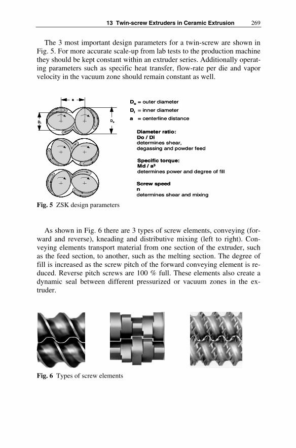
13 Twin-screw Extruders in Ceramic Extrusion 269
The 3 most important design parameters for a twin-screw are shown in Fig. 5. For more accurate scale-up from lab tests to the production machine they should be kept constant within an extruder series. Additionally operat-ing parameters such as specific heat transfer, flow-rate per die and vapor velocity in the vacuum zone should remain constant as well.
Fig. 5 ZSK design parameters
As shown in Fig. 6 there are 3 types of screw elements, conveying (for-ward and reverse), kneading and distributive mixing (left to right). Con-veying elements transport material from one section of the extruder, such as the feed section, to another, such as the melting section. The degree of fill is increased as the screw pitch of the forward conveying element is re-duced. Reverse pitch screws are 100 % full. These elements also create a dynamic seal between different pressurized or vacuum zones in the ex-truder.
Fig. 6 Types of screw elements
a
DiDo
a
DiDo
Do = outer diameter
Di = inner diameter
a = centerline distance
Diameter ratio:Do / Didetermines shear, degassing and powder feed
Specific torque:Md / a3
determines power and degree of fill
Screw speedndetermines shear and mixing
Do = outer diameter
Di = inner diameter
a = centerline distance
Diameter ratio:Do / Didetermines shear, degassing and powder feed
Specific torque:Md / a3
determines power and degree of fill
Screw speedndetermines shear and mixing

270 Werner Wiedmann, Maria Hölzel
Kneading blocks are used to melt, disperse (break into smaller particles) and homogenize the material being processed. They are normally com-pletely self-wiping and vary in disc width, disc to disc rotation angle and direction. Distributive mixing elements have a lot of stream splitting chan-nels but introduce minimal energy into the material. They are generally not mechanically self-wiping but kept clean by the shear stresses of the high viscosity product flow.
Figure 7 shows the typical design of 1- or 2-flighted conveying ele-ments, but also 3-flighted elements are still used for plastification tasks. The designation 1, 2, or 3 refers to number of independent helical flow channels along the axis of the element. Today 2-flighted screws with open channels and small crests are the most commonly used design. Single-flighted elements with broad crests and a slightly smaller free volume have advantages in the feed and discharge zone due to their higher conveying efficiency and in the discharge zone due to better bearing surface charac-teristics in the viscous material.
Fig. 7 1- and 2-flighted conveying screws
The working principle of kneading blocks is shown in Fig. 8. Staggering the kneading disc in the conveying direction creates low shear distributive mixing and material transport (T) in the flow direction. However, stagger-
three parallelscrew channels
L
one parallelscrew channel
1 1
11 2 3
L
1-flighted elements
1
1
11
3
2
2-flighted elementsthree parallelscrew channels
L
one parallelscrew channel
1 11 1
11 2 3
L
1-flighted elements
1
1
11
3
2
2-flighted elements
1-flighted elements
1
1
1
1
11
3
2
11
3
2
2-flighted elements

13 Twin-screw Extruders in Ceramic Extrusion 271
ing the discs in the reverse direction results in high shear dispersive mixing (M) in filled channels. Particles flowing in the circumferential direction are especially kneaded and sheared. The higher the staggering angle (W) the better is the distributive mixing effect, the broader the kneading discs (S) the better dispersive mixing.
Fig. 8 Working principle of kneading blocks
13.4 High Torque Versus high Volume Extruders
Technical and design improvements resulting in increased torque, free volume or screw speed, have led to an enhanced machine performance (Fig. 9). Over the past 50 years, machine output has increased at an ap-proximately 7 % compounded annual rate [WH04a]. This development has been made possible by:
• improved shaft/element interface geometries as well as shaft materials and manufacturing techniques,
• the increase in free volume associated with the migration from triple to double-lobe screw profiles and subsequently to deeper flighted double-lobe designs,
• improved materials, manufacturing processes and design through the use of FEM calculations, as well as,
• continued optimization of the power train, feeding devices, screw con-figurations and discharge equipment.
W
W ... staggering angleS ... width of the disk
S
K ... dispersive mixing (kneading, shearing)M ... distribuitive mixing
T ... transporting effectThere are the following relations: M
TW -->
-->
MS -->K
T
M
K
W
W ... staggering angleS ... width of the disk
S
W
W ... staggering angleS ... width of the disk
S
K ... dispersive mixing (kneading, shearing)M ... distribuitive mixing
T ... transporting effectThere are the following relations: M
TW -->
-->
MS -->K
TT
M
KK

272 Werner Wiedmann, Maria Hölzel
Fig. 9 Development of ZSK design parameters
In 1983, the first of a series of higher torque (M/a³=8.7 Nm/cm³) and higher speed (600 rpm) twin-screw extruders based on an involute spline screw shaft and an improved gearbox design was introduced. In 1995, the next jump in torque (M/a³=11.3 Nm/cm³), and speed (1200 rpm) appeared on the market. Now in 2004 another improvement in torque has been im-plemented. The latest machines have 20 % more power, or a specific torque of 13.6 Nm/cm³. These MEGAcompounder PLUS (Mc PLUS) ma-chines are designed for compounding tasks involving significant require-ments with respect to specific energy and/or specific torque. It is also im-portant to note, that these improvements were significant enough that the combination of torque (M/a³ ≥ 11 Nm/cm³), volume (Do/Di ≥ 1.5) and speed (n ≥ 600 rpm) is patented in the U.S. [HHM+00] and numerous other countries.
In 2001 the issue of efficient compounding of lower bulk density mate-rials and other not in torque limited processes, was addressed with the in-troduction of a high-volume (deeper cut screws with Do/Di=1.8), medium torque (M/a³=8.7 Nm/cm³) extruder designed for speeds up to 1800 rpm. This MEGAvolume (Mv) series replaced the former high-volume Con-tinua series. As indicated, its field of application is a second product group that requires a large process volume to enhance the counter-current flow of air removed from fluidizing powders, to create residence time for reactions or, because long before the torque limit is reached, a temperature or prod-uct quality limitation occurs.
1955: 1. generationDo/Di = 1.22Md/a³ ~3.7 Nm/cm³n = 150 min-1
Same center line distance
Same center line distance
2001: MvDo/Di = 1.80Md/a³ = 8.7 Nm/cm³n = 1800 min-1
Increaseof volume
Incr
eas
e o
f spe
ed
an
d to
rque
Incr
ease
of t
orq
ue
spee
d a
nd v
olum
e
1970: 2-lobeDo/Di = 1.44Md/a³ ~5.0 Nm/cm³n = 300 min-1
1985: SCDo/Di = 1.55Md/a³ = 8.7 Nm/cm³n = 600 min-1
1995: McDo/Di = 1.55Md/a³ = 11.3 Nm/cm³n = 1200 min-1
2004: Mc PLUSDo/Di = 1.55Md/a³ = 13,6 Nm/cm³n = 1200 min-1
1972: ContinuaDo/Di = 1.71Md/a³ = 4.3 Nm/cm³n = 300 min-1
Increaseof volume
1955: 1. generationDo/Di = 1.22Md/a³ ~3.7 Nm/cm³n = 150 min-1
Same center line distance
Same center line distance
2001: MvDo/Di = 1.80Md/a³ = 8.7 Nm/cm³n = 1800 min-1
2001: MvDo/Di = 1.80Md/a³ = 8.7 Nm/cm³n = 1800 min-1
Increaseof volumeIncreaseof volume
Incr
eas
e o
f spe
ed
an
d to
rque
Incr
eas
e o
f spe
ed
an
d to
rque
Incr
ease
of t
orq
ue
spee
d a
nd v
olum
eIn
crea
se o
f to
rque
sp
eed
and
vol
ume
1970: 2-lobeDo/Di = 1.44Md/a³ ~5.0 Nm/cm³n = 300 min-1
1970: 2-lobeDo/Di = 1.44Md/a³ ~5.0 Nm/cm³n = 300 min-1
1985: SCDo/Di = 1.55Md/a³ = 8.7 Nm/cm³n = 600 min-1
1985: SCDo/Di = 1.55Md/a³ = 8.7 Nm/cm³n = 600 min-1
1995: McDo/Di = 1.55Md/a³ = 11.3 Nm/cm³n = 1200 min-1
1995: McDo/Di = 1.55Md/a³ = 11.3 Nm/cm³n = 1200 min-1
2004: Mc PLUSDo/Di = 1.55Md/a³ = 13,6 Nm/cm³n = 1200 min-1
2004: Mc PLUSDo/Di = 1.55Md/a³ = 13,6 Nm/cm³n = 1200 min-1
1972: ContinuaDo/Di = 1.71Md/a³ = 4.3 Nm/cm³n = 300 min-1
1972: ContinuaDo/Di = 1.71Md/a³ = 4.3 Nm/cm³n = 300 min-1
Increaseof volumeIncreaseof volume

13 Twin-screw Extruders in Ceramic Extrusion 273
Fig. 10 Operating windows for high-torque and high-volume extruders
The number of torque limited processes is about 70 % [WH04b]. The reason for this is explained in Fig. 10 where a standardized maximum out-put (volume specific output relative to speed and cube of axial distance) is plotted as a function of the diameter ratio. The descending curves indicate the torque limited output rate for different extruder series and specific me-chanical energy inputs. The ascending curves indicate feed limitations for non-fluidized powder or granules with densities between 0.1 and 1.0 g/cm3.
The boundaries set by the 0.15 to 0.25 kWh/kg specific energy curves and the 0.3 to 0.5 g/cm3 lines for the feed material density limit a charac-teristic operating window for plastic compounding processes covered by the Mc PLUS. For products like ceramic honeycomb catalyst carriers where high torque is needed at low screw speeds for minimal energy input due to the temperature limit of 32°C, the capacity limit is even higher than the Mc PLUS range shown in Fig. 10, if the feed powders are dense enough.
Figure 10 shows the positioning of the high volume twin-screw on the right side of the master chart. The main application is for processes with an energy consumption between 0.15 and 0.05 kWh/kg and a wide range of materials with densities of 0.2 to 0.8 g/cm3.
Additionally, it has to be noted that the density range below 0.3 g/cm3
encompasses numerous fine grain powders with large air inclusions be-
0
50
100
150
200
250
300
350
400
1 1,1 1,2 1,3 1,4 1,5 1,6 1,7 1,8 1,9 2
ZSK Mc PLUS
ZSK Mv
Powder density 1,0 g/cm³ 0,7 g/cm³
0,5 g/cm³
0,3 g/cm³
0,1 g/cm³No
rma
lize
dc
ap
ac
ity
m*
95
50
/n
*a
³
Diameter ratio Do/Di
ZSK Mv
ZSK Mc PLUS
Fluidization
Specific energy s = 0,15 kWh/kgs = 0,25 kWh/kg
s = 0,15 kWh/kg
m in [kg/h]n in [min-1]a³ in [cm³]
s = 0,05 kWh/kg

274 Werner Wiedmann, Maria Hölzel
tween the particles. This air is pressed out by the plasticizing (melting) zone and can escape only by traveling upstream counter-current to the flow of the incoming feedstock. This can lead to fluidization and therefore to se-rious feed limitations. The high volume extruder particularly benefits these types of materials. In these cases, output of feed limited processes can in-crease by significantly more than the 40 % offered by the higher screw channel volume of the high volume extruder.
Typical applications for high free volume extruders are processing highly filled plastics and chemicals, sealants, bulk ceramics for power sta-tions with higher temperature limits of about 90°C, wood fiber filled PP, dewatering processes, powder coatings, battery separator films and food applications for starches, cereals, petfood and chewing gum. They are mostly limited by feeding, reaction time, product temperature, shaft cool-ing or product quality and are thus always below the torque limit of the high volume extruder (Fig. 11).
Fig. 11 Typical applications for high torque and high volume machines
13.5 Compounding Applications with high Solid Contents
For high filled products the main criteria for quality is the distribution of the solids in the binder. Only when agglomerates are broken up and the solids are wetted evenly with the binder the desired product properties such as mechanical strength or morphology can be achieved.
0
50
100
150
200
250
300
350
0,02 0,06 0,10 0,14 0,18 0,22 0,26 0,30 0,34
SEI [kWh/kg]
norm
iete
r D
urch
satz
Pet food
Sealants, Sound deadening sheets
Battery separators(Shaft cooling)
Starch,Cereals
ZSK MEGAvolume
Nor
mie
rter
Du r
chsa
tz
Specific Energy s [kWh/kg]
No
rmal
ized
c ap a
c ity
m*
9 55 0
/n*
a³
PP + 40% Talc, compacted
ZSK MEGAcompounder PLUS
Masterbatch black/ organic pigments
PA + 40% glass
Masterbatch white
Catalyst carrier
m in [kg/h]n in [min-1]a³ in [cm³]
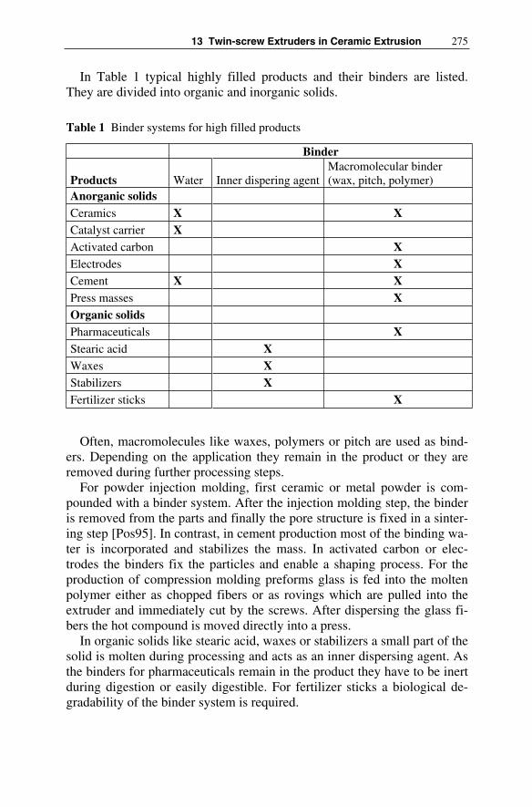
13 Twin-screw Extruders in Ceramic Extrusion 275
In Table 1 typical highly filled products and their binders are listed. They are divided into organic and inorganic solids.
Table 1 Binder systems for high filled products
Binder
Products Water Inner dispering agent Macromolecular binder (wax, pitch, polymer)
Anorganic solids Ceramics X X Catalyst carrier X Activated carbon X Electrodes X Cement X X Press masses X Organic solids Pharmaceuticals X Stearic acid X Waxes X Stabilizers X Fertilizer sticks X
Often, macromolecules like waxes, polymers or pitch are used as bind-ers. Depending on the application they remain in the product or they are removed during further processing steps.
For powder injection molding, first ceramic or metal powder is com-pounded with a binder system. After the injection molding step, the binder is removed from the parts and finally the pore structure is fixed in a sinter-ing step [Pos95]. In contrast, in cement production most of the binding wa-ter is incorporated and stabilizes the mass. In activated carbon or elec-trodes the binders fix the particles and enable a shaping process. For the production of compression molding preforms glass is fed into the molten polymer either as chopped fibers or as rovings which are pulled into the extruder and immediately cut by the screws. After dispersing the glass fi-bers the hot compound is moved directly into a press.
In organic solids like stearic acid, waxes or stabilizers a small part of the solid is molten during processing and acts as an inner dispersing agent. As the binders for pharmaceuticals remain in the product they have to be inert during digestion or easily digestible. For fertilizer sticks a biological de-gradability of the binder system is required.

276 Werner Wiedmann, Maria Hölzel
For the described products, good dispersion, and thus a high shear rate can be necessary. However, for many products this is directly opposed to a shear and temperature sensitivity of the solids or the binders. The follow-ing examples of ceramics extrusion show that an equilibrium has to be de-veloped between a good dispersion and the lowest possible temperature and shear in order not to damage the materials.
13.6 Ceramic Extrusion Plants
Typical ceramic materials produced on a co-rotating twin screw extruder are for example catalyst carriers. They are commonly shaped into granules for use as bulk material in reactors in the chemical industry or into honey-combs for catalytic converters in automobiles exhaust systems (Fig. 12). After extrusion, the catalyst carriers are cut oversized in the lineal direc-tion, dried and then cut to the proper length. Afterwards the binder is re-moved and the carriers are calcinated or sintered. Finally, to provide them with catalytic properties, they are impregnated with an active film in a bath [Fri76].
Fig. 12 Ceramic catalyst carriers: honeycombs and granules
The objective is to produce a plasticized material that is easily shaped in a die plate and has a specific porosity with a defined pore size and a large inner and outer surface area for a good catalytic activity. Therefore, shear is applied to the ceramic to move the particles against each other so that all hollow spaces between the solid particles can be filled with the liquid binder (see Fig. 13) and the so called “kneading dough” is formed [Fri80]. The dispersed binder provides the extruded profile with the strength

13 Twin-screw Extruders in Ceramic Extrusion 277
needed to maintain the product shape after extruding [GGL85]. When the binder and water are finally removed, a high porosity solid structure with great strength remains.
Fig. 13 Liquid distribution in a solid system: A: dry material;B: small amount of liquid and isolated bridges without plastic flow;C: increasing filling of the pores with liquid;D: capillary state: solids can slide on the liquid film
13.6.1 Production of Honeycomb Catalyst Carriers
A process set up for producing honeycomb catalyst carriers is shown in Fig. 14.
Fig. 14 Machine set up for the production of honeycombs
The ceramic powder is quickly premixed with the binder which is typi-cally Carboxymethyl cellulose (CMC) and some water in a plug shear
A B C DA B C D
3
1
4
5
7
6
2
8 9 1011
12
13
1 Pre-conditioner 5 Crammer feeder 9 Process section2 Feeding premix 6 Twin screw vent port 10 Screen pack changer3 Piston pump 7 Vacuum pump 11 Die plate changer4 Liquid storage 8 Main drive and gear box 12 Air-bed conveyer
13 Honeycomb catalyst carrier
3
1
4
5
7
6
2
8 9 1011
12
13
1 Pre-conditioner 5 Crammer feeder 9 Process section2 Feeding premix 6 Twin screw vent port 10 Screen pack changer3 Piston pump 7 Vacuum pump 11 Die plate changer4 Liquid storage 8 Main drive and gear box 12 Air-bed conveyer
13 Honeycomb catalyst carrier

278 Werner Wiedmann, Maria Hölzel
mixer with rotating knives for breaking lumps. If mixing time is too long the premix starts plasticizing and becomes difficult to feed. The premix with a ceramic content of at least 80 % is sieved and transported to a stor-age vessel. Material not passing the sieve is recycled to the mixer. The premix is then fed with a gravimetric belt feeder into the extruder. To avoid problems with feeding the premix into the extruder the hopper is equipped with a stuffing screw. Such a so called crammer feeder, as shown in Fig. 15, is capable of feeding large amounts of wet powder into a slowly rotating extruder at a high degree of fill.
Fig. 15 Crammer feeder
The low rotational speed is necessary for this product as the binder is very temperature sensitive. Above 34 °C it starts changing its structure which leads to a blocking of the die plate so that the process breaks down. After feeding the material into the extruder it is mixed and plasticized in a kneading zone which consists mainly of kneading blocks, as shown in Fig. 6, with varying angles and disc widths. After mixing the material vacuum is applied to remove air entrained in the material as it went through the feed hopper. There are several designs for the air outlet (Fig. 16, left side). Which one is used depends on the product behaviour. For materials that stick on the screws or for low viscosity materials (both do not tend to be pressed out of the extruder inserts) vent insert forms B and C are used

13 Twin-screw Extruders in Ceramic Extrusion 279
where the down turning screw is not covered. For material not sticking to the screws usually an insert with form A is used to avoid material coming up in the vent dome.
Fig. 16 Inserts for ZSK venting (left) and side degassing ZS EG (right)
In the described process the product normally still cannot be contained in the machine during venting. Therefore a side degassing (ZS-EG) as shown in Fig. 16 (right side) is used for the evacuation of volatiles. Here a pair of co-rotating screws conveys the material trying to come out of the extruder back into it.
The remaining machine length is used to build up pressure to force the material through the screen pack changer and the die. Therefore high pres-sure levels are required. Depending on the shape of the honeycomb the pressure can reach 300 bar or more. Often, there is not a single die plate but a die plate changer which permits quickly changing out the die plate when it is blocked. The material is pressed through the die with a wall thickness of around 70 µm and then transported over an air-bed conveyer for cooling (Fig. 17).
Form A:rolling productsForm A:rolling products
Form B: sticky productsForm B: sticky products
Form C:low viscous productsForm C:low viscous products
Sight glass
Vacuum port
Devolatilization barrel
Collecting container for melt residues
Sight glass
Vacuum port
Devolatilization barrel
Collecting container for melt residues

280 Werner Wiedmann, Maria Hölzel
Due to the fine structure of up to 1200 cells/in² the process is very sensi-tive to interruptions. Therefore during start up and also after changing the screen pack or the die plate there is a high reject rate of product. For a higher rate of yield, more and more often two extruders, each 5 to 6 barrels in length, are used which are arranged successively in a cascade (Fig. 18).
Fig. 17 Discharge of extruded honeycomb profiles
Fig. 18 Extruder cascade for producing honeycomb catalyst carriers
SPC
Vacuum
Feeding premix
Screen pack changer
SPCDie plate changerDPC
product
1st ZSK
2nd ZSK
SPC
Vacuum
Feeding premix
Screen pack changer
SPCDie plate changerDPC
product
SPC
Vacuum
Feeding premix
Screen pack changer
SPCDie plate changerDPC
product
1st ZSK
2nd ZSK

13 Twin-screw Extruders in Ceramic Extrusion 281
The first extruder is used for the mixing step and after a short pressurizing zone the material passes through a screen pack changer which filters out almost all agglomerates. Then the mass is fed directly into the second ex-truder which builds up pressure for a second screen pack changer and the die plate. In this arrangement after start up a flow interruption arising from changing the first screen pack has no influence on the product flow through the die plate and therefore enables a much longer stable produc-tion.
13.6.2 Production of Granulated Catalyst Carriers
The high degree of fill combined with the low rotational screw speed of the machine lead to high torque levels. Thus, these processes are usually performed on a ZSK MEGAcompounder (Mc). In comparison, when pro-ducing granulated catalyst carriers a ZSK MEGAvolume (Mv) is suitable more often. A typical machine set up is shown in Fig. 19.
Fig. 19 Machine set up for the production of granulated catalyst carriers
After feeding the ceramic mass, which can be dry or wet powder, the liquid is added which is usually diluted acid [Zue99]. For free flowing fine powders a twin screw feeder as shown in Fig. 20 is suitable as it prevents material from flowing through the feeder like water. For high powder con-tents, intake into the extruder can be limited when feeding through a hop-per. In this case a side feeder (see Fig. 20) which conveys the material into the extruder can help increasing the maximum flow rate.
1 Grav. feeder ceramics2 Dosing acid/water3 pump4 Motor and Gearbox
5 Process section6 Twin-screw vent stuffer7 Vacuum pump8 Die-plate-changer
8
1 Grav. feeder ceramics2 Dosing acid/water3 pump4 Motor and Gearbox
5 Process section6 Twin-screw vent stuffer7 Vacuum pump8 Die-plate-changer
88

282 Werner Wiedmann, Maria Hölzel
Fig. 20 Twin screw feeder for free flowing powders (left) and twin screw side feeder (right)
All materials are thoroughly mixed in several kneading zones designed with various kneading blocks (see Fig. 6) to break up the agglomerates and plasticize the ceramic. To remove air entrained by the powder the mixture is degassed further downstream. This is done either atmospherically or if required (as shown in the drawing Fig. 19) by applying vacuum. Problems in this process can occur from too much heat generated by shear in the kneading zones. In this case the diluted water starts evaporating (especially in the degassing zone) so that the material becomes dryer. This leads to a further increase in temperature. The whole process destabilizes and finally breaks down when the dry product blocks the die plate or when the torque level is too high due to the compacted material.
The product is discharged into strands with a diameter determined by the application (Fig. 21). The discharge zone can be designed with or with-out dead space (see Fig. 21). When using normal screw tips the whole area (shaped like an 8 or a circle) can be used to press out the material into strands. Often, ceramic masses flow only under shear stress. Thus, they tend to block the die if there is dead space between the screws and the die plate. Therefore, a discharge with a minimized dead space is desirable as the material is conveyed directly up to the die plate and pressed through it by the screws. The disadvantage of this set up is that the area available for the discharge is limited between inner and outer diameter of the screws. After leaving the die plate, strands with a diameter of about 1–3 mm break into almost regular granules of about 5 mm in length. Larger diameters or special extrusion shapes have to be cut to the required length at the die plate with a pelletizer.
One of the main challenges in the extrusion of ceramics is the choice of a suitable steel grade for the screws as well as for the barrels. It is aimed to

13 Twin-screw Extruders in Ceramic Extrusion 283
Fig. 21 Discharge of granulated catalyst carriers
Fig. 22 Wear protected barrels and screw elements
Barrel boredirectly coated
Barrel with replaceable wear protection liner
Barrel boredirectly coated
Barrel with replaceable wear protection liner
Through-hardened screw element
Kneading element from PM-bonded material with
multi-splint involutes boreThrough-hardened
screw element
Kneading element from PM-bonded material with
multi-splint involutes bore

284 Werner Wiedmann, Maria Hölzel
keep the wear due to abrasion caused by ceramic powder and due to corro-sion in case of an aggressive binder (acid e.g.) as low as possible. There are several options for wear protection as shown in Fig. 22. The barrels can be equipped with wear resistant liners which can easily be replaced. Bar-rels with a coated bore are more expensive when they have to be replaced but for heat sensitive products they have a better heat transfer. The screw elements can be either hardened completely to protect them against abra-sion, or a powder-metallurgical (PM) produced highly wear resistant shell is applied by diffusion-bonding to a ductile core. The ductile core helps transmitting high torque levels, while the hard shell protects the element against wear.
13.7 Summary
Mixing and forming of ceramic compounds is more and more often per-formed on tightly intermeshing co-rotating twin screw extruders. In twin screw extruders of the ZSK type several process steps can be performed in one process section by choosing an appropriate screw and barrel configuration. Depending on the limiting factors for each product (volume or torque) two series with a different degree of free volume are available.
Therefore, demands arising from different ceramic masses and binder systems can be individually addressed. Two examples for catalyst carriers – honeycombs and granulated bulk material – give an impression of the variety of machine set ups but also of the feeding and discharge systems possible.
Literature
[Fri76] Friedrich R (1976) Kontinuierliche Aufbereitung von kerami-schen Katalysator-Trägermassen. In: Chemie Technik (Son-derdruck)
[Fri80] Friedrich R (1980) Powder Compression with corotating twin-screw extruders. J Journal of Powder & Bulk Solids Technology vol 4 No 4 pp 27-32
[GGL85] Gardner RW, Guile DL, Lynn M (1985) Process for mixing and extruding ceramic materials. In: Corning Glass Works, Corning, New York, US 4551295
[HHM+00] Heidemeyer P, Häring E, Münz R, Herter, R, Burkhardt U: (unknown) Method of carrying out continuous preparation

13 Twin-screw Extruders in Ceramic Extrusion 285
processes on tightly meshing mextruders rotating in the same sense. In: Krupp Werner & Pfleiderer GmbH, Germany, US 6042260
[Pos95] Possen J (1995) Aufbereitung und Spritzgießverarbeitung ei-ner mit Keramik- und Metall-Pulver gefüllten Formmasse. In:Studienarbeit, IKV Aachen, RWTH Aachen
[WH04a] Wiedmann W, Heidemeyer P (2004) Compounding – optimal torque, volume and speed solution. Part 1 J Extrusion 11 No 10 pp 58-64
[WH04b] Wiedmann W, Heidemeyer P (2004) Compounding – optimal torque, volume and speed solution. Part 2 J Extrusion 12 No 10 pp 62-65
[Zue99] Zuhlke S (1999) Herstellung und Charakterisierung perowski-tischer Katalysatoren zur Nachverbrennung organischer Komponenten. Dissertation, Universität Karlsruhe

14 Piston Extruders
Günther Doll, Frank Händle, Friedrich Spießberger
14.1 Piston Extruders in Ceramics
It was in 1619 that John Etherington built the first hand-operated piston extruder for the extrusion of bricks.
This was followed by numerous different designs including double-acting piston extruders; reference is made in this connection to the details and illustrations under chapter 5.
Fig. 1 Piston extruder with hinged extrusion barrel (1870)
Piston extruders were, and still are, employed not only for the extrusion of ceramic bodies but also find application in many branches of industry for the shaping of plastic materials, or for bodies which have been plasti-cized by the tempering process.
In 1810 Joseph Bramah used the first hydraulically-operated piston ex-truder for the shaping of lead slabs to produce pipes.
Piston extruders are used in the foodstuffs industry, notably in the pro-duction of pasta, and are also employed for the shaping of aluminium pro-files, wrought copper alloys and steel, for the extrusion and de-watering of sewage sludge, for the extrusion of hard metal, graphite, coal, plastics, etc.

288 Günther Doll, Frank Händle, Friedrich Spießberger
Focus in the following will be on the description of hydraulic piston ex-truders as employed in the ceramic industry and for the extrusion of hard metal, since the application in both cases is very similar and several inter-esting solutions have evolved for the shaping of hard metal with the use of piston extruders.
14.2 Types of Piston Extruder
Column extrusion by piston extruders is to be understood as a discontinu-ous shaping or extrusion process in which a plastic body is pushed through a die or matrice by a piston, whereby the geometry of the die determines the extruded profile.
Piston extruders available these days for use in the ceramic industry can be classified into types of construction according to the following criteria:
• By the press force(from 1–1000 tons),
• By the diameter of the receiver (from 10–1000 mm),
• By the type of pressure-generating system (hydraulic or mechanical),
• By the direction of extrusion, (horizontal, vertical or tiltable between horizontal and vertical),
• By the positioning of the receiver (tiltable or non-tiltable),
• By the type of material to be fed (bulk material, kneaded material or pre-shaped billets),
• By the method of charging (manual, semi-automatic, automatic),
• By the type of de-airing (with/without de-airing),
• By the method of control (speed-controlled, pressure-controlled, non-controlled),
• By the tempering of the receiver (cooled, heated, non-tempered receiver),
• By the method of fixing the tool (mechanical, hydraulic),
• By the configuration of the extruder in relation to the drive system (mono or split version).

14 Piston Extruders 289
In addition there are a number of other special criteria and characteristic features. These may relate say to the difference in the hydraulic system, oil-hydraulic or water-hydraulic version, or to the degree of convenience of the control system and which operating data is available online, or whether the receiver can be changed to suit different diameters, etc.
14.3 The Components of Piston Extruders
The essential components of a tiltable piston extruder as generally applied in the ceramic industry nowadays can be seen in Fig. 2.
Fig. 2 Main Components of a piston extruder (A: hydraulic piston, B: hydraulic system, C: base frame, D: receiver,E: press frame)
14.3.1 Hydraulic System and Hydraulic Piston
The hydraulic drive respectively the pressure-generating system determine the press force.
This hydraulically-generated press force must be distinguished from the theoretical material pressure prevailing in the receiver. This is a theoretical value because this observation is based on a Newtonian fluid, whilst cera-mic materials behave as anisotropic media.
This material pressure is calculated in bar, whereby the cross section of the receiver prior to actual shaping within the pressure head and die enters the calculation.
An example: a piston extruder is equipped with say two exchangeable receivers of 250 and 350 mm in diameter. The pressure of the system is say 280 bar and the diameter of the piston is say 200 mm, which would correspond to a press force of 880 kN.
In the case of the receiver with a 250 mm diameter the theoretical mate-rial pressure is 179.2 bar, whereas for the receiver with 350 mm diameter

290 Günther Doll, Frank Händle, Friedrich Spießberger
this would be only 91.4 bar. This value has to be taken into account in de-signing the piston extruder, in particular the receiver.
The material pressure on the other hand is not identical with the flow or radial pressure, which for instance is measured ahead of the die and which depends on the rheology of the body, the geometry of the die, the friction conditions within the die, the column speed, etc.
The hydraulic system comprises the following components:
• Hydraulic pump with oil tank, • Hydraulic cylinder, • Control valves, • Piping/connecting lines, • Other mechanical equipment (moving cylinder, hydraulic motors, etc.).
Fig. 3 Hydraulic unit with pump, oil tank and valves
14.3.2 Base Frame and Press Frame
The type of base frame is determined by the design of the piston extruder. The loads exerted on the base frame are mainly of a static nature and are governed by the weight of the components, especially that of the hydraulic cylinder and that of the receiver, moreover by the position of the press frame with the resulting difference in load situations for the base frame and foundation.

14 Piston Extruders 291
Dynamic loads are only experienced during tilting of the press frame and receiver, when swivel forces are transmitted into the base frame via the tilting cylinder.
With common sizes of piston extruder the hydraulic unit is integral to the base frame, whereas very large size piston extruders often feature the hydraulic unit installed in a separate room, both for reasons of space and reduction of the noise level.
In contrast to this the press frame is subject to a permanent dynamic load as it must absorb the press forces which develop during extrusion be-tween the hydraulic piston and the receiver.
A correspondingly generous dimensioning of the press frame as well as of the pivotal points of the hydraulic cylinder on the one hand, and of the receiver fixed to the base frame on the other, is a prerequisite to ensure a long lifetime of the piston extruder.
Fig. 4 Base and press frame of a 400 mm diameter horizontal piston extruder
14.3.3 Tiltable Receiver Support
The tiltable receiver support must serve to:
• absorb the torques which develop during the extrusion process, • initiate the tilting action of the receiver via the swivel motor fixed to the
support,• lock on the receiver and the adaptor for fastening of the pressure head
and die. • Therefore the receiver support within the press frame must be of an
amply sturdy design.

292 Günther Doll, Frank Händle, Friedrich Spießberger
Fig. 5 140 mm piston extruder with tilting press frame
14.3.4 Control, Switch Cabinet, Control Panel
Basically three automatic control options are available for modern piston extruders:
Based on PLC, on PC or on micro-processors. The requirements in respect of the control system to be adopted are gov-
erned by the operation mode and the type of valve technique employed. With speed-controlled piston extruders, which imply a high definition of
the signals, the micro-processor based systems are likely to represent the optimum technical solution at present.
The control panel in a swivel-type version is usually placed next to the piston extruder and displays the essential parameters such as piston speed, radial pressure, vacuum, position of the piston, etc., moreover it contains the control elements (for example at the operating panel) for altering the piston speed, on-off, emergency off-switch, etc.
Usually piston extruders can be run in three operating modes: manual mode, automatic mode and semi-automatic mode.
They also feature an interface to the common operating data logging systems, such as LabView, etc.

14 Piston Extruders 293
Fig. 6 Panel of a PLC based control system
Fig. 7 Panel of a micro-processor based control system
The electrical hardware (contactors, relays, voltage supply, etc.) is in-corporated in the switch cabinet which is placed on the base frame.
14.3.5 Pressure Head and Die
The pressure head/die unit, also called the tool, is made up of two parts: the tapered transition piece between receiver and die and the die itself; see also the contribution of Berger under chapter 12.

294 Günther Doll, Frank Händle, Friedrich Spießberger
As the same pressure head – possibly with exchangeable inserts - is fre-quently used for the extrusion of diverse profiles, particular priority must be given to fast changing of the dies. The tool can be fixed either by screws, or with the aid of a bayonet catch, or by means of hydraulically-actuated locks.
Depending on the weight of the tool either hoisting equipment or spe-cially-designed transport cars are employed.
In practical operation dies are often made or designed in-house by facto-ries themselves.
Fig. 8 Die with sensor for radial pressure and temperature
14.3.6 Receiver
Apart from the fact that receivers may vary in design depending on the construction of the piston extruder – tiltable, non-tiltable – they are also available in several options, one being in respect of tempering: heatable, coolable, not suitable for tempering.
Other options are those manufactured in different materials, or the type built as a two-part assembly consisting of the basic body and a protective tube which can be exchanged when extruding very abrasive or corrosive materials once a certain state of wear has been reached.
In principle it is possible to change the receiver in order to extrude cer-tain profiles using either smaller or larger receivers. The limiting factors are the diameter of the piston rod and the necessary material pressure.

14 Piston Extruders 295
Fig. 9 Tiltable receiver in filling position
14.3.7 Press Ram
The press ram is fitted to the front end of the piston rod and can be rotated around the centre line or arranged in a fixed position. The press ram must be easily replaceable, as it is subject to wear and tear. It is made either of metal or plastic and may be of a convex or concave shape as the case may be. The position of the press ram is always displayed at the control panel.
Fig. 10 Press ram in cleaning position

296 Günther Doll, Frank Händle, Friedrich Spießberger
14.3.8 De-airing Bell
To enable the body to be de-aired prior to compaction, a guided vacuum bell, which is shifted hydraulically, is used to provide a hermetic seal of the cavity between the piston and the receiver.
In order to obtain the degree of vacuum required, the manufacture of the de-airing bell must be very accurately accomplished and it must be pro-vided with suitable seals and scrapers to prevent soiling. Moreover the suc-tion point in the receiver must be suitably protected against penetration of contaminating material.
A vacuum indicator is positioned at a suitable spot in the vacuum line to be easily visible.
Fig. 11 De-airing bell
14.3.9 Tool Changing Device
The tool holding fixture is fitted to the front end of the pressure head, also an adapter piece if required. The latter is required if tools of different dia-meters are used. Tool changing systems have been developed, which e-nable a very fast and ergonomic changing of the different nozzles using appropriate hoists and a suitable docking unit. The precise changing posi-tion is reached by means of a specially-designed hydraulic swivel motor.
The hoisting equipment employed for this purpose can also be used for handling the propelling device.

14 Piston Extruders 297
Fig. 12 Piston extruder for hard metal with automatic tool changing device
14.3.10 Vacuum Pump
Piston extruders use the same vacuum pumps as employed for de-airing extrusion machines; see the contributions of Laenger and Redmann under chapters 15 and 16.
The suction capacity of the vacuum pump depends on the size of the re-ceiver and the method of charging. The higher the suction capacity, the faster the necessary ultimate pressure in closed position, measured by va-cuum sensors, will be reached.
Usually the ultimate pressure of vacuum pumps ranges between 5 and 30 mbar.
Modern plants have the facility of pre-setting the required degree of de-airing subject to the product to be extruded; yet maximum de-airing does not necessarily ensure an optimum product quality.
At the start up of a piston extruder, the pressure head and die as well as the foremost part of the receiver are not yet filled with compacted material, therefore during the first filling/compacting stage a separate vacuum bell at the die must be activated to suck off any excess air until the compacted material provides a good sealing.
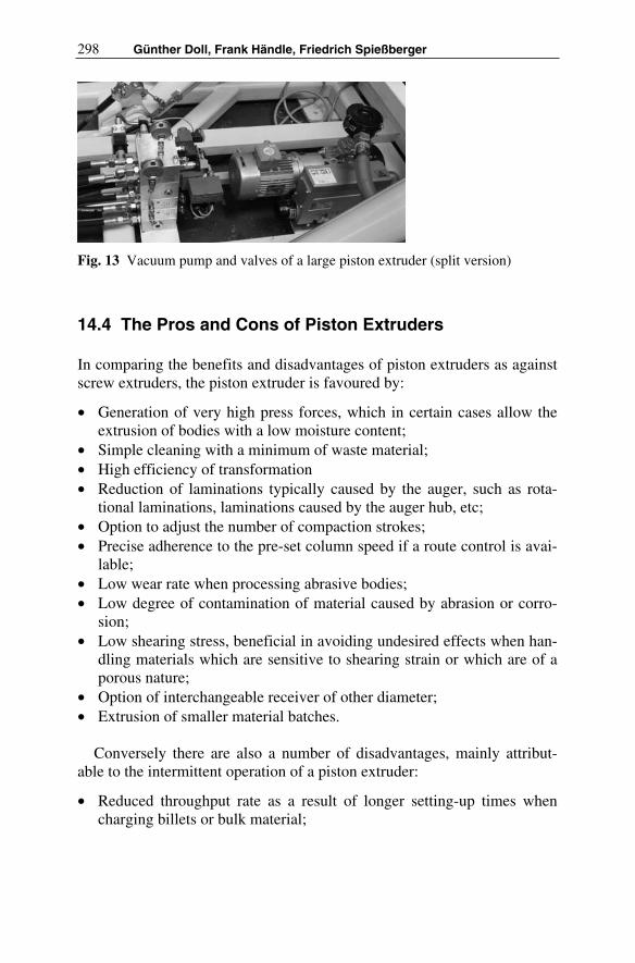
298 Günther Doll, Frank Händle, Friedrich Spießberger
Fig. 13 Vacuum pump and valves of a large piston extruder (split version)
14.4 The Pros and Cons of Piston Extruders
In comparing the benefits and disadvantages of piston extruders as against screw extruders, the piston extruder is favoured by:
• Generation of very high press forces, which in certain cases allow the extrusion of bodies with a low moisture content;
• Simple cleaning with a minimum of waste material; • High efficiency of transformation • Reduction of laminations typically caused by the auger, such as rota-
tional laminations, laminations caused by the auger hub, etc; • Option to adjust the number of compaction strokes; • Precise adherence to the pre-set column speed if a route control is avai-
lable;• Low wear rate when processing abrasive bodies; • Low degree of contamination of material caused by abrasion or corro-
sion;• Low shearing stress, beneficial in avoiding undesired effects when han-
dling materials which are sensitive to shearing strain or which are of a porous nature;
• Option of interchangeable receiver of other diameter; • Extrusion of smaller material batches.
Conversely there are also a number of disadvantages, mainly attribut-able to the intermittent operation of a piston extruder:
• Reduced throughput rate as a result of longer setting-up times when charging billets or bulk material;
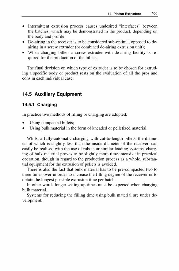
14 Piston Extruders 299
• Intermittent extrusion process causes undesired “interfaces” between the batches, which may be demonstrated in the product, depending on the body and profile;
• De-airing in the receiver is to be considered sub-optimal opposed to de-airing in a screw extruder (or combined de-airing extrusion unit);
• When charging billets a screw extruder with de-airing facility is re-quired for the production of the billets.
The final decision on which type of extruder is to be chosen for extrud-ing a specific body or product rests on the evaluation of all the pros and cons in each individual case.
14.5 Auxiliary Equipment
14.5.1 Charging
In practice two methods of filling or charging are adopted:
• Using compacted billets; • Using bulk material in the form of kneaded or pelletized material.
Whilst a fully-automatic charging with cut-to-length billets, the diame-ter of which is slightly less than the inside diameter of the receiver, can easily be realised with the use of robots or similar loading systems, charg-ing of bulk material proves to be slightly more time-intensive in practical operation, though in regard to the production process as a whole, substan-tial equipment for the extrusion of pellets is avoided.
There is also the fact that bulk material has to be pre-compacted two to three times over in order to increase the filling degree of the receiver or to obtain the longest possible extrusion time per batch.
In other words longer setting-up times must be expected when charging bulk material.
Systems for reducing the filling time using bulk material are under de-velopment.

300 Günther Doll, Frank Händle, Friedrich Spießberger
14.5.2 Transport and Cutting Device
Special handling and cutting systems have been designed for cutting of the extrudates, which not only ensure a gentle transport of the blanks, but also allow low cutting tolerances.
Figure 14 shows a mobile cutting device which guarantees an accurate cutting of the green blanks to different lengths.
The exact cutting to length of the rods/blanks in the green state is ac-complished by external automatic high-efficiency sawing equipment cut-ting to a tolerance of ± 0.1 mm. The saw unit is fed by a fully-automatic robot pallet system.
Fig. 14 Transport and cutting device
14.5.3 Propelling Device
The piston extruder must be thoroughly cleaned after a batch of material has been processed through the machine. After dismantling of the tool the material cone still left in the pressure head and die is pushed back with the aid of a hydraulically-operated propelling device until the cone protrudes the receiver and can be manually removed

14 Piston Extruders 301
14.6 Development
The fundamental characteristic of a piston extruder which distinguishes it from a screw extruder is the intermittent mode of operation, from which all essential benefits but also disadvantages derive. There are clear benefits for particular applications such as in the laboratory or in producing large honeycomb catalyst converters; in other fields the piston extruder has to be ruled out as its disadvantages are of too greater significance for those ap-plications.
Already in the 19th century this initiated research work to develop so-called continuous piston extruders – see also the contribution of Bender/ Böger under chapter 5.
In order to reduce charging times, a second receiver is freshly loaded with material and placed in position ready to be swung in and located be-neath the lifted press ram. In this way the extrusion process can be contin-ued within a short period of time. In the meantime the first emptied re-ceiver can be refilled, etc. (Fig. 15). This idea has been pursued in several ways, such as that of filling the receiver by means of continuous feed screws.
Fig. 15 Vertical piston extruder with two rotating barrels (1880)

302 Günther Doll, Frank Händle, Friedrich Spießberger
Other approaches also exist and, though hastily announced as break-throughs, when looked at more closely these appear less promising and at best only offer what may be termed semi-continuous extrusion options.
Literature
There is no up to date literature on the subject of the piston extruder in ce-ramics except for some reference in textbooks like Reed or Richerson; see list of literature.
Some information about piston extruders in other fields can be found via Google or other search engines.
Also in the leaflets and internal literature of producers of piston extrud-ers like Collin (www.collin.de), ECT (www.ect-haendle.de), Haginger (www.haginger.com), Loomis (www.loomis-gmbh.de), Mohr Corp. (www.mohrcorp.com) etc. some valuable information might be available.

15 Evacuation in Ceramic Extrusion – Dependences and Local Situations
Fritz Laenger
Quite a few experts entertain fairly vague notions about how much vacuum a combined de-airing extrusion machine can achieve as a function of:
• the temperature of the extrusion compound and/or the temperature in the vacuum de-airing chamber,
• the site elevation and• weather-induced fluctuations in air pressure.
So-called barometric vacuum meters that indicate vacuum as a percentage often cause same confusion, especially in connection with site elevation as an actuating variable. The two pertinent figures illustrate and exemplify those dependences. The residual pressure is indicated along the ordinate in mbar for nonbarometric instruments and in % vacuum for barometric in-struments. Since the extrusion body temperature is an important factor with regard to steaming it, has been included as a parameter.
The physical dependences are formulated such as to allow conversion from one dimension to another. Also included is a list of references für those wishing to delve more deeply into the complexities of the subject.
15.1 Vacuum Measurement
The presence of a substantial constant vacuum in the space between the de-airing mixer and the extruder exerts a major influence on the quality of the extruded body.
In addition to such mechanical and process-technological prerequisites as a leakage free system and a finely shredded body to ensure a large spe-cific surface, the crucial factors also include the degree of body compac-tion, i.e., the pressure in the pressure zone of the de-airing mixer.

304 Fritz Laenger
The properties of the body, its particle-size distribution, plasticity, etc. are very important. Without going too much into detail, let us note that same relatively friable compositions are easy to evacuate, while many very fine-grained compounds are fairly difficult to handle.
The characteristics and requirements of the product must also be known, of course, in order to plan optimal evacuation. Hourdis bricks with 60-70 % perforations, for example, are less exacting from the stand point of evacuation than, say, 500 mm compact slugs used for making insulators.
Finally, the climatic conditions and local factors must also be clarified in advance: Is water available? How much does the temperature of the wa-ter fluctuate in the course of a year? Even oil-operated vacuum pumps have to be designed differently for service in, say, Saudi Arabia than in Sweden.
Once all the information has been gathered about the system's mechani-cal and process-technological characteristics and those of the bodies, the requirements to be met by the product, and the local situation, including climate, then the individual data of the envisaged vacuum system can be defined.
A few Practical Hints
1) For most applications, a high constant vacuum is advantageous, but the-re are exceptions to the rule that require very careful definition.
2) In the course of the shaping process, the vacuum pump draws moisture out of the body-according to measurements, as much as 2 % dry base. Especially if the production process is interrupted, particles of body may dry out and cause problems.
3) It can also be a problem to run up the vacuum unit before full vacuum is achieved in the de-airing chamber. Visual control or, even better, a sui-table vacuum gauge with switching contacts can prevent such problems.
15.2 Percent Vacuum as a Function of Site Elevation, Parameter: Temperature of Extrusion Compound
The example shows the vacuum as a function of site elevation [m] for an extrusion compound temperature of 40°C and illustrates the difference between the degree of vacuum (indicated in mbar and as % vacuum) mea-sured with and without dependence on air pressure.
Nonbarometric measuring rules out the effects of site elevation, since vacuum pumps still operate with no losses at high elevations. The custo-

15 Evacuation in Ceramic Extrusion – Dependences and local Situations 305
mary barometric approach to measuring vacuum with vacuum gauges feigns a gradualloss of vacuum with increasing elevation. This is because the ambient pressure decreases with increasing elevation, while the baro-metric vacuum gauge was probably calibrated at an ambient pressure of roughly 1000 mbar. The difference amounts to same 20 % at an elevation of 2000 m [1].
The vacuum also deteriorates remarkably due to steam admission with a corresponding rise in the temperature of the extrusion compound. As the temperature rises, the effect becomes more pronounced, because the partial pressure of the water in the clay increases at an accelerating rate [2], [3]. For vacuum-sensitive bodies/products, the use of a nonbarometric vacuum measuring instrument is recommened to preclude misinterpretation. The formulae describing the relationship between barometric and nonbaro-metric measuring techniques are presented in section 13.4.
Fig. 1 %-vacuum as a function of site elevation parameter: Temperature of Ex-trusion Compound, T
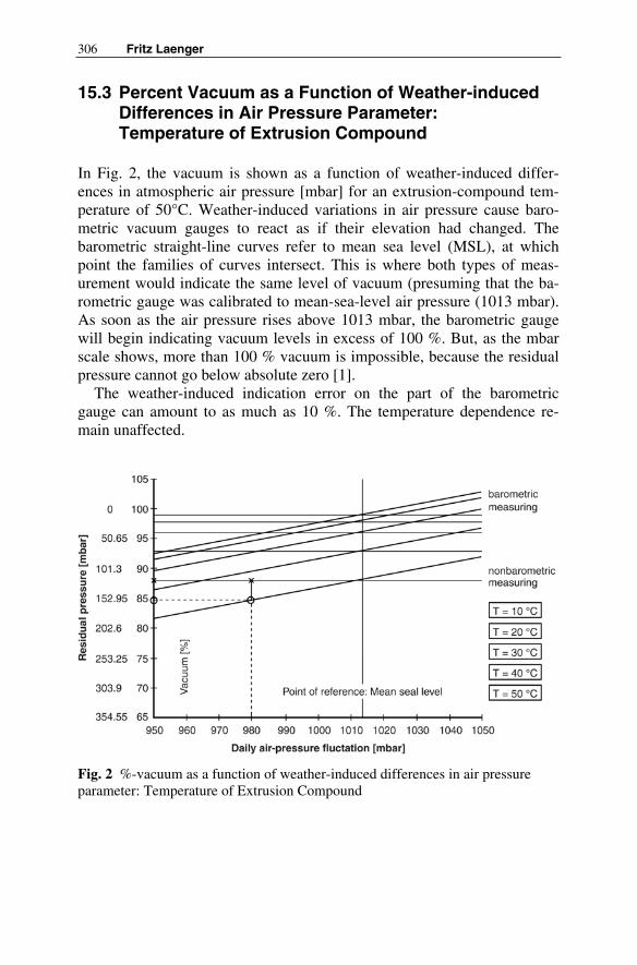
306 Fritz Laenger
15.3 Percent Vacuum as a Function of Weather-induced Differences in Air Pressure Parameter:Temperature of Extrusion Compound
In Fig. 2, the vacuum is shown as a function of weather-induced differ-ences in atmospheric air pressure [mbar] for an extrusion-compound tem-perature of 50°C. Weather-induced variations in air pressure cause baro-metric vacuum gauges to react as if their elevation had changed. The barometric straight-line curves refer to mean sea level (MSL), at which point the families of curves intersect. This is where both types of meas-urement would indicate the same level of vacuum (presuming that the ba-rometric gauge was calibrated to mean-sea-level air pressure (1013 mbar). As soon as the air pressure rises above 1013 mbar, the barometric gauge will begin indicating vacuum levels in excess of 100 %. But, as the mbar scale shows, more than 100 % vacuum is impossible, because the residual pressure cannot go below absolute zero [1].
The weather-induced indication error on the part of the barometric gauge can amount to as much as 10 %. The temperature dependence re-main unaffected.
Fig. 2 %-vacuum as a function of weather-induced differences in air pressureparameter: Temperature of Extrusion Compound

15 Evacuation in Ceramic Extrusion – Dependences and local Situations 307
15.4 Physical Interdependences
First we discuss the percentage of vacuum as a function of extrusion-compound temperature [T] and site elevation [h] for barometric measuring:
vac T h,( ) vac T( ) ∆p h( )∆p∆p [%] (1)
Effect of temperature:
vac T( )p0 pres T( )
p0
100.pp
[%] (2)
with pres is a function of temperature according Table 1 and [2]. Effect of site elevation:
∆p h( ) 100 pair h( )airair[%] (3)
where: pair(h) = percentage drop in ambient pressure as a function of site elevation h, referred to po. The so called Boltzmann barometric equation based on percentage:
pair h( ) 100 e
ρ 0 g. h.
100 p0.
.pair h( ) 100 e
ρ 0 g. h.
100 p0.
.pair h( ) 100 e
ρ 0 g. h.
100 p0.
. [%] (4)
Inserting equation (4) in (3) and then together with (2) into (1) yields:
(5)vac T h,( )
p0 pres T( )
p0
100. 1 e
ρ g. h.( )
1000 p0.
100.pp
[%]
The interdependence for vacuum as a function of extrusion-compound temperature and weather-induced variation in air pressure for barometric measuring is shown in equation (6).
vac T pdly,p0 pres T( )
p0
100. 1pdly
p0
100.vac T pdly,p0 pres T( )
p0
100. 1pdly
p0
100. [%]
Where pdly varies between 950 and 1050 mbar.
(6)

308 Fritz Laenger
Note:
In case of nonbarometric vacuum gauging, only the temperature of the ex-trusion compound influences the results of measurement, since the possi-ble effects of site elevation and of daiIy air-pressure variation are auto-matically accounted for. Thus, equation (2) applies.
Signs:
• T = temperature of extrusion compound [OC], • h = site elevation [m], • po = 1013 mbar, normalpressure, • rho0 = 1,25 kg/m3; density of air at mean sea level, • g = 9,81 m/s2, acceleration due to gravity.
pres(T) = saturation vapor pressure [mbar] for water vapor [2] as a func-tion of extrusion-compound temperature:
Table 1
T [°C] 10 20 30 40 50 pres(T)[mbar]
12 23 42 74 123
Literature
[1] Bender W, Länger F (1989) Evakuierung keramischer Massen beim Extrudieren, 1. Grundlagen. J Keramische Zeitschrift vol 41 No 12 pp 886-892
[2] Leybold-Heraeus (1990) Grundlagen der Vakuumtechnik, Berech-nungen und Tabellen. Köln
[3] VDI-Gesellschaft (1984) Berechnungsblätter für den Wärmeüber-gang. VDI-Wärmeatlas, VDI-Verlag, Düsseldorf
[4] Hoch KE (1981) Einfluss von Vakuumhöhe und Pressdruck auf das Entlüftungsergebnis beim Strangpressen. J Keramische Zeitschrift vol 33 No 3 pp 155-157
[5] Pupp W (1972) Vakuumtechnik. Verlag Karl Thiemig, München [6] Sentker U (1980) Entlüftung keramischer Massen bei der Strangver-
pressung – De-airing of ceramics clays in extrusion. J ZI Ziegel-industrie International 5: 278-284
[7] Segebrecht U (1993) Flüssigkeitsring-Vakuumpumpen und Flüssig-keitsring-Kompressoren. SIHI, Verlag moderne Industrie, Landsberg

16 Evacuation Technology for Ceramic Extrusion
Mark Redmann
16.1 Introduction
To day, many process steps and production methods would be impossible to imagine without the use of a vacuum. Pump technology combined with consistent implementation of physical conditions allow processes to be implemented that were totally unthinkable a while ago.
If the thermodynamic principle that two defined thermal state variables can yield a third is turned on its head, then vacuum pumps make it possible to vary the pressure and the heating or cooling in order to vary the tem-perature. With both state variables, it is possible to determine the specific volume, provided that the behaviour of the material is known.
For the user, this knowledge means that the desired operating pressures cannot be achieved with the selected vacuum technology or that the opera-tional safety of the vacuum system may be impaired.
This section describes how the various vacuum pumps work and the limits on their use. It also describes the most important devices needed to operate the vacuum pumps. The vacuum pump with separators and fittings is designated as a vacuum system. The vacuum pumps and then the separa-tors in the vacuum system are described below.
16.2 Liquid-ring Vacuum Systems
Vacuum systems based on liquid-ring vacuum pumps have been used for decades to generate industrial vacuums. This type of pump has a simple structure and can be used universally, so it can be found in many different types of process. A pump fluid – generally water – is used in the pump to generate the vacuum. The liquid ring vacuum pump is a dynamic pump in which the turning of an eccentric rotor in a housing builds up a ring of pump fluid (Fig. 1).

310 Mark Redmann
Fig. 1 Section through a liquid-ring vacuum pump, Dr.-Ing. K. Busch GmbH
The ring closes off the individual cells of the rotor from neighbouring cells. Because of the off-centre position, the volumes of gas thus closed off in the individual cells are different. The enlargement and reduction of the individual cells while the rotor is turning causes the volume of gas in the cell to expand and compress.
There are various aspects that must be considered when generating the vacuum with the aid of the fluid.
Every fluid has a different boiling point according to the ambient tem-perature and pressure. Reducing the ambient pressure lowers the boiling temperature. The liquid-ring vacuum pump is normally operated with wa-ter. Water has a boiling pressure or partial pressure of 24 mbar at an ambi-ent temperature of 20°C. It can be seen from this example that the possible applications for this pump are limited by the boiling point of the pump fluid used. Once the pump fluid has evaporated, the available volume in the cell is filled with evaporating pump fluid. The intake capacity at the in-take port of the pump becomes zero. Cavitation occurs in the operating state that is designated as the ultimate pressure. Cavitation is the implosion of vapour bubbles in the pump fluid caused by rapid pressure changes. Cavitation in the vicinity of the housing and rotor causes erosion which can totally destroy the affected material. For this reason, the ultimate pres-sure of a liquid-ring vacuum pump is specified in relation to the pump fluid and temperature, e.g. 33 mbar ultimate pressure at a pump fluid tem-perature of 15°C provides a margin for error.

16 Vacuum for Ceramic Evacuation 311
The use of liquid ring vacuum pumps may become a critical issued given the increasingly restrictive environmental legislation. The pump fluid comes into contact with the process vapours, and is enriched with va-pour components. Operation with a closed pump fluid circuit (Fig. 2) con-sisting of a pump fluid separator, heat exchanger and pipes minimises the problems of disposing of a contaminated pump fluid. This way of working is highly recommended if the process vapours are well understood. If va-pour components tend to crystallise or desublimate, then the pump fluid circuit may become full of particles, causing a blockage in the circuit. For this reason, many vacuum systems in use are fitted with a partially closed or open circuit. The pump fluid consumption for a liquid-ring vacuum pump with an intake capacity of 250 m³/h is approximately 1m³/h water for an open circuit and 50% less for a partially closed circuit and every 5° in-crease in the water temperature.
Fig. 2 Liquid ring vacuum system with closed pump fluid circuit,Dr.-Ing. K. Busch GmbH
In general, liquid ring vacuum systems are operated with simple particle separators on the intake side. The idea is to have the vapour components separated out on the intake side, provided that this is a low-maintenance option, and controlled compression and condensing of the process vapours occurs in the vacuum pump.
Liquid ring vacuum systems are standard systems for creating cost-effective and generally low-maintenance installations.

312 Mark Redmann
16.3 Vacuum Systems with Rotary Vane Vacuum Pumps
Vacuum systems with rotary vane vacuum pumps may be used where the process requires vacuums < 50 mbar or if liquid ring vacuum pumps can-not be used in the installation. These vacuum systems are designed to sepa-rate out as much of the process vapours and particles as possible on the in-take side or to condense the process vapours into the atmosphere as moist air. Rotary vane vacuum pumps may be operated as recirculating lubrica-tion or blow-by vacuum pumps. The vacuum pump is built with a rotor turning eccentrically in a cylinder. The rotor has axial slots and rotating vanes are pressed against the cylinder by centrifugal force in these slots (Fig. 3).
Fig. 3 Section through a rotary vane vacuum pump, Dr.-Ing. K. Busch GmbH
Oil is injected into the cylinder to reduce friction and to improve the seal of the sickle-shaped compression chamber formed between the vanes, the rotor and the cylinder. The pump fluid – oil – comes into contact with the process vapours. Vapour components may be dissolved in the oil or ab-sorbed as an additional phase. In either case the lubricating properties of the oil may be changed and cause the vacuum pump to fail. Vacuum pumps with blow-by lubrication were developed in order to reduce the risk of changing the physical properties of the oil (Fig. 4).
These vacuum pumps are very lightly lubricated in order to reduce oil consumption. To achieve the same performance values as rotary vane vac-uum pumps with recirculating lubrication, the blow-by lubrication variants

16 Vacuum for Ceramic Evacuation 313
Fig. 4 Section through a rotary vane vacuum pump with blow-by lubrication,Dr.-Ing. K. Busch GmbH
are fitted with additional vanes on the rotor and a secondary compression stage. The operating windows may be very small because of the way the vacuum pump works. The film of lubricant in the pump may be washed away if the pump is used to take up condensable vapour components from the recipient. In this case, the rotary vane vacuum pump will run dry and generate high operating temperatures. This will cause wear of the vanes. The resulting heat of compression is mostly given off as vapour. The high compression temperatures compared to the pump types described above may cause cracking of hydrocarbons that are unstable at high temperatures. The resulting particles will clog up the vanes and pump, reducing the suc-tion performance and causing the pump to fail.
To operate vacuum systems with rotary vane vacuum pumps, it follows that the variants with recirculating lubrication must be operated in such a way that the saturated vapour mass flow passes through the vacuum pump without condensing out. The variants with blow-by lubrication flush out any process condensates with the pump fluid – generally oil. Care must be taken to ensure that the flow of condensate does not wash away the lubri-cating film in the vacuum pump or react chemically with the pump fluid.
Rotary vane vacuum pumps are always tailored for the specific applica-tion. The optimisation of a rotary vane vacuum pump with recirculating lubrication for extracting saturated water vapour under suction conditions is described below by way of example.

314 Mark Redmann
During compression against the atmosphere, part of the saturated vapour may condense out in the vacuum pump at temperatures below 100°C. The pump is equipped with a gas ballast in order to prevent this condensation. The gas ballast opening is a hole in the cylinder that opens to the atmos-phere. The hole is provided at the point at which the volume enclosed be-tween two vanes is compressed between the gas inlet and gas outlet. Under ideal conditions, the volume is vented to ambient pressure through the opening. The saturated vapour flow is increased by the additional, unsatu-rated inert gas flow under atmospheric conditions and is entrained by the pump. This action is promoted by increasing the operating temperature of the pump. The operating temperature must be matched to the lubricating oil to prevent heat damage to the pump fluid.
Vacuum systems with rotary vane vacuum pumps have the advantage that vacuums of < 1 mbar are theoretically possible, regardless of the am-bient and water temperatures in the installation. The effect of the process on the possible operating pressure should be checked.
In general, when rotary vane vacuum pumps are used, the separation on the intake side must be optimised so that the vacuum pump is affected as little as possible by vapour components or so that the process vapours pass through the vacuum pump without changing its overall physical state.
16.4 Vacuum Systems with Dry-running Vacuum Pumps
In the past, environmental problems associated with the commonly used pump fluids, namely water and oil, have led to the development of dry vacuum pumps that compress without contact. Rotary lobe and screw-type vacuum pumps (Fig. 5 and 6) are the types most commonly used for indus-trial applications.
The common feature of these pump types is that, unlike the products de-scribed above, they are two-stage pumps. This structure makes these pumps more expensive to produce than conventional vacuum pumps. The rotors are made so that the gap between the rotors and between the rotors and the housing is the same, whatever the angular position of the rotors.
The rotors are different, however, so it is the shape that classifies the pump type.
Rotary lobe vacuum pump
The rotary lobe vacuum pump (Fig. 5) is a single or multistage vacuum pump in which the gas is sucked into the cylinder gap as illustrated.

16 Vacuum for Ceramic Evacuation 315
Fig. 5 Section through a rotary lobe vacuum pump, Dr.-Ing. K. Busch GmbH
The rotary lobes rotate in opposite directions. Each lobe has one or two teeth, the shape of which is such that the gap between the tooth and the second lobe and cylinder remains constantly narrow. As the lobes rotate in opposite directions, the teeth move together, roll over one another and then move apart. This cycle is repeated with every revolution of the shafts ac-cording to the number of teeth. The volume beneath the inlet to the cylin-der increases until the next tooth moves past. Then the volume enclosed between the teeth of the lobe is pumped until it emerges opposite the sec-ond lobe. The gas is then compressed between two teeth of the two lobes until one lobe exposes the outlet slot in the cylinder cover and the gas is expelled.
Screw vacuum pump
The second contact-free vacuum pump variant that works without pump fluid is the screw vacuum pump (Fig. 6).
Fig. 6 Section through a screw vacuum pump, Dr.-Ing. K. Busch GmbH

316 Mark Redmann
The cylinder contains two specially-shaped screws rotating in opposite directions with zones of constant or varying pitch along their length. The profile is cut with a sharp edge and has a narrow sealing slot. The gas is pumped internally, compressed and expelled at the end of the screw at the front of the device.
The two types of pump described above generate different pressure dif-ferences in the order given. The vacuum pumps compress against ambient pressure. Some of the gases sucked in flow back internally through the in-ternal seal determined by gap and gap lengths The point at which the in-take capacity becomes zero, i.e. when the flow rate of the returning gas corresponds to the incoming flow rate, is known as the ultimate pressure. The rotary lobe vacuum pump reaches an ultimate pressure of between 20 and 100 mbar absolute. The screw vacuum pump can generate an ultimate pressure of less than 1 mbar absolute.
Because compression takes place without contact or pump fluid, excel-lent separation of particles on the intake side is essential while the machine is in operation. Condensates, on the other hand, can be pumped to a certain extent. These vacuum pumps more or less combine the robustness and low maintenance of liquid ring vacuum pumps with the low and stable ultimate pressure of rotary vane vacuum pumps. Theoretically, vacuum pumps that do not require pump fluid would seem to be the ideal replacement for the vacuum pumps used in the past. However, because compression takes place without contact or pump fluid, the vacuum pumps currently available work with higher gas temperatures than the rotary vane or liquid ring vac-uum pumps. The high gas temperatures have both advantages and disad-vantages. The temperature level prevents vapour components condensing out. On the other hand, the temperatures can give rise to chemical reac-tions such as polymerisation or cracking, thus reducing the availability of the vacuum pump.
16.5 Vacuum Pump Combinations
The individual types of pump are described above. It is also possible to combine vacuum pumps together. The simplest combination is to set up several identical vacuum pumps in parallel (Fig. 7).
There may be several reasons for this set-up. One reason is that the in-take capacity can be adapted to different flow rates from the recipient. It also increases the operational reliability. If one vacuum pump fails, it does not cause the whole production line to stop. Additional vacuum pumps can also be used to cover peak loads. This parallel set-up is used for vacuum control stations or where the pump sizes needed for the required intake ca-pacity are not available.

16 Vacuum for Ceramic Evacuation 317
Fig. 7 Control station with a rotary lobe vacuum pump, Dr.-Ing. K. Busch GmbH
Fig. 8 Combination with rotary lobe and Roots vacuum pump,Dr.-Ing. K. Busch GmbH
Vacuum pumps can also be set up in series (Fig. 8). In this case, several vacuum pumps of different sizes are connected in
series. A constant flow of volatile vapour components is extracted from the recipient. If the vapour undergoes no phase change and isothermic com-pression occurs, then the product of working pressure and intake capacity remains constant (perfect gas law). If the pressure increases, the volume must become less than before the compression. A Roots vacuum pump (Fig. 9) is a machine which, under normal operating conditions, can gener-

318 Mark Redmann
ate pressure differences of less than 60 mbar in a vacuum. If the process takes place at an intake pressure of less than 50 mbar, then the possibility of using a Roots vacuum pump should be considered. With the maximum pressure difference, the required intake capacity of the booster pump and the compression stage at atmospheric can be reduced to a fraction of the required intake capacity. The permitted compression ratios for a Roots vacuum pump are determined by the intake pressure and the resulting power input.
All of the other vacuum pumps listed above can be used as booster pumps. This combination is particularly suitable for continuous processes in which the intake pressure in the recipient must be kept almost constant.
Fluctuations due to different vapour flows can be evened out by regulat-ing the pressure of the first compression stage by adjusting the speed.
Fig. 9 Section through a Roots vacuum pump, Dr.-Ing. K. Busch GmbH
16.6 Components of the Vacuum System
Every vacuum system consists of various components intended to ensure that the process works reliably. On the intake side, the vacuum pump is protected mechanically by a separator. This separator must work just as well in each different application. The simplest type of separator is a con-tainer that slows down the gas flow and increases the dwell time of the gaseous components (Fig. 10).
The dwell time is increased with a long flow path created using a sepa-rator plate between the gas inlet and gas outlet. The separator reliably re-tains particles entrained from the recipient or fluids occurring in the pipes. The separator is used as a back-up separator for a connected pipe or a liq-uid ring vacuum pump.

16 Vacuum for Ceramic Evacuation 319
Fig. 10 Section through a volume separator, Dr.-Ing. K. Busch GmbH
Another separator with a comparable task is the cyclone. In the cyclone, a flow field allows forces to act on particles in the vapour flow. This force presses the particles against the container jacket and hold them back. The flow conditions make the cyclone a compact device, and the shape is a good indicator of its effectiveness. The cyclone is designed for an applica-tion window, so its use is limited to processes that can be precisely speci-fied.
Multi-stage separators have become popular for rotary vane vacuum pumps and pumps that do not use pump fluids. The term “multi-stage” re-lates to devices that combine two or more separator mechanisms. The housing (Fig. 11) is designed as a swirl apparatus at the inlet. The tangen-tial gas inlet and the deflection cone force the vapour flow into a flow which lies against the inside of the container jacket. Coarse particles and fluids are retained in this part. After being deflected into the conical insert, the vapours are routed through a filter unit. The filter insert integrated into the top part of the housing is easily accessible and can be quickly replaced. Different filters may be used to suit the operating conditions.
Separators on the discharge side separate the pump fluid from the gas and retain any condensates that build up during compression.
The simplest designs are volume separators in which droplets of pump fluid are separated from the exhaust gas flow by the reduction in the flow speed. These separators are used in liquid ring vacuum systems. The sepa-ration can be improved by fitting swirl bodies. A mixture of saturated va-pours that varies according to the operating temperature of the vacuum pump always emerges from the exhaust gas nozzle.

320 Mark Redmann
Fig. 11 Section through a liquid and dust separator, Dr.-Ing. K. Busch GmbH
The pump fluid separator of an oil-sealed rotary vane vacuum pump is more complex than the unit described above. The oil is separated from the exhaust gas in several stages. The separation mechanisms are connected in series according to the particle size. The vapours are passed through the demister starting with gravity separation. This is followed by exhaust fil-ters in which the oil particles are collected by coalescing, then drip down and are routed into the oil circuit or a collecting container. The separator housing is heavily ribbed so that the compression energy absorbed by the pump fluid is dissipated by free convection. In this way, vapour compo-nents in the pump fluid separator can condense and modify the physical properties of the pump fluid. This can result in an emulsion with reduced lubricating properties, a pure condensate which displaces the oil because of its density and is then largely extracted or other easily miscible substances that have properties different to those of the original oil.
The separators for vacuum pumps that do not use pump fluid are silenc-ers which, because of their surface area, condense vapour components of the exhaust gas. If the process also creates aerosols by flushing the vacuum pump, for example, an oil mist separator similar to the one on the rotary vane vacuum pump may be used.

16 Vacuum for Ceramic Evacuation 321
16.7 Control and Regulation
Vacuum systems are electrically switched and monitored throughout the installation. Many vacuum systems require a motor-protective circuit-breaker and an On/Off button, or the signals from the level, temperature and pressure monitoring components are processed in a controller.
It is becoming increasingly important for vacuum system operators to be able to regulate the pressure in the recipient. The intake pressure should be matched to the process so that none of the product-related components can escape due to the vacuum, or the power consumption of the vacuum sys-tem should be matched to the method. The pressure should always be set to the necessary level of accuracy. The pressure is often set by restricting the intake cross-section or by additional leak air. The adjusting fittings are arranged in the overall installation so that they can be easily accessed from the recipient. This has a detrimental effect on the way that the separator in-stalled on the intake side of the vacuum system works. The addition of ambient air increases the inert gas flow that already transports separated fluids through the system. Flow restrictions between the recipient and separator reduce the operating pressure in the separator and help to prevent condensation. This always increases the impurities in the vacuum pump, however.
The pressure should be regulated as close as possible to the vacuum pump. Ideally it should be regulated IN the vacuum pump. Vacuum pumps that do not use pump fluid can be set to a speed range of 1:5 using a fre-quency converter, provided that the drive motor is monitored for overheat-ing. A control sequence consisting of pressure transmitter, controller, fre-quency converter and motor allows automatic responses to different recipes or quality fluctuations in the output products.
16.8 Summary
The current competitive climate is forcing processors to cut their costs. One cost factor is the salaries for operators at production plants. The time required to operate and maintain the plant components must also be re-duced. One way is to automate the processes, while another is to reduce maintenance and operating costs.
Vacuum systems cannot be avoided in many extrusion processes. The vacuum system is one component of the overall plant that requires regular maintenance.
The liquid ring and rotary vane vacuum pumps that have long been used in many methods can now be replaced with vacuum pumps without pump

322 Mark Redmann
fluid in conjunction with suitable separators. The use of vacuum pumps that do not require pump fluid cuts the costs of maintenance and operating materials. And by varying the speed of the drive motor, it is possible to set recipe-specific vacuums via the process control system, at the same time modifying the vacuum system's power consumption.
Literature
[1] Jouston K (2004) Wutz – Handbuch der Vakuumtechnik. Verlag Vieweg, Wiesbaden, 8. Auflage
[2] Faragallah WH, Surek D (2004) Rotierende Verdrängerpumpen. Ver-lag und Bildarchiv WH Faragallah, 2. überarbeitete Auflage
[3] Bannwarth H (1994) Technisches Handbuch Flüssigkeitsring-Vaku-umpumpen, -Kompressoren und -Anlagen. VCH Verlagsgesellschaft, Weinheim, 2. überarbeitete Auflage
[4] Baehr HD (2002) Thermodynamik. Springer-Verlag Berlin, 11. Auf-lage

17 Thermoplastic Extrusion for Ceramic Bodies
Frank Clemens
17.1 Introduction
Originally for the extrusion of ceramic bricks and tiles, clay and water were used to endow ceramic particle mixtures with sufficient plastic be-havior to permit practical shaping of the ceramic bodies. High performance ceramics, however, often require the elimination of clay from extrusion formulations because the chemistry of the clay is incompatible with that of the desired ceramic materials. Therefore organic materials are frequently used in ceramic extrusion to provide plastic flow. Not only plastic behav-ior is important for the extrusion of ceramic bodies. There are many other characteristics which can be tailored by the suitable addition of organics in a ceramic extrusion paste, or feedstock.
In principle three different organic systems can be used for extrusion of ceramic materials, namely solvent-based systems, thermoplastic systems, and thermosetting systems. Some of the advantages and disadvantages of these three classes are summarized in Table 1.
Table 1 Classes of organic binder systems for ceramic extrusion
Advantage Disadvantage
Solvent-basedsystem
Short time for debinding processEasy use
Warping during drying High abrasivity / high tool wear Phase separation at high pressure
Thermoplasticsystem
Elongation in warm state pos-sible Good green strength Low abrasivity Contour accuracy Feedstock recycleability
Warping during debinding Time consuming debindingprocess
Thermosettingsystem
Good green strength Contour accuracy Elongation in warm state pos-sible
Time consuming debindingprocessDifficult use

324 Frank Clemens
The so-called solvent-based binder systems contain polymers which solvate or swell in a solvent (e.g. water, alcohol). Typical polymers used in extrusion are PEG, PVA, agar agar and cellulose. Thermoplastic materials are polymers which when heated, soften, melt or become more pliable, and harden during cooling in a reversible physical process. Materials in this class which are used quite often for ceramic processing are PE, PP, EVA, POM and PMMA. Thermosetting materials are polymers which can be melted only once and which, after melting, harden as more heat is added. Thermoset plastics which are used in the ceramic industry are phenolic res-ins and different silicon resins like polysiloxane.
a) Green Al2O3 tube prepared with b) Green Al2O3 tube prepared with a a solvent-based binder system thermoplastic binder system
Fig. 1 Abrasivity of feedstocks during extrusion is influenced by the binder sys-tem used
One of the main advantages of thermoplastic systems for ceramic extru-sion is the lower abrasivity of the feedstock material relative to other binder systems. The lower abrasivity of a extrusion feedstock prepared with a thermoplastic binder system compared to one with a solvent-based binder for a given ceramic powder, in this case Al2O3, is shown Fig. 1. In this study a feedstock with 58 vol.-% coarse Al2O3 powder was extruded through a steel die. Looking at the surfaces of the tubes, discoloration of the material stemming from abrasion of the die can be clearly

17 Thermoplastic Extrusion for Ceramic Bodies 325
seen in both samples. However, the darker discoloration of the sample ex-truded with the solvent-based binder system indicates higher tool abrasion by this feedstock compared to the feedstock prepared with thermoplastic binder.
Another advantage of thermoplastic binder systems over solvent-based ones is the contour accuracy of the extruded material which permits easy fabrication of fine structures (e.g. thin-walled tubes, micro-tools). For such fine structures with very small cross-sectional areas, extrusion pressures can be as high as 700 or 800 bar, and at such high pressures phase separa-tion in feedstocks with solvent-based binder systems can occur. Even for higher pressures such phase separation effects are generally not observed when using thermoplastic binder systems.
17.2 Thermoplastic Extrusion Processing
In the literature a great variety of thermoplastic binder systems are de-scribed. In principle the same polymer binders, plasticizers, surfactants and sliding agents known from metal and ceramic injection molding processing can be used for thermoplastic extrusion of ceramic bodies. A good review on material selection for ceramic powder injection molding in which the different raw materials for feedstock preparation are described is given by Edirisinge et. al. [Edi 86].
17.2.1 Influence of Powder Loading
As the volume fraction of powder in a feedstock is increased, the viscosity of the feedstock rises exponentially until a critical volume fraction of pow-der is reached. Figure 2 shows the mixer torque (which is directly propor-tional to the viscosity of the feedstock) as a function of silicon carbide powder concentration in a polyethylene/wax binder system [Cle 05]. It is assume that by extrapolating the data to zero reciprocal torque, the maxi-mum powder loading for the feedstock formulations can be determined.
With this method, a maximum powder loading of 62% by volume was calculated for a SiC/polyethylene/wax-feedstock prepared with carbon black sintering additive. For the feedstocks without carbon black, a value of 57 vol% was calculated. This result corresponded with the fact that it was not possible to produce an extrudable carbon black-free SiC feedstock with a powder loading higher than 52 vol%. The feedstocks prepared at 53 and 54 vol% were powdery, very brittle and did not exhibit any plastic be-havior.
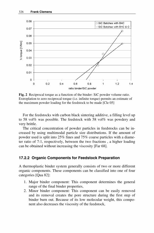
326 Frank Clemens
Fig. 2 Reciprocal torque as a function of the binder: SiC powder volume ratio.Extroplation to zero reciprocal torque (i.e. infinite torque) permits an estimate of the maximum powder loading for the feedstock to be made [Cle 05]
For the feedstocks with carbon black sintering additive, a filling level up to 58 vol% was possible. The feedstock with 58 vol% was powdery and very brittle.
The critical concentration of powder particles in feedstocks can be in-creased by using multimodal particle size distributions. If the amount of powder used is split into 25% fines and 75% coarse particles with a diame-ter ratio of 7:1, respectively, between the two fractions , a higher loading can be obtained without increasing the viscosity [Far 68].
17.2.2 Organic Components for Feedstock Preparation
A thermoplastic binder system generally consists of two or more different organic components. These components can be classified into one of four categories [Qua 82]:
1. Major binder component: This component determines the general range of the final binder properties,
2. Minor binder component: This component can be easily removed and its removal creates the pore structure during the first step of binder burn out. Because of its low molecular weight, this compo-nent also decreases the viscosity of the feedstock,

17 Thermoplastic Extrusion for Ceramic Bodies 327
3. Plasticizer: The role of this component is to decrease the viscosity of the feedstock and thereby enable easy flow of the material,
4. Surfactant: This component promotes wetting of the ceramic powder by the binder.
In practice a given organic component can be classified into more then one of these categories, e.g. stearic acid is a surfactant, but when used in con-junction with thermoplastic binders like polyolefins, it will also act as a plasticizer. Accordingly it is possible that a thermoplastic binder system will consist of only two organic components which each perform two or more of the functions described above.
17.2.3 Typical Thermoplastic Binders
Typical thermoplastic binders which are found in literature for injection molding of ceramic bodies are, styrene-butadiene, polyethylene, polypro-pylene, polybutene, ethylene vinyl acetate, polymethylmethacrylate and polyoxymethylene. When selecting one of these binders for thermoplastic extrusion of ceramic bodies, it should be noted that the shrinkage of par-tially-crystalline polymers is higher than for amorphous polymers, and hence warping during cooling is more critical in the former case. This is, however, not the only criterion for selection; price and processability at adequate temperatures are also important factors to consider.
17.2.4 Thermoplastic Binder Systems for Special Applications
In the following, different binder systems which have been used for ther-moplastic extrusion of ceramic bodies will be discussed [Lenk 97, Weg 98, Hoy 98, Cle 00, Schub 00, Bee 02, Gri 02, Tru 04, Schey 04, Pou 04, Yoo 05, Cle 05].
In 1997, Lenk et. al. described a thermoplastic binder system consisting of polyethylene, paraffin, wax and surfactants [Lenk 97]. Various binder components for injection molding, extrusion and hot molding were tested for the fabrication of bars, tubes, discs, rings and balls of SiC-platelet-reinforced SiC composites. Good alignment of the SiC platelets in the ma-trix made it possible to improve the densification of the composite.
Wegmann et. al. described the extrusion of polycrystalline ceramic fi-bers using different thermoplastic and water-based binder systems [Weg 98]. Invariably the highest powder loadings in the study were reached using the thermoplastic binder systems with all the ceramic powders con-sidered. Furthermore, only a thermoplastic polyethylene/wax binder sys-

328 Frank Clemens
tem permitted hollow fibers and very thin fibers (< 50µm) to be success-fully produced. One of the biggest problems with the water-based binder systems was the ocurrence of binder separation at high pressures.
Co-extrusion processing using thermoplastic binder systems for ceramic bodies has been described by Van Hoy [Hoy 98]. The major binder com-ponent used in this study was ethylene vinyl acetate, and methoxypoly-ethylene glycol was used as a plasticizer. Feedstocks of alumina, a piezo-electric ceramic powder and carbon black were repeatedly co-extruded to form an array of fine “M”-shaped structures. With this method the size of the alumina “M” shapes could be reduced by a factor of 915. In this exam-ple the use of solvent-based binders would have been problematical be-cause of drying of the feedstocks and extrudates during the co-extrusion process and during handling.
A co-extrusion technique was also applied by Beeaff and Hilmas to pro-duce a BaTiO3 multilayer capacitor with nickel electrodes [Bee 02]. Poly-ethylene co-butyl acrylate was used as the major binder component. The minor binder, plasticizer and surfactants used were polyethylene ethyl ace-tate, microcrystalline wax, mineral oil and PEG. With this binder system it was possible to produce multilayer capacitors with 10 µm thick Ni elec-trode layers by co-extrusion. The limitation was given by the grain size of the ceramic powder used and not by the processing technique.
Poulon-Quintin used the co-extrusion process to fabricate bi-phase ox-ide ceramic filament structures [Pou 04]. For these investigations commer-cial Al2O3 and ZrO2 feedstocks from the University of Warwick were used. The polymer binder system in these feedstocks was based on low molecu-lar weight polyethylene and a small amount of polyethyleneglycol.
For the co-extrusion of multilayer actuators, Yoon at. al. used a binder system consisting of ethylene ethyl acrylate, acrylic resin, mineral oil, polyethylene glycol and stearic acid. After sintering the resulting multi-layer actuator was composed of 40 active PZN-PZT and PZN-PZT/Ag layers. The thicknesses of the PZN-PZT and the PZN-PZT/ Ag layers were 200 and 70 µm, respectively.
Thin-walled ceramic tubes have been fabricated by using a binder sys-tem consisting of polyethylene and a commercial wax [Cle 00]. It was pos-sible to produce dense zirconia tubes with an outer diameter of 6.7 mm and a wall thickness of less than 0.2 mm after sintering. The homogeneity of a number of feedstocks containing different amounts of zirconia powder was characterized using a capillary rheometer (e.g. agglomerates and other in-homogeneities passing through the capillary cause perceptible fluctuations in the extrusion pressure). The feedstock containing 50 vol% powder showed the best results, with no pressure peaks indicative of hard agglom-erates being detected.

17 Thermoplastic Extrusion for Ceramic Bodies 329
Trunec has described the thermoplastic extrusion of thin-wall tubes ma-de of yttria-stabilized zirconia and gadolinia-doped ceria [Tru 04]. These ceramics are used for solid oxide electrolyte applications, e.g. solid oxide fuel cells. The thermoplastic binder system used consists of ethylene-vinyl acetate copolymer, paraffin wax and stearic acid. With this system tubes with an outer diameter of 10.5 mm and wall thicknesses of 290 and 280 µm could be fabricated.
Extrusion on the basis of liquid, thermoplastic or emulsified silicon res-ins has been shown by Schubert et. al. [Schub 00]. Because of crosslinking at higher temperatures, processing parameters for hot plastic forming must be controlled carefully. Schubert et. al. investigated different plasticizer agents, including paraffin, polyethylene wax, methylcellulose ether, methyl polysiloxane and dimethyldiethoxysilane, and different fillers for the fabrication of polymer-derived ceramic composites. For the thermo-plastic extrusion process the viscosity of the feedstock was increased to ensure fast setting of the material to preserve the shape of the extrudate af-ter leaving the die orifice. Subsequently debinding of the plasicizer and thermal cross-linking of the remaining binder was performed.
For small production runs of ceramics, extrusion free-forming through fine nozzles is useful In a pilot study Grida et. al. used a microcrystalline wax and stearic acid as a surfactant [Gri 03] The ceramic performs pro-duced can be used as scaffolds in tissue and bone engineering, or for metal matrix composites.
It is also possible to extrude ceramic nanopowders with thermoplastic binder systems. Scheying et. al., for example, investigated the extrusion of monoclinic zirconia nanopowder [Schey 04]. The powder loadings achieved in the feedstocks were 44 and 53 vol% when using powders with primary particle sizes of 9 and 25 nm, respectively. The binder system used consisted of either polyethylene-co-vinyl acetate or polyethylene as the major component and decanoic acid as a surfactant.
Heiber at. al. investigated the extrusion of commercial silicon dioxide nanopower using a mixture of polyethylene and wax [Hei 04]. With this thermoplastic binder system, powder loadings up to 58 vol% were achieved. With this very high powder loading it was possible to achieve dense glass fibers after sintering at 1100°C.
17.3 Thermoplastic Extrusion Processing
Generally for the thermoplastic extrusion of ceramic bodies, a binder which melts or softens at higher temperature is used. Figure 3 shows the processing steps for the extrusion of ceramic bodies when using thermo-
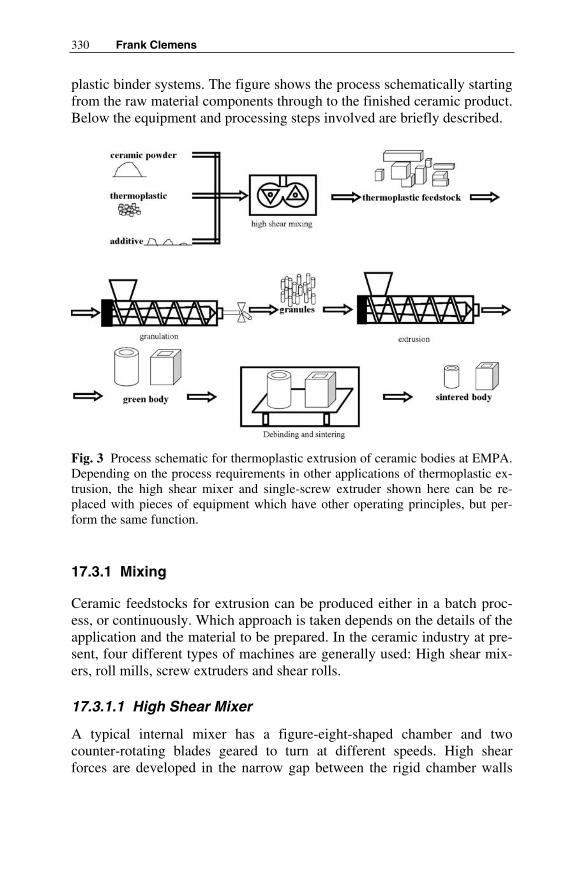
330 Frank Clemens
plastic binder systems. The figure shows the process schematically starting from the raw material components through to the finished ceramic product. Below the equipment and processing steps involved are briefly described.
Fig. 3 Process schematic for thermoplastic extrusion of ceramic bodies at EMPA. Depending on the process requirements in other applications of thermoplastic ex-trusion, the high shear mixer and single-screw extruder shown here can be re-placed with pieces of equipment which have other operating principles, but per-form the same function.
17.3.1 Mixing
Ceramic feedstocks for extrusion can be produced either in a batch proc-ess, or continuously. Which approach is taken depends on the details of the application and the material to be prepared. In the ceramic industry at pre-sent, four different types of machines are generally used: High shear mix-ers, roll mills, screw extruders and shear rolls.
17.3.1.1 High Shear Mixer
A typical internal mixer has a figure-eight-shaped chamber and two counter-rotating blades geared to turn at different speeds. High shear forces are developed in the narrow gap between the rigid chamber walls

17 Thermoplastic Extrusion for Ceramic Bodies 331
and the rotating blades. In Fig. 4a a special kind of internal mixer, a torque rheometer, is shown. With this piece of equipment the torque exerted on the mixer blades during the mixing process can be recorded. The mixing torque is proportional to the shear stress in the mixture if no sliding or slipping occurs between the mixture and the mixer walls and if free flow of the material is prevented (i.e. the mixing chanber must be closed to prevent material escaping).
(a)
(b)Fig. 4 (a) Opened mixing chamber of torque rheometer and (b) a torque curve as typically recorded during mixing of a ceramic feedstock.

332 Frank Clemens
A typical torque characteristic as a function of time during mixing of a polymer/ceramic powder composition is shown in Fig. 4b. First, the poly-mer binder system is fully melted in the heated chamber of the high shear mixer. Subsequently, ceramic material (powder) is filled into the mixing chamber and as the degree of chamber fill increases, the torque rises. With increasing powder content frictional heating sets in and consequently the mixture temperature also increases during filling, as shown.
After the filling step, the mixer is closed (rectangular punch visible top center in Fig. 4a and the homogenization of the ceramic-polymer mixture starts. As the powder particles are progressively separated from one an-other and dispersed in the fluid binder, the viscosity of the mixture, and hence the recorded torque, drop as shown in Fig. 4b. When the torque reaches a steady state plateau, no additional mixing takes place, and the mixing time necessary to obtain a homogeneous material is defined as the time required to reach this steady state.
17.3.1.2 Roll Mill
The roll mill system consists of a pair of heatable counter-rotating metal cylinders arranged parallel to one other with an adjustable gap, or nip, be-tween them. A pre-mixed feedstock is dropped on these rolls and is drawn into the gap between the two rolls where high-shear mixing occurs. One roll normally turns faster than the other, and because of this speed differ-ence (friction ratio) the shear force is amplified. The feedstock usually forms a coating around the slower roll.
17.3.1.3 Screw Extruder
In this technique the feedstock components are fed onto the screw of an extruder and mixing takes place as the material is transported along the ex-truder barrel. Initial mixing in the solid state takes place in the feeding zone, and subsequently the screw draws the mixture into the heated mixing zone where the polymer components melt and the feedstock is homoge-nized under high-shear conditions. For the mixing process, screws designs with a variety of elements which perform different functions (e.g. feed, transition and dispersive mixing elements, kneading blocks, gear mixers) are used. The elements used and the order in which they are arranged on the screw depends on the polymer binder system and the ceramic powder used. When working with highly abrasive feedstock materials it is also possible to have multiple feeding zones along the length of the screw so that the abrasive powder can be added piecemeal to the feedstock. At the end of the extruder the mixture is extruded though a die and pelletized at the die orifice.

17 Thermoplastic Extrusion for Ceramic Bodies 333
17.3.1.4 Shear Roll
With this equipment the mixing process takes place in the gap (continu-ously adjustable) between two counter-rotating heatable rolls, and as such the operating principle is comparable to that of the roll mill described ear-lier. However, in this case the rolls are not perfectly parallel which means that during the course of mixing the material is transported form one end of the rolls to the other. The premixed mixture of binder and ceramic pow-der is fed onto the rolls by screws, pumps, or vibration conveyors. The rolls can be heated up or cooled down at different locations along the rolls. Along the shear gap at desired locations other additives can be added sepa-rately from the initial charge. At the end of the rolls a granulator element can be installed to produce pellets of the feedstock material.
17.3.2 Extrusion
To continuously or semi-continuously produce ceramic parts, extrusion is very interesting because of the relative simplicity of the equipment. Nearly all materials (polymers, metals, ceramics, foodstuffs) can be extruded if they can in some way or other be obtained in a plastic state which permits them to be pressed through the orifice of a die. In the case of inherently non-plastic materials such as ceramics and hard metals, for instance, this means the material in powder form must be mixed with a binder which ex-hibits the desired plastic properties.
The extrusion technique, however, is not useful for all kind of products, the main limitation being that only objects featuring a constant cross-section along their length can be produced. Typical products formed by ex-trusion are listed in Table 2.
Table 2 Typical shapes in ceramic extrusion and application examples
Extruded shape Examples of applications Tube, pipe Membranes, heat exchangers, solid oxide fuel cells, wear
parts , tooling, combustion chambers, refractories Rod Wear parts , tooling, refractories, dentistry Honeycomb Membranes, heat exchangers, solid oxide fuel cells cata-
lystsPlate, foil, film Membranes, solid oxide fuel cells, refractories Fiber, hollow fiber Membranes, heat exchangers, micro tools, active fiber
composites, micro-reactors, fibers for functional or struc-tural applications
334 Frank Clemens
For the extrusion process two different types of extruders are generally used: Ram (or piston) extruders, and screw extruders.
17.3.2.1 Ram Extruder
Ram extruders, also called piston extruders, consist of a ram travelling in-side a cylinder (or barrel) to the end of which a die with the desired orifice geometry is attached. The feedstock is filled into the cylinder and forced under pressure through the die orifice by the ram pressing on the material. The ram is normally hydraulically actuated, but it can also be driven by a screw jack or other mechanical drive. Heating of the thermoplastic feed-stock is achieved through heating elements arranged in, or around, the cyl-inder walls and the extrusion die. Because of the simple syringe-and-plunger arrangement, this extruder design has two main advantages over screw extruders: Extrusion can be performed at very high pressures, and the small number of moving parts means that tooling wear, and conse-quently feedstock contamination with abraded tooling material, is kept to a minimum.
17.3.2.2 Screw Extruder
A screw extruder also consists of a cylinder with a die attached at one end, however in this case the feedstock is transported down the barrel to the die by means of a screw (or screws). The pelletized or granulated feedstock material is fed into the feeding zone of the extruder and is then drawn down the barrel by the screw to the melting section where the thermoplas-tic binder softens or melts under the influence of external heating (e.g. heating jackets) and internal friction. In the following sections along the barrel the pressure on the feedstock progressively increases to a maximum, and the material then exits through the die which gives the plastic extru-date its desired cross-section. Independently adjustable heating zones along the length of the barrel and in the extrusion dies permit the tempera-ture profile along the barrel to be finely controlled. Such process parame-ters and the properties of the thermoplastic binder must be carefully opti-mized to ensure that the soft and putty-like hot extrudate stiffens and sets solid very fast after it exits the orifice of the die, otherwise the contour ac-curacy of the extruded body can not be guaranteed.
Screw extruders are primarily developed for the polymers and plastics industry, and a large variety of designs and sizes are consequently avail-able. Mainly single and twin-screw extruders are used for thermoplastic ceramic body extrusion.

17 Thermoplastic Extrusion for Ceramic Bodies 335
17.3.2.3 Binder burn out
Prior to sintering, the binder system must be completely removed from the extruded parts. Compared to solvent-based binder systems, thermoplastic binders are more difficult to remove from extruded bodies. In solvent-based systems, the removal of solvent during the drying step immediately after extrusion results in open porosity being formed through which the decomposition products of the high molecular weight polymers can be eas-ily transported during the following thermal binding treatment. In thermo-plastic debinding this initial open porosity does not exist, and poorly-controlled decomposition of the binder can easily lead to bubble and crack formation due to the build-up of internal pressure.
In the literature several different binder removal processes are described [Man 82, Ger 87, Cal 90, Ebe 93, Char 95, Tsa 95, Tru 02].
17.3.2.3.1 Binder Removal by Thermal Heat Treatment
In principle the removal of thermoplastic binder systems from ceramic green bodies can be achieved by thermal heat treatment. Unlike in solvent-based binder systems where some initial porosity is available after removal of the solvent (drying step), there is no open porosity in thermoplastic green extrudates at the beginning of the debinding process. To ensure complete burning out of the binder, diffusion of oxygen into the green body and diffusion of the evaporated, decomposed or combusted organic products out of the body must be guaranteed. Waxes (short chain poly-mers) are removed in the gaseous state and porosity is created during the first step of the debinding process of the thermoplastic binder system. Sub-sequently the decomposition products of the major binder component can escape through the created porosity without causing any defects in the ce-ramic bodies before sintering.
Calvert et. al. describes a theoretical model to calculate the burn out time as a function of the extrudate thickness without “bubble” formation [Cal 90]. By increasing early development of porosity within the sample, higher debinding temperatures can be used and consequently faster burn-out can be achieved. Furthermore the products of the binder decomposition should have a high vapor pressure and should diffuse rapidly through the extruded body.
For bodies of big wall thickness the initial creation of open porosity is critical [Cal 90]. During heat treatment the evaporation and decomposition of the polymers generate gas inside the body. If the pores are not open or there are not enough paths to channel the gas to the surface of the extru-date, pressure will build up inside the body and cracks will be created dur-

336 Frank Clemens
ing the debinding process. Therefore binder components with different de-composition characteristics (e.g. melting points, partial vapor pressures) are used. Thermal binder removal is very sensitive to changes in heating rates, dwell times and debinding atmospheres, and therefore strict process control is indispensable.
17.3.2.3.2 Binder Removal by Wicking
Another option is to build up an open pore structure in the ceramic body by wicking out parts of the binder system by exploiting the capillary effect. Generally binder removal can be described with three mechanisms [Ger 87, Log 90]: fluid wicking, diffusion control, and permeation control. In this approach the green ceramic body is placed on a porous substrate or embedded in a fine ceramic powder. When the temperature of the ceramic body exceeds the melting temperature of the lowest melting component, capillary forces draw (wick) the resulting fluid components out of the ce-ramic body into the surrounding porous material. To ensure that this wick-ing process takes place, the average pore size of the powder bed should be lower than that found in the green ceramic body. After the melted compo-nents have been wicked into the powder bed and some initial open porosity has been created, normal thermal debinding (diffusion and permeation control) can be used to remove the rest of the binder components in the body.
17.3.2.3.3 Binder Removal by Solvent Extraction
To create an initial porous structure before thermal binder removal, it is also possible to extract parts of the binder system by solvent extraction. In this technique the ceramic green bodies are immersed in a liquid which solvates one of the components in the binder used. A prerequisite of this process is that the binder component to be removed first has a high solubil-ity in the solvent to ensure rapid dissolution. Furthermore the viscosity of the resulting polymer solution should be low, and diffusion of the liquid inside the body should be fast. Swelling of the binder components during solvent extraction can cause defects to be formed inside the ceramic body because of the internal stresses generated. Solvent extraction is a relatively fast and the cost of the equipment relatively low.
17.3.2.3.4 Binder Removal by Supercritical Extraction
Supercritical extraction involves a gas under supercritical conditions where it changes into a supercritical fluid. The diffusion coefficient of the super-

17 Thermoplastic Extrusion for Ceramic Bodies 337
critical fluid is similar to that of the gas, and the solubility is similar to the liquid phase. The big advantage is that such a fluid has no surface tension, and therefore no capillary forces are developed by the fluid in the body. Consequently inhomogeneous regions in the body (e.g. agglomerates, mi-cro defects and density variations) are no so critical. Various gases can be used for this removal step, however carbon dioxide is the most common because of it is safe and cost effective.
17.3.2.3.5 Binder Removal by Catalytic Process
By using a catalyst the polymeric components at the surface of the green body are cracked into monomers and evaporate. The porosity thus created exposes virgin polymer beneath the surface and the catalytic process con-tinues deeper into the sample, debinding the green body from the outside inwards. With this technique short time debinding times can be achieved. The big advantage of this process is that binder removal takes place at temperatures lower than the melting temperature of the polymers, and con-sequently warping during the debinding process is not such a problem.
17.3.3 Finished and Semi-finished Products
In the following different examples of thermoplastic extruded ceramic products at EMPA are briefly described.
17.3.3.1 Fibers and Hollow Fibers
Silicon carbide fibers with diameters between 100 and 500 µm and alu-mina hollow fibers with a wall thickness of 30 µm were successfully pro-duced for microtool applications like heat exchanger tubes, refractory tools, thermocouple protection tubes and electric heating elements. Exam-ples of these two fibers are shown in Fig. 5. The strength of the SiC fibers was shown to be as high as for SiC bulk material 800 MPa (tensile test with a free clamping length of 50 mm), which is sufficient for microtool applications.
In another study, a thermoplastic binder system was used to develop amorphous SiO2-fibers for use as novel semiconductor fiber substrates with a view to integrating computing power in disappearing and wearable microelectronic systems. For the development of a fiber-based computer, it must be considered that integrated circuit fabrication methods depend not only on high temperatures, but also on the ability to finely focus UV

338 Frank Clemens
(a)
(b)
Fig. 5 a) Silicon carbide heat element for micro system devices b) Alumina hollow fiber for micro system devices
radiation on the circuit substrate surface during lithographic patterning. Fi-bers with a circular cross-section do not possess a flat plane on which such beams can be focused, and therefore for such applications the need for a fiber with at least one flat face is generated. Figure 6 show two different fiber substrate geometries featuring such flat faces which were fabricated using thermoplastic extrusion.

17 Thermoplastic Extrusion for Ceramic Bodies 339
(a)
(b)
Fig. 6 a) Triangular and b) rectangular cross-section silicon dioxide fibersdeveloped for semiconductor applications
17.3.3.2 Thin Wall Tubes
Mixed-conducting perovskites have been investigated in detail as mem-brane materials for high-temperature oxygen separation. Such membranes can advantageously be integrated in chemical processes requiring pure oxygen, such as the partial oxidation (POX) of methane to synthesis gas

340 Frank Clemens
(syngas). For this application tubes with a wall thickness of 300 µm were successfully extruded using a thermoplastic binder system and subse-quently sintered and tested. Examples of the tubes produced are shown in Fig. 7. The extruded tubes are more promising in this membrane applica-tion than thick-walled tubes made by isostatic pressing and their further development will be a focus in the coming years.
(a)
(b)
Fig. 7 Perovskite tubular membranes for use in the partial oxidation of methane to syngas:
a) Green extruded tubes; b) Wall cross-section of a sintered membrane

17 Thermoplastic Extrusion for Ceramic Bodies 341
17.3.3.3 Thin Ceramic Sheets
Next to tubes and fibers, thin ceramic sheets are also a very interesting subject for the development of thermoplastic ceramic extrusion systems. It has been shown that it is feasible to produce ceramic sheets and films with thicknesses under 200 µm. Figure 8 shows a picture of a ceramic sheet made of silicon dioxide nanoparticles. This technique could, for example, be used for the fabrication of multilayer ceramic bodies (e.g. multilayer capacitors, structural laminates) which currently are produced using the tape casting process. Big advantages relative to this conventional process would be the recycleability of the thermoplastic feedstocks and the higher achievable powder loading.
Fig. 8 Extruded ceramic sheet made of silicon dioxide nanoparticles
17.4 Conclusion
Perusal of the published literature on the topic of extrusion shows that a wide variety of thermoplastic binder systems have been used for the fabri-cation of fiber, hollow fiber, tube, sheet and honeycomb structures made of ceramic materials. Generally speaking, for thermoplastic extrusion to be successful, it is necessary that the binder system used consists of a major and a minor binder component, a plasticizer and a surfactant to ensure a good wetting of the ceramic powder.

342 Frank Clemens
For preparing extrusion feedstocks a number of different mixing tech-nologies are available. For research and development purposes high shear mixers are very interesting because the equipment is available in small sizes which permits feedstocks to be optimized using only small amounts of raw materials. Sliding, gluey and sticking behavior of the feedstocks can also be easily analyzed using high shear mixers. However, for production scales only screw extruders and shear rolls are economical.
Relative to solvent based binder systems thermoplastic binder systems have several advantages, including less abrasive behavior of the ceramic feedstocks, recyclability, the absence of phase separation phenomena un-der high pressures and good mechanical strength of the green ceramic bod-ies. The main disadvantage of thermoplastic systems is the time-con-suming and critical process of binder removal.
When considering the listed advantages and disadvantages together it is clear that thermoplastic binder systems are particularly suited for the fabri-cation of thin structures and micro-system components. All the different cases which were considered above dealt with such fine structures (fibers, hollow fibers, thin wall tubes, thin sheets) where it has been shown in the past, that the debinding process is not so critical because of the relatively small process path-lengths involved.
Literature
[Far68] Farris RJ (1968) Prediction of the Viscosity of Multimodal Suspensions from Unimodal Viscosity Data. J Trans Soc Rheology vol 12 No 2 pp 281-301
[Qua82 Quackenbush CL, French K, Meil JT (1982) Fabrication of Sin-terable Silicon Nitride by Injection Moulding. J Ceram Eng Sci Proc vol 3 pp 30-34
[Man82] Mangel L (1982) Injection Molding Ceramics. J Ceram Eng Sci Proc vol 3 No 1-3 pp 529-537
[Edi86] Edirisinge MJ; Eveans JRG (1986) Review: Fabrication of En-gineering Ceramics by Injection Molding, I. Material Selection. J Int J High Tech Ceram vol 2 No 1 pp 1-31
[Ger87] German RM (1987) Theory of thermal debinding. J Int J Pow-der Metall vol 24 No 4 pp 237-245
[Log90] Lograsso BL, German RM (1990) Thermal debinding of injec-tion molded powder compacts. J Powder Metall Int vol 22 No 1 pp 17-22

17 Thermoplastic Extrusion for Ceramic Bodies 343
[Cal90] Calvert P, Cirma M (1990) Theoretical Models for Binder Burnout. J Am Ceram Soc vol 73 No 3 pp 575-579
[Ebe93] Ebenhöch, J ter Maat J (1993) Ceramic Injection Molding with a Polyacrylat Based Binder System. In: Advances of Powder Metallurgy and Particulate Materials, vol 5, Powder Injection Molding. Metall Powder Industires Federation, Princeton, pp 73-89
[Char95] Chartier T, Ferrato M, Baumard JF (1995) Supercritical De-binding of Injection Molded Ceramics. J Am Ceram Soc vol 78 pp 1787-1792
[Tsa95] Tsai DS, Chen WW (1995) Solvent Debinding Kinetics of Alumina Green Bodies by Powder Injection Molding. J CeramInt 21:257-264
[Lenk97] Lenk R, Adler J (1997) SiC platelet orientation in a liquid-phase-sintered silicion carbide composite formed by thermo-plastic forming techniques. J Eur Ceram Soc vol 17 No 2-3 pp 197-202
[Hoy98] Van Hoy C, Barda A, Griffith M, Halloran JW (1998) Micro-fabrication of ceramics by coextrusion. J Am Ceram Soc vol 81 No 1 pp 152-158
[Weg98] Wegmann M, Gut B, Berroth K (1998) Extrusion of polycrys-talline ceramic fibers. J cfi/Berichte der DKG (German Ce-ramic Society Report) vol 75 No 10 pp 35-37
[Cle00] Clemens F, Graule T (2002) Thin wall ceramic tubes by extru-sion of thermoplastic ZrO2 compounds. In: Kermel V, Lardot V, Libert D, Urbain I (eds) Euro Ceramics VII, Trans Tech Publications Ltd, PT 1-3 206-2:425-428
[Schub00] Schubert R, Kastner F (2000) Influence of organic components and the parameters of plastic forming on essential properties of polymer-derived ceramic composites. J cfi/Berichte der DKG (German Ceramic Society Report) vol 77 No 5 pp 32-40
[Bee02] Beeaff DR, Hilmas GE (2002) Rheological behavior of coex-truded multilayer architectures. J Mater Sci vol 37 No 6 pp 1259-1264
[Gri02] Grida I, Evans JRG (2003) Extrusion freeforming of ceramics through fine nozzles. J Eur Ceram Soc vol 23 No 5 pp 629-635
[Tru02] Trunec M, Cihlar, J (2002) Thermal Removal of Multicompo-nent Binder from Ceramic Injection Mouldings. J Eur Ceram Soc vol 22 pp 2231-41
[Pou04] Poulon-Quintin A, Berger MH, Bunsell AR, Kaya C, Butler EG, Wootton A, Lewis MH (2004) Processing and structures of

344 Frank Clemens
biphase oxide ceramic filaments. J Eur Ceram Soc vol 24 No 1 pp 101-110
[Hei04] Heiber J, Clemens F, Graule T, Hülsenberg D (2004) Fabrica-tion of SiO2 glass Fibers by Thermoplastic Extrusion. J Glass Science and Technology vol 77 No 5 pp 211-216
[Schey04] Scheying G, Wuhrl I, Eisele U, Riedel R (2004) Monoclinic zirconia bodies by thermoplastic ceramic extrusion. J Am Ce-ram Soc vol 87 No 3 pp 358-364
[Tru04] Trunec M (2004) Fabrication of zirconia- and ceria-based thin wall tubes by thermoplastic extrusion. J Eur Ceram Soc vol 24 No 4 pp 645-651
[Cle05] Clemens FJ, Wallquist V, Buchser W, Wegmann M, Graule T (2005) Silicon Carbide Fiber-Shaped Microtools by Extrusion and Sinterning SIC with and without Carbon Powder Sinterning Additive. Ceram Int – submitted
[Yoo05] Yoon CB, Koh YH, Park GT, Kim HE (2005) Multilayer actua-tor composed of PZN-PZT and PZNPZT/Ag fabricated by Co-extrusion process. J Am Ceram Soc vol 88 No 6 pp 1625-1627

18 Tribological Principles
Günter Mennig
The extrusion of ceramic bodies represents part of the overall production process of ceramic products. It comprises all essential process-specific substages such as
• Feeding,• Compacting,• Plastifying,• Pressure build-up.
The range of ceramic bodies to be processed is, moreover, very extensi-ve and diverse, even though there is no distinct transition of phases as is the case for example with plastics. Another factor to be considered is that, in many cases, chemical reactions take place, and it is therefore understan-dable that the overall term extrusion does encompass different individual process stages, which in turn can be split into a certain number of tribolo-gical subsystems.
18.1 Tribological System
According to the German Standard DIN 50320, a tribosystem affected by wear can be reduced to the structure as shown in Fig. 1.The elements of such a system consist of the primary body, the counter body, the interfacial medium and surrounding medium. Wear is a result of the action of the collective stress on the structure respectively on the ele-ments of the tribological system and manifests itself in energetic and mate-rial interactions between these elements. It is defined by the wear parame-ters. Basically all wear mechanisms can occur: abrasion, adhesion, tribo-chemical reactions or wear caused by fatigue. In the case of the extrusion of ceramic bodies, corrosion must be considered as another harmful mechanism. When determining the elements of the tribosystem for the

346 Günter Mennig
Fig. 1 Tribological System as per DIN 50320 1 Primary body 3 Interfacial medium 2 Counter body 4 Surrounding medium
extrusion process, the primary body is clearly represented by the housing walls of the extruder enveloping the process, therefore the walls within which the work is taking place. The counter body is usually the material to be extruded. If the moving elements of the machine touch each other, the counter body may be identical in type to the primary body. The allocation of the interfacial medium and the surrounding medium is not so clearly de-fined, all the more so as these may not always have to be present.
18.1.1 The Counter Body
Whilst on the one hand the ceramic mass causing the wear can be clearly identified as the counter body, on the other it is very difficult within the area of extrusion to carry out a wear-specific classification of the many dif-ferent systems of material. This can most readily be approached in relation to pure abrasion, as it is only materials or their component substances which have a higher hardness value than those of the fixed boundaries enc-losing the working space, which can produce wear in the “high position”.
18.1.2 The Primary Body
Apart from the heat of reaction occurring in exceptional cases, all energy required for the extrusion process is introduced into the system through the surfaces of the machinery elements involved (barrel, srew, kneading ele-

18 Tribological Principles 347
ments, etc.). Here it is a matter of heat supply and heat loss, and in particu-lar mechanical work, which to a great extent is converted to heat by way of dissipation. In this manner the enthalpy is increased which, during the course of the process, can split into different fractions of inner energy and displacement action (potential energy as a result of the hydrostatic pressu-re). The power introduced, respectively torque, is transmitted from one ac-tive area to the next (actio = reactio) by the body to be extruded. Depen-ding on the actual areas involved and the specific portions of energy, this may cause substantial loads on the surfaces. Since a certain wear rate can often be tolerated in extrusion of ceramic materials, as is also for instance the case in the extrusion of plastic materials, it is interesting to compare the depth effect of the individual wear mechanisms. Figure 2 shows the multilayer composition and the resulting three-dimensional refined struc-ture of a technical surface.
Fig. 2 Composition of metallic surfaces and depth effect of wear mechanisms 1 Adhesive wear 2 Abrasive wear 3 Corrosive wear 4 Surface wear by tribochemical reactions 5 Fatigue wear
This is divided into an inner proper and outer alien boundary layer. In this context the outer boundary layer can be designated as a chemical reac-tion layer of the inner boundary layer with the respective surrounding me-dium. In certain cases the outer boundary layer does not exist. The chemi-cal composition of the inner boundary layer corresponds to that of the base material. However as a result of treating/machining of the work pieces the-re are inhomogeneities resulting in inner stresses, so that their mechanical properties may vary from those of the base material.

348 Günter Mennig
In order to withstand the complex strains involved in extrusion, high-quality materials, surface treatment and coating processes are now being applied. This introduces additional inhomogeneities into the tribosystem such as different depth of hardness, multi-phase materials, etc., which complicate the analysis of wear mechanisms even more.
18.2 Elementary Wear Processes
In extrusion the existence of a homogenous tribosystem cannot be as-sumed. As a rule, distinct variations in material and of an energetic nature have to be considered in processing ceramic materials. Even if there are no phase changes, the material parameters vary considerably in respect to their mechanical, thermal, rheological, tribological and chemical character-istics as a result of the effects created by temperature, pressure and speed. It is thus impossible to analyse an extruder as a comprehensive tribosystem in its entirety.
18.2.1 Reduction of the Tribosystem
Using the screw /barrel system as an example, the link between input, ef-fective and loss, respectively perturbances, variables has been examined for extruders in plastics processing by adopting a stringent systems analy-sis approach. As the stress parameters are highly location-dependent, it is necessary to differentiate the tribosystem of smaller barrel and screw-dependent subsystems. An exemplary representation of a section of the barrel surface and corresponding material to be extruded for the area of the solids zone is shown in Fig. 3. The limitations of the system are set in such a manner that any modification of the parameters (∆p, ∆T etc.) still possi-ble may be disregarded.
By displacing such subsystems axially to local coordinates, all tribologi-cal situations encountered within an auger/barrel system can be recorded in a systematic manner. It was further proven that by the choice of appropri-ate subsystems, the study of wear mechanisms also in the area of direct in-teraction of moving, solid surfaces can be restricted to one such single sys-tem. Likewise this also applies by approximation to barrel and auger-related subsystems. Using this method of approach all types of wear and wear mechanisms which may develop within the auger/barrel system, and their assignation to respective material and operating conditions can be analysed. It shows that all four wear mechanisms as well as corrosion may

18 Tribological Principles 349
appear in different forms (type of wear). In practice one has to frequently expect superimposed, combined wear mechanisms.
Fig. 3 Reduction of the tribosystem screw/barrel S1 Overall system S 2 Subsystem
18.2.2 Solids Zone
Abrasion is the dominant wear mechanism, if the material to be extruded or its components are harder than the surrounding housing walls or ma-chinery parts.
Should this be the case, dramatic wear in the so-called “high position” can be observed. Figure 4 demonstrates the fundamental correlation be-tween the hardness figures of the wear partners involved and the surface wear.
The pressure forces necessary for this are often on hand, as the body must be subjected to high pressure to enable compacting and partly also plastifying of the body. Depending on the geometry of the pressed hard particle, the microgrooving can be in the form of micromachining (sharp edges of grains ), or that of a micro material displacement (smooth, globu-lar shapes) and in borderline cases also microfractures. As a result of the

350 Günter Mennig
point-like contact geometry between a sphere and a plane and the high forces across the projected area, globular wear particles within the solids zone may cause a higher wear rate than fibres, see Fig. 5.
Fig. 4 Influence of the abrasive material hardness on the wear of metallic mate-rial.A Abrasive material W Material
Fig. 5 Wear of material caused by variably-reinforced moulding compound (in the solids zone) (GF = Glass fibre; GK = Glass sphere)
Wea
r W
m

18 Tribological Principles 351
The wear situation is likely to be aggravated should hard additives of a coarser grain fraction be embedded in a softer matrix, such as clay, as the result of an upstream kneading process. This may lead to grain sliding wear (besides a two-body and even a proper three-body abrasive wear), which could, in the absence of an intermediate lubricating medium, have drastic consequences. Similarly, lack of an intermediate medium will fa-vour any likely adhesive wear.
Whilst the wear at the deeper cut flow channels has the profile of an erosion, three-body abrasive wear may occur, just as in the solids zone, if the flow cross-sections are reduced, as shown in illustration 6.
Therefore a higher wear can be observed in practice at all lateral faces of augers and kneading elements than at the surfaces of the lower cut flow channels.
Fig. 6 Schematic representation of the three-body abrasive wear
As the energy input into the interacting surface regions of barrel and screw flight is identical but, in the case of the barrel, is distributed over a greater surface area, it is clear from the outset that the housing elements will, as a rule-of-thumb, have triple the lifetime.

352 Günter Mennig
On account of the single-sided screw bearing system, deflection (eccen-tricity) is more likely within the pressure zone than in the compacting zone. It is possible in principle for adhesive wear to cause seizure, if suffi-cient forces are involved.
In view of the ongoing trend of modifying ceramic bodies by the use of additives, thus producing more and more complex compounds, the influ-ence of the corrosive component will increase. As no practice-orientated, simple method for testing the corrosive nature of material bodies exists, any systematic knowledge in this field is quite restricted. It is however well known that corrosion paired with abrasion in a synergistic manner may result in an extremely high overall wear situation. This has been veri-fied by a series of model tests. The conception is that the alien outer boundary layer which has been chemically changed as a result of corrosion and which, under certain circumstances, may even offer a protective effect, is worn away by abrasive attack to its proper inner boundary layer and thus again exposes a virgin reactive metallic surface to corrosion. The interac-tion of abrasive wear of passivated or saturated covering layers with the formation of new reactive metal surfaces may lead to a situation where the combination of two wear mechanisms which, when viewed individually, can be considered to be of a mild nature, could result in an exponential in-crease in the overall wear. Altogether, it must in practice be assumed that there is often a local interaction which is unknown in detail, or overlapping of separate wear mechanisms.
The entire wear problem becomes more complicated if one is dealing with a primary body that cannot be considered homogeneous. It is obvious that the localized wear processes must be a function of the wear depth in case of heat and surface treatments or surface coating. This issue is made even more complex by the fact that modern surface coating methods have been introduced in extruder engineering. The varying reaction of the mat-rix with the embedded hard-phase particles may produce totally different final results, depending on the composition of the counter body. Basic ex-periments have proven convincingly that it could well, for instance, de-pend on the size of the wear particles of the counter body whether the usu-ally softer metallic matrix will be “washed out”, thus causing the hard-phase particles to break out, or whether the wear particles can no longer enter the free spaces and therefore slip off on the hard phase exclusively. In the first instance, total wear will be significantly higher. It can therefore be assumed that the situation will on the whole, become still more complex, also in respect of the primary body due to ongoing new deve-lopments in more efficient, yet at the same time, heterogeneous materials.

18 Tribological Principles 353
Literature
[1] Mennig G (1995) Wear in Plastics Processing – How to Understand Protect and Avoid. Hanser/Gardner, Munich, Vienna, New York, Cincinnati

19 Measures for Protection Against Abrasion on Screws used in Extruding Ceramic Compounds
Walter Reisinger
In the ceramic industry, the materials and additives used in the extrusion process result in heavy wear on the screws and barrels. To counteract this effect, it is crucial that the processing units are designed to provide an eco-nomically acceptable working life. The screws should also be able to be re-coated i.e. used several times to reduce the cost to working life ratio. There are various means for providing protection against premature wear.
19.1 Protection against Abrasion by using the Appropriate Material
We refer here to protection against wear by using the appropriate material without any additional coating.
Fig. 1 Capacity of wear resistance (costs)
Abrasion protection purely through the choice of a high-quality material in conjunction with appropriately treating the material with heat is the

356 Walter Reisinger
method mainly used for components which are either small or exposed to high stress. The outstanding feature of these components is their extremely low surface roughness. However, this method is too expensive for manu-facturing large components as it does not allow for re-building or re-coating.
In between the material-based and the coating-based abrasion protection methods is the method by using a relatively reasonably priced steel (nitride steels) together with the appropriate nitride coating process (Fig. 1).
Due to the relatively rapid reduction in hardness in relation to layer thickness (Figs. 2 and 3), this process is normally only used for the protec-tion of the screw’s flights.
Fig. 2 Screw with nitrided surface
Fig. 3 Hardness distribution for nitrided steel
19.2 Layer-based Abrasion Protection
The types of coating are generally classified according to the manner in which they are applied:
A. Galvanic coating The only galvanic process of importance to ceramic material extrusion is hard chromium plating, in particular in cases in which a high quality sur-
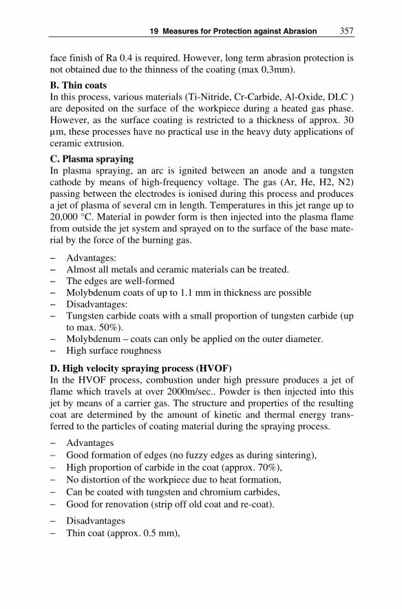
19 Measures for Protection against Abrasion 357
face finish of Ra 0.4 is required. However, long term abrasion protection is not obtained due to the thinness of the coating (max 0,3mm).
B. Thin coats In this process, various materials (Ti-Nitride, Cr-Carbide, Al-Oxide, DLC ) are deposited on the surface of the workpiece during a heated gas phase. However, as the surface coating is restricted to a thickness of approx. 30 µm, these processes have no practical use in the heavy duty applications of ceramic extrusion.
C. Plasma spraying In plasma spraying, an arc is ignited between an anode and a tungsten cathode by means of high-frequency voltage. The gas (Ar, He, H2, N2) passing between the electrodes is ionised during this process and produces a jet of plasma of several cm in length. Temperatures in this jet range up to 20,000 °C. Material in powder form is then injected into the plasma flame from outside the jet system and sprayed on to the surface of the base mate-rial by the force of the burning gas.
− Advantages: − Almost all metals and ceramic materials can be treated. − The edges are well-formed − Molybdenum coats of up to 1.1 mm in thickness are possible − Disadvantages: − Tungsten carbide coats with a small proportion of tungsten carbide (up
to max. 50%). − Molybdenum – coats can only be applied on the outer diameter. − High surface roughness
D. High velocity spraying process (HVOF) In the HVOF process, combustion under high pressure produces a jet of flame which travels at over 2000m/sec.. Powder is then injected into this jet by means of a carrier gas. The structure and properties of the resulting coat are determined by the amount of kinetic and thermal energy trans-ferred to the particles of coating material during the spraying process.
− Advantages− Good formation of edges (no fuzzy edges as during sintering), − High proportion of carbide in the coat (approx. 70%), − No distortion of the workpiece due to heat formation, − Can be coated with tungsten and chromium carbides, − Good for renovation (strip off old coat and re-coat).
− Disadvantages− Thin coat (approx. 0.5 mm),
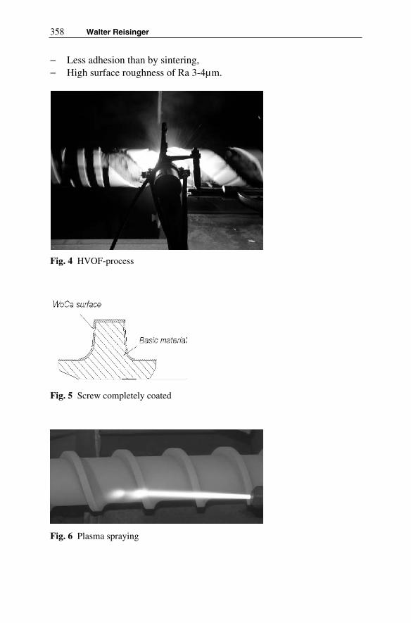
358 Walter Reisinger
− Less adhesion than by sintering, − High surface roughness of Ra 3-4µm.
Fig. 4 HVOF-process
Fig. 5 Screw completely coated
Fig. 6 Plasma spraying

19 Measures for Protection against Abrasion 359
E. Bonding process (sintering) In the sintering process, the sprayed powder is melted by gas or an oxygen flame and deposited on the workpiece (which has a temperature of approx. 80 °C) until the desired thickness is reached. The workpiece is then heated, either in a sintering furnace or by means of an acetylene burner to a tem-perature of approx. 1,050° C to enable the coat to melt-bond onto the workpiece.
− Advantages− Very good bonding to the base material, as it is alloyed,− Thick coating achieved, even with a tungsten carbide material (approx.
2mm).
− Disadvantages− Fuzzy edges, − High loss of carbide due to long heating period, − Distortion of the workpiece, − No repair possible, − Low proportion of carbide (approx. 35%), − Base material loses its tempered toughness.
F. Plasma-transfer arc welding (PTA) From the known welding methods, PTA welding (Fig. 4) has established itself as the standard process used for technical and geometrically complex types of screws. As its inclination is not to mix with the base material, this welding process produces top quality coatings.
A pilot plasma arc is used to ignite an arc to the workpiece. This trans-ferring arc is mechanically constrained by a water cooled nozzle-burner meaning that, compared with the normal welding process, a distinctly higher concentration of energy is achieved. This concentration of energy can be varied, by the geometry of the plasma bore within the anode, by the strength of the current of the pilot arc or transferring arc and, by the amount of plasma gas used.
The process is used to apply abrasion protective coats of cobalt and nickel-based alloys. Tungsten carbides (there is a choice of square or round carbides) are used to enhance abrasion protection on the screw flights, they are not used on the drive faces as the roughness which appears there during their use impedes the transportation of the ceramic material (Fig. 5).
The distribution of carbides (Fig. 5) is clearly visible under the micro-scope. Using this process, coat thicknesses of up to 2 mm can be obtained. After the welding process has been completed, the workpieces must al-

360 Walter Reisinger
ways be touched up. In the near future, the laser beam welding process will become increasingly popular as it makes it possible to apply thicker coats with a greater range of alloy combinations.
Fig. 7 PTA welding process
Fig. 8 PTA – welded flights
Fig. 9 Distribution of carbides

19 Measures for Protection against Abrasion 361
Very often, combinations of the aforementioned processes are used, as it is important to take into account the various wearing features for the vary-ing extrusion applications and materials. The most commonly used combi-nations are various PTA alloys for the screw flights and drive faces (Fig. 6) or for completely armoured screws in conjunction with PTA-armoured screw surfaces (Fig. 7).
Fig. 10 PTA welded flights an drive faces
Fig. 11 Completely armoured screw: flight welded, faces coated
Advantages:
− Thick coating (2mm) − Repair possible
Disadvantages:
− Low proportion of carbide − Very rough surface (needs machining)

362 Walter Reisinger
Table showing the features of material-based and layer-based processes.
Process Hard-ness
Layerthick-ness
Surface rough-ness [Ra]
Costs Reg.
Material-based
Steels ++ n/a 0,4 medium - high no PM steels ++(+) n/a 0,4 medium - high no
Ceramic (++++) n/a ?? ?? no Nitration + 500µm 0,4 low yes
Layer-based
Co + Ni base w/o carbides
sintered++
-2mm 3 – 4 medium no sintered with
carbides ++ -2mm medium yes
welded -2mm 2 – 3 high yes HVOF -0.5mm HVOF 3 – 4 medium no
Chromium car-bide
-0.5mm medium yes
Thin layer ++++ -30µm 0,3 ÷0,6 very high no Hard chromium ++ 300µm 0,2 ÷0,4 medium yes
Literature
Habig, K.H.: Verschleiß und Härte von Werkstoffen, München 1980
Czichos, H.: Tribologie Handbuch, Braunschweig 2006
Wunsch, F.: Wörterbuch Maschinenbau und Tribology, Berlin 2003
Kunst, H.: Verschleißhemmende Schichten, Renningen 2002
Woydt, M.: Tribologie keramischer Werkstoffe, Renningen 2001
Mennig, G.(Ed.): Wear in Plastics Processing – How to Understand, Pro-tect and Avoid, München 1995
www.3s-gmbh.at
www.castolin.com

20 Perspectives for Wear Reduction with Ceramic Extruder Components
Holger Wampers
20.1 Introduction
Against the background of a very high wear of the contacted material sur-faces, ceramics with their outstanding good wear properties advice them-selves for application in extrusion process. Due to their high wear resis-tance a reduction of machine downtime, metal contamination of product as well as torque moment can be achieved. The application of ceramic com-ponents requires a new mindset of the designing engineers because they have to take into account the typical ceramic disadvantages like pure linear material behaviour, small breaking elongation and statistical fracture be-haviour including size effect.
It’s a must to apply a material suitable module- and joining technique for the complex stress collective. For the ceramic components it’s neces-sary to detect the in use mechanical, thermal and chemical loads. To ana-lyze the stress field the FEA (Finite-Element-Analysis) is a suitable tool to calculate the particular stress distributions. In the next step the stress dis-tributions (axial and torque loads) will be superposed to get an idea of the whole stress field. Furthermore with the FEA it’s possible to calculate the tension stressed volume (Veff) for these geometric complex components and offers the possibility to calculate fracture probabilities according to the Weibull-Theory.
20.2 Properties of Ceramics
The properties of ceramics are significant different from those of metallic materials. For example can be named the statistical fracture behaviour, thermal shock sensibility, thermal conductivity, fracture toughness, density and thermal expansion coefficient. Depending on the selected ceramic sev-

364 Holger Wampers
eral properties can be bring to bear. If a component requires a high wear resistance, Sintered Silicon Carbide (SSiC, Table 1) could be a good solu-tion as construction material because of it’s very good hardness, chemical resistance and high thermal conductivity (cooling of auger and cylinder). In contrast are standing low fracture strength and fracture toughness (KIc).The inverse effect occurs by choosing Silicon Nitride (SN) with it’s high fracture strength and toughness but low hardness and chemical resistance. Resulting from this consideration follows the challenge for the design en-gineer to analyze the boundary conditions of the application as good as possible and to choose a suitable ceramic material. According to this fol-lows, that for auger and cylinder different materials could be applied.
20.2.1 Mechanical-thermal Properties
Mechanical Properties The main difference between ceramics and metals is related to the different strength behaviour of both materials. Whereas metals are displaying a elas-tic-plastic behaviour, ceramics show a pure linear-elastic behaviour. Hence to this the strength of metals is depicted as averages of the Gaussian distri-bution, whereas ceramics are characterized by the so called Weibull distri-bution with Weibull modulus m and the comparison stress σov. The Weibull modulus describes the homogeneity of the flaw distribution, whereas the comparison stress describes the strength standardized by the effective volume Veff (Veff=V0=1mm³) and fracture probability F = 63,2 %. Those parameters are used in the Weibull equation (Eq. 1) /WEI39/:
⎟⎟
⎟
⎠
⎞
⎜⎜
⎜
⎝
⎛
⎟⎟
⎠
⎞
⎜⎜
⎝
⎛
σσ
⋅−=−m
ov
p
0
eff
V
VexpF1 (1)
and describing the correlation of fracture probability F and loading σp. The higher the parameters Weibull modulus m and compared strength σov, the lower the fracture probability will become. This behaviour includes con-sideration of the size effect that occurs in ceramics significantly /MUN89/. The size of the effective tensile stressed volume (Veff) influences the frac-ture strength. This effect results from the statistical distribution of flaws in the material, due to this the probability to find a crack initiating flaw in a big effective volume is higher, than in a small one. Metals compensate this through plastic deformation, ceramics answer with spontaneous fracture. High effective volume’s lead to higher fracture probability values and the other way round. The size of the Veff is defined from Eq. 2/WEI39/, /MUN89/:

20 Perspectives – Wear Reduction with Ceramic Extruder Components 365
( ) ( ) ( )( ) . dVzyxVm
Veff ∫∫∫ σ⋅σ⋅σ=
Here is σ(x,y,z) the normalized strength function in the respective coordi-nate axis. It’s remarkable, that the Veff is depending of Weibull modulus m and in conclusion to this identical geometric volumes with different Weibull modulus (f.e. geometric similar specimen or components made from two different ceramic materials) are leading to different effective volumes Veff and therefore different fracture stresses. Higher Weibull Moduli are leading to lower effective volumes. To receive a preferably re-liable forecast of strength behaviour it is required to test specimen with a high effective volume. A maximum effective volume could be generated with tensile specimen because the whole volume will be stressed by ten-sion. From Eq. 2 follows for the tensile rod that the strength function σ(x,y,z) = 1, because no gradients occur (homogeneous stress distribution). Hence to this follows for tensile rods:
( ) . Vhrz,,rd r1V geo2
h
0
2
0
r
0
meff =π=ϕ=
∫ ∫ ∫
π
(3)
Like Eq. 3 depicts, the effective volume is equal to the geometric volume. Because of measurement requirements (failure influence due to excentric-ities, clamping moments) the tensile test is not conducted, but the so called four-point-bending test according to DIN EN 843-1.
Fig. 1 4-Point-Bending-Device with specimen
Due to the elastomer bearing of the specimen in the four-point-bending device like shown in Fig. 1, clamping failures can be reduced to a mini-
bearing
(2)

366 Holger Wampers
mum. The resulting strength parameters m and σov are used to design ce-ramic components and are displaying beside the material constants (den-sity, Youngs modulus and transversal contraction) the entry parameters for calculation with FEA. This method is also applicable for other brittle mate-rials like hard metals. A bending test with standard steel like St37 or St 50 (structural steel) would lead to Weibull-Moduli of m >100 (no size effect), but hard metals will be in a significant lower range, which leads to the as-sumption, that the Weibull-Theory is also a suitable instrument to describe the material behaviour of hard metals too.
The hardness of ceramics is clearly higher than the hardness of un-treated steel. Also with nitriding, nitro-carburation or hardening the hard-ness of ceramics can not be achieved. Other disadvantages of surface treated steels are the low penetration depth and heat distortion. In applica-tion the hardened surface areas are sensitive to chipping. If a small surface area shows first chipping, the degradation increases rapidly. Hard metals are showing hardness’s up to 2000 HV (Vickers-Hardness) and possess a constant hardness over the whole material thickness. In Fig. 2 an overview of several metals and ceramics in hardness scale Vickers and Mohs is given.
Hard Metals
Temperable Hard Materials
Hard Alloys
Hardened Steels Technical CeramicsNitrided Steels
100 400 1000 1400 2000
1 4 5 6 7 8 9
Talcum Wollastonite Glass
Asbest FeldsparTitanium Dioxide
10000
10
Quartz Topaz Corundum Diamond
Vickers
Mohs
Barite, Calcium Carbonate, Dolomite, Mica, Kaoline, Aluminium Hydroxide
Fig. 2 Hardness in Vickers, Mohs for ceramics, hard-faced metals and hardmetals
The fracture toughness KIC of ceramics (KIC= 3-8 MPa√m) is situated clearly lower than those of metals (KIC= 40-80 MPa√m) and hard metals (KIC= 15-20 MPa√m) /MEN91/. The low fracture toughness of ceramics is responsible for their high brittleness (Table 1).

20 Perspectives – Wear Reduction with Ceramic Extruder Components 367
Thermal Properties Ceramics can be applied till to very high temperatures (-1500°C) and showing till fracture only very small deformations. The thermal expansion is smaller than those of metals, due to this the joining technique of metal- ceramic- joints needs special requirements. Another specialty is the ther-mal shock sensivity. In Table 1 the values of the thermal shock coefficient R1 are given. The values are valid for a fast thermal shock (f.e. quenching in water). If the critical temperature difference is reached crack elongation starts in a very small temperature interval and due to this the strength is re-duced significantly /MUN89/,/HAS74/. This effect is well known by sin-tered Alumina, but doesn’t play a role in extrusion process due to low processing temperature.
Table 1 Mechanical-Thermal properties of ceramics
MaterialProperties
Unit Alu-mina
Zirconia Siliconcarbide Siliconnitride
sintered infiltrated (10 bar) Purity
>99%ZrO2
(TZP)SSiC SiSiC ND-SN
Density ρ g/cm³ 3,9 6 3,12 3,1 3,2
4-point bending strength*
σ4PB,m MPa 350 900 400 360 800
WeibullModulus
m - 10 10 12 10 15
Comparisonstress **
σov MPa 400 1060 500 470 925
YoungsModulus
E GPa 380 210 400 380 320
FractureToughness
KIC MPa*m1/2 4 8 3 3,5 6,5
Hardness HV 10 GPa 20 12 25 20 15
Thermal Ex-pansion
α 10-6 1/K 8 11 4,5 4 3
Thermal Con-ductivity
λ W/mK 25 2 100 110 30
Max. Working Temperature
Tmax °C 1500 1000 1500 1380 1250
Thermal Shock Coefficient
R1 K 80 350 130 100 600
Chemical Resis-tance
rated good good very good good good
Raw material costs
€/kg 5 75 15 7 60
* middle values for normal distributed fracture-properties; ** related to Veff = 1mm³ and F=63,2%

368 Holger Wampers
The thermal conductivity varies by ceramics quite significantly. The values can be distributed beginning from an isolator (ZrO2, λ=2 W/mK) till high conductive materials like SSiC with λ=100 W/mK or Alumina Nitride (AlN) λ=180 W/mK. With increasing temperature the thermal conductivity decreases. The absolute value of thermal conductivity plays a major role in extrusion process, because the auger and cylinder are responsible for dis-charging the by friction produced energy. A very good thermal conductiv-ity is demanded by the cylinder, because of it’s higher surface in compari-son to the auger.
20.2.2 Wear Properties
Due to their high hardness ceramics seems to be special suitable to with-stand the wear attack of high abrasive compounds. From literature are no near application investigations known about the wear behaviour of ceram-ics in extrusion process. For this reason in the following the principal be-haviour should be depicted. According to investigations of the BAM (Bundesanstalt für Materialforschung und -prüfung, Berlin) /WOY 87/ fol-lows, that the wear of ceramics is related to a product approach of the form:
yxIC
VHK
1CW
⋅⋅= (4)
The interaction of constants in Eq. 4 (WV=Wear Volume, KIC= Fracture Toughness; H=Hardness) are depending on the Parameters x,y and C from the considered tribo-system respectively, i.e. according to wear situation a high hardness or a high fracture toughness can be favourable to receive a low wear volume Wv.
Comparing investigations of metal and ceramic specimen in sliding con-tact with Polycarbonate powder with a content of 30% of glass (SiO2) are showing the distinguished wear behaviour of ceramics in comparison to metallic materials. Investigations of Mennig (Fig. 3) /MEN91/ prove the very low wear ratio’s (wear volume per cycle) of ceramics in comparison to cold work steel (f.e. X220 CrVWo12-2) or NiCrCo-steels, whereas the ZrO2 is displaying better values, although ZrO2 possesses a lower hardness but higher fracture toughness than SSiC or Al2O3.
Additional parameters in application who are able to influence the wear behaviour are system parameters like pressure, temperature, humidity, ro-tary speed, torque, friction…just to name a few. Therefore the absolute transfer to the real extrusion process is difficult or at least impossible.

20 Perspectives – Wear Reduction with Ceramic Extruder Components 369
Fig. 3 Wear ratios of metals and ceramics in contact with Polycarbonate with 30% glass (SiO2) content
20.3 Design and Field-testing of Ceramic Augers
The following investigations were done by a BMBF sponsored project: “Ceramic Components for the extrusion of high abrasive compounds”. Prior thing was to determine the job specifications for extrusion augers, which were caused by the adopted mechanical stresses and producibility of the ceramic components. Four-point-bending tests and inner pressure burst tests are accomplished to determine the Weibull-Parameter m (Weibull-modulus) and σov (comparison stress). Because of the influence of the size effect on the failure of ceramic components, the measured parameters of bending- and burst test are interpreted by a so called average function. This function warrants a better portability of the measured parameters m and σov
to the failure behaviour of real components due to their bigger effective volume compared to the 4PB-specimen effective volume [WAM02]. The determined parameters of the average function are displaying the input data set for the calculation of the fracture probability of the ceramic com-ponents by FEA. The analysis of the mechanical stresses of the extruder leads to the following simplified assumption (Fig. 4) [LAE91]:
SiS
iC
Zro
2
Al 2O
3
Nik
ro29
2
Nik
ro12
8
V48
3
WF
N
R21
0
R12
0
R11
2
S6-
5-2
0
Wv /z [mm³ 10-5]
5PC + 30% SiO2
X22
0C
rVM
o12
2
X15
5C
rMo
121
7,5

370 Holger Wampers
Fig. 4 Torque and pressure distribution versus the auger length
20.3.1 Ceramic Oriented Design Optimization
Taking into account the force-, heat- and mass flow the construction of the auger and liner is subjected to the following principles:
(1) Retention of the metallic force transmission (fit-in key), (2) The suitable ceramic at the right location, (3) Ceramic-compatible joining technique.
To (1): To avoid a redesign of the force transmission location and bear-ing of the auger the ceramic auger segments are glued on a stepped metal-lic mandrel. The length of the ceramic segments is geared to the maximum producible length and to the functional areas: homogenization (end auger, length 252mm), pre-pressurization (midsection auger, length 338 mm) and end-pressurization (front auger, length 45mm). The diameter of the man-drel is proven by FEA as well as the ceramic segments.
To (2): Ceramic compounds additives for plasticizing are necessary for extrusion. Because of their thermal instability the compound is needed to be water-cooled over auger and liner. Taking into account these aspects the used ceramics have to show a high thermal conductivity. From the investi-gated ceramics (Al2O3, ZrO2, SSN, SSiC) the SiC-material fits best (λ~110 W/mK at RT). Zirconia shows the lowest thermal conductivity (λ ~2 W/m K at RT). For this reason Zirconia was chosen to be applied only in the mechanical high stressed front auger segment. SSiC is utilized for the liner, midsection auger- and end auger segment of the auger due to low mechanical stresses and high demanded thermal conductivity.
MT
[Nm
]
1100
80
p [bar]120
Length
front auger
Axial-pressure
Radial-pressure
midsection augerend auger
extrusion direction

20 Perspectives – Wear Reduction with Ceramic Extruder Components 371
To (3): Due to the low temperatures in the extruder gluing was chosen as joining technique. Torques loading with ceramic/metal joints specimen of glued shafts to collar connections (rod:steel/hub:SSiC) are evaluated in torsion tests. The measured shear stresses of the glue achieved a maximum from about τg=6 MPa. This was enough to transmit the torque of the mid-section, front and end auger with the assumpted torque distribution.
20.3.2 FEM-simulation of Ceramic Augers
Using an IKKM developed FEA-Model [SAU03] it is possible to calculate stress distributions of various auger geometries under consideration of torque and axial pressure. Using of parametric data input files allows an easy variation of geometric parameters like pitch, thread angle, thread root radius, thread width, auger outside diameter and core diameter. For every segment the torque gradient is mapped by iterative calculated tangential force vectors due to unknown frictional coefficients. This approach war-rants a realistic torque reduce over the length of each segment. The solu-tions (Fig. 5) are calculated with the original geometric metal auger pa-rameters. With several variations of the geometric parameters it could be shown, that reducing stresses are achievable by using higher thread width or bigger thread root radius. The front auger segment wasn’t calculated with this model because of its double-threaded pitch. It was calculated by an analytical approach.
Fig. 5 FEM-calculation of end auger (left) and midsection auger (right) segment
The pressure-difference over the thread was estimated with ∆p=80 bars. This assumption contains an approximate security loading of about 40% to the realistic case of operation. The torque at the torque transmission point was estimated with MT =1100 Nm. The midsection auger segment shows a fracture probability of FB=7,5·10-4 % and that for the end auger segment of FB=6,23·10-6 %, both made of SSiC. These positive results admit the appli-cation of ceramic segments for extrusion process.

372 Holger Wampers
20.3.3 Comparison of Wear Behaviour of Ceramic and Metallic Augers
By project partner HITK (Hermsdorfer Institute for Technical Ceramics) various compounds (Silicates, Titanates, Oxides) can be extruded to moulded products. These are especially tubes with one and more channels as well as honeycombs which are used as components for environmental equipments and for material separation. For example a single-auger ex-truder fabricated by Fa. Händle, Germany is used. Its multipart pressing auger (mortised front auger) has a diameter of 80 mm. Main task of the HITK in project was to compare the following versions of auger modifica-tion regarding its abrasion behaviour:
− steel auger with steel front auger, − steel auger with ceramic front auger made from ZrO2 (Fig. 6), − two-part ceramic auger from SSiC with TZP (Tetragonal Zirconia Poly-
crystals) – ZrO2 front auger (Fig. 8).
The abrasion was generated by extruding ceramic honeycombs and tubes from various ceramic compounds to be used in R&D and production. The evaluation of abrasion was made gravimetrically as well as measure-ment of surface roughness /HAE04/.
Fig. 6 Steel auger with ZrO2 – front auger
20.3.3.1 Steel Auger in Comparison to Ceramic Front Auger (ZrO2)
A special hardened steel auger with new installed steel front auger (both hardfaced with Stellite 6) was used for the determination of “basic abra-

20 Perspectives – Wear Reduction with Ceramic Extruder Components 373
sion”. The construction of the auger is shown in Fig. 6 with mounted ce-ramic front auger. The steel front auger is fixed directly to the last auger gear (no gap). In contrast to this the ceramic front auger is fixed to the steel auger body via a auger channel free zone. This auger channel free zone has a positive and negative side. The negative effect is, that a back-flow of the compound takes place what implements a pressure drop. The positive effect is the additionally possibility for a centering of the auger to provide hits between auger and liner in starting process. Especially SSiC possesses a high failure potential against hit and push stresses due to it’s small KIc-value. Nevertheless the latter construction did not show technical limitations regarding density, textures and flow ability of the extruded structures. First result was, that no abrasion could be gravimetrically measured by the ceramic front auger. Comparing the weight loss of both augers gives a scenario like displayed in Fig. 7.
Fig. 7 Related wear of steel auger and steel auger with ceramic front auger
As expected both compounds of corundum (coarse and fine) generate a significant abrasion to the steel auger. In case of using the ZrO2 front auger the value of abrasion was only 40 to 50% of that total abrasion performed by the steel auger with steel front auger. In conclusion to this the dominant wear rate is taking place at the front auger, where the axial pressure value reaches his maximum and according to this the friction is maximum too. Roughness was measured (Hommel-Tester T 1000 E) on selected and marked positions of the new (as fired) and used ZrO2-front auger. A smoothening effect after extrusion of 590 kg different compounds oc-curred. The average surface finish Ra decreased related to Point 1 from Ra=0,85 µm to Ra=0,23 µm and related to Point 2 from Ra=0,25 µm to Ra=0,11 µm.
Corundum (coarse)
Corundum (fine)
1 2 3 4 5 6 7
Abrasion in g per 100 kg Extrudat
Steel Ceramic
SteelCeramic
Steel: hardfaced with Stellite 6 (400-600 HV 30)Ceramic: ZrO2 (TZP) (1300 HV 1);

374 Holger Wampers
20.3.3.2 Full Ceramic Auger in Field Test
For these experiments H.C. Starck Ceramics has manufactured and pro-vided a full ceramic auger (Fig. 8) consisting of two auger segments from silicon carbide (SSiC) and a new TZP ZrO2-front auger. The segments were adhered onto a stepped steel rod, like described in Fig. 4.
Fig. 8 Full ceramic extrusion auger (H.C. Starck) and steel auger
Neither silicates nor compounds of corundum having different particle sizes have led to a gravimetrically verifiable abrasion on the SSiC ceramic auger and its ZrO2-front auger even after total 680 kg extruded material. In the front zone of the SSiC-auger (4th auger channel) is a verifiable trend for a slight surface roughening of the ceramic (high pressure), but the rear part of the SSiC-auger (9th auger channel) became smoothed because of the lower pressure stress on the surface. Till today more than 3 t of material were extruded with this ceramic screw, the cumulative weight loss is smaller than 1g. The application of ceramic screws demands a high atten-tion to handling of the auger (pulling of auger for revision) and start-up process. The start up process exhibits a special problem, because of the slow filling process of the cylinder. Due to the ordinary floating bearing of the auger, the auger describes an excentric displacement. This bears a high risk for hits between auger and cylinder and causes chipping on the ce-ramic components. To avoid this effect a special start-up procedure with an aligned speed ratio of process auger and conveying auger is required. In addition to the ceramic auger, cylinder segments from ceramic were ap-plied. The worn out cylinders were skimmed and in a first attempt replaced with SSiC-segments.

20 Perspectives – Wear Reduction with Ceramic Extruder Components 375
Fig. 9 Cylinder segment with profiled SSiC inlet (H.C. Starck)
The material selection is founded by the outstanding thermal conductiv-ity of SSiC (λ=100 W/mK). But the chipping problems required a material with a higher fracture toughness. In the newest version LP-SSiC (Liquid-Phase sintered Silicon Carbide) segments were applied. LP-SSiC possesses similar thermal conductivity, but higher fracture toughness than SSiC (KIC
= 4,5 MPa√m). In additional a redesign of the saw tooth profile was con-ducted.
It was interesting to experience, that although extruding the same com-pound (coarse corundum) and using the same extrusion die (tube profile, 10 mm diameter) the torque during extrusion decreased from approx. 700 Nm to approx. 590 Nm if the ceramic auger is used. This value is reduced to 430 Nm for the application of ceramic auger with ceramic cylinder. Do-ing so there haven’t been any negative effects on the densification and the forming of the tubes. Reduced torques during extrusion decreases energy consumption and protects extruder and the extrusion dies due to lower fric-tion.
20.4 Application of Ceramic Auger in Production Process of Al2O3 Filtration Tubes
For the application of ceramic augers in mass production of Al2O3
-filtration tubes (Fa. Tami, Hermsdorf) other criteria’s has to be fulfilled as in the size of pilot plant stations with discontinuous production. The glued

376 Holger Wampers
segments are displaying a not satisfactoriness solution, because of the high efforts have to be taken in case of de-gluing of worn out or damaged seg-ments. The de-gluing process bears additional problems. First reason is, that the whole auger segments have to be de-glued, also not damaged seg-ments. Second reason is, that the steel rod has a higher thermal expansion than ceramic and due to this high tensile stresses were applied to the ce-ramic segments. This leads to high fracture probabilities for the undam-aged segments. From this follows the requirement to design a solution, which allows an easy mounting/demounting of the segments. In analogy to the existing steel solution, ceramic segments were glued on inside-toothed steel cylinders. This hybrid segments were pushed on a outside toothed steel rod. With this solution it’s also possible to put ceramic and metals segments in adapted to the wear situation on the rod (Fig. 10).
Fig. 10 Hybrid auger with metallic and ceramic segments (∅ 80mm,Lauger=835 mm)
For calculation of the segments a FEA-analysis was conducted. For the loads a axial pressure of ∆p=80 bar and a torque gradient of ∆Mt =130 Nm per segment was assumed. These values should be lower in reality, be-cause of the supporting effect of the suction side (the pressure difference is getting smaller) and the reduced torque caused by ceramic segments. Val-ues of the real process were not well known at this point, so the calcula-tions are showing a worst case scenario.
According to Fig. 11 it can be seen, that the fracture probability F for a spontaneous fracture of Al2O3 is lower than F<10-6. Other ceramics with a higher strength like Silicon Nitride (Fig. 13) or Zirconia would lead to even lower fracture risks. In Fig. 11 the complex stress status of the seg-ments is displayed through the colours. In the edge radius occur the highest stresses due to stress superposition of axial pressure (leading to bending stresses on suction side) and torque (due to gradient of section modulus).

20 Perspectives – Wear Reduction with Ceramic Extruder Components 377
Al2O3-Segment:∆MT=130 Nm ∆p=80 bar FB=10-6
Fig. 11 FEA-Calculation of an Al2O3-Segment
In comparison to the direct glued segments occurring disadvantages too: 1. The axial force is transmitted over front face of segments. This re-
quires a soft interlayer to avoid contact or Hertzian stresses. 2. The tightness of the contact areas has to be achieved. If extrudate
infiltrates the interspace between the segments it’s very difficult to remove them from steel rod.
3. The reduced gluing areas lead to higher shear stresses in the gluing gap
4. An increase of contact points due to shorter segments leads to a higher number of pitch interceptions. This leads to back – flow leakages (Fig. 12).
Fig. 12 Front auger (Siliconnitride) with by 50% reduced gluing area

378 Holger Wampers
Fig. 13 Pitch transition between two segments
In both applications – pilot plant stations and mass production – no wear of the ceramic segments could be measured. The service life times of Stel-lite armoured steel segments average 5 t of extrudate (Alumina etc.). With the ceramic segments more than 50 t could be reached. After the first tons of extrudate the ceramic gets a polished surface. In this low level of wear only a very small ablate of the surface takes place. The reason for failure of the ceramics is not founded in wear of the surface, but catastrophic fail-ure due to materials inhomogenities in the extrudate (contact stresses), overloaded gluing contacts or high contact stresses due to Hertzian con-tacts (auger hits cylinder). To solve these problems some more homeworks especial in application have to be conducted, but the ceramic in extrusion is on the right track.
20.5 Conclusions and Outlook
The application of ceramics in extrusion requires a to the properties of the ceramic tailored construction, which makes the load collective consisting of torque, axial force and wear bearable for the ceramic components. In addition the interactions between joint stresses and load stresses have to be considered who cause additional stresses by superposition. A good com-promise is offered with Silicon Nitride and Zirconia. In contrast are stand-ing higher costs and a high demanded service life time to achieve an eco-nomic benefit. The FEA demonstrates the general adoption of the segments, but could not include real occurring effects like material inho-mogenities or forces caused by impacts or Hertzian contacts. With the

20 Perspectives – Wear Reduction with Ceramic Extruder Components 379
adopted segments made from Silicon Nitride or Zirconia service life time factors compared to Stellite armoured metal segments from up to 15 are achieved. Materials like SSiC and Al2O3 are bearing a high risk due to chipping, which limits the service life time to a minimum level, but show-ing a moderate price level. The advantage of ceramics in extrusion beside an enlargement of service life time is a metal-free extrudate. Processing of food or pharmaceutical products could be a sinful application for ceramic auger and cylinders. Other applications could be found by using the out-standing high temperature properties of ceramics in processes with a hot extrudate (>1000°C). In the moment augers of SSiC could be manufac-tured by H.C. Starck up to a length of 1200 mm.
Literature
[LAE91] Länger F (1990) Designing an extruder with allowance for the properties of ceramic extrusion compounds – part 1. J cfi/Berichte der DKG (German Ceramic Society Report) vol 67 No 4 pp 162-164
[SAU03] Sauerzapfe K (2003) Modellierung des Kraftflusses in kerami-schen Schnecken für Extrusion und Spritzguss. Studienarbeit, IKKM - Institut für Keramische Komponenten im Maschinen-bau, Aachen
[WAM02] Wampers H (2002) Keramikschnecken zum Fördern und Sprit-zen. IKKM/IPAK-Seminar, Aachen,
[WOE00] Wötting G, Hennicke J, Feuer H, Thiemann KH (2001) Reli-ability and Reproducibility of Silicon Nitride Valves: Experi-ences of a Field Test. In: Heinrich LJ (ed) Proceedings of the 7th
Conf on eramic Material & Components for Engines, Goslar, Wiley-VCH, Weinheim
[WOY87] Woydt M (1987) Verschleißschutz in Gleisketten mit harten o-der weichen Oberflächen. In: Forschungsbericht 133, BAM Berlin, ISBN 3-88314-609-9
[HAE04] Händle F, Maier HR, Spätling J, Wampers H, Winterstein G, Götting G (2004) Ceramic Components for the Extrusion of Ce-ramic Compounds. J cfi/Berichte der DKG (German Ceramic Society Report) vol 81 No 4 pp E12-E20
[MEN91] Mennig G (1991) Verschleiß in der Kunststoffverarbeitung. Carl Hanser Verlag, München
[MUN89] Munz D, Fett T (1989) Mechanisches Verhalten keramischer Werkstoffe. Springer-Verlag, Berlin

380 Holger Wampers
[WEI39] Weibull A (1939) A Statistical Distribution Function of Wide Applicability. Ingeniörs Vetenskap Akademien, Handlingar No 154

21 Test Methods for Plasticity and Extrusion Behaviour
Katrin Göhlert, Maren Uebel
There is no generally-acknowledged method or measuring unit to specify the extrusion behaviour of ceramic bodies. In order to obtain an adequately precise description of the extrusion behaviour, numerous specific methods do exist, which have to be chosen according to the material, for example for bodies to produce bricks and tiles or bodies for the manufacture of catalyst converters, as well as methods relating to specific application re-quirements, be it for example for the purposes of production, quality con-trol or development of the body.
Only the most important methods are detailed here. In respect of the general methods as applied in ceramic laboratories, ref-
erence should be made to the relevant literature [1-3]. Very specialised methods which have partly been devised in companies for in-house pur-poses are also not covered within the framework of this contribution.
The crucial point in extrusion is the plasticity of the ceramic body. As there is neither a reliable definition nor a reliable method in ceramics for determining plasticity, it is also referred to as “extrudability”, “ductility”, “consistency” or “workability”.
21.1 Actuating Variables
The most important actuating variables in respect of plasticity are the moisture content of the body, the grain size distribution, the mineralogical structure, the additives used and the de-airing (Fig. 1).
Fundamentally it is of great significance that tests in laboratories or pilot plants are able to reproduce to the greatest possible extent the parameters relevant to shaping in actual production plants. But this is only possible to a limited degree, simply in view of the difference in the size and capacity of the equipment and the products. Therefore it is one of the most impor-

382 Katrin Göhlert, Maren Uebel
tant tasks of any laboratory or pilot plant to devise methods, respectively models, which ensure a sufficiently accurate “scale up” system.
Fig. 1 Main factors for influencing the plasticity
The following articles 1.1 to 1.5 deal with the methods for determina-tion of the main actuating variables, whereas 2.2.1 to 2.2.6 describe the methods for determination of the plasticity.
21.1.1 Moisture Content
Essentially two methods are used in ceramic laboratories to establish the moisture content: one is using the moisture analyser and the other the de-termination of the moisture content in the drying chamber. To ascertain the moisture content with the aid of the moisture analyser, a material sample of approx. 10–20g is taken from the material to be extruded and the mois-ture content is assessed in the moisture analyser (Fig. 2).
It is useful to grind the sample before placing it into the moisture ana-lyser. The most popular moisture analysers work on the basis of infrared, and the time required for an analysis of an average-sized sample is be-tween 5 and 15 minutes. The result can be directly read off expressed as a percentage. Working with a moisture analyser is convenient and is recom-mended in particular for the assessment of the moisture content of raw ma-terials prior to calculation of the batch formula, also for the purpose of checking the incoming material delivered from suppliers of raw materials and ceramic bodies.

21 Test Methods for Plasticity and Extrusion Behaviour 383
Fig. 2 Moisture analyser (photo: Sarto-rius)
As an option, the moisture content can be determined in the drying cabinet by drying of the material to the point of reaching mass constancy. The amount of material to be used for this purpose is between 10 and 30g. The weight of the sample is determined in the wet state and it should also be ground for this method. After the sample has been dried at a tempera-ture of 110°C, it has to be cooled down in the desiccator.
After approx. 2 hours the moisture content of the material can be estab-lished by weighing and can be expressed as a percentage either related to the dried or wet body, using the following formulae [4]:
Moisture (dry based in %) = (masswet – massdry) / massdry (1)
Moisture (wet based in %) = (masswet – massdry) / masswet (2)
All other indirect or direct methods of moisture determination (assess-ment of amount of steam, measuring the specific inductive capacity and others), as described in [1] and [5] are usually not employed in ceramics, as these are time consuming and do not provide reproducible measuring results.
The correct regulation of the moisture content of a raw material or a body to be extruded has a direct influence on other ceramic and techno-logical properties. From a technological aspect the achievement of a good compaction of the extrudate and the influence on the body shrinkage are primarily worth mentioning, besides the extrusion as such.

384 Katrin Göhlert, Maren Uebel
21.1.2 Grain Size Distribution
Knowledge of the grain size distribution of a raw material or the material batch allows extensive conclusions to be drawn on the further behaviour throughout all stages of process technology, as well as on the ceramic pa-rameters. Basically the following methods of analysis are known in labora-tories for determining the grain size distribution:
• Dry screening, • Centrifuging,• Wet screening, • Methods of sedimentation, • Laser granulometry.
Due to their measuring principle, all test methods are subject to physical and partly also chemical boundary conditions, which necessitate verifica-tion of the suitability of the method for each individual raw material or batch.
Dry screening is suitable for hard materials within a coarse range to 63 µm and is frequently used in combination with defined oscillation. Suit-able screening machines with vibrating devices and software-supported gravimetric analysis are employed, with which the sieve fractures can be determined individually (Fig. 3).
Fig. 3 Sieve shakers (photo: Retsch)

21 Test Methods for Plasticity and Extrusion Behaviour 385
The sample must be dried completely for screening. The more ideally spherical the shape of the grain, the more accurate is the result of the screening.
Wet screening can be universally applied and enables determination of the grain size distribution in the coarse range to a degree of fineness of 45 µm. However this is a time consuming and labour intensive screening method. The screens are selected according to the guideline values. After weighing, the dried material specimen, for example a sample of 50 g, is placed on the coarsest selected screen and the actual screening is effected with the aid of a water jet. For this purpose, special auxiliary devices are available for screening machines such as the one supplied by Retsch. Screening is complete once no cloudiness is visible in the water stream.
The sieve fractions are dried and the grain size distribution is calculated. Centrifuging is a method rarely applied in ceramic laboratories and
therefore not described in any detail here. The sedimentation method is one of those in the longest use for ascer-
taining the grain size distribution of ceramic materials, in addition to the screening methods already described above. It is based on the physical principle of sedimentation. A uniform density of the sample is a prerequi-site for measuring. The particles descend in the measuring cell in defined times and defined lengths of path in a laminar flow. The grain size distri-bution can be calculated by observing the viscosity of the deflocculant and by applying Stokes' law. [6]
In the past, sedimentation of a sample required an analysis over several days, whereby individual fractions were taken out after defined periods of time and evaluated by gravimetric determination, as is the case with the ANDREASEN method. Nowadays analysis equipment is employed in ce-ramic laboratories for sedimentation, which provides relatively fast results (Fig. 4).
Wet screening at an aperture of say 100 or 63 µm is required to prepare the samples to be measured in the fines range. The sample is then taken into a stable suspension of a defined concentration. Depending on the sample involved, special deflocculants are used.
Sedimentation of the sample is carried out in a measuring cell, radiolu-cent for X-rays, in a streamline flow. The X-rays are weakened by the sample in the measuring cell. This weakening is determined in the measur-ing cell from small to large sedimentation distances (fine....coarse). Using Stokes' law, the grain size distribution of the sample is determined. Ideally the material sample to be tested should be made up of globular particles for the purpose of the sedimentation measuring method, in which case the ap-plied law of physics for calculating the grain size distribution is valid without any restriction, and a reproducible measuring result can be ob-

386 Katrin Göhlert, Maren Uebel
tained within a short period of time. The measuring range of these devices is between approx. 200 µm ....0.1 µm. Any samples which have a larger percentage of grains in the nano-range cannot be measured with these de-vices without difficulty.
Fig. 4 Sedigraph 5100 for measuring the grain size distribution (photo: Micro-meritics)
Laser granulometry is the method most commonly employed for test-ing samples in the advanced ceramics industry for determination of the grain size distribution. The particles are set in rotation in a measuring cell and exposed to a defined laser irradiation (Fig. 5). The diffraction pattern of the rotating particles is converted to grain sizes from which the grain size distribution is established.
A certain sample concentration must exist within the measuring cell. The only task in preparing the samples is screening of the coarse portion
of particles in excess of 500µm, the normal measuring limit of suitable analysis instruments. The sample is suspended in a deflocculant. Distilled water will often suffice for this purpose; dispergators may be required in certain cases or sometimes measurement can only be accomplished in al-cohol. Any agglomerations of the fines particles of the samples already ex-isting or newly formed are destroyed with the aid of external and internal ultrasonic, which can be varied in intensity and reaction time depending on the specific properties of the sample and in particular its fineness. An ul-
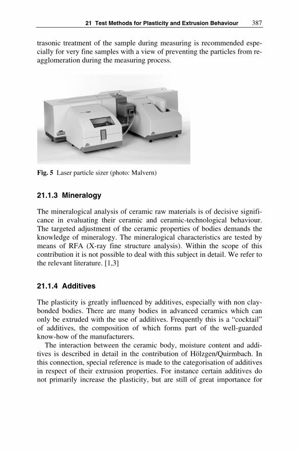
21 Test Methods for Plasticity and Extrusion Behaviour 387
trasonic treatment of the sample during measuring is recommended espe-cially for very fine samples with a view of preventing the particles from re-agglomeration during the measuring process.
Fig. 5 Laser particle sizer (photo: Malvern)
21.1.3 Mineralogy
The mineralogical analysis of ceramic raw materials is of decisive signifi-cance in evaluating their ceramic and ceramic-technological behaviour. The targeted adjustment of the ceramic properties of bodies demands the knowledge of mineralogy. The mineralogical characteristics are tested by means of RFA (X-ray fine structure analysis). Within the scope of this contribution it is not possible to deal with this subject in detail. We refer to the relevant literature. [1,3]
21.1.4 Additives
The plasticity is greatly influenced by additives, especially with non clay-bonded bodies. There are many bodies in advanced ceramics which can only be extruded with the use of additives. Frequently this is a “cocktail” of additives, the composition of which forms part of the well-guarded know-how of the manufacturers.
The interaction between the ceramic body, moisture content and addi-tives is described in detail in the contribution of Hölzgen/Quirmbach. In this connection, special reference is made to the categorisation of additives in respect of their extrusion properties. For instance certain additives do not primarily increase the plasticity, but are still of great importance for

388 Katrin Göhlert, Maren Uebel
extrusion, as they reduce the wall friction between the ceramic material and the extrusion tools.
21.1.5 Vacuum
The effect of vacuum in extrusion is covered extensively in the contribu-tions of Bartusch/Händle, Laenger and Redman. Further reference can be found in the bibliography mentioned there.
The extrudability of ceramic bodies is decisively influenced by de-airing, whereby the technically-possible degree of de-airing is not the aim for many bodies; in plant operation de-airing for ceramic extrusion is car-ried out at around 5–10 mbar. Extrusion is deliberately rather carried out with a lower vacuum, for instance in order to avoid drying of the body in the vacuum chamber.
Insufficient de-airing manifests itself in the appearance of so-called “dog ears”, moreover by a low density and low strength of the green prod-uct, as the air still embedded in the material produces pores. This means that extrudates produced from an identical body, or having an identical plasticity, have different physical properties, depending on the degree of de-airing.
21.2 Test Methods to Determine Plasticity
Introduction
In the following the major test methods for determination of the extrusion behaviour of ceramic bodies are introduced. The most important property for extrusion as a rheological parameter is the plasticity or ductility. Defi-nitions of the term plasticity, or ductility, have been published amongst others by Haase, Moore and Astbury [7-9].
In terms of rheology ceramic bodies hold a special position between ideal elastic and ideal plastic bodies, as they exhibit Bingham behaviour. Plotted on a shear stress/shearing speed graph, ceramic plastic bodies start to deform only after having reached a certain shear stress τ0, the so-called yield point.
The rheological characteristics of ceramic materials and the mathemati-cal models which have been developed describing the flow behaviour are dealt with in great detail within the contribution of Laenger.

21 Test Methods for Plasticity and Extrusion Behaviour 389
21.2.2 Methods and Instruments
Table 1 shows a summary of the most important principles and measuring methods for determination of the flow behaviour, respectively the plastic-ity, of ceramic materials.
The methods and instruments most relevant to practical use are ex-plained below in more detail.
It is a fact that even today no methods exist, which clearly establish and depict the plasticity relevant to extrusion. This holds true particularly for such methods as Pfefferkorn or the penetrometer, which provide a refer-ence figure. It appears that the most apt are those methods that simulate the extrusion process.
Table 1 Summary of the major measuring methods for determining plasticity
Measuringprinciple
Examples Reproducibility Effort/ Time con-sumption
Remarks
Impact de-formation
Pfefferkorn Average Average Production of test samples required
Penetration Penetrometer Pen-Check
Average to high, subject to in-strument
Low Can be established direct from the product
Pressure Capillary Rheometer
High High Production of test samples required
Dynamic al-ternating load
AstburyHennicke
Average High Production of test samples required
Torque Brabender Plastograph
High Average Measurement canbe carried out with the material used in production
Tensilestrength
Linseis Average Average Production of test samples required
Formation of cracks
Dietzel Low Average Production of test samples required; subjective method
Variousmeasuredquantitiessuch as pres-sure, torque
Brabendermeasuring ex-truder,HaakeESM
Average to high, subject to in-strument
High Simulation of the extrusion process
Others Riecke Atterberg
Low Average Subjective method

390 Katrin Göhlert, Maren Uebel
21.2.2.1 The Pfefferkorn Method
Measuring of the plasticity according to Pfefferkorn is based on the princi-ple of impact deformation.
A defined sample with a diameter of D = 33 mm and an initial height of h0 = 40 mm, produced either manually or by way of extrusion, is deformed by a free falling plate with a weight of 1.2 kg (Fig. 6).
The initial height h0 is related to the impact deformation height h1, the result of which is the ratio of deformation. As a rule this measurement is taken with bodies of varying moisture content.
The ratios of deformation h0/h1 or the impact deformation heights h1 are plotted on a graph over the moisture content figures. The steeper the curve, the “shorter” (more lean) is the body, i.e. the more intensely the body will react to variations in the moisture content.
Experience shows that the impact deformation heights according to Pfefferkorn for bodies to be extruded lie within a span of approx. 25 mm for soft extrusion and approx. 37 mm for stiff extrusion.
The Pfefferkorn method is widely accepted in practice and was origi-nally developed for soft silicate ceramic materials. The Pfefferkorn method is less suitable for stiffer bodies, as usually processed in the advanced ce-ramics industry, as the low resolution at a small impact deformation height impedes the reproducibility.
Fig. 6 Sketch showing principle of the Pfefferkorn instrument (from [10])

21 Test Methods for Plasticity and Extrusion Behaviour 391
21.2.2.2 Penetrometer
Measuring instruments on the basis of the penetration method were origi-nally devised for soil mechanics; the first unit suitable for practical use was that of Soil test Inc.
Measuring following the penetrometer principle uses a penetration tool of varying geometry, which is pushed evenly into the compact body up to a certain (measuring) mark. The measured value represents the force needed for the penetration.
The penetrometer instruments widely used in the ceramic industry are easy to manage, as measurement can be made directly on the extrudate (Fig. 7).
The simple type of penetrometer still used even today in brick factories for quality control of the column works on the spring-resistance principle; the measured value can be read off a scale expressed as pressure in kp/cm².
Fig. 7 Assorted penetrometer instruments (photo: ECT)
The latest penetrometer designs endeavour to eliminate the inaccuracies in measuring and reading encountered with this measuring method. The spring has been replaced by a piezo element; the measured value is dis-played digitally as force in a measuring field and depending on the geome-try of the selected penetration tool can be evaluated as pressure. As meas-ured values can vary considerably with all hand-operated instruments because of the penetration speed applied, laboratories now use devices on which the penetration speed as well as the penetration depth can be pre-set in order to avoid subjective influencing factors (Fig. 8).

392 Katrin Göhlert, Maren Uebel
Fig. 8 Automated PEN-Check (photo: ECT)
21.2.2.3 Plasticity According to Linseis and Hofmann
With this measuring method the materials to be extruded of different mois-ture content are forced through a nozzle of say 1 cm² cross section by means of a piston extruder and the shearing strength required for this proc-ess is determined. The column is subsequently torn apart and the tear resis-tance measured.
The degree of plasticity is the ratio of tear resistance σz to shearing strength σD.
Highly plastic bodies are accordingly those which offer little resistance to deformation, but nevertheless still have a high tear resistance. [11,12]
21.2.2.4 Capillary Rheometer
The most commonly-used laboratory process to determine the flow charac-teristics of ceramic bodies is that of capillary rheometry, for which various instruments are available, in the form of either single-bore capillary or twin-bore capillary rheometers. Using a pressure piston, the ceramic body is forced through a nozzle of a defined geometry at different feed rates. The resistance of the ceramic body against the deformation in the nozzle causes a pressure drop within the capillary, which corresponds to a certain

21 Test Methods for Plasticity and Extrusion Behaviour 393
shear stress. This pressure drop is the measured value, taken in the in-feed zone of the nozzle. This means “In principal one can deduce the feed rate from the measured pressure value, the shearing rate from the pre-set flow rate, and from the quotient of both figures the desired shear viscosity”. [13]
The difference between single and twin-bore capillary rheometers (Fig. 9) cannot be dealt with in this contribution. Basically this is a matter of be-ing able to make the so-called “Bagley correction” with less effort and fewer errors. Likewise, no reference can be made here as to how dilatant respectively structural viscose behaviour (Rabinowitsch correction) and the strain properties of ceramic bodies or wall slipping effects (according to the Mooney method) can be determined with the capillary rheometer.
Fig. 9 Twin bore capillary rheometer (photo: Malvern)
For the development of superior ceramic bodies, the application of a capillary rheometer is an absolute must. For ceramic bodies which include coarser grain fractions the relatively small capillary/nozzle diameters can cause a problem, as can the fact that the readings obtained with the capil-lary rheometer can only be meaningfully interpreted against a background of great experience. [14]
This is the reason why simplified instruments have been developed in the recent past for practical use in factories or in the laboratory, which function on the principle of the capillary rheometer but are better suited to

394 Katrin Göhlert, Maren Uebel
withstand the rough operating conditions, which sometimes prevail in fac-tories.
21.2.2.5 Brabender Measuring Kneader
The Brabender measuring kneader or torque rheometer was originally de-signed for the caoutchouc industry, yet this is widely used, especially in the USA, to determine the plasticity of ceramic bodies. [15,16]
The Brabender measuring kneader (Fig. 10) comprises a measuring cell in the form of an enclosed kneading chamber, in which two interlocking and counter-rotating Z-shaped kneading arms are installed. The speed of these kneading arms can be varied, as can the temperature of the measur-ing cell either by cooling or heating. It is the torque which is measured, based on the premise that plasticity constitutes the capability of a ceramic body to have a certain resistance to deformation during the kneading proc-ess. With the use of the Brabender measuring kneader, the fundamental in-terdependence between plasticity and moisture content for ceramic bodies can be determined very precisely. This applies similarly to the interde-pendence between plasticity and temperature, or the dependency of plastic-ity on additives.
The plasticity readings obtained from the Brabender measuring kneader expressed in the form of torque figures are not identical with the plasticity figures relevant to extrusion. This also holds true for those measured val-ues determined by the penetrometer or other measuring methods. Yet the Brabender measuring kneader is ideally suited for the development or op-timisation of bodies which need to be plastified prior to extrusion by means of continuous or intermittent kneading.
Fig. 10 Disassembled Brabender measuring kneader (photo: Brabender)

21 Test Methods for Plasticity and Extrusion Behaviour 395
21.2.2.6 Measuring Extruder
All methods described so far can only provide an incomplete picture of the complex concept of plasticity relevant to extrusion – it would be more correct to use the term “apparent plasticity”. Therefore tests using a meas-uring extruder were developed to attempt the near simulation of the extru-sion process as it takes place in an auger extruder. A suitable and adequate measuring technique is conditional for such a simulation process. Even more important when testing ceramic bodies is the selection of realistic size ratios for the measuring extruder, which allow a scale up. Practice has shown that it is hardly possible to simulate those conditions in a measuring extruder of 20 mm barrel diameter which will later prevail with large ex-truders of 750 mm barrel diameter for the production of slugs (billets) in electroceramics. It will serve to use the ESM method as an example, in or-der to describe the operating principle of a measuring extruder; the meas-uring extruders offered by Brabender and Haake work on a similar basis.
The extruder simulation model (ESM) was developed by Händle GmbH. The theoretical fundamental principles and examples for application of the ESM are described in detail in various articles published by Laenger [17]. This model is based on measurements obtained from a special laboratory version measuring extruder of 80 mm barrel diameter.
The particular ESM extruder was modified in such a manner that it can be used with a measuring barrel serving as a large capillary rheometer, whereby an auger in lieu of a pressure piston forces the material into the nozzle. This means that the pressure drop is measured analogously to the capillary rheometer. The results of this test produce the yield point and the apparent flow curve of the body, amongst other readings.
In a second test using a special extruder barrel the development of the pressure in the auger for different speeds, auger geometry and nozzle cross sections, respectively the influence of deformation conditions, are estab-lished. Simultaneously the torque figures as well as the axial and radial pressure rates are measured during both tests.
All data obtained from the tests with the ESM (table 2) are processed in a mathematical model. By adopting similitude models, the data can be used as a design basis for extruders, e.g. the L/D ratio of the auger, the au-ger geometry, the gearbox torque, and the size of the thrust bearing, etc.

396 Katrin Göhlert, Maren Uebel
Table 2 Variables and target values of the Extruder-Simulation-model[17 part 4a]
VARIABLES TARGET VALUESGEOMETRY:Auger diameter Hub diameter Barrel diameter Auger length PitchThickness of the flight Number of flights State of wear MATERIAL PARAMETERS: Yield point ViscosityBOUNDARY CONDITIONS: Wall slippage velocities Type of barrel liner SpeedFeeding factor
PROCESS PARAMETERS: Throughput capacity Pressure build up BackpressureBackup length SpeedFeeding factor TorqueBearing pressure EfficiencyTemperature rise Power requirement
Literature
[1] Singer F, Singer SS (1964) Industrielle Keramik, Band 1 Die Rohstoffe. Springer Verlag Berlin, Göttingen, Heidelberg, New York, pp 280-428
[2] Sütterlin, D (1982) Das keramische Laboratorium. In: Bender W, Händle F (eds) Handbuch für die Ziegelindustrie. Bauverlag Wies-baden und Berlin pp 532-550
[3] Handbuch der Keramik (1996) Das keramische Laboratorium. Vol 4 IVA Verlag Schmidt Freiburg. Reh H (2001) Das Keramiker-Jahrbuch. Göller Verlag Baden-Baden
[4] Mettler Toledo (1995) Methoden der Feuchtegehaltsbestimmung. Applikationsbroschüre
[5] Webb P (2002) Interpretation of particle size reported by different analytical techniques. Homepage Micromeritics
[6] Haase T (1957) Die Bildsamkeit plastischer keramischer Massen. JBerichte der DKG vol 34 pp 27-33

21 Test Methods for Plasticity and Extrusion Behaviour 397
[7] Moore F (1965) Rheology of Ceramic systems. Mac Laren and Sons Ltd. London
[8] Astbury NF (1962) A Plasticity Model. J Trans J Br Ceram Soc vol 62 pp 1-18
[9] Heuschkel H, Heuschkel G, Muche K (1990) ABC der Keramik. Verlag für die Grundstoffindustrie, p 329
[10] Hoffmann U (1970) Plastizität keramischer Massen. In: Handbuch der Keramik Gruppe IV B 2b, Verlag Schmidt Freiburg
[11] Schlegel W (1982) Bestimmung der Bildsamkeit keramischer Mas-sen. J Keramische Zeitschrift vol 34 pp 149-152
[12] Remmler T (2006) Bestimmung der Fließeigenschaften von kerami-schen Massen mit einem Doppelkapillar-Rheometer. MAL VERN Instruments
[13] Mazeo FA (2001) Extrusion and rheology of fine particulated ce-ramic pastes. Dissertation, Rutgers University New Jersey
[14] Lawrence WG (1961) Clay-Water Systems. The Ceramic Associa-tion of New York, Alfred University, New York, pp 56-62
[15] Händle F (1978) Contribution to the subject of plasticity in clay-water systems. J ZI Ziegelindustrie International vol 9 pp 472-476
[16] Länger F (1990-1993) Designing an extruder with allowance for the properties of ceramic extrusion compounds. Part 1 cfi/Berichte der DKG (German Ceramic Society Report) vol 67 No 3 pp 162-164, Part 2a vol 68 No 9 pp 409-412, Part 2b vol 68 No 10/11 pp 531-533, Part 3 vol 69 No 3 pp 102-108, Part 4a vol 69 No 7/8 pp 266-272, Part 4b vol 69 No 9 pp 347-352, Part 5a vol 69 No 10 pp 397-401, Part 5b vol 70 No 3 pp 92-96

22 Simulation in Ceramic Extrusion
Boris Buchtala, Sigrid Lang
Starting with the governing equations of fluid flow we will collect the in-gredients for the numerical simulation of fluid flow in ceramic extrusion. We start with the derivation of the governing equations to describe ceramic extrusion processes. Since most ceramic materials don’t change in volume we will restrict our discussion to incompressible flow. A simple example closes the first chapter.
A short chapter is dedicated to the solution of the governing equation. Since a detailed description of numerical methods dealing with the solu-tion of the governing equations can be found in many textbooks only the underlying principles will be explained.
Special aspects concerning the special treatment of ceramic material properties in modern CFD (Computational Fluid Dynamics) codes will conclude this small general survey on simulation in ceramic extrusion.
22.1 The Fundamentals
Here we will summarize the governing equations of fluid flow which are necessary to describe fluid flows in general. We will also discuss boundary conditions and appropriate material laws for ceramic materials to close the mathematical problem.
22.1.1 Conservation Equations
Simulation of fluid flow in arbitrary geometries deals with the numerical solution of the conservation equations of mass, momentum and energy. Their derivation can be found in a multitude of good textbooks like (Alex-androu 2001, Anderson 1995, Böhme 2000, Hoffmann and Chiang 1993/95, Spurk 2003,). They are repeated below for convenience.

400 Boris Buchtala, Sigrid Lang
Conservation of mass for an incompressible fluid
0div =vρ (1)
tells us that at each instance of time the same amount of mass that enters an arbitrary control volume must leave this volume which is equal stating the time rate of change of the volume of a moving fluid element per unit volume is zero.
The conservation equation of momentum for fluid continua reads
gTv ρρ ++−= divgrad
DD
pt
. (2)
The time rate of change of momentum of a moving material element is equal to the volume specific pressure-, frictional- and volume forces acting on the element. T denotes the frictional stress tensor.
The time rate of change of inner energy is in equilibrium to the dissipa-tion rate plus the heat flux due to internal heating:
qDT div)sp(D
D −⋅=t
eρ . (3)
sp(T�D) is the so called dissipation function with the strain velocity tensor D. In case of a simple shear flow this term reduces to γτ &⋅ . For the consti-tutive equations to be discussed later the strain rate tensor D is of great im-portance. He represents the symmetric part of the velocity gradient tensor. In an Cartesian coordinate system the components of D are
⎟⎟
⎟
⎟
⎟
⎟
⎟
⎟
⎠
⎞
⎜⎜
⎜
⎜
⎜
⎜
⎜
⎜
⎝
⎛
∂∂
⎟⎟
⎠
⎞
⎜⎜
⎝
⎛
∂∂+
∂∂
⎟
⎠
⎞
⎜
⎝
⎛
∂∂+
∂∂
⎟⎟
⎠
⎞
⎜⎜
⎝
⎛
∂∂+
∂∂
∂∂
⎟⎟
⎠
⎞
⎜⎜
⎝
⎛
∂∂+
∂∂
⎟
⎠
⎞
⎜
⎝
⎛
∂∂+
∂∂
⎟⎟
⎠
⎞
⎜⎜
⎝
⎛
∂∂+
∂∂
∂∂
=
z
w
y
w
z
v
x
w
z
u
y
w
z
v
y
v
x
v
y
u
x
w
z
u
x
v
y
u
x
u
2
2
2
2
1D . (4)
Terms on the main diagonal are strain velocities, side elements represent angle rates of initially cuboid elements. The first invariant of D, sp(D), is equal to div v, the volumetric strain rate, which must be zero for incom-pressible flow.

22 Simulation in Ceramic Extrusion 401
22.1.2 Constitutive Equations
At this point of our discussion with e, p, q, T, v we still have fourteen un-known variables left (keeping in mind that T is a symmetric tensor). On the other hand only five equations to describe the flow field are available. To allow the solution of these equations, namely the Navier-Stokes equa-tions, we have to state some additional equations which describe the spe-cific material properties of the ceramic extrudate.
The majority of ceramic materials exhibit visco-plastic behaviour (in such a way that below a certain stress level oτ , the so called plastic level, they behave as a rigid body. Exceeding the plastic level the strain rate might be proportional to the additional frictional stresses like
ητγ =& (5)
or the strain rate might increase above average e.g.
mτφγ ⋅=& (6)
(Ostwald 1925) with a temperature dependant fluidity φ and a flow expo-nent m as a measure of shear thinning. Ceramic materials with Newtonian behaviour above the stress threshold, Eqn. (5), are called Bingham materi-als, materials which exhibit shear thinning, Eqn. (6), are called Casson materials.
The constitutive equation for Bingham materials is
⎪
⎩
⎪
⎨
⎧
>⎟
⎟
⎠
⎞
⎜
⎜
⎝
⎛
−
≤=
oo
o
B τττ
ηT
TT
T
D1
0
2 . (7)
Bη is called the Bingham viscosity. In general it depends on temperature and pressure; in practice the pressure dependency can be neglected very often. Considering a simple shear flow where 2D reduces to γ& and T to τthe interrelationship of γ& , τ and
γτηγτη && oB +== (8)
is shown in Fig. 1 assuming 31015 ⋅=oτ Pa, 4109 ⋅=Bη Pa s.

402 Boris Buchtala, Sigrid Lang
0 2 4 6 8 10 12
x 104
0
0.2
0.4
0.6
0.8
1
shear stressτ [Pa]
shea
r ra
teγ
[s-1
]
Bingham
Casson
τo
0 2 4 6 8 100
1
2
3
4x 10
5
shear rateγ [s-1
]
shea
r vi
scos
ityη
[Pa]
Bingham
Cassonη
B
Fig. 1 Flow curve and shear viscosity function of Bingham- and Casson materials
The heuristic extension of the rheological state equation from Bingham to Casson materials is straightforward. It can be derived directly from Eqn. (7) by introducing a strain rate dependant viscosity )( 2Iη instead of Bηwhere 2I is the second invariant of the strain rate tensor 2D:
∑∑=i j
jiijI γγ &&
21
2 . (9)
Together with e.g. the power law of Ostwald and de Waele, Eqn. (6), we deduce (Hensen et. al. 1989)
m
m
m II 2
1
2
1
2 )(−−
⋅= φη . (10)
In the case of simple shear flow we finally find the relationship
γτγφγτη &&& om
m
m +==−− 11
(11)
which is also shown in Fig. 1 using =m 1.85 and 9101 −⋅=φ Pa-m/s. Setting =m 1, the Bingham law turns out to a special case of the more general
Casson law, where φη /1=B .Analyzing Fig. 1 we see that for shear stress values τ reaching the plas-
tic level oτ , which is tantamount to shear rates γ& near zero, the shear vis-cosity η reaches infinity. This situation and the discontinuity of τ in his first derivative at oτ leads to remarkable difficulties in the course of nu-merically solving the conservation equations (1)–(3). Suggestions how these problems can be circumvented will be discussed later in chapter 3.1.

22 Simulation in Ceramic Extrusion 403
At this stage we have to realize that there are still eight unknown vari-ables left. Therefore we introduce the caloric equation of state together with the temperature T as a new variable:
Tce v= . (12)
vc denotes the specific heat capacity at constant volume. Furthermore the heat flux due to internal heating is described using Fourier’s law of ther-mal heat conduction
Tgradλ−=q (13)
with λ as the specific heat conductivity. Inserting the constitutive equa-tions (7), (12), and (13) into the Navier-Stokes equations we have five equations to determine our five unknown variables p, T, v.
The accurate knowledge of the material properties ρ , η , vc , λ itself or of the descriptive parameters present in the constitutive equations plays a vital part in the simulation of ceramic extrusion. As it has been men-tioned earlier they may depend on temperature, like viscosity does, and pressure. In many cases the pressure dependence is negligible. Practical guidelines how to implement temperature dependency in the constitutive equations are given in (Hensen et. al. 1989).
It should not be left unsaid that due to the temperature dependence of viscosity the energy equation (3) is no longer decoupled from the mass- and momentum equations (1), (2). As a consequence the solution proce-dure to solve the governing flow equations has to allow for this coupled behaviour.
The material parameters have to be determined experimentally prior to any calculation. This time consuming and also difficult task has to be done quite carefully because their correct knowledge is a major aspect of (un)certainty in the aspired solution.
22.1.3 Initial- and Boundary Conditions
The governing equations, along with the appropriate constitutive relations, completely describe the fluid flow within a given geometry. However, the mathematical model forms a system of partial differential equations obey-ing mixed elliptic-parabolic behaviour which cannot be solved unless we specify the boundary conditions for the problem. Mathematically they fix the integration constants yielded upon integration. From a physical point of

404 Boris Buchtala, Sigrid Lang
view, the boundary conditions provide inevitable information on how the fluid interacts with its surrounding.
Considering time dependent flow problems, not only the conditions at the flow boundaries have to be provided throughout the whole solution process but also the initial conditions of the complete flow field must be specified to get the solution process started.
In ceramic extrusion we typically have to deal with inflow- and outflow boundaries, (moving) walls and free surface boundaries for which the ap-propriate mathematical formulation will be given in the subsequent para-graphs. Since we use pressure, temperature and velocity as our independ-ent set of variables, the boundary conditions must be expressed in terms of p, T, v. They can take two different forms: The dependent variables are specified along the boundary (Dirichlet boundary condition) or the direc-tional derivatives of the dependent variables are prescribed (Neumannboundary condition).
Unfortunately, for a given domain of interest boundary conditions can be chosen that over- or underspecify the problem. An example of an over-specified problem is a constant area duct, with a fixed fluid velocity at the inlet and but different at the outlet. Naturally, for an incompressible fluid both conditions cannot be physically satisfied in the absence of a mass source. In the same sense, a closed box with only heat flux boundary con-ditions is under specified since the temperature level is not constrained, and therefore unpredictable. It becomes clear that defining well posed boundary conditions is quite important for the proper solution of a flow problem. An easy way to check for well posed boundary conditions is to ask yourself “Could the chosen configuration be physically recreated in the laboratory?”.
In most cases, proper conditions for p, T, v or their derivatives at inflow- and outflow boundaries can be set according to the physical setup of the problem. For example if the mass flow is known in advance, the velocity at the inlet can be determined as soon as a velocity profile is chosen – the pressure level will be fixed at the outlet. On the other hand, if the pressure at the inlet and at the outlet is prescribed, the velocity cannot be chosen since the mass flow rate is part of the solution.
In any fluid continuum possessing a viscosity, however small, the veloc-ity of the fluid adjacent to the solid boundary is the same as the boundary, there is no relative motion between fluid particles and solid boundaries with which they are in contact. Despite its apparent simplicity, the no-slip boundary condition leads to some physical inconsistencies that are not yet resolved completely. For example, the no-slip condition cannot explain the motion of a liquid interface in contact with a solid boundary: according to this condition, the liquid interface in a partially filled glass must remain

22 Simulation in Ceramic Extrusion 405
stationary with respect to the glass even when the glass is moved. Obvi-ously, at a macroscopic level we know that this is not the case. As a matter of fact there is strong evidence that wall slip occurs in many non-Newtonian fluids like for instance ceramic materials. Owing to the mutu-ally reactive forces of particle at fluid walls the microstructure of heavy clay extrusion bodies can break open in the immediate vicinity of solid boundaries (Fig. 2). The consequence is an intense agglomerate destruction and alignment as well as increased moisture close to the wall.
Fig. 2 Microscopic view of wall slip (Hoffmann 2001)
The described phase separation of extrusion bodies gives rise to the formation of a low-viscosity boundary layer at the wall. The thickness hs
of this lubricating film is very small compared to the dimensions of the non-separated core material. Wall slip is taken into account using an ap-parent slip velocity us at solid boundaries (Mooney 1931, Wein and Tovchigechko 1992, Yoshimura and Prud’Homme 1988). Above the slip stress level sτ where sliding is initiated, the slip velocity us relative to the wall is assumed to be proportional to the shear stress along the wall
⎪⎩
⎪
⎨
⎧
>−+
≤=
sss
sw
sw
sh
u
uu ττττ
η
ττ
)( . (14)
This formulation stems from the microscopic assumption that inside the low-viscosity boundary layer the velocity increases linearly up to us. Both parameters, sτ and ssh η , depend on the specific ceramic material properties and must be determined, e.g. by rheometer measurement, prior to any calculation. Firma Braun (also authors in this book) determine the so called k-factor

406 Boris Buchtala, Sigrid Lang
=ks
s
h
η (15)
together with the other quantities by a special experimental setup. Further information on the implementation of wall slip models into CPD codes will be given in chapter 3.2.
As stated earlier we must supply boundary conditions at the whole boundary of the computational domain which means that we also have to specify appropriate values for the pressure at walls. However in reality the pressure at solid walls cannot be prescribed since it evolves with the flow state. For practical purposes a meaningful strategy has to be chosen when solving the partial differential equations. For example the pressure at the wall can be obtained from within the flow field by assuming a zero pres-sure gradient or alternatively by solving the 1-D momentum equation per-pendicular to the wall. Fortunately all modern CFD codes supply pressure boundary conditions at the wall automatically.
The temperature boundary condition for the energy equation is either as-signed directly or the derivative of T might be set according to a given heat flux, Eqn. (13).
Free surfaces are often encountered in extrusion processes, e.g. when the shape of the extrudate leaving the die is of interest. Unlike the bounda-ries discussed so far, the shape of a free surface boundary is not know a priori since it evolves as part of the solution. Thus two boundary condi-tions are necessary: a kinematic condition that signifies that the particles at the free surface move with the local fluid velocity and a dynamic condition that assures force balance at the surface. The kinematic condition is ex-pressed as
0=⋅⎟⎠
⎞
⎜
⎝
⎛ − nvx
Dt
D(16)
where x is the position of a material point on the surface. Eqn. (16) states that the free surface must follow the trajectories in the normal direction while the tangential displacement is not restricted. It is used to determine the geometrical shape of the free surface. The dynamic condition reads
)( Tnnt +−⋅=+ pff nt (17)
Where t and n represent unit vectors in the tangential and normal direc-tions respectively, an ft and fn the components of an external force f along these directions.

22 Simulation in Ceramic Extrusion 407
22.1.4 A Simple Example
The conservation equations for mass and momentum are more complex than they appear. They are nonlinear, coupled and difficult to solve. Only in a small number of cases – mostly fully developed flows with constant viscosity in simple geometries e.g. in channels, pipes, between parallel plates – it is possible to obtain an analytical solution of the Navier-Stokes equations. In this chapter we will consider such a type of elementary flow, to show, how simple geometries and physics have to be for an analytical solution. Further elementary fluid flows can be found in a multitude of books about fluid mechanics. We follow in this chapter the accomplish-ments of (Sabersky and Acosta 1964).
We consider the steady flow of a viscous incompressible fluid in an in-finitely long stationary channel of breadth h with no body forces present. The flow is everywhere parallel to the x-axis and the y-axis is placed at the bottom of the channel.
u(y)h
x
y
Fig. 3 Illustration for elementary Poiseuille Flow in a Channel
With v = v (x,y,z)=(u,v,w) and v=w=0 the conservation of mass (1) be-comes
0=∂∂
x
u(18)
and the equation of motion becomes in the x-, y-, and directions, respec-tively

408 Boris Buchtala, Sigrid Lang
2
210
y
u
x
p
∂∂+
∂∂−= ν
ρ
y
p
∂∂−=
ρ1
0
z
p
∂∂−=
ρ1
0
(19)
with the kinematic viscosity ν = η/ρ. From Eq. (18) it follows, that u can be a function of y only. Furthermore Eq. (19) shows that p cannot depend on y or z, but only on x, that is
2
2
dy
ud
dx
dp η= . (20)
The right hand side of this equation can only depend upon y and the left hand side only upon x. These requirements can only be satisfied if both-sides are equal to the same constant, that is after integration
BAyydx
dpyu ++−= 2
2
1)(
η. (21)
Where A and B are constants, which may be determined by the bound-ary conditions. Because of wall slip we have u=0 at y=0 and u=0 at y=h.Therefore we obtain
)(2
1 2yhydx
dpu −−=
η. (22)
Thus the velocity profile is parabolic with the maximum velocity at the centre of the channel. The volume flow rate per unit depth of channel is
dx
dphdyuq
h
η12
3
0
−== ∫ . (23)
The existence of the motion in this case depends upon the pressure gra-dient dp/dx, which has to be negative for a positive flow rate, that is, the pressure decreases in the direction of flow.
Considering a finite channel with a known volume flow rate q, the mean velocity can be expressed as

22 Simulation in Ceramic Extrusion 409
dx
dph
h
qu
η121
2
0 −=⋅
= (24)
where u0 typically denotes the homogenous inflow velocity. The maximum velocity umax which can be achieved in the channel can be written in terms of u0 by (24), (22) and the maximum velocity at y=h/2
0max 2
3uu = (25)
Elementary flows are important for studying the fundamentals of fluid dynamics, but their practical relevance is limited, because in all cases, in which an analytical solution is possible, many terms in the equations are zero. However these flows serve as benchmarks for numerical solutions and therefore are quite valuable.
22.2 Solution of the Governing Equations
As stated above the equations of fluid mechanics (1)–(3) are solvable with a closed analytic solution for only a small number of flows. Therefore two common approaches are used for real flows: Simplification of the equa-tions usually based on a combination of approximation, dimensional con-siderations and empirical input and/or Computational Fluid Dynamics (CFD). We will focus our comments on three common methods of CFD, that is solving the equations numerically on computers.
The spectrum of CFD is as broad as the applications of the Navier-Stokes equations are. At the one end one can purchase design packages for pipe systems that solve problems in a few seconds on personal computers, on the other hand there are codes – and physical problems – that may re-quire days on large computers. We shall be concerned with three methods designed to solve a large range of fluid motion in two or three dimensions. Two of them are commonly used in commercial CFD-codes. Before we specify these methods, we will shortly summarize the request for an ap-proximate numerical solution.
The starting point is a Mathematical Model, i.e. the set of equations and boundary conditions, which covers the physics of the flow most suitable. For some problems the governing equations are known accurately (e.g. the Navier-Stokes equations for incompressible Newtonian fluids). However for many phenomena (e.g. turbulence or multiphase flow) and especially for the description of ceramic materials or wall slip phenomena the exact equations are either not available or a numerical solution is not feasible.

410 Boris Buchtala, Sigrid Lang
This makes introduction of models a necessity. A description of special models for ceramic flows is given in Chapter (3.1) and (3.2). In order to validate the models we have to rely on experimental data (Chapter (3.3).
Numerical solutions for partial differential equations are based on dis-crete locations, at which the variables have to be calculated. Such a nu-merical grid is essentially a discrete representation of the geometric do-main on which the problem is to be solved. The most common options to divide the solution domain are
1. Structured and Block-structured grid 2. Unstructured grids.
Structured grids are regular, give accurate numerical solutions, but are dif-ficult to realise for complex geometries. This is the disadvantage of regular grids, that they can be used only for geometrically simple solution do-mains. For geometrically complex domains, those domains have to be sub-divided in simple structures by a blocking algorithm.
Fig. 4 Example of a 3D structured grid, which has a fine level in the boundary layer of the flow domain
For very complex geometries, the most flexible type of grid is one which can fit an arbitrary solution domain boundary. In practice, grids are made of triangles or quadrilaterals in 2D, and mostly tetrahedral or hexa-hedra in 3D. Such grids can be generated automatically by general purpose codes (e.g. ANSYS/Prep, ANSYS ICEM CFD, …) and are usually used with finite element and finite volume methods. At this point some com-ments on the numerical solution methods should be made, i.e. the methods of approximating the differential equations. There are many approaches, but the most important are: finite difference (FD), finite volume (FV) and finite element (FE) methods.
The finite difference method is the oldest method for numerical solution of partial differential equations. It is also the easiest method used for sim-ple geometries. The starting point is the conservation equation in differen-

22 Simulation in Ceramic Extrusion 411
tial form. The solution domain is covered by a grid and at each grid point, in short, the differential equation is approximated by replacing the partial derivatives by finite differences. The disadvantage of this method is, that the conservation is not enforced unless special care is taken. A further limitation is the restriction to structured grids and therefore to non complex geometries.
Fig. 5 Example of a 3D unstructured grid for a geometrical complex domain.
The finite volume method uses the integral form of the conservation equations. The solution domain is subdivided into a finite number of con-trol volumes and the conservation equations are applied to each volume. The method can accommodate any type of grid, so it is suitable for com-plex geometries. The method is conservative by construction.
The finite element method is similar to the finite volume method in many ways. The domain is discretized into a set of volumes or finite ele-ments that are generally unstructured. In every volume the equations are multiplied by a weight function before they are integrated over the entire domain.
Finite volume or finite element methods will in the authors opinion sur-vive since they are able to deal with arbitrary geometries. For more details on these methods see books by (Zinkiewicz 1997) or (Girault and Raviart 1986). Also common multi-purpose-codes like ANSYS or ANSYS/CFX are based on finite element and finite volume methods.

412 Boris Buchtala, Sigrid Lang
22.3 Computational Fluid Dynamics for Ceramic Extrusion
The typical approach for a 3D-Simulation of the extrusion process is, to create a 3D-CAD-Model of the extruder, to perform the grid generation and to import the model in a (commercial) CFD-software. Here you set up the solver parameters, run the simulation and analyze/visualize the results.
As mentioned earlier, necessary for the description of the fluid flow is the knowledge of the material properties density and viscosity. Thus for the complex rheology of the ceramic material additionally the preparatory work of designation of the parameters ηB and τ0 (7) is required. If in addi-tion the formation of phase separation at the wall by a wall slip boundary condition is to be included, the rheological measurement of the parameters τS and k is indispensable.
In this chapter we will summarize the needed facilities for the physical modelling of the material and the flow conditions, which the chosen CFD-code must provide. We focus on the design of the models in ANSYS/ FLOTRAN and ANSYS/CFX, but the specifications will be kept generally applicable to other commercial codes.
22.3.1 Bingham Fluids
Bingham materials pursue the following scheme: As long as the stress is below the plastic level τF = τ0 the material behaves like a rigid body. When the stress exceeds the plastic level, the additional stress is propor-tional to the strain rate, i.e. the behaviour is Newtonian (figs. 1 and 6)
Fig. 6 Stress vs. Strain Rate Relationship for “Biviscosity” Bingham Fluids
τ
µr
µ0
τF /( µr- µ0)γ
τF

22 Simulation in Ceramic Extrusion 413
In practice (7) it is modelled as a “biviscosity” model (ANSYS User´s Manual, 2004)
⎪
⎪
⎩
⎪
⎪
⎨
⎧
−≤
−>+
=
0
0/0
µµτγµ
µµτγγτµ
µ
rif
rif
Fr
FF
bing
&
&&
(26)
where µbing = η of eq. (7), µ0 is the plastic viscosity (previously ηB), γ& is the shear strain rate and µr is the Newtonian viscosity. µr is chosen to at least an order of magnitude larger than µ0. Typically µr is approximately 100 µ0 to replicate true Bingham fluid behaviour. Both µ0 and τF are de-pendent on the specific material and may be determined by rheometer measurement.To represent the above-named Bingham viscosity in the simulation model the possibility to characterize Non-Newtonian fluids in the CFD-code is necessary. Most commercial CFD-Software allocate a so-called “Power-Law-Model” whereby (26) may be possibly specified. Otherwise the Bingham model has to be implemented in the actual internal expression language, e.g. an executive Fortran-Routine in ANSYS/FLOTRAN or a definition in the CFX-Expression Language (CEL). In either case it is in-evitable for the CFD-code to have dynamic access to the (system-) variable for the shear strain rate γ& .
22.3.2 Wall Slip Models
To satisfy the phase separation and the lubricating film there are 3 possi-bilities to model the wall slip behaviour:
1. A Two-Phase-Model. 2. A One-Phase-Model with a viscosity, which may depend from the
location and may vary throughout the solution stage. 3. A wall boundary condition for the slip velocity.
A two-phase-model for the lubricating film and the core flow requires the particular CFD-code to have the facility for the mathematical model-ling of multiphase flows. In this case it is possible to define two fluid ma-terials in two fluid domains (film and core flow) interacting at the phase boundary. Both fluids FLUID1 and FLUID 2 may have the same magni-tude of density but disagree in their viscosities µcore and µfilm. While the un-

414 Boris Buchtala, Sigrid Lang
separated material FLUID1 conforms to the Bingham fluid viscosity µbing
(26), the film material FLUID2 has to follow the case differentiation, qualifying the formation of a boundary layer of low viscosity
⎩
⎨
⎧
≥<⋅
=GWbing
GWS
film if
ifhk
ττµττ
µ (27)
where hS is the dimension of the film layer (see Fig. 2). Typically hS is very small compared to the dimensions of the core material (1-10µm).
Common applications for multiphase flows are several fluids with dis-tinct density like bubbles in water. Therefore the use of modelling a ce-ramic fluid having two location-dependent viscosities but one homogene-ous density will overshoot the mark. Hence for the implementation of FLUID 1 and FLUID 2 it is sufficient to define one single fluid with a vis-cosity, which is dependent from the location in the fluid domain and to dis-tinguish the fluids resp. the domains by “labels”. For this purpose a multi-component flow has to be set up with two concentrations, which are not allowed to interfuse. To put into practice, ANSYS/FLOTRAN makes the “multiple-species-variable” available, in CFX the domain dependency may be realised in a CEL-expression. At this point it is important pointing out, that the discretization of the geometry conforms to at least one element of thickness hS near the boundary wall.
Fig. 7 Example for a model with two fluid-domains FLUID1 (region near the walls in the film layer hS) and FLUID 2 (core flow)
To represent the wall slip by a special velocity, the CFD-code must pro-vide a suitable handling of this boundary behaviour. The CFX-5 solver al-
FLUID 1 FLUID 2

22 Simulation in Ceramic Extrusion 415
lows the following wall boundary condition conditions to be set for lami-nar flow:
( )⎪
⎩
⎪
⎨
⎧
≥⎟⎟
⎠
⎞
⎜⎜
⎝
⎛ −≤
= −
crit
Bpm
norm
crit
crit
SLIP forea
for
Vnorm ττ
τττ
ττ
τ
0
(28)
Here: Vslip = slip velocity at the wall, p = local pressure, a, τcrit, τnorm,, Band m are constants set by the user. With B = 0, τnorm = m = 1, τcrit = τS and a= hS/ηS the form (14) of wall slip will be obtained. Working with a suchlike wall slip model presupposes, that the discretiza-tion of the geometry conforms to exactly one element of thickness hS near the boundary wall.
3.3 Verification of the Simulation Model
While CFD technology has advanced by orders of magnitude there are still questions about the accuracy of any single simulation. When comparing results from the simulation to results obtained in an experiment there are many issues that can affect the validity of the results:
• Do the boundary conditions exactly match that of the experiment?• Do the material properties exactly match that of the experiment?• How accurate are the experimental measurements?• Are the experimental results repeatable?• Is the solution grid independent?• Is the solution fully converged?
Uncertainty in any of the above issues leads to a good chance that the simulation results will not be a 100% match with the experiment results. In many cases getting simulation results within 10% of the experimental re-sults is considered very good agreement. Getting simulation results within 1% of the experiment is often impossible due to the issues outlined above. Exceptions are academic cases which have simple geometry and physics.
In this chapter an important recommendation will be noted: From the aforementioned steps, indispensable for a FEM-extruder-simulation, the correct initiation of material parameters is required. Inaccurateness of measurement of the material parameters µ0 , τF ,τS and k together with im-preciseness of the numerical solution is the major element of uncertainty of such extruder simulations.

416 Boris Buchtala, Sigrid Lang
For the purpose of a qualitative evaluation of a complex extruder design it often may be sufficient to carry out the simulation with reduced physics, that is to pass on wall slip and to perform the simulation for example with a constant low viscosity. But the more exact the real conditions should be followed, the more activities to locate the material parameters have to be spent. A reasonable access to avoid disaccords in the interpretation of the simulations on complex geometries is to calibrate the physical model on a simple nozzle. On such a basic structure it is possible to compare the measured pressures with the calculates values and to customize the com-plex physics of Bingham or wall slip parameters.
Fig. 8 Verification of physics by comparing the calculated pressure with the measured pressure distribution on a “Mundstück” of Fa. Braun
0
2000
4000
6000
8000
10000
12000
14000
16000
18000
0,00E+00 5,00E-02 1,00E-01 1,50E-01 2,00E-01 2,50E-01
m
Pa

22 Simulation in Ceramic Extrusion 417
Literature
[1] Alexandrou AN (2001) Principles of Fluid mechanics. Prentics-Hall, New Jersey
[2] Anderson Jr. JD (1995) Computational Fluid Dynamics. MCGRaw-Hill Science / Engineering/Math, New York
[3] ANSYS Users Manual for ANSYS Rev 9.0. Analysis Guides, Commands, Elements, Theory and Verification, ANSYS Inc, Hous-ton, Canonsburg
[4] Böhme G (2000) Strömungsmechanik nichtnewtonscher Fluide. Teubner Studienbücher, Stuttgart
[5] CAD-FEM Infoplaner [6] CFX Users Manual [7] Girault V, Raviart PA (1986) Finite Element Methods for Navier-
Stokes-Equations. Springer-Verlag Berlin[8] Hensen F, Knappe W, Potente H (1989) Handbuch der Kunststoff -
Extrusionstechnik I Grundlagen. Carl Hanser Verlag, München[9] Hoffmann KA, Chiang ST (1993) Computational Fluid Dynamics
for Engineers – Vol I. Engineering Education System, Wichita State University, Kansas
[10] Hoffmann KA, Chiang ST (1995) Computational Fluid Dynamics for Engineers – Vol I. Engineering Education System, Wichita State University, Kansas
[11] Hoffmann W, Berger H (2001) Rheologie einer grobkeramischen Pressmasse. J ZI Ziegelindustrie International 4:27-34
[12] Hoffmann W (2002) Strömungssimulation keramischer Pasten – Teil 1: Mathematische Grundlagen und Modellierung. J Keramische Zeitschrift vol 54 No 3 pp 194-198
[13] Mooney M (1931) Explicit Formulas for slip and fluidity. J Rheolvol 2 pp 210-222
[14] Oswald W (1925) Über die Geschwindigkeitsfunktion der Viskosität disperser Systeme. J Kolloid-Zeitung vol 36 pp 99-117
[15] Sabersky RH, Acosta AJ (1964) Fluid Flow- a First Course in Fluid Mechanics. The Macmillan Company, New York
[16] Spurk JH (2003) Strömungslehre. Springer-Verlag, Berlin [17] Wein O, Tovchigrechko VV (1992) Rational Viscosimetry under
Pressure of Apparent Wall Slip. J Rheol vol 36 No 5[18] Yoshimura A, Prud´Homme RK (1988) Wall Slip Corrections for
Couette and parallel Disk Viscosimeters. J Rheol vol 32 No 1 [19] Zinkiewicz OC (1997) The Finite Element Methode. 3rd Edition,
McGraw Hill, London

23 Selected Literature
Ackley G, Reed JS (1984) Body Parameters Affecting Extrusion. J Ad-vances in Ceramics, vol. 9, Forming of Ceramics. American Ceramic So-ciety, Westerville, Ohio, pp 193-200
Adcock DS, McDowall IC (1957) The Mechanism of Filterpressing and Slip Casting. J Am Ceram Soc 40:355-362
Alexandrou AN (2001) Principles of Fluid mechanics. Prentics-Hall, New Jersey
Alexandrou AN, Duc E, Entov V (2001) Inertial, viscous and yield stress effects in Bingham fluid filling of a 2-D cavity. J Journal of Non-Newtonian Fluid Mechanics, 96:383-403
Alt LR (1957) Extrusion Die Problems. J Ceramic Bulletin 36 No 4 pp 137-138
Amelina EA et al (1972) Der Einfluss von Adsorptionsschichten grenzflä-chenaktiver Stoffe auf die Kohäsion fester Teilchen. In: Berichte von 6ten Internationalen Kongress für gfa. Stoffe Zürich, vol 3 p 507
Anderson Jr JD (1995) Computational Fluid Dynamics. MCGRaw-Hill Science / Engineering/Math, New York
Anderson PJ, Murray P (1959) Zeta Potentials in Relation to Rheological Properties of Oxide Slips. J Am Ceram Soc 42:70-74
ANSYS Users Manual for ANSYS Rev 9.0. Analysis Guides, Commands, Elements, Theory and Verification, ANSYS Inc, Houston, Canonsburg
Astbury NF (1962) A Plasticity Model. J Trans J Br Ceram Soc vol 62 pp 1-18
Atlas J (1968) Les poudres atomisés dans le pressage isostatique. JIndustrie Ceramique, L' 604:124
Atterberg A (1911) J Int Mill Bodenkunde No 1 p 10

420 Frank Händle
Baehr HD (2002) Thermodynamik. Springer Verlag Berlin, 11. Auflage
Bagley EB (1957) J 3. Appl. Phys 28:624-627
Bannwarth H (1994) Technisches Handbuch Flüssigkeitsring-Vakuum-pumpen, -Kompressoren und -Anlagen. VCH Verlagsgesellschaft, Wein-heim, 2. überarbeitete Auflage
Bartusch R (1984) Bildsame Strangformgebung feinkeramischer Massen. In: Freiberger Forschungshefte, A 695 „Grundstoff-Verfahrenstechnik – Silikattechnik, VEB Deutscher Verlag für Grundstoffindustrie, Leipzig, pp 3-80
Basterfield RA, Lawrence CJ, Adams MJ (2005) On the interpretation of orifice extrusion data for viscoplatic materials. J Chem Eng Sci 60:2599-2607
Bates AJD, Bridgwater J (2000) The radial flow pf pastes and gels. JChem Eng Sci 55:3003-3012
Baulig A (1995) Roller Pressing for the Production of Ceramic Compo-nents with Internal Hollow Structures (in German). J Keramische Zeit-schrift 11:898-900
Bednarek E (1980) Badania prototypowego zespołu ślimakowego prasy pasmowej dla przemysłu ceramiki budowlanej, częşć I (Untersuchungen des Prototyps einer Schneckenbaugruppe einer Bandpresse (Übersetzung). J Miesięcznik naukowo-techniczny branźy ceramiki budowlanej (Wis-senschaftlich-technische Monatszeitschrift der Baukeramik-Branche) vol 12 No 5 pp 97-101
Beeaff DR, Hilmas GE (2002) Rheological behavior of coextruded multi-layer architectures. J Mater Sci vol 37 No 6 pp 1259-1264
Bekker PCF, Kühnel RA (1986) Untersuchung con Schichtbildung in ge-brannten Kanalisationsrohren. J Keramische Zeitschrift vol 38 No 3 pp 124-126
Bella I (1979) Rheologische Untersuchung der Ziegeltone zur Cha-rakterisierung ihrer Plastizität. J ZI Ziegelindustrie International 9:529-532
Benbow JJ, Bridgwater J (1987) The Role of Frictional Forces in Paste Extrusion. In: Briscoe BJ, Adams MJ (Hrsg) Tribology in Particulate Technology. Adam Hilger, Bristol and Philadelphia, pp 80-90
Benbow JJ, Bridgwater J (1993) Paste Flow and Extrusion. Clarendon Press, Oxford

23 Selected Literature 421
Benbow JJ, Jazayeri SH, Bridgwater J (1988) J Ceram Trans ACS 2 pp 624-634
Benbow JJ, Oxley EW, Bridgwater J (1987) The Extrusion Mechanics of Pastes – the Influence of Paste Formulation on Extrusion Parameters. JChem Eng Sci vol. 42 No 9 pp 2151-2162
Benbow JJ, Lawson TA, Oxley EW (1989) Prediction of Paste Extrusion Pressure. J Ceramic Bulletin vol. 68 No 10 pp 1821-1824
Bender W (1975) Das Strangformverfahren in der Grobkeramik. J Silikat-Journal 3
Bender W (1998) Extrusion technology in the structural ceramic industry. J Brick and Tile Industry International No 4
Bender W (2000) Extrusion technology for the 3rd millenium. J Brick and Tile Industry International No 10
Bender W (2004) Vom Ziegelgott zum Industrieelektroniker – Geschichte der Ziegelherstellung von den Anfängen bis heute. Bundesverband der Deutschen Ziegelindustrie e.V., Bonn
Bender W, Händle F (1982) Brick and Tile making – Procedures and Op-erating Practice in the Heavy Clay Industry. Bauverlag GmbH, Wiesbaden und Berlin
Bender W, Händle F (1992) Frost Resistance of ceramic building materi-als. In: ZI Jahrbuch, Bauverlag GmbH Wiesbaden und Berlin, pp 86-100
Bender, W, Händle F, Reh H (1987) Das ist Keramik. Poster, Händle GmbH & Co. KG, 75417 Mühlacker
Bender W, Laenger F (1989) Evakuierung keramischer Massen beim Extrudieren, 1. Grundlagen. J Keramische Zeitschrift vol 41 No 12 pp 886-892
Bender W, Lutz D (1982) Kosteneinflussgrößen beim Betrieb von Va-kuumaggregaten. J Keramische Zeitschrift vol 34 No 8 pp 419-422
Bender W, Lutz D (1982) Kosteneinflussgrößen beim Betrieb von Va-kuumaggregaten. J Keramische Zeitschrift vol 34 No 10 pp 567-572
Bender W, Lutz D (1983) Kosteneinflussgrößen beim Betrieb von Va-kuumaggregaten. J Keramische Zeitschrift vol 35 No 1 pp15-18
Bender W, Lutz D (1983) Kosteneinflussgrößen beim Betrieb von Va-kuumaggregaten. J Keramische Zeitschrift vol 35 No 3 pp 135-137

422 Frank Händle
Bender W, Lutz D (1984) Sonderzubehör für Vakuumaggregate. J Kera-mische Zeitschrift vol 36 No 6 pp 301-305
Bender W, Lutz D (1985) Die Steifverpressung – eine interessante grobke-ramische Formgebungstechnologie. J Sprechsaal vol 118 No 10 pp 979-983
Benzin T, Körner U, Schwabe JH (2000) Untersuchungen zur Wirkung von Vibration am Presskopf von Extrudern – Auslegung und Inbetrieb-nahme eines Presskopfes. In: Untersuchungsbericht, Institut für Fertigteil-technik und Fertigbau Weimar e.V.
Bigg DM, Barry RG (1998) Rheological Analysis as a Tool to Predict Quality in Powder Injection Molding. J ANTEC-Papers pp 997-1000
Bingham EC (1916-1917) An Investigation of the Laws of Plastic Flow. JBulletin of the Bureau of Standards 13:309-353
Bird RB, Steward WE, Lightfood EN (1960) Transport Phenomena, Wiley International Edition
Blackburn S, Burbidge AS, Mills H (2000) A critical assessment to de-scribing the extrusion of highly concentrated suspensions and pastes. In:Proceedings ot XIIIth International Congress on Rheology, Cambridge, Paper 4 pp 139-141
Blair GWS (1940) Einführung in die technische Fließkunde. Theodor Steinkopf Verlag, Dresden
Bleininger AV, Hornung RM (1915) Notes on Casting. J Trans Am Ceram Soc XVII: 330-335
Blin C (1977) Adjuvants améliorants la résistance des pâtes crues. J Indu-strie Ceramique, L' vol 703 No 2 p 87
Bloor EC (1957) J Trans Brit Ceram Soc vol 56 pp 423-481
Bloor EC (1957) 28. – Plasticity: A Critical Survey. J Trans Br Ceram Soc vol 56 No 9 pp 423-481
Bloor EC (1959) 20. – Plasticity in Theorie and Practice. J Trans Br Ce-ram Soc vol 58 No 9 pp 429-453
Blume AJ (1972) Extrusion die design. J Am Ceram Soc Bull 51:174 ff
Bodin V (1956) Technologie des Produits de Terre Cuite. Gauthier-Villars, Paris

23 Selected Literature 423
Böger HH (2005) Von der ägyptischen Schraube zur Ziegelstrangpresse. In: 22. Bericht der Stiftung Ziegelei-Museum-Cham, CH-6330 Cham, ISBN 3-9523037-0-4
Bohlmann C, Hölzgen M, Geis W, Quirmbach P (1998) Setting the Plas-ticity using various Additive Systems. J cfi/Berichte der DKG (German Ceramic Society Report) vol 75 No 1-2, pp 40-44
Böhme G et al (1962) Adhesion Measurements Involving Small Particles. J Trans Inst Chem Con vol 40 p 252
Böhme G (2000) Strömungsmechanik nichtnewtonscher Fluide. Teubner Studienbücher, Stuttgart
Bouchner B (1975) Der Einfluss von fester, flüssiger und Gasphase beim Pressen keramischer Massen. J Sprechsaal vol 108 p 506
Bowden FB, Tabor D (1949) The Friction and Lubrication of Solids. The University Press, Oxford,
Turba E (1965) The Behaviour of Powders Compacted in a Die. J Proc Br Ceram Soc 3:101
Brociner RE, Bailey RT (1966) Mechanical Treatment of Ceramic Bodies. In: 10th Int Ceram Congress, Stockholm
Budnikov PP, Shishkov NV (1964) The criterion of homogeneity in ce-ramic green products. J Glass Ceram 21, 11, 11/1 pp 653-655 doi: 10.1007/BF00688363
Buessem EC, Nagy B (1954) The mechanism of the deformation of clay. In: Nat Acad Sci Nat Res Coun, Pub 327, Clay and Clay Minerals, pp 480-491
Buhmann A (1957) Versuche, durch geeignete Form des Mundstückes die Ausbildung von Fließ-strukturen in der grünen Elektrodenmasse während des Pressens zu verhindern. In: internes Material Spezial-Labor Dr. Buh-mann, Nr. 1410, Griesheim
CAD-FEM Infoplaner
Calvert P, Cirma M (1990) Theoretical Models for Binder Burnout. J Am Ceram Soc vol 73 No 3 pp 575-579
Capes CE (1980) Particle Size Enlargement. Elsevier Scient Publ Co, Am-sterdam

424 Frank Händle
Capitz G (1962) 27.- A Theoretical Analysis of extrusion process. In: Nel-son Research Laboratories, English Electric Co. Ltd., Stafford, pp 339-360
Capriz G (1963) A theoretical analysis of extrusion processes. J Trans Br Ceram Soc
Carley JF, Mallouk RS, McKelvey JM (1953) Simplified flow theory for screw extruders. J Industrial and Engineering Chemiestry vol. 45 No 5pp 974-978
Carley JF, Strub RA (1953) Basic concepts of extrusion. J Industrial and Engineering Chemiestry vol. 45 No 5 pp 970-973
Carley JF, Strub RA (1953) Application of theory to design of screw ex-truders. J Industrial and Engineering Chemiestry vol. 45 No 5 pp 978-982
Casale FA, Phelps GW (1979) Efeito da Granulometria dos Materiais nao Plasticos nas de Propriedades das Barbotinas de Louça Sanitaria. J Cera-mica 25:42-47
CFX Users Manual
Chandler HW, George SD, Liddle J (2002) Deformation and flow of stiff pastes: review of rheology of some soft solids. J Br Ceram Trans vol 101 No 2 pp 47-57
Chartier T, Ferrato M, Baumard JF (1995) Supercritical Debinding of In-jection Molded Ceramics. J Am Ceram Soc vol 78 pp 1787-1792
Chronberg MS, Händle F (1978) Processes and Equipment for the Produc-tion of materials by Electrophoresis Elephant. J Interceram vol 27 No 1 p 33
Clemens FJ, Graule T (2002) Thin wall ceramic tubes by extrusion of thermoplastic ZrO2 compounds. In: Kermel V, Lardot V, Libert D, UrbainI (eds) Euro Ceramics VII, Trans Tech Publications Ltd, PT 1-3 206-2:425-428
Clemens FJ, Wallquist V, Buchser W, Wegmann M, Graule T (2005) Sili-con Carbide Fiber-Shaped Microtools by Extrusion and Sinterning SIC with and without Carbon Powder Sinterning Additive. Ceram Int – submit-ted
Clews FH (1969) Heavy Clay Technology. In: Academic Press
Coffin LB (1966) A Permeable Ceramic Mold Material. J Am Ceram Soc Bull 45:1014-1016

23 Selected Literature 425
Colwell RE (1953) A statistical study of extrusion variables. J SPE Journal No 6 pp16-21
Company Documentation, Ziegelmundstückbau Braun, D-88048 Fried-richshafen – Kluftern
Connor JH (1966) Mechanism pf pugging processes. J Am Ceram Soc Bull 45:183-186
Cooper AR, Eaton LE (1962) Compaction Behavior of Several Ceramic Powders. J Am Ceram Soc vol 45 No 3 pp 97
Cooper CF (1969) Ceramic fabrication science. Some problems. J Proc Br Ceram Soc vol 12 No 3
Cunningham LE, Duffy EW (1944) Effect of Deflocculants on Physical Properties of Pottery Plaster Molds. J J Am Ceram Soc 23:249-254
Davenport STE (1951) VII. – A freezing technique for works extrusion problems. J Trans Br Ceram Soc vol. 50 No 3 pp 101-121
Davis CT (1895) A Practical Treatise on the manufacture of Brick, Tiles and Terra-Cotta. Henry Carey Baird & Co, Philadelphia
Davis D (1986) The business of shaping. J Journal – the institute christmas lecture vol. 85 No 2 pp 36-39
Dean RB (1948) Modern Colloids. Van Nostrand, New York
Deeds CT, van Ohphen H, Bradley, WF (1966) Intersalation and Inter-layer Hydration of Minerals of the Kaolinite Group. In: Proceedings of the Int Clay Conf Pergamon Press Part 2 p 183
Dietzel, A (1964) Keramische Werkstoffe bei hohen Temperaturen und Drücken (Vorwort). J Berichte der DKG vol 41 No 2 pp 23-41
Dobson E (1921) A Rudimentary Treatise on the manufacture of Bricks and tiles. Crosby Lockwood and Son, London
Domanti ATJ, Bridgwater J (2004) On the origin of paste fracture. J Ind Eng Chem Res 43:3750-3757
Easterling K, Zschech E (1996) Werkstoffe im Trend. Verlag Technik, Berlin, p 34

426 Frank Händle
Ebenhöch, J ter Maat J (1993) Ceramic Injection Molding with a Polyacry-lat Based Binder System. In: Advances of Powder Metallurgy and Particu-late Materials, vol 5, Powder Injection Molding. Metall Powder Industries Federation, Princeton, pp 73-89
Eckedahl C (1961) J The British Clayworker vol 70 pp 244-248
Edirisinge MJ; Eveans JRG (1986) Review: Fabrication of Engineering Ceramics by Injection Molding, I. Material Selection. J Int J High Tech Ceram vol 2 No 1 pp 1-31
Efremov GL (1960) Effect of the shape and distribution of clay particles on shrinkage of products. J Glass Ceram 14, 6, 5/1 pp 201-205 doi: 10.1007/BF00668286
Emiliani T (1971) La Tecnologia della Ceramica. Ed. Fratelli Lega, Faenza
Entelis FS (1977) Texture des pâtes céramiques et forme des filiéres d´étireuses sous vide. J Industrie Ceramique, L' vol 707 No 6 pp 441-442
Entelis FS, Svarcman ER, Sololova NI (1975) Abhängigkeit des Gefüges keramischer Massen von der Mundstückskonstruktion der Vakuumpresse (Übersetzung). J Steklo i Keramika 3:28-30
Fadeeva VS (1960) Extrusion of ceramic products from plastic clays. JGlass Ceram 14, 3, 5/1/ pp 86-94, doi: 10.1007/BF00714723
Faragallah WH, Surek D (2004) Rotierende Verdrängerpumpen. Verlag und Bildarchiv WH Faragallah, 2. überarbeitete Auflage
Farris RJ (1968) Prediction of the Viscosity of Multimodal Suspensions from Unimodal Viscosity Data. J Trans Soc Rheology vol 12 No 2 pp 281-301
Fedors RF, Landl RF (1979) Effect of Surface Adsorption and Agglomera-tion on the Packing of Particles. J Powder Tech 23:219
Felder R (1990) Charakterisierung von Pasten mit einem Schergerät im Hinblick auf ihre Ausformbarkeit. Dissertation, Universität Karlsruhe
Fillipi C (1980) Lamination in Clay Extrusion – Causes and Correction. Part I: Clay Mineralogy provides the first clue to lamination. J Brick & Clay Record vol 177 No 8 pp 28-30
Fillipi C (1980) Lamination in Clay Extrusion – Causes and Correction. Part II: Clay Winning, Storage and Mixing. J Brick & Clay Record vol 177 No 10 pp 32-34

23 Selected Literature 427
Fillipi C (1980) Lamination in Clay Extrusion – Causes and Correction. Part III: Clay Preparation & Extrusion can avoid laminations. J Brick & Clay Record vol 177 No 11 pp 44-46
Fillipi C (1981) Lamination in Clay Extrusion – Causes and Correction. Part IV: The auger and the die to prevent laminations. J Brick & Clay Re-cord vol 178 No 1 pp 32-35
Fischer P, Epstein B, Proff R (1986) Richtungseffekte bei strangepreßter Tonkeramik. J cfi/Berichte der DKG (German Ceramic Society Report) vol 63 No 7/8 pp 353-359
Franke G (1964) Der Einfluss von Pressdruck und Gleitmitteln bei der Herstellung von Schamottesteinen aus unplastischen Gemengen. J Silikat-technik vol 15 No 5 p 159
Friedrich R (1976) Kontinuierliche Aufbereitung von keramischen Kataly-sator-Trägermassen. In: Chemie Technik (Sonderdruck)
Friedrich R (1980) Powder Compression with corotating twin-screw ex-truders. J Journal of Powder & Bulk Solids Technology vol 4 No 4 pp 27-32
Funke G (1964) Wie Ausschuss und Bruchverluste in der grobkeramischen Industrie verringert werden können. J Die Ziegelindustrie No 4 pp 91-93
Gardner RW, Guile DL, Lynn M (1985) Process for mixing and extruding ceramic materials. In: Corning Glass Works, Corning, New York, US 4551295
Geiger K (1989) Rheologische Charakterisierung von EPDM-Kautschuk-mischungen mittels Kapillarrheometer-Systemen. J KGK Kautschuk Gummi Kunststoffe vol 42 No 4
German RM (1987) Theory of thermal debinding. J Int J Powder Metall vol 24 No 4 pp 237-245
Girault V, Raviart PA (1986) Finite Element Methods for Navier-Stokes-Equations. Springer Verlag Berlin
Gippini E (1970) Contribution à l'étude du pressage et de l'humidité optimale de moulage. J Industrie Ceramique, L' 633:731
Gleißle W, Graczyk J (1993) Formbarkeit keramischer Massen durch Extrusion. J Chem Ing Tech vol 65 No 10 pp 1206-1213

428 Frank Händle
Gleißle W, Graczyk J (1993) Rheologie und Extrudierbarkeit keramischer Massen. J Rheology vol 93 No 3 pp 28-38
Gömze AL (1986) Chois of technical parameters for screw presses. J In-terbrick 2:30-34
Gonzales RJ, Torres RL, De Greef DM (2001) Application of an ideal model to the scaling up of a laboratory extruder. J Journal of Food Engi-neering 48:45-51
Goodson FJ (1959) Experiments in Extrusion. J Trans Br Ceram Soc vol 58 No 3 pp 158-187
Goodson FJ (1962) Clay Preparation and Shaping. Brick Development As-sociation Ltd, Nottingham
Goodson FJ, Hodgekinson HR (1959) Extrusion Research. In: The A. T. Green Book, Br Ceram R A pp 269-274
Götz J, Zick K, Kreibich W (2003) Possible optimisation of pastes and the according apparatus in process engineering by MRI flow experiments. JChem Process Eng 42:517-534
Graczyk J, Gleißle W, Roth A, Koffer M (1990) J Erdöl Kohle Erdgas Pet-rochemie 43:27-30
Graczyk J, Gleißle W (1992) The rheometric characterization of ceramic pastes for catalysts. In: Theoretical and Applied Rheology, Proc Xith Int Congress on Rheology, Bruessels, pp 601-603
Grätz R (1969) Quantitative Erfassung der Texturen in keramischen Kör-pern – Untersuchungen zur Verminderung von Texturen. J Die Ziegelin-dustrie 9/10:197-203
Grätz R (1974) Veränderung des Ziegelscherbens durch Zuschlagstoffe, Zerkleinerung und Evakuierung. In: Ziegeleitechnisches Jahrbuch, Bau-verlag GmbH Wiesbaden und Berlin, pp 227-311
Grätz R (1977) Einflußgrößen bei der plastischen Formgebung auf Eigen-schaften grobkeramischer Erzeugnisse. J Keramische Zeitschrift vol 29 No 1 pp 15-18
Grätz R (1977) Einflußgrößen bei der plastischen Formgebung auf Ziegel-eigenschaften. In: Mitteilungen des Instituts für Ziegelforschung, Formge-bung und Oberfläche, Bericht 15, Juni 1977, Blatt 1-3
Grätz R (1980) Entstehung und Beurteilung der Texturen beim Strang-pressen. J Keramische Zeitschrift vol 32 No 2 pp 76-84

23 Selected Literature 429
Green AT, Stewart CH (1953) Ceramics, a symposium arranged and edited by Green and Steward. British Ceramic Society, Stoke-on-Trent, p 755
Grida I, Evans JRG (2003) Extrusion freeforming of ceramics through fine nozzles. J Eur Ceram Soc vol 23 No 5 pp 629-635
Grim RE (1968) Clay Mineralogy. 2nd edition, McGraw-Hill, New York
Guiu JMG (1982) STEIF-Strangverpressung von Baukeramik. J ZI Ziegel-industrie International 2:118-127
Haage R (1975) Zur Klärung der Begriffe Struktur und Textur für den Be-reich der Keramik. J Silikattechnik vol 26 No 6 pp 200-201
Haase T (1954) Untersuchungen zur Bildsamkeit keramischer Massen. JSilikattechnik vol 5 No 10 pp 428-432
Haase T (1957) Probleme der plastischen keramischen Formgebung. J Die Ziegelindustrie 24:781-783
Haase T (1957) Die Bildsamkeit plastischer keramischer Massen. J Be-richte der DKG vol 34 pp 27-33
Haase T (1960) Vorgänge beim Trockenpressen. J Berichte der DKG vol 37 No 3 p 97
Haase T, Petermann K (1955) Die Abhängigkeit der Viskosität bildsamer keramischer Massen von der Deformationsgeschwindigkeit. J Silikattech-nik vol 6 No 10 pp 427-430
Haase T, Petermann K (1956) Der Einfluß der Verformungsge-schwindigkeit auf die Struktur plastischer keramischer Massen. J Silikat-technik vol 7 No 2 pp 58-60
Hagen W (1955) Über die Struktur und ihre Beseitigung. J Berichte der DKG vol 32 No 4 pp 114-119
Hallmann E (1960) Die Berechnung der Schneckenpresse für Stoffe aus festen Partikeln. J Die Ziegelindustrie 9/10:321-330
Hallmann E (1960) Die Berechnung der Schneckenpresse für Stoffe aus festen Partikeln. J Die Ziegelindustrie 17:627-634
Hallmann E (1962) Berechnung der Schnecke von Strangpressen für plas-tische Stoffe. J Die Ziegelindustrie 12:425-431
Hallmann E (1983) Schneckenpressenberechnungen für keramische Stoffe, Teil I bis IV J Sprechsaal vol 116 No 1:25-27, No 8:653-662, No 10:895-898, No 12:1075-1077S

430 Frank Händle
Handbuch der Keramik (1996) Das keramische Laboratorium. Vol 4 IVA Verlag Schmidt Freiburg. Reh H (2001) Das Keramiker-Jahrbuch. Göller Verlag Baden-Baden
Händle F (1975) Perspectives in the Ceramic Shaping Technology. J Inter-ceram vol 24 No 4 pp 262-265
Händle F (1977) Comparative study of vacuum unit systems in the heavy clay industry J Interceram vol 26 No 3 pp 192-195
Händle F (1978) Contribution to the subject of plasticity in clay-water sys-tems. J ZI Ziegelindustrie International vol 9 pp 472-476
Händle F (1978) Beitrag zur sogenannten Plastizität von Ton-Wasser-Systemen. J ZI Ziegelindustrie International vol 31 No 9 pp 472-476
Händle F (1980) Elektrophoretische Verformung von keramischen Materi-alien. J Keramische Zeitschrift Bd 32 No 4 pp 185-188
Händle F (1982) 10. Formgebung. In: Bender W, Händle F (eds) Hand-buch für die Ziegelindustrie. Bauverlag GmbH, Wiesbaden und Berlin, pp 196-282
Händle F (1982) Shaping. J Brick & Tile Industrie International No 1
Händle F, Lutz D (2005) New Insights on the extrusion of ceramic bodies. J ZI Ziegelindustrie International 5:8-17
Händle F, Maier HR, Spätling J, Wampers H, Winterstein G, Götting G (2004) Ceramic Components for the Extrusion of Ceramic Compounds. Jcfi/Berichte der DKG (German Ceramic Society Report) vol 81 No 4 pp E12-E20
Hauser EA (1939) Colloidal Phenomena. McGraw-Hill, New York
Häusser A (1966) Rohstoffe, Strangpressen, Texturen. J Die Ziegel-industrie vol 19 pp 834-838, 869-874, 904-907
Häusser A (1967) Rohstoffe, Strangpressen, Texturen. J Die Ziegel-industrie vol 20 No 1 pp 9-11, No 2 pp 26-30, No 3 pp 96-102
Hauth WE (1982) Joining of Technical Ceramics J cfi/Berichte der DKG (German Ceramic Society Report) vol 59 pp 12-16.
Heiber J, Clemens F, Graule T, Hülsenberg D (2004) Fabrication of SiO2 glass Fibers by Thermoplastic Extrusion. J Glass Science and Technology vol 77 No 5 pp 211-216

23 Selected Literature 431
Heidemeyer P, Häring E, Münz R, Herter, R, Burkhardt U: (unknown) Method of carrying out continuous preparation processes on tightly mesh-ing mextruders rotating in the same sense. In: Krupp Werner & Pfleiderer GmbH, Germany, US 6042260
Hemstock GW, Swanson JW (1956) Clay Deflocculation and its Effect on the Flow Properties of Clay Slips. TAPPI:Technical Association of the Pulp & Paper Industry Journal 39:35-39
Hennicke HW (1967) Zum Begriff Keramik und zur Einteilung kerami-scher Werkstoffe. J Berichte der DKG vol 44 No 5 pp 209-211
Hennicke J, Hennicke HW (1981) Formgebung in der Keramik. In: Hand-buch der Keramik. Verlag Schmidt GmbH (ed) Freiburg i. Br., Gruppe I D1
Henry EC (1943) Measurement of Workability of Ceramic Bodies for Plastic Molding Processes. J Am Ceram Soc vol 26 No 1 pp 37-39 doi: 10.1111/j.1151-2916.1943.tb15179.x
Hensen F, Knappe W, Potente H (1989) Handbuch der Kunststoff – Extru-sionstechnik I Grundlagen. Carl Hanser Verlag, München
Herdan G (1961) Small Particle Statistics. 2nd edition, Butterworths, Lon-don
Herrmann H (1972) Schneckenmaschinen in der Verfahrenstechnik. Springer Verlag Berlin Heidelberg ISBN 3-540 05632-7
Herrmon ER, Cutler IB (1962) The Kinetics of Slip Casting”. J Trans Br Ceram Soc 61:207-211
Heuschkel H, Heuschkel G, Muche K (1990) ABC der Keramik. Verlag für die Grundstoffindustrie, p 329
Hielscher J (1963) Amerikanische Konstruktionsversuche mit Schnecken für Röhrenstrangpressen. J Die Ziegelindustrie 23:861-864
Hoch KE (1981) Einfluß von Vakuumhöhe und Pressdruck auf das Entlüf-tungsergebnis beim Strangpressen. J Keramische Zeitschrift vol 33 No 3 pp 155-157
Hodgkinson HR (1962) The mechanics of extrusion. J Claycraft 11:42-48
Hodgkinson HR (1963) A Film: The Plane-Flow Extrusion of Plastic Clay. Special Publication No 41, The British Ceramic Research Association
Hodgkinson HR (1963) Die ebenflächig-fließende Verpressung von plasti-schem Ton. In: The British Ceramic Research Association, Spezial-Veröffentlichung No 41pp 1-19

432 Frank Händle
Hodgkinson HR (1970) The shaping and preparation of clay in Germany. JBr Ceram Soc 7:8-12
Hoffmann ER (1972) Importance of Binders in Spray Dried Pressbodies. JCeram Bull 51:240
Hoffmann KA, Chiang ST (1993) Computational Fluid Dynamics for En-gineers – Vol I. Engineering Education System, Wichita State University, Kansas
Hoffmann U (1970) Plastizität keramischer Massen. In: Handbuch der Ke-ramik Gruppe IV B 2b, Verlag Schmidt Freiburg
Hoffmann U (1979) Plastizität keramischer Massen. In: Handbuch der Ke-ramik, Verlag Schmid GmbH, Freiburg i. Brg., Gruppe IV B 2b, pp 1-4
Hoffmann W (2002) Strömungssimulation keramischer Pasten – Teil 1: Mathematische Grundlagen und Modellierung. J Keramische Zeitschrift vol 54 No 3 pp 194-198
Hoffmann W, Berger H (2001) Rheologie of a heavy clay extrusion body. J ZI Ziegelindustrie International 4:27-34
Hofmann M (1986) Röntgenographische Texturuntersuchungen an einer ungebrannten Steinzeugröhre. In: Untersuchungsbericht Forschungs-laboratorien ZFE AMF 31 – Physikalische Analytik, Erlangen, 22.07.1986
Hofmann M, Dannheim H (1986) Strangpresstexturen – Theorie und prak-tischer Nachweis über die Schwindung. J Keramische Zeitschrift vol 38 No 5 pp 241-246
Hofmann U, Czerch W, Scharrer E (1958) Über die Ursachen der Tro-ckenbiegefestigkeit der Tone. J Ber DKG vol 35 No 7 pp 219-225
Homayr J Die Entstehung und Einschränkung von Texturen bei der Nass-verpressung von Ziegelmaterialien.
Horrighs W (1985) Die Dimensionierung von Strangpressen mit paralle-lem Formkanal zum Verdichten und Fördern von Schüttgütern. J Aufbe-reitungs-Technik 12:724-732
Horrigsh W (1986) Massenstromregelung von Extrudern und Schnecken-maschinen bei konstantem Verdichtungsdruck durch Axialverstellung ihrer Wellen. J Aufbereitungs-Technik 6:317-320
Hülsenberg D (1980) Maschinelle Formgebung in der Keramik. VEB Ver-lag für Grundstoffindustrie, Leipzig, 1. Auflage
23 Selected Literature 433
Iler RK (1955) The Colloid Chemistry of Silica and Silicates.Cornell Univ Press, Ithaca. New York
Informationszentrum Technische Keramik – IZTK (ed) (1999) Brevier Technische Keramik. Fahner Verlag, Lauf
Informationszentrum Technische Keramik – IZTK (ed) (2001) Keramik in der Praxis. Seminarreihe 2001, Verband der Keramischen Industrie (VKI), Selb
Isenhour CT (1979) Influence of die design on the quality of extrudate. JCeramic Bulletin vol. 58 No 8 pp 766-785
Ittner H (1986) C.I.P. with the R.T.S. system. J cfi/Berichte der DKG (German Ceramic Society Report) vol 63 No 3 pp 126 ff
Jessberger HL (1963) Die viskosen und thixotropen Eigenschaften von Ton-Wasser-Gemischen, Teil 1: Meßmethoden zum Bestimmen der Fließ-eigenschaften. J VDI-Zeitschrift vol 105 No 1 pp 8-13
Jessberger HL (1963) Die viskosen und thixotropen Eigenschaften von Ton-Wasser-Gemischen, Teil 2: Messen des thixotropen Verhaltens. JVDI-Zeitschrift vol 105 No 2 pp 59-66
Jessberger HL (1963) Die viskosen und thixotropen Eigenschaften von Ton-Wasser-Gemischen, Teil 3: Experimentelle Untersuchungen zum Er-fassen des thixotropen Verhaltens. J VDI-Zeitschrift vol 105 No 5 pp 187-194
Johnson AL, Norton FH (1941) Fundamental Study of Clay: II, Mecha-nism of Deflocculation in the Clay-Water System. J Amer Ceram Soc 24:189-203
Johnson WJ (1962) Evaluation of NCPRC Research auger in sewer pipe production. J Ceramic Bulletin vol. 41 No 9 pp 550-553
Jouston K (2004) Wutz – Handbuch der Vakuumtechnik. Verlag Vieweg, Wiesbaden, 8. Auflage
Kämpf L (1965) Vorrichtung zur Bekämpfung von Texturen bei strangge-pressten Profilen. J Silikattechnik vol 16 No 11pp 351-354
Kästner E (1981) Einsatz horizontaler Formgebungsanlagen zur Herstel-lung von keramischen Rohren. J Baustoffindustrie vol 24 No 5 pp 147 ff
Kerl B (1907) Handbuch der gesamten Thonwarenindustrie. Überarbeitet von Cramer und Hecht, Braunschweig, 3. Auflage

434 Frank Händle
Kingery WD (1960) Pressure Forming of Ceramics. In: Ceramic Fabrica-tion Processes, John Wiley & Sons, Inc New York, pp 55-61
Kingery WD (1960) Introduction to Ceramics. John Wiley, New York
Kingery WD (1983) Powder Preparation in Ceramic Powders In: Vin-cenzini P (ed) Ceramic Powders. Elsevier Science Ltd
Kingery WD, Francl J (1954) Fundamental study of clay: XIII, Drying be-havior and plastic properties. J Journal of the American Ceramic Society vol 37 No 12 pp 596-602
Köbler H (1955) Wie können schädliche Strukturen in Massesträngen vermieden werden? J Keramische Zeitschrift vol 7 No 9 pp 469-470
Köhne KH (1956) Maßnahmen zur Strukturbeseitigung in keramischen Strangpressen. J Die Ziegelindustrie 24:904-911
Komarek KR (1967) Selecting Binders and Lubricants for Agglomeration Processes. J Chem Eng J 25:154.
Koshlyak LL (1960) A method of evaluating the effectiveness of clay-working equipment. J Glass Ceram 17, 1, 12/1 pp 29-32 doi: 10.1007/BF00838663,
Krause E, Berger I, Plaul T, Schulle W (1982) Technologie der Keramik. Band 2, Mechanische Prozesse, VEB Verlag für Bauwesen, Berlin
Krause E, Berger E, Nehlert J, Wiegmann J (1985) Technologie der Kera-mik. Band 1, 2. Auflage, VEB Verlag für Bauwesen, Berlin, pp 184 ff
Krupp H (1967) J: Adv Colloid Interface Sci 1:111-239
Krycer J et al (1983) An Evaluation of Tablet Binding Agents. J Powder Tech vol 34 No 39 p 53
Kulikov OL, Hornung K (2002) Wall detachment and high rate surface de-fects during extrusion of clay. J Journal of Non-Newtonian Fluid Mechan-ics 107:133-144
Kwak SJ, Mutsuddy BC (unknown) Rheological Evalution of ceramic-binder mixtures from torque rheometer data. In: Chemical Bibliography 888, Institute of Materials Processing, Michigan Technological University, Houghton, Michigan, 49931
Lambe CM (1941) Control of Clays Containing Varying Quantities of Ad-sorbed Salts. J Am Ceram Soc Bull 20:155-58

23 Selected Literature 435
Lambe CM (1958) Preparation and Use of Plaster Molds. In: Kingery WD (ed) Ceramic Fabrication Processes. John Wiley & Son, New York
Lang S, Berger H (2004) Simulation of clay flow through an extrusion process. In: Infoplaner CADFEM
Laenger F (1989) Extruderauslegung unter Berücksichtigung der Merkma-le keramischer Pressmassen, Teil 1. In: Internes Material Händle GmbH & Co. KG , Mühlacker, Oktober 1989
Laenger F (1989) Die Schneckenpresse ist tot – es lebe die Schneckenpres-se. (Vortrag zur DKG – Tagung 1989 in Koblenz)
Laenger F (1990-1993) Designing an extruder with allowance for the properties of ceramic extrusion compounds. J cfi/Berichte der DKG (Ger-man Ceramic Society Report) Part 1 vol 67 No 3 pp 162-164, Part 2a vol 68 No 9 pp 409-412, Part 2b vol 68 No 10/11 pp 531-533, Part 3 vol 69 No 3 pp 102-108, Part 4a vol 69 No 7/8 pp 266-272, Part 4b vol 69 No 9 pp 347-352, Part 5a vol 69 No 10 pp 397-401, Part 5b vol 70 No 3 pp 92-96
Lawrence WG (1961) Clay-Water Systems. The Ceramic Association of New York, Alfred University, New York, pp 56-62
Lehman L (1958) Plaster Molds and the Influence of their Properties on the Formation of a Slip Casting. Berichte der DKG 35:273-277
Leisenberg W (1989) Regelung des Feuchtegehaltes bei der Formgebung von Ziegeln. In: ZI-Jahrbuch 1989, Bauverlag Wiesbaden und Berlin, pp 27-33
Lenk R, Adler J (1997) SiC platelet orientation in a liquid-phase-sintered silicion carbide composite formed by thermoplastic forming techniques. JEur Ceram Soc vol 17 No 2-3 pp 197-202
Levine S (1960) Organic (temporary) Binders for Ceramic Systems. J Ce-ram Age p 39
Leybold-Heraeus (1990) Grundlagen der Vakuumtechnik, Berechnungen und Tabellen. Köln
Li YY, Perera SP, Crittenden BD, Bridgwater J (2001) The effect of binder on the manufacture of a 5A zeolite monolithe. J Powder Technol-ogy 116:85-96
Litzow K (1984) Keramische Technik. Callwey-Verlag, München, pp 69
Lograsso BL, German RM (1990) Thermal debinding of injection molded powder compacts. J Powder Metall Int vol 22 No 1 pp 17-22

436 Frank Händle
Löhlein A (1989) Untersuchungen zum Gleichstromdurchgang in plasti-schen keramischen Massen. J Silikattechnik vol 40 No 10 pp 342-345
Loichot PF (1952) Die Design and operation in clayworking plants. J Ce-ramic Bulletin vol. 31 No 3 pp 73-75
Lopes C (1982) Principios båsicos para regulagem de boquilhas de extrusão. J Ceramica vol 28 No 153 (Septembro) pp 371-376
Lubitz G (1978) Die Berechnung einer Schneckenpresse für die Steifver-pressung mit einem Pressdruck von 100 bar am Austrittsende der Schne-cke im Presskopf. Ingenieurarbeit im Fach Keramische Arbeitsmaschinen, Gesamthochschule Duisburg, Fachbereich 8, Keramik, Matrikel – Nr. 057914
Lund HH, Bortz SA, Reed AJ (1962) Auger design for clay extrusion. JCeramic Bulletin vol. 41 No 9 pp 554-559
Maack P (1952) Grundsätzliches zur Bildung und Behebung von Struktu-ren im Strangmaterial. J Die Ziegelindustrie 14: 526-529
Macey HH (1944) Experiments on plasticity. J Trans Br Ceram Soc 43:5-28
McCauley RA, Phelps GW, McLaren MG (1980) Water as a Ceramic Raw Material in Slip Casting. J Interceram 29:476-78
Mangel L (1982) Injection Molding Ceramics. J Ceram Eng Sci Proc vol 3 No 1-3 pp 529-537
Mantle MD, Bardesley MH, Gladden LF, Bridgwater J (2004) Lamina-tions in ceramic forming – mechanism revealed by MRI. J Acta Materialia 52:899-909
Markhoff CJ, Mutsuddy BC, Lennon JW (unknown) A method for deter-mining critical ceramic powder volume concentration in the plastic form-ing of ceramic mixes. In: Chemical Bibliography 878, Columbus Labora-tories, Columbus, OH, 43201
Mazeo FA (2001) Extrusion and rheology of fine particulated ceramic pastes. Dissertation, Rutgers University New Jersey
Mennig G (1991) Verschleiß in der Kunststoffverarbeitung. Carl Hanser Verlag, München
Mennig G (1995) Wear in Plastics Processing – How to Understand Pro-tect and Avoid. Hanser/Gardner, Munich, Vienna, New York, Cincinnati

23 Selected Literature 437
Meskat W (1951) Die Wirkungsfunktionen der Schneckenstrangpresse. JKunststoffe vol 41 No 12 pp 417-421
Meskat W (1955) Theorie der Stoffbewegung in Schneckenmaschinen, Teil 1: Der Strömungsvorgang bei Newtonschen Flüssigkeiten in ein-spindeligen Schneckenpumpen. J Kunststoffe vol 45 No 3 pp 87-92
Meskat W (1980) Bewegung plastischer Massen in Schneckenpressen. (Vortrag Farbenfabrik Bayer, Werk Dormagen, 1980)
Mettler Toledo (1995) Methoden der Feuchtegehaltsbestimmung. Applika-tionsbroschüre
Mooney M (1931) Explicit Formulas for slip and fluidity. J Rheol vol 2 pp 210-222
Moore F (1962) The Physics of Extrusion. J Claycraft vol 36 Nr 11 (No-vember) pp 50-57
Moore F (1965) Rheology of Ceramic systems. Mac Laren and Sons Ltd. London
Moore F (1967) Rheologie in der Keramik. Hermann Hübener Verlag, Goslar
Mostetzky H (1974) Zwei Modellelemente für die Bildsamkeit kerami-scher Massen. J Tonindustrie-Zeitung vol 98 No 11pp 287-288 (Sonder-druck Nr. 728 )
Mostetzky H (1976) L´origine del comportamento plastico di impasti ce-ramici. J La Ceramica vol 19 No 2
Mostetzky H (1978/1979) Formgebung in der Keramik, Schlickergiessen. In: Handbuch der Keramik J Keramische Zeitschrift vol 30 No 5, vol 31 No 5
Munz D, Fett T (1989) Mechanisches Verhalten keramischer Werkstoffe. Springer-Verlag, Berlin
Mysels KJ (1959) Introduction to Colloid Chemistry. Interscience, New York
Nemtschinow IA, Ochoschina JP (1978) Ein neuer Formkopf zum Druck-ausgleich bei der Herstellung von Ziegeln. J Baustoffe 2:12-13
Nentwig H (1964) Das Pressen als Formgebungsverfahren. J Silikattech-nik Vol 15 No 2 p 61

438 Frank Händle
Neumann F (1874) Die Ziegelfabrikation. Bernhard Friedrich Vogt, Wei-mar, 7. Auflage
Nies BW, Lambe CM (1956) Movement of Water in Plaster Molds. J Am Ceram Soc Bull 35:319-324
Noble W, Williams AN, Clews FH (1958) Influence of Moisture Contents and Forming Pressure on the Properties of Heavy Clay Products. J Trans J Br Ceram Soc vol 57 No 7 p 414
Norton F (1960) Prospects for the development of fine-ceramic manufac-turing techniques. J Glass Ceram 16, 5, 11/1 pp 294-296 doi: 10.1007/ BF00695638
Onada GY, Hench LL (1978) Ceramic Processing before Firing. John Wiley and Sons, New York
Onufer RJ (1968) Characterization of clay plasticity with a torque measur-ing rheometer. In: Rutgers University, Rutgers School of Ceramics, New Brunswick, New Jersey, October 5, 1968 – Brabender OHG Literaturver-zeichnis Nr. 352
Ortelli G (1973) La choix des matières premières pour le pressage isostati-que. J Bulletin de la Société Française de la Céramique vol 11
Oswald W (1925) Über die Geschwindigkeitsfunktion der Viskosität disperser Systeme. J Kolloid-Zeitung vol 36 pp 99-117
Ovenston A, Benbow JJ (1968) Effects of die geometry on the extrusion of clay-like material. J Trans Br Ceram Soc
Packard RQ (1967) Moisture Stress in Unfired Ceramic Clay Bodies. JAm Ceram Soc vol 50 No 5 pp 223-229 doi: 10.1111/j.1151-2916.1967. tb15092.x
Parks JR, Hill MJ (1959) Design of extrusion augers and the characteristic equation of ceramic extrusion machines. J J Am Ceram Soc vol 42 No 1pp 1-6
Pels Leusden CO (1966) Über die Fliessvorgänge in der Schneckenpresse. (Vortrag zum Xth International Ceramic Congress in Stockholm, Sweden, June 12-18)

23 Selected Literature 439
Pels Leusden CO (1967) Über Zusammenhänge zwischen rheologischen Eigenschaften plastischer, keramischer Stoffe und technische Daten bei ih-rer Verformung. J Berichte der DKG vol 44 No 10 pp 506-512
Pels Leusden CO (1969) Bildung und Abbau von Schnittexturen. J Die Ziegelindustrie 20:457-463
Pels Leusden CO (1970) Mundstücksgestaltung für eine spannungsarme Formgebung. J Berichte der DKG vol 47 No 6 pp 345-350
Pels Leusden CO (1973) Ursachen der Texturbildung und Maßnahmen zu deren Einschränkung. J ZI Ziegelindustrie International 12:438-448
Pels Leusden CO (1975) Die Formgebung auf Strangpressen. In: Ziegelei-technisches Jahrbuch 1975, Bauverlag GmbH Wiesbaden und Berlin, pp 239-380
Pels Leusden CO (1977) Formgebung auf Strangpressen, Teil 1: Rheologie steif-plastischer Massen. J Keramische Zeitschrift vol 29 No 12 pp 665-668
Pels Leusden CO (1978) Formgebung auf Strangpressen, Teil 2: Die Her-stellung einwandfreier Stränge. J Keramische Zeitschrift vol 30 No 2 pp 93-97
Pels Leusden CO (1978) Formgebung auf Strangpressen, Teil 3: Verschie-dene Typen von Vakuumpressen. J Keramische Zeitschrift vol 30 No 6 pp 306-309
Pels Leusden CO (1982) The basics of shaping. In: Bender W, Händle F (eds) Brick and Tile Making. Bauverlag GmbH, Wiesbaden und Berlin
Pels Leusden CO (1982) Extrusion. In: Bender W, Händle, F (eds) Brick and Tile Making. Bauverlag GmbH, Wiesbaden und Berlin, pp 215-235
Pels Leusden CO (1985) Formation and Influencing of Laminations during the Shaping Process. J ZI Ziegelindustrie International 7:390-405
Pels Leusden CO Einflussgrößen bei der plastischen Formgebung auf Zie-geleigenschaften. Mitteilungen des Instituts für Ziegelforschung, 3 (15), Essen
Pels Leusden CO Ursachen für die Entstehung der Texturen und Möglich-keiten ihre Ausprägung zu mindern. Mitteilungen des Instituts für Ziegel-forschung, 3 (19), Essen
Pels Leusden CO Ablauf der Texturbildung bei der Formgebung in Schne-ckenpressen. Mitteilungen des Instituts für Ziegelforschung, 3 (20), Essen

440 Frank Händle
Petzow G (1987) Der Mensch, seine Werkstoffe und Technik im Dreiklang des Fortschritts. J Keramische Zeitschrift vol 39 No 9 pp 610-614
Pfefferkorn K (1924) Ein Beitrag zur Bestimmung der Plastizität in Tonen und Kaolinen. J Sprechsaal vol 57 No 25 pp 297-299
Phelps GW (1959) The Role of Organic Matter in Slip Casting. J Am Ce-ram Soc Bull 38:246-50
Phelps GW (1963) The Role of Naturally Occurring Organic Matter in Clay Slip Casting. Univ Microfilms Ann Arbor
Phelps GW (1976) Particle Size Distribution and Slip Rheology. J ProcPorc Enam Inst 38:1-15.
Phelps GW (1978) Particle Size and Permeability in Slip Casting. In: Pal-mour H (ed) Processing of Crystalline Ceramics. Plenum Press, New York, pp 57-65
Phelps GW, Maguire SG (1956) Water as a Ceramic Raw Material. J Am Ceram Soc Bull 35:422-426
Phelps GW, McLaren MG (1978) Particle Size Distribution and Slip Prop-erties. In: Onoda GY, Hench LL (eds) Ceramic Processing before Firing. John Wiley & Sons, New York
Phelps GW, Silwanowicz A (1970) The Role of Nonclay Particle Size in Whiteware Slip Casting. J J Can Ceram Soc 39:17-19
Phelps GW, Silwanowicz A, Romig W (1971) Role of Particle Size Distri-bution in Nonclay Slip Rheology. J Am Ceram Soc Bull 50:720-722.
Pietsch W (1967) Das Agglomerationsverhalten feiner Teilchen. J Staub 27:20
Plaul, T (1973) Technologie der Grobkeramik. Band 1, Kapitel Formge-bung, VEB Verlag für Bauwesen, Berlin
Pohl KD, Schwiete HE (1969) Untersuchungen zum Problem der Bindung organischer Bestandteile an Tonminerale. J Berichte der DKG vol 46 No 11 p 587
Possen J (1995) Aufbereitung und Spritzgießverarbeitung einer mit Kera-mik- und Metall-Pulver gefüllten Formmasse. Studienarbeit, IKV Aachen, RWTH Aachen
Poulon-Quintin A, Berger MH, Bunsell AR, Kaya C, Butler EG, Wootton A, Lewis MH (2004) Processing and structures of biphase oxide ceramic filaments. J J Eur Ceram Soc vol 24 No 1 pp 101-110

23 Selected Literature 441
Price DB, Reed JS (1983) Boundary conditions in electrical porcelain ex-trusion. J Ceramic Bulletin vol 62 No 12 pp 1348-1350
Probst M (1999) Laminations in Ceramic Production. J ZI Ziegelindustrie International vol 52 No 4:17-31,No 5:51-63
Puri AN (1949) Soils: Their Physics and Chemistry. Reinhold Publ, New York
Pupp W (1972) Vakuumtechnik. Verlag Karl Thiemig, München
Quackenbush CL, French K, Meil JT (1982) Fabrication of Sinterable Sili-con Nitride by Injection Moulding. J Ceram Eng Sci Proc vol 3 pp 30-34
Rademacher IJC (1973) Charakteristische Eigenschaften von Senkrecht-Schneckenförderern. J Fördern und Heben vol 23 No 15 S 825-831
Rank M (2004) Shaping of Heat-Insulating Bricks. J Keramische Zeit-schrift vol 56 No 1 pp 22-24
Raschke K (1990) Bestimmung der Fließeigenschaften feuchter Schüttgü-ter mit Anwendung bei der Schneckenextrusion. Dissertation, Universität Karlsruhe
Reed JS (1995) Principles of Ceramics Processing. John Wiley & Sons, New York, pp 450 ff
Reed JS, Runk RB (1976) Dry Pressing In: Wang FF (ed) Treatise on Ma-terials Science and Technology. vol. 9 Ceramic Fabrication Processes, Academic Press New York pp 71-93
Reh H (1969) Das Strömungsverhalten keramischer Massen in Vakuum-strangpressen. J Sprechsaal vol 102 No 18 pp 803-806
Reh H(1969) Das Strömungsverhalten keramischer Massen in Vakuum-strangpressen (Fortsetzung). J Sprechsaal vol 102 No 21 pp 958-966
Reh H (1986) Zur Klassifizierung der Keramik. J Keramische Zeitschrift vol 38 No 3 pp 128-129
Reiner M (1990) Rheologie in elementarer Darstellung . Carl Hanser Ver-lag, München
Remmler T (2006) Bestimmung der Fließeigenschaften von keramischen Massen mit einem Doppelkapillar-Rheometer. MAL VERN Instruments
Rheologie – Atlas Bd 1, VDMA, Frankfurt a. Main

442 Frank Händle
Richerson DW (1992) Extrusion. In: Modern Ceramic Engineering. Mar-cel Dekker Inc, New York, pp 478-488
Rieke R (1923) J Berichte der DKG 4:176-187
Riess K, Meskat W (1951) Schneckenmaschinen für die Verfahrenstechnik zähflüssiger und plastischer Massen. J Chem-Ing Technik vol 23 No 9/10 pp 205-212
Robinson GC (1978) Extrusion defects. In: Onoda GY, Hench LL (eds) Ceramic Processing before firing. John Wiley & Sons, New York, Chis-ters, Brisbane, Toronto pp 391-407
Rough SL, Bridgwater J, Wilson DI (2002) In situ measurements of po-rosities and permeabilities of alumina pastes. J Powder Tech 123:262-274
Roy SK (1968) Slip Casting in Plaster Molds. In: Proc WW/ME Divs, Am Ceram Soc, Bedford Springs, Pa. Sept.
Roy SK (1970) Private communication to author
Rudi DI, Schlewin DN, Schwajka DI (1979) Untersuchung des Formge-bungsprozesses keramischer Erzeugnisse in einer schneckenlosen Presse (Übersetzung). J Baustoffe 4:24-25
Rumpf H. (1962) In: Kneper WA (ed) Agglomeration. Interscience New York pp 379-414
Rumpf H, Schubert H (1978) Adhesion Forces in Agglomeration Proc-esses. In: Onoda GY, Hench LL (eds) Ceramic Processing before Firing. John Wiley & Sons, New York
Ruppel I (1991) Extrusion. In: Engineered Materials Handbook, ASM In-ternational vol 4 pp 166-172
Rymon-Lipinski T, Gebhardt F (1994) Roll-Pressing of Ceramic Bbodies. J cfi/Berichte der DKG (German Ceramic Society Report) vol 71 No 8 pp 467-469
Ryan W (1968) Properties of Ceramic Raw Materials. Pergamon Press Ox-ford
Ryan W, Worrall WE (1961) Casting Experiments with Fireclays. J Trans Br Ceram Soc 60:540-555
Sabersky RH, Acosta AJ (1964) Fluid Flow- a First Course in Fluid Me-chanics. The Macmillan Company, New York

23 Selected Literature 443
Sarkar N, Greminger GK (1983) Methylcellulose Polymers as Multi func-tional Pressing Aids in Ceramics. J Am Ceram Soc Bull vol 62 No11 p1280
Sauerzapfe K (2003) Modellierung des Kraftflusses in keramischen Schnecken für Extrusion und Spritzguss. Studienarbeit, IKKM – Institut für Keramische Komponenten im Maschinenbau, Aachen
Scheying G, Wuhrl I, Eisele U, Riedel R (2004) Monoclinic zirconia bo-dies by thermoplastic ceramic extrusion. J Am Ceram Soc vol 87 No 3 pp 358-364
Schlegel D, Rautenbach R (1975) Modellversuche zur Förderung dispers-plastischer Substanzen mit Wandgleiten in Schneckenpressen. J Tonin-dustrie-Zeitung vol 99 No 3 pp 62-65
Schlegel W (1982) Bestimmung der Bildsamkeit keramischer Massen. JKeramische Zeitschrift vol 34 No 3 pp 149-152
Schlinkert C (1969) Erkennen und Beseitigen von Formgebungsfehlern. JDie Ziegelindustrie 7/8:167-178
Schmidt EW (1978) Elephant – Experimentation ou avenier? J Brick and tile Industry International No 4 pp 217 ff
Schober G, Mörtel H (1988) Plastische keramische Massen im Scherver-such und im Vergleich mit einem rheologischen Modell. Teil 1 und 2 Jcfi/Berichte der DKG (German Ceramic Society Report) vol 65 3/4:67-69, 5:134-136
Schofield RK, Samson HR (1954) Flocculation of Kaolinite Due to Attrac-tion of Oppositely Charged Crystal Faces. J Discuss Faraday Soc No IB pp 134-45
Schubert H (1982) Kapillarität in porösen Feststoffsystemen. Springer Verlag Berlin
Schubert H (1984) Capillary Forces-Modeling and Application in Particu-late Technology. J Powder Tech 37:105
Schubert R, Kastner F (2000) Influence of organic components and the pa-rameters of plastic forming on essential properties of polymer-derived ce-ramic composites. J cfi/Berichte der DKG (German Ceramic Society Re-port) vol 77 No 5 pp 32-40
Schuetz JE (1986) Methylcellulose Polymers as Binders for Extrusion of Ceramics. J Ceramic Bulletin vol 65 No 12 pp 1556-1559

444 Frank Händle
Schulle W, Bartusch R (1984) Beitrag zur rheologischen Charakterisierung bildsamer keramischer Massen. J Keramische Zeitschrift vol 36 No 10 pp 524-528
Schüller KH, Hennicke HW (1985) Zur Systematik der keramischen Werkstoffe. J Berichte der DKG vol 62 No 7 pp 259-263
Searle AB (1956) Modern Brickmaking. Revised and Enlarged, Ernst Benn Limited, London, Fourth Edition
Seanor JG (1963) Laminations – Causes and Cures. Part I: What causes them in clay products? J Brick & Clay Record vol 142 No 4 pp 80-81, 113-114
Seanor JG (1963) Laminations – Causes and Cures. Part II: Relation of clay particles to bonding. J Brick & Clay Record vol 142 No 5 pp 52-53, 63
Seanor JG (1963) Laminations – Causes and Cures. Part III: Lamination – what causes them in clay? J Brick & Clay Record vol 142 No 6 pp 64-67, 77
Seanor JG (1963) Laminations – Causes and Cures. Part IV: Lamination – what causes them in clay performance? J Brick & Clay Record vol 143 No 1 pp 38-40, 51
Seanor JG, Schweizer WP (1962) Basic Theoretical Factors in Extrusion Augers . J Ceramic Bulletin vol 41 No 9 pp 560-562
Seanor JG, Schweizer WP (1963) Basic Theoretical Factors in Extrusion Augers (Übersetzung: Grund-legende theoretische Faktoren bei Strangpress-Schraubwellen). J The British Clayworker vol 72 No 849 pp 40-42
Segebrecht U (1993) Flüssigkeitsring-Vakuumpumpen und Flüssigkeits-ring-Kompressoren. SIHI, Verlag moderne Industrie, Landsberg
Sennett P, Olivier JP (1965) Colloidal Dispersions. Electrokinetic Effects and the Concept of Zeta Potential. In: Gushee DE (ed) Chemistry and Physics of Interfaces. Amer Chem Soc, Washington, D. C.
Sentker U (1980) Entlüftung keramischer Massen bei der Strangverpres-sung – Deairing of ceramics clays in extrusion. J ZI Ziegelindustrie Inter-national 5: 278-284
Shanefield DJ (1995) Extrusion. In: Organic Additives and Ceramic Proc-essing. Kluwer Academic Publishers, Boston, pp 284-285

23 Selected Literature 445
Shaw DJ (1970) Introduction to Colloid and Surface Chemistry. 2nd edi-tion, Butterworths, London
Shearer WL (1932) Control of Plasticities of Ceramic Slips. J Am Ceram Soc 15:622-629.
Shell HR, Cortelyou WP (1943) Soluble Salts Content of Pottery Bodies During Preparation. J J Am Ceram Soc 26:17-85
Simons HR, WeithAJ, Schack W (1952) Extrusion of ceramic materials. In: Extrusion of plastics, rubber and metals, Book Devision Reinhold Pub-lishing Corp., New York, pp 372-375
Singer F, Hecht H (1923) Keramik. Vieweg & Sohn, Braunschweig
Singer F, Singer SS (1963) Industrial Ceramics. Chapman and Hall, Lon-don
Singer F, Singer SS (1964) Industrielle Keramik, Band 1 Die Rohstoffe. Springer Verlag Berlin, Göttingen, Heidelberg, New York, pp 280-428
Škrabák M (1973) Mechanik des Vorganges beim Pressen nasser, poröser und zusammendrückbarer Medien. J Verfahrenstechnik vol 7 No 1 pp 14-22
Sommerfeld A (1978) Mechanik der deformierbaren Medien – Vorlesung über theoretische Physik. Verlag Harri Deutsch Thun, Frankfurt a. Main
Spurk JH (2003) Strömungslehre. Springer Verlag, Berlin
Stedham MEC (unknown) Forming pressure in the semi-dry brickmaking process. pp 339-349
Steele AP (unknown) Some advantages of stiff extrusion.
Steele AP (1979) Weich- und Hartverpressung – ein Vergleich. J ZI Inter-national 2:93-96
Steenheuer C (1980) Das Fließverhalten einer bildsamen Masse in einer Modellkolbenpumpe. In: Studienarbeit, Fachschule des Landes Rheinland-Pflalz, Abteilung Koblenz, Fachrichtung Keramik – Höhr Grenzhausen, Sommersemester 1980
Stieß W (1950) Messungen an Ziegeleiton als Grundlage für die Berech-nung von Schneckenpressen. In: Übersichtsmaterial, Ingenieurschule Lage, Konstanz, 6. Juni 1950, pp 1-9
Subasilar B, Gündüz G, Ertürk T (1986) Effects of determination zone ge-ometry on particle alignment in the extrusion of clay. J Br Ceram Trans J vol 85 No 2 pp 49-51

446 Frank Händle
Sütterlin, D (1982) Das keramische Laboratorium. In: Bender W, Händle F (eds) Handbuch für die Ziegelindustrie. Bauverlag Wiesbaden und Ber-lin pp 532-550
Teubner G (1960) Betrachtungen über eine Sonderausführung der Press-schnecke. J Die Ziegelindustrie 13:483-488
Thiele W (1988) Optimierung stranggepresster Kohlenstoffmaterialien durch konstruktive Änderungen des Pressenkopfes von Schneckenextru-dern. J Werkstoffe & Konstruktion vol 2 No 2 pp 161-164
Thomas HA (1965) Laminations eleminated by vanes welded to auger. JBrick and clay record 6:56-58
Trunec M, Cihlar, J (2002) Thermal Removal of Multicomponent Binder from Ceramic Injection Mouldings. J Eur Ceram Soc vol 22 pp 2231-41
Trunec M (2004) Fabrication of zirconia- and ceria-based thin wall tubes by thermoplastic extrusion. J Eur Ceram Soc vol 24 No 4 pp 645-651
Tsai DS, Chen WW (1995) Solvent Debinding Kinetics of Alumina Green Bodies by Powder Injection Molding. J Ceram Int 21:257-264
Van der Zwan J, Siskens CAM (1980) The compaction and mechanical properties of some spray dried ceramic materials. In: Science of Ceramics vol 10, Bad Honnef , West-Germany
Van Hoy C, Barda A, Griffith M, Halloran JW (1998) Microfabrication of ceramics by coextrusion. J Am Ceram Soc vol 81 No 1 pp 152-158
Van Olphen H (1963) An Introduction to Clay Colloid Chemistry. John Wiley, New York
van Wazcr JR, Lyons JW, Kim KY, Colwell RE (1963) Viscosity and Flow Measurement. Interscience Pubi, John Wiley, New York
van Wunnik J, Dennis JS, Phelps GW (1961) The Effect of Temperature on Slips and Molds. J Can Ceram Soc 30:1-7
VDI-Gesellschaft (1984) Berechnungsblätter für den Wärmeübergang. VDI-Wärmeatlas, VDI-Verlag, Düsseldorf
Verwey EJW, Overbeck JTG (1949) Theory of the Stability of Lyophobic Colloids. Elsevier Publ, Amsterdam.
Vimini C (1980) Etirage en double couche de produits de terre cuite. J In-dustrie Ceramique, L' vol 742 No 9 pp 589-591

23 Selected Literature 447
Wahl W (1995) Verschleißschutz bei Abrasiv-Schäden. VDI, Düsseldorf
Wagner W (1969/1970) Untersuchungen über den Einfluss von organi-schen Flüssigkeiten auf den Abrieb und die Druckfestigkeit von gepressten Pulvern. In: Aachener Blätter für Aufbereitung, Verkoken, Brikettieren vol 19/20 p 77
Walker EG (1965) The Role of the Mould in Casting. J Trans Br Ceram Soc 64:233-248
Walkers FW Jr, Kerr EG (1917) Effect of Variation in Pressure and Mois-ture upon the Forming of Dust Pressed Tile. J Trans Am Ceram Soc vol 19 p 409
Wampers H (2002) Keramikschnecken zum Fördern und Spritzen. IKKM/IPAK-Seminar, Aachen,
Waters PL (1971) Briquet Binders, a Reappraisal. In: Inst Briquet Agglom Bien Conf 12:145-149.
Waye BE (1964) Dry Pressing. J J Br Ceram Soc 1:378
Webb HW (1933) Die Filling, Hardness and Wedging of Dust Pressed Tiles. J Trans Br Ceram Soc vol 32 No 5 p 218
Webb P (2002) Interpretation of particle size reported by different analyti-cal techniques. Homepage Micromeritics
Wegmann M, Gut B, Berroth K (1998) Extrusion of polycrystalline ce-ramic fibers. J cfi/Berichte der DKG (German Ceramic Society Report) vol 75 No 10 pp 35-37
Weibull A (1939) A Statistical Distribution Function of Wide Applicabil-ity. Ingeniörs Vetenskap Akademien, Handlingar No 154
Wein O, Tovchigrechko VV (1992) Rational Viscosimetry under Pressure of Apparent Wall Slip. J J Rheol vol 36 No 5
Wells LJ, Nightingale SA (2002) The effect of mixing and aging on ta-phole clays. In: Proceedings of the Iron and Steel Society/AIME, 61st
Ironmaking Conference, USA, pp 205-212
Westmark H (1967) Altes und Neues zum Problem der Bildsamkeit – Ver-such eines Gespräches zwischen Theorie und Praxis. J Silikat-Journal vol 6 No 11/12 S 292-293 (Vortrag zur Tagung der Bezirksgruppe Bayern der Deutschen Keramischen Gesellschaft am 1.12.1967 in Weiden (Oberpfalz) – Vortragender: Prof. Dr. H. W. Hennicke (TH Clausthal)

448 Frank Händle
Weymouth JH, Williamson WO (1953) The effects of extrusion and some other processes on the microstructure of clay. J Am J Sci vol. 251 No 2 pp 89-108
White JF,Clavel AL (1963) Extrusion Pof Non-Clay-Oxides. J Ceramic Bulletin vol. 42 No 11 pp 698-702
White WA, Pichler E(1959) Water Sorption Properties of Clay Minerals. In: 111. State Geol Surv Circ No. 266, Champaign, 111
Wiedmann W, Heidemeyer P (2004) Compounding – optimal torque, vol-ume and speed solution. Part 1 J Extrusion 11 No 10 pp 58-64
Wiedmann W, Heidemeyer P (2004) Compounding – optimal torque, vol-ume and speed solution. Part 2 J Extrusion 12 No 10 pp 62-65
Williams JC, Allen T (1980) Handbook of Powder Technology 1.
Williamson WO (1966) Structure and behavior of extruded clay. J Ce-ramic Age 2:39-40
Windhab E (1985) Untersuchungen zum rheologischen Verhalten konzent-rierter Suspensionen. In: Forschungsberichte VDI Reihe 3, No 118
Worrall WE (1956) The Organic Matter of Clays.J Trans Br Ceram Soc 55:689-705
Wötting G, Hennicke J, Feuer H, Thiemann KH (2001) Reliability and Reproducibility of Silicon Nitride Valves: Experiences of a Field Test. In:Heinrich LJ (ed) Proceedings of the 7th Conf on Ceramic Material & Com-ponents for Engines, Goslar, Wiley-VCH, Weinheim
Woydt M (1987) Verschleißschutz in Gleisketten mit harten oder wei- chen Oberflächen. In: Forschungsbericht 133, BAM Berlin, ISBN 3-88314-609-9
Yoon CB, Koh YH, Park GT, Kim HE (2005) Multilayer actuator com-posed of PZN-PZT and PZNPZT/Ag fabricated by Coextrusion process. JAm Ceram Soc vol 88 No 6 pp 1625-1627
Yoshimura A, Prud´Homme RK (1988) Wall Slip Corrections for Couette and parallel Disk Viscosimeters. J J Rheol vol 32 No 1
Zheng J, Carlson WB, Reed JS (1993) Flow Mechanics on Extrusion through a Square-Entry Die. J Am Ceram Soc vol. 75 No 11 pp 3011-3016

23 Selected Literature 449
Zinkiewicz OC (1997) The Finite Element Methode. 3rd Edition, McGraw Hill, London
Zivanović BM, Janjić O (1977) Cold forming of heavy-clay products by double-layer technique. J Interceram 1:24-25
Zolotarsky AZ (unknown) Hydrodynamic theory of screw presses opera-tion for ceramic products moulding. In: internes Material, VNPO, “STENMA”, Moscow
Zuhlke S (1999) Herstellung und Charakterisierung perowskitischer Kata-lysatoren zur Nachverbrennung organischer Komponenten. Dissertation, Universität Karlsruhe
Anonymus (1853/1854) Lord Berriedales Verbesserung an Ziegelmaschi-nen. J Dingler´s Polytechnisches Journal Bd 130 pp 330-331
Anonymus (1951) Horizontale und vertikale Schnecken-Pressen mit und ohne Vakuum. In: Prospektmaterial Rieter Werke, Konstanz, Ausgabe Ap-ril 1951
Anonymus (1957) Die Steigerung des Kopfmessers in Ziegelstrang-pressen. J Die Ziegelindustrie 24:784-786
Anonymus (1963) Stillstand oder Fortschritt in der Ziegelindustrie? J Die Ziegelindustrie 2:38-42
Anonymus (1963) Stillstand oder Fortschritt in der Ziegelindustrie? J Die Ziegelindustrie 6:195-205
Anonymus (1964) Stillstand oder Fortschritt in der Ziegelindustrie? J Die Ziegelindustrie 2: 48-53
Anonymus (1964) Stillstand oder Fortschritt in der Ziegelindustrie? J Die Ziegelindustrie 3: 84-87
Anonymus (1964) Stillstand oder Fortschritt in der Ziegelindustrie? J Die Ziegelindustrie 4:150-153
Anonymus (1969) Maßnahmen zur Vermeidung von Texturbildung. J Die Ziegelindustrie 13/14:305-307
Anonymus (1975) Regelung des Wassergehaltes keramischer Massen. In: Schlussbericht Forschungsvorhaben Nr. 2271, Institut für Ziegelforschung Essen e.V., 1975

450 Frank Händle
Anonymus (1980) Keramik, Glas + Metall. DVS Berichte Band 66, Düs-seldorf
Anonymus (unknown) Some thougths on extrusion of heavy clay products. In: internes material J.C. Steel & Sons, Inc., Statesville, NC 28677

The Authors of the Book
Name: Rainer Bartusch Born: 05.10.1952 Institution: KI Keramik-Institut GmbH, D-01662 Meissen, Ossietzkystrasse
37aE-Mail: [email protected] 1971 – 1975: Study at the university TU Bergakademie Freiberg (Saxony)
Engineering (Technology of ceramic, glass and construction mate-rials)
1975 – 1983: Fellow at the TU Bergakademie Freiberg, Dr.-Ing. graduation 1983 – 1984: Assistant R&D in china factories Kahla and Triptis 1984 – 1993: Fellow and lecturer at the TU Bergakademie Freiberg, Institute of
Silicate Technology (Director Prof. W. Schulle) 1993 – 1994: Project engineer at Händle GmbH Mühlacker 1994 – 2002: Manager of the Department for Technology Transfer of „Verein
zur Förderung von Innovationen in der Keramik e.V.“ Meissen 2002 – Project manager at the KI Keramik-Institut GmbH Meissen 2003 – Lecturer at the University of Art and Design, Burg Giebichenstein
HallePublications: Plastic extrusion of fine ceramics bodies (Freiberger Forschungs-
heft, Deutscher Verlag für Grundstoffindustrie Leipzig 1984)
Name: Willi Bender Born: 07.03.1935 1949 – 1952: Apprenticeship as brick- and tilemaker 1953 – 1956: Study at the National brick & tile engineering college in Landshut
Graduated as a ceramic engineer – Dipl. Ing. (FH) 1957 – 1962: Active as Production Engineer in the brick and tile industry 1963 – 1997: Project & Sales Engineer Händle GmbH, Mühlacker
Head of the project processing department since 1979, since 1985 confidential clerk
1973 – 1976: Avocational studies with graduation as certified business adminis-trator
1997 – Retirement, devoted in the exploration of the history of the heavy clay ceramics
Publications: More than 70 publications Books: “The planning of brickworks” Wiesbaden 1978
“Brick and Tile Making” (Co-Ed. & Co-Autor) Wiesbaden 1982

452 The Authors of the Book
„Lexikon der Ziegel“, Wiesbaden, 1. ed. 1991, 2. ed. 1995„Vom Ziegelgott zum Industrieelektroniker – Geschichte der Zie-gelherstellung von den Anfängen bis heute“, Bonn 2004
Name: Harald Berger Born: 28.09.1953 Institution: Braun GmbH, D-88048 Friedrichshafen, Markdorfer Straße 1 E-Mail: [email protected] 1977 – 1981: Study of mechanical engineering at the university of applied sci-
ences, Konstanz 1981 – 1986: Design & development engineer of several engineering companies 1986 – 1989: Project manager of Sulzer Escher Wyss, Ravensburg 1989 – CIM/CAD project manager up to 1992. Head of the technical de-
partment for Export & Development, responsible for Technical ce-ramics of Braun GmbH
Publications: “Flow simulation in the Ceramic Brick and Tile Industry” In: ZI 4/2000 ( with. W. Hoffmann),“Rheology of a heavy clay extrusion body”, In: ZI 4/2001“Simulation of clay flow through an extrusion process” In: CAD-FEM Infoplaner 2/2004 (together with S. Lang )
Name: Hans-Heinrich Böger Born: 09.08.1937 E-Mail: [email protected] 1951 – 1954: training to qualify as draftsman in mechanical engineering 1956 – 1959: study at School of Engineering for Building Materials Technol-
ogy, Apolda, graduate engineer in heavy ceramics (polytechnic) 1959 – 1971: Technologist and Technical Manager in several brickworks and
factories producing engineering bricks1972 – 1978: Chief Technologist of VEB Ziegelwerke Halle and technological
expert for brickmaking plants1979 – 1988: Director for Science and Technology of VEB Ziegelwerke Halle
and part-time lecturer for engineering at School of Engineering for Building Materials Technology, Apolda
1989 – 1990: Research Associate in Ziegelwerk Halle 1991 – 1996: Managing Director of Klinker- und Ziegelwerk Wansleben GmbH 1996 – Klinkerfachhandel Boeger GmbH, Halle/Saale with focus on
products associated with preservation of sites of historic interest Publications: „Die Baustoffindustrie zu Themen des Wärmeverbundes in Ziege-
leien und praktische technisch technologische Betriebsanalyse“, In: Tagungsberichte VEB Spezialbau Magdeburg „Von Babylon bis Harzgerode zur Geschichte des Ziegelofens“ In: Berichte der DKG,„Von der ägyptischen Schraube zur Ziegelstrangpresse“ In: 22. Berichte der Stiftung Ziegeleimuseum Cham/CH
The Authors of the Book 453
Name: Andrea Bresciani Born: 19.12.1960 Institution: SACMI IMOLA S.C., 40026 IMOLA – ITALY E-Mail: [email protected] 1978 – 1984: Study at Bologna University, Master Science degree in Industrial
Chemistry1985 – 1988: Researcher at the “Giulio Natta” Research Centre of Himont spa, 1988 – R&D Technology Manager at SACMI IMOLA R&D Centre – Ce-
ramic Division Publications: Ceramic Forum International 2006
Qualicer Congress, Castellón (ES) 2006 Ceramic Industry 2006 Qualicer Congress, Castellón (ES) 2004 L’industrie Céramique & Verrière 984, 2003 Interceram 51, 2002 Qualicer Congress, Castellón (ES) 2002 Tile & Brick International 2002Qualicer Congress, Castellón (ES) 2000
Name: Prof. Dr. John Bridgwater (Emeritus) Institution: Department of Chemical Engineering
University of Cambridge E-Mail: [email protected] 1959 BA, Department of Chemical Engineer-
ing, University of Cambridge 1961 MSE, Chemical Engineering, University of Princeton 1973 PhD, Chemical Engineering, University of Cambridge 1986 ScD, Chemical Engineering, University of Cambridge 1993 – 2004: Shell Professor from 1993 to 2004 at the department of Chemical
Engineering, University of Cambridge 2004 – University of Birmingham and the University of Oxford.
His research interests have centred upon the scientific design of processes for powders. He has been President of the Institution of Chemical Engineers, and, for 20 years, Executive Editor of Chemical Engineering Science
Publications: Chadwick PC, Rough SL, Bridgwater J, 2005, Holdup and resi-dence time distributions in inclined dishes, Industrial & Engineer-ing Chemistry Research, 44, 7529–7539 Domanti ATJ, Bridgwater J, 2004, On the origins of paste frac-ture, Industrial & Engineering Chemistry Research, 43, 3750–3757Ouchiyama N, Rough SL, Bridgwater J, 2005, A population bal-ance approach to describing bulk attrition, Chemical Engineering Science, 60, 1429–1440 Yao J, Wang C, Lim EWC, Bridgwater J, 2006, Granular attrition in a rotary valve: Attrition product size and shape, Chemical En-gineering Science, 61, 3435–3451

454 The Authors of the Book
Zhou YC, Yu AB, Stewart RL, Bridgwater J, 2004, Microdynamic analysis of the particle flow in a cylindrical bladed mixer, Chemi-cal Engineering Science, 59, 1343–1364.
Name: Dr. Boris Buchtala Born: 18.3.1968 E-Mail: [email protected] 1987 – 1993: Study of aeronautics and space engineering at University of Stutt-
gart1994 – 1995: Scientific employee at the Institute for technical thermodynamics
at DLR, Stuttgart 1995–1999 Scientific employee at the Institute for aerodynamics and gasdynamics IAG at the University of Stutt-gart
1999 – 2005: Employee at Robert Bosch GmbH 1906 – Head of predevelopment for systems in industrial technology (Co-
operate Research of Robert Bosch GmbH) Publications: „Vereinfachende Berechnungsmethoden für dreidimensionale,
kompressible Hyperschallgrenzschichten“ In: Deutscher Luft- und Raumfahrtkongress, Erlangen 1994. Gekoppelte Berechnung der Dynamik und Aerodynamik von Drehflüglern, Shaker Verlag, 2002,„Hydrauliksimulation für die jüngste Generation von Fahrsicher-heitssystemen“In: 4th RB-FV Colloquium on 1D Hydraulic Simulation, Stuttgart 2002
Name: Dr. rer. Nat. Frank Jörg Clemens Born: 11.07. 1968 Institution: Empa, Laboratory of High Performance Ceramics, Überlandstraße
129, 8600 Dübendorf, Switzerland E-Mail: [email protected] 1989 – 1991: Study mechanical engineering at Technische Universität Stuttgart 1991 – 1996: Study of mineralogy at Eberhard-Karls-Universität Tübingen, fin-
ishing with degree of Dipl. Mineralogist 1996 – 2000: PhD Student at Eberhard-Karls-Universität Tübingen 1995 – 1998: Diploma thesis on Simulation and investigation of the etching be-
haviour of Silicon wafers micro mechanical devices, Robert Bosch GmbH, Department of Micro Sensors Development, Reutlingen (Germany)
1996 – 1998: Technical project management on R&D of oxide based ceramic matrix composites for aero and space applications at Daimler Chrysler Aerospace Dornier GmbH, Department of Ceramic Re-search, Friedrichshafen
1998 – 2002: Post-Doc on extrusion of fine ceramic structures and project man-ager for compounding and extrusion of ceramic structures at EMPA

The Authors of the Book 455
2002 –2006: Team leader compounding and extrusion at EMPA Since 2003: Associate lecturer at ETH Zurich: Composite Materials (Diploma
and Batchelor course), Department of Materials Since 2005: Associate lecturer at ETH Zurich: Advanced Composite and
Adaptive Material Systems (Master course), Department of Mate-rials
Since 2006: Group leader functional ceramic and nano materials at EMPA, Laboratory for High Performance Ceramics, Dübendorf
Publications : Peters P.W.M., Daniels B., Clemens F., Vogel W.D.: “Mechanical characterisation of mullite-based ceramic matrix composites at test temperatures up to 1200°C“ J. Euro. Ceram. Soc. 20 [5] 2000, pp. 531–538Clemens F., Corbari R., Graule T., “Preparation and rheological investigations on thermoplastic ZrO2 pastes”, Materials Week 2000, 25.–28.09.2000 Kübler J., Clemens F., Aquino E., Graule T., “Correlation between properties of extruded ZrO2-rods in the green and sintered states”, CIMTEC Florence (I), 14.-18. July 2002 Clemens, F.; Wegmann, M.; Graule, T.; Mathewson, A.; Healy, T.; Donnelly, J.; Ullsperger, A.; Hartmann, W.: Computing fibers – a novel fiber for intelligent fabrics. Advanced Engineering Ma-terials 5 (2003) no. 9, pp. 682–687 Wegmann M., Clemens F., Graule T., Hendry A., „Microextrusion of lanthanide-doped barium titanate for PTCR applications“, AM CERAM SOC BULL 82 (11), 2003, 9501–9508 Heiber, J.; Clemens, F.; Graule, T.; Hülsenberg, D.: Fabrication of SiO2 glass fibres by thermoplastic extrusion. Glass Sci.Technol. Band 77 [5] 2004, 211–216 Diethelm S., Sfeir J., Clemens F., Van herle J., Favrat D., “Planar and tubular perovskite-type membrane reactors for the partial oxi-dation of methane to syngas”, J Solid State Electrochem (8) (2004) 611–617. Heiber, J.; Clemens, F.; Graule, T.; Hülsenberg, D., “Thermoplas-tic extrusion to highly-loaded thin green fibres containing Pb(Zr,Ti)O3”, Advanced Engineering Materials 7 [5] 2005, 404–408Wegmann, M., Clemens, F., Hendry, A., Graule, T., “Dispersion of lanthanoid-coated barium titanate in a paraffin-based extrusion binder system”, Ceramics International, 32 [2], 2006, 147–156.
Name: Günther Doll Born: 05.08.1933 Institution: Ingenieurbüro Doll, 70736 Stuttgart-Fellbach E-Mail: [email protected] 1948 – 1952: Training as qualified toolmaker

456 The Authors of the Book
1952 – 1957: Department Head of tool-making section in a company for meas-uring technique
1957 – 1958: Industrial training at the Daimler-Benz Testing Facility, Stuttgart 1958 – 1961: Study of mechanical engineering at polytechnic in
Esslingen/Neckar,Short-term course at Technical University Berlin as visiting stu-dent
1961 – 1968: Chief Engineer responsible for hydraulics and automation systems 1968 – 1971: Managing Director of Messrs. Schirm und Doll, Steuerungssyste-
me1971 – 2002: Sales Representative of Messrs. HAWE Hydaulik, Muenchen 1971 – Managing Director of Ingenieurbüro Doll Guest lectures: At International Conference for Control Engineering, Oslo 1964
Polytechnic, Trier and several technical colleges,Company in-house training schemes
Name: Wolfgang Gleißle Born: 28.04.1938 Institution: Inst. für Mech. Verfahrenstechnik und Mechanik, Universität
KarlsruheE-Mail: [email protected] 1963 – 1969: Study of chemical engineering at university of Karlsruhe 1978 PhD at university of Karlsruhe 1969 – 2003: Scientific employee and lecturer at Universität Karlsruhe,
25 research programs on the rheology of polymers and ceramic materials supported by the Deutsche Forschungs Gemeinschaft (DFG)
Publications: More than 80 publications „Praktische Rheologie der Kunststoffe und Elastomere“,Düsseldorf, 1991
Name: Katrin Göhlert Born: 12.09.1963 Institution: Händle GmbH, Industriestraße 47, D-75417 Mühlacker E-Mail: [email protected] 1983 – 1988: Study at the Technical University Bergakademie Freiberg,
Material science – Anorganic non-metallic materials 1988 – 1992: Fellow at the Technical University Bergakademie Freiberg 1992 – 1997: Assistant at the Laboratory of Händle GmbH 1998 – Head of the Laboratory and Pilot Plant at Händle GmbH Publications: Göhlert, K.; Irmer, G.; Michalowsky, L.; Monecke, J.:
„Polytypenanalyse von SiC mittels Ramanspektroskopie“. In: Materialwissenschaft und Werkstofftechnik 21 (1990) Göhlert, K.; Irmer, G.; Michalowsky, L.; Monecke, J.: Polytype analysis of SiC powders by Raman spectroskopy

The Authors of the Book 457
In: Journal of Molecular Structure 219 (1990) Schulle, W.; Götze, St.; Göhlert, K.: „Untersuchungen zur Form-gebung von Arbeitsmassen auf SiC-Basis“In: Silikattechnik 41 (1990)
Name: Frank Händle Born: 08.09.1940 Institution: ECT GmbH, D-75417 Mühlacker, Kisslingweg 10 E-Mail: [email protected] 1961 – 1969: Study at the universities Geneva, München, Berlin,
Engineering, Economics, Philosophy 1965 – 1971: Fellow at Max-Planck Institute for Human Development, Berlin
Guest scientist at universities and R&D organizations in the USA and Europe
1969 – 1971: Lecturer at the Technical University Berlin for “Planning and Sys-tem Theory”
1969 – 2007: Lectures and papers in and outside of Europe. More than 50 publi-cations about Systems Theory, Management of R&D, Ceramic Technology
1987 – 1989: Lecturer at the University of Applied Sciences, Pforzheim for “Strategic Management”
1971 – 2002: Managing Director of Händle GmbH 2002 – Managing Director of ECT GmbH Publications: Brick and Tile Making (Ed.), Wiesbaden 1982
Systemtherorie und Systemtechnik (Ed.), München 1974 Management in Forschung und Entwicklung, Berlin 1971
Name: Kerstin Hohlfeld Born: 29.12.1961 Institution: KI Keramik-Institut GmbH, D-01662 Meißen, Ossietzkystraße
37aE-Mail: [email protected] 1980 – 1985: Study at the TU Bergakademie Freiberg
process engineering and silicate technique 1985 – 1995: Research Engineer and Laboratory Leader in German and English
companies for refractories1995 – 1998: Quality Manager in the industry for building materials 1998 – Project Manager at KI Keramik-Institut GmbH Publications: Several articles in technical periodicals
(ZI International, Keramische Zeitschrift etc.)
Name: Maria Hölzel Born: 02.07.1976 Institution: Coperion Werner & Pfleiderer GmbH & Co. KG, D-70469 Stutt-
gart, Theodorstr. 10 E-Mail: [email protected]

458 The Authors of the Book
1995 – 2002: Studies at the RWTH Aachen University Mechanical engineering, specialization in process engineering
2002 – 2004: Member of the scientific staff at the Institute of Plastics Process-ing (IKV) at the RWTH Aachen University
2005 – Process engineer at Coperion Werner & Pfleiderer, Stuttgart Development of compounding processes for chemical applications
Name : Michael Hölzgen Born : 09.02.1960 Institution: Zschimmer & Schwarz GmbH & Co KG Chemische Fabriken Max-Schwarz-Straße 3-5
D – 56112 Lahnstein E-Mail: [email protected] 1981 – 1985: Study of ceramics at University Höhr-Grenzhausen 1985 – 1986: Technical Sales Engineer for Refractories at Didier AG 1986 – 2002: Business Group Manager Refractories, Head of Technical Service
at Zschimmer & Schwarz 2002 – Director of Ceramic Division Publications: Co-author in Kollenberg, W. (Ed.):Technische Keramik, Essen
2004
Name: Fritz Laenger Born: 03.06.1959 Institution: cpe ceramic process engineering, D-75417 Mühlacker, Kissling-
weg 64 E-Mail: [email protected] 1981 – 1987: Study at the universities Esslingen and Karlsruhe
Engineering and Physics 1987 – 1999: Leader of R & D department at Händle GmbH, Mühlacker 1999 – Managing Director of cpe, Mühlacker 2000 – Managing Director of Autohaus Bergle GmbH. Publications: “Designing an extruder with allowance for the properties of ce-
ramic extrusion compounds Part 1–5b, In.: cfi Ber. DKG 1991–1993 “Vacuum that unknown quantity” In: Internal publication of Händle GmbH, 1994
Name: Dr. Sigrid Lang Born: 12.06.1962 Institution: CADFEM GmbH, D-85567 Grafing, Marktplatz 2 E-Mail: [email protected] 1982 – 1992: Study at the university of Freiburg i. Br.,
Mathematics (PhD), Linguistics 1994 – 1997: Lecturer at the Berufsakademie Lörrach for “Theoretical
Informatics”

The Authors of the Book 459
1992 – 1999: Employee for “Modeling and Simulation of Biological, Chemical and Physical processes” at the Scientific Services of Ciba Geigy (Basel), later Novartis (Basel)
1999 – Employee at CADFEM GmbH, main focus on Computational Fluid Dynamics and Multiphysics
Publications: S. Lang, A. Kuttler, P. Bujard: “Modelling and numerical compu-tation of the effective thermal conductivity of particulate filled polymers”, Zeitschrift für Angewandte Mathematik und Mechanik, Proceedings of the Third International Congress on In-dustrial and Applied Mathematics, 1995, Issue 5 A. Kuttler, S. Lang, K. Kaufmann: “Numerical Modeling of Com-plex Transport Phenomena in Biological and Chemical Systems, SPEED UP”, 1998, Vol. IV Anton Kolbeck, Torsten Hauck, Jörg Jendrny, Ortwig Hahn, Sigrid Lang: “No-Flow Underfill Process for Flip-Chip Assem-bly”, Proceedings of the 14th European Microelectronic and Pack-aging Conference, 2003, Friedrichshafen, Germany
Name: Dietmar Lutz Born: 21.02.1949 Institution: Ingenieurbuero Lutz, D-75417 Mühlacker, Am Landgraben 4 E-Mail: [email protected] 1966 – 1969: training to qualify as toolmaker 1970 – 1973: Study at Polytechnic Heilbronn, mechanical engineering 1973 – 2002: Messrs. Händle Maschinen und Anlagenbau Mühlacker,
Head of section “Extrusion” in the design department 2002 – Head of Ingenieurbüro Lutz with focus on the
extrusion of ceramic and similar materials Publications: Various publications in ceramic magazines about extrusion
Name: Prof. Dr.-Ing. Günter Mennig Born: 03.11.1939 E-Mail: [email protected] 1958 – 1964: Study of mechanical engineering at Technical University Stuttgart 1969 PhD graduation 1964 – 1970: Research Assistant at the Institute for Plastics Technology, Tech-
nical University Stuttgart 1970 – 1973: Associate Professor at the Indian Institute of Technology, Madras 1973 – 1982: Head of Technology at the German Plastics Institute, Darmstadt 1982 – Deputy Head of Institute as well as Honorary Professor at the
Technical University, Darmstadt 1994 – 2005: Professor for plastics processing technique at the Technical Uni-
versity, Chemnitz (TUC) 1997 – 2000: Dean of the Faculty for Mechanical Engineering and Process En-
gineering, TUC

460 The Authors of the Book
2005 – Member of the study group employed by the TUC Member of: Association of German Engineers (VDI), Düsseldorf Institute of Materials (IM), London Editorial Board of the technical periodical: “International Plastics Engineering and Technology” Board of Trustees of several institutes (e.g. DKI, TITK, KUZ)
1988 – 1990: Member of VDI Advisory Board, plastics technology 1984 – 1994: Member of Advisory Board, plastics technology, Technical Col-
lege, Darmstadt 1987 – 1996: Professional expert appointed by DFG Guest lectures: At various technical colleges and universities in Germany and
abroadPublications: More than 140 contributions in German and international technical
journalsEditor of : „Verschleiß in der Kunststoffverarbeitung“ (Wear in Plastics Processing) Werkzeuge der Kunststoffverarbeitung” (Tools in Plastic Processing)
Name: Prof. Dr. Peter Quirmbach Born: 14.02.1960 Institution: Deutsches Institut für Feuerfest und Keramik GmbH
D-53113 Bonn, An der Elisabethkirche 27 E-Mail: [email protected] 1980 – 1989: Studies at the Technical University of Clausthal
Material Science of Nonmetallic Materials 1989 – 1992: Scientist at Max-Planck Institute for Metals Research, Stuttgart
Ph.D. degree at University of Stuttgart in Chemistry 1992 – 1996: Lecturer at the Technical University of Aachen (RWTH)
Head of Refractories Group at the Institute for Mineral Engineer-ing, RWTH Aachen
1996 – 2006: Head of R & D at ZSCHIMMER & SCHWARZ, Ceramics Divi-sion, Lahnstein Lecturer at Technical University of Aachen (RWTH)
2006 – Managing Director of DIFK GmbH, Bonn Chief Scientist at Research Organization Refractories, BonnHonorary Professor at Technical University of Freiberg
Publications: „Gaskorrosion nichtoxidischer keramischer Werkstoffe“ In: Technische Keramische Werkstoffe, Kriegesmann (Ed.), Köln 1992Korrosion und Verschleiß (Ed.), Köln 1994„Organische Additive“ In: Technische Keramik, Kollenberg (Ed.), Essen 2004,
„Chemische Eigenschaften“In: Keramik, Salmang, Scholze, Telle (Ed.), Berlin 2006 „Organische und anorganisch-polymere Additive“ In: Keramik, Salmang, Scholze, Telle (Ed.), Berlin 2006

The Authors of the Book 461
Name: Mark Redmann Born: 18.02.1961 Institution: Dr.-Ing. K. Busch GmbH; D-79689 Maulburg; Schauinsland-
straße 1 E-Mail: [email protected] 1983 – 1989: Study at the University of Hannover, Process Engineering 1990 – 1992: Project engineer for twin screw extrusion at Berstorff GmbH 1992 – 2000: Project engineer for vacuum systems; Dr.-Ing. K. Busch GmbH 2000 – Manager vacuum application plastics; Dr.-Ing. K. Busch GmbH 2001 – Lecturer at the University of Applied Sciences, Lörrach for Tech-
nical Thermodynamics
Name: Hubertus Reh Born: 24.08.1935 Institution: r-consult, Fohrenweg 14, D-79189 Bad Krozingen E-Mail: [email protected] 1954 – 1956: Study at the Fachhochschule Höhr-Grenzhausen 1956 – 1970: Ceramic Engineer in leading positions at Steinzeugfabrik Embrach
AG (Swizzerland; electrical insulators, technical stoneware prod-ucts), at Roerstrands Porslinsfabriker Lidköping (Sweden; table-ware), at Gail AG Gießen (Germany; extruded and pressed floor tiles)
1971 – 1974: Gail AG, Manager of Research & Development and Product Man-ager
1974 – 1978: Managing Director of National Ceramics Industry, Johannesburg (South Africa; extruded floor tiles)
1978 – 1980: Managing Director of Jasba Rees, Rees ( extruded tiles) 1980 – 1981: Technical Manager at Steuler GmbH (refractories, extruded tiles,
tableware)1983 Start of own consulting company r-consult: worldwide technical
consulting and market research 1982 – 1991: Editor in Chief of publishing house Schmid, Freiburg (Keramische
Zeitschrift, Interceram, powder metallurgy international, Tile & Brick)
1991 – 2003: Editor in Chief of “ceramic forum international”, Baden-Baden, editor of “Ceramic Yearbook” 1996–2006
2004 – Journalist and consultant Publications: Lectures in and outside Europe. More than 120 publications in
ceramics journals of Germany, South Africa, Czech Republic, USA, Sweden, Spain, The Netherlands about extrusion, product development, cordierite, vitreous china, tile production, advanced ceramics, market research, ceramics education and history ofceramics technology

462 The Authors of the Book
Name: Walter Reisinger Born: 07.07.1962 Institution: 3S GmbH, A-4661 Roitham, Pühretstrasse 3 E-Mail: [email protected] 1977 – 1991: Company Linsinger Austria, mechanical engineer 1982 – 1987: HTL Vöcklabruck 1991 – Managing Director of 3S GmbH
Name: Friedrich Spießberger Born: 17.02.1955 Institution: Haginger Maschinenbau GmbH & Co.KG E-Mail: [email protected] 1969 – 1974: Study of mechanical engineering at Advanced Technical Federal
Education and Research Institute (HTL), Vöcklabruck1975 – 1979: Messrs. Chemie Linz AG, Linz
Construction department, responsible for detail drawings, ar-rangement drawings, and tubing drawings
1979 – 1987: Haginger Industrieanlagen, Gmunden, Head of sales department, Head of design, manufacturing and purchasing
1987 – 1998: Haginger Industrieanlagen, Gmunden Technical Director Development of extruding hard metal into rod-shaped products Further development in the fields of drawing and handling plants. Plant engineering and special design machines
1998 – Haginger Maschinenbau GmbH & Co KG. Managing Director
Name: Dr. Maren Uebel Born: 14.10.1960 Institution: Keramik Institut Meißen, Ossietzkystr. 37A, 01662 Meißen E-Mail: [email protected] 1979 – 1984: Study at the Technical University Bergakademie Freiberg,
Material Science – anorganic nonmetallic materials 1984 – 1986: Assistant at the Technical University Bergakademie Freiberg, de-
flocculation of ceramic slips 1986 – 1989: Siltronic Company, Freiberg: Assistant in research and develop-
ment of semiconductor materials/physical properties of SiO2 and AIIIBV-semiconductors
1989 – 1998: Assistant in different porcelain factories, Head of Quality Man-agement
1999 – Assistant at the Keramik Institut Meißen, Head of the Laboratories and Testing Plant
Publications: Klaus Stedingk, Maren Uebel, Dieter Reiche: „Untersuchungen an ausgewählten Ziegelton-Rohstoffen Sachsen-Anhalts“In: Rohstoffbericht 2005, Punkt 4.1., S. 57–119

The Authors of the Book 463
Name: Holger Wampers Born: 08.02.1966 Institution: H.C. Starck Ceramics GmbH & Co. KG, Lorenz-Hutschreuther-
Str. 81, 95100 Selb E-Mail: [email protected] 1987 – 1999: Study at the RWTH Aachen University, Germany, Study Course:
Technical Engineering1999 – 2005: Scientific Assistant at the Institute for Ceramic Components in
Technical Engineering IKKM2005 – Employee at H.C. Starck Ceramics, Technical Marketing Publications: Händle, F., Maier H.R, Spätling, J., Wampers, H., Winterstein, G.;
Wötting, G. “Ceramic Components for the Extrusion of Ceramic Compounds”, cfi/Ber. DKG 81 (2004), No.4. Wampers, H.; „Keramikschnecken zum Fördern und Spritzen“ IKKM/IPAK-Seminar 2002, ISBN 3-937814-52-1, Wampers, H.; Maier, H.R.; Winterstein, G.; Berthold, J. „Kera-mikschnecken zum Fördern und Spritzen“, Vortrag DKG Jahres-tagung 2004
Name: Dr.-Ing. Werner Wiedmann Born: 02.10.1947 Institution: Coperion Werner & Pfleiderer,
Theodorstrasse 10, D-70466 Stuttgart E-Mail: [email protected] 1967 – 1972: Study at the Chemical Institute Dr. Flad and at the University of
Stuttgart: Chemistry and Mechanical and Chemical Engineering 1973 – 1975: Jahnke & Kunkel, Staufen: Thesis about high-speed dispersion
machines1976 – 2007: Coperion Werner & Pfleiderer in different Process Technology
functions for the mixing and compounding of rubber, chemicals, food and plastics Actually head of the Process Technology Department.
Publications: High-speed rotor-stator dispersion machines Coal slurry feeding into pressurized gasification reactors Optimisation of rotor geometries in rubber mixers Extrusion cooking of food and feed Closed loop quality control in extrusion Twin-screw extruders for recycling Compounding of biodegradable plastics High torque and high speed applications for plastics compounding High volume applications for adhesives, sealants, chemicals

Index
abrasive wear 347, 351, 352 accessories 83, 84 additives 387 additives for extrusion 233 adhesive wear 347, 351 Ainslie 95 Al2O3 324, 328, 339 alumina 324, 328, 339 ANSYS/CFX 412 ANSYS/FLOTRAN 412, 414 apparent flow curve 182, 186 auger 82, 84, 117, 161 auger characteristic 169 auger extruder 100 auger geometry 75, 77 auger pitch 76 auger shaft 67, 85, 117 auger shaft 82
back pressure prevention rings 116 backlog point (RSP 1) 191 Bagley correction 183 Bagley pressure 178 Bagley-corrected flow curve 186 barometric vacuum meters 303 barrel diameter 69 barrel liners 82, 115 BaTiO3 328 binder
– classes of organic binder systems 323
– solvent-based system 324 – thermoplastic binder system 325 – thermoplastic system 324, 326,
327– thermosetting system 324
binder component 326
Bingham 158, 401 Bingham‘s viscosity 160 block flow 159 Boltzmann barometric equation 307 bonding process (sintering) 359 Bonnot Company 126 Borie 131 Brabender measuring kneader 394
capacity of wear resistance 355 capillary casting in plaster moulds 28 capillary rheometer 392 capillary rheometry 177 capillary-rheometric determination 184 Carl Schlickeysen 101, 103 Casson 401 catalyst carriers 277 ceramic compounds 153 ceramic extruders 153 ceramic extrusion plants 276 ceramic monolith 249 ceramic-compatible joining technique
370ceramics 367 cermets 61 CFD 399 CFX-5 415 charging 300 chemical-mineralogical order of the
ceramic materials 55 classification of ceramic materials 39 classification of materials in the main
group 41 classification of the ceramic products
by application 53 clay or other additive 137 clay pipe 258

466 Index
co-extrusion 328 combination pressure head 247, 249 combined de-airing extrusion 85 combined de-airing extrusion machine
128combined de-airing extrusion unit 63,
95, 124 compact de-airing extrusion unit 87 compact version combined de-airing
extrusion unit 86 compaction 149 components of piston extruders 289 components of the vacuum system 318 compounding systems 267 computational fluid dynamics 409 conoid pressure head 111 core holder bow 109 core holder 109 corrosion 345, 349, 352 counter body 345 crammer feeder 278 cutting 141 cutting laminations 211
de-airing 124 de-airing bell 297 de-airing double shaft mixer 87 de-airing extrusion 106 de-airing laminations 219 de-airing mixer 87 de-airing pug sealer 88 de-airing single shaft mixer 88 degassing 141 design of extrusion tools 246 determination of tensile strength 224 diameter 69 die 108, 161, 245 die assembly 249 dilatometer method 225 direct shaping process 64 dirichlet boundary 404 dissipation function 169, 400 double-acting piston extruder 92 Dr. O. Dürst 126 Dr. Rodney Delano Bagley 111 drive 82
drive elements 121 dry pressing 14 dry screening 384 dry-running vacuum pump 314 ductility 388 dutch clay mill 100 dynamic condition 406
E. C. Bingham 133 electrophoresis 98 electrophoretic extrusion 98 Elephant 98 elliptic-parabolic behaviour 403 equations of momentum and motion
158europresse 97 evacuation 279, 303 evacuation technology 309 expression rolls 95 extrudability 175 extruder barrel 63, 68, 69, 73, 74, 82,
114extruder cascade 280 extruder housing 81 extruder machine body 119 extruder process parameters 169 extruder simulation model 153, 396 extruding 22 extrusion 145, 345, 348 extrusion moisture content 66 extrusion pressure 65, 66, 72 extrusion stiffness 66
fatigue wear 347 fatty acid preparation 241 FEA (Finite-Element-Analysis) 363 feed device 119 feed paddles 120 feed roller 120 finite difference 411 finite element 411 finite volume 411 flow curve 158 flow function 183 flow laminations 208 fluctuating plasticity 197
Index 467
fracture probabilities 376 free surfaces 406 full ceramic auger 374 functioning of screw extruders 190
galvanic coating 356 gearbox 82 gearbox and drive 84 grain size distribution 384 granulated catalyst carriers 281 granulation 149
hardness distribution for nitrided steel356
heavy clay ceramic 252 Henry Clayton 93 Herschel/Bulkley 158 Hertel 103, 133 Hertzian stresses 377 high pressure extrusion 72 high torque versus high volume
extruders 271 high velocity spraying process (HVOF)
357high-performance material 47 hinged-type extruders 68 historical development of ceramic
material 42 honeycomb 111 honeycomb compound 170 horizontal extruders 67 Hostenberg 92 hot extrusion 77, 80 hydraulic piston 289 hydraulic system 289 hydrolysis of an oxide crystal surface
235
Infeed device 81 infeed rolls 120, 121 inner gliding surfaces 210 interactions in acidic environment 236 interactions in basic environment 236 interfacial medium 345 IZF core 111
J.J. Speckstruyff 100 John Etherington 92
kinematic condition 406
laminations 205 – influence of the auger blades 215 – influence of the auger rotation 216 – influence of the hub 214 – optimisation of the body 226 – qualitative methods 222 – types of 206
laminations as a result of inhomogeneous body 221
laminations resulting from sealed air220
laminations specific to extruders 213 laser granulometry 386 layer-based abrasion protection 356 lifetime 352 liquid and dust separator 320 liquid-ring vacuum system 309 Lord Berriedale 100 low pressure 72 lubricants 237
material groups/chemical-mineralogical classification 59
material law 153 material properties 50 maximum powder loading 325 measuring extruder 395 measuring methods 389 medium pressure extrusion 72 Messrs. Chamber Brothers 125 Messrs. John Whitehead & Co 92 metal contamination 363 metal-free extrudate 379 methods for detection and evaluation of
laminations 221 mixer blades 83 mixer shaft 83, 85 mixing trough 83 modification to flow rate 192 modification to nozzle 193

468 Index
modification to plasticity – “stiffer” mass 194
modification to the friction conditions201
modification to the nozzle 199 modification to the plasticity – “softer”
mass 195 modification to the screw geometry
199modified Mooney method 165 module- and joining technique 363 moisture analysers 382 moisture montent 382 monobloc de-airing extrusion unit 86 Mooney 163 Mooney correction 183 moulding aids 237 multiple column extrusion 77, 78, 109 multiple shaft extruders 71
Neumann boundary 404 Newtonian flow 168 no-slip boundary condition 404 numerical simulation 399
one-phase-model 414 operating behaviour of screw extruders
189operating windows for high-torque and
high-volume extruders 273 optima concrete 115
parting agents 238 paste flow 145 penetrometer 391 penetrometer method 224 perforated bricks 109 perovskite 341 Pfefferkorn method 390 phase separation 405 piston extruder 92, 287 pitch 76 plasma spraying 357 plasma-transfer arc welding (PTA) 359 plastic deformation 234 plastic level 401
plasticity 175, 233, 388 plasticizer 327, 328 polyethers 239 polymeric alcohol 240 pre-shaping 91 press ram 296 pressure anisotropy 155 pressure casting in polymer moulds 30 pressure gradient 168 pressure head 111, 245 pressure head/die combination 112 primary body 345 principle of the puger extruder 137 process steps 140 property values for ceramic material
46pros and cons of piston extruders 299 protection against abrasion 355 pug mill 100 PZN-PZT 328
R. H. Stanley 125 radial dry powder column extruder 91 radiographic method (XRD) 223 Randal & Saunder 100 range of product size 148 receiver 295 reduced torques 375 reduction of machine downtime 363 regulating end auger 118, 119 regulating pressure head 112, 113 re-pressing process 64 rheological properties 153 rheological simulation model 167 rheology 175, 388 ring-type laminations 105 roots vacuum pump 318 rotary lobe vacuum pump 314 rotary vane vacuum pump 312 RTS 135 running-out machine 92, 93
scale lubrication die 109 s-crack 105, 216 screw elements 269 screw vacuum pump 315

Index 469
sedimentation method 385 semi-stiff extrusion 72 service life times 378 shaping in ceramic technology 13 shaping parameter 31 shear flow 159 shear rate 158 shear stress 154 shear stress vs. extrusion rate and
sliding speed 186 shredder device 84 shrinkage measurement 225 SiC 325, 327, 338 SiC feedstock 325 silicon carbide 325, 338 silicon dioxide 329, 338, 340, 342 silicon nitride 364 single auger extruders 70 single-acting piston 93 single-acting piston extruder 92 sintered silicon carbide 364 SiO2 329, 338, 340, 342 sliding function 183 slip casting 25 slip velocity 414 soft extrusion 253 soft extrusion 72 soft-mud moulding machines 100 solid brick 257 specific material properties 43 specific pressure formation 191 split tile 259 stepped barrel 116 stiff extrusion 261 stiff extrusion 72, 107 strain velocity tensor 400 strainer plate 245 structured grid 410 stupids 92, 93 surfactant 327, 329, 342 surrounding medium 345 suspended auger extruder 106 suspended extrusion machines 106
temporary binder 238 test methods 381, 388
thermoplastic binders 327 thickeners 237 thin coat 357 tile forming sequence 21 tiltable receiver 292 time-temperature curves for
discontinuous and continuous kneading 267
tool changing device 298 tribochemical reaction 347 tribomaterial 262 twin auger 100 twin pressure head 79 twin shaft extruders 70 twin-auger extruder 102 twin-layer extrusion (Co-extrusion) 77 twin-screw extruders 265 twin-shaft auger extruder 107 two-phase-model 414 types of piston extruder 288
universal de-airing extrusion unit 86 unstructured grid 410 upright extruders 67
vacuum 303, 388 vacuum chamber 84 vacuum extruder 124 vacuum extrusion 80 vacuum pump 304 vacuum pump combination 316 variation in laminations in the auger
extruder 218 vertical extruders 67 vertically-operating piston extruders
93Vickers-Hardness 366 volume separator 319
wall slip 405 wall slippage 153 wear depth 347 wear mechanism 345, 348 wear protected barrels and screw
elements 283 Weibull-Theory 363

470 Index
Weißenberg-Rabinowitsch correction183
well posed boundary condition 404 wet screening 385 wetting Agents 238 working principle of co-rotating twin-
screw extruders 268
working principle of kneading blocks271
yield value 159
zirconia 328, 329, 370 ZrO2 328, 329