
Microfabrication of VO2 Thin Films via a Photosensitive Sol ...
Microfabrication of Ceramics by Co-extrusion
Charles Van Hoy, Andrew Barda, Michelle Griffith,*,† and John W. Halloran*
Department of Materials Science and Engineering, University of Michigan, Ann Arbor, Michigan 48109–2136
Fine-scale ceramic objects are fabricated by forcing a ther-moplastic ceramic extrusion compound through a die withreduction ratio R. Objects with complex shapes are fabri-cated by assembling an extrusion feedrod from a shapedceramic compound with space-filling fugitive compound.After each reduction state, R2 extrudates are assembledinto a feedrod and extruded again, reducing the size andmultiplying the number of shaped objects. Several stagesof extrusion produce arrays of objects in the size range of10 µm.
I. Introduction
FINE-SCALE ceramic objects can be produced as free-standingthree-dimensional objects in the millimeter size range using
conventional pressing or molding techniques, but it is imprac-tical to use these methods for much finer objects. Tape castingis convenient for planar objects as thin as about 10mm, but thefeatures are small only in one dimension. Fine-scale structureshave been produced by a variety of techniques for piezoelectriccomposites,1 which feature arrays of small simple objects.More complicated fine-scale shapes are envisioned for certainadvanced actuators,2 for which a process with more freedom ofshape is desirable. We report here on ceramic microfabricationby co-extrusion (MFCX), a new method to produce axisym-metric ceramic objects with micrometer-size features in twodimensions.
The reduction in area that occurs during extrusion can beused to create objects which are microscopically small in twodimensions. Subsequent slicing of the extrudate could subdi-vide them into small three-dimensional objects. The co-extrusion process that we report here for microfabrication,however, is not conventional ceramic extrusion. In conven-tional extrusion, the fabricated object takes the cross-sectionalshape of the extrusion die and can be no smaller than the dieorifice. A complex extrusion die is needed to form a complexshape. The MFCX process uses a simple round or square diefor size reduction. Shaping is done by using a shaped object oftwo or more materials as the extrudate. One material is theprimary material, the ceramic which is to be microfabricated.The second material is a fugitive substance, whose function isto fill space and have similar flow behavior as the primarymaterial during extrusion. These are extruded together, or co-extruded, to reduce the cross-sectional dimensions. This paperpresents the method of microfabrication by co-extrusion, withexamples of several shapes in alumina and PbO-containingferroic ceramics.
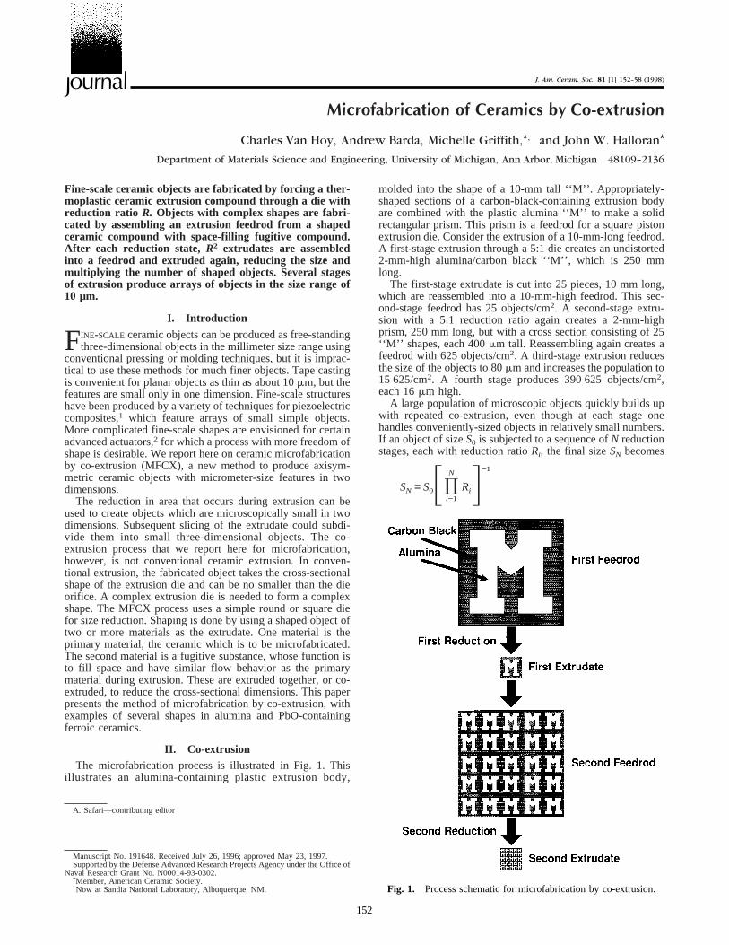
II. Co-extrusionThe microfabrication process is illustrated in Fig. 1. This
illustrates an alumina-containing plastic extrusion body,
molded into the shape of a 10-mm tall ‘‘M’’. Appropriately-shaped sections of a carbon-black-containing extrusion bodyare combined with the plastic alumina ‘‘M’’ to make a solidrectangular prism. This prism is a feedrod for a square pistonextrusion die. Consider the extrusion of a 10-mm-long feedrod.A first-stage extrusion through a 5:1 die creates an undistorted2-mm-high alumina/carbon black ‘‘M’’, which is 250 mmlong.
The first-stage extrudate is cut into 25 pieces, 10 mm long,which are reassembled into a 10-mm-high feedrod. This sec-ond-stage feedrod has 25 objects/cm2. A second-stage extru-sion with a 5:1 reduction ratio again creates a 2-mm-highprism, 250 mm long, but with a cross section consisting of 25‘‘M’’ shapes, each 400mm tall. Reassembling again creates afeedrod with 625 objects/cm2. A third-stage extrusion reducesthe size of the objects to 80mm and increases the population to15 625/cm2. A fourth stage produces 390 625 objects/cm2,each 16mm high.
A large population of microscopic objects quickly builds upwith repeated co-extrusion, even though at each stage onehandles conveniently-sized objects in relatively small numbers.If an object of sizeS0 is subjected to a sequence ofN reductionstages, each with reduction ratioRi, the final sizeSN becomes
SN = S0F)i−1
N
RiG−1
A. Safari—contributing editor
Manuscript No. 191648. Received July 26, 1996; approved May 23, 1997.Supported by the Defense Advanced Research Projects Agency under the Office of
Naval Research Grant No. N00014-93-0302.*Member, American Ceramic Society.†Now at Sandia National Laboratory, Albuquerque, NM. Fig. 1. Process schematic for microfabrication by co-extrusion.
J. Am. Ceram. Soc., 81 [1] 152–58 (1998)Journal
152

For the case where the reduction ratio is the same for all stages,this is simply
SN =S0
RN
so the size is decreased by a power law of the reduction ratioraised to the number of stages. The population of objects, ex-pressed as the number per unit cross-sectional area afterNreduction stages,PN, is
PN = P0F)i−1
N
RiG2
or if the reduction ratio is constant
PN = P0R2N
While the microfabricated objects become tiny and very nu-merous, at each stage the extrudate itself is never smaller thanS0/R, several millimeters in size. When extrudate is cut andrebundled, one handlesR2 pieces, which typically numberabout 25–36. After the last stage of reduction, the microscopicobjects are arrayed within the extrudate in a convenient formfor sintering.
The fugitive material can be any substance that extrudes welland has flow properties which can be matched with the primarymaterial, provided it can be cleanly removed after microfabri-cation. This includes materials which can be dissolved away,evaporated, or removed by reaction. Carbon black is a veryconvenient fugitive substance for materials which are sinteredin air. It is inexpensive and typically formulated to enhancedispersion in polymers. During slow heating in air, carbonblack does not appreciably oxidize until about 500°C, which isabove the temperature required for binder removal. Thus poly-mer removal and fugitive removal are conveniently separated.Under appropriate conditions, carbon black oxidation isgradual, so it need not disrupt microfabricated articles. It workswell for stable oxides like alumina. More care must be takenfor readily reduced ceramics, such as lead zirconate titanate(PZT)3, but it is possible to remove the carbon black with noapparent damage to the ceramic.
III. Experimental Procedure
The MFCX method is similar to what we have previouslyreported for producing textured ceramics.4 A thermoplastic ex-trudable mixture is made by compounding ceramic powder ina heated shear mixer.‡ Ethylene vinyl acetate (EVA)§ is meltedat 140°C in a 60 mL mixer–measuring head equipped withroller blades. Ceramic powder is gradually added, with smalladditions of methoxypolyethylene glycol¶ as a plasticizer, toyield a final composition which is 50 vol% ceramic. The com-pound is brought to a specific viscosity level around 18 mzN oftorque at 60 rpm, by adjusting the polymer/plasticizer ratio.The flow field in the torque rheometer is complex, but can beapproximately related to viscosity and shear rate.5 With ourparticular roller mixer geometry, 60 rpm corresponds to amaximum shear rate at the wall of 150 s−1, and 18 mzN oftorque implies an apparent viscosity of 3480 Pazs. The ceramicpowders include an alumina,†† a lead zirconate titanate(PZT),‡‡ and a lead magnesium niobate–lead titanate (PMN–PT).§§ The particle size of these powders is about 0.5mm. A
carbon black powder,¶¶with median particle size of 70 nm, wasused as the fugitive material. The compound was mixed twiceto improve homogeneity.
The primary and fugitive compounds are compressionmolded into suitable shapes using steel tooling at about 150°C,and assembled into a feedrod. A laboratory-scale piston-styleextruder,††† with either a 22 mm diameter cylindrical or a 25.4mm square barrel, presses the feedrod through a 60° cone in theheated extrusion die. Extrusion is typically conducted at 105°Cat a piston speed of 6 mm/min, with ram pressures around 1MPa. The extrudate is larger than the die orifice by about 3–8linear percent, due to die swell. This causes a slight distortionof the square extrudate so that it has a slightly barrel-shapedcross section. The extrudate is collected after the first extrusionpass, cut into suitable lengths, and reassembled into a feedrod.This is consolidated at 150°C by pressing at 2 mm/min to 1MPa. The reassembled feedrod is extruded a second time, andthe process is repeated for up to four stages.
The microfabricated objects are buried in powder for supportduring sintering and to slow oxygen transport to the carbon-aceous fugitive materials, and thereby avoid thermal runawayduring the exothermic oxidation. The PZT and PMN–PT areburied in a PZT packing powder before. The EVA binder isremoved with the following heating schedule in air: 5°C/min to100°C; 1°C/min to 250°C; hold 1 h; heat 1°C/min to 500°C;hold 1 h. Carbon black removal and sintering are done byheating at 5°C/min to 1600°C (for alumina), 1250°C (for PZT),or 1100°C (for PMN-PT).
IV. Results
(1) Alumina ‘‘M’’ ShapesA series of microscopic ‘‘M’’ shapes were fabricated from
alumina by MFCX. A 25.4 mm high, 50.8 mm long ‘‘M’’ wasfashioned out of the alumina/EVA compound by carving sec-tions of it by hand with a scalpel. The carbon black/EVAcompound was similarly carved to fill out the spaces in thesquare cross section. These were pressed into a 25.4 mm squarefeedrod, and extruded through a 4 mmsquare orifice. Afteraccounting for die swell, the actual reduction ratio wasR 45.5. Figure 2(A) shows the 4.8 mm high ‘‘M’’ in the green stateafter the first reduction stage. The first-stage extrudate wassurrounded by 10 mm thick slabs of the carbon black com-pound and extruded for a second stage. Figure 2(B) shows an840 mm tall ‘‘M’’ after two reduction passes. A third stagefeedrod was made by assembling 25 sections and reduced in athird stage to produce an array of 25 ‘‘M’’s, each about 150mm high, shown in Fig. 2(C). A fourth stage of assembling andreduction produced an array of 625 ‘‘M’’s, each about 27mmhigh. These four stages of reduction atR4 5.5 had reduced thesize of the objects by a factor of 915 times, without significantdistortion of the shape.
The extrudate was sliced into 2 mm thick sections beforesintering. Figure 3(A) shows four of the objects after the 500°Cbinder removal treatment. Much of the carbon black fugitivematerial remains, although the carbon immediately adjacent tothe alumina has been removed. Sintering at 1600°C produces adense sintered ‘‘M’’, about 18mm high, shown in Fig. 3(B).This object has been overfired, so excessive grain growth limitsthe resolution of the shape. The sintered objects were about 2mm long by 18mm high, looking rather like white whiskers inthe optical microscope.
(2) PZT ArrayA PZT–thermoplastic compound was prepared at 50 vol%
ceramic loading as described above. The PZT–plastic com-‡Plasti-Corder PL 2100 Electronic Torque Rheometer, C. W. Brabender, South
Hackensack, NJ.§ELVAX 470, E. I. DuPont Co., Wilmington, DE.¶Carbowax MPEG 550, Union Carbide Corp., Danbury, CT.††Reynolds RC-HP-DBM, Reynolds Metal Co., Bauxite, AK.‡‡EC-76, EDO Western, Salt Lake City, UT.§§AVX Ceramics Corp., Myrtle Beach, SC.
¶¶Cabot Black Pearls BP 120, Cabot Corp., Boston, MA.†††Bradford Small Scale Extrusion Unit, Bradford University Research, Ltd., West
Yorkshire, U.K.
January 1998 Microfabrication of Cermaics by Co-extrusion 153

pound was formed into sheets 0.3 mm thick by pressing be-tween steel plates at 150°C. The carbon black–plastic com-pound was similarly pressed into 0.22 mm thick sheets. Thesewere cut into squares and stacked alternately. The stack waswrapped with PZT compound to form the first-stage feedrod.This was extruded through a square orifice at a reduction ratioof R 4 5.5. Figure 4 illustrates the reduction process. This is
a cross section cut through the cone area of the extrusion rod,showing the PZT–carbon black laminate being reduced in size.The resultant extrudate had a 4 mmwide array of green 50mmthick PZT lines, each separated by 36mm thick carbon blackspacers, as shown in Fig. 5(A). After binder removal, carbonoxidation, and sintering at 1250°C, we obtained a free-standingarray of dense PZT ceramic sheets, which appear in cross sec-tion as lines, 40mm wide with 25–30mm spacing. The spacingvaries because, after removing the carbon, the PZT lines areunsupported during sintering, and tend to slump.
A finer structure can be produced with a second stage ofreduction withR 4 5.5, to yield a green array with green PZTlines about 7mm thick. The array had regions of good order,but also regions where the lines were distorted. These localdefects may be associated with inhomogeneities in the plasticcompound on the scale of a few micrometers. After sintering at1250°C, the array was mounted and polished, and etched toreveal the grain boundaries. Figure 6(A) shows a well-orderedregion of the array with sheets about 7mm wide. In manyplaces the line is only one grain thick, as these sintering con-ditions have produced a PZT grain size comparable to thefeature width. A distorted region is shown in Fig. 6(B), whereadjacent PZT lines have come into contact with one another.
Fine lines could also be obtained from a single pass reduc-
Fig. 2. (A) 4.8 mm tall ‘‘M’’ in the green state after the first reduc-tion stage. (B) 840mm tall ‘‘M’’ in the green state after two reductionpasses. (C) An array of 25 ‘‘M’’s, each about 150mm tall.
Fig. 3. (A) Four of the third stage reduced ‘‘M’’s after the 500°Cbinder removal treatment. (B) Dense sintered ‘‘M’’, about 18mm high.
154 Journal of the American Ceramic Society—Van Hoy et al. Vol. 81, No. 1

tion with a larger reduction ratio. Figure 7 shows two greenPZT–carbon black arrays after a single pass reduction througha round die. The square laminate was placed at the center of theround feedrod, where it occupied about half of the feedrod. Theremaining volume was filled by carbon black. Although it wasa square feature passing through a round hole, the array suf-fered little radial distortion. AtR 4 10:1 the array featured 25mm PZT lines with 20mm carbon black spacers. A more ag-gressive 20:1 reduction produced 15mm PZT lines with 10mmcarbon black spacers. These underwent binder removal andcarbon black burnout to produce an undistorted bisque-firedstructure. Slumping occurred during sintering at 1250°C, how-ever, producing the distorted sintered array shown in Fig. 8.The distortion was caused by warping during sintering shrink-age, which in this case occurs for an unsupported array of thinsheets. A suitable support structure would have to be designedto maintain the geometry during densification.
(3) C-ShapesA series of ‘‘C-Block’’ actuators2 requires a linear combi-
nation of bimorphs bent in a C-shape. As a prototype for this,we fabricated the ‘‘C’’ shape from PZT and PMN–PT. A steeltool with four convex and concave undulations with a peak-to-valley amplitude of 6 mm was used to fabricate green cor-rugated shapes, 0.3 mm thick, 25.4 mm wide, and 50.8 mmlong, from both the PZT–plastic compound and the carbonblack–plastic compound. A three layer stack of PZT/carbonblack/PZT was built, and assembled with correspondinglyshaped solid carbon black–plastic compound to create afeedrod. Figure 9 shows a C-shape with one stage of reduction,after being sliced about 0.5 mm thick and sintered. The objectconsists of two parallel undulating walls, each about 50mmthick, separated by a uniform 50mm wide gap created by thecentral carbon black layer. The peak-to-valley amplitude of theundulations is about 1090mm. The PZT appears to have sin-tered to high density. Figure 10 shows the edge of anotherC-shape fabricated out of PMN–PT, with one reduction pass,after sintering at 1100°C for 1 h. It appears to be fully dense,with a grain size around 2mm. The X-ray diffraction pattern ofthe PMN–PT after extrusion, carbon removal, and sintering, isidentical to the starting powder.
(4) Interface InstabilitiesFor the alumina/EVA and PZT/EVA systems shown above,
the interface between the primary material and the carbonblack/EVA fugitive material remains planar throughout the ex-tensive flow that occurs during co-extrusion. This is necessaryfor microfabrication. Figure 11 is an example of an unstableinterface developed between PZT/EVA and a fugitive material
made from 3mm synthetic graphite powder‡‡‡ in EVA after an8:1 reduction. Jagged instabilities with an amplitude around100 mm have developed at the interface. Further instabilityduring a second stage of reduction entirely disrupted the fea-tures, creating a random assembly of PZT and graphite regions.Interfacial instabilities can also occur if the thermoplastic car-rier polymers are changed. For example, similar jagged insta-bilities, under certain conditions of temperature and composi-tion, occur with mixtures of EVA and ethylene ethylacrylate(EEA), or with incompatible plasticizers.
V. Discussion
Co-extrusion has been conducted successfully over a narrowrange of relative viscosities of the two plastic bodies, expressedas a viscosity ratio of the primary compound and the fugitivecompound. Satisfactory co-extrusion could be achieved withviscosity ratios ranging from 0.74 to 1.27. Outside of thisrange, distortions can be severe. The lower-viscosity melt has
‡‡‡HPN2 Synthetic Graphite, Dixon Ticonderoga Co., Lakehurst, NJ.
Fig. 4. Cross section of the PZT–carbon black laminate being re-duced in the cone section of the extrusion die.
Fig. 5. (A) Green array of PZT and carbon black after one stage ofreduction. (B) Sintered array of PZT lines after one stage of reductionwith R 4 6.
January 1998 Microfabrication of Cermaics by Co-extrusion 155

a tendency to flow around and encapsulate the higher-viscositymelt. It is preferred to have the lower-viscosity material incontact with the die wall. For square tooling, using carbonblack as the fugitive and alumina or PZT as the primary, thebest results were obtained when the primary material had a10–20% higher apparent viscosity.
Shape fidelity of the MFCX process is limited by distortionsof the flow field, which depends upon the rheological matchbetween the primary materials and the fugitive material, and byfriction and die swell. Under appropriate conditions, reductionsof up toR4 20 can be accomplished in a single pass with littledistortion. Up to four consecutive passes have been done withR4 5.5. It appears that the finest feature that can be fabricatedis ultimately limited by the granularity of the extrusion bodyitself, which is proportional to the largest particles in the pow-ders. The present scale is, however, somewhat larger than this,and distortions can appear at a scale of about 10mm. These maybe due to undispersed powder agglomerates or heterogeneitiesof the powder–polymer compound. Inhomogeneities on thisscale could have been responsible for the distortions of the 7mm lines seen in Fig. 6(B).
Interfacial instabilities such as those shown in Fig. 11 disrupt
microfabrication and destroy fidelity. When these occur, theycan be ameliorated by improving the viscosity match betweenthe primary and fugitive materials. According to the literatureon polymer co-extrusion,6,7 under extrusion conditions, it isalso necessary to have good adhesion between the two mate-rials being extruded. Adhesion may explain why interfacialinstabilities are observed with some combinations of thermo-plastic polymers and plasticizers.
Fig. 6. (A) Sintered array of PZT lines after two stages of reduction,in a region of good order. Polished and etched. The dark material is themounting medium. (B) Sintered array of PZT lines after two stages ofreduction, in a distorted region, illustrating defects in the PZT lines.Polished and etched. The dark material is the mounting medium.
Fig. 7. Green PZT–carbon black arrays after a single pass reductionthrough a round die at reductions of 10:1 (A), producing 25mm PZTlines with 20mm carbon black spacers, and 20:1 (B), producing 15mmPZT lines with 10mm carbon black spacers.
Fig. 8. Sintered PZT array, after 10:1 reduction, showing slumpingof unsupported PZT lines.
156 Journal of the American Ceramic Society—Van Hoy et al. Vol. 81, No. 1

The MFCX process is superficially similar to polymer co-extrusion, but the latter involves true viscous flow of moltenpolymers. A much closer analogue8 is the art glass process§§§
of millefiori, where a design is assembled from rods of coloredglass, although the size reduction occurs by drawing of theglass, rather than extrusion. Co-extrusion and co-drawing ofplastic metals may be a closer analogue. An outstanding ex-ample of this is the production of Nb–Ti superconductingwire,9 where quite elaborate arrangements of Nb–Ti rods in a
Cu matrix are reduced and drawn with great fidelity in kilo-meter lengths with ultimate reduction ratios on the order of1000. In this case the metal flows by true plastic deformation,and the two metals must have compatible plastic deformationbehavior. Apparently it is possible to obtain significant sizereductions with excellent fidelity using either viscous flow orplastic flow. The rheological behavior of our ceramic–polymercompounds have not been fully characterized, but preliminarywork10 indicates significant plastic behavior under extrusionconditions.
The MFCX process itself only produces a fine-scale greenobject. Preserving the microfabricated objects during sinteringis a challenge. Distortions during sintering are similar to con-ventional articles. An example is an array of tall fine lines,which tend to slump during sintering. Such shapes, if macro-scopic, would be fired with setters to prevent slumping. Dis-crete setters can be impractical for microfabricated objects, sosupports have to be built into the design. For example, a ‘‘win-dow frame’’ can be built around an array of lines to support itduring sintering. The relatively straight lines of Fig. 5(B) wasfrom an array with a window frame support, while the slumped§§§We thank Prof. Carlo Pantano for bringing this to our attention.
Fig. 9. Free-standing two-layer C-shape from PZT after one reduc-tion pass, after sintering at 1250°C: (A) low-magnification view show-ing shape; (B) detail of PZT walls and central space.
Fig. 10. Edge of a C-shape from PMN–PT after one reduction pass,after sintering at 1100°C, showing high sintered density.
Fig. 11. Instability at the interface between PZT primary materialand graphite fugitive material after one reduction at 8:1 ratio.
January 1998 Microfabrication of Cermaics by Co-extrusion 157

lines in Fig. 8 were in an unsupported system. Alternately, onecould incorporate a second refractory fugitive into the extru-date which could, for example, be dissolved away after sinter-ing. We are currently working on methods to avoid distortionduring sintering.
The size of the features produced by MFCX is comparable tothose produced using the ‘‘lost mold’’ technique11 which in-volves slip casting into finely patterned plastic molds producedby synchrotron radiation lithography (LIGA).12 Feature sizefrom MFCX is also comparable with those achieved by ce-ramic ‘‘micromolding’’ with photolithographically patternedpolyimide13,14 molds. These methods are comparable toMFCX, since they produce axisymmetric shapes with very finefeatures in two dimensions. However, with ‘‘lost mold’’ and‘‘micromolding’’ the fabricated object is very short (about 400mm thick for the LIGA lost mold method), since these methodsessentially create patterned surfaces on a macroscopic sub-strate. The MFCX objects are macroscopic in the axial direc-tion, as the extrudate is typically 1 m long. Small three-dimensional objects are liberated by machining away thesubstrate for LIGA lost mold or by slicing the extrudate forMFCX, with the minimum object thickness determined by themachining technique. Thicknesses in the range of several mi-crometers should be achievable.
Fine-scale structures can also be made by tape casting. Forexample, Stevensonet al.15 reported PZT elements 20mmthick produced by laminating sintered tape cast sheets. Injec-tion molding method have been developed16 capable of pro-ducing features on the order of 22mm.
VI. Conclusions
Small green ceramic objects with complex axisymmetricshapes can be fabricated by piston extrusion through simpleround or square dies. This is done using feedrods in which theprimary ceramic plastic compound has the required shape, withthe remaining space in the feedrod filled with a second fugitiveplastic material. The fugitive material is later removed. Thesize of the object decreases by the reduction ratio of the die,R.Ceramic green objects in the size range of 10–30mm can beobtained with single reductions at largeR, or repeated reduc-tions at smallR.
Carbon black, removed by oxidation, is a useful fugitive foralumina and PbO-containing ferroic oxides. Thermoplasticmixtures of carbon black in ethylene vinyl acetate (EVA) canbe co-extruded with mixtures of alumina or lead zirconate ti-tanate (PZT) in EVA. Arrays of 15mm wide green PZT lineswere fabricated with a single reduction state atR 4 20. Sin-
tered alumina ‘‘M’’ shapes, 22mm high, were fabricated withfour successive reductions atR4 5.5, for a total size reductionby a factor of 915.
Acknowledgments: We thank Professor Diann Brei for guidance onapplications and Aaron Crumm for helping with the manuscript.
References1V. F. Janas and A. Safari, ‘‘Overview of Fine-Scale Piezoelectric Ceramic/
Polymer Composite Processing,’’J. Am. Ceram. Soc.,78 [11] 2945–55 (1995).2J. D. Ervin, D. Brei, C. A. Van Hoy, J. R. Mawdsley, and J. W. Halloran,
‘‘New Fabrication Process for Active Micro-Sized Metal–Ceramic Devices’’;pp. 695–702 in Proceedings of the ASME Aerospace Division, AD-Vol. 52.Edited by C. I. Chang, J. Coulter, D. Brei, D. Martinez, W. Ng, and P. P.Friedman. American Society of Mechanical Engineers, New York, 1996.
3M. Kahn and M. Chase, ‘‘Effects of Heat Treatments on Multilayer Piezo-electric Ceramic–Air Composites,’’J. Am. Ceram. Soc.,75 [3] 649–56 (1992).
4A. Brady, G. Hilmas, and J. W. Halloran, ‘‘Forming Textured Ceramics byMultiple Coextrusion’’; pp. 321–25 in Ceramic Transactions, Vol. 51,CeramicProcessing Science and Technology.Edited by H. Hausner and G. Messing.American Ceramic Society, Westerville, OH, 1995.
5L. L. Blyler, Jr., and J. H. Daane, ‘‘An Analysis of Brabender Torque Rhe-ometer Data,’’Polym. Sci. Eng.[July] 178–81 (1967).
6S. Levy and J. F. Carley (Eds.), ‘‘Coextrusion and Dual-Extrusion Technol-ogy’’; Ch. 7 in Plastics Extrusion Technology Handbook,2nd ed. IndustrialPress, New York, 1989.
7N. Minagawa and J. C. White, ‘‘Co-extrusion of Unfilled and Titania-FilledPolyethylene: Influence of Viscosity and Die Cross Section on Interfacial Sta-bility,’’ Polym. Eng. Sci.,15 [Dec.] 825 (1975).
8A. C. Revi, Nineteenth Century Glass; pp. 94–100. Schiffler Publishing,Exton, PA, 1967.
9E. W. Collings,Applied Superconductivity, Metallurgy, and Physics of Ti-tanium Alloys,Vol. 2. Plenum Press, New York, 1986.
10D. Rucker; Ph.D. Thesis in progress. University of Michigan, Ann Arbor,MI.
11U. Bast, H. Kaarmann, K. Lubitz, M. Vogt, W. Wersing, and D. Cramer,‘‘Composite Ultrasonic Transducer and Method for Manufacturing a StructuredComposite Therefrom of Piezoelectric Ceramics,’’ U.S. Pat. No. 5 164 920,1992.
12E. W. Becker, W. Erhfeld, P. Hagmann, A. Maner, and D. Muchmeyer,‘‘Fabrication of Microstructures with High Aspect Ratios and Great StructuralHeights by Synchrotron Radiation Lithography, Gavanoforming, and PlasticMolding (LIGA Process),’’Microelectron. Eng.,4, 35–56 (1986).
13J. A. Bride, S. Baskaran, N. Taylor, J. W. Halloran, W. H. Juan, S. W.Pang, and M. O’Donnell, ‘‘Photolithographic Micromolding of Ceramics UsingPlasma Etched Polyimide Patterns,’’Appl. Phys. Lett.,63 [24] 3379–81 (1993).
14M. L. Griffith, A. Barda, N. Taylor, J. W. Halloran, W. H. Juan, and S. W.Pang, ‘‘Micromolding of Ceramics using Photolithographic Polyimide Pat-terns’’; pp. 321–25 in Ceramic Transactions, Vol. 51,Ceramic ProcessingScience and Technology.Edited by H. Hausner and G. Messing. AmericanCeramic Society, Westerville, OH, 1995.
15J. W. Stevenson, M. R. Reidmeyer, and W. Huebner, ‘‘Fabrication andCharacterization of PZT/Thermoplastic Polymer Composites for High Fre-quency Phased Linear Arrays,’’J. Am. Ceram. Soc.,77 [9] 2481–84 (1994).
16P. G. Pazol, L. J. Bowen, R. L. Gentilman, H. T. Phan, W. J. Serwatk, C. G.Oakley, and D. R. Dietz, ‘‘Ultrafine Piezoelectric Composite Materials for HighFrequency Ultrasonic Transducers’’; presented at the 1995 IEEE UltrasonicsSymposium, Seattle, WA, November 1995. h
158 Journal of the American Ceramic Society—Van Hoy et al. Vol. 81, No. 1
Copyright © 2022 FDOKUMEN