Operators Manual SET5 - glm-laser.com
192
SET5F SETSFS SET5W SET5WS Electronic Total Station OPERATOR'S MANUAL Thank you for selecting the SET5FlSET5FSISET5Wl SET5WS ElectronicTotal Station. Before using the instrument, please read this operator's manual. Verify that all equipment is included by referr~ng to "STANDARD EQUIPMENT", P168. The specifications and general appearance of the instrument may be altered at any time and may differ from those appearing in brochures and this manual. The picture on the cover and illustrations are of the SET5W. - i
-
Upload
khangminh22 -
Category
Documents
-
view
3 -
download
0
Transcript of Operators Manual SET5 - glm-laser.com

SET5F SETSFS SET5W
SET5WS Electronic Total Station
OPERATOR'S MANUAL
Thank you for selecting the SET5FlSET5FSISET5Wl SET5WS Electronic Total Station. Before using the instrument, please read this operator's manual. Verify that all equipment is included by referr~ng to "STANDARD EQUIPMENT", P168. The specifications and general appearance of the instrument may be altered at any time and may differ from those appearing in brochures and this manual. The picture on the cover and illustrations are of the SET5W.
- i

b IMPORTAMT * For lithium battery A lithium battery is used to power the SET memory. This ensures "continuous memory" so that all data IS
safe. The lithium battery contains enough power to back up the memory for up to 10 years. If the lithlum battery is completely discharged, all data will be cleared.
If the lithium battery becomes low, an error message "Backup battery low!", "RAM cleared and "Code file checksum error Code file deleted" will be displayed at power-on.
R A M c l e a r e d After that, "delete all data ?" is displayed. To download the data to
Code f i I e c h e c k s u m e r r o r
C o d e f i l e d e l e t e d 1 Data checksum e r r o r !
a personal computer, press <No> and download the data in Data memory mode. If cYes> is pressed, the data will be cleared. To replace the lithium battery, please contact your SOKKlA agent. When the battery is replaced, all data is cleared.
d e l e t e a l l d a t a ? Y e s No
For rechargeable battery The battery has not been charged at the factory. Please charge the battery fully before using, referring to "22. POWER SUPPLIES.

* For Tribrach When the new SET is shipped, the tribrach clamp is fixed with a screw. Loosen it and leave it loose. If the SET is again shipped, fix the tribrach clamp with this screw to secure the tribrach to the instrument.
/--- Tribrach clamp locking screw
b NOTE * If the display appears as at left for
P a s s w o r d = 0 0 0 some reason, please press <ESC>. The instrument returns to
(Usually this mode is not used.)
iii

Table of Contents
Table of Contents
ALWAYS FOLLOW PRECAUTIONS FOR SAFE OPERATION ...... viii
FEATURES ...................................................................................... xii
EXPLANATION OF SOFTKEYS .................................................. xiii
HOW TO USE THIS MANUAL ....................................................... xiv
Introduction
1 . PRECAUTIONS ................................................................. 3
2 . PARTS OF THE [NSTRUMENT ......................................... 4
3 . DISPLAY SYMBOLS ......................................................... 6
4 . KEY FUNCTIONS .............................................................. 7
5 . MODE DIAGRAM .......................................................... 10
Preparation for measurement
6 . MOUNTING THE BATTERY ............................................ 13
7 . SETTING UP THE INSTRUMENT ................................... 14 7.1 Centering ........................................................................ 14 7.2 Levelling ......................................................................... 16
8 . POWER ON AND PREPARATION FOR MEASUREMENT ..... 20 8.1 Power on and off ............................................................. 20 8.2 Indexing the vertical and horizontal circles ..................... 22 8.3 Focusing and target sighting ........................................... 23 8.4 Display and reticle illumination ....................................... 25 8.5 Setting the instrument options ........................................ 26

Table of Contents =-i
Table of Contents Measurement
................................................ 9 . ANGLE MEASUREMENT 33 9.1 Measure the horizontal angle between 2 points ............. 34 9.2 Set Horizontal circle to a required value ......................... 35 9.3 Horizontal angle display selection .................................. 36 9.4 Horizontal angle repetition .............................................. 37 9.5 Slope in % ..................................................................... 39
10 . DISTANCE MEASUREMENT .......................................... 40 10.1 Atmospheric correction ................................................... 41 10.2 Return signal checking ................................................... 44 10.3 Distance and angle measurement .................................. 45 10.4 Tracking measurement ................................................. 47 10.5 Review of measured data ............................................... 48
11 . COORDINATE MEASUREMENT .................................... 49 11.1 Instrument station coordinates setting ............................ 50 11.2 Target height and instrument height setting .................... 52 11.3 Azimuth angle setting ..................................................... 53 11.4 3-Dimensional coordinate measurement ........................ 56
Advanced measurement functions
12 . RESECTlON MEASUREMENT ....................................... 61
13 . MISSING LINE MEASUREMENT .................................... 66 ......... 13.1 Measuring the distance between 2 or more points 67
13.2 Changing the starting position ........................................ 69
14 . SETTING-OUT MEASUREMENT .................................... 70 14.1 Distance setting-out measurement ................................. 71 14.2 Coordinates setting-out measurement ............................ 74 14.3 REM setting-out measurement ....................................... 77
15 . OFFSET MEASUREMENT ........................................ 7 8 15.1 Distance offset ......................................................... 79 15.2 Angle offset ................................................................ 81
16 . REM MEASUREMENT .................................................. 83

Table of Contents .--
Table of Contents Using Data memory function
17 . DATA MEMORY FUNCTION ........................................... 89 .................................... 17.1 Changing the instrument options 91
................................................................... 17.2 Job selecting 92 ... 17.3 Instrument station data and Measured data recording 93
17.4 lnstrument station data and Measured data rev~ewing / deleting / outputting .................................... 101
................ 17.5 Feature code inputting / deleting / reviewing 104 ............ 17.6 Coordinate data inputting / deleting / reviewing 107
Troubleshooting
18 . ERROR MESSAGES ..................................................... 163 19 . CHECKS AND ADJUSTMENTS .................................... 1116
19.1 Plate level ...................................................................... 116 19.2 Circular level ............................................................... 118 19.3 Tilt sensor ................................................................... 119 19.4 Reticle .......................................................................... 123 19.5 Optical plummet ........................................................... 128 19.6 Distance measurement check flow chart ...................... 130 19.7 Additive distance constant ............................................ 131

Table of Contents
Table of Contents Measurement options selection
20 . CHANGING INSTRUMENT PARAMETERS ................. 135
21 . CHANGING LOCATION OF FUNCTIONS FOR KEYS ... 144 21.1 Key function allocating ............................................. 146 21.2 Registered location recalling ......................................... 151
22 . POWER SUPPLIES ..................................................... 153
23 . REFLECTING PRlSMS AND ACCESSORIES .............. 156
Appendices
Appendix 1 : Manually indexing the veslical circle by face left. face right measurements ...................... 161
Appendix 2: For distance measurement of the highest accuracy ........................................................ 162
Appendix 3: Earth-curvature and refraction correction . 164
Appendix 4: Standard accessories ................................... 165
Appendix 5: Optional accessories .................................... 166
S'ITANDARD EQUIPMENT ................................................. 168
.................................................................... MAINTENANCE 169 . . . . SPEClFlCATiONS ............................................................... 170
ATMOSPHERlC CORRECTION CHART .............................. 174
.................................................................... REGULATIONS 175

ALWAYS FOLLOW PRECAUTIONS FOR SAFE OPERATION -
For the safe use of the product and prevention of injury to operators and other persons as well as prevention of property damage, items which should be observed are indicated by an exclamation point within a triangle used with WARNING and CAUTION statements in this operator's manual.
The definitions of the indications are listed below. Be sure you understand them before reading the main text.
Definition of Indication f Ignoring this indication and making an operation
error could possibly result in death or serious injury to the operator
Ignoring this indication and making an operation 7 CAUTION error could possibly result in personal injury or prop- A erty damage
Definition of Symbols
This symbol indicates items for which caution (hazard warn- ings inclusive) is urged. Specific details are printed in or near the symbol.
This symbol indicates items which are prohibited. Specific details are printed in or near the symbol.
This symbol indicates items which must always be performed. Specific details are printed in or near the symbol.
ALWAYS FOLLOW PRECAUTIONS FOR SAFE OPERATlON
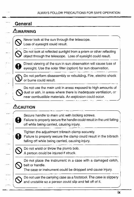
General
AWARNING Never look at the sun through the telescope. Loss of eyesight could result.
8 Do not look at reflected sunlight from a prism or other reflecting object through the telescope. Loss of eyesight could result.
Direct viewing of the sun in sun observation will cause loss of eyesight. Use the solar filter (option) for sun observation.
Do not perform disassembly or rebuilding. Fire, electric shock or burns could result.
Do not use the main unit in areas exposed to high amounts of 8 dust or ash, in areas where there is inadequate ventilation, or near combustible materials. An explosion could occur.
Secure handle to main unit with locking screws. Q Failure to properly secure the handle could result in the unit falling
off while being carried, causing injury.
Tighten the adjustment tribrach clamp securely. @ Failure to properly secure the clamp could result in the tribrach
falling off while being carried, causing injury.
8 Do not wield or throw the plumb bob. A person could be injured if struck.
Do not place the instrument in a case with a damaged catch, @ belt or handle.
The case or instrument could be dropped and cause injury.
Do not use the carrying case as a footstool. The case is slippery and unstable so a person could slip and fall off of it.

ALWAYS FOLLOW PRECAUTIONS FOR SAFE OPERATION
Power Supply
Do not use voltage other than the specified power supply voltage. \
Fire or electrical shock could result.
Use only the specified battery charger to recharge the batteries. @ Other chargers may be of different voltage rating or polarity
causing sparking which could lead to fire or burns.
Do not place articles such as clothing on the battery power @ charger while charging batteries.
Sparks could be induced leading to fire.
Do not use damaged power cords, plugs or loose outlets. Fire or electric shock could result.
Do not use batteries or the battery charger if wet. Resultant shorting could lead to fire or burns.
@ Battery BDC25A meets IPX7 specification for waterproofing (immersion-proof). But shorting could occur if the terminals become wet.
Do not use power cords other than those designated. Fire or electric shock could result.
To prevent shorting of the battery in storage, apply insulating tape or the equivalent to the battery terminals. Otherwise shorting could occur resulting in fire or burns.
Do not heat or throw batteries into fire. An explosion could occur resulting in injury.
Do not connect or disconnect power supply plugs with wet Electric shock could result.
Do not touch liquid leaking from batteries. Harmful chemicals could cause burns or blisters.

ALWAYS FOLLOW PRECAUTIONS FOR SAFE OPERATION
- 2
I When mounting the instrument to the tripod, tighten the centering \
8 screw securely. Failure to tighten the screw properly could result in the instrument falling off the tripod causing injury.
I Securely tighten the leg fixing screws of the tripod on which the I instrument is mounted. Failure to tighten the screws could result in the tripod collapsing, causing injury.
Do not carry the tripod with the tripod shoes pointed at other Q persons.
A person could be injured if struck by the tripod shoes.
Keep hands and feet away from the tripod shoes when fixing the @ tripod in the ground.
A hand or foot stab wound could occur.
Tighten the leg fixing screws securely before carrying the tripod. @ Failure to tighten the screws could lead to the tripod legs
extending, causing injury.

FEATURES -
WATERPROOF (SETSWISWS) SET WANS conforms to IP grade X7 specification for waterproofing (Immersion-proof) when the Connector caps are attached and the Battery BDC25A is mounted.
DUAL AXIS TILT SENSOR * The vertical and horizontal angle value can be
compensated. Q Vertical angle value only can be compensated.
SOFTKEYS Q All 4 function keys can be customized for your needs.
RESUME FUNCTION * The previous mode at power off is memorized for about 1
week. When the SET is switched on, the previous mode is resumed.
AVERAGE IS CALCULATED * The average of horizontal angle can be calculated and
displayed in the repetition mode. Q The average of distance can be calculated and displayed in
the average measurement mode.
ADVANCED MEASUREMENT Resection measurement Missing line measurement
* Setting-out measurement * REM measurement
DATA CAN BE STORED IN AN INTERNAL MEMORY Q 3000 point data can be stored in an internal memory.
DATA OUTPUT The SET RS-232C compatible data output connector is provided for use with a data collector or an external device.

EXPLANATION OF SOFTKEYS -
Softkeys * The bottom line of the SET display lists 4 softkeys. A softkey
is a software key; the definition of the key is shown in the bottom line of the display. Only the softkeys relevant to your current task appear. If you press the key under the displayed function, the function is performed. Up to 4 softkeys are available at a time. For example, if you press the number one left key at the following display, the horizontal angle display is been set to 0. I z A 9 0 0 0 0 0 ' -I: 1 H A R 1 2 5 " 5 6 ' 4 0 "
OSET HOLD T i l t -+P3
By pressing the key under "+PX, the next page is displayed.
"ESC" key is available in any mode. By pressing the "ESC" key, the mode is closed and the display returns to Basic mode. By pressing and holding, the power off and illumination functions are displayed.
Allocating functions for each key When SET left the factory, the location of the functions for each key were set to defaults. Any function can be allocated in any page of any mode. For a description of how to allocate functions, please refer to "21. CHANGING LOCATIONS OF FUNCTIONS FOR KEYS.
- xiii

HOW TO USE THIS MANUAL
The SET allows you to change the location of functions for each key, so it is difficult to determine on which mode and page a function is located. Therefore, in this manual, the operations are mainly explained using the default location of the functions for keys.
Typefaces are used in this manual as follows:
<Key> Indicates a keyboard key that causes an immediate action. Examples: <Sdist>, < l >, < 1 >, <Enter> .
B NOTE lndicates additional information.
b IMPORTANT lndicates important information.
b PRECAUTION lndicates precaution information.
BP EXAMPLE lndicates an operation example.
b EXPLANATION lndicates an explanation for a particular term or opera- tion.
b PROCEDURE lndicates an operation procedure.

Infroduc~LE'on
1 . PRECAUTIONS ................................................... 3
............................. 2 . PARTS OF THE INSTRUMENT 4
.................................................. KEY FUNCTIONS 7
................................................. . 5 MODE DIAGRAM 10


1. PRECAUTIONS 111
* Never place the SET directly on the ground. Avoid damaging the tripod head and centering screw with sand or dust.
Do not aim the telescope at the sun. Avoid damaging the LED of the EDM by using a solar filter when the telescope is pointed at the sun.
Protect the SET with an umbrella against direct sunlight, rain and humidity (SET FIFS).
* Handle the SET with care. Avoid heavy shocks or vibration.
* When the operator leaves the SET, the vinyl cover should be placed on the instrument.
Always switch the power off before removing the standard battery.
Remove the standard battery from the SET before putting it in the carrying case. When the SET is placed in the carrying case, follow the layout plan.
* Make sure that the inside of the carrying case and the instrument are dry before closing the case. If moisture is trapped inside the case, it may cause the instrument to rust.
PRECAUTION for SET 5Wf5WS SET WiWS conforms to IP grade X7 specification for waterproofing (Immersion-proof) only when the Connector caps are attached and the Battery BDC25A is mounted. IPX7 does not guarantee the instrument if it is used or left in water.
Degree of water resistance @ Mount the Battery BDC25A and attach the Connector caps
correctly. When remounting the battery or Connector caps, make sure water does not come in contact with the battery terminals and connectors. If moisture enters the inside of the instrument, it could damage the product.
Make sure that the inside of the carrying case and the instrument are dry before closing the case. If moisture is trapped inside the case, it may cause the instrument to rust.
* The standard or optional accessories otherwise the Battery BDC25A do not meet IPX7 specifications.
2. PARTS OF THE INSTRUMENT
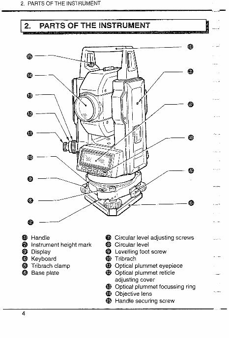
@ Handle @ Circular level adjusting screws @ Instrument height mark @ Circular level @ Display @ Levelling foot screw @ Keyboard Tribrach @ Tribrach clamp 6) Optical plummet eyepiece @ Base plate @ Optical plummet reticle
adjusting cover @ Optical plummet focussing ring @ Objective lens @ Handle securing screw

2. PARTS OF THE INSTRUMENT 111.
@ Tubular compass slot @ External power source @ Battery connector l Connector cap 8 Horizontal clamp @ Plate level (D Horizontal fine motion screw @ Plate level adjusting screw @ Data output connector / @ Vertical clamp
Connector cap @ Vertical fine motion screw @ Telescope eyepiece @ Telescope focusing ring @ Peep sight @ Instrument center mark -
5

3. DISPLAY SYMBOLS , rn
1 3. DISPLAY SYMBOLS
ZA : Zenith angle (Z=O) VA : Vertical angle (H=O) /
Vertical angle (H=0i90°) : Slope in O/O
HAR : Horizontal angle right HAL : Horizontal angle left HAh : Horizontal angle hold HARP : Horizontal angle repetition dHA : Horizontal angle from
setting-out data X : Tilt angle in sighting direction Y : Tilt angle in horizontal axis
direction I+ : Tilt angle compensation on
S : Slope distance : Slope in % at Missing line measurement
H : Horizontal distance V : Height difference Ht. : REM value tk : Tracking measurement data - - -A: Average measurement data Stn: Instrument station coordinates P : Coordinate setting-out data N : N coordinate data E : E coordinate data Z : Z coordinate data
<Remaining battery power> (BDC25A, Temperature=25"C, EDM on)
& 3 : 90t0 100% &2 :50 to 90% h l : lO to 50% 1 0 : Oto 10%

4. KEY FUNCTIONS -
The key functions are listed below. To use the functions marked with " * ", allocate them to the softkeys by referring to "21. CHANGING LOCATlON OF FUNCTlONS FOR KEYS.
General <ESC>: Transfer to Angle & Distance measurement mode While holding <ESC>, <ILLUM>
: Display and reticle illumination ON/OFF While holding <ESC>, <off>: Switch the power off <THEO> : Transfer to Theodolite mode <EDM> : Transfer to EDM mode <S-O> : Transfer to S-0 mode <GONF> : Transfer to Setting mode -PX> : Go to next page <--->* : No function
<ILLUM> : Display and reticle illumination ON/OFF <Enter> : Memorize the selected data <Exit> : Exit from each mode <CE> : Return to previous display <EDIT> : Edit the data <Input> : Change the displayed data <Clear> : Set the data to 0 <off> : Switch the power off <REG>* : Record Instrument station data and Measured data <1> : Move to previous option 1 Count up (*') ..: 1 > : Move to next option / Count down (*I)
< - F Z : Move to right option / Go to the next column (*') <1> : Select the number 1 <2> : Select the number 2 <3> : Select the number 3
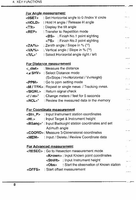
4. KEY FUNCTIONS - For Anale measurement <OSET> : Set Horizontal angle to 0 /Index V circle <HOLD> : Hold H angle / Release H angle <Tilt> : Display the tilt angle <REP> : Transfer to Repetition mode
<BS> : Finish No.$ point sighting <FS> : Finish No.2 point sighting
<ZA/Yo> : Zenith angle 1 Slope in % (*') <VAla/o> : Vertical angle / Slope in % (*') <RlL>* : Select Horizontal angle right / left
For Distance measurement <-dist> : Measure the distance <A SHV> : Select Distance mode
(S=Slope / H=Horizontal / V=Height) <BPM> : Go to ppm setting mode <M I TRK> : Repeat or single meas. /Tracking meas. <SIGNL> : Return signal check <f I m>* : Change meters /feet for 5 seconds <RCL>* : Review the measured data in the memory
For Coordinate measurement <Stn-P> : lnput lnstrument station coordinates <Ht.> : lnput Target & lnstrument height <BSang>* : lnput Backsight station coordinates and set
Azimuth angle <COORD> : Measure 3-Dimensional coordinates <MEM> : lnput / Delete / Review Coordinate data
For Advanced measurement <RESEC> : Go to Resection measurement mode
<Known> : lnput Known point coordinates <StnHt> : lnput lnstrument height <Obs> : Start the observation of Known station
<OFFS> : Start offset measurement

4. KEY FUNCTIONS - <MLM> : Start Missing line measurement
<S / %> : Slope in % between 2 points <Move> : Change the starting position
<REM> : Start Remote elevation measurement <S-0-D> : lnput Distance setting-out data <S-0-P> : lnput Coordinates of point to be set out <S03h)> : Start 3-dimension setting-out measurement <SO-Xd>* : Start Distance setting-out measurement <SO.-HA>*: Start H angle setting-out measurement
b NOTE After performing these function, the display returns to the I st page of the previous mode and the H angle and V angle are displayed.
) : When c T > , c c > or c-,> is held down, scrolling of the selected function is performed.
(*" : "ZA/%" is displayed when parameter "V angle format" is set to "Zenith 0". "VA/%" is displayed when parameter "V angle format" is set to "Horizontal 0 or "Horizontal +90°".

5. MODE DIAGRAM - 1 5. MODE DIAGRAM I
Basic mode / EDM THE0 S - 0 CONF 1
cCONF> Setting mode I 1 . C o n f i a u r a t i o n
Y 2 . T i I t c o r r e c t i o n 3 . K e y s e l e c t
Distance measurement = Atmospheric correction 0 Tracking measurement * Return signal checking * REM measurement * Offset measurement
0 Horizontal angle 0 set Horizontal angle hold Tilt angle display
* Repetition measurement Slope in % Horizontal angle rightlleft
Coordinate measurement * Setting-out measurement
Resection measurement
* Parameter setting T i l t sensor adjusting
Key function allocating
Press ESC key to go to Basic mode from every mode.
This location of the functions for keys is the default setting. To use other functions, allocate them by referring to "21. CHANGING LOCATION OF FUNCTIONS FOR KEYS.

Preparatcisn for measuwment
7 . SEIBllNG UP THE lNSTRUMENT ....................... '84 7.1 Centering ...................................................................... 14 7.2 Levelling ........................................................................... 16
8 . POWER ON AND PREPARATlON FOR MEASUREMENT ..... 20 8.1 Power on and off ............................................................ 20 8.2 Indexing the vertical and horizontal circles ...................... 22
............................................ 8.3 Focusing and target sighting 23 8.4 Display and rettcle illumination ........................................ 25 8.5 Setting the Instrument opt~ons ......................................... 26 kb EXPLANATION Automatic tilt angle compensation ......... 27 b EXPLANATION Horizontal angle back-up ....................... 27 b EXPLANATION Resume function .................................... 28 b EXPLANATlON Parallax .................................................. 28 P EXPLANATION Power-saving cut-off .............................. 28 B EXPLANATION Levelling using the tilt angle display ...... 28


6. MOUNTING THE BATTERY -..
* Charge the battery fully before measurement.
b NOTE Switch off the power before replacing the battery.
b PROCEDURE Mounting the battery
Battery release cover 1. Close the battery release cover. Release button
2. Match the battery guide with the Gu~de p ~ n hole in the instrument battery
recess.
3. Press the top of the battery until a click is heard.
Removing the battery
@Open the battery release cover 1. Open the battery release cover.
2. Press the release button downward.
3. Remove the battery.
@Press the release button downward
If the power is to be switched on immediately after replacing the battery, please refer to "8.1 Power on and off".

7.1 Centring -
* Mount the battery in the instrument before performing this operation, because the instrument will tilt slightly if the battery is mounted after levelling.
7.1 Centering
b PROCEDURE @ Level -
1. Make sure the legs are spaced at equal intervals and the head is approximately level.
a1 2. Set the tripod so that the head clng is positioned over the surveying
point.
3. Make sure the tripod shoes are @ Survey point firmly fixed in the ground.
Install the instrument
4. Place the instrument on the tripod head.
5. Supporting it with one hand, tighten the centering screw on the bottom of the unit to make sure it is secured to the tripod.
Centering screw

7. SETTING UP THE INSTRUMENT ...I
Focus on the surveying point
Focus on the reticle Ihl f I n
@ Focus on the surveying point
6. Looking through the optical plummet eyepiece @, turn the optical plummet eyepiece to focus on the reticle.
7. Turn the optical plummet focusing ring @to focus on the surveying point.

7.2 Levelling
7.2 Levelling
b PROCEDURE Center the surveying point in the reticle
1. Adjust the levelling foot screws @to center the surveying point in the optical plummet reticle.
Center the bubble in the circular level Adjust
2. Observe the off-center direction of the bubble in the circular level @, and shorten the nearest tripod leg, or extend the leg farthest from the direction to center the bubble.
3. One more tripod leg must be adjusted to center the bubble.
Center the bubble in the plate level
C 4. Loosen the horizontal clamp @ to turn the upper part of the instrument until the plate level @ is parallel to a line between levelling foot screws A and B.
A 5. Center the air bubble, using
levelling foot screws A and B.
The bubble moves towards a Bubble movement clockwise rotated levelling foot
screw.

7. SETTING UP THE INSTRUMENT m
Turn 90' and center the bubble
C 6. Turn the upper part of the Instrument though 90". The plate level IS now perpendicular to a line between levelling foot screws A and B.
B 7. Center the air bubble, using levelling foot screw C.
Turn another 90' and check bubble position
C 8. Turn the upper part of the instrument a further 90" and check to see if the bubble is in the center of the plate level.
If the bubble is off-center,
A B perform the following:
a Adjust levelling foot screws A and B in equal and opposite directions to remove half of the bubble displacement.
@ Turn the upper part a further 90°, and use levelling foot screw C to remove half of the displacement in this direction.
Or try the adjustment described in "19.1 Plate level".

7.2 Levelling - Check to see if bubble is in same position in any direction
9. Turn the instrument and check to see if the air bubble is in the same position for any position of the upper part. If it is not, repeat the levelling procedure.
Center the SET over the Surveying point SET5F15W
10. Loosen the centering screw slightly.
11. Looking through the optical plummet eyepiece, slide the instrument over the tripod head until the surveying point is exactly centered in the reticle.
12. Retighten the centering screw securely.
13. Check again to make sure the bubble in the plate level is centered. If not, repeat the procedures starting from step 4.

7. SETTING UP THE INSTRUMENT - Center the SET over the Surveying point SETSFSAWS
10. Turn the tribrach shifting clamp counterclockwise. Shifting tribrach can be adjusted up to +8mm.
11. Looking through the optical plummet eyepiece, adjust the instrument position on the tribrach to center the surveying point.
12. Tighten the shifting clamp to fix the instrument in the center position.

8.1 Power on and off -
The following preparations are required for measurement.
8.1 Power on and off 8.2 Indexing the vertical and horizontal circles 8.3 Focusing and target sighting 8.4 Display and reticle illumination 8.5 Setting the instrument options
8.1 Power on and off
B PROCEDURE Power on and off
Press any one of the 5 keys When the power is switched on,
(- o E ~ ) a self-check is run to make sure the instrument is operating normally. After that, the display indicates that the instrument is
H A R 0 S E T ready for vertical and horizontal circle indexing.
0
If this error message is T ~ l t o u t o f r a n g e displayed, the instrument tilt sensor is indicating that the instrument is off-level.
X: T~lt angle In the sightlng derection Relevel the instrument (Xlce Y: Tllt angle In the horizontal axis again until 4 is displayed.
derection To switch the power off, while holding <ESC>, press <off>.
T i t angle compensation" b EXPLANATION Automatic tilt angle compensation, on P.27

8. POWER ON AND PREPARATION FOR MEASUREMENT - b NOTE lnstrument parameter "Tilt correction" (refer to chapter 20)
Parameter "Tilt correction" can be used to switch off and on the automatic tilt angle compensation; for example, it should be switched off if the display is unsteady due to vibration or strong wind.
When all data has been cleared R A M C l e a r e d from the memory, the display
appears as at left. After that the instrument is ready for vertical and horizontal circle indexing. I;:.l When " V 1 is displayed for the vertical angle, please refer to "Appendix1 : Manually indexing the vertical circle".
When the parameter "H indexing" is set to 'Manual", " 0 is displayed for the horizontal angle.
If the battery is at the "low" level, the message "Battery is low !" will be displayed. Switch the power off and charge the battery.
B NOTE lnstrument parameter "V indexing" (refer to chapter 20) Parameter "V indexing" can change the vertical indexing method. Options are indexed by transitting the telescope or indexing by face left, face right sightings.
B+ NOTE lnstrument parameter "H indexing" (refer to chapter 20) Parameter "H indexing" can be used to change the horizontal circle indexing method. Options are indexed by rotating the upper part or indexing and zero setting at power-on.
"Horizontal angle back-up" b EXPLANATION Horizontal angle back-up, on P.27
8.1 Indexing the vertical and horizontal circles
8.2 Indexing the vertical and horizontal circles
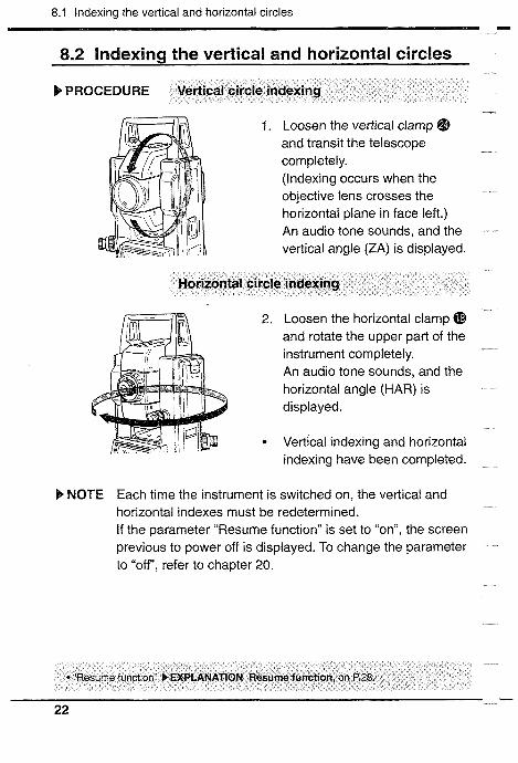
b PROCEDURE Vertical circle indexing
1. Loosen the vertical clamp @ and transit the telescope completely. (Indexing occurs when the objective lens crosses the horizontal plane in face left.) An audio tone sounds, and the vertical angle (ZA) is displayed.
Horizontal circle indexing
2. Loosen the hor~zontal clamp @ and rotate the upper part of the Instrument completely. An aud~o tone sounds, and the hor~zontal angle (HAR) IS
d~splayed.
* Vertlcal ~ndex~ng and hor~zontal lndexlng have been completed.
b NOTE Each time the instrument is switched on, the vertical and horizontal indexes must be redetermined. If the parameter "Resume function" is set to "on", the screen previous to power off is displayed. To change the parameter to "off, refer to chapter 20.
"Resume funct~on" b EXPLANATION Resume function, on P.28.

8. POWER ON AND PREPARATION FOR MEASUREMENT .-.)
8.3 Focusing and target sighting
b PROCEDURE Focus on the reticle
1. Look through the telescope eyepiece @ at a bright and featureless background.
2. Turn the eyepiece clockwise, then counterclockwise little by little until just before the reticle image becomes focused.
Using these procedures, frequent reticle refocusing is not necessary, since your eye is focused at infinity.
Sight the target
3. Loosen the vertical @ and horizontal @ clamps, and use the peep sight @ to bring the target into the field of view. Tighten both clamps.
Focus on the target
4. Turn the telescope focusing ring @4 to focus on the target.
5. Turn the vertical @ and horizontal @ fine motion screws
<Target center> <Prism center> to align the target with the reticle.

8.3 Focusing and target sighting I
The last adjustment of each fine motion screw should be in the clockwise direction.
Readjust the focus until there is no parallax
6. Readjust the focus with the focusing ring @ until there is no parallax between the target image and the reticle.
b NOTE Observe to the same point of the reticle when the telescope face is changed.
"There is no parallax" F EXPLANATION Parallax, on P28.
8. POWER ON AND PREPARATION FOR MEASUREMENT
8.4 Dis~lav and reticle! illlumination
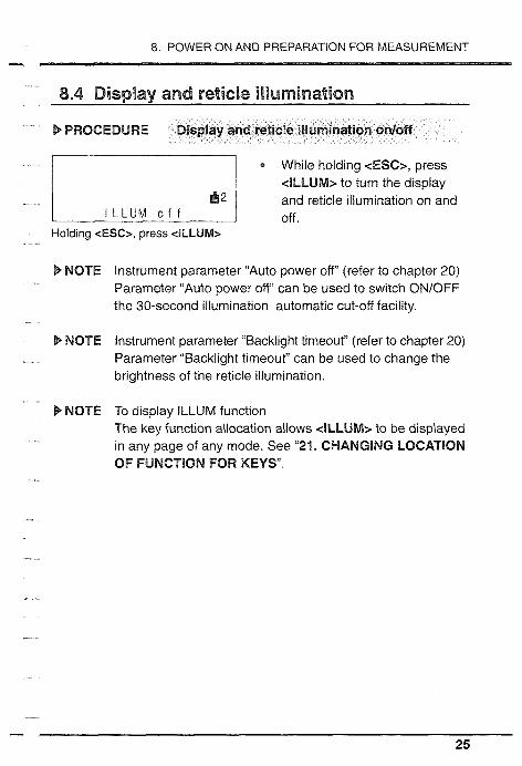
b PROCEDURE Display and reticle illumination onloff
While holding 6ESC>, press <ILLUM> to turn the display and reticle illumination on and off.
Holding <ESC>, press <ILLUM>
B- NOTE lnstrument parameter "Auto power off (refer to chapter 20) Parameter "Auto power OW' can be used to switch ON/OFF the 30-second illumination automatic cut-off facility.
b NOTE lnstrument parameter "Backlight timeout" (refer to chapter 20) Parameter "Backlight timeout" can be used to change the brightness of the reticle illumination.
b NOTE To display ILLUM function The key function allocation allows eILLUM.2 to be displayed in any page of any mode. See "21. CHANGING LOCATION OF FUMCTlQN FOR KEYS".

8.5 Setting the Instrument options - 8.5 Setting the lnslrument options
* Confirm that these parameters are set according to your measurement needs. Especially be sure to set the parameters of "EDM measurement" and "Prism constant" to your requirements. To confirm or change the parameter options, please refer to "20. CHANGING INSTRUMENT PARAMETERS".
*: Factory setting - 26

8. POWER ON AND PREPARATION FOR MEASUREMENT -.I
b EXPLANATION Automatic tilt angle compensation
* When the compensation symbol is shown on the display, the vertical and horizontal angles are automatically compensated for small tilt errors using the 2-axis tilt sensor.
* Read the compensated angles after the displayed angle values become steady.
* The formula used for calculation of the compensation value applied to the horizontal angle uses the tilt and vertical angles as follows: Compensated horizontal angle = Measured horizontal angle +Tilt in angle YI tan (vertical angle). Therefore, when the SET is not perfectly levelled, changing the vertical angle by rotating the telescope will cause the displayed horizontal angle value to change. (The displayed horizontal angle value will not change during telescope rotation when the instrument is correctly levelled.) When the measured vertical angles are within +lo of the zenith or nadir, tilt compensation is not applied to the horizontal angle. In this situation, the displayed horizontal angle value flashes to show that the tilt compensation is not being applied.
b EXPLANATION Horizontal angle back-up
* The parameter "H circle indexing" default setting allows for the memorization of the previous horizontal 0 position at power-off for about 1 week. The horizontal left or right angle display selection is also memorized. When next switching on the SET and indexing the horizontal circle again, the horizontal angle is recovered at the previously-memorized 0 position. This feature is useful when the battery voltage becomes low during measurement or after automatic power- off has occurred. -
27

EXPLANATION
b EXPLANATION Resume function
- "Resume function" means to return to or begin again after interruptim. It means that the previous mode is recovered after switching on the SET and indexing the vertical and horizontal circles. The resume function does not work after more than 1 week (memory back-up period). In that case or when the resume function "no" IS selected, the SET returns to Theodolite mode after switching on and indexing the vertical and horizontal circles.
b EXPLANATION Parallax
0 This is the relative displacement of the target image with respect to the reticle when the observer's head is moved slightly before the eyepiece. Parallax will introduce reading errors and must be removed before observations are taken. Parallax can be removed by refocusing the reticle.
b EXPLANATION Power-saving cut-off
The SET switches off automatically 30 minutes after the last operation.
b+ NOTE Instrument parameter "Auto power cut-off' (refer to chapter 20) Parameter "Auto power cut-off' can be changed so that the SET will not switch off automatically after 30 minutes.
b EXPLANATION Levelling using the tilt angle display
For levelling, the tilt angle X and Y values can be displayed for use as a 2-axis (X,Y) tilt sensor. The measurement range is +3'.

8. POWER ON AND PREPARATION FOR MEASUREMENT - b PROCEDURE Set the telescope parallel to a line between
levelling foot screws A and B
1. Turn the upper part of the instrument until the telescope is parallel to a line between levelling foot screws A and B and tighten the horizontal clamp @.
Display the tilt angle
<Till> 2. In 2nd page of THE0 mode,
press <Tilt>. T I l t X 0" 0 1 ' 2 0 "
Y - 0 " 00'40" The X and Y tilt angles are displayed.
Set both tilt angles to 0
3. Set both tilt angles to 0" by turning the levelling screws A and B for the X direction and C for the Y direction.
4. To exit from the tilt angle display, press <Exit> to return to the previous mode or press < E X > to go to Basic mode.
b NOTE "Tilt out of range" indicates that the tilt angle exceeds the +3' measurement range.
T i l t out o f r a n g e
X - > I + y - 1 < + & 2


9 . ANGLE MEASUREMENT ....................................... 33 9.1 Measure the horizontal angle between 2 points ............. 34 9.2 Set Horizontal circle to a required value ......................... 35 9.3 Horizontal angle display selection .................................. 36 9.4 Horizontal angle repetition .............................................. 37
....................................................................... 9.5 Slope in % 39
10 . DISTANCE MEASUREMENT ............................... 40 10.1 Atmospheric correction ................................................. 41 10.2 Return signal checking ................................................. 44 10.3 Distance and angle measurement ................................ 45 10.4 Tracking measurement ............................................... 47 10.5 Review of measured data ............................................. 48
11 . COORDINATE MEASUREMENT ......................... 49 11.1 Instrument station coordinates setting .......................... 50 11.2 Target height and instrument height setting .................. 52 11.3 Azimuth angle setting .................................................... 53 11.4 3-Dimensional coordinate measurement ...................... 56


9. ANGLE MEASUREMENT
) 9. ANGLE MEASUREMENT
a The following functions are available for angle measurement.
9.1 Measure the horizontal angle between 2 points (Horizontal angle 0)
9.2 Set Horizontal circle to a required value (Horizontal angle hold)
9.3 Horizontal angle display selection (Right / left) 9.4 Horizontal angle repetition 9.5 S l o ~ e in %
b NOTE Check before Angle measurement:
1. The SET is set up correctly over the surveying point. 2. The remaining battery power is adequate. 3. The V and H circles have been indexed. 4. The instrument parameters have been set.
b NOTE Vertical and Horizontal angle recording The key function allocation allows <REG> to be displayed in any page of any mode. By using this function after angle measurement, SET can store the data into the memory. See "21. CHANGING LOCATION OF FsJNCTlONS FOR KEYS" and "17. DAW MEMORY FUNCTION".

9.1 Measure the horizontal angle between 2 points (H angle 0)
9.1 Measure the horizontal angle between 2 points (H angle 0)
* To measure the angle between 2 points, the horizontal circle can be set to 0 at any direction.
b PROCEDURE Horizontal angle 0 set
In 2nd page of THEO mode
H A R 3 5 0 ° 3 8 ' 1 0 " O S E T H O L D T i l t --P3
Press <OSET> to set the horizontal angle to zero.
b EXAMPLE Measure the horizontal angle between 2 points
First target 1. Using horizontal clamp @ and fine motion screw @, sight the first target as at left.
Station
<OSET> 2. In THE0 mode, press <OSET>.
The horizontal angle display has been set to "0°" as at left.
Second target 3. Sight the second target.
The displayed horizontal angle is the angle between the 2 points.

9. ANGLE MEASUREMENT -.I
9.2 Set Horizontal circle to a required value
You can set the horizontal circle of the target direction to a required value.
b PROCEDURE Horizontal angle hold / release
2nd a e of THEO mode In 2nd page of THEO mode
H A R 3 5 0 ° 3 8 ' 1 0 " OSET H O L D T I l t -+3
<HOLD> 1. Press <HOLD> to set the requ~red horizontal angle value.
H A h 3 5 0 ° 3 8 ' 1 0 " 2. Press <HOLD> again to cancel OSET H O L D T I l t -.P3 the entered horizontal angle.
<HOLD>
b EXAMPLE Set Horizontal circle to a required value.
1. In THEO mode, use the horizontal clamp @ and fine motion screw @ to turn the theodolite until a required value is shown on the display.
I 1 The value entered becomes the horizontal angle Sight the reference target, <HOLD>
2. Press <HOLD> to set the horizontal angle.
The display on the left shows the horizontal angle for the target set to a required value.
3. Sight the reference target and press <HOLD> again to release the setting.
35

9.3 Horizontal angle display selection (Right / left)
9.3 Horizontal angle display selection (Right / left)
b PROCEDURE Horizontal angle right / left
3nd page of THEO mode
R E P Z A l % R I L - + P I < WL>
3nd page of THEO mode
In 3rd page of THEO mode
* Press cWL> to select horizontal angle left.
* Press <R/L> to select horizontal angle right.
Z A " 2 0 2 1 2 0 ~ -;; 1 H A L 2 7 0 " 0 0 ' 0 0 "
R E P Z A l % R I L +P1 <R/L>
9. ANGLE MEASUREMENT
9.4 Horizontal angle repetition
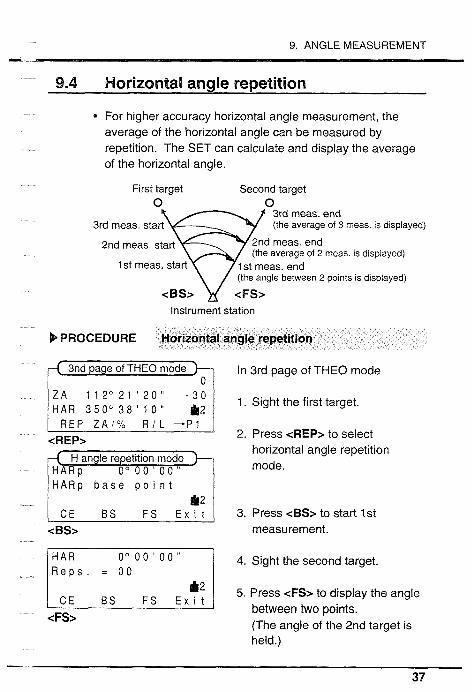
* For higher accuracy horizontal angle measurement, the average of the horizontal angle can be measured by repetition. The SET can calculate and display the average of the horizontal angle.
First target Second target 0
3rd meas. end 3rd meas. start (the average of 3 meas IS displayed)
2nd meas. end (the average of 2 meas IS d~splayed)
1 st meas, start 1 st meas. end (the angle between 2 polnts 1s d~splayed)
Instrument station
b PROCEDURE Horizontal angle repetition
3nd page of THEO mode
Z A 1 1 2 ~ 2 1 2 0 ' -:: 1 HAR 3 5 0 ° 3 8 ' 1 0 " REP Z A / % RIL --PI
<REP>
0" 0 0 ' 0 0 " H A R P b a s e potnt
C E B S FS Ext t <BS>
In 3rd page of THEO mode
1. Sight the first target.
2. Press <REP> to select horizontal angle repetition mode.
3. Press <BS> to start 1st measurement.
4. Sight the second target.
5. Press <FS> to display the angle between two points. (The angle of the 2nd target is held.)

9.4 Horizontal angle repetit~on u-.
6. Sight the first target again.
1 4 0 " 00'00" C E BS F S E x i t
<BS> 7. Press <BS> to release horizontal angle hold and begin second measurement.
0" 00'00" El 8. Sight the second target again.
9. Press <FS> to display the <FS> average of the 2 measurements
at the 3rd line. (The angle of the 2nd target is held.)
To continue the measurement, repeat steps 6 to 9.
10. Press <EXIT> to end horizontal angle repetition mode.
In Repetition mode, the displayed horizontal angle is not corrected by the tilt sensor.
* When the data output is requested by an external device in H angle repetition mode, H angle from 0°, which is determined before selecting H angle repetition mode, is output. The average of measurements is not output.
0 Number of measurements: Up to 10 times. Repetition display range: +359g0 59' 59" To previous measurement: cCE> Exit from the mode: <Exit>

9. ANGLE MEASUREMENT -..
9.5 Slope in %
The SET can display the slope in %.
b PROCEDURE Slope in %
In 3rd page of THEO mode
* Press cZA/O/o> to display Slope R E P Z A / % R I L -+I in %.
Press cZA/Yo> to display
- 0 . 4 0 2 % Vertical angle. H A R 0 ° 0 0 ' 0 0 "
R E P Z A / % R I L - - P I
Display range: Less than rt1000% 0 cZA/Yo> is displayed when parameter "V angle format" is set
to "Zenith 0"". <ZA/%> is displayed when parameter "V angle format" is set to "Horizontal 0"" or "Horizontal 1.90"".

10.1 Atmospheric correction -
The following preparations are required for Distance measurement. 10.1 Atmospheric correction 10.2 Return signal checking
The distance is measured according to the parameter "EDM measurement" (the measurement mode) which you selected in "8.5 Setting the Instrument options". Refer to chapter 20 to change the measurement mode.
When the data output is requested by an external device in Average measurement mode, the data is output the selected number of times.
b NOTE Slope distance recording The key function allocation allows <REC> to be displayed in any page of any mode. By using this function after distance measurement, the SET can store the data into the memory. See "21. CHANGING LOCATION OF FUNCTIONS FOR KEYS and "17. DATA MEMORY FUNCTION.
b NOTE Change feet 1 meter The key function allocation allows <flm> to be displayed in any page of any mode. Press <f/m> to change the distance unit for 5 seconds. See "21. CHANGING LOCATION OF FUNCTIONS FOR KEYS.
10. DISTANCE MEASUREMENT - 10.1 Atmospheric correction
The atmospheric correction is necessary for accurate distance measurement, because the velocity of light in air is affected by the temperature and atmospheric pressure. The SET is designed so that the correction factor is 0 ppm for a temperature of 15°C (59°F) and an atmospheric pressure of 1013hPa (29.9 inchHg).
b NOTE To obtain the average refractive index of the air throughout the measured light path, you should use the average atmospheric pressure and temperature. Take care when calculating the correction factor in mountainous terrain. Refer to "Appendix 2 .
By inputting the temperature and pressure values, the correction value is calculated and set into the memory. The formula used is as follows:
If the atmospheric correction is not required, set the ppm value to 0.
* To input ppm value, read the correction factor from the table in "ATMOSPHERIC CORRECTION CHART.

10.1 Atmospheric correction
B EXAMPLE Reading the correction factor from the table
Temperature = 25°C Pressure = 1000hPa --The correction value is
B PROCEDURE ppm setting mode
In 2nd page of EDM mode Atmospheric correction value Prism constant correction value
I P p M S 'GNL- 'P3 1.Press~PPM>togotopprn <PPnm> setting mode.
- Press <I> to cancel set up of ppm input and return to EDM mode.
2. Press <2> to set up temperature and pressure input.
Temp & P r e s s 3 p p m value 111.1 .211 18311
<2>

10. DISTANCE MEASUREMENT -L
3. lnput Temperature using < $ > (count up) < , > (count down),
P . 1 ' 0 1 3 h P a and press <Enter>. (To move
4. lnput Pressure.
/2 Bsl$ll1 1811M a+H E n t e r
5. Press <Enter> to set Pressure (EDM mode).
the column, press <-+>.)
Temperature input range: -30 to 60'C Least input: 1 "C Pressure input range: 500 to 1400hPa Least input: 1 hPa Exit from pprn mode: <ESC> (To Basic mode)
6. Press <3> to set up correction value input.
r < --, + 0 i.3;: 7. Input the ppm value using < t >
(count up) < $ > (count down), and press <Enter>. (To move
<Enter> the column, press <-+>.)
pprn input range: -499 to 499ppm pprn Least input: 1 pprn Exit from pprn mode: <ESC> (To Basic mode)

10.2 Return signal checking
10.2 Return signall checking
Especially for long distances, it is useful to check that the returned signal is adequate for measurement.
b PROCEDURE Return signal checking
2nd page of EDM mode
< F i n e ave rage > - 3 0
<SIGNL> n signal checking mode
< F i n e ave rage > - 3 0 R e t u r n signal...- 1 2
<Exit> or <-dist>
In 2nd page of EDM mode
1. Sight the center of the target with the telescope.
2. Press <SIGNL> to go to Return signal checking mode.
" " : No return signal " 7, '6 111- , BM-", i'B1llm-",
: Adequate for measurement " I I " : Return signal is too strong
2. Press <Exit> to quit Checking mode or press <-disb to start the distance measurement.

10. DISTANCE MEASUREMENT - 10.3 Distance and angle measurement
b NOTE Check before Distance measurement: 1. The SET is set up correctly over the surveying point. 2. The remaining battery power is adequate. 3. The V and H circles have been indexed. 4. The instrument parameters have been set. 5. The atmospheric correction is set. 6. The center of the target is correctly sighted.
b PROCEDURE S N N selection and Distance meas.
--( 1 st page of EDM mode )-- S d i s t 1 3 < F i n e a v e r a g e > - 3 0
1 2 l ~ d i s t ASHV T H E O --P2 I 4sJ-m
< F ~ n e a v e r a g e > - 3 0
<-dist>
1 2 3 . 4 5 6 m
HAR 3 5 0 ° 3 8 ' 1 0 " S T O P
<STOb
In 1st page of EDM mode
1. Press <ASHV> to select slope distance, Horizontal distance and Height difference.
2. Press cdist> to start Distance measurement. The measured distance, vertical angle and horizontal angle are displayed.
3. Press <STOP> to stop the measurement.

10.3 Distance and angle measurement
b EXAMPLE Measure the horizontal distance 3 times in the fine measurement mode, and display its average
0 Confirm the following: 1. The parameter "EDM measurement" is set to "fine and
average" and "3 times". 2. In EDM mode, "Horizontal distance" is selected by
pressing cASHV>, or in THE0 mode, cHdist> is displayed.
b PROCEDURE Sight the target and start the measurement
1. Sight the target.
cHdist> 2. In the 1st page of EDM mode,
1 2 3 4 . 5 6 6 rn 8 0 " 2 1 ' 2 0 "
H A R 6 0 ° 0 0 ' 2 0 "
1 3 H d ~ s t - 3 0
..................... 1 2
I I
HAR 6 0 " 0 0 ' 2 0 "
press cHdist>.
"Hdist" flashes and the distance
After that, the horizontal distance, the vertical angle and the horizontal angle are displayed. The distance is measured 3 times.
STOP measurement is started.
After 0.4 second, the average of 3 measurements is displayed in 0.1 mm steps and the measurement is stopped. H-A: Average of H distance
In the case of the average measurement, the last-displayed horizontal distance is calculated by using the average of the selected number of measurements of the slope distance and last-measured angle. The height difference is calculated by the same way.

10. DISTANCE MEASUREMENT - 10.4 Trackina measurement
@ Tracking measurement is used for fast, non-high accuracy distance measurement. Tracking is useful when the distance to a moving reflecting prism is measured, for example, when setting-out points.
* If Tracking is selected, the distance is measured independently of parameter "EDM measurement" setting.
b PROCEDURE Tracking measurement
< F i n e a v e r a g e > - 3 0
cM/TRK>
1st page of EDM mode
< T r a c k ~ n g >
S d r s t S H V T H E 0 -+P2 c-dist>
1 1 2 ° 2 1 ' 2 0 " H A R 3 5 0 " 3 8 ' 1 0 " S T O P
<STOP>
In 2nd page of EDM mode
1. Press cM/TRK> to select Tracking measurement.
2. Sight the reflecting prism.
3. Press c-dist> to start the distance measurement.
The measured distance and vertical and horizontal angles are displayed.
4. Press <STOP> to stop the measurement.
Press <M/TRK> again to return to previous mode.

10.5 Review of measured data - 10.5 Review of measured data
The distance and angle measured most recently are stored in the memory until the power is switched off.
The stored slope distance, horizontal distance and height difference can be displayed in Recall mode as follows.
b PROCEDURE Data recall
3rd page of EDM mode In 3rd page of EDM mode
8 0 " 2 1 ' 2 0 " H A R 6 0 ° 0 0 ' 2 0 " S d i s t A S H V T H E 0 --P2
< F t n e a v e r a g e > - 3 0 1 E M M L M O F F S fi 1 1. Press <RCL> to go to Recall mode.
<RCL> The stored data measured most recently is displayed.
2. Press <ESC> to end Recall mode and go back to Basic mode.

11. COORDINATE MEASUREMENT
1 11. COORDlNATE MEASUREMENT I The SET calculates the 3-Dimensional coordinates of the prism position by inputting the instrument height, the target height and the instrument station coordinates and by measuring the slope distance, the horizontal angle and the vertical angle of the prism position.
The following preparations are required for Coordinate measurement. 11.1 lnstrument station coordinates setting 71.2 Target height and lnstrument height setting 11.3 Azimuth angle setting
The distance is measured according to the parameter "EDM measurement" (the measurement mode) which you selected in "8.5 Setting the Instrument options". Refer to chapter 20 to change the measurement mode.
b NOTE Measured Coordinate recording The key function allocation allows <REC> to be displayed on any page of any mode. By using this function after coordinate measurement, the SET can store the data into the memory. See "21. CHANGING LOCATION OF FUNCTIONS FOR KEYS and "17. DATA MEMORY FUNCTION".
11 .I lnstrument s t a t ~ o n coordinates setting --.
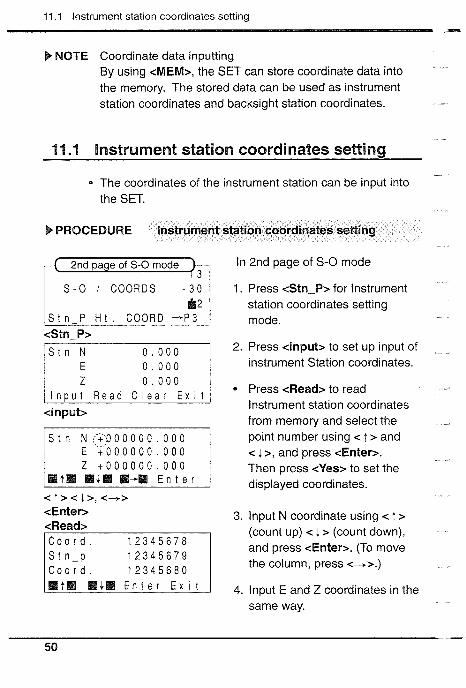
kb NOTE Coordinate data inputting By using <MEM>, the SET can store coordinate data into the memory. The stored data can be used as instrument station coordinates and backsight station coordinates.
11 .I Instrument station coordinates setting
The coordinates of the instrument station can be input into the SET.
% PROCEDURE lnstrument station coordinates setting
2nd a e of S-0 mode -!
S t n N ( ' i P O O O O O . 0 0 0 E 1 0 0 0 0 0 0 . 0 0 0 z + 0 0 0 0 0 0 . 0 0 0
B t W BI11$- M81-. E n t e r
< j > < & > , <-+> <Enter> <Read>
1 2 3 4 5 6 7 9 C o o r d . 1 2 3 4 5 6 8 0
In 2nd page of S-0 mode
1. Press <Stn-P> for lnstrument station coordinates setting mode.
2. Press <input> to set up input of instrument Station coordinates.
Press <Read> to read lnstrument station coordinates from memory and select the point number using < t > and < j. >, and press <Enter>. Then press <Yes> to set the displayed coordinates.
3. lnput N coordinate using < t > (count up) < 4 > (count down), and press <Enter>. (To move the column, press <+>.)
4. lnput E and Z coordinates in the same way.

11. COORDINATE MEASUREMENT II
Input range: -999999.999 to 999999.999m Least input: 0.001 m Retain the displayed value: <Exit> Set the value to 0: <Clear> Exit from the mode: <ESC> (To Basic mode)
If the Instrument station coordinate is not known, the "Resection measurement" can be used to determine the instrument station coordinates. See chapter 12.

11.2 Target height and lnstrument height setting - 11.2 Target height and lnstrument height setting
In preparation for Coordinate measurement, the instrument height and target height should be input to the SET before the measurement. Target height: the height difference between the
surveying point and the center of the target
lnstrument height: the height difference between the surveying point and the instrument station height mark
The heights of the instrument and target must be measured manually beforehand, using a measuring tape, etc.
b PROCEDURE Target height & Instr. height setting
In 2nd page of S-0 mode I ' - ' coo""' " i: 1 I . Press <kit.> for Target &
Stn-P Ht COORD +P3 lnstrument height setting mode.
<kit.> 2. Press <Input> to set up Target
& Instr. height settings.
<Input> 3, lnput Target height using < t >
InstrHt. t 0 0 0 0 . 0 0 0 (count up) < i > (count down), and press <Enter>. (To move the column, press <+>.)
< t > < l > , < - - t > <Enter> 4. Input Instr. height and set it in
the same way.
11. COORDINATE MEASUREMENT - Input range: -9999.999 to 9999.999m Least input: 0.001 m Retain the displayed value: <Exit> Set the value to 0: <Clear> Exit from the mode: <ESC> (To Basic mode)
11.3 Azimuth angle setting
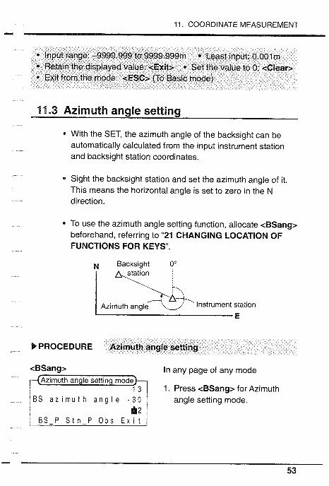
With the SET, the azimuth angle of the backsight can be automatically calculated from the input instrument station and backsight station coordinates.
* Sight the backsight station and set the azimuth angle of it. This means the horizontal angle is set to zero in the N direction.
To use the azimuth angle setting function, allocate <BSang> beforehand, referring to "21 CHANGING LOCATION OF FUNCTIONS FOR KEYS".
N Backsight Oo station
nstrument station Azimuth angle
b PROCEDURE Azimuth angle setting
<BSang> In any page of any mode
1. Press <BSang> for Azimuth BS a z ~ m u t h angle - 3 0 angle setting mode.
BS-P Stn-P O b s E x ~ t

11.3 Azimuth angle setting -
l l n p u t Read C l e a r E x i t 1
<Input>
(<Read>)
C o o r d . 12345679 C o o r d . 12345680
Press <Stn-P> if setting lnstrument station coordinates. See "11 .I lnstrument station coordinates setting".
2. Press <BS-P> for setting Backsight station coordinates
3. Press <Input> to set up coordinates input.
Press <Read> to read lnstrument station coordinates from memory and select the point number using < T > and < i >, and press <Enter>. Then press <Yes> to set the displayed coordinates.
4. lnput N coordinate using < t > (count up) < 1 > (count down), and press <Enter>. (To move the column, press <--+>.)
5. lnput E coordinate in the same way.
lnput range: -9999.999 to 9999.999m Least input: 0.001 m To previous display: <Exit> Set the value to 0: <Clear> Exit from the mode: <ESC> (To Basic mode)

11. COORDINATE MEASUREMENT -.II
6. Press <Obs> to start the observation.
B S a z ~ r n u t h a n g l e - 3 0
S t n - P O b s E x ~ t 7. Sight Backsight station.
Instrument station
1 3 8. Press <Yes> to calculate
B S o b s e r v a t i o n - 3 0 Azimuth angle.
1 st page of THE0 mode
1 2 Y e s E x i t
ZA 8 1 ° 5 9 ' 2 0 " H A R 45" 0 0 ' 0 0 " 1 2
HA!?: Azimuth angle of
<Yes> Backsight station

11.4 3-Dimensional coordinate measurement - 11.4 3-Dimensional coordinate measurement
The coordinates of the target are calculated using the following formulas and the results are then displayed. It is first necessary to input the instrument station coordinates, the instrument and target heights and to set the azimuth angle.
N1=N0+SxsinOzxcosOh El=E~+SxsinOzxsinOh Zl=Zo+Mh+SxcosOz-Ph NO: Instr. station N coord~nate S: Slope d~stance Mh: Instr. height Eo: Instr. station E coordinate 0 z: Zenith angle Ph: Target height ZO: Instr. stat~on Z coord~nate 0 h: Azimuth angle
Zenith angle, Slope distance I
i ,Target height -
Azimuth angle
b NOTE Check before Coordinate measurement: 1. The SET is set up correctly over the surveying point. 2. The remaining battery power is adequate. 3. The V and H circles have been indexed. 4. The instrument parameters have been set. 5. The atmospheric correction is set. 6. 11.1 to 11.3 have been performed.

11. COORDINATE MEASUREMENT - b PROCEDURE Coordinate measurement
Trget 1. Sight the target.
b Instrument stat~on
2nd a e of S-0 mode In 2nd page of S-0 mode r=q 2. Press <COORD> to start Coordinate measurement.
Stn P H t . COORD ->P3 <COORD>
71,. 1234.564 3. Press <STOF5 to stop the 1234.564 measurement.
STOP <STOP>
To measure the next target point, check the target height.


Advanced measurement functions
12 . RESECTION MEASUREMENT ............................ 61
63 . MISSING LINE MEASUREMENT ......................... 66 13.1 Measuring the distance between 2 or more points ....... 67 13.2 Changing the starting position ...................................... 69
14 . SETTING-OUT MEASUREMENT ......................... 70 14.1 Distance setting-out measurement ..................................... 71 14.2 Coordinates setting-out measurement .......................... 74 14.3 REM setting-out measurement ..................................... 77
15 . OFFSET MEASUREMENT ................................... 78 15.1 Distance offset ............................................................... 79 15.2 Angle offset ................................................................... 81
16 . REM MEASUREMENT ......................................... 83


12. RESECTION MEASUREMENT -
0 The "Resection measurement" is used to determine the instrument station coordinates by observing 2 or more known points.
* The SET can calculate the instrument station coordinates by observing 2 to 5 known points. To calculate the instrument station coordinates:
@ When the distance can be measured, 2 known points are required.
@ When the distance of even 1 point cannot be measured, at least 3 points are required.
The more known points that are observed and the more distances that are measured, the higher the precision of the calculation.
The calculated station point coordinates can be stored in the memory of the SET. The stored data can be used as known station coordinates. To store the calculated coordinates, see "17.3 Instrument station data and Measured data recording".
12. RESECTION MEASUREMENT
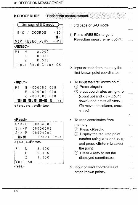
) PROCEDURE Resection measurement
3nd page of S-0 mode In 3rd page of S-0 mode
S - O I C O O R D S -;I 1. Press <RESEC> to go to
MEM R E S E C A S H V -+P2 Resection measurement point
<Input>
E t 0 0 0 0 0 0 . 0 0 0 z + 0 0 0 0 0 0 . 0 0 0
M t H M i a H-H E n t e r < ; >< 1 ><-+><Enter>
<Read> S t n - P 0 0 0 0 0 0 0 2 S t n - P 0 0 0 0 0 0 0 3 S t n - P 0 0 0 0 0 0 0 4
E n t e r E x i t < T >< 1 ><Enter>
2. lnput or read from memory the first known point coordinates.
0 To input the first known point, Press <Input>
@ lnput coordinates using < t > (count up) and < 1 > (count down), and press <Enter>. (To move the column, press <->.)
To read coordinates from memory
Press <Read>. @ Display the required point
number using < t > and < i >, and press <Enter> to select the point.
@ Press <Yes> to set the displayed coordinates.
3. lnput or read coordinates of other known points.

12. RESECTION MEASUREMENT - 4. After inputting all known points
(up to 5 points), press cobs> and start the observations.
Press <TgtHt> to input the target height.
<Sdist> or <Angle> 5. Sight the first target. When you - <STOP> measure the distance, press / s 1 4 . 5 6 7 m 1 3 1 cSdist> and <STOP>. When I Z A 8 0 ° 2 1 ' 2 0 " - 3 0 1 youdonotmeasurethe ~ H A R 60 ' 0 0 ' 2 0 ' / distance, press <Angle>.
Y e s N o
6. Press <Yes>.
7. Observe known points other than the last point. When the number of sighted known points is sufficient to calculate the instrument station, <CAL> is displayed.
8. Sight the last known point and press <CAL>. "Busy" is
6 0 " 0 0 ' 2 0 " displayed and the SET starts to Y e s N o C A L calculate the instrument station.
<CAL> When the calculation is finished, the result is displayed.

12. RESECTION MEASUREMENT - 4 When the SET cannot find the
solution of the calculation, "no solution" is displayed. You can select whether to re-observe from the first point (start point) or only the last point.
When a calculation error occurs, "Calculation error" is displayed and the screen returns to allow you to input the known point. Input known point again.
* When the number of observed points is not sufficient for calculation, ''Too few point" is displayed. Add (input) and observe more points.
9. Press <Yes> to confirm the result. Press cRec> to record the station point. Press <BS> to set the azimuth angle of the known point to the last known point.
For details about <REC>, see "17.3 Instrument station data and measured data recording".

12. RESECTION MEASUREMENT - b EXPLANATION Situation to be selected and avoided
0 The instrument station coordinates may not be calculated correctly when the instrument station and more than 3 known stations are on a single circle.
Situation to be avoided
When the known station may be on a single circle:
a Move the instrument station as close as possible to the center of the triangle.
@O @ Observe one more known
point which is not on the circle.
@ Measure the distance of at o least 1 known point.
When the included angle between the known points is too narrow or the distances between the instrument station and the known stations are too long, the SET may not be able to find the solution of the calculation.

13.1 Measur~ng the d~stance between 2 or more po~nts 1111
The missing line measurement is used to measure the slope, horizontal distances and height difference between the starting position (PI) and any other points without moving the instrument itself.
Instrument statlon
To measure the distances between the surveying points, set the reflecting prism on a fixed height object, such as a pole.
The distance is measured according to the parameter "EDM measurement" (the measurement mode) which you selected in "8.5 Setting the instrument options". Refer to chapter 20 to change the measurement mode.
13. MISSING LINE MEASUREMENT
13.1 Measuring the distance between 2 or more points
* The SET can measure the distances to many points consecutively.
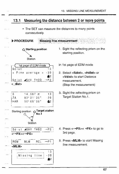
b PROCEDURE Missing line measurement
y r t i n g position
k. Station
F i e a v e r a g e > -:: 1 S d i s t A S H V T H E O + P 2
c-dist>
S 1 4 . 5 6 7 m 1 3 Z A 8 0 " 2 1 ' 2 0 " - 3 0 HAR 6 0 " 0 0 ' 2 0 " 1 2
Starting position Target station O\CP NO.,
hi Station
/ ~ d i s t A S H V T H E O --P2
<-+PX>c-.PX>
REM M L M R C L +P1
cMLM>
1. Sight the reflecting prism on the starting position.
In 1st page of EDM mode
2. Select cSdistz, cHdist> or cVdist> to start Distance measurement. (Stop the measurement)
3. Sight the reflecting prism on Target Station No.1.
4. Press c-+PX>c-.PX> to go to 3rd page.
5. Press cMLM> to start Missing line measurement.

13.1 Measuring the distance between 2 or more points
v 1 . 0 1 2 m 1 2 STOP S / % E x i t
<STOP>
1 4 . 5 6 7 m
1 . 0 1 2 m
S 1 4 . 5 6 7 m 1 3 H 2 0 . 7 5 7 m - 3 0
Slope distance, Horizontal distance and Height difference between 2 points is displayed. S: Slope distance H: Horizontal distance V: Height difference
6. Press <STOP> to stop the measurement.
Repeat the above procedures to start the next missing line measurement Exit from the missing line mode: <Exit> (To EDM mode)
Target station No.1 Startlng pos~tion 7. Sight the reflecting prism on
Target station Target station No.2. eO.* Station
* The SET can display the slope between 2 points in %.
/ M L M M e s 1 % E I t
b PROCEDURE Slope in % between 2 points
8. Press <MLM> to start Missing
1 4 . 5 6 7 m When missing line measurement 31 has finished, press <Styo> to 1 . 0 1 2 m display Slope in %.
<MLM> line measurement.
I M L M M o v e S / % E x i t 1 <styo>
Press <St%> again to display the slope distance Display range: Less than 51 00096 (Horizontal = 096)

13. MISSING LINE MEASUREMENT -Y
13.2 Changing the starting position
The last measured target station can be changed to become the next starting position.
New starting position
b PROCEDURE Changing the starting position
S 1 4 . 5 6 7 m When missing line measurement
M i s s i n g I i n e The data for the last target p o l n t r e p l a c e d - 3 0 station is set as the data for the
new starting position.
H 2 0 , 7 5 7 rn - 3 0 v 12
MLM Move S t % E x i t
New startlng posit~on (Target station No,l) 2. Sight each target station and
Starting pos~t~on press <MLM> to continue.
station Missing line measurement from the new starting position to the
Station next target stations.
MLM Move S t % E x i t
<MLM>
has finished,
1. Press <Move> to change the
<Move> starting position.

14.1 Distance setting-out measurement m
The Setting-out measurement is used to set out the required point. The difference between the previously input data to the instrument (the setting-out data) and the measured value can be displayed by measuring the horizontal angle, horizontal distance (<SO-Hd>), coordinates (<Coord>), or height (<SO-Ht>) of the sighted point.
Setting out mode (<S-O>) <3D_SQ> F <SO-Xd> Distance setting-out
<Coord> Coordinate setting-out <SO-Hb REM Setting-out
Displayed value = Difference between measured value and setting-out data
- The distance is measured according to the parameter "EDM measurement" (the measurement mode) and Tracking measurement mode selection.

14. SETTING-OUT MEASUREMENT
4.1 Distance setting-out measurement
* This measurement is used to set out the point from a reference direction and a certain distance away from the instrument station.
tion to be set out
b PROCEDURE Distance setting-out measurement
Reference direction 1. Sight the reference direction.
Instrument station
press <OSET> to set Horizontal angle to 0.
OSET HOLD T I l t -*P3 <OSET>
8 1 " 59'20" -30
Sdi s t EDM l LLUM -P2

14.1 Distance setting-out measurement
Direction to be 3. Turn the theodolite until a Reference direction Set Out required angle is shown on the
'\ display. \\\\\\.J Instrument station
cESC> 4. Press cESC> to go to Basic Basic mode mode.
o p e r a t i o n EDM THE0 S - 0 CONF
cS-O> 5. Press <S-O> go to S-0 mode. I st page of S -0 mode
S - 0 d i s t a n c e I
,2 nw--- cS-0-D> for Distance
a-v uata setting mode. istance S-0 data settingmodeh
[ l n p u t - - - C l e a r E x i t 1 <Input> 7. Input Distance S-0 data.
Press <Input> and input
+ o o o o . 0 0 0 horizontal distance S-0 data using c t > (count up) and c i >
I st a e of S -0 mode 8. Set the reflecting prism on the sighting line and sight it
H A R 45" 53 ' 2 0 " correctly.
SO-3D S -0 -P S -0 -D +P2
MSll H i l l M+E E n t e r (count down). (c-> is to go to
<1><1>and<+> next column.)
<Enter> Then press <Enter>.

14. SETTING-OUT MEASUREMENT m
Direction to be - If necessary, press <ASHV> to Reference direction Set Out select H distance mode or press
v\ <MTTRK> to select the Tracking Reflecting measurement mode. prism \ \ \ /
9. Press <SO-3D> and <SO-Hd> lnstrument station (horizontal distance setting-out)
<S0_3D> to start Distance S-0 <SO-Hd> measurement.
The difference between the setting-out data and the measured distance is displayed
Direction to be at the 1st line.
Reference direction set out '\
10. Move the reflecting prlsm
prism towards or away from the instrument until H distance
14 .567111
HAR 6 0 " 0 0 ' 2 0 "
Instrument station becomes Om to determine the 0 . 0 0 0 m point.
- data: Move away from Instr. H A R 6 0 " 0 0 ' 2 0 " + data: Move towards Instr.
1 S T O P <STOP> 11 .Press <STOP> to stop the
measurement. (1 st page of S-0 mode)
It is possible to set out a slope distance, horizontal distance, height difference value after setting the required value. When the Repeat measurement or the Tracking measurement is selected, sighting the moving reflecting prism again changes the distance without key operation.
Retain the displayed value: <Exit> (To 1st page of S-0 mode) Set the value to 0: <Clear> Input range: -9999.999 to 9999.999m Least input: 0.001 m

14.2 Coordinates setting-out measurement
14.2 Coordinates setting-out measurement
This measurement is used to set out the point of a coordinate away from the reference point (the instrument station).
After inputting the coordinates for the point to be set out, the SET calculates the sett~ng-out horizontal angle, horizontal distance and the height, and stores the values in the memory. By using cS0_3D>, the required coord~nate location can be set out.
M O0 Adistance
Backsight station Present
target posltlon Pos~tion to be set out
Instrument stat~on
b PROCEDURE Set the backsight station
1. Set the coordinates and azimuth angle of the backsight station Refer to "11.3 Azimuth angle setting".
Input instrument station and setting-out point
2. In 2nd page of S-0 mode, press
S - 0 1 COORD cStn-P> and input or read the instrument station coordinates.
cStn-P>

14. SETTING-OUT MEASUREMENT -L
3. In 1st page of S - 0 mode, press <S-0-P> and input the coordinates of the point to be set out.
4. In 2nd page of S-0 mode, press <Ht.> and input the target height and the instrument height.
Perform the H angle S-0 measurement
cS0_3D> 5. Press <S0_3D> for the S-0
Direction to be set out measurement and use the
J horizontal clamp and fine motion screw to turn the theodolite until the "dHA value becomes OOOO'OO".
Instrument station
H A R 8 7 " 3 4 ' 2 0 "
Perform the ti distance setting-out measurement
6. Set the reflecting prism on the sighting line and sight it correctly.
2.5671-11
6 0 " 0 0 ' 2 0 " STOP
7. Press <SO-Hd> to start distance setting-out measurement.
If necessary, press <ASHV> to select H distance mode before pressing cS0_3D>.

14.2 Coordinates setting-out measurement C
Direction to be
Reference direction set out
r, \ Prism '.
Instrument station
0.000rn
60" 00'20" S T O P
<STOP>
The difference between the setting-out data and the measured distance is displayed at the first line.
8. Move the reflecting prism towards or away from the instrument until the horizontal distance becomes Om to determine the distance of the point. - data: Move away from the
instrument + data: Move towards the
instrument
9. Press <STOP> to stop the measurement.
Perform height setting-out measurement
10. Press <Coord> to start height setting-out measurement
11. Move the reflecting prism up or down until the Z coordinate becomes "0.000 to determine the height of the point. - data: Move up + data: Move down
12. Press <STOP> to stop the measurement.

14. SETTING-OUT MEASUREMENT - 14.3 REM setting-out measurement
To set out the point where a target cannot be positioned, perform REM setting-out measurement. See "15. REM measurement" for details of the REM measurement.
b PROCEDURE REM setting-out measurement
1. Set the reflecting prism above or below the object and measure the target height.
2. In 2nd page of S-0 mode, press <Ht.> and input the target height and the instrument height.
3. Press <S-0-D> to input the height difference between the target and the point to be set out.
6 0 " 0 0 ' 2 0 " S T O P
8 0 " 2 1 ' 2 0 " H A R 6 0 ° 0 0 ' 2 0 "
4. Press <S0_3D> for the S-0 measurement and <SO-Ht> to start REM setting-out measurement.
5. Rotate the telescope up or down until "Ht." value becomes "0.000m". Now the telescope sight at the REM Setting-out point.
6. Press <STOP> to stop REM setting-out measurement.
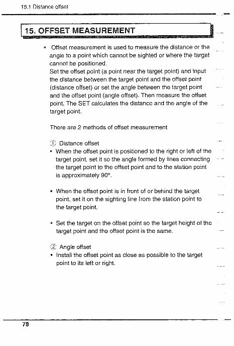
15.1 Distance offset - 1 15. OFFSET MEASUREMENT I
0 Offset measurement is used to measure the distance or the angle to a point which cannot be sighted or where the target cannot be positioned. Set the offset point (a point near the target point) and input the distance between the target point and the offset point (distance offset) or set the angle between the target point and the offset point (angle offset). Then measure the offset point. The SET calculates the distance and the angle of the target point.
There are 2 methods of offset measurement
@ Distance offset 4 When the offset point is positioned to the right or left of the
target point, set it so the angle formed by lines connecting the target point to the offset point and to the station point is approximately 90".
When the offset point is in front of or behind the target point, set it on the sighting line from the station point to the target point.
Set the target on the offset point so the target height of the target point and the offset point is the same.
@ Angle offset - Install the offset point as close as possible to the target point to its left or right.

15. OFFSET MEASUREMENT m
15.1 Distance offset
Set the offset point to the right or left of the target point so that the angle formed by lines connecting the target point to the offset point and to the station point is almost 90".
Set the offset point in front of or behind the target point, on the sighting line from the station point to the target point.
/ Target point
A Instrument station
b PROCEDURE Distance offset
<OFFS> 1. In 3rd page of EDM mode, press /of f s e t 1 3 1 <OFFS> and select <I> 1 . D 1 s t a n c e O f f s e t - 3 0 (Distance off set). 2 . A n g l e O f f s e t a 2
2. Sight the offset point.
<I > 3. Press <Sdist> and measure the
offset point. (If necessary, press eASHV> to select H distance mode.)
<Sdist> <STOP> 4. Press <STOP> to stop the
1 0 OOOm measurement. The SET displays
the distance and the angle of H A R 1 1 l o 2 0 ' 3 1 " the offset point. S d ~ s t E d ~ t OK E x ~ t (The measurement mode is set

15.1 Distance offset - to the previously measured mode. If the previous measurement mode was coordinate mode, the mode is set to the coordinate mode.)
<Edit> D i s t 1 . 0 0 0 m D i r e c t i o n h i g h t 1
l l n p u t - - - C l e a r E x i t 1 <Exit>
1 1 l o 2 0 ' 3 1 " S d i s t E d i t OK E x i t
1 0 . 0 4 9 m i 3 9 O 5 2 5 4 -1; 1
HAR 9 0 ° 1 6 ' 1 5 " 1 2 / Y e s N o R e c E x i t 1 <Yes> or <No> or <Rec>
5. Press <Edit> and input the distance between the target point and offset point. Then select the position of the offset point (right or left, in front of or behind the target point) using <+>. Press <Exit>.
6. Press <OK> to calculate the distance and the angle of the target point. The SET calculates the distance and the angle of the target point and displays them.
7. To record the calculation result (SHV or NEZ), press <REG. To confirm the result without recording, press <Yes>. To cancel the result, press <NO>.
For details about <REC>, see "17.3 Instrument station data and measured data recording".
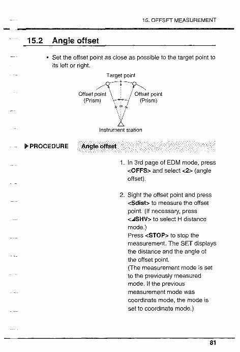
15. OFFSET MEASUREMENT
15.2 Angle offset
Set the offset point as close as possible to the target point to its left or right.
Target point
Offset (Pr~sm) point i (Pr~sm) point
A Instrument station
b PROCEDURE Angle offset
1. In 3rd page of EDM mode, press <OFFS> and select <2> (angle offset).
2. Sight the offset point and press <Sdist> to measure the offset point. (If necessary, press <ASHV> to select H distance mode.) Press <STOP> to stop the measurement. The SET displays the distance and the angle of the offset point. (The measurement mode is set to the previously measured mode. If the previous measurement mode was coordinate mode, the mode is set to coordinate mode.)

15.2 Angle offset 13
3. Sight the target point using the Horizontal clamp and the Horizontal fine motion screw.
4. Press <OK> to calculate the distance and the angle of the target point. The SET calculates the distance and the angle of the target point and displays them.
5. To record the calculation result , press <REC>. To confirm the result without recording, press <Yes>. To cancel the result, press <No>.
For details about < R E G , see ''17.3 Instrument station data and measured data recording".

16. REM MEASUREMENT -
When measuring the height of certain objects such as overhead power cables or bridge supports where the reflecting prism cannot usually be positioned, the Remote Elevation Measurement function can be used to calculate the height above the ground using a point directly above or below the object.
0 ~ 1 : Vertical angle of prism 022 : Vertical angle of object
The height of the target is calculated using the following formulas.
Ht = hi + h2 hz = S sin 0 zl x cot 0 22 - S cos 0 ZI
The measured values are first displayed after 0.7 seconds and then every 0.5 seconds for all measurement modes.
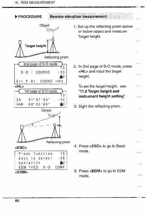
16. REM MEASUREMENT
b PROCEDURE Remote elevation measurement
Object 1. Set up the reflecting prism above k & * s e or below object and measure
Target he~ght.
2. In 2nd page of S -0 mode, press <Ht.> and input the target height.
S t n - P H i . COORD - P 3 <Ht.z To set the target height, see
"1 1.2 Target height and instrument height setting".
HAR 60" 0 3 ' 00" '* 1 3 S~ght the reflect~ng prlsm. Object
prlsm
cESC> 4. Press <ESC> to go to Baslc mode.
o p e r a t I o n EDM T H E 0 S - 0 CONF
<EDM> 5. Press <EDM> to go to EDM mode.

16. REM MEASUREMENT - 1 st page of EDM mode
< F i n e a v e r a g e > - 3 0
6. Press <Sdist>, <Hdist> or <Vdist> and measure the distance. (press <STOP>.)
Z A 8 0 ' 2 1 2 0 ' -;: 1 H A R 6 0 " 0 0 ' 2 0 "
<STOP> Object 7. Slght the object, and press kv6<@" <--+PX>ePX> to go to 3rd
page.
The object height is displayed at the first line.
1 R E M M L M OFF$ +p 1
4 . 5 6 7 m 9. Press <STOP> to stop REM.
HAR 6 0 " 0 0 ' 2 0 " STOP
8. Press &EM> to start REM
The maximum vertical angle: +89" from the horizontal line (Measuring value limit (Ht.): L-9999.999m)
&EM> measurement.


Using data memory function
................................ 17 . DATA MEMORY FUNCTION 89 ................................. 17.1 Changing the instrument options 91
17.2 Job selecting .............................................................. 92 ..... 17.3 Instrument station data and Measured data recording 93
17.4 lnstrument station data and Measured data reviewing / deleting / outputting ................................................... 101
............. 17.5 Feature code inputting / deleting / reviewing 104 ........ 17.6 Coordinate data inputting / deleting / reviewing 107


17. DATA MEMORY FUNCTION -
The SET can store data into memory. The data which can be stored are instrument station data and measured data into job files, coordinate data into internal memory and feature code into stack. The instrument station data, measured coordinate data and recorded coordinate data can be used as instrument station coordinates, backsight station coordinates, known point coordinates, and setting-out coordinates.
* Up to 3000 points can be stored for the instrument station data, measured coordinate data and recorded coordinate data.
/ Job;les (1 to 5) 1 n t y a memoly I Stack I
Read
Backsight station coordinate Known point coordinate Setting-out coordinate
* To use these functions, allocate cMEM> and cREC> beforehand, referring to chapter 20.

17.1 Changing the Instrument options
Data to be recorded in Record mode
I Stn-P I Feature code, instrument station number, instrument height, temperature, atmospheric pressure, atmospheric correction value, prism constant correction value and instrument station coordinates
/ N,E,Z (E, N, Z) I Feature code, point number, target height, N coordinate*, E coordinate* and Z coordinate*
I V,H ] Feature code, point number, target height, vertical angle* and horizontal angle*
1 S.V.H I Feature code, point number, target height, slope distance*, vertical angle* and horizontal angle*
Items with " * " cannot be input in Record mode. The feature code and instrument station coordinates can be read from the internal memory or selected job. To record the feature code, refer to "17.5 Feature code recording 1 deleting I reviewing". To record the coordinate data, please refer to "17.3 lnstrument station data and Measured data recording" and "17.6 Coordinate data inputting I deleting I reviewing".
* Memory mode menu
Job I Selecting job
I Code I Recording, deleting and reviewing feature code
Data
/ Coordinates
Outputting, reviewing and deleting the
Inputting data, deleting and reviewing
measured data stored in the job
the input data stored in the memory

17. DATA MEMORY FUNCTION
17.1 Changing the Instrument options
Confirm that these parameters are set according to the data recording conditions.
9 To confirm or change the parameter options, refer to "20. CHANGING INSTRUMENT PARAMETERS".
*: Factory setting

17.2 Job select~ng * -
17.2 Job selecting
a The SET can store the instrument station data and measured data in job files. Select the job file to which the data is to be recorded before recording the data.
b PROCEDERE Job selecting
In 3rd page of S-0 mode
1. Press cMEM> for Data memory mode.
Data memory mode ll lMemo r y 2. Press < t > or c 1 > to display
I J o b I "Job.
at. E n t e r E x i t
<Enten 3. Press <Enter> for Job selecting
Data memo mode mode. JOB S e l e c t r?aT Number of stored data
I ~ T M ~ i l s l E n t e r c I > c t > 4. Press c t > or < ! > to display the <Enter> required job name.
5. Press <Enter> to select the job name. (The display returns to Data memory mode)
Job name can be selected from 5 jobs, "JOBl", "JOBZ", "JOB3, "JOB4" and "JOB5".
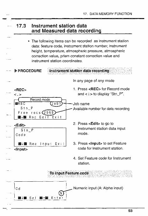
17. DATA MEMORY FUNCTION - 17.3 lnstrument station data
and Measured data recording
* The following items can be recorded as instrument station data: feature code. instrument station number, instrument height, temperature, atmospheric pressure, atmospheric correction value, prism constant correction value and instrument station coordinates.
b PROCEDURE lnstrument station data recording
In any page of any mode
1. Press cREC> for Record mode and < ! > to display "Stn-P".
Job name S t n - P Available number for data recording
<Edit> 2. Press <Edit> to go to lnstrument station data input mode.
3. Press <input> to set Feature <Input> code for Instrument station.
4. Set Feature code for lnstrument station.
To input Feature code
Numeric input (A: Alpha input)
W i l l S e l 1+1 E n t e r

17.3 Instrument station data and Measured data record~ng - I st page * Display next function: c , >
0 Display next character: <Sel> Go to next column: c-,>
2nd page Delete character at left: <BSp>
* Go to previous column: <t-> * Read Feature codes from Stack
<List> 3rd page * Toggles between alpha and
numeric input: <AIN> * Clear the code data: <Clear>
Input Feature code and press <Enter> to set Feature code.
Feature code can be up to 13 characters long * Characters allowed are "A" to "Z", "0" to "9", "-", "-", "*" and "&"
To read Feature code from Stack
"j Press <List> to read Feature codes and display the required code using < t > and c 12.
M4Ll BSp W+M L l s t <List>
Then press <Enter> to input Feature code.

17. DATA MEMORY FUNCTION rn
5. Press < i > to display lnstrument station number.
6. Press <Input> to input lnstrument station number and input lnstrument station number using < t > (count up) and < J. > (count down), then press <Enter> to set lnstrument station number.
7. Press < 4 > to display "InstrHt".
<Input> 8. Press <Input> to input < I > , <izand<-> Instrument height and input <Enter> Instrument height using < t >
(count up) and < i > (count down), then press .=Enter> to set lnstrurnent height.
lnput range: -9999.999 to 9999.999m Least input: 0.001 m
T e m p . P r e s s 1 0 1 3 h P a
MCsl R e c l n p u t Ex I t
9. Press < i > to display "Temp.", "Press." and "ppm".

17.3 Instrument station data and Measured data recording
T e m p . t 1 5 O C P r e s s l O l 3 h P a
l l f l l i 121.1111 111+111 E n t e r
10. Press <Input> to set Atmospheric correction value.
11. lnput Temperature using c t > (count up) and < J. > (count down) and press <Enter>. Then input Pressure and press <Enter> (ppm value is calculated automatically and displayed.)
If required, input ppm value and press <Enter>.
Temperature input range: -30 to 60°C Least input: 1°C Pressure input range: 500 to 1400hPa * Least input: 1 hPa ppm input range: -499 to 499ppm Least input: lppm
I Mi. R e c l n p u t ~ x i t l <Input>
12. Press c ? > to display 'PCn.
13. Press <Input> to input Prism constant correction value.
14. lnput Prism constant correction value using < t > (count up) and c l > (count down), and press <Enter> to set Prism constant correction value.
lnput range: -99 to Omm Least input: 1 mm

17. DATA MEMORY FUNCTION - < i z 15. Press < l > to display
0.000 "Stn N, E, Z .
0.000 0.000
HCa R e c l n p u t ~ x i t [ <Input> 16. Press <Input> to set Instrument
station coordinate
17. Set lnstrument station coordinate.
To input lnstrument station coordinate
S t n N t000000.000
t000000.000 M.t. M i B IB+M Ente r
< t> , <+>and<-+> <Enter>
Press <input> to set up input of lnstrument station coordinate, then input N coordinate using < t > (count up) and < i > (count down), then press <Enter> to set N coordinate. lnput E and Z coordinates in the same way.
lnput range: -999999.999 to 999999.999m * Least input 0.001 m Retain the displayed value: <Exit> Set the value to 0: <Clear> Exit from the mode: <ESC>

17.3 lnstrument station data and Measured data recording ..-
To read Instrument station coordinates
Press <Read> to read lnstrument <Read> station coordinate. C o o r d 00000001 St n-p 00001 0 0 1 Coord: Data in the memory N , E , Z , 0 0 0 1 0 0 0 1 * Stn-p: Data in the selected JOB
8 N, E, Z: Data in the selected <t>,<. I> JOB <Enter>
Display the required point number at the first line using c ! > and c t > and press <Enter>.
123456.000 displayed coordinates as 0 . 0 0 0 Instrument station coordinates.
<Yes>
Stn N 123456.000 19. Press c R e o to record lnstrument station data.
0 .000 (1st page of former mode) mi. R e c l n p u t E x i t 1 cRec>
0 After angle measurement, distance measurement or coordinate measurement, the stored data measured most recently can be recorded in the selected job.
0 The following items can be recorded: V, H: Feature code, point number, target height,
atmospheric correction value, measured vertical and horizontal angle*.

17. DATA MEMORY FUNCTION v
S, V, H: Feature code, point number, target height, atmospheric correction value, measured slope distance*, vert~cal angle and horizontal angle*.
N, E, Z: Feature code, polnt number, target height, atmospheric correction value and measured coordinates*.
Items with " * " cannot be input in Recode mode.
b PROCEDURE Measured data recording
<Rec> In anv ~ a a e of anv mode after - . - required measurement
1. Press <REG> for Record mode.
Job name Available number for data recording
<1> 2. Press < l > to display "N,E,Z", "V,Hn or "S,V,H".
Free recs 2989 1 M i a Rec E d i t E x i t 1 <Edit> 3. Press <Edit> to set Measured
point data.
4. Press <Input> to set up to input <Input> of Point number. < T >, < . > and <-*> <Enter> 5. Input Point number using < 7 >
(count up) and < i > (count down), and press <Enter> to set Point number.

17.3 Instrument statlon data and Measured data record~ng I-
[ mi. R e c l nput E x i t ( <Input>
7
/ M $ @ Sel M+H Ente r /
6. Press c 1 > to display "Code".
7. Press <Input> to set Feature code.
Display next function: <: i > Display next character: <Sel> GO to next column: <+> Delete character at left: <BSp> Go to previous column: <+> Toggles between alpha and numeric input: <A/N>
Clear the code data: <Clear>
8. Input Feature code.
9. Press <Enter> to set Feature code.
Feature code can be up to 13 characters long Feature code characters allowed are 'A" to "Z", "0" to "9" 'l", "-", "0" and "&"
Mi. R e c E x i t
JOB1 F r e e r e c s 1 2 3 4 0 0 0 0 0 0 0 1
Mi. R e c E d i t E x i t
10. Press c + > to display Measured data.
11. Press < R e o to record Measured data.
While recording the data, job name, available number and point number are displayed.
After that, the display returns to the 1 st page of former mode.
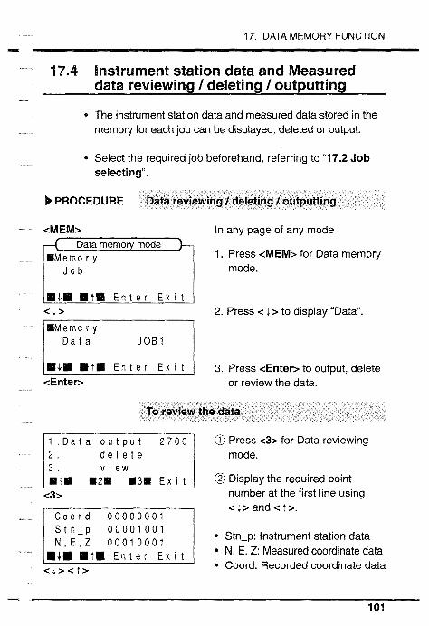
17. DATA MEMORY FUNCTION I
17.4 Instrument station data and Measured data reviewing / deleting / outputting
0 The instrument station data and measured data stored in the memory for each job can be displayed, deleted or output.
* Select the required job beforehand, referring to "17.2 Job selecting".
b PROCEDURE Data reviewing I deleting I outputting
<MEM> In any page of any mode Data memory mode
1. Press <MEM> for Data memory
I mode.
] m i l m t l Ente r Ex1 t 1 <;> 2. Press < 1 > to display "Data"
3. Press <Enter> to output, delete or review the data.
To review the data 7, @ Press <3> for Data reviewing d e l e t e mode. v i e w 1 112. .3. E~ i t I @ Display the required point
<3> number at the first line using
S t n - p 0 0 0 0 1 0 0 1 N , E , Z 0 0 0 1 0 0 0 1
MJ.. MtB Ente r E x i t
Stn-p: Instrument station data N, E, Z: Measured coordinate data Coord: Recorded coordinate data
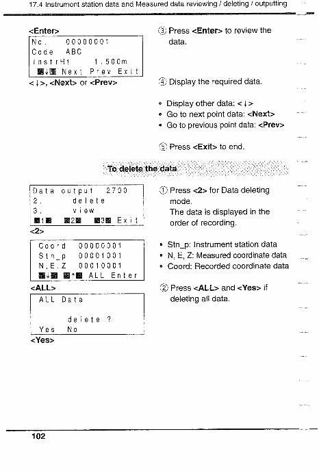
17.4 Instrument station data and Measured data rewewing / deleting / outputting - <Enter>
l n s t r H t 1 . 5 0 0 m M+M N e x t P r e v Exit
< 12, <Next> or &rev>
@ Press <Enter> to review the data.
@ Display the required data.
0 Display other data: < 1 > 0 Go to next point data: <Next>
Go to previous point data: <Prev>
@ Press <Exit> to end.
To delete the data
: a t o u t p u t 2 7 0 0 d e l e t e v i e w
m1. M2M M3H Exit <2>
Press <2> for Data deleting mode. The data is displayed in the order of recording.
Stn-p: lnstrument station data N, E, Z: Measured coordinate data Coord: Recorded coordinate data
<ALL> @ Press <ALL> and <Yes> if A L L D a t a deleting all data.
d e l e t e
<Yes>

17. DATA MEMORY FUNCTION -.-
d e l e t e ? Y e s N o
<Yes>
d e l e t e
BIB B2. B3M E x ~ t
To delete a line of data, press < ? > or < 1 > to display the point number to be deleted at the first line, and press <Enter>. Then press <Yes> to delete the displayed coordinate data.
After deleting the data, the display returns as at left.
* Exit from the mode: <ESC> (To Basic mode)
To output the data r] @ Press < I > for Data output d e l e t e mode.
B1. B2H .3. E x ~ t
@ Press <Yes> to output the data.
<Yes> 1 ~ ~ 2 3 2 ~ Output
Number of data output
d e l e t e display returns as at left.
RIM B2. 8 3 1 E x ~ t
Stop outputting: <Exit>

17.5 Feature code inputting I deleting 1 reviewing - 17.5 Feature code inputting / deleting / reviewing
The SET can input the feature codes in the memory in advance. These data can be used when recording the instrument station data and measured data.
b PROCEDURE Feature code inputting / deleting / reviewing
/H$M IBtM Ente r E x i t I < i >
In any page of any mode
1. Press <MEM> for Data memory mode.
2. Press c 1 > to display "Code".
3. Press <Enter> to input, delete or review Feature code.
4. Inputldelete/view Feature code.
To input Feature code
d e l e t e v iew
01W M2W E3. E x i t
Available number of Feature codes stored in the memory
<I> @ Press < I> for Feature code input mode.
I 1 Numeric input (A: Alpha input)

17. DATA MEMORY FUNCTION -.
I st page
/ M i l l S e l H-• E n t e r I 2nd page
I H i m B S p ll+B L i s t
3rd page . - M$m A I N C l e a r
I lli. S e l a+. E n t e r / <Enter>
1 st page Display next function: < i >
* Display next 1 character: cSelz * Go to next column: <-z
2nd page * Delete left character: <BSp>
Go to previous column: <t> 3rd page
Toggles between alpha and numeric input: <A/N>
* Clear the code data: <Clear>
@ Input Feature code.
@ Press <Enter> to set Feature code.
Feature code can be up to 13 characters long Up to 40 Feature codes can be input Characters allowed are "A" to "Z," "0" to "9," "-," "-," "0" and "&"
To delete Feature code
1 C o d e I n p u t d e l e t e
HI. D 2 M B 3 D E x i t
<2>
T R E E 2 T R E E 3
.$PI M t l l A L L E n t e r
<ALL>
A L L C o d e d a t a
d e l e t e ? Y e s N o
Press <2> for Feature code delete mode. Feature codes are displayed in the order of recording.
Press <ALL> if deleting all data. Then press <Yes> to delete all data.

17.5 Feature code ~nputt~ng I delet~ng I revlewlng *-
< t r < l r To delete a Feature code, press <Enter> < t > or < 1 > to display the vi Feature code to be deleted at
the first line, and then press <Enter>.
Y e s N o Then press <Yes> to delete the <yes> displayed feature code.
To review Feature code
1 . C o d e i n p u t d e l e t e v i e w
MI. M2. M3. E x i t
T R E E 2 T R E E 3
BIIJM aairlar A L L E n t e r 1
Press <3> for Feature code review mode. Feature codes are displayed in the order of recording.
Go to previous Feature code: < t > Go to next Feature code: < 1 >
5. Press <Exit> to end.

17. DATA MEMORY FUNCTION .).I).
17.6 Coordinate data inputting / deleting / reviewing
The SET can input the coordinate data into memory in advance. These data can be used as instrument station coordinates, backsight station coordinates, known point coordinates, and setting-out coordinates.
b PROCEDURE Coordinate data inputtingldeDeting1reviewing
<MEM> In any page of any mode Data memory mode
1. Press <MEM> for Memory 1 J o b ' I mode,
/MJ.IBB kllta E n t e r E x i t I < L > 2. Press < i > to display
@Memo r y "Coordinates".
C o o r d ~ n a t e s 1 To input Coordinate data - For Coordinate data input by key-in
m$m +m E n t e r E x i t
Number of empty data records i n p u t available
3. Press <Enter> to input, delete
"input".
<Enter> or review Coordinate data.
@ Press <Enter> for Coordinate data input mode.

17.6 Coordinate data inputting 1 deleting 1 reviewing
N t000000.000 E t000000.000 z + o o o o o o . o o o
I l t M I I JM Il+M E n t e r 1 <f> ,<+>and<->
<Enter>
Coord. 1 N o 00000001
WfBB 81411 M+W E n t e r <T>, < i>and<+> <Enter>
@? lnput N coordinate data using < t > (count up) and < 1 > (count down), and press <Enter> to set N coordinate data.
@ lnput E and Z coordinate data in the same way.
@ lnput the point number using < t > (count up) and < l > (count down), and press <Enter> to set the point number.
Coordinate data input range: -999999.999 to 999999.999m Coordinate data least input: 0.001 m Point number input range: I to 99999999 Exit from the input: <ESC> (To Basic mode)
For Coordinate data input from an external device in SDR33 format
Coordinates RS 2 3 2C
F r e e r e c s 2900
< J > < t >
RS232C l n p u t
1 Y e s N O
<Yes>
a Press < t > or < ; > to display "RS232Cn.
@ Press <Enter> for coordinate data input from external device mode.
@? Press <Yes> to input Coordinate data from external device.

17. DATA MEMORY FUNCTION - R S 2 3 2 C I n p u t Number of Coordinate data
input from external device
@ lnput Coordinate data from external device.
To delete Coordinate data
d e l e t e F r e e r e c s 2 9 0 0
C o o r d . 1 0 0 0 0 0 0 0 C o o r d . 1 0 0 0 0 0 0 5 C o o r d . 1 0 0 0 0 0 1 0 I&. IltB A L L E n t e r 1 A L L C o o r d , d a t a
d e l e t e ? I Y e s N O
<Yes>
d e l e t e ? Y e s N o
<Yes>
@ Press < 7 > or < ! > to display "delete".
@ Press <Enter> for coordinate data deleting mode.
* Press <ALL> if deleting all data. Then press <Yes> to delete all data.
To delete a data, press c t > or c 1 > to display the point number to be deleted at the first line and press <Enter>. Then press <Yes> to delete the displayed coordinate data.

17.6 Coordinate data inputting 1 deleting / reviewing
To review Coordinate data
Press < t > or < 1 > to display "view" and press <Enter> for
Free recs 2900 coordinate data vlewing mode.
< i > c T > <Enter>
@ Display the required point Coord 10000005 number at the first line. Coo r d 1000001 0
< J > < t > <Enter> Press <Enter> to select the
point number.
M$M Next Prev Exit
100000.000 Display other data: < 1 > * Go to next point data: <Next>
< i > <Next> <Prev> Go to previous point data: <Prev>
c i> @ Press < 1 > to display
@ Display the required coordinate data.
/ P N 100000.000 Coordinates.

'1 8 . ERROR MESSAGES ........................................... 1'13
19 . CHECKS AND ADJUSTMENTS ......................... 116 ..................................................................... 19.1 Plate level 116
19.2 Circular level ................................................................. 118 19.3 Tilt sensor ..................................................................... 119 19.4 Reticle .......................................................................... 123
........................................................... 19.5 Optical plummet 128 ..................... 19.6 Distance measurement check flow chart 130
19.7 Additive distance constant ........................................... 131


18. ERROR MESSAGES
1 18. ERROR MESSAGES
When an error message is displayed, take the action described in the table below.
0 If the same error message is repeated or if other messages are shown, please contact your SOKKlA agent.
Bad cond~tion
Backup battery low! i
1 ~ a t a checksum
Meaning Action
Prism sighting is bad. Sight the target correctly again. Measure again after confirming the returned signal.
Lithium battery Contact your SOKKIA becomes low. agent to replace the
lithium battery. When the battery is replaced all data is cleared.
Lithium battery is low. Press <No> to / download the data stored in memory before power-off. Press <Yes> to switch the power off and all data will be cleared.
Battery voltage is too Charge the battery or low. replace it with a
charged one.
3000 points data and code are damaged.
Lithium battery is low. Contact your SOKKIA agent to replace the lithium battery. When the battery is replaced all data is cleared.

18. ERROR MESSAGES ilIi.1
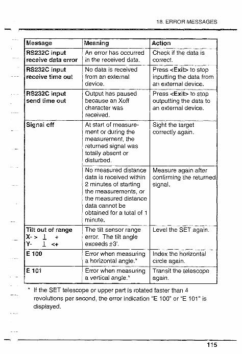
18. ERROR MESSAGES -
the measurements, or the measured distance data cannot be obtained for a total of 1
* If the SET telescope or upper part is rotated faster than 4 revolutions per second, the error indication "E 100" or "E 101" is displayed.

19.1 Plate level
I 19. CHECKS AND ADJUSTMENTS 1 @ Periodically, checks and adjustments should be performed
before and during measurement. In addition, the instrument should be checked after long storage, transportation or when damage to the instrument is suspected to have occurred due to a strong shock.
b NOTE The checks should be performed in the following order.
The glass tube of the plate level is sensitive to temperature changes or shock.
b PROCEDURE Check
C 1. Turn the upper part of the instrument until the plate level @I is parallel to a line between levelling foot screws A and B. Center the plate level bubble
A using levelling foot screws A and B.
(pm@qf The bubble moves towards a
+ clockwise rotated levelling foot screw.
Bubble movement
2. Loosen the horizontal C
clamp @ and turn the upper part 90". The plate level is perpendicular to a line between levelling screws A and B.
B

19. CHECKS AND ADJUSTMENTS - 3. Center the plate level bubble
using levelling screw C.
4. Turn the upper part through 180" and check the bubble position. If the bubble is still centered, no adjustment is necessary. If the bubble is off-center, adjust as follows:
b PROCEDURE Adjustment
Use levelling screws 5. Correct half of the bubble
0 @ displacement using levelling foot screw C.
1
Use adjusting pin 6. Correct the remaining half . - .
@ of the displacement by adjusting the screw @with the adjusting
r pin. The bubble moves towards a
h clockwise rotation of the adjusting screw.
7. Repeat the procedures from 1 to 6 until the bubble remains centered for any position of the upper part.
If the bubble cannot be centerd, please contact your SOKKIA agent.

19.2 Circular level
19.2 Circular level
b PROCEDURE Check
1. Perform the plate level adjustment or level the instrument carefully using the plate level.
2. Check the position of the circular level bubble. If the bubble is still centered, no adjustment is necessary. If the bubble is off-center, adjust as follows:
Adjustment
Circular level 3. Verify the off-center direction of adjusting screws
the bubble.
4. Loosen the adjusting screw &) farthest from that direction to center the bubble.
5. Adjust all 3 adjusting screws until the tightening tension of each screw is the same, and the bubble is centered.
)NOTE Over-tightening the adjusting screws may damage the circular level. Unequal tightening of the screws may mean that the bubble will go out of adjustment.
If the bubble cannot be centered, please contact your SOKKIA agent.

19. CHECKS AND ADJUSTMENTS m
69.3 Tilt sensor
* If there is a tilt 0 point error, the tilt angle is not 0 when the instrument is levelled, and it causes an angle error. This tilt 0 point error can be checked and adjusted as follows.
b PROCEDURE Check
1. Carefully level the SET.
2. In Baslc mode, press <@ONF> for Setting mode.
k e y s t o s e l e c t o p e r a t t o n
<CONF>
Settln mode 3. Press <2> for Tilt sensor
C o n i i g u r a t i o n checking mode. T ~ l t c o r r e c t i o n
3 . K e y s e l e c t
<2>
4. Wait for a few seconds untll the tilt angle readings are steady,
T I l t X - 0 " 0 0 ' 2 0 " and note the tilt angle values XI Y - 0 " 0 0 ' 4 0 " and Y1
e.g.: XI=-20 Y1=-40 1 st line: Horizontal angle
2nd line: Tilt angle of X direction 3rd line: Tilt angle of Y direct~on GI HAR 270" 0 0 ' 0 0 " 5. Loosen the horizontal clamp @
T i I t X 0 ° 0 0 ' 4 0 " and turn the theodolite through 180" referring to the horizontal angle display. Tighten the horizontal clamp.

19.3 Tilt sensor - e.g.: X2 = 40 6. When the tilt angle readings are
YZ = -20 steady, note the tilt angle values, X2 and Y2.
e.g.: X direction = (-20+40) /2=10 7. Calculate the offset values. Y direction = {-40+(-20)} /2=-30 (X1 + X2) / 2
If the offset value (X and Y) are f 10" or less, no adjustment is necessary. Press <Exit> to finish the check.
If one of the offset values is greater than i 1 On, the sensor index should be adjusted as follows without pressing <Exit>.
b PROCEDURE Adjustment
8. Press <OSET> for Tilt sensor adjusting mode.
The horizontal angle becomes 0".
/ S E T ~ x i t ] <SET> 9. Press <SET> to memorize tilt
angle X2 and Y2.
El HAR 1 8 0 " 00'00" 10. Loosen the horizontal clamp
T I l t X 0°00'40" and turn the upper part through 1 80°, referring to the horizontal angle display.

19. CHECKS AND ADJUSTMENTS - <SET> X=0398 Y=0440
T I I t X -0" 00'20"
e.g.: Tilt 0 point data X =398 Y =440
11. When the tilt angle readings are steady, press <SET> to memorize X2 and Y2.
The tilt 0 point data is displayed at the 1 st line.
If the tilt 0 point data is greater than 400k120, press <Exit> to stop the adjustment (Please contact your SOKKIA agent).
If it is 400+120 or less, continue the adjustment without pressing <Exit>.
<Enter> 12. Press <Enter> to store the new Tilt sensor checkin mode Tilt 0 point data.
H A R 180" 00'00" (Tilt sensor checking mode) T I l t X 0°00'00"
The adjusted new tilt angle values, X and Y are displayed.
13. When the tilt angle readings are steady, note the tilt angle value, X3 and Y3.
- 14. Loosen the horizontal clamp and turn the upper part through 180".
15. When the tilt angle readings are steady, note the Tilt angle value, X4 and Y4.

19.3 Tilt sensor - e-g.: X direction = {0+(-lo)} 12 = -5 Y direction = (-1 0+0) 12 = -5
Input ppm value C o n f i g u r a t i o n
2 . T i l t c o r r e c t i o n 3 . K e y s e l e c t
16. Calculate the offset values. (X3 + X4) 1 2 (Y3 + Y4) 12 If the offset values (X and Y) are f 10" or less, the adjustment has been finished.
17. Press <Exit> to finish the check. (Setting mode)
If one of the offset values are greater than 21 OM, repeat the adjustment procedures.
Exit from the mode: <Exit> If the offset values are greater than +lo", in spite of repeating the adjustment, please contact your SOKKIA agent.

19. CHECKS AND ADJUSTMENTS -
This adjustment is very delicate. If you have any difficulties, please contact your SOKKIA agent.
b IMPORTANT Make sure that no dirt, dust or water becomes attached to the inside of the telescope reticle cover when it is removed to adjust the reticle. After adjustment, securely reattach the reticle cover. Any water or dust on the inside of the reticle cover will reduce the instruments capacity for water resisting. (SET5Wl5WS)
b PROCEDURE Check 1 <Perpendicularity of the reticle to the horizontal axis>
1. Carefully level the SET.
2. Select and s~ght a clear target on the upper part A of the reticle line.
3. Turn the telescope vertical fine motion screw @ until the target is on the lower part of the reticle B. Check that the target is still positioned centrally within the reticle lines. If the target is off-center, adjust as follows:

19.4 Reticle
Adjustment 1
Reticle 1 4. Remove the telescope reticle cover.
5. Slightly loosen one vertical and one horizontal adjustment screw by an equal amount using the adjusting pin.
6. Place a small piece of plastic or Adjust~ng screw moun wood against one side of the top
adjusting screw mount as a buffer.
7. Look through the eyepiece and gently tap the piece of plastic or wood to rotate the reticle slightly.
8. Retighten the two adjusting screws loosened in step 5 by the same amount.
b NOTE Over-tightening the adjusting screws may damage the reticle. Unequal tightening of the adjusting screws may mean that the reticle will go out of adjustment.
8. Check the reticle perpendicularity again using procedures 1 and 2 above and repeat the adjustment if necessary.
9. Replace the reticle cover.

19. CHECKS AND ADJUSTMENTS - .b MOTE After this adjustment, perform the check and adjustment of
the reticle position as follows.
Check 2 (Vertical and horizontal reticle line positions)
About 1 oom 1. Set up a clear target 100m - - - - - - - - - - - - - - - - - - -
(328ft) from the SET.
2. Carefully level the SET, switch the power on and index the vertical and horizontal circles.
3. Sight the target on face left. Read the horizontal angle A1 and vertical angle 91.
e.g.: H angle AT = 18" 34' 00" V angle 91 = 90" 30' 20"
Telescope face right 4. Now sight the target on face right and read the horizontal angle A2 and vertical angle 92.
H A R 1 9 8 " 3 4 ' 2 0 "
e.g.: H angle A2 = 198" 34' 20" V angle 92 = 269" 30' 00" 5. Calculate A2 - AT and 92 + 91.
Az - A1 should be within
e.g.: 180" i20" H angle A2 - A1 92 + 91 should be within
= 198" 34' 20" - 18" 34' 00" 360" i20". = 180" 00' 20" If a difference of more than i20"
V angle 92 + 91 still remains after repeating = 2690 30' 0°" 30' 20" these procedures several times, = 360" 00' 20" adjust as follows.
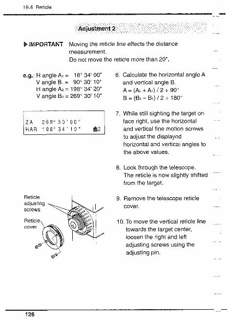
19.4 Reticle - Adjustment 2
b IMPORTANT Moving the reticle line effects the distance measurement. Do not move the reticle more than 20".
e.g.: H angle AT = 18" 34' 00" 6. Calculate the horizontal angle A V angle BI = 90" 30' 10" and vertical angle 5. H angle A2 = 198" 34' 20" A=(A2+Ai ) /2+90° V angle B2 = 269" 30' 10" ~ = ( B z - B i ) / 2 + 180"
7. While still sighting the target on face right, use the horizontal
H A R 1 9 8 ° 3 4 ' 1 0 " and vertical fine motion screws to adjust the displayed horizontal and vertical angles to the above values.
8. Look through the telescope. The reticle is now slightly shifted from the target.
Ret~cle 9. Remove the telescope reticle cover.
10. To move the vertical reticle line towards the target center, loosen the right and left adjusting screws using the adjusting pin.

19. CHECKS AND ADJUSTMENTS
Move to the r~ght To move the reticle to the right (left): @ very slightly loosen the left
0 (right) adjusting screw,
a @tighten the right. (left)
(0) adjusting screw by the same amount.
To move the horizontal retlcle line towards the target center, loosen the top and bottom adjusting screws using the adjusting pin. To move the reticle down (up): @ slightly loosen the top
(bottom) adjusting screw, @tighten the bottom (top)
adjusting screw by the same amount.
[( ) for opposite direct~on]
b NOTE Over-tightening the adjusting screws may damage the reticle. Unequal tightening of the adjusting screws may mean that the reticle will go out of adjustment.
11. Finally tighten the top and bottom adjusting screws as before. Check the reticle position and repeat the procedure until the reticle comes close to the target center.
12. Replace the reticle cover.

19.5 Optical plummet
11 9.5 Optical plummet
b IMPORTANT Make sure that no dirt, dust or water becomes attached to the inside of the optical plummet cover when it is removed to adjust the optical plummet. After adjustment, securely reattach the optical plummet cover. Any water or dust on the inside of the optical plummet will reduce the instruments capacity for water resisting. (SET5W15WS)
b PROCEDURE Check
1. Carefully level the SET and exactly center a surveying point in the reticle of the optical plummet.
2. Turn the upper part 180" and check the position of the surveying point in the reticle. If the surveying point is still centered, no adjustment is necessary. If the surveying point is not still centered in the optical plummet, adjust as follows:
b PROCEDURE Adjustment
3. Correct half the deviation with the levelling foot screw @.
4. Unscrew the optical plummet reticle cover @ to adjust the remaining half of the displacement with the 4 adjusting screws.

19. CHECKS AND ADJUSTMENTS - 5. When the surveying point is on
the part shown in V (A) area: @I Loosen the upper (lower)
screw slightly, @ tighten the lower (upper)
screw by the same amount.
6. Next, if the surveying point is seen to be on the part shown in solid line (dotted line):
0 0 @ Loosen the right (left) screw (0) (0) slightly,
@ tighten the left (right) screw by the same amount.
b NOTE Over-tightening the adjusting screws may mean that the reticle will go out of adjustment.
7. Check the adjustment by rotating the upper part of the instrument. The surveying point should remain centered in the reticle. If necessary, repeat the adjustment.
8. Replace the optical plummet reticle cover.

19.6 Distance measurement check flow chart
-8 9.6 Distance measurement check flow chart
Perform the procedures in the flow chart below. If error messages are displayed, please contact your SOKKIA agent. (Set parameter "EDM measurement" to "Repeat measurement mode" and set parameter "Resume function" to "of f .)
b PROCEDURE Check
( start )
Level and switch on i
I Index H and V circles and go to EDM mode I i
[ Sight center of prism and press cSIGNL> I i < Signal strength adequate?
No . .
& Yes Cover objective lens I
"Signal off" displayed?
Uncover objective lens i
Press C-dist> I
replace with a
Power switch on
& Power switch off
I < c-dist> flashes? Yes
<~lstance dfsplayed i e r about 5 s e c o n d s 7 p
('1 6 [Contact your SOKKIA agent]
Yes Yes "Battery IS lowl" < D~stance dlsplakd success~vely~ d~splayed? 1 Yes No
Press <STOP>

19. CHECKS AND ADJUSTMENTS - 19.7 Additive distance constant
* The additive distance constant K of the SET is adjusted to 0 before delivery. However, it may change over time and so should be determined periodically and then used to correct distances measured. The most reliable method of confirming the constant is to test the SET on an established baseline. If a baseline is not available, please perform the following procedures.
b NOTE Errors in setting up the instrument and sighting the target will affect the determination of the additive distance constant, therefore perform these procedures as carefully as possible.
b PROCEDURE Check
About 1 OOm - - - - - - - - - - - - - - - - - - I. Select points A and B on flat ground about 100m apart, and C in the middle.
C B 2. Set up the SET at A and the
A target at B.
3. Measure (fine measurement) the distance A-B 10 times.
4. Shift the SET to C and measure the distance C-A and C-B 10 times each.
A B 5. Calculate the averages of AB,
CA and CB.

19.7 Additive distance constant - 6. Compute the additive distance K
using the formula: K = AB - (CA + CB).
7. Obtain the K value several times. If all K values are greater than +3mm, please contact your SOKKIA agent.
b NOTE Ensure that the target height is the same as the instrument height. If the ground is not flat, use an automatic level to set the correct instrument heights of all points.

Measurement options selection
...... 20 . CHANGING INSTRUMENT PARAMETERS 135
... 21 . CHANGING LOCATION OF FUNCTIONS FOR KEYS 144 21.1 Key function allocating ................................................ 146 21.2 Registered location recalling ....................................... 151 b EXPLANATION Difference between "Enter" and "Key
.... registration" in key function allocating 152
22 . POWER SUPPLIES ............................................ 153
23 . REFLECTING PRISMS AND ACCESSORIES ... 156

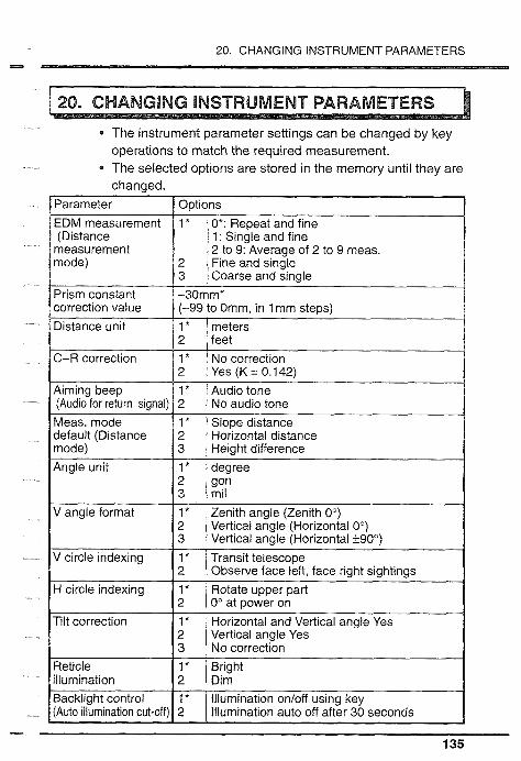
20. CHANGING INSTRUMENT PARAMETERS -
The instrument parameter settings can be changed by key operations to match the required measurement. The selected options are stored in the memory until they are chanaed.
measurement
Aiming beep (Audio for return signal) Meas. mode default (Distance mode) Angle unit
V angle format
V circle indexing
H circle indexing
I * Audio tone 2 No audio tone 1 * Slope distance 2 Horizontal distance 3 Height difference I * degree 2 gon 3 mil 1 * Zenith angle (Zenith 0") 2 Vertical angle (Horizontal 0") 3 Vertical angle (Horizontal +90°) 1 * Transit telescope 2 Observe face left, face right sightings l* Rotate upper part 2 0" at power on
I I
Tilt correction 1 * Horizontal and Vertical angle Yes 2 Vertical anale Yes
I I
Reticle I * Bright illumination 2 Dim
lllumination onloff using key lllumination auto off after 30 seconds
Backlight control (Auto illumination cut-off)
1 * 2

20. CHANGING INSTRUMENT PARAMETERS -.
*: Factory settfng
b PROCEDURE From Basic mode to Setting mode
In Basic mode
o p e r a t i o n EDM T H E 0 S - 0 CONF
<CONF>
2 . T i l t c o r r e c t i o n 3 . K e y s e l e c t
<1>
In Basic mode
1. Press <CONF> for Setting mode.
2. Press < I> for Parameter setting mode.
The first parameter is displayed.
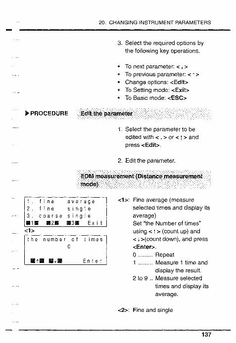
20. CHANGING INSTRUMENT PARAMETERS - 3. Select the required options by
the following key operations.
* To next parameter: c i > * To previous parameter: < t > * Change options: <Edit> * To Setting mode: <Exit> * To Basic mode: <ESC>
b PROCEDURE Edit the parameter
1. Select the parameter to be edited with < i > or < I > and press <Edit>.
2. Edit the parameter.
EDM measurement (Distance measurement mode)
1 . f ~ n e a v e r a g e
c o a r s e s i n g l e .I. M2B 8 3 1 E x i t
t h e n u m b e r o f t ~ r n e s
at. H1II E n t e r
<I>: Fine average (measure selected times and display its average) Set "the Number of times" using c I > (count up) and c r >(count down), and press <Enter>. 0 ......... Repeat 1 ......... Measure 1 time and
display the result. 2 to 9 .. Measure selected
times and display its average.
<2>: Fine and single

20. CHANGING INSTRUMENT PARAMETERS
<3>: Coarse and single cExib: Retain the previously
selected option.
Prism constant
Set "the prism constant" using c : > (count up) and c 1 > (count down), and press <Enter>. ( To move the column, press c-+>.)
The input range is -99 to 0 mm ( least input is 1 mm). Each reflecting prism type has a different prism constant value. Here, we will set the constant correction value for the reflecting prism being used. The prism constant correction values for reflecting prisms made by SOKKIA are as follows:
APO1 S + APOl APOl CPO1
Correction value = -30 Correction value = -40 Correction value = 0
Distance unit
I . m e t e r 2 . f e e t
RIM B2M E x i t 1 <I>: meters <2>: feet <Exit>: Retain the previously
selected option.
C+R correction
<I>: No correction 422: Yes (K=0.142) <Exit>: Retain the previously
M l B M2B selected option.
About C & R correction, refer to "Appendix 3: C&R CORRECTION".
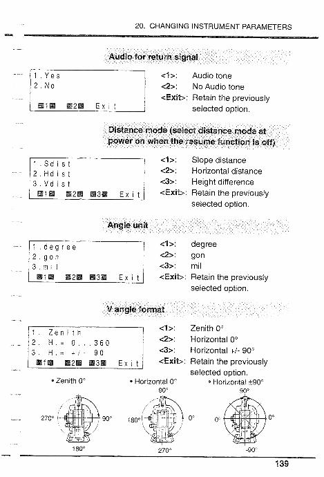
20. CHANGING INSTRUMENT PARAMETERS -.4
Audio for return signal
<I>: Audio tone <2>: No Audio tone <Exit>: Retain the previously
I B2H E x r t selected optron.
Distance mode (select distance mode at power on when the resume function is off)
<I>: Slope distance
2 . H d i s t <2>: Horizontal distance
3 . V d i s t <3>: Height difference / ~1 ~ 2 8 ~3889 E i 1 <Exit>: Retain the previously
selected option.
Angle unit
1 deg ree <'I>: degree <2>: gon ~32: mrl
1 m2B m3a E x I t <Exit>: Reta~n the prev~ously selected optton.
V angle format
I : Zenrth 0° c2>: Horrzontal 0°
H = + I - 9 0 c3>: Hor~zontal +I- 90"
1 m 2 ~ M3m E , <Exit>: Reta~n the prevrously selected optlon.
* Zentth O0 * Horizontal 0" Hortzontalrt9O0 90' 90"
0" 0" 0"
180" - 270" -90"
a 39

20. CHANGING INSTRUMENT PARAMETERS
V circle indexing
<l>: Transit telescope <2>: F.L./F.R.Sighting <Exit>: Retain the previously
selected option.
Refer to "Appendix 3: C&R CORRECTION" to index by face left, face right sighting.
H circle indexing
<I>: Rotate upper part
2 . M a n u a l <2>: 0" at power on <Exit>: Retain the previously
selected option.
Tilt correction
1 . Y e s ( H . V ) 2 . Y e s ( V )
.la B2. H3. E x i t
<I>: H & V angle Yes <2>: V angle Yes <3>: No <Exit>: Retain the previously
selected option.
Reticle illumination
<I>: Bright
2 . D i m <2>: Dim <Exit>: Retain the previously
selected option.

20. CHANGING INSTRUMENT PARAMETERS - Auto illumination cut-off
? . K e y o n l o f f <I>: OnIOff using key 2 30sec t lmeou t <2>: Auto off after 30 seconds
<Exit>: Retain the previously 1.1. .2E selected option.
Auto power cut-off
<I>: Auto power off after 30 minutes
c2>: On/Off using key <Exit>: Retain the previously
selected option.
Baud rate
2.9600 b a u d
<I>: 1 200 baud c2>: 9600 baud <Exit>: Retain the previously
selected option.
Resume function
<I>: Resume function ON ~ 2 2 : Resume function OFF <Exit>: Retain the previously
selected option.
Coordinate format
<I>: N, E, Z <2>: E, N, Z <Exit>: Retain the previously
selected option.

20. CHANGING INSTRUMENT PARAMETERS v
Angle resolution
1 . 1 0 1 0 0 2 r n g o n <I>: 1 " / 0.02mgon 2 . 5 " 1 I r n g o n <2>: 5" / 1 mgon
<Exit>: Retain the previously BIB M2m selected option.
T&P unit
2 . O C rnrnHg 3 . N e x t
<3>
2 . " F mmHg 3 . O F i n c h H g
<I>: "C, hPa <2>: OC, mmHg <3>: Next
<I>: OF, hPa <2>: O F , mmHg <3>: OF, inchHg
<Exit>: Retain the previously selected option.
Point number increment
Set "Point number increment" using < t > (count up) and c J. >(count down), and press <Enter>. ( To move the column, press <-+>.)
The input range is 0 to 999 mm ( least input is 1).

20. CHANGlNG INSTRUMENT PARAMETERS -
1 . Y e s 1 : Yes <2>: No <Exit>: Retain the previously
mlm m2B selected option.
Checksum
I : Yes <2>: No <Exit>: Retain the previously
selected option.

21. CHANGING LOCATION OF FUNCTIONS FOR KEYS
- The SET allows you to change locations of the functions for each key (except <ESC>). You can arrange the keyboard according to your requirements in order to save key strokes and to avoid mistakes. You will get the most efficiency by customizing function locations for your own applications.
I Present locations I
Change location of functions in Function allocation mode
Difference between "Enter" and "Register" b EXPLANATION Difference between "Enter" and "Key registration" in key function allocating

21. CHANGING LOCATION OF FUNCTIONS FOR KEYS w 3
The factory settings are shown below. "User location 2 settings can be changed. If changed, the previous settings will be erased and cannot be recalled.
Factory setting User location 2
EDM mode EDM mode
S d i s t < F i n e a v e r a g e > - 3 0
S d i s t < F i n e a v e r a g e > - 3 "
1 3 S d i s t R E C COORD --P2
Theodolite mode Theodolite mode
HAR 3 5 0 " 3 8 ' 1 0 "
O S E T H O L D T i I t --P3 P P M S I G N L T i l t 4 P 3 R E P Z A l % R I L - - P i
Setting-out mode Setting-out mode
SO-3D S - 0 - P S - 0 - D - + P 2 S - 0 - P SO-HA SO-Hd -+P2 S t n - P H t . C O O R D --P3 S t n - P H t . M I T R K --P3
M E M R E S E C A S H V + P I S - 0 - D R E S E C A S H V - + P I

21 .I Key function allocating --.
21 .I Key function aillocating
Any functions mentioned below can be allocated in any page of any mode. After storing the locations, the locations are stored permanently until they are changed again. 2 locations can be registered at the internal memory. The registered location can be renewed.
b NOTE The previously-stored locations of functions are cleared after changing or registering the new locations.
The following functions can be allocated in each mode (THEO, EDM and S-0).
b NOTE The functions marked with * are not allocated in the default setting.
General <TI-IEO> <EDM> <S-O> <CONIF> c-.PX> <--->*
<ILLUQVI> -4VlEM>
: Transfer to THEO mode : Transfer to EDM mode : Transfer to S-0 mode : Transfer to Setting mode : Go to next page : No function : Display and ret~cle illum~nation ONtOFF : Select job
Input/Delete/Review Measured and coordinate data and Feature code
: Record Instrument station data and Measured data
: Sw~tch the power off

21. CHANGING LOCATION OF FUNCTIONS FOR KEYS - For Anqle measurement <OSET> : Set Horizontal angle to 0 /Index V circle <HOLD> : Hold H angle 1 Release H angle <Tilt> : Display the tilt angle <REP> : Transfer to Repetition mode <ZNYo> : Zenith angle / Slope in % ( ' I )
<VA/YO> : Vertical angle / Slope in O/O("') <Wh> : Select Horizontal angle right 1 left
For Distance measurement <-dist> : Measure the distance <A SHV> : Select Distance mode
(S=Slope / H=Horizontal l V=Height) <PPM> : Go to ppm setting mode <M VI /FIRM> : Repeat or single meas. 1 Tracking meas. <SIGNL> : Return signal check <f 1 m>* : Change meters / feet for 5 seconds <RCL>* : Review the measured data in the memory
For Coordinate measurement <Stn-P> : lnput lnstrument station coordinates <Wt.> : lnput Target & lnstrument height <BSang>* : lnput Backsight station coordinates and set
Azimuth angle <COORD> : Measure 3-Dimensional coordinates
: "ZN06" is displayed when parameter "V angle format" is set to "Zenith 0 . "ZN%" is displayed when parameter "V angle format" is set to "Horizontal 0 or "Horizontal 190"".

21.1 Key function allocating - For Advanced measurement <RESEC> : Go to Resection measurement mode <OFFS> : Start offset measurement cMLM> : Start Missing line measurement cREM> : Start Remote elevation measurement <S-0-D> : lnput Distance setting-out data <S-O-P> : lnput Coordinates of point to be set out <SO_3D> : Start &dimension setting-out measurement. <SO-Xd> : Start Distance setting-out measurement <SO-HA> : Start H angle setting-out measurement
B PROCEDURE
Bas~c mode In Basic mode
1. Press <CONF> for Setting
o p e r a t I on mode. EDM THEO S - 0 CONF
cCOMF>
Settlng mode 2. Press <3> for Key selection Con f l g u r a t ~ o n mode.
2 . T i l t c o r r e c t i o n 3 . Key s e l e c t
<3> I T I Ke selection mode 3. Press r1> for Function allocating mode.
2 . r e c a l l
Funct~on allocat~n mode 4. Select the required mode.
T h e o d o l i t e k e y 0 EDM mode: < I> 3 S e t t i n g o u t k e y THE0 mode: <2> mlB M211 83B E x i t s-omode:<3>
< I > or <2> or c3>

21. CHANGING LOCATION OF FUNCTIONS FOR KEYS
- - . - - - - - - It. I i . II-1I1 E n t e r I
K e y registration 1 . u s e r ' s 1
E x i t I <I> or c2> or <3>
Key selection mode 1 . D ~ s t a n c e k e y 2 . T h e o d o l i t e k e y 3 . S e t t i n g o u t k e y !
First line = First page Second line = Second page Third line = Third page Go to next function: < i >
0 Go to previous function: < T > Go to next position: <-.>
5. Display the required function. Repeat for the required numbers of functions.
6. Press <Enter> to enter the new location into memory.
7. Register the new location to ''user's 1 " or "user's 2". (The previously-registered location is cleared.) or Exit from this mode without registering. (Function allocating mode)
Register to user's 1 : <I> Register to user's 2: <2> Not register: <Exit>
If there are more than 5 functions to be allocated, allocate the page-turn function in any location of each line. If there is no function to be allocated, allocate "- - -" for key.
To Setting mode: <Exit> Exit from the mode: <ESC> (To Basic mode) Location storage period: Until next changing (Power-off possible) Up to 9 functions in 3 pages can be allocated

21 .I Key function allocat~ng - When Coordinate functions are used, allocate related functions.
For &Dimensional coordinates measurement Allocate <Ht.> and <BSang> with <COORD>. <Ht.> (Input Target and Instrument height) <BSang> (Set Azimuth angle) <COORD> (Measure 3-Dimensional coordinates) If these are not allocated, the previously stored data IS used.

21. CHANGING LOCATION OF FUNCTIONS FOR KEYS --E
26.2 Registered floeation recalling
The factory setting location or the registered locations stored in the memory can be recalled.
b PROCEDURE Key function recalling
Basic mode r e s s f u n c t i o n
k e y s t o s e l e c t o p e r a t i o n 8 2 I -
I EDM T H E 0 S - 0 CONF 1 <COW>
Settln mode C o n f ~ g u r a t l o n
K e y s e l e c t m18 B2H M3. E x i t
<3>
Key selection mode
2 . r e c a l 1
/ W111 112111 E x i t I
d e f a u l t El. M2H M3H E x 1 t
In Basic mode
1. Press <COMF> for Setting mode.
2. Press <3> for Key selection mode.
3. Press <2> for Key function recalling mode.
4. Select the required location. (Key function mode)
Recall "user's 1 ": <1> Recall "user's 2": <2> Recall Factory setting: <3>

21.2 Registered location recalling - b EXPLANATION Difference between "Enter" and "Key
registration" in key function allocating
There are 2 methods for changing the locations of functions for keys. By knowing how to use "Enter" or "'Key registration" properly, it will be easier to operate the SET.
@ <Enter> the new location or register the new location: After entering the new location, the functions are displayed in the entered location until next changing.
@ Recall the registered locations: After registering a location, the registered location can be recalled at any time.
For example, if someone enters another location, you can recall the location you registered.

22. POWER SUPPLIES -.L
The SET can be operated with the following combinations.
b NOTE Use the SET only with the combinations shown here.
* : Standard equipment. Items not marked with * are optional accessories.
.IMPORTANT Accessories other than the BDC25A do not meet IPX7 specifications for water proofing.

22. POWER SUPPLIES - b NOTE When using any external power supply (**), it is
recommended that the BDC25A battery be left in place to balance the weight on the axes.
Battery BDC25A
0 Battery operating left is shortened at extreme temperatures due to the battery's Ni-Cd composition.
0 If the battery is discharged excessively, its life may be shortened. Store it in a charged state.
0 The battery can be recharged about 300 times under ordinary use (Temperature = 20°C, Humidity = 65%).
0 The storage temperature is between 0 and 40°C. Specifications:
Output voltage: 6VDC Capacity: 1200mAh Water resistance: conforms to IPX7 (BDC25A) Size: 58 x 23 x 92mm Weight: about 0.2kg
Battery charger CDC27, CDC31, CDC31 A or CDC47
0 The battery charger becomes warm while charging. This is normal.
0 How to charge: Connect the charger to the power supply, connect the adaptor to the battery charger and mount the battery in the adaptor. Then;
0 the charging light flashes during charging and lights steadily when charging is finished. (CDC27tCDC311 CDC47) the charging lamp lights on during charging and it flashes when the charging is finished. (CDC31A)
* The charging temperature is between 10 and 40°C. 0 Charge the battery until the light remains on.

22. POWER SUPPLIES -.
* Specifications: Input: CDC27: 90 to 125V AC, 50/60Hz, 20VA
CDC31/31 N47: 180 to 264V AC, 50/60Hz, 20VA Output: 7.5V DC, 1.2A Charging time at 25°C: about 80 minutes (BDC25A) Size: 66 x 124 x 45mm Weight: CDC27: about 0.35kg
CDC31/31N47: about 0.38kg
b PRECAUTION For the use of external power supplies
Ensure that the car cigarette lighter has 12V DC output and that the negative terminal is grounded. Leave the engine running during use. Before using EDC2/2A, set the voltage selector to the correct voltage.
* EDC14 has a breaker switch. If you short circuit the battery or the polarity is not correct, the breaker will switch off the power. When the breaker switches off the power, remove the rubber cover and set the breaker switch so that a red mark appears.

23. REFLECTING PRISMS AND ACCESSORIES -
All SOKKIA reflecting prisms and accessories have standardized screws (518" x 11 thread) for ease of use.
* All the above equipment is optional. *: To change the stored prism constant value, see chapter 20. **: Fluorescent target paint finishing allows clearer sighting in adverse
observing conditions.

23. REFLECTING PRISMS AND ACCESSORIES -.
b PRECAUTION For use of reflecting prisms
* Carefully face the reflecting prism towards the instrument and sight the prism target center accurately.
* To use the triple prism assembly AP31 or AP32 as a single prism (e.g. for short distances), mount the single prism APO1 in the center hole of the prism holder.
b PRECAUTION For use of the instrument height adaptor AP41
Check the plate level of the AP41 as described in "19.1 Plate level".
* Check that the optical plummet of the AP41 sights the same point as that of the SET, referring to "19.5 Optical plummet".
* Check that "236" (the height of the SET in mm) is displayed in the window of the instrument height adaptor AP41.
b PROCEDURE Adjustment for the height of the AP41
Loosen the 2 fixing screws. @ Turn the center part
counterclockwise to unlock it. @ Move it up or down until "236"
appears in the window.
0 @ Turn the center part clockwise to (01 lock it.
@ Tighten the fixing screws.
b PRECAUTION For use of tribrach
* Use the plate level on the AP41 to adjust the tribrach circular level as described in "19.2 Circular level".


Appendices
Appendix 1 : Manually indexing the vertical circ8e by face left. face right measurements ... 161
Appendix 2: For distance measurement of the highest accuracy ................................ 162
Appendix 3: Earth-curvature and refraction correction ........................................... 164
Appendix 4: Standard ac~essories ........................ 165
Appendix 5: Optional accessories ......................... 166
STANDARD EQUIPMENT ......................................... 168
SPECIFICATIONS .................................................... 170
ATMOSPHERIC CORREGTlON CHART .................. 174


Appendix 1 -
Like all theodolites, the SET will have a small vertical index error. For angle measurement of the highest accuracy, the vertical index error can be removed as follows: Set Parameter "V circle indexing" to "Manual". See chapter 20.
b PROCEDURE Manually indexing the vertical circle
"Vl" is displayed.
I I 2. In face left (Vf), accurately
sight a clear target at a horizontal distance of about 30m.
3. Press <OSET>.
Z A V 2 H A R 6 0 ° 0 0 ' 0 0 " 1 2
"V2" is displayed.
4. Loosen the horizontal clamp and rotate the upper part of the SET through 180". In face right (V2), accurately sight the same target.
5. Press <OSET>. The vertical circle has been indexed.
If the power is switched off, the vertical circle should be indexed again.
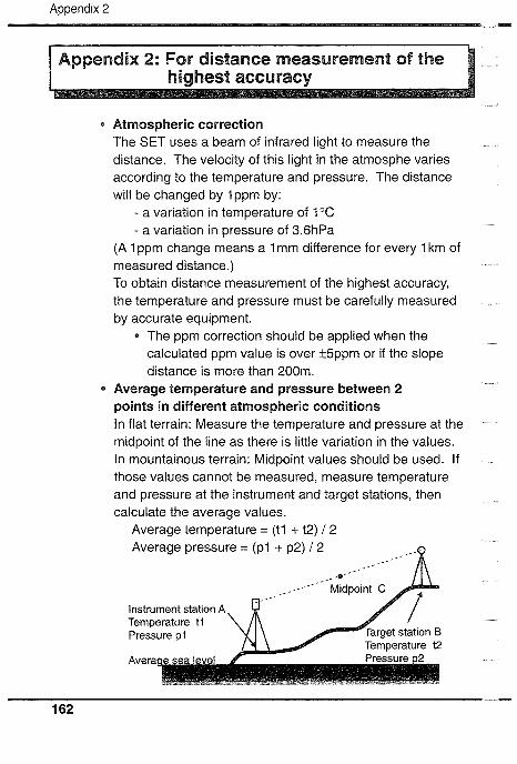
Appendix 2
surement of the
Atmospheric correction The SET uses a beam of infrared light to measure the distance. The velocity of this light in the atmosphe varies according to the temperature and pressure. The distance will be changed by lppm by:
- a variation in temperature of 1°C - a variation in pressure of 3.6hPa
(A 1 ppm change means a 1 mm difference for every 1 km of measured distance.) To obtain distance measurement of the highest accuracy, the temperature and pressure must be carefully measured by accurate equipment.
* The ppm correction should be applied when the calculated ppm value is over Mppm or if the slope distance is more than 200m.
Average temperature and pressure between 2 points in different atmospheric conditions In flat terrain: Measure the temperature and pressure at the midpoint of the line as there is little variation in the values. In mountainous terrain: Midpoint values should be used. If those values cannot be measured, measure temperature and pressure at the instrument and target stations, then calculate the average values.
Average temperature = (t l + t2) / 2 Average pressure = (p l + p2) / 2 ..--0
Instrument station A Temperature t l
Temperature t2
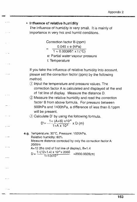
influence of relative humidity The influence of humidity is very small. It is mainly of importance in very hot and humid conditions.
Correction factor B (ppm)
- - 0.045 x e (hPa) 1 + 0.003661 x t ("C)
e: Partial water vapour pressure t: Temperature
If you take the influence of relative humidity into account, please set the correction factor (ppm) by the following method. @ Input the temperature and pressure values. The
correction factor A is calculated and displayed at the end of I st line of display. Measure the distance D.
@ Measure the relative humidity and read the correction factor B from above formula. For pressure between 5OOhPa and 1400hPa, a difference of less than O.1ppm will be present.
@ Calculate D' by using the following formula.
e.g. Temperature: 30°C, Pressure: 1020hPa, Relative humidity: 80% Measure distance corrected by only the correction factor A: 2000m A=12 (the end of first line of display), B=1.4
D'= 1 +(12+1.4) x 1 0-6 x 2000 =2000~0028(m, 1 +12x10."

Appendix 3 - 1 Appendix 3: Earth-curvature and
refraction correction
@ When measuring the horizontal distance and height difference, the earth-curvature and refraction correction can be selected by the parameter "C + R correction".
Difference between "no correction" and "applied correction" (No correction)
Horizontal distance: H = S x sin Z Height difference: V = S x cos Z
(Applied correction) 1-W2
Horizontal distance: H' = S x sinz - - x S2 x sin Z x cos Z R 1 - K
Height difference: V = S x cosZ + - x S2 x sin2 Z 2R
S: Slope distance Targel
A" (atmospheric corrected value) Z: Vertical angle (0" at zenith) K: Atmospheric refraction constant
Instrument Ps (0.142) station
R: Radius of the earth Average sea ievei +- (6.372 x 1 06m)
I
e.g.: Correction value at Z=70° (K=0.142)
b NOTE The horizontal distance is the distance measured at the height of the surveying point above sea level. If required, reduce this distance to the average sea level and apply the local projection correction.
S distance H' - H V' - V
200m -0.002m 0.002m
500m -0.01 2m 0.01 5m
1000m -0.047m 0.059m
1500m -0.1 05m 0.134m

Appendix 4 -
Plumb bob If the weather is calm, or for initial tripod centering, the plumb bob can be used for centering. To use, unwind the plumb bob and attach it to the hook inside the centering screw. Use the cord grip piece to adjust the cord length.
To mount the CP7, slide it into the tubular compass slot. To use, loosen the clamping screw to free the compass needle. Turn the instrument in the face left position until the compass needle bisects the index lines. The telescope is now aligned with magnetic north. After use, tighten the clamp and remove the compass from the slot. Replace it in the specified position in the carrying case.
b NOTE Magnetism and metal will influence the tubular compass, making it incapable of projecting true magnetic north. Do not use the magnetic north indicated by this compass for base line surveying.
Handle The carrying handle can be removed from the instrument as follows: @ Unscrew the handle
securing screw @ Slide the handle to the side @ Remove the handle

Diagonal eyepiece DE17A
The diagonal eyeplece is convenient for near-vertical observations and in places where space around the
E17A instrument is I~mited. Remove the handle and the telescope eyepiece by unscrewing the mounting nng, and screw in the diagonal eyepiece.
B [MPORTANT When the diagonal eyepiece is attached, SET W's capacity of water resisting is reduced.
0 Solar filter OF11OFlA
For observations to the sun, and where glare is present. The OF1 and OFlA (flip-up type) filters are mounted on the objective lens.
DF1

Appendix 5 - EQecarolnic field book SDR series
The SDR series collects and stores slope distance and, vertical and horizontal angle data from the SET. Calculations can be performed on the data so that the measurements can be verified in the field. The stored data can be transmitted to a data
Modem
processing system.
Computer I
b IMPORTANT When the SET W is connected with the SDR series, its capacity of water resisting is reduced.
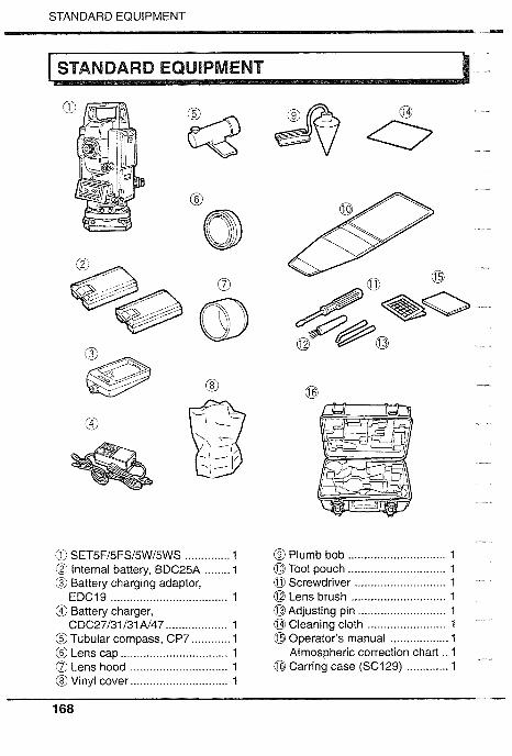
STANDARD EQUIPMENT -
@ SET5Fl5FSl5W15WS .............. 1 @ Internal battery, BDC25A ........ 1 @ Battery charging adaptor,
EDC19 .................................... 1 @ Battery charger,
CDC27131 I31 N47 .... .... ........... 1 @ Tubular compass, CP7 ............ 1 @ Lens cap ................................. 1 a Lens hood .............................. 1 @ Vinyl cover .............................. 1
@ Plumb bob .............................. 1 @Tool pouch .............................. 1 0 Screwdriver ............................ 1 @ Lens brush ............................. 1 @Adjusting pin ........................... 1 @ Cleaning cloth ........................ 1 @ Operator's manual .................. 1
Atmospheric correction chart .. 1 @ Carring case (SC129) .. ...... .... . 1

MAINTENANCE
I MAINTENANCE
1. Make sure that the inside of the carrying case and the instrument are dry before closing the case. If moisture is trapped inside the case, it may cause the instrument to rust.
2. Always clean the instrument before returning it to the case. The lens requires special care. Dust it off with the lens brush first, to remove minute particles. Then, after providing a little condensation by breathing on the lens, wipe it with a soft clean cloth or lens tissue.
3. Do not wipe the displays and keyboard or carrying case with an organic solvent.
4. Store the SET in a dry room where the temperature remains fairly constant.
5. Check the tripod for loose fit and loose screws.
6. If any trouble is found on the rotatable portion, screws (@, @, @, @, @, @ and @) or optical parts (e.g. lens), contact your SOKKIA agent.
7. When the instrument is not used for a long time, check it at least once every 3 months.
8. When removing the SET from the carrying case, never pull it out by force. The empty carrying case should then be closed to protect it from moisture.
9. Check the SET for proper adjustment periodically to maintain the instrument accuracy.

SPECIFICATIONS p..
Telescope Length: Aperture: Magnification: Image: Resolving power: Field of view: Minimum focus: Reticle illumination:
Angle measurement Horizontal and vertical
circles type: Angle units:
Display range: Horizontal angle: Vertical angle:
Minimum display:
Accuracy:
Measuring time: Automatic compensator:
Type: Minimum display:
Range of compensation: Measuring mode:
Horizontal angle:
Vertical angle:
165mm 45mm 30 x Erect 3" 1'30' (26m / 1000m) 1.3m Bright or dim settings (Selectable with parameter)
Incremental with 0 index
Degree / gon / mil (Selectable with parameter)
-3599" 59' 59" to 3599" 59' 59" 0°0'0" to 359" 59' 59" 1" (0.2mgon l0.005mil) /5" ( I mgon / 0.02mil) (Selectable with parameter) Standard deviation of mean of measurement take in positions I and II (DIN 18723) 5" (1.5mgon / 0.02mil) Less than 0.5sec. Selectable ON (V & H / only V) / OFF Liquid, 2-axis tilt sensor Same as the angle display f 3'
Right / Left / Repetition / Hold (Selectable with keyboard) Zenith 0 1 Horizontal OIHorizontal +90° (Selectable with parameter) Slope in % (Selectable with keyboard)
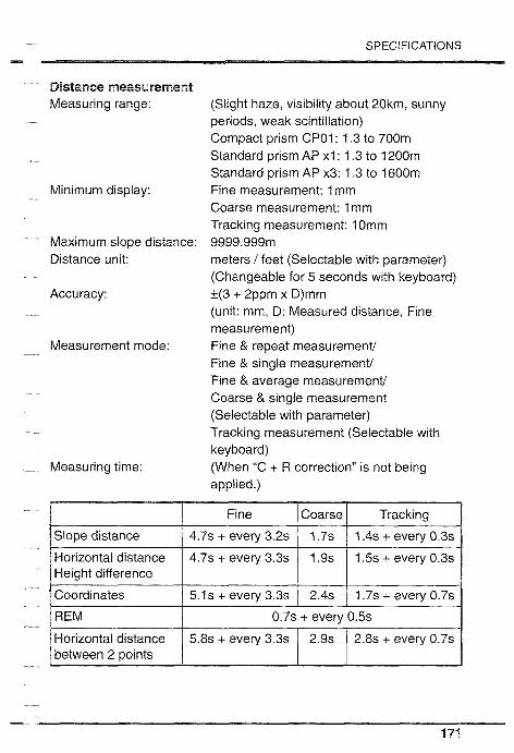
SPECIFICATIONS =
Distance measurement Measuring range:
Minimum display:
Maximum slope distance: Distance unit:
Accuracy:
Measurement mode:
Measuring time:
(Slight haze, visibility about 20km, sunny periods, weak scintillation) Compact prism CPOI : 1.3 to 700m Standard prism AP x l : 1.3 to 1200m Standard prism AP x3: 1.3 to 1600m Fine measurement: 1 mm Coarse measurement: 1 mm Tracking measurement: 1 Omm 9999.999m meters / feet (Selectable with parameter) (Changeable for 5 seconds with keyboard) 1(3 + 2ppm x D)mm (unit: mm, D: Measured distance, Fine measurement) Fine & repeat measurement/ Fine & single measurement/ Fine & average measurement/ Coarse & single measurement (Selectable with parameter) Tracking measurement (Selectable with keyboard) (When "C + R correction" is not being applied.)

SPECIFICATIONS - S~gnal source: Infrared LED Light intensity control: Automatic Atmospheric correction:
Temperature input range: -30 to 60°C (in 1 "C steps) / -22 to 140°F (in 1 OF steps)
Pressure input range: 500 to 1400hPa (in 1 hPa steps)/ 375 to 1050mmHg (in 1 mmHg steps)/ 14.8 to 41.3inchHg (in 0.1 inchHg steps) (Selectable with parameter)
ppm input range: -499 to 499ppm (in 1 ppm steps) Prism constant correction: -99 to Omm (in 1 mm steps) Earth-curvature and ON / OFF (Selectable with parameter)
refraction correction:
Power supply Power source: Ni-Cd rechargeable battery, BDC25A
(6VDC) Working duration at 25°C Distance & Angle measurement:
(Fine & single measurement, measurement interval = every 30 secs) BDC25A: About 5 hours (About 600 points) Optional battery BDC12: About 25 hours
(About 3000 points) Angle measurement only:
BDC25A: About 9 hours BDC12: About 45 hours
Water resistance: BDC25A: Conforms to IPX7 Charging time: CDC27 / 31 / 31 A / 47: About 80 minutes
CDC11 / 11 D / 11 E: About 15 hours

SPECIFICATIONS -.
General Water resistance: Display:
Keyboard:
Sensitivity of levels:
Optical plummet:
Horizontal and vertical fine motion screw:
Self-diagnostic function: Power saving auto cut off:
Data recording: Data output: Operating temperature: Instrument height: Size:
Weight:
Conforms to IPX7 (SET5WlSET5WS) 2 LCD dot matrix displays on each face 20 characters x 4 lines 5 softkeys Allocating functions for keys and register locations are available Plate level: 40" / 2mm Circular level: 10' / 2mm Image: Erect Magnification: 3x Minimum fucus: 0.5m 1 -speed motion
Provided 30 minutes after operation / On / off with key (Selectable with parameter) 3000 point data can be stored in memory Asynchronous serial, RS-232C compatible -20 to 50°C 236mm (9.3inch) from tribrach bottom 150(W) x 165(D) x 353(H)mm (with handle and battery) SET5F: about 5.4kg SET5FS: about 5.5kg SET5W: about 5.6kg SET5WS: about 5.7kg (with handle and battery)

ATMOSPHERIC CORRECTION CHART
This chart shows the correction every 2ppm, while the atmospheric correction can be input to the SET for every
PPm.
To convert pressure in mmHg to hPa, divide by 0.75. To convert pressure in inchHg to hPa, multiply by 33.87.
hPa = mmHg 10.75= 33.87 x inchHg
To convert temperature in OF to "C, compute using the following formula:
"C = 0.56 x ("F - 32)
(Metric) (ppm) $ ' $ , . . s ' $ @ @ , ! ? @ @ * @ +
600 700 800 900 1000 1060
Pressure (hPa)

REGULATIONS -
Radio Ftegauencv Interference
WARNING: Changes or modifications to this unit not expressly approved by the party responsible for compliance could void the user's authority to operate the equipment.
NOTE: This equipment has been tested and found to comply with the limits for a Class A digital device pursuant to Part 15 of the FCC Rules. These limits are designed to provide reasonable protection against harmful interference when the equipment is operated in a commercial environment. This equipment generates, uses, and can radiate radio frequency energy and, if not installed and used in accordance with the instruction manual, may cause harmful interference to radio communications. Operation of this equipment in a residential area is likely to cause harmful interference in which case the user will be required to correct the interference at his own expense.
Notice for Canada This Class A digital apparatus meets all requirements of Canadian Interference-Causing Equipment Regulations. Cet appareil numerique de la Class A respecte toutes les exigences du Reglement sur le materiel brouilleur du Canada.

REGULATIONS - @E Conformity Declaration

REGULATIONS .II

MEMO
......................