Operator's Manual - IDEALARC® DC-1500 - Solyman
44
Operator’s Manual IDEALARC ® DC-1500 Register your machine: www.lincolnelectric.com/register Authorized Service and Distributor Locator: www.lincolnelectric.com/locator IM10214 | Issue Date Mar-15 © Lincoln Global, Inc. All Rights Reserved. For use with machines having Code Numbers: 12479 Need Help? Call 1.888.935.3877 to talk to a Service Representative Hours of Operation: 8:00 AM to 6:00 PM (ET) Mon. thru Fri. After hours? Use “Ask the Experts” at lincolnelectric.com A Lincoln Service Representative will contact you no later than the following business day. For Service outside the USA: Email: [email protected] Save for future reference Date Purchased Code: (ex: 10859) Serial: (ex: U1060512345)
-
Upload
khangminh22 -
Category
Documents
-
view
1 -
download
0
Transcript of Operator's Manual - IDEALARC® DC-1500 - Solyman

Operator’s Manual
IDEALARC ® DC-1500
Register your machine:
www.lincolnelectric.com/register
Authorized Service and Distributor Locator:
www.lincolnelectric.com/locator
IM10214 | Issue D ate Mar-15
© Lincoln Global, Inc. All Rights Reserved.
For use with machines having Code Numbers:
12479
Need Help? Call 1.888.935.3877
to talk to a Service Representative
Hours of Operation:
8:00 AM to 6:00 PM (ET) Mon. thru Fri.
After hours?
Use “Ask the Experts” at lincolnelectric.com
A Lincoln Service Representative will contact you
no later than the following business day.
For Service outside the USA:
Email: [email protected]
Save for future reference
Date Purchased
Code: (ex: 10859)
Serial: (ex: U1060512345)

THANK YOU FOR SELECTING A QUALITY PRODUCT BY LINCOLN ELEC TRIC.
PLEASE EXAMINE CARTON AND EQUIPMENT FORDAMAGE IMMEDIATELY
When this equipment is shipped, title passes to the purchaserupon receipt by the carrier. Consequently, claims for materialdamaged in shipment must be made by the purchaser against thetransportation company at the time the shipment is received.
SAFETY DEPENDS ON YOU
Lincoln arc welding and cutting equipment is designed and builtwith safety in mind. However, your overall safety can be increasedby proper installation ... and thoughtful operation on your part. DO NOT INSTALL, OPERATE OR REPAIR THIS EQUIPMENT WITHOUT READING THIS MANUAL AND THE SAFETYPRECAUTIONS CONTAINED THROUGHOUT. And, most importantly,think before you act and be careful.
This statement appears where the information must be followedexactly to avoid serious personal injury or loss of life.
This statement appears where the information must be followedto avoid minor personal injury or damage to this equipment.
KEEP YOUR HEAD OUT OF THE FUMES.
DON’T get too close to the arc.Use corrective lenses if necessaryto stay a reasonable distanceaway from the arc.
READ and obey the Safety DataSheet (SDS) and the warning labelthat appears on all containers ofwelding materials.
USE ENOUGH VENTILATION orexhaust at the arc, or both, tokeep the fumes and gases from your breathing zone and the general area.
IN A LARGE ROOM OR OUTDOORS, natural ventilation may beadequate if you keep your head out of the fumes (See below).
USE NATURAL DRAFTS or fans to keep the fumes away from your face.
If you de velop unusual symptoms, see your supervisor. Perhaps the welding atmosphere and ventilation system should be checked.
WEAR CORRECT EYE, EAR & BODY PROTECTION
PROTECT your eyes and face with welding helmetproperly fitted and with proper grade of filter plate(See ANSI Z49.1).
PROTECT your body from welding spatter and arcflash with protective clothing including woolenclothing, flame-proof apron and gloves, leatherleggings, and high boots.
PROTECT others from splatter, flash, and glarewith protective screens or barriers.
IN SOME AREAS, protection from noise may be appropriate.
BE SURE protective equipment is in good condition.
Also, wear safety glasses in work areaAT ALL TIMES.
SPECIAL SITUATIONSDO NOT WELD OR CUT containers or materials which previouslyhad been in contact with hazardous substances unless they areproperly cleaned. This is extremely dangerous.
DO NOT WELD OR CUT painted or plated parts unless specialprecautions with ventilation have been taken. They can releasehighly toxic fumes or gases.
Additional precautionary measuresPROTECT compressed gas cylinders from excessive heat,mechanical shocks, and arcs; fasten cylinders so they cannot fall.
BE SURE cylinders are never grounded or part of an electrical circuit.
REMOVE all potential fire hazards from welding area.
ALWAYS HAVE FIRE FIGHTING EQUIPMENT READY FORIMMEDIATE USE AND KNOW HOW TO USE IT.
WARNING
CAUTION
Safety 01 of 04 - 06/15/2016

SECTION A:WARNINGS
CALIFORNIA PROPOSITION 65 WARNINGS
Diesel EnginesDiesel engine exhaust and some of its constituents are known to the State of California to cause cancer, birth defects, and otherreproductive harm.
Gasoline EnginesThe engine exhaust from this product contains chemicals known to the State of California to cause cancer, birth defects, or otherreproductive harm.
ARC WELDING CAN BE HAZARDOUS. PROTECTYOURSELF AND OTHERS FROM POSSIBLE SERIOUSINJURY OR DEATH. KEEP CHILDREN AWAY. PACEMAKER WEARERS SHOULD CONSULT WITHTHEIR DOCTOR BEFORE OPERATING.
Read and understand the following safety highlights. Foradditional safety information, it is strongly recommended that you purchase a copy of “Safety in Welding & Cutting - ANSI Standard Z49.1” from the American Welding Society, P.O. Box 351040, Miami, Florida 33135 or CSA Standard W117.2-1974. A Free copy of “Arc Welding Safety” booklet E205 is available from the Lincoln Electric Company, 22801 St. Clair Avenue, Cleveland, Ohio 44117-1199.
BE SURE THAT ALL INSTALLATION, OPERATION,MAINTENANCE AND REPAIR PROCEDURES AREPERFORMED ONLY BY QUALIFIED INDIVIDUALS.
FOR ENGINE POWEREDEQUIPMENT.
1.a. Turn the engine off before troubleshootingand maintenance work unless themaintenance work requires it to be running.
1.b. Operate engines in open, well-ventilatedareas or vent the engine exhaust fumes outdoors.
1.c. Do not add the fuel near an open flamewelding arc or when the engine is running.Stop the engine and allow it to cool beforerefueling to prevent spilled fuel fromvaporizing on contact with hot engine partsand igniting. Do not spill fuel when fillingtank. If fuel is spilled, wipe it up and do not start engine untilfumes have been eliminated.
1.d. Keep all equipment safety guards, covers and devices in position and in good repair.Keep hands, hair, clothing and tools away from V-belts, gears, fans and all other moving parts when starting, operating orrepairing equipment.
1.e. In some cases it may be necessary to remove safety guards toperform required maintenance. Remove guards only whennecessary and replace them when the maintenance requiringtheir removal is complete. Always use the greatest care whenworking near moving parts.
1.f. Do not put your hands near the engine fan. Do not attempt tooverride the governor or idler by pushing on the throttle controlrods while the engine is running.
1.g. To prevent accidentally starting gasoline engines while turningthe engine or welding generator during maintenance work,disconnect the spark plug wires, distributor cap or magneto wireas appropriate.
1.h. To avoid scalding, do not remove the radiatorpressure cap when the engine is hot.
ELECTRIC ANDMAGNETIC FIELDS MAYBE DANGEROUS
2.a. Electric current flowing through any conductorcauses localized Electric and Magnetic Fields (EMF). Welding current creates EMF fields around welding cables and welding machines
2.b. EMF fields may interfere with some pacemakers, and welders having a pacemaker should consult their physicianbefore welding.
2.c. Exposure to EMF fields in welding may have other health effectswhich are now not known.
2.d. All welders should use the following procedures in order tominimize exposure to EMF fields from the welding circuit:
2.d.1. Route the electrode and work cables together - Securethem with tape when possible.
2.d.2. Never coil the electrode lead around your body.
2.d.3. Do not place your body between the electrode and workcables. If the electrode cable is on your right side, thework cable should also be on your right side.
2.d.4. Connect the work cable to the workpiece as close as pos-sible to the area being welded.
2.d.5. Do not work next to welding power source.
SAFETY
Safety 02 of 04 - 06/15/2016

ELECTRIC SHOCK CAN KILL.
3.a. The electrode and work (or ground) circuits areelectrically “hot” when the welder is on. Donot touch these “hot” parts with your bare skin or wet clothing.Wear dry, hole-free gloves to insulate hands.
3.b. Insulate yourself from work and ground using dry insulation.Make certain the insulation is large enough to cover your full areaof physical contact with work and ground.
In addition to the normal safety precautions, ifwelding must be performed under electricallyhazardous conditions (in damp locations or whilewearing wet clothing; on metal structures such asfloors, gratings or scaffolds; when in crampedpositions such as sitting, kneeling or lying, if thereis a high risk of unavoidable or accidental contactwith the workpiece or ground) use the followingequipment:
• Semiautomatic DC Constant Voltage (Wire) Welder.
• DC Manual (Stick) Welder.
• AC Welder with Reduced Voltage Control.
3.c. In semiautomatic or automatic wire welding, the electrode,electrode reel, welding head, nozzle or semiautomatic weldinggun are also electrically “hot”.
3.d. Always be sure the work cable makes a good electricalconnection with the metal being welded. The connection shouldbe as close as possible to the area being welded.
3.e. Ground the work or metal to be welded to a good electrical (earth)ground.
3.f. Maintain the electrode holder, work clamp, welding cable andwelding machine in good, safe operating condition. Replacedamaged insulation.
3.g. Never dip the electrode in water for cooling.
3.h. Never simultaneously touch electrically “hot” parts of electrodeholders connected to two welders because voltage between thetwo can be the total of the open circuit voltage of bothwelders.
3.i. When working above floor level, use a safety belt to protectyourself from a fall should you get a shock.
3.j. Also see It ems 6.c. and 8.
ARC RAYS CAN BURN.
4.a. Use a shield with the proper filter and cover plates to protect youreyes from sparks and the rays of the arc when welding orobserving open arc welding. Headshield and filter lens shouldconform to ANSI Z87. I standards.
4.b. Use suitable clothing made from durable flame-resistant materialto protect your skin and that of your helpers from the arc rays.
4.c. Protect other nearby personnel with suitable, non-flammablescreening and/or warn them not to watch the arc nor exposethemselves to the arc rays or to hot spatter or metal.
FUMES AND GASESCAN BE DANGEROUS.
5.a. Welding may produce fumes and gaseshazardous to health. Avoid breathing these fumes and gases.When welding, keep your head out of the fume. Use enoughventilation and/or exhaust at the arc to keep fumes and gasesaway from the breathing zone. When welding hardfacing(see instructions on container or SDS) or on leador cadmium plated steel and other metals orcoatings which produce highly toxic fumes, keepexposure as low as possible and within applicableOSHA PEL and ACGIH TLV limits using localexhaust or mechanical ventilation unless exposureassessments indicate otherwise. In confinedspaces or in some circumstances, outdoors, arespirator may also be required. Additionalprecautions are also required when welding on galvanized steel.
5. b. The operation of welding fume control equipment is affected byvarious factors including proper use and positioning of theequipment, maintenance of the equipment and the specificwelding procedure and application involved. Worker exposurelevel should be checked upon installation and periodicallythereafter to be certain it is within applicable OSHA PEL andACGIH TLV limits.
5.c. Do not weld in locations near chlorinated hydrocarbon vaporscoming from degreasing, cleaning or spraying operations. Theheat and rays of the arc can react with solvent vapors to formphosgene, a highly toxic gas, and other irritating products.
5.d. Shielding gases used for arc welding can displace air and causeinjury or death. Always use enough ventilation, especially inconfined areas, to insure breathing air is safe.
5.e. Read and understand the manufacturer’s instructions for thisequipment and the consumables to be used, including theSafety Data Sheet (SDS) and follow your employer’s safetypractices. SDS forms are available from your weldingdistributor or from the manufacturer.
5.f. Also see item 1.b.
SAFETY
Safety 03 of 04 - 06/15/2016

WELDING AND CUTTINGSPARKS CAN CAUSEFIRE OR EXPLOSION.
6.a. Remove fire hazards from the welding area. Ifthis is not possible, cover them to prevent the welding sparksfrom starting a fire. Remember that welding sparks and hotmaterials from welding can easily go through small cracks andopenings to adjacent areas. Avoid welding near hydraulic lines.Have a fire extinguisher readily available.
6.b. Where compressed gases are to be used at the job site, specialprecautions should be used to prevent hazardous situations.Refer to “Safety in Welding and Cutting” (ANSI Standard Z49.1)and the operating information for the equipment being used.
6.c. When not welding, make certain no part of the electrode circuit istouching the work or ground. Accidental contact can causeoverheating and create a fire hazard.
6.d. Do not heat, cut or weld tanks, drums or containers until theproper steps have been taken to insure that such procedures will not cause flammable or toxic vapors from substances inside.They can cause an explosion even though they have been“cleaned”. For information, purchase “Recommended SafePractices for the Preparation for Welding and Cutting ofContainers and Piping That Have Held Hazardous Substances”,AWS F4.1 from the American Welding Society (see address above).
6.e. Vent hollow castings or containers before heating, cutting orwelding. They may explode.
6.f. Sparks and spatter are thrown from the welding arc. Wear oil freeprotective garments such as leather gloves, heavy shirt, cufflesstrousers, high shoes and a cap over your hair. Wear ear plugswhen welding out of position or in confined places. Always wearsafety glasses with side shields when in a welding area.
6.g. Connect the work cable to the work as close to the welding areaas practical. Work cables connected to the building framework orother locations away from the welding area increase thepossibility of the welding current passing through lifting chains,crane cables or other alternate circuits. This can create firehazards or overheat lifting chains or cables until they fail.
6.h. Also see item 1.c.
6.I. Read and follow NFPA 51B “Standard for Fire Prevention DuringWelding, Cutting and Other Hot Work”, available from NFPA, 1Batterymarch Park, PO box 9101, Quincy, MA 022690-9101.
6.j. Do not use a welding power source for pipe thawing.
CYLINDER MAY EXPLODE IFDAMAGED.
7.a. Use only compressed gas cylinders containingthe correct shielding gas for the process usedand properly operating regulators designed forthe gas and pressure used. All hoses, fittings,etc. should be suitable for the application andmaintained in good condition.
7.b. Always keep cylinders in an upright position securely chained toan undercarriage or fixed support.
7.c. Cylinders should be located:
• Away from areas where they may be struck or subjectedto physical damage.
• A safe distance from arc welding or cutting operationsand any other source of heat, sparks, or flame.
7.d. Never allow the electrode, electrode holder or any otherelectrically “hot” parts to touch a cylinder.
7.e. Keep your head and face away from the cylinder valve outletwhen opening the cylinder valve.
7.f. Valve protection caps should always be in place and hand tightexcept when the cylinder is in use or connected for use.
7.g. Read and follow the instructions on compressed gas cylinders,associated equipment, and CGA publication P-l, “Precautions forSafe Handling of Compressed Gases in Cylinders,” available fromthe Compressed Gas Association, 14501 George Carter WayChantilly, VA 20151.
FOR ELECTRICALLYPOWERED EQUIPMENT.
8.a. Turn off input power using the disconnectswitch at the fuse box before working on the equipment.
8.b. Install equipment in accordance with the U.S. National ElectricalCode, all local codes and the manufacturer’s recommendations.
8.c. Ground the equipment in accordance with the U.S. NationalElectrical Code and the manufacturer’s recommendations.
Refer tohttp://www.lincolnelectric.com/safetyfor additional safety information.
SAFETY
Safety 04 of 04 - 06/15/2016

66 TABLE OF CONTENTSPage
Installation .......................................................................................................Section ATechnical Specifications ........................................................................................A-1Location .................................................................................................................A-2Input Wiring............................................................................................................A-2Output Connection ..........................................................................................A-2,A-3
________________________________________________________________________
Operation .........................................................................................................Section BSafety Precautions ................................................................................................B-1Meaning of Symbols ..............................................................................................B-1Set Polarity .............................................................................................................B-4Start the Welder ....................................................................................................B-4Set for Machine or Remote Control.......................................................................B-4Set the Welder Output...........................................................................................B-4Mode Switch..........................................................................................................B-4Set-up for Various Processes................................................................................B-4General Set-Up Procedures When Using DC-1500 and Lincoln Automatic Head NA-3 .......B-5, B-6General Set-Up Procedures When Using DC-1500 and Lincoln Automatic Head NA-5 ..............B-7Recommended Set-Up Procedures for NA-3/DC-1500, NA-5/DC-1500 ...............B-7
_______________________________________________________________________
Maintenance ....................................................................................................Section DSafety Precaution ..................................................................................................D-1General Maintenance ............................................................................................D-1Overload Protection and Thermal Protection Light ...............................................D-1
________________________________________________________________________
Section E ..............................................................................................TroubleshootingSafety Precautions.................................................................................................E-1How to Use Troubleshooting Guide.......................................................................E-1Troubleshooting Guide ............................................................................E-2 thru E-4P.C. Board Troubleshooting Guide ................................................................E-5, E-6
________________________________________________________________________
Wiring Diagram, Connection Diagrams and Dimension Print .......................Section F________________________________________________________________________
Parts List ........................................................................................................parts.lincolnelectric.com
Content/details may be changed or updated without notice. For most current Instruction Manuals, go to
parts.lincolnelectric.com.
________________________________________________________________________

A-1INSTALLATION
IDEALARC® DC-1500
A-1
INPUT: THREE PHASE ONLY
INPUT AC VOLTAGE (U1) FREQUENCY AC INPUT CURRENT (I1MAX, I1EFF) AT 1500A 44V MAXIMUM RATED OUTPUT (I2, U2)
380VRMS 50/60Hz 216ARMS
440VRMS 50/60Hz 187ARMS
INSULATION CLASS
PRIMARY COILS SECONDARY COILS INTERPHASE COILS
CLASS H (180º C) CLASS F (155º C) CLASS F (155º C)
STANDARDS COMPLIANCE
CCC, CE, IP21S
RATED OUTPUTS (ALL MODES)
DUTY CYCLE(1) (X) DC AMPSAVG DC VOLTSAVG
MAXIMUM 100% 1500 (I2) 44 (U2)
MINIMUM 100% 200 24
PHYSICAL DIMENSIONS
HEIGHT WIDTH DEPTH WEIGHT
57.2 IN.
1453 MM
22.3 IN.
566 MM
38 IN.
965 MM
1420 LBS
644 KG.
ADDITIONAL OUTPUTS (ALL MODES)
DUTY CYCLE(1) (X) DC AMPSAVG DC VOLTSAVG
MAXIMUM 100% 1500 60
MINIMUM 100% 200 20
RECOMMENDED INPUT WIRE AND FUSE SIZES FOR MAXIMUM RATED OUTPUT.IN ADDITION, FOLLOW LATEST NATIONAL ELECTRICAL CODE AND LOCAL CODE.
INPUTAC VOLTAGE
(U1)FREQUENCY
MAXIMUMEFFECTIVE INPUT
CURRENT(I1EFF)
TYPE 90°C COPPERWIRE IN CONDUIT
AWG (mm2)
COPPER GROUNDWIRE IN CONDUIT
AWG (mm2)
BUSSMANN LIMITRON FUSE SIZE ANDCATALOG NUMBER(2)
FUSE SIZE CATALOG NUMBER
380VRMS 50/60HZ 216ARMS 4/0 (120) 3 (25) 400A KTS-R-400
440VRMS 50/60HZ 187ARMS 3/0 (95) 3 (25) 350A KTS-R-350
OCV VOLTAGE AND AUXILIARY POWER
PEAK OPEN CIRCUIT (NO-LOAD) DC VOLTAGE (U0) AC AUXILIARY POWER
CV SUBMERGED ARC: 100V
110 VOLTSRMS
8 AMPSRMS
CV INNERSHIELD: 97V
CC SUBMERGED ARC: 100V
TEMPERATURE RANGES
OPERATING TEMPERATURE RANGE STORAGE TEMPERATURE RANGE
14º F TO 104º F (-10º C TO +40º C) -40º F TO 140º F (-40º C TO +60º C)
(1) Based upon 10 minute time period (for 100% duty cycle, it is 10 minutes on and 0 minutes off).
(2) Use only Bussmann Limitron fuses specified. Other fuses may not protect the welder and may cause overheating and possible fire damage.
TECHNICAL SPECIFICATIONS – DC-1500

A-2INSTALLATION
IDEALARC® DC-1500
A-2
LOCATIONInstall the welder in a dry location where there is free circula-tion of air in through the louvers in the front and out throughthe louvers in the back of the case. A location which minimizesthe amount of smoke and dirt drawn into the machinereduces the chance of dirt accumulation that can block airpassages and cause overheating.
This equipment is for industrial use only and it is not intend-ed for use in residential locations where the electrical poweris provided by the public low-voltage supply system. Therecan be potential difficulties in residential locations due toconducted as well as radiated radio-frequency disturbances.The EMC or RF classification of this equipment is Class A.
INPUT WIRING
Failure to fuse the input lines per the specificationsin this manual will constitute customer abuse andvoid the warranty.-----------------------------------------------------------------------Be sure the voltage, phase and frequency of the input power isas specified on the welder nameplate.
Have a qualified electrician remove the lower right side casepanel and connect 3 phase AC power to terminals L1, L2 andL3 of the input contactor in accordance with the NationalElectrical Code, all local codes and the wiring diagram locatedinside the machine.
The frame of the welder must be grounded. A stud markedwith the symbol located on the fan shroud is provided forthis purpose. See the U.S. National Electrical Code fordetails on proper grounding methods.
Connect the transformer input leads for the properinput voltage in accordance with the connection dia-gram pasted to the inside of the lower right side casepanel.
• Failure to follow these instructions can cause immediatefailure of components within the machine.
• When powering welder from a generator be sure to turnoff the welder first, before generator is shut down inorder to prevent damage to welder.
OUTPUT CONNECTION(Turn Power Source Off)
1. Output Studs
The “Positive” and “Negative” output studs arelocated on the front panel. Two of each are provid-ed to simplify connecting multiple electrode orwork cables as suggested in the table below.
Connect the electrode cables to the “Positive”studs for electrode positive (DC+) polarity or tothe “Negative” stud for electrode negative (DC-)polarity as required by the welding procedures.Connect the work cables to the other set of studs.Tighten the nuts with a wrench.
2. Auxiliary Power
This machine supplies the 8 amperes of 110 volt,AC power needed for the automatic wire feeders.The power is available from terminals #31 and#32 on the terminal strip.
3. Wire Feeder ConnectionTurn the welder off. Remove the screw and lift thehinged door on the front of the control panel toexpose the terminal strips. Connect the leads ofthe wire feeder input control cable to the terminalstrip exactly as specified in the appropriate con-nection diagram included in the wire feederOperating Manual. Attach the control cable to thepanel at the right of the terminal strip using theclamp attached to the control cable. Close thedoor and replace the screw.
To connect the DC-1500 to wire feeders not covered in available connection diagrams, contactthe factory for instructions giving complete nameplate information for the DC-1500 and wirefeeder.
Suggested Copper Cable Sizes — 80% Duty CycleBelow 1000 amps Two 4/0 (120mm2)
1000 to 1200 amps Three 4/0 (120mm2) Up to
1200 to 1500 amps Four 4/0 (120mm2) 200’ (61m)
WARNING
FALLINGEQUIPMENT can
cause injury.
• Do not lift this machine using liftbale if it is equipped with aheavy accessory such as a traileror gas cylinder.
• Lift only with equipment ofadequate lifting capacity.
• Be sure machine is stable whenlifting.
WARNING
CAUTION
ELECTRIC SHOCKcan kill.
• Have an electrician install andservice this equipment.
• Turn the input power off at thefuse box before working onequipment.
• Do not touch electrically hotparts.

A-3INSTALLATION
IDEALARC® DC-1500
A-34. Optional Remote Control (K775)
To install, turn the power off. Remove the screwand lift the hinged door on the front of the controlpanel to expose the terminal strips. Connect thenumbered leads to the appropriate terminals — 75to 75, etc — on the terminal strip and the greenlead to the stud marked with the symbol .Attach the control cord to the panel at the right ofthe terminal strip using a suitable clamp. Close thedoor and replace the screw. The Remote Controlcord can be lengthened to any length by properlysplicing an appropriate four conductor rubber-cov-ered cable to the standard 25’ (7.6m) cord beforeconnecting to the DC-1500 terminal strip.
5. Connecting for Air Carbon Arc
To use the DC-1500 for air carbon arc or otherapplications, disconnect all wire feeder weldingcables and control leads and connect a jumperbetween #2 and #4 on the terminal strip on the frontof the DC-1500. With the #2 to #4 jumper connect-ed, the output studs are energized whenever themachine is on.
If the electrode leads to the wire are not discon-nected per instructions, the wire feeder nozzle or gunand electrode will be electrically “hot”.---------------------------------------------------------------
6. DC-1500 Paralleling Kit
A kit for field installation only, (order K1900-1) isavailable for paralleling two DC-1500’s for currentsup to 3000 amperes, 100% duty cycle. Completeinstallation instructions are shipped with the kit.
7. Connecting for High Frequency Starting
As shipped, these welders can be used with a highfrequency unit for improved automatic welding start-ing characteristics.
WARNING

B-1OPERATION
IDEALARC® DC-1500
B-1
MEANINGS OF SYMBOLS
The DC-1500 nameplate has been designed to useinternational symbols in describing the function of thevarious components. Below are the symbols used.
POWER ON-OFF SWITCH
Input (Power)
On
Off
OUTPUT CONTROL DIAL
Output Control
Increase/Decrease ofOutput (Voltage orCurrent)
OUTPUT CONTROL LOCAL-REMOTE SWITCH
Remote Output Voltageor Current Control
Local Output Voltage orCurrent Control
THERMAL PROTECTION LIGHT
High Temperature
Fuse
ELECTRODE POLARITY SWITCH
Positive Electrode
Negative Electrode
EARTH GROUND CONNECTION ON FAN SHROUD
Signifying the Earth(Ground) Connection
ELECTRIC SHOCKcan kill.
• Do not touch electrically liveparts or electrode with skin orwet clothing.
• Insulate yourself from workand ground.
ARC RAYScan burn.
• Wear eye, ear and body protec-tion.
WELDING SPARKScan cause fire or
explosion.
• Keep flammable materialaway.
FUMES ANDGASES can be
dangerous.
• Keep your head out of fumes.
• Use ventilation or exhaust toremove fumes from breath-ing zone.
WARNING
SAFETY PRECAUTIONS
B-2OPERATIONB-2
IDEALARC® DC-1500
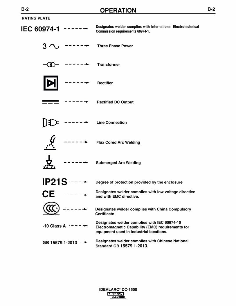
RATING PLATE
Submerged Arc Welding
Designates welder complies with low voltage directiveand with EMC directive.
Designates welder complies with International ElectrotechnicalCommission requirements 60974-1. IEC 60974-1
Three Phase Power
Transformer
Rectifier
Rectified DC Output
Line Connection
Flux Cored Arc Welding
Degree of protection provided by the enclosure IP21S
Designates welder complies with China CompulsoryCertificate
CE
Designates welder complies with IEC 60974-10Electromagnetic Capability (EMC) requirements forequipment used in industrial locations.
-10 Class A
Designates welder complies with Chinese NationalStandard GB 15579.1-2013.
GB 15579.1-2013

RATING PLATE
B-3OPERATIONB-3
IDEALARC® DC-1500
Rated peak no-load voltage (DCpeak).U0
Rated supply voltage (ACrms).U1
Conventional load voltage (DCavg).U2
Rated maximum supply current (ACrms).I1max
Maximum effective supply current (ACrms).I1eff
Rated welding current (DCavg).I2
Duty cycle. (Based upon 10 minute time period).X
B-4OPERATIONB-4
IDEALARC® DC-1500
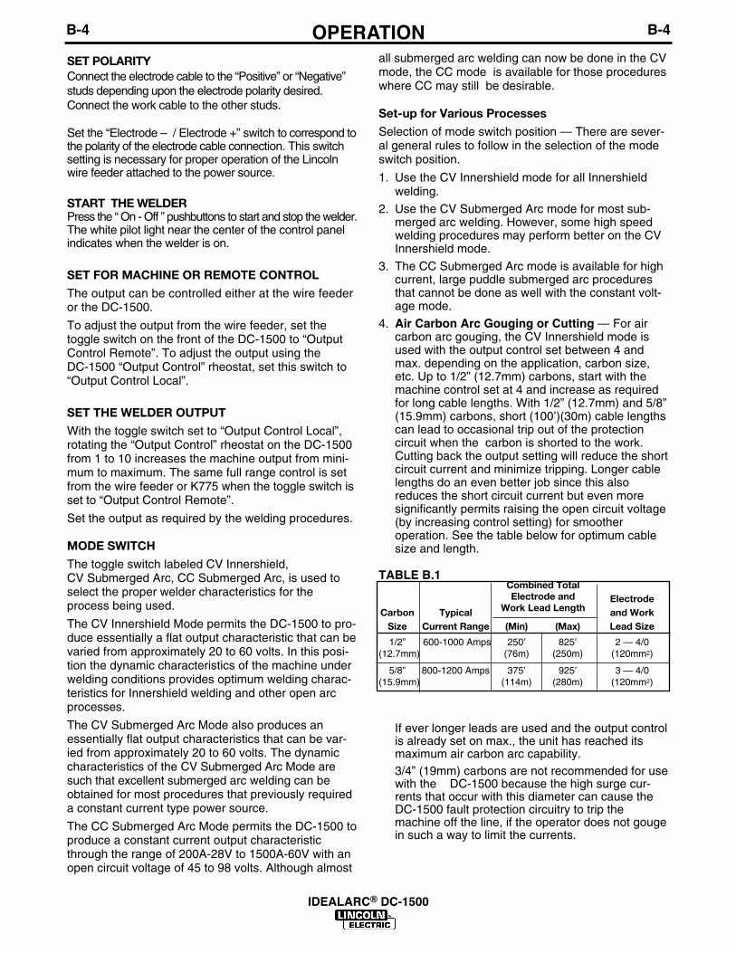
SET POLARITYConnect the electrode cable to the “Positive” or “Negative”studs depending upon the electrode polarity desired.Connect the work cable to the other studs.
Set the “Electrode – / Electrode +” switch to correspond tothe polarity of the electrode cable connection. This switchsetting is necessary for proper operation of the Lincolnwire feeder attached to the power source.
START THE WELDERPress the “ On - Off ” pushbuttons to start and stop the welder.The white pilot light near the center of the control panelindicates when the welder is on.
SET FOR MACHINE OR REMOTE CONTROLThe output can be controlled either at the wire feederor the DC-1500.
To adjust the output from the wire feeder, set the toggle switch on the front of the DC-1500 to “OutputControl Remote”. To adjust the output using the DC-1500 “Output Control” rheostat, set this switch to“Output Control Local”.
SET THE WELDER OUTPUTWith the toggle switch set to “Output Control Local”,rotating the “Output Control” rheostat on the DC-1500from 1 to 10 increases the machine output from mini-mum to maximum. The same full range control is setfrom the wire feeder or K775 when the toggle switch isset to “Output Control Remote”.
Set the output as required by the welding procedures.
MODE SWITCHThe toggle switch labeled CV Innershield, CV Submerged Arc, CC Submerged Arc, is used toselect the proper welder characteristics for theprocess being used.
The CV Innershield Mode permits the DC-1500 to pro-duce essentially a flat output characteristic that can bevaried from approximately 20 to 60 volts. In this posi-tion the dynamic characteristics of the machine underwelding conditions provides optimum welding charac-teristics for Innershield welding and other open arcprocesses.
The CV Submerged Arc Mode also produces anessentially flat output characteristics that can be var-ied from approximately 20 to 60 volts. The dynamiccharacteristics of the CV Submerged Arc Mode aresuch that excellent submerged arc welding can beobtained for most procedures that previously requireda constant current type power source.
The CC Submerged Arc Mode permits the DC-1500 toproduce a constant current output characteristicthrough the range of 200A-28V to 1500A-60V with anopen circuit voltage of 45 to 98 volts. Although almost
all submerged arc welding can now be done in the CVmode, the CC mode is available for those procedureswhere CC may still be desirable.
Set-up for Various ProcessesSelection of mode switch position — There are sever-al general rules to follow in the selection of the modeswitch position.
1. Use the CV Innershield mode for all Innershieldwelding.
2. Use the CV Submerged Arc mode for most sub-merged arc welding. However, some high speedwelding procedures may perform better on the CVInnershield mode.
3. The CC Submerged Arc mode is available for highcurrent, large puddle submerged arc proceduresthat cannot be done as well with the constant volt-age mode.
4. Air Carbon Arc Gouging or Cutting — For aircarbon arc gouging, the CV Innershield mode isused with the output control set between 4 andmax. depending on the application, carbon size,etc. Up to 1/2” (12.7mm) carbons, start with themachine control set at 4 and increase as requiredfor long cable lengths. With 1/2” (12.7mm) and 5/8”(15.9mm) carbons, short (100’)(30m) cable lengthscan lead to occasional trip out of the protection circuit when the carbon is shorted to the work.Cutting back the output setting will reduce the shortcircuit current and minimize tripping. Longer cablelengths do an even better job since this alsoreduces the short circuit current but even more significantly permits raising the open circuit voltage(by increasing control setting) for smoother operation. See the table below for optimum cablesize and length.
TABLE B.1
If ever longer leads are used and the output controlis already set on max., the unit has reached itsmaximum air carbon arc capability.
3/4” (19mm) carbons are not recommended for usewith the DC-1500 because the high surge cur-rents that occur with this diameter can cause theDC-1500 fault protection circuitry to trip themachine off the line, if the operator does not gougein such a way to limit the currents.
Combined TotalElectrode and Electrode
Carbon Typical Work Lead Length and WorkSize Current Range (Min) (Max) Lead Size1/2” 600-1000 Amps 250’ 825’ 2 — 4/0
(12.7mm) (76m) (250m) (120mm2)
5/8” 800-1200 Amps 375’ 925’ 3 — 4/0(15.9mm) (114m) (280m) (120mm2)
B-5OPERATIONB-5
IDEALARC® DC-1500
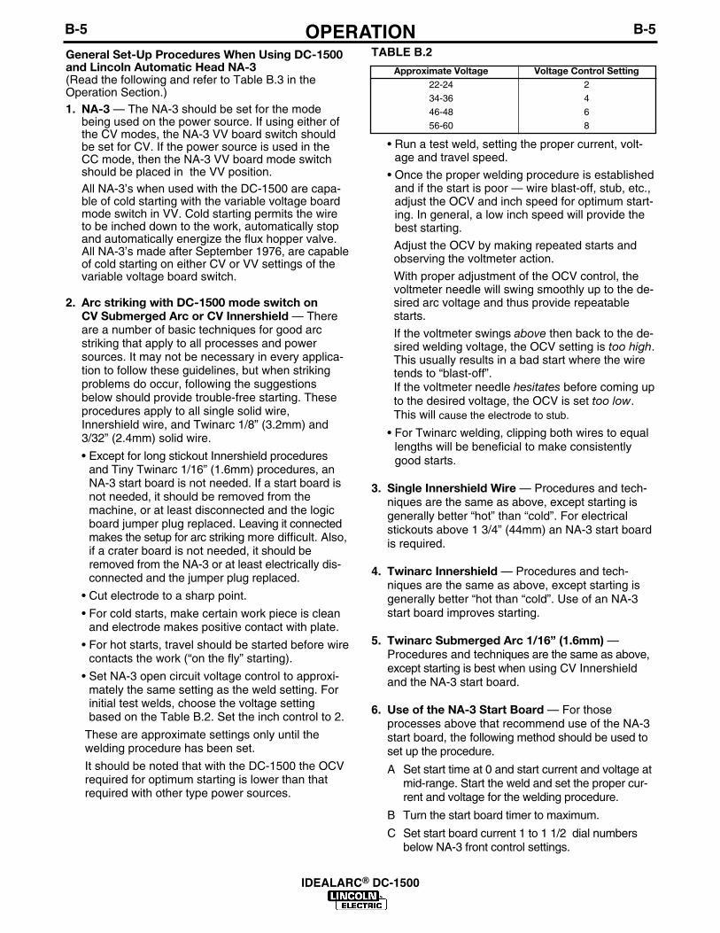
Approximate Voltage Voltage Control Setting22-24 2
34-36 4
46-48 6
56-60 8
General Set-Up Procedures When Using DC-1500and Lincoln Automatic Head NA-3(Read the following and refer to Table B.3 in theOperation Section.)
1. NA-3 — The NA-3 should be set for the modebeing used on the power source. If using either ofthe CV modes, the NA-3 VV board switch shouldbe set for CV. If the power source is used in theCC mode, then the NA-3 VV board mode switchshould be placed in the VV position.
All NA-3’s when used with the DC-1500 are capa-ble of cold starting with the variable voltage boardmode switch in VV. Cold starting permits the wireto be inched down to the work, automatically stopand automatically energize the flux hopper valve.All NA-3’s made after September 1976, are capableof cold starting on either CV or VV settings of thevariable voltage board switch.
2. Arc striking with DC-1500 mode switch on CV Submerged Arc or CV Innershield — Thereare a number of basic techniques for good arcstriking that apply to all processes and powersources. It may not be necessary in every applica-tion to follow these guidelines, but when strikingproblems do occur, following the suggestionsbelow should provide trouble-free starting. Theseprocedures apply to all single solid wire,Innershield wire, and Twinarc 1/8” (3.2mm) and3/32” (2.4mm) solid wire.
• Except for long stickout Innershield proceduresand Tiny Twinarc 1/16” (1.6mm) procedures, anNA-3 start board is not needed. If a start board isnot needed, it should be removed from themachine, or at least disconnected and the logicboard jumper plug replaced. Leaving it connectedmakes the setup for arc striking more difficult. Also,if a crater board is not needed, it should beremoved from the NA-3 or at least electrically dis-connected and the jumper plug replaced.
• Cut electrode to a sharp point.
• For cold starts, make certain work piece is cleanand electrode makes positive contact with plate.
• For hot starts, travel should be started before wirecontacts the work (“on the fly” starting).
• Set NA-3 open circuit voltage control to approxi-mately the same setting as the weld setting. Forinitial test welds, choose the voltage settingbased on the Table B.2. Set the inch control to 2.
These are approximate settings only until thewelding procedure has been set.
It should be noted that with the DC-1500 the OCVrequired for optimum starting is lower than thatrequired with other type power sources.
TABLE B.2
• Run a test weld, setting the proper current, volt-age and travel speed.
• Once the proper welding procedure is establishedand if the start is poor — wire blast-off, stub, etc.,adjust the OCV and inch speed for optimum start-ing. In general, a low inch speed will provide thebest starting.
Adjust the OCV by making repeated starts andobserving the voltmeter action.
With proper adjustment of the OCV control, thevoltmeter needle will swing smoothly up to the de-sired arc voltage and thus provide repeatablestarts.
If the voltmeter swings above then back to the de-sired welding voltage, the OCV setting is too high.This usually results in a bad start where the wiretends to “blast-off”.If the voltmeter needle hesitates before coming upto the desired voltage, the OCV is set too low.This will cause the electrode to stub.
• For Twinarc welding, clipping both wires to equallengths will be beneficial to make consistentlygood starts.
3. Single Innershield Wire — Procedures and tech-niques are the same as above, except starting isgenerally better “hot” than “cold”. For electricalstickouts above 1 3/4” (44mm) an NA-3 start boardis required.
4. Twinarc Innershield — Procedures and tech-niques are the same as above, except starting isgenerally better “hot than “cold”. Use of an NA-3start board improves starting.
5. Twinarc Submerged Arc 1/16” (1.6mm) —Procedures and techniques are the same as above,except starting is best when using CV Innershieldand the NA-3 start board.
6. Use of the NA-3 Start Board — For thoseprocesses above that recommend use of the NA-3start board, the following method should be used toset up the procedure.
A Set start time at 0 and start current and voltage atmid-range. Start the weld and set the proper cur-rent and voltage for the welding procedure.
B Turn the start board timer to maximum.
C Set start board current 1 to 1 1/2 dial numbersbelow NA-3 front control settings.

B-6OPERATIONB-6
IDEALARC® DC-1500
D Place start board’s voltage control approximatelyequal to NA-3 voltage control setting.
When set per C and D, above, the starting onlyprocedure will provide a current setting lower thanthe NA-3 current setting and a voltage settingnearly equal to the desired welding procedure.
E With the start board time delay set at maximum,establish the correct arc striking procedure as de-scribed previously by changing OCV and inchspeed.
F Now increase the start board current and voltageto bring the start current and voltage closer to thewelding procedure. The start board current andvoltage should be as close to the welding proce-dure as possible while still getting satisfactorystarts.
G Now decrease the start time as low as possiblefor optimum starts.
7. Arc striking with the DC-1500 mode switch in CC Submerged Arc.
• NA-3 — The NA-3 variable voltage board modeswitch should be set to the VV position.
• Set OCV control at 6.5 to 7.0.
• Other techniques recommended in the previoussections for good arc striking apply here also.

B-7OPERATIONB-7
IDEALARC® DC-1500
INNERSHIELD SUBMERGED ARCSingle Single
Innershield Innershield High CurrentEquipment and Stickout under Stickout over Twinarc Single Tiny Twin 1/16” (1) Tiny Twin Very LargeControl Settings 1 3/4” (44mm) 1 3/4” (44mm) Innershield Solid Wire (1.6mm) Over 1/16” (1.6mm) PuddleWire Feed Type NA-3S NA-3S NA-3S
Control or NA-5 or NA-5 or NA-5 NA-3S NA-5 NA-3S NA-5 NA-3S NA-5 NA-3S NA-5NA-3N NA-3N NA-3N
NA-3S VV BoardMode Switch CV — CV — CV — CV — CV — CV — VV —
NA-3 Inch SpeedDial Setting (5) 2 — 2 — 2 — 2 — 2 — 2 — 2 —
NA-5 Arc Striking — (4) — (4) — (4) — (4) — (4) — (4) — (4)
Wire Speed (5)
NA-3 OCV Control (5) (6) — (6) — (6) — (6) — (6) — (6) — 6.5 - 7.0 —
NA-5 Arc Striking (4) (4) (4) (4) (4) (4) (4)
Volts Control — — — — — — —
NA-3 Start Board (2) — Req’d (2) — Req’d (2) — (2) — (2) — (2) — (2) —
DC-1500 OutputControl Switch — Remote Remote Remote Remote Remote Remote RemoteLocal or Remote
DC-1500 CV CV CV CV Submerged CV CV Submerged NA-3S NA-5Mode Innershield Innershield Innershield Arc (3) Innershield Arc (3)
CC CVSSwitch
DC-1500 Output Inoperative Inoperative Inoperative Inoperative Inoperative Inoperative InoperativeControl
For initial test welds, set the NA-5 arc strikingwire speed control to 1/2 the weld wire feedspeed and the arc striking voltage control 4volts above the weld voltage.
• If striking is still not satisfactory, see the NA-5operating manual for information on the feedmotor acceleration.
• If installed, adjust the “Start Controls” to set thewelding procedures for the time set on the timerto provide the bead size, penetration, or otherfactor as needed for the application. If not used,this board should be disconnected and thejumper plug replaced.
• If installed, adjust the “Crater Controls” to setthe welding procedures for the set time after thestop button is pressed to provide the bead sizeor fill the crater as needed for the application. Ifnot used, this board should be disconnectedand the jumper plug replaced.
• Set the “Burnback Time” to provide the stoppingcharacteristics needed.
General Set-Up Procedures When Using DC-1500 andLincoln Automatic Head NA-5(See Table B.3)
1. Install the NA-5 per the information in the NA-5 oper-ating manual. Connect the NA-5 to the DC-1500 asdescribed on the connection diagram.
2. Place the DC-1500 mode switch in the proper positionaccording to the process and procedure to be used.
3. Place the local/remote switch in remote.
4. Connect the work lead to the work or a suitable pieceof scrap. Clip the end of the electrode to a sharppoint.
5. Preset the Start (if used), Weld and Crater (if used)Controls to the wire speed and voltage specified inthe procedure.
6. Make several test welds, readjusting the starting andstopping controls in the following order:
• Set the Arc Striking Wire Speed and Volts Controlsfor optimum arc striking.
RECOMMENDED SET-UP PROCEDURES FOR NA-3/DC-1500, NA-5/DC-1500
(1) Starting is best with “hot” starting. Start button is pressed with wire above the work.(2) If an NA-3 start board is called for, refer to (General Set-Up Procedures When Using DC-1500 and Lincoln Automatic Head NA-3
in this Operation Section) for details on how to set the controls. If an NA-3 start board is not required, it should be electrically discon-nected and the jumper plug replaced.
(3) Some high speed welding procedures may perform better on the CV Innershield mode. Merely change the switch between CV Innershieldand CV Submerged Arc position and select the best welding.
(4) The NA-5 arc striking wire speed should initially be set at 1/2 the welding wire feed speed, and the NA-5 arc striking volts control 4volts above the welding voltage. These controls can be adjusted as required for optimum arc striking.
(5) Exact dial setting depends on cable size and length, carbon size, etc.(6) Set the OCV control to the same dial setting as the NA-3 voltage control. For initial test welds, choose the setting on Table B.1 in this
Operation Section.
TABLE B.3

D-1MAINTENANCED-1
IDEALARC® DC-1500
GENERAL MAINTENANCE1. The fan motors have sealed bearings which require
no service.
2. In extremely dusty locations, dirt may clog the air channels causing the welder to run hot. Blowout the welder with low pressure air at regular intervals.
OVERLOAD PROTECTION AND THETHERMAL PROTECTION LIGHTThe DC-1500 has built-in protective thermostats. If therectifier or transformer reaches the maximum safeoperating temperature because of frequent overload orhigh room temperature plus overload, the contactordrops out stopping the welder. Pressing the “On” but-ton will illuminate an amber light on the front of themachine indicating that one of the thermostats hasopened. The thermostat will automatically reset whenthe temperature reaches a safe operating level. Pressthe “On” button to start the welder.
The power rectifiers are also protected by a specialsolid state circuit. With the occurrence of a short cir-cuit or excessively high overloads, the input contactoropens. When the overload is removed, press the “On”button to start the welder.
An 8 amp slow blow fuse located on the front of themachine protects the 110 volt auxiliary AC circuit (#31and #32) from overload. If replacing, use the sametype and size fuse.
• Have an electrician install andservice this equipment.
• Turn the input power off at thefuse box before working onequipment.
• Do not touch electrically hot parts.ELECTRIC SHOCKcan kill.
WARNING

E-1TROUBLESHOOTINGE-1
IDEALARC® DC-1500
If for any reason you do not understand the test procedures or are unable to perform the tests/repairs safely, contact yourLocal Lincoln Authorized Field Service Facility for technical troubleshooting assistance before you proceed.
CAUTION
This Troubleshooting Guide is provided to help youlocate and repair possible machine malfunctions.Simply follow the three-step procedure listed below.
Step 1. LOCATE PROBLEM (SYMPTOM).Look under the column labeled “PROBLEM (SYMP-TOMS)”. This column describes possible symptomsthat the machine may exhibit. Find the listing thatbest describes the symptom that the machine isexhibiting.
Step 2. POSSIBLE CAUSE.The second column labeled “POSSIBLE CAUSE” liststhe obvious external possibilities that may contributeto the machine symptom.
Step 3. RECOMMENDED COURSE OF ACTIONThis column provides a course of action for thePossible Cause, generally it states to contact yourlocal Lincoln Authorized Field Service Facility.
If you do not understand or are unable to perform theRecommended Course of Action safely, contact yourlocal Lincoln Authorized Field Service Facility.
HOW TO USE TROUBLESHOOTING GUIDE
Service and Repair should only be performed by Lincoln Electric Factory Trained Personnel.Unauthorized repairs performed on this equipment may result in danger to the technician andmachine operator and will invalidate your factory warranty. For your safety and to avoid ElectricalShock, please observe all safety notes and precautions detailed throughout this manual.
__________________________________________________________________________
WARNING
Note: To locate the “Firing Circuit” and “Control Circuit” P.C. boards, remove the upper case panel on the leftside of the machine. The names are printed on the boards.

E-2TROUBLESHOOTINGE-2
IDEALARC® DC-1500
Observe all Safety Guidelines detailed throughout this manual
If for any reason you do not understand the test procedures or are unable to perform the tests/repairs safely, contact yourLocal Lincoln Authorized Field Service Facility for technical troubleshooting assistance before you proceed.
CAUTION
PROBLEMS(SYMPTOMS)
POSSIBLE CAUSE
RECOMMENDEDCOURSE OF ACTION
Input contactor (CR1) chatters.
Machine input contactor does notoperate.
Machine input contactor operatesbut no output when trying to weld.
Machine has maximum output but nocontrol.
1. Faulty input contactor (1CR).2. Low line voltage.3. Faulty protection relay (2CR).
1. Supply line fuse blown.
2. Contactor power circuit dead.
3. Broken power lead.4. Wrong input voltage.
5. Primary or power SCR ther-mostats open. Amber thermostatlight will illuminate when the “On”button is pressed.
6. Open input contactor (1CR).7. Faulty on-off switch.8. Faulty protection relay (2CR).
1. Electrode or work lead loose orbroken.
2. Open main transformer (T5) pri-mary or secondary circuit.
3. “Firing Circuit” P.C. board notconnected or is faulty.
4. Output pilot relay (6CR) not oper-ating or faulty.
1. “Output Control” switch (SW4) inwrong position.
2. “Output Control” switch faulty.3. Open in feed back circuitry.
4. Faulty “Control Circuit” or “FiringCircuit” P.C. boards.
5. Output control potentiometeropen (lead no. 75).
1. Repair or replace.2. Check with power company.3. Replace relay.
1. Replace if blown. Look for rea-son first.
2. Check pilot transformer T1 andassociated leads and 5 amp fuse.
3. Check input voltage at contactor.4. Check voltage against name-
plate.5. Check for overheating. Make
sure both fans are operating andthere is no obstruction to free airflow. Faulty thermostats —replace.
6. Replace contactor.7. Replace switch.8. Replace relay.
1. Repair connection.
2. Repair.
3. All nine light emitting diodes (1thru 9) must be lit. (See “P.C.Board Troubleshooting Guide”.)
4. Check relay by connecting ajumper across terminals 2 and 4on DC-1500 terminal strip.Replace if faulty.
1. Check position of switch.2. Check switch and replace if
faulty.3. Check wiring and control and
“Firing Circuit” P.C. board wiringharness plugs.
4. All light emitting diodes must belit, except 4 on “Control Circuit”board. (See “P.C. BoardTroubleshooting Guide.”)
5. Check and replace if faulty.

E-3TROUBLESHOOTINGE-3
IDEALARC® DC-1500
Observe all Safety Guidelines detailed throughout this manual
If for any reason you do not understand the test procedures or are unable to perform the tests/repairs safely, contact yourLocal Lincoln Authorized Field Service Facility for technical troubleshooting assistance before you proceed.
CAUTION
PROBLEMS(SYMPTOMS)
POSSIBLE CAUSE
RECOMMENDEDCOURSE OF ACTION
Machine does not have maximumoutput.
Machine has output but trips offimmediately.
Variable or sluggish welding arc.
Machine will not shut off.
1. One input fuse blown.
2. One phase of main transformeropen.
3. Faulty “Control Circuit” or “Firing Circuit” P.C. boards.
4. Output control potentiometerdefective.
5. Output control potentiometerleads open 226, 237, 236, 73, 74,76, 77.
1. Machine has either an internal orexternal short circuit on the out-put.
2. Faulty “Control Circuit” P.C.board.
3. Machine output voltage applied tocontrol leads.
1. Poor work or electrode connec-tion.
2. Welding Cables too small.
3. Welding current or voltage toolow.
1. Input contacts frozen.
2. Output pilot relay (6CR) contactsstuck closed.
1. Check and replace if blown afterchecking for reason for blownfuse.
2. Check for open and repair.
3. All light emitting diodes must be liton both P.C. boards, except 4 on“Control Circuit” board.(See “P.C.Board Troubleshooting Guide.”)
4. Check and replace if faulty.
5. Check and repair broken leads.
1. Check internally and externally forany shorts and remove or repair.
2. If no short circuits, LED 4 must belit (See “P.C. BoardTroubleshooting Guide”).
3. Check control cable or wire feed-er for shorted or grounded controlleads.
1. Check and clean all connections.
2. Check Suggested Copper CableSizes in the table of theInstallation Section.
3. Check procedures for recommended settings.
1. Check for approximately .13 inch(3.3mm) clearance between contacts.
2. Check and replace if necessary.

E-4TROUBLESHOOTINGE-4
IDEALARC® DC-1500
Observe all Safety Guidelines detailed throughout this manual
If for any reason you do not understand the test procedures or are unable to perform the tests/repairs safely, contact yourLocal Lincoln Authorized Field Service Facility for technical troubleshooting assistance before you proceed.
CAUTION
PROBLEMS(SYMPTOMS)
POSSIBLE CAUSE
RECOMMENDEDCOURSE OF ACTION
Output control not functioning on themachine.
Output control not functioning on themachine.
Machine trips off with HighCurrent Procedures on starting.
1. “Output Control” switch in thewrong position.
2. Faulty output control switch.3. Faulty “Output Control” rheostat.4. Leads or connections open in
“Control Circuit”.
5. Faulty “Firing Circuit” or “ControlCircuit” P.C. board.
1. “Output Control” switch (SW4) inthe wrong position.
2. Faulty output control switch (SW4).
3. Faulty remote control rheostat.4. Leads or connections open in
“Control Circuit”5. Faulty “Firing Circuit” or “Control
Circuit” P.C. board.
1. OCV setting too high.2. Defective “Control Circuit” P.C. board.
1. Place switch in “Output Control atLocal”.
2. Check and replace if found faulty.3. Check and replace if found faulty.4. Check lead continuity and connec-
tions for an open and repair if nec-essary.
5. All light emitting diodes must be liton both P.C. boards, except 4 on“Control Circuit” board. (See“P.C. Board TroubleshootingGuide.”)
1. Place switch in “Output ControlRemote”.
2. Check and replace if found faulty.3. Check and replace if found faulty.4. Check all leads and connections,
internal and remote, for continuityand repair if necessary.
5. All light emitting diodes must be liton both P.C. boards, except 4 on“Control Circuit” board. (See“P.C. Board TroubleshootingGuide.”)
1. Reduce OCV setting.2. Replace “Control Circuit” P.C. board.

If voltage is present, turn the machine off, removethe 12-pin harness plug from the P.C. board, turnthe machine back on and check the voltage acrosspins 2 and 4 on the plug. This should be approxi-mately 33 volts.
If no voltage and there is voltage at terminals 203and 204 on terminal strip TS-1 this indicates a bro-ken lead or loose terminal on either lead 203 or204.If voltage is present and LED 7 is not lit,replace P.C. board.
2. LED 8 indicates AC power being supplied to P.C.board from control transformer T3. If not, follow thesame procedure as above in (1) for terminals 205and 206 on terminal strip TS-1 and pins 7 and 3 onthe connector.
3. LED 9 indicates AC power being supplied to P.C.board from control transformer T4. If not, follow thesame procedure as above in (1) for terminals 207and 208 on terminal strip TS-1 and pins 9 and 8 onthe connector.
4. LED 1 through 6 indicate gate signals are beingsupplied to the main power SCR’s 1 through 6respectively. If light LED 5 on the “Control Circuit”P.C. board and LED’s 7 through 9 on the “Firing Circuit” P.C. board are lit and LED’s 1through 6 are not lit, check lead 231 between the“Firing Circuit” P.C. board and the “Control Circuit”P.C. board that is not broken and is connected toeach connector. If the lead shows continuity andLED 1 through 6 are not lit, replace the”FiringCircuit” P.C. board. If any one of the LED’s 1through 6 is not lit and LED’s 7 through 9 are lit,replace the “Firing Circuit” P.C. board.
If troubleshooting guide indicates a possible P.C.board problem, the guide on TABLE E.1 can be usedto locate the problem.
• Have an electrician install andservice this equipment.
• Turn the input power off at thefuse box before working onequipment.
• Do not touch electrically hotparts.
ELECTRICSHOCK Can kill.
WARNING
CONTROL CIRCUIT P.C. BOARD1. LED 1 indicates AC input voltage is present at pins
255-256. If not lit, check the voltage across thesecondary winding of the control transformer T7.The voltage should be approximately 42 volts. Ifnot, the problem is in the power supply and notthe P.C. board.
2. LED 2 indicates welder output voltage is being sup-plied to the control circuit. If not lit, check to makecertain 222 from pin 2 of the 12-pin control circuitP.C. board connector is connected to the powersource negative output stud, and is not broken.
3. LED 3 indicates power is being applied to faultprotection relay 2CR, when wire feeder button ispressed or jumper is connected across 2 and 4.
4. LED 4 indicates when fault protection circuit isbeing activated.
5. LED 5 indicates a control signal is being suppliedto the firing circuit. As the output control is varied,LED 5 should change brilliancy.
FIRING CIRCUIT P.C. BOARDMachine settings Terminals #2 and #4 jumpered onfor P.C. board DC-1500. Output Control attroubleshooting Local. CC Submerged Arcoperation.
All nine light emitting diodes must be lit when thepower source is turned on and the wire feed arc startbutton is pressed or a jumper is connected between 2and 4.
1. LED 7 indicates AC power being supplied to P.C.board from control transformer T2. If not lit, checkvoltage across terminals 203 and 204 on the termi-nal strip located on the left side of the bottom fanbaffle. Voltage should be approximately 33 volts. Ifno voltage indicates a supply problem, checkwiring and transformer.
E-5P.C. BOARD TROUBLESHOOTING GUIDEE-5
IDEALARC® DC-1500
If for any reason you do not understand the test procedures or are unable to perform the tests/repairs safely, contact yourLocal Lincoln Authorized Field Service Facility for technical troubleshooting assistance before you proceed.
CAUTION

E-6P.C. BOARD TROUBLESHOOTING GUIDEE-6
IDEALARC® DC-1500
Observe all Safety Guidelines detailed throughout this manual
If for any reason you do not understand the test procedures or are unable to perform the tests/repairs safely, contact yourLocal Lincoln Authorized Field Service Facility for technical troubleshooting assistance before you proceed.
CAUTION
OUTLINE FOR DC-1500 TROUBLESHOOTING GUIDENO WELDER OUTPUT MACHINE HAS OUTPUT BUT ERRATIC WELDING
(INPUT CONTACTOR “ON” TERMINALS 2 AND 4 CLOSED) TRIPS OFF IMMEDIATELYCHECK PROCEDURE
CHECK CONTROL CIRCUIT BOARD CHECK FOR SHORTLED 5 BETWEEN ELECTRODE AND CHECK MODE SWITCH FOR
WORK LEADS, REMOVE PROPER POSITION FOREXTERNAL LEADS FROM PROCESS BEING USED
IF OFF IF ON THE OUTPUT TERMINALSCHECK LED’S
CHECK LED 1 CHECK FIRING CIRCUIT BOARD IF TROUBLE STILL 1,2,3,4,5,6LED’S PERSISTS, FOR EQUAL
IF OFF IF ON CHECK LED 3 ON BRILLIANCYALL CONTROL CIRCUIT
CHECK AC REPLACE NINE LIGHTS BOARD IF LIGHTS ARE NOT ALLINPUT TO CONTROL SHOULD APPROXIMATELY EQUALCONTROL CIRCUIT BE ON IF LIGHT GOES ON,THEN BRIGHT, REPLACECIRCUIT BOARD QUICKLY OUT WHEN START FIRING CIRCUIT BOARDBOARD IF YES BUTTON IS PRESSED,
POSSIBLE IF NO CONTROL CIRCUITDEFECTIVE T7 CHECK GATE BOARD IS
TRANSFORMER LEAD CHECK DEFECTIVE AND SHOULDCONNECTIONS LED’S BE REPLACED
TO SCR’S 7, 8, 9
IF ONE IF ON ANDOR MORE OTHER LIGHTSARE OUT ARE OUT
CHECK AC REPLACEINPUT TO FIRING CIRCUIT
FIRING CIRCUIT BOARDBOARD
203-204, 205-206207-208
POSSIBLEDEFECTIVE
TRANSFORMERST2, T3, OR T4
• Have an electrician install and
service this equipment.
• Turn the input power off at the
fuse box before working on
equipment.
• Do not touch electrically hot parts.ELECTRIC SHOCKcan kill.
WARNING
TABLE E.1

F-1DIAGRAMSF-1
IDEALARC® DC-1500
NO
TE:
This
dia
gram
is fo
r ref
eren
ce o
nly.
It
may
not
be
accu
rate
for a
ll m
achi
nes
cove
red
by th
is m
anua
l. T
he s
peci
fic d
iagr
am fo
r a p
artic
ular
cod
e is
pas
ted
insi
de th
em
achi
ne o
n on
e of
the
encl
osur
e pa
nels
. If
the
diag
ram
is il
legi
ble,
writ
e to
the
Serv
ice
Dep
artm
ent f
or a
repl
acem
ent.
Giv
e th
e eq
uipm
ent c
ode
num
ber.

F-2DIAGRAMSF-2
IDEALARC® DC-1500
Connection of DC-1500 to NA-5
Above diagram shows electrode connected positive. Tochange polarity, turn power off, reverse the electrode andwork leads at the power source, and position the switch onpower source to proper polarity.
N.A. Welding cables must be of proper capacity for the current and duty cycleof immediate and future applications.
N.B. Extend lead 21 using #14 (2.5mm2) or larger insulated wire physicallysuitable for the installation. An S16586-[ ] remote voltage sensing worklead is available for this purpose. Connect it directly to the work piecekeeping it separate from the welding work cable connection to workpiece. For convenience, this extended #21 lead should be taped alongthe welding work cable. (This extended #21 lead connection replaces theneed to employ the remote work lead accessory on LN-9’s which have adirect work lead jack.)
N.C. Tape up bolted connection.
N.D. Connect the NA-5 control cable ground lead to the frame terminal markednear the power source terminal strip. The power source must be
properly grounded.
N.E. If using an older automatic control cable with leads 75, 76, 77; connectlead 75 to #75 on terminal strip, connect lead #76 to #74 on terminalstrip, connect lead #77 to #73 on terminal strip.
N.F. Connect the jumpers on the NA-5 voltage board as follows: connect REDjumper to pin “S”, connect WHITE jumper to pin “B”.
N.G. Set the DC-1500 controls as follows:Set the control switch to “Output Control Remote”. For C.V. SubmergedArc Processes, set the mode switch to “C.V. Submerged Arc”. For OpenArc Processes, set the mode switch to “C.V. Innershield”.
N.H. For proper operation, the electrode cable must be snugged under theclamp bar on the left side of the NA-5 control box.
S168897-6-84G
F-3DIAGRAMSF-3
IDEALARC® DC-1500
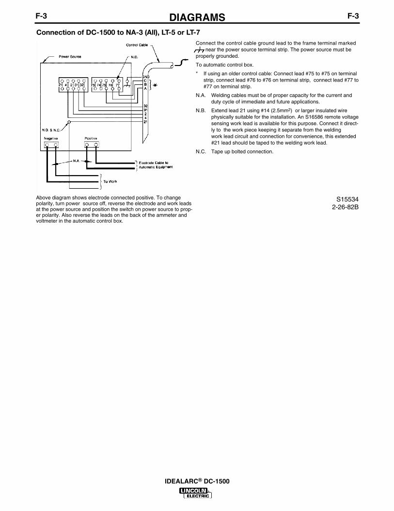
Connection of DC-1500 to NA-3 (All), LT-5 or LT-7
Above diagram shows electrode connected positive. To changepolarity, turn power source off, reverse the electrode and work leadsat the power source and position the switch on power source to prop-er polarity. Also reverse the leads on the back of the ammeter andvoltmeter in the automatic control box.
Connect the control cable ground lead to the frame terminal markednear the power source terminal strip. The power source must be
properly grounded.
To automatic control box.
* If using an older control cable: Connect lead #75 to #75 on terminalstrip, connect lead #76 to #76 on terminal strip, connect lead #77 to#77 on terminal strip.
N.A. Welding cables must be of proper capacity for the current andduty cycle of immediate and future applications.
N.B. Extend lead 21 using #14 (2.5mm2) or larger insulated wirephysically suitable for the installation. An S16586 remote voltagesensing work lead is available for this purpose. Connect it direct-ly to the work piece keeping it separate from the weldingwork lead circuit and connection for convenience, this extended#21 lead should be taped to the welding work lead.
N.C. Tape up bolted connection.
S155342-26-82B

F-4DIMENSION PRINTF-4
IDEALARC® DC-1500

Idealarc DC1500 - 12479

KEY PART NUMBER DESCRIPTION QTYP-887-A Index of Sub Assemblies AR
P-887-C Front Panel Assembly AR
P-887-D Transformer Assembly & Internal Parts -R AR
P-887-E Internal Parts - Left Side AR
P-887-G Rectifier Assembly AR
P-887-J Remote Control AR
Index of Sub Assemblies - 12479
Idealarc DC1500 - 12479 1
Prin
ted
10/1
2/20
15 a
t 12:
55:1
0. P
rodu
ced
by E
nigm
a.

No Image
Index of Sub Assemblies - 12479
2 Idealarc DC1500 - 12479
Prin
ted
10/1
2/20
15 a
t 12:
55:1
0. P
rodu
ced
by E
nigm
a.

KEY PART NUMBER DESCRIPTION QTY1 9SL6477 FRONT PANEL ASBLY 1
2 9SL5813-6 Nameplate 1
3 9ST13562-1 TOGGLE SWTICH 1
4 9ST11160 SWITCH 1
5 9ST13486-4 PILOT LIGHT 1
6 9ST10812-40 RHEOSTAT 1
9ST12792-1 INSULATION 1
9ST10491 KNOB 1
7 9SS10433 FUSE-HOLDER30A 1
9ST10728-16 FUSE 1
8 9ST13381-3 SWITCH TOGGLE 3PDT 1
9 9SM6574-A PUSH BUTTON ASBLY 1
10 9ST12893 DECAL-NEGATIVE 1
11 9ST12892 DECAL-POSITIVE 1
12 9SS10255-14 GROMMET 1
13 9SS8542 TERMINAL STRIP 1
14 9SS14530-11 TERMINAL STRIP 1
16 9ST14373 INSULATION 4
17 9ST10082-4 SEMS SCREW 4
18 9SCF000010 #10-24HN 4
19 9ST8141-4 CONNECTION STRAP 4
20 9ST6931-11 STUD 4
21 9ST3960 FLANGE NUT 4
22 9SCF000054 1/2-13HJN 8
23 9SS9262-1 PLAIN WASHER 8
24 9ST14374 INSULATING BUSHING 4
25 9SS10773-9 INSULATING WASHER 4
26 9SE106A-15 LOCKWASHER 4
31 9SM8772-127 LEAD 2
32 9SS17405 NUMBER PLATE 1
36 9ST9639-1 CLAMP 1
37 9ST13486-2 PILOT LIGHT 1
9SL6374-1 ROOF 1
9SL5347-1 CASE SIDE 2
Front Panel Assembly
Idealarc DC1500 - 12479 3
Prin
ted
10/1
2/20
15 a
t 12:
55:1
0. P
rodu
ced
by E
nigm
a.

KEY PART NUMBER DESCRIPTION QTY9SL5347-2 CASE SIDE 2
9SL5353 REAR PANEL 1
9SL5352 REAR PANEL 1
9SS17201-1 OUTPUT BY-PASS CAPACITORASBLY 1
9ST13260-4 DECAL-EARTH GROUND CONN 1
Front Panel Assembly
4 Idealarc DC1500 - 12479
Prin
ted
10/1
2/20
15 a
t 12:
55:1
0. P
rodu
ced
by E
nigm
a.

P-887-C.jpg
Front Panel Assembly
Idealarc DC1500 - 12479 5
Prin
ted
10/1
2/20
15 a
t 12:
55:1
0. P
rodu
ced
by E
nigm
a.
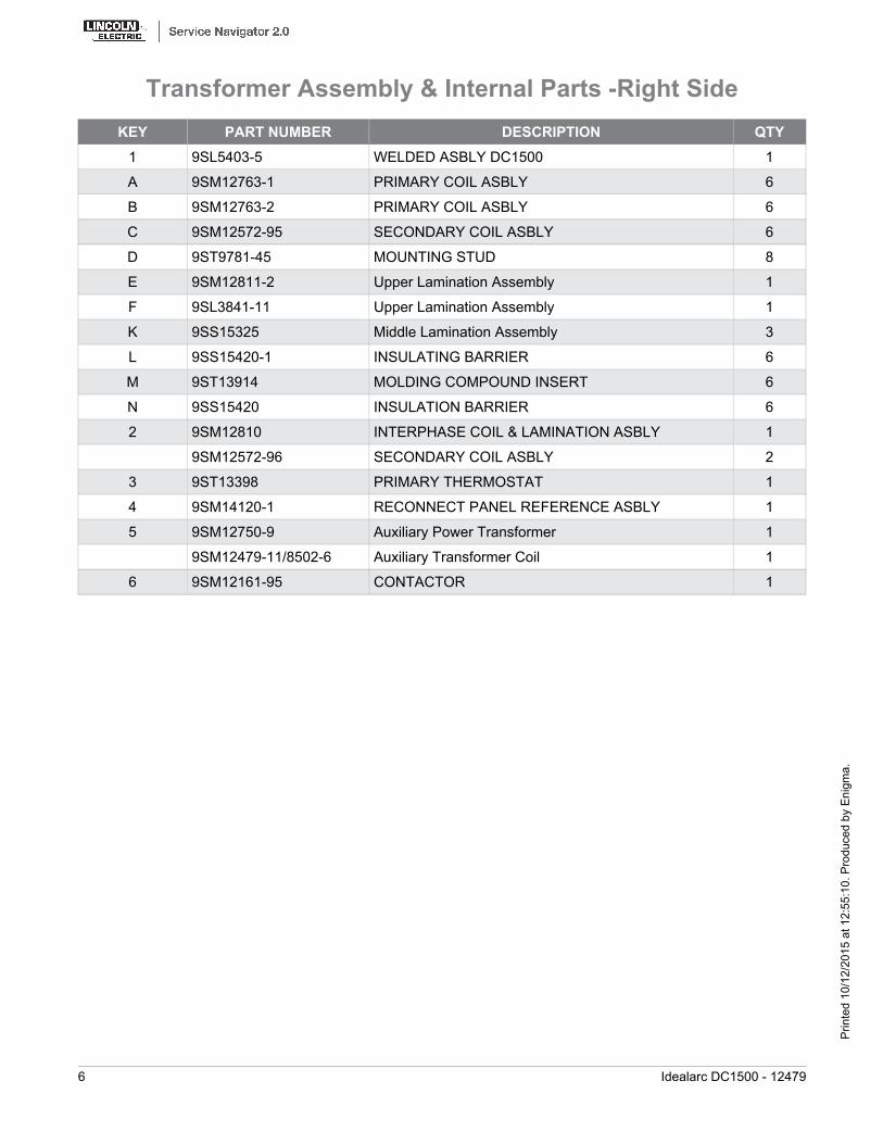
KEY PART NUMBER DESCRIPTION QTY1 9SL5403-5 WELDED ASBLY DC1500 1
A 9SM12763-1 PRIMARY COIL ASBLY 6
B 9SM12763-2 PRIMARY COIL ASBLY 6
C 9SM12572-95 SECONDARY COIL ASBLY 6
D 9ST9781-45 MOUNTING STUD 8
E 9SM12811-2 Upper Lamination Assembly 1
F 9SL3841-11 Upper Lamination Assembly 1
K 9SS15325 Middle Lamination Assembly 3
L 9SS15420-1 INSULATING BARRIER 6
M 9ST13914 MOLDING COMPOUND INSERT 6
N 9SS15420 INSULATION BARRIER 6
2 9SM12810 INTERPHASE COIL & LAMINATION ASBLY 1
9SM12572-96 SECONDARY COIL ASBLY 2
3 9ST13398 PRIMARY THERMOSTAT 1
4 9SM14120-1 RECONNECT PANEL REFERENCE ASBLY 1
5 9SM12750-9 Auxiliary Power Transformer 1
9SM12479-11/8502-6 Auxiliary Transformer Coil 1
6 9SM12161-95 CONTACTOR 1
Transformer Assembly & Internal Parts -Right Side
6 Idealarc DC1500 - 12479
Prin
ted
10/1
2/20
15 a
t 12:
55:1
0. P
rodu
ced
by E
nigm
a.

P-887-D.jpg
Transformer Assembly & Internal Parts -Right Side
Idealarc DC1500 - 12479 7
Prin
ted
10/1
2/20
15 a
t 12:
55:1
0. P
rodu
ced
by E
nigm
a.

KEY PART NUMBER DESCRIPTION QTY2 9SG8394-1 Control Circuit PC Board 1
3 9SG8390-1 Firing Circuit PC Board 1
4 9SS15122-11 RELAY 1
7 9SM12390-74 Transformer T2 380V 440V 1
8 9SM12390-75 Transformer T3 380V 440V 1
9 9SM12390-76 Transformer T4 380V 440V 1
10A 9SS14779-4 FAN MOTOR 1
10B 9SS14779-6 FAN MOTOR 1
11A 9SM6819-7 FAN 1
11B 9SM6819-8 FAN 1
12 9SS14530-7 TERMINAL STRIP 1
9ST10726-95 NUMBER PLATE 1
13 9SM12390-72 TRANSFORMER ASBLY 1
14 9SS15611 PILOT RELAY 1
9SM13028 DUST COVER 1
9SS14293-9 RELAY 1
9SS18922-1 Ground Screw Assembly 5
9SL10671 OUTPUT STUD COVER REF ASBLY 1
9SS14113-10 Ground Strap 1
Internal Parts - Left Side
8 Idealarc DC1500 - 12479
Prin
ted
10/1
2/20
15 a
t 12:
55:1
0. P
rodu
ced
by E
nigm
a.

P-887-E.jpg
Internal Parts - Left Side
Idealarc DC1500 - 12479 9
Prin
ted
10/1
2/20
15 a
t 12:
55:1
0. P
rodu
ced
by E
nigm
a.

KEY PART NUMBER DESCRIPTION QTY1 9SL5348-5 RECTIFIER ASBLY 1
2 9SL5348-4 RECTIFIER ASBLY 1
3 9SL5348-6 RECTIFIER ASBLY 1
4 9SL6981 SNUBBER PC BD ASBLY 1
4 9SL6980 SNUBBER PC BD ASBLY 1
5 9SS16018 SHUNT 1
5 9SS15326 SHUNT ASBLY 1
9SS12334-23 REED SWITCH ASBLY 1
9SS12334-33 REED SWITCH ASBLY 1
6 9ST13840 RESISTOR DIODE ASBLY PURCH DPNI 1
6 9ST14450 RESISTOR DIODE ASBLY 1
7 9SS10404-7 RESIST0R-WIREWOUND 1
9ST9781-34 THRU BOLT 1
9ST9764-2 INSULATING WASHER 4
Rectifier Assembly
10 Idealarc DC1500 - 12479
Prin
ted
10/1
2/20
15 a
t 12:
55:1
0. P
rodu
ced
by E
nigm
a.

P-887-G.jpg
Rectifier Assembly
Idealarc DC1500 - 12479 11
Prin
ted
10/1
2/20
15 a
t 12:
55:1
0. P
rodu
ced
by E
nigm
a.

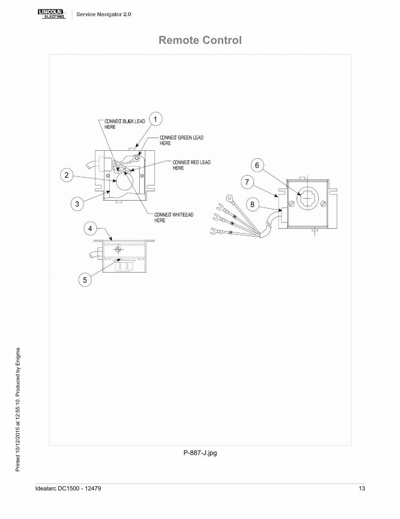
KEY PART NUMBER DESCRIPTION QTYK775 Remote Control 1
1 9SS8025-70 SELF TAPPING SCREW 4
2 9ST10812-40 RHEOSTAT 1
3 9ST12792-1 INSULATION 1
4 9SM12695 BOX WRAPAROUND 1
5 9SS14268 NAMEPLATE 1
6 9ST10491 KNOB 1
7 9SM12618 REMOTE CONTROL BOX 1
8 9ST9274-4 GROMMET 1
9 9SM12617 PORT VOLT CONT CABLE ASBLY 1
Remote Control
12 Idealarc DC1500 - 12479
Prin
ted
10/1
2/20
15 a
t 12:
55:1
0. P
rodu
ced
by E
nigm
a.
P-887-J.jpg
Remote Control
Idealarc DC1500 - 12479 13
Prin
ted
10/1
2/20
15 a
t 12:
55:1
0. P
rodu
ced
by E
nigm
a.

WARNING
AVISO DEPRECAUCION
ATTENTION
WARNUNG
ATENÇÃO
Spanish
French
German
Portuguese
Japanese
Chinese
Korean
Arabic
LEIA E COMPREENDA AS INSTRUÇÕES DO FABRICANTE PARA ESTE EQUIPAMENTO E AS PARTES DE USO, E SIGA ASPRÁTICAS DE SEGURANÇA DO EMPREGADOR.
● Keep your head out of fumes.● Use ventilation or exhaust to
remove fumes from breathing zone.
● Los humos fuera de la zona de res-piración.
● Mantenga la cabeza fuera de loshumos. Utilice ventilación oaspiración para gases.
● Gardez la tête à l’écart des fumées.● Utilisez un ventilateur ou un aspira-
teur pour ôter les fumées des zonesde travail.
● Vermeiden Sie das Einatmen vonSchweibrauch!
● Sorgen Sie für gute Be- undEntlüftung des Arbeitsplatzes!
● Mantenha seu rosto da fumaça.● Use ventilação e exhaustão para
remover fumo da zona respiratória.
● Turn power off before servicing.
● Desconectar el cable de ali-mentación de poder de la máquinaantes de iniciar cualquier servicio.
● Débranchez le courant avant l’entre-tien.
● Strom vor Wartungsarbeitenabschalten! (Netzstrom völlig öff-nen; Maschine anhalten!)
● Não opere com as tampas removidas.● Desligue a corrente antes de fazer
serviço.● Não toque as partes elétricas nuas.
● Do not operate with panel open orguards off.
● No operar con panel abierto oguardas quitadas.
● N’opérez pas avec les panneauxouverts ou avec les dispositifs deprotection enlevés.
● Anlage nie ohne Schutzgehäuseoder Innenschutzverkleidung inBetrieb setzen!
● Mantenha-se afastado das partesmoventes.
● Não opere com os paineis abertosou guardas removidas.

WARNING
AVISO DEPRECAUCION
ATTENTION
WARNUNG
ATENÇÃO
Spanish
French
German
Portuguese
Japanese
Chinese
Korean
Arabic
READ AND UNDERSTAND THE MANUFACTURER’S INSTRUCTION FOR THIS EQUIPMENT AND THE CONSUMABLES TO BEUSED AND FOLLOW YOUR EMPLOYER’S SAFETY PRACTICES.
SE RECOMIENDA LEER Y ENTENDER LAS INSTRUCCIONES DEL FABRICANTE PARA EL USO DE ESTE EQUIPO Y LOSCONSUMIBLES QUE VA A UTILIZAR, SIGA LAS MEDIDAS DE SEGURIDAD DE SU SUPERVISOR.
LISEZ ET COMPRENEZ LES INSTRUCTIONS DU FABRICANT EN CE QUI REGARDE CET EQUIPMENT ET LES PRODUITS AETRE EMPLOYES ET SUIVEZ LES PROCEDURES DE SECURITE DE VOTRE EMPLOYEUR.
LESEN SIE UND BEFOLGEN SIE DIE BETRIEBSANLEITUNG DER ANLAGE UND DEN ELEKTRODENEINSATZ DES HER-STELLERS. DIE UNFALLVERHÜTUNGSVORSCHRIFTEN DES ARBEITGEBERS SIND EBENFALLS ZU BEACHTEN.
● Do not touch electrically live parts orelectrode with skin or wet clothing.
● Insulate yourself from work andground.
● No toque las partes o los electrodosbajo carga con la piel o ropa moja-da.
● Aislese del trabajo y de la tierra.
● Ne laissez ni la peau ni des vête-ments mouillés entrer en contactavec des pièces sous tension.
● Isolez-vous du travail et de la terre.
● Berühren Sie keine stromführendenTeile oder Elektroden mit IhremKörper oder feuchter Kleidung!
● Isolieren Sie sich von denElektroden und dem Erdboden!
● Não toque partes elétricas e elec-trodos com a pele ou roupa molha-da.
● Isole-se da peça e terra.
● Keep flammable materials away.
● Mantenga el material combustiblefuera del área de trabajo.
● Gardez à l’écart de tout matérielinflammable.
● Entfernen Sie brennbarres Material!
● Mantenha inflamáveis bem guarda-dos.
● Wear eye, ear and body protection.
● Protéjase los ojos, los oídos y elcuerpo.
● Protégez vos yeux, vos oreilles etvotre corps.
● Tragen Sie Augen-, Ohren- und Kör-perschutz!
● Use proteção para a vista, ouvido ecorpo.

CUSTOMER ASSISTANCE POLICYThe business of The Lincoln Electric Company is manufacturing andselling high quality welding equipment, consumables, and cuttingequipment. Our challenge is to meet the needs of our customers andto exceed their expectations. On occasion, purchasers may askLincoln Electric for advice or information about their use of ourproducts. We respond to our customers based on the best informationin our possession at that time. Lincoln Electric is not in a position towarrant or guarantee such advice, and assumes no liability, withrespect to such information or advice. We expressly disclaim anywarranty of any kind, including any warranty of fitness for anycustomer’s particular purpose, with respect to such information oradvice. As a matter of practical consideration, we also cannot assumeany responsibility for updating or correcting any such information oradvice once it has been given, nor does the provision of informationor advice create, expand or alter any warranty with respect to the saleof our products.
Lincoln Electric is a responsive manufacturer, but the selection anduse of specific products sold by Lincoln Electric is solely within thecontrol of, and remains the sole responsibility of the customer. Manyvariables beyond the control of Lincoln Electric affect the resultsobtained in applying these types of fabrication methods and servicerequirements.
Subject to Change – This information is accurate to the best of ourknowledge at the time of printing. Please refer to www.lincolnelectric.com for any updated information.