Operator's Manual - E-Katalog LKPP
395
ACCENT MC240 Chemistry Analyzer Operator ’ s Manual
-
Upload
khangminh22 -
Category
Documents
-
view
2 -
download
0
Transcript of Operator's Manual - E-Katalog LKPP

ACCENT MC240
Chemistry Analyzer
Operator’s Manual

ACCENT MC240 Operator’s Manual i
© 2019 PZ Cormay S.A. All rights Reserved.
For this Operator's Manual, the issue date is 2019-04.
Intellectual Property Statement
PZ Cormay S.A. (hereinafter called Cormay) owns the intellectual property rights to this Cormay product and this manual. This manual may refer to information protected by copyright or patents and does not convey any license under the patent rights or copyright of Cormay, or of others.
Cormay intends to maintain the contents of this manual as confidential information. Disclosure of the information in this manual in any manner whatsoever without the written permission of Cormay is strictly forbidden.
Release, amendment, reproduction, distribution, rental, adaptation, translation or any other derivative work of this manual in any manner whatsoever without the written permission of Cormay is strictly forbidden.
is the trademark, registered or otherwise, of Cormay in Poland and other countries. All other trademarks that appear in this manual are used only for informational or editorial purposes. They are the property of their respective owners.
Responsibility on the Manufacturer Party
Contents of this manual are subject to change without prior notice.
All information contained in this manual is believed to be correct. Cormay shall not be liable for errors contained herein or for incidental or consequential damages in connection with the furnishing, performance, or use of this manual.
Cormay is responsible for the effects on safety, reliability and performance of this product, only if:
all installation operations, expansions, changes, modifications and repairs of this product are conducted by Cormay authorized personnel;
the electrical installation of the relevant room complies with the applicable national and local requirements; and
the product is used in accordance with the instructions for use.

ii ACCENT MC240 Operator’s Manual
Warning
It is important for the hospital or organization that employs this equipment to carry out a reasonable service/maintenance plan. Neglect of this may result in machine breakdown or personal injury.
Note
This equipment must be operated by skilled/trained clinical professionals.
Warranty
THIS WARRANTY IS EXCLUSIVE AND IS IN LIEU OF ALL OTHER WARRANTIES, EXPRESSED OR IMPLIED, INCLUDING WARRANTIES OF MERCHANTABILITY OR FITNESS FOR ANY PARTICULAR PURPOSE.
Exemptions
Cormay's obligation or liability under this warranty does not include any transportation or other charges or liability for direct, indirect or consequential damages or delay resulting from the improper use or application of the product or the use of parts or accessories not approved by Cormay or repairs by people other than Cormay authorized personnel.
This warranty shall not extend to:
Malfunction or damage caused by improper use or man-made failure.
Malfunction or damage caused by unstable or out-of-range power input.
Malfunction or damage caused by force majeure such as fire and earthquake.
Malfunction or damage caused by improper operation or repair by unqualified or unauthorized service people.
Malfunction of the instrument or part whose serial number is not legible enough.
Others not caused by instrument or part itself.
Return Policy
In the event that it becomes necessary to return this product or part of this product to CORMAY, the following procedure should be followed:
1. The return should be established with the person handling the customer complaint.
2. The customer should obtain complaint number; the number is given in accordance to complaint handling process. The complaint number must appear on the outside of the shipping container. Returned shipments will not be accepted if the complaint number is not clearly visible.
3. Freight policy: The customer is responsible for freight charges when this product is shipped to CORMAY (this includes customs charges).
4. Return address: Please send the part(s) or equipment to the address confirmed by the person handling the customer complaint.

ACCENT MC240 Operator’s Manual iii
Customer service department
Manufacturer: PZ CORMAY S.A.
Address: Wiosenna 22 Str.
05-092 Łomianki, POLAND
Website: www.cormay.pl
E-mail Address: [email protected]
Tel: +48 22 751 79 10
Fax: +48 22 751 79 11


Preface
ACCENT MC240 Operator’s Manual 1
Preface
This manual contains the instructions necessary to operate the product safely and in accordance with its function and intended use. Please read this manual thoroughly before using the product. Observance of this manual is a prerequisite for proper performance and correct operation, and it ensures patient and operator safety. All graphics including screens and printouts in this manual are for illustration purpose only and must not be used for any other purposes. The screens and printouts on the actual product should prevail.
Intended audience
This manual is intended for medical laboratory professionals to do the following:
Learn about the system hardware and software.
Perform daily operating tasks.
Maintain and troubleshoot the system.
Related documents
The following documents are provided for searching information about the instrument:
Operator's Manual
Contains instrument compositions, operating instructions, maintenance and troubleshooting methods. At the beginning of this manual is a table of contents, which provides references of all chapters for searching desired information. At the end of this manual is a glossary and index, which provide term definitions and index to key words.
This manual is based on the maximum configuration and therefore some contents may not apply to your product. It you have any questions, please contact us.
Operation Card
Provides daily operating procedure for quickly guiding you through basic operations of the instrument. It includes pre-startup checks and startup, operations before test, routine test, daily performance and powering off.
Maintenance Card
Provides regular and irregular maintenance of the instrument to help you maintain it so that it can work normally.
For detailed maintenance instructions, see the Operator's Manual.
Online help
Contains detailed descriptions of the software screens and parameters. It also covers the Operator's Manual, which enables you to retrieve information related to the software screens and operation tasks.
Conventions
Graphical symbols, formats and abbreviations are used to get better visual effects and readability. To help you understand this manual correctly, this section provides statements of pictures, terms and applicable models used in this manual.
Symbols and formats
The following symbols and formats are used:

Preface
2 ACCENT MC240 Operator’s Manual
Symbol and format Meaning
Item list.
Reference content or cross reference.
Bold Headings or important information.
Italic Key points.
Start of operating procedure.
Picture
All pictures in this manual are for illustration purpose only and must not be used for any other purposes. The pictures of the actual product should prevail.
Terms
The analyzer has one probe for adding sample and reagent. If not specifically stated, it is referred to as "probe". For emphasis purpose in software operations, "sample probe" is used for adding sample, and "reagent probe" is used for adding reagent.
The analyzer has one carousel for holding sample and reagent. If not specifically stated, it is referred to as "sample/reagent carousel". For emphasis purpose in software operations, "sample carousel" is used for sample, and "reagent carousel " is used for reagent.
Instrument configuration:
The illustrations and instructions in this manual are based on the maximum configurations of the instrument. For the final configurations of this product, please refer to the Packing list.
Online help
The operating software provides a context-sensitive online help, which can help you better understand the screen parameters and perform correct operations. The online help is related to software screens, and it can display information related to menu page, maintenance item, maintenance command, and event log.
You can open the online help window in the following ways:
Alt+F1: press this shortcut key combination on any screen.
: click this icon on the top-right of any screen.
: click this button to the left of a maintenance item, a maintenance command, or an event log.

Safety information
ACCENT MC240 Operator’s Manual 3
Safety information
This chapter provides you with safety symbols used in this manual and their meanings, summarizes the safety hazards and operating precautions that should be considered seriously when the instrument is being operated, and lists the labels and silkscreens that have been applied to the instrument and their indications.
Safety symbols
Safety symbols are used in this manual in order to remind you of the instructions necessary to operate the product safely and in accordance with its function and intended use. A safety symbol and text constitutes a warning as shown in the table below:
Symbol Meaning
Caution
Biological risks
Summary of hazards
This section lists hazards of the instrument itself. The hazards of specific operation are included in the warning information of each operation task.
Observe the following safety precautions when using the product. Ignoring any of them may lead to personal injury or equipment damage.

Safety information
4 ACCENT MC240 Operator’s Manual
WARNING
If the product is used in a manner not specified by our company, the protection provided by the product may be impaired.
Electric shock hazards
WARNING
When the MAIN POWER is turned on, users other than the servicing personnel authorized by our company must not open the rear cover or side cover.
Spillage of reagent or sample on the product may cause equipment failure and even electric shock. Do not place sample and reagent on the product. In case of spillage, switch off the power immediately, remove the spillage and contact our Customer Service Department or your local distributor.
Moving Parts Hazards
WARNING
Do not touch such moving parts as sample/reagent carousel, reaction carousel, probe, mixer, and cuvette wash station, when the system is in operation.
Exercise caution while using the ISE module Prevent your hair, legs or other parts of your body from being hurt by the driving parts.
Do not put your fingers or hands into any open part when the system is in operation.
Photometer lamp hazards
WARNING
Eye injury could occur from light emission from the photometer lamp. Do not stare into the lamp when the system is in operation.
If you want to replace the photometer lamp, first switch off the MAIN POWER and then wait at least 5 minutes for the lamp to cool down before touching it. Do not touch the lamp before it cools down, or you may get burned.
Sample, calibrator and control hazards
BIOHAZARD
Inappropriately handling samples, controls and calibrators may lead to biohazardous infection. Do not touch samples, controls, calibrators, mixtures, or waste with your bare hands. Wear gloves and lab coat and, if necessary, goggles.
In case your skin contacts the sample, control or calibrator, follow the standard laboratory safety procedure and consult a doctor.
The serum samples remaining in the electrodes may contain a great number of viruses. Wear gloves to prevent infection while operating around the electrodes.
Safety information
ACCENT MC240 Operator’s Manual 5
Reagent and wash solution hazards
WARNING
Reagents,diluted wash solution and concentrated wash solution are corrosive to human skins. Exercise caution when using reagents and concentrated wash solution. In case your skin or clothes contact them, wash them off with soap and clean water. If reagents or wash solution spills into your eyes, rinse them with much water and consult an oculist.
Waste hazards
BIOHAZARD
Some substances contained in reagent, control, calibrator, concentrated wash solution, and waste are subject to regulations of contamination and disposal. Dispose of the waste in accordance with your local or national rule for biohazard waste disposal and consult the manufacturer or distributor of the reagents for details.
Wear gloves and lab coat and, if necessary, goggles.
System disposal hazards
WARNING
Materials of the analyzer are subject to contamination regulations. Dispose of the waste analyzer in accordance with your local or national rule for waste disposal.
Fire and explosion hazards
WARNING
Ethanol is flammable substance. Please exercise caution while using ethanol around the instrument in order to prevent fire and explosion.
Removal of analyzer from use for repair or disposal
WARNING
When the analyzer is not in use, for example, in repair, transportation or disposal process, please clean and sterilize the parts that may cause biohazards(probe, mixer, etc.) and remind the person who handles the device of the related hazards.
Cleaning and Decontamination
CAUTION
Appropriate decontamination should be carried out in accordance with laboratory safety regulations if reagent, sample or other liquids are spilled onto the equipment. In case of large-amount liquid ingression, please contact our customer service department or the local distributor.
No decontamination or cleaning agents can be used which could cause a HAZARD as a result of a reaction with parts of the equipment or with material contained in it. Strong acid or alkaline solutions are forbidden to clean the equipment.
If there is any doubt about the compatibility of the decontamination or cleaning agents with parts of the equipment or with material contained in it, please contact our customer service department or the local distributor.
Summary of precautions
This section lists precautions to be understood during instrument operation. The precautions of specific operation are included in the warning information of each operation task.
To use the product safely and efficiently, pay attention to the following operating precautions.

Safety information
6 ACCENT MC240 Operator’s Manual
Intended use
WARNING
The instrument is an automated chemistry analyzer for in vitro diagnostic use in clinical laboratories and designed for in vitro quantitative determination of clinical chemistries in serum, plasma, urine and cerebrospinal fluid samples.
Please consult us before you use the instrument for other purposes.
When drawing a clinical conclusion, please also refer to patients' clinical symptoms and other test results.
Environment precautions
CAUTION
Please install and operate the system in an environment specified by this manual. Installing and operating the system in other environment may lead to unreliable results and even equipment damage.
To relocate the system, please contact our Customer Service Department or your local distributor.
Installation precautions
NOTE
The safety of any system incorporating the instrument is the responsibility of the assembler of the system.
Electromagnetic noise precautions
CAUTION
The intended use environments of this IVD medical equipment includes typical healthcare environments (hospitals, clinics, doctor’s offices). This device has been designed and tested to CISPR 11 Class A, and in a domestic environment may cause radio interference, in which case, you may need to take measures to mitigate the interference.
Electromagnetic noise may interfere with operations of the system. Do not install devices generating excessive electromagnetic noise around the system. Do not use such devices as radio transmitters in the room housing the system. Do not use other CRT displays around the system.
The electromagnetic environment should be evaluated prior to operation of the device.
Do not use other medical instruments around the system that may generate electromagnetic noise to interfere with their operations.
Do not use this device in close proximity to sources of strong electromagnetic radiation (e.g.unshielded intentional RF sources ), as these may interfere with the proper operation.
NOTE
It is the manufacturer's responsibility to provide equipment electromagnetic compatibility information to the customer or user.
It is the user's responsibility to ensure that a compatible electromagnetic environment for the equipment can be maintained in order that the device will perform as intended.

Safety information
ACCENT MC240 Operator’s Manual 7
Operating precautions
CAUTION
Take the clinical symptoms or other test results of the patient into considerations when making diagnosis based on the measuring results produced by the system.
Operate the system strictly as instructed by this manual. Inappropriate use of the system may lead to unreliable test results or even equipment damage or personal injury.
When using the system for the first time, run calibrations and QC tests to make sure the system is in proper state.
Be sure to run QC tests every time when you use the system, otherwise the result may be unreliable.
Start the operating software again when the analyzing unit is powered off.
Do not uncover the reagent carousel when the system is in operation. Keep the reagent carousel cover closed.
The RS-232 port on the analyzing unit is used for connection with the operation unit only. Do not use it for other connections. Use the cables provided by our company or your local distributor for the connection.
The operation unit is a personal computer with the operating software installed. Installing other software or hardware on the computer may interfere with the system operation. Do not run other software when the system is working.
Computer virus may destroy the operating software or test data. Do not use the computer for other purposes or connect it to the Internet. If the computer is infected by virus, please install anti-virus software to check for and clear virus.
Do not touch the display, mouse or keyboard with wet hands or hands with chemicals.
Do not place the MAIN POWER to ON again within 10 seconds after placing it to OFF; otherwise the system may enter the protection status. If it does so, place the MAIN POWER to OFF and place it to ON again.
Chemistry parameter configuration precautions
CAUTION
To define such parameters as sample volume, reagent volume and wavelength, follow the instructions in this manual and the instructions of reagents.

Safety information
8 ACCENT MC240 Operator’s Manual
ISE module precautions
CAUTION
To prevent ISE electrodes from being damaged due to water scarcity, if the system, when equipped with an ISE module will be powered off for a long time, perform the electrode storage maintenance.
Sample precautions
CAUTION
Use samples that are completely free of insoluble substances like fibrin or suspended matter; otherwise the sample probe may be clogged.
Medicines, anticoagulants or preservative in the samples may lead to unreliable results.
Hemolysis, icterus or lipemia in the samples may lead to unreliable test results; running a serum index test therefore, is recommended.
Store the samples properly. Improper storage may change the compositions of samples and lead to unreliable results.
Sample volatilization may lead to unreliable results. Do not leave the sample open for a long period.
Prepare sufficient sample volume before analysis.
Load samples to correct positions on the sample carousel before the analysis begins; otherwise reliable results may not be obtained.
Reagent, calibrator and control precautions
CAUTION
Use proper reagents, calibrators and controls on the system.
Select appropriate reagents according to the performance characteristics of the system. Consult the reagent suppliers, our company or our authorized distributor for details, if you are not sure about your reagent choice.
Store and use the reagents, calibrators and controls strictly as instructed by the suppliers; otherwise, reliable results or best performance of the system may not be obtained. Improper storage of reagents, calibrators and controls may lead to unreliable results and bad performance of the system even in validity period.
Perform calibration after changing the reagents, otherwise reliable results may not be obtained.
Contamination caused by carryover among reagents may lead to unreliable test results. Consult the reagent suppliers for details.
ISE calibration precautions
BIOHAZARD
The calibrators contain preservatives. In case your skin contacts calibrators, wash them off with soap and water. In case the calibrators spill into your eyes, rinse them with water and consult an oculist. If you swallow them by mistake, see a doctor.

Safety information
ACCENT MC240 Operator’s Manual 9
CAUTION
Use the calibrators specified by our company. Use of other reagents or calibrators may result in unreliable results, or damage the Hydropneumatic system, or even shorten the electrodes life span.
Prior to using the calibrators, check if they are within the expiration date.
Place them correctly; otherwise, it may cause unreliable results, or leak, or module damage.
ISE wash solution biohazards
BIOHAZARD
The ISE wash solution is sodium hypochlorite. Use the ISE wash solution carefully to prevent it from contacting your skins or eyes. If your skins or eyes contact the ISE wash solution, rinse them off with fresh water and consult a doctor.
Data archiving precautions
NOTE
The system automatically stores the data to the built-in hard disk. Data loss, however, is still possible due to mis-deletion or physical damage of the hard disk. You are recommended to regularly archive the data to such medium as CDs.
To avoid the data loss caused by unexpected power failure, UPS (uninterrupted power supply) is recommended.
External equipment precautions
WARNING
For operating instructions and precautions of the computer and printer, please refer to their operation manuals.
External equipment connected to the analogue and digital interfaces must be authorized and complied with relevant safety and EMC standards (e.g., IEC 60950 Safety of Information Technology Equipment Standard and CISPR 22 EMC of Information Technology Equipment Standard (CLASS B)). Any person, who connects additional equipment to the signal input or output ports and configures an IVD system, is responsible for ensuring that the system works normally and complies with the safety and EMC requirements. If you have any questions, consult the technical services department of your local representative.
Tube and liquid container precautions
WARNING
When the tube or the part that contain liquid become aged or damaged, please stop its use immediately and contact our customer service department or your local distributor to check and replace it.

Safety information
10 ACCENT MC240 Operator’s Manual
Labels and silkscreen
The following labels and silkscreen are used on the product for system identification and operating instruction.
For the label marked with , please consult the related documentations in order to find out the nature of the potential HAZARDS and any actions which have to be taken to avoid them.
Check the labels regularly for cleanliness and integrity. If any of the labels becomes vague or peels off, contact our Customer Service Department or your local distributor for replacement.
Labels and silkscreen
Symbol Meaning
Serial Number
Date of Manufacture
Manufacturer
CE marking. The device is fully in conformance with the Council Directive Concerning In Vitro Diagnostic Medical Devices 98/79/EC.
Authorized Representative in the European Community
The following definition of the WEEE label applies to EU member states only: The use of this symbol indicates that this product should not be treated as household waste. By ensuring that this product is disposed of correctly, you will help prevent bringing potential negative consequences to the environment and human health. For more detailed information with regard to returning and recycling this product, please consult the distributor from whom you purchased the product.
In Vitro diagnostic medical device
Biological risks
Caution
Caution: hot surface
“ON” (Power)
“OFF” (Power)

Safety information
ACCENT MC240 Operator’s Manual 11
Symbol Meaning
“ON” for a part of equipment
“OFF” for a part of equipment
Serial interface
Protective conductor terminal
Fuse(for models powered by 220V-240V~ or
220V/230V~ supply voltage)
Fuse(for models powered by 110V/115V~ supply voltage)

Safety information
12 ACCENT MC240 Operator’s Manual
Warning labels
Biohazard warning
This label indicating the risk of biohazardous infection is located in the following positions:
Probe
Waste outlet
Waste tank
Moving parts warning
This symbol and text indicating the hazardous moving parts is located in the following positions:
Probe
Mixer
Wash station
Photometer lamp warning
This symbol and text located on the lamp housing reminds you of not touching the lamp before it gets cool.
Probe collision warning
This symbol and text located near the sample/reagent carousel and reaction carousel reminds you of not opening the cover to prevent from damaging the probe.
ISE module
This symbol and text located on the left side panel of the analyzer. Please turn off the main power before opening the small door.
Liquid level floater
This symbol and text is located near the liquid level floater of the DI water tank and the wash solution tank, Please do not take out the liquid level floater during test.

Safety information
ACCENT MC240 Operator’s Manual 13
Cuvette replacement window
This symbol and text is located on the cuvette replacement window.
Risk of injury when replacing the lamp
This label is located close to the door of the lamp. Do not touch the moving parts when replacing the lamp.
Chemical hazard
This label is applied on the diluted wash solution tank. Please take protective measures to prevent chemical hazard.
Cabinet
This label is applied at the middle of the cabinet back. If you want to relocate your analyzer, contact our Customer Service Department or your local distributor. When relocating it, do not carry it with the cabinet. Only when the cabinet is supported by the anchors, can the analyzer be placed on the cabinet.

Safety information
14 ACCENT MC240 Operator’s Manual

ACCENT MC240 Operator’s Manual 15
Table of contents Intellectual Property Statement ...............................................................................................................................................i
Responsibility on the Manufacturer Party ..........................................................................................................................i
Warranty ......................................................................................................................................................................................... ii
Exemptions ...................................................................................................................................................................... ii
Return Policy ................................................................................................................................................................... ii
Customer service department................................................................................................................................. iii
Preface ............................................................................................................................................................................................. 1
Intended audience ........................................................................................................................................................ 1
Related documents ........................................................................................................................................................ 1
Conventions..................................................................................................................................................................... 1
Online help ....................................................................................................................................................................... 2
Safety information ······················································································································· 3
Safety symbols ............................................................................................................................................................................... 3
Summary of hazards ................................................................................................................................................................... 3
Summary of precautions .......................................................................................................................................................... 5
Labels and silkscreen .............................................................................................................................................................. 10
Labels and silkscreen ............................................................................................................................................... 10
Warning labels ............................................................................................................................................................. 12
Table of contents ······················································································································· 15
1 System description ················································································································ 1-1
1.1 Installation requirements and procedure ............................................................................................................... 1-2
1.1.1 Installation requirements ............................................................................................................................ 1-2
1.1.2 Installation Procedure .................................................................................................................................. 1-5
1.2 Hardware components .................................................................................................................................................. 1-6
1.2.1 Overview ........................................................................................................................................................... 1-6
1.2.2 Sample/Reagent handling system .......................................................................................................... 1-8
1.2.3 Mixer assembly ............................................................................................................................................ 1-14
1.2.4 Reaction system .......................................................................................................................................... 1-14
1.2.5 Cuvette wash station .................................................................................................................................. 1-15
1.2.6 Photometric system ................................................................................................................................... 1-16
1.2.7 ISE unit (optional) ...................................................................................................................................... 1-16
1.2.8 Cabinet ............................................................................................................................................................ 1-17
1.2.9 Operation unit .............................................................................................................................................. 1-17
1.2.10 Output unit .................................................................................................................................................. 1-18
1.2.11 Accessories and consumables ............................................................................................................. 1-18
1.3 Software description .................................................................................................................................................... 1-19
1.3.1 Screen areas .................................................................................................................................................. 1-19
1.3.2 Screen elements ........................................................................................................................................... 1-22
1.3.3 Software hierarchy ..................................................................................................................................... 1-26
1.3.4 Using the mouse .......................................................................................................................................... 1-27
1.3.5 Using online help ......................................................................................................................................... 1-28

Table of contents
16 ACCENT MC240 Operator’s Manual
1.4 System specifications .................................................................................................................................................. 1-29
1.4.1 Analyzing unit .............................................................................................................................................. 1-29
1.4.2 Power supply requirements ................................................................................................................... 1-31
1.4.3 Environment requirements .................................................................................................................... 1-31
1.4.4 Dimensions and weight ........................................................................................................................... 1-31
1.4.5 Noise and fuse .............................................................................................................................................. 1-32
1.4.6 Input device ................................................................................................................................................... 1-32
1.4.7 Output device ................................................................................................................................................ 1-32
1.4.8 Communication interfaces ...................................................................................................................... 1-32
1.4.9 Safety classification .................................................................................................................................... 1-32
1.4.10 EMC requirements ................................................................................................................................... 1-33
2 Daily operating procedure ······································································································· 2-1
2.1 Daily operating procedure ........................................................................................................................................... 2-2
2.2 Startup and daily checks ................................................................................................................................................ 2-2
2.2.1 Checks before startup ................................................................................................................................... 2-2
2.2.2 Startup ................................................................................................................................................................ 2-3
2.2.3 Checking system status ................................................................................................................................ 2-6
2.3 Operations before routine test ................................................................................................................................ 2-10
2.3.1 Preparing reagents ..................................................................................................................................... 2-10
2.3.2 Calibration ..................................................................................................................................................... 2-16
2.3.3 QC ...................................................................................................................................................................... 2-20
2.4 Routine test ..................................................................................................................................................................... 2-22
2.4.1 Programming and processing samples .............................................................................................. 2-23
2.4.2 Checking test results .................................................................................................................................. 2-25
2.4.3 Checking test status and performing test control ......................................................................... 2-26
2.5 Daily maintenance and powering off ................................................................................................................... 2-28
2.5.1 Daily maintenance...................................................................................................................................... 2-29
2.5.2 Powering off .................................................................................................................................................. 2-29
2.5.3 Operations after powering off ............................................................................................................... 2-29
3 Reagent································································································································· 3-1
3.1 Special reagent .................................................................................................................................................................. 3-2
3.1.1 ISE reagent/calibration screen ................................................................................................................ 3-2
3.1.2 Loading special reagents in Running status ........................................................................................ 3-2
3.1.3 Unloading special reagents ......................................................................................................................... 3-3
3.1.4 Printing ISE reagent/calibration list...................................................................................................... 3-3
3.2 Biochemistry reagent ..................................................................................................................................................... 3-3
3.2.1 Biochemistry reagent/calibration screen............................................................................................ 3-3
3.2.2 Sorting reagents .............................................................................................................................................. 3-4
3.2.3 Loading biochemistry reagents in Running status ........................................................................... 3-4
3.2.4 Unloading biochemistry reagents ............................................................................................................ 3-4
3.2.5 Customizing reagent display ..................................................................................................................... 3-5
3.2.6 Setting up reagent alarm limit .................................................................................................................. 3-6
3.2.7 Checking and auto refreshing reagent inventory ............................................................................ 3-6
4 Calibration ····························································································································· 4-1
4.1 ISE calibration ................................................................................................................................................................... 4-2
4.1.1 Calibration setup ............................................................................................................................................ 4-2

Table of contents
ACCENT MC240 Operator’s Manual 17
4.1.2 Calibration status and alarm ...................................................................................................................... 4-2
4.1.3 Results recall .................................................................................................................................................... 4-3
4.2 Biochemistry calibration ............................................................................................................................................... 4-5
4.2.1 Calibration setup ............................................................................................................................................ 4-5
4.2.2 Calibration status and alarm ................................................................................................................... 4-11
4.2.3 Reagent blank ............................................................................................................................................... 4-12
4.2.4 Recalling calibration results ................................................................................................................... 4-15
5 QC ········································································································································ 5-1
5.1 Overview ............................................................................................................................................................................. 5-2
5.1.1 QC procedure ................................................................................................................................................... 5-2
5.1.2 QC result flags .................................................................................................................................................. 5-2
5.1.3 Control status ................................................................................................................................................... 5-2
5.2 QC setup ............................................................................................................................................................................... 5-3
5.2.1 Defining/Editing a control ......................................................................................................................... 5-3
5.2.2 Setting up control concentrations ........................................................................................................... 5-4
5.2.3 Setting up QC rules ........................................................................................................................................ 5-4
5.2.4 Auto QC .............................................................................................................................................................. 5-5
5.2.5 Deleting a control ........................................................................................................................................... 5-6
5.3 Recalling control results ................................................................................................................................................ 5-6
5.3.1 Result > History screen ............................................................................................................................... 5-6
5.3.2 Levey-Jennings screen ................................................................................................................................. 5-8
5.3.3 Recalling cumulative sum chart ............................................................................................................... 5-9
5.3.4 Recalling Twin-Plot chart ........................................................................................................................ 5-10
5.3.5 QC > Results screen .................................................................................................................................... 5-11
5.3.6 Recalling QC Summary ............................................................................................................................. 5-14
6 Program ································································································································ 6-1
6.1 Sample management ...................................................................................................................................................... 6-2
6.2 Sample programming and processing ..................................................................................................................... 6-3
6.2.1 Processing samples with LIS ..................................................................................................................... 6-3
6.2.2 Processing bar-coded samples ................................................................................................................. 6-4
6.2.3 Batch programming ...................................................................................................................................... 6-5
6.2.4 Adding samples ............................................................................................................................................... 6-6
6.2.5 Adding/Modifying chemistries ................................................................................................................. 6-7
6.2.6 Rerunning samples ........................................................................................................................................ 6-7
6.2.7 Sample blank ................................................................................................................................................. 6-12
6.2.8 Whole Blood Test ......................................................................................................................................... 6-13
6.3 Serum Index ..................................................................................................................................................................... 6-14
6.3.1 Introduction ................................................................................................................................................... 6-14
6.3.2 Theory of Serum Index ............................................................................................................................. 6-15
6.3.3 Serum Index Setup ...................................................................................................................................... 6-15
6.3.4 Auto Serum Index ....................................................................................................................................... 6-17
6.3.5 Running SI Chemistry ............................................................................................................................... 6-17
6.4 Extended functions ....................................................................................................................................................... 6-17
6.4.1 Clearing samples .......................................................................................................................................... 6-17
6.4.2 Sample and chemistry lists ...................................................................................................................... 6-18
6.4.3 Viewing unpositioned samples ............................................................................................................. 6-20

Table of contents
18 ACCENT MC240 Operator’s Manual
6.4.4 Releasing sample position ....................................................................................................................... 6-21
6.4.5 View sample logs ......................................................................................................................................... 6-22
6.4.6 Customizing sample information ......................................................................................................... 6-23
6.4.7 Customizing patient demographics ..................................................................................................... 6-24
6.4.8 Optimizing result display ......................................................................................................................... 6-24
6.5 Results Recall .................................................................................................................................................................. 6-26
6.5.1 Viewing current results ............................................................................................................................ 6-26
6.5.2 Viewing history results............................................................................................................................. 6-27
6.5.3 Reviewing sample results ........................................................................................................................ 6-29
6.5.4 Viewing/Editing patient demographics ............................................................................................ 6-29
6.5.5 Viewing reaction curve ............................................................................................................................ 6-30
6.5.6 Sending results to LIS host ...................................................................................................................... 6-33
6.5.7 Printing results ............................................................................................................................................. 6-34
6.5.8 Editing results ............................................................................................................................................... 6-35
6.5.9 Deleting results ............................................................................................................................................. 6-37
6.5.10 Customizing result display ................................................................................................................... 6-37
6.5.11 Recalculating results ................................................................................................................................ 6-39
6.5.12 Compensating results ............................................................................................................................. 6-39
6.5.13 Recalling result trend ............................................................................................................................. 6-40
6.5.14 Archiving results ....................................................................................................................................... 6-41
6.6 Test statistics ................................................................................................................................................................... 6-41
6.7 Result statistics ............................................................................................................................................................... 6-43
7 Chemistry ······························································································································ 7-1
7.1 Importing/Exporting chemistries ............................................................................................................................. 7-2
7.1.1 Importing default chemistry list .............................................................................................................. 7-2
7.1.2 Importing specified chemistry list .......................................................................................................... 7-3
7.1.3 Exporting chemistries .................................................................................................................................. 7-4
7.2 Biochemistry setup .......................................................................................................................................................... 7-4
7.2.1 User-defined chemistry setup ................................................................................................................... 7-5
7.2.2 Processing parameters ................................................................................................................................ 7-6
7.2.3 Error detection limits................................................................................................................................. 7-10
7.2.4 Using qualitative result ............................................................................................................................. 7-14
7.2.5 Slope and offset adjustment ................................................................................................................... 7-15
7.2.6 Reference/Critical range setup ............................................................................................................. 7-16
7.3 ISE chemistry setup ...................................................................................................................................................... 7-17
7.3.2 Viewing ISE chemistry parameters ..................................................................................................... 7-18
7.3.3 Description of ISE chemistry parameters ........................................................................................ 7-18
7.3.4 Using ISE qualitative result ..................................................................................................................... 7-19
7.4 Chemistry configuration ............................................................................................................................................ 7-19
7.4.1 Enabling chemistries ................................................................................................................................. 7-20
7.4.2 Disabling chemistries ................................................................................................................................ 7-20
7.4.3 Customizing chemistry display order ................................................................................................. 7-21
7.4.4 Adjusting test order of chemistries ..................................................................................................... 7-21
7.5 Twin chemistry .............................................................................................................................................................. 7-22
7.5.1 Chemistry definition .................................................................................................................................. 7-23
7.5.2 Removing twin relation ............................................................................................................................ 7-23

Table of contents
ACCENT MC240 Operator’s Manual 19
7.5.3 Reagent setup ............................................................................................................................................... 7-23
7.5.4 Setting up and requesting calibration ................................................................................................ 7-23
7.5.5 Setting up and requesting quality control ......................................................................................... 7-24
7.5.6 Sample programming and processing................................................................................................ 7-24
7.6 Special Calculations ...................................................................................................................................................... 7-24
7.6.1 Defining/Editing a calculation ............................................................................................................... 7-24
7.6.2 Enabling/Disabling calculations ........................................................................................................... 7-25
7.6.3 Deleting user-defined calculations ........................................................................................................ 7-26
7.6.4 Running calculations .................................................................................................................................. 7-26
7.7 Panels ................................................................................................................................................................................. 7-26
7.7.1 Defining/Editing a panel ......................................................................................................................... 7-26
7.7.2 Adjusting display order of panels.......................................................................................................... 7-27
7.7.3 Deleting panels ............................................................................................................................................. 7-27
7.7.4 Running panels ............................................................................................................................................ 7-27
7.7.5 Setting up and running default panel ................................................................................................. 7-27
7.8 Off-system chemistry .................................................................................................................................................. 7-28
7.8.1 Defining/Editing off-system chemistry ............................................................................................. 7-28
7.8.2 Running off-system chemistry .............................................................................................................. 7-29
7.8.3 Deleting off-system chemistry ............................................................................................................... 7-29
7.9 Carryover setup ............................................................................................................................................................. 7-29
7.9.1 Defining/Editing carryover pair ........................................................................................................... 7-30
7.9.2 Removing a carryover pair ..................................................................................................................... 7-31
7.10 Masking/Unmasking chemistries........................................................................................................................ 7-31
7.11 Reflex ............................................................................................................................................................................... 7-32
7.11.1 Setting up reflex relation ........................................................................................................................ 7-32
7.11.2 Editing reflex relation .............................................................................................................................. 7-33
7.11.3 Deleting reflex relation ............................................................................................................................ 7-33
7.11.4 Measurement and result recall .......................................................................................................... 7-33
8 Utility ···································································································································· 8-1
8.1 System commands ........................................................................................................................................................... 8-2
8.1.1 Home ................................................................................................................................................................... 8-2
8.1.2 Stop print .......................................................................................................................................................... 8-2
8.1.3 Waking up the System ................................................................................................................................. 8-2
8.2 System setup ...................................................................................................................................................................... 8-2
8.2.2 Sample test setup page ................................................................................................................................ 8-3
8.2.3 Auto rerun setup ............................................................................................................................................ 8-5
8.3 Instrument setup .............................................................................................................................................................. 8-6
8.3.1 Sleep/Awake .................................................................................................................................................... 8-6
8.3.2 Masking/Unmasking Chemistries .......................................................................................................... 8-9
8.3.3 Dictionary setup ............................................................................................................................................. 8-9
8.3.4 System communication options ........................................................................................................... 8-10
8.3.5 Selecting language ....................................................................................................................................... 8-11
8.3.6 Software upgrading .................................................................................................................................... 8-11
8.3.7 Viewing software versions ..................................................................................................................... 8-12
8.3.8 Setting up system date and time ........................................................................................................... 8-12
8.3.9 Setting up QC run length and auto QC ................................................................................................ 8-13

Table of contents
20 ACCENT MC240 Operator’s Manual
8.3.10 Auto release of samples ......................................................................................................................... 8-13
8.3.11 Voice tone setup ........................................................................................................................................ 8-13
8.3.12 Optimizing result display ...................................................................................................................... 8-14
8.3.13 Customizing sample information ...................................................................................................... 8-14
8.3.14 Customizing patient demographics .................................................................................................. 8-14
8.3.15 Reagent/Calibration setup ................................................................................................................... 8-15
8.3.16 Customizing reagent display ............................................................................................................... 8-15
8.3.17 Customizing sample position .............................................................................................................. 8-15
8.4 Print setup........................................................................................................................................................................ 8-15
8.4.1 General print setup options .................................................................................................................... 8-15
8.4.2 Editing print template ............................................................................................................................... 8-16
8.4.3 Importing print template ......................................................................................................................... 8-16
8.4.4 Setting up default template...................................................................................................................... 8-17
8.4.5 Deleting a template ..................................................................................................................................... 8-17
8.4.6 Defining chemistry print order ............................................................................................................. 8-17
8.5 Bar code setup ................................................................................................................................................................ 8-18
8.6 LIS setup ........................................................................................................................................................................... 8-20
8.6.1 Introduction ................................................................................................................................................... 8-20
8.6.2 Setting up host communication parameters ................................................................................... 8-21
8.6.3 Defining channel number of chemistries ......................................................................................... 8-23
8.7 User and Password Setup .......................................................................................................................................... 8-23
8.7.1 Defining a user ............................................................................................................................................. 8-23
8.7.2 Modifying a user ......................................................................................................................................... 8-24
8.7.3 Assigning/Modifying permissions ...................................................................................................... 8-25
8.7.4 Deleting a user .............................................................................................................................................. 8-25
9 Template modifying software ··································································································· 9-1
9.1 Main screen ........................................................................................................................................................................ 9-2
9.1.1 Main screen ...................................................................................................................................................... 9-2
9.1.2 File (F) ................................................................................................................................................................ 9-2
9.1.3 Edit (E) ............................................................................................................................................................... 9-4
9.1.4 View (V) ............................................................................................................................................................. 9-5
9.1.5 Insert (I) ............................................................................................................................................................ 9-6
9.1.6 Format (M) ....................................................................................................................................................... 9-7
9.1.7 Set(S) .................................................................................................................................................................. 9-8
9.1.8 Help (H) ............................................................................................................................................................. 9-8
9.1.9 Page ..................................................................................................................................................................... 9-9
9.2 Common tools .................................................................................................................................................................... 9-9
9.3 Draw tools ........................................................................................................................................................................ 9-10
9.4 Property window ........................................................................................................................................................... 9-10
9.4.1 Line ................................................................................................................................................................... 9-11
9.4.2 Rectangle ......................................................................................................................................................... 9-11
9.4.3 Label ................................................................................................................................................................. 9-12
9.4.4 Text ................................................................................................................................................................... 9-14
9.4.5 Title ................................................................................................................................................................... 9-15
9.4.6 Image ............................................................................................................................................................... 9-16
9.5 Report window ............................................................................................................................................................... 9-17

Table of contents
ACCENT MC240 Operator’s Manual 21
10 Maintenance ······················································································································· 10-1
10.1 Overview ........................................................................................................................................................................ 10-2
10.1.1 Safety information ................................................................................................................................... 10-2
10.1.2 Tools and Spare Parts .............................................................................................................................. 10-2
10.1.3 Concepts ....................................................................................................................................................... 10-3
10.1.4 Maintenance period ................................................................................................................................ 10-5
10.1.5 Maintenance execution methods ....................................................................................................... 10-5
10.1.6 Extended operations of maintenance item .................................................................................... 10-6
10.2 Scheduled maintenance and maintenance commands ............................................................................... 10-7
10.2.1 Scheduled maintenance ......................................................................................................................... 10-7
10.2.2 Biochemistry maintenance commands ........................................................................................... 10-7
10.2.3 ISE maintenance commands ............................................................................................................... 10-8
10.3 Maintenance log sheet .............................................................................................................................................. 10-9
10.4 Daily maintenance .................................................................................................................................................. 10-12
10.4.1 Checking probe/mixer/wash well ................................................................................................. 10-12
10.4.2 Checking DI water tank and tube connection ............................................................................ 10-13
10.4.3 Checking diluted wash solution tank and tube connection .................................................. 10-13
10.4.4 Checking waste connection and waste tank connection ....................................................... 10-14
10.4.5 Checking probe wash solution ......................................................................................................... 10-14
10.4.6 Cleaning electrode tubes ...................................................................................................................... 10-15
10.4.7 Checking Sample/Reagent Syringe ................................................................................................ 10-16
10.5 Weekly maintenance.............................................................................................................................................. 10-17
10.5.1 Cleaning probe exterior ...................................................................................................................... 10-17
10.5.2 Clean the mixer....................................................................................................................................... 10-18
10.5.3 Special Wash ........................................................................................................................................... 10-19
10.5.4 Cuvette check .......................................................................................................................................... 10-19
10.6 Monthly maintenance ........................................................................................................................................... 10-20
10.6.1 Cleaning wash wells .............................................................................................................................. 10-20
10.6.2 Cleaning wash station and tubes ..................................................................................................... 10-21
10.6.3 Cleaning sample injection port ........................................................................................................ 10-22
10.6.4 Pump calibration ................................................................................................................................... 10-22
10.6.5 Air bubble detector calibration ........................................................................................................ 10-23
10.6.6 Photometer check ................................................................................................................................. 10-23
10.7 Three-month maintenance ................................................................................................................................. 10-24
10.7.1 Cleaning DI water tank ........................................................................................................................ 10-24
10.7.2 Cleaning diluted wash solution tank .............................................................................................. 10-25
10.8 Six-month maintenance ....................................................................................................................................... 10-25
10.8.1 Replacing lamp ....................................................................................................................................... 10-25
10.9 As-needed/As-required maintenance ............................................................................................................ 10-26
10.9.1 Cleaning analyzer panels .................................................................................................................... 10-26
10.9.2 Cleaning sample/reagent compartment ...................................................................................... 10-27
10.9.3 Cleaning probe interior....................................................................................................................... 10-28
10.9.4 Cleaning rotor ......................................................................................................................................... 10-30
10.9.5 Replacing the probe ............................................................................................................................. 10-30
10.9.6 Replacing the mixer .............................................................................................................................. 10-31
10.9.7 Removing Air Bubbles in Syringe ................................................................................................... 10-33

Table of contents
22 ACCENT MC240 Operator’s Manual
10.9.8 Replacing Syringe .................................................................................................................................. 10-34
10.9.9 Replacing cuvette ................................................................................................................................... 10-35
10.9.10 Special wash probe ............................................................................................................................ 10-36
10.9.11 Bar code maintenance ...................................................................................................................... 10-37
10.9.12 Replacing ISE electrode ..................................................................................................................... 10-37
10.9.13 Removing reagent pack ................................................................................................................... 10-39
10.9.14 Storing electrodes ................................................................................................................................ 10-39
10.9.15 Cleaning ISE waste tube ................................................................................................................... 10-40
10.9.16 Replacing filter ..................................................................................................................................... 10-43
11 Alarms and troubleshooting ·································································································· 11-1
11.1 Classification of logs ................................................................................................................................................... 11-2
11.1.1 Error logs ..................................................................................................................................................... 11-2
11.1.2 Edit logs ........................................................................................................................................................ 11-3
11.2 Viewing and handling logs ..................................................................................................................................... 11-3
11.2.1 Description of Error Log screen ........................................................................................................ 11-3
11.2.2 Description of Edit Log screen ........................................................................................................... 11-4
11.2.3 Recalling logs .............................................................................................................................................. 11-4
11.2.4 Refreshing Logs ........................................................................................................................................ 11-5
11.2.5 Clearing logs ................................................................................................................................................ 11-5
11.2.6 Printing logs ................................................................................................................................................ 11-5
11.3 Error Troubleshooting .............................................................................................................................................. 11-5
11.3.1 Error indications ...................................................................................................................................... 11-6
11.3.2 Identifying errors ..................................................................................................................................... 11-7
11.4 Data alarms .................................................................................................................................................................... 11-7
11.4.1 Data alarms and corrective actions ................................................................................................... 11-8
11.5 Error Messages and Corrective Actions ......................................................................................................... 11-23
12 Operation theories ··············································································································· 12-1
12.1 Overview ........................................................................................................................................................................ 12-2
12.2 Principles of measurement .................................................................................................................................... 12-2
12.2.1 Endpoint measurements ....................................................................................................................... 12-2
12.2.2 Fixed-time measurements .................................................................................................................... 12-4
12.2.3 Calculation of Response ......................................................................................................................... 12-4
12.2.4 Kinetic measurements ........................................................................................................................... 12-4
12.3 Calibration math model and factors ................................................................................................................... 12-7
12.3.1 Linear calibrations................................................................................................................................... 12-8
12.3.2 Non-Linear Calibrations ........................................................................................................................ 12-8
12.4 QC evaluation ............................................................................................................................................................ 12-10
12.4.1 Evaluation of single controls .............................................................................................................. 12-10
12.4.2 Two-control evaluation ....................................................................................................................... 12-11
12.4.3 Cumulative Sum ..................................................................................................................................... 12-12
12.5 Prozone Check .......................................................................................................................................................... 12-13
12.5.1 Introduction ............................................................................................................................................. 12-13
12.5.2 Prozone check ........................................................................................................................................ 12-13
12.6 Principles of ISE measurement .......................................................................................................................... 12-14
Glossary ····································································································································· 1
Index ·········································································································································· 1

Table of contents
ACCENT MC240 Operator’s Manual 23

Table of contents
24 ACCENT MC240 Operator’s Manual

ACCENT MC240 Operator’s Manual 1-1
1 System description
This chapter describes the system from the installation, hardware, software and specifications perspectives, including:
Installation requirements and methods of the instrument
Hardware components
Introduction of software screens
Technical specifications

1.1 Installation requirements and procedure 1 System description
1-2 ACCENT MC240 Operator’s Manual
1.1 Installation requirements and procedure
1.1.1 Installation requirements
CAUTION
Install the instrument in a place meeting the requirements presented in this section; otherwise, it will not perform as intended.
Installation environment
The following environment requirements must be satisfied:
The system is for indoor use only.
The bearing platform and ground should be level (with gradient less than 1/200).
The bearing platform should be able to support at least 150Kg weight.
The bearing ground should be able to support at least 200Kg weight.
The installation site should be well ventilated.
The installation site should be free of dust.
The installation side should not be in direct sun.
The installation site should be kept away from a heat or draft source.
The installation site should be free of corrosive gas and flammable gas.
The bearing platform should be free of vibration.
The installation site should be kept away from large noise and power supply interference.
Keep the system away from brush-type motors and electrical contact device that is frequently switched on and off.
Do not use such devices as mobile phones and radio transmitter near the system.
The system should be installed in a place with altitude height -400-2000 m.
Power supply
The following power supply requirements must be satisfied:
Connect the system to a power supply meeting the requirements specified in this manual.
For more information on power supply, see 1.4.2Power supply requirements on page 1-31.
Use the three-wire power cord provided with the system, which has good grounding performance.
Connect the system to a properly-grounded power socket.
Configure the grounding voltage correctly.
WARNING
Make sure the power socket is grounded correctly. Improper grounding may lead to electric shock or equipment damage. Check if the power sockets outputs voltage meeting the specified requirements and has a proper fuse installed.
Temperature and humidity
The following temperature and humidity requirements must be satisfied:
Ambient temperature: 15°C-30°C
Relative humidity: 35%-85%, without condensation

1 System description 1.1 Installation requirements and procedure
ACCENT MC240 Operator’s Manual 1-3
CAUTION
Operating the system in an environment other than the specified may lead to unreliable test results. If the temperature or relative humidity does not meet the above-mentioned requirements, use air-conditioning equipment.
Water supply and drainage
The supplied water must meet the requirements of water quality, with resistance more than 1MΩ.CM at 25℃and conductance no more than1μS/cm.
CAUTION
The water supply must meet the requirements; otherwise insufficiently purified water may result in misleading test results.
The high-/low-concentration waste produced during cuvette wash are drained separately. The high-concentration waste is discharged to the provided 10 L waste tank, and the low-concentration waste is discharged to the provided 15 L waste tank or to a drain outlet.
BIOHAZARD
Dispose of the waste liquid according to the local regulations.
After installing the instrument, connect it with the fluidic components as instructed in the figure below.
BIOHAZARD
Wear gloves and lab coat, if necessary, goggles.
CAUTION
When connecting the tubes, exercise caution to avoid folding or pressing them.
Figure 1.1 Fluidic connection diagram
Fluidic interface panel
High-conc. waste tank
High-conc. waste outlet
DI water inlet
High-concentration waste high level
floater
FL04
Diluted wash solution tank
Diluted wash solution inlet
Diluted wash solution low level floater
FL02
Low-conc. waste outlet2
Low-conc. waste outlet1
DI water low level
floater
FL01
FL03
Low-conc. waste tankDI water tank

1.1 Installation requirements and procedure 1 System description
1-4 ACCENT MC240 Operator’s Manual
Figure 1.2 Fluidic interface label
Space and accessibility requirements
Install the instrument according to the clearance requirements as shown in the figure below.
Do not place the instrument at the place difficult to cut off the power supply.
Figure 1.3 System clearances
Front
Analyzing Unit
Operation Unit
Maximum of 2500
Min. 500
660
Min
. 500 860
Min
. 500
Min. 500
Unit: mm
Wall
Recommended computer configuration
Table 1.1 Recommended computer configuration
Item Description
CPU At least 2.8 GHz or above
Random access memory (RAM)
At least 4 GB or above
Network adapter The computer is connected to the chemistry analyzer through a network adapter. If you are going to connect the computer with the LIS or Internet, you should prepare another network adapter (Intel gigabit network adapter)
Serial port The computer should provide an RS232 serial port, which is used to connect it with the chemistry analyzer.
Parallel port or USB interface
Used for connecting the operation unit with a printer or an external storage device.
Network interface Used for communication between the analyzing unit and the operation unit, or between the LIS and the operation unit.

1 System description 1.1 Installation requirements and procedure
ACCENT MC240 Operator’s Manual 1-5
Item Description
Hard disk defragment At least 500 GB or above for hard disk. Install the operating system in the C drive and the operating software of the instrument in the D drive. Make sure that the C drive is over 30 GB and the D drive over 100 GB, and the disk file system is of NTFS format. Deselect the two options at the bottom of the disk properties window: "Compress drive to save disk space" and "Allow Indexing Service to index this disk for fast file searching".
Operating system The operating system installed on the computer must be an activated or free version Microsoft Windows 10 (64 bit).
Application software Except for the operating system, other application software must not be installed or reserved on the computer. If an anti-virus application has been installed, then remove the automatic scheduled scanning and add the operating software and BSLOG to the trust list.
Screen saver and system standby
Turn off the screen saver and BS Special Power Policy power scheme, and then disable the hibernation option.
Screen display properties
Set the screen resolution as 1280*1024 pixels.
Sound card and speaker The system must be configured with sound card and speaker.
Recommended printer configuration
You are suggested to choose one of the following printers for use with the computer:
Ink jet printer
Laser printer (black and white)
Stylus printer
1.1.2 Installation Procedure
WARNING
The system should be installed only by technicians of or authorized by our company.
The system should be installed by technicians of or authorized by our company. Before the technicians arrive, prepare a proper site to install the system.
Before installation
When you receive the package, check it carefully. If you find any signs of mishandling or damage, file a claim immediately with our Customer Service Department or your local distributor.
After opening the package, check the delivered goods against the packing list, and then visually check the system appearance. If you find anything missing or damaged, alert our Customer Service Department or your local distributor immediately.
System relocation
If you want to relocate your system, contact our Customer Service Department or your local distributor.

1.2 Hardware components 1 System description
1-6 ACCENT MC240 Operator’s Manual
1.2 Hardware components
1.2.1 Overview
The analyzer consists of the following components:
Analyzing unit (analyzer)
Operation unit (computer)
Output unit (printer)
Accessories and consumables
Figure 1.4 Chemistry analyzer
(1) Analyzing unit (2) Operation unit
(3) Output unit
(1) (2) (3)

1 System description 1.2 Hardware components
ACCENT MC240 Operator’s Manual 1-7
Figure 1.5 Layout
(1)Sample/reagent carousel control button (2) Sample/reagent carousel
(3)Probe (4)Mixer
(5)Cuvette replacement window (6)Probe wash well
(7) Wash station (8)Syringe
Analyzing unit
The analyzer, determines various clinical chemistries in samples and generates test results. It is composed of the following components:
Sample/Reagent handling system
Mixer assembly
Reaction system
Cuvette wash station
Photometric system
ISE unit
Cabinet
Operation unit
A computer with the operating software installed to perform test requisition, measurement, reaction process monitoring, result calculation, and input, storing and query of test data.
Output unit
A printer for printing out test results and other data.
Accessories and consumables
Includes cuvette, lamp, concentrated wash solution, and other accessories and consumables required by test.
(1) (3) (5)
(7)
(2)
(8)
(4)
(6)

1.2 Hardware components 1 System description
1-8 ACCENT MC240 Operator’s Manual
1.2.2 Sample/Reagent handling system
The sample/reagent handling system holds sample and reagent and provides them for analysis. It consists of the following assemblies:
Sample/Reagent carousel assembly
Built-in bar code reader (optional)
Dispenser assembly
Probe wash assembly
Sample/Reagent carousel assembly
The sample/reagent carousel is a turntable located on the left side of the analyzer panel. It holds sample tubes and reagent bottles and carries each of them to the aspirate position for aspirating.
Figure 1.6 Sample/Reagent carousel assembly
(1) ISE sample injection port (2) Aspirate port on inner ring
(3) Aspirate port on middle ring (4) Aspirate port on outer ring
(5) Sample/Reagent carousel
Carousel positions
The carousel holds both sample and reagent, and it includes the outer ring, middle ring and inner ring. The three rings provides the following positions:
Outer ring: No.1-50, can hold 50 samples; supporting bar code scanning.
Middle ring: can hold 50 20mL or 40mL reagent bottles or 50 sample tubes with adapter; supporting bar code scanning.
Inner ring: 50 positions are provided. When 40mL reagent bottles are placed in the middle ring, the inner ring cannot hold the 20mL reagent bottles. When 20mL reagent bottles or sample containers are placed on the middle ring, 20mL reagent bottles can be placed on the inner ring.
The following fixed positions are provided for special reagents:
W for physiological saline(No.50)
D for probe wash solution(No. 49)
(3)
(4)
(5)
(2) (1)

1 System description 1.2 Hardware components
ACCENT MC240 Operator’s Manual 1-9
ISE wash solution(No.48)
Sample/reagent carousel control button
This button located at the lower left corner of the reagent carousel is used to rotate the sample/reagent carousel to a convenient position to load the sample and reagent. When the button is pressed, the carousel will rotate counterclockwise for 11 sample positions on the outer ring, and then stop.
Reagent refrigeration
The sample/reagent carousel provides a refrigerating environment, which is constant within 2°C-12°C for 24 hours a day. The reagents stored in such environment can be kept stable with little volatilization.
CAUTION
Every day before analysis, remove the plugs on the sample/reagent carousel in order to prevent mechanical reset failure and bending the reagent probe. Restore the plugs after finishing tests of the day.
Ensure that the sample/reagent carousel is closed while the system is running tests. Opening the carousel cover during test could result in probe collision or other failures.
NOTE
The refrigeration unit is powered independently from the analyzing unit, and it is operational once the MAIN POWER is put to the ON position.
Installing/Removing the sample/reagent carousel
WARNING
Before installing or removing the sample/reagent carousel, make sure that the analyzer is in standby status or is shut down, and the sample/reagent carousel has stopped.
BIOHAZARD
Wear gloves and lab coat and, if necessary, goggles.
Figure 1.7 Sample/Reagent carousel
(1) Handle (2) Bar code scanning window
(3) Sample/reagent carousel control button
(2)
(1)
(3)

1.2 Hardware components 1 System description
1-10 ACCENT MC240 Operator’s Manual
Removing the sample/reagent carousel
1 Loosen the two retaining screws.
2 Grab the handle and pull the sample/reagent carousel upward to remove it from the rotor..
Installing the sample/reagent carousel
1 Align the positioning pin on the sample/reagent carousel.
2 Tighten the two retaining screws on the carousel.
CAUTION
Make sure the carousel cover is closed; otherwise the refrigeration performance could be degraded and the probe could be damaged.
Before system operation, make sure that the carousel cover is closed properly; otherwise the probe could be damaged.
The sample/reagent compartment and the carousel could be contaminated during measurement. If sample or reagent spills in the compartment or on the carousel, switch off the analyzing unit power, and wipe them with cloth soaked with water or disinfector.
Sample containers
Sample containers are used to hold sample.
Sample tubes varying in specification requires different minimum sample volumes. Each sample tube must contain the minimum amount of sample; otherwise, correct aspirating cannot be ensured. The minimum sample volume is the sum of the sample volume for analysis (sum of defined sample volume for chemistry and the extra aspiration 5μl) and the dead volume of the sample container.
Table 1.2 Specification of sample containers
Sample Container Specification Dead Volume
Microtube Φ14×25 mm, 0.5 mL(Not used for ISE test)
120μL
Φ14×25 mm, 2 mL (Not used for ISE test)
150μL
Φ12×37 mm, 2 mL(Not used for ISE test)
120μL
Primary tube or plastic tube
Φ12×68.5 mm 8mm higher than the unacceptable sample level.
Φ12×99 mm
Φ12.7×75 mm
Φ12.7×100 mm
Φ13×75 mm
Φ13×95 mm
Φ13×100 mm
For the tests of the whole blood(centrifuged),onlyΦ12×68.5 mm, Φ12×99 mm, Φ12.7×75 mm, Φ12.7×100 mm, Φ13×75 mm, Φ13×95 mm, Φ13×100 mm anticoagulation tubes can be used. The sample height in the tube should be no higher than 55mm and the blood cell level should be no lower than 10mm. Microcups are not allowed. To ensure the clinical performance and avoid the system alarm, EDTA anticoagulation tubes are recommended.

1 System description 1.2 Hardware components
ACCENT MC240 Operator’s Manual 1-11
Reagent bottles
20mL and 40mL reagent bottles are used.
Loading/Unloading sample tube
WARNING
Before installing or removing a sample tube, make sure that the sample/reagent carousel and the probe have stopped.
Do not use sample tubes other than the specified ones.
BIOHAZARD
Wear gloves and lab coat and, if necessary, goggles.
To load a sample tube, insert it into the tube holder until the tube bottom contacts the groove of the tube rack.
To unload a sample tube, grab it and pull it upwards to remove from the tube holder.
Loading/Unloading reagent bottle
WARNING
Before installing or removing a reagent bottle, make sure that the sample/reagent carousel and the probe have stopped.
Do not use reagent bottles other than the specified.
Some reagents may hurt human skins. Exercise caution when using the reagents. In case your skin or clothes contact them, wash them off with clean water. In case the reagents spill into your eyes, rinse them with much water and consult an oculist.
To load a reagent bottle, insert it into the bottle holder until the bottle bottom contacts the groove of the holder.
To remove a reagent bottle, grab it and pull it upwards to remove from the bottle holder.
Built-in bar code reader (Optional)
It is located on the upper-left corner of the sample/reagent carousel, and used to scan the bar code on sample tube and reagent bottle.
Figure 1.8 Bar code scanning window
(1) Bar code scanning window
(1)

1.2 Hardware components 1 System description
1-12 ACCENT MC240 Operator’s Manual
WARNING
The light radiated from the sample bar code reader may hurt your eyes. Do not stare into the laser beam coming from the bar code reader.
The table below lists the specifications of the bar code reader:
Table 1.3 Specifications of the bar code reader
Symbology Codabar, ITF, Code128, Code39, UPC/EAN, and Code93
Minimum bar code density
Outer ring:0.19 mm ~ 0.50 mm
Middle ring:0.25 mm ~ 0.50 mm
Length Sample bar code: 3-27 digits
Reagent bar code: 13-30 digits
Format and content User-defined
Maximum width 55mm
Minimum height Sample bar code: 10 mm
Reagent bar code: 12 mm
Maximum inclination angle
±5°
Print quality No less than Class C according to the ANSI MH10.8M Print Quality Specification.
Width and narrowness Sample bar code: (2.5-3.0):1
Reagent bar code: 2.5:1
Print paper Coated paper or matte paper. Printing bar code on common paper may result in vague bar code or degraded bar code label. You are not suggested to print bar code on common print paper.
Characters Meaningful characters, such as numbers (0-9) and upper-case letters (A-Z). You are recommended to print the check digit in order to check that a bar code is read accurately.
Dispenser assembly
The dispenser assembly located at the upper-right corner of the sample/reagent carousel is composed of the probe, probe arm, probe rotor, syringe, wash well, and related fluidic path. It aspirates the specified amount of sample and reagent from a sample tube and a reagent bottle and then dispenses them into a cuvette for reaction.

1 System description 1.2 Hardware components
ACCENT MC240 Operator’s Manual 1-13
Figure 1.9 Dispenser assembly
(1) Probe arm (2) Probe rotor
(3) Probe wash well (4) Probe
WARNING
When the system is in operation, do not place any part of your body or any obstacle in the route where the sample probe arm moves; otherwise, personal injury or equipment damage may be caused.
Probe
One probe is available to add sample and reagent with the following volume range:
Biochemistry: 2-35 μL, with increment of 0.1 μL.
ISE test: 70 μL for serum and plasma, and 140 μL for diluted urine.
Reagent: 10-200 μL, with increment of 0.5 μL.
Besides adding sample and reagent, the probe has the following functions:
Vertical obstruct detection: Detects obstacles in the vertical direction. When the probe collides with an obstacle in the vertical direction, the auto guard system is started to prevent the probe from being damaged.
Level detection and tracking: Detects the liquid level in sample tube and reagent bottle and determines the depth of lowering down into the liquid based on the specified aspirate volume.
Probe clog detection module(Optional)
Probe clog detection module is used to detect if the probe is clogged. If it is clogged, the software will give an alarm.
Probe wash assembly
The probe wash assembly consists of the wash well and related fluidic path. It is responsible for cleaning the probe interior and exterior after the probe adds sample or reagent.
(1)
(2)
(4)
(3)

1.2 Hardware components 1 System description
1-14 ACCENT MC240 Operator’s Manual
1.2.3 Mixer assembly
The mixer assembly, located on the lower-left side of the reaction carousel, is composed of the mixer, mixer arm, and drive assembly. It stirs the reaction liquid in cuvettes once sample and reagent are added.
Figure 1.10 Mixer assembly
(1) Mixer arm (2) Mixer rotor
(3) Mixer wash well (4) Mixer
When stirring is finished, the mixer moves automatically to the wash well for cleaning.
1.2.4 Reaction system
The reaction system consists of the reaction carousel, cuvettes and drive assembly. It holds the reaction cuvettes and carries them to the specified position for washing, adding reagent and sample, mixing, reaction, and absorbance measuring.
Reaction carousel
The reaction carousel is a single-ring turntable, which can hold 8 cuvette segments. Each cuvette segment includes 10 cuvettes.
The reaction carousel is heated by means of air bath to provide a constant environment at 37±0.3°C with fluctuation of ±0.1°C.
(1)
(2)
(4)
(3)

1 System description 1.2 Hardware components
ACCENT MC240 Operator’s Manual 1-15
Figure 1.11 Reaction carousel
(1) R1 dispense position (2) Sample and R2 dispense position
(3) Cuvette replacement window (4) Reaction carousel
Reaction cuvette
Plastic reaction cuvette segments are used. Each segment includes 10 cuvettes (5 mm × 5 mm). The light path length of the cuvette is 5 mm, and the internal dimension is 5 mm (length) × 5 mm (depth) × 29.5 mm (height).
The cuvettes used on the analyzer can be washed automatically and should be replaced every 3 months.
1.2.5 Cuvette wash station
The instrument provides the 8-phase cuvette auto wash function, through which the cuvettes are washed twice via four wash probes when a test is finished.
The cuvette wash station consists of the wash probes, elevating motor and related fluidic path. The wash probes driven by the elevating motor to go up and down during each wash phase dispense and aspirate wash solution in the cuvettes to finish washing.
(1)
(2)
(4)
(3)

1.2 Hardware components 1 System description
1-16 ACCENT MC240 Operator’s Manual
Figure 1.12 Cuvette wash station
(1) Phase-4 wipe block (2) Phase 1-3 wash probes
(3) Wash tubes
The cuvette wash station performs 8-phase wash on cuvettes by using diluted wash solution and deionized water, so that the cuvettes can be contamination free and dry during the test process.
After wash, the liquid waste is discharged in two flows: high-concentration waste and low-concentration waste. The system provides level detection of high-concentration waste. When the high-concentration waste exceeds the specified volume, the system gives an alarm to remind you to empty the high-concentration waste tank.
For drainage requirements of high-/low-concentration waste, see Water supply and drainage on page 1-3.
1.2.6 Photometric system
The photometric system located inside the analyzing unit measures absorbance of the reaction mixture in cuvettes. It comprises the light source, gratings, PDA, and other components.
1.2.7 ISE unit (optional)
WARNING
The ISE unit must be operated by skilled/trained doctors, nurses or clinical professionals.
Exercise caution while using the ISE unit Prevent your hair, legs or other parts of your body from being hurt by the driving parts.
The ISE (Ion Selective Electrode) unit consists of the ISE module, the pump module and the reagent module, and can measure the concentration of Na+, K+ and Cl- ions in serum, plasma and diluted urine.
If not specifically noted, "ISE module" represents the ISE unit.
(3)
(1)
(2)

1 System description 1.2 Hardware components
ACCENT MC240 Operator’s Manual 1-17
Figure 1.13 ISE system
(1) Reagent module (2) Pump module
(3) ISE module
In ISE test, 70 μL serum or plasma, or 140 μL diluted urine (diluted at the ratio of 1:10) is required.
The following components are comprised in the ISE unit:
ISE module: includes the spacer, Na, K, Cl, and reference electrodes.
Reagent module: includes the calibrator A, calibrator B, waste container, and chip for measuring reagent volume.
Pump module: includes the calibrator A pump, calibrator B pump and waste pump.
1.2.8 Cabinet
The cabinet is used to hold the analyzer and can at least bear 150 kg weight.
1.2.9 Operation unit
The operation unit is a computer configured with the operating software. It consists of the monitor, computer, keyboard, and mouse.
Figure 1.14 Operation unit
(1) Display monitor (2) Mouse
(3) Keyboard (4) Computer
For more information on the operation unit, see its operation manual.
(3)
(2)
(1)
(1)
(2) (3)
(4)

1.2 Hardware components 1 System description
1-18 ACCENT MC240 Operator’s Manual
1.2.10 Output unit
The output unit is a printer used to print out test results and other data. The system supports three types of printer: inkjet printer, laser printer (black and white) and stylus printer.
Figure 1.15 Output unit
(1) Printer
You should purchase an appropriate printer compatible with the analyzer.
For more information on the printer, see its operation manual.
1.2.11 Accessories and consumables
Accessories are necessary components for the instrument to perform sample analysis, and they should be replaced regularly. Consumables are replenishable materials to be replaced after each use, or vulnerable materials that should be replaced on a regular basis.
CAUTION
Use the accessories, power cords and consumables manufactured or recommended by our company in order to achieve the promised system performance and safety. If needed, contact our customer service department or your local distributor.
The Accessories and consumables list is subject to change; if needed, contact our customer service department or your local distributor.
Table 1.4 Accessories and consumables
No Part Name Remark
1 Needle .0.25+/-0.01mm*125mm round head Accessory
2 Valve Washer,10-32,18011Telfon washer Accessory
3 20ml reagent bottle white Accessory
4 40ml reagent bottle white Accessory
5 20ml reagent bottle Accessory
6 Reagent bottle label Accessory
7 White cap of reagent bottle Accessory
8 Accessory kit bar code Accessory
9 Parameter list Accessory
10 Cross screwdriver 102*100 Accessory
11 Serial port cable Accessory
12 Cuvette (Surface processed) Accessory
13 10L water tank Accessory
14 Water tank Accessory
15 Filter Accessory
16 Tube Φ9.525XΦ15.875 PVC 55~60 degree Accessory
(1)

1 System description 1.3 Software description
ACCENT MC240 Operator’s Manual 1-19
No Part Name Remark
17 Operating Software Installation CD Accessory
18 Plug Accessory
19 Cable strap CHS-3X100mm Nylon Accessory
20 Mixer wrench Accessory
21 Tube.3.2*6.4mm TPU(Polyether)tube Accessory
22 Reference electrode Consumable
23 K electrode Consumable
24 Na electrode Consumable
25 Spacer Consumable
26 ISE wash solution Consumable
27 Urine diluent Consumable
28 MEDICA control (Level 3) Consumable
29 Urine diluent (125ml) Consumable
30 ISE reagent pack Consumable
31 ISE reagent pack (5425)with package Consumable
32 Cl electrode 5207 Consumable
33 ISE Accessory kit with package Consumable
34 ISE Accessory kit (OEM with package) Consumable
35 Wash solution(international 6 bottles) Consumable
36 Wash solution(international 1L*1 bottle) Consumable
37 Plastic cuvette (8 pcs) Consumable
38 Three-core power cord international standard 10A 250V 1.6m Consumable
39 Power cord Europe standard (International) Consumable
40 Power cord US standard 1.5M15A Consumable
41 Power cord UK standard Consumable
42 1.8mPower cord India H05VV-F3X1.5mmVolex Consumable
43 Power cord Australia V-75 3×1.0 PVC Consumable
44 Power cord Brazil 250V 10A 3M Consumable
45 Sample tube adapter(5pcs) Consumable
1.3 Software description
1.3.1 Screen areas
The software screen is divided into the following areas:

1.3 Software description 1 System description
1-20 ACCENT MC240 Operator’s Manual
Figure 1.16 Screen areas
(1) Status display area (2) Shortcut icons area
(3) Function window (4) Prompt message area
(5) Function buttons area
Status display area
The status display area shows the system status, including: biochemistry/ISE system status, test time left, countdown for pausing, LIS connection, printer, login user, and system date/time.
If not especially stated, "non-test status" in this manual refers to Incubation, Standby and Stopped; while "test status" refers to other statuses.
(1) (2)
(3) (5)
(4)

1 System description 1.3 Software description
ACCENT MC240 Operator’s Manual 1-21
Table 1.5 Status display area
Status indicator Description
Biochemistry/ISE This indicator appears on the left of the status display area. If an ISE module is installed, the ISE status appears.
The status of the biochemistry system includes: Initialize, Incubation, Standby, Running, Pause, Stopped, Maintenance, Sample load, Reagent load, cuvette load, inventory check, restore and Shutdown.
The status of the ISE module includes: Initialize, Standby, Running, Stopped, Maintenance, and Shutdown.
Test time left This indicator appears in the middle of the status display area. It indicates the minutes left that the analysis will be finished.
Countdown for pausing This indicator appears on the right of the status display area. It indicates the minutes left that the dispensing of sample or reagent will be stopped.
LIS connection status
This indicator appears on the left of the status display area. The following information is indicated:
If the icon appears in blue, the LIS host is connected and online.
If the icon appears in grey, the LIS host is offline.
Printer connection status
This indicator appears on the left of the status display area. It indicates the status of the printer: not printing and printing.
If the icon appears in grey , the printer is not printing or unconnected.
If the icon appears in blue , the printer is printing.
Login user This indicator appears in the middle of the status display area. It indicates the user who logs in the system.
Date and time This indicator appears on the right of the status display area. It indicates the system date and time.
Shortcut icons area
The shortcut icons area contains the following icons used to quickly access certain function window or perform an operation:
: Start icon. Select it to display the Start Conditions window, on which you are allowed to start new analysis or resume testing.
: Pause icon. Select it to stop dispensing of sample and reagent. Then you are allowed to load new samples or reagents on the sample/reagent carousel. To resume the test, select
.
: Emergency stop icon. Select it to stop all tests and other actions. To restore the system into Standby status, execute the Home command.
: STAT icon. Select it to display the STAT Sample Program window, on which you are enabled to program emergency samples quickly.

1.3 Software description 1 System description
1-22 ACCENT MC240 Operator’s Manual
: Online help icon. Select it to display the online help of the current window, where you can find description of parameters and operations.
Function window
It displays the page or window related to the selected function button or shortcut icon. It is used to perform system operations.
Prompt message area
The prompt message area contains two lines, the upper line displaying operation prompts for screen controls and the lower line displaying error messages.
Function buttons area
The function buttons area contains the following buttons used to access various function windows of the system:
: used to program patient samples and control samples, and view sample carousel status.
: used to recall test results of patient samples and controls and view the result statistics and test statistics.
: used to set reagents, define/edit calibrators, request calibrations, recall calibration results, and view reagent carousel status.
: used to define/edit controls and QC rules, recall QC results and summary.
: used to execute instrument commands, set up chemistry and system parameters, perform system maintenance, and view component status.
: used to recall and handle error logs and editing logs.
: used to log off or shut down the system.
1.3.2 Screen elements
Page
A page appears when a tab is selected. The figure below is an example of page:

1 System description 1.3 Software description
ACCENT MC240 Operator’s Manual 1-23
Figure 1.17 Example of page
Window
A window has visible boundaries, which consists of title bar, content area and buttons.
The figure below is an example of window:
Figure 1.18 Example of window
Tab
Click a tab to access the working page that it indexes.
The figure below is an example of tab:
Figure 1.19 Example of tab
Drop-down list
Click to display a list and choose desired item in the list.
The figure below is an example of drop-down list:
Page
Tabs
Window

1.3 Software description 1 System description
1-24 ACCENT MC240 Operator’s Manual
Figure 1.20 Example of drop-down list
Combo box
A combo box includes a field and a drop-down list, in which you can manually input characters or select an option.
The figure below is an example of combo box:
Figure 1.21 Example of combo box
Edit box
An edit box is a field in which you can input characters manually.
The figure below is an example of edit box:
Figure 1.22 Example of edit box
Radio button
A radio button is a circle with text beside. It indicates a set of choices from which only one can be selected.
The figure below is an example of radio button:
Figure 1.23 Example of radio button
Check box
A check box is a square box with text beside. It indicates a set of choices from which one or more can be selected.
The figure below is an example of check box:
Edit box
Combo box
Radio button
Drop-down list

1 System description 1.3 Software description
ACCENT MC240 Operator’s Manual 1-25
Figure 1.24 Example of check box
Button
A button is used to open a window or to execute a defined function.
The figure below is an example of button:
Figure 1.25 Example of button
Scroll bar
A scroll bar is used to display the hidden contents when they are too many to be shown on one screen. A vertical scroll bar moves the screen up and down, and a horizontal scroll bar moves the screen left and right.
The figure below is an example of scroll bar:
Figure 1.26 Example of scroll bar
List
A list holds multiple chemistries or panels, or contains texts or charts in the form of table.
The figure below is an example of list:
Vertical scroll bar
Horizontal scroll bar
Button
Check box

1.3 Software description 1 System description
1-26 ACCENT MC240 Operator’s Manual
Figure 1.27 Example of list
Slider
A slider is used to select a scale continuously. Click and hold the slider and drag it to the desired scale.
The figure below is an example of slider:
Figure 1.28 Example of slider
1.3.3 Software hierarchy
The figure below shows the menu structure of the operating software. By clicking a function button, or a shortcut icon can access the relevant window.
Slider
List

1 System description 1.3 Software description
ACCENT MC240 Operator’s Manual 1-27
Figure 1.29 Software hierarchy
1.3.4 Using the mouse
The mouse can be used to move, click, double-click, and drag an object. It can be also used to select an option when combined with the keyboard.
Move
The mouse is presented in the form of pointer on the screen. Place the mouse on a flat platform, and then move it to the make the pointer lap over the object that you want to select or edit.
Click
Move the mouse to make the pointer lap over the object that you want to select or edit, and then press the left mouse button and release it quickly.
Double-click
Move the mouse to make the pointer lap over the object that you want to select or edit, and then quickly press the left mouse button twice and release it.
Drag
Dragging is used to move the slider on a screen in order to choose a scale. Move the mouse to make it stop over the slider, press and hold the left mouse button, move the mouse left and right to adjust the slider to the desired scale.
Program
Result
Sample
Quality Control
Status
Current
History
Statistics
Reagent Reagent/Calibration
Biochemistry Calibration
ISE Calibration
Reagent Carousel Status
Cal Setup
QC
Levey-Jennings
Cumulative sum
Twin-Plot
Results
Summary
QC Setup
Utility Commands
Chemistries
System Setup
Maintenance
Status
Alarm Error Log
Edit Log
Exit
By Sample
By Chemistry
Status Summary
Count
Temperature
Hydro
Power

1.3 Software description 1 System description
1-28 ACCENT MC240 Operator’s Manual
Using the mouse in conjunction with a keyboard
Some lists on the screen allow you to select more than one object at one time, and you can achieve this by using a mouse in conjunction with a keyboard. When selected, the objects will be highlighted for easy identification.
Perform the following operations to select more than one object:
To select discontinuous objects, press the left mouse button to select the first object, press and hold the Ctrl key, use the mouse to select other desired objects, and then release the Ctrl key.
To select continuous objects, press the left mouse button to select the first object, press and hold the Shift key, use the mouse to select the last object, and then release the Shift key.
1.3.5 Using online help
The online help provides you information related to the software screens. If you want to understand a parameter or an operation on a screen, you can go to the online help for relevant information.
Accessing the online help
Access the online help in any of the following ways:
Select the icon on the upper right corner to display the help topic related to the current screen.
Figure 1.30 Accessing the online help from the main screen
Select the icon in front of each maintenance command or regular maintenance item to display the relevant operating instructions.
Figure 1.31 Accessing the online help from the Maintenance window
Select the icon in front of each error log to display the corresponding topic.
Figure 1.32 Accessing the online help from the Error Log screen
Select the icon on a warning message window to display the corresponding descriptions and solutions.

1 System description 1.4 System specifications
ACCENT MC240 Operator’s Manual 1-29
Select the icon on an error message window to display the corresponding descriptions and solutions.
Press the shortcut key combination Alt+F1 to display the topic related to the current page or window.
Viewing other information
To view other information in the online help, perform the following steps:
1 Select the icon on the upper right corner of the main screen, or press the shortcut key combination Alt+F1.
2 Select the following tabs to view relevant information:
Contents: to navigate through all topics of the online help.
Index: to view topics related to the input keywords.
Search: to view topics containing the input keywords.
Favourites: to view your favorite topics.
3 Read the help topics. Move the scroll bar on the right side of the help window to view more information.
4 Select to close the help window.
1.4 System specifications
This section provides technical specifications of the system. Understand them to use the system correctly.
1.4.1 Analyzing unit
The technical specifications and performance parameters of the analyzing unit are shown in the following tables.
Throughput and reaction type
Table 1.6 Specifications of throughput and reaction type
Throughput for biochemistries
Up to 240 tests/hour
Throughput for ISE tests (including K, Na, Cl)
Serum/plasma: 80 samples/hour and 240 tests/hour
Diluted urine: 60 samples/hour and 180 tests/hour
Biochemistries and ISE chemistries
Up to 400 tests/hour
Maximum number of tests run simultaneously
Without ISE module: up to 100
With ISE module: up to 103
Principles of analysis Colorimetry, turbidity, and ISE method
Reaction types Endpoint, fixed-time, and Kinetic
Reagent mode Supporting single-/double-reagent tests
Wavelength Supporting single/double-wavelength mode

1.4 System specifications 1 System description
1-30 ACCENT MC240 Operator’s Manual
Sample/Reagent handling system
Table 1.7 Specifications of the sample/reagent handling system
Sample/Reagent carousel Includes outer ring, middle ring and inner ring, with 150 positions.
Outer ring: 50 sample positions
Middle ring: 50 positions for sample or reagent
Inner ring: 50 reagent positions
The middle and inner rings can be merged for holding 40 mL reagent bottle.
24 hour continuous refrigeration at 2-12 °C.
Sample volume for routine chemistry
2 μL - 35 μL, with increment of 0.1 μL
Sample volume for ISE chemistry
Serum/Plasma: 70μL; diluted urine: 140 μL
Reagent volume R1:100 μL - 200 μL, with increment of 0.5 μL
R2:10 μL - 200 μL, with increment of 0.5 μL
Probe One probe for adding sample and reagent, featuring level detection,horizontal and vertical obstruct detection, probe clog detection and level tracking.
Probe washing The probe is cleaned in its wash well with water spraying its interior and exterior
Emergent samples Emergent samples can be inserted at any time with highest priority.
Rerunning mode Supporting auto dilution, standard volume, increment, decrement, decrement dilution, increment dilution.
Mixer assembly
One mixer to mix the reaction liquid after sample and R2 are added.
Cleaned externally with deionized water.
Reaction system
Table 1.8 Specifications of the reaction system
Reaction carousel 80 positions available
Reaction temperature 37 °C ± 0.3 °C
Heating mode Air bath
Reaction cuvette Plastic cuvette segment, each including 10 cuvettes. 5 mm × 5 mm × 29.5 mm (length × depth × height), light path length 5 mm
Reaction mixture volume 100 μL - 360 μL
Cuvette wash station
Table 1.9 Specifications of the cuvette wash station
Cuvette wash 8-phase wash through 4 wash probes.
Preheating Supporting cuvette wash with preheated deionized water and wash solution
Wash station Featuring vertical obstruct detection

1 System description 1.4 System specifications
ACCENT MC240 Operator’s Manual 1-31
Photometric system
Table 1.10 Specifications of the photometric system
Light source 12V/20W tungsten-halogen lamp, 2000 hours life span
Colorimetric component Reaction cuvette
Light-splitting mode Holographic concave flat-field gratings
Measuring wavelength 12 wavelengths: 340nm, 380nm, 412nm, 450nm, 505nm, 546nm, 570nm,605 nm,660 nm,700 nm,740 nm and 800nm
Absorbance measurement range
0 - 3.5 A
Measuring period 15 seconds
Reaction volume 100 μL - 360 μL
Average water consumption
≤ 6.5 L/H
1.4.2 Power supply requirements
Choose proper power supply according to the following requirements:
Table 1.11 Power supply requirements
Power supply 110V:
110V/115V~, 60Hz
220V:
220V-240V~, 50Hz
220V/230V~, 60Hz
Rated power consumption 1300VA
Voltage fluctuation ±10%
Frequency fluctuation ±1Hz
1.4.3 Environment requirements
Operate and store the instrument in compliance with the following environment requirements:
Operating environment
Temperature: 15 - 30 °C
Relative humidity: 35% - 85%, without condensation
Altitude height: -400 m - 2000 m (80 kPa - 106 kPa)
Storage environment
Temperature: 0 - 40 °C
Relative humidity: 30% - 85%, without condensation
Altitude height: 50 kPa - 106 kPa
1.4.4 Dimensions and weight
Analyzer Dimension: ≤ 860 mm (length) × 660 mm (depth) × 550 mm (height)
Analyzer Weight: 115±15 Kg
Cabinet Demension: ≤ 860 mm (length) × 660 mm (depth) × 650 mm (height)
Cabinet Weight: ≤ 50 Kg

1.4 System specifications 1 System description
1-32 ACCENT MC240 Operator’s Manual
1.4.5 Noise and fuse
Table 1.12 Noise and fuse
Noise ≤ 65 dBA
Fuse 250V T10AH 250V T15AH
CAUTION
Use the fuse specified in this manual.
1.4.6 Input device
Keyboard (prepared by user)
Mouse (prepared by user)
Bar code reader
LIS: HL7 and ASTM1394 (communicating through serial port or net port of the TCP/IP interface of static IP address)
1.4.7 Output device
Printer (prepared by user)
Display monitor (prepared by user)
LIS: HL7 and ASTM1394 (communicating through serial port or net port of the TCP/IP interface of static IP address)
1.4.8 Communication interfaces
The analyzing unit, operation unit, output unit (printer), LIS, and external storage device, can be connected through the following interfaces. Connect them correctly according to the descriptions below:
Table 1.13 Communication interfaces
RS232 serial port Used for communication between the analyzing unit and the operation unit
Used for communication between the LIS and the operation unit
Used for connecting the operation unit with a printer
Network interface Used for communication between the internet and the operation unit.
Used for communication between the LIS and the operation unit
Parallel port or USB interface Used for connecting the operation unit with a printer
Used for connecting the operation unit with an external storage device
VGA or DVI interface Used for connecting the operation unit with a display monitor
1.4.9 Safety classification
Table 1.14 Safety classification
Overvoltage type Class II
Pollution degree 2
Device type Fixed device

1 System description 1.4 System specifications
ACCENT MC240 Operator’s Manual 1-33
Work type Continuous
Degree of IP(Ingress Protection)
Common device ,IPX0 (no protection against liquids)
1.4.10 EMC requirements
This equipment complies with the emission and immunity requirements described in EN61326-1:2013/IEC61326-1:2012 and EN61326-2-6:2013/IEC61326-2-6:2012.

1.4 System specifications 1 System description
1-34 ACCENT MC240 Operator’s Manual

ACCENT MC240 Operator’s Manual 2-1
2 Daily operating procedure
This chapter describes a typical daily operating procedure of the instrument. For instructions of more operations, see other chapters in this book.
All operations described in this chapter are based on complete configuration of the instrument. If you do not have certain optional module, please neglect the relevant steps or operate in another way provided.
To understand the detailed information of software screens, see the Online Help.

2.1 Daily operating procedure 2 Daily operating procedure
2-2 ACCENT MC240 Operator’s Manual
2.1 Daily operating procedure
The daily operation of the instrument includes startup and daily checks, operations before routine test, routine test, daily maintenance and powering off.
The following is a typical daily operating procedure:
Figure 2.1 Daily operating procedure
2.2 Startup and daily checks
Startup and daily checks can be done in following steps:
Checks before startup
Startup
Checking instrument status
2.2.1 Checks before startup
Perform the following checks before starting up the instrument:
Table 2.1 Checks before startup
Startup and daily checks
1. Checks before startup
2. Startup
3. Checking system status
Operations before routine test
1. Preparing reagents
2. Calibration
3. QC
Routine test
1. Sample processing
2. Checking results
3. Checking test status and test control
Daily maintenance and powering off
1. Daily maintenance
2. Powering off
3. Operations after powering off

2 Daily operating procedure 2.2 Startup and daily checks
ACCENT MC240 Operator’s Manual 2-3
Check items Checking methods Comment
Water supply Check the deionized water tank or other water reservoirs, and make sure that water can be supplied continuously.
Ensure that the top of the deionized water tank is lower than the operating platform of the analyzer.
If you use a water unit, check if it has been powered on.
Check if the connections between the water supply and the analyzer are correct and tight.
Check if the water tubes are free of twists and leaks.
Power supply Check if the power supply is available and can provide correct voltage.
Check the connections among the analyzing unit, operation unit and printer. Make sure the connections are correct and secure. Check the power cords and make sure they are well connected to the power sockets.
Printing paper
Check if sufficient printing paper is prepared in the printer. If not, refill the printing paper.
Waste connection
Check if the high-concentration waste tank has been emptied. If not, empty it.
High-concentration waste volume: 1 L/H.
Ensure that the top of the waste tank is lower than the operating platform of the analyzer, to prevent waste from flowing back.
Ensure that the waste tubes are above the waste tank and smooth without bending or twisting. Otherwise, the waste may overflow the analyzer panels to damage the analyzer.
Check if the low-concentration waste tank has been emptied. If not, empty it.
Low-concentration waste volume 6.5 L/H.
Check if the low-concentration waste tube is not bent and the sewer opening is lower than the waste outlet of the system.
Probe and mixer
Check the probe for dirt and bend.
If it is polluted, clean it.
If it is bent, replace it.
Check the mixer for dirt and bend.
If it is polluted, clean it.
If it is bent, replace it.
Diluted and probe wash solution
Check the probe wash solution on the sample/reagent carousel. If necessary, fill more or replace the wash solution.
Insufficient diluted wash solution or probe wash solution could terminate the measurements. Check the diluted wash solution. If necessary, fill more or
replace the wash solution.
2.2.2 Startup
The instrument can be started manually or automatically. For manual startup, you need to switch on the power supply manually; for auto startup, you should set up the weekday and time for the instrument to start up automatically.

2.2 Startup and daily checks 2 Daily operating procedure
2-4 ACCENT MC240 Operator’s Manual
Manual startup
You need to switch on the power supply and log on the operating software. When the instrument is powered on, the operating software runs automatically and requires you to enter the username and password.
To switch on the power supply
1 Turn on the main power switch on the rear panel.
Place the switch to the position to turn it on. Place the switch to the position to turn it off.
2 Turn on the analyzing unit power switch on the left panel.
Figure 2.2 Analyzing unit power switch
(1) Analyzing unit power switch
Place the switch to the position to turn it on. Place the switch to the position to turn it off.
3 Turn on the printer.
4 Turn on the monitor and computer of the operation unit.
To start the operating software
NOTE
If virtual reagent carousel is used, please make sure that the loaded one is the NO.1 reagent carousel before starting the operating software each time.
1 When the operation unit (computer) is turned on, the operating software will run automatically.
2 Enter the username and password in the Login window, and then select OK.
3 Select Quick Mode if analyzer initialization procedure is not needed.
(1)

2 Daily operating procedure 2.2 Startup and daily checks
ACCENT MC240 Operator’s Manual 2-5
NOTE
The default username and password for administrator is Admin. Please note that the password is case sensitive. You are recommended to change the password when logging on the system for the first time in order to prevent others from abusing the privileges of the administrator.
If an operator forgets his password, he may ask the administrator to log on the system and delete the username and then redefine a username; or he may contact our customer service department or your local distributor. If the administrator forgets his password, contact our customer service department or your local distributor.
CAUTION
To ensure accurate test results, do not start measurement until the system status turns to Standby and the system has been turned on for about 20 minutes, so that the light source and reaction temperature gets steady.
Auto startup
You should specify the weekday and time for auto startup. When the set time is reached, the system will start up automatically if it is off.
To set up auto startup timer
1 Select Utility > System Setup, and click Instrument F1.
2 Select Sleep/Awake.
3 Select Auto Startup Setup.
Figure 2.3 Auto Startup Setup window
4 Specify the weekday and time for auto startup.
Any time within a week (from Monday to Sunday) can be defined for the system to start up automatically.
5 Select Save.
6 Select Close.

2.2 Startup and daily checks 2 Daily operating procedure
2-6 ACCENT MC240 Operator’s Manual
NOTE
After setting up the auto startup time, ensure that the operation unit and the analyzer are connected to power supply; otherwise, they cannot be started up automatically.
To start the operating software
1 When the set time is reached, the instrument starts up automatically, and the operating software starts running.
2 Enter the username and password in the Login window, and then select OK.
2.2.3 Checking system status
After the startup procedure is finished, check the system status, such as system status, alarm status, reagent/calibration status, maintenance status and sub system status.
If the status is not satisfied for measurement, troubleshoot and maintain the system as instructed by 10 Maintenance on page 10-1 and 11 Alarms and troubleshooting on page 11-1.
Checking system status
Check the system status, print status, ISE module status, and LIS connection status, according to the table below:
Table 2.2 System status
Status name Status Meaning Action
System status Initialize The system is performing the startup procedure.
Wait until the initialization is complete.
Incubation The lamp has been turned on and is stabilizing.
Wait until the lamp incubation is complete.
Standby The system is started and can perform tests.
You can start tests.
Stopped The system experiences a failure during startup.
Select Utility > Command > Home to initialize the system.
Printer status Grey icon
The printer is connected normally and in standby status.
You can start printing reports.
ISE module status Initialize The ISE module is performing the startup procedure.
Wait until the initialization is complete.
Standby The ISE module is started and can perform tests.
You can start tests.
Stopped The ISE module experiences a failure during startup.
Select Utility > Command > Home to initialize the system.
LIS connection status Blue icon
The LIS is connected normally.
You can download sample programs from the LIS, or send test results to it.
Grey icon LIS is not connected. Select Utility > System Setup,
click Host F5, set up the LIS communication status, and then click Connect.
Checking alarm status
Check for alarms during the startup procedure and take corrective actions.

2 Daily operating procedure 2.2 Startup and daily checks
ACCENT MC240 Operator’s Manual 2-7
To check alarm status
1 Check the Alarm button on the left of the main screen.
2 If the button is normal, it means that no alarm occurs. Neglect the following steps.
3 If the button appears in yellow, it indicates that a warning occurs.
4 If the button appears in red, it indicates that an error occurs, or both warning and error occur.
5 Select the Alarm button. The Error Log screen is displayed.
Figure 2.4 Error Log screen
6 Select the help button in front of the new alarm messages to view relevant descriptions and solutions.
7 Take actions according to the recommended solutions.
Checking reagent/calibration status
Check the reagent and calibration status, and determine if the reagent volume is sufficient and if chemistry calibration fails or is required.
To check reagent/calibration status
1 Check the Reagent button on the left of the main screen.
If it appears in yellow, it indicates that a warning occurs.
If it appears in red, it indicates that an error occurs, or both warning and error occur.
2 Select the Reagent button. The Reagent/Calibration screen is displayed.

2.2 Startup and daily checks 2 Daily operating procedure
2-8 ACCENT MC240 Operator’s Manual
Figure 2.5 Reagent/Calibration screen
3 View the reagent status. When a reagent is insufficient or exhausted, the corresponding chemistry name and chemistries left will be indicated as follows:
Yellow: indicates that the reagent is insufficient or expired, and the analysis will continue. Refill or replace the reagent.
Red: indicates that the reagent is exhausted or at least one reagent type is not loaded, and the analysis is stopped. Refill or replace the reagent.
4 View the calibration status. When the calibration is succeeded or failed, the Cal Status column of the chemistry shows the calibration status in corresponding color.
Yellow: indicates that the calibration factors of the chemistry have been calculated, or extended, edited or overridden.
Red: indicates that the calibration of the chemistry fails or expired, or the chemistry needs to be calibrated.
5 Check the calibration time left. If it will be expired, perform calibration immediately.
For more information about calibration, refer to 2.3.2Calibrationon page 2-16.
Checking maintenance status
When the system is started up, it is necessary to check the maintenance status. If a maintenance procedure is expired, perform it immediately to make sure that the system will run normally.
When a maintenance procedure is expired, the following buttons and options will be indicated by corresponding color:
Utility button on the left of the main screen
Maintenance tab
Maintenance button
Scheduled Maintenance tab
Maintenance frequency tab
Maintenance procedure

2 Daily operating procedure 2.2 Startup and daily checks
ACCENT MC240 Operator’s Manual 2-9
To check maintenance status
1 Check the Utility button on the left of the main screen. If it appears in yellow, it indicates that a maintenance procedure is expired.
2 Select Utility > Maintenance > Maintenance.
3 Check if the Scheduled Maintenance tab and maintenance frequency tabs appear in yellow. If they do, it indicates that at least one maintenance procedure is expired.
4 Select the maintenance frequency tab appearing in yellow, find the expired maintenance procedure, and then perform the maintenance.
For more information of maintenance, see 10 Maintenance on page 10-1.
5 Repeat steps 3 and 4 until the maintenance frequency tabs and maintenance procedures are displayed in normal color.
Checking subsystem status
The subsystem status indicates the current working status of each subsystem and hardware component, which includes the status summary, cycle count, temperature, fans and Hydropneumatic subsystem.
Description of subsystem status
Status summary
The status summary provides a high-level status summary of the system temperatures and Hydropneumatic system.
Cycle count
The cycle count provides an approximation of a component’s usage, which can be useful for estimating the maintenance frequencies or anticipating component failure.
Temperatures
The actual temperature and valid range of the reaction carousel, cuvette cleaning fluid, cuvette wash solution and reagent preheating temperature are displayed.
Hydropneumatic subsystem
Status for the Hydropneumatic subsystem shows: working status of various tanks.
Checking subsystem status
Check the actual value of each component against the reference range and check if the status is normal. Abnormal value or status will be indicated in red.
Power
Check the current of the radiators.
Follow this procedure to check the subsystem status:
1 Select Utility > Status.
2 Choose a subsystem tab.
3 Check the subsystem status. When abnormity occurs, troubleshoot errors with the following methods:
Table 2.3 Troubleshooting errors of the subsystems

2.3 Operations before routine test 2 Daily operating procedure
2-10 ACCENT MC240 Operator’s Manual
Subsystem status
Abnormal phenomena Corrective actions
Count If the cycle count of a component reaches certain limit and an alarm occurs, the count appears in red.
Replace the component or contact out customer service department or your local distributor for replacement of the component.
Temperature If a component’s temperature is beyond the valid range or abnormal and an alarm occurs, the measured value appears in red. (It indicates overheat protection device works normally.)
1. Exit the operating software and switch off the analyzing unit power. After that, switch on the analyzing unit power again and run the operating software.
2. If the error remains, contact out customer service department or your local distributor for replacement of the component.
Hydropneumatics If a Hydropneumatic component is beyond the valid range or abnormal and an alarm occurs, the status appears in red.
Power If the current of the radiator is beyond the valid range, the status appears in red.
2.3 Operations before routine test
Before starting routine test, you must prepare the biochemical reagents, ISE reagent and other special reagents, to ensure that tests be performed normally. To ensure steady test performance of the system, you are suggested to perform calibration and QC tests regularly.
2.3.1 Preparing reagents
Reagent types
After checking the system status, you need to prepare the following reagents used in routine test:
Biochemical reagent
ISE reagent pack
Diluted wash solution
Probe wash solution
ISE wash solution
Physiological saline
Pretreatment reagent
You can load all these reagents in Standby or Incubation status.

2 Daily operating procedure 2.3 Operations before routine test
ACCENT MC240 Operator’s Manual 2-11
Safety information
WARNING
The probe tip is sharp and may cause puncture wounds. To prevent injury, exercise caution when working around the probes.
BIOHAZARD
Wear gloves and lab coat, if necessary, goggles.
Do not touch the reagent directly with your body; otherwise, skin wound or inflammation may be caused.
Loading biochemical reagents
The system supports manual and auto load of biochemical reagents. If your system is not equipped with a bar code reader, you need to enter the reagent information manually when loading reagents; if a bar code reader is configured, the system will scan all reagents automatically and read reagent information from the bar code. Open reagents can be loaded manually or via bar code scanning, while closed reagents can only be loaded via bar code scanning.
Chemistries without reagents loaded can be requested but will not be included in measurements. Each chemistry can have more than one bottle of reagent loaded; however, the reagent of same chemistry must be loaded on the same reagent carousel.
If an exclamation mark (!) appears near a reagent type, it indicates that one or more reagent types of the chemistry have not been loaded yet.
NOTE
Before loading biochemistry reagent, ensure that there are no air bubbles inside the reagent bottle so as to avoid inaccurate test results.
If a chemistry is set with sample pretreatment, ensure that the chemistry reagent and the pretreatment reagent are loaded to the same reagent carousel; otherwise, the chemistry cannot be run.
Manual load
When loading reagents manually, you need to enter the reagent information, which is the only information source of the loaded reagents. If loaded reagents are bar-coded, the reagent information cannot be edited; otherwise, all reagent information except for position, chemistry and reagent type can be edited.
Manually loaded reagents have the letter “M” (Manual) appearing near them.
Figure 2.6 Flag for manually loaded reagents
(1) Flag "M" for manually loaded reagents
(1)
(1)

2.3 Operations before routine test 2 Daily operating procedure
2-12 ACCENT MC240 Operator’s Manual
Manual load of biochemical reagents includes two steps:
Setting up reagent information
Loading reagents
To set up reagent information
1 Select Reagent > Reagent/Calibration, or select Reagent > Reagent Carousel Status.
2 Select a reagent carousel from the Reagent Carousel drop-down list.
3 Choose a position to which you want to load a reagent, and then select Load F1. The Load Reagent window is displayed.
Figure 2.7 Load reagent window
4 Enter the following reagent information:
Bar code
Chemistry name
Reagent type(R1/R2)
Lot number
Serial number
Bottle type
Expiration date
5 Select Load F3 to save the input information.
6 Select Prev F1 and Next F2 to load reagents for other chemistries, and then repeat steps 4-5.
7 Select Print F7 to print out the biochemical reagent list.
To load reagents
1 Remove the sample/reagent carousel cover.

2 Daily operating procedure 2.3 Operations before routine test
ACCENT MC240 Operator’s Manual 2-13
CAUTION
If the system is running tests, click and wait until the system status becomes Pause before removing the reagent carousel cover. Otherwise, probe collision or other error may occur.
2 Load reagents to the set positions according to the reagent load list, and then uncap the reagent bottles.
3 Restore the sample/reagent carousel cover.
4 Select End Load F2.
5 Select Inventory F3 to check the volume of the loaded reagents and refresh the number of tests left on the screen.
For more information on reagent inventory check, see 3.2.7 Checking and auto refreshing reagent inventory on page 3-6.
Auto load
Auto load is to load bar-coded reagents to the reagent carousel, which are identified by bar code scanning. The closed reagents can be loaded only through bar code scanning.
To load bar-coded reagents
1 Remove the sample/reagent carousel cover.
CAUTION
If the system is running tests, click and wait until the system status becomes Pause before removing the reagent carousel cover. Otherwise, probe collision or other error may occur.
2 Place the reagents in idle positions of the reagent carousel and then uncap the reagent bottles.
3 Restore the sample/reagent carousel cover.
4 Select End Load F2.
The system scans all reagent positions and read the reagent information from the bar code.
Loading ISE reagent pack
The ISE reagent pack comprises calibrator A, calibrator B, waste container, and volume detection chip. Before running ISE tests, load the reagent pack, perform fluidic prime and calibration.
To load ISE reagent pack
1 Select Reagent > Reagent/Calibration > ISE Reagent, and select Load F1.
2 Remove the red caps from the reagent pack and push the wand above the top of reagent pack.
3 Make sure that the three pipe adapters at the bottom of the wand are opposite to those on the top of reagent pack, and then push down the wand. The wand will only fit one way.
4 Once the wand is connected to the reagent pack, place the reagent pack in the mounting position.

2.3 Operations before routine test 2 Daily operating procedure
2-14 ACCENT MC240 Operator’s Manual
NOTE
When installing ISE reagent pack, do not twist, press and squeeze the pipes of the ISE Module otherwise the ISE pipes may be clogged.
To perform fluidic prime and calibration
1 On the Rgt Load window, enter the purge times in the Purge A/B field. The input can be any integer within 1-50 and the default is 30.
2 Click Prime.
3 When Purge A/B is complete, select OK to perform calibration.
Loading ISE wash solution
ISE wash solution is used to wash the electrodes. Follow this procedure to load ISE wash solution:
1 Open the ISE wash solution loading window:
a. Select Reagent > Reagent/Calibration.
b. Select ISE Wash Solution in the special reagent list.
c. Click Load F1.
Or
a. Select Reagent > Reagent Carousel Status.
b. Click position 48#.
c. Click Load F1.
2 Input the following reagent information:
Serial number
Lot number
Volume
Expiration date
Alarm limit
3 Click Load F3 to save the input information.
4 Remove the sample/reagent carousel cover.
5 Put the ISE wash solution in position 48# on the sample/reagent carousel.
6 Restore the sample/reagent carousel cover.
7 Click End Load F2.
Loading diluted wash solution
Diluted wash solution is diluted at the ratio 1:8 ~1:15from concentrated wash solution. It is used to clean the reaction cuvettes and the mixer.
A tank of diluted wash solution is 10L and can be used for analysis for 5 days on condition that 720 tests are performed every day. Please check and refill the diluted wash solution according to the consumption and tank volume.
Load the diluted wash solution in following steps:
Preparing diluted wash solution
Loading diluted wash solution

2 Daily operating procedure 2.3 Operations before routine test
ACCENT MC240 Operator’s Manual 2-15
CAUTION
Use the concentrated wash solution specified by our company. Using other wash solutions may cause inaccurate test result.
To prepare diluted wash solution
1 Pour the concentrated wash solution (1L) into the diluted wash solution tank.
2 Add deionized water to the diluted wash solution tank according to the dilution ratio.
3 Install the tank cap, and shake the tank slightly to mix the liquid completely.
To load diluted wash solution
Connect the diluted wash solution tank to the corresponding interface on the analyzer.
Loading probe wash solution
Probe wash solution, also called probe special wash solution, is used for cleaning the probe. You should check it every day to ensure that it is sufficient for routine test.
To prepare probe wash solution
1 Find a 20 mL or 40mL reagent bottle.
2 Fill the reagent bottle with concentrated wash solution.
To load probe wash solution
1 Select Reagent > Reagent/Calibration, and select Wash D(49#).
2 Or select Reagent > Reagent Carousel Status, and then click position D.
3 Click Load F1 to display the Reagent Load window.
4 Input the following information:
Serial number
Lot number
Volume
Expiration date
Alarm limit
5 Click Load F3, and then click Exit F5 to close the window.
6 Remove the sample/reagent carousel cover.
7 Put the probe wash solution in position D (No.49) on inner ring of the sample/reagent carousel.
NOTE
Before loading wash solution, ensure that there are no air bubbles inside the reagent bottle to avoid affecting washing effects.
8 Restore the sample/reagent carousel cover.
9 Click End Load F2.
Loading physiological saline
Physiological saline is used for sample dilution, sample blank test, reagent blank test, and calibration test. Follow this procedure to load physiological saline.
To prepare physiological saline
1 Find a 20 mL or 40mL reagent bottle.
2 Fill the reagent bottle with physiological saline.

2.3 Operations before routine test 2 Daily operating procedure
2-16 ACCENT MC240 Operator’s Manual
To load physiological saline
1 Select Reagent > Reagent/Calibration, and select Saline W.
2 Or select Reagent > Reagent Carousel Status, and then click position W(No.50).
3 Click Load F1 to display the Reagent Load window.
4 Input the following information:
Volume
Alarm limit
5 Click Load F3, and then click Exit F5 to close the window.
6 Remove the sample/reagent carousel cover.
7 Put the physiological saline in position W (No.50) on inner ring of the sample/reagent carousel.
8 Restore the sample/reagent carousel cover.
9 Click End Load F2.
Loading pretreatment reagent
Pretreatment reagent is used to pretreat whole blood samples. Follow this procedure to load pretreatment reagent:
1 Select Reagent > Reagent/Calibration, and click Load F1 to display the Load Reagent window.
2 Or select Reagent > Reagent Carousel Status, click the position on the reagent carousel graph to load the pretreatment reagent, and select Load F1.
NOTE
Pretreatment reagent can be only loaded on one reagent carousel. Make sure that it is on the same carousel as the chemistry reagent set with sample pretreatment; otherwise, the chemistry cannot be run.
3 Enter the following information:
Bar code
Chemistry
Bottle type
Lot number
Serial number
Reagent type(R0)
Expiration date
4 Select Load F3, and select Exit F5 to close the window.
5 Remove the sample/reagent carousel cover.
6 Place the pretreatment reagent in the set position of the sample/reagent carousel.
7 Restore the sample/reagent carousel cover.
8 Select End Load F2.
2.3.2 Calibration
Calibration is performed to obtain calibration factors for calculate sample test results. The calibration test procedure is as shown below:

2 Daily operating procedure 2.3 Operations before routine test
ACCENT MC240 Operator’s Manual 2-17
Figure 2.8 Calibration test procedure
Requesting calibration
Calibration request includes ISE test and biochemistries.
CAUTION
After changing electrodes or other consumables, perform a calibration. You are recommended to perform calibration at least once every day to ensure accurate results.
To request ISE calibration
1 Select Reagent > Reagent/Calibration.
Requesting calibration
Request ISE test
Request biochemistries
Preparing calibrators
Starting analysis
Succeeded?
Checking calibration results
Performing QC test
Troubleshooting the error and taking actions
No
Yes

2.3 Operations before routine test 2 Daily operating procedure
2-18 ACCENT MC240 Operator’s Manual
Figure 2.9 ISE Reagent/Calibration screen
2 Select ISE.
3 Click Calibrate F5.
To request biochemistry calibration
1 Select Reagent > Reagent/Calibration.
2 Select a reagent carousel from the Reagent Carousel drop-down list.
3 Select the down-arrow button on the right side of the screen to display the biochemistry reagent/calibration screen.
Figure 2.10 Biochemistry Reagent/Calibration screen

2 Daily operating procedure 2.3 Operations before routine test
ACCENT MC240 Operator’s Manual 2-19
4 Select chemistries you want to calibrate.
Select the up-/down-arrow buttons to select more chemistries.
5 Select Cal F5.
6 Select Calibration, and select OK.
7 If you want to abort the calibration requests, select No Cal F6.
Calibration tests can be canceled only when they have not been started or are interrupted.
Preparing calibrators
BIOHAZARD
Inappropriate handling of calibrators may lead to biohazardous infection. Do not touch the calibrators directly with your hands. Wear gloves and lab coat, if necessary, goggles. In case your skin contacts the calibrators, follow standard laboratory safety procedure and consult a doctor.
CAUTION
Do not use expired calibrators; otherwise, unreliable test results may be caused.
To prepare calibrators
1 Select Reagent > Reagent/Calibration.
2 Select a reagent carousel from the Reagent Carousel drop-down list.
3 Select the down-arrow button on the right side of the screen to display the biochemistry reagent/calibration screen.
4 Select Load List F4.
The calibrator list shows all requested chemistries as well as calibrators, positions, concentration, lot number and expiration date.
5 Select Print F7, and select Close F8.
6 Load calibrators to the sample carousel according to the calibrator list.
Starting analysis
After requesting calibrations and load calibrators to the sample carousel, you can start the calibration test.
To start calibration test
1 Select on upper right corner of the main screen. The Start Conditions window is displayed.
Figure 2.11 Start Conditions window

2.3 Operations before routine test 2 Daily operating procedure
2-20 ACCENT MC240 Operator’s Manual
2 Select a sample carousel to which the calibrators are loaded.
3 Select a reagent carousel to which the reagents are loaded.
4 Select OK to start analysis.
Checking calibration results
After the calibration test is complete, check the test results and calibration status. If you see any abnormity, troubleshoot the error immediately.
To check calibration results
1 Select Reagent > Biochemistry Calibration or Reagent > ISE Calibration.
2 Check for result flags in the result list.
If you see result flags, troubleshoot the error according to 11.4.1 Data alarms and corrective actions on page 11-8.
3 Check if the Cal Status column appears in red. If it is, it means the calibration fails or calibration is required. Perform calibration immediately.
4 After taking actions, you can start the QC test.
2.3.3 QC
QC results are tools used to monitor the system performance. To check if the system is running normally and steadily, you are recommended to run control samples every day.
The QC test procedure is as shown below:
Figure 2.12 QC test procedure
Programming controls
Before routine test, biochemistries, ISE test, calculations, and panels should be run with control samples. Prior to programming controls, make sure that the QC parameters have been set correctly; otherwise, the chemistries cannot be requested.
Programming controls
Preparing controls
Starting analysis
In control?
Checking QC results
Performing routine test
Troubleshooting the error and taking actions
No
Yes

2 Daily operating procedure 2.3 Operations before routine test
ACCENT MC240 Operator’s Manual 2-21
To program controls
1 Select Program > Quality Control
Figure 2.13 Quality Control screen
2 Select a control from the Control drop-down list.
3 Select a position from the Pos drop-down list.
The options include all positions defined for the control. The default is the position on the first defined sample carousel in ascending numerical order.
4 Choose a sample cup type to be used by the selected control.
5 Choose desired chemistries and panels in the chemistry list.
If the chemistries included in a panel are not set up for QC parameters, they will not be programmed for quality control.
6 If you want to run the QC test by the reagent lot number of the chemistry:
a. First select Options F2.
b. Then select reagent lot number for the chemistry.
c. Select Save.
7 Select Save F8
8 To program other controls, select Prev F4 or Next F5, and then repeat steps 3-7.

2.4 Routine test 2 Daily operating procedure
2-22 ACCENT MC240 Operator’s Manual
Preparing controls
BIOHAZARD
Inappropriate handling of control samples may lead to biohazardous infection. Do not touch the control samples directly with your hands. Wear gloves and lab coat, if necessary, goggles. In case your skin contacts the control samples, follow standard laboratory safety procedure and consult a doctor.
CAUTION
Do not use expired control samples; otherwise, unreliable test results may be caused.
To prepare controls
1 Select Program > Sample.
2 Select List F5.
The sample list shows all programmed patient samples, control samples and chemistries.
3 Select Print F7.
Samples and controls are printed out separately.
4 Select Exit F8.
5 Load control samples to the sample carousel according to the printed list.
Starting analysis
After programming and load the control samples, you can start the QC test.
To start QC test
1 Select on upper right corner of the main screen. The Start Conditions window is displayed.
2 Select a sample carousel to which the control samples are loaded.
3 Select a reagent carousel to which the reagents are loaded.
4 Select OK to start analysis.
Checking QC results
After the QC test is complete, check if the test results are within the normal range and the data points on the QC chart are normal. If you see any abnormity, troubleshoot the error immediately.
To check QC results
1 Select Result > Current, and click the By Sample option button.
2 Check for result flags in the result list.
If you see result flags, troubleshoot the error according to 11.4.1 Data alarms and corrective actions on page 11-8.
3 Select QC > Levey-Jennings or Twin-Plot, and check if the data points on the charts are normal.
4 After taking actions, you can start the routine test.
2.4 Routine test
Routine test includes the following operations:
Programming and processing samples
Checking test results

2 Daily operating procedure 2.4 Routine test
ACCENT MC240 Operator’s Manual 2-23
Checking test status and performing test control
2.4.1 Programming and processing samples
Analysis of routine and STAT samples are described in this section supposing no LIS or bar code reader is configured. STAT sample is to be run at higher priority than routine sample.
BIOHAZARD
Inappropriate handling of samples may lead to biohazardous infection. Do not touch the samples directly with your hands. Wear gloves and lab coat, if necessary, goggles. In case your skin contacts the samples, follow standard laboratory safety procedure and consult a doctor.
CAUTION
Do not use expired samples; otherwise, unreliable test results may be caused.
NOTE
Before loading sample, ensure that there are no air bubbles inside the sample cup so as to avoid inaccurate test results.
To program routine and STAT samples
1 Select Program > Sample.
Figure 2.14 Sample screen
2 Input the sample information, including: sample ID, carousel No. and position, STAT property, sample type, comment, and patient ID.
3 Select chemistries and panels to be run.
4 To input patient information, click Demog F1.
5 To set number of replicates and dilution factors, click Options F2.
6 Click Save F8.
7 To program more samples, repeat steps 2-6.

2.4 Routine test 2 Daily operating procedure
2-24 ACCENT MC240 Operator’s Manual
To quickly program STAT samples
1 Select on upper right corner of the main screen. The STAT Sample Program window is displayed.
Figure 2.15 STAT Sample Program window
2 Input the sample information, including: sample ID, carousel No. and position, sample type, and sample cup.
3 Confirm the default chemistries.
4 To select more chemistries, perform the following steps:
a. Click Chems F3.
b. Select chemistries and panels to be run for the samples.
c. Click Save F7.
5 To input patient information, click Demog F1.
6 To set number of replicates and dilution factors, click Options F2.
7 Click Save F7.
8 To program more samples, repeat steps 2-7.
9 Click Close F8 to close the window.
To prepare samples
1 Select Program > Sample.
2 Select List F5.
The sample list shows all programmed samples, controls and chemistries.
3 Select Print F7.
Samples and controls are printed out separately.
4 Select Exit F8.
5 Load samples to the sample carousel according to the printed list.
To start sample analysis
1 Select on upper right corner of the main screen. The Start Conditions window is displayed.
2 Select a sample carousel to which the samples are loaded.
3 Select a reagent carousel to which the reagents are loaded.
4 Select a patient sample range: All or Partial. When you select Partial, you should specify a sample position range for analysis.
5 Select OK.

2 Daily operating procedure 2.4 Routine test
ACCENT MC240 Operator’s Manual 2-25
Other sample test methods
Besides the manual programming of single sample described above, the system supports other test methods.
Batch programming
With this function, you can program multiple samples at one time. For batch-programmed samples, all program information such as sample information, chemistries and patient demographics other than position, ID and bar code are the same.
For details about batch programming, see 6.2.3 Batch programming on page 6-5.
Adding samples
You can add routine sample and STAT sample at any time.
For details about adding samples, see 6.2.4 Adding samples on page 6-6.
Adding chemistries
You can add chemistries to samples of any status. Whether to change the program information will be determined based upon the sample status.
For details about adding chemistries, see 6.2.5 Adding/Modifying chemistries on page 6-7.
Rerunning samples
The system supports manual rerun and auto rerun. Manual rerun can be performed through the List window and the Current or History screen. Auto rerun is based on the set critical range of the ISE test and the rerun conditions of biochemistries. When the conditions are met, the relevant chemistries will be rerun automatically.
For details about rerunning samples, see 6.2.6 Rerunning samples on page 6-7.
Programming bar-coded samples with LIS
If the instrument is connected with LIS and bar code reader, you can program samples without manually inputting the program information.
For details about programming bar-coded samples with LIS, see 6.2.1 Processing samples with LIS on page 6-3.
Whole blood sample test
The system supports whole blood test.
For details about whole blood sample test, see 6.2.8Whole Blood Test on page 6-13.
2.4.2 Checking test results
After the sample analysis is complete, you can check the test results on the Result > Current screen. The test results beyond the set reference range will be flagged and indicated in yellow. After checking the results, you can print them on reports.
To check test results
1 Select Result > Current > By Sample.
2 Select the desired sample in the left list. The test results of this sample are displayed in the right list.
3 Check for flags in the result list.
4 If you see result flags, troubleshoot the error according to 11.4.1 Data alarms and corrective actions on page 11-8.
5 Take corrective actions.

2.4 Routine test 2 Daily operating procedure
2-26 ACCENT MC240 Operator’s Manual
To print test results
1 Select Result > Current > By Sample.
2 Select the desired sample in the left list.
3 Click Print F7.
4 Select Print Sample Report.
5 Select the print range: Selected Sample(s) or All Sample(s).
6 To neglect the samples that have been printed, select the Bypass Printed Sample(s) check box.
7 Click OK.
2.4.3 Checking test status and performing test control
During the analysis, you can check reagent inventory on the Reagent/Calibration screen, and view test status of calibrators, controls, routine and emergent samples on the Program > Status screen. View the reagent carousel status through Reagent > Reagent Carousel Status screen. If needed, you can pause or stop analysis, or change the sample carousel and reagent carousel, during test.
Checking sample carousel status
On the Program > Status screen, you can check the test status of each sample position.
To check sample carousel status
1 Select Program > Status.
Figure 2.16 Status screen
2 View the status of calibrators, controls and samples on the sample carousel graph.
Refer to the explanations of various sample statuses on the lower-right corner of the screen.
3 To view the detailed information of certain sample, select the sample position on the sample carousel graph.
The detailed information of the selected sample position is displayed on the right side of the screen.

2 Daily operating procedure 2.4 Routine test
ACCENT MC240 Operator’s Manual 2-27
4 Choose the following buttons as needed:
Search F1: used to search for desired calibrator, control or patient sample.
Log F2: used to recall controls and patient samples which are not complete due to some reasons within the recent 24 hours.
Release F3: used to release the specified or all positions on the current sample carousel.
Result F4: used to display the Current Results screen, on which you can recall all controls and patient samples that are programmed and analyzed since the system is started up.
Scan F5: used to scan the specified position or all positions on the selected sample carousel.
Checking reagent carousel status
On the Reagent > Reagent Carousel Status screen, you can check the reagent volume and view the detailed information of each reagent.
To check reagent carousel status
1 Select Reagent > Reagent Carousel Status.
2 Select a reagent carousel from the Carousel drop-down list.
Figure 2.17 Reagent carousel status
3 Check the reagent volume status according to the explanation in the middle of the carousel graph. If a reagent is insufficient or exhausted, replace it immediately.
For instructions of loading reagent in Running status, see 3.2.3Loading biochemistry reagents in Running status on page 3-4.
4 To view the detailed information of certain reagent, select the reagent position on the reagent carousel graph.
The detailed information of the selected reagent position is displayed on the right side of the screen.
5 Select the following buttons to perform respective operations:

2.5 Daily maintenance and powering off 2 Daily operating procedure
2-28 ACCENT MC240 Operator’s Manual
Load F1: select this button to load the reagent.
End Load F2: If a bar code reader is configured and the reagents have been loaded, select this button to scan the reagent carousel; if the function of auto refreshing reagent inventory has been enabled, the reagents with inventory 0 can be refreshed as available when End Load F2 is selected.
Inventory F3: select this button to check reagent inventory.
Switching carousels
Switching carousels means changing sample carousel and reagent carousel during measurement, so that the samples and reagents on them can be tested.
Switching sample carousel
The system supports 10 virtual sample carousels, on all of which samples can be programmed in order to improve the test efficiency.
After samples on multiple sample carousels are programmed, if those on the current sample carousel are about to finish sample dispensing during test process, the screen shows the countdown for sample loading and the Start Conditions window pops up. Select desired sample carousel, load samples to it, and then select OK to resume the test.
Switching reagent carousel
The system supports 2 virtual reagent carousels, on both of which biochemistry reagents, wash solution and physiological saline can be loaded. However, reagents of the same chemistry must be loaded on the same carousel, and only the chemistries on the same carousel can be tested in every batch of tests.
To run chemistries on the other reagent carousel, click to display the Start Conditions window. Select the other reagent carousel, load reagents to it, and then select OK to resume the test.
Pause
"Pause" means to stop addition of sample and reagent temporarily during test process, so that
you can load/unload sample and reagent on the carousel. After you click , when the started tests finish sample/reagent dispensing, the system enters the Pause status. Then you can start loading/unloading sample and reagent.
To cancel pausing and resume the test, select .
Emergency stop
Emergency stop will terminate all measurements on the instrument, and all tests that are not finished yet will be invalidated. Do not use emergent stop unless it is really needed, for example, system failure. Emergency stop can be performed in any system status.
Select the icon on upper right corner of the screen, and then select OK. All unfinished actions of the system are cancelled, all pumps and valves are turned off, and the system enters the Stopped status.
To restore system failure, select Utility > Commands, and then select Home. To resume the
analysis, select the icon.
2.5 Daily maintenance and powering off
After finishing the test tasks of the day, you should perform the following operations:

2 Daily operating procedure 2.5 Daily maintenance and powering off
ACCENT MC240 Operator’s Manual 2-29
Daily maintenance
Powering off
Operations after powering off
2.5.1 Daily maintenance
Perform the daily maintenance procedures and those maintenance procedures indicated in yellow.
Daily maintenance procedures include:
Check probe/mixer/wash well
Check DI water tank and tube connection
Check diluted wash solution tank and tube connection
Check waste connection
Check probe wash solution
Clean electrode tubes
2.5.2 Powering off
If you have set the auto startup timer, ignore the following powering off procedure.
To power off the system
1 Make sure that the system is in Standby status.
2 Select Exit > Shut Down on the left of the main screen. The Windows operating system will quit automatically.
3 Switch off the power in the following order:
Printer
Monitor display of the operation unit
Analyzing unit power switch
When the analyzing unit power is switched off, the refrigeration system is still running. If you are going to store the system for over 7 days, switch off the main power.
NOTE
When the analyzing unit power is switched off, the refrigeration system is still running. If you are going to store the system for over 7 days, switch off the main power.
2.5.3 Operations after powering off
Perform the following operations after powering off the system:
1 Remove the sample/reagent carousel cover, and then remove the calibrators, controls and patient samples.
2 Check the analyzer panel for stains and wipe them off with clean gauze if any.
3 Check the high-concentration waste tank and the low-concentration waste tank. Clear them if necessary.

2.5 Daily maintenance and powering off 2 Daily operating procedure
2-30 ACCENT MC240 Operator’s Manual

ACCENT MC240 Operator’s Manual 3-1
3 Reagent
This chapter describes reagent and calibration operations related to ISE and biochemistry tests.

3.1 Special reagent 3 Reagent
3-2 ACCENT MC240 Operator’s Manual
3.1 Special reagent
3.1.1 ISE reagent/calibration screen
Select Reagent > Reagent/Calibration. The ISE reagent/calibration is displayed by default.
Figure 3.1 ISE reagent/calibration screen
The ISE reagent/calibration screen is divided into three areas:
ISE test calibration information area
Special reagent list
Function buttons area
When a reagent is insufficient or exhausted, the reagent name will be indicated as follows:
Yellow: indicates that the reagent is insufficient or expired.
Red: indicates that the reagent is exhausted and the volume is 0.
3.1.2 Loading special reagents in Running status
The special reagents used by the system include: ISE reagent, diluted wash solution, probe wash solution, physiological saline and ISE wash solution. If the software indicates that any of them has been used up or is less than the alarm limit, replace them immediately.
The methods of loading reagent in Running status are similar with in Standby and Incubation status, except that you need to pause the sample and reagent addition before the operation.
To load special reagents in Running status
1 Click Load F1.
2 When the system status changes to Rgt Load, start replacing reagents in the same way as initial loading.
For the methods of loading special reagents, see 2.3.1reagents on page2-10.
3 After finishing replacement, the system automatically resumes the previous test or to start new test.

3 Reagent 3.2 Biochemistry reagent
ACCENT MC240 Operator’s Manual 3-3
3.1.3 Unloading special reagents
The system allows you to unload the ISE reagent, probe wash solution, physiological saline, ISE wash solution.
To unload special reagents
1 Select Reagent > Reagent/Calibration.
2 Select the special reagent you want to unload.
3 Click Load F1.
4 Click Unload F3.
5 Click Exit F5.
To ensure that the routine test can go smoothly, load the special reagent immediately after unloading.
3.1.4 Printing ISE reagent/calibration list
The ISE calibration information and special reagent information on the ISE reagent/calibration screen can be printed on a report.
To print ISE reagent/calibration list
1 Select Reagent > Reagent/Calibration.
2 Click Print F7.
3.2 Biochemistry reagent
3.2.1 Biochemistry reagent/calibration screen
Select Reagent > Reagent/Calibration. Click the down-arrow button on the right side of the screen to display the biochemistry reagent/calibration screen.
Figure 3.2 Biochemistry reagent/calibration screen

3.2 Biochemistry reagent 3 Reagent
3-4 ACCENT MC240 Operator’s Manual
All set biochemistry reagents are displayed. The reagent name is indicated by different colors according to the reagent volume and loading status.
Yellow: indicates that the reagent is insufficient or expired.
Red: indicates that the reagent is exhausted or at least one reagent type is not loaded.
3.2.2 Sorting reagents
Reagents on the biochemistry reagent/calibration screen can be sorted by name, position, chemistries left, days left, calibration time left, and calibration status, and a V-type symbol appears to the right of the sort criteria. Prior to loading reagents or running calibrations, sort the reagents to display the desired ones in the front.
To sort reagents
1 Select Reagent > Reagent/Calibration.
2 Select a reagent carousel from the Reagent Carousel drop-down list.
3 Select the down-arrow button on the right side of the screen to display the biochemistry reagent/calibration screen.
4 Choose a sorting criterion, and then click on the corresponding list head to rearrange the reagents.
a. To view or load reagents, choose the following standards:
Reagent position
Chemistry name
Chemistries left
Tests left
Days left
b. To view calibration status or run calibrations, choose the following standard:
Calibration time left
Calibration status
3.2.3 Loading biochemistry reagents in Running status
If the screen prompts that a biochemistry reagent has been used up or is less than the alarm limit, replace it immediately.
The methods of loading reagent in Running status are similar with in Standby and Incubation status, except that you need to pause the sample and reagent addition before the operation.
To load biochemistry reagents in Running status
1 Click Load F1.
2 When the system status changes to Rgt Load, start replacing reagents in the same way as initial loading.
For the methods of loading biochemistry reagents, see 2.3.1reagents on page 2-10
3 After finishing replacement, the system automatically resumes the previous test or to start new test.
3.2.4 Unloading biochemistry reagents
If some chemistries will not be used, you are allowed to clear the chemistry parameters and unload the relevant reagents. When a chemistry is requested for quality control, sample analysis or calibration, all reagents of the chemistry still can be unloaded.
When a reagent is unloaded, all relevant information and its position are cleared. The reagents that are being used for analysis cannot be unloaded.

3 Reagent 3.2 Biochemistry reagent
ACCENT MC240 Operator’s Manual 3-5
The following procedure is only applicable to unloading the reagents without bar code; for those reagents with barcode, when the reagents are taken away from the reagent carousel, they are unloaded automatically.
To unload biochemistry reagents
1 Select Reagent > Reagent/Calibration, and select the up and down arrow buttons to display the biochemical regent/calibration screen.
2 Or select Reagent > Reagent Carousel Status.
3 Select the desired reagent.
4 Select Load F1, and then Unload F4.
5 Remove the sample/reagent carousel cover, take out the reagent , and restore the cover.
6 Select Exit F5 to close the window.
7 Select End Load F2.
3.2.5 Customizing reagent display
The reagent information on the biochemistry reagent/calibration screen can be tailored and displayed in desired order.
To customize reagent display
1 Select Utility > System Setup.
2 Click Instrument F1, and select Customize Reagent Display.
Figure 3.3 Customize Reagent Display window
3 To display a header on the reagent/calibration screen, select the check box on the left.
4 To cancel displaying a header, deselect the corresponding check box.
5 Select Up and Down to adjust the display order of the reagent information.
6 Select Save to save the settings.
7 Select Exit to close the window.

3.2 Biochemistry reagent 3 Reagent
3-6 ACCENT MC240 Operator’s Manual
3.2.6 Setting up reagent alarm limit
The system provides the function of reagent alarm limit setup. When a reagent is less than the set alarm limit, the reagent name and the number of chemistries left on the biochemistry reagent/calibration screen will be indicated in yellow. You should replace the reagent immediately.
To set up reagent alarm limit
1 Select Utility > Chemistries.
2 Select the chemistry that you want to set reagent alarm limit.
3 Select Define F1. Select down arrow to get to the second page.
4 Type in the reagent alarm limit.
Enter an integer within 1-100. The default is 10.
5 Select Save F7.
6 Select Close F8.
3.2.7 Checking and auto refreshing reagent inventory
The system provides the manual and auto check of inventory of biochemical reagents. During the test, the system automatically checks the reagent inventory and displays it on the Reagent/Calibration screen. After the reagents are loaded, it is necessary to perform the inventory check in order to ensure that sufficient reagents are available for analysis.
When reagent has been loaded and End Load button is selected, you can configure whether to automatically refresh the reagent with 0 inventory as available for test.
Checking reagent inventory
Reagent inventory check is allowed only when the biochemistry system status is Incubation or Standby, and the ISE system is Standby or Stopped or unconfigured.
Checking reagent inventory
1 Select Reagent > Reagent/Calibration, or select Reagent > Reagent Carousel Status.
2 Select Inventory F3.
Figure 3.4 Check window
3 Choose reagent positions:
Following position(s): check the reagents on specified positions. Enter reagent positions and separate them with a comma. Enter single reagent positions like 1, 2, 3, or position range like 2-15, 20-25.
All positions: check all reagent positions of the reagent carousel.

3 Reagent 3.2 Biochemistry reagent
ACCENT MC240 Operator’s Manual 3-7
All reagents of selected chemistry: check the inventory of all reagent types of the selected chemistry.
4 Select Check.
The reagent carousel graph refreshes the reagent status automatically.
The Reagent/Calibration screen refreshes the Tests Left of the selected chemistry, Chems Left, and the Volume of the selected wash solution.
Canceling reagent inventory check
To cancel reagent inventory check, select Close on the Check window, and then select No Invent. F3 on the Reagent/Calibration screen, or on the Reagent Carousel Status screen.
Auto refreshing reagent inventory
1 Select Utility > System Setup.
2 Select Instrument F1, and then select Reagent/Calibration Setup.
3 Select the option Auto Refresh Reagent Inventory, which is unselected by default.
4 Click Save.
5 Click Exit to close the window.

3.2 Biochemistry reagent 3 Reagent
3-8 ACCENT MC240 Operator’s Manual

ACCENT MC240 Operator’s Manual 4-1
4 Calibration
This chapter provides calibration setup, calibration status, and calibration result recall of ISE test and biochemistry.

4.1 ISE calibration 4 Calibration
4-2 ACCENT MC240 Operator’s Manual
4.1 ISE calibration
This section describes the calibration setup, calibration status, and calibration result recall of ISE test.
4.1.1 Calibration setup
You are allowed to set up the calibration time and auto calibration of ISE test.
When a calibrator is expired, it will be indicated in yellow and cannot be used for calibration. When the auto calibration interval is reached, the system reminds you to perform ISE calibration.
To set up ISE calibration options
1 Select Reagent > Setup, and then select Rules F4.
2 Select ISE from the Chemistry pull-down list.
Figure 4.1 ISE calibration setup window
3 Enter the calibration time in the Cal Time field.
The input range is 1-9999, and the default is 8 hours. If the field is left blank, it indicates that the calibration factors can be always used.
4 Select the Auto Calibration check box and enter the auto calibration time or select Auto Calibration during Startup Procedure.
The range is 1-24 hour; the default is blank.
5 Select Save F7 to save the settings.
6 Select Close F8 to close the window.
4.1.2 Calibration status and alarm
On the Reagent/Calibration screen, the chemistries are indicated with various texts and colors for different calibration status. Chemistries in Cal Required, Cal Failed or Cal Time Out status can be requested but will not be run.
Check the chemistries' calibration status frequently and take relevant actions according to the following table.

4 Calibration 4.1 ISE calibration
ACCENT MC240 Operator’s Manual 4-3
Table 4.1 ISE calibration status
Calibration Status
Description Severity Color
Cal Required Indicates that the chemistry needs to be calibrated.
This status appears when the chemistry is not calibrated or the ISE reagent/electrode is replaced.
Serious Red
Requested Indicates that the chemistry has been requested for calibration but not finished yet.
Normal No color indication
Calibrated Indicates that the chemistry has been calibrated successfully and has not exceeded the calibration time.
Normal No color indication
Cal Failed Indicates that the chemistry has calibration factors calculated but they exceed the acceptance limits, or has no calibration factors calculated.
Serious Red
Cal Time Out Appears when the chemistry exceeds the calibration period or the reagent of different serial number and lot number is used. Appears when the chemistry exceeds the calibration time.
Serious Red
Cal Time Extended
Indicates that the calibration period has been extended and the current calibration factors can be used without time limit.
Warning Yellow
N/A Indicates that the reagent is not loaded. Normal No color indication
4.1.3 Results recall
You can recall history calibration result and calibration trend, archive calibration result, and extend the calibration time.
Recalling history calibration results
To recall history calibration results
1 Select Reagent > ISE Calibration.
2 Select the History option button, and then select date range that the ISE test is calibrated.
3 Select Search F1.
The ISE calibration results are displayed in the result list.
4 To print the calibration report, select Print F7.
Recalling calibration trends
To recall calibration trends
1 Select Reagent > ISE Calibration.
2 Search for desired calibration results.
3 Select Trend F6. The Calibration Trends window is displayed.
4 Choose desired trend type and calibration date range, and then select Search F1.
The ISE trend within the specified time period is displayed on the screen. The trend type options will not include Reference Electrode when trends of ISE Urine are being recalled.

4.1 ISE calibration 4 Calibration
4-4 ACCENT MC240 Operator’s Manual
Figure 4.2 Calibration Trends window
5 Choose the Tabular Trend tab to view the trend data.
Figure 4.3 Tabular Trend window
6 To print the current graphic trend or data, select Print F7.
7 Select Close F8 to close the window.
Archiving ISE calibration results
Both the current and early calibration factors of ISE chemistries can be archived. The archiving file is of .csv format and named by the date and time the results are archived.
To archive ISE calibration results
1 Select Reagent > ISE Calibration.
2 Search for desired calibration results.
3 Select Archive F5.
4 Confirm the archiving path and file name.

4 Calibration 4.2 Biochemistry calibration
ACCENT MC240 Operator’s Manual 4-5
5 Select OK.
Extending ISE calibration time
When ISE calibration factors exceed the validity period, they cannot be used for measurement, and the calibration status changes to Cal Time Out. If you are certain that the calibration factors are correct and valid, you may prolong their validity period by using the calibration time extension function.
A calibration time can be extended only if the current calibration of the chemistry is timed out or succeeded. The results calculated based on extended calibration factors will be flagged.
To extend ISE calibration time
1 Select Reagent > Reagent/Calibration.
2 Choose the ISE chemistry.
3 Select Cal Options F8.
4 Select Extend Calibration Time from the Calibration Options window.
5 Select OK. The calibration factors of the ISE chemistry can be used without time limit.
6 To remove the extended status, recalibrate the ISE chemistry.
4.2 Biochemistry calibration
This section describes calibration setup, calibration status and alarm, reagent blank test, calibration result recall of biochemistry.
In a calibration, the system measures the response of the calibrator with given concentration, and then calculates the factors in the concentration-response equation. In this way, a math equation about concentration and response is determined. The concentration of a patient sample can be calculated based on the math equation and the measured sample response.
4.2.1 Calibration setup
Perform calibration settings in the following order:
Define a calibrator
Import a calibrator
Set up calibrator concentrations
Calibrator dilution setup
Set up calibration rules
Set up calibrator acceptance limits
Auto calibration
If you change the calibration model, number of replicates, calibrator concentration, and calibrators, you must run calibration test again.
You are allowed to remove the calibrators other than WATER.
Defining a calibrator
The system allows the definition of up to 99 calibrators. You are allowed to add, edit and delete calibrators only when the system status is not Running.
To define a calibrator
1 Select Reagent > Cal Setup.

4.2 Biochemistry calibration 4 Calibration
4-6 ACCENT MC240 Operator’s Manual
2 Select Define F1.
Figure 4.4 Calibrator Definition window
3 Enter the calibrator name, lot number and expiration date.
4 Assign positions for the calibrator.
You are allowed to assign one position of each sample carousel for the calibrator.
NOTE
Calibrators of a chemistry must be placed and analyzed on the same sample carousel.
5 Select Save to save your input information.
6 To define more calibrators, click New and then repeat step 3 to 7.
7 Select Close to exit the window.
8 To edit a calibrator, select it, click Edit F2, and then change the settings as the steps above.
Importing a calibrator
Calibrator parameters such as calibrator name, lot number, expiration date, concentration of each chemistry and dilution parameter can be imported.
To import a calibrator
1 Select Reagent > Cal Setup.
2 Select Define F1.
3 Select Import and insert USB drive.
4 Select the path of .cif file.
Only .cif file can be imported; each .cif file stores information for one calibrator and each time only one calibrator can be imported. When the system reads the calibrator information, the following window is displayed:

4 Calibration 4.2 Biochemistry calibration
ACCENT MC240 Operator’s Manual 4-7
Figure 4.5 Calibrator Definition window
5 Select the chemistries you want to import. All chemistries are selected by default.
6 Enter the lot number, select OK, and then select Close.
When one calibrator correponds to two or more sets of reagent paramters, enter the lot number of the reagent.
7 Select Save and then Close.
Setting up calibrator concentrations
You are required to set up calibrator concentrations for each chemistry after defining the calibrator. Only the calibrator with positions assigned and concentrations determined can be used for programming. The default calibrator WATER has concentration of 0 for all chemistries. It has no lot number and expiration date and must not be edited or removed.
You are allowed to change the calibrator concentrations when the system is not running any tests.
To set up calibrator concentrations
1 Select Reagent > Cal Setup.
2 Choose a calibrator in the left list.
The chemistries configured for the calibrator are displayed in the right list.
3 Click Chems F3 to choose chemistries to which the calibrator is applicable.
4 Select the corresponding Conc column and type in the calibrator concentration for it.
The concentration must be above 0.
5 Select the Unit from the drop-down list.
6 Select Save F8 to save your input information.
A message box pops up indicating that parameters are changed and calibration is required.
Setting up calibrator dilution factors
The system supports calibrator dilution and allows one calibrator to have 9 concentrations for the same chemistry.
You are only required to enter the final concentration of the diluted calibrator and the diluted calibrator volume aspirated by the sample probe during calibration. The system will automatically calculate the diluent volume and the sample volume for diluting. When you set up the dilution factors for a chemistry, its original calibrator concentration will be removed.

4.2 Biochemistry calibration 4 Calibration
4-8 ACCENT MC240 Operator’s Manual
You are allowed to edit or delete the calibrator dilution factors when the system is not running any tests.
To set up calibrator dilution factors
1 Select Reagent > Cal Setup.
2 Choose the desired calibrator and chemistry.
3 Select Dilute F5.
Figure 4.6 Calibrator Dilution Setup window
4 Set up the unit, concentration, aspirated volume, neat sample volume, and diluent volume.
The input of aspirated volume and neat sample volume must be an integer multiple of 0.1 within 2 μL - 35 μL. The aspirated volume is required.
The input of diluent volume must be an integer multiple of 0.5 within 100 μL - 200 μL. This field can be left blank.
If the neat sample volume and diluent volume are defined, ensure that the sum of the two volumes is within 125 μL - 235 μL.
5 Select Save.
6 To edit the dilution factors, select the number button on the left, click Edit, and change the settings.
7 To delete the dilution factors, select the number button on the left and click Delete.
8 Select Close to exit the window.
Setting up calibration rules
You should set up the calibration rules after defining a calibrator and determining concentrations for it. You are allowed to set up or edit the calibration rules, replicates, K factor and auto calibration only when the system is not running any tests.
To set up calibration rules
1 Select Reagent > Cal Setup.
2 Select Rules F4.

4 Calibration 4.2 Biochemistry calibration
ACCENT MC240 Operator’s Manual 4-9
Figure 4.7 Calibration Setup window
3 Choose a chemistry from the Chem drop-down list.
4 Set the calibration method, K factor and number of replicates.
5 Choose calibrators in the right list for the chemistry.
The correspondence between the number of calibrators and calibration math model is shown in the table below.
Table 4.2 Correspondence between number of calibrators and calibration math model
Calibration Math Model Number of Calibrators
K Factor N=0 or 1
Two-point linear N=2
Multi-point linear 2< N≤10
Logit-Log 4P 4≤N≤10
Logit-Log 5P 5≤N≤10
Exponential 5P 5≤N≤10
Polynomial 5P 5≤N≤10
Parabola 3≤N≤10
Spline 3≤N≤10
Log3P 3≤N≤10
Broken Line 2≤N≤10
6 Select Save F7 to save your input information.
7 Select Close F8 to close the window.
Setting up calibrator acceptance limits
The calibration results are compared with the determined acceptance limits. If the calibration results exceed the acceptance limits, the system will give an alarm and flag the results on calibration reports.
To set up calibrator acceptance limits
1 Select Reagent > Cal Setup.
2 Select Rules F4.

4.2 Biochemistry calibration 4 Calibration
4-10 ACCENT MC240 Operator’s Manual
3 Enter the following acceptance limits in the Acceptance Limits area.
Calibration time
Slope difference
Standard deviation (SD)
Sensitivity
Repeatability
Determination coefficient
4 Select Save F7 to save your input information.
5 Select Close F8 to close the window.
Auto calibration
Based on the auto calibration conditions, the system can determine chemistries that need to be calibrated and remind you through calibration status and color indication.
Setting up auto calibration
1 Select Reagent > Cal Setup.
2 Select Rules F4.
3 Choose a chemistry from the Chem drop-down list.
4 Choose auto calibration conditions:
Bottle changed
Lot changed
Unavailable for closed chemistries, of which calibration will be run automatically when reagent lot number is changed.
Calibration time
NOTE
If the Manage Reagents by Lot option on the System Setup screen is enabled, Bottle Changed and Lot Changed will not appear. When a different reagent lot is used, the system will request and run calibration automatically.
5 Select Save F7.
Auto calibration reminding
When the auto calibration conditions are satisfied, the system will remind you through the calibration status, prompt message and color indication.
If you choose the Bottle Changed option, the system will display a message indicating calibration is required when you use a different bottle of reagents.
If you choose the Lot Changed option, the system will display a message indicating calibration is required when you use reagents of a different lot.
If you choose the Cal Time option, the system will remind you in 30 minutes before the calibration is timed out and display the chemistry name and calibration status with yellow.
Removing auto calibration
1 Select Reagent > Cal Setup.
2 Select Rules F4.
3 Choose a chemistry from the Chem drop-down list.
4 Deselect all auto calibration conditions.
5 Select Save F7.

4 Calibration 4.2 Biochemistry calibration
ACCENT MC240 Operator’s Manual 4-11
6 Select Close F8 to close the window.
Deleting a calibrator
You are allowed to remove the calibrators other than WATER. When a calibrator is deleted, all calibration settings and its position are cleared, and it cannot be used for programming. The stored test results of the calibrator can be recalled according to the chemistry name. only calibrators that are not requested or run can be deleted.
To delete a calibrator
1 Select Reagent > Cal Setup.
2 Choose a calibrator you want to remove.
3 Select Delete F6.
4 Select OK. The selected calibrator is deleted.
4.2.2 Calibration status and alarm
On the Reagent/Calibration screen, the chemistries are indicated with various texts and colors for different calibration status. Chemistries in Cal Required, Cal Failed or Cal Time Out status can be requested but will not be run.
Check the chemistries' calibration status frequently and take relevant actions according to the following table.
Table 4.3 Calibration status
Calibration Status
Description Severity Color
Cal Required Indicates that the chemistry needs to be calibrated.
This status appears when the chemistry is not calibrated and auto calibration conditions are satisfied; or calibration information or chemistry parameters are modified.
Serious Red
Requested Indicates that the chemistry has been requested for calibration but the test has not begun.
Normal No color indication
Calibrated Indicates that the chemistry has been calibrated and has not exceeded the calibration period.
Normal No color indication
Cal Failed Indicates that the test has finished but cannot calculate the final result, or the calculated result exceeds the acceptance limits, or calibration is requested but without results due to test error.
Serious Red
Cal Time Out Appears when the chemistry exceeds the calibration period.
Serious Red
Cal Time Extended
Indicates that the calibration period has been extended and the current calibration factors can be used without time limit.
Warning Yellow
Calculated Indicates that the calibration factors of the chemistry have been recalculated.
Warning Yellow
Edited Indicates that the calibration factors of the chemistry have been edited.
Warning Yellow
Cal Overridden
Indicates that the test results of the chemistry are based on a failed calibration, and flagged accordingly.
Warning Yellow

4.2 Biochemistry calibration 4 Calibration
4-12 ACCENT MC240 Operator’s Manual
Calibration Status
Description Severity Color
N/A Indicates the reagent has no calibration status. Normal No color indication
4.2.3 Reagent blank
In a reagent blank test, the reagents react with the physiological saline or a calibrator with concentration of 0, and then the blank absorbance is calculated. When a reagent is uncapped for a long period, the reagent absorbance may be changed. At this time, you are allowed to run a reagent blank instead of calibration to calculate the reagent blank absorbance, which will be used to adjust the calibration factors of the reagent in order to ensure reliable sample results.
The reagent blank is allowed only in the Calibrated status, which means the calibration is successfully performed.
If the reagent blank results, including the mixed blank absorbance and blank response, are within the acceptance range, the system will update the calibration factors and the remaining calibration time based on the results. If the results exceed the acceptant limits, the system will give an alarm and remind you to rerun the reagent blank. The Biochemistry Calibration screen shows the calculated reagent blank response, absorbance and run date.
Setting up mixed blank absorbance and blank response
The mixed blank absorbance indicates the allowable range of the absorbance measured at the end point of a zero-concentration calibrator reaction or a reagent blank reaction. If the absorbance measured at the reaction end point is beyond the set range, the system will flag the test result.
The blank response specifies the allowable range of the response in a zero-concentration calibrator analysis or a reagent blank test. If the response is beyond the set range, the system will flag the test result.
To set up mixed blank absorbance and blank response
1 Select Utility > Chemistries.
2 Choose a biochemical chemistry, or enter the chemistry name in the Chemistry Name field.
3 Select Define F1.
4 Enter the mixed blank absorbance range in the Mixed Blank Abs field.
Both the low and high limits must be an integer within -35,000~35,000. The default is -35,000~35,000, and it can be left blank.
5 Enter the blank response range in the Blank Response field.
Both the low and high limits must be an integer within -35,000~35,000. The default is -35,000~35,000, and can be left blank.
6 Select Save F7.
Running reagent blank test
Please note that reagent blank can only be run in following conditions:
Chemistries with all calibration math models rather than two-point linear and K factor must have the 0-concentration calibrator set up.
K factor chemistries must have calibrators set up.
The reagent blank is allowed only in Calibrated calibration status.
Running reagent blank test
1 Select Reagent > Reagent/Calibration,

4 Calibration 4.2 Biochemistry calibration
ACCENT MC240 Operator’s Manual 4-13
2 Select a reagent carousel from the drop-down list of Reagent Carousel.
3 Select the up and down arrow buttons to display the biochemical reagent/calibration screen.
4 Check if the desired chemistries' calibration status is Calibrated.
5 Choose the chemistries.
6 Select Cal F5.
7 Choose Rgt Blk, and select OK.
8 Select the icon to start the analysis.
Recalling reagent blank results
If the reagent blank results are within the acceptance limit range, they will be used to update the current calibration parameters. You are allowed to recall the reagent blank response, absorbance and run date on the Biochemistry Calibration screen. Calibration curve of reagent blank cannot be recalled.
To recall reagent blank response
1 Select Reagent > Biochemistry Calibration.
2 Choose the desired calibration result.
3 Select Reac Curve F3.
Figure 4.8 Reagent blank reaction curve
The response value current displayed is the updated reagent blank response.
4 Select the reaction data table to view the reagent blank reaction data.

4.2 Biochemistry calibration 4 Calibration
4-14 ACCENT MC240 Operator’s Manual
Figure 4.9 Reagent blank reaction data
5 Choose the following buttons as needed:
Prev F4: to view reaction curve and data of the previous calibration test.
Next F5: to view reaction curve and data of the next calibration test.
Print F7: to print the current reaction curve or data.
6 Select Close F8.
To recall reagent blank trends
1 Select Reagent > Biochemistry Calibration.
2 Choose the desired calibration result.
3 Select Trend F6.
Figure 4.10 Graphic Trend tab page
4 Choose a trend type you want to recall.
The options include:
R1 blank absorbance
Mixed blank absorbance

4 Calibration 4.2 Biochemistry calibration
ACCENT MC240 Operator’s Manual 4-15
Calibrator response
K factor (for linear calibrations only)
5 Select the calibration time range.
6 Select Search F1.
The graphical trend of the selected chemistry within the specific period is displayed.
7 Select the Tabular Trend tab to view the trend data.
Figure 4.11 Tabular Trend tab page
8 Choose the following buttons as needed:
Prev F4: to view the calibration trends and data of the previous chemistry.
Next F5: to view the calibration trends and data of the next chemistry.
Print F7: to print the current graphic trend or data.
9 Select Close F8 to close the window.
4.2.4 Recalling calibration results
This chapter describes the following operations related to calibration result of biochemistry.
Recalling history calibration results
Observing calibration curve
Recalculating calibration factors
Observing calibration reaction curve
Editing calibration factors
Archiving calibration results
Observing calibration trends
Extending calibration time
Overriding calibration
Rejecting calibration
Recalling history calibration results
1 Select Reagent > Biochemistry Calibration.
2 Choose the History option button.
3 Choose a chemistry from the Chem drop-down list.

4.2 Biochemistry calibration 4 Calibration
4-16 ACCENT MC240 Operator’s Manual
4 Select the date range in the Cal Date field.
5 Select Search F1.
The calibration factors used within the specified period are displayed on the screen.
6 Choose the following buttons as needed:
Cal Curve F2
Reac Curve F3
Edit F4
Archive F5
Trend F6
Print F7
Observing calibration curve
A calibration curve reflects the mathematical relation between calibrator concentration and response. It is drawn based on the obtained response and the multiple values between the minimum and maximum concentrations of the calibrator. The calibration curve is a straight line in linear calibrations and a curve in nonlinear calibrations.
K-factor, edited or reagent-blanked calibration factors have no calibration curve to recall.
To observe calibration curve
1 Search for desired calibration results on the Biochemistry Calibration screen.
2 Choose a chemistry in the result list.
3 Select Cal Curve F2. The Calibration Curve window is displayed.
Figure 4.12 Calibration Curve window
4 Choose the following buttons as needed:
Prev F4: to view the calibration curve of the previous chemistry.
Next F5: to view the calibration curve of the next chemistry.
Recalculate F6: to recalculate the calibration factors based on the specified math model.
Print F7: to print the current calibration curve.
5 Select Close F8 to close the window.

4 Calibration 4.2 Biochemistry calibration
ACCENT MC240 Operator’s Manual 4-17
Recalculating calibration factors
Calibration results in Calibrated, Cal Failed, Cal Time Out, Extended, or Overridden status can be recalculated based on the existing factors, a new math model and calibrators. The flag "CALR" indicating that the calibration result is recalculated will appear on the Biochemistry Calibration screen.
Recalculating calibration factors is not applicable to K factor calibrations. Calibration factors that have been recalculated cannot be calculated again.
To recalculate calibration factors
1 Select Reagent > Biochemistry Calibration.
2 Search for desired calibration results to recalculate.
3 Choose a chemistry in the result list.
4 Select Cal Curve F2.
5 Select Recalculate F6. The Recalculate window shows.
Figure 4.13 Recalculate window
6 Choose a math model from the Math Model drop-down list.
The corresponding calculation formula is displayed in the text box to the right of the Math Model field.
7 Choose calibrators to recalculate in the left list. Move the scroll bar to view more calibrators.
Choose the correct number of calibrators corresponding to the math model.
8 Select Save F7.
The system will recalculate the calibration factors with the selected math model and calibrators.
If the recalculation is succeeded, the new calibration factors will be displayed on the Biochemistry Calibration screen with the calibration status shown as Recalculated, and "CALR" will appear in the corresponding Flag column.
If the recalculation fails, the system will show a message box indicating the old calibration factors will remain to be used.
9 To view the reaction curve of the selected calibrator, select Reac Curve F1.
10 Select Close F8 to close the window.

4.2 Biochemistry calibration 4 Calibration
4-18 ACCENT MC240 Operator’s Manual
Observing calibration reaction curve
A calibration reaction curve reflects the relationship of the absorbance measured at the primary wavelength, secondary wavelength and primary-secondary wavelength. It is drawn based on the absorbance of the calibrator-reagent mixture measured within the reaction period.
To observe calibration reaction curve
1 Search for desired calibration results on the Biochemistry Calibration screen.
2 Choose a chemistry in the result list.
3 Select Reac Curve F3. The Reaction Curve window is displayed.
Figure 4.14 Reaction Curve window
4 Select a point on the curve. Relevant measuring period and absorbance are displayed on the right of the window.
5 Select a filter condition from the following options:
None: observe reaction curve and data in the default mode.
Chemistry: observe reaction curve of the results for the selected test.
Calibrator: observe reaction curve of the results for the selected calibrator.
6 Choose the Reaction Data tab to view the reaction data.

4 Calibration 4.2 Biochemistry calibration
ACCENT MC240 Operator’s Manual 4-19
Figure 4.15 Reaction Data tab page
7 Choose the following buttons as needed:
Reagent F1: to view the calibrators and reagents used in calibration, and reagents for reagent blank test.
Sample Blank F2: to view the sample blank reaction curve and reaction data of the calibrator.
Adjust F3: to adjust the absorbance display range of current reaction curve.
Prev F4: to view reaction curve and data of the previous calibration test.
Next F5: to view reaction curve and data of the next calibration test.
Print F7: to print the current reaction curve or data.
8 Select Close F8 to close the window.
To view reagent information
1 Select Reagent F1 on the Reaction Curve window.
Figure 4.16 Reagent window

4.2 Biochemistry calibration 4 Calibration
4-20 ACCENT MC240 Operator’s Manual
The window shows the calibrators and reagents used in calibration, and reagents for reagent blank test.
2 Select Close to exit the window.
Editing calibration factors
If the calibration factors of linear calibration are higher or lower than the expected values or than those obtained on other instruments, you are allowed to edit them to keep them consistent with the expected ones or those on other instruments. The flag "CALE" will appear for results calculated based on edited calibration factors, and the calibration curve and reaction curve of edited calibration factors cannot be recalled.
Prior to editing calibration factors, ensure that you have sufficient permissions and the system status is not Running.
To edit calibration factors
1 Select Reagent > Biochemistry Calibration.
2 Search for desired calibration results to edit.
3 Choose a desired chemistry.
4 Select Edit F4. The Edit window shows.
Figure 4.17 Edit window
5 Type in slope K and offset R0.
6 Select Save.
The system will refresh the calibration results and curves with the input slope and offset, and take the edited calibration factors as the defaults.
7 Select Close to exit the window.
Archiving calibration results
The system allows you to archive all searched calibration results to a storage device, such as U disk. Archived calibration results are displayed in the same format as on the software screen. The archived content includes: chemistry name, flag, calibration status, R0, K factor, calibration coefficients A/B/C/D, and calibration time. The archiving file is of .csv format and named by date and time.
To archive calibration results
1 Select Reagent > Biochemistry Calibration.
2 Search for desired calibration results.
3 Select Archive F5.
4 Confirm the archiving path and file name.

4 Calibration 4.2 Biochemistry calibration
ACCENT MC240 Operator’s Manual 4-21
5 Select OK.
Observing calibration trends
Calibration graphical trends summarize a chemistry's calibrations during a period of time and reflect the trends of the calibrations. The calibration graphical trends show the chemistry's R1 blank absorbance, mixed blank absorbance and calibrator response.
R1 blank absorbance and mixed blank absorbance are available only for chemistries with 0-concentration calibrators. The K factor trends can be recalled for linear chemistries.
To observe calibration trends
1 Search for desired calibration results on the Biochemistry Calibration screen.
2 Choose a chemistry in the result list.
3 Select Trend F6. The Calibration Trends window is displayed.
Figure 4.18 Calibration Trends window
4 Choose a trend type you want to recall.
The options include:
R1 blank absorbance
Mixed blank absorbance
Calibrator response
K factor (for linear calibrations only)
5 Select the date range in the Cal Date field.
6 Select Search F1.
The trend within the specified period is displayed on the screen.
7 Choose the Tabular Trend tab to view the trend data.

4.2 Biochemistry calibration 4 Calibration
4-22 ACCENT MC240 Operator’s Manual
Figure 4.19 Tabular Trend window
8 Choose the following buttons as needed:
Reac Curve F3: to view the reaction curve and data of the selected calibrator.
Prev F4: to view the calibration trends and data of the previous chemistry among the selected results.
Next F5: to view the calibration trends and data of the next chemistry among the selected results.
Print F7: to print the current graphic trend or data.
9 Select Close F8 to close the window.
Extending calibration time
Calibration factors that exceed the calibration period cannot be used for result calculation. The calibration status becomes Cal Time Out and the chemistry can no longer be run. The system will display a warning message in 30 minutes before the calibration is timed out, and you are allowed to recalibrate the chemistry or extend its calibration time. If you are certain that the calibration factors are correct and valid, you may prolong their validity period by using the calibration time extension function. A calibration time can be extended only if the current calibration of the chemistry is timed out or succeeded. The results calculated based on extended calibration factors will be flagged with "EXT".
To extend calibration time
1 Select Reagent > Reagent/Calibration.
2 Select a reagent carousel from the drop-down list of Reagent Carousel;
3 Select the up and down arrow buttons to display the biochemical reagent/calibration screen.
4 Choose a chemistry you want to extend.
5 Select Cal Options F8.
6 Select Extend Calibration Time from the Calibration Options window.
7 Select OK. The calibration factors of the selected chemistry can be used without time limit.
To remove an extended status
Calibration extension is not absolutely definite. Recalibrate the chemistry to remove the extended status.

4 Calibration 4.2 Biochemistry calibration
ACCENT MC240 Operator’s Manual 4-23
Calibration override
The Calibration Override option allows the system to override a failed calibration and calculate results based on the failed calibration factors. Calibration override is only applied to failed calibrations. Results that are obtained based on failed calibration factors will be flagged with "OVE".
CAUTION
Before overriding a calibration, make sure that the calibration factors are within the acceptance limits of your laboratory. The magnitude of the error should be totally under the control of your laboratory. Use of overridden
calibration factors may lead to unreliable results and influence the doctor’s diagnosis. Think twice before
overriding a failed calibration.
To override a calibration
1 Select Reagent > Reagent/Calibration.
2 Choose a chemistry you want to override.
3 Select Cal Options F8.
4 Select Calibration Override from the Calibration Options window.
5 Select OK. The failed calibration factors of the selected chemistry can be used for result calculation.
Removing Cal Overridden status
Recalibrate the chemistry to remove its Cal Overridden status.
Reject
If the current calibration fails but sample analysis needs to be performed immediately, you may use the Reject function to reject the current calibration factors, and use the latest valid ones for calculating sample results, which will be flagged with "CALJ".. Calibration factors of status other than Requested and Cal Required can be rejected. Rejected calibration factors cannot be rejected again.
Rejecting a calibration
1 Select Reagent > Reagent/Calibration.
2 Choose a chemistry you want to reject.
3 Select Cal Options F8.
4 Select Reject from the Calibration Options window.
5 Select OK. Calibration factors of the selected chemistry are rejected.
Removing Reject status
Recalibrate the chemistry to remove its Reject status.

4.2 Biochemistry calibration 4 Calibration
4-24 ACCENT MC240 Operator’s Manual

ACCENT MC240 Operator’s Manual 5-1
5 QC
This chapter describes QC setup and QC result processing.

5.1 Overview 5 QC
5-2 ACCENT MC240 Operator’s Manual
5.1 Overview
QC test is performed on samples provided with known concentration range of various analytes by authority divisions or reagent suppliers. By comparing with the given range, the test results obtained on this instrument can be used to judge if the instrument is in normal status and the sample results are reliable.
To ensure the system performance, run control samples every time after you perform a calibration, or change the reagent lot, or maintain and troubleshoot the instrument.
5.1.1 QC procedure
After you define a chemistry, control, and QC rules there is no need to edit them frequently, and you are only required to run control samples every day to make sure that the system works well. Run control samples according to the following procedure:
Figure 5.1 QC procedure
Define
control
samples
Choose QC
rules
Set up QC
parameters
Set up two-
control
evaluation
Enable auto
QC
Load control
samples
Program
control
samples
Running
control
samples
Recall QC
results
Monthly
operations
Daily operations
Print monthly
QC plot and
QC summary
Print real-time
QC results
5.1.2 QC result flags
When a QC result fails, the system will give an audible alarm and show alarm message to remind you of the failure. Moreover, the following flags will appear for failed results in the Flag column of the QC reports.
1-3s
2-2s
R-4s
2-2s
4-1s
10-x
2.7s
3.0s
5.1s
The system checks the failed QC results for system error or random error and then flag them accordingly. A "#" sign indicates a systematic error, and an asterisk "*" indicates a random error.
For more information about QC result flags, see 11.4Data alarms on page 11-7.
5.1.3 Control status
When you choose a control on the Program > Quality Control screen, the current status of the control is displayed in the Sample Status field. It is necessary to understand the control statuses. The table below shows the various statuses of control samples.
Table 5.1 Descriptions of control status

5 QC 5.2 QC setup
ACCENT MC240 Operator’s Manual 5-3
Control Status Description
N/A Indicates that the control is not programmed for analysis.
Requested Indicates that the control sample has been programmed but not analyzed yet.
In Progress Indicates that the control sample is being analyzed.
Incomplete Indicates that all chemistries of the control sample have been finished but one or more of them have no results.
Complete Indicates that all chemistries of the control sample have been finished with results.
5.2 QC setup
Perform QC settings in the following order:
Define a control
Set up control concentrations
Set up QC rules
Auto QC
You can delete controls while the system is in non-test status.
5.2.1 Defining/Editing a control
The system allows the definition of up to 99 controls. You are required to enter the control name and sample type. The combination of control name and lot number must not be duplicate and should be unique. If a control has no lot number, you are not allowed to define another control with the same name.
To define/edit a control
1 Select QC > QC Setup.
2 Select Define F1.
Figure 5.2 Define/Edit Controls window
3 Set up the control name, No., lot number, expiration date, and sample type.
4 Assign positions for the control.

5.2 QC setup 5 QC
5-4 ACCENT MC240 Operator’s Manual
You are allowed to assign one position of each sample carousel for the control.
5 Select OK to save your input information.
6 To define more controls, select New and repeat step 3 to 5.
7 Select Exit to exit the window.
5.2.2 Setting up control concentrations
After defining a control, you must set the applicable chemistries and concentration parameters. Only when both control position and concentration are specified can QC test be requested and run.
To set up control concentrations
1 Select QC > QC Setup.
2 Choose a control in the left list.
3 Select Chems F2 and choose chemistries for the control.
4 Select the Mean column of a chemistry and type in the average concentration for it.
5 Select the SD column of a chemistry and type in the standard deviation for it.
6 Select a unit from the drop-down list.
The options include all units set for the chemistry. This field is uneditable for open-reagent chemistry.
7 Select Save F8 to save your input information.
5.2.3 Setting up QC rules
You should set up the control rules after defining a control and determining concentrations for it. The controls without QC rule can still be programmed and analyzed but will not be monitored for error detection.
You are allowed to change the QC rules when the system is not running any tests.
To set up QC rules
1 Select QC > QC Setup.
2 Select Rules F3. The QC Rules Setup window is displayed.
Figure 5.3 QC Rules Setup window
3 Choose a chemistry from the Chem list.

5 QC 5.2 QC setup
ACCENT MC240 Operator’s Manual 5-5
4 Choose QC rules in the Westgard Rules area.
5 Select the control limit from cumulative sum.
6 If you assign a couple of controls for the chemistry, you are allowed to enable the Two-Control Evaluation option.
Those controls not contained in the two-control evaluation will be monitored according the Westgard rules.
7 Select the first control in the Control (X) field.
8 Select the second control in the Control (Y) field.
9 Select OK to save your input information.
10 Select Exit to exit the window.
5.2.4 Auto QC
The system provides the auto quality control function. The conditions for auto quality control include:
Number of samples: indicates the number of patient samples. After the given number of samples is finished, the system will run the selected control(s) automatically.
When calibrated: The system will automatically run the chemistry for the selected control(s) every time when the chemistry is calibrated. Auto QC is not applicable to non-measurement calibrations, such as recalculation and editing.
When the control samples automatically run are selected, all chemistries configured for the control samples will be run.
To set up and run auto QC
1 Select Utility > System Setup.
2 Select Instrument F1.
3 Choose 9 QC Evaluation.
Figure 5.4 QC Parameters window
4 Select Auto QC on carousel.
5 Set up the conditions for auto quality control:
Number of Samples: enter the number of samples for auto QC run. The input range is 10-500, 0 means auto QC is disabled.

5.3 Recalling control results 5 QC
5-6 ACCENT MC240 Operator’s Manual
When Calibrated: select the checkbox to allow the system to run controls when a chemistry is calibrated.
6 Choose controls to be run automatically.
One or more controls can be selected.
7 Select OK.
During test, the system will insert QC runs automatically once the conditions are met.
To remove auto QC status
To remove an auto QC status, clear the auto QC settings on the QC Parameters window.
5.2.5 Deleting a control
When a control is deleted, the control information, concentration parameters and QC results as well as the control position are cleared. If the deleted control is included in the two-control evaluation the relevant two-control evaluation will be disabled. Those controls programmed for analysis cannot be deleted.
To delete a control
1 Select QC > QC Setup.
2 Choose a control in the left list.
3 Select Delete F6.
5.3 Recalling control results
The Recalling Control Results option allows you to view control sample results, L-J chart, cumulative sum, twin-plot chart, analysis data and data summary.
5.3.1 Result > History screen
The History screen is used to recall results of patient sample and control sample that are programmed and analyzed before the current day. You can observe QC reaction curve and print QC results.
To recall history QC results
1 Select Result > History.
2 Choose a result recall mode:
By sample
By chemistry
3 When recalling results by sample, choose a control in the left list. The right list displays all results of the control.
4 When recalling results by chemistry, choose a chemistry in the left list. The right list displays all results of the chemistry.
5 Choose the following buttons as needed:
Search F1: to recall control results.
Options F2: to delete or archive control samples.
Reac Curve F4: to view reaction curve of the selected QC test.
Print F7: to print control results.
Host F8: to transmit the selected control results to the LIS host.

5 QC 5.3 Recalling control results
ACCENT MC240 Operator’s Manual 5-7
To view control reaction curve
1 Choose the desired chemistry on the History Results screen..
2 Select Reac Curve F4. The Reaction Curve window is displayed.
Figure 5.5 Reaction Curve screen
3 Choose the Reaction Data tab to view the reaction data.
Figure 5.6 Reaction Data screen
4 Choose the following buttons as needed:
Sample Blank F2: to view the sample blank reaction curve and reaction data of the selected control.
Adjust F3: to adjust the absorbance display range of current reaction curve.
Prev F4: to view the reaction curve and data of the previous test.
Next F5: to view the reaction curve and data of the next test.
Print F7: to print the current reaction curve or data.
5 Select Close F8 to close the window.

5.3 Recalling control results 5 QC
5-8 ACCENT MC240 Operator’s Manual
To print control results
1 Select the desired control result on the History screen.
2 Select Print F7.
3 Select Print Sample Report.
4 Choose the print range:
Selected Sample(s)
All Sample(s)
5 If you print all samples, you are allowed to skip those that are already printed out. Mark the Bypass Printed Sample(s) checkbox.
6 Select OK.
5.3.2 Levey-Jennings screen
The Levey-Jennings (L-J) screen provides the functions of recalling L-J chart and filling comments.
A Levey-Jennings (L-J) chart, drawn based on the QC date (X) and test results (Y), shows the QC result trend of a chemistry during the specified period. The graphical trends of up to 3 controls can be displayed on one L-J chart and distinguished with different colors. Each page can display 31 QC points. The query date must not be longer than 1 year.
To recall L-J chart
1 Select QC > Levey-Jennings.
2 Click Chart F3 to set the drawing mode of the L-J chart.
3 Choose a chemistry to recall in the Chem drop-down list, or select Chems F2 and then choose a chemistry.
4 Select the date range in the QC Date field.
5 Choose controls you desire to view. Up to 3 controls can be selected.
6 Select Search F1. The L-J chart area shows the QC result trends of the selected chemistry during the specified period.

5 QC 5.3 Recalling control results
ACCENT MC240 Operator’s Manual 5-9
Figure 5.7 Levey-Jennings screen
7 Choose the following buttons as needed:
Prev F4: to view the L-J chart of the previous chemistry.
Next F5: to view the L-J chart of the next chemistry.
Delete F6: to delete the selected point on the L-J chart If you want to display the removed points on the L-J chart, mark the Show Deleted checkbox.
Print F7: to print the current L-J chart.
Comment F8: to add, modify and delete comments of a QC point.
To add/modify comments
1 Choose a QC point on the L-J chart.
2 Select Comment F8, and then input comments for the QC point.
3 Select OK.
4 To delete the comments of a QC point, perform the following steps:
a. Select the QC point on the chart.
b. Click Comment F8.
c. Clear the comments.
d. Click OK.
5.3.3 Recalling cumulative sum chart
1 Select QC > Cumulative sum.
2 Choose a chemistry to recall in the Chem drop-down list, or select Chems F2 and then choose a chemistry.
3 Select the date range in the QC Date field.
4 Choose controls you desire to view.
5 Select Search F1. The Cumulative sum chart area shows the QC result trends of the selected chemistry during the specified period.

5.3 Recalling control results 5 QC
5-10 ACCENT MC240 Operator’s Manual
Figure 5.8 Cumulative sum screen
6 Choose the following buttons as needed:
Prev F4: to view the cumulative sum chart of the previous chemistry.
Next F5: to view the cumulative sum chart of the next chemistry.
Delete F6: to delete the selected point on the cumulative sum chart. If you want to display the removed points on the cumulative sum chart, mark the Show Deleted checkbox.
Print F7: to print the current cumulative sum chart
Comment F8: to add, modify and delete comments of a QC point.
To add/modify comments
1 Choose a QC point on the cumulative sum chart.
2 Select Comment F8, and then input comments for the QC point.
3 Select OK.
4 To delete the comments of a QC point, perform the following steps:
Select the QC point on the chart.
Click Comment F8.
Clear the comments.
Click OK
5.3.4 Recalling Twin-Plot chart
A twin-plot chart, drawn based on the results of control X and control Y in the same run, is used to detect systematic errors and random errors. It shows the recent 10 QC results of a chemistry and excludes those that have been deleted.
To recall Twin-Plot chart
1 Select QC > Twin-Plot.
2 Choose a chemistry to recall in the Chem drop-down list, or select Chems F2 and then choose a chemistry.

5 QC 5.3 Recalling control results
ACCENT MC240 Operator’s Manual 5-11
3 Select Search F1. The twin-plot chart area displays the recent 10 results of control X and control Y for the chemistry.
Figure 5.9 Twin-Plot screen
4 Choose the following buttons as needed:
Prev F4: to view the twin-plot chart of the previous chemistry.
Next F5: to view the twin-plot chart of the next chemistry.
Print F7: to print the current twin-plot chart.
5.3.5 QC > Results screen
The QC > Results screen provides the functions of recalling QC data, viewing reaction curve and archiving QC data.
QC data includes QC results, and the set mean and standard deviation, and can be recalled based on control name, chemistry name and run date.
To recall QC data
1 Select QC > Results.
2 Select Chems F2.
3 Choose a chemistry to recall, and then select OK.
4 Select the date range in the QC Date field.
5 Choose a control in the Control drop-down list.
6 Select Search F1.
The result list shows all results of the control for the chemistry during the specified period, as well as the set means and standard deviations.

5.3 Recalling control results 5 QC
5-12 ACCENT MC240 Operator’s Manual
Figure 5.10 Results screen
7 Choose the following buttons as needed:
Sort F3: to sequence the QC results by control or chemistry.
Reac Curve F4: to view the reaction curve and data of the selected QC result.
Comment F5: to add comments to the selected QC result.
Archive F6: to archive the currently displayed QC results to an external storage device.
Print F7: to print the QC results currently displayed in the result list.
To sort QC results
1 Search for desired QC results on the Results screen.
2 Select Sort F3.
3 Select a sorting criterion.
Control: control number + chemistry + run date/time
Chemistry: chemistry order + control + run date/time
4 Select OK.
The QC results on the Results screen are rearranged ascending based on the selected criterion.
To view control reaction curve
1 Search for desired QC results on the Results screen.
2 Choose a QC result to recall.
3 Select Reac Curve F4. The Reaction Curve window is displayed.

5 QC 5.3 Recalling control results
ACCENT MC240 Operator’s Manual 5-13
Figure 5.11 Control reaction curve
4 Select a point on the curve. Relevant measuring period and absorbance are displayed on the right of the window.
5 Select a filter condition from the following options:
None: observe reaction curve and data in the default mode.
Chemistry: observe reaction curve of the results for the selected test.
Control: observe reaction curve of the results for the selected control.
6 Select the Reaction Data tab to view the reaction data.
Figure 5.12 Control reaction data
7 Choose the following buttons as needed:
Reagent F1: to view the reagents used for quality control, calibrators and reagents used in calibration, and reagents for reagent blank test.
Sample Blank F2: to view the sample blank reaction curve and reaction data of the selected control.
Adjust F3: to adjust the absorbance display range of current reaction curve.
Prev F5: to view the reaction curve and data of the previous QC test.

5.3 Recalling control results 5 QC
5-14 ACCENT MC240 Operator’s Manual
Next F6: to view the reaction curve and data of the next QC test.
Print F7: to print the current reaction curve or data.
8 Select Close F8 to close the window.
To add QC comments
1 Search for desired QC results on the Results screen.
2 Choose a QC result in the result list.
3 Select Comment F5.
4 Type in comments for the selected QC result.
Up to 100 characters can be entered.
5 Select OK.
To archive QC data
1 Search for desired QC results on the Results screen.
2 Select Archive F6.
3 Select OK.
5.3.6 Recalling QC Summary
The QC summary reports the measurements of a control for the selected chemistry during the specified period. It presents you the means, standard deviations and coefficients of variation in this period, and compares them with the set mean and SD, enabling you to check if the system is working normally.
To recall QC summary
1 Select QC > Summary.
2 Select Chems F2.
3 Choose a chemistry to recall, and then select OK.
4 Select the date range in the QC Date field.
5 Choose a control in the Control drop-down list.
6 Select Search F1.
The result summary of the control for the chemistry is displayed on the screen.

5 QC 5.3 Recalling control results
ACCENT MC240 Operator’s Manual 5-15
Figure 5.13 Summary screen
7 To print the QC summary report, select Print F7.

5.3 Recalling control results 5 QC
5-16 ACCENT MC240 Operator’s Manual

ACCENT MC240 Operator’s Manual 6-1
6 Program
This chapter describes operations related to sample analysis.

6.1 Sample management 6 Program
6-2 ACCENT MC240 Operator’s Manual
6.1 Sample management
Before programming samples, it is necessary to understand the sample containers and sample volume of the system, as well as how to load and unload samples.
Sample container types
The sample carousel supports blood collecting tube, centrifugal tube, plastic tube and Microtube, which are available in the following specifications:
Microtube: Φ14×25 mm, 0.5 mL (Beckman); Φ14×25 mm, 2 mL (Beckman); Φ12×37 mm, 2 mL (Hitachi).
Blood collecting tube or plastic tube: Φ12×68.5 mm, Φ12×99 mm, Φ12.7×75 mm, Φ12.7×100 mm, Φ13×75 mm, Φ13×95 mm, Φ13×100 mm.
For the tests of the whole blood(centrifuged),onlyΦ12×68.5 mm, Φ12×99 mm, Φ12.7×75 mm, Φ12.7×100 mm, Φ13×75 mm, Φ13×95 mm, Φ13×100 mm anticoagulation tubes can be used. The sample height in the tube should be no higher than 55mm and the blood cell level should be no lower than 10mm. Microcups are not allowed. To ensure the clinical performance and avoid the system alarm, EDTA anticoagulation tubes are recommended.
Sample volume
The amount of sample required for a common measurement is 2-35 μL, with an increment of 0.1 μL. Analysis with insufficient samples may lead to inaccurate results.
If a sample is exhausted during the analysis, the system will automatically invalidate all incomplete chemistry of the sample. Before running samples, make sure that they are sufficient in volume for analysis.
Loading samples
BIOHAZARD
Wear gloves and lab coat, if necessary, goggles.
To load samples
1 Check if the sample inside the sample tube is sufficient for analysis and the bar code label is applied correctly.
2 Check the system status.
If the system status is Running, select to request for sample stop.
If the system status is Standby or Incubation, proceed to the next step.
3 Check if the sample carousel and the sample probe have stopped moving.
4 To load samples, remove the sample carousel cover.
5 Insert the sample tube into the tube holder until the tube bottom contacts the groove of the tube rack.
6 Repeat step 5 to load more samples.
7 Restore the sample carousel.

6 Program 6.2 Sample programming and processing
ACCENT MC240 Operator’s Manual 6-3
Unloading samples
BIOHAZARD
Wear gloves and lab coat, if necessary, goggles.
To unload samples
1 Check if the sample carousel and the sample probe have stopped moving.
2 If the system status is Running, select to request for sample stop.
3 Remove the sample carousel cover.
4 Grab the sample tube and pull it upward to remove it from the tube holder.
5 Repeat step 4 to unload more samples.
6 Restore the sample carousel.
6.2 Sample programming and processing
Except for routine sample test, the system also provides the following test functions:
Processing samples with LIS
Processing bar-coded samples
Batching programming
Adding samples
Adding/Modifying tests
Rerunning samples
Running sample blank
Processing whole blood test
6.2.1 Processing samples with LIS
When connected with LIS, the system allows automatically obtaining and manually downloading sample programs.
Obtaining samples automatically
When the system status is Standby or Pause, load the samples to the sample carousel, and then
select . The system will automatically scan the samples and then query the LIS host to download relevant program information. After matching the downloaded program information with the samples, the system will start the analysis.
Downloading sample programs manually
Both bar-coded and non-bar-coded samples can be downloaded from LIS. Bar-coded samples can be programmed and analyzed automatically, while non-bar-coded samples need to be positioned before analysis.
To download bar-coded samples
1 Select Program > Sample, select List F5 and then Download F7.
2 Choose one of the following options:
All programmed samples: to download all samples programmed on the current day.
Latest samples: to download samples that are programmed on the current day but have not been downloaded.

6.2 Sample programming and processing 6 Program
6-4 ACCENT MC240 Operator’s Manual
Samples with the following IDs: to download samples with the specified program date and ID. Enter the sample IDs or ID range to download.
Sample with the following bar code: to download the sample with the specified bar code. Enter the bar code of the desired sample.
3 Select OK.
4 Confirm the sample information and selected chemistries/panels on the Sample List screen.
5 Load the samples to idle positions of the sample carousel.
6 Select the icon, set the test conditions, select the Sample Crsl Bar Code check box, and then click OK to start analysis.
To download non-bar-coded samples
1 After downloading samples from LIS, select List F5.
2 Select Unpositioned F2,and select Assign.
3 Select the date the desired samples are programmed.
4 Type in the single sample ID or ID range in the ID field.
5 Choose a sample carousel on which you will place the sample.
6 Enter the sample position.
The options include all available positions of the selected sample carousel.
To assign position for single sample, input the position number in the first edit box.
To assign positions for multiple samples, enter the start position number in the first edit box, and then the end position number in the second edit box. The system will assign positions for the samples ascending according to the sample ID.
7 Select OK.
8 Load the samples to the assigned positions on the sample carousel.
9 Select the icon, set the test conditions, and then click OK to start analysis.
6.2.2 Processing bar-coded samples
Bar-coded samples can be processed with or without LIS.
For processing samples with LIS, see 6.2.1Processing samples with LIS on page 6-3.
If your system is not connected with a LIS host, you can program bar-coded samples with the default panel or program them manually one by one or by batch. This section describes two methods of manually programming samples without LIS.
For sample analysis with default panel, see 7.7.5Setting up and running default panel on page 7-27.
Before processing bar-coded samples, check if the following conditions are satisfied:
The sample bar code reader has been configured.
The Sample Crsl Bar Code check box on the Sample Bar Code window is selected.
The system status is Standby or Pause.
To process bar-coded samples without LIS -- Method 1
1 Program samples manually according to "2.4.1Programming and processing samples" (Page 2-23).
2 Place the bar-coded samples sequentially on the sample carousel.
3 Select the icon on the upper-right corner of the main screen.

6 Program 6.2 Sample programming and processing
ACCENT MC240 Operator’s Manual 6-5
4 Select a sample carousel to which the samples are loaded.
5 Select the Sample Crsl Bar Code check box.
6 Specify the sample range: All or Partial. When you select Partial, you should specify a sample position range for analysis.
7 Select OK.
The system scans the samples on the sample carousel to match the program information, and then starts analysis.
To process bar-coded samples without LIS -- Method 2
1 Program samples manually according to "2.4.1Programming and processing samples" (Page 2-23).
2 Place bar-coded samples sequentially on the sample carousel.
If the auto numbering feature is enabled, the system will automatically number the samples according to the order in which they have been placed. The start number will be the next available one since the last sample is programmed.
For auto numbering of bar-coded samples, see 8.5 Bar code setup on page 8-18.
3 Select Program > Status.
4 Select Scan F5. The Scan window is displayed.
Figure 6.1 Scan window
5 Choose the scanning range.
All positions: to scan all positions on the sample carousel.
Specified positions: to scan the specified positions on the sample carousel. Input the start and end scanning positions.
6 Select OK.
7 Select the icon, set the test conditions, and then click OK to start analysis.
6.2.3 Batch programming
For batch-programmed samples, all program information such as sample information, chemistries and patient demographics other than position, ID and bar code are the same.
To batch program samples
1 Select Program > Sample.
2 Enter the sample ID of the first sample.
3 Enter the start position to place the samples.

6.2 Sample programming and processing 6 Program
6-6 ACCENT MC240 Operator’s Manual
4 Set the sample information, including: STAT property, sample type, comment, and patient ID.
5 Choose desired chemistries.
6 To set patient demographics, select Demog F1.
7 To set replicates and dilution factors, select Options F2.
8 Select Batch F3.
Figure 6.2 Program Batch window
8 Enter the sample ID of the last sample.
9 Select OK.
10 Select the icon, set the test conditions, and then click OK to start analysis.
6.2.4 Adding samples
You can add routine samples and STAT samples at any time, and test them in the same way as routine test. You can also add and analyze calibrators and controls in the same way.
BIOHAZARD
Inappropriate handling of samples may lead to biohazardous infection. Do not touch the samples directly with your hands. Wear gloves and lab coat, if necessary, goggles. In case your skin contacts the samples, follow standard laboratory safety procedure and consult a doctor.
CAUTION
Do not use expired samples; otherwise, unreliable test results may be caused.
To add samples in Running status
1 Add samples according to 2.4.1Programming and processing samples (page 2-23).
2 Select the icon on the upper-right corner of the main screen.
3 When the system status becomes Pause, place the added samples on the assigned positions
of the sample carousel, and then select .
If the samples are on the current sample carousel, click OK to start the test.
Otherwise, you should specify the sample carousel and position to start the analysis.
To add samples in other system statuses
1 Add samples according to 2.4.1Programming and processing samples (page 2-23).
2 Place the added samples on the assigned positions of the sample carousel.
3 Select the icon, set the test conditions, and then click OK to start analysis.

6 Program 6.2 Sample programming and processing
ACCENT MC240 Operator’s Manual 6-7
6.2.5 Adding/Modifying chemistries
No matter in which status a sample is, chemistries can be added or removed.
To add/modify chemistries
1 Select Program > Sample.
2 Type in the sample ID and press Enter.
The programming information of the sample is displayed on the screen.
3 Deselect chemistries you won't run, and then select chemistries you desire to run.
4 Deselect panels you won't run, and then select panels you desire to run.
5 Select Save F8.
If the system is running tests, it will analyze the added chemistries and panels automatically.
If the system is in Standby status, select the icon, set the test conditions, and then click OK to start analysis.
6.2.6 Rerunning samples
The system provides the manual rerun and auto rerun functions, for rerunning samples that have abnormal results or have results beyond the set linearity range or critical range.
Perform manual rerun on the following screens:
Program > Sample > List window: rerun single or batch samples
Result > Current or History screen: rerun by sample or by chemistry
Perform auto rerun on the following screens:
Utility > Chemistries > Reference/Critical Range window: rerun ISE test
Utility > System Setup > Auto Rerun Setup screen: rerun biochemistry
Manual rerun on List window
The List > Rerun window allows you to manually rerun single or multiple samples that are in Complete, Incomplete, Rerun or In Progress status.
When rerunning samples, you are allowed to edit the sample cup type, sample position, STAT feature and chemistries. If a chemistry is finished, it can be rerun with edited sample volume, replicates and predilution factor. Sample ID, bar code, sample type and collection time of rerunning samples must not be edited.
To rerun single sample
1 Select Program > Sample, and select List F5.
2 Select Rerun F4.
Figure 6.3 Rerun window

6.2 Sample programming and processing 6 Program
6-8 ACCENT MC240 Operator’s Manual
3 Type in the ID or bar code of the sample you desire to rerun or enter the barcode of the sample.
4 Click Select.
Figure 6.4 Rerun Samples window
5 Edit the following information:
Position: change the carousel number and position of the sample.
STAT: select or deselect the STAT checkbox.
Comment: choose or enter a sample comment.
Chemistry and panel: change chemistries and panels.
Options: edit the number of replicates and predilution factors for the sample or for a chemistry, and then modify the sample cup type.
6 Select Save F8.
7 Select Exit F7.
8 After confirming all rerun information, load samples to the assigned positions, and select
to start the analysis.
If the sample is on the current sample carousel, it is analyzed automatically.
Otherwise, you should specify the sample carousel and position to start the analysis.
To rerun batch samples
1 Select Program > Sample, and select List F5.
2 Select Rerun F4.
3 Type in the sample ID or range you desire to rerun.
Separate single samples with comma, e.g. 5, 7, 9; and connect multiple continuous samples with a dash, e.g. 1-3.
4 Select Batch.

6 Program 6.2 Sample programming and processing
ACCENT MC240 Operator’s Manual 6-9
Figure 6.5 Rerun Batch window
5 Choose chemistries for rerunning the samples.
The list includes all chemistries that have been enabled and configured. The selected chemistries will be requested for rerunning the samples.
6 Select OK.
7 After confirming all rerun information, load samples to the assigned positions, and select
to start the analysis.
If the samples are on the current sample carousel, they are analyzed automatically.
Otherwise, you should specify the sample carousel and position to start the analysis.
Manual rerun on Current or History screen
With the Rerun F5 button on the Current or History screen, you can rerun samples in Complete or Incomplete status that have finished tests. You can rerun multiple chemistries by sample or rerun multiple samples by chemistry.
To rerun chemistries by sample
1 Select Result > Current or History, and choose the By Sample option.
2 Search for desired sample results.
3 Select the sample and chemistries you desire to rerun.
4 Select Rerun F5.
Figure 6.6 Rerun window
5 Modify the following sample information for all chemistries:

6.2 Sample programming and processing 6 Program
6-10 ACCENT MC240 Operator’s Manual
Carousel No. and position
Sample volume (2-35)
Sample cup
Off-line dilution factor (2-9999)
Predilution factor (4-100)
Sample blank
6 Modify the following information for single chemistry:
Sample volume (2-35)
Predilution factor (4-100)
Sample blank
Pretreatment
7 Select Save.
8 Load samples to the assigned positions, and select to start the analysis.
If the sample is on the current sample carousel, it is analyzed automatically.
Otherwise, you should specify the sample carousel and position to start the analysis.
To rerun samples by chemistry
1 Select Result > Current Results or History Results, and choose the By Chemistry option.
2 Search for desired sample results.
3 Choose the chemistry and samples you desire to rerun.
4 Select Rerun F5.
Figure 6.7 Rerun window
5 To run sample blank for all samples, select the Sample Blank check box.
6 Modify the following information for single sample:
Sample volume (2-35)
Predilution factor (4-100)
Off-line dilution factor (2-9999)
Sample blank
Pretreatment
7 Select OK.
8 Load samples to the original positions, and select to start the analysis.

6 Program 6.2 Sample programming and processing
ACCENT MC240 Operator’s Manual 6-11
If the samples are on the current sample carousel, they will be analyzed automatically.
Otherwise, you should specify the sample carousel and position to start the analysis.
Auto rerun of ISE chemistry based on critical range
The auto rerun function can be enabled on the Reference/Critical Range window. Once the auto rerun is enabled, the system will check if the ISE result is beyond the critical range, and if it is, will rerun the sample.
To auto rerun ISE test
1 Select Utility > Chemistries, and select Ref Range F4.
2 Select ISE from the Chemistry drop-down list.
3 Set up the critical range as well as sample type, patient gender and age range
4 Mark the Auto Rerun checkbox with a tick.
5 Select Save F7 to save the settings.
6 Select Exit F8 to close the window.
The system will rerun samples if the ISE test result is beyond the critical range
Rerunning biochemistries when meeting auto rerun conditions
The auto rerun function can be also enabled on the Define/Edit Chemistries window. Once the auto rerun is enabled, the system will check if the rerun conditions are met and if they are, will rerun the sample.
To enable auto rerun and set up error detection parameters
1 Select Utility > Chemistries.
2 Choose a chemistry, and select Define F1.
3 Mark the Auto Rerun checkbox with a tick.
4 Select the down-arrow button to show the error detection parameters setup page.
5 Set up the following parameters:
Linearity range (for standard, decreased and increased volumes)
Linearity limit
Substrate depletion limit
Mixed blank absorbance
R1 blank absorbance
Blank response
Prozone check parameters (Q1-Q4, PC, ABS)
6 Select Save F7 to save the settings.
7 Select Close F8 to close the window.
To set up critical range
1 Select Utility > Chemistries, and select Ref Range F4.
2 Select the desired biochemistry from the Chemistry drop-down list.
3 Set up the critical range as well as sample type, patient gender and age range.
4 Select Save F7 to save the settings.
5 Select Exit F8 to close the window.
To set up the auto rerun conditions
1 Select Utility > System Setup.
2 Click the arrow buttons to display the auto rerun setup screen.

6.2 Sample programming and processing 6 Program
6-12 ACCENT MC240 Operator’s Manual
3 Select the check box in front of desired conditions, and choose a sample volume for rerun from the drop-down list.
4 Click Save F8.
The system will rerun samples with the set volume type if the test result satisfies the conditions
Recalling rerun results
The rerun results of a sample are presented on the Recall Rerun Results window, through which you are allowed to recall all rerun results. You can set the result of any rerun as the default of a chemistry.
To recall rerun results
1 Select Result > Current or History.
2 Search for desired sample results.
3 Choose a sample and then a chemistry you desire to recall.
4 Select Options F2, and select Recall Rerun Results. The Recall Rerun Results window is displayed.
The window shows the sample information and all reruns results of the chemistry.
Figure 6.8 Recall Rerun Results window
5 The latest rerun result is the default one. To change the default result, choose a result, and then select Set Defaults.
The Default column of the result shows Y, which stands for Yes.
6 Select Exit to exit the window.
6.2.7 Sample blank
Sample blank is similar to sample analysis except for use of equivalent amount of physiological saline. Sample blank is used for removal of non-chromogenesis reaction, such as influence of sample interference (Hemolysis, icterus and lipemia) on absorbance readings. Sample blank is only effective for single-reagent endpoint chemistries.
To run sample blank
1 Select Utility > Chemistries.
2 Choose a chemistry.

6 Program 6.2 Sample programming and processing
ACCENT MC240 Operator’s Manual 6-13
3 Select Define F1.
4 Mark the Sample Blank checkbox with a tick.
5 Select Save F7.
6 Select Close F8.
The system will run a sample blank when running calibrators, controls and samples for the chemistry.
To recall sample blank reaction curve
1 Select Result > Current or History.
2 Search for desired sample results.
3 Choose a sample and then a chemistry you desire to recall.
4 Select Reac Curve F4.
5 Select Sample Blank F2.
6 Choose the Reaction Data tab to view the reaction data.
7 To print the reaction curve or reaction data, select Print F7.
8 Select Close F8 to close the window.
6.2.8 Whole Blood Test
The system supports whole blood test by pretreating patient sample, control and calibrator before test. Chemistries run with whole blood are similar with other routine biochemistries in parameter setup, calibration setup and reagent loading, except that pretreatment reagent should be set and loaded.
For pretreatment setup, see 7.2.3Error detection limits on page 7-10.
For instructions of loading pretreatment reagent, see Loading pretreatment reagent on page 2-16.
For the test of whole blood(centrifuged)sample, the parameters can be set up on the chemistry parameter screen or on the chemistry options window and rerun window. On the chemistry parameter screen, once sample pretreatment is selected, all the tests of this chemistry will perform pretreatment. You can enable or disable pretreatment on the chemistry options window or rerun window so that manually pretreated sample can be tested.
Preparing sample
Put the centrifuged whole blood sample(2000rpm,5min) into the sample positions.
NOTE
For the tests with blood cell pretreatment, please prepare the centrifuged whole blood sample. For the centrifuged whole blood sample,onlyΦ12×68.5 mm, Φ12×99 mm, Φ12.7×75 mm, Φ12.7×100 mm, Φ13×75 mm, Φ13×95 mm, Φ13×100 mm anticoagulation tubes can be used. The sample height in the tube should be no higher than 55mm and the blood cell level should be no lower than 10mm. Microcups are not allowed. To ensure the clinical performance and avoid the system alarm, EDTA anticoagulation tubes are recommended.
If manual pretreatment is required due to abnormal test results, please deselect the pretreatment option on the chemistry options window and the rerun window.
Follow the steps below to perform whole blood sample tests:
1 Select Utility > Chemistries.
2 Select a chemistry.
3 Select Define F1.
4 Select Sample pretreatment and common pretreatment or blood cell treatment.

6.3 Serum Index 6 Program
6-14 ACCENT MC240 Operator’s Manual
5 Enter Pretreat sample Vol and Pretreat reagent vol.
6 Select Save F7.
7 Select Exit F8.
Check if the reagent and pretreatment reagent have been loaded and the reagent has been calibrated.
8 Select Program > Sample.
9 Enter the following sample information:
ID
Position
STAT
Sample type(Other)
Comment
Chemistry and panel
10 Select chemistry options:
Sample volume
Sample cup
Replicates
Off-line dilution
Predilution
Sample blank
Pretreatment
11 Select Save F8.
12 Click .
6.3 Serum Index
6.3.1 Introduction
Serum index is the degree of hemolysis, icterus and lipemia contained in serum sample. They are usually seen in serums and can influence the test results in physical or chemical way.
The serum index function is used to analyze the interferents in samples, helping clinical professionals to evaluate the test results.

6 Program 6.3 Serum Index
ACCENT MC240 Operator’s Manual 6-15
6.3.2 Theory of Serum Index
Figure 6.9 Absorption spectrum of interferents in serum samples
The figure above shows the absorption spectrum of interferents in serum samples. (1) refers to lipemia, (2) refers to hemolysis, and (3) refers to icterus.
The three interferents are selective to wavelength and have complex absorption spectrums. They cannot be removed completely by means of double-wavelength measurements. The serum index option can be used to analyze the interferents contained in samples, helping clinical professionals to evaluate the test results.
Six wavelengths are chosen to determine the serum index. The equations of serum index are as follows:
Lipemia: primary wavelength of 660, secondary wavelength of 700.
660 700LA A A , lipemia index: LACL /1
Hemolysis: primary wavelength of 570, secondary wavelength of 605.
605570 AAAH , hemolysis index: )(/1 LH ABAAH
Icterus: primary wavelength of 450, secondary wavelength of 505.
505450 AAAI , icterus index: ])([/1 LLHI AFABAEADI
Where,
B and F: determined by the absorption spectrum of lipemia.
E: determined by the absorption spectrum of hemolysis.
C: determined by single lipemia.
A: determined by single hemolysis.
D: determined by single icterus.
6.3.3 Serum Index Setup
The serum index includes lipemia (L), hemolysis (H) and icterus (I), and has the common name of SI. The chemistry name, sample volume and reagent volume of SI are defined by the manufacturer and cannot be modified by users. The SI chemistry cannot be deleted. You are allowed to define the print names and qualitative result flags for the chemistry.
Defining print name
1 Select Utility-Chemistries.
2 Choose the SI chemistry.
3 Select Define F1.
(1)
(2)
(3)

6.3 Serum Index 6 Program
6-16 ACCENT MC240 Operator’s Manual
Figure 6.10 Serum Index window
4 Type in the print name of lipemia in the Print Name of the Lipemia area. Up to 15 characters can be entered.
The lipemia index will appear as the print name on patient reports and as “SI” on other reports.
5 Repeat step 4 to define print names for hemolysis and icterus.
6 Select Save F7.
7 Select Close F8.
Defining qualitative result flags
The Qualitative Analysis option, when enabled, analyzes every sample for the detection of lipemia, hemolysis and icterus and calculates the numeric values of the index. If the volume of the interferents contained in a sample is beyond the set range, a flag will be added to the patient report.
The system allows 6 ranges and flags for each interferent.
1 Select Utility-Chemistries.
2 Choose the SI chemistry.
3 Select Define F1.
4 Mark the Use Qualitative Result checkbox in the Lipemia area.
The Range and Flag fields below are activated for editing.
5 Type in the detection range in the first edit box of the Range field, and then enter a flag in the first edit box of the Flag field.
For instance, type in “10” in the first edit box of the Range field in the Lipemia area, and then enter “+” in the Flag field of the same row. If the lipemia volume (L1) contained in a sample is lower than 10, the “+” sign will be added to the result in the patient report. Type in “20” in the second edit box below the Range icon and “+-” in the second edit box below the Flag icon. If the lipemia volume (L2) is greater than 10 and lower than 20, the result will be flagged with the “+-” sign. The cycle continues. If the result is greater than L5, the six flag will appear on the patient report.
6 Repeat step 4-5 to define ranges and flags for hemolysis and icterus.
7 Select Save F7.
8 Select Close F8.

6 Program 6.4 Extended functions
ACCENT MC240 Operator’s Manual 6-17
6.3.4 Auto Serum Index
When the Auto Serum Index function is enabled, the system will select the SI chemistry automatically for serum or plasma samples. The SI chemistry will also be requested automatically when you program routine samples manually or by using the LIS host, or program STAT samples, or program routine samples with the default panels.
When programming samples with auto serum index, you are required to select at least one chemistry other than SI.
1 Select Utility-System Setup.
2 Mark the Auto Serum Index checkbox with a tick.
3 Select Save F8.
6.3.5 Running SI Chemistry
The SI chemistry is only applicable to serum and plasma samples (routine and STAT) rather than controls and calibrators.
To run the SI chemistry, choose the SI chemistry while programming samples. It will be analyzed along with other chemistries.
6.4 Extended functions
This section describes other functions related to sample analysis.
6.4.1 Clearing samples
The Clear Samples function is used to delete programmed samples that have not been analyzed. One or more samples can be cleared at one time. When samples are cleared, the sample information will be removed completely; the sample ID, position and bar code can be used for programming other samples. The action of clearing samples will be recorded in the edit logs.
To clear samples
1 Select Program > Sample.
2 Select Clear F4. The Clear Samples window appears.
Figure 6.11 Clear Samples window
3 Select samples you desire to clear.
Current sample: type in the sample ID on the Sample screen.
Sample(s) with following ID(s): type in the sample ID range in the Sample ID field. Single sample ID and sample range are acceptable.
4 Select OK.
The selected samples are cleared along with their programming information.

6.4 Extended functions 6 Program
6-18 ACCENT MC240 Operator’s Manual
6.4.2 Sample and chemistry lists
The List option allows you to view, inquire and print all unfinished samples, and assign positions for unpositioned samples. You are also allowed to view the requested chemistries’ calibration status, reagent status, tests left, and number of requests.
The List window includes two tab pages: Sample List and Chemistry List.
Sample list
The sample list shows all patient and controls samples that have been programmed but not analyzed yet. On the Sample List screen, you can search samples, assign position for unpositioned samples, download program information from LIS, rerun tests, and print the sample list.
For assigning position for unpositioned samples, see 6.4.3 Viewing unpositioned samples on page 6-20.
For downloading program information from LIS, see 6.2.1 Processing samples with LIS on page 6-3.
For manual rerun, see Manual rerun on List window on page 6-7.
To view programmed samples
1 Select Program > Sample.
2 Select List F5.
Figure 6.12 Sample List tab page
3 Move the scroll bar to view more samples.
4 To print the sample list, select Print F7.
5 Select Exit F8 to close the window.
To inquire samples by program date, sample status or ID
1 Select Search F1 on the Sample List tab page.

6 Program 6.4 Extended functions
ACCENT MC240 Operator’s Manual 6-19
Figure 6.13 Search window
2 Enter the conditions:
Select the program date of samples you desire to inquire; and/or
Select a sample status, which is available in All, Programmed, In Progress, Incomplete, Complete, and Rerun; and/or
Type in the single sample ID or ID range in the Sample ID field.
3 Select OK. All samples that satisfy the conditions are displayed on the screen.
To inquire a bar-coded sample
1 Select Search F1 on the Sample List tab page.
2 Type in the sample bar code you desire to inquire.
3 Select OK. The corresponding sample is displayed on the screen.
Chemistry list
The chemistry list shows the summary of chemistries that are requested on the current day or requested before but not finished yet. On the Chemistry List screen, you can download program information from LIS and rerun tests.
For downloading program information from LIS, see 6.2.1 Processing samples with LIS on page 6-3.
For manual rerun, see Manual rerun on List window on page 6-7.
To view chemistry list
1 Select Program > Sample.
2 Select List F5.
3 Select the Chemistry List tab.

6.4 Extended functions 6 Program
6-20 ACCENT MC240 Operator’s Manual
Figure 6.14 Chemistry List tab page
4 Move the scroll bar to view more chemistries.
5 To print the chemistry list, select Print F7.
6 Select Exit F8 to close the window.
6.4.3 Viewing unpositioned samples
Unpositioned samples are those:
downloaded from the LIS host and not positioned yet. Such samples cannot be programmed for analysis until they have positions assigned. If your system is equipped with a sample bar code reader, the samples can be analyzed immediately without assigning positions for them.
those are in Incomplete status when their positions are used for programming new samples.
those are incomplete when their positions are released.
Once positioned, the samples will be removed from the unpositioned samples list.
To view unpositioned samples
1 Select Program > Sample.
2 Select List F5.
3 Select Unpositioned F2.
Figure 6.15 Unpositioned Samples window
4 Move the scroll bar to view more samples.

6 Program 6.4 Extended functions
ACCENT MC240 Operator’s Manual 6-21
To assign positions and perform test
1 Select Assign on the Unpositioned Samples window.
Figure 6.16 Assign positions
2 Select the program date of sample(s) to assign position.
3 Type in the sample ID or range in the ID field.
4 Choose a sample carousel on which you will place the sample.
5 Enter the positions in the Pos field.
To assign position for single sample, input the position number in the first edit box.
To assign positions for multiple samples, enter the start position number in the first edit box, and then the end position number in the second edit box. The system will assign positions for the samples ascending according to the sample ID.
6 Select OK.
7 Select the icon, set the test conditions, and then click OK to start analysis.
6.4.4 Releasing sample position
When a sample is analyzed, the position cannot be used for programming new sample until it is released. The system provides the function of manual and auto releasing samples.
The Program > Status screen provides the Release Sample Position function, which allows you to release the selected position or all positions on the current sample carousel that are not running any tests. Only patient samples rather than controls, calibrators, ISE wash solution and physiological saline can be released.
Sample positions can be released automatically at specified time every day.
When a sample is released, its results and programming information can be still recalled.
To manually release sample positions
1 Select Program > Status.
2 Choose a sample carousel to release samples.
3 Select Release F3.

6.4 Extended functions 6 Program
6-22 ACCENT MC240 Operator’s Manual
Figure 6.17 Release Positions window
4 Choose the sample range:
Following position(s): type in single sample position or position range in the edit box.
All positions: to release all positions of the selected sample carousel.
5 Select OK.
To automatically release samples
1 Select Utility > System Setup.
2 Select Instrument F1.
3 Select Auto Release Sample.
4 Select the auto release time of patient samples in the Auto Release Time field.
Select an integer between 00 and 23. The default is 00.
5 Select OK.
When the time is reached, the system will release automatically all sample positions in the status of Complete.
6.4.5 View sample logs
The Sample Logs screen provides the controls and patient samples that are not complete within the recent 24 hours due to certain reasons. You are to rerun the samples or take other actions for the controls and samples.
To view sample logs
1 Select Program > Status.
2 Select Log F2.

6 Program 6.4 Extended functions
ACCENT MC240 Operator’s Manual 6-23
Figure 6.18 Sample Logs window
3 To print the sample logs select Print F7.
4 Select Exit F8 to close the window.
6.4.6 Customizing sample information
The system provides the Cust. Sample Info. option for specifying sample information to be displayed on the Sample screen.
To customize sample information
1 Select Utility > System Setup.
2 Select Instrument F1.
3 Select Cust. Sample Info.
Figure 6.19 Customize Sample Information window

6.4 Extended functions 6 Program
6-24 ACCENT MC240 Operator’s Manual
4 Find desired sample information and mark the corresponding Customize checkbox.
Click the checkbox again to deselect it.
5 Select Save.
6 Select Exit to close the window.
6.4.7 Customizing patient demographics
You can specify patient demographics to be displayed, its default and its display order on the Patient Demographics screen.
To customize patient demographics
1 Select Utility > System Setup.
2 Select Instrument F1.
3 Select Patient Demographics.
Figure 6.20 Patient Demographics
4 Select the desired information and the default value and then click Add.
5 Select the desired information and click Delete to delete it from the demographics list.
6 Select Up, Down, Home and End button to adjust the displayed order of patient demographics.
7 Select OK to save the settings.
8 Select Exit to close the window.
6.4.8 Optimizing result display
Due to low sensitivity of certain reagents, samples with low concentration may have 0 or negative results, or cannot be represented accurately by results out of linearity range. To express sample concentration accurately, the system provides the Optimize Result Display option to customize such results.
Table 6.1 Optimizing result display
When test result.. Displayed as...
Less than the low limit of linearity range < Low limit of linearity range

6 Program 6.4 Extended functions
ACCENT MC240 Operator’s Manual 6-25
When test result.. Displayed as...
greater than the high limit of linearity range
> High limit of linearity range
less than concentration of the lowest-concentration calibrator
< Concentration of the lowest-concentration calibrator
greater than concentration of the highest-concentration calibrator
> Concentration of the highest-concentration calibrator
less than both the low limit of linearity range and concentration of the lowest-concentration calibrator
< Maximum of the two values
greater than the high limit of linearity range and concentration of the highest-concentration calibrator
> Minimum of the two values
Result optimizing will not affect storage, transmission and archiving of results. Only users who have the permissions of system setup are allowed to optimize result display.
To optimize result display
1 Select Utility > System Setup.
2 Select Instrument F1.
3 Select Optimize Result Display.
Figure 6.21 Optimize Result Display window
4 Find desired chemistry, and mark the corresponding Low and High checkboxes.
5 To optimize result display of all chemistries, select Select All.
6 To cancel all settings, select Clear.
7 Select Save.
8 Select Cancel to close the window.

6.5 Results Recall 6 Program
6-26 ACCENT MC240 Operator’s Manual
6.5 Results Recall
The Results Recall option allows routine samples, STAT samples and controls to be recalled and handled on the Current Results or History Results screen. The Current Results include those that are programmed and analyzed on the current day; the History Results are those programmed and analyzed before the current day. All results can be recalled by sample or by chemistry.
Except the Recalculate option for current results, other operations are applicable to both current and history results.
6.5.1 Viewing current results
The Current screen shows all samples and controls that are programmed and analyzed on the current day. You can search current results by sample information and patient demographics, and can sort samples by sample category, sample ID, status, position, completion time, program date/time, host, print and review statuses.
To view current results
1 Select Result > Current.
Figure 6.22 Current screen
The sample type includes R, E and C. R stands for routine sample, E for STAT sample, and C for control.
The Host column indicates the transmission status of the sample. Y means that the sample has been sent to the LIS host, and N means the opposite.
The Print column indicates the print status of the sample. Y means that the sample has been printed, and N means the opposite.
When certain test of a control sample or patient sample triggers a data alarm, the sample will appear in yellow. The pretreated chemistries will be highlighted in purple.
2 Choose a result recall mode:
By sample
By chemistry

6 Program 6.5 Results Recall
ACCENT MC240 Operator’s Manual 6-27
3 When recalling results by sample, choose a sample in the left list. The right list displays all results of the sample.
4 When recalling results by chemistry, choose a chemistry in the left list. The right list displays all results of the chemistry.
5 Choose the following buttons as needed:
Search F1: to inquire sample results.
Options F2: to delete, edit and print samples, recall rerun results, customize result display options, recalculate results, compensate results, archive results, and observe result trend.
Demog F3: to view patient demographics of the sample.
Reac Curve F4: to view the reaction curve and data of the selected test.
Rerun F5: to rerun a finished sample.
Review F6 to review the sample result.
Print F7: to print sample results.
Host F8: to transmit the selected sample results to the LIS host.
To recall current results
1 Select Result > Current.
2 Select Search F1.
Figure 6.23 Recall results window
3 Enter one or more search conditions.
4 Select OK. The samples matching the condition are displayed on the screen.
5 Select a function button to perform relevant operations.
6.5.2 Viewing history results
The History screen shows all samples and controls that are programmed and analyzed before the current day. You can search history samples by sample type, patient name, patient ID, sample ID or sample bar code, along with the program date. To quickly search for desired results from the tremendous amount of data, you are recommended to enter both the program date and any of the conditions.
To view history results
1 Select Result > History.

6.5 Results Recall 6 Program
6-28 ACCENT MC240 Operator’s Manual
Figure 6.24 History Results screen
The sample type includes R, E and C. R stands for routine sample, E for STAT sample, and C for control.
The Hostcolumn indicates the transmission status of the sample. Y means that the sample has been sent to the LIS host, and N means the opposite.
The Print column indicates the print status of the sample. Y means that the sample has been printed, and N means the opposite.
2 Choose a result recall mode:
By sample
By chemistry
3 Select Search F1 to search for desired results.
4 When recalling results by sample, choose a sample in the left list. The right list displays all results of the sample.
5 When recalling results by chemistry, choose a chemistry in the left list. The right list displays all results of the chemistry.
6 Choose the following buttons as needed:
Options F2: to delete, edit and print samples, recall rerun results, customize result display options, compensate results, archive results, and observe result trend.
Demog F3: to view patient demographics of the sample.
Reac Curve F4: to view the reaction curve and data of the selected test.
Rerun F5: to rerun a finished sample.
Review F6 to review the sample results.
Print F7: to print sample results.
Host F8: to transmit the selected sample results to the LIS host.
To recall history results
1 Select Result > History Results.
2 Select Search F1.

6 Program 6.5 Results Recall
ACCENT MC240 Operator’s Manual 6-29
Figure 6.25 Recall Results window
3 Select the program date range you want to recall. Select the start date in the first box and the end date in the second box.
4 Enter one or more search conditions.
5 Select OK. The samples matching the condition are displayed on the screen.
6 Select a function button to perform relevant operations.
6.5.3 Reviewing sample results
Only when the sample status is complete, can the sample results be reviewed.
To review sample results
1 Select Result > Current or History.
2 Choose the By Sample option.
3 Choose a sample or more samples in the sample list.
4 Select Review F6.
The review status in the sample list turns from N to Y.
5 Select No Review to cancel the review operation.
6.5.4 Viewing/Editing patient demographics
Patient demographics can be viewed or edited in any system status.
To view/edit patient demographics
1 Select Result > Current or History.
2 Choose the By Sample option.
3 Choose a sample in the sample list.
4 Select Demog F3.

6.5 Results Recall 6 Program
6-30 ACCENT MC240 Operator’s Manual
Figure 6.26 Demographics window
Patient demographics can be customized. For more information, see 6.4.7Customizing
patient demographics on page 6-24.
5 Edit the related patient information:
6 Select Save F7 to save your input.
7 To obtain the default values, select Restore F3.
8 Select Exit F8 to close the window.
6.5.5 Viewing reaction curve
A reaction curve reflects the relationship of the absorbance measured at the primary wavelength, secondary wavelength and primary-secondary wavelength. It is drawn based on the absorbance of the sample-reagent mixture measured within the reaction period.
Observing reaction curve and data is not applicable to ISE chemistry, off-system chemistry, and special calculation.
Viewing reaction curve
1 Search for desired samples on the Current or History screen.
2 Choose a result recall mode:
By sample
By chemistry
3 Choose desired result in the result list.
4 Select Reac Curve F4. The Reaction Curve window is displayed.

6 Program 6.5 Results Recall
ACCENT MC240 Operator’s Manual 6-31
Figure 6.27 Sample reaction curve
5 Select a point on the curve. Relevant measuring period and absorbance are displayed on the right of the window.
6 Select a filter condition from the following options:
None: observe reaction curve and data in the default mode.
Chemistry: observe reaction curve of the results for the selected test.
Sample: observe reaction curve of the results for the selected sample.
7 Choose the Reaction Data tab to view the reaction data.
Figure 6.28 Sample reaction data
8 Choose the following buttons as needed:
Reagent F1: to view the reagents used for sample analysis, calibrators and reagents used in calibration, and reagents for reagent blank test.
Sample Blank F2: to view the sample blank reaction curve and reaction data of the selected sample.
Adjust F3: to adjust the absorbance display range of current reaction curve. Refer to the following page for details.

6.5 Results Recall 6 Program
6-32 ACCENT MC240 Operator’s Manual
Prev F4: to view the reaction curve and data of the previous test.
Next F5: to view the reaction curve and data of the next test.
Print F7: to print the current reaction curve or data.
9 Select Close F8 to close the window.
Viewing reagent information
On the reaction curve window, you are allowed to view the reagents in sample measurement, the calibrators and reagents used in calibration, and reagents for reagent blank test.
To view reagent information
1 Select Reagent F1 on the Reaction Curve window.
Figure 6.29 Reagent window
The window shows the calibration date and time; sample measurement date and time; calibrators, reagents for reagent blank test; and reagents for sample analysis.
2 Select Close to exit the window.
Adjusting display range
The maximum absorbance display range of reaction curve can be adjusted automatically or manually. The adjustment is only applicable to the currently-displayed curve, which will restore the default display when opened next time.
To adjust display range
1 Select Adjust F3 on the Reaction Curve window.

6 Program 6.5 Results Recall
ACCENT MC240 Operator’s Manual 6-33
Figure 6.30 Adjust window
2 Choose an adjustment mode:
Auto: The system automatically determines the display range of X axis (measuring period) and Y axis (absorbance) according to the reaction data.
Manual: The system displays the reaction curve according to the specified absorbance range. Input the absorbance range (-35,000-35,000).
3 Select OK. The current reaction curve is refreshed accordingly.
6.5.6 Sending results to LIS host
Sample results and QC results can be sent to the LIS host in any system status if the LIS host is connected correctly. The Host option allows the transmission of single or multiple samples, or all samples to the LIS host.
To send results to LIS host
1 Search for desired samples on the Current or History screen.
2 Choose the By Sample option.
3 To transmit single or multiple samples, select them in the sample list
4 To transmit all samples, do not select any samples.
5 Select Host F8.
Figure 6.31 Transmit Results window
6 Select the sample range you want to transmit:
Selected sample(s)
All samples
7 If you transmit all samples, you are allowed to skip those results that are already transmitted to the LIS host. Mark the Bypass Transmitted Results checkbox.
8 Select OK.

6.5 Results Recall 6 Program
6-34 ACCENT MC240 Operator’s Manual
6.5.7 Printing results
Samples can be printed manually on the Current Results and History Results screens. The system allows multiple samples to be printed on one report or one sample on one report. Before printing the recalled results, you should select a report template on the System Setup screen.
The Print option allows single or multiple samples, or all samples to be printed out.
Printing results by sample
You can print test results of one or more samples when they are recalled by sample.
To print results by sample
1 Search for desired samples on the Current or History screen.
2 Choose the By Sample option.
3 To print single or multiple samples, select them in the sample list.
4 To print all samples, do not select any samples.
5 Select Print F7.
Figure 6.32 Print window
6 Select Print Sample Report.
7 Choose the print range:
Selected Sample(s)
All Sample(s)
8 If you print all samples, you are allowed to skip those that are already printed out. Mark the Bypass Printed Sample(s) checkbox.
9 Select OK.
Printing results by chemistry
You can print test results of one or more chemistries when they are recalled by chemistries.
To print results by chemistry
1 Search for desired samples on the Current or History screen.
2 Choose the By Chemistry option.
3 To print single chemistry in the chemistry list, select it; to print all chemistries, there is no need to select them.

6 Program 6.5 Results Recall
ACCENT MC240 Operator’s Manual 6-35
4 Select Print F7.
Figure 6.33 Print window
5 Choose the print range:
Selected chemistry
All chemistries
6 Select OK.
6.5.8 Editing results
The Edit Results option allows editing of results that slightly exceed the reference range or the linearity range but will not lead to mis-diagnosis of patients, or of results that are all on the high side or low side. This option is used for sample results only, exclusive of control results. Results of special calculations cannot be edited while results of off-system chemistry can be edited. Edited results will be flagged for distinguishing from others.
Only the samples that have been analyzed and have results can be edited. For those tests that are run for over one time, result of each run can be edited. For rerun tests, only the default result can be edited.
CAUTION
Edit Results function gives doctors with freedom to modify the results, and therefore, must be used with cautions. Only users that have sufficient permissions are allowed to edit results.
To edit results
1 Select Result > Current or History.
2 Choose a result recall mode:
By sample
By chemistry
3 Select Search F1 to search for desired results.
4 Choose a sample or chemistry in the sample list which includes the off-system chemistries as well.
5 Select Options F2, and select Edit Results.
The screen shows the samples or chemistry and all measured results.

6.5 Results Recall 6 Program
6-36 ACCENT MC240 Operator’s Manual
Figure 6.34 Edit Results window – By sample (Current results)
Figure 6.35 Edit Results window – By sample(History results)
Figure 6.36 Edit Results window – By chemistry
6 Choose a chemistry to edit, and then input result in the Final Result column.

6 Program 6.5 Results Recall
ACCENT MC240 Operator’s Manual 6-37
For normal runs, only Complete chemistries can be edited.
For reruns, only the default result can be edited.
7 Select Save to save your editing.
8 Select Exit to close the window.
6.5.9 Deleting results
The system has a limited storage capacity, and when it is exceeded, the results with the earliest date will be overridden. The system allows deleting of routine samples, emergent samples and controls, while they are sent to the LIS host or printed out. When the system status is Running, samples in the status of Running cannot be deleted; when the system status is but Running, samples in any status can be removed. Deleted results cannot be restored. Make sure that you have archived them by sending them to the LIS host or printed out or in other ways.
Before deleting a result, check if you have sufficient permissions. Only users that have sufficient permissions are allowed to delete results. The deleting operation will be automatically recorded in event logs.
To delete results
1 Select Result > Current or History.
2 Choose a result recall mode:
By sample
By chemistry
3 Select Search F1 to search for desired results.
4 When recalling results by sample, choose samples in the sample list. When recalling results by chemistry, choose a chemistry in the left list.
5 Select Options F2, and select Delete Results.
Figure 6.37 Delete Results window
6 Choose the sample range:
Selected result(s): to delete the results of the selected samples or chemistries.
All results: to delete all results on the screen.
7 Select OK.
6.5.10 Customizing result display
The Customize Result Display option allows tailoring of sample and result display options on the Current and History screens. When recalling results by sample, the sample list and result list can be customized. When recalling results by chemistry, only the result list can be tailored.
To customize result display
1 Select Result > Current or History.
2 Choose a result recall mode:

6.5 Results Recall 6 Program
6-38 ACCENT MC240 Operator’s Manual
By sample
By chemistry
3 Select Options F2, and select Customize Result Display.
Figure 6.38 Customize Result Display window – By sample
Figure 6.39 Customize Result Display window – By chemistry
4 If recalling results by sample,
a. To forbid display of a header name in the sample list, deselect the corresponding checkbox.
b. Choose desired header names in the Sample List Setup area and screens where they are going to be displayed. Use the Up and Down buttons to adjust the display order of the header names.
c. Choose desired header names in the Result List Setup area. Use the Up and Down buttons to adjust the display order of the header names.
To forbid display of a header name in the result list, deselect the corresponding checkbox.
5 If recalling results by chemistry,
a. To forbid display of a header name in the result list, deselect the corresponding checkbox.

6 Program 6.5 Results Recall
ACCENT MC240 Operator’s Manual 6-39
b. Choose desired header names in the Result List Setup area. Use the Up and Down buttons to adjust the display order of the header names.
6 Select Save to save the settings and close the window.
6.5.11 Recalculating results
The Recalculate Results option is used to recalculate current sample results with the latest valid calibration factors of relevant chemistry. This option is often used when test result cannot be calculated due to incomplete or failed calibration.
Recalculate Results is only applicable to biochemistries. Result of samples in In Progress status cannot be recalculated. The recalculation will be automatically recorded in event logs.
To recalculate results
1 Select Result > Current.
2 Select Options F2, and select Recalculate.
Figure 6.40 Recalculate window
3 Choose a chemistry from the Chem drop-down list.
4 Select Calculate.
Results of the selected chemistry for the specified samples are recalculated automatically with the latest calibration factors and then displayed in the list at the bottom.
5 Select Close to exit the window.
6.5.12 Compensating results
The Compensate Results option is used to recalculate multiple results of certain biochemistry through the linear formula Y=K*X+B with specified slope K and offset B.
Compensate Results is invalid for ISE chemistry, special calculations and off-system chemistries. A calculation will be recalculated automatically once its constituent chemistries are compensated. Only users that have sufficient permissions are allowed to compensate results. The compensation will be automatically recorded in event logs.

6.5 Results Recall 6 Program
6-40 ACCENT MC240 Operator’s Manual
To compensate results
1 Select Result > Current or History.
2 Choose the By Chemistry option.
3 Choose the chemistry that you want to compensate in the left list.
4 Select Options F2, and select Compensate Results.
All results of the chemistry are displayed in the list at the bottom.
Figure 6.41 Compensate window
5 Input the slope K and offset B.
6 Select Save.
The system recalculates all results of the chemistry with the specified slope and offset. The final results are displayed in the list of the window.
7 Select Exit to close the window.
6.5.13 Recalling result trend
Result trend allows you to observe the result trend of the selected chemistry.
To recall result trend
1 Select Result > Current or History.
2 Choose the result recall mode - By chemistry.
3 Select Search F1 to search for desired results.
4 Choose a chemistry in the left list.
5 Select Options F2, and select Recall Result Trend.

6 Program 6.6 Test statistics
ACCENT MC240 Operator’s Manual 6-41
Figure 6.42 Result Trend window
6 Move the cursor to certain point on the graphic trend. The actual result, final result, completion time, reagent lot number, serial number, and calibration time are displayed on the right of the window.
7 To show all results of repeated analysis or rerun tests, select the Include Replicate Results checkbox.
8 To observe result trend of other sample tests, select Prev F1 or Next F2.
9 Select Exit F8 to close the window.
6.5.14 Archiving results
The system allows archiving of sample results to a storage device. The file format is CSV and the default file name is SampleResultYYYYMMDD.csv. which cannot be edited.
To archive sample results and data
1 Search for desired sample results on the Current or History screen.
NOTE
It may take a long time to archive a large amount of results. You are recommended not to archive results over one week each time.
2 Select Options F2.
3 Select Archive.
4 Select OK.
6.6 Test statistics
On the Tests screen, you can view test requests and reagent application for each chemistry during a period, and you can sample requests and the quantity of its chemistries as well. Calibration test and QC test are not included in the statistics.
To view test statistics
1 Select Result > Statistics > Tests.
2 Select By Sample or By Test.

6.6 Test statistics 6 Program
6-42 ACCENT MC240 Operator’s Manual
Figure 6.43 Tests screen - By sample
Figure 6.44 Tests screen - By test
By Sample: To view all requested samples and the quantity of its requested chemistries.
By Test: To view test requisitions and reagent volume for the chemistries.
3 Select or enter the start date and end date in the Date field. the start date cannot be later than the end date.
4 Select Search F1.
All samples or tests requested during the period are displayed in the middle list of the Tests screen.
5 Select Print to print out the currently displayed statistic information of measurements.

6 Program 6.7 Result statistics
ACCENT MC240 Operator’s Manual 6-43
6.7 Result statistics
Result statistics option can summarize the total chemistries and the distribution trend of its results and provide the test data and graph. Calibration and control tests are not included in the statistics.
1 Select Result > Statistics.
2 Select the Results.
3 Select Statistic Graph or Statistic Data.
4 Click Search F1. The Recall results box pops up.
Figure 6.45 Recall results window
5 Input one or more search conditions.
6 Click OK.
The statistic results matching the search conditions are displayed.
Figure 6.46 Result statistics screen -statistic graph

6.7 Result statistics 6 Program
6-44 ACCENT MC240 Operator’s Manual
Figure 6.47 Result statistics screen -statistic data
7 Select Print F7 to print out the statistic graph and statistic data.

ACCENT MC240 Operator’s Manual 7-1
7 Chemistry
This chapter describes the setup methods of closed-/open-reagent chemistries and special chemistries, as well as the extended chemistry functions.

7.1 Importing/Exporting chemistries 7 Chemistry
7-2 ACCENT MC240 Operator’s Manual
7.1 Importing/Exporting chemistries
The system supports specified and default chemistries to be imported from an external file, and open-reagent chemistries to be exported to an external storage device.
A maximum of 300 open-/closed-reagent chemistries can be imported. When chemistries are imported, they are enabled by default if set up correctly. If the number of open-reagent chemistries imported exceeds the maximum limit, the excessive open-reagent chemistries will be disabled.
Only users with sufficient permission are allowed to import or export chemistries. Importing and exporting chemistries can be performed only when the system status is Standby, Incubation and Stopped.
CAUTION
While importing chemistries, do not switch off the analyzing unit main power or exit the operating software.
If an imported chemistry is no longer needed, it can be deleted with the Delete F2 button on the Chemistries screen.
7.1.1 Importing default chemistry list
Closed-reagent chemistries can be imported from an .item file. They include biochemistries, ISE test and special calculations, as well as carryover pairs, reagent type, biochemistry calibration settings, ISE calibration settings, unit conversion rules, processing parameters, error detection limits, carryover settings and slope and offset.
Only the full name, print name, result unit, decimal places, and error detection limits can be edited, while others can only be browsed.
To import default chemistry list
1 Select Utility > Chemistries, select Config F3.
2 Select Options, and then select Import.
Figure 7.1 Import window
3 Select Load Default.

7 Chemistry 7.1 Importing/Exporting chemistries
ACCENT MC240 Operator’s Manual 7-3
All chemistries contained in the default parameter form are displayed in the Available Chemistries list.
4 Use the following buttons to import desired chemistries:
Add All>>: add all chemistries in the Available Chemistries list to the Imported Chemistries list.
Add ->: add the selected chemistries in the Available Chemistries list to the Imported Chemistries list.
<-Remove: remove the selected chemistries from the Imported Chemistries list.
<<Remove All: remove all chemistries from the Imported Chemistries list.
5 Select Import.
All imported chemistries are enabled by default and can be used for measurement. If the result unit is changed, the corresponding chemistry must be recalibrated.
6 Select Exit.
7.1.2 Importing specified chemistry list
Open-reagent chemistries can be imported from a .csv file. The open-reagent chemistries include biochemistries, as well as the processing parameters, error detection limits, slope and offset.
To import specified chemistry list
1 Select Utility > Chemistries, select Config F3, and then Options.
2 Select Import.
3 Select Load.
4 Locate the path of the parameter form, select a .csv file, and then select Open.
All chemistries contained in the parameter form are displayed in the Available Chemistries list.
5 Use the following buttons to import desired chemistries:
Add All>>: add all chemistries in the Available Chemistries list to the Imported Chemistries list.
Add ->: add the selected chemistries in the Available Chemistries list to the Imported Chemistries list.
<-Remove: remove the selected chemistries from the Imported Chemistries list.
<<Remove All: remove all chemistries from the Imported Chemistries list.
6 Select Import.
All imported chemistries with correct parameters are enabled by default and can be used for measurement. If you change any of the following parameters of an imported chemistry, recalibrate the chemistry:
Reaction type
Primary wavelength
Secondary wavelength
Reaction direction
Reaction time
Blank time
Result unit
Standard sample volume, diluting sample volume and diluent volume
Reagent volume (R1 and R2)
Sample blank

7.2 Biochemistry setup 7 Chemistry
7-4 ACCENT MC240 Operator’s Manual
Twin chemistries
Pretreatment parameters
7 Select Exit.
7.1.3 Exporting chemistries
Open-reagent chemistries, as well as the processing parameters, error detection limits and slope and offset, can be exported to a storage device.
To export chemistries
1 Select Utility > Chemistries, select Config F3 and then Options.
2 Select Export.
Figure 7.2 Export window
3 Use the following buttons to export desired chemistries:
Add All>>: add all chemistries in the Available Chemistries list to the Exported Chemistries list.
Add ->: add the selected chemistries in the Available Chemistries list to the Exported Chemistries list.
<-Remove: remove the selected chemistries from the Exported Chemistries list.
<<Remove All: remove all chemistries from the Exported Chemistries list.
4 Select Export.
5 Select the path to export and input the file name.
The default file name is composed of the current date and time, such as 20140827_0951. The file format is .csv.
6 Select Save.
7 Select Exit.
7.2 Biochemistry setup
This section describes the setup of open-reagent chemistry and closed-reagent chemistry.

7 Chemistry 7.2 Biochemistry setup
ACCENT MC240 Operator’s Manual 7-5
7.2.1 User-defined chemistry setup
User-defined chemistry, also called open-reagent chemistry, can be defined, edited and deleted. Only when the system status is Standby, Incubation or Stopped, can be operations be done.
Defining a chemistry
Up to 200 chemistries can be defined.
To define a chemistry
1 Select Utility > Chemistries.
2 Choose a blank frame in the chemistry list, and select Define F1.
Figure 7.3 Chemistry Type window
Biochemistry is selected by default.
3 Select OK.
4 Set the processing parameters and error detection limits of the chemistry.
For more information on setup of processing parameters and error detection limits, see 7.2.2Processing parameters on page 7-6 and 7.2.3Error detection limits on page 7-10.
5 Select Save F7 to save your input information.
6 Select Close F8 to exit the window.
7 To set up the reference range, select Ref Range F4.
8 To set up slope and offset, select Slop/Offset F5.
Editing user-defined chemistry
You are allowed to edit user-defined chemistries if:
You have sufficient permissions, and
The system is not running tests.
Editing user-defined chemistries is similar to defining a chemistry. Refer to other sections in this chapter for details.
If any of the following chemistry parameters are changed, a calibration is required:
Primary wavelength
Secondary wavelength
Blank time
Reaction time
Reagent volume (R1/R2)
Standard sample volume, diluting sample volume and diluent volume
Reaction type
Reaction direction

7.2 Biochemistry setup 7 Chemistry
7-6 ACCENT MC240 Operator’s Manual
Sample blank and result unit
Twin chemistries
Pretreatment parameters
Deleting a user-defined chemistry
Make sure that you have sufficient permission to delete a chemistry you have defined. When a chemistry is deleted, all relevant test results, data and parameters are cleared.
To delete a user-defined chemistry
1 Remove the reagent from the reagent carousel.
2 Select Utility > Chemistries.
3 Select the chemistry in the chemistry list.
4 Check if the following conditions are satisfied:
The selected chemistry is not requested or run for samples, calibrators and controls.
The selected chemistry is disabled.
The corresponding reagent has been unloaded from the reagent carousel.
5 Select Delete F2.
7.2.2 Processing parameters
This section describes the setup of processing parameters. The processing parameters setup window is as shown below:
Figure 7.4 Processing parameters setup window
Chem
Chemistry name is the only identity of a chemistry and must not be duplicate. A chemistry name can be composed of up to 10 characters.
No.
No. is a unique number for chemistry. It can be left blank but must not be duplicate. Chemistry number is composed of numbers, and it ranges from 1-400 for open-reagent chemistries.

7 Chemistry 7.2 Biochemistry setup
ACCENT MC240 Operator’s Manual 7-7
Sample type
Sample type refers to the samples to which the chemistry is applicable. The options include serum, plasma, urine, CSF and other. The options available in the Sample Type drop-down list are those supported by the chemistry, and the default is the default sample type.
The system allows definition of chemistry parameters for more than one sample type, including the processing parameters and error detection limits. During definition of chemistries, the parameters should be firstly defined for serum sample, and then other sample types. Such chemistries will be calibrated with serum sample parameters by default.
Chemistry
Chemistry is the complete form of chemistry name. It can be composed of up to 50 characters. The input is not case sensitive. The Chemistry field can be left blank or duplicate.
A chemistry is only represented by its print name on patient reports and appears on other reports in the form of short name.
Print Name
Print name is displayed on patient reports representing a chemistry. It can be composed of up to 15 characters. The print name can be edited and duplicate. When this field is left blank, the short form of the chemistry name will appear on reports. A chemistry is represented by its short name on all reports other than patient reports.
Reaction Type
Reaction type is a measurement theory based on which chemistries are run for samples and then calculated. The system supports three reaction types, which are Endpoint, Fixed-time and Kinetic.
Table 7.1 Reaction types
Reaction Type Description
Endpoint Qualitative analysis is performed based on the absorption spectrum and absorbed light intensity of the reactant when the reaction becomes equilibrious.
Fixed-time For this reaction type, the reaction velocity is directly proportional to the substrate concentration. As the substrate is consumed continuously, the reaction velocity is decreasing gradually, and so is the absorbance change rate. It will take a long time for such reaction to become equilibrium, and the reaction can get steady only after a delay.
Kinetic Kinetic, also called continuous monitoring method, is used to continuously measure the multiple change points of a reactant or substrate’s concentration which varies with the enzymatic reaction, thus calculating the initial velocity of the enzymatic reaction and then the enzyme activity. This reaction type is mainly used for measurement of enzyme activity.
Reaction Direction
Reaction direction refers to the change trend of absorbance during the reaction process, and includes two options:
Positive: indicates increasing absorbance with time.
Negative: indicates decreasing absorbance with time.
Primary Wavelength
The primary wavelength is chosen based on the light absorption features of the reactant and used to measure the absorbed light intensity.

7.2 Biochemistry setup 7 Chemistry
7-8 ACCENT MC240 Operator’s Manual
Options for primary wavelength include: 340,380,412,450,505,546,570,605,660,700,740and 800nm.
Secondary Wavelength
The secondary wavelength is used to correct the absorbance measured at the primary wavelength and eliminate the influence of noise, such as light flash and drift, and scratches on cuvettes, etc. The two wavelengths cannot be equal.
Options for secondary wavelength include: blank, 340,380,412,450,505,546,570,605,660,700,740and 800nm.
Unit
Changing the result units of the chemistries are allowed.
For closed-reagent chemistries, only the unit options provided by the manufacturer can be selected. When the result unit is changed, the system will automatically refresh the finished sample results, calibrator concentrations, control concentrations, reference ranges and offsets in light of the conversion rate between units.
For open-reagent chemistries, the result unit is blank by default. After changing the unit, you are required to update calibrator concentrations, control concentrations and standard deviations (SDs), reference ranges and offsets. Those test results calculated with the old unit will remain unchanged.
Decimal
Decimal specifies the number of decimal places for test results. The decimal is allowed to be edited. Up to 3 decimal places can be set up and respectively correspond to 0, 0.1, 0.01 and 0.001.
Incubation Time, Blank Time and Reaction Time
Incubation time refers to the period between sample addition and R2 addition. It is applicable to double-reagent chemistry.
Blank time refers to the period between dispensing of the second reactant (reagent or sample) in reversed order and of the last reactant (reagent or sample).
For endpoint analysis, the reaction time refers to the time span from the start point of the reaction to the end point; for fixed-time and Kinetic analysis, it refers to the period from reaction equilibrium to the end of monitoring.
Incubation time, blank time and reaction time are counted in measuring points. Suppose the incubation time is F, the blank time range is N-P and the reaction time range is L-M.
For single-reagent chemistry, 1 point is the measuring point at which sample is added and the measuring point before it is -1 point(there is no invalid point among all measuring points); for double-reagent chemistry, 1 point is the measuring point at which R2 is added and the measuring point before it is -1 point(there is no invalid point among all measuring points).
Table 7.2 Input range of incubation time, blank time and reaction time for endpoint analysis
Endpoint Incubation time
Blank time Reaction time K
When the blank absorbance is read before the reaction begins,
Single-reagent 0 -13≤N≤P≤-1 1≤L≤M≤59 K1
Double-reagent 21 -21≤N≤P≤-1 1≤L≤M≤38 K2
When the blank absorbance is read after the reaction begins,
Single-reagent 0 1≤N≤P P<L≤M≤59 1

7 Chemistry 7.2 Biochemistry setup
ACCENT MC240 Operator’s Manual 7-9
Endpoint Incubation time
Blank time Reaction time K
Double-reagent 21 1≤N≤P P<L≤M≤38 1
When the blank absorbance is not subtracted,
Single-reagent 0 N and P are blank.
1≤L≤M≤59 0
Double-reagent 21 N and P are blank.
1≤L≤M≤38 0
Table 7.3 Input range of incubation time, blank time and reaction time for fixed-time and Kinetic analysis
Fixed-time and Kinetic
Incubation time
Blank time Reaction time K
When the blank absorbance is read before the reaction begins,
Single-reagent 0 -13≤N<P≤-1 1≤L<M≤59 K1
Double-reagent 21 -21≤N<P≤-1 1≤L<M≤38 K2
When the blank absorbance is not subtracted,
Single-reagent 0 N and P are blank.
1≤L≤M≤59 0
Double-reagent 21 N and P are blank.
1≤L≤M≤38 0
The blank time and reaction time are almost the same for both fixed-time and Kinetic analysis, except that M-L≥2 is required for Kinetic analysis, that is, the reaction time should include at least 3 measuring points.
Sample Volume, Standard, Aspirated, Diluent, Increased, and Decreased
Sample volume is the standard sample amount, which should be dispensed in a normal test. It ranges from 2 μL to 35μL with an increment of 0.1 μL. The default is 2 μL. A maximum of one decimal is allowed.
Aspirated volume refers to the amount of sample used for dilution at the specified ratio. It ranges from 2 μL to 35 μL with an increment of 0.1 μL. The default is blank. A maximum of one decimal is allowed.
Diluent volume refers to the amount of diluent used for sample dilution. It ranges from 100 μL to 200 μL with an increment of 0.5 μL. The default is blank. A maximum of one decimal is allowed.
NOTE
If aspirated volume for dilution and diluent volume are defined, ensure the total sum of them is within 125μL - 235 μL; otherwise, the settings cannot be saved.
The diluent volume for standard, increased and decreased analysis can be defined in the same way.
Decreased sample volume indicates the sample amount required for a decrement test. It ranges from 2 μL to 35μL with an increment of 0.1 μL. The default is blank. A maximum of one decimal is allowed.
Increased sample volume indicates the sample amount required for an increment test. It ranges from 2 μL to 35μL with an increment of 0.1 μL. The default is blank. A maximum of one decimal is allowed.

7.2 Biochemistry setup 7 Chemistry
7-10 ACCENT MC240 Operator’s Manual
Sample Blank
Sample blank is similar to sample analysis except for use of equivalent amount of physiological saline Sample blank is used for removal of non-chromogenesis reaction, such as influence of sample interference (Hemolysis, icterus and lipemia) on absorbance readings. Sample blank is only effective for single-reagent endpoint chemistries.
Mark the Sample Blank checkbox with a tick. The chemistry will be sample blanked before the reaction begins, and the Sample Blank checkbox on the Options and Rerun windows will be selected automatically and cannot be modified.
Auto Rerun
The Auto Rerun option is used to rerun the chemistries when the auto rerun conditions are satisfied.
Mark the Auto Rerun checkbox means enabling the auto rerun option.
For more information about auto rerun, see 6.2.6Rerunning samples on page 6-7.
Reagent Volume
Reagent volume specifies the reagent amount, which should be dispensed for measurement.
R1: 100 μL to 200 μL with an increment of 0.5 μL.
R2: 10 μL to 200 μL with an increment of 0.5 μL.
NOTE
The combined volume of all reagents and sample must be within 100 μL and 360 μL.
7.2.3 Error detection limits
This section describes the setup of error detection limits. The error detection limits setup window is as shown below:
Figure 7.5 Error detection limits setup window

7 Chemistry 7.2 Biochemistry setup
ACCENT MC240 Operator’s Manual 7-11
Linearity Range
The linearity range indicates the measurable range of the system, during which the test result is linear to the response R. Determine the linearity range according to the reagent package insert.
The linearity range for standard, increased and decreased sample volume test should be set separately. The input should be no more than 12 digits, and the default is blank.
The system compares the calculated sample concentration with the linearity range When the high limit is exceeded, the > sign will appear near the result; when the low limit is exceeded, the < sign will appear.
The default is blank, which means not performing this check.
Linearity Limit
Linearity limit is only applicable to Kinetic analysis, in which the absorbance change is linear to the reaction time. If the reagent undergoes substrate depletion or the photometer fluctuates, or the reaction mixture is not stirred evenly, the test results may be unreliable. Therefore, the linearity of the measuring period is calculated and then compared with the set linearity limit.
If the reaction data within the linearity range does not satisfy the linearity limit, the system will flag the test result with "LIN" on the patient report.
The linearity limit can be any number between 0 and 1 with a maximum of 2 decimals. The default is blank, which means not performing this check.
Substrate Depletion
The Substrate Depletion option is only applicable to Kinetic and fixed-time analysis. It can be obtained through the following formula:
Substrate depletion limit = Input substrate depletion limit + K(L1-Lb)
Where,
L1: refers to the absorbance of primary wavelength measured at the first measuring point when sample is dispensed and stirred in sample analysis.
Lb: refers to the absorbance of primary wavelength measured at the first measuring point when sample is dispensed and stirred in a reagent blank test or calibration with 0-concentration calibrator.
K: correction factor of liquid volume
Results will not be adjusted when L1-Lb≤0 or the measurement is not a reagent blank or 0-concentration calibration. Substrate depletion is not applicable for calibrations.
We deem that substrate depletion occurs if the primary wavelength absorbance of the first measuring point is greater than the substrate depletion limit in ascending reactions or lower than the substrate depletion limit in descending reactions. When substrate depletion occurs, the system will flag the test result with "BOE" in the patient report.
The substrate depletion limit can be any number within -35,000~35,000. The default is blank, which means not performing this check.
R1 Blank Absorbance Range
The R1 Blank Abs indicates the allowable range of the maximum absorbance in the previous period prior to sample dispensing. The input range must be within -35,000~35,000, and the low limit lower than the high limit.
If the maximum absorbance in the previous period prior to sample dispensing is beyond the set range, the system will flag the test result with "RBK".
The default is -35,000~35,000; the field can be left blank.

7.2 Biochemistry setup 7 Chemistry
7-12 ACCENT MC240 Operator’s Manual
Mixed Blank Absorbance Range
The Mixed Blank Abs indicates the allowable range of the absorbance measured at the end point of a zero-concentration calibrator reaction or a reagent blank reaction. The input range must be within -35,000~35,000, and the low limit lower than the high limit.
If the absorbance measured at the reaction end point is beyond the set range, the system will flag the test result with "MBK".
The default is -35,000~35,000; the field can be left blank.
Blank Response
The Blank Response specifies the allowable range of the response in a zero-concentration calibrator analysis or a reagent blank test. The input range can be any number within -35,000~35,000, and the low limit lower than the high limit.
If the response is beyond the set range, the system will flag the test result with "BLK".
The default is -35,000~35,000; the field can be left blank.
On-board Stability
It refers to the number of days that the reagent can be kept valid since uncapped at the first time.
The input range must be within 1-999 days. The default is blank.
Twin Chemistry
Twin Chemistry is associated with the current chemistry, and the two chemistries are run with the same reagent. Results of two twin chemistries are calculated in the same test.
The chemistry whose result will be firstly calculated should be defined prior to the associated chemistry. Volume of the shared reagent and sample volume must be the same for the two chemistries. Only the two chemistries that have had no reagents loaded can be configured as twins.
For more information about twin chemistries, see 7.5Twin chemistr on page 7-22.
Reagent Alarm Limit
Set up the reagent alarm limit for the chemistry. The input range is 1-100, and the default is 10. It can be left blank. When the number of chemistries left is lower than the limit, an alarm will occur; if no alarm limit is defined, the system will not give an alarm.
Only when sample type is Serum can reagent alarm limit be defined.
Enzyme Linear Extension
Linearity limit is only applicable to Kinetic analysis. Select this option to enable enzyme linear extension function.
For more details of enzyme linear extension, see Enzyme linearity range extension on page 12-7.
Prozone Check
Prozone check is only applicable to clinical sample test. It is not conducted for calibration test, QC test, sample blank test and reagent blank.
You are required to set up the following parameters for prozone check, which are Q1, Q2, Q3, Q4, Q5,Q6 ,V1,V2,V3,PC1 and PC2.

7 Chemistry 7.2 Biochemistry setup
ACCENT MC240 Operator’s Manual 7-13
q1, q2, q3, q4, q5 and q6 are the number of the measuring point on the reaction curve. Aq1~Aq2 are the corresponding absorbance of q1~q6. If the test is a double wavelength one, they stand for the absorbance of the primary-secondary wavelength.
V1 is the threshold of │Aq2- Aq1│. Y means the condition │Aq2- Aq1│< V1 is satisfied; N means that│Aq2- Aq1│≥V1 is satisfied.
V2 is the threshold of │Aq4- Aq3│. As for Y/N, Y means the condition │Aq4- Aq3│< V2 is satisfied; N means that│Aq4- Aq3│≥ V2 is satisfied.
PC1 and PC2 are the low limit and high limit of the threshold of formula 1. Y means the value of PC is within the range of formula 1; N means out of the range of formula 1.
V3 is the threshold of formula 2. Y means the value of formula 2 is within the defined range; N means out of the defined range.
Select A/ O from the drop down list. The default is A. A means there is And logic between formula 1 and formula 2; O means there is Or logic between formula 1 and formula 2.
For single reagent chemistry:-13≤q1, q2, q3, q4, q5, q6≤M. M is the end point of the defined reaction time.
For double reagent chemistry:-21≤q1, q2, q3, q4, q5, q6≤M. M is the end point of the defined reaction time.
q1≠q2 and q3≠q4 but q5=q6 is allowed.
The input range for PC1, PC2, V1, V2 and V3 is [-35000, 35000]. And PC1<PC2.
Formula 1:
2
12
AA
34
AA
112
34
PC
qqPC
Formula 2:
When q5≠q6,Aq6- Aq5≥V3.
When q5=q6, Aq5≥V3.
Where,
Aq5 is the absorbance of q5 measuring point.Aq6 is the absorbance of q6 measuring point.
Sample Pretreatment
Enable the pretreatment function to pretreat patient samples with pretreatment reagent for the chemistry.
Only when the Sample Pretreatment checkbox is selected, common pretreatment and blood cell treatment can be enabled, and the pretreat sample volume and pretreatment reagent volume can be set.
Common pretreatment: Probe aspirates the sample from the top of the sample tube and then the sample is pretreated with pretreatment reagent.
Blood cell pretreatment: Probe aspirates the sample from the bottom of the sample tube and then the sample is pretreatment with pretreatment reagent.

7.2 Biochemistry setup 7 Chemistry
7-14 ACCENT MC240 Operator’s Manual
Pretreatment chemistries cannot be set with predilution factor. To set pretreatment parameters for either of twin chemistries, remove the twin relation prior to the settings. Setting pretreatment parameters for the twin of a latter chemistry is not allowed.
Calibrator Pretreatment
When this option is enabled, the calibrators of the chemistry will be pretreated with the pretreatment reagent during calibration test according to the set calibrator volume and diluent volume.
Control Pretreatment
When this option is enabled, the controls of the chemistry will be pretreated with the pretreatment reagent during QC test according to the set pretreat sample volume and pretreatment reagent volume.
Pretreatment sample volume
Enter the pretreat sample volume within 2 μL - 35 μL, with an increment of 0.1 μL. The default is 4 μL. For blood cell pretreatment, the pretreat sample volume is 2μl~10μl,.
Pretreatment reagent volume
Enter the pretreatment reagent volume within 100 μL - 200 μL, with an increment of 0.5 μL. The default is 200 μL. The sum of pretreat sample volume and pretreatment reagent volume must be within 125 μL - 235 μL.
7.2.4 Using qualitative result
When the analyzer is in the status of standby, incubation, or stopped, you can flag the result of the chemistries qualitatively and the results will be represented by a qualitative flag.
To use qualitative result
1 Select Utility > Chemistries.
2 Select the desired chemistry.
3 Select Define F1.
4 Select Qualitative F3.
Figure 7.6 Qualitative result window
5 Select Use Qualitative Result.
6 Enter the qualitative range and flag.

7 Chemistry 7.2 Biochemistry setup
ACCENT MC240 Operator’s Manual 7-15
For instance, type in "10" in the first edit box of the Range field, and then enter "+" in the Flag field of the same row. If the chemistry result (L1) contained in a sample is less than or equal to 10, the "+" sign will be added to the result in the patient report. Type in "20" in the second edit box below the Range icon and "+-" in the second edit box below the Flag icon. If the chemistry result (L2) is greater than 10 and less than or equal to 20, the result will be flagged with the "+-" sign. The cycle continues. If the result is greater than L5, the six flag will appear on the patient report.
7 Select OK to save the setup.
7.2.5 Slope and offset adjustment
The slope and offset are calculation factors that are used to compensate the test results of a chemistry when the QC result of the chemistry is slightly deviating.
When the measurement is finished, the system adjusts the test result with the following equation:
y=kx+b
Where, x is the test result before adjustment, y is the result after adjustment, k is the slope, and b is the offset.
Before setting up the calculating factors, make sure that you have sufficient permissions and the system is not running tests.
To set up slope and offset
1 Select Utility > Chemistries.
2 Select Slope/OffsetF5.
Figure 7.7 Slope/Offset Adjustment window
3 Choose a chemistry.
4 Double click the Slope field and then input the slope.
5 Double click the Offset field and then input the offset.
6 Select Save to save your input information.
7 To restore the factory settings of slope and offset, select Restore Defaults.
8 Select Close the exit the window.

7.2 Biochemistry setup 7 Chemistry
7-16 ACCENT MC240 Operator’s Manual
7.2.6 Reference/Critical range setup
The system allows the setup of reference/critical ranges for each chemistry.
Reference range indicates the allowable concentration range of a normal sample.
Critical range is the allowable result range from the perspective of clinical diagnosis.
If the calculated sample concentration is beyond the defined reference range or critical range, the following flags will be given:
Table 7.4 Flags for test result beyond reference range and critical range
Condition Flag
Greater than the high limit of the reference range ^
Less than the low limit of the reference range v
Greater than the high limit of the critical range ^!
Less than the low limit of the critical range v!
The system provides auto rerun of ISE test. When ISE test result is beyond the set critical range, the ISE test will be rerun automatically.
Prior to defining the reference/critical range, ensure that you have sufficient permissions and the system status is not Running.
Defining/Editing reference/critical range
To define/edit reference/critical range
1 Select Utility > Chemistries.
2 Select Ref Range F4.
Figure 7.8 Reference/Critical Range Setup window
3 Choose a chemistry from the Chemistry drop-down list.
4 Set the applicable sample type, patient gender and age range.
5 Set the reference range and critical range.
6 To rerun the ISE chemistry when its test result is beyond the critical range, mark the Auto Rerun check box with a tick.
For more information about auto rerun, see 6.2.6Rerunning samples on page 6-7.

7 Chemistry 7.3 ISE chemistry setup
ACCENT MC240 Operator’s Manual 7-17
7 Select Save F7. The reference/critical range are displayed in the middle list.
8 Select Prev F4 or Next F5 to set up reference/critical range for more chemistries.
9 Select Exit F8 to close the window.
Setting up default reference/critical range
You are allowed to select a default reference/critical range for a sample type and gender. The default range appears in red. Only one default reference/critical range is allowed for the same sample type and gender of each chemistry.
To set up default reference/critical range
1 Select Utility > Chemistries.
2 Select Ref Range F4.
3 Choose the chemistry, sample type, gender and age range.
4 Choose a reference/critical range in the middle list.
5 Select Set Defaults F1.
The selected reference/critical range is set as the default of the chemistry. The system will check the test result, and if necessary, flag and rerun the chemistry.
6 Select Exit F8 to close the window.
Deleting a reference/critical range
You are allowed to delete the set reference range and critical range.
1 Select Utility > Chemistries.
2 Select Ref Range F4.
3 Choose the chemistry name, sample type, gender and age range.
4 Choose a reference/critical range you want to remove.
5 Select Delete F2, and then select OK.
6 To clear all ranges of the chemistry, select Del All F3, and then select OK.
7 Select Exit F8 to close the window.
7.3 ISE chemistry setup
The ISE module measures the concentration of K+, Na+ and Cl- ions contained in human body fluid by means of electrodes, helping diagnosis of electrolyte disturbance, body fluid equilibrium, and other relevant diseases.
The ISE chemistries are applicable to serum and urine, and the default sample type is serum. If the sample is of a type other than serum and urine, it will be analyzed with the chemistry parameters for serum.
ISE chemistry parameters can be viewed but cannot be modified and reconfigured. ISE test results can be expressed by qualitative flags.

7.3 ISE chemistry setup 7 Chemistry
7-18 ACCENT MC240 Operator’s Manual
Figure 7.9 Define/Edit ISE Chemistries window
7.3.2 Viewing ISE chemistry parameters
The ISE chemistry parameters are open to all users for viewing in any system status.
1 Select Utility > Chemistries.
2 Choose the ISE box.
3 Select Define F1.
4 View the parameters.
5 Click Exit to close the window.
7.3.3 Description of ISE chemistry parameters
ISE chemistry parameters and measurement range are displayed on the Define/Edit ISE chemistries screen. ISE chemistry has two test mode: serum and urine. For urine, it has to be diluted manually before test.
In the following table, U stands for urine and S for serum.
Table 7.5 ISE chemistry parameters(cannot be edited)
Parameter/Chemistry K+ Na+ Cl-
Unit (S) mmol/L mmol/L mmol/L
Unit (U) mmol/L mmol/L mmol/L
Decimal (S) 0.01 0.1 0.1
Decimal (U) 0 0 0
Measurement Range (S)
1.00–8.00 100.0–200.0 50.0–150.0
Measurement Range (U)
5–200 10–500 15–400
Unit
The unit of K, Na and Cl is mmol/L which can be viewed but cannot be edited.

7 Chemistry 7.4 Chemistry configuration
ACCENT MC240 Operator’s Manual 7-19
Decimal
The decimal of the result can be viewed but cannot be edited.
Measurement range
The measurement range can be viewed but cannot be edited.
7.3.4 Using ISE qualitative result
To use ISE qualitative result
1 Select Utility > Chemistries.
2 Choose the ISE box, select Define F1, and then click the down arrow button.
Figure 7.10 Define/Edit ISE Chemistries window
3 Select Use Qualitative Result under Na.
4 Enter the qualitative range and flag.
For instance, type in "10" in the first edit box of the Range field under Na, and then enter "+" in the Flag field of the same row. If the Na concentration (L1) contained in a sample is less than or equal to 10, the "+" sign will be added to the result in the patient report. Type in "20" in the second edit box below the Range icon and "+-" in the second edit box below the Flag icon. If the Na concentration (L2) is greater than 10 and less than or equal to 20, the result will be flagged with the "+-" sign. The cycle continues. If the result is greater than L5, the six flag will appear on the patient report.
5 Repeat steps 5-6 to flag the qualitative result for K and Cl.
6 Click OK to save the setup.
7 Select Exit to close the window.
7.4 Chemistry configuration
The Chemistry Configuration function is used to enable/disable chemistries that have been defined correctly and customize their display order on the Sample, STAT Sample Program and Quality Control screens.

7.4 Chemistry configuration 7 Chemistry
7-20 ACCENT MC240 Operator’s Manual
7.4.1 Enabling chemistries
Only the enabled chemistries can be requested for measurements and recalled on results screens. The closed-reagent chemistries are enabled by default after being imported from a chemistry file; while the open-reagent chemistries will be enabled only if the parameters are set up correctly. If an ISE module is configured, the ISE chemistries will always be enabled.
The system allows up to 200 chemistries to be enabled. The number of open-reagent chemistries can be adjusted according to the practical situations in your laboratory.
To enable chemistries
1 Select Utility > Chemistries.
2 Select Config F3.
Figure 7.11 Chemistry Configuration window
3 Choose one or more chemistries in the Available Chemistries list.
4 Select Add->.
The selected chemistries are enabled and appear in the Configured Chemistries list.
5 To enable all available chemistries, select Add All>>.
All chemistries in the Available Chemistries list are enabled and displayed in the Configured Chemistries list.
6 Select OK.
7.4.2 Disabling chemistries
Some chemistries that will not be used for the moment can be disabled, and will no longer appear on request screens. ISE chemistries and SI are always available and cannot be disabled. Results of disabled chemistries cannot be recalled until the chemistries are enabled again.
A chemistry can be disabled only if:
It is not an ISE chemistry.
It has no reagent position.
It has no calibrator position and has not been requested for calibration.
It has no control position.

7 Chemistry 7.4 Chemistry configuration
ACCENT MC240 Operator’s Manual 7-21
It is not contained in samples and controls that are in Programmed, Incomplete or Rerun status.
To disable chemistries
1 Select Utility > Chemistries.
2 Select Config F3.
3 Choose a chemistry in the Configured Chemistries list.
4 Select <-Remove.
The selected chemistry is disabled and removed from the Configured Chemistries list.
5 To disable all chemistries, select <<Remove All.
All chemistries in the Configured Chemistries list that meet the requirements are disabled. The disabled open-reagent chemistries are indicated in red.
If one of the chemistries does not satisfy the requirements, the operation will be aborted and all the chemistries cannot be disabled.
6 Select OK.
7.4.3 Customizing chemistry display order
Chemistries can be customized to match the test order of your laboratory and will be refreshed on the request screens.
Chemistries on the Chemistry Configuration window are displayed alphabetically. In case an ISE module is configured, Na, K and Cl will appear on the first three positions in the Configured Chemistries list. In the Available Chemistries and Configured Chemistries lists, click the Chemistry or Module header line to sort the chemistries by name or by module.
To customize chemistry display order
1 Select Utility > Chemistries.
2 Select Config F3.
3 Choose a chemistry in the Configured Chemistries list.
4 Use the following buttons to adjust the chemistry's display order:
Home: to move the chemistry to the first position.
Up: to move the chemistry to the previous position.
Down: to move the chemistry to the next position.
End: to move the chemistry to the last position.
5 Select OK.
The chemistry list on the request screens are refreshed automatically.
7.4.4 Adjusting test order of chemistries
Test order of configured biochemistries can be adjusted manually. During sample analysis, the chemistries are run in the order of ISE chemistries, SI, and then biochemistries. If multiple biochemistries are requested, they will be run in the default order. If the test order is adjusted manually, the biochemistries will be run in the updated order.
Only users with corresponding permission are allowed to adjust the test order of biochemistries.
To adjust test order of chemistries
1 Select Utility > Chemistries.
2 Select Config F3.
3 Select Options, and then select Test Order.

7.5 Twin chemistry 7 Chemistry
7-22 ACCENT MC240 Operator’s Manual
Figure 7.12 Test Order window
4 Choose a chemistry in the Configured Chemistries list.
5 Use the following buttons to adjust the chemistry’s test order:
Home: to move the chemistry to the first position.
Up: to move the chemistry to the previous position.
Down: to move the chemistry to the next position.
End: to move the chemistry to the last position.
6 Select OK.
7 To restore the default test order, select Restore Defaults.
7.5 Twin chemistry
Twin chemistries are run and calculated based on the same reagent. Results of the two twin chemistries are calculated through the same test. Take the reagent HBA1C as an example. It can be used for running two chemistries in the same test. The chemistry HB is measured during the former reaction period, while the chemistry HbA1c measured during the latter one. Finally, HbA1C (%) can be calculated based on results of the two chemistries.
Similar to normal chemistries, twin chemistries can be run only when the following settings are finished:
defining chemistries
assigning reagent position
setting up calibrator and calibration rule
setting up control and QC rule

7 Chemistry 7.5 Twin chemistry
ACCENT MC240 Operator’s Manual 7-23
7.5.1 Chemistry definition
Twin chemistries can be defined in the same way as normal chemistries. The following parameters, however, must be set up differently for two twin chemistries:
Sample type
Normal sample volume, increased sample volume, and decreased sample volume
Volume of the same reagent type
Prozone check
For setup of chemistry parameters, see 7.2 Biochemistry setup on page 7-4.
A chemistry that has been set as the twin of another chemistry must not have another twin. When twin chemistries are defined, both chemistries must be calibrated.
7.5.2 Removing twin relation
To remove the twin relation between two chemistries, cancel the selection of a twin chemistry. Only when reagents of the two chemistries are unloaded can the twin relation between them be removed.
7.5.3 Reagent setup
Twin chemistries are run with the same reagent in the same position. The reagent can be loaded manually or through bar code scanning.
Manual load
You are only required to manually set up reagents for one of the twin chemistries. The reagent of the same type for the other twin chemistry will be automatically set up with the same position.
Automatic load
Place the bar-coded reagents of twin chemistries on the reagent carousel, the system will scan the reagent bar code and automatically assign the same position for the same reagent of the twin chemistries.
If reagent loading fails for either of the twin chemistries, both chemistries cannot be run.
For details of reagent loading, see 2.3.1reagents on page 2-10.
7.5.4 Setting up and requesting calibration
Calibration setup
The calibrator, number of replicates and auto calibration conditions must be the same for two twin chemistries.
For calibration settings, see 4.2.1 Calibration setup on page 4-5.
Requesting calibration
Twin chemistries can be requested for calibration in the same way as normal chemistries. When either of the twin chemistries is requested, the other twin will be requested automatically, and finally both chemistries will be calibrated. You are allowed to recall the calibration results, calibration curves and reaction curves of the two chemistries.

7.6 Special Calculations 7 Chemistry
7-24 ACCENT MC240 Operator’s Manual
7.5.5 Setting up and requesting quality control
QC setup
Twin chemistries must be defined with the same control, and the QC setup of twin chemistries is the same as that of normal chemistries.
For QC settings, see 5.2 QC setup on page 5-3.
Programming controls
Twin chemistries can be requested for quality control in the same way as normal chemistries. When either of the twin chemistries is requested, the other twin will be requested automatically, and finally both chemistries will be run for quality control. You are allowed to recall the QC results and QC reaction curves of the two chemistries.
7.5.6 Sample programming and processing
Twin chemistries can be requested for sample analysis in the same way as normal chemistries. When either of the twin chemistries is requested, the other twin will be requested automatically, and finally both chemistries will be run for sample analysis. You are allowed to recall the sample results and sample reaction curves of the two chemistries.
7.6 Special Calculations
Calculation of certain chemistries can derive new chemistries of clinical purposes, such as A/G (ALB/ (TP-ALB)), I-BIL (T-Bil - D-Bil), etc.
A calculation is composed of chemistries, calculation operators and algorithm. Only users with sufficient permissions are allowed to define, modify and delete calculations.
7.6.1 Defining/Editing a calculation
Importing and defining calculations is supported. The system allows a maximum of 50 calculations to be defined.
For importing methods of closed calculations, see 7.1.1 Importing default chemistry list on Page 7-2.
To define/edit a calculation
1 Select Utility > Chemistries.
2 Select Calculations F6, and then elect Define F1.

7 Chemistry 7.6 Special Calculations
ACCENT MC240 Operator’s Manual 7-25
Figure 7.13 Special Calculations window
3 Input the following information:
Abbreviation name and full name
Sample type
Print name
Result unit and decimal place
4 If you are going to use the calculation for analysis, mark the Enable checkbox. Select Flag to flag the result of the calculation.
5 Edit the calculation formula:
Choose chemistries in the Chemistries list. The chemistries are then displayed in the Formula field.
Choose numbers and operators in the Mathematical Symbols area to constitute the calculation formula along with the chemistries.
To remove a chemistry, number or operator, move the cursor behind them and select BS.
To clear the entire formula, select AC.
6 Select Flag qualitative results if you want to flag the qualitative results.
For more information on using qualitative results, see 7.2.4 Using qualitative result on page 7-14.
7 Select OK to save the settings.
8 Select Exit to exit the window.
7.6.2 Enabling/Disabling calculations
When a special calculation is defined, it is enabled by default and will be calculated for sample analysis. If a calculation is disabled, it will not be calculated for sample measurements. Before enabling or disabling a calculation, make sure that the system status is not Running.
To enable/disable calculations
1 Select Utility > Chemistries.
2 Select Calculations F6.
3 To activate a calculation, mark the Enable checkbox.

7.7 Panels 7 Chemistry
7-26 ACCENT MC240 Operator’s Manual
4 To inactivate a calculation, deselect the Enable checkbox.
7.6.3 Deleting user-defined calculations
Calculations can be deleted by users with sufficient permissions while the system status is not Running. Only user-defined calculations rather than closed calculations can be deleted.
To delete user-defined calculations
1 Select Utility > Chemistries.
2 Select Calculations F6.
3 Choose calculations to delete.
4 Select Delete F2.
7.6.4 Running calculations
Calculations will not be run for calibration, but for quality control and sample analysis along with other chemistries.
If a chemistry contained in a calculation is run for more than one replicates, the final result of the chemistry will be used to calculate the result of the special calculation.
7.7 Panels
A couple of chemistries combined together for certain clinical purposes can constitute a panel, such as liver function, kidney function, etc. Panels can help fast programming of samples.
Panels can be composed of biochemistries and ISE chemistries. The system allows a maximum of 100 panels to be defined. Only users with sufficient permissions are allowed to define, modify and delete panels.
7.7.1 Defining/Editing a panel
To define/edit a panel
1 Select Utility > Chemistries.
2 Select Panels F7, and then select Define F1.
Figure 7.14 Define/Edit Panels window
3 Type in the panel number and name.

7 Chemistry 7.7 Panels
ACCENT MC240 Operator’s Manual 7-27
4 Choose panel types.
Sample: indicates that the panel can be used for sample analysis.
QC: indicates that the panel can be used for quality control.
At least one panel type must be selected. A panel can be applied to both sample and control analysis.
5 Choose chemistries for the panel.
At least one biochemistry should be selected.
6 Select Program Panel and Print Panel.
When Program Panel option is selected, the defined panel will be displayed on the sample program screen. When Print Panel is selected, the test results of the chemistries on the sample report will be grouped according to the panel.
7 Select Save F7.
8 Select Close F8 to close the window.
7.7.2 Adjusting display order of panels
Display order of panels on the Sample and Quality Control screens can be adjusted manually for convenient test requisition.
To adjust display order of panels
1 Select Utility > Chemistries.
2 Select Panels F7.
3 Select the panel you want to move.
4 Select Up F3 to move the current panel to the previous position, or select Down F4 to move it to the next position.
5 Select Save F7 to save the settings.
7.7.3 Deleting panels
Panels can be deleted by users with sufficient permissions while the system status is not Running. When a panel is removed, the chemistries contained in it will still remain and can constitute panels with other chemistries.
To delete panels
1 Select Utility > Chemistries.
2 Select Panels F7.
3 Choose panels to delete.
4 Select Delete F2.
7.7.4 Running panels
Panels will not be run for calibration, but for sample and control analysis along with other chemistries.
7.7.5 Setting up and running default panel
The system allows a maximum of one default panel to be defined. When a bar-coded sample has no relevant programming information on the LIS host or has not been programmed manually, it can be analyzed with the default panel. The default panel is only applicable to routine and emergent samples, and often used for a tremendous amount of samples that are analyzed with the same chemistries.
Only a sample panel rather than control panel can be set as the default.

7.8 Off-system chemistry 7 Chemistry
7-28 ACCENT MC240 Operator’s Manual
To define the default panel
1 Select Utility > Chemistries, and then select Panels F7.
2 Choose the desired panel in the panel list.
3 Mark the Default check box in the same row as the selected panel.
4 Select Close F8 to close the window.
To running the default panel for patient sample
1 Load bar-coded samples to the sample carousel.
2 Select the icon on the upper-right corner of the main screen.
3 Select a sample carousel to which the samples are loaded.
4 Select OK.
7.8 Off-system chemistry
All the chemistries that are not run by the analyzer are referred to as the off-system chemistries. You can manually enter the off-system chemistry results into the system to print out them in the patient report
There are two types of off-system test: qualitative and quantitative.
Qualitative chemistries: No numeric results are obtained but the flags you defined on the system. Reference value can be set for the qualitative chemistries
Quantitative chemistries: Numeric results and defined flags are displayed and printed. Reference range can be set for the quantitative chemistries
7.8.1 Defining/Editing off-system chemistry
To define/edit off-system chemistry
1 Select Utility > Chemistries.
2 Select a blank chemistry box, and select Define F1.
3 Select Off-system, and select OK.
Figure 7.15 Define/Edit chemistries
4 Enter the following chemistry parameters:
Abbreviation name and full name

7 Chemistry 7.9 Carryover setup
ACCENT MC240 Operator’s Manual 7-29
ID number
Print name
Attribute and reference value
Result unit and decimal place
5 To set up result flags for quantitative result, perform the following steps:
a. Select the Use Qualitative Result check box.
b. Enter the qualitative range and flag.
For instance, type in "10" in the first edit box of the Range field, and then enter "+" in the Flag field of the same row. If the chemistry result (L1) contained in a sample is less than or equal to 10, the "+" sign will be added to the result in the patient report. Type in "20" in the second edit box below the Range icon and "+-" in the second edit box below the Flag icon. If the chemistry result (L2) is greater than 10 and less than or equal to 20, the result will be flagged with the "+-" sign. The cycle continues. If the result is greater than L5, the six flag will appear on the patient report.
6 Select Save F7.
7 Select Exit F8.
7.8.2 Running off-system chemistry
After the off-system chemistries are programmed, you can edit their results on the Result screen. The results of the off-system chemistries can be edited in any status of the sample.
To run off-system chemistry
1 Program off-system chemistries on the Program > Sample screen.
For more information on sample programming, see 2.4.1samples on page 2-23.
2 Select Result > Current.
3 Select the desired sample in the sample list.
4 Select Option F2, and select Edit Results.
5 Select the requested off-system chemistries, and input the results.
6 Click Save.
7.8.3 Deleting off-system chemistry
When the system status is not running, the off-system chemistries can be deleted.
To delete off-system chemistry
1 Select Utility > Chemistries.
2 Select the off-system chemistry you want to delete.
3 Select Delete F2.
7.9 Carryover setup
The Carryover Setup option is used to set up the carryover relations between open-reagent chemistries and between cuvettes. The system will insert a cleaning to reagent probe and cuvettes based on the carryover settings. The closed-reagent chemistries have been set up by the manufacturer and cannot be viewed or edited, while the open-reagent chemistries need to be set up on the Carryover window.
When carryover settings are performed for a twin chemistry, the other twin will update synchronously.
Carryover setup can only be performed by users with sufficient permissions when the system status is not Running.

7.9 Carryover setup 7 Chemistry
7-30 ACCENT MC240 Operator’s Manual
7.9.1 Defining/Editing carryover pair
To define/edit carryover pair
1 Select Utility > Chemistries, and select Carryover F8.
Figure 7.16 Carryover window
2 Choose the carryover type:
Reagent
Cuvette
Sample
3 Choose one or all contaminator chemistries that may contaminate other chemistries.
"ALL" means all chemistries may contaminate others.
4 Choose one or all contaminated chemistries in the Contaminated list.
"ALL" means all chemistries may be contaminated. All (the entire contaminator) to All (the contaminated) is not permitted to set up.
5 Choose contaminator reagent that may contaminate other reagent.
6 Choose the contaminated reagent.
7 Choose contaminator sample type that may contaminate other sample type.
8 Choose the contaminated sample type.
9 Choose a wash type.
10 Define the wash cycle.
Only when wash type is special wash, can compulsory special wash option be activated. If compulsory special wash option is selected, wash solution will be aspirated to special wash the probe to remove the carryover. If probe wash solution is not loaded or insfficient, the tests of the contaminated chemistry will be aborted.
11 Select Save F7.
The defined carryover pair appears in the Carryover Pairs list. To abort the carryover settings, select Discard F6.
12 Select Define F1 and follow the above steps to set up other carryover pairs.
13 Select Close F8 to close the window.

7 Chemistry 7.10 Masking/Unmasking chemistries
ACCENT MC240 Operator’s Manual 7-31
7.9.2 Removing a carryover pair
To remove a carryover pair
1 Select Utility > Chemistries, and select Carryover F8.
2 Choose desired carryover pair.
3 Select Delete F5.
4 Select OK to confirm the deletion.
5 Select Close F8 to close the window.
7.10 Masking/Unmasking chemistries
The chemistry masking function is used when a chemistry needs to be disabled temporarily due to abnormal result or reagent exhaustion. Masked chemistries can be requested but cannot be run until they are unmasked.
In any system status chemistries can be masked or unmasked. Any users are allowed to mask or unmask chemistries.
If a sample contains masked chemistries, it will enter the Incomplete status when finished; if chemistries are unmasked while the sample status is Programmed, the they will be run along with other chemistries; if chemistries are unmasked while the sample is being analyzed, they will be added automatically to the analysis; if chemistries are unmasked after the sample is analyzed, they will be run automatically when analysis begins next time.
To mask/unmask chemistries
1 Select Utility > System Setup.
2 Select Instrument F1.
3 Select Mask/Unmask Chem.
Figure 7.17 Mask/Unmask Chemistries window
4 Choose chemistries to mask, select OK.
The marked chemistry will have a symbol appearing on its upper-left corner, and will still be displayed on the Sample, Quality Control and Reagent/Calibration screens.
5 To unmask chemistries, select them and then select OK.
6 Select Exit to close the window.

7.11 Reflex 7 Chemistry
7-32 ACCENT MC240 Operator’s Manual
7.11 Reflex
The Reflex option allows related chemistries to be requested and run automatically when the deciding biochemistry's result is within specified range. Each biochemistry may embrace multiple reflex conditions, and each condition may contain a maximum of 20 related chemistries.
Reflex conditions and related chemistries are open for observation, but only users with corresponding permission are allowed to set, modify or delete reflex relation.
7.11.1 Setting up reflex relation
Before using the reflex function, it must be enabled with reflex conditions and related chemistries configured. Please note that the chemistries in a reflex condition must have existed. When the system status is running, the reflex function cannot be set up.
To set up reflex relation
1 Select Utility > Chemistries.
2 Choose a chemistry for which you desire to configure reflex settings, and then select Define F1.
3 Select Reflex F2.
Figure 7.18 Reflex window
4 Mark the Enable Reflex Function checkbox to activate this option.
5 Set up reflex conditions.
Two conditions are available: "or" and "and":
or: When the test result (concentration) is greater than certain value OR less than certain value, the related chemistries will be requested and run automatically.
and: When the test result (concentration) is greater than certain value AND less than certain value, the related chemistries will be requested and run automatically.
Select an option and input the concentration range.
6 Choose related chemistries in the chemistry list.
The options include all configured biochemistries.
7 Select OK.
The defined reflex relation is shown in the left list.

7 Chemistry 7.11 Reflex
ACCENT MC240 Operator’s Manual 7-33
8 Select Exit to close the window.
7.11.2 Editing reflex relation
Only users with corresponding permission are allowed to edit reflex relation.
To edit reflex relation
1 Select the desired reflex relation on the Reflex window.
2 Modify the condition and related chemistries.
3 Select OK.
4 Select Exit to close the window.
7.11.3 Deleting reflex relation
Only users with corresponding permission are allowed to delete reflex relation. If a chemistry is deleted, the corresponding reflex relation to which it is related will be removed automatically.
To delete reflex relation
1 Select the desired reflex relation on the Reflex window.
2 Select Delete.
3 Select OK.
4 Select Exit to close the window.
7.11.4 Measurement and result recall
Chemistries with reflex settings are run in the same way as routine biochemistries. When the test result meets the set condition, the related chemistries will be requested and run automatically while those that have been requested for the sample will be excluded. To view the results, select Result > Current or History.

7.11 Reflex 7 Chemistry
7-34 ACCENT MC240 Operator’s Manual

ACCENT MC240 Operator’s Manual 8-1
8 Utility
This chapter provides descriptions of system commands, system setup, instrument setup, print setup, bar code setup, LIS setup, and user setup.

8.1 System commands 8 Utility
8-2 ACCENT MC240 Operator’s Manual
8.1 System commands
The system provides two commands: Home and Stop Print, which are respectively used to restore the system into standby status and stop the printing.
8.1.1 Home
The Home command is used to initialize the biochemistry system and the ISE module and to recover them from failures, making all components return to the home positions. When the Home command is executed, the system status becomes Standby
To home the system
1 Select Utility > Commands.
2 Select Home.
8.1.2 Stop print
The Stop Print command will stop all print requests in the print queue and prevent them from being sent to the printer. This feature is used for stopping print requests of many pages, such as error logs, QC reports multi-sample reports, etc. The print tasks that are Printing, Deleted, Canceling or Canceled in the print task window will not be deleted.
To stop printing
1 Select Utility > Commands.
2 Select Stop Print. All print requests in the print queue will be removed.
8.1.3 Waking up the System
1 Select Utility > Commands.
2 Select Wake Up.
3 The system is waking up, and the system status becomes Standby.
8.2 System setup
This section describes the setup options on the System Setup screen, which includes the following pages:
Sample test setup page
Auto rerun setup page
Click the arrow buttons on the right to switch between the two pages.
Select Utility > System Setup to display the following screen:

8 Utility 8.2 System setup
ACCENT MC240 Operator’s Manual 8-3
Figure 8.1 System Setup screen
8.2.2 Sample test setup page
The following setup options are provided on the sample test setup page.
Default sample type
The system supports a couple of sample types, which include serum, plasma, urine, cerebrospinal fluid samples (CSF) and other. The default is serum. When the default sample type is set up, it will be selected by default for programmed samples on the Sample screen.
Default sample cup type
The system supports the standard sample cup and Microtube The default is the standard sample cup. When the default sample cup type is set up, it will be selected by default for programmed samples on the Sample screen.
Sample Valid for
Sample valid for refers to the time interval that a patient sample is first loaded to the sample carousel and then expired. When the valid period of samples is set up, only samples within this period are allowed for analysis. If the valid period is not set up, the samples are valid all the time.
The valid period ranges from 1 to 99 in hour or day. The default is day.
Valid period is applicable to patient samples rather than calibrators and controls. Once the collection time is entered, the system will calculate the valid period from the time when the sample is collected; otherwise, the time when the sample is programmed will be used for calculating the valid period.
Reaction temperature monitoring
The reaction temperature can be monitored before analysis begins.

8.2 System setup 8 Utility
8-4 ACCENT MC240 Operator’s Manual
When the Start Analysis When Temperature is Steady checkbox is selected, the system will check before analysis begins if the reaction temperature is normal. If the temperature is
normal, you are allowed to select to start analysis; otherwise, a message will appear indicating analysis is forbidden in current condition.
When the Start Analysis When Temperature is Steady checkbox is not selected, the system will still check before analysis begins if the reaction temperature is normal and within
37±2.0°C. If the temperature is normal, you are allowed to select to start analysis; otherwise, the system will remind you that the results may be influenced if you continue to start analysis. You may continue or abort the analysis.
Alarm for each reagent bottle
Each chemistry can have more than one bottle of reagent loaded. You can set up alarms for the case that each reagent is used up.
Select the Alarm for each reagent bottle option. When the reagent of a bottle is exhausted, the system will give an alarm. If the option is not selected, the system will not give an alarm.
Manage reagents by lot
This option is used to monitor the calibration status and time of each reagent lot, supports reagent lot calibration, and displays calibration results of each reagent lot.
When this option is enabled, special attentions should be paid for the following operations:
Loading reagents: You are required to input the lot number when loading reagents manually. The lot number of bar-coded reagents cannot be left blank; otherwise, reagent load will fail.
Viewing calibration status and requesting calibration: You can view calibration status and time of each reagent lot, and request calibration accordingly.
Recalling calibration results: You can recall calibration results of each reagent lot on the Biochemistry Calibration screen.
Auto calibration: Auto calibration by reagent bottle or lot is forbidden. When a different reagent lot is used, the system will request and run calibration automatically. Reagent lots with valid calibration factors will not be calibrated again when used for measurement.
Special wash before test
Select this option to execute a special wash with wash solution for the probe and mixer before a batch of tests. If it is unselected, no special wash will be performed before a batch of tests.
Pause immediately
Select this option to pause the analyzer immediately after one test period once the Pause button on the right corner of the main screen is clicked.
Result display settings
This option is used to set up flags and color for results less than or greater than the reference range, as well as color for results less than or greater than the critical range.
Click the relevant color setup button, choose desired color, and then select OK. The system will display flags in the Flag column of the Current Results and History Results screens and on patient reports if the test result is less than or greater than the reference range. The flags can be composed of numbers, letters and symbols for no more than 10 digits. The default flags for reference range are "^" and "v". If a result is greater than the high limit, "^" will appear near the result; if a result is less than the low limit, "v" will appear near the result.
If test results are beyond the critical range, they will appear in the set color.

8 Utility 8.2 System setup
ACCENT MC240 Operator’s Manual 8-5
Reagent alarm limit
Reagent alarm limit is only applicable to ISE reagent. The input range is 1-50, and the default is 5. If the inventory alarm limit is set up, the system will give an alarm and mark the reagent with colors when the reagent inventory is less than the alarm limit.
Alarm Sound volume
This option is to adjust the volume of alarm tone and beep. Alarm tone is the sound of a system alarm and beep is given when mis-input or mis-operation occurs. Volume of both sounds can be adjusted manually according to the practical conditions of the environment. Drag the slider in the Alarm Volume and Beep Volume fields horizontally. The scale is ascending from left to right. When the slider is moved to the leftmost position, the alarm buzzer is silenced.
Since the Windows 10 does not support alarming through buzzer, you should install an audio card on your computer in order to ensure the alarm and beep sound can be adjusted and given.
ISE prime cycle
Set up the ISE prime cycle. The input range is 1-50, and the default is 30.
While the analyzer is started up and new reagent pack is identified, the ISE module will prime automatically to replace the reagents inside of it with fresh reagents.
Only administrators are allowed to define or modify the startup prime times.
8.2.3 Auto rerun setup
The system provides a couple of conditions for auto rerun. When selected conditions are satisfied, chemistries for which auto rerun has been enabled will be rerun automatically with the specified sample volume type.
Only users who have the permissions of system setup are allowed to set up auto rerun conditions.
Above Critical High
Select a rerun mode from the drop-down list. It means that the system will rerun the tests with the selected mode when the test result exceeds the critical range high limit.
Unselection means this item will not be checked.
Below Critical Low
Select a rerun mode from the drop-down list. It means that the system will rerun the tests with the selected mode when the test result is lower than the critical range low limit.
Unselection means this item will not be checked.
Above Linearity High
Select a rerun mode from the drop-down list. It means that the system will rerun the tests with the selected mode when the test result exceeds the linearity high limit.
Unselection means this item will not be checked.
Below Linearity Low
Select a rerun mode from the drop-down list. It means that the system will rerun the tests with the selected mode when the test result is lower than the linearity low limit.
Unselection means this item will not be checked.

8.3 Instrument setup 8 Utility
8-6 ACCENT MC240 Operator’s Manual
Above Highest Calib.
Select a rerun mode from the drop-down list. When selected, it means the analyzer will rerun the sample with the selected mode automatically if its response is beyond that of the highest-concentration calibrator.
Unselection means this item will not be checked.
Below Lowest Calib.
Select a rerun mode from the drop-down list. When selected, it means the analyzer will rerun the sample with the selected mode automatically if its response is beyond that of the lowest-concentration calibrator.
Unselection means this item will not be checked.
Substrate Depletion
Select a rerun mode from the drop-down list. When selected, it means the analyzer will rerun the tests with the selected mode automatically if the substrate ran out during running.
Unselection means this item will not be checked.
Prozone Check Error
Select a rerun mode from the drop-down list. It means that the system will rerun the tests with the selected mode when prozone occurs during reaction process.
Unselection means this item will not be checked.
Nonlinear
Select a rerun mode from the drop-down list. If the calculated linearity is greater than the defined linearity limit, the system will rerun the tests with the selected mode.
Unselection means this item will not be checked.
No Linear Interval
Select a rerun mode from the drop-down list. It means that the system will rerun the tests with the selected mode when the number of measuring points within substrate limit is less than or equal to 3. This option applies to Kinetic method only.
Unselection means this item will not be checked.
No Calculation Interval
Select a rerun mode from the drop-down list. If the number of measuring points within linearity range is less than 2 during high-activity enzyme measurement, the linearity range will be expanded. If the number of measuring points is less than 2 even when the lag time is included, the system will rerun the tests with the selected mode. This option applies to Kinetic method only.
Unselection means this item will not be checked.
8.3 Instrument setup
On the Instrument Setup window, you are allowed to perform the following settings.
8.3.1 Sleep/Awake
Sleep/Awake feature includes the Auto Sleep Setup, Auto Startup Setup and Auto Awake Setup options.

8 Utility 8.3 Instrument setup
ACCENT MC240 Operator’s Manual 8-7
The Auto Sleep Setup option is used to set up the time interval of auto sleep time of the system. After the sleep time interval is set up, a countdown will begin from the moment that the system status becomes Standby. When the time interval is elapsed, the system will begin sleeping. Except for the auto sleep setting, the system can be woken up by means of the wake up command.
The Auto Startup Setup and Auto Awake Setup options allow you to define date and time of starting up or waking up the system. When the time is reached, the system will be started up or woken automatically no matter if it is off or sleeping.
Auto Sleep Setup
1 Select Utility - System Setup.
2 Select Instrument F1.
3 Select 1 Sleep/Awake.
4 Select 1 Auto Sleep Setup.
Figure 8.2 Auto Sleep Setup window
5 Type in the time interval for auto sleep.
The options include N/A, 30, 60, 90, 120, 150, 180,210,240,270 and 300 and the default is 60 minutes. N/A means the auto sleep timer is disabled
NOTE
If auto sleep is not enabled, some components, such as lamp, may get aged quickly and degraded in performance. You are recommended to enable this option.
6 Select Save.
When the interval is elapsed, the system will starts to sleep and the system status becomes Sleep.
7 Select Exit.
Auto Startup Setup
NOTE
After setting up the auto startup time, ensure that the operation unit and the analyzer are connected to power supply; otherwise, they cannot be started up automatically.
1 Select Utility - System Setup.

8.3 Instrument setup 8 Utility
8-8 ACCENT MC240 Operator’s Manual
2 Select Instrument F1.
3 Select 1 Sleep/Awake.
4 Select 2 Auto Startup Setup.
Figure 8.3 Auto Startup Setup
5 Choose the weekday for auto startup, and then set up the specific time.
Any time within a week(from Monday to Sunday) can be defined for the system to start up automatically.
6 Select Save.
When the date and time is reached, the system will be started up automatically if it is off.
7 Select Close.
Auto Awake Setup
NOTE
After setting up the auto awake time, ensure that the operation unit and the analyzing unit are connected to power supply; otherwise, they cannot be woken up automatically.
1 Select Utility - System Setup.
2 Select Instrument F1.
3 Select 1 Sleep/Awake.
4 Select 3 Auto Awake Setup.

8 Utility 8.3 Instrument setup
ACCENT MC240 Operator’s Manual 8-9
Figure 8.4 Auto Awake Setup
5 Choose the weekday for auto startup, and then set up the specific time.
Any time within a week (from Monday to Sunday) can be defined for the system to wake up automatically.
6 Select Save.
When the date and time is reached, the system will be woken up automatically if it is sleeping.
7 Select Exit.
8.3.2 Masking/Unmasking Chemistries
The Masking/Unmasking Chemistries option is used to disable chemistries, which will still be displayed on the Sample, Quality Control and Reagent/Calibration screens. Masked chemistries can be requested but will not be run for sample analysis.
For details of chemistry masking/unmasking, see 7.10Masking/Unmasking chemistries on page 7-31.
8.3.3 Dictionary setup
The Dictionary option is provided for setting up and managing frequent data information, such as: result unit, sample type, sample comment, and QC comment. Sample comment can be entered manually or selected from the Comment drop-down list on the Sample screen, Levey-Jennings screen, and (QC) Results screen.
Data options can be defined, edited or deleted in any system status. The default data options cannot be deleted or edited.
To define, edit and delete data options
1 Select Utility > System Setup, and select Instrument F1.
2 Select Dictionary.

8.3 Instrument setup 8 Utility
8-10 ACCENT MC240 Operator’s Manual
Figure 8.5 Dictionary window
3 Choose desired dictionary in the Data list.
4 To add a data option:
a. Select New.
b. Input the data description in the Data field.
c. Select Save.
5 To modify a data option:
a. Select desired data option in the data list.
b. Modify the data description in the Data field.
c. Select Save.
6 To delete a data option:
a. Select desired data option in the data list.
b. Select Delete.
7 Select Close.
8.3.4 System communication options
The Com Setup option is used to set up the IP address for connections between the PC and LIS/RMS.
To set up communication parameters
1 Select Utility > System Setup, and select Instrument F1.
2 Select Com Setup. The System Communication window is displayed.

8 Utility 8.3 Instrument setup
ACCENT MC240 Operator’s Manual 8-11
Figure 8.6 System communication setup
3 Select PC and LIS (selected by default) and PC and RMS.
4 Choose a network connection in the Network Adaptor area.
5 Set up the connection between operation unit and LIS/RMS.
Auto Obtain IP Address(selected by default)
Or set using Following IP Address: type in the IP Address, Subnet Mask and Default Gateway for connecting the operation unit PC with the LIS host and RMS.
6 Select Apply.
A dialog box pops up: Check the network cable connection prior to applying new settings. Please check the connection of the network cable and then click OK to save the settings.
7 Select Exit to close the window.
8.3.5 Selecting language
The operating software is displayed by default in the same language as the current operating software. You are allowed to change the language of the operating software.
Select System Setup > Instrument F1 > 5 Language, and then choose a language from the following options: Chinese, English, Turkish, Russian, French, Portuguese, Italian, Spanish, and Polish. Select OK to save the settings. The language you select will take effect only when you reboot the operating software.
8.3.6 Software upgrading
Software Upgrade is used to upgrade the operating software and ISE module software. When software versions is upgraded, the original data, including those in the database and saved in files, will not be destroyed and can be compatible with the new versions.
To upgrade the software
1 Select Utility > System Setup.
2 Select Instrument F1.
3 Select Version Upgrade.
4 Insert the U disk containing the software into the USB interface of the computer.
5 Select OK, and then operate according to the screen prompts.

8.3 Instrument setup 8 Utility
8-12 ACCENT MC240 Operator’s Manual
8.3.7 Viewing software versions
You are allowed to view the version number of the operating software and control software in any system status.
To view the software version
1 Select Utility > System Setup, and select Instrument F1.
2 Select Version Info.
Figure 8.7 Software Version window
3 View the version number of the operating software, model and number of open channels.
4 To view the version numbers of the smart module software, select Details.
5 Move the scroll bar to view more versions.
6 Select OK.
8.3.8 Setting up system date and time
The Date and Time option allows you to set the current date and time, select the date/time formats to be displayed on software screens and printed reports, and restore default date and time formats.
When adjusted, the date and time will influence the time left of reagents and calibration, shelf life of samples, and run length of two-control evaluation. The date and time cannot be edited when the system status is Running. Modification of the date and time will not affect samples on the Current Results screen or QC evaluation and Twin-Plot chart
To set up the system date and time
1 Select Utility > System Setup, and select Instrument F1.
2 Select Date/Time.

8 Utility 8.3 Instrument setup
ACCENT MC240 Operator’s Manual 8-13
Figure 8.8 Date/Time window
3 Set the current date and time.
4 Choose a date format from the Order drop-down list.
yyyy-mm-dd: e.g. 2014-08-27
dd-mm-yyyy: e.g. 27-08-2014
mm-dd-yyyy: e.g. 08-27-2014
5 Choose a time format from the Time Format drop-down list.
24-hour: e.g. 14:33:27
12-hour: e.g. 02:33:27
6 To restore the date and time defaults, select Restore Defaults.
7 Select OK to save your input information.
8 Select Exit to close the window.
8.3.9 Setting up QC run length and auto QC
By choosing the QC Evaluation, you are allowed to set up the QC run length and auto QC conditions.
For setup of QC run, see Setting up QC run on page 12-11.
For auto QC setup, see 5.2.4 Auto QC on page 5-5.
8.3.10 Auto release of samples
The system allows setting of daily release time of samples. When the set time is reached, samples that are currently in Complete status will be released automatically.
For more information on auto releasing samples, see 6.4.4Releasing sample position on page 6-21.
8.3.11 Voice tone setup
This option is used to customize the alarm sound and beep sound.
The Voice Tone Setup option provides voice tone choices for system failures or user’s mis-input or mis-operation. You are allowed to import audio files from an external storage device and set them as voice tone.

8.3 Instrument setup 8 Utility
8-14 ACCENT MC240 Operator’s Manual
To import audio files
1 Select Utility > System Setup, and select Instrument F1.
2 Select Voice Tone Setup.
3 Select Import.
4 Select the path and one or more favorite audio files.
5 Select Open.
The imported audio files are displayed in the Alarm and Message Tip drop-down lists.
To set up voice tone
1 Select Utility > System Setup, and select Instrument F1.
2 Select Voice Tone Setup.
Figure 8.9 Voice Tone Setup window
3 Choose a voice tone from the drop-down list, and then select the corresponding Test button to test the voice effect until the proper one is found.
4 Select Save to save the settings.
8.3.12 Optimizing result display
This option is used to set up display mode of sample results that are beyond the linearity range.
For more information on optimizing result display, see 6.4.8display on page 6-24.
8.3.13 Customizing sample information
Customizing sample information allows you to specify sample information to be displayed on the Sample screen.
For more information on customizing sample information, see 6.4.6information on page6-23.
8.3.14 Customizing patient demographics
You can specify patient demographics to be displayed, its default and its display order on the Patient Demographics screen.
For more information on customizing patient demographics, see 6.4.7demographics on page 6-24.

8 Utility 8.4 Print setup
ACCENT MC240 Operator’s Manual 8-15
8.3.15 Reagent/Calibration setup
Via Reagent/Calibration option on instrument setup screen, you can configure whether to automatically refresh the reagent with 0 inventory as available for test, when reagent has been loaded and End Load F2 button is selected.
For more information on auto refreshing reagent volume, see 3.2.7 Checking and auto refreshing reagent inventory on page 3-6.
8.3.16 Customizing reagent display
This option is used to set up reagent information displayed on the biochemistry reagent/calibration screen.
For more information on customizing reagent display, see 3.2.5Customizing reagent display on page 3-5.
8.3.17 Customizing sample position
On the middle ring of the sample/reagent carousel, 50 sample tubes can be placed with adapters. Before placing sample tubes on the middle ring, you should specify the sample position range so that the samples can be identified correctly.
To customize sample position
1 Select Utility > System Setup, and select Instrument F1.
2 Select Customize Sample Position.
3 Specify the sample position range (50-100).
For example: When 60 is input, it means that the positions from No.1 on the outer ring to No.60 on the middle ring are used to hold samples.
4 Select Save.
5 Select Exit.
After customizing sample positions, the positions on the sample carousel and reagent carousel are indicated as follows:
The set positions of the inner ring on the Program > Status screen are indicated in white, which means available for sample.
The positions indicated with two crosses"××"on the sample carousel graph can be only used for reagents.
The positions indicated with a red cross " " on the Reagent > Reagent Carousel Status screen means unavailable for reagents.
8.4 Print setup
Results and data can be printed out with the specified template through the printer. You are allowed not only to set up the printer type, default printer and printed hospital name, import print report, but also define the print order of chemistries, edit print template and preview print template.
8.4.1 General print setup options
You can enable auto printing of patient report, calibration report and QC report, and specify a printer and print mode.

8.4 Print setup 8 Utility
8-16 ACCENT MC240 Operator’s Manual
To perform general print setup
1 Select Utility > System Setup, and select Print F3.
Figure 8.10 Print setup screen
2 Enable the following auto print functions:
Auto print patient reports
Print after reviewal
Auto print QC reports
Auto print calibration reports
3 Choose a printer type.
The system supports three types of printer, which include laser printer, inkjet printer and stylus printer.
4 Choose a default printer to print reports.
5 Choose a print mode between Paginal and Serial.
6 Select OK.
8.4.2 Editing print template
To edit print template
1 Select Utility > System Setup, and select Print F3.
2 Select a report type from the Report list on the left of the window.
3 Select a template from the template list.
4 Click Edit to open the template modifying software. You can edit the report templates as needed.
For details of the template modifying software, see 9 Template modifying software on page 9-1.
8.4.3 Importing print template
To import print template
1 Select Utility > System Setup, and select Print F3.
2 Click Import to import the print template.

8 Utility 8.4 Print setup
ACCENT MC240 Operator’s Manual 8-17
Figure 8.11 Import print template window
3 Select a report type from the Factory drop-down list.
4 Select one or more templates in the template list to be imported, and click Import.
The selected template(s) can be imported.
5 Click Customize to import the template you edited from a tmplt file.
The legal directory should be a portable storage device. The templates can be imported in batch.
6 Click Import
The imported templates will be displayed in the template list.
7 Click Exit to exit the window.
8.4.4 Setting up default template
To set up default template
1 Select Utility > System Setup, and select Print F3.
2 Select a report type from the Report list on the left of the window.
3 Select a template from the template list.
4 Click Set Defaults to set the selected template in the template list as the default one.
8.4.5 Deleting a template
To delete a template
1 Select Utility > System Setup, and select Print F3.
2 Select a report type from the Report list on the left of the window.
3 Select a template from the template list.
4 Click Delete to delete the selected template.
If it is the default one or it has the print duty, it cannot be deleted.
8.4.6 Defining chemistry print order
To define chemistry print order
1 Select Utility > System Setup, and select Print F3.
2 Select Print Order.

8.5 Bar code setup 8 Utility
8-18 ACCENT MC240 Operator’s Manual
Figure 8.12 Print Order window
3 Use the following buttons to adjust the chemistry print order:
Home: to move the chemistry to the first position.
Up: to move the chemistry to the previous position.
Down: to move the chemistry to the next position.
End: to move the chemistry to the last position.
4 Set up result print mode.
To print results on patient report, select the corresponding Print checkbox.
To forbid printing results on patient report, deselect the corresponding Print checkbox or leave it unselected.
5 Select OK to save your settings.
6 To restore the factory settings, select Restore Defaults.
8.5 Bar code setup
On the Bar Code Setup window, you can set up sample and reagent bar code parameters. Only when a bar code reader is installed, can the settings be performed.
To perform sample bar code setup
1 Select Utility > System Setup, and select Bar Code F4.
2 Choose Sample Bar Code.
3 Choose a bar code symbology and set up the check digit status.
The following symbologies are provided:
Codabar
Interleaved 2 of 5
Code128
Code39
UPC/EAN
Code93

8 Utility 8.5 Bar code setup
ACCENT MC240 Operator’s Manual 8-19
Code 128, Code 93 and UPC/EAN requires a check digit by default, and other symbologies are not compulsive. The Code 128 is selected by default and cannot be modified.
CAUTION
You are recommended to enable the check function for all symbologies in order to prevent misreading of bar code.
4 Set up sample bar code applications.
Enable/Disable sample carousel bar code
When this option is selected, the system scans the entire sample carousel to locate samples at the beginning of test.
Enable or disable auto numbering of bar-coded samples
When this option is enabled, the system will automatically number the bar-coded samples during bar code scanning. The start number will be the next available one since the last sample is programmed. The default start number for every day is 1.
Extract sample information
° When this option is selected, the system will automatically extract the sample information according to the barcode.
° Only when LIS communication mode is unidirectional, can the option be enabled.
Define STAT sample positions on sample carousel
Input the start and end positions within the range of 1~50. If the sample positions on the middle ring are customized, these positions can be set as STAT positions. The set positions will be indicated by E (Emergent) on the sample carousel status screen. Samples placed in the specified STAT positions will be taken automatically as emergent samples.
The Sample Crsl Bar Code and Auto Number Scanned Samples options are selected by default.
5 Select OK to save the setup.
6 Select Format
7 Define the bar code digits.
The system can scan a sample bar code of fixed length or within 3-27 digits. The Interleaved 2 of 5 only supports bar code of even number length and the digits of the barcode must be defined.
To use a fixed-length bar code,
° Mark the Fixed Digits checkbox of relevant symbology.
° Type in the number of digits in the edit box to the right of the Fixed Digits field.
To use a sample bar code within 3-27 digits, you have no need to define the fixed digits.
8 Select OK to save the settings.
To perform reagent bar code setup
1 Select Utility > System Setup, and select Bar Code F4.
2 Choose Reagent Bar Code.
3 Select or deselect Analyze barcode of open reagent.
If Reagent barcode system is configured, the option Analyze barcode of open reagent is not selected by default
When Analyze barcode of open reagent is selected, once the barcode of the open reagent is identified, its information is analyzed according to its setup.
While loading the reagent manually, you can enter the barcode of the open reagent on the condition that Analyze barcode of open reagent is not selected.
4 Choose a bar code symbology and set up the check digit status.

8.6 LIS setup 8 Utility
8-20 ACCENT MC240 Operator’s Manual
The following symbologies are provided:
Codabar
Interleaved 2 of 5
Code128
Code39
UPC/EAN
Code93
Code 128, Code 93 and UPC/EAN requires a check digit by default, and other symbologies are not compulsive. The Code 128 is selected by default and cannot be modified.
CAUTION
You are recommended to enable the check function for all symbologies in order to prevent misreading of bar code.
5 Define the total length of reagent bar code.
Type in the total length of the reagent bar code in the T field. The input range is 13-30 digits. The Interleaved 2 of 5 only supports bar code of even number length.
Type in the start digit of the reagent bar code in the S field.
Type in the end digit of the reagent bar code in the E field.
6 Determine reagent bar code compositions.
Type in the number of digits for reagent information in the Digits field.
Type in the start digit of the reagent information in the S field.
Type in the end digit of the reagent information in the E field.
Table 8.1 Reagent bar code compositions
Reagent Information Number of Digits
Chemistry number 0-4 digits
Chemistry name 0-10 digits
Reagent type 1 digit ("1" stands for R1 and "2" stands for R2)
Serial number 0-5 digits
Bottle type 1-3 digits
Lot number 0-18 digits
Expiration date 0, 4, 6 or 8 digits (4 digits: yymm; 6 digits: yyyymm; 8 digits: yyyymmdd)
7 Select OK.
8.6 LIS setup
8.6.1 Introduction
The analyzer is connected with LIS (Laboratory Information System) through a fixed interface, to download sample program information, send test results after test, review and print the test results.

8 Utility 8.6 LIS setup
ACCENT MC240 Operator’s Manual 8-21
Figure 8.13 Connection between the analyzer and LIS
The host communication parameters, such as transmission mode, IP address and port, should be set up prior to use of the LIS host. To download sample program information from or sent results to the host, you need to set up the chemistry code used for identification of chemistries on both the LIS host and the analyzer, which, otherwise, cannot identify the chemistries simultaneously.
8.6.2 Setting up host communication parameters
To set up host communication parameters
1 Select Utility > System Setup.
2 Select Host F5. The Host Communication Parameters window shows.
Figure 8.14 Host communication Parameters window
3 Set up the following parameters:
Table 8.2 Host communication parameters
Parameter Description
Transport Choose a transport mode from the Transport Mode drop-down list. The options include Serial and TCP/IP. The default is Serial.
IP address Enter the IP address of the LIS host. The connection between the analyzer and the LIS host is based on the network, i.e. TCP/IP protocol.
Port Enter the interface number of the LIS host.
LIS
Chemistry Analyzer
Sample program
Result transfer

8.6 LIS setup 8 Utility
8-22 ACCENT MC240 Operator’s Manual
Parameter Description
Serial communication parameters
If you choose Serial as the transport mode, set up the following parameters:
Serial port: The default is COM1.
Data bits: 7 or 8. The default is 8.
Stop bits: 1 or 2. The default is 1.
Parity: None, Odd, or Even. The default is None.
Baud rate: 300, 1200, 2400, 4800, 9600, or 19200. The default is 9600.
Protocol Choose a protocol for connection between the analyzer and the LIS host from the Protocol drop-down list. The options include HL7 and ASTM 1394.
Mode Choose a data transmission mode for the analyzer and LIS host. The available options are Unidirectional and Bidirectional.
Unidirectional: You are only allowed to send results and patient demographics to the host rather than downloading sample programs from it.
Bidirectional: You are allowed to send results and patient demographics to the host and downloading sample programs from it.
Timeout Enter the time out limit for querying the LIS host. The input range is 30s-60s, and the default is 30s.
If the time out limit is exceeded when you attempt to download sample programs from, or send results to, or connect the analyzer with the LIS host, the system will give an alarm indicating communication timed out.
Auto Connect to LIS When the checkbox is selected, the system will connect to the LIS host automatically when started up.
Retry after Disconnection
When the checkbox is selected, the system will try to reconnect the LIS host for every set interval once the connection is interrupted.
Interval Input the time interval for which the system will try to reconnect the LIS host for every set interval once the connection is interrupted. The default is 30 seconds.
Send Complete Samples
When the checkbox is selected, the system will automatically send results to the LIS host after a sample changes from In Progress to Complete. This function is only applicable to samples analyzed on the current day rather than those analyzed before.
Send Incomplete Samples
When the checkbox is selected, the system will automatically send results to the LIS host after a sample changes from In Progress to Incomplete. This function is only applicable to samples analyzed on the current day rather than those analyzed before.
Advanced options Select Advanced. The Advanced window appears, providing the following options:
Send Programmed Samples: When the checkbox is selected, the system will automatically send the program information to the LIS host once a single or batch routine and STAT samples are programmed.
Rerun Finished Chemistries When Downloaded: When the checkbox is selected, chemistries that have been finished will be rerun if downloaded again. If this option is not selected, they will be neglected.
Send Actual Results and Rerun Results: When the checkbox is selected, all actual results and rerun results of each chemistry will be sent to the LIS. If this option is not selected, only the default result will be sent.
Bypass Results Beyond Linearity Range: When the checkbox is selected, those results that are beyond the linearity range will not be sent to the LIS. If this option is not selected, they will be sent.
Ignore Alarms for Unknown Chemistries: When the checkbox is selected, the system will not give an alarm if the samples downloaded from the LIS host contain unknown chemistries without identification code. If this option is not selected, an alarm will be given indicating sample programming failure.

8 Utility 8.7 User and Password Setup
ACCENT MC240 Operator’s Manual 8-23
4 Select Save to save your input information.
5 Select Connect to connect the analyzer with the LIS host.
8.6.3 Defining channel number of chemistries
Chemistries are identified by channel number on the analyzer and LIS host. Make sure that the channel numbers assigned to chemistries on the analyzer are consistent with those on the LIS host; otherwise, correct information transfer cannot be done.
To define channel number of chemistries
1 Select Utility > System Setup.
2 Select Host F5. The Host Communication Parameters window shows.
3 View the chemistry channel number list on the right of the window.
The screen shows the chemistries and code in two columns. The left column provides all chemistries that have been defined and set up correctly; the right column shows the code for identifying a chemistry on the LIS host.
4 Click on the Channel No. column of a chemistry, and then type in a code for it.
5 Repeat step 4 to define a code for other chemistries.
6 Select Save.
8.7 User and Password Setup
Users can be defined, deleted or modified on the User and Password window. The system allows up to 100 users to be defined and belonged to two user groups: administrator and operator. Administrators are allowed to assign permissions for operators.
NOTE
The default username and password for administrator is Admin. Please note that the password is case sensitive. You are recommended to change the password when logging on the system for the first time in order to prevent others from abusing the privileges of the administrator.
If an operator forgets his password, he may ask the administrator to log on the system and delete the username and then redefine a username; or he may contact our customer service department or your local distributor. If the administrator forgets his password, contact our customer service department or your local distributor.
8.7.1 Defining a user
Only administrators are allowed to define users. Up to 100 users are allowed, including administrators. You should enter the username, password, confirm password and user group when defining a user.
To define a user
1 Select Utility > System Setup, and select User F6.

8.7 User and Password Setup 8 Utility
8-24 ACCENT MC240 Operator’s Manual
Figure 8.15 User and Password window
2 Enter the username.
3 Enter the password.
A maximum of 20 characters can be entered.
4 Enter the password again in the Confirm field.
5 Choose a user group in the User Group drop-down list.
The options include:
Administrator
Operator
6 Select a doctor from Associated Physician drop-down list.
When the user and the associated physician have been set up, the default tester in the patient demographics is the associated physician of the current login user.
7 Select New. The defined user appears in the user list.
8 Select Exit to close the window.
8.7.2 Modifying a user
Only administrators are allowed to edit the user group of themselves and other users. Username and password can only be modified by the user himself rather than anyone else.
To modify a user
1 Select Utility > System Setup, and select User F6.
2 Choose a user to edit in the user list.
3 Enter the new username.
4 Enter the new password.
5 Enter the new password again in the Confirm Password field.
6 Choose a user group in the User Group drop-down list.
The options include:
Administrator
Operator
7 Select Modify.
8 Select Exit to close the window.

8 Utility 8.7 User and Password Setup
ACCENT MC240 Operator’s Manual 8-25
8.7.3 Assigning/Modifying permissions
Permissions are assigned to user groups, which include administrator and operator. Administrators are allowed to use, assign and modify all permissions that are assigned for operators; while operators are only allowed to use common functions, such as assigning reagent position; programming samples, controls and calibrators; recalling sample/QC/calibration results; and those assigned by the administrators.
To assign/modify permissions
1 Select Utility > System Setup, and select User F6.
2 Choose a user you desire to setup permissions in the user list, and then select Permission.
Figure 8.16 Permission assignment
3 Assign permissions for the selected user.
To assign new permissions, select the box in front of the relevant operation. The select button changes to Yes.
To cancel permissions, deselect the box in front of the relevant operation. The select button changes to No.
4 Select Save to save the settings.
5 Select Exit to close the window.
8.7.4 Deleting a user
The username that has been used to log on the system currently cannot be deleted. Only the administrators are allowed to delete users.
To delete a user
1 Select Utility > System Setup, and select User F6.
2 Choose a username in the user list.
3 Select Delete.
4 Select OK.
5 Select Exit to close the window.

8.7 User and Password Setup 8 Utility
8-26 ACCENT MC240 Operator’s Manual

ACCENT MC240 Operator’s Manual 9-1
9 Template modifying software
The Template Modifying Software is affiliated with the Operating Software and used to create or edit print templates, which illustrate the contents and format of patient reports.
The Template Modifying Software can be started separately or together with the Operating Software. To start the Template Modifying Software, select the Edit button on the Print page of the operating software.
The following sections introduce the Template Modifying Software by menus and toolbars.

9.1 Main screen 9 Template modifying software
9-2 ACCENT MC240 Operator’s Manual
9.1 Main screen
9.1.1 Main screen
The following figure shows the main screen of the Template Modifying Software Main screen
9.1.2 File (F)
The File menu is used to create, save, import/export and print out the templates. Select File on upper-left corner of the main screen. The File menu is displayed.
Figure 9.1 File menu
The following table explains the menu in detail.
Table 9.1 Options of the File menu

9 Template modifying software 9.1 Main screen
ACCENT MC240 Operator’s Manual 9-3
Option Description
New Select New to create a template. The type of the template is determined by the report that is currently selected on the report window.
You can also use the shortcut key Ctrl+N instead.
After changing the currently-displayed template, select New to display the following dialog box.
Select Yes to save the changes and create a template.
Select No to cancel the changes and create a template.
Select Cancel to abort creating and return to the previous screen.
Save Select Save to save the newly-created template or the changes to a template.
You can also use the shortcut key Ctrl+S instead.
To save a new template, you should define the template name:
Enter the name in the edit box.
Select OK to save the template and add the name to the template list on the report window.
Select Cancel to abort saving and return to the previous screen.
If a template with the same name already exists, a dialog box pops up.
Select Yes to overwrite the template.
Select No to cancel saving and return to the previous screen.
Save As Save the current template with another name.
If a template with the same name already exists, a dialog box appears to ask for your confirmation.
Delete Delete a template. Not available.
Import Template
Import a template. Not available.
Export Template
Export a template. Not available.
Import Image
Import BMP, GIF, JPEG, PNG, TIFF, and EMF images from a storage device to the picture folder.
Print Print the current template. Not available.

9.1 Main screen 9 Template modifying software
9-4 ACCENT MC240 Operator’s Manual
Option Description
Preview Select this option to view the template exactly as it will be printed out.
The main screen will be hidden when you preview a template.
The tool bar on the Preview window is as follows.
If the template has more than one page, and are available.
: Go to the first page.
: Go to the previous page.
: Go to the specified page.
: Go to the next page.
: Go to the last page.
: Select to expand the template view among 25%, 50%, 75% and 100%. The default is 100%.
: Select to shrink the template view.
: Print out the template. It is equivalent to the Print option in the File menu.
: Select to exit the preview window and return to the template.
Exit Select this option to close the Template Modifying Software.
You can use the shortcut key Alt+F4 instead.
If the template is changed, the following dialog box pops up.
Select Yes to save the changes and exit the software.
Select No to exit the software without saving the changes.
Select Cancel to abort exiting and return to the previous screen.
9.1.3 Edit (E)
The Edit menu provides the functions like cut, copy, paste and delete. Select Edit on the menu bar of the main screen. The Edit menu is displayed.

9 Template modifying software 9.1 Main screen
ACCENT MC240 Operator’s Manual 9-5
Figure 9.2 Edit menu
NOTE
The control(s) you have cut or copied can only be pasted on the current Template Modifying Software rather than another one or other software.
The following table explains the menu in detail.
Table 9.2 Options of the Edit menu
Option Description
Cut Select this option to copy and delete single or multiple controls.
You can use the shortcut key Ctrl+X instead.
This option is available only when a control(s) is selected.
Copy Select this option to copy single or multiple controls.
You can use the shortcut key Ctrl+C instead.
This option is available only when a control(s) is selected.
Paste Select this option to paste the controls that are previously cut or copied at the same place as where the controls are from.
You can use the shortcut key Ctrl+P instead.
This option is available only when a control(s) is cut or copied.
Delete Select this option to delete single or multiple controls
You can use the shortcut key Ctrl+D instead.
This option is available only when a control(s) is selected.
9.1.4 View (V)
The View menu is used to enable or disable the toolbars and to set up the displaying proportion. Select View on the menu bar of the main screen. The View menu is displayed.
Figure 9.3 View menu
The following table explains the menu in detail.

9.1 Main screen 9 Template modifying software
9-6 ACCENT MC240 Operator’s Manual
Table 9.3 Options of the View menu
Option Description
Common Tool
Enable or disable the common toolbar.
Draw Tool Enable or disable the draw toolbar.
Property Window
Enable or disable the property window.
Report Window
Enable or disable the report window.
Status Bar Enable or disable the status bar.
25%-200%
Select a proportion to display the template. The default is 100%.
NOTE
You are recommended to select 100% when saving a template.
9.1.5 Insert (I)
The Insert menu is used to create controls in the editing page. Select Insert on the menu bar of the main screen. The Insert menu is displayed.
Figure 9.4 Insert menu
Only one option on the Insert menu can be selected simultaneously.
Table 9.4 Options of the Insert menu
Option Description
Select Select this option to change the mouse pointer to a .
When the mouse pointer changes to a , you can select single or multiple controls in the editing area.
NOTE
Selecting a control while holding the Ctrl key copies the control.
Line Select this option to insert a line in the editing area. The mouse pointer changes into a +. Click once in the editing area and drag the mouse to draw a line.
Rectangle Select this option to insert a rectangle in the editing area. The mouse pointer changes into a +. Click once in the editing area and drag the mouse to draw a rectangle.

9 Template modifying software 9.1 Main screen
ACCENT MC240 Operator’s Manual 9-7
Option Description
Label Select this option to insert a label in the editing area. The mouse pointer changes into a +. Click once in the editing area and drag the mouse to draw a label.
Label is a type of text control and the contents on a label will not change when printed.
Text Select this option to insert a text control in the editing area. The mouse pointer changes into a +. Click once in the editing area and drag the mouse to create a text.
The contents in a text control will be replaced by the actual test data when printed.
Title Select this option to insert a title in the editing area. The mouse pointer changes into a +. Click once in the editing area and drag the mouse to create a title.
Title is a type of text control. The “%s” will be replaced by a hospital name
when printed. Please note “%s” is added by user and not produced automatically.
Image Select this option to insert an image in the editing area. The mouse pointer changes into a +. Click once in the editing area and drag the mouse to create an image.
The image on the template is for illustration only and will be replaced by corresponding curve graph when printed.
9.1.6 Format (M)
The Format menu is used to arrange the controls on a template. Select Format on the menu bar of the main screen. The Format menu is displayed.
Figure 9.5 Format menu
The following table explains the menu in detail.
Table 9.5 Options of the Format menu
Option Description
Left Align the specified controls with the left of the lastly-selected control.
Right Align the specified controls with the right of the lastly-selected control.
Top Align the specified controls with the top side of the lastly-selected control.
Bottom Align the specified controls with the bottom side of the lastly-selected control.

9.1 Main screen 9 Template modifying software
9-8 ACCENT MC240 Operator’s Manual
Option Description
Center H Align one or multiple controls to the horizontal center of current template.
Center V Align one or multiple controls to the vertical center of current template.
Even Space H
Arrange three or more controls with same space horizontally.
Even Space V
Arrange three or more controls with same space vertically.
Same Width Adjust the specified controls to the same width as the lastly-selected control.
Same Height Adjust the specified controls to the same height as the lastly-selected control.
Same Size Adjust the specified controls to the same width and height as the lastly-selected control.
9.1.7 Set(S)
The Set menu only includes an option, Print ID. See the figure below.
Figure 9.6 Set menu
Select Print ID. The Set Print ID dialog box is displayed. You can enable or disable the print fields and view the corresponding ID of each field.
Figure 9.7 Set Print ID window
9.1.8 Help (H)
Select Help on the menu bar of the main screen. The Help menu is displayed.
Figure 9.8 Help menu

9 Template modifying software 9.2 Common tools
ACCENT MC240 Operator’s Manual 9-9
The following table explains the menu in detail.
Table 9.6 Options of the Help menu
Option Description
Version Select this option to view the version information of the template modifying software.
9.1.9 Page
When no control is selected, the property window shows the properties of the current template, such as paper, print type, etc.
Figure 9.9 Page property area
The following table explains the template properties in detail.
Table 9.7 Page properties
Parameter Description
Paper Define the paper type of the template. There are 9 common types available.
If the paper width and height you defined are beyond the specified range, Custom is displayed in the Paper field.
Paper Width Define the width of the template.
Paper Height
Define the height of the template.
Grid Point Enable or disable grid points on the template.
Print Type Includes Paginal and Serial. Not available.
Combination Type
Whether to print two reports on one piece of paper. Merging reports is now not permitted. Not available.
9.2 Common tools
The common toolbar provides the shortcut buttons that enables you to perform an operation quickly.
Figure 9.10 Common toolbar
The following table shows the correspondence between the shortcut buttons and menu options.
Table 9.8 Common tools
Button Menu Option Button Menu Option

9.3 Draw tools 9 Template modifying software
9-10 ACCENT MC240 Operator’s Manual
New File/New Cut Edit/Cut
Save File/Save (not enabled) Copy Edit/Copy
Save As File/Save As Paste Edit/Paste
Import File/Import Delete Edit/Delete
Export File/Export Zoom View/25%-200%
Delete File/Delete Property View/Property Window
Print File/Print Rpt List View/Report Window
Preview File/Preview Print ID Set/Print ID
9.3 Draw tools
The draw toolbar provides the shortcut buttons that enables you to create and draw controls quickly.
Figure 9.11 Draw tool bar
The following table shows the correspondence between the shortcut buttons and menu options.
Table 9.9 Draw tools
Button Menu Option Button Menu Option
Insert/Select
Format/Top
Insert/Line
Format/Bottom
Insert/Rectangle
Format/Center H
Insert/Label
Format/Center V
Insert/Text
Format/Even Space H
Insert/Title
Format/Even Space V
Insert/Image
Format/Same Width
Format/Left
Format/Same Height
Format/Right
Format/Same Size
9.4 Property window
The property window enables you to view and edit the properties of the selected control. If no control is selected in the window, the properties of the current template are displayed.

9 Template modifying software 9.4 Property window
ACCENT MC240 Operator’s Manual 9-11
9.4.1 Line
When a line control is selected, the property window shows the properties of the line.
Figure 9.12 Line property area
The following table explains the line properties in detail.
Table 9.10 Line properties
Parameter Description
ID Print ID of the line. The ID is 2.
Start X Set the X-coordinate value of the start point.
NOTE
The control coordinate originates from the upper-left corner of the editing area, from which the X axis (positive) is extended horizontally to the right and the Y axis (positive) vertically to the bottom. The unit is mm.
Start Y Set the Y-coordinate value of the start point.
End X Set the X-coordinate value of the end point.
End Y Set the Y-coordinate value of the end point.
Line Width Set the width of the line. The unit is mm.
Group No. A group gathers multiple controls that will be used frequently on the template. e.g. a line of controls constitutes a group. The group No. is 0 if not defined.
Line Color Set the color of the line.
Print Enable or disable printing the line on actual reports.
9.4.2 Rectangle
When a rectangle control is selected, the property window shows the properties of the rectangle.

9.4 Property window 9 Template modifying software
9-12 ACCENT MC240 Operator’s Manual
Figure 9.13 Rectangle property area
The following table explains the rectangle properties in detail.
Table 9.11 Rectangle properties
Parameter Description
ID Print ID of the line. The ID is 1.
Start X Set the X-coordinate value of the start point (upper-left corner).
Start Y Set the Y-coordinate value of the start point (upper-left corner).
Width Set the width of the rectangle.
Height Set the height of the rectangle.
Frame Width Set the frame width of the rectangle.
Group No. A group gathers multiple controls that will be used frequently on the template. e.g. a line of controls constitutes a group. The group No. is 0 if not defined.
Frame Color Set the color of the frame.
Print Enable or disable printing the rectangle on actual reports.
9.4.3 Label
When a label control is selected, the property window shows the properties of the label.

9 Template modifying software 9.4 Property window
ACCENT MC240 Operator’s Manual 9-13
Figure 9.14 Label property area
The following table explains the label properties in detail.
Table 9.12 Label properties
Parameter Description
ID Print ID of the label. The ID is 4.
Text Set the text on the label. It will be printed unchanged on actual reports.
Start X Set the X-coordinate value of the start point (upper-left corner).
Start Y Set the Y-coordinate value of the start point.
Width Set the width of the label.
Height Set the height of the label.
Group No. A group gathers multiple controls that will be used frequently on the template. e.g. a line of controls constitutes a group. The group No. is 0 if not defined.
Bk Color Set the background color of the label.
Font Set the font of the label text.
Text Place Set the aligning mode of label text. It includes Left, Center and Right.
Print Frame Enable and disable printing frame.
Frame Width Set the width of the label frame.
Frame Color Set the color of the label frame.
Print Enable or disable printing the label on actual reports.
Text ID Set text ID for the control. When it is edited, the template is refreshed.
Replace text Choose whether to use the defined text ID to replace the text of the control.

9.4 Property window 9 Template modifying software
9-14 ACCENT MC240 Operator’s Manual
9.4.4 Text
When a text control is selected, the property window shows the properties of the text.
Figure 9.15 Text property area
The following table explains the text properties in detail.
Table 9.13 Text properties
Parameter Description
ID Print ID of the text. The default is 0 and means unknown ID.
Print ID indicates the meaning of the text. Correct printout can be ensured only when print ID is set properly.
Name Set the contents to be displayed on the text control. It varies from different IDs.
Text Set the contents displayed on the text control. It will be replaced by actual data when printed.
Show Detail Enable or disable printing the control in group.
Start X Set the X-coordinate value of the start point (upper-left corner).
Start Y Set the Y-coordinate value of the start point.
Width Set the width of the text.
Height Set the height of the text.
Group No. A group gathers multiple controls that will be used frequently on the template. e.g. a line of controls constitutes a group. The group No. is 0 if not defined.
Text Type Reserved parameter. The default is 0.
Bk Color Set the background color of the text.
Font Set the font of the text.
Text Place Set the aligning mode of the text. It includes Left, Center and Right.

9 Template modifying software 9.4 Property window
ACCENT MC240 Operator’s Manual 9-15
Parameter Description
Print Frame Enable and disable printing frame.
Frame Width Set the width of the text frame.
Frame Color Set the color of the label frame.
Print Enable or disable printing the text on actual reports.
9.4.5 Title
When a title control is selected, the property window shows the properties of the title.
Figure 9.16 Title property area
The following table explains the title properties in detail.
Table 9.14 Title properties
Parameter Description
ID Print ID of the title. The ID is 5.
Text Set the contents to be displayed on the title. “%s” will be replaced by a hospital name and can be displayed in any place of the title.
Start X Set the X-coordinate value of the start point (upper-left corner).
Start Y Set the Y-coordinate value of the start point.
Width Set the width of the title.
Height Set the height of the title.
Bk Color Set the background color of the title.
Font Set the font of the title text.

9.4 Property window 9 Template modifying software
9-16 ACCENT MC240 Operator’s Manual
Parameter Description
Text Place Set the aligning mode of title text. It includes Left, Center and Right.
Print Frame Enable and disable printing frame.
Frame Width Set the width of the title frame.
Frame Color Set the color of the title frame.
Print Enable or disable printing the title on actual reports.
Text ID Set text ID for the control. When it is edited, the template is refreshed.
Replace text Choose whether to use the defined text ID to replace the text of the control.
9.4.6 Image
When an image control is selected, the property window shows the properties of the image.
Figure 9.17 Image property area
The following table explains the image properties in detail.
Table 9.15 Image properties
Parameter Description
ID Print ID of the image. The ID is 3.
Start X Set the X-coordinate value of the start point (upper-left corner).
Start Y Set the Y-coordinate value of the start point.
Width Set the width of the image.
Height Set the height of the image.
Group No. A group gathers multiple controls that will be used frequently on the template. e.g. a line of controls constitutes a group. The group No. is 0 if not defined.
Print Enable or disable printing the image on actual reports.
File Name Name of image file. Specify it in the picture folder and draw it on the image control.

9 Template modifying software 9.5 Report window
ACCENT MC240 Operator’s Manual 9-17
9.5 Report window
The report window locates on the lower-right corner of the main screen and shows all the templates of a selected report type.
Figure 9.18 Report window
(1) Report type (2) Template list
(1)
(2)

9.5 Report window 9 Template modifying software
9-18 ACCENT MC240 Operator’s Manual

ACCENT MC240 Operator’s Manual 10-1
10 Maintenance
This chapter provides you with maintenance of the instrument, including frequently-used maintenance commands and scheduled maintenance procedures. The purpose, time, system status, precautions and steps of each maintenance procedure are described here.

10.1 Overview 10 Maintenance
10-2 ACCENT MC240 Operator’s Manual
10.1 Overview
Maintenance of the system should be performed regularly by trained personnel to ensure reliable performance and reduce unnecessary service calls. Even you are only an operator, it is important for you to read this chapter. Your thorough understanding will help you obtain the best performance of the system.
In the case of maintenance that is beyond your capability or not covered in this chapter, contact our customer service department or your local distributor.
Maintenance frequency
The maintenance frequencies stated in this manual are based on 720 tests/day, and 720*25=18,000 tests/month.
10.1.1 Safety information
WARNING
Maintain the system strictly as instructed by this manual. Inappropriate maintenance may lead to unreliable results, equipment damage or personal injury.
Do not touch the components other than those specified in this chapter.
Performing unauthorized maintenance procedures can damage the instrument and cause personal injury, or invalidate the applicable warranty provisions in the service contract.
Do not spill water or reagent on mechanical or electrical components of the system.
Shut down and turn off the system and disconnect the power plugs before cleaning. Take necessary measures to prevent water ingression, otherwise equipment damage or personal injury may be caused.
Replacement of the photometer lamp should be done when the system power has been switched off for at least 5 minutes.
If the system fails and needs servicing, contact our Customer Service Department or your local distributor. The system may need to be stopped or transported during servicing, which will probably cause biohazards, electric shock hazards and moving part hazards. Exercise caution when prepare the system for servicing.
BIOHAZARD
Wear gloves and lab coat, and if necessary, goggles during the maintenance process.
CAUTION
To wipe off dust from the system surface, use a soft, clean and moistened cloth soaked with soap water rather than organic solvents such as ethanol. After cleaning, wipe the surface dry with dry cloth.
Replacement of major parts as photometer lamp, probe and mixer must be followed by re-calibration.
After performing maintenance, make verification to ensure that the system runs normally.
If the system is to be stored for a long time (over 1 week) or transported, contact our customer service department or your local distributor to perform necessary maintenance in order to ensure the system’s optimal performance in following use.
10.1.2 Tools and Spare Parts
Please use the accessories and spare parts manufactured or recommended by our company in order to achieve the promised system performance. If needed, contact our customer service department or your local distributor.

10 Maintenance 10.1 Overview
ACCENT MC240 Operator’s Manual 10-3
Accessories
Cross screwdriver (φ4.7×100): for install and removing the probe
Round-head needle, 0.25+/-0.01mm×125mm: for unclogging the probe
Spare parts
Table 10.1 Spare parts
Part name Related maintenance Comment
Lamp Replacing lamp Regularly-replaced part.
Replace it when it serves for over 2000 hours or in every 6 months.
Syringe Replacing syringe Replace it when it serves for over 100,000 times.
Reaction cuvette Replacing cuvette Consumable. Replace it when needed.
Probe Replacing probe Regularly-replaced part.
Replace it when needed.
ISE electrode Replacing ISE electrode Regularly-replaced part.
Replace it when needed.
Electrode case Storing ISE electrode Use it when store the ISE electrodes.
ISE wash solution Cleaning electrode tubes Consumable. Use it when cleaning the electrode tubes every day.
Tools to be prepared by user
Before maintenance, prepare the following tools:
Table 10.2 Tools to be prepared by user
Item Applicable maintenance
Clean gauze Checking syringe; cleaning rotors, probe/mixer exterior and cuvette wash station
Cotton swabs Cleaning wash well and sample/reagent compartment
Suction cleaner Cleaning fans and dust screens
Hair brush Cleaning dust screen
Tweezers Removing/Installing probe and syringe washer
Thread syringe Unclogging the probe
Tube brush or ultrasound cleaner Cleaning filter core
Beaker Unclogging and cleaning the probe
Ethanol Cleaning the photometer lens, probe, mixer and wash station
NaClO (0.5% sodium hypochlorite solution)
Cleaning wash wells
Fiber-free gloves Cleaning and replacing reaction cuvettes
Large water container Cleaning deionized water tank
Screen and keyboard wash solution Cleaning screen and keyboard
Sample tube Cleaning ISE electrodes
10.1.3 Concepts
The Maint window includes the following tab pages:

10.1 Overview 10 Maintenance
10-4 ACCENT MC240 Operator’s Manual
Scheduled Maintenance: Provides maintenance reminding and maintenance record tracking.
Biochemistry Maintenance: Provides maintenance commands of the biochemistry system, which can be performed through the screen wizards.
ISE Maintenance: Provides maintenance commands of the ISE module, which can be performed through the screen wizards.
The scheduled maintenance items can be performed manually or automatically through a wizard. The biochemistry and ISE maintenance commands can be executed by specified frequency or according to the instrument condition.
Scheduled maintenance item
Scheduled maintenance procedures are determined by use of the components and frequency of performance, and should be performed regularly by trained personnel to ensure reliable performance and reduce unnecessary service calls. The maintenance item can be performed manually, or by executing one or more maintenance commands.
The scheduled maintenance item list provides the functions of maintenance confirmation, auto maintenance reminding, filling maintenance logs, recalling maintenance history, and customizing maintenance items.
Maintenance confirmation
After maintenance confirmation, the system updates the Date Performed of relevant maintenance item as the current date, and uses it to calculate the next maintenance time.
Auto maintenance reminding
When a maintenance procedure is expired, the system displays the following buttons and options in yellow. You should perform relevant maintenance immediately.
Utility button on the left of the main screen
Maintenance tab
Maintenance button
Scheduled Maintenance tab
Maintenance frequency tab
Maintenance procedure
Filling maintenance logs
Recording the abnormal conditions and other information about the maintenance.
Recalling maintenance history
Viewing all execution records of each maintenance item, including date, log and operator. Each maintenance record can be edited or deleted.
Customizing maintenance item
Defining and customizing maintenance items according to the actual use. You are allowed to add and delete self-defined maintenance items.
Biochemistry maintenance command
Maintenance item of the biochemistry system, which can be performed through wizard. The commands may be included in certain scheduled maintenance procedure, or may be executed independently when needed.

10 Maintenance 10.1 Overview
ACCENT MC240 Operator’s Manual 10-5
ISE maintenance command
Maintenance item of the ISE module, which can be performed through wizard. The commands may be included in certain scheduled maintenance procedure, or may be executed independently when needed.
10.1.4 Maintenance period
The scheduled maintenance procedures are divided into the following periods:
Daily: 1 day
Weekly: 8 days
Two-week: 15 days(No maintenance item for this model)
Monthly: 31 days
Three-month: 91 days
Six-month: 181 days
Other (As-needed/As-required)
The maintenance frequency is counted down from the date of performing. When the countdown becomes 0, the corresponding maintenance procedure is highlighted in yellow. To determine that a due maintenance procedure is due, check if the following items are displayed in yellow background:
Utility button on the main screen
Maintenance tab
Maintenance button
Scheduled Maintenance tab
Maintenance frequency tab
Maintenance procedure
The maintenance information will not be lost when the operating software version is upgraded. When new version software is installed to remove the system failure or fix the system, the maintenance counter returns to 0 and restarts a countdown.
10.1.5 Maintenance execution methods
Follow these steps to perform scheduled maintenance and maintenance commands.
To perform scheduled maintenance
1 Determine the maintenance items you are going to perform.
Check for maintenance items indicated in yellow on the Scheduled Maintenance tab page.
Determine maintenance items according to using conditions of the system components.
Select Utility > Status > Count, check the use count of each component, and determine maintenance items.
2 Find the maintenance items in this chapter and perform the described steps.
3 After maintenance, select Utility > Maintenance > Maintenance > Scheduled Maintenance, and then click the relevant frequency tab.
4 Select the corresponding Select check box and click OK. The system updates the current date as the date performed.
5 Click Log to record comments and other important information of the maintenance, and then click OK.

10.1 Overview 10 Maintenance
10-6 ACCENT MC240 Operator’s Manual
To execute biochemistry maintenance command
1 Select Utility > Maintenance > Maintenance > Biochemistry Maintenance.
2 Click the maintenance command you are going to execute.
3 Perform the maintenance according to the wizard.
To execute ISE maintenance command
1 Select Utility > Maintenance > Maintenance > ISE Maintenance.
2 Click the maintenance command you are going to execute.
3 Perform the maintenance according to the wizard.
10.1.6 Extended operations of maintenance item
You can view execution records of each maintenance item, customize and delete self-defined maintenance items.
Viewing maintenance history
This feature provides a stored history record of maintenance performance with date and operator for the procedure selected. You are allowed to edit or delete a maintenance record.
To view maintenance history
1 Choose a maintenance procedure on the Scheduled Maintenance screen.
2 Select History. The Maintenance Log window is displayed.
3 View all performance records of the selected maintenance procedure.
4 To edit a maintenance record:
a. Mark the checkbox of the desired maintenance record.
b. Select Edit.
c. Modify the maintenance record.
d. Select OK.
Only one maintenance record can be edited at one time.
5 To delete maintenance records:
a. Mark the checkbox of one or more desired maintenance records.
b. Select Delete.
c. Select OK. The selected maintenance records are removed.
6 Select Close to exit the window.
Customizing maintenance item
Based on the actual use condition of the instrument, you can define and delete maintenance items.
To access the Customize Maintenance Procedure window
Select Customize on the Scheduled Maintenance screen. You can add, define and delete maintenance items for the selected frequency.
To define a maintenance procedure
1 Select New.
2 Enter the name of the new maintenance procedure.
3 Select OK. The maintenance procedure is displayed in the Available Procedures list.
4 Use >> and << to configure or cancel user-defined maintenance procedures. The property of a user-defined maintenance procedure is User.
5 Select OK to save the configuration, or select Cancel to abort it.

10 Maintenance 10.2 Scheduled maintenance and maintenance commands
ACCENT MC240 Operator’s Manual 10-7
To configure a maintenance procedure
1 Choose a maintenance frequency in the Frequency drop-down list.
2 Choose a maintenance procedure in the Available Procedures list. Move the vertical scroll bar to view more maintenance procedures.
3 Select >>. The selected maintenance procedure appears in the Enabled Procedures list, and the relevant maintenance schedule screen will be refreshed automatically.
To remove a maintenance procedure
1 Choose a maintenance procedure in the Enabled Procedures list.
2 Select <<. The selected maintenance procedure is removed from the Enabled Procedures list and appears in the Available Procedures list. The relevant maintenance schedule screen will be refreshed automatically.
3 Select OK to save the configuration, or select Cancel to abort it.
Deleting self-defined maintenance procedure
The system allows deleting of maintenance procedures that will no longer be used. Only user-defined rather than manufacturer-defined maintenance procedures can be deleted.
To delete self-defined maintenance procedure
1 Choose a maintenance procedure on the Scheduled Maintenance screen.
2 Select Delete.
3 Select OK. The selected maintenance procedure is deleted. The Available Procedures list on the Customize Maintenance Procedure window is refreshed automatically.
10.2 Scheduled maintenance and maintenance commands
This section provides a summary of all scheduled maintenance items, biochemistry and ISE maintenance commands. Execute them when needed.
10.2.1 Scheduled maintenance
Please refer to Table 10.5Maintenance log sheet for all scheduled maintenance items and their execution frequency.
CAUTION
"Cleaning ISE waste tube" is not provided on the software. To avoid clogged waste tube after long-term use, when you see alarm “No fluid in tube” or “Air in calibrator A” or “Air in calibrator B”, and check that the waste tube is clogged, perform this maintenance item.
10.2.2 Biochemistry maintenance commands
The following table lists all maintenance commands of the biochemistry system, as well as their usage and execution time. You can execute them according to the descriptions in this chapter or through the wizard on the software.
Table 10.3 Biochemistry maintenance commands

10.2 Scheduled maintenance and maintenance commands 10 Maintenance
10-8 ACCENT MC240 Operator’s Manual
Biochemistry maintenance command
Usage Execution time
Home Reset the probe, mixer and wash station, and clean the probe and mixer.
Check probe/mixer/wash well
Clean probe interior
Replace probe
Replace mixer
Clean wash wells
Special wash probe
Clean probe/mixer/wash wells
Reset the probe and mixer mechanically to return them to the wash position.
Check probe/mixer/wash well
Clean probes interior Remove air bubbles possibly existing in the tubes, and clean the probe and wash well.
After maintenance of probe and wash wells
Special wash Use concentrated wash solution to clean the probe, mixer, cuvettes, and wash station.
Special wash
Special wash probes Use concentrated wash solution to clean the probe in order to eliminate cross contamination.
Special wash probe
Clean probes/mixers exterior
Remove air bubbles possibly existing in the tubes, and clean the probe and wash well.
After maintenance of probe and wash wells
Prime wash station Prime the wash station and tubes to remove air bubbles.
Clean wash station
Cuvette check Check for dirty cuvettes by running water blank.
Cuvette check
Special wash
Photometer check Check the light intensity by measuring the average absorbance of 5 cuvettes at 340 nm.
Photometer check
Replace lamp
Replace lamp Replace the lamp. Replace lamp
Replace cuvettes Replace cuvettes. Replace cuvette
10.2.3 ISE maintenance commands
The following table lists all maintenance commands of the ISE module, as well as their usage and execution time. You can execute them according to the descriptions in this chapter or through the wizard on the software.
Table 10.4 ISE maintenance commands
ISE maintenance command
Usage Execution time
Two-point calibration Calibrate the ISE module with calibrators A and B.
When needed
Clean electrode tubes Clean the electrode tubes with ISE wash solution to remove the materials on the electrode surface.
Clean electrode tubes
Pump calibration Calibrate the peristaltic pump to ensure accurate test result.
Pump calibration

10 Maintenance 10.3 Maintenance log sheet
ACCENT MC240 Operator’s Manual 10-9
ISE maintenance command
Usage Execution time
Maintenance Discharge the calibrator from the electrode inside before electrode replacement.
When needed
Or automatically executed during "Clean sample injection port" and "Replace electrode"
Air bubble detector calibration
Calibrate the air bubble detector to ensure good sensitivity.
Air bubble detector calibration
Purge A Dispense 100 μL calibrator A to the inside of the electrodes through the sample injection port.
When needed
Or automatically executed during " Clean sample injection port", "Replace electrode" and "Unload reagent pack"
Purge B Dispense 100 μL calibrator B to the inside of the electrodes through the sample injection port.
When needed
Or automatically executed during " Clean sample injection port", "Replace electrode" and "Unload reagent pack"
Replace electrode Replace the ISE electrodes. Replace electrode
Replace tubes of pump and calibrator
Replace the aging tubes of the peristaltic pump and calibrator.
Used by service engineers to replace the tubes of pump and calibrator
Unload reagent pack Remove the reagent pack and empty the tubes.
Remove reagent pack
Program check View the software version of the ISE module.
When needed
Air bubble detector calibration result
View the result of air bubble detector calibration.
After performance of "Air bubble detector calibration"
Pump calibration result View the result of pump calibration. After performance of "Pump calibration"
Write dallas chip Write information on the Dallas chip. When needed
Read dallas chip Read the information on the Dallas chip.
When needed
Store Electrodes Remove the electrodes and store them When needed
Clean Sample Injection Port Clean the sample injection port When needed
10.3 Maintenance log sheet
Refer to the following table for scheduled maintenance procedures you are supposed to perform. Please copy it every month and place a check mark in relevant day column every time after you performing maintenance.

10.3 Maintenance log sheet 10 Maintenance
10-10 ACCENT MC240 Operator's Manual
Table 10.5 Maintenance log sheet
Maintenance log sheet Month Year
Daily maintenance 1 2 3 4 5 6 7 8 9 10 11 12 13 14 15 16 17 18 19 20 21 22 23 24 25 26 27 28 29 30 31
1 Check probe/mixer/wash well
2 Check DI water tank and tube
connection
3 Check diluted wash solution
tank and tube connection
4 Check waste connection
5 Check probe wash solution
6 Clean electrode tubes
7 Check sample/reagent syringe
Weekly maintenance 1 2 3 4 5 6 7 8 9 10 11 12 13 14 15 16 17 18 19 20 21 22 23 24 25 26 27 28 29 30 31
1 Clean probe exterior
2 Clean mixer
3 Special wash
4 Cuvette check
Monthly maintenance 1 2 3 4 5 6 7 8 9 10 11 12 13 14 15 16 17 18 19 20 21 22 23 24 25 26 27 28 29 30 31
1 Clean wash wells
2 Clean wash station
3 Clean sample injection port
4 Pump calibration
5 Air bubble detector calibration
6 Photometer Check
Three-month maintenance 1 2 3 4 5 6 7 8 9 10 11 12 13 14 15 16 17 18 19 20 21 22 23 24 25 26 27 28 29 30 31
1 Clean DI water tank
2 Clean diluted wash solution
tank
3 Replace filter core
Six-month maintenance 1 2 3 4 5 6 7 8 9 10 11 12 13 14 15 16 17 18 19 20 21 22 23 24 25 26 27 28 29 30 31
1 Replace lamp
As-required/As-needed maintenance 1 2 3 4 5 6 7 8 9 10 11 12 13 14 15 16 17 18 19 20 21 22 23 24 25 26 27 28 29 30 31
1 Clean analyzer panels
2 Bar code maintenance
3 Clean sample/reagent
compartment

10 Maintenance 10.3 Maintenance log sheet
ACCENT MC240 Operator’s Manual 10-11
Maintenance log sheet Month Year
4 Clean probe interior
5 Clean rotors
6 Replace probe
7 Replace mixer
8 Special wash probe
9 Replace cuvette
10 Replace ISE electrode
11 Store electrodes
12 Remove reagent pack
13 Clean ISE waste tube
14 Replace syringe
15 Remove air bubbles in syringe

10.4 Daily maintenance 10 Maintenance
10-12 ACCENT MC240 Operator’s Manual
10.4 Daily maintenance
10.4.1 Checking probe/mixer/wash well
Abnormal probe, wash well or mixer may influence the measurement performance and lead to inaccurate results. Prior to measurements every day, check the probe and mixer for stains and crystals, and check if the water flow in the wash wells is abnormal. If the above-mentioned abnormities exist, clean or adjust the probe and mixer immediately.
Purpose
To check the probe for water dripping, stains and liquid flow abnormities, and check if the mixer can rotate normally and the water flow in the wash wells is abnormal.
When to do
You are recommended to do this maintenance procedure every day before starting the analysis.
System status
Make sure that the system status is Standby.
Precautions
Warning
The probe and mixer are sharp and vulnerable. To prevent injury and equipment damage, exercise caution when working around the probe and mixer. Keep away from the probe and mixer to avoid collision with them.
BIOHAZARD
Wear gloves and lab coat, and if necessary, goggles.
How to do
1 Open the protective shield of the analyzer.
2 Select Utility > Maintenance > Maintenance > Biochemistry Maintenance.
3 Select Clean Probes/Mixers/Wash Wells.
4 Check the exterior of the probe and mixer for stains. If stains exist, perform the "Cleaning probe exterior" and "Cleaning the mixer" procedures.
5 Select Continue to clean the probe interior.
6 Check the liquid flow of the probe.
If the liquid flow is sprayed out or does not come out vertically, the probe may be clogged. Perform the "Special wash probe" procedure, and then check it again.
If the abnormity remains, perform the "Cleaning probe interior" procedure.
If the abnormity still remains, perform the "Replacing the probe" procedure, or contact a service engineer.

10 Maintenance 10.4 Daily maintenance
ACCENT MC240 Operator’s Manual 10-13
Figure 10.1 Normal and abnormal liquid flows of the probe
7 Select Second Wash. The probe interior wash can be performed again.
8 Select Continue.
9 Observe the water flow of the probe/mixer wash wells, and check if the water reaches to about 5 mm of the probe/mixer from the tip.
10 If the water flow is abnormal, contact a service engineer.
11 Select Continue and Done.
12 Restore the protective shield.
10.4.2 Checking DI water tank and tube connection
If the deionized water tank is empty or the tubes are not connected properly, the deionized water cannot be supplied normally or leak may be caused, influencing the measurements. Perform this check every day.
Purpose
To check the deionized water tank and the tube connection to ensure normal supply of DI water.
When to do
You are recommended to do this maintenance procedure every day before starting the analysis.
System status
Make sure that the system is powered off, or the system status is Incubation or Standby.
How to do
1 Check that the water tank or other water containers have sufficient deionized water.
2 Check that the tubes are not bent or folded or leaking.
10.4.3 Checking diluted wash solution tank and tube connection
If the diluted wash solution tank is empty or the tubes are not connected properly, tests cannot be performed. Perform this check every day.
Purpose
To check the diluted wash solution tank and the tube connection to ensure normal supply of diluted wash solution.
OK Error

10.4 Daily maintenance 10 Maintenance
10-14 ACCENT MC240 Operator’s Manual
When to do
You are recommended to do this maintenance procedure every day before starting the analysis.
System status
Make sure that the system is powered off, or the system status is Incubation or Standby.
How to do
1 Check that the diluted wash solution tank has sufficient wash solution.
2 If the wash solution is insufficient, fill more.
10.4.4 Checking waste connection and waste tank connection
If the waste tube is not connected properly or the high-/low-concentration waste tanks are full, overflow may be caused, resulted in environmental contamination or cross contamination, or even damaging the equipment. It is necessary to regularly check the waste tube connection and the high-/low-concentration waste tanks.
Refer to the following waste amount when checking the waste tanks:
high-concentration waste1 L/H, low-concentration waste no more than 6.5 L/H.
Purpose
To check the waste tube connection and the high-/low-concentration waste tanks to prevent overflow.
When to do
You are recommended to do this maintenance procedure every day before starting the analysis.
System status
Make sure that the system is powered off, or the system status is Incubation or Standby.
Precautions
BIOHAZARD
Wear gloves and lab coat, and if necessary, goggles during the maintenance process.
Dispose of the waste in accordance with your local or national guidelines for biohazard waste disposal.
How to do
1 Check the high-/low-concentration waste tubes, and ensure that they are not leaking or bent.
2 Check if the high-/low-concentration waste tanks are full. If yes, empty them.
10.4.5 Checking probe wash solution
Insufficient probe wash solution may cause probe clogging and cross contamination. You are recommended to check and replace the probe wash solution every day to ensure its sufficiency.
Three special washes will be conducted for the probe when every batch of tests is finished, and about 245 μL wash solution is consumed each time. The amount of concentrated wash solution for weekly cleaning of reaction cuvettes is 15 mL.
Purpose
To check the sample probe wash solution volume to prevent measurements from being terminated.

10 Maintenance 10.4 Daily maintenance
ACCENT MC240 Operator’s Manual 10-15
When to do
You are recommended to do this maintenance procedure every day before starting the analysis.
System status
Make sure that the system is powered off, or the system status is Incubation or Standby.
Precautions
CAUTION
You are recommended to replace the probe wash solution every day in order to prevent probe clogging and cross contamination.
While the system is running tests, do not try to fill probe wash solution until the system status becomes Standby.
How to do
1 Check the volume of the probe wash solution on the sample/reagent carousel position 49#.
2 If necessary, fill more or replace the wash solution. To ensure wash effects, you are recommended to replace it.
10.4.6 Cleaning electrode tubes
When the ISE module finishes a great number of measurements, the proteins and lipid contained in samples may remain on surfaces of the electrodes, influencing their measurement performance. You should clean the electrodes regularly to ensure system performance.
Purpose
To remove the proteins and lipid remaining on the electrode surfaces.
When to do
You are recommended to perform this procedure after finishing all ISE tests of the day, or before shutting down the system, or 50 samples are analyzed.
Materials required
ISE wash solution, 20 mL or 40 mL reagent bottle
System status
Make sure that the status of both the biochemistry system and ISE module is Standby.

10.4 Daily maintenance 10 Maintenance
10-16 ACCENT MC240 Operator’s Manual
Precautions
BIOHAZARD
Wear gloves and lab coat, and if necessary, goggles.
The wash solution may hurt your eyes and skins. Exercise caution while using the wash solution. If your eyes contact the wash solution, rinse them off with fresh water and consult a doctor.
CAUTION
Please use consumables recommended by our company. Use of other consumables may degrade the system performance.
NOTE
After performing this procedure, recalibrate the ISE electrodes prior to starting analysis.
How to do
1 Select Utility > Maintenance > Maintenance > ISE Maintenance.
2 Choose Clean Electrode Tubes. The maintenance guide window shows.
3 Open the upper protective shield of the analyzer.
4 Fill a reagent bottle with at least 2.5 mL ISE wash solution, and then load it to ISE wash solution position (Position 48#) on the sample/reagent carousel.
5 Select Continue. The system starts cleaning the ISE electrode tubes.
6 Select Done.
After finishing the maintenance, run ISE calibration.
For more information on ISE calibration, see Requesting calibration on page 2-17.
10.4.7 Checking Sample/Reagent Syringe
The sample syringe /reagent syringe is precise devices used to aspirate/dispense small amount of sample and reagent. If the syringe leaks, it cannot aspirate/dispense the correct amount of sample or reagent, and may even be damaged. Prior to measurements every day, check the sample/reagent syringe for leak.
Purpose
To check the sample/reagent syringe for leak and air bubbles.
When to do
You are recommended to do this maintenance procedure every day before starting the analysis.
Materials required
Clean gauze
System status
Make sure that the system status is Incubation or Standby.
Precautions
BIOHAZARD
Wear gloves and lab coat, and if necessary, goggles.
How to do

10 Maintenance 10.5 Weekly maintenance
ACCENT MC240 Operator’s Manual 10-17
1 Open the upper shield. You will see one syringe.
2 Check the T piece assembly and plunger guide cap for leak.
3 Use dry gauze to wipe the T piece, and then check if the gauze is moistened.
If it is not, proceed to the next step.
If it is, tighten the T piece.
Check the T piece and plunger guide cap again. If the leak remains, check if the washer inside the syringe connector is intact.
If the washer is damaged, replace it with a new one; otherwise, replace the syringe.
4 Check the syringe interior for air bubbles. If yes, remove the air bubbles.
5 Check if the retaining screws at the bottom of the syringe are tightened.
If not, tighten them and proceed to the next step.
If yes, proceed to the next step.
10.5 Weekly maintenance
10.5.1 Cleaning probe exterior
The probe is often dirty on its surface, causing carryover between samples or reagents and resulting in inaccurate results. You are recommended to perform this procedure every week.
Purpose
To clean the exterior of the probe to prevent cross contamination.
When to do
This procedure should be performed on weekly basis.
Materials required
2 pieces of clean gauze, ethanol, deionized water, tweezers
System status
Make sure that the system status is not Running.
Precautions
Warning
The probe tip is sharp and may cause puncture wounds. To prevent injury, exercise caution when working around the probes. If the probe is bent or damaged, replace it immediately; otherwise, unreliable results may be obtained.
BIOHAZARD
Wear gloves and lab coat, and if necessary, goggles during the maintenance process.
How to do
1 Switch off the analyzing unit power.
2 Pull the probe arm to the highest point and then rotate it to move the probe to a position convenient for cleaning.
3 Use gauze soaked with ethanol to gently wipe the probe exterior. Clean the probe tip until it becomes clear without stain.

10.5 Weekly maintenance 10 Maintenance
10-18 ACCENT MC240 Operator’s Manual
4 Use gauze moistened with deionized water to clear the ethanol on the probe.
CAUTION
Do not pull the probe horizontally to prevent probe damage.
5 After finishing the cleaning, close the shielding cover, and turn on the analyzing unit power switch.
6 Select Utility > Commands > Home to reset the system.
10.5.2 Clean the mixer
The mixer is often dirty on its surface, causing carryover between samples or reagents and resulting in inaccurate results. You are recommended to perform this procedure every week.
Purpose
To clean the mixer to prevent cross contamination.
When to do
This procedure should be performed on weekly bases.
Materials required
2 pieces of clean gauze, ethanol, deionized water, tweezers
System status
Make sure that the system status is not Running.
Precautions
BIOHAZARD
Wear gloves and lab coat, and if necessary, goggles during the maintenance process.
CAUTION
Exercise caution while working around the mixer. If it is bent or damaged, replace it immediately; otherwise, unreliable results may be obtained.
How to do
1 Switch off the analyzing unit power.
2 Pull the mixer arm to the highest point and then rotate it to move the mixer to a position convenient for cleaning.
3 Use gauze soaked with ethanol to gently wipe the mixer exterior until it becomes clear without stain.
4 Use gauze moistened with deionized water to clear the ethanol on the mixer.
CAUTION
Do not pull the mixer horizontally to prevent damage.
5 After finishing the cleaning, close the shielding cover, and turn on the analyzing unit power switch.
6 Select Utility > Commands > Home to reset the system.

10 Maintenance 10.5 Weekly maintenance
ACCENT MC240 Operator’s Manual 10-19
10.5.3 Special Wash
Special wash is to clean the probe, mixer, reaction cuvettes, and wash station by using the concentrated wash solution, with the aim of eliminating carryover and preventing waste from leaving in the waste tubes.
Purpose
To eliminate cross contamination among the probe, mixer, cuvettes and wash station, and prevent waste from leaving in the waste tubes.
When to do
You are recommended to perform this procedure on weekly basis or when the equipment is to be stored for a long time.
Materials required
Concentrated wash solution manufactured by our company
System status
Make sure that the system status is Standby.
How to do
1 Open the upper protective shield of the analyzer.
2 Place more than 40 mL concentrated wash solution in position D(Position 49) of the reagent carousel.
3 Select Utility > Maintenance > Maintenance > Biochemistry Maintenance, and select the Special Wash check box.
4 To perform cuvette check after the special wash, mark the check box in front of Perform Cuvette Check.
5 Select Continue. The system starts cleaning the probe, mixer, cuvettes, and wash station.
After the cleaning, the system performs cuvette check automatically.
10.5.4 Cuvette check
If the uniformity of a cuvette becomes poor due to contaminated interior or exterior, and the transmittance decreases, accurate test results may not be obtained. Check the reaction cuvettes regularly, and if necessary, replace them.
Purpose
To check for dirty cuvettes by measuring the water blank of each cuvette.
When to do
Every week
Any time
After performing special wash
After replacing or cleaning the cuvettes
System status
Prior to performing the maintenance, make sure that the system has been power on for over 5 minutes and the system status is Standby.

10.6 Monthly maintenance 10 Maintenance
10-20 ACCENT MC240 Operator’s Manual
Precautions
NOTE
When a cuvette is deemed dirty, clean or replace it immediately, and then perform the cuvette check again.
How to do
1 Select Utility > Maintenance > Maintenance > Biochemistry Maintenance.
2 Choose Cuvette Check.
3 Make sure that the lamp has been turned on for over 5 minutes. Select Continue and then select Start.
When finishing the check, the system refreshes the cuvette status based on the check results and highlights the dirty cuvettes in yellow.
4 Record the cuvettes highlighted in yellow and replace them.
5 Select Result. The Cuvette Check Results window appears and shows the latest check results at all wavelengths.
6 To view the test result and current status of certain cuvette, click the cuvette No. in the result list. The Cuvette Status window pops up.
7 Choose the following buttons as needed:
|<: to view the first cuvette.
<: to view the previous cuvette.
>: to view the next cuvette.
>|: to view the last cuvette.
Print: to print the results currently displayed on the screen.
Exit: to close the Cuvette Status window.
8 Select Exit to close the Cuvette Check window.
10.6 Monthly maintenance
10.6.1 Cleaning wash wells
When the system is used for a long time, waste and dust may accumulate in the wash wells and block them. Clean the wash wells every month to keep them clean and smooth.
Purpose
To remove the waste and dust from the wash wells (of the probe and mixer).
When to do
This procedure should be performed on monthly basis.
Materials required
Cotton swabs and sodium hypochlorite solution (NaClO, with 0.5% chlorite)
System status
Make sure that the system status is not Running.

10 Maintenance 10.6 Monthly maintenance
ACCENT MC240 Operator’s Manual 10-21
Precautions
BIOHAZARD
Wear gloves and lab coat, and if necessary, goggles during the maintenance process.
How to do
1 Switch off the analyzing unit power.
2 Rotate the probe and mixer to keep them away from the wash wells.
3 Use clean cotton swabs moistened with NaClO to clean the wash wells.
4 After finishing the cleaning, turn on the analyzing unit power switch.
5 Select Utility > Commands > Home or execute the Clean Probes/Mixers/Wash Wells command, and check if the wash wells have a normal water flow.
10.6.2 Cleaning wash station and tubes
Clean the wash station regularly to prevent waste from accumulating on it.
Purpose
To clean the cuvette wash station in order to avoid waste buildup and cross contamination.
When to do
This procedure should be performed on monthly basis.
Materials required
Gauze, ethanol, deionized water, waste container (large beaker)
System status
Make sure that the system status is Standby
Precautions
BIOHAZARD
Wear gloves and lab coat, and if necessary, goggles during the maintenance process.
Dispose of the used gauze in accordance with your local or national guidelines for biohazard waste disposal.
How to do
1 Remove the cuvette wash station and use ethanol-moistened gauze to wipe the wash probes and wipe block.
2 Use gauze moistened with deionized water to clear the ethanol on the wash probes.
3 Restore the wash station.
4 Select Utility > Maintenance > Maintenance > Biochemistry Maintenance.
5 Choose Prime Wash Station The maintenance guide window shows. Select Continue.
6 Enter the wash cycle (1~100). Select Continue.
7 When the cleaning and priming are finished, select Done.
8 Select Utility > Commands, and then select Home to put the instrument into the Standby status.

10.6 Monthly maintenance 10 Maintenance
10-22 ACCENT MC240 Operator’s Manual
10.6.3 Cleaning sample injection port
When the ISE module is used for a period, stains may build up in the sample injection port and influence the measurement performance. Clean the sample injection port regularly to keep it clear.
Purpose
To remove the stains accumulating in the sample injection port.
When to do
You are recommended to perform this procedure every month.
Materials required
Deionized water, cotton swabs, and ethanol
Precautions
BIOHAZARD
Wear gloves and lab coat, and if necessary, goggles during the maintenance process.
System status
Make sure that the status of the ISE module is Standby or Stopped.
How to do
1 Select Utility > Maintenance > Maintenance > ISE Maintenance, and choose the Clean Sample Injection Port option.
2 Select Continue.
3 Use clean cotton swab soaked with ethanol to wipe the sample injection port (interior of the sample injection cup of the ISE module ) until it is clean.
4 Use a clean cotton swab soaked with DI water to wipe the interior and periphery of the sample injection port.
5 Select Done.
6 Select Purge A and Purge B to prime the ISE module, each for 3 times.
7 Restore the cover of the ISE module.
10.6.4 Pump calibration
The peristaltic pump may get aging when used for a long time. It is necessary to calibrate it regularly.
Purpose
To calibrate the peristaltic pump to ensure accurate test result.
When to do
This procedure should be performed on monthly basis.
Materials required
Deionized water, sample tube
System status
Make sure that the status of the biochemistry system and the ISE module is Standby.

10 Maintenance 10.6 Monthly maintenance
ACCENT MC240 Operator’s Manual 10-23
Precautions
BIOHAZARD
Wear gloves and lab coat, and if necessary, goggles during the maintenance process.
How to do
1 Select Utility > Maintenance > Maintenance > ISE Maintenance.
2 Choose Pump Calibration.
3 Fill the sample tube with at least 1000 μL deionized water and then place it in No.40 position of the sample carousel.
4 Select Start.
When the calibration is complete, the calibration results are displayed on the screen.
5 Select Done.
6 To view the detailed results, select Pump Calibration Result. The detailed results are displayed in the data list.
10.6.5 Air bubble detector calibration
The air bubble detector may get aging when used for a long time. It is necessary to calibrate it regularly.
Purpose
To calibrate the air bubble detector to ensure accurate test result.
When to do
This procedure should be performed on monthly basis.
System status
Make sure that the status of the biochemistry system and the ISE module is Standby.
Precautions
BIOHAZARD
Wear gloves and lab coat, and if necessary, goggles during the maintenance process.
How to do
1 Select Utility > Maintenance > Maintenance > ISE Maintenance.
2 Choose Air Bubble Detector Calibration.
3 Select Start.
When the calibration is complete, the calibration results are displayed on the screen.
4 Select Done.
5 To view the detailed results, select Air Bubble Detector Calibration Result. The detailed results are displayed in the data list.
10.6.6 Photometer check
If the lamp is aging, the light amount will go beyond measurement range of the photometer, and correct measurement will not be done due to too much noise. You should check the lamp regularly.

10.7 Three-month maintenance 10 Maintenance
10-24 ACCENT MC240 Operator’s Manual
Purpose
To check the light intensity by measuring absorbance of 5 cuvettes and help you determine whether to replace the lamp.
When to do
You are recommended to perform this procedure on monthly basis or after replacing the lamp.
System status
Prior to performing the maintenance, make sure that the system has been power on for over 10 minutes and the system status is Standby
Precautions
NOTE
Before checking the lamp, perform the Cuvette Check procedure and replace or clean the dirty cuvettes; otherwise, the photometer check results are unreliable.
To ensure the photometer's measurement performance, replace the lamp in the case of weak light intensity.
How to do
1 Select Utility > Maintenance > Maintenance > Biochemistry Maintenance.
2 Choose Photometer Check.
3 Select Continue and then select Start.
4 If an alarm occurs during the check, operate as follows:
If the alarm indicates the lamp is off, check if the lamp has been turn on. If not, execute the Home command; if yes, contact our customer service department or your local distributor.
If the alarm indicates light intensity too strong, contact our customer service department or your local distributor.
If the alarm indicates light intensity weak, replace the lamp.
For more information on replacing lamp, refer to 10.8.1 Replacing lamp on page 10-25.
5 When the test is finished, check the test results.
On the left of the screen shows the absorbance at each wavelength in the current photometer check; on the right of the screen shows that of the previous photometer check.
6 Check the results of the previous and current photometer check to understand the lamp status.
7 Choose the following buttons as needed:
Print: to print the photometer check results currently available on the screen.
Exit: to close the window.
8 Select Done to close the Photometer Check window.
10.7 Three-month maintenance
10.7.1 Cleaning DI water tank
Stains will remain in the deionized water tank when it is used for a long time and may influence the cleaning effects of the system.
Purpose
To clean the deionized water tank to ensure good cleaning performance of the system.

10 Maintenance 10.8 Six-month maintenance
ACCENT MC240 Operator’s Manual 10-25
When to do
You are recommended to perform this procedure every 3 months.
Materials required
Water container
System status
Make sure that the system status is Standby.
How to do
1 Remove the quick connector from the outlet of the water tank.
2 Clean the water tank repeatedly with deionized water.
3 Connect the outlet tube of the water tank.
10.7.2 Cleaning diluted wash solution tank
Stains will remain in the diluted wash solution tank when it is used for a long time and may influence the cleaning effects of the system.
Purpose
To clean the diluted wash solution tank to ensure good cleaning performance of the system.
When to do
You are recommended to perform this procedure every 3 months.
Materials required
Water container
System status
Make sure that the system status is Standby
How to do
1 Remove the quick connector from the outlet of the diluted wash solution tank.
2 Clean the diluted wash solution tank repeatedly with deionized water.
3 Connect the outlet tube of the diluted wash solution tank.
10.8 Six-month maintenance
10.8.1 Replacing lamp
An aged lamp will has its energy decreased and influence the measurement accuracy. Failed lamp will make measurements impossible. To ensure the optimal performance of the system, replace the lamp regularly.
Every time after you replacing the lamp, if the light intensity is insufficient, replace the lamp immediately.
Purpose
To ensure that the lamp works normally.

10.9 As-needed/As-required maintenance 10 Maintenance
10-26 ACCENT MC240 Operator’s Manual
When to do
You are recommended to perform this procedure every 6 months or when you find that the lamp does not satisfy the requirements after performing the Photometer Check.
Materials required
New lamp
System status
Make sure that the system status is Standby or Stopped.
Precautions
CAUTION
Too hot lamp may burn you. Do not replace the lamp until it gets cool.
Please use consumables recommended by our company. Use of other consumables may degrade the system performance.
Do not touch the light entrance on the lamp housing or the lens in front of the lamp. In case the light entrance is dirty, use cotton swabs moistened with absolute ethanol to clean it.
How to do
1 Select Utility > Maintenance > Maintenance > Biochemistry Maintenance.
2 Choose Replace Lamp. The maintenance guide window pops up. Select Continue.
3 Make sure that the lamp has cooled down for 5 minutes, and then select Continue.
4 Open the small door at the right panel.
5 Loosen the nuts on the cable terminals, and then remove the O-ring connectors from the terminals.
6 Loosen the retaining screw on the left side of the lamp.
7 Remove the lamp from the lamp housing.
CAUTION
Do not hold the lamp by its bulb to prevent contamination and damage.
8 Install the new lamp, and the retaining screw, O-ring connectors, cable terminal nuts and lamp cover plate in the reversed order.
9 Select Done.
Perform the Photometer Check procedure to ensure the system power is normal.
For more information, refer to 10.6.6 Photometer check (page 10-23).
10.9 As-needed/As-required maintenance
10.9.1 Cleaning analyzer panels
The analyzer and computer are often accessed and easily get dirty. To keep a good operating environment and minimize the biohazards, clean the components that are often accessed, such as analyzer panel, carousel cover, screen, keyboard, etc.
Purpose
To clean the analyzer panels, carousel covers, screen, and keyboard.

10 Maintenance 10.9 As-needed/As-required maintenance
ACCENT MC240 Operator’s Manual 10-27
When to do
Perform this procedure when dust or other stains are found on the components.
Materials required
Clean gauze, screen wash solution, and deionized water
System status
Make sure that the system status is not Running.
Precautions
BIOHAZARD
Wear gloves and lab coat, and if necessary, goggles during the maintenance process.
Dispose of the used gauze in accordance with your local or national guidelines for biohazard waste disposal.
CAUTION
Do not spill liquid on the analyzer. Liquid ingression may cause equipment damage.
How to do
1 Use clean gauze moistened with ethanol to clean the analyzer panels and carousel covers.
2 Use wash solution to clean the screen and keyboard.
10.9.2 Cleaning sample/reagent compartment
When sample or reagent is sprayed into the compartment, or dusts accumulate inside the compartment, clean them immediately in order to minimize the risks of cross contamination.
Purpose
To clean the sample/reagent carousel assembly to ensure clear operating environment and eliminate the risks of cross contamination.
When to do
Perform this procedure when sample or reagent is spilled into the compartment or dust is found inside of it.
Materials required
Clean gauze, deionized water, ethanol, and cotton swabs
System status
Make sure that the system is not running any tests

10.9 As-needed/As-required maintenance 10 Maintenance
10-28 ACCENT MC240 Operator’s Manual
Precautions
BIOHAZARD
Wear gloves and lab coat, and if necessary, goggles during the maintenance process.
Dispose of the used gauze in accordance with your local or national guidelines for biohazard waste disposal.
CAUTION
Do not spill water or ethanol into the sample compartment to prevent equipment damage.
How to do
1 Remove the sample/reagent carousel cover and the carousel, and then store them properly.
2 Use clean gauze soaked with deionized water or ethanol to clean the interior of the compartment. If necessary, use gauze moistened with neutral wash solution.
3 Use clean gauze soaked with deionized water or ethanol to clean the carousel, and then use cotton swabs dipped with ethanol to clean the sample and reagent positions.
4 Install the sample/reagent carousel and the carousel cover.
10.9.3 Cleaning probe interior
The probe, once blocked, cannot aspirate or dispense sample and reagent correctly. Clean the probe interior regularly to ensure normal test performance of the instrument.
Purpose
To clean the interior of the probe and avoid clogging.
When to do
Perform this procedure when you find that the probe is clogged and cannot aspirate or dispense sample and reagent, or when the probe is detected with abnormal liquid flow during the "Checking probe/mixer/wash well" maintenance.
Materials required
Unclogging device (or needle), small slot-head screwdriver, small Philips-head screwdriver, beaker, tweezers, deionized water, and thread syringe
System status
Make sure that the system status is not running any tests.
Precautions
BIOHAZARD
Wear gloves and lab coat, and if necessary, goggles during the maintenance process.
How to do
To remove the probe
1 Recall the maintenance logs and check if the probe has been removed and reinstalled for 3 times. If it has, replace the washer with a new one.
a. Prepare a new washer.
b. Moisten it with deionized water.
Store the washer properly to avoid being lost.

10 Maintenance 10.9 As-needed/As-required maintenance
ACCENT MC240 Operator’s Manual 10-29
2 Switch off the analyzing unit power.
3 Loosen the screws on the arm cover and remove the cover from the arm base.
4 Press the circuit board with one hand and unplug the tube connector with the other hand.
5 Use a small screwdriver to remove the retaining screw from the probe and take out the spring.
6 While holding the connector on the probe with one hand, unscrew the tube connector counterclockwise with the other hand until the tube connector is disconnected. Remove the tube from the probe.
Exercise caution to prevent the washer from dropping out. If the washer drops out, store it in a clear place for later installation. To replace the washer, take it out from the tube connector.
7 To replace the washer, remove it.
8 Remove the sample probe.
To clean the probe
1 Connect the unclogging device to the probe.
2 Fill the syringe with deionized water and then connect it to the unclogging device.
3 Put the probe inside the beaker while keeping the probe tip not contacting the beaker.
4 Push the syringe to rinse the interior of the probe. Repeat this step for 10 times.
5 If the syringe plunger leaks and the probe cannot be unclogged due to serious blockage, replace the probe.
6 Check if continuous water flow comes out of the probe in the same direction with the probe. If it does, it indicates the cleaning procedure is finished successfully.
7 If water flow is still abnormal after unclogging, replace the probe with a new one.
8 Remove the unclogging device.
To install the probe
1 Insert the probe downwards into the hole on the probe arm while aligning the screw hole on the probe plate to the rod inside the arm.
2 If you have removed the old washer from the tube connector, install a new one.
3 Connect the tube connector to the probe and then tighten it.
4 Fix the earthing wire of the probe to the earthing terminal inside the arm; connect the probe connector to the liquid level detection board.
5 Sleeve the spring on the rod and tighten the retaining screw.
Pay attention to the spring direction and make the thread opening face downwards.
6 Pinch the probe by the part near the probe arm. Push the probe upwards and then release it to check if the spring works well.
6 If the spring cannot restore, check if it is clamped or fixed too tightly.
To check the probe
1 Switch on the analyzing unit power, and then check if the No.D2 LED indicator on the circuit board inside the probe arm is lit.
2 If it is not, the liquid level detection system is abnormal. Contact our customer service department or your local distributor.
3 Install the probe arm cover properly, and then tighten the screws on it.
4 Pinch the probe by the part near the probe arm. Push the probe upwards and then release it to check if the spring works well.

10.9 As-needed/As-required maintenance 10 Maintenance
10-30 ACCENT MC240 Operator’s Manual
5 If the spring cannot restore, it indicates that the arm cover is not installed correctly. Reinstall the arm cover and check the spring until it can move freely.
6 Execute the Home maintenance command or the Home system command. Check if the water flow coming out of the probe is continuous and in the same direction as the probe.
7 If it is not, perform the "Checking probe/mixer/wash well" procedure to troubleshoot the problems.
10.9.4 Cleaning rotor
Clean the rotor of the probe and mixer to eliminate noise and fraying.
Purpose
Clean the rotor of the probe and mixer to minimize noise and fraying due to movement in order to extend the service life.
When to do
This procedure should be performed when there are dirty substances or dust on the rotors.
Materials required
Clean gauze
System status
Make sure that the system status is Standby.
Precautions
Warning
The probe and mixer tip are sharp and may cause puncture wounds. To prevent injury, exercise caution when working around the probes and mixers.
BIOHAZARD
Wear gloves and lab coat, and if necessary, goggles during the maintenance process.
Dispose of the used gauze in accordance with your local or national guidelines for biohazard waste disposal.
How to do
1 Switch off the analyzing unit power.
2 Pull the probe/mixer arm to the highest point, and then rotate the arm to move the probe/mixer to a position convenient to operate.
3 Wipe the rotor with clean gauze.
4 After finishing the cleaning, turn on the analyzing unit power switch.
5 Select Utility > Commands > Home to reset the probe and mixer.
10.9.5 Replacing the probe
Replace the probe when it is damaged and cannot be repaired, or blocked seriously, or bent.
Purpose
To replace the probe.

10 Maintenance 10.9 As-needed/As-required maintenance
ACCENT MC240 Operator’s Manual 10-31
When to do
Perform this procedure when the probe is damaged and cannot be repaired due to the following causes, such as serious blockage, or bending.
Materials required
Small slot-head screwdriver, small Philips-head screwdriver, tweezers, and new probe
System status
Make sure that the system is not running any tests.
Precautions
Warning
The probe tip is sharp and may cause puncture wounds. To prevent injury, exercise caution when working around the probes.
BIOHAZARD
Wear gloves and lab coat, and if necessary, goggles during the maintenance process.
How to do
To remove the old probe
Remove the old probe.
For more information on removing probe, see 10.9.3 Cleaning probe interior on page 10-28.
To install the new probe
Install the new probe.
For more information on installing probe, see 10.9.3 Cleaning probe interior on page 10-28.
To check the new probe
Check the new probe.
For more information on checking probe, see 10.9.3 Cleaning probe interior on page 10-28.
10.9.6 Replacing the mixer
Replace the mixer when it is bent or damaged and cannot be repaired.
Purpose
Replace the mixer.
When to do
Perform this procedure when the mixer is damaged and cannot be repaired.
Materials required
Ethanol, clean gauze, new mixer
System status
Make sure that the system is not running any tests.

10.9 As-needed/As-required maintenance 10 Maintenance
10-32 ACCENT MC240 Operator’s Manual
Precautions
Warning
The mixer tip is sharp and may cause puncture wounds. To prevent injury, exercise caution when working around the mixer.
BIOHAZARD
Wear gloves and lab coat, and if necessary, goggles during the maintenance process.
CAUTION
When trying to pull out the mixer, concentrate your force in the direction of the axis on the mixer arm Biased force may damage the mixer and/or the axis.
Ensure the mixer is all the way pushed to the end.
How to do
Replacing the mixer includes the following steps:
Removing the mixer
Installing and checking the mixer
To remove the mixer
1 Switch off the analyzing unit power.
2 Gently pull the mixer to its highest point and rotate it to a position convenient to operate.
3 Pinch the mixer by the knurled part with one hand and unscrew (counterclockwise) the retaining nut with the other hand until the mixer loosened.
Figure 10.2 Mixer
4 Pull the bar downward to remove it and remove the nut.
To install and check the new mixer
1 Align the new mixer to the bigger hole of the retaining nut and gently screw it into the nut until the end of the mixer is in line with the smaller hole of the nut.
Knurled part
Mixer

10 Maintenance 10.9 As-needed/As-required maintenance
ACCENT MC240 Operator’s Manual 10-33
Figure 10.3 Mixer and lock nut
2 Pinch the mixer by the flat part and align the hole of the nut to the axis on the mixer and push the nut onto the mixer until it reaches the end of the mixer.
3 Screw the lock nut clockwise to tighten the mixer.
4 Visually check whether the mixer is vertical to the bar arm.
5 If it is not, remove the mixer and reinstall it.
6 Pull the mixer arm to its highest point and rotate it back to a position above its wash well.
7 Turn on the analyzing unit power switch.
8 Select Utility > Commands, and execute the Home command.
10.9.7 Removing Air Bubbles in Syringe
Purpose
To remove the air bubbles possibly existing inside the syringe tubes.
When to do
Perform this procedure when you find air bubbles inside the sample syringe.
Materials required
Deionized water, beaker
System status
Make sure that the system status is Standby.
Precautions
BIOHAZARD
Wear gloves and lab coat, and if necessary, goggles during the maintenance process.
How to do
1 Switch off the analyzing unit power, and open the upper shield of the analyzer.
2 Loosen counterclockwise the four retaining screws on top of the syringe, and then remove the screws and the fixing blocks.
3 Loosen counterclockwise the retaining screw at the bottom of the syringe and then remove it.
4 Hold the T piece with one hand and the syringe connector with the other hand. Loosen the syringe counterclockwise and then remove the washer.
Mixer
Lock nut

10.9 As-needed/As-required maintenance 10 Maintenance
10-34 ACCENT MC240 Operator’s Manual
5 Soak the syringe connector in the deionized water beaker, pull the plunger head to aspirate half syringe of deionized water, and then push the plunger head to remove the air. Repeat this pull-push operation until the air bubbles are removed from the syringe. Fill the syringe with half cylinder of deionized water to prevent new bubbles.
6 Put the washer in the T piece. Hold the T piece with one hand and the syringe connector with the other hand, and then screw the T piece clockwise.
7 Install the syringe on the bracket.
8 Install the fixing blocks and 4 retaining screws while having the retaining screws not tightened.
9 Align the plunger head to the retaining screw at the bottom of the syringe, and then tighten clockwise the retaining screw.
10 Pinch the plunger guide cap to adjust the syringe height to make the syringe head over the upper fixing block for 7.5 scales.
11 Tighten the four retaining screws on the fixing blocks.
12 Turn on the analyzing unit power switch.
13 Perform the Home maintenance procedure. Check the new syringe for leak and bubbles, and if there is, perform the Check Sample/Reagent Syringe procedure.
10.9.8 Replacing Syringe
The syringe has a limited life span, and when due, may have leak or other phenomena causing inaccurate aspirating/dispensing and resulting in unreliable results.
Purpose
To replace the syringe assembly to ensure optimal measuring performance.
When to do
Perform this procedure when the syringe is used for 100,000 times.
Materials required
Deionized water, beaker, and syringe assembly
System status
Make sure that the system status is Standby.
Precautions
BIOHAZARD
Wear gloves and lab coat, and if necessary, goggles during the maintenance process.
How to do
1 Prepare a new syringe assembly and washer, put the plunger head in the deionized water beaker to remove air from the syringe, and then moisten the washer in the deionized water.
2 Switch off the analyzing unit power.
3 Open the upper shield of the analyzer. You will see one syringe. They are, from left to right, sample syringe, reagent syringe 1 and reagent syringe 2.
4 Loosen counterclockwise the four retaining screws on top of the syringe, and then remove the screws and the fixing blocks.
5 Loosen counterclockwise the retaining screw at the bottom of the syringe and then remove it.

10 Maintenance 10.9 As-needed/As-required maintenance
ACCENT MC240 Operator’s Manual 10-35
6 Hold the T piece with one hand and the syringe connector with the other hand. Loosen the syringe counterclockwise and then remove the washer.
7 Soak the new syringe connector in the deionized water beaker, pull the plunger head to aspirate half syringe of deionized water, and then push the plunger head to remove the air.
8 If there is no washer inside the T piece, put the new washer in the T piece. Hold the T piece with one hand and the syringe connector with the other hand, and then screw the T piece clockwise.
9 Install the syringe on the bracket.
10 Install the fixing blocks and 4 retaining screws while having the retaining screws not tightened.
11 Align the plunger head to the retaining screw at the bottom of the syringe, and then tighten clockwise the retaining screw.
12 Pinch the plunger guide cap to adjust the syringe height to make the syringe head over the upper fixing block for 7.5 scales.
13 Tighten the four retaining screws on the fixing blocks.
14 Turn on the analyzing unit power switch.
15 Perform the Home maintenance procedure. Check if the new syringe has leak. If it does, perform the Check Sample/Reagent Syringe procedure to check the syringe.
10.9.9 Replacing cuvette
The reaction cuvettes, if contaminated by serum or other stains, or scratched or damaged, will result in inaccurate photometric measurement. Check the reaction cuvettes regularly, and if necessary, replace them immediately. It is recommended to replace the cuvette every three months.
Purpose
To ensure that the cuvettes are normal and not contaminated, scratched or damaged.
When to do
Replacing cuvettes is performed as needed or as required. Replace a cuvette if,
It is detected abnormal through the Cuvette Check procedure.
It is overflowing.
Scratches or cracks are found on the optical surface of the cuvette.
Every three months
Materials required
Fiber-free gloves, dry cloth or gauze, and reaction cuvettes
System status
Make sure that the system status is Standby .

10.9 As-needed/As-required maintenance 10 Maintenance
10-36 ACCENT MC240 Operator’s Manual
Precautions
Warning
While installing the reaction cuvettes, exercise caution to avoid scratching them. Do not touch the optical surface of the reaction cuvettes. If the optical surface is polluted, the obtained absorbance may be inaccurate.
While installing the reaction cuvettes, make sure that the optical surface is confronted with the outside of the reaction carousel.
Wear gloves free of fibre and powder to avoid polluting the optical surface of the reaction cuvettes.
BIOHAZARD
Wear gloves and lab coat, and if necessary, goggles during the maintenance process.
CAUTION
Please use consumables recommended by our company. Use of other consumables may degrade the system performance.
While installing the reaction cuvettes, exercise caution to avoid scratching them. Do not touch the optical surface of the reaction cuvettes. If the optical surface is polluted, the obtained absorbance may be inaccurate.
While installing the reaction cuvettes, make sure that the optical surface is confronted with the outside of the reaction carousel.
Wear gloves free of fibre and powder to avoid polluting the optical surface of the reaction cuvettes.
How to do
1 Select Utility > Maintenance > Maintenance > Biochemistry Maintenance.
2 Choose Replace Cuvette.
3 Open the cuvette replacement cover.
4 Select Continue.
5 Type in the position number of the cuvette you want to replace.
6 Find the specified cuvette position, grab the cuvette segment with your thumb and forefinger, and then take it out.
7 Install a new cuvette segment on the positioning pins, and then press it with the retaining screw.
8 Close the cuvette replacement cover.
9 Select Done.
10.9.10 Special wash probe
Purpose
To eliminate cross contamination of the probe, and prevent waste from leaving in the waste tubes.
When to do
Perform this procedure when the probe is clogged or the carryover result exceeds the limit.
Materials required
Concentrated wash solution manufactured by our company, or sodium hypochlorite solution (NaClO, with 0.5% chlorite)
System status
Make sure that the system status is Standby

10 Maintenance 10.9 As-needed/As-required maintenance
ACCENT MC240 Operator’s Manual 10-37
How to do
1 Place more than 20 mL concentrated wash solution in position D of the reagent carousel.
2 Select Utility > Maintenance > Maintenance > Biochemistry Maintenance.
3 Choose Special Wash Probe.
4 Set replicates and wash volume, and then select Continue.
6 When the cleaning is finished, select Done.
10.9.11 Bar code maintenance
This maintenance procedure is used to clean the bar code scanning windows in order to avoid influencing bar code scanning.
Purpose
To clean the glass of the bar code scanning windows in order to avoid influencing bar code scanning.
When to do
This maintenance should be performed if the glass of the bar code scanning window is contaminated and causes bar code scanning failure.
Materials required
Clean gauze, deionized water, ethanol, and cotton swabs
System status
Make sure that the system is not running any tests.
Precautions
BIOHAZARD
Wear gloves and lab coat, and if necessary, goggles during the maintenance process.
CAUTION
Exercise caution not to spray water or ethanol or other liquids on the glass of the bar code scanning window.
How to do
1 Remove the sample/reagent carousel cover and the carousel.
2 Use clean gauze to clean the bar code scanning window inside the compartment.
3 If necessary, use gauze soaked with ethanol or deionized water. Make sure that there is no trace or dust left on the glass.
4 Install the carousel and the carousel cover.
10.9.12 Replacing ISE electrode
ISE electrodes are consumables and have a limited life span. When used for a long period or after measuring a large number of samples, the ISE electrodes may have their performance degraded and should be replaced immediately.
Purpose
To replace the ISE electrodes to ensure the optimal measurement performance.
When to do
Reference electrode: Every 6 months

10.9 As-needed/As-required maintenance 10 Maintenance
10-38 ACCENT MC240 Operator’s Manual
Other electrodes:
° When 10,000 ISE tests are performed.
° When the ISE electrodes are used for 6 months since installation.
° When calibration fails or quality control is abnormal as the result of degraded electrode performance.
Materials required
Reference electrode, ISE electrode
System status
Make sure that the status of the ISE module is Standby or Stopped
Precautions
BIOHAZARD
Wear gloves and lab coat, and if necessary, goggles.
NOTE
After performing this procedure, recalibrate the ISE electrodes prior to starting analysis.
How to do
To remove the electrodes
1 Select Utility > Maintenance > Maintenance > ISE Maintenance.
2 Choose Replace Electrode.
3 Select desired electrodes, and enter the lot number and expiration date.
4 Select Add and then select OK.
5 Select Continue.
6 Open the ISE side door and remove the cover of the shielding box.
7 Open the electrode case, take out the electrode, remove the tapes around its inside, and then use clean tissue to wipe it.
NOTE
Take out the insert from the reference electrode, and ensure no crystallized salt exists in and around it. If needed, clean the electrode with warm water.
Make sure the red ball of the reference electrode floats on the internal fluid. Make sure the O rings of all electrodes remain intact.
8 Remove all electrodes from the ISE module.
To install the new electrodes
1 To install a new reference electrode:
a. Place the reference electrode at the bottom of the ISE module and make the rear part of the electrode contact closely with the internal wall of the ISE module.
b. Loosen the compressor and ensure the electrodes are fixed tightly.
2 Install other electrodes in the order of Cl, K, Na, and spacer from bottom to top.
3 If the O ring is lost, install a new one.
There are two more O rings in each electrode case.
4 Check if the electrode positions are correct:

10 Maintenance 10.9 As-needed/As-required maintenance
ACCENT MC240 Operator’s Manual 10-39
The Na, K and Cl electrodes are of the same size and shape. Ensure that the electrodes are inserted in the correct order.
If one of the electrodes cannot be easily pushed into the housing, check the electrode first and then repeat the installation process.
Check if the 5 electrodes are relatively on the same straight line; otherwise, liquid cannot flow through the electrode tubes smoothly.
5 Select Continue. The system primes the tubes with calibrators A and B.
6 Select Done.
7 Restore the cover of the shielding box and close the side door of the ISE module.
8 Run ISE calibration.
NOTE
The new electrode can be calibrated successfully only after certain time period.
9 If the calibration fails, perform the following operations:
Run ISE calibration for multiple times so that the electrodes can get steady quickly.
Or, drip little serum sample in the electrode channel, and leave it for 10-30 minutes, and then run calibration again.
10.9.13 Removing reagent pack
When powering off the analyzer for a long time, or storing the electrodes, or replacing the electrode tubes, remove the reagent pack first.
When to do
Perform this maintenance procedure when powering off the analyzer for a long time (over 3 days), or storing the electrodes, or replacing the electrode tubes.
System status
Make sure that the status of the ISE module is Standby or Stopped
How to do
1 Select Utility > Maintenance > Maintenance > ISE Maintenance, and choose Remove Reagent Pack.
2 Remove the tube of pump A and then reinstall the tube by switching the connectors of the tube.
3 Handle pump B in the same way.
4 Select Continue.
The system executes purge A and B each for 30 times.
5 Restore the reversed pump tubes.
6 Install the three red caps on the tube connectors of the reagent pack, and keep the reagent pack at room temperature away from sunshine.
7 Select Done.
10.9.14 Storing electrodes
Before the analyzer is powered off for a long time or after the reagent pack is removed, the ISE electrodes cannot be moistened by regular prime, and may be damaged due to lack of water. It is necessary to store the electrodes properly before powering off the analyzer for a long period.

10.9 As-needed/As-required maintenance 10 Maintenance
10-40 ACCENT MC240 Operator’s Manual
Purpose
To store the electrodes separately to prevent them from being damaged due to lack of water while the analyzer is powered off.
Materials required
Electrode cases and tapes
When to do
Perform this procedure when the analyzer is going to be powered off for over 3 days. If it will be powered off for no more than 3 days, prime the ISE electrodes to protect them from being damaged.
System status
Make sure that the status of the ISE module is Standby or Stopped
Precautions
BIOHAZARD
Wear gloves and lab coat, and if necessary, goggles during the maintenance process.
NOTE
Make sure that the storage temperature is below 40℃.
How to do
1 Remove the reagent pack according to 10.9.13 Removing reagent pack on page 10-39.
2 Open the ISE side door and remove the cover of the shielding box.
3 Remove all electrodes from the ISE module.
4 To save the reference electrode:
a. Put back the insert to the cell of the reference electrode and prevent the crystallized salt from clogging the cell.
b. Store the electrode in an electrode case at the room temperature in a sun-shielding place.
5 To save the Na, K and Cl electrodes:
a. Take out a little calibrator A from the reagent pack, inject it into the cell of the electrode and seal it with tape. Make sure proper amount of calibrator is injected into the cell of the electrode.
b. Store the capped electrodes in an electrode case at the room temperature in a sun-shielding place.
6 Restore the cover of the shielding box and close the side door of the ISE module.
10.9.15 Cleaning ISE waste tube
Samples containing insoluble substance like fibrin may accumulate in the ISE wand waste outlet after extended usage and clog the waste tube.
Purpose
Clean the waste tube of ISE module to prevent the sediment inside from clogging the tube.
When to do
When the alarm "No fluid in tube" or "Air in calibrator A" or "Air in calibrator B" occurs and the waste tube is clogged.

10 Maintenance 10.9 As-needed/As-required maintenance
ACCENT MC240 Operator’s Manual 10-41
Materials required
Unclogging tool for the ISE waste tube, bleaching agent(Dilution Ratio 1:1) or 50% sodium hypochlorite, and deionized water
System status
Make sure that the system is not running test.
Precautions
BIOHAZARD
Wear gloves and lab coat, and if necessary, goggles during the maintenance process.
Note
Excessive bleach and DI water flushed into the ISE reagent pack waste bag may cause waste bag over expansion and clog the Cal A & Cal B reagent flow.
Do not spill liquid on the analyzer. Liquid ingression may cause equipment damage.
How to do
1 Ensure the analyzer is in Standby status. Open the ISE cover on the left panel.
Figure 10.4 Open the ISE cover
(1) ISE module cover
2 Remove the electrode housing cover. Remove the waste tube fitting from the bottom of the right angle adapter. Remove waste peri-pump tube from the pump bracket. Refer to pictures below.
(1)

10.9 As-needed/As-required maintenance 10 Maintenance
10-42 ACCENT MC240 Operator’s Manual
Figure 10.5 Removing the right angle adapter and waste pump
(1) Waste pump tube (2) Right angle adapter
3 Connect the waste tube fitting to a syringe and unclogging tool with 5 mL of undiluted household bleach. Refer to pictures below.
Figure 10.6 Connect the unclogging tool and the right angle adapter
(1) and (2) Unclogging tool (3) Tube fitting for right angle adaptor
4 Press the wand release button to remove the wand from the current in use ISE reagent pack and keep it in a save place. Engage the wand to an old used-up reagent pack.
5 Inject bleach into the ISE waste tube and soak the tube for 5 minutes. Discharge the waste into the reagent pack.
6 If the bleach cannot be injected into the ISE pack, remove the wand and push down to open the waste valve manually with a sharp object, and then inject again.
If bleach can go through this time, the waste bag was clogged and cannot be used.
If bleach still cannot be injected, replacing the ISE wand is recommended.
(1)
(3)
(2)
(1)
(2)

10 Maintenance 10.9 As-needed/As-required maintenance
ACCENT MC240 Operator’s Manual 10-43
Figure 10.7 Waste valve
(1) Waste valve
7 Repeat steps 5-6, and clean the tubes with the syringe by aspirating 5 mL deionized water.
8 Remove the wand from the old use-up pack and re-install it back to the current in use ISE pack. Re-install the waste tube fitting back to the ISE electrode housing right angle adaptor and waste peri-pump tube back to the pump bracket. Re-install the housing cover.
9 Calibrate ISE pump to ensure it passes, all reagents and waste flow are normal.
10 Calibrate all electrodes and run QC test to ensure they all pass within their given range.
10.9.16 Replacing filter
The filter on the DI water tube and the diluted wash solution tube should not be used for over one year. When replacement is needed, contact our customer service department or your local distributor.
(1)

10.9 As-needed/As-required maintenance 10 Maintenance
10-44 ACCENT MC240 Operator’s Manual

ACCENT MC240 Operator’s Manual 11-1
11 Alarms and troubleshooting
This chapter describes how to view and edit error logs and edit logs and how to locate failure and determine relevant corrective actions. Read this chapter thoroughly to achieve the best performance of the instrument.

11.1 Classification of logs 11 Alarms and troubleshooting
11-2 ACCENT MC240 Operator’s Manual
11.1 Classification of logs
The logs provided by the system are divided into:
Error log
Edit log
11.1.1 Error logs
Error logs record all types of failures occurring on the system components. Error code
Each error has a unit code used for identification and locating probable causes and solutions. An error code consists of 6 letters and numbers, such as "C01001", in which "C" indicates that the error occurs on the operation unit, "01" is the error description of instrument connection, and "001" is the serial number of the error. Therefore, "C01001" is described as "the first error of instrument connection on the operation unit".
The following tables provide a summary of error codes for the operation unit and analyzing unit.
Table 11.1 Error code of the operation unit
Error Code Description
C Indicates that the error occurs on the operation unit.
00-99 Indicates the specific component on which the error occurs.
00-Operating system
01- System communication
02-Database
03-Result calculation
04-Sample bar code
05-Reagent bar code
06-LIS host communication
07-Other
000-999 Serial number of the error.
Table 11.2 Error code of the analyzing unit
Error Code Description
A Indicates that the error occurs on the analyzing unit.
00-99 Indicates the specific component on which the error occurs.
00-Command execution
01/02-Probe unit
05-Mixer
06-Reaction carousel unit
07-Sample /reagent carousel unit
11-Wash unit
12-Temperature unit
21-Probe interior wash unit
22-Home process or ISE unit
000-999 Serial number of the error.

11 Alarms and troubleshooting 11.2 Viewing and handling logs
ACCENT MC240 Operator’s Manual 11-3
Help
Every error log is provided with online help information. Select the icon in front of an error log. The descriptions, possible causes and solutions of the error are displayed.
11.1.2 Edit logs
Edit logs record all deletions and part of editing actions performed by the user.
The deleting logs record all deleting actions other than the error deletion.
The editing logs include editing of sample results and calibration factors.
11.2 Viewing and handling logs
All error logs and edit logs can be recalled, searched, refreshed, deleted and printed.
11.2.1 Description of Error Log screen
Select Alarm in the function buttons area of the main screen. The Error Log screen is displayed by default and shows all errors occurring on the current day.
Figure 11.1 Error Log screen
Every error log contains the event ID, date/time, error description (by processing method), event class (by subsystem) and symptom.
Choose the following buttons as needed:
Search F1: to search for error logs by date, event ID, symptom, or event class.
Refresh F2: to refresh the error logs based on the current search conditions.
Delete F3: to remove specified error logs on the screen.
Print F7: to print all error logs currently displayed on the screen.

11.2 Viewing and handling logs 11 Alarms and troubleshooting
11-4 ACCENT MC240 Operator’s Manual
11.2.2 Description of Edit Log screen
Select Alarm > Edit Log. The Edit Log screen is displayed and shows all editing actions occurring on the current day.
Figure 11.2 Edit Log screen
Every edit log contains the serial number, date/time, operator, event type and description.
Choose the following buttons as needed:
Search F1: to search for edit logs based on the occurring date.
Refresh F2: to refresh the edit logs based on the current search conditions.
Delete F3: to remove specified edit logs on the screen.
Print F7: to print all edit logs currently displayed on the screen.
11.2.3 Recalling logs
Error logs and edit logs can be recalled by all users in any system status. Error logs can be recalled by date, event ID, symptom and event class, while edit logs can only be recalled by occurring date.
Perform the following steps to recall desired event logs:
1 Select Alarm > Error Log or Edit Log.
2 Select Search F1.
3 Enter one or more of the following conditions:
Date
Event ID (available for error logs only)
Symptom (available for error logs only)
Event class (available for error logs only)
4 Select OK. The event logs satisfying the conditions are displayed on the screen.
5 Choose the following buttons as needed:

11 Alarms and troubleshooting 11.3 Error Troubleshooting
ACCENT MC240 Operator’s Manual 11-5
Refresh F2: to refresh the logs based on the current search conditions.
Delete F3: to remove specified logs on the screen.
Print F7: to print all logs currently displayed on the screen.
11.2.4 Refreshing Logs
To refresh the event logs, perform the following procedure:
1 Select Alarm > Error Log or Edit Log.
2 Select Refresh F2.
3 The system refreshes the logs based on the previous search conditions.
New error logs are displayed chronologically and highlighted by different colors. Yellow indicates a warning, and red indicates a serious error.
New edit logs are displayed chronologically on the front-most of the log list.
4 Choose the following buttons as needed:
Delete F3: to remove specified logs on the screen.
Print F7: to print all logs currently displayed on the screen.
11.2.5 Clearing logs
Since the system has a limited storage capacity, you should clear and manage the event logs regularly to ensure that the most-recent and important logs are kept. Only users with sufficient permissions are allowed to delete event logs.
For more information about user permissions, refer to 8.7.3permissions on page 8-25.
Perform the following steps to clear event logs:
1 Select Alarm > Error Log or Edit Log.
2 Select event logs you desire to delete.
3 Select Delete F3.
4 Select OK. To abort the deleting, select Cancel.
When you confirm the deleting, the system removes the selected event logs from the screen.
11.2.6 Printing logs
After searching for desired logs on the Error Log or Edit Log screen, select Print F7. The event logs currently displayed are printed out in the same format as shown on the screen.
Printing logs will take a long time and requires a great number of papers. Think twice before printing logs.
To terminate the printing, select Utility > Commands > Stop Print.
11.3 Error Troubleshooting
When an error occurs, it will be indicated in many ways. The following pages describe how to troubleshoot errors and help you determine solutions to such errors.
Generally, troubleshooting is divided into the following steps:
An error occurs and is indicated in various ways.
Check the error logs and component status.
Identify the error and determine relevant solutions.

11.3 Error Troubleshooting 11 Alarms and troubleshooting
11-6 ACCENT MC240 Operator’s Manual
Implement the solutions.
Check and evaluate the implementation of the solutions.
11.3.1 Error indications
Errors may occur on hardware, software and the entire system. When an error occurs, it will be indicated in many ways to help identify it and determine the possible causes and solutions. Errors can be indicated by alarm tone, alarm message, color, alarm message box, result flag and error log, through which you will obtain detailed information about errors and find the relevant solutions.
Alarm tone
When an error occurs, the buzzer gives alarm tone reminding you to notice the error and take corrective actions. Alarm tone can be adjusted manually or silenced.
Perform the following steps to adjust the alarm tone:
1 Select Utility > System Setup.
2 Adjust the alarm tone in the Alarm Volume field.
3 Test the alarm tone until it is satisfied.
4 To silence the alarm tone, drag the slider to the leftmost position of the scale.
5 Select Save F8 to save the adjustment.
Alarm message
When an error occurs, the system gives an alarm and displays the alarm message in the second line of the prompt message area.
Color highlight
An error will be indicated by highlighting relevant buttons and screen texts with different colors. Yellow indicates a warning, and red indicates a serious warning or error.
Reagent button
Utility button
Alarm button
Select a button to access relevant function page, check for abnormities and take corrective actions. When the problem is solved, the alarm indication disappears.
Alarm message box
An error can also be shown in an alarm message box, which contains the date/time, event ID, time(s) and help icon.
Errors that are indicated through an alarm message box are divided into the following types:
Common error: including those that are indicated by warning the user, and by invalidating tests, reagents and samples. When such error occurs, the alarm message box shows with the title bar highlighted in yellow.
Serious error: including those except for the common error. When such error occurs, the alarm message box shows with the title bar highlighted in red, and you are only allowed to reboot or exit the system.
When an alarm message box appears, select the Alarm button to view the new error logs, analyze the possible causes and determine relevant corrective actions.

11 Alarms and troubleshooting 11.4 Data alarms
ACCENT MC240 Operator’s Manual 11-7
Flag
Flag is also called data alarm. When calibration error or failure, or sample result error occurs due to the sample, reagent or system failure, a flag will appear near the corresponding calibration result or sample results.
Error log
All alarms are recorded in the error logs. By recalling the error logs you are enabled to master the current status of the system and troubleshoot errors.
11.3.2 Identifying errors
To identify errors, understand the error indication thoroughly, check the error logs and system status, and then determine relevant solutions.
The table below shows the error types that may occur on the system. Find relevant corrective actions according to the description.
Table 11.3 Error types
Error Type Description
Instrument failure and error
Instrument failure and error may be detected on all subsystems and processed in different ways. Such errors are shown in the Error messages and corrective actions table, and can be identified through the event ID.
Data alarm Data alarm is a flag indicating biochemistry or ISE chemistry result error. The flags are included in the Result flags table, and can be identified through the flag symbol.
11.4 Data alarms
Data alarm is a result flag indicating that an error or abnormity occurs to a result. By identifying results flags can evaluate if the results are reliable and acceptable. Data alarm is not necessarily an error but will definitely influence the result and should be considered carefully.
The system provides monitoring of biochemistry results and ISE chemistry results. When calibration error or failure, or sample result error occurs due to the sample, reagent or system failure, a flag will appear near the corresponding calibration result or sample results. The following pages summary the result flags of the system.

11.4 Data alarms 11 Alarms and troubleshooting
11-8 ACCENT MC240 Operator’s Manual
11.4.1 Data alarms and corrective actions
Table 11.4 Data alarms and corrective actions
Flag Alarm Type Description Probable Causes Corrective Actions
< Result related Exceeds linearity range low
The result exceeds the low limit of the linearity range.
Take no actions, or rerun the test for confirmation.
< ISE result related Exceeds measurement range low
Sample or control result exceeds the low limit of the measurement range.
Take no actions, or rerun the test for confirmation.
> Result related Exceeds linearity range high
The result exceeds the high limit of the linearity range.
Rerun the test with sample diluted or decreased.
> ISE result related Exceeds measurement range high
Sample or control result exceeds the high limit of the measurement range.
Rerun the test with sample diluted or decreased.
▲ Result related Sample volume is Increased one
Sample volume is Increased one No actions are required.
▼ Result related Sample volume is decreased one
Sample volume is decreased one No actions are required.
^ Result related Exceeds reference range high
The result exceeds the high limit of the reference range.
No actions are required.
^! Result related Exceeds critical range high
The result exceeds the high limit of the critical range.
No actions are required.
v Result related Exceeds reference range low
The result exceeds the low limit of the reference range.
No actions are required.
v! Result related Exceeds critical range low The result exceeds the low limit of the critical range.
No actions are required.
10-x Result related 10-x Results of five runs (10 results), or 10 continuous results of a control are on the same side.
Check if the reagent is qualified, control sample is normal, and the instrument is working correctly.
1-2s Result related 1-2s The current QC result is between ±2 and
±3 standard deviations from the assigned mean concentration.
No actions are required.

11 Alarms and troubleshooting 11.4 Data alarms
ACCENT MC240 Operator’s Manual 11-9
Flag Alarm Type Description Probable Causes Corrective Actions
1-3s Result related 1-3s The current QC result is greater than ±3 standard deviations from the assigned mean concentration.
Check if the reagent is qualified, control sample is normal, and the instrument is working correctly.
2-2s Result related 2-2s Results of two controls in the same run or two continuous results of a control are on the same side and greater than ±2 standard deviations from the assigned mean concentration.
Check if the reagent is qualified, control sample is normal, and the instrument is working correctly.
4-1s Result related 4-1s Results of two runs (4 results), or 4 continuous results of a control are on the same side and greater than ±1 standard deviation from the assigned mean concentration.
Check if the reagent is qualified, control sample is normal, and the instrument is working correctly.
2.7s Result related 2.7s Multiple QC data and threshold values or cumulative sum exceed ±2.7SD.
Check if the reagent is qualified and control is normal. If the error remains, contact our customer service department or your local distributor.
3.0s Result related 3.0s Multiple QC data and threshold values or cumulative sum exceed ±3.0SD.
Check if the reagent is qualified and control is normal. If the error remains, contact our customer service department or your local distributor.
5.1s Result related 5.1s Multiple QC data and threshold values or cumulative sum exceed ±5.1SD.
Check if the reagent is qualified and control is normal. If the error remains, contact our customer service department or your local distributor.

11.4 Data alarms 11 Alarms and troubleshooting
11-10 ACCENT MC240 Operator’s Manual
Flag Alarm Type Description Probable Causes Corrective Actions
ABS Result related Absorbance out of range The absorbance of primary or secondary wavelength used for calculating results is greater than 3.4A.
Check the sample for foreign matters or interferents; check if the reagent is qualified and placed in the correct position; check the cuvette is clean; check if the photometric system is working normally.
BLK Calibration related Blank response out of range
The reagent goes wrong; insufficient reagent is dispensed; the cuvette contains air bubbles; the light drifts; or the cuvette is overflowed.
Check if the cuvette is not overflowed, the reagent is sufficient without air bubbles, the light does not drift and the chemistry parameters are reasonable. If yes, replace the reagent and then rerun the test.
BOE Result related Substrate depletion The sample concentration is too high, and substrate depletion occurs during fixed-time measurements.
Check the reaction curve and the substrate depletion limit. Rerun the test with diluted sample.
CalcE Result related The results of constituent chemistries of a calculation out of range
The test results of constituent chemistries of the calculation are out of linearity range.
No actions are required.
CALE Result related Edited calibration factor The calibration factors are edited. No actions are required.
CALF Result related Calibration failed.(for biochemistries)
The calibration fails. Recalibrate.
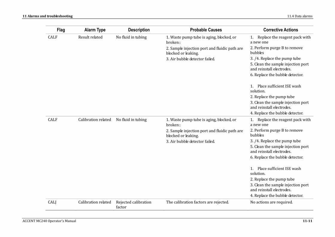
11 Alarms and troubleshooting 11.4 Data alarms
ACCENT MC240 Operator’s Manual 11-11
Flag Alarm Type Description Probable Causes Corrective Actions
CALF Result related No fluid in tubing 1. Waste pump tube is aging, blocked, or broken;
2. Sample injection port and fluidic path are blocked or leaking.
3. Air bubble detector failed.
1. Replace the reagent pack with a new one
2. Perform purge B to remove bubbles
3. /4. Replace the pump tube
5. Clean the sample injection port and reinstall electrodes.
6. Replace the bubble detector.
1. Place sufficient ISE wash solution.
2. Replace the pump tube
3. Clean the sample injection port and reinstall electrodes.
4. Replace the bubble detector.
CALF Calibration related No fluid in tubing 1. Waste pump tube is aging, blocked, or broken;
2. Sample injection port and fluidic path are blocked or leaking.
3. Air bubble detector failed.
1. Replace the reagent pack with a new one
2. Perform purge B to remove bubbles
3. /4. Replace the pump tube
5. Clean the sample injection port and reinstall electrodes.
6. Replace the bubble detector.
1. Place sufficient ISE wash solution.
2. Replace the pump tube
3. Clean the sample injection port and reinstall electrodes.
4. Replace the bubble detector.
CALJ Calibration related Rejected calibration factor
The calibration factors are rejected. No actions are required.

11.4 Data alarms 11 Alarms and troubleshooting
11-12 ACCENT MC240 Operator’s Manual
Flag Alarm Type Description Probable Causes Corrective Actions
CALM Result related Air in segment 1. Waste pump tube is aging, blocked, or broken;
2. Sample injection port and fluidic path are blocked or leaking.
3. Air bubble detector failed.
1. Replace the pump tube
2. Clean the sample injection port and reinstall electrodes.
3. Replace the bubble detector.
CALM Calibration related Air in segment 1. Waste pump tube is aging, blocked, or broken;
2. Sample injection port and fluidic path are blocked or leaking.
3. Air bubble detector failed.
1. Replace the pump tube
2. Clean the sample injection port and reinstall electrodes.
3. Replace the bubble detector.
CALR Result related Recalculated calibration factor
The calibration factors are recalculated. No actions are required.
COV Calibration related Calibration curve not convergent
For nonlinear calibration, a satisfying base cannot be calculated and no calibration curve is drawn.
Check that the reagent and calibrator are normal, and then recalibrate. If the error remains, contact our customer service department.
CSD Calibration related Calibration curve standard deviation out of range
The calculated standard deviation of the calibration curve exceeds the specified limit.
Check if the acceptance limit is reasonable and the reagent and calibrator are normal, and then recalibrate.
DEL Calibration related Deleted QC result The QC result has been deleted. No actions are required.
DET Calibration related Calibration determination coefficient out of range
The calculated determination coefficient of the calibration curve exceeds the specified limit.
Check if the acceptance limit is reasonable and the reagent and calibrator are normal, and then recalibrate.

11 Alarms and troubleshooting 11.4 Data alarms
ACCENT MC240 Operator’s Manual 11-13
Flag Alarm Type Description Probable Causes Corrective Actions
DEP Calibration related Saving calibration result error
1. ISE communication cable failure.
2. Communication interface or pins failure
3. Main control board of the ISE module goes wrong.
4. Software error.
1. Replace the ISE communication cable.
2. Replace the interface or pins.
3. Replace the main control board of the ISE module.
4. Upgrade the operating software or reinstall it.
DTGL Result related Insufficient probe wash solution
The probe wash solution is insufficient during measurement.
Fill more probe wash solution.
DUP Calibration related Calibration repeatability error
The difference between the maximum and minimum response of the calibrator exceeds the specified limit.
Check if the acceptance limit is reasonable, troubleshoot the error, and then recalibrate.
EDT Result related Edited result The result has been edited. No actions are required.
EDT Calibration related Edited calibration factor The calibration factors have been edited. No actions are required.
ENC Result related No calculation interval The sample concentration is too high, and substrate depletion occurs within the lag time of rate check measurements.
Check the reaction curve and the substrate depletion limit. Rerun the test with diluted sample.
EXP Result related Enzyme linearity range extension
The high-concentration sample leads to substrate depletion during the reaction time, and the result is calculated by using measuring points within the lag time.
Rerun the test with diluted sample.
EXT Result related Extended calibration factor
The result is obtained by extending the calibration time.
Take no actions, or recalibrate.
FAC Calibration related Calibration slope difference out of range
The slope difference is applicable to linear calibration only and refers to the K factor (slope) difference between two adjacent calibrations. It exceeds the specified limit.
Check if the acceptance limit is reasonable and the reagent and calibrator are normal, and then recalibrate.
ICA Result related The response is normal, but results cannot be calculated.
The chemistry has not been calibrated. Rerun it after calibration.

11.4 Data alarms 11 Alarms and troubleshooting
11-14 ACCENT MC240 Operator’s Manual
Flag Alarm Type Description Probable Causes Corrective Actions
L! Result related Water blank fluctuation is out of range.
1. The cuvette is overflowing.
2. The lamp has been replaced incorrectly.
3. Cuvette check is not performed after maintenance.
4. The cable connectors are not tightened.
5. The retaining screw is not tightened.
6. Cleaning liquid inside the cuvette is little.
7. The lamp is aged.
8. The photometer goes wrong.
1. Check if the cuvette is overflowing.
2. Check if the Replace Lamp command is executed during lamp replacement.
3. Check if the cable connectors and retaining screw of the lamp have been tightened.
4. Check if the cleaning liquid inside the cuvette is no less than half of the cuvette.
5. Check if the reaction curve fluctuates irregularly. If yes, replace the lamp.
6. If the error remains, contact our customer service department.
LIN Result related Non-linear The measuring points for result calculation are nonlinear, because the sample concentration is too high, or the substrate depletion limit is not specified or unreasonable. The lamp is aged.
Check the reaction curve and the substrate depletion limit. Rerun the test with diluted sample. If the alarm occurs for more than one chemistry, and the reaction curve fluctuates irregularly, replace the lamp.
LOW Result related Response less than that of the minimum-concentration calibrator
The sample concentration is lower than the sensitivity indicated on the reagent pack, making response less than that of the lowest-concentration calibrator.
For ascending calibration curve, rerun the test with standard or increased sample volume; for descending calibration curve, rerun the test with diluted sample.

11 Alarms and troubleshooting 11.4 Data alarms
ACCENT MC240 Operator’s Manual 11-15
Flag Alarm Type Description Probable Causes Corrective Actions
MBK Calibration related Mixed blank absorbance out of range
The reagent goes wrong; the cuvette is not clear; the reaction cuvette is overflowed; or insufficient reagent is dispensed.
Check if the cuvette is clear and not overflowed, the reagent is sufficient without air bubbles, and the chemistry parameters are reasonable. If yes, replace the reagent and then rerun the test.
MON Calibration related Calibration curve not monotonic
The calibration data and calibration curve are not monotonic.
Check if the calibrator is defined and placed correctly, and then recalibrate.
NLN Result related No linear interval The high-concentration sample leads to less than 3 valid measuring points within the reaction time of rate check measurements.
Rerun the test with diluted sample.
NOIS Result related Electrode voltage noise 1. Electrode failure.
2. Environment interference.
3. ISE main control board failure.
4. Salt buildup around electrodes or tubes due to fluidic leaks.
1. Replace the electrode.
2. Relocate the instrument.
3. Replace the main control board of the ISE module.
4. Clean the tubes and electrodes.
NOIS Calibration related Electrode voltage noise 1. Electrode failure.
2. Environment interference.
3. ISE main control board failure.
4. Salt buildup around electrodes or tubes due to fluidic leaks.
1. Replace the electrode.
2. Relocate the instrument.
3. Replace the main control board of the ISE module.
4. Clean the tubes and electrodes.
OVE Result related Overridden calibration factor
The result is obtained by overriding a failed calibration.
Take no actions, or recalibrate.

11.4 Data alarms 11 Alarms and troubleshooting
11-16 ACCENT MC240 Operator’s Manual
Flag Alarm Type Description Probable Causes Corrective Actions
PUGA Result related Air in calibrator A 1. Calibrator A is exhausted.
2. Bubbles exist in calibrator tube A
3. Pump tube A is aging, blocked, or broken.
4. Waste pump tube is aging, blocked, or broken;
5. Sample injection port and fluidic path are blocked or leaking.
6. Air bubble detector failed.
1. Replace the reagent pack with a new one
2. Perform purge B to remove bubbles
3. /4. Replace the pump tube
5. Clean the sample injection port and reinstall electrodes.
6. Replace the bubble detector.
PUGA Calibration related Air in calibrator A 1. Calibrator A is exhausted.
2. Bubbles exist in calibrator tube A
3. Pump tube A is aging, blocked, or broken.
4. Waste pump tube is aging, blocked, or broken;
5. Sample injection port and fluidic path are blocked or leaking.
6. Air bubble detector failed.
1. Replace the reagent pack with a new one
2. Perform purge B to remove bubbles
3. /4. Replace the pump tube
5. Clean the sample injection port and reinstall electrodes.
6. Replace the bubble detector.
PUGB Result related Air in calibrator B 1. Calibrator B is exhausted.
2. Bubbles exist in calibrator tube B
3. Pump tube A is aging, blocked, or broken.
4. Waste pump tube is aging, blocked, or broken;
5. Sample injection port and fluidic path are blocked or leaking.
6. Air bubble detector failed.
1. Replace the reagent pack with a new one
2. Perform purge B to remove bubbles
3. /4. Replace the pump tube
5. Clean the sample injection port and reinstall electrodes.
6. Replace the bubble detector.

11 Alarms and troubleshooting 11.4 Data alarms
ACCENT MC240 Operator’s Manual 11-17
Flag Alarm Type Description Probable Causes Corrective Actions
PUGB Calibration related Air in calibrator B 1. Calibrator B is exhausted.
2. Bubbles exist in calibrator tube B
3. Pump tube A is aging, blocked, or broken.
4. Waste pump tube is aging, blocked, or broken;
5. Sample injection port and fluidic path are blocked or leaking.
6. Air bubble detector failed.
1. Replace the reagent pack with a new one
2. Perform purge B to remove bubbles
3. /4. Replace the pump tube
5. Clean the sample injection port and reinstall electrodes.
6. Replace the bubble detector.
PRO Result related Prozone check error Antibody excess occurs due to too high sample concentration.
Check the reaction curve and the prozone check parameters. Rerun the test with diluted sample.
R Result related Rerun result The result is obtained by rerunning the test. No actions are required.
R4S Result related R4S One result of a run is greater than +2 standard deviations from the assigned mean and the other greater than -2SDs.
Check if the reagent is qualified, control sample is normal, and the instrument is working correctly.
RBK Result related R1 blank absorbance out of range
The reagent goes wrong; the cuvette is not clear; the reaction cuvette is overflowed; or insufficient reagent is dispensed.
Check if the cuvette is clear and not overflowed, the reagent is sufficient without air bubbles, and the chemistry parameters are reasonable. If yes, replace the reagent and then rerun the test.
RCE Result related Response calculation error
Absorbance data for calculation is incomplete, or the dividend is 0.
Rerun the test. If the error remains, contact our customer service department.
REC Result related Recalculated result The sample result is recalculated manually with the latest calibration factors.
/

11.4 Data alarms 11 Alarms and troubleshooting
11-18 ACCENT MC240 Operator’s Manual
Flag Alarm Type Description Probable Causes Corrective Actions
RESP Result related ISE response check code error
Command format or execution error
1. ISE communication cable failure.
2. Communication interface or pins failure
3. Main control board of the ISE module goes wrong.
4. Software error.
1. Replace the ISE communication cable
2. Replace the interface or pins.
3. Replace the main control board of the ISE module.
4. Upgrade the operating software or reinstall it.
RESP Calibration related ISE response check code error
Command format or execution error
1. ISE communication cable failure.
2. Communication interface or pins failure
3. Main control board of the ISE module goes wrong.
4. Software error.
1. Replace the ISE communication cable.
2. Replace the interface or pins.
3. Replace the main control board of the ISE module.
4. Upgrade the operating software or reinstall it
RGTE Result related Expired reagent The result is based on an expired reagent. Replace the reagent.
RGTL Result related Insufficient reagent The result is based on insufficient reagent. Replace the reagent.
RGTL Calibration related Insufficient reagent The calibration result is based on insufficient reagent.
Replace the reagent.
RRN Result related Response greater than that of the maximum-concentration calibrator
The sample concentration exceeds the high limit of the calibrator concentration.
Rerun the test with diluted sample.
SEN Calibration related Calibration sensitivity error
The difference of final response of the maximum and minimum concentration calibrators exceeds the specified limit.
Check if the acceptance limit is reasonable and the reagent and calibrator are normal, and then recalibrate.
SJAM Result related Sample probe is clogged Probe clogging is detected during sampling or the sample probe is clogged during sampling.
Sample treatment.

11 Alarms and troubleshooting 11.4 Data alarms
ACCENT MC240 Operator’s Manual 11-19
Flag Alarm Type Description Probable Causes Corrective Actions
SLDR Calibration related Electrode slope drift 1. Electrode or reagent pack fails.
2. Electrode is unsteady.
3. New reagent pack is unsteady.
4. Reference electrode has been used for over 66 months.
5. ISE main control board failure.
6. Ambient temperature fluctuates drastically
1. Replace the problematic electrode and reagent pack.
2. New electrode will become steady after 15 minutes since installed.
3. Run a couple of calibrations after installing new reagent pack.
4. Replace the reference electrode.
5. Replace the ISE main control board.
6. Control the ambient temperature to make the fluctuation within +/-4℃.
SLEX Calibration related Slope out of range 1. Electrode is not installed correctly.
2. Calibrator expired.
3. Electrode degenerated
4. Bubbles in reference electrode
5. Reference electrode has been used for a long time
6. Electrodes interfered.
7. Module or tubing temperature above 32℃.
1. Reinstall the electrode
2. Replace the calibrator.
3. Replace the problematic electrode and rerun.
4. Remove the electrode and clap on it to eliminate bubbles. Reinstall the electrode and run calibration.
5. Replace reference electrode and rerun.
6. Troubleshoot the electrodes by replacing them in different groups.
7. Monitor temperature, if too high, relocate equipment.
SLP Result related Corrected result The result is adjusted with calculation factors.
No actions are required.

11.4 Data alarms 11 Alarms and troubleshooting
11-20 ACCENT MC240 Operator’s Manual
Flag Alarm Type Description Probable Causes Corrective Actions
SLP Result related The results are produced when the calibration factors instead of the default ones are configured for the second time calibration.
Calibration factors instead of the default ones are configured for the second time calibration.
No actions are required.
SMPA Result related Air in sample 1. Sample is insufficient or contains many bubbles after dispensing.
2. No or insufficient sample has been dispensed into the sample injection port.
3. The electrodes are not properly installed, causing leakage.
4. The waste pump tube is aging or broken.
1. Increase the sample volume. At least 90μl sample should be prepared.
2. Electrode is not installed correctly. Reinstall it.
3. Check the waste tube, and if necessary, replace it.
SMPE Result related Expired sample The sample is expired. Replace the sample.
SMPL Result related Insufficient sample The sample is insufficient during analysis. Refill the sample.
SMPL Calibration related Insufficient sample The sample is insufficient during analysis. Refill the sample.
VDRF Result related Electrode voltage drift 1. Electrode or reagent pack fails.
2. Electrode is unsteady.
3. New reagent pack is unsteady.
4. Reference electrode has been used for over 66 months.
5. ISE main control board failure.
6. Ambient temperature fluctuates drastically.
1. Replace the problematic electrode and reagent pack.
2. New electrode will become steady after 15 minutes since installed.
3. Run a couple of calibrations after installing new reagent pack.
4. Replace the reference electrode.
5. Replace the ISE main control board.
6. Control the ambient temperature to make the fluctuation within +/-4℃

11 Alarms and troubleshooting 11.4 Data alarms
ACCENT MC240 Operator’s Manual 11-21
Flag Alarm Type Description Probable Causes Corrective Actions
VOUT Result related Electrode Voltage Overflow
1. Electrode or reagent pack fails.
2. Electrode is unsteady.
3. New reagent pack is unsteady.
4. Reference electrode has been used for over 66 months.
5. ISE main control board failure.
1. Replace the problematic electrode and reagent pack.
2. New electrode will become steady after 15 minutes since installed.
3. Run a couple of calibrations after installing new reagent pack.
4. Replace the reference electrode.
5. Replace the ISE main control board.
VOUT Calibration related Electrode Voltage Overflow
1. Electrode or reagent pack fails.
2. Electrode is unsteady.
3. New reagent pack is unsteady.
4. Reference electrode has been used for over 66 months.
5. ISE main control board failure.
1. Replace the problematic electrode and reagent pack.
2. New electrode will become steady after 15 minutes since installed.
3. Run a couple of calibrations after installing new reagent pack.
4. Replace the reference electrode.
5. Replace the ISE main control board.
T1 Result related Reaction disk temperature error
1. The ambient temperature is out of range.
2. The temperature sensor goes wrong. (component error and cable error)
3. The temperature protection switch goes wrong. (component error and cable error)
4. The heater goes wrong. (component error and cable error)
5. PCB error
6. Parameters are lost.
7. Electromagnetic interference exists.
1. Check if the error is accidental.
2. If not, contact our customer service department.

11.4 Data alarms 11 Alarms and troubleshooting
11-22 ACCENT MC240 Operator’s Manual
Flag Alarm Type Description Probable Causes Corrective Actions
TD Result related Photoelectric measurement period is out of range
1. Software error 1. Rerun the operating software.
2. Reboot the operation unit.
3. If the error remains, contact our customer service department or your local distributor.

11 Alarms and troubleshooting 11.5 Error Messages and Corrective Actions
ACCENT MC240 Operator’s Manual 11-23
11.5 Error Messages and Corrective Actions
Table 11.5 Error messages and corrective actions
Event ID Component Event class
Error Message and
Event Log
Flag Probable Causes Corrective Actions
A00006 Middle layer unit Error Equipment configuration cannot be read or saved
Error:
/ E2PROM read/write error Switch off the analyzing unit power and switch on it again. Recover failure by performing the Home maintenance procedure. If this message appears for 3 times, contact our customer service department or your local distributor.
A00007 Middle layer unit Error Instruction execution error
/ Instrument instructions cannot be executed.
Switch off the analyzing unit power and switch on it again. Recover failure by performing the Home maintenance procedure. If this message appears for 3 times, contact our customer service department or your local distributor.
A01006 Sample probe unit Error Sample probe vertical movement error
Position:
Error:
Or
Sample probe horizontal movement error
Position:
Error:
/ Sample probe vertical movement error
1. Sensor status error:
The sample probe assembly is probably forced to move vertically.
2. Failed to find the zero position:
The sample probe assembly is probably jammed.
3. Collision occurs during operation other than aspirating:
Recover failure by performing the Home maintenance procedure. If this message appears for 3 times, contact our customer service department or your local distributor.

11.5 Error Messages and Corrective Actions 11 Alarms and troubleshooting
11-24 ACCENT MC240 Operator’s Manual
Event ID Component Event class
Error Message and
Event Log
Flag Probable Causes Corrective Actions
Or
Sample syringe movement error.
Position:
Error:
The sample probe collides with other object.
4. Collision error:
The collision remains.
5. Moving vertically is not allowed in current position:
The sample probe moves vertically in an unknown position.
Sample probe horizontal movement error
1. Sensor status error:
The sample probe assembly is probably forced to move horizontally.
2. Failed to find the zero position:
The sample probe assembly is obstructed when rotating.
3. Collision occurs during horizontal movement:
The sample probe assembly is obstructed when rotating.
4. Moving horizontally is not allowed in current position:
The sample probe assembly is probably forced to move vertically.
Sample syringe movement error.
1. Sensor status error:
The syringe assembly is

11 Alarms and troubleshooting 11.5 Error Messages and Corrective Actions
ACCENT MC240 Operator’s Manual 11-25
Event ID Component Event class
Error Message and
Event Log
Flag Probable Causes Corrective Actions
probably forced to move.
2. Failed to find the zero position:
The syringe assembly is probably jammed.
A01007 Sample probe unit Warning Sample probe collides with an obstacle when aspirating
Sample position:
Sample ID/bar code:
Specific position:
/ 1. Collision occurs during aspirating:
The sample probe collides with other object.
1. Collision occurs during aspirating:
Remove the obstacle, and then recover failure by performing the Home maintenance procedure.
A01021 Sample probe unit Warning The probe collides with an obstacle when aspirating.
/ Clog detection board communication error.
Recover the failure. If this message appears for 3 times, contact our customer service department or your local distributor.
A01024 Sample probe unit Warning Insufficient sample
or
Sample probe level detection failed.
/ There is no sample or insufficient sample on the designated position.
1. Check if the sample is sufficient, and then try again.
2. If the error remains, contact our customer service department or your local distributor.
A01027 Sample probe unit Warning Sample is insufficient or contains air bubbles
Position:
Sample ID/bar code:
or
Probe level detection failed
Position:
Sample ID/bar code:
There is no sample or insufficient sample on the designated position.
1. Check if the sample is sufficient, and then try again.
2. If the error remains, contact our customer service department or your local distributor.
A01028 Sample probe unit Error Sample probe fails to detect liquid level during
/ There is no deionized water, or the deionized water is not
1. Check if the water supply is

11.5 Error Messages and Corrective Actions 11 Alarms and troubleshooting
11-26 ACCENT MC240 Operator’s Manual
Event ID Component Event class
Error Message and
Event Log
Flag Probable Causes Corrective Actions
cleaning supplied normally. normal.
2. Recover the failure for 3 times. If the error remains, contact our Customer Service Department or your local distributor.
A01029 Sample probe unit Error Sample is insufficient or contains fibrins and clots or Probe clog detection failed.
Position:
Sample ID/bar code:
/ 1. The sample contains clots, or is too thick.
2. The sample probe is clogged.
1. Check that the sample is preprocessed correctly; or check if the sample contains foreign matters such as clot. If it does, change the sample.
2. Clean the sample probe with diluted wash solution. If the problem remains, remove the sample probe and unclog it, and then continue with the measurement.
A01030 Sample probe unit Error Probe is clogged during cleaning.
/ The sample probe is clogged. 1. Clean the sample probe with diluted wash solution. Remove the sample probe and unclog it.
2. If the problem remains, contact the manufacturer.
A01033 Sample probe unit Warning Sample probe fails to detect liquid level on reaction carousel when dispensing.
Cuvette No.:
Sample ID/bar code:
Chemistry:
or
Sample probe level detection failed.
Cuvette No.:
/ There is no reagent or insufficient reagent in the reaction cuvette.
1. Check if R1 volume is sufficient and the reagent bottle is free of air bubbles, and then try again.
2. If the problem remains, contact the manufacturer.

11 Alarms and troubleshooting 11.5 Error Messages and Corrective Actions
ACCENT MC240 Operator’s Manual 11-27
Event ID Component Event class
Error Message and
Event Log
Flag Probable Causes Corrective Actions
Sample ID/bar code:
Chemistry:
A01036 Probe unit Error Probe level detection board communication error
Level detection board communication error
Recover the failure. If this message appears for 3 times, contact our customer service department or your local distributor.
A01039 Probe unit Error Instruction execution error
/ Instrument instructions cannot be executed.
Switch off the analyzing unit power and switch on it again. Recover failure by performing the Home maintenance procedure. If this message appears for 3 times, contact our customer service department or your local distributor.
A02007 Probe unit Warning Probe R2 collides with an obstacle when aspirating
Reagent position:
Specific position:
/ 1. Collision occurs during aspirating:
The probe R2 collides with other object.
1. Collision occurs during aspirating:
Remove the obstacle and then recover the failure.
A02023 Probe unit Warning Insufficient reagent
Or
Probe R2 level detection failed.
/ There is no reagent or insufficient reagent on the designated position.
1. Check if the reagent is sufficient, and then try again.
2. If the error remains, contact our customer service department or your local distributor.
A02025 Probe unit Warning Probe dispenses insufficient reagent
/ 1. The probe aspirates nothing.
1. Check if the reagent satisfies the requirement and is sufficient in volume, and then try again.
2. Recover the failure. If this message appears for 3 times, contact our customer service department or your local

11.5 Error Messages and Corrective Actions 11 Alarms and troubleshooting
11-28 ACCENT MC240 Operator’s Manual
Event ID Component Event class
Error Message and
Event Log
Flag Probable Causes Corrective Actions
distributor.
A02027 Probe unit Warning Water residues exist in the cuvette or Probe level detection failed
/ DI water residual exists in cuvette.
Recover the failure. If this message appears for 3 times, contact our customer service department or your local distributor.
A02032 Probe unit Warning Reagent is insufficient or contains air bubbles
Chemistry:
Position:
1. Air bubbles exist in the reagent bottle.
2. The reagent bottle does not meet the requirements.
1. Check if the reagent bottle contains air bubbles, and then try again.
2. Check if the reagent bottle meets the requirements.
3. If the error remains, contact our customer service department or your local distributor.
A05006 Mixer unit Error Mixer vertical movement error
Mixer horizontal movement error
/ 1. Sensor status error. The assembly is probably forced to move vertically.
2. Failed to find the zero position. The mixer assembly is probably jammed
3. Vertical movement is not allowed in current horizontal position.
The reagent mixer moves vertically in an unknown position.
1. Sensor status error. The assembly is probably forced to move vertically.
2. Failed to find the zero position The mixer assembly is obstructed when rotating
3. Horizontal movement is
Recover failure by performing the Home maintenance procedure. If this message appears for 3 times,
contact our customer service department or your local distributor.

11 Alarms and troubleshooting 11.5 Error Messages and Corrective Actions
ACCENT MC240 Operator’s Manual 11-29
Event ID Component Event class
Error Message and
Event Log
Flag Probable Causes Corrective Actions
not allowed in current vertical position.
A05007 Mixer unit Error Instruction execution error
/ Instrument instructions cannot be executed.
Switch off the analyzing unit power and switch on it again. Recover failure by performing the Home maintenance procedure. If this message appears for 3 times, contact our customer service department or your local distributor.
A06006 Reaction carousel unit
Error Reaction carousel movement error
Error:
/ Reaction carousel movement error
1. Failed to find the home position
The reaction carousel is obstructed or blocked.
2. The coder missed steps
The reaction carousel is obstructed or blocked.
3. The reaction carousel missed steps when moving to the home position.
The reaction carousel is obstructed or blocked.
Switch off the analyzing unit power and switch on it again. Recover failure by performing the Home maintenance procedure. If this message appears for 3 times, contact our customer service department or your local distributor.
A06008 Reaction carousel unit
Error Instruction execution error
/ Instrument instructions cannot be executed.
Switch off the analyzing unit power and switch on it again. Recover failure by performing the Home maintenance procedure. If this message appears for 3 times, contact our customer service department or your local distributor.

11.5 Error Messages and Corrective Actions 11 Alarms and troubleshooting
11-30 ACCENT MC240 Operator’s Manual
Event ID Component Event class
Error Message and
Event Log
Flag Probable Causes Corrective Actions
A07006 Sample/reagent carousel unit
Error Sample carousel movement error
Error:
/ Sample carousel movement error
1. Failed to find the home position
The sample carousel is obstructed or blocked.
2. The coder missed steps
The sample carousel is obstructed or blocked.
3. The sample carousel missed steps when moving to the home position.
The sample carousel is obstructed or blocked.
Recover the failure. If this message appears for 3 times, contact our customer service department or your local distributor.
A07009 Sample/reagent carousel unit
Error Sample bar code reader error
/ The sample bar coder reader goes wrong due to system failure.
Recover the failure. If the error still remains, contact our Customer Service Department or your local distributor.
A07010 Sample/reagent carousel unit
Warning Sample bar code error
Position:
/ Sample bar coder reader does not work normally due to communication error.
Try again. If your attempt fails, contact our customer service department or your local distributor.
A07011 Sample/reagent carousel unit
Error Sample bar code sending buffer is full
/ Sample bar coder sending buffer is full due to communication error.
Recover the failure or reboot the analyzing unit.
A09011 Sample/reagent carouse unit
Error Reagent bar code reader does not work normally
/ The reagent bar coder reader goes wrong due to system failure.
Recover the failure. If the error still remains, contact our Customer Service Department or your local distributor.
A09012 Sample/reagent carousel unit
Warning Reagent bar code error
Position:
/ Reagent bar coder sending buffer is full due to
Try again. If your attempt fails, contact our customer service

11 Alarms and troubleshooting 11.5 Error Messages and Corrective Actions
ACCENT MC240 Operator’s Manual 11-31
Event ID Component Event class
Error Message and
Event Log
Flag Probable Causes Corrective Actions
communication error. department or your local distributor.
A09014 Sample/reagent carousel unit
Error Reagent bar code sending buffer is full
Position:
/ Reagent bar coder reader does not work normally due to communication error.
Recover the failure or reboot the analyzing unit.
A11005 Wash station Error Wash station movement error
Error:
/ Wash station movement error
1. Sensor status error
The wash station assembly is probably forced to move.
2. Failed to find the home position
The wash station assembly is obstructed by other object.
3. The wash station collides with an obstacle when moving.
The wash station collides with other object, or the wash probes then collide with the reaction carousel.
Switch off the analyzing unit power and switch on it again. Recover failure by performing the Home maintenance procedure. If this message appears for 3 times, contact our customer service department or your local distributor.
A11013 Wash station Error Water tank is empty / 1. The water tank is empty.
2. The low-level floater of the water tank goes wrong.
1. Check if the water level inside the water tank is low.
2. Check if the error is accidental.
3. If the error is not accidental, contact our customer service department or your local distributor.
A11015 Wash station Error Insufficient diluted wash solution
/ 1. The low-level floater of the diluted wash solution tank goes wrong.
2. The diluted wash solution
1. Check the floater of the diluted wash solution tank.
2. Fill the diluted wash solution tank.

11.5 Error Messages and Corrective Actions 11 Alarms and troubleshooting
11-32 ACCENT MC240 Operator’s Manual
Event ID Component Event class
Error Message and
Event Log
Flag Probable Causes Corrective Actions
tank is empty.
3. Check if the error is accidental.
4. If the error is not accidental, contact our customer service department or your local distributor.
A11020 Wash station Error High concentration waste tank is full
/ 1. The high concentration waste tank is full
2. The floater of the high concentration waste tank goes wrong.
1. Check the high-concentration waste tank. If it is full, replace the waste tank, close the full tank and dispose of the waste properly.
2. Check if the error is accidental.
3. If the error is not accidental, contact our customer service department or your local distributor.
A11034 Wash station Error Cuvette wash syringe movement error.
/ Sensor status error. The syringe assembly is probably forced to move.2.Failed to find the mechanical zero position. The syringe assembly is probably jammed.
Switch off the analyzing unit power and switch on it again. Recover failure by performing the Home maintenance procedure. If this message appears for 3 times, contact our customer service department or your local distributor.
A11038 Wash station Error Instruction execution error
/ Instruction execution error Switch off the analyzing unit power and switch on it again. Recover failure by performing the Home maintenance procedure. If this message appears for 3 times, contact our customer service department or your local distributor.
A12005 Temperature unit Warning Reaction carousel temperature is out of
T1 1. The ambient temperature is out of range.
1. Check if the error is accidental.
2. If the error is not accidental,

11 Alarms and troubleshooting 11.5 Error Messages and Corrective Actions
ACCENT MC240 Operator’s Manual 11-33
Event ID Component Event class
Error Message and
Event Log
Flag Probable Causes Corrective Actions
range
2. The temperature sensor goes wrong. (component error and cable error)
3. The temperature protection switch goes wrong. (component error and cable error)
4. The heater goes wrong. (component error and cable error)
5. Temperature control fan error.
6 PCB error
7. Parameters are lost.
8. Electromagnetic interference exists.
contact our customer service department or your local distributor.
A12006 Temperature unit Warning Temperature of wash solution for cleaning cuvettes is out of range
Temperature:
/ 1. The ambient temperature is out of range.
2. The temperature sensor goes wrong. (component error and cable error)
3. The temperature protection switch goes wrong. (component error and cable error)
4. The heater goes wrong. (component error and cable error)
5. PCB error
6. Parameters are lost.
7. Electromagnetic interference exists.
1. Check the temperature of the deionized water for cleaning the whole unit.
2. Check if the water supply is normal and has the temperature between 15°C-30°C.
3. Check if the error is accidental.
4. If the error is not accidental, contact our customer service department or your local distributor.

11.5 Error Messages and Corrective Actions 11 Alarms and troubleshooting
11-34 ACCENT MC240 Operator’s Manual
Event ID Component Event class
Error Message and
Event Log
Flag Probable Causes Corrective Actions
A12007 Temperature unit Warning Temperature of deionized water for cleaning cuvettes is out of range
/ 1. The ambient temperature is out of range.
2. The temperature sensor goes wrong. (component error and cable error)
3. The temperature protection switch goes wrong. (component error and cable error)
4. The heater goes wrong. (component error and cable error)
5. PCB error
6. Parameters are lost.
7. Electromagnetic interference exists.
1. Check the temperature of the deionized water for cleaning the whole unit.
2. Check if the water supply is normal and has the temperature between 15°C-30°C.
3. Check if the error is accidental.
4. If the error is not accidental, contact our customer service department or your local distributor.
A12010 Temperature unit Warning Reagent preheating temperature is out of range.
/ 1. The ambient temperature is out of range.
2. The temperature sensor goes wrong. (component error and cable error)
3. The temperature protection switch goes wrong. (component error and cable error)
4. The heater goes wrong. (component error and cable error)
5. PCB error
6. Parameters are lost.
7. Electromagnetic interference exists.
1. Check the temperature of the deionized water for cleaning the whole unit.
2. Check if the water supply is normal and has the temperature between 15°C-30°C.
3. Check if the error is accidental.
4. If the error is not accidental, contact our customer service department or your local distributor.

11 Alarms and troubleshooting 11.5 Error Messages and Corrective Actions
ACCENT MC240 Operator’s Manual 11-35
Event ID Component Event class
Error Message and
Event Log
Flag Probable Causes Corrective Actions
A14007 Temperature unit Warning Reagent refrigeration temperature is out of range. TDISP Temperature:
/ 1. Reagent refrigeration temperature is out of range.
2. The temperature sensor goes wrong. (component error and cable error)
3. Radiator goes wrong. (component error and cable error)
4. PCB error
5. Parameters are lost.
6. Electromagnetic interference exists.
1. Check the reagent refrigeration temperature sensor.
2. Check if the error is accidental.
3. If the error is not accidental, contact our customer service department or your local distributor.
A14008 Temperature unit Warning Reagent refrigeration temperature is out of range. TDISP Temperature: ?
/ 1. Reagent refrigeration temperature is out of range.
2. The temperature sensor goes wrong. (component error and cable error)
3. Radiator goes wrong. (component error and cable error)
4. PCB error
5. Parameters are lost.
6. Electromagnetic interference exists.
1. Check the reagent refrigeration temperature sensor.
2. Check if the error is accidental.
3. If the error is not accidental, contact our customer service department or your local distributor.
A21001 Probe Interior Wash Unit
Error Probe interior wash syringe movement error.
Error:
/ 1. Sensor status error. The syringe assembly is probably forced to move.2.Failed to find the mechanical zero position. The syringe assembly is probably jammed.
Switch off the analyzing unit power and switch on it again. Recover failure by performing the Home maintenance procedure. If this message appears for 3 times, contact our customer service department or your local distributor.

11.5 Error Messages and Corrective Actions 11 Alarms and troubleshooting
11-36 ACCENT MC240 Operator’s Manual
Event ID Component Event class
Error Message and
Event Log
Flag Probable Causes Corrective Actions
A22001 ISE unit Error Slope out of range, electrode:
SLEX 1. Electrode installation incorrect. 2. Calibrator expired. 3. Electrode degenerated. 4. Bubbles in reference electrode. 5. Reference electrode has been used for a long time. 6. Electrodes interfered. 7. Module or tubing temperature above 32°C.
1. Reinstall the electrode. 2. Replace the calibrator. 3. Replace the problematic electrode and rerun. 4. Remove the electrode and clap on it to eliminate bubbles. Reinstall the electrode and run calibration. 5. Replace reference electrode and rerun. 6. Troubleshoot the electrodes by replacing them in different groups. 7. Monitor temperature, if too high, relocate equipment.
A22002 ISE unit Error Air in sample. Position: SMPA 1. Sample is insufficient or contain much bubbles after dispensing. 2. No or insufficient sample has been dispensed into the sample injection port.
3. Liquid leakage due to that the electrodes are not properly installed. 4. The waste pump tube is aging or broken.
1.&2. Increase the sample volume. At least 90μl sample should be prepared. 3. Electrode is not installed correctly. Reinstall it. 4. Check the waste tube, and if necessary, replace it.
A22004 ISE unit Error ISE unit cannot be connected.
/ 1. ISE power supply failure. 2. ISE communication cable failure. 3. Communication interface or pins failure. 4. ISE main control board failure.
1. Replace the 24V power supply board. 2. Replace the ISE communication cable. 3. Replace the interface or pins. 4. Replace the ISE main control board.
A22005 ISE unit Error ISE unit response error / 1. ISE communication cable failure.
1. Replace the ISE communication cable.

11 Alarms and troubleshooting 11.5 Error Messages and Corrective Actions
ACCENT MC240 Operator’s Manual 11-37
Event ID Component Event class
Error Message and
Event Log
Flag Probable Causes Corrective Actions
2. Communication interface or pins failure. 3. ISE main control board failure. 4. Software failure.
2. Replace the interface or pins. 3. Replace the ISE main control board. 4. Upgrade the operating software or reinstall it.
A22006 ISE unit Error Purge A and B failed. / 1. Leaks exist due to improperly-installed electrode or missing O ring. 2. Sample injection port or electrode inside is clogged. 3. Calibrator is exhausted. 4. Prime combinations are not enough. 5. Pump tube is aging, blocked, or broken. 6. Calibrator cannot be dispensed normally due to clogged reagent pack tube.
1. Reinstall the electrode and check for O ring. 2. Use warm water to clean and unclog the sample injection port with fresh water and unclog the electrode tube. Check the reference electrode for crystallized salt. 3. Replace the reagent pack. 4. Increase the prime cycle. 5. Replace the pump tube. 6. Unclog the reagent pack tube with warm water.
A22007 ISE unit Warning ISE reagent is going to be exhausted.
/ Calibrator is exhausted. Replace the reagent pack with a new one.
A22008 ISE unit Error Voltage overflow, electrode:
VOUT 1. Electrode or reagent pack failed. 2. Electrode is unsteady. 3. New reagent pack is unsteady. 4. Reference electrode has been used for over 6 months. 5. ISE main control board failure.
1. Replace the problematic electrode and reagent pack. 2. New electrode will become steady after 15 minutes since installed. 3. Run a couple of calibrations after installing new reagent pack. 4. Replace the reference electrode. 5. Replace the ISE main control board.
A22009 ISE unit Error Electrode slope drift. (during calibration)
Or
VDRF/ SLDR
1. Electrode or reagent pack failed. 2. Electrode is unsteady.
1. Replace the problematic electrode and reagent pack. 2. New electrode will become

11.5 Error Messages and Corrective Actions 11 Alarms and troubleshooting
11-38 ACCENT MC240 Operator’s Manual
Event ID Component Event class
Error Message and
Event Log
Flag Probable Causes Corrective Actions
Electrode voltage drift. (during sample analysis)
Electrode:
3. New reagent pack is unsteady. 4. Reference electrode has been used for over 6 months. 5. ISE main control board failure. 6. Ambient temperature fluctuates drastically.
steady after 15 minutes since installed. 3. Run a couple of calibrations after installing new reagent pack. 4. Replace the reference electrode. 5. Replace the ISE main control board. 6. Control the ambient temperature to make the fluctuation within +/-4℃.
A22010 ISE unit Error Voltage noise, electrode: NOIS 1. Electrode failure. 2. Environment interference. 3. ISE main control board failure. 4. Salt buildup around electrodes or tubes due to fluidic leaks.
1. Replace the electrode. 2. Relocate the instrument. 3. Replace the ISE main control board. 4. Clean the tubes and electrodes.
A22011 ISE unit Error Air in calibrator B PUGB 1. Calibrator B is exhausted. 2. Bubbles exist in calibrator tube B. 3. Pump tube B is aging, blocked, or broken. 4. Waste pump tube B is aging, blocked, or broken. 5. Sample injection port and fluidic path are blocked or leaking. 6. Air bubble detector fails.
1. Replace the reagent pack with a new one. 2. Perform purge B to remove bubbles. 3.&4. Replace the pump tube. 5. Clean the sample injection port and reinstall electrodes. 6. Replace the air bubble detector.
A22012 ISE unit Error Air in calibrator A PUGA 1. Calibrator A is exhausted. 2. Bubbles exist in calibrator tube A. 3. Pump tube B is aging, blocked, or broken.
1. Replace the reagent pack with a new one. 2. Perform purge A to remove bubbles. 3.&4. Replace the pump tube.

11 Alarms and troubleshooting 11.5 Error Messages and Corrective Actions
ACCENT MC240 Operator’s Manual 11-39
Event ID Component Event class
Error Message and
Event Log
Flag Probable Causes Corrective Actions
4. Waste pump tube B is aging, blocked, or broken. 5. Sample injection port and fluidic path are blocked or leaking. 6. Air bubble detector fails.
5. Clean the sample injection port and reinstall electrodes. 6. Replace the air bubble detector.
A22013 ISE unit Error ISE pump calibrating failed!
/ 1. Pump tube is aging. 2. Sample probe aspiration/dispensing failure.
1. Replace the pump tube. 2. Replace the sample probe.
A22014 ISE unit Error Air bubble detector failure
/ 1. Air bubble detector board is eroded due to the leaks at the joint of sample injection port and bubble detector. 2. Air bubble detector fails.
Replace the bubble detector.
A22015 ISE unit Error Reading reagent pack chip error
/ 1. Reagent pack is not installed. 2. Reagent pack wand fails.
1. Install reagent pack. 2. Replace the wand.
A22016 ISE unit Error Reagent pack chip writing error. Unload the reagent pack and load it again.
/ 1. Reagent pack is not installed. 3. Reagent pack wand fails.
1. Install reagent pack. 3. Replace the wand.
A22017 ISE unit Error Air in ISE wash solution / 1. ISE wash solution is insufficient. 2. Waste pump tube B is aging, blocked, or broken. 3. Sample injection port and fluidic path are blocked or leaking. 4. Air bubble detector fails.
1. Place sufficient ISE wash solution. 2. Replace the pump tube. 3. Clean the sample injection port and reinstall electrodes. 4. Replace the air bubble detector.
A22018 ISE unit Error No fluid in tubing CALF 1. Waste pump tube B is aging, blocked, or broken. 2. Sample injection port and
1. Place sufficient ISE wash solution.
2. Replace the pump tube.

11.5 Error Messages and Corrective Actions 11 Alarms and troubleshooting
11-40 ACCENT MC240 Operator’s Manual
Event ID Component Event class
Error Message and
Event Log
Flag Probable Causes Corrective Actions
fluidic path are blocked or leaking. 3. Air bubble detector fails.
3. Clean the sample injection port and reinstall electrodes. 4. Replace the air bubble detector.
A22019 ISE unit Error Saving calibration result error
DEP 1. ISE communication cable failure. 2. Communication interface or pins failure. 3. ISE main control board failure. 4. Software failure.
1. Replace the ISE communication cable. 2. Replace the interface or pins. 3. Replace the ISE main control board. 4. Upgrade the operating software or reinstall it.
A22021 ISE unit Error Command format or execution error
RESP 1. ISE communication cable failure. 2. Communication interface or pins failure. 3. ISE main control board failure. 4. Software failure.
1. Replace the ISE communication cable. 2. Replace the interface or pins. 3. Replace the ISE main control board. 5. Upgrade the operating software or reinstall it.
A22022 ISE unit Error No fluid in tubing / 1. Waste pump tube B is aging, blocked, or broken. 2. Sample injection port and fluidic path are blocked or leaking. 3. Air bubble detector fails.
1. Place sufficient ISE wash solution.
2. Replace the pump tube. 3. Clean the sample injection port and reinstall electrodes. 4. Replace the air bubble detector.
A22023 ISE unit Error No reagent module has been loaded.
/ 1. Reagent pack is not installed. 2. Reagent pack wand fails.
1. Install reagent pack. 2. Replace the wand.
A22024 ISE unit Error ISE response check code error
RESP 1. The communication wire between ISE and the middle-layer unit goes wrong. 2. Communication interface or pin error. 3.Main control board does not
1.Replace the communication wire
2.Change the interface or the pin.
3.Change the main control board.
4.Upgrade the software or reinstall the software.

11 Alarms and troubleshooting 11.5 Error Messages and Corrective Actions
ACCENT MC240 Operator’s Manual 11-41
Event ID Component Event class
Error Message and
Event Log
Flag Probable Causes Corrective Actions
function.
4.Software error
A22027 / Error Fluidic prime failed. / Fluidic is not primed. 1. Turn off the analyzing unit power and reswitch it on.
2. If the error occurs for continuous three times, please contact our customer service or your local distributor.
A22036 / Error Initializing sample bar code reader failed.
/ Sample bar code reader failed due to system error.
1. Recover failure by performing the Home maintenance procedure.
2. If this error remains
contact our customer service department or your local distributor.
A22038 / Error Scanning reagent bar code failed.
/ Scanning reagent bar code failed.
1. Turn off the analyzing unit power and reswitch it on.
2. If the error occurs for continuous three times, please contact our customer service or your local distributor.
A22039 / Error Unmatched software version.
/ 1.Version inquiry instruction failed.
2. The version information of the control software does not match the one stored in the operating software.
1. Turn off the analyzing unit power and reswitch it on.
2. If the error occurs for continuous three times, please contact our customer service or your local distributor.
A22042 Temperature control unit
Warning Temperature of cuvette cleaning fluid is out of range: %s\r\n
Temperature: %s
/ Warning No. 1:
Sensor shortcut or temperature above 75℃.
Warning No. 2:
1. Turn off the analyzing unit power and reswitch it on.
2. If the error is not accidental, contact our customer service

11.5 Error Messages and Corrective Actions 11 Alarms and troubleshooting
11-42 ACCENT MC240 Operator’s Manual
Event ID Component Event class
Error Message and
Event Log
Flag Probable Causes Corrective Actions
Sensor disconnected or temperature below 0℃.
Warning No.3:
Heater is heating for a long time
Warning No.4:
Heater control is locked.
department or your local distributor.
A22043 Temperature control unit
Warning Temperature of cuvette wash solution is out of range: %s\r\n
Temperature: %s
/ Warning No. 1:
Sensor shortcut or temperature above 75℃.
Warning No. 2:
Sensor disconnected or temperature below 0℃.
Warning No.3:
Heater is heating for a long time
Warning No.4:
Heater control is locked.
1. Turn off the analyzing unit power and reswitch it on.
2. If the error is not accidental, contact our customer service department or your local distributor.
C00007 Operating system Error CPU performance low / The CPU is too busy. Reboot the computer and operating software. If this message appears for 3 times, contact our customer service department or your local distributor.
C00011 Operating system Error The last abnormal exit may cause carryover not handled. Execute the Special Wash maintenance command before starting analysis to ensure accurate results.
/ The operating software is abnormal, or the instrument power is cut off unexpectedly.
Restart the operating software, and execute the Special Wash maintenance command before starting analysis.

11 Alarms and troubleshooting 11.5 Error Messages and Corrective Actions
ACCENT MC240 Operator’s Manual 11-43
Event ID Component Event class
Error Message and
Event Log
Flag Probable Causes Corrective Actions
C00012 Operating system Warning Sound card failure / No sound card is installed. Sound card failure. Incorrect sound card driver.
Reinstall the sound card or the sound card driver.
C00013 Operating system Error The cuvette status may not be refreshed due to the last abnormal exit of the system. To ensure the correct test results, please check the cuvettes and replace them.
/ The operating software is not exited normally due to some reasons.
Take out and check the standby cuvettes. If they are used, replace them. When you are uncertain if they are used, replace them.
C01001 Instrument connection
Error Equipment cannot be connected
/ The serial cable is not connected; or the analyzing unit power is switched off.
Check the serial port connection. Replug the cable. Check if the analyzing unit is powered on. Start the initialization again. Restart the computer and analyzing unit. If three continuous attempts are failed, contact our customer service department or your local distributor.
C02001 Database Error Database initialing failed / The database file is damaged or lost.
Reboot the computer and analyzing unit. If three continuous attempts are failed, contact our customer service department or your local distributor.
C02002 Database Error Database upgrade failed / The database file is damaged or lost.
Reboot the computer and analyzing unit. If three continuous attempts are failed, contact our customer service department or your local distributor.
C02004 Database Warning Database backup failed / The database file is damaged or lost.
Reboot the computer and analyzing unit. If three continuous attempts are failed, contact our

11.5 Error Messages and Corrective Actions 11 Alarms and troubleshooting
11-44 ACCENT MC240 Operator’s Manual
Event ID Component Event class
Error Message and
Event Log
Flag Probable Causes Corrective Actions
customer service department or your local distributor.
C02005 Database Warning Reading/Writing database failed
/ The database does not work normally.
Reboot the computer and analyzing unit. If three continuous attempts are failed, contact our customer service department or your local distributor.
C03001 Result calculation Warning Result cannot be calculated
Sample ID/bar code:
Position:
Chemistry:
RCE Absorbance data for calculation is incomplete, or the dividend is 0.
Rerun the test. If the error remains, contact our customer service department or your local distributor.
C03002 Result calculation Warning Absorbance out of range
Sample ID/bar code:
Position:
Chemistry:
ABS 1. Probe R1 dispenses insufficient reagent, or air bubbles exist in the reagent.
2. The reagent is placed in an incorrect position or is abnormal.
3. The sample concentration is too high, resulting in great response.
4. The absorbance data used for calculation is incomplete (due to photoelectric data loss), or the error of division by zero occurs.
1. Observe the reaction curve. If the absorbance of R1 is too high, check the reagent for air bubbles and the syringe for leaking.
2. Check if the reagent has been placed in the correct position.
3. Rerun the test after dilution.
4. Contact our customer service department or your local distributor.
C03003 Result calculation Warning R1 blank absorbance out of range
RBK The reagent goes wrong; the cuvette is not clear; the reaction cuvette is overflowed; or insufficient reagent is dispensed.
Check if the reagent is sufficient without air bubbles and the chemistry parameters are reasonable. If yes, replace the reagent and then rerun the test. Check if the cuvette is normal. If

11 Alarms and troubleshooting 11.5 Error Messages and Corrective Actions
ACCENT MC240 Operator’s Manual 11-45
Event ID Component Event class
Error Message and
Event Log
Flag Probable Causes Corrective Actions
the error remains, contact our customer service department or your local distributor.
C03004 Result calculation Warning Substrate depletion
Sample ID/bar code:
Position:
Chemistry:
BOE The sample concentration is too high, and substrate depletion occurs during fixed-time measurements.
Check the reaction curve and the substrate depletion limit. Rerun the test with diluted sample.
C03005 Result calculation Warning Result cannot be calculated
Sample ID/bar code:
Position:
Chemistry:
ENC The sample concentration is too high, and substrate depletion occurs within the lag time of rate check measurements.
Check the reaction curve and the substrate depletion limit. Rerun the test with diluted sample.
C03006 Result calculation Warning Linearity limit out of range
Sample ID/bar code:
Position:
Chemistry:
LIN The measuring points for result calculation are nonlinear, because the sample concentration is too high, or the substrate depletion limit is not specified or unreasonable.
Check the reaction curve and the substrate depletion limit. Rerun the test with diluted sample.
C03007 Result calculation Warning Prozone check error
Sample ID/bar code:
Position:
Chemistry:
PRO Antibody excess occurs due to too high sample concentration.
Check the reaction curve and the prozone check parameters. Rerun the test with diluted sample.
C03008 Result calculation Warning Sample concentration is higher than that of the highest-level calibrator
Sample ID/bar code:
Position:
Chemistry:
RRN The sample concentration exceeds the high limit of the calibrator concentration.
Rerun the test with diluted sample.
C03009 Result calculation Warning Mixed blank absorbance out of range
MBK The reagent goes wrong; the cuvette is not clear; the
Check if the reagent is sufficient without air bubbles and the

11.5 Error Messages and Corrective Actions 11 Alarms and troubleshooting
11-46 ACCENT MC240 Operator’s Manual
Event ID Component Event class
Error Message and
Event Log
Flag Probable Causes Corrective Actions
Chemistry: reaction cuvette is overflowed; or insufficient reagent is dispensed.
chemistry parameters are reasonable. Check if the cuvette is normal. Replace the reagent and then rerun the test. If the error remains, contact our customer service department or your local distributor.
C03010 Result calculation Warning Blank response out of range
Chemistry:
BLK The reagent goes wrong; insufficient reagent is dispensed; the cuvette contains air bubbles; the light drifts; or the cuvette is overflowed.
Check if the reagent is sufficient without air bubbles and the chemistry parameters are reasonable. Check if the cuvette is normal. Replace the reagent and then rerun the test. If the error remains, contact our customer service department or your local distributor.
C03011 Result calculation Warning Calibration repeatability exceeds limit. Chem:
DUP The difference between the maximum and minimum response of the calibrator exceeds the specified limit.
Check if the acceptance limit is reasonable, troubleshoot the error, and then recalibrate.
C03012 Result calculation Warning Calibration sensitivity exceeds limit. Chem:
SEN The difference of final response of the maximum and minimum concentration calibrators exceeds the specified limit.
Check if the acceptance limit is reasonable and the reagent and calibrator are normal, and then recalibrate.
C03013 Result calculation Warning Calibration curve SD exceeds limit, Chem:
CSD The calculated standard deviation of the calibration curve exceeds the specified limit.
Check if the acceptance limit is reasonable and the reagent and calibrator are normal, and then recalibrate.
C03014 Result calculation Warning Calibration determination coefficient exceeds limit,
DET The calculated determination coefficient of the calibration curve exceeds the specified
Check if the acceptance limit is reasonable and the reagent and calibrator are normal, and then

11 Alarms and troubleshooting 11.5 Error Messages and Corrective Actions
ACCENT MC240 Operator’s Manual 11-47
Event ID Component Event class
Error Message and
Event Log
Flag Probable Causes Corrective Actions
Chem: limit. recalibrate.
C03015 Result calculation Warning Calibration slope difference out of range. Chem:
FAC The slope difference is applicable to linear calibration only and refers to the K factor (slope) difference between two adjacent calibrations. It exceeds the specified limit.
Check if the acceptance limit is reasonable and the reagent and calibrator are normal, and then recalibrate.
C03016 Result calculation Warning Calibration curve is not monotonic, Chem:
MON The calibration data and calibration curve are not monotonic.
Check if the calibrator is defined and placed correctly, and then recalibrate.
C03017 Result calculation Warning Calibration curve is not convergent, Chem:
COV For nonlinear calibration, a satisfying base cannot be calculated and no calibration curve is drawn.
Check that the reagent and calibrator are normal, and then recalibrate. If the error remains, contact our customer service department or your local distributor.
C03018 Result calculation Warning Chemistry:
Control: 1-2s warning
1-2s The QC result is between ±2
and ±3 standard deviations from the assigned mean concentration.
No actions are required.
C03019 Result calculation Warning Chemistry:
Control: 1-3s out of control
1-3s The QC result is greater than ±3 standard deviations from the assigned mean concentration.
Check if the reagent is qualified and control is normal. If the error remains, contact our customer service department or your local distributor.
C03020 Result calculation Warning Chemistry:
Control: 2-2s out of control
2-2s Results of two controls or two results of one control within a run are simultaneously greater than +2 or -2 standard deviations from the assigned mean.
Check if the reagent is qualified and control is normal. If the error remains, contact our customer service department or your local distributor.

11.5 Error Messages and Corrective Actions 11 Alarms and troubleshooting
11-48 ACCENT MC240 Operator’s Manual
Event ID Component Event class
Error Message and
Event Log
Flag Probable Causes Corrective Actions
C03021 Result calculation Warning Chemistry:
Control: R-4s out of control
R-4s One result of a run is greater than +2 standard deviations from the assigned mean and the other greater than -2SDs.
Check if the reagent is qualified and control is normal. If the error remains, contact our customer service department or your local distributor.
C03022 Result calculation Warning Chemistry:
Control: 4-1s out of control
4-1s Results of two runs in two-control evaluation or four continuous results of a control are greater than +1 or -1 standard deviation from the assigned mean concentration.
Check if the reagent is qualified and control is normal. If the error remains, contact our customer service department or your local distributor.
C03023 Result calculation Warning Chemistry:
Control: 10-x out of control
10-x Results of five runs in two-control evaluation or ten continuous results of a control that are being compared are on the same side.
Check if the reagent is qualified and control is normal. If the error remains, contact our customer service department or your local distributor.
C03024 Result calculation Error Biochemistry test period time out. Cannot continue
/ 1. Software error
2. Operating system error
Rerun the test. Reboot the operating software, analyzing unit and computer. If the error remains, contact our customer service department or your local distributor.
C03026 Result calculation Warning Photoelectric data is lost / Communication error. If the error persists, contact our customer service department or your local distributor.
C03027 Result calculation Warning Chemistry:
Control: 1.0-2.7 out of control
2.7s Multiple QC data and threshold values or cumulative sum exceed ±2.7SD.
Check if the reagent is qualified and control is normal. If the error remains, contact our customer service department or your local distributor.
C03028 Result calculation Warning Chemistry:
Control: 1.0-3.0 out of
3.0s Multiple QC data and threshold values or
Check if the reagent is qualified and control is normal. If the error

11 Alarms and troubleshooting 11.5 Error Messages and Corrective Actions
ACCENT MC240 Operator’s Manual 11-49
Event ID Component Event class
Error Message and
Event Log
Flag Probable Causes Corrective Actions
control cumulative sum exceed ±3.0SD.
remains, contact our customer service department or your local distributor.
C03029 Result calculation Warning Chemistry:
Control: 0.5-5.1 out of control
5.1s Multiple QC data and threshold values or cumulative sum exceed ±5.1SD.
Check if the reagent is qualified and control is normal. If the error remains, contact our customer service department or your local distributor.
C03030 Result calculation Error Photoelectric measurement period is out of range
Sample ID/bar code:
Position:
Chemistry:
TD 1. Software error 1. Rerun the operating software.
2. Reboot the operation unit.
3. If the error remains, contact our customer service department or your local distributor.
C03031 Result calculation Error Multiple consecutive photoelectric measurements are time out
Sample ID/bar code:
Position:
Chemistry:
/ 1. Software error 1. Rerun the operating software.
2. Reboot the operation unit.
3. If the error remains, contact our customer service department or your local distributor.
C04001 Sample bar code Warning Duplicate sample bar code.
Sample ID/bar code:
Position 1:
Position 2:
/ Duplicate bar code is used. Replace the duplicate sample bar code label.
C04002 Sample bar code Warning Bar code has no corresponding programming.
Sample ID/bar code:
Position:
/ The sample of the bar code has not been programmed.
Program the sample of the bar code.

11.5 Error Messages and Corrective Actions 11 Alarms and troubleshooting
11-50 ACCENT MC240 Operator’s Manual
Event ID Component Event class
Error Message and
Event Log
Flag Probable Causes Corrective Actions
C04006 Sample bar code Warning Sample is expired
Sample ID/bar code:
Position:
/ The sample is loaded after its shelf life is exceeded.
The sample is expired. Replace the sample and program it again. Reject the expired sample. If the sample shelf life is too short, change it to a reasonable one.
C04008 Sample bar code Warning Sample bar code too long. Position:
/ The bar code length is greater than the maximum value of 27 digits.
Redefine the bar code with no more than 27 digits.
C04009 Sample bar code Warning Sample bar code is less than 3 digits.
position:
/ The sample bar code is too short, less than the minimum range of 3 digits.
Reprint the bar code and ensure it is no less than 3 digits.
C04012 Sample bar code Warning Sample bar code analysis error
Sample bar code: Position:
/ Barcode information does not conform with the barcode format
Reset the barcode format or reprint the barcode and scan it.
C05001 Reagent bar code Warning Duplicate reagent bar code
Reagent:
Position 1:
Position 2:
/ Incorrect reagent or reagent bar code is being used, or an invalid reagent bar code is being used. Bar code is aligned with reagents, and cannot be used again for new reagent when a reagent is exhausted.
Reprint the reagent bar code, or replace the reagent bottle with an invalid bar code.
C05002 Reagent bar code Warning Reagent bar code data error.
Position:
/ Incorrect reagent bar code is being used, or reagent bar code is not configured reasonably. The reagent bar code contains incomplete or incorrect reagent information, such as expiration date, reagent volume, etc.
Print the new reagent bar code with correct settings and check the bar code against the settings. Replace the reagent bottle, or contact the reagent supplier.

11 Alarms and troubleshooting 11.5 Error Messages and Corrective Actions
ACCENT MC240 Operator’s Manual 11-51
Event ID Component Event class
Error Message and
Event Log
Flag Probable Causes Corrective Actions
C05003 Reagent bar code Warning Reagent bar code analysis error
Position:
/ Incorrect reagent bar code is being used, or reagent bar code settings are incorrect. The system fails to extract reagent information from the bar code.
Check the reagent bar code settings, or reprint the reagent bar code against the settings. Contact the reagent supplier.
C05006 Reagent bar code Error Wash solution position on reagent carousel is occupied by another reagent
Position:
/ Reagent rather than wash solution is placed in the fixed wash solution position (D) on reagent carousel.
Reposition the reagent, or remove it from the fixed reagent position.
C05008 Reagent bar code Error Physiological saline position on reagent carousel is occupied by another reagent
Position:
/ Reagent rather than physiological saline is placed in the fixed physiological saline position (W) on reagent carousel.
Reposition the reagent, or remove it from the fixed wash solution position.
C05010 Reagent bar code Error The pretreatment reagent position is occupied by other reagent. Position:
/ Reagent rather than pretreatment reagent is placed in the pretreatment reagent position on reagent carousel.
Reposition the reagent, or remove it from the pretreatment reagent position.
C05011 Reagent bar code Error The ISE wash solution position is occupied by another reagent.
/ Reagent rather than ISE wash solution is placed in the pretreatment reagent position on reagent carousel.
Reposition the reagent, or remove it from the ISE wash solution position.
C05012 Other Warning The reagent is about to expire. Check its expiration date on the Rgt box or on the bottle label. Chem: %s, Lot No. %s, Rgt pos. %s
/ The reagent is about to expire.
Check if the reagent is expired. Replace the expired reagent.

11.5 Error Messages and Corrective Actions 11 Alarms and troubleshooting
11-52 ACCENT MC240 Operator’s Manual
Event ID Component Event class
Error Message and
Event Log
Flag Probable Causes Corrective Actions
C06001 Host communication
Error LIS initialization error / Host file is damaged or does not exist.
Reinstall the operating software.
C06002 Host communication
Error LIS communication parameter error
/ Host parameters error Re-set or modify the host communication parameters.
C06003 Host communication
Error LIS communication error
/ Communication error If the error occurs accidentally, send or receive the instruction again. If the error still remains, contact our customer service department or your local distributor.
C06004 Host communication
Error LIS host cannot be connected
/ Abnormal network connection or the LIS host is not started.
Check Disconnections and network cable. Check if LIS host and LIS station can start normally.
C06005 Host communication
Warning Sending sample results failed.
Sample ID/bar code:
Position:
/ Communication error If the error occurs accidentally, send or receive the instruction again. If the error still remains, contact our customer service department or your local distributor.
C06006 Host communication
Warning Sending sample information failed.
Sample ID/bar code:
Position:
/ Communication error If the error occurs accidentally, send or receive the instruction again. If the error still remains, contact our customer service department or your local distributor.
C06007 Host communication
Warning Inquiring sample information failed.
Sample ID/bar code:
Position:
/ LIS host failure. If the error occurs accidentally, neglect it. If the error occurs frequently, contact the manufacturer of LIS or contact our customer service department or your local distributor.

11 Alarms and troubleshooting 11.5 Error Messages and Corrective Actions
ACCENT MC240 Operator’s Manual 11-53
Event ID Component Event class
Error Message and
Event Log
Flag Probable Causes Corrective Actions
C06008 Host communication
Warning Downloading sample failed.
Sample ID/bar code:
Position:
/ Incorrect channel settings or insufficient or redundant chemistries on the LIS host.
Check and re-set the chemistry correspondence between the operating software and the LIS host.
C07003 Light source Error Light intensity is too weak
/ 1. The lamp is not installed correctly.
2. The cuvette is contaminated.
3. The lamp is aging.
4. The wash station dispenses liquid incorrectly.
5. The photoelectric collection board goes wrong.
1. Check if the lamp is installed correctly.
2. Perform the diluted wash procedure and then the lamp check procedure.
3. Replace the lamp.
4. Check if the wash station dispenses liquid with correct volume to reaction cuvettes.
5. If your attempt fails, contact our customer service department or your local distributor.
C07004 Light source Warning Cuvette blank out of range
Cuvette No.:
/ 1. The cuvette is contaminated.
2. The lamp is aging.
3. The lamp is not installed correctly.
4. The wash station dispenses liquid incorrectly.
5. The photoelectric collection board goes wrong.
1. Open the reaction carousel and check if the lamp is turned on. If it is not, rerun the operating software.
2. Check if the lamp is installed correctly.
3. Perform the diluted wash procedure and then the cuvette check procedure.
4. Replace or clean the failed cuvette.
5. Replace the lamp.
6. Check if the wash station dispenses liquid with correct volume to reaction cuvettes.

11.5 Error Messages and Corrective Actions 11 Alarms and troubleshooting
11-54 ACCENT MC240 Operator’s Manual
Event ID Component Event class
Error Message and
Event Log
Flag Probable Causes Corrective Actions
7. If your attempt fails, contact our customer service department or your local distributor.
C07005 Light source Error Lamp is not turned on / 1. The lamp is damaged.
2. The lamp cable is not connected properly.
3. The power board of the lamp is not connected properly.
4. The power supply of the analyzing unit is disconnected.
5. The photoelectric collection board goes wrong.
1. Open the reaction carousel and check if the lamp is turned on. If it is not, rerun the operating software.
2. Check if the lamp cable is tightened.
3. Replace the lamp.
4. If your attempt fails, contact our customer service department or your local distributor.
C07006 Light source Error Light intensity is too strong
/ 1. A cuvette position has no cuvette installed.
2. The circuit gain is too high and beyond the measurement range.
1. Check if all cuvette positions have cuvettes installed.
2. Contact our customer service department or your local distributor to adjust the gain.
C07007 Light source Error Dark current is too high
Channel:
AD:
/ 1. The photoelectric collection board goes wrong.
2. The photoelectric collection board or its shielding box is not properly earthed.
If three continuous attempts are failed, contact our customer service department or your local distributor.
C07009 Light source Error Water blank out of range (10X)
L! 1. The cuvette wash station is overflowing.
2. The lamp has been replaced incorrectly.
3. Cuvette check is not performed after maintenance.
4. The cable connectors are
1. Check if the cuvette is overflowing.
2. Check if the Replace Lamp command is executed during lamp replacement.
3. Check if the Cuvette Check command is executed after

11 Alarms and troubleshooting 11.5 Error Messages and Corrective Actions
ACCENT MC240 Operator’s Manual 11-55
Event ID Component Event class
Error Message and
Event Log
Flag Probable Causes Corrective Actions
not tightened.
5. The retaining screw is not tightened.
6. The wash station dispenses insufficient fluid.
7. The lamp is aged.
maintenance.
4. Check if the cleaning liquid inside the cuvette is no less than half of the cuvette.
5. Check if the cable connectors and retaining screw of the lamp have been tightened.
6. Check if the reaction curve fluctuates irregularly. If yes, replace the lamp.
7. If the error remains, contact our customer service department.
C07012 Other error of operation unit
Warning Storage device error. Cannot import data
/ No U disk is inserted. No file is found in the U disk, or file error, or file is damaged. The U disk is locked or damaged.
Check if a U disk is inserted or full. Check if the storage device is damaged.
C07013 Other error of operation unit
Warning Storage device error. Cannot export data
/ No U disk is inserted. Insufficient disk space. The U disk is locked or damaged.
Check if a U disk is inserted or full. Check if the storage device is damaged.
C07014 Other error of operation unit
Warning Reagent exhausted
Chemistry:
Position:
/ All reagents of the reagent type for the chemistry are less than the minimum limit. All reagents of the type are too little to be detected.
Refill or replace the reagent.
C07016 Other error of operation unit
Warning Insufficient wash solution
Position:
/ Insufficient wash solution on the reagent carousel.
Refill the wash solution on the reagent carousel.
C07017 Other error of operation unit
Warning Wash solution is exhausted
Position:
/ The wash solution on the reagent carousel is exhausted.
Refill the wash solution on the reagent carousel.
C07022 Other error of Warning Less than X tests are left / All reagents of the reagent Refill or replace the reagent.

11.5 Error Messages and Corrective Actions 11 Alarms and troubleshooting
11-56 ACCENT MC240 Operator’s Manual
Event ID Component Event class
Error Message and
Event Log
Flag Probable Causes Corrective Actions
operation unit in biochemistry reagent. Chemistry:
type for the chemistry are less than the minimum limit. All reagents of the type are too little to be detected.
C07023 Other error of operation unit
Warning Chemistry: %s, 30 minutes left for next calibration.
/ The calibration factors will be expired.
Recalibrate the chemistries.
C07027 Other error of operation unit
Warning Calibrator %s has been expired
/ The calibrator is expired. Replace the calibrator.
C07028 Other error of operation unit
Warning Chemistry: %s, lot No.: %s, position: %s, has been expired
/ The reagent is expired. Replace the reagent.
C07029 Other error of operation unit
Warning Chemistry: %s, lot No.: %s,
position: %s, has exceeded the on-board stability time
/ The on-board stability time of the reagent pack is too long.
Replace the reagent.
C07034 Other error of operation unit
Warning Insufficient physiological saline
Position:
/ Insufficient physiological saline.
Refill the physiological saline on the reagent carousel.
C07035 Other error of operation unit
Warning Physiological saline is exhausted
Position:
/ Physiological saline is exhausted.
Refill the physiological saline on the reagent carousel.
C07036 Other Warning Chemistry: %s. Calibration factors are expired
/ The calibration factors have been expired.
Recalibrate the chemistry.
C07037 Other Warning Reagent bottle number of %s chemistry is changed. Please recalibrate
/ Serial number of the reagent is changed.
Recalibrate the chemistry.

11 Alarms and troubleshooting 11.5 Error Messages and Corrective Actions
ACCENT MC240 Operator’s Manual 11-57
Event ID Component Event class
Error Message and
Event Log
Flag Probable Causes Corrective Actions
C07038 Other Warning Reagent lot number of %s chemistry is changed. Please recalibrate
/ Lot number of the reagent is changed.
Recalibrate the chemistry.
C07039 Other Warning Calibration factors of %s chemistry are expired. Recalibrate
/ The calibration factors are expired.
Recalibrate the chemistry.
C07040 Other Warning Reagent exhausted
Chemistry:
/ 1. The reagent is running out.
2. The reagent is too little to be detected.
Refill or replace the reagent.
C07041 Other Error ISE reagent is less than %s
/ ISE reagent inventory is below the alarm limit
Check the inventory. If the reagent is insufficient, load the reagent.
C07042 Other Warning %s, lot number: %s, position: %s, has been expired
/ One or more special reagents have been expired.
Replace them with new reagents.
C07043 Other Warning Pretreatment reagent is exhausted.
Position:
/ The pretreatment reagent is running out.
Add more pretreatment reagent in specified position of the reagent carousel.
C07044 Other Warning Pretreatment reagent is insufficient.
Position:
/ The pretreatment reagent is insufficient.
Add more pretreatment reagent in specified position of the reagent carousel.
C07045 Other Warning ISE wash solution is exhausted.
/ ISE wash solution is exhausted.
Add the ISE wash solution.
C07046 Other Warning ISE wash solution is insufficient.
/ ISE wash solution is insufficient.
Add the ISE wash solution.

11.5 Error Messages and Corrective Actions 11 Alarms and troubleshooting
11-58 ACCENT MC240 Operator’s Manual

ACCENT MC240 Operator’s Manual 12-1
12 Operation theories
This chapter gives brief introduction of the operation theories of the instrument, which include:
Principles of biochemistry measurement
Calibration math model and calculation of factors
QC determination methods
Prozone check
Principles of ISE measurement

12.1 Overview 12 Operation theories
12-2 ACCENT MC240 Operator’s Manual
12.1 Overview
The system is a fully automated computer-controlled clinical chemistry analyzer allowing random selection of chemistries. It is capable of running a variety of chemistries based on the operation theories and measurement principles.
The system performs measurement and generates the test results in the following procedure:
Figure 12.1 Measurement workflow
The system measures the light intensity through photoelectric conversion, linear amplification and AD conversion, and then calculates the reaction mixture’s absorbance and the absorbance change rate, that is, the response, based on which the calibration factors are obtained. The system performance is evaluated according to the test results of the control samples. If the system is working normally, you may start the analysis of patient samples and the system will calculate the sample results with the calibration factors.
12.2 Principles of measurement
The system performs measurement with the following principles:
Endpoint
Fixed-time
Kinetic
In the description of the following sections, N and P indicate the blank read time range, L and M indicate the reaction read time range, and F indicates the incubation time. In double-wavelength measurements, absorbance A is the absorbance difference between the primary and secondary wavelengths; in single-wavelength measurements, absorbance A is the absorbance measured at the primary wavelength.
12.2.1 Endpoint measurements
In endpoint measurements, the reaction reaches equilibrium after a period of time. Since the equilibrium constant is quite high, it can be considered that all substrates (analytes) have changed into products, and the absorbance of the reactant will not change any more. The absorbance change is directly proportional to the analytes' concentration. The endpoint method, also called equilibrium method, is most ideal for measurements.
The endpoint reaction is insensitive to minor changes in such conditions as the enzyme volume, pH value and temperature, provided the changes are not significant enough to affect the reaction time
AD value
Absorbance
Response
Calibration factors
QC result
QC conclusion
Sample result

12 Operation theories 12.2 Principles of measurement
ACCENT MC240 Operator’s Manual 12-3
Calculation of reaction absorbance
Set up the reaction time range by understanding the following instructions:
If L=M, that is, [M] and [M] are entered for the reaction time range, one measuring point will be used for absorbance calculation, and the reaction absorbance will be the absorbance measured at point M, i.e. Ai=AM.
If L=M-1, that is, [M-1] and [M] are entered for the reaction time range, two measuring points will be used for absorbance calculation, and the reaction absorbance will be the
average of the absorbance measured at the two points, i.e. Ai=2
1 MM AA.
If L=M-2, that is, [M-2] and [M] are entered for the reaction time range, three measuring points will be used for absorbance calculation, and the reaction absorbance will be the mediate absorbance measured at the three points, while the maximum and minimum absorbance is removed.
If M>L+2, the reaction absorbance will be the average of the remaining absorbance when the maximum and minimum absorbance is removed.
Calculation of blank absorbance
The blank absorbance Ab is calculated in the same way as the reaction absorbance Ai.
When N and P are not specified, the blank absorbance Ab will not be calculated.
Calculation of K factor
The system provides four K factors for result calculation, which are expressed through the following equations:
1
1
1 R
R S
Vk
V V
1
1 2
2 R S
R S R
V Vk
V V V
Where, VR1 and VR2 are the volumes of R1 and R2; Vs is the actual sample volume dispensed for reaction.
Calculation of response
The response in endpoint measurements is calculated as follows:
i bR A k A
k is the calculation factor and varies with the chemistry parameters.
Sample blanked response
Sample blank is used for removal of non-chromogenesis reaction, such as influence of sample interference (Hemolysis, icterus and lipemia) on absorbance readings. The sample blank reaction curve is almost a straight line with slope of 0 during the reaction period, and therefore means nothing for fixed-time and Kinetic analysis.
In single-reagent endpoint measurements, the response of the sample blank test is
i bRsb A k A , and the sample blanked response is SbRRR '
.

12.2 Principles of measurement 12 Operation theories
12-4 ACCENT MC240 Operator’s Manual
12.2.2 Fixed-time measurements
In fixed-time measurements, namely, rate measurements, the reaction velocity (v) is directly proportional to the substrate concentration [S] within a specific period, that is, v=k[S]. As the substrate is consumed continuously, the reaction velocity is decreasing gradually, and so is the absorbance change rate. It takes a long time for the reaction to reach equilibrium. Theoretically, the absorbance reading can be taken at any time. The reaction can, however, become steady only after a lag because it is complicated at the beginning and there are miscellaneous reactions due to complex serum compositions.
For any rate measurements, the substrate concentration [S] at a given point t since the reaction begins is obtained through the following formula:
kteSS 0
Where,
S0: the initial substrate concentration
e: base of the natural log
k: velocity constant
The change of substrate concentration Δ[S] over a fixed time interval, 1t to 2t , is related to [S0]
by the following equation:
eeS
S ktkt 21
][][
0
That is, the change in substrate concentration is directly proportional to its initial concentration within a fixed time interval (Tl-Tm). This is the common feature of rate measurements. Within this interval, the absorbance change is directly proportional to the analytes concentration. The fixed-time reaction is also called, rate reaction, first-order Kinetic reaction and two-point Kinetic reaction.
It is available in single-interval and double-interval according to the input mode of measuring points. In the double-interval reaction, the sample blank, which is the absorbance change at two points within the incubation time, is subtracted from the reaction absorbance.
The fixed-time measurements allow the check of substrate depletion at the two measuring points. When detecting substrate depletion, the system will flag the test result with "BOE" and give an alarm.
12.2.3 Calculation of Response
The response in fixed-time measurements is calculated as follows:
60*( )P NM L
M L P N
A AA AR k
t t t t
k is the calculation factor and varies with the chemistry parameters.
12.2.4 Kinetic measurements
In Kinetic measurements, namely, zero-order Kinetic measurements or continuous-monitoring measurements, the reaction velocity is not related to substrate concentration and remains constant during the reaction process. As a result, the analytes absorbance changes evenly at a given wavelength, and the change rate (A/min) is directly proportional to the activity or concentration of the analytes. The Kinetic method is usually used to measure enzyme activity.

12 Operation theories 12.2 Principles of measurement
ACCENT MC240 Operator’s Manual 12-5
In fact, it is impossible for the substrate concentration to be absolutely high, and the reaction will be no longer a zero-order reaction when the substrate is consumed to certain degree. Therefore, the reaction type only stands within certain reaction period. In addition, the reaction can become steady only after a period of time, because the reaction is complicated at the beginning and there are miscellaneous reactions due to complex serum compositions.
In Kinetic reaction, the concentration or activity is obtained according to the absorbance change among specified measuring points.
Data calculation in Kinetic measurements
Figure 12.2 Data calculation flow of Kinetic measurements
Determination of linearity range
The absorbance linearity range is determined based on the substrate depletion limit, and checked within the reaction time rather than the blank time
Figure 12.3 Determination of linearity range for Kinetic measurements
Number (N) of measuring points without
substrate depletion between L and M′ is greater than
or equal to 3.
Find M′ without substrate
depletion within M and the
reaction start reading point
Linearity range [L-M′]
Enter [L-M]
Enter substrate
depletion limit?
Substrate
depleted at M?
No
Linearity range [L-M]
No
Yes
Yes
No
Yes
Alarm of "NLN"
The number (N) of measuring points within the substrate depletion limit is monitored for different operations:
If N≥3, the linearity range includes all measuring points from the reaction start point to the substrate depletion limit; If substrate is depleted, the result will be flagged with “BOE”.
If N=2, the system will give the flag "NLN"and “BOE” while using two measuring points for calculating the response.
If N=0 or 1, when Enzyme Linear Extension option is enabled. For Enzyme Linear Extension, the system will give the flag”EXP”,”NLN” and “BOE”.
Determination of linearity range
Calculate response with the least square method
Evaluation for linearity

12.2 Principles of measurement 12 Operation theories
12-6 ACCENT MC240 Operator’s Manual
Calculation of response
Absorbance change rate⊿ALM' within the reaction time
The response ⊿ALM' within L-M' is calculated with the least square method.
'
LM' '2
( ) ( )
A 60*
( )
M
i i
i L
M
i
i L
T T A A
T T
Where,
L: start point of the linearity rangeM': end point of the linearity range
Ai: absorbance measured at measuring point i
A : average absorbance within L-M'
Ti: actual measuring time (second) at measuring point i
T : average measuring time within L-M
If there are less than two measuring points without substrate depletion within the reaction time, the system will calculate the absorbance change rate by extending the enzyme linearity rang.
Absorbance change rate ⊿ANP within the blank time
The absorbance change rate ⊿ANP within the blank time is calculated with the same equation
as ⊿ALM'.
If N=P=0, the absorbance change rate within the blank time is 0.
Calculation of response
The response in Kinetic measurements is calculated as follows:
LM' NPA AR K
k is the calculation factor and varies with the chemistry parameters.
Evaluation for linearity
Linearity= LimitLinearityA
AA
vu
bf 100
,
Where, fA , bA and vuA , are the absorbance change rates in the front part, back part
and at all measuring points of the reaction. These three values are calculated based on the number of measuring points within the linearity range.
When N>8, fA is the absorbance change rate of the first 6 measuring points, bA of
the last 6 measuring points, and vuA , of all measuring points.
When 84 N , fA is the absorbance change rate of the first 3 measuring points,
bA of the last 3 measuring points, and vuA , of all measuring points.
When N 3, the system will not check the test results for linearity.
When bf AA 60 or vuA ,
60 (unit: A/10000/minute), the system will not check the test results for linearity.

12 Operation theories 12.3 Calibration math model and factors
ACCENT MC240 Operator’s Manual 12-7
The system will compare the calculated linearity with that defined for the chemistry, and will flag the test result with “LIN” and given an alarm if the configured linearity is exceeded.
Enzyme linearity range extension
Figure 12.4 Reaction curve with extended enzyme linearity range
In high-activity enzyme measurements, the substrate may be depleted quickly and the reaction curve will appear obviously nonlinear (as a smooth curve). If the measurement is performed based on the general procedure, the system will flag the test result with "NLN" (no linearity interval), reminding the user to rerun the test after diluting the sample. This will more or less bring troubles to the user.
Extending enzyme linearity range:
Suppose the reaction start time is t1 and the reaction time is tL-tM, then t1-tL is the lag time.
If the number (N) of valid measuring points within tL-tM is less than 2 and too few to calculate the response, the sample response can be obtained by extending the enzyme linearity range.
Calculation of ⊿Amax:
The linearity range t1-tL' without substrate depletion is found within the lag time t1-tL.
If the number (N) of valid measuring points within tL-tM is less than 2, the system will not calculate the response but flag the test result with "ENC" (no calculation interval) and give an alarm;
or the system calculates the reaction rate ⊿A=60*(Ai+1-Ai)/(ti+1-ti), i=1, 2…L' with the lag
time t1-tL'. The maximum ⊿A is taken as the response of the sample. Therefore, the enzyme linearity range is extended via the lag time. The results calculated by extending the enzyme linearity range will be flagged with "EXP" and "NLN".
12.3 Calibration math model and factors
The system provides linear and non-linear math models. The former is used for Colorimetry chemistries and the later for turbidity chemistries.
In this section,
R: calibrator response
C: calibrator concentration (or internal converting concentration in non-linear calibrations
K, R0, a, b, c and d: calibration factors
Absorbance
Lag time
Reaction Time
Substrate depletion mark
Substrate depleted
Absorbance read time

12.3 Calibration math model and factors 12 Operation theories
12-8 ACCENT MC240 Operator’s Manual
12.3.1 Linear calibrations
Single-point linear calibration
The single-point linear calibration is also called the K factormethod. Calculation formula:
)( 0RRKC /10,000
Where, K is the user-defined K factor, R0 is the reagent blank response of the first calibrator. If the chemistry is not reagent blanked, R0=0.
Two-point linear calibration
Calculation formula: )( 0RRKC
The formula contains two factors, K and R0, where 12
12
RR
CCK
, and
K
CRR 1
10 .
The calibration math model requires two calibrators. C1 and C2 are the concentrations of calibrator 1 and 2; R1 and R2 are the responses of calibrator 1 and 2.
Multi-point linear calibration
Calculation formula: )( 0RRKC
The formula contains two factors, K and R0. The calibration math model requires n(n≥3) calibrators. Ci is the concentration of calibrator i. Ri is the response of calibrator i. K and R0 can be calculated with the least square method:
nRiRi
nRiCiCiRi
Kn
i
n
i
n
i
n
i
n
i
/)(
/))((
2
11
2
111
K
nCi
nRiR
n
in
i
/)(
/)( 1
1
0
12.3.2 Non-Linear Calibrations
Logit–Log 4P
Calculation formula: )]ln(exp[1
10
CbaKRR
The formula contains four factors, which are R0, K, a and b.
The calibration math model requires at least four calibrators. The four factors can be calculated with the L-M method.
This calibration type is applied to the chemistries which have a calibration curve with the response reversely proportional to the concentration.
Logit–Log 5P
Calculation formula: )]ln(exp[1
10
cCCbaKRR

12 Operation theories 12.3 Calibration math model and factors
ACCENT MC240 Operator’s Manual 12-9
The formula contains five factors, which are R0, K, a, b and c. The calibration math model requires at least five calibrators, and calculates the five factors with the L-M method.
This math model has the same application with the Logit-Log 4P except for a higher fitting.
Exponential 5P
Calculation formula: ])(ln)(lnlnexp[ 32
0 CcCbCaKRR
The formula contains five factors, which are R0, K, a, b and c. The calibration math model requires at least five calibrators, and calculates the five factors with the L-M method.
This calibration type is applied to the chemistries which have a calibration curve with the response directly proportional to the concentration.
Polynomial 5P
Calculation formula:
30200 )100
()100
()100
(lnRR
dRR
cRR
baC
The formula contains five factors, which are R0, a, b, c and d. The calibration math model requires at least five calibrators. The response (R) of the first calibrator (with internal converting concentration of 0) is R0, which is given.
Suppose, Cy ln and 100
0RRx
.
Then, 32 dxcxbxay can be calculated with the least square method for polynomial
expressions.
Parabola
Calculation formula: 0
2 RbCaCR
The formula contains three factors, which are a, b and R0. The calibration math model requires at least three calibrators. The three factors can be calculated with the least square method.
Spline
Calculation formula: 32
0 )()()( iiiiiii CCcCCbCCaRR
The calibration math model requires 2-9 calibrators. Suppose the number of calibrators is n,
then the calculation formula contains 4(n-1) factors, which are iR0 , ia, ib
, and ic. Due to the
subsection fitting, this math model has be best fit curves than other math models.
Logit–Log 3P
Calculation formula: aCKRR
1
10
The calibration math model requires 3-10 calibrators. Use L-M method to calculate R0, K and a.
Broken Line
Calculation formula: )(
0iiRRKC

12.4 QC evaluation 12 Operation theories
12-10 ACCENT MC240 Operator’s Manual
The calibration math model requires 2-10 calibrators. Suppose the number of calibrators is n,
then the calculation formula contains 2(n-1) factors, which are iK
, iR
0 ( i =2…,n).
12.4 QC evaluation
The system provides the Westgard rules for evaluating QC results of the chemistries, and give alarms and flags when the obtained QC results are beyond the reference range. Since every chemistry may have one or more control samples, the QC results can be evaluated with different rules accordingly. Those controls that are not included in any lots will be evaluated as single controls.
12.4.1 Evaluation of single controls
The Westgard rules for evaluation of single controls are listed in the table below:
Table 12.1 Westgard rules for single controls
Rules Description Flag Error Type
1-2s One result is between ±2 and ±3 standard deviations from the assigned mean concentration.
N/A N/A
1-3s One result is greater than ±3 standard deviations from the assigned mean concentration.
1-3s *(1)
2-2s Two continuous results are greater than +2 or -2 standard deviations from the assigned mean concentration, e.g. (Xn, Xn-1)
2-2s #(2)
4-1s Four continuous results are greater than +1 or -1 standard deviation from the assigned mean concentration, e.g. (Xn, Xn-1, Xn-2, Xn-3)
4-1s #
10-x Ten results being compared are on the same side, e.g. (Xn, Xn-1, Xn-2, Xn-3..Xn-9)
10-x #
(1) An asterisk "*" indicates a random error, which requires no special action but must not be ignored.
(2) A "#" symbol indicates a systematic error, which requires special consideration.

12 Operation theories 12.4 QC evaluation
ACCENT MC240 Operator’s Manual 12-11
The evaluation procedure of single controls is shown in the figure below:
Figure 12.5 Evaluation procedure of single controls
Control data
>2S
13S 22S 41S 10X
Out of control
In-control
No No No
Yes
Yes Yes Yes Yes
No
No
WarningYes
12S
No
12.4.2 Two-control evaluation
Setting up QC run
A QC run is based on two control samples: C1 and C2, and at most one QC run is performed for each chemistry. The system allows the definition of QC run interval on the System Setup screen. The maximum QC run interval is 24 hours.
To set up QC run
1 Select Utility > System Setup.
2 Select Instrument F1.
3 Choose 9 QC Evaluation.
4 Type in the QC run length in the Run Length field.
Enter an integer between 1 and 24. The default is 24.
5 Select OK.
Two-control evaluation rules
In every QC run, two results are obtained: Xn and Yn, which are used to define a point on the Twin-plot chart. In this way, a complete twin-plot chart is drawn based on all the QC results and used for detecting systematic errors and random errors.
The Westgard rules for two-control evaluation are listed in the table below:
Table 12.2 Two-control evaluation rules
Rules Description Flag Error Type
1-2s One result is between ±2 and ±3 standard deviations from the assigned mean concentration.
N/A N/A
1-3s One result is greater than ±3 standard deviations from the assigned mean concentration.
1-3s *(1)
2-2SA Two results (Xn, Yn) of a run are simultaneously greater than +2 or -2 standard deviations from the assigned mean.
2-2s #(2)

12.4 QC evaluation 12 Operation theories
12-12 ACCENT MC240 Operator’s Manual
R-4s One result of a run is greater than +2 standard deviations from the assigned mean and the other greater than -2SDs.
R-4s *
2-2SW Two continuous results of a control are greater than +2 or -2 standard deviations from the assigned mean concentration, e.g. (Xn, Xn-1), (Yn, Yn-1).
2-2s #
4-1SA Results of two continuous runs are greater than +1 or -1 standard deviation from the assigned mean, e.g. (Xn, Yn, Xn-1, Yn-1).
4-1s #
4-1SW Four continuous results of a control are greater than +1 or -1 standard deviations from the assigned mean concentration, e.g. (Xn, Xn-1, Xn-2, Xn-3), (Yn, Yn-1, Yn-2, Yn-3).
4-1s #
10-XA Results of five continuous runs (10 results) compared are on the same side, e.g. (Xn, Yn, Xn-1, Yn-1, Xn-2, Yn-2, Xn-3, Yn-3, Xn-4, Yn-4).
10-x #
10-XW Ten continuous results (10 results) of a control are on the same side, e.g. (Xn, Xn-1, Xn-2, Xn-3..Xn-9), (Yn, Yn-1, Yn-2, Yn-3..Yn-9).
10-x #
(1) An asterisk "*" indicates a random error, which requires no special action but must not be ignored.
(2) A "#" symbol indicates a systematic error, which requires special consideration.
The random errors in two-control evaluation correspond to those in single-control evaluation as follows:
22SA\22SW corresponding to 22s.
41SA\41SW corresponding to 41s.
10XA\10XW corresponding to 10x.
The procedure of two-control evaluation is shown in the figure below:
Figure 12.6 Two-control evaluation workflow
Measured values of X and Y controls
12S
13S 22SA R4S 22SW
Out of control (occurrence of alarm)
In control
No No No
Yes
Yes Yes Yes Yes
No
No
41SA
No No
Yes
41SW
No
Yes
10XA
No
Yes
10XW
Yes
12.4.3 Cumulative Sum
According to different requests on QC result, Cumulative Sum (Cumulative sum check) often
adopts following three methods to monitor the system error ( x is the mean value, and SD is short for Standard Deviation).
Table 12.3 Cumulative Sum QC methods

12 Operation theories 12.5 Prozone Check
ACCENT MC240 Operator’s Manual 12-13
Method Threshold (k) Control Limit (h)
CS-(1.0SD: 2.7SD) x ±1.0SD ±2.7SD
CS-(1.0SD: 3.0SD) x ±1.0SD ±3.0SD
CS-(0.5SD: 5.1SD) x ±0.5SD ±5.1SD
When Cumulative Sum QC is performed, first the difference between the QC test result and the threshold (k) and the accumulative sum are calculated and then the software judges whether the QC test result is out of control by calculating if the accumulative sum exceeds the control limit(h).
12.5 Prozone Check
12.5.1 Introduction
Figure 12.7 Reaction curve of antigen and antibody
Equivalent
zone
Postzone
(antigen excess)
Prozone
(antibody excess)
Concentration C
Resp
onse R
In the reaction of antigen and antibody, the amount of generated insoluble compound is closely related to the proportion of antigen and antibody. The maximum amount of compound will be generated at a proper proportion of antigen and antibody, at this point least light is passed and the greatest absorbance is obtained. For other proportions, the amount of insoluble compound will decrease with more light passed and lower absorbance calculated. Therefore, samples with quite different concentrations may generate the equivalent amount of insoluble antigen/antibody compound, and can have the same test results without a Prozone check. The Prozone check, therefore, is necessary for antigen-antibody reactions.
12.5.2 Prozone check
Prozone check is only applicable to clinical sample test. It is not conducted for calibration test, QC test, sample blank test and reagent blank test.
You are required to set up the following parameters for prozone check, which are Q1, Q2, Q3, Q4, Q5,Q6 ,V1,V2,V3,PC1 and PC2.
q1, q2, q3, q4, q5 and q6 are the number of the measuring point on the reaction curve. Aq1~Aq2 are the corresponding absorbance of q1~q6. If the test is a double wavelength one, they stand for the absorbance of the primary-secondary wavelength.

12.6 Principles of ISE measurement 12 Operation theories
12-14 ACCENT MC240 Operator’s Manual
V1 is the threshold of │Aq2- Aq1│. Y means the condition │Aq2- Aq1│< V1 is satisfied; N means that│Aq2- Aq1│≥V1 is satisfied.
V2 is the threshold of │Aq4- Aq3│. As for Y/N, Y means the condition │Aq4- Aq3│< V2 is satisfied; N means that│Aq4- Aq3│≥ V2 is satisfied.
PC1 and PC2 are the low limit and high limit of the threshold of formula 1. Y means the value of PC is within the range of formula 1; N means out of the range of formula 1.
V3 is the threshold of formula 2. Y means the value of formula 2 is within the defined range; N means out of the defined range.
Select A/ O from the drop down list. The default is A. A means there is And logic between formula 1 and formula 2; O means there is Or logic between formula 1 and formula 2.
For single reagent chemistry:-13≤q1, q2, q3, q4, q5, q6≤M. M is the end point of the defined reaction time.
For double reagent chemistry:-21≤q1, q2, q3, q4, q5, q6≤M. M is the end point of the defined reaction time.
q1≠q2 and q3≠q4 but q5=q6 is allowed.
The input range for PC1, PC2, V1, V2 and V3 is [-35000, 35000]. And PC1<PC2.
Formula 1:
2
12
AA
34
AA
112
34
PC
qqPC
Formula 2:
When q5≠q6,Aq6- Aq5≥V3.
When q5=q6, Aq5≥V3.
Where,
Aq5 is the absorbance of q5 measuring point.Aq6 is the absorbance of q6 measuring point.
12.6 Principles of ISE measurement
The ISE unit measures the concentration of Na+, K+ and Cl- ions contained in serum and urine samples with the ion-selective electrode method. The relation between the electromotive force of ion-selective electrodes and the ion concentration is expressed in a Nernst formula. Serum is tested without dilution while urine should be diluted manually before test with buffer solution at the ratio of 1:9.
A single measurement of the ISE unit is conducted in the following order:
Drainage: The calibrator in the ISE pipe is drained
Sample analysis: The sample probe dispenses the sample (70 μL for serum sample,140 μL for diluted urine) into the sample injection port of the ISE module and then the sample is absorbed into the flow cell for measurement. When the measurement is finished, the waste is drained from it.
Cleaning pipework: 100 μL calibrator A is dispensed into the ISE module for cleaning the ISE flow cell.

12 Operation theories 12.6 Principles of ISE measurement
ACCENT MC240 Operator’s Manual 12-15
Single point calibration: 80 μL calibrator is dispensed into the ISE module to perform single point calibration.

12.6 Principles of ISE measurement 12 Operation theories
12-16 ACCENT MC240 Operator’s Manual

ACCENT MC240 Operator’s Manual Glossary-1
Glossary
Absorbance
The difference between the amount of light entering a solution (incident light) and the amount of light passing through the solution (transmitted light) without being absorbed, to determine the concentration of the substance in the solution.
Analyzing unit
The analyzing unit, the analyzer, determines various clinical chemistries in samples and displays the test results. It consists of the sample/reagent handling system, reaction system, cuvette wash station, photometric system, and mixer assembly Auto rerun
When a result is beyond the defined range or satisfies the defined conditions, the chemistry will be run again.
Bar code reader
It scans the bar code label on sample tube and reagent bottle to identify the sample and reagent.
Batch program
Batch program is to program a group of samples with identical programming information, with the exception of the sample ID.
Blank time
Blank time refers to the period between dispensing of the second reactant (reagent or sample) in reversed order and of the last reactant (reagent or sample).
Bottle type
Volume of the reagent bottle.
Calibration curve
A calibration curve reflects the mathematical relation between calibrator concentration and response. It is drawn based on the obtained response and the multiple values between the minimum and maximum concentrations of the calibrator.
Calibration factor
Calibration factor is obtained based on the equation of calibrator concentration (known) and response (calibration math model).
Calibration math model
Calibration math model is used to calculate calibration factors and create calibration curves. It includes single-point K factor, two-point linear, multi-point linear, Logit-Log4P, Logit-Log5P, Exponential5P, Polynomial5P, Parabola and Spline.
Calibration trend
Calibration trend summarizes a chemistry’s calibrations during a period of time and reflect the trends of the calibrations.
Carryover

Glossary
Glossary-2 ACCENT MC240 Operator’s Manual
Carryover is the interference of certain substance contained in a reagent. It can influence measurement of another chemistry or the reaction of other mixture, resulting in inaccurate results.
Chemistry configuration
Chemistry configuration is applicable to all chemistries other than ISE chemistry and SI, and used to enable or disable chemistries that have been defined correctly.
Closed-reagent chemistry
Closed-reagent chemistry is run by using the reagents provided by the analyzer manufacturer. Closed-reagent chemistries cannot be modified or deleted.
Concentrated wash solution
Used to clean the reaction cuvettes during 8 phases.
Critical range
An allowable result range from the perspective of clinical diagnosis. If the test result is beyond the critical range, the patient may need immediate treatment. You may enable the auto rerun function for a chemistry, which will be rerun automatically once the test result is beyond the critical range.
Current results
Current results include those that are in Incomplete status until the current system time and those programmed and analyzed on the current day.
Cuvette wash station
The cuvette wash station consists of the wash probes, elevating motor and related tubing, and is used to clean the reaction cuvettes with the four wash probes when a test is finished.
Database
A collection of data arranged for quick search and retrieval.
Decreased
Decreased indicates the sample volume required for analysis and can be defined on the Define/Edit Chemistries window.
Diluent
Liquid used to dilute other liquids.
Dilution factor
User-defined dilution ratio, to be multiplied with sample result to obtain the final result.
Download
To obtain sample programming information from the LIS host and match it with the scanned samples. The system supports real-time and manual downloading of sample programming information.
Endpoint
The endpoint method, also called equilibrium method, is most ideal for measurements. In endpoint measurements the reaction reaches equilibrium after a period of time. Since the equilibrium constant is quite high, it can be considered that all substrates (analytes) have changed into products, and the absorbance of the reactant will not change any more. The absorbance change is directly proportional to the analytes’ concentration.

Glossary
ACCENT MC240 Operator’s Manual Glossary-3
Fixed-time
In fixed-time measurements, namely, rate measurements, the reaction velocity (v) is directly proportional to the substrate concentration [S] within a specific period, that is, v=k[S].
Flag
Flag is a manufacturer-defined symbol, which appears on patient reports or result list when a result is beyond the user-defined reference range or exceeds the defined limits.
High-concentration waste
High-concentration waste is produced during the phase 1 cuvette wash. It can be drained to the provided high-concentration waste tank and then disposed of according to your local or national regulations.
History results
Stored results are those programmed and analyzed before the current day.
Increased
Increased indicates the sample volume required for analysis and can be defined on the Define/Edit Chemistries window.
Initialization
Initialization is a series of operations automatically performed by the system during the startup procedure. It includes parameters check, reset, testing, cleaning and priming.
Inventory check
Used to check the remaining volume of the biochemistry reagents, sample probe wash solution and reagent probe wash solution and refresh the tests left and wash solution volume on the Reagent/Calibration screen.
ISE
ISE is the abbreviation of Ion Selective Electrode. It consists of the ISE module, pump module and reagent module, and is used to measure the concentration of Na, K and Cl ions in serum, plasma and diluted urine.
K factor
K factor is manually input for single-point linear calibration formula )( 0RRKC
and used to calculate results.
Lamp
Lamp is located on the photometer assembly and used to measure the absorbance of mixture in a reaction cuvette. It should be replaced regularly.
Linearity
Degree of linearity for a reaction curve or calibration curve. Reaction curve linearity is available in fixed-time measurements while calibration curve linearity specifies the allowable concentration range for result calculation.
LIS
LIS stands for Laboratory Information System. It is a host computer and communicates with chemistry analyzers through the internet interface.
L-J chart

Glossary
Glossary-4 ACCENT MC240 Operator’s Manual
A Levey-Jennings (L-J) chart, drawn based on the QC date (X) and test results (Y), shows the QC result trend of a chemistry during the specified period. The graphical trends of up to 3 controls can be displayed on one L-J chart and distinguished with different colors.
Lot number
Lot number is assigned to controls, calibrators or wash solutions of the same lot for identifying manufacture date, quality, expiration date and other related information.
Low-concentration waste
Low-concentration waste is produced during phase 2-4 cuvette wash and probe/mixer cleaning. It can be drained to the provided low-concentration waste tank or the sewer of your laboratory.
Mask/Unmask chemistries
Used when a chemistry needs to be disabled temporarily due to abnormal result or reagent
exhaustion. The masked chemistry will have a symbol appearing on its upper-left corner, and will still be displayed on the Sample, Quality Control and Reagent/Calibration screens but not run for sample analysis. Masked chemistries cannot be requested until they are unmasked.
Mixer
The system provides one mixer for stirring the mixture inside a reaction cuvette when sample and R2 are respectively dispensed.
Multi-sample report
Containing the results of multiple samples, and can be printed out on the Current Results and History Results screens.
Off-line dilution
Prior to analysis, samples are diluted manually based on specific ratio.
Offset
Offset is a value added or subtracted to compensate a result. It is often used along with the slope in the equation y=kx+b, in which k is the slope and b is the offset.
Off-system chemistry
All the chemistries that are not run by the analyzer are referred to as the off-system chemistries.
Online help
Online help provides you with help information about the screens. If you do not understand a parameter or an operation on a screen, you can go to the online help for relevant information. Access the online help from the following screens:
Select the icon on the upper right corner to display the help topic related to the current screen.
Select the button in front of each maintenance instruction or item to display the relevant operating instructions.
Select the button in front of each error log to display the corresponding topic.
Click the button on a warning message window to display the corresponding descriptions and solutions.
Press the shortcut combination key Alt+F1 to display the topics related to the current screen or window.

Glossary
ACCENT MC240 Operator’s Manual Glossary-5
Open-reagent chemistry
Open-reagent chemistry, an opposite of the closed-reagent chemistry can be measured by using the reagents provided by other manufacturers. It can be user-defined, edited and deleted.
Operation unit
The operation unit, a computer configured with the operating software, controls the analyzing unit to finish tests and produce test results.
Output unit
A printer used to print out test results and other data.
Panel
Consists of a couple of chemistries combined together for certain clinical purposes, such as liver function, kidney function, etc. Panels can help fast programming of samples.
Patient demographics
Patient demographics contain information related to the patient and sample, such as patient name, age, gender, collection date/time, etc.
Physiological saline
0.9% sodium chloride solution, used for reagent blank and sample dilution.
Predilution
Prior to analysis, samples are diluted automatically based on the defined dilution factor.
Primary wavelength
The primary wavelength is chosen based on the light absorption features of the reactant and used to measure the absorbed light intensity.
Prime
Prime is an action to replace the reagents in tubing of the ISE module. A prime is required to replace the reagents in tubing with new ones during the startup procedure or when a reagent is changed.
Print name
Print name appears on a patient report representing a chemistry, and if left blank, will be replaced by the short name of the chemistry.
Probe
The probe aspirates the specified amount of sample and reagent and then dispenses it into a cuvette for reaction and analysis.
Probe ash solution
It is placed in position D of the sample/reagent carousel, and used for special cleaning the probe, in order to prevent cross contamination.
Prozone check
Prozone check is intended to checking samples with quite different concentrations, which may generate the equivalent amount of insoluble antigen/antibody compound and can have the same test results. The rate check method is supported.
Pull-down list

Glossary
Glossary-6 ACCENT MC240 Operator’s Manual
A control of the software screen or window. Select the down-triangle button on the right of a pull-down list to show multiple options.
QC panel
Used for analysis of control samples.
QC rule
A set of rules to evaluate if the QC results are under control and the analyzing system is stable. Examples of QC rule are 1-2s, 1-3s, etc.
QC summary
Contains the mean values and standard deviations of controls analyzed within the specified period, as well as the set mean and SD value. The obtained results are compared with the set values to judge if the system is working normally.
Qualitative analysis
Qualitative analysis is used to analyze every sample for the detection of lipemia, hemolysis and icterus and calculate the numeric values of the index. If the volume of the interferents contained in a sample is beyond the set range, a flag will be added to the patient report.
Random error
An alarm of quality control monitoring. A random error may occur when the lowest and highest values of QC results respectively exceed -2SD/-3SD and +2SD/+3SD.
Reaction carousel
Reaction carousel is a turntable, and used to hold reaction cuvettes and transmit each of them to the photometric position for signal detecting and absorbance calculation.
Reaction curve
A reaction curve reflects the relationship of the absorbance measured at the primary wavelength, secondary wavelength and primary-secondary wavelength. It is drawn based on the absorbance of the sample-reagent mixture measured within the reaction period. The system provides 4 types of reaction curves: calibration reaction curve, QC reaction curve, sample blank reaction curve, and sample reaction curve.
Reaction cuvette
Reaction cuvette is a carrier in which reagents and samples react with each other and then carried to the photoelectric position for signal detecting and response calculation.
Reaction direction
Reaction direction refers to the change trend of absorbance during the reaction process. It includes positive and negative.
Reaction time
For endpoint analysis, the reaction time refers to the time span from the start point of the reaction to the end point; for fixed-time and Kinetic analysis, it refers to the period from reaction equilibrium to the end of monitoring.
Reagent blank
In the reagent blank test, the reagents react with the physiological saline and the blank absorbance is calculated to correct the calibration factors. Only the reagents that are in Calibrated status can be requested for reagent blank.
Reagent carryover

Glossary
ACCENT MC240 Operator’s Manual Glossary-7
Cross contamination between the reagent probe and the mixers. When the number of tests between the contaminating chemistry and the contaminated is less than or equal to the defined number (N), and no concentrated wash is inserted between the two chemistries, it indicates that the reagents underlie the risk of carryover.
Reagent inventory alarm limit
Alarm limit of reagents and wash solutions. When the reagent inventory is lower than the alarm limits during or before the analysis, the system will give an alarm and display the reagent or wash solution name in yellow on the Reagent/Calibration screen.
Reference range
Reference range is a user-defined range consisting of low limit and high limit. When a result is beyond the reference range, a flag will appear near the result.
Release
Used to clear the specified sample position or all positions on the current sample carousel. When a sample is released, its results and programming information can be still recalled. The released position can be used for programming of new samples.
Replicates
Number of times to run a test, to ensure accurate results.
Result statistics
Result statistics option can summarize the total chemistries and the distribution trend of its results and provide the test data and graph.
Sample blank
Sample blank is similar to sample analysis except for use of equivalent amount of physiological saline Sample blank is used for removal of non-chromogenesis reaction, such as influence of sample interference (Hemolysis, icterus and lipemia) on absorbance readings.
Sample/Reagent carousel
The sample/reagent carousel is located on left side of the analyzer panel. It holds sample tubes and reagent bottles and carries each of them to the aspirate position for aspirating.
Sample comments
Remarks for some special samples, such as, ** sample has hemolysis; ** sample needs to be analyzed immediately, etc.
Sample log
Contains the controls and patient samples that are not complete within the recent 24 hours due to certain reasons. Based on the sample log you are allowed to rerun the samples or take other actions for the controls and samples.
Sample panel
Used for analysis of patient samples.
Sample type
Type of sample. The sample type options include serum, plasma, urine, CSF and other.
Page
Page is a part of the software interface. It is rectangular and contains various controls, such as edit box, function button, etc.

Glossary
Glossary-8 ACCENT MC240 Operator’s Manual
Secondary wavelength
The secondary wavelength is used to remove the interference in primary wavelength values and eliminate the influence of noise, such as light flash and drift, and scratches on cuvettes, etc. It cannot be the same as the primary wavelength.
Serial number
Sequence number of the reagent bottle.
Slope
Multiplied with the test result to make it consistent with that obtained on other instruments. It is often used along with the offset in the equation y=kx+b, in which k is the slope and b is the offset.
Special calculation
Special calculation is derived from calculation of certain chemistries and has specific clinical purposes, such as A/G, TBil-DBil, etc.
Special wash
Special wash is to clean the probe, mixer and reaction cuvettes by using the probe wash solution, with the aim of eliminating carryover and preventing waste from leaving in the waste tubes.
Standard deviation (SD)
Standard deviation is the mean of deviations from the mean value. It is an index to judge the measurement accuracy under specific conditions. In this manual, SD refers to the standard deviation of control concentration.
Standby
Standby is one of the system statuses. When the system status is Standby, it indicates that all tests are finished and all actions of the system have stopped.
STAT
STAT means emergent, including common STAT and quick STAT program. STAT sample program allows emergent samples to be programmed and analyzed with high priority. Common STAT program is used in daytime to run emergent samples with higher priority than routine samples. Quick STAT program is mainly used in nighttime and weekends to program emergent samples quickly with higher priority than routine and common STAT samples.
Symbology
Symbology is a set of rules for encoding and decoding information contained in a bar code label. The system provides a couple of symbologies, such as Codabar, ITF, code128, code39, UPC/EAN, and Code93.
Systematic error
An alarm of quality control monitoring. A systematic error may occur when both the lowest value and highest value of a QC result are on the same side.
Test statistics
On the Tests screen, you can view test requests and reagent application for each chemistry during a period, and sample requests and the quantity of its chemistries.
Transmit
Transmit is an action sending specified sample results or QC results to the LIS host.
Twin chemistries

Glossary
ACCENT MC240 Operator’s Manual Glossary-9
Twin chemistries are run with the same reagents and calculated through the same test. For two twin chemistries, the sample volume, volume of shared reagent, calibration replicates, and auto calibration conditions should be the same. When either of the two chemistries is requested for calibration, quality control or sample analysis, the other chemistry will be automatically requested, and finally results of both chemistries will be calculated.
Twin-Plot chart
A twin-plot chart, drawn based on the results of control X and control Y in the same run, is used to detect systematic errors and random errors. It shows the recent 10 QC results of a chemistry and excludes those that have been deleted.
Two-control evaluation
In two-control evaluation, two results are obtained: Xn and Yn, which are used to define a point on the Twin-plot chart. In this way, a complete twin-plot chart is drawn based on all the QC results and used for detecting systematic errors and random errors.
Unpositioned samples
Samples without positions assigned or with positions not assigned successfully, including those:
downloaded from the LIS host and not positioned yet.
that are in Incomplete status when their positions are assigned for new samples.
that are incomplete when their positions are released.
Wash solution
It is used to clean the probe, mixer and reaction cuvettes.
Westgard rule
Westgard rule is used for monitoring of quality control. In the Westgard rule, single rules such as 12S, 13S, 22S and 41S are combined to evaluate results of single or multiple controls.

Glossary
Glossary-10 ACCENT MC240 Operator’s Manual

Index
ACCENT MC240 Operator’s Manual Index-1
Index
A
Absorbance, 11-44, 12-2
auto serum index, 6-17
B
Background, 9-13, 9-14, 9-15 Blank time, 12-6 Bottle type, 8-20
C
calibration curve, 12-8, 12-9 Calibration math model, 12-9
Carryover, 7-29 Cleaning the dust screen, 10-3 Cleaning the filter core, 10-3 Cleaning the wash wells, 10-3
clearing samples, 6-17
Control, 5-12 Critical range, 6-11 Current results, 6-27
D
Default panel, 6-17, 7-27 Dust screens, 10-3
E
Endpoint, 12-2 Endpoint measurements, 12-2
F
Filter core, 10-3 Fixed-time measurements, 12-4
H
High limit, 8-5 High-concentration waste, 10-14 Host, 11-52 host communication, 11-52
I
Installation requirements, 1-1 ISE module, 8-5
K
K factor, 11-47, 12-3
L
Light source, 11-53, 11-54
Linear, 12-8 Linearity range, 12-7
LIS, 6-17, 6-28, 7-27, 8-20, 11-52, 11-53, 8 Lot number, 8-20 Low limit, 8-5
M
Measuring point, 12-6 Mouse, 1-27
P
Panels, 7-26, 7-27 physiological saline, 11-51, 11-56 Primary tube, 1-10 Print name, 6-15, 6-16
R
Random error, 6 Reaction carousel, 11-29 Reaction curve, 12-7, 12-13
reagent blank, 4-12 Reagent volume, 6-15, 11-50 response, 12-8, 12-9
S
Sample carousel, 11-30 Sample carousel outer ring, 11-30 Sample list, 6-37 Sample probe, 11-25 Sample syringe, 11-24
Scheduled maintenance, 10-4 Serial number, 8-20 Software version, 10-5 Special calculation, 7-25, 7-26 Standby, 2-5, 2-29, 7-2, 8-7, 10-14, 10-16, 10-26, 10-33,
10-34
STAT, 6-17 Substrate, 12-4 Syringe plunger assembly, 10-34

Index
Index-2 ACCENT MC240 Operator’s Manual
T
Template Modifying Software, 9-4 Two-control evaluation, 12-11
W
water supply module, 2-3 Wavelength, 1-29

P/N: 046-017331-00 (1.0)