OPERATIONAL DIAGNOSTICS SYNTHESIS OF THE NAVAL ...
24
ZESZYTY NAUKOWE AKADEMII MARYNARKI WOJENNEJ SCIENTIFIC JOURNAL OF POLISH NAVAL ACADEMY 2017 (LVIII) 1 (208) 75 DOI: 10.5604/0860889X.1237624 Bogdan Pojawa OPERATIONAL DIAGNOSTICS SYNTHESIS OF THE NAVAL GAS TURBINES OPERATED BY THE POLISH NAVY ABSTRACT The article presents overall energy research conducted by the Polish Naval Academy for the purpose of operational diagnostics of the naval gas turbines operated by the Polish Navy. In this article are presented the purpose and methodology of research, identification of the object of research and test equipment used for research. The research results will be presented in another article Analysis operational parameters of the naval gas turbines. As far as the Polish Navy vessels are concerned, there were four types of the naval gas turbines operated in the years 1983–2003: DE 59, DR 76, DR 77 and LM 2500. Currently, since 2013, there are four LM 2500 engines in service, which drive ‘Oliver Hazard Perry’ type missile frigates. In the near term, an another LM 2500 engine along with a 661M type patrol boat will become operational. Within the framework of energy research, the engine starting process, running on idle and in the whole range of variation of load as well as the process of stopping the engines will be placed under systematic operational surveillance. Key words: technical diagnostics, naval gas turbine, technical condition, LM 2500 engine. INTRODUCTION At the present time, the operation of engines and broad technical equipment is aimed at increasing their reliability, higher performance and energy efficiency as well as minimizing operating costs and risks to people and the environment. These require- ments entail increasing complexity of the organization of the operation process and Polish Naval Academy, Faculty of Mechanical and Electrical Engineering, Śmidowicza 69 Str., 81-127 Gdynia, Poland; e-mail: [email protected]
-
Upload
khangminh22 -
Category
Documents
-
view
0 -
download
0
Transcript of OPERATIONAL DIAGNOSTICS SYNTHESIS OF THE NAVAL ...

Z E S Z Y T Y N A U K O W E A K A D E M I I M A R Y N A R K I W O J E N N E J S C I E N T I F I C J O U R N A L O F P O L I S H N A V A L A C A D E M Y
2017 (LVIII) 1 (208)
75
DOI: 10.5604/0860889X.1237624
B o g d a n P o j a w a
O P E R A T I O N A L D I A G N O S T I C S S Y N T H E S I S O F T H E N A V A L G A S T U R B I N E S O P E R A T E D
B Y T H E P O L I S H N A V Y
ABSTRACT
The article presents overall energy research conducted by the Polish Naval Academy for the purpose
of operational diagnostics of the naval gas turbines operated by the Polish Navy. In this article are
presented the purpose and methodology of research, identification of the object of research and
test equipment used for research. The research results will be presented in another article Analysis
operational parameters of the naval gas turbines. As far as the Polish Navy vessels are concerned,
there were four types of the naval gas turbines operated in the years 1983–2003: DE 59, DR 76,
DR 77 and LM 2500. Currently, since 2013, there are four LM 2500 engines in service, which drive
‘Oliver Hazard Perry’ type missile frigates. In the near term, an another LM 2500 engine along
with a 661M type patrol boat will become operational. Within the framework of energy research,
the engine starting process, running on idle and in the whole range of variation of load as well as
the process of stopping the engines will be placed under systematic operational surveillance.
Key words:
technical diagnostics, naval gas turbine, technical condition, LM 2500 engine.
INTRODUCTION
At the present time, the operation of engines and broad technical equipment
is aimed at increasing their reliability, higher performance and energy efficiency as well
as minimizing operating costs and risks to people and the environment. These require-
ments entail increasing complexity of the organization of the operation process and
Polish Naval Academy, Faculty of Mechanical and Electrical Engineering, Śmidowicza 69 Str., 81-127 Gdynia, Poland; e-mail: [email protected]
Bogdan Pojawa
76 Zeszyty Naukowe AMW — Scientific Journal of PNA
the number of necessary technical measures used in this field. Taking into account
the fact that modern engines and technical devices are highly complicated, expensive
and they often must meet numerous requirements, standards and regulations, e.g.
in terms of environmental protection, they must be operated according to an appro-
priate operational strategy. The theory of operation deals with developing appropriate
operational strategies as well as synthesizing, analyzing and studying operational
systems, in particular the issues relating to the processes of using and operating
machines included in these systems. Operational strategy is to establish ways of using
and operating machines as well as relations between them in the light of the adopted
criteria. The most popular operational strategies included in the theory of opera-
tion are as follows: based on reliability, based on economic efficiency, based on the
amount of work done, based on technical condition. Operational system of the ob-
jects being considered is most often based on one of the above-mentioned strategies,
while the elements of the other strategies serve as its supplement. In operational
practice, mixed operational strategies are most popular. They are adjusted to the re-
quirements and operational conditions of both engines and technical equipment [4, 20,
30, 31, 37, 40, 41].
Currently existing operational systems are usually multi-criteria and mainly
based on the technical condition strategy and overall operating costs. This strategy
is based on operational decision-making on the basis of the current assessment of
the technical condition of the object (system) being operated. Therefore, technical
diagnostics is very important in such systems. There are three main types of them:
receiving, operational and overhaul diagnostics [41].
Operational diagnostics is essential to the operation process, which uses the
results of measurements carried out periodically or continuously. The state of the ob-
ject and its defects are both determined on the basis thereof [4, 30, 40, 41]. The symp-
toms of the state relating to the process variables (such as pressure, temperature,
power) as well as residual processes which inevitably accompany the operation of each
machine: thermal, electrical and above all vibroacoustic processes, are used to diagnose
the device state within the operational diagnostics. They allow carrying out the
diagnostic process without switching off the device (non-invasive diagnostics). In
terms of operational diagnostics, two ways of diagnostic deduction [40, 41]:
based on diagnostic systems using the symptom – state relation;
based on a model using the state – model parameters relation.
Finally, the results of the operational diagnostics allow [20, 30, 31, 40, 41]:
determining whether an object is functioning (or may be functioning) properly —
utility diagnoses obtained from the study of the functional properties of an object;

Operational diagnostics synthesis of the naval gas turbines operated by the Polish Navy
1 (208) 2017 77
determining a prognosis relating to the expected lifetime of an object — this is
usually done by determining the probability of the correct operation in a given
period of time;
the possibility to locate each damage (obtaining sufficiently accurate operational
diagnoses);
determining the cause of a damage.
The beginnings of operational diagnostics of the naval gas turbines in the Polish
Navy date back to 1985. At that time, as a result of putting into service of the four
1241 RE missile corvettes (fig. 1) (ORP ‘Górnik’, ORP ‘Hutnik’, ORP ‘Metalowiec’ and
ORP ‘Rolnik’) equipped with modern — for those times — DR 76 and DR 77 naval
gas turbines (eight DR 76 engines and eight DR 77 engines) and the 61MP missile
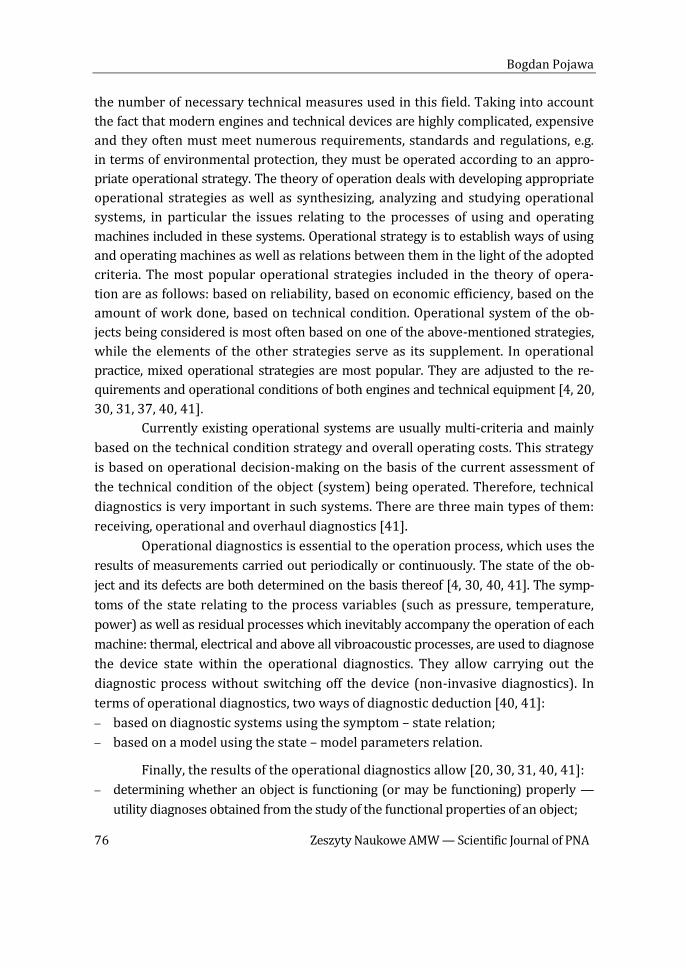
destroyer ORP ‘Warszawa’ (fig. 2) with DE 59 engines (four engines), there was a need
to organize a diagnostics system (20 engines in total). Since 1985, at the Institute of
Shipbuilding and Marine Propulsion, there were many scientific research papers [5, 15,
28, 32] carried out and doctoral theses defended [19, 24, 29, 39] under the guidance
of Professor A. Charchalis. They focused on diagnosing this type of engines. They
dealt with developing effective diagnostic methods that could be used in operating
conditions of marine engines [1–3, 6–10, 14, 21, 22, 25, 34]. In the 1990s, their re-
sults made it possible to develop and implement an underlying multi-symptom
system for diagnosing naval gas turbines operated in the Polish Navy [5, 11, 12, 27].
This system enabled a transition from the operational strategy based on the amount
of work done to the technical condition strategy. Experiences acquired in this field
were used in the operation of LM 2500 naval gas turbines (4 engines) which were put
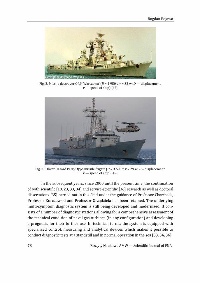
into service in the Polish Navy in 2000 together with ‘Oliver Hazard Perry’ type missile
frigates (fig. 3). (ORP ‘Pułaski’ and ORP ‘Kościuszko’) [33].
Fig. 1. 1241 RE missile corvette (D = 490 t, v = 45 w; D — displacement, v — speed of ship) [42]
Bogdan Pojawa
78 Zeszyty Naukowe AMW — Scientific Journal of PNA
Fig. 2. Missile destroyer ORP ‘Warszawa’ (D = 4 950 t, v = 32 w; D — displacement, v — speed of ship) [42]
Fig. 3. ‘Oliver Hazard Perry’ type missile frigate (D = 3 600 t, v = 29 w; D – displacement, v — speed of ship) [42]
In the subsequent years, since 2000 until the present time, the continuation
of both scientific [18, 23, 33, 34] and service-scientific [36] research as well as doctoral
dissertations [35] carried out in this field under the guidance of Professor Charchalis,
Professor Korczewski and Professor Grządziela has been retained. The underlying
multi-symptom diagnostic system is still being developed and modernized. It con-
sists of a number of diagnostic stations allowing for a comprehensive assessment of
the technical condition of naval gas turbines (in any configuration) and developing
a prognosis for their further use. In technical terms, the system is equipped with
specialized control, measuring and analytical devices which makes it possible to
conduct diagnostic tests at a standstill and in normal operation in the sea [33, 34, 36].

Operational diagnostics synthesis of the naval gas turbines operated by the Polish Navy
1 (208) 2017 79
In this article, due to the wealth of material, the issues relating to the opera-
tional diagnostics of naval gas turbines are shown only in the field of energy research.
Therefore, the article presents the identification of testing object, purpose, methodology
and apparatus used for research. The results of ongoing research will be presented
in the next article.
IDENTIFICATION OF TESTING OBJECT
Since 1983, equipment available to the Polish Navy included the following
naval gas turbines covered by operational diagnostics with the use of a underlying
multi-symptom diagnostic system [6, 7, 21, 27, 42]:
eight DR 76 engines (in the years 1983–2013);
eight DR 77 engines (in the years 1983–2013);
two DE 59P engines (in the years 1988–2003);
two DE 59L engines (in the years 1988–2003),
four LM 2500 engines (since 2000 until present).
In the near term, an another LM 2500 engine will come into operation together
with a 661M patrol boat ORP ‘Ślązak’. This boat will be equipped with a combined
propulsion system CODAG which includes two 12V 596TE90 marine combustion
engines MTU (sustainer engines) and LM 2500 naval gas turbine GE/AVIO (peak
output engine) [42].
Naval gas turbines DR 76 and DR 77 were used in a combined propulsion
system COGAG installed in 1241 RE missile corvettes. It consisted of two identical
propulsion units on the board- and portside, connected by a transverse shaft. The pro-
pulsion system consists of two DR 76 naval sustainer gas turbines and two DR 77
naval peak output gas turbines (fig. 4). The total power of this propulsion system
amounted to 23.500 kW. The torque from the engines was transmitted onto two
lines of shafts by a cruising gear (CG) and onto a three-blade solid propeller by
a peak gear (PG). The gear units were equipped with disengaging couplings (DC)
which allowed for the following operating modes [16, 27]:
one sustainer engine (DR 76) and two propellers in operation, with the use of
a transverse shaft;
autonomous operation of sustainer engines (DR 76), each with its propeller;
autonomous operation of peak output engines (DR 77), each with its propeller;
operation of all drive engines (COGAG) with both sustainer and peak power en-
gines on one side driving their propellers.

Bogdan Pojawa
80 Zeszyty Naukowe AMW — Scientific Journal of PNA
DR 76
DR 76
DR 77
DR 77
DC
DC
DC
DC
DC
PG
PG
CG
CG
STERN POWER PLANT BOW POWER PLANT
PS
ST
Fig. 4. Schematic diagram of a combined propulsion system (COGAG) of a 1241 RE missile corvette [16]
Both DR 76 and DR 77 included in the propulsion system of a ship had similar
three-rotor design with a two-rotor gas generator, annular-tubular return combustion
chamber and reversible power turbine [16]. Cross-section of an engine on the example
of the DR 76 engine is shown in figure 5. Basic parameters of both DR 76 and DR 77
engines are presented in table 1. These engines consisted of the following main
components [16]:
eight-stage low-pressure compressor (LPC);
nine-stage high-pressure compressor (HPC);
annular-tubular combustion chamber (CC);
one-stage high-pressure turbine (HPT);
one-stage low-pressure turbine (LPT);
three-stage reversible power turbine (PT).
Both low-pressure and high-pressure compressors along with their turbines
formed two unconnected kinematic rotors (low-pressure and high-pressure respective-
ly) rotating at different speeds in any range of engine operation. Both low-pressure and
high-pressure rotors as well as the combustion chamber formed the gas generator.
Reversible power turbine was a separate rotor, not connected kinetically with other
rotors, located behind the low-pressure turbine. Power turbine rotor had three stages
of ‘forward’ movement and one stage of ‘back’ movement. ‘Back’ blade ring was located
above the blade ring of the 3rd stage of ‘forward’ movement and the direction of

Operational diagnostics synthesis of the naval gas turbines operated by the Polish Navy
1 (208) 2017 81
exhaust flow was provided by adjustable blinds. The design of the engine’s reversible
mechanism included an indirect operational mode of the power turbine, so-called
‘stop-propeller’, in which gas-dynamic moments of both ‘forward’ and ‘back’ blade
rings balanced against each other [16].
Fig. 5. Cross-section of the DR 76 and DR 77 naval gas turbines: LPC — low-pressure compressor,
HPC — high-pressure compressor, CC — combustion chamber, LPT — low-pressure turbine, HPT — high-pressure turbine, PT —power turbine [16]
DE 59 naval gas turbines occurred in the combined propulsion system (COGAG)
installed in the 61MP missile destroyer. It consisted of two identical propulsion units
on the board- and portside. The propulsion system consisted of the four DE 59 naval
gas turbines, including two DE 59P and two DE 59L engines, with the total power of
70.500 kW (fig. 6). The torque from the engines was transmitted onto two lines of shafts
with the three-blade solid propellers. The gear units were equipped with disengaging
couplings (DC) which allowed for the following operating modes [17]:
one drive system’s engine of the board- and portside in operation, each with its
propeller;
all drive engines in operation (COGAG), with drive systems of the board- and
portside driving its propeller.
The DE 59 engines had also three-rotor design with a two-rotor gas generator,
annular-tubular return combustion chamber and power turbine [17]. Cross-section
of the DE 59 engine is shown in figure 7, while the basic operating parameters are
presented in table 1.

Bogdan Pojawa
82 Zeszyty Naukowe AMW — Scientific Journal of PNA
STERN POWER PLANT BOW POWER PLANT
PS
ST
DE 59DCRG
DE 59DC
DE 59DCRG
DE 59DC
Fig. 6. Schematic diagram of a combined propulsion system (COGAG)
of a 61MP missile destroyer [17]
The DE 59 engines consisted of the following main components [17]:
eight-stage low-pressure compressor (LPC);
nine-stage high-pressure compressor (HPC);
annular-tubular combustion chamber (CC);
two-stage high-pressure turbine (HPT);
two-stage low-pressure turbine (LPT);
two-stage non-reversing power turbine (PT).
‘Back’ movement was implemented in this propulsion system by a reduction-
-reversing gear.
Fig. 7. Cross-section of the DE 59 naval gas turbine [17]
The LM 2500 naval gas turbines occur in a combined propulsion system
(COGAG) installed in the ‘Oliver Hazard Perry’ missile frigates. The propulsion system

Operational diagnostics synthesis of the naval gas turbines operated by the Polish Navy
1 (208) 2017 83
consists of two LM 2500 naval gas turbines, reduction gear and shaft line with five-
-blade adjustable propeller (fig. 8). The total power of this propulsion system
amounts to 30.000 kW. The drive system allows for the following operating modes [38]:
operation of one engine on the board- or portside;
simultaneous operation of two engines on the board- and portside.
Fig. 8. Schematic diagram of a combined propulsion system (COGAG)
of a ‘Oliver Hazard Perry’ missile frigate [38]
The LM 2500 engine is a two-rotor engine with a one-rotor gas generator.
The gas generator consists of a sixteen-stage axial compressor, annular combustion
chamber with 30 injectors and 2 starters as well as a two-stage axial gas generator
turbine. The power turbine is a six-stage axial turbine [38]. The cross-section of the
LM 2500 engine is presented in figure 9, while the basic operating parameters are
presented in table 1.
Fig. 9. Cross-section of the LM 2500 naval gas turbine [38]

Bogdan Pojawa
84 Zeszyty Naukowe AMW — Scientific Journal of PNA
The engines are installed in containers attached to the foundations by means
of elastic dampers. Such a location allows for both noise and vibration absorption as
well as protecting the marine power plant against the fire of the main engines.
These containers provide a suitable temperature on the outside of the engine at
a standstill and in normal operation. A container is also a base for automation de-
vices (transmitters and sensors) as well as oil, fuel and (starting and control) air
connections. In addition, inside the container, there are temperature and flame
sensors that inform about the fire [38].
‘Back’ movement was implemented in this propulsion system by an adjustable
propeller [38].
Tab. 1. Basic operating parameters for the rated working range of DR 76, DR 77, DE 59
and LM 2500 engines [16, 17, 38]
Parameter Designation Unit DR 76 DR 77 DE 59 LM 2500
power output P kW 2940 8820 17 640 15 000
low pressure compressor speed
nLPC RPM 14 820 11 320 5800 −
high pressure compressor speed
nHPC RPM 20 700 14 400 7480 −
gas generator speed nGG RPM − − − 9500
power turbine speed nPT RPM 8600 6400 5350 3600
specific fuel consumption
be g/kWh 299 274 275 268
power turbine inlet exhaust gas temperature
TPT K 935 945 890 −
combustion chamber outlet exhaust gas temperature
TCC K 1285 1420 1090 1485
compressor pressure ratio
− 12.16 16.77 − 18.8
mass flow rate of air �̇�𝑎𝑖𝑟 kg/s 14.36 32.28 − 70.1
effective efficiency e % 32 30 30 37
RESEARCH PURPOSE AND METHODOLOGY
The energy research for the purpose of operational diagnostic of naval gas
turbines are conducted in order to [15, 26, 27, 33]:
verify indications of marine control and measurement system;
determine and assess changes concerning operating parameters of the engine
during starting, idling, work with load and during stop (overrun);

Operational diagnostics synthesis of the naval gas turbines operated by the Polish Navy
1 (208) 2017 85
check the correct functioning of the automation system during start-up, while
working with load and during stopping the engine;
check the control parameters according to operational requirements, in particular
during idling;
analyse the operating characteristics of the engine;
evaluate the fuel system in a steady state;
assess the technical state of the flow part.
The energy research is carried out in accordance with the research methodology
developed for the needs thereof [26, 27]. Energy research are always preceded by:
calibration of sensors and measuring transducers;
calibration of measuring lines, along with an indication of measurement uncer-
tainties;
checking the correct functioning of the systems used for measuring and recording
systems for measurement, recording and visualization of the operating parameters
of engines tested;
checking and adjusting the marine systems of measurement and automation of
engines tested.
Calibration of sensors and measuring lines (both marine ones and used
measurement and recording system) is carried out using appropriate calibrators.
They allow, in case of pressure sensors, to produce a calibration pressure and in
case of the voltage or current sensors to set the appropriate model signal. After
calibration the characteristics (functions) of the individual measurement lines are
developed, allowing the conversion of electrical signals from the sensors into units
of measured physical quantities (pressure, temperature, speed). These characteristics,
in modern measuring and recording systems, are introduced directly into the memory
of a given system, and in case of older systems they are used during the preparation
and analysis of measurement data.
The next stage of preparatory activities is connecting the measuring and re-
cording system used for the study to systems and installations of examined propul-
sion system (of examined engines). When older measuring and recording systems
(61MP and RE 1241 propulsion systems) are used for energy research, sensors
independent of ship measurement systems were applied [15, 26]. The special splitters,
connectors and switches mounted on marine systems and installations of the examined
propulsion system enabled connecting the sensors (fig. 10). When modern systems of
measurement and recording (frigates missile propulsion systems) are used for energy
research, the system is connected to the marine measurement cards in the automation

Bogdan Pojawa
86 Zeszyty Naukowe AMW — Scientific Journal of PNA
module (FSEE), to which fed signals from various sensors of tested propulsion sys-
tem are transferred (fig. 11). The configuration of systems in this way enables inde-
pendent and parallel measurements of operating parameters of engines tested
for the purpose of energy research, without any restrictions and disruption to ma-
rine measurement and control system due to working propulsion system, which is
examined [27, 33].
Fig. 10. Measuring and recording system ‘PSZCZOŁOJAD’ during energy research implemented on the ship [15]
Fig. 11. Automation module of missile frigate propulsion system (FSEE): 1 — set of measurement signals outputs, 2 — measuring cards [33]
1 2

Operational diagnostics synthesis of the naval gas turbines operated by the Polish Navy
1 (208) 2017 87
Before starting the energy research, the tests proving correctness regarding
results of marine measurement systems and security as well as elements of automatic
control system of tested engines. These tests are performed during the simulation
research of engines that do not work, using testers (referencing-unit) specially con-
structed for this purpose [26, 27].
After completion of the preparatory activities, the energy research is possible.
The examination of the start-up, idling and stopping the engine is performed when
the ship is in the harbour, while the tests during work with load are carried out in
real conditions — in the sea. During tests in the sea the simultaneous measure-
ments of set energy states of all engines are performed, usually with speeds set by
rotor gas generator in the range from idle to the nominal engine load. The engine
load is changed in accordance with a program of research. During the measurement
of operating parameters of the engine during start-up or stop, the measurements
begin about 10 seconds prior to the planned process in order to accurately register
the initial phase of the process, which is a reference for tests conducted later. Parame-
ters during work with load are measured after about 1 minute of work of the engine
at a given load. This is to stabilize the operating parameters of the previously con-
ducted process of acceleration or deceleration of the engine. The following time
intervals of engine operating parameters have been recorded [15, 26, 27, 33]:
starting-up 120 s;
with set load 20 s;
override during stop 220 s.
Subsequently the summary and substantive analysis of measurement results
of recorded operating parameters of tested engines are performed. In order to enable
comparison of the characteristics of tested engines, as well as to relate them to dif-
ferent weather conditions, the results should be reduced to the so-called normalized
conditions (standard reference state). Standard atmosphere conditions are defined
by the following parameters: absolute pressure of 1 atm (101 325 Pa) and the abso-
lute temperature 288.15 K [26, 27, 34]. Conversion relations used to normalize the
values of the parameters measured or calculated are presented in table 2.
If the measurement results are developed, it is possible to determine the charac-
teristics of engines and individual methods of diagnostic symptoms. Based on the compi-
lation of the result it is also possible to verify the indications of marine control and
measurement system and to determine uncertainties. If the value of the relative
error exceeds 10%, it is assumed that a given measuring line is faulty.

Bogdan Pojawa
88 Zeszyty Naukowe AMW — Scientific Journal of PNA
Tab. 2. Conversion formulas used to reduce the value of the measured parameters to standard reference state: R — reduced, M — measured, 0 — ambient [34]
Parameter Conversion formula
power 𝑃𝑅 = 𝑃𝑀 ∙101325
𝑝0∙ √
288.15
𝑇0
torque 𝑀𝑅 = 𝑀𝑀 ∙101325
𝑝0∙ √
288.15
𝑇0
speed 𝑛𝑅 = 𝑛𝑀 ∙ √288.15
𝑇0
mass flow rate �̇�𝑅 = �̇�𝑀 ∙101325
𝑝0∙ √
𝑇0288.15
temperature 𝑇𝑅 = 𝑇𝑀 ∙288.15
𝑇0
pressure (air, exhaust gas) 𝑝𝑅 = 𝑝𝑀 ∙101325
𝑝0
hourly fuel consumption 𝐵ℎ𝑅 = 𝐵ℎ𝑀 ∙101325
𝑝0∙ √
288.15
𝑇0
fuel pressure 𝑝𝑓𝑢𝑒𝑙𝑅 = 𝑝𝑓𝑢𝑒𝑙𝑀 ∙288.15
𝑇0∙ (101325
𝑝0)2
EQUIPMENT APPLIED FOR RESEARCH
Operating diagnosis of naval gas turbines in the field of energy research re-
quires measurement parameters of the engine during its start-up and stop as well
as within the entire range of loads. These parameters include: temperature, abso-
lute pressure and mass flow of operating medium within characteristic sections,
which correspond to nodal points regarding implementation of thermodynamic
engine cycle. On the basis of recorded parameters it is possible to determine charac-
teristics of the tested engine diagnostic systems that are set in the developed diag-
nostic methods. Schematic diagram along with control sections of the LM 2500
engine is presented in figure 12, while DR 76 and DR 77 engines — in figure 13.
Operating parameters of the engine type LM 2500 measured during the energy
research are presented in table 3. Operating parameters of the engines type DR 76
and DR 77 measured during energy research are presented in table 4.

Operational diagnostics synthesis of the naval gas turbines operated by the Polish Navy
1 (208) 2017 89
pfuel
HPTC PT
CC
SURROUNDINGS
Fu
el
Sy
stem
p1 T1 nGGP M nPT
Inst
all
ati
on
of
Exh
au
st
Gas
Ou
tlet
Inst
all
ati
on
of
Air
Inta
ke
Gas Generator
Power TurbineLM-2500 Naval Gas Turbine
Reduction
Gear
Shaft Line
and CPP
pCDP p4.1 T4.1
Fig. 12. Schematic diagram of naval gas turbine type LM 2500 along with the selected control sections [27]
Fig. 13. Schematic diagram of naval gas turbine type DR 76 and DR 77 along with the selected control sections [26]

Bogdan Pojawa
90 Zeszyty Naukowe AMW — Scientific Journal of PNA
Tab. 3. Parameters of running engine type LM 2500 measured during the energy research [27]
Parameter designation
Measuring range Description of the parameter
nGG 0–12 000 RPM gas generator speed
nPT 0–5000 RPM power turbine speed
p1 0–16 psia gas generator inlet air pressure
T1 –40–150F gas generator inlet air temperature
pCDP 0–300 psig gas generator compressor discharge air pressure
π 0–20 compressor pressure ratio
p4.1 0–75 psia power turbine inlet exhaust gas pressure
T4.1 0–2 000F power turbine inlet exhaust gas temperature
pfuel 0–1 500 psig fuel manifold pressure
M 0–35 000 ftlbf torque output
P 0–25 000 HP power output
Tab. 4. Parameters of running engine type DE 59, DR 76, DR 77 measured during energy research [26]
Parameter designation
Measuring range Description of the parameter
IS 0–1000 A starting current
US 0–60 V starting voltage
UF 0–60 V field voltage
nLPC 0–20 000 RPM low pressure compressor speed
nHPC 0–22 000 RPM high pressure compressor speed
nPT 0–10 000 RPM power turbine speed
p1.1 –0,4–0 bar compressor inlet air pressure
p21 0–6,0 bar low pressure compressor outlet air pressure
p2.2 0–16,0 bar high pressure compressor outlet air pressure
pfuel 0–100.0 bar fuel manifold pressure
t1.1 –70–180C compressor inlet air temperature
t4.2 0–1000C power turbine inlet exhaust gas temperature
t4 0–1000C power turbine outlet exhaust gas temperature
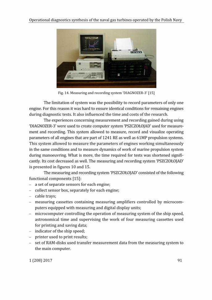
For the measurement, recording and visualization of the above-mentioned
operating parameters, during the start-ups and stops of the engine, as well as during
the work with load, the computer system for measuring and recording ‘DIAGNOSER-3’
was applied. This system was developed by a team from the Institute of Shipbuilding
and Marine Propulsion of Polish Naval Academy. The measuring and recording system
‘DIAGNOZER-3’ is depicted in figure 14.
Operational diagnostics synthesis of the naval gas turbines operated by the Polish Navy
1 (208) 2017 91
Fig. 14. Measuring and recording system ‘DIAGNOZER-3’ [15]
The limitation of system was the possibility to record parameters of only one
engine. For this reason it was hard to ensure identical conditions for remaining engines
during diagnostic tests. It also influenced the time and costs of the research.
The experiences concerning measurement and recording gained during using
‘DIAGNOZER-3’ were used to create computer system ‘PSZCZOŁOJAD’ used for measure-
ment and recording. This system allowed to measure, record and visualize operating
parameters of all engines that are part of 1241 RE as well as 61MP propulsion systems.
This system allowed to measure the parameters of engines working simultaneously
in the same conditions and to measure dynamics of work of marine propulsion system
during manoeuvring. What is more, the time required for tests was shortened signifi-
cantly. Its cost decreased as well. The measuring and recording system ‘PSZCZOŁOJAD’
is presented in figures 10 and 15.
The measuring and recording system ‘PSZCZOŁOJAD’ consisted of the following
functional components [15]:
a set of separate sensors for each engine;
collect sensor box, separately for each engine;
cable trays;
measuring cassettes containing measuring amplifiers controlled by microcom-
puters equipped with measuring and digital display units;
microcomputer controlling the operation of measuring system of the ship speed,
astronomical time and supervising the work of four measuring cassettes used
for printing and saving data;
indicator of the ship speed;
printer used to print results;
set of RAM-disks used transfer measurement data from the measuring system to
the main computer.

Bogdan Pojawa
92 Zeszyty Naukowe AMW — Scientific Journal of PNA
Despite the fact that the measuring and recording systems ‘DIAGNOZER-3’
and ‘PSZCZOŁOJAD’ perfectly fulfilled their roles, their limitation was that the measure-
ment of operating parameters took place at the frequency of 1 Hz and there was no
possibility to change it, which is standard option in modern measuring and recording
systems. This limitation resulted in the fact that these systems could not be used for
measuring operating parameters during acceleration and deceleration. In order to enable
measurements of operating parameters of the above processes another system was
built, which is ‘TURBODYN’. It allowed simultaneous measurement, recording and visu-
alization of the engine operation parameters at the frequency of 1 Hz, 2 Hz, 5 Hz and
10 Hz. The measuring and recording system ‘TURBODYN’ is presented in figure 16.
Fig. 15. Measuring and recording system ‘PSZCZOŁOJAD’ [15]
Fig. 16. Measuring and recording system ‘TURBODYN’ [15]

Operational diagnostics synthesis of the naval gas turbines operated by the Polish Navy
1 (208) 2017 93
In the recent years a considerable development in measurement technology
could be observed. Owing to this fact there are ample opportunities for the construc-
tion of new and universal measuring and recording systems. It became possible to
purchase, unlike the past, completed specialized measuring and recording systems
dedicated to various fields of technology. Therefore the basic diagnosing system of
naval gas turbines has been modernised and developed in the recent years and a new
measuring and recording system has been built on the basis of the purchased signal
recorder DAS 1400 manufactured by SEFRAM [33, 34]. The recorder allows working
with any standard PC with USB port, XGA, Ethernet, used as a port for data trans-
mission. The main technical parameters of the recorder are:
the number of analogue input channels max. 36;
resolution capability 16 bit;
the type of input signal voltage/current;
input range +/ 5 V, 0–20 mA;
processing accuracy +/ 0,1%, +/ 1 LSB;
maximum sampling frequency 100 kHz;
built-in hard disk 80 GB.
The developed system during the measurement stores the recorded values in
the internal memory and after the measurement cycle transfers it to a laptop. The re-
corded parameters can be analysed with the use of specialized calculation programs.
The view of the measuring and recording system DAS 1400 is shown in figure 17.
Fig. 17. The measuring and recording system Sefram DAS 1400 during energy research carried out on the ship [author’s collection]
CONCLUSIONS
Operational system of the naval gas turbines developed by the Polish Navy
is currently a multi-criteria system, based mainly on the technical condition strategy

Bogdan Pojawa
94 Zeszyty Naukowe AMW — Scientific Journal of PNA
and total operating costs. Operational diagnostics plays an important role in this
system, in which energy research presented in the article is conducted. For the purpose
of research, an underlying multi-symptom diagnostic system has been developed
and implemented. The results of systematic diagnostic research allow for a conscious
operation of the engines according to their technical condition. They are also used
in operational decision-making processes regarding the ongoing maintenance, adjust-
ments, repairs and, finally assessing the effects of the work performed.
Experience gained from systematic diagnostic research allow for confirming
their validity and usefulness. This is particularly important at a time when the opera-
tion of the engines, including repairs, involves limited funds. The research made it
possible to change the strategy of using the engines from the one based on the amount
of work done to the technical condition strategy. In the recent years, this allows for
extending the time between overhauls of both DR 76 and DR 77 engines and thus
maintaining the vessels’ fighting ability. Currently, in accordance with this strategy
and with good effect, the LM 2500 engines have been operated on vessels with more
than 38 years of service.
Knowledge and experience from diagnostic tests are also used in education
and trainings of those responsible for the operation of this type of engines carried
out at the Faculty of Mechanical and Electrical Engineering of the Polish Naval Academy
in Gdynia. This is even more important given the fact that improper operation often
leads to a serious damage affecting the fighting ability of a vessel and thus generates
high and unexpected costs in the process of operation.
REFERENCES
[1] Adamkiewicz A., Grządziela A., Możliwość oceny niewyważenia zespołu wirnikowego okrętowego turbinowego silnika spalinowego na podstawie sygnałów drganiowych pozyskanych z łożyska nośnego, ‘Tribologia’, 2002, No. 1, pp. 57–70 [Feasibility of unbalan-cing estimation of the gas turbine rotor using vibration signals from load bearing — available in Polish].
[2] Adamkiewicz A., Relacje diagnostyczne w okrętowych turbinowych silnikach spalinowych, ‘Problemy Eksploatacji’, 2001, No. 3, pp. 9–19 [Diagnostic relationships in naval gas turbines — available in Polish].
[3] Adamkiewicz A., Zagadnienia przedłużania okresu eksploatacji okrętowych turbinowych silników spalinowych, ‘Prace Naukowe Politechniki Warszawskiej. Mechanika’ 2005, No. 211, pp. 7–17 [The issue of extending operation time of marine gas turbine — available in Polish].
[4] Cempel C., Tomaszewski F., Diagnostyka maszyn, Międzyresortowe Centrum Naukowe Eksploatacji Majątku Trwałego, Radom 1992 [Diagnostics of machines — available in Polish].

Operational diagnostics synthesis of the naval gas turbines operated by the Polish Navy
1 (208) 2017 95
[5] Charchalis A. et al., Opracowanie programu badań diagnostycznych i metod oceny dla weryfikacji (wydłużenia) okresu międzyremontowego silników turbinowych okrętu 1241 RE, AMW, Gdynia 1991 [Development of a program of diagnostic tests and evaluation methods for verification of intermittent naval gas turbines of ship 1241 RE — available in Polish].
[6] Charchalis A., Diagnozowanie okrętowych silników turbinowych, AMW, Gdynia 1991 [Diagnosis of naval gas turbines — available in Polish].
[7] Charchalis A., Korczewski Z., Badania diagnostyczne okrętowych turbinowych silników spali-nowych na podstawie analizy zmian parametrów termogazodynamicznych, XIV Międzynarodowe Sympozjum Siłowni Okrętowych, Szczecin 1992, pp. 63–71 [Diagnostic tests of naval gas turbines based on analysis of changes in thermogasic parameters — available in Polish].
[8] Charchalis A., Korczewski Z., Dyson P. K., Evaluation of operating conditions of the passages of naval gas turbines by gas path analysis, The Institute of Marine Enginers, London 1996.
[9] Charchalis A., Korczewski Z., Metody diagnozowania okrętowych turbinowych silników spali-nowych, ‘Przegląd Mechaniczny’ 1997, No. 3−4, pp. 45–57 [Methods of diagnosis of naval gas turbines — available in Polish].
[10] Charchalis A., Pojawa B., Ocena stanu technicznego okrętowego turbinowego silnika spali-nowego na podstawie badań momentu obrotowego przy rozruchu, XXVIII Ogólnopolskie Sympozjum ‘Diagnostyka maszyn’, Węgierska Górka 2001, pp. 133–140 [Assessment of the tech-nical state of the naval gas turbine based on torque tests at start-up — available in Polish].
[11] Charchalis A., Systemy pomiarowe wykorzystywane w diagnostyce okrętowych turbinowych silników spalinowych, XV Międzynarodowe Sympozjum Siłowni Okrętowych, Gdynia 1993, pp. 73–81 [Measurement systems used in the diagnostics of naval gas turbines — available in Polish].
[12] Charchalis A., Wielosymptomowy system diagnozowania okrętowych turbinowych silników spalinowych, ‘Diagnostyka’, 2004, Vol. 30/1, pp. 101–105 [Multi-symptoms system of diagno-sing of marine gas turbines — available in Polish].
[13] Charchalis A., Wirkowski P., Badania eksploatacyjne okrętowych turbinowych silników spali-nowych LM 2500, ‘Diagnostyka’, 2004, Vol. 30/1, pp.106–110 [Exploitation’s researches of marine gasturbines LM 2500 — available in Polish].
[14] Charchalis A., Wróblewski K., Włoch J., Diagnostyka okrętowego turbinowego silnika spali-nowego na podstawie eksploatacyjnych parametrów rozruchu, XIV Międzynarodowe Sympo-zjum Siłowni Okrętowych, Szczecin 1992, pp. 73–85 [Diagnostics of the naval gas turbine based on operational starting parameters — available in Polish].
[15] Diagnostyka okrętowych turbinowych silników spalinowych, AMW, Gdynia 1996, targeted project No. 148-23/C-SO/93 [Diagnostics of naval gas turbines — available in Polish].
[16] Dokumentacja techniczna i eksploatacyjna układu napędowego M15 [Technical and operating documentation of the M15 propulsion system — available in Polish].
[17] Dokumentacja techniczna i eksploatacyjna układu napędowego M3A [Technical and operating documentation of the M3A propulsion system — available in Polish].
[18] Grządziela A., Metoda diagnozowania okrętowej linii wałów z zastosowaniem zidentyfikowanych modeli dynamicznych, ‘Zeszyty Naukowe AMW’, 2008, No. 172A [Diagnostic method for marine shaft lines using identified dynamic models — available in Polish].

Bogdan Pojawa
96 Zeszyty Naukowe AMW — Scientific Journal of PNA
[19] Grządziela A., Metoda kontroli współosiowości elementów okrętowego układu napędowego z turbi-nowymi silnikami spalinowymi, PhD thesis, AMW, Gdynia 1998 [A method of controlling the coaxiality of marine propulsion system components with naval gas turbines — available in Polish].
[20] Korbicz J., Kościelny J. M., Kowalczuk Z., Cholewa W., Diagnostyka procesów. Modele, metody sztucznej inteligencji, zastosowania, WNT, Warszawa 2002 [Process diagnostics. Models, arti-ficial intelligence, applications — available in Polish].
[21] Korczewski Z., Badania diagnostyczne w eksploatacji okrętowych turbinowych silników spali-nowych, ‘Zeszyty Naukowe AMW’, 2005, No. 2, pp. 67–88. [Diagnostic research in the opera-tion of naval gas turbines — available in Polish].
[22] Korczewski Z., Badania procesu przyspieszania w konstrukcjach wielowirnikowych okrętowego turbinowego silnika spalinowego, XVII Międzynarodowe Sympozjum Siłowni Okrętowych, Szczecin 1995, pp. 93–105 [Research on the acceleration process in multi-rotor constructions of a naval gas turbine — available in Polish].
[23] Korczewski Z., Identyfikacja procesów gazodynamicznych w zespole sprężarkowym okrętowego turbinowego silnika spalinowego dla potrzeb diagnostyki, ‘Zeszyty Naukowe AMW’, 1999, No. 138A [Identification of gas-dynamic processes in the compressor assembly of a naval gas turbine for diagnostic purposes — available in Polish].
[24] Korczewski Z., Metoda diagnozowania części przepływowej okrętowych turbinowych silników spalinowych w eksploatacji, PhD thesis, AMW, Gdynia 1992 [Method of diagnosis of flow parts of naval gas turbines in operation — available in Polish].
[25] Korczewski Z., Simulation model of the compressors configuration of naval gas turbine for diagnostic purposes, ‘Marine Technology Transactions. Technika Morska’, 1997, Vol. 8.
[26] Metodyka badań okrętowych turbinowych silników spalinowych typu DR76 i DR77 użytkowanych w MW RP, praca zbiorowa, AMW, Gdynia 2006 [Methodology of research of naval gas turbines DR76 and DR77 used in Polish Navy, group work — available in Polish].
[27] Metodyka badań okrętowych turbinowych silników spalinowych typu LM 2500 użytkowanych w MW RP, praca zbiorowa, AMW, Gdynia 2006 [Methodology of research of naval gas turbines LM 2500 used in Polish Navy, group work — available in Polish].
[28] Metodyka oceny współosiowości elementów transmisji momentu obrotowego w okrętowych układach napędowych, AMW, Gdynia 1995–1998, research project No. 0 T00A 009 16 [Methodology for assessing the coaxiality of torque transmission components in marine pro-pulsion systems — available in Polish].
[29] Mironiuk W., Ocena stanów awaryjnych układów łożyskowych turbinowych silników spali-nowych, Phd thesis, AMW, Gdynia 1995. [Assessment of emergency conditions of bearing sys-tems of naval gas turbines — available in Polish].
[30] Moczulski W., Diagnostyka techniczna. Metody pozyskiwania wiedzy, Publ. Silesian University of Technology, Gliwice 2002 [Technical diagnostics. Knowledge acquisition methods — available in Polish].
[31] Niziński S., Michalski R., Diagnostyka obiektów technicznych, Publ. University of Warmia and Mazury, Olsztyn 2001 [Diagnostics of technical objects — available in Polish].
[32] Ocena stanu technicznego okrętowych turbinowych silników spalinowych w oparciu o badania ich cech dynamicznych, AMW, Gdynia 1995–1998, research project No. 9T12D00811 [Assessment of the technical state of naval gas turbines based on their dynamic characteristics — available in Polish].

Operational diagnostics synthesis of the naval gas turbines operated by the Polish Navy
1 (208) 2017 97
[33] Opracowanie systemu diagnostycznego okrętowych turbinowych silników spalinowych fregat wdrażanych w Marynarce Wojennej RP, AMW, Gdynia 1995–1998, research project No. 0 T00A 062 19 [Development of a diagnostic system for naval gas turbines of frigates de-ployed in the Polish Navy — available in Polish].
[34] Pojawa B., Characteristics Determination of LM-2500 Naval Gas Turbine in Aspect of Energy Modeling and Simulations, ‘Solid State Phenomena’, 2015, Vol. 236, pp. 169–179.
[35] Pojawa B., Metoda diagnozowania układu rozruchowego okrętowego turbinowego silnika spalinowego, PhD thesis, AMW, Gdynia 2003 [Method of diagnosis of the start-up system of a naval gas turbine — available in Polish].
[36] Sprawozdania z badań diagnostycznych turbinowych silników spalinowych eksploatowanych na okrętach MW RP, AMW, Gdynia 1985–2016, research and service [Reports on diagnostic tests of naval gas turbines operating in Polish Navy — available in Polish].
[37] Szczeciński S., Balicki W., Diagnozowanie lotniczych silników turbinowych, Biblioteka Naukowa Instytutu Lotnictwa, Warszawa 2001 [Diagnosing aircraft turbine engine — available in Polish].
[38] Technical, Manual and Organizational Level Maintenance — LM-2500 propulsion gas turbine module of propulsion system of Oliver Hazard Perry class frigate FFG-9, Marine and Industrial Engines and Services Division, General Electric Company, Cincinnati, Ohio 2003.
[39] Włoch J., Diagnozowanie okrętowych turbinowych silników spalinowych na podstawie wielkości charakteryzujących przebieg rozruchu i zatrzymania, PhD thesis, AMW, Gdynia 1994 [Diagnosing naval gas turbines on the basis of parameters characterizing the start-up and stop process — available in Polish].
[40] Żółtowski B., Elementy racjonalnej eksploatacji systemów technicznych, ‘Inżynieria i Aparatura Chemiczna’, 2012, No. 2, pp. 34–36 [Elements of rational use of technical systems — available in Polish].
[41] Żółtowski B., Podstawy diagnostyki maszyn, Publ. University of Technology and Agriculture, Bydgoszcz 1996 [Fundamentals of machine diagnostics — available in Polish].
[42] http://www.3fo.mw.mil.pl [access 09.11.2016].
S Y N T E Z A D I A G N O S T Y K I E K S P L O A T A C Y J N E J O K R Ę T O W Y C H T U R B I N O W Y C H S I L N I K Ó W
S P A L I N O W Y C H E K S P L O A T O W A N Y C H W M A R Y N A R C E W O J E N N E J R P
STRESZCZENIE
W artykule przedstawiono całokształt badań energetycznych realizowanych przez Akademię Mary-
narki Wojennej na potrzeby diagnostyki eksploatacyjnej okrętowych turbinowych silników spalino-
wych eksploatowanych w Marynarce Wojennej RP. Przedstawiono cel i metodykę badań, identyfikację
obiektu badań oraz aparaturę badawczą, wyniki będą zaprezentowane w kolejnym artykule Analiza

Bogdan Pojawa
98 Zeszyty Naukowe AMW — Scientific Journal of PNA
parametrów eksploatacyjnych okrętowych turbinowych silników spalinowych. Na okrętach MW RP
w latach 1983−2003 eksploatowane były cztery typy okrętowych turbinowych silników spalino-
wych: DE 59, DR 76, DR 77 i LM 2500. Obecnie, od 2013 roku, w bieżącej eksploatacji znajdują się
cztery silniki typu LM 2500 występujące na fregatach rakietowych typu ‘Oliver Hazard Perry’.
W najbliższej perspektywie czasowej do eksploatacji wejdzie kolejny silnik typu LM 2500 wraz
z okrętem patrolowym projektu 661M. Systematycznym nadzorem eksploatacyjnym, w ramach
badań energetycznych, objęty jest proces rozruchu silników, ich pracy na biegu jałowym oraz
w całym zakresie zmienności obciążeń, jak również proces zatrzymania silników.
Słowa kluczowe:
diagnostyka techniczna, okrętowy turbinowy silnik spalinowy, stan techniczny, silnik LM 2500.